
Advanced Electric Discharge Machining of Stainless Steels
48
materials Review Advanced Electric Discharge Machining of Stainless Steels: Assessment of the State of the Art, Gaps and Future Prospect Jaber E. Abu Qudeiri 1, *, Ahmad Saleh 2 , Aiman Ziout 1 , Abdel-Hamid I. Mourad 1,3 , Mustufa Haider Abidi 4 and Ahmed Elkaseer 5,6 1 Mechanical Engineering Department, College of Engineering, United Arab Emirate University, Al Ain 15551, UAE; [email protected] (A.Z.); [email protected] (A.-H.I.M.) 2 Department of Mechanical Engineering, Zarqa University, Zarqa 13132, Jordan; [email protected] 3 Mechanical Design Department, Faculty of Engineering-El Mataria, Helwan University, Cairo 11795, Egypt (On leave) 4 Raytheon Chair for Systems Engineering (RCSE Chair), Advanced Manufacturing Institute, King Saud University, Riyadh 11421, Saudi Arabia; [email protected] 5 Institute for Automation and Applied Informatics, Karlsruhe Institute of Technology, 76344 Karlsruhe, Germany; [email protected] 6 Department of Production Engineering and Mechanical Design, Faculty of Engineering, Port Said University, Port Said 42523, Egypt * Correspondence: [email protected] Received: 9 February 2019; Accepted: 13 March 2019; Published: 19 March 2019 Abstract: Electric discharge machining (EDM) is a material removal process that is especially useful for difficult-to-cut materials with complex shapes and is widely used in aerospace, automotive, surgical tools among other fields. EDM is one of the most efficient manufacturing processes and is used to achieve highly accurate production. It is a non-contact thermal energy process used to machine electrically conductive components irrespective of the material’s mechanical properties. Studies related to the EDM have shown that the process performance can be considerably improved by properly selecting the process material and operating parameters. This paper reviews research studies on the application of EDM to different grades of stainless steel materials and describes experimental and theoretical studies of EDM that have attempted to improve the process performance, by considering material removal rate, surface quality and tool wear rate, amongst others. In addition, this paper examines evaluation models and techniques used to determine the EDM process conditions. This review also presents a discussion on developments in EDM and outlines the likely trend for future research. Keywords: EDM; stainless steels; machining; process parameters; processes responses 1. Introduction In recent years, the rapidly rising demand for materials with special characteristics in such advanced industrial applications as aerospace and surgical instruments, has led to the development of new materials. However, these materials are mostly difficult-to-cut using more conventional manufacturing processes [1–5] and this pushes manufacturers to explore new machining processes which maintain or even improve precision but at reasonable cost. Stainless steel is one of the widely used difficult-to-cut materials because of its superior properties which combine good corrosion and chemical reaction resistance, with the ability to be easily cleaned, polished and sterilized. New stainless steel compositions are developed to meet Materials 2019, 12, 907; doi:10.3390/ma12060907 www.mdpi.com/journal/materials
-
Upload
khangminh22 -
Category
Documents
-
view
0 -
download
0
Transcript of Advanced Electric Discharge Machining of Stainless Steels
materials
Review
Advanced Electric Discharge Machining of StainlessSteels: Assessment of the State of the Art, Gaps andFuture Prospect
Jaber E. Abu Qudeiri 1,*, Ahmad Saleh 2, Aiman Ziout 1 , Abdel-Hamid I. Mourad 1,3 ,Mustufa Haider Abidi 4 and Ahmed Elkaseer 5,6
1 Mechanical Engineering Department, College of Engineering, United Arab Emirate University,Al Ain 15551, UAE; [email protected] (A.Z.); [email protected] (A.-H.I.M.)
2 Department of Mechanical Engineering, Zarqa University, Zarqa 13132, Jordan; [email protected] Mechanical Design Department, Faculty of Engineering-El Mataria, Helwan University,
Cairo 11795, Egypt (On leave)4 Raytheon Chair for Systems Engineering (RCSE Chair), Advanced Manufacturing Institute,
King Saud University, Riyadh 11421, Saudi Arabia; [email protected] Institute for Automation and Applied Informatics, Karlsruhe Institute of Technology,
76344 Karlsruhe, Germany; [email protected] Department of Production Engineering and Mechanical Design, Faculty of Engineering, Port Said University,
Port Said 42523, Egypt* Correspondence: [email protected]
Received: 9 February 2019; Accepted: 13 March 2019; Published: 19 March 2019�����������������
Abstract: Electric discharge machining (EDM) is a material removal process that is especially usefulfor difficult-to-cut materials with complex shapes and is widely used in aerospace, automotive,surgical tools among other fields. EDM is one of the most efficient manufacturing processes andis used to achieve highly accurate production. It is a non-contact thermal energy process used tomachine electrically conductive components irrespective of the material’s mechanical properties.Studies related to the EDM have shown that the process performance can be considerably improvedby properly selecting the process material and operating parameters. This paper reviews researchstudies on the application of EDM to different grades of stainless steel materials and describesexperimental and theoretical studies of EDM that have attempted to improve the process performance,by considering material removal rate, surface quality and tool wear rate, amongst others. In addition,this paper examines evaluation models and techniques used to determine the EDM process conditions.This review also presents a discussion on developments in EDM and outlines the likely trend forfuture research.
Keywords: EDM; stainless steels; machining; process parameters; processes responses
1. Introduction
In recent years, the rapidly rising demand for materials with special characteristics in suchadvanced industrial applications as aerospace and surgical instruments, has led to the developmentof new materials. However, these materials are mostly difficult-to-cut using more conventionalmanufacturing processes [1–5] and this pushes manufacturers to explore new machining processeswhich maintain or even improve precision but at reasonable cost.
Stainless steel is one of the widely used difficult-to-cut materials because of its superiorproperties which combine good corrosion and chemical reaction resistance, with the ability to beeasily cleaned, polished and sterilized. New stainless steel compositions are developed to meet
Materials 2019, 12, 907; doi:10.3390/ma12060907 www.mdpi.com/journal/materials
Materials 2019, 12, 907 2 of 48
the need for higher corrosion resistance, increased strength and elevated temperature resistance.As mentioned in Reference [6], about 150 separate and distinct compositions of stainless steels alreadyexist. These compositions include grades #304, #305 and #316, each of which was developed to meeta specific end-use and each of which—in common with most stainless steels—contain common alloyingingredients, such as chromium, nickel or molybdenum [7].
Electric discharge machining (EDM) is one of the most advanced and successful manufacturingmethods used to machine materials that are difficult-to-cut [8–12]. EDM is being used in modernindustries to facilitate complex machining processes and achieve highly accurate machining [13–20].EDM is utilized to remove material from a conductive workpiece by repetitively applying sparksbetween the EDM electrode tool or wire and the workpiece. In this process, no mechanical cuttingforces are applied because no contact exists between the electrode tool and the workpiece [17,21–24].The fundamental principles of the EDM process are applied in many processes, including: die-sinkingEDM, wire EDM, micro-EDM, powder-mixed EDM and dry EDM. These variants make the processsuitable for machining components from the relatively large to the micro-scale.
The EDM process has advantages over other machining processes. EDM can machine complexshapes and extremely hard materials as described in a number of publications [9,25–30]. The EDMcan be used to machine very small, delicate and fragile products without damage because no cuttingforces are applied and hence there are no mechanical induced residual stresses. However, EDM has itsown limitations with regards to the workpiece material and shape [26,31,32]. At present EDM can onlybe applied on electrically conductive materials. The process has low material removal rate and highelectrical power consumption. Furthermore, additional cost is incurred preparing the electrode toolin case of the die-sinking EDM. Finally, sharp corners are difficult to produce using EDM because ofelectrode tool wear.
While many studies have reviewed EDM, wire EDM and other EDM processes [10,33–39], no studyhas reviewed and reported on the use of EDM for machining of stainless steel specifically, though thereare many reviews available on other materials machined by EDM.
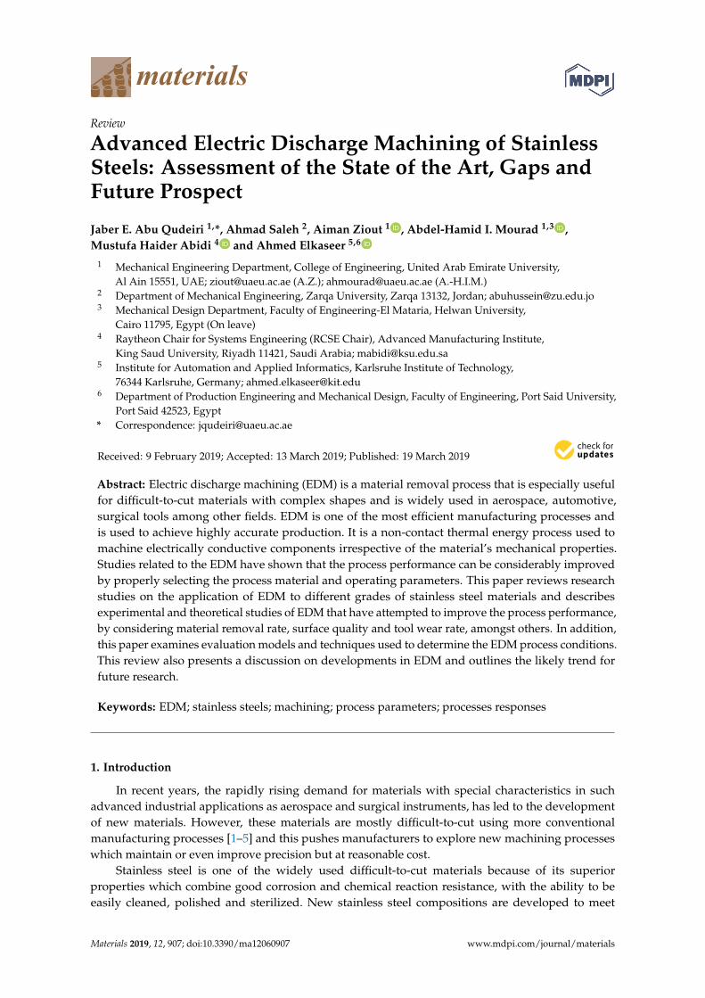
This study aims to provide an overview of the significant contributions of EDM to the machiningof various stainless steel variants. This paper reviews the research studies that used different EDMvariants for machining different types of steel materials. The paper starts with a brief introductionof EDM and its development, then it provides the working principles of this machining method.EDM process parameters and performance measures are then discussed. Next, the paper presentsthe various types of EDM processes. This study also provides a review of the major areas of researchinto the application of EDM to different grades of steel. The conclusions drawn by and the trend of,the reviewed research are presented and discussed. Figure 1 shows the EDM processes and their maininput (process) parameters and output (performance) measures.
Materials 2019, 12, 907 3 of 48Materials 2019, 12, x FOR PEER REVIEW 3 of 49
Figure 1. Electric discharge machining (EDM) processes, process parameters and performance
measures.
2. General View of the EDM Method
2.1. EDM Principles
The EDM manufacturing process was invented in the 1940’s [17]. The principle of the EDM
technique is to use thermoelectric energy to erode a workpiece by automatic spark repetition [40–43].
The rapidly recurring electrical discharges (sparks) between a non-contact electrode tool and the
workpiece allow erosion caused by sparks generated between electrode tool and the workpiece
surface [44]. In this process, both the workpiece and the electrode tool are submerged in an insulating
dielectric fluid. The gap between the electrode tool and the workpiece is carefully selected so that the
voltage across the gap has a value that can ionize the dielectric fluid in the gap due to electrical
breakdown. Discrete electric discharges between the electrode tool and workpiece are produced
which in turn generates a high temperature plasma channel, where instant thermal dissipation
occurs. The local high temperature melts both workpiece and tool. Then, the eroded material
solidifies in the form of debris. Flushing the dielectric fluid during the machining process carries
away debris (separated solid particles) and restores the sparking condition in the gap and avoids
short circuiting. No cutting forces exist between the electrode tool and the workpiece because there
is no contact between them. This minimizes the vibration and stress problems that can occur during
machining [45–48]. A principle of EDM is shown in Figure 2.
EDM Process
Wire EDM
Powder-mixed
EDM
Micro-EDM
Sinking EDM
Dry EDM
Performance measures
Material Removal
Rate
Surface Quality
Electrode Tool
Wear Rate
Process Parameters
Discharge voltage
Peak current
Inter-electrode
gap
Pulse interval
Pulse duration
Polarity
Pulse wave form
Electrode rotation
Workpiece
rotation
Dielectric flushing
Ele
ctri
cal
par
amet
ers
No
n-E
lect
rica
l p
aram
eter
s
Figure 1. Electric discharge machining (EDM) processes, process parameters and performance measures.
2. General View of the EDM Method
2.1. EDM Principles
The EDM manufacturing process was invented in the 1940’s [17]. The principle of the EDMtechnique is to use thermoelectric energy to erode a workpiece by automatic spark repetition [40–43].The rapidly recurring electrical discharges (sparks) between a non-contact electrode tool and theworkpiece allow erosion caused by sparks generated between electrode tool and the workpiecesurface [44]. In this process, both the workpiece and the electrode tool are submerged in an insulatingdielectric fluid. The gap between the electrode tool and the workpiece is carefully selected so thatthe voltage across the gap has a value that can ionize the dielectric fluid in the gap due to electricalbreakdown. Discrete electric discharges between the electrode tool and workpiece are producedwhich in turn generates a high temperature plasma channel, where instant thermal dissipation occurs.The local high temperature melts both workpiece and tool. Then, the eroded material solidifies inthe form of debris. Flushing the dielectric fluid during the machining process carries away debris(separated solid particles) and restores the sparking condition in the gap and avoids short circuiting.No cutting forces exist between the electrode tool and the workpiece because there is no contact betweenthem. This minimizes the vibration and stress problems that can occur during machining [45–48].A principle of EDM is shown in Figure 2.

Materials 2019, 12, 907 4 of 48
Materials 2019, 12, x FOR PEER REVIEW 4 of 49
Figure 2. Principle of EDM.
2.2. EDM Process Parameters
The EDM process is driven by both electrical and non-electrical parameters. The major electrical
parameters are discharge voltage, peak current, pulse duration and interval, electrode tool gap,
polarity and pulse waveform. The non-electrical parameters include rotation of the electrode tool, the
flushing action of the dielectric fluid and the properties of the workpiece. These parameters are
described in this section.
The discharge or machining voltage is the average voltage in the spark gap during machining.
The electrical potential drops sharply after the open gap voltage because of the discharge and the
current flow rises. The machining will begin at the working voltage. The discharge voltage directly
influences the size of spark gap and overcut [49–54]. A low voltage is normally used with electrode
tool and workpiece materials that possess high electrical conductivity. In contrast, materials with low
conductivity use a much higher voltage [55]. The peak current, which is defined by the maximum
power spent in discharge machining, is a parameter that highly influences the EDM process. The
peak current is represented by the maximum level that is reached during the on-time of each pulse.
This parameter has a direct effect on the material removal rate (MRR), tool wear rate (TWR) and
machining accuracy [56–61]. These characteristics make it very important and has resulted in research
into high wear resistance that can occur with high current conditions [47].
The pulse on-time is the duration for which the discharge is applied. A high-temperature plasma
channel heats both the electrode tool and the workpiece during the discharge. The amount of energy
generated during the pulse on-time has a direct effect on the MRR [62–67]. Increasing the discharge
energy by applying longer pulse on-times increases the MRR [68,69]. Debris form during the
discharging period, creating an insulation layer and lead to arcing. This layer can be flushed away
during pulse-off time. The pulse off-time is the time in which no discharge is applied. Proper selection
of the pulse off-time provides stable machining [22,25,36,70,71]. A shorter period can increase the
machining speed but off-time should be long enough to allow flushing away of debris from the gap;
otherwise, it may result in unsuitable conditions for the next on-time pulse [72], taking into account
that long breaks between pulses can cause overcooling the machined material which has impact on
MRR. The pulse wave form is usually rectangular in shape, to reduce electrode tool wear other pulse
shapes have been used, for example, trapezoidal [73,74]. Another generator has recently been
developed to facilitate initiation of the main pulse by producing a high voltage pulse with a low
current for a short period before the main pulse [22].
The effect of the EDM process parameters on performance cannot be easily explained because of
the stochastic nature of the discharge mechanism [75]. Thus, many studies related to EDM have
explored the influence of the process parameters on performance measures and have introduced the
concept of optimal process parameters that achieve best performance [18,63,64,76–79].
The electrode tool polarity in the EDM process can be positive or negative and this determines
the direction of the electrical current, from or toward the electrode tool. The choice of polarity
depends on many factors, including electrode tool and workpiece materials, current density and
Figure 2. Principle of EDM.
2.2. EDM Process Parameters
The EDM process is driven by both electrical and non-electrical parameters. The major electricalparameters are discharge voltage, peak current, pulse duration and interval, electrode tool gap, polarityand pulse waveform. The non-electrical parameters include rotation of the electrode tool, the flushingaction of the dielectric fluid and the properties of the workpiece. These parameters are described inthis section.
The discharge or machining voltage is the average voltage in the spark gap during machining.The electrical potential drops sharply after the open gap voltage because of the discharge and thecurrent flow rises. The machining will begin at the working voltage. The discharge voltage directlyinfluences the size of spark gap and overcut [49–54]. A low voltage is normally used with electrodetool and workpiece materials that possess high electrical conductivity. In contrast, materials with lowconductivity use a much higher voltage [55]. The peak current, which is defined by the maximumpower spent in discharge machining, is a parameter that highly influences the EDM process. The peakcurrent is represented by the maximum level that is reached during the on-time of each pulse.This parameter has a direct effect on the material removal rate (MRR), tool wear rate (TWR) andmachining accuracy [56–61]. These characteristics make it very important and has resulted in researchinto high wear resistance that can occur with high current conditions [47].
The pulse on-time is the duration for which the discharge is applied. A high-temperatureplasma channel heats both the electrode tool and the workpiece during the discharge. The amountof energy generated during the pulse on-time has a direct effect on the MRR [62–67]. Increasing thedischarge energy by applying longer pulse on-times increases the MRR [68,69]. Debris form duringthe discharging period, creating an insulation layer and lead to arcing. This layer can be flushedaway during pulse-off time. The pulse off-time is the time in which no discharge is applied. Properselection of the pulse off-time provides stable machining [22,25,36,70,71]. A shorter period can increasethe machining speed but off-time should be long enough to allow flushing away of debris from thegap; otherwise, it may result in unsuitable conditions for the next on-time pulse [72], taking intoaccount that long breaks between pulses can cause overcooling the machined material which hasimpact on MRR. The pulse wave form is usually rectangular in shape, to reduce electrode tool wearother pulse shapes have been used, for example, trapezoidal [73,74]. Another generator has recentlybeen developed to facilitate initiation of the main pulse by producing a high voltage pulse with a lowcurrent for a short period before the main pulse [22].
The effect of the EDM process parameters on performance cannot be easily explained becauseof the stochastic nature of the discharge mechanism [75]. Thus, many studies related to EDM haveexplored the influence of the process parameters on performance measures and have introduced theconcept of optimal process parameters that achieve best performance [18,63,64,76–79].
Materials 2019, 12, 907 5 of 48
The electrode tool polarity in the EDM process can be positive or negative and this determinesthe direction of the electrical current, from or toward the electrode tool. The choice of polaritydepends on many factors, including electrode tool and workpiece materials, current density and pulselength [80–82]. In die-sinking EDM, the generators have the flexibility to switch to either a positive ora negative electrode tool polarity based on the machining requirements. Positive electrode tool polarityis generally used in EDM operations because electrode tool wear will be lower. The negative electrodetool polarity is a better choice if a high MRR is more important than precision. Nevertheless, this is atthe cost of very high electrode tool wear. Negative electrode tool polarity machining conditions aresuitable for machining materials, such as carbide, titanium and copper alloys, amongst others. In thewire-EDM process, the electrode “wire” usually has a negative polarity because a high machining rateis required and the wire wear is not important because the wire can be fed continuously to replace theeroded portion.
The necessary sparks do not occur if the electrode tool and the workpiece touch eachother. Thus, the electrode tool and the workpiece are separated by a small distance called the“inter-electrode gap.” The discharge gap is controlled by the discharge gap servo that maintainsthe proper separation [83,84] which is normally between 0.005 mm and 0.1 mm. The electrode toolis moved up and down during machining to enable proper evacuation of the debris. The dischargeoccurs during the down period and the up period allows the flushing of the debris away from themachining area. For finishing and micro EDM processes, RC generator is usually used. The RC pulsegenerator is a low-cost power source for EDM and principally a relaxation oscillator with a resistorand a capacitor. It can produce very small pulse energy that generates small craters which in turn leadto produce small surface roughness. However, lack of precision control is the main disadvantage ofRC generator especially for timing and slow charging [10,13,85–87].
The main non-electrical parameters are the flushing of the dielectric fluid, workpiece and electrodetool rotation. The EDM process needs a dielectric fluid medium that submerges both the electrodetool and the workpiece to at least a suitable distance above the gap between them. In addition to highdielectric strength, the dielectric fluid must have a flushing ability and fast recovery after breakdown.The dielectric fluid provides insulation against premature discharging, reduces the temperature in andaround the machined area and cleans away the separated debris.
For the die-sinking EDM, the dielectric fluid is a hydrocarbon and silicone-based dielectricoil and kerosene with an increased flash-point. Some die-sinking EDMs use de-ionized water forhigh-precision machining, such as fine hole drilling. De-ionized water and oil are also used with wireEDM. Many studies have recently been conducted to explore the use of oil-based synthetics to avoidharmful effects to the worker and the environment [48,88,89]. Previous studies have reported that thedielectric type, flushing method and flushing pressure influence the MRR, TWR, surface roughness(SR) and surface quality (SQ) [90–93]. Dielectric flushing is improved with workpiece and electrodetool rotation [94,95]. The improvement in flushing due to electrode tool rotation achieves a better SRand a higher MRR [96–98]. Selecting the optimal flushing pressure can minimize the density of thecrack and the recast layer [92].
2.3. Performance Measure Parameters
The performance parameters are the factors that measure the performance of the EDM process.These parameters include the MRR, TWR and SQ. The MRR is a measure of the performance of theerosion rate of the workpiece surface and an indication of the machining ratio. The MRR is usuallyexpressed as the volume of the removed material per unit time. Techniques and methods to improve theMRR have attracted attention because the MRR represents the machining speed [29,99–103]. The TWRis a measure of the erosion rate of the electrode tool and has a direct influence on the shape of themachined cavity because of the continual change in the electrode tool profile during the machiningprocess. Similar to the MRR, the TWR can be expressed by the volume of material removed per unittime. Previous studies focused on reducing the TWR because the wear of the electrode tool affects the

Materials 2019, 12, 907 6 of 48
electrode tool profile and leads to a lower precision [78,104,105]. The SQ is a measure of the quality ofthe machined surface and includes many components, such as the SR, extent of the heat affected zone(HAZ), recast layer thickness and micro-crack density. Many research studies have explored utilizationof the EDM process in surface treatment and have reported the SQ generated by the process [106].
2.4. Types of EDM Processes
2.4.1. Die-Sinking EDM
In the die-sinking EDM process, the workpiece is machined by a controlled electrical sparkgenerated in the gap between the electrode tool and the workpiece. Sparking is repeated until theelectrode tool shape is replicated in the workpiece surface facing the electrode tool. The heat producedby the electrical spark causes a sharp temperature rise in the area to be machined (i.e., 8000 to 12,000 ◦C).EDM machines contain a unit that controls and monitors the machining variables, such as the gap andaxis movements. Furthermore, this system shows the process execution sequence.
Normally, copper or graphite is used as the electrode tool material in this process withhydrocarbon dielectric because of its positive effect on the SR and EWR (Electrode tool Wear Rate).The dielectric flows through the cooling system, carrying the debris and eroded material with it,is filtered to remove the suspended particles and is returned to the system. In the die-sinking EDMprocess, the electrode should be re-shaped to carry out the finishing operations. Figure 3 showsa schematic diagram of the die-sinking EDM.
Materials 2019, 12, x FOR PEER REVIEW 6 of 49
2.4. Types of EDM Processes
2.4.1. Die-Sinking EDM
In the die-sinking EDM process, the workpiece is machined by a controlled electrical spark
generated in the gap between the electrode tool and the workpiece. Sparking is repeated until the
electrode tool shape is replicated in the workpiece surface facing the electrode tool. The heat
produced by the electrical spark causes a sharp temperature rise in the area to be machined (i.e., 8000
to 12,000 °C). EDM machines contain a unit that controls and monitors the machining variables, such
as the gap and axis movements. Furthermore, this system shows the process execution sequence.
Normally, copper or graphite is used as the electrode tool material in this process with
hydrocarbon dielectric because of its positive effect on the SR and EWR (Electrode tool Wear Rate).
The dielectric flows through the cooling system, carrying the debris and eroded material with it, is
filtered to remove the suspended particles and is returned to the system. In the die-sinking EDM
process, the electrode should be re-shaped to carry out the finishing operations. Figure 3 shows a
schematic diagram of the die-sinking EDM.
Figure 3. Schematic diagram of the die-sinking EDM.
2.4.2. Wire EDM
In the wire EDM, a metallic thin wire is used to cut the workpiece along a well-defined path.
Discrete sparks between the wire and the workpiece cause eroding in the machined area. The wire
used is usually thin, the standard EDM wire is 0.25 mm. Micro-wires dimeter can range from 0.020
mm to 0.15 mm [107] and is normally copper, brass or coated steel materials. As with the die-sinking
EDM, the wire and the workpiece do not have any contact during machining [108] and both should
be immersed in a dielectric fluid. A high peak current of short duration is applied in this process. The
machining variables and the movement of the worktable that holds the workpiece are controlled by
the control units. Thus, complicated shapes can be produced using this process [9,14,27,109–114]. The
control unit contains a microprocessor to maintain the gap between the wire and the workpiece in a
suitable range, normally between 25 µm and 50 µm. In addition, the unit controls the feeding of the
wire through the workpiece at a suitable speed that produces surfaces with very high accuracy. De-
ionized water is a common dielectric fluid used in this process. The wire EDM process has a wide
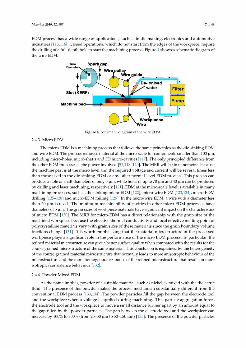
range of applications, such as in die making, electronics and automotive industries [115,116]. Closed
operations, which do not start from the edges of the workpiece, require the drilling of a full-depth
hole to start the machining process. Figure 4 shows a schematic diagram of the wire EDM.
Figure 3. Schematic diagram of the die-sinking EDM.
2.4.2. Wire EDM
In the wire EDM, a metallic thin wire is used to cut the workpiece along a well-defined path.Discrete sparks between the wire and the workpiece cause eroding in the machined area. The wireused is usually thin, the standard EDM wire is 0.25 mm. Micro-wires dimeter can range from0.020 mm to 0.15 mm [107] and is normally copper, brass or coated steel materials. As with thedie-sinking EDM, the wire and the workpiece do not have any contact during machining [108]and both should be immersed in a dielectric fluid. A high peak current of short duration isapplied in this process. The machining variables and the movement of the worktable that holdsthe workpiece are controlled by the control units. Thus, complicated shapes can be produced using thisprocess [9,14,27,109–114]. The control unit contains a microprocessor to maintain the gap between thewire and the workpiece in a suitable range, normally between 25 µm and 50 µm. In addition, the unitcontrols the feeding of the wire through the workpiece at a suitable speed that produces surfaceswith very high accuracy. De-ionized water is a common dielectric fluid used in this process. The wire
Materials 2019, 12, 907 7 of 48
EDM process has a wide range of applications, such as in die making, electronics and automotiveindustries [115,116]. Closed operations, which do not start from the edges of the workpiece, requirethe drilling of a full-depth hole to start the machining process. Figure 4 shows a schematic diagram ofthe wire EDM.Materials 2019, 12, x FOR PEER REVIEW 7 of 49
Figure 4. Schematic diagram of the wire EDM.
2.4.3. Micro EDM
The micro-EDM is a machining process that follows the same principles as the die-sinking EDM
and wire EDM. The process removes material at the micro-scale for components smaller than 100 μm,
including micro-holes, micro-shafts and 3D micro-cavities [117]. The only principled difference from
the other EDM processes is the power involved [51,118–120]. The MRR will be in nanometres because
the machine part is at the micro level and the required voltage and current will be several times less
than those used in the die-sinking EDM or any other normal-level EDM process. This process can
produce a hole or shaft diameters of only 5 µm, while holes of up to 70 µm and 40 µm can be produced
by drilling and laser machining, respectively [121]. EDM at the micro-scale level is available in many
machining processes, such as die-sinking micro-EDM [122], micro-wire EDM [123,124], micro-EDM
drilling [125–128] and micro-EDM milling [129]. In the micro-wire EDM, a wire with a diameter less
than 20 μm is used. The minimum machinability of cavities in other micro-EDM processes have
diameters of 5 µm. The grain sizes of workpiece materials have significant impact on the
characteristics of micro EDM [130]. The MRR for micro-EDM has a direct relationship with the grain
size of the machined workpiece because the effective thermal conductivity and local effective melting
point of polycrystalline materials vary with grain sizes of these materials since the grain boundary
volume fractions change [131]. It is worth emphasizing that the material microstructure of the
processed workpiece plays a significant role in the performance of the micro EDM process. In
particular, the refined material microstructure can give a better surface quality when compared with
the results for the course grained microstructure of the same material. This conclusion is explained
by the heterogeneity of the course grained material microstructure that normally leads to more
anisotropic behaviour of the microstructure and the more homogenous response of the refined
microstructure that results in more isotropic/consistence behaviour [132].
2.4.4. Powder-Mixed EDM
As the name implies, powder of a suitable material, such as nickel, is mixed with the dielectric
fluid. The presence of this powder makes the process mechanism substantially different from the
conventional EDM process [133,134]. The powder particles fill the gap between the electrode tool and
the workpiece when a voltage is applied during machining. This particle aggregation forces the
electrode tool and the workpiece to move a small distance further apart by an amount equal to the
gap filled by the powder particles. The gap between the electrode tool and the workpiece can increase
by 100% to 300% (from 25–50 μm to 50–150 μm) [135]. The presence of the powder particles between
the electrode tool and the workpiece leads to earlier and faster sparking, which causes a higher
erosion rate.
Figure 4. Schematic diagram of the wire EDM.
2.4.3. Micro EDM
The micro-EDM is a machining process that follows the same principles as the die-sinking EDMand wire EDM. The process removes material at the micro-scale for components smaller than 100 µm,including micro-holes, micro-shafts and 3D micro-cavities [117]. The only principled difference fromthe other EDM processes is the power involved [51,118–120]. The MRR will be in nanometres becausethe machine part is at the micro level and the required voltage and current will be several times lessthan those used in the die-sinking EDM or any other normal-level EDM process. This process canproduce a hole or shaft diameters of only 5 µm, while holes of up to 70 µm and 40 µm can be producedby drilling and laser machining, respectively [121]. EDM at the micro-scale level is available in manymachining processes, such as die-sinking micro-EDM [122], micro-wire EDM [123,124], micro-EDMdrilling [125–128] and micro-EDM milling [129]. In the micro-wire EDM, a wire with a diameter lessthan 20 µm is used. The minimum machinability of cavities in other micro-EDM processes havediameters of 5 µm. The grain sizes of workpiece materials have significant impact on the characteristicsof micro EDM [130]. The MRR for micro-EDM has a direct relationship with the grain size of themachined workpiece because the effective thermal conductivity and local effective melting point ofpolycrystalline materials vary with grain sizes of these materials since the grain boundary volumefractions change [131]. It is worth emphasizing that the material microstructure of the processedworkpiece plays a significant role in the performance of the micro EDM process. In particular, therefined material microstructure can give a better surface quality when compared with the results for thecourse grained microstructure of the same material. This conclusion is explained by the heterogeneityof the course grained material microstructure that normally leads to more anisotropic behaviour of themicrostructure and the more homogenous response of the refined microstructure that results in moreisotropic/consistence behaviour [132].
2.4.4. Powder-Mixed EDM
As the name implies, powder of a suitable material, such as nickel, is mixed with the dielectricfluid. The presence of this powder makes the process mechanism substantially different from theconventional EDM process [133,134]. The powder particles fill the gap between the electrode tooland the workpiece when a voltage is applied during machining. This particle aggregation forcesthe electrode tool and the workpiece to move a small distance further apart by an amount equal tothe gap filled by the powder particles. The gap between the electrode tool and the workpiece canincrease by 100% to 300% (from 25–50 µm to 50–150 µm) [135]. The presence of the powder particles
Materials 2019, 12, 907 8 of 48
between the electrode tool and the workpiece leads to earlier and faster sparking, which causes a highererosion rate.
2.4.5. Dry EDM
The dry EDM uses dielectric high-pressure gas instead of dielectric liquid [12,136–139].Here, the electrode tool is in the form of a thin-walled pipe through which high-pressure gas orair is supplied [140]. The pressurized gases flow outwards through the gap between electrode tooland machined surface and carry away the debris being formed. The gases also reduce the machiningarea temperature. Using gas instead of fluid in this process can reduce harmful environmental effects.Most notably the dielectric fluid and the powder-mixed dielectrics in the EDM processes are associatedwith evaporation from the fluid surface during machining. Utilizing gas can also decrease the cost ofmanaging the debris waste and enhance the machining performance and the environment as regardsworker health. From this point of view, this process could be named as the “Green EDM.” The dry EDMprocess positively influences the MRR [138,141] and reduces the EWR [142]. Under ideal conditions,this process allows to obtain very good accuracy and surface layer quality [143].
In addition to the previous main types of EDM, there are other types such as EDM milling,in this type the final shape is obtained using a simple electrode tool which is moved in a 3D path alongseveral directions and may also subject to rotations [144]. A combination of the two cutting systemscan also be applied. Also, EDM grinding, when the electrode tool design as a rotating disk [145].
2.5. Mathematical Modeling of the Thermos-Physical Phenomenon in EDM
EDM involves removal of material from the workpiece due to heat generated from electricdischarge in the inter-electrode gap. Plethora of research study and analyse this phenomenon;mathematical models are developed to provide better understanding of the EDM process. A quasi-staticmodel is proposed by [146], the model computes the material removal rate based on predicteddistribution of the temperature in the workpiece. Equation of transient heat conduction is employedto predict the distribution. The model assumes Gaussian heat flux since it gives better results asdemonstrated by [147]. Finite element method is used to solve the model and obtain the results, whichshow significant closeness to the experimental results. Vaporization of workpiece and tool materialsis studied by [148]. The model is used to predict the aerosol emission of EDM process. 70% of theaerosol is found to be vaporized material from the workpiece and the tool, the rest comes from thedielectric fluid.
The electric field generated in the interelectrode gap is modelled by [149]. The model representsthe electric field at two stages. First; before-discharge stage, where Laplace equation is used to modelthe electrostatic field. Second; during–discharge state, where Poisson equation is used to model thespatial discharge from electrode and particles of the dielectric fluid. Fluid flow in the interelectrodegap is modelled by [150]. The model attempts to study the motion of the debris particle as well as thedrag force between the particles and the dielectric fluid. The purpose is to improve the removal ofdebris from the machining zone. Fluent software is used to build 3D model of drilling high aspect ratioof a hole. The effect of incorporating ultrasonic vibration is verified using the proposed model; optimalamplitudes and frequencies are determined using the model based on a set of process parameters.
3. Different Stainless Steel Grades
Steels can be categorized into four groups; stainless steel, tool steel, carbon steel and alloysteel. Each of these groups has its own characteristics, which makes it suitable for specificapplications. This paper focuses on stainless steel. This group has good corrosion and chemicalreaction resistance. Stainless steel can be divided into three classes; martensitic, ferritic and austenitic.All stainless steels contain common alloying ingredients, such as chromium (minimum of 11%),nickel and molybdenum [7]. The composition and properties of some stainless steels are givenin the Table 1. As mentioned in Reference [7], there are actually about 150 separate and distinct

Materials 2019, 12, 907 9 of 48
compositions and each of them serves specific requirements. Stainless steel is widely used in householdcutlery, food handling/processing, hardware, surgical instruments and structural/architecturalapplications [151–153].
Table 1. Designations, compositions, mechanical properties and typical applications for austenitic,ferritic, martensitic and precipitation-hardenable stainless steels [7].
AISINumber
UNSNumber
Composition(wt.%) a Condition b
Mechanical Properties
TensileStrength
[MPa (ksi)]
YieldStrength
[MPa (ksi)]
Ductility[%EL in
50 mm (2in.)]Typical Applications
Ferritic
409 S409000.08 C, 11.0 Cr,
1.0 Mn,0.50 Ni, 0.75 Ti
Annealed 380 (55) 205 (30) 20Automotive exhaust
components, tanks foragricultural sprays
446 S44600 0.20 C, 25 Cr,1.5 Mn Annealed 515 (75) 275 (40) 20
Valves(high temperature),
glass moulds,combustion chambers
Austenitic
304 S30400 0.08 C, 19 Cr,2.0 Mn, 9 Ni Annealed 515 (75) 205 (30) 40
Chemical and foodprocessing equipment,
cryogenic vessels
316L S316030.03 C, 17 Cr,
2.0 Mn,2.5 Mo, 12 Ni
Annealed 485 (70) 170 (25) 40 Welding construction
Martensitic
410 S41000 0.15 C, 12.5 Cr,1.0 Mn Annealed Q&T 485 (70)
825 (120)275 (40)629 (90)
2012
Rifle barrels, cutlery,jet engine parts
440A S440020.70 C, 17 Cr,
1.0 Mn,0.75 Mo
Annealed Q&T 725 (105)1790 (260)
415 (60)1650 (240)
205
Cutlery, bearings,surgical tools
Precipitation Hardenable
17-7PH S177001.0 Al, 0.09 C,17 Cr, 1.0 Mn,
7 Ni
Precipitationhardened 1450 (210) 1310 (190) 1–6 Springs, knives,
pressure vessels
a The balance of the composition is iron; b Q & T denotes quenched and tempered.
The machinability, which is defined as the speed at which a material can be cut [154], is differentfor the different stainless steel grades. The 400 series is most easily machined, whereas the 200 and300 series are the most difficult [155]. Figure 5 presents the comparative machinability of the mostfrequently used stainless steel.
Materials 2019, 12, x FOR PEER REVIEW 9 of 49
Table 1. Designations, compositions, mechanical properties and typical applications for austenitic,
ferritic, martensitic and precipitation-hardenable stainless steels [7].
AISI
Number
UNS
Number
Composition
(wt.%) a Condition b
Mechanical Properties
Tensile
Strength
[MPa (ksi)]
Yield
Strength
[MPa (ksi)]
Ductility
[%EL in 50
mm (2in.)]
Typical Applications
Ferritic
409 S40900
0.08 C, 11.0 Cr,
1.0 Mn, 0.50
Ni, 0.75 Ti
Annealed 380 (55) 205 (30) 20
Automotive exhaust
components, tanks for
agricultural sprays
446 S44600 0.20 C, 25 Cr,
1.5 Mn Annealed 515 (75) 275 (40) 20
Valves (high temperature),
glass moulds, combustion
chambers
Austenitic
304 S30400 0.08 C, 19 Cr,
2.0 Mn, 9 Ni Annealed 515 (75) 205 (30) 40
Chemical and food
processing equipment,
cryogenic vessels
316L S31603
0.03 C, 17 Cr,
2.0 Mn,
2.5 Mo, 12 Ni
Annealed 485 (70) 170 (25) 40 Welding construction
Martensitic
410 S41000 0.15 C, 12.5 Cr,
1.0 Mn
Annealed
Q&T
485 (70) 825
(120)
275 (40) 629
(90)
20
12
Rifle barrels, cutlery, jet
engine parts
440A S44002
0.70 C, 17 Cr,
1.0 Mn,
0.75 Mo
Annealed
Q&T
725 (105)
1790 (260)
415 (60)
1650 (240)
20
5
Cutlery, bearings, surgical
tools
Precipitation Hardenable
17-7PH S17700
1.0 Al, 0.09 C,
17 Cr, 1.0 Mn,
7 Ni
Precipitation
hardened 1450 (210) 1310 (190) 1–6
Springs, knives, pressure
vessels
a The balance of the composition is iron; b Q & T denotes quenched and tempered.
The machinability, which is defined as the speed at which a material can be cut [154], is different
for the different stainless steel grades. The 400 series is most easily machined, whereas the 200 and
300 series are the most difficult [155]. Figure 5 presents the comparative machinability of the most
frequently used stainless steel.
Figure 5. Comparative machinability of frequently used stainless steels and their free-machining
counterparts.
0
10
20
30
40
50
60
70
80
90
100
Rat
ing
in
%
Stainless Steel grades
Maximum ComparativeMachinability
Average ComparativeMachinability
Figure 5. Comparative machinability of frequently used stainless steels and their free-machining counterparts.
Materials 2019, 12, 907 10 of 48
4. Research on EDM of Stainless Steel
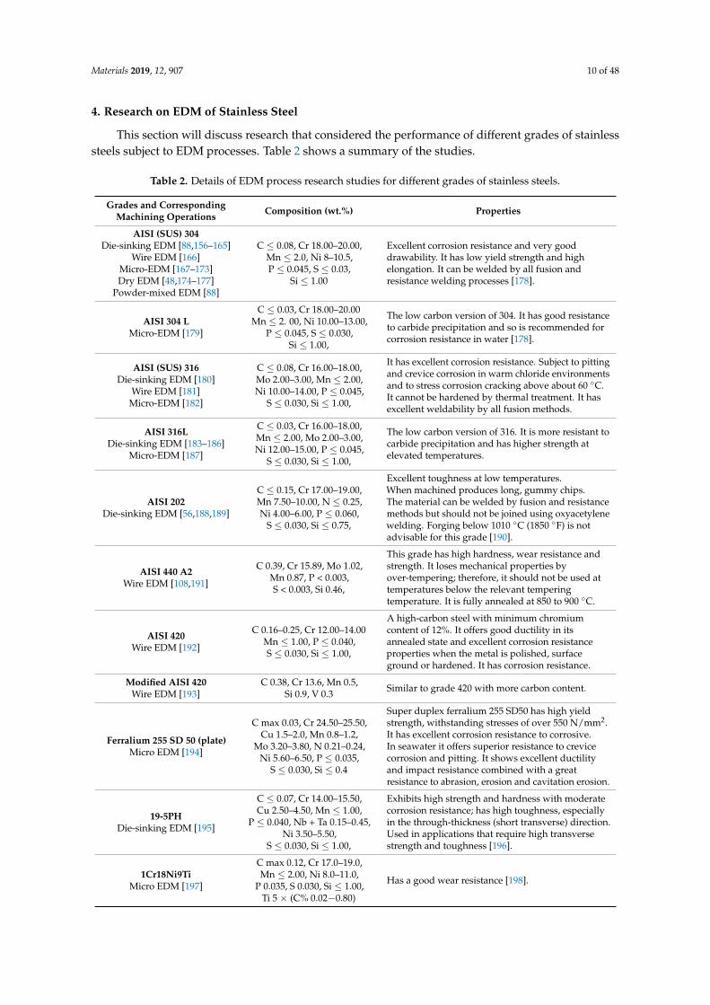
This section will discuss research that considered the performance of different grades of stainlesssteels subject to EDM processes. Table 2 shows a summary of the studies.
Table 2. Details of EDM process research studies for different grades of stainless steels.
Grades and CorrespondingMachining Operations Composition (wt.%) Properties
AISI (SUS) 304Die-sinking EDM [88,156–165]
Wire EDM [166]Micro-EDM [167–173]Dry EDM [48,174–177]
Powder-mixed EDM [88]
C ≤ 0.08, Cr 18.00–20.00,Mn ≤ 2.0, Ni 8–10.5,P ≤ 0.045, S ≤ 0.03,
Si ≤ 1.00
Excellent corrosion resistance and very gooddrawability. It has low yield strength and highelongation. It can be welded by all fusion andresistance welding processes [178].
AISI 304 LMicro-EDM [179]
C ≤ 0.03, Cr 18.00–20.00Mn ≤ 2. 00, Ni 10.00–13.00,
P ≤ 0.045, S ≤ 0.030,Si ≤ 1.00,
The low carbon version of 304. It has good resistanceto carbide precipitation and so is recommended forcorrosion resistance in water [178].
AISI (SUS) 316Die-sinking EDM [180]
Wire EDM [181]Micro-EDM [182]
C ≤ 0.08, Cr 16.00–18.00,Mo 2.00–3.00, Mn ≤ 2.00,Ni 10.00–14.00, P ≤ 0.045,
S ≤ 0.030, Si ≤ 1.00,
It has excellent corrosion resistance. Subject to pittingand crevice corrosion in warm chloride environmentsand to stress corrosion cracking above about 60 ◦C.It cannot be hardened by thermal treatment. It hasexcellent weldability by all fusion methods.
AISI 316LDie-sinking EDM [183–186]
Micro-EDM [187]
C ≤ 0.03, Cr 16.00–18.00,Mn ≤ 2.00, Mo 2.00–3.00,Ni 12.00–15.00, P ≤ 0.045,
S ≤ 0.030, Si ≤ 1.00,
The low carbon version of 316. It is more resistant tocarbide precipitation and has higher strength atelevated temperatures.
AISI 202Die-sinking EDM [56,188,189]
C ≤ 0.15, Cr 17.00–19.00,Mn 7.50–10.00, N ≤ 0.25,Ni 4.00–6.00, P ≤ 0.060,
S ≤ 0.030, Si ≤ 0.75,
Excellent toughness at low temperatures.When machined produces long, gummy chips.The material can be welded by fusion and resistancemethods but should not be joined using oxyacetylenewelding. Forging below 1010 ◦C (1850 ◦F) is notadvisable for this grade [190].
AISI 440 A2Wire EDM [108,191]
C 0.39, Cr 15.89, Mo 1.02,Mn 0.87, P < 0.003,S < 0.003, Si 0.46,
This grade has high hardness, wear resistance andstrength. It loses mechanical properties byover-tempering; therefore, it should not be used attemperatures below the relevant temperingtemperature. It is fully annealed at 850 to 900 ◦C.
AISI 420Wire EDM [192]
C 0.16–0.25, Cr 12.00–14.00Mn ≤ 1.00, P ≤ 0.040,S ≤ 0.030, Si ≤ 1.00,
A high-carbon steel with minimum chromiumcontent of 12%. It offers good ductility in itsannealed state and excellent corrosion resistanceproperties when the metal is polished, surfaceground or hardened. It has corrosion resistance.
Modified AISI 420Wire EDM [193]
C 0.38, Cr 13.6, Mn 0.5,Si 0.9, V 0.3 Similar to grade 420 with more carbon content.
Ferralium 255 SD 50 (plate)Micro EDM [194]
C max 0.03, Cr 24.50–25.50,Cu 1.5–2.0, Mn 0.8–1.2,
Mo 3.20–3.80, N 0.21–0.24,Ni 5.60–6.50, P ≤ 0.035,
S ≤ 0.030, Si ≤ 0.4
Super duplex ferralium 255 SD50 has high yieldstrength, withstanding stresses of over 550 N/mm2.It has excellent corrosion resistance to corrosive.In seawater it offers superior resistance to crevicecorrosion and pitting. It shows excellent ductilityand impact resistance combined with a greatresistance to abrasion, erosion and cavitation erosion.
19-5PHDie-sinking EDM [195]
C ≤ 0.07, Cr 14.00–15.50,Cu 2.50–4.50, Mn ≤ 1.00,
P ≤ 0.040, Nb + Ta 0.15–0.45,Ni 3.50–5.50,
S ≤ 0.030, Si ≤ 1.00,
Exhibits high strength and hardness with moderatecorrosion resistance; has high toughness, especiallyin the through-thickness (short transverse) direction.Used in applications that require high transversestrength and toughness [196].
1Cr18Ni9TiMicro EDM [197]
C max 0.12, Cr 17.0–19.0,Mn ≤ 2.00, Ni 8.0–11.0,
P 0.035, S 0.030, Si ≤ 1.00,Ti 5 × (C% 0.02−0.80)
Has a good wear resistance [198].

Materials 2019, 12, 907 11 of 48
Table 2. Cont.
Grades and CorrespondingMachining Operations Composition (wt.%) Properties
Other gradesDie-sinking EDM [199–203]
Micro-EDM [41,204–207]Dry EDM [136]
Wire EDM [208,209]
Grade not mentioned Grade not mentioned
4.1. Performance Measures for the EDM of Stainless Steel
A significant amount of research has been conducted into the effect of working parameters onthe processing performance of EDM of stainless steel [74,77,181,204,206,210,211]. Many methods havebeen introduced to improve performance. Shen, et al. [48] recently proposed high-speed dry EDMto improve MRR. Utilizing the proposed method, the material rapidly melted by the high-dischargeenergy and was flushed out at high pressure. The authors considered the influence of workpiecepolarity, discharge current, pulse duration, gas pressure and electrode tool rotation speed on themachining performance. Moreover, the study investigated the solidified layer, surface morphology,composition of the working material and phase of the AISI 304 stainless steel used with the high-speeddry EDM. Figure 6 shows some of the results from this paper.
Materials 2019, 12, x FOR PEER REVIEW 11 of 49
Other grades
Die-sinking EDM [199–203]
Micro-EDM [41,204–207]
Dry EDM [136]
Wire EDM [208,209]
Grade not mentioned Grade not mentioned
4.1. Performance Measures for the EDM of Stainless Steel
A significant amount of research has been conducted into the effect of working parameters on
the processing performance of EDM of stainless steel [74,77,181,204,206,210,211]. Many methods have
been introduced to improve performance. Shen, et al. [48] recently proposed high-speed dry EDM to
improve MRR. Utilizing the proposed method, the material rapidly melted by the high-discharge
energy and was flushed out at high pressure. The authors considered the influence of workpiece
polarity, discharge current, pulse duration, gas pressure and electrode tool rotation speed on the
machining performance. Moreover, the study investigated the solidified layer, surface morphology,
composition of the working material and phase of the AISI 304 stainless steel used with the high-
speed dry EDM. Figure 6 shows some of the results from this paper.
Figure 6. (a) Scanning Capacitance Microscopy (SCM) photograph of the cross-section of the AISI304
in high-speed dry EDM; (b) EDS spectra of the re-solidified layer and base materials; (c) XRD
diffractograms of the re-solidified layer, heat affected zone and base materials; and (d) micro-
hardness of the cross-section [48].
Ugrasen, et al. [193] used multiple regression analysis and the group method data handling
technique to develop a model for predicting the parameters that defined machine performance. The
effects of the cutting parameters, including pulse-on, pulse-off, current and bed speed with constant
voltage and flush rate on the four response parameters (accuracy, SR, volumetric MRR and TWR),
were discussed. Muthuramalingam and Mohan [188] studied the surface finish obtained using an iso
duration current pulse generator. The authors reported that, the modified iso duration current pulse
Figure 6. (a) Scanning Capacitance Microscopy (SCM) photograph of the cross-section of the AISI304in high-speed dry EDM; (b) EDS spectra of the re-solidified layer and base materials; (c) XRDdiffractograms of the re-solidified layer, heat affected zone and base materials; and (d) micro-hardnessof the cross-section [48].
Ugrasen, et al. [193] used multiple regression analysis and the group method data handlingtechnique to develop a model for predicting the parameters that defined machine performance.The effects of the cutting parameters, including pulse-on, pulse-off, current and bed speed withconstant voltage and flush rate on the four response parameters (accuracy, SR, volumetric MRR and
Materials 2019, 12, 907 12 of 48
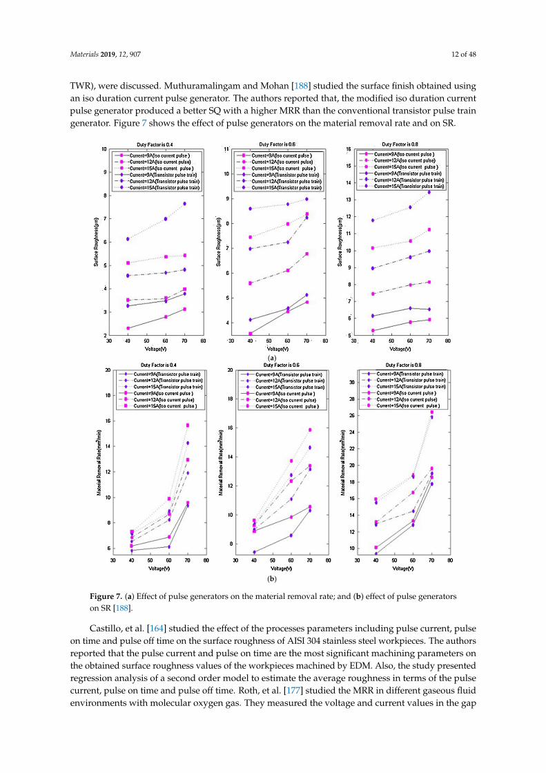
TWR), were discussed. Muthuramalingam and Mohan [188] studied the surface finish obtained usingan iso duration current pulse generator. The authors reported that, the modified iso duration currentpulse generator produced a better SQ with a higher MRR than the conventional transistor pulse traingenerator. Figure 7 shows the effect of pulse generators on the material removal rate and on SR.
Materials 2019, 12, x FOR PEER REVIEW 12 of 49
generator produced a better SQ with a higher MRR than the conventional transistor pulse train
generator. Figure 7 shows the effect of pulse generators on the material removal rate and on SR.
(a)
(b)
Figure 7. (a) Effect of pulse generators on the material removal rate; and (b) effect of pulse generators
on SR [188].
Castillo, et al. [164] studied the effect of the processes parameters including pulse current, pulse
on time and pulse off time on the surface roughness of AISI 304 stainless steel workpieces. The
authors reported that the pulse current and pulse on time are the most significant machining
parameters on the obtained surface roughness values of the workpieces machined by EDM. Also, the
study presented regression analysis of a second order model to estimate the average roughness in
terms of the pulse current, pulse on time and pulse off time. Roth, et al. [177] studied the MRR in
different gaseous fluid environments with molecular oxygen gas. They measured the voltage and
Figure 7. (a) Effect of pulse generators on the material removal rate; and (b) effect of pulse generatorson SR [188].
Castillo, et al. [164] studied the effect of the processes parameters including pulse current, pulseon time and pulse off time on the surface roughness of AISI 304 stainless steel workpieces. The authorsreported that the pulse current and pulse on time are the most significant machining parameters onthe obtained surface roughness values of the workpieces machined by EDM. Also, the study presentedregression analysis of a second order model to estimate the average roughness in terms of the pulsecurrent, pulse on time and pulse off time. Roth, et al. [177] studied the MRR in different gaseous fluidenvironments with molecular oxygen gas. They measured the voltage and current values in the gap
Materials 2019, 12, 907 13 of 48
and used these to calculate the effective energy specific values of the MRR. These authors reportedthat increasing the oxygen gas of the fluid environment increases the MRR for single sparks and theprocess time efficiency. The micro-hole operation was discussed by Li, et al. [205], their paper studiedthe SQ of the micro-hole with different power supply modes.
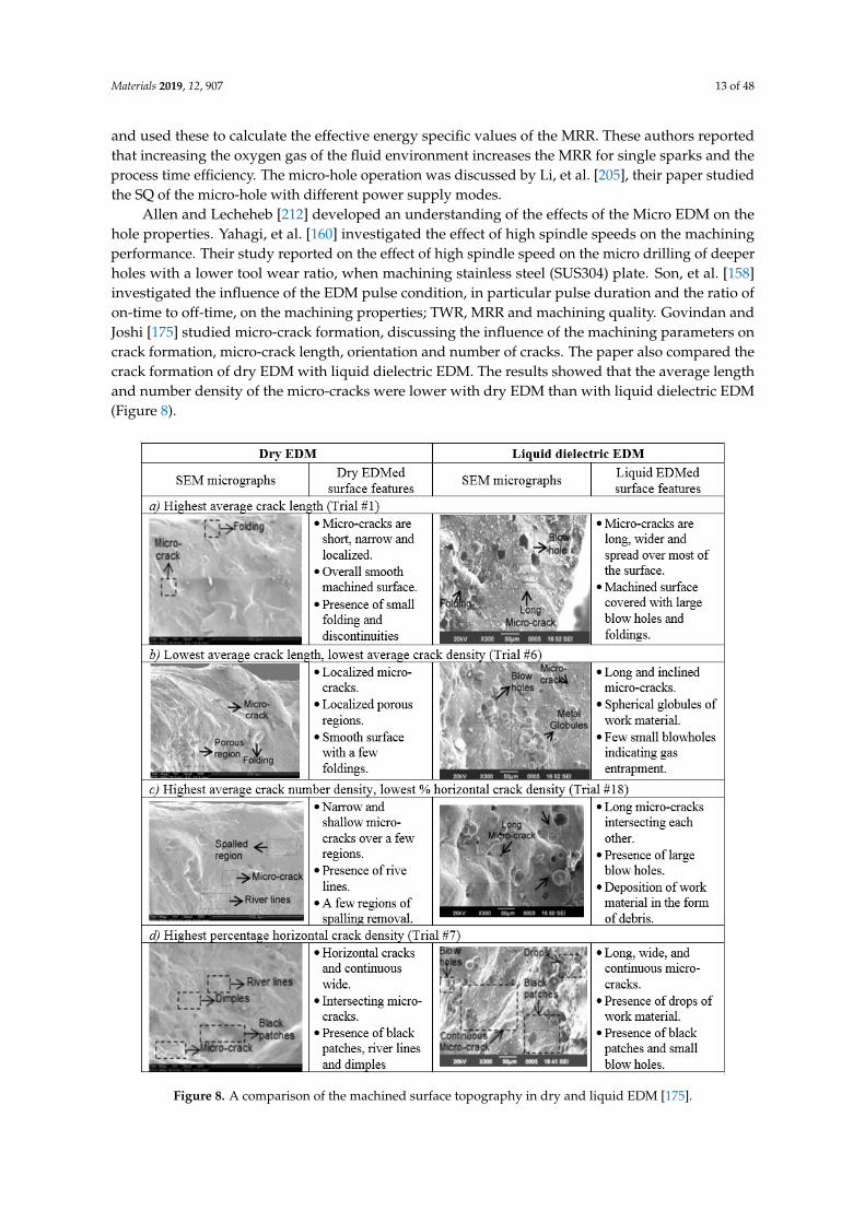
Allen and Lecheheb [212] developed an understanding of the effects of the Micro EDM on thehole properties. Yahagi, et al. [160] investigated the effect of high spindle speeds on the machiningperformance. Their study reported on the effect of high spindle speed on the micro drilling of deeperholes with a lower tool wear ratio, when machining stainless steel (SUS304) plate. Son, et al. [158]investigated the influence of the EDM pulse condition, in particular pulse duration and the ratio ofon-time to off-time, on the machining properties; TWR, MRR and machining quality. Govindan andJoshi [175] studied micro-crack formation, discussing the influence of the machining parameters oncrack formation, micro-crack length, orientation and number of cracks. The paper also compared thecrack formation of dry EDM with liquid dielectric EDM. The results showed that the average lengthand number density of the micro-cracks were lower with dry EDM than with liquid dielectric EDM(Figure 8).
Materials 2019, 12, x FOR PEER REVIEW 13 of 49
current values in the gap and used these to calculate the effective energy specific values of the MRR.
These authors reported that increasing the oxygen gas of the fluid environment increases the MRR
for single sparks and the process time efficiency. The micro-hole operation was discussed by Li, et al.
[205], their paper studied the SQ of the micro-hole with different power supply modes.
Allen and Lecheheb [212] developed an understanding of the effects of the Micro EDM on the
hole properties. Yahagi, et al. [160] investigated the effect of high spindle speeds on the machining
performance. Their study reported on the effect of high spindle speed on the micro drilling of deeper
holes with a lower tool wear ratio, when machining stainless steel (SUS304) plate. Son, et al. [158]
investigated the influence of the EDM pulse condition, in particular pulse duration and the ratio of
on-time to off-time, on the machining properties; TWR, MRR and machining quality. Govindan and
Joshi [175] studied micro-crack formation, discussing the influence of the machining parameters on
crack formation, micro-crack length, orientation and number of cracks. The paper also compared the
crack formation of dry EDM with liquid dielectric EDM. The results showed that the average length
and number density of the micro-cracks were lower with dry EDM than with liquid dielectric EDM
(Figure 8).
Figure 8. A comparison of the machined surface topography in dry and liquid EDM [175]. Figure 8. A comparison of the machined surface topography in dry and liquid EDM [175].

Materials 2019, 12, 907 14 of 48
Jegan, et al. [56] studied the effect of the machining parameters, including discharge current,pulse on-time and pulse off-time on the performance of EDM when machining AISI 202 stainlesssteel. They utilized the grey relational analysis to find the optimal performance parameters such asMRR and SR. Rajmohan, et al. [157] studied the effect of EDM machining parameters such as pulse-ontime, pulse-off time, voltage and current on MRR for 304 stainless steel signal to noise ratio (S/N) andanalysis of variance (ANOVA) was used. Experiments were carried out as per design of experimentsapproach Taguchi table orthogonal array to analyse the effect of process parameters on MRR and alsoto identify the optimum cutting parameters, the interaction plot of MRR is shown in Figure 9.
Materials 2019, 12, x FOR PEER REVIEW 14 of 49
Jegan, et al. [56] studied the effect of the machining parameters, including discharge current,
pulse on-time and pulse off-time on the performance of EDM when machining AISI 202 stainless
steel. They utilized the grey relational analysis to find the optimal performance parameters such as
MRR and SR. Rajmohan, et al. [157] studied the effect of EDM machining parameters such as pulse-
on time, pulse-off time, voltage and current on MRR for 304 stainless steel signal to noise ratio (S/N)
and analysis of variance (ANOVA) was used. Experiments were carried out as per design of
experiments approach Taguchi table orthogonal array to analyse the effect of process parameters on
MRR and also to identify the optimum cutting parameters, the interaction plot of MRR is shown in
Figure 9.
Figure 9. Interaction plot of the material removal rate (MRR) [157].
Roth, et al. [176] studied the MRR for different electrode tool and workpiece materials in terms
of the breakdown behaviour of the process. The authors reported that the breakdown mechanism
was different from the traditional EDM when the work gap was filled with gas rather than liquid
dielectric. They presented MRR, TWR and specific MRR, as well as the sparking, arcing and ignition
delay times on the function of the anode material (see Figure 10).
Govindan, et al. [174] presented an experimental characterization of 304 stainless steel removal
using the dry electrical discharge drilling technique. They selected various independent parameters
for the experiments. All the experiments were performed in a ‘quasi-explosion’ mode by controlling
the pulse off-time. The main response variables analysed in this work were MRR, TWR, over size and
compositional variation across the machined cross-sections. The authors reported that the discharge
current, gap voltage and rotational speed significantly influence the MRR. The TWR was found close
to zero in most of the experiments. The paper presented the influence of the machining parameters
in the MRR and TWR (Figures 11 and 12).
Figure 9. Interaction plot of the material removal rate (MRR) [157].
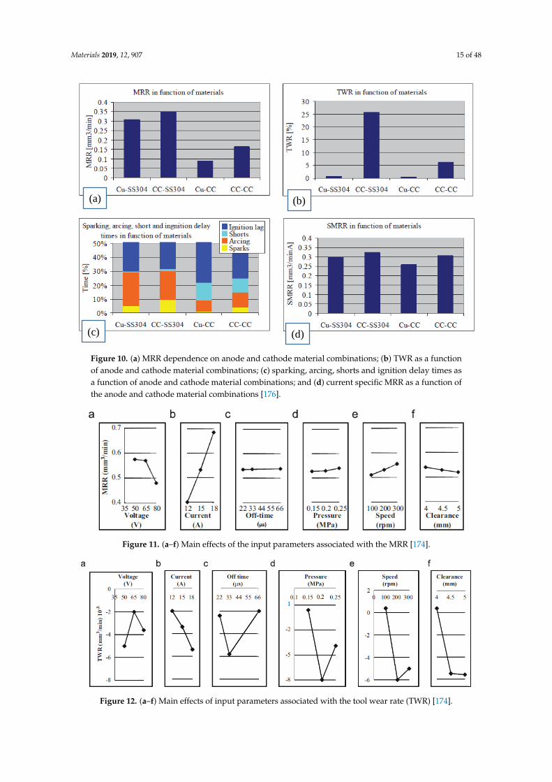
Roth, et al. [176] studied the MRR for different electrode tool and workpiece materials in terms ofthe breakdown behaviour of the process. The authors reported that the breakdown mechanism wasdifferent from the traditional EDM when the work gap was filled with gas rather than liquid dielectric.They presented MRR, TWR and specific MRR, as well as the sparking, arcing and ignition delay timeson the function of the anode material (see Figure 10).
Govindan, et al. [174] presented an experimental characterization of 304 stainless steel removalusing the dry electrical discharge drilling technique. They selected various independent parametersfor the experiments. All the experiments were performed in a ‘quasi-explosion’ mode by controllingthe pulse off-time. The main response variables analysed in this work were MRR, TWR, over size andcompositional variation across the machined cross-sections. The authors reported that the dischargecurrent, gap voltage and rotational speed significantly influence the MRR. The TWR was found closeto zero in most of the experiments. The paper presented the influence of the machining parameters inthe MRR and TWR (Figures 11 and 12).
Materials 2019, 12, 907 15 of 48
Materials 2019, 12, x FOR PEER REVIEW 15 of 49
Figure 10. (a) MRR dependence on anode and cathode material combinations; (b) TWR as a function
of anode and cathode material combinations; (c) sparking, arcing, shorts and ignition delay times as
a function of anode and cathode material combinations; and (d) current specific MRR as a function of
the anode and cathode material combinations [176].
Figure 11. (a–f) Main effects of the input parameters associated with the MRR [174].
Figure 12. (a–f) Main effects of input parameters associated with the tool wear rate (TWR) [174].
(a) (b)
(c) (d)
Figure 10. (a) MRR dependence on anode and cathode material combinations; (b) TWR as a functionof anode and cathode material combinations; (c) sparking, arcing, shorts and ignition delay times asa function of anode and cathode material combinations; and (d) current specific MRR as a function ofthe anode and cathode material combinations [176].
Materials 2019, 12, x FOR PEER REVIEW 15 of 49
Figure 10. (a) MRR dependence on anode and cathode material combinations; (b) TWR as a function
of anode and cathode material combinations; (c) sparking, arcing, shorts and ignition delay times as
a function of anode and cathode material combinations; and (d) current specific MRR as a function of
the anode and cathode material combinations [176].
Figure 11. (a–f) Main effects of the input parameters associated with the MRR [174].
Figure 12. (a–f) Main effects of input parameters associated with the tool wear rate (TWR) [174].
(a) (b)
(c) (d)
Figure 11. (a–f) Main effects of the input parameters associated with the MRR [174].
Materials 2019, 12, x FOR PEER REVIEW 15 of 49
Figure 10. (a) MRR dependence on anode and cathode material combinations; (b) TWR as a function
of anode and cathode material combinations; (c) sparking, arcing, shorts and ignition delay times as
a function of anode and cathode material combinations; and (d) current specific MRR as a function of
the anode and cathode material combinations [176].
Figure 11. (a–f) Main effects of the input parameters associated with the MRR [174].
Figure 12. (a–f) Main effects of input parameters associated with the tool wear rate (TWR) [174].
(a) (b)
(c) (d)
Figure 12. (a–f) Main effects of input parameters associated with the tool wear rate (TWR) [174].
Materials 2019, 12, 907 16 of 48
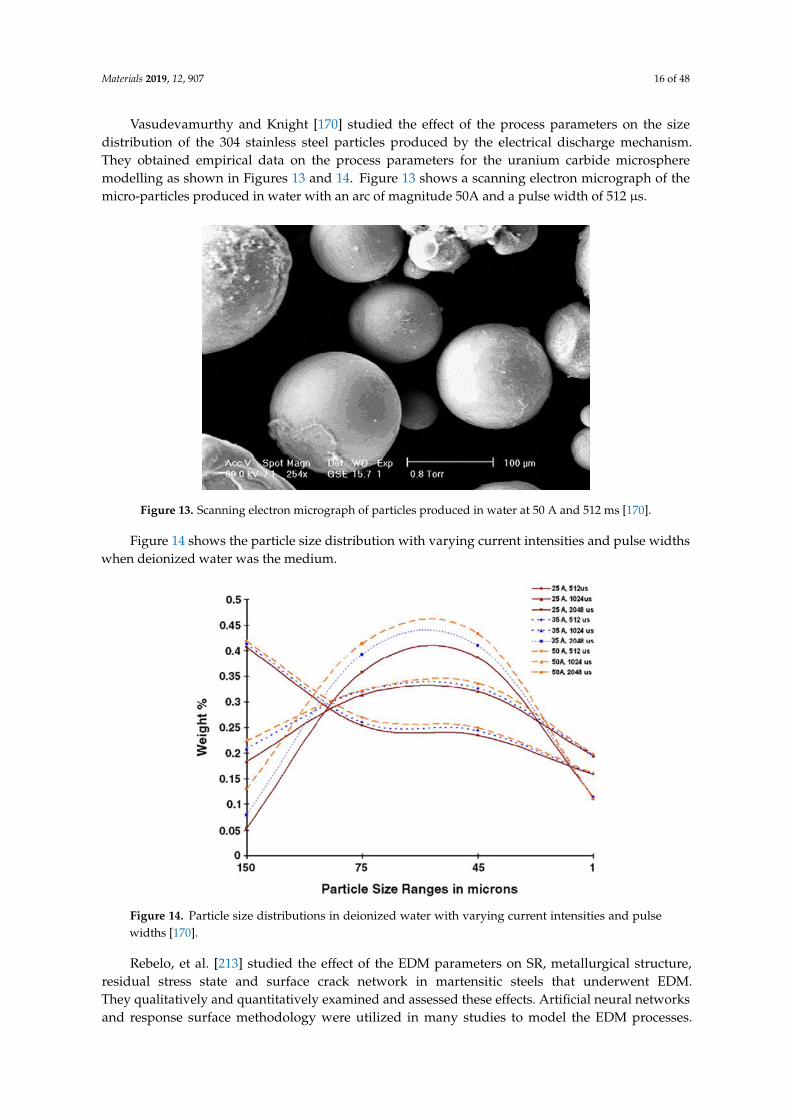
Vasudevamurthy and Knight [170] studied the effect of the process parameters on the sizedistribution of the 304 stainless steel particles produced by the electrical discharge mechanism.They obtained empirical data on the process parameters for the uranium carbide microspheremodelling as shown in Figures 13 and 14. Figure 13 shows a scanning electron micrograph of themicro-particles produced in water with an arc of magnitude 50A and a pulse width of 512 µs.
Materials 2019, 12, x FOR PEER REVIEW 16 of 49
Vasudevamurthy and Knight [170] studied the effect of the process parameters on the size
distribution of the 304 stainless steel particles produced by the electrical discharge mechanism. They
obtained empirical data on the process parameters for the uranium carbide microsphere modelling
as shown in Figures 13 and 14. Figure 13 shows a scanning electron micrograph of the micro-particles
produced in water with an arc of magnitude 50A and a pulse width of 512 μs.
Figure 13. Scanning electron micrograph of particles produced in water at 50 A and 512 ms [170].
Figure 14 shows the particle size distribution with varying current intensities and pulse widths
when deionized water was the medium.
Figure 14. Particle size distributions in deionized water with varying current intensities and pulse
widths [170].
Rebelo, et al. [213] studied the effect of the EDM parameters on SR, metallurgical structure,
residual stress state and surface crack network in martensitic steels that underwent EDM. They
qualitatively and quantitatively examined and assessed these effects. Artificial neural networks and
response surface methodology were utilized in many studies to model the EDM processes. Tang and
Guo [211] combined the Deng Grey Incidence Analysis model and Taguchi orthogonal array analysis
of the experimental results to optimize electrical discharge machining parameters with a high level
Figure 13. Scanning electron micrograph of particles produced in water at 50 A and 512 ms [170].
Figure 14 shows the particle size distribution with varying current intensities and pulse widthswhen deionized water was the medium.
Materials 2019, 12, x FOR PEER REVIEW 16 of 49
Vasudevamurthy and Knight [170] studied the effect of the process parameters on the size
distribution of the 304 stainless steel particles produced by the electrical discharge mechanism. They
obtained empirical data on the process parameters for the uranium carbide microsphere modelling
as shown in Figures 13 and 14. Figure 13 shows a scanning electron micrograph of the micro-particles
produced in water with an arc of magnitude 50A and a pulse width of 512 μs.
Figure 13. Scanning electron micrograph of particles produced in water at 50 A and 512 ms [170].
Figure 14 shows the particle size distribution with varying current intensities and pulse widths
when deionized water was the medium.
Figure 14. Particle size distributions in deionized water with varying current intensities and pulse
widths [170].
Rebelo, et al. [213] studied the effect of the EDM parameters on SR, metallurgical structure,
residual stress state and surface crack network in martensitic steels that underwent EDM. They
qualitatively and quantitatively examined and assessed these effects. Artificial neural networks and
response surface methodology were utilized in many studies to model the EDM processes. Tang and
Guo [211] combined the Deng Grey Incidence Analysis model and Taguchi orthogonal array analysis
of the experimental results to optimize electrical discharge machining parameters with a high level
Figure 14. Particle size distributions in deionized water with varying current intensities and pulsewidths [170].
Rebelo, et al. [213] studied the effect of the EDM parameters on SR, metallurgical structure,residual stress state and surface crack network in martensitic steels that underwent EDM.They qualitatively and quantitatively examined and assessed these effects. Artificial neural networksand response surface methodology were utilized in many studies to model the EDM processes.
Materials 2019, 12, 907 17 of 48
Tang and Guo [211] combined the Deng Grey Incidence Analysis model and Taguchi orthogonal arrayanalysis of the experimental results to optimize electrical discharge machining parameters with a highlevel of accuracy. The results showed that the obtained optimized parameters increased the MRR byalmost 24%.
Spedding and Wang [192] used two techniques to develop models for the wire EDM process:the response surface methodology and an artificial neural networks. They investigated SR, skewness,kurtosis and waviness of a wire surface that underwent EDM. A measure of the surface waviness(as an output parameter) was included in the process modelling. Tarng, et al. [214] utilized a feedforward neural network to predict the influence of the cutting parameters on the cutting performance.They applied a simulated annealing algorithm to the neural network to find the optimal cuttingparameters based on a performance index within the allowable working conditions. Based onthe experimental results for SUS304 stainless steel it was claimed that the cutting performance ofa wire-EDM can be greatly enhanced using this approach. Abdulkareem, et al. [215] investigated theeffect of cryogenic cooling on reducing EWR in the EDM process. It was found out that with the helpof cryogenic cooling the EWR was reduced by 27% and surface roughness improved. Srivastava andPandey [216] also used cryogenic cooling of the electrode tool and showed that EWR was reduced by20% and that SR was also reduced.
Jithin, et al. [184] studied the effect of operating parameters such as gap voltage and pulseon-time on the surface roughness of Stainless steel 316L and electrode tool of copper, tungstenand copper–tungsten were used. The authors reported that, at low level of operating parameters,the surface irregularities such as micro-globules and micro-cracks by copper electrode tool is lesserthan the surface irregularities by other electrode tool materials. At high levels of operating parameters,a denser distribution of surface irregularities due to high electrical discharge efficiency was observed.Deris, et al. [185] conducted experimental study to investigate the influence of EDM parametersincluding peak current, servo voltage, pulse on time, pulse off time and servo speed on electrode toolwear rate value by using Grey Relational Analysis. The authors reported that peak current is the mostsignificant parameter to the EWR value.
Boban, et al. [172] presented an experimental investigation to find the effect of polarity in toolwear micro EDM drilling of stainless steel SS 304. Three electrode tools were used namely, coper,brass and tungsten. The authors reported that, the direct polarity has significant influence in reducingthe tool wear over the reverse polarity for the three electrode tools and the material removal rate ismaximized with the direct polarity. Chandramouli and Eswaraiah [199,200] presented an experimentalinvestigation to find the optimal process parameters of EDM including peak current, pulse on time,pulse off time and tool lift time on Material Removal Rate and Surface Roughness. They used L27Taguchi experimental design to conduct the experiments on 17-4 Precipitation Hardening Stainless Steel(PH Steel). The authors reported that, peak current, pulse on time and tool lift time have significantlyaffected the material removal rate and surface roughness.
Ramachandra [180] optimized the machining parameters including Discharge current, Pulseon time and Duty cycle to maximize Material Removal Rate and minimize and Surface Roughness.AISI 316 stainless steel materials workpiece and Copper electrode tool were used. Taguchi’s L9orthogonal array was used to study the response of control factors. Buschaiaha, et al. [162] presentedan experimental study to characterize the electric discharge machining of AISI304 steel on EDMwith the copper electrode tool. EDM parameters including as peak current, pulse duration andelectrode tool diameter were considered to analyse the effect of each parameter on the machiningcharacteristics. The authors reported that, these parameters have a significant influence on machiningcharacteristic such that surface roughness. Table 3 summarizes the latest studies on optimizing theprocess parameters of the EDM machining.
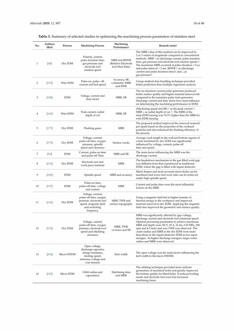
Materials 2019, 12, 907 18 of 48
Table 3. Summary of selected studies in optimizing the machining process parameters of stainless steel.
No. Authors(Ref) Process Machining Process Machining
Performance Remark (note)
1 [48] Dry EDM
Polarity, current,pulse duration time,
gas pressure andelectrode toolrotation speed
MRR and REWR(Relative Electrode
tool Wear Rate)
The MRR value of this method can be improved by2 or 3 orders of magnitude compared to conventionalmethods. MRR ↑ as (discharge current, pulse durationtime, gas pressure and electrode tool rotation speed) ↑.The maximum MRR occurred at pulse duration = 9 µsand pulse interval = 2 ms. REWR ↑ as (dischargecurrent and pulse duration time)↑ and ↓ asgas pressure↑
2 [193] Wire EDM Pulse-on, pulse- off,current and bed speed
Accuracy, SR,volumetric MRR
and EWR
Group method data handling technique providedbetter prediction than multiple regression analysis.
3 [188] EDM Voltage, current andduty factor MRR, SR
The iso duration current pulse generator producedbetter surface quality and higher material removal ratecompared to the transistor pulse train generator.Discharge current and duty factor have most influenceon determining the machining performance in EDM.
4 [166] Wire-EDM Peak current, radialdepth of cut MRR, SR
(Machining speed and SR) ↑ as the peak current ↑.MRR ↓ as radial depth of cut ↑. The MRR of thestrip-EDM turning was 74.3% higher than the MRR forwire-EDM turning.
5 [177] Dry EDM Flushing gases MRR
The proposed method improved the removed materialper spark based on the properties of the oxidizedparticles and also enhanced the flushing efficiency ofthe process.
6 [175] Dry EDM
Voltage, current,pulse-off time, oxygen
pressure, spindlespeed and clearance
Surface cracks
Average crack length in the wall and bottom regions ofa hole machined by dry EDM was significantlyinfluenced by voltage, current, pulse-offtime and speed.
7 [56] EDM Current, pulse-on timeand pulse-off Time MRR and SR The main factor influencing the MRR was the
discharge current.
8 [176] Dry EDM Electrode tool andwork piece material MRR
The breakdown mechanism in the gas filled work gapwas different from that experienced in traditionalEDM, where the gap is filled with liquid dielectric.
9 [160] EDM Spindle speed MRR and accuracyMuch deeper and more accurate micro-holes can bemachined and lower tool wear ratio can be achievedunder high spindle speed
10 [157] EDMPulse-on time,
pulse-off time, voltageand current
MRR Current and pulse time were the most influentialfactors on the MRR.
11 [136] Dry EDM
Voltage, current,pulse-off time, oxygenpressure, electrode toolspeed, magnetic field
and switchingfrequency
MRR, TWR andsurface topography
Using a magnetic field led to higher transfer ofthermal energy to the workpiece and improvedmaterial removal in dry EDM. Applying the magneticfield also improved the geometric and surface quality.
12 [174] Dry EDM
Voltage, current,pulse-off time, oxygenpressure, electrode tool
speed and shieldingclearance
MRR, TWR,oversize and SR
MRR was significantly affected by gap voltage,discharge current and electrode tool rotational speed.Optimal processing parameters to achieve maximumMRR and depth were (50 V, 18 A, 22 ms, 0.25 MPa, 300rpm and 4.5 mm) and zero TWR was observed. Thecrater radius and MRR in the dry EDM were morethan those in the liquid dielectric EDM at low inputenergies. At higher discharge energies, larger craterradius and MRR were observed.
13 [204] Micro-WEDM
Open voltage,discharge capacitor,charge resistance,
feeding speed,reference voltage and
wire tension
Kerf width The open voltage was the main factor influencing thekerf width in the micro-WEDM.
14 [182] Micro-EDM Orbit radius andcapacitance
Machining timeand MRR
The orbiting technique provided more uniformgeometries of machined holes and greatly improvedthe bottom quality for blind holes. It reduced toolingneeds and electrode tool wear but increasedmachining times.
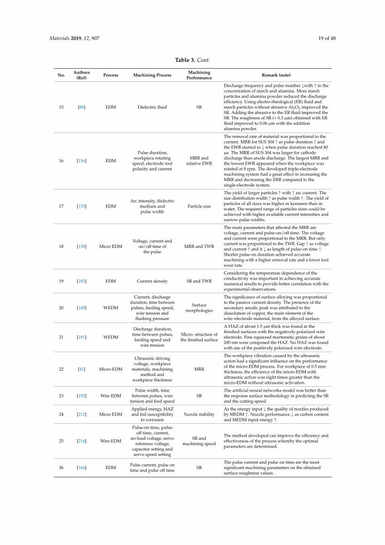
Materials 2019, 12, 907 19 of 48
Table 3. Cont.
No. Authors(Ref) Process Machining Process Machining
Performance Remark (note)
15 [88] EDM Dielectric fluid SR
Discharge frequency and pulse number ↓with ↑ in theconcentration of starch and alumina. More starchparticles and alumina powder reduced the dischargeefficiency. Using electro-rheological (ER) fluid andstarch particles without abrasive Al2O3 improved theSR. Adding the abrasive to the ER fluid improved theSR. The roughness of SR (= 0.3 µm) obtained with ERfluid improved to 0.06 µm with the additionalumina powder.
16 [156] EDM
Pulse duration,workpiece rotating
speed, electrode toolpolarity and current
MRR andrelative EWR
The removal rate of material was proportional to thecurrent. MRR for SUS 304 ↑ as pulse duration ↑ andthe EWR started to ↓ when pulse duration reached 80µs. The MRR of SUS 304 was larger for cathodedischarge than anode discharge. The largest MRR andthe lowest EWR appeared when the workpiece wasrotated at 8 rpm. The developed triple-electrodemachining system had a great effect in increasing theMRR and decreasing the ERR compared to thesingle-electrode system.
17 [170] EDMArc intensity, dielectric
medium andpulse width
Particle size
The yield of larger particles ↑ with ↑ arc current. Thesize distribution width ↑ as pulse width ↑. The yield ofparticles of all sizes was higher in kerosene than inwater. The required range of particles sizes could beachieved with higher available current intensities andnarrow pulse widths.
18 [158] Micro EDMVoltage, current and
on/off time ofthe pulse
MRR and TWR
The main parameters that affected the MRR arevoltage, current and pulse-on/off time. The voltageand current were proportional to the MRR. But onlycurrent was proportional to the TWR. Gap ↑ as voltageand current ↑ and it ↓ as length of pulse-on time ↑.Shorter pulse-on duration achieved accuratemachining with a higher removal rate and a lower toolwear rate.
19 [183] EDM Current density SR and TWR
Considering the temperature dependence of theconductivity was important in achieving accuratenumerical results to provide better correlation with theexperimental observations.
20 [108] WEDM
Current, dischargeduration, time betweenpulses, feeding speed,
wire tension andflushing pressure
Surfacemorphologies
The significance of surface alloying was proportionalto the passive current density. The presence of thesecondary anodic peak was attributed to thedissolution of copper, the main element of thewire–electrode material, from the alloyed surface.
21 [191] WEDM
Discharge duration,time between pulses,
feeding speed andwire tension
Micro- structure ofthe finished surface
A HAZ of about 1.5 µm thick was found in thefinished surfaces with the negatively polarized wireelectrode. Fine equiaxed martensitic grains of about200 nm were composed the HAZ. No HAZ was foundwith use of the positively polarized wire electrode.
22 [41] Micro-EDM
Ultrasonic drivingvoltage, workpiece
materials, machiningmethod and
workpiece thickness
MRR
The workpiece vibration caused by the ultrasonicaction had a significant influence on the performanceof the micro-EDM process. For workpiece of 0.5 mmthickness, the efficiency of the micro-EDM withultrasonic action was eight times greater than themicro-EDM without ultrasonic activation.
23 [192] Wire EDMPulse width, time
between pulses, wiretension and feed speed
SRThe artificial neural networks model was better thanthe response surface methodology in predicting the SRand the cutting speed.
24 [212] Micro EDMApplied energy, HAZand foil susceptibility
to corrosionNozzle stability
As the energy input ↓ the quality of nozzles producedby MEDM ↑. Nozzle performance ↓ as carbon contentand MEDM input energy ↑.
25 [214] Wire-EDM
Pulse-on time, pulse-off time, current,
no-load voltage, servoreference voltage,
capacitor setting andservo speed setting
SR andmachining speed
The method developed can improve the efficiency andeffectiveness of the process whereby the optimalparameters are determined.
26 [164] EDM Pulse current, pulse ontime and pulse off time SR
The pulse current and pulse on time are the mostsignificant machining parameters on the obtainedsurface roughness values.
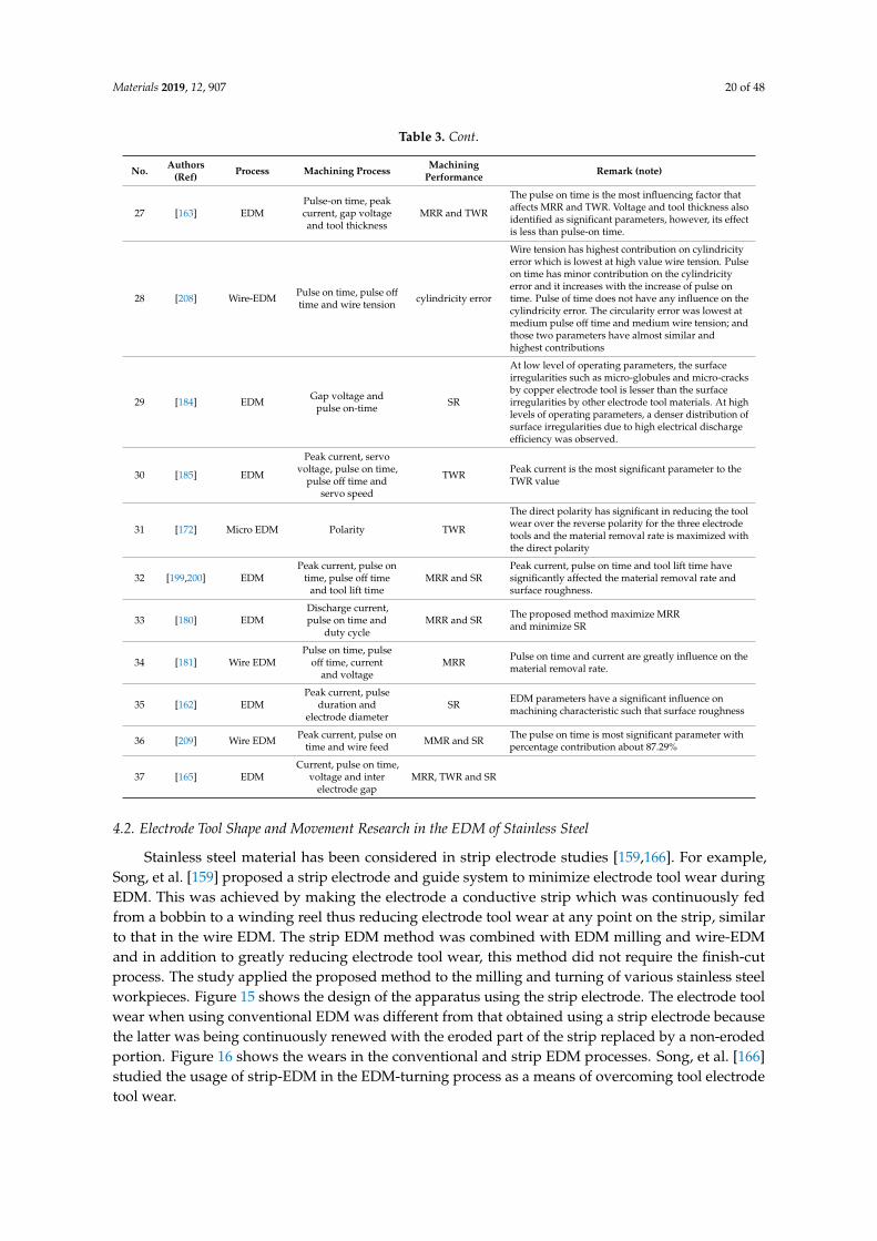
Materials 2019, 12, 907 20 of 48
Table 3. Cont.
No. Authors(Ref) Process Machining Process Machining
Performance Remark (note)
27 [163] EDMPulse-on time, peakcurrent, gap voltageand tool thickness
MRR and TWR
The pulse on time is the most influencing factor thataffects MRR and TWR. Voltage and tool thickness alsoidentified as significant parameters, however, its effectis less than pulse-on time.
28 [208] Wire-EDM Pulse on time, pulse offtime and wire tension cylindricity error
Wire tension has highest contribution on cylindricityerror which is lowest at high value wire tension. Pulseon time has minor contribution on the cylindricityerror and it increases with the increase of pulse ontime. Pulse of time does not have any influence on thecylindricity error. The circularity error was lowest atmedium pulse off time and medium wire tension; andthose two parameters have almost similar andhighest contributions
29 [184] EDM Gap voltage andpulse on-time SR
At low level of operating parameters, the surfaceirregularities such as micro-globules and micro-cracksby copper electrode tool is lesser than the surfaceirregularities by other electrode tool materials. At highlevels of operating parameters, a denser distribution ofsurface irregularities due to high electrical dischargeefficiency was observed.
30 [185] EDM
Peak current, servovoltage, pulse on time,
pulse off time andservo speed
TWR Peak current is the most significant parameter to theTWR value
31 [172] Micro EDM Polarity TWR
The direct polarity has significant in reducing the toolwear over the reverse polarity for the three electrodetools and the material removal rate is maximized withthe direct polarity
32 [199,200] EDMPeak current, pulse on
time, pulse off timeand tool lift time
MRR and SRPeak current, pulse on time and tool lift time havesignificantly affected the material removal rate andsurface roughness.
33 [180] EDMDischarge current,pulse on time and
duty cycleMRR and SR The proposed method maximize MRR
and minimize SR
34 [181] Wire EDMPulse on time, pulse
off time, currentand voltage
MRR Pulse on time and current are greatly influence on thematerial removal rate.
35 [162] EDMPeak current, pulse
duration andelectrode diameter
SR EDM parameters have a significant influence onmachining characteristic such that surface roughness
36 [209] Wire EDM Peak current, pulse ontime and wire feed MMR and SR The pulse on time is most significant parameter with
percentage contribution about 87.29%
37 [165] EDMCurrent, pulse on time,
voltage and interelectrode gap
MRR, TWR and SR
4.2. Electrode Tool Shape and Movement Research in the EDM of Stainless Steel
Stainless steel material has been considered in strip electrode studies [159,166]. For example,Song, et al. [159] proposed a strip electrode and guide system to minimize electrode tool wear duringEDM. This was achieved by making the electrode a conductive strip which was continuously fedfrom a bobbin to a winding reel thus reducing electrode tool wear at any point on the strip, similarto that in the wire EDM. The strip EDM method was combined with EDM milling and wire-EDMand in addition to greatly reducing electrode tool wear, this method did not require the finish-cutprocess. The study applied the proposed method to the milling and turning of various stainless steelworkpieces. Figure 15 shows the design of the apparatus using the strip electrode. The electrode toolwear when using conventional EDM was different from that obtained using a strip electrode becausethe latter was being continuously renewed with the eroded part of the strip replaced by a non-erodedportion. Figure 16 shows the wears in the conventional and strip EDM processes. Song, et al. [166]studied the usage of strip-EDM in the EDM-turning process as a means of overcoming tool electrodetool wear.
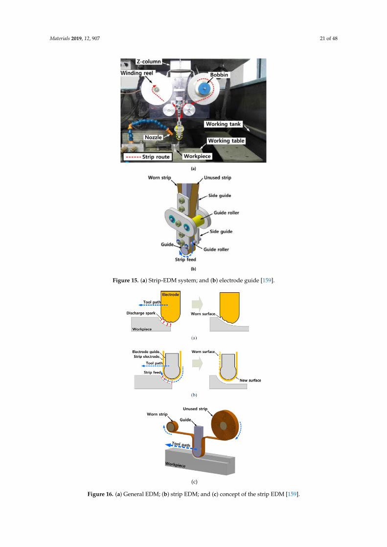
Materials 2019, 12, 907 21 of 48
Materials 2019, 12, x FOR PEER REVIEW 22 of 49
Figure 15. (a) Strip-EDM system; and (b) electrode guide [159].
(c)
Figure 15. (a) Strip-EDM system; and (b) electrode guide [159].
Materials 2019, 12, x FOR PEER REVIEW 22 of 49
Figure 15. (a) Strip-EDM system; and (b) electrode guide [159].
(c)
Figure 16. (a) General EDM; (b) strip EDM; and (c) concept of the strip EDM [159].
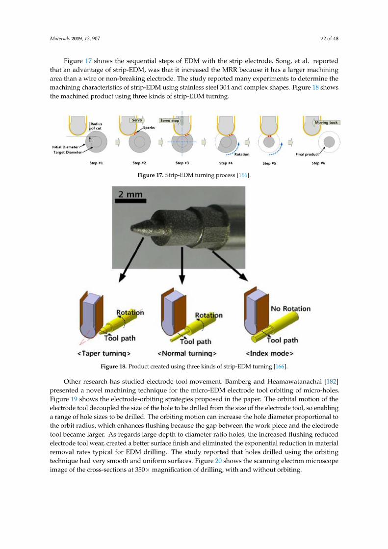
Materials 2019, 12, 907 22 of 48
Figure 17 shows the sequential steps of EDM with the strip electrode. Song, et al. reportedthat an advantage of strip-EDM, was that it increased the MRR because it has a larger machiningarea than a wire or non-breaking electrode. The study reported many experiments to determine themachining characteristics of strip-EDM using stainless steel 304 and complex shapes. Figure 18 showsthe machined product using three kinds of strip-EDM turning.
Materials 2019, 12, x FOR PEER REVIEW 23 of 49
Figure 16. (a) General EDM; (b) strip EDM; and (c) concept of the strip EDM [159].
Figure 17 shows the sequential steps of EDM with the strip electrode. Song, et al. reported that
an advantage of strip-EDM, was that it increased the MRR because it has a larger machining area
than a wire or non-breaking electrode. The study reported many experiments to determine the
machining characteristics of strip-EDM using stainless steel 304 and complex shapes. Figure 18 shows
the machined product using three kinds of strip-EDM turning.
Figure 17. Strip-EDM turning process [166].
Figure 18. Product created using three kinds of strip-EDM turning [166].
Other research has studied electrode tool movement. Bamberg and Heamawatanachai [182]
presented a novel machining technique for the micro-EDM electrode tool orbiting of micro-holes.
Figure 19 shows the electrode-orbiting strategies proposed in the paper. The orbital motion of the
electrode tool decoupled the size of the hole to be drilled from the size of the electrode tool, so
enabling a range of hole sizes to be drilled. The orbiting motion can increase the hole diameter
proportional to the orbit radius, which enhances flushing because the gap between the work piece
and the electrode tool became larger. As regards large depth to diameter ratio holes, the increased
flushing reduced electrode tool wear, created a better surface finish and eliminated the exponential
reduction in material removal rates typical for EDM drilling. The study reported that holes drilled
using the orbiting technique had very smooth and uniform surfaces. Figure 20 shows the scanning
electron microscope image of the cross-sections at 350× magnification of drilling, with and without
orbiting.
Figure 17. Strip-EDM turning process [166].
Materials 2019, 12, x FOR PEER REVIEW 23 of 49
Figure 16. (a) General EDM; (b) strip EDM; and (c) concept of the strip EDM [159].
Figure 17 shows the sequential steps of EDM with the strip electrode. Song, et al. reported that
an advantage of strip-EDM, was that it increased the MRR because it has a larger machining area
than a wire or non-breaking electrode. The study reported many experiments to determine the
machining characteristics of strip-EDM using stainless steel 304 and complex shapes. Figure 18 shows
the machined product using three kinds of strip-EDM turning.
Figure 17. Strip-EDM turning process [166].
Figure 18. Product created using three kinds of strip-EDM turning [166].
Other research has studied electrode tool movement. Bamberg and Heamawatanachai [182]
presented a novel machining technique for the micro-EDM electrode tool orbiting of micro-holes.
Figure 19 shows the electrode-orbiting strategies proposed in the paper. The orbital motion of the
electrode tool decoupled the size of the hole to be drilled from the size of the electrode tool, so
enabling a range of hole sizes to be drilled. The orbiting motion can increase the hole diameter
proportional to the orbit radius, which enhances flushing because the gap between the work piece
and the electrode tool became larger. As regards large depth to diameter ratio holes, the increased
flushing reduced electrode tool wear, created a better surface finish and eliminated the exponential
reduction in material removal rates typical for EDM drilling. The study reported that holes drilled
using the orbiting technique had very smooth and uniform surfaces. Figure 20 shows the scanning
electron microscope image of the cross-sections at 350× magnification of drilling, with and without
orbiting.
Figure 18. Product created using three kinds of strip-EDM turning [166].
Other research has studied electrode tool movement. Bamberg and Heamawatanachai [182]presented a novel machining technique for the micro-EDM electrode tool orbiting of micro-holes.Figure 19 shows the electrode-orbiting strategies proposed in the paper. The orbital motion of theelectrode tool decoupled the size of the hole to be drilled from the size of the electrode tool, so enablinga range of hole sizes to be drilled. The orbiting motion can increase the hole diameter proportional tothe orbit radius, which enhances flushing because the gap between the work piece and the electrodetool became larger. As regards large depth to diameter ratio holes, the increased flushing reducedelectrode tool wear, created a better surface finish and eliminated the exponential reduction in materialremoval rates typical for EDM drilling. The study reported that holes drilled using the orbitingtechnique had very smooth and uniform surfaces. Figure 20 shows the scanning electron microscopeimage of the cross-sections at 350×magnification of drilling, with and without orbiting.

Materials 2019, 12, 907 23 of 48
Materials 2019, 12, x FOR PEER REVIEW 24 of 49
Figure 19. Electrode orbiting strategies: (a) slicing the hole into cylinders of thickness t and radius r;
(b) slicing the hole into cylindrical shells of radius r; and (c) spiralling into the hole with radius r [182].
Figure 20. Cross-section of 500 µm deep micro-holes without orbiting; with 5 µm orbit radius; and
with 7.5 µm orbit radius drilled with 60 V and 47 pF capacitance [182].
Similarly, Rajurkar and Shen [179] presented an approach based on the planetary movement of
an electrode tool to create the extra space needed for debris removal from the narrow gap when
drilling high aspect ratio micro-holes as well as blind non-circular micro-holes. This proposed
approach was verified by drilling through micro-holes with an aspect ratio of 18 and blind non-
Figure 19. Electrode orbiting strategies: (a) slicing the hole into cylinders of thickness t and radius r;(b) slicing the hole into cylindrical shells of radius r; and (c) spiralling into the hole with radius r [182].
Materials 2019, 12, x FOR PEER REVIEW 24 of 49
Figure 19. Electrode orbiting strategies: (a) slicing the hole into cylinders of thickness t and radius r;
(b) slicing the hole into cylindrical shells of radius r; and (c) spiralling into the hole with radius r [182].
Figure 20. Cross-section of 500 µm deep micro-holes without orbiting; with 5 µm orbit radius; and
with 7.5 µm orbit radius drilled with 60 V and 47 pF capacitance [182].
Similarly, Rajurkar and Shen [179] presented an approach based on the planetary movement of
an electrode tool to create the extra space needed for debris removal from the narrow gap when
drilling high aspect ratio micro-holes as well as blind non-circular micro-holes. This proposed
approach was verified by drilling through micro-holes with an aspect ratio of 18 and blind non-
Figure 20. Cross-section of 500 µm deep micro-holes without orbiting; with 5 µm orbit radius; andwith 7.5 µm orbit radius drilled with 60 V and 47 pF capacitance [182].
Similarly, Rajurkar and Shen [179] presented an approach based on the planetary movement ofan electrode tool to create the extra space needed for debris removal from the narrow gap when drilling
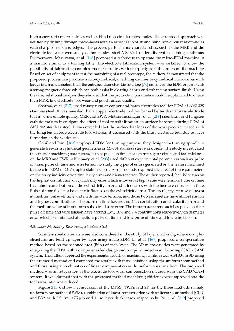
Materials 2019, 12, 907 24 of 48
high aspect ratio micro-holes as well as blind non-circular micro-holes. This proposed approach wasverified by drilling through micro-holes with an aspect ratio of 18 and blind non-circular micro-holeswith sharp corners and edges. The process performance characteristics, such as the MRR and theelectrode tool wear, were analysed for stainless steel AISI 304L under different machining conditions.Furthermore, Masuzawa, et al. [168] proposed a technique to operate the micro-EDM machine ina manner similar to a turning lathe. The electrode fabrication system was installed to allow thepossibility of fabricating complex microelectrodes with sharp edges and corners on-the-machine.Based on set of equipment to test the machining of a real prototype, the authors demonstrated that theproposed process can produce micro-cylindrical, overhung cavities or cylindrical micro-holes withlarger internal diameters than the entrance diameter. Lin and Lee [74] enhanced the EDM process witha strong magnetic force which can both assist in clearing debris and enhancing surface finish. Usingthe Grey relational analysis they showed that the production parameters could be optimized to obtainhigh MRR, low electrode tool wear and good surface quality.
Sharma, et al. [217] used rotary tubular copper and brass electrodes tool for EDM of AISI 329stainless steel. It was revealed that a copper electrode tool performed better than a brass electrodetool in terms of hole quality, MRR and EWR. Muthuramalingam, et al. [218] used brass and tungstencarbide tools to investigate the effect of tool re-solidification on surface hardness during EDM ofAISI 202 stainless steel. It was revealed that the surface hardness of the workpiece increased withthe tungsten carbide electrode tool whereas it decreased with the brass electrode tool due to layerformation on the workpiece.
Gohil and Puri, [163] employed EDM for turning purpose, they designed a turning spindle togenerate free-form cylindrical geometries on SS-304 stainless steel work piece. The study investigatedthe effect of machining parameters, such as pulse-on time, peak current, gap voltage and tool thicknesson the MRR and TWR. Alshemary, et al. [208] used different experimental parameters such as, pulseon time, pulse off time and wire tension to study the types of errors generated on the feature machinedby the wire EDM of 2205 duplex stainless steel. Also, the study explored the effect of these parameterson the on cylindricity error, circularity error and diameter error. The author reported that, Wire tensionhas highest contribution on cylindricity error which is lowest at high value wire tension. Pulse on timehas minor contribution on the cylindricity error and it increases with the increase of pulse on time.Pulse of time does not have any influence on the cylindricity error. The circularity error was lowestat medium pulse off time and medium wire tension; and those two parameters have almost similarand highest contributions. The pulse on time has around 14% contribution on circularity error andthe medium value of it minimizes the circularity error. The input parameters such has pulse on time,pulse off time and wire tension have around 13%, 16% and 7% contributions respectively on diametererror which is minimized at medium pulse on time and low pulse off time and low wire tension.
4.3. Layer Machining Research of Stainless Steel
Stainless steel materials were also considered in the study of layer machining where complexstructures are built up layer by layer using micro-EDM. Li, et al. [167] proposed a compensationmethod based on the scanned area (BSA) of each layer. The 3D micro-cavities were generated byintegrating the EDM with a computer aided design and computer aided manufacturing (CAD/CAM)system. The authors reported the experimental results of machining stainless steel AISI 304 in 3D usingthe proposed method and compared the results with those obtained using the uniform wear methodand those using a combination of linear compensation with uniform wear method. The proposedmethod was an integration of the electrode tool wear compensation method with the CAD/CAMsystem. It was claimed that with the proposed method machining efficiency was improved and thetool wear ratio was reduced.
Figure 21a–c show a comparison of the MRRs, TWRs and SR for the three methods namelyuniform wear method (UWM), combination of linear compensation with uniform wear method (CLU)and BSA with 0.5 µm, 0.75 µm and 1 µm layer thicknesses, respectively. Yu, et al. [219] proposed
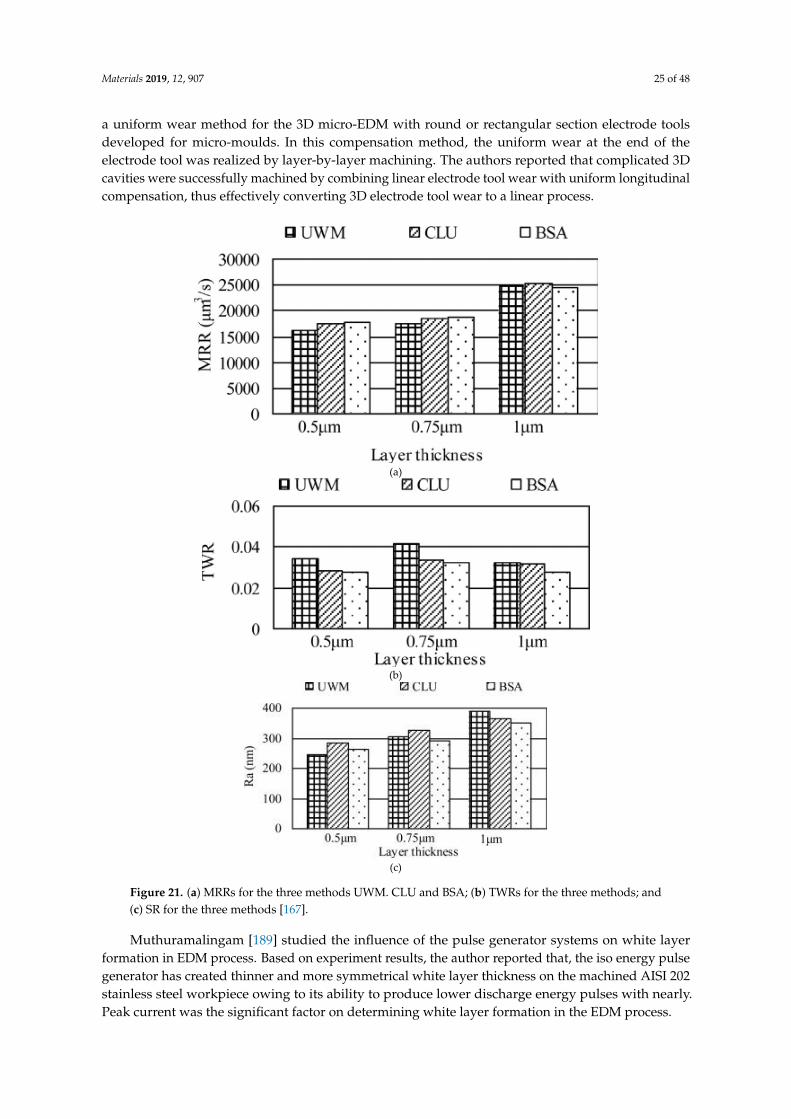
Materials 2019, 12, 907 25 of 48
a uniform wear method for the 3D micro-EDM with round or rectangular section electrode toolsdeveloped for micro-moulds. In this compensation method, the uniform wear at the end of theelectrode tool was realized by layer-by-layer machining. The authors reported that complicated 3Dcavities were successfully machined by combining linear electrode tool wear with uniform longitudinalcompensation, thus effectively converting 3D electrode tool wear to a linear process.
Materials 2019, 12, x FOR PEER REVIEW 26 of 49
cavities were successfully machined by combining linear electrode tool wear with uniform
longitudinal compensation, thus effectively converting 3D electrode tool wear to a linear process.
(a)
(b)
(c)
Figure 21. (a) MRRs for the three methods UWM. CLU and BSA; (b) TWRs for the three methods; and
(c) SR for the three methods [167].
Muthuramalingam [189] studied the influence of the pulse generator systems on white layer
formation in EDM process. Based on experiment results, the author reported that, the iso energy pulse
generator has created thinner and more symmetrical white layer thickness on the machined AISI 202
stainless steel workpiece owing to its ability to produce lower discharge energy pulses with nearly.
Peak current was the significant factor on determining white layer formation in the EDM process.
Figure 21. (a) MRRs for the three methods UWM. CLU and BSA; (b) TWRs for the three methods; and(c) SR for the three methods [167].
Muthuramalingam [189] studied the influence of the pulse generator systems on white layerformation in EDM process. Based on experiment results, the author reported that, the iso energy pulsegenerator has created thinner and more symmetrical white layer thickness on the machined AISI 202stainless steel workpiece owing to its ability to produce lower discharge energy pulses with nearly.Peak current was the significant factor on determining white layer formation in the EDM process.

Materials 2019, 12, 907 26 of 48
4.4. Combined and Hybrid Processes for Stainless Steel
Many studies introduced hybrid process for EDM [220]. Stainless steel materials were alsoconsidered in many hybrid processes. Zeng, et al. [171] investigated the combining of micro-EDMand micro-electro-chemical machining (ECM) for the milling of a 3D micro-structure. The micro-EDMshaping and micro-ECM finishing were performed in sequence on the same machine tool with thesame electrode tool but different dielectric media. The processing conditions were experimentallyinvestigated for 304 stainless steel. The electrode tool used in both processes was fabricated onlineusing an anti-copying block. The authors reported that the machining precision and shape accuracywere much better than parts machined using only micro-ECM milling. They also found that the SQ andmechanical properties of the workpiece were improved. The study demonstrated that this combinedmilling method was possible and useful in the field of 3D metallic micro-structure milling. Figure 22shows the scanning electron microscopy (SEM) morphologies of the SR of the bottom surface. Figure 23shows the SEM photos for squire cavity shape machined using only EDM compared to those machinedby combined milling with machining gap of 10 µm with different gaps.
Materials 2019, 12, x FOR PEER REVIEW 27 of 49
4.4. Combined and Hybrid Processes for Stainless Steel
Many studies introduced hybrid process for EDM [220]. Stainless steel materials were also
considered in many hybrid processes. Zeng, et al. [171] investigated the combining of micro-EDM
and micro-electro-chemical machining (ECM) for the milling of a 3D micro-structure. The micro-EDM
shaping and micro-ECM finishing were performed in sequence on the same machine tool with the
same electrode tool but different dielectric media. The processing conditions were experimentally
investigated for 304 stainless steel. The electrode tool used in both processes was fabricated online
using an anti-copying block. The authors reported that the machining precision and shape accuracy
were much better than parts machined using only micro-ECM milling. They also found that the SQ
and mechanical properties of the workpiece were improved. The study demonstrated that this
combined milling method was possible and useful in the field of 3D metallic micro-structure milling.
Figure 22 shows the scanning electron microscopy (SEM) morphologies of the SR of the bottom
surface. Figure 23 shows the SEM photos for squire cavity shape machined using only EDM
compared to those machined by combined milling with machining gap of 10 µm with different gaps.
Figure 22. SR of the bottom surface [171].
Figure 23. Scanning electron microscope (SEM) photos of the square cavity machined by EDM and
micro-EDM combined with milling [171].
Govindan, et al. [136] presented another hybrid process when they assessed material removal in
pulsed magnetic field-assisted dry EDM. The application of the pulsating magnetic field increased
the movement of electrons and the degree of ionization in the plasma. Based on experiments of two
stainless steel split workpieces with parametric variations, the authors reported that this hybrid
approach led to productivity improvement of 130%, with zero tool wear, as compared to the dry
EDM process without the magnetic field. An improvement in the SQ was also found by the SEM.
Figures 24 and 25 show a comparison between the MRR and the TWR in the dry EDM process
performance with the magnetic field architecture (MFA) and without magnetic field (WMFA).
Figure 22. SR of the bottom surface [171].
Materials 2019, 12, x FOR PEER REVIEW 27 of 49
4.4. Combined and Hybrid Processes for Stainless Steel
Many studies introduced hybrid process for EDM [220]. Stainless steel materials were also
considered in many hybrid processes. Zeng, et al. [171] investigated the combining of micro-EDM
and micro-electro-chemical machining (ECM) for the milling of a 3D micro-structure. The micro-EDM
shaping and micro-ECM finishing were performed in sequence on the same machine tool with the
same electrode tool but different dielectric media. The processing conditions were experimentally
investigated for 304 stainless steel. The electrode tool used in both processes was fabricated online
using an anti-copying block. The authors reported that the machining precision and shape accuracy
were much better than parts machined using only micro-ECM milling. They also found that the SQ
and mechanical properties of the workpiece were improved. The study demonstrated that this
combined milling method was possible and useful in the field of 3D metallic micro-structure milling.
Figure 22 shows the scanning electron microscopy (SEM) morphologies of the SR of the bottom
surface. Figure 23 shows the SEM photos for squire cavity shape machined using only EDM
compared to those machined by combined milling with machining gap of 10 µm with different gaps.
Figure 22. SR of the bottom surface [171].
Figure 23. Scanning electron microscope (SEM) photos of the square cavity machined by EDM and
micro-EDM combined with milling [171].
Govindan, et al. [136] presented another hybrid process when they assessed material removal in
pulsed magnetic field-assisted dry EDM. The application of the pulsating magnetic field increased
the movement of electrons and the degree of ionization in the plasma. Based on experiments of two
stainless steel split workpieces with parametric variations, the authors reported that this hybrid
approach led to productivity improvement of 130%, with zero tool wear, as compared to the dry
EDM process without the magnetic field. An improvement in the SQ was also found by the SEM.
Figures 24 and 25 show a comparison between the MRR and the TWR in the dry EDM process
performance with the magnetic field architecture (MFA) and without magnetic field (WMFA).
Figure 23. Scanning electron microscope (SEM) photos of the square cavity machined by EDM andmicro-EDM combined with milling [171].
Govindan, et al. [136] presented another hybrid process when they assessed material removal inpulsed magnetic field-assisted dry EDM. The application of the pulsating magnetic field increasedthe movement of electrons and the degree of ionization in the plasma. Based on experiments oftwo stainless steel split workpieces with parametric variations, the authors reported that this hybridapproach led to productivity improvement of 130%, with zero tool wear, as compared to the dryEDM process without the magnetic field. An improvement in the SQ was also found by the SEM.Figures 24 and 25 show a comparison between the MRR and the TWR in the dry EDM processperformance with the magnetic field architecture (MFA) and without magnetic field (WMFA).
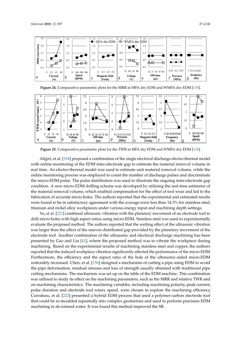
Materials 2019, 12, 907 27 of 48
Materials 2019, 12, x FOR PEER REVIEW 28 of 49
Figure 24. Comparative parametric plots for the MRR in MFA dry EDM and WMFA dry EDM [136].
Figure 25. Comparative parametric plots for the TWR in MFA dry EDM and WMFA dry EDM [136].
Aligiri, et al. [194] proposed a combination of the single electrical discharge electro-thermal
model with online monitoring of the EDM inter-electrode gap to estimate the material removal
volume in real time. An electro-thermal model was used to estimate unit material removal volume,
while the online monitoring process was employed to count the number of discharge pulses and
discriminate the micro-EDM pulse. The pulse distribution was used to illustrate the ongoing inter-
electrode gap condition. A new micro-EDM drilling scheme was developed by utilizing the real-time
estimator of the material removal volume, which enabled compensation for the effect of tool wear
and led to the fabrication of accurate micro-holes. The authors reported that the experimental and
estimated results were found to be in satisfactory agreement with the average error less than 14.3%
for stainless steel, titanium and nickel alloy workpieces under various energy input and machining
depth settings.
Yu, et al. [221] combined ultrasonic vibration with the planetary movement of an electrode tool
to drill micro-holes with high aspect ratios using micro-EDM. Stainless steel was used to
experimentally evaluate the proposed method. The authors reported that the wetting effect of the
ultrasonic vibration was larger than the effect of the uneven distributed gap provided by the
planetary movement of the electrode tool. Another combination of the ultrasonic and electrical
discharge machining has been presented by Gao and Liu [41], where the proposed method was to
vibrate the workpiece during machining. Based on the experimental results of machining stainless
steel and copper, the authors reported that the induced workpiece vibration significantly affected the
performance of the micro-EDM. Furthermore, the efficiency and the aspect ratio of the hole of the
ultrasonic-aided micro-EDM noticeably increased. Chen, et al. [156] designed a mechanism of cutting
a pipe using EDM to avoid the pipe deformation, residual stresses and loss of strength usually
obtained with traditional pipe cutting mechanisms. The mechanism was set up on the table of the
EDM machine. This combination was utilized to study its effect on the machining parameters, such
as the MRR and relative TWR and on machining characteristics. The machining variables, including
machining polarity, peak current, pulse duration and electrode tool rotary speed, were chosen to
explore the machining efficiency. Curodeau, et al. [222] presented a hybrid EDM process that used a
polymer-carbon electrode tool that could be re-moulded repeatedly into complex geometries and
used to perform precision EDM machining in de-ionised water. It was found this method improved the
SR.
Figure 24. Comparative parametric plots for the MRR in MFA dry EDM and WMFA dry EDM [136].
Materials 2019, 12, x FOR PEER REVIEW 28 of 49
Figure 24. Comparative parametric plots for the MRR in MFA dry EDM and WMFA dry EDM [136].
Figure 25. Comparative parametric plots for the TWR in MFA dry EDM and WMFA dry EDM [136].
Aligiri, et al. [194] proposed a combination of the single electrical discharge electro-thermal
model with online monitoring of the EDM inter-electrode gap to estimate the material removal
volume in real time. An electro-thermal model was used to estimate unit material removal volume,
while the online monitoring process was employed to count the number of discharge pulses and
discriminate the micro-EDM pulse. The pulse distribution was used to illustrate the ongoing inter-
electrode gap condition. A new micro-EDM drilling scheme was developed by utilizing the real-time
estimator of the material removal volume, which enabled compensation for the effect of tool wear
and led to the fabrication of accurate micro-holes. The authors reported that the experimental and
estimated results were found to be in satisfactory agreement with the average error less than 14.3%
for stainless steel, titanium and nickel alloy workpieces under various energy input and machining
depth settings.
Yu, et al. [221] combined ultrasonic vibration with the planetary movement of an electrode tool
to drill micro-holes with high aspect ratios using micro-EDM. Stainless steel was used to
experimentally evaluate the proposed method. The authors reported that the wetting effect of the
ultrasonic vibration was larger than the effect of the uneven distributed gap provided by the
planetary movement of the electrode tool. Another combination of the ultrasonic and electrical
discharge machining has been presented by Gao and Liu [41], where the proposed method was to
vibrate the workpiece during machining. Based on the experimental results of machining stainless
steel and copper, the authors reported that the induced workpiece vibration significantly affected the
performance of the micro-EDM. Furthermore, the efficiency and the aspect ratio of the hole of the
ultrasonic-aided micro-EDM noticeably increased. Chen, et al. [156] designed a mechanism of cutting
a pipe using EDM to avoid the pipe deformation, residual stresses and loss of strength usually
obtained with traditional pipe cutting mechanisms. The mechanism was set up on the table of the
EDM machine. This combination was utilized to study its effect on the machining parameters, such
as the MRR and relative TWR and on machining characteristics. The machining variables, including
machining polarity, peak current, pulse duration and electrode tool rotary speed, were chosen to
explore the machining efficiency. Curodeau, et al. [222] presented a hybrid EDM process that used a
polymer-carbon electrode tool that could be re-moulded repeatedly into complex geometries and
used to perform precision EDM machining in de-ionised water. It was found this method improved the
SR.
Figure 25. Comparative parametric plots for the TWR in MFA dry EDM and WMFA dry EDM [136].
Aligiri, et al. [194] proposed a combination of the single electrical discharge electro-thermal modelwith online monitoring of the EDM inter-electrode gap to estimate the material removal volume inreal time. An electro-thermal model was used to estimate unit material removal volume, while theonline monitoring process was employed to count the number of discharge pulses and discriminatethe micro-EDM pulse. The pulse distribution was used to illustrate the ongoing inter-electrode gapcondition. A new micro-EDM drilling scheme was developed by utilizing the real-time estimator ofthe material removal volume, which enabled compensation for the effect of tool wear and led to thefabrication of accurate micro-holes. The authors reported that the experimental and estimated resultswere found to be in satisfactory agreement with the average error less than 14.3% for stainless steel,titanium and nickel alloy workpieces under various energy input and machining depth settings.
Yu, et al. [221] combined ultrasonic vibration with the planetary movement of an electrode tool todrill micro-holes with high aspect ratios using micro-EDM. Stainless steel was used to experimentallyevaluate the proposed method. The authors reported that the wetting effect of the ultrasonic vibrationwas larger than the effect of the uneven distributed gap provided by the planetary movement of theelectrode tool. Another combination of the ultrasonic and electrical discharge machining has beenpresented by Gao and Liu [41], where the proposed method was to vibrate the workpiece duringmachining. Based on the experimental results of machining stainless steel and copper, the authorsreported that the induced workpiece vibration significantly affected the performance of the micro-EDM.Furthermore, the efficiency and the aspect ratio of the hole of the ultrasonic-aided micro-EDMnoticeably increased. Chen, et al. [156] designed a mechanism of cutting a pipe using EDM to avoidthe pipe deformation, residual stresses and loss of strength usually obtained with traditional pipecutting mechanisms. The mechanism was set up on the table of the EDM machine. This combinationwas utilized to study its effect on the machining parameters, such as the MRR and relative TWR andon machining characteristics. The machining variables, including machining polarity, peak current,pulse duration and electrode tool rotary speed, were chosen to explore the machining efficiency.Curodeau, et al. [222] presented a hybrid EDM process that used a polymer-carbon electrode toolthat could be re-moulded repeatedly into complex geometries and used to perform precision EDMmachining in de-ionised water. It was found this method improved the SR.
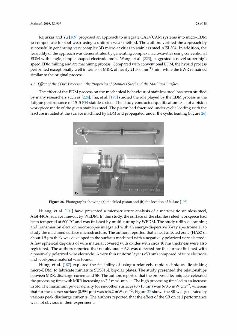
Materials 2019, 12, 907 28 of 48
Rajurkar and Yu [169] proposed an approach to integrate CAD/CAM systems into micro-EDMto compensate for tool wear using a uniform wear method. The authors verified the approach bysuccessfully generating very complex 3D micro-cavities in stainless steel AISI 304. In addition, thefeasibility of the approach was demonstrated by generating complex macro-cavities using conventionalEDM with single, simple-shaped electrode tools. Wang, et al. [223], suggested a novel super highspeed EDM milling and arc machining process. Compared with conventional EDM, the hybrid processperformed exceptionally well in terms of MRR, of nearly 21,500 mm3/min. while the EWR remainedsimilar to the original process.
4.5. Effect of the EDM Process on the Properties of Stainless Steel and the Machined Surface
The effect of the EDM process on the mechanical behaviour of stainless steel has been studiedby many researchers such as [224]. Jha, et al. [195] studied the role played by the EDM process in thefatigue performance of 15–5 PH stainless steel. The study conducted qualification tests of a pistonworkpiece made of the given stainless steel. The piston had fractured under cyclic loading with thefracture initiated at the surface machined by EDM and propagated under the cyclic loading (Figure 26).
Materials 2019, 12, x FOR PEER REVIEW 29 of 49
Rajurkar and Yu [169] proposed an approach to integrate CAD/CAM systems into micro-EDM
to compensate for tool wear using a uniform wear method. The authors verified the approach by
successfully generating very complex 3D micro-cavities in stainless steel AISI 304. In addition, the
feasibility of the approach was demonstrated by generating complex macro-cavities using
conventional EDM with single, simple-shaped electrode tools. Wang, et al. [223], suggested a novel
super high speed EDM milling and arc machining process. Compared with conventional EDM, the
hybrid process performed exceptionally well in terms of MRR, of nearly 21,500 mm3/min. while the
EWR remained similar to the original process.
4.5. Effect of the EDM Process on the Properties of Stainless Steel and the Machined Surface
The effect of the EDM process on the mechanical behaviour of stainless steel has been studied
by many researchers such as [224]. Jha, et al. [195] studied the role played by the EDM process in the
fatigue performance of 15–5 PH stainless steel. The study conducted qualification tests of a piston
workpiece made of the given stainless steel. The piston had fractured under cyclic loading with the
fracture initiated at the surface machined by EDM and propagated under the cyclic loading (Figure
26).
Figure 26. Photographs showing (a) the failed piston and (b) the location of failure [195].
Huang, et al. [191] have presented a microstructure analysis of a martensitic stainless steel, AISI
440A, surface fine-cut by WEDM. In this study, the surface of the stainless steel workpiece had been
tempered at 600 °C and was finished by multi-cutting by WEDM. The study utilized scanning and
transmission electron microscopes integrated with an energy-dispersive X-ray spectrometer to study
the machined surface microstructure. The authors reported that a heat-affected zone (HAZ) of about
1.5 µm thick was developed in the surfaces machined with a negatively polarized wire electrode. A
few spherical deposits of wire material covered with oxides with circa 10 nm thickness were also
registered. The authors reported that no obvious HAZ was detected for the surface finished with a
positively polarized wire electrode. A very thin uniform layer (<50 nm) composed of wire electrode
and workpiece material was found.
Hung, et al. [187] explored the feasibility of using a relatively rapid technique, die-sinking micro-
EDM, to fabricate miniature SUS316L bipolar plates. The study presented the relationships between
MRR, discharge current and SR. The authors reported that the proposed technique accelerated the
processing time with MRR increasing to 7.2 mm3min−1. The high processing time led to an increase in
SR. The maximum power density for smoother surfaces (0.715 µm) was 673.5 mWcm−2, whereas that
for the coarser surface (0.994 µm) was 646.2 mWcm−2. Figure 27 shows the SR was generated by
various peak discharge currents. The authors reported that the effect of the SR on cell performance
was not obvious in their experiment.
Figure 26. Photographs showing (a) the failed piston and (b) the location of failure [195].
Huang, et al. [191] have presented a microstructure analysis of a martensitic stainless steel,AISI 440A, surface fine-cut by WEDM. In this study, the surface of the stainless steel workpiece hadbeen tempered at 600 ◦C and was finished by multi-cutting by WEDM. The study utilized scanningand transmission electron microscopes integrated with an energy-dispersive X-ray spectrometer tostudy the machined surface microstructure. The authors reported that a heat-affected zone (HAZ) ofabout 1.5 µm thick was developed in the surfaces machined with a negatively polarized wire electrode.A few spherical deposits of wire material covered with oxides with circa 10 nm thickness were alsoregistered. The authors reported that no obvious HAZ was detected for the surface finished witha positively polarized wire electrode. A very thin uniform layer (<50 nm) composed of wire electrodeand workpiece material was found.
Hung, et al. [187] explored the feasibility of using a relatively rapid technique, die-sinkingmicro-EDM, to fabricate miniature SUS316L bipolar plates. The study presented the relationshipsbetween MRR, discharge current and SR. The authors reported that the proposed technique acceleratedthe processing time with MRR increasing to 7.2 mm3·min−1. The high processing time led to an increasein SR. The maximum power density for smoother surfaces (0.715 µm) was 673.5 mW·cm−2, whereasthat for the coarser surface (0.994 µm) was 646.2 mW·cm−2. Figure 27 shows the SR was generated byvarious peak discharge currents. The authors reported that the effect of the SR on cell performancewas not obvious in their experiment.
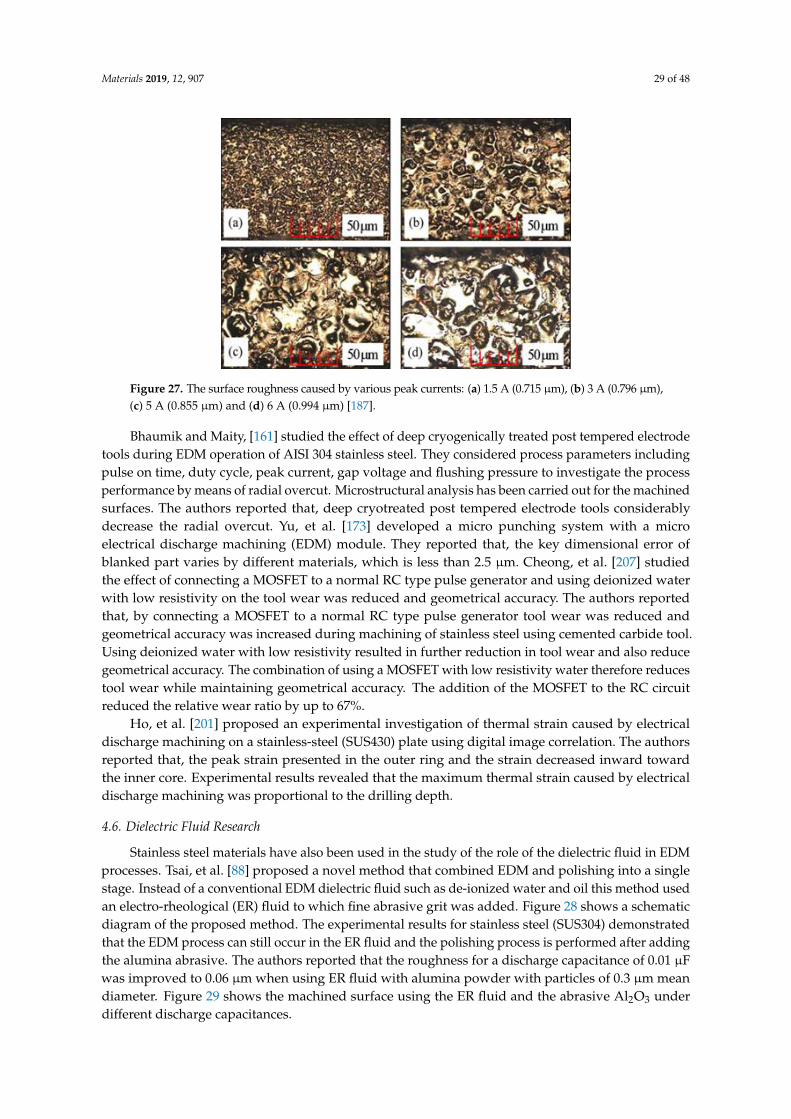
Materials 2019, 12, 907 29 of 48
Materials 2019, 12, x FOR PEER REVIEW 30 of 49
Figure 27. The surface roughness caused by various peak currents: (a) 1.5 A (0.715 µm), (b) 3 A (0.796
µm), (c) 5 A (0.855 µm) and (d) 6 A (0.994 µm) [187].
Bhaumik and Maity, [161] studied the effect of deep cryogenically treated post tempered
electrode tools during EDM operation of AISI 304 stainless steel. They considered process parameters
including pulse on time, duty cycle, peak current, gap voltage and flushing pressure to investigate
the process performance by means of radial overcut. Microstructural analysis has been carried out
for the machined surfaces. The authors reported that, deep cryotreated post tempered electrode tools
considerably decrease the radial overcut. Yu, et al. [173] developed a micro punching system with a
micro electrical discharge machining (EDM) module. They reported that, the key dimensional error
of blanked part varies by different materials, which is less than 2.5 μm. Cheong, et al. [207] studied
the effect of connecting a MOSFET to a normal RC type pulse generator and using deionized water
with low resistivity on the tool wear was reduced and geometrical accuracy. The authors reported
that, by connecting a MOSFET to a normal RC type pulse generator tool wear was reduced and
geometrical accuracy was increased during machining of stainless steel using cemented carbide tool.
Using deionized water with low resistivity resulted in further reduction in tool wear and also reduce
geometrical accuracy. The combination of using a MOSFET with low resistivity water therefore
reduces tool wear while maintaining geometrical accuracy. The addition of the MOSFET to the RC
circuit reduced the relative wear ratio by up to 67%.
Ho, et al. [201] proposed an experimental investigation of thermal strain caused by electrical
discharge machining on a stainless-steel (SUS430) plate using digital image correlation. The authors
reported that, the peak strain presented in the outer ring and the strain decreased inward toward the
inner core. Experimental results revealed that the maximum thermal strain caused by electrical
discharge machining was proportional to the drilling depth.
4.6. Dielectric Fluid Research
Stainless steel materials have also been used in the study of the role of the dielectric fluid in EDM
processes. Tsai, et al. [88] proposed a novel method that combined EDM and polishing into a single
stage. Instead of a conventional EDM dielectric fluid such as de-ionized water and oil this method
used an electro-rheological (ER) fluid to which fine abrasive grit was added. Figure 28 shows a
schematic diagram of the proposed method. The experimental results for stainless steel (SUS304)
demonstrated that the EDM process can still occur in the ER fluid and the polishing process is
performed after adding the alumina abrasive. The authors reported that the roughness for a discharge
capacitance of 0.01 µF was improved to 0.06 µm when using ER fluid with alumina powder with
particles of 0.3 µm mean diameter. Figure 29 shows the machined surface using the ER fluid and the
abrasive Al2O3 under different discharge capacitances.
Figure 27. The surface roughness caused by various peak currents: (a) 1.5 A (0.715 µm), (b) 3 A (0.796 µm),(c) 5 A (0.855 µm) and (d) 6 A (0.994 µm) [187].
Bhaumik and Maity, [161] studied the effect of deep cryogenically treated post tempered electrodetools during EDM operation of AISI 304 stainless steel. They considered process parameters includingpulse on time, duty cycle, peak current, gap voltage and flushing pressure to investigate the processperformance by means of radial overcut. Microstructural analysis has been carried out for the machinedsurfaces. The authors reported that, deep cryotreated post tempered electrode tools considerablydecrease the radial overcut. Yu, et al. [173] developed a micro punching system with a microelectrical discharge machining (EDM) module. They reported that, the key dimensional error ofblanked part varies by different materials, which is less than 2.5 µm. Cheong, et al. [207] studiedthe effect of connecting a MOSFET to a normal RC type pulse generator and using deionized waterwith low resistivity on the tool wear was reduced and geometrical accuracy. The authors reportedthat, by connecting a MOSFET to a normal RC type pulse generator tool wear was reduced andgeometrical accuracy was increased during machining of stainless steel using cemented carbide tool.Using deionized water with low resistivity resulted in further reduction in tool wear and also reducegeometrical accuracy. The combination of using a MOSFET with low resistivity water therefore reducestool wear while maintaining geometrical accuracy. The addition of the MOSFET to the RC circuitreduced the relative wear ratio by up to 67%.
Ho, et al. [201] proposed an experimental investigation of thermal strain caused by electricaldischarge machining on a stainless-steel (SUS430) plate using digital image correlation. The authorsreported that, the peak strain presented in the outer ring and the strain decreased inward towardthe inner core. Experimental results revealed that the maximum thermal strain caused by electricaldischarge machining was proportional to the drilling depth.
4.6. Dielectric Fluid Research
Stainless steel materials have also been used in the study of the role of the dielectric fluid in EDMprocesses. Tsai, et al. [88] proposed a novel method that combined EDM and polishing into a singlestage. Instead of a conventional EDM dielectric fluid such as de-ionized water and oil this method usedan electro-rheological (ER) fluid to which fine abrasive grit was added. Figure 28 shows a schematicdiagram of the proposed method. The experimental results for stainless steel (SUS304) demonstratedthat the EDM process can still occur in the ER fluid and the polishing process is performed after addingthe alumina abrasive. The authors reported that the roughness for a discharge capacitance of 0.01 µFwas improved to 0.06 µm when using ER fluid with alumina powder with particles of 0.3 µm meandiameter. Figure 29 shows the machined surface using the ER fluid and the abrasive Al2O3 underdifferent discharge capacitances.
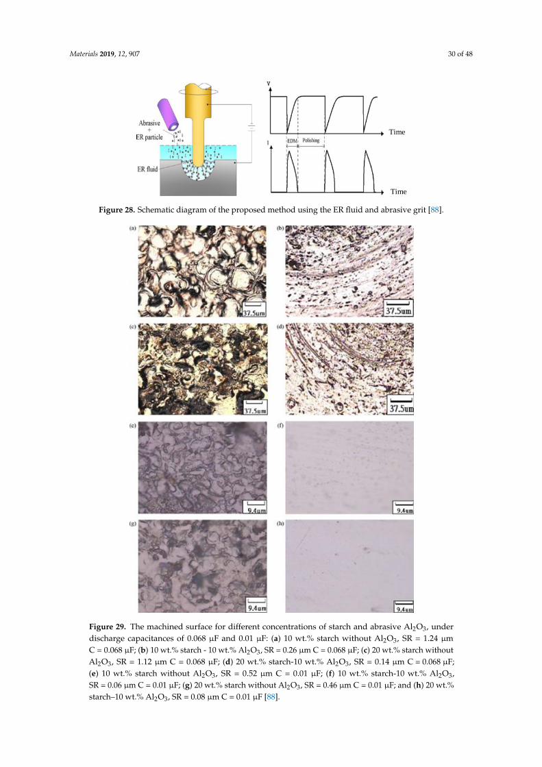
Materials 2019, 12, 907 30 of 48
Materials 2019, 12, x FOR PEER REVIEW 31 of 49
Figure 28. Schematic diagram of the proposed method using the ER fluid and abrasive grit [88].
Figure 29. The machined surface for different concentrations of starch and abrasive Al2O3, under
discharge capacitances of 0.068 µF and 0.01 µF: (a) 10 wt.% starch without Al2O3, SR = 1.24 µm C =
0.068 µF; (b) 10 wt.% starch - 10 wt.% Al2O3, SR = 0.26 µm C = 0.068 µF; (c) 20 wt.% starch without
Al2O3, SR = 1.12 µm C = 0.068 µF; (d) 20 wt.% starch-10 wt.% Al2O3, SR = 0.14 µm C = 0.068 µF; (e) 10
wt.% starch without Al2O3, SR = 0.52 µm C = 0.01 µF; (f) 10 wt.% starch-10 wt.% Al2O3, SR = 0.06 µm C =
0.01 µF; (g) 20 wt.% starch without Al2O3, SR = 0.46 µm C = 0.01 µF; and (h) 20 wt.% starch–10 wt.%
Al2O3, SR = 0.08 µm C = 0.01 µF [88].
Time
Time
Figure 28. Schematic diagram of the proposed method using the ER fluid and abrasive grit [88].
Materials 2019, 12, x FOR PEER REVIEW 31 of 49
Figure 28. Schematic diagram of the proposed method using the ER fluid and abrasive grit [88].
Figure 29. The machined surface for different concentrations of starch and abrasive Al2O3, under
discharge capacitances of 0.068 µF and 0.01 µF: (a) 10 wt.% starch without Al2O3, SR = 1.24 µm C =
0.068 µF; (b) 10 wt.% starch - 10 wt.% Al2O3, SR = 0.26 µm C = 0.068 µF; (c) 20 wt.% starch without
Al2O3, SR = 1.12 µm C = 0.068 µF; (d) 20 wt.% starch-10 wt.% Al2O3, SR = 0.14 µm C = 0.068 µF; (e) 10
wt.% starch without Al2O3, SR = 0.52 µm C = 0.01 µF; (f) 10 wt.% starch-10 wt.% Al2O3, SR = 0.06 µm C =
0.01 µF; (g) 20 wt.% starch without Al2O3, SR = 0.46 µm C = 0.01 µF; and (h) 20 wt.% starch–10 wt.%
Al2O3, SR = 0.08 µm C = 0.01 µF [88].
Time
Time
Figure 29. The machined surface for different concentrations of starch and abrasive Al2O3, underdischarge capacitances of 0.068 µF and 0.01 µF: (a) 10 wt.% starch without Al2O3, SR = 1.24 µmC = 0.068 µF; (b) 10 wt.% starch - 10 wt.% Al2O3, SR = 0.26 µm C = 0.068 µF; (c) 20 wt.% starch withoutAl2O3, SR = 1.12 µm C = 0.068 µF; (d) 20 wt.% starch-10 wt.% Al2O3, SR = 0.14 µm C = 0.068 µF;(e) 10 wt.% starch without Al2O3, SR = 0.52 µm C = 0.01 µF; (f) 10 wt.% starch-10 wt.% Al2O3,SR = 0.06 µm C = 0.01 µF; (g) 20 wt.% starch without Al2O3, SR = 0.46 µm C = 0.01 µF; and (h) 20 wt.%starch–10 wt.% Al2O3, SR = 0.08 µm C = 0.01 µF [88].
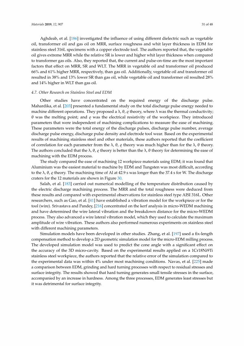
Materials 2019, 12, 907 31 of 48
Aghdeab, et al. [186] investigated the influence of using different dielectric such as vegetableoil, transformer oil and gas oil on MRR, surface roughness and whit layer thickness in EDM forstainless steel 316L specimens with a copper electrode tool. The authors reported that, the vegetableoil gives extreme MRR while the relative SR is lower and higher whit layer thickness when comparedto transformer gas oils. Also, they reported that, the current and pulse-on-time are the most importantfactors that effect on MRR, SR and WLT. The MRR in vegetable oil and transformer oil produced66% and 61% higher MRR, respectively, than gas oil. Additionally, vegetable oil and transformer oilresulted in 38% and 13% lower SR than gas oil, while vegetable oil and transformer oil resulted 28%and 14% higher in WLT than gas oil.
4.7. Other Research on Stainless Steel and EDM
Other studies have concentrated on the required energy of the discharge pulse.Mahardika, et al. [203] presented a fundamental study on the total discharge pulse energy needed tomachine different operations. They proposed a λ, θ, $ theory, where λ was the thermal conductivity;θ was the melting point; and $ was the electrical resistivity of the workpiece. They introducedparameters that were independent of machining complications to measure the ease of machining.These parameters were the total energy of the discharge pulses, discharge pulse number, averagedischarge pulse energy, discharge pulse density and electrode tool wear. Based on the experimentalresults of machining stainless steel and other materials, these authors reported that the coefficientof correlation for each parameter from the λ, θ, $ theory was much higher than for the λ, θ theory.The authors concluded that the λ, θ, $ theory is better than the λ, θ theory for determining the ease ofmachining with the EDM process.
The study compared the ease of machining 12 workpiece materials using EDM; it was found thatAluminium was the easiest material to machine by EDM and Tungsten was most difficult, accordingto the λ, θ, $ theory. The machining time of Al at 42.9 s was longer than the 37.4 s for W. The dischargecraters for the 12 materials are shown in Figure 30.
Salah, et al. [183] carried out numerical modelling of the temperature distribution caused bythe electric discharge machining process. The MRR and the total roughness were deduced fromthese results and compared with experimental observations for stainless steel type AISI 316L. Otherresearchers, such as Gao, et al. [41] have established a vibration model for the workpiece or for thetool (wire). Srivastava and Pandey, [216] concentrated on the kerf analysis in micro-WEDM machiningand have determined the wire lateral vibration and the breakdown distance for the micro-WEDMprocess. They also advanced a wire lateral vibration model, which they used to calculate the maximumamplitude of wire vibration. These authors also performed numerous experiments on stainless steelwith different machining parameters.
Simulation models have been developed in other studies. Zhang, et al. [197] used a fix-lengthcompensation method to develop a 2D geometric simulation model for the micro-EDM milling process.The developed simulation model was used to predict the cone angle with a significant effect onthe accuracy of the 3D micro-cavity. Based on the experimental results applied on a 1Cr18Ni9Tistainless steel workpiece, the authors reported that the relative error of the simulation compared tothe experimental data was within 4% under most machining conditions. Navas, et al. [225] madea comparison between EDM, grinding and hard turning processes with respect to residual stresses andsurface integrity. The results showed that hard turning generates small tensile stresses in the surface,accompanied by an increase in hardness. Among the three processes, EDM generates least stresses butit was detrimental for surface integrity.

Materials 2019, 12, 907 32 of 48
Materials 2019, 12, x FOR PEER REVIEW 33 of 49
Figure 30. SEM images of the discharge craters for different workpiece materials: (a) aluminium (Al),
(b) silver (Ag), (c) brass (Br), (d) copper (Cu), (e) nickel (Ni), (f) steel (Fe), (g) platinum (Pt), (h)
titanium (Ti), (i) stainless steel, (j) tantalum (Ta), (k) molybdenum (Mo) and (l) tungsten (W) [203].
Figure 30. SEM images of the discharge craters for different workpiece materials: (a) aluminium (Al),(b) silver (Ag), (c) brass (Br), (d) copper (Cu), (e) nickel (Ni), (f) steel (Fe), (g) platinum (Pt), (h) titanium(Ti), (i) stainless steel, (j) tantalum (Ta), (k) molybdenum (Mo) and (l) tungsten (W) [203].
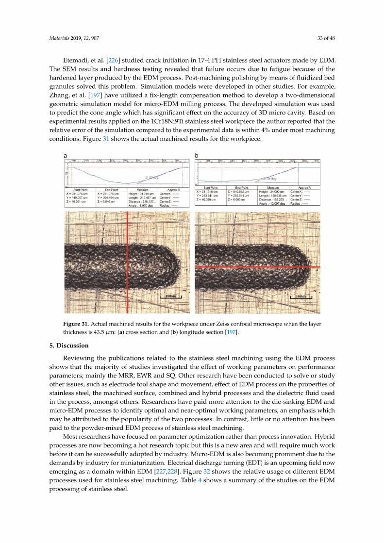
Materials 2019, 12, 907 33 of 48
Etemadi, et al. [226] studied crack initiation in 17-4 PH stainless steel actuators made by EDM.The SEM results and hardness testing revealed that failure occurs due to fatigue because of thehardened layer produced by the EDM process. Post-machining polishing by means of fluidized bedgranules solved this problem. Simulation models were developed in other studies. For example,Zhang, et al. [197] have utilized a fix-length compensation method to develop a two-dimensionalgeometric simulation model for micro-EDM milling process. The developed simulation was usedto predict the cone angle which has significant effect on the accuracy of 3D micro cavity. Based onexperimental results applied on the 1Cr18Ni9Ti stainless steel workpiece the author reported that therelative error of the simulation compared to the experimental data is within 4% under most machiningconditions. Figure 31 shows the actual machined results for the workpiece.
Materials 2019, 12, x FOR PEER REVIEW 34 of 49
Simulation models have been developed in other studies. Zhang, et al. [197] used a fix-length
compensation method to develop a 2D geometric simulation model for the micro-EDM milling
process. The developed simulation model was used to predict the cone angle with a significant effect
on the accuracy of the 3D micro-cavity. Based on the experimental results applied on a 1Cr18Ni9Ti
stainless steel workpiece, the authors reported that the relative error of the simulation compared to
the experimental data was within 4% under most machining conditions. Navas, et al. [225] made a
comparison between EDM, grinding and hard turning processes with respect to residual stresses and
surface integrity. The results showed that hard turning generates small tensile stresses in the surface,
accompanied by an increase in hardness. Among the three processes, EDM generates least stresses
but it was detrimental for surface integrity.
Etemadi, et al. [226] studied crack initiation in 17-4 PH stainless steel actuators made by EDM.
The SEM results and hardness testing revealed that failure occurs due to fatigue because of the
hardened layer produced by the EDM process. Post-machining polishing by means of fluidized bed
granules solved this problem. Simulation models were developed in other studies. For example,
Zhang, et al. [197] have utilized a fix-length compensation method to develop a two-dimensional
geometric simulation model for micro-EDM milling process. The developed simulation was used to
predict the cone angle which has significant effect on the accuracy of 3D micro cavity. Based on
experimental results applied on the 1Cr18Ni9Ti stainless steel workpiece the author reported that the
relative error of the simulation compared to the experimental data is within 4% under most
machining conditions. Figure 31 shows the actual machined results for the workpiece.
Figure 31. Actual machined results for the workpiece under Zeiss confocal microscope when the layer
thickness is 43.5 μm: (a) cross section and (b) longitude section [197].
5. Discussion
Reviewing the publications related to the stainless steel machining using the EDM process
shows that the majority of studies investigated the effect of working parameters on performance
parameters; mainly the MRR, EWR and SQ. Other research have been conducted to solve or study
other issues, such as electrode tool shape and movement, effect of EDM process on the properties of
stainless steel, the machined surface, combined and hybrid processes and the dielectric fluid used in
the process, amongst others. Researchers have paid more attention to the die-sinking EDM and
micro-EDM processes to identify optimal and near-optimal working parameters, an emphasis which
Figure 31. Actual machined results for the workpiece under Zeiss confocal microscope when the layerthickness is 43.5 µm: (a) cross section and (b) longitude section [197].
5. Discussion
Reviewing the publications related to the stainless steel machining using the EDM processshows that the majority of studies investigated the effect of working parameters on performanceparameters; mainly the MRR, EWR and SQ. Other research have been conducted to solve or studyother issues, such as electrode tool shape and movement, effect of EDM process on the properties ofstainless steel, the machined surface, combined and hybrid processes and the dielectric fluid usedin the process, amongst others. Researchers have paid more attention to the die-sinking EDM andmicro-EDM processes to identify optimal and near-optimal working parameters, an emphasis whichmay be attributed to the popularity of the two processes. In contrast, little or no attention has beenpaid to the powder-mixed EDM process of stainless steel machining.
Most researchers have focused on parameter optimization rather than process innovation. Hybridprocesses are now becoming a hot research topic but this is a new area and will require much workbefore it can be successfully adopted by industry. Micro-EDM is also becoming prominent due to thedemands by industry for miniaturization. Electrical discharge turning (EDT) is an upcoming field nowemerging as a domain within EDM [227,228]. Figure 32 shows the relative usage of different EDMprocesses used for stainless steel machining. Table 4 shows a summary of the studies on the EDMprocessing of stainless steel.

Materials 2019, 12, 907 34 of 48
Materials 2019, 12, x FOR PEER REVIEW 35 of 49
may be attributed to the popularity of the two processes. In contrast, little or no attention has been
paid to the powder-mixed EDM process of stainless steel machining.
Most researchers have focused on parameter optimization rather than process innovation.
Hybrid processes are now becoming a hot research topic but this is a new area and will require much
work before it can be successfully adopted by industry. Micro-EDM is also becoming prominent due
to the demands by industry for miniaturization. Electrical discharge turning (EDT) is an upcoming
field now emerging as a domain within EDM [227,228]. Figure 32 shows the relative usage of different
EDM processes used for stainless steel machining. Table 4 shows a summary of the studies on the
EDM processing of stainless steel.
Figure 32. Relative usage of the different EDM processes utilized for studying stainless steel
machining.
Table 4. Summary of the studies on the EDM processing of stainless steel.
No Authors
(Ref) Process Workpiece Material Objective Function
1 [197] Micro-wire
EDM 1Cr18Ni9Ti
Predicting the cone angle and its effect on the accuracy of
the 3D micro-cavity
2 [48] Dry EDM AISI 304 Influence of the working parameters on the performance
parameters
3 [193] Wire EDM Stavax (modified AISI
420)
Influence of the working parameters on the performance
parameters
4 [188] Die-sinking
EDM AISI 202
Surface quality and performance measures in EDM of
stainless steel
5 [159] Die-sinking
EDM Stainless steel #304
Proposing a strip electrode and guide system to
overcome the electrode tool wear problem during the
EDM process
6 [166] Die-sinking
EDM Stainless steel #304
Proposing strip-EDM in the EDM-turning process to
overcome the tool electrode tool wear problem. The
paper also studies the influence of the working
parameters on the performance parameters
7 [177] Dry EDM Stainless steel #304 Influence of the working parameters on the performance
parameters
8 [205] Micro-EDM Stainless steel plate Studied the surface quality of micro-holes
9 [167] Micro-EDM Stainless steel #304 Layer machining
10 [175] Dry EDM Stainless steel #304 Influence of the working parameters on the performance
parameters
11 [171] Micro-ECM Stainless steel #304 Investigated micro-EDM and micro-ECM for combined
milling of a 3D micro-structure
12 [202] Die-sinking
EDM Stainless steel
Developed a pulse generator capable of shutting off
harmful pulses
10%
10%
35%
45%
Dry EDM Wire EDM Micro EDM Die-sinking EDM
Figure 32. Relative usage of the different EDM processes utilized for studying stainless steel machining.
Table 4. Summary of the studies on the EDM processing of stainless steel.
No Authors(Ref) Process Workpiece Material Objective Function
1 [197] Micro-wire EDM 1Cr18Ni9Ti Predicting the cone angle and its effect on theaccuracy of the 3D micro-cavity
2 [48] Dry EDM AISI 304 Influence of the working parameters on theperformance parameters
3 [193] Wire EDM Stavax(modified AISI 420)
Influence of the working parameters on theperformance parameters
4 [188] Die-sinking EDM AISI 202 Surface quality and performance measures in EDMof stainless steel
5 [159] Die-sinking EDM Stainless steel #304Proposing a strip electrode and guide system toovercome the electrode tool wear problem duringthe EDM process
6 [166] Die-sinking EDM Stainless steel #304
Proposing strip-EDM in the EDM-turning process toovercome the tool electrode tool wear problem.The paper also studies the influence of the workingparameters on the performance parameters
7 [177] Dry EDM Stainless steel #304 Influence of the working parameters on theperformance parameters
8 [205] Micro-EDM Stainless steel plate Studied the surface quality of micro-holes
9 [167] Micro-EDM Stainless steel #304 Layer machining
10 [175] Dry EDM Stainless steel #304 Influence of the working parameters on theperformance parameters
11 [171] Micro-ECM Stainless steel #304 Investigated micro-EDM and micro-ECM forcombined milling of a 3D micro-structure
12 [202] Die-sinking EDM Stainless steel Developed a pulse generator capable of shutting offharmful pulses
13 [56] Die-sinking EDM AISI 202 Influence of the working parameters on theperformance parameters
14 [176] Dry EDM Stainless steel #304 Influence of the working parameters on theperformance parameters
15 [160] Die-sinking EDM Stainless steel #304 Influence of the working parameters on theperformance parameters
16 [157] Die-sinking EDM Stainless steel #304 Influence of the working parameters on theperformance parameters
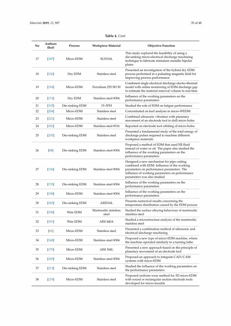
Materials 2019, 12, 907 35 of 48
Table 4. Cont.
No Authors(Ref) Process Workpiece Material Objective Function
17 [187] Micro-EDM SUS316L
This study explored the feasibility of using adie-sinking micro-electrical discharge machiningtechnique to fabricate miniature metallic bipolarplates
18 [136] Dry EDM Stainless steelPresented an investigation of the hybrid dry EDMprocess performed in a pulsating magnetic field forimproving process performance
19 [194] Micro-EDM Ferralium 255 SD 50Combined single electrical discharge electro-thermalmodel with online monitoring of EDM discharge gapto estimate the material removal volume in real time
20 [174] Dry EDM Stainless steel #304 Influence of the working parameters on theperformance parameters
21 [195] Die-sinking EDM 15–5PH Studied the role of EDM on fatigue performance
22 [204] Micro-EDM Stainless steel Concentrated on kerf analysis in micro-WEDM
23 [221] Micro-EDM Stainless steel Combined ultrasonic vibration with planetarymovement of an electrode tool to drill micro holes
24 [182] Micro-EDM Stainless steel #316 Reported on electrode tool orbiting of micro-holes
25 [203] Die-sinking EDM Stainless steelPresented a fundamental study of the total energy ofdischarge pulses required to machine differentworkpiece materials
26 [88] Die-sinking EDM Stainless steel #304
Proposed a method of EDM that used ER fluidinstead of water or oil. The paper also studied theinfluence of the working parameters on theperformance parameters
27 [156] Die-sinking EDM Stainless steel #304
Designed a new mechanism for pipe cuttingcombined with EDM. Influence of the workingparameters on performance parameters. Theinfluence of working parameters on performanceparameters was also studied
28 [170] Die-sinking EDM Stainless steel #304 Influence of the working parameters on theperformance parameters
29 [158] Micro-EDM Stainless steel #304 Influence of the working parameters on theperformance parameters
30 [183] Die-sinking EDM AISI316L Presents numerical results concerning thetemperature distribution caused by the EDM process
31 [108] Wire EDM Martensitic stainlesssteel
Studied the surface alloying behaviour of martensiticstainless steel
32 [191] Wire EDM AISI 440A Studied a microstructure analysis of the martensiticstainless steel
33 [41] Micro-EDM Stainless steel Presented a combination method of ultrasonic andelectrical-discharge machining
34 [168] Micro-EDM Stainless steel #304 Proposed a new type of micro-EDM machine, wherethe machine operated similarly to a turning lathe
35 [179] Micro EDM AISI 304L Presented a new approach based on the principle ofplanetary movement of an electrode tool
36 [169] Micro-EDM Stainless steel #304 Proposed an approach to integrate CAD/CAMsystems with micro-EDM
37 [213] Die-sinking EDM Stainless steel Studied the influence of the working parameters onthe performance parameters
38 [219] Micro-EDM Stainless steelProposed uniform wear method for 3D micro-EDMwith round or rectangular section electrode toolsdeveloped for micro-moulds
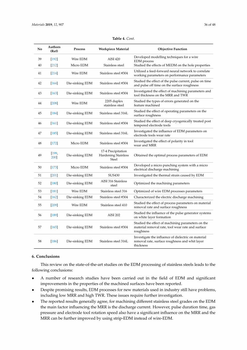
Materials 2019, 12, 907 36 of 48
Table 4. Cont.
No Authors(Ref) Process Workpiece Material Objective Function
39 [192] Wire EDM AISI 420 Developed modelling techniques for a wireEDM process
40 [212] Micro EDM Stainless steel Studied the effects of MEDM on the hole properties
41 [214] Wire EDM Stainless steel #304 Utilized a feed-forward neural network to correlateworking parameters on performance parameters
42 [164] Die-sinking EDM Stainless steel #304 Studied the effect of the pulse current, pulse on timeand pulse off time on the surface roughness
43 [163] Die-sinking EDM Stainless steel #304 Investigated the effect of machining parameters andtool thickness on the MRR and TWR
44 [208] Wire EDM 2205 duplexstainless steel
Studied the types of errors generated on thefeature machined
45 [184] Die-sinking EDM Stainless steel 316L Studied the effect of operating parameters on thesurface roughness
46 [161] Die-sinking EDM Stainless steel #304 Studied the effect of deep cryogenically treated posttempered electrode tools
47 [185] Die-sinking EDM Stainless steel 316L Investigated the influence of EDM parameters onelectrode tools wear rate
48 [172] Micro EDM Stainless steel #304 Investigated the effect of polarity in toolwear and MRR
49 [199,200] Die-sinking EDM
17-4 PrecipitationHardening Stainless
SteelObtained the optimal process parameters of EDM
50 [173] Micro EDM Stainless steel #304 Developed a micro punching system with a microelectrical discharge machining
51 [201] Die-sinking EDM SUS430 Investigated the thermal strain caused by EDM
52 [180] Die-sinking EDM AISI 316 Stainlesssteel Optimized the machining parameters
53 [181] Wire EDM Stainless steel 316 Optimized of wire EDM processes parameters
54 [162] Die-sinking EDM Stainless steel #304 Characterized the electric discharge machining
55 [209] Wire EDM Stainless steel 410 Studied the effect of process parameters on materialremoval rate and surface roughness
56 [189] Die-sinking EDM AISI 202 Studied the influence of the pulse generator systemson white layer formation
57 [165] Die-sinking EDM Stainless steel #304Studied the effect of machining parameters on thematerial removal rate, tool wear rate and surfaceroughness
58 [186] Die-sinking EDM Stainless steel 316LInvestigate the influence of dielectric on materialremoval rate, surface roughness and whit layerthickness
6. Conclusions
This review on the state-of-the-art studies on the EDM processing of stainless steels leads to thefollowing conclusions:
• A number of research studies have been carried out in the field of EDM and significantimprovements in the properties of the machined surfaces have been reported.
• Despite promising results, EDM processes for new materials used in industry still have problems,including low MRR and high TWR. These issues require further investigation.
• The reported results generally agree, for machining different stainless steel grades on the EDMthe main factor influencing the MRR is the discharge current. However, pulse duration time, gaspressure and electrode tool rotation speed also have a significant influence on the MRR and theMRR can be further improved by using strip-EDM instead of wire-EDM.
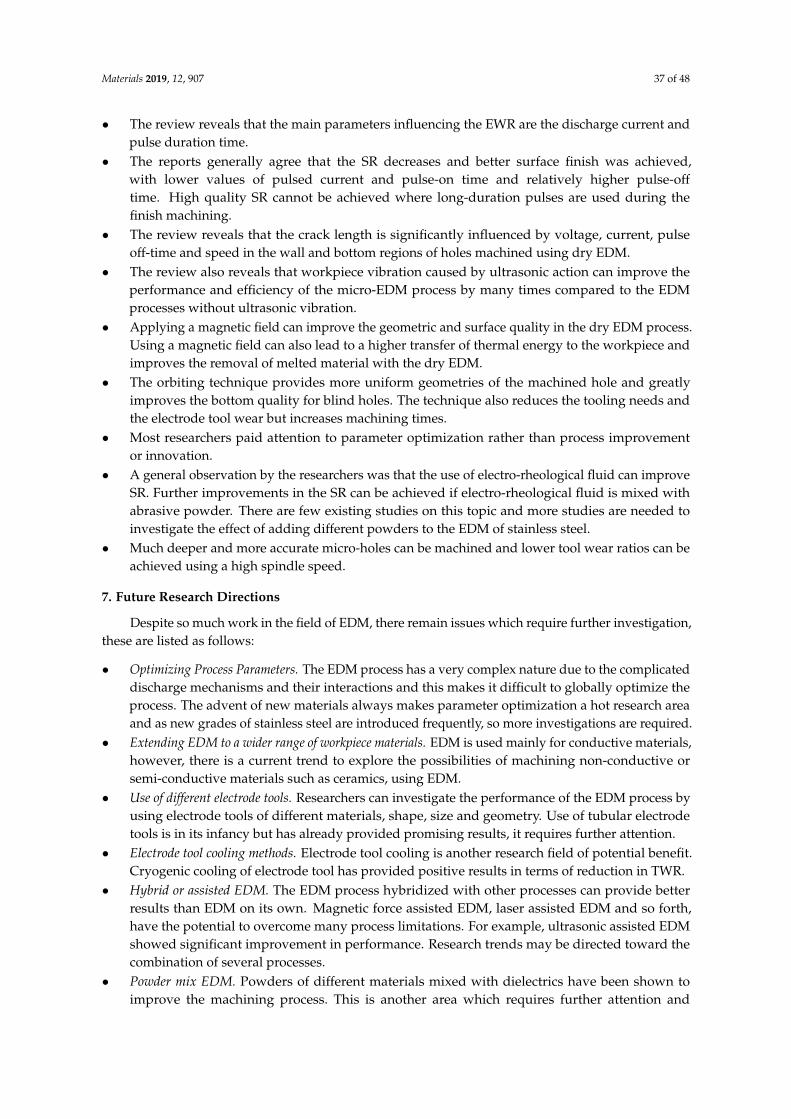
Materials 2019, 12, 907 37 of 48
• The review reveals that the main parameters influencing the EWR are the discharge current andpulse duration time.
• The reports generally agree that the SR decreases and better surface finish was achieved,with lower values of pulsed current and pulse-on time and relatively higher pulse-offtime. High quality SR cannot be achieved where long-duration pulses are used during thefinish machining.
• The review reveals that the crack length is significantly influenced by voltage, current, pulseoff-time and speed in the wall and bottom regions of holes machined using dry EDM.
• The review also reveals that workpiece vibration caused by ultrasonic action can improve theperformance and efficiency of the micro-EDM process by many times compared to the EDMprocesses without ultrasonic vibration.
• Applying a magnetic field can improve the geometric and surface quality in the dry EDM process.Using a magnetic field can also lead to a higher transfer of thermal energy to the workpiece andimproves the removal of melted material with the dry EDM.
• The orbiting technique provides more uniform geometries of the machined hole and greatlyimproves the bottom quality for blind holes. The technique also reduces the tooling needs andthe electrode tool wear but increases machining times.
• Most researchers paid attention to parameter optimization rather than process improvementor innovation.
• A general observation by the researchers was that the use of electro-rheological fluid can improveSR. Further improvements in the SR can be achieved if electro-rheological fluid is mixed withabrasive powder. There are few existing studies on this topic and more studies are needed toinvestigate the effect of adding different powders to the EDM of stainless steel.
• Much deeper and more accurate micro-holes can be machined and lower tool wear ratios can beachieved using a high spindle speed.
7. Future Research Directions
Despite so much work in the field of EDM, there remain issues which require further investigation,these are listed as follows:
• Optimizing Process Parameters. The EDM process has a very complex nature due to the complicateddischarge mechanisms and their interactions and this makes it difficult to globally optimize theprocess. The advent of new materials always makes parameter optimization a hot research areaand as new grades of stainless steel are introduced frequently, so more investigations are required.
• Extending EDM to a wider range of workpiece materials. EDM is used mainly for conductive materials,however, there is a current trend to explore the possibilities of machining non-conductive orsemi-conductive materials such as ceramics, using EDM.
• Use of different electrode tools. Researchers can investigate the performance of the EDM process byusing electrode tools of different materials, shape, size and geometry. Use of tubular electrodetools is in its infancy but has already provided promising results, it requires further attention.
• Electrode tool cooling methods. Electrode tool cooling is another research field of potential benefit.Cryogenic cooling of electrode tool has provided positive results in terms of reduction in TWR.
• Hybrid or assisted EDM. The EDM process hybridized with other processes can provide betterresults than EDM on its own. Magnetic force assisted EDM, laser assisted EDM and so forth,have the potential to overcome many process limitations. For example, ultrasonic assisted EDMshowed significant improvement in performance. Research trends may be directed toward thecombination of several processes.
• Powder mix EDM. Powders of different materials mixed with dielectrics have been shown toimprove the machining process. This is another area which requires further attention and
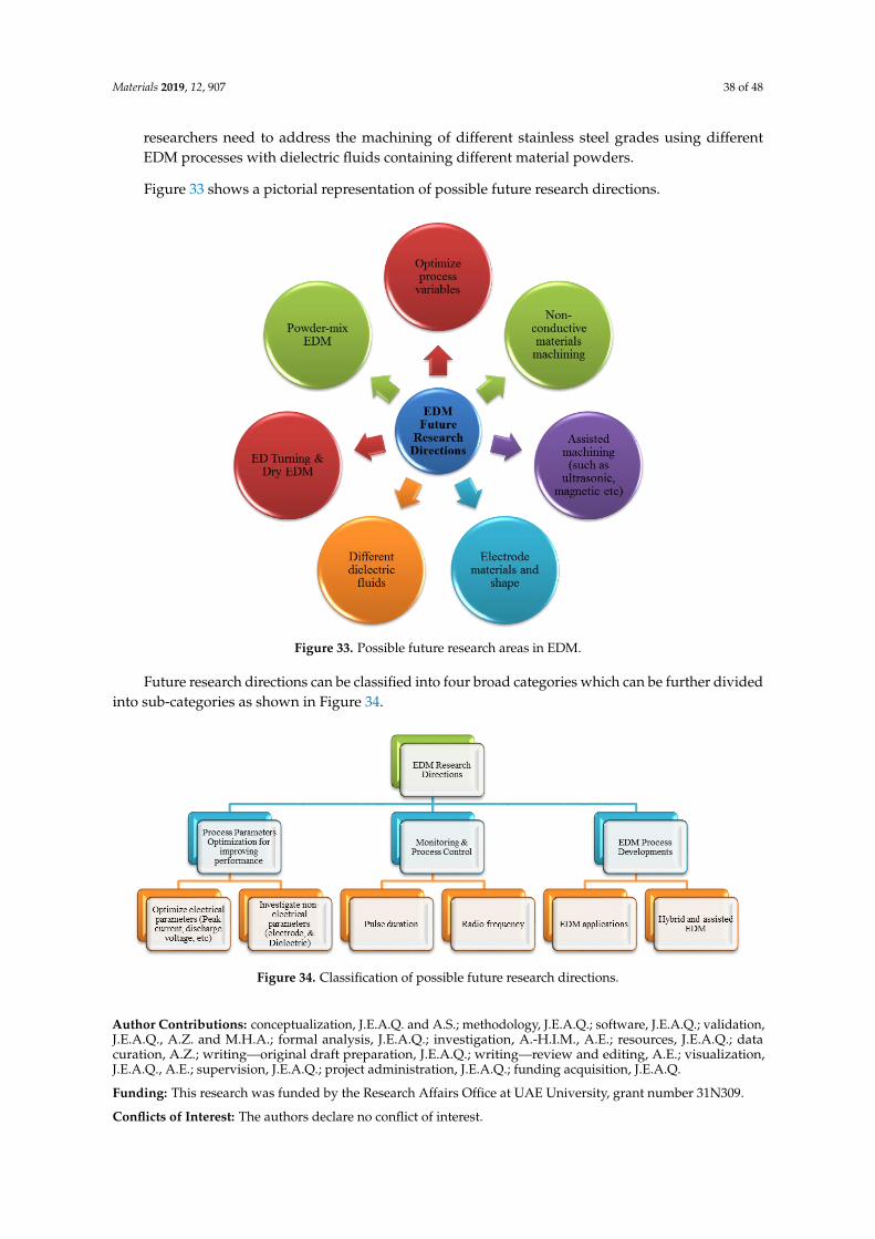
Materials 2019, 12, 907 38 of 48
researchers need to address the machining of different stainless steel grades using differentEDM processes with dielectric fluids containing different material powders.
Figure 33 shows a pictorial representation of possible future research directions.Materials 2019, 12, x FOR PEER REVIEW 39 of 49
Figure 33. Possible future research areas in EDM.
Future research directions can be classified into four broad categories which can be further
divided into sub-categories as shown in Figure 34.
Figure 34. Classification of possible future research directions.
Author Contributions: conceptualization, J.E.A.Q. and A.S.; methodology, J.E.A.Q.; software, J.E.A.Q.;
validation, J.E.A.Q., A.Z. and M.H.A.; formal analysis, J.E.A.Q.; investigation, A.-H.I.M., A.E.; resources,
J.E.A.Q.; data curation, A.Z.; writing—original draft preparation, J.E.A.Q.; writing—review and editing, A.E.;
visualization, J.E.A.Q., A.E.; supervision, J.E.A.Q.; project administration, J.E.A.Q.; funding acquisition, J.E.A.Q.
Funding: This research was funded by the Research Affairs Office at UAE University, grant number 31N309.
Conflicts of Interest: The authors declare no conflict of interest.
References
1. Pérez, J.; Llorente, J.; Sanchez, J. Advanced cutting conditions for the milling of aeronautical alloys. J. Mater.
Process. Technol. 2000, 100, 1–11.
2. Komanduri, R.; Hou, Z.-B. On thermoplastic shear instability in the machining of a titanium alloy (Ti-6Al-
4V). Metall. Mater. Trans. A 2002, 33, 2995.
Figure 33. Possible future research areas in EDM.
Future research directions can be classified into four broad categories which can be further dividedinto sub-categories as shown in Figure 34.
Materials 2019, 12, x FOR PEER REVIEW 39 of 49
Figure 33. Possible future research areas in EDM.
Future research directions can be classified into four broad categories which can be further
divided into sub-categories as shown in Figure 34.
Figure 34. Classification of possible future research directions.
Author Contributions: conceptualization, J.E.A.Q. and A.S.; methodology, J.E.A.Q.; software, J.E.A.Q.;
validation, J.E.A.Q., A.Z. and M.H.A.; formal analysis, J.E.A.Q.; investigation, A.-H.I.M., A.E.; resources,
J.E.A.Q.; data curation, A.Z.; writing—original draft preparation, J.E.A.Q.; writing—review and editing, A.E.;
visualization, J.E.A.Q., A.E.; supervision, J.E.A.Q.; project administration, J.E.A.Q.; funding acquisition, J.E.A.Q.
Funding: This research was funded by the Research Affairs Office at UAE University, grant number 31N309.
Conflicts of Interest: The authors declare no conflict of interest.
References
1. Pérez, J.; Llorente, J.; Sanchez, J. Advanced cutting conditions for the milling of aeronautical alloys. J. Mater.
Process. Technol. 2000, 100, 1–11.
2. Komanduri, R.; Hou, Z.-B. On thermoplastic shear instability in the machining of a titanium alloy (Ti-6Al-
4V). Metall. Mater. Trans. A 2002, 33, 2995.
Figure 34. Classification of possible future research directions.
Author Contributions: conceptualization, J.E.A.Q. and A.S.; methodology, J.E.A.Q.; software, J.E.A.Q.; validation,J.E.A.Q., A.Z. and M.H.A.; formal analysis, J.E.A.Q.; investigation, A.-H.I.M., A.E.; resources, J.E.A.Q.; datacuration, A.Z.; writing—original draft preparation, J.E.A.Q.; writing—review and editing, A.E.; visualization,J.E.A.Q., A.E.; supervision, J.E.A.Q.; project administration, J.E.A.Q.; funding acquisition, J.E.A.Q.
Funding: This research was funded by the Research Affairs Office at UAE University, grant number 31N309.
Conflicts of Interest: The authors declare no conflict of interest.
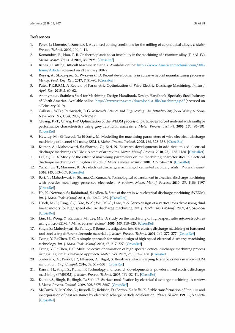
Materials 2019, 12, 907 39 of 48
References
1. Pérez, J.; Llorente, J.; Sanchez, J. Advanced cutting conditions for the milling of aeronautical alloys. J. Mater.Process. Technol. 2000, 100, 1–11.
2. Komanduri, R.; Hou, Z.-B. On thermoplastic shear instability in the machining of a titanium alloy (Ti-6Al-4V).Metall. Mater. Trans. A 2002, 33, 2995. [CrossRef]
3. Benes, J. Cutting Difficult Machine Materials. Available online: http://www.Americanmachinist.com/304/Issue/Article (accessed on 24 January 2007).
4. Ruszaj, A.; Skoczypiec, S.; Wyszynski, D. Recent developments in abrasive hybrid manufacturing processes.Manag. Prod. Eng. Rev. 2017, 8, 81–90. [CrossRef]
5. Patel, P.R.B.S.M. A Review of Parametric Optimization of Wire Electric Discharge Machining. Indian J.Appl. Res. 2015, 5, 60–62.
6. Anonymous. Stainless Steel for Machining, Design Handbook, Design Handbook, Specialty Steel Industryof North America. Available online: http://www.ssina.com/download_a_file/machining.pdf (accessed on6 February 2019).
7. Callister, W.D.; Rethwisch, D.G. Materials Science and Engineering: An Introduction; John Wiley & Sons:New York, NY, USA, 2007; Volume 7.
8. Chiang, K.-T.; Chang, F.-P. Optimization of the WEDM process of particle-reinforced material with multipleperformance characteristics using grey relational analysis. J. Mater. Process. Technol. 2006, 180, 96–101.[CrossRef]
9. Hewidy, M.; El-Taweel, T.; El-Safty, M. Modelling the machining parameters of wire electrical dischargemachining of Inconel 601 using RSM. J. Mater. Process. Technol. 2005, 169, 328–336. [CrossRef]
10. Kumar, A.; Maheshwari, S.; Sharma, C.; Beri, N. Research developments in additives mixed electricaldischarge machining (AEDM): A state of art review. Mater. Manuf. Process. 2010, 25, 1166–1180. [CrossRef]
11. Lee, S.; Li, X. Study of the effect of machining parameters on the machining characteristics in electricaldischarge machining of tungsten carbide. J. Mater. Process. Technol. 2001, 115, 344–358. [CrossRef]
12. Yu, Z.; Jun, T.; Masanori, K. Dry electrical discharge machining of cemented carbide. J. Mater. Process. Technol.2004, 149, 353–357. [CrossRef]
13. Beri, N.; Maheshwari, S.; Sharma, C.; Kumar, A. Technological advancement in electrical discharge machiningwith powder metallurgy processed electrodes: A review. Mater. Manuf. Process. 2010, 25, 1186–1197.[CrossRef]
14. Ho, K.; Newman, S.; Rahimifard, S.; Allen, R. State of the art in wire electrical discharge machining (WEDM).Int. J. Mach. Tools Manuf. 2004, 44, 1247–1259. [CrossRef]
15. Hsieh, M.-F.; Tung, C.-J.; Yao, W.-S.; Wu, M.-C.; Liao, Y.-S. Servo design of a vertical axis drive using duallinear motors for high speed electric discharge machining. Int. J. Mach. Tools Manuf. 2007, 47, 546–554.[CrossRef]
16. Lim, H.; Wong, Y.; Rahman, M.; Lee, M.E. A study on the machining of high-aspect ratio micro-structuresusing micro-EDM. J. Mater. Process. Technol. 2003, 140, 318–325. [CrossRef]
17. Singh, S.; Maheshwari, S.; Pandey, P. Some investigations into the electric discharge machining of hardenedtool steel using different electrode materials. J. Mater. Process. Technol. 2004, 149, 272–277. [CrossRef]
18. Tzeng, Y.-F.; Chen, F.-C. A simple approach for robust design of high-speed electrical-discharge machiningtechnology. Int. J. Mach. Tools Manuf. 2003, 43, 217–227. [CrossRef]
19. Tzeng, Y.-F.; Chen, F.-C. Multi-objective optimisation of high-speed electrical discharge machining processusing a Taguchi fuzzy-based approach. Mater. Des. 2007, 28, 1159–1168. [CrossRef]
20. Surleraux, A.; Pernot, JP.; Elkaseer, A.; Bigot, S. Iterative surface warping to shape craters in micro-EDMsimulation. Eng. Comput. 2016, 32, 517–531. [CrossRef]
21. Kansal, H.; Singh, S.; Kumar, P. Technology and research developments in powder mixed electric dischargemachining (PMEDM). J. Mater. Process. Technol. 2007, 184, 32–41. [CrossRef]
22. Kumar, S.; Singh, R.; Singh, T.; Sethi, B. Surface modification by electrical discharge machining: A review.J. Mater. Process. Technol. 2009, 209, 3675–3687. [CrossRef]
23. McCown, B.; McCabe, D.; Russell, D.; Robison, D.; Barton, K.; Raffa, K. Stable transformation of Populus andincorporation of pest resistance by electric discharge particle acceleration. Plant Cell Rep. 1991, 9, 590–594.[CrossRef]

Materials 2019, 12, 907 40 of 48
24. Yan, B.; Huang, F.; Chow, H.; Tsai, J. Micro-hole machining of carbide by electric discharge machining.J. Mater. Process. Technol. 1999, 87, 139–145. [CrossRef]
25. Guu, Y.; Chou, C.; Chiou, S.-T. Study of the effect of machining parameters on the machining characteristicsin electrical discharge machining of Fe-Mn-Al alloy. Mater. Manuf. Process. 2005, 20, 905–916. [CrossRef]
26. Kansal, H.; Singh, S.; Kumar, P. Numerical simulation of powder mixed electric discharge machining(PMEDM) using finite element method. Math. Comput. Model. 2008, 47, 1217–1237. [CrossRef]
27. Mahapatra, S.S.; Patnaik, A. Parametric optimization of wire electrical discharge machining (WEDM) processusing Taguchi method. J. Braz. Soc. Mech. Sci. Eng. 2006, 28, 422–429. [CrossRef]
28. Pecas, P.; Henriques, E. Influence of silicon powder-mixed dielectric on conventional electrical dischargemachining. Int. J. Mach. Tools Manuf. 2003, 43, 1465–1471. [CrossRef]
29. Saito, K.; Kishinami, T.; Konno, H.; Sato, M.; Takeyama, H. Development of numerical contouring controlelectric discharge machining (NCC-EDM). CIRP Ann. 1986, 35, 117–120. [CrossRef]
30. Sohani, M.; Gaitonde, V.; Siddeswarappa, B.; Deshpande, A. Investigations into the effect of tool shapes withsize factor consideration in sink electrical discharge machining (EDM) process. Int. J. Adv. Manuf. Technol.2009, 45, 1131. [CrossRef]
31. Haddad, M.; Tajik, M.; Tehrani, A.F.; Mohammadi, A.; Hadi, M. An experimental investigation of cylindricalwire electrical discharge turning process using Taguchi approach. Int. J. Mater. Form. 2009, 2, 167–179.[CrossRef]
32. Joshi, S.; Pande, S. Intelligent process modeling and optimization of die-sinking electric discharge machining.Appl. Soft Comput. 2011, 11, 2743–2755. [CrossRef]
33. Chakraborty, S.; Dey, V.; Ghosh, S. A review on the use of dielectric fluids and their effects in electricaldischarge machining characteristics. Precis. Eng. 2015, 40, 1–6. [CrossRef]
34. Choudhary, S.K.; Jadoun, R. Current advanced research development of electric discharge machining (EDM):A review. Int. J. Res. Advent Technol. 2014, 2, 273–297.
35. Garg, R.; Singh, K.; Sachdeva, A.; Sharma, V.S.; Ojha, K.; Singh, S. Review of research work in sinking EDMand WEDM on metal matrix composite materials. Int. J. Adv. Manuf. Technol. 2010, 50, 611–624. [CrossRef]
36. Jahan, M.; Rahman, M.; Wong, Y. A review on the conventional and micro-electrodischarge machining oftungsten carbide. Int. J. Mach. Tools Manuf. 2011, 51, 837–858. [CrossRef]
37. Muthuramalingam, T.; Mohan, B. A review on influence of electrical process parameters in EDM process.Arch. Civ. Mech. Eng. 2015, 15, 87–94. [CrossRef]
38. Rajurkar, K.P.; Sundaram, M.; Malshe, A. Review of electrochemical and electrodischarge machining.Procedia CIRP 2013, 6, 13–26. [CrossRef]
39. Abu Qudeiri, J.E.; Mourad, A.-H.I.; Ziout, A.; Abidi, M.H.; Elkaseer, A. Electric discharge machining oftitanium and its alloys. Int. J. Adv. Manuf. Technol. 2018, 96, 1319–1339. [CrossRef]
40. Dauw, D.; Snoeys, R.; Dekeyser, W. Advanced pulse discriminating system for EDM process analysis andcontrol. CIRP Ann. 1983, 32, 541–549. [CrossRef]
41. Gao, C.; Liu, Z. A study of ultrasonically aided micro-electrical-discharge machining by the application ofworkpiece vibration. J. Mater. Process. Technol. 2003, 139, 226–228. [CrossRef]
42. Gostimirovic, M.; Kovac, P.; Skoric, B.; Sekulic, M. Effect of electrical pulse parameters on the machiningperformance in EDM. Indian J. Eng. Mater. Sci. 2011, 18, 411–415.
43. Schulze, H.P. Energetic consideration of the spark erosion using different process energy sources andpulse-unit-gap conditions. Key Eng. Mater. 2015, 701–706. [CrossRef]
44. Marafona, J.; Chousal, J. A finite element model of EDM based on the Joule effect. Int. J. Mach. Tools Manuf.2006, 46, 595–602. [CrossRef]
45. Abbas, N.M.; Solomon, D.G.; Bahari, M.F. A review on current research trends in electrical dischargemachining (EDM). Int. J. Mach. Tools Manuf. 2007, 47, 1214–1228. [CrossRef]
46. Cui, J.; Chu, Z. Composite motion design procedure for vibration assisted small-hole EDM using one voicecoil motor. Shock Vib. 2016, 2016, 4179296. [CrossRef]
47. Ho, K.; Newman, S. State of the art electrical discharge machining (EDM). Int. J. Mach. Tools Manuf. 2003, 43,1287–1300. [CrossRef]
48. Shen, Y.; Liu, Y.; Zhang, Y.; Dong, H.; Sun, W.; Wang, X.; Zheng, C.; Ji, R. High-speed dry electrical dischargemachining. Int. J. Mach. Tools Manuf. 2015, 93, 19–25. [CrossRef]

Materials 2019, 12, 907 41 of 48
49. Anpilov, A.; Barkhudarov, E.; Bark, Y.B.; Zadiraka, Y.V.; Christofi, M.; Kozlov, Y.N.; Kossyi, I.; Kop’ev, V.;Silakov, V.; Taktakishvili, M. Electric discharge in water as a source of UV radiation, ozone and hydrogenperoxide. J. Phys. D Appl. Phys. 2001, 34, 993. [CrossRef]
50. Grigoryev, E.G.; Olevsky, E.A. Thermal processes during high-voltage electric discharge consolidation ofpowder materials. Scr. Mater. 2012, 66, 662–665. [CrossRef]
51. Huang, S.; Liu, Y.; Li, J.; Hu, H.; Sun, L. Electrochemical discharge machining micro-hole in stainless steelwith tool electrode high-speed rotating. Mater. Manuf. Process. 2014, 29, 634–637. [CrossRef]
52. Ikonomou, M.G.; Blades, A.T.; Kebarle, P. Electrospray mass spectrometry of methanol and water solutionssuppression of electric discharge with SF 6 gas. J. Am. Soc. Mass Spectrom. 1991, 2, 497–505. [CrossRef]
53. Singh, V.; Bhandari, R.; Yadav, V.K. An experimental investigation on machining parameters of AISI D2 steelusing WEDM. Int. J. Adv. Manuf. Technol. 2017, 93, 203–214. [CrossRef]
54. Sun, B.; Sato, M.; Clements, J.S. Use of a pulsed high-voltage discharge for removal of organic compounds inaqueous solution. J. Phys. D Appl. Phys. 1999, 32, 1908. [CrossRef]
55. Rajmohan, K.; Kumar, A.S. Experimental investigation and prediction of optimum process parameters ofmicro-wire-cut EDM of 2205 DSS. Int. J. Adv. Manuf. Technol. 2017, 93, 187–201. [CrossRef]
56. Jegan, T.C.; Anand, M.D.; Ravindran, D. Determination of electro discharge machining parameters in AISI202stainless steel using grey relational analysis. Procedia Eng. 2012, 38, 4005–4012. [CrossRef]
57. Kuppan, P.; Rajadurai, A.; Narayanan, S. Influence of EDM process parameters in deep hole drilling ofInconel 718. Int. J. Adv. Manuf. Technol. 2008, 38, 74–84. [CrossRef]
58. Lajis, M.A.; Radzi, H.; Amin, A. The implementation of Taguchi method on EDM process of tungsten carbide.Eur. J. Sci. Res. 2009, 26, 609–617.
59. Lin, Y.C.; Yan, B.H.; Chang, Y.S. Machining characteristics of titanium alloy (Ti–6Al–4V) using a combinationprocess of EDM with USM. J. Mater. Process. Technol. 2000, 104, 171–177. [CrossRef]
60. Liu, Y.; Guo, Y.; Liu, J. Electric discharge milling of polycrystalline diamond. Proc. Inst. Mech. Eng. Part B J.Eng. Manuf. 1997, 211, 643–647. [CrossRef]
61. Singh, H.; Garg, R. Effects of process parameters on material removal rate in WEDM. J. Achiev. Mater. Manuf.Eng. 2009, 32, 70–74.
62. Bhattacharyya, B.; Munda, J. Experimental investigation on the influence of electrochemical machiningparameters on machining rate and accuracy in micromachining domain. Int. J. Mach. Tools Manuf. 2003, 43,1301–1310. [CrossRef]
63. Lin, C.; Lin, J.; Ko, T. Optimisation of the EDM process based on the orthogonal array with fuzzy logic andgrey relational analysis method. Int. J. Adv. Manuf. Technol. 2002, 19, 271–277. [CrossRef]
64. Lin, J.; Wang, K.; Yan, B.; Tarng, Y. Optimization of the electrical discharge machining process based on theTaguchi method with fuzzy logics. J. Mater. Process. Technol. 2000, 102, 48–55. [CrossRef]
65. Ramakrishnan, R.; Karunamoorthy, L. Modeling and multi-response optimization of Inconel 718 onmachining of CNC WEDM process. J. Mater. Process. Technol. 2008, 207, 343–349. [CrossRef]
66. Selvakumar, G.; Jiju, K.B.; Veerajothi, R. Experimental study on wire electrical discharge machining oftapered parts. ARAB. J. Sci. Eng. 2016, 41, 4431–4439. [CrossRef]
67. Sharif, S.; Safiei, W.; Mansor, A.; Isa, M.; Saad, R. Experimental study of electrical discharge machine (diesinking) on stainless steel 316L using design of experiment. Procedia Manuf. 2015, 2, 147–152. [CrossRef]
68. Kansal, H.; Singh, S.; Kumar, P. Parametric optimization of powder mixed electrical discharge machining byresponse surface methodology. J. Mater. Process. Technol. 2005, 169, 427–436. [CrossRef]
69. Muthuramalingam, T.; Mohan, B. Influence of discharge current pulse on machinability in electrical dischargemachining. Mater. Manuf. Process. 2013, 28, 375–380. [CrossRef]
70. Pattnaik, S.; Priyadarshini, M.; Mahapatra, K.; Mishra, D.; Panda, S. Multi objective optimization of EDMprocess parameters using fuzzy TOPSIS method. In Proceedings of the 2015 International Conference onInnovations in Information, Embedded and Communication Systems (ICIIECS), Coimbatore, India, 19–20March 2015; pp. 1–5.
71. Rajurkar, K.P.; Wang, W.M. Improvement of EDM Performance With Advanced Monitoring and ControlSystems. J. Mech. Des. 1997, 119, 770. [CrossRef]
72. Fuller, J.E. Electrical discharge machining. ASM Handb. 1989, 16, 557–564.73. De Bruyn, H. Slope Control: A great improvement in spark erosion. Ann. CIRP 1967, 16, 183–191.

Materials 2019, 12, 907 42 of 48
74. Lin, Y.-C.; Chen, Y.-F.; Wang, D.-A.; Lee, H.-S. Optimization of machining parameters in magnetic forceassisted EDM based on Taguchi method. J. Mater. Process. Technol. 2009, 209, 3374–3383. [CrossRef]
75. Pandit, S.; Mueller, T. Verification of on-line computer control of EDM by data dependent systems. J. Eng. Ind.1987, 109, 117–121. [CrossRef]
76. Lingadurai, K.; Nagasivamuni, B.; Kamatchi, M.M.; Palavesam, J. Selection of wire electrical dischargemachining process parameters on stainless steel AISI grade-304 using design of experiments approach.J. Inst. Eng. (India) Ser. C 2012, 93, 163–170. [CrossRef]
77. Majumder, A. Process parameter optimization during EDM of AISI 316 LN stainless steel by using fuzzybased multi-objective PSO. J. Mech. Sci. Technol. 2013, 27, 2143–2151. [CrossRef]
78. Marafona, J.; Wykes, C. A new method of optimising material removal rate using EDM with copper–tungstenelectrodes. Int. J. Mach. Tools Manuf. 2000, 40, 153–164. [CrossRef]
79. Su, J.; Kao, J.; Tarng, Y. Optimisation of the electrical discharge machining process using a GA-based neuralnetwork. Int. J. Adv. Manuf. Technol. 2004, 24, 81–90. [CrossRef]
80. Mohan, B.; Rajadurai, A.; Satyanarayana, K. Effect of SiC and rotation of electrode on electric dischargemachining of Al–SiC composite. J. Mater. Process. Technol. 2002, 124, 297–304. [CrossRef]
81. Mohan, B.; Rajadurai, A.; Satyanarayana, K. Electric discharge machining of Al–SiC metal matrix compositesusing rotary tube electrode. J. Mater. Process. Technol. 2004, 153, 978–985. [CrossRef]
82. Wilson, C. Investigations on lightning discharges and on the electric field of thunderstorms. Mon. Weather Rev.1921, 49, 241. [CrossRef]
83. Crookall, J.; Heuvelman, C. Electro-discharge machining—The state of the art. Ann. CIRP 1971, 20, 113–120.84. Liao, Y.-S.; Chuang, T.-J.; Yu, Y.-P. Study of machining parameters optimization for different materials in
WEDM. Int. J. Adv. Manuf. Technol. 2014, 70, 2051–2058. [CrossRef]85. Jahan, M.P.; Wong, Y.S.; Rahman, M. A study on the quality micro-hole machining of tungsten carbide
by micro-EDM process using transistor and RC-type pulse generator. J. Mater. Process. Technol. 2009, 209,1706–1716. [CrossRef]
86. Natarajan, N.; Suresh, P. Experimental investigations on the microhole machining of 304 stainless steel bymicro-EDM process using RC-type pulse generator. Int. J. Adv. Manuf. Technol. 2015, 77, 1741–1750. [CrossRef]
87. Han, F.; Chen, L.; Yu, D.; Zhou, X. Basic study on pulse generator for micro-EDM. Int. J. Adv. Manuf. Technol.2007, 33, 5–6. [CrossRef]
88. Tsai, Y.; Tseng, C.; Chang, C. Development of a combined machining method using electrorheological fluidsfor EDM. J. Mater. Process. Technol. 2008, 201, 565–569. [CrossRef]
89. Valaki, J.B.; Rathod, P.P. Assessment of operational feasibility of waste vegetable oil based bio-dielectricfluid for sustainable electric discharge machining (EDM). Int. J. Adv. Manuf. Technol. 2016, 87, 1509–1518.[CrossRef]
90. Fujiki, M.; Ni, J.; Shih, A.J. Investigation of the effects of electrode orientation and fluid flow rate in near-dryEDM milling. Int. J. Mach. Tools Manuf. 2009, 49, 749–758. [CrossRef]
91. Lonardo, P.; Bruzzone, A. Effect of flushing and electrode material on die sinking EDM. CIRP Ann.-Manuf.Technol. 1999, 48, 123–126. [CrossRef]
92. Wong, Y.; Lim, L.; Lee, L. Effects of flushing on electro-discharge machined surfaces. J. Mater. Process. Technol.1995, 48, 299–305. [CrossRef]
93. Anonymous. Dielectric Fluids for Electro Dischargemachining; British Petroleum Company: London, UK, 1982.94. Guu, Y.; Hocheng, H. Effects of workpiece rotation on machinability during electrical-discharge machining.
Mater. Manuf. Process. 2001, 16, 91–101. [CrossRef]95. Soni, J.S.; Chakraverti, G. Machining characteristics of titanium with rotary electro-discharge machining.
Wear 1994, 171, 51–58. [CrossRef]96. Kagaya, K.; Oishi, Y.; Yada, K. Micro-electrodischarge machining using water as a working fluid—I:
Micro-hole drilling. Precis. Eng. 1986, 8, 157–162. [CrossRef]97. Sato, T.; Mizutani, T.; Yonemochi, K.; Kawata, K. The development of an electrodischarge machine for
micro-hole boring. Precis. Eng. 1986, 8, 163–168. [CrossRef]98. Yan, B.; Wang, C.; Liu, W.; Huang, F. Machining characteristics of Al2O3/6061Al composite using rotary
EDM with a disklike electrode. Int. J. Adv. Manuf. Technol. 2000, 16, 322–333. [CrossRef]99. Bayramoglu, M.; Duffill, A. Manufacturing linear and circular contours using CNC EDM and frame type
tools. Int. J. Mach. Tools Manuf. 1995, 35, 1125–1136. [CrossRef]

Materials 2019, 12, 907 43 of 48
100. Erden, A. Effect of materials on the mechanism of electric discharge machining (EDM). J. Eng. Mater. Technol.1983, 105, 132–138. [CrossRef]
101. KANEKO, T.; TSUCHIYA, M. Three-dimensionally controlled EDM Using a cylindrical electrode (5th report).J. Jpn. Soc. Electr. Mach. Eng. 1985, 18, 1–16.
102. Roethel, F.; Kosec, L.; Garbajs, V. Contribution to the MICRO-analysis of the Spark Eroded Surfaces.CIRP Ann. CIRP 1976, 25, 135–140.
103. Soni, J.; Chakraverti, G. Experimental investigation on migration of material during EDM of die steel(T215 Cr12). J. Mater. Process. Technol. 1996, 56, 439–451. [CrossRef]
104. Mohri, N.; Suzuki, M.; Furuya, M.; Saito, N.; Kobayashi, A. Electrode wear process in electrical dischargemachinings. CIRP Ann. 1995, 44, 165–168. [CrossRef]
105. Staelens, F.; Kruth, J.-P. A computer integrated machining strategy for planetary EDM. CIRP Ann. 1989, 38,187–190. [CrossRef]
106. Schumacher, B. EDM technology for precision workpieces with excellent surface quality. Proc. ISEM 1983, 7,124–135.
107. Wendorf, D.M.; Milos, M. Things to Consider When Wire and Small-Hole EDMing. 2009, Volume 2. Availableonline: https://www.xactedm.com/DBfiles/news-file/59.pdf (accessed on 5 February 2019).
108. Huang, C.A.; Shih, C.L.; Li, K.C.; Chang, Y.-Z. The surface alloying behavior of martensitic stainless steel cutwith wire electrical discharge machine. Appl. Surf. Sci. 2006, 252, 2915–2926. [CrossRef]
109. Bae, W.-G.; Kim, D.; Song, K.Y.; Jeong, H.E.; Chu, C.N. Engineering stainless steel surface via wire electricaldischarge machining for controlling the wettability. Surf. Coat. Technol. 2015, 275, 316–323. [CrossRef]
110. Furutani, K.; Suzuki, K. Experimental investigations of deposition conditions for saw wire fabrication byelectrical discharge machining. Int. J. Adv. Manuf. Technol. 2015, 76, 1643–1651. [CrossRef]
111. Huang, C.; Tu, G.; Yao, H.; Kuo, H. Characteristics of the rough-cut surface of quenched and temperedmartensitic stainless steel using wire electrical discharge machining. Metall. Mater. Trans. A 2004, 35,1351–1357. [CrossRef]
112. Masuzawa, T.; Fujino, M.; Kobayashi, K.; Suzuki, T.; Kinoshita, N. Wire electro-discharge grinding formicro-machining. CIRP Ann. 1985, 34, 431–434. [CrossRef]
113. Sidhom, H.; Ghanem, F.; Amadou, T.; Gonzalez, G.; Braham, C. Effect of electro discharge machining (EDM)on the AISI316L SS white layer microstructure and corrosion resistance. Int. J. Adv. Manuf. Technol. 2013, 65,141–153. [CrossRef]
114. Usta, B.K.; Gokdel, Y.; Mutlu, S.; Yalcinkaya, A. Selectively thinned stainless steel scanners throughelectrical discharge machining. In Proceedings of the 16th International Conference on Optical MEMSand Nanophotonics, Istanbul, Turkey, 8–11 August 2011; pp. 179–180.
115. Pradhan, M. Estimating the effect of process parameters on MRR, TWR and radial overcut of EDMed AISID2 tool steel by RSM and GRA coupled with PCA. Int. J. Adv. Manuf. Technol. 2013, 68, 591–605. [CrossRef]
116. Yan, M.-T.; Lai, Y.-P. Surface quality improvement of wire-EDM using a fine-finish power supply. Int. J. Mach.Tools Manuf. 2007, 47, 1686–1694. [CrossRef]
117. Yi, S.M.; Park, M.S.; Lee, Y.S.; Chu, C.N. Fabrication of a stainless steel shadow mask using batch modemicro-EDM. Microsyst. Technol. 2008, 14, 411–417. [CrossRef]
118. Jahan, M.P.; San Wong, Y.; Rahman, M. A comparative experimental investigation of deep-hole micro-EDMdrilling capability for cemented carbide (WC-Co) against austenitic stainless steel (SUS 304). Int. J. Adv.Manuf. Technol. 2010, 46, 1145–1160. [CrossRef]
119. Mahendran, S.; Devarajan, R.; Nagarajan, T.; Majdi, A. A Review of Micro-EDM. Proceeding of theInternational MultiConference of Engineers an Computer Sciences 2010 Vol II, IMECS 2010, Hong Kong,China, 17–19 March 2010.
120. Rasheed, M.S.; Abidi, M.H.; El-Tamimi, A.M.; Al-Ahmari, A. Investigation of micro-edm input parameterson various outputs in machining ni-ti shape memory alloy using full factorial design. Adv. Mater. Res. 2013,816–817, 173–179. [CrossRef]
121. Lappin, D.; Mohammadi, A.R.; Takahata, K. An experimental study of electrochemical polishing formicro-electro-discharge-machined stainless-steel stents. J. Mater. Sci. Mater. Med. 2012, 23, 349–356.[CrossRef]
122. Habib, M.A.; Rahman, M. Performance analysis of EDM electrode fabricated by localized electrochemicaldeposition for micro-machining of stainless steel. Int. J. Adv. Manuf. Technol. 2010, 49, 975–986. [CrossRef]

Materials 2019, 12, 907 44 of 48
123. Herzig, M.; Berger, T.; Schulze, H.-P.; Hackert-Oschätzchen, M.; Kröning, O.; Schubert, A. Modification ofthe process dynamics in micro-EDM by means of an additional piezo-control system. AIP Conf. Proc. 2017,1896, 050003.
124. Kuriachen, B.; Somashekhar, K.; Mathew, J. Multiresponse optimization of micro-wire electrical dischargemachining process. Int. J. Adv. Manuf. Technol. 2015, 76, 91–104. [CrossRef]
125. D’Urso, G.; Maccarini, G.; Quarto, M.; Ravasio, C. Investigation on power discharge in micro-EDM stainlesssteel drilling using different electrodes. J. Mech. Sci. Technol. 2015, 29, 4341–4349. [CrossRef]
126. D’Urso, G.; Maccarini, G.; Ravasio, C. Influence of electrode material in micro-EDM drilling of stainless steeland tungsten carbide. Int. J. Adv. Manuf. Technol. 2016, 85, 2013–2025. [CrossRef]
127. Dave, H.; Mathai, V.; Desai, K.; Raval, H. Studies on quality of microholes generated on Al 1100 usingmicro-electro-discharge machining process. Int. J. Adv. Manuf. Technol. 2015, 76, 127–140. [CrossRef]
128. Rasheed, M.S.; Al-Ahmari, A.; El-Tamimi, A.; Abidi, M.H. Analysis of influence of micro-EDM parameterson MRR, TWR and Ra in machining Ni-Ti shape memory alloy. Int. J. Recent Technol. Eng. 2012, 1, 32–37.
129. Jafferson, J.; Hariharan, P.; Kumar, J.R. Effect of non-electrical parameters in µED milling: An experimentalinvestigation. Int. J. Adv. Manuf. Technol. 2016, 85, 2037–2047. [CrossRef]
130. Liu, Q.Y.; Zhang, Q.H.; Zhang, J.H.; Zhang, M. Influence of Grain Size and Grain Boundary of Workpiece onMicro EDM. Adv. Mater. Res. 2014, 941–944, 2116–2120. [CrossRef]
131. Liu, Q.; Zhang, Q.; Zhang, M.; Zhang, J. Effects of grain size of AISI 304 on the machining performancesin micro electrical discharge machining. Proc. Inst. Mech. Eng. Part B J. Eng. Manuf. 2017, 231, 359–366.[CrossRef]
132. Elkaseer, A.; Bigot, S.; Surleraux, A.; Rosochowski, A. Effect of material microstructure on the micro-EDMprocess. In Proceedings of the the 8th International Conference on Micro Manufacturing (ICOMM2013),Victoria, BC, Canada, 25–28 March 2013; pp. 336–343.
133. Reddy, V.V.; Kumar, A.; Valli, P.M.; Reddy, C.S. Influence of surfactant and graphite powder concentrationon electrical discharge machining of PH17-4 stainless steel. J. Braz. Soc. Mech. Sci. Eng. 2015, 37, 641–655.[CrossRef]
134. Zhao, W.; Meng, Q.; Wang, Z. The application of research on powder mixed EDM in rough machining.J. Mater. Process. Technol. 2002, 129, 30–33. [CrossRef]
135. Furutania, K.; Saneto, A.; Takezawa, H.; Mohri, N.; Miyake, H. Accretion of titanium carbide by electricaldischarge machining with powder suspended in working fluid. Precis. Eng. 2001, 25, 138–144. [CrossRef]
136. Joshi, S.; Govindan, P.; Malshe, A.; Rajurkar, K. Experimental characterization of dry EDM performed ina pulsating magnetic field. CIRP Ann. 2011, 60, 239–242. [CrossRef]
137. Kunieda, M.; Aduchi, Y.; Yoshida, M. Study on process reaction force generated by discharge in EDM.Proc. Int. Conf. MMSS 2000, 313–324.
138. Kunleda, M.; Miyoshi, Y.; Takaya, T.; Nakajima, N.; ZhanBo, Y.; Yoshida, M. High speed 3D milling bydry EDM. CIRP Ann. 2003, 52, 147–150. [CrossRef]
139. Yu, Z.B.; Takahashi, J.; Nobuhiro, N.; Sadao, S.; Kunieda, M. Feasibility of 3-D Surface Machining by DryEDM. Int. J. Electr. Mach. 2005, 10, 15–20.
140. Besliu, I.; Schulze, H.-P.; Coteată, M.; Amarandei, D. Study on the dry electrical discharge machining.Int. J. Mater. Form. 2010, 3, 1107–1110. [CrossRef]
141. Singh, P.; Chaudhary, A.K.; Singh, T.; Rana, A.K. Comparison of Outputs for Dry EDM and EDM with Oil:A Review. Int. J. Res. Emerg. Sci. Technol. 2005, 2, 45–49.
142. Kunieda, M.; Yoshida, M.; Taniguchi, N. Electrical Discharge Machining in Gas. CIRP Ann. 1997, 46, 143–146.[CrossRef]
143. Zyra, A.; Bizon, W.; Skoczypiec, S. Primary research on dry electrodischarge machining with additionalworkpiece cooling. AIP Conf. Proc. 2018, 2017, 020034.
144. Narasimhan, J.; Yu, Z.; Rajurkar, K.P. Tool Wear Compensation and Path Generation in Micro and Macro EDM.Jmp J. Manuf. Process. 2005, 7, 75–82. [CrossRef]
145. Weng, F.-T.; Shyu, R.F.; Hsu, C.-S. Fabrication of micro-electrodes by multi-EDM grinding process. J. Mater.Process. Technol. 2003, 140, 332–334. [CrossRef]
146. Shahane, S.; Pande, S.S. Development of a Thermo-Physical Model for Multi-spark Wire EDM Process.Procedia Manuf. 2016, 5, 205–219. [CrossRef]
Materials 2019, 12, 907 45 of 48
147. Joshi, S.N.; Pande, S.S. Development of an intelligent process model for EDM. Int. J. Adv. Manuf. Technol.2009, 45, 3–4. [CrossRef]
148. Suthangathan Paramashivan, S.; Mathew, J.; Mahadevan, S. Mathematical modeling of aerosol emissionfrom die sinking electrical discharge machining process. Appl. Math. Model. 2012, 36, 1493–1503. [CrossRef]
149. Golabczak, A.; Konstantynowicz, A.; Golabczak, M. Mathematical Modelling of the Physical Phenomena inthe Interelectrode Gap of the EDM Process by Means of Cellular Automata and Field Distribution Equations.In Advanced Structured Materials-Experimental and Numerical Investigations of Advanced Materials and Structures;Springer: Berlin/Heidelberg, Germany, 2013.
150. Liu, Y.; Chang, H.; Zhang, W.; Ma, F.; Sha, Z.; Zhang, S. A Simulation Study of Debris Removal Process inUltrasonic Vibration Assisted Electrical Discharge Machining (EDM) of Deep Holes. Micromachines 2018, 9,378. [CrossRef]
151. Lo, K.H.; Shek, C.H.; Lai, J.K.L. Recent developments in stainless steels. MSR Mater. Sci. Eng. R 2009, 65,39–104. [CrossRef]
152. Qiu, J. Stainless Steels and Alloys: Why They Resist Corrosion and How They Fail; Corrosion Special TopicalPapers; Nanyang Technological University: Singapore, 1995.
153. Rosenwasser, S.N.; Miller, P.; Dalessandro, J.A.; Rawls, J.M.; Toffolo, W.E.; Chen, W. The application ofmartensitic stainless steels in long lifetime fusion first wall/blankets. J. Nuclear Mater. 1979, 85–86, 177–182.[CrossRef]
154. Parashar, N.; Mittal, R.K. Elements of Manufacturing Processes; Phi Learning: New Delhi, India, 2012.155. Lula, R.A. Stainless Steel; American Society for Metals: Novelty, OH, USA, 1993.156. Chen, S.L.; Lin, M.H.; Hsieh, S.F.; Chiou, S.Y. The characteristics of cutting pipe mechanism with
multi-electrodes in EDM. J. Mater. Process. Technol. 2008, 203, 461–464. [CrossRef]157. Rajmohan, T.; Prabhu, R.; Rao, G.S.; Palanikumar, K. Optimization of Machining Parameters in Electrical
Discharge Machining (EDM) of 304 Stainless Steel. Procedia Eng. 2012, 38, 1030–1036. [CrossRef]158. Son, S.; Lim, H.; Kumar, A.S.; Rahman, M. Influences of pulsed power condition on the machining properties
in micro EDM. J. Mater. Process. Technol. 2007, 190, 73–76. [CrossRef]159. Song, K.Y.; Chung, D.K.; Park, M.S.; Chu, C.N. Development of Strip EDM. Procedia CIRP 2013, 6, 53–57.
[CrossRef]160. Yahagi, Y.; Koyano, T.; Kunieda, M.; Yang, X. Micro drilling EDM with high rotation speed of tool electrode
using the electrostatic induction feeding method. Procedia CIRP 2012, 1, 162–165. [CrossRef]161. Bhaumik, M.; Maity, K. Effect of Process Parameters and Cryotreated Post Tempered Electrodes on the Radial
Overcut of AISI 304 During EDM: A Comparative Study. In Advanced Manufacturing and Materials Science;Springer: Berlin/Heidelberg, Germany, 2018; pp. 21–28.
162. Buschaiah, K.; JagadeeswaraRao, M.; Krishnaiah, A. Investigation On The Influence Of Edm Parameters OnMachining Characteristics For Aisi 304. Mater. Today Proc. 2018, 5, 3648–3656. [CrossRef]
163. Gohil, V.; Puri, Y. A study on the effect of tool electrode thickness on MRR, and TWR in electrical dischargeturning process. IOP Conf. Ser. Mater. Sci. Eng. 2018, 346, 012036. [CrossRef]
164. Hernández-Castillo, I.; Sánchez-López, O.; Lancho-Romero, G.A.; Castañeda-Roldán, C.H. An experimentalstudy of surface roughness in electrical discharge machining of AISI 304 stainless steel. Ing. Investig. 2018,38, 90–96. [CrossRef]
165. Nagaraju, N.; Venkatesu, S.; Ujwala, N. Optimization of Process Parameters of EDM Process Using FuzzyLogic and Taguchi Methods for Improving Material Removal Rate and Surface Finish. Mater. Today Proc.2018, 5, 7420–7428. [CrossRef]
166. Song, K.Y.; Chung, D.K.; Park, M.S.; Chu, C.N. EDM turning using a strip electrode. J. Mater. Process. Technol.2013, 213, 1495–1500. [CrossRef]
167. Li, J.-Z.; Xiao, L.; Wang, H.; Yu, H.-L.; Yu, Z.-Y. Tool wear compensation in 3D micro EDM based on thescanned area. Precis. Eng. 2013, 37, 753–757. [CrossRef]
168. Masuzawa, T.; Okajima, K.; Taguchi, T.; Fujino, M. EDM-Lathe for Micromachining. CIRP Ann.-Manuf.Technol. 2002, 51, 355–358. [CrossRef]
169. Rajurkar, K.P.; Yu, Z.Y. 3D Micro-EDM Using CAD/CAM. CIRP Ann. 2000, 49, 127–130. [CrossRef]170. Vasudevamurthy, G.; Knight, T.W. Effect of system parameters on size distribution of 304 stainless steel
particles produced by electrical discharge mechanism. Mater. Lett. 2007, 61, 4872–4874. [CrossRef]

Materials 2019, 12, 907 46 of 48
171. Zeng, Z.; Wang, Y.; Wang, Z.; Shan, D.; He, X. A study of micro-EDM and micro-ECM combined milling for3D metallic micro-structures. Precis. Eng. 2012, 36, 500–509. [CrossRef]
172. Boban, J.; Lawrence, A.; Manesh, K.; Varghese, L. Effect of polarity in micro-electrical discharge machining.In Proceedings of the International Conference in Emerging Trends in Engineering, Science and Technology(ICETEST 2018), Thrissur, Kerala, India, 18–20 January 2018; p. 365.
173. Yu, Z.; Li, D.; Yang, J.; Zeng, Z.; Yang, X.; Li, J. Fabrication of micro punching mold for micro complex shapepart by micro EDM. Int. J. Adv. Manuf. Technol. 2019, 100, 743–749. [CrossRef]
174. Govindan, P.; Joshi, S.S. Experimental characterization of material removal in dry electrical discharge drilling.Int. J. Mach. Tools Manuf. 2010, 50, 431–443. [CrossRef]
175. Govindan, P.; Joshi, S.S. Analysis of micro-cracks on machined surfaces in dry electrical discharge machining.JMP J. Manuf. Process. 2012, 14, 277–288. [CrossRef]
176. Roth, R.; Balzer, H.; Kuster, F.; Wegener, K.; Wegener, K.; Wegener, K. Influence of the Anode Material on theBreakdown Behavior in Dry Electrical Discharge Machining. Procedia CIRP 2012, 1, 639–644. [CrossRef]
177. Roth, R.; Kuster, F.; Wegener, K. Influence of oxidizing gas on the stability of dry electrical dischargemachining process. Procedia CIRP 2013, 6, 338–343. [CrossRef]
178. Anonymous. 304/304L Stainless Steel. Available online: http://www.aksteel.com/pdf/markets_products/stainless/austenitic/304_304l_data_sheet.pdf (accessed on 7 February 2019).
179. Yu, Z.Y.; Rajurkar, K.P.; Shen, H. High Aspect Ratio and Complex Shaped Blind Micro Holes by Micro EDM.CIRP Ann.-Manuf. Technol. 2002, 51, 359–362. [CrossRef]
180. Ramachandra, R. Optimization of MRR and SR for AISI 316 Stainless steel material by using RSM Techniquein EDM machining. Int. J. Eng. Sci. Math. 2017, 6, 314–321.
181. Babu, V.T.; Venkatesh, B.; Seshappa, A. Optimization of Wire Electrical Discharge Machining (WEDM)Processes parameters on SS316 Using Taguchi Method. Int. J. Mech. Eng. Technol. 2017, 8, 729–734.
182. Bamberg, E.; Heamawatanachai, S. Orbital electrode actuation to improve efficiency of drilling micro-holesby micro-EDM. J. Mater. Process. Technol. 2009, 209, 1826–1834. [CrossRef]
183. Salah, N.B.; Ghanem, F.; Atig, K.B. Numerical study of thermal aspects of electric discharge machiningprocess. Int. J. Mach. Tools Manuf. 2006, 46, 908–911. [CrossRef]
184. Jithin, S.; Shetye, S.S.; Rodrigues, J.J.; Mhetre, K.S.; Mastud, S.A.; Joshi, S.S. Analysis of electrical dischargetexturing using different electrode materials. Adv. Mater. Process. Technol. 2018, 4, 466–479. [CrossRef]
185. Deris, A.M.; Zain, A.M.; Sallehuddin, R.; Yusuf, S.; Sharif, S. Grey Relational Analysis (GRA) of electrodewear rate in die sinking electric discharge machining. J. Eng. Appl. Sci. 2017, 12, 1795–1799.
186. Aldulaimy, H.L.; Hammed, S. The effect of different dielectrics on material removal rate, surface roughnessand white layer thickness in EDM process. Int. J. Eng. Technol. 2018, 7, 4455–4461.
187. Hung, J.-C.; Chang, D.-H.; Chuang, Y. The fabrication of high-aspect-ratio micro-flow channels on metallicbipolar plates using die-sinking micro-electrical discharge machining. Power J. Power Sources 2012, 198,158–163. [CrossRef]
188. Muthuramalingam, T.; Mohan, B. Performance analysis of iso current pulse generator on machiningcharacteristics in EDM process. Arch. Civ. Mech. Eng. 2014, 14, 383–390. [CrossRef]
189. Muthuramalingam, T. Measuring the influence of discharge energy on white layer thickness in electricaldischarge machining process. Meas. J. Int. Meas. Confed. 2019, 131, 694–700. [CrossRef]
190. AZoM. Stainless Steel Grade 202. Available online: http://www.azom.com/article.aspx?ArticleID=8209(accessed on 7 February 2019).
191. Huang, C.A.; Hsu, F.Y.; Yao, S.J. Microstructure analysis of the martensitic stainless steel surface fine-cut bythe wire electrode discharge machining (WEDM). Mater. Sci. Eng. A 2004, 371, 119–126. [CrossRef]
192. Spedding, T.A.; Wang, Z.Q. Study on modeling of wire EDM process. J. Mater. Process. Technol. 1997, 69, 18.[CrossRef]
193. Ugrasen, G.; Ravindra, H.V.; Prakash, G.V.N.; Keshavamurthy, R. Comparison of Machining PerformancesUsing Multiple Regression Analysis and Group Method Data Handling Technique in Wire EDM of StavaxMaterial. Procedia Mater. Sci. 2014, 5, 2215–2223. [CrossRef]
194. Aligiri, E.; Yeo, S.H.; Tan, P.C. A new tool wear compensation method based on real-time estimation ofmaterial removal volume in micro-EDM. J. Mater. Process. Technol. 2010, 210, 2292–2303. [CrossRef]
195. Jha, A.K.; Sreekumar, K.; Sinha, P.P. Role of electro-discharge machining on the fatigue performance of15-5PH stainless steel component. EFA Eng. Fail. Anal. 2010, 17, 1195–1204. [CrossRef]

Materials 2019, 12, 907 47 of 48
196. 15-5PH Stainless Steel. Available online: http://www.aksteel.com/pdf/markets_products/stainless/precipitation/15-ph_data_sheet.pdf (accessed on 7 February 2019).
197. Zhang, L.; Du, J.; Zhuang, X.; Wang, Z.; Pei, J. Geometric prediction of conic tool in micro-EDM milling withfix-length compensation using simulation. Int. J. Mach. Tools Manuf. 2015, 89, 86–94. [CrossRef]
198. Peng, Z.; Zhao, H. The corrosion mechanism of 1Cr18Ni9Ti alloy used for an underwater craft component.Anti-Corros. Methods Mater. 2015, 62, 156–162. [CrossRef]
199. Chandramouli, S.; Eswaraiah, K. Optimization of EDM process parameters in machining of 17-4 PH steelusing Taguchi method. Mater. Today Proc. 2017, 4, 2040–2047. [CrossRef]
200. Chandramouli, S.; Eswaraiah, K. Experimental investigation of EDM process parameters in machining of17-4 PH Steel using taguchi method. Mater. Today Proc. 2018, 5, 5058–5067. [CrossRef]
201. Ho, C.-C.; Chang, Y.-J.; Hsu, J.-C.; Kuo, C.-L.; Huang, F.-C. Experimental Investigation of Thermal StrainCaused by Electrical Discharge Machining on Stainless Steel SUS430. Sens. Mater. 2017, 29, 1615–1623.
202. Jiang, Y.; Zhao, W.; Xi, X. A study on pulse control for small-hole electrical discharge machining. J. Mater.Process. Technol. 2012, 212, 1463–1471. [CrossRef]
203. Mahardika, M.; Tsujimoto, T.; Mitsui, K. A new approach on the determination of ease of machining by EDMprocesses. Int. J. Mach. Tools Manuf. 2008, 48, 746–760. [CrossRef]
204. Di, S.; Chu, X.; Wei, D.; Wang, Z.; Chi, G.; Liu, Y. Analysis of kerf width in micro-WEDM. Int. J. Mach. ToolsManuf. 2009, 49, 788–792. [CrossRef]
205. Li, Q.; Bai, J.; Li, C.; Li, S. Research on multi-mode pulse power supply for array micro holes machining inmicro-EDM. Procedia CIRP 2013, 6, 168–173. [CrossRef]
206. Sharma, N.; Khanna, R.; Gupta, R.D. WEDM process variables investigation for HSLA by response surfacemethodology and genetic algorithm. Eng. Sci. Technol. Int. J. 2015, 18, 171–177. [CrossRef]
207. Cheong, H.G.; Kim, Y.S.; Chu, C.N. Effect of reverse current on tool wear in micro-electrical discharge milling.Precis. Eng. 2019, 55, 484–490. [CrossRef]
208. Alshemary, A.; Pramanik, A.; Basak, A.; Littlefair, G. Accuracy of duplex stainless steel feature generated byelectrical discharge machining (EDM). Measurement 2018, 130, 137–144. [CrossRef]
209. Patil, M.B.; Naik, G.; Naik, P. Analysis of process parameters in wire edm with stainless steel 410 using topsismethod. J. Emerg. Technol. Innov. Res. 2018, 5, 728–735.
210. Fukuzawa, Y.; Kojima, Y.; Tani, T.; Sekiguti, E.; Mohri, N. Fabrication of Surface Modification Layer onStainless Steel by Electrical Discharge Machining. Mater. Manuf. Process. 1995, 10, 195–203. [CrossRef]
211. Tang, L.; Guo, Y.F. Electrical discharge precision machining parameters optimization investigation on S-03special stainless steel. Int. J. Adv. Manuf. Technol. 2014, 70, 1369–1376. [CrossRef]
212. Allen, D.M.; Lecheheb, A. Micro electro-discharge machining of ink jet nozzles: Optimum selection ofmaterial and machining parameters. J. Mater. Process. Technol. 1996, 58, 53–66. [CrossRef]
213. Rebelo, J.C.; Morao Dias, A.; Kremer, D.; Lebrun, J.L. Influence of EDM pulse energy on the surface integrityof martensitic steels. J. Mater. Process. Technol. 1999, 84, 90. [CrossRef]
214. Tarng, Y.S.; Ma, S.C.; Chung, L.K. Determination of optimal cutting parameters in wire electrical dischargemachining. Int. J. Mach. Tools Manuf. 1995, 35, 1693. [CrossRef]
215. Abdulkareem, S.; Khan, A.A.; Konneh, M. Reducing electrode wear ratio using cryogenic cooling duringelectrical discharge machining. Int. J. Adv. Manuf. Technol. 2009, 45, 1146–1151. [CrossRef]
216. Srivastava, V.; Pandey, P.M. Performance evaluation of electrical discharge machining (EDM) process usingcryogenically cooled electrode. Mater. Manuf. Process. 2012, 27, 683–688. [CrossRef]
217. Sharma, P.; Singh, S.; Mishra, D.R. Electrical Discharge Machining of AISI 329 Stainless Steel Using Copperand Brass Rotary Tubular Electrode. Procedia Mater. Sci. 2014, 5, 1771–1780. [CrossRef]
218. Muthuramalingam, T.; Mohan, B.; Jothilingam, A. Effect of Tool Electrode Resolidification on SurfaceHardness in Electrical Discharge Machining. Mater. Manuf. Process. 2014, 29, 1374–1380. [CrossRef]
219. Yu, Z.Y.; Masuzawa, T.; Fujino, M. Micro-EDM for three dimensional cavities—Development of uniformwear method. Ann. CIRP 1998, 47, 169–172. [CrossRef]
220. Skoczypiec, S.; Ruszaj, A. A sequential electrochemical–electrodischarge process for micropart manufacturing.Precis. Eng. 2014, 38, 680–690. [CrossRef]
221. Yu, Z.Y.; Zhang, Y.; Li, J.; Luan, J.; Zhao, F.; Guo, D. High aspect ratio micro-hole drilling aided with ultrasonicvibration and planetary movement of electrode by micro-EDM. CIRP Ann. Manuf. Technol. 2009, 58, 213–216.[CrossRef]
Materials 2019, 12, 907 48 of 48
222. Curodeau, A.; Marceau, L.F.; Richard, M.; Lessard, J. New EDM polishing and texturing process withconductive polymer electrodes. J. Mater. Process. Technol. 2005, 159, 17–26. [CrossRef]
223. Wang, F.; Liu, Y.; Zhang, Y.; Tang, Z.; Ji, R.; Zheng, C. Compound machining of titanium alloy by super highspeed EDM milling and arc machining. J. Mater. Process. Technol. 2014, 214, 531–538. [CrossRef]
224. Mascaraque-Ramirez, C.; Franco, P. Experimental Study of Surface Finish During Electro-DischargeMachining of Stainless Steel. Procedia Eng. 2015, 132, 679–685. [CrossRef]
225. García Navas, V.; Ferreres, I.; Marañón, J.A.; Garcia-Rosales, C.; Gil Sevillano, J. Electro-discharge machining(EDM) versus hard turning and grindingComparison of residual stresses and surface integrity generated inAISI O1 tool steel. J. Mater. Process. Technol. 2008, 195, 186–194. [CrossRef]
226. Etemadi, A.-R.; Fazel, B.; Emami, A. Metallurgical Analysis of Crack Initiation of Wire-Cut ElectricalDischarge-Machined Spline Actuators Made of 17-4 PH Stainless Steel. J. Fail. Anal. Prev. 2011, 11, 493–496.[CrossRef]
227. Giridharan, A.; Samuel, G.L. Modeling and analysis of crater formation during wire electrical dischargeturning (WEDT) process. Int. J. Adv. Manuf. Technol. 2015, 77, 1229–1247. [CrossRef]
228. Aravind Krishnan, S.; Samuel, G.L. Multi-objective optimization of material removal rate and surfaceroughness in wire electrical discharge turning. Int. J. Adv. Manuf. Technol. 2013, 67, 2021–2032. [CrossRef]
© 2019 by the authors. Licensee MDPI, Basel, Switzerland. This article is an open accessarticle distributed under the terms and conditions of the Creative Commons Attribution(CC BY) license (http://creativecommons.org/licenses/by/4.0/).


![Photocatalytic Activity of Atomic Layer Deposited TiO[sub 2] Coatings on Austenitic Stainless Steels and Copper Alloys](https://static.fdokumen.com/doc/165x107/6319b7dad4191f2f9307bc44/photocatalytic-activity-of-atomic-layer-deposited-tiosub-2-coatings-on-austenitic.jpg)