Machining Specifications and Drawing Notes
11
This sample chapter is for review purposes only. Copyright © The Goodheart-Willcox Co., Inc. All rights reserved. I 2 3 4 5 UNIT 11 Machining Specifications and Drawing Notes B After completing this unit, you will be able to: As is common, older drawings will use different Identify and interpret general notes on a print. Identify and interpret local notes on a print. Read and interpret specifications for holes and additional processes such as counterbores and countersinks. C Read and interpret callouts for common machining processes such as necks, keyways, and knurls. standards and must be read by the print reader. You should become familiar with the standards used by your company and the processes involved in the work you are required to perform. This unit will help provide you the knowledge needed for this. Notes Basically, notes are classified as either general or local, but both types of notes can contain similar Additional information must often appear on information. The type of note is determined by the a drawing to provide information and instructions application of the note and how it is placed on the beyond the title block information, list of materials, drawing. General notes apply to the entire drawing. graphic shape description, and basic dimensioning. They are usually placed in a horizontal position D These additional annotations are usually classified as notes, specifications, or callouts. Notes can be above or to the left of the title block. General notes are not referenced in the list of materials or from used to eliminate repetitive information or to give specific areas of the drawing. Some examples of more information about the size of holes, fastener general notes are given in Figure 11-1. types, or other special specifications for removal of Sometimes there are exceptions to general machining burrs. notes indicated in local notes. In this case, the Sometimes notes can contain so much general note is followed by the phrase EXCEPT AS information that placing the note on the drawing SHOWN or UNLESS OTHERWISE SPECIFIED. The makes the drawing unreadable. This is often the case E for architectural and structural drawing specifications. general note then applies to the entire part or to the entire drawing, except where a difference is noted For these notes, the information is typed or printed by a local note. on separate sheets. The sheets are then included with the set of drawings. This is from where the term “drawings and specifications” is derived. Many large industries have internal process- specification manuals. These manuals may specify how to annotate a drawing so the machinist F has information on how to perform machining processes—the machine, tools, and cutters to be used, as well as the tolerances. Most current drafting standards discourage the practice of putting all of these processes on the drawing, allowing any vendor or supplier to choose their own processes, as long Figure 11-1. as the part matches size and location dimensions. General notes apply to the entire drawing. G 201 A
-
Upload
khangminh22 -
Category
Documents
-
view
0 -
download
0
Transcript of Machining Specifications and Drawing Notes

This sample chapter is for review purposes only. Copyright © The Goodheart-Willcox Co., Inc. All rights reserved.
I 2 3 4 5
UNIT 11 Machining Specifications and Drawing Notes
B
After completing this unit, you will be able to: As is common, older drawings will use different Identify and interpret general notes on a print. Identify and interpret local notes on a print. Read and interpret specifications for holes and additional processes such as counterbores and countersinks.
C Read and interpret callouts for common machining processes such as necks, keyways, and knurls.
standards and must be read by the print reader. You should become familiar with the standards used by your company and the processes involved in the work you are required to perform. This unit will help provide you the knowledge needed for this.
Notes
Basically, notes are classified as either general or local, but both types of notes can contain similar
Additional information must often appear on information. The type of note is determined by the a drawing to provide information and instructions application of the note and how it is placed on the beyond the title block information, list of materials, drawing. General notes apply to the entire drawing. graphic shape description, and basic dimensioning. They are usually placed in a horizontal position
D These additional annotations are usually classified as notes, specifications, or callouts. Notes can be
above or to the left of the title block. General notes are not referenced in the list of materials or from
used to eliminate repetitive information or to give specific areas of the drawing. Some examples of more information about the size of holes, fastener general notes are given in Figure 11-1.
types, or other special specifications for removal of Sometimes there are exceptions to general machining burrs. notes indicated in local notes. In this case, the Sometimes notes can contain so much general note is followed by the phrase EXCEPT AS
information that placing the note on the drawing SHOWN or UNLESS OTHERWISE SPECIFIED. The makes the drawing unreadable. This is often the case
E for architectural and structural drawing specifications. general note then applies to the entire part or to the entire drawing, except where a difference is noted
For these notes, the information is typed or printed by a local note. on separate sheets. The sheets are then included with the set of drawings. This is from where the term “drawings and specifications” is derived.
Many large industries have internal process- specification manuals. These manuals may specify how to annotate a drawing so the machinist
F has information on how to perform machining processes—the machine, tools, and cutters to be used, as well as the tolerances. Most current drafting standards discourage the practice of putting all of these processes on the drawing, allowing any vendor or supplier to choose their own processes, as long Figure 11-1. as the part matches size and location dimensions. General notes apply to the entire drawing.
G 201
A

202 Print Reading for Industry
Local notes, also referred to as specific notes or callouts, apply only to certain features or areas. They are positioned near the feature or area to which the note apply. A leader is used to indicate the feature or area. See Figure 11-2.
Sometimes local notes use numbers enclosed in an equilateral triangle. This is called a flag. See Figure 11-3. The actual note text appears in a central location with other “flagged” local note text. This
1
2
3
4
Figure 11-3.
.030 X Chamfer.
This surface to be coplanar with surface marked "Y". Rubber stamp part number here.
Mount in chuck using this surface.
Unit 11 Machining Specifications and Drawing Notes 203
technique can help keep the area near the views more free from clutter.
Holes
Often, a hole has specifications associated with it. For example, a hole may be counterbored or countersunk. Additionally, especially on older drawings, the type of operation may be specified. These specifications are usually identified in a note.
Drilled and Reamed Holes
Drilled holes are created with a twist drill, not a mill cutter. As mentioned, ASME standards discourage specifying whether or not the hole must be manufactured by drilling. If specified, drilled holes are usually specified by the diameter of the drill bit.
96 DP DIAMOND
A flagged local note is a number enclosed in an equilateral triangle. The actual note text appears in a central location with other local note text, as shown here.
The number of holes and depth may also be specified. Figure 11-4 shows how symbols are used in local callouts for holes. Standard practice recommends specifying the holes as 2X250 with the leader line only pointing to one hole. The depth symbol is used in front of the depth value. If the depth is specified as THRU (for through), the hole passes entirely through the feature. Also illustrated in Figure 11-4 are local notes for counterbore and countersink, which are enlargements to the hole opening.
Review Figure 9-3 in the dimensioning unit for a thorough review of symbols used in local notes for holes. The symbols in current standards explain
UNDERCUT
Figure 11-4. These callouts use standard symbols for number of places, diameter, depth, counterbore, and countersink.
common terms symbolically or with alphabetic characters and should be used on drawings in lieu of words when feasible. In former practice, the local note for two holes may have specified .250 DRILL, TWO PLACES and the word DEEP, if used, would be after the value instead of the deep symbol in front of the value.
Some hole notes contain the term TYP. This stands for typical. When this term appears in the specification, the note applies to all similar features on the print, unless otherwise noted.
Slotted holes are dimensioned various ways,
Figure 11-5. For a slotted hole, the diameter is usually given along with the center-to-center linear distance. The radius is simply indicated as R or FULL R.
Figure 11-6. If the specification of the manufacturing processes is deemed necessary, a drill and ream note may be used. In former practice, drawings often specified the manufacturing process.
Counterbores and Countersinks Counterbored holes have been cylindrically
enlarged on the one or both ends to form a recessed
Figure 11-2.
KNURL – 30° RAISED
DRILL SPOT FOR SET SCREW
.125 WIDE x .062 DEEP
#808 WOODRUFF KEYSEAT
.531 as discussed in the unit on dimensioning. Usually, a slotted hole is dimensioned by diameter, with a center-to-center linear dimension, but the radius is indicated as FULL R or just simply R, Figure 11-5.
Reamed holes are created with a machine tool called a ream or reamer. This tool primarily applies to metal manufacturing and creates a very true, smooth, and accurately sized hole. To create a reamed hole, the hole is initially created as a drill hole slightly smaller than the finished size. Then, the hole is reamed to the specified finished size. The specification for a reamed hole, if required, is shown in Figure 11-6. The drilled hole size may be omitted, but if the process to create the hole is
flat shoulder. A counterbore is often used to recess a bolt or machine screw head below the surface of the part. A counterbore specification is shown in Figure 11-7. Current standards provide a symbol for counterbore and depth. The counterbore diameter, the through hole, and the depth of the counterbore are often given in one note that points to the outermost circle representing a plan view of the hole. However, separate notes can be used. Although discouraged, C’BORE may be used as the abbreviation in the callout instead of the symbol.
Spotfaced holes are simply very shallow counterbores. The spotface provides a flat surface on
Local notes should use symbols that have been standardized for several years. In former practice, words were in common use, as shown here.
critical, it may also be shown in the specification. rough stock for the purpose of a bearing or seating surface (for a bolt head, nut, etc.). See Figure 11-8. The

204 Print Reading for Industry 1.000 .750 THRU
DIA THROUGH
1.000
.78520 THRU
Unit 11 Machining Specifications and Drawing Notes 205
.750 .375 .125 X 45° CHAMFER
° BOTH ENDS
Current Standard Past Practice
Figure 11-9.
Example 1 Example 2
Figure 11-7. The figure on the left shows the current practice for specifying a counterbore hole. The figure on the right shows the older practice.
Countersunk holes are holes with a cone-shaped enlargement and can be dimensioned by note. Chamfer depth can also be dimensioned as shown on the right in example 2.
Figure 11-8.
1.000 .750 THRU
SPOTFACE
hole is often drawn with an included angle of even if the angle is. There are different ways to specify the size of a countersink. Usually the included angle is called out in the local note, which is determined by the bit. The machinist also then needs a specification for the larger diameter of the rim or the depth of the countersink.
When a larger hole has a conical transition to a smaller hole, this is called a counterdrill. The transition is usually shown at the same angle as a drill bit tip). Dimensioning the angle is considered optional. The depth of the counterdrill is considered to be the portion of the larger hole that is full diameter. See Figure 11-10.
Holes are sometimes drilled and countersunk for the purpose of holding the part between lathe
Figure 11-10. A counterdrilled hole has a conical transition that does not require an angular dimension. The depth measurements are for the full-diameter distances.
Figure 11-11 illustrates different methods for
specifying a chamfer on the print, either by using a local note or by using linear and angular dimensions. If a chamfer is the leg distance is the same on both sides. For angles other than 45n, a leg distance must be specified. Figure 11-12 shows recommended standard practice for chamfered edges where surfaces are not to each other.
Necks and Undercuts
Sometimes a groove or neck is cut into a cylindrical surface for a retaining ring or to provide a good transition between two features. The groove is dimensioned by a local note, such as .06 WIDE X .03 DEEP. Linear measurements that specify the resulting diameter within the groove
The specification for a spotface is shown here.
depth is often omitted. The machinist understands to simply “break off” the rough surface at a depth of roughly A new ASME standard symbol introduced in 2009 features an “SF” inside the counterbore bracket symbol as a way of specifying the counterbore is a spotface. As with most new symbols, it may not be present on older prints.
Countersunk holes have a cone-shaped enlargement on the end. These holes are usually used to provide a seat for conical screw heads and rivets. Current standards provide a symbol for countersinking holes. See Figure 11-9. Older practices specified countersink with C’SINK and this may still be found on some drawings. A countersunk
centers or in a machining fixture. These are called machining centers and have no other function than providing a place to hold the part. Machining centers can be indicated by local note or callout. Machining center surfaces can also be identified as datum surfaces to establish a datum axis.
Common Machining Operations
There are various machining operations that can be performed on a part. In the past, these operations were performed on manual machining equipment. Today, in many cases the machining process has been automated with CNC equipment. This section covers various machining processes. The processes are the same whether performed by CNC equipment or on manual machining equipment.
Chamfered Edges
Beveled edges on parts are common for a variety of reasons and are often called chamfers. One reason for chamfering an edge is to remove burrs. In essence, a chamfered edge around a hole is the same as a countersink, but the term countersink is more commonly used with smaller holes. A countersink bit can perform the operation on smaller holes. The term chamfer is more often applied for larger holes. It also describes a straight edge that has been beveled. The end of a cylinder is also chamfered in many cases to allow for easier assembly.
Example 1 Example 2
Figure 11-11. Chamfers on the end of a cylinder can be dimensioned by note (example 1) or by dimensions (example 2).
206 Print Reading for Industry Unit 11 Machining Specifications and Drawing Notes 207
.250 .246
1.582 1.578
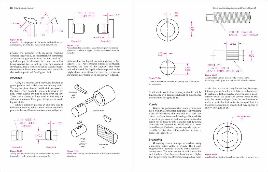
Figure 11-12. Chamfers on non-perpendicular surfaces should not be dimensioned by note, but rather with dimensions.
provide the inspector with an easier checking distance, Figure 11-13. In similar fashion, sometimes an undercut groove is used at the head of a cylindrical part to eliminate the chance for a fillet being created due to tool tip wear or a rounded cutting tool. While local notes can be used to specify the undercut, linear measurements that are easily checked are preferred. See Figure 11-14.
Keyways
Example 1 Example 2
Figure 11-14. An undercut is sometimes used to help prevent corner interference where a larger cylinder intersects a smaller cylinder.
distances that are logical inspection distances. See Figure 11-16. This technique eliminates confusion regarding the size of the keyway. The older method allowed the depth to be interpreted as the height above the center of the curve, but it was also sometimes interpreted to be the keyway sidewall.
.250
.246
Figure 11-16.
1.167 1.163
Figure 11-17. A callout for a knurl may specify several items,
A key is a fastener used to prevent rotation of gears, pulleys, and rocker arms on rotating shafts. The key is a piece of metal that fits into a keyseat in the shaft, which holds the key, or a keyway in the hub, which allows the hub to slide over the key. There are a variety of keys used in industry for different situations. Examples of keys are shown in Figure 11-15.
While a common practice at one time was to indicate a keyway with a note, newer standards promote the use of linear dimensions to specify exact
Example 1 Example 2
Gib-Head Taper Key
Pratt and
Whitney Key
Square Key
Woodruff Key
Linear dimensions are used to specify exact distances for keyways.
To eliminate confusion, keyways should not be dimensioned by a callout, but should be dimensioned as illustrated in Figure 11-16.
Knurls
Knurls are patterns of ridges and grooves cut into a cylindrical surface for the purpose of providing a grip or increasing the diameter of a part. The pattern is often crisscrossed, leaving a diamond-like series of ridges. A metal part may feature a knurl so that it can be force fit into a plastic part. Knurling standards are covered in ASME B94.6. A knurl should be specified with respect to pitch, type, and possibly the diameters before and after the knurl is made. See Figure 11-17.
Broaching
Broaching is done on a special machine using a machine cutter called a broach. The broach progressively “punches” a shape with a series of
including pitch, type, and before and after diameters.
of circular, square or irregular outline; keyways; internal gear teeth; splines; or flat external contours. Broaching is fast, accurate, and produces a good- quality finish. As discussed several times in this unit, the practice of specifying the machine tool to make a particular feature is discouraged, but if a broaching operation is specified, it may appear as shown in Figure 11-18.
BRO.3A7C5H .125
Figure 11-13. A ring groove or neck may be dimensioned by note (example 1) or by dimensions (example 2).
Figure 11-15. There are a variety of keys used in industry for different situations.
cutting teeth. The teeth are set in such a way that each tooth is a few thousandths of an inch higher than the preceding one. Broaching can produce holes
Figure 11-18. A callout for a typical broaching operation is shown here.
208 Print Reading for Industry
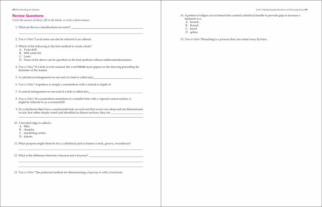
Review Questions Circle the answer of choice, fill in the blank, or write a short answer.
1. What are the two classifications for notes?
Unit 11 Machining Specifications and Drawing Notes 209
14. A pattern of ridges cut or formed into a metal cylindrical handle to provide grip or increase a diameter is a: A. broach. B. thread. C. knurl. D. spline.
2. True or False? Local notes can also be referred to as callouts. 15. True or False? Broaching is a process that cuts metal away by force.
3. Which of the following is the best method to create a hole?
A. Twist drill. B. Mill cutter bit. C. Laser. D. None of the above can be specified as the best method without additional information.
4. True or False? If a hole is to be reamed, the word REAM must appear on the drawing preceding the
diameter of the reamer.
5. A cylindrical enlargement on one end of a hole is called a(n) .
6. True or False? A spotface is simply a counterbore with a locked-in depth of
7. A conical enlargement on one end of a hole is called a(n) .
8. True or False? If a counterbore transitions to a smaller hole with a tapered conical surface, it might be referred to as a counterdrill.
9. If a cylindrical object has a countersunk hole on each end that is not very deep and not dimensioned
in size, but rather simply noted and identified as datum surfaces, they are .
10. A beveled edge is called a:
A. fillet. B. chamfer. C. machining center. D. datum.
11. What purpose might there be for a cylindrical part to feature a neck, groove, or undercut?
12. What is the difference between a keyseat and a keyway?
13. True or False? The preferred method for dimensioning a keyway is with a local note.

210 Print Reading for Industry
Review Activity 11-1
For each local note or callout given on the next page, use lettering to put the notes into words that you can read. An example has been done for you. Also refer to Figure 9-3 as needed.
1. diameter hole, deep, two places
2.
3.
4.
5.
6.
7.
8.
9.
10.
1.
3.
5.
7.
9.
2.
4.
6.
8.
10.
Unit 11 Machining Specifications and Drawing Notes 211
212 Print Reading for Industry
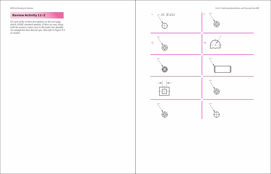
Review Activity 11-2
1. 2.
Unit 11 Machining Specifications and Drawing Notes 213
For each of the written descriptions on the next page, sketch ASME standard symbols, if there are any, along with the numeric values next to the leader line shoulder. An example has been done for you. Also refer to Figure 9-3 as needed.
9. 10.
214 Print Reading for Industry Unit 11 Machining Specifications and Drawing Notes 215
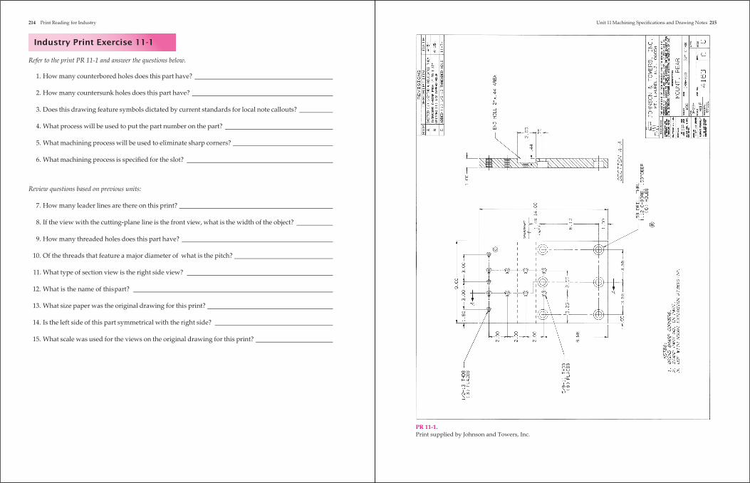
Industry Print Exercise 11-1
Refer to the print PR 11-1 and answer the questions below.
1. How many counterbored holes does this part have?
2. How many countersunk holes does this part have?
3. Does this drawing feature symbols dictated by current standards for local note callouts?
4. What process will be used to put the part number on the part?
5. What machining process will be used to eliminate sharp corners?
6. What machining process is specified for the slot?
Review questions based on previous units:
7. How many leader lines are there on this print?
8. If the view with the cutting-plane line is the front view, what is the width of the object?
9. How many threaded holes does this part have?
10. Of the threads that feature a major diameter of what is the pitch?
11. What type of section view is the right side view?
12. What is the name of this part?
13. What size paper was the original drawing for this print?
14. Is the left side of this part symmetrical with the right side?
15. What scale was used for the views on the original drawing for this print?
PR 11-1. Print supplied by Johnson and Towers, Inc.
216 Print Reading for Industry Unit 11 Machining Specifications and Drawing Notes 217
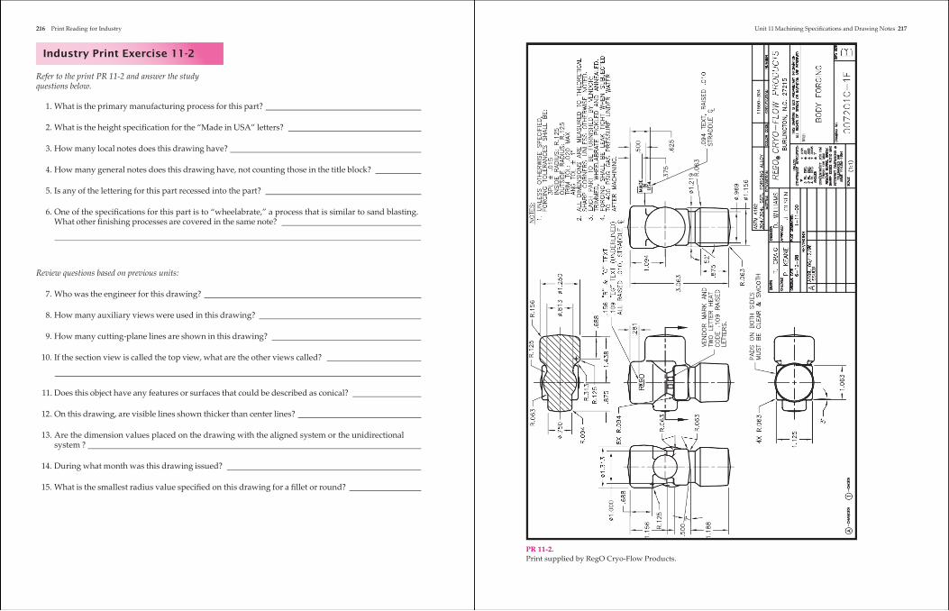
Industry Print Exercise 11-2
Refer to the print PR 11-2 and answer the study questions below.
1. What is the primary manufacturing process for this part?
2. What is the height specification for the “Made in USA” letters?
3. How many local notes does this drawing have?
4. How many general notes does this drawing have, not counting those in the title block?
5. Is any of the lettering for this part recessed into the part?
6. One of the specifications for this part is to “wheelabrate,” a process that is similar to sand blasting.
What other finishing processes are covered in the same note?
Review questions based on previous units:
7. Who was the engineer for this drawing?
8. How many auxiliary views were used in this drawing?
9. How many cutting-plane lines are shown in this drawing?
10. If the section view is called the top view, what are the other views called?
11. Does this object have any features or surfaces that could be described as conical?
12. On this drawing, are visible lines shown thicker than center lines?
13. Are the dimension values placed on the drawing with the aligned system or the unidirectional
system ?
14. During what month was this drawing issued?
15. What is the smallest radius value specified on this drawing for a fillet or round?
PR 11-2. Print supplied by RegO Cryo-Flow Products.
218 Print Reading for Industry Print AP-012:
Unit 11 Machining Specifications and Drawing Notes 219
Bonus Print Reading Exercises
The following questions are based on various bonus prints located in the folder at the back of this textbook. Refer to the print indicated, evaluate the print, and answer the question.
Print AP-004:
1. According to the notes, what must be performed per military standard A-8625?
Print AP-007: 2. What will be placed in the groove that must be free of parting line flash?
12. How many general notes are listed on this drawing?
13. According to the notes, is this drawing inches or metric?
14. According to the notes, in what state must datum A be when checking flatness of the datum surface?
Print AP-014: 15. Some of the corners have leaders indicating an R value, and some have a C value. What
manufacturing term does the C stand for?
3. List three conditions considered unacceptable for the valve seat surface. Print AP-016: 16. How much torque is to be applied when installing the flange screws?
Print AP-008: 4. To help facilitate machining and inspection, what is permitted on both ends of this object?
5. What type of line is used to indicate the cylindrical surfaces that are to be heat treated?
Print AP-009: 6. How many counterbore operations are called out in View F-F for this part?
7. How many spot drill operations are called out in View F-F for this part?
17. What process is specified for part #15 before assembly?
Print AP-017: 18. Which note was added with revision B?
19. This assembly drawing is for a cutting tool. According to the notes, what is the maximum speed for it?
Print AP-018: 20. What finish is specified for this part?
8. Many of the holes specified in View F-F are located on a basic diameter B.C. What does B.C. stand for?
Print AP-010: 9. What substance will be used on the set screws when they are installed?
21. What is the approximate weight of this assembly?
22. According to note 4, how many minutes away from vertical is the maximum allowable angle for the edge of the insert?
Print AP-011: 10. Is the part number stamp covered by local note, general note, or both?
Print AP-019: 23. There are three optional holes on this part. If used, what are they for?
11. What is the maximum amount of break to be used on sharp corners and edges?
220 Print Reading for Industry
Print AP-020: 24. Which one of the following processes does not apply to this part?
A. Forging. B. Carburizing. C. Grinding. D. Welding.
25. What term is applied to breaking off the sharp edges of the teeth?
Print AP-021: 26. Which of the general notes specifies a geometric control and, thus, could be replaced with a feature
control frame?
Print AP-022: 27. What is the basic radius for fillets and rounds, unless otherwise specified?
28. How many leader lines are used in this print for notes?
Print AP-023: 29. What finish is specified for this part?
30. How are burrs to be removed?
Print AP-025: 31. Unless specified, what imperfection along the edges is acceptable?
Print AP-026: 32. What do the circular hidden lines represent in the top view?