Engineering Drawing Practices
118
National Défense D-01-400-001/SG-000 Defence nationale STANDARD ENGINEERING DRAWING PRACTICES (ENGLISH) (Supersedes D-01-400-001/SG-000 dated 1979-04-02) Cette publication est disponible en français sous le numéro D-01-400-001/SG-001. NOTICE This documentation has been reviewed by the technical authority and does not contain controlled goods. Disclosure notices and handling instructions originally received with the document shall continue to apply. AVIS Cette documentation a été révisée par l’autorité technique et ne contient pas de marchandises contrôlées. Les avis de divulgation et les instructions de manutention reçues originalement doivent continuer de s’appliquer. Issued on Authority of the Chief of the Defence Staff OPI: DMPP 5 2018-01-31 OCI: DSCO 4
-
Upload
khangminh22 -
Category
Documents
-
view
2 -
download
0
Transcript of Engineering Drawing Practices

National Défense D-01-400-001/SG-000Defence nationale
STANDARD
ENGINEERING DRAWING PRACTICES (ENGLISH)
(Supersedes D-01-400-001/SG-000 dated 1979-04-02)
Cette publication est disponible en français sous le numéro D-01-400-001/SG-001.
NOTICE
This documentation has been reviewed by the technical authority and does not contain controlled goods. Disclosure notices and handling instructions originally received with the document shall continue to apply.
AVIS
Cette documentation a été révisée par l’autorité technique et ne contient pas de marchandises contrôlées. Les avis de divulgation et les instructions de manutention reçues originalement doivent continuer de s’appliquer.
Issued on Authority of the Chief of the Defence Staff
OPI: DMPP 5 2018-01-31 OCI: DSCO 4
D-01-400-001/SG-000
A
LIST OF EFFECTIVE PAGES
Insert latest changed pages; dispose of superseded pages in accordance with applicable orders.
NOTE
The portion of the text affected by the latest change is indicated by a black vertical line in the margin of the page. Changes to illustrations are indicated by miniature pointing hands or black vertical lines.
Dates of issue for original and changed pages are:
Original .........................0.......................... 2018-01-31Ch .................................1.......................... Ch .................................2.......................... Ch .................................3.......................... Ch .................................4.......................... Ch .................................5..........................
Ch ................................ 6 .......................... Ch ................................ 7 .......................... Ch ................................ 8 .......................... Ch ................................ 9 .......................... Ch ............................... 10 ......................... Ch ............................... 11 .........................
Zero in Change No. Column indicates an original page. Total number of pages in this publication is 119consisting of the following:
Page No. Change No. Page No. Change No.
Title ..................................................................... 0 A ......................................................................... 0 i/ii to vii/viii .......................................................... 0 1-1/1-2 ................................................................ 0 2-1/2-2 ................................................................ 0 3-1 to 3-10 .......................................................... 0 4-1 to 4-3/4-4 ...................................................... 0
5-1 to 5-3/5-4 ......................................................0 6-1/6-2 ................................................................0 7-1 to 7-57/7-58 ..................................................0 8-1 to 8-7/8-8 ......................................................0 9-1 to 9-5/9-6 ......................................................0 10-1 to 10-4 ........................................................0 IL-1 to IL-7/IL-8 ...................................................0
Contact Officer: DMPP 5-3
© Her Majesty the Queen in Right of Canada, as represented by the Minister of National Defence, 2018

D-01-400-001/SG-000
i/ii
FOREWORD
This standard has been approved by the Department of National Defence (DND) and shall be used in the preparation of and revision to engineering drawings and associated lists effective on 2018-01-31. It does notgovern drawings in the civil engineering and architectural field.
The policy of DND is to utilize to the maximum degree possible those industry standards which fully satisfy the needs of the Canadian Armed Forces with respect to their technical requirements. However, there are a number of differences in details and definitions reflecting DND requirements and practices. Accordingly this standard will be revised periodically to take advantage of new developments in those industry standards which meet DND requirements.
Figures included in this standard have been prepared to specific textual requirements and may not necessarily be complete in other respects. In the event of discrepancies between the text and the figures, the text shall take precedence. These figures are catalogued for appropriate selection and use in support of levels of engineering drawings being prepared under the requirements of D-01-400-002/SF-000, Specification for Levels of Engineering Drawings and Associated Lists.
Certain provisions of this standard are subject to international standardization agreement. When a revision or cancellation of this standard is proposed, the Department of National Defence, DMPP 5 will take the appropriate action respecting the international agreement concerned.
Recommended corrections, additions or deletions should be addressed to the following:
National Defence Headquarters 101 Colonel By Dr Ottawa, ON K1A 0K2 Attention: Director Materiel Policy and Procedures 5-3 (DMPP 5-3).
In the alternative, the Contact Officer email address is: +DMPP 5 MA&S E&M Inquiries@ADM(Mat) DMPP@Ottawa-Hull, attention: DMPP 5-3.
OPI: DMPP 5 OCI: DSCO 4


D-01-400-001/SG-000
iii
CONTENTS
PAGE
SECTION 1 SCOPE ..................................................................................................................................... 1-1/1-2
1.1 Purpose ........................................................................................................................................ 1-1/1-2 1.2 Intended Use ................................................................................................................................ 1-1/1-2 1.3 Definition of Terms ....................................................................................................................... 1-1/1-2
SECTION 2 APPLICABLE DOCUMENTS .................................................................................................. 2-1/2-2
2.1 Government and Non-Government References .......................................................................... 2-1/2-2 2.2 Order of Precedence .................................................................................................................... 2-1/2-2
SECTION 3 ENGINEERING DRAWING FORMATS.......................................................................................... 3-1
3.1 Scope .................................................................................................................................................. 3-1 3.2 Metric Format ...................................................................................................................................... 3-1 3.3 Associated Lists .................................................................................................................................. 3-1 3.4 Zoning ................................................................................................................................................. 3-1 3.5 Graphical Scales ................................................................................................................................. 3-1 3.6 Blocks .................................................................................................................................................. 3-1 3.7 Security Classification ......................................................................................................................... 3-3 3.8 Completion of Integral Parts List ......................................................................................................... 3-3 3.9 Copyright Notice .................................................................................................................................. 3-3 3.10 CTAT Marking ..................................................................................................................................... 3-4
SECTION 4 GENERAL DRAWING PRACTICES .............................................................................................. 4-1
4.1 Scope .................................................................................................................................................. 4-1 4.2 ASME Y14.100 .................................................................................................................................... 4-1 4.3 Use of Colours ..................................................................................................................................... 4-1 4.4 Balloon System ................................................................................................................................... 4-1 4.5 Dimensioning and Tolerancing ............................................................................................................ 4-1 4.6 Identification of Materials and Processes ........................................................................................... 4-1 4.7 Signs and Symbols.............................................................................................................................. 4-2 4.8 Lettering .............................................................................................................................................. 4-2
SECTION 5 NUMBERING AND CODING .......................................................................................................... 5-1
5.1 Scope .................................................................................................................................................. 5-1 5.2 NATO Supply Code for Manufacturers (NSCM) Number ................................................................... 5-1 5.3 Drawing Number ................................................................................................................................. 5-1 5.4 Part Number ........................................................................................................................................ 5-2 5.5 Item Number ........................................................................................................................................ 5-2 5.6 Identification by Item Numbers ............................................................................................................ 5-2 5.7 Item Identification and Part Numbering ............................................................................................... 5-2 5.8 Associated Lists ........................................................................................................................... 5-3/5-4 5.9 Identification Changes .................................................................................................................. 5-3/5-4
SECTION 6 DRAWING TITLES .................................................................................................................. 6-1/6-2
6.1 Scope ........................................................................................................................................... 6-1/6-2 6.2 Creation of Drawing Titles ............................................................................................................ 6-1/6-2 6.3 Spelling and Meaning ................................................................................................................... 6-1/6-2
SECTION 7 TYPES OF ENGINEERING DRAWINGS ....................................................................................... 7-1
7.1 Scope .................................................................................................................................................. 7-1 7.2 Engineering Drawing ........................................................................................................................... 7-2 7.3 Detail Drawing ..................................................................................................................................... 7-2 7.4 Assembly Drawing............................................................................................................................... 7-3 7.5 Control Drawing ................................................................................................................................... 7-4 7.6 Installation Drawing ............................................................................................................................. 7-8

D-01-400-001/SG-000
iv
CONTENTS
PAGE
7.7 Diagrammatic Drawing ....................................................................................................................... 7-9 7.8 Special Purpose Drawings ............................................................................................................... 7-10
SECTION 8 REVISION OF ENGINEERING DRAWINGS ................................................................................. 8-1
8.1 Scope ................................................................................................................................................. 8-1 8.2 Revision Methods ............................................................................................................................... 8-1 8.3 Identifying Revision of Drawings ........................................................................................................ 8-1 8.4 Recording Revisions on Drawings ..................................................................................................... 8-1 8.5 Revision of Multisheet Drawings ........................................................................................................ 8-2 8.6 Redrawn or Replaced Drawing (Retained for Reference) ................................................................. 8-2 8.7 Cancelled Drawings (Retained for Reference) .................................................................................. 8-2
SECTION 9 ASSOCIATED LISTS ..................................................................................................................... 9-1
9.1 Scope ................................................................................................................................................. 9-1 9.2 Parts List (PL) ..................................................................................................................................... 9-1 9.3 Data List (DL) ..................................................................................................................................... 9-1 9.4 Cover Sheet ....................................................................................................................................... 9-1 9.5 List Preparation .................................................................................................................................. 9-1 9.6 Revisions ............................................................................................................................................ 9-2 9.7 Design Agent Identification ................................................................................................................ 9-2 9.8 Additional Blocks and Columns .......................................................................................................... 9-2 9.9 Data List ............................................................................................................................................. 9-2 9.10 Cover Sheet Preparation .................................................................................................................... 9-3
SECTION 10 DEFINITIONS ............................................................................................................................... 10-1
10.1 Scope ............................................................................................................................................... 10-1 10.2 Assembly .......................................................................................................................................... 10-1 10.3 Bulk Materials ................................................................................................................................... 10-1 10.4 Contract ............................................................................................................................................ 10-1 10.5 Contractor ......................................................................................................................................... 10-1 10.6 Dash Numbers ................................................................................................................................. 10-1 10.7 Data List ........................................................................................................................................... 10-1 10.8 Design Authority ............................................................................................................................... 10-1 10.9 Design Agent .................................................................................................................................... 10-2 10.10 Document ......................................................................................................................................... 10-2 10.11 Formulation ...................................................................................................................................... 10-2 10.12 Item ................................................................................................................................................... 10-2 10.13 Level – LEVEL .................................................................................................................................. 10-2 10.14 Manufacturer .................................................................................................................................... 10-2 10.15 Master Drawings .............................................................................................................................. 10-2 10.16 May ................................................................................................................................................... 10-2 10.17 NATO Supply Code for Manufacturers (NSCM) .............................................................................. 10-2 10.18 Part ................................................................................................................................................... 10-2 10.19 Part Number ..................................................................................................................................... 10-2 10.20 Revision ............................................................................................................................................ 10-3 10.21 Revision Authorization Document .................................................................................................... 10-3 10.22 Revision Symbol ............................................................................................................................... 10-3 10.23 Shall .................................................................................................................................................. 10-3 10.24 Should .............................................................................................................................................. 10-3 10.25 Standards ......................................................................................................................................... 10-3 10.26 Standard, Industry ............................................................................................................................ 10-3 10.27 Subassembly .................................................................................................................................... 10-3 10.28 Symmetrically Opposite Parts .......................................................................................................... 10-3 10.29 System (General) ............................................................................................................................. 10-4

D-01-400-001/SG-000
v/vi
CONTENTS
PAGE
10.30 Technical Data Action Notice (TDAN) .............................................................................................. 10-4 10.31 Unit ................................................................................................................................................... 10-4 10.32 Vendor .............................................................................................................................................. 10-4 10.33 Will .................................................................................................................................................... 10-4
INDEX LIST ..................................................................................................................................................IL-1


D-01-400-001/SG-000
vii/viii
LIST OF FIGURES
FIGURE TITLE PAGE
3-1 Metric Drawing Sizes ................................................................................................................ 3-4 3-2 Drawing Format – A0 (Shown), A1, A2, A3, A4 ........................................................................ 3-5 3-3 Drawing Format – A0R ............................................................................................................. 3-6 3-4 Title Block ................................................................................................................................. 3-7 3-5 Integral Parts List Block ............................................................................................................ 3-8 3-6 Additional Drawing Number Block ............................................................................................ 3-9 3-7 Auxiliary Title and Drawing Number Block ............................................................................... 3-9 3-8 Auxiliary Application Block ...................................................................................................... 3-10 4-1 Aligned Method .................................................................................................................. 4-3/4-4 7-1 Mono-Detail Drawing .............................................................................................................. 7-14 7-2 Tabulated Detail Drawing ....................................................................................................... 7-15 7-3 Tube Bend Drawing ................................................................................................................ 7-16 7-4 Assembly Drawing .................................................................................................................. 7-17 7-5 Detail Assembly Drawing ........................................................................................................ 7-18 7-6 Inseparable Assembly Drawing (2 Sheets) ............................................................................ 7-19 7-7 Matched Set Drawing ............................................................................................................. 7-21 7-8 Arrangement Drawing ............................................................................................................. 7-22 7-9 Specification Control Drawing ................................................................................................. 7-23 7-10 Source Control Drawing .......................................................................................................... 7-24 7-11 Altered Item Drawing (Vendor Data Available) (Sheet 1 of 2) ................................................. 7-25
Altered Item Drawing (Vendor Data Not Available) (Sheet 2 of 2) .......................................... 7-26 7-12 Selected Item Drawing (Sheet 1 of 2) ..................................................................................... 7-27
Selected Item Drawing (Dimensional) (Sheet 2 of 2) ............................................................. 7-28 7-13 Interface Control Drawing ....................................................................................................... 7-29 7-14 Installation Control Drawing .................................................................................................... 7-30 7-15 Installation Assembly Drawing ................................................................................................ 7-31 7-16 Elevation Drawing ................................................................................................................... 7-32 7-17 Electrical Schematic Drawing ................................................................................................. 7-33 7-18 Connection Diagram (2 Sheets) ............................................................................................. 7-34 7-19 Interconnection Diagram ......................................................................................................... 7-36 7-20 Single Line or One Line Diagram ............................................................................................ 7-37 7-21 Logic Diagram ......................................................................................................................... 7-38 7-22 Mechanical Schematic Drawing .............................................................................................. 7-39 7-23 Piping Diagram ....................................................................................................................... 7-40 7-24 Running Wire List Drawing ..................................................................................................... 7-41 7-25 Wiring Harness Drawing (Sheet 1 & 2 of 3) ............................................................................ 7-42
Wiring Harness Drawing (Peg Board System) (Sheet 3 of 3) ................................................ 7-44 7-26 Cable Assembly Drawing ........................................................................................................ 7-45 7-27 Lead Assembly Drawing (Single Conductor) (Sheet 1 of 2) ................................................... 7-46
Lead Assembly Drawing (Multi-Conductor) (Sheet 2 of 2) ...................................................... 7-47 7-28 Printed Wiring Master Drawing ............................................................................................... 7-48 7-29 Kit Drawing .............................................................................................................................. 7-49 7-30 Formulation Drawing ............................................................................................................... 7-50 7-31 Ship Equipment Drawing ........................................................................................................ 7-51 7-32 Envelope Drawing ................................................................................................................... 7-52 7-33 Tabulated Drawing Assembly ................................................................................................. 7-53 7-34 Multidetail Drawing ................................................................................................................. 7-54 7-35 Modification Drawing .............................................................................................................. 7-55 7-36 Installation Drawing ................................................................................................................ 7-56 7-37 Undimensioned Drawing ................................................................................................ 7-57/7-58 8-1 Revision on Multisheet Drawing (4 Sheets) ............................................................................... 8-3 8-2 Technical Data Action Notice ............................................................................................. 8-7/8-8 9-1 Data List .................................................................................................................................... 9-4 9-2 Cover Sheet ....................................................................................................................... 9-5/9-6 9-2


D-01-400-001/SG-000
1-1/1-2
SECTION 1 SCOPE
1.1 Purpose
1.1.1 This standard prescribes the general requirements for the preparation of and revision to engineering drawings and associated lists prepared for or by DND to the extent specified in accordance with D-01-400-002/SF-000.
1.2 Intended Use
1.2.1 Engineering drawings and associated lists, prepared and revised in accordance with this standard may be used by DND for design, manufacture, procurement, production, testing and trial evaluation, materiel inspection and cataloguing, general maintenance of equipment, material identification and whenever drawings are required.
1.3 Definition of Terms
1.3.1 For definition of terms used in this standard see Section 10.


D-01-400-001/SG-000
2-1/2-2
SECTION 2 APPLICABLE DOCUMENTS
2.1 Government and Non-Government References
2.1.1 The following documents form part of this standard to the extent specified herein. Unless otherwise specified, the issue or amendment of specifications, standards, drawings or other documents effective for a particular contract shall be as stated in the procurement documents or in the contract:
(a) Government Documents:
A-LM-137-C0M/LX-001 Canadian Government Catalogue of Material.
C-02-007-000/AG-001 Controlled Technology Access and Transfer (CTAT) Manual.
C-02-007-024/JX-001 Canadian Forces Technical Glossary.
D-01-400-002/SF-000 Specification for Levels of Engineering Drawings and Associated Lists.
Handbook H4-1, H4-2 Federal Supply Code for Manufacturers.
Handbook H6 Federal Item Identification Guides for Supply Cataloguing.
MIL-STD-25 Structural Symbols for use on Ship Drawings.
Public Works and Government Services Canada Industrial Security Manual
Copies of specifications and standards shall be obtained in accordance with the procedure outlined in the contract or, in the case of potential contractors, through Public Services and Procurement Canada, www.canada.ca (formerly Public Works and Government Services Canada).
(b) Non-Government Documents:
ASME Y14.100-2013 Engineering Drawing Practices.
Copies of the above noted document may be obtained from: The American Society of Mechanical Engineers (ASME), www.asme.org.
(c) References:
Concise Oxford English Dictionary.
Harrap’s French and English Dictionary.
Le Petit Robert.
Webster’s Third New International Dictionary (Unabridged).
2.2 Order of Precedence
2.2.1 In the event of a conflict between the text of this standard and the references cited herein, the text of this standard shall take precedence.


D-01-400-001/SG-000
3-1
SECTION 3 ENGINEERING DRAWING FORMATS
3.1 Scope
3.1.1 This section establishes sizes and minimum format requirements for the preparation of engineering drawings.
3.2 Metric Format
3.2.1 Engineering drawing formats shall be in metric sizes only, except as modified in para 3.2.2. See Figure 3-1 for detailed breakdown.
3.2.2 Roll Size (Elongated) Formats. Roll size formats may be used when necessary and shall only be based upon the A0 size format, see Figure 3-3. It is recommended that the length of roll size formats be in increments of 148.5 millimeters. An A0 roll size format shall be designated as “A0R” in the drawing size block of the title block, see para 3.6.17.
3.3 Associated Lists
3.3.1 Associated lists shall consist of the types of sheets illustrated in Section 9.
3.4 Zoning
3.4.1 Vertical and horizontal zoning shall be used on A0, A1 and roll size formats. Zones shall be numbered horizontally from the right hand edge and lettered vertically, with upper case letters, reading from the bottom. Zones shall be spaced 105 millimetres vertically and 148.5 millimetres horizontally. See Figures 3-2 and 3-3.
3.5 Graphical Scales
3.5.1 Metric Scale. A graphical metric scale shall be shown in the left hand margin of A0, A1 and roll size drawings as illustrated in Figures 3-2 and 3-3. The scale shall be 200 millimetres in length with 10 millimetres divisions.
3.5.2 Inch Scale. A graphical inch scale shall be shown in the right hand margin of roll size drawings and in the top margin of A0 and A1 size drawings as illustrated in Figures 3-2 and 3-3. The scale shall be divided into 10 one-inch divisions, with the lowest division subdivided into 8 equal divisions and the highest into 10 equal divisions.
3.6 Blocks
3.6.1 Blocks, Sheet and Roll Size Formats. Blocks for sheet and roll size formats shall conform to the arrangements and dimensions shown in Figures 3-4 to 3-8. These requirements override those in ASME Y14.100.
3.6.1.1 Title Block, Sheet and Roll Size Formats. This block shall be located in the lower right hand corner, see Figures 3-2 to 3-4. For roll size drawings the drawing title and drawing number shall be repeated in the auxiliary title and drawing number block, see para 3.6.21.
3.6.2 Drawn (DWN) block. This block shall contain the lettered name and initials of the draftsperson who prepared the drawing.
3.6.3 Checked (CKD) block. This block shall contain the lettered name and initials of the examiner who checked the drawing.
3.6.4 Quality Assurance (INSPECT) Block. This block shall contain the lettered name or designation of the inspector who inspected the drawing.
D-01-400-001/SG-000
3-2
3.6.5 Canadian Armed Forces Approval (CF APPVL) Block. This block shall contain the designation of the design authority. See para 10.8.
3.6.6 Design Agent (DESIGN AGENT) Block. This block shall contain the designation of the design agent. See para 10.9.
3.6.7 Drawing Date (APPVL DATE) Block. This block shall contain the date of the CAF approval by the design authority.
3.6.8 Application Block. This block may show the model, class of ship and/or auxiliary vessel, site number, or the drawing number of the next higher assembly to which the current drawing applies.
3.6.9 Tolerance Block. This block shall provide information on general tolerances.
3.6.10 Angle of Projection Block. This block shall contain the symbol for the angle of projection used in accordance with ASME Y14.100. See Figure 3-4 for an example of a third angle projection symbol.
3.6.11 Title Block. This block shall contain an approved item name compiled in accordance with Section 6 of this document, ASME Y14.100, and the drawing type selected.
3.6.12 NATO Supply Code for Manufacturers (NSCM) Number Block. This block shall contain the five character code identification number of the design authority in accordance with A-LM-137-C0M/LX-001.
3.6.13 Drawing Number Block. This block shall contain the Canadian Armed Forces drawing number, see para 5.3.
3.6.14 Scale. The drawing scale shall be entered in the tolerance block, see Figure 3-4.
3.6.15 Sheet Block. The sheet number (1, 2 etc.) and the total number of sheets of a drawing shall be entered in this block. For example, “Sheet 1 of 1”, “Sheet 1 of 2” or “Sheet 2 of 2”.
3.6.16 Drawing Interpretation Block. The drawing interpretation block shall contain the drawing classification level in accordance with D-01-400-002/SF-000.
3.6.17 Drawing Size Block. The block to the right of the drawing date block shall contain the metric sheet size designation, i.e. A4, A3, A2, A1, A0, A0R.
3.6.18 Integral Parts List Block. A parts list, prepared integral with the drawing, shall contain the columns shown in Figure 3-5. The location of the integral parts list shall be as shown in Figures 3-2 and 3-3. Additional integral parts list blocks (columns) may be located to the left of and adjacent to, the original block or on the following sheet of a multi-sheet drawing.
3.6.19 Revision Block. The location of the revision block and the arrangement of column headings shall be as shown in Figure 3-4. Additional revision blocks (columns) may be located to the left of the original revision block.
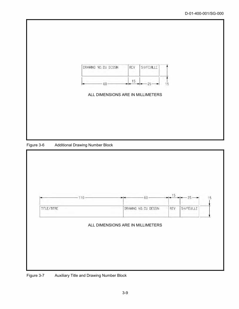
3.6.20 Additional Drawing Number Blocks. Roll size drawings shall have the drawing number, revision letter and sheet number located in each eight zone increment as shown in Figures 3-3 and 3-6.
3.6.21 Auxiliary Title and Drawing Number Block. The drawing title, drawing number, revision and sheet number shall be repeated in the auxiliary title and drawing number block at the upper left hand corner of the roll size drawing format. See Figures 3-3 and 3-7.
3.6.22 Auxiliary Application Block. An auxiliary application block may be drawn in the upper left hand corner of the roll size drawing format, see Figure 3-8. When an auxiliary title and number block is used, the auxiliary block shall be located immediately below the auxiliary title and number block, see Figure 3-3.
3.6.23 Unused Blocks. Unused blocks on drawings shall have a line drawn through the block to indicate that the information which would normally be entered therein has not been omitted inadvertently.

D-01-400-001/SG-000
3-3
3.7 Security Classification
3.7.1 Security Classification Marking. Engineering drawings containing classified information shall be marked in accordance with provisions of the Public Works and Government Services Canada Industrial Security Manual.
3.7.2 Security Classification Determination. Determination of the required security classification will be the responsibility of DND.
3.7.3 Security Classification Location. When required, the Security classification shall be located as shown in Figures 3-2 and 3-3.
3.8 Completion of Integral Parts List
3.8.1 Dash Number (-NO.) Column. This column shall contain the applicable dash number (if required) which represents the part depicted by the drawing. When drawings of symmetrically opposite parts, see para 5.4.2, or tabulated drawings, see paras 7.3.4 and 7.4.3, are prepared, the required columns for dash numbers shall be added and completed.
3.8.2 Quantity (QTY) Column. The quantity of each item required to produce the part depicted for the applicable dash number, shall be inserted in this column, see Figure 7-2.
3.8.3 Item Number (ITEM NO.) Column. Item numbers shall begin at the top of the integral parts list and shall be listed consecutively for each item called out.
3.8.4 Identifying Number (IDENTIFYING NO.) Column. This column shall contain the identifying number for each item called out, see para 5.4.
3.8.5 Nomenclature Column. This column shall contain the noun or noun phrase describing each item called out.
3.8.6 Description Column. This column shall contain stock size and identification for materials, see para 4.6.
NOTE
When drawings that do not have part numbers are called up in an integral parts list, the drawing numbers shall be inserted in the description column. Examples of these drawings include, but are not limited to, schematic drawings and specification control drawings.
3.8.7 Specification Column. This column shall contain the material specifications, standards identification and all qualitative information e.g. class, type, grade, etc., see para 4.6.
3.8.8 NATO Supply Code for Manufacturers (NSCM) Number Column. This column contains the five character code identification number which corresponds to the design agent identification. When no NSCM number is available the column shall reference a note which will indicate the name and addressof the design agent.
3.9 Copyright Notice
3.9.1 The drawing shall include the bilingual copyright notice, located in the lower left hand corner of all sheets, see Figures 3-3 and 3-4, which shall read:

D-01-400-001/SG-000
3-4
NOTICE
THE DEPARTMENT OF NATIONAL DEFENCE DOES NOT WARRANT OR GUARANTEE THE CORRECTNESS OR ACCURACY OF THE INFORMATION CONTAINED IN THIS DOCUMENT FOR OTHER THAN OFFICAL DEFENCE PURPOSES. THE DEPARTMENT OF NATION DEFENCE DOES NOT GRANT ANY LICENCE, CONVEY ANY INTELLECTUAL PROPERTY RIGHTS, OR GIVE PERMISSION FOR ANY USE IN WHOLE OR IN PART BY ANY RECEPIENT, HOLDER OR USER OF THIS DOCUMENT, AND ANY SUCH PERSON USING THIS DOCUMENT OR THE INFORMATION THEREIN DOES SO AT THEIR OWN RISK.
AVIS
LE MINISTÈRE DE LA DÉFENSE NATIONALE NE GARANTIT PAS L’EXACTITUDE DE L’INFORMATION CONTENUE DANS LE PRÉSENT DOCUMENT POUR DES FINS AUTRES QUE POUR LA DÉFENSE NATIONALE. LE MINISTÈRE DE LA DÉFENSE NATIONALE N’ACCORDE AUCUNE LICENCE, NE CÈDE AUCUN DROIT DE PROPRIÉTÉ INTELLECTUELLE ET NE DONNE AUCUNE PERMISSION POUR QUELQUE UTILISATION QUE CE SOIT, EN TOUT OU EN PARTIE, PAR TOUT DESTINATAIRE, DÉTENTEUR OU UTILISATEUR DU PRÉSENT DOCUMENT. TOUTE PERSONNE UTILISANT LE PRÉSENT DOCUMENT OU L’INFORMATION QU’IL CONTIENT LE FAIT À SES PROPRES RISQUES.
3.10 CTAT Marking
3.10.1 Controlled Technology Access and Transfer (CTAT) Marking. Each sheet of a drawing shall include the appropriate CTAT marking for the data contained in the drawing. The format and wording of the marking shall be in accordance with applicable contract and C-02-007-000/AG-001. See Figures 3-2 and 3-3 for the recommended location of the marking.
Drawing Size W x L (max) (mm)
A4 210 x 297
A3 297 x 420
A2 420 x 594
A1 594 x 841
A0 841 x 1189
B1 707 x 1000
Figure 3-1 Metric Drawing Sizes

D-01-400-001/SG-000
3-5
Figure 3-2 Drawing Format – A0 (Shown), A1, A2, A3, A4
ALL
DIM
EN
SIO
NS
AR
E IN
MIL
LIM
ETE
RS

D-01-400-001/SG-000
3-6
Figure 3-3 Drawing Format – A0R
ALL
DIM
EN
SIO
NS
AR
E IN
MIL
LIM
ETE
RS

D-01-400-001/SG-000
3-7
ALL
DIM
ENSI
ON
S AR
E IN
MIL
LIM
ETER
S
Figure 3-4 Title Block

D-01-400-001/SG-000
3-8
ALL
DIM
ENSI
ON
S AR
E IN
MIL
LIM
ETER
S
Figure 3-5 Integral Parts List Block
D-01-400-001/SG-000
3-9
ALL DIMENSIONS ARE IN MILLIMETERS
Figure 3-6 Additional Drawing Number Block
ALL DIMENSIONS ARE IN MILLIMETERS
Figure 3-7 Auxiliary Title and Drawing Number Block

D-01-400-001/SG-000
3-10
ALL DIMENSIONS ARE IN MILLIMETERS
Figure 3-8 Auxiliary Application Block

D-01-400-001/SG-000
4-1
SECTION 4 GENERAL DRAWING PRACTICES
4.1 Scope
4.1.1 This section establishes the general drawing practices to be used in the production of engineering drawings in conjunction with ASME Y14.100. This section contains only those topics where DND requirements take precedence over those in ASME Y14.100.
4.2 ASME Y14.100
4.2.1 Drawings shall meet the requirements of ASME Y14.100 except those for digital data, the revision of engineering drawings and for associated lists. Where specific DND requirements on formatting or content contained in this standard deviate from ASME Y14.100, the requirements of this standard shall take precedence.
4.3 Use of Colours
4.3.1 Unless otherwise specified, the use of colours on technical drawings is not recommended. If it is essential for clarity to use colours, their meanings shall be clearly shown on the drawing.
4.4 Balloon System
4.4.1 The location of an item on the field of drawing shall be identified by a number enclosed in a balloon (circle) with a leader extending from the balloon to the item being located. The encircled number shall correspond to the applicable item number in the parts list. This is not a requirement when there is only one material call-out in the part lists (e.g., mono-detail drawing). See Figure 7-2. The diameter of the balloon (circle) shall be, as a minimum, to a ratio of 3 to 1 to the text height used (e.g. 9mm diameter for 3mm text height).
4.5 Dimensioning and Tolerancing
4.5.1 Dimensioning and tolerancing shall be in accordance with ASME Y14.100, with the following exceptions.
4.5.2 Units of Measurement. The DND/CAF Technical Authority will determine the units of measure (metric or imperial).
4.5.3 Dimensioning and Tolerancing Methods. Dimensions and tolerances may use either the unidirectional method (see ASME Y14.100) or aligned method (see Figure 4-1). For publication drawings or small sketches for use in standards or handbooks, the unidirectional method is preferred. In the aligned method, dimensions shall be avoided in the angular area shown in Area A of Figure 4-1. Only one method should be used on a drawing or set of drawings.
4.6 Identification of Materials and Processes
4.6.1 Method 1. Materials including bulk materials, and processes necessary to meet the design requirements of an item, shall be completely identified on the drawing by reference to applicable specifications or standards and the originator. Qualifying information as to type, grade, class, condition, and any other information required to fully describe the item shall be included. The revision of the specification or standard shall not be shown. Where several processes or protective treatments are involved, and a particular sequence is necessary to meet design requirements, they shall be shown in the order of that sequence. When materials are covered by a process specification, the specification shall be referenced as a general note. Supplementary requirements for stock sizes may include, but are not limited to, the following:
(a) Sheet and plate, designating thickness;
(b) Flat and square stock – thickness x width;

D-01-400-001/SG-000
4-2
(c) Round stock – wire, designate diameter;
(d) Hexagon stock – across the flats;
(e) Tubes – outside diameter x wall thickness;
(f) Pipe – standard pipe size and schedule;
(g) Angles – leg widths x leg thickness;
(h) Lumber – nominal size;
(i) Plywood – thickness;
(j) Cloth and fabric – weight;
(k) Tape and webbing – weight x width;
(l) Tees – flange times stem x stem thickness;
(m) Light channels – depth x width of flange x web thickness; and
(n) Structural – depth x weight per foot.
EXAMPLES
Channels – 4U to 5.4 lb
I Beams – 4I at 7.7 lb
H Beams – 4H at 13 lb
4.6.2 Method 2. Materials and processes which cannot be identified adequately in accordance with para 4.6.1, Method 1, may be identified by, but are not limited to the following:
(a) Trade name or commercial designation;
(b) NSCM number or name and address of the manufacturer of the material;
(c) Chemical composition (when applicable);
(d) Physical and mechanical properties in sufficient detail to disclose strength and safety characteristics which are a stated requirement of the design; and
(e) Properties of electrical insulating materials.
4.6.3 Method 3. All formulations for explosives, propellants, pyrotechnics, fillers, etc., shall be treated as a part and identified by a part number.
4.7 Signs and Symbols
4.7.1 Ship Structural Symbols. Ship structural symbols shall be in accordance with MIL-STD-25.
4.8 Lettering
4.8.1 Lettering Style. Upper case vertical style lettering is preferred.

D-01-400-001/SG-000
4-3/4-4
Figure 4-1 Aligned Method


D-01-400-001/SG-000
5-1
SECTION 5 NUMBERING AND CODING
5.1 Scope
5.1.1 Numbering, coding and identification practices for engineering drawings, associated lists, and documents referenced thereon, and also the identification of parts, materials, processes and treatments specified on these engineering drawings, shall be in accordance with ASME Y14.100. This section contains only those topics where DND requirements take precedence over those in ASME Y14.100.
5.2 NATO Supply Code for Manufacturers (NSCM) Number
5.2.1 Design Authority. The NSCM number is a five character numeric code used to identify the design authority within DND and shall always appear in the NSCM block of the drawing, see Figure 3-4. These numbers are assigned in accordance with A-LM-137-C0M/LX-001.
5.2.2 Manufacturers. The NSCM number is a five character numeric code used to identify all activities which have produced or are producing items used by DND. These numbers are assigned in accordance with A-LM-137-C0M/LX-001 or Handbooks H4-1, H4-2. Organizations which neither manufacture nor control design such as dealers, agents or vendors of items produced by others are not included. The name of the manufacturer or supplier may be used in lieu of the NSCM number. It is preferred that the NSCM number be used.
5.3 Drawing Number
5.3.1 The drawing number is a number assigned to a drawing for identification purposes. Drawing numbers shall be allocated by DND in accordance with this standard.
5.3.2 Composition of Drawing Number. The drawing number is composed of seven numerals, consisting of the year, and five sequential numerals as shown below, e.g. 1598540. The first two numerals “15” denote the last two numerals of the year in which the drawing commenced (i.e. 2015). The last five numerals “98540” are the digits of the number assigned to the drawing from the block of numbers supplied by DND.
5.3.2.1 Conceptual and Developmental Design Drawings Number. When a drawing is prepared to meet the requirements of Level 1 (see DND D-01-400-002/SF-000) the drawing number shall be suffixed with the letter “X” e.g., 1598540-X.
5.3.3 Allotment, control and assignment of drawing numbers:
(a) Allotment of Drawing Numbers. Requests for an allotment of drawing numbers shall be forwarded to the Director of Supply Chain Operations (DSCO) at the following address:
Department of National Defence 101 Colonel By Drive Ottawa, Ontario K1A 0K2
Attention: DSCO 4
Requests from contractors shall be in writing quoting the contract number, DND file number, project directive or other procurement documents for which the numbers are required. An estimate of the size of the allotment of numbers required shall be provided which shall be sufficiently liberal to preclude the necessity of subsequent requests for additional numbers.
(b) Control of Drawing Numbers:
i. DND. DND will control all numbers allotted for use on engineering drawings;
ii. The Contractor. The contractor shall maintain a register, listing in sequence the numbers with

D-01-400-001/SG-000
5-2
the titles assigned to each drawing. On the termination of each contract, applicants shall return a list of all unused numbers to DSCO 4, together with a copy of their register; and
iii. DND Drawing Offices. On the completion of each calendar year applicants shall return a list ofall unused numbers to DSCO 4, together with a copy of their register.
NOTE
When a calendar year ends, numbers for the new calendar year shall be requested. Numbers supplied for a specific calendar year shall be used in that calendar year only.
(c) Assignment of Drawing Numbers: Numbers shall be assigned to engineering drawings commencing with the lowest number supplied regardless of the drawing size.
5.4 Part Number
5.4.1 Part numbers consist of numbers, which may or may not be separated by dash numbers. The drawing number suffixed with a dash number is the preferred method. (e.g. 7812345-1). NATO stock numbers shall not be considered as part numbers.
5.4.2 Assignment of Identifying Part Number. The identifying part number shall be as follows:
(a) Mono-Detail Drawing. The drawing number suffixed by dash 1.
(b) Matched Set Drawing. A matched parts drawing depicts parts which are machine matched, or otherwise mated, and for which replacement as a matched set or pair is essential. See Figure 7-7.
(c) Symmetrically Opposite Parts. Symmetrically opposite parts, when feasible, shall be described by showing one of the parts, in which case they shall be identified by adding a dash number after the drawing number as NOTE 1. For example, 7700100 -1 LH SHOWN, 7700100 -2 RH OPPOSITE shall appear on the drawing, 7700100 being the drawing number. The use of odd dash numbers for the parts shown and even dash numbers for the opposite parts is preferred. Truly identical parts which can be reversed in any position shall have only one identifying part number.
5.5 Item Number
5.5.1 An item number is assigned to an item, part, assembly, etc. (see para 5.6), on the field of a drawing as a locator instead of using the item part number, and for cross-referencing to an integral parts list, see Figure 7-2. The parts, assemblies, and items so marked, have other identifying numbers for purposes of procurement and marking which are cross-referenced to the item numbers in the integral parts list, or in a table on the drawing. The item number shall not be quoted as part of the drawing or part number.
5.6 Identification by Item Numbers
5.6.1 Items shall be identified on the field of the drawing by item numbers (see paras 4.4 and 5.5) cross-referenced to the identifying numbers appearing in the integral parts list. When several items are identified on a single drawing, such as a tabulated or installation drawing each item shall be assigned a separate identification in accordance with para 5.7.
5.7 Item Identification and Part Numbering
5.7.1 Item Identification. Each item (detail, part, assembly) shall be identified as follows:
(a) An item covered by an approved standard and used without alteration or selection shall be identified by the standard part number;
(b) An item covered by an approved Government specification containing a part identification system and used without alteration shall be identified by the specification part identification; and

D-01-400-001/SG-000
5-3/5-4
(c) Materials (including bulk materials) shall be listed in the integral parts list and processes shall be included as a general note.
5.7.2 Part Numbering. All other items shall be identified by a part number or drawing number, as follows:
(a) Design authorities using items other than their own design without alteration or selection shall identify such items by the existing part number and identification;
(b) Items referenced above which are altered or selected shall be identified by a part number established (see paras 7.5.5 and 7.5.6) by using the drawing which depicts requirements for such alterations or selection;
(c) Specifications control drawing numbers are administrative control numbers and shall not be used to replace the originator’s part identification numbers. Source control drawing numbers are part identification numbers. When more than one vendor is listed on a source control drawing for items that are repairable and the repair parts are not interchangeable, each vendor’s item shall be the source control drawing number suffixed with a dash number, see Figure 7-9.
5.8 Associated Lists
5.8.1 Data List (DL). A data list shall be assigned the same number as the drawing for which the list is prepared. The number shall be prefixed by DL and when applicable suffixed by the dash number, e.g. DL-7700100-10.
5.9 Identification Changes
5.9.1 Identification Changes Requiring New Drawings. A change in identification number shall require the preparation of a new drawing. Items shall be redrawn and assigned new drawing numbers different from the former drawing numbers when a part or assembly is changed. For additional information refer to ASME Y14.100.
5.9.2 Identification Changes Not Requiring New Drawings. New engineering drawings shall not be prepared when changes are authorized covering:
(a) Materials, bulk materials and processes covered by specifications or standards (see para 4.6);
(b) Materials or processes which cannot be identified adequately in accordance with para 4.6; and
(c) Formulations for explosives, propellants, pyrotechnics, fillers etc. (see para 4.6).


D-01-400-001/SG-000
6-1/6-2
SECTION 6 DRAWING TITLES
6.1 Scope
6.1.1 This section establishes practices for creating titles for engineering drawings and for parts detailed therein.
6.2 Creation of Drawing Titles
6.2.1 The creation of drawing titles for engineering drawings shall be in accordance with Appendix C of ASME Y14.100 and 6.3 below.
6.3 Spelling and Meaning
6.3.1 The latest edition of the Concise English Oxford Dictionary in general shall be the authority for spelling and meaning of words. However, Webster’s Third New International Dictionary (unabridged) shall be used for the interpretation of US drawings, documents and publications. For terms with dual or multiple definitions, the Military definitions as published in C-02-007-024/JX-001 and in the Handbook H6, Section “A”, shall be used. C-02-007-024/JX-001 shall have precedence.
6.3.2 The latest edition of Harrap’s French and English Dictionary, as well as Le Petit Robert, shall be the authority for spelling and meaning of French words contained on bilingual drawings.


D-01-400-001/SG-000
7-1
SECTION 7 TYPES OF ENGINEERING DRAWINGS
7.1 Scope. This section covers additional requirements for the types of engineering drawings normally prepared by and for DND.
7.1.1 Types of Engineering Drawings
Detail Drawing. See para 7.3
Mono-Detail Drawings, see para 7.3.2 and Figure 7-1
Multidetail Drawing, see para 7.3.3 and Figure 7-34
Tabulated Detail Drawing, see para 7.3.4 and Figure 7-2
Tube Bend Drawing, see para 7.3.5 and Figure 7-3
Assembly Drawing. See para 7.4 and Figure 7-4
Detail Assembly Drawing, see para 7.4.2 and Figure 7-5
Tabulated Assembly Drawing, see para 7.4.3 and Figure 7-33
Inseparable Assembly Drawing, see para 7.4.4 and Figure 7-6 (2 Sheets)
Matched Set Drawing, see para 7.4.5 and Figure 7-7
Arrangement Drawing, see para 7.4.6 and Figure 7-8
Installation Assembly Drawing, see para 7.4.7 and Figure 7-15
Control Drawing. See para 7.5
Envelope Drawing, see para 7.5.2 and Figure 7-32
Specification Control Drawing, see para 7.5.3 and Figure 7-9
Source Control Drawing, see para 7.5.4 and Figure 7-10
Altered Item Drawing, see para 7.5.5 and Figure 7-11 (2 Sheets)
Selected Item Drawing, see para 7.5.6 and Figure 7-12 (2 Sheets)
Interface Control Drawing, see para 7.5.7 and Figure 7-13
Installation Control Drawing, see para 7.5.8 and Figure 7-14
Installation Drawing. See para 7.6 and Figure 7-36
Elevation Drawing, see para 7.6.2 and Figure 7-16
Diagrammatic Drawing. See para 7.7
Electrical Schematic Diagram, see para 7.7.2 and Figure 7-17
Connection Diagram, see para 7.7.3 and Figure 7-18 (2 Sheets)
Interconnection Diagram, see para 7.7.4 and Figure 7-19
Single Line or One Line Diagram, see para 7.7.5 and Figure 7-20
Logic Diagram, see para 7.7.6 and Figure 7-21
Mechanical Schematic Diagram, see para 7.7.7 and Figure 7-22
Piping Diagram, see para 7.7.8 and Figure 7-23
D-01-400-001/SG-000
7-2
Special Purpose Drawings. See para 7.8
Running Wire List Drawing, see para 7.8.2 and Figure 7-24
Wiring Harness Drawing, see para 7.8.3 and Figure 7-25 (3 Sheets)
Cable Assembly Drawing, see para 7.8.4 and Figure 7-26
Lead Assembly Drawing (Single Conductor), see para 7.8.5 and Figure 7-27 (Sheet 1)
Lead Assembly Drawing (Multi-Conductor), see para 7.8.6 and Figure 7-27 (Sheet 2)
Undimensioned Drawing, see para 7.8.7 and Figure 7-37
Printed Wiring Master Drawing, see para 7.8.8 and Figure 7-28
Kit Drawing, see para 7.8.9 and Figure 7-29
Formulation Drawing, see para 7.8.10 and Figure 7-30
Ship Equipment Drawing, see para 7.8.11 and Figure 7-31
Modification Drawing, see para 7.8.12 and Figure 7-35
Wireway Routing Drawing, see para 7.8.15
7.2 Engineering Drawing
7.2.1 An engineering drawing depicts by means of pictorial or textual presentations, or combinations of both, the physical and functional requirements of an item.
7.2.2 Drawing Type Requirements. Normally, several types of engineering drawings combined into sets with attendant associated lists are required to completely define the requirements of an end product. As aminimum, a combination of detail and assembly drawings may suffice to define these requirements. However, as the complexity of the item increases, specialized engineering drawings may be required to provide for a full engineering description. As a rule, combinations of detail, assembly, control, installation, and diagrammatic drawings will provide the necessary engineering description. In certain cases, special drawings may be required, see para 7.8.
7.3 Detail Drawing
7.3.1 A detail drawing depicts complete requirements for the part delineated on the drawing. The requirements complete with related specifications and standards shall include materials, heat treatments, paints, finishes, and other information required to complete the drawing.
7.3.2 Mono-Detail Drawing. A mono-detail drawing delineates a single part, see Figure 7-1.
7.3.2.1 Requirements. A mono-detail drawing shall define all features of the part depicted, including, as applicable, configuration, dimensions, tolerances, materials, mandatory processes, surface finish, protective coating and symbols. Documents required to supplement the detail drawing in stating end product requirements for the part shall be described by notes or tables on the drawing.
7.3.3 Multidetail Drawing. A multidetail drawing delineates two or more uniquely identified parts on the same drawing. Multidetail drawings may be used for tooling drawings, but shall not be used for depicting end products requiring part numbers, see Figure 7-34.
7.3.3.1 Requirements. Each part depicted on a multidetail drawing shall meet the requirements of para 7.3.2.1.
7.3.4 Tabulated Detail Drawing. A tabulated detail drawing depicts similar items which, as a group, have constant and variable characteristics. Each item shall be identified by a dash number commencing at dash 1 and shall not exceed dash 99, see para 5.4. A tabulated drawing precludes the preparation of an individual drawing of each item tabulated, see Figure 7-2. The tabulation block shall be located in the upper left hand corner of the drawing format.
D-01-400-001/SG-000
7-3
7.3.4.1 Requirements. The difference (variables) between the items depicted by tabulated drawing shall be tabulated, and the fixed (constant) characteristics shall be depicted or stated once. Normally, a pictorial representation of a single item is shown, with variable dimensions coded by means of letters used as headings for columns in the headings (letters) using the alphabet in reverse order commencing with the letter Z, and on the same line as the identifying number of the item to which they pertain. The statement of requirements shall be as complete as that required by para 7.3.2.1 for a single part.
7.3.5 Tube Bend Drawing. A tube bend drawing depicts, by means of pictorial or tabular delineation, or combinations thereof, complete bend data required for the fabrication of a rigid metal tube, see Figure 7-3.
7.3.5.1 Requirements. A tube bend drawing shall disclose, as applicable, tube material, type ends, identification and quantity of fittings, bend radii and angles, intersection points, intermediate and overall lengths and all other data required for fabrication of the item. Tubing of complex configuration should preferably be disclosed by utilizing combinations of pictorial and tabular delineation. Tubing having simple configuration may be defined by means of a tabular presentation.
7.4 Assembly Drawing
7.4.1 An assembly drawing depicts the assembled relationship of (a) two or more parts, (b) a combination of parts and subordinate assemblies, or (c) a group of assemblies required to form an assembly of higher order, see Figure 7-4. It shall contain sufficient views to show the relationship between each subordinate assembly and part comprising the assembly depicted. Subordinate assemblies and parts shall be identified in the field of the drawing by item numbers cross-referenced to the identifying numbers in a table or parts list. When information regarding the assembled relationship and identification of parts is shown on assembly drawings of subordinate assemblies, it should not be repeated on the assembly drawing of higher order, only the identifying number of each subordinate assembly, its configuration and location being shown. Assembly drawings shall, if applicable, contain references to pertinent associated lists, installation drawings, wiring and schematic diagrams, etc. The division of an item into subordinate assemblies shall be in accordance with practical assembly and disassembly procedures.
NOTES
1. Electrical items shall be shown and identified on assembly drawings depicting where mounted;however, small electrical items mounted by means of wire connectors affixed thereto may beshown and identified either on the assembly drawing or on the pertinent wiring diagram, e.g.,schematic or interconnection diagrams.
2. Attaching parts (bolts, nuts, washers, etc.) required to mount and retain assemblies onfoundations or on assemblies of higher order shall be indicated on the drawing showing theitem on which the attachment takes place.
7.4.2 Detail Assembly Drawing. A detail assembly drawing depicts an assembly on which two or more parts are detailed in the assembly view or on detail views. Separate engineering drawings are not required for parts so delineated, see Figure 7-5.
7.4.2.1 Requirements. Details of parts and assembly views in detail assembly drawings shall have the completeness required by paras 7.3.2.1 and 7.4.1.
7.4.3 Tabulated Assembly Drawing. An assembly drawing depicting more than one assembly by tabulation such as the requirement for a tabulated detail drawing (see para 7.3.4) shall clearly delineate the difference between each tabulated assembly, and be identified by a dash number commencing at dash 1, see Figure 7-33.
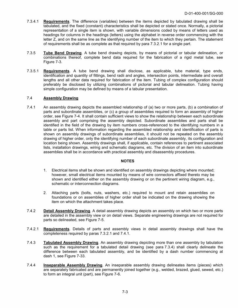
7.4.4 Inseparable Assembly Drawing. An inseparable assembly drawing delineates items (pieces) which are separately fabricated and are permanently joined together (e.g., welded, brazed, glued, sewed, etc.) to form an integral unit (part), see Figure 7-6.

D-01-400-001/SG-000
7-4
7.4.4.1 Requirements. An inseparable assembly drawing shall fully define the end-product as assembled. Pieces of the inseparable assembly may be detailed either on separate detail drawings or on the separable assembly drawing itself.
7.4.5 Matched Set Drawing. A matched set drawing depicts parts which are machine matched, or otherwise mated, and for which replacement as a matched set is essential, see Figure 7-7.
7.4.5.1 Requirements. The operating or mating characteristics of the matched parts (set) shall be stated. The matched parts may be detailed on the matched parts drawing or on separate drawings. A single part number shall be assigned to each of the matched parts and the drawing shall require unique identification marking of the matched set. “Furnished only as a matched set” or a similar note shall be on the drawing.
7.4.6 Arrangement Drawing. An arrangement drawing is a drawing that depicts in any combination of projections or perspectives, with or without controlling dimensions, the relationship of major units of the item depicted, see Figure 7-8.
7.4.6.1 Requirements. An arrangement drawing shall show sufficient views of the item so that general understanding is conveyed of the configuration and location of major units. Overall, location and other general dimensions necessary to define the configuration may be shown. Major units shall be identified.
7.4.7 Installation Assembly Drawing. An installation assembly drawing shows the installed and assembled position of an item(s) relative to its supporting structure or to associated items, see Figure 7-15.
7.4.7.1 Requirements. An installation assembly drawing shall include the following, as applicable:
(a) Listing of items to be installed;
(b) Locating dimensions and associated tolerances;
(c) Types and quantities of attachment;
(d) Process and special installation requirements;
(e) Adjustment data;
(f) Special test or inspection requirements; and
(g) Detail definition of special installation parts.
NOTE
Such drawings are used to install and assemble bell cranks, electrical wiring harnesses, tubing, etc., into the supporting structure of the end-product.
7.5 Control Drawing
7.5.1 A control drawing depicts configuration and configuration limitations, performance and test requirements, weight and space limitations, access clearance, pipe and cable attachments, and, such other information to the extent necessary so that an item can be developed or procured on the commercial market to meet the stated requirements, or, for the installation and co-functioning of an item to be installed with related items. Control drawings are identified as envelope, specification control, source control, altered item, selected item, interface control and installation control drawings.
7.5.2 Envelope Drawing. An envelope drawing depicts an item, either government or privately developed, where it is desirable to have all features other than those shown on the drawing left to the ingenuity of the producer to meet the specified performance data and design requirements. The notation “ENVELOPE DRAWING” shall be placed above the title block, see Figure 7-32.

D-01-400-001/SG-000
7-5
NOTES
1. The term “performance data” means a listing of those physical and functional characteristicsunder specified operating conditions (loads, speeds, etc.) and environmental conditions, asrequired to fully describe the essential operating characteristics under which the item mustoperate and perform. The characteristics so listed shall be defined to the degree thatinterchangeability of substitute items produced by any manufacturer is assured if the specifiedperformance is possessed by these items.
2. The term “design requirements” means the minimum performance requirements to be met bya component to satisfy the design of the end-item or a system designed for the end-item.
7.5.2.1 Requirements. Envelope drawing disclosure requirements are identical to those for specification control drawings.
NOTE
When development is completed an envelope drawing shall evolve to a set of engineering drawings; or into a specification or source control drawing; or specification, depending on the circumstances.
7.5.3 Specification Control Drawing. A specification control drawing depicts an existing commercial item or vendor developed item advertised or catalogued as available on an unrestricted basis on order as an “off-the-shelf” item or an item which, while not commercially available, is procurable on order from a specialized segment of industry. The drawing, under the heading “Suggested Source(s) of Supply” shall list the name and address, or NSCM number of two or more known sources together with their vendor part numbers, unless, after search of all vendor data for similar products, it is determined that there is only one source. In addition, the notation “SPECIFICATION CONTROL DRAWING” shall appear above the title block and in the associated lists. See Figure 7-9.
NOTES
1. The suggested sources listed on a specification control drawing are not intended to representthe only sources for the item.
2. Testing or qualification of commercial or vendor-developed items in advance of a procurementaction is not a prerequisite for inclusion of an item on a specification control drawing. If suchtesting or approval is essential, the item normally is a candidate for source control drawingcoverage.
3. Vendor-developed items are those products of industries which normally provide customer application engineering services for a commercial product line and their products are commercially available from a specialised segment of an industry. Typical examples of such items are: special motors, synchros, transformers, potentiomenters, hydraulic valves, carburetors, potted servo-amplifiers, keyboards and tape readers.
4. Altered items, selected items and items depicted in Government, Military and recognizedindustry association standards or specifications shall bit be delineated on specification controldrawings.
5. Specification control drawings shall not be used to depict commercial or vendor-developeditems upon which a design agent has placed requirements in addition to those normallyprovided by vendors. These kinds of items shall be depicted on either selected item drawingsor altered item drawings as appropriate.
6. It is not intended that this standard, by itself, cause preparation of specification controldrawings for all applicable vendor items. Preparation criteria for engineering drawings aregoverned by the contract.

D-01-400-001/SG-000
7-6
7.5.3.1 Requirements. A specification control drawing shall disclose as applicable, configuration, dimensions of envelope, mounting and mating dimensions, interface dimensional characteristics, and limits thereto. In addition, as necessary, inspection and acceptance test requirements, performance, reliability, maintainability, environmental and other functional requirements shall be shown to ensure identification and adequate reprocurement of an interchangeable item. If an electrical, electronic or similar circuit is involved, a schematic, connection or other appropriate diagrammatic disclosure shall be included on the drawing (or referenced thereon), thereby providing sufficient information for making external connections.
7.5.4 Source Control Drawing. A source control drawing depicts an existing commercial or vendor item which exclusively provides the performance, installation and interchangeable characteristics required for one or more specific critical applications. Quality conformance inspection and approval procedure shall be stated on the drawing or in a document referenced on the drawing. The drawing shall include the following as a Note 1:
“NOTE: 1: ONLY THE ITEM DESCRIBED ON THIS DRAWING WHEN PROCURED FROM THE VENDOR(S) LISTED HEREON IS APPROVED BY (NAME AND ADDRESS OF COGNIZANT DESIGN AUTHORITY) FOR USE IN THE APPLICATION(S) SPECIFIED HEREON. A SUBSTITUTE ITEM SHALL NOT BE USED WITHOUT PRIOR APPROVAL BY (NAME OR COGNIZANT DESIGN AUTHORITY) OR BY (NAME OF GOVERNMENT PROCUREMENT AUTHORITY).
IDENTIFICATION OF THE APPROVED SOURCE(S) IS NOT TO BE CONSTRUED AS A GUARANTEE OF PRESENT OR CONTINUED AVAILABILITY AS A SOURCE OF SUPPLY FOR THE ITEM DESCRIBED ON THE DRAWINGS.”
7.5.4.1 The drawing shall include, under the heading “APPROVED SOURCES OF SUPPLY”, the name and address or manufacturer’s NSCM number and vendor part number of each item that has been tested and approved for use in the specific applications stated on the drawing. In addition, “SOURCE CONTROL DRAWING” shall be shown adjacent to the title block. The item(s) thus disclosed shall be identified in all subsequent actions (including procurement) by the source control drawing number. Whenever another vendor’s item is qualified for the stated application or when a new critical application is found and all vendor items that are cited on the drawing are approved for use in the new critical application, the drawing may be revised, rather than a new drawing issued to show the new vendor or application. Each new vendor added must be approved for all stated applications, see Figure 7-10.
NOTE
Altered items, selected items and items depicted in Government, Military and recognized industry association standards or specifications shall not be delineated on source control drawings.
7.5.4.2 Requirements. Source control drawing requirements are identical to those for specification control drawings, see para 7.5.3.1.
7.5.5 Altered Item Drawing. When any standard item or design item or vendor activity item is altered, the design agent responsible for the alteration shall prepare an altered item drawing. (When a vendor document is referenced, the vendor data shall be submitted along with the altered item drawing. If vendor, or original design data, is unobtainable, the altered item drawing shall contain the necessary information required to define the requirements for that item prior to its alteration). See Figure 7-11 (Sheet 1 of 2) when vendor data is available and Figure 7-11 (Sheet 2 of 2) when the vendor is not available.

D-01-400-001/SG-000
7-7
7.5.5.1 Requirements. An altered item drawing shall delineate complete details of the alteration. The drawing shall include necessary information to identify the item prior to its alteration including the original identifying part number and, if a commercial or vendor-developed item, the name and address, NSCM number of the source of the original part. The name and address of the source need not to be furnished if the original part is a Government or industry standard item. The notation “ALTERED ITEM DRAWING” shall appear adjacent to the title block. The identification of the part so depicted shall be in accordance with para 5.7.2(b).
7.5.6 Selected Item Drawing. A selected item drawing defines an existing standard or design or vendor item with further required selection or restriction of the item for fit, tolerance, performance, or reliability within the range or limits prescribed for that item, see Figure 7-12 (Sheet 1 or 2). When a vendor document is referenced, the vendor data shall be submitted along with the selected item drawing. If vendor or original design data is unobtainable, the selected item drawing shall contain the necessary information required to define the requirements for that item prior to selection, see Figure 7-12 (Sheet 2 of 2). Although physical modification is not performed on the item, it, by virtue of the selection technique employed, is demonstratively different than those identified on the document from which selection was made.
7.5.6.1 Requirements. A selected item drawing shall delineate the complete details on which selection of the item is predicted with a full disclosure of the range or limit restrictions for fit, tolerance, performance, or reliability. In addition, the drawing shall include all necessary information to identify the item prior to its delimited selection including the original identifying part number and, if a commercial or vendor-developed item, the name and address, the NSCM number of the original source. The notation “SELECTED ITEM DRAWING” shall appear adjacent to the title block. The identification of the part so depicted shall be in accordance with para 5.7.2(b).
7.5.7 Interface Control Drawing. An interface control drawing depicts physical and functional interface engineering requirements of an item which affects the design or operation of co-functioning items. These drawings are used as design control documents, delineating interface engineering data coordinated for the purpose of:
(a) Establishing and maintaining compatibility between co-functioning items;
(b) Controlling interface designs, thereby preventing changes to requirements of items which would affect compatibility with co-functioning sub-systems; and
(c) Communicating design decisions and changes, see Figure 7-13.
7.5.7.1 Requirements. An interface control drawing shall delineate, as necessary:
(a) Configuration and all interface dimensional data applicable to the envelope, mounting and mating of the items;
(b) Complete interface engineering requirements, such as mechanical, electrical, electronic, hydraulic, pneumatic, optical, etc., which affect the physical or functional characteristics of co-functioning items; and
(c) Any other characteristics which cannot be changed without affecting system design criteria. Interface drawings may be categorized as mechanical, electrical, interconnections, configuration and installation, operational sequence requirements, system switching, etc., as necessary. The notation “INTERFACE CONTROL DRAWING” shall be shown, adjacent to the title block.
7.5.8 Installation Control Drawing. An installation control drawing sets forth information for an item in terms of area, weight and space, access clearance, draining clearances, pipe and cable attachments required for the installation and co-functioning of the item to be installed with related items, see Figure 7-14.

D-01-400-001/SG-000
7-8
7.5.8.1 Requirements. An installation control drawing shall include the overall and principal dimensions in sufficient detail to establish the limits of space in all directions required for installation, operation and servicing. The amount of clearance required to permit the opening of doors or the removal of plug-in units shall be included. Clearance for travel or rotation of any moving parts shall be shown, including the centres of rotation, angles of train in azimuth, elevation and depression, and radii from each pivot to the end of each rotating element involved in clearance determination. In addition, the notation “INSTALLATION CONTROL DRAWING” shall be shown adjacent to the title block.
7.6 Installation Drawing
7.6.1 An installation drawing shows general configuration and complete information necessary to install the item relative to its supporting structure or to associated items, see Figure 7-36. An installation drawing may show a specific completed installation. Installation drawings for one-of-a-kind installation may be revised to record the as-installed or as-built condition.
7.6.1.1 Requirements. An installation drawing may include the following, as applicable:
(a) Interface mounting and mating information such as dimensions of location for attaching hardware;
(b) Interface pipe and cable attachments required for the installation and co-functioning of the item to be installed with related items;
(c) Information necessary for the preparation of foundation plans, including mounting plate details, drilling plans and shock mounting and buffer details;
(d) Location, size and arrangement of ducts;
(e) Weight of unit;
(f) Location, type and dimensions of cable entrances, terminal tubes and electrical connectors;
(g) Interconnecting and cabling data;
(h) Reference notes to applicable lists and assembly drawings;
(i) Overall and principal dimensions when not disclosed on an installation control drawing (see para 7.5.8) in sufficient detail to establish the limits of space in all directions required for installation, operation and servicing; the amount of clearance required to permit the opening of doors or the removal of plug-in units; clearance for travel or rotation of any moving parts, including the centres of rotation, angles of elevation and depression;
(j) An integral parts list to establish the requirements for the installation hardware, and if desired, the items being installed;
(k) The term “INSTALLATION DRAWING” in the second part of the drawing title;
(l) When applicable, as a general note, “USE IN CONJUNCTION WITH” (using assembly drawing title and number); and
(m) Special tools which may be required, referenced in general notes or installation instructions.
7.6.2 Elevation Drawing. An elevation drawing depicts vertical projections of buildings or structures; or profiles of equipment such as aircraft, vehicles and ships, or portions of the same, see Figure 7-16.
7.6.2.1 Requirements. As applicable, an elevation drawing shows configuration, shapes and sizes of features, walls, bulkheads, compartments, assignment of space, location and arrangement of machinery or fixed equipment. An elevation drawing may indicate materials of construction.

D-01-400-001/SG-000
7-9
7.7 Diagrammatic Drawing
7.7.1 A diagrammatic drawing delineates features and relationship of items forming an assembly or system by means of symbols and lines. A diagrammatic drawing is a graphic explanation of the manner by which an installation, assembly or system (e.g., mechanical, electrical, electronic, hydraulic, pneumatic) performs its intended function.
7.7.2 Electrical Schematic Diagram. An electrical schematic diagram and elementary wiring diagram show, by means of graphic symbols, the connections and functions of a specific circuit arrangement. A schematic diagram facilitates tracing the circuit and its functions without regard to the actual physical size, shape, or location of the component devices or parts, see Figure 7-17 and MIL STD 15-2 and ASME Y14.5.
7.7.3 Connection Diagram. A connection or wiring diagram shows the electrical connections of an installation or of its component devices or parts. It may cover internal or external connections, or both, and it contains such detail as is needed to make or trace connections that are involved. A connection diagram usually shows general physical arrangement of the component devices or parts, see Figure 7-18 and ASME Y14.5. A connection diagram may be prepared in the form of a “running wire list”, see para 7.8.2 and Figure 7-24.
7.7.4 Interconnection Diagram. An interconnection diagram is a form of connection or wiring diagram which shows only external connections between units, sets, groups, and systems, see Figure 7-19, and ASME Y14.5. Concerning a form of interconnection diagram known as a “running wire list”, see para 7.8.2 and Figure 7-24.
7.7.4.1 Requirements. When preparing interconnection diagrams the following shall be included:
(a) Wire and cable identification and core markings;
(b) When cable assemblies and wiring harnesses are represented by single heavy lines, the direction of any wires leaving the cable or harness shall be shown;
(c) Each wire and conductor within a cable, shall be identified by a wire identification code at each end, except short wires and cables less than three inches in length, such as jumpers. The contact of the connector or terminal of the terminal board shall be identified;
(d) Each wire shall have the other end termination noted above the wire line and following the wire identification;
(e) The internal circuit function of all terminations shall be identified;
(f) All connections, terminal boards, etc., shall be identified; and
(g) All equipment relevant to the installation shall be delineated and identified on the field of the drawing.
7.7.5 Single Line or One Line Diagram. A single line or one line diagram shows, by means of single lines and graphic symbols, the course of an electric circuit, or system of circuits and the component devices or parts used therein, see Figure 7-20 and ASME Y14.5.
7.7.6 Logic Diagram. A logic diagram shows, by means of graphic symbols, the sequence and function of logic circuity, see Figure 7-21.
7.7.7 Mechanical Schematic Diagram. A mechanical schematic diagram illustrates the operational sequence or arrangement of a mechanical device(s), see Figure 7-22.
7.7.8 Piping Diagram. A piping (hydraulic, pneumatic, or fluid) diagram depicts the interconnection of components by piping, tubing or hose, and when desired, sequential flow of fluids in the system, see Figure 7-23.

D-01-400-001/SG-000
7-10
7.7.8.1 Requirements. Sufficient detail shall be shown to explain the arrangement or operational sequence of the piping, valves, etc. Symbolic line representation may be used to distinguish functions of various parts. When the objective is to show arrangement, the following characteristics may be shown: routing of fluids, physical locations and arrangement of compounds, pipe diameters, types and sizes of fittings, flow, pressure, volume, etc.
7.8 Special Purpose Drawings
7.8.1 Special purpose drawings are other than end item drawings used to supplement end item requirements. These kinds of engineering drawings may be required for management control, logistic purposes, configuration management, manufacturing aids and other functions unique to a DND design agent.
7.8.2 Running Wire List Drawing. A running wire list drawing consists of tabular data and instructions required to establish wiring connections between units of an equipment or between equipments, sets or assemblies of a system. A running wire list is a form of interconnection diagram and does not require a parts list, see Figure 7-24.
7.8.2.1 Requirements. An individual list shall be prepared for each cable or unit. The principal parts of a running wire list shall indicate wiring connections and normally indicate the function of each wire, the “from” and “to” end termination of each wire and the colour code of each wire. The unit shall be listed by unit designation and nomenclature. Included in note or tabular form should be instructions, notes and references thereto, any necessary illustrations or figures to supplement the tabulations, and summaries of cabling information by units.
7.8.3 Wiring Harness Drawing. A wiring harness drawing shows the path of a group of wire laced together in a specified configuration, so formed to simplify and standardize the manufacture and installation.
7.8.3.1 Requirements. The drawing shall include an integral parts list, a wire destination table listing the assigned wire numbers, wire colours, wire lengths, “from” and “to” end terminations and item number cross-referenced to the applicable integral number for that wire in the item parts list. Instructions and references for the manufacture of the harness and other data as necessary should be included in note form. The conductors and attachments shall be shown by means of single lines and graphic symbols. The drawing shall completely define the harness form and termination points by:
(a) A completely dimensioned drawing, see Figure 7-25 (Sheet 1 of 3);
(b) A grid system of vertical and horizontal graphic scales which are provided instead of dimensions, for use in ascertaining the required dimensional data, see Figure 7-25 (Sheet 2 of 3);
(c) An undimensioned drawing which shows the wires developed in an accurate template form, whereby full size copies of the drawing can be used as a peg-board, where the drawing is fastened down, brads of the indicated size driven in at designated locations and the wires routed and laced so as to form a harness of the required configuration, see Figure 7-25 (Sheet 3 of 3).
7.8.4 Cable Assembly Drawing. A cable assembly drawing depicts a definite length of electrical cable having one or both ends processed, processed and terminated, or either, in fittings that provide for connection to other items, see Figure 7-26.
7.8.4.1 Requirements. A cable assembly drawing shall include the following information as applicable: overall dimensions, including or excluding terminations, tolerances, preparation of wiring or schematic diagram, identifying colour code of wires and termination terminals, identification bands or marking, special cable end preparation instructions, applicable tests, finish, if any, and special assembly instructions.
7.8.5 Lead Assembly Drawing (Single Conductor). This drawing depicts a definite length of electrical wire or similar conductor, one or both ends of which are processed or terminated, see Figure 7-27 (Sheet 1 of 2).

D-01-400-001/SG-000
7-11
7.8.5.1 Requirements. The lead assembly single conductor shall be prepared as for a mono-detail or assembly drawing except that the conductor shall be shown by means of a single line and the attachments by graphic symbols. The wire designation shall be inserted near the left end of the conductor.
7.8.6 Lead Assembly Drawing (Multi-Conductor). This drawing depicts definite lengths of two or more electrical wires or similar conductors which are not jacketed, bound, or laced together, but which have at least one of their ends processed in a single common termination or fitting, see Figure 7-27 (Sheet 2 of 2).
7.8.6.1 Requirements. The drawing shall be prepared as for an assembly drawing except that the conductors, connectors, etc., shall be shown by means of single lines and graphic symbols. A wire designation shall be inserted near the left end of each conductor. Short wires, such as jumpers, do not necessarily require a designation.
7.8.7 Undimensioned Drawing. An undimensioned drawing depicts to a precise scale, loft line information, a template, a pattern or a printed circuit, see Figure 7-37.
7.8.7.1 Requirements. Undimendioned drawings shall include all information necessary to fabricate parts with established manufacturing limits.
7.8.8 Printed Wiring Master Drawing. A master drawing is one that shows the dimensional limits or grid location applicable to any or all parts of a printed circuit, including the base, see Figure 7-28.
7.8.8.1 Requirements. The master drawing establishes the size and shape of the board, the size and location of all holes therein, and the shape or arrangement of both conductor and non-conductor patterns or elements, with separate views of each side of double-sided boards or multi-layer boards. All pattern features not controlled by the hole sizes and locations shall be adequately dimensioned either specifically or by notes. All locations on the master drawing shall be dimensioned by use of a modular grid system. The basic modular units of length shall be 0.100, 0.050, or 0.25 inch, in that order of preference. The basic unit shall be applied in the “X” and “Y” axes Cartesian coordinates. All locations shall either be dimensioned on the drawing or indicated by means of a grid intersection. This applies to the location of terminal areas, holes, and test points, and overall printed wiring board dimensions. Critical pattern features which may affect circuit performance because of distributed inductance or capacitance effects, shall also be dimensioned.
7.8.9 Kit Drawing. A kit drawing indicates or depicts a packaged unit, item or group of items, instructions, photographs or drawings such are used in modification, installation or survival. The items in a kit normally do not in themselves constitute a complete functional assembly. A kit drawing may be a listing of part numbers, a pictorial representation of parts or a combination of both, see Figure 7-29.
7.8.9.1 Requirements. A kit drawing shall include or reference a list of the entire kit contents, including part numbers and part nomenclature and quantities required.
7.8.10 Formulation Drawing. A formulation drawing depicts the constituents of an explosive, propellant, pyrotechnic, filler, etc. It is used to discretely identify the mixture, its weight, volume, or particle size as used within the particular formulation, see Figure 7-30.
7.8.10.1 Requirements. Formulation drawings are textual drawings which, as a minimum, disclose and identify a chemical mixture or compound by use of dicrete identification. In addition, the weight, volume, percentage composition, or particle size of the chemical or compound making up the formulation shall be defined along with the necessary batching and processing steps required to attain the required formulation.
7.8.11 Ship Equipment Drawing. A ship equipment drawing depicts components, equipment and systems, e.g., pumps or radar systems that may be used on one or more ships. See Figure 7-31.

D-01-400-001/SG-000
7-12
7.8.11.1 Requirements. Ship equipment drawings must be considered for each application in three divisions, as follows:
(a) Equipment drawings previously accepted for shipboard use and also approved for the particular application;
(b) Equipment drawings previously accepted for shipboard use but not approved for the particular application; and
(c) Equipment drawings not previously accepted for shipboard use.
7.8.11.2 Weight and Centre of Gravity. The net weight and also the operating weight with fluids, where applicable, shall be indicated. In addition, the vertical, longitudinal, and transverse location of the centre of gravity (wet or dry, as appropriate) of each separate ship-installed unit or assembly weighing 100 pounds or more shall be shown on the outline drawings, assembly drawings, manufacturer’s control drawings, or installation drawings.
7.8.12 Modification Drawing. Modification drawings delineate changes to delivered item assemblies, installations or systems. Modification drawings show the addition, removal or reworking of item equipment installations, or systems to satisfy the design authority’s requirements or to incorporate mandatory changes (i.e., safety, reliability, or application extension) in delivered equipment. Indicate above or adjacent to the title block the words “MODIFICATION DRAWING”. See Figure 7-35.
7.8.12.1 Requirements. Modification drawings contain complete information for accomplishing the change, including, as applicable:
(a) Instructions for the removal or installation of affected parts;
(b) Special notes, including identification by the drawing number of the modified part;
(c) Dimensions necessary to accomplish the modification;
NOTE
These should be given from some specific point which is readily identified and accessible, rather than from some theoretical reference plane.
(d) A parts list (integral or separate) containing all items required for the modification and items to be deleted or salvaged and items to compile a kit, as applicable;
(e) Listing of special tools or equipment required or supplied; and
(f) Identification of the items which are to be modified, i.e., serial number, aircraft tail number, ship’s pennant number, etc.
7.8.13 Wireway Routing Drawings. Wireway routing drawings show the cableway routing throughout the ship and shall include sufficient compartment or space detail to show wireway location and obstructions. Wireway routing drawings shall also show construction and installation details.
7.8.13.1 Requirements. Wireway routing drawings shall depict the following:
(a) Space requirements for the wireways;
(b) General configuration of the wireways;
(c) General cable lay at various sections;
(d) Cables within the wireways together with entries and exits as shown by cable designations;

D-01-400-001/SG-000
7-13
(e) Mounting and fastening methods;
(f) Methods of entering bulkheads or penetrating decks;
(g) Methods for fire blocking openings in bulkheads and decks where applicable;
(h) Details of conduit usage and associated methods of blocking (see para i);
(i) Stuffing tubes or transits which are used for penetrating water tight, gas tight, flame tight, or smoke inhibiting bulkheads;
(j) Mounting and fastening methods for vertical risers;
(k) Additional information in note form which may be provided as appropriate on any of the above requirements, as well as, material requirements, estimated weight of cable and wireway within specified areas and installation instructions.

D-01-400-001/SG-000
7-14
Figure 7-1 Mono-Detail Drawing

D-01-400-001/SG-000
7-15
Figure 7-2 Tabulated Detail Drawing

D-01-400-001/SG-000
7-16
Figure 7-3 Tube Bend Drawing

D-01-400-001/SG-000
7-17
Figure 7-4 Assembly Drawing

D-01-400-001/SG-000
7-18
Figure 7-5 Detail Assembly Drawing

D-01-400-001/SG-000
7-19
Figure 7-6 (Sheet 1 of 2) Inseparable Assembly Drawing
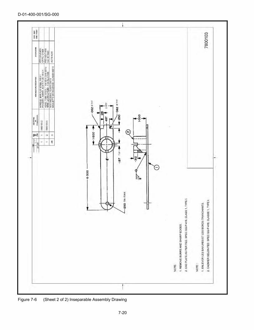
D-01-400-001/SG-000
7-20
Figure 7-6 (Sheet 2 of 2) Inseparable Assembly Drawing
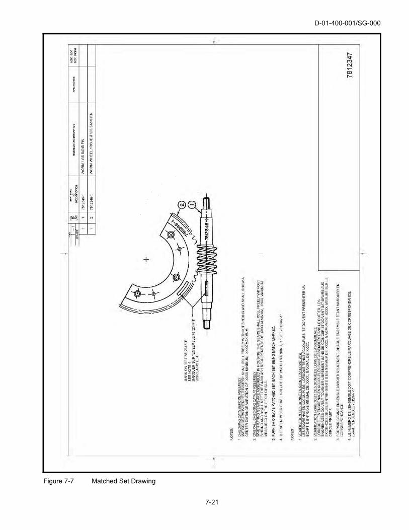
D-01-400-001/SG-000
7-21
Figure 7-7 Matched Set Drawing

D-01-400-001/SG-000
7-22
Figure 7-8 Arrangement Drawing

D-01-400-001/SG-000
7-23
Figure 7-9 Specification Control Drawing

D-01-400-001/SG-000
7-24
Figure 7-10 Source Control Drawing

D-01-400-001/SG-000
7-25
Figure 7-11 (Sheet 1 of 2) Altered Item Drawing (Vendor Data Available)

D-01-400-001/SG-000
7-26
Figure 7-11 (Sheet 2 of 2) Altered Item Drawing (Vendor Data Not Available)

D-01-400-001/SG-000
7-27
Figure 7-12 (Sheet 1 of 2) Selected Item Drawing

D-01-400-001/SG-000
7-28
Figure 7-12 (Sheet 2 of 2) Selected Item Drawing (Dimensional)

D-01-400-001/SG-000
7-29
Figure 7-13 Interface Control Drawing

D-01-400-001/SG-000
7-30
Figure 7-14 Installation Control Drawing

D-01-400-001/SG-000
7-31
Figure 7-15 Installation Assembly Drawing

D-01-400-001/SG-000
7-32
Figure 7-16 Elevation Drawing

D-01-400-001/SG-000
7-33
Figure 7-17 Electrical Schematic Drawing

D-01-400-001/SG-000
7-34
Figure 7-18 (Sheet 1 of 2) Connection Diagram

D-01-400-001/SG-000
7-35
Figure 7-18 (Sheet 2 of 2) Connection Diagram

D-01-400-001/SG-000
7-36
Figure 7-19 Interconnection Diagram

D-01-400-001/SG-000
7-37
Figure 7-20 Single Line or One Line Diagram

D-01-400-001/SG-000
7-38
Figure 7-21 Logic Diagram

D-01-400-001/SG-000
7-39
Figure 7-22 Mechanical Schematic Drawing

D-01-400-001/SG-000
7-40
Figure 7-23 Piping Diagram

D-01-400-001/SG-000
7-41
Figure 7-24 Running Wire List Drawing

D-01-400-001/SG-000
7-42
Figure 7-25 (Sheet 1 of 3) Wiring Harness Drawing

D-01-400-001/SG-000
7-43
Figure 7-25 (Sheet 2 of 3) Wiring Harness Drawing
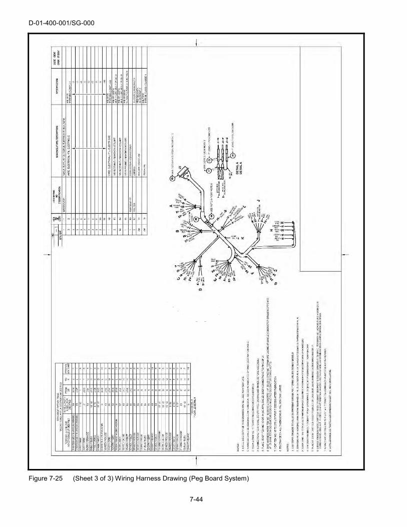
D-01-400-001/SG-000
7-44
Figure 7-25 (Sheet 3 of 3) Wiring Harness Drawing (Peg Board System)

D-01-400-001/SG-000
7-45
Figure 7-26 Cable Assembly Drawing

D-01-400-001/SG-000
7-46
Figure 7-27 (Sheet 1 of 2) Lead Assembly Drawing (Single Conductor)

D-01-400-001/SG-000
7-47
Figure 7-27 (Sheet 2 of 2) Lead Assembly Drawing (Multi-Conductor)

D-01-400-001/SG-000
7-48
Figure 7-28 Printed Wiring Master Drawing

D-01-400-001/SG-000
7-49
Figure 7-29 Kit Drawing

D-01-400-001/SG-000
7-50
Figure 7-30 Formulation Drawing

D-01-400-001/SG-000
7-51
Figure 7-31 Ship Equipment Drawing

D-01-400-001/SG-000
7-52
Figure 7-32 Envelope Drawing

D-01-400-001/SG-000
7-53
Figure 7-33 Tabulated Drawing Assembly

D-01-400-001/SG-000
7-54
Figure 7-34 Multidetail Drawing

D-01-400-001/SG-000
7-55
Figure 7-35 Modification Drawing

D-01-400-001/SG-000
7-56
Figure 7-36 Installation Drawing

D-01-400-001/SG-000
7-57/7-58
Figure 7-37 Undimensioned Drawing


D-01-400-001/SG-000
8-1
SECTION 8 REVISION OF ENGINEERING DRAWINGS
8.1 Scope
8.1.1 This section covers the requirement of revising approved original engineering drawings and for identifying and recording revisions. The instructions in this section take precedence over similar instructions in ASME Y14.100.
8.2 Revision Methods
8.2.1 Revisions shall be made by removal and/or addition of information or by redrawing, whichever is most suitable.
8.2.2 The introduction of additional drawings or lists constitutes a revision.
8.3 Identifying Revision of Drawings
8.3.1 A description of every change, addition or deletion shall be recorded on a Technical Data Action Notice (TDAN).
8.3.2 Revision Letters. Upper-case letters shall be used and shall be in alphabetical sequence. The letters “I”, “O”, “Q” and “X” shall not be used. When revisions are numerous enough to exhaust the alphabet, the revision following “Z” shall be “AA”, the next “AB” then “AC”, and so on. Should “AA” to “AZ” be exhausted, the next sequence shall be “BA”, “BB”, and so on. Revision letters shall not exceed two characters. The first revision for a drawing shall be assigned the letter “A”. Release of a drawing does not constitute need for a revision letter.
8.3.3 Multiple Changes. All changes to a drawing incorporated at one time shall be identified by one revision letter.
8.4 Recording Revisions on Drawings
8.4.1 Revision Block Entry. Each revision to a drawing sheet shall be recorded in the revision block of that sheet in accordance with Figure 8-1 and the following (see para 3.6.19 for revision block format):
(a) Zone Column. This column is not used and a dash (-) shall be inserted.
(b) Letter (LTR) Column. The identifying letter pertaining to the particular revision being recorded shall be entered in the revision letter column.
(c) Revision Column. The identifying number of the Technical Data Action Notice (TDAN), shall be entered in the revision column. See Figures 8-1 and 8-2.
(d) Date Column. This column shall contain the date the revision is approved.
(e) Drawn (DWN) Column. This column shall contain the initials of the draftsperson.
(f) Checked (CKD) Column. This column shall contain the initials of the checker.
(g) Approval (APPVL) Column. This column shall contain the initials of the design authority.
8.4.2 Revision History. In cases where an engineering drawing/data list has undergone a number of revisions, and there is insufficient space to continue the revision block, the oldest entries in the revision block shall be removed to make space for the next revision. The retained revision history shall be shifted into the space created by the removal to ensure that the chronological order of the revision history is maintained.

D-01-400-001/SG-000
8-2
8.5 Revision of Multisheet Drawings
8.5.1 Concurrent Changes. Concurrent changes made upon any or all sheets of a multisheet drawing shall be identified by the same revision letter. Each subsequent revision affecting any or all sheets shall be identified on sheet 1 by the revision letter next in sequence to that used for designating the last revision.
8.5.2 Tabulation of Revisions. Revision upon any sheet of the group shall be made and recorded in accordance with para 8.4, except that the sequence of revision letters shall apply to the group as a whole rather than to each individual sheet. Sheet 1 shall include a tabulation similar to that shown in Figure 8-1 (sheet 1 of 4) to indicate the revision status of each sheet in the group. Whenever a change is made on any sheet, the revision letter applicable to that change shall be entered in the revision status block on sheet 1, in the column for the revised sheet and also in the column for sheet 1 (regardless of whether there is another change on sheet 1). For each of the other sheets, the last applicable revision letter shall be entered in the appropriate column of the revision status block. For all sheets that have never been revised, a dash shall be entered in the appropriate columns.
8.5.3 Addition of New Sheets. When a multisheet drawing is revised to include new sheet(s), the new sheet(s) shall have the same revision letter as the other revised sheet(s) in the group.
8.6 Redrawn or Replaced Drawing (Retained for Reference)
8.6.1 When a drawing is being redrawn or replaced, and retained for reference the original drawing shall be revised by a revision using the revision letter next in sequence, and the following note shall be added adjacent to the title block: “REPLACED WITH CHANGE or (WITHOUT CHANGE) BY REVISION ‘....’ DO NOT DESTROY”.
8.6.2 The new drawing shall be introduced by amendment, and the following note shall be placed by the title block: “REPLACES REVISION ‘....’ WITH CHANGE or (WITHOUT CHANGE)”.
8.6.3 The revision letter for the amendment on the new drawing shall follow in sequence the last revision letter on the old drawing.
NOTE
The revision record on the original drawing shall be omitted from the revision block of the new drawing.
8.7 Cancelled Drawings (Retained for Reference)
8.7.1 When a drawing is being cancelled and the drawing retained for reference it shall be cancelled by a revision using the revision letter next in sequence, and the following note shall be added adjacent to the title block: “CANCELLED, REPLACED BY DRAWING NO .....”, or (NO REPLACEMENT) “DO NOT DESTROY”.
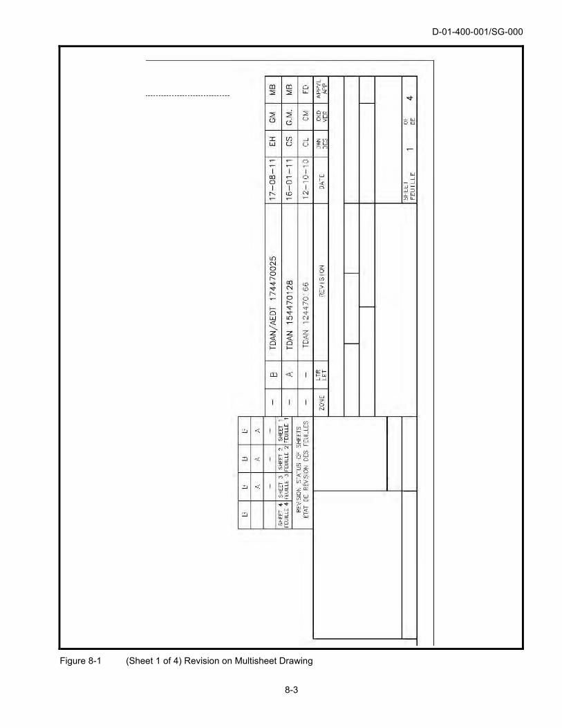
D-01-400-001/SG-000
8-3
Figure 8-1 (Sheet 1 of 4) Revision on Multisheet Drawing
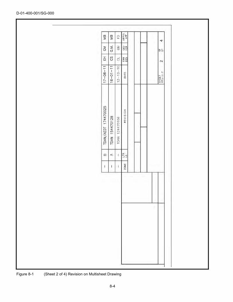
D-01-400-001/SG-000
8-4
Figure 8-1 (Sheet 2 of 4) Revision on Multisheet Drawing

D-01-400-001/SG-000
8-5
Figure 8-1 (Sheet 3 of 4) Revision on Multisheet Drawing

D-01-400-001/SG-000
8-6
Figure 8-1 (Sheet 4 of 4) Revision on Multisheet Drawing

D-01-400-001/SG-000
8-7/8-8
Figure 8-2 Technical Data Action Notice


D-01-400-001/SG-000
9-1
SECTION 9 ASSOCIATED LISTS
9.1 Scope
9.1.1 This section establishes the minimum requirements for the preparation of associated lists including but not limited to, parts lists and data lists. The instructions in this section take precedence over similar instructions in ASME Y14.100.
9.2 Parts List (PL)
9.2.1 A parts list is a tabulation of all parts and bulk materials (except those materials which support a process) used in the item to which the list applies. Reference documents may also be tabulated on a parts list. A parts list integral with the drawing is the preferred method.
9.3 Data List (DL)
9.3.1 A data list shall list and identify all drawings, subsidiary DLs, installation instructions (notes) and other documents, required for the manufacture of an item, in accordance with the requirements of the design authority. A data list shall be prepared for all general assemblies, arrangement drawings, kit drawings and subassemblies under the conditions indicated in para 9.5.1, and for groups of related independent drawings and items, for which no assembly drawings exist.
9.3.2 Sequence. The drawings and other documents to be listed shall be segregated into groups in the order shown under the following headings:
(a) Subsidiary Data Lists;
(b) Engineering Drawings;
(c) Parts Lists (if not integral to the drawing); and
(d) Notes.
9.4 Cover Sheet
9.4.1 A cover sheet shall be prepared to support one or more of the following conditions:
(a) Drawings prepared or supplied to support a contract; and
(b) When commercial, foreign government or joint ownership drawings are prepared or supplied.
9.4.2 Sequence. The listing of information shall be grouped in the order shown under the following headings:
(a) CONTRACT NO.; and
(b) PROPRIETARY RIGHTS.
9.5 List Preparation
9.5.1 The type(s) of list(s) to be prepared, drawing assembly level at which lists will be prepared, and whether parts lists shall be prepared integral or separate from the drawing shall be as determined by DND.
NOTE
When separate parts lists are prepared, a note “SEE SEPARATE PARTS LIST PL-XXXXXXX-X” shall be located adjacent to the title block of the parent engineering drawing.

D-01-400-001/SG-000
9-2
9.5.2 Sheet Numbering. All sheets shall be numbered consecutively starting with number 1. The first sheet shall indicate the total number of sheets in the list. When a cover sheet is used, it shall be numbered sheet 1.
9.6 Revisions
9.6.1 Lists may be revised independently of the associated drawings.
9.6.2 Revision Identification. A revision letter and the date of revision shall be applied to each list or each affected sheet of a list when any change is made. The letters “I”, “O”, “Q” and “X” shall not be used as revision letters.
9.6.3 Adding Items. New or superseding items may be either added at the end of a list or inserted in the list in the proper sequence.
9.6.4 Revision Description. A description of every change, addition or deletion shall be recorded on a Technical Data Action Notice (TDAN).
9.7 Design Agent Identification
9.7.1 The design agent’s name and address or NSCM number shall be entered on all associated lists in the block provided by format.
9.8 Additional Blocks and Columns
9.8.1 Additional blocks and columns may be added for use of the design agent.
9.9 Data List
9.9.1 A data list shall list the drawings, documents and associated lists pertaining to the item for which the data list is prepared. Data lists shall be prepared on the format illustrated in Figure 9-1. A note “SEE DATA LIST DL-XXXXXXX-X” shall be located close to the title block of any drawing for which a DL has been prepared. DLs shall also be prepared for subassemblies under the following conditions:
(a) When a requirement exists for a subassembly to be stocked as a separate item;
(b)
(c)
9.9.2
When a subassembly is used on more than one assembly; or
When the design authority specifies the complexity of a subassembly justifies a DL.
Entries (DL). Entries shall be made in the blocks and columns of the data list as directed below and
shall be upper case letters.
(a) Design Agent Block. The name and address or NSCM number of the contractor (or design agent) shall be entered on each sheet.
(b) Contract Number (CN No.) Block. The contract number under which the list is initially prepared is entered in this block. Each sheet of the list requires this entry.
(c) NSCM Number Block. The NSCM number designating the design authority shall be entered on each sheet.
(d) Canadian Armed Forces Approval (CAF appvl) Block. This block shall contain the designation and signature of the design authority.
(e) Date Block. This block shall contain the date of the CAF approval by the design authority. The date shall be uniform; for example, 30 January 2017, shall be written as “30-Jan-17”.
(f) Compiled Block. This block shall contain the name or initials of the person who prepared the list.

D-01-400-001/SG-000
9-3
(g) Checked (CKD) Block. This block shall contain the name or initials of the person who checked the list.
(h) Revision (Rev) Block. This block shall contain the revision letter, authorizing document (TDAN), initials of the checker and the date of revision, as applicable to the sheet.
(i) Data List (DL) Number. This block shall contain the same number as the drawing for which the list is prepared and shall appear on each sheet of the list.
(j) Revision Letter (Rev Ltr) Block. When the list is initially released, enter a dash (-) and release date on sheet 1 of the list. Each time a sheet of the list is revised, enter the appropriate revision letter and revision date in this block on sheet 1.
(k) Sheet Number Block. Enter the appropriate sheet number on each sheet. The total number of sheets in the list shall be entered as specified in 9.5.2.
(l) NATO Stock Number (NSN) Block. This block shall contain the NATO stock number of the item referenced.
(m) Title Block. This block shall contain the basic noun or noun phrase of the item to which the list applies.
(n) Line Column. This column shall contain the line number of the entry being made.
(o) Identifying Number Column. This column shall contain the assigned number of each document listed in numerical or alpha-numerical order.
(p) Title – Description Column. As a minimum enter the assigned noun or noun phrase of each document whose number appears in the identifying number column.
(q) Application Column. This column shall contain the identifying number of the next assembly to which the drawing applies.
(r) Supplementary Data Column. This column may contain such data as specification numbers, NATO stock numbers, commercial item numbers and other related data.
9.10 Cover Sheet Preparation
9.10.1 The cover sheet shall be used to satisfy the conditions listed in 9.4. A cover sheet shall be prepared using the format illustrated in Figure 9-2.
9.10.2 Entries, Cover Sheet. Entries shall be made in the blocks of the cover sheet as directed in Section 9.9, Data Lists, and shall be typed in upper case letters. When a cover sheet is required it shall become sheet 1 of the list.
9.10.3 Listing of Information. The information shall be in sufficient detail to identify and meet the conditions identified in accordance with para 9.4 and the information shall be grouped in accordance with para 9.4.2.

D-01-400-001/SG-000
9-4
Figure 9-1 Data List

D-01-400-001/SG-000
9-5/9-6
Figure 9-2 Cover Sheet


D-01-400-001/SG-000
10-1
SECTION 10 DEFINITIONS
10.1 Scope
10.1.1 This part contains a list of definitions for terms used in this standard.
10.2 Assembly
10.2.1 An assembly is a number of parts or subassemblies or any combination thereof joined together to perform a specific function e.g. gear train, fan assembly, amplifier, etc.
NOTE
The distinction between an assembly and a subassembly is determined by the individual application. An assembly in one instance may be a main assembly and in another, where it forms a portion of a larger assembly, a subassembly.
10.3 Bulk Materials
10.3.1 "Bulk Materials" are those necessary constituents of an assembly or part such as oil, wax, solder, cement, ink, damping fluid, grease, powdered graphite, flux, welding rod, thread, twine and chain, for which the quantity required is not readily predetermined or, if knowing the quantity, the physical nature of the material is such that it is not adaptable to depiction on a drawing; or which can be cut to finished size without any further machining operations and the configuration is such that it can be fully described in writing without the necessity of pictorial presentation.
10.4 Contract
10.4.1 The agreement, enforceable by law, for the supply of materiel or performance of services, not prohibited by law, entered into by the contracting authority on behalf of the Department of National Defence, for a legal consideration, with an organization or individual, thereafter called the contractor.
10.5 Contractor
10.5.1 One who contracts to perform work or furnish materiel in accordance with the contract.
10.6 Dash Numbers
10.6.1 Dash numbers are used to identify variables listed on a drawing. A dash number may also be used suffixed to the drawing number to form a part number for part identification.
10.7 Data List
10.7.1
10.8
A data list is a document which lists and identifies all subsidiary DLs, drawings, instructions and notes.
Design Authority (DA)
10.8.1 The office within the Department of National Defence responsible for the design or the approval of the design or changes thereto for a specific item of defence materiel.
NOTE
This is equivalent to “Design Activity” in the ASME Y14 standards.

D-01-400-001/SG-000
10-2
10.9 Design Agent
10.9.1 An office responsible to the design authority for the development or modification of the design and preparation of engineering data for a specific item of defence materiel. This agent may be a Departmental office, a contractor or others, for example NETE, LESC, ATESS, and 202 WORKSHOP.
10.10 Document
10.10.1 A document may be a specification, a drawing, a list, a standard, a pamphlet, a report or other information relating to the design, procurement, manufacture, test or inspection of items or services under the contract.
10.11 Formulation
10.11.1 Formulations are mixtures such as explosives, fillers, propellants, pyrotechnics, etc. Each formulation is discretely identified. Formulations are not to be construed as "bulk materials".
10.12 Item
10.12.1 A uniquely identified object adapted for use. An item may form part of another item and may include materials, parts, assemblies, equipment, accessories and attachments.
10.13 Level – LEVEL
10.13.1 The classification engineering content as selected from D-01-400-002/SF-000.
10.14 Manufacturer
10.14.1 A manufacturer is a person or firm who operates or maintains a factory or establishment that produces the materials, supplies, articles or equipment required under the contract or of the general character described by the specifications, standards and publications.
10.15 Master Drawings
10.15.1 The latest official version of the drawing/data list.
10.16 May
10.16.1 "May" should be used to express permissive action, if necessary, and is normally directed to contractor activities.
10.17 NATO Supply Code for Manufacturers (NSCM)
10.17.1 The NSCM number is a five character numeric code used to identify all activities which have produced or are producing items used by DND. These numbers are assigned in accordance with A-LM-137-C0M/LX-001 or H4-1, H4-2. Organizations which neither manufacture nor control design such as dealers, agents or vendors of items produced by others are not included. This is equivalent to the terms "Cage Code" and "NCAGE" in the ASME standards.
10.18 Part
10.18.1 A part is one piece, or two or more pieces joined together which are not normally subject to disassembly without destruction or impairment of designed use.
10.19 Part Number
10.19.1 Part numbers are numbers assigned to identify a specific item.
D-01-400-001/SG-000
10-3
10.20 Revision
10.20.1 The term "revision" as used herein refers to any change to a drawing/data list.
10.21 Revision Authorization Document
10.21.1 A revision authorization document describes the revision in detail and is issued by the office having the authority to revise the drawing. A Technical Data Action Notice (TDAN), see para 10.30.1, shall be used for DND/CAF drawings/associated lists.
10.22 Revision Symbol
10.22.1 A revision symbol is an identifying letter which denotes the revision status of the drawing.
10.23 Shall
10.23.1 The word "shall" shall be used for expressing requirements which are binding on the contractor and similar non-government sources, e.g., subcontractor, prime contractor, manufacturer, supplier, vendor, etc. The word "shall" shall not be used to indicate action by the Government authorities, e.g., design, inspection, procurement, etc. The word "must" shall not be used as an alternative for "shall".
10.24 Should
10.24.1 "Should" shall be used to express informative information and is normally directed to contractor activities.
10.25 Standards
10.25.1 "Standards" are documents that establish engineering and technical limitations and application for items, materials, processes, methods, designs and engineering practices. They will:
(a) Limit the selection of materials, items, services, etc. in order to provide for:
i. functional and physical interchangeability of parts, components, subassemblies, and equipments;
ii. compatibility of items and equipments in their own or related systems;
(b) Establish basic engineering terminology and codes; and
(c) Limit the variety of end-use items which can be procured for stock and issue.
10.26 Standard, Industry
10.26.1 An industry standard is a nationally recognized standard issued with intent to establish common technical requirements by an organization recognized for the purpose which conducts professional standardization activities.
10.27 Subassembly
10.27.1 A subassembly is two or more parts which form a portion of an assembly or a unit replaceable as a whole, but having a part or parts which are individually replaceable.
10.28 Symmetrically Opposite Parts
10.28.1 "Symmetrically opposite parts" are those parts which are mirror images of each other.

D-01-400-001/SG-000
10-4
10.29 System (General)
10.29.1 A system is a combination of parts, assemblies, and sets joined together to perform a specific operational function or functions (Examples: air conditioning system, piping system, refrigeration system.)
10.30 Technical Data Action Notice (TDAN)
10.30.1 The TDAN is a document that controls the movement of technical data. It authorizes and describes the introduction, revision, supersession, or cancellation of technical data.
10.31 Unit
10.31.1 A unit is an assembly or any combination of parts, subassemblies and assemblies mounted together normally capable of independent operation in a variety of situations (e.g. hydraulic jack, radio receiver.)
10.32 Vendor
10.32.1 “Vendor" is a designer, manufacturer, wholesaler, or agent who supplies items used in the performance of the contract.
10.33 Will
10.33.1 The word "will" shall be used to express declaration of purpose or action on the part of the Government.

D-01-400-001/SG-000
IL-1
INDEX LIST Additional Blocks and Columns 9.8 Altered Item Drawing 7.5.5
Requirements 7.5.5.1 APPLICABLE DOCUMENTS 2. Arrangement Drawing 7.4.6
Requirements 7.4.6.1 ASME Y14.100 4.2 Assembly 10.2 Assembly Drawing 7.4
Tabulated Assembly Drawing 7.4.3 ASSOCIATED LISTS / Associated Lists 3.3,
5.8, 9.
Data List (DL) 5.8.1 Balloon System 4.4 Blocks 3.6
Additional Drawing Number Blocks 3.6.20 Angle of Projection Block 3.6.10 Application Block 3.6.8 Auxiliary Application Block 3.6.22 Auxiliary Title and Drawing Number Block 3.6.21 Canadian Armed Forces Approval (CF APPVL) Block 3.6.5 Checked (CKD) Block 3.6.3 Design Agent Block 3.6.6 Drawing Date Block 3.6.7 Drawing Interpretation Block 3.6.16 Drawing Number Block 3.6.13 Drawing Size Block 3.6.17 Drawn (DWN) Block 3.6.2 Integral Parts List Block 3.6.18 NATO Supply Code for Manufacturers (NSCM) Number Block 3.6.12 Quality Assurance (QA) Block 3.6.4 Revision Block 3.6.19 Scale 3.6.14 Sheet Block 3.6.15 Title Block 3.6.11 Tolerance Block 3.6.9 Unused Blocks 3.6.23
Blocks, Sheet and Roll Size Formats 3.6.1
Title Block, Sheet and Roll Size Formats 3.6.1.1 Bulk Materials 10.3 Cable Assembly Drawing 7.8.4
Requirements 7.8.4.1 Cancelled Drawings (Retained for Reference) 8.7
D-01-400-001/SG-000
IL-2
Completion of Integral Parts List 3.8 Dash Number (-NO.) Column 3.8.1 Description Column 3.8.6 Identifying Number (IDENTIFYING NO.) Column 3.8.4 Item Number (ITEM NO.) Column 3.8.3 NATO Supply Code for Manufacturers (NSCM) Number Column 3.8.8 Nomenclature Column 3.8.5 Quantity (QTY) Column 3.8.2 Specification Column 3.8.7
Composition of Drawing Number 5.3.2
Conceptual and Developmental Design Drawings Number 5.3.2.1 Contract 10.4 Contractor 10.5 Control Drawing 7.5 Copyright Notice 3.9 Cover Sheet 9.4
Sequence 9.4.2 Cover Sheet Preparation 9.10
Entries, Cover Sheet 9.10.2 Listing of Information 9.10.3
Creation of Drawing Titles 6.2 CTAT Marking 3.10
Controlled Technology Access and Transfer (CTAT) Marking 3.10.1 Dash Numbers 10.6 Data List 9.9,
10.7 Entries (DL) 9.9.2
Data List (DL) 9.3,
Sequence 9.3.2 Definition of Terms 1.3 DEFINITIONS 10. Design Agent 10.9 Design Agent Identification 9.7 Design Authority 10.8 Detail Assembly Drawing 7.4.2
Requirements 7.4.2.1 Detail Drawing 7.3 Diagrammatic Drawing 7.7
Connection or Wiring Diagram 7.7.3

D-01-400-001/SG-000
IL-3
Electrical Schematic Diagram 7.7.2 Logic Diagram 7.7.6 Mechanical Schematic Diagram 7.7.7 Single Line or One Line Diagram 7.7.5
Dimensioning and Tolerancing 4.5
Dimensioning and Tolerancing Methods 4.5.3 Units of Measurement 4.5.2
Document 10.10 Drawing Number 5.3 DRAWING TITLES 6. Elevation Drawing 7.6.2
Requirements 7.6.2.1 Engineering Drawing 7.2
Drawing Type Requirements 7.2.2 Envelope Drawing 7.5.2
Requirements 7.5.2.1 ENGINEERING DRAWING FORMATS 3. Formulation 10.11 Formulation Drawing 7.8.10
Requirements 7.8.10.1 GENERAL DRAWING PRACTICES 4. Government and Non-Government References 2.1 Graphical scales 3.5
Inch scale 3.5.2 Metric scale 3.5.1
Identification by Item Numbers 5.6 Identification changes 5.9
Identification Changes Not Requiring New Drawings 5.9.2 Identification Changes Requiring New Drawings 5.9.1
Identification of Materials and Processes 4.6
Method 1 4.6.1 Method 2 4.6.2 Method 3 4.6.3
Identifying Revision of Drawings 8.3
Multiple Changes 8.3.3 Revision Letters 8.3.2
Inseparable Assembly Drawing 7.4.4
Requirements 7.4.4.1 Installation Assembly Drawing 7.4.7
Requirements 7.4.7.1

D-01-400-001/SG-000
IL-4
Installation Control Drawing 7.5.8 Requirements 7.5.8.1
Installation Drawing 7.6
Requirements 7.6.1.1 Intended Use 1.2 Interconnection Diagram 7.7.4
Requirements 7.7.4.1 Interface Control Drawing 7.5.7
Requirements 7.5.7.1 Item 10.12 Item Identification and Part Numbering 5.7
Item Identification 5.7.1 Part Numbering 5.7.2
Item Number 5.5 Kit Drawing 7.8.9
Requirements 7.8.9.1 Lead Assembly Drawing, Multi-Conductor 7.8.6
Requirements 7.8.6.1 Lead Assembly Drawing, Single Conductor 7.8.5
Requirements 7.8.5.1 Lettering 4.8
Lettering style 4.8.1 Level – LEVEL 10.13 List Preparation 9.5
Sheet numbering 9.5.2 Manufacturer 10.14 Master Drawings 10.15 Matched Set Drawing 7.4.5
Requirements 7.4.5.1 May 10.16 Metric Format 3.2
Roll Size (Elongated) Formats 3.2.2 Modification Drawing 7.8.12
Requirements 7.8.12.1 Mono-Detail Drawing 7.3.2
Requirements 7.3.2.1 Multidetail Drawing 7.3.3
Requirements 7.3.3.1

D-01-400-001/SG-000
IL-5
NATO Supply Code for Manufacturers (NSCM) 10.17 NATO Supply Code for Manufacturers (NSCM) Number 5.2
Design Authority 5.2.1 Manufacturers 5.2.2
NUMBERING AND CODING 5. Order of Precedence 2.2 Part 10.18 Part Number 5.4,
10.19 Assignment of Identifying Part Number 5.4.2
Parts List (PL) 9.2 Piping Diagram 7.7.8
Requirements 7.7.8.1 Printed Wiring Master Drawing 7.8.8
Requirements 7.8.8.1 Purpose 1.1 Recording Revisions on Drawings 8.4
Revision Block Entry 8.4.1 Revision History 8.4.2
Redrawn or Replaced Drawing (Retained for Reference) 8.6 Revision 10.20 Revision Authorization Document 10.21 REVISION OF ENGINEERING DRAWINGS 8. Revision of Multisheet Drawings 8.5
Addition of New Sheets 8.5.3 Concurrent Changes 8.5.1 Tabulation of Revisions 8.5.2
Revision Methods 8.2 Revision Symbol 10.22 Revisions 9.6
Adding Items 9.6.3 Revision Description 9.6.4 Revision Identification 9.6.2
Running Wire List Drawing 7.8.2
Requirements 7.8.2.1

D-01-400-001/SG-000
IL-6
SCOPE / Scope 1., 3.1, 4.1, 5.1, 6.1, 7.1, 8.1, 9.1, 10.1
Security Classification 3.7
Security Classification Determination 3.7.2 Security Classification Location 3.7.3 Security Classification Marking 3.7.1
Selected Item Drawing 7.5.6
Requirements 7.5.6.1 Shall 10.23 Ship Equipment Drawing 7.8.11
Requirements 7.8.11.1 Weight and Centre of Gravity 7.8.11.2
Should 10.24 Signs and Symbols 4.7
Ship Structural Symbols 4.7.1 Source Control Drawing 7.5.4
Requirements 7.5.4.2 Special Purpose Drawings 7.8 Specification Control Drawing 7.5.3
Requirements 7.5.3.1 Spelling and Meaning 6.3 Standard, Industry 10.26 Standards 10.25 Subassembly 10.27 Symmetrically Opposite Parts 10.28 System (General) 10.29 Tabulated Detail Drawing 7.3.4
Requirements 7.3.4.1 Technical Data Action Notice (TDAN) 10.30 Tube Bend Drawing 7.3.5
Requirements 7.3.5.1 TYPES OF ENGINEERING DRAWINGS 7.

D-01-400-001/SG-000
IL-7/IL-8
Undimensioned Drawing 7.8.7 Requirements 7.8.7.1
Unit 10.31
Use of Colours 4.3
Vendor 10.32
Will 10.33
Wiring Harness Drawing 7.8.3 Requirements 7.8.3.1
Wireway Routing Drawings 7.8.13 Requirements 7.8.13.1
Zoning 3.4