NC Trainer2/NC Trainer2 plus Instruction Manual - Mitsubishi ...
230
-
Upload
khangminh22 -
Category
Documents
-
view
0 -
download
0
Transcript of NC Trainer2/NC Trainer2 plus Instruction Manual - Mitsubishi ...


Introduction
This instruction manual describes how to use NC Trainer2 / NC Trainer2 plus. Incorrect handling may lead to
unforeseen accidents, so make sure to read this instruction manual thoroughly before operation to ensure correct
usage.
NC Trainer2/NC Trainer2 plus support the following series.
(Note) C80 Series is not supported by NC Trainer2.
Abbreviations in this manual are as follows:
Notes on Reading This Manual
(1) This manual describes as many special operations as possible, but it should be kept in mind that operations
not mentioned in this manual cannot be performed.
(2) For the specifications of individual machine tools, refer to the manuals issued by the respective machine tool
builders. The "restrictions" and "available functions" described by the machine tool builders have precedence
over this manual.
Supported models Details
M800W Series M830W
M800S Series M830S
M80 Series M80 TypeA, M80 TypeB
E80 Series E80 TypeA, E80 TypeB
C80 Series (Note) C80
Supported models Details
M700VW Series M730VW
M700VS Series M730VS
M70V Series M70V TypeA, M70V TypeB
E70 Series E70
Abbreviations Supported models
M800, M800 Series M800W Series/M800S Series
M80, M80 Series M80 Series
M8, M8 Series M800W Series/M800S Series/M80 Series/E80 Series
Abbreviations Supported models
M700V, M700V Series M700VW Series/M700VS Series
M7, M7 Series M700VW Series/M700VS Series/M70V Series/E70 Series


Precautions for Safety
Always read the specifications issued by the machine tool builder, this manual, related manuals and attached
documents before installation, operation, programming, maintenance or inspection to ensure correct use.
Understand this numerical controller, safety items and cautions before using the unit.
This manual ranks the safety precautions into "DANGER", "WARNING" and "CAUTION".
Note that even items ranked as " CAUTION", may lead to major results depending on the situation. In any case,
important information that must always be observed is described.
The signs indicating prohibited and mandatory matters are explained below.
The meaning of each pictorial sign is as follows.
Not applicable in this manual.
Not applicable in this manual.
When the user may be subject to imminent fatalities or major injuries if handling is
mistaken.
When the user may be subject to fatalities or major injuries if handling is mistaken.
When the user may be subject to bodily injury or when physical damage may occur if
handling is mistaken.
Indicates a prohibited matter. For example, "Fire Prohibited" is indicated as .
Indicates a mandatory matter. For example, grounding is indicated as .
CAUTION
CAUTION rotated
object
CAUTION HOT
Danger Electric shock
risk
Danger explosive
Prohibited
Disassembly is
prohibited
KEEP FIRE AWAY
General instruction
Earth ground
DANGER
WARNING
CAUTION
DANGER
WARNING

1. Items related to product and manual
For items described as "Restrictions" or "Usable State" in this manual, the instruction manual issued by
the machine tool builder takes precedence over this manual.
Items not described in this manual must be interpreted as "not possible".
This manual is written on the assumption that all option functions are added. Confirm with the
specifications issued by the machine tool builder before starting use.
Some screens and functions may differ depending on the NC system (or its version), and some functions
may not be possible. Please confirm the specifications before use.
Never input parameter setting file (ALL.PRM) to actual machine. It may cause a breakdown.
To protect the availability, integrity and confidentiality of the NC system against cyber-attacks including
unauthorized access, denial-of-service (Dos) (*1) attack, and computer virus from external sources via a
network, take security measures such as firewall, VPN, and anti-virus software.
(*1) Denial-of-service (Dos) refers to a type of cyber-attack that disrupts services by overloading the system
or by exploiting a vulnerability of the system.
Mitsubishi Electric assumes no responsibility for any problems caused to the NC system by any type of
cyber-attacks including DoS attack, unauthorized access and computer virus.
CAUTION

Trademarks
MELDAS, MELSEC, EZSocket, EZMotion, iQ Platform, MELSOFT, GOT, CC-Link, CC-Link/LT and CC-Link
IE are either trademarks or registered trademarks of Mitsubishi Electric Corporation in Japan and/or other
countries.
Ethernet is a registered trademark of Xerox Corporation in the United States and/or other countries.
Microsoft® and Windows® are either trademarks or registered trademarks of Microsoft Corporation in the
United States and/or other countries.
CompactFlash and CF are either trademarks or registered trademarks of SanDisk Corporation in the United
States and/or other countries.
Wind River Systems, Inc.® and Tornado® are either trademarks or registered trademarks of Wind River
Systems, Inc. in the United States and/or other countries.
Sentinel HASP® is either a registered trademark or a trademark of Safenet in the United States and/or other
countries.
Intel® and Pentium® are either trademarks or registered trademarks of Intel Corporation in the United States
and/or other countries.
Other company and product names that appear in this manual are trademarks or registered trademarks of the
respective companies.


CONTENTS
I NC Trainer2................................................................................................... 1
1 Introduction .................................................................................................................................................. 31.1 Outline of NC Trainer2 ........................................................................................................................... 41.2 Characteristics of NC Trainer2............................................................................................................... 51.3 Functions of NC Trainer2....................................................................................................................... 61.4 About a License for NC Trainer2 ........................................................................................................... 7
1.4.1 License Type for NC Trainer2........................................................................................................ 71.5 Precautions ............................................................................................................................................ 8
2 Installation and Setup................................................................................................................................ 132.1 Operating Environment ........................................................................................................................ 142.2 Procedure of the First Installation ........................................................................................................ 152.3 Installation Procedure When Upgrading .............................................................................................. 192.4 Procedure of Uninstalling..................................................................................................................... 19
2.4.1 Procedure of Uninstalling by the Control Panel ........................................................................... 19
3 Configuration of the Screen...................................................................................................................... 213.1 Configuration of the Screen ................................................................................................................. 22
3.1.1 Standard Display Mode................................................................................................................ 243.1.2 Full Screen Display ...................................................................................................................... 243.1.3 Multi-window Display Mode ......................................................................................................... 25
3.1.3.1 Arranging Windows.............................................................................................................. 253.2 Menu List ............................................................................................................................................. 26
3.2.1 [Project (P)] Menu........................................................................................................................ 263.2.2 [View (V)] Menu ........................................................................................................................... 26
3.2.2.1 Changing the Display Language.......................................................................................... 273.2.3 [Tool (T)] Menu ............................................................................................................................ 283.2.4 [Window (W)] Menu ..................................................................................................................... 283.2.5 [Help (H)] Menu............................................................................................................................ 283.2.6 Tool Bar ....................................................................................................................................... 293.2.7 Status Bar .................................................................................................................................... 29
3.3 Operation of NC Screen....................................................................................................................... 303.3.1 NC Keyboard ............................................................................................................................... 303.3.2 NC Menu Key............................................................................................................................... 313.3.3 Machine Operation Panel ............................................................................................................ 31
3.3.3.1 Restarting NC ...................................................................................................................... 36
4 How to Use NC Trainer2 ............................................................................................................................ 394.1 Starting NC Trainer2 ............................................................................................................................ 404.2 Exiting from NC Trainer2 ..................................................................................................................... 414.3 Creating a Project ................................................................................................................................ 41
4.3.1 Creating a New Project ................................................................................................................ 414.3.2 Changing the Project ................................................................................................................... 464.3.3 Changing the Settings of Project Option...................................................................................... 474.3.4 Renaming the Project .................................................................................................................. 504.3.5 Copying the Project...................................................................................................................... 514.3.6 Deleting the Project...................................................................................................................... 524.3.7 Importing NC Trainer2 plus Project.............................................................................................. 53
II NC Trainer2 plus ....................................................................................... 55
1 Introduction ................................................................................................................................................ 571.1 Outline of NC Trainer2 plus ................................................................................................................. 581.2 Characteristics of NC Trainer2 plus ..................................................................................................... 59
1.2.1 M800/M80/E80 Series, M700V/M70V/M700/M70 Series, and E70 ............................................. 591.2.2 C80 .............................................................................................................................................. 60

1.3 Differences of Functions between NC Trainer2 and NC Trainer2 plus ................................................ 611.4 About a License for NC Trainer2 plus .................................................................................................. 62
1.4.1 License Type for NC Trainer2 plus .............................................................................................. 621.4.2 When Inserting Multiple License Keys ......................................................................................... 63
1.5 Precautions .......................................................................................................................................... 651.6 Restrictions for PLC Signals ................................................................................................................ 69
2 Installation and Setup................................................................................................................................ 752.1 Operating Environment ........................................................................................................................ 762.2 Procedure of the First Installation ........................................................................................................ 762.3 Installation Procedure When Upgrading .............................................................................................. 802.4 Procedure of Uninstalling ..................................................................................................................... 80
3 Configuration of the Screen...................................................................................................................... 813.1 Configuration of the Screen ................................................................................................................. 823.2 Menu List.............................................................................................................................................. 82
3.2.1 [Project (P)] Menu ........................................................................................................................ 823.2.2 [View (V)] Menu ........................................................................................................................... 83
3.2.2.1 Changing the Display Language.......................................................................................... 833.2.3 [Tool (T)] Menu ............................................................................................................................ 833.2.4 [Window (W)] Menu ..................................................................................................................... 833.2.5 [Help (H)] Menu............................................................................................................................ 833.2.6 Tool Bar ....................................................................................................................................... 833.2.7 Status Bar .................................................................................................................................... 83
3.3 Operation of NC Screen....................................................................................................................... 843.3.1 NC Keyboard ............................................................................................................................... 843.3.2 NC Menu Key............................................................................................................................... 843.3.3 Machine Operation Panel ............................................................................................................ 84
3.3.3.1 Restarting NC ...................................................................................................................... 84
4 How to Use NC Trainer2 plus.................................................................................................................... 854.1 Starting NC Trainer2 plus..................................................................................................................... 864.2 Exiting from NC Trainer2 plus .............................................................................................................. 864.3 Creating a Project ................................................................................................................................ 86
4.3.1 Creating a New Project ................................................................................................................ 864.3.2 Changing the Project ................................................................................................................... 914.3.3 Changing the Settings of Project Option...................................................................................... 934.3.4 Renaming the Project .................................................................................................................. 954.3.5 Copying the Project...................................................................................................................... 954.3.6 Deleting the Project...................................................................................................................... 95
5 The Function of NC Trainer2 plus ............................................................................................................ 975.1 Custom Machine Operation Panel ....................................................................................................... 99
5.1.1 Custom Machine Operation Panel ............................................................................................... 995.1.2 NC Trainer2 Builder Interface .................................................................................................... 102
5.1.2.1 Configuration of the Screen ............................................................................................... 1025.1.2.2 Menu List ........................................................................................................................... 103
5.1.2.2.1 [Project (P)] Menu...................................................................................................... 1035.1.2.2.2 [Edit (E)] Menu........................................................................................................... 1035.1.2.2.3 [View (V)] Menu ......................................................................................................... 1035.1.2.2.4 [Tool (T)] Menu .......................................................................................................... 1045.1.2.2.5 [Help (H)] Menu ......................................................................................................... 1045.1.2.2.6 Tool Bar ..................................................................................................................... 1045.1.2.2.7 Status Bar ................................................................................................................. 104
5.1.3 Start and Exit NC Trainer2 Builder............................................................................................. 1055.1.4 Creating a Project of the Custom Machine Operation Panel ..................................................... 106
5.1.4.1 Creating a New Project ...................................................................................................... 1065.1.4.2 Saving the Project.............................................................................................................. 1075.1.4.3 Closing the Project............................................................................................................. 1075.1.4.4 Opening the Project ........................................................................................................... 1085.1.4.5 Saving the Project As a Different Name ............................................................................ 109

5.1.5 Setting of Custom Machine Operation Panel............................................................................. 1105.1.6 Exporting the Custom Machine Operation Panel....................................................................... 1165.1.7 Adding the Custom Machine Operation Panel to "Peripheral Settings"..................................... 1175.1.8 Reading Device Comments ....................................................................................................... 118
5.1.8.1 The procedure to read device comments .......................................................................... 1195.1.8.2 Device Comment File ........................................................................................................ 120
5.1.9 Exporting the File of Button/Lamp Setting ................................................................................. 1255.2 Creating User PLC and Checking the Operation ............................................................................... 126
5.2.1 User PLC Development Method with GX Developer ................................................................. 1275.2.2 User PLC Development Method with GX Works2 ..................................................................... 1305.2.3 User PLC Development Method with PLC Onboard.................................................................. 134
5.3 Display of Custom Release Screen ................................................................................................... 1375.3.1 The Folder to Store Necessary Files for Displaying Custom Release Screen........................... 1395.3.2 Path Designation of GIP File, DLL File, and Executing File....................................................... 1395.3.3 Display of Executing File Registration Method .......................................................................... 1405.3.4 Outline of Debug for Custom Release Screen........................................................................... 1405.3.5 Source Level Debug of Custom Release Screen (Compilation Method) ................................... 1415.3.6 Settings of Custom Release Start Up Screen............................................................................ 1425.3.7 G Code Guidance Release Setting............................................................................................ 1435.3.8 Custom Cycle Setting for Interactive Cycle Insertion................................................................. 1435.3.9 Restrictions for Custom Release Screen................................................................................... 143
5.4 APLC release..................................................................................................................................... 1445.4.1 Writing APLC Release C Language Module.............................................................................. 1445.4.2 Outline for the Debug of APLC Release C Language Module................................................... 1465.4.3 Execution Procedure of C Language Module During Debugging .............................................. 1485.4.4 Modification of Source Code File for Debug .............................................................................. 1495.4.5 Preparation for Debug................................................................................................................ 1545.4.6 Debugging Procedure................................................................................................................ 1565.4.7 Task Lock Function for APLC Debug......................................................................................... 1565.4.8 Cautions for Source Level Debug.............................................................................................. 157
5.5 Importing the NC Data from Actual NC.............................................................................................. 1585.6 Network Connection Setting .............................................................................................................. 160
5.6.1 Network Connection Setting Method ......................................................................................... 1605.7 Virtual Network Driver Setting Method............................................................................................... 1615.8 Set GX Simulator3 Connection .......................................................................................................... 164
5.8.1 GX Simulator3 Connection Setting Method ............................................................................... 164
6 Exporting and Importing NC Trainer2 plus Project .............................................................................. 1656.1 Exporting NC Trainer2 plus Project ................................................................................................... 1666.2 Importing NC Trainer2 plus Project.................................................................................................... 171
III Appendix................................................................................................. 173
Appendix 1 Specifications List .................................................................................................................. 175Appendix 1.1 M830/M80/E80/C80 Specifications List ............................................................................. 176Appendix 1.2 M700VW/M70V/E70 Specifications List............................................................................. 186
Appendix 2 Troubleshooting ..................................................................................................................... 195Appendix 2.1 Troubleshooting ................................................................................................................. 196
Appendix 2.1.1 Error Messages.......................................................................................................... 196Appendix 2.1.1.1 Error Messages Common Between NC Trainer2 and NC Trainer2 plus ........... 196Appendix 2.1.1.2 Error Messages Dedicated to NC Trainer2 plus ................................................ 198Appendix 2.1.1.3 Error Messages Dedicated to NC Trainer2 Builder ........................................... 199
Appendix 2.1.2 FAQ............................................................................................................................ 200Appendix 2.1.2.1 3D Program Check Screen Is Not Displayed..................................................... 200Appendix 2.1.2.2 When Speed Change Skip Is Executed, a Program Error "P601 No spec: Skip"
Occurs................................................................................................................ 200Appendix 2.1.2.3 Displayed Key Is Different from the Key Input from Keyboard .......................... 201Appendix 2.1.2.4 Cannot Be Restarted After the Communication with a License Key of Network
Connection Type Is Lost .................................................................................... 202Appendix 2.1.2.5 NC Configurator2 Cannot Connect to NC Trainer2 plus.................................... 202

Appendix 2.1.2.6 The Message Related to a Digital Signature Is Displayed at Installation and NC Trainer2/NC Trainer2 plus Cannot Be Installed .......................................... 202
Appendix 2.1.2.7 Screen Is Displayed Smaller and Buttons Are Difficult to Press or Screen Is Not Displayed Properly Due to the Display Resolution ...................................... 203
Appendix 2.1.2.8 NC Trainer2 / NC Trainer2 plus Is Forcefully Closed When an Application Using the Same Driver that the License Key Uses Is Installed .......................... 204
Appendix 2.1.2.9 Cannot Connect to the RT ToolBox3 Simulator from NC Trainer2 plus ............ 205
Appendix 3 Explanation of Keys ............................................................................................................... 209Appendix 3.1 Explanation of Keys ........................................................................................................... 210

1 IB-1501318-J
I NC Trainer2

2IB-1501318-J

3 IB-1501318-J
1
Introduction

NC Trainer2/NC Trainer2 plus Instruction Manual
1 Introduction
4IB-1501318-J
1.1 Outline of NC Trainer2NC Trainer2 is an application for operating the screen of MITSUBISHI CNC M800/M80/E80/M700V/M70V/E70 Series
and machining programs. This application can be used for mastering the operation of CNC and checking the machining
program operations.
Machining programs created with NC Trainer2 can be used for NC (actual machine) after checking the operations.
NC control unit and dedicated display device are not required for NC Trainer2.
The characteristics of NC Trainer2 are listed below.
- Displaying the NC screen
- Operation by pressing key and using mouse on the NC screen (correspond to operating on the touch-sensitive
screen)
- Creating the machining programs and checking the operations
- Supporting the functions equivalent of M830/M80 TypeA/M80 TypeB/E80 TypeA/E80 TypeB/M730V/M70V
TypeA/M70V TypeB/E70
Note that the functions (such as tool length measurement) which must be connected to the peripheral device, such
as servo and sensor, cannot be executed.
< Definitions of terms used in this manual >
- NC data: Parameters and the compensation amount retained in NC and the machining programs of NC memory
are indicated here.
- Project: Data including models, types, the number of axes, NC options and NC data are indicated here.
Refer to the following manuals for operating procedure or programming, etc. of MITSUBISHI CNC M800/M80/E80/C80
Series.
- M800/M80/E80 Series Instruction Manual IB-1501274
- M800/M80/E80/C80 Series Programming Manual Lathe System (1/2) IB-1501275
- M800/M80/E80/C80 Series Programming Manual Lathe System (2/2) IB-1501276
- M800/M80/E80/C80 Series Programming Manual Machining Center System (1/2) IB-1501277
- M800/M80/E80/C80 Series Programming Manual Machining Center System (2/2) IB-1501278
Refer to the following manuals for operating procedure or programming, etc. of MITSUBISHI CNC M700V/M70V/E70
Series.
- M700V/M70V Series Instruction Manual IB-1500922
- M700V/M70V Series Programming Manual (Lathe System) IB-1500924
- M700V/M70V Series Programming Manual (Machining Center System) IB-1500926
- E70 Series Instruction Manual IB-1501186
- E70 Series Programming Manual (Lathe System) IB-1501193
- E70 Series Programming Manual (Machining Center System) IB-1501200
Refer to MITSUBISHI ELECTRIC FA Global Website for each manual.
MITSUBISHI ELECTRIC FA Global Website: http://www.mitsubishielectric.com/fa/index.html

NC Trainer2/NC Trainer2 plus Instruction Manual
1 Introduction
5 IB-1501318-J
1.2 Characteristics of NC Trainer2The following is the characteristics of NC Trainer2.
- NC Trainer2 is a tool for end users. This tool can be used for creating machining programs and mastering NC
operation.
- NC Trainer2 can be set for mastering machine tool operation by providing a project which is exported from NC
Trainer2 plus to be imported by an NC Trainer2 user.
NC Trainer2
NC Trainer2 plus projectexported data
NC Trainer2 plusproject
NC Trainer2project

NC Trainer2/NC Trainer2 plus Instruction Manual
1 Introduction
6IB-1501318-J
1.3 Functions of NC Trainer2Refer to the section "Appendix 1 Specifications List" for details of the functions of NC Trainer2.
The functions not described in the specifications list will be explained in this section.
: Supported : Not supported
(Note 1) It is enabled when importing a project which is exported from NC Trainer2 plus to NC Trainer2.
Function NC Trainer2 Remarks
Export of projects
Display of custom release screen(Interpreter method / Compilation method)
(Note 1)
Display of custom release screen(Executing file registration method)
Cannot be started by an operation of NC Trainer2 plus when using F0 release (directly start the executing file)
Source debug for custom release screen(Only for compilation method)
Execution of user PLC ladder
PLC onboard
Execution of APLC release module (Note 1)
Source debug for APLC release module
Creation of custom machine operation panel
Display of custom machine operation panel (Note 1)
Import of custom machine operation panel
Import of NC data

NC Trainer2/NC Trainer2 plus Instruction Manual
1 Introduction
7 IB-1501318-J
1.4 About a License for NC Trainer21.4.1 License Type for NC Trainer2
A license key is required to be inserted into the USB port of a computer to start NC Trainer2.
(Note1) There are separate license keys for NC Trainer2 and for NC Trainer2 plus. NC Trainer2 plus cannot be started
with the license key attached to NC Trainer2 and NC Trainer2 cannot be started with the one attached to NC
Trainer2 plus.
(Note2) NC Trainer cannot be started with the license key attached to NC Trainer2 and NC Trainer2 cannot be started
with the one attached to NC Trainer.
<Stand-alone type>
- Required to purchase one user licence per computer.
- Insert the license key of NC Trainer2 into a computer with NC Trainer2 installed.
NC Trainer2
Install Insert
License key (USB)

NC Trainer2/NC Trainer2 plus Instruction Manual
1 Introduction
8IB-1501318-J
1.5 Precautions
When using NC Trainer2, pay attention to the following.
- The displayed "Memory card (Only for a project of M80 TypeA/M80 TypeB/M70V TypeA/M70V TypeB/E70)"
device is the path designated at the time of installation. "C:\MELCNC\NCT2\HD" is set by default.
- The displayed "HD (Only for a project of M830/M730V)" device is the path designated at the time of
installation. "C:\MELCNC\NCT2\HD" is set by default.
- When license key is not inserted at starting NC Trainer2, the following dialog box is displayed and NC Trainer2
cannot be started. After pressing the "OK" button, insert license key and start NC Trainer2 again.
- More than one NC Trainer2 cannot start at a time.
- NC Trainer2 and NC Trainer2 plus cannot start at a time.
- When the license key of standalone type is used together with network connection type, insert them into
separate computers.
- Refrain from inserting license keys of standalone type and network connection type to the same computer.
- When license key is removed while operating NC Trainer2, the application will be force-quit regardless of the
operation state. Project data may be corrupted depending on the operation state, so never remove license key
during the operation.
- When the computer with a license key of network connection type is in a state where the network
communication is disabled such as sleep or shutdown, NC Trainer2 on the license certificated computer will be
force-quit. Project data may be corrupted depending on the operation state, so prevent the computer with a
license key of network connection type from entering the network communication disabled state, such as sleep
or shutdown.
- If the communication is lost for the disconnection of LAN cable, etc. when NC Trainer2 is started with a license
key of network connection type, NC Trainer2 will be force-quit in the same way as when the license key is
removed. Project data may be corrupted depending on the operation state, so prevent the computer from
entering the communication disabled state, such as disconnection of LAN cable.
- When NC is executed on NC Trainer2, Caps Lock on PC keyboard turns ON. Thus please be careful during
setting operation.
- When restart "PR display" is required during NC operation, press the "NCRestart" button to restart NC.
- Although parameter setting file (ALL.PRM) can be output from [Mainte] - [Input/output] screen of NC standard
screen, never input this file to actual machine. The parameter may not conform to the specification of the
actual machine and cause a breakdown.
- When changing [Tool (T)] - [Set Machine Parameter (M)] while parameter screen of NC is displayed,
environmental settings still cannot be set (or can be set). After entering another screen, environmental settings
of NC can be set (or cannot be set).
- The password holding status cannot be changed by changing the value of the parameter "#11018 M password
hold" (machine user password hold) from [Mainte] - [Param] screen of NC. The setting from [Tool] - [Set
Machine Parameters] is applied.
- Date and time cannot be changed from an NC screen.
- The floating-point arithmetic may result in an error between the CPU of the personal computer running NC
Trainer2 and actual NC.

NC Trainer2/NC Trainer2 plus Instruction Manual
1 Introduction
9 IB-1501318-J
- When using the machining program which is created with NC Trainer2 on the actual machine, be sure to check
the operation thoroughly. If the NC version is different between NC Trainer2 and the actual machine, the
operations may differ.
- The NC option setting is not restored even if the data saved by data backup is restored.
- The free-form pocket machining function for NAVI MILL is not supported. Free-form pocket machining is
handled as an EIA process when a program including free-form pocket machining is read.
- - Do not import the project exported by NC Trainer2 plus to NC Trainer/NC Trainer plus.
An error will occur when importing the project, or the imported project will not activate normally.
- Do not activate the project created by NC Trainer2 with NC Trainer. An error occurs when activating the
project.
- When activating the project created by NC Trainer, the message that verifies the format conversion may
appear.
- When the project is converted to a new format, the project can not be opened by NC Trainer.
- If there is no possibility to open the project by NC Trainer, click "Yes(Y)" to open the project.
- If there is a possibility to open the project by NC Trainer, click "No(N)" to open by read-only.
- To cancel opening the project, click "Cancel" button.
- When project is opened by read-only, "(Read-only)" will display next to the project name of the title bar.
Also, the following functions will be restricted.
- When changing the project option setting created by NC Trainer, format conversion may be required as with a
read-only project.
- Background check is not available with M830 project. Foreground check is always used.
Restricted functions Restricted description
Saving the NC data
A parameter and a machining program of NC memory changed by NC operation can not be saved.The change settings will not reflected even if the NC is restarted when parameter settings are changed, etc. and NC is required to restart (when "PR" lights on the NC standard screen, etc).Confirming message to save NC data will not display when ending the NC project regardless of the valid/invalid setting of [Tool (T)] - [Confirm NC Data Storage (N)].
Import the actual NC data NC data of the actual NC data can not be imported.
Input APLC release C language module
APLC release C language module (APLC.o) can not be input.
Change the option settingTo change the option setting, the format needs to be converted. Refer to "4.3.3 Changing the option of the project " for detail.
Export the projectTo export the project, the format needs to be converted. Refer to "6.1 Exporting the NC Trainer2 plus project" of "II NC Trainer2 plus" for detail.

NC Trainer2/NC Trainer2 plus Instruction Manual
1 Introduction
10IB-1501318-J
- Do not install NC Trainer plus when NC Trainer2 is already installed. Similarly, do not install NC Trainer when
NC Trainer2 plus is already installed. When either NC Trainer or NC Trainer plus is uninstalled after NC
Trainer2 or NC Trainer2 plus has been installed, the following dialog box may appear when activating the other
application and it cannot be started, or the application may be force-quit sometime after starting. If that
happens, uninstall the application and install it again.
- Do not use the data created by NC Trainer2 with NC Trainer. The application may not work normally when
using it.
- Collecting sampling data can not be executed.
- Safety ladder cannot be operated.
Also, the safety ladder cannot be input or output. Specifically, the following input/output functions are
restricted.
<M830/M80 TypeA/M80 TypeB/E80 TypeA/E80 TypeB project>
- A gesture operation is available with M830/M80 TypeA/M80 TypeB project on Windows 8.1 or later.
- The following miscellaneous functions (M codes) are allocated to the spindle control function or spindle/C axis
control function with the standard user ladder.
(Note 1) M17 or M18 command operate on the C axis of the designated part system.
- The alarm "P482 Illegal axis (mill)" will occur by executing the cylindrical interpolation command (G07.1) while
performing the graphic check or finish shape view programming under the following conditions.
- Any project of M830 Series is selected
- "Arbitrary axis exchange control" specification is ON
Set "Arbitrary axis exchange control" specification to OFF when you execute the cylindrical interpolation
command (G07.1) without using the arbitrary axis exchange control function.
- A custom tool management screen specified by a setting file created by machine tool builders cannot be
displayed for a M830/M80 TypeA/M80 TypeB/E80 TypeA/E80 TypeB project.
Restricted functions Restricted contents
The [Mainte] - [I/O] screen of the NC screen Data cannot be transferred.
Batch backups Data cannot be backed up and restored.
Automatic backups Data cannot be backed up.
Code Function Code Function
M03 1st spindle forward run M45 4th spindle stop
M04 1st spindle reverse run M53 5th spindle forward run
M05 1st spindle stop M54 5th spindle reverse run
M17 C axis servo off signal ON M55 5th spindle stop
M18 C axis servo off signal OFF M63 6th spindle forward run
M23 2nd spindle forward run M64 6th spindle reverse run
M24 2nd spindle reverse run M65 6th spindle stop
M25 2nd spindle stop M73 7th spindle forward run
M33 3rd spindle forward run M74 7th spindle reverse run
M34 3rd spindle reverse run M75 7th spindle stop
M35 3rd spindle stop M83 8th spindle forward run
M43 4th spindle forward run M84 8th spindle reverse run
M44 4th spindle reverse run M85 8th spindle stop

NC Trainer2/NC Trainer2 plus Instruction Manual
1 Introduction
11 IB-1501318-J
- A logo created by machine tool builders cannot be displayed on the NC standard screen for a M830/M80
TypeA/M80 TypeB/E80 TypeA/E80 TypeB project.
- A comment of device release screen specified by a comment file created by machine tool builders cannot be
displayed.
- When NC Trainer2 is uninstalled with NC Visualizer installed, the driver is reinstalled when the NC Visualizer
license key is installed. After the completion of driver reinstallation, NC Visualizer can be started.
- When NC Trainer2 and some MELSOFT products such as GX works3, etc. are to be installed on the same
PC, if NC Trainer2 is installed before MELSOFT products are installed, project creation/startup may fail with
NC Trainer2.
Install NC Trainer2 after installing other MELSOFT products. When the creation/switching of the project fails
as a result of installing MELSOFT products after NC Trainer2, reinstall NC Trainer2.

NC Trainer2/NC Trainer2 plus Instruction Manual
1 Introduction
12IB-1501318-J

13 IB-1501318-J
2
Installation and Setup

NC Trainer2/NC Trainer2 plus Instruction Manual
2 Installation and Setup
14IB-1501318-J
2.1 Operating EnvironmentThe system environment necessary for the operation of NC Trainer2 is shown below.
Item Description
OSWindows 8.1 / Windows 10 (32bit version / 64bit version) *WOW64 is used for 64-bit version.
CPU Speed of 2.66GHz or greater and containing 2 or more cores
Memory 4GB or more
Available hard disk space 4GB or more (excluding the free space necessary for running the OS)
DisplayVideo adapter with FHD (1920x1080) or better resolution and a monitor (the number of colors that can be displayed simultaneously is 65536 or more,16.77 million colors are recommended)
InterfaceUSB 1.1 or higher10/100/1000M Ethernet (For network connection type only)
Language English / Japanese/ Simplified Chinese / Traditional Chinese

NC Trainer2/NC Trainer2 plus Instruction Manual
2 Installation and Setup
15 IB-1501318-J
2.2 Procedure of the First Installation
(Note 1) Do not install license key until the installation of NC Trainer2 has been completed. When mistakenly install the
Key and "add hardware wizard" is displayed, press the "cancel" button to cancel. After pressing the "cancel"
button, remove the license key from the computer.
(Note 2) When NC Trainer2 and some MELSOFT products such as GX works3, etc. are to be installed on the same
PC, if NC Trainer2 is installed before MELSOFT products are installed, project creation/startup may fail with
NC Trainer2.
Install NC Trainer2 after installing other MELSOFT products. When the creation/switching of the project fails
as a result of installing MELSOFT products after NC Trainer2, reinstall NC Trainer2.
(1) Insert NC Trainer2 installation CD in computer’s CD-ROM drive.
(2) Execute "NC Trainer2.exe" in the installation CD.
(Note 1) The installation screens are displayed in Japanese when installing on Japanese-language version of
Windows. They are displayed in English when installing on other language versions of Windows.
(Note 2) When NC Trainer has been installed on the computer, uninstallation of NC Trainer is started. Install NC
Trainer2 after uninstalling NC Trainer. Refer to the section "2.4 Procedure of Uninstalling" for details.
(Note 3) The installation of NC Trainer2 has to be carried out by the authority of the administrator.
If User Account Control in Windows 8.1 or Windows 10 is enabled, the confirmation dialog box as below
pops up. Then, select "YES" to start the installation.

NC Trainer2/NC Trainer2 plus Instruction Manual
2 Installation and Setup
16IB-1501318-J
(3) Splash screen is displayed. Then the installer is started.
(4) The setup screen is displayed.
Press the "Next" button.
(5) The software license agreement is displayed.
Read the software license agreement carefully, and press the "Yes" button.
If "No" is selected (when you do not agree this agreement), the installation of NC Trainer2 is discontinued.

NC Trainer2/NC Trainer2 plus Instruction Manual
2 Installation and Setup
17 IB-1501318-J
(6) The "Customer Information" screen is displayed. Input user name and company name and press the "Next" button.
(7) Input the product ID on the Input Product ID screen and press the "Next" button.
(8) The "Choose Designation Location" screen is displayed. Press "Browse" and select the installation destination
when changing the installation destination. Press the "Next" button after the installation destination settings.
(Note) To change the folder to install the application file, specify the full path of the folder using up to 80
characters. A full path over 80 characters cannot be set.

NC Trainer2/NC Trainer2 plus Instruction Manual
2 Installation and Setup
18IB-1501318-J
(9) The "Create a folder to store NC data file" screen is displayed.
Press "Browse" and select the folder to store NC data file when changing the folder.
Press the "Next" button after the settings.
(Note 1) If NC Trainer was used in the past, the data created by NC Trainer can be taken over automatically when
selecting the same data storage folder as in the past. When selecting a different folder from the one used
for NC Trainer to store NC data file, the data can be taken over by copying the data created by NC
Trainer to the folder after installing NC Trainer2. For a project that contains custom screen data
designated with absolute path, however, you need to change the path described in config.ini and
customdef.ini according to the change of the data storage folder. Refer to the section "5.3.2 Path
Designation of GIP File and DLL File" of "II NC Trainer2 plus" for details.
(Note 2) The following are the precautions when changing the folder to store NC data file.
- Do not use kana-kanji as a folder name.
- A folder name over 19 characters cannot be set.
- Do not designate a folder under C:/Program Files and
C:/Windows. (Writing data to these folders is usually prohibited.)
- When installing both NC Trainer2 and NC Trainer2 plus, designate a different folder for each.
If designating the same folder, the same name project cannot be created for NC Trainer2 and NC
Trainer2 plus. (Same for copying and renaming the project.)
- Do not designate a drive other than C or D. If designating a drive other than C or D, the operation for the
file in HD or memory card device may not be executed.
(10) The "Start Copying Files" screen is displayed. Press the "Next" button after confirming the installation destination
settings. (When the setting is changed, press the "Back".)
The setup starts.
If "To create a shortcut on your desktop (D)" is checked, the shortcut of NC Trainer2 is created on the desktop after
the installation is completed.
(Note) The "HASP SRM Run-time Environment installation omitted. Newer version already installed." message
box might show up during installation. Click "OK" to continue installation.

NC Trainer2/NC Trainer2 plus Instruction Manual
2 Installation and Setup
19 IB-1501318-J
(11) When the installation is correctly completed, the complete screen is displayed.
When "Finish" button is pressed, the installation completes.
2.3 Installation Procedure When UpgradingWhen upgrading NC Trainer2, carry out the following procedure.
(1) Refer to the section "2.4 Procedure of Uninstalling" and uninstall NC Trainer2.
(2) Refer to the section "2.2 Procedure of the First Installation" and reinstall NC Trainer2.
2.4 Procedure of UninstallingUninstall NC Trainer2 from Control Panel.
(Note) When a license key is inserted to the computer that NC Trainer2 is to be uninstalled, start the uninstallation
after removing the key. Do not insert a license key until the uninstallation is completed.
2.4.1 Procedure of Uninstalling by the Control Panel
(1) Select the [Start] - [Control Panel] - [Programs] - [Programs and Features].
Select the NC Trainer2 from the list, and press the "Uninstall".

NC Trainer2/NC Trainer2 plus Instruction Manual
2 Installation and Setup
20IB-1501318-J
(2) The "Confirm Uninstall" screen is displayed.
When the "OK" is pressed, the uninstallation starts.
(When the "Cancel" is pressed, return to the Control Panel screen.)
(Note) After starting the uninstallation, it cannot be canceled.
(3) When the uninstallation is finished, the complete screen is displayed.
When "Finish" button is pressed, the uninstallation completes.

21 IB-1501318-J
3
Configuration of the Screen

NC Trainer2/NC Trainer2 plus Instruction Manual
3 Configuration of the Screen
22IB-1501318-J
3.1 Configuration of the ScreenNC Trainer2 has two display modes.
(a) Standard display mode
NC screen, NC keyboard, and the machine operation panel are displayed in one window.
This mode can be displayed in full size.
(b) Multi-window display mode
Each window of NC screen, NC keyboard, and the machine operation panel are displayed in the NC Trainer2
screen.
Each window can be moved freely and changed whether to display or hide.
Note that NC screen window cannot be hidden.
< For 10.4-type NC screen >
< For 15-type NC screen >
(a) Standard display mode (b) Multi-window display mode
(a) Standard display mode
(1)
(2)(3)
(6)
(8)
(6)
(7)
(4)
(5)
(4)
(7)
(5)
(7)
(6)(1)(2)(3)
(4)
(8)

NC Trainer2/NC Trainer2 plus Instruction Manual
3 Configuration of the Screen
23 IB-1501318-J
(b) Multi-window display mode
Display item
Item Description
(1) Title bar The project name, application name, maximize/minimize button, close button are displayed.
(2) Menu bar Possible to carry out functions such as project setting and display mode changeover.
(3) Tool bar Possible to use frequently used functions without selecting from the menu bar.
(4) NC screen The standard screen of NC and custom release screen are displayed.
(5) NC menu key Perform the same input operation as NC menu key of actual machine.
(6) NC key board Perform the same input operation as NC keyboard of actual machine.
(7) Machine operation panelExecute the operations such as the operation mode changeover, automatic operation startup and override settings.
(8) Status barInput information of Caps Lock key, Num Lock key, selecting menu item, tool bar icon, and the description of machine operation panel button are displayed.
(1)(2)(3)
(4)
(5)
(6)
(7)
(8)

NC Trainer2/NC Trainer2 plus Instruction Manual
3 Configuration of the Screen
24IB-1501318-J
3.1.1 Standard Display Mode
When the window size is reduced with the window size change, scroll bar will appear at lower end or right end.
When the window size is enlarged, it is displayed at the center of the window and the margin is filled in color of black.
3.1.2 Full Screen Display
Applications are displayed in full size display without the window frame. In full screen display, NC Trainer2 screen is
displayed at the center of the desktop.
Pop-up menu can be displayed with right click on the application only in full size screen.
(Note) Select [Restore View Mode (U)] from pop-up menu to release the full screen display.
When the window size is reduced When the window size is enlarged
< For 10.4-type NC screen > < For 15-type NC screen >
Pop-up menu item
Item Description
Restore View Mode (U) Cancel the full screen display.
Exit (X)Exit from the application.- The state of full screen display is not retained. Next time the application is started, the full screen display is canceled.

NC Trainer2/NC Trainer2 plus Instruction Manual
3 Configuration of the Screen
25 IB-1501318-J
3.1.3 Multi-window Display Mode
NC key board window and machine operation panel window can be hidden by clicking the "X" button. To display the
hidden window again, click the window name to display in menu bar or [Window (W)] of pop-up menu.
Also child windows can be changed to the minimum size by clicking the minimize button.
If child windows extend beyond client area of window when window size is reduced, scroll bar will appear at lower end or
right end.
3.1.3.1 Arranging Windows
Arranging windows can be executed only in multi-window view mode.
To display each window of NC screen, NC keyboard and machine operation panel aligned, select [Window (W)] -
[Arrange Window (A)] from menu bar.
< For 10.4-type NC screen >
< For 15-type NC screen >
(Note) Hidden child windows are not displayed even if arranging windows is executed, however, when
displaying again, these windows are displayed on the arranged position.

NC Trainer2/NC Trainer2 plus Instruction Manual
3 Configuration of the Screen
26IB-1501318-J
3.2 Menu ListA list of pull-down menus of NC Trainer2 and the usage of each item are described below.
3.2.1 [Project (P)] Menu
(Note) If no project has been registered, [Change Project (O)], [Set Project Option (S)], [Rename Project (M)], [Copy
Project (C)], and [Delete Project (D)] cannot be selected.
3.2.2 [View (V)] Menu
Operation menu item
Item Description
New Project (N)Select to create a new project.Refer to "4.3.1 Creating a New Project" for details.
Change Project (O)Select to change the project executed.Refer to "4.3.2 Changing the Project" for details.
Set Project Option (S)Select to change the settings of the existing project.Refer to "4.3.3 Changing the Settings of Project Option" for details.
Rename Project (M)Select to rename the existing project.Refer to "4.3.4 Renaming the Project" for details.
Copy Project (C)Select to copy the existing project.Refer to "4.3.5 Copying the Project" for details.
Delete Project (D)Select to delete the existing project.Refer to "4.3.6 Deleting the Project" for details.
Export (E) For NC Trainer2, this is displayed in gray and cannot be selected.
Import (I)Select to import the exported data from each application.It has following sub-menus.
Project (P)Select to read a project which is exported from NC Trainer2 plus as a project for NC Trainer2.Refer to "4.3.7 Importing NC Trainer2 plus Project" for details.
Custom Machine Operation Panel (C)
For NC Trainer2, this is displayed in gray and cannot be selected.
NC DATA (N) For NC Trainer2, this is displayed in gray and cannot be selected.
Write APLC module (L) For NC Trainer2, this is displayed in gray and cannot be selected.
Exit (X) Exit from the NC Trainer2.
View menu item
Item Description
View Mode (V)
Changes the view mode.Standard display mode or multi-window display mode can be selected for view mode.- A check mark will appear at the left of the selecting display mode.- Switching the display mode is carried out immediately.
Language (L)
Change the display language.The display language can be selected from Japanese, English, Simplified Chinese and Traditional Chinese.- If none of the system font for Japanese, Simplified Chinese or Traditional Chinese (MS UI Gothic, PMingLiU or SimSum) is installed in the OS, Japanese, 中文 ( 简体 ) or 中文 ( 繁體 ) cannot be selected here (Refer to the language correspondence table in "3.2.2.1 Changing the Display Language").- A check mark will appear at the left of the selecting display language.- When changing the display language, this setting will be validated after restarting NC Trainer2.
Tool Bar (T)Change whether to display or hide the tool bar.A check mark will appear at left of [Tool bar] menu when displaying.
Status Bar (S)Change whether to display or hide the status bar.A check mark will appear at the left of [Status bar] menu when displaying.
Full Screen (F)When in standard display mode, the executing project can be displayed in full screen.- When the project is not executed or multi-window display mode is selected, this cannot be selected.

NC Trainer2/NC Trainer2 plus Instruction Manual
3 Configuration of the Screen
27 IB-1501318-J
3.2.2.1 Changing the Display Language
(1) To change the display language of NC Trainer2, select [View (L)] - [Language (L)] -
[Japanese (J)],
[English (E)],
[ 中文 ( 简体 ) (S)],
or [ 中文 ( 繁體 ) (T)]
from menu bar.
This operation changes the display language except for the NC screen (for example, menu bar, message box,
dialog box, etc.). The display language of NC screen cannot be changed with this operation.
(2) When the display language is changed, Reboot Request message box will appear.
After restarting NC Trainer2, screen is displayed in the selected language.
(Note 1) NC Trainer2 is not restarted automatically even if pressing the [OK] button.
(Note 2) To change the display language of NC screen, execute a project and change the language settings by
the maintenance screen of NC.

NC Trainer2/NC Trainer2 plus Instruction Manual
3 Configuration of the Screen
28IB-1501318-J
3.2.3 [Tool (T)] Menu
3.2.4 [Window (W)] Menu
(Note 1) This menu can be selected only in multi-window display mode. In standard display mode, this cannot be
selected.
(Note 2) When selecting the item of "Arrange Window", windows including hidden child windows are arranged. Then
displaying child windows after arranging the windows, they are displayed on the arranged state.
3.2.5 [Help (H)] Menu
Tool menu item
Item Description
Set Machine Parameters (M)
"Input the password" message will disappear and each environmental settings for NC can be set.- A check mark will appear when it is enabled.- If this setting is changed while parameter screen of NC is displayed, the environmental settings for NC still cannot be set (or can be set). Entering another NC screen, and the environmental settings for NC can be set (or cannot be set).
Confirm NC Data Storage (N)
Normally, NC internal data such as parameters and machining program changed by the NC operation is saved automatically. Validate this item to display the confirmation message whether to save them automatically.- A check mark will appear when it is enabled.
Network Settings of NC (W) For NC Trainer2, this is displayed in gray and cannot be selected.
APLC Debug Task Lock (T) For NC Trainer2, this is displayed in gray and cannot be selected.
[EN]_Connection destination GX Simulator3 settings
For NC Trainer2, this is displayed in gray and cannot be selected.
Window menu item
Item Description
Arrange Window (A) Windows of the NC screen, NC keyboard and operation panel are arranged.
NC Keyboard (K)Change whether to display or hide the NC keyboard window.- A check mark will appear while displaying NC keyboard window.
Operation panel (O)Change whether to display or hide the operation panel window.- A check mark will appear while displaying operation panel window.
Help menu item
Item Description
Connect to MITSUBISHI ELECTRIC FA Global Website (C)
Start Internet browser and go to MITSUBISHI ELECTRIC FA Global Website.To get the latest version of NC Trainer2 or Instruction Manual of CNC, FA membership registration (Free) is required before using this service.Note that this service is available only in the Japanese version.
Version Information (A) Display the dialog box of version information.

NC Trainer2/NC Trainer2 plus Instruction Manual
3 Configuration of the Screen
29 IB-1501318-J
3.2.6 Tool Bar
The display of the project list etc. can be used without selecting from the menu bar. When the mouse cursor is positioned
on the tool bar, the explanation of the function outline will appear.
3.2.7 Status Bar
Selecting menu item, tool bar icon, and the description of the machine operation panel button are displayed. Also, the
status of Caps Lock key and Num Lock key are displayed.
Tool bar item
Item Description
(1) New Project Display the dialog box of creating a new project.
(2) Change Project Display the dialog box of changing the project.
(3) Set Project Option Display the dialog box of setting the project option.
(4) Full Screen Switch the full-screen display.
(5) Version Information Display the dialog box of version information.
(1)(2)(3)(4)(5)
Selecting menu item, tool bar icon,
and the description of the machine operation panel buttonCaps Lock key status
Num Lock key status

NC Trainer2/NC Trainer2 plus Instruction Manual
3 Configuration of the Screen
30IB-1501318-J
3.3 Operation of NC Screen3.3.1 NC Keyboard
When each button on NC keyboard is left-clicked, the same operation as operating the actual NC machine by using NC
keyboard can be carried out. Refer to the section "Appendix 3 Explanation of Keys" for details.
<ONG Keyboard (M array)> <ONG Keyboard (L array)>
M8
M7

NC Trainer2/NC Trainer2 plus Instruction Manual
3 Configuration of the Screen
31 IB-1501318-J
3.3.2 NC Menu Key
When each button on NC menu key is left clicked, menu on NC screen can be operated.
Refer to the section "Appendix 3 Explanation of Keys" for details.
3.3.3 Machine Operation Panel
In NC Trainer2, the PLC program to operate the machine operation panel is running.
The machine operation panel consists of the buttons to operate NC and lamps to indicate the output signal status from
NC.
(Note) For all operations that can be performed with each part system, the 1st part system is the operation target.
Display item of machine operation panel
Item Description
This is a button to start an automatic operation (Cycle Start).
This button has the same function as button.
When the button is pressed, lamp of button will light.
This is a button to stop automatic operation (Feed Hold).
The button has the same function as button.
When the button is pressed, lamp of button will light.
ON/OFF of single block changes every time this button is pressed.
The button has the same function as button.
When single block is ON, lamp of button will light.
This is a button to reset NC (same as the [RESET] key on NC keyboard).This button is auto-repeated.
This is a button to restart NC.Refer to "3.3.3.1 Restarting NC" for details.
Lamp (above each operation button)

NC Trainer2/NC Trainer2 plus Instruction Manual
3 Configuration of the Screen
32IB-1501318-J
(Note) For all operations that can be performed with each part system, the 1st part system is the operation target.
Item Description
This is a button to carry out a handle operation.Press [+] button to turn the handle to the right. Press [-] button to turn the handle to the left. [+] button and [-] button are auto-repeated.
Magnification per pulse follows , , and buttons.
Emergency stop button.When the button is pressed, NC will enter an emergency stop state.To release the emergency stop state, press the button again.
Select the memory mode.
Lamp of the currently selected mode (any one of them) will light.
Select the MDI mode.
Select the handle feed mode.
Select the incremental mode.
Select the jog feed mode.
Select the reference position return mode.
Select the rapid traverse feed mode.
Change ON/OFF of single block.When it is ON, lamp will light.
Change ON/OFF of optional block skip.When it is ON, lamp will light.
Change ON/OFF of manual machine lock and automatic machine lock.When it is ON, lamp will light.
Change ON/OFF of the dry run.When it is ON, lamp will light.
Change ON/OFF of the optional stop.When it is ON, output signal status will light.
Set the override value of the commanded speed (F) to 10%, 50%, 100% or 150% for cutting feed during automatic operation.Lamp of the currently selected value (any one of them) will light.When the button which is lighting is pressed again, override is set to 0%.

NC Trainer2/NC Trainer2 plus Instruction Manual
3 Configuration of the Screen
33 IB-1501318-J
Item Description
Set the magnification per pulse of the handle to 1, 10, 100 or 1000.(When [+] button or [-] button of the handle is pressed once, one pulse is generated.)Lamp of the currently selected value (any one of them) will light.
Set the feedrate for manual operation (jog feed, incremental feed mode, etc) to 1, 10, 100 or 1000 mm/min (inch/min).This speed is applied to the memory mode when dry run is ON and feedrate in MDI operation mode. Lamp of the currently selected value (any one of them) will light.
Set the rapid traverse override to 1%, 25%, 50% or 100%.Lamp of the currently selected value (any one of them) will light.
Select to rotate the spindle manually in the forward direction during jog feed or rapid traverse feed.
Lamp of the currently selected mode (any one of them) will light.
Select to rotate the spindle manually in the reverse direction during jog feed or rapid traverse feed.
Select to stop the spindle manually during jog feed or rapid traverse feed.
Inform NC of the ON/OFF state of the manual absolute (ABS).This signal informs NC whether to update the program coordinate system or not by the amount moved with manual operation (jog, handle, etc.). When the manual absolute signal is ON, lamp will light.
Switch the control to valid or invalid for the target part system.When the control is valid, corresponding lamp will light.
Informs NC of the PLC skip signal 1 to 4. The button is used to create the false skip signal with manual measure, G31.1 command, etc.To use the signal, skip related parameters of #1173 to #1180, etc. are required to be set.
Select the axis to move in the jog feed mode, incremental feed mode, reference position return mode and handle feed mode.Lamp of the currently selected axis (any one of them) will light.
Move the axis in +/- direction in the jog feed mode, incremental mode and reference position return mode.Lamp will light while the button is pressed.
Start the automatic operation (Cycle Start).During the automatic operation startup, lamp will light.
Stop the automatic operation (Feed Hold).During the automatic operation pose, lamp will light.
This button is ignored even if it is pressed.When M00 (Program Stop) is commanded, lamp will light and block stops.
This button is ignored even if it is pressed.

NC Trainer2/NC Trainer2 plus Instruction Manual
3 Configuration of the Screen
34IB-1501318-J
(Note 1) An operation that can be executed individually for each part system applies to all the part systems for which
the control switch button ( ) is ON.
(Note 2) When you switch the part system control to valid, NC screen display is also switched to that system.
(Note 3) Lamp on each button will light even if a signal is output to one of the all part systems with control enabled.
(Note 4) If you disable the control of a certain part system, a signal input to the part system is retained, however a lamp
whose signal is output to the part system only turns OFF. When you enable the part system control next time,
the lamp will light according to the status of the input signal before it is invalidated.
Example) When the memory mode is selected for the 1st part system and the manual handle feed mode is
selected for the 2nd part system in 2-part system.
(1) Both and lamps light.
(2) When you disable the 2nd part system control by pressing button, the lamp of button will turn
off.
The other lamps such as button, etc. will not turn off since these buttons are already turned ON in
the 1st part system.
(3) When you enable the 2nd part system control again by pressing button, the lamp of button
will light.

NC Trainer2/NC Trainer2 plus Instruction Manual
3 Configuration of the Screen
35 IB-1501318-J
The default settings of the machine operation panel are shown below.
Item Description Default
Operation mode Memory mode
Single block OFF
Optional block skip OFF
Manual and automatic machine lock OFF
Dry run OFF
Optional stop OFF
Cutting feed override 100%
Handle ratio 1
Feedrate for manual operation MID (100 mm/min(inch/min))
Rapid traverse override 100%
Spindle command SP STOP (Spindle stop)
Manual absolute (ABS) OFF
Part system control switchON up to the valid number of part systems

NC Trainer2/NC Trainer2 plus Instruction Manual
3 Configuration of the Screen
36IB-1501318-J
3.3.3.1 Restarting NC
Press the "NCRestart" button to restart NC when parameter settings are changed, etc. and NC is required to restart
(when "PR" lights on the NC standard screen, etc). After NC is restarted, changed settings will be reflected.
(1) The confirmation message "Is it OK to reboot NC data?" appears by pressing the "NCRestart" button.
(2) Select "OK" button, then NC screen disappears once.
(3) NC startup screen appears and NC is restarted.
(4) When restart is completed, NC standard screen is displayed.

NC Trainer2/NC Trainer2 plus Instruction Manual
3 Configuration of the Screen
37 IB-1501318-J
(Note1) If restart is executed by pressing the "NCRestart" button, NC data of the executing project is
automatically stored. Note that even if [Tool (T)] - [Confirm NC Data Storage (N)] is enabled, the
confirmation message is not displayed and NC data is automatically stored.
(Note 2) When the executed project is read-only, NC data will not be saved even if the NC is restarted and
changed settings will not be reflected.

NC Trainer2/NC Trainer2 plus Instruction Manual
3 Configuration of the Screen
38IB-1501318-J

39 IB-1501318-J
4
How to Use NC Trainer2

NC Trainer2/NC Trainer2 plus Instruction Manual
4 How to Use NC Trainer2
40IB-1501318-J
4.1 Starting NC Trainer2(1) Insert a license key into a USB port of a computer.
<Stand-alone type>
Insert a license key to a computer with NC Trainer2 installed.
(Note) When license key is not inserted at starting NC Trainer2, the following dialog box is displayed and NC Trainer2
cannot be started. After pressing the "OK" button, insert license key and start NC Trainer2 again.
When license key is removed while operating NC Trainer2, the application will be force-quit regardless of the
operation state. Project data may be corrupted depending on the operation state, so never remove license key
during the operation.
(2) For Windows 10, select NC Trainer2 (NC Trainer2 plus) from "Start" menu.
For Windows 8.1, select NC Trainer2 (NC Trainer2 plus) from start screen.
(3) <When project has not been registered>
"New Project" dialog box will appear.
Refer to the section "4.3.1 Creating a New Project" for details.
<When project has been registered>
"Open Project" dialog box is displayed.
Select the project to execute from the dialog box and press the "OK" button. Then NC screen, NC menu keys, NC
keyboard and machine operation panel are displayed.
The default cursor position in the "Open Project" dialog box is on the project displayed previously.
(Note) If [Cancel] is selected from the dialog box, only the main window is displayed.

NC Trainer2/NC Trainer2 plus Instruction Manual
4 How to Use NC Trainer2
41 IB-1501318-J
(4) NC startup screen is displayed and NC is started.
(5) NC standard screen is displayed and the operation is enabled.
(Note) As the view mode (standard display mode / multi-window display mode) is retained, the screen is displayed in
the mode previously selected.
4.2 Exiting from NC Trainer2Perform one of the following procedures to exit from NC Trainer2.
(a) Select [Project (P)] - [Exit (X)] from the menu bar.
(b) Click on the X button on the title bar of the tool.
(c) Select [Exit (X)] from the pop-up menu.
4.3 Creating a Project4.3.1 Creating a New Project
The following are the procedures to create a new project.
(1) Select [Project (P)] - [New Project (N)] from the menu bar.
(2) Set the basic parameters for NC in the new project dialog box.

NC Trainer2/NC Trainer2 plus Instruction Manual
4 How to Use NC Trainer2
42IB-1501318-J
Display item of New Project dialog box
Item Description
New Project Name (N)
Input the new project name.- A project name can be up to 80 one-byte characters. (Each two-byte character is equivalent to two characters.)- One-byte characters and two-byte characters can be used for a project name.- A project name is not case-sensitive.- The following characters cannot be used for a project name. \ / : * ? < > | " (Same as the prohibited characters for a file name)- A created project name cannot be designated.- Blank project name cannot be used.- Blank and Period (.) cannot be used for the first or last character of a project name.- CON, PRN, AUX, CLOCK$, NUL, COM0 to COM9 and LPT0 to LPT9 cannot be used for a project name.
Model Name (M)
Specify the NC model. The following models can be selected.M830M80 TypeAM80 TypeBE80 TypeAE80 TypeBM730VM70V TypeAM70V TypeBE70
Machine Type (T)Designate the NC configuration. The following configuration can be selected.Machining center: M systemLathe: L system
Number of Spindles (S)
Set the number of axes.The setting range differs depending on the model name and machine type, and is shown in the following table.
Language on NC Screen (L)Set the language displayed on NC Screen while executing a project.Languages supported in NC can be selected.
NC Screen Size (D)
Set the NC screen size. The following size can be selected. 15-type 10.4-type* 15-type can be selected only when the model name is M830/M80 TypeA/M80 TypeB/M730V.
Number of Axes
Set the number of axes for each part system.If the number of axes in a part system is 0, the part system is invalid.(Note 1) You can set up to 4 part systems, and maximum 4 axes can be set for one part system. Since the setting of the number of PLC axis is fixed to 0, you cannot change it.(Note 2) The setting items for 5th to 8th part systems are displayed only when M830 is selected on Model Name.
M830M80 TypeAM80 TypeB
M730VM70V TypeA
M70V TypeBE70
E80 TypeA
E80 TypeB
M system L system
0 to 40 to 2
0 to 4
0 to 2
0 to 2
0 to 2
0 to 20 to 1
0 to 4
0 to 40 to 8
0 to 4
0 to 6
0 to 1
0 to 1 0 to 3
0 to 3
0 to 3
Model NameMachine Type

NC Trainer2/NC Trainer2 plus Instruction Manual
4 How to Use NC Trainer2
43 IB-1501318-J
(3) Press the [Peripheral Settings] tab to select NC peripheral devices according to your environment.
Item Description
Command Type
Set the G code system and compensation type for programs.1: List1 (for M system) Type I (one compensation amount for one compensation No.)2: List1 (for M system) Type II (shape and wear compensation amounts for one compensation No.)3: List2 (for L system) Type III (shape and wear compensation amounts for one compensation No.)4: List3 (for L system) Ditto5: List4 (for special L system) Ditto6: List5 (for special L system) Ditto7: List6 (for special L system) Ditto8: List7 (for special L system) Ditto9: List8 (for M system) M2 format type Type I (one compensation amount for one compensation No.)10: List8 (for M system) M2 format type Type II (shape and wear compensation amounts for one compensation No.)
- If M system is selected for the machine type, command types are common in all part systems. Therefore, set the same value to all part systems.
"OK" button Create a new project.
"Cancel" button Cancel to create a new project.
Display item of Peripheral Settings tab
Item Description
NC Keyboard (K)Select NC Keyboard to be used. The following NC Keyboards can be selected.- ONG Keyboard (M array) : default- ONG Keyboard (L array)
Machine Operation Panel Cannot be set with NC Trainer2.For a new project created with NC Trainer2, the standard machine operation panel is selected.For a project imported from NC Trainer2 plus, the custom machine operation panel which is set for the project of NC Trainer2 plus is selected.
Standard (S)
Custom (C)

NC Trainer2/NC Trainer2 plus Instruction Manual
4 How to Use NC Trainer2
44IB-1501318-J
(4) Press the [Option Setting] tab to select NC options according to your environment.
(Note) Refer to the section "Appendix 1 Specifications list" for details on NC options.
<M800> <M80/E80>
<M700V> <M70V/E70>
Display item of M800/M700V Option Setting tab
Item Description
NC Option List (L)
Display the NC option list that can be selected for the project.Check the check box to validate an NC option.- For the option required to format NC memory, [*] mark is indicated at the end of the option name.- NC options involved changing user PLC are not included in NC Trainer2.
Select All (S)Check all items.- Note that the items are checked only on the maximum spec option, for options which cannot be selected concurrently such as least command increment, etc.
Cancel All (C)Delete the check mark for all items.- Note that items are checked only on the minimum spec option, for options which cannot be selected at one time such as the least command increment, etc.
Display the description of NC option (E)
When this is checked, a dialog box appears showing the description of currently selected NC option.

NC Trainer2/NC Trainer2 plus Instruction Manual
4 How to Use NC Trainer2
45 IB-1501318-J
(Note) The dialog boxes for NC option and additional unit shows the description as below.
(Setting of NC option and additional unit is enabled while the dialog box is open.)
(5) Press the "OK" button, and the NC screen of created project is displayed. At this time, NC data of the executing
project is automatically stored.
Note that if [Tool (T)] - [Confirm NC Data Storage (N)] is enabled, the confirmation message is displayed. When
pressing the "OK" button, NC data is stored and NC screen of created project is displayed.
(Note) Created project is started in the state that NC memory and tool life management data are formatted.
Display item of M80/E80 Option Setting tab
Item Description
Additional Unit List (L) There is no option which can be changed for M80/E80.
Display the Description of Units (E) Always disabled and the description for the option is not displayed.
Display item of M70V/E70 Option Setting tab
Item Description
Additional Unit List (L)
Displays a list of additional units.Check the check box to validate an additional unit.- The selectable unit differ by the NC model of a project to create. No additional unit can be selected if the NC model is E70.- The function extension units FCU7-HN721 and -HN722 can not be selected at the same time.- There is "*" mark after the unit name if the unit needs the format of NC memory.
Display the Description of Units (E)When this is checked, a dialog box appears showing the description of currently selected additional unit.

NC Trainer2/NC Trainer2 plus Instruction Manual
4 How to Use NC Trainer2
46IB-1501318-J
4.3.2 Changing the Project
The following are the procedures to change the project.
(1) Select [Project (P)] - [Change Project (O)] from menu bar.
(2) Project list is displayed. Select the project to change.
(Note) NC Trainer2 does not display projects which were created with NC Trainer2 plus (except for projects
imported from NC Trainer2 plus).
(3) Press the "OK" button, and NC screen of selected project is displayed. At this time, NC data of the executing project
is automatically stored.
Note that if [Tool (T)] - [Confirm NC Data Storage (N)] is enabled, the confirmation message is displayed. When
pressing the "Yes" button, NC data is stored and NC screen of created project is displayed.
(Note 1) If selecting the currently-executing project, the dialog box is closed.
(Note 2) If the project created by NC Trainer/NC Trainer plus is selected, the following message box may appear.
-If there is no possibility to open the project by NC Trainer, click "Yes(Y)".
-If there is a possibility to open the project by NC Trainer, click "No(N)" to open by read-only.
-To cancel opening the project, click "Cancel" button.
-Refer to "1.5 Precautions" for the restraints of each function when the project is opened by read-only.

NC Trainer2/NC Trainer2 plus Instruction Manual
4 How to Use NC Trainer2
47 IB-1501318-J
4.3.3 Changing the Settings of Project Option
The following are the procedures to change the settings of the project option.
(1) Select [Project (P)] - [Set Project Option (P)] from menu bar. Select Project dialog box is displayed.
(Note) NC Trainer2 does not display projects which were created with NC Trainer2 plus (except for projects
imported from NC Trainer2 plus).
(2) When selecting the project to change the settings and press the "OK" button, Option Setting dialog box is displayed.
<M800> <M80/E80>
<M700V> <M70V/E70>

NC Trainer2/NC Trainer2 plus Instruction Manual
4 How to Use NC Trainer2
48IB-1501318-J
(Note 1) When the "OK" button is pressed after changing the setting, the operation will stop once, and then NC is
restarted with the changed project settings. If changed project and executing project are the same, NC
data at this point is stored and NC is restarted. If changed project and executing project are different, the
confirmation message will be displayed depending on the state of [Tool (T)] - [Confirm NC Data Storage
(N)]. And after pressing the "OK" button to store, NC is restarted with changed project settings. When
pressing the "Cancel" button, changing the option settings is canceled and Set Project Option dialog box
is displayed.
(Note 2) Only "NC Screen Size" can be changed on [NC Setting tab]. To change other setting values, create a
new project. Refer to the section "4.3.1 Creating a New Project" on how to create a project.
(Note 3) On Set Project Option dialog box, if the project created by NC Trainer is selected, the following message
box may appear.
To change the settings of project option, the project needs to be converted to the new format.
- If there is no possibility to open the project by NC Trainer, click "Yes(Y)" and set the NC options.
- To save the selected project in a format that allows the project to be opened with NC Trainer, click
"No(N)". This stops changing the settings of project option and returns to Set Project Option dialog box.
(3) When changing the option and the unit name that [*] mark is indicated at the end of the option name and pressing
the "OK" button, a dialog prompts the user to format NC memory is displayed.
In this case, press the "OK" button and format the NC memory.
Display item of Set Project Option dialog box
Item Description
NC Setting tabThis is a tab to set or display the NC models, NC configuration and the display language of NC screen.Refer to "4.3.1 Creating a New Project" for details.
Peripheral Settings tabThis is a tab to set or display the type of machine operation panel.Refer to "4.3.1 Creating a New Project" for details.
Option Setting tabThis is a tab to set or display the NC options and the unit of a project.[*] mark indicates the options and the unit required to format NC memory.Refer to "4.3.1 Creating a New Project" for details.
"OK" button Click to apply the changed settings of a project and close the dialog box.
"Cancel" button Click to cancel the changed settings of a project and close the dialog box.

NC Trainer2/NC Trainer2 plus Instruction Manual
4 How to Use NC Trainer2
49 IB-1501318-J
<Formatting NC memory>
All data in NC memory will be deleted after formatting. Save required data on other memory device (HD) with
transfer function in advance.
(1) Select the [Mainte] tab on NC screen. After displaying the maintenance screen, press the [Mainte] menu.
(2) Press the [ ] or button to display next menu.
(3) Put [Set Machine Parameters (M)] in [Tool (T)] menu on menu bar into checked mode.
(4) Press the [Format] menu on the screen.
(5) When "Format NC memory? (Y/N)" message is displayed, press [Y].
(6) When format is completed correctly, "Format complete" message will appear.
(7) Press the "NCRestart" button to restart NC. When it is restarted, NC standard screen will appear.

NC Trainer2/NC Trainer2 plus Instruction Manual
4 How to Use NC Trainer2
50IB-1501318-J
4.3.4 Renaming the Project
The following are the procedures to change the project name.
(1) Select [Project (P)] - [Rename Project (M)] from menu bar. Select Project dialog box is displayed.
(Note) NC Trainer2 does not display projects which were created with NC Trainer2 plus (except for projects
imported from NC Trainer2 plus).
(2) Select the project to rename and press the "OK" button. Then Rename Project dialog box is displayed.
(Note) For currently-executing project, press the "OK" button and the operation will stop once, then NC is
restarted with changed project name. Therefore, NC data is stored at this point.
When pressing the "Cancel" button, new project name is canceled and Select Project dialog box is
displayed.

NC Trainer2/NC Trainer2 plus Instruction Manual
4 How to Use NC Trainer2
51 IB-1501318-J
4.3.5 Copying the Project
The following are the procedures to copy the project.
(1) Select [Project (P)] - [Copy Project (C)] from menu bar. Select Project dialog box is displayed.
(Note) NC Trainer2 does not display projects which were created with NC Trainer2 plus (except for projects
imported from NC Trainer2 plus).
(2) Select the project to copy and press the "OK" button. Then Copy Project dialog box is displayed.
(Note) When selecting the executing project as the copy source, NC data stored at the last time is copied.
Therefore, it may be different from the current NC data (parameters, machining programs, etc).

NC Trainer2/NC Trainer2 plus Instruction Manual
4 How to Use NC Trainer2
52IB-1501318-J
4.3.6 Deleting the Project
The following are the procedures to delete the project.
(1) Select [Project (P)] - [Delete Project (D)] from menu bar. Select Project dialog box is displayed.
(Note) NC Trainer2 does not display projects which were created with NC Trainer2 plus (except for projects
imported from NC Trainer2 plus).
(2) Select the project to delete and press the "OK" button, Delete Project dialog box is displayed. Press the "OK" button
to delete.
(Note) When selecting the executing project from Select Project dialog box, the following confirmation message
is displayed. When pressing the "OK" button, the currently-executing project is stopped and then deleted.

NC Trainer2/NC Trainer2 plus Instruction Manual
4 How to Use NC Trainer2
53 IB-1501318-J
4.3.7 Importing NC Trainer2 plus Project
The project which is created with NC Trainer2 plus to be tailored to a machine tool (such as parameter, user PLC, and
machine operation panel, etc.) can be operated with NC Trainer2 by importing the project (The project can also be
imported to NC Trainer2 plus).
(Note) The project which is created with NC Trainer plus can be imported to NC Trainer2/NC Trainer2 plus.
Below is an explanation of the procedure for importing project data which is exported from NC Trainer2 plus.
(1) Select [Project (P)] - [Import (I)] - [Project (P)] from menu bar.
The following dialog box is displayed.
(Note1) The import data is provided as a folder which contains various data files. The import data folder is
displayed as icon on the dialog box.
(Note2) The project name to be added by importing is the same as the folder name of import data. Select [Project
(P)] - [Rename Project (M)] from menu bar after importing to change the project name.
(2) Press the "Import (P)" button after designating the folder name for the import data. Importing the project process
starts.
(Note) When the NC is running, the NC will be stopped. When the setting of [Tool (T)] - [Confirm NC Data
Storage (N)] on the menu bar is enabled, the confirmation message to save NC data appears before NC
is stopped.

NC Trainer2/NC Trainer2 plus Instruction Manual
4 How to Use NC Trainer2
54IB-1501318-J
(3) After the import is completed, the NC starts with the added project.

55 IB-1501318-J
I I NC Trainer2 plus

56IB-1501318-J

57 IB-1501318-J
1
Introduction

NC Trainer2/NC Trainer2 plus Instruction Manual
1 Introduction
58IB-1501318-J
1.1 Outline of NC Trainer2 plusNC Trainer2 plus enables to develop a custom software application without an NC control unit or dedicated display
device.
The characteristics of NC Trainer2 plus are listed below.
- Development support for custom screen (Can be debugged with a single personal computer even if there is no NC
device)
- Development support for user PLC (ladder)
- Development support for APLC release function
- Providing a machine operating environment (custom machine operation panel) which meets the specifications of
the user's machine tool
- Support for the functions corresponding to C80
Note that the functions (such as tool length measurement) which must be connected to the peripheral device, such
as servo and sensor, cannot be executed.
< Definitions of terms used in this manual >
- NC data: Parameters and the compensation amount retained in NC and the machining programs of NC memory
are indicated here.
- Project: Data including models, types, the number of axes, NC options and NC data are indicated here.
Refer to the following manuals for operating procedure or programming, etc. of MITSUBISHI CNC M800/M80/E80/C80
Series.
- M800/M80/E80 Series Instruction Manual IB-1501274
- C80 Series Instruction Manual IB-1501453
- M800/M80/E80/C80 Series Programming Manual Lathe System (1/2) IB-1501275
- M800/M80/E80/C80 Series Programming Manual Lathe System (2/2) IB-1501276
- M800/M80/E80/C80 Series Programming Manual Machining Center System (1/2) IB-1501277
- M800/M80/E80/C80 Series Programming Manual Machining Center System (2/2) IB-1501278
Refer to the following manuals for operating procedure or programming, etc. of MITSUBISHI CNC M700V/M70V/E70
Series.
- M700V/M70V Series Instruction Manual IB-1500922
- M700V/M70V Series Programming Manual (Lathe System) IB-1500924
- M700V/M70V Series Programming Manual (Machining Center System) IB-1500926
- E70 Series Instruction Manual IB-1501186
- E70 Series Programming Manual (Lathe System) IB-1501193
- E70 Series Programming Manual (Machining Center System) IB-1501200
Refer to MITSUBISHI ELECTRIC FA Global Website for each manual.
MITSUBISHI ELECTRIC FA Global Website: http://www.mitsubishielectric.com/fa/index.html

NC Trainer2/NC Trainer2 plus Instruction Manual
1 Introduction
59 IB-1501318-J
1.2 Characteristics of NC Trainer2 plusThe following is the characteristics of NC Trainer2 and NC Trainer2 plus.
- NC Trainer2 is a tool for end users. This tool can be used for creating machining programs and mastering NC
operation.
- NC Trainer2 plus is a tool for machine tool builders. This tool can be used for checking operation of machining
programs created for a machine tool, ladders created with a relative development tool, custom release screens, and
APLC.o.
- A custom machine operation panel which is matched to a machine tool can be created with NC Trainer2 Builder (a
tool provided with NC Trainer2 plus).
- NC Trainer2 can be set for mastering machine tool operation by providing a project which is exported from NC
Trainer2 plus to be imported by an NC Trainer2 user.
1.2.1 M800/M80/E80 Series, M700V/M70V/M700/M70 Series, and E70
Visual C++
M7:NC Compiler / M8:NC Compiler2
NC Trainer2 plus
NC Trainer2
NC Designer2
GX Developer/GX Works2
NC Trainer2 Builder
APLC.o
(Custom release screen drawing tool)
(Ladder development tool)
Custom release screendata
Ladder
Custom release screenDLL
NC Trainer2 plusproject
(A tool provided with NC Trainer2 plus)
Custom machine operation panel setting
Custom machine operation panel project
NC Trainer2 plus projectexported data
NC Trainer2 plusproject
NC Trainer2project
For machine tool builders
For end users
Relative development tools (sold separately)

NC Trainer2/NC Trainer2 plus Instruction Manual
1 Introduction
60IB-1501318-J
1.2.2 C80
(Note 1) A sequence program operates with the GX Works3 simulation function GX Simulator3. Start GX Simulator3
before starting or switching a C80 project, or changing the settings of a project option on NC Trainer2 plus.
(Note 2) Reading or writing PLC devices from GX Works3 or GT Simulator3 is only possible via GX Simulator3 on a PC
running both NC Trainer2 plus and GX Simulator3.
(Note 3) Set the Simulator No. of GX Simulator3 in the "Set GX Simulator3 connection" dialog. Refer to the section "5.8
Set GX Simulator3 Connection" for details of the "Set GX Simulator3 connection" dialog.
GX Simulator3
GT Simulator3GT SoftGOT
NC Trainer2 plus
GX Works3
NC Trainer2 plus Builder
APLC.o
GT Designer3
NC Compiler2
(Sequence program development tool)
Sequence program
NC Trainer2 plusproject
(A tool provided with NC Trainer2 plus)
Custom machine operation panel setting
Custom machine operation panel project
For machine tool buildersRelative development tools (sold separately)
Screen data
(Screen design tool)
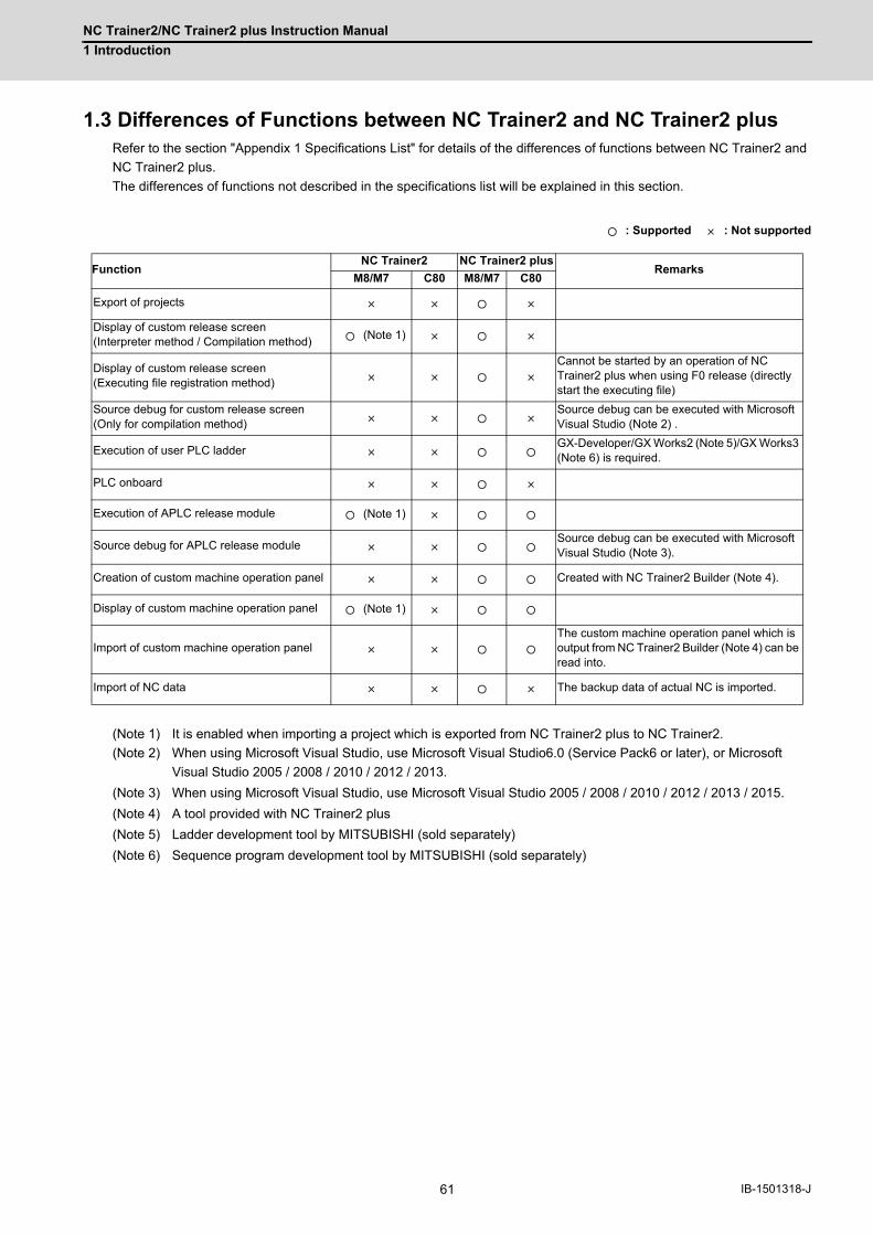
NC Trainer2/NC Trainer2 plus Instruction Manual
1 Introduction
61 IB-1501318-J
1.3 Differences of Functions between NC Trainer2 and NC Trainer2 plusRefer to the section "Appendix 1 Specifications List" for details of the differences of functions between NC Trainer2 and
NC Trainer2 plus.
The differences of functions not described in the specifications list will be explained in this section.
: Supported : Not supported
(Note 1) It is enabled when importing a project which is exported from NC Trainer2 plus to NC Trainer2.
(Note 2) When using Microsoft Visual Studio, use Microsoft Visual Studio6.0 (Service Pack6 or later), or Microsoft
Visual Studio 2005 / 2008 / 2010 / 2012 / 2013.
(Note 3) When using Microsoft Visual Studio, use Microsoft Visual Studio 2005 / 2008 / 2010 / 2012 / 2013 / 2015.
(Note 4) A tool provided with NC Trainer2 plus
(Note 5) Ladder development tool by MITSUBISHI (sold separately)
(Note 6) Sequence program development tool by MITSUBISHI (sold separately)
FunctionNC Trainer2 NC Trainer2 plus
RemarksM8/M7 C80 M8/M7 C80
Export of projects
Display of custom release screen(Interpreter method / Compilation method)
(Note 1)
Display of custom release screen(Executing file registration method)
Cannot be started by an operation of NC Trainer2 plus when using F0 release (directly start the executing file)
Source debug for custom release screen(Only for compilation method)
Source debug can be executed with Microsoft Visual Studio (Note 2) .
Execution of user PLC ladderGX-Developer/GX Works2 (Note 5)/GX Works3 (Note 6) is required.
PLC onboard
Execution of APLC release module (Note 1)
Source debug for APLC release moduleSource debug can be executed with Microsoft Visual Studio (Note 3).
Creation of custom machine operation panel Created with NC Trainer2 Builder (Note 4).
Display of custom machine operation panel (Note 1)
Import of custom machine operation panelThe custom machine operation panel which is output from NC Trainer2 Builder (Note 4) can be read into.
Import of NC data The backup data of actual NC is imported.

NC Trainer2/NC Trainer2 plus Instruction Manual
1 Introduction
62IB-1501318-J
1.4 About a License for NC Trainer2 plus1.4.1 License Type for NC Trainer2 plus
A license key is required to be inserted into the USB port of a computer to start NC Trainer2. There are two licence types
depending on the license key type which is attached to the purchased NC Trainer2.
(Note1) There are separate license keys for NC Trainer2 and for NC Trainer2 plus. NC Trainer2 plus cannot be started
with the license key attached to NC Trainer2 and NC Trainer2 cannot be started with the one attached to NC
Trainer2 plus.
(Note2) NC Trainer plus cannot be started with the license key attached to NC Trainer2 plus and NC Trainer2 plus
cannot be started with the one attached to NC Trainer plus.
(1) Standalone type
- Required to purchase one user licence per computer.
- Insert the license key of NC Trainer2 plus into a computer with NC Trainer2 plus installed.
(2) Network connection type
- 3/50 user license types are available.
- NC Trainer2 plus can be installed on the computers more than the purchased user licence numbers, however,
the number of the computers which can be started NC Trainer2 plus at a time is up to the number of purchased
license.
- NC Trainer2 plus can be started at a time with one license key of NC Trainer2 plus on multiple computers in the
same network. The number of the computers which can be started NC Trainer2 plus at a time is up to the number of
purchased license.
- Insert the license key to one computer in the network. Other computers in the same network confirm to the
computer with the license key via a network whether to start NC Trainer2 plus.
- NC Trainer2 plus cannot be started on computers in the separate network from the computer with a license key.
NC Trainer2 plus
Install Insert
License key (USB)
NC Trainer2 plus
The term "the same network" in this explanation indicates a local area network which does not go beyond a router or gateway.
Insert Install
License key (USB)
Router or gateway
Insert
License key (USB)
NC Trainer2 can be started. NC Trainer2 cannot be started.

NC Trainer2/NC Trainer2 plus Instruction Manual
1 Introduction
63 IB-1501318-J
1.4.2 When Inserting Multiple License Keys
(1) When inserting multiple license keys of network connection type
The maximum number of the computers which can be started NC Trainer2 plus at a time is the total number of user
licenses for these license keys.
Multiple license keys can be inserted into one computer.
(2) When inserting license keys of standalone type and network connection type to separate computers
(Note) When the license key of NC Trainer2 plus for standalone type is used together with network connection
type, insert them into separate computers.
- When NC Trainer2 plus is started on the computer with a license key of standalone type, the license key of
standalone type will always be used.
- When NC Trainer2 plus is started on the computer without a license key of standalone type, the license key of
network connection type will always be used.
Insert Insert
License key(3 license type)
License key(50 license type)
NC Trainer2 plus can be started up to 53
Insert InsertUsed for license certification
Used for license certification
Used for license certification
Used for license certification
License key of standalone type
License key of network connection type

NC Trainer2/NC Trainer2 plus Instruction Manual
1 Introduction
64IB-1501318-J
(3) When inserting license keys of standalone type and network connection type to the same computer
(Note) Refrain from inserting license keys of NC Trainer2 plus for standalone type and network connection type
to the same computer.
- When NC Trainer2 plus is started on the computer with license keys of standalone type and network connection
type, which key is used depends on the order of the license key insertion and the location of the USB port.
- When NC Trainer2 plus is started on other computers in the same network, the license key of network connection
type will always be used. (A license key of standalone type will not be used by other computers.)
- When NC Trainer2 plus is started on the computer with license key, and license key of network connection type is
used, the standalone type will be void. That is, the number of computers which can be started NC Trainer2 plus at a
time in the same network will be one less than the total of purchased user license numbers.
<When using the license key of NC Trainer2 with the license key of NC Trainer2 plus>
- The license key of NC Trainer2 and the license key of NC Trainer2 plus can be inserted together.
- The license key of NC Trainer2 and the license key of NC Trainer2 plus can be inserted to separate computers in
the same network.
NC Trainer2 plus
Insert Insert
Used for license certification
License key of standalone type
License key of network connection type
(50 license type)
One user license is wasted because it will not be used by other computers.
NC Trainer can be started up to 49 PCs.

NC Trainer2/NC Trainer2 plus Instruction Manual
1 Introduction
65 IB-1501318-J
1.5 Precautions
When using NC Trainer2 plus, pay attention to the following.
- The displayed "Memory card (Only for a project of M80 TypeA/M80 TypeB/M70V TypeA/M70V TypeB/E70)"
device is the path designated at the time of installation. "C:\MELCNC\NCT2\HD" is set by default.
- The displayed "HD (Only for a project of M830/M730V/C80)" device is the path designated at the time of
installation. "C:\MELCNC\NCT2\HD" is set by default.
- When license key is not inserted at starting NC Trainer2 plus, the following dialog box is displayed and NC
Trainer2 plus cannot be started. After pressing the "OK" button, insert license key and start NC Trainer2 plus
again.
- More than one NC Trainer2 plus cannot start at a time.
- NC Trainer2 and NC Trainer2 plus cannot start at a time.
- More than one NC Trainer2 Builder cannot start at a time.
- When the license key of standalone type is used together with network connection type, insert them into
separate computers.
- Refrain from inserting license keys of standalone type and network connection type to the same computer.
- When license key is removed while operating NC Trainer2 plus, the application will be force-quit regardless of
the operation state. Project data may be corrupted depending on the operation state, so never remove license
key during the operation.
- When the computer with a license key of network connection type is in a state where the network
communication is disabled such as sleep or shutdown, NC Trainer2 plus on the license certificated computer
will be force-quit. Project data may be corrupted depending on the operation state, so prevent the computer
with a license key of network connection type from entering the network communication disabled state, such
as sleep or shutdown.
- If the communication is lost for the disconnection of LAN cable, etc. when NC Trainer2 plus is started with a
license key of network connection type, NC Trainer2 plus will be force-quit in the same way as when the
license key is removed. Project data may be corrupted depending on the operation state, so prevent the
computer from entering the communication disabled state, such as disconnection of LAN cable.
- When NC is executed on NC Trainer2 plus, Caps Lock on PC keyboard turns ON. Thus please be careful
during setting operation.
- When restart "PR display" is required during NC operation, press the "NCRestart" button to restart NC.
- Although parameter setting file (ALL.PRM) can be output from [Mainte] - [Input/output] screen of NC standard
screen, never input this file to actual machine. The parameter may not conform to the specification of the
actual machine and cause a breakdown.
- When changing [Tool (T)] - [Set Machine Parameter (M)] while parameter screen of NC is displayed,
environmental settings still cannot be set (or can be set). After entering another screen, environmental settings
of NC can be set (or cannot be set).
- Standard operation mode cannot be used for PLC onboard screen with the project of M730V/M70V TypeA/
M70V TypeB/E70.
- A memory card can be selected as an external device of PLC onboard for NC Trainer2 plus, however, the
memory card is not a removable disk of the computer.
The path which is designated at the installation is a substitute for memory card. The default setting is
"C:\MELCNC\NCT2P\M-CARD".
- The password holding status cannot be changed by changing the value of the parameter "#11018 M password
hold" (machine user password hold) from [Mainte] - [Param] screen of NC. The setting from [Tool] - [Set
Machine Parameters] is applied.
- Date and time cannot be changed from an NC screen.

NC Trainer2/NC Trainer2 plus Instruction Manual
1 Introduction
66IB-1501318-J
- The floating-point arithmetic may result in an error between the CPU of the personal computer running NC
Trainer plus and actual NC.
- When using the machining program which is created with NC Trainer2 plus on the actual machine, be sure to
check the operation thoroughly. If the NC version is different between NC Trainer2 plus and the actual
machine, the operations may differ.
- The NC option setting is not restored even if the data saved by data backup is restored.
- The free-form pocket machining function for NAVI MILL is not supported. Free-form pocket machining is
handled as an EIA process when a program including free-form pocket machining is read.
- Some PLC signals cannot be used. Refer to "1.6 Restrictions for PLC Signals" for details.
- The certification for automatic operation lock function always succeeds regardless of the password.
- The parameter "#3114 cax_para_chg Spindle/C axis parameter switch" is always operated as "0" in spindle
position control.
- For direct robot control, NC Trainer2 plus can connect to a robot simulator only. Do not connect to an actual
robot.
- For a project of C80, PLC errors and warnings cannot be displayed on the NC screen. Check PLC errors and
warnings in GX Works3 module diagnostics or GX Simulator3.
Example) "A01 Another CPU module moderate error 1220" multi CPU error
- Do not import the project exported by NC Trainer2 plus to NC Trainer/NC Trainer plus. An error will occur
when importing the project, or the imported project will not activate normally.
- The custom machine operation panel exported by NC Trainer Builder can be imported to NC Trainer2 plus, but
the custom machine operation panel exported by NC Trainer2 Builder cannot be imported to NC Trainer plus.
It will cause an error when importing.
- When the project created by NC Trainer Builder is edited and saved with NC Trainer2 Builder, the project can
not be opened by NC Trainer Builder.
However, if saved without editing, the project can be opened.
- Do not open the project created by NC Trainer2 plus using NC Trainer plus. An error may occur when
activating the project.
- When opening the project created by NC Trainer plus, the message that verifies the format conversion may
appear.
- When the project is converted to a new format, the project can not be opened by NC Trainer plus.
- If there is no possibility to open the project by NC Trainer plus, click "Yes(Y)" to open the project.
- If there is a possibility to open the project by NC Trainer plus, click "No(N)" to open by read-only.
- To cancel opening the project, click "Cancel" button.

NC Trainer2/NC Trainer2 plus Instruction Manual
1 Introduction
67 IB-1501318-J
- When a project is opened by read-only, "(Read-only)" will display next to the project name of the title bar.
Also, the following functions will be restricted.
- When changing the option setting of the project created by NC Trainer plus, format conversion may be
required as with a read-only project.
- When exporting the project may appear created by NC Trainer plus, it must be converted to the same format
as the read-only state project.
- Background check is not available with M830 project. Foreground check is always used.
- Do not install NC Trainer plus when NC Trainer2 is already installed. Similarly, do not install NC Trainer when
NC Trainer2 plus is already installed. When either NC Trainer or NC Trainer plus is uninstalled after NC
Trainer2 or NC Trainer2 plus has been installed, the following dialog box may appear when activating the other
application and it cannot be started, or the application may be force-quit sometime after starting. If that
happens, uninstall the application and install it again.
- A sequence program operates with the GX Works3 simulation function (GX Simulator3). Start GX Simulator3
before starting or switching a C80 project, or changing the settings of a project option on NC Trainer2 plus.
- Do not use the data created by NC Trainer2 plus with NC Trainer plus. The application may not work normally
when using it.
- Collecting sampling data can not be executed.
- Safety ladder cannot be operated.
Also, the safety ladder cannot be input or output. Specifically, the following input/output functions are
restricted.
<M830/M80 TypeA/M80 TypeB/E80 TypeA/E80 TypeB project>
<C80 project>
- A gesture operation is available with M830/M80 TypeA/M80 TypeB project on Windows 8.1 or later.
Restricted functions Restricted description
Saving the NC data
A parameter and a machining program of NC memory changed by NC operation can not be saved.The change settings will not reflected even if the NC is restarted when parameter settings are changed, etc. and NC is required to restart (when "PR" lights on the NC standard screen, etc).Confirming message to save NC data will not display when ending the NC project regardless of the valid/invalid setting of [Tool (T)] - [Confirm NC Data Storage (N)].
Import the actual NC data NC data of the actual NC data can not be imported.
Input APLC release C language module
APLC release C language module (APLC.o) can not be input.
Change the option settingTo change the option setting, the format needs to be converted. Refer to "4.5.7 Changing the option of the project " for detail.
Export the projectTo export the project, the format needs to be converted. Refer to "4.6.1 Exporting the NC Trainer2 plus project" for detail.
Restricted functions Restricted contents
The [Mainte] - [I/O] screen of the NC screen Data cannot be transferred.
Batch backups Data cannot be backed up and restored.
Automatic backups Data cannot be backed up.
Restricted functions Restricted contents
The I/O screen on the maintenance screen of the NC screen
Data cannot be transferred.

NC Trainer2/NC Trainer2 plus Instruction Manual
1 Introduction
68IB-1501318-J
- When enabling the safety observation/smart safety observation option for the project of M830/C80 or
functional safety expansion unit for the project of M80 TypeA/M80 TypeB, parameters related to the smart
safety observation can be displayed and changed. However, the safety observation/smart safety observation
function itself does not work.
- The following miscellaneous functions (M codes) are allocated to the spindle control function or spindle/C axis
control function with the standard user ladder.
(Note 1) M17 or M18 command operate on the C axis of the designated part system.
- The alarm "P482 Illegal axis (mill)" will occur by executing the cylindrical interpolation command (G07.1) while
performing the graphic check or finish shape view programming under the following conditions.
- Any project of M830 Series is selected
- "Arbitrary axis exchange control" specification is ON
Set "Arbitrary axis exchange control" specification to OFF when you execute the cylindrical interpolation
command (G07.1) without using the arbitrary axis exchange control function.
- A custom tool management screen specified by a setting file created by machine tool builders cannot be
displayed for a M830/M80 TypeA/M80 TypeB/E80 Type A/E80 Type B project.
- A logo created by machine tool builders cannot be displayed on the NC standard screen for a M830/M80
TypeA/M80 TypeB/E80 Type A/E80 Type B project.
- A comment of device release screen specified by a comment file created by machine tool builders cannot be
displayed.
- When NC Trainer2 plus is uninstalled with NC Visualizer installed, the driver is reinstalled when the NC
Visualizer license key is installed. After the completion of driver reinstallation, NC Visualizer can be started.
- When NC Trainer2 plus and some MELSOFT products such as GX works3, etc. are to be installed on the
same PC, if NC Trainer2 plus is installed before MELSOFT products are installed, project creation/startup may
fail with NC Trainer2 plus.
Install NC Trainer2 plus after installing other MELSOFT products. When the creation/switching of the project
fails as a result of installing MELSOFT products after NC Trainer2 plus, reinstall NC Trainer2 plus.
Code Function Code Function
M03 1st spindle forward run M45 4th spindle stop
M04 1st spindle reverse run M53 5th spindle forward run
M05 1st spindle stop M54 5th spindle reverse run
M17 C axis servo off signal ON M55 5th spindle stop
M18 C axis servo off signal OFF M63 6th spindle forward run
M23 2nd spindle forward run M64 6th spindle reverse run
M24 2nd spindle reverse run M65 6th spindle stop
M25 2nd spindle stop M73 7th spindle forward run
M33 3rd spindle forward run M74 7th spindle reverse run
M34 3rd spindle reverse run M75 7th spindle stop
M35 3rd spindle stop M83 8th spindle forward run
M43 4th spindle forward run M84 8th spindle reverse run
M44 4th spindle reverse run M85 8th spindle stop

NC Trainer2/NC Trainer2 plus Instruction Manual
1 Introduction
69 IB-1501318-J
1.6 Restrictions for PLC Signals
The following PLC signals cannot be used for NC Trainer2 plus. Input signals (NC to PLC) always output 0 to the PLC.
As for output signals (PLC to NC), even if the NC receives output signals from the PLC, it does not execute operations
corresponding to those signals.
■Input signal (NC to PLC)
<X Device>
(Note) Forced output from [Diagn] - [I/F diagn] is possible.
Device No. Signal name
Common for part systems
X70E Battery warning
X70F Battery alarm
X752 24 hours continuous operation
Part system 1 Part system 2 Part system 3 Part system 4
X880 to X887 X888 to X88F X890 to X897 X898 to X89F Near reference position 1st to 8th axis
X8C0 to X8C7 X8C8 to X8CF X8D0 to X8D7 X8D8 to X8DF Zero point initialization set completed 1st to 8th axis
X8E0 to X8E7 X8E8 to X8EF X8F0 to X8F7 X8F8 to X8FF Zero point initialization set error completed 1st to 8th axis
X900 to X907 X908 to X90F X910 to X917 X918 to X91F In current limit 1st to 8th axis
X920 to X927 X928 to X92F X930 to X937 X938 to X93F Current limit reached 1st to 8th axis
XA60 to XA67 XA68 to XA6F XA70 to XA77 XA78 to XA7F Vertical axis pull-up prevented 1st to 8th axis
XC05 XD45 XE85 XFC5 In automatic initial set mode
XC09 XD49 XE89 XFC9In tape mode*Tape operation cannot be executed although this signal turns ON/OFF by turning the device tape mode ON/OFF.
XC98, XC99 XDD8, XDD9 XF18, XF19 X1058, X1059 NC alarm 1, 2
XC9C XDDC XF1C X105C NC warning (Servo warning)
XCA7 XDE7 XF27 X1067 Absolute position warning
XCD8 XE18 XF58 X1098 Door open enable
XCE8 XE28 XF68 X10A8 Door open enable (2 channels per 1 part system)
XD1E to XD20 XE5E to XE60 XF9E to XFA0 X10DE to X10E0Tool axis coordinate system, table coordinate system, and feature coordinate system in manual feed for 5-axis machining (2nd handle)
XD21 to XD23 XE61 to XE63 XFA1 to XFA3 X10E1 to X10E3Tool axis coordinate system, table coordinate system, and feature coordinate system in manual feed for 5-axis machining (3rd handle)
1st spindle 2nd spindle 3rd spindle 4th spindle 5th spindle 6th spindle
X1889 X18E9 X1949 X19A9 X1A09 X1A69 Current detection
X188A X18EA X194A X19AA X1A0A X1A6A Speed detection
X188B X18EB X194B X19AB X1A0B X1A6B In spindle alarm
X1897 X18F7 X1957 X19B7 X1A17 X1A77 In spindle torque limit
X1898 X18F8 X1958 X19B8 X1A18 X1A78 In motor 1 selection
X1899 X18F9 X1959 X19B9 X1A19 X1A79 In motor 2 selection
X189D X18FD X195D X19BD X1A1D X1A7D Speed detection 2
X189E X18FE X195E X19BE X1A1E X1A7E In M coil selection
X18B3 X1913 X1973 X19D3 X1A33 X1A93 Hob axis delay excess
Common for part systems
X1CD0 to X1CFC Handy terminal key 1 to 45

NC Trainer2/NC Trainer2 plus Instruction Manual
1 Introduction
70IB-1501318-J
<R register (input)>
Device No. Signal name
Common for part systems
R0 to R7 Analog input 1 to 8
R8 KEY IN 1
R26 Turret interference check status
R27 Interference object alarm information
R31 Diagnosis data output
R56 Battery drop cause
R57 Temperature warning cause
R58 5V/24V error cause
R59 Control unit temperature 2
R60 Control unit temperature
R96 Speed monitor door open possible
R97 Safety observation I/O signal status
R168 to R173 PLC axis alarm/warning No. 1st to 6th axis
Part system 1 Part system 2 Part system 3 Part system 4
R574 R774 R974 R1174 In initialization
R575 R775 R975 R1175 Initialization incompletion
R580, R581 R780, R781 R980, R981 R1180, R1181Near reference position (per reference position) 1st to 4th axis, 5th to 8th axis
R582 R782 R982 R1182 Presetter contact
R583 R783 R983 R1183 Presetter interlock
R4756 to R4771 R4772 to R4787 R4788 to R4803 R4804 to R4819 Servo deflection amount 1st to 8th axis
R4820 to R4835 R4836 to R4851 R4852 to R4867 R4868 to R4883 Motor rotation speed 1st to 8th axis
R4884 to R4899 R4900 to R4915 R4916 to R4931 R4932 to R4947 Motor load current 1st to 8th axis
R5332 to R5339 R5340 to R5347 R5348 to R5355 R5356 to R5363 Servo alarm/warning No. 1st to 8th axis
1st spindle 2nd spindle 3rd spindle 4th spindle 5th spindle 6th spindle
R6529 R6579 R6629 R6679 R6729 R6779 Spindle alarm/warning No.
R6532,R6533
R6582,R6583
R6632,R6633
R6682,R6683
R6732,R6733
R6782,R6783
Synchronous tapping Current error width
R6534,R6535
R6584,R6585
R6634,R6635
R6684,R6685
R6734,R6735
R6784,R6785
Synchronous tapping Maximum error width
R6536,R6537
R6586,R6587
R6636,R6637
R6686,R6687
R6736,R6737
R6786,R6787
Synchronous tapping Current error angle
R6538,R6539
R6588,R6589
R6638,R6639
R6688,R6689
R6738,R6739
R6788,R6789
Synchronous tapping Maximum error angle
R8002 R8008 R8014 R8020 R8026 R8032
PLC axis indexing control status 2(Note) The following bits cannot be used.bitB: Battery dropbitC: Absolute position power shutoff movement overbitD: Absolute position data lossbitE: Initialization setting completedbitF: Initialization setting error completed
R8003 R8009 R8015 R8021 R8027 R8033PLC axis indexing control status 1(Note) The following bits cannot be used.bit6: In torque limit

NC Trainer2/NC Trainer2 plus Instruction Manual
1 Introduction
71 IB-1501318-J
(Note) Forced output from [Diagn] - [I/F diagn] is possible.
■Output signal (PLC to NC)
<Y Device>
Device No. Signal name
Common for part systems
R10000 to R10007 RIO1 No. of error occurrences 1st to 8th ch
R10008 to R10015 RIO2 No. of error occurrences 1st to 8th ch
R10016 to R10023 RIO3 No. of error occurrences 1st to 8th ch
R10064 Connection status of each channel RIO1,2
R10065 Connection status of each channel RIO3
R10068 CRC warning channel RIO1,2
R10069 CRC warning channel RIO3
Device No. Signal name
Common for part systems
Y721 PLC axis 2nd handle valid
Y722 PLC axis 3rd handle valid
Y728 CRT changeover completion
Y729 Screen display request
Y73F Interference check valid
Y742 Contactor shutoff test
Y747 Turret interference check valid
Y75D Automatic power OFF request
Y764 Encoder 1 arbitrary pulse selection
Y765 Encoder 2 arbitrary pulse selection
Y766 Encoder 1 arbitrary pulse valid
Y767 Encoder 2 arbitrary pulse valid
Y768 Door open I
Part system 1 Part system 2 Part system 3 Part system 4
Y960 to Y967 Y968 to Y96F Y970 to Y977 Y978 to Y97F Zero point initialization set mode 1st to 8th axis
Y980 to Y987 Y988 to Y98F Y990 to Y997 Y998 to Y99F Zero point initialization set start 1st to 8th axis
Y9A0 to Y9A7 Y9A8 to Y9AF Y9B0 to Y9B7 Y9B8 to Y9BF Current limit changeover 1st to 8th axis
Y9C0 to Y9C7 Y9C8 to Y9CF Y9D0 to Y9D7 Y9D8 to Y9DF Droop release request 1st to 8th axis
YAE0 to YAE7 YAE8 to YAEF YAF0 to YAF7 YAF8 to YAFF Vertical axis pull-up prevention request 1st to 8th axis
YC05 YD45 YE85 YFC5 Automatic initialization mode
YC09 YD49 YE89 YFC9
In tape mode*Tape operation cannot be executed although this signal of X device turns ON/OFF by turning the device tape mode ON/OFF.
YC0A YD4A YE8A YFCA Online operation mode (Computer link B)
YC48 to YC4C YD88 to YD8C YEC8 to YECC Y1008 to Y100C 2nd handle axis selection code 1,2,4,8,16
YC4F YD8F YECF Y100F 2nd handle valid
YC50 to YC54 YD90 to YD94 YED0 to YED4 Y1010 to Y1014 3rd handle axis selection code 1,2,4,8,16
YC57 YD97 YED7 Y1017 3rd handle valid
YCC0, YCC1 YE00, YE01 YF40, YF41 Y1080, Y1081 Current limit mode 1,2
YCE1 YE21 YF61 Y10A1 Door open II
YCE2 YE22 YF62 Y10A2 Door open signal input (spindle speed monitor)
YCE8 YE28 YF68 Y10A8 Door open II (2 channels per 1 part system)
YD1E to YD20 YE5E to YE60 YF9E to YFA0 Y10DE to Y10E0Tool axis coordinate system, table coordinate system, and feature coordinate system in manual feed for 5-axis machining (2nd handle)
YD21 to YD23 YE61 to YE63 YFA1 to YFA3 Y10E1 to Y10E3Tool axis coordinate system, table coordinate system, and feature coordinate system in manual feed for 5-axis machining (3rd handle)

NC Trainer2/NC Trainer2 plus Instruction Manual
1 Introduction
72IB-1501318-J
<R register (output)>
Device No. Signal name
1st spindle 2nd spindle 3rd spindle 4th spindle 5th spindle 6th spindle
Y189A,Y189B
Y18FA,Y18FB
Y195A,Y195B
Y19BA,Y19BB
Y1A1A,Y1A1B
Y1A7A,Y1A7B
Spindle torque limit 1,2
Y18A2,Y18A3
Y1902,Y1903
Y1962,Y1963
Y19C2,Y19C3
Y1A22,Y1A23
Y1A82,Y1A83
Spindle position control (C axis) Cutting gain
Y18A6 Y1906 Y1966 Y19C6 Y1A26 Y1A86 M coil selection
Device No. Signal name
Common for part systems
R200 to R207 Analog output 1 to 8
R212 KEY OUT1
R215 Power OFF indication Y device No.
R272, R273Near-point dog ignored (Axis 1 to 8 for part system 1,2), (Axis 1 to 8 for part system 3,4)
R279 PLC axis near-point dog ignored
R296 Speed monitor mode
R297 Handy terminal Data area top address
R298 Handy terminal Data valid number of registers
R299 Handy terminal Cause of communication
R342 Specified shape interference Shape No. designation
R365 Measures against tool setter chattering Movement amount
R396 User PLC info program format info
R456, R457 Encoder 1 arbitrary pulse 1,2
R458, R459 Encoder 2 arbitrary pulse 1,2
R2110Pallet 1 Machining program device No.* 2: DS, 3: FD, and 4: Memory card cannot be used.
R2116Pallet 2 Machining program device No.* 2: DS, 3: FD, and 4: Memory card cannot be used.
R2122Pallet 1 180° Machining program device No.* 2: DS, 3: FD, and 4: Memory card cannot be used.
R2128Pallet 1 270° Machining program No.* 2: DS, 3: FD, and 4: Memory card cannot be used.
R2134Pallet 2 0° Machining program device No.* 2: DS, 3: FD, and 4: Memory card cannot be used.
R2140Pallet 2 90° Machining program device No.* 2: DS, 3: FD, and 4: Memory card cannot be used.
R2146Pallet 2 180° Machining program device No.* 2: DS, 3: FD, and 4: Memory card cannot be used.
R2152Pallet 2 270° Machining program device No.* 2: DS, 3: FD, and 4: Memory card cannot be used.
Part system 1 Part system 2 Part system 3 Part system 4
R2510, R2511 R2710, R2711 R2910, R2911 R3110, R3111 2nd handle feed magnification
R2512, R2513 R2712, R2713 R2912, R2913 R3112, R3113 3rd handle feed magnification
R2525 R2725 R2925 R3125External search device No.* 2: IC card, 3: Floppy disk, 4: High-speed program server and 5: Tape cannot be used.
R2592 R2792 R2992 R3192 Reference position adjustment completion
R2593 R2793 R2993 R3193 Current limit changeover
R2594 R2794 R2994 R3194 Wear compensation No. (tool presetter)
R2596 R2796 R2996 R3196 Turret interference object tool No. designation

NC Trainer2/NC Trainer2 plus Instruction Manual
1 Introduction
73 IB-1501318-J
Operations and timings of the following PLC signals are different between actual NC and NC Trainer2 plus.
■Input signal (NC to PLC)
<X Device>
Example) For Spindle rotation speed synchronization completion (X18A9)
Device No. Signal name
Part system 1 Part system 2 Part system 3 Part system 4
X780 to X787 X788 to X78F X790 to X797 X798 to X79F Servo ready 1st to 8th axis
X940 to X947 X948 to X94F X950 to X957 X958 to X95F NC axis up-to-speed 1st to 8th axis
XC11 XD51 XE91 XFD1 Servo ready completion
XC19 XD59 XE99 XFD9 All axes in-position
XCB3 XDF3 XF33 X1073 Spindle-spindle polygon synchronization completion
1st spindle 2nd spindle 3rd spindle 4th spindle 5th spindle 6th spindle
X1888 X18E8 X1948 X19A8 X1A08 X1A68 Spindle 2nd in-position
X188C X18EC X194C X19AC X1A0C X1A6C Zero speed
X188D X18ED X194D X19AD X1A0D X1A6D Spindle up-to-speed
X188E X18EE X194E X19AE X1A0E X1A6E Spindle in-position
X188F X18EF X194F X19AF X1A0F X1A6F In L coil selection
X1890 X18F0 X1950 X19B0 X1A10 X1A70 Spindle ready-ON
X1891 X18F1 X1951 X19B1 X1A11 X1A71 Spindle servo-ON
X1895 X18F5 X1955 X19B5 X1A15 X1A75 Z phase passed
X1896 X18F6 X1956 X19B6 X1A16 X1A76 Position loop in-position
X189F X18FF X195F X19BF X1A1F X1A7F Index positioning completion
X18A9 X1909 X1969 X19C9 X1A29 X1A89 Spindle rotation speed synchronization completion
X18AA X190A X196A X19CA X1A2A X1A8A Spindle phase synchronization completion
X18AC X190C X196C X19CC X1A2C X1A8C Chuck close confirmation
X18B5 X1915 X1975 X19D5 X1A35 X1A95 In spindle holding force up
<Actual operation>
Spindle synchronization (Y18B0)
In spindle synchronization (X18A8)
Basic spindle rotation speed
Synchronous spindle rotation speed
Spindle rotation speed synchronization completion (X18A9)
<Operation on NC Trainer2 plus>
Spindle synchronization (Y18B0)
In spindle synchronization (X18A8)
Spindle rotation speed synchronization completion (X18A9)

NC Trainer2/NC Trainer2 plus Instruction Manual
1 Introduction
74IB-1501318-J

75 IB-1501318-J
2
Installation and Setup

NC Trainer2/NC Trainer2 plus Instruction Manual
2 Installation and Setup
76IB-1501318-J
2.1 Operating EnvironmentThe following is the operating environment for the operation of NC Trainer2 plus.
Operating environment for each model
For the other operating environment, refer to the section "2.1 Operating Environment" of "I NC Trainer2".
2.2 Procedure of the First Installation
(Note 1) Do not install license key until the installation of NC Trainer2 plus has been completed. When mistakenly
install the Key and "add hardware wizard" is displayed, press the "cancel" button to cancel. After pressing the
"cancel" button, remove the license key from the computer.
(Note 2) When NC Trainer2 plus and some MELSOFT products such as GX works3, etc. are to be installed on the
same PC, if NC Trainer2 plus is installed before MELSOFT products are installed, project creation/startup may
fail with NC Trainer2 plus.
Install NC Trainer2 plus after installing other MELSOFT products. When the creation/switching of the project
fails as a result of installing MELSOFT products after NC Trainer2 plus, reinstall NC Trainer2 plus.
(1) Insert NC Trainer2 plus installation CD in computer’s CD-ROM drive.
(2) Execute "NCTrainer2Plus.exe" in the installation CD.
(Note 1) The installation screens are displayed in Japanese when installing on Japanese-language version of
Windows. They are displayed in English when installing on other language versions of Windows.
(Note 2) When NC Trainer plus has been installed on the computer, uninstallation of NC Trainer plus is started.
Install NC Trainer2 plus after uninstalling NC Trainer plus. Refer to the section "2.5 Procedure of
Uninstalling" for details.
(Note 3) The installation of NC Trainer2 plus has to be carried out by the authority of the administrator.
If User Account Control in Windows 8.1 or Windows 10 is enabled, the confirmation dialog box as below
pops up. Then, select "Yes" to start the installation.
Item Description
C80 GX Works3 (Sequence program development tool by Mitsubishi Electric)

NC Trainer2/NC Trainer2 plus Instruction Manual
2 Installation and Setup
77 IB-1501318-J
(3) Splash screen is displayed. Then the installer is started.
(4) The setup screen is displayed.
Press the "Next" button.
(5) The software license agreement is displayed.
Read the software license agreement carefully, and press the "Yes" button.
If "No" is selected (when you do not agree this agreement), the installation of NC Trainer2 plus is discontinued.

NC Trainer2/NC Trainer2 plus Instruction Manual
2 Installation and Setup
78IB-1501318-J
(6) The "Customer Information" screen is displayed. Input user name and company name and press the "Next" button.
(7) Input the product ID on the Input Product ID screen and press the "Next" button.
(8) The "Choose Designation Location" screen is displayed. Press "Browse" and select the installation destination
when changing the installation destination. Press the "Next" button after the installation destination settings.
(Note) To change the folder to install the application file, specify the full path of the folder using up to 80
characters. A full path over 80 characters cannot be set.

NC Trainer2/NC Trainer2 plus Instruction Manual
2 Installation and Setup
79 IB-1501318-J
(9) The "Create a folder to store NC data file" screen is displayed.
Press "Browse" and select the folder to store NC data file when changing the folder.
Press the "Next" button after the settings.
(Note 1) If NC Trainer plus was used in the past, the data created by NC Trainer plus can be taken over
automatically when selecting the same data storage folder as in the past. When selecting a different
folder from the one used for NC Trainer plus to store NC data file, the data can be taken over by copying
the data created by NC Trainer plus to the folder after installing NC Trainer2 plus. For a project that
contains custom screen data designated with absolute path, however, you need to change the path
described in config.ini and customdef.ini according to the change of the data storage folder. Refer to the
section "5.3.2 Path Designation of GIP File, DLL File, and Executing File" for details.
(Note 2) The following are the precautions when changing the folder to store NC data file.
- Do not use kana-kanji as a folder name.
- A folder name over 19 characters cannot be set.
- Do not designate a folder under C:\Program Files and
C:\Windows. (Writing data to these folders is usually prohibited.)
- When installing both NC Trainer2 and NC Trainer2 plus, designate a different folder for each.
If designating the same folder, the same name project cannot be created for NC Trainer2 and NC
Trainer2 plus. (Same for copying and renaming the project.)
- Do not designate a drive other than C or D. If designating a drive other than C or D, the operation for the
file in HD or memory card device may not be executed.
(10) The "Start Copying Files" screen is displayed. Press the "Next" button after confirming the installation destination
settings. (When the setting is changed, press the "Back".)
The setup starts.
If "To create a shortcut on your desktop (D)" is checked, the shortcut of NC Trainer2 plus is created on the desktop
after the installation is completed.

NC Trainer2/NC Trainer2 plus Instruction Manual
2 Installation and Setup
80IB-1501318-J
(Note 1) The "HASP SRM Run-time Environment installation omitted. Newer version already installed." message
box might show up during installation. Click "OK" to continue installation.
(Note 2) The warning "The software you are installing has not passed Windows Logo testing. " can be displayed
when installing a virtual network driver. Press "Continue" and continue to install.
(11) When the installation is correctly completed, the complete screen is displayed.
When "Finish" button is pressed, the installation completes.
After the installation is completed, set a virtual network. Refer to the section "5.6 Network Connection Setting" for
details.
2.3 Installation Procedure When Upgrading
The operating procedure is the same as that of NC Trainer2. Refer to the section "2.3 Installation Procedure When
Upgrading" of "I NC Trainer2" for details.
2.4 Procedure of Uninstalling
The operating procedure is the same as that of NC Trainer2. Refer to the section "2.4 Procedure of Uninstalling" of "I NC
Trainer2" for details.

81 IB-1501318-J
3
Configuration of the Screen

NC Trainer2/NC Trainer2 plus Instruction Manual
3 Configuration of the Screen
82IB-1501318-J
3.1 Configuration of the Screen
The configuration of the screen is the same as that of NC Trainer2. Refer to the section "3.1 Configuration of the Screen"
of "I NC Trainer2" for details.
3.2 Menu ListA list of pull-down menus of NC Trainer2 plus and the usage of each item are described below.
3.2.1 [Project (P)] Menu
(Note) If no project has been registered, [Change Project (O)], [Set Project Option (S)], [Rename Project (M)], [Copy
Project (C)], [Export (E)], [Write APLC module (L)], and [Delete Project (D)] cannot be selected.
Operation menu item
Item Description
New Project (N)Select to create a new project.Refer to "4.3.1 Creating a New Project" for details.
Change Project (O)Select to change the project executed.Refer to "4.3.2 Changing the project" for details.
Set Project Option (S)Select to change the settings of the existing project.Refer to "4.3.3 Changing the settings of project option" for details.
Rename Project (M)Select to rename the existing project.Refer to "4.3.4 Renaming the project" for details.
Copy Project (C)Select to copy the existing project.Refer to "4.3.5 Copying the project" for details.
Delete Project (D)Select to delete the existing project.Refer to "4.3.6 Deleting the project" for details.
Export (E)Convert the data format of NC Trainer2 plus project to the format which can be operated with NC Trainer2 and output.Refer to "6.1 Exporting NC Trainer2 plus Project" for details.
Import (I)Select to import the exported data from each application.It has following sub-menus.
Project (P)Select to read a project which is exported from NC Trainer2 plus as a project for NC Trainer2 plus.Refer to "6.2 Importing NC Trainer2 plus Project" for details.
Custom Machine Operation Panel (C)
Select to register the custom machine operation panel which is created with NC Trainer2 Builder as a new machine operation panel for NC Trainer2 plus.Refer to "5.1.7 Adding the Custom Machine Operation Panel to "Peripheral Settings"" for details.
NC DATA (N)Select to import the NC data which is backed up with actual NC to the project of NC Trainer2 plus.Refer to "5.5 Importing the NC Data from Actual NC" for details.
Write APLC module (L)Select to store APLC release C language module (APLC.o) in the NC memory of NC Trainer2 plus.Refer to "5.4.1 Writing APLC Release C Language Module" for details.
Exit (X) Exit from the NC Trainer2 plus.

NC Trainer2/NC Trainer2 plus Instruction Manual
3 Configuration of the Screen
83 IB-1501318-J
3.2.2 [View (V)] Menu
[View (V)] menu is the same as that of NC Trainer2. Refer to the section "3.2.2 [View (V)] Menu" of "I NC Trainer2" for
details.
3.2.2.1 Changing the Display Language
The operating procedure is the same as that of NC Trainer2. Refer to the section "3.2.2.1 Changing the Display
Language" of "I NC Trainer2" for details.
3.2.3 [Tool (T)] Menu
3.2.4 [Window (W)] Menu
[Window (W)] menu is the same as that of NC Trainer2. Refer to the section "3.2.4 [Window (W)] Menu" of "I NC
Trainer2" for details.
3.2.5 [Help (H)] Menu
[Help (H)] menu is the same as that of NC Trainer2. Refer to the section "3.2.5 [Help (H)] Menu" of "I NC Trainer2" for
details.
3.2.6 Tool Bar
Tool bar is the same as that of NC Trainer2. Refer to the section "3.2.6 Tool Bar" of "I NC Trainer2" for details.
3.2.7 Status Bar
Status bar is the same as that of NC Trainer2. Refer to the section "3.2.7 Status Bar" of "I NC Trainer2" for details.
Tool menu item
Item Description
Set Machine Parameters (M)
"Input the password" message will disappear and each environmental settings for NC can be set.- A check mark will appear when it is enabled.- If this setting is changed while parameter screen of NC is displayed, the environmental settings for NC still cannot be set (or can be set). Entering another NC screen, and the environmental settings for NC can be set (or cannot be set).
Confirm NC Data Storage (N)
Normally, NC internal data such as parameters and machining program changed by the NC operation is saved automatically. Validate this item to display the confirmation message whether to save them automatically.- A check mark will appear when it is enabled.
Network settings of NC (W)Set the network connection of NC which is executed on NC Trainer2 plus.Refer to "5.6 Network Connection Setting" for details.
APLC Debug Task Lock (T)
Can be selected only while debugging APLC.o with NC Trainer2 plus. Otherwise this is displayed in gray and cannot be selected.Refer to "5.4.7 Task Lock Function for APLC Debug" for details.- When the function is enabled, a check mark is attached.
Set GX Simulator3 connection (C)For a project of C80, set the simulator No. of GX Simulator3 that connects with NC Trainer2 plus. Refer to the section "5.8 Set GX Simulator3 Connection" for details.

NC Trainer2/NC Trainer2 plus Instruction Manual
3 Configuration of the Screen
84IB-1501318-J
3.3 Operation of NC Screen3.3.1 NC Keyboard
NC keyboard is the same as that of NC Trainer2. Refer to the section "3.3.1 NC Keyboard" of "I NC Trainer2" for details.
3.3.2 NC Menu Key
NC menu key is the same as that of NC Trainer2. Refer to the section "3.3.2 NC Menu Key" of "I NC Trainer2" for details.
3.3.3 Machine Operation Panel
In NC Trainer2 plus, the PLC program to operate the machine operation panel is running.
The machine operation panel consists of the buttons to operate NC and lamps to indicate the output signal status from
NC.
When selecting the standard machine operation panel on NC Trainer2 plus, the following machine operation panel is
used.
Refer to the section "5.2 Custom Machine Operation Panel" for details of custom machine operation panel.
Display item of machine operation panel is the same as that of NC Trainer2. Refer to the section "3.3.3 Machine
Operation Panel" of "I NC Trainer2" for details.
3.3.3.1 Restarting NC
The operating procedure is the same as that of NC Trainer2. Refer to the section "3.3.3.1 Restarting NC" of "I NC
Trainer2" for details.
Display item of machine operation panel
Lamp (above each operation button)

85 IB-1501318-J
4
How to Use NC Trainer2 plus

NC Trainer2/NC Trainer2 plus Instruction Manual
4 How to Use NC Trainer2 plus
86IB-1501318-J
4.1 Starting NC Trainer2 plus
The operating procedure is the same as that of NC Trainer2. Refer to the section "4.1 Starting NC Trainer2" of "I NC
Trainer2" for details.
4.2 Exiting from NC Trainer2 plus
The operating procedure is the same as that of NC Trainer2. Refer to the section "4.2 Exiting from NC Trainer2" of "I NC
Trainer2" for details.
4.3 Creating a Project4.3.1 Creating a New Project
The following are the procedures to create a new project.
(1) Select [Project (P)] - [New Project (N)] from the menu bar.
(Note) For C80, start GX Simulator3, then create a new project.
(2) Set the basic parameters for NC in the new project dialog box.

NC Trainer2/NC Trainer2 plus Instruction Manual
4 How to Use NC Trainer2 plus
87 IB-1501318-J
Display item of New Project dialog box
Item Description
New Project Name (N)
Input the new project name.- A project name can be up to 80 one-byte characters. (Each two-byte character is equivalent to two characters.)- One-byte characters and two-byte characters can be used for a project name.- A project name is not case-sensitive.- The following characters cannot be used for a project name. \ / : * ? < > | " (Same as the prohibited characters for a file name)- A created project name cannot be designated.- Blank project name cannot be used.- Blank and Period (.) cannot be used for the first or last character of a project name.- CON, PRN, AUX, CLOCK$, NUL, COM0 to COM9 and LPT0 to LPT9 cannot be used for a project name.
Model Name (M)
Specify the NC model. The following models can be selected.M830M80 TypeAM80 TypeBE80 TypeAE80 TypeBC80M730VM70V TypeAM70V TypeBE70
Machine Type (T)Designate the NC configuration. The following configuration can be selected.Machining center: M systemLathe: L system
Number of Spindles (S)
Set the number of axes.The setting range differs depending on the model name and machine type, and is shown in the following table.
Language on NC Screen (L)Set the language displayed on NC Screen while executing a project.Languages supported in NC can be selected.
NC Screen Size (D)
Set the NC screen size. The following size can be selected. 15-type 10.4-type* 15-type can be selected only when the model name is M830/M80 TypeA/M80 TypeB/M730V.
Number of Axes
Set the number of axes for each part system.If the number of axes in a part system is 0, the part system is invalid.(Note 1) The setting items for 5th to 8th part systems are displayed only when M830/C80 is selected on Model Name.
M830M80 TypeAM80 TypeB
M730V
M70V TypeAM70V TypeBE70
E80 TypeA
E80 TypeBC80
M system L system
0 to 40 to 2
0 to 4
0 to 2
0 to 20 to 2
0 to 20 to 1
0 to 4
0 to 50 to 8
0 to 4
0 to 6
0 to 1
0 to 1 0 to 3
0 to 3
0 to 3
Model NameMachine Type
0 to 7 0 to 7
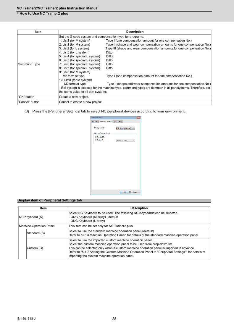
NC Trainer2/NC Trainer2 plus Instruction Manual
4 How to Use NC Trainer2 plus
88IB-1501318-J
(3) Press the [Peripheral Settings] tab to select NC peripheral devices according to your environment.
Command Type
Set the G code system and compensation type for programs.1: List1 (for M system) Type I (one compensation amount for one compensation No.)2: List1 (for M system) Type II (shape and wear compensation amounts for one compensation No.)3: List2 (for L system) Type III (shape and wear compensation amounts for one compensation No.)4: List3 (for L system) Ditto5: List4 (for special L system) Ditto6: List5 (for special L system) Ditto7: List6 (for special L system) Ditto8: List7 (for special L system) Ditto9: List8 (for M system) M2 form at type Type I (one compensation amount for one compensation No.)10: List8 (for M system) M2 form at type Type II (shape and wear compensation amounts for one compensation No.)- If M system is selected for the machine type, command types are common in all part systems. Therefore, set the same value to all part systems.
"OK" button Create a new project.
"Cancel" button Cancel to create a new project.
Display item of Peripheral Settings tab
Item Description
NC Keyboard (K)Select NC Keyboard to be used. The following NC Keyboards can be selected.- ONG Keyboard (M array) : default- ONG Keyboard (L array)
Machine Operation Panel This item can be set only for NC Trainer2 plus.
Standard (S)Select to use the standard machine operation panel. (default)Refer to "3.3.3 Machine Operation Panel" for details of the standard machine operation panel.
Custom (C)
Select to use the imported custom machine operation panel. Select the custom machine operation panel to be used from drop-down list.This can be selected only when a custom machine operation panel is imported in advance.Refer to "5.1.7 Adding the Custom Machine Operation Panel to "Peripheral Settings"" for details of importing the custom machine operation panel.
Item Description

NC Trainer2/NC Trainer2 plus Instruction Manual
4 How to Use NC Trainer2 plus
89 IB-1501318-J
(4) Press the [Option Setting] tab to select NC options according to your environment.
(Note) Refer to the section "Appendix 1 Specifications list" for details on NC options.
<M800/C80> <M80/E80>
<M700V> <M70V/E70>
Display item of M800/C80/M700V Option Setting tab
Item Description
NC Option List (L)
Display the NC option list that can be selected for the project.Check the check box to validate an NC option.- For the option required to format NC memory, [*] mark is indicated at the end of the option name.
Select All (S)Check all items.- Note that the items are checked only on the maximum spec option, for options which cannot be selected concurrently such as least command increment, etc.
Cancel All (C)Delete the check mark for all items.- Note that items are checked only on the minimum spec option, for options which cannot be selected at one time such as the least command increment, etc.
Display the description of NC option (E)
When this is checked, a dialog box appears showing the description of currently selected NC option.

NC Trainer2/NC Trainer2 plus Instruction Manual
4 How to Use NC Trainer2 plus
90IB-1501318-J
(Note 1) The dialog boxes for NC option and additional unit shows the description as below.
(Setting of NC option and additional unit is enabled while the dialog box is open.)
(Note 2) For a C80 project, press the "OK" button, and the "Set GX Simulator3 connection" dialog is displayed. Select
the simulator No. of GX Simulator3.
Refer to "5.8 Set GX Simulator3 Connection" for "Set GX Simulator3 connection" dialog.
(5) Press the "OK" button, and the NC screen of created project is displayed. At this time, NC data of the executing
project is automatically stored.
Note that if [Tool (T)] - [Confirm NC Data Storage (N)] is enabled, the confirmation message is displayed. When
pressing the "OK" button, NC data is stored and NC screen of created project is displayed.
(Note) Created project is started in the state that NC memory and tool life management data are formatted.
Display item of M80/E80 Option Setting tab
Item Description
Additional Unit List (L)
Displays a list of additional units.Check the check box to validate an additional unit.- The selectable unit differ by the NC model of a project to create. No additional unit can be selected if the NC model is E80.
Display the description of the Units (E)
When this is checked, a dialog box appears showing the description of currently selected additional unit.
Display item of M70V/E70 Option Setting tab
Item Description
Additional Unit List (L)
Displays a list of units.Check the check box to validate an additional unit.- The selectable unit differ by the NC model of a project to create. No additional unit can be selected if the NC model is E70.- The function extension units FCU7-HN721 and -HN722 can not be selected at the same time.- There is "*" mark after the unit name if the unit needs format of NC memory.
Display the description of the Units (E)
When this is checked, a dialog box appears showing the description of currently selected additional unit.

NC Trainer2/NC Trainer2 plus Instruction Manual
4 How to Use NC Trainer2 plus
91 IB-1501318-J
4.3.2 Changing the Project
The following are the procedures to change the project.
(1) Select [Project (P)] - [Change Project (O)] from menu bar.
(Note) For C80, start GX Simulator3, then create a new project.
(2) Project list is displayed. Select the project to change.
(Note 1) NC Trainer2 plus does not display projects which were created with NC Trainer2.
(Note 2) For a C80 project, press the "OK" button, and the "Set GX Simulator3 connection" dialog is displayed.
Select the simulator No. of GX Simulator3. If selecting the currently-executing project to change, "Set GX
Simulator3 connection" dialog is not displayed.
Refer to "5.8 Set GX Simulator3 Connection" for "Set GX Simulator3 connection" dialog.

NC Trainer2/NC Trainer2 plus Instruction Manual
4 How to Use NC Trainer2 plus
92IB-1501318-J
(3) Press the "OK" button, and NC screen of selected project is displayed. At this time, NC data of the executing project
is automatically stored.
Note that if [Tool (T)] - [Confirm NC Data Storage (N)] is enabled, the confirmation message is displayed. When
pressing the "Yes" button, NC data is stored and NC screen of created project is displayed.
(Note 1) If selecting the currently-executing project, the dialog box is closed.
(Note 2) If the project is created by NC Trainer/NC Trainer plus is selected, the following message box may
appear.
-If there is no possibility to open the project by NC Trainer plus, click "Yes(Y)".
-If there is a possibility to open the project by NC Trainer plus, click "No(N)" to open by read-only.
-To cancel opening the project, click "Cancel" button.
-Refer to "1.5 Precautions" for the restraints of each function when the project is opened by read-only.

NC Trainer2/NC Trainer2 plus Instruction Manual
4 How to Use NC Trainer2 plus
93 IB-1501318-J
4.3.3 Changing the Settings of Project Option
The following are the procedures to change the settings of the project option.
(1) Select [Project (P)] - [Set Project Option (P)] from menu bar to change or refer to settings of the project. Select
Project dialog box is displayed.
(Note 1) For C80, start GX Simulator3, then create a new project.
(Note 2) NC Trainer2 plus does not display projects which were created with NC Trainer2.
(2) When selecting the project to change the settings and press the "OK" button, Option Setting dialog box is displayed.
<M800/C80> <M80/E80>
<M700V> <M70V/E70>

NC Trainer2/NC Trainer2 plus Instruction Manual
4 How to Use NC Trainer2 plus
94IB-1501318-J
(Note 1) When the "OK" button is pressed after changing the setting, the operation will stop once, and then NC is
restarted with the changed project settings. If changed project and executing project are the same, NC
data at this point is stored and NC is restarted. If changed project and executing project are different, the
confirmation message will be displayed depending on the state of [Tool (T)] - [Confirm NC Data Storage
(N)]. And after pressing the "OK" button to store, NC is restarted with changed project settings. When
pressing the "Cancel" button, changing the option settings is canceled and Set Project Option dialog box
is displayed.
(Note 2) Only "NC Screen Size" can be changed on [NC Setting tab]. To change other setting values, create a
new project. Refer to the section "4.3.1 Creating New Project" on how to create a project.
(Note 3) On Set Project Option dialog box, if the project created by NC Trainer plus is selected, the following
message box may appear.
To change the settings of the project option, the project needs to be converted to new format.
- If there is no possibility to open the project by NC Trainer plus, click "Yes(Y)" to activate.
- To save the selected project in a format that allows the project to be opened with NC Trainer plus, click
"No(N)". This stops changing the settings of project option and returns to Set Project Option dialog box.
(3) When changing the option and the unit name that [*] mark is indicated at the end of the option name and pressing
the "OK" button, a dialog prompts the user to format NC memory is displayed.
In this case, press the "OK" button and format the NC memory.
<Formatting NC memory>
The operating procedure is the same as that of NC Trainer2. Refer to the section "4.3.3 Changing the Settings of
Project Option" of "I NC Trainer2" for details.
Display item of Set Project Option dialog box
Item Description
NC Setting tabThis is a tab to set or display the NC models, NC configuration and the display language of NC screen.Refer to "4.3.1 Creating a New Project" for details.
Peripheral Settings tabThis is a tab to set or display the type of machine operation panel.Refer to "4.3.1 Creating a New Project" for details.
Option Setting tabThis is a tab to set or display the NC options and the unit of a project.[*] mark indicates the options and the unit required to format NC memory.Refer to "4.3.1 Creating a New Project" for details.
"OK" button Click to apply the changed settings of a project and close the dialog box.
"Cancel" button Click to cancel the changed settings of a project and close the dialog box.

NC Trainer2/NC Trainer2 plus Instruction Manual
4 How to Use NC Trainer2 plus
95 IB-1501318-J
4.3.4 Renaming the Project
The operating procedure is the same as that of NC Trainer2. Refer to the section "4.3.4 Renaming the Project" of "I
NC Trainer2" for details.
4.3.5 Copying the Project
The operating procedure is the same as that of NC Trainer2. Refer to the section "4.3.5 Copying the Project" of "I
NC Trainer2" for details.
4.3.6 Deleting the Project
The operating procedure is the same as that of NC Trainer2. Refer to the section "4.3.6 Deleting the Project" of "I
NC Trainer2" for details.

NC Trainer2/NC Trainer2 plus Instruction Manual
4 How to Use NC Trainer2 plus
96IB-1501318-J

97 IB-1501318-J
5
The Function of NC Trainer2 plus

NC Trainer2/NC Trainer2 plus Instruction Manual
5 The Function of NC Trainer2 plus
98IB-1501318-J
What is available on NC Trainer2 plus is as follows, and the same screen as user-developed machine tool can be
displayed and the NC can be operated by the same operating method.
- Creating and displaying the custom machine operation panel
- Writing the user ladder
- Displaying the custom release screen
- Writing APLC release C language module (APLC.o)
- Exporting NC Trainer2 plus project (Importing to NC Trainer2)
The functions available only for NC Trainer2 plus are explained in this chapter.

NC Trainer2/NC Trainer2 plus Instruction Manual
5 The Function of NC Trainer2 plus
99 IB-1501318-J
5.1 Custom Machine Operation Panel5.1.1 Custom Machine Operation Panel
The custom machine operation panel is used for arrangement of buttons/lamps which is matched to the image of the
machine operation panel of machine tool builder, IO device allocation which is matched to the user PLC, and test
environment for the user PLC, etc.
The button/lamp setting can be executed in batches by outputting device comments as a CSV file from GX Developer
(after GX Converter add-in) and reading it with NC Trainer2 Builder. Refer to the section "5.1.8 Reading Device
Comments" for details of button/lamp setting.
The interface of custom machine operation panel is as follows.
Item Description
TabThe objects (buttons/lamps) which are displayed on the area can be switched by pressing tab switch button.There are five tabs. Each tab is referred to as tab 1 to 5 beginning at the top.
Constantly-displayed area The same buttons/lamps are always displayed in this area unlike the tab.
This is a button attached with a lamp. The lamp is arranged above the button.
A device can be allocated to each button and lamp.Refer to "5.1.5 Setting of Custom Machine Operation Panel" for details of button/lamp setting.
This is a button to start an automatic operation (Cycle Start).Input device to start an automatic operation is required to be allocated to this button. (The user PLC determines the input device.)Refer to "5.1.5 Setting of Custom Machine Operation Panel" for details of the setting.
This is a button to carry out a handle operation.Press [+] button to turn the handle to the right. Press [-] button to turn the handle to the left. [+] button and [-] button are auto-repeated.The setting cannot be changed for this button.
This is a button to restart the NC.The setting cannot be changed for this button.
Tab switch button
Tab Constantly-displayed area
Lamp (ON)

NC Trainer2/NC Trainer2 plus Instruction Manual
5 The Function of NC Trainer2 plus
100IB-1501318-J
The custom machine operation panel is created with NC Trainer2 Builder. NC Trainer2 Builder is a tool provided with NC
Trainer2 plus and it is installed at the same time as when NC Trainer2 plus is installed.
The workflow for creating a custom machine operation panel and using it with NC Trainer2 plus is shown below.
Start NC Trainer2 Builder.
(Refer to "5.1.3 Start and Exit NC Trainer2 Builder" for details.)
(1) Creating a project of the custom machine operation panel with NC Trainer2 Builder
(Refer to "5.1.4 Creating a Project of the Custom Machine Operation Panel" for details.)
(2) Setting buttons/lamps on the custom machine operation panel with NC Trainer2 Builder
(Refer to "5.1.5 Setting of Custom Machine Operation Panel" for details.)
(3) Exporting the custom machine operation panel with NC Trainer2 Builder
(Refer to "5.1.6 Exporting the Custom Machine Operation Panel" for details.)
Start NC Trainer2 plus.
(Refer to "4.1 Starting NC Trainer2 plus" for details.)
(4) Importing the custom machine operation panel with NC Trainer2 plus
(Refer to "5.1.7 Adding the Custom Machine Operation Panel to "Peripheral Settings"" for details.)
(5) Selecting the custom machine operation panel as a machine operation panel of a project with NC Trainer2
plus
(Refer to "4.3.1 Creating a New Project" for details.)
<NC Trainer2 Builder>
<NC Trainer2 plus>
(1) Creating a project
(2) Setting buttons/lamps
(3) Export
Custom machine operation panel setting data
(4) Import
NC Trainer2 plus project
NC Trainer2 Builderproject
(5)Selecting a custom machine operation panel

NC Trainer2/NC Trainer2 plus Instruction Manual
5 The Function of NC Trainer2 plus
101 IB-1501318-J
< Custom machine operation panel of the project which is imported to NC Trainer2 / NC Trainer2 plus >
- The custom machine operation panel which is attached to the imported project can be used only for the
project. It cannot be selected for other projects.
- The custom machine operation panel which is attached to the imported project is displayed on the Set Project
Option with being enclosed in < > such as "<Custom machine operation panel name>".
- The setting of the custom machine operation panel of the imported project cannot be changed with NC
Trainer2 (The setting item for Machine Operation Panel on the Set Project Option dialog box is displayed in
gray).
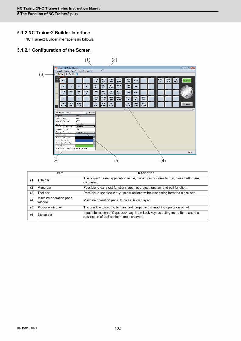
NC Trainer2/NC Trainer2 plus Instruction Manual
5 The Function of NC Trainer2 plus
102IB-1501318-J
5.1.2 NC Trainer2 Builder Interface
NC Trainer2 Builder interface is as follows.
5.1.2.1 Configuration of the Screen
Item Description
(1) Title barThe project name, application name, maximize/minimize button, close button are displayed.
(2) Menu bar Possible to carry out functions such as project function and edit function.
(3) Tool bar Possible to use frequently used functions without selecting from the menu bar.
(4)Machine operation panel window
Machine operation panel to be set is displayed.
(5) Property window The window to set the buttons and lamps on the machine operation panel.
(6) Status barInput information of Caps Lock key, Num Lock key, selecting menu item, and the description of tool bar icon, are displayed.
(1) (2)
(3)
(4)(5)(6)

NC Trainer2/NC Trainer2 plus Instruction Manual
5 The Function of NC Trainer2 plus
103 IB-1501318-J
5.1.2.2 Menu List
A list of pull-down menus and the usage of each item are described below.
5.1.2.2.1 [Project (P)] Menu
(Note 1) The project path list is displayed on the menu in the actual screen.
5.1.2.2.2 [Edit (E)] Menu
5.1.2.2.3 [View (V)] Menu
< Changing the Display Language >
(1) To change the display language of NC Trainer2 Builder, select [View (L)] - [Language (L)] -[Japanese (J)], [English
(E)], [ 中文 ( 简体 ) (S)], or [ 中文 ( 繁體 ) (T)] from the menu bar.
This operation changes the display language of menu bar, message box, dialog box, etc.
(2) When the display language is changed, Reboot Request message box will appear.
After restarting the tool, screen is displayed in the selected language.
(Note) The tool is not restarted automatically even if pressing the [OK] button.
Project menu item
Item Description
New Project (N) Create a new project.
Open project (O)... Open an existing project.
Close (C) Close the opening project.
Save (S) Save the setting of the opening project.
Save As (A)... Save the opening project with a different name. (Same as project copy.)
Export (E)... Export the custom machine operation panel for NC Trainer2 plus.
(Project history) (Note 1)The projects that opened in the past are displayed.(Up to the last 4 projects)A project can be opened by selecting it from the list.
Exit (X) Exit from the NC Trainer2 Builder.
Edit menu item
Item Description
Cut (T) Save the copy of selected object for pasting and then delete it.
Copy (C) Save the copy of selected object for pasting.
Paste (P) Paste the object which has been saved for pasting to the selected position.
View menu item
Item Description
Language (L)Change the display language of the application.(The setting will be enabled after restarting the application.)It has following sub-menus.
Japanese (J) Display in Japanese.
English (E) Display in English.
中文 (简体 ) (S) Display in Simplified Chinese.
中文 ( 繁體 ) (T) Display in Traditional Chinese
Tool Bar (T) Change whether to display or hide the tool bar.
Status Bar (S) Change whether to display or hide the status bar.

NC Trainer2/NC Trainer2 plus Instruction Manual
5 The Function of NC Trainer2 plus
104IB-1501318-J
5.1.2.2.4 [Tool (T)] Menu
5.1.2.2.5 [Help (H)] Menu
5.1.2.2.6 Tool Bar
The description of each icon on the tool bar is as follows.
5.1.2.2.7 Status Bar
Tool menu item
Item Description
Read Device Comment (R)...Read a CSV file that the button/lamp setting is described and execute a batch setting of the button/lamp.
Write Button/Lamp's File (W)... Output the settings of button/lamp to CSV file.
Help menu item
Item Description
Version Information (A) Display the version information.
Tool bar item
Item Description
(1) New Project Create a new project.
(2) Open project Open the existing project.
(3) Save Save the setting of the opening project.
(4) Cut Save the copy of selecting object for pasting and then delete it.
(5) Copy Save the copy of selecting object for pasting.
(6) Paste Paste the object which is saved for pasting to the selected position.
(7) Version Information Display the version information.
(1)(2)(3)(4)(5)(6)(7)
Selecting menu item, and the dscription
of the tool bar icon CapsLock key status
NumLockkey status

NC Trainer2/NC Trainer2 plus Instruction Manual
5 The Function of NC Trainer2 plus
105 IB-1501318-J
5.1.3 Start and Exit NC Trainer2 Builder
The following describes how to start NC Trainer2 Builder.
- For Windows 10
Select [All apps] - [MELSOFT application] - [NC Trainer2 Builder] from the [Start] menu of Windows.
- For Windows 8.1
Select the "NC Trainer2 Builder" from Windows "Start screen".
The following main window is displayed after starting NC Trainer2 Builder.
To exit from NC Trainer2 Builder, execute any of the following operations.
- Select [Project (P)] - [Exit (X)] from the menu bar.
- Click the button on the upper right of the main window.
- Click the icon and select "Close (C)" from the menu displayed.
- Press the [F4] key while pressing the [Alt] key.

NC Trainer2/NC Trainer2 plus Instruction Manual
5 The Function of NC Trainer2 plus
106IB-1501318-J
5.1.4 Creating a Project of the Custom Machine Operation Panel
Create a project with NC Trainer2 Builder to create a custom machine operation panel. The information such as the
setting of the custom machine operation panel or operating condition is saved in a project.
5.1.4.1 Creating a New Project
The following are the procedures to create a new project of NC Trainer2 Builder.
(1) To create a new project, execute any of the following operations.
- Select [Project (P)] - [New Project (N)] from the menu bar.
-Click the icon on the tool bar.
- Input Ctrl + N
(2) [New Project] dialog is displayed. Specify a project name to create.
(Note 1) A project name can be up to 32 one-byte characters. (Each two-byte character is equivalent to two
characters.)
(Note 2) One-byte characters and two-byte characters can be used for a project name.
(Note 3) A project name is not case-sensitive.
(Note 4) The following characters cannot be used for a project name.
\ / : * ? < > | " (Same as the prohibited characters for a file name)
(Note 5) Blank and Period (.) cannot be used for the first or last character of a project name.
(Note 6) CON, PRN, AUX, CLOCK$, NUL, COM0 to COM9 and LPT0 to LPT9 cannot be used for a project name.
(3) Press the "Create (C)" button to create the project.
(Note) The folder of the same name as the project name is created to a saving destination specified by [New
Project] dialog. The data files of the project are created in the folder.

NC Trainer2/NC Trainer2 plus Instruction Manual
5 The Function of NC Trainer2 plus
107 IB-1501318-J
5.1.4.2 Saving the Project
Execute one of the following operations to save the setting of the custom machine operation panel.
- Select [Project (P)] - [Save (S)] from the menu bar.
- Click icon on the tool bar.
- Input Ctrl + S.
5.1.4.3 Closing the Project
Select [Project (P)] - [Close (C)] from the menu bar to close the opening project.
The following screen will appear after closing a project.

NC Trainer2/NC Trainer2 plus Instruction Manual
5 The Function of NC Trainer2 plus
108IB-1501318-J
5.1.4.4 Opening the Project
(1) Execute one of the following operations to open an existing project.
- Select [Project (P)] - [Open project (O)] from the menu bar.
- Click icon on the tool bar.
- Input Ctrl + O.
The following dialog box is displayed.
(Note) The folder for the project of NC Trainer2 Builder is displayed as icon.
(2) Press the "Open project (O) " button after designating the project to be opened.
(Note) Refer to the section "5.1.4.1 Creating a New Project" for available project name.
The following screen is displayed and the custom machine operation panel can be set.

NC Trainer2/NC Trainer2 plus Instruction Manual
5 The Function of NC Trainer2 plus
109 IB-1501318-J
5.1.4.5 Saving the Project As a Different Name
The procedure to save the setting of the custom machine operation panel as a different project name is as follows.
(1) Select [Project (P)] - [Save As (A)] from the menu bar.
The following dialog box is displayed.
(Note) The folder for the project of NC Trainer2 Builder is displayed as icon.
(2) Press the "Save (S) " button after inputting the new project name.
(Note) Refer to the section "5.1.4.1 Creating a New Project" for available project name.
(3) The current project is closed after saving and the project which is named and saved is opened.
(Note) Be aware that the setting change is not saved for the project which has been opened (When
executing "Save As" without saving after changing the setting, the setting change is not saved for the
opening project but for the project which is named and saved).

NC Trainer2/NC Trainer2 plus Instruction Manual
5 The Function of NC Trainer2 plus
110IB-1501318-J
5.1.5 Setting of Custom Machine Operation Panel
(1) Setting of Button / Lamp
The setting procedure of button/lamp is as follows.
(a) Left-click the button/lamp to set on the machine operation panel window. The button/lamp is
selected and enclosed in a selection marker (The selection of a button/lamp is also executed with TAB key and
Shift+TAB key).
(b) The setting of selected button/lamp is displayed on the property window. Change the setting on the property
window.
The [*] mark will be displayed until the project is saved after the setting is changed.
Selected button
Property window
[*]

NC Trainer2/NC Trainer2 plus Instruction Manual
5 The Function of NC Trainer2 plus
111 IB-1501318-J
The property (setting item) of the button/lamp
(Note 1) The same input device can be allocated to multiple buttons. Input device will be 1 if any one of the buttons is in
the state of setting input device to 1.
(Note 2) The same output device can be allocated to multiple lamps. The statuses of all these lamps are changed
according to the value of output device.
Property name Description
Display Name
- Characters to be displayed on the button- Up to 8 one-byte characters.(Each two-byte character is equivalent to two one-byte characters.) - When the character string longer than the button width (4 one-byte characters), a line feed is automatically inserted.- The maximum number of lines which can be displayed on the button is up to two.- To insert a line feed at arbitrary position, input \n (\n is not counted as the number of characters).- To display \, input \\ (\\ is counted as a one-byte character).- When inputting \x (x is a character other than n or \), \ is not displayed and only x is displayed (\x is counted as a one-byte character).
Input Device (Button)
- Designate the number of the input device (X000 to X2FF in hexadecimal, ZR5000 to ZR5111, ZR5200 to ZR5311, or ZR5400 to ZR5511 in decimal) to be allocated to the button.- When the setting value is blank, no allocation.- Device can be input when both display name and input device are specified. (When either display name or input device is blank, input device will be 0 even if the button is pressed.)
Button Type- Select from Momentary or Alternate. Momentary: Turns ON only while pressing the button. Alternate: ON and OFF is switched every time the button is pressed.
Contact type button- Contact type button A contact: Input device will be 1 while the button is ON. B contact: Input device will be 1 while the button is OFF.
Output Device (Lamp)
- Designate the number of the output device (Y000 to Y2BF in hexadecimal, ZR6000 to ZR6111, ZR6200 to ZR6311, or ZR6400 to ZR6511 in decimal) to be allocated to the lamp.- When the setting value is blank, no allocation.- Device can be output when both display name and output device are specified. (When either display name or output device is blank, the lamp will not light even if the output device is 1.)
Contact Type Lamp- Select from A contact or B contact. A contact: It will light when output device is 1 and will not light when Y device is 0. B contact: It will light when output device is 0 and will not light when Y device is 1.
Button Color Specifies the button color. Custom color can be selected.
Button Font Color Specify the color of font on the button. Custom color can be specified.
Button (ON) Color- Specify the color when alternate button is ON. Custom color can be specified. - It can be specified when "Button Type" is alternate.- When alternate button is OFF, the color can be specified by "Button Color".
Button Font (ON) Color- Specify the font color when alternate button is ON. Custom color can be specified. - It can be specified when "Button Type" is alternate.- When alternate button is OFF, the font color can be specified by "Button Font Color".
Lamp Color Specify the color when the lamp is ON.
Status Bar Display String
- Specify the description of the button that is displayed on the status bar of NC Trainer2/NC Trainer2 plus.(displays when the cursor is on the button)- Up to 100 one-byte characters. (each two-byte character is equivalent to two one-byte characters.)

NC Trainer2/NC Trainer2 plus Instruction Manual
5 The Function of NC Trainer2 plus
112IB-1501318-J
The characters displayed on a button are arranged by centering vertically and horizontally.
When the button type is Alternate, the graphic for the button ON/OFF which is displayed on NC Trainer2 / NC
Trainer2 plus is as follows. (When the property of each button color is set to default.)
- When the button is ON :
- When the button is OFF : (Initial state at starting a project)
To change the button/lamp color, select the "Edit colors" dialog box displayed by button of each property. By
clicking the "Define Custom Colors" button on top of the dialog box, custom colors can be selected.
The default settings of button/lamp color are as follows.
The characters to be set(Example)
Display on the button
X
MDI
FEED50%
FD\nHOLD
A\\B
A\3B
Property name Default settings (R, G, B)
Button color (213, 225, 237)
Button character color (0, 0, 0)
Button color (ON) (0, 0, 255)
Button character color (ON) (255, 255, 255)
Lamp color (0, 255, 0)

NC Trainer2/NC Trainer2 plus Instruction Manual
5 The Function of NC Trainer2 plus
113 IB-1501318-J
(2) Setting of CycleStart button
The CycleStart button on the machine operation panel can also be set. Select the CycleStart button on the machine
operation panel and change the setting with property window.
The property (setting item) of the CycleStart
Property name Description
Display Name - Up to 10 one-byte characters of alphanumeric. (The default setting is CycleStart.)
Input Device (Button)
- Designate the number of the input device (X000 to X2FF in hexadecimal, ZR5000 to ZR5111, ZR5200 to ZR5311, or ZR5400 to ZR5511 in decimal) to be allocated to the button.- When the setting value is blank, no allocation.- Device can be input when both display name and input device are specified. (When either display name or input device is blank, input device will be 0 even the button is pressed.)
Button Type - Cannot be set (displayed in gray).Always set to Momentary.
Contact type button - Cannot be set (displayed in gray).Always set to A contact.
Output Device (Lamp) - Cannot be set (displayed in gray).
Contact Type Lamp - Cannot be set (displayed in gray).
Button Color- Specify the button color. Custom color can be selected.- The default color is (R, G, B) = (0, 255, 0)
Button Font Color- Specify the color of character on the button. Custom color can be selected.- The default color is (R, G, B) = (0, 0, 0)
Button (ON) Color - Can not be set (displayed in gray)
Button (On) Font Color - Can not be set (displayed in gray9)
Lamp color - Can not be set (displayed in gray9)
Status Bar Display String
- Specify the description of the button that is displayed on the status bar of NC Trainer2/NC Trainer2 plus.(displays when the cursor is on the button)- Up to 100 one-byte characters. (each two-byte character is equivalent to two one-byte characters.)

NC Trainer2/NC Trainer2 plus Instruction Manual
5 The Function of NC Trainer2 plus
114IB-1501318-J
(3) Switching of the tab and setting of the tab name
Click the tab switch button to switch the tab which is displayed on the machine operation panel window.
The tab name displayed on the tab switch button is set on the tab name edit box in the property window.
The tab name is up to 5 one-byte characters. (Each two-byte character is equivalent to two characters.)
(Note 1) When there is no button/lamp that a device is allocated in a tab, the tab and tab switch button is not
displayed on NC Trainer2 / NC Trainer2 plus.
(Note 2) When there is no button/lamp that a device is allocated in all the tab, only tab 1 is displayed on NC
Trainer2 / NC Trainer2 plus.
(4) Showing RIO of device
The RIO (Remote I/O) device channel (ch), station number (sta), and point (pt) can be displayed by checking the
RIO Show check box.
(Note 1) The display range is 1 to 3 for ch, 1 to 64 for sta, and 0 to 31 for pt.
(Note 2) To create a custom machine operation panel using the RIO device random allocation function of NC, set
the device for RIO fixed allocation on "Property". Refer to the Instruction Manual of CNC for details of the
RIO device random allocation function.
Tab switch button
Selected tab number is displayed
Tab name edit box
Shows RIO of input device
Shows RIO of output device
RIO Showcheck box

NC Trainer2/NC Trainer2 plus Instruction Manual
5 The Function of NC Trainer2 plus
115 IB-1501318-J
Usage examples)
When using device X100, Y100 while the head device setting parameter for RIO device random allocation on
NC is set as follows;
"X100, Y100" is allocated to "RIO ch2 sta 1 pt 0" for RIO fixed allocation. However, for the allocation above,
"X100, Y100" is allocated to "RIO ch1 sta 1 pt 0".
To use the device "X100, Y100" with the above allocation on the custom machine operation panel of NC
Trainer2/NC Trainer2 plus, set "X000, Y000" for the RIO fixed allocation "ch1 sta 1 pt 0" of RIO unit, which is
actually used on the custom machine operation panel.
RIO slave channel Allocation PLC device (DI/DO)
ch1 sta 1 X100(DI), Y100(DO)

NC Trainer2/NC Trainer2 plus Instruction Manual
5 The Function of NC Trainer2 plus
116IB-1501318-J
5.1.6 Exporting the Custom Machine Operation Panel
Export the custom machine operation panel from NC Trainer2 Builder and import it with NC Trainer2 plus to use the
created custom machine operation panel on NC Trainer2 plus.
Below is an explanation of the procedure for exporting the custom machine operation panel.
(1) Open the project of the machine operation panel to be exported.
(2) Select [Project (P)] - [Export (E)] from the menu bar.
"Export custom machine operation panel" dialog is displayed.
(Note 1) The folder for the export data of the machine operation panel is displayed as icon.
(Note 2) The default setting for the export name is the project name.
(3) Press the "Export (E)" button after inputting the folder to create the export data and export name.
(Note) Available export name is the same as a project name of NC Trainer2 Builder. Refer to the section "5.1.4.1
Creating a New Project" for details.
The folder of the same name as the export name is created under the folder to create the export data, and data files
are created in the folder.
(4) The following message box will appear when the export is completed. Press the "OK" button.
When providing the export data to other computers, provide the folder created by exporting in whole.

NC Trainer2/NC Trainer2 plus Instruction Manual
5 The Function of NC Trainer2 plus
117 IB-1501318-J
5.1.7 Adding the Custom Machine Operation Panel to "Peripheral Settings"
Below is an explanation of the procedure to import the custom machine operation panel which is exported from NC
Trainer2 Builder to NC Trainer2 plus. This adds the custom machine operation panel which can be selected by
"Peripheral Settings".
(1) Start NC Trainer2 plus.
(2) Select [Project (P)] - [Import (I)] - [Custom Machine Operation Panel (C)] from the menu bar.
The following dialog box is displayed.
(Note) The import data is provided as a folder which contains various data files. The import data folder is
displayed as icon in the dialog box.
(3) Press the "Import (P)" button after inputting the folder name for import data on "Import name (N) :".
The custom machine operation panel to be imported is added to NC Trainer2 plus with the specified name in
"Import name (N):".
(Note 1) Available import name is the same as a project name of NC Trainer2 Builder. Refer to the section "5.1.4.1
Creating a New Project" for details.
(Note 2) Even when the NC is running, the custom machine operation panel is imported without stopping the NC.
(4) The completion message box will appear when the import is completed. Press the "OK" button.

NC Trainer2/NC Trainer2 plus Instruction Manual
5 The Function of NC Trainer2 plus
118IB-1501318-J
5.1.8 Reading Device Comments
When GX Converter is installed on the GX Developer as an add-in, device comments can be output as a CSV file.
The following button/lamp setting can be executed in batches by reading the CSV file with NC Trainer2 Builder.
- Devices allocated to buttons/lamps
- Characters displayed on buttons
This function enables to cut the time and effort to make the custom machine operation panel matching to the user
PLC.
NC Trainer2 Builder
NC Trainer2 plus
GX Developer (after GX Converter add-in)
Writing the user ladder
Device commentoutput Device comment
CSV file
Editing the CSV file(Match the device information to the layout of the
buttons/lamps)
Device commentsCSV file (after edit)
Reading the device comment(reading the CSV file)
Export
Custom machine operation panel export data
Import

NC Trainer2/NC Trainer2 plus Instruction Manual
5 The Function of NC Trainer2 plus
119 IB-1501318-J
5.1.8.1 The procedure to read device comments
Below is an explanation of the procedure to set the buttons/lamps in batches by reading the device comments.
Note that the batch setting can only be carried out for the buttons/lamps on the displayed tab.
(1) Start GX Developer (after GX Converter add-in) and open GX Developer project.
(2) Select [Project] -[Import file] - [Import from TEXT, CSV format file] from the menu bar.
(3) "Data Conversion Wizard - Step 1 of 1" dialog is displayed.
(4) The "Save As" dialog is displayed by pressing "Finish".
Designate the output file name of the CSV file to which the device comments will be written, and press the
"OK" button.
(Select CSV (Comma delimited) as a file type.)
(5) Edit the contents of the CSV file to match to the layout of the buttons/lamps. Refer to the section "5.1.8.2
Device Comment File" for details.
(6) Start NC Trainer2 Builder, and open a project.
(7) Display the tab to set the buttons/lamps in batches.
Item Description
Data type Select "Common comment" or "Program comment".
Data name Select device comment to convert.
Export file type Select "CSV File".

NC Trainer2/NC Trainer2 plus Instruction Manual
5 The Function of NC Trainer2 plus
120IB-1501318-J
(8) Select [Tool (T)] - [Load Device Comment (R)] from the menu bar. "Load Device Comments" dialog is
displayed. Press the "Open (O)" button after selecting the CSV file of the device comments.
(Note) The setting of the buttons/lamps on the displayed tab is overwritten with the setting of the CSV file.
(9) The completion message box will appear when the batch setting of the buttons/lamps is completed. Press the
"OK" button.
5.1.8.2 Device Comment File
The device comment file (CSV file) format which is read with "Read Device Comment" is as follows.
- Each column (field) is separated with a comma (,).
- Below is an explanation of each column.
X281, BTN01, FEED50%, MON, A, 213:225:237, 0:0:0, , , Set feed 50%
X282, BTN01, FEED100%, ALT, B, 213:255:237, 0:0:0, 0:0:255, 255:255:255, Set feed 100%
Y281, LED01, FEED50%, , A, 0:255:0, , , , Set feed 50%
Y282, LED02, FEED100%, , B, 0:255:0, , , , Set feed 100%
Device
Device name
Comment
Button type
Contact type
Button/Lamp Color
Button Font Color
Button (ON) Color
Button(ON) Font Color
Status Bar Display String

NC Trainer2/NC Trainer2 plus Instruction Manual
5 The Function of NC Trainer2 plus
121 IB-1501318-J
Field Explanation
Device
- Designate the device allocated on a button/lamp with one-byte character.- When designating any device other than X0 to X2FF, Y0 to Y2FF, ZR5000 to ZR5111, ZR5200 to ZR5311, ZR5400 to ZR5511, ZR6000 to ZR6111, ZR6200 to ZR6311, and ZR6400 to ZR6511, the line will not be regarded not as data but as a disabled line.- When only a comma is specified, position of button/lamp to set will be skipped. (Skip is to be described later.)- If the device is specified and the comment is blank, the button/lamp will not function.
Device name -Always enter a comma although the device name is not used.
Comment
- Specify the display name of the button.- The display name will be set from top to the 8 one-byte characters.(each two-byte character is equivalent to two one-byte characters)- Input ¥n to start a new line on the character string of the button. (¥n does not count as character limit)- To display \ on the button, input \\. (\\ is count as an one-byte character)- \x in the comment is displayed as x only on the button. (\x is count as an one-byte character)- The one/two-byte space in front/back of the comment will not display. (The space in front/back of the comment does not count as one-byte character)- The display name will be blank if only comma is set.- Normally, input device comment is set to device name.(A case when output device comment is displayed is to be described later.)
Button type
- Select the button type. MOM : momentary ALT : alternate (Other than those above is set to momentary)- This line is not used when the device is output device, however, input a comma.- If it is only a comma, it is set as momentary.
Contact type
- Select the setting of the button/lamp. A : A contact B : B contact- For only comma, it is set to A contact.
Button/Lamp Color
- Specify the color of button/lamp.- To specify by RGB format, separate the each value (0 to 255) of R, G, B by a colon " ; " as follows "213:255:237".- If it is only by comma, it becomes 213:225:237(button)/0:255:0(lamp).
Button Font Color- Specify the color displays on button. The specifying process is same as "Button/Lamp Color".- This line is not used if the device is output device, however, input comma. It becomes 0:0:0 only by a comma.
Button (ON) Color
Specify the color when alternate button is ON. The specifying process is same as "Button/lamp color".- This line is not used if the device is output device or when button type is alternate, however, input comma. It becomes 0:0:255 only by comma.
Button (ON) Font Color
Specify the color on button when alternate button is ON. The specifying process is same as "Button/lamp color".- This line is not used if the device is output device or when button type is alternate, however, input comma. It becomes 255:255:255 only by comma.
Status Bar Display String
- Specify the character strings displayed on the status bar when the cursor is on the button.- Up to 100 one-byte characters. (each two-byte character is equivalent to two one-byte characters.)- The one/two-byte space in front/back of the comment will not display. (the space in front/back of the comment does not count as one-byte character)- Normally Status Bar Display String of input device is used. (When the Status Bar Display String of output device is used is mentioned later)- This line can be omitted.

NC Trainer2/NC Trainer2 plus Instruction Manual
5 The Function of NC Trainer2 plus
122IB-1501318-J
- When including a comma (,) for Device name, Comment, Status Bar Display String enclose before and after
the characters with double quotation (").
- When including a double quotation (") for Device name, Comment, Status Bar Display String, enclose before
and after the characters with double quotation ("). And then, enter a double quotation twice in a row at the
position to display the double quotation.
- If (\") is included in the comment, (\) of (\") will be set to the property of Display name. ((\) is treated as a double
quotation to enclose the character string.) The end of Display name property becomes (\) and (\) will not be
displayed on the button.
- Use Unicode for CSV file character code to use characters other than one-byte characters of alphanumeric,
symbol, or space for Device name, Comment, and Status Bar Display String.
(SJIS can be used only for Japanese. The character code of CSV file output by GX-Developer is SJIS.)
(Note) The CSV file which is output from GX Developer has no field for after Button type as follows. Add fields
for after Button type if needed.
Setting of buttons/lamps on a tab is executed as follows.
- The input/output devices are allocated to buttons/lamps according to the order in the CSV file.
- The allocation order of buttons on the tab is shown as below. The allocation order of the lamp on the tab
is the same as of buttons.(Note that a device cannot be allocated on undisplayed tab and the buttons/
lamps in constantly-displayed area.)
The characters displayed on the button Description in the CSV file
AB AB
A,B "A,B"
"AB" """AB"""
"AB"C" """AB""C"""
X280, BTN00, FEED0% X281, BTN01, FEED50% X282, BTN02, FEED100% X283, BTN03, FEED150% Y280, LED00, FEED0% Y281, LED01, FEED50% Y282, LED02, FEED100% Y283, LED03, FEED150%
Start position
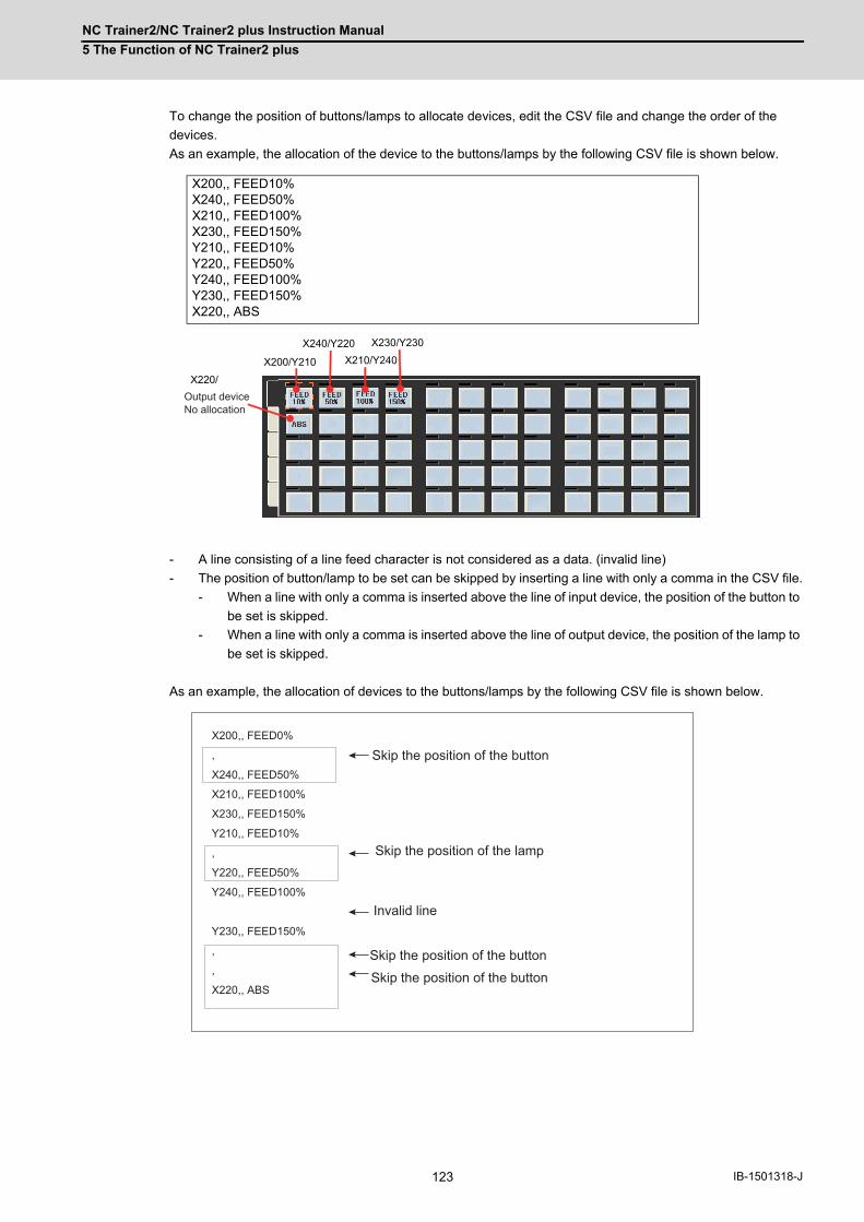
NC Trainer2/NC Trainer2 plus Instruction Manual
5 The Function of NC Trainer2 plus
123 IB-1501318-J
To change the position of buttons/lamps to allocate devices, edit the CSV file and change the order of the
devices.
As an example, the allocation of the device to the buttons/lamps by the following CSV file is shown below.
- A line consisting of a line feed character is not considered as a data. (invalid line)
- The position of button/lamp to be set can be skipped by inserting a line with only a comma in the CSV file.
- When a line with only a comma is inserted above the line of input device, the position of the button to
be set is skipped.
- When a line with only a comma is inserted above the line of output device, the position of the lamp to
be set is skipped.
As an example, the allocation of devices to the buttons/lamps by the following CSV file is shown below.
X200,, FEED10% X240,, FEED50% X210,, FEED100% X230,, FEED150% Y210,, FEED10% Y220,, FEED50% Y240,, FEED100% Y230,, FEED150% X220,, ABS
X200/Y210
X240/Y220 X210/Y240
X230/Y230
X220/Output deviceNo allocation
X200,, FEED0%
,
X240,, FEED50%
X210,, FEED100%
X230,, FEED150%
Y210,, FEED10%
,
Y220,, FEED50%
Y240,, FEED100%
Y230,, FEED150%
,
,
X220,, ABS
Skip the position of the button
Skip the position of the lamp
Invalid line
Skip the position of the buttonSkip the position of the button

NC Trainer2/NC Trainer2 plus Instruction Manual
5 The Function of NC Trainer2 plus
124IB-1501318-J
Precautions: To blank the display name but to specify the device, put a comma (,) after the comment line.
If there is no comma after the comment line, that line will be invalid.
- The display name of the button will be as follows depending on the allocation state of input/output device.
- The Status Bar Display String will be as follows depending on the allocation state of input/output device.
- The button/lamp on a tab which is not set by CSV file is set as follows.(The contents which are set before
execution of "Read Device Comment" are overwritten.)
- When it is set to the last button/lamp on the tab, all the record on CSV file after it will be ignored.
LampButton
Output device allocation
Allocated Not allocated
Input deviceallocation
AllocatedInput device
commentInput device
comment
Not allocatedOutput device
commentNone
LampButton
Output device allocation
Allocated Not allocated
Input deviceallocation
AllocatedStatus Bar Display
String of Output device
Status Bar Display String of Input
device
Not allocatedStatus Bar Display
String of Output device
None
The characters displayed on the button Description in the CSV file
Display Name (blank)
Input Device (Button) No allocation
Button Type Momentary
Contact type button A contact
Output Device (Lamp) No allocation
Contact Type Lamp A contact
Button Color (R,G,B)=(213, 225, 237)
Button Font Color (R,G,B)=(0, 0, 0)
Button (OM) color (R,G,B)=(0, 0, 255)
Button (ON) Font color (R,G,B)=(255, 255, 255)
Lamp Color (R,G,B)=(0, 255, 0)
Status Bar Display String (blank)
X200/Y210
X240/Y220 X210/Y240
X230/Y230
X220/ Output device no
X200,, FEED0%X240,, , ←X210,, ←X230,, FEED150%
This line will be invalid.240 will be set to X device and the display name will be set to blank.

NC Trainer2/NC Trainer2 plus Instruction Manual
5 The Function of NC Trainer2 plus
125 IB-1501318-J
5.1.9 Exporting the File of Button/Lamp Setting
Write the settings of button/lamp of custom machine operation panel on displaying tab to CSV file.
(The settings of button/lamp that are not on the tab does not export to CSV file)
(1) Start the NC Trainer2 Builder and open the project.
(2) Change the settings of button/lamp to the tab that exports CSV file.
(3) Select [Tool (T)] - [Write Button/Lamp’s config File(W)...] on menu bar to display "Write Button/Lamp's Config File"
dialog. Input the exporting file name and click [Save (S)] button.
(4) When the writing of CSV file is finished, the completion message box will appear. Click the "OK" button.
- Refer to "5.1.8.2 Device Comment File" of "5.1.8 Reading Device Comments" for CSV file format.
- The character code of exporting CSV file is an UNICODE.

NC Trainer2/NC Trainer2 plus Instruction Manual
5 The Function of NC Trainer2 plus
126IB-1501318-J
5.2 Creating User PLC and Checking the OperationWith NC Trainer2 plus, user PLCs can be created and the operation can be checked.
Note that the execution timing of ladder of NC Trainer2 plus is different from that of actual NC. Therefore NC Trainer2
plus cannot check the operation completely. The operation of user PLCs created with NC Trainer2 plus should be
checked finally on actual NC.
There are following methods to develop the user PLC with NC Trainer2 plus.
(1) Using GX Developer
With NC Trainer2 plus, use MITSUBISHI Integrated FA Software MELSOFT Series GX Developer that is a PLC
development tool of MITSUBISHI Programmable Controllers MELSEC Series. GX Developer is a Windows
application and sold separately from NC Trainer2 plus.
Refer to the section "5.2.1 User PLC Development Method with GX Developer" for details.
(2) Using GX Works2
With NC Trainer2 plus, use MITSUBISHI Integrated FA Software MELSOFT Series GX Works2 that is a PLC
development tool of MITSUBISHI Programmable Controllers MELSEC Series.
GX Works2 is a Windows application and sold separately from NC Trainer2 plus.
Refer to the section "5.2.2 User PLC Development Method with GX Works2" for details.
(3) Using PLC onboard
MITSUBISHI CNC M800/M80/E80 Series and M700V/M70V/E70 Series have a PLC onboard as a built-in PLC edit
function. (On-board refers generically to the PLC related operations carried out with the CNC unit and hereafter
referred to as "PLC Onboard".)
PLC onboard can be used on NC Trainer2 plus for all projects.
Refer to the section "5.2.3 User PLC Development Method with PLC Onboard" for details.
(4) Using GX Works3
For Mitsubishi Electric CNC C80 Series, use FA Integrated Engineering Software MELSOFT Series GX Works3. A
sequence program created by GX Works3 operates with the simulation function (GX Simulator3).
Refer to GX Works3 Operating Manual for details.

NC Trainer2/NC Trainer2 plus Instruction Manual
5 The Function of NC Trainer2 plus
127 IB-1501318-J
5.2.1 User PLC Development Method with GX Developer
(1) Outline of GX Developer
GX Developer is a PLC development tool of MITSUBISHI Programmable Controllers MELSEC Series. A user PLC
for MITSUBISHI CNC Series can be developed by the same operation as MELSEC Series.
To develop a user PLC with NC Trainer2 plus and GX Developer, use GX Developer Version8 (type name:
SW8D5C-GPPW). Refer to the operation manual attached to GX Developer for details.
(2) Development method
Refer to the following manual about the user PLC development method for MITSUBISHI CNC with GX Developer.
MITSUBISHI CNC M800/M80/E80 Series PLC Development Manual (IB-1501270-A or later)
MITSUBISHI CNC M800/M80/E80 Series PLC Programming Manual (IB-1501271-A or later)
MITSUBISHI CNC M700V/M70V/E70 Series PLC Programming Manual (IB-1500918 or later)
(3) Connection method
For NC Trainer2 plus and GX Developer, execute both software applications in the same computer and connect
them via a virtual network.
Below is an explanation of the connection method for NC Trainer2 plus and GX Developer.
[1] Start NC Trainer2 plus, and confirm that the network connection has been set.
(Refer to the section "5.6 Network Connection Setting".)
[2] Select [Tool (T)] - [Network Settings of NC (W)] from the menu bar on NC Trainer2 plus.
The following dialog box is displayed and then IP address of NC is displayed. Record the IP address of
NC and press the "OK" button.

NC Trainer2/NC Trainer2 plus Instruction Manual
5 The Function of NC Trainer2 plus
128IB-1501318-J
[3] Select a project on NC Trainer2 plus and start to execute the NC.
[4] Start GX Developer and open a project.
[5] Select [Online] - [Transfer Setup] from the menu bar on GX Developer. Connection setup dialog is
displayed.
[6] Click [Ethernet board] from PC side I/F.
[7] Double-click [Ethernet module] from PLC side I/F.

NC Trainer2/NC Trainer2 plus Instruction Manual
5 The Function of NC Trainer2 plus
129 IB-1501318-J
[8] PLC side I/F detailed setting of Ethernet module dialog is displayed. Select [IP address], set the IP
address recorded on step [2] and press the [OK] button
[9] On the Connection setup dialog, click [Other station (same network)] from Other station and [Ethernet]
from Network route.
[10] On the Connection setup dialog of GX Developer, click the [Connection test] button.
When the setting is correct, the message box for connection success will appear.
[11] Click the [OK] button on Connection setup dialog on GX Developer.
(4) Precautions
Below are the precautions for the user PLC development method with NC Trainer2 plus and GX Developer.
- Do not use more than two among the PLC onboard on NC Trainer2 plus, GX Developer, and GX Works2 at a
time. Some functions (updating ladder monitor, etc.) cannot be operated correctly if they are used together.

NC Trainer2/NC Trainer2 plus Instruction Manual
5 The Function of NC Trainer2 plus
130IB-1501318-J
5.2.2 User PLC Development Method with GX Works2
(1) Outline of GX Works2
GX Works2 is a PLC development tool of MITSUBISHI Programmable Controllers MELSEC Series. A user PLC for
MITSUBISHI CNC Series can be developed by the same operation as MELSEC Series.
Screen of GX Works2
Refer to the operation manual attached to GX Works2 for function details.
(2) Development method
The user PLC development method with NC Trainer2 plus and GX Works2 is basically the same as using an actual
NC and GX Works2. Refer to the following manual about the user PLC development method for MITSUBISHI CNC
with GX Works2.
MITSUBISHI CNC M800/M80/E80 Series PLC Development Manual (IB-1501256-F or later)
MITSUBISHI CNC M800/M80/E80 Series PLC Programming Manual (IB-1501257-F or later)
(3) Connection method
For NC Trainer2 plus and GX Works2, execute both software applications in the same computer and connect them
via a virtual network.
Below is an explanation of the connection method for NC Trainer2 plus and GX Works2.
[1] Start NC Trainer2 plus, and confirm that the network connection has been set.
(Refer to the section "5.6 Network Connection Setting".)
[2] Select [Tool (T)] - [Network Settings of NC (W)] from the menu bar on NC Trainer2 plus.
The following dialog box is displayed and then IP address of NC is displayed.
Record the IP address of NC and press the [OK] button.

NC Trainer2/NC Trainer2 plus Instruction Manual
5 The Function of NC Trainer2 plus
131 IB-1501318-J
[3] Select a project on NC Trainer2 plus and start to execute the NC.
[4] Start GX Works2 and open a project.
[5] Select the connection destination to use from the connection destination view of the GX Works2
navigation window.
Connection setup dialog is displayed.
[6] Click [Ethernet Board] from PC side I/F.

NC Trainer2/NC Trainer2 plus Instruction Manual
5 The Function of NC Trainer2 plus
132IB-1501318-J
[7] Double-click [Ethernet Module] from PLC side I/F.
[8] PLC side I/F detailed setting of Ethernet module dialog is displayed. Select [IP Address], set the IP
address recorded on the step [2] and press the [OK] button.
[9] On the Connection setup dialog, click [Other station (Single Network)] from Other Station Setting and
[Ethernet] from Network Communication Route.

NC Trainer2/NC Trainer2 plus Instruction Manual
5 The Function of NC Trainer2 plus
133 IB-1501318-J
[10] On the Connection setup dialog of GX Works2, click the [Connection Test] button.
When the setting is correct, the message box for connection success will appear.
[11] Click the [OK] button on Connection setup dialog on GX Works2.
(4) Precautions
Below are the precautions for the user PLC development method with NC Trainer2 plus and GX Works2.
- Do not use more than two among the PLC onboard on NC Trainer2 plus, GX Developer, and GX Works2 at a
time. Some functions cannot be operated correctly if they are used together at a time.
- Projects of NC Trainer2 plus M730V/M70V TypeA/M70V TypeB/E70 cannot be connected to GX Works2. Use
GX Developer or PLC onboard.

NC Trainer2/NC Trainer2 plus Instruction Manual
5 The Function of NC Trainer2 plus
134IB-1501318-J
5.2.3 User PLC Development Method with PLC Onboard
(1) Outline of PLC onboard
The PLC onboard on NC Trainer2 plus can develop user PLCs for MITSUBISHI CNC as with the PLC onboard of
MITSUBISHI CNC M800/M80/E80 Series and M700V/M70V/E70 Series, such as creating, editing, saving, reading
and monitoring a user PLC.
(2) Development method
PLC onboard on NC Trainer2 plus is the same as PLC onboard function of M800/M80/E80 Series for the project of
M830/M80 TypeA/M80 TypeB/E80 TypeA/E80 TypeB, and is the same as that of M700VS for the project of M730V/
M70V TypeA/M70V TypeB/E70. Refer to the explanation of built-in edit function in the following manual for details
of the user PLC development method with PLC onboard.
MITSUBISHI CNC M800/M80/E80 Series PLC Development Manual (IB-1501270-A or later)
MITSUBISHI CNC M700V/M70V/E70 Series PLC Programming Manual (IB-1500918 or later)
(3) Starting PLC onboard
There are two methods used to start the PLC Onboard.
1) Start from the NC screen
[1] Start NC Trainer2 plus and execute a project.
[2] Select [Tool (T)]-[Set Machine Parameters (M)] from the menu bar on NC Trainer2 plus, and check the
item.
[3] The PLC Onboard screen is displayed by clicking [Ladder Monitor] menu on the maintenance screen of
NC.
* The PLC Onboard cannot be started from the NC screen with the project of M730V/M70V TypeA/M70V
TypeB/E70.

NC Trainer2/NC Trainer2 plus Instruction Manual
5 The Function of NC Trainer2 plus
135 IB-1501318-J
2) Start by pressing the [F0] key
[1] Start NC Trainer2 plus and execute a project.
[2] Select [Tool (T)]-[Set Machine Parameters (M)] from the menu bar on NC Trainer2 plus, and check the
item.
[3] Set the bit selection parameter “#6451 bit0 (onboard on)” to 1 on NC maintenance screen.
[4] Press the F0 key on NC keyboard or the Shift+F10 key on PC keyboard to display the PLC onboard
screen.

NC Trainer2/NC Trainer2 plus Instruction Manual
5 The Function of NC Trainer2 plus
136IB-1501318-J
(4) Operation for an external file
For the PLC onboard on NC Trainer2 plus, the "(folder name to store NC Trainer2 data)\M-CARD" folder of
Windows is allocated as an external device virtually.
(Normally, M-CARD folder is allocated under C:\MELCNC\NCT2P.)
To designate a file or directory on an external device, designate /M-CARD as the first directory of path. This /M-
CARD directory corresponds to the "(folder name to store NC Trainer2 data)\M-CARD" folder of Windows.
For example, when /M-CARD/M7LAD directory is designated on PLC on-board, C:\MELCNC\NCT2P\M-
CARD\M7LAD folder of Windows is the target of input/output.
(5) Precautions
Below are the precautions for the user PLC development method with PLC onboard on NC Trainer2 plus.
- Do not use more than two among the PLC onboard on NC Trainer2 plus, GX Developer, and GX Works2 at a
time. Some functions cannot be operated correctly if they are used together.
- Do not change the name of M-CARD folder. Input/output operation cannot be executed by external file
operation if changed.

NC Trainer2/NC Trainer2 plus Instruction Manual
5 The Function of NC Trainer2 plus
137 IB-1501318-J
5.3 Display of Custom Release ScreenCustom release is a function which allows a user-original window to be displayed as a standard screen or another
operation screen. A screen which is displayed by the custom release is called custom release screen.
NC Trainer2 plus can display a custom release screen ("NC Designer2 interpreter method", "NC Designer2 compilation
method" and "Executing file registration method") which is created for M800/M80/E80 Series and M700V/M70V/E70
Series.
(NC Trainer2 can also display a custom release screen, "NC Designer2 interpreter method", "NC Designer2 compilation
method", and "Executing file registration method" (menu release) by importing a created project from NC Trainer2 plus.)

NC Trainer2/NC Trainer2 plus Instruction Manual
5 The Function of NC Trainer2 plus
138IB-1501318-J
Custom release screens are developed with an NC engineering tool NC Designer2. Refer to "MITSUBISHI CNC NC
Designer2 Instruction Manual" for details of the development method.
(Note 1) To display custom release screens of NC Designer2 compilation method developed for M800S/M80/E80/
M700VS/M70V/E70, it is required to recompile the source code with Microsoft Visual C++.
(Note 2) Custom release screens of Executing file registration method (F0 release) cannot be displayed by a key
operation with NC Trainer2/NC Trainer2 plus, however, the operation can be checked by starting the
executing file directly.
Custom release screens of Executing file registration method (menu release) can be displayed by pressing the
menu of NC Trainer2/NC Trainer2 plus.
(Note 3) The custom release screens developed with NC Designer can also be displayed.
Macro Data Project
file (*.GIP)
Original source code
(C++) Source code (C++)
Original source code
Source code Compilation link
Automatic generation of
interpretation data
(1) NC Designer2 Interpreter method
(2) NC Designer2 Compiler method
(3) EXE file registration method
Compilation link
Commercially available
application
Commercially available application
development tool (VB, VC, etc.)
Automatic generation of source code
2NC Designer2

NC Trainer2/NC Trainer2 plus Instruction Manual
5 The Function of NC Trainer2 plus
139 IB-1501318-J
Below are the differences from the custom release of M800/M80/E80 Series and M700V/M70V/E70 Series.
5.3.1 The Folder to Store Necessary Files for Displaying Custom Release Screen
For NC Trainer2 plus, necessary files for displaying custom release screens are prepared for each project. The
necessary files are stored under the folder to store NC Trainer2 plus data (normally,
C:\MELCNC\NCT2P)\projects\project name\custom.
(For M800W/M700VW, necessary files for displaying custom release screens are stored in D:\custom.)
5.3.2 Path Designation of GIP File, DLL File, and Executing File
To display custom release screens, the path of GIP file (*.GIP), DLL file (*.DLL), and executing file (*.EXE) of Executing
file registration method (menu release) of the custom release screens is required to be described in config.ini and
customdef.ini. For NC Trainer2 plus, there are two methods of path designation as follows.
(1) Designation by absolute path
Designate the absolute path beginning with the folder to store NC Trainer2 plus data (normally,
C:\MELCNC\NCT2P)\custom\.
<Example of config.ini>
(Note 1) Although the necessary files for displaying custom release screens are stored under the folder to store
NC Trainer2 plus data\projects\project name\custom, the files that are copied under the folder to store NC
Trainer2 plus data \custom are used for displaying the screen.
(Note 2) For M800W/M700VW, designate the path beginning with D:\custom\. To display a custom release screen
whose operation was checked with NC Trainer2 plus on M800W/M700VW, change the path designation.
For M800S/M80/E80/M700VS/M70V/E70, change it to a relative path.
(Note 3) When there are spaces in the path for the executing file (*.EXE) of executing file registration method
(menu release), the described executing file may not run. Designate a path that does not have spaces.
(2) Designation by relative path
Designate the relative path from the folder to store NC Trainer2 plus data (normally, C:\MELCNC\NCT2P)\custom\.
<Example of config.ini >
(Note 1) It is the same designation method as M800S/M80/E80/M700VS/M70V/E70. When a custom release
screen whose operation was checked with NC Trainer2 plus is displayed on M800S/M80/E80/M700VS/
M70V/E70, the path designation is not required to be changed. For M800W/M700VW, change the path
designation.
(Note 2) Custom release screens of Executing file registration method (menu release) cannot be displayed by
relative path designation. Designate the executing file by absolute path.
[INTERPRETER]RUN=2PROJECT01=C:\MELCNC\NCT2P\custom\PANEL.GIP PAGE_OFFSET01=7000PROJECT02=C:\MELCNC\NCT2P\custom\WINDOW.GIPPAGE_OFFSET02=8000
[INTERPRETER]RUN=2PROJECT01=PANEL.GIP PAGE_OFFSET01=7000PROJECT02=WINDOW.GIPPAGE_OFFSET02=8000

NC Trainer2/NC Trainer2 plus Instruction Manual
5 The Function of NC Trainer2 plus
140IB-1501318-J
5.3.3 Display of Executing File Registration Method
The custom release screens (F0 release) of executing file registration method cannot be displayed by an operation with
NC Trainer2 plus, however, the operation can be checked by starting the executing file directly.
For custom release screens of Executing file registration method (F0 release), create the following BAT file or VB script
in the same folder as the executing file and start the BAT file or VB script. (The installation folder is "C:\Program
Files\MELSOFT\NC Trainer2 plus" and the executing file name is "custom.exe" for the following example. Change these
settings depending on the execution environment of NC Trainer2 plus and executing file.)
○For M800 (BAT file)
(VB script)
○For M700V (BAT file)
(VB script)
The following are the precautions for the Executing file registration method (F0 release and menu release).
(Note 1) The custom release screen is not displayed on NC screen of NC Trainer2 plus, but it is displayed as an
independent window.
(Note 2) To exit from NC Trainer2 plus, close the executing file first. If not, NC Trainer2 plus may not be exited
normally.
(Note 3) When NC restart or project operation (such as changing projects) is executed on NC Trainer2 plus, close the
executing file first. If not, NC restart or project operation is failed.
5.3.4 Outline of Debug for Custom Release Screen
By using NC Trainer2 plus, custom release screens can be debugged without actual NC. The following methods of
custom release screen can be debugged.
@echo offset PATH=C:\Program Files\MELSOFT\NC Trainer2 plus\M8;%PATH%start custom.exe
Set objShell = WScript.CreateObject("WScript.Shell")Set objEnv = objShell.Environment("Process")objEnv("PATH") = "C:\Program Files\MELSOFT\NC Trainer2 plus\M8;" & objEnv("PATH")objShell.run "custom.exe"
@echo offset PATH=C:\Program Files\MELSOFT\NC Trainer2 plus\M7;%PATH%start custom.exe
Set objShell = WScript.CreateObject("WScript.Shell")Set objEnv = objShell.Environment("Process")objEnv("PATH") = "C:\Program Files\MELSOFT\NC Trainer2 plus\M7;" & objEnv("PATH")objShell.run "custom.exe"
Method of custom release screenDebug Remarks
Interpreter method × Only the operation check is enabled.
Compilation method ○
Source level debug is enabled with Microsoft Visual Studio®Refer to “5.3.5 Source Level Debug of Custom Release Screen (Compilation Method)” for details.
Executing file registration method ○ Debug with Microsoft Visual Studio®, etc. as with a normal application debug.

NC Trainer2/NC Trainer2 plus Instruction Manual
5 The Function of NC Trainer2 plus
141 IB-1501318-J
5.3.5 Source Level Debug of Custom Release Screen (Compilation Method)
By using NC Trainer2 plus and Microsoft Visual Studio® (hereafter Visual Studio), the source level debug of custom
release screens (compilation method) can be executed. Refer to the Instruction Manual of NC Designer2 for available
version of Visual Studio.
The following is the debug procedure for custom release screen (compilation method).
(1) Open a project of custom release screen (compilation method) to debug with Visual Studio, and debug build the dll
of the custom release screen.
(Note) When moving the project to different folder, rebuild the source code file of dll even though it is not
modified. Otherwise the debug cannot be executed.
(2) Create a project for debug of the custom release screen with NC Trainer2 plus. After creating the project, once exit
from NC Trainer2 plus.
(3) Copy the debug built dll of the custom release screen to the custom folder of the NC Trainer2 plus project for
debug (the folder to store NC Trainer2 plus data\projects\project name\custom).
(4) Store config.ini and customdef.ini to display the custom release screen in the same folder.
(5) Start NC Trainer2 plus and execute the NC Trainer2 plus project for debug.
(6) When the NC standard screen is displayed on NC Trainer2 plus, attach to melhmi (executing process of NC screen)
with Visual Studio.
<For Visual Studio2005/2008/2010/2012>
Display [Attach to Process] dialog box by selecting [Debug (D)]-[Attach to Process (P)…] from the menu.
Select melhmi.exe and click the [Attach (A)] button.
<For Visual Studio 6.0>
Display [Attach to Process] dialog box by selecting [Build (B)]-[Started Debugging (D)]-[Attach to Process
(A)...] from the menu. Select melhmi and click the [OK] button.

NC Trainer2/NC Trainer2 plus Instruction Manual
5 The Function of NC Trainer2 plus
142IB-1501318-J
(7) Display the source code file of the custom release screen with Visual Studio and set the break point.
(8) Display the custom release screen with NC Trainer2 plus and debug the screen.
(9) To terminate the debug, exit from NC Trainer2 plus or restart the NC (click [NC Restart] button). When the NC
screen disappears, the debug execution of Visual Studio is also terminated automatically.
(Note) When the debug execution is force-quit on Visual Studio 6.0 before exiting from NC Trainer2 plus, the NC
screen cannot be displayed on NC Trainer2 plus. In that case, exit from NC Trainer2 plus or restart the
NC.
5.3.6 Settings of Custom Release Start Up Screen
The bmp file of start up screen can be use as the start up screen when starting the NC by storing it in the project folder of
NC Trainer2 plus (the folder to store NC Trainer2 plus data\projects\project). The name of the bmp file is fixed as
"startupscreen.bmp" (for 10.4-type NC screen) or "startupscreen_xga.bmp" (for 15-type NC screen). If there is no
"startupscreen.bmp" in the NC Trainer2 plus project folder, the standard start up screen displays when staring the NC.
For NC Trainer2, by importing the project created by NC Trainer2 plus the Custom Release Start Up Screen can be
displayed.
The specification of "startupscreen.bmp" on actual NC is as follows.
(*) If the specification of "startupscreen.bmp" is different from actual NC, it will display as the start up screen
on the NC Trainer2 plus. If the width is not 640 or height is bigger than 480 on the actual NC M800S/M80/
E80/M700VS/M70V/E70, it will display as the standard start up screen.
Models Size Number of colors
M800W/M700VW Width640×Height480 24bit
M800S/M80/E80 Width640×Height440 8bit or 24bit
M700VS/M70V/E70 Width640×Height440 8bit
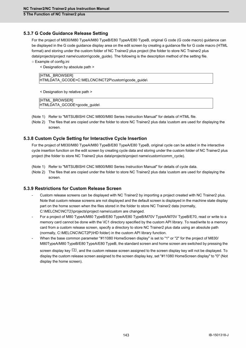
NC Trainer2/NC Trainer2 plus Instruction Manual
5 The Function of NC Trainer2 plus
143 IB-1501318-J
5.3.7 G Code Guidance Release Setting
For the project of M830/M80 TypeA/M80 TypeB/E80 TypeA/E80 TypeB, original G code (G code macro) guidance can
be displayed in the G code guidance display area on the edit screen by creating a guidance file for G code macro (HTML
format) and storing under the custom folder of NC Trainer2 plus project (the folder to store NC Trainer2 plus
data\projects\project name\custom\gcode_guide). The following is the description method of the setting file.
○ Example of config.ini
< Designation by absolute path >
< Designation by relative path >
(Note 1) Refer to "MITSUBISHI CNC M800/M80 Series Instruction Manual" for details of HTML file.
(Note 2) The files that are copied under the folder to store NC Trainer2 plus data \custom are used for displaying the
screen.
5.3.8 Custom Cycle Setting for Interactive Cycle Insertion
For the project of M830/M80 TypeA/M80 TypeB/E80 TypeA/E80 TypeB, original cycle can be added in the interactive
cycle insertion function on the edit screen by creating cycle data and storing under the custom folder of NC Trainer2 plus
project (the folder to store NC Trainer2 plus data\projects\project name\custom\comm_cycle).
(Note 1) Refer to "MITSUBISHI CNC M800/M80 Series Instruction Manual" for details of cycle data.
(Note 2) The files that are copied under the folder to store NC Trainer2 plus data \custom are used for displaying the
screen.
5.3.9 Restrictions for Custom Release Screen
- Custom release screens can be displayed with NC Trainer2 by importing a project created with NC Trainer2 plus.
Note that custom release screens are not displayed and the default screen is displayed in the machine state display
part on the home screen when the files stored in the folder to store NC Trainer2 data (normally,
C:\MELCNC\NCT2)\projects\project name\custom are changed.
- For a project of M80 TypeA/M80 TypeB/E80 TypeA/E80 TypeB/M70V TypeA/M70V TypeB/E70, read or write to a
memory card cannot be done with the \IC1 directory specified by the custom API library. To read/write to a memory
card from a custom release screen, specify a directory to store NC Trainer2 plus data using an absolute path
(normally, C:\MELCNC\NCT2P)\HD folder) in the custom API library function.
- When the base common parameter "#11080 HomeScreen display" is set to "1" or "2" for the project of M830/
M80TypeA/M80 TypeB/E80 TypeA/E80 TypeB, the standard screen and home screen are switched by pressing the
screen display key , and the custom release screen assigned to the screen display key will not be displayed. To
display the custom release screen assigned to the screen display key, set "#11080 HomeScreen display" to "0" (Not
display the home screen).
[HTML_BROWSER]HTMLDATA_GCODE=C:\MELCNC\NCT2P\custom\gcode_guide\
[HTML_BROWSER]HTMLDATA_GCODE=gcode_guide\

NC Trainer2/NC Trainer2 plus Instruction Manual
5 The Function of NC Trainer2 plus
144IB-1501318-J
5.4 APLC releaseAPLC release is a function which calls APLC release C language module (APLC.o) created by users from the NC.
Complicated control operations that are difficult to be mounted by user PLC can be created with C language.
With NC Trainer2 plus, the C language module compiled for M800/M80/E80/C80 Series and M700V/M70V/E70 Series
can be written in the memory of the NC directly and the operation can be checked.
(Note) For NC Trainer2 plus, the execution of C language module from compact flashes is not supported.
5.4.1 Writing APLC Release C Language Module
The following is the procedure to write APLC release C language module (APLC.o) in the NC memory of NC Trainer2
plus.
(1) Store C language module (APLC.o) to be stored in the NC memory to any folder. (The file name is fixed to APLC.o.)
(2) Start NC Trainer2 plus. Select the project to write C language module when the project list dialog is displayed.
(When there is no project, the project list dialog is not displayed. Write C language module after creating a project.)
(3) After starting the NC, select [Project (P)] - [Write APLC module (L)] from the menu bar.
Designate APLC.o stored on step (1) and press the [Write (W)] button when the file selection dialog is displayed.
(Caution) If the project is opened by read-only (Refer to "1.5 Precautions"), [Write APLC module (L)] menu is
displayed in gray and cannot be selected.

NC Trainer2/NC Trainer2 plus Instruction Manual
5 The Function of NC Trainer2 plus
145 IB-1501318-J
(4) The writing process of C language module is started.
(Note) When the writing process of C language module is executed, the NC will enter an emergency stop state.
(5) The message box will appear after completing the writing process of C language module. To enable APLC, restart
the NC with NC Restart button.

NC Trainer2/NC Trainer2 plus Instruction Manual
5 The Function of NC Trainer2 plus
146IB-1501318-J
5.4.2 Outline for the Debug of APLC Release C Language Module
By using NC Trainer2 plus and Microsoft Visual Studio® (hereafter Visual Studio), the source level debug of APLC
release C language module can be executed. The C language module which can be debugged is all types of type 1 (PLC
asynchronous processing), type 2 (PLC synchronous processing) and type 3 (PLC calling processing).
The following is S/W configuration during debugging.
Name Explanation
Visual Studio
Use for the compiling and the source level debug of C language module.The following versions are available.Visual Studio 2005,Visual Studio 2008,Visual Studio 2010,Visual Studio 2012, Visual Studio 2013, Visual Studio 2015
Source code file of C language module
Source code file of C language module created by user
aplc.hHeader file of APLC release libraryIt is included in the source code file of C language module.
vxWorks.hHeader file which defines the data types, etc. used for NC systemIt is included in the source code file of C language module.
aplcDebug.lib Library file to link when C language module is compiled and generating aplc.dll.
aplc.dll Dll file for the source level debug with Visual Studio
aplc.exeExecuting program for debug of C language moduleAt the start, aplc.dll is loaded and then NC Trainer2 plus is started for debug.
NC Trainer2 plusWhen starting from aplc.exe, call C language module dedicated to debug instead of C language module (APLC.o) created by user.It is not required to write APLC module before the debug.
NC Trainer2 plus aplc.exe
Visual Studio
aplc.dll
aplcDebug.lib
aplc.h vxWorks.h
NC Trainer plus provided fileTool by other manufacturer File created by user
Source code file of C language module
Compiling
Link
Debug executionStart at starting debug
Load
Calling function
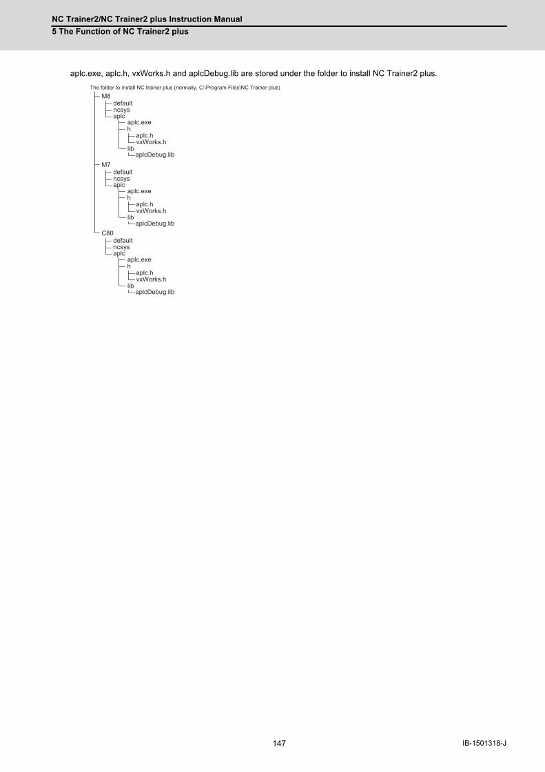
NC Trainer2/NC Trainer2 plus Instruction Manual
5 The Function of NC Trainer2 plus
147 IB-1501318-J
aplc.exe, aplc.h, vxWorks.h and aplcDebug.lib are stored under the folder to install NC Trainer2 plus.
defaultncsysaplc
aplc.exeh
aplc.hvxWorks.h
libaplcDebug.lib
defaultncsysaplc
aplc.exeh
aplc.hvxWorks.h
libaplcDebug.lib
M8
M7
defaultncsysaplc
aplc.exeh
aplc.hvxWorks.h
libaplcDebug.lib
C80
The folder to install NC trainer plus (normally, C:\Program Files\NC Trainer plus)

NC Trainer2/NC Trainer2 plus Instruction Manual
5 The Function of NC Trainer2 plus
148IB-1501318-J
5.4.3 Execution Procedure of C Language Module During Debugging
Below is an explanation of the execution procedure of C language module in aplc.dll during debugging.
- To execute C language module in aplc.dll during debugging, mount the initialization function aplc_top on aplc.dll
and register C language module by the function (The same registration functions as of actual NC,
setUserBaseMain, setUserPlcPreMain, and setUserPlcCallFunc are available). At the start of debug, aplc_top is
called from aplc.exe. At that time, the function address of C language module is registered to the function table in
aplc.exe. And then the registered C language module is called when C language module is called on NC Trainer2
plus side.
- Type 1 and Type 2/3 C language module are executed on the different threads. As with actual NC, type 2/3 C
language module is executed by interrupting type 1 C language module.
aplc_top
aplc.exe
aplc.dll
Action from NC Trainer2 plus
Main thread
Type 1 Calling notice Temporary stop Type 2/3
Calling notice
Function table
Type 1Execution thread
Type 2/3Execution thread
CallingCallingCallingCalling at the start
Registration
Type 1C language
module(PLC
asynchronous)
Type 2C language
module(PLC
synchronous)
Type 3C language
module(PLC calling)

NC Trainer2/NC Trainer2 plus Instruction Manual
5 The Function of NC Trainer2 plus
149 IB-1501318-J
5.4.4 Modification of Source Code File for Debug
To debug C language module at the source level, the source code file actually used for APLC release function should be
modified for Visual Studio.
The available functions on Visual Studio side are as follows.
○: Available ×: Unavailable Name: Alternative function
(Note 1) □=Device name: X,Y,M,L,F,SM,TI,TO,STI,STO,CI,CO
(For a project of M730V/M70 TypeA/M70 TypeB/E70/C80)
(Note 2) □=Device name: R,D
(For a project of M730V/M70 TypeA/M70 TypeB/E70/C80)
(Note 3) □=Device name: X,Y,M,L,F,SM,TI,TO,STI,STO,CI,CO,B,SB
(For a project of M830/M80 TypeA/M80 TypeB/E80 TypeA/E80 TypeB)
(Note 4) □=Device name: R,D,ZR,W,SW,SD
(For a project of M830/M80 TypeA/M80 TypeB/E80 TypeA/E80 TypeB)
Item to be modified Modification method
Include aplc.h and vxWorks.h Include the source code file of C language module aplc.h and vxWorks.h.
long longunsigned long long
Replace with LONGLONG type or ULONGLONG type defined by vxWorks.h.
Function other than APLC release library
Refer to the following lists.For unavailable functions, modify to the alternative processing.
APLC release library (All of them can be used.)
Function nameAvailability
M8 M7 C80
getNCData ○ ○ ○
setNCData ○ ○ ○
scaldr ○ ○ ○
aplcSrch ○ ○ ○
melplcBset □ (Note 1) (Note 3) ○ ○ ○
melplcBrst □ (Note 1) (Note 3) ○ ○ ○
melplcBtst □ (Note 1) (Note 3) ○ ○ ○
melplcWset □ (Note 2) (Note 4) ○ ○ ○
melplcWtst □ (Note 2) (Note 4) ○ ○ ○
melplcLset □ (Note 2) (Note 4) ○ ○ ○
melplcLtst □ (Note 2) (Note 4) ○ ○ ○
melplcBset □ _Ex (Note 3) ○ × ×
melplcBrst □ _Ex (Note 3) ○ × ×
melplcBtst □ _Ex (Note 3) ○ × ×
melplcWset □ _Ex (Note 4) ○ × ×
melplcWtst □ _Ex (Note 4) ○ × ×
melplcLset □ _Ex (Note 4) ○ × ×
melplcLtst □ _Ex (Note 4) ○ × ×
abtol ○ ○ ○
ahtol ○ ○ ○
atobcd ○ ○ ○
atos ○ ○ ○
dchtoa ○ ○ ○
ltoa ○ ○ ○
ostrcmp ○ ○ ○

NC Trainer2/NC Trainer2 plus Instruction Manual
5 The Function of NC Trainer2 plus
150IB-1501318-J
○: Available ×: Unavailable Name: Alternative function
(Note 1) Always complete successfully without password certification.
(Note 2) Always complete successfully without password registration.
○: Available ×: Unavailable Name: Alternative function
Function for automatic operation lock
Function name Availability
melplc_PasswordInfo ○ (Note 1)
melplc_PasswordWrite ○ (Note 2)
Standard library (stdlib)
Function name Availability
abs ○
atof ○
atoi ○
atol ○
bsearch ○
div ○
div_r div
labs ○
ldiv ○
ldiv_r ldiv
qsort ○
rand ○
srand ○
strtod ○
strtol ○
strtoul ○

NC Trainer2/NC Trainer2 plus Instruction Manual
5 The Function of NC Trainer2 plus
151 IB-1501318-J
○: Available ×: Unavailable Name: Alternative function
○: Available ×: Unavailable Name: Alternative function
Character string library
Function name Availability
memchr ○
memcmp ○
memcpy ○
memmove ○
memset ○
strcat ○
strchr ○
strcmp ○
strcoll ○
strcpy ○
strcspn ○
strerror_r strerror
strerror ○
strlen ○
strncat ○
strncmp ○
strncpy ○
strpbrk ○
strrchr ○
strspn ○
strstr ○
strtok ○
strtok_r strtok
strxfrm ○
Character type library
Function name Availability
isalnum ○
isalpha ○
iscntrl ○
isdigit ○
isgraph ○
islower ○
isprint ○
ispunct ○
isspace ○
isupper ○
isxdigit ○
tolower ○
toupper ○

NC Trainer2/NC Trainer2 plus Instruction Manual
5 The Function of NC Trainer2 plus
152IB-1501318-J
(Note) The result of the calculation may differ from actual machine in the range of rounding error.
○: Available ×: Unavailable Name: Alternative function
○: Available ×: Unavailable Name: Alternative function
Arithmetic operation library
Function name Availability
asin ○
acos ○
atan ○
atan2 ○
ceil ○
cosh ○
exp ○
fabs ○
floor ○
fmod ○
frexp ○
ldexp ○
log ○
log10 ○
modf ○
pow ○
sin ○
cos ○
sinh ○
sqrt ○
tan ○
tanh ○
Time library
Function name Availability
asctime ○
asctime_r asctime
clock ○
ctime ○
ctime_r ctime
difftime ○
gmtime ○
gmtime_r gmtime
localtime ○
localtime_r localtime
mktime ○
strftime ○
time ○
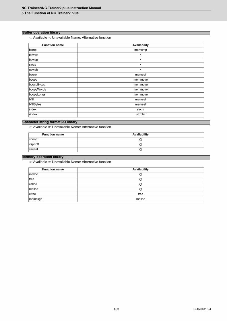
NC Trainer2/NC Trainer2 plus Instruction Manual
5 The Function of NC Trainer2 plus
153 IB-1501318-J
○: Available ×: Unavailable Name: Alternative function
○: Available ×: Unavailable Name: Alternative function
○: Available ×: Unavailable Name: Alternative function
Buffer operation library
Function name Availability
bcmp memcmp
binvert ×
bswap ×
swab ×
uswab ×
bzero memset
bcopy memmove
bcoypBytes memmove
bcopyWords memmove
bcopyLongs memmove
bfill memset
bfillBytes memset
index strchr
rindex strrchr
Character string format I/O library
Function name Availability
sprintf ○
vsprintf ○
sscanf ○
Memory operation library
Function name Availability
malloc ○
free ○
calloc ○
realloc ○
cfree free
memalign malloc

NC Trainer2/NC Trainer2 plus Instruction Manual
5 The Function of NC Trainer2 plus
154IB-1501318-J
5.4.5 Preparation for Debug
Prepare the source level debug of C language module according to the following procedures.
(1) Create a new empty DLL project (32bit version) as a project for debug of C language module with Visual Studio.
(Refer to the Help of Visual Studio for creation procedure of DLL project.)
(2) Add the source file of C language module to the project created on step 1).
(3) Select [Project (P)]-[Property (P)] from the menu bar of Visual Studio and open [Project name Property Pages]
dialog box. Select [Active (Debug)] from [Configuration (C)]. At the category of [Configuration Properties]-[General],
set to [Use Multi-Byte Character Set] for [Character Set].

NC Trainer2/NC Trainer2 plus Instruction Manual
5 The Function of NC Trainer2 plus
155 IB-1501318-J
(4) Set the project items according to the following table in the same way.
(5) Close the [Project name Property Pages] dialog box with the [OK] button.
(6) Build aplc.dll by selecting [Build (B)]-[Build Solution (B)] from the menu bar on Visual Studio.
Category Item Details
Configuration Properties- Debug
Command
For a project of M8The folder to install NC Trainer2 plus\M8\aplc\aplc.exe(normally, C:\Program Files\MELSOFT\NC Trainer2 plus\M8\aplc\aplc.exe)
For a project of M7The folder to install NC Trainer2 plus\M7\aplc\aplc.exe(normally, C:\Program Files\MELSOFT\NC Trainer2 plus\M7\aplc\aplc.exe)
For a project of C80The folder to install NC Trainer2 plus\C80\aplc\aplc.exe(normally, C:\Program Files\MELSOFT\NC Trainer2 plus\C80\aplc\aplc.exe)
Command ArgumentsThe project name of NC Trainer2 plus which is started during debugging
Working Directory The solution folder for this project\Debug
Configuration Properties- C/C++- GENERIC
Additional included directory
For a project of M8The folder to install NC Trainer2 plus\M8\aplc\h(normally, C:\Program Files\MELSOFT\NC Trainer2 plus\M8\aplc\h)
For a project of M7The folder to install NC Trainer2 plus\M7\aplc\h(normally, C:\Program Files\MELSOFT\NC Trainer2 plus\M7\aplc\h)
For a project of C80The folder to install NC Trainer2 plus\C80\aplc\h(normally, C:\Program Files\MELSOFT\NC Trainer2 plus\C80\aplc\h)
Correspond to 64bit portingNo(This item is not included in Visual Studio2010/2012/2013)
Configuration Properties- C/C++- Code Generation
Run time library Multi-threaded (/MT)
Configuration Properties- C/C++- Language
Handle wchar_t as build-in type No
Configuration Properties- Linker-GENERIC
Output File The solution folder for this project \Debug\aplc.dll
Additional library directory
For a project of M8The folder to install NC Trainer2 plus\M8\aplc\lib(normally, C:\Program Files\MELSOFT\NC Trainer2 plus\M8\aplc\lib)
For a project of M7The folder to install NC Trainer2 plus\M7\aplc\lib(normally, C:\Program Files\MELSOFT\NC Trainer2 plus\M7\aplc\lib)
For a project of C80The folder to install NC Trainer2 plus\C80\aplc\lib(normally, C:\Program Files\MELSOFT\NC Trainer2 plus\C80\aplc\lib)
Configuration Properties- Linker- In
Additional Dependencies aplcDebug.lib
Ignore specific library LIBC.lib

NC Trainer2/NC Trainer2 plus Instruction Manual
5 The Function of NC Trainer2 plus
156IB-1501318-J
5.4.6 Debugging Procedure
Below is an explanation of the procedure for source level debug of C language module.
(1) When NC Trainer2 plus is already started, exit it and then set the break point to the source file of C language
module with Visual Studio.
(2) Start debugging with Visual Studio. NC Trainer2 plus is started automatically and a debug is started.
(3) To terminate debug, exit from NC Trainer2 plus and then force-quit the debug on Visual Studio.
5.4.7 Task Lock Function for APLC Debug
Task lock function for APLC debug is a function which interrupts the execution processing of NC system while calling C
language module of type 2 (PLC synchronous processing)/type 3 (PLC calling processing). This function is disabled
while calling C language module of type 1(PLC asynchronous).
For NC Trainer2 plus, the processing execution timing of APLC is operated in asynchronous with NC system. Therefore
this function is used to execute the processing of APLC synchronized with NC system by type 2/type 3.
Note that when this function is enabled, NC Trainer2 plus slows down because NC system is operated synchronously at
anytime.
- To enable or disable the APLC debug task lock, select [Tool (T)]- [APLC Debug Task Lock (T)] from the menu bar
on NC Trainer2 plus. It will be enabled immediately during debug.
- The menu [APLC Debug Task Lock (T)] above can be selected only when NC Trainer2 plus is started automatically
by debug execution of C language module with Visual Studio.

NC Trainer2/NC Trainer2 plus Instruction Manual
5 The Function of NC Trainer2 plus
157 IB-1501318-J
5.4.8 Cautions for Source Level Debug
- When the NC is restarted with NC Trainer2 plus during debug, C language module on Visual C++ side is not called
anymore and cannot be debugged. Exit NC Trainer2 plus first and exit (the debug execution of) Visual C++, and
then start debugging again.
- For C language module on Visual Studio side, a bus error (example: access to the address which is not 4 byte
boundary with int type pointer) does not occurred.
- The processing execution of NC system is interrupted even when creating a C language module with the source file
describing both type 1 (PLC asynchronous processing) and type 2 (PLC synchronous processing)/type 3 (PLC
calling processing), enabling the APLC debug task lock, and setting a break point for processing of type 1 (PLC
asynchronous). Disable the APLC debug task lock not to interrupt the execution processing of NC system by the
processing of type 1 (PLC asynchronous).
- If the initialize module (a module registered using the function setUserBaseIni or setUserPlcIni to register) is broken
120 seconds or longer, the error message "Failed to activate the NC" displays, the project is force-quit, and it can
not be debugged.
Do not break the initialize module is 120 seconds or longer.
If the project has been force-quit, exit NC Trainer2 plus first and exit (the debug execution of) Visual C++, and then
start debugging again.

NC Trainer2/NC Trainer2 plus Instruction Manual
5 The Function of NC Trainer2 plus
158IB-1501318-J
5.5 Importing the NC Data from Actual NCTo simulate the same operation as actual NC on NC Trainer2 plus, import the NC data backed up with actual NC to NC
Trainer2 plus.
The backup of actual NC is executed on [Mainte]- [All backup] screen.
The import target data are the following data which are backed up with NC data backup of M800/M80/E80 Series,
M700V/M70V Series, and E70.
- The data stored in the NC memory (parameter, option, machining program, macro, etc.)
- User PLC
- APLC release C language module (APLC.o)
The following data which are backed up with M800 Series cannot be imported to NC Trainer2 plus.
However, safety parameters can be transferred from the [Mainte] - [I/O] screen of the NC screen.
- Safety parameter
- Safety ladder
The following data which are backed up with M800S/M80/E80 Series, M700VS/M70V Series, and E70 cannot be
imported to NC Trainer2 plus.
- Custom data
Below is an explanation of the procedure to import the NC data.
(1) Store the backup data of actual NC (whole folder) in a SD card or USB memory and connect with a personal
computer.
(2) Create a new project. Select the machine operation panel matched to the user PLC to be imported.
(3) Display [Import NC data] dialog box by selecting [Project (P)] - [Import (I)] - [NC DATA (N)] from the menu bar of NC
Trainer2 plus and press the [Import (P)] button after designating the folder to store NC data.
(4) [Select NC data] dialog box is displayed. Check the data to be imported and press the [OK] button.
(Note 1) NC memory that is different NC model can not be imported.

NC Trainer2/NC Trainer2 plus Instruction Manual
5 The Function of NC Trainer2 plus
159 IB-1501318-J
(5) NC data import is started.
(Note) When import process is executed, the NC will enter an emergency stop state.
(6) When NC data import is completed, a message box is displayed. Press the [OK] button and restart the NC.
(Note 1) The function disabled on NC Trainer2 plus cannot be used even if NC data is imported.
(Note 2) NC option setting after import is not reflected in the NC option setting which is displayed on [Set Project
Option] dialog box (Refer to the section "4.3.3 Changing the Settings of Project Option"). Check [Diagn] -
[Option display] on NC standard screen for available NC options.
(Note 3) If the project is opened by read-only (Refer to "1.5 Precautions"), the NC data can not be imported.

NC Trainer2/NC Trainer2 plus Instruction Manual
5 The Function of NC Trainer2 plus
160IB-1501318-J
5.6 Network Connection Setting
NC which is operated on NC Trainer2 plus can communicate the NC engineering tool with a network connection.
The network connection setting for NC Trainer2 plus is explained in this chapter.
(Note 1) The tools that can be connected with NC Trainer2 plus are GX Developer, GX Works2, NC
Configurator2, and NC Explorer. For NC Explorer, use version C5 or later.
(Note 2) Do not connect with NC Monitor2 or NC Analyzer2. If these tools are connected, some screens are not
displayed correctly and some functions (such as servo adjustment) do not operate.
(Note 3) When connecting multiple NC engineering tools to NC Trainer2 plus, make sure to connect no more than
a total of nine simultaneously.
(Note 4) When connecting multiple NC engineering tools to NC Trainer2 plus simultaneously, make sure that the
same type of tool is not connected multiple times.
5.6.1 Network Connection Setting Method
(1) Select "Tool (T)" - "Network Settings of NC (W)" from the menu bar.
(2) An Network Settings of NC dialog box appears.
Set each setting item of network communication.
(Note 1) When multiple IP addresses are set to a network card, IP address is disabled when selecting [Use IP
address of this PC]. Do not set multiple IP addresses to a network card when selecting [Use IP address of
this PC].
(3) Click [OK] button. The settings will be valid from the next time of the NC startup.
Setting item Description
Use the virtual network (V)
Select this when communicating using the virtual network for NC Trainer2 plus. * Only communications between the executing NC Trainer2 plus and NC engineering tools on the same computer are enabled. A connection with an executing NC engineering tools on a different computer is not possible.
Use IP address of this PC (P)
Select this when using the IP address and the subnet mask of the computer on the NC. Connecting an executing NC engineering tools on a different computer with NC Trainer2 plus is possible. * When executing NC Trainer2 plus and NC engineering tools on the same computer, execute NC Trainer2 plus first. When executing NC engineering tools first, NC Trainer2 plus may not be connected.
IP address (I) (Note 1)
The IP address of the NC is displayed.If the computer has multiple network cards when selecting [Use IP address of this PC], select the IP address from drop-down list.If "Disabled" is displayed when selecting [Use the virtual network], virtual network driver setting is required.Refer to "5.7 Virtual Network Driver Setting Method".
Subnet mask The subnet mask of the NC is displayed.

NC Trainer2/NC Trainer2 plus Instruction Manual
5 The Function of NC Trainer2 plus
161 IB-1501318-J
5.7 Virtual Network Driver Setting MethodThe method of setting the virtual network driver for NC Trainer2 plus is explained. (Set by the user with
administrator authority.)
(1) Open the setting screen for Network connection as follows.
- Windows 10
Select [Start]-[All apps]-[Windows System]-[Control Panel]-[Network and Internet]-[Network and Sharing
Center] from task bar, and then select [Change adapter settings] on the left side of the screen [Network and
Sharing Center].
- Windows 8.1
Right-click on start screen then click [All Apps], and select [Control Panel]-[Network and Internet]-[Network and
Sharing Center] from application list.
Select [Change adopter settings] on the left side of the screen [Network and Sharing Center].

NC Trainer2/NC Trainer2 plus Instruction Manual
5 The Function of NC Trainer2 plus
162IB-1501318-J
(2) Double-click "NC Trainer Virtual Network" on the setting screen of Network connection.
(3) The following dialog box is displayed. Select [Internet Protocol Version 4 (TCP/IPv4)] and press the [Properties (R)]
button.

NC Trainer2/NC Trainer2 plus Instruction Manual
5 The Function of NC Trainer2 plus
163 IB-1501318-J
(4) The following dialog box is displayed.
Enable [Use the following IP address (S)] and set the IP address and Subnet Mask.
Leave "Default Gateway" and "DNS server" blank.
The IP address set on the dialog box is the one for a software side to communicate with the NC on NC Trainer2
plus.
(Note 1) Set the network address for the virtual network driver (192.168.200 in the figure above) so as to be
different from the network address for other local area connection. When the same network address is
set to both, it cannot communicate correctly.
(Note 2) When setting the default gateway or DNS server, the communication via other network adapter cannot be
executed.
(5) Press the [OK] button successively and complete the setting.
The IP address for NC side is allocated automatically based on the IP address for the virtual network driver as
follows. (When the network address is 192.168.200)
(Note 1) The IP address setting(#1926 Global IP address) of NC parameter is not be used.
IP address for the virtual network driver IP address for NC side (Note 1)
192.168.200.1 192.168.200.2
192.168.200.2 192.168.200.3
192.168.200.3 192.168.200.4
: : :
: : :
192.168.200.253 192.168.200.254
192.168.200.254 192.168.200.1

NC Trainer2/NC Trainer2 plus Instruction Manual
5 The Function of NC Trainer2 plus
164IB-1501318-J
5.8 Set GX Simulator3 ConnectionFor a project of C80, set the simulator No. of GX Simulator3 that connects with NC Trainer2 plus. The set data is
enabled by restarting the NC.
5.8.1 GX Simulator3 Connection Setting Method
(1) Select "Tool (T)" - "Set GX Simulator3 connection(C)" from the menu bar.
(2) A "Set GX Simulator3 connection" dialog appears.
(Note 1) When starting or switching a C80 project, a message confirming simulator No. setting appears before the
NC starts.
Setting item Description
Simulator No.(S)
For a project of C80, set the simulator No. of GX Simulator3 that connects with NC Trainer2 plus. The following simulator Nos. can be selected."1.1", "2.1", "3.1", and "4.1".
Show the confirmation message before activating NC(N)
If checked, a message confirming simulator No. setting appears when the NC is started. (Note 1)
Setting item Description
Simulator No.(S)
For a project of C80, set the simulator No. of GX Simulator3 that connects with NC Trainer2 plus. The following simulator Nos. can be selected."1.1", "2.1", "3.1", and "4.1".
Do not show this dialog again(D)
If checked, this dialog does not appear when starting or switching a C80 project.Also, "Show the confirmation message before activating NC(N)" in the "Set GX Simulator3 connection" dialog is unchecked.

165 IB-1501318-J
6
Exporting and ImportingNC Trainer2 plus Project

NC Trainer2/NC Trainer2 plus Instruction Manual
6 Exporting and Importing NC Trainer2 plus Project
166IB-1501318-J
6.1 Exporting NC Trainer2 plus ProjectThe project exporting function of NC Trainer2 plus enables NC Trainer2 to be operated as a tool for mastering machine
tool operation of customers.
<NC Trainer2 plus>
<NC Trainer2>
<GX Developer/ GX Works2> (*2)
<M7:NC Compiler / M8:NC Compiler2> (*5)
<NC Trainer2 Builder> (*1)
<NC Designer2> (*3)
APLC.o
<VisualC++> (*4)
(*1)
(*2) (*3)
(*4) (*5)
Exporting a project
Exported data
Importing a project
Custom machine operation panel
User ladder
Custom release screen data
Custom release screen DLL
Custom machine operation panel creation tool provided with NC Trainer2 plusLadder development tool by MITSUBISHI (sold separately)NC custom release screen drawing tool by MITSUBISHI (sold separately)C++ compiler by Microsoft (sold separately)Compiler by MITSUBISHI (sold separately)

NC Trainer2/NC Trainer2 plus Instruction Manual
6 Exporting and Importing NC Trainer2 plus Project
167 IB-1501318-J
The following data are stored for the export data of a project.
- Data to be stored in NC memory (parameter, machining program, macro, etc.)
- Project information
- User PLC
- Custom machine operation panel setting
- Custom release screen data (The folder to store NC Trainer2 plus data\Projects\Project name\custom folder)
- Custom release Start-up screen data (The folder to store NC Trainer2 plus data\Projects\Project
name\startupscreen.bmp or startupscreen_xga.bmp)
- APLC.o
The following data are not stored for the export data of a project.
- The data which is stored in the folder corresponding to HD (The folder to store NC Trainer2 plus data \HD
folder)
(such as machining program)
- The data created on NAVI MILL/NAVI LATHE screen
- The data which is stored in the folder corresponding to memory card (The folder to store NC Trainer2 plus data
\M-CARD folder) by the file operation on the onboard screen
Execute the following procedure to export a project.
(1) Select [Project (P)] - [Export (E)] from the menu bar.
The dialog box of project list is displayed.
(Note 1) The project which is created with NC Trainer2 is not displayed.
(Note 2) The C80 project is not displayed.

NC Trainer2/NC Trainer2 plus Instruction Manual
6 Exporting and Importing NC Trainer2 plus Project
168IB-1501318-J
(2) Select the project to export and press the "OK" button.
"Export Project" dialog is displayed.
Specify a folder to store the export data and an export name.
(Note 1) An export name can be up to 80 one-byte characters. (Each two-byte character is equivalent to two
characters.)
(Note 2) One-byte characters and two-byte characters can be used for an export name.
(Note 3) An export name is not case-sensitive.
(Note 4) The following characters cannot be used for an export name.
\ / : * ? < > | " (Same as the prohibited characters for a file name)
(Note 5) Blank and Period (.) cannot be used for the first or last character of an export name.
(Note 6) CON, PRN, AUX, CLOCK$, NUL, COM0 to COM9 and LPT0 to LPT9 cannot be used for an export
name.
(Note 7) When the project created by NC Trainer plus is selected and "OK" is clicked on the project list dialog box,
the following message box may appear.
To export the project, the project needs to be converted to a new format.
- If there is no possibility to open the project by NC Trainer plus, click "Yes(Y)". A dialog box pops up,
where a folder to store the exported data and an export name are specified.
- To leave the project in the format that allows the project to be opened by NC Trainer plus, click "No
(N)" or "Cancel" button.
When "No(N)" is clicked, exporting the project stops and the project list dialog box closes.
When "Cancel" is clicked, the screen turns back to the project list dialog box and the project can be
selected again.

NC Trainer2/NC Trainer2 plus Instruction Manual
6 Exporting and Importing NC Trainer2 plus Project
169 IB-1501318-J
(3) Press the "Export (E)" button after entering the required information for exporting.
Project export is started. The folder whose name is the same as the export name is created under the folder to
store, and various data files are stored in there.
(Note 1) When a project is executed, the NC is stopped before exporting.
(Note 2) When [Tool (T)] - [Confirm NC Data Storage (N)] on the menu bar is enabled, the confirmation message
box for NC data storage is displayed before stopping the NC. Whether to store NC data can be selected
on the message box.
(Note 3) When currently-executing project and project to be exported is the same, NC data is always stored
regardless of the setting for [Tool (T)] - [Confirm NC Data Storage (N)].
(Note 4) Press the "Cancel" button to return to the display of Select Project dialog box.
(4) The following message will appear when the export is completed.

NC Trainer2/NC Trainer2 plus Instruction Manual
6 Exporting and Importing NC Trainer2 plus Project
170IB-1501318-J
(5) Press the "OK" button on the message box and the NC screen of the selected project for exporting is displayed.
When providing the export data to other computer, provide the folder created by exporting in whole.
Refer to "6.2 Importing NC Trainer2 plus Project" for details of project import procedure. NC option and custom
machine operation panel of the imported project are handled as follows.
< NC option of the project which is imported to NC Trainer2 >
- NC options which are set with NC Trainer2 plus project continue to operate after importing (NC options which
cannot be set to be enabled on NC Trainer2 are also enabled).
- Some of NC options of NC Trainer2 plus are not displayed on the option setting for the project of NC Trainer2.
Select [Diagn] - [Option display] on the NC standard screen to check the status of NC options after importing.
< Custom machine operation panel of the project which is imported to NC Trainer2 / NC Trainer2 plus >
- The custom machine operation panel which is attached to the imported project can be used only for the
project. It cannot be selected for other projects.
- The custom machine operation panel which is attached to the imported project is displayed on the Set Project
Option with being enclosed in < > such as "<Custom machine operation panel name>".
- The setting of the custom machine operation panel of the imported project cannot be changed with NC
Trainer2 (The setting item for Machine Operation Panel on the Set Project Option dialog box is displayed in
gray).

NC Trainer2/NC Trainer2 plus Instruction Manual
6 Exporting and Importing NC Trainer2 plus Project
171 IB-1501318-J
6.2 Importing NC Trainer2 plus Project
The operating procedure is the same as that of NC Trainer2. Refer to the section "4.3.7 Importing NC Trainer2 plus
Project" of "I NC Trainer2" for details.

NC Trainer2/NC Trainer2 plus Instruction Manual
6 Exporting and Importing NC Trainer2 plus Project
172IB-1501318-J

173 IB-1501318-J
I I I Appendix

174IB-1501318-J
175
付録 Ap1 章
175 IB-1501318-J
Appendix 1
Specifications List

NC Trainer2/NC Trainer2 plus Instruction Manual
Appendix 1 Specifications List
176IB-1501318-J
Appendix 1.1 M830/M80/E80/C80 Specifications List
(*1) Up to one rotary axis
(*2) G/B: Guide Bush
○○Standard △Optional NC function that can be selected □Selection
M830 M80Type A
M80Type B
E80Type A
E80Type B M830 M80
Type AM80
Type BE80
Type AE80
Type B M830 M80Type A
M80Type B
E80Type A
E80Type B C80 M830 M80
Type AM80
Type BE80
Type AE80
Type B C80
1. Control axes 1.1 Control axes 1.1.1 Number of basic control axes (NC axes) ○3 ○3 ○3 ○ 3 ○ 3 ○2 ○2 ○2 ○ 2 ○ 2 ○3 ○3 ○3 ○ 3 ○ 3 ○ 3 ○2 ○2 ○2 ○ 2 ○ 2 ○ 2 1.1.2 Max. number of axes (NC axes + Spindles + PLC axes) 12 10 6 5 4 24 12 9 7 6 ○32 11 9 6 4 16 ○32 12 9 8 6 16 1.1.2.1 Max. number of NC axes (in total for all the part systems) 8 8 4 4 3 ○16 8 7 4 4 ○16 8 5 5 (*1) 3 16 ○32 10 7 5 4 16
87112243344811224seldnips fo rebmun .xaM 2.2.1.1 4+G/B(*2) 4 3 3 7
8336688026680000000000sexa CLP fo rebmun .xaM 3.2.1.1 1.1.4 Max. number of PLC indexing axes ― ― ― ― ― ― ― ― ― ― 8 4 4 1 0 8 8 4 4 1 1 8 1.1.5 Number of simultaneous contouring control axes 4 4 4 4 3 4 4 4 4 4 4 4 4 4 3 4 4 4 4 4 4 4
845582183)1*( 558214444434444metsys trap a ni sexa CN fo rebmun .xaM 6.1.1 1.1.7 Axis name extension ― ― ― ― ― ― ― ― ― ― ○ ○ ○ ― ― ○ ○ ○ ○ ― ― ○ 1.2 Control part system 1.2.1 Standard number of part systems 1 1 1 1 1 1 1 1 1 1 1 1 1 1 1 1 1 1 1 1 1 1 1.2.2 Max. number of part systems (main + sub) ○2 ○2 ○1 ○1 ○1 ○4 ○4 ○2 ○1 ○1 ○2 ○2 ○1 ○1 ○1 ○7 ○8 ○4 ○2 ○1 ○1 ○7 1.2.2.1 Max. number of main part systems ○2 ○2 ○1 ○1 ○1 ○4 ○2 ○2 ○1 ○1 ○2 ○2 ○1 ○1 ○1 ○7 ○8 ○2 ○2 ○1 ○1 ○7 1.2.2.2 Max. number of sub part systems ― ― ― ― ― ○4 ○2 ○1 ― ― ○2 ― ― ― ― ― ○8 ○2 ○1 ― ― ○2 1.3 Control axes and operation modes 1.3.2 Memory mode ○ ○ ○ ○ ○ ○ ○ ○ ○ ○ ○ ○ ○ ○ ○ ○ ○ ○ ○ ○ ○ ○ 1.3.3 MDI mode ○ ○ ○ ○ ○ ○ ○ ○ ○ ○ ○ ○ ○ ○ ○ ○ ○ ○ ○ ○ ○ ○ 1.3.4 High-speed program server mode 1.3.4.2 Display unit-side High-speed program server mode △ ― ― ― ― △ ― ― ― ― △ ― ― ― ― ― △ ― ― ― ― ― 1.3.5 Front-side SD card mode ― ○ ○ ○ ○ ― ○ ○ ○ ○ ― ○ ○ ○ ○ ― ― ○ ○ ○ ○ ―2. Input command 2.1 Data increment 2.1.1 Least command increment Least command increment 1μm ○ ○ ○ ○ ○ ○ ○ ○ ○ ○ ○ ○ ○ ○ ○ ○ ○ ○ ○ ○ ○ ○ Least command increment 0.1μm ○ ○ ○ ○ ― ○ ○ ○ ○ ○ ○ ○ ○ ○ ― ○ ○ ○ ○ ○ ○ ○ Least command increment 0.01μm(10nm) △ ― ― ― ― △ ― ― ― ― △ ― ― ― ― ― △ ― ― ― ― ― Least command increment 0.001μm(1nm) △ ― ― ― ― △ ― ― ― ― △ ― ― ― ― ― △ ― ― ― ― ― 2.1.2 Least control increment Least control increment 0.01μm(10nm) ○ ○ ○ ○ ○ ○ ○ ○ ○ ○ ○ ○ ○ ○ ○ ○ ○ ○ ○ ○ ○ ○ Least control increment 0.001μm(1nm) ○ ○ ○ ○ ○ ○ ○ ○ ○ ○ ○ ○ ○ ○ ○ ○ ○ ○ ○ ○ ○ ○ 2.1.3 Indexing increment ○ ○ ○ ○ ○ ○ ○ ○ ○ ○ ○ ○ ○ ○ ○ ○ ○ ○ ○ ○ ○ ○ 2.2 Unit system 2.2.1 Inch/Metric changeover ○ ○ ○ ○ ○ ○ ○ ○ ○ ○ ○ ○ ○ ○ ○ ○ ○ ○ ○ ○ ○ ○ 2.2.2 Input command increment tenfold ○ ○ ○ ○ ○ ― ― ― ― ― ○ ○ ○ ○ ○ ○ ― ― ― ― ― ― 2.3 Program format 2.3.1 Program format 2.3.1.1 Format 1 for Lathe (G Code List 2, 3) ― ― ― ― ― ○ ○ ○ ○ ○ ― ― ― ― ― ― ○ ○ ○ ○ ○ ○ 2.3.1.2 Format 2 for Lathe (G Code List 4, 5) ― ― ― ― ― ○ ○ ○ ○ ○ ― ― ― ― ― ― ○ ○ ○ ○ ○ ○ 2.3.1.3 Special format for lathe (G Code List 6, 7) ― ― ― ― ― ○ ○ ○ ○ ○ ― ― ― ― ― ― ○ ○ ○ ○ ○ ○ 2.3.1.4 Format 1 for Machining center ○ ○ ○ ○ ○ ― ― ― ― ― ○ ○ ○ ○ ○ ○ ― ― ― ― ― ― 2.3.1.5 Format 2 for Machining center (M2 format) ○ ○ ○ ― ― ― ― ― ― ― ○ ○ ○ ― ― ○ ― ― ― ― ― ― 2.3.1.6 MITSUBISHI CNC special format ― ― ― ― ― ○ ○ ○ ○ ○ ― ― ― ― ― ― ○ ○ ○ ○ ○ ○ 2.3.2 Program format switch ― ― ― ― ― △ ― ― ― ― ― ― ― ― ― ― △ ― ― ― ― ― 2.4 Command value 2.4.1 Decimal point input I II ○ ○ ○ ○ ○ ○ ○ ○ ○ ○ ○ ○ ○ ○ ○ ○ ○ ○ ○ ○ ○ ○ 2.4.2 Absolute/Incremental command ○ ○ ○ ○ ○ ○ ○ ○ ○ ○ ○ ○ ○ ○ ○ ○ ○ ○ ○ ○ ○ ○ 2.4.3 Diameter/Radius designation ― ― ― ― ― ○ ○ ○ ○ ○ ― ― ― ― ― ― ○ ○ ○ ○ ○ ○ 2.4.4 Diameter/Radius designation switch ○ ― ― ― ― ○ ○ ○ ○ ○ ○ ― ― ― ― ― ○ ○ ○ ○ ○ ○3. Positioning/Interpolation 3.1 Positioning 3.1.1 Positioning ○ ○ ○ ○ ○ ○ ○ ○ ○ ○ ○ ○ ○ ○ ○ ○ ○ ○ ○ ○ ○ ○ 3.1.2 Unidirectional positioning △ ○ ○ ○ ○ ― ― ― ― ― △ ○ ○ ○ ○ △ ― ― ― ― ― ― 3.2 Linear/Circular interpolation 3.2.1 Linear interpolation ○ ○ ○ ○ ○ ○ ○ ○ ○ ○ ○ ○ ○ ○ ○ ○ ○ ○ ○ ○ ○ ○ 3.2.2 Circular interpolation (Center/Radius designation) ○ ○ ○ ○ ○ ○ ○ ○ ○ ○ ○ ○ ○ ○ ○ ○ ○ ○ ○ ○ ○ ○ 3.2.3 Helical interpolation ○ ○ ○ ○ ○ ○ ○ ○ ○ ○ ○ ○ ○ ○ ○ ○ ○ ○ ○ ○ ○ ○ 3.2.4 Spiral/Conical interpolation △ ○ ― ― ― ― ― ― ― ― △ ○ ― ― ― △ ― ― ― ― ― ― 3.2.5 Cylindrical interpolation △ ○ ○ ― ― △ ○ ○ ○ ○ △ ○ ○ ― ― △ △ ○ ○ ○ ○ △ 3.2.6 Polar coordinate interpolation △ ― ― ― ― △ ○ ○ ○ ○ △ ― ― ― ― △ △ ○ ○ ○ ○ △ 3.2.7 Milling interpolation ― ― ― ― ― △ ○ ○ ○ ○ ― ― ― ― ― ― △ ○ ○ ○ ○ △ 3.2.8 Hypothetical axis interpolation △ ― ― ― ― ― ― ― ― ― △ ― ― ― ― ― ― ― ― ― ― ― 3.3 Curve interpolation 3.3.1 Involute interpolation △ ○ ― ― ― ― ― ― ― ― △ ○ ― ― ― ― ― ― ― ― ― ― 3.3.2 Exponential interpolation △ ― ― ― ― △ ― ― ― ― △ ― ― ― ― ― △ ― ― ― ― ― 3.3.3 Spline interpolation (G05.1Q2/G61.2) △ ○ ― ― ― ― ― ― ― ― △ ○ ― ― ― △ ― ― ― ― ― ― 3.3.4 NURBS interpolation △ ― ― ― ― ― ― ― ― ― △ ― ― ― ― ― ― ― ― ― ― ― 3.3.5 3-dimensional circular interpolation △ ― ― ― ― ― ― ― ― ― △ ― ― ― ― ― ― ― ― ― ― ― 3.3.6 Spline interpolation2 (G61.4) △ ○ ― ― ― ― ― ― ― ― △ ○ ― ― ― △ ― ― ― ― ― ―
metsys Lmetsys MNC Trainer2 NC Trainer2 plus
metsys Lmetsys M
Class

NC Trainer2/NC Trainer2 plus Instruction Manual
Appendix 1 Specifications List
177 IB-1501318-J
○○Standard △Optional NC function that can be selected □Selection
M830 M80Type A
M80Type B
E80Type A
E80Type B M830 M80
Type AM80
Type BE80
Type AE80
Type B M830 M80Type A
M80Type B
E80Type A
E80Type B C80 M830 M80
Type AM80
Type BE80
Type AE80
Type B C80Class
metsys Lmetsys MNC Trainer2 NC Trainer2 plus
metsys Lmetsys M
4. Feed 4.1 Feedrate
0001000100010001000100010001000100010001000100010001000100010001000100010001000100010001)nim/m( etar esrevart dipaR 1.1.4 0001000100010001000100010001000100010001000100010001000100010001000100010001000100010001)nim/m( etardeef gnittuC 2.1.4 0001000100010001000100010001000100010001000100010001000100010001000100010001000100010001)nim/m( etardeef launaM 3.1.4
4.1.4 Rotary axis command speed tenfold ○ ○ ○ ○ ○ ○ ○ ○ ○ ○ ○ ○ ○ ○ ○ ○ ○ ○ ○ ○ ○ ○ 4.2 Feedrate input methods 4.2.1 Feed per minute (Asynchronous feed) ○ ○ ○ ○ ○ ○ ○ ○ ○ ○ ○ ○ ○ ○ ○ ○ ○ ○ ○ ○ ○ ○ 4.2.2 Feed per revolution (Synchronous feed) △ ○ ○ ○ ○ ○ ○ ○ ○ ○ △ ○ ○ ○ ○ △ ○ ○ ○ ○ ○ ○ 4.2.3 Inverse time feed △ ○ ― ― ― ― ― ― ― ― △ ○ ― ― ― △ ― ― ― ― ― ― 4.2.4 F 1-digit feed ○ ○ ○ ○ ○ ○ ○ ○ ○ ○ ○ ○ ○ ○ ○ ○ ○ ○ ○ ○ ○ ○ 4.2.5 Manual speed command ― ― ― ― ― ― ― ― ― ― △ ○ ○ ○ ― △ △ ○ ○ ○ ○ △ 4.2.7 G00 feedrate designation (,F command) △ ○ ― ― ― △ ○ ― ― ― △ ○ ― ― ― △ △ ○ ― ― ― △ 4.2.8 Selection of axis (axes) for feedrate command △ ― ― ― ― ― ― ― ― ― △ ― ― ― ― ― ― ― ― ― ― ― 4.3 Override 4.3.1 Rapid traverse override ○ ○ ○ ○ ○ ○ ○ ○ ○ ○ ○ ○ ○ ○ ○ ○ ○ ○ ○ ○ ○ ○ 4.3.2 Cutting feed override ○ ○ ○ ○ ○ ○ ○ ○ ○ ○ ○ ○ ○ ○ ○ ○ ○ ○ ○ ○ ○ ○ 4.3.3 2nd cutting feed override ― ― ― ― ― ― ― ― ― ― ○ ○ ○ ○ ○ ○ ○ ○ ○ ○ ○ ○ 4.3.4 Override cancel ― ― ― ― ― ― ― ― ― ― ○ ○ ○ ○ ○ ○ ○ ○ ○ ○ ○ ○ 4.4 Acceleration/Deceleration 4.4.1 Automatic acceleration/deceleration after interpolation ○ ○ ○ ○ ○ ○ ○ ○ ○ ○ ○ ○ ○ ○ ○ ○ ○ ○ ○ ○ ○ ○ 4.4.2 Rapid traverse constant-gradient acceleration/deceleration ○ ○ ○ ○ ○ ○ ○ ○ ○ ○ ○ ○ ○ ○ ○ ○ ○ ○ ○ ○ ○ ○ 4.4.3 Rapid traverse constant-gradient multi-stepacceleration/deceleration △ ○ ○ ― ― ― ― ― ― ― △ ○ ○ ― ― △ ― ― ― ― ― ―
4.5 Thread cutting 4.5.1 Thread cutting (Lead/Thread number designation) △ ○ ○ ○ ○ ○ ○ ○ ○ ○ △ ○ ○ ○ ○ △ ○ ○ ○ ○ ○ ○ 4.5.2 Variable lead thread cutting ― ― ― ― ― ○ ○ ○ ○ ○ ― ― ― ― ― ― ○ ○ ○ ○ ○ ○ 4.5.3 Synchronous tapping 4.5.3.1 Synchronous tapping cycle ○ ○ ○ ○ ○ ○ ○ ○ ○ ○ ○ ○ ○ ○ ○ ○ ○ ○ ○ ○ ○ ○ 4.5.3.2 Pecking tapping cycle △ ○ ○ ○ ○ △ ○ ○ ○ ○ △ ○ ○ ○ ○ △ △ ○ ○ ○ ○ △ 4.5.3.3 Deep-hole tapping cycle △ ○ ○ ○ ○ △ ○ ○ ○ ○ △ ○ ○ ○ ○ △ △ ○ ○ ○ ○ △ 4.5.3.4 Synchronous tapping with multiple spindles ― ― ― ― ― ― ― ― ― ― ― ― ― ― ― △ ― ― ― ― ― △ 4.5.4 Chamfering ― ― ― ― ― ― ― ― ― ― ― ― ― ― ― ― ○ ○ ○ ○ ○ ○ 4.5.6 Circular thread cutting ― ― ― ― ― △ ○ ― ― ― ― ― ― ― ― ― △ ○ ― ― ― ― 4.5.10 Thread recutting ― ― ― ― ― △ ○ ― ― ― ― ― ― ― ― ― △ ○ ― ― ― △ 4.5.11 Thread cutting override ― ― ― ― ― △ ○ ― ― ― ― ― ― ― ― ― △ ○ ― ― ― △ 4.5.12 Variable feed thread cutting ― ― ― ― ― △ ○ ― ― ― ― ― ― ― ― ― △ ○ ― ― ― △ 4.5.13 Thread cutting time constant switch ○ ○ ○ ○ ○ ○ ○ ○ ○ ○ ○ ○ ○ ○ ○ ― ○ ○ ○ ○ ○ ― 4.6 Manual feed 4.6.1 Manual rapid traverse ○ ○ ○ ○ ○ ○ ○ ○ ○ ○ ○ ○ ○ ○ ○ ○ ○ ○ ○ ○ ○ ○ 4.6.2 Jog feed ○ ○ ○ ○ ○ ○ ○ ○ ○ ○ ○ ○ ○ ○ ○ ○ ○ ○ ○ ○ ○ ○ 4.6.3 Incremental feed ○ ○ ○ ○ ○ ○ ○ ○ ○ ○ ○ ○ ○ ○ ○ ○ ○ ○ ○ ○ ○ ○ 4.6.4 Handle feed ○ ○ ○ ○ ○ ○ ○ ○ ○ ○ ○ ○ ○ ○ ○ ○ ○ ○ ○ ○ ○ ○ 4.6.5 Manual feedrate B ― ― ― ― ― ― ― ― ― ― ○ ○ ○ ○ ○ ○ ○ ○ ○ ○ ○ ○ 4.6.6 Manual feedrate B surface speed control ― ― ― ― ― ― ― ― ― ― △ ― ― ― ― ― ― ― ― ― ― ― 4.6.8 Manual speed clamp ○ ○ ○ ○ ○ ○ ○ ○ ○ ○ ○ ○ ○ ○ ○ ○ ○ ○ ○ ○ ○ ○ 4.7 Dwell 4.7.1 Dwell (Time-based designation) ○ ○ ○ ○ ○ ○ ○ ○ ○ ○ ○ ○ ○ ○ ○ ○ ○ ○ ○ ○ ○ ○ 4.7.2 Dwell (Revolution-based designation) ― ― ― ― ― ○ ○ ○ ○ ○ ― ― ― ― ― ― ○ ○ ○ ○ ○ ○5. Program memory/editing 5.1 Memory capacity 5.1.1 Memory capacity (number of programs stored) 230kB[600m] (400 programs) ― ― ― ― ― ― ― ― ○ ○ ― ― ― ― ― ― ― ― ― ○ ○ ― 500kB[1280m] (1000 programs) ○ ○ ○ ○ ○ ○ ○ ○ ― ― ○ ○ ○ ○ ○ ○ ○ ○ ○ ― ― ○ 1000kB[2560m] (1000 programs) △ ― ― ― ― △ ― ― ― ― △ ― ― ― ― △ △ ― ― ― ― △ 2000kB[5120m] (1000 programs) △ ― ― ― ― △ ― ― ― ― △ ― ― ― ― △ △ ― ― ― ― △ 5.2 Editing 5.2.1 Program editing ○ ○ ○ ○ ○ ○ ○ ○ ○ ○ ○ ○ ○ ○ ○ ○ ○ ○ ○ ○ ○ ○ 5.2.2 Background editing ○ ○ ○ ○ ○ ○ ○ ○ ○ ○ ○ ○ ○ ○ ○ ○ ○ ○ ○ ○ ○ ○ 5.2.3 Buffer correction ○ ○ ○ ○ ○ ○ ○ ○ ○ ○ ○ ○ ○ ○ ○ ○ ○ ○ ○ ○ ○ ○ 5.2.5 Multi-part system simultaneous program editing ○ ― ― ― ― ○ ○ ○ ― ― ○ ― ― ― ― ― ○ ○ ○ ― ― ○ 5.2.6 Special program editing display for synchronization between partsystems △ ○ ― ― ― △ ○ ○ ― ― △ ○ ― ― ― ― △ ○ ○ ― ― △
5.2.7 Finish shape view programming △ ○ ○ ― ― △ ○ ○ ○ ○ △ ○ ○ ― ― ― △ ○ ○ ○ ○ ―

NC Trainer2/NC Trainer2 plus Instruction Manual
Appendix 1 Specifications List
178IB-1501318-J
○○Standard △Optional NC function that can be selected □Selection
M830 M80Type A
M80Type B
E80Type A
E80Type B M830 M80
Type AM80
Type BE80
Type AE80
Type B M830 M80Type A
M80Type B
E80Type A
E80Type B C80 M830 M80
Type AM80
Type BE80
Type AE80
Type B C80
metsys Lmetsys MNC Trainer2 NC Trainer2 plus
metsys Lmetsys M
Class
6. Operation and display 6.2 Operation methods and functions 6.2.1 Operation input ○ ○ ○ ○ ○ ○ ○ ○ ○ ○ ○ ○ ○ ○ ○ ○ ○ ○ ○ ○ ○ ○ 6.2.2 Absolute/Incremental setting ○ ○ ○ ○ ○ ○ ○ ○ ○ ○ ○ ○ ○ ○ ○ ○ ○ ○ ○ ○ ○ ○ 6.2.5 Displayed part system switch ○ ○ ― ― ― ○ ○ ○ ― ― ○ ○ ― ― ― ○ ○ ○ ○ ― ― ○ 6.2.6 Menu list ○ ○ ○ ○ ○ ○ ○ ○ ○ ○ ○ ○ ○ ○ ○ ○ ○ ○ ○ ○ ○ ○ 6.2.7 Display switch by operation mode ○ ○ ○ ○ ○ ○ ○ ○ ○ ○ ○ ○ ○ ○ ○ ○ ○ ○ ○ ○ ○ ○ 6.2.8 External signal display switch ― ― ― ― ― ― ― ― ― ― ○ ○ ― ― ― ○ ○ ○ ― ― ― ○ 6.2.10 Parameter guidance ○ ○ ○ ○ ○ ○ ○ ○ ○ ○ ○ ○ ○ ○ ○ ○ ○ ○ ○ ○ ○ ○ 6.2.11 Alarm guidance ○ ○ ○ ○ ○ ○ ○ ○ ○ ○ ○ ○ ○ ○ ○ ○ ○ ○ ○ ○ ○ ○ 6.2.12 Machining program input mistake check warning △ ― ― ― ― △ ― ― ― ― △ ― ― ― ― ― △ ― ― ― ― ― 6.2.15 User selectable menu configuration ○ ○ ○ ○ ○ ○ ○ ○ ○ ○ ○ ○ ○ ○ ○ ○ ○ ○ ○ ○ ○ ○ 6.2.17 Device open parameter ○ ○ ○ ○ ○ ○ ○ ○ ○ ○ ○ ○ ○ ○ ○ ― ○ ○ ○ ○ ○ ― 6.2.18 SRAM open parameter ○ ○ ○ ○ ○ ○ ○ ○ ○ ○ ○ ○ ○ ○ ○ ― ○ ○ ○ ○ ○ ― 6.2.19 MTB selectable menu configuration ○ ○ ○ ○ ○ ○ ○ ○ ○ ○ ○ ○ ○ ○ ○ ○ ○ ○ ○ ○ ○ ○ 6.3 Display methods and contents 6.3.1 Status display ○ ○ ○ ○ ○ ○ ○ ○ ○ ○ ○ ○ ○ ○ ○ ○ ○ ○ ○ ○ ○ ○ 6.3.2 Clock display ○ ○ ○ ○ ○ ○ ○ ○ ○ ○ ○ ○ ○ ○ ○ ○ ○ ○ ○ ○ ○ ○ 6.3.3 Monitor screen display ○ ○ ○ ○ ○ ○ ○ ○ ○ ○ ○ ○ ○ ○ ○ ○ ○ ○ ○ ○ ○ ○ 6.3.4 Setup screen display ○ ○ ○ ○ ○ ○ ○ ○ ○ ○ ○ ○ ○ ○ ○ ○ ○ ○ ○ ○ ○ ○ 6.3.5 Edit screen display ○ ○ ○ ○ ○ ○ ○ ○ ○ ○ ○ ○ ○ ○ ○ ○ ○ ○ ○ ○ ○ ○ 6.3.6 Diagnosis screen display ○ ○ ○ ○ ○ ○ ○ ○ ○ ○ ○ ○ ○ ○ ○ ○ ○ ○ ○ ○ ○ ○ 6.3.7 Maintenance screen display ○ ○ ○ ○ ○ ○ ○ ○ ○ ○ ○ ○ ○ ○ ○ ○ ○ ○ ○ ○ ○ ○ 6.3.9 Home screen ○ ○ ○ ○ ○ ○ ○ ○ ○ ○ ○ ○ ○ ○ ○ ― ○ ○ ○ ○ ○ ― 6.3.10 Additional languages 6.3.10.1 Japanese ○ ○ ○ ○ ○ ○ ○ ○ ○ ○ ○ ○ ○ ○ ○ ○ ○ ○ ○ ○ ○ ○ 6.3.10.2 English ○ ○ ○ ○ ○ ○ ○ ○ ○ ○ ○ ○ ○ ○ ○ ○ ○ ○ ○ ○ ○ ○ 6.3.10.3 German ○ ○ ○ ○ ○ ○ ○ ○ ○ ○ ○ ○ ○ ○ ○ ○ ○ ○ ○ ○ ○ ○ 6.3.10.4 Italian ○ ○ ○ ○ ○ ○ ○ ○ ○ ○ ○ ○ ○ ○ ○ ○ ○ ○ ○ ○ ○ ○ 6.3.10.5 French ○ ○ ○ ○ ○ ○ ○ ○ ○ ○ ○ ○ ○ ○ ○ ○ ○ ○ ○ ○ ○ ○ 6.3.10.6 Spanish ○ ○ ○ ○ ○ ○ ○ ○ ○ ○ ○ ○ ○ ○ ○ ○ ○ ○ ○ ○ ○ ○ 6.3.10.7 Chinese 6.3.10.7.1 Chinese (Traditional Chinese characters) ○ ○ ○ ○ ○ ○ ○ ○ ○ ○ ○ ○ ○ ○ ○ ○ ○ ○ ○ ○ ○ ○ 6.3.10.7.2 Chinese (Simplified Chinese characters) ○ ○ ○ ○ ○ ○ ○ ○ ○ ○ ○ ○ ○ ○ ○ ○ ○ ○ ○ ○ ○ ○ 6.3.10.8 Korean ○ ○ ○ ○ ○ ○ ○ ○ ○ ○ ○ ○ ○ ○ ○ ○ ○ ○ ○ ○ ○ ○ 6.3.10.9 Portuguese ○ ○ ○ ○ ○ ○ ○ ○ ○ ○ ○ ○ ○ ○ ○ ○ ○ ○ ○ ○ ○ ○ 6.3.10.10 Hungarian ○ ○ ○ ○ ○ ○ ○ ○ ○ ○ ○ ○ ○ ○ ○ ○ ○ ○ ○ ○ ○ ○ 6.3.10.11 Dutch ○ ○ ○ ○ ○ ○ ○ ○ ○ ○ ○ ○ ○ ○ ○ ○ ○ ○ ○ ○ ○ ○ 6.3.10.12 Swedish ○ ○ ○ ○ ○ ○ ○ ○ ○ ○ ○ ○ ○ ○ ○ ○ ○ ○ ○ ○ ○ ○ 6.3.10.13 Turkish ○ ○ ○ ○ ○ ○ ○ ○ ○ ○ ○ ○ ○ ○ ○ ○ ○ ○ ○ ○ ○ ○ 6.3.10.14 Polish ○ ○ ○ ○ ○ ○ ○ ○ ○ ○ ○ ○ ○ ○ ○ ○ ○ ○ ○ ○ ○ ○ 6.3.10.15 Russian ○ ○ ○ ○ ○ ○ ○ ○ ○ ○ ○ ○ ○ ○ ○ ○ ○ ○ ○ ○ ○ ○ 6.3.10.16 Czech ○ ○ ○ ○ ○ ○ ○ ○ ○ ○ ○ ○ ○ ○ ○ ○ ○ ○ ○ ○ ○ ○ 6.3.10.17 Indonesian ○ ○ ○ ○ ○ ○ ○ ○ ○ ○ ○ ○ ○ ○ ○ ― ○ ○ ○ ○ ○ ―7. Input/Output functions and devices 7.1 Input/Output data 7.1.1 Machining program input/output ○ ○ ○ ○ ○ ○ ○ ○ ○ ○ ○ ○ ○ ○ ○ ○ ○ ○ ○ ○ ○ ○ 7.1.2 Tool offset data input/output ○ ○ ○ ○ ○ ○ ○ ○ ○ ○ ○ ○ ○ ○ ○ ○ ○ ○ ○ ○ ○ ○ 7.1.3 Common variable input/output ○ ○ ○ ○ ○ ○ ○ ○ ○ ○ ○ ○ ○ ○ ○ ○ ○ ○ ○ ○ ○ ○ 7.1.4 Parameter input/output ○ ○ ○ ○ ○ ○ ○ ○ ○ ○ ○ ○ ○ ○ ○ ○ ○ ○ ○ ○ ○ ○ 7.1.5 History data output ○ ○ ○ ○ ○ ○ ○ ○ ○ ○ ○ ○ ○ ○ ○ ○ ○ ○ ○ ○ ○ ○ 7.1.7 System configuration data output ○ ○ ○ ○ ○ ○ ○ ○ ○ ○ ○ ○ ○ ○ ○ ○ ○ ○ ○ ○ ○ ○

NC Trainer2/NC Trainer2 plus Instruction Manual
Appendix 1 Specifications List
179 IB-1501318-J
(*3) For L system this function is available only while performing the program format switch function.
○○Standard △Optional NC function that can be selected □Selection
M830 M80Type A
M80Type B
E80Type A
E80Type B M830 M80
Type AM80
Type BE80
Type AE80
Type B M830 M80Type A
M80Type B
E80Type A
E80Type B C80 M830 M80
Type AM80
Type BE80
Type AE80
Type B C80
metsys Lmetsys MNC Trainer2 NC Trainer2 plus
metsys Lmetsys M
Class
8. Spindle, Tool and Miscellaneous functions 8.1 Spindle functions (S) 8.1.1 Spindle control functions 8.1.1.3 Coil switch ― ― ― ― ― ― ― ― ― ― ○ ○ ○ ○ ○ ○ ○ ○ ○ ○ ○ ○ 8.1.1.6 Spindle-mode servo motor control △ ○ ○ ― ― △ ○ ○ ○ ○ △ ○ ○ ― ― △ △ ○ ○ ○ ○ △ 8.1.1.7 Spindle-mode rotary axis control ― ― ― ― ― ― ― ― ― ― △ ○ ― ― ― ― ― ― ― ― ― ― 8.1.1.8 Turret gear change control ― ― ― ― ― ― ― ― ― ― ― ― ― ― ― ― △ ○ ○ ○ ― ― 8.1.2 S code output ○ ○ ○ ○ ○ ○ ○ ○ ○ ○ ○ ○ ○ ○ ○ ○ ○ ○ ○ ○ ○ ○ 8.1.3 Constant surface speed control ○ ○ ○ ○ ○ ○ ○ ○ ○ ○ ○ ○ ○ ○ ○ ○ ○ ○ ○ ○ ○ ○ 8.1.4 Spindle override ― ― ― ― ― ― ― ― ― ― ○ ○ ○ ○ ○ ○ ○ ○ ○ ○ ○ ○ 8.1.5 Multiple-spindle control 8.1.5.1 Multiple-spindle control I ― ― ― ― ― ○ ○ ○ ○ ― ― ― ― ― ― ― ○ ○ ○ ○ ― ○ 8.1.5.2 Multiple-spindle control II ― ― ― ― ― ― ― ― ― ― ○ ○ ○ ― ― ○ ○ ○ ○ ○ ― ○ 8.1.6 Spindle orientation ― ― ― ― ― ― ― ― ― ― ○ ○ ○ ○ ○ ○ ○ ○ ○ ○ ○ ○ 8.1.7 Spindle position control (Spindle/C axis control) 8.1.7.1 Spindle position control (Spindle/C axis control) ○ ○ ○ ○ ― ○ ○ ○ ○ ○ ○ ○ ○ ○ ― ○ ○ ○ ○ ○ ○ ○ 8.1.7.2 C axis control during Spindle synchronization △ ― ― ― ― △ ○ ○ ― ― △ ― ― ― ― △ △ ○ ○ ― ― △ 8.1.8 Spindle synchronization 8.1.8.1 Spindle synchronization I ○ ○ ○ ― ― ○ ○ ○ ○ ○ ○ ○ ○ ― ― ○ ○ ○ ○ ○ ○ ○ 8.1.8.2 Spindle synchronization II ― ― ― ― ― ― ― ― ― ― ○ ○ ○ ― ― ○ ○ ○ ○ ○ ○ ○ 8.1.8.3 Guide bushing spindle synchronization ― ― ― ― ― ― ― ― ― ― ― ― ― ― ― ― △ ○ ― ― ― ― 8.1.9 Tool spindle synchronization I (Polygon) 8.1.9.1 Tool spindle synchronization I A (Spindle-Spindle, Polygon) △ ○ ○ ― ― △ ○ ○ ○ ○ △ ○ ○ ― ― ― △ ○ ○ ○ ○ △ 8.1.9.2 Tool spindle synchronization I B (Spindle-Spindle, Polygon) △ ○ ○ ― ― △ ○ ○ ○ ○ △ ○ ○ ― ― ― △ ○ ○ ○ ○ △ 8.1.9.3 Tool spindle synchronization I C (Spindle-NC axis, Polygon) △ ○ ― ― ― △ ○ ― ― ― △ ○ ― ― ― ― △ ○ ― ― ― △ 8.1.10 Tool spindle synchronization II (Hobbing) △ ○ ― ― ― △ ○ ― ― ― △ ○ ― ― ― ― △ ○ ― ― ― △ 8.1.11 Spindle speed clamp ○ ○ ○ ○ ○ ○ ○ ○ ○ ○ ○ ○ ○ ○ ○ ○ ○ ○ ○ ○ ○ ○ 8.1.14 Spindle superimposition control ― ― ― ― ― △ ― ― ― ― ― ― ― ― ― ― △ ― ― ― ― △ 8.1.15 Multiple spindle synchronization set control ― ― ― ― ― ○ ○ ○ ― ― ― ― ― ― ― ○ ○ ○ ○ ― ― ○ 8.2 Tool functions (T) 8.2.1 Tool functions (T command) ○ ○ ○ ○ ○ ○ ○ ○ ○ ○ ○ ○ ○ ○ ○ ○ ○ ○ ○ ○ ○ ○ 8.3 Miscellaneous functions (M) 8.3.1 Miscellaneous functions ○ ○ ○ ○ ○ ○ ○ ○ ○ ○ ○ ○ ○ ○ ○ ○ ○ ○ ○ ○ ○ ○ 8.3.2 Multiple M codes in 1 block ○ ○ ○ ○ ○ ○ ○ ○ ○ ○ ○ ○ ○ ○ ○ ○ ○ ○ ○ ○ ○ ○ 8.3.3 M code independent output ○ ○ ○ ○ ○ ○ ○ ○ ○ ○ ○ ○ ○ ○ ○ ○ ○ ○ ○ ○ ○ ○ 8.3.4 Miscellaneous function finish ○ ○ ○ ○ ○ ○ ○ ○ ○ ○ ○ ○ ○ ○ ○ ○ ○ ○ ○ ○ ○ ○ 8.3.5 M code output during axis traveling ― ― ― ― ― ○ ○ ― ― ― ― ― ― ― ― ― ○ ○ ― ― ― ○ 8.3.6 Miscellaneous function command high-speed output ― ― ― ― ― ― ― ― ― ― ○ ○ ○ ○ ○ ○ ○ ○ ○ ○ ○ ○ 8.4 2nd miscellaneous functions (B) 8.4.1 2nd miscellaneous functions ○ ○ ○ ○ ○ ○ ○ ○ ○ ○ ○ ○ ○ ○ ○ ○ ○ ○ ○ ○ ○ ○ 8.4.2 2nd miscellaneous function name extension ○ ○ ○ ○ ○ ○ ○ ○ ○ ○ ○ ○ ○ ○ ○ ○ ○ ○ ○ ○ ○ ○9. Tool compensation 9.1 Tool length/Tool position 9.1.1 Tool length offset ○ ○ ○ ○ ○ ○ ○ ○ ○ ○ ○ ○ ○ ○ ○ ○ ○ ○ ○ ○ ○ ○ 9.1.2 Tool position offset ○ ○ ○ ○ ○ ― ― ― ― ― ○ ○ ○ ○ ○ ○ ― ― ― ― ― ― 9.1.3 Tool compensation for additional axes ― ― ― ― ― ○ ○ ○ ○ ○ ― ― ― ― ― ― ○ ○ ○ ○ ○ ○ 9.1.4 Tool position compensation (G43.7) △ ― ― ― ― ― ― ― ― ― △ ― ― ― ― ― ― ― ― ― ― ― 9.2 Tool radius 9.2.1 Tool radius compensation ○ ○ ○ ○ ○ ― ― ― ― ― ○ ○ ○ ○ ○ ○ ― ― ― ― ― ― 9.2.2 3-dimensional tool radius compensation △ ― ― ― ― △(*3) ― ― ― ― △ ― ― ― ― ― △(*3) ― ― ― ― ― 9.2.3 Tool nose radius compensation (G40/41/42) △ ― ― ― ― ○ ○ ○ ○ ○ △ ― ― ― ― ― ○ ○ ○ ○ ○ ○ 9.2.4 Automatic decision of nose radius compensation direction(G46/40) ― ― ― ― ― ○ ○ ○ ○ ○ ― ― ― ― ― ― ○ ○ ○ ○ ○ ○
9.2.5 Tool radius compensation diameter designation ○ ○ ○ ○ ○ ― ― ― ― ― ○ ○ ○ ○ ○ ○ ― ― ― ― ― ― 9.3 Tool offset amount 9.3.1 Number of tool offset sets 99 sets ― ― ― ― ○ ― ― ○ ○ ○ ― ― ― ― ○ ― ― ― ○ ○ ○ ― 128 sets ― ― ― ― ― ○ ― ― ― ― ― ― ― ― ― ― ○ ― ― ― ― ○ 200 sets ○ ― ― ○ ― ― ― ― ― ― ○ ― ― ○ ― ○ ― ― ― ― ― ― 256 sets ― ― ― ― ― ― ○ ― ― ― ― ― ― ― ― ― ― ○ ― ― ― △ 400 sets △ ○ ○ ― ― △ ― ― ― ― △ ○ ○ ― ― △ △ ― ― ― ― ― 999 sets △ ― ― ― ― △ ― ― ― ― △ ― ― ― ― ― △ ― ― ― ― ― 9.3.2 Offset memory 9.3.2.1 Tool shape/wear offset amount ○ ○ ○ ○ ○ ○ ○ ○ ○ ○ ○ ○ ○ ○ ○ ○ ○ ○ ○ ○ ○ ○ 9.3.2.2 Compensation type selection by parameter ○ ○ ○ ― ― ― ― ― ― ― ○ ○ ○ ― ― ― ― ― ― ― ― ― 9.3.3 Number of tool offset sets allocation to part systems ○ ― ― ― ― ○ ○ ○ ― ― ○ ― ― ― ― ― ○ ○ ○ ― ― ―

NC Trainer2/NC Trainer2 plus Instruction Manual
Appendix 1 Specifications List
180IB-1501318-J
○○Standard △Optional NC function that can be selected □Selection
M830 M80Type A
M80Type B
E80Type A
E80Type B M830 M80
Type AM80
Type BE80
Type AE80
Type B M830 M80Type A
M80Type B
E80Type A
E80Type B C80 M830 M80
Type AM80
Type BE80
Type AE80
Type B C80
metsys Lmetsys MNC Trainer2 NC Trainer2 plus
metsys Lmetsys M
Class
10. Coordinate system 10.1 Coordinate system type and setting 10.1.1 Machine coordinate system ○ ○ ○ ○ ○ ○ ○ ○ ○ ○ ○ ○ ○ ○ ○ ○ ○ ○ ○ ○ ○ ○ 10.1.2 Coordinate system setting ○ ○ ○ ○ ○ ○ ○ ○ ○ ○ ○ ○ ○ ○ ○ ○ ○ ○ ○ ○ ○ ○ 10.1.3 Automatic coordinate system setting ○ ○ ○ ○ ○ ○ ○ ○ ○ ○ ○ ○ ○ ○ ○ ○ ○ ○ ○ ○ ○ ○ 10.1.4 Workpiece coordinate system selection 10.1.4.1 Workpiece coordinate system selection (6 sets) ○ ○ ○ ○ ○ ○ ○ ○ ○ ○ ○ ○ ○ ○ ○ ○ ○ ○ ○ ○ ○ ○ 10.1.4.2 Extended workpiece coordinate system selection (48 sets)G54.1P1 to P48 △ ○ ○ ○ ― △ ○ ○ ○ ○ △ ○ ○ ○ ― △ △ ○ ○ ○ ○ △
10.1.4.3 Extended workpiece coordinate system selection (96 sets)G54.1P1 to P96 △ ― ― ― ― ― ― ― ― ― △ ― ― ― ― ― ― ― ― ― ― ―
10.1.4.4 Extended workpiece coordinate system selection (300 sets)G54.1P1 to P300 △ ― ― ― ― ― ― ― ― ― △ ― ― ― ― ― ― ― ― ― ― ―
10.1.5 External workpiece coordinate offset ○ ○ ○ ○ ○ ○ ○ ○ ○ ○ ○ ○ ○ ○ ○ ○ ○ ○ ○ ○ ○ ○ 10.1.6 Workpiece coordinate system preset (G92.1) △ ― ― ― ― ○ ○ ○ ○ ○ △ ― ― ― ― ― ○ ○ ○ ○ ○ ○ 10.1.7 Local coordinate system ○ ○ ○ ○ ○ ○ ○ ○ ○ ○ ○ ○ ○ ○ ○ ○ ○ ○ ○ ○ ○ ○ 10.1.8 Coordinate system for rotary axis ○ ○ ○ ○ ○ ○ ○ ○ ○ ○ ○ ○ ○ ○ ○ ○ ○ ○ ○ ○ ○ ○ 10.1.9 Plane selection ○ ○ ○ ○ ○ ○ ○ ○ ○ ○ ○ ○ ○ ○ ○ ○ ○ ○ ○ ○ ○ ○ 10.1.10 Origin set/Origin cancel ○ ○ ○ ○ ○ ○ ○ ○ ○ ○ ○ ○ ○ ○ ○ ○ ○ ○ ○ ○ ○ ○ 10.1.11 Counter set ○ ○ ○ ○ ○ ○ ○ ○ ○ ○ ○ ○ ○ ○ ○ ○ ○ ○ ○ ○ ○ ○ 10.1.12 Workpiece position offset for rotary axis △ ○ ― ― ― ― ― ― ― ― △ ○ ― ― ― ― ― ― ― ― ― ― 10.1.13 Workpiece coordinate system shift ― ― ― ― ― ○ ○ ○ ○ ○ ― ― ― ― ― ― ○ ○ ○ ○ ○ ○ 10.2 Return 10.2.1 Manual reference position return ○ ○ ○ ○ ○ ○ ○ ○ ○ ○ ○ ○ ○ ○ ○ ○ ○ ○ ○ ○ ○ ○ 10.2.2 Automatic 1st reference position return ○ ○ ○ ○ ○ ○ ○ ○ ○ ○ ○ ○ ○ ○ ○ ○ ○ ○ ○ ○ ○ ○ 10.2.3 2nd, 3rd, 4th reference position return ○ ○ ○ ○ ○ ○ ○ ○ ○ ○ ○ ○ ○ ○ ○ ○ ○ ○ ○ ○ ○ ○ 10.2.4 Reference position check ○ ○ ○ ○ ○ ○ ○ ○ ○ ○ ○ ○ ○ ○ ○ ○ ○ ○ ○ ○ ○ ○ 10.2.6 Tool exchange position return ○ ○ ○ ○ ○ ○ ○ ○ ○ ○ ○ ○ ○ ○ ○ ○ ○ ○ ○ ○ ○ ○11. Operation support functions 11.1 Program control 11.1.1 Optional block skip ○ ○ ○ ○ ○ ○ ○ ○ ○ ○ ○ ○ ○ ○ ○ ○ ○ ○ ○ ○ ○ ○ 11.1.2 Optional block skip addition ― ― ― ― ― ― ― ― ― ― ○ ○ ○ ― ― ○ ○ ○ ○ ― ― ○ 11.1.3 Single block ○ ○ ○ ○ ○ ○ ○ ○ ○ ○ ○ ○ ○ ○ ○ ○ ○ ○ ○ ○ ○ ○ 11.2 Program test 11.2.1 Dry run ○ ○ ○ ○ ○ ○ ○ ○ ○ ○ ○ ○ ○ ○ ○ ○ ○ ○ ○ ○ ○ ○ 11.2.2 Machine lock ○ ○ ○ ○ ○ ○ ○ ○ ○ ○ ○ ○ ○ ○ ○ ○ ○ ○ ○ ○ ○ ○ 11.2.3 Miscellaneous function lock ― ― ― ― ― ― ― ― ― ― ○ ○ ○ ○ ○ ○ ○ ○ ○ ○ ○ ○ 11.2.4 Graphic check 11.2.4.1 Graphic check ○ ○ ○ ○ ○ ○ ○ ○ ○ ○ ○ ○ ○ ○ ○ ― ○ ○ ○ ○ ○ ― 11.2.4.2 3D solid program check ○ ○ ○ ○ ○ ○ ○ ○ ○ ○ ○ ○ ○ ○ ○ ― ○ ○ ○ ○ ○ ― 11.2.4.3 Graphic check rotary axis drawing ― ― ― ― ― △ ○ ○ ○ ○ ― ― ― ― ― ― △ ○ ○ ○ ○ ― 11.2.5 Graphic trace 11.2.5.1 Graphic trace ○ ○ ○ ○ ○ ○ ○ ○ ○ ○ ○ ○ ○ ○ ○ ― ○ ○ ○ ○ ○ ― 11.2.5.2 Graphic trace rotary axis drawing ― ― ― ― ― △ ○ ○ ○ ○ ― ― ― ― ― ― △ ○ ○ ○ ○ ― 11.2.6 Machining time computation ○ ○ ○ ○ ○ ○ ○ ○ ○ ○ ○ ○ ○ ○ ○ ― ○ ○ ○ ○ ○ ― 11.2.7 Manual arbitrary reverse run (Program check operation) ― ― ― ― ― ― ― ― ― ― △ ○ ○ ― ― △ △ ○ ○ ○ ○ △ 11.2.8 High-speed simple program check ― ― ― ― ― ― ― ― ― ― ○ ○ ○ ○ ○ ○ ○ ○ ○ ○ ○ ○ 11.3 Program search/start/stop 11.3.1 Program search ○ ○ ○ ○ ○ ○ ○ ○ ○ ○ ○ ○ ○ ○ ○ ○ ○ ○ ○ ○ ○ ○ 11.3.2 Sequence number search ○ ○ ○ ○ ○ ○ ○ ○ ○ ○ ○ ○ ○ ○ ○ ○ ○ ○ ○ ○ ○ ○ 11.3.3 Collation and stop ○ ○ ○ ― ― ○ ○ ○ ― ― ○ ○ ○ ― ― ○ ○ ○ ○ ― ― ○ 11.3.4 Program restart ― ― ― ― ― ― ― ― ― ― ○ ○ ○ ○ ○ ○ ○ ○ ○ ○ ○ ○ 11.3.5 Automatic operation start ○ ○ ○ ○ ○ ○ ○ ○ ○ ○ ○ ○ ○ ○ ○ ○ ○ ○ ○ ○ ○ ○ 11.3.6 NC reset ○ ○ ○ ○ ○ ○ ○ ○ ○ ○ ○ ○ ○ ○ ○ ○ ○ ○ ○ ○ ○ ○ 11.3.7 Feed hold ○ ○ ○ ○ ○ ○ ○ ○ ○ ○ ○ ○ ○ ○ ○ ○ ○ ○ ○ ○ ○ ○ 11.3.8 Search & Start ― ― ― ― ― ― ― ― ― ― ○ ○ ○ ○ ○ ○ ○ ○ ○ ○ ○ ○ 11.3.10 Auto-restart ○ ○ ○ ○ ○ ○ ○ ○ ○ ○ ○ ○ ○ ○ ○ ○ ○ ○ ○ ○ ○ ○ 11.4 Interrupt operation 11.4.1 Manual interruption ○ ○ ○ ○ ○ ○ ○ ○ ○ ○ ○ ○ ○ ○ ○ ○ ○ ○ ○ ○ ○ ○ 11.4.2 Automatic operation handle interruption ― ― ― ― ― ― ― ― ― ― ○ ○ ○ ○ ○ ○ ○ ○ ○ ○ ○ ○ 11.4.3 Manual absolute switch ○ ○ ○ ○ ○ ○ ○ ○ ○ ○ ○ ○ ○ ○ ○ ○ ○ ○ ○ ○ ○ ○ 11.4.4 Thread cutting cycle retract ○ ○ ○ ― ― ○ ○ ○ ― ― ○ ○ ○ ― ― ― ○ ○ ○ ― ― ○ 11.4.5 Tapping retract ― ― ― ― ― ― ― ― ― ― ○ ○ ○ ○ ○ ○ ○ ○ ○ ○ ○ ○ 11.4.6 Manual numerical value command ○ ○ ○ ○ ○ ○ ○ ○ ○ ○ ○ ○ ○ ○ ○ ○ ○ ○ ○ ○ ○ ○ 11.4.7 Arbitrary reverse run ― ― ― ― ― ― ― ― ― ― ○ ○ ― ― ― ― ― ― ― ― ― ― 11.4.8 MDI interruption ○ ○ ○ ○ ○ ○ ○ ○ ○ ○ ○ ○ ○ ○ ○ ○ ○ ○ ○ ○ ○ ○ 11.4.9 Simultaneous operation of manual and automatic modes ― ― ― ― ― ― ― ― ― ― ○ ○ ○ ○ ○ ○ ○ ○ ○ ○ ○ ○ 11.4.10 Simultaneous operation of JOG and handle modes ― ― ― ― ― ― ― ― ― ― ○ ○ ○ ○ ○ ○ ○ ○ ○ ○ ○ ○ 11.4.11 Reference position retract ― ― ― ― ― ― ― ― ― ― ○ ○ ○ ○ ○ ○ ○ ○ ○ ○ ○ ○ 11.4.12 Tool retract and return ― ― ― ― ― ― ― ― ― ― △ ○ ○ ― ― ― △ ○ ○ ― ― ― 11.4.13 Skip retract ― ― ― ― ― ― ― ― ― ― ○ ○ ○ ― ― ○ ― ― ― ― ― ― 11.4.14 PLC interruption ― ― ― ― ― ― ― ― ― ― ○ ○ ○ ○ ○ ○ ○ ○ ○ ○ ○ ○ 11.4.16 Machining interruption ― ― ― ― ― ― ― ― ― ― ― ― ― ― ― △ ― ― ― ― ― △

NC Trainer2/NC Trainer2 plus Instruction Manual
Appendix 1 Specifications List
181 IB-1501318-J
○○Standard △Optional NC function that can be selected □Selection
M830 M80Type A
M80Type B
E80Type A
E80Type B M830 M80
Type AM80
Type BE80
Type AE80
Type B M830 M80Type A
M80Type B
E80Type A
E80Type B C80 M830 M80
Type AM80
Type BE80
Type AE80
Type B C80
metsys Lmetsys MNC Trainer2 NC Trainer2 plus
metsys Lmetsys M
Class
12. Program support functions 12.1 Machining method support functions 12.1.1 Program 12.1.1.1 Subprogram control [Layers] ○10 ○10 ○10 ○10 ○10 ○10 ○10 ○10 ○10 ○10 ○10 ○10 ○10 ○10 ○10 ○8 ○10 ○10 ○10 ○10 ○10 ○8 12.1.1.2 Figure rotation △ ― ― ― ― ― ― ― ― ― △ ― ― ― ― ― ― ― ― ― ― ― 12.1.1.3 Scaling △ ○ ○ ○ ― ― ― ― ― ― △ ○ ○ ○ ― △ ― ― ― ― ― ― 12.1.1.4 Axis name switch ― ― ― ― ― ○ ○ ○ ○ ○ ― ― ― ― ― ― ○ ○ ○ ○ ○ ○ 12.1.2 Macro program 12.1.2.1 User macro [Layers] ○4 ○4 ○4 ○4 ○4 ○4 ○4 ○4 ○4 ○4 ○4 ○4 ○4 ○4 ○4 ○4 ○4 ○4 ○4 ○4 ○4 ○4 12.1.2.2 Machine tool builder macro ○ ○ ○ ○ ○ ○ ○ ○ ○ ○ ○ ○ ○ ○ ○ ○ ○ ○ ○ ○ ○ ○ 12.1.2.3 Macro interruption ― ― ― ― ― ― ― ― ― ― ○ ○ ○ ○ ○ ○ ○ ○ ○ ○ ○ ○ 12.1.2.4 Variable command 200 sets ― ― ― ― ○ ― ― ― ― ○ ― ― ― ― ○ ― ― ― ― ― ○ ― 600 sets ― ― ― ○ ― ― ― ○ ○ ― ― ― ― ○ ― ― ― ― ○ ○ ― ― 700 sets ○ ○ ○ ― ― ○ ○ ― ― ― ○ ○ ○ ― ― ○ ○ ○ ― ― ― ○ 8000 sets △ ○ ― ― ― △ ○ ― ― ― △ ○ ― ― ― ― △ ○ ― ― ― ― (600+100×number of part systems) sets ○ ○ ― ― ― ○ ○ ― ― ― ○ ○ ― ― ― ○ ○ ○ ― ― ― ○ (7900+100×number of part systems) sets △ ○ ― ― ― △ ○ ― ― ― △ ○ ― ― ― ― △ ○ ― ― ― ― 12.1.3 Fixed cycle 12.1.3.1 Fixed cycle for drilling ○ ○ ○ ○ ○ ○ ○ ○ ○ ○ ○ ○ ○ ○ ○ ○ ○ ○ ○ ○ ○ ○ 12.1.3.2 Fixed cycle for drilling (Type II) ― ― ― ― ― ― ○ ○ ○ ○ ― ― ― ― ― ― ○ ○ ○ ○ ○ ○ 12.1.3.3 Special fixed cycle △ ○ ○ ○ ○ ― ― ― ― ― △ ○ ○ ○ ○ △ ― ― ― ― ― ― 12.1.3.4 Fixed cycle for turning machining ○ ○ ― ― ― ○ ○ ○ ○ ○ ○ ○ ― ― ― ― ○ ○ ○ ○ ○ ○ 12.1.3.5 Compound type fixed cycle for turning machining ― ― ― ― ― △ ○ ○ ○ ○ ― ― ― ― ― ― △ ○ ○ ○ ○ ○ 12.1.3.6 Compound type fixed cycle for turning machining (Type II) ― ― ― ― ― △ ○ ○ ○ ○ ― ― ― ― ― ― △ ○ ○ ○ ○ △ 12.1.3.7 Small-diameter deep-hole drilling cycle ○ ○ ○ ― ― △ ― ― ― ― ○ ○ ○ ― ― ― △ ― ― ― ― ― 12.1.4 Mirror image 12.1.4.1 Mirror image by parameter setting ○ ○ ○ ○ ○ ○ ○ ○ ○ ○ ○ ○ ○ ○ ○ ○ ○ ○ ○ ○ ○ ○ 12.1.4.2 Mirror image by external input ― ― ― ― ― ― ― ― ― ― ○ ○ ○ ○ ○ ○ ○ ○ ○ ○ ○ ○ 12.1.4.3 Mirror image by G code ○ ○ ○ ○ ○ ― ― ― ― ― ○ ○ ○ ○ ○ ○ ― ― ― ― ― ― 12.1.4.4 Mirror image for facing tool posts ― ― ― ― ― ○ ○ ○ ― ― ― ― ― ― ― ― ○ ○ ○ ― ― ○ 12.1.4.5 T code mirror image for facing tool posts ― ― ― ― ― ○ ○ ○ ― ― ― ― ― ― ― ― ○ ○ ○ ― ― ○ 12.1.5 Coordinate system operation 12.1.5.1 Coordinate rotation by program △ ○ ○ ○ ○ △ ○ ― ― ― △ ○ ○ ○ ○ △ △ ○ ― ― ― △ 12.1.5.2 Coordinate rotation by parameter △ ― ― ― ― ― ― ― ― ― △ ― ― ― ― ― ― ― ― ― ― ― 12.1.5.3 3-dimensional coordinate conversion △ ○ ― ― ― △ ○ ― ― ― △ ○ ― ― ― △ △ ○ ― ― ― ― 12.1.6 Dimension input 12.1.6.1 Corner chamfering/Corner R △ ○ ○ ○ ○ △ ○ ○ ○ ○ △ ○ ○ ○ ○ △ △ ○ ○ ○ ○ △ 12.1.6.2 Linear angle command △ ○ ○ ○ ― △ ○ ○ ○ ○ △ ○ ○ ○ ― △ △ ○ ○ ○ ○ △ 12.1.6.3 Geometric command △ ○ ○ ○ ― ○ ○ ○ ○ ○ △ ○ ○ ○ ― ― ○ ○ ○ ○ ○ ○ 12.1.6.4 Polar coordinate command △ ○ ○ ― ― ― ― ― ― ― △ ○ ○ ― ― △ ― ― ― ― ― ― 12.1.7 Axis control 12.1.7.1 Chopping 12.1.7.1.1 Chopping ― ― ― ― ― ― ― ― ― ― △ ○ ○ ― ― △ △ ○ ○ ― ― △ 12.1.7.2 Normal line control ○ ○ ― ― ― ― ― ― ― ― ○ ○ ― ― ― ○ ― ― ― ― ― ― 12.1.7.3 Circular cutting ○ ○ ○ ○ ○ ― ― ― ― ― ○ ○ ○ ○ ○ ○ ― ― ― ― ― ― 12.1.8 Multi-part system control 12.1.8.1 Timing synchronization between part systems ○ ○ ― ― ― ○ ○ ― ― ― ○ ○ ― ― ― ○ ○ ○ ― ― ― ○ 12.1.8.2 Start point designation timing synchronization ○ ○ ― ― ― ○ ○ ― ― ― ○ ○ ― ― ― ○ ○ ○ ― ― ― ○ 12.1.8.3 Mixed control 12.1.8.3.1 Mixed control (cross axis control) ― ― ― ― ― △ ○ ― ― ― ― ― ― ― ― ― △ ○ ― ― ― △ 12.1.8.3.2 Arbitrary axis exchange control △ ○ ― ― ― △ ○ ― ― ― △ ○ ― ― ― △ △ ○ ― ― ― △ 12.1.8.4 Control axis superimposition 12.1.8.4.1 Control axis superimposition ― ― ― ― ― △ ○ ― ― ― ― ― ― ― ― ― △ ○ ― ― ― ― 12.1.8.4.2 Arbitrary axis superimposition control ― ― ― ― ― △ ― ― ― ― ― ― ― ― ― ― △ ― ― ― ― ― 12.1.8.5 Control axis synchronization between part systems ― ― ― ― ― △ ○ ○ ― ― ― ― ― ― ― ― △ ○ ○ ― ― △ 12.1.8.6 Balance cut ― ― ― ― ― ○ ○ ― ― ― ― ― ― ― ― ― ○ ○ ― ― ― ○ 12.1.8.7 Common memory for part systems ― ― ― ― ― ○ ○ ― ― ― ― ― ― ― ― ― ○ ○ ― ― ― ○ 12.1.8.8 Multi-part system simultaneous thread cutting 12.1.8.8.1 Two-part system simultaneous thread cutting ― ― ― ― ― △ ○ ― ― ― ― ― ― ― ― ― △ ○ ― ― ― ○ 12.1.8.8.2 Multi-part system simultaneous thread cutting ― ― ― ― ― △ ― ― ― ― ― ― ― ― ― ― △ ― ― ― ― ― 12.1.8.9 Multi-part system program management ○ ○ ― ― ― ○ ○ ○ ― ― ○ ○ ― ― ― ○ ○ ○ ○ ― ― ○ 12.1.8.10 Synchronization between part systems 12.1.8.10.1 Single block between part systems ― ― ― ― ― △ ○ ○ ― ― ― ― ― ― ― ― △ ○ ○ ― ― △ 12.1.8.10.2 Dwell/Miscellaneous function time override ― ― ― ― ― △ ○ ○ ― ― ― ― ― ― ― ― △ ○ ○ ― ― △ 12.1.8.10.3 Synchronization between part systems OFF △ ― ― ― ― △ ○ ○ ― ― ― ― ― ― ― ― △ ○ ○ ― ― △ 12.1.8.11 Sub part system control I ― ― ― ― ― ― ― ― ― ― △ ― ― ― ― ― △ ○ ○ ― ― △ 12.1.8.12 Sub part system control II ― ― ― ― ― △ ○ ― ― ― ― ― ― ― ― ― △ ○ ― ― ― △ 12.1.9 Data input/output by program 12.1.9.1 Parameter input by program ○ ○ ○ ○ ○ ○ ○ ○ ○ ○ ○ ○ ○ ○ ○ ○ ○ ○ ○ ○ ○ ○ 12.1.9.2 Compensation data input by program ○ ○ ○ ○ ○ ○ ○ ○ ○ ○ ○ ○ ○ ○ ○ ○ ○ ○ ○ ○ ○ ○ 12.1.9.3 Tool/Material shape input by program ○A1 ○ ○ ○ ○ ○A1 ○ ○ ○ ○ ○A1 ○ ○ ○ ○ ○ ○A1 ○ ○ ○ ○ ○ 12.1.9.5 API section and sub-section Nos. input/output by program ○A1 ○ ○ ○ ○ ○A1 ○ ○ ○ ○ ○A1 ○ ○ ○ ○ ○ ○A1 ○ ○ ○ ○ ○ 12.1.9.6 R-Navi data input by program ― ― ― ― ― ― ― ― ― ― △ ○ ― ― ― ― ― ― ― ― ― ― 12.1.10 Machining modal 12.1.10.1 Tapping mode ○ ○ ○ ○ ○ ○ ○ ○ ○ ○ ○ ○ ○ ○ ○ ○ ○ ○ ○ ○ ○ ○ 12.1.10.2 Cutting mode ○ ○ ○ ○ ○ ○ ○ ○ ○ ○ ○ ○ ○ ○ ○ ○ ○ ○ ○ ○ ○ ○ 12.1.11 High-speed parts machining 12.1.11.1 Rapid traverse block overlap △ ○ ○ ― ― △ ○ ○ ― ― △ ○ ○ ― ― △ △ ○ ○ ― ― △

NC Trainer2/NC Trainer2 plus Instruction Manual
Appendix 1 Specifications List
182IB-1501318-J
(*4) eSSS supported
○○Standard △Optional NC function that can be selected □Selection
M830 M80Type A
M80Type B
E80Type A
E80Type B M830 M80
Type AM80
Type BE80
Type AE80
Type B M830 M80Type A
M80Type B
E80Type A
E80Type B C80 M830 M80
Type AM80
Type BE80
Type AE80
Type B C80
metsys Lmetsys MNC Trainer2 NC Trainer2 plus
metsys Lmetsys M
Class
12.2 Machining accuracy support functions 12.2.1 Automatic corner override ○ ○ ○ ○ ○ ○ ○ ○ ○ ○ ○ ○ ○ ○ ○ ○ ○ ○ ○ ○ ○ ○ 12.2.2 Deceleration check 12.2.2.1 Exact stop check mode ○ ○ ○ ○ ○ ○ ○ ○ ○ ○ ○ ○ ○ ○ ○ ○ ○ ○ ○ ○ ○ ○ 12.2.2.2 Exact stop check ○ ○ ○ ○ ○ ○ ○ ○ ○ ○ ○ ○ ○ ○ ○ ○ ○ ○ ○ ○ ○ ○ 12.2.2.3 Error detection ― ― ― ― ― ― ― ― ― ― ○ ○ ○ ○ ○ ○ ○ ○ ○ ○ ○ ○ 12.2.2.4 Programmable in-position check ○ ○ ○ ○ ○ ○ ○ ○ ○ ○ ○ ○ ○ ○ ○ ○ ○ ○ ○ ○ ○ ○ 12.3 High-speed and high-accuracy functions [kBPM: k Block per Minute] 12.3.1 High-speed machining mode
12.3.1.1 High-speed machining mode I (G05P1) maximum [kBPM] △33.7 ○33.7 ○16.8 ― ― △33.7 ○33.7 ― ― ― △33.7 ○33.7 ○16.8 ― ― △33.7 △33.7 ○33.7 ― ― ― △33.7
12.3.1.2 High-speed machining mode II (G05P2) maximum [kBPM] △168 ○67.5 ○67.5 ― ― △168 ○67.5 ― ― ― △168 ○67.5 ○67.5 ― ― △67.5 △168 ○67.5 ― ― ― △67.5
12.3.2 High-accuracy control
12.3.2.1 High-accuracy control (G61.1/G08) △ ○ ○ ○ ― △ ○ ○ ○ ○ △ ○ ○ ○ ― △ △ ○ ○ ○ ○ △
12.3.2.2 Multi-part system simultaneous high-accuracy control △ ○ ― ― ― △ ― ― ― ― △ ○ ― ― ― △ △ ― ― ― ― ―
12.3.2.3 SSS control △ ○ ○ ― (*4) ― △ ○ ○ ― (*4) ― (*4) △ ○ ○ ― (*4) ― △ △ ○ ○ ― (*4) ― (*4) ―
12.3.2.4 Tolerance control △ ○ ○ ○ ― △ ○ ○ ○ ○ △ ○ ○ ○ ― △ △ ○ ○ ○ ○ ―
12.3.2.5 Variable-acceleration pre-interpolationacceleration/deceleration △ ― ― ― ― ― ― ― ― ― △ ― ― ― ― ― ― ― ― ― ― ―
12.3.2.6 High-accuracy acceleration/deceleration time constantextension △ ― ― ― ― ― ― ― ― ― △ ― ― ― ― ― ― ― ― ― ― ―
12.3.2.7 Axis-specific acceleration tolerance control △ ― ― ― ― △ ― ― ― ― △ ― ― ― ― ― △ ― ― ― ― ―
12.3.3 High-speed high-accuracy control
12.3.3.1 High-speed high-accuracy control I (G05.1Q1) maximum[kBPM] △67.5 ○33.7 ○33.7 ― ― △67.5 ○33.7 ― ― ― △67.5 ○33.7 ○33.7 ― ― △33.7 △67.5 ○33.7 ― ― ― △33.7
12.3.3.2 High-speed high-accuracy control II (G05P10000) maximum[kBPM] △168 ○67.5 ○67.5 ― ― △168 ○67.5 ― ― ― △168 ○67.5 ○67.5 ― ― △67.5 △168 ○67.5 ― ― ― △67.5
12.3.3.3 High-speed high-accuracy control III (G05P20000) maximum[kBPM] △270 ○135 ― ― ― ― ― ― ― ― △270 ○135 ― ― ― △135 ― ― ― ― ― ―
12.3.3.4 Smooth fairing △ ○ ― ― ― ― ― ― ― ― △ ○ ― ― ― △ ― ― ― ― ― ― 12.3.4 Machining condition selection I ○ ○ ○ ○ ― ○ ○ ― ― ― ○ ○ ○ ○ ― ○ ○ ○ ― ― ― ○ 12.3.5 Direct command mode ― ― ― ― ― △ ― ― ― ― ― ― ― ― ― ― △ ― ― ― ― ― 12.4 Programming support functions 12.4.1 Playback ― ― ― ― ― ― ― ― ― ― ○ ○ ○ ○ ― ○ △ ― ― ― ― ― 12.4.3 Interactive cycle insertion △ ○ ○ ○ ○ △ ○ ○ ○ ○ △ ○ ○ ○ ○ ― △ ○ ○ ○ ○ ― 12.4.4 Simple programming (NAVI MILL/LATHE) △ ○ ○ ○ ○ △ ○ ○ ○ ○ △ ○ ○ ○ ○ ― △ ○ ○ ○ ○ ― 12.4.5 G code guidance ○ ○ ○ ○ ○ ○ ○ ○ ○ ○ ○ ○ ○ ○ ○ ○ ○ ○ ○ ○ ○ ○ 12.4.7 DXF data input △ ○ ― ― ― △ ○ ― ― ― △ ○ ― ― ― ― △ ○ ― ― ― ―13. Machine accuracy compensation 13.1 Static accuracy compensation 13.1.1 Backlash compensation ○ ○ ○ ○ ○ ○ ○ ○ ○ ○ ○ ○ ○ ○ ○ ○ ○ ○ ○ ○ ○ ○ 13.1.2 Memory-type pitch error compensation [sets] ○32 ○16 ○16 ○16 ○16 ○32 ○16 ○16 ○16 ○16 ○32 ○16 ○16 ○16 ○16 ○10 ○32 ○16 ○16 ○16 ○16 ○10 13.1.3 Memory-type relative position error compensation ○ ○ ○ ○ ○ ○ ○ ○ ○ ○ ○ ○ ○ ○ ○ ○ ○ ○ ○ ○ ○ ○ 13.1.4 External machine coordinate system compensation ― ― ― ― ― ― ― ― ― ― △ ○ ○ ○ ○ △ △ ○ ○ ○ ○ △ 13.1.5 Circular radius error compensation △ ○ ○ ― ― △ ○ ○ ― ― △ ○ ○ ― ― △ △ ○ ○ ― ― △ 13.1.6 Ball screw thermal expansion compensation ― ― ― ― ― ― ― ― ― ― △ ○ ○ ○ ○ △ △ ○ ○ ○ ○ △ 13.1.7 Rotation center error compensation ― ― ― ― ― ― ― ― ― ― △ ― ― ― ― ― △ ― ― ― ― ― 13.1.8 Position-dependent gradually increasing-type backlashcompensation △ ○ ○ ○ ○ △ ○ ○ ― ― △ ○ ○ ○ ○ △ △ ○ ○ ― ― △
13.1.9 Bidirectional pitch error compensation △ ○ ○ ― ― △ ○ ○ ― ― △ ○ ○ ― ― △ △ ○ ○ ― ― △ 13.1.10 Cyclic error compensation △ ○ ○ ― ― △ ○ ○ ― ― △ ○ ○ ― ― ― △ ○ ○ ― ― ― 13.1.11 Spatial error compensation ― ― ― ― ― ― ― ― ― ― △ ― ― ― ― ― ― ― ― ― ― ― 13.1.12 Backlash compensation II △ ○ ○ ○ ○ ― ― ― ― ― △ ○ ○ ○ ○ ― ― ― ― ― ― ―14. Automation support functions 14.1 Measurement 14.1.1 Skip 14.1.1.1 Skip ○ ○ ○ ― ― ○ ○ ○ ― ― ○ ○ ○ ― ― ○ ○ ○ ○ ― ― ○ 14.1.1.2 Multiple-step skip ○ ○ ○ ― ― ○ ○ ○ ― ― ○ ○ ○ ― ― ○ ○ ○ ○ ― ― ○ 14.1.1.4 PLC skip △ ○ ○ ○ ○ △ ○ ○ ○ ○ △ ○ ○ ○ ○ △ △ ○ ○ ○ ○ △ 14.1.1.5 Speed change skip △ ― ― ― ― △ ― ― ― ― △ ― ― ― ― ― △ ― ― ― ― ― 14.1.2 Automatic tool length measurement ― ― ― ― ― ― ― ― ― ― ○ ○ ○ ○ ○ ○ ○ ○ ○ ○ ○ ○ 14.1.3 Manual tool length measurement 1 ― ― ― ― ― ― ― ― ― ― ○ ○ ○ ○ ○ ○ ○ ○ ○ ○ ○ ○ 14.1.4 Manual tool length measurement 2 ― ― ― ― ― ― ― ― ― ― ○ ○ ○ ○ ○ ○ ○ ○ ○ ○ ○ ○ 14.1.5 Workpiece coordinate offset measurement ― ― ― ― ― ― ― ― ― ― ― ― ― ― ― ― ○ ○ ○ ○ ○ ○ 14.1.6 Workpiece position measurement ― ― ― ― ― ― ― ― ― ― ○ ○ ○ ○ ○ ○ ― ― ― ― ― ― 14.1.7 Rotation measurement ― ― ― ― ― ― ― ― ― ― ○ ○ ○ ― ― ○ ― ― ― ― ― ― 14.2 Tool life management 14.2.1 Tool life management 14.2.1.1 Tool life management I ― ― ― ― ― ― ― ― ― ― ○ ○ ○ ○ ○ ○ ○ ○ ○ ○ ○ ○ 14.2.1.2 Tool life management II ― ― ― ― ― ― ― ― ― ― ○ ○ ○ ○ ○ ○ ○ ○ ○ ○ ○ ○ 14.2.1.3 Tool life management III ― ― ― ― ― ― ― ― ― ― ○ ○ ○ ○ ○ ○ ― ― ― ― ― ― 14.2.2 Number of tool life management sets 99 sets ― ― ― ― ― ― ― ― ― ― ― ― ― ― ― ― ― ― ○ ○ ○ ― 128 sets ― ― ― ― ― ― ― ― ― ― ― ― ― ― ― ― ○ ― ― ― ― ○ 200 sets ― ― ― ― ― ― ― ― ― ― ○ ○ ○ ○ ○ ○ ― ― ― ― ― ― 256 sets ― ― ― ― ― ― ― ― ― ― ― ― ― ― ― ― ― ○ ― ― ― △ 400 sets ― ― ― ― ― ― ― ― ― ― △ ― ― ― ― ― △ ― ― ― ― ― 999 sets ― ― ― ― ― ― ― ― ― ― △ ― ― ― ― ― △ ― ― ― ― ― 14.2.3 Tool life management set allocation to part systems ― ― ― ― ― ― ― ― ― ― ○ ― ― ― ― ― ○ ○ ○ ― ― ○ 14.3 Others 14.3.7 Direct robot control ― ― ― ― ― ― ― ― ― ― ○ ○ ○ ○ ○ ― ○ ○ ○ ○ ○ ―

NC Trainer2/NC Trainer2 plus Instruction Manual
Appendix 1 Specifications List
183 IB-1501318-J
(*5) The key history is not recorded.
○○Standard △Optional NC function that can be selected □Selection
M830 M80Type A
M80Type B
E80Type A
E80Type B M830 M80
Type AM80
Type BE80
Type AE80
Type B M830 M80Type A
M80Type B
E80Type A
E80Type B C80 M830 M80
Type AM80
Type BE80
Type AE80
Type B C80
metsys Lmetsys MNC Trainer2 NC Trainer2 plus
metsys Lmetsys M
Class
15. Safety and maintenance 15.1 Safety switches 15.1.1 Emergency stop ○ ○ ○ ○ ○ ○ ○ ○ ○ ○ ○ ○ ○ ○ ○ ○ ○ ○ ○ ○ ○ ○ 15.1.2 Data protection key ― ― ― ― ― ― ― ― ― ― ○ ○ ○ ○ ○ ○ ○ ○ ○ ○ ○ ○ 15.2 Display for ensuring safety 15.2.1 NC warning ○ ○ ○ ○ ○ ○ ○ ○ ○ ○ ○ ○ ○ ○ ○ ○ ○ ○ ○ ○ ○ ○ 15.2.2 NC alarm ○ ○ ○ ○ ○ ○ ○ ○ ○ ○ ○ ○ ○ ○ ○ ○ ○ ○ ○ ○ ○ ○ 15.2.3 Operation stop cause ○ ○ ○ ○ ○ ○ ○ ○ ○ ○ ○ ○ ○ ○ ○ ○ ○ ○ ○ ○ ○ ○ 15.2.4 Emergency stop cause ○ ○ ○ ○ ○ ○ ○ ○ ○ ○ ○ ○ ○ ○ ○ ○ ○ ○ ○ ○ ○ ○ 15.3 Protection 15.3.1 Stroke end (Over travel) ― ― ― ― ― ― ― ― ― ― ○ ○ ○ ○ ○ ○ ○ ○ ○ ○ ○ ○ 15.3.2 Stored stroke limit 15.3.2.1 Stored stroke limit I/II ○ ○ ○ ○ ○ ○ ○ ○ ○ ○ ○ ○ ○ ○ ○ ○ ○ ○ ○ ○ ○ ○ 15.3.2.2 Stored stroke limit IB △ ○ ○ ― ― △ ○ ○ ― ― △ ○ ○ ― ― △ △ ○ ○ ― ― △ 15.3.2.3 Stored stroke limit IIB △ ○ ○ ― ― △ ○ ○ ― ― △ ○ ○ ― ― △ △ ○ ○ ― ― △ 15.3.2.4 Stored stroke limit IC △ ○ ○ ― ― △ ○ ○ ― ― △ ○ ○ ― ― △ △ ○ ○ ― ― △ 15.3.3 Stroke check before travel △ ○ ○ ― ― △ ○ ○ ― ― △ ○ ○ ― ― △ △ ○ ○ ― ― ― 15.3.4 Chuck/Tailstock barrier check ― ― ― ― ― ― ○ ○ ○ ○ ― ― ― ― ― ― ○ ○ ○ ○ ○ ○ 15.3.5 Interlock ― ― ― ― ― ― ― ― ― ― ○ ○ ○ ○ ○ ○ ○ ○ ○ ○ ○ ○ 15.3.6 External deceleration ― ― ― ― ― ― ― ― ― ― ○ ○ ○ ○ ○ ○ ○ ○ ○ ○ ○ ○ 15.3.7 Interference check III ― ― ― ― ― ― ― ― ― ― △ ― ― ― ― ― △ ― ― ― ― ― 15.3.10 Parameter lock ― ― ― ― ― ― ― ― ― ― ○ ○ ○ ○ ○ ○ ○ ○ ○ ○ ○ ○ 15.3.11 Program protection (Edit lock B, C) ○ ○ ○ ○ ○ ○ ○ ○ ○ ○ ○ ○ ○ ○ ○ ○ ○ ○ ○ ○ ○ ○ 15.3.12 Program display lock ○ ○ ○ ○ ○ ○ ○ ○ ○ ○ ○ ○ ○ ○ ○ ○ ○ ○ ○ ○ ○ ○ 15.3.13 Data protection by user's level △A1 ○ ○ ○ ○ △A1 ○ ○ ○ ○ △A1 ○ ○ ○ ○ △ △A1 ○ ○ ○ ○ △ 15.3.17 Interference check between part systems ― ― ― ― ― ― ― ― ― ― ― ― ― ― ― ― ○ ○ ― ― ― ― 15.4 Maintenance and troubleshooting 15.4.1 Operation history ○(*5) ○(*5) ○(*5) ○(*5) ○(*5) ○(*5) ○(*5) ○(*5) ○(*5) ○(*5) ○(*5) ○(*5) ○(*5) ○(*5) ○(*5) ○ ○(*5) ○(*5) ○(*5) ○(*5) ○(*5) ○ 15.4.3 NC data backup ○ ○ ○ ○ ○ ○ ○ ○ ○ ○ ○ ○ ○ ○ ○ ○ ○ ○ ○ ○ ○ ○ 15.4.5 Automatic backup ○ ○ ○ ○ ○ ○ ○ ○ ○ ○ ○ ○ ○ ○ ○ ― ○ ○ ○ ○ ○ ― 15.4.10 NC Configurator2 ― ― ― ― ― ― ― ― ― ― ○ ○ ○ ○ ○ ○ ○ ○ ○ ○ ○ ○ 15.5 Functional safety
15.5.1 Safety observation ― ― ― ― ― ― ― ― ― ― △ △ △ ― ― ― △ △ △ ― ― ― 15.5.2 Smart Safety observation 15.5.2.1 Safety-related I/O observation ― ― ― ― ― ― ― ― ― ― △ △ △ ― ― △ △ △ △ ― ― △ 15.5.2.2 Emergency stop observation ― ― ― ― ― ― ― ― ― ― △ △ △ ― ― △ △ △ △ ― ― △ 15.5.2.3 Drive safety function 15.5.2.3.1 SLS (Safely-Limited Speed) ― ― ― ― ― ― ― ― ― ― △ △ △ ― ― △ △ △ △ ― ― △ 15.5.2.3.2 SLP (Safely-Limited Position) ― ― ― ― ― ― ― ― ― ― △ △ △ ― ― △ △ △ △ ― ― △ 15.5.2.3.3 SOS (Safe Operating Stop) ― ― ― ― ― ― ― ― ― ― △ △ △ ― ― △ △ △ △ ― ― △ 15.5.2.3.4 SSM (Safe Speed Monitor) ― ― ― ― ― ― ― ― ― ― △ △ △ ― ― △ △ △ △ ― ― △ 15.5.2.3.5 SBC/SBT (Safe Brake Control/Safe Brake Test) ― ― ― ― ― ― ― ― ― ― △ △ △ ― ― △ △ △ △ ― ― △ 15.5.2.3.6 SCA (Safe Cam) ― ― ― ― ― ― ― ― ― ― △ △ △ ― ― △ △ △ △ ― ― △ 15.5.2.3.7 SS1/SS2 (Safe Stop) ― ― ― ― ― ― ― ― ― ― △ △ △ ― ― △ △ △ △ ― ― △ 15.5.2.3.8 STO (Safe Torque Off) ― ― ― ― ― ― ― ― ― ― △ △ △ ― ― △ △ △ △ ― ― △
* Only displaying and changing parameters are available for NC Trainer2/NC Trainer2 plus. The safety observation/smart safety observation function itself does not work.

NC Trainer2/NC Trainer2 plus Instruction Manual
Appendix 1 Specifications List
184IB-1501318-J
(*3) For L system this function is available only while performing the program format switch function.
○○Standard △Optional NC function that can be selected □Selection
M830 M80Type A
M80Type B
E80Type A
E80Type B M830 M80
Type AM80
Type BE80
Type AE80
Type B M830 M80Type A
M80Type B
E80Type A
E80Type B C80 M830 M80
Type AM80
Type BE80
Type AE80
Type B C80
metsys Lmetsys MNC Trainer2 NC Trainer2 plus
metsys Lmetsys M
Class
17. Machine support functions 17.1 PLC 17.1.1 Built-in PLC processing mode ○ ○ ○ ○ ○ ○ ○ ○ ○ ○ ○ ○ ○ ○ ○ ― ○ ○ ○ ○ ○ ― 17.1.2 PLC functions
17.1.2.1 Built-in PLC basic function ― ― ― ― ― ― ― ― ― ― ○ ○ ○ ○ ○△
(MELSEC)
○ ○ ○ ○ ○△
(MELSEC)
17.1.2.1.1 Index modification ― ― ― ― ― ― ― ― ― ― ○ ○ ○ ○ ○△
(MELSEC)
○ ○ ○ ○ ○△
(MELSEC)
17.1.2.1.2 Multi-program [number of programs] ― ― ― ― ― ― ― ― ― ― ○120 ○60 ○60 ○60 ○60△
(MELSEC)
○120 ○60 ○60 ○60 ○60△
(MELSEC)
17.1.2.1.3 Multi-project [number of projects stored] Number of PLC projects: 2 ○ ○ ○ ○ ○ ○ ○ ○ ○ ○ ○ ― ○ ○ ○ ― ○ ― ○ ○ ○ ― Number of PLC projects: 3 ― ― ― ― ― ― ― ― ― ― △ ○ ― ― ― ― △ ○ ― ― ― ― Number of PLC projects: 6 ― ― ― ― ― ― ― ― ― ― △ ― ― ― ― ― △ ― ― ― ― ―
17.1.2.1.4 Function block (FB) ― ― ― ― ― ― ― ― ― ― ○ ○ ○ ○ ○△
(MELSEC)
○ ○ ○ ○ ○△
(MELSEC)
17.1.2.1.5 Label programming ― ― ― ― ― ― ― ― ― ― ○ ○ ○ ○ ○△
(MELSEC)
○ ○ ○ ○ ○△
(MELSEC)
17.1.2.2 PLC exclusive instruction ― ― ― ― ― ― ― ― ― ― ○ ○ ○ ― ―△
(MELSEC)
○ ○ ○ ― ―△
(MELSEC)
17.1.2.3 Enhanced PLC Security Mode ― ― ― ― ― ― ― ― ― ― ○ ○ ○ ○ ○ ― ○ ○ ○ ○ ○ ― 17.1.3 PLC support functions 17.1.3.1 Alarm message display ― ― ― ― ― ― ― ― ― ― ○ ○ ○ ○ ○ ― ○ ○ ○ ○ ○ ― 17.1.3.2 Operator message display ― ― ― ― ― ― ― ― ― ― ○ ○ ○ ○ ○ ○ ○ ○ ○ ○ ○ ○ 17.1.3.3 Memory switch (PLC switch) 17.1.3.3.1 Memory switch (PLC switch) 32 points ― ― ― ― ― ― ― ― ― ― ○ ○ ○ ○ ○ ― ○ ○ ○ ○ ○ ― 17.1.3.3.2 Memory switch (PLC switch) 64 points ― ― ― ― ― ― ― ― ― ― △ ○ ○ ― ― ― △ ○ ○ ― ― ― 17.1.3.3.3 Memory switch (PLC switch) 96 points ― ― ― ― ― ― ― ― ― ― △ ― ― ― ― ― △ ― ― ― ― ― 17.1.3.4 Load meter display ― ― ― ― ― ― ― ― ― ― ○ ○ ○ ○ ○ ○ ○ ○ ○ ○ ○ ○ 17.1.3.5 User PLC version display ― ― ― ― ― ― ― ― ― ― ○ ○ ○ ○ ○ ○ ○ ○ ○ ○ ○ ○
17.1.3.6 Ladder program writing during RUN ― ― ― ― ― ― ― ― ― ― ○ ○ ○ ○ ○△
(MELSEC)
○ ○ ○ ○ ○△
(MELSEC)
17.1.3.7 PLC program protection ― ― ― ― ― ― ― ― ― ― ○ ○ ○ ○ ○△
(MELSEC)
○ ○ ○ ○ ○△
(MELSEC)
17.1.4 Built-in PLC capacity
17.1.4.1 Standard PLC capacity [number of steps] ○128000
○64000
○32000
○20000
○20000
○128000
○64000
○32000
○20000
○20000
○128000
○64000
○32000
○20000
○20000
△(MELSE
C)
○128000
○64000
○32000
○20000
○20000
△(MELSE
C)
17.1.4.2 Large PLC capacity: 256000 steps ― ― ― ― ― ― ― ― ― ― △ ― ― ― ― ― △ ― ― ― ― ― 17.1.4.3 Large PLC capacity: 512000 steps ― ― ― ― ― ― ― ― ― ― △ ― ― ― ― ― △ ― ― ― ― ―
17.1.5 Machine contact input/output I/F ○ ○ ○ ○ ○ ○ ○ ○ ○ ○ ○ ○ ○ ○ ○△
(MELSEC)
○ ○ ○ ○ ○△
(MELSEC)
17.1.6 Ladder monitor ― ― ― ― ― ― ― ― ― ― ○ ○ ○ ○ ○ ― ○ ○ ○ ○ ○ ― 17.1.7 PLC development 17.1.7.1 On-board development ― ― ― ― ― ― ― ― ― ― ○ ○ ○ ○ ○ ― ○ ○ ○ ○ ○ ― 17.1.7.2 MELSEC development tool (GX Developer) ― ― ― ― ― ― ― ― ― ― ○ ○ ○ ○ ○ ― ○ ○ ○ ○ ○ ― 17.1.7.3 MELSEC development tool (GX Works2) ― ― ― ― ― ― ― ― ― ― ○ ○ ○ ○ ○ ― ○ ○ ○ ○ ○ ― 17.1.7.4 MELSEC development tool (GX Works3) ― ― ― ― ― ― ― ― ― ― ― ― ― ― ― ○ ― ― ― ― ― ○ 17.1.8 PLC parameter 17.1.8.1 PLC constant (150 points) ― ― ― ― ― ― ― ― ― ― ○ ○ ○ ○ ○ ○ ○ ○ ○ ○ ○ ○ 17.1.8.2 PLC constant extension (Up to 750 points) ― ― ― ― ― ― ― ― ― ― ○ ○ ○ ― ― ― ○ ○ ○ ― ― ― 17.1.9 GOT connection 17.1.9.1 Ethernet connection ― ― ― ― ― ― ― ― ― ― ○ ○ ○ ― ― ○ ○ ○ ○ ○ ○ ○ 17.1.10 Pallet program registration ― ― ― ― ― ― ― ― ― ― △ ― ― ― ― ― ― ― ― ― ― ― 17.2 Machine construction 17.2.1 Servo OFF ― ― ― ― ― ― ― ― ― ― ○ ○ ○ ○ ○ ○ ○ ○ ○ ○ ○ ○ 17.2.2 Axis detachment ― ― ― ― ― ― ― ― ― ― ○ ○ ○ ○ ○ ○ ○ ○ ○ ○ ○ ○ 17.2.3 Synchronous control ― ― ― ― ― ― ― ― ― ― △ ○ ○ ― ― △ △ ○ ○ ― ― △ 17.2.4 Inclined axis control ― ― ― ― ― ― ― ― ― ― △ ○ ○ ― ― ― △ ○ ○ ○ ○ △ 17.2.5 Position switch ― ― ― ― ― ― ― ― ― ― ○24 ○24 ○24 ○24 ○24 ○ ○24 ○24 ○24 ○24 ○24 ○ 17.2.7 Index table indexing ― ― ― ― ― ― ― ― ― ― ○ ○ ○ ○ ○ ○ ○ ○ ○ ○ ○ ○ 17.2.8 Tool length compensation along the tool axis ― ― ― ― ― ― ― ― ― ― △ ― ― ― ― ― △(*3) ― ― ― ― ― 17.2.9 Tool handle feed & interruption ― ― ― ― ― ― ― ― ― ― △ ― ― ― ― ― ― ― ― ― ― ― 17.2.12 Inclined surface machining command ― ― ― ― ― ― ― ― ― ― △ ○ ― ― ― △ △ ○ ― ― ― ― 17.2.16 3-dimensional manual feed ― ― ― ― ― ― ― ― ― ― △ ○ ― ― ― △ △ ○ ― ― ― ― 17.2.17 R-Navi ― ― ― ― ― ― ― ― ― ― △ ○ ― ― ― ― ― ― ― ― ― ― 17.2.18 Simple synchronous control ― ― ― ― ― ― ― ― ― ― △ ○ ― ― ― ― ― ― ― ― ― ― 17.2.23 Multiple-axis synchronization control ― ― ― ― ― ― ― ― ― ― △ ○ ○ ○ ― ― ― ― ― ― ― ―

NC Trainer2/NC Trainer2 plus Instruction Manual
Appendix 1 Specifications List
185 IB-1501318-J
○○Standard △Optional NC function that can be selected □Selection
M830 M80Type A
M80Type B
E80Type A
E80Type B M830 M80
Type AM80
Type BE80
Type AE80
Type B M830 M80Type A
M80Type B
E80Type A
E80Type B C80 M830 M80
Type AM80
Type BE80
Type AE80
Type B C80
metsys Lmetsys MNC Trainer2 NC Trainer2 plus
metsys Lmetsys M
Class
17.3 PLC operation 17.3.1 Arbitrary feed in manual mode ― ― ― ― ― ― ― ― ― ― ○ ○ ○ ○ ○ ○ ○ ○ ○ ○ ○ ○ 17.3.2 Circular feed in manual mode ― ― ― ― ― ― ― ― ― ― △ ○ ○ ― ― ― △ ○ ○ ― ― ― 17.3.3 PLC axis control ― ― ― ― ― ― ― ― ― ― ○ ○ ○ ○ ― ○ ○ ○ ○ ○ ○ ○ 17.3.5 PLC axis indexing ― ― ― ― ― ― ― ― ― ― ○ ○ ○ ○ ― ○ ○ ○ ○ ○ ○ ○ 17.3.6 NC axis/PLC axis switchover ― ― ― ― ― ― ― ― ― ― △ ○ ○ ― ― △ △ ○ ○ ― ― △ 17.4 PLC interface 17.4.1 CNC control signal ○ ○ ○ ○ ○ ○ ○ ○ ○ ○ ○ ○ ○ ○ ○ ○ ○ ○ ○ ○ ○ ○ 17.4.2 CNC status signal ○ ○ ○ ○ ○ ○ ○ ○ ○ ○ ○ ○ ○ ○ ○ ○ ○ ○ ○ ○ ○ ○ 17.4.3 PLC window ― ― ― ― ― ― ― ― ― ― ○ ○ ○ ○ ○ ○ ○ ○ ○ ○ ○ ○ 17.4.4 External search ― ― ― ― ― ― ― ― ― ― ○ ○ ○ ○ ○ ○ ○ ○ ○ ○ ○ ○ 17.4.5 Direct Screen Selection ― ― ― ― ― ― ― ― ― ― ○ ○ ○ ○ ○ ○ ○ ○ ○ ○ ○ ○ 17.7 Installing S/W for machine tools 17.7.1 Customization(NC Designer2) ― ― ― ― ― ― ― ― ― ― ○ ○ ○ ○ ○ ― ○ ○ ○ ○ ○ ―
17.7.1.1 Customization data storage capacity [MB] ― ― ― ― ― ― ― ― ― ―
Depending
on harddisk
space
Depending
on harddisk
space
Depending
on harddisk
space
Depending
on harddisk
space
Depending
on harddisk
space
―
Depending
on harddisk
space
Depending
on harddisk
space
Depending
on harddisk
space
Depending
on harddisk
space
Depending
on harddisk
space
―
17.7.1.2 Customization working memory size [MB] ― ― ― ― ― ― ― ― ― ― 6 3 3 1 1 ― 6 3 3 1 1 ―
17.7.3 EZSocket I/F ― ― ― ― ― ― ― ― ― ― ○ ○ ○ ○ ○ ― ○ ○ ○ ○ ○ ―
17.7.4 APLC release ― ― ― ― ― ― ― ― ― ― ○ ○ ○ ○ ○ ○ ○ ○ ○ ○ ○ ○ 17.7.5 Custom API library ― ― ― ― ― ― ― ― ― ― ○ ○ ○ ○ ○ ― ○ ○ ○ ○ ○ ― 17.7.6 MES interface library ― ― ― ― ― ― ― ― ― ― △ ○ ○ ○ ○ ― △ ○ ○ ○ ○ ― 17.7.7 SLMP Server ― ― ― ― ― ― ― ― ― ― ○ ○ ○ ○ ○ ― ○ ○ ○ ○ ○ ― 17.7.10 GOT2000 screen design tool GT Works3 ― ― ― ― ― ― ― ― ― ― ― ― ― ― ― ○ ― ― ― ― ― ○ 17.8 Others 17.8.3 Automatic operation lock ― ― ― ― ― ― ― ― ― ― ○ ○ ○ ○ ○ ○ ○ ○ ○ ○ ○ ○

NC Trainer2/NC Trainer2 plus Instruction Manual
Appendix 1 Specifications List
186IB-1501318-J
Appendix 1.2 M700VW/M70V/E70 Specifications List○○Standard Optional NC function that can be selected □Selection
M700VW M70VType B
M70VType A E70 M700VW M70V
Type BM70V
Type A E70 M700VW M70VType B
M70VType A E70 M700VW M70V
Type BM70V
Type A E70
1. Control axes 1.1 Control axes 1.1.1 Number of basic control axes (NC axes) ○3 ○3 ○3 ○3 ○2 ○2 ○2 ○2 ○3 ○3 ○3 ○3 ○2 ○2 ○2 ○2 1.1.2 Max. number of axes (NC axes + Spindles + PLC axes) 12 6 10 4 16 7 11 6 16 9 11 6 16 9 11 7 1.1.2.1 Max. number of NC axes (in total for all the part systems) 8 4 8 3 16 4 8 4 16 5 8 3 16 5 9 4 1.1.2.2 Max. number of spindles 4 2 2 1 6 3 4 2 4 2 2 1 6 3 4 2 1.1.2.3 Max. number of PLC axes 2 0 0 0 0 0 0 0 0 6 6 6 2 6 6 6 3 1.1.3 Max. number of auxiliary axes 0 0 0 0 0 0 0 0 0 0 0 0 0 0 0 0 1.1.4 Max. number of PLC indexing axes ― ― ― ― ― ― ― ― 6 4 4 1 6 4 4 1 1.1.5 Number of simultaneous contouring control axes 4 4 4 3 4 4 4 4 4 4 4 3 4 4 4 4 1.1.6 Max. number of NC axes in a part system 4 4 4 3 4 4 4 4 8 5 8 3 8 5 8 4 1.2 Control part system 1.2.1 Standard number of part systems 1 1 1 1 1 1 1 1 1 1 1 1 1 1 1 1 1.2.2 Max. number of part systems ○2 ○1 ○2 ○1 ○4 ○1 ○2 ○1 ○2 ○1 ○2 ○1 ○4 ○1 ○2 ○1 1.3 Control axes and operation modes 1.3.2 Memory mode ○ ○ ○ ○ ○ ○ ○ ○ ○ ○ ○ ○ ○ ○ ○ ○ 1.3.3 MDI mode ○ ○ ○ ○ ○ ○ ○ ○ ○ ○ ○ ○ ○ ○ ○ ○ 1.3.4 High-speed program server mode 1.3.5 Front IC card mode ― ○ ○ ○ ― ○ ○ ○ ― ○ ○ ○ ― ○ ○ ○ 1.3.6 Hard disk mode △ ― ― ― △ ― ― ― △ ― ― ― △ ― ― ―2. Input command 2.1 Data increment 2.1.1 Least command increment 2.1.1.1 Least command increment 1μm △ ○ ○ ○ △ ○ ○ ○ △ ○ ○ ○ △ ○ ○ ○ 2.1.1.2 Least command increment 0.1μm △ ○ ○ ○ △ ○ ○ ○ △ ○ ○ ○ △ ○ ○ ○ 2.1.1.3 Least command increment 0.01μm(10nm) △ ― ― ― △ ― ― ― △ ― ― ― △ ― ― ― 2.1.1.4 Least command increment 0.001μm(1nm) △ ― ― ― △ ― ― ― △ ― ― ― △ ― ― ― 2.1.2 Least control increment 2.1.2.2 Least control increment 0.01μm(10nm) ○ ○ ○ ○ ○ ○ ○ ○ ○ ○ ○ ○ ○ ○ ○ ○ 2.1.2.3 Least control increment 0.001μm(1nm) ○ ○ ○ ○ ○ ○ ○ ○ ○ ○ ○ ○ ○ ○ ○ ○ 2.1.3 Indexing increment ○ ― ― ― ○ ― ― ― ○ ― ― ― ○ ― ― ― 2.2 Unit system 2.2.1 Inch/Metric changeover △ ○ ○ ○ △ ○ ○ ○ △ ○ ○ ○ △ ○ ○ ○ 2.2.2 Input command increment tenfold ○ ○ ○ ○ ― ― ― ― ○ ○ ○ ○ ― ― ― ― 2.3 Program format 2.3.1 Program format 2.3.1.1 Format 1 for Lathe ― ― ― ― ○ ○ ○ ○ ― ― ― ― ○ ○ ○ ○ 2.3.1.2 Format 2 for Lathe ― ― ― ― ○ ○ ○ ― ― ― ― ― ○ ○ ○ ― 2.3.1.3 Special format for lathe ― ― ― ― ○ ○ ○ ○ ― ― ― ― ○ ○ ○ ○ 2.3.1.4 Format 1 for Machining center ○ ○ ○ ○ ― ― ― ― ○ ○ ○ ○ ― ― ― ― 2.3.1.5 Format 2 for Machining center (M2 format) ○ ○ ○ ― ― ― ― ― ○ ○ ○ ― ― ― ― ― 2.3.1.6 MITSUBISHI CNC special format ― ― ― ― ○ ○ ○ ― ― ― ― ― ○ ○ ○ ― 2.4 Command value 2.4.1 Decimal point input I II ○ ○ ○ ○ ○ ○ ○ ○ ○ ○ ○ ○ ○ ○ ○ ○ 2.4.2 Absolute/Incremental command ○ ○ ○ ○ ○ ○ ○ ○ ○ ○ ○ ○ ○ ○ ○ ○ 2.4.3 Diameter/Radius designation ― ― ― ― ○ ○ ○ ○ ― ― ― ― ○ ○ ○ ○3. Positioning/Interpolation 3.1 Positioning 3.1.1 Positioning ○ ○ ○ ○ ○ ○ ○ ○ ○ ○ ○ ○ ○ ○ ○ ○ 3.1.2 Unidirectional positioning △ ○ ○ ○ ― ― ― ― △ ○ ○ ○ ― ― ― ― 3.2 Linear/Circular interpolation 3.2.1 Linear interpolation ○ ○ ○ ○ ○ ○ ○ ○ ○ ○ ○ ○ ○ ○ ○ ○ 3.2.2 Circular interpolation (Center/Radius designation) ○ ○ ○ ○ ○ ○ ○ ○ ○ ○ ○ ○ ○ ○ ○ ○ 3.2.3 Helical interpolation △ ○ ○ ○ △ ○ ○ ○ △ ○ ○ ○ △ ○ ○ ○ 3.2.4 Spiral/Conical interpolation △ ― ○ ― ― ― ― ― △ ― ○ ― ― ― ― ― 3.2.5 Cylindrical interpolation △ ○ ○ ― △ ○ ○ ○ △ ○ ○ ― △ ○ ○ ○ 3.2.6 Polar coordinate interpolation △ ― ― ― △ ○ ○ ○ △ ― ― ― △ ○ ○ ○ 3.2.7 Milling interpolation ― ― ― ― △ ○ ○ ○ ― ― ― ― △ ○ ○ ○ 3.2.8 Hypothetical axis interpolation △ ― ― ― ― ― ― ― △ ― ― ― ― ― ― ― 3.3 Curve interpolation 3.3.2 Exponential interpolation △ ― ― ― △ ― ― ― △ ― ― ― △ ― ― ― 3.3.3 Spline interpolation (1st part system only) △ ― ○ ― ― ― ― ― △ ― ○ ― ― ― ― ― 3.3.4 NURBS interpolation △ ― ― ― ― ― ― ― △ ― ― ― ― ― ― ― 3.3.5 3-dimensional circular interpolation △ ― ― ― ― ― ― ― △ ― ― ― ― ― ― ―
CClass M system L system M system L systemNC Trainer2 NC Trainer2 plus

NC Trainer2/NC Trainer2 plus Instruction Manual
Appendix 1 Specifications List
187 IB-1501318-J
○○Standard Optional NC function that can be selected □Selection
M700VW M70VType B
M70VType A E70 M700VW M70V
Type BM70V
Type A E70 M700VW M70VType B
M70VType A E70 M700VW M70V
Type BM70V
Type A E70
CClass M system L system M system L systemNC Trainer2 NC Trainer2 plus
4. Feed 4.1 Feed rate 4.1.1 Rapid traverse rate (m/min) 1000 1000 1000 1000 1000 1000 1000 1000 1000 1000 1000 1000 1000 1000 1000 1000 4.1.2 Cutting feed rate (m/min) 1000 1000 1000 1000 1000 1000 1000 1000 1000 1000 1000 1000 1000 1000 1000 1000 4.1.3 Manual feed rate (m/min) 1000 1000 1000 1000 1000 1000 1000 1000 1000 1000 1000 1000 1000 1000 1000 1000 4.1.4 Rotary axis command speed tenfold ○ ○ ○ ○ ○ ○ ○ ○ ○ ○ ○ ○ ○ ○ ○ ○ 4.2 Feed rate input methods 4.2.1 Feed per minute ○ ○ ○ ○ ○ ○ ○ ○ ○ ○ ○ ○ ○ ○ ○ ○ 4.2.2 Feed per revolution △ ○ ○ ○ ○ ○ ○ ○ △ ○ ○ ○ ○ ○ ○ ○ 4.2.3 Inverse time feed △ ― ○ ― ― ― ― ― △ ― ○ ― ― ― ― ― 4.2.4 F 1-digit feed ○ ○ ○ ○ ○ ○ ○ ○ ○ ○ ○ ○ ○ ○ ○ ○ 4.2.5 Manual speed command ― ― ― ― ― ― ― ― △ ○ ○ ○ △ ○ ○ ○ 4.3 Override 4.3.1 Rapid traverse override ○ ○ ○ ○ ○ ○ ○ ○ ○ ○ ○ ○ ○ ○ ○ ○ 4.3.2 Cutting feed override ○ ○ ○ ○ ○ ○ ○ ○ ○ ○ ○ ○ ○ ○ ○ ○ 4.3.3 2nd cutting feed override ― ― ― ― ― ― ― ― ○ ○ ○ ○ ○ ○ ○ ○ 4.3.4 Override cancel ― ― ― ― ― ― ― ― ○ ○ ○ ○ ○ ○ ○ ○ 4.4 Acceleration/Deceleration 4.4.1 Automatic acceleration/deceleration after interpolation ○ ○ ○ ○ ○ ○ ○ ○ ○ ○ ○ ○ ○ ○ ○ ○ 4.4.2 Rapid traverse constant inclination acceleration/deceleration ○ ○ ○ ○ ○ ○ ○ ○ ○ ○ ○ ○ ○ ○ ○ ○ 4.4.3 Rapid traverse constant inclination multi-step acceleration/deceleration (1st part system only) △ ○ ○ ― ― ― ― ― △ ○ ○ ― ― ― ― ―
4.5 Thread cutting 4.5.1 Thread cutting (Lead/Thread number designation) △ ○ ○ ○ ○ ○ ○ ○ △ ○ ○ ○ ○ ○ ○ ○ 4.5.2 Variable lead thread cutting ― ― ― ― ○ ○ ○ ○ ― ― ― ― ○ ○ ○ ○ 4.5.3 Synchronous tapping (with digital I/F spindle) 4.5.3.1 Synchronous tapping cycle △ ○ ○ ○ △ ○ ○ ○ △ ○ ○ ○ △ ○ ○ ○ 4.5.3.2 Pecking tapping cycle △ ○ ○ ― ― △ ○ ○ ― ― ― ― ―△ ○ ○ 4.5.3.3 Deep-hole tapping cycle △ ○ ○ ― ― △ ○ ○ ― ― ― ― ―△ ○ ○ 4.5.4 Chamfering ― ― ― ― ― ― ― ― ― ― ― ― ○ ○ ○ ○ 4.5.6 Circular thread cutting ― ― ― ― △ ― △ ― ― ― ― ― △ ― △ ― 4.5.10 Thread recutting ― ― ― ― △ ― △ ― ― ― ― ― △ ― △ ― 4.6 Manual feed 4.6.1 Manual rapid traverse ○ ○ ○ ○ ○ ○ ○ ○ ○ ○ ○ ○ ○ ○ ○ ○ 4.6.2 Jog feed ○ ○ ○ ○ ○ ○ ○ ○ ○ ○ ○ ○ ○ ○ ○ ○ 4.6.3 Incremental feed ○ ○ ○ ○ ○ ○ ○ ○ ○ ○ ○ ○ ○ ○ ○ ○ 4.6.4 Handle feed ○ ○ ○ ○ ○ ○ ○ ○ ○ ○ ○ ○ ○ ○ ○ ○ 4.6.5 Manual feed rate B ― ― ― ― ― ― ― ― ○ ○ ○ ○ ○ ○ ○ ○ 4.6.6 Manual feed rate B surface speed control ― ― ― ― ― ― ― ― △ ― ― ― ― ― ― ― 4.7 Dwell 4.7.1 Dwell (Time-based designation) ○ ○ ○ ○ ○ ○ ○ ○ ○ ○ ○ ○ ○ ○ ○ ○5. Program memory/editing 5.1 Memory capacity 5.1.1 Memory capacity (number of programs stored) 5.1.1.1 15kB[40m] (64 programs) △ ― ― ― △ ― ― ― △ ― ― ― △ ― ― ― 5.1.1.2 30kB[80m] (128 programs) △ ― ― ― △ ― ― ― △ ― ― ― △ ― ― ― 5.1.1.3 60kB[160m] (200 programs) △ ― ― ― △ ― ― ― △ ― ― ― △ ― ― ― 5.1.1.4 125kB[320m] (200 programs) △ ― ― ― △ ― ― ― △ ― ― ― △ ― ― ― 5.1.1.5 230kB[600m] (400 programs) △ ― ― ○ △ ― ― ○ △ ― ― ○ △ ― ― ○ 5.1.1.6 500kB[1280m] (1000 programs) △ ○ ○ ― △ ○ ○ ― △ ○ ○ ― △ ○ ○ ― 5.1.1.7 1000kB[2560m] (1000 programs) △ ― ― ― △ ― ― ― △ ― ― ― △ ― ― ― 5.1.1.8 2000kB[5120m] (1000 programs) △ ― △ ― △ ― △ ― △ ― △ ― △ ― △ ― 5.2 Editing 5.2.1 Program editing ○ ○ ○ ○ ○ ○ ○ ○ ○ ○ ○ ○ ○ ○ ○ ○ 5.2.2 Background editing ○ ○ ○ ○ ○ ○ ○ ○ ○ ○ ○ ○ ○ ○ ○ ○ 5.2.3 Buffer correction ○ ○ ○ ○ ○ ○ ○ ○ ○ ○ ○ ○ ○ ○ ○ ○

NC Trainer2/NC Trainer2 plus Instruction Manual
Appendix 1 Specifications List
188IB-1501318-J
○○Standard Optional NC function that can be selected □Selection
M700VW M70VType B
M70VType A E70 M700VW M70V
Type BM70V
Type A E70 M700VW M70VType B
M70VType A E70 M700VW M70V
Type BM70V
Type A E70
CClass M system L system M system L systemNC Trainer2 NC Trainer2 plus
6. Operation and display 6.2 Operation methods and functions 6.2.1 Operation input ○ ○ ○ ○ ○ ○ ○ ○ ○ ○ ○ ○ ○ ○ ○ ○ 6.2.2 Absolute value/Incremental value setting ○ ○ ○ ○ ○ ○ ○ ○ ○ ○ ○ ○ ○ ○ ○ ○ 6.2.5 Displayed part system switch ○ ― ○ ― ○ ― ○ ― ○ ― ○ ― ○ ― ○ ― 6.2.6 Menu list ○ ○ ○ ○ ○ ○ ○ ○ ○ ○ ○ ○ ○ ○ ○ ○ 6.2.7 Display switch by operation mode ○ ○ ○ ○ ○ ○ ○ ○ ○ ○ ○ ○ ○ ○ ○ ○ 6.2.8 External signal display switch ― ― ― ― ― ― ― ― ○ ― ○ ― ○ ― ○ ― 6.2.11 Parameter/Operation guidance ○ ○ ○ ○ ○ ○ ○ ○ ○ ○ ○ ○ ○ ○ ○ ○ 6.2.12 Alarm guidance △ ○ ○ ○ △ ○ ○ ○ △ ○ ○ ○ △ ○ ○ ○ 6.2.13 Machining program input mistake check warning △ ― ― ― △ ― ― ― △ ― ― ― △ ― ― ― 6.2.16 User selectable menu configuration ○ ○ ○ ○ ○ ○ ○ ○ ○ ○ ○ ○ ○ ○ ○ ○ 6.2.18 Device open parameter ○ ○ ○ ― ○ ○ ○ ― ○ ○ ○ ― ○ ○ ○ ― 6.2.19 SRAM open parameter ○ ○ ○ ― ○ ○ ○ ― ○ ○ ○ ― ○ ○ ○ ― 6.2.20 MTB selectable menu configuration ○ ○ ○ ○ ○ ○ ○ ○ ○ ○ ○ ○ ○ ○ ○ ○ 6.3 Display methods and contents 6.3.1 Status display ○ ○ ○ ○ ○ ○ ○ ○ ○ ○ ○ ○ ○ ○ ○ ○ 6.3.2 Clock display ○ ○ ○ ○ ○ ○ ○ ○ ○ ○ ○ ○ ○ ○ ○ ○ 6.3.3 Monitor screen display ○ ○ ○ ○ ○ ○ ○ ○ ○ ○ ○ ○ ○ ○ ○ ○ 6.3.4 Setup screen display ○ ○ ○ ○ ○ ○ ○ ○ ○ ○ ○ ○ ○ ○ ○ ○ 6.3.5 Edit screen display ○ ○ ○ ○ ○ ○ ○ ○ ○ ○ ○ ○ ○ ○ ○ ○ 6.3.6 Diagnosis screen display ○ ○ ○ ○ ○ ○ ○ ○ ○ ○ ○ ○ ○ ○ ○ ○ 6.3.7 Maintenance screen display ○ ○ ○ ○ ○ ○ ○ ○ ○ ○ ○ ○ ○ ○ ○ ○ 6.3.8 Additional languages 6.3.8.1 Japanese ○ ○ ○ ○ ○ ○ ○ ○ ○ ○ ○ ○ ○ ○ ○ ○ 6.3.8.2 English ○ ○ ○ ○ ○ ○ ○ ○ ○ ○ ○ ○ ○ ○ ○ ○ 6.3.8.3 German ○ ○ ○ ○ ○ ○ ○ ○ ○ ○ ○ ○ ○ ○ ○ ○ 6.3.8.4 Italian ○ ○ ○ ○ ○ ○ ○ ○ ○ ○ ○ ○ ○ ○ ○ ○ 6.3.8.5 French ○ ○ ○ ○ ○ ○ ○ ○ ○ ○ ○ ○ ○ ○ ○ ○ 6.3.8.6 Spanish ○ ○ ○ ○ ○ ○ ○ ○ ○ ○ ○ ○ ○ ○ ○ ○ 6.3.8.7 Chinese 6.3.8.7.1 Traditional Chinese characters ○ ○ ○ ○ ○ ○ ○ ○ ○ ○ ○ ○ ○ ○ ○ ○ 6.3.8.7.2 Simplified Chinese characters ○ ○ ○ ○ ○ ○ ○ ○ ○ ○ ○ ○ ○ ○ ○ ○ 6.3.8.8 Korean ○ ○ ○ ○ ○ ○ ○ ○ ○ ○ ○ ○ ○ ○ ○ ○ 6.3.8.9 Portuguese ○ ○ ○ ○ ○ ○ ○ ○ ○ ○ ○ ○ ○ ○ ○ ○ 6.3.8.10 Hungarian ○ ○ ○ ○ ○ ○ ○ ○ ○ ○ ○ ○ ○ ○ ○ ○ 6.3.8.11 Dutch ○ ○ ○ ○ ○ ○ ○ ○ ○ ○ ○ ○ ○ ○ ○ ○ 6.3.8.12 Swedish ○ ○ ○ ○ ○ ○ ○ ○ ○ ○ ○ ○ ○ ○ ○ ○ 6.3.8.13 Turkish ○ ○ ○ ○ ○ ○ ○ ○ ○ ○ ○ ○ ○ ○ ○ ○ 6.3.8.14 Polish ○ ○ ○ ○ ○ ○ ○ ○ ○ ○ ○ ○ ○ ○ ○ ○ 6.3.8.15 Russian ○ ○ ○ ○ ○ ○ ○ ○ ○ ○ ○ ○ ○ ○ ○ ○ 6.3.8.16 Czech ○ ○ ○ ○ ○ ○ ○ ○ ○ ○ ○ ○ ○ ○ ○ ○7. Input/Output functions and devices 7.1 Input/Output data 7.1.1 Machining program input/output ○ ○ ○ ○ ○ ○ ○ ○ ○ ○ ○ ○ ○ ○ ○ ○ 7.1.2 Tool offset data input/output ○ ○ ○ ○ ○ ○ ○ ○ ○ ○ ○ ○ ○ ○ ○ ○ 7.1.3 Common variable input/output ○ ○ ○ ○ ○ ○ ○ ○ ○ ○ ○ ○ ○ ○ ○ ○ 7.1.4 Parameter input/output ○ ○ ○ ○ ○ ○ ○ ○ ○ ○ ○ ○ ○ ○ ○ ○ 7.1.5 History data output ○ ○ ○ ○ ○ ○ ○ ○ ○ ○ ○ ○ ○ ○ ○ ○ 7.1.7 System configuration data output ○ ○ ○ ○ ○ ○ ○ ○ ○ ○ ○ ○ ○ ○ ○ ○
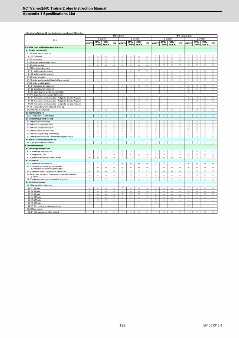
NC Trainer2/NC Trainer2 plus Instruction Manual
Appendix 1 Specifications List
189 IB-1501318-J
○○Standard Optional NC function that can be selected □Selection
M700VW M70VType B
M70VType A E70 M700VW M70V
Type BM70V
Type A E70 M700VW M70VType B
M70VType A E70 M700VW M70V
Type BM70V
Type A E70
CClass M system L system M system L systemNC Trainer2 NC Trainer2 plus
8. Spindle, Tool and Miscellaneous functions 8.1 Spindle functions (S) 8.1.1 Spindle control functions 8.1.1.3 Coil switch ― ― ― ― ― ― ― ― ○ ○ ○ ○ ○ ○ ○ ○ 8.1.2 S code output ○ ○ ○ ○ ○ ○ ○ ○ ○ ○ ○ ○ ○ ○ ○ ○ 8.1.3 Constant surface speed control △ ○ ○ ○ △ ○ ○ ○ △ ○ ○ ○ △ ○ ○ ○ 8.1.4 Spindle override ― ― ― ― ― ― ― ― ○ ○ ○ ○ ○ ○ ○ ○ 8.1.5 Multiple-spindle control 8.1.5.1 Multiple-spindle control I ― ― ― ― ○ ○ ○ ○ ― ― ― ― ○ ○ ○ ○ 8.1.5.2 Multiple-spindle control II ― ― ― ― ― ― ― ― ○ ○ ○ ― ○ ○ ○ ○ 8.1.6 Spindle orientation ― ― ― ― ― ― ― ― ○ ○ ○ ○ ○ ○ ○ ○ 8.1.7 Spindle position control (Spindle/C axis control) ○ ○ ○ ○ ○ ○ ○ ○ ○ ○ ○ ○ ○ ○ ○ ○ 8.1.8 Spindle synchronization 8.1.8.1 Spindle synchronization I ― ― ― ― △ ○ ○ ○ ― ― ― ― △ ○ ○ ○ 8.1.8.2 Spindle synchronization II ― ― ― ― ― ― ― ― ― ― ― ― △ ○ ○ ○ 8.1.8.3 Guide bushing spindle synchronization ― ― ― ― ― ― ― ― ― ― ― ― △ ― - ― 8.1.9 Tool spindle synchronization I (Polygon) 8.1.9.1 Tool spindle synchronization I A (Spindle-Spindle, Polygon) ― ― ― ― △ ○ ○ ○ ― ― ― ― △ ○ ○ ○ 8.1.9.2 Tool spindle synchronization I B (Spindle-Spindle, Polygon) ― ― ― ― △ ○ ○ ○ ― ― ― ― △ ○ ○ ○ 8.1.9.3 Tool spindle synchronization I C (Spindle-NC axis, Polygon) ― ― ― ― △ ― ○ ― ― ― ― ― △ ― ○ ― 8.1.10 Tool spindle synchronization II (Hobbing) ― ― ― ― △ ― ○ ― ― ― ― ― △ ― ○ ― 8.1.11 Spindle speed clamp ○ ○ ○ ○ ○ ○ ○ ○ ○ ○ ○ ○ ○ ○ ○ ○ 8.2 Tool functions (T) 8.2.1 Tool functions (T command) ○ ○ ○ ○ ○ ○ ○ ○ ○ ○ ○ ○ ○ ○ ○ ○ 8.3 Miscellaneous functions (M) 8.3.1 Miscellaneous functions ○ ○ ○ ○ ○ ○ ○ ○ ○ ○ ○ ○ ○ ○ ○ ○ 8.3.2 Multiple M codes in 1 block ○ ○ ○ ○ ○ ○ ○ ○ ○ ○ ○ ○ ○ ○ ○ ○ 8.3.3 M code independent output ○ ○ ○ ○ ○ ○ ○ ○ ○ ○ ○ ○ ○ ○ ○ ○ 8.3.4 Miscellaneous function finish ○ ○ ○ ○ ○ ○ ○ ○ ○ ○ ○ ○ ○ ○ ○ ○ 8.3.5 M code output during axis traveling ― ― ― ― △ ― ○ ― ― ― ― ― △ ― ○ ― 8.3.6 Miscellaneous function command high-speed output ― ― ― ― ― ― ― ― ○ ○ ○ ○ ○ ○ ○ ○ 8.4 2nd miscellaneous functions (B) 8.4.1 2nd miscellaneous functions ○ ○ ○ ○ ○ ○ ○ ○ ○ ○ ○ ○ ○ ○ ○ ○9. Tool compensation 9.1 Tool length/Tool position 9.1.1 Tool length compensation ○ ○ ○ ○ ○ ○ ○ ○ ○ ○ ○ ○ ○ ○ ○ ○ 9.1.2 Tool position offset ○ ○ ○ ― ― ― ― ― ○ ○ ○ ― ― ― ― ― 9.1.3 Tool compensation for additional axes ― ― ― ― ○ ○ ○ ○ ― ― ― ― ○ ○ ○ ○ 9.2 Tool radius 9.2.1 Tool radius compensation ○ ○ ○ ○ ― ― ― ― ○ ○ ○ ○ ― ― ― ― 9.2.2 3-dimensional tool radius compensation (Compensation vector designation type) △ ― ― ― ― ― ― ― △ ― ― ― ― ― ― ―
9.2.3 Tool nose radius compensation (G40/41/42) ― ― ― ― ○ ○ ○ ○ ― ― ― ― ○ ○ ○ ○ 9.2.4 Automatic decision of nose radius compensation direction (G46/40) ― ― ― ― ○ ○ ○ ○ ― ― ― ― ○ ○ ○ ○
9.2.5 Tool radius compensation diameter designation ○ ○ ○ ― ― ― ― ― ○ ○ ○ ― ― ― ― ― 9.3 Tool offset amount 9.3.1 Number of tool offset sets 9.3.1.1 20 sets ― ― ― ― △ ― ― ― ― ― ― ― △ ― ― ― 9.3.1.2 40 sets △ ― ― ― ― ― ― ― △ ― ― ― ― ― ― ― 9.3.1.3 80 sets ― ― ― ― △ ○ ○ ○ ― ― ― ― △ ○ ○ ○ 9.3.1.4 200 sets △ ― ― ○ ― ― ― ― △ ― ― ○ ― ― ― ― 9.3.1.5 400 sets △ ○ ○ ― ― ― ― ― △ ○ ○ ― ― ― ― ― 9.3.1.6 999 sets △ ― ― ― ― ― ― ― △ ― ― ― ― ― ― ― 9.3.1.7 (99× number of part systems) sets ― ― ― ― △ ― ― ― ― ― ― ― △ ― ― ― 9.3.2 Offset memory 9.3.2.1 Tool shape/wear offset amount ○ ○ ○ ○ ○ ○ ○ ○ ○ ○ ○ ○ ○ ○ ○ ○

NC Trainer2/NC Trainer2 plus Instruction Manual
Appendix 1 Specifications List
190IB-1501318-J
○○Standard Optional NC function that can be selected □Selection
M700VW M70VType B
M70VType A E70 M700VW M70V
Type BM70V
Type A E70 M700VW M70VType B
M70VType A E70 M700VW M70V
Type BM70V
Type A E70
CClass M system L system M system L systemNC Trainer2 NC Trainer2 plus
10. Coordinate system 10.1 Coordinate system type and setting 10.1.1 Machine coordinate system ○ ○ ○ ○ ○ ○ ○ ○ ○ ○ ○ ○ ○ ○ ○ ○ 10.1.2 Coordinate system setting ○ ○ ○ ○ ○ ○ ○ ○ ○ ○ ○ ○ ○ ○ ○ ○ 10.1.3 Automatic coordinate system setting ○ ○ ○ ○ ○ ○ ○ ○ ○ ○ ○ ○ ○ ○ ○ ○ 10.1.4 Workpiece coordinate system selection 10.1.4.0.1 Workpiece coordinate system selection (6 sets) ○ ○ ○ ○ ○ ○ ○ ○ ○ ○ ○ ○ ○ ○ ○ ○ 10.1.4.0.2 Extended workpiece coordinate system selection (48 sets) G54.1P1 to P48 △ ○ ○ ○ △ ○ ○ ○ △ ○ ○ ○ △ ○ ○ ○
10.1.4.0.3 Extended workpiece coordinate system selection (96 sets) G54.1P1 to P96 △ ― ― ― ― ― ― ― △ ― ― ― ― ― ― ―
10.1.4.0.4 Extended workpiece coordinate system selection (300 sets) G54.1P1 to P300 △ ― ― ― ― ― ― ― △ ― ― ― ― ― ― ―
10.1.5 External workpiece coordinate offset ○ ○ ○ ○ ○ ○ ○ ○ ○ ○ ○ ○ ○ ○ ○ ○ 10.1.6 Workpiece coordinate system preset (G92.1) △ ― ― ― △ ○ ○ ○ △ ― ― ― △ ○ ○ ○ 10.1.7 Local coordinate system ○ ○ ○ ○ ○ ○ ○ ○ ○ ○ ○ ○ ○ ○ ○ ○ 10.1.8 Coordinate system for rotary axis ○ ○ ○ ○ ○ ○ ○ ○ ○ ○ ○ ○ ○ ○ ○ ○ 10.1.9 Plane selection ○ ○ ○ ○ ○ ○ ○ ○ ○ ○ ○ ○ ○ ○ ○ ○ 10.1.10 Origin set/Origin cancel ○ ○ ○ ○ ○ ○ ○ ○ ○ ○ ○ ○ ○ ○ ○ ○ 10.1.11 Counter set ○ ○ ○ ○ ○ ○ ○ ○ ○ ○ ○ ○ ○ ○ ○ ○ 10.2 Return 10.2.1 Manual reference position return ○ ○ ○ ○ ○ ○ ○ ○ ○ ○ ○ ○ ○ ○ ○ ○ 10.2.2 Automatic 1st reference position return ○ ○ ○ ○ ○ ○ ○ ○ ○ ○ ○ ○ ○ ○ ○ ○ 10.2.3 2nd, 3rd, 4th reference position return ○ ○ ○ ○ ○ ○ ○ ○ ○ ○ ○ ○ ○ ○ ○ ○ 10.2.4 Reference position check ○ ○ ○ ○ ○ ○ ○ ○ ○ ○ ○ ○ ○ ○ ○ ○ 10.2.6 Tool exchange position return ○ ○ ○ ○ ○ ○ ○ ○ ○ ○ ○ ○ ○ ○ ○ ○11. Operation support functions 11.1 Program control 11.1.1 Optional block skip ○ ○ ○ ○ ○ ○ ○ ○ ○ ○ ○ ○ ○ ○ ○ ○ 11.1.2 Optional block skip addition ― ― ― ― ― ― ― ― △ ○ ○ ― △ ○ ○ ― 11.1.3 Single block ○ ○ ○ ○ ○ ○ ○ ○ ○ ○ ○ ○ ○ ○ ○ ○ 11.2 Program test 11.2.1 Dry run ○ ○ ○ ○ ○ ○ ○ ○ ○ ○ ○ ○ ○ ○ ○ ○ 11.2.2 Machine lock ○ ○ ○ ○ ○ ○ ○ ○ ○ ○ ○ ○ ○ ○ ○ ○ 11.2.3 Miscellaneous function lock ― ― ― ― ― ― ― ― ○ ○ ○ ○ ○ ○ ○ ○ 11.2.4 Graphic check 11.2.4.1 Graphic check △ ○ ○ ○ △ ○ ○ ○ △ ○ ○ ○ △ ○ ○ ○ 11.2.4.2 3D solid program check △ ― ○ ― ― ― ― ― △ ― ○ ― ― ― ― ― 11.2.4.3 Graphic check rotary axis drawing ― ― ― ― △ ― △ ― ― ― ― ― △ ― △ ― 11.2.5 Graphic trace 11.2.5.1 Graphic trace △ ○ ○ ○ △ ○ ○ ○ △ ○ ○ ○ △ ○ ○ ○ 11.2.5.2 Graphic trace rotary axis drawing ― ― ― ― △ ― △ ― ― ― ― ― △ ― △ ― 11.2.6 Machining time computation ○ ○ ○ ○ ○ ○ ○ ○ ○ ○ ○ ○ ○ ○ ○ ○ 11.3 Program search/start/stop 11.3.1 Program search ○ ○ ○ ○ ○ ○ ○ ○ ○ ○ ○ ○ ○ ○ ○ ○ 11.3.2 Sequence number search ○ ○ ○ ○ ○ ○ ○ ○ ○ ○ ○ ○ ○ ○ ○ ○ 11.3.3 Verification stop △ ○ ○ ― △ ○ ○ ― △ ○ ○ ― △ ○ ○ ― 11.3.4 Program restart ― ― ― ― ― ― ― ― △ ○ ○ ○ △ ○ ○ ○ 11.3.5 Automatic operation start ○ ○ ○ ○ ○ ○ ○ ○ ○ ○ ○ ○ ○ ○ ○ ○ 11.3.6 NC reset ○ ○ ○ ○ ○ ○ ○ ○ ○ ○ ○ ○ ○ ○ ○ ○ 11.3.7 Feed hold ○ ○ ○ ○ ○ ○ ○ ○ ○ ○ ○ ○ ○ ○ ○ ○ 11.3.8 Search & Start ― ― ― ― ― ― ― ― ○ ○ ○ ○ ○ ○ ○ ○ 11.4 Interrupt operation 11.4.1 Manual interruption ○ ○ ○ ○ ○ ○ ○ ○ ○ ○ ○ ○ ○ ○ ○ ○ 11.4.2 Automatic operation handle interruption ― ― ― ― ― ― ― ― ○ ○ ○ ○ ○ ○ ○ ○ 11.4.3 Manual absolute switch ○ ○ ○ ○ ○ ○ ○ ○ ○ ○ ○ ○ ○ ○ ○ ○ 11.4.4 Thread cutting cycle retract ― ― ― ― △ ○ ○ ― ― ― ― ― △ ○ ○ ― 11.4.5 Tapping retract ― ― ― ― ― ― ― ― ○ ○ ○ ○ ○ ○ ○ ○ 11.4.6 Manual numerical value command ○ ○ ○ ○ ○ ○ ○ ○ ○ ○ ○ ○ ○ ○ ○ ○ 11.4.7 Arbitrary reverse run ― ― ― ― ― ― ― ― △ ― ○ ― ― ― ― ― 11.4.8 MDI interruption ○ ○ ○ ○ ○ ○ ○ ○ ○ ○ ○ ○ ○ ○ ○ ○ 11.4.9 Simultaneous operation of manual and automatic modes ― ― ― ― ― ― ― ― ○ ○ ○ ○ ○ ○ ○ ○ 11.4.10 Simultaneous operation of JOG and handle modes ― ― ― ― ― ― ― ― ○ ○ ○ ○ ○ ○ ○ ○ 11.4.11 Reference position retract ― ― ― ― ― ― ― ― ○ ○ ○ ○ ○ ○ ○ ○ 11.4.12 Tool retract and return ― ― ― ― ― ― ― ― △ ― ― ― ― ― ― ― 11.4.13 Skip retract ― ― ― ― ― ― ― ― △ ○ ○ ― ― ― ― ― 11.4.14 PLC interruption ― ― ― ― ― ― ― ― △ ○ ○ ― △ ○ ○ ―
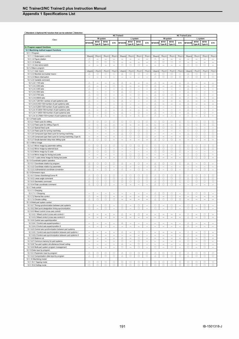
NC Trainer2/NC Trainer2 plus Instruction Manual
Appendix 1 Specifications List
191 IB-1501318-J
○○Standard Optional NC function that can be selected □Selection
M700VW M70VType B
M70VType A E70 M700VW M70V
Type BM70V
Type A E70 M700VW M70VType B
M70VType A E70 M700VW M70V
Type BM70V
Type A E70
CClass M system L system M system L systemNC Trainer2 NC Trainer2 plus
12. Program support functions 12.1 Machining method support functions 12.1.1 Program 12.1.1.1 Subprogram control ○8layers ○8layers ○8layers ○8layers ○8layers ○8layers ○8layers ○8layers ○8layers ○8layers ○8layers ○8layers ○8layers ○8layers ○8layers ○8layers 12.1.1.2 Figure rotation △ ― ― ― ― ― ― ― △ ― ― ― ― ― ― ― 12.1.1.3 Scaling △ ○ ○ ○ ― ― ― ― △ ○ ○ ○ ― ― ― ― 12.1.1.4 Axis name switch ― ― ― ― ○ ○ ○ ― ― ― ― ― ○ ○ ○ ― 12.1.2 Macro program 12.1.2.1 User macro △4layers △4layers △4layers △4layers △4layers △4layers △4layers △4layers △4layers △4layers △4layers △4layers △4layers △4layers △4layers △4layers 12.1.2.2 Machine tool builder macro △ ○ ○ ― △ ○ ○ ― △ ○ ○ ― △ ○ ○ ― 12.1.2.3 Macro interruption ― ― ― ― ― ― ― ― △ ○ ○ ○ △ ○ ○ ○ 12.1.2.4 Variable command 12.1.2.4.1 100 sets △ ― ― ― △ ― ― ― △ ― ― ― △ ― ― ― 12.1.2.4.2 200 sets △ ― ― ○ △ ― ― ○ △ ― ― ○ △ ― ― ○ 12.1.2.4.3 300 sets △ ― ― ― △ ― ― ― △ ― ― ― △ ― ― ― 12.1.2.4.4 600 sets △ ― ― ― △ ○ ― ― △ ― ― ― △ ○ ― ― 12.1.2.4.5 700 sets △ ○ ○ ― △ ― ○ ― △ ○ ○ ― △ ― ○ ― 12.1.2.4.6 8000 sets △ ― △ ― △ ― △ ― △ ― △ ― △ ― △ ― 12.1.2.4.7 (50+50× number of part systems) sets △ △ △ ― ― ― △ ― ― ― 12.1.2.4.8 (100+100×number of part systems) sets △ △ △ ― ― ― △ ― ― ― 12.1.2.4.9 (200+100×number of part systems) sets △ △ △ ― ― ― △ ― ― ― 12.1.2.4.10 (500+100×number of part systems) sets △ △ △ ― ― ― △ ― ― ― 12.1.2.4.11 (600+100×number of part systems) sets △ ○ △ ○ △ ― ○ ― △ ― ○ ― 12.1.2.4.12 (7900+100×number of part systems) sets △ △ △ △ △ ― △ ― △ ― △ ― 12.1.3 Fixed cycle 12.1.3.1 Fixed cycle for drilling ○ ○ ○ ○ ○ ○ ○ ○ ○ ○ ○ ○ ○ ○ ○ ○ 12.1.3.2 Fixed cycle for drilling (Type II) ― ― ― ― ― ― ― ― ― ― ― ― ○ ○ ○ ○ 12.1.3.3 Special fixed cycle △ ○ ○ ○ ― ― ― ― △ ○ ○ ○ ― ― ― ― 12.1.3.4 Fixed cycle for turning machining ― ― ― ― ○ ○ ○ ○ ― ― ― ― ○ ○ ○ ○ 12.1.3.5 Compound type fixed cycle for turning machining ― ― ― ― △ ○ ○ ○ ― ― ― ― △ ○ ○ ○ 12.1.3.6 Compound type fixed cycle for turning machining (Type II) ― ― ― ― △ ○ ○ ○ ― ― ― ― △ ○ ○ ○ 12.1.3.7 Small-diameter deep-hole drilling cycle △ ○ ○ ― ― ― ― ― △ ○ ○ ― ― ― ― ― 12.1.4 Mirror image 12.1.4.1 Mirror image by parameter setting ○ ○ ○ ○ ○ ○ ○ ○ ○ ○ ○ ○ ○ ○ ○ ○ 12.1.4.2 Mirror image by external input ― ― ― ― ― ― ― ― ○ ○ ○ ○ ○ ○ ○ ○ 12.1.4.3 Mirror image by G code ○ ○ ○ ○ ― ― ― ― ○ ○ ○ ○ ― ― ― ― 12.1.4.4 Mirror image for facing tool posts ― ― ― ― △ ○ ○ ― ― ― ― ― △ ○ ○ ― 12.1.4.5 T code mirror image for facing tool posts ― ― ― ― △ ○ ○ ― ― ― ― ― △ ○ ○ ― 12.1.5 Coordinate system operation 12.1.5.1 Coordinate rotation by program △ ○ ○ ○ △ ― ○ ― △ ○ ○ ○ △ ― ○ ― 12.1.5.2 Coordinate rotation by parameter △ ― ― ― ― ― ― ― △ ― ― ― ― ― ― ― 12.1.5.3 3-dimensional coordinate conversion △ ― ○ ― △ ― ○ ― △ ― ○ ― △ ― ○ ― 12.1.6 Dimension input 12.1.6.1 Corner chamfering/Corner R △ ○ ○ ○ △ ○ ○ ○ △ ○ ○ ○ △ ○ ○ ○ 12.1.6.2 Linear angle command △ ○ ○ ○ △ ○ ○ ○ △ ○ ○ ○ △ ○ ○ ○ 12.1.6.3 Geometric command △ ○ ○ ○ ○ ○ ○ ○ △ ○ ○ ○ ○ ○ ○ ○ 12.1.6.4 Polar coordinate command △ ○ ○ ― ― ― ― ― △ ○ ○ ― ― ― ― ― 12.1.7 Axis control 12.1.7.1 Chopping 12.1.7.1.1 Chopping ― ― ― ― ― ― ― ― △ ○ ○ ― △ ○ ○ ― 12.1.7.2 Normal line control △ ― ○ ― ― ― ― ― △ ― ○ ― ― ― ― ― 12.1.7.3 Circular cutting △ ○ ○ ○ ― ― ― ― △ ○ ○ ○ ― ― ― ― 12.1.8 Multi-part system control 12.1.8.1 Timing synchronization between part systems ○ ― ○ ― ○ ― ○ ― ○ ― ○ ― ○ ― ○ ― 12.1.8.2 Start point designation timing synchronization ○ ― ○ ― ○ ― ○ ― ○ ― ○ ― ○ ― ○ ― 12.1.8.3 Mixed control (cross axis control) 12.1.8.3.1 Mixed control (cross axis control) I ― ― ― ― △ ― ○ ― ― ― ― ― △ ― ○ ― 12.1.8.3.2 Mixed control (cross axis control) II ― ― ― ― ― ― ― ― ― ― ― ― △ ― ○ ― 12.1.8.4 Control axis superimposition 12.1.8.4.1 Control axis superimposition I ― ― ― ― △ ― ― ― ― ― ― ― △ ― ― ― 12.1.8.4.2 Control axis superimposition II ― ― ― ― ― ― ― ― ― ― ― ― △ ― ― ― 12.1.8.5 Control axis synchronization between part systems 12.1.8.5.1 Control axis synchronization between part systems I ― ― ― ― △ ― ○ ― ― ― ― ― △ ― ○ ― 12.1.8.5.2 Control axis synchronization between part systems II ― ― ― ― ― ― ― ― ― ― ― ― △ ― ○ ― 12.1.8.6 Balance cut ― ― ― ― △ ― ○ ― ― ― ― ― △ ― ○ ― 12.1.8.7 Common memory for part systems ― ― ― ― ○ ― ○ ― ― ― ― ― ○ ― ○ ― 12.1.8.8 Two-part system simultaneous thread cutting ― ― ― ― △ ― ○ ― ― ― ― ― △ ― ○ ― 12.1.8.9 Multi-part system program management ― ― ― ― ○ ― ○ ― ○ ― ○ ― ○ ― ○ ― 12.1.9 Data input by program 12.1.9.1 Parameter input by program △ ○ ○ ○ △ ○ ○ ○ △ ○ ○ ○ △ ○ ○ ○ 12.1.9.2 Compensation data input by program △ ○ ○ ○ △ ○ ○ ○ △ ○ ○ ○ △ ○ ○ ○ 12.1.10 Machining modal 12.1.10.1 Tapping mode ○ ○ ○ ○ ○ ○ ○ ○ ○ ○ ○ ○ ○ ○ ○ ○ 12.1.10.2 Cutting mode ○ ○ ○ ○ ○ ○ ○ ○ ○ ○ ○ ○ ○ ○ ○ ○

NC Trainer2/NC Trainer2 plus Instruction Manual
Appendix 1 Specifications List
192IB-1501318-J
○○Standard Optional NC function that can be selected □Selection
M700VW M70VType B
M70VType A E70 M700VW M70V
Type BM70V
Type A E70 M700VW M70VType B
M70VType A E70 M700VW M70V
Type BM70V
Type A E70
CClass M system L system M system L systemNC Trainer2 NC Trainer2 plus
12.2 Machining accuracy support functions 12.2.1 Automatic corner override ○ ○ ○ ○ ○ ○ ○ ○ ○ ○ ○ ○ ○ ○ ○ ○ 12.2.2 Deceleration check 12.2.2.1 Exact stop check mode ○ ○ ○ ○ ○ ○ ○ ○ ○ ○ ○ ○ ○ ○ ○ ○ 12.2.2.2 Exact stop check ○ ○ ○ ○ ○ ○ ○ ○ ○ ○ ○ ○ ○ ○ ○ ○ 12.2.2.3 Error detection ― ― ― ― ― ― ― ― ○ ○ ○ ○ ○ ○ ○ ○ 12.2.2.4 Programmable in-position check ○ ○ ○ ○ ○ ○ ○ ○ ○ ○ ○ ○ ○ ○ ○ ○ 12.3 High-speed and high-accuracy functions [kBPM:k Block per Minute] 12.3.1 High-speed machining mode I (G05P1) Max.[kBPM] △16.8 ○ ○ ― ― ― ― ― △16.8 ○ ○ ― ― ― ― ― 12.3.2 High-speed machining mode II (G05P2) Max.[kBPM] △168 ― ○33.7 ― ― ― ― ― △168 ― ○33.7 ― ― ― ― ― 12.3.3 High-speed high-accuracy control 1 (G05.1Q1) Max.[kBPM] (1st part system only) △33.7 ○16.8 ○16.8 ― ― ― ― ― △33.7 ○16.8 ○16.8 ― ― ― ― ―
12.3.4 High-speed high-accuracy control 2 (G05P10000) Max.[kBPM] (limited to 1-part system configuration) △168 ― ○33.7 ― ― ― ― ― △168 ― ○33.7 ― ― ― ― ―
12.3.5 High-accuracy control1(G61.1/G08) (1st part system only) △ ○ ○ ― ― ― ― ― △ ○ ○ ― ― ― ― ― 12.3.6 High-accuracy spline interpolation1(G61.2) (1st part system only) △ ― ○ ― ― ― ― ― △ ― ○ ― ― ― ― ― 12.3.7 High-accuracy spline interpolation2(G61.3) (1st part system only) △ ― ○ ― ― ― ― ― △ ― ○ ― ― ― ― ― 12.3.8 SSS control 12.3.8.1 SSS control (1st part system only) △ ― △ ― ― ― ― ― △ ― △ ― ― ― ― ― 12.3.9 High-accuracy acceleration/deceleration time constant extension (1st part system only) △ ― ― ― ― ― ― ― △ ― ― ― ― ― ― ―
12.3.10 Machining condition selection I (1st part system only) ○ ○ ○ ― ― ― ― ― ○ ○ ○ ― ― ― ― ― 12.3.12 Direct command mode ― ― ― ― △ ― ― ― ― ― ― ― △ ― ― ― 12.3.13 High-accuracy control in 2 part systems (The separate option of high-accuracy control etc., is required.) △ ― △ ― ― ― ― ― △ ― △ ― ― ― ― ―
12.4 Programming support functions 12.4.1 Playback ― ― ― ― ― ― ― ― △ ○ ○ ○ △ ― ― ― 12.4.3 Simple programming △ ○ ○ ○ △ ○ ○ ○ △ ○ ○ ○ △ ○ ○ ○ 12.4.4 G code guidance △ ○ ○ ○ △ ○ ○ ○ △ ○ ○ ○ △ ○ ○ ○13. Machine accuracy compensation 13.1 Static accuracy compensation 13.1.1 Backlash compensation ○ ○ ○ ○ ○ ○ ○ ○ ○ ○ ○ ○ ○ ○ ○ ○ 13.1.2 Memory-type pitch error compensation △ ○ ○ ○ △ ○ ○ ○ △ ○ ○ ○ △ ○ ○ ○ 13.1.3 Memory-type relative position error compensation △ ○ ○ ○ △ ○ ○ ○ △ ○ ○ ○ △ ○ ○ ○ 13.1.4 External machine coordinate system compensation ― ― ― ― ― ― ― ― △ ○ ○ ○ △ ○ ○ ○ 13.1.5 Circular error radius compensation △ ○ ○ ― △ ○ ○ ― △ ○ ○ ― △ ○ ○ ― 13.1.6 Ball screw thermal expansion compensation ― ― ― ― ― ― ― ― △ ○ ○ ― △ ○ ○ ― 13.1.7 Rotation center error compensation ― ― ― ― ― ― ― ― △ ― ― ― ― ― ― ― 13.1.8 Position-dependent gradually increasing-type backlash compensation △ ○ ○ ― △ ○ ○ ― △ ○ ○ ― △ ○ ○ ―
13.1.9 Two-way pitch error compensation △ ○ ○ ― △ ○ ○ ― △ ○ ○ ― △ ○ ○ ―14. Automation support functions 14.1 Measurement 14.1.1 Skip 14.1.1.1 Skip △ ○ ○ ― △ ○ ○ ― △ ○ ○ ― △ ○ ○ ― 14.1.1.2 Multiple-step skip △ ○ ○ ― △ ○ ○ ― △ ○ ○ ― △ ○ ○ ― 14.1.1.4 PLC skip △ ○ ○ ― △ ○ ○ ― △ ○ ○ ― △ ○ ○ ― 14.1.1.5 Speed change skip △ ― ― ― △ ― ― ― △ ― ― ― △ ― ― ― 14.1.2 Automatic tool length measurement ― ― ― ― ― ― ― ― △ ○ ○ ― △ ○ ○ ― 14.1.3 Manual tool length measurement 1 ― ― ― ― ― ― ― ― △ ○ ○ ○ △ ○ ○ ○ 14.1.4 Manual tool length measurement 2 ― ― ― ― ― ― ― ― △ ○ ○ ― △ ○ ○ ― 14.1.5 Workpiece coordinate offset measurement ― ― ― ― ― ― ― ― ― ― ― ― △ ○ ○ ― 14.1.6 Workpiece position measurement ― ― ― ― ― ― ― ― △ ○ ○ ― ― ― ― ― 14.1.7 Rotation measurement ― ― ― ― ― ― ― ― △ ○ ○ ― ― ― ― ― 14.2 Tool life management 14.2.1 Tool life management 14.2.1.1 Tool life management I ― ― ― ― ― ― ― ― △ ○ ○ ○ △ ○ ○ ○ 14.2.1.2 Tool life management II ― ― ― ― ― ― ― ― △ ○ ○ ○ △ ○ ○ ○ 14.2.1.3 Tool life management III ― ― ― ― ― ― ― ― △ ○ ○ ○ ― ― ― ― 14.2.2 Number of tool life management sets 14.2.2.1 80 sets ― ― ― ― ― ― ― ― ― ― ― ― △ ○ ○ ○ 14.2.2.2 200 sets ― ― ― ― ― ― ― ― △ ○ ○ ○ ― ― ― ― 14.2.2.3 400 sets ― ― ― ― ― ― ― ― △ ― ― ― ― ― ― ― 14.2.2.4 600 sets ― ― ― ― ― ― ― ― △ ― ― ― ― ― ― ― 14.2.2.5 800 sets ― ― ― ― ― ― ― ― △ ― ― ― ― ― ― ― 14.2.2.6 1000 sets ― ― ― ― ― ― ― ― △ ― ― ― ― ― ― ―

NC Trainer2/NC Trainer2 plus Instruction Manual
Appendix 1 Specifications List
193 IB-1501318-J
(*1) The key history is not recorded.
○○Standard Optional NC function that can be selected □Selection
M700VW M70VType B
M70VType A E70 M700VW M70V
Type BM70V
Type A E70 M700VW M70VType B
M70VType A E70 M700VW M70V
Type BM70V
Type A E70
CClass M system L system M system L systemNC Trainer2 NC Trainer2 plus
15. Safety and maintenance 15.1 Safety switches 15.1.1 Emergency stop ○ ○ ○ ○ ○ ○ ○ ○ ○ ○ ○ ○ ○ ○ ○ ○ 15.1.2 Data protection key ― ― ― ― ― ― ― ― ○ ○ ○ ○ ○ ○ ○ ○ 15.2 Display for ensuring safety 15.2.1 NC warning ○ ○ ○ ○ ○ ○ ○ ○ ○ ○ ○ ○ ○ ○ ○ ○ 15.2.2 NC alarm ○ ○ ○ ○ ○ ○ ○ ○ ○ ○ ○ ○ ○ ○ ○ ○ 15.2.3 Operation stop cause ○ ○ ○ ○ ○ ○ ○ ○ ○ ○ ○ ○ ○ ○ ○ ○ 15.2.4 Emergency stop cause ○ ○ ○ ○ ○ ○ ○ ○ ○ ○ ○ ○ ○ ○ ○ ○ 15.3 Protection 15.3.1 Stroke end (Over travel) ― ― ― ― ― ― ― ― ○ ○ ○ ○ ○ ○ ○ ○ 15.3.2 Stored stroke limit 15.3.2.1 Stored stroke limit I/II ○ ○ ○ ○ ○ ○ ○ ○ ○ ○ ○ ○ ○ ○ ○ ○ 15.3.2.2 Stored stroke limit IB △ ○ ○ ― △ ○ ○ ― △ ○ ○ ― △ ○ ○ ― 15.3.2.3 Stored stroke limit IIB △ ○ ○ ― △ ○ ○ ― △ ○ ○ ― △ ○ ○ ― 15.3.2.4 Stored stroke limit IC △ ○ ○ ― △ ○ ○ ― △ ○ ○ ― △ ○ ○ ― 15.3.3 Stroke check before travel △ ○ ○ ― ― ― ― ― △ ○ ○ ― ― ― ― ― 15.3.4 Chuck/Tailstock barrier check ― ― ― ― ○ ○ ○ ○ ― ― ― ― ○ ○ ○ ○ 15.3.5 Interlock ― ― ― ― ― ― ― ― ○ ○ ○ ○ ○ ○ ○ ○ 15.3.6 External deceleration ― ― ― ― ― ― ― ― ○ ○ ○ ○ ○ ○ ○ ○ 15.3.10 Parameter lock ― ― ― ― ― ― ― ― ○ ○ ○ ○ ○ ○ ○ ○ 15.3.11 Program protection (Edit lock B, C) ○ ○ ○ ○ ○ ○ ○ ○ ○ ○ ○ ○ ○ ○ ○ ○ 15.3.12 Program display lock ○ ○ ○ ○ ○ ○ ○ ○ ○ ○ ○ ○ ○ ○ ○ ○ 15.3.16 Interference check between part systems ― ― ― ― ― ― ― ― ― ― ― ― ○ ― ○ ― 15.4 Maintenance and troubleshooting 15.4.1 Operation history ○ (*1) ○ (*1) ○ (*1) ○ (*1) ○ (*1) ○ (*1) ○ (*1) ○ (*1) ○ (*1) ○ (*1) ○ (*1) ○ (*1) ○ (*1) ○ (*1) ○ (*1) ○ (*1) 15.4.3 NC data backup ○ ○ ○ ○ ○ ○ ○ ○ ○ ○ ○ ○ ○ ○ ○ ○ 15.4.6 Automatic backup ○ ○ ○ ○ ○ ○ ○ ○ ○ ○ ○ ○ ○ ○ ○ ○ 15.4.7 System setup ― ― ― ― ― ― ― ― ○ ○ ○ ○ ○ ○ ○ ○ 15.4.13 Parameter setting tool 15.4.13.1 NC Configurator2 (Need to purchase separate S/W) ○ ○ ○ ○ ○ ○ ○ ○ ○ ○ ○ ○ ○ ○ ○ ○

NC Trainer2/NC Trainer2 plus Instruction Manual
Appendix 1 Specifications List
194IB-1501318-J
(*2) Index qualification is available.
○○Standard Optional NC function that can be selected □Selection
M700VW M70VType B
M70VType A E70 M700VW M70V
Type BM70V
Type A E70 M700VW M70VType B
M70VType A E70 M700VW M70V
Type BM70V
Type A E70
CClass M system L system M system L systemNC Trainer2 NC Trainer2 plus
17. Machine support functions 17.1 PLC 17.1.1 Built-in PLC processing mode ○ ○ ○ ○ ○ ○ ○ ○ ○ ○ ○ ○ ○ ○ ○ ○ 17.1.2 PLC functions 17.1.2.1 Built-in PLC basic function ― ― ― ― ― ― ― ― ○ (*2) ○ ○ ○ ○ (*2) ○ ○ ○ 17.1.2.2 PLC exclusive instruction ― ― ― ― ― ― ― ― ○ ○ ○ ― ○ ○ ○ ― 17.1.3 PLC support functions 17.1.3.1 Alarm message display ― ― ― ― ― ― ― ― ○ ○ ○ ○ ○ ○ ○ ○ 17.1.3.2 Operator message display ― ― ― ― ― ― ― ― ○ ○ ○ ○ ○ ○ ○ ○ 17.1.3.3 Memory switch (PLC switch) 17.1.3.3.1 Memory switch (PLC switch) 32 points ― ― ― ― ― ― ― ― ○ ○ ○ ○ ○ ○ ○ ○ 17.1.3.3.2 Memory switch (PLC switch) 64 points ― ― ― ― ― ― ― ― △ ― ― ― △ ― ― ― 17.1.3.4 Load meter display ― ― ― ― ― ― ― ― ○ ○ ○ ○ ○ ○ ○ ○ 17.1.3.5 User PLC version display ― ― ― ― ― ― ― ― ○ ○ ○ ○ ○ ○ ○ ○ 17.1.3.6 Multi-ladder program register and execution ― ― ― ― ― ― ― ― ○ ○ ○ ○ ○ ○ ○ ○ 17.1.3.7 Ladder program writing during RUN ― ― ― ― ― ― ― ― ○ ○ ○ ○ ○ ○ ○ ○ 17.1.3.8 PLC protection ― ― ― ― ― ― ― ― ○ ○ ○ ○ ○ ○ ○ ○ 17.1.4 Built-in PLC capacity 17.1.4.1 Standard PLC capacity ○64000 ○20000 ○32000 ○8000 ○64000 ○20000 ○32000 ○8000 ○64000 ○20000 ○32000 ○8000 ○64000 ○20000 ○32000 ○8000 17.1.4.2 Large PLC capacity ― ― ― ― ― ― ― ― △128000 ― ― ― △128000 ― ― ― 17.1.5 Machine contact input/output I/F ○ ○ ○ ○ ○ ○ ○ ○ ○ ○ ○ ○ ○ ○ ○ ○ 17.1.6 Ladder monitor ― ― ― ― ― ― ― ― ○ ○ ○ ○ ○ ○ ○ ○ 17.1.7 PLC development 17.1.7.1 On-board development ― ― ― ― ― ― ― ― ○ ○ ○ ○ ○ ○ ○ ○
17.1.7.2 MELSEC development tool (GX Developer) (Need to purchase separate S/W) ― ― ― ― ― ― ― ― ○ ○ ○ ○ ○ ○ ○ ○
17.1.8 PLC parameter 17.1.8.1 PLC constant (150 points) ― ― ― ― ― ― ― ― ○ ○ ○ ○ ○ ○ ○ ○ 17.1.8.2 PLC constant extension (Up to 755 points) ― ― ― ― ― ― ― ― ○ ― ― ― ○ ― ― ― 17.1.9 GOT connection 17.1.10 Pallet program registration ― ― ― ― ― ― ― ― △ ― ― ― ― ― ― ― 17.2 Machine construction 17.2.1 Servo OFF ― ― ― ― ― ― ― ― ○ ○ ○ ○ ○ ○ ○ ○ 17.2.2 Axis detachment ― ― ― ― ― ― ― ― △ ○ ○ ○ △ ○ ○ ○ 17.2.3 Synchronous control ― ― ― ― ― ― ― ― △ ○ ○ ― △ ○ ○ ― 17.2.4 Inclined axis control ― ― ― ― ― ― ― ― ― ― ― ― △ ○ ○ ○ 17.2.5 Position switch ― ― ― ― ― ― ― ― ○24 ○24 ○24 ○24 ○24 ○24 ○24 ○24 17.2.7 Index table indexing ― ― ― ― ― ― ― ― ○ ○ ○ ― ○ ○ ○ ― 17.2.9 Tool length compensation along the tool axis ― ― ― ― ― ― ― ― △ ― ― ― ― ― ― ― 17.2.10 Tool handle feed & interruption ― ― ― ― ― ― ― ― △ ― ― ― ― ― ― ― 17.2.13 Inclined surface machining command ― ― ― ― ― ― ― ― △ ― ― ― ― ― ― ― 17.2.16 3-dimensional manual feed ― ― ― ― ― ― ― ― △ ― ― ― ― ― ― ― 17.2.17 R-Navi ― ― ― ― ― ― ― ― △ ― ― ― ― ― ― ― 17.3 PLC operation 17.3.1 Arbitrary feed in manual mode ― ― ― ― ― ― ― ― ○ ○ ○ ○ ○ ○ ○ ○ 17.3.2 Circular feed in manual mode ― ― ― ― ― ― ― ― △ ― ― ― △ ― ― ― 17.3.3 PLC axis control ― ― ― ― ― ― ― ― △ ○ ○ ○ △ ○ ○ ○ 17.3.5 PLC axis indexing ― ― ― ― ― ― ― ― △ ○ ○ ○ △ ○ ○ ○ 17.4 PLC interface 17.4.1 CNC control signal ○ ○ ○ ○ ○ ○ ○ ○ ○ ○ ○ ○ ○ ○ ○ ○ 17.4.2 CNC status signal ○ ○ ○ ○ ○ ○ ○ ○ ○ ○ ○ ○ ○ ○ ○ ○ 17.4.3 PLC window ― ― ― ― ― ― ― ― △ ○ ○ ○ △ ○ ○ ○ 17.4.4 External search ― ― ― ― ― ― ― ― △ ○ ○ ○ △ ○ ○ ○ 17.5 Machine contact I/O 17.5.5 MITSUBISHI CNC machine operation panel ○ ○ ○ ○ ○ ○ ○ ○ ○ ○ ○ ○ ○ ○ ○ ○ 17.7 Installing S/W for machine tools 17.7.1 Customization(NC Designer) (Need to purchase separate S/W) ― ― ― ― ― ― ― ― ○ ○ ○ ○ ○ ○ ○ ○
17.7.1.1 Customization data storage capacity [MByte] ― ― ― ― ― ― ― ―Depending
on harddisk space
Dependingon hard
disk space
Dependingon hard
disk space
Dependingon hard
disk space
Dependingon hard
disk space
Dependingon hard
disk space
Dependingon hard
disk space
Dependingon hard
disk space
17.7.1.2 Customization working memory size [MByte] ― ― ― ― ― ― ― ― 6 3 3 1 6 3 3 1 17.7.1.3 Direct screen selection ― ― ― ― ― ― ― ― ○ ○ ○ ○ ○ ○ ○ ○ 17.7.3 EZSocket I/F (Need to purchase separate S/W) ― ― ― ― ― ― ― ― ○ ○ ○ ○ ○ ○ ○ ○ 17.7.4 APLC release (Need to purchase separate S/W) ― ― ― ― ― ― ― ― ○ ○ ○ ○ ○ ○ ○ ○ 17.7.5 Custom API library (Need to purchase separate S/W) ― ― ― ― ― ― ― ― ○ ○ ○ ○ ○ ○ ○ ○ 17.8 Others 17.8.3 Automatic operation lock ― ― ― ― ― ― ― ― ○ ○ ○ ― ○ ○ ○ ―

195
付録 Ap2 章
195 IB-1501318-J
Appendix 2
Troubleshooting

NC Trainer2/NC Trainer2 plus Instruction Manual
Appendix 2 Troubleshooting
196IB-1501318-J
Appendix 2.1 Troubleshooting
Remedies for common problems of NC Trainer2 / NC Trainer2 plus are shown below.
Appendix 2.1.1 Error Messages
The error messages listed below are shown when an error occurs during each operation of NC Trainer2 / NC
Trainer2 plus.
Appendix 2.1.1.1 Error Messages Common Between NC Trainer2 and NC Trainer2 plus
Message Cause Remedy
Failed to find the data storage folder.Data storage folder selected at the time of installation cannot be browsed.
Reinstall NC Trainer2 / NC Trainer2 plus.
Enter the project name. A project name has not been entered.
Correct the entered project name.
Entered project name is too long. Shorten it to 80 characters or less (A double-byte character is counted as two characters).
Entered project name is too long.
A project with the same name as the entered one exists. Enter another project name.
A project with the same name as the entered one exists.
A project name made up of only null characters (spaces) is not usable.
Null characters are used as a project name.
An unavailable character (\ / : * ? < > | ") is included in the entered project name.
An unavailable character is included in the entered project name.
Entered project name is not available. Enter another name.
A reserved name for Windows is used as a project name.
A null character (space) and period cannot be placed at the beginning or end of the project name. Correct the name.
A null character (space) or period is used at the beginning or end of the project name.
Entered command type is illegal. Correct the value.
A value out of the designated range is entered for Command Type of the New Project dialog box.
Refer to "4.3.1 Creating a New Project" and correct the entered value.
Entered value is illegal.Correct the value.Non-numeric value is set for each setting section of the New Project dialog box.
Enter the import name. An import name has not been entered.
Correct the entered import name.
Entered import name is too long. Shorten it to 80 characters or less (A double-byte character is counted as two characters).
Entered import name is too long.
An import name made up of only null characters (spaces) is not usable.
Null characters are used as an import name.
An unavailable character (\ / : * ? < > | ") is included in the entered import name.
An unavailable character is included in the entered import name.
Entered import name is not available. Enter another import name.
A reserved name for Windows is used as an import name.
A null character (space) and period cannot be placed at the beginning or end of the import name. Correct the name.
A null character (space) or period is used at the beginning or end of the import name.
Project import data is illegal. Select import data again.
The wrong folder is selected for the import data of the project, or the import data is broken.
- Select correct import data of the project.- Export the project data using NC Trainer2 plus, and import it again.
Failed to start Internet browser. An Internet browser may not be installed.
Set up an internet access environment to connect to MITSUBISHI ELECTRIC FA Global Website.

NC Trainer2/NC Trainer2 plus Instruction Manual
Appendix 2 Troubleshooting
197 IB-1501318-J
Failed to activate the application.
Requested processing cannot be executed for the reason such as:- Corruption of the executable file.- Hard disk capacity shortage.- Memory shortage.
- Quit other applications and then restart NC Trainer2 / NC Trainer2 plus.- Restart the computer.- Reinstall NC Trainer2 / NC Trainer2 plus.- Check the hard-disk space.- Check the hardware specification of the computer you are using.
Failed to activate the NC.
Failed to quit the NC.
Preparation for creating project has failed.
Failed to save the application setting.
Failed to create project.
Failed to change project option.
Failed to copy the project.
Failed to rename the project.
Failed to delete the project.
Failed to open the project because it is illegal.Any file inside of the project folder is broken.
Use the backup data of that project, if available, to open the project.Import the import data of that project, if available.Create a new project again.
Message Cause Remedy

NC Trainer2/NC Trainer2 plus Instruction Manual
Appendix 2 Troubleshooting
198IB-1501318-J
Appendix 2.1.1.2 Error Messages Dedicated to NC Trainer2 plus
(*1) The number of axes which can be set depends on the NC model.
Message Cause Remedy
Specified number of spindles is exceeding the commandable range. Correct the entered value.
Specified number of spindles on the [New Project] dialog is exceeding the commandable range.
Refer to "4.3.1 Creating a New Project" and correct the entered value.
Make sure to specify 1 or greater for the number of axes in the 1st part system.
0 is specified for the number of axes in the 1st part system on the [New Project] dialog.
To activate the number of axes in the 3rd part system, you also have to activate the number of axes in the lower part systems.
1 or greater is specified for the number of axes in the 3rd part system even though 0 is specified for the number of axes in the 2nd part system on the [New Project] dialog.
To activate the number of axes in the 4th part system, you also have to activate the number of axes in the lower part systems.
1 or greater is specified for the number of axes in the 4th part system even though 0 is specified for the number of axes in the 2nd or 3rd part system on the [New Project] dialog.
Up to 6 PLC axes can be set. Correct the entered value. (*1)
Over 6 PLC axes are set on the [New Project] dialog. (*1)
Up to 12 axes can be set for each part system. Correct the entered value. (*1)
Over 12 axes are set for the number of axes on the [New Project] dialog. (*1)
Up to 16 control axes (NC axes, spindles and PLC axes) can be set. Correct the entered value. (*1)
Over 16 control axes (NC axes, spindles and PLC axes) are set on the [New Project] dialog. (*1)
Enter export name. An export name has not been entered.
Correct the entered export name.
Entered export name is too long. Shorten it to 80 characters or less (A double-byte character is counted as two characters).
Entered export name is too long.
An export name made up of only null characters (spaces) is not usable.
Null characters are used as an export name.
An unavailable character (\ / : * ? < > | ") is included in the entered export name.
An unavailable character is included in the entered export name.
Entered export name is not available. Enter another export name.
A reserved name for Windows is used as an export name.
A null character (space) and period cannot be placed at the beginning or end of the export name. Correct the name.
A null character (space) or period is used at the beginning or end of the export name.
Custom machine operation panel import data is illegal. Select import data again.
The folder which is not for custom machine operation panel import data is specified or the import data is damaged.
- Select custom machine operation panel import data again.- Export custom machine operation panel again with NC Trainer2 Builder and then import it.
Entered import name is too long. Shorten it to 32 characters or less. (A double-byte character is counted as two characters).
Import name entered by the custom machine operation panel import function is too long.
Correct the entered import name.
NC data is not found.The backup data of actual NC is not found in the specified folder for importing the NC data.
Select the folder which the backup data of actual NC has been stored.
The NC data is unsupported.The backup data of actual NC other than M700V is specified when importing the NC data.
Select the backup data of actual M700V NC.
Files other than APLC.o can't be selected.Files other than APLC.o are selected when writing APLC.o.
Select APLC.o.
File size is illegal.File size of APLC.o which is selected when storing APLC.o is 0 byte or exceeds the maximum size (120 kbytes).
Select APLC.o of 120 kbytes or less.
Selected GX Simulator3 is not activated.Simulator No.:
NC Trainer2 plus cannot connect to the GX Simulator3 set as the connection destination because it is not started.
Check the connection destination simulator No., and start or switch a project after starting GX Simulator3.

NC Trainer2/NC Trainer2 plus Instruction Manual
Appendix 2 Troubleshooting
199 IB-1501318-J
Appendix 2.1.1.3 Error Messages Dedicated to NC Trainer2 Builder
(*1) Data storage folder (Normally C:\MELCNC\NCT2P)\NCTrainer2Builder.ini
(*2) The files under the data storage folder (Normally C:\MELCNC\NCT2P)\opepanels\project name folder
Message Cause Remedy
Failed to find the data storage folder.Data storage folder selected at the time of installation cannot be browsed.
Reinstall NC Trainer2 / NC Trainer2 plus.
Enter the project name. A project name has not been entered.
Correct the entered project name.
Entered project name is too long. Shorten it to 32 characters or less (A double-byte character is counted as two characters).
Entered project name is too long.
A project name made up of only null characters (spaces) is not usable.
Null characters are used as a project name.
An unavailable character (\ / : * ? < > | ") is included in the entered project name.
An unavailable character is included in the entered project name.
Entered project name is not available. Enter another name.
A reserved name for Windows is used as a project name.
Enter the export name. An export name has not been entered.
Correct the entered export name.
Entered export name is too long. Shorten it to 32 characters or less (A double-byte character is counted as two characters).
Entered export name is too long.
An export name made up of only null characters (spaces) is not usable.
Null characters are used as an export name.
An unavailable character (\ / : * ? < > | ") is included in the entered export name.
An unavailable character is included in the entered export name.
Entered export name is not available. Enter another export name.
A reserved name for Windows is used as an export name.
Failed to activate the application.
Requested processing cannot be executed for the reason such as:- Corruption of the executable file.- Hard disk capacity shortage.- Memory shortage.
- Quit other applications and then restart NC Trainer2 / NC Trainer2 plus.- Restart the computer.- Reinstall NC Trainer2 / NC Trainer2 plus.- Check the hard-disk space.- Check the hardware specification of the computer you are using.
Failed to save the application setting.
- Hard disk capacity shortage.- The setting file is write protected.- The setting file is access-prohibited by security setting.
- Check the hard-disk space.- Allow the setting file (*1) for the application to be written.- Allow the setting file for the application to be accessed by security setting.
Failed to save project.
- Hard disk capacity shortage.- The project file is write protected.- The project file is access-prohibited by security setting.
- Check the hard-disk space.- Allow the project related files (*2) to be written.- Allow the project related files to be accessed by security setting.
Failed to open project.- The project file is damaged.- The project file is access-prohibited by security setting.
- Delete the project related files (*2) and folders, and recreate them.- Allow the project related files to be accessed by security setting.

NC Trainer2/NC Trainer2 plus Instruction Manual
Appendix 2 Troubleshooting
200IB-1501318-J
Appendix 2.1.2 FAQ
Appendix 2.1.2.1 3D Program Check Screen Is Not Displayed
Depending on the computer you are using, 3D program check screen on the NC screen might not be displayed
correctly. Try either (1) or (2) as updating the graphic driver etc. might solve this.
(1) Update your graphic driver card
(Check with the graphic card manufacturer or the computer manufacturer for the latest graphic driver.)
(2) Set [Hardware acceleration] to "None".
(You need to have an administrator account.)
[Procedure]
1. Right-click on the desktop and click [Screen resolution].
2. Select [Advanced Settings].
3. Select [Change settings] in [Troubleshoot] tab and move Hardware acceleration’s slider to "None". If
Hardware acceleration’s settings cannot be changed from [Troubleshooting] tab, change the setting
with utility provided by graphic card manufacturer.
4. Press the "OK" button and restart Windows.
Appendix 2.1.2.2 When Speed Change Skip Is Executed, a Program Error "P601 No spec: Skip"
Occurs
Settings of the speed change skip option, skip option (the high-speed skip option) and multiple-step skip option
are required to use the speed change skip function.
Refer to the section "4.3.3 Changing Project Option Settings" of "I NC Trainer2" for details and enable these
options.

NC Trainer2/NC Trainer2 plus Instruction Manual
Appendix 2 Troubleshooting
201 IB-1501318-J
Appendix 2.1.2.3 Displayed Key Is Different from the Key Input from Keyboard
When the PC keyboard is changed (when Japanese keyboard is changed to English keyboard, etc.) or
multiple different types of PC keyboards are connected, Windows may not judge the types of PC keyboard. If
this phenomenon occurs, the following method might solve this.
[When using keyboard connected by USB]
1. For Windows 10, input "regedit" to [Search the web and Windows] box on the task bar and press the
Enter key. Then click [regedit Run command].
For Windows 8.1, click down arrow button on start screen. Then click [Run] from list of application, input
[regedit], and press the Enter key.
* When the [User Account Control] screen is displayed, execute the following operation.
When the dialog box that requires administrator’s password is displayed, input an administrator’s
account password and press the "OK" or "Yes" button. When the dialog box that requires
confirmation is displayed, press the "Continue" or "Yes" button.
2. [Registry Editor] is started. Then select the following registry sub key.
HKEY_LOCAL_MACHINE\SYSTEM\CurrentControlSet\Services\i8042prt\Parameters
3. Set the registry entry as the following table shows.
< When using 106/109 Japanese keyboard >
< When using 101/102 English (US) keyboard >
* When changing the registry entry, right click the value name and select [Touch up].
Delete the existing value displayed in [Value data]. Input the setting values referring to the above
table and select the "OK" button.
* Create the registry entry if not existed. To create an entry, right click blank area of advances window
and point [NEW]. Click [String value] when the value type is "REG_SZ", and select [DWORD Value]
when the value type is "REG_DWORD". Then input the value name, and input the setting values to
[Value data] referring to the above table and press the "OK" button.
4. Exit from [Registry Editor]. Then restart Windows.
Value Name Value type Value data
LayerDriver JPN REG_SZ kbd106.dll
OverrideKeyboardIdentifier REG_SZ PCAT_106KEY
OverrideKeyboardSubtype REG_DWORD 2
OverrideKeyboardType REG_DWORD 7
Value Name Value type Value data
LayerDriver JPN REG_SZ kbd101.dll
OverrideKeyboardIdentifier REG_SZ PCAT_101KEY
OverrideKeyboardSubtype REG_DWORD 0
OverrideKeyboardType REG_DWORD 7

NC Trainer2/NC Trainer2 plus Instruction Manual
Appendix 2 Troubleshooting
202IB-1501318-J
Appendix 2.1.2.4 Cannot Be Restarted After the Communication with a License Key of Network
Connection Type Is Lost
If the communication is lost for the disconnection of LAN cable, etc. when operating NC Trainer2 / NC Trainer2
plus up to the maximum number of license keys, NC Trainer2 / NC Trainer2 plus cannot be restarted for a
while (about 10 minutes) even if reconnecting the LAN cable.
Wait for a while (about 10 minutes) or once remove the license key of network connection type and reinsert to
start NC Trainer2 / NC Trainer2 plus.
Appendix 2.1.2.5 NC Configurator2 Cannot Connect to NC Trainer2 plus
NC Configurator2 may not connect to NC Trainer2 plus when Windows firewall function is enabled. Disable the
firewall function or register NC Configurator2 as an exception.
(Carry out with the authority of the administrator.)
Appendix 2.1.2.6 The Message Related to a Digital Signature Is Displayed at Installation and NC
Trainer2/NC Trainer2 plus Cannot Be Installed
NC Trainer2/NC Trainer2 plus might not be installed when the message "Windows requires a digitally signed
driver. A recently installed program tried to install an unsigned driver...." is displayed. When a security
countermeasure software is installed, temporary stop the function or uninstall the software and try to install NC
Trainer2/NC Trainer2 plus again. Or, install NC Trainer2/NC Trainer2 plus after uninstalling the windows
update program "KB3004394".

NC Trainer2/NC Trainer2 plus Instruction Manual
Appendix 2 Troubleshooting
203 IB-1501318-J
Appendix 2.1.2.7 Screen Is Displayed Smaller and Buttons Are Difficult to Press or Screen Is
Not Displayed Properly Due to the Display Resolution
When the display resolution is high (4K or 3K, etc.), the screen is displayed smaller and the buttons are difficult
to press. Also, when the size of text or other items on a screen are set in Windows settings to a value other
than the default value (96 DPI, 100%, 9 pt), the screen may not display properly. For example, the characters
on a dialog screen are cut off in the middle of a sentence.
[When the screen is displayed smaller and the buttons are difficult to press]
For Windows 10 (Ver. 1703 or later) (1), display NC Trainer2 / NC Trainer2 plus using high DPI scaling (3) with
the Windows 10 function (2).
[When the screen is not displayed properly]
Perform any of the following procedures to display the screen properly.
- Return the size of the text on the screen or other items to the default value (96 DPI, 100%, 9 pt).
- For Windows 10 (Ver. 1703 or later) (1), display NC Trainer2 / NC Trainer2 plus using high DPI
scaling (3) with the Windows 10 function (2).
(1) The Windows version can be checked by the following procedure.
1. Press Windows key + [R], or select [Windows System] -> [Run] from the Start menu of Windows.
2. Enter 'winver' in the "Run" dialog.
3. Check the version in the displayed dialog.
(2) The following are the operation procedures for Windows 10 function.
1. Select NCTrainer2.exe or NCTrainer2Plus.exe, then select [Properties] on the right-click menu. (4)
2. Select "Override high DPI scaling behavior. Scaling performed by:" in the [Compatibility] tab, then
select "System" from the pull-down list.
3. Click the [OK] button.
(3) The NC Trainer2 / NC Trainer2 plus display will be blurred by enlarging.
The following lists the setting values for "Change the size of text, apps, and other items" and the
recommended display resolution for each setting value in Windows 10.
Setting value Display resolution
100 % 1024 × 768 dots or more
125 % 1900 × 1200 dots or more
150 % 1900 × 1200 dots or more
175 % 2880 × 1620 dots or more
200 % 2880 × 1620 dots or more
225 % 3840 × 2160 dots or more
250 % 3840 × 2160 dots or more

NC Trainer2/NC Trainer2 plus Instruction Manual
Appendix 2 Troubleshooting
204IB-1501318-J
(4) NCTrainer2.exe or NCTrainer2Plus.exe is stored in the folder in which NC Trainer2 or NC Trainer2 plus is
installed. When the installation destination folder is set as the default, they are stored in the following
folders.
[NC Trainer2]
64 bit OS: C:\Program Files (x86)\MELSOFT\NC Trainer2\bin\NCTrainer2.exe
32 bit OS: C:\Program Files\MELSOFT\NC Trainer2\bin\NCTrainer2.exe
[NC Trainer2 plus]
64 bit OS: C:\Program Files (x86)\MELSOFT\NC Trainer2 plus\bin\NCTrainer2Plus.exe
32 bit OS: C:\Program Files\MELSOFT\NC Trainer2 plus\bin\NCTrainer2Plus.exe
Appendix 2.1.2.8 NC Trainer2 / NC Trainer2 plus Is Forcefully Closed When an Application
Using the Same Driver that the License Key Uses Is Installed
When NC Trainer2 / NC Trainer2 plus is installed when there is an installed application using a different
version of the HASP driver (HASP driver (Note 1)) that the license key uses, NC Trainer2 / NC Trainer2 plus
may be forcefully closed. Try either of the following.
(1) Access the support page (Note 2) of Gemalto, which provides the HASP driver, and download and
apply the latest HASP driver.
(2) Install NC Trainer2 / NC Trainer2 plus after uninstalling the application using a different version of
the HASP driver that the license key uses
(Note 1) Provided by Gemalto
(Note 2) https://sentinelcustomer.gemalto.com/sentineldownloads/

NC Trainer2/NC Trainer2 plus Instruction Manual
Appendix 2 Troubleshooting
205 IB-1501318-J
Appendix 2.1.2.9 Cannot Connect to the RT ToolBox3 Simulator from NC Trainer2 plus
When NC Trainer2 plus and RT ToolBox3 Simulator are started with the same PC, NC Trainer2 plus cannot
connect to RT ToolBox3 Simulator. Try connecting by the following method. Note that the connecting method
varies depending on "Network Settings of NC" in NC Trainer2 plus.
[When "Use IP address of this PC" is selected for "Network Settings of NC"]
Set "Send Port number (Number 2 of MONPORT)", which is the parameter related to the RT ToolBox3
realtime monitor function, to "0" (Note 1). (Note 2)
(Note 1) "0" is a special value that is returned for the send port number that is set in the UDP header
information of the start packet data received by the robot controller.
(Note 2) Set the parameter by either of the following methods in RT ToolBox3.
[Setting from the Ethernet parameter screen]
[Setting from the Parameter List screen]

NC Trainer2/NC Trainer2 plus Instruction Manual
Appendix 2 Troubleshooting
206IB-1501318-J
[When "Use the virtual network" is selected for "Network Settings of NC"]
Set the IP address of the virtual network driver to the CNC parameter "#11911 RC IP address (Robot
controller IP address)."
When Windows Firewall function is enabled, the firewall function needs to be disabled, or RT ToolBox3
Simulator needs to be registered as an exception.
To register a Windows Firewall exception, follow the procedures below. (Carry out with the authority of
the administrator.)
[Procedure]
(1) Open the [Control Panel].
Windows 10: Click the [Start] icon on the taskbar. Click [Windows System] folder from [All apps].
Click [Control Panel]
Windows 8.1: Click the downward-facing arrow in the Start screen. Click [Control Panel] in the Apps
screen.
(2) Click [System and Security].
(3) Click [Allow an app through Windows Firewall].

NC Trainer2/NC Trainer2 plus Instruction Manual
Appendix 2 Troubleshooting
207 IB-1501318-J
(4) Click the [Change settings] button to enable changes to check boxes and the [OK] button.
(5) Check the [Private] and [Public] check boxes next to RT ToolBox3 Simulator, and click the [OK]
button.
The name displayed in "Allowed apps and features" varies with the robot controller selected by the
RT ToolBox3 project. When "FR-R Series CR800-R" is selected, "RoboSim800R" is displayed.

NC Trainer2/NC Trainer2 plus Instruction Manual
Appendix 2 Troubleshooting
208IB-1501318-J

209
付録 Ap3 章
209 IB-1501318-J
Appendix 3
Explanation of Keys

NC Trainer2/NC Trainer2 plus Instruction Manual
Appendix 3 Explanation of Keys
210IB-1501318-J
Appendix 3.1 Explanation of KeysOn the NC Trainer2 / NC Trainer2 plus, the following shortcut keys are available.
(Note 1) These keys are not provided in the NC key board. Use PC keyboard.
Key type NC keyboard Operation PC keyboard
Function key (Functionselection key)
MONITOR This displays the screen related to "operations". SHIFT+F1SET_UP This displays the screen related to "setup". SHIFT+F2EDIT This displays the screen related to "editing". SHIFT+F3DIAGN This displays the screen related to "diagnosis". SHIFT+F4MAINTE This displays the screen related to "maintenance". SHIFT+F5
Custom release screenThe screen differ according to the machine tool builder's specification.
CTRL+F3
CTRL+F4
SFP (Note 1) SHIFT+F9F 0 SHIFT+F10
Part system changeover key ($ ⇔ $)
When using a multi-part system NC, this displays the data of the next part system. The screen does not change if it is a part system common screen or when only one part system is used.
CTRL+F1
Help key ?This displays the operation guidance, parameter guidance and alarm guidance corresponding to the current operation.
CTRL+F2
Menu list key MENU LIST This displays each screen's menu configuration as a list. CTRL+F8
Frame key (Note 1)
This switches the tag.CTRL+F9
(Note 1) CTRL+F10
Pagechangeover key
Previous page key
When the displayed contents cover several pages, this displays the contents
of the previous page. The " " mark at the top of the screen indicates that there is a previous page.
PageUp
Next page key
When the displayed contents cover several pages, this displays the contents
of the next page. The " " mark at the top of the screen indicates that there is a next page.
PageDown
MENU key
MENU1
This changes the screen and displays the data.
F1MENU2 F2MENU3 F3MENU4 F4MENU5 F5MENU6 F6MENU7 F7MENU8 F8MENU9 F9MENU10 F10
Menuchangeover key
(left side)
This changes the operation menu for the displayed screen to the current screen group screen selection menu. This is also used to cancel the menu operations of the displayed screen.
F11
(right side)
When all of the menus cannot be displayed at once, this displays the menus
not currently displayed. The " " and" " marks at the bottom of the screen indicate that there are menus not displayed.
F12
Data delete key DELETEThis deletes the character just before the cursor position in the data setting area.
DELETE
Data insert key INSERT
This inputs the data insertion mode. When a data setting key is pressed, a character is inserted in front of the current cursor position.The overwrite mode is entered when the DELETE, C.B CAN, INPUT, cursor or TAB, etc., keys are pressed, or when the screen is changed.
INSERT
Cancel keyC.B.
This cancels the setting in the data setting area.SHIFT+Home
CAN ESC
INPUT key INPUTThis fixes the data in the data setting area, and writes it to the internal data. The cursor moves to the next position.
ENTER
Cursor key
↑ This moves the cursor up or down one when setting data in the screen display items.
↑
↓ ↓
← This moves the data input cursor one character to the left or right in the data setting area.
←
→ →
Tab key
Left tab(| ← ) This moves the cursor one item to the left or right when selecting data in the screen display items. at cursor left end: Moves to the right end of previous line.at cursor right end: Moves to left end of next line.
SHIFT+TAB
Right tab( → |) TAB
Lower caseinput key ABC/abc… (Note 1) This changes the input between upper case and lower case alphabetic
characters.Caps Lock
MENU1 MENU2 MENU3 MENU4 MENU5 MENU6 MENU7 MENU8 MENU9 MENU10

Revision History
Date of revision Manual No. Revision details
Jan. 2015 IB(NA)1501318-A First edition created.(NC Trainer2, NC Trainer2 plus S/W version A0)
Jun. 2015 IB(NA)1501318-B Contents were revised to correspond to NC Trainer2, NC Trainer2 plus software version A1.Contents were revised to correspond to Mitsubishi CNC M800/M80 Series software version A1.
- Revised the following chapters.IntroductionI 1.3 Functions of NC Trainer2I 1.5 PrecautionsI 4.3.1 Creating a New ProjectI 4.3.3 Changing the Settings of Project OptionII 1.3 Differences of functions between NC Trainer2 and NC Trainer2 plus II 1.5 PrecautionsII 4.3.1 Creating a New ProjectII 4.3.3 Changing the Settings of Project OptionII 5.1.5 Setting of Custom Machine Operation PanelII 5.2 Creating User PLC (Ladder) and Checking the Operation II 5.2.1 User PLC Development Method with GX DeveloperII 5.2.2 User PLC Development Method with PLC OnboardII 5.3 Display of Custom Release ScreenII 5.3.2 Path Designation of GIP File and DLL FileII 5.3.6 Settings of Custom Release Start Up ScreenII 5.3.7 Restrictions for Custom Release ScreenII 5.4 APLC releaseII 5.4.9 Importing the NC Data from Actual NCAppendix 1 Specifications List
Other contents were added/revised/deleted according to specification.
Oct. 2015 IB(NA)1501318-C Contents were revised to correspond to NC Trainer2, NC Trainer2 plus software version A3.Contents were revised to correspond to Mitsubishi CNC M800/M80 Series software version A4.Corresponded to M700V/M70V/E70 Series software version K8. - Revised the following chapters.I 1.5 PrecautionsI 2.1 Operating EnvironmentI 2.2 Procedure of the First InstallationI 3.1 Configuration of the ScreenI 3.1.2 Full Screen DisplayI 3.1.3.1 Arranging WindowsI 3.3.1 NC KeyboardI 3.3.3 Machine Operation PanelI 4.3.1 Creating a New ProjectI 4.3.3 Changing the Settings of Project OptionII 1.3 Differences of Functions between NC Trainer2 and NC Trainer2 plusII 1.5 PrecautionsII 2.2 Procedure of the First InstallationII 5.2 Creating User PLC (Ladder) and Checking the OperationII 5.2.1 User PLC Development Method with GX DeveloperII 5.2.2 User PLC Development Method with PLC OnboardII 5.3.6 Settings of Custom Release Start Up ScreenII 5.4.2 Outline for the Debug of APLC Release C Language ModuleII 5.4.5 Preparation for DebugII 6.1 Exporting NC Trainer2 plus ProjectAppendix 1 Specifications ListAppendix 2.1.2.7 The Message Related to a Digital Signature Is Displayed at Installation and NC Trainer2/NC Trainer2 plus Cannot Be Installed Other contents were added/revised/deleted according to specification.
Mar. 2016 IB(NA)1501318-D Contents were revised to correspond to NC Trainer2, NC Trainer2 plus software version A4.Contents were revised to correspond to Mitsubishi CNC M800/M80 Series software version B2.Corresponded to M700V/M70V/E70 Series software version L1.
- Revised the following chapters.I 2.1 Operating EnvironmentI 2.2 Procedure of the First InstallationI 3.2.5 [Help (H)] MenuI 4.1 Starting NC Trainer2
(Continue to the next page)

Date of revision Manual No. Revision details
(Continued)
II 1.3 Differences of Functions between NC Trainer2 and NC Trainer2 plusII 2.3 Network Setting for Connecting with GX-DeveloperII 5.1.3 Start and Exit NC Trainer2 BuilderII 5.3.8 Restrictions for Custom Release ScreenII 5.4.2 Outline for the Debug of APLC Release C Language ModuleII 5.4.5 Preparation for DebugAppendix 1 Specifications ListAppendix 2 Troubleshooting
- The following chapter was added.II 5.3.7 Settings of Home Screen (Machine State Display Part)
Other contents were added/revised/deleted according to specification.
Sep. 2016 IB(NA)1501318-E Contents were revised to correspond to NC Trainer2, NC Trainer2 plus software version A5.Contents were revised to correspond to Mitsubishi CNC M800/M80 Series software version C0.Corresponded to CNC M700V/M70V/E70 Series software version L3.
- Revised the following chapters.I 1.1 Outline of NC Trainer2I 1.5 PrecautionsI 2.1 Operating EnvironmentI 2.2 Procedure of the First InstallationI 3.3.1 NC KeyboardI 3.3.3.1 Restarting NCI 4.1 Starting NC Trainer2I 4.3.1 Creating a New ProjectII 1.1 Outline of NC Trainer2 plusII 1.5 PrecautionsII 2.2 Procedure of the First InstallationII 2.3 Network Setting for Connecting with GX-DeveloperII 4.3.1 Creating a New ProjectII 4.3.3 Changing the Settings of Project OptionII 5.1.3 Start and Exit NC Trainer2 BuilderII 5.3.6 Settings of Custom Release Start Up ScreenII 5.4.4 Modification of Source Code File for DebugII 5.4.5 Preparation for DebugAppendix 1 Specifications ListAppendix 2.1.2.3 Displayed Key Is Different from the Key Input from Keyboard
- The following chapter was deleted.Appendix 2.1.2.6 The Icon of NC Trainer2/NC Trainer2 plus Is Not Displayed Correctly on Start Screen of Windows 8
Other contents were added/revised/deleted according to specification.
Jun. 2017 IB(NA)1501318-F Contents were revised to correspond to NC Trainer2, NC Trainer2 plus software version A6.Contents were revised to correspond to Mitsubishi CNC M800/M80 Series software version C3.Contents were revised to correspond to Mitsubishi CNC M700V/M70V/E70 Series software version L6.
- Revised the following chapters.I 1.2 Characteristics of NC Trainer2I 1.5 PrecautionsI 2.2 Procedure of the First InstallationI 3.1 Configuration of the ScreenI 3.1.1 Standard Display ModeI 3.1.2 Full Screen DisplayI 3.1.3 Multi-window Display ModeI 3.3.3 Machine Operation PanelI 4.1 Starting NC Trainer2I 4.3.1 Creating a New ProjectII 1.2 Characteristics of NC Trainer2 plusII 1.5 PrecautionsII 1.6 Restrictions for PLC SignalsII 2.2 Procedure of the First InstallationII 3.3.3 Machine Operation PanelII 4.3.1 Creating a New ProjectII 5.2.2 User PLC Development Method with PLC OnboardII 5.3.6 Settings of Custom Release Start Up Screen (Continue to the next page)
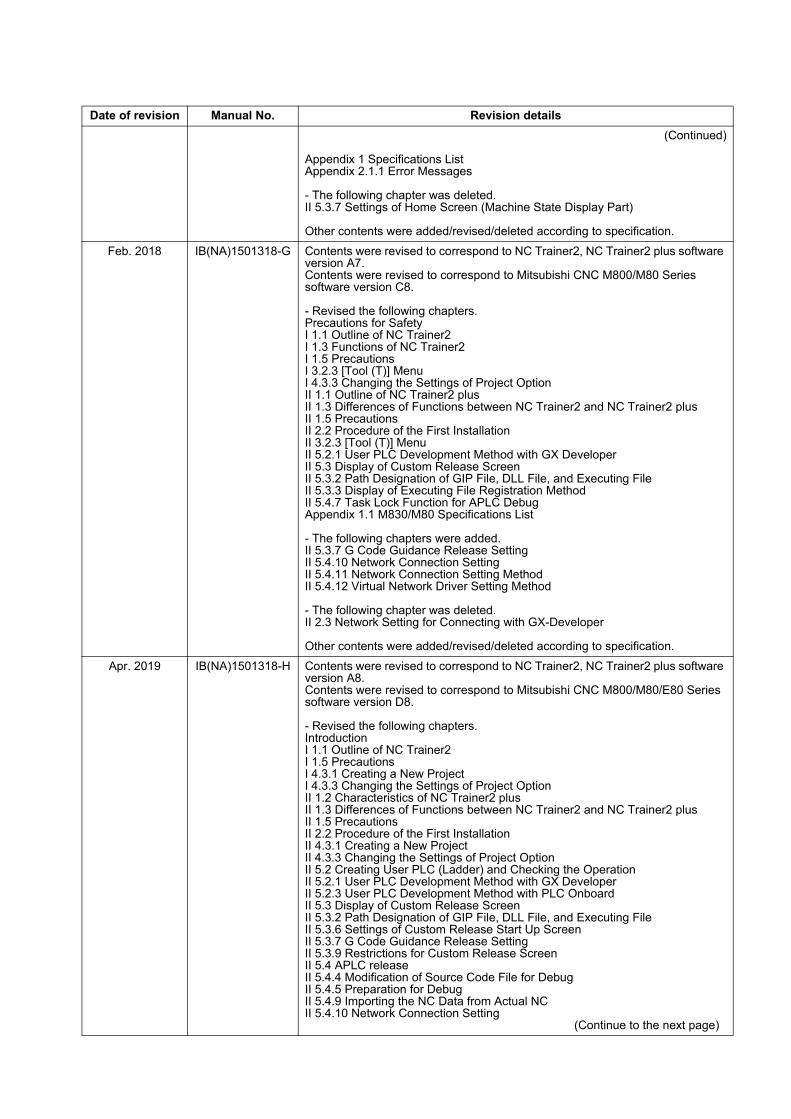
Date of revision Manual No. Revision details
(Continued)
Appendix 1 Specifications ListAppendix 2.1.1 Error Messages
- The following chapter was deleted.II 5.3.7 Settings of Home Screen (Machine State Display Part)
Other contents were added/revised/deleted according to specification.
Feb. 2018 IB(NA)1501318-G Contents were revised to correspond to NC Trainer2, NC Trainer2 plus software version A7.Contents were revised to correspond to Mitsubishi CNC M800/M80 Series software version C8. - Revised the following chapters.Precautions for SafetyI 1.1 Outline of NC Trainer2I 1.3 Functions of NC Trainer2I 1.5 PrecautionsI 3.2.3 [Tool (T)] MenuI 4.3.3 Changing the Settings of Project OptionII 1.1 Outline of NC Trainer2 plusII 1.3 Differences of Functions between NC Trainer2 and NC Trainer2 plusII 1.5 PrecautionsII 2.2 Procedure of the First InstallationII 3.2.3 [Tool (T)] MenuII 5.2.1 User PLC Development Method with GX DeveloperII 5.3 Display of Custom Release ScreenII 5.3.2 Path Designation of GIP File, DLL File, and Executing FileII 5.3.3 Display of Executing File Registration MethodII 5.4.7 Task Lock Function for APLC DebugAppendix 1.1 M830/M80 Specifications List - The following chapters were added.II 5.3.7 G Code Guidance Release Setting II 5.4.10 Network Connection SettingII 5.4.11 Network Connection Setting MethodII 5.4.12 Virtual Network Driver Setting Method - The following chapter was deleted.II 2.3 Network Setting for Connecting with GX-Developer Other contents were added/revised/deleted according to specification.
Apr. 2019 IB(NA)1501318-H Contents were revised to correspond to NC Trainer2, NC Trainer2 plus software version A8.Contents were revised to correspond to Mitsubishi CNC M800/M80/E80 Series software version D8. - Revised the following chapters.IntroductionI 1.1 Outline of NC Trainer2I 1.5 PrecautionsI 4.3.1 Creating a New ProjectI 4.3.3 Changing the Settings of Project OptionII 1.2 Characteristics of NC Trainer2 plusII 1.3 Differences of Functions between NC Trainer2 and NC Trainer2 plusII 1.5 PrecautionsII 2.2 Procedure of the First InstallationII 4.3.1 Creating a New ProjectII 4.3.3 Changing the Settings of Project OptionII 5.2 Creating User PLC (Ladder) and Checking the OperationII 5.2.1 User PLC Development Method with GX DeveloperII 5.2.3 User PLC Development Method with PLC OnboardII 5.3 Display of Custom Release ScreenII 5.3.2 Path Designation of GIP File, DLL File, and Executing FileII 5.3.6 Settings of Custom Release Start Up ScreenII 5.3.7 G Code Guidance Release SettingII 5.3.9 Restrictions for Custom Release ScreenII 5.4 APLC releaseII 5.4.4 Modification of Source Code File for DebugII 5.4.5 Preparation for DebugII 5.4.9 Importing the NC Data from Actual NCII 5.4.10 Network Connection Setting (Continue to the next page)

Date of revision Manual No. Revision details
(Continued)II 5.4.11 Network Connection Setting MethodII 6.1 Exporting NC Trainer2 plus Project Appendix 1.1 M830/M80/E80 Specifications List
- The following chapters were added.II 5.2.2 User PLC Development Method with GX Works2II 5.3.8 Custom Cycle Setting for Interactive Cycle Insertion
Other contents were added/revised/deleted according to specification.
Jul. 2021 IB(NA)1501318-J Contents were revised to correspond to NC Trainer2, NC Trainer2 plus software version A9.Contents were revised to correspond to Mitsubishi CNC M800/M80/E80 Series software version F0. Contents were revised to correspond to Mitsubishi CNC C80 Series software version B6.
- Revised the following chapters.IntroductionPrecautions for SafetyI 1.5 PrecautionsI 2.1 Operating EnvironmentI 2.2 Procedure of the First InstallationI 3.2.3 [Tool (T)] MenuI 3.3.3.1 Restarting NCI 4 How to Use NC Trainer2 plusII 1.1 Outline of NC Trainer2 plusII 1.2.1 M800/M80/E80 Series, M700V/M70V/M700/M70 Series, and E70II 1.3 Differences of Functions between NC Trainer2 and NC Trainer2 plusII 1.5 PrecautionsII 2.1 Operating EnvironmentII 2.2 Procedure of the First InstallationII 3.2.1 [Project (P)] MenuII 3.2.3 [Tool (T)] MenuII 4.3.1 Creating a New ProjectII 4.3.2 Changing the ProjectII 4.3.3 Changing the Settings of Project OptionII 5.1.1 Custom Machine Operation PanelII 5.1.2.1 Configuration of the ScreenII 5.1.3 Start and Exit NC Trainer2 BuilderII 5.1.4 Creating a Project of the Custom Machine Operation PanelII 5.2 Creating User PLC and Checking the OperationII 5.3 Display of Custom Release ScreenII 5.3.2 Path Designation of GIP File, DLL File, and Executing FileII 5.4.1 Writing APLC Release C Language ModuleII 5.4.2 Outline for the Debug of APLC Release C Language ModuleII 5.4.4 Modification of Source Code File for DebugII 5.4.5 Preparation for DebugII 5.4.7 Task Lock Function for APLC DebugII 5.5 Importing the NC Data from Actual II 5.6 Network Connection SettingII 5.6.1 Network Connection Setting MethodII 5.7 Virtual Network Driver Setting MethodII 6.1 Exporting NC Trainer2 plus ProjectAppendix 1.1 M830/M80/E80/C80 Specifications ListAppendix 2.1.1.2 Error Messages Dedicated to NC Trainer2 plusAppendix 2.1.2.3 Displayed Key Is Different from the Key Input from Keyboard
- The following chapters were added.II 1.2.2 C80II 5.8 Set GX Simulator3 ConnectionAppendix 2.1.2.7 Screen Is Displayed Smaller and Buttons Are Difficult to Press or Screen Is Not Displayed Properly Due to the Display ResolutionAppendix 2.1.2.8 NC Trainer2 / NC Trainer2 plus Is Forcefully Closed When an Application Using the Same Driver that the License Key Uses is InstalledAppendix 2.1.2.9 Cannot Connect to the RT ToolBox3 Simulator from NC Trainer2 plus
Other contents were added/revised/deleted according to specification


Global Service Network
AMERICA EUROPE
.V.B EPORUE CIRTCELE IHSIBUSTIM)RETNEC AF ACIREMA( .CNI NOITAMOTUA CIRTCELE IHSIBUSTIMCentral Region Service Center (Chicago) European Service Headquarters (Dusseldorf, GERMANY)
YNAMREG ,NEGNITAR 28804 1 ztalP-cirtcelE-ihsibustiM .A.S.U ,16006 SIONILLI ,SLLIH NONREV ,YAWKRAP SDOOW ETAROPROC 005 0195-684-2012-94+ :XAF / 0005-684-2012-94+ :LET 0562-874-748-1+ :XAF / 0052-874-748-1+ :LET
Minneapolis, MN Service Satellite Detroit, MI Service Satellite South Germany Service Center (Stuttgart) Grand Rapids, MI Service Satellite SCHELMENWASENSTRASSE 16-20, 70567 STUTTGART, GERMANY Milwaukee, WI Service Satellite TEL: + 49-711-770598-123 / FAX: +49-711-770598-141 Cleveland, OH Service Satellite Indianapolis, IN Service Satellite France Service Center (Paris) St. Louis, MO Service Satellite 2 RUE DE L’UNION, 92565 RUEIL-MALMAISON CEDEX, FRANCE
TEL: +33-1-41-02-83-13 / FAX: +33-1-49-01-07-25South/East Region Service Center (Georgia) 1845 SATTELITE BOULEVARD STE. 450, DULUTH, GEORGIA 30097, U.S.A. France Service Satellite (Lyon)
ECNARF TSEIRP TNIAS 00896 DONOM SEUQCAJ EELLA ,021 9154-852-876-1+ XAF / 9254-852-876-1+ LET Charleston, SC Service Satellite TEL: +33-1-41-02-83-13 / FAX: +33-1-49-01-07-25 Charlotte, NC Service Satellite Raleigh, NC Service Satellite Italy Service Center (Milan) Dallas, TX Service Satellite CENTRO DIR. COLLEONI, PALAZZO SIRIO, VIALE COLLEONI 7, 20864 AGRATE BRIANZA (MB) ITALY Houston, TX Service Satellite TEL: +39-039-6053-342 / FAX: +39-039-6053-206 Hartford, CT Service Satellite Knoxville, TN Service Satellite Italy Service Satellite (Padova) Nashville, TN Service Satellite VIA G. SAVELLI, 24 - 35129 PADOVA, ITALY Baltimore, MD Service Satellite TEL: +39-039-6053-342 / FAX: +39-039-6053-206 Pittsburg, PA Service Satellite Tampa, FL Service Satellite U.K. Service Center Syracuse, NY Service Satellite TRAVELLERS LANE, HATFIELD, HERTFORDSHIRE, AL10 8XB, U.K. Orlando, FL Service Satellite TEL: +49-2102-486-5000 / FAX: +49-2102-486-5910 Lafayette, LA Service Satellite Philadelphia, PA Service Satellite Spain Service Center
CTRA. RUBI, 76-80 8174 SAINT CUGAT DEL VALLES, BARCELONA SPAINWestern Region Service Center (California) TEL: +34-935-65-2236 / FAX: +34-935-89-1579 5900-B KATELLA AVE. - 5900-A KATELLA AVE. CYPRESS, CALIFORNIA 90630, U.S.A. TEL: +1-714-699-2625 / FAX: +1-847-478-2650 Poland Service Center San Jose, CA Service Satellite UL.KRAKOWSKA 50, 32-083 BALICE, POLAND Seattle, WA Service Satellite TEL: +48-12-347-6500 / FAX: +48-12-630-4701 Denver, CO Service Satellite
Hungary Service CenterCanada Region Service Center (Tronto) BUDAÖRS OFFICE PARK, SZABADSÁG ÚT 117., 2040 BUDAÖRS, HUNGARY
1074-036-21-84+ :XAF / 0056-743-21-84+ :LET ADANAC ,2JO R3L OIRATNO ,MAHKRAM EUNEVA HT41 9924 TEL: +1-905-475-7728 / FAX: +1-905-475-7935 Edmonton, AB Service Satellite Turkey Service Center Montreal, QC Service Satellite MITSUBISHI ELECTRIC TURKEY A.Ş
SERIFALI MAHALLESI NUTUK SOKAK. NO.41 34775 Mexico Region Service Center (Queretaro) UMRANIYE, ISTANBUL, TURKEY Parque Tecnológico Innovación Querétaro, Lateral Carretera Estatal 431, Km 2+200, Lote 91 Modulos 1 y 2 TEL: +90-216-969-2500 / FAX: +90-216-526-3995 Hacienda la Machorra, CP 76246, El Marqués, Querétaro, México TEL: +52-442-153 6050 Czech Republic Service Center Monterrey, NL Service Satellite AutoCont Control Systems s.r.o (Service Partner) Mexico City, DF Service Satellite KAFKOVA 1853/3, 702 00 OSTRAVA 2, CZECH REPUBLIC
TEL: +420-59-5691-185 / FAX: +420-59-5691-199
BRAZIL Russia Service CenterMITSUBISHI ELECTRIC RUSSIA LLC
MITSUBISHI ELECTRIC DO BRASIL COMÉRCIO E SERVIÇOS LTDA. LETNIKOVSKAYA STREET 2, BLD.1, 5TH 115114 MOSCOW, RUSSIAVotorantim Office TEL: +7-495-721-2070 / FAX: +7-495-721-2071 AV. GISELE CONSTANTINO,1578, PARQUE BELA VISTA, VOTORANTIM-SP, BRAZIL CEP:18.110-650 TEL: +55-15-3023-9000 Sweden Service Center Blumenau, Santa Catarina office HAMMARBACKEN 14, P.O.BOX 750 SE-19127, SOLLENTUNA, SWEDEN
TEL: +46-8-6251000 / FAX: +46-8-6251014
Bulgaria Service Center AKHNATON Ltd. (Service Partner) 4 ANDREJ LJAPCHEV BLVD. POB 21, BG-1756 SOFIA, BULGARIA TEL: +359-2-8176009 / FAX: +359-2-9744061
Ukraine Service Center (Kiev) CSC Automation Ltd. (Service Partner) 4 B, YEVHENA SVERSTYUKA STR., 02002 KIEV, UKRAINE TEL: +380-44-494-3344 / FAX: +380-44-494-3366
Belarus Service Center TECHNIKON Ltd. (Service Partner) NEZAVISIMOSTI PR.177, 220125 MINSK, BELARUS TEL: +375-17-393-1177 / FAX: +375-17-393-0081
South Africa Service Center Adroit Technologies (Service Partner) 20 WATERFORD OFFICE PARK, WATERFORD DRIVE, CNR OF WITKOPPEN ROAD, FOURWAYS JOHANNESBURG SOUTH AFRICA TEL: +27-11-658-8100 / FAX: +27-11- 658-8101

ASEAN CHINA
)RETNEC AF ANIHC( .DTL )ANIHC( NOITAMOTUA CIRTCELE IHSIBUSTIM)RETNEC AF NAESA( .DTL .ETP AISA CIRTCELE IHSIBUSTIMSingapore Service Center CNC Call Center 307 ALEXANDRA ROAD #05-01/02 MITSUBISHI ELECTRIC BUILDING SINGAPORE 159943 TEL: +86-400-921-5130 TEL: +65-6473-2308 / FAX: +65-6476-7439
Shanghai Service Center 1-3,5-10,18-23/F, NO.1386 HONG QIAO ROAD, CHANG NING QU,
PHILIPPINE SHANGHAI 200336, CHINA TEL: +86-21-2322-3030 / FAX: +86-21-2322-3000*8422
MELCO FACTORY AUTOMATION PHILIPPINES INC. Qingdao Service CenterHead Office Suzhou Service Center 128 LOPEZ RIZAL STREET, BRGY., HIGHWAY HILLS, MANDALUYONG CITY , MM PHILIPPINES 1550 Wuhan Service Center TEL: +63-2-8256-8042 / FAX: +632-8637-2294 Ningbo Service Center
Hefei Service CenterPhilippines Service Center Beijing Service Center KM.23 WEST SERVICE ROAD SSH, CUPANG ,MUNTINLUPA CITY PHILIPPINES Tianjin Service Center TEL: +63-2-8807-0420 / FAX: +63-2-8842-5202 Xian Service Center
Dalian Service Center Chengdu Service Center
VIETNAMShenzhen Service Center
MITSUBISHI ELECTRIC VIETNAM CO.,LTD. LEVEL8, GALAXY WORLD TOWER B, 1 YABAO ROAD, LONGGANG DISTRICT,Vietnam Ho Chi Minh Service Center SHENZHEN 518129, CHINA 11TH & 12TH FLOOR, VIETTEL TOWER B, 285 CACH MANG THANG 8 STREET, WARD 12, DISTRICT 10, TEL: +86-755-2399-8272 / FAX: +86-755-8229-3686 HO CHI MINH CITY, VIETNAM Dongguan Service Center TEL: +84-28-3910 5945 / FAX: +84-28-3910 5947 Xiamen Service Center
Vietnam Hanoi Service Center 24TH FLOOR, HANDICO TOWER, PHAM HUNG ROAD, ME TRI HA, ME TRI WARD, KOREA NAM TU LIEM DISTRICT, HA NOI CITY, VIETNAM TEL: +84-24-3937-8075 / FAX: +84-24-3937-8076 MITSUBISHI ELECTRIC AUTOMATION KOREA CO., LTD. (KOREA FA CENTER)
Korea Service Center 8F GANGSEO HANGANG XI-TOWER A, 401 YANGCHEON-RO, GANGSEO-GU,
INDONESIA SEOUL 07528 KOREA TEL: +82-2-3660-9609 / FAX: +82-2-3664-8668
PT. MITSUBISHI ELECTRIC INDONESIA Korea Daegu Service SatelliteIndonesia Service Center (Cikarang) JL. KENARI RAYA BLOK G2-07A, DELTA SILICON 5, LIPPO CIKARANG - BEKASI 17550, INDONESIA TEL: +62-21-2961-7797 / FAX: +62-21-2961-7794 TAIWAN
MITSUBISHI ELECTRIC TAIWAN CO., LTD. (TAIWAN FA CENTER) MALAYSIA Taiwan Taichung Service Center
NO.8-1, GONGYEQU 16TH RD., XITUN DIST., TAICHUNG CITY 40768, TAIWANMITSUBISHI ELECTRIC SALES MALAYSIA SDN. BHD. TEL: +886-4-2359-0688 / FAX: +886-4-2359-0689Malaysia Service Center (Kuala Lumpur Service Center) LOT 11, JALAN 219, P.O BOX 1036, 46860 PETALING JAYA, SELANGOR DARUL EHSAN. MALAYSIA Taiwan Taipei Service Center
NAWIAT ,55111 YTIC IEPIAT ,.TSID NILIHS ,.DR .N NAHSGNOHZ ,6.CES ,88.ON ,F11 9262-0697-3-06+ :XAF / 8262-0697-3-06+ :LET Johor Bahru Service Satellite TEL: +886-2-2833-5430 / FAX: +886-2-2833-5433 Pulau Pinag Service Satellite
Taiwan Tainan Service Center THAILAND 11F.-1, NO.30, ZHONGZHENG S. RD., YONGKANG DIST., TAINAN CITY 71067, TAIWAN
TEL: +886-6-252-5030 / FAX: +886-6-252-5031MITSUBISHI ELECTRIC FACTORY AUTOMATION (THAILAND) CO.,LTD.Thailand Service Center (Bangkok) 101, TRUE DIGITAL PARK OFFICE, 5TH FLOOR, SUKHUMVIT ROAD, BANGCHAK, PHRAKHANONG, OCEANIA BANGKOK, 10260 THAILAND TEL: +66-2-092-8600 / FAX: +66-2-043-1231-33 MITSUBISHI ELECTRIC AUSTRALIA PTY. LTD. Bowin Service Center (Chonburi) Oceania Service Center Korat Service Center 348 VICTORIA ROAD, RYDALMERE, N.S.W. 2116 AUSTRALIA
TEL: +61-2-9684-7269/ FAX: +61-2-9684-7245
INDIA
MITSUBISHI ELECTRIC INDIA PVT., LTD.CNC Technical Center (Bangalore) PLOT NO. 56, 4TH MAIN ROAD, PEENYA PHASE 3, PEENYA INDUSTRIAL AREA, BANGALORE 560058, KARNATAKA, INDIA TEL : +91-80-4655-2121 / FAX : +91-80-4655-2147 Chennai Service Satellite Coimbatore Service Satellite Hyderabad Service Satellite
North India Service Center (Gurgaon) PLOT 517, GROUND FLOOR, UDYOG VIHAR PHASE-III, GURUGRAM 122008, HARYANA, INDIA TEL : +91-124-463-0300 / FAX : +91-124-463-0399 Ludhiana Service Satellite Panthnagar Service Satellite Delhi Service Satellite Jamshedpur Service Satellite Manesar Service Satellite
West India Service Center (Pune) ICC-Devi GAURAV TECHNOLOGY PARK, UNIT NO.402, FOURTH FLOOR, NORTH WING, SURVEY NUMBER 191-192 (P), NEXT to INDIAN CARD CLOTHING COMPANY Ltd, OPP. VALLABH NAGAR, PIMPRI, PUNE- 411 018, MAHARASHTRA, INDIA TEL : +91-20-6819 2274 / FAX : +91-20-4624 2100 Kolhapur Service Satellite Aurangabad Service Satellite Mumbai Service Satellite
West India Service Center (Ahmedabad) 204-209, 2ND FLOOR, 31FIVE, CORPORATE ROAD PRAHLADNAGAR, AHMEDABAD -380015, GUJARAT, INDIA TEL : + 91-79-6777 7888 Rajkot Service Satellite

Notice
Every effort has been made to keep up with software and hardware revisions in the contents described in this manual. However, please understand that in some unavoidable cases simultaneous revision is not possible.Please contact your Mitsubishi Electric dealer with any questions or comments regarding the use of this product.
Duplication Prohibited
This manual may not be reproduced in any form, in part or in whole, without written permission from Mitsubishi Electric Corporation.
COPYRIGHT 2015-2021 MITSUBISHI ELECTRIC CORPORATION ALL RIGHTS RESERVED