inverter freqrol-cs80 - Mitsubishi Electric Factory Automation
Upload
khangminh22Category
view
0download
0
Energy Measuring Unit Control Unit
Control Unit Engineering Tool
MODEL
EMU4-CNT-MB EMU4-KNET User’s Manual (Details)
● Before operating the instrument, you should first read thoroughly this operation manual for safe operation and optimized performance of the product. Deliver this user’s manual to the end user.
1
Introduction Thank you for purchasing our Energy Measuring Unit, EcoMonitorPlus.
⚫ This manual provides some information on how to set up and operate this product. Carefully read the manual to properly use the product. Especially, when installing it, be sure to read the chapter of Safety Precautions to properly handle it.
⚫ After reading this manual, keep it ready to hand and accessible for future use at all times. ⚫ Be sure to forward this manual to the end user. ⚫ If you are considering using this product for a special purpose such as nuclear power plants, aerospace, medical care, or
passenger vehicles, consult our sales representative. For details, refer to the end of this manual.
■Symbol icon
The following table shows the symbol icons used in this manual.
Symbol icon Details
Danger This indicates information that, if ignored, could result in serious injury or even death due to incorrect
handling.
Caution This indicates information that, if ignored, could result in physical injury or damage to property due to
incorrect handling.
Supplement This indicates a precaution to avoid malfunctions or to properly operate the product.
This indicates a reference described about related matters.
■Check of your package contents The following items are included in the package of this product. When unpacking your package, check all the contents.
EcoMonitorPlus x 1 Lithium battery x 1
*Stored in the battery cover of this product. User’s Manual (Digest) x 1
■Related materials
Refer to the following documents as necessary. You can download them from the Mitsubishi FA Global site.
Title Ref. No.
Energy Measuring Unit Contorol Unit User’s Manual (Details) IB63E89 (This manual)
Energy Measuring Unit Energy Measuring Extension Model for Same Voltage System/ Energy Measuring Unit Energy Measuring Extension Model for Different Voltage System User’s Manual (Details)
IB63A21
Energy Measuring Unit Extension Model for Pulse Input/Energy Measuring Unit Extension Model for Analog Input User’s Manual (Details)
IB63D01
Logging Unit for Energy Measuring Unit User’s Manual IB63780
Small Type Display Unit for Energy Measuring Unit User’s Manual (Details) IB63A24
Energy Measuring Unit EcoMonitorLight/EcoMonitorPlus Series MODBUS I/F Specification LSPY-9025
Energy Measuring Unit Programming Manual (CC-Link) For ver.1 remote device station LEN160305
Energy Measuring Unit Programming Manual (CC-Link) For ver.2 remote device station LEN160316
Energy Measuring Unit Programming Manual (CC-Link IE Field Network Basic) (SLMP) LEN180123
■Trademark
・Microsoft and Windows are registered trademarks of Microsoft Corporation in the United States and other countries.
・MODBUS is a trademark of Schneider Electric USA Inc.
・Ethernet is a trademark of Fuji Xerox Co., Ltd.
・Other company and product names herein are trademarks or registered trademarks of their respective owners.
・In the text, trademark symbols such as "TM" and "®" may not be written.

2
Features
● This product, EcoMonitorPlus, is a unit with building block method. The basic unit in combination with one option unit and/or maximum three extension units can provide various applications.
● The contact output/analog output controls the load of equipment or devices.
● The communication function (MODBUS RTU, CC-Link, or CC-Link IE Field Network Basic) enables to transmit the control information to superior monitoring systems. *When a communication function other than MODBUS RTU is used, the appropriate option unit is required.
● Integrating the measuring and control functions easily enables energy saving control. *This unit does not have any measuring function. Combining with the appropriate extension unit enables the integration of measuring and control functions.
● Writing some settings with Control Unit Engineering Tool (Model: EMU4-KNET) enables this unit to execute the control. Control Unit Engineering Tool can be downloaded for free from the Mitsubishi FA Global site.
● This unit comes with a version upgrade function for supporting new functions. It can be updated to the latest version by using Control Unit Engineering Tool (Model: EMU4-KNET).
Basic unit Extension unit (Max 3 units) Option unit (Max 1 unit)

3
Table of Contents
Introduction .......................................................................................................................................................................................................................................... 1 Features ................................................................................................................................................................................................................................................ 2 Table of Contents .............................................................................................................................................................................................................................. 3 1. Safety Precautions ....................................................................................................................................................................................................................... 5
1.1 Precautions for Operating Environment and Conditions ............................................................................................................................................. 5 1.2 Precautions for Preparation before Use ............................................................................................................................................................................ 5 1.3 Precautions for Installation and Wiring ................................................................................................................................................................................ 5 1.4 Precautions for Use ..................................................................................................................................................................................................................... 7 1.5 Precautions for Maintenance ................................................................................................................................................................................................... 8 1.6 Precautions for Storage ............................................................................................................................................................................................................. 8 1.7 Precautions for Disposal ............................................................................................................................................................................................................ 8 1.8 Packaging Materials and User’s Manual .............................................................................................................................................................................. 8
2. Notifications .................................................................................................................................................................................................................................... 8 3. System Configuration .................................................................................................................................................................................................................. 9
3.1 Precautions for System Configuration ................................................................................................................................................................................ 9 3.2 Basic Configuration ................................................................................................................................................................................................................... 10 3.3 Configuration with Combination of Multiple Control Units (1 System) .............................................................................................................. 11 3.4 Configuration with Combination of Multiple Control Units (2 Systems or more) .......................................................................................... 12 3.5 Connection with Superior Monitoring Systems via MODBUS RTU Communication ................................................................................... 13 3.6 Connection with Superior Monitoring Systems via other than MODBUS RTU Communication ............................................................ 14
4. Control Unit .................................................................................................................................................................................................................................. 15 4.1 Name and Function of Each Part ........................................................................................................................................................................................ 15 4.2 How to Install/Detach the Control Unit .......................................................................................................................................................................... 17 4.3 How to Wire the Control Unit ............................................................................................................................................................................................... 18
5. Control Unit Engineering Tool ................................................................................................................................................................................................ 28 5.1 Operating Environment and Installation ........................................................................................................................................................................... 28 5.2 Precautions for Operation ..................................................................................................................................................................................................... 30 5.3 Basic Operation .......................................................................................................................................................................................................................... 30 5.4 Screen Transition ....................................................................................................................................................................................................................... 33 5.5 Project Management ................................................................................................................................................................................................................. 33
6. Procedure for Setup/Operation ............................................................................................................................................................................................ 35 6.1 First Setup .................................................................................................................................................................................................................................... 35 6.2 Basic Operation .......................................................................................................................................................................................................................... 37 6.3 Operation for Replacing/Removing the Control Unit................................................................................................................................................. 47
7. Setting Operation ....................................................................................................................................................................................................................... 50 7.1 System Management ................................................................................................................................................................................................................ 50 7.2 Setting Menu ................................................................................................................................................................................................................................ 52 7.3 Verification of Settings ............................................................................................................................................................................................................ 53 7.4 Read of Settings ......................................................................................................................................................................................................................... 54 7.5 Setting of Terminals.................................................................................................................................................................................................................. 55 7.6 Setting of Control Method ..................................................................................................................................................................................................... 59 7.7 Interlocking Control ................................................................................................................................................................................................................... 60 7.8 Compressor Control.................................................................................................................................................................................................................. 72 7.9 Schedule Control ........................................................................................................................................................................................................................ 91 7.10 Write of Network Information ........................................................................................................................................................................................... 101 7.11 Check of Connection ........................................................................................................................................................................................................... 103 7.12 Write of Settings .................................................................................................................................................................................................................... 104 7.13 Change of RUN/STOP ........................................................................................................................................................................................................ 104
8. Measurement Value Monitoring ........................................................................................................................................................................................... 106 9. Control Monitoring ................................................................................................................................................................................................................... 107
9.1 Control Status Monitoring .................................................................................................................................................................................................... 107 9.2 Manual Control of output...................................................................................................................................................................................................... 108
10. Maintenance Menu (with Control Unit Engineering Tool) ......................................................................................................................................... 110 10.1 Output of Event Log ............................................................................................................................................................................................................ 110 10.2 Setting of Clock ..................................................................................................................................................................................................................... 114 10.3 Change of Password ............................................................................................................................................................................................................ 115 10.4 Setting of Logging Unit ....................................................................................................................................................................................................... 116 10.5 Check of IP Address ............................................................................................................................................................................................................ 117 10.6 Check of F/W Version ......................................................................................................................................................................................................... 118 10.7 Update of F/W ........................................................................................................................................................................................................................ 119
11. Reference ................................................................................................................................................................................................................................. 120 11.1 Troubleshooting ...................................................................................................................................................................................................................... 120 11.2 After Sales Service .............................................................................................................................................................................................................. 121 11.3 Q&A ............................................................................................................................................................................................................................................. 122
12. Requirements for Compliance with EMC Directive .................................................................................................................................................... 123

4
13. Specifications .......................................................................................................................................................................................................................... 124 13.1 Specifications of the Control Unit ................................................................................................................................................................................. 124 13.2 Specifications of MODBUS Communication ............................................................................................................................................................. 125 13.3 Specifications of Ethernet Communication ............................................................................................................................................................... 125 13.4 Specifications of Control Unit Engineering Tool ..................................................................................................................................................... 126 13.5 Version History of Control Unit Engineering Tool .................................................................................................................................................. 126 13.6 Specifications of Lithium Battery .................................................................................................................................................................................. 126
14. Optional Products (sold separately) ................................................................................................................................................................................ 127 14.1 List of Optional Products .................................................................................................................................................................................................. 127 14.2 External Dimensions of Optional Products ................................................................................................................................................................ 128
15. External Dimensions of the Control Unit ....................................................................................................................................................................... 133 16. The Software End User License Agreement ................................................................................................................................................................ 134

5
1. Safety Precautions
This product shall be used in conditions;
i) where any problem, fault or failure occurring in this product, if any, shall not lead to any major or serious accident;
and
ii) Confirmed that the laws and regulations related to the equipment to be controlled are satisfied
and
iii) where the backup and fail-safe function are systematically or automatically provided outside of this product for the case of
any problem, fault or failure occurring in this product.
This product has been designed and manufactured for the purpose of being used in general industries.
MITSUBISHI SHALL HAVE NO RESPONSIBILITY OR LIABILITY (INCLUDING, BUT NOT LIMITED TO ANY AND ALL
RESPONSIBILITY OR LIABILITY BASED ON CONTRACT, WARRANTY, TORT, PRODUCT LIABILITY) FOR ANY INJURY
OR DEATH TO PERSONS OR LOSS OR DAMAGE TO PROPERTY CAUSED BY the PRODUCT THAT ARE OPERATED OR
USED IN APPLICATION NOT INTENDED OR EXCLUDED BY INSTRUCTIONS, PRECAUTIONS, OR WARNING
CONTAINED IN MITSUBISHI'S USER, INSTRUCTION AND/OR SAFETY MANUALS, TECHNICAL BULLETINS AND
GUIDELINES FOR the PRODUCT.
1.1 Precautions for Operating Environment and Conditions
This unit is intended for use in pollution degree 2 *Note1 environment. When using in higher pollution degree, protect the unit from pollution using another device to be incorporated. The overvoltage category of the auxiliary power circuit (MA, MB) of this unit is CAT III *Note1. Do not use this unit in the following places. Otherwise, there is danger of a malfunction or reduction of the product life.
・The Ambient temperature exceeds the range -5 °C to +55 °C. ・The daily average temperature exceeds +35 °C.
・The Relative humidity exceeds the range 30 % to 85 % RH, or condensing
・Exposed to excessive vibration or impact
・Exposed to much dust, corrosive gas, salty environment, or oil smoke
・Exposed to strong magnetic fields or large exogenous noise
・Exposed to rain or water drops. ・Exposed to direct sunlight
・Metal fragments or conductive substances are scattered. ・The altitude exceeds 2000 m.
This unit is an open type device, which is designed to be housed within another system for prevention of electric shock. Be sure to install the unit into the system such as a control panel.
For the precautions to conform the system constructed with this unit to the EMC Directive, refer to 12 Requirements for Compliance with EMC Directive. *Note1: For the definitions of the pollution degree and overvoltage category, refer to EN61010-1/2010.
1.2 Precautions for Preparation before Use
⚫ Observe the use environment and conditions for installation place. ⚫ This unit has a built-in lithium battery, which is disconnected when shipped from the factory. Before use, connect the battery. ⚫ Control Unit Engineering Tool (Model: EMU4-KNET) is required to set up this unit. ⚫ For the compressor control set at the control method setting, using the three contacts controls the three operation modes:
loaded operating mode, unloaded operating mode, and stop mode. Therefore, compressors that this unit can control are limited to the ones with an operating system structure that each contact output status corresponds to each operation mode as the following table.
Operation mode of compressor
Contact
Loaded operating mode
Unloaded operating mode
Stop mode
Loaded/Unloaded ON OFF OFF
Operating ON ON OFF
Stop ON ON OFF
1.3 Precautions for Installation and Wiring
Danger
⚫ Shut off all the phases of external power supply used by this product before installation or wiring work. Otherwise, there is danger of an electric shock or damage to the product.
⚫ Be sure to work for installation and wiring in a non-energized state. Otherwise, there is danger of an electric shock, a product failure, or a fire.

6
Caution
<Precautions for installation and wiring work>
・A qualified electrician must install and wire this unit properly for safety. ・Keep the space around this product (all directions except the back) is 30 mm or more (100 mm or more for UL standard
compliance). ・Take care not to enter any foreign objects such as chips or wire pieces into this unit when tapping or wiring. ・Check the connection diagram thoroughly for wiring. Wrong wiring can cause a product failure, a fire, or an electric
shock. ・In order to prevent the invasion of noise, the transmission signal lines and output signal lines must not be placed close
to or bound together with the power lines or high voltage lines. When lying parallel to the power lines or high voltage lines, refer to the following table for the separation distance. (except the input part of the terminal block) If there is concern about the influence of noise even if the distance is as follows, we recommend using a shielded cable.
Conditions Distance
Power lines of 600 V or less 300 mm or more
Other power lines 600 mm or more
*When there is concern about the invasion of noise, it is recommended to use shielded cables for the wiring with the above separation distance.
・Place the wires connected to this unit in a duct or fixed them with clamps. Otherwise, cable dangling/movement or unnecessary careless tension can cause damage to the unit and/or wires, or a poor connection of the wire can cause a product malfunction.
・ <Connection to the terminal block>
・Strip the wires by appropriate length. If the stripping length is too long, it could cause short-circuit with the adjacent wire. On the other hand, if it is too short, it could cause a contact failure due to the bad fitting.
・Take care not to cause a short circuit of the adjacent electrodes due to the filaments. (Do not perform solder plating of the cable core.)
・Do not connect three wires or more to one of the terminal block. Otherwise, the connection could get loose, resulting in that the wires might come off.
・Use appropriate size wires. If an inappropriate size wire is used, it could cause a fire due to generated heat. ・Tighten the screws with a specified torque. Insufficient tightening could cause a drop, short-circuit, or a malfunction
while over-tightening could damage the screws and/or unit, resulting in a drop, short-circuit, or a malfunction. ・After tightening the screws, be sure to confirm all the screws tightened. Forgetting to tighten the screws could cause
a product malfunction, a fire, or an electric shock. ・Be sure to attach the terminal cover and close it to prevent an electric shock. ・Use crimp-type terminals appropriate for the size of electric wires. If an inappropriate crimp-type terminal is used, it
could result in a malfunction/failure/burnout of the unit or a fire caused by a wire breakage or a contact failure. ・Be sure to ground the frame grounding (FG) terminal with Class D grounding. The ground resistance is 100 Ω or less. ・When disconnecting the wires from this unit, do not pull them with a strong force. If you pull them connected to the
unit, a malfunction or damage to the unit and/or wires could be caused. ・Do not directly touch any conductive parts or electrical circuits of this unit. Otherwise, there is danger of an electric
shock or a failure/malfunction of the unit.
<Connection of the frame grounding (FG) terminal>
・When this unit is subjected to an insulation resistance test or a commercial frequency withstand voltage test, perform the test within the specified voltage.
・For actual use, ground the frame grounding (FG) terminal. (Type D grounding: Type 3 grounding) ・To protect persons with little knowledge about electrical equipment from electric shock, either of the following
measures must be taken against the panel: Lock the panel so that only those who have gotten an education about electrical equipment and have the sufficient knowledge can unlock it, or construct a structure that shuts off the power supply automatically by opening the panel. Cover the dangerous voltage part of this unit with a cover.

7
1.4 Precautions for Use
⚫ This unit cannot be used for deal and proof of electric energy measurement stipulated in the measurement law. ⚫ While some settings are written to this unit with Control Unit Engineering Tool (Model: EMU4-KNET), if power outage
occurs, the setting will not be correctly set up. After power recovery, conduct the setting again. ⚫ When some measurement values measured by an extension unit are acquired via communication, the same data may be
provided in response for max two minutes. Do not use this unit in combination with a system that requests high response accuracy.
Caution
・Observe the ratings specified in this manual. Using this unit outside the ratings could cause not only a malfunction or a failure but also ignition or burnout.
・Do not disassemble or modify this unit for use. Otherwise, there is danger of a product failure, an electric shock, or a fire.
・For protection against electric shock, use an insulation precision screwdriver to press the reset button on the front of this unit.
・Do not touch any live parts such as the connection terminals. Otherwise, there is danger of an electric shock, electric burn injury, or burnout of the unit. If any exposed conductor is found, stop the operation immediately and take an appropriate action such as isolation protection.
・Press the reset button with an appropriate force (1.6 N). Applying inappropriate force could cause a product failure.
・Check that the communication connectivity is secured between the computer where Control Unit Engineering Tool (Model: EMU4-KNET) is to be run and the control unit.
・This unit comes with a built-in clock. Before use, set the present date with Control Unit Engineering Tool (Model: EMU4-KNET).
・While the BAT. LED lights up, if the power supply is turned off, the present time data will be deleted. If the BAT. LED lights up, replace the lithium battery.
8
1.5 Precautions for Maintenance
⚫ Use a soft dry cloth to wipe dirt off the surface of this unit. Do not leave a chemical cloth in contact with the unit for a long time or do not wipe it with thinner or benzene.
⚫ Conduct the following inspections to properly use this unit for a long time: (1) Daily maintenance
① No damage with this unit ② No abnormality with the LCD indicator ③ No abnormal noise, smell or heat
(2) Periodical maintenance (Every 6 months to once a year) ・ No looseness in the installation or in the connection of the terminal block ・ Replace the lithium battery when the battery voltage is low (BAT. LED lights up) or every 3 years.
Caution
・Do periodical maintenance in a non-energized state. Otherwise, an electric shock, a product failure, or a fire could be caused. Tighten the terminal screws regularly to prevent a fire.
・While the BAT. LED lights up, if the power supply is turned off, the present time data will be deleted. If the BAT LED lights up, replace the lithium battery.
1.6 Precautions for Storage
⚫ To store this unit, turn off the power, disconnect the wires, and put them in a plastic bag. ⚫ For long term storage, disconnect the battery from the unit.
The cumulative power interruption backup time is 1 year for the lithium battery. If the battery is used over the backup time, the present time data will be deleted.
⚫ Avoid the following places for long term storage. Otherwise, a product failure or reduction of the product life could be caused. ・The Ambient temperature exceeds the range -10 °C to +60 °C. ・The average daily temperature exceeds +35 °C.
・The Relative humidity exceeds the range 30 % to 85 % RH, or condensing
・Exposed to excessive vibration or impact
・Exposed to much dust, corrosive gas, salty environment, or oil smoke
・Metal fragments or conductive substances are scattered.
・Exposed to rain, water drop, or direct sunlight.
1.7 Precautions for Disposal
When disposing of this unit, treat it as industrial waste. This unit has a built-in lithium battery. The lithium battery must be disposed of according to the local regulation.
Caution There may be remaining electrical capacity in the lithium battery removed from this unit. Treat it separately because, when it contacts other metals, heat generation, rupture, or ignition may occur.
1.8 Packaging Materials and User’s Manual
For reduction of environment load, the packaging materials are produced with cardboard.
2. Notifications
⚫ No part of this manual may be reprinted or reproduced in any form or by any means without the consent of our company.
⚫ This manual is designed with the assumption that the OS of your computer is Windows 10. Therefore, depending on settings or specifications of the computer to be used, the examples of the window screen or operation described in this manual may be different from those of your computer.
⚫ We make efforts to update this manual as soon as possible according to the revision of software or hardware. However, note that it may not be timely updated.

9
3. System Configuration
The following shows some examples of system configured using this unit.
3.1 Precautions for System Configuration
This section desribes the precautions for combining the control unit with other product or system.
■When connecting some extension units with the small type display unit For the use of the control unit in combination with some extension units, note the following points:
・To set up the extension units, the optional small type display unit (Model: EMU4-D65) is required. With one small type display unit, you can set up any extension units connected to each control unit by switching the connection destination.
・The settings of the control unit are displayed on the basic setting mode in the small type display unit, however, from which no settings can be set for the control unit.
・The range set by Control Unit Engineering Tool or by small type display unit is as follows:
Unit Model Control Unit Engineering Tool Small type display unit
Control unit EMU4-CNT-MB 〇 -
Extension unit EMU4-A2 - 〇
EMU4-VA2 - 〇
EMU4-AX4 - 〇
EMU4-PX4 - 〇
*1: In order to set the logging ID of the logging unit (Model: EMU4-LM) in combination with the control unit, use Control Unit Engineering Tool. With the combination, no settings can be set with the small type display unit.
*2: In terms of the settings of MODBUS RTU communication, the setting values set from Control Unit Engineering Tool are valid. No settings can be set with the small type display unit.
・After the extension unit is set with the small type display unit, be sure to power ON the control unit after OFF from ON or press the reset button to restart it.
■When replacing the existing basic unit with the control unit When the existing basic unit is replaced with the control unit, note the following points:
・If there is Extension model for the system with the same voltage (Model: EMU4-A2) in the extensin units connected, be sure to connect Extension model for the system with the different voltage (Model: EMU4-VA2) between the above mentioned extension unit and the control unit.
・The MODBUS RTU communication settings are changed to the ones set for the control unit. When using the existing basic unit with some settings changed from the default, recreate the settings with Control Unit Engineering Tool.
10
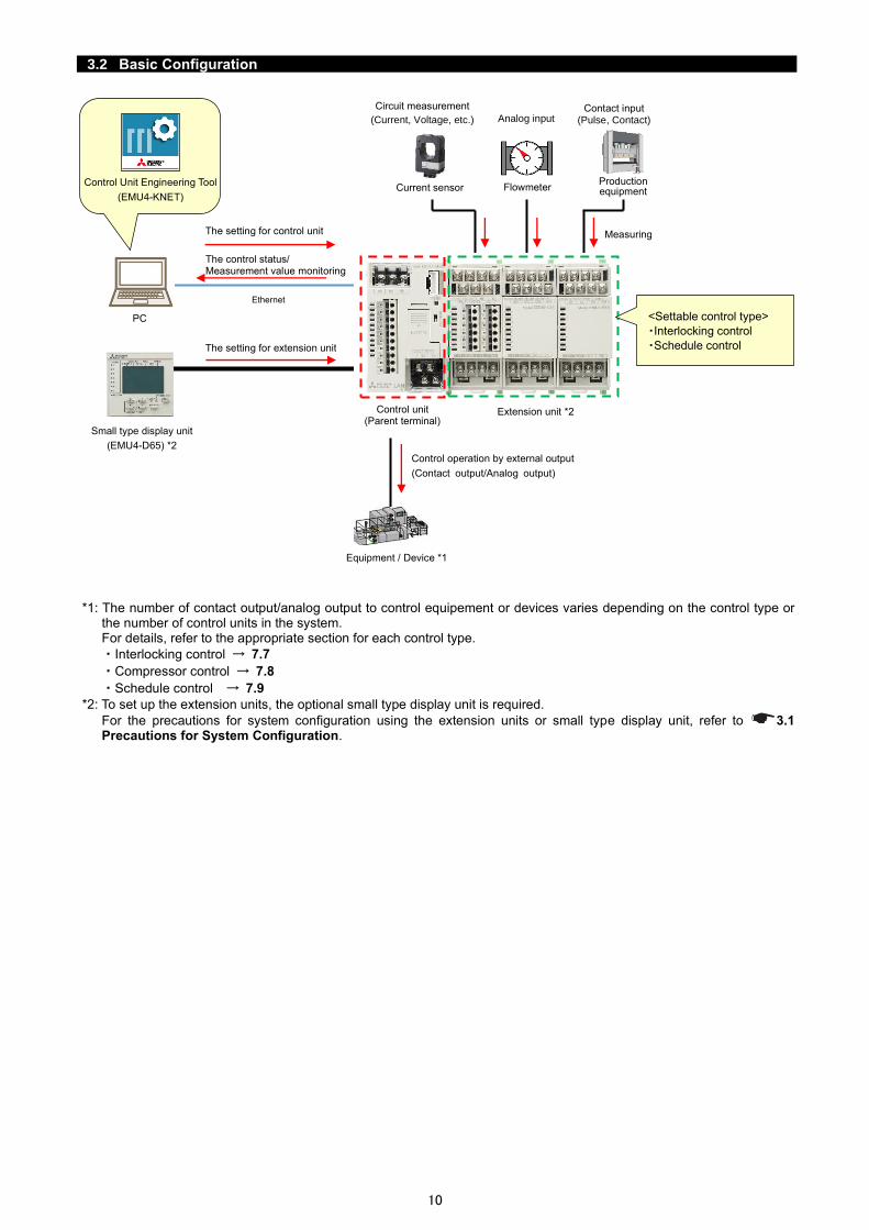
3.2 Basic Configuration
*1: The number of contact output/analog output to control equipement or devices varies depending on the control type or the number of control units in the system. For details, refer to the appropriate section for each control type.
・Interlocking control → 7.7
・Compressor control → 7.8
・Schedule control → 7.9
*2: To set up the extension units, the optional small type display unit is required.
For the precautions for system configuration using the extension units or small type display unit, refer to ..1 Precautions for System Configuration.
Control unit (Parent terminal)
PC
Ethernet
Control Unit Engineering Tool
(EMU4-KNET) Current sensor
Production equipment Flowmeter
Extension unit *2
Equipment / Device *1
Circuit measurement
(Current, Voltage, etc.) Analog input Contact input
(Pulse, Contact)
Control operation by external output
(Contact output/Analog output)
The setting for extension unit
The control status/ Measurement value monitoring
Measuring
<Settable control type>
・Interlocking control
・Schedule control
Small type display unit
(EMU4-D65) *2
The setting for control unit
11
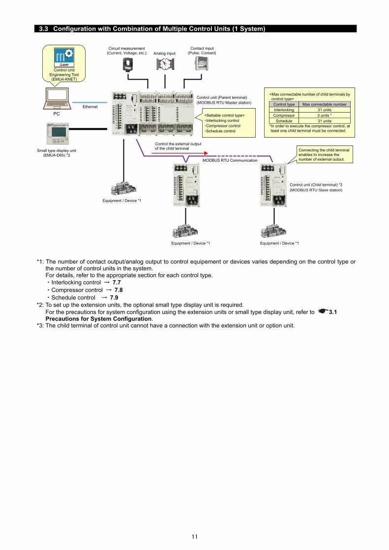
3.3 Configuration with Combination of Multiple Control Units (1 System)
*1: The number of contact output/analog output to control equipement or devices varies depending on the control type or the number of control units in the system. For details, refer to the appropriate section for each control type.
・Interlocking control → 7.7
・Compressor control → 7.8
・Schedule control → 7.9
*2: To set up the extension units, the optional small type display unit is required.
For the precautions for system configuration using the extension units or small type display unit, refer to ..1 Precautions for System Configuration.
*3: The child terminal of control unit cannot have a connection with the extension unit or option unit.
Circuit measurement (Current, Voltage, etc.)
Contact input (Pulse, Contact)
PC
Ethernet
Control Unit
Engineering Tool (EMU4-KNET)
Equipment / Device *1
Small type display unit
(EMU4-D65) *2
MODBUS RTU Communication
Control unit (Child terminal) *3
(MODBUS RTU Slave station)
Control the external output of the child terminal
Control unit (Parent terminal)
(MODBUS RTU Master station)
Connecting the child terminal enables to increase the
number of external output.
<Settable control type>
・Interlocking control
・Compressor control
・Schedule control
<Max connectable number of child terminals by control type>
Control type Max connectable number
Interlocking 31 units
Compressor 3 units *
Schedule 31 units
*In order to execute the compressor control, at
least one child terminal must be connected.
Analog input
Equipment / Device *1 Equipment / Device *1

12
3.4 Configuration with Combination of Multiple Control Units (2 Systems or more)
*1: The number of contact output/analog output to control equipement or devices varies depending on the control type or the number of control units in the system. For details, refer to the appropriate section for each control type.
・Interlocking control → 7.7
・Compressor control → 7.8
・Schedule control → 7.9
*2: To set up the extension units, the optional small type display unit is required.
For the precautions for system configuration using the extension units or small type display unit, refer to ..1 Precautions for System Configuration.
*3: The child terminal of control unit cannot have a connection to the extension unit or option unit.
PC
Circuit measurement
(Current, Voltage, etc.)
Contact input
(Pulse, Contact)
Ethernet
Control Unit
Engineering Tool
(EMU4-KNET)
Equipment / Device *1
Small type display unit
(EMU4-D65) *2
MODBUS RTU Communication
Control unit (Child terminal) *3
(MODBUS RTU Slave station)
Control the external output of the child terminal
Control unit (Parent terminal)
(MODBUS RTU Master station)
Connecting the child terminal enables to
increase the number of external output.
<Max connectable number of child terminals by control type>
Control type Max connectable number
Interlocking 31 units
Compressor 3 units *
Schedule 31 units
*In order to execute the compressor control, at least one child terminal must be connected.
System 1
System 20
・ ・ ・
Control Unit Engineering Tool
can manage Max 20 systems
per project.
Circuit measurement
(Current, Voltage, etc.)
Analog input
Equipment / Device *1
MODBUS RTU Communication
Control unit (Child terminal) *3
(MODBUS RTU Slave station)
Control the external output of the child terminal
Control unit (Parent terminal)
(MODBUS RTU Master station)
Connecting the child terminal enables to
increase the number of external output.
<Settable control type>
・Interlocking control
・Compressor control
・Schedule control
Small type display unit
(EMU4-D65) *2
Analog input
Contact input
(Pulse, Contact)

13
3.5 Connection with Superior Monitoring Systems via MODBUS RTU Communication
*1: The number of contact output/analog output to control equipement or devices varies depending on the control type or the number of control units in the system. For details, refer to the appropriate section for each control type.
・Interlocking control → 7.7
・Compressor control → 7.8
・Schedule control → 7.9
*2: To set up the extension units, the optional small type display unit is required.
For the precautions for system configuration using the extension units or small type display unit, refer to ..1 Precautions for System Configuration.
*3: For details on MODBUS RTU communication with superior monitoring systems, refer to MODBUS I/F specifications.
PC
Circuit measurement
(Current, Voltage, etc.)
Analog input
Contact input
(Pulse, Contact)
Ethernet
Control Unit
Engineering Tool
(EMU4-KNET)
Equipment / Device *1
Small type display unit
(EMU4-D65) *2
Control unit (Parent terminal)
(MODBUS RTU Slave station)
System 1
・ ・ ・
<Settable control type>
・Interlocking control
・Schedule control
*The parent terminal only that does not combine with any
child terminal can be connected to the MODBUS RTU
Master station (programmable controller, etc.)
Circuit measurement
(Current, Voltage, etc.)
Analog input
Contact input
(Pulse, Contact)
Small type display unit
(EMU4-D65) *2
Control unit (Parent terminal)
(MODBUS RTU Slave station)
System 20
Superior monitoring system
(Programmable controller, etc.)
MODBUS RTU Master station
Other terminal devices (MODBUS RTU Slave station)
MODBUS RTU Communication *3
∙Collect control information from the control unit
∙Control the contacts of the
control unit
Control Unit Engineering Tool
can manage Max 20 systems
per project.
Equipment / Device *1
Max 31 units

14
3.6 Connection with Superior Monitoring Systems via other than MODBUS RTU Communication
*1: The number of contact output/analog output to control equipement or devices varies depending on the control type or
the number of control units in the system. For details, refer to the appropriate section for each control type. ・Interlocking control → 7.7 ・Compressor control → 7.8 ・Schedule control → 7.9
*2: To set up the extension units, the optional small type display unit is required. For the precautions for system configuration using the extension units or small type display unit, refer to ..1 Precautions for System Configuration.
*3: To communicate with the superior monitoring systems, the option unit must be connect to the control unit. *4: For details on communication with the superior monitoring systems, refer to the following manuals:
・CC-Link Energy Measuring Unit Programming Manual (CC-Link) For ver.1 remote device station Energy Measuring Unit Programming Manual (CC-Link) For ver.2 remote device station
・CC-Link IE Field Network Basic Energy Measuring Unit Programming Manual (CC-Link IE Field Network Basic) (SLMP)
*5: The child terminal of control unit cannot have a connection to the extension unit or option unit.
PC
Ethernet
Control Unit
Engineering Tool
(EMU4-KNET)
System 1
・ ・ ・
Control Unit Engineering Tool
can manage Max 20 systems
per project.
Superior monitoring system
(Programmable controller, etc.)
Other terminal units
CC-Link / CC-Link IE Field Network Basic *3 *4
∙Collect control information from the control unit
∙Control the contacts of the
control unit
Circuit measurement
(Current, Voltage, etc.)
Analog input
Contact input
(Pulse, Contact) MODBUS RTU Communication
Control unit (Child terminal) *2
(MODBUS RTU Slave station)
Control unit (Parent terminal)
(MODBUS RTU Master station)
System 20
Circuit measurement
(Current, Voltage, etc.)
Analog input
Contact input
(Pulse, Contact)
Control unit (Parent terminal)
(MODBUS RTU Master station)
Small type display unit
(EMU4-D65) *2
<Max connectable number of child terminals
by control type>
Control type Max connectable number
Interlocking 31 units
Compressor 3 units *
Schedule 31 units
*In order to execute the compressor control, at least one child terminal must be connected.
Small type display unit
(EMU4-D65) *2
Equipment / Device *1
Equipment / Device *1
Control unit (Child terminal) *2
(MODBUS RTU Slave station)
15
4. Control Unit
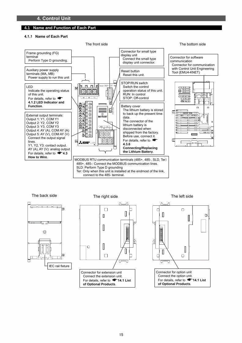
4.1 Name and Function of Each Part
Name of Each Part
The front side
Connector for extension unit Connect the extension unit.
For details, refer to 14.1 List of Optional Products.
IEC rail fixture
Connector for option unit Connect the option unit.
For details, refer to 14.1 List of Optional Products.
The back side The right side The left side
LED Indicate the operating status of this unit. For details, refer to 4.1.2 LED Indicator and Function.
External output terminals: Output 1: Y1, COM Y1 Output 2: Y2, COM Y2 Output 3: Y3, COM Y3 Output 4: AY (A), COM AY (A) Output 5: AY (V), COM AY (V)
Connect the output signal lines. Y1, Y2, Y3: contact output. AY (A), AY (V): analog output For details, refer to 4.. How to Wire.
Connector for small type display unit
Connect the small type display unit connector.
Reset button Reset this unit.
STOP/RUN switch Switch the control operation status of this unit. RUN: In control STOP: Off-control
Battery cover The lithium battery is stored to back up the present time data. The connector of the lithium battery is disconnected when shipped from the factory. Before use, connect it. For details, refer to 4...6 Connecting/Replacing the Lithium Battery.
MODBUS RTU communication terminals (485+, 485-, SLD, Ter) 485+, 485-: Connect the MODBUS communication lines. SLD: Perform Type D grounding Ter: Only when this unit is installed at the endmost of the link,
connect to the 485- terminal.
Connector for software communication Connector for communication with Control Unit Engineering Tool (EMU4-KNET)
Frame grounding (FG) terminal
Perform Type D grounding.
Auxiliary power supply terminals (MA, MB)
Power supply to run this unit
The bottom side

16
LED Indicator and Function
The following table shows a list of LED names and functions.
Name Display color Function Status
RUN LED Red Indicate the operating status of this unit. ON: In normal operation OFF: Power off or hardware trouble *1
MASTER LED Red Indicate the Master station or Slave station of MODBUS RTU communication.
ON: Master station OFF: Slave station
CNT. LED Red Indicate the control execution status. ON: In control (RUN) OFF: Off-control (STOP)
ERR. LED Red Indicate the error status. ON: Error occurring *1 OFF: No error
LAN LED Red Indicate the LAN communication status. ON: Sending/receiving data OFF: Off-communication
BAT. LED Red Indicate the remaining lithium battery level. ON: Low battery voltage *2 OFF: Normal battery voltage
Y1 LED Red Indicate the ON/OFF status of contact output Y1. ON: Contact is ON. OFF: Contact is OFF.
Y2 LED Red Indicate the ON/OFF status of contact output Y2. ON: Contact is ON. OFF: Contact is OFF.
Y3 LED Red Indicate the ON/OFF status of contact output Y3. ON: Contact is ON. OFF: Contact is OFF.
AY (A) LED Red Indicate the analog output status. (Current output: 4 mA to 20 mA) *When the analog output type setting is voltage 0 V to 5 V, the status is OFF.
ON: In analog signal output OFF: Analog signal output stopped
AY (V) LED Red Indicate the analog output status. (Voltage output: 0 V) to 5 V) *When the analog output type setting is current 4 mA to 20 mA, the status is OFF.
ON: In analog signal output OFF: Analog signal output stopped
Note1: For details, refer to 11.1 Troubleshooting. Note2: When the battery voltage is low, if the power supply is turned off, the present time data will be deleted. If the BAT. LED
lights up, replace the lithium battery.
Supplement
The action in each control operating status is as follows: ●In control (RUN) The control is executed according to the settings written into the parent terminal of control unit.
●Off-control (STOP) The present output state is retained. No control is executed according to the settings written into the parent terminal of control unit.

17
4.2 How to Install/Detach the Control Unit
*The following illustrates an example of using a unit of EMU4-HM1-MB.
Caution A qualified electrician must install and wire this unit properly for safety.
Installing on IEC Rail
②Pull up this unit.
①Hold this unit and
pull the IEC rail stopper downward. ④Push the IEC rail
stopper upward.
●Applicable IEC rail ●Installing ●Detaching ①Pull the IEC rail stopper of this unit downward.
②Hook on the rail.
IEC rail
③Push this unit to
engage with the rail.
or more
Installing on JIS Type Attachment Plate
●Installing ●JIS type attachment plate ●Detaching
Fitting spring
Attachment plate
Hook ②Fit the hooks of the
plate into the three grooves on the top face of this unit.
③Fit the fitting spring into the groove
on the bottom face of this unit.
①Check that the IEC rail stopper is positioned upward.
①Push the fitting
spring down.
②Lift the bottom of this unit
gently and detach it in the opposite way as installing.

18
4.3 How to Wire the Control Unit
You will wire this unit according to the following examples. For the wiring of other units such as an extension unit or option unit, refer to the user’s manual of each product.
Precautions for Wiring
Caution
・In order to prevent the invasion of noise, the transmission signal lines and output signal lines must not be placed close to or bound together with the power lines or high voltage lines. When lying parallel to the power lines or high voltage lines, refer to the following table for the separation distance. (except the input part of the terminal block) If there is concern about the influence of noise even if the distance is as follows, we recommend using a shielded cable.
Conditions Distance Power lines of 600 V or less 300 mm or more Other power lines 600 mm or more
*When there is concern about the invasion of noise, it is recommended to use shielded cables for the wiring with the above separation distance.
・For actual use, ground the frame grounding (FG) terminal. (Type D grounding: Type 3 grounding)
・When the unit is subjected to an insulation resistance test or a pressure test, do not connect the FG
terminal. For the applied place, refer to 1. Specifications.
■How to connect wires <Terminals for auxiliary power supply and MODBUS RTU communication> ⚫ For the use of an applicable crimp-type terminal and electric wire, refer to the following table. ⚫ Tighten the terminal screws with a specified torque as the following table.
Applicable wire
Tightening torque
Applicable crimp-type terminal
Auxiliary power terminal Stranded wire: AWG 22 to 16 (0.3 mm2 to 1.3 mm2)
Solid wire: AWG 22 to 16
(φ0.65 mm to 1.25 mm)
0.8 N・m to
1.0 N・m
For M3.5 screw with outer diameter of 7.1 mm or less
MODBUS RTU communication terminal
SPEV (SB) – MPC – 0.2 × 3P or equivalent
0.5 N・m to
0.6 N・m
For M3 screw with outer diameter of 6.1 mm or less
<Terminals for external output (contact output/analog output)> ⚫ The wire stripping length must be 10 to 11 mm. ⚫ When using a stranded wire, use with a rod terminal or twist the wire tip so as not to scatter the filaments. ⚫ To connect/disconnect the wire to/from the terminal, conduct that by pressing the push button. After inserting the wire,
check that it is properly done. ⚫ Insert the wire as far as it goes into the terminal block. ⚫ The following table shows applicable electric wires for use.
Applicable wire Applicable crimp-type terminal
Stranded wire: AWG 20 to 16 (0.5 mm2 to 1.3 mm2)
Solid wire: AWG 24 to 17 (φ0.5 mm to 1.2 mm)
TGV TC-1.25-11T produced by NICHIFU or its equivalent
■Precautions for compliance with UL To comply with the UL standards, observe the following conditions for wiring.
・Do not connect three or more wires to one terminal block.
・Perform crimping of the wires to be connected to the terminal block.
■An example of system configuration for MODBUS RTU communication The following illustrates an example of system configuration when this unit is to the superior monitoring systems via MODBUS RTU communication.
⚫Connection of the MODBUS RTU communication terminals (485+, 485-, SLD, and Ter)
1. Use shielded twisted pair cables for transmission lines.
For the recommended cables, refer to 1..2 Specifications of MODBUS Communication. 2. Install 120 ohm termination resistors to the devices at both ends of the MODBUS transmission line.
For this unit, short-circuiting the 485- and Ter terminals enables 120 ohm termination. 3. Ground with thicker wires to decrease impedance. 4. The MODBUS transmission lines must not be placed close to or bound together with the high voltage lines. 5. Ground the SLD terminal at one end.
or
USB or LAN
MODBUS RTU (RS-485)
120 ohm termination
PC
PLC
120 ohm termination
Max connectable number: 31 units

19
・Connection with MODBUS module (QJ71MB91, QJ71C24N)
Note: Connect 110 ohm termination resistors on the MODBUS module (QJ71MB91, QJ71C24N) side.
For details, refer to MELSEC Q series MODBUS Interface Module User's Manual (QJ71MB91) and Q Corresponding Serial Communication Module User's Manual (Basic).
・Connection with MELSEC iQ-F series programmable controller
Note: Connect 110 ohm termination resistors on the MELSEC iQ-F programmable controller side.
For details, refer to MELSEC iQ-F FX5 User's Manual, MODBUS Communication (Ref. No. JY997D56101).
Terminating resistor
R
SDA
485-
Ter
SLD
485+
EMU4-CNT-MB
485-
Ter
SLD
485+
EMU4-CNT-MB
485-
Ter
SLD
485+
EMU4-CNT-MB MODBUS module
(QJ71MB91)
SDB
RDA
RDB
SG
FG
MELSEC iQ-F Programmable
controller
R
485-
Ter
SLD
485+
EMU4-CNT-MB
485-
Ter
SLD
485+
EMU4-CNT-MB
485-
Ter
SLD
485+
EMU4-CNT-MB
SDA
SDB
RDA
RDB
SG
Terminating resistor

20
・Connection with MELSEC iQ-R Serial Communication Module (RJ71C24, RJ71C24-R4)
Note: Connect 110 ohm termination resistors on the MELSEC iQ-R programmable controller side.
For details, refer to Before Using the Product for RJ71C24 and RJ71C24-R4 (Ref.NO. BCN-P59999-0075-C).
・Connection with GOT (GOT1000, GOT2000)
Note: Set the termination resistor of the GOT (GOT1000, GOT2000) side to 110 ohm.
For details, refer to GOT1000 Series Connection Manual (Microcomputers, MODBUS Products, Peripherals) for GT Works3 and GOT2000 Series Connection Manual (Microcomputers, MODBUS/Fieldbus Products, Peripherals) For GT Works3 Version1.
R
485-
Ter
SLD
485+
EMU4-CNT-MB
485-
Ter
SLD
485+
EMU4-CNT-MB
485-
Ter
SLD
485+
EMU4-CNT-MB
Serial communication
module (RJ71C24)
SDA
SDB
RDA
RDB
SG
FG
SLD
EMU4-CNT-MB EMU4-CNT-MB EMU4-CNT-MB
Terminating resistor

21
Wiring for Interlocking Control
*To comply with the UL standards, fuses must be used. For the fuses, use P405H produced by Daito Communication Apparatus or its equivalent.
*For the wiring length between each output terminal and the equipment, refer to 4...1 Precautions for Wiring.
Contact output 1
Contact output 2
Contact output 3
RS-485(MODBUS RTU)
Fuse 0.5 A
Equipment A
Equipment B
Equipment C
Equipment D
(+)
(-)
(+) (-) (-)
(+) (-) (-)
(+) (-)
EMU4-CNT-MB
Analog output *Connect to either of the output-side terminals: current output of AY (A) and COM AY (A) or voltage output of AY (V) and COM AY (V) depending on the application.

22
Wiring for Compressor Control
*To comply with the UL standards, fuses must be used. For the fuses, use P405H produced by Daito Communication Apparatus or its equivalent.
*For the wiring length between each output terminal and the equipment, refer to 4...1 Precautions for Wiring.
Contact output 1
Contact output 2
Contact output 3
RS-485(MODBUS RTU)
Fuse 0.5 A
(+) (-) (-)
(+) (-) (-)
(+) (-) (-)
Compressor
Load/ Unload
Operating
Stop
The connection destinations of each contact output of this control unit and each control contact (load/unload, operating, or stop) of a compressor differ depending on the settings.
For details, refer to 7.8.1 Registering the Compressor Setting.
EMU4-CNT-MB

23
Wiring for Schedule Control
*To comply with the UL standards, fuses must be used. For the fuses, use P405H produced by Daito Communication Apparatus or its equivalent.
*For the wiring length between each output terminal and the equipment, refer to 4...1 Precautions for Wiring.
Contact output 1
Contact output 2
Contact output 3
RS-485(MODBUS RTU)
Equipment A
Equipment B
Equipment C
(+) (-) (-)
(+) (-) (-)
(+) (-) (-)
EMU4-CNT-MB
Fuse 0.5 A
24
Connecting with Control Unit Engineering Tool
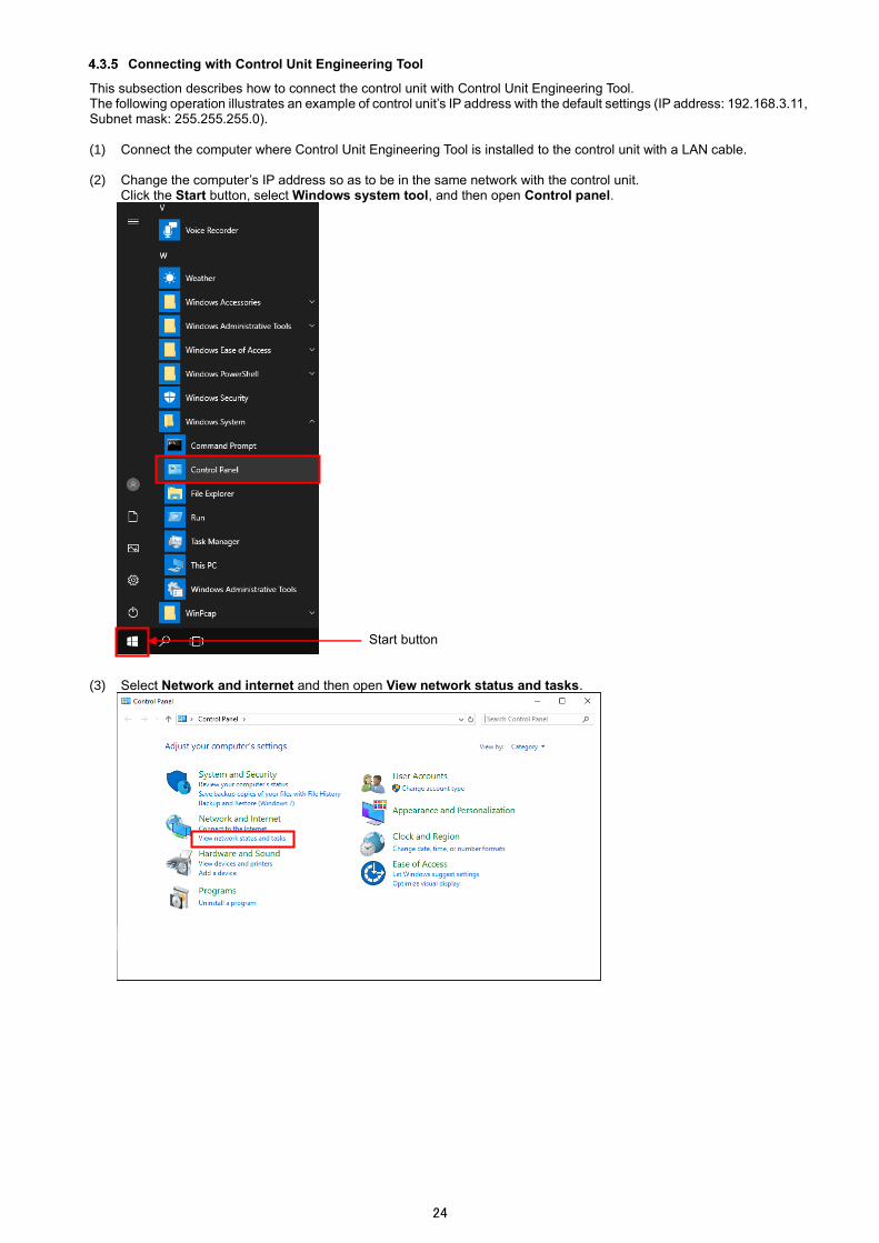
This subsection describes how to connect the control unit with Control Unit Engineering Tool. The following operation illustrates an example of control unit’s IP address with the default settings (IP address: 192.168.3.11, Subnet mask: 255.255.255.0). (1) Connect the computer where Control Unit Engineering Tool is installed to the control unit with a LAN cable.
(2) Change the computer’s IP address so as to be in the same network with the control unit.
Click the Start button, select Windows system tool, and then open Control panel.
(3) Select Network and internet and then open View network status and tasks.
Start button

25
(4) Click Local area connection and then click the Property button.
(5) Select Internet Protocol Version 4 (TCP/IPv4) and then click the Property button.
*If there is no registration in the list, add it. For details, refer to the user’s manual about operating system.

26
(6) Select Use the following address and enter the IP address and subnet mask.
*Write down the setting values before change because they are required when the computer’s IP address is restored to the original one.
The network address parts of the IP address must be the same values as those of the control unit. The host address part of the IP address must be different values from that of the control unit. Neither 0 nor 255 can be set. *1: The network address part of an IP address is any parts that corresponds to 1 of the subnet mask when the IP
address and subnet mask are converted to binary numbers.
<Example>
Network settings of the control unit Network address part Host address part
IP address 192 168 3 11
IP address (binary numbers) 11000000 10101000 00000011 00001011
Subnet mask 255 255 255 0
Subnet mask (binary numbers) 11111111 11111111 11111111 00000000
(7) After the input, click the OK button.
The network information will be automatically updated. Perform the operation according to the message.

27
Connecting/Replacing the Lithium Battery
Caution Do not connect or replace the lithium battery under live line conditions. Otherwise, an electric shock, a product failure, or a fire could be caused.
■To connect the lithium battery (when purchasing)
①Slide the battery cover downward to open it. ②Connect the lithium battery connector to this unit.
Take care to insert the connector with the proper orientation.
③Slide the battery cover upward to fix to this unit.
Take care not to pinch the cable of the lithium battery.
■To replace the lithium battery
①Slide the battery cover downward to open it.
②Disconnect the lithium battery connector from this unit.
③Replace the lithium battery with a new one and connect
the new battery connector to this unit.
④Slide the battery cover upward to fix to the unit.
Take care not to pinch the cable of the lithium battery.
Caution
When the lithium battery is replaced, the present time data is deleted. After the replacement, be sure to set the time.
For details, refer to 10.2 Setting of Clock.

28
5. Control Unit Engineering Tool
This chapter describes the installation of Control Unit Engineering Tool, its operating environment, and basic operation. *Control Unit Engineering Tool can be downloaded for free from the Mitsubishi FA Global site. The site URL is described on the back cover.
5.1 Operating Environment and Installation
Download File Composition
The following shows the download file.
File name Details
Emu4KnetSetup.exe Installer of Control Unit Engineering Tool
Recommended System Environment
The following shows the recommended system specifications for the software running.
Item Details
OS Microsoft Windows 10 Pro 32/64-bit
Language Japanese, English, Simplified Chinese
CPU Depend on the OS system requirements
Memory Depend on the OS system requirements
Hard disk 4GB or more space
Display 1024 × 768 or more
External interface LAN port (100BASE-TX standard)
.NET Framework Microsoft .NET Framework 4.6.2
Installing Control Unit Engineering Tool
Download Control Unit Engineering Tool (Model: EMU4-KNE) for setup. When first setting up this software, be sure to read this chapter for proper setup. (1) From the folder downloaded, start the installer Emu4KnetSetup.exe. (2) The following window appears. Click the Next button.
(3) The following window appears. When you agree with this Software License Agreement to use the software, click the Yes button.

29
(4) The following window appears.
When installing to the default destination folder, click the Next button to start the installation. *The default destination is C¥Mitsubishi¥Emu4Knet¥.
(5) When the installation is completed, the following window appears. Click the Finish button to close the window.
Uninstalling Control Unit Engineering Tool
When Control Unit Engineering Tool is no longer required, it can be easily uninstalled from your computer according to the following procedure. (1) From Start menu, click Settings, select Apps, and open Apps & features. (2) From the list, select Control Unit Engineering Tool and click the Uninstall button.

30
(3) The following confirmation message appears.
Click the Yes button to start the uninstallation.
(4) When the uninstallation is completed, the following window appears. Click the Finish button to close the window.
5.2 Precautions for Operation
While Control Unit Engineering Tool is being operated, it is in communication with the corresponding control unit. During the communication, never turn off the power of the control unit, restart it, remove the LAN cables, or operate the small type display unit. Otherwise, an error will occur in communication between Control Unit Engineering Tool and the control unit, and the operation will not work properly.
5.3 Basic Operation
Starting Control Unit Engineering Tool
Double-click the shortcut on the desktop, or from Start menu, click MITSUBISHI Energy Management and select Control Unit Engineering Tool (MU4-KNET). The software starts. *The default display language is Japanese.
Ending Control Unit Engineering Tool
On the following window (project management window), click the × button to close the window. The software ends.
31
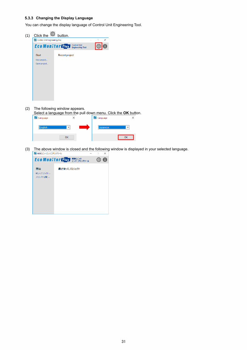
Changing the Display Language
You can change the display language of Control Unit Engineering Tool.
(1) Click the button.
(2) The following window appears.
Select a language from the pull down menu. Click the OK button.
(3) The above window is closed and the following window is displayed in your selected language.

32
Displaying the Version information
You can check the version of Control Unit Engineering Tool.
(1) Click the button.
(2) The version information is displayed. Click the OK button to close the window.

33
5.4 Screen Transition
The following illustrates the screen transition diagram of the software. To return to the previous window screen, click the × button at the upper right of the window.
5.5 Project Management
This section describes the operation of the project, which is a folder to store settings.
Creating the Project
You will create a new project. (1) Click the New project tab
Startup
Project management
System management
Setting menu
Verify settings
Read settings
Set terminals
Set control method
Write network information
Check connection
Write settings
Change RUN/STOP
Maintenance menu
Event log output
Clock setting
Password change
Logging unit setting
IP address check
F/W version check
Measurement value monitoring Control monitoring
Open the project
Select the system
F/W update
34
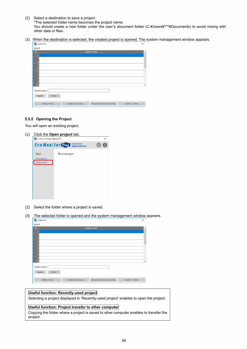
(2) Select a destination to save a project.
*The selected folder name becomes the project name. You should create a new folder under the user’s document folder (C:¥Users¥***¥Documents) to avoid mixing with other data or files.
(3) When the destination is selected, the created project is opened. The system management window appears.
Opening the Project
You will open an existing project. (1) Click the Open project tab.
(2) Select the folder where a project is saved. (3) The selected folder is opened and the system management window appears.
Useful function: Recently-used project
Selecting a project displayed in ‘Recently-used project’ enables to open the project.
Useful function: Project transfer to other computer
Copying the folder where a project is saved to other computer enables to transfer the project.

35
6. Procedure for Setup/Operation
The following shows the overall flow on setup or operation. *To use this unit, it is required to set it up with Control Unit Engineering Tool (EMU4-KNET). The Tool can be downloaded for free from the Mitsubishi FA Global site. The site URL is described on the back cover.
*The following procedure is for one system. When there are multiple systems, conduct the setup/operation for each system.
6.1 First Setup
Operation of Control unit Operation of Control Unit Engineering Tool
Create the project.
Refer to 5.5.1 Creating the Project.
Create the system.
Refer to 7.1 System Management.
Write the network information into the control unit.
Refer to 7.10.1 Writing Network Information.
Connect the parent terminal of control unit and the computer with a LAN cable.
Start
Yes
No
Change the STOP/RUN switch of the parent terminal from RUN to STOP.
To the next page
Set up the network information for each control unit in the system.
Refer to 7.5 Setting of Terminals.
Have you set up the network information for every control unit in the system?
Make a one-to-one connection between the control unit and the computer with a LAN cable.
Yes
No Have you set up the password for every control unit in the system?
Set up the password of the control unit.
Refer to 10.. Change of Password.
Connect the lithium battery to the control unit.
For details, refer to 4...6 Connecting/Replacing the Lithium Battery.
Turn on the auxiliary power of the control unit.
Connect the lithium battery in a non-energized state.
Make a one-to-one connection between the control unit and the computer with a LAN cable.

36
Operation of Control unit Operation of Control Unit Engineering Tool
Create the settings for control method.
・Interlocking control…refer to 7.7.
・Compressor control…Refer to 7.8.
・Schedule control…Refer to 7.9.
Continued from the previous page
Change the control operation state of the control unit to RUN.
It can be changed both from the unit and from the software. Execute it from either of them.
Control unit operation Software operation
Set the STOP/RUN switch of the unit to RUN. Change the control operation state of the unit.
Refer to 7.1. Change of RUN/STOP.
Setting the control operation state to RUN starts the control. Execute it in good condition to operate.
Set up the extension unit with the small type display unit.
Refer to Small Type Display Unit for Energy Measuring Unit User’s Manual (Details).
Connect the parent terminal and the computer with a LAN cable.
Adjust the parent terminal clock to the present time.
Refer to 10.2 Setting of Clock.
Write the created settings into the control unit.
Refer to 7.12 Write of Settings.
Perform the wiring of MODBUS RTU communication for every control unit in the system.
Check the wiring connection.
Refer to 7.11 Check of Connection.
Yes
No Is the connection check result normal?
If an extension unit is connected to the parent terminal, finish the connection and the wiring of the extension unit side by this point.
End
If the result is not normal, check the connection result, network settings, or communication lines to identify the source and eliminate it.
Execute the manual control.
Refer to 9.2 Manual Control of output. *If not necessary, move to the next step.
Connect the control target equipment and each control unit.

37
6.2 Basic Operation
The following table describes the procedure of each operation. Reference Item Details
6.2.1 Checking the control status How to check the present control status of each control unit.
6.2.2 Manually operating the contact output/analog output
How to manually control the contact output/analog output of the control unit.
6.2.3 Changing the control setting
How to change the control setting. (but not the control type)
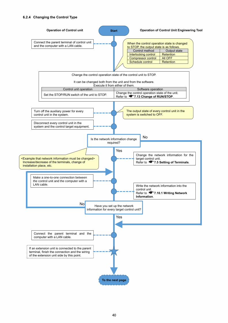
6.2.4 Changing the control type How to change the control type.
6.2.5 Changing the IP address How to change the IP address of the parent terminal.
6.2.6 Setting the clock How to set the control unit clock to the present time. *The clock accuracy is five minute per month difference. Check the clock time regularly, and if there is a difference, adjust the time.
*When the clock is reset due to battery exhaustion or its replacement, this item should be referred.
6.2.7 Acquiring the event log (The latest 10 logs)
How to output the event logs from the control unit without stopping control. *The latest 10 event logs are output.
6.2.8 Acquiring the event log (All logs)
How to output the event logs from the control unit with control stopped. *All the event logs are output that the control unit stores.
6.2.9 Updating the firmware How to update the firmware of the control unit.
6.2.10 Changing the control setting with updating the firmware
How to change the control setting but not the control type at the same time when the firmware of the control unit is updated.
Checking the Control Status
Operation of Control unit Operation of Control Unit Engineering Tool
Check the control status of the control unit on the control monitor window.
Refer to 9 Control Monitoring.
Connect the parent terminal of control unit and the computer with a LAN cable.
End
Start
38
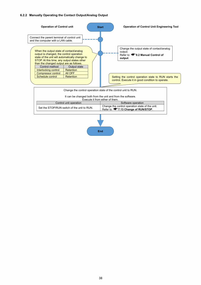
Manually Operating the Contact Output/Analog Output
Operation of Control unit Operation of Control Unit Engineering Tool
Change the output state of contact/analog output.
Refer to 9.2 Manual Control of output.
End
Start
Connect the parent terminal of control unit and the computer with a LAN cable.
Change the control operation state of the control unit to RUN.
It can be changed both from the unit and from the software. Execute it from either of them.
Control unit operation Software operation
Set the STOP/RUN switch of the unit to RUN. Change the control operation state of the unit.
Refer to 7.1. Change of RUN/STOP.
Setting the control operation state to RUN starts the control. Execute it in good condition to operate.
When the output state of contact/analog output is changed, the control operation state of the unit will automatically change to STOP. At this time, any output states other than the changed output are as follows.
Control method Output state
Interlocking control Retention
Compressor control All OFF
Schedule control Retention

39
Changing the Control Setting
Operation of Control unit Operation of Control Unit Engineering Tool
Change the settings for control method.
・Interlocking control…refer to 7.7.
・Compressor control…Refer to 7.8.
・Schedule control…Refer to 7.9.
Change the control operation state of the control unit to RUN.
It can be changed both from the unit and from the software. Execute it from either of them.
Control unit operation Software operation
Set the STOP/RUN switch of the unit to RUN. Change the control operation state of the unit.
Refer to 7.1. Change of RUN/STOP.
Connect the parent terminal of control unit and the computer with a LAN cable.
Change the control operation state of the control unit to STOP.
It can be changed both from the unit and from the software. Execute it from either of them.
Control unit operation Software operation
Set the STOP/RUN switch of the unit to STOP. Change the control operation state of the unit.
Refer to 7.1. Change of RUN/STOP.
Write the changed settings into the control unit.
Refer to 7.12 Write of Settings.
Setting the control operation state to RUN starts the control. Execute it in good condition to operate.
Start
End
When the control operation state is changed to STOP, the output state is as follows.
Control method Output state
Interlocking control Retention
Compressor control All OFF
Schedule control Retention
40
Changing the Control Type
Operation of Control Unit Engineering Tool
Write the network information into the control unit.
Refer to 7.10.1 Writing Network Information.
If an extension unit is connected to the parent terminal, finish the connection and the wiring of the extension unit side by this point.
Start
Yes
No
To the next page
Change the network information for the target control unit.
Refer to 7.5 Setting of Terminals.
Connect the parent terminal of control unit and the computer with a LAN cable.
Change the control operation state of the control unit to STOP.
It can be changed both from the unit and from the software. Execute it from either of them.
Control unit operation Software operation
Set the STOP/RUN switch of the unit to STOP. Change the control operation state of the unit.
Refer to 7.1. Change of RUN/STOP.
Turn off the auxiliary power for every control unit in the system.
The output state of every control unit in the system is switched to OFF.
Disconnect every control unit in the system and the control target equipment.
Yes
Have you set up the network information for every target control unit?
No Is the network information change
required?
Operation of Control unit
Connect the parent terminal and the computer with a LAN cable.
When the control operation state is changed to STOP, the output state is as follows.
Control method Output state
Interlocking control Retention
Compressor control All OFF
Schedule control Retention
<Example that network information must be changed> Increase/decrease of the terminals, change of installation place, etc.
Make a one-to-one connection between the control unit and the computer with a LAN cable.

41
Operation of Control unit Operation of Control Unit Engineering Tool
Create the settings for control method.
・Interlocking control…refer to 7.7.
・Compressor control…Refer to 7.8.
・Schedule control…Refer to 7.9.
Continued from the previous page
End
Change the control operation state of the control unit to RUN.
It can be changed both from the unit and from the software. Execute it from either of them.
Control unit operation Software operation
Set the STOP/RUN switch of the unit to RUN. Change the control operation state of the unit.
Refer to 7.1. Change of RUN/STOP.
Setting the control operation state to RUN starts the control. Execute it in good condition to operate.
Set up the extension unit with the small type display unit.
Connect the parent terminal and the computer with a LAN cable.
Perform the wiring of MODBUS RTU communication for every control unit in the system.
Check the wiring connection.
Refer to 7.11 Check of Connection.
Yes
No Is the connection check result normal?
Set the parent terminal clock to the present time.
Refer to 10.2 Setting of Clock.
Connect the control target equipment and each control unit.
Write the created settings into the control unit.
Refer to 7.12 Write of Settings.
If the result is not normal, check the connection result, network settings, or communication lines to identify the source and eliminate it.
Execute the manual control.
Refer to 9.2 Manual Control of output. *If not necessary, move to the next step.

42
Changing the IP Address
Operation of Control unit Operation of Control Unit Engineering Tool
End
Change the control operation state of the control unit to RUN.
It can be changed both from the unit and from the software. Execute it from either of them.
Control unit operation Software operation
Set the STOP/RUN switch of the unit to RUN. Change the control operation state of the unit.
Refer to 7.1. Change of RUN/STOP.
Setting the control operation state to RUN starts the control. Execute it in good condition to operate.
Start
Make a one-to-one connection between the target control unit and the computer with a LAN cable.
Change the control operation state of the control unit to STOP.
It can be changed both from the unit and from the software. Execute it from either of them.
Control unit operation Software operation
Set the STOP/RUN switch of the unit to STOP. Change the control operation state of the unit.
Refer to 7.1. Change of RUN/STOP.
Write the network information into the control unit.
Refer to 7.10.1 Writing Network Information.
Change the network information for the control unit.
Refer to 7.5 Setting of Terminals.
When the control operation state is changed to STOP, the output state is as follows.
Control method Output state
Interlocking control Retention
Compressor control All OFF
Schedule control Retention
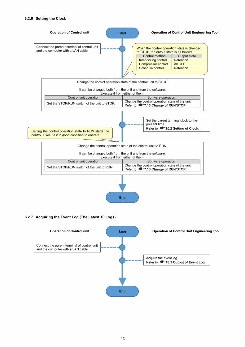
43
Setting the Clock
Acquiring the Event Log (The Latest 10 Logs)
Operation of Control unit Operation of Control Unit Engineering Tool
Change the control operation state of the control unit to RUN.
It can be changed both from the unit and from the software. Execute it from either of them.
Control unit operation Software operation
Set the STOP/RUN switch of the unit to RUN. Change the control operation state of the unit.
Refer to 7.1. Change of RUN/STOP.
Connect the parent terminal of control unit and the computer with a LAN cable.
Change the control operation state of the control unit to STOP.
It can be changed both from the unit and from the software. Execute it from either of them.
Control unit operation Software operation
Set the STOP/RUN switch of the unit to STOP. Change the control operation state of the unit.
Refer to 7.1. Change of RUN/STOP.
Set the parent terminal clock to the present time.
Refer to 10.2 Setting of Clock.
Start
Setting the control operation state to RUN starts the control. Execute it in good condition to operate.
End
When the control operation state is changed to STOP, the output state is as follows.
Control method Output state
Interlocking control Retention
Compressor control All OFF
Schedule control Retention
Operation of Control unit Operation of Control Unit Engineering Tool
End
Start
Connect the parent terminal of control unit and the computer with a LAN cable.
Acquire the event log.
Refer to 10.1 Output of Event Log.

44
Acquiring the Event Log (All Logs)
Operation of Control unit Operation of Control Unit Engineering Tool
Acquire the event log.
Refer to 10.1 Output of Event Log.
Change the control operation state of the control unit to RUN.
It can be changed both from the unit and from the software. Execute it from either of them.
Control unit operation Software operation
Set the STOP/RUN switch of the unit to RUN. Change the control operation state of the unit.
Refer to 7.1. Change of RUN/STOP.
Setting the control operation state to RUN starts the control. Execute it in good condition to operate.
Change the control operation state of the control unit to STOP.
It can be changed both from the unit and from the software. Execute it from either of them.
Control unit operation Software operation
Set the STOP/RUN switch of the unit to STOP. Change the control operation state of the unit.
Refer to 7.1. Change of RUN/STOP.
Connect the parent terminal of control unit and the computer with a LAN cable.
Start
End
When the control operation state is changed to STOP, the output state is as follows.
Control method Output state
Interlocking control Retention
Compressor control All OFF
Schedule control Retention

45
Updating the Firmware
Operation of Control Unit Engineering Tool
End
Check the F/W version of every control unit in the system.
Refer to 10.6 Check of F/W Version.
Change the control operation state of the control unit to RUN.
It can be changed both from the unit and from the software. Execute it from either of them.
Control unit operation Software operation
Set the STOP/RUN switch of the unit to RUN. Change the control operation state of the unit.
Refer to 7.1. Change of RUN/STOP.
Setting the control operation state to RUN starts the control. Execute it in good condition to operate.
Connect the parent terminal of control unit and the computer with a LAN cable.
Change the control operation state of the control unit to STOP.
It can be changed both from the unit and from the software. Execute it from either of them.
Control unit operation Software operation
Set the STOP/RUN switch of the unit to STOP. Change the control operation state of the unit.
Refer to 7.1. Change of RUN/STOP.
By manual operation, the output of every control unit is switched to OFF.
Refer to 9.2 Manual Control of output.
Update the F/W version of the control unit.
Refer to 10.7 Update of F/W.
Connect the parent terminal and the computer with a LAN cable.
No
Connect the control unit and the computer with a LAN cable.
Yes
No
Yes
Have you updated the F/W version of every control unit in the system to the latest version?
Have you checked that the F/W version of every unit in the system has been updated to the latest version?
Refer to 10.6 Check of F/W Version.
Operation of Control unit Start
When the control operation state is changed to STOP, the output state is as follows.
Control method Output state
Interlocking control Retention
Compressor control All OFF
Schedule control Retention

46
Changing the Control Setting with Updating the Firmware
Operation of Control unit Operation of Control Unit Engineering Tool
End
Start
Check the F/W version of every control unit in the system.
Refer to 10.6 Check of F/W Version.
Change the control operation state of the control unit to RUN.
It can be changed both from the unit and from the software. Execute it from either of them.
Control unit operation Software operation
Set the STOP/RUN switch of the unit to RUN. Change the control operation state of the unit.
Refer to 7.1. Change of RUN/STOP.
Setting the control operation state to RUN starts the control. Execute it in good condition to operate.
Connect the parent terminal of control unit and the computer with a LAN cable.
Change the control operation state of the control unit to STOP.
It can be changed both from the unit and from the software. Execute it from either of them.
Control unit operation Software operation
Set the STOP/RUN switch of the unit to STOP. Change the control operation state of the unit.
Refer to 7.1. Change of RUN/STOP.
By manual operation, the output of every control unit is switched to OFF.
Refer to 9.2 Manual Control of output.
Update the F/W version of the control unit.
Refer to 10.7 Update of F/W.
Connect the control unit and the computer with a LAN cable.
No
Connect the parent terminal and the computer with a LAN cable.
Yes
No
Yes Change the settings for control method.
・Interlocking control…refer to 7.7.
・Compressor control…Refer to 7.8.
・Schedule control…Refer to 7.9.
Write the changed settings into the control unit.
Refer to 7.12 Write of Settings.
Have you updated the F/W version of every control unit in the system to the latest version?
Have you checked that the F/W version of every unit in the system has been updated to the latest version?
Refer to 10.6 Check of F/W Version.
When the control operation state is changed to STOP, the output state is as follows.
Control method Output state
Interlocking control Retention
Compressor control All OFF
Schedule control Retention

47
6.3 Operation for Replacing/Removing the Control Unit
Replacing the Control Unit due to its Failure
Operation of Control unit Operation of Control Unit Engineering Tool
To the next page
Enter the network information for the replaced control unit.
Refer to 7.5 Setting of Terminals.
Connect the parent terminal of control unit and the computer with a LAN cable.
Change the control operation state of the control unit to STOP.
It can be changed both from the unit and from the software. Execute it from either of them.
Control unit operation Software operation
Set the STOP/RUN switch of the unit to STOP. Change the control operation state of the unit.
Refer to 7.1. Change of RUN/STOP.
Replace the failing control units.
Connect the lithium battery to the replaced control unit.
Refer to 4...6 Connecting/Replacing the Lithium Battery.
Make a one-to-one connection between the replaced control unit and the computer with a LAN cable.
Yes
No Have you set up the password for
every replaced control unit?
Set up the password of the control unit.
Refer to 10.. Change of Password.
Write the network information into the
control unit. Refer to 7.10.1 Writing Network Information.
Yes
No Have you set up the network information for every replaced
control unit?
Start
When the control operation state is changed to STOP, the output state is as follows.
Control method Output state
Interlocking control Retention
Compressor control All OFF
Schedule control Retention
Turn off the power and external power supply for contact output of every control unit in the system.
Make a one-to-one connection between the control unit and the computer with a LAN cable.
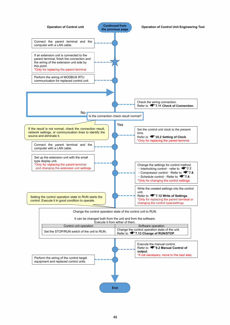
48
Operation of Control unit Operation of Control Unit Engineering Tool
Change the settings for control method.
・Interlocking control…refer to 7.7.
・Compressor control…Refer to 7.8.
・Schedule control…Refer to 7.9.
*Only for changing the control settings
Continued from the previous page
End
Change the control operation state of the control unit to RUN.
It can be changed both from the unit and from the software. Execute it from either of them.
Control unit operation Software operation
Set the STOP/RUN switch of the unit to RUN. Change the control operation state of the unit.
Refer to 7.1. Change of RUN/STOP.
Setting the control operation state to RUN starts the control. Execute it in good condition to operate.
Execute the manual control.
Refer to 9.2 Manual Control of output. *If not necessary, move to the next step.
Set up the extension unit with the small type display unit. *Only for replacing the parent terminal and changing the extension unit settings.
Connect the parent terminal and the computer with a LAN cable.
Set the control unit clock to the present time.
Refer to 10.2 Setting of Clock. *Only for replacing the parent terminal
Perform the wiring of the control target equipment and replaced control units.
Write the created settings into the control unit.
Refer to 7.12 Write of Settings. *Only for replacing the parent terminal or changing the control type/settings.
Perform the wiring of MODBUS RTU communication for replaced control unit.
Check the wiring connection.
Refer to 7.11 Check of Connection.
Yes
No Is the connection check result normal?
Connect the parent terminal and the computer with a LAN cable.
If an extension unit is connected to the parent terminal, finish the connection and the wiring of the extension unit side by this point. *Only for replacing the parent terminal
If the result is not normal, check the connection result, network settings, or communication lines to identify the source and eliminate it.

49
Removing the Control Unit
*For the procedure for reinstallation or operation from the beginning, refer to 6.1 First Setup.
Operation of Control unit Operation of Control Unit Engineering Tool Start
Connect the parent terminal of control unit and the computer with a LAN cable.
Change the control operation state of the control unit to STOP.
It can be changed both from the unit and from the software. Execute it from either of them.
Control unit operation Software operation
Set the STOP/RUN switch of the unit to STOP. Change the control operation state of the unit.
Refer to 7.1. Change of RUN/STOP.
Remove the control unit.
Turn off the auxiliary power and external power supply for contact output of the control unit.
When the auxiliary power of the control unit is turned off, the output state is all switched to OFF.
Work in a non-energized state.
End
When the control operation state is changed to STOP, the output state is as follows.
Control method Output state
Interlocking control Retention
Compressor control All OFF
Schedule control Retention

50
7. Setting Operation
The control unit settings are conducted from Control Unit Engineering Tool. This chapter describes the system management window and setting menu related to settings about control.
7.1 System Management
On the following window, you will register, change, or delete the system. Each operation of setting, monitoring, and maintenance is executed on a registered system basis. Click the following appropriate tab to move to the screen for each operation.
Registering/Changing the System Information
(1) Select an ID to register or to change the system name. The selected line is displayed in blue.
① ② ③ ④
Button name Details Reference
① Setting menu Open the setting menu such as terminal or control setting 7.2
② Maintenance menu Open the maintenance menu such as clock setting or
firmware update. 10
③ Measurement value monitoring
Open the window to monitor the measurement values measured by the extension unit connected to the parent terminal of control unit.
8
④ Control monitoring Open the window to monitor the control status in the system
or to manually control. 9

51
(2) Enter a name to register in the system name field and then click the Register button.
*The following characters are not available: ¥ / : * ? ” < > | , *The leading whitespace is not considered as characters.
(3) Register the system name to the selected ID or change the selected ID system name by entering an arbitrary name.
Deleting the System
(1) Select a system to delete. The selected line is displayed in blue.
Useful function: Copy of system
The following procedure is used to copy any arbitrary system. The terminal and control settings of the system are also copied from the copy source to the copy destination.
(1) Select a system to copy. Press the Ctrl and C key in that state. (2) Select an ID of no registration. (3) Press the Ctrl and V key. The selected system at (1) has been copied.
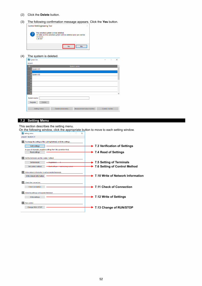
52
(2) Click the Delete button.
(3) The following confirmation message appears. Click the Yes button.
(4) The system is deleted.
7.2 Setting Menu
This section describes the setting menu. On the following window, click the appropriate button to move to each setting window.
7.. Verification of Settings
7.10 Write of Network Information
7.4 Read of Settings
7.5 Setting of Terminals
7.6 Setting of Control Method
7.11 Check of Connection
7.12 Write of Settings
7.1. Change of RUN/STOP
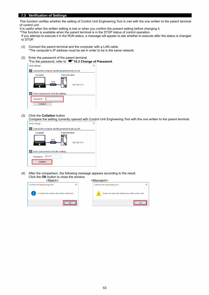
53
7.3 Verification of Settings
This function verifies whether the setting of Control Unit Engineering Tool is met with the one written to the parent terminal of control unit. It is useful when the written setting is lost or when you confirm the present setting before changing it. *This function is available when the parent terminal is in the STOP status of control operation. If you attempt to execute it in the RUN status, a message will appear to ask whether to execute after the status is changed to STOP. (1) Connect the parent terminal and the computer with a LAN cable.
*The computer’s IP address must be set in order to be in the same network.
(2) Enter the password of the parent terminal.
*For the password, refer to 10.. Change of Password.
(3) Click the Collation button.
Compare the setting currently opened with Control Unit Engineering Tool with the one written to the parent terminal.
(4) After the comparison, the following message appears according to the result.
Click the OK button to close the window. <Match> <Mismatch>

54
7.4 Read of Settings
This function reads the settings of the parent terminal of control unit. It is useful when the verification result is mismatch at 7.. Verification of Settings or when the backup is executed for settings written to the parent terminal. *This function is available when the parent terminal is in the STOP status of control operation. If you attempt to execute it in the RUN status, a message will appear to ask whether to execute after the status is changed to STOP.
*If the read of the parent terminal settings is executed, the settings of the selected system on Control Unit Engineering Tool will be overwritten and not be returned to their previous values. (1) Connect the parent terminal and the computer with a LAN cable.
*The computer’s IP address should be set in order to be in the same network.
(2) Enter the password of the parent terminal.
*For the password, refer to 10.. Change of Password.
(3) Click the Reading button to read the settings from the parent terminal.
(4) After the read, the following message appears.
Click the OK button to close the window.

55
7.5 Setting of Terminals
You will set the settings for the terminal units that constitute the system. Register the settings corresponding to the terminal to be actually used.
Adding the Child Terminal of Control Unit
(1) Click the Add button.
(2) The child terminal is added to the terminal list.

56
Deleting the Child Terminal of Control Unit
(1) Select a child terminal to delete and then click the Delete button.
(2) The selected child terminal is deleted.
*If some terminal ID numbers exists that are larger than the deleted terminal ID in the child terminals, the ID numbers will be changed to assign consecutive numbers to every ID.

57
Registering/Changing Information on the Control Unit
You will register or change the terminal information on the control unit (parent/child terminal). (1) Register each item.
*The registration information differs depending on the terminal type (parent/child terminal) or the existence of child terminals in the system.
■For the parent terminal without any child terminal in the system
■For the parent terminal with some child terminals in the system
■For any child terminals

58
⭘: Configurable ×: No settings required -: No setting items
Item Details
Parent terminal Child
terminal Without
child terminals
With child
terminals
Unit configuration Register the model and name of the terminal units that constitute the system.
Model name Only when an extension unit is used, set this item. Select the extension unit model from the pull-down menu.
・Blank (no extension unit) ・EMU4-A2
・EMU4-AX4 ・EMU4-VA2
・EMU4-PX4
When the extension unit, EMU4-A2, is selected, EMU4-VA2 must be set to an extension unit field above EMU4-A2.
⭘ ⭘ -
Unit name Enter a name of the unit. A maximum of 30 characters are allowed in the input field.
○ ⭘ ○
Network information for Ethernet
Register the settings for the network connecting to a computer. This setting is for the parent terminal only.
IP address Enter an IP address. Setting range: 1.0.0.0 to 126.255.255.255
128.0.0.0 to 191.255.255.255 192.0.0.0 to 223.255.255.255
*0.0.0.0 and xxx.xxx.xxx.255 (xxx is an arbitrary number available.) are not available.
Default: 192.168.3.11
○ ○ ×
Subnet mask Enter a subnet mask. When it is expressed in binary numbers, set the numbers fulfilling the following conditions:
・The most significant bit is 1.
・Do not enter 0 between 1 and 1.
・The least significant bit is 0.
・255.255.255.254 is not available. Default: 255.255.255.0
○ ○ ×
Default gateway Enter a default gateway. *0.0.0.0 and xxx.xxx.xxx.255 (xxx is an arbitrary number available.) are not available.
Default: Blank
○ ○ ×
Network information for MODBUS RTU
Register the settings for MODBUS RTU communication. For the parent terminal without any child terminal in the system, it is set to communicate with the superior monitoring systems. For any child terminals, it is set to communicate with the parent terminal.
Slave address Set the Slave address. The same address as other terminals cannot be set repeatedly. Setting range: 1 to 247 (Default: 1) *For the parent terminal without any child terminal in the system, set a different address from other terminals in the same MODBUS RTU communication network.
○ - ○
Baud rate *1 Select a baud rate from the pull-down menu.
・2400 ・19200 (Default)
・4800 ・38400
・9600
○ - -
Parity Select a parity bit from the pull-down menu.
・NONE ・ODD ・EVEN (Default)
○ - -
Stop bit Select a stop bit from the pull-down menu.
・1 (Default) ・2
○ - -
*1: For the parent terminal with some child terminals in the system or for any child terminals, the baud rate is set to 19200.
(2) Click the Register button to save the settings.

59
7.6 Setting of Control Method
You will set the control type of the system.
(1) Click the Set control method button in the setting menu.
(2) The following message appears. Select a control type from the pull-down menu and then click the Register button.
*When the control type is changed, the following message appears. To continue the current setting, click the Yes button. Note that in this case, the control settings before change is deleted. To cancel the setting change of control type not to delete the currently registered settings, click the No button.
(3) The window appears to set the settings for the control type you have selected.
For details on each control type settings, refer to the following:
・Interlocking control … 7.7 Interlocking Control
・Compressor control … 7.8 Compressor Control
・Schedule control … 7.9 Schedule Control
The current control type
<Control type>
・Interlocking control
・Compressor control
・Schedule control

60
7.7 Interlocking Control
Interlocking control is a control type that an ON/OFF contact output or an analog output value varies according to a measurement value measured by the extension unit. The maximum output number of contact output/analog output varies depending on the number of control units in the system.
Output Number of outputs Maximum number of outputs
Contact output The number of control units in the system × 3 96
Analog output The number of control units in the system 32
The control unit collects a measurement value from the extension unit every minute, and the conditional expression set in advance determines the state of contact output/analog output. After that, in the next period (1 minute), the output state is controlled. *The measurement value of the extension unit represents a measurement value for a few seconds from every minute (**:**:00).
<Contact output control>
The contact output control function executes a comparison between a measurement value and the constant, between measurement values, or between contact states, and in accordance with the comparison result, controls the ON/OFF contact output. The control execution timing is 1 minute. In addition, by executing the two type comparisons, the logical sum (OR) or logical multiply (AND) of each comparison result provides the ON/OFF contact output control. The measurement values to be used for comparison are selected from the measurement items in Energy Measuring Unit Extension model for same voltage system (Model: EMU4-A2), Energy Measuring Unit Extension model for different voltage system (Model: EMU4-VA2), or Energy Measuring Unit Extension model for analog input (Model: EMU4-AX4) that is connected to the control unit. *The measurement items measuring integrated values are not selectable.
00 min
Collect a measurement value and the conditional expression determines the output.
Output control (ON)
59 min 01 min
Threshold
Measurement value
Action of control unit
Collected Collected Collected
Control Control
Collect a measurement value and the conditional expression determines the output.
Output control (OFF)
Collect a measurement value and the conditional expression determines the output.
Output control (ON)
[Conditional expression] Measurement value > Threshold: Contact output is ON.
[Conditional expression A] Measurement value < Threshold: ON
Determination result A OFF OFF ON ON
[Conditional expression B] Measured value > Threshold: ON
Determination
result B OFF ON ON OFF
Action of control unit
Contact output Logical multiply
(AND) OFF OFF ON
Contact output Logical sum (OR) OFF ON ON
Collect a measurement value and the conditional expression determines the output.
Collect a measurement value and the conditional expression determines the output.
Measurement value
Threshold
00 min 59 min 01 min
Threshold
Measurement value

61
<Control timing delay setting>
For the contact output, setting the delay time for ON and delay time for OFF enables to delay the control execution timing. When the control unit collects the next measurement value and ends a determination by the conditional expression, if the determination are different from a scheduled output, a new output determination will be employed.
00 min
Threshold
Measurement value
Collected
Action of control unit
Collect a measurement value and the conditional expression determines the output.
Collect a measurement value and the conditional expression determines the output.
Output control (OFF)
Output control (ON)
Output control (ON)
[Conditional expression] When a measurement value exceeds the threshold, the contact output is ON. Delay time for ON: None Delay time for OFF: None
01 min
Collected Collected
Control Control
59 min
Collect a measurement value and the conditional expression determines the output.
The delay of 60 seconds from the original control timing
[Conditional expression] When a measurement value exceeds the threshold, the contact output is ON. Delay time for ON: 60 seconds Delay time for OFF: 60 seconds
Control (ON)
If the determination result (ON/OFF) is switched during the delay time, the latest determination will be employed.
59 min 00 min 01 min 02 min
Threshold
Measurement value
Action of control unit
Collect a measurement value and the conditional expression determines the output.
Output control (ON) Control (OFF)
Control (ON) Control (ON)
Output control (ON)
Collect a measurement value and the conditional expression determines the output.
Collect a measurement value and the conditional expression determines the output.
Collect a measurement value and the conditional expression determines the output.
Collected Collected Collected Collected
[Conditional expression] When a measurement value exceeds the threshold, the contact output is ON. Delay time for ON: 90 seconds Delay time for OFF: 90 seconds
Control (ON)
If the determination result (ON/OFF) is switched during the delay time, the latest determination will be employed.
59 min
Threshold
Measurement value
Action of control unit
Collect a measurement value and the conditional expression determines the output.
Output control (ON) (ON)
Control (OFF)
Control (ON)
Control (ON)
Output control (ON)
Collect a measurement value and the conditional expression determines the output.
Collect a measurement value and the conditional expression determines the output.
Collect a measurement value and the conditional expression determines the output.
Collected Collected
The delay of 90 seconds from the original control timing
Collected Collected
00 min 01 min 02 min

62
<Analog output control>
The analog output control function calculates the analog output value corresponding to a measurement value by setting the upper/lower limit of the measurement value, and controls the output. In addition, setting the upper/lower limit value of analog output enables to change the output range. The measurement value is selected from the measurement items in Energy Measuring Unit Extension model for same voltage system (Model: EMU4-A2), Energy Measuring Unit Extension model for different voltage system (Model: EMU4-VA2), or Energy Measuring Unit Extension model for analog input (Model: EMU4-AX4) that is connected to the control unit. *The measurement items measuring integrated values are not selectable. *The following chart shows a measurement value and analog output value with positive gradient. It is possible to set a chart with negative gradient.
Caution
<Notes about measurement value> When a scaling value measured by the analog input unit (Model: EMU4-AX4) is used as a measurement value, the scaling value must be set with the optional small type display unit (Model: EMU4-D65).
For details on the scaling value, refer to Energy Measuring Unit Extension Model for Analog Input User’s Manual (Details).
For details on how to set the scaling value, refer to Small Type Display Unit for Energy Measuring Unit User’s Manual (Details).
Analog output value (4 to 20 mA/0 to 5 V)
20 mA/5 V
4 mA/0 V
Actual range of analog output
Measurement value
Upper limit
Lower limit
Upper limit
Lower limit
Lower limit Upper limit
Measurement value

63
Registering/Changing the Interlocking Control Setting (Contact Output)
(1) Select a terminal’s output to set from the left table on the window. The selected field is displayed in blue.
(2) Enter an output name.
A maximum of 30 characters are allowed in the input field.
(3) Register a conditional expression to set the contact to ON. Click the ... button. The following window appears.
On the above window, the conditional expression is set up to determine the ON/OFF contact output. There are two patterns for conditional expression as the following table.
Comparison method Details
Measurement value comparison A method to compare a measurement value measured by the extension unit with the constant or other measuring point.
Contact state comparison A method to compare whether the contact input state measured by the extension unit is ON or OFF.

64
<How to set the measurement value comparison>
(a) Select Comparison of measurement value.
(b) Click the ... button.
(c) The following window appears. Select a unit (circuit) and its measurement item in that order to set a standard measuring point for conditional expression.
*The measurement items measuring integrated values are not selectable. *Depending on the wiring or settings, some measurement items not measured may be displayed. If these measuring points are selected, the control execution will not be correctly done. Therefore, do not select the measurement items not measured by the extension unit.
(d) Click the OK button to determine the standard measuring point. Return to the conditional expression setting window.
(e) Select an inequality sign (> or <) from the pull-down menu.
When EMU4-A2 or EMU4-VA2 is set, select the circuit.

65
(f) A value for comparison will be set for the standard measuring point. Select constant or measurement item from the pull-down menu. For constant, enter a value to the right. For measurement item, select a measuring point in the same way as (b) to (d) above.
■For constant
■For measurement item
(g) Confirm the settings. Click the OK button to close the window.
<How to set the contact state comparison>
(a) Select Comparison of contact state.
(b) Click the ... button.
(c) The following window appears. Select a unit and its measurement item in that order to set a standard measuring point for conditional expression.
*For this setting, only EMU4-PX4, with measurement items of contact input state, is selectable.

66
(d) Click the OK button to determine the standard measuring point. Return to the conditional expression setting window.
(e) Select ON or OFF from the pull-down menu.
(f) Click the OK button to determine the settings and close the window.
(4) When multiple conditional expressions are set at (3) above, set the combination of each conditional expression with the radio button.
Item Details
OR If either of the conditional expressions is met, the contact output will be switched to ON.
AND If both of the conditional expressions are met, the contact output will be switched to ON.
(5) Set the control delay time for the ON/OFF contact output execution.
The setting ranges from 0 to 3,600 seconds.
(6) Click the Register button to save the settings.
Useful function: Copy of interlocking control (contact output)
The following procedure is used to copy any desired control setting of contact output. (1) Select a control setting of contact output to copy. Press the Ctrl and C key in that state. (2) Select a field of no registration.
*It is impossible to copy to an analog output field. (3) Press the Ctrl and V key. The selected control setting at (1) has been copied.

67
Registering/Changing the Interlocking Control Setting (Analog Output)
(1) Select a terminal’s output to set from the left table on the window. The selected field is displayed in blue.
(2) Enter an output name.
A maximum of 30 characters are allowed in the input field.
(3) Select an analog output range from the pull-down menu. (0 V to 5 V or 4 mA to 20 mA)
(4) Set a standard measurement item for analog output value.
Click the ... button.

68
(5) The following window appears.
Select a unit (circuit) and its measurement item in that order to set a standard measuring point for conditional expression.
*The measurement items measuring integrated values are not selectable. *Depending on the wiring or settings, some measurement items not measured may be displayed. If these measuring points are selected, the control execution will not be correctly done. Therefore, do not select the measurement items not measured by the extension unit.
(6) Click the OK button to determine the standard measuring point.
Return to the interlocking control setting window.
When EMU4-A2 or EMU4-VA2 is set, select the circuit.

69
(7) Set the analog output conditions.
Refer to How to determine the analog output conditions in the next page to set a value or unit of each item.
No. Setting item Details
① Gradient Select a gradient of correlation between a measurement value and an analog output value. Positive: When a measurement value increases, an analog output value
increases. Negative: When a measurement value increases, an analog output value
decreases.
② Unit Select or enter a unit of output scaling value. A maximum of 8 characters are allowed in the input field.
・A ・mA ・kA ・V ・kV ・W
・kW ・MW ・Hz ・N ・kN ・Pa
・kPa ・MPa ・°C ・° ・% ・(Blank)
③ Output scaling Max value Set each output scaling value. The setting ranges up to 11 digits, including max three digits after the decimal point.
In addition, set each value so as to be ③≧⑤≧⑥≧④ and ③>④.
④ Output scaling Min value
⑤ Output scaling upper limit value
⑥ Output scaling lower limit value
⑦ Measurement value upper limit Set each measurement value for ⑤ and ⑥.
The setting ranges up to 11 digits, including max three digits after the decimal point.
⑧ Measurement value lower limit
(8) Click the Register button to save the settings.
② ③
④
⑤
⑥
⑦ ⑧
①
Useful function: Copy of interlocking control (analog output)
The following procedure is used to copy any desired control setting of analog output. (1) Select a control setting for analog output to copy. Press the Ctrl and C key in that state. (2) Select a field of no registration.
*It is impossible to copy to a contact output field. (3) Press the Ctrl and V key. The selected control setting at (1) has been copied.

70
How to determine the analog output condition
The following illustrates an example of how to determine the analog output conditions.
・Output range: 4 mA to 20 mA
・Gradient: positive (1) First, determine the analog output range with a measurement value measured by the extension unit.
The example here is a temperature for measurement value, and 50℃ and 10℃ are set for A and B respectively.
At this time, A and B represent the measurement value upper limit and measurement value lower limit respectively. (2) Next, consider the equipment, which uses the analog output of the control unit for input, as a standard.
Calculate the values to be converted from the equipment side for the following four inputs: ・20 mA ・4mA ・A´ (Analog output value to the measurement value upper limit ・B´ (Analog output value to the measurement value lower limit)
*A and B are arbitrary values from 4 mA to 20 mA. This case should be A´≧B´ because the gradient is positive.
The example here is an inverter (frequency output) for equipment and arbitrary values from 6 Hz to 60 Hz are assigned.
The following calculated values are sorted in descending order:
C: 60 … Output scaling Max value
D: 55 … Output scaling upper limit value
E: 10 … Output scaling lower limit value
F: 6 … Output scaling Min value
The following window shows that the fields from A to F have been input. For the unit field, set the unit of C to F.
A: 50
Measurement value (℃)
B: 10
Equipment
(Inverter, etc.)
4 20 A´ B´
Input: 4 mA to 20 mA
Conversion value (Hz)
Input
The analog output range to be used
C: 60
D: 55
E: 10
F: 6
C 60
Hz
℃
D 55
E 10
F 6
B 10 A 50

71
Deleting the Interlocking Control Setting
You will delete the registered settings for contact/analog output. (1) Select a terminal’s output to delete from the left table on the window.
The selected field is displayed in blue.
(2) Click the Delete button. (3) The following confirmation message appears.
Click the Yes button to delete the selected output setting.
(4) The setting of the selected field is deleted.

72
7.8 Compressor Control
Compressor control is a function that executes energy saving operation by switching the operation modes of a compressor (loaded operating mode, unloaded operating mode, and stop mode) in order to optimize the pressure of piping. One control unit in the system controls one compressor’s operation mode. The number of controllable compressors is two to four units. In order to execute the compressor control, the valid and invalid time periods are set for control execution with the calendar setting. When the present time of the control unit becomes arbitrary times set in advance, the compressor control is executed. The control is executed by monitoring the upper/lower limit of piping pressure. The piping pressure is measured by the analog input unit (Model: EMU4-AX4) connected to the control unit. According to the result by monitoring the upper/lower limit of measured pressure values, the operation mode of the compressor is controlled.
Caution
<Precautions for connectable/controllable compressors> This function controls the operation modes of a compressor (loaded operating mode, unloaded operating mode, and stop mode) by using the three contacts. Therefore, connectable/controllable compressors are limited to the ones that can move to each operation mode at the corresponding contact state as the following table.
Operation mode of compressor
Contact
Loaded operating mode
Unloaded operating mode
Stop mode
Loaded/Unloaded ON OFF OFF Operating ON ON OFF
Stop ON ON OFF
<Precautions for control unit clock>
The control unit has a built-in clock. The clock accuracy is five minute per month difference. Check the clock time regularly, and if there is a difference, adjust the time. For details on how to check the present time, refer to 10.2 Setting of Clock.
<Precautions for pressure measurement> As a measurement value, a scaling value of pressure measured by the analog input unit (Model: EMU4-AX4) is used. To set the scaling value, the optional small type display unit (Model: EMU4-D65) is required.
For details on the scaling value, refer to Energy Measuring Unit Extension Model for Analog Input User’s Manual (Details).
For details on how to set the scaling value, refer to Small Type Display Unit for Energy Measuring Unit User’s Manual (Details).
<Flow of compressor control>
(1) Check the valid and invalid time periods of compressor control set in advance as of the present date. (2) During the invalid time period of compressor control, all the compressors stop (the contacts of all the control units are
switched to OFF). (3) When the valid time of compressor control comes, all the compressors start (the contacts of all the control units are
switched to ON). (4) The compressor control is executed by the upper/lower limit monitoring of measurement values. (5) When the invalid time of compressor control comes that is set with the calendar setting, all the compressors stop (the
contacts of all the control units are switched to OFF).
➝
March 2020
Sun Mon Tue Wed Thu Fri Sat
1 2 3 4 5 6 7
8 9 10 11 12 13 14
15 16 17 18 19 20 21
22 23 24 25 26 27 28
29 30 31
February 2022
Sun Mon Tue Wed Thu Fri Sat 1 2 3 4 5
6 7 8 9 10 11 12
13 14 15 16 17 18 19
20 21 22 23 24 25 262
27 28
0:00 24:00 8:00 17:00
March 9, 2020: Valid/invalid time period of compressor control
Valid (Control by the upper/lower
limit monitoring)
Invalid
(2) (5) (3) (4)
Calendar setting
Invalid

73
<Details on the control with the calendar setting>
This calendar function requires to set the valid and invalid time periods of control in the day. For the valid control, it starts all the compressors with the loaded operating mode, and then executes the control by the upper/lower limit monitoring. For the invalid control, all the compressors are switched to the stop mode. When this function is not activated, all the compressors are in the stop mode and the control by the upper/lower limit monitoring is not executed. It is necessary to set the calendar settings for two years at one time. The settings will be configured in the following way:
① Create a day pattern, which sets the valid and invalid time periods of control in the day. A maximum of four day patterns can be created.
② Assign the day pattern to each day to create the week pattern. With the created week pattern, the control is executed for two years.
③ To any dates not applied to the pattern set at ②, the day pattern is assigned.
Calendar setting ➝
0:00 24:00 8:00 17:00
Day pattern 1: Weekday
Valid (Control by the upper/lower
limit monitoring)
Invalid Invalid
Week pattern
Day Sun Mon Tue Wed Thu Fri Sat
Pattern Holiday Weekday Weekday Weekday Weekday Weekday Holiday
0:00 24:00
Day pattern 2: Holiday
Invalid
Date of control execution different from the week pattern
Date Pattern
March 20, 2020 Holiday
・
・
・
・
・
・
February 11, 2022 Holiday
For two years
② ②
③
①
①
March 2020 Sun Mon Tue Wed Thu Fri Sat
1 2 3 4 5 6 7 8 9 10 11 12 13 14 15 16 17 18 19 20 21 22 23 24 25 26 27 28 29 30 31
February 2022 Sun Mon Tue Wed Thu Fri Sat
1 2 3 4 5 6 7 8 9 10 11 12
13 14 15 16 17 18 19 20 21 22 23 24 25 262 27 28

74
<Details on the control by the upper/lower limit monitoring>
This function sets the upper-upper limit, upper limit, lower limit, and lower-lower limit values in advance. According to the result of the upper/lower limit monitoring of a measurement value, the operation mode of a compressor is controlled. The control unit collects a measurement value from the extension unit every minute, and executes the upper/lower limit monitoring of the measurement value. According to the monitoring result, the operation mode of a compressor is determined. At the next control period, the operation mode is controlled. Furthermore, in order to avoid a sudden start/stop of the compressor, a control delay time can be set. The control timing is delayed by the set delay time from the original one. There are a start delay time and adjustment operation time as for the delay time:
・Start delay time: A delay time when a compressor is switched from the stop mode to the loaded operating mode.
・Adjustment operation time: A delay time when a compressor is switched from the unloaded operating mode to the stop mode or from the stop mode to the unloaded operating mode.
*When the compressor is switched from the stop mode to the unloaded operating mode, the control timing is delayed by the total time of start delay time and adjustment operation time.
From the next page, the details of specific controls will be explained. *The measurement value of the extension unit represents a measurement value for a few seconds from every minute (**:**:00).
Time
Collect a measurement value and the upper/lower limit monitoring determines the operation mode.
Control the operation mode. *ON/OFF contact output
Action of control unit *Delay time: 0 min
Action of control unit *Delay time: 1 min
Delay time: 1 min
Upper-upper limit value
Upper limit value
Pressure 59 min 00 min 01 min
Lower limit value
Lower-lower limit value
Collect a measurement value and the upper/lower limit monitoring determines the operation mode.
Collect a measurement value and the upper/lower limit monitoring determines the operation mode.
Collect a measurement value and the upper/lower limit monitoring determines the operation mode.
Control the operation mode. *ON/OFF contact output
Control the operation mode. *ON/OFF contact output
Collect a measurement value and the upper/lower limit monitoring determines the operation mode.
Collect a measurement value and the upper/lower limit monitoring determines the operation mode.
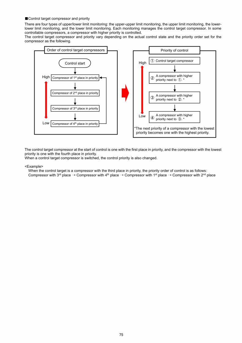
75
■Control target compressor and priority
There are four types of upper/lower limit monitoring: the upper-upper limit monitoring, the upper limit monitoring, the lower-lower limit monitoring, and the lower limit monitoring. Each monitoring manages the control target compressor. In some controllable compressors, a compressor with higher priority is controlled. The control target compressor and priority vary depending on the actual control state and the priority order set for the compressor as the following.
The control target compressor at the start of control is one with the first place in priority, and the compressor with the lowest priority is one with the fourth place in priority. When a control target compressor is switched, the control priority is also changed. <Example>
When the control target is a compressor with the third place in priority, the priority order of control is as follows:
Compressor with 3rd place ➝ Compressor with 4th place ➝ Compressor with 1st place ➝ Compressor with 2nd place
Control start
Compressor of 1st place in priority
Priority of control
Control target compressor
A compressor with higher
priority next to ①. *
A compressor with higher
priority next to ②. *
A compressor with higher
priority next to ③. *
①
②
③
④
*The next priority of a compressor with the lowest priority becomes one with the highest priority.
Compressor of 2nd place in priority
Compressor of 3rd place in priority
Compressor of 4th place in priority
High
Low
High
Low
Order of control target compressors
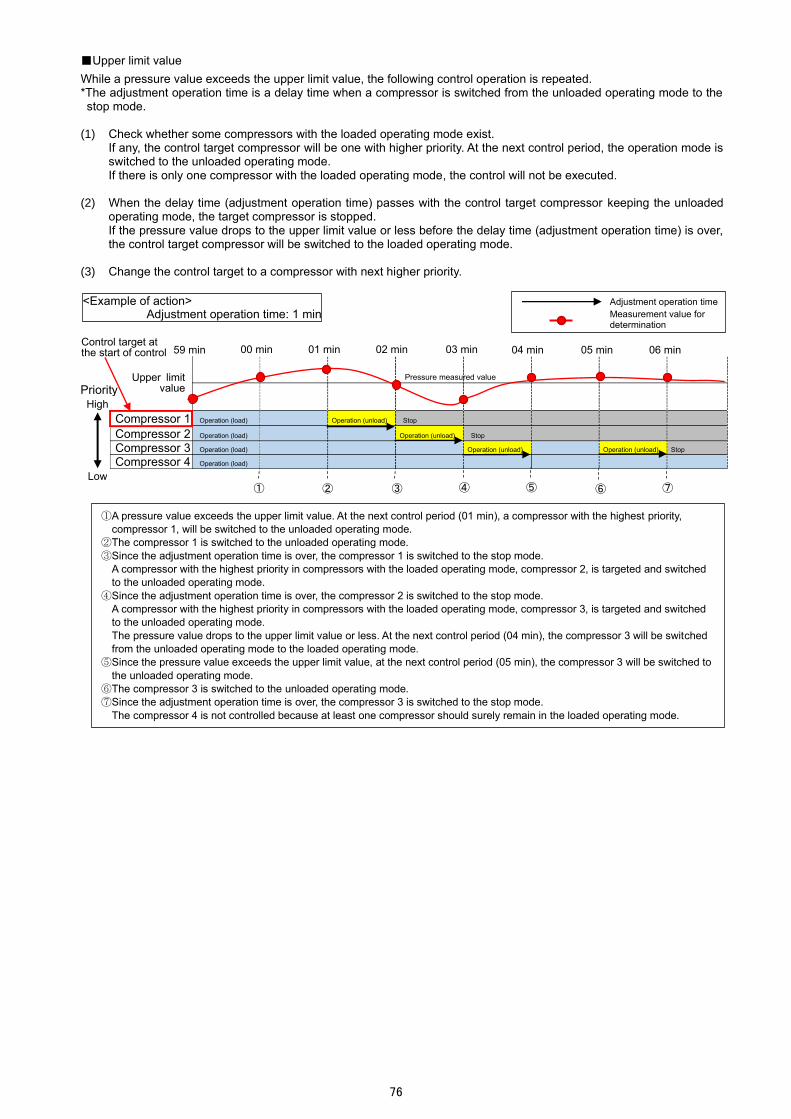
76
■Upper limit value
While a pressure value exceeds the upper limit value, the following control operation is repeated. *The adjustment operation time is a delay time when a compressor is switched from the unloaded operating mode to the stop mode.
(1) Check whether some compressors with the loaded operating mode exist.
If any, the control target compressor will be one with higher priority. At the next control period, the operation mode is switched to the unloaded operating mode. If there is only one compressor with the loaded operating mode, the control will not be executed.
(2) When the delay time (adjustment operation time) passes with the control target compressor keeping the unloaded operating mode, the target compressor is stopped. If the pressure value drops to the upper limit value or less before the delay time (adjustment operation time) is over, the control target compressor will be switched to the loaded operating mode.
(3) Change the control target to a compressor with next higher priority.
Upper limit
value
Compressor 1 Operation (load) Operation (unload) Stop
Compressor 2 Operation (load) Operation (unload) Stop
Compressor 3 Operation (load) Operation (unload) Operation (unload) Stop
Compressor 4 Operation (load)
Adjustment operation time
Measurement value for determination
② ③ ④ ⑥ ⑦
Pressure measured value
59 min
① ⑤
<Example of action> Adjustment operation time: 1 min
Priority High
Low
00 min 01 min 02 min 03 min 04 min 05 min 06 min Control target at the start of control
①A pressure value exceeds the upper limit value. At the next control period (01 min), a compressor with the highest priority,
compressor 1, will be switched to the unloaded operating mode.
②The compressor 1 is switched to the unloaded operating mode.
③Since the adjustment operation time is over, the compressor 1 is switched to the stop mode.
A compressor with the highest priority in compressors with the loaded operating mode, compressor 2, is targeted and switched
to the unloaded operating mode.
④Since the adjustment operation time is over, the compressor 2 is switched to the stop mode.
A compressor with the highest priority in compressors with the loaded operating mode, compressor 3, is targeted and switched
to the unloaded operating mode.
The pressure value drops to the upper limit value or less. At the next control period (04 min), the compressor 3 will be switched
from the unloaded operating mode to the loaded operating mode.
⑤Since the pressure value exceeds the upper limit value, at the next control period (05 min), the compressor 3 will be switched to
the unloaded operating mode.
⑥The compressor 3 is switched to the unloaded operating mode.
⑦Since the adjustment operation time is over, the compressor 3 is switched to the stop mode.
The compressor 4 is not controlled because at least one compressor should surely remain in the loaded operating mode.

77
■Upper-upper limit value
When a pressure value exceeds the upper-upper limit value, the next control operation is executed once. After that, until
the pressure value drops to the upper limit value or less, the same operation as ■Upper limit value is repeated.
After dropping to the upper-upper limit value or less, if the pressure value exceeds the upper-upper limit value again, the control will be executed again. *The adjustment operation time is a delay time when a compressor is switched from the unloaded operating mode to the stop mode.
(1) According to the mode of the control target compressor, the following control operation is executed.
・When the control target is in the loaded operating mode, it is switched to the stop mode. After switching to the stop mode, the control target is changed to a compressor with next higher priority. If there is only one compressor with the loaded operating mode, the control will not be executed.
・When the control target is in the unloaded operating mode, it is switched to the stop mode. After switching to the stop mode, the control target is changed to a compressor with next higher priority.
(2) Check whether some compressors with the loaded operating mode exist.
If any, the control target compressor will be one with higher priority. At the next control period, the operation mode is switched to the unloaded operating mode. If there is only one compressor with the loaded operating mode, the control will not be executed.
Upper-upper
limit value
Upper limit value
Compressor 1 Operation (load) Operation (unload) Stop
Compressor 2 Operation (load) Operation (unload) Stop
Compressor 3 Operation (load) Operation (unload) Stop
Compressor 4 Operation (load)
① ② ③ ④
①A pressure value exceeds the upper limit value. At the next control period (01 min), a compressor with the highest priority,
compressor 1, will be switched to the unloaded operating mode.
②The compressor 1 is switched to the unloaded operating mode.
The pressure value exceeds the upper-upper limit value. At the next control period (02 min), the compressor 1 will be switched to
the stop mode regardless of the adjustment operation time.
In addition, the compressor 2 with the highest priority is switched to the unloaded operating mode.
③Regardless of the adjustment operation time, the compressor 1 is switched to the stop mode.
A compressor with the highest priority in compressors with the loaded operating mode, compressor 2, is targeted and switched to
the unloaded operating mode.
④Since the adjustment operation time is not over, the control is not executed.
⑤Since the adjustment operation time is over, the compressor 2 is switched to the stop mode.
A compressor with the highest priority in compressors with the loaded operating mode, compressor 3, is targeted and switched to
the unloaded mode.
⑥Since the adjustment operation time is not over, the control is not executed.
Although the pressure value exceeds the upper-upper limit value, the compressor 4 is not controlled because no compressor with
the unloaded operating mode exists at the next control period (06 min) and at least one compressor should surely remain in the
loaded operating mode.
⑦The compressor 3 is switched to the stop mode.
Since at least one compressor should surely remain in the loaded operating mode, the compressor 4 is not controlled
*The parts written in red indicate the control operation executed in excess of the upper-upper limit value.
⑤ ⑥ ⑦
<Example of action> Adjustment operation time: 2 minutes
Adjustment operation time Measurement value for determination
Pressure measured value
59 min
Priority High
Low
00 min 01 min 02 min 03 min 04 min 05 min 06 min Control target at the start of control

78
■Lower limit value
While a pressure value is below the lower limit value, the following control operation is repeated. *The adjustment operation time is a delay time when a compressor is switched from the stop mode to the loaded operating mode.
(1) When a pressure value becomes below the lower limit value for the first time only, the following control operation is
executed. Except for the first time, this control operation is not executed and the operation is moved to (2) below. When the pressure value becomes the lower limit value or more once and then drops below the lower limit value or less again, the control is executed as the first time.
・Check whether some compressors with the stop mode exist. If any, a compressor with higher priority will be switched to the loaded operating mode at the next control period.
(2) Check whether some compressors with the stop mode exist.
If any, the control target compressor will be one with higher priority.
(3) When the set delay time (total of adjustment operation time and start delay time) passes with the control target compressor keeping the stop mode, the control target is switched to the loaded operating mode. If the pressure value becomes the lower limit value or more before the delay time (total of adjustment operation time and start delay time) is over, the control will not be executed. *The delay time is reset. When the control is resumed, it is in standby mode until the reconfigured delay time is over.
(4) Change the control target to a compressor with next higher priority.
Lower limit value
Compressor 1 Stop Operation (load)
Compressor 2 Stop Operation (load)
Compressor 3 Stop Operation (load)
Compressor 4 Operation (load)
④
①A pressure value drops below the lower limit value. At the next control period (01 min), a compressor with the highest priority,
compressor 1, will be switched to the loaded operating mode.
②The compressor 1 is switched to the loaded operating mode.
A compressor with the highest priority in compressors with the stop mode, compressor 2, is targeted and it keeps standby
mode until the adjustment operation time is over.
③Since the adjustment operation time is over, the standby mode is kept until the start delay time is over.
④Since the start delay time is over, the compressor 2 is switched to the loaded operating mode.
A compressor with the highest priority in compressors with the stop mode, compressor 3, is targeted and it keeps standby
mode until the adjustment operation time is over.
However, since the pressure value becomes the lower limit value or more, the control will not be executed at the next control
period (04 min).
⑤Since the pressure value drops below the lower limit value, at the next control period (05 min), the compressor 3 with the
highest priority will be switched to the loaded operating mode.
⑥The compressor 3 is switched to the loaded operating mode.
Since no compressor with the stop mode exists, the control operation is ended.
③ ② ① ⑤ ⑥ ⑦
<Example of action> Adjustment operation time: 1 minute Start delay time: 1 minute
Pressure measured value
59 min
Priority High
Low
00 min 01 min 02 min 03 min 04 min 05 min 06 min
Adjustment operation time
Start delay time Measurement value for determination
Control target at the start of control

79
■Lower-lower limit value
When a pressure value drops below the lower-lower limit value, the next control operation is executed once. After that, until
the pressure value rises to the lower limit value or more, the same operation as ■Lower limit value is repeated.
When the pressure value becomes the lower-lower limit value or more once and then drops below the lower-lower limit value again, the control is executed again. *The adjustment operation time is a delay time when a compressor is switched from the stop mode to the loaded operating mode.
(1) When the control target is in the stop mode, it is switched to the loaded operating mode regardless of the set delay
time (adjustment operation time and start delay time).
Lower limit value
Lower-lower
limit value
Compressor 1 Stop Operation (load)
Compressor 2 Stop Operation (load)
Compressor 3 Stop Operation (load)
Compressor 4 Operation (load)
① ② ④
①A pressure value drops below the lower limit value. At the next control period (01 min), a compressor with the highest priority,
compressor 1, will be switched to the loaded operating mode.
②The compressor 1 is switched to the loaded operating mode.
A compressor with the highest priority in compressors with the stop mode, compressor 2, is targeted and it keeps standby mode
until the adjustment operation time is over.
The pressure value drops below the lower-lower limit value. At the next control period (02 min), the compressor 2 will be
switched to the loaded operating mode regardless of the adjustment operation time and start delay time.
③The compressor 2 is switched to the loaded operating mode regardless of the adjustment operation time and start delay time.
A compressor with the highest priority in compressors with the stop mode, compressor 3, is targeted and it keeps standby mode
until the adjustment operation time is over.
④The standby mode is kept until the adjustment operation time is over.
⑤Since the adjustment operation time is over, the standby mode is kept until the start delay time is over.
⑥The standby mode is kept until the start delay time is over.
Although the pressure value drops below the lower-lower limit value, the control is not executed because no compressor with
the stop mode exists at the next control period (06 min).
⑦The compressor 3 is switched to the loaded operating mode.
Since no compressor with the stop mode exists, the control is not executed.
*The parts written in red indicate the control operation executed when the pressure value is below the lower-lower limit value.
③ ⑤ ⑥ ⑦
<Example of action> Adjustment operation time: 2 minute Start delay time: 2 minute
Adjustment operation time Start delay time Measurement value for determination
Pressure measured value
Priority High
Low
Control target at the start of control
59 min 00 min 01 min 02 min 03 min 04 min 05 min 06 min

80
<Example of action when the pressure value is both above the upper limit value and below the lower limit value>
Upper-upper
limit value
Upper limit
value
Lower limit
value
Lower-lower
limit value
Compressor 1 Operation (load) Stop Operation (load)
Compressor 2 Operation (load) Operation (unload) Stop
Compressor 3 Operation (load) Operation (unload) Stop
Compressor 4 Operation (load) Operation (unload)
④
①A pressure value exceeds the upper-upper limit value. At the next control period (01 min), the compressor 1 will be switched to
the stop mode regardless of the adjustment operation time.
In addition, the compressor 2 with the next highest priority will be switched to the unloaded operating mode.
②The compressor 1 and compressor 2 are switched to the stop mode and unloaded operating mode respectively.
③Since the adjustment operation time is over, the compressor 2 is switched to the stop mode.
The compressor 3 with the highest priority in compressors with the loaded operating mode is targeted and switched to the
unloaded operating mode.
④Since the adjustment operation time is over, the compressor 3 is switched to the stop mode.
Since the pressure value drops below the lower-lower limit value, at the next control period (04 min), the compressor 1 will be
switched to the loaded operating mode regardless of the adjustment operation time and start delay time.
⑤Regardless of the adjustment operation time and start delay time, the compressor 1 is switched to the loaded operating mode.
The compressor 2 with the highest priority in compressors with the stop mode is targeted and it keeps standby mode until the
adjustment operation time is over.
⑥Since the pressure value rises to the lower limit value or more, at the next control period (06 min), the control for compressor 2
will not be executed.
Furthermore, since the pressure value exceeds the upper limit value, at the next control period (06 min), the compressor 4 with
the highest priority will be switched to the unloaded operating mode.
⑦The compressor 4 is switched to the unloaded operating mode.
③ ② ① ⑤ ⑥ ⑦
<Example of action> Adjustment operation time: 1 minute Start delay time: 1 minute
Adjustment operation time Start delay time Measurement value for determination
Pressure measured value
59 min 00 min 01 min 02 min 03 min 04 min 05 min 06 min Control target at the start of control
Priority High
Low

81
Registering the Compressor Setting
You will register the settings for compressors to be controlled and for upper/lower limit monitoring. (1) Click the compressor tab on the top of the window.
The following window appears.
(2) Set the number of compressors to be controlled.
Clicking the Add button adds a new compressor to the bottom of the table. By clicking the Delete button, the selected compressor, which is displayed in blue, is deleted. The settable number is two to four units. *The control units more than the compressors must be registered in the system. For details, refer to 7.5 Setting of Terminals.
ID

82
(3) Select a compressor for setup and then enter each item.
After the input, click the Apply button to save the settings.
Item Details
Name Enter a name to register the compressor. A maximum of 30 characters are allowed in the input field.
Contact assignment Set the terminal and contacts to control the compressor.
Terminal Select a control unit to control the compressor from the pull-down menu. The control unit registered to other compressor cannot be selected repeatedly.
Load/Unload DY Select a contact number to control the state.
*For each contact operation, refer to Contact state corresponding to the compressor
operation mode below.
Register each contact without using the same contact number repeatedly. The setting range: 1 to 3 *<Default> Load/Unload:1, Operation: 2, Stop: 3
Operation DY
Stop DY
Start/Stop priority Set the order to control the compressor. The order is determined through the following process:
・A compressor with higher priority (with small number) is controlled first.
・In the case that there are some compressors with the same priority, the one with small ID is controlled first.
The setting range: 1 to 4
(4) Execute the same operation as (3) above for each compressor.
Contact state corresponding to the compressor operation mode The following table shows the contact output states corresponding to the compressor operation modes. The explanation here is an example of using the following settings:
Load/Unload DY: 1 Operation DY: 2 Stop DY: 3
Operation mode of compressor
Contact number
Loaded operating mode
Unloaded operating mode
Stop mode
1 ON OFF OFF
2 ON ON OFF
3 ON ON OFF
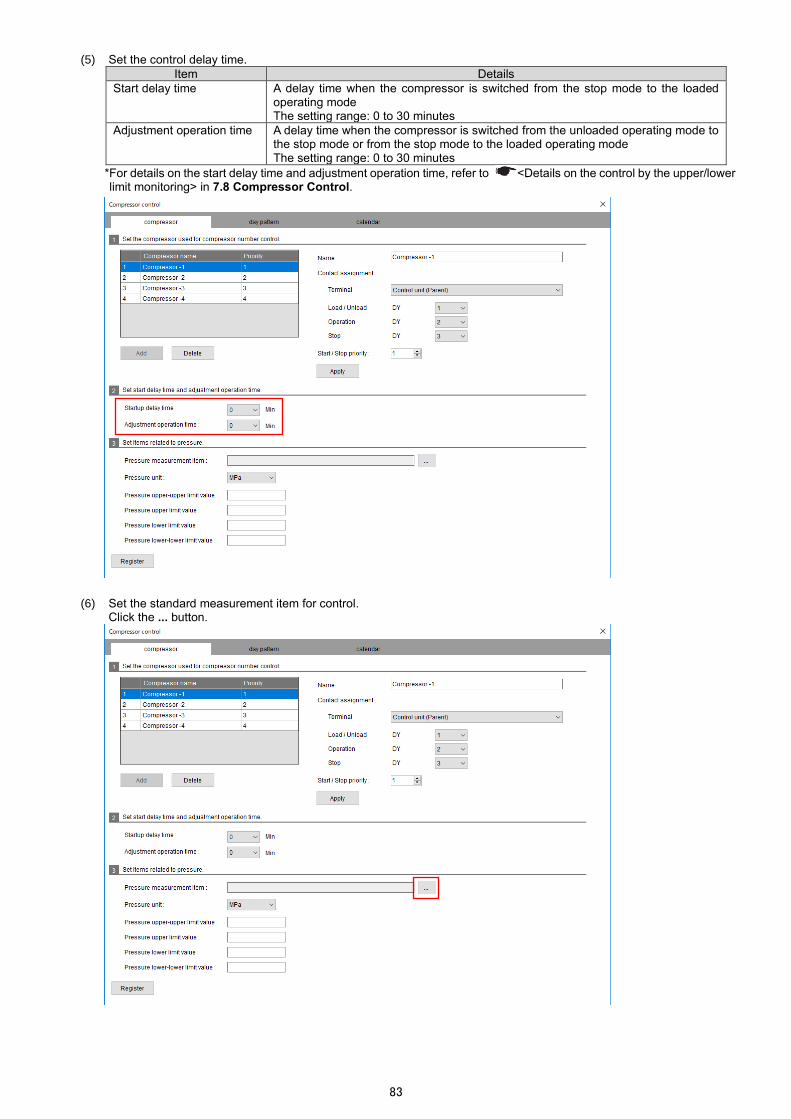
83
(5) Set the control delay time.
Item Details
Start delay time A delay time when the compressor is switched from the stop mode to the loaded operating mode The setting range: 0 to 30 minutes
Adjustment operation time A delay time when the compressor is switched from the unloaded operating mode to the stop mode or from the stop mode to the loaded operating mode The setting range: 0 to 30 minutes
*For details on the start delay time and adjustment operation time, refer to <Details on the control by the upper/lower limit monitoring> in 7.8 Compressor Control.
(6) Set the standard measurement item for control.
Click the ... button.

84
(7) The following window appears.
Select a unit and its measurement item in that order to set the standard measuring point for conditional expression.
*A scaling value of the analog input unit (EMU4-AX4) only is available.
(8) Click the OK button to determine the standard measuring point.
Return to the compressor control window. (9) Set the upper and lower limit.
Register each item.
Item Details
Pressure unit Select a unit of measurement value from the pull-down menu.
・MPa ・kPa ・Pa
Pressure upper-upper limit value Set the upper-upper limit, upper limit, lower limit, and lower-lower limit values. The setting ranges from 0 to 9999. Set each value so as to be the following equation:
∙Upper-upper limit value > Upper limit value > Lower limit value > Lower-
lower limit value
Pressure upper limit value
Pressure lower limit value
Pressure lower-lower limit value
(10) Click the Register button to save the settings.

85
Registering/Changing the Day Pattern
You will set the valid and invalid time periods of compressor control in the day. (1) Click the day pattern tab on the top of the window.
The following window appears.
(2) Set the day pattern number and name.
Item Details
Day pattern number Register the number of a day pattern. The number ranges from 1 to 4. *A maximum of 4 day patterns can be saved.
Day pattern name Register a name for the day pattern. *A maximum of 30 characters are allowed in the input field.

86
(3) Set the valid and invalid time periods of compressor control in the day.
Item Details
Time Set the time to switch the valid/invalid status for compressor control. It is possible to set by the minute. After selecting an hour or minute, enter a number or click the ▲ or ▼ button to set. Including 0:00 of the first field, a maximum of 24 times can be set. Default: 0:00
Control status (valid/invalid)
Select valid or invalid for compressor control from the pull-down menu. Default: Non setting (Blank)
*1: To the first field (0:00) of the control status, be sure to set other than blank. *2: It is impossible to set the same time to other field repeatedly. *3: Except for the first field (0:00), be sure to set the control status (valid/invalid) to any fields where the time is set. Regardless of the setting order, the control is executed from the earlier time. *After completing the settings, by closing the window once and opening again, the settings are automatically sorted in chronological order.
<Example> At registration After redisplay (After sorting)
(4) Click the Register button to save the settings.
Time
Valid/Invalid control

87
Deleting the Day Pattern
(1) Click the day pattern tab on the top of the window. The following window appears.
(2) Select a day pattern number to delete and then click the Delete button.
(3) The following confirmation message appears.
Click the Yes button to delete the day pattern.
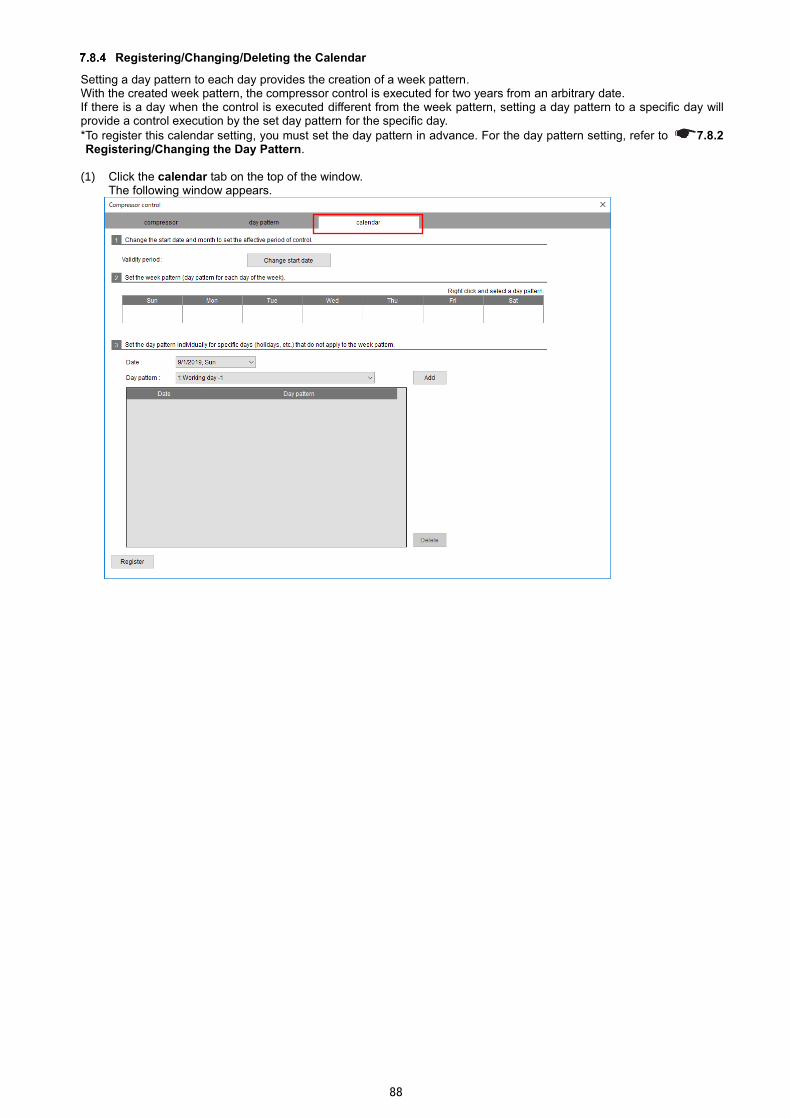
88
Registering/Changing/Deleting the Calendar
Setting a day pattern to each day provides the creation of a week pattern. With the created week pattern, the compressor control is executed for two years from an arbitrary date. If there is a day when the control is executed different from the week pattern, setting a day pattern to a specific day will provide a control execution by the set day pattern for the specific day.
*To register this calendar setting, you must set the day pattern in advance. For the day pattern setting, refer to 7.8.2 Registering/Changing the Day Pattern.
(1) Click the calendar tab on the top of the window.
The following window appears.

89
(2) Set each item.
Item Details
Validity period Indicate the validity time period for compressor control execution. The validity period is for two years from a start date. The start date can be changed by clicking the Change start date button.
Week pattern *1 Set the day pattern for each day. Right-click the field of each day to select a day pattern. A selectable item, Clear, represents a state of no day pattern setting. *That day is treated as a state of invalid control.
Specific day pattern Set as necessary. When there is a day when the control is executed different from the week pattern, set this. Select Date and Day pattern and then click the Add button to set the pattern. When deleting a setting, select the setting and then click the Delete button. *When the validity period has been changed, any settings not within a new validity period will be deleted.
Date Select a day to set. Any day within the validity period is selectable.
Day pattern *1 Select a day pattern to set to the special day.
*To set this calendar, you must register the day pattern settings in advance. For details, refer to 7.8.2 Registering/Changing the Day Pattern.

90
(3) Click the Register button to save the settings.

91
7.9 Schedule Control
Schedule control is a control method that switches an ON/OFF contact output when the clock time of the control unit becomes an arbitrary time by setting the ON and OFF time periods of contact output in the day in advance. This schedule control requires the settings for two years, of which the ON and OFF time periods are set for each contact output. The maximum number of contact output varies depending on the number of control units in the system.
Output Number of output Maximum number of output
Contact output The number of control units in the system × 3 96
Caution
<Precautions for control unit clock> The control unit has a built-in clock. The clock accuracy is five minute per month difference. Check the clock time regularly, and if there is a difference, adjust the time. For details on how to check the present time, refer to 10.2 Setting of Clock.

92
The settings will be configured in the following way:
① Create a day pattern, a time schedule where the ON and OFF time periods of contact output are set in the day. The number of day patterns for registration varies depending on the number of registered terminals.
Number of registered terminals Number of day patterns for registration
1 to 5 4 patterns
6 to 11 3 patterns
12 to 17 2 patterns
18 to 32 1 pattern
② Assign the day pattern to each day to create the week pattern. With the created week pattern, the control is executed for two years.
③ To any dates not applied to the week pattern, the day pattern is assigned.
Calendar setting ➝
Week pattern
Day Sun Mon Tue Wed Thu Fri Sat
Pattern Holiday Weekday Weekday Weekday Weekday Weekday Holiday
Date of control execution different from the week pattern
Date Pattern
March 20, 2020 Holiday
・
・
・
・
・
・
February 11, 2022 Holiday
For two years
② ②
③
0:00 24:00 Day pattern 1: Weekday
Contact output 1 Contact output 2 Contact output 3
OFF ON ON OFF
OFF OFF
OFF OFF ON
Control unit 1
・・・
Control unit N
OFF ON OFF
OFF OFF ON
OFF ON OFF
0:00 24:00 Day pattern 2: Holiday
OFF Control unit 1
・・・
Control unit N
OFF
OFF
OFF
OFF
OFF
①
①
Contact output 1 Contact output 2 Contact output 3
Contact output 1 Contact output 2 Contact output 3
Contact output 1 Contact output 2 Contact output 3
March 2020 Sun Mon Tue Wed Thu Fri Sat
1 2 3 4 5 6 7 8 9 10 11 12 13 14 15 16 17 18 19 20 21 22 23 24 25 26 27 28 29 30 31
February 2022 Sun Mon Tue Wed Thu Fri Sat
1 2 3 4 5 6 7 8 9 10 11 12 13 14 15 16 17 18 19 20 21 22 23 24 25 262 27 28

93
Registering/Changing the Day Pattern
You will set the ON and OFF time periods of contact output in the day. (1) Click the day pattern tab on the top of the window.
The following window appears.
(2) Set the day pattern number and name.
Item Details
Day pattern number
Register the number of a day pattern. *The maximum number of savings varies depending on the number of registered terminals.
Number of registration terminals Number of registration of day pattern Day pattern No.
1 to 5 4 patterns 1 to 4
6 to 11 3 patterns 1 to 3
12 to 17 2 patterns 1 to 2
18 to 32 1 pattern 1
Day pattern name
Register a name for the day pattern. *A maximum of 30 characters are allowed in the input field.

94
(3) Select a terminal to set the day pattern.
The selected terminal is displayed in blue.
(4) Enter an output name of each contact output.
A maximum of 30 characters are allowed in the input field.
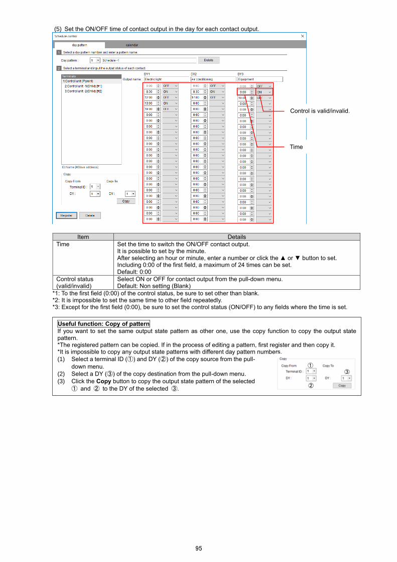
95
(5) Set the ON/OFF time of contact output in the day for each contact output.
Item Details
Time Set the time to switch the ON/OFF contact output. It is possible to set by the minute. After selecting an hour or minute, enter a number or click the ▲ or ▼ button to set. Including 0:00 of the first field, a maximum of 24 times can be set. Default: 0:00
Control status (valid/invalid)
Select ON or OFF for contact output from the pull-down menu. Default: Non setting (Blank)
*1: To the first field (0:00) of the control status, be sure to set other than blank. *2: It is impossible to set the same time to other field repeatedly. *3: Except for the first field (0:00), be sure to set the control status (ON/OFF) to any fields where the time is set.
Useful function: Copy of pattern If you want to set the same output state pattern as other one, use the copy function to copy the output state pattern. *The registered pattern can be copied. If in the process of editing a pattern, first register and then copy it. *It is impossible to copy any output state patterns with different day pattern numbers.
(1) Select a terminal ID (①) and DY (②) of the copy source from the pull-
down menu.
(2) Select a DY (③) of the copy destination from the pull-down menu.
(3) Click the Copy button to copy the output state pattern of the selected
① and ② to the DY of the selected ③.
①
②
③
Time
Control is valid/invalid.

96
Regardless of the setting order, the control is executed from the earlier time. *After completing the settings, by closing the window once and opening again, the settings are automatically sorted in chronological order.
<Example> At registration After redisplay (After sorting)
(6) Click the Register button to save the settings.
(7) Execute the same operation as (3) to (6) above for each terminal as necessary to set the output state to the day
pattern. *Any terminals of no output setting are set as always OFF.
(8) Set other day pattern in the same way.

97
Deleting the Day Pattern
There are two ways on how to delete the day pattern: deleting by the terminal and deleting all the settings registered to the day pattern number.
■How to delete the settings of the terminal of a specific day pattern
(1) Select the terminal of a day pattern to delete and then click the Delete button on the bottom left of the window.
(2) The following message appears.
Click the Yes button.
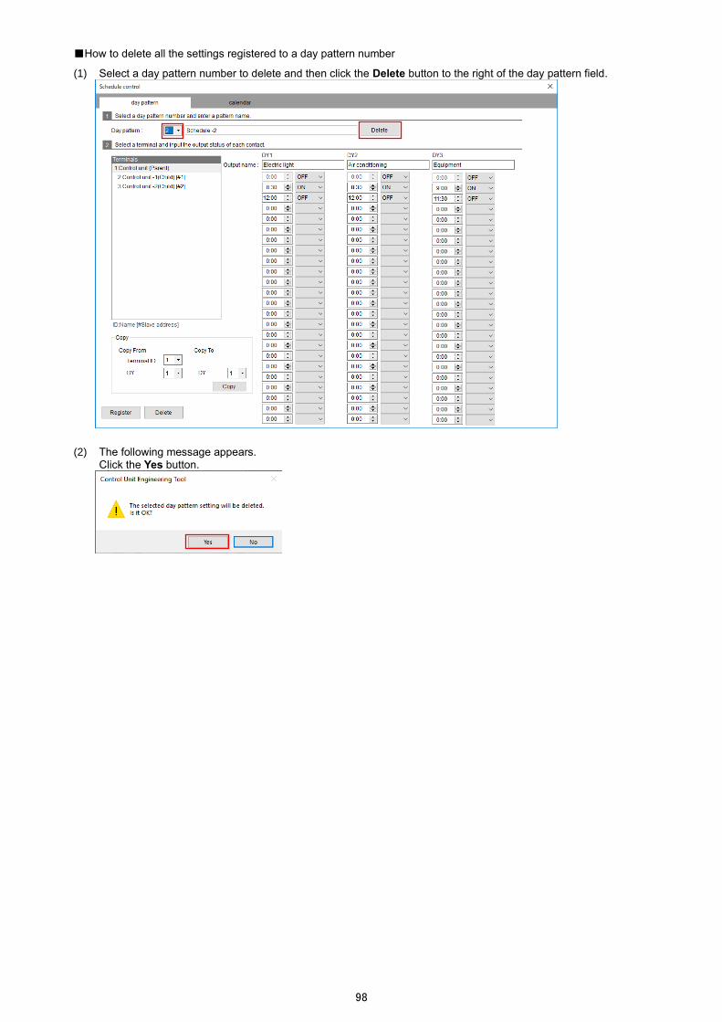
98
■How to delete all the settings registered to a day pattern number
(1) Select a day pattern number to delete and then click the Delete button to the right of the day pattern field.
(2) The following message appears.
Click the Yes button.

99
Registering/Changing/Deleting the Calendar
Setting a day pattern to each day provides the creation of a week pattern. With the created week pattern, the ON/OFF contact output is controlled for two years from an arbitrary date. If there is a day when the control is executed different from the week pattern, setting a day pattern to a specific day will provide a control execution by the set day pattern for the specific day.
*To register this calendar setting, you must set the day pattern in advance. For the day pattern setting, refer to 7.8.2 Registering/Changing the Day Pattern.
(1) Click the calendar tab on the top of the window.
The following window appears.
(2) Enter each item.

100
Item Details
Validity period Indicate the validity time period for schedule control execution. The validity period is for two years from a start date. The start date can be changed by clicking the Change start date button.
Week pattern *1 Set the day pattern for each day. Right-click the field of each day to select a day pattern. A selectable item, Clear, represents a state of no day pattern setting.
Specific day pattern Set as necessary. When there is a day when the control is executed different from the week pattern, set this. Select Date and Day pattern and then click the Add button to set the pattern. To delete a setting, select the setting and then click the Delete button. *When the validity period has been changed, any settings not within a new validity period are deleted.
Date Select a day to set. Any day within the validity period is selectable.
Day pattern *1 Select a day pattern to set to the special day.
*To set this calendar, you must register the day pattern settings in advance. For details, refer to 7.9.1 Registering/Changing the Day Pattern.
(3) Click the Register button to save the settings.

101
7.10 Write of Network Information
This function is used when the network information (Ethernet or MODBUS RTU communication) of the control unit is confirmed or changed. Make a one-to-one connection between the target terminal unit and the computer via Ethernet. After the connection, the write/read of network information is executed.
For details on the network information, refer to 7.5 Setting of Terminals. *This function is available when the target terminal is in the STOP status of control operation. If you attempt to execute it in the RUN status, a message will appear to ask whether to execute after the status is changed to STOP.
Writing Network Information
(1) Select a terminal of the write target from the left table. The selected terminal is displayed in blue. In the Value to write columns of the table, the network information registered at the terminal setting is displayed.
(2) Make a one-to-one connection between the computer and the write target terminal with a LAN cable.
*Set the computer’s IP address in order to be in the same network.
(3) Enter the IP address and password of the target terminal. The default IP address is 192.168.3.11.
For the password, refer to 10.. Change of Password.
(4) Click the Writing button.
(5) After the write has been completed, the following message appears.
Click the OK button to close the message.
If the write execution fails, refer to 11.. Q&A to identify the source. After eliminating it, execute the write again. <When changed to the IP address of the same network> <When changed to the IP address of a different network>
Network information registered at the terminal setting
The default setting appears when the window is opened. If it is different, change to the current IP address.

102
Reading Network Information
(1) Select a terminal of the read target from the left table. The selected terminal is displayed in blue. In the Value to write columns of the table, the network information registered at the terminal setting is displayed.
(2) Make a one-to-one connection between the computer and the target terminal with a LAN cable.
*Set the computer’s IP address in order to be in the same network.
(3) Enter the IP address and password of the target terminal. The default IP address is 192.168.3.11.
For the password, refer to 10.. Change of Password.
(4) Click the Reading button. (5) After the read has been completed, the terminal network information is displayed in the Read value columns of the
table.
Network information registered at the terminal setting
The default setting appears when the window is opened. If it is different, change to the current IP address.

103
7.11 Check of Connection
Communicating with the terminals in the system enables to check the MODBUS RTU communication connection with each control unit in the system. (1) Connect the computer and the parent terminal of control unit with a LAN cable.
In addition, connect between each control unit in the system via MODBUS RTU communication. *Set the computer’s IP address in order to be in the same network with the parent terminal of control unit.
(2) Enter the password of the parent terminal.
For the password, refer to 10.. Change of Password.
(3) Click the Connection check button. (4) The check result is displayed in the list on the bottom of the window.
Icon Result Details
Connection OK The connection is correct.
Connection NG
The connection is not correct. Check the MODBUS RTU communication lines or network settings to eliminate the source
Unit configuration mismatch
For a unit configuration with a target control unit, the model name of the extension unit actually connected is different from the one set with Control Unit Engineering Tool. Check the control unit configuration and then change the setting in order to match with the actual model. *If the number of the extension units differs, the result will be displayed as Connection NG not Unit configuration mismatch.
Mismatch between the settings and actual connection

104
7.12 Write of Settings
This function writes the control settings to the parent terminal of control unit. *This function is available when the parent terminal is in the STOP status of control operation. If you attempt to execute it in the RUN status, a message will appear to ask whether to execute after the status is changed to STOP. (1) Connect the computer and the parent terminal with a LAN cable.
*Set the computer’s IP address in order to be in the same network.
(2) Enter the password of the parent terminal.
For the password, refer to 10.. Change of Password.
(3) Click the Write settings button to write the settings.
(4) After the write has been completed, the following message appears.
Click the OK button to close the message.
If the write execution fails, refer to 11.. Q&A to identify the source. After eliminating it, execute the write again.
7.13 Change of RUN/STOP
This function changes the control operation status of the parent terminal of control unit. To execute the change, the parent terminal must be connected to the computer with a LAN cable. (1) Connect the computer and the parent terminal with a LAN cable.
*Set the computer’s IP address in order to be in the same network. (2) Enter the password of the parent terminal.
For the password, refer to 10.. Change of Password.

105
(3) Click the Reading button to check the current control operation status.
After the read has been completed, the current control operation status is displayed on the window.
(4) Click the RUN or STOP button to change the control operation status.
(5) After the status change has been completed, the following message appears.
Click the OK button to close the message. The display window is also changed to the one with the change reflected.

106
8. Measurement Value Monitoring
This chapter describes measurement value monitoring in Control Unit Engineering Tool. This function monitors some values measured by the extension unit. The extension unit (circuit) is selected and its measurement values are monitored and displayed. The measurement values are updated every one minute. *It is impossible to monitor any measurement items measuring integrated values.
(1) Select an extension unit or circuit to monitor.
(2) Click the Start monitor button to start the monitoring.
When stopping the monitoring, click the Monitor stop button.
*During the monitoring, it is impossible to change the target unit or circuit.
When EMU4-A2 or EMU4-VA2 is set, select the circuit.

107
9. Control Monitoring
This chapter describes control monitoring in Control Unit Engineering Tool. This function displays the control status on the selected system or manually controls any output. *For the control type of non-analog output, no unit of analog output value is displayed.
9.1 Control Status Monitoring
You will monitor the control status of each output. To start the monitoring, click the Start monitor button. To stop it, click the Monitor stop button. *During the monitoring, the button display changes from Start monitor to Monitor stop.

108
9.2 Manual Control of output
You will manually control each output. *During the monitoring, the manual control is impossible. *When the control type is compressor control or schedule control, there is no analog output function. Do not manually control any analog output.
Caution
・This function is available when the parent terminal is in the STOP status of control operation.
・When you attempt to operate it in the RUN status, a message appears to ask whether to execute after the status is changed to STOP. After the manual control operation, the control operation status never returns to RUN. Therefore, manually change to RUN.
・When the control type is schedule control, if the contact output is manually controlled and the control operation status is changed to RUN, the change will be retained until the next control execution time comes.
(1) Click the Manual control button of an output you want to change.
(2) The following window appears.
Enter each item and then click the Execute button for manual control.
Caution
For analog voltage output, execute the manual control after the control unit starts the analog output since the setting is written. When the control unit does not start the analog output, the unit of output value is not displayed. If, under such a condition, the analog output is manually controlled, an analog current output will be changed.
<For contact output> <For analog output>
Item Details
Output value
For contact output Select a contact output status from the pull-down menu.
・ON ・OFF
For analog output Enter an output value. Setting range: 4.000 to 20.000 (Current output) 0.000 to 5.000 (Voltage output)

109
(3) After the manual control execution has been completed, the following message appears for each output.
Click the OK button to close the message.
<For contact output> <For analog output>

110
10. Maintenance Menu (with Control Unit Engineering Tool)
This chapter describes some settings other than control and additional features/functions. For these operations, Control Unit Engineering Tool (Model: EMU4-KNE) is used.
10.1 Output of Event Log
The event logs of the parent terminal will be output in CSV format (saved in the computer). (1) Connect the parent terminal and the computer with a LAN cable.
*Set the computer’s IP address in order to be in the same network. (2) Select the number of event logs for output.
Output number Details
Latest 10 Output the latest 10 event logs.
All items Output all the event logs in the past. *This function is available when the parent terminal is in the STOP status of control operation. If you attempt to execute it in the RUN status, a message will appear to ask whether to execute after the status is changed to STOP.
*For details on the output file, refer to 10.1.1 File Name and Format of Event Log.
(3) Click the ... button to select a destination of the output logs. (4) Enter a password.
For the password, refer to 10.. Change of Password. (5) Click the Event log output button.
(6) After the event log output has been completed, the following message appears.
Click the OK button to close the message.

111
File Name and Format of Event Log
The format varies depending on the event to be recorded. You can identify the format type of output file or recorded logs by checking the event code type.
For the event code type or details on each data, refer to 10.1.2 Details on Log Contents.
■The file created by the event log output and the type of output log
Number of output File name Output log type
The latest 10 EventLog_Part_YYYY_MM_DD_hh_mm_ss.csv
The latest 10 event logs are output regardless of the log format.
All EventLog_All_YYYY_MM_DD_hh_mm_ss.csv
All the event logs are output regardless of the log format.
EventLog_Type1_YYYY_MM_DD_hh_mm_ss.csv
The event logs of format 1 are all output.
EventLog_Type2_YYYY_MM_DD_hh_mm_ss.csv
The event logs of format 2 are all output.
EventLog_Type3_YYYY_MM_DD_hh_mm_ss.csv
The event logs of format 3 are all output.
*For the file name, YYYY, MM, DD, hh, mm, and ss represent the year, month, day, hour, minute, and second respectively.
■Format 1 (Control type: Interlocking control)
Column Log contents
1 Year/Month/Day/Hour/Minute/Second
2 Present status/mode
3 Event code type
4 Slave address of the event source
5 Event code
6 Control status (contact output 1)
7 Control status (contact output 2)
8 Control status (contact output 3)
9 Measurement value 1 for conditional expression (contact output 1)
10 Measurement value 2 for conditional expression (contact output 1)
11 Measurement value 3 for conditional expression (contact output 1)
12 Measurement value 4 for conditional expression (contact output 1)
13 Measurement value 1 for conditional expression (contact output 2)
14 Measurement value 2 for conditional expression (contact output 2)
15 Measurement value 3 for conditional expression (contact output 2)
16 Measurement value 4 for conditional expression (contact output 2)
17 Measurement value 1 for conditional expression (contact output 3)
18 Measurement value 2 for conditional expression (contact output 3)
19 Measurement value 3 for conditional expression (contact output 3)
20 Measurement value 4 for conditional expression (contact output 3)
21 Analog output value
22 Measurement value used for analog output
*Each of the measurement values 1 to 4 for conditional expression is displayed in the following window.
Measurement value 1 for conditional expression
Measurement value 2 for conditional expression
Measurement value 3 for conditional expression
Measurement value 4 for conditional expression

112
■Format 1 (Control type: Compressor control) ■Format 1 (Control type: Schedule control) Column Log contents
1 Year/Month/Day/Hour/Minute/Second
2 Present status/mode
3 Event code type
4 Slave address of the event source
5 Event code
6 Control status (contact output)
7 Measurement value of pressure measurement item
Column Log contents
1 Year/Month/Day/Hour/Minute/Second
2 Present status/mode
3 Event code type
4 Slave address of the event source
5 Event code
6 Control status (contact output)
■Format 2 ■Format 3 Column Log contents
1 Year/Month/Day/Hour/Minute/Second
2 Present status/mode
3 Event code type
4 Slave address of the event source
5 Event code
Column Log contents
1 Year/Month/Day/Hour/Minute/Second
2 Present status/mode
3 Event code type
4 Slave address of the event source
5 Event code
6 Error code
Details on Log Contents
■Year/Month/Day/Hour/Minute/Second
The event occurrence time is recorded.
Data Note
YYYY/MM/DD_hh: mm: ss YYYY: year, MM: month, DD: day, hh: hour, mm: minute, ss: second, _: space
■Present status/mode
The control operation status or mode is recorded for control unit.
Value Control operation status Operation mode *1 Others
0 RUN Operating mode
-
1 STOP
2
-
Test mode
3 Test mode for pulse output test
4 Test mode for alarm output test
5 Test mode for communication test
6 Setting mode
11 - Error stop mode
*It represents the status or mode operated with the small type display unit.
■Event code type
The event code type is recorded for an event occurred The recorded value indicates the format of event logs as the following.
Value Details
0001 Format 1
0002 Format 2
0003 Format 3
■Slave address of the event source
The Slave address of MODBUS RTU communication is recorded for the control unit where an event has occurred.
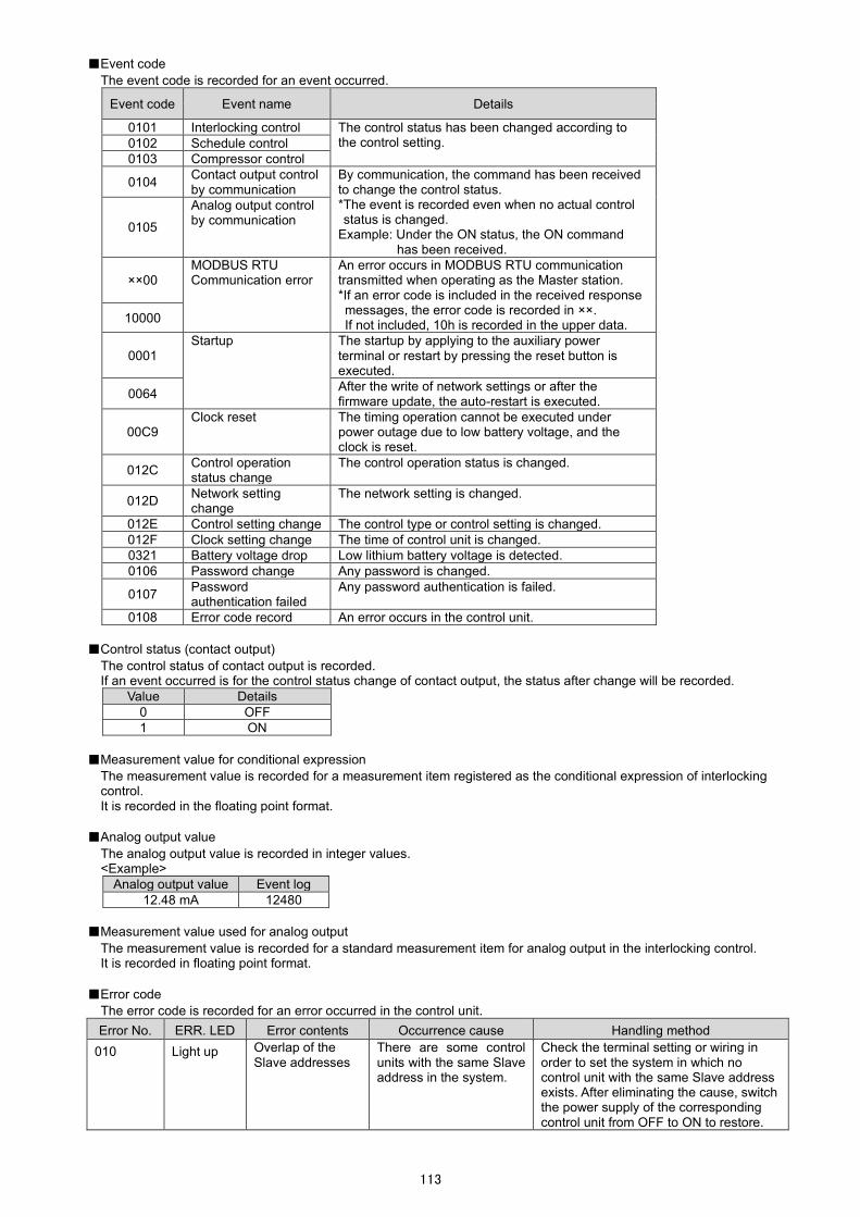
113
■Event code
The event code is recorded for an event occurred.
Event code Event name Details
0101 Interlocking control The control status has been changed according to the control setting. 0102 Schedule control
0103 Compressor control
0104 Contact output control by communication
By communication, the command has been received to change the control status. *The event is recorded even when no actual control status is changed.
Example: Under the ON status, the ON command has been received.
0105
Analog output control by communication
××00 MODBUS RTU Communication error
An error occurs in MODBUS RTU communication transmitted when operating as the Master station. *If an error code is included in the received response messages, the error code is recorded in ××. If not included, 10h is recorded in the upper data.
10000
0001 Startup The startup by applying to the auxiliary power
terminal or restart by pressing the reset button is executed.
0064 After the write of network settings or after the firmware update, the auto-restart is executed.
00C9 Clock reset The timing operation cannot be executed under
power outage due to low battery voltage, and the clock is reset.
012C Control operation status change
The control operation status is changed.
012D Network setting change
The network setting is changed.
012E Control setting change The control type or control setting is changed.
012F Clock setting change The time of control unit is changed.
0321 Battery voltage drop Low lithium battery voltage is detected.
0106 Password change Any password is changed.
0107 Password authentication failed
Any password authentication is failed.
0108 Error code record An error occurs in the control unit.
■Control status (contact output)
The control status of contact output is recorded. If an event occurred is for the control status change of contact output, the status after change will be recorded.
Value Details
0 OFF
1 ON
■Measurement value for conditional expression
The measurement value is recorded for a measurement item registered as the conditional expression of interlocking control. It is recorded in the floating point format.
■Analog output value
The analog output value is recorded in integer values. <Example>
Analog output value Event log
12.48 mA 12480
■Measurement value used for analog output
The measurement value is recorded for a standard measurement item for analog output in the interlocking control. It is recorded in floating point format.
■Error code
The error code is recorded for an error occurred in the control unit.
Error No. ERR. LED Error contents Occurrence cause Handling method
010 Light up Overlap of the Slave addresses
There are some control units with the same Slave address in the system.
Check the terminal setting or wiring in order to set the system in which no control unit with the same Slave address exists. After eliminating the cause, switch the power supply of the corresponding control unit from OFF to ON to restore.

114
10.2 Setting of Clock
You will set the clock of the control unit. The clock setting is only for the parent terminal. *This function is available when the parent terminal is in the STOP status of control operation. If you attempt to execute it in the RUN status, a message will appear to ask whether to execute after the status is changed to STOP. (1) Connect the parent terminal and the computer with a LAN cable.
*Set the computer’s IP address in order to be in the same network. (2) Click the Reading button to execute the read of the parent terminal clock.
(3) The read time is displayed on the window.
If the displayed time is different from the present time, execute the same operation as (4) to (7) below.

115
(4) Set the present time to the Date and time to set field.
With any one of year, month, day, hour, minute, or second selected, enter the number or click the ▲ or ▼ button to
change the number. (5) Enter a password.
For the password, refer to 10.. Change of Password. (6) Click the Configuration button to set the present time for the parent terminal.
(7) After the settings have been completed, the following message appears.
Click the OK button to close the message.
10.3 Change of Password
You will change the maintenance password of the control unit. *The control unit does not have any function of password reset or initialization of all settings. Therefore, do not forget a new password after change.
*This function is available when the parent terminal is in the STOP status of control operation. If you attempt to execute it in the RUN status, a message will appear to ask whether to execute after the status is changed to STOP. (1) Select a terminal to change the password.
The selected terminal is displayed in blue.

116
(2) Connect the target control unit and the computer with a LAN cable.
*Set the computer’s IP address in order to be in the same network. (3) Enter a password to each input field of Password before change, Changed password, and Changed password (for
confirmation). A maximum of 20 characters are allowed in the input field. *The default password is ecopass.
(4) Click the Change button. (5) After the change has been completed, the following message appears.
Click the OK button to close the message.
10.4 Setting of Logging Unit
You will set the logging ID for the logging unit (EMU4-LM) connected to the parent terminal unit. On the following window, it is possible to clear the logging data. *This setting is required when the parent terminal is combined with the logging unit.
*For details on the logging ID, refer to Logging Unit for Energy Measuring Unit User’s Manual (Details). *This function is available when the parent terminal is in the STOP status of control operation. If you attempt to execute it in the RUN status, a message will appear to ask whether to execute after the status is changed to STOP. (1) Connect the target control unit and the computer with a LAN cable.
*Set the computer’s IP address in order to be in the same network. (2) Enter the password for maintenance.

117
■When setting the logging ID
(3) Select the logging ID and then click the Write button. (4) After the write has been completed, the following message appears.
Click the OK button to close the message.
■When deleting the logging data in the logging unit.
(3) Click the Clear logging data button. (4) After the data clear has been completed, the following message appears.
Click the OK button to close the message.
10.5 Check of IP Address
This function will be used when the IP address of the control unit is unclear. The range of IP addresses is specified to execute the search whether any control units exist that are connected to computers within the range *Note that the search range is limited to a network with the same first to third octet of IP address.
(1) Make a one-to-one connection between the parent terminal and the computer with a LAN cable.
*Set the computer’s IP address in order to be in the same network. (2) Set the range to search the IP address and then click the Examine button.
The first to third octet
IP address: XXX.XXX.XXX.XXX

118
(3) The check result is displayed in the table on the bottom of the window.
When an IP addresses available for communication has been found, the following message appears for confirmation. To stop the check, click the Cancel button.
When there is no IP address, the following message appears. When executing the search in a different network, change the computer’s IP address and search range of IP addresses.
10.6 Check of F/W Version
You will check the firmware version of every control unit in the system. (1) Connect the parent terminal and the computer with a LAN cable.
In addition, connect each control unit in the system together via MODBUS RTU communication. *Set the computer’s IP address in order to be in the same network.
(2) Click the F/W version confirmation button.
<When an IP address available for communication has been found>
<When there is no IP address available for communication >

119
(3) The firmware version of each control unit is displayed on the window.
After the confirmation for firmware version has been completed, the following message appears. Click the OK button to close the message.
10.7 Update of F/W
This function executes the firmware version update for the control unit. The present version of Control Unit Engineering Tool does not require any firmware version update of the control unit. To avoid any misuse, this function is not available.
<Completion message>

120
11. Reference
This chapter describes how to deal with some troubleshooting and introduces Q & A.
11.1 Troubleshooting
If you observe abnormal sound, odor, smoke, or heat generation from this product, turn off its power supply to stop using it promptly. In addition, if you are considering repair of your product, check the following points before that.
A setting content and its actual control operation differ.
In order to identify the cause, check the following points.
If the cause is identified, remove it.
No. Item Confirmation contents
① Wiring
By executing the operation of 7.11 Check of Connection, check whether
an error occurs in communication.
If any error is occurring, check the following point:
・The terminal of the connection destination is powered up.
・The wiring is correctly done.
・There is no disconnecting.
② Control setting
・The setting is correctly done.
・The control setting is written.
・The clock of the control unit is set.
*For interlocking control, it is unnecessary.
③
Measurement
value
(Extension unit)
By executing the operation of 8 Measurement Value Monitoring, check
that correct measurement values are displayed.
If any error is occurring, check the following point:
・The settings of any extension units are correctly done.
・The wiring is correctly done.
・There is no disconnecting.
④ Error
・Check whether any error occurs from the LED indicator of the control
unit.
Refer to 4.1.2 LED Indicator and Function.
・Output the event logs and check whether any error occurs.
Refer to 10.1 Output of Event Log.
The baud rate of MODBUS RTU communication cannot be changed.
①After the setting is changed from the small type display unit (Model: EMU4-D65), switching the power supply
from OFF to ON returns to the previous setting.
②Even though the setting is changed from Control Unit Engineering Tool, it is not reflected.
●Cause①
No change can be made to the baud rate of MODBUS RTU communication from the small type display unit.
Therefore, switching the power of the control unit from OFF to ON returns to the previous setting.
*Although the setting after change is displayed, the control unit is operating with the setting before change.
●Resolution②
Switch the power of the control unit from OFF to ON or reset it with the reset button.
●Cause②
After the setting change, the display is not reflected until the control unit is powered ON from OFF or reset with
the reset button.
*Although the setting after change is displayed, the control unit is operating with the setting before change.
Analog output (voltage output) cannot be manually controlled.
●Resolution
After the control unit starts the analog output since the control setting is written, execute the manual control.
●Cause
For analog output (voltage output), when the manual control is executed before the control unit starts the analog
output since the setting is written, an analog output (current output) is changed.

121
The status of a child terminal displayed by the control monitoring function and its actual control status differ.
●Resolution
Press the reset button of the corresponding control unit to reset.
●Cause
When a problem such as power failure occurs and the power supplies of child terminals are switched from ON
to OFF and again to ON, the corresponding control units all switch the output to OFF.
Therefore, during the control monitoring execution, when the power supplies of child terminals under output
are switched from ON to OFF and again to ON, the status displayed by the control monitoring function and its
actual control status differ.
If your situation does not correspond to the above cause or if the problem is not resolved even though the
above resolution is executed, contact your nearest sales office.
RUN LED is off.
Check the use environment (such as ambient temperature) and then turn OFF/ON the power supply.
If the problem occurs again, it will be possible that the unit fails. Contact your nearest sales office.
11.2 After Sales Service
If you have any questions or if the product fails, contact your nearest sales office.
For details, refer to the end of this manual.
● The warranty period is for one year from the date of you purchase or 18 months after manufacturing, whichever is earlier.
● When the product is used under the normal use conditions that the operating condition, usage, and use environment comply with the conditions and precautions described in the catalog, user’s manual, and caution label on the product, if the product fails during this warranty period, we will repair the product free of charge.
● Even within the warranty period, non-free repair is applied to the following cases:
・Any failures due to the customer’s improper storage, incorrect handling, carelessness, or fault
・Any failures due to faulty workmanship
・Any failures due to incorrect use or improper modification
・Any failures due to force majeure such as a fire or abnormal voltage or due to natural disasters such as earthquakes, windstorms, or floods
・Any failures due to the problem in question that could not be predicted with the technology available at the time when the product was shipped
● Our company shall not be liable to compensate for any loss arising from events not attributable to our company, customers’ opportunity loss or lost earnings due to failure of the product, any loss, secondary loss, or accident caused by a special reason regardless of our company’s predictability, damage to other products besides our products, or other operations

122
11.3 Q&A
■Q&A about installation
Q When even one control unit in the system is replaced, why is it that all the terminal units in the system must be
powered off?
A
All the terminal units in the system must be powered off because of the following reasons:
①Because live line work is not permitted.
②Because a difference is not made between the output status in the system managed by the parent terminal and that of a
replaced terminal.
■Q&A about settings
Q
The write of network information fails, and the following message appears.
A
Check the following points:
・The control unit for the write is powered up.
・The LAN cable is firmly inserted.
・The IP address of the target control unit is correct.
・The target control unit is in the same network with the computer.
Q
The write of settings fails, and the following message appears.
A A password entered at the write operation does not correspond to the password set for the target control unit.
Enter a correct password.
Q
The write of settings fails, and the following message appears.
A Check the following points:
・The IP address of the control unit for the write is correct.
・The target control unit is in the same network with the computer.
Q
The write of settings fails, and the following message appears.
A Check the following points:
・The control unit for the write is powered up.
・The LAN cable is firmly inserted.

123
12. Requirements for Compliance with EMC Directive The EMC Directive specifies both ‘Emission (electromagnetic interference), requiring that products do not emit strong electromagnetic waves to the outside’ and ‘Immunity (electromagnetic susceptibility), requiring that products are not affected by electromagnetic waves from the outside.’ This section summarizes the precautions to have a system constructed with Energy Measuring Unit (applicable model: EMU4-BM1-MB and EMU4-HM1-MB) comply with the EMC Directive. The following description is based on the regulatory requirements and standards that we understand. However, it shall not be guaranteed that the whole system constructed in accordance with the description here complies with the EMC Directive. The manner to comply with the EMC Directive or assessment of the compliance must be determined by the system manufacturer itself finally.
(1) Harmonized standards for EMC Directive: EN61326-1: 2013
(a) Conditions to comply with the harmonized standards Energy Measuring Unit is an open type device, which is incorporated into other system, and must be installed inside a conductive control panel. In the test items involved, the radiated emission and immunity tests have been performed with the unit installed into the control panel.
(2) Recommended conditions for installing into the control panel
(a) Control panel ⚫ Use a conductive control panel. ⚫ When bolting the top or bottom plate to the control panel, mask the grounding part of the control panel so as not
to be painted. ⚫ Secure the conductivity on the inner plate surface in the control panel as large as possible by taking measures
such as masking the bolting part installed to the unit so that the inner plate is able to ensure electrical contact with the control panel itself.
⚫ Ground the control panel itself with a thick ground wire to keep low impedance even at high frequencies.
(b) Installation of power line and ground line ⚫ Provide a grounding point to the control panel near Energy Measuring Unit, and ground the frame GND terminal
of the unit and the ground (PE) terminal of the control panel with a ground wire as thick and short as possible. The wire length is 30 centimeters or less.
(3) Cable
(a) For Auxiliary power, voltage input, CC-Link communication, MODBUS communication, and small type display unit When it is required to comply with the EMC Directive (EN-61326-1), install a ferrite core on each connection cable. The ferrite cores used when we have performed the test are as follows: ⚫ Auxiliary power
KITAGAWA INDUSTRIES CO., LTD., RFC-H13 KITAGAWA INDUSTRIES CO., LTD., TRM-31-20-15E-WE
⚫ Voltage input KITAGAWA INDUSTRIES CO., LTD., RFC-H13
⚫ CC-Link communication line, MODBUS communication line KITAGAWA INDUSTRIES CO., LTD., RFC-20
⚫ Small type display unit KITAGAWA INDUSTRIES CO., LTD., RFC-H13
(b) For external input signal line and external output signal line Observe the following conditions for each wiring line: ⚫ For wiring inside buildings, the wiring length must not exceed 30 meters. ⚫ Do not perform the wiring from inside the building to outside the building.

124
13. Specifications
13.1 Specifications of the Control Unit
Item Details
Model EMU4-CNT-MB
Auxiliary power supply rating 100 V AC to 240 V AC (+10%, -15%), 50 Hz to 60 Hz, 13 VA, Transient voltage: 4000 V
Consumption VA
Unit 9.0 VA (at 110 V AC: 7.0 VA, at 220 V AC: 9.0 VA)
Maximum configuration*1 22 VA (at 110 V AC: 18 VA, at 220 V AC: 22 VA)
Transient overvoltage Auxiliary power supply: CAT Ⅲ
External output
Contact output
Number of output points
3 points
Output signal type No-voltage normally open contact
Rated switching voltage/current
35 V DC, 75 mA or 24 V AC, 75 mA (Power factor = 1)
Analog output
Number of output points
1 point
Output voltage/current
Voltage output: 0 V to 5 V DC (external load resistance: 5k Ω or more) Current output: 4 mA to 20 mA DC (external load resistance: 600 Ω or less) *The output range (voltage/current output) can be switched depending on the settings.
Power interruption backup
Setting Stored in the nonvolatile memory. *Data is not deleted when power outage occurs. Event log
Timing Operated with the lithium battery during power outage. *When the battery voltage is low (BAT. LED lights up), if power outage occurs, the timing will stop. After power recovery, the timing will start from [00:00] Jan. 1, 2019.
Clock accuracy *2 ±5 minute per month
*The reference value is ±1 minute per month in an environment with temperature of + 25 ° C.
Operating environment
Operating temperature -5°C to +55°C
Operating humidity 30% to 85% RH, non-condensing
Storage temperature -10°C to +60°C
Operating altitude 2000 m or less
Commercial frequency withstand voltage Between all the terminals other than the MODBUS RTU communication terminals or the frame GND terminal and casing: 2000 V AC, 1 minute
Between all the auxiliary power supply terminals and all the terminals of external output, connector for small type display unit, MODBUS RTU communication , and connector for software communication: 2000 V AC, 1 minute
Between all the terminals of external output and connector for small type display unit and the terminal of connector for software communication: 2000 V AC, 1 minute
Between all the terminals of external output and connector for small type display unit and the terminals of connector for extension unit and connector for option unit: 2000 V AC, 1 minute
Between the terminal of connector for software communication and the terminals of connector for extension unit and connector for option unit: 2000 V AC, 1 minute
Insulation resistance 10 MΩ or more (500 V DC) at the same part above
Compatible standards CE marking (EMC: EN61326-1: 2013, Safety: EN-61010-1: 2010) UL: UL61010-1
Optional consumables *3 Lithium battery (Model: EMU4-BT) Cumulative power interruption backup time: 1 year (Daily average temperature: +35°C or less) *It is recommended that the battery is replaced every three years.
External dimensions (unit: mm) 56 (W) x 90 (H) x 94 (D) (expect for the protruding portions) (Maximum dimension including the protruding portions: 60 (W) x 99 (H) x 94 (D))
*1: The maximum configuration is when Pulse Input Unit (Model:EMU4-PX4)×3 units and CC-Link communication Unit
(Model:EMU4-CM-C) and Small Type Display Unit (Model:EMU4-D65) are combined.If the total consumption VA of each unit exceeds 22 VA, treat it as 22 VA.
*2: Check the clock time regularly, and if there is a difference, adjust the time. For details on how to check the present time, refer to 10.2 Setting of Clock.
*3: Using in a high ambient temperature makes the battery life shorter. (For your reference: 50 days under the temperature of 55°C)

125
13.2 Specifications of MODBUS Communication
Item Details
Physical interface RS-485 2-wire half duplex
Protocol MODBUS RTU mode
Transmission method Asynchronous
Transmission wiring type Multi-point bus (either directly on the trunk cable, forming a daisy-chain)
Baud rate 2400, 4800, 9600, 19200, 38400 bps (Default: 19200 bps)
Data bit 8
Stop bit 1, 2 (Default: 1)
Parity ODD, EVEN, NONE (Default: EVEN)
Slave address 1 to 255 (FFh) (Default: 1) *0 is impossible to set because of the broadcast address. The range of 248 to 255 is reserved.
Response time 1 s or less: time to response after query data is received
Maximum transmission distance 1200 m
Maximum connectable devices *1 31 units
Termination resistor 120 Ω 1/2 W
Recommended cable SPEV (SB)-MPC-0.2×3P (produced by Fujikura Dia Cable) or its equivalent
*1: When the connection terminal is the control unit, the available number varies depending on the system configuration or control setting.
For details, refer to . System Configuration.
13.3 Specifications of Ethernet Communication
Item Details
Interface 1 port (10BASE-T/100BASE-TX)
Connector applicable for external wiring RJ-45
Cable Cable compliant with the IEEE802.3 10BASE-T or 100BASE-TX standard
Maximum station-to-station distance 100 m
Number of cascade connection stages *1 Max. 2 stages
Functions supported Auto MDIX function (straight/crossover cable automatically detected)
IP address Default: 192.168.3.11
Subnet mask Default: 255.255.255.0
Default gateway Default: None (Blank)
*Its number is for the use of repeater hubs. For the connectable number using switching hubs, contact the manufacturer of switching hubs you use.

126
13.4 Specifications of Control Unit Engineering Tool
Item Details
Model EMU4-KNET
Basic
specification Language Japanese, English, Simplified Chinese
Setting
function
Maximum
registration
number
System 20 system per project
Terminal 32 terminals: 1 parent terminal and 31 child terminals per system *Each terminal is connected together via MODBUS RTU communication.
Control method
Set the control method on a system basis. ・Interlocking control ・Compressor control ・Schedule control
Control period Execute output control every minute.
Communication setting MODBUS RTU communication (Slave address, baud rate, etc.)
Network settings (IP address, subnet mask, etc.)
Terminal setting Write/Read settings to/from the terminal, collation function
Logging unit setting Set the logging ID to the terminal, delete the logging data.
Clock setting Set the clock to the terminal.
Password setting Set the communication password for each terminal
F/W update
Update the firmware version of the terminal. For the version after update, refer to Version History of control Unit Engineering Tool below.
Monitoring
function
Measurement value
monitoring Display the measurement values of the extension unit connected to the terminal
Control monitoring Display the control status (contact output/analog output) of each terminal for each system.
Connection check Check the communication status for each system.
Manual control Manually switch the control status (contact output/analog output) of each terminal
Collection
function Event log output Collect the event logs from the terminal
13.5 Version History of Control Unit Engineering Tool
Version Changes Note
1.0.0 - (First edition)
13.6 Specifications of Lithium Battery
Item Details
Model name EMU4-BT
Type Lithium manganese dioxide battery
Nominal voltage 3 V
Capacity 220 mAh
Weight 3.8 g

127
14. Optional Products (sold separately)
14.1 List of Optional Products
The following table shows a list of optional products. For details, refer to the user’s manual of each product.
Product name Model name Note
Extension unit Energy Measuring Unit Extension model for same voltage system
EMU4-A2 Adding to the basic unit enables to measure multiple circuits in the same voltage system.
Energy Measuring Unit Extension model for different voltage system
EMU4-VA2 Adding to the basic unit enables to measure multiple circuits in a different voltage system.
Energy Measuring Unit Extension model for pulse input
EMU4-PX4 Adding to the basic unit enables to measure pulse/contact input of max four circuits. In addition, data monitoring is executed for the upper limit. When the set upper limit value is exceeded, LED is displayed or contact is output.
Energy Measuring Unit Extension model for analog input
EMU4-AX4 Adding to the basic unit enables to measure analog input (0 V to +5 V/ 0 mA to +20 mA) of max four circuits. In addition, data monitoring is executed for the upper/lower limit. When the set upper/lower limit value is exceeded, LED is displayed or contact is output.
Option unit CC-Link Communication Unit for Energy Measuring Unit
EMU4-CM-C Connecting to the basic unit enables CC-Link communication.
Logging Unit for Energy Measuring Unit
EMU4-LM Connecting to the basic unit enables data logging.
CC-Link IE Field Network Basic Communication Unit for Energy Measuring Unit
EMU4-CM-CIFB Connecting to the basic unit enables CC-Link IE Field Network Basic communication.
Accessory Small Type Display Unit for Energy Measuring Unit
EMU4-D65 It is possible to display some measurement values. It is also used when settings are set.
Consumables Lithium battery EMU4-BT It is used for EMU4-CNT-MB and EMU4-LM.
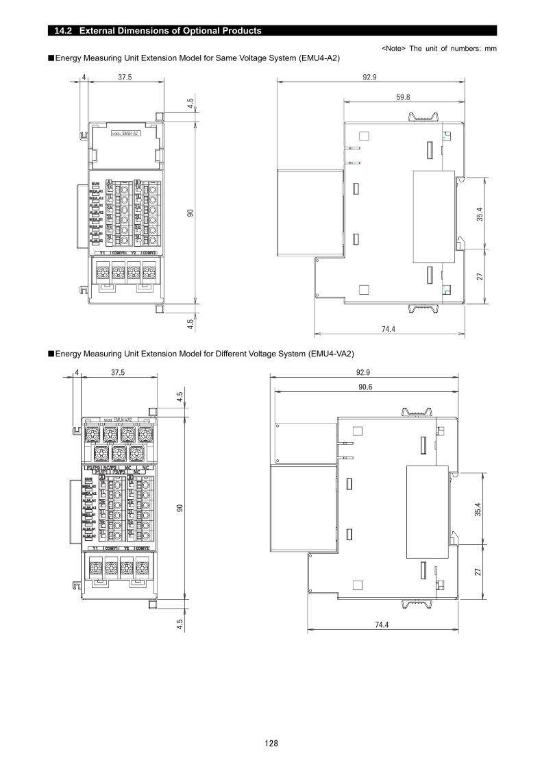
128
14.2 External Dimensions of Optional Products
<Note> The unit of numbers: mm
■Energy Measuring Unit Extension Model for Same Voltage System (EMU4-A2)
■Energy Measuring Unit Extension Model for Different Voltage System (EMU4-VA2)

129
<Note> The unit of numbers: mm
■Energy Measuring Unit Extension Model for Pulse Input (EMU4-PX4)
■Energy Measuring Unit Extension Model for Analog Input (EMU4-AX4)
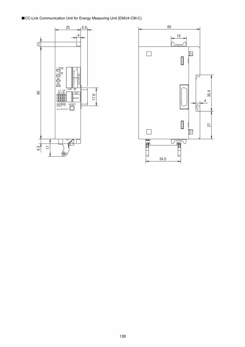
130
■CC-Link Communication Unit for Energy Measuring Unit (EMU4-CM-C)

131
■Logging Unit for Energy Measuring Unit (EMU4-LM)
■CC-Link IE Field Network Basic Communication Unit for Energy Measuring Unit (EMU4-CM-CIFB)

132
■Small Type Display Unit for Energy Measuring Unit (EMU4-D65)

133
15. External Dimensions of the Control Unit
<Note> The unit of numbers: mm
■Model: EMU4-CNT-MB
■Model: EMU4-BT

134
16. The Software End User License Agreement
CORPORATION (hereinafter referred to as "MITSUBISHI") to you (hereinafter referred to as "CUSTOMER"). The term “SOFTWARE" means any program on any media and any and all related documents and materials provided herewith by MITSUBISHI. The SOFTWARE is protected by copyright laws and international copyright treaties as well as any other applicable intellectual property laws and treaties. The SOFTWARE is licensed under the terms and conditions herein, not sold. ARTICLE 1 - GRANT OF LICENSE 1.1 MITSUBISHI hereby grants to CUSTOMER a non-exclusive and non-transferable license to use one copy of the
SOFTWARE in object code form on a single module. 1.2 MITSUBISHI hereby grants to CUSTOMER a non-exclusive and non-transferable license to make one (1) copy of the
SOFTWARE for ARCHIVAL PURPOSES ONLY; provided, however, that such copy shall contain the same copyright notice and proprietary marking appearing on the original SOFTWARE.
ARTICLE 2 – COPYRIGHT All title and copyrights in and to the SOFTWARE and any copies of the SOFTWARE shall be owned by MITSUBISHI. All rights not specifically and expressly granted to the CUSTOMER under this Agreement shall be reserved by MITSUBISHI.
ARTICLE . – RESTRICTIONS Except as expressly provided in the above Article 1, CUSTOMER shall not: (a) make any copy or copies of the SOFTWARE; (b) modify the SOFTWARE; (c) sell, distribute, sub-license, lease, rent, assign, transfer or otherwise dispose of the SOFTWARE; (d) reverse engineer, decompile or disassemble the SOFTWERE; (e) sub-license, assign or transfer the rights granted to CUSTOMER hereunder.
ARTICLE 4 - LIMITED WARRANTY 4.1 MITSUBISHI will, free of charge, repair or replace any defective recording media upon which the SOFTWARE is recorded
if the media is returned by CUSTOMER to the location where CUSTOMER obtained it within ninety (90) days from the date of initial receipt of the SOFTWARE by CUSTOMER. This limited warranty does no cover defects due to any accident, abuse or misapplication, or any cause occurring after the initial receipt of the SOFTWARE by CUSTOMER. The repair or replacement of the SOFTWARE pursuant to this Article 4.1 shall be CUSTOMER's exclusive remedy.
4.2 MITSUBISHI does not warrant that the functions of the SOFTWARE will meet CUSTOMER's requirements or that SOFTWARE operation will be error-free or uninterrupted.
ARTICLE 5 - LIMITATION OF LIABILTY MITSUBISHI SHALL NOT BE LIABLE FOR ANY DAMAGES INCLUDING, BUT NOT LIMITED TO, GENERAL, DIRECT,INDIRECT, SPECIAL, INCIDENTAL, OR CONSEQUENTIAL DAMAGES (INCLUDING BUT NOT LIMITED TO LOSS OF PROFITS, BUSINESS INTERRUPTION AND THE LIKE),WHETHER BASED ON CONTRACT, TORT, OR ANY OTHER LEGAL THEORY, AND EVEN IF ADVISED OF THE POSSIBILITY OF SUCH DAMAGES.
ARTICLE 6 - EXPORT CONTROL CUSTOMER agrees to comply strictly with all applicable laws and regulations including but not limited to export control laws and regulations. CUSTOMER shall not, without MITSUBISHI's prior written consent and any applicable governmental approval, carry out or export the SOFTWARE, directly or indirectly, to any country other than the country where CUSTOMER initially obtained the SOFTWARE.
ARTICLE 7 - TERM AND TERMINATION 7.1 Unless terminated under this Agreement, this Agreement shall continue in effect indefinitely. 7.2 MITSUBISHI may terminate this Agreement if CUSTOMER fails to comply with any of the terms and conditions of this
Agreement. 7.3 CUSTOMER may, with one (1) month prior written notice to MITSUBISHI, terminate this Agreement. 7.4 On termination of this Agreement for any reason, all CUSTOMER's rights granted by under this Agreement shall be
automatically terminated and CUSTOMER shall promptly cease to use all the SOETWARE and, at CUSTOMER's costs, i) shall promptly return all copies of the SOFTWARE to MITSUBISHI or ii) shall promptly destroy all copies of the SOFTWARE and submit to MITSUBISHI a certificate testifying that all copies of the SOFTWARE have been destroyed.
ARTICLE 8 – MISCELLANEOUS 8.1 This Agreement shall be governed in all respects by the laws of Japan. 8.2 CUSTOMER agrees and acknowledges that CUSTOMER's breach or threatened breach of this Agreement will cause
irreparable injury to MITSUBISHI and that, in addition to any other remedies that may be available, in law, in equity or otherwise, MITSUBISHI shall be entitled to obtain injunctive relief against threatened breach of this Agreement or the continuation of any such breach by CUSTOMER in any competent court.

IB63E89B 21 12 New publication effective Dec.2021
Specifications are subject to change without notice.
HEAD OFFICE: TOKYO BUILDING, 2-7-3, MARUNOUCHI, CHIYODA-KU, TOKYO 100-8310, JAPAN
Energy Measuring Unit Control unit Control Unit Engineering Tool ■Service Network
Country/Region Corporation Name Address Telephone Australia Mitsubishi Electric Australia Pty. Ltd. 348 Victoria Road, Rydalmere, N.S.W. 2116, Australia +61-2-9684-7777 Algeria Mec Casa Rue i N 125 Hay-Es-Salem, 02000, W-Chlef, Algeria +213-27798069
Bangladesh PROGRESSIVE TRADING CORPORATION HAQUE TOWER,2ND FLOOR,610/11,JUBILEE ROAD, CHITTAGONG, BANGLADESH +880-31-624307 ELECTRO MECH AUTOMATION& ENGINEERING LTD.
SHATABDI CENTER, 12TH FLOOR, SUITES:12-B, 292, INNER CIRCULAR ROAD, FAKIRA POOL, MOTIJHEEL, DHAKA-1000, BANGLADESH
+88-02-7192826
Belarus Tehnikon Oktyabrskaya 19, Off. 705, BY-220030 Minsk, Belarus +375 (0)17 / 210 46 26 Belgium Mitsubishi Electric Europe B.V. Benelux Branch Nijverheidsweg 23A, 3641 RP Mijdrecht +31 (0)297 250 350
Brazil Mitsubishi Electric do Brasil Comércio e Serviços Ltda.
Avenida Adelino Cardana, 293 – 21º Andar, Bethaville, Barueri, SP, Brasil, CEP 06401-147 +55-11-4689-3000
Cambodia DHINIMEX CO.,LTD #245, St. Tep Phan, Phnom Penh, Cambodia +855-23-997-725 Central America Automation International LLC 7050 W. Palmetto Park Road Suite #15 PMB #555, Boca Raton, FL 33433 +1-561-237-5228
Chile Rhona S.A. (Main office) Vte. Agua Santa 4211 Casilla 30-D (P.O. Box) Vina del Mar, Chile +56-32-2-320-600
China
Mitsubishi Electric Automation (China) Ltd. Mitsubishi Electric Automation Building, No.1386 Hongqiao Road, Shanghai, China 200336 +86-21-2322-3030 Mitsubishi Electric Automation (China) Ltd. BeiJing
5/F,ONE INDIGO,20 Jiuxianqiao Road Chaoyang District,Beijing, China 100016 +86-10-6518-8830
Mitsubishi Electric Automation (China) Ltd. ShenZhen
Level 8, Galaxy World Tower B, 1 Yabao Road, Longgang District, Shenzhen, China 518129 +86-755-2399-8272
Mitsubishi Electric Automation (China) Ltd. GuangZhou
Rm.1006, A1 Times E-Park, No.276-282, Hanxi Road East, Zhongcun Street, Panyu Distric, Guangzhou, China 510030
+86-20-8923-6730
Mitsubishi Electric Automation (China) Ltd. ChengDu
1501-1503,15F, Guang-hua Centre Building-C, No.98 North Guang Hua 3th Rd Chengdu, China 610000
+86-28-8446-8030
Mitsubishi Electric Automation (Hong Kong) Ltd. 20/F.,1111 king's Road, Taikoo shing, Hong Kong +852-2510-0555 Taiwan,China Setsuyo Enterprise Co., Ltd. 5th Fl., No.105, Wu Kung 3rd, Wu-Ku Hsiang, Taipei, Taiwan +886-(0)2-2298-8889
Colombia Proelectrico Representaciones S.A. Carrera 42 Nº 75 – 367 Bodega 109, Itagüi, Medellín, Antioquia, Colombia +57-4-4441284 Czech Republic AUTOCONT CONTROL SYSTEMS S.R.O Technologická 374/6, CZ-708 00 Ostrava - Pustkovec +420 595 691 150
Denmark BEIJER ELECTRONICS A/S LYKKEGARDSVEJ 17, DK-4000 ROSKILDE, Denmark +45 (0)46/ 75 76 66 Egypt Cairo Electrical Group 9, Rostoum St. Garden City P.O. Box 165-11516 Maglis El-Shaab,Cairo - Egypt +20-2-27961337
France Mitsubishi Electric Europe B.V. French Branch FR-92741 Nanterre Cedex +33 (0)1 55 68 57 01 Germany Mitsubishi Electric Europe B.V. Mitsubishi-Electric-Platz 1, 40882 Ratingen, Germany +49 (0) 2102 4860
Greece KALAMARAKIS - SAPOUNAS S.A. IONIAS & NEROMILOU STR., CHAMOMILOS ACHARNES, ATHENS, 13678 Greece +30-2102 406000 UTECO 5, MAVROGENOUS STR., 18542 PIRAEUS, Greece +30-211-1206-900
Hungary Meltrade Ltd. Fertö utca 14. HU-1107 Budapest, Hungary +36 (0)1-431-9726
India
Mitsubishi Electric India Private Limited 2nd Floor, Tower A&B, Cyber Greens, DLF Cyber City, DLF Phase-III, Gurgaon - 122 022 Haryana, India
+91-124-4630300
Mitsubishi Electric India Private Limited Pune Sales Office
ICC-Devi Gaurav Technology Park, Unit no. 402, Fourth Floor, Survey no. 191-192 (P), Opp. Vallabh Nagar Bus Depot, Pune – 411018, Maharashtra, India
+91-20-68192100
Mitsubishi Electric India Private Limited FA Center
204-209, 2nd Floor, 31FIVE, Corporate Road, Prahladnagar, Ahmedabad 380015,Gujarat. India
+91-79677-77888
Indonesia PT.Mitsubishi Electric Indonesia Gedung Jaya 8th floor, JL.MH. Thamrin No.12 Jakarta Pusat 10340, Indonesia +62-21-3192-6461 P.T. Sahabat Indonesia P.O.Box 5045 Kawasan Industri Pergudangan, Jakarta, Indonesia +62-(0)21-6610651-9
Ireland Mitsubishi Electric Europe B.V. Westgate Business Park, Ballymount, IRL-Dublin 24, Ireland +353 (0)1-4198800 Israel Gino Industries Ltd. 26, Ophir Street IL-32235 Haifa, Israel +972 (0)4-867-0656 Italy Mitsubishi Electric Europe B.V. Viale Colleoni 7, I-20041 Agrate Brianza (MI), Italy +39 039-60531
Kazakhstan Kazpromavtomatika Ul. Zhambyla 28, KAZ - 100017 Karaganda +7-7212-501000 Korea Mitsubishi Electric Automation Korea Co., Ltd 9F Gangseo Hangang xi-tower A, 401 Yangcheon-ro, Gangseo-gu, Seoul 07528 Korea +82-2-3660-9573
Laos AROUNKIT CORPORATION IMPORT- EXPORT SOLE CO.,LTD
SAPHANMO VILLAGE. SAYSETHA DISTRICT, VIENTIANE CAPITAL, LAOS +856-20-415899
Lebanon Comptoir d'Electricite Generale-Liban Cebaco Center - Block A Autostrade Dora, P.O. Box 11-2597 Beirut - Lebanon +961-1-240445 Lithuania Rifas UAB Tinklu 29A, LT-5300 Panevezys, Lithuania +370 (0)45-582-728
Malaysia Mittric Sdn Bhd
No. 5 Jalan Pemberita U1/49, Temasya Industrial Park, Glenmarie 40150 Shah Alam,Selangor, Malaysia
+603-5569-3748
Flexible Automation System Sdn Bhd 60, Jalan USJ 10/1B,UEP Subang Jaya,47620 Selangor Darul Ehsan,Malaysia +603-5633-1280 Malta ALFATRADE LTD 99 PAOLA HILL, PAOLA PLA 1702, Malta +356 (0)21-697-816
Maroco SCHIELE MAROC KM 7,2 NOUVELLE ROUTE DE RABAT AIN SEBAA, 20600 Casablanca, Maroco +212 661 45 15 96 Myanmar Peace Myanmar Electric Co.,Ltd. NO137/139 Botahtaung Pagoda Road, Botahtaung Town Ship 11161,Yangon,Myanmar +95-(0)1-202589
Nepal Watt&Volt House KHA 2-65,Volt House Dillibazar Post Box:2108,Kathmandu,Nepal +977-1-4411330 Netherlands Mitsubishi Electric Europe B.V. Benelux Branch Nijverheidsweg 23A, 3641 RP Mijdrecht +31 (0)297 250 350
North America Mitsubishi Electric Automation, Inc. 500 Corporate Woods Parkway, Vernon Hills, IL 60061 USA +847-478-2100 Norway Scanelec AS Leirvikasen 43B, NO-5179 Godvik, Norway +47 (0)55-506000
Mexico Mitsubishi Electric Automation, Inc. Mexico Branch
Blvd. Miguel de Cervantes Saavedra 301, Torre Norte Piso 5, Col. Ampliación Granada, Miguel Hidalgo, Ciudad de México, CP 11520, México
+52-55-3067-7511
Middle East Arab Countries &
Cyprus
Comptoir d'Electricite Generale-International-S.A.L.
Cebaco Center - Block A Autostrade Dora P.O. Box 11-1314 Beirut - Lebanon +961-1-240430
Pakistan Prince Electric Co. 2-P GULBERG II, LAHORE, 54600, PAKISTAN +92-42-575232, 5753373
Peru Rhona S.A. (Branch office) Avenida Argentina 2201, Cercado de Lima +51-1-464-4459
Philippines MELCO Factory Automation Philippines Inc. 128, Lopez Rizal St., Brgy. Highway Hills, Mandaluyong City, Metro Manila, Phillippines +63-(0)2-256-8042 Edison Electric Integrated, Inc. 24th Fl. Galleria Corporate Center, Edsa Cr. Ortigas Ave., Quezon City Metro Manila, Philippines +63-(0)2-634-8691
Poland Mitsubishi Electric Europe B.V. Polish Branch Krakowska 48, 32-083 Balice, Poland +48 12 347 65 00 Republic of
Moldova Intehsis SRL bld. Traian 23/1, MD-2060 Kishinev, Moldova +373 (0)22-66-4242
Romania Sirius Trading & Services SRL RO-060841 Bucuresti, Sector 6 Aleea Lacul Morii Nr. 3 +40-(0)21-430-40-06 Russia Mitsubishi Electric (Russia) LLC 2 bld.1, Letnikovskaya street, Moscow, 115114, Russia +7 495 721-2070
Saudi Arabia Center of Electrical Goods Al-Shuwayer St. Side way of Salahuddin Al-Ayoubi St. P.O. Box 15955 Riyadh 11454 - Saudi Arabia +966-1-4770149 Singapore Mitsubishi Electric Asia Pte. Ltd. 307 Alexandra Road, Mitsubishi Electric Building, Singapore 159943 +65-6473-2308
Slovakia PROCONT, Presov Kupelna 1/, SK - 08001 Presov, Slovakia +421 (0)51 - 7580 611 SIMAP Jana Derku 1671, SK - 91101 Trencin, Slovakia +421 (0)32 743 04 72
Slovenia Inea RBT d.o.o. Stegne 11, SI-1000 Ljubljana, Slovenia +386 (0)1-513-8116 South Africa CBI-electric: low voltage Private Bag 2016, ZA-1600 Isando Gauteng, South Africa +27-(0)11-9282000
Spain Mitsubishi Electric Europe B.V. Spanish Branch Carretera de Rubí 76-80, E-08190 Sant Cugat del Vallés (Barcelona), Spain +34 (0)93-565-3131
Sweden Mitsubishi Electric Europe B.V. (Scandinavia) Hedvig Möllers gata 6, 223 55 Lund, Sweden +46 (0)8-625-10-00 Euro Energy Components AB Järnvägsgatan 36, S-434 24 Kungsbacka, Sweden +46 (0)300-690040
Switzerland TriElec AG Muehlentalstrasse 136, CH-8201 Schaffhausen, Switzerland +41-(0)52-6258425
Thailand
United Trading & Import Co., Ltd. 77/12 Bamrungmuang Road,Klong Mahanak Pomprab Bangkok Thailand +66-223-4220-3 MITSUBISHI ELECTRIC FACTORY AUTOMATION (THAILAND) CO.,LTD
101, True Digital Park Office, 5th Floor, Sukhumvit Road, Bangchak, Phara Khanong, Bangkok, 10260 Thailand
+662-092-8600
Tunisia MOTRA Electric 3, Résidence Imen, Avenue des Martyrs Mourouj III, 2074 - El Mourouj III Ben Arous, Tunisia +216-71 474 599 Turkey Mitsubishi Electric Turkey A.Ş. Şerifali Mahallesi Kale Sokak No: 41, 34775 Ümraniye, İstanbul, Turkey +90-216-969-2666
United Kingdom Mitsubishi Electric Europe B.V. Travellers Lane, UK-Hatfield, Herts. AL10 8XB, United Kingdom +44 (0)1707-276100 Uruguay Fierro Vignoli S.A. Avda. Uruguay 1274 Montevideo Uruguay +598-2-902-0808
Vietnam Mitsubishi Electric Vietnam Co.,Ltd. Head Office
11th & 12th Floor, Viettel Tower B, 285 Cach Mang Thang 8 Street, Ward 12, District 10, Ho Chi Minh City, Vietnam
+84-28-3910-5945
Mitsubishi Electric Vietnam Co.,Ltd. Hanoi Branch
24th Floor, Handico Tower, Pham Hung Road, khu do thi moi Me Tri Ha, Nam Tu Liem District, Hanoi City, Vietnam
+84-24-3937-8075
Copyright © 2022 FDOKUMEN