
RV-8CRL Standard Specifications Manual - Mitsubishi Electric ...
132
Mitsubishi Electric Industrial Robot CR800-D Controller RV-8CRL Standard Specifications Manual BFP-A3678-J
-
Upload
khangminh22 -
Category
Documents
-
view
0 -
download
0
Transcript of RV-8CRL Standard Specifications Manual - Mitsubishi Electric ...

Mitsubishi Electric Industrial RobotCR800-D Controller
RV-8CRL Standard Specifications Manual
BFP-A3678-J


All teaching work must be carried out by an operator who has received special training. (This also applies to maintenance work with the power source turned ON.)Enforcement of safety training
For teaching work, prepare a work plan related to the methods and procedures of operating the robot, and to the measures to be taken when an error occurs or when restarting. Carry out work following this plan. (This also applies to maintenance work with the power source turned ON.)Preparation of work plan
Prepare a device that allows operation to be stopped immediately during teaching work. (This also applies to maintenance work with the power source turned ON.)Setting of emergency stop switch
During teaching work, place a sign indicating that teaching work is in progress on the start switch, etc. (This also applies to maintenance work with the power source turned ON.)Indication of teaching work in progress
Provide a fence or enclosure during operation to prevent contact of the operator and robot.Installation of safety fence
Establish a set signaling method to the related operators for starting work, and follow this method.Signaling of operation start
As a principle turn the power OFF during maintenance work. Place a sign indicating that maintenance work is in progress on the start switch, etc.Indication of maintenance work in progress
Before starting work, inspect the robot, emergency stop switch and other related devices, etc., and confirm that there are no errors.Inspection before starting work
Always read the following precautions and the separate "Safety Manual" before starting use of the robot to learn the required measures to be taken.
Safety Precautions
CAUTION
CAUTION
WARNING
CAUTION
DANGER
CAUTION
CAUTION
CAUTION

The points of the precautions given in the separate "Safety Manual" are given below.Refer to the actual "Safety Manual" for details.
When automatic operation of the robot is performed using multiple control devices (GOT, programmable controller, push-button switch), the interlocking of operation rights of the devices, etc. must be designed by the customer.
Use the robot within the environment given in the specifications. Failure to do so could lead to a drop or reliability or faults. (Temperature, humidity, atmosphere, noise environment, etc.)
Transport the robot with the designated transportation posture. Transporting the robot in a non-designated posture could lead to personal injuries or faults from dropping.
Always use the robot installed on a secure table. Use in an instable posture could lead to positional deviation and vibration.
Wire the cable as far away from noise sources as possible. If placed near a noise source, positional deviation or malfunction could occur.
Do not apply excessive force on the connector or excessively bend the cable. Failure to observe this could lead to contact defects or wire breakage.
Make sure that the workpiece weight, including the hand, does not exceed the rated load or tolerable torque. Exceeding these values could lead to alarms or faults.
Securely install the hand and tool, and securely grasp the workpiece. Failure to observe this could lead to personal injuries or damage if the object comes off or flies off during operation.
Securely ground the robot and controller. Failure to observe this could lead to malfunctioning by noise or to electric shock accidents.
Indicate the operation state during robot operation. Failure to indicate the state could lead to operators approaching the robot or to incorrect operation.
When carrying out teaching work in the robot's movement range, always secure the priority right for the robot control. Failure to observe this could lead to personal injuries or damage if the robot is started with external commands.
Keep the jog speed as low as possible, and always watch the robot. Failure to do so could lead to interference with the workpiece or peripheral devices.
After editing the program, always confirm the operation with step operation before starting automatic operation. Failure to do so could lead to interference with peripheral devices because of programming mistakes, etc.
DANGER
CAUTION
CAUTION
CAUTION
CAUTION
CAUTION
CAUTION
WARNING
WARNING
CAUTION
WARNING
CAUTION
CAUTION

Make sure that if the safety fence entrance door is opened during automatic operation, the door is locked or that the robot will automatically stop. Failure to do so could lead to personal injuries.
Never carry out modifications based on personal judgments, or use non-designated maintenance parts. Failure to observe this could lead to faults or failures.
When the robot arm has to be moved by hand from an external area, do not place hands or fingers in the openings. Failure to observe this could lead to hands or fingers catching depending on the posture.
Do not stop the robot or apply emergency stop by turning the robot controller's main power OFF. If the robot controller main power is turned OFF during automatic operation, the robot accuracy could be adversely affected. Moreover, it may interfere with the peripheral device by drop or move by inertia of the arm.
Do not turn off the main power to the robot controller while rewriting the internal information of the robot controller such as the program or parameters.If the main power to the robot controller is turned off while in automatic operation or rewriting the program or parameters, the internal information of the robot controller may be damaged.
Do not connect the Handy GOT when using the GOT direct connection function of this product. Failure to observe this may result in property damage or bodily injury because the Handy GOT can automatically operate the robot regardless of whether the operation rights are enabled or not.
Do not remove the SSCNET III cable while power is supplied to the multiple CPU system or the servo amplifier. Do not look directly at light emitted from the tip of SSCNET III connectors or SSCNET III cables of the Motion CPU or the servo amplifier. Eye discomfort may be felt if exposed to the light. (Reference: SSCNET III employs a Class 1 or equivalent light source as specified in JIS C 6802 and IEC60825-1 (domestic standards in Japan).)
Do not remove the SSCNET III cable while power is supplied to the controller. Do not look directly at light emitted from the tip of SSCNET III connectors or SSCNET III cables. Eye discomfort may be felt if exposed to the light. (Reference: SSCNET III employs a Class 1 or equivalent light source as specified in JIS C 6802 and IEC60825-1 (domestic standards in Japan).)
Attach the cap to the SSCNET III connector after disconnecting the SSCNET III cable. If the cap is not attached, dirt or dust may adhere to the connector pins, resulting in deterioration connector properties, and leading to malfunction.
CAUTION
CAUTION
WARNING
CAUTION
CAUTION
DANGER
DANGER
DANGER
DANGER

Make sure there are no mistakes in the wiring. Connecting differently to the wayspecified in the manual can result in errors, such as the emergency stop not being released. In order to prevent errors occurring, please be sure to check that all functions (such as the teaching box emergency stop, cus-tomer emergency stop, and door switch) are working properly after the wiring setup is completed.
Use the network equipments (personal computer, USB hub, LAN hub, etc) confirmed by manufacturer. The thing unsuitable for the FA environment (related with conformity, temperature or noise) exists in the equipments connected to USB. When using network equipment, measures against the noise, such as measures against EMI and the addition of the ferrite core, may be necessary. Please fully confirm the operation by customer. Guarantee and maintenance of the equipment on the market (usual office automation equipment) cannot be performed.
To maintain the security (confidentiality, integrity, and availability) of the robot and the system against unauthorized access, DoS*1 attacks, computer viruses, and other cyberattacks from unreliable networks and devices via network, take appropriate measures such as firewalls, virtual private networks (VPNs), and antivirus solutions.Mitsubishi Electric shall have no responsibility or liability for any problems involving robot trouble and system trouble by unauthorized access, DoS attacks, computer viruses, and other cyberattacks.*1 DoS: A denial-of-service (DoS) attack disrupts services by overloading systems or exploiting vulnerabilities, resulting in a denial-of-service (DoS) state.
CAUTION
CAUTION
CAUTION

*CR800 controller
Notes of the basic component are shown.
Please install the earth leakage breaker in the primary side power supply of the controller because of leakage protection.
1) Prepare the following items.
2) Confirm that the primary power matches the specifications.3) Confirm that the primary power is OFF and that the earth leakage breaker power switch is OFF.4) Connect the ACIN cable to the breaker.
Connect the power terminals of the ACIN cable to the secondary side terminals of the earth leakage breaker. Also, ground the FG terminal of the cable.
5) Connect the ACIN cable to the ACIN connector on the rear of the controller.<1> Face the main key on the ACIN cable plug upwards. (Refer to the "ACIN cable connection" illustra-tion.)<2> Align the main key of the ACIN cable plug with the grooves on the ACIN connector. Push the plug into the connector as far as it will go.The plug may be damaged if it is not correctly aligned with the connector.<3> Tighten the coupling on the ACIN cable, turning it to the right until it locks.
6) Connect one end of the grounding cable to the PE (protective earth) terminal on the controller and ground the other end (2-point grounding) in order to comply with the requirements of EN 61800-5-1 for the touch current of 3.5 mA AC or more.
7) Connect the primary power cable to the primary side terminal of the earth leakage breaker.
Part name Specifications Remarks
Earth leakage breaker The following is recommended product. Prepared by customer.
Single phase: NV30FAU-2P-10A-AC100-240V-30mA(Terminal cover: TCS-05FA2)
Cable for primary power supply
AWG14 (2mm2) or above Prepared by customer.Tightening torque for terminal fixing screw is 2 to 3N•m.
Grounding cable AWG14 (2mm2) or above Prepared by customer.Tightening torque for terminal fixing screw is 2 to 3N•m.
ACIN cable Terminal: M5, cable length: 3m Supplied with the product.
CAUTION
Note 1) Always use the terminal cover for the earth leakage breaker.
L N
Controller rear
ACIN cable(attachment)
PE terminalPE terminal
Primary side
Secondry side
Single phaseAC200V
ACIN connector
PE (protective earth) terminalM4 screw
Grounding cable
Note 1)Earth leakage breaker (NV)
<3>
<1> <2>ACIN cable connection
ACIN cable (male)
ACIN connector (female)
Main key (wide)
Groove for main key (wide)
Top
Top
Coupling

■Revision history
Date of print Specifications No. Details of revisions
2019-06-24 BFP-A3678 • First print.
2019-07-26 BFP-A3678-A • Added "External magnetic field" to "2.1 Standard specifications".• Added the procedure for enabling the safety diagnosis function (STO function).
2019-10-31 BFP-A3678-B • Added additional information to the specifications of the S15.• The safety option (4F-SF002-01) is now available.• Deleted cycle time information.• Added “6.4 EMC installation guideline”.• Added the model name of the sensor attachment adapter used for the force sen-
sor set (4F-FS002H-W1000).• Revised "2.2.6 Protection specifications".• Amended the following:
“Fig. 3-28: Specifications for the connection cable”“(4) MELSOFT RT ToolBox3/MELSOFT RT ToolBox3 mini/MELSOFT RT Tool-Box3 Pro”
• Added a figure to "2.1.2 The counter-force applied to the installation surface".
2020-01-24 BFP-A3678-C • Corrected "Fig. 2-1: Positions of the centers of gravity for loads with relatively small volume".
2020-10-30 BFP-A3678-D • Amended the precautions regarding the prevention of unauthorized access.• Added an example of a protective circuit. (Fig. 3-5)• Removed Windows XP and Windows Vista from the supported operating systems for RT ToolBox3, RT ToolBox3 mini, and RT ToolBox3 Pro.
• Added information to the specifications of the earth leakage breaker.• Added precautions for vertical installation of the robot controller.• Corrected the battery name. (ER6 → ER6V)• Corrected other mistakes and changed some sections.
2021-01-22 BFP-A3678-E • Revised “6.4 EMC installation guideline”.
2021-01-29 BFP-A3678-F • Updated contents for the optional product "MELFA-3D Vision 3.0 (3F-53U-WINM)".
• Deleted the optional product "MELFA-3D Vision 2.0 (4F-3DVS2-PKG3)" and associated parts.
2021-02-19 BFP-A3678-G • Added support for the Function expansion card option (2F-DQ510, 2F-DQ511, 2F-DQ520, 2F-DQ521).
• Added support for RT ToolBox3 maintenance forecast function.
2021-04-01 BFP-A3678-H • Elaborated on explanations on the STO function.
2021-09-30 BFP-A3678-J • Corrected the explanation of the parameter "SRVON".• Added illustrations showing the installation position of ferrite cores. (Fig. 3-6)• Revised "(7) Parallel I/O interface".• Revised "(9) Parallel I/O unit".• Corrected the explanation of noise in "6.2 Working environment".• Corrected other mistakes and changed some sections.

■Introduction
This series provides compact vertical multi-joint robots for use in machine processes and assem-blies.However, to comply with the target application, a work system having a well-balanced robot arm, peripheral devices or robot and hand section must be structured.When creating these standard specifications, we have edited them so that the Mitsubishi robot's characteristics and specifications can be easily understood by users considering the implementation of robots. However, if there are any unclear points, please contact your nearest Mitsubishi branch or dealer.Mitsubishi hopes that you will consider these standard specifications and use our robots.
Note that in this specification document the specifications related to the robot arm is described Page 9, "2 Robot arm", the specifications related to the controller Page 30, "3 Controller", and software functions and a command list Page 95, "4 Software" separately.
This document has indicated the specification of the following types robot.<Robot type>• RV-8CRL
• No part of this manual may be reproduced by any means or in any form, without prior consent fromMitsubishi.
• The contents of this manual are subject to change without notice.• The specifications values are based on Mitsubishi standard testing methods.• The information contained in this document has been written to be accurate as much as possible.
Please interpret that items not described in this document "cannot be performed." or "alarmmay occur". Please contact your nearest dealer if you find any doubtful, wrong or skipped point.
• This is the original document.• Microsoft, Windows, Windows 7, Windows 8, Windows 8.1, Windows 10 are either registered
trademarks or trademarks of Microsoft Corporation in the United States and/or other countries.• The official name of Windows® is Microsoft®Windows®Operating System.• Windows® 7, Windows® 8, Windows® 8.1, Windows® 10 are either product names of Microsoft
Corporation in the United States.• Ethernet is registered trademarks or trademarks of Xerox Corporation in the United States.• All other company names and production names in this document are the trademarks or registered
trademarks of their respective owners.• Referenced Standard (Requirement of Chinese standardized law): This Product is designed and
manufactured accordance with GB 11291.1.• Illustrations in this Instruction Manual may differ from the actual products.
Copyright(C) 2019-2021 MITSUBISHI ELECTRIC CORPORATION

Contents
i
Page1 General configuration ...................................................................................................................... 1-1
1.1 Structural equipment ................................................................................................................. 1-11.1.1 Standard structural equipment ............................................................................................ 1-11.1.2 Special specifications ......................................................................................................... 1-11.1.3 Options ............................................................................................................................... 1-11.1.4 Maintenance parts .............................................................................................................. 1-1
1.2 Model type name of robot ......................................................................................................... 1-21.2.1 How to identify the robot model .......................................................................................... 1-21.2.2 Combination of the robot arm and the controller ................................................................ 1-2
1.3 Contents of the structural equipment ........................................................................................ 1-31.3.1 Robot arm ........................................................................................................................... 1-31.3.2 Controller ............................................................................................................................ 1-41.3.3 Function extension device .................................................................................................. 1-5
1.4 Contents of the Option equipment and special specification .................................................... 1-61.4.1 List of the robot arm option equipment and special specification ....................................... 1-61.4.2 List of the controller option equipment and special specification ........................................ 1-61.4.3 Function extension device .................................................................................................. 1-7
2 Robot arm ....................................................................................................................................... 2-92.1 Standard specifications ............................................................................................................. 2-9
2.1.1 Basic specifications ............................................................................................................ 2-92.1.2 The counter-force applied to the installation surface ........................................................ 2-10
2.2 Definition of specifications ...................................................................................................... 2-112.2.1 Pose repeatability ............................................................................................................. 2-112.2.2 Rated load (mass capacity) .............................................................................................. 2-122.2.3 Relationships Among Mass Capacity, Speed, and Acceleration/Deceleration Speed ...... 2-13
(1) Setting Load Capacity and Size (Hand Conditions) ....................................................... 2-132.2.4 Vibrations at the Tip of the Arm during Low-Speed Operation of the Robot ..................... 2-132.2.5 Collision detection ............................................................................................................. 2-132.2.6 Protection specifications ................................................................................................... 2-14
(1) Types of protection specifications .................................................................................. 2-14(2) About the use with the bad environment ........................................................................ 2-15
2.3 Names of each part of the robot ............................................................................................. 2-162.4 Outside dimension • Operating range diagram ....................................................................... 2-17
2.4.1 Outside dimensions of machine cables ............................................................................ 2-192.5 Tooling .................................................................................................................................... 2-20
2.5.1 Wiring and piping for hand ................................................................................................ 2-202.5.2 Internal wiring and piping .................................................................................................. 2-212.5.3 Internal wiring for the hand cable ...................................................................................... 2-212.5.4 Air supply circuit example for the hand ............................................................................. 2-222.5.5 About the Installation of Tooling Wiring and Piping .......................................................... 2-22
2.6 Options .................................................................................................................................... 2-24(1) Machine cable (replaceable): Fixed type ........................................................................ 2-25(2) Machine cable (replaceable): Flexed type ...................................................................... 2-26
2.7 About Overhaul ....................................................................................................................... 2-282.8 Maintenance parts .................................................................................................................. 2-29
3 Controller ...................................................................................................................................... 3-303.1 Standard specifications ........................................................................................................... 3-30
3.1.1 Basic specifications .......................................................................................................... 3-303.1.2 Protection specifications and operating supply ................................................................. 3-32
(1) Protection specifications ................................................................................................. 3-32(2) Operating supply ............................................................................................................ 3-32
3.2 Names of each part ................................................................................................................. 3-333.2.1 Controller .......................................................................................................................... 3-33
3.3 Outside dimensions/Installation dimensions ........................................................................... 3-35

Contents
ii
Page3.3.1 Outside dimensions .......................................................................................................... 3-353.3.2 Installation dimensions ..................................................................................................... 3-36
3.4 External input/output ............................................................................................................... 3-383.4.1 Types ................................................................................................................................ 3-38
3.5 Dedicated input/output ............................................................................................................ 3-393.6 Emergency stop input and output etc. .................................................................................... 3-42
3.6.1 Connection of the external emergency stop and mode selector switch ............................ 3-433.6.2 Special stop input (SKIP) .................................................................................................. 3-473.6.3 Door switch function ......................................................................................................... 3-483.6.4 Mode selector switch function ........................................................................................... 3-48
(1) Automatic Operation/Jog Operation/Brake Release and Necessary Switch Settings .... 3-493.7 Additional Axis Function .......................................................................................................... 3-50
3.7.1 Wiring of the Additional Axis Interface .............................................................................. 3-50(1) Example of the installation of the noise filter .................................................................. 3-51(2) Line noise filter ............................................................................................................... 3-52
3.8 Additional axis synchronization output .................................................................................... 3-53(1) Example circuit ............................................................................................................... 3-53(2) Image of how to connect the controller connector .......................................................... 3-54
3.9 Options .................................................................................................................................... 3-55(1) Teaching pendant (T/B) .................................................................................................. 3-56(2) High efficient teaching pendant (T/B) ............................................................................. 3-59(3) Function extension card ................................................................................................. 3-61(4) Controller protection box ................................................................................................ 3-62(5) MELSOFT RT ToolBox3/MELSOFT RT ToolBox3 mini/MELSOFT RT ToolBox3 Pro ... 3-67(6) Instruction Manual (bookbinding) ................................................................................... 3-69(7) Parallel I/O interface ....................................................................................................... 3-70(8) External I/O cable ........................................................................................................... 3-76(9) Parallel I/O unit ............................................................................................................... 3-78(10) External I/O cable ......................................................................................................... 3-88(11) CC-Link interface .......................................................................................................... 3-90(12) SD memory card ........................................................................................................... 3-93
3.10 Maintenance parts ................................................................................................................ 3-94
4 Software ........................................................................................................................................ 4-954.1 List of commands .................................................................................................................... 4-954.2 List of parameters ................................................................................................................... 4-98
5 Instruction Manual ....................................................................................................................... 5-1005.1 The details of each instruction manuals ................................................................................ 5-100
6 Safety .......................................................................................................................................... 6-1016.1 Safety .................................................................................................................................... 6-101
6.1.1 Self-diagnosis stop functions .......................................................................................... 6-1016.1.2 External input/output signals that can be used for safety protection measures .............. 6-1026.1.3 Precautions for using robot ............................................................................................. 6-102
(1) Robot installation .......................................................................................................... 6-102(2) Prevention of contact with operator .............................................................................. 6-102(3) Work procedures .......................................................................................................... 6-102(4) Training ......................................................................................................................... 6-103(5) Daily inspection and periodic inspection ....................................................................... 6-103
6.1.4 Safety measures for automatic operation ....................................................................... 6-1036.1.5 Safety measures for teaching ......................................................................................... 6-1036.1.6 Safety measures for maintenance and inspections, etc. ................................................ 6-1036.1.7 Examples of safety measures ......................................................................................... 6-104
(1) External emergency stop connection [supplementary explanation] ............................. 6-1086.2 Working environment ............................................................................................................ 6-109

Contents
iii
Page(1) Power supply ................................................................................................................ 6-109(2) Noise ............................................................................................................................ 6-109(3) Temperature and humidity ............................................................................................ 6-109(4) Vibration ....................................................................................................................... 6-109(5) Installation environment ................................................................................................ 6-109
6.3 Precautions for handling ....................................................................................................... 6-1096.4 EMC installation guideline ..................................................................................................... 6-111
6.4.1 Outlines ........................................................................................................................... 6-1116.4.2 EMC directive ................................................................................................................. 6-1116.4.3 EMC measures ............................................................................................................... 6-1116.4.4 Example of EMC measures ............................................................................................ 6-1126.4.5 Parts for EMC measures ................................................................................................ 6-112
7Appendix .......................................................................................................................... Appendix-113Appendix 1: Inertia calculation method .......................................................................... Appendix-113
(1) Load moment calculation example (for J5 axis with flange facing downwards) .... Appendix-113
(2) Load inertia calculation example (for J6 axis) ................................................. Appendix-113Appendix 2: Classification of functions using external input/output signals ................... Appendix-114Appendix 3: Safety diagnosis function (Test pulse diagnosis) ....................................... Appendix-115Appendix 4: Safety block diagram ................................................................................. Appendix-116Appendix 5: Specifications discussion material ............................................................. Appendix-117

1 General configuration
Structural equipment 1-1
1 General configuration1.1 Structural equipment
Structural equipment consists of the following types.
1.1.1 Standard structural equipmentThe following items are enclosed as a standard.
1) Robot arm2) Controller3) Machine cable4) Robot arm installation bolts5) CD-ROM (Instruction manual)
1.1.2 Special specificationsFor the special specifications, some standard configuration equipment and specifications have to be changed before factory shipping. Confirm the delivery date and specify the special specifications at the order.
1.1.3 OptionsUser can install options after their delivery. The customer needs to arrange for the installation.
1.1.4 Maintenance partsMaterials and parts for the maintenance use.

1-2 Model type name of robot
1 General configuration
1.2 Model type name of robotThis robot has arranged the type name corresponding to load mass, arm length, and environment specifica-tion. Details are shown below, please select the robot suitable for the customer's use.
1.2.1 How to identify the robot modelRV - ◊ CR L - D -Sxx
(a) (b) (c) (d) (e) (f)
(a) RV ................................. Indicates the vertical multi-joint robot.
(b) ◊..................................... Indicates the maximum load.8: 8kg
(c) CR ................................. Indicates the CR series.
(d) L .................................... Indicates long arm type.
(e) D.................................... Indicates the controller type.D: Stand alone type
(f) -Sxx ................................ Indicates a special model. In order, limit special specification.S15: The parallel I/O interface installed on the controller is source
type (2D-TZ378). It was originally sink type (2D-TZ368).
1.2.2 Combination of the robot arm and the controllerTable 1-1: Combination of the robot arm and the controller
Robot armController
Type name Protection specification Arm length Brake Axial
constitution
RV-8CRL IP rating Note1)
Note1) This robot arm's protective structure is IP65. The protective structure of all the controllers is IP20 (opentype). To protect a controller, use the optional controller protection box (IP54).
Long arm All axes 6-axis type CR800-CVD

1 General configuration
Contents of the structural equipment 1-3
1.3 Contents of the structural equipment1.3.1 Robot arm
The list of structural equipment is shown in below.
Fig.1-1: Structural equipment
6-axis vertical multi-joint robot (RV-8CRL)
* Refer to Page 9, "2.1 Standard specifications" for details on the specifications.
Machine cable(Fixed type: 5m)
[Caution]Standard configuration Optionequipment
Machine cable (replaceable type)• Fixed type: 1F-□□UCBL-43• Flexed type: 1F-□□LUCBL-43
Note 1)□□ refer the length. Refer to Table 1-2 for details.
Note 2) Replace the enclosed stan-dard cable with this cable.

1-4
1 General configuration
1.3.2 ControllerThe devices shown below can be installed on the controller.The controllers that can be connected differ depending on the specification of the robot. (Refer to Page 2,
"1.2 Model type name of robot".)
Fig.1-2: Structural equipment
PLC (Programmable Logic Controller)External device
Prepared by customer
Network base card• EtherNet/IP interface• PROFINET interface• CC-Link IE Field interface• EtherCAT interface
Refer to Table 1-3 for details of each inter-face card.
RT ToolBox3• 3F-14C-WINE (DVD-ROM)
RT ToolBox3 mini • 3F-15C-WINE (DVD-ROM)
RT ToolBox3 Pro • 3F-16D-WINE (DVD-ROM)
(Windows 7, Windows 8, Windows 8.1, Windows 10)
Personal computerPrepared by customer
*)Refer to Table
1-5 for USB cable
Instruction Manual (bookbinding)5F-BR01-PE01
Parallel I/O interface2D-TZ368 (Sink)2D-TZ378 (Source)
CC-Link interface2D-TZ576
Teaching pendant (T/B)• R32TB
High efficient teaching pendant (T/B)
• R56TB
Controller• CR800-CVD
External I/O cable• 2D-CBL05 (5m)• 2D-CBL15 (15m)
Parallel I/O unit2A-RZ361 (Sink)2A-RZ371 (Source)
External I/O cable• 2A-CBL05 (5m)• 2A-CBL15 (15m)
Controller protection box• CR800-MB
SD memory card• 2F-2GBSD
Standard configuration
Options
Prepared by customer
[Caution]
equipment
Parallel I/O interface
The 2D-TZ368 (sink type) is installed in slot 1.The 2D-TZ378 (source type) is installed in the S15 with special specifications.
Safety option• 4F-SF002-01
Refer to Table 1-3 for detail.
Function extension card

1 General configuration
1-5
1.3.3 Function extension deviceThese devices (option) are used to extend the function of the robot.
Fig.1-3: Function extension device
Force sensor set• 4F-FS002H-W200• 4F-FS002H-W1000 Note 1)
Note 1) Use the sensor attachment adapter "1F-FSFLGSET-01".
MELFA-3D Vision 3.0• 3F-53U-WINM

1-6 Contents of the Option equipment and special specification
1 General configuration
1.4 Contents of the Option equipment and special specificationA list of all Optional equipment and special specifications are shown below.
1.4.1 List of the robot arm option equipment and special specificationTable 1-2: The list of robot option equipment and special specification
1.4.2 List of the controller option equipment and special specificationTable 1-3: The list of the controller option equipment and special specification
Item Type Specifications Classification Note1)
Note1) ○: option.
Description
Machine cable (replaceable type)
1F-□□UCBL-43 For fixing○
" □□ " in type shows the length of the cables as follows.10=10m, 15=15m, 20=20m(The standard cable is 5 m long.)
1F-□□LUCBL-43 For flexing○
" □□ " in type shows the length of the cables as follows.10=10m, 15=15m, 20=20m(The standard cable is 5 m long.)
Item Type Specifications Classification Note1) Description
Simple teaching pendant
R32TB Cable length 7m ○ With 3-position enable switchIP65R32TB-15 Cable length 15m ○
Highly efficient teaching pendant
R56TB Cable length 7m ○R56TB-15 Cable length 15m ○
Parallel I/O Interface 2D-TZ368(Sink type)/2D-TZ378(Source type)
DO: 32 pointDI: 32 pointInsulated type output signal
(0.1A/24V /point)Insulated type input signal
(9mA/ 24V /point)
○
The card type external input-and-output. Interface. Install to the slot of controller.The 2D-TZ368 (sink type) is installed in SLOT1 of the robot controller from the factory.The 2D-TZ378 (source type) is installed in the S15 with special specifications.
External I/O cable (For Parallel I/O Interface)
2D-CBL05 5m ○ Use to connect the external peripheral device to the parallel input/output interface.2D-CBL15 15m ○
Parallel I/O Unit 2A-RZ361(Sink type)/2A-RZ371(Source type)
DO: 32 point/DI: 32 pointInsulated type output signal
(0.1A/24V /point)Insulated type input signal
(7mA/ 24V /point)
○
The unit for expansion the external input/output.
External I/O cable (For Parallel I/O Unit)
2A-CBL05 5m ○ Use to connect the external peripheral device to the parallel input/output unit2A-CBL15 15m ○
CC-Link interface 2D-TZ576 Only Intelligent device station, Local station ○ For MELSEC PLC with CC-Link connec-
tion.
Network base card(EtherNet/IP inter-face)
2D-TZ535 Communication interface for mounting the Anybus CompactCom module manufactured by HMS.The customer needs to prepare the EtherNet/IP module (AB6314) manufactured by HMS.
○
Refer to separate volume "Network Base Card Instruction Manual" for details.
Network base card(PROFINET inter-face)
2D-TZ535-PN Communication interface for mounting the Anybus CompactCom module manufactured by HMS.The customer needs to prepare the PROFINET IO module (AB6489-B) manufactured by HMS.
○
Refer to separate volume "Network Base Card Instruction Manual" for details.
Network base card(CC-Link IE Field interface)
2F-DQ535 Communication interface for mounting the Anybus CompactCom module manufactured by HMS.The customer needs to prepare the CC-Link IE Field module (AB6709) manufactured by HMS.
○
Refer to separate volume "Network Base Card Instruction Manual" for details.

1 General configuration
Contents of the Option equipment and special specification 1-7
1.4.3 Function extension device
Table 1-4: The list of function extension device
Network base card(EtherCAT interface)
2F-DQ535-EC Communication interface for mounting the Anybus CompactCom module manufactured by HMS.The customer needs to prepare the EtherCAT module (AB6607) manufactured by HMS.
○
Refer to separate volume "Network Base Card Instruction Manual" for details.
Function extension card
2F-DQ510 MELFA Smart Plus card pack (A-type) ○ Item to enable the software extension
function MELFA Smart Plus.Software version of controller: Ver. A5p or later.2F-DQ520 MELFA Smart Plus card pack (AB-
type) ○
2F-DQ511 MELFA Smart Plus card (A-type) ○
2F-DQ521 MELFA Smart Plus card (B-type) ○
SD memory card 2F-2GBSD Memory card capacity 2GB. ○ -
Safety option 4F-SF002-01 Item to support the safety I/O. ○ Refer to separate volume "Robot Safety Option Instruction Manual" for details.
Controller protec-tion box
C800-MB IP54○
The controller protection box is used to protect the controller from an oilmist or other operating environment.
RT ToolBox3 3F-14C-WINE DVD-ROM○
Windows 7, Windows 8, Windows 8.1, Windows 10Supporting English.(With the simulation function)
RT ToolBox3 mini 3F-15C-WINE DVD-ROM○
Windows 7, Windows 8, Windows 8.1, Windows 10Supporting English.
RT ToolBox3 Pro 3F-16D-WINE DVD-ROM○
Windows 7, Windows 8, Windows 8.1, Windows 10Supporting English.
Instruction Manual 5F-BR01-PE01 RV-8CRL ○ -
Note1) ○: option.
Item Type name SpecificationsClassification
Note1)
Note1) ○: option.
Remarks
Force sensor set 4F-FS002H-W200 A set of devices necessary for force sense control function, such as a force sensor, an interface unit, and support software.
○
Refer to separate volume "Force Sense Function Instruction Man-ual" for details.
4F-FS002H-W1000Note2)
Note2) Use the sensor attachment adapter "1F-FSFLGSET-01".
MELFA-3D Vision 3.0
3F-53U-WINM Software that connects a com-pact 3D vision sensor for robots to measure and recognize parts.
○Refer to separate volume "MELFA-3D Vision 3.0 Instruction Manual" for details.
Item Type Specifications Classification Note1) Description
1-8 Contents of the Option equipment and special specification
1 General configuration
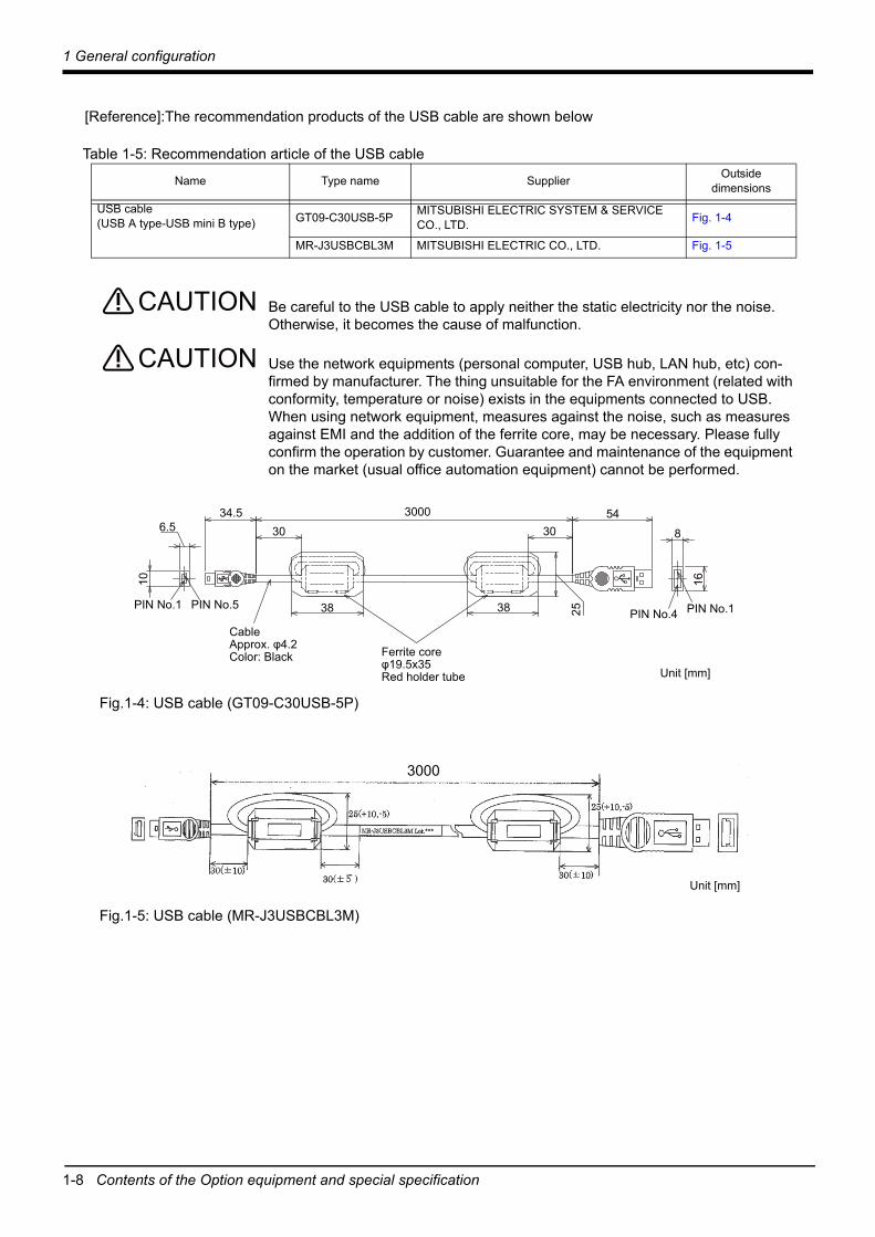
[Reference]:The recommendation products of the USB cable are shown below
Table 1-5: Recommendation article of the USB cable
Be careful to the USB cable to apply neither the static electricity nor the noise.Otherwise, it becomes the cause of malfunction.
Use the network equipments (personal computer, USB hub, LAN hub, etc) con-firmed by manufacturer. The thing unsuitable for the FA environment (related with conformity, temperature or noise) exists in the equipments connected to USB. When using network equipment, measures against the noise, such as measures against EMI and the addition of the ferrite core, may be necessary. Please fully confirm the operation by customer. Guarantee and maintenance of the equipment on the market (usual office automation equipment) cannot be performed.
Fig.1-4: USB cable (GT09-C30USB-5P)
Fig.1-5: USB cable (MR-J3USBCBL3M)
Name Type name Supplier Outside dimensions
USB cable(USB A type-USB mini B type) GT09-C30USB-5P MITSUBISHI ELECTRIC SYSTEM & SERVICE
CO., LTD. Fig. 1-4
MR-J3USBCBL3M MITSUBISHI ELECTRIC CO., LTD. Fig. 1-5
CAUTION
CAUTION
34.530
38
3054
8
16
2538PIN No.1 PIN No.5 PIN No.1PIN No.4
Unit [mm]
3000
CableApprox. φ4.2Color: Black Ferrite core
φ19.5x35Red holder tube
6.5
10
Unit [mm]
3000

2 Robot arm
Standard specifications 2-9
2 Robot arm2.1 Standard specifications2.1.1 Basic specifications
Table 2-1: Standard specifications of RV-8CRL robotItem Unit Specifications
Type RV-8CRLEnvironment Oil mist specificationDegree of freedom 6 Installation posture On floor, hanging, (against wall Note1) )
Note1) When used by mounting on the wall, a special specification that limits the operating range of the J1 axis will be used. Please give an order separately.
Structure Vertical, multiple-joint typeDrive system AC servo motor (brake provided on all axes)Position detection method Absolute encoderMotor capac-ity
Waist (J1) W 600Shoulder (J2) 750Elbow (J3) 400Wrist twist (J4) 100Wrist pitch (J5) 100Wrist roll (J6) 100
Operatingrange
Waist (J1) Degree ±170Shoulder (J2) ±110Elbow (J3) +0 to +165Wrist twist (J4) ±200Wrist pitch (J5) ±120Wrist roll (J6) ±360
Speed ofmotion
Waist (J1) Degree/s
288Shoulder (J2) 321Elbow (J3) 360Wrist twist (J4) 337Wrist pitch (J5) 450Wrist roll (J6) 720
Maximum reach radius (P point) mm 931Maximum resultant velocity Note2)
Note2) This is the value on the mechanical interface surface when all axes are combined.
mm/sec 10,500Load Rating kg 7
Maximum Note3)
Note3) Allowable load when the mechanical interface faces downward at an inclination within ±10° to the vertical direction.
kg 8Pose repeatability Note4)
Note4) The pose repeatability details are given in Page 11, "2.2.1 Pose repeatability"
mm ±0.02Ambient temperature Note5) °C 0 to 40Mass kg 41Allowablemoment load
Wrist twist (J4)N•m
16.2Wrist pitch (J5) 16.2Wrist roll (J6) 6.86
Allowableinertia
Wrist twist (J4)kg•m2
0.45Wrist pitch (J5) 0.45Wrist roll (J6) 0.10
Tool wiring - D-sub 15 pinsTool pneumatic pipes - φ6×2Supply pressure MPa 0.54Protection specification Note6) Note7) Note8) - IP65
Painting color - Light gray (Equivalent to Munsell: 0.6B7.6/0.2, PANTONE: 428C)External magnetic field mT Less than 10

2-10 Standard specifications
2 Robot arm
2.1.2 The counter-force applied to the installation surfaceThe counter-force applied to the installation surface for the strength design of the robot installation surface is shown.
Table 2-2: Value of each counter-force
Note5) Sets the robot's operating environmental temperature as parameter OLTMX. Corresponding to the environment, the continuous control action performance and the overload-protection function are optimized. (Refers to "Optimizing the overload level" described in "Chapter 5 Functions set with parameters" of separate instruction manual/ Detailed explanations of functions and operations for details.)
Note6) The protection specification details are given in Page 14, "2.2.6 Protection specifications".Note7) The protection performance may not be ensured depending on the oil characteristics. Please consult the dealer.Note8) If the controller is used in oil mist or similar environments, use the controller protection box to protect the controller from the
environment.
Item Unit ValueFalls moment: ML N•m 900Torsion moment: MT N•m 900Horizontal translation force: FH N 1,000Vertical translation force: FV N 1,700
FH
FH
FH
FH
FV
FV
MT
MLML

2 Robot arm
Definition of specifications 2-11
2.2 Definition of specificationsThe accuracy of pose repeatability mentioned in catalogs and in the specification manual is defined as fol-lows.
2.2.1 Pose repeatabilityFor this robot, the pose repeatability is given in accordance with JIS B 8432 (Pose repeatability). Note that the value is based on 100 measurements (although 30 measurements are required according to JIS).
[Caution] The specified "pose repeatability" is not guaranteed to be satisfied under the following conditions.
[1] Operation pattern factors1) When an operation that approaches from different directions and orientations are included in
relation to the teaching position during repeated operations2) When the speed at teaching and the speed at execution are different
[2] Load fluctuation factor1) When work is present/absent in repeated operations
[3] Disturbance factor during operation1) Even if approaching from the same direction and orientation to the teaching position, when
the power is turned OFF or a stop operation is performed halfway
[4] Temperature factors1) When the operating environment temperature changes2) When accuracy is required before and after a warm-up operation
[5] Factors due to differences in accuracy definition1) When accuracy is required between a position set by a numeric value in the robot's internal
coordinate system and a position within the actual space2) When accuracy is required between a position generated by the pallet function and a posi-
tion within the actual space

2-12
2 Robot arm
2.2.2 Rated load (mass capacity)The robot's mass capacity is expressed solely in terms of mass, but even for tools and works of similar mass, eccentric loads will have some restrictions When designing the tooling or when selecting a robot, consider the following issues.
(1) The tooling should have the value less or equal than the smaller of the allowable inertia and the allowable moment found in Page 9, "2.1.1 Basic specifications".The examples of inertia calculation methods are described in Page 113, "Appendix 1: Inertia calculation method".
(2) Fig. 2-1 shows the distribution dimensions for the positions of the centers of gravity for loads with rel-atively small volume. Refer to the figure for designing tooling.
(3) Even if the load is force, not the mass, design the tooling so that moment does not exceed the allow-able moment. Refer to Page 9, "2.1 Standard specifications" for details of allowable moment value.
[Caution] The mass capacity is greatly influenced by the operating speed of the robot and the motion pos-ture. Even if you are within the allowable range mentioned previously, an overload or generate anovercurrnt alarm could occur. In such cases, it will be necessary to change the time setting for accel-eration/deceleration, the operating speed, and the motion posture.
[Caution] The overhang amount of the load, such as the mass capacity and the allowable moment of inertiadefined in this section, are dynamic limit values determined by the capacity of the motor that drivesaxes or the capacity of the speed reducer. Therefore, it does not guarantee the accuracy on all areasof tooling. Guaranteed accuracy is measured from the center point of the mechanical interface sur-face. Please note that if the point of operation is kept away from the mechanical interface surface bylong and low-rigid tooling, the positioning accuracy may deteriorate or may cause vibration.
[Caution] Even within the allowable range previously mentioned, an overload alarm may be generated if anascending operation continues at a micro-low speed. In such a case, it is necessary to increase theascending speed.
Fig.2-1: Positions of the centers of gravity for loads with relatively small volume
150
85
100
100
220
310
100
200
300
115
200
7kg
6kg5kg
4kg3kg
2kg
1kg
300400500600
240
255280355
310430600
135155
175
Unit: mm
Rotation center for J6 axis
Rotation center for J5 axis

2 Robot arm
2-13
2.2.3 Relationships Among Mass Capacity, Speed, and Acceleration/Deceleration SpeedThis robot automatically sets the optimum acceleration and deceleration speeds and maximum speed, according to the load capacity and size that have been set, and operates using these automatically set speeds.To achieve that, it is necessary to correctly set the actual load data (mass and size of hand and work) to be used. However, vibration, overheating and errors such as excessive margin of error and overload may occur, depending on the robot operation pattern or ambient temperature. In such a case, change the setting value to the +20% range.If a setting is performed in such a way that it falls below the mounted load, the life span of the mechanism elements used in the robot may be shortened.
(1) Setting Load Capacity and Size (Hand Conditions)Set up the capacity and size of the hand with the "HNDDAT*" parameter (optimum acceleration/deceleration setting parameter), and set up the capacity and size of the work with the "WRKDAT*" parameter. Numbers 0 to 8 can be used for the asterisk (*) part. Designate the "HNDDAT*" and "WRKDAT*" parameters to be used using the "LoadSet" command in a program. For more details, refer to the separate "Instruction Manual/Detailed Explanation of Functions and Opera-tions."It is the same meaning as "LoadSet 0.0" if not using the "LoadSet".
<Factory settings>
2.2.4 Vibrations at the Tip of the Arm during Low-Speed Operation of the RobotVibrations at the tip of the arm may increase substantially during the low-speed operation of the robot, depending on the combination of robot operation, hand mass and hand inertia. This problem occurs when the vibration count specific to the robot arm and the vibration count of the arm driving force are coming close to each other. These vibrations at the tip of the arm can be reduced by taking the following measures:
1) Lower the robot's operating speed by approximately 5% from high speed using the Ovrd command.2) Change and move the teaching points of the robot.3) Change the hand mass and hand inertia.
2.2.5 Collision detectionThis series have the "collision detection function" which detects the abnormalities by the collision of the robot arm, however initial setting is in invalid condition. The enable/disable of this function can be changed by parameter: COL and command: ColChk, this function is effective for protect of the robot and of the peripheral equipment.The abnormalities are detected by the robot's kinetics model, presuming torque necessary for movement at any time. Therefore, the setting parameter (HNDDAT*, WRKDAT*) of the hand and the work piece condi-tions should be right. And, it may be detected as the collision in movement as speed and motor torque are changed rapidly. (for example, the movement near the place of the origin by linear interpolation, the reversal movement, the cold condition, the operation after long term stoppage)In such a case, by adjusting the value of the setting parameter (COLLVL, COLLVLJG) of the collision detec-tion level according to actual use environment, the sensitivity of collision detection can be optimized and the damage risk can be reduced further. And, in the operation after the low temperature or long term stoppage, please operate by accustoming at low speed (warm-up), or use the warm-up operation mode.Refer to the separate instruction manual "Detailed explanations of functions and operations" for details of related parameter.
Table 2-3: Factory-shipments condition
Hand mass Size X Size Y Size Z Center-of-grav-ity position X
Center-of-grav-ity position Y
Center-of-grav-ity position Z
[kg] [mm] [mm] [mm] [mm] [mm] [mm]HNDDAT* = 8.0 100.0 100.0 100.0 0.0 0.0 155.0WRKDAT* = 0.0 0.0 0.0 0.0 0.0 0.0 0.0
JOG operation Automatic
RV-8CRL Invalid Invalid

2-14
2 Robot arm
2.2.6 Protection specifications(1) Types of protection specifications
The robot arm has protection specifications that comply with the IEC Standards. The protection specifica-tions and applicable fields are shown in Table 2-4.
Table 2-4: Protection specifications and applicable fields
Use the controller protection box to protect the controller from the environment when the controller will be used in the environment such as the oil mist shown in the Table 2-4.
The IEC IP symbols define the degree of protection against solids and fluids, and do not indicate a protec-tive structure against the entry of oil. The IEC standard is described by the following "Information" And, the corrosion of the rust etc. may occur to the robot with the liquids.
"Information"• The IEC IP65
Protection against water infiltration as specified in IP65 indicates a protective structure that is not harmfully affected when 12.5±5% liters of water is supplied from a test device at a position approx. 3m away in various directions and a water pressure of 30kPa at the nozzle section. The water is filled one minute per 1m2 of test device surface area for a total of three minutes.
• The IEC IP67Protection against water infiltration as specified in IP67 indicates a protective structure that is not harmfully affected, even if the test device dives underwater for the 30 minutes. The diving depth is shown below. When the height of the test device is less than 850 mm, the position of the lowest part is 1 m from the water surface.When the height of the test device is 850 mm or more, the position of the highest part is 150 mm from the water surface.
TypeProtection
specifications(IEC Standards value)
Classification Applicable field Remarks
RV-8CRL IP65Oil mist specifi-cations
Machine tool (cutting)Machine shop with heavy oil mistDusty work shop
Note that if the cutting machine is using abrasive materials, the robot's life will be shortened.
RV-7FRLM (example) IP67
CAUTION
2 Robot arm
2-15
(2) About the use with the bad environmentThis robot has protection methods that conform to IEC IP65 standards.Usage conditions are shown below.
1) The robot is designed for use in combination with machining device.2) We have confirmed that the robot arm meets the protection specifications by testing it using our spec-
ified cutting oil. However, the parts of the controller may be damaged by the cutting oil. When using the controller in an oil mist environment, always use the controller protection box. Our warranty does not cover damages or failure resulting from the robot being operated in any environment where other cutting oils than those listed in the table are used (except cutting oils with respect to which the robot's compatibility with the protection specification is verified through our operability evaluation) or where the robot body may be directly splashed with water, oil or dust in quantities larger than stated in the protection specification.
3) Take measures so that the robot will not be exposed to water, oil and/or chips for a long period of time.
Also, entrained water droplets lead to the formation of rust on the robot, but would not usually affect the robot's ability to operate normally.The warranty is invalid for any faults that occur when the robot is used under the following conditions.Also, if the cover and/or other parts are damaged by interferences caused by the peripheral devices and the robot, the protection specification (seal performance, etc.) may be degraded. Therefore, please pay extra attention when handling the robot.Refer to Page 109, "6.2 Working environment".
1) In surroundings that generate inflammable gases or corrosive gasses.2) Atmosphere of the mist containing polish liquid etc.3) Atmosphere in which the water, the oil, and the dust exceeding protection specification fall on the
robot arm directly.

2-16 Names of each part of the robot
2 Robot arm
2.3 Names of each part of the robot
Fig.2-2: Names of each part of the robot
-+
-+
-+
-
+
-
+
J3 axis
-
-
+
J5 axis
J2 axis
Base
J1 axis
J6 axis
J4 axisWrist
Elbow
Mechanical interface(Hand installariton flange surface)
Upper arm(No.1 arm)
For arm(No.2 arm)

2 Robot arm
Outside dimension • Operating range diagram 2-17
2.4 Outside dimension • Operating range diagram
*1) The depth in which the screw is tightened is 7.5 to 8mm.*2) Screw holes (M4, depth: 8) for securing the user wiring and piping.*3) Dimensions including the minimum bending radius of the machine cable.
Fig.2-3: Outside dimensions
Note) Don't install the robot arm in the position where direct rays or the heat of lighting hits. The skin temperature of the robot arm may rise, and the error may occur.
20
View A: Detail of mechanical interface
φ40h8 depth 6P.C.D.φ31.5
φ20H7 depth 6
45°φ5H7 depth 8
4-M5 screw depth 8 *1)
A
(160
)
97(160)
80 80
8080
9797
Ra6.3
4-φ9 installation hole
190
(Installation surface)
Ra6
.3
(Inst
alla
tion
surfa
ce)
R150
View B: Detail of installation dimension
BMinimum 310 *3)
390
450
1020
100
47085
25
45
280
3030
9040
50
7125
45135
93
30 30
166151Rev. *
30
*2)
*2)
*2)
*2)
*2)
250 or more (maintenance space)

2-18 Outside dimension • Operating range diagram
2 Robot arm
The following figure shows a robot at the position of:J1=0°, J2=0°, J3=90°, J4=0°, J5=0°, and J6=0°
*1) The area which P point cannot be moved: P point cannot move to this area. This limitation is valid at factory shipping, but it can be released by parameter MELTEXS.
Fig.2-4: Operating range diagram
Rev. *
930.5 930.5
1320
.524
4.4
634.
493
0.5
85 470
390
450
100
R930.5 +110
° -110°
Control point (R point) P-point path
P point
Upper view
P-point path
P point
Operating range for each axis:J1: ±170°J2: ±110°J3: +0° to +165°J4: ±200°J5: ±120°J6: ±360°
R930.5
R219.3
-170°
+170°
Side view
Flange downward limit line
R258.2
The area which P point cannot be moved
370
200
300
175
175
R230
The area which P point cannot be moved
The area which P point cannot be moved
The area which P point cannot be moved
The area which P point cannot be moved *1)

2 Robot arm
Outside dimension • Operating range diagram 2-19
2.4.1 Outside dimensions of machine cables
Note) When using machine cables (replaceable type), refer to Page 25, "(1) Machine cable (replaceable): Fixed type" for the cable diameter.
App
rox.
φ17 90mm
Approx. 73
Appr
ox. 4
5Approx. φ82
Approx. 113[Controller side]
[Rorbot arm side]A
ppro
x.
73
Mass: 3.1kgMinimum bending radius: 90mm
Cable
2-20 Tooling
2 Robot arm
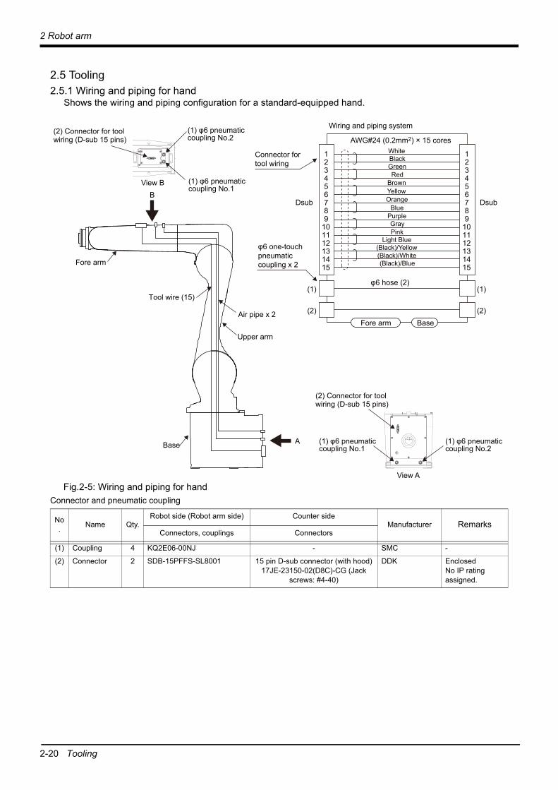
2.5 Tooling2.5.1 Wiring and piping for hand
Shows the wiring and piping configuration for a standard-equipped hand.
Fig.2-5: Wiring and piping for handConnector and pneumatic coupling
No. Name Qty.
Robot side (Robot arm side) Counter sideManufacturer Remarks
Connectors, couplings Connectors
(1) Coupling 4 KQ2E06-00NJ - SMC -
(2) Connector 2 SDB-15PFFS-SL8001 15 pin D-sub connector (with hood)17JE-23150-02(D8C)-CG (Jack
screws: #4-40)
DDK EnclosedNo IP rating assigned.
Dsub Dsub
AWG#24 (0.2mm2) × 15 cores
Connector fortool wiring
φ6 one-touch pneumatic coupling x 2
φ6 hose (2)
Wiring and piping system
WhiteBlackGreenRed
BrownYellowOrange
BluePurpleGrayPink
Light Blue(Black)/Yellow(Black)/White(Black)/Blue
123456789
101112131415
123456789
101112131415
(1)
(2)
(1)
(2)Fore arm Base
(1) φ6 pneumatic coupling No.1
(2) Connector for toolwiring (D-sub 15 pins)
(2) Connector for toolwiring (D-sub 15 pins)
(1) φ6 pneumatic coupling No.2Base
Tool wire (15)
Air pipe x 2
Upper arm
Fore arm
(1) φ6 pneumatic coupling No.1
(1) φ6 pneumatic coupling No.2
View A
View B
A
B

2 Robot arm
Tooling 2-21
2.5.2 Internal wiring and pipingThe robot has two φ6 air hoses between the pneumatic inlet on the base and the top part of the forearm. The hose end section has four coupling bridges for a φ6 hose on both the base and forearm side.
2.5.3 Internal wiring for the hand cableThe cables for the hand run from the base to the top part of the forearm (AWG #24 (0.2 mm2) x 15 cores). The cable ends in connectors as a bridge of data.Allowable current: 1AAllowable voltage: 24V

2 Robot arm
2-22
2.5.4 Air supply circuit example for the handAn example of pneumatic supply circuitry for the hand is shown below.
1) Make sure that a surge voltage protection circuit such as a diode is connected to the solenoid coil in parallel.
2) When the factory pneumatic pressure drops, as a result of the hand clamp strength weakening, there can be damage to the work. To prevent it, install a pressure switch to the source of the air as shown in Fig. 2-6 and use the circuit described so that the robot stops when pressure drops. Use a hand with a spring-pressure clamp, or a mechanical lock-type hand, that can be used in cases where the pressure switch becomes damaged.
3) If the air supply temperature (primary piping) used for the tool etc. is lower than ambient air tempera-ture, the dew condensation may occur on the coupling or the hose surface.
Fig.2-6: Air supply circuit example for the hand
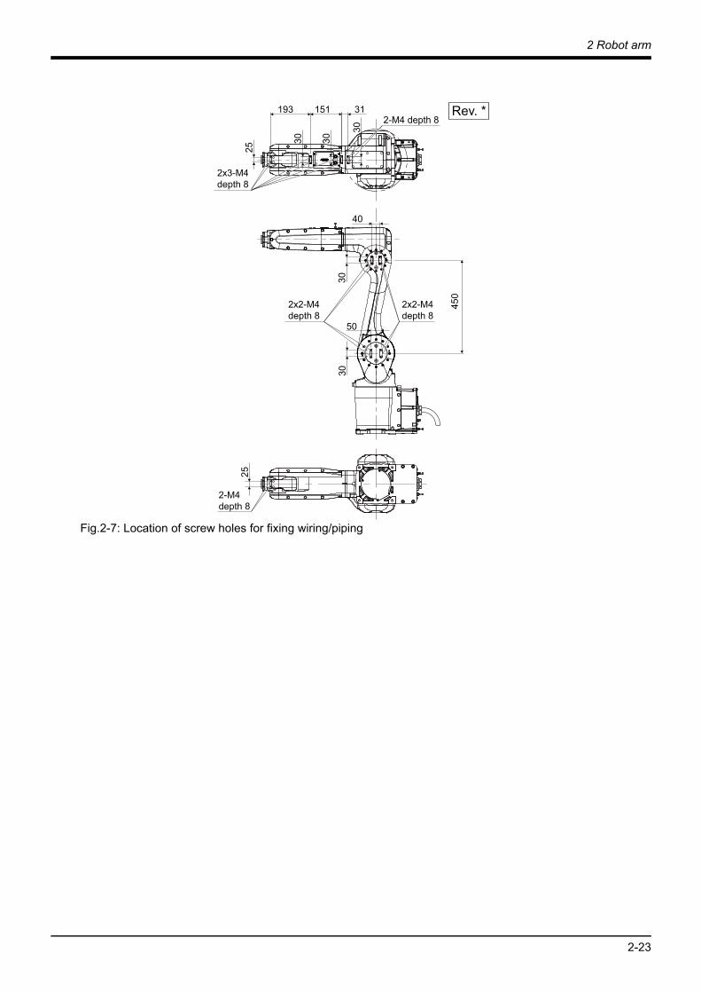
2.5.5 About the Installation of Tooling Wiring and PipingThe customer is required to provide tooling wiring, piping and metal fixtures. Screw holes are provided on the robot arm for the installation of tooling wiring, piping and metal fixtures. (Refer to the Page 17, "2.4 Outside dimension • Operating range diagram".)The length of wiring and piping and the installation position on the robot must be adjusted according to the work to be done by the robot. Please use the following example as reference.
<Precautions>• After performing wiring and piping to the robot, operate the robot at low speed to make sure that each part does not interfere with the robot arm and the peripheral devices.• If you install metal fixtures and a solenoid valve using the screw holes on the No.2 arm portion, add the mass of the metal fixtures and the solenoid valve to mass of a hand and set to parameter: HNDDAT. More-over, Fix the parts, such as a solenoid valve, firmly to prevent the parts getting shaky during operation of a robot.• Hand signals (900 to 907) are not available.
エア源(クリーンエアー)0.7MPa以下 フィルター レギュレーター
圧力スイッチ
ロボット本体のAIR INへ(MAX0.54MPa)
RegulatorFilterPneumatic source(Clean)0.7MPa or less
Pressure switch
To the AIR IN (Robot arm)(MAX. 0.54MPa)
2 Robot arm
2-23
Fig.2-7: Location of screw holes for fixing wiring/piping
450
25
3030
40
50
25
31
30 30
151 Rev. *193
30
2x3-M4 depth 8
2-M4 depth 8
2x2-M4 depth 8
2x2-M4 depth 8
2-M4 depth 8

2-24 Options
2 Robot arm
2.6 Options■What are options?
There are a variety of options for the robot designed to make the setting up process easier for customer needs.customer installation is required for the options.

2 Robot arm
Options 2-25
(1) Machine cable (replaceable): Fixed type
■Order type: ● Fixed type 1F-□□UCBL-43 Note) The numbers in the boxes □□ refer the length.
■Outline
The fixed type machine cable can be used instead of the supplied one (5 m) to extend the distance between the controller and the robot.
■ConfigurationTable 2-5: Configuration equipment and types
Part name Type Note1)
Note1) The numbers in the boxes □□ refer the length.
Qty. Mass (kg) Note2)
Note2) Mass indicates one set.
Remarks
Fixed type machine cable (replaceable) 1F-□□UCBL-43 1 cable 5.4 (10m)7.8 (15m)
10.1 (20m)
10m, 15m or 20m each
Instruction Manual (cable replacement guide-lines)
BFP-A3691 1pc - -

2-26 Options
2 Robot arm
(2) Machine cable (replaceable): Flexed type
■Order type: ● Flexed type 1F-□□LUCBL-43 Note) The numbers in the boxes □□ refer the length.
■Outline
These cables consist of flexed cables, and used for extending the distance between the controller and the robot arm. Replace the enclosed standard cables (5m) with these cables.
■ConfigurationTable 2-6: Configuration equipment and types
■SpecificationsThe specifications for the fixed type cables are the same as those for standard cables. Shows usage condi-tions for flexed type cables in Table 2-7.
Table 2-7: Conditions for the flexed type cables
[Caution] The guidance of life count may greatly differ according to the usage state items related to Table 2-7 and to the amount of silicon grease applied in the cableveyor.Recommendation grease: G-501 (Supplier: Shin-Etsu Chemical Co., Ltd.)
[Caution] When a cableveyor is used, partitions are required to avoid overlapping or riding up of the cables.Also, adjust the cable length to eliminate tension or excessive looseness, and fix it securely.
Part name Type Note1)
Note1) The numbers in the boxes □□ refer the length.
Qty. Mass (kg) Note2)
Note2) Mass indicates one set.
Remarks
Flexed type machine cable (replaceable) 1F-□□LUCBL-43 1 cable 11.1 (10m)15.4 (15m)19.8 (20m)
10m, 15m or 20m each
Nylon clamp NK-24N 2 pcs. - -
Silicon rubber - 2 pcs. - -
Instruction Manual (cable replacement guide-lines)
BFP-A3691 1pc - -
Item Specifications
Minimum flexed radius 100mm or more
Cableveyor, etc., occupation rate 50% or less
Maximum movement speed 2,000mm/s or less
Guidance of life count 7.5 million times (With silicone grease coating)
Environmental proof IP54
Cable configuration φ8.9x3, φ6.5x6, φ6.2x4, φ6x2
2 Robot arm
Options 2-27
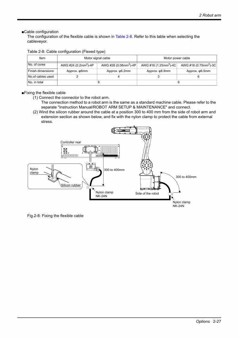
■Cable configurationThe configuration of the flexible cable is shown in Table 2-8. Refer to this table when selecting the cableveyor.
Table 2-8: Cable configuration (Flexed type)
■Fixing the flexible cable(1) Connect the connector to the robot arm.
The connection method to a robot arm is the same as a standard machine cable. Please refer to the separate "Instruction Manual/ROBOT ARM SETUP & MAINTENANCE" and connect.
(2) Wind the silicon rubber around the cable at a position 300 to 400 mm from the side of robot arm and extension section as shown below, and fix with the nylon clamp to protect the cable from external stress.
Fig.2-8: Fixing the flexible cable
Item Motor signal cable Motor power cable
No. of cores AWG #24 (0.2mm2)-4P AWG #28 (0.08mm2)-4P AWG #16 (1.25mm2)-4C AWG #18 (0.75mm2)-3C
Finish dimensions Approx. φ6mm Approx. φ6.2mm Approx. φ8.9mm Approx. φ6.5mm
No.of cables used 2 4 3 6
No. in total 6 9
Controller rear
Side of the robot
300 to 400mm
300 to 400mm
Nylon clampNK-24N
Nylon clampNK-24N
Nylon clamp
Silicon rubber

2-28 About Overhaul
2 Robot arm
2.7 About OverhaulRobots which have been in operation for an extended period of time can suffer from wear and other forms of deterioration. In regard to such robots, we define overhaul as an operation to replace parts running out of specified service life or other parts which have been damaged, so that the robots may be put back in shape for continued use. As a rule of thumb, it is recommended that overhaul be carried out before the total amount of servo-on time reaches the specified time (24,000 hours for the robot arm and 36,000 hours for the controller). However, the degree of the equipment's wear and deterioration presumably varies depend-ing on their operating conditions. Especially for operation with high load and frequency, the maintenance cycle may be shorter. For details on the part selection for replacement and the timing of overhaul, contact your dealer.
Fig.2-9: Periodic inspection/overhaul periods
If overhaul is performed
If overhaul is not performed
Servo-on time
Predetermined time period
Shipment
Over-haul
Periodic inspection
Failu
re ra
te λ

2 Robot arm
Maintenance parts 2-29
2.8 Maintenance partsA long-term use of industrial robots causes a malfunction due to wear or deterioration of their components, as well as general machines. To prevent such a malfunction and perform smooth operation of the robot for a long term, the regular maintenance, inspection, and replacement of consumable parts are required. Refer to "Maintenance and Inspection" in the separate manual "INSTRUCTION MANUAL/ROBOT ARM SETUP & MAINTENANCE" for details of the maintenance and inspection. The consumable parts used in the robot arm are shown in Table 2-9. Purchase these parts from the designated maker or dealer when required. Some Mitsubishi-designated parts differ from the maker's standard parts. Thus, confirm the part name, robot arm and controller serial No. and purchase the parts from the dealer.
Table 2-9: Consumable part listNo. Part name Type Note1)
Note1) Confirm the robot arm serial No., and contact the dealer or service branch of Mitsubishi Electric Co., for the type.
Usage place Qty. Supplier
1 Grease - Reduction gears of each axis As needed Mitsubishi Electric

3-30 Standard specifications
3 Controller
3 Controller3.1 Standard specifications3.1.1 Basic specifications
Table 3-1: Specifications of controllerItem Unit Specification Remarks
Type CR800-CVD Note1)
Number of control axis Simultaneously 6 Additional 8 axes available.Memory capacity
Programmed positions point 39,000No. of steps step 78,000Number of program 512
Robot language MELFA-BASIC V, VITeaching method Pose teaching method, MDI
method Note2)
External input and output
Input/output point 32/32 2D-TZ368 (sink type) is attached at the time of shipment.The 2D-TZ378 (source type) is installed from the factory in the S15 with special specifications.
Dedicated input/output Assigned with general-purpose input/output
The signal number of "STOP" input signals is fixing.
Emergency stop input Note3) point 1 (duplicated) Note4)
Emergency stop output point 1 (duplicated)Mode selector switch inputNote5)
point 1 (duplicated)
Mode output point 1 (duplicated)Robot error output point 1 (duplicated)Additional axis synchroniza-tion output
point 1 (duplicated)
Door switch input point 1 (duplicated)Ecoder input Channel 2 -
Interface Additional axis, force sensor interface Channel 1 SSCNET III/H (Connect with MR-J4-B
series)Remote input/output Channel 1 Compatible with Ver. 1.0/2.0USB port 1 Ver. 2.0 HighSpeed device functions
only. USB mini-BEthernet
port1 For customer: 1000BASE-T/
100BASE-TX/10BASE-T
1 Dedicated T/B port: 100BASE-TX/10BASE-T
Option slot
slot 2
For option interface 2D-TZ368 is installed to slot 1. The 2D-TZ378 is installed in the S15 with special speci-fications.Note6)
SD memory card slot slot 1 For extended memoryRS-422 port 1 Dedicated T/B port
Power source Input voltage range V Single phase AC 200 to 230 The rate of power-supply voltage fluctuation is within 10%.
Power capacity kVA 2.0 Does not include rush current. Note7)
Power supply frequency Hz 50/60
Outline dimensions Note8) mm 430(W) x 425(D) x 99.5(H) Excluding protrusions
Mass kg Approx. 12.5Construction Self-contained floor type, Opened
type.Installation vertically or horizontally
IP20 Note9)
Ambient temperature
In use °C 0 to 40 Without freezeAt transport/storage -15 to +70
3 Controller
Standard specifications 3-31
Ambient humidity
In use %RH 45 to 85 Without dew dropsAt transport/storage 90 or less
Overvoltage category Note10) II or less
Pollution level Note11) 2 or less
Altitude m 1000 or lessGrounding Ω 100 or less 100Ωor less (class D
grounding)Note12)
Paint color Dark gray Equivalent to Munsell: 3.5PB3.2/0.8, PANTONE: 432C
Note1) For details of the operation procedure, basic operations, and maintenance and inspection items of the controller, referto the information on the CR800-D in the separate volume "Controller Setup, Basic Operation and Maintenance".
Note2) Pose teaching method: The method to register the current position of the robot arm.MDI method: The method to register by inputting the numerical value Immediate.
Note3) At factory settings, the STO function activated by an external emergency stop input meets the requirements of SIL 2,Category 3, and PL d. The STO function activated by an external emergency stop input meets the requirements of SIL3, Category 4, and PL e when the parameter setting is changed by referring to Page 115, "Appendix 3: Safetydiagnosis function (Test pulse diagnosis)".
Note4) For details on the functions using external input/output signals, always refer to Page 114, "Appendix 2: Classificationof functions using external input/output signals".
Note5) Provide a mode selector switch to change the mode (MANUAL/AUTOMATIC) of the controller. Select the switchthat meets the following specifications.• The switch can be locked in each position of the selected mode.• The selected switch position can be clearly distinguished from each other.• Only one mode can be selected at a time.(Recommended switch model: HA1K-2C2A-2 manufactured by IDEC. The key switch can be locked in eachposition by removing its key.)The mode can be changed by other means than the selector switch. For example, the user can use a mode change program. In the program, provide a means to lock the selectedmode with a password.
Note6) Two connectors for 2D-TZ368/2D-TZ378 are attached (FCN-360 BKO-C11465H01).Note7) The power capacity is the recommended value. The power capacity does not include the rush current when the
power is turned ON. The power capacity is a guideline and the actual operation is affected by the input powervoltage. Use the short circuit breaker which operates by the current leakage under the commercial frequencydomain (50-60Hz). If sensitive to the high frequency ingredient, it will become the cause in which below themaximum leak current value carries out the trip. The following lists the current values of the representative models as a reference.
Note8) Refer to Page 35, "3.3.1 Outside dimensions" for details.Note9) This controller is standard specification. (Refer to Page 32, "3.1.2 Protection specifications and operating
supply".)Note10) This indicates the section of the power supply to which the equipment is assumed to be connected between the
public electrical power distribution network and the machinery within premises. Category II applies to equipment for which electrical power is supplied from fixed facilities. The surge voltage withstand level for up to the rated voltage of 300V is 2500V.
Note11) This index indicates the degree to which conductive material is generated in terms of the environment in which the equipment is used. Pollution level 2 is when only non-conductive pollution occurs. A temporary conductivity caused by condensing must be expected occasionally.
Note12) The robot must be grounded by the customer.
Item Unit Specification Remarks
Item Current [A] Apparent power [kVA] Voltage at measurement [V]
At control power ON 0.42 0.09 219.3At servo ON 1.20 0.26 220.0In automatic operation Effective value 2.23 0.50 219.2
Peak 9.19 2.26 220.0

3-32 Standard specifications
3 Controller
3.1.2 Protection specifications and operating supply(1) Protection specifications
A protection method complying with the IEC Standard IP20 (Opened type) is adopted for CR800 controller.The IEC IP symbols refer only to the degree of protection between the solid and the fluids, and don't indicated that any special protection has been constructed for the prevention against oil and water.
[Information]• The IEC IP20It indicates the protective structure that prevents an iron ball 12 0+0.05mm diameter, which is being pressed with the power of 3.1 kg±10%, from going through the opening in the outer sheath of the supplied equipment.
(2) Operating supplyThe controller is supposed to be installed and used in the customer's system. Supply the primary power of the controller from the system. In addition, provide a safety device (ex. earth leakage breaker) that can shut off the power of the controller in the customer's system. When using an earth leakage breaker as a safety device, select a product with the highest sensitivity possible referring to the specifications in the table below.
Refer to the section Page 109, "6.2 Working environment" for details on the working environment.
Item Unit Specification
Rated voltage V AC200 to 230
Rated sensitivity current mA 30 or more, but as low as possible
Rated current A 10 or more, but as low as possible
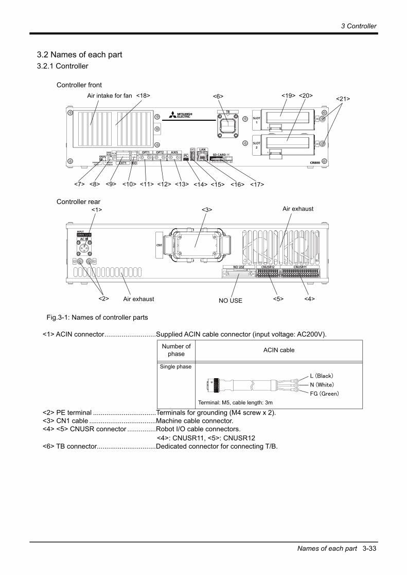
3 Controller
Names of each part 3-33
3.2 Names of each part3.2.1 Controller
Fig.3-1: Names of controller parts
<1> ACIN connector...........................Supplied ACIN cable connector (input voltage: AC200V).
<2> PE terminal .................................Terminals for grounding (M4 screw x 2).<3> CN1 cable ...................................Machine cable connector.<4> <5> CNUSR connector ...............Robot I/O cable connectors.
<4>: CNUSR11, <5>: CNUSR12 <6> TB connector...............................Dedicated connector for connecting T/B.
Number of phase ACIN cable
Single phase
Terminal: M5, cable length: 3m
Air intake for fanController front
Controller rearAir exhaust
Air exhaust
<1>
<2>
<3>
<6>
<5>NO USE <4>
<7> <8> <9> <10> <11> <12> <13> <14> <15> <16> <17>
<19><18> <20> <21>
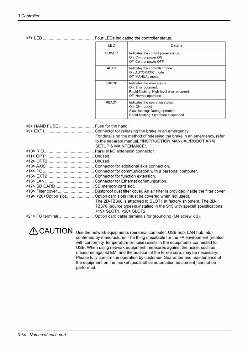
3-34 Names of each part
3 Controller
<7> LED ............................................ Four LEDs indicating the controller status.
<8> HAND FUSE .............................. Fuse for the hand.<9> EXT1 .......................................... Connector for releasing the brake in an emergency.
For details on the method of releasing the brake in an emergency, refer to the separate manual, "INSTRUCTION MANUAL/ROBOT ARM SETUP & MAINTENANCE".
<10> RIO........................................... Parallel I/O extension connector.<11> OPT1........................................ Unused.<12> OPT2........................................ Unused.<13> AXIS ......................................... Connector for additional axis connection.<14> PC ............................................ Connector for communication with a personal computer.<15> EXT2 ........................................ Connector for function extension.<16> LAN .......................................... Connector for Ethernet communication.<17> SD CARD................................. SD memory card slot.<18> Filter cover ............................... Dustproof dust filter cover. An air filter is provided inside the filter cover.<19> <20>Option slot........................ Option card slots (must be covered when not used).
The 2D-TZ368 is attached to SLOT1 at factory shipment. The 2D-TZ378 (source type) is installed in the S15 with special specifications.<19> SLOT1, <20> SLOT2
<21> FG terminal .............................. Option card cable terminals for grounding (M4 screw x 2).
Use the network equipments (personal computer, USB hub, LAN hub, etc) confirmed by manufacturer. The thing unsuitable for the FA environment (related with conformity, temperature or noise) exists in the equipments connected to USB. When using network equipment, measures against the noise, such as measures against EMI and the addition of the ferrite core, may be necessary. Please fully confirm the operation by customer. Guarantee and maintenance of the equipment on the market (usual office automation equipment) cannot be performed.
LED Details
POWER Indicates the control power status.On: Control power ONOff: Control power OFF
AUTO Indicates the controller mode.On: AUTOMATIC modeOff: MANUAL mode
ERROR Indicates the error status.On: Error occurred.Rapid flashing: High-level error occurred.Off: Normal operation
READY Indicates the operation status.On: ON (ready)Slow flashing: During operationRapid flashing: Operation suspended.
CAUTION

3 Controller
Outside dimensions/Installation dimensions 3-35
3.3 Outside dimensions/Installation dimensions3.3.1 Outside dimensions
Fig.3-2: Outside dimensions of controller
430(30) 30 (3
.5)
370
99.596
425
340
4540
45

3-36 Outside dimensions/Installation dimensions
3 Controller
3.3.2 Installation dimensionsThe following figures show the dimensions required installing the controller. For the placement of the controller on its side (the horizontal installation), two stacks is permitted.
Fig.3-3: Installation dimensions
When installing the controller vertically, ensure that the air intake is at the bottom as illustrated in Fig. 3-3.
Fixing installation section sure for prevention from the fall, when using the controller placing vertically. The reference figure of the metal plate for fixing is shown in Fig. 3-4.You should install the metal plate for fixation to the controller with M4 x 8 or the shorter screw. The screw projection length inside the controller (side board thickness is 1.2 mm) surely makes 6.8 mm or less.
Horizontal installation
Vertical installation
145mm
Air intake
Air intake
170mm 150mm
20mm50mm150mm
145mm
150m
m
CAUTION
CAUTION

3 Controller
Outside dimensions/Installation dimensions 3-37
When storing the controller in a cabinet, etc., take special care to the heat radiating properties and ventilation properties so that the ambient temperature remains within the specification values. And, don't install the controller in the position where direct rays or the heat of lighting hits. The skin temperature of the controller may rise, and the error may occur.
Fig.3-4: Reference figure of the fixing metal plate for vertical installation
CAUTION(1
4)12
0 120 120
360400420
120 21.7 12.1
516.
542
64 6840
(40)
148
4-φ10 hole4-φ6.5 hole
4-φ4.5 hole
4-C3
1020
(t2)10
14
(10)

3-38 External input/output
3 Controller
3.4 External input/output3.4.1 Types
(1) Dedicated input/output..................... These inputs and outputs carry out the robot remote operation and status display.
(2) General-purpose input/output .......... These are inputs and outputs that the customer can program for peripheral device control.
(3) Hand input/output ............................ These are inputs and outputs related to the hand that the customer can program.
(4) Emergency stop/Door switch input .. Information on wiring the emergency stop and wiring used to ensure safety can be found on Page 42, "3.6 Emergency stop input and output etc." and on Page 104, "6.1.7 Examples of safety measures".
<For Reference>Linking our GOT2000 Series display equipment to the robot controller over the Ethernet permits you to control robot controller's input/output from a GOT (graphic operation terminal).

3 Controller
Dedicated input/output 3-39
3.5 Dedicated input/outputShow the main function of dedicated input/output in the Table 3-2. Refer to attached instruction manual "Detailed explanations of functions and operations" in the product for the other functions. Each parameter indicated with the parameter name is used by designated the signal No., assigned in the order of input signal No. and output signal No.
Table 3-2: Dedicated input/output list
Parameter name
Input Note1) Output
Name Function Level Name Function
TEACHMD None Teaching mode output signal
Outputs that the teaching mode is entered.
ATTOPMD None Automatic mode output signal
Outputs that the automatic mode is entered.
ATEXTMD None Remote mode output signal
Outputs that the remote mode is entered.
RCREADY None Controller power ON complete signal
Outputs that external input signals can be received.
AUTOENA Automatic operation enabled input signal
Allows automatic operation.
L
Automatic operation enabled output signal
Outputs the automatic operation enabled state.
START Start input signal Starts all slots. E Operating output signal
Outputs that the slot is operating.
STOP Stop input signal Stops all slots.The input signal No. is fixed to 0.Note) Use the emergency stop
input for stop inputs related to safety.
L
Wait output signal Outputs that the slot is temporarily stopped.
STOP2 Stop input signal The program during operation is stopped. Unlike the STOP parameter, change of the signal number is possible. Notes) Specification is the same
as the STOP parameter.
L
Wait output signal Outputs that the slot is temporarily stopped.Notes) Specification is the same as
the STOP parameter.
SLOTINIT Program reset input signal
Resets the wait state.E
Program selection enabled output signal
Outputs that the slot is in the program selection enabled state.
ERRRESET Error reset input signal
Resets the error state. E Error occurring output signal
Outputs that an error has occurred.
CYCLE Cycle stop input signal
Carries out cycle stop.E
In cycle stop operation output signal
Outputs that the cycle stop is operating.
SRVOFF Servo ON enabled input signal
Turns the servo OFF for all mechanisms. L
Servo ON enabled output signal
Outputs servo-on disable status. (Echo back)
SRVON Servo ON input signal
Powers on the robot servos.For multiple mechanisms, it powers on the servos of all the mechanisms.
E
In servo ON output signal
Outputs the servo ON state.For multiple mechanisms, the output is performed when at least one of the mechanisms is in the servo ON state.
IOENA Operation rights input signal
Requests the operation rights for the external signal control. L Operation rights
output signalOutputs the operation rights valid state for the external signal control.
MELOCK Machine lock input signal
Sets/resets the machine lock state for all mechanisms. E In machine lock
output signalOutputs the machine lock state.
SAFEPOS Evasion point return input signal
Requests the evasion point return operation. E
In evasion point return output signal
Outputs that the evasion point return is taking place.

3-40 Dedicated input/output
3 Controller
OUTRESET General-purpose output signal reset
Resets the general-purpose output signal. E None
EMGERR None Emergency stop output signal
Outputs that an emergency stop has occurred.
S1START :S32START
Start input Starts each slot. E In operation output Outputs the operating state for each slot.
S1STOP :S32STOP
Stop input Stops each slot. L In wait output Outputs that each slot is temporarily stopped.
PRGSEL Program selection input signal
Designates the setting value for the program No. with numeric value input signals.
E None
OVRDSEL Override selection input signal
Designates the setting value for the override with the numeric value input signals.
E None
IODATANote2)
Numeric value input (start No., end No.)
Used to designate the program name, override value., mechanism value.
LNumeric value output (start No., end No.)
Used to output the program name, override value., mechanism No.
PRGOUT Program No. output request
Requests output of the program name. E Program No. output
signal
Outputs that the program name is being output to the numeric value output signal.
LINEOUT Line No. output request
Requests output of the line No.E Line No. output
signal
Outputs that the line No. is being output to the numeric value output signal.
OVRDOUT Override value output request
Requests the override output.E
Override value output signal
Outputs that the override value is being output to the numeric value output signal.
ERROUT Error No. output request
Requests the error No. output.E Error No. output
signal
Outputs that the error No. is being output to the numeric value output signal.
JOGENA Jog valid input signal
Validates jog operation with the external signals E Jog valid output
signalOutputs that the jog operation with external signals is valid.
JOGM Jog mode input 2-bit
Designates the jog mode. L Jog mode output 2-bit
Outputs the current jog mode.
JOG+ Jog feed + side for 8-axes
Requests the + side jog operation. L None
JOG- Jog feed - side for 8-axes
Requests the - side jog operation. L None
HNDCNTL1
:HNDCNTL3
None
Mechanism 1 hand output signal status :Mechanism 3 hand output signal status
Mechanism 1: Outputs the status of general-purpose outputs 900 to 907.
Mechanism 2: Outputs the status of general-purpose outputs 910 to 917.
Mechanism 3: Outputs the status of general-purpose outputs 920 to 927.
HNDSTS1
:HNDSTS3
None
Mechanism 1 hand input signal status :Mechanism 3 hand input signal status
Mechanism 1: Outputs the status of hand inputs 900 to 907.
Mechanism 2: Outputs the status of hand inputs 910 to 917.
Mechanism 3: Outputs the status of hand inputs 920 to 927.
Parameter name
Input Note1) Output
Name Function Level Name Function

3 Controller
Dedicated input/output 3-41
HNDERR1
:HNDERR3
Mechanism 1 hand error input signal :Mechanism 3 hand error input signal
Requests the hand error occurrence. L
Mechanism 1 hand error output signal :Mechanism 3 hand error output signal
Outputs that a hand error is occurring.
AIRERR1
:AIRERR3
Pneumatic pressure error 1 input signal :Pneumatic pressure error 3 input signal
Request the pneumatic pressure error occurrence. L
Pneumatic pressure error 1 output signal. :Pneumatic pressure error 3 output signal.
Outputs that a pneumatic pressure error is occurring.
M1PTEXC
:M3PTEXC
None L
Maintenance parts replacement time warning signal
Outputs that the maintenance parts have reached the replacement time.
USERAREANote3) None User-designated
area 32-pointsOutputs that the robot is in the user-designated area.
Note1) The level indicates the signal level.L: Level signal → The designated function is validated when the signal is ON, and is invalidated
when the signal is OFF.E: Edge signal → The designated function is validated when the signal changes from the OFF to
ON state, and the function maintains the original state even when the signal thenturns OFF.
Note2) Four elements are set in the order of input signal start No., end No., output signal start No. and endNo.
Note3) Up to eight points can be set successively in order of start output signal No. and end output signal No.
Parameter name
Input Note1) Output
Name Function Level Name Function

3-42 Emergency stop input and output etc.
3 Controller
3.6 Emergency stop input and output etc.Do wiring of the external emergency stop, the special stop input, the door switch, and the mode selector
switch from the "special input/output" terminal connector.
Table 3-3: Special input/output terminal
*At the time of the power supply OFF, the output point of contact is always open.
[Note] Wire for each input terminal as shown in Fig. 3-8. The contact capacity of each input/output terminal is DC24V/100mA. Do not connect the equipment except for this range. Noise or other effects that overload contact capacities will lead to failure. An example of noise prevention is shown in Fig. 3-5.In the customer's system, do not ground the + side of 24V power supply prepared by customer for connect to the controller. (related with emergency stop and parallel input/output) If it connects with the controller under the condition that the + side is grounded, it will lead to failure of controller.
Fig.3-5: Protection circuit example
Item Name Function
Input Emergency stop Applies the emergency stop. Dual line, normal closeInput Special stop input Applies the stop. (Refer to Page 47, "3.6.2 Special stop input (SKIP)")Input Door switch Servo-off. Dual line, normal close (Page 48, "3.6.3 Door switch function")Input Mode selector switch Changes the mode (MANUAL/AUTOMATIC) of the controller. Dual line (Page 48, "3.6.4 Mode
selector switch function")Output Robot error output Contactor is opening during error occurrence.Output Emergency stop output The point of contact opens under occurrence of emergency stop of external input signal,
emergency stop of T/B.Output Mode output MANUAL mode: contactor is opening, AUTOMATIC mode: contactor is closing.Output Additional axis
synchronization outputWhen an additional axis is used, the servo ON/OFF status of the additional axis can be synchronized with the robot arm. (Page 53, "3.8 Additional axis synchronization output")
Robot controller100mA
Customer device
Supplied by customer
Contact
*1)Contact capacity:24 V DC
Varistor
An example of connecting devices such as relays
Use noise prevention methods that are specific to the devices being used and the environment they are being used in.
Use noise prevention methods that are specific to the devices being used and the environment they are being used in.
Robot controller100mA
Customer device
Supplied by customer
Contact
*1)Contact capacity:24 V DC
Varistor
An example of connecting devices such as PLCs
Diode
*1) The actual internal robot controller circuit differs from the internal robot controller circuit in the figure.
Recommended varistorModel Manufacturer Varistor voltage Max. permissible circuit voltage
ERZV10D390 Panasonic 39V 31V72210S0250K101 TDK 39V 31V

3 Controller
Emergency stop input and output etc. 3-43
[Note] If a stop signal or servo OFF signal is input simultaneously with a door switch open/emergency stop input, the error, H056n “Servo sys. error (A/D)” may occur.When a door switch open/emergency stop is input, the robot turns off the servo after it stops. It is unnecessary to input a stop signal or servo OFF signal. To input a stop signal or servo OFF signal with a door switch open/emergency stop input, wait for 100ms or more after a door switch open/emergency stop input.
Pin number assignment of each terminal and the circuit diagram are shown in Fig. 3-8.
3.6.1 Connection of the external emergency stop and mode selector switchThe input terminals for the external emergency stop, door switch, and mode selector switch are arranged as shown in Fig. 3-8. Customers should be sure to prepare the external emergency stop, door switch, and mode selector switch, etc. and use the robot while these are connected. Connection procedures are shown below.In addition, refer to Page 104, "6.1.7 Examples of safety measures" for the information on the emergency stop connection and cautions.
[Caution] The emergency stop circuit is duplicated inside the controller. The emergency stop switch uses adouble contact-type switch, so please be sure to fix both of the contacts to the connector pins asshown below in order to ensure the wiring is duplicated. An error will continue to occur in the eventthat only one of the pins is connected.
1) Please prepare the emergency stop switch, door switch, and mode selector switch.2) Connect the contacts of each switch to the contacts as shown below:
a) External emergency switchCNUSR11 connector "between 7 and 23" and "between 14 and 30".
b) Door switchCNUSR11 connector "between 6 and 22" and "between 13 and 29".
c) Mode selector switchCNUSR11 connector "between 5 and 21" and "between 12 and 28".
[Caution] Be sure to use a shield cable for the emergency stop wiring cable and dedicated stop input wiringcable. And when operating in an environment that is easily affected by noise, be sure to install theferrite core (recommended model name: E04SR301334, manufacturer: Seiwa Electric Mfg. Co.,Ltd.). Be sure to place the ferrite core in 300mm or less from the connecting terminal section.
Fig.3-6: Installation position of ferrite coresFor information on the installation method, follow the instructions of the ferrite core being used.
Make sure there are no mistakes in the wiring. Connecting differently to the way specified in the manual can result in errors, such as the emergency stop not being released. In order to prevent errors occurring, please be sure to check that all functions (such as the teaching box emergency stop, customer emergency stop, and door switch) are working properly after the wiring setup is completed.
CNUSR11 connector
CNUSR12 connector
Within 300mm
Ferrite core
CAUTION

3-44 Emergency stop input and output etc.
3 Controller
You should always connect doubly connection of the emergency stop, the door switch, and the mode selector switch. In connection of only one side, if the relay of customer use should break down, it may not function correctly.The robot output contacts (error output, emergency stop output, mode output, additional axis synchronization output) are duplicated output contacts that are wired in series. As with emergency stop switches and door switches, ensure that all connections to customer devices are duplicated to achieve redundancy.
Please make sure to wire the multiple emergency stop switches so that they each function independently. Check and make sure that the emergency stop doesn't only function under an AND condition (when multiple emergency stop switches are ON at the same time).
Fig.3-7: Emergency stop cable and mode selector switch connection
CAUTION
CAUTION
CNUSR11 connector

3 Controller
Emergency stop input and output etc. 3-45
Fig.3-8: External emergency stop connection
Place the emergency stop switch in an easily operable position, and be sure to wire it to the emergency stop correctly by referencing Page 104, "6.1.7 Examples of safety measures". This is a necessary measure in order to ensure safe operation so that the robot can be stopped immediately by pressing the emergency stop switch in the event that the robot malfunctions.
1430
Door switch input
*1)
1329
1228
1127
1026
824
723
622
521
420
319
117
(Customer) (Customer)
Mode selector switch input
Door switch input
Mode output
+24V
+24V
+24V
+24V
+24V
+24V
+24V
+24V
+3.3V+3.3V
+3.3V
+3.3V
+3.3V
+3.3V+3.3V
+3.3V
+3.3V
+3.3V
+3.3V
+3.3V
Robot error output
Mode selector switch input
*1)The terminal can be used only for the external emergency stop input to the robot controller.
Please do not carry out an insulation pressure test. Moreover, it becomes the cause of failure if it connects incorrectly.
Please refer to the example of safety measures of "Specifications Manual".
Internal circuit structure(Controller side)
T/B emergency stop
CNUSR11
CNUSR11
CNUSR11
CNUSR11
Control circuit 2
Control circuit 1
Emergency stop output
External emergen-cy stop input
*1)
External emergen-cy stop input
Mode output
Robot error output
Emergency stop output
WARNING
CAUTION

3-46 Emergency stop input and output etc.
3 Controller
Fig.3-9: Wiring method to the user wiring connector
Fully check the number of the cable insertion hole (connector pin number) for incorrect connection. Incorrect wiring may damage the robot or cause a malfunction.
When wiring to the CNUSR11/CNUSR12 connector, pay attention to fraying wires of the core wires. The fraying wires can come into contact with the adjacent terminal, causing a short circuit.Do not apply solder on core wires. Doing so may cause a contact failure.
CNUSR11 connectorA
User wiring connectorWiring to a connector
Latch
Cable insertion holeFlathead screwdriver
7mm
Cable
CNUSR11 connector
View A: Pin number of connector16
32
1
17
CNUSR12 connector
Lever
Lever
CNUSR12 connector
9
18
1
10
Connection procedureWire cables to the CNUSR11 and CNUSR12 user wiring connectors (attachment), and fit them into the corresponding connectors (ports) located on the rear side of the controller.The customer needs to prepare the following items.• Cable: AWG24 to 16 (0.2 to 1.5mm2)• Flathead screwdriver: The width of the tip is 2.5mm.
1) Prepare the user wiring connector (attachment).2) Strip off 7 mm of the cable sheath.3) Insert the cable all the way in the insertion hole while pressing down the latch on the user wiring connector
with a flatblade screwdriver.4) When all the required wirings have been completed, fit the user wiring connector (CNUSR11/CNUSR12)
into the corresponding connector (CNUSR11/CNUSR12 port) on the controller.5) When the user wiring connector has properly fitted, the levers on both sides of the connector rise and the
connector is fixed. (To dismount the connector, lower the levers.)
The connection has been completed.
CAUTION
CAUTION

3 Controller
Emergency stop input and output etc. 3-47
3.6.2 Special stop input (SKIP)The SKIP is the input signal to stop the robot. Please connect the pin 4, 13 of the CNUSR12 connector
shown in Fig. 3-10.
Table 3-4: Special stop input electric specification
Fig.3-10: Connection of the special-stop-input
Item Specifications Internal circuit
Type DC input
No. of input point 1
Insulation method Photo-coupler insulation
Rated input voltage DC24V
Rated input current Approx. 11mA
Working voltage range DC 21.6 to 26.4V (Ripple rate within 5%)
ON voltage/ON current DC 8V or more / 2mA or more
OFF voltage/OFF current DC 4V or less / 1mA or less
Input resistance Approx. 2.2kΩ
Response time
OFF→ON 1ms or less
ON→OFF 1ms or less
Common method 1 point per common
External wire connection method
Connector
330
2.2k 入力
+24V(COM)
1A
1B
Input
4
13
CNUSR12 connector
Note) In the customer's system, do not ground the + side of 24V power supply prepared by customer for connect to the controller. (related with emergency stop and parallel input/output) If it connects with the controller under the condition that the + side is grounded, it will lead to failure of controller.
* Refer to Page 46 "Fig. 3-9: Wiring method to the user wiring connector" for more details about how to wire a connector.
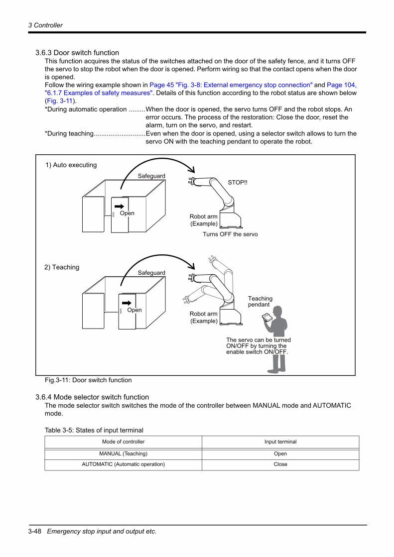
3-48 Emergency stop input and output etc.
3 Controller
3.6.3 Door switch functionThis function acquires the status of the switches attached on the door of the safety fence, and it turns OFF the servo to stop the robot when the door is opened. Perform wiring so that the contact opens when the door is opened. Follow the wiring example shown in Page 45 "Fig. 3-8: External emergency stop connection" and Page 104, "6.1.7 Examples of safety measures". Details of this function according to the robot status are shown below (Fig. 3-11).*During automatic operation .........When the door is opened, the servo turns OFF and the robot stops. An
error occurs. The process of the restoration: Close the door, reset the alarm, turn on the servo, and restart.
*During teaching............................Even when the door is opened, using a selector switch allows to turn the servo ON with the teaching pendant to operate the robot.
Fig.3-11: Door switch function
3.6.4 Mode selector switch functionThe mode selector switch switches the mode of the controller between MANUAL mode and AUTOMATIC mode.
Table 3-5: States of input terminalMode of controller Input terminal
MANUAL (Teaching) Open
AUTOMATIC (Automatic operation) Close
Safeguard
Turns OFF the servo
STOP!!
Open
Safeguard
Open
Robot arm(Example)
Robot arm(Example)
Teaching pendant
The servo can be turned ON/OFF by turning the enable switch ON/OFF.
1) Auto executing
2) Teaching
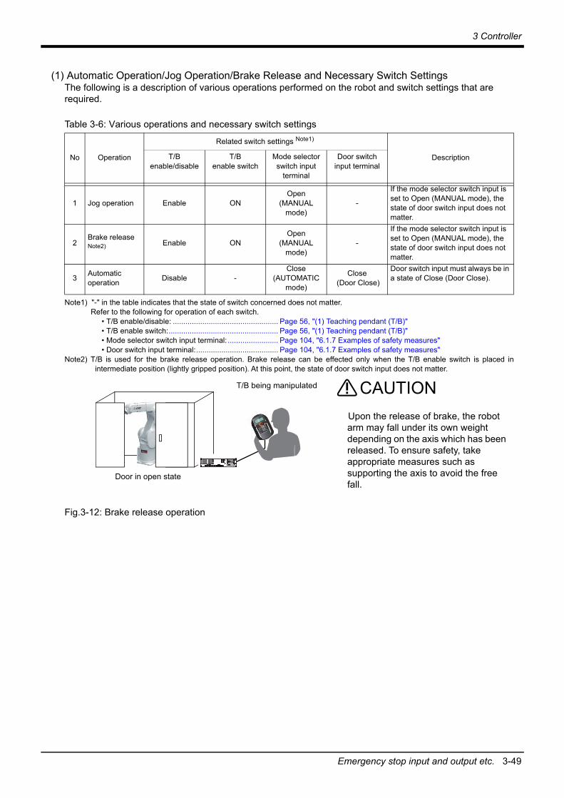
3 Controller
Emergency stop input and output etc. 3-49
(1) Automatic Operation/Jog Operation/Brake Release and Necessary Switch SettingsThe following is a description of various operations performed on the robot and switch settings that are required.
Table 3-6: Various operations and necessary switch settings
Fig.3-12: Brake release operation
No Operation
Related switch settings Note1)
Note1) "-" in the table indicates that the state of switch concerned does not matter.Refer to the following for operation of each switch.
• T/B enable/disable: .................................................. Page 56, "(1) Teaching pendant (T/B)"• T/B enable switch:.................................................... Page 56, "(1) Teaching pendant (T/B)"• Mode selector switch input terminal: ........................ Page 104, "6.1.7 Examples of safety measures"• Door switch input terminal:....................................... Page 104, "6.1.7 Examples of safety measures"
DescriptionT/B enable/disable
T/B enable switch
Mode selector switch input
terminal
Door switch input terminal
1 Jog operation Enable ONOpen
(MANUAL mode)
-
If the mode selector switch input is set to Open (MANUAL mode), the state of door switch input does not matter.
2Brake release Note2)
Note2) T/B is used for the brake release operation. Brake release can be effected only when the T/B enable switch is placed inintermediate position (lightly gripped position). At this point, the state of door switch input does not matter.
Enable ONOpen
(MANUAL mode)
-
If the mode selector switch input is set to Open (MANUAL mode), the state of door switch input does not matter.
3 Automatic operation Disable -
Close(AUTOMATIC
mode)
Close (Door Close)
Door switch input must always be in a state of Close (Door Close).
Door in open state
T/B being manipulated
Upon the release of brake, the robot arm may fall under its own weight depending on the axis which has been released. To ensure safety, take appropriate measures such as supporting the axis to avoid the free fall.
CAUTION

3-50 Additional Axis Function
3 Controller
3.7 Additional Axis FunctionThis controller is equipped with an additional axis interface for controlling an additional axis when a traveling axis or rotary
table is added to the robot. A maximum of eight axes of servo motors can be controlled at the same time by connecting a general-purpose servo amplifier (MR-J4-B series) that supports Mitsubishi's SSCNET III. Refer to the separate "Additional axis interface Instruction Manual" for details on the additional axis function.
3.7.1 Wiring of the Additional Axis InterfaceTable 3-7 shows the connectors for additional axes inside the controller.Fig. 3-13 shows a connection example (configuration example).
Table 3-7: Dedicated connectors inside the controller
Fig.3-13: Example of addition axis connection
Name Connector name Details
Connector for additional axes AXIS The connector for connecting the general-purpose servo amplifier.
* It cannot communicate, if connection of CN1A and CN1B is mistaken.
AXIS connectorSSCNET III cable
SSCNET III cable
To CN1A connector
To CN1A connector
To CN1B connector To CN1B connector
Cap

3 Controller
Additional Axis Function 3-51
(1) Example of the installation of the noise filter■EMC filter (recommended)
Please install the recommendation filter shown below according to the example of connection.
Table 3-8: Combination of a servo amplifier and filter (Soshin Electric)
Table 3-9: Combination of a servo amplifier and filter (COSEL)
Servo amplifier
Recommended filter (Soshin Electric)
Mass [kg]Model Rated current [A] Rated voltage
[VAC]Leakage current
[mA]
MR-J4-10B(-RJ) to MR-J4-100B(-RJ) HF3010A-UN Note1)
Note1) Following surge protector is separately required to use any of these EMC filters.RSPD-250-U4 (Manufacture: OKAYA Electric Industries CO., Ltd.)
10
250
53.5
MR-J4-200B(-RJ)MR-J4-350B(-RJ) HF3030A-UN Note1) 30 5.5
MR-J4-500B(-RJ)MR-J4-700B(-RJ) HF3040A-UN Note1) 40
6.5
6
MR-J4-11KB(-RJ)MR-J4-15KB(-RJ)MR-J4-22KB(-RJ)
HF3100A-UN Note1) 100 12
MR-J4-60B4(-RJ)MR-J4-100B4(-RJ) TF3005C-TX 5
500 5.5
6MR-J4-200B4(-RJ)MR-J4-700B4(-RJ) TF3020C-TX 20
MR-J4-11KB4(-RJ) TF3030C-TX 30 7.5
MR-J4-15KB4(-RJ) TF3040C-TX 4012.5
MR-J4-22KB4(-RJ) TF3060C-TX 60
MR-J4-10B1(-RJ) to MR-J4-40B1(-RJ) TF3010A-UN Note1) 10 250 5 3.5
Servo amplifier
Recommended filter (COSEL)
Mass [kg]Model Rated current [A] Rated voltage
[VAC]Leakage current
[mA]
MR-J4-11KB(-RJ) to MR-J4-22KB(-RJ) FTB-100-355-LNote1)
Note1) Following surge protector is separately required to use any of these EMC filters.RSPD-500-U4 (Manufacture: OKAYA Electric Industries CO., Ltd.)
100 500 40 5.3
MR-J4-22KB4(-RJ) FTB-80-355-L Note1) 80 500 80 5.3

3-52 Additional Axis Function
3 Controller
■Installing an EMC noise filter
Fig.3-14: Example of EMC noise filter installation
(2) Line noise filterThis filter is effective in suppressing noises radiated from the power supply side and output side of the servo amplifier
and also in suppressing high-frequency leakage current (zero-phase current) especially within 0.5MHz to 5MHz band.
Fig.3-15: Example of noise filter installation
MCCB
EMC filter
Surge protector
Power supply
1
1 2 3
2
3
4 L1
L2
L3
L11
L21
5
6
E
MC
Servo amplifier
Note 1)
Note 2)
Note 1) For 1-phase 200V to 230VAC power supply, connect the power supply to L1, L2 and leave L3 open. There is no L3 for 1-phase 100 to 120 VAC power supply.
Note 2) The example is when a surge protector is connected.

3 Controller
Additional axis synchronization output 3-53
3.8 Additional axis synchronization outputWhen an additional axis is used, the servo ON/OFF status of the additional axis can be synchronized with the servo ON/OFF status of the robot itself by using the output contact (AXMC) provided on the rear or inside of the controller and configuring a circuit so that the power to the servo amplifier for the additional axis can be turned off when this output is open. An example circuit is shown in Page 53, "(1) Example circuit". An image of how to connect the connector is shown in Page 54, "(2) Image of how to connect the controller connector".When you are using an additional axis, please perform appropriate circuit connections by referring to these drawings.Refer to Page 50, "3.7 Additional Axis Function"and the separate "Additional axis interface Instruction Manual" for details on the additional axis function.
Note1) you use the addition axis function as a user mechanism who became independent of the robot arm,please do not connect this output signal. Servo-on of the user mechanism may be unable.
(1) Example circuit
Fig.3-16: Example of circuit for additional axis synchronization output
[Note] For the input/output cable (CNUSR connector cable) that connects customer's system and the controller, prevent ground faults from occurring at the + side of the 24V power supply prepared by customer. A ground fault may lead to a failure of the protection device in the controller.Bending or frictional forces may be applied to the input/output cable repeatedly depending on the system configuration or layout. In this case, use a flexible cable for the input/output cable. Note that a fixed cable may be broken, resulting in a ground fault.
NV
To the internal circuit
1) Get the power supply for the controller from the secondary terminal of short circuit breaker (NV) built in the addition axis amplifier box.
2) Get the power supply for the MC synchronization from the secondary terminal of short circuit breaker (NV) prepared by the customer.
AXMC is output from the contact for internal servo power supplies.
<Controller>
CNUSR connector
AXMC11
AXMC12
AXMC21
AXMC22
Note 2)
Note 2)
Note 1)
Note 1) Connector and pin number
Note 2) This output is opened, if the robot turns off the servo by occurrence of alarm etc.<Electric specification>DC24V/10mA to 100mA
AXMC11AXMC12AXMC21AXMC22
Signal Connector Pin number
CNUSR11
CNUSR11
925218
NV MC MC1 MC2Amplifier
88
DC24V
<Addition axis amplifier box>

3-54 Additional axis synchronization output
3 Controller
(2) Image of how to connect the controller connector
Fig.3-17: AXMC terminal connector
CNUSR11 connector
* Refer to Page 46 "Fig. 3-9: Wiring method to the user wiring connector" for more details about how to wire a connector.

3 Controller
3-55
3.9 Options■What are options?
There are a variety of options for the robot designed to make the setting up process easier for user needs.User installation is required for the options.

3-56 Teaching pendant (T/B)
3 Controller
(1) Teaching pendant (T/B)■Order type: ●R32TB :Cable length 7m
●R32TB-15 :Cable length 15m
■OutlineThis is used to create, edit and control the program, teach the operation position and for jog feed, etc. For safety proposes, a 3-position enable switch is mounted.*1)
For multiple robots, you can operate them with just one teaching pendant by repeating the removal of it from another robot and the connection of it to the target robot.
■ConfigurationTable 3-10: Configuration device
■SpecificationsTable 3-11: Specifications
*1) <3-position enable switch>In ISO/10218 (1992) and JIS-B8433 (1993), this is defined as an "enable device". These standards specify that the robot operation using the teaching pendant is enabled only when the "enable device" is at a specified position.With the Mitsubishi Electric industrial robot, the above "enable device" is configured of an "Enable/Disable switch" and "Enable switch".The 3-position enable switch has three statuses. The following modes are entered according to the switch state.
a) "Not pressed" ................................. The robot does not operate. *)b) "Pressed lightly" ............................. The robot can be operated and teaching is possible.c) "Pressed with force" ....................... The robot does not operate. *)
*) Releasing or forcefully pressing the 3-position enable switch cuts power to the servos in the sameway as when the emergency stop is input. This helps to ensure safety. Operations such as editing programs and displaying the robot's status are possible while the 3-posi-tion enable switch is released or forcefully pressed (excludes operating the robot).
Part name Type Qty. Mass (kg) Note1)
Note1) Mass indicates one set.
Remarks
Teaching pendant R32TBEither one pc.
1.7 Cable length is 7m.
R32TB-15 2.8 Cable length is 15m.
Items Specifications Remarks
Outline dimensions 195(W) x 292(H) x 106(D) (refer to outline drawing)
Body color Dark gray
Mass Approx. 0.9kg (body only, excluding cables)
Connection method Connects with controller via connector.
Interface RS-422
Display method LCD method: 24 characters x 8 lines, LCD illumination: with backlight At 8x8 font
Operation section 36 keys

3 Controller
Teaching pendant (T/B) 3-57
Fig.3-18: Outside dimensions of teaching pendant
■Installation methodThe teaching pendant is connected to the TB connector on the front of the controller.
Enable/Disable switch
Emergency stop
Enable switch
Operetion key
Body
Cable (with connector)
<Back>
<Bottom>
63.5
<Front>
LCD
291.9
195.2
133
<side>
105.5
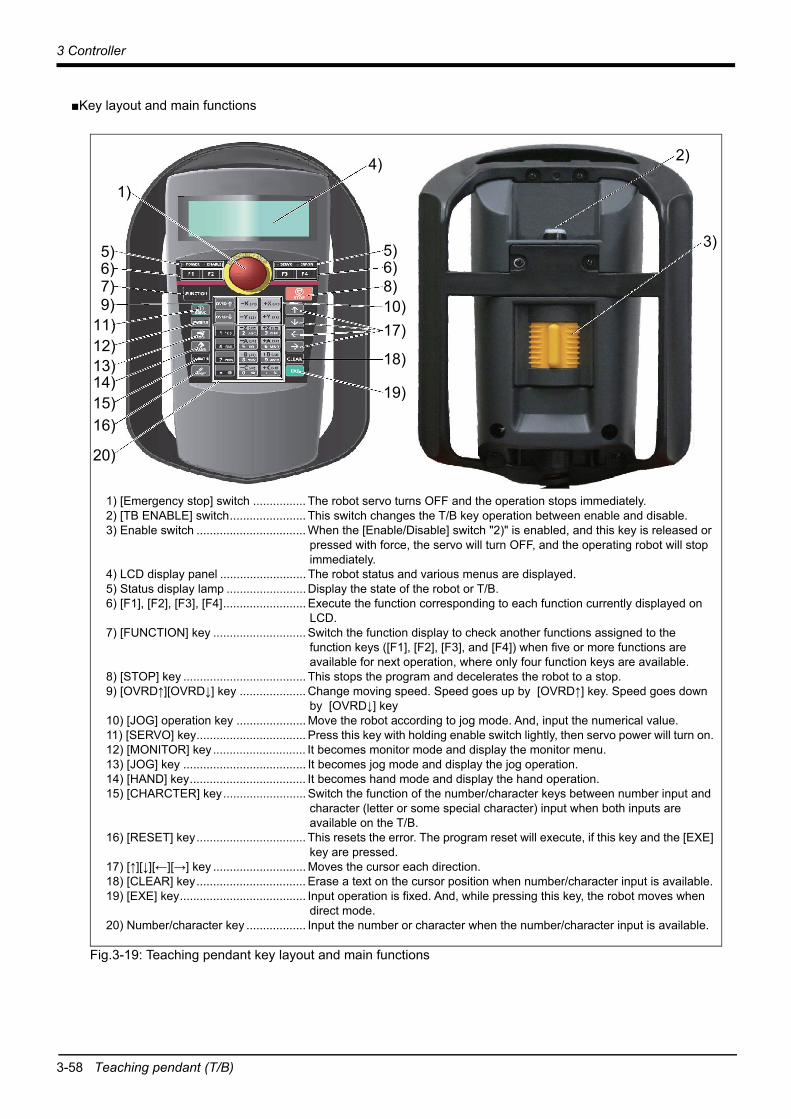
3-58 Teaching pendant (T/B)
3 Controller
■Key layout and main functions
Fig.3-19: Teaching pendant key layout and main functions
1) [Emergency stop] switch ................ The robot servo turns OFF and the operation stops immediately.2) [TB ENABLE] switch....................... This switch changes the T/B key operation between enable and disable.3) Enable switch ................................. When the [Enable/Disable] switch "2)" is enabled, and this key is released or
pressed with force, the servo will turn OFF, and the operating robot will stop immediately.
4) LCD display panel .......................... The robot status and various menus are displayed.5) Status display lamp ........................ Display the state of the robot or T/B.6) [F1], [F2], [F3], [F4]......................... Execute the function corresponding to each function currently displayed on
LCD. 7) [FUNCTION] key ............................ Switch the function display to check another functions assigned to the
function keys ([F1], [F2], [F3], and [F4]) when five or more functions are available for next operation, where only four function keys are available.
8) [STOP] key ..................................... This stops the program and decelerates the robot to a stop.9) [OVRD↑][OVRD↓] key .................... Change moving speed. Speed goes up by [OVRD↑] key. Speed goes down
by [OVRD↓] key10) [JOG] operation key ..................... Move the robot according to jog mode. And, input the numerical value. 11) [SERVO] key................................. Press this key with holding enable switch lightly, then servo power will turn on. 12) [MONITOR] key ............................ It becomes monitor mode and display the monitor menu.13) [JOG] key ..................................... It becomes jog mode and display the jog operation. 14) [HAND] key................................... It becomes hand mode and display the hand operation.15) [CHARCTER] key......................... Switch the function of the number/character keys between number input and
character (letter or some special character) input when both inputs are available on the T/B.
16) [RESET] key................................. This resets the error. The program reset will execute, if this key and the [EXE] key are pressed.
17) [↑][↓][←][→] key ............................ Moves the cursor each direction.18) [CLEAR] key................................. Erase a text on the cursor position when number/character input is available.19) [EXE] key...................................... Input operation is fixed. And, while pressing this key, the robot moves when
direct mode.20) Number/character key .................. Input the number or character when the number/character input is available.
1)
2)
3)
4)
5)6)8)10)17)
18)
19)
6)7)9)
11)12)13)14)15)16)
20)
5)

3 Controller
High efficient teaching pendant (T/B) 3-59
(2) High efficient teaching pendant (T/B)■Order type: ●R56TB :Cable length 7m
●R56TB-15 :Cable length 15m■Outline
This is used to create, edit and control the program, to teach the operation position, or to perform jog feed, etc. This highly efficient teaching pendant has a touchscreen graphical user interface (GUI) which allows easy operation. In addition, the 3-position enable switch *1) is provided for the safety use.
For multiple robots, you can operate them with just one teaching pendant by repeating the removal of it from another robot and the connection of it to the target robot.
■ConfigurationTable 3-12: Configuration device
■SpecificationsTable 3-13: Specifications
■Installation methodThe teaching pendant is connected to the TB connector on the front of the controller.
*1) <3-position enable switch>In ISO/10218 (2006) and JIS-B8433 (1993), this is defined as an "enable device". These standards specify that the robot operation using the teaching pendant is enabled only when the "enable device" is at a specified position.With the Mitsubishi Electric industrial robot, the above "enable device" is configured of an "Enable/Disable switch" and "Enable switch".The 3-position enable switch has three statuses. The following modes are entered according to the switch state.
a) "Not pressed" ..................................The robot does not operate. b) "Pressed lightly" ..............................The robot can be operated and teaching is possible.c) "Pressed with force" ........................The robot does not operate.
*) Releasing or forcefully pressing the 3-position enable switch cuts power to the servos in the same way as when the emergency stop is input. This helps to ensure safety. Operations such as editing programs and displaying the robot's status are possible while the 3-posi-tion enable switch is released or forcefully pressed (excludes operating the robot).
Part name Type Qty. Mass (kg) Note1)
Note1) Mass indicates one set.
Remarks
High efficient teaching pendant
R56TBEither one pc.
2.1 Cable length is 7m.
R56TB-15 3.2 Cable length is 15m.
Items Specifications RemarksOutline dimensions 252(W) x 240(H) x 114(D) (refer to outline drawing)Body color Dark grayMass Approx. 1.25kg (body only, excluding cables)Connection method Connects with controller via connector.Interface RS-422, Ethernet (10BASE-T) For connection with
robot controllerUSB host Note1)
Note1) The operation of the following USB memory sticks has been confirmed.a) Kingston Data TravelerManufacture: Kingston, Type: USB 2.0 memory stick,
Memory sizes: 128 MB - 1GBb) Transcend Jet FlashManufacture: Transcend, Type: USB 2.0 memory stick,
Memory sizes: 128 MB - 1GBNotice) The operation of those other than the above is not guaranteed.
Display 6.5" TFT (640 x 480) color touchscreen, with backlight

3-60 High efficient teaching pendant (T/B)
3 Controller
■Outside dimensions and main functions
Fig.3-20: Teaching pendant outside dimensions and main functions
252
240
37.2
55.3
21.5
24)
23)
3) 4)
5) 8)
) 9)
12) 13)
14) 15)
16)
17)
18) 19)
20)
21)
11)
22)
6)
10)
1)2)
7)
1) TEACH button...........................This changeover switch is used to enable or disable the T/B key operations. The lamp (white) lights up during enabling state.
2) Wheel........................................Move the cursor to select the menu and so on.3) Emergency stop button .............This stops the robot in an emergency state. The servo turns OFF. Turn to the
right to cancel.4) Touch stylus (Integrated in housing)
The pen which operates the touch panel.5) Power supply LED, T/B enable LED
POWER LED lights up during supplying the power supply. TB ENABLE LED lights up during enabling state.
6) Touch panel...............................Tap to operate with the stylus pen and the screen is displayed.7) USB connecter..........................Plug-in the USB memory stick.8) STOP button .............................This stops the robot immediately. The servo does not turn OFF.9) SERVO button ..........................This turns ON the servo power simultaneously with the enable switch. The LED
(green) lights during servo ON.10) RESET button .........................This key resets an error state that has occurred.11) CAUTION button ..................... If this button is pushed in jog operation, the limit switch can be canceled.
Moreover, push this button, when releasing the brake.12) HOME button ..........................Not use.13) OVRD button...........................This scrolls override up or down.14) HAND button...........................Display the screen of hand operation.15) JOG button..............................Display the screen of jog operation.16) +/- button.................................This button operates corresponding to the selected operation.17) EXE button..............................Move the robot, such as hand alignment.18) MENU button ..........................Display the menu screen.19) RETURN button ......................Close each operation screen.20) Arrow button............................Move the cursor21) OK button................................Fix each screen operation.22) CANCEL button ......................Cancel each screen operation.23) Multi grip handle......................Holds the T/B.24) Enable switch.......................... If this switch is released or pressed with force while the T/B is enabled, the
servo power supply turns OFF. To move the robot in jog operation or the like, press the switch lightly and hold it. The enable switch is mounted on each of the multi grip handle.

3 Controller
Function extension card 3-61
(3) Function extension card
■Order type: ●2F-DQ510 .................... MELFA Smart Plus card pack (A-type)●2F-DQ520 .................... MELFA Smart Plus card pack (AB-type)●2F-DQ511 .................... MELFA Smart Plus card (A-type)●2F-DQ521 .................... MELFA Smart Plus card (B-type)
■Outline
This card is used to enable the MELFA Smart Plus option.Insert this card in the option slot on the front of the controller, and enable the MELFA Smart Plus software extension function.
■ConfigurationTable 3-14: Configuration device
Part name Type Qty. Mass (Kg) Remarks
MELFA Smart Plus card pack A-type 2F-DQ510 1 0.5 Software version of controller: Ver. A5p or laterAB-type 2F-DQ520 1 0.5
MELFA Smart Plus card A-type 2F-DQ511 1 0.5
B-type 2F-DQ521 1 0.5

3-62 Controller protection box
3 Controller
(4) Controller protection box
■Order type: CR800-MB
■Outline
Storing the controller in this box protects the controller from dust and water.Use this option, when the controller is installed where environment is oil mist such as machine shop etc.
■ConfigurationTable 3-15: Configuration equipment and types
■SpecificationsTable 3-16: Specifications
(1) The robot must be grounded by the customer.(2) The customer needs to prepare the power cable for protection box fan and the grounding cable.
(Power supply voltage for fan: 200 VAC, Screw size for power supply connection terminal block: M4)
Part name Type Qty. Mass (Kg)Note1)
Note1) Mass indicates one set.
Remarks
Controller protection box CR800-MB 1
21
-
Label for serial number - 1 -
Transparent seal - 1 -
Cable tie T50L 4 -
Screw for fixing of the controller mounting plate
M4x8 4 -
Instruction Manual BFP-A3501 1 - -
Item Unit Specifications Remarks
Outside dimension mm 500(W)×725(D)×250(H) Protrusions such as rubber legs are excluded.
Mass kg 21 -
Construction - IP54 Note1)
Note1) In the environment where oil, such as machining oil, drops on the controller protection box, provide a shield plateto protect the controller protection box from the oil droplets.
Self-contained floor type
Grounding - 100 or less (class D grounding) -
Paint color - Dark gray Equivalent to Munsell: 3.5PB3.2/0.8, PANTONE: 432C

3 Controller
Controller protection box 3-63
■Outside dimension
Fig.3-21: Outside dimension
Controller setting position
Cable cover
Cable cover
500(10) (10)
(85) 325 (85)495
250
25
725
(102
.5)
520
(102
.5)
(45)160(45)
100
520
100
Rubber foot fixation screw for placing vertically (Four places)

3-64 Controller protection box
3 Controller
■Names of each part
Fig.3-22: Names of each part
Cable cover
Controller Fixing le
Front view
T/B connector
Label for serial number (attachment)+ Transparent seal (attachment)
T/B junction cable
Heat exchanger (AC fan) Controller mounting plate
Machine cable (CN1)
Power supply cable, Grounding cable (customer preparation)
Power supply relay terminal (M4 screw)
FG terminal (M4 screw)ACIN cable(supplied with controller)
External emergency stop wiring (customer preparation)
Front side
Side view

3 Controller
Controller protection box 3-65
■Wiring system diagram
Fig.3-23: Wiring system diagram
[ Note] The figure above is a diagrammatic illustration. The layout inside the controller protection box shown in the figure differs from the actual layout.
Relay terminal block(M4 screw)
ACIN cable(supplied with controller) Controller
Machine cable(CN1)
External emergency stip wiring (customer preparation)
Heat exchanger AC fan
FG terminal (M4 screw)
Controller protection box
Power supply cableGrounding cable(customer preparation)
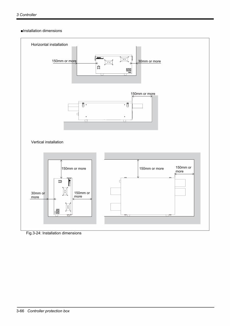
3-66 Controller protection box
3 Controller
■Installation dimensions
Fig.3-24: Installation dimensions
Horizontal installation
Vertical installation
150mm or more
30mm or more150mm or more
30mm or more
150mm or more 150mm or more
150mm or more
150mm ormore
3 Controller
MELSOFT RT ToolBox3/MELSOFT RT ToolBox3 mini/MELSOFT RT ToolBox3 Pro 3-67
(5) MELSOFT RT ToolBox3/MELSOFT RT ToolBox3 mini/MELSOFT RT ToolBox3 Pro
■Order type: ●MELSOFT RT ToolBox3*For windows DVD-ROM : 3F-14C-WINE
●MELSOFT RT ToolBox3 mini*For windows DVD-ROM : 3F-15C-WINE
●MELSOFT RT ToolBox3 Pro*For windows DVD-ROM : 3F-16D-WINE
■Outline
This is handy software that fully uses the personal computer functions. It can be used in various stages from the robot specifications study (tact study, etc.) to the design support (creation and editing of programs), start up support (execution, control and debugging of program), and maintenance (maintenance forecast).
■ConfigurationTable 3-17: Product configuration
■Features(1) Simple operation with guidance method and menu method
The Windows standard is used for windows operation, so the controller initialization and startup operations can be carried out easily by following the instructions given on the screen. Even a beginner can easily carry out the series of operations from program creation to execution.
(2) Increased work efficiency with ample support functionsThe work efficiency is greatly improved with the multi-window method that carries out multiple steps and displays in parallel. The renumbering function, and copy, search, syntax check and step execution are especially sufficient, and are extremely useful when editing or debugging the program.With the simulation function support of MELSOFT RT ToolBox3, the program can be debugged and the tact checked before starting the machine at the site. This allows the on-site startup work efficiently to be greatly improved.MELSOFT RT ToolBox3 Pro allows a simulation of robot operation on three-dimensional CAD software SolidWorks®.
(3) The maintenance forecast function increases the efficiency of maintenance work. Analyze the load con-dition while the robot is actually operating. Based on this analysis, calculate the time for maintenance, such as lubrication and belt replacement. By utilizing this information, the line stop time as well as the maintenance costs can be reduced.Maintenance forecast is not supported with controller software versions A5n or earlier (shipped before April 2021). When updating the software version to a version that supports the maintenance forecast function, the maintenance forecast results will not be correct as the operation data for the period of time the robot was used with the unsupported software will not have been calculated.
(4) The position recovery support function increases the recovery efficiency in the event of origin position displacement. This function compensates the origin settings and position data by just reproducing several previous teaching points when hand and/or arm displacement occurs, when replacing the motor and the belts, or when reloading the robot. This function can reduce the time required for recovery.
Part name Type Medium Mass (kg) Note1)
Note1) Mass indicates one set.
Remarks
RT ToolBox3 3F-14C-WINE DVD-ROM 0.2
RT ToolBox3 mini 3F-15C-WINE DVD-ROM 0.2
RT ToolBox3 Pro 3F-16D-WINE DVD-ROM 0.2

3-68 MELSOFT RT ToolBox3/MELSOFT RT ToolBox3 mini/MELSOFT RT ToolBox3 Pro
3 Controller
■FunctionsTable 3-18: Functions
Function Functional existenceNote1)
Note1) The functions included with the MELSOFT RT ToolBox3 ,MELSOFT RT ToolBox3 mini, and the MELSOFT RT ToolBox3 Pro are shown below. ○: Function provided ×: Function not provided
Details
Compatible model ○ ○ ○
Personal computer running Windows 7, Windows 8, Windows 8.1, or Windows 10. Note2)
Note2) Recommend corresponding to CE Marking, an FCC standard, and a VCCI standard.
Program editing functions
Editing functions
○ ○ ○
• MELFA BASIC V, VI language compatible• Multiple editing screen simultaneously display• Command input, comment writing• Position data editing• File operation (writing to controller, personal computer)• Search and replace function (using characters, line Nos.,
labels)• Copy, cut, paste, insert (per character, line), undo (per
command statement, position conversion)• Line No. automatic generation, renumbering• Batch syntax check• Command template• Position conversion batch editing• Position variable template• Print, print preview
Control functions ○ ○ ○ • Program file control (list, copy, movement, delete, content
comparison, name change, protect)
Debugging functions ○ ○ ○
• Direct editing of program in controller• Confirmation of robot program operation (step execution,
direct execution)
Simulation function○ ○ ×
• Off-line simulation of robot program operation using CG (computer graphics)
• Tact time calculation
Monitor functions
○ ○ ○
• Robot operation monitor (robot operation state, stop signal, error monitor, program monitor (execution program, variables), general-purpose input/output signals (forced output possible), dedicated input/output signals, operation confirmation (operation range, current position, hand, etc.)
• Operation monitor (working time statistics, production information, robot version)
• Servo monitor (load)
Maintenance function ○ ○ ○ • Parameter setting• Batch, divided backup
Simulation function on SolidWorks. ○ × ×
• Off-line simulation of robot program operation using CG (computer graphics)
• Tact time calculation• Complex motion path generation, etc.
MELSOFT RT ToolBox3 mini (3F-15C-WINE) MELSOFT RT ToolBox3 (3F-14C-WINE) MELSOFT RT ToolBox3 Pro (3F-16D-WINE)

3 Controller
Instruction Manual (bookbinding) 3-69
(6) Instruction Manual (bookbinding)
■Order type: • 5F-BR01-PE01: Instruction manuals of RV-8CRL
■Outline
This is a printed version of the CD-ROM (instruction manual) supplied with this product.
■ConfigurationTable 3-19: Product configuration
Name Type Mass (Kg) Note1)
Note1) Mass indicates one set.
Specifications
Instruction Manual 5F-BR01-PE01 3.0 The instructions manual set of RV-8CRL.
Safety Manual BFP-A3541 - Items relating to safety in handling the robot
Standard Specifications BFP-A3678 - Specification of the robot arm and controller
Robot Arm Setup & Maintenance BFP-A3679 - Installation method of the robot arm, jog operation, and maintenance and inspection procedures
Controller Setup, Basic Operation and Maintenance BFP-A3476 - Installation method of the controller, basic operation,
and maintenance and inspection procedures
Detailed Explanation of Functions and Operations BFP-A3478 - Functions of the controller and T/B, operation method,
and explanation of MELFA-BASIC VI.
Troubleshooting BFP-A3480 - Causes of errors occurred and their countermeasures
Additional axis function BFP-A3504 - Function of the additional axis, operation method.
Tracking Function BFP-A3520 - Function of the tracking, operation method.
GOT Direct Connection Extended Function BFP-A3546 -Explains of data configuration of shared memory, monitoring, and operating procedures, between the GOT and controller.
Ethernet Function BFP-A3379 - Ethernet communication method between personal computer and robot controller.
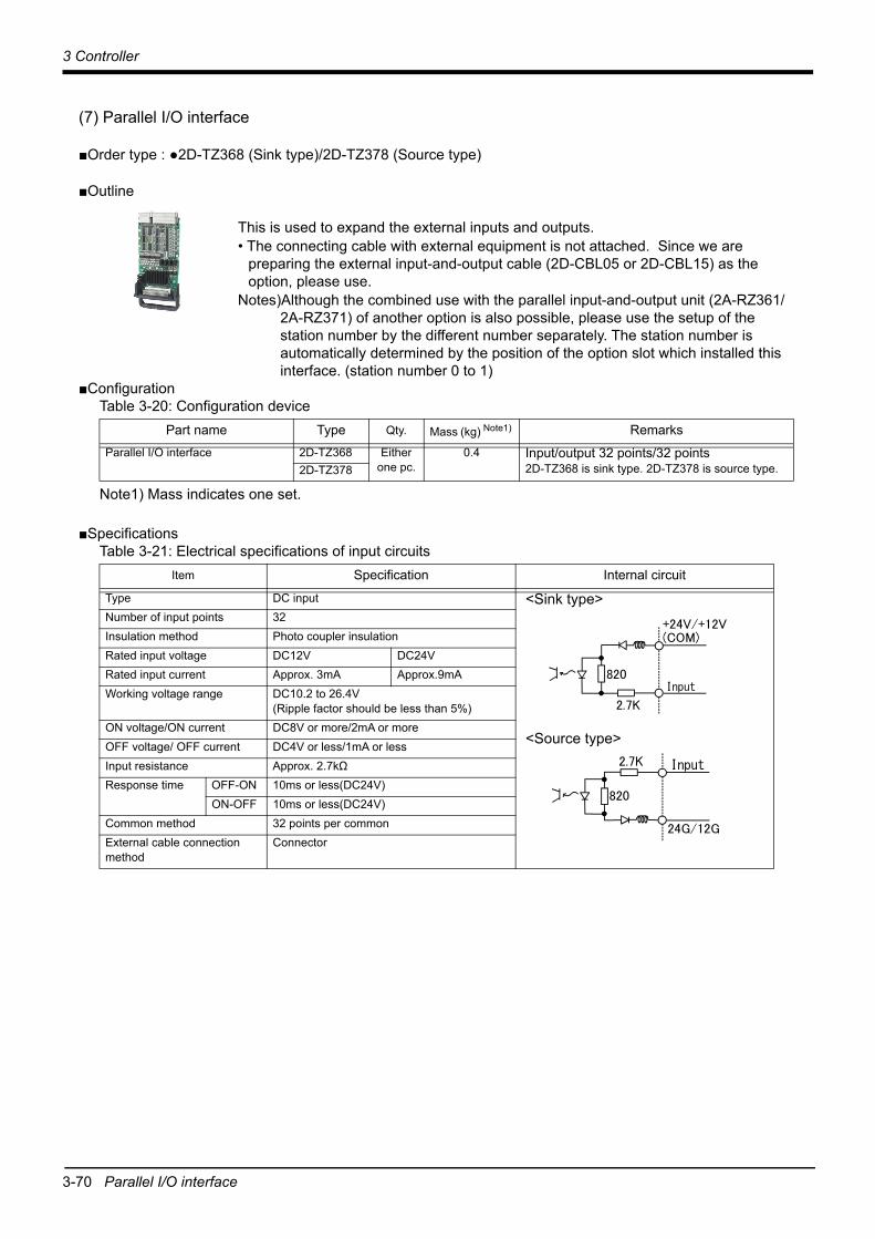
3-70 Parallel I/O interface
3 Controller
(7) Parallel I/O interface
■Order type : ●2D-TZ368 (Sink type)/2D-TZ378 (Source type)
■Outline
This is used to expand the external inputs and outputs.• The connecting cable with external equipment is not attached. Since we are
preparing the external input-and-output cable (2D-CBL05 or 2D-CBL15) as the option, please use.
Notes)Although the combined use with the parallel input-and-output unit (2A-RZ361/2A-RZ371) of another option is also possible, please use the setup of the station number by the different number separately. The station number is automatically determined by the position of the option slot which installed this interface. (station number 0 to 1)
■ConfigurationTable 3-20: Configuration device
■SpecificationsTable 3-21: Electrical specifications of input circuits
Part name Type Qty. Mass (kg) Note1)
Note1) Mass indicates one set.
RemarksParallel I/O interface 2D-TZ368 Either
one pc.0.4 Input/output 32 points/32 points
2D-TZ368 is sink type. 2D-TZ378 is source type. 2D-TZ378
Item Specification Internal circuit
Type DC input <Sink type>
<Source type>
Number of input points 32 Insulation method Photo coupler insulationRated input voltage DC12V DC24V Rated input current Approx. 3mA Approx.9mA Working voltage range DC10.2 to 26.4V
(Ripple factor should be less than 5%) ON voltage/ON current DC8V or more/2mA or more OFF voltage/ OFF current DC4V or less/1mA or less Input resistance Approx. 2.7kΩResponse time OFF-ON 10ms or less(DC24V)
ON-OFF 10ms or less(DC24V) Common method 32 points per common External cable connection method
Connector
Input
+24V/+12V(COM)
2.7K
820
2.7K
820
24G/12G
Input
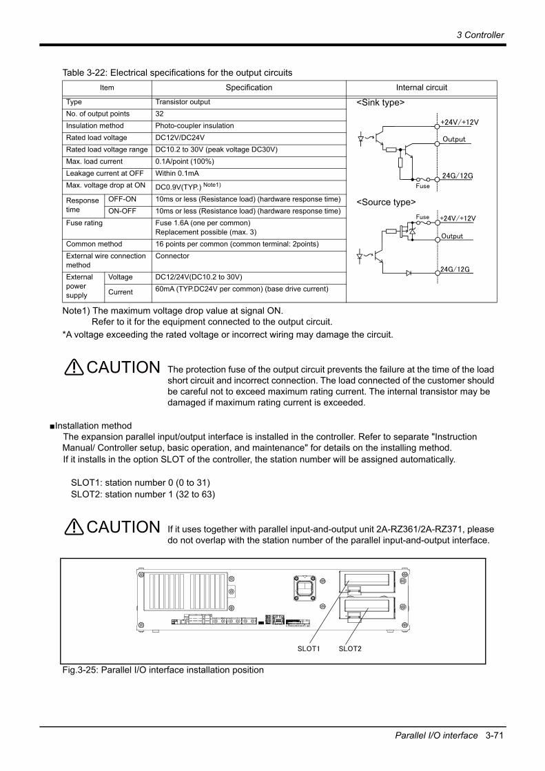
3 Controller
Parallel I/O interface 3-71
Table 3-22: Electrical specifications for the output circuits
*A voltage exceeding the rated voltage or incorrect wiring may damage the circuit.
The protection fuse of the output circuit prevents the failure at the time of the load short circuit and incorrect connection. The load connected of the customer should be careful not to exceed maximum rating current. The internal transistor may be damaged if maximum rating current is exceeded.
■Installation methodThe expansion parallel input/output interface is installed in the controller. Refer to separate "Instruction Manual/ Controller setup, basic operation, and maintenance" for details on the installing method. If it installs in the option SLOT of the controller, the station number will be assigned automatically.
SLOT1: station number 0 (0 to 31)SLOT2: station number 1 (32 to 63)
If it uses together with parallel input-and-output unit 2A-RZ361/2A-RZ371, please do not overlap with the station number of the parallel input-and-output interface.
Fig.3-25: Parallel I/O interface installation position
Item Specification Internal circuit
Type Transistor output <Sink type>
<Source type>
No. of output points 32 Insulation method Photo-coupler insulationRated load voltage DC12V/DC24V Rated load voltage range DC10.2 to 30V (peak voltage DC30V) Max. load current 0.1A/point (100%) Leakage current at OFF Within 0.1mAMax. voltage drop at ON DC0.9V(TYP.) Note1)
Note1) The maximum voltage drop value at signal ON. Refer to it for the equipment connected to the output circuit.
Response time
OFF-ON 10ms or less (Resistance load) (hardware response time) ON-OFF 10ms or less (Resistance load) (hardware response time)
Fuse rating Fuse 1.6A (one per common)Replacement possible (max. 3)
Common method 16 points per common (common terminal: 2points)External wire connection method
Connector
External power supply
Voltage DC12/24V(DC10.2 to 30V)
Current 60mA (TYP.DC24V per common) (base drive current)
+24V/+12V
Output
24G/12GFuse
+24V/+12V
24G/12G
Fuse
Output
CAUTION
CAUTION

3-72 Parallel I/O interface
3 Controller
■Pin layout of connector
Fig.3-26: Pin layout of connector
■Connector pin No. and signal assignmentThe station number is fixed by the slot to install and the allocation range of the general-purpose input-and-output signal is fixed.
Table 3-23: The slot number and the station number
The connector pin number of the parallel input-and-output interface installed in SLOT1 and signal number allocation are shown in Table 3-24 and Table 3-25. If it installs in other slots, please interpret and utilize.
Slot number Station number
Range of the general-purpose input-and-output signal
Connector <1> Connector <2>
SLOT1 0 Input: 0 to 15Output: 0 to 15
Input: 16 to 31Output: 16 to 31
SLOT2 1 Input: 32 to 47Output: 32 to 47
Input: 48 to 63Output: 48 to 63
1B
1A 20A
20B
1D
1C 20C
20D
Connector<2>Output 16 to 31Input 16 to 31(when station number 0)
Connector<1>Output 0 to 15Input 0 to 15(when station number 0)

3 Controller
Parallel I/O interface 3-73
Table 3-24: Connector<1> pin assignment list and external I/O cable (2D-CBL**) color(SLOT1)
Table 3-25: Connector<2> pin assignment list and external I/O cable (2D-CBL**) color(SLOT1)
PinNo. Line color
Function namePinNo. Line color
Function name
General-purpose Dedicated/power supply, common General-purpose Dedicated/power supply,
common
1C Orange/Red a 24G/12G: For pins 5D-20D
1D Orange/Black a +24V/+12V(COM): For pins 5D-20D
2C Gray/Red a COM: For pins 5C-20CNote1)
Note1) Sink type: +24V/+12V(COM), Source type: 24G/12G
2D Gray/Black a Reserved
3C White/Red a Reserved 3D White/Black a Reserved4C Yellow/Red a Reserved 4D Yellow/Black a Reserved5C Pink/Red a General-purpose input 15 5D Pink/Black a General-purpose output 156C Orange/Red b General-purpose input 14 6D Orange/Black b General-purpose output 147C Gray/Red b General-purpose input 13 7D Gray/Black b General-purpose output 138C White/Red b General-purpose input 12 8D White/Black b General-purpose output 129C Yellow/Red b General-purpose input 11 9D Yellow/Black b General-purpose output 11
10C Pink/Red b General-purpose input 10 10D Pink/Black b General-purpose output 1011C Orange/Red c General-purpose input 9 11D Orange/Black c General-purpose output 912C Gray/Red c General-purpose input 8 12D Gray/Black c General-purpose output 813C White/Red c General-purpose input 7 13D White/Black c General-purpose output 714C Yellow/Red c General-purpose input 6 14D Yellow/Black c General-purpose output 615C Pink/Red c General-purpose input 5 Operation rights input
signal Note2)
Note2) The dedicated signal is assigned at shipping. It can change with the parameter.
15D Pink/Black c General-purpose output 5
16C Orange/Red d General-purpose input 4 Servo ON input signal Note2)
16D Orange/Black d General-purpose output 4
17C Gray/Red d General-purpose input 3 Start input Note2) 17D Gray/Black d General-purpose output 3 Operation rights output signal Note2)
18C White/Red d General-purpose input 2 Error reset input signal Note2)
18D White/Black d General-purpose output 2 Error occurring output signal Note2)
19C Yellow/Red d General-purpose input 1 Servo OFF input signal Note2)
19D Yellow/Black d General-purpose output 1 In servo ON output signal Note2)
20C Pink/Red d General-purpose input 0 Stop input Note3)
Note3) The dedicated input signal (STOP) is assigned at shipping. The signal number is fixing.
20D Pink/Black d General-purpose output 0 Operating output Note2)
PinNo. Line color
Function namePinNo. Line color
Function name
General-purpose Dedicated/power supply, common General-purpose Dedicated/power supply,
common
1A Orange/Red a 24G/12G: For pins 5B-20B
1B Orange/Black a +24V/+12V(COM): For pins 5B-20B
2A Gray/Red a COM: For pins 5A-20ANote1)
Note1) Sink type: +24V/+12V(COM), Source type: 24G/12G
2B Gray/Black a Reserved
3A White/Red a Reserved 3B White/Black a Reserved4A Yellow/Red a Reserved 4B Yellow/Black a Reserved5A Pink/Red a General-purpose input 31 5B Pink/Black a General-purpose output 316A Orange/Red b General-purpose input 30 6B Orange/Black b General-purpose output 307A Gray/Red b General-purpose input 29 7B Gray/Black b General-purpose output 298A White/Red b General-purpose input 28 8B White/Black b General-purpose output 289A Yellow/Red b General-purpose input 27 9B Yellow/Black b General-purpose output 27
10A Pink/Red b General-purpose input 26 10B Pink/Black b General-purpose output 2611A Orange/Red c General-purpose input 25 11B Orange/Black c General-purpose output 2512A Gray/Red c General-purpose input 24 12B Gray/Black c General-purpose output 2413A White/Red c General-purpose input 23 13B White/Black c General-purpose output 2314A Yellow/Red c General-purpose input 22 14B Yellow/Black c General-purpose output 2215A Pink/Red c General-purpose input 21 15B Pink/Black c General-purpose output 2116A Orange/Red d General-purpose input 20 16B Orange/Black d General-purpose output 2017A Gray/Red d General-purpose input 29 17B Gray/Black d General-purpose output 1918A White/Red d General-purpose input 18 18B White/Black d General-purpose output 1819A Yellow/Red d General-purpose input 17 19B Yellow/Black d General-purpose output 1720A Pink/Red d General-purpose input 16 20B Pink/Black d General-purpose output 16

3-74 Parallel I/O interface
3 Controller
<Reference> The example of connection with our PLC
Fig.3-27: Connection with a Mitsubishi PLC (Example of sink type)
The following shows an example of a protective circuit.
Fig.3-28: Connection with a Mitsubishi PLC (Example of sink type) for use of a protective circuit
<Sink>Parallel I/O interface
(Output)
(Input)
60mA(+24V/+12V)
Output
Output
Fuse (24G/12G)
+24V
External power supply
X
COM
QX41(Mitsubishi programmable controller)
(COM)
Input2.7K
Input
External power supply
+24V
Y
+24V
QY41P (Mitsubishi programmable controller)
COM24G
* The input/output circuit external power supply (24 VDC) must be prepared by the customer.
Note) In the customer's system, do not ground the + side of 24V power supply prepared by customer for connect to the controller. (related with emergency stop and parallel input/output) If it connects with the controller under the condition that the + side is grounded, it will lead to failure of controller.

3 Controller
Parallel I/O interface 3-75
Fig.3-29: Connection with a Mitsubishi PLC (Example of source type)
The following shows an example of a protective circuit.
Fig.3-30: Connection with a Mitsubishi PLC (Example of source type) for use of a protective circuit
<Source>Parallel I/O interface
(Output)
(Output)
60mA(+24V/+12V)
Output
Output
Fuse
(24G/12G)
+24V
External power supply
X
QX81 (Mitsubishi programmable controller)
(COM)
Input2.7K
Input
External power supply
+24V
Y
+24V
QY81P (Mitsubishi programmable controller)
24G
* The input/output circuit external power supply (24 VDC) must be prepared by the customer.
Note) In the customer's system, do not ground the + side of 24V power supply prepared by customer for connect to the controller. (related with emergency stop and parallel input/output) If it connects with the controller under the condition that the + side is grounded, it will lead to failure of controller.
COM

3-76 External I/O cable
3 Controller
(8) External I/O cable
■Order type : ●2D-CBL□□[Note]The numbers in the boxes□□ refer to the length. (05: 5m, 15: 15m)
■OutlineThis is the dedicated cable used to connect an external peripheral device to the connector on the parallel I/O interface. For parallel I/O unit is another option 2A-CBL□□. One end matches the connector on the parallel input/output unit, and the other end is free. Connect the peripheral device's input/output signal using the free end. One cable correspond to the input 16 points and output 16 points. Two cables are needed to connection of (input 32 points and output 32 points)
with built-in standard.
■ConfigurationTable 3-26: Configuration device
■SpecificationsTable 3-27: Specifications
■Connector pin numbers and cable colorsTable 3-28: Connector pin numbers and cable colors
Notes) Pin number of connector<1> are 1C, 2C, ....20C, 1D, 2D, ....20D, connector<2> are 1A, 2A, ....20A, 1B, 2B, ....20B.
Part name Type Qty. Mass (kg) Note1)
Note1) Mass indicates one set.
Remarks
External I/O cable 2D-CBL□□ 1 pc. 0.7(5m)1.84(15m) 5m or 15m
Items Specifications
Number of cables x cable size AWG #28 x 20P (40 cores)
Total length 5m, 15m
Pin no. Cable colors Pin no. Cable colors Pin no. Cable colors Pin no. Cable colors
1A/C Orange/Red a 11A/C Orange/Red c 1B/D Orange/Black a 11B/D Orange/Black c
2A/C Gray/Red a 12A/C Gray/Red c 2B/D Gray/Black a 12B/D Gray/Black c
3A/C White/Red a 13A/C White/Red c 3B/D White/Black a 13B/D White/Black c
4A/C Yellow/Red a 14A/C Yellow/Red c 4B/D Yellow/Black a 14B/D Yellow/Black c
5A/C Pink/Red a 15A/C Pink/Red c 5B/D Pink/Black a 15B/D Pink/Black c
6A/C Orange/Red b 16A/C Orange/Red d 6B/D Orange/Black b 16B/D Orange/Black d
7A/C Gray/Red b 17A/C Gray/Red d 7B/D Gray/Black b 17B/D Gray/Black d
8A/C White/Red b 18A/C White/Red d 8B/D White/Black b 18B/D White/Black d
9A/C Yellow/Red b 19A/C Yellow/Red d 9B/D Yellow/Black b 19B/D Yellow/Black d
10A/C Pink/Red b 20A/C Pink/Red d 10B/D Pink/Black b 20B/D Pink/Black d

3 Controller
External I/O cable 3-77
■Connections and outside dimensionsThe sheath of each signal cable (40 lines) is color indicated and marked with dots. Refer to the cable color specifications in "Table 3-37: Connector pin numbers and cable colors" when making the connections.
Fig.3-31: Connections and outside dimensions
(Eg.) Pin number: color indication 1 : Orange / Red / a
Type of dot mark (see figure below)Color of dot mark
Line colortype
a type
Pattern of the print mark
One dot
Two dots
Three dots
Four dots
b type
c type
d type
1A/C 1B/D
20A/C 20B/D
or
Plug (Fujitsu Ltd) Connector: FCN-361J040-AU Cover : FCN-360C040-B

3-78 Parallel I/O unit
3 Controller
(9) Parallel I/O unit
■Order type: 2A-RZ361(Sink type)/2A-RZ371(Source type)
■OutlineThis is used to expand the external inputs and outputs.• The connection cable is not included. .Prepare the optional external input/
output cable (2A-CBL05 or 2A-CBL15).• Use 2A-RZ361 if the external input/output signal logic is of the sink type and
2A-RZ371 for source type signal logic.
Notes) Although the combined use with the parallel I/O interface (2D-TZ368/2D-TZ378) of another option is also possible, please use the setup of the station number by the different number separately. The station number is automatically fixed by the position of the option slot which installed the parallel I/O interface in 0-1.
■ConfigurationTable 3-29: Configuration device
■Specifications1) Up to eight stations can be connected to this unit (one station occupies one unit).
The combined use with another optional parallel I/O interface (2D-TZ368/2D-TZ378) is possible, but the maximum number of stations is eight in total. In this case, set any of station numbers carefully so that they do not duplicate.
2) The power supply (24V) must be prepared by the customer and connected with the power connection cable (DCcable-2)A separate 24V power supply is required for the input/output circuit wiring.
Part name Type Qty. Mass (kg) Note1)
Note1) Mass indicates one set.
Remarks
Parallel I/O unit 2A-RZ361 Either one pc. 0.7
Input/output 32 points/32 points2A-RZ361 is the sink type.2A-RZ371 is the source type.2A-RZ371
Robot I/O link connection connector NETcable-1 2 sets -
Connector with pins.The cable must be prepared and wired by the customer.
Power connection connector DCcable-2 Each 1
set -Connector with pins.The cable must be prepared and wired by the customer.
Terminator R-TM 1 pc. - 100Ω (1/4W)

3 Controller
Parallel I/O unit 3-79
Table 3-30: Electrical specifications of input circuits
Table 3-31: Electrical specifications for the output circuits
*A voltage exceeding the rated voltage or incorrect wiring may damage the circuit.
The output circuit protective fuses prevent failure in case of load short-circuit and improper connections. Please do not connect loads that cause the current to exceed the maximum rated current. If the maximum rated current is exceeded, the internal transistors may be damaged.
Inputs the power supply for control (DCcable-2) then inputs the controller’s power supply.
Item Specification Internal circuit
Type DC input <Sink type>
<Source type>
Number of input points 32 Insulation method Photo coupler insulation Rated input voltage 12VDC 24VDC Rated input current Approx 3mA Approx 7mA Working voltage range 10.2 to 26.4VDC(Ripple factor should be less than
5%.)ON voltage/ON current 8VDC or more/ 2mA or more OFF voltage/ OFF current 4VDC or less/ 1mA or less Input resistance Approx. 3.3kΩ Response time OFF-ON 10ms or less (24VDC)
ON-OFF 10ms or less (24VDC) Common method 8 points per commonExternal cable connection method
Connector
Item Specification Internal circuit Type Transistor output <Sink type>
<Source type>
No. of output points 32 Insulation method Photo-coupler insulation Rated load voltage 12VDC/24VDC Rated load voltage range 10.2 to 30VDC(peak voltage 30VDC)Max. load current 0.1A/point (100%) Leakage current at OFF 0.1mA or less Max. voltage drop at ON 0.9VDC(TYP.) Note1)
Note1) The maximum voltage drop value at signal ON. Refer to it for the equipment connected to the output circuit.
Response time OFF-ON 2ms or less
(hardware response time)
ON-OFF 2ms or less(Resistance load) (hardware response time)
Fuse rating Fuse 3.2A (one per common) Replacement not possible
Common method 8 points per common (common terminal: 4 points)External wire connection method Connector
External power supply
Voltage 12VDC/24VDC(10.2 to 30VDC)
Current 60mA (TYP. 24VDC per common) (base drive current)
入力
+24V/+12V(COM)
3.3K
820 Input
3.3K
820
24G/12G
入力Input
+24V/+12V
出力
24G/12Gヒューズ
Output
Fuse
+24V/+12V
24G/12G
出力
ヒューズ
Output
Fuse
CAUTION
CAUTION

3-80 Parallel I/O unit
3 Controller
Fig.3-32: Specifications for the connection cable
Note 1) The 24V power supply is prepared by customer (The power consumption is approx. 0.3A.)In the customer's system, do not ground the + side of 24V power supply prepared by customer for connect to the controller. (related with emergency stop and parallel input/output) If it connects with the controller under the condition that the + side is grounded, it will lead to failure of controller.
Note 2) The cable for general purpose can be used to the network cable. However, use the twisted shield cable of AWG#22(0.3mm2) or more.
NET cable-1 (Network cable)
Connector: J21DF-06V-KX-L
Connected the frame ground or protect ground
Connector: 1-178288-3
Connector: 2-178288-3
Pin No.
1
2
3
RIO1/2
TXRXH
TXRXL
SG(GND)
RIO
TXRXDH
TXRXDL
SG(GND)
FG
+
-
Pin No.
1A
1B
2B
3A
DCcable-2 (Power cable)
Pin No.
1
2
3
RIO1/2
24V
24G(RG)
FG(PE)
+24V Power
R-TM (Terminator)
Pin No.
1
2
3
RIO1/2
TXRXH
TXRXL
SG(GND)
100Ω
List of parts and manufacturerType Connector type Contact type Resistant Manufacturer
NETcable-11-178288-3 (2) 1-175218-2 (6) - Tyco Electronics51103-0300 (1) 50351-8100 (3) - MOLEXJ21DF-06V-KX-L (1) SJ2F-01GF-P1.0 (4) - JST
DCcable-2 2-178288-3 (1) 1-175218-5 (3) - Tyco ElectronicsR-TM 1-178288-3 (1) 1-175218-3 (2) 100Ω(1/4W) (1) Equivalent to KOA.
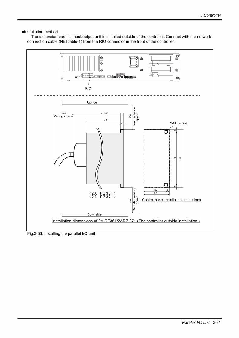
3 Controller
Parallel I/O unit 3-81
■Installation methodThe expansion parallel input/output unit is installed outside of the controller. Connect with the network
connection cable (NETcable-1) from the RIO connector in the front of the controller.
Fig.3-33: Installing the parallel I/O unit
6 05 4 6
放熱
、配
線余
裕
150
6156
2 - M 5 ネ ジ
6
168
放熱
余裕
1 2 8
(1 7 5 )
100
天
配 線 余 裕(40 )
地
<2 A -R Z 3 61 >
制 御 盤 取 付 寸 法
2A - R Z 36 1/ 2 A - R Z 37 1 の 取 付 寸 法
6
<2 A -R Z 3 71 >
Installation dimensions of 2A-RZ361/2ARZ-371 (The controller outside installation.)
Upside
Wiring space
Hea
t rad
iatio
n sp
ace
2-M5 screw
Downside
Rad
iatio
n/w
iring
sp
ace
Control panel installation dimensions
RIO

3-82 Parallel I/O unit
3 Controller
Fig.3-34: Connection method of expansion parallel I/O unit
局番設定 1 . . . 6
<CN100><CN300>
局番設定 7
<CN100>
<CN300>
NETcable-1ケーブル
R-TMターミネータ
パラレル入出力ユニット 1 . . . . 6 パラレル入出力ユニット7
RIOコネクタ
DCINコネクタ
RIO2コネクタRIO1コネクタ
NETcable-1ケーブル
DCcable-2ケーブル
RIO2コネクタ
RIO1コネクタ
DCINコネクタ
前 面
FGFG
入出力ユニット底面コネクタ配置図
注1)
注1)
RIO2コネクタRIO1コネクタ
DCINコネクタ
DCcable-2ケーブル
100mm以内*1)
フェライトコア
FG*2)
20~30mm金属製ブレード部
シース シース
*2) ケーブルアースクランプ
シースはケーブルのコネクタ端から200~300mmの箇所を目安にカバーの着脱ができる程度の位置で剥いてください。※シールド線に傷をつけないようにご注意願います。
*1) フェライトコアはそれぞれのコネクタから100mm 以内に取り付けてください。
注2)
*1) Install the ferrite core in within 100mm from each connector.
RIO
Parallel I/O unit 1 . . . 6 Parallel I/O unit 7Station No. setting1 . . . 6
Station No. setting7
Note)NETcable-1cable
RIO1 connector
RIO1 connectorRIO2 connector
RIO1 connector RIO2
connector
Note)NETcable-1cable
DCINconnector
DCcable-2cable DCcable-2
cable
DCINconnector
RIO2 connector
DCIN connector
R-TMterminator
I/O unit the bottom connecter layout
Connect the NET cable-1 to the RIO connector on the front of the controller. Each unit is connected to froma daisy chain.Always install a terminator (R-TM) to the last unit.Note 1) Use a shield cable for NET cable-1 as a measure against noise.
The unit could malfunction because of noise if the shield cable is not used.Always connect the shield to FG. Install the attached ferrite core in both ends.
Note 2) Install the ferrite core on the cable as required. Recommended ferrite core: E04SR301334 (manufacture: SEIWA ELECTRIC MFG)
Within 100mm
Front side
*2) Grounding terminal position
Sheath Sheath
Metal braid sectionPeel the sheath in the position about 200-300mm from the connector end of the cable, so you can install and remove the cover.* Don't damage the shield line.
*2)
*1)
Ferrite core

3 Controller
Parallel I/O unit 3-83
■Pin arrangement of the connector
Fig.3-35: Pin arrangement of the parallel I/O unit
■Assignment of pin number and signalThe assignment range of the general-purpose input-and-output signal is fixed by the setup of the station number.Although the combined use with the parallel I/O interface (2D-TZ368/2D-TZ378) of another option is also possible, please use the setup of the station number by the different number separately.
Table 3-32: Assignment of pin number and signal
The connector pin number of the parallel I/O unit of the station number 0 and signal number assignment are shown in Table 3-33 and Table 3-34. If it is set as other station number, please interpret and utilize.
Unit Number Station number CN100 CN300
1st set 0 Input: 0 to 15Output: 0 to 15
Input: 16 to 31Output: 16 to 31
2nd set 1 Input: 32 to 47Output: 32 to 47
Input: 48 to 63Output: 48 to 63
3rd set 2 Input: 64 to 79Output: 64 to 79
Input: 80 to 95Output: 80 to 95
4th set 3 Input: 96 to 111Output: 96 to 111
Input: 112 to 127Output: 112 to 127
5th set 4 Input: 128 to 143Output: 128 to 143
Input: 144 to 159Output: 144 to 159
6th set 5 Input: 160 to 175Output: 160 to 175
Input: 176 to 191Output: 176 to 191
7th set 6 Input: 192 to 207Output: 192 to 207
Input: 208 to 223Output: 208 to 223
8th set 7 Input: 224 to 239Output: 224 to 239
Input: 240 to 255Output: 240 to 255
50
26
25
1
Channel No. setting
TXD LED display
Input 0 to 15Output 0 to 15
<CN100>
<CN300> Input 16 to 31Output 16 to 31
*2A-RZ361/2 A-RZ371 are 32/32 input-and-output units. (One-station occupancy)
*1)
*1)TXD LED displayIndicator for the communication status. The dimly lit lamp indicates that the unit is in the normal condition. The brightness of the light depends on the communication conditions.

3-84 Parallel I/O unit
3 Controller
Table 3-33: CN100 connector signal assignment/external I/O cable 2A-CBL□□ wire color list (station number "0")
PinNo. Line color
Function name PinNo. Line color
Function name
General-purpose Dedicated/power supply, common General-purpose Dedicated/power supply,
common
1 Orange/Red A FG 26 Orange/Blue A FG2 Gray/Red A 0V:For pins 4-7, 10-13 27 Gray/Blue A 0V:For pins 29-32, 35-383 White/Red A 12V/24V:For pins 4-7 28 White/Blue A 12V/24V:For pins 29-324 Yellow/Red A General-purpose output 0 Operating output Note1)
Note1) The dedicated signal is assigned at shipping. It can change with the parameter.
29 Yellow/Blue A General-purpose output 45 Pink/Red A General-purpose output 1 In servo ON output signal
Note1) 30 Pink/Blue A General-purpose output 5
6 Orange/Red B General-purpose output 2 Error occurring output signal Note1)
31 Orange/Blue B General-purpose output 6
7 Gray/Red B General-purpose output 3 Operation rights output signal Note1)
32 Gray/Blue B General-purpose output 7
8 White/Red B 0V:For pins 4-7, 10-13 33 White/Blue B 0V:For pins 29-32, 35-389 Yellow/Red B 12V/24V:For pins 10-13 34 Yellow/Blue B 12V/24V:For pins 35-3810 Pink/Red B General-purpose output 8 35 Pink/Blue B General-purpose output 1211 Orange/Red C General-purpose output 9 36 Orange/Blue C General-purpose output 1312 Gray/Red C General-purpose output 10 37 Gray/Blue C General-purpose output 1413 White/Red C General-purpose output 11 38 White/Blue C General-purpose output 1514 Yellow/Red C COM0:For pins 15-22
Note2)
Note2) Sink type:12V/24V(COM),Source type:0V(COM)
39 Yellow/Blue C COM1:For pins 40-47 Note2)
15 Pink/Red C General-purpose input 0 Stop input Note3)
Note3) The dedicated input signal (STOP) is assigned at shipping. The signal number is fixing.
40 Pink/Blue C General-purpose input 8
16 Orange/Red D General-purpose input 1 Servo OFF input signal Note1)
41 Orange/Blue D General-purpose input 9
17 Gray/Red D General-purpose input 2 Error reset input signal Note1)
42 Gray/Blue D General-purpose input 10
18 White/Red D General-purpose input 3 Start input Note1) 43 White/Blue D General-purpose input 11
19 Yellow/Red D General-purpose input 4 Servo ON input signal Note1)
44 Yellow/Blue D General-purpose input 12
20 Pink/Red D General-purpose input 5 Operation rights input signal Note1)
45 Pink/Blue D General-purpose input 13
21 Orange/Red E General-purpose input 6 46 Orange/Blue E General-purpose input 1422 Gray/Red E General-purpose input 7 47 Gray/Blue E General-purpose input 1523 White/Red E Reserved 48 White/Blue E Reserved24 Yellow/Red E Reserved 49 Yellow/Blue E Reserved25 Pink/Red E Reserved 50 Pink/Blue E Reserved

3 Controller
Parallel I/O unit 3-85
Table 3-34: CN300 connector signal assignment/external I/O cable 2A-CBL□□ wire color list (station number "0")
PinNo. Line color
Function name PinNo. Line color
Function name
General-purpose Dedicated/power supply, common General-purpose Dedicated/power supply,
common
1 Orange/Red A FG 26 Orange/Blue A FG2 Gray/Red A 0V:For pins 4-7, 10-13 27 Gray/Blue A 0V:For pins 29-32, 35-383 White/Red A 12V/24V:For pins 4-7 28 White/Blue A 12V/24V:For pins 29-324 Yellow/Red A General-purpose output 16 29 Yellow/Blue A General-purpose output 205 Pink/Red A General-purpose output 17 30 Pink/Blue A General-purpose output 216 Orange/Red B General-purpose output 18 31 Orange/Blue B General-purpose output 227 Gray/Red B General-purpose output 19 32 Gray/Blue B General-purpose output 238 White/Red B 0V:For pins 4-7, 10-13 33 White/Blue B 0V:For pins 29-32, 35-389 Yellow/Red B 12V/24V:For pins 10-13 34 Yellow/Blue B 12V/24V:For pins 35-38
10 Pink/Red B General-purpose output 24 35 Pink/Blue B General-purpose output 2811 Orange/Red C General-purpose output 25 36 Orange/Blue C General-purpose output 2912 Gray/Red C General-purpose output 26 37 Gray/Blue C General-purpose output 3013 White/Red C General-purpose output 27 38 White/Blue C General-purpose output 3114 Yellow/Red C COM0:For pins 15-
22Note1)
Note1) Sink type:12V/24V(COM),Source type:0V(COM)
39 Yellow/Blue C COM1:For pins 40-47 Note1)
15 Pink/Red C General-purpose input 16 40 Pink/Blue C General-purpose input 2416 Orange/Red D General-purpose input 17 41 Orange/Blue D General-purpose input 2517 Gray/Red D General-purpose input 18 42 Gray/Blue D General-purpose input 2618 White/Red D General-purpose input 19 43 White/Blue D General-purpose input 2719 Yellow/Red D General-purpose input 20 44 Yellow/Blue D General-purpose input 2820 Pink/Red D General-purpose input 21 45 Pink/Blue D General-purpose input 2921 Orange/Red E General-purpose input 22 46 Orange/Blue E General-purpose input 3022 Gray/Red E General-purpose input 23 47 Gray/Blue E General-purpose input 3123 White/Red E Reserved 48 White/Blue E Reserved24 Yellow/Red E Reserved 49 Yellow/Blue E Reserved25 Pink/Red E Reserved 50 Pink/Blue E Reserved

3-86 Parallel I/O unit
3 Controller
<Reference> The example of connection with our PLC
Fig.3-36: Connection with a Mitsubishi PLC (Example of sink type)
The following shows an example of a protective circuit.
Fig.3-37: Connection with a Mitsubishi PLC (Example of sink type) for use of a protective circuit
<Sink>Parallel I/O unit
(Output)
(Input)
60mA(+24V/+12V)
Output
Output
Fuse (24G/12G)
+24V
External power supply
X
COM
QX41(Mitsubishi programmable controller)
(COM)
Input3.3K
Input
External power supply
+24V
Y
+24V
QY41P (Mitsubishi programmable controller)
COM24G
* The input/output circuit external power supply (24 VDC) must be prepared by the customer.
Note) In the customer's system, do not ground the + side of 24V power supply prepared by customer for connect to the controller. (related with emergency stop and parallel input/output) If it connects with the controller under the condition that the + side is grounded, it will lead to failure of controller.

3 Controller
Parallel I/O unit 3-87
Fig.3-38: Connection with a Mitsubishi PLC (Example of source type)
The following shows an example of a protective circuit.
Fig.3-39: Connection with a Mitsubishi PLC (Example of source type) for use of a protective circuit
<Source>Parallel I/O unit
(Output)
(Output)
60mA(+24V/+12V)
Output
Output
Fuse
(24G/12G)
+24V
External power supply
X
QX81 (Mitsubishi programmable controller)
(COM)
Input3.3K
Input
External power supply
+24V
Y
+24V
QY81P (Mitsubishi programmable controller)
24G
* The input/output circuit external power supply (24 VDC) must be prepared by the customer.
Note) In the customer's system, do not ground the + side of 24V power supply prepared by customer for connect to the controller. (related with emergency stop and parallel input/output) If it connects with the controller under the condition that the + side is grounded, it will lead to failure of controller.
COM

3-88 External I/O cable
3 Controller
(10) External I/O cable
■Order type: 2A-CBL□□ Note)The numbers in the boxes□□ refer to the length.(05: 5m, 15: 15m)
■OutlineThis is the dedicated cable used to connect an external peripheral device to the connector on the parallel input/output unit.One end matches the connector on the parallel input/output unit, and the other end is free. Connect the peripheral device's input/output signal using the free end.One cable correspond to the input 16 points and output 16 points.Two cables are needed to connection of (input 32 points and output 32 points) with built-in standard.
■ConfigurationTable 3-35: Configuration device
■SpecificationsTable 3-36: Specifications
■Connector pin numbers and cable colorsTable 3-37: Connector pin numbers and cable colors
Part name Type Qty. Mass(kg)Note1)
Note1) Mass indicates one set.
Remarks
External I/O cable 2A-CBL□□ 1pc. 0.7(5m)1.84(15m) 5m or 15m
Items Specifications
Number of cables x cable size 50 cores x AWG #28
Total length 5m or 15m
Pin no. Cable colors Pin
no. Cable colors Pin no. Cable colors Pin
no. Cable colors Pin no. Cable colors
1 Orange/Red A 11 Orange/Red C 21 Orange/Red E 31 Orange/Blue B 41 Orange/Blue D
2 Gray/Red A 12 Gray/Red C 22 Gray/Red E 32 Gray/Blue B 42 Gray/Blue D
3 White/Red A 13 White/Red C 23 White/Red E 33 White/Blue B 43 White/Blue D
4 Yellow/Red A 14 Yellow/Red C 24 Yellow/Red E 34 Yellow/Blue B 44 Yellow/Blue D
5 Pink/Red A 15 Pink/Red C 25 Pink/Red E 35 Pink/Blue B 45 Pink/Blue D
6 Orange/Red B 16 Orange/Red D 26 Orange/Blue A 36 Orange/Blue C 46 Orange/Blue E
7 Gray/Red B 17 Gray/Red D 27 Gray/Blue A 37 Gray/Blue C 47 Gray/Blue E
8 White/Red B 18 White/Red D 28 White/Blue A 38 White/Blue C 48 White/Blue E
9 Yellow/Red B 19 Yellow/Red D 29 Yellow/Blue A 39 Yellow/Blue C 49 Yellow/Blue E
10 Pink/Red B 20 Pink/Red D 30 Pink/Blue A 40 Pink/Blue C 50 Pink/Blue E

3 Controller
External I/O cable 3-89
■Connections and outside dimensionsThe sheath of each signal cable (50 lines) is color indicated and marked with dots. Refer to the cable color specifications in "Table 3-37: Connector pin numbers and cable colors" when making the connections.
Fig.3-40: Connections and outside dimensions
(Eg.) Pin number: color indication 1 : Orange / Red / A
Type of dot mark (see figure below)Color of dot mark
Type of dot mark
A type
B type
C type
D type
E type
F type
G type
H type
I type
J type
Dot pattern
Receptacle type (PCB side):57AE-40500-21D(D8)
Plug type (cable side):57YE-30500-2(D8)
……DDK
Maker
……DDK
26
5000
66
50 25
1
18.5
1
18.5
18.5
Continuous
18.5
1.5
1.5
1.5
1.5
18.5
3
3
3
18.5
18.5
18.5
7.5
7.5
Continuous
35.7
13.54
16.2 9.27
76. 7
4
64.5
3
51.8
16
2.1
59
Type of dot mark Dot pattern
Note1) The type of the plug shows the specification of this cable. The following connector is recommended when user make the cable. ・Plug type (cable side) : 57E series (Soldering type).....................................................DDK 57FE series (Flat cable pressure connection type)......DDK
Note1)

3-90 CC-Link interface
3 Controller
(11) CC-Link interface
■Order type: ●2D-TZ576
■OutlineThe CC-Link interface is the optioninterface to not only add bit data to the robot controller, but also to add CC-Link field network function that allows cyclic transmission of word data.
■ConfigurationTable 3-38: Configuration device
Table 3-39: Procured by the customer
Fig.3-41: Example of CC-Link Product Configuration
Part name Type Qty. Mass(kg)Note1)
Note1) Mass indicates one set.
Remarks
CC-Link interface TZ576 1 0.6Manual BFP-A8634 1 - CD-ROMFerrite core E04SR301334 2 -
Be sure to install this for noise countermeasure.Cable clamp AL4 2 -
AL5 2 -On-line connector for communication
A6CON-LJ5P 1 -
Terminal resistor A6CON-TR11N 1 - Resistance value: 100ΩOne-touch connector plug for communication
A6CON-L5P 2 -
Part name Type Qty. Remarks
Master station
FX3U-16CCL-M (FX series)
1
RJ61BT11 (R series)QJ61BT11 (Q series)QJ61BT11N (Q series)AJ61QBT11 (QnA series)A1SJ61QBT11 (QnAS series)AJ61BT11 (A series)A1SJ61BT11 (AnS series)A80BD-J61BT11 (personal computer board)
Communication cable - 1 Ddedicated cable

3 Controller
CC-Link interface 3-91
■SpecificationsTable 3-40: Specifications
Item Specifications Remarks
Communication function Bit data and word data can be transmitted. Word data are used by the registers.
Station type Intelligent device station Note1)
Note1) Not available for the transient transmission function and FX-series models that do not support intelligent devices.
Support station Local station No master station function
The version corresponding to CC-Link Ver.2 The extended cyclic setup is possible.
Mountable option slot Slot 1, 2
Number of mountable CC-Link interface cards
1 Multiple CC-Link interface cards cannot be inserted.
Number of stations 1 to 64 stations When four stations are occupied, continuous station numbers are used. The station numbers are set by a DIP switch.
Transmission speed 10M/5M/2.5M/625K/156K bps This is set by the rotary SW.
Station number 1 to 64 When two or more stations are occupied, continuous station numbers are used.Number of occupied stations 1/2/3/4
Extended cyclic setup 1/2/4/8
Maximum link point Remote I/O (RX, RY).
Each 896 points The two last cannot be used.
Remote register (RWr, RWw)
Each 128 register 16 bits/register
Extended cyclic setup - 1 fold setup
2 fold setup
3 fold setup
4 fold setup
Link point per set
When one station is occupied
Remote I/O (RX, RY).
32 point 32 point 64 point 128 point
Remote register ( RWw)
4 word 8 word 16 word 32 word
Remote register (RWr)
4 word 8 word 16 word 32 word
When two stations is occupied
Remote I/O (RX, RY).
64 point 96 point 192 point 384 point
Remote register ( RWw)
8 word 16 word 32 word 64 word
Remote register (RWr)
8 word 16 word 32 word 64 word
When three stations is occupied
Remote I/O (RX, RY).
96 point 160 point
320 point 640 point
Remote register ( RWw)
12 word 24 word 48 word 96 word
Remote register (RWr)
12 word 24 word 48 word 96 word
When four stations is occupied
Remote I/O (RX, RY).
128 point
224 point
448 point 896 point
Remote register ( RWw)
16 word 32 word 64 word 128 word
Remote register (RWr)
16 word 32 word 64 word 128 word
Number of the maximum occupancy station 4 stations
The I/O first number of the robot controller. No. 6000 -.The number corresponding to the station
number by the setup of the parameter "CCFIX."
3-92 CC-Link interface
3 Controller
■Functions(1) Communication function
• The number of usable points is 896 points maximum for bit control and 128 points maximum for wordcontrol.
(2) Easy setup• The CC-Link interface card can be set by a rotary switch or DIP switch.• No separate space is required to mount the CC-Link interface card as it is embedded in the robot controller
(can only be mounted into slot 2).• Easy wiring since only four terminals need to be connected.• Dedicated commands have been added to MELFA-BASIC V, VI (robot programming language); thus, no
complex interface programming is required.
(3) High-speed response• The link scan time when connecting 64 stations is approximately 7.2 ms.• A transmission speed can be selected from 10M, 5M, 2.5M, 625K and 156K bps according to the
transmission distance.
3 Controller
SD memory card 3-93
(12) SD memory card■Order type: 2F-2GBSD
■Outline
This card is used as an extended memory.To save logging data, insert an SD card into the SD card slot on the front of the robot controller.
■ConfigurationTable 3-41: Configuration device
Part name Type Qty. Remarks
SD memory card 2F-2GBSD 1 Memory card capacity: 2GB
3-94 Maintenance parts
3 Controller
3.10 Maintenance partsThe consumable parts used in the controller are shown in Table 3-42. Purchase these parts from your dealer when required. Some Mitsubishi-designated parts differ from the maker's standard parts. Thus, con-firm the part name, robot arm and controller serial No. and purchase the parts from your dealer.
Table 3-42: Controller consumable parts list
No. Name Type Note1)
Note1) Confirm the robot arm serial No., and contact the dealer or service branch of Mitsubishi Electric Co., for the type.
Qty. Usage place Supplier
1 Filter BKOFA0773H42 1 Inside the filter cover Mitsubishi Electric

4 Software
List of commands 4-95
4 Software4.1 List of commands
The available new functions in MELFA-BASIC VI are given in Table 4-1.
Table 4-1: List of MELFA-BASIC VI commandsType Class Function Input format (example)
Struc-tured pro-gramming
Function procedure Defines the Function procedure.Function procedure summarizes a series of processing enclosed by the Function statement and the FEnd statement.
Function M Func(M1, M2) M3=M1+M2 Func=M3 Exit FunctionFEnd
Library function
#Include statement Reads the designated program. #Include "PRG1"
Position and oper-ation con-trol
Interpolation operation
Moves to the multiple designated positions with the designated interpolation operations and options.
Move L, P1, P2, P3, Spd=50
Joint interpolation Moves to the designated position with joint interpolation. Mov P1Linear interpolation Moves to the designated position with linear interpolation. Mvs P1Circular interpola-tion
Moves along a designated arc (start point→passing point→start point (end point)) with 3-dimensional circular interpolation (360 degrees).
Mvc P1,P2,P1
Moves along a designated arc (start point→passing point→end point) with 3-dimensional circular interpolation.
Mvr P1,P2,P3
Moves along the arc on the opposite side of a designated arc (start point→reference point→end point) with 3-dimensional cir-cular interpolation.
Mvr2 P1,P9,P3
Moves along a set arc (start point→end point) with 3-dimen-sional circular interpolation.
Mvr3 P1,P9,P3
Speed designation Designates the speed for various interpolation operations with a percentage (0.1% unit).
Ovrd 100
Designate the speed for joint interpolation operation with a per-centage (0.1% unit).
JOvrd 100
Designates the speed for linear and circular interpolation with a numerical value (mm/s unit).
Spd 123.5
Designates the acceleration/deceleration time as a percentage in respect to the predetermined maximum acceleration/deceler-ation. (1% unit)
Accel 50,80
Automatically adjusts the acceleration/deceleration according to the parameter setting value.
Oadl ON
Sets the hand and work conditions for automatic adjustment of the acceleration/deceleration.
Loadset 1,1
Operation Adds a process unconditionally to the operation. WthAdds a process conditionally to the operation. WthIfDesignates smooth operation. Cnt 1,100,200Performance of movement is upgraded corresponding to the application.
MvTune 4
Designates the positioning completion conditions with a No. of pulses.
Fine 200
Designates the positioning completion conditions with a dis-tance in a straight line
Fine 1, P
Turns the servo power ON/OFF for all axes. Servo OFFLimits the operation of each axis so that the designated torque is not exceeded.
Torq 4,10
Position control Designates the base conversion data. Base P1Designates the tool conversion data. Tool P1
Float control The robot arm rigidity is lowered and softened. (XYZ coordinate system)
Cmp Pos ,&B00000011
The robot arm rigidity is lowered and softened. (JOINT coordi-nate system)
Cmp Jnt ,&B00000011
The robot arm rigidity is lowered and softened. (TOOL coordi-nate system)
Cmp Tool ,&B00000011
The robot arm rigidity is returned to the normal state. Cmp OffThe robot arm rigidity is designated. CmpG
1.0,1.0,1.0,1.0,1.0,1.0,1.0,1.0

4-96 List of commands
4 Software
Position and oper-ation con-trol
Pallet Defines the pallet. Def Plt 1,P1,P2,P3,P4,5,3,1Operates the pallet grid point position. Plt 1,M1
Singular point pas-sage
Move to a specified position using linear interpolation passing through a singular point.
Mvs P1 Type 0,2
Branching Branches unconditionally to the designated place. GoTo *LBLBranches according to the designated conditions. If M1=1 Then GoTo *L100
Else GoTo *L200EndIf
Repeats until the designated end conditions are satisfied. For M1=1 To 10
Next M1Repeats while the designated conditions are satisfied. While M1<10
WEndBranches corresponding to the designated expression value. On M1 GoTo *La1, *Lb2,
*Lc3Executes program block corresponding to the designated expression value.
Select Case 1
BreakCase 2
BreakEnd Select
Moves the program process to the next line. SkipCollision detection Set to enable/disable the collision detection. ColChk On/Off
Set the detection level of the collision detection. ColLvl 100,80,,,,,,Subroutine Executes the designated subroutine. (Within program) GoSub *L200
Returns from the subroutine. ReturnExecutes the designated program. CallP "P10",M1,P1Defines the program argument executed with the CALLP com-mand.
FPrm M10,P10
Executes the subroutine corresponding to the designated expression value.
On M1 GoSub*La1,*La2,*La3
Interrupt Defines the interrupt conditions and process. Def Act 1, M1=1 GoTo *L123Enables/disables the interrupt. Act 1=1Defines the start line of the program to be executed when an interrupt is generated from the communication line.
On Com(1) GoSub *LABC
Enables the interrupt from the communication line. Com(1) OnDisables the interrupt from the communication line. Com(1) OffStops the interrupt from the communication line. Com(1) Stop
Wait Designates the wait time, and the output signal pulse output time. (0.01s unit)
Dly 0.5
Waits until the variable becomes the designated value. Wait M_In(20)=1Stop Stops the program execution. Hlt
Generates an error. During program execution, continue, stop or servo OFF can be designated.
Error 9000
End Ends the program execution. EndHand Hand open Opens the designated hand. HOpen 1
Hand close Closes the designated hand. HClose 1Input/out-put
Assignment Defines the input/output variables. Def IO PORT1=Bit,99Input Retrieves the general-purpose input signal. M1=M_In (78)Output Calls out the general-purpose output signal. M_Out(23) =0
Parallel execution
Mechanism desig-nation
Acquires the mechanism with the designated mechanism No. GetM 1Releases the mechanism with the designated mechanism No. RelM 1
Selection Selects the designated program for the designated slot. XLoad 2,"P102"Start/stop Carries out parallel execution of the designated program. XRun 3,"100",0
Stops parallel execution of the designated program. XStp 3Returns the designated program's execution line to the head and enters the program selection enabled state.
XRst 3
Type Class Function Input format (example)

4 Software
List of commands 4-97
Others Definition Defines the integer type or real number type variable. Def Inte KAISUUDefines the character string variable. Def Char MESSAGEDefines the layout variable. (Up to 3-dimensional possible) Dim PDATA(2,3)Defines the joint variable. Def Jnt TAIHIDefines the position variable. Def Pos TORUDefines the function. Def FN TASU(A,B)=A+B
Clear Clears the general-purpose output signal, variables in program, variables between programs, etc.
Clr 1
File Opens a file. Open "COM1:" AS #1Closes a file. Close #1Inputs data from a file. Input #1,M1Outputs data to a file. Print #1,M1
Comment Describes a comment. Rem "ABC"Label Indicates the branching destination. *SUB1
Type Class Function Input format (example)

4-98 List of parameters
4 Software
4.2 List of parametersShow the main parameter in the Table 4-2.
Table 4-2: List of parameters
Parameter Details
Standard tool coordinates. MEXTL Set the default value for the tool data. Unit: mm or deg.
Standard base coordinates MEXBS Set the relation of the world coordinate system and robot coordinate system.Unit: mm or deg.
XYZ operation range MEPAR Designate the overrun limit value for the world coordinate system.
JOINT operation range MEJAR Set the overrun limit value for each joint axis.
Free plane limit This is the overrun limit set with the free plane.Create a plane with the three coordinates x1, y1, z1 to x3, y3, z3, and set the outer side of the plane as the outside operation range (error). The following three types of parame-ters are used.
SFC1P :SFC8P
Eight types of free plane limits can be set in SFC1P to SFC8P. There are nine elements, set in the order of x1, y1, z1, x2, y2, z2, x3, y3, z3.
SFC1ME :SFC8ME
Designate which mechanism to use eight types of set free plane limits.The mechanism No. to use is set with 1 to 3.
SFC1AT :SFC8AT
Set the validity of the eight types of set free plane limits.(Valid 1/Valid 2/invalid = 1/-1/0)
User-defined area An area (cube) defined with two XYZ coordinate points can be designated and that area set as the outside operation range. Furthermore, a signal can be output when the axis enters that area. Up to 32 types of area can be designated.
AREA1CS :AREA32CS
Specify the coordinate system of the user definition area *.0: Base coordinate system (conventional compatibility) 1: Robot coordinate system
AREA1P1 :AREA32P1
Designated the 1st point of the area.There are eight elements, set in the order of x, y, z, a, b, c, L1, L2.(L1 and L2 are the additional axes.)
AREA1P2 :AREA32P2
Designated the 2nd point of the area.There are eight elements, set in the order of x, y, z, a, b, c, L1, L2.(L1 and L2 are the additional axes.)
AREA1ME :AREA32ME
Designate which mechanism to use the 32 types of set area.The mechanism No. to use is set with 1 to 3.
AREA1AT :AREA32AT
Designate the area check type.(Invalid/zone/interference = 0/1/2)Zone: The dedicated output signal USRAREA turns ON.Interference: An error occurs..
Automatic return setting RETPATH Set to restart the program after returning to the interrupt position when resuming opera-tion after an interruption.
Buzzer ON/OFF BZR Designate whether to the turn buzzer ON or OFF.
Jog setting JOGJSP Designate the joint jog and step operation speed.(Set dimension H/L amount, max. override.)
JOGPSP Designate the linear jog and step operation speed.(Set dimension H/L amount, max. override.)
Jog speed limit value JOGSPMX Limit the operation speed during the teaching mode. Max. 250[mm/s]
Hand type HANDTYPE Set the hand type of the single/double solenoid, and the signal No.(Single/double = S/D)Set the signal No. after the hand type. Example) D900
Stop input B contact desig-nation
INB Change the dedicated input (stop) to either of normal open or normal close.
4 Software
List of parameters 4-99
User-designated origin USERORG Designate the user-designated origin position.
Program selection memory SLOTON Select the program selected previously when initializing the slot. The non-selected state will be entered when not set.
Communication setting CBAU232 Set the baud rate.
CLEN232 Set the character length.
CPRTY232 Set the parity.
CSTOP232 Set the stop bit.
CTERM232 Set the end code.
Slot table SLT1 :SLT32
Make settings (program name, operation type, order of priority, etc.) for each slot during slot initialization.
No. of multi-tasks TASKMAX Designate the No. of programs to be executed simultaneously. (Max. 32)
Select the function of singular point adjacent alarm
MESNGLSW
Designate the valid/invalid of the singular point adjacent alarm. (Invalid/Valid =0/1)When this parameter is set up "VALID", this warning sound is buzzing even if parameter: BZR (buzzer ON/OFF) is set up "OFF".
Display language LNG Sets the display language on the RT ToolBox3 (option).
Parameter Details

5-100 The details of each instruction manuals
5 Instruction Manual
5 Instruction Manual5.1 The details of each instruction manuals
The contents and purposes of the documents enclosed with this product are shown below. Use these documents according to the application.For special specifications, a separate instruction manual describing the special section may be enclosed.
Manual name Description
Safety Manual Explains the common precautions and safety measures to be taken for robot handling, system design and manufacture to ensure safety of the operators involved with the robot.
Standard Specifications Explains the product's standard specifications, factory-set special specifications, option configuration and maintenance parts, etc. Precautions for safety and technology, when incorporating the robot, are also explained.
Robot Arm Setup & Maintenance Explains the procedures required to operate the robot arm (unpacking, transportation, installation, confirmation of operation), and the maintenance and inspection procedures.
Controller setup, basic operation, and maintenance
Explains the procedures required to operate the controller (unpacking, transportation, installation, confirmation of operation), basic operation from creating the program to automatic operation, and the maintenance and inspection procedures.
Detailed explanations of functions and operations
Explains details on the functions and operations such as each function and operation, commands used in the program, connection with the external input/output device, and parameters, etc.
Troubleshooting Explains the causes and remedies to be taken when an error occurs. Explanations are given for each error No.
Additional axis function Explains the specifications, functions and operations of the additional axis control.
Tracking Function Explains the control function and specifications of conveyor tracking.
GOT Direct Connection Extended Function
Explains the detailed description of data configuration of shared memory, monitoring, and operating procedures about the GOT (standalone type robot).
Ethernet Function Explains the measures to perform communication with personal computers on Ethernet with the TCP/IP protocol.

6 Safety
Safety 6-101
6 Safety6.1 Safety
Measures to be taken regarding safety of the industrial robot are specified in the "Labor Safety and Sanita-tion Rules". Always follow these rules when using the robot to ensure safety.
6.1.1 Self-diagnosis stop functionsThis robot has the self-diagnosis stop functions shown in Table 6-1 and the stop functions shown in Table 6-2 for safe use.
Table 6-1: Self-diagnosis stop functions
Table 6-2: List of stop functions
No. Function Details Remarks 1 Overload protection func-
tion Activates when the total servo current time exceeds the specified value.
The drive circuit is shut off. The robot stops, and an alarm displays.
2 Overcurrent diagnosis function
Activates when an overcurrent flows to the motor circuit.
The drive circuit is shut off. The robot stops, and an alarm displays.
3 Encoder disconnection diagnosis function
Activates when the encoder cable is discon-nected.
The drive circuit is shut off. The robot stops, and an alarm displays.
4 Deflection over diagno-sis function
Activates when an error occurs between the com-mand value and actual position, and the error exceeds the specified amount.
The drive circuit is shut off. The robot stops, and an alarm displays.
5 AC power voltage drop diagnosis function
Activates when the AC power voltage drops below the specified value.
The drive circuit is shut off. The robot stops, and an alarm displays.
6 CPU error detection function
Activates when an error occurs in the CPU. The drive circuit is shut off. The robot stops, and an alarm displays.
7 Overrun preven-tion func-tion
Software limit detec-tion
This is the limit provided by the software to enable operation only in the operation range. The drive circuit is shut off. The robot stops,
and an alarm displays.
Mechanical stopper
This is the mechanical stopper provided outside the software.
The robot mechanically stops, and function 1 or 2 activates.
Stopfunction
Teaching pendant
Externalinput Details
Emer-gency stop ○ ○
The servo power is shut off and the mechanical brakes activate to stop the robot by stop-ping operation in an emergency.To recover, reset the alarm, and turn the servo ON with the servo ON command.
Stop ○ ○The robot immediately decelerates to stop by stopping operation as usual.Note that the servo power is not shut off. Use this when using the collision evasion sen-sor, etc.

6-102 Safety
6 Safety
6.1.2 External input/output signals that can be used for safety protection measures
Table 6-3: External input/output signals that can be used for safety protection measures
6.1.3 Precautions for using robotThe safety measures for using the robot are specified in the "Labor Safety and Sanitation Rules". An outline of the rules is given below.
(1) Robot installation• Secure sufficient work space required to safely perform work such as teaching and maintenance related to
the robot.• Install the controller outside the robot's motion space. (If a safety fence is provided, install outside the
fence.)• Install the controller where the entire robot operation can be viewed.• Install display lamps, etc., to indicate the robot's operation state.• Securely fix the robot arm onto the fixing table with the designated bolts.
(2) Prevention of contact with operator• Install a safety fence or enclosure so that the operator cannot easily enter the robot's motion space.• Install an interlock function that will stop the robot if the safety fence or enclosure door is opened.
(3) Work procedures• Create and observe work procedures for the robot teaching, operation, inspection and emergencies.• Create hand signals to be followed when several operators are working together.• Create displays such as "Teaching in Progress" and "Inspection in Progress" to be put up when an opera-
tor is in the robot's motion space so that other operators will not operate the operation panel (controller,control panel).
Signal Connection point Parameter Functions Usage method
Inpu
t
External emer-gency stop Note1)
Note1) The external emergency stop input and the door switch input have duplicate NC contacts for redundancy.Thus, if the emergency stop input circuit is opened when the robot is started up, the robot will not operate.Refer to Page 104, "6.1.7 Examples of safety measures"for details. And, refer to Page 49, "(1) Automatic Operation/Jog Operation/Brake Release and Necessary Switch Set-tings"for the function of the door switch input and the mode selector switch input.
ConnectorCNUSR11
- This servo power is shut off, and the robot stops immediately.
Externally installed emergency stop switch.Stopping at high-level error occurrence.
Door switch input Note1)
- The door switch of the safe protection fence.
Stop Parallel I/O unit or interface
STOP, STOP2
The program execution is stopped, and the robot stops. The servo power is not shut off.
The robot is stopped when a peripheral device fault occurs. The servo power is not shut off.
Servo OFF SRVOFF The servo power can be shut off. The robot is stopped when a peripheral device fault occurs. The servo power is also shut off.
Automatic operation enable
AUTOENA Disables automatic operation when inactive.
Door switch on safety protection fence.
Out
put
Emergency stop output
ConnectorCNUSR11
- Outputs the input signal of external emergency stop or emergency stop switch of T/B turned on.
Display and warn the pilot lamp, the input signal of external emergency stop or the emergency stop switch of T/B turned on.
In servo ON Parallel I/O unit or interface
SRVON The servo power ON/OFF state is out-put.
The servo power ON/OFF state is shown and alerted with the display lamps.
Waiting STOP, STOP2
Outputs that the robot is temporarily stopped.
The temporary stop state is shown and alerted with the display lamps.
In alarm ConnectorCNUSR11
ERRRESET Outputs when an alarm occurs in the robot.
The alarm state is shown and alerted with the display lamps.

6 Safety
Safety 6-103
(4) Training• Train the operators about the operations, maintenance and safety required for the robot work.• Only trained and registered operators must operate the robot.
Participation in the "Special training for industrial robots" sponsored by the Labor Safety and SanitationCommittee, etc., is recommended for safety training.
(5) Daily inspection and periodic inspection• Always inspect the robot before starting daily operations and confirm that there are no abnormalities.• Set the periodic inspection standards in view of the robot's ambient environment and operation frequency,
and perform periodic inspections.• Make records when periodic inspections and repairs have been done, and store the records for three or
more years.
6.1.4 Safety measures for automatic operation(1) Install safety fences so that operators will not enter the operation area during operation and indicate
that automatic operation is in progress with lamps, etc.(2) Create signals to be given when starting operation, assign a person to give the signal, and make sure
that the operator follows the signals.
6.1.5 Safety measures for teachingObserve the following measures when teaching, etc., in the robot's operation range.
(1) Specify and follow items such as procedures related to teaching work, etc. (2) Take measures so that operation can be stopped immediately in case of trouble, and measures so that
operation can be restarted.(3) Take measures with the robot start switch, etc., to indicate that teaching work is being done.(4) Always inspect that stop functions such as the emergency stop device before starting the work.(5) Immediately stop the work when trouble occurs, and correct the trouble.(6) Take measures so that the work supervisor can immediately stop the robot operation when trouble
occurs.(7) The teaching operator must have completed special training regarding safety. (Training regarding
industrial robots and work methods, etc.)(8) Create signals to be used when several operators are working together.
6.1.6 Safety measures for maintenance and inspections, etc.Turn the power OFF and take measures to prevent operators other than the relevant operator from press-ing the start switch when performing inspections, repairs, adjustments, cleaning or oiling.If operation is required, take measures to prevent hazards caused by unintentional or mistaken operations.(1) Specify and follow items such as procedures related to maintenance work, etc. (2) Take measures so that operation can be stopped immediately in case of trouble, and measures so that
operation can be restarted.(3) Take measures with the robot start switch, etc., to indicate that work is being done.(4) Take measures so that the work supervisor can immediately stop the robot operation when trouble
occurs.(5) The operator must have completed special training regarding safety. (Training regarding industrial
robots and work methods, etc.)(6) Create signals to be used when several operators are working together.

6-104 Safety
6 Safety
6.1.7 Examples of safety measuresThe controller's dedicated I/O terminal connector has a duplicate emergency stop circuit. The safety measure examples are shown in Fig. 6-1 to Fig. 6-4. Create a circuit as shown below for safety measures. In addition, the figure shows the normal state which is not in the emergency stop state.[Note] • In the emergency-stop related wiring by the customer, if the coil (is not the contact points) of the
relay prepared by the customer is connected to the controller, please be sure to implement the measure against the noise by the customer in the coil section. And, please also take the lifetime of noise suppression parts into consideration.
• Electric specification of the emergency-stop-related output terminal: 24V DC or less, related current 100mA or less.
• In the customer's system, do not ground the + side of 24V power supply prepared by customer for connect to the controller. (related with emergency stop and parallel input/output) If it connects with the controller under the condition that the + side is grounded, it will lead to failure of controller.
Fig.6-1: Example of safety measures (wiring example 1)
T/B emergency stop button
Emergency stop switch(2-contact type)
Peripheral equippment
Internal emergency stop circuit
Internal power supply 24V
Error output
Mode output
Emergency stop output
Mode selector switch input
Safety fence door
Door switch input
CNUSR11*1
*2
14/730/23
13/629/22
12/528/21
10/326/19
11/427/20
8/124/17
+24V
+24V
+24V
+24V
+3.3V+3.3V
+3.3V
+3.3V
+3.3V
+3.3V
*1) The CNUSR11 connector is a two-level terminal block, indicating that there are two circuits (channels). Two terminals (cable insertion holes) need to be used for one circuit.*2) The T/B emergency stop button connected with the controller.
<Wiring example 1>: Connect the emergency stop switch of peripheral equipment to the controller. The power supply for emergency stop input uses the power supply in the controller.<Operation of the emergency stop>If the emergency stop switch of peripheral equipment is pushed, the robot will also be in the emer-gency stop state.

6 Safety
Safety 6-105
Fig.6-2: Example of safety measures (wiring example 2)
Monitor
Circuit
Monitor
CNUSR11*1
*2
14/730/23
13/629/22
12/528/21
10/326/19
11/427/20
8/124/17
+24V
+24V
+24V
+24V
+3.3V+3.3V
+3.3V
+3.3V
+3.3V
+3.3V
*1) The CNUSR11 connector is a two-level terminal block, indicating that there are two circuits (channels). Two terminals (cable insertion holes) need to be used for one circuit.*2) The T/B emergency stop button connected with the controller.
T/B emergency stop button
Emergency stop switch(2-contact type)
Peripheral equippment
Internal emergency stop circuit
Internal power supply 24V
Error output
Mode output
Emergency stop output
Mode selector switch input
Safety fence door
Door switch input
<Wiring example 2>: Connect the emergency stop switch, and door switch of peripheral equipment to the controller. The power supply for emergency stop input uses the power supply in the controller. Monitor the emergency stop state by the peripheral equipment side.<Operation of the emergency stop>If the emergency stop switch of peripheral equipment is pushed, the robot will also be in the emer-gency stop state. When the controller power is OFF, the peripheral devices are in the emergency stop state.

6-106 Safety
6 Safety
Fig.6-3: Example of safety measures (wiring example 3)
<Wiring example 3>: Connect the emergency stop switch of peripheral equipment, and the door switch to two controllers, and it interlocks. The power supply for emergency stop input uses the power supply in the controller. Monitor the emergency stop state by the peripheral equipment side.<Operation of the emergency stop>If the emergency stop switch of peripheral equipment is pushed, the robot will also be in the emergency stop state. When the controller power is OFF, the peripheral devices are in the emergency stop state.
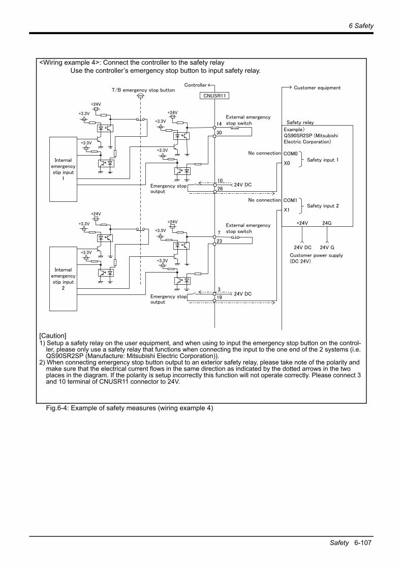
6 Safety
Safety 6-107
Fig.6-4: Example of safety measures (wiring example 4)
<Wiring example 4>: Connect the controller to the safety relayUse the controller’s emergency stop button to input safety relay.
[Caution]1) Setup a safety relay on the user equipment, and when using to input the emergency stop button on the control-
ler, please only use a safety relay that functions when connecting the input to the one end of the 2 systems (i.e. QS90SR2SP (Manufacture: Mitsubishi Electric Corporation)).
2) When connecting emergency stop button output to an exterior safety relay, please take note of the polarity and make sure that the electrical current flows in the same direction as indicated by the dotted arrows in the two places in the diagram. If the polarity is setup incorrectly this function will not operate correctly. Please connect 3 and 10 terminal of CNUSR11 connector to 24V.

6-108 Safety
6 Safety
(1) External emergency stop connection [supplementary explanation]
(1) Use a 2-contact type switch for all switches.(2) Install a limit switch on the safety fence's door. With a constantly open contact (normal open), wire to
the door switch input terminal so that the switch turns ON (is conducted) when the door is closed, and turns OFF (is opened) when the door is open.
(3) Use a manual-return type of normal close which have two lines for the emergency stop button.(4) Classify the faults into minor faults (faults that are easily restored and that do not have a great effect)
and major faults (faults that cause the entire system to stop immediately, and that require care in resto-ration), and wire accordingly.
[Caution] The emergency stop input (terminal block) on the user wiring in the controller can be used forsafety measures as shown in figure above. Note that there are limits to the No. of switch contacts,capacity and cable length, so refer to the following and install.
• Switch contact .... ............. Prepare a 2-contact type.*1)
• Switch contact capacity .... Related current of 24 VDC or higher for a no-voltage contact. *1)
• Cable length ....... ............. The length of the wire between the switch and terminal block mustbe max. 15m or less. Please use the shield line, in case of thecable may receive the noise etc. by other equipment, such asservo amplifier. And, if it is necessary, please fix a ferrite core (rec-ommended model name: E04SR301334, manufacturer: SeiwaElectric Mfg. Co., Ltd.) to the shielded cable.The size of the wire that fits to use is shown below.CNUSR11 connector: AWG24 to 16 (0.2 to 1.25mm2)
Electric specification of the emergency stop related output circuit is 100mA/24V or less. Don't con-nect the equipment except for this range.
Be sure to perform wiring correctly. If there are mistakes in the wiring, the robot may not stop when the emergency stop button is pressed and there will be a risk of damage or personal injury occurring.After wiring, be sure to press each of the installed emergency stop switches and check whether the emergency stop circuit works properly.
Be sure to duplicate connection of the emergency stop, door switch and mode selector switch. If not duplicated, these functions may fail due to a broken relay used by customer, etc.
*1) The minimum load electric current of the switch is more than 5mA/24V.
CAUTION
CAUTION

6 Safety
Working environment 6-109
6.2 Working environmentAvoid installation in the following places as the equipment's life and operation will be affected by the ambi-ent environment conditions. When using in the following conditions, the customer must pay special atten-tion to the preventive measures.
(1) Power supply• Where the voltage fluctuation will exceed the input voltage range.• Where a momentary power failure exceeding 20ms may occur.• Where the power capacity cannot be sufficiently secured.
Please use the controller with an input power supply voltage fluctuation rate of 10% or less. In the case of 200 VAC input, for example, if the controller is used with 180 VAC during the day and 220 VAC during the night, turn the servo off once and then on again.If this is not performed, an excessive regeneration or overvoltage error may occur.
(2) Noise• Where a surge voltage exceeding 2000V, 5kHz (equivalent to EN 61000-4-4) may be applied on the pri-
mary voltage. Locations where a strong electric field or magnetic field exists, such as near large inverters,high output frequency oscillator, large contactors and welding machines.
[Recommendation]A noise-cut transformer; a noise filter; reinforcement of ground lines and electromagnetic shields; isola-tion by keeping away from noise sources; reduction of noise level of emission.
This product has undergone EMC testing for products intended for use in industrial environments (tested to standards EN 61000-6-2 and EN 61000-6-4). This product is not intended to be connected to residen-tial, commercial, or light-industrial power supplies.
(3) Temperature and humidity• Where the atmospheric temperature exceeds 40 degree , lower than 0 degree.• Where the relative humidity exceeds 85% RH or below 45% RH, or condensation may occur.• Where the robot will be subject to direct sunlight or near heat generating sources such as heaters.
(4) Vibration• Where excessive vibration or impact may be applied. (Use in an environment of 34m/s2 or less during
transportation and 5m/s2 or less during operation.)
(5) Installation environment• Where strong electric fields or magnetic fields are generated.• Where the installation surface is rough. (Avoid installing the robot on a bumpy or inclined floor.)• Where there is heavy powder dust and oil mist present.
6.3 Precautions for handling(1) The robot has brakes. If the robot is moved with an excessive external force while the brake is applied,
the robot accuracy may decrease, a backlash may occur, or the reduction gear may be damaged.(2) Avoid moving the robot arm by hand. When unavoidable, gradually move the arm. If moved suddenly,
the accuracy may drop due to an excessive backlash, or the backed up data may be destroyed.(3) Note that depending on the posture, even when within the movement range, the wrist section could inter-
fere with the base section. Take care to prevent interference during jog. *1)
(4) The robot arm consists of precision parts such as bearing. Lubricants such as grease are also applied on the moving parts to keep the mechanical accuracy. In a cold start under low temperature or in the first start after being stored for one month or longer, lubricants may not be spread enough. Such condition may lower the positioning accuracy, cause servo and overload alarms, and early wearing of the moving parts. To avoid such situation, perform warm-up operation of the machine at a low speed (at about 20% of normal operation speed). Move the robot arm from the lower to the upper limit of the movable range with the 30 degree joint angle or more for about 10 minutes. After that, speed up the operation gradually.
*1) Jog operation refers to operating the robot manually using the teaching pendant.
CAUTION

6-110 Precautions for handling
6 Safety
Please use the warm-up operation. (About the details of the warm-up operation, refer to "INSTRUC-TION MANUAL/Detailed explanations of functions and operations".)
(5) The robot arm and controller must be grounded with 100Ω or less (class D grounding) to secure the noise resistance and to prevent electric shocks.
(6) The items described in these specifications are conditions for carrying out the periodic maintenance and inspections described in the instruction manual.
(7) When using the robot arm on a mobile axis or elevating table, the machine cables enclosed as standard configuration may break due to the fixed installation specifications. In this case, use a flexed type cable which is one of the optional replaceable machine cables.
(8) If this robot interferes with the workpiece or peripheral devices during operation, the position may devi-ate, etc. Take care to prevent interference with the workpiece or peripheral devices during operation.
(9) The hanging installation jig can be borrowed from the maker. Order to dealer when need.(10) Do not attach a tape or a label to the robot arm and the controller. If a tape or a label with strong adhe-
sive power, such as a packaging tape, is attached to the coated surfaces of the robot arm and controller, the coated surface may be damaged when such tape or label is peeled off.
(11) If the robot is operated with a heavy load and at a high speed, the surface of the robot arm gets very hot. It would not result in burns, however, it may cause secondary accidents if touched carelessly.
(12) Do not shut down the input power supply to stop the robot. If the power supply is frequently shut down during a heavy load or high-speed operation, the speed reducer may be damaged, backlash may occur, and the program data may be destroyed.
(13) If the robot collides with the mechanical stopper during automatic operation due to incorrect origin settings or other reasons, parts of the mechanical stopper or the reduction gear or other mechanical parts may need to be replaced. For parts replacement, contact Mitsubishi Electric or your local sales rep-resentative. If the robot is continued to be used with damaged mechanical parts or reduction gear, the degree of their damage may increase.
(14) During the robot's automatic operation, a break is applied to the robot arm when the input power supply is shut down by a power failure, for instance. When a break is applied, the arm may deviate from the operation path predetermined by automatic operation and, as a result, it may interfere with the mechani-cal stopper depending on the operation at shutdown. In such a case, take an appropriate measure in advance to prevent any dangerous situation from occurring due to the interference between the arm and peripheral devices.Example) Installing a UPS (uninterruptible power supply unit) to the primary power source in order to
reduce interference.(15) Do not conduct an insulated voltage test. If conducted by mistake, it may result in a breakdown.(16) Fretting may occur on the axis which moving angle or moving distance move minutely, or not moves.
Fretting is that the required oil film becomes hard to be formed if the moving angle is small, and wear occurs. The axis which not moved is moving slightly by vibration etc. To make no fretting recommends to move these axes about once every day the 30 degree or more, or the 20mm or more.
(17) The United Nations’ Recommendations on the Transport of Dangerous Goods must be observed for transborder transportation of lithium batteries by air, sea, and land. The lithium batteries (ER6V) used in Mitsubishi industrial robots contain lithium and fall under the definition.When the lithium batteries are shipped for storage, etc., they will be classified as Class 9: Miscellaneous dangerous substances and articles. Please contact your transportation company and must provide appropriate transport safety measures as the customer’s consignor.
(18) If the air supply temperature (primary piping) used for the tool etc. is lower than ambient air tempera-ture, the dew condensation may occur on the coupling or the hose surface.
(19) When fumigants that contain halogen materials such as fluorine, chlorine, bromine, and iodine are used for disinfecting and protecting wooden packaging from insects, they cause malfunction when entering our products. Please take necessary precautions to ensure that remaining materials from fumigant do not enter our products, or treat packaging with methods other than fumigation (heat method). Addition-ally, disinfect and protect wood from insects before packing products.

6 Safety
EMC installation guideline 6-111
6.4 EMC installation guideline6.4.1 Outlines
The EMC directive is coerced from January 1, 1996, and it is necessary to attach the CE mark which shows that the product is in conformity to directive.Since the industrial robot is the component of the automation system, it considers that the EMC directive is not the target product of the direct. However, because it is one of the main components, introduces the method and components of the measures for conforming the automation system to the EMC directive.And also we are carrying out the qualification test about the conformity of the EMC directive under the envi-ronment based on the contents of this document. However, the noise level is changed by the kind of equip-ment to be used, the layout, the construction of the controlling board, the course of wiring, etc. Therefore, please confirm by the customer eventually.
6.4.2 EMC directiveThe Mitsubishi Electric industrial robot follows the European EMC directive. EMC can be broadly classified into two categories: EMI and EMS.
(1) Emission (EMI: Electromagnetic Interference).......The capacity not to generate the disturbance noise which has a bad influence outside.
(2) Immunity (EMS: Electromagnetic Susceptibility) ...The capacity which does not malfunction for the disturbance noise from the outside.
Each contents are shown below.
6.4.3 EMC measuresThere are mainly following items in the EMC measures.
(1) Store into the sealed metal board.(2) Grounding all the conductor that have floated electrically (makes the impedance low).(3) Wiring so that the power source wire and signal wire are separated.(4) Use the shield cable for the cable which wired outside of the metal board.(5) Install the noise filter.
To suppress the noise emitted out of the board, be careful of the following item.(1) Ensure grounding of the equipment.(2) Use the shield cable.(3) Separate the metal board electrically. Narrows the distance/hole.
The strength of electromagnetic noise emitted to environment is changed a lot by the shielding effi-ciency of cable and the distance of metal board, so it should be careful.
Item Name Contents
Emission(EMI)
Radiative noise disturbance The electromagnetic noise etc. which are emitted to environs.
Electrical-conduction noise disturbance The electromagnetism noise etc. which flow out of the power-supply line.
Immunity(EMS)
Electrostatic discharge immunity test The noise from the electrified human body.
Radiated, radio-frequency, electromagnetic field immunity test susceptibility test
The electromagnetism noise from the transceiver, the broad-casting station, etc.
Electrical fast transient burst immunity test The relay noise or the electromagnetism noise etc. which are caused in power-supply ON/OFF.
Immunity to conducted distrurbances induced radio-frequency fields
The electromagnetism noise etc. which flow in through the power source wire and the grounding wire.
Power frequency magnetic field immunity test The electromagnetism noise with a power supply frequency of 50/60 Hz etc.
Voltage dips, short interruptions and voltage varia-tions immunity test
The noise in the variation of the source voltage of the power dispatching, etc.
Surge immunity test The electromagnetism noise by the thunderbolt, etc.

6-112 EMC installation guideline
6 Safety
6.4.4 Example of EMC measuresIndustrial robots are designed for use with other devices. We declare conformity with EMC Directive for our industrial robots by testing them in the following system architecture. However, it does not mean that every system meets the requirements of EMC standards.Electromagnetic compatibility depends on the relationship between the industrial robot and devices in the system, wiring conditions, layout, or other factors. Therefore, check whether the entire machinery/system meets the requirements.
Fig.6-5: Example of EMC measures
1) Install ferrite cores <6> through <9> on the machine cable.2) Attach the shield tube <5> to the machine cable and ground both ends of the tube.3) Install the ferrite cores <4> on the cable of the teaching pendant.4) Install the ferrite cores <3> on the power cable.5) Attach the noise filters <2> and surge protector <1> to the power cable.
Table 6-4: Parts for EMC measures
6.4.5 Parts for EMC measuresFor details on the parts for EMC measures described on Page 112, "6.4.4 Example of EMC measures", con-tact your nearest Mitsubishi branch or dealer.
No. Item Model Quantity Manufacturer
1 Surge protector RSPD-250-Q4 1 OKAYA ELECTRIC INDUSTRIES CO., LTD.
2 Noise filter SUP-EL15-ER6 2 OKAYA ELECTRIC INDUSTRIES CO., LTD.
3 Ferrite core RFC-H13 2 KITAGAWA INDUSTRIES CO.,LTD.
4 Ferrite core E04SR301334 2 SEIWA ELECTRIC MFG CO.Ltd
5 Shield tube MTFX40 1 Zippertubing (Japan), Ltd.
6Ferrite core RFC-20
1KITAGAWA INDUSTRIES CO.,LTD.
7 2
8Ferrite core GTFC41-27-16
6KITAGAWA INDUSTRIES CO.,LTD.
9 6
<5>
<4>
<1>
<2>×2
<8>×6 <7>×2<9>×6<6>
<3>×2

7 Appendix
Inertia calculation method Appendix-113
7 AppendixAppendix 1: Inertia calculation method
An allowable moment of inertia in the mechanical interface at the tip of the robot arm is determined. If a load exceeding the allowable moment of inertia is put, on the tip of the arm, vibration during operation and an overload alarm may occur. Therefore, consider the matching/appropriateness of the hand and load to be mounted on the tip of the arm for the robot specifications when you select a robot. The following describes the load inertia calculation method.
For the vertical multi-joint robot, consider the load moment and the load inertia on the wrist axes (J4 to J6 axes). To consider them, calculate the load moment and load inertia applied on each of J4 to J6 axes in con-sideration of the posture of the hand and workpiece. The following figures show the examples.
(1) Load moment calculation example (for J5 axis with flange facing downwards)
(2) Load inertia calculation example (for J6 axis)
Hand W1kg
Workpiece W2kg
Center of gravity of the hand
Center of gravity of the workpiece
J5 axis
L1
L2
The items shown in the right picture are defined as follows.Hand mass : W1 (kg)Center of gravity of the hand : L1 (m)Workpiece mass : W2 (kg)Center of gravity of the workpiece : L2 (m)The load moment applied to the J5 axis is calculated as follows.Where g is gravitational acceleration (m/s2).
Load moment about the J5 axis : M (Nm) = W1 × L1 × g + W2 × L2 × g
Check that the value of M is equal to or less than the allowable load moment of the target model.
Note) When the robot changes its posture significantly in a direction other than the vertical downward direction, check the load moment inertia about the J4 axis as well.
Hand W1kg
Workpiece W2kg
Center of gravity of the hand
Center of gravity of the workpiece
J6 axis
The items shown in the right picture are defined as follows.Hand mass : W1 (kg)Distance between the center of J6 axis and the center of gravity of the hand : L1 (m)Workpiece mass : W2 (kg)Center of gravity of the workpiece : L2 (m)
Assume that both hand and workpiece are rectangle. When their surface areas
can be expressed as follows, respectively: a1 × b1,
and a2 × b2 (where a = height, b = width), the load inertia about the J6 axis is
calculated as follows.
Load inertia about the J6 axis of the hand : I1 (kg•m2) = Iz1 + W1 × L12 = W1 × (a12 + b12)/12 + W1 × L12
Load inertia about the J6 axis of the workpiece : I2 (kg•m2) = Iz2 + W2 × L22 = W2 × (a22 + b22)/12 + W2 × L22
Total load inertia about the J6 axis of both hand and workpiece : I (kg•m2) = I1 + I2Check that the value of I is equal to or less than the allowable load moment of the target model.
L1
L2

Appendix-114 Classification of functions using external input/output signals
7 Appendix
Appendix 2: Classification of functions using external input/output signalsBefore using the functions, note the following.
Table 7-1: Classification of functions using external input/output signalsClassification Function Description
Safety signal Emergency stop input Detects emergency stop inputs. The safety diagnosis function for the emergency stop input circuit makes the STO function meet the requirements of Category 4, PL e.At factory settings, the STO function meets the requirements of Category 3, PL d. To make the STO function meet the requirements of Category 4, PL e, change the parameter setting by referring to Page 115, "Appendix 3: Safety diagnosis function (Test pulse diagnosis)".
Mode selector switch input Switches the controller mode between MANUAL and AUTOMATIC.
Door switch input Receives the status of the switch installed on the door of the safety fence to detect the opening of the door.
Non-safety signal Emergency stop output Monitors whether the robot is in the emergency stop state.
Mode output Monitors whether the robot operates in MANUAL or AUTOMATIC mode.
Robot error output Monitors the error status of the robot.
Additional axis synchronization output
Synchronizes the state of the additional axes (servo ON/OFF) with that of the robot arm.For details, refer to Page 53, "3.8 Additional axis synchronization output".

7 Appendix
Safety diagnosis function (Test pulse diagnosis) Appendix-115
Appendix 3: Safety diagnosis function (Test pulse diagnosis)This function enables diagnosis of external wiring by pulse signals output from the emergency stop ports (EXTEMG11, EXTEMG21). Changing parameter TPOEMG allows EXTEMG11 and EXTEMG21 to output off-pulses regularly. The width of output pulses is always approximately 20 ms. Checking regularly the test pulses inside the robot controller enables confirming the correct operation of the emergency stop lines.When using this function, connect emergency stop switches by seeing Fig. 7-2.Make sure to prevent test pulses of this function from causing faulty operation of peripheral devices.
Fig.7-1: Test pulse diagnosis
Table 7-2: Parameter details
Fig.7-2: How to wire emergency stop lines
Item Description
Parameter name TPOEMG
Function This enables configuring the pulse output function for outputting test pulse signals from emergency stop ports (EXTEMG11, EXTEMG21).
What parameter settings means 0: Outputs no test pulses1: Outputs test pulses
Default 0
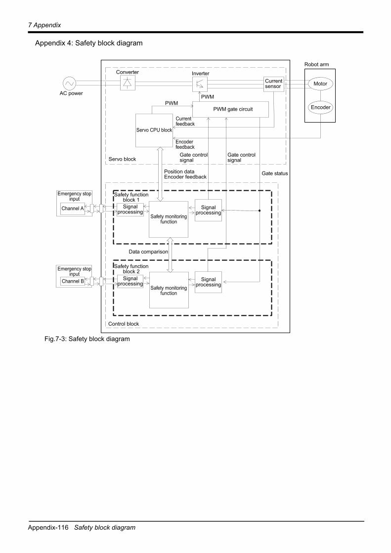
Appendix-116 Safety block diagram
7 Appendix
Appendix 4: Safety block diagram
Fig.7-3: Safety block diagram
EncoderPWM gate circuit
Channel ASafety monitoring
function
Safety monitoringfunction
Signalprocessing
Signalprocessing
Currentsensor
Emergency stopinput
Emergency stopinput
Signalprocessing
Signalprocessing
Control block
PWM
Servo block
PWM
Gate status
Gate controlsignal
Gate controlsignal
Inverter
Robot arm
Servo CPU block
Safety functionblock 1
Safety functionblock 2
Motor
Data comparison
Encoderfeedback
Currentfeedback
Channel B
Position dataEncoder feedback
Converter
AC power

7 Appendix
Specifications discussion material Appendix-117
Appendix 5: Specifications discussion material■Customer information
■Purchased model
■Options (Installable after shipment)
■Maintenance parts (Consumable parts)
■Robot selection check list
Company name NameAddress Telephone
Type Note1)
Note1) Refer to the Page 2, "1.2 Model type name of robot" for the details of the robot arm type name.
Controller
RV-8CRL-D CR800-CVD
Item Type Provision, and specifications when provided.Robot arm
Machine cable (replacement) 1F-□□UCBL-43 Fixed type: □Not provide □10m □15m □20m1F-□□LUCBL-43 Flexed type:□Not provide □10m □15m □20m
Control-ler
Simple teaching pendant R32TB-□□ □Not provided □7m □15mHighly efficient teaching pendant R56TB-□□ □Not provided □7m □15mParallel I/O interface 2D-TZ368/
2D-TZ378□Not provided 2D-TZ368(Sink type)/ □-1pc. □-2pc.
2D-TZ378(Source type)/□-1pc. □-2pc.External I/O cable(For parallel I/O interface)
2D-CBL□□(2D-TZ368/TZ378)
□Not provided □5m-( )pc. □15m-( )pc.
Parallel I/O unit 2A-RZ361/2A-RZ371
□Not provided □2A-RZ361(Sink type)/( ) unit□2A-RZ371(Source type)/( ) unit
External I/O cable(For Parallel I/O unit)
2A-CBL□□(2A-RZ361/RZ371)
□Not provided □5m-( )pc. □15m-( )pc.
CC-Link interface 2D-TZ576 □Not provided □ProvidedEtherNet/IP interface 2D-TZ535 □Not provided □ProvidedPROFINET interface 2D-TZ535-PN □Not provided □ProvidedCC-Link IE Field interface 2F-DQ535 □Not provided □ProvidedEtherCAT interface 2F-DQ535-EC □Not provided □ProvidedFunction extension card 2F-DQ510 MELFA Smart Plus card pack (A-type): □Not provided □Provided
2F-DQ520 MELFA Smart Plus card pack (AB-type): □Not provided □Provided2F-DQ511 MELFA Smart Plus card (A-type): □Not provided □Provided2F-DQ521 MELFA Smart Plus card (B-type): □Not provided □Provided
SD memory card 2F-2GBSD □Not provided □ProvidedSafety option 4F-SF002-01 □Not provided □ProvidedController protection box CR800-MB □Not provided □ProvidedRT ToolBox3 3F-14C-WINE □Not provided □Windows 7/8/8.1/10 English DVD-ROMRT ToolBox3 mini 3F-15C-WINE □Not provided □Windows 7/8/8.1/10 English DVD-ROMRT ToolBox3 Pro 3F-16D-WINE □Not provided □Windows 7/8/8.1/10 English DVD-ROMInstructions manual 5F-BR01-PE01 □Not provided □Provided ( ) sets
Function extension
Force sensor set 4F-FS002H-W200 □Not provided □Provided4F-FS002H-W1000Note1)
Note1) Use the sensor attachment adapter "1F-FSFLGSET-01".
□Not provided □ProvidedMELFA-3D Vision 3.0 3F-53U-WINM □Not provided □Provided
Maintenance parts □Backup batteries ER6V ( ) pcs. □Grease ( ) cans
Work description □Material handling □Assembly □Machining L/UL □Sealing □Testing and inspection □Other ( )
Workpiece mass ( )g Hand mass ( )gAtmosphere □ General environment
□ Oil mist: Confirm oil proof □ request (Oil name: )Note1) / □ not request □ Other ( )
Note1) Refer to Page 14, "2.2.6 Protection specifications" about oil resistance.
Remarks

Appendix-118 Specifications discussion material
7 Appendix


HEAD OFFICE: TOKYO BUILDING, 2-7-3, MARUNOUCHI, CHIYODA-KU, TOKYO 100-8310, JAPANNAGOYA WORKS: 5-1-14, YADA-MINAMI, HIGASHI-KU NAGOYA 461-8670, JAPANAuthorised representative:
Mitsubishi Electric Europe B.V. FA - European Business GroupMitsubishi-Electric-Platz 1, D-40882 Ratingen, GermanyTel: +49(0)2102-4860
Sep. 2021 MEE Printed in Japan on recycled paper. Specifications are subject to change without notice.