FR-A200E(UL) - Instruction Manual IB(NA)-66496-A (03.95).pdf
Upload
khangminh22Category
view
1download
0
HEAD OFFICE: TOKYO BUILDING 2-7-3, MARUNOUCHI, CHIYODA-KU, TOKYO 100-8310, JAPAN
FR-A701INSTRUCTION FR-A721-5.5K to 55FR-A741-5.5K to 55
INVERTER
IB(NA)-0600331ENG-F(2102)MEE Printed in Japan Specifications subject to change without notice.
INVER
TERFR
-A701
INSTR
UC
TION
MA
NU
AL (B
ASIC
)
F
OUTLINE ..........................1.1 Product checking and pa1.2 Inverter and peripheral d1.3 Method of removal and r1.4 Installation of the inverte
WIRING.............................2.1 Terminal connection diag2.2 Main circuit terminal spec2.3 Control circuit specificatio2.4 Connection of motor with
PRECAUTIONS FOR USE3.1 EMC and leakage curren3.2 Power-off and magnetic 3.3 Inverter-driven 400V clas3.4 Precautions for use of th3.5 Failsafe of the system wh
DRIVING THE MOTOR ....4.1 Step of operation............4.2 Operation panel (FR-DU4.3 Before operation.............4.4 Start/stop from the opera4.5 Start and stop using term4.6 Parameter List ................
TROUBLESHOOTING .....5.1 Reset method of protecti5.2 List of fault or alarm disp5.3 Causes and corrective a5.4 Correspondences betwe5.5 Check and clear of the 5.6 Check first when you hav
PRECAUTIONS FOR MAI6.1 Inspection item ...............6.2 Measurement of main cir
SPECIFICATIONS............7.1 Rating .............................7.2 Common specifications..7.3 Outline dimension drawin7.4 Installation of the heatsin
Thank you for choosing this Mitsubishi EleThis Instruction Manual is intended for useIf you are going to utilize functions and pe0600337ENG]. The Instruction Manual (Appyour Mitsubishi Electric sales representativ
1
2
3
4
5
6
7
MANKK
CONTE.....................rts identification .evices.................einstallation of thr and enclosure d
.....................ram....................ifications ...........ns...................... encoder (vector
OF THE INVts .......................contactor (MC) ...s motor ..............e inverter ............ich uses the inve
................................................07).................................................tion panel (PU oinals (External o...........................
.....................ve function .........lay ......................ctions..................en digital and actfaults history.....e a trouble.........
NTENANCE A...........................cuit voltages, cur
...........................................................................gs......................k portion outside
ctric Inverter.rs who "just warformance, refelied) is separate.
UAL (BASIC)
1
2
3
NTS........................................................ 1....................................................................... 1....................................................................... 2e front cover................................................... 4esign ............................................................. 6
...................................................... 12..................................................................... 12..................................................................... 13..................................................................... 20 control)........................................................ 29
ERTER......................................... 36..................................................................... 36..................................................................... 42..................................................................... 43..................................................................... 44rter .............................................................. 46
nt to run the inverter".r to the FR-A701 Series Instruction Manual (Applied) [IB-
ely available from where you purchased the inverter or
7014
5
6
7
...................................................... 48..................................................................... 48..................................................................... 49..................................................................... 57peration mode)............................................. 84peration) ...................................................... 93................................................................... 101
.................................................... 143................................................................... 143................................................................... 144................................................................... 145ual characters............................................ 161................................................................ 162................................................................... 164
ND INSPECTION..................... 172................................................................... 172rents and powers ...................................... 179
.................................................... 184................................................................... 184................................................................... 186................................................................... 187 the enclosure for use................................ 196

This Instruction Manual (Basic) provides handling information and precautions for use of the equipment.Please forward this Instruction Manual (Basic) to the end user.
1. Electric Shock Prevention
2. Fire Prevention
3. Injury Prevention
4. Additional InstructionsAlso the following points must be noted to prevent anaccidental failure, injury, electric shock, etc.(1) Transportation and Mounting
This section is specifically about safety mattersDo not attempt to install, operate, maintain or inspect theinverter until you have read through the Instruction Manualand appended documents carefully and can use theequipment correctly. Do not use this product until you havea full knowledge of the equipment, safety information andinstructions.In this Instruction Manual, the safety instruction levels areclassified into "WARNING" and "CAUTION".
Incorrect handling may cause hazardous conditions, resulting in death or severe injury.
Incorrect handling may cause hazardous conditions, resulting in medium or slight injury, or may cause only material damage.
The level may even lead to a seriousconsequence according to conditions. Both instructionlevels must be followed because these are important topersonal safety.
While power is ON or when the inverter is running, do notopen the front cover. Otherwise you may get an electricshock.
Do not run the inverter with the front cover or wiring coverremoved. Otherwise you may access the exposed high-voltage terminals or the charging part of the circuitry andget an electric shock.
Even if power is OFF, do not remove the front coverexcept for wiring or periodic inspection. You mayaccidentally touch the charged inverter circuits and get anelectric shock.
Before wiring or inspection, power must be switched OFF.To confirm that, LED indication of the operation panelmust be checked. (It must be OFF.) Any person who isinvolved in wiring or inspection shall wait for at least 10minutes after the power supply has been switched OFFand check that there are no residual voltage using a testeror the like. The capacitor is charged with high voltage forsome time after power OFF, and it is dangerous.
This inverter must be earthed (grounded). Earthing(grounding) must conform to the requirements of nationaland local safety regulations and electrical code (NEC section250, IEC 61140 class 1 and other applicable standards).A neutral-point earthed (grounded) power supply for 400Vclass inverter in compliance with EN standard must be used.
Any person who is involved in wiring or inspection of thisequipment shall be fully competent to do the work.
The inverter must be installed before wiring. Otherwiseyou may get an electric shock or be injured.
Setting dial and key operations must be performed withdry hands to prevent an electric shock.
Do not subject the cables to scratches, excessive stress,heavy loads or pinching. Otherwise you may get anelectric shock.
Do not change the cooling fan while power is ON. It isdangerous to change the cooling fan while power is ON.
Do not touch the printed circuit board or handle thecables with wet hands. Otherwise you may get an electricshock.
When measuring the main circuit capacitor capacity, theDC voltage is applied to the motor for 1s at powering OFF.Never touch the motor terminal, etc. right after poweringOFF to prevent an electric shock.
WARNING
CAUTION
CAUTION
WARNING
Inverter must be installed on a nonflammable wall withoutholes (so that nobody touches the inverter heatsink on therear side, etc.). Mounting it to or near flammable materialcan cause a fire.
If the inverter has become faulty, the inverter power mustbe switched OFF. A continuous flow of large current couldcause a fire.
The voltage applied to each terminal must be the onesspecified in the Instruction Manual. Otherwise burst,damage, etc. may occur.
The cables must be connected to the correct terminals.Otherwise burst, damage, etc. may occur.
Polarity must be correct. Otherwise burst, damage, etc.may occur.
While power is ON or for some time after power-OFF, donot touch the inverter as they will be extremely hot. Doingso can cause burns.
The product must be transported in correct method thatcorresponds to the weight. Failure to do so may lead toinjuries.
Do not stack the boxes containing inverters higher thanthe number recommended.
The product must be installed to the position wherewithstands the weight of the product according to theinformation in the Instruction Manual.
Do not install or operate the inverter if it is damaged orhas parts missing.
When carrying the inverter, do not hold it by the frontcover or setting dial; it may fall off or fail.
Do not stand or rest heavy objects on the product. The inverter mounting orientation must be correct. Foreign conductive objects must be prevented from
entering the inverter. That includes screws and metalfragments or other flammable substance such as oil.
As the inverter is a precision instrument, do not drop orsubject it to impact.
The inverter must be used under the followingenvironment. Otherwise the inverter may be damaged.
Envi
ronm
ent
Surroundingairtemperature
-10°C to +50°C (non-freezing)
Ambienthumidity 90%RH or less (non-condensing)
Storagetemperature -20°C to +65°C *1
Atmosphere Indoors (free from corrosive gas, flammable gas,oil mist, dust and dirt)
Altitude/vibration
Maximum 1,000m above sea level for standardoperation. 5.9m/s2 or less at 10 to 55Hz (directions of X, Y, Zaxes)
1 Temperature applicable for a short time, e.g. in transit. If halogens (including fluorine, chlorine, bromine, and
iodine) contained in fumigants for wood packages enterthis product, the product may be damaged. Prevent theentry of fumigant residuals or use an alternative methodsuch as heat disinfection. Note that sterilization ordisinfection of wood packages should be performedbefore packing the product.
CAUTION
CAUTION
CAUTION
A-1

(2) Wiring
(3) Trial run
(4) Usage
*1 DoS: A denial-of-service (DoS) attack disrupts services byoverloading systems or exploiting vulnerabilities, resulting in adenial-of-service (DoS) state.
(5) Emergency stop
(6) Maintenance, inspection and parts replacement
(7) Disposal
Do not install a power factor correction capacitor or surgesuppressor/capacitor type filter on the inverter outputside. These devices on the inverter output side may beoverheated or burn out.
The connection orientation of the output cables U, V, W tothe motor affects the rotation direction of the motor.
Before starting operation, each parameter must beconfirmed and adjusted. Failure to do so may cause somemachines to make unexpected motions.
Any person must stay away from the equipment when theretry function is set as it will restart suddenly after trip.
Since pressing key may not stop output depending
on the function setting status, separate circuit and switchthat make an emergency stop (power OFF, mechanicalbrake operation for emergency stop, etc.) must beprovided.
OFF status of the start signal must be confirmed beforeresetting the inverter fault. Resetting inverter alarm withthe start signal ON restarts the motor suddenly.
The inverter must be used for three-phase induction motors.Connection of any other electrical equipment to theinverter output may damage the equipment.
Performing pre-excitation (LX signal and X13 signal)under torque control (Real sensorless vector control) maystart the motor running at a low speed even when the startcommand (STF or STR) is not input. The motor may alsorun at a low speed when the speed limit value = 0 with astart command input. It must be confirmed that the motorrunning will not cause any safety problem beforeperforming pre-excitation.
Do not modify the equipment. Do not perform parts removal which is not instructed in this
manual. Doing so may lead to fault or damage of the product. In order to protect security (confidentiality, integrity, and
availability) of the inverter and the system againstunauthorized access, DoS*1 attack, computer virus, or anyother form of cyberattack by external systems vianetwork, take security measures that include firewall orvirtual private network (VPN) settings and installation ofantivirus software on computers. We shall not be liable forany problems resulting from failures of the inverter or thesystem that might occur due to DoS attack, unauthorizedaccess, computer virus, or any other form of cyberattack.
CAUTION
CAUTION
WARNING
The electronic thermal relay function does not guaranteeprotection of the motor from overheating. It isrecommended to install both an external thermal and PTCthermistor for overheat protection.
Do not use a magnetic contactor on the inverter input forfrequent starting/stopping of the inverter. Otherwise thelife of the inverter decreases.
The effect of electromagnetic interference must bereduced by using a noise filter or by other means.Otherwise nearby electronic equipment may be affected.
When driving a 400V class motor by the inverter, themotor must be an insulation-enhanced motor or measuresmust be taken to suppress surge voltage. Surge voltageattributable to the wiring constants may occur at themotor terminals, deteriorating the insulation of the motor.
When parameter clear or all parameter clear is performed,the required parameters must be set again before startingoperations because all parameters return to the initial value.
The inverter can be easily set for high-speed operation.Before changing its setting, the performances of themotor and machine must be fully examined.
Stop status cannot be hold by the inverter's brakefunction. In addition to the inverter’s brake function, aholding device must be installed to ensure safety.
Before running an inverter which had been stored for a longperiod, inspection and test operation must be performed.
For prevention of damage due to static electricity, nearbymetal must be touched before touching this product toeliminate static electricity from your body.
A safety backup such as an emergency brake must beprovided for devices or equipment in a system to preventhazardous conditions in case of failure of this product oran external device controlling this product.
When the breaker on the inverter input side trips, thewiring must be checked for fault (short circuit), andinternal parts of the inverter for a damage, etc. The causeof the trip must be identified and removed before turningON the power of the breaker.
When any protective function is activated, appropriatecorrective action must be taken, and the inverter must bereset before resuming operation.
Do not carry out a megger (insulation resistance) test onthe control circuit of the inverter. It will cause a failure.
The inverter must be treated as industrial waste.
CAUTION
CAUTION
CAUTION
CAUTION
A-2

Application of caution labelsCaution labels are used to ensure safety during use ofMitsubishi Electric inverters.Make copies of the following labels and apply them to theinverter if the "retry function" and/or "automatic restart afterinstantaneous power failure" have been enabled. For the retry function
For automatic restart after instantaneous power failure
Monitor item unit labelThe monitor item unit label is used for indications on theoperation panel or the parameter unit. When the motorrotation speed (r/min), line speed (m/min), or other optionalitems are monitored, make copies of the following label andapply the applicable symbol on the "Hz" or "V" indication onthe operation panel or the parameter unit.
General instructionMany of the diagrams and drawings in this InstructionManual (Basic) show the inverter without a cover or partiallyopen for explanation. Never operate the inverter in thismanner. The cover must be always reinstalled and theinstruction in this Instruction Manual (Basic) must befollowed when operating the inverter.
CAUTIONRetry Function HasBeen Selected
Stay away from the motor and machine.They will start suddenly (after giventime has elapsed) when alarm occurs.
CAUTIONAutomatic Restart afterInstantaneous PowerFailure Has Been Selected
Stay away from the motor and machine.They will start suddenly (after reset time has elapsed) wheninstantaneous power failure occurs.
h
A
m3/min
%
h
A
m3/min
%
r/min
Hz
l/min
X0.1
r/min
Hz
l/min
X0.1
V
kW
m/min
X0.01
V
kW
m/min
X0.01
A-3

— CONTENTS —
1 OUTLINE 1
1.1 Product checking and parts identification .............................................................. 11.2 Inverter and peripheral devices.............................................................................. 2
1.2.1 Peripheral devices ..................................................................................................................... 3
1.3 Method of removal and reinstallation of the front cover ......................................... 41.4 Installation of the inverter and enclosure design.................................................... 6
1.4.1 Inverter installation environment................................................................................................ 61.4.2 Cooling system types for inverter enclosure.............................................................................. 91.4.3 Inverter placement................................................................................................................... 10
2 WIRING 12
2.1 Terminal connection diagram............................................................................... 122.2 Main circuit terminal specifications ...................................................................... 13
2.2.1 Specification of main circuit terminal ....................................................................................... 132.2.2 Terminal arrangement of the main circuit terminal, power supply and the motor wiring ......... 142.2.3 Cables and wiring length ......................................................................................................... 162.2.4 When connecting the control circuit and the main circuit separately
to the power supply ................................................................................................................. 19
2.3 Control circuit specifications ................................................................................ 202.3.1 Control circuit terminals ........................................................................................................... 202.3.2 Changing the control logic ....................................................................................................... 232.3.3 Control circuit terminal layout .................................................................................................. 252.3.4 Wiring instructions ................................................................................................................... 262.3.5 When connecting the operation panel using a connection cable ............................................ 272.3.6 RS-485 terminal block ............................................................................................................. 272.3.7 Communication operation........................................................................................................ 282.3.8 USB connector ........................................................................................................................ 28
2.4 Connection of motor with encoder (vector control) .............................................. 29
3 PRECAUTIONS FOR USE OF THE INVERTER 36
3.1 EMC and leakage currents .................................................................................. 363.1.1 Leakage currents and countermeasures ................................................................................. 363.1.2 EMC measures........................................................................................................................ 383.1.3 Power supply harmonics ......................................................................................................... 403.1.4 Harmonic suppression guideline ............................................................................................. 40
3.2 Power-off and magnetic contactor (MC) .............................................................. 423.3 Inverter-driven 400V class motor ......................................................................... 433.4 Precautions for use of the inverter ....................................................................... 443.5 Failsafe of the system which uses the inverter .................................................... 46
I

CO
NT
EN
TS
4 DRIVING THE MOTOR 48
4.1 Step of operation.................................................................................................. 484.2 Operation panel (FR-DU07)................................................................................. 49
4.2.1 Parts of the operation panel (FR-DU07).................................................................................. 494.2.2 Basic operation (factory setting) .............................................................................................. 504.2.3 Operation lock (Press [MODE] for an extended time (2s)) ...................................................... 514.2.4 Monitoring of output current and output voltage ...................................................................... 524.2.5 First priority monitor ................................................................................................................. 524.2.6 Setting dial push ...................................................................................................................... 524.2.7 Changing the parameter setting value..................................................................................... 534.2.8 Parameter clear, all parameter clear ....................................................................................... 544.2.9 Parameter copy and parameter verification............................................................................. 55
4.3 Before operation .................................................................................................. 574.3.1 Simple mode parameter list ..................................................................................................... 574.3.2 Overheat protection of the motor by the inverter (Pr. 9) .......................................................... 584.3.3 When the rated motor frequency is 50Hz (Pr. 3) .................................................................... 594.3.4 Increase the starting torque (Pr. 0) ......................................................................................... 604.3.5 Limit the maximum and minimum output frequency (Pr. 1, Pr. 2) ........................................... 614.3.6 Change acceleration and deceleration time (Pr. 7, Pr. 8)........................................................ 624.3.7 Selection of the start command and frequency command locations (Pr. 79) .......................... 634.3.8 Large starting torque and low speed torque are necessary (Advanced magnetic
flux vector control, Real sensorless vector control) (Pr. 71, Pr. 80, Pr. 81, Pr. 800) ............. 644.3.9 Higher accuracy operation using a motor with encoder (Vector control)
(Pr.71, Pr.80, Pr.81, Pr.359, Pr.369, Pr.800) .......................................................................... 674.3.10 Exhibiting the best performance of the motor performance (offline auto tuning)
(Pr. 71, Pr. 83, Pr. 84, Pr. 96) .............................................................................................. 724.3.11 High accuracy operation unaffected by the motor temperature
(online auto tuning) (Pr. 95) ................................................................................................ 774.3.12 To perform high accuracy/fast response operation (gain adjustment of Real
sensorless vector control and vector control) (Pr. 818 to Pr. 821, Pr. 880) .......................... 78
4.4 Start/stop from the operation panel (PU operation mode) ................................... 844.4.1 Setting the set frequency to operate (example: performing operation at 30Hz) ...................... 844.4.2 Use the setting dial like a potentiometer to perform operation. ............................................... 864.4.3 Setting the frequency by switches (three-speed setting)......................................................... 874.4.4 Setting the frequency by analog input (voltage input) ............................................................. 894.4.5 Setting the frequency by analog input (current input) .............................................................. 91
4.5 Start and stop using terminals (External operation) ............................................. 934.5.1 Setting the frequency by the operation panel (Pr. 79 = 3) ....................................................... 934.5.2 Setting the frequency by switches (three-speed setting) (Pr. 4 to Pr. 6) ................................. 954.5.3 Setting the frequency by analog input (voltage input) ............................................................. 974.5.4 Changing the frequency (60Hz, initial value) at the maximum voltage input
(5V, initial value) ...................................................................................................................... 984.5.5 Setting the frequency by analog input (current input) .............................................................. 994.5.6 Changing the frequency (60Hz, initial value) at the maximum current input
(at 20mA, initial value) ........................................................................................................... 100
4.6 Parameter List.................................................................................................... 1014.6.1 List of parameters classified by the purpose ......................................................................... 1014.6.2 Parameter list ........................................................................................................................ 104
II

5 TROUBLESHOOTING 143
5.1 Reset method of protective function .................................................................. 1435.2 List of fault or alarm display ............................................................................... 1445.3 Causes and corrective actions........................................................................... 1455.4 Correspondences between digital and actual characters .................................. 1615.5 Check and clear of the faults history.................................................................. 1625.6 Check first when you have a trouble.................................................................. 164
5.6.1 Motor does not start............................................................................................................... 1645.6.2 Motor or machine is making abnormal acoustic noise........................................................... 1665.6.3 Inverter generates abnormal noise........................................................................................ 1665.6.4 Motor generates heat abnormally.......................................................................................... 1675.6.5 Motor rotates in the opposite direction .................................................................................. 1675.6.6 Speed greatly differs from the setting.................................................................................... 1675.6.7 Acceleration/deceleration is not smooth................................................................................ 1685.6.8 Motor current is too large....................................................................................................... 1685.6.9 Speed does not accelerate.................................................................................................... 1695.6.10 Motor and machine vibrate .................................................................................................... 1695.6.11 Speed varies during operation............................................................................................... 1705.6.12 Operation mode is not changed properly .............................................................................. 1715.6.13 Operation panel (FR-DU07) display is not operating............................................................. 1715.6.14 Power lamp is not lit .............................................................................................................. 1715.6.15 Unable to write parameter setting.......................................................................................... 171
6 PRECAUTIONS FOR MAINTENANCE AND INSPECTION 172
6.1 Inspection item................................................................................................... 1726.1.1 Daily inspection ..................................................................................................................... 1726.1.2 Periodic inspection ................................................................................................................ 1726.1.3 Daily and periodic inspection................................................................................................. 1736.1.4 Display of the life of the inverter parts ................................................................................... 1746.1.5 Checking the inverter and converter modules ....................................................................... 1756.1.6 Cleaning ................................................................................................................................ 1766.1.7 Replacement of parts ............................................................................................................ 176
6.2 Measurement of main circuit voltages, currents and powers............................. 1796.2.1 Measurement of powers ........................................................................................................ 1816.2.2 Measurement of voltages and use of PT............................................................................... 1816.2.3 Measurement of currents....................................................................................................... 1826.2.4 Use of CT and transducer ..................................................................................................... 1826.2.5 Measurement of inverter input power factor .......................................................................... 1826.2.6 Measurement of converter output voltage (across terminals P/+ and N/-) ............................ 1836.2.7 Measurement of inverter output frequency............................................................................ 1836.2.8 Insulation resistance test using megger ................................................................................ 1836.2.9 Pressure test ......................................................................................................................... 183
III

CO
NT
EN
TS
7 SPECIFICATIONS 184
7.1 Rating................................................................................................................. 1847.1.1 Inverter rating ........................................................................................................................ 1847.1.2 Motor rating ........................................................................................................................... 185
7.2 Common specifications...................................................................................... 1867.3 Outline dimension drawings............................................................................... 187
7.3.1 Inverter outline dimension drawings ...................................................................................... 1877.3.2 Dedicated motor outline dimension drawings........................................................................ 192
7.4 Installation of the heatsink portion outside the enclosure for use ...................... 1967.4.1 Protrusion of heatsink............................................................................................................ 196
APPENDICES 198
Appendix 1 Main differences and compatibilities with the FR-A700 series ................. 198Appendix 2 Instructions for compliance with the EU Directives (400V class only) ..... 199Appendix 3 Instructions for UL and cUL Compliance ................................................. 202Appendix 4 Instructions for EAC.................................................................................. 204Appendix 5 Restricted Use of Hazardous Substances in Electronic and Electrical Prod-
ucts ........................................................................................................... 205Appendix 6 Referenced Standard (Requirement of Chinese standardized law) (400V
class only)................................................................................................. 205Appendix 7 Control mode-based parameter (function) correspondence
table and instruction code list ................................................................... 206
<Abbreviations>DU: Operation panel (FR-DU07)PU: Operation panel (FR-DU07) and parameter unit (FR-PU04, FR-PU07)Inverter: Mitsubishi Electric inverter FR-A701 seriesFR-A701: Mitsubishi Electric inverter FR-A701 seriesPr.: Parameter Number (Number assigned to function)PU operation: Operation using the PU (FR-DU07/FR-PU04/FR-PU07)External operation: Operation using the control circuit signalsCombined operation: Combined operation using the PU (FR-DU07/FR-PU04/FR-PU07) and external operationStandard motor: SF-JRConstant-torque motor: SF-HRCAVector dedicated motor: SF-V5RU
<Trademarks>LONWORKS® is registered trademarks of Echelon Corporation in the U.S.A. and other countries.DeviceNet is a registered trademark of ODVA (Open DeviceNet Vender Association, Inc.).Company and product names herein are the trademarks and registered trademarks of their respective owners.
REMARKS For differences and compatibility between the FR-A701 series and FR-A700 series, refer to page 198.
IV

1
Product checking and parts identification
1 OUTLINE
1.1 Product checking and parts identificationUnpack the inverter and check the capacity plate on the front cover and the rating plate on the inverter side face toensure that the product agrees with your order and the inverter is intact.
REMARKSFor removal and reinstallation of covers, refer to page 4.Harmonic suppression guideline (when inverters are used in Japan)All models of general-purpose inverters used by specific consumers are covered by "Harmonic suppression guideline for consumers who receive high voltage or special high voltage". (For details, refer to page 40 .)
Inverter Model Serial number
Capacity plate
PU connector
USB connector
Control circuit
terminal block
Main circuit terminal block
RS-485 terminals
Cooling fan
Fan blockFan cover
Capacity plate
Operation panel
(FR-DU07)
Front cover
Power lamp
Lit when the control circuit
(R1/L11, S1/L21) is supplied
with power.
FR-A721-5.5K
Rating plate
Input rating
Applied motor capacity
Serial number
Rating plateInverter model FR-A721-5.5K
Charge lampLit when power is supplied to the main circuit
Alarm lamp
Lit when the inverter is
in the alarm status
(major fault).
Output rating
Voltage/current input switch
AU/PTC switchover switch
Connector for plug-in
option connection(Refer to the Instruction Manual
of options.)
There are three connection
connectors and they are called
connector 1, connector 2, and
connector 3 from the top.
FR
Symbol
- - K
Represents inverter
capacity (kW)Voltage Class
Three-phase 200V class
A721 5.5
A721
• Inverter Model
Three-phase 400V classA741
(Refer to page 22)
(Refer to page 49)
(Refer to page 13)
(Refer to page 177)
(Refer to page 27)
(Refer to page 20)
(Refer to Chapter 4 of the Instruction Manual (Applied).)
Accessory· Eyebolt for hanging the inverter
* The 5.5K and 7.5K are not provided with eyebolts.
Capacity Eyebolt size Quantity11K, 15K M8 2
18.5K to 30K M10 237K to 55K M12 2
(Refer to page 13)
(Refer to page 4)
(Refer to page 12)
(Refer to page 177)(Refer to page 177)
(Refer to page 337)

2
Inverter and peripheral devices
1
OU
TLIN
E
1.2 Inverter and peripheral devices
CAUTION· Do not install a power factor correction capacitor, surge suppressor or radio noise filter on the inverter output side. This will cause the
inverter to trip or the capacitor, and surge suppressor to be damaged. If any of the above devices are connected, immediately remove them.· This inverter has a built-in AC reactor (FR-HAL) and a circuit type specified in Harmonic suppression guideline in Japan is three-
phase bridge (capacitor smoothed) and with reactor (AC side). (Refer to page 40) Do not use an AC reactor (FR-HAL) of a stand-alone option except following purpose. (Note that overload protection of the converter may operate when a thyristor load isconnected in the power supply system. To prevent this, always install an optional stand-alone AC reactor (FR-HAL).) A DCreactor (FR-HEL) can not be connected to the inverter.
· Electromagnetic wave interferenceThe input/output (main circuit) of the inverter includes high frequency components, which may interfere with the communicationdevices (such as AM radios) used near the inverter. In this case, connecting a capacitor type filter will reduce electromagneticwave interference.
· Refer to the instruction manual of each option and peripheral devices for details of peripheral devices.
Motor
Devices connected to the output
EMC filter (ferrite core) (FR-BLF)
Install a noise filter to reduce the electromagnetic noise generated from the inverter.Effective in the range from about 1MHz to 10MHz. A wire should be wound four turns at a maximum.
Three-phase AC power supplyUse within the permissible power supply specifications of the inverter.
Molded case circuit breaker (MCCB) or earth leakage circuit breaker (ELB), fuseThe breaker must be selected carefully since an in-rush current flows in the inverter at power on.
Magnetic contactor (MC)Install the magnetic contactor to ensure safety. Do not use this magnetic contactor to start and stop the inverter. Doing so will cause the inverter life to be shorten.
Do not install a power factor correction capacitor, surge suppressor or radio noise filter on the output side of the inverter. When installing a molded case circuit breaker on the output side of the inverter, contact each manufacturer for selection of the molded case circuit breaker.
U WV
EMC filter (ferrite core)(FR-BLF)Install a noise filter to reduce the electromagnetic noise generated from the inverter.Effective in the range from about 1MHz to 10MHz.When more wires are passed through, a more effective result can be obtained. The total number of wires passed through should be 4T or more.
Earth (Ground)
Earth (Ground)To prevent an electric shock, always earth (ground) the motor and inverter.
Earth(Ground)
EMC filter (capacitor) (FR-BIF)Reduces the radio noise.
: Install these options as required.
R/L1 S/L2 T/L3
USB connectorA personal computer and an inverter can be connected with a USB (Ver1. 1) cable.(Refer to page 184)
(Refer to page 3)
(Refer to page 3)
Inverter (FR-A701)The life of the inverter isinfluenced by surrounding airtemperature. The surroundingair temperature should be as lowas possible within thepermissible range. This must benoted especially when theinverter is installed in anenclosure. (Refer to page 6)Wrong wiring might lead todamage of the inverter. Thecontrol signal lines must be keptfully away from the main circuitto protect them from noise.(Referto page 12)
(Refer to page 28)

3
Inverter and peripheral devices
1.2.1 Peripheral devices
Check the inverter model of the inverter you purchased. Appropriate peripheral devices must be selected according tothe capacity. Refer to the following list and prepare appropriate peripheral devices:
200V class
400V class
Motor Output (kW)*1
Applicable Inverter Model Breaker Selection*2 Input Side Magnetic Contactor*3
5.5 FR-A721-5.5K 40A S-N20, N217.5 FR-A721-7.5K 50A S-N2511 FR-A721-11K 75A S-N3515 FR-A721-15K 100A S-N50
18.5 FR-A721-18.5K 125A S-N5022 FR-A721-22K 150A S-N6530 FR-A721-30K 175A S-N8037 FR-A721-37K 225A S-N12545 FR-A721-45K 300A S-N15055 FR-A721-55K 350A S-N180
Motor Output (kW)*1
Applicable Inverter Model Breaker Selection*2 Input Side Magnetic Contactor*3
5.5 FR-A741-5.5K 20A S-N11, N127.5 FR-A741-7.5K 30A S-N20, N2111 FR-A741-11K 40A S-N20, N2115 FR-A741-15K 50A S-N20, N21
18.5 FR-A741-18.5K 60A S-N2522 FR-A741-22K 75A S-N2530 FR-A741-30K 100A S-N5037 FR-A741-37K 125A S-N5045 FR-A741-45K 150A S-N6555 FR-A741-55K 175A S-N80
*1 Selections for use of the Mitsubishi Electric 4-pole standard motor with power supply voltage of 200VAC/400VAC 50Hz.*2 Select the MCCB according to the inverter power supply capacity.
Install one MCCB per inverter.For the use in the United States or Canada, refer to page 202, and select an appropriate fuse or molded casecircuit breaker (MCCB).
*3 Magnetic contactor is selected based on the AC-1 class. The electrical durability of magnetic contactor is 500,000 times. When the magneticcontactor is used for emergency stop during motor driving, the electrical durability is 25 times.When using the MC for emergency stop during motor driving or using on the motor side during commercial-power supply operation, select the MCwith class AC-3 rated current for the motor rated current.
CAUTION· When the inverter capacity is larger than the motor capacity, select an MCCB and a magnetic contactor according to the
inverter model and cable according to the motor output.· When the breaker on the inverter input side trips, check for the wiring fault (short circuit), damage to internal parts of the
inverter, etc. Identify the cause of the trip, then remove the cause and power on the breaker.
MCCB INV
MCCB INV
IM
IM

Method of removal and reinstallation ofthe front cover
1
OU
TLIN
E
1.3 Method of removal and reinstallation of the front coverRemoval of the operation panel
1) Loosen the two screws on the operation panel.(These screws cannot be removed.)
2) Push the left and right hooks of the operation paneland pull the operation panel toward you to remove.
When reinstalling the operation panel, insert it straight to reinstall securely and tighten the fixed screws of theoperation panel.
Removal of the front cover
Front cover 2
Installation hook
Front cover 1
1) Remove installation screws on the front cover 1 to remove the front cover 1.
2) Loosen the installation screws of the front cover 2.
3) Pull the front cover 2 toward you to remove by pushing an installation hook on the right side using left fixed hooks as supports.
4

Method of removal and reinstallation of the front cover
Reinstallation of the front cover
CAUTION1. Fully make sure that the front cover has been reinstalled securely. Always tighten the installation screws of the front cover.2. The same serial number is printed on the capacity plate of the front cover and the rating plate of the inverter. Before
reinstalling the front cover, check the serial numbers to ensure that the cover removed is reinstalled to the inverter from whereit was removed.
Front cover 2 Front cover 2
Front cover 2Front cover 1
1) Insert the two fixed hooks on the left side of the front cover 2 into the sockets of the inverter.
2) Using the fixed hooks as supports, securely press the front cover 2 against the inverter. (Although installation can be done with the operation panel mounted, make sure that a connector is securely fixed.)
3) Fix the front cover 2 with the installation screws. 4) Fix the front cover 1 with the installation screws.
REMARKS· For the 55K, the front cover 1 is separated into two parts.
5

Installation of the inverter and enclosuredesign
1
OU
TLIN
E
1.4 Installation of the inverter and enclosure designWhen an inverter enclosure is to be designed and manufactured, heat generated by contained equipment, etc., theenvironment of an operating place, and others must be fully considered to determine the enclosure structure, size andequipment layout. The inverter unit uses many semiconductor devices. To ensure higher reliability and long period ofoperation, operate the inverter in the ambient environment that completely satisfies the equipment specifications.
1.4.1 Inverter installation environmentThe inverter consists of precision mechanical and electronic parts. Never install or handle it in any of the followingconditions as doing so could cause an operation fault or failure.
As the inverter installation environment should satisfy the standard specifications indicated in the following table,operation in any place that does not meet these conditions not only deteriorates the performance and life of theinverter, but also causes a failure. Refer to the following points and take adequate measures.
Environmental standard specifications of inverterItem Description
Surrounding air temperature -10°C to +50°C (non-freezing)
Ambient humidity 90% RH maximum (non-condensing)Atmosphere Free from corrosive and explosive gases, dust and dirt
Maximum Altitude 1,000m or lessVibration 5.9m/s2 or less at 10 to 55Hz (directions of X, Y, Z axes)
Direct sunlight High temperature, high humidity
Horizontal placement
Mounting to combustible material
Oil mist, flammable gas, corrosive gas, fluff, dust, etc.
Transportation by holding the front cover
Vertical mounting (When installing two or more inverters, install them in parallel.)
Vibration (5.9m/s2 or more at 10 to 55Hz (directions of X, Y, Z axes))
6

Installation of the inverter and enclosure design
(1) TemperatureThe permissible surrounding air temperature of the inverter is between -10°C and +50°C. Always operate the inverterwithin this temperature range. Operation outside this range will considerably shorten the service lives of thesemiconductors, parts, capacitors and others. Take the following measures so that the surrounding air temperature ofthe inverter falls within the specified range.1)Measures against high temperature
• Use a forced ventilation system or similar cooling system. (Refer to page 9.)• Install the enclosure in an air-conditioned electrical chamber.• Block direct sunlight.• Provide a shield or similar plate to avoid direct exposure to the radiated heat and wind of a heat source.• Ventilate the area around the enclosure well.
2)Measures against low temperature• Provide a space heater in the enclosure.• Do not power off the inverter. (Keep the start signal of the inverter off.)
3)Sudden temperature changes• Select an installation place where temperature does not change suddenly.• Avoid installing the inverter near the air outlet of an air conditioner.• If temperature changes are caused by opening/closing of a door, install the inverter away from the door.
(2) HumidityNormally operate the inverter within the 45 to 90% range of the ambient humidity. Too high humidity will pose problemsof reduced insulation and metal corrosion. On the other hand, too low humidity may produce a spatial electricalbreakdown. The insulation distance specified in JEM1103 "Control Equipment Insulator" is defined as humidity 45 to85%.1)Measures against high humidity
• Make the enclosure enclosed, and provide it with a hygroscopic agent.• Take dry air into the enclosure from outside.• Provide a space heater in the enclosure.
2)Measures against low humidityWhat is important in fitting or inspection of the unit in this status is to discharge your body (static electricity)beforehand and keep your body from contact with the parts and patterns, besides blowing air of proper humidity intothe enclosure from outside.
3)Measures against condensationCondensation may occur if frequent operation stops change the in-enclosure temperature suddenly or if the outside-air temperature changes suddenly.Condensation causes such faults as reduced insulation and corrosion.• Take the measures against high humidity in 1).• Do not power off the inverter. (Keep the start signal of the inverter off.)
(3) Dust, dirt, oil mistDust and dirt will cause such faults as poor contact of contact points, reduced insulation or reduced cooling effect dueto moisture absorption of accumulated dust and dirt, and in-enclosure temperature rise due to clogged filter.In the atmosphere where conductive powder floats, dust and dirt will cause such faults as malfunction, deterioratedinsulation and short circuit in a short time.Since oil mist will cause similar conditions, it is necessary to take adequate measures.
Countermeasures• Place in a totally enclosed enclosure.
Take measures if the in-enclosure temperature rises. (Refer to page 9.)• Purge air.
Pump clean air from outside to make the in-enclosure pressure higher than the outside-air pressure.
7

Installation of the inverter and enclosuredesign
1
OU
TLIN
E
(4) Corrosive gas, salt damageIf the inverter is exposed to corrosive gas or to salt near a beach, the printed board patterns and parts will corrode orthe relays and switches will result in poor contact.In such places, take the measures given in Section (3).
(5) Explosive, flammable gasesAs the inverter is non-explosion proof, it must be contained in an explosion proof enclosure.In places where explosion may be caused by explosive gas, dust or dirt, an enclosure cannot be used unless itstructurally complies with the guidelines and has passed the specified tests. This makes the enclosure itself expensive(including the test charges).The best way is to avoid installation in such places and install the inverter in a non-hazardous place.
(6) HighlandUse the inverter at the altitude of within 1000m. If it is used at a higher place, it is likely that thin air will reduce the cooling effect and low air pressure will deterioratedielectric strength.
(7) Vibration, impactThe vibration resistance of the inverter is up to 5.9m/s2 at 10 to 55Hz frequency (directions of X, Y, Z axes) and 1mmamplitude.Vibration or impact, if less than the specified value, applied for a long time may make the mechanism loose or causepoor contact to the connectors.Especially when impact is imposed repeatedly, caution must be taken as the part pins are likely to break.
Countermeasures• Provide the enclosure with rubber vibration isolators.• Strengthen the structure to prevent the enclosure from resonance.• Install the enclosure away from sources of vibration.
8

Installation of the inverter and enclosure design
1.4.2 Cooling system types for inverter enclosure
From the enclosure that contains the inverter, the heat of the inverter and other equipment (transformers, lamps,resistors, etc.) and the incoming heat such as direct sunlight must be dissipated to keep the in-enclosure temperaturelower than the permissible temperatures of the in-enclosure equipment including the inverter.The cooling systems are classified as follows in terms of the cooling calculation method.1) Cooling by natural heat dissipation from the enclosure surface (Totally enclosed type)2) Cooling by heat sink (Aluminum heatsink, etc.)3) Cooling by ventilation (Forced ventilation type, pipe ventilation type)4) Cooling by heat exchanger or cooler (Heat pipe, cooler, etc.)
Cooling System Enclosure Structure Comment
Natural cooling
Natural ventilation (Enclosed, open type)
Low in cost and generally used, but the enclosure size increases as the inverter capacity increases. For relatively small capacities.
Natural ventilation (Totally enclosed type)
Being a totally enclosed type, the most appropriate for hostile environment having dust, dirt, oil mist, etc. The enclosure size increases depending on the inverter capacity.
Forced cooling
Heatsink cooling Having restrictions on the heatsink mounting position and area, and designed for relative small capacities.
Forced ventilation For general indoor installation. Appropriate for enclosure downsizing and cost reduction, and often used.
Heat pipe Totally enclosed type for enclosure downsizing.
INV
INV
INV
Heatsink
INV
INV
Heat
pipe
9

Installation of the inverter and enclosuredesign
1
OU
TLIN
E
1.4.3 Inverter placement(1) Installation of the Inverter
Installation on the enclosure
(2) Clearances around the inverterTo ensure ease of heat dissipation and maintenance, leave at least the shown clearances around the inverter. At least thefollowing clearances are required under the inverter as a wiring space, and above the inverter as a heat dissipation space.
(3) Inverter mounting orientationMount the inverter on a wall as specified. Do not mount it horizontally or any other way.
CAUTION When encasing multiple inverters, install them in parallel as a cooling measure. Install the inverter vertically.
REMARKSFor replacing the cooling fan, 30cm of space is necessary in front of the inverter. Refer to page 177 for fan replacement.
Vertical
Refer to the clearances below.
Clearances (side)Clearances (front)Surrounding air temperature and humidity
Measurement position
Measurement position
Inverter
Inverter
Leave enough clearances and take
cooling measures.
5cm 5cm
5cm
10cm or more
10cm or more
5cm
or more
5cm
or more
5cm
or
moreTemperature: -10°C to 50°CAmbient humidity: 90% RH maximum
10

Installation of the inverter and enclosure design
(4) Above the inverterHeat is blown up from inside the inverter by the small fan built in the unit. Any equipment placed above the invertershould be heat resistant.
(5) Arrangement of multiple invertersWhen multiple inverters are placed in the same enclosure, generally arrange them horizontally as shown in the figurebelow (a). When it is inevitable to arrange them vertically to minimize space, take such measures as to provide guidessince heat from the bottom inverters can increase the temperatures in the top inverters, causing inverter failures.
When mounting multiple inverters, fully take caution not to make the surrounding air temperature of the inverter higherthan the permissible value by providing ventilation and increasing the enclosure size.
Arrangement of multiple inverters
(6) Placement of ventilation fan and inverterHeat generated in the inverter is blown up from the bottom of the unit as warm air by the cooling fan. When installing aventilation fan for that heat, determine the place of ventilation fan installation after fully considering an air flow. (Airpasses through areas of low resistance. Make an airway and airflow plates to expose the inverter to cool air.)
Placement of ventilation fan and inverter
Guide Guide
Enclosure Enclosure
Guide
(a) Horizontal arrangement (b) Vertical arrangement
Inverter
InverterInverterInverter Inverter
Inverter
Inverter Inverter
<Good example> <Bad example>
11

2
WIR
ING
12
Terminal connection diagram
2 WIRING2.1 Terminal connection diagram
CAUTION· To prevent a malfunction due to noise, keep the signal cables more than 10cm away from the power cables. Also separate the main circuit wire
of the input side and the output side. · After wiring, wire offcuts must not be left in the inverter.
Wire offcuts can cause an alarm, failure or malfunction. Always keep the inverter clean.When drilling mounting holes in an enclosure etc., take care not to allow chips and other foreign matter to enter the inverter.
· Set the voltage/current input switch correctly. Different setting may cause a fault, failure or malfunction.
R/L1S/L2T/L3
R1/L11S1/L21
PC
10E(+10V)
10(+5V)
2
(Analog common)
23
1
1
4
C1
B1
A1
UVW
0 to ±10VDC
0 to 5VDC0 to 10VDC
MC
Main circuitControl circuit
C2
B2
A2
IM
0 to 20mADC
AU
PTC
TXD+TXD-
RXD+RXD-
SGGND
SIN
K
SOU
RC
E
*3
*2
*4
STF
STR
STOP
RH
RM
RL
JOG
RT
MRS
RES
AU
CS
SD
RUN
SU
IPF
OL
FU
SE
(+)(-)
5
VCC
(+)(-)
5V
*1 Earth (Ground)
N/-P/+
*2. JOG terminal can be used
as pulse train input terminal.Use Pr. 291 to selectJOG/pulse.
Main circuit terminalControl circuit terminal
Three-phase AC power supply
MCCB
Jumper
Earth(Ground)
selectable
selectable
selectable
0 to ±5VDC *4
4 to 20mADC0 to 5VDC0 to 10VDC
*4
Option connector 1
Option connector 2
Option connector 3
Connector for plug-in option connection
Frequency setting signal (Analog)
Frequency setting potentiometer
1/2W1k�*5
Control input signals (No voltage input allowed)Forwardrotation
startReverserotation
startStart self-
holding selection
Terminal functions vary with the input terminal assignment (Pr. 178 to Pr. 189)
Middlespeed
High speed
Low speed
Multi-speed selection
Jog operation
Second function selection
Output stop
Reset
Terminal 4 input selection(Current input selection)
Selection of automatic restart after instantaneous
power failure
USBconnector
PUconnector
Terminating resistor
Data reception
Data transmission
RS-485 terminals
Open collector output commonSink/source common
Frequency detection
Running
Up to frequency
Instantaneous power failure
Overload
Terminal functions vary with the output terminal assignment (Pr. 190 to Pr. 194)
Open collector output
(Permissible load current 100mA)
Relay output 2
Relay output 1(Fault output)
Terminal functions vary with the output terminal assignment (Pr. 195, Pr. 196)
Relay output
Motor
*3. AU terminal can be used as PTC input terminal.
*1. To supply power to the control circuit separately, remove the jumper across R1/L11 and S1/L21.
*5. It is recommended to use 2W1k� when the frequency setting signal is changed frequently.
(Initial value)
(Initial value)
(Initial value)
ON4 2
OFF
Voltage/current input switch
*4
Auxiliary input
Terminal 4 input
(Current input)
*4. Terminal input specifications can be changed by analog input specifications switchover (Pr. 73, Pr. 267). Set the voltage/current input switch in the OFF position to select voltage input (0 to 5V/0 to 10V) and ON to select current input (4 to 20mA).
Sink logic
*6. Do not connect any options to P/+ and N/-.
FM
SD
+ -
AM5
*8
(+)
(-)(0 to 10VDC)Analog signal output
Moving-coil type1mA full-scale
(Frequency meter, etc.)Indicator
Calibration resistor *7
24VDC power supply(Common for external power supply transistor)
Contact input common
*6 *6
*8. FM terminal can be used for pulse train output of open collector output using Pr.291.
*7. It is not necessary when calibrating the indicator from the operation panel.
(Refer to Chapter 4 of the Instruction Manual (Applied))
(Refer to Chapter 4 of the Instruction Manual (Applied))
(Refer to Chapter 4 of the Instruction Manual (Applied))
(Refer to Chapter 4 of the Instruction Manual (Applied))

Main circuit terminal specifications
2.2 Main circuit terminal specifications2.2.1 Specification of main circuit terminal
Terminal Symbol Terminal Name Description
R/L1, S/L2, T/L3
AC power input Connect to the commercial power supply.
U, V, W Inverter output Connect a three-phase squirrel-cage motor.
R1/L11, S1/L21
Power supply for control circuit
Connected to the AC power supply terminals R/L1 and S/L2. To retain the fault display and fault output, remove the jumpers from terminals R/L1-R1/L11 and S/L2-S1/L21 and apply external power to these terminals.Do not turn off the power supply for control circuit (R1/L11, S1/L21) with the main circuit power (R/L1, S/L2, T/L3) on. Doing so may damage the inverter. The circuit should be configured so that the main circuit power (R/L1, S/L2, T/L3) is also turned off when the power supply for control circuit (R1/L11, S1/L21) is off. The following power supply capacities are required to supply power separately from R1/L11 and S1/L21:90VA for 15K or lower, 100VA for 18.5K or higher
P/+, N/- DC terminal Do not connect any options.
Earth (Ground) For earthing (grounding) the inverter chassis. Must be earthed (grounded).
13

2
WIR
ING
Main circuit terminal specifications
2.2.2 Terminal arrangement of the main circuit terminal, power supply and the motor wiring
200V class
FR-A721-5.5K, 7.5K FR-A721-11K, 15K
FR-A721-18.5K to 45K FR-A721-55K
IM
R/L1 S/L2 T/L3 N/- P/+
R1/L11 S1/L21
Charge lamp
Jumper
Screw size
(M4)
Screw size (M5)
Power supply Motor
IM
R/L1 S/L2 T/L3 N/- P/+
R1/L11 S1/L21
Charge lamp
Jumper
Screw size
(M4)
Screw size (M5 for 11K, M6 for 15K)
Power supply Motor
R/L1 S/L2 T/L3
IMPower supply Motor
N/- P/+
R1/L11 S1/L21
Jumper
Charge
lamp
Screw size
(18.5K/22K/30K: M8, 37K/45K: M10)
Screw size (M4)
Screw size
(M6 for 18.5K to 30K,
M8 for 37K and 45K)
R1/L11 S1/L21
Jumper
Charge
lamp
Power supply
IMMotor
Screw size (M8)
R/L1 S/L2 T/L3 N/-
Screw size (M12)
Screw size (M4)
P/+
14

Main circuit terminal specifications
400V classFR-A741-5.5K, 7.5K FR-A741-11K, 15K
FR-A741-18.5K to 45K FR-A741-55K
CAUTION· The power supply cables must be connected to R/L1, S/L2, T/L3. (Phase sequence needs not to be matched.) Never connect
the power cable to the U, V, W of the inverter. Doing so will damage the inverter.· Connect the motor to U, V, W. At this time, turning ON the forward rotation switch (signal) rotates the motor in the
counterclockwise direction when viewed from the motor shaft.
IM
MotorPower supply
R/L1 S/L2 T/L3 N/- P/+
Jumper
Charge lamp
Screw size (M4)
R1/L11 S1/L21
Screw size (M4)
IM
R/L1 S/L2 T/L3 N/- P/+
S1/L21R1/L11
MotorPower supply
Jumper
Charge lampScrew size (M4)
Screw size (M5)
IM
R/L1 S/L2 T/L3 N/- P/+
Screw size (M4)
S1/L21R1/L11
Charge lamp
Jumper
MotorPower supply
Screw size (M6 for 18.5K to 30K,
M8 for 37K and 45K)
IM
R/L1 S/L2 T/L3 N/- P/+
S1/L21R1/L11 Screw size (M4)
Charge lamp
Jumper
Screw size (M8)
Power supply Motor
15

Main circuit terminal specifications
2
WIR
ING
2.2.3 Cables and wiring length(1) Applicable cable sizeSelect the recommended cable size to ensure that a voltage drop will be 2% or less.If the wiring distance is long between the inverter and motor, a main circuit cable voltage drop will cause the motortorque to decrease especially at the output of a low frequency.The following table indicates a selection example for the wiring length of 20m.200V class (when input power supply is 220V)
*1 The cable size is that of the cable (HIV cable (600V class 2 vinyl-insulated cable) etc.) with continuous maximum permissible temperature of75°C. Assumes that the surrounding air temperature is 50°C or less and the wiring distance is 20m or less.
*2 The recommended cable size is that of the cable (THHW cable) with continuous maximum permissible temperature of 75°C. Assumes that thesurrounding air temperature is 40°C or less and the wiring distance is 20m or less. (For the use in the United States or Canada, refer to page 202.)
*3 For the 15K or lower, the recommended cable size is that of the cable (PVC cable) with continuous maximum permissible temperature of 70°C.Assumes that the surrounding air temperature is 40°C or less and the wiring distance is 20m or less.For the 18.5K or higher, the recommended cable size is that of the cable (XLPE cable) with continuous maximum permissible temperature of 90°C.Assumes that the surrounding air temperature is 40°C or less and wiring is performed in an enclosure. (Selection example for use mainly in Europe.)
*4 The terminal screw size indicates the terminal size for R/L1, S/L2, T/L3, U, V, W, and a screw for earthing (grounding). A screw for earthing (grounding) of the 18.5K or higher is indicated in ( ).
400V class (when input power supply is 440V)
Applicable Inverter Model
Terminal Screw Size *4
Tightening Torque N·m
Crimping Terminal
Cable SizesHIV, etc. (mm2) *1 AWG/MCM *2 PVC, etc. (mm2) *3
R/L1, S/L2, T/L3
U, V, WR/L1, S/L2, T/L3
U, V, W Earthingcable
R/L1, S/L2, T/L3
U, V, WR/L1, S/L2, T/L3
U, V, W Earthingcable
FR-A721-5.5K M5 2.5 5.5-5 5.5-5 5.5 5.5 5.5 10 10 6 6 6FR-A721-7.5K M5 2.5 14-5 8-5 14 8 5.5 6 8 16 10 16FR-A721-11K M5 2.5 14-5 14-5 14 14 8 6 6 16 16 16FR-A721-15K M6 4.4 22-6 22-6 22 22 14 4 4 25 25 16FR-A721-18.5K M8(M6) 7.8 38-8 38-8 38 38 14 2 2 35 35 25FR-A721-22K M8(M6) 7.8 38-8 38-8 38 38 22 2 2 35 35 25FR-A721-30K M8(M6) 7.8 60-8 60-8 60 60 22 1/0 1/0 50 50 25FR-A721-37K M10(M8) 14.7 80-10 80-10 80 80 22 3/0 3/0 70 70 35FR-A721-45K M10(M8) 14.7 100-10 100-10 100 100 38 4/0 4/0 95 95 50FR-A721-55K M12(M8) 24.5 100-12 100-12 100 100 38 4/0 4/0 95 95 50
Applicable Inverter Model
Terminal Screw Size *4
Tightening Torque
N·m
Crimping Terminal
Cable SizesHIV, etc. (mm2) *1 AWG/MCM *2 PVC, etc. (mm2) *3
R/L1, S/L2, T/L3
U, V, WR/L1, S/L2, T/L3
U, V, W EarthingCable
R/L1, S/L2, T/L3
U, V, WR/L1, S/L2, T/L3
U, V, W EarthingCable
FR-A741-5.5K M4 1.5 2-4 2-4 2 2 3.5 12 14 2.5 2.5 4FR-A741-7.5K M4 1.5 5.5-4 5.5-4 3.5 3.5 3.5 12 12 4 4 4FR-A741-11K M5 2.5 5.5-5 5.5-5 5.5 5.5 5.5 10 10 6 6 10FR-A741-15K M5 2.5 8-5 8-5 8 8 5.5 8 8 10 10 10FR-A741-18.5K M6 4.4 14-6 8-6 14 8 8 6 8 16 10 16FR-A741-22K M6 4.4 14-6 14-6 14 14 14 6 6 16 16 16FR-A741-30K M6 4.4 22-6 22-6 22 22 14 4 4 25 25 16FR-A741-37K M8 7.8 22-8 22-8 22 22 14 4 4 25 25 16FR-A741-45K M8 7.8 38-8 38-8 38 38 22 1 2 50 50 25FR-A741-55K M8 7.8 60-8 60-8 60 60 22 1/0 1/0 50 50 25*1 The cable size is that of the cable (HIV cable (600V class 2 vinyl-insulated cable) etc.) with continuous maximum permissible temperature of 75°C.
Assumes that the surrounding air temperature is 50°C or less and the wiring distance is 20m or less.*2 For the 45K or lower, the recommended cable size is that of the cable (THHW cable) with continuous maximum permissible temperature of 75°C.
Assumes that the surrounding air temperature is 40°C or less and the wiring distance is 20m or less.For the 55K, the recommended cable size is that of the cable (THHN cable) with continuous maximum permissible temperature of 90°C. Assumes thatthe surrounding air temperature is 40°C or less and wiring is performed in an enclosure.(For the use in the United States or Canada, refer to page 202.)
*3 For the 45K or lower, the recommended cable size is that of the cable (PVC cable) with continuous maximum permissible temperature of 70°C. Assumesthat the ambient temperature is 40°C or less and the wiring distance is 20m or less.For the 55K, the recommended cable size is that of the cable (XLPE cable) with continuous maximum permissible temperature of 90°C. Assumes thatthe ambient temperature is 40°C or less and wiring is performed in an enclosure.(Selection example for use mainly in Europe.)
16

Main circuit terminal specifications
The line voltage drop can be calculated by the following formula:
Line voltage drop [V]=
Use a larger diameter cable when the wiring distance is long or when it is desired to decrease the voltage drop (torquereduction) in the low speed range.
CAUTION· Tighten the terminal screw to the specified torque.
A screw that has been tighten too loosely can cause a short circuit or malfunction.A screw that has been tighten too tightly can cause a short circuit or malfunction due to the unit breakage.
· Use crimping terminals with insulation sleeve to wire the power supply and motor.
(2) Notes on earthing (grounding) Always earth (ground) the motor and inverter.
1)Purpose of earthing (grounding)Generally, an electrical apparatus has an earth (ground) terminal, which must be connected to the ground beforeuse. An electrical circuit is usually insulated by an insulating material and encased. However, it is impossible tomanufacture an insulating material that can shut off a leakage current completely, and actually, a slight current flowinto the case. The purpose of earthing (grounding) the case of an electrical apparatus is to prevent operator fromgetting an electric shock from this leakage current when touching it. To avoid the influence of external noises, this earthing (grounding) is important to audio equipment, sensors,computers and other apparatuses that handle low-level signals or operate very fast.
2)Earthing (grounding) methods and earthing (grounding) workAs described previously, earthing (grounding) is roughly classified into an electrical shock prevention type and anoise-affected malfunction prevention type. Therefore, these two types should be discriminated clearly, and thefollowing work must be done to prevent the leakage current having the inverter's high frequency components fromentering the malfunction prevention type earthing (grounding):
(a) If possible, use (l) independent earthing (grounding) in figure below for the inverter. If independent earthing(grounding) is not available, use (ll) joint earthing (grounding) in the figure below which the inverter isconnected with the other equipment at an earthing (grounding) point. The (lll) common earthing (grounding)as in the figure below, which inverter shares a common earth (ground) cable with the other equipment, mustbe avoided.A leakage current including many high frequency components flows in the earth (ground) cables of theinverter and inverter-driven motor. Therefore, use the independent earthing (grounding) and separated theearthing (grounding) cable of the inverter from equipments sensitive to EMI.In a high building, it may be effective to use the EMI prevention type earthing (grounding) connecting to aniron structure frame, and electric shock prevention type earthing (grounding) with the independent earthing(grounding) together.
(b) This inverter must be earthed (grounded). Earthing (Grounding) must conform to the requirements of nationaland local safety regulations and electrical codes. (NEC section 250, IEC 61140 class 1 and other applicablestandards).Use a neutral-point earthed (grounded) power supply for 400V class inverter in compliance with EN standard.
(c) Use the thickest possible earth (ground) cable. The earth (ground) cable should be of not less than the sizeindicated in the table on the previous page.
(d) The grounding point should be as near as possible to the inverter, and the ground wire length should be asshort as possible.
(e) Run the earth (ground) cable as far away as possible from the I/O wiring of equipment sensitive to noises andrun them in parallel in the minimum distance.
3 × wire resistance[mΩ/m] × wiring distance[m] × current[A]
1000
InverterOther
equipment
(I) Independent earthing (grounding).......Best
InverterOther
equipment
(II) Joint earthing (grounding).......Good
InverterOther
equipment
(III) Joint earthing (grounding).......Not allowed
17

Main circuit terminal specifications
2
WIR
ING
(3) Total wiring lengthThe overall wiring length for the connection to a single motor or multiple motors should be within 500m.(The wiring length should be within 100m for the operation under vector control.)
(4) Cable size of the control circuit power supply (terminal R1/L11, S1/L21)· Terminal screw size: M4· Cable size: 0.75mm2 to 2mm2
· Tightening torque: 1.5N·m
Total wiring length
When driving a 400V class motor by the inverter, surge voltages attributable to the wiring constants may occur atthe motor terminals, deteriorating the insulation of the motor.Refer to page 43 for measures against deteriorated insulation.
CAUTION· Especially for long-distance wiring, the inverter may be affected by a charging current caused by the stray capacitances of the
wiring, leading to a malfunction of the overcurrent protective function or fast response current limit function or a malfunction or faultof the equipment connected on the inverter output side. If fast response current limit function malfunctions, disable this function.(For Pr. 156 Stall prevention operation selection, refer to Chapter 4 of the Instruction Manual (Applied).)
· For explanation of the surge voltage suppression filter (FR-ASF-H/FR-BMF-H) and sine wave filter (MT-BSL/BSC), refer to themanual of each option.
· Do not connect a surge voltage suppression filter (FR-ASF-H/FR-BMF-H) during the operation under vector control.
500m or less
300m
300m
300m + 300m = 600m
18

Main circuit terminal specifications
2.2.4 When connecting the control circuit and the main circuit separately to the power supply
<Connection diagram> When fault occurs, opening of the electromagnetic contactor (MC) on theinverter power supply side results in power loss in the control circuit,disabling the fault output signal retention. Terminals R1/L11 and S1/L21 areprovided to hold a fault signal. In this case, connect the power supplyterminals R1/L11 and S1/L21 of the control circuit to the input side of the MC.Do not connect the power cable to incorrect terminals. Doing so maydamage the inverter.
1)Remove the upper screws.2)Remove the lower screws.3)Pull the jumper toward you to
remove.4)Connect the separate power supply
cable for the control circuit to the upper terminals (R1/L11, S1/L21).
CAUTION· Do not turn off the control power (terminals R1/L11 and S1/L21) with the main circuit power (R/L1, S/L2, T/L3) on. Doing so may
damage the inverter. Make up a circuit which will switch off the main circuit power supply terminals R/L1, S/L2, T/L3 when thecontrol circuit power supply terminals R1/L11, S1/L21 are switched off.
· Be sure to use the inverter with the jumpers across terminals R/L1 and R1/L11 and across terminals S/L2 and S1/L21 removedwhen supplying power from other sources. The inverter may be damaged if you do not remove the jumper.
· The voltage should be the same as that of the main control circuit when the control circuit power is supplied from other than theinput side of the MC.
· When separate power is supplied from R1/L11 and S1/L21, the power capacity necessary for the 15K or lower is 90VA, for the18.5K or higher is 100VA.
· If the main circuit power is switched OFF (for 0.1s or more) then ON again, the inverter resets and a fault output will not be held.
Inverter
MC
R/L1
S/L2
T/L3
R1/L11
S1/L21
Remove the jumper
S1/L21R1/L11
3)
4)
1)
2)
Power supply
terminal block for
the control circuit
Power supply terminal block
for the control circuitR/L1S/L2 T/L3
R1/
L11
S1/
L21 Power supply
terminal block
for the control circuit
Main power supply
MC
FR-A721-5.5K to 15K FR-A741-5.5K to 15K
FR-A721-18.5K to 55K FR-A741-18.5K to 55K
19

Control circuit specifications
2
WIR
ING
2.3 Control circuit specifications2.3.1 Control circuit terminals
indicates that terminal functions can be selected using Pr. 178 to Pr. 196 (I/O terminal function selection) (Refer to Chapter 4 of
the Instruction Manual (Applied).)(1) Input signals
Type Terminal
SymbolTerminal
Name Description Rated Specifications
Refer to page
Con
tact
inpu
t
STF Forward rotation start
Turn ON the STF signal to start forward rotation and turn it OFF to stop.
When the STF and STR signals are turned ON simultaneously, the stop command is given.
Input resistance 4.7kVoltage at opening: 21 to 27VDCContacts at short-circuited: 4 to 6mADC
93STR Reverse
rotation startTurn ON the STR signal to start reverse rotation and turn it OFF to stop.
STOPStart self-holding selection
Turn ON the STOP signal to self-hold the start signal. *2
RH, RM, RL
Multi-speed selection
Multi-speed can be selected according to the combination of RH, RM and RL signals. 95
JOG
Jog mode selection
Turn ON the JOG signal to select Jog operation (initial setting) and turn ON the start signal (STF or STR) to start Jog operation. *2
Pulse train input
JOG terminal can be used as pulse train input terminal. To use as pulse train input terminal, the Pr. 291 setting needs to be changed.(maximum input pulse: 100k pulses/s)
Input resistance 2kContacts at short-circuited: 8 to 13mADC
*2
RTSecond function selection
Turn ON the RT signal to select second function.When the second function such as "second torque boost" and "second V/F (base frequency)" are set, turning on the RT signal selects these functions.
Input resistance 4.7kVoltage at opening: 21 to 27VDCContacts at short-circuited: 4 to 6mADC
*2
MRS Output stopTurn ON the MRS signal (20ms or more) to stop the inverter output.Use to shut off the inverter output when stopping the motor by electromagnetic brake.
*2
RES Reset
Used to reset fault output provided when fault occurs.Turn ON the RES signal for more than 0.1s, then turn it OFF.Initial setting is for reset always. By setting Pr. 75, reset can be set to enabled only at fault occurrence. Recover about 1s after reset is cancelled.
143
AU
Terminal 4 input selection
Terminal 4 is valid only when the AU signal is turned ON. (The frequency setting signal can be set between 4 and 20mADC.)Turning the AU signal ON makes terminal 2 (voltage input) invalid.
99
PTC inputAU terminal is used as PTC input terminal (thermal protection of the motor). When using it as PTC input terminal, set the AU/PTC switch to PTC.
*2
CS
Selection of automatic restart after instantaneous power failure
When the CS signal is left ON, the inverter restarts automatically at power restoration. Note that restart setting is necessary for this operation. In the initial setting, a restart is disabled.(Refer to Pr. 57 Restart coasting time in Chapter 4 of the Instruction Manual (Applied).)
*2
SD
Contact input common (sink) (initial setting)
Common terminal for contact input terminal (sink logic) and terminal FM.
-------------------- —
External transistor common (source)
When connecting the transistor output (open collector output), such as a programmable controller, when source logic is selected, connect the external power supply common for transistor output to this terminal to prevent a malfunction caused by undesirable currents.
24VDC power supply common
Common output terminal for 24VDC 0.1A power supply (PC terminal).Isolated from terminals 5 and SE.
PC
External transistor common (sink) (initial setting)
When connecting the transistor output (open collector output), such as a programmable controller, when sink logic is selected, connect the external power supply common for transistor output to this terminal to prevent a malfunction caused by undesirable currents.
Power supply voltage range 19.2 to 28.8VDCPermissible load current 100mA
24Contact input common (source)
Common terminal for contact input terminal (source logic).
24VDC power supply Can be used as 24VDC 0.1A power supply.
20

Control circuit specifications
*1 Set Pr. 73, Pr. 267, and a voltage/current input switch correctly, then input an analog signal in accordance with the setting.Applying a voltage signal with voltage/current input switch ON (current input is selected) or a current signal with switch OFF (voltage input isselected) could cause component damage of the inverter or analog circuit of signal output devices.
*2 Refer to Chapter 4 of the Instruction Manual (Applied).
(2) Output signals
Freq
uenc
y se
tting
10E Frequency setting power supply
When connecting the frequency setting potentiometer at an initial status, connect it to terminal 10.Change the input specifications of terminal 2 when connecting it to terminal 10E. (Refer to Pr. 73 Analog input selection in Chapter 4 of
the Instruction Manual (Applied).)
10VDCPermissible load
current 10mA*2
105VDC
Permissible load current 10mA
89, 97
2Frequency setting(voltage)
Inputting 0 to 5VDC (or 0 to 10V, 0 to 20mA) provides the maximum output frequency at 5V (10V, 20mA) and makes input and output proportional. Use Pr. 73 to switch from among input 0 to 5VDC (initial setting), 0 to 10VDC, and 0 to 20mA.Set the voltage/current input switch in the ON position to select current input (0 to 20mA). *1
Voltage input:Input resistance 10k± 1kMaximum permissible voltage 20VDCCurrent input:Input resistance 245± 5Maximum permissible current 30mA
89, 97
4Frequency setting(current)
Inputting 4 to 20mADC (or 0 to 5V, 0 to 10V) provides the maximum output frequency at 20mA makes input and output proportional. This input signal is valid only when the AU signal is ON (terminal 2 input is invalid). Use Pr. 267 to switch from among input 4 to 20mA (initial setting), 0 to 5VDC, and 0 to 10VDC. Set the voltage/current input switch in the OFF position to select voltage input (0 to 5V/0 to 10V). *1
(Refer to Chapter 4 of the Instruction Manual (Applied).) Use Pr. 858 to switch terminal functions.
91, 99
1Frequency setting auxiliary
Inputting 0 to ±5 VDC or 0 to ±10VDC adds this signal to terminal 2 or 4 frequency setting signal. Use Pr. 73 to switch between the input 0 to ±5VDC and 0 to ±10VDC (initial setting). Use Pr. 868 to switch terminal functions.
Input resistance 10k± 1kMaximum permissible voltage ± 20VDC
*2
5Frequency setting common
Common terminal for frequency setting signal (terminal 2, 1 or 4) and analog output terminal AM. Do not earth (ground). -------------------- ------
Type Terminal
SymbolTerminal
Name Description Rated Specifications
Refer to page
Rel
ay
A1,B1,C1
Relay output 1 (alarm output)
1 changeover contact output indicates that the inverter protective function has activated and the output stopped.Fault: No conduction between B and C (conduction between A and C)Normal: Conduction between B and C (No conduction between A and C)
Contact capacity: 230VAC 0.3A (Power factor=0.4)30VDC 0.3A
*2
A2,B2,C2
Relay output 2 1 changeover contact output *2
Type Terminal
SymbolTerminal
Name Description Rated Specifications
Refer to page
Voltage/currentinput switch
24
switch1
switch2
21

Control circuit specifications
2
WIR
ING
*2 Refer to Chapter 4 of the Instruction Manual (Applied).(3) Communication
Ope
n co
llect
or
RUN Inverter running
Switched low when the inverter output frequency is equal to or higher than the starting frequency (initial value 0.5Hz). Switched high during stop or DC injection brake operation. *1
Permissible load 24VDC (27VDC maximum) 0.1A(A voltage drop is 2.8V maximum when the signal is on.)*1 Low is when the
open collector output transistor is ON (conducts).High is when the transistor is OFF (does not conduct).
*2
SU Up to frequency
Switched low when the output frequency reaches within the range of ±10% (initial value) of the set frequency. Switched high during acceleration/deceleration and at a stop. *1
Alarm code (4 bits) output
*2
OL Overload warning
Switched low when stall prevention is activated by the stall prevention function. Switched high when stall prevention is cancelled. *1
*2
IPF Instantaneous power failure
Switched low when an instantaneous power failure and under voltage protections are activated. *1
*2
FU Frequency detection
Switched low when the inverter output frequency is equal to or higher than the preset detected frequency and high when less than the preset detected frequency. *1
*2
SE Open collector output common Common terminal for terminals RUN, SU, OL, IPF, FU -------------------- -----
Puls
e
FM
For meterSelect one e.g. output frequency from monitor items. Not output during inverter reset.The output signal is proportional to the magnitude of the corresponding monitoring item.To set a full-scale value for monitoring the output frequency and the output current, set Pr. 56 and Pr. 158. *2
Output item: Output frequency (initial setting)
Permissible load current 2mA1440 pulses/s at 60Hz
*2
NPN open collector output
Signals can be output from the open collector terminals by setting Pr. 291.
Maximum output pulse: 50k pulses/sPermissible load current : 80mA
*2
Anal
og
AM Analog signal output
Output item: Output frequency (initial setting)
Output signal 0 to 10VDCPermissible load current 1mA(load impedance 10k or more) Resolution 8 bits
*2
Type Terminal
SymbolTerminal
Name Description Refer to page
RS-
485
-------------------- PU connector
With the PU connector, communication can be made through RS-485.(for connection on a 1:1 basis only). Conforming standard: EIA-485 (RS-485). Transmission format: Multidrop link. Communication speed: 4800 to 38400bps. Overall length: 500m
27
RS-
485
term
inal
s TXD+ Inverter transmission terminal
With the RS-485 terminals, communication can be made through RS-485.Conforming standard: EIA-485 (RS-485)Transmission format: Multidrop linkCommunication speed: 300 to 38400bpsOverall length: 500m
27
TXD-
RXD+ Inverter reception terminalRXD-
SG Earth (Ground)
USB -------------------- USB
connector
The FR Configurator can be used by connecting the inverter to the personal computer through USB.Interface: Conforms to USB1.1Transmission speed: 12MbpsConnector: USB B connector (B receptacle)
28
Type Terminal
SymbolTerminal
Name Description Rated Specifications
Refer to page
22

Control circuit specifications
2.3.2 Changing the control logic
The input signals are set to sink logic (SINK) when shipped from the factory.To change the control logic, the jumper connector on the back of the control circuit terminal block must be moved to theother position.(The output signals may be used in either the sink or source logic independently of the jumper connector position.)1)Loosen the two installation screws in both ends of the control circuit terminal block. (These screws cannot be
removed.)Pull down the terminal block from behind the control circuit terminals.
2)Change the jumper connector set to the sink logic (SINK) on the rear panel of the control circuit terminal block tosource logic (SOURCE).
3)Using care not to bend the pins of the inverter's control circuit connector, reinstall the control circuit terminal blockand fix it with the mounting screws.
CAUTION1. Make sure that the control circuit connector is fitted correctly.2. While power is ON, never disconnect the control circuit terminal block.
Jumper connector
23

Control circuit specifications
2
WIR
ING
4)Sink logic and source logic In sink logic, a signal switches ON when a current flows from the corresponding signal input terminal.
Terminal SD is common to the contact input signals. Terminal SE is common to the open collector output signals. In source logic, a signal switches ON when a current flows into the corresponding signal input terminal.
Terminal PC is common to the contact input signals. Terminal SE is common to the open collector output signals.
When using an external power supply for transistor output
Sink logic typeUse terminal PC as a common terminal, and performwiring as shown below. (Do not connect terminal SD ofthe inverter with terminal 0V of the external powersupply. When using terminals PC and SD as a 24VDCpower supply, do not install a power supply in parallel inthe outside of the inverter. Doing so may cause amalfunction due to undesirable currents.)
Source logic typeUse terminal SD as a common terminal, and performwiring as shown below. (Do not connect terminal PC ofthe inverter with terminal +24V of the external powersupply. When using terminals PC and SD as a 24VDCpower supply, do not install an external power supply inparallel with the inverter. Doing so may cause amalfunction in the inverter due to undesirable currents.)
Current
PC
STFR
STRR
Source logic
Source
connector
Current
SD
STFR
STRR
Sink
connector
Sink logic
Current flow concerning the input/output signal
when sink logic is selected
Current flow concerning the input/output signal
when source logic is selected
DC input (source type)
<Example: QX80>
24VDC
RUN
SE
TB1
TB18
R
Inverter
R
Current flow
+ -+-
DC input (sink type)
<Example: QX40>
Inverter
24VDC
RUN
SE
TB1
TB17
R
R
Current flow
QY40P type transistor
output unit
TB1
TB2
TB17
TB18
24VDC SD
PC
STR
STF
Inverter
24VDC
(SD)
Current flow
Constant voltage circuit
QY80 type transistor
output unit
Constant
voltage
circuit
PC
TB1
TB2
TB17Fuse
TB18
STF
STR
SD
Inverter
24VDC
(SD)
24
VD
C
Current flow
24

Control circuit specifications
2.3.3 Control circuit terminal layout
(1) Common terminals of the control circuit (SD, 5, SE)Terminals SD, 5, and SE are all common terminals (0V) for I/O signals and are isolated from each other. Do not earth(ground) these terminals.Avoid connecting the terminal SD and 5 and the terminal SE and 5.Terminal SD is a common terminal for the contact input terminals (STF, STR, STOP, RH, RM, RL, JOG, RT, MRS, RES,AU, CS) and frequency output signal (FM).The open collector circuit is isolated from the internal control circuit by photocoupler.Terminal 5 is a common terminal for frequency setting signal (terminal 2, 1 or 4) and analog output terminal AM.It should be protected from external noise using a shielded or twisted cable.Terminal SE is a common terminal for the open collector output terminal (RUN, SU, OL, IPF, FU).The contact input circuit is isolated from the internal control circuit by photocoupler.
(2) Signal inputs by contactless switches
Terminal screw size: M3.5Tightening torque: 1.2N·m
CAUTIONDo not tighten a screw when a square washer is turned out of position as shown below. Doing so may damage parts.
The contacted input terminals of the inverter (STF, STR, STOP, RH,RM, RL, JOG, RT, MRS, RES, AU, CS) can be controlled using atransistor instead of a contacted switch as shown on the right.
External signal input using transistor
A1 B1 C1 A2 B2 C2 10E 10 2 5 4
1AMSDRESMRSSTOPAURTRHRMRL
PCCSJOGSTRSTFSDSDFUOLIPFSURUNSE
FM
+24V
STF, etc.
Inverter
SD
25

Control circuit specifications
2
WIR
ING
2.3.4 Wiring instructions
1) It is recommended to use the cables of 0.75mm2 gauge for connection to the control circuit terminals.If the cable gauge used is 1.25mm2 or more, the front cover may be lifted when there are many cables running orthe cables are run improperly, resulting in an operation panel contact fault.
2) The wiring length should be 30m (200m for terminal FM) maximum.3) Use two or more parallel micro-signal contacts or twin contacts to
prevent a contact faults when using contact inputs since thecontrol circuit input signals are micro-currents.
4) Use shielded or twisted cables for connection to the control circuit terminals and run them away from the main andpower circuits (including the 200V relay sequence circuit).
5) Do not apply a voltage to the contact input terminals (e.g. STF) of the control circuit.6) Always apply a voltage to the fault output terminals (A, B, C) via a relay coil, lamp, etc.
Micro signal contacts Twin contacts
26

Control circuit specifications
2.3.5 When connecting the operation panel using a connection cableHaving an operation panel on the enclosure surface is convenient. With a connection cable, you can mount theoperation panel (FR-DU07) to the enclosure surface, and connect it to the inverter.
2.3.6 RS-485 terminal block
CAUTIONDo not connect the PU connector to the computer's LAN port, FAX modem socket or telephone connector.The inverter and machine could be damaged due to differences in electrical specifications.
REMARKS Refer to page 4 for removal method of the operation panel.· Overall wiring length when the operation panel is connected: 20m maximum· Refer to the following when fabricating the cable on the user side.
The inverter can be connected to the computer and FR-PU04/FR-PU07.
Conforming standard: EIA-485 (RS-485) Transmission format: Multidrop link Communication speed: MAX 38400bps Overall length: 500m Connection cable: Twisted pair cable
(4 pairs)
Parameter unit connection cable
(FR-CB2��)(option)
Operation panel(FR-DU07)
Operation panel connection connector
(FR-ADP)(option)
Name RemarksCommunication cable Cable compliant with EIA-568 (such as 10BASE-T cable)
RXDRDA1(RXD1+)
RDB1(RXD1-)
RDA2(RXD2+)
RDB2(RXD2-)
SDA1(TXD1+)
SDB1(TXD1-)
SDA2(TXD2+)
SDB2(TXD2-)
P5S(VCC)
SG(GND)
P5S(VCC)
SG(GND) VCC
TXD
OPEN
100Ω
Terminating resistor switch
Factory-set to "OPEN".
Set only the terminating resistor switch of the
remotest inverter to the "100Ω" position.
27

Control circuit specifications
2
WIR
ING
2.3.7 Communication operation
2.3.8 USB connector
A personal computer and an inverter can be connected with a USB (Ver1. 1) cable.You can perform parameter setting and monitoring with the FR Configurator.
USB communication specifications
Using the PU connector or RS-485 terminal, you canperform communication operation from a personalcomputer etc. When the PU connector is connectedwith a personal, FA or other computer by acommunication cable, a user program can run andmonitor the inverter or read and write to parameters.For the Mitsubishi inverter protocol (computer linkoperation), communication can be performed with thePU connector and RS-485 terminal.For the Modbus-RTU protocol, communication canbe performed with the RS-485 terminal.For further details, refer to Chapter 4 of the Instruction Manual (Applied).
Interface Conforms to USB1.1Transmission speed 12Mbps
Wiring length Maximum 5mConnector USB B connector (B receptacle)
Power supply Self-power supply
Programmable controller
Multidrop link
(32 inverters maximum
are connectable)
Inverter Inverter Inverter
USB cable USB connector
Place a flat-blade screwdriver,
etc. in a slot and push up the
cover to open.
Removal of cover
28

Connection of motor with encoder (vector control)
2.4 Connection of motor with encoder (vector control)Orientation control and encoder feedback control, and speed control, torque control and position control by full-scalevector control operation can be performed using a motor with encoder and a plug-in option FR-A7AP.
(1) Structure of the FR-A7AP
(2) Terminals of the FR-A7AP
Terminal Terminal Name DescriptionPA1 Encoder A-phase signal input terminal
A-, B- and Z-phase signals are input from the encoder.
PA2 Encoder A-phase inverse signal input terminalPB1 Encoder B-phase signal input terminalPB2 Encoder B-phase inverse signal input terminalPZ1 Encoder Z-phase signal input terminalPZ2 Encoder Z-phase inversion signal input terminalPG Encoder power supply (positive side) input terminal Input terminal for the encoder power supply.
Connect the external power supply (5V, 12V, 15V, 24V) and the encoder power cable.SD Encoder power supply ground terminal
PINNot used.
PO
Front view Rear viewMounting
hole
Mounting
hole
Mounting
hole
Encoder specification selection switch (SW1)
Used to change the specification of encoder
(differential line driver/complementary).
Switch for manufacturer
setting (SW3)
Do not change from initially-
set status (1, 2:OFF ).
Terminating resistor selection
switch (SW2)
Switch ON/OFF of the internal
terminating resistor.
CON2 connector
Not used.
Terminal
block
Connector
Connect to the inverter
option connector.
Terminal layout
PA2
PB2
PZ2
SD
SD
PO
PA1
PB1
PZ1
PG
PG
PIN
1234
ON
12
ON
12
ON
SW2
SW1
LED1
LED2
LED3
SW
3
FR
-A7
AP
PIN and PO are
not used.
(Refer to page 30.)
(Refer to page 30.)
29

Connection of motor with encoder (vector control)
2
WIR
ING
(3) Switches of the FR-A7AP• Encoder specification selection switch (SW1)
Select either differential line driver or complementaryIt is initially set to the differential line driver. Switch its position accordingto output circuit.
• Terminating resistor selection switch (SW2)Select ON/OFF of the internal terminating resistor. Set the switch to ON(initial status) when an encoder output type is differential line driver andset to OFF when complementary.ON : with internal terminating resistor (initial status)OFF : without internal terminating resistor
• Motor used and switch setting
• Encoder specification
REMARKS· Set all switches to the same setting (ON/OFF).· If the encoder output type is differential line driver, set the terminating resistor
switch to the "OFF" position when sharing the same encoder with other unit (NC (numerical controller), etc.) or a terminating resistor is connected to other unit.
Motor Encoder Specification Selection Switch (SW1)
Terminating Resistor Selection Switch (SW2)
Power Specifications *2
Mitsubishi Electric standard motor with encoderMitsubishi Electric high efficiency motor with encoder
SF-JR Differential ON 5VSF-HR Differential ON 5V
Others *1 *1 *1
Mitsubishi Electric constant-torque motor with encoder
SF-JRCA Differential ON 5VSF-HRCA Differential ON 5VOthers *1 *1 *1
Vector control dedicated motor SF-V5RU Complimentary OFF 12VOther manufacturer motor with encoder – *1 *1 *1
*1 Set according to the motor (encoder) used.*2 Choose a power supply (5V/12V/15V/24V) for encoder according to the encoder used.
CAUTIONSW3 switch is for manufacturer setting. Do not change the setting.
Item Encoder for SF-JR/HR/JRCA/HRCA Encoder for SF-V5RUResolution 1024 Pulse/Rev 2048 Pulse/RevPower supply voltage 5VDC±10% 12VDC±10%
Current consumption 150mA 150mA
Output signal form A, B phases (90° phase shift)Z phase: 1 pulse/rev
A, B phases (90° phase shift)Z phase: 1 pulse/rev
Output circuit Differential line driver 74LS113 equivalent Complimentary
Output voltage H level: 2.4V or moreL level: 0.5V or less
H level: "Power supply for encoder-3V" or moreL level: 3V or less
CAUTIONEncoder with resolution of 1000 to 4096 pulse/rev is recommended.
Complementary
Differential line
driver (initial status)
1234
ON
12
ONSW2
SW1
SW
3
FR
-A7
AP
Internal terminating
resistor-ON
(initial status)
Internal terminating resistor-OFF
1234
ON
12
ONSW2
SW1
SW
3
FR
-A7
AP
30

Connection of motor with encoder (vector control)
(4) Encoder Cable
• When using the dedicated encoder cable (FR-JCBL, FR-V5CBL, etc.) for the conventional motor, cut the crimpingterminal of the encoder cable and strip its sheath to make its cables loose.Also, protect the shielded cable of the twisted pairshielded cable to ensure that it will not make contact withthe conductive area.Wire the stripped wire after twisting it to prevent it frombecoming loose. In addition, do not solder it.
SF-JR/HR/JRCA/HRCA Motor with Encoder SF-V5RU, SF-THY
* As the terminal block of FR-A7AP is an insertion type, earthing cables need to be modified. (See below)
REMARKSInformation on blade terminalsCommercially available product examples (as of October 2020)Phoenix Contact Co., Ltd.
NICHIFU Co., Ltd.
L
F-DPEVSB 12P 0.2mm2 MS3057-12A
Earth cable
MS3106B20-29S
60mm
Approx. 140mm
Type Length L (m)FR-JCBL5 5FR-JCBL15 15FR-JCBL30 30
*
PZ2PZ1PB2PB1PA2PA1
PGSD
PBNARC
HK
Encoder
2mm2
A BC
D
EK
FGH
J
LM
S
N
R
PT
MS3106B20-29S(As viewed from wiring side)
Positioning keyway
FR-A701
(FR-A7AP)
L MS3106B20-29S
Earth cableF-DPEVSB 12P 0.2mm2
MS3057-12AEncoder side
connector
Inverter side
60mm
11
mm
Type Length L (m)FR-V7CBL5 5FR-V7CBL15 15FR-V7CBL30 30
A P clip for earthing (grounding) a shielded cable is provided.
PZ2PZ1PB2PB1PA2PA1
SDPG
GFDCBA
RS
Encoder
2mm2
FR-A701
(FR-A7AP)
AB
CD
EK
FGH
J
LM
S
N
R
PT
MS3106B20-29S(As viewed from wiring side)
Positioning keyway
5mm
Wire stripping size
Use a blade terminal as necessary.
Terminal Screw Size Wire Size (mm2)
Blade Terminal Model Blade TerminalCrimping ToolWith insulation sleeve Without insulation sleeve
M2 0.3, 0.5 AI 0,5-6WH A 0,5-6 CRIMPFOX 6
Terminal Screw Size Wire Size (mm2)
Blade Terminal Product Number
Insulation Product Number
Blade TerminalCrimping Tool
M2 0.3 to 0.75 BT 0.75-7 VC 0.75 NH 67
When using the blade terminal (without insulation sleeve), use care so that the twisted wires do not come out.
31

Connection of motor with encoder (vector control)
2
WIR
ING
Connection terminal compatibility table
(5) Wiring• Speed control
• Torque control
Motor SF-V5RU, SF-THY SF-JR/HR/JRCA/HRCA (with Encoder)Encoder cable FR-V7CBL FR-JCBL
FR-A7AP terminal
PA1 PA PAPA2 Keep this open. PARPB1 PB PBPB2 Keep this open. PBRPZ1 PZ PZPZ2 Keep this open. PZRPG PG 5ESD SD AG2
Standard motor with encoder (SF-JR), 5V differential line driverVector control dedicated motor
(SF-V5RU, SF-THY), 12V complementary
Standard motor with encoder (SF-JR), 5V differential line driverVector control dedicated motor
(SF-V5RU, SF-THY), 12V complementary
Three-phase
AC power supply
MCCB
R/L1
S/L2
T/L3
SF-JR motor
with encoder
U
V
W
U
V
W
E
C
*3
*1
*2
*4
*6
R
PA1FR-A7AP
PA2
PB1
PB2
PZ1
PZ2
PG
PG
SD
SD
Differential
Terminatingresistor ON
OFF
Complementary
A
N
B
P
H
K
IM
Forward rotation start
Reverse rotation start
Contact input common
STF
STR
SD
Encoder
Earth(Ground)
Inverter
10
22
3
1
1
Frequency command
Frequency setting
potentiometer
1/2W1kΩ 5
(+)(-)
5VDC power supply *5(+) (-)
Torque limit
command
( 10V)
SF-V5RU, SF-THYA
B
C
G1
G2
FAN
CS(OH)
SD
PC2W1kΩ
External
thermal
relay input *8Thermal relay
protector
U
V
W
U
V
W
E
IM
Inverter
Earth (Ground)
*4
*3
PA1FR-A7AP
PA2
PB1
PB2
PZ1
PZ2
*1A
*2
B
C
D
F
G
S
R
(+) (-)
Differential
Terminating
resistor
ON
OFF
Complementary
Encoder
12VDC power supply *5
PG
PG
SD
SD
*6
*7Three-phase
AC power
supply
MCCB MC OCR
Three-phase
AC power supply
MCCB
R/L1
S/L2
T/L3
SF-JR motor
with encoderU
V
W
U
V
W
E
C
*3
*1
*2
*4
*6
R
PA1FR-A7AP
PA2
PB1
PB2
PZ1
PZ2
PG
PG
SD
SD
Differential
Terminatingresistor ON
OFF
Complementary
A
N
B
P
H
K
IM
Forward rotation start
Reverse rotation start
Contact input common
STF
STR
SD
Encoder
Earth(Ground)
Inverter
10
22
3
1
1
Speed limit command
Frequency setting
potentiometer
1/2W1kΩ 5
(+)(-) 5VDC
power supply *5(+) (-)
Torque command
( 10V)
SF-V5RU, SF-THYA
B
C
G1
G2
FAN
CS(OH)
SD
PC2W1kΩ
External
thermal
relay input *8Thermal relay
protector
U
V
W
U
V
W
E
IM
Inverter
Earth (Ground)
*4
*3
PA1FR-A7AP
PA2
PB1
PB2
PZ1
PZ2
*1A
*2
B
C
D
F
G
S
R
(+) (-)
Differential
Terminating
resistor
ON
OFF
Complementary
Encoder
12VDC power supply *5
PG
PG
SD
SD
*6
*7Three-phase
AC power
supply
MCCB MC OCR
32

Connection of motor with encoder (vector control)
• Position controlVector control dedicated motor (SF-V5RU, SF-THY), 12V complementary
*1 The pin number differs according to the encoder used.Speed control, torque control, and position control by pulse train input are properly performed without the connection ofthe Z-phase.
*2 Connect the encoder so that there is no looseness between the motor and motor shaft. Speed ratio should be 1:1. *3 Earth (Ground) the shielded cable of the encoder cable to the enclosure with a P clip, etc. (Refer to page 34.)*4 For the complementary, set the terminating resistor selection switch to off position. (Refer to page 30.)*5 A separate power supply of 5V/12V/15V/24V is necessary according to the encoder power specification.*6 For terminal compatibility of the FR-JCBL, FR-V7CBL and FR-A7AP, refer to page 32.*7 For the fan of the 7.5kW or less dedicated motor, the power supply is single phase. (200V/50Hz, 200 to 230V/60Hz)*8 Assign OH (external thermal input) signal to the terminal CS. (Set "7" in Pr. 186 )
Connect a 2W1k resistor between the terminal PC and CS (OH). Install theresistor pushing against the bottom part of the terminal block so as to avoid acontact with other cables.
Refer to Chapter 4 of the Instruction Manual (Applied) for details of Pr. 186 CSterminal function selection.
*9 Assign the function using Pr. 178 to Pr. 184, Pr. 187 to Pr. 189 (input terminal functionselection).
*10 When position control is selected, terminal JOG function is invalid and the simple position pulse train input terminalbecomes valid.
*11 Assign the function using Pr. 190 to Pr. 194 (output terminal function selection).
SF-V5RU, SF-THYA
B
C
G1
G2
MCCB MC
FAN
*7
CS(OH)
SD
PC2W1kΩ
Three-phase AC
power supply
Earth(ground) Thermal
protectorExternal thermal
relay input *8
1
5
(+)(-)
R/L1
S/L2
T/L3
*4 *6
*3
PA1FR-A7AP
PA2
PB1
PB2
PZ1
PZ2
Forward stroke end
Reverse stroke end
Pre-excitation/servo on
Clear signal
Pulse train
Sign signal
Preparation ready signal
STR
STF
LX *9
CLR *9CLEAR
JOG *10
NP *9
*1
OFF
U
V
W
U
V
W
E
A
*2
B
PA1
PA2
PB1
PB2
PZ1
PZ2
C
D
F
G
S
R
IM
Encoder
Inverter
Positioning unit
MELSEQ-Q QD75P1
12VDC power supply(+) (-) *5
PULSE F
PULSE R
PULSE COM
CLEAR COM
RDY COM
READY
PC
RDY *11
SE
FLS
RLS
DOG
STOP
COM
24VDC power supply
Three-phase AC
power supply
Torque limit command
(±10V)
ON
Differential
line driver
Complementary
Terminating
resistor
PG
PG
SD
SD
MCCB
OCR
CS(OH)
Resistor (2W1kΩ)
PC
Control circuit
terminal block
33

Connection of motor with encoder (vector control)
2
WIR
ING
(6) Instructions for encoder cable wiring• Use twisted pair shield cables (0.2mm2 or larger) to connect the FR-A7AP and position detector. Cables to terminals PG
and SD should be connected in parallel or be larger in size according to the cable length.To protect the cables from noise, run them away from any source of noise (e.g. the main circuit and power supply voltage).
* When differential line driver is set and a wiring length is 30m or moreThe wiring length can be extended to 100m by slightly increasing the power by 5V (approx. 5.5V) using six or more cables with gauge size of 0.2mm2
in parallel or a cable with gauge size of 1.25mm2 or more. Note that the voltage applied should be within power supply specifications of encoder.• To reduce noise of the encoder cable, earth (ground) the encoder
shielded cable to the enclosure (as near as the inverter) with a P clip orU clip made of metal.
(7) Parameter for encoder (Pr. 359, Pr. 369)
(8) Motor for vector control and parameter setting
Wiring Length Parallel Connection Larger-Size CableWithin 10m At least two cables in parallel
Cable gauge 0.2mm2
0.4mm2 or largerWithin 20m At least four cables in parallel 0.75mm2 or larger
Within 100m * At least six cables in parallel 1.25mm2 or larger
REMARKS· For details of the optional encoder dedicated cable (FR-JCBL/FR-V7CBL), refer
to page 31.· The FR-V7CBL is provided with a P clip for earthing (grounding) shielded cable.
ParameterNumber Name Initial
ValueSetting Range Description
359 Encoder rotation direction 1
0
1
369 Number of encoder pulses 1024 0 to 4096 Set the number of encoder pulses output.
Set the number of pulses before it is multiplied by 4.The above parameters can be set when the FR-A7AP (option) is mounted.
Motor NamePr. 9
Electronic thermal O/L relay
Pr. 71 Applied motor
Pr. 80 Motor capacity
Pr. 81 Number of motor
poles
Pr. 359 Encoder rotation
direction
Pr. 369 Number of
encoder pulses
Mitsubishi Electric standard motor
SF-JR Motor rated current 0 Motor capacity Number of motor poles 1 1024SF-HR Motor rated current 40 Motor capacity Number of motor poles 1 1024Others Motor rated current 3 *1 Motor capacity Number of motor poles *2 *2
Mitsubishi Electric constant-torque motor
SF-JRCA 4P Motor rated current 1 Motor capacity 4 1 1024SF-HRCA Motor rated current 50 Motor capacity Number of motor poles 1 1024Others Motor rated current 13 *1 Motor capacity Number of motor poles *2 *2
Mitsubishi Electric vector control dedicated motor
SF-V5RU (1500r/min series)
0 *3 30 Motor capacity 4 1 2048
SF-V5RU (except for 1500r/min series)
0 *3 13 *1 Motor capacity 4 1 2048
SF-THY 0 *3 33 *1 Motor capacity 4 1 2048Other manufacturer's standard motor — Motor rated current 3 *1 Motor capacity Number of motor poles *2 *2
Other manufacturer's constant-torque motor
— Motor rated current 13 *1 Motor capacity Number of motor poles *2 *2
Values in the bolded frame are initial values.*1 Offline auto tuning is necessary. (Refer to page 72)*2 Set this parameter according to the motor (encoder) used.*3 Use thermal protector input provided with the motor.
Parameters referred to
• Vector control (speed control, torque control, position control), orientation control, encoder feedback controlRefer to Chapter 4 of the Instruction Manual (Applied).
Encoder cable
ShieldP clip
Earthing (grounding) example using a P clip
Forward rotation is clockwise
rotation when viewed from A.A
Encoder
CW
A
Encoder
CCWForward rotation is counterclockwise
rotation when viewed from A.
34

Connection of motor with encoder (vector control)
(9) Combination with a vector control dedicated motorRefer to the table below when using with a vector control dedicated motor.
• Combination with the SF-V5RU
• Combination with the SF-V5RU1, 3, 4 and SF-THY
Models surrounded by black borders and 400V class are developed upon receipt of order.*1 The maximum speed is 2400r/min.*2 80% output in the high-speed range. (The output is reduced when the speed is 2400r/min or more.)*3 90% output in the high-speed range. (The output is reduced when the speed is 1000r/min or more.)
Voltage 200V class 400V classRated speed 1500r/min
Base frequency 50HzMaximum speed 3000r/min
Motor capacity Motor frame number Motor model Inverter model Motor frame
number Motor model Inverter model
3.7kW 112M SF-V5RU3K FR-A721-5.5K — — —5.5kW 132S SF-V5RU5K FR-A721-7.5K 132S SF-V5RUH5K FR-A741-7.5K7.5kW 132M SF-V5RU7K FR-A721-11K 132M SF-V5RUH7K FR-A741-11K11kW 160M SF-V5RU11K FR-A721-15K 160M SF-V5RUH11K FR-A741-15K15kW 160L SF-V5RU15K FR-A721-18.5K 160L SF-V5RUH15K FR-A741-18.5K
18.5kW 180M SF-V5RU18K FR-A721-22K 180M SF-V5RUH18K FR-A741-22K22kW 180M SF-V5RU22K FR-A721-30K 180M SF-V5RUH22K FR-A741-30K30kW 200L *2 SF-V5RU30K FR-A721-37K 200L *2 SF-V5RUH30K FR-A741-37K37kW 200L *2 SF-V5RU37K FR-A721-45K 200L *2 SF-V5RUH37K FR-A741-45K45kW 200L *2 SF-V5RU45K FR-A721-55K 200L *2 SF-V5RUH45K FR-A741-55K
SF-V5RU1 (1:2) SF-V5RU3 (1:3) SF-V5RU4 (1:4)Voltage 200V class
Rated speed 1000r/min 1000r/min 500r/min Base
frequency 33.33Hz 33.33Hz 16.6Hz
Maximum speed 2000r/min 3000r/min 2000r/min
Motor capacity
Motor frame
number
Motor model
Inverter model
Motor frame
number
Motor model
Inverter model
Motor frame
number
Motor model
Inverter model
3.7kW 132S SF-V5RU3K1 FR-A721-5.5K 132M SF-V5RU3K3 FR-A721-5.5K 160L SF-V5RU3K4 FR-A721-7.5K5.5kW 132M SF-V5RU5K1 FR-A721-7.5K 160M SF-V5RU5K3 FR-A721-7.5K 180L SF-V5RU5K4 FR-A721-7.5K7.5kW 160M SF-V5RU7K1 FR-A721-11K 160L SF-V5RU7K3 FR-A721-11K 200L SF-V5RU7K4 FR-A721-11K11kW 160L SF-V5RU11K1 FR-A721-15K 180M SF-V5RU11K3 FR-A721-15K 225S SF-V5RU11K4 FR-A721-15K15kW 180M SF-V5RU15K1 FR-A721-18.5K 180L SF-V5RU15K3 FR-A721-18.5K 225S SF-V5RU15K4 FR-A721-22K
18.5kW 180L SF-V5RU18K1 FR-A721-22K 200L SF-V5RU18K3 FR-A721-22K 250MD SF-THY FR-A721-22K22kW 200L SF-V5RU22K1 FR-A721-30K 200L SF-V5RU22K3 FR-A721-30K 280MD SF-THY FR-A721-30K30kW 200L*3 SF-V5RU30K1 FR-A721-37K 225S*1 SF-V5RU30K3 FR-A721-37K 280MD SF-THY FR-A721-37K37kW 225S SF-V5RU37K1 FR-A721-45K 250MD*1 SF-THY FR-A721-45K 280MD SF-THY FR-A721-45K45kW 250MD SF-THY FR-A721-55K 250MD*1 SF-THY FR-A721-55K 280MD SF-THY FR-A721-55K
35

EMC and leakage currents
3
REC
AU
TIO
NS
FOR
USE
OF
THE
INVE
RTE
R
3 PRECAUTIONS FOR USE OF THE INVERTER
3.1 EMC and leakage currents3.1.1 Leakage currents and countermeasuresCapacitances exist between the inverter I/O cables, other cables and earth and in the motor, through which a leakagecurrent flows. Since its value depends on the static capacitances, carrier frequency, etc., low acoustic noise operationat the increased carrier frequency of the inverter will increase the leakage current. Therefore, take the followingmeasures. Select the earth leakage circuit breaker according to its rated sensitivity current, independently of the carrierfrequency setting.(1) To-earth (ground) leakage currentsLeakage currents may flow not only into the power system of the inverter but also into the other lines through the earth(ground) cable, etc. These leakage currents may operate earth (ground) leakage circuit breakers and earth leakagerelays unnecessarily. Precautions
If the carrier frequency setting is high, decrease the Pr. 72 PWM frequency selection setting. Note that motor noiseincreases. Selecting Pr. 240 Soft-PWM operation selection makes the sound inoffensive.
By using earth leakage circuit breakers designed to suppress harmonics and surge voltage in the power system ofthe inverter and other devices, operation can be performed with the carrier frequency kept high (with low noise).
To-earth (ground) leakage currents Take caution as long wiring will increase the leakage current. Decreasing the carrier frequency of the inverter
reduces the leakage current. Increasing the motor capacity increases the leakage current. The leakage current of the 400V class is larger than
that of the 200V class.(2) Line-to-line leakage currentsHarmonics of leakage currents flowing in static capacitances between the inverter output cables may operate theexternal thermal relay unnecessarily. When the wiring length is long (50m or more) for the 400V class small-capacitymodel (7.5K or lower), the external thermal relay is likely to operate unnecessarily because the ratio of the leakagecurrent to the rated motor current increases. Line-to-line leakage current data example (200V class)
*The leakage currents of the 400V class are about twice as large.
Precautions Use Pr. 9 Electronic thermal O/L relay. If the carrier frequency setting is high, decrease the Pr. 72 PWM frequency selection setting. Note that motor noise
increases. Selecting Pr. 240 Soft-PWM operation selection makes the sound inoffensive. To ensure that the motor isprotected against line-to-line leakage currents, it is recommended to use a temperature sensor to directly detectmotor temperature.
Installation and selection of molded case circuit breakerInstall a molded case circuit breaker (MCCB) on the power receiving side to protect the wiring of the inverter inputside. Select the MCCB according to the inverter input side power factor (which depends on the power supply voltage,output frequency and load). Especially for a completely electromagnetic MCCB, one of a slightly large capacity mustbe selected since its operation characteristic varies with harmonic currents. (Check it in the data of the correspondingbreaker.) As an earth leakage circuit breaker, use the Mitsubishi Electric earth leakage circuit breaker designed forharmonics and surge suppression.
Motor Capacity(kW)
Rated Motor Current(A)
Leakage Currents(mA)Wiring length 50m Wiring length 100m
3.7 12.8 440 6305.5 19.4 490 6807.5 25.6 535 725
Motor SF-JR 4PCarrier frequency: 14.5kHzUsed wire: 2mm2, 4-core cabtyre cable
Power
supply
Thermal relay
Line-to-line static capacitances
MCCB MC
Line-to-line leakage currents path
Motor
Inverter IM
36
P

EMC and leakage currents
(3) Selection of rated sensitivity current of earth leakage circuit breakerWhen using the earth leakage circuit breaker with the inverter circuit, select its rated sensitivity current as follows,independently of the PWM carrier frequency:
<Example>
Breaker designed for harmonic and surge suppressionRated sensitivity current: In 10 (Ig1 + Ign + Igi + Ig2 + Igm)
Standard breakerRated sensitivity current: In 10 {Ig1 + Ign + Igi + 3 Ig2 + Igm)}
Ig1, Ig2: Leakage currents in wire path during commercialpower supply operation
Ign: Leakage current of inverter input side noise filterIgm: Leakage current of motor during commercial power
supply operationIgi: Leakage current of inverter unit
Breaker Designed for Harmonic and
Surge SuppressionStandard Breaker
Leakage current Ig1 (mA) 33 5m
= 0.171000m
Leakage current Ign (mA) 0 (without noise filter)Leakage current Igi (mA) 1
Leakage current Ig2 (mA) 33 40m
= 1.321000m
Motor leakage current Igm (mA) 0.29Total leakage current (mA) 2.78 6.00
Rated sensitivity current (mA) Ig 10) 30 100
CAUTION Install the earth leakage circuit breaker (ELB) on the input side of the inverter. In the connection earthed-neutral system, the sensitivity current is blunt against an earth (ground) fault in the inverter output
side. Earthing (Grounding) must conform to the requirements of national and local safety regulations and electrical codes. (NECsection 250, IEC 61140 class 1 and other applicable standards)Use a neutral-point earthed (grounded) power supply for 400V class inverter in compliance with EN standard.
When the breaker is installed on the output side of the inverter, it may be unnecessarily operated by harmonics even if theeffective value is less than the rating. In this case, do not install the breaker since the eddy current and hysteresis loss willincrease, leading to temperature rise.
The following models are standard breakers....BV-C1, BC-V, NVB, NV-L, NV-G2N, NV-G3NA and NV-2F earth leakage relay(except NV-ZHA), NV with AA neutral wire open-phase protectionThe other models are designed for harmonic and surge suppression....NV-C/NV-S/MN series, NV30-FA, NV50-FA, BV-C2,earth leakage alarm breaker (NF-Z), NV-ZHA, NV-H
(200V 60Hz)(200V 60Hz)
1. 5 3. 72. 2
7. 5 152211
3730
55455.5 18. 5
0. 1
0. 20. 30. 50. 71. 0
2. 0
0
20
4060
80
100
120
2 3.55.5
8 14223038
6080100
150
Motor capacity (kW)
Leakage current example ofcable path per 1km during thecommercial power supply operationwhen the CV cable is routed in metal conduit
Leakage current example ofthree-phase induction motorduring the commercialpower supply operation
Leak
age
curre
nts
(mA)
Leak
age
curre
nts
(mA)
Cable size (mm2) Motor capacity (kW)
For " " connection, the amount of leakage current is approx.1/3 of the above value.
(Three-phase three-wire delta connection 400V60Hz)
Leakage current example of cable path per 1km during the commercial power supply operation when the CV cable is routed in metal conduit
Leakage current example of three-phase induction motor during the commercial power supply operation
(Totally-enclosed fan-cooled type motor 400V60Hz)
0
20
4060
80
100
120
Leak
age
curre
nts
(mA)
Leak
age
curre
nts
(mA)
2 3.55.5
8 14223038
6080100
150
Cable size (mm2)
0. 1
0. 20. 30. 50. 71. 0
2. 0
1. 5 3. 72. 2
7. 5 152211
3730
55455.5 18. 5
Noise filter
Inverter
ELB
Ig1 Ign
Igi
Ig2 Igm
IM
5.5mm2 ×
5m 5.5mm2 ×
40m
200V5.5kW
3φ
37

EMC and leakage currents
3
REC
AU
TIO
NS
FOR
USE
OF
THE
INVE
RTE
R
3.1.2 EMC measures
Some electromagnetic noises enter the inverter to malfunction it and others are radiated by the inverter to malfunctionperipheral devices. Though the inverter is designed to have high immunity performance, it handles low-level signals, soit requires the following basic techniques. Also, since the inverter chops outputs at high carrier frequency, that couldgenerate electromagnetic noises. If these electromagnetic noises cause peripheral devices to malfunction, EMImeasures should be taken to suppress noises. These techniques differ slightly depending on EMI paths.
1)Basic techniques Do not run the power cables (I/O cables) and signal cables of the inverter in parallel with each other and do not
bundle them. Use twisted shield cables for the detector connecting and control signal cables and connect the sheathes of the
shield cables to terminal SD. Earth (Ground) the inverter, motor, etc. at one point.
2)Techniques to reduce electromagnetic noises that enter and malfunction the inverter (Immunity measures))When devices that generate many electromagnetic noises (which use magnetic contactors, magnetic brakes, manyrelays, for example) are installed near the inverter and the inverter may be malfunctioned by electromagnetic noises,the following measures must be taken: Provide surge suppressors for devices that generate many electromagnetic noises to suppress electromagnetic
noises. Fit data line filters (page 39) to signal cables. Earth (Ground) the shields of the detector connection and control signal cables with cable clamp metal.
3)Techniques to reduce electromagnetic noises that are radiated by the inverter to malfunction peripheral devices (EMImeasures)Inverter-generated electromagnetic noises are largely classified into those radiated by the cables connected to theinverter and inverter main circuits (I/O), those electromagnetically and electrostatically induced to the signal cables ofthe peripheral devices close to the main circuit power supply, and those transmitted through the power supply cables.
Noise propagated through
power supply cable
Path 3)
Path 2)
Path 1)Noise directly
radiated from inverter
Path 4), 5)
Air propagated
electromagnetic
noise
Path 6)
Electrical path
propagated noise
Path 8)
Path 7)
Inverter generated
electromagnetic
noise
Electromagnetic
induction noise
Electrostatic
induction noise
Noise radiated from
power supply cable
Noise radiated from motor connection cable
Noise from earth (ground)cable due to leakagecurrent
Instrument Receiver
IMMotor
Telephone
Sensor
1)
2)
3)
3)
8)
7)
5)
7)
4)6)
Inverter
1)
Sensor
power supply
38
P

EMC and leakage currents
Data line filterData line filter is effective as an EMC measure. Provide a data line filter for the detector cable, etc.
EMC measures
Propagation Path Measures
1) 2) 3)
When devices that handle low-level signals and are liable to malfunction due to electromagnetic noises, e.g. instruments, receivers and sensors, are contained in the enclosure that contains the inverter or when their signal cables are run near the inverter, the devices may be malfunctioned by air-propagated electromagnetic noises. The following measures must be taken:(1) Install easily affected devices as far away as possible from the inverter.(2) Run easily affected signal cables as far away as possible from the inverter and its I/O cables.(3) Do not run the signal cables and power cables (inverter I/O cables) in parallel with each other and do
not bundle them.(4) Insert common mode filters into I/O and capacitors between the input lines to suppress cable-
radiated noises.(5) Use shield cables as signal cables and power cables and run them in individual metal conduits to
produce further effects.
4) 5) 6)
When the signal cables are run in parallel with or bundled with the power cables, magnetic and static induction noises may be propagated to the signal cables to malfunction the devices and the following measures must be taken:(1) Install easily affected devices as far away as possible from the inverter.(2) Run easily affected signal cables as far away as possible from the I/O cables of the inverter.(3) Do not run the signal cables and power cables (inverter I/O cables) in parallel with each other and do
not bundle them.(4) Use shield cables as signal cables and power cables and run them in individual metal conduits to
produce further effects.
7)When the peripheral devices use the power system of the inverter, inverter-generated noises may flow back through the power supply cables to malfunction the devices. In such a case, installing the common mode filter (FR-BLF) to the power cables (output cable) of the inverter will prevent malfunction.
8)When a closed loop circuit is formed by connecting the peripheral device wiring to the inverter, leakage currents may flow through the earth (ground) cable of the inverter to malfunction the device. In such a case, disconnection of the earth (ground) cable of the device may cause the device to operate properly.
REMARKSFor compliance with the EU EMC Directive, refer to page 199.
Inverter
Sensor
Use 4-core cable for motor
power cable and use one
cable as earth (ground) cable.
Use a twisted pair shielded cable
Inverterpowersupply
Controlpowersupply
Do not earth (ground) shield but
connect it to signal common cable.
Enclosure
Decrease
carrier frequency
MotorIMFR-
BLF
FR-
BLF
FR-
BIF
Do not earth (ground)
enclosure directly.
Do not earth (ground) control cable.
Separate inverter and power
line by more than 30cm (at
least 10cm) from sensor circuit.
Install common mode filter (FR-BLF)
on inverter output side.
Install capacitor type FR-BIF filter
on inverter input side.
Install common mode filter (FR-BLF)
on inverter input side.
Powersupply
for sensor
39

EMC and leakage currents
3
REC
AU
TIO
NS
FOR
USE
OF
THE
INVE
RTE
R
3.1.3 Power supply harmonics
The inverter may generate power supply harmonics from its converter circuit to affect the power generator, powercapacitor etc. Power supply harmonics are different from noise and leakage currents in source, frequency band andtransmission path. Take the following countermeasure suppression techniques.This inverter has a built-in AC reactor (FR-HAL) and a circuit type specified in Harmonic suppression guideline in Japanis three-phase bridge (capacitor smoothed) and with reactor (AC side).
3.1.4 Harmonic suppression guidelineHarmonic currents flow from the inverter to a power receiving point via a power transformer. The harmonic suppressionguideline was established to protect other consumers from these outgoing harmonic currents.The three-phase 200V input specifications 3.7kW or less are previously covered by "Harmonic suppression guidelinefor household appliances and general-purpose products" and other models are covered by "Harmonic suppressionguideline for consumers who receive high voltage or special high voltage". However, the general-purpose inverter hasbeen excluded from the target products covered by "Harmonic suppression guideline for household appliances andgeneral-purpose products" in January 2004. Later, this guideline was repealed on September 6, 2004. All capacities ofall models are now target products of "Harmonic suppression guideline for consumers who receive high voltage orspecial high voltage" (hereinafter referred to as "Guideline for specific consumers").
"Guideline for specific consumers"This guideline sets forth the maximum values of harmonic currents outgoing from a high-voltage or especially high-voltage consumer who will install, add or renew harmonic generating equipment. If any of the maximum values isexceeded, this guideline requires that consumer to take certain suppression measures.
(1) Application of the harmonic suppression guideline for specific consumers
Table 1 Maximum Values of Outgoing Harmonic Currents per 1kW Contract PowerReceived Power
Voltage 5th 7th 11th 13th 17th 19th 23rd Over 23rd
6.6kV 3.5 2.5 1.6 1.3 1.0 0.9 0.76 0.7022kV 1.8 1.3 0.82 0.69 0.53 0.47 0.39 0.3633kV 1.2 0.86 0.55 0.46 0.35 0.32 0.26 0.24
Install, add or renew
equipment
Calculation of equivalent
capacity total
Equivalent capacity total
Calculation of outgoing
harmonic current
Not more than harmonic current upper
limit?
Harmonic suppression
measures unnecessary
Harmonic suppression
measures necessaryEqual to or less than upper limit
More than upper limit
Above reference
capacity
Equal to or less than reference capacity
40
P

EMC and leakage currents
1)Calculation of equivalent capacity P0 of harmonic generating equipmentThe "equivalent capacity" is the capacity of a 6-pulse converter converted from the capacity of consumer's harmonicgenerating equipment and is calculated with the following equation. If the sum of equivalent capacities is higher thanthe limit in Table 3, harmonics must be calculated with the following procedure:
2)Calculation of outgoing harmonic currentOutgoing harmonic current = fundamental wave current (value converted from received power voltage) operation
ratio harmonic content Operation ratio: Operation ratio = actual load factor operation time ratio during 30 minutes Harmonic content: Found in Table 4.
3)Harmonic suppression technique requirementIf the outgoing harmonic current is higher than the maximum value per 1kW (contract power) contract power, aharmonic suppression technique is required.
4)Harmonic suppression techniques
Table 2 Conversion factors for FR-A701 seriesClass Circuit Type Conversion Factor (Ki)
3 Three-phase bridge(Capacitor smoothing) With reactor (AC side) K32 = 1.8
Table 3 Equivalent Capacity LimitsReceived Power Voltage Reference Capacity
6.6kV 50kVA22/33kV 300kVA
66kV or more 2000kVA
Table 4 Harmonic content (Values of the fundamental current is 100%)Reactor 5th 7th 11th 13th 17th 19th 23rd 25th
Used (AC side) 38 14.5 7.4 3.4 3.2 1.9 1.7 1.3
P0 = (Ki Pi) [kVA] * Rated capacity: Determined by the capacity of the appliedmotor and found in Table 5. It should be noted that the ratedcapacity used here is used to calculate generated harmonicamount and is different from the power supply capacityrequired for actual inverter drive.
Ki: Conversion factor(According to Table 2)Pi: Rated capacity of harmonic generating equipment* [kVA]i : Number indicating the conversion circuit type
Table 5 Rated capacities and outgoing harmonic currents of inverter-driven motors
AppliedMotor (kW)
Rated Current (A)
Fundamental Wave Current
Converted from 6.6kV
(mA)
Rated Capacity
(kVA)
Outgoing Harmonic Current Converted from 6.6kV (mA)(With reactor, 100% operation ratio)
200V 400V 5th 7th 11th 13th 17th 19th 23rd 25th
5.5 19.1 9.55 579 6.77 220.0 83.96 42.85 19.69 18.53 11.00 9.843 7.5277.5 25.6 12.8 776 9.07 294.9 112.5 57.42 26.38 24.83 14.74 13.19 10.0911 36.9 18.5 1121 13.1 426.0 162.5 82.95 38.11 35.87 21.30 19.06 14.5715 49.8 24.9 1509 17.6 573.4 218.8 111.7 51.31 48.29 28.67 25.65 19.62
18.5 61.4 30.7 1860 21.8 706.8 269.7 137.6 63.24 59.52 35.34 31.62 24.1822 73.1 36.6 2220 25.9 843.6 321.9 164.3 75.48 71.04 42.18 37.74 28.8630 98.0 49.0 2970 34.7 1129 430.7 219.8 101.0 95.04 56.43 50.49 38.6137 121 60.4 3660 42.8 1391 530.7 270.8 124.4 117.1 69.54 62.22 47.5845 147 73.5 4450 52.1 1691 645.3 329.3 151.3 142.4 84.55 75.65 57.8555 180 89.9 5450 63.7 2071 790.3 403.3 185.3 174.4 103.6 92.65 70.85
No. Item Description
1 Installation of power factor improving capacitor
When used with a series reactor, the power factor improving capacitor has an effect of absorbing harmonic currents.
2 Transformer multi-phase operation
Use two transformers with a phase angle difference of 30° as in - , - combination to provide an effect corresponding to 12 pulses, reducing low-degree harmonic currents.
3 Passive filter(AC filter)
A capacitor and a reactor are used together to reduce impedances at specific frequencies, producing a great effect of absorbing harmonic currents.
4 Active filter
This filter detects the current of a circuit generating a harmonic current and generates a harmonic current equivalent to a difference between that current and a fundamental wave current to suppress a harmonic current at a detection point, providing a great effect of absorbing harmonic currents.
41

42
Power-off and magnetic contactor (MC)
3
PREC
AU
TIO
NS
FOR
USE
OF
THE
INVE
RTE
R
3.2 Power-off and magnetic contactor (MC)(1) Inverter input side magnetic contactor (MC)On the inverter input side, it is recommended to provide an MC for the following purposes.( Refer to page 3 for selection.)
1)To release the inverter from the power supply when the fault occurs or when the drive is not functioning (e.g.emergency stop operation).
2)To prevent any accident due to an automatic restart at restoration of power after an inverter stop made by a power failure3)To separate the inverter from the power supply to ensure safe maintenance and inspection work
The inverter's input side MC is used for the above purpose, select class JEM1038-AC3MC for the inverter input sidecurrent when making an emergency stop during normal operation.
(2) Handling of the inverter output side magnetic contactorSwitch the magnetic contactor between the inverter and motor only when both the inverter and motor are at a stop.When the magnetic contactor is turned ON while the inverter is operating, overcurrent protection of the inverter andsuch will activate. When an MC is provided to switch to a commercial power supply, for example, it is recommended touse bypass-inverter switchover function Pr. 135 to Pr. 139 (Chapter 4 of the Instruction Manual (Applied)).
REMARKSSince repeated inrush currents at power on will shorten the life of the converter circuit (switching life is about 500,000 times.),frequent starts and stops of the MC must be avoided. Turn ON/OFF the inverter start controlling terminals (STF, STR) to run/stopthe inverter.
• Inverter start/stop circuit exampleAs shown on the left, always use the start signal (ON orOFF of STF (STR) signal) to make a start or stop.*1 When the power supply is 400V class, install a step-down
transformer.*2 Connect the power supply terminals R1/L11, S1/L21 of the
control circuit to the input side of the MC to hold an alarmsignal when the inverter's protective circuit is activated. Atthis time, remove jumpers across terminals R/L1-R1/L11and S/L2-S1/L21. (Refer to page 19 for removal of thejumper.)
Power
supply
MCCB
RA
U
V
A1
B1
C1
W
To the
motor
Inverter
MC
STF/STR
R/L1
S/L2
T/L3
R1/L11
S1/L21
OFF ON
MC
Stop
Start
RA
MC
Operation preparation
Start/Stop
MC
RASD
T *1
*2

43
Inverter-driven 400V class motor
3.3 Inverter-driven 400V class motorIn the PWM type inverter, a surge voltage attributable to wiring constants is generated at the motor terminals.Especially for a 400V class motor, the surge voltage may deteriorate the insulation. When the 400V class motor isdriven by the inverter, consider the following measures:
MeasuresIt is recommended to take either of the following measures:
(1) Rectifying the motor insulation and limiting the PWM carrier frequency according to the wiring lengthFor the 400V class motor, use an insulation-enhanced motor.Specifically,1)Specify the "400V class inverter-driven insulation-enhanced motor".2)For the dedicated motor such as the constant-torque motor and low-vibration motor, use the "inverter-driven,
dedicated motor".3)Set Pr. 72 PWM frequency selection as indicated below according to the wiring length
(2) Suppressing the surge voltage on the inverter sideConnect the surge voltage suppression filter (FR-ASF-H/FR-BMF-H) on the inverter output side.
Wiring Length50m or less 50m to 100m exceeding 100m
Pr. 72 PWM frequency selection 15 (14.5kHz) or less 9 (9kHz) or less 4 (4kHz) or less
CAUTION· For explanation of surge voltage suppression filter (FR-ASF-H/FR-BMF-H), refer to the manual of each option.· Do not perform Real sensorless vector control and vector control with a surge voltage suppression filter (FR-ASF-H) connected.· A surge voltage suppression filter (FR-ASF-H/FR-BMF-H) can be used under V/F control and Advanced magnetic flux vector
control.

3
ECA
UTI
ON
S FO
R U
SE O
F TH
E IN
VER
TER
Precautions for use of the inverter
3.4 Precautions for use of the inverterThe FR-A701 series is a highly reliable product, but incorrect peripheral circuit making or operation/handling methodmay shorten the product life or damage the product.Before starting operation, always recheck the following items.
(1) Use crimping terminals with insulation sleeve to wire the power supply and motor.
(2) Application of power to the output terminals (U, V, W) of the inverter will damage the inverter. Never performsuch wiring.
(3) After wiring, wire offcuts must not be left in the inverter.Wire offcuts can cause an alarm, failure or malfunction. Always keep the inverter clean. When drilling mounting holes inan enclosure etc., take care not to allow chips and other foreign matter to enter the inverter.
(4) Use cables of the size to make a voltage drop 2% maximum.If the wiring distance is long between the inverter and motor, a main circuit cable voltage drop will cause the motor torqueto decrease especially at the output of a low frequency.Refer to page 16 for the recommended cable sizes.
(5) The overall wiring length should be within 500m with unshielded wires (within 100m for the operation undervector control or when using shielded wires).Especially for long distance wiring, the fast-response current limit function may decrease or the equipment connected tothe output side may malfunction or become faulty under the influence of a charging current due to the stray capacity ofthe wiring. Therefore, note the overall wiring length. (Refer to page 18.)
(6) Electromagnetic wave interferenceThe input/output (main circuit) of the inverter includes high frequency components, which may interfere with thecommunication devices (such as AM radios) used near the inverter. In this case, connecting a capacitor type filter willreduce electromagnetic wave interference.
(7) Do not install a power factor correction capacitor, surge suppressor or capacitor type filter on the inverteroutput side.This will cause the inverter to trip or the capacitor, and surge suppressor to be damaged. If any of the above devices isinstalled, immediately remove it.
(8) For some short time after the power is switched off, a high voltage remains in the smoothing capacitor. When accessing the inverter for inspection, wait for at least 10 minutes after the power supply has been switched off, andthen make sure that the voltage across the main circuit terminals P/+-N/- of the inverter is not more than 30VDC using atester, etc. The capacitor is charged with high voltage for some time after power off and it is dangerous.
(9) A short circuit or earth (ground) fault on the inverter output side may damage the inverter modules.· Fully check the insulation resistance of the circuit prior to inverter operation since repeated short circuits caused by
peripheral circuit inadequacy or an earth (ground) fault caused by wiring inadequacy or reduced motor insulationresistance may damage the inverter modules.
· Fully check the to-earth (ground) insulation and inter-phase insulation of the inverter output side before power-on.Especially for an old motor or use in hostile atmosphere, securely check the motor insulation resistance etc.
(10) Do not use the inverter input side magnetic contactor to start/stop the inverter.Since repeated inrush currents at power ON will shorten the life of the converter circuit (switching life is about 500,000times), frequent starts and stops of the MC must be avoided.Always use the start signal (ON/OFF of STF and STR signals) to start/stop the inverter.
(11) Do not apply a voltage higher than the permissible voltage to the inverter I/O signal circuits.Application of permissible voltage to the inverter I/O signal circuit and incorrect polarity may damage the I/O terminal.Especially check the wiring to prevent the speed setting potentiometer from being connected incorrectly to shortterminals 10E-5.
(12) Provide electrical and mechanical interlocks for MC1and MC2 which are used for bypass operation.When the wiring is incorrect or if there is an electronicbypass circuit as shown on the right, the inverter will bedamaged by leakage current from the power supply due toarcs generated at the time of switch-over or chatteringcaused by a sequence error.(Commercial operation can not be performed with the vectordedicated motor (SF-V5RU, SF-THY).)
(Refer to page 12)
Power
supply
InverterUndesirable current
MC2
MC1Interlock
U
V
W
R/L1
S/L2
T/L3
IM
PR
44

Precautions for use of the inverter
(13) If the machine must not be restarted when power is restored after a power failure, provide a magnetic contactorin the inverter's input side and also make up a sequence which will not switch on the start signal.If the start signal (start switch) remains on after a power failure, the inverter will automatically restart as soon as thepower is restored.
(14) Inverter input side magnetic contactor (MC)On the inverter input side, connect an MC for the following purposes. (Refer to page 3 for selection.)1)To release the inverter from the power supply when a fault occurs or when the drive is not functioning (e.g. emergency
stop operation). For example, MC avoids overheat or burnout of the brake resistor when heat capacity of the resistor isinsufficient or brake regenerative transistor is damaged with short while connecting an optional brake resistor.
2)To prevent any accident due to an automatic restart at restoration of power after an inverter stop made by a powerfailure
3)To separate the inverter from the power supply to ensure safe maintenance and inspection work.The inverter's input side MC is used for the above purpose, select class JEM1038-AC3 MC for the inverter inputside current when making an emergency stop during normal operation.
(15) Handling of inverter output side magnetic contactorSwitch the magnetic contactor between the inverter and motor only when both the inverter and motor are at a stop. Whenthe magnetic contactor is turned ON while the inverter is operating, overcurrent protection of the inverter and such willactivate. When MC is provided for switching to the commercial power supply, for example, switch it ON/OFF after theinverter and motor have stopped.
(16) A motor with encoder is necessary for vector control. In addition, connect the encoder directly to the backlash-free motor shaft. (An encoder is not necessary for Real sensorless vector control.)
(17) Countermeasures against inverter-generated EMIIf electromagnetic noise generated from the inverter causes frequency setting signal to fluctuate and motor rotationspeed to be unstable when changing motor speed with analog signal, the following countermeasures are effective.· Do not run the signal cables and power cables (inverter I/O cables) in parallel with each other and do not bundle them.· Run signal cables as far away as possible from power cables (inverter I/O cables).· Use shield cables as signal cables.· Install a ferrite core on the signal cable (Example: ZCAT3035-1330 TDK).
(18) Instructions for overload operationWhen performing an operation of frequent start/stop with the inverter, rise/fall in the temperature of the transistor elementof the inverter will repeat due to a continuous flow of large current, shortening the life from thermal fatigue. Since thermalfatigue is related to the amount of current, the life can be increased by reducing current at locked condition, startingcurrent, etc. Decreasing current may increase the life. However, decreasing current will result in insufficient torque andthe inverter may not start. Therefore, choose the inverter which has enough allowance for current (up to 2 rank larger incapacity).
(19) Make sure that the specifications and rating match the system requirements.
45

Failsafe of the system which uses theinverter
3
ECA
UTI
ON
S FO
R U
SE O
F TH
E IN
VER
TER
3.5 Failsafe of the system which uses the inverter
When a fault occurs, the inverter trips to output a fault signal. However, a fault output signal may not be output at an inverterfault occurrence when the detection circuit or output circuit fails, etc. Although Mitsubishi Electric assures best qualityproducts, provide an interlock which uses inverter status output signals to prevent accidents such as damage to machinewhen the inverter fails for some reason and at the same time consider the system configuration where failsafe from outsidethe inverter, without using the inverter, is enabled even if the inverter fails.
(1) Interlock method which uses the inverter status output signals By combining the inverter status output signals to provide an interlock as shown below, an inverter alarm can bedetected.
No. Interlock Method Check Method Used Signals Refer to Page
1)Inverter protective function operation
Operation check of an alarm contactCircuit error detection by negative logic
Fault output signal (ALM signal)
Refer to Chapter 4 of the Instruction Manual (Applied)
2) Inverter running status Operation ready signal checkOperation ready signal (RY signal)
Refer to Chapter 4 of the Instruction Manual (Applied)
3) Inverter running statusLogic check of the start signal and running signal
Start signal (STF signal, STR signal)Running signal (RUN signal)
Refer to Chapter 4 of the Instruction Manual (Applied)
4) Inverter running statusLogic check of the start signal and output current
Start signal (STF signal, STR signal)Output current detection signal (Y12 signal)
Refer to Chapter 4 of the Instruction Manual (Applied)
1) Check by the output of the inverter fault signalWhen the fault occurs and trips the inverter, the fault outputsignal (ALM signal) is output (ALM signal is assigned toterminal A1B1C1 in the initial setting).Check that the inverter functions properly.In addition, negative logic can be set (on when the inverter isnormal, off when the fault occurs).
2) Checking the inverter operating status by the inverteroperation ready completion signalOperation ready signal (RY signal) is output when theinverter power is ON and the inverter becomes operative.Check if the RY signal is output after powering on theinverter.
3) Checking the inverter operating status by the start signalinput to the inverter and inverter running signal.The inverter running signal (RUN signal) is output when theinverter is running (RUN signal is assigned to terminal RUNin the initial setting).Check if RUN signal is output when inputting the start signalto the inverter (forward signal is STF signal and reversesignal is STR signal). For logic check, note that RUN signalis output for the period from the inverter decelerates untiloutput to the motor is stopped, configure a sequenceconsidering the inverter deceleration time
ON
Reset processing
(about 1s)
OFF
Reset ON
Ou
tpu
t fr
eq
ue
ncy
ALM
(when output
at NC contact)
RES
Inverter fault occurrence
(output shutoff)
Time
OFF
ON
Time
Power
supply
Ou
tpu
t fr
eq
ue
ncy
STF
RH
RY
Reset
processing
Pr. 13 Starting frequency
ON OFF
ON OFF
ON OFF
ON
DC injection brake
operation point
DC injection
brake operation
RUN ON OFF
46
PR

Failsafe of the system which uses the inverter
(2) Backup method outside the inverterEven if the interlock is provided by the inverter status signal, enough failsafe is not ensured depending on the failurestatus of the inverter itself. For example, when the inverter CPU fails, even if the interlock is provided using the inverterfault output signal, start signal and RUN signal output, there is a case where a fault output signal is not output and RUNsignal is kept output even if an inverter fault occurs.Provide a speed detector to detect the motor speed and current detector to detect the motor current and consider thebackup system such as checking up as below according to the level of importance of the system.
1) Start signal and actual operation checkCheck the motor running and motor current while the start signal is input to the inverter by comparing the start signal tothe inverter and detected speed of the speed detector or detected current of the current detector. Note that the motorcurrent runs as the motor is running for the period until the motor stops since the inverter starts decelerating even if thestart signal turns OFF. For the logic check, configure a sequence considering the inverter deceleration time. In addition, itis recommended to check the three-phase current when using the current detector.
2) Command speed and actual operation checkCheck if there is no gap between the actual speed and commanded speed by comparing the inverter speed commandand detected speed of the speed detector.
4) Checking the motor operating status by the start signal input to the inverter and inverter output current detection signal.The output current detection signal (Y12 signal) is output when the inverter operates and currents flows in the motor.Check if Y12 signal is output when inputting the start signal to the inverter (forward signal is STF signal and reversesignal is STR signal). Note that the current level at which Y12 signal is output is set to 150% of the inverter rated currentin the initial setting, it is necessary to adjust the level to around 20% using no load current of the motor as reference withPr. 150 Output current detection level.For logic check, as same as the inverter running signal (RUN signal), the inverter outputs for the period from the inverterdecelerates until output to the motor is stopped, configure a sequence considering the inverter deceleration time.
Output Signal
Pr. 190 to Pr. 196 Setting When using various signals, assign functions to Pr.190 to Pr.
196 (output terminal function selection) referring to the table onthe left.
Positive logic Negative logicALM 99 199RY 11 111
RUN 0 100Y12 12 112
CAUTION Changing the terminal assignment using Pr. 190 to Pr. 196 (output terminal function selection) may affect the other functions. Set
parameters after confirming the function of each terminal.
Inverter
Controller
System failure
To the alarm detection sensor
Sensor
(speed, temperature,
air volume, etc.)
47

48
Step of operation
4D
RIV
ING
TH
E M
OTO
R
4 DRIVING THE MOTOR
4.1 Step of operationThe inverter needs frequency command and start command. Frequency command (set frequency) determines therotation speed of the motor. Turning ON the start command starts the motor to rotate.Refer to the flow chart below to perform setting.
·When protecting the motor from overheat by the inverter, set Pr. 9 Electronic thermal O/L relay (Refer topage 58)
· When the rated frequency of the motor is 50Hz, set Pr. 3 Base frequency (Refer to page 59)
CAUTIONCheck the following items before powering ON the inverter.· Check that the inverter is installed correctly in a correct place. (Refer to page 10)· Check that wiring is correct. (Refer to page 12)· Check that no load is connected to the motor.
Connect a switch, relay, etc.
to the control circuit
terminal block of the inverter
to give a start command. (External)
Start command using the PU connector and RS-485
terminal of the inverter and plug-in option (Communication)
Set from the
PU (FR-DU07/
FR-PU04/
FR-PU07).
(PU)
Change frequency
with ON/OFF switches
connected to terminals
(multi-speed setting)
Perform frequency setting by a current output device (Connection across
terminals 4-5)
Perform frequency setting by a voltage output device(Connection across
terminals 2-5)
Set from the
PU (FR-DU07/
FR-PU04/
FR-PU07).
Change of frequency
with ON/OFF switches
connected to terminals
(multi-speed setting)
Perform frequency setting by a current output device (Connection across terminals 4-5)
Perform frequency setting by a voltage output device (Connection across terminals 2-5)
(External) (External) (External)
(PU) (External) (External) (External)
Start command with
on the operation panel (PU)
Step of operationf opStep of operation
Installation/mounting
System examination
Wiring of the power
supply and motor
How to give a start
command?
How to give a frequency
command?
How to give a frequency
command?
ON
Time
(S)
(Hz)
Frequency
command
Frequency command
Inverter
output
frequency
: Initial setting
Fre
qu
en
cy
{Refer to page 84} {Refer to page 87} {Refer to page 91} {Refer to page 89}
{Refer to page 14}
{Refer to page 10}
Refer to Chapter 4 of the Instruction Manual (Applied) .
{Refer to page 93} {Refer to page 95} {Refer to page 99} {Refer to page 97}
{Refer to page 64, 67}

Operation panel (FR-DU07)
4.2 Operation panel (FR-DU07)
4.2.1 Parts of the operation panel (FR-DU07)
Setting dial(Setting dial: Mitsubishi Electric inverter dial)Used to change the frequency setting and parameter settings.
Operation mode switchoverUsed to switch between the PU and External operation mode.When using External operation mode (operation using a separately connected frequency setting potentiometer and start signal), press this key to light up the EXT indicator. (Change the Pr. 79 setting to use the combined mode.)PU: PU operation modeEXT: External operation mode
Monitor (4-digit LED)Shows the frequency, parameter number, etc.
Monitor indicatorLit to indicate monitoring mode.
PU: Lit to indicate PU operation mode.EXT: Lit to indicate External operation mode.NET: Lit to indicate Network operation mode.
Rotation direction indicator
REV: Lit during reverse rotationFWD: Lit during forward rotation
Start command forward rotationStart command reverse rotation
Stop operationUsed to stop Run command.Fault can be reset when protective function is activated (fault).
Mode switchoverUsed to change each setting mode.
Unit indicator· Hz: Lit to indicate frequency.· A: Lit to indicate current.· V: Lit to indicate voltage.(Flicker when the set frequency monitor is displayed.)
* Energy saving monitor is displayed when the energy saving monitor of Pr. 52 is set.
Used to set each setting.If pressed during operation, monitor changes as below;
Running frequency
Output current
Output voltage
Operation mode indicator
Lit: Forward/reverse operationFlickering: When the frequency command is not
given even if the forward/reverse command is given.When the MRS signal is input.
*
No function
49

Operation panel (FR-DU07)
4D
RIV
ING
TH
E M
OTO
R
4.2.2 Basic operation (factory setting)
At power-ON (External operation mode)
PU operation mode
(output frequency monitor)
Parameter setting mode
PU Jog operation mode
Output current monitor Output voltage monitor
Display the present
setting
Value change
Value change
Parameter write is completed!!
Parameter and a setting value
flicker alternately.
Parameter clear All parameter
clear
Fault clear
Parameter copy
(Example)
(Example)
Frequency setting has been
written and completed!!
and frequency flicker.
[Operation for displaying faults history]
Past eight faults can be displayed.
(The latest fault is ended by ".".)
When no fault history exists, is displayed.
Operation mode switchover
Pa
ram
ete
r se
ttin
gF
au
lts h
isto
ryM
on
ito
r/fr
eq
ue
ncy s
ett
ing
(Refer to page 162)
(Refer to page 53)
50

Operation panel (FR-DU07)
4.2.3 Operation lock (Press [MODE] for an extended time (2s))
· Set "10 or 11" in Pr. 161, then press for 2s to make the setting dial and key operation invalid.
· When the setting dial and key operation are invalid, appears on the operation panel.
If dial and key operation is attempted while dial and key operation are invalid, appears. (When dial or keyis not touched for 2s, the monitor display appears.)
· To make the setting dial and key operation valid again, press for 2s.
Operation using the setting dial and key of the operation panel can be invalid to prevent parameter change, andunexpected start or frequency setting.
POINTSet "10 or 11" (key lock valid) in Pr.161 Frequency setting/key lock operation selection.
Functions valid even in the operation lock status
Stop and reset with .
CAUTIONRelease the operation lock to release the PU stop by key operation.
1.Screen at power-ON
The monitor display appears.
DisplayOperation
PU indicator is lit.2.Press to choose the PU
operation mode.
3.Press to choose the parameter
setting mode.
Flicker ··· Parameter setting complete!!
7.Press to set.
5.Press to read the currently set value.
4.Turn until appears.
The parameter
number read
previously
appears.
8.Press for 2s to show the key lock.
Press for 2s.
(Pr. 161)
" " (initial value) appears.
6.Turn to change it to the setting
value " ".
51

52
Operation panel (FR-DU07)
4D
RIV
ING
TH
E M
OTO
R
4.2.4 Monitoring of output current and output voltage
4.2.5 First priority monitor
Hold down for 1s to set monitor description to be appeared first in the monitor mode.
(To return to the output frequency monitor, hold down for 1s after displaying the output frequency monitor.)
4.2.6 Setting dial push
Push the setting dial ( ) to display the set frequency currently set.
POINT
Monitor display of output frequency, output current, and output voltage can be changed by pushing duringmonitoring mode.
2.Independently of whether the inverter is running
in any operation mode or at a stop, the output
current monitor appears by pressing .
3.Press to show the output voltage monitor.
1.Press during operation to choose the output
frequency monitor
DisplayOperation

53
Operation panel (FR-DU07)
4.2.7 Changing the parameter setting value
Changing example Change the Pr. 1 Maximum frequency.
are displayed ... Why?
appears. ...... Write disable error appears. ...... Write error during operation appears. ...... Calibration error appears. ..... Mode designation error
For details refer to page 145.
REMARKSThe number of digits displayed on the operation panel (FR-DU07) is four.If the values to be displayed have five digits or more including decimal places, the fifth or later numerals can not be displayed norset.
(Example) When Pr. 1When 60Hz is set, 60.00 is displayed.When 120Hz is set, 120.0 is displayed and second decimal place is not displayed nor set.
1.Screen at power-ON
The monitor display appears.
DisplayOperation
3.Press to choose the parameter
setting mode.
4. Pr. 1) appears.
Flicker ··· Parameter setting complete!!
7.Press to set.
5.Press to read the currently set value.
" "(initial value) appears.
6.Turn to change it to the set
value " ".
PU indicator is lit.2.Press to choose the PU operation
mode.
· Press to show the setting again.
· Press twice to show the next parameter.
· By turning , you can read another parameter.
The parameter
number read
previously appears.
· Press twice to return the monitor to frequency monitor.
to

4D
RIV
ING
TH
E M
OTO
R
54
Operation panel (FR-DU07)
4.2.8 Parameter clear, all parameter clear
POINT· Set "1" in Pr. CL parameter clear or ALLC all parameter clear to initialize all parameters. (Parameters are not cleared
when "1" is set in Pr. 77 Parameter write selection. )· Refer to the parameter list on page 104 and later for parameters to be cleared with this operation.
and are displayed alternately ... Why?The inverter is not in PU operation mode.
1. Press .
is lit and the monitor (4-digit LED) displays "0" (Pr. 79 = "0" (initial value)).2. Carry out operation from step 6 again.
1.Screen at power-ON
The monitor display appears.
DisplayOperation
3.Press to choose the parameter
setting mode.
Flicker ··· Parameter setting complete!!
7.Press to set.
5.Press to read the currently set value.
" "(initial value) appears.
PU indicator is lit.2.Press to choose the PU operation
mode.
· Turn to read another parameter.
· Press twice to show the next parameter.
· Press to show the setting again.
4.Turn until " ", " "
appears.
6.Turn clockwise to change it to
the setting value of " ".
The parameter
number read
previously appears.
Parameter clear All parameter clear
All parameter clearParameter clear

Operation panel (FR-DU07)
4.2.9 Parameter copy and parameter verification
(1) Parameter copy
PCPY Setting Description0 Cancel1 Copy the source parameters to the operation panel.2 Write the parameters copied to the operation panel into the destination inverter.3 Verify parameters in the inverter and operation panel. (Refer to page 56.)
REMARKS· When the copy destination inverter is not the FR-A701 series or parameter copy write is performed after parameter copy read is
stopped, "model error ( )" is displayed.· Refer to the parameter list on page 104 and later for availability of parameter copy.· When the power is turned OFF or an operation panel is disconnected, etc. during parameter copy write, perform write again or
check the values by parameter verification.· Initial settings of certain parameters are different for different capacities, so some parameter settings may be automatically
changed when parameter copy is performed from a different-capacity inverter. After performing a parameter copy from adifferent-capacity inverter, check the parameter settings. (Refer to the parameter list (page 104) for the parameters with differentinitial settings for different capacities.)
Parameter settings can be copied to multiple inverters.
1.Connect the operation panel to the
copy source inverter.
• Connect it during a stop.
DisplayOperation
2.Press to choose the parameter
setting mode.
Flicker ··· Parameter copy complete!!
6.Press to copy the source parameters
to the operation panel.
4.Press to to read the currently set value.
" "(initial value) appears.
Flicker ··· Parameter copy complete!!
9.Press to write the parameters copied to
the operation panel to the destination inverter.
3.Turn until (parameter copy)
appears.
5.Turn to change it to the setting value
" ".
Flickers for about 30s
The frequency flickers
for about 30s
About 30s later
10.When copy is completed,
" " and " " flicker.
11.After writing the parameter values to the copy
destination inverter, always reset the inverter,
e.g. switch power OFF once, before starting operation.
7.Connect the operation panel to the
copy source inverter.
8.After performing steps 2 to 5,
turn to change it to " ".
The parameter
number previously
read appears.
55

Operation panel (FR-DU07)
4D
RIV
ING
TH
E M
OTO
R
(2) Parameter verification
appears...Why? Parameter read error. Perform operation from step 3 again.
appears...Why? Parameter write error. Perform operation from step 8 again.
Whether same parameter values are set in other inverters or not can be checked.
flickers ... Why?Set frequencies, etc. may be different. Check set frequencies.
• Hold down to verify.
2.Screen at power-ON
The monitor display appears.
DisplayOperation
7.Press to read the parameter setting
of the verified inverter to the operation panel.
1.Move the operation panel to the
inverter to be verified.
• Move it during a stop.
Flicker ··· Parameter verification complete!!
4.Turn until (parameter copy)
appears.
6.Turn to change it to the set value
" "(parameter copy verification mode).
8.It there is no difference, " " and " "
flicker to complete verification.
Flickers for about 30s
Flickering
• If different parameters exist, different
parameter numbers and flicker.
The parameter
number read
previously appears.
5.Press to read the currently set
value.
" "(initial value) appears.
3.Press to choose the parameter
setting mode.
56

57
Before operation
4.3 Before operation
4.3.1 Simple mode parameter list
For simple variable-speed operation of the inverter, the initial setting of the parameters may be used as they are. Setthe necessary parameters to meet the load and operational specifications. Parameter setting, change and check canbe made from the operation panel (FR-DU07). For details of parameters, refer to Chapter 4 of the InstructionManual (Applied).
POINTOnly simple mode parameter can be displayed using Pr.160 User group read selection. (All parameters are displayedwith the initial setting.) Set Pr. 160 User group read selection as required. (Refer to page 53 for parameter change.)
Pr. 160 Description9999 Only the simple mode parameters can be displayed.
0(Initial Value) Simple mode and extended mode parameters can be displayed.
1 Only the parameters registered in the user group can be displayed.
Parameter Number Name Increments Initial
Value Range ApplicationsRefer
to Page
0 Torque boost 0.1% 3/2%*1 0 to 30%
Set to increase a starting torque or when the motor with a load will not rotate, resulting in an alarm [OL] and a trip [OC1]*1 The initial value differs according to the inverter
capacity. (7.5K or lower/11K or higher)
60
1 Maximum frequency 0.01Hz 120Hz 0 to 120Hz Set when the maximum output frequency need
to be limited. 61
2 Minimum frequency 0.01Hz 0Hz 0 to 120Hz Set when the minimum output frequency need
to be limited. 61
3 Base frequency 0.01Hz 60Hz 0 to 400Hz Set when the rated motor frequency is 50Hz.Check the motor rating plate. 59
4 Multi-speed setting (high speed) 0.01Hz 60Hz 0 to 400Hz
Set when changing the preset speed in the parameter with a terminal. 955 Multi-speed setting
(middle speed) 0.01Hz 30Hz 0 to 400Hz
6 Multi-speed setting (low speed) 0.01Hz 10Hz 0 to 400Hz
7 Acceleration time 0.1s 5/15s*2 0 to 3600s Acceleration/deceleration time can be set.*2 The initial value differs according to the inverter
capacity. (7.5K or lower/11K or higher)62
8 Deceleration time 0.1s 5/15s*2 0 to 3600s
9 Electronic thermal O/L relay 0.01A
Inverter rated
current 0 to 500A Protect the motor from overheat by the inverter.
Set the rated motor current. 58
79 Operation mode selection 1 0 0, 1, 2, 3, 4,
6, 7Select the operation command location and frequency command location. 63
125Terminal 2 frequency setting gain frequency
0.01Hz 60Hz 0 to 400Hz
Frequency for the maximum value of the potentiometer (5V initial value) can be changed. 98
126Terminal 4 frequency setting gain frequency
0.01Hz 60Hz 0 to 400Hz
Frequency for the maximum current input (20mA initial value) can be changed. 100
160 User group read selection 1 0 0, 1, 9999
Parameter which can be read from the operation panel and parameter unit can be restricted.
—

58
Before operation
4D
RIV
ING
TH
E M
OTO
R
4.3.2 Overheat protection of the motor by the inverter (Pr. 9)
Set the rated motor current in Pr. 9 Electronic thermal O/L relay to protect the motor from overheat.
Parameter Number Name Initial Value Setting Range *2 Description
9 Electronic thermal O/L relay Inverter rated current *1 0 to 500A Set the rated motor current.
*1 Refer to page 184 for the rated inverter current value.*2 The minimum setting increments are 0.01A.
Changing example Change the Pr. 9 Electronic thermal O/L relay setting to 22A according to the motor rated current. (FR-A721-5.5K)
REMARKS· Since a thermal protector is provided for a vector control dedicated motor (SF-V5RU), set "0" in Pr. 9.
CAUTION· Protective function by electronic thermal relay function is reset by inverter power reset and reset signal input. Avoid
unnecessary reset and power-OFF.· When two or more motors are connected to the inverter, they cannot be protected by the electronic thermal relay function.
Install an external thermal relay to each motor.· When the difference between the inverter and motor capacities is large and the setting is small, the protective characteristics of
the electronic thermal relay function will be deteriorated. In this case, use an external thermal relay.· A special motor cannot be protected by the electronic thermal relay function. Use an external thermal relay.
· PTC thermistor output built-in the motor can be input to the PTC signal (AU terminal). For details, refer to Chapter 4 of theInstruction Manual (Applied).
" ". (22A)
5.Press to show the present
set value.
3.Press to choose the parameter
setting mode.
Flicker ··· Parameter setting complete!!
7.Press to set.
· Press to show the setting again.
· Press twice to show the next parameter.
· By turning , you can read another parameter.
4.Turn until Pr. 9 Electronic
thermal O/L relay appears.
6.Turn to change the set value
to
1.Screen at power-ON
The monitor display appears.
2.Press to choose PU operation
mode.
PU indicator is lit.
The parameter number
read previously appears.
DisplayOperation
(24A for FR-A721-5.5K)
Refer to page 184 for initial value of the inverter rated current.

59
Before operation
4.3.3 When the rated motor frequency is 50Hz (Pr. 3)
First, check the motor rating plate. If a frequency given on the rating plate is "50Hz" only, always set Pr. 3 Base frequencyto "50Hz". Leaving the base frequency unchanged from "60Hz" may make the voltage low and the torque insufficient. Itmay result in an inverter trip (E.OC) due to overload.
Parameter Number Name Initial Value Setting Range Description
3 Base frequency 60Hz 0 to 400Hz Set the frequency when the motor rated torque is generated.
Changing example Change Pr. 3 Base frequency to 50Hz according to the motor rated frequency.
REMARKS· Pr. 3 is invalid and Pr. 84 Rated motor frequency is valid under Advanced magnetic flux vector control, Real sensorless vector
control, and vector control.
V/FV/FV/F
3.Press to choose parameter
setting mode.
Flicker ··· Parameter setting complete!!
7.Press to set.
· By turning , you can read another parameter.
· Press to show the setting again.
· Press twice to show the next parameter.
4.Turn until Pr. 3 Base frequency
appears.
1.Screen at power-ON
The monitor display appears.
2.Press to choose the PU operation
mode.
PU indicator is lit.
DisplayOperation
The parameter number read previously appears.
5.Press to show the currently set
value. (60Hz)
6.Turn to change it to
the set value " ". (50Hz)

4D
RIV
ING
TH
E M
OTO
R
60
Before operation
4.3.4 Increase the starting torque (Pr. 0)
Set this parameter when "the motor with a load will not rotate", "an alarm [OL] is output, resulting in an invertertrip due to [OC1], etc.
Parameter Number Name Initial Value Setting
Range Description
0 Torque boost7.5K or lower 3%
0 to 30%Motor torque in the low-frequency range can be adjusted to the load to increase the starting motor torque.11K or higher 2%
Changing example When the motor with a load will not rotate, increase the Pr. 0 value 1% by 1% unit by looking at the motor movement. (The guideline is for about 10% change at the greatest.)
REMARKS· A too large setting may cause the motor to overheat, resulting in an overcurrent trip (OL (overcurrent alarm) then E.OC1
(overcurrent trip during acceleration)), overload trip (E.THM (motor overload trip), and E.THT (inverter overload trip)). (When a fault occurs, release the start command, and decrease the Pr. 0 setting 1% by 1% to reset.)
POINTIf the inverter still does not operate properly after the above measures, adjust Pr. 80, Pr. 81 (Advanced magnetic fluxvector control), Pr.800 (Real sensorless vector control). The Pr. 0 setting is invalid under Advanced magnetic fluxvector control, Real sensorless vector control and vector control. (Refer to Chapter 4 of the Instruction Manual(Applied).)
V/FV/FV/F
Output
voltage
Pr.0Pr.46
Setting
range
Base frequency
0
100%
Output frequency(Hz)
Pr.112
1.Screen at power-ON
The monitor display appears.
DisplayOperation
The initial value
differs according
to the capacity.
3.Press to choose the parameter
setting mode.
4. Pr. 0) appears.
Flicker ··· Parameter setting complete!!
7.Press to set.
PU indicator is lit.2.Press to choose PU operation mode.
· Press to show the setting again.
· Press twice to show the next parameter.
· By turning , you can read another parameter.
The parameter
number read
previously appears.
6.Turn to change it to the set value
" ".
5.Press to read the currently set value.
" "(initial value is 3% for the 5.5K)
appears.

61
Before operation
4.3.5 Limit the maximum and minimum output frequency (Pr. 1, Pr. 2)Motor speed can be limited.
Parameter Number Name Initial Value Setting Range Description
1 Maximum frequency 120Hz 0 to 120Hz Set the upper limit of the output frequency.2 Minimum frequency 0Hz 0 to 120Hz Set the lower limit of the output frequency.
Changing example Limit the frequency set by the potentiometer, etc. to 60Hz maximum.(Set "60"Hz in Pr. 1 Maximum frequency.)
REMARKS· The output frequency is clamped by the Pr. 2 setting even if the set frequency is lower than the Pr. 2 setting (The frequency will
not decrease to the Pr. 2 setting.)Note that Pr. 15 Jog frequency has higher priority than the minimum frequency.
· When the Pr. 1 setting is changed, frequency higher than the Pr. 1 setting can not be set by .· When performing a high speed operation at 120Hz or more, setting of Pr. 18 High speed maximum frequency is necessary.
(Refer to Chapter 4 of the Instruction Manual (Applied).)
CAUTIONIf the Pr. 2 setting is higher than the Pr. 13 Starting frequency value, note that the motor will run at the set frequency according to the acceleration time setting by merely switching the start signal on, without entry of the command frequency.
Output frequency
(Hz)
Pr.1
Pr.18
Pr.2 Frequency setting
Clamped at the
maximum frequency
Clamped at theminimum frequency
5, 10V(20mA)
0(4mA)
1.Screen at power-ON
The monitor display appears.
DisplayOperation
3.Press to choose the parameter
setting mode.
4. Pr. 1) appears.
Flicker ··· Parameter setting complete!!
7.Press to set.
5.Press to read the currently set value.
" "(initial value) appears.
6.Turn to change it to the set
value " ".
PU indicator is lit.2.Press to choose the PU operation
mode.
· Press to show the setting again.
· Press twice to show the next parameter.
· By turning , you can read another parameter.
The parameter
number read
previously appears.

4D
RIV
ING
TH
E M
OTO
R
62
Before operation
4.3.6 Change acceleration and deceleration time (Pr. 7, Pr. 8)
* Depends on the Pr. 21 Acceleration/deceleration time increments setting. The initial value for the setting range is "0 to 3600s" and setting increments is"0.1s".
Set in Pr. 7 Acceleration time a larger value for a slower speed increase and a smaller value for a faster speed increase.Set in Pr. 8 Deceleration time a larger value for a slower speed decrease and a smaller value for a faster speed decrease.
Parameter Number Name Initial Value Setting Range Description
7 Acceleration time 7.5K or lower 5s0 to 3600/360s * Set the motor acceleration time.
11K or higher 15s
8 Deceleration time 7.5K or lower 5s0 to 3600/360s * Set the motor deceleration time.
11K or higher 15
Changing example Change the Pr. 7 Acceleration time setting from "5s" to"10s".
Running
frequency
Acceleration
time
Deceleration
time
Time
Pr.20
Pr.7 Pr.8
Ou
tpu
t
fre
qu
en
cy (
Hz)
Pr.110 Pr.111
Pr.44 Pr.45
(60Hz)
1.Screen at power-ON
The monitor display appears.
DisplayOperation
3.Press to choose the parameter
setting mode.
4. Pr. 7) appears.
Flicker ··· Parameter setting complete!!
7.Press to set.
PU indicator is lit.2.Press to choose the PU operation
mode.
· Press to show the setting again.
· Press twice to show the next parameter.
· By turning , you can read another parameter.
The initial value
differs according
to the capacity.
5.Press to read the currently set value.
" "(initial value) appears.
6.Turn to change it to the set
value " ".
The parameter
number read
previously appears.

63
Before operation
4.3.7 Selection of the start command and frequency command locations (Pr. 79)
*1 The priorities of the frequency commands when Pr. 79 = "3" are "Multi-speed operation (RL/RM/RH/REX) > PID control (X14) > terminal 4 analoginput (AU) > digital input from the operation panel".
*2 For the terminal used for the X12 signal (PU operation interlock signal) input, set "12" in Pr. 178 to Pr. 189 (input terminal function selection) to assignfunctions.
For Pr. 178 to Pr. 189, refer to Chapter 4 of the Instruction Manual (Applied).When the X12 signal is not assigned, function of the MRS signal switches from MRS (output stop) to PU operation interlock signal.
Select the start command location and frequency command location.
Parameter Number Name Initial
ValueSetting Range Description
LED Indication: Off: On
79Operation mode selection
0
0Use External/PU switchover mode (press to switch
between the PU and External operation mode. (Refer to page 84))At power on, the inverter is in External operation mode.
PU operation mode
External operation mode
NET operation mode
1 Fixed to PU operation modePU operation mode
2Fixed to External operation modeOperation can be performed by switching between theexternal and NET operation mode.
External operation mode
NET operation mode
3
External/PU combined operation mode 1
External/PU combined operation mode
Frequency command Start commandPU (FR-DU07/FR-PU04/FR-PU07) setting or external signal input (multi-speed setting, across terminals 4-5 (valid when AU signal turns on)). *1
External signal input (terminal STF, STR)
4
External/PU combined operation mode 2Frequency command Start command
External signal input(Terminal 2, 4, 1, JOG, multi-speed selection, etc.)
Input from the PU (FR-DU07/FR-PU04/FR-PU07)
( , )
6Switchover modeSwitch among PU operation, external operation, andNET operation while keeping the same operating status. PU operation mode
External operation mode
NET operation mode7
External operation mode (PU operation interlock)X12 signal ON *2
Operation mode can be switched to PU operationmode.(output stop during external operation)
X12 signal OFF *2
Operation mode can not be switched to the PUoperation mode.

Before operation
4D
RIV
ING
TH
E M
OTO
R
4.3.8 Large starting torque and low speed torque are necessary (Advanced magneticflux vector control, Real sensorless vector control) (Pr. 71, Pr. 80, Pr. 81, Pr. 800)
* Use Pr. 178 to Pr. 189 to assign the terminals used for the X18 and MC signal. (Refer to Chapter 4 of the Instruction Manual (Applied).)
Advanced magnetic flux vector control can be selected by setting the capacity, poles and type of the motor used in Pr.80 and Pr. 81. Real sensorless vector control can be selected for applications requiring high accuracy and fast responsecontrol. Perform offline auto tuning and online auto tuning when using Real sensorless vector control. What is Advanced magnetic flux vector control?
The low speed torque can be improved by providing voltage compensation to flow a motor current which meets theload torque. Output frequency compensation (slip compensation) is made so that the motor actual speedapproximates a speed command value. Effective when load fluctuates drastically, etc.Low-speed torque is improved as compared to V/F control. In addition, speed accuracy is improved when load isapplied.
What is Real sensorless vector control?This function enables vector control with a general-purpose motor without encoder. Low speed torque and speedaccuracy are improved as compared to Advanced magnetic flux vector control. Always perform offline auto tuningand online auto tuning when using Real sensorless vector control.Real sensorless vector control is suitable for the following applications.· To minimize the speed fluctuation even at a severe load fluctuation· To generate low speed torque· To prevent machine from damage due to too large torque (torque limit)· To perform torque control
Parameter Number Name Initial
Value Setting Range Description
71 Applied motor 0 0 to 8, 13 to 18, 30, 33, 34, 40, 43, 44, 50, 53, 54
By selecting a standard motor or constant-torque motor, thermal characteristic and motor constants of each motor are set.
80 Motor capacity 99990.4 to 55kW Set the applied motor capacity.
9999 V/F control
81 Number of motor poles 9999
2, 4, 6, 8, 10 Set the number of motor poles.
12, 14, 16, 18, 20 X18 signal-ON:V/F control *
Set 10 + number of motor poles.
9999 V/F control
800 Control method selection 20
0 to 5 Vector control (Refer to page 67)9 Vector control test operation10 Speed control
Real sensorless vector control
11 Torque control
12 MC signal-ON:torqueMC signal-OFF:speed *
20 V/F control (Advanced magnetic flux vector control)
POINTIf the following conditions are not satisfied, select V/F control since malfunction such as insufficient torque and unevenrotation may occur.· The motor capacity should be equal to or one rank lower than the inverter capacity.· Motor to be used is either Mitsubishi Electric standard motor (SF-JR 3.7kW or higher), high efficiency motor (SF-HR
3.7kW or higher) or Mitsubishi Electric constant-torque motor (SF-JRCA 4P, SF-HRCA 3.7kW or more). When using amotor other than the above (other manufacturer's motor), perform offline auto tuning without fail. (Advanced magneticflux vector control)When performing Real sensorless vector control, offline auto tuning are necessary even when Mitsubishi Electric motoris used.
· Single-motor operation (one motor run by one inverter) should be performed.· The wiring length from inverter to motor should be within 30m. (Perform offline auto tuning in the state where actual
wiring work is performed when the wiring length exceeds 30m.)
CAUTION· Uneven rotation slightly increases as compared to the V/F control. (It is not suitable for machines such as grinding machine and
wrapping machine which requires less uneven rotation at low speed.)· Changing the terminal assignment using Pr. 178 to Pr. 189 (input terminal function selection) may affect the other functions.
Please make setting after confirming the function of each terminal.· When Advanced magnetic flux vector control is performed with a surge voltage suppression filter (FR-ASF-H) connected,
output torque may decrease.· Do not perform Real sensorless vector control with a surge voltage suppression filter (FR-ASF-H) connected.
Magnetic fluxMagnetic fluxMagnetic flux SensorlessSensorlessSensorless
64

Before operation
<Selection method of Advanced magnetic flux vector control>
REMARKS· When higher accuracy operation is necessary, set Real sensorless vector control after performing offline auto tuning and select
Real sensorless vector control.
· Use Pr. 89 to adjust the motor speed fluctuation at load fluctuation. (Refer to Chapter 4 of the Instruction Manual (Applied).)
Test run
Perform secure wiring. (Refer to page 12.)
Set the motor. (Pr. 71) (Refer to page 64.)
Set the run command. (Refer to page 84.)
As required· Perform offline auto tuning. (Pr. 96) (refer to page 72).· Select online auto tuning. (Pr. 95) (refer to page 77).
Select the start command and speed command.(1) Start command
1) Operation panel: Setting by pressing / of theoperation panel
2) External command: Setting by forward rotation or reverserotation command (terminal STF or STR)
(2) Speed command
1) Operation panel: Setting by pressing of the operation panel2) External analog command (terminal 2 or 4) :
Give a speed command using the analog signal input toterminal 2 (or terminal 4).
3) Multi-speed command:The external signals (RH, RM, RL) may also be used to givespeed command.
Set the motor capacity and the number of motor poles according as required. (Pr. 80, Pr. 81) (Refer to page 64.)
Set the motor capacity (kW) in Pr. 80 Motor capacity and set the numberof motor poles (number of poles) in Pr. 81 Number of motor poles. (V/Fcontrol is performed when the setting is "9999" (initial value).
*1 For other settings of Pr. 71, refer to Chapter 4 of the Instruction Manual (Applied).*2 Refer to page 72 for offline auto tuning.
Motor Pr. 71 Setting *1 Remarks
Mitsubishi Electric standard motor
Mitsubishi Electric high efficiency motor
SF-JR 0 (initial value)SF-HR 40
Others 3 Offline auto tuning is necessary.*2
Mitsubishi Electric constant-torque
motor
SF-JRCA 4P 1SF-HRCA 50
Others (SF-JRC, etc.) 13 Offline auto tuning is necessary. *2
Other manufacturer's standard motor
3 Offline auto tuning is necessary. *2
Other manufacturer's constant-torque
motor
13 Offline auto tuning is necessary. *2
65

66
Before operation
4D
RIV
ING
TH
E M
OTO
R
<Selection method of Real sensorless vector control (speed control) >
Speed control is exercised to match the speed command and actual motor speed.
CAUTION Make sure to perform offline auto tuning before performing Real sensorless vector control. Speed command setting range is 0 to 120Hz for Real sensorless vector control. The carrier frequencies are selectable from among 2k, 6k, 10k, 14kHz for Real sensorless vector control. Torque control can not be performed in the low speed (approx. 10Hz or less) regeneration range and with light load at low speed
(approx. 20% or less of rated torque at approx. 5Hz or less). Choose vector control. Performing pre-excitation (LX signal and X13 signal) under torque control may start the motor running at a low speed even when
the start command (STF or STR) is not input. The motor may run also at a low speed when the speed limit value = 0 with a startcommand input. Perform pre-excitation after making sure that there will be no problem in safety if the motor runs.
Do not switch between the STF (forward rotation command) and STR (reverse rotation command) during operation under torquecontrol. Overcurrent trip (E.OC) or opposite rotation deceleration fault (E.11) occurs.
When the inverter is likely to start during motor coasting under Real sensorless vector control, set to make frequency search ofautomatic restart after instantaneous power failure valid (Pr. 57 "9999", Pr. 162 = "10").
Enough torque may not be generated in the ultra-low speed range less than approx. 2Hz when performing Real sensorlessvector control.The guideline of speed control range is as shown below.Driving: 1:200 (2, 4, 6 poles) Can be used at 0.3Hz or more at rated 60Hz
1:30 (8, 10 poles) Can be used at 2Hz or more at rated 60HzRegeneration:1:12 (2 to 10 poles) Can be used at 5Hz or more at rated 60Hz
Test run
Perform secure wiring. (Refer to page 12.)
Set the motor. (Pr. 71) (Refer to page 65.)
Perform offline auto tuning. (Pr. 96) (Refer to page 72.)
Select a control method. (Refer to page 64)
As required Easy gain tuning (Refer to page 78) Select online auto tuning. (Pr. 95) (Refer to page 77) Manual input speed control gain adjustment (Refer to page 80)
Set "10" (speed control) or "12" (speed-torque switchover) in Pr. 800 and make speed control valid.
Select the start command and speed command.(1) Start command
1) Operation panel: Setting by pressing / of the operation panel
2) External command: Setting by forward rotation and reverse rotationcommand (terminal STF or STR)
(2) Speed command
1) Operation panel: Setting by turning of the operation panel
2) External analog command (terminal 2 or 4) :Give a speed command using the analog signal input to terminal 2 (orterminal 4).
3) Multi-speed command:The external signals (RH, RM, RL) may also be used to give speedcommand.
Set the motor capacity and the number of motor poles. (Pr. 80, Pr. 81)(Refer to page 75.)
Set the operation command. (Refer to page 84 )
Set the torque limit. (Pr. 810)(Refer to Chapter 4 of the Instruction Manual (Applied).)
Set the motor capacity (kW) in Pr. 80 Motor capacity and set the number of motor poles (number of poles) in Pr. 81 Number of motor poles.(V/F control is performed when the setting is "9999" (initial value).)
Set "3" (standard motor) or "13" (constant-torque motor) in Pr. 71Applied motor.

Before operation
4.3.9 Higher accuracy operation using a motor with encoder (Vector control)(Pr.71, Pr.80, Pr.81, Pr.359, Pr.369, Pr.800)
* Use Pr. 178 to Pr. 189 to assign the terminals used for the X18 and MC signal. (Refer to Chapter 4 of the Instruction Manual (Applied).)
Full-scale vector control can be performed fitting the FR-A7AP/FR-A7AL (option) and using a motor with encoder.Fast response/high accuracy speed control (zero speed control, servo lock), torque control, and position controlcan be performed. What is vector control?
Excellent control characteristics when compared to V/F control and other control techniques, achieving thecontrol characteristics equal to those of DC machines.It is suitable for applications below.· To minimize the speed fluctuation even at a severe load fluctuation· To generate low speed torque· To prevent machine from damage due to too large torque (torque limit)· To perform torque control or position control· Servo-lock torque control which generates a torque at zero speed (i.e. status of motor shaft = stopped)
Parameter Number Name Initial
Value Setting Range Description
71 Applied motor 00 to 8, 13 to 18, 30, 33, 34, 40, 43, 44,
50, 53, 54
By selecting a standard motor or constant-torque motor, thermal characteristic and motor constants of each motor are set.
80 Motor capacity 99990.4 to 55kW Set the applied motor capacity.
9999 V/F control
81 Number of motor poles 9999
2, 4, 6, 8, 10 Set the number of motor poles.
12, 14, 16, 18, 20 X18 signal-ON:V/F control * Set 10 + number of motor poles.
9999 V/F control
359 Encoder rotation direction 1
0
1
369 Number of encoder pulses 1024 0 to 4096 Set the number of pulses of the encoder.
Set the number of pulses before multiplied by four.
800 Control method selection 20
0 Speed control
Vector control
1 Torque control
2 MC signal-ON:torqueMC signal-OFF:speed *
3 Position control
4 MC signal-ON:positionMC signal-OFF:speed *
5 MC signal-ON:torqueMC signal-OFF:position *
9Vector control test operation
(Refer to Chapter 4 of the Instruction Manual (Applied).)
10 to 12 Real sensorless vector control(Refer to page 65)
20 V/F control (Advanced magnetic flux vector control)
VectorVectorVector
A
Encoder
CW
Clockwise direction as viewed
from A is forward rotation
CCW
A
Encoder
Counter clockwise direction as
viewed from A is forward rotation
67

Before operation
4D
RIV
ING
TH
E M
OTO
R
POINTIf the conditions below are not satisfied, malfunction such as insufficient torque and uneven rotation may occur.· The motor capacity should be equal to or one rank lower than the inverter capacity.· Motor to be used is any of Mitsubishi Electric standard motor with encoder (SF-JR 3.7kW or higher), high
efficiency motor with encoder (SF-HR 3.7kW or higher) or Mitsubishi Electric constant torque motor with encoder(SF-JRCA 4P, SF-HRCA 3.7kW or higher) or vector control dedicated motor (SF-V5RU (1500r/min series)). Whenusing a motor other than the above (other manufacturer's motor), perform offline auto tuning without fail.
· Single-motor operation (one motor run by one inverter) should be performed.· Wiring length from inverter to motor should be within 30m. (Perform offline auto tuning in the state where wiring
work is performed when the wiring length exceeds 30m.)
CAUTION· Changing the terminal assignment using Pr. 178 to Pr. 189 (input terminal function selection) may affect the other functions. Make
setting after confirming the function of each terminal.· Do not perform vector control with a surge voltage suppression filter (FR-ASF-H/FR-BMF-H) connected.
68

69
Before operation
<Selection method of speed control>
Speed control is exercised to match the speed command and actual motor speed.
CAUTION Speed command setting range is 0 to 120Hz for vector control. The carrier frequencies are selectable among 2k, 6k, 10k, and 14kHz for vector control.
Test run
Perform secure wiring. (Refer to page 32.)
Set the motor and encoder. (Pr. 71, Pr. 359, Pr. 369)
Set the run command. (Refer to page 86.)
As required· Perform offline auto tuning. (Pr. 96) (refer to page 72).· Select online auto tuning. (Pr. 95) (refer to page 77).· Easy gain tuning (refer to page 78)· Manual input speed control gain adjustment (refer to page 80)
Select the start command and speed command.(1) Start command
1)Operation panel: Setting by pressing / of theoperation panel
2)External command: Setting by forward rotation or reverserotation command (terminal STF or STR)
(2)Speed command
1)Operation panel: Setting by pressing of the operation panel2)External analog command (terminal 2 or 4) :
Give a speed command using the analog signal input toterminal 2 (or terminal 4).
3)Multi-speed command:The external signals (RH, RM, RL) may also be used to givespeed command.
Set the motor capacity and the number of motor poles (Pr. 80, Pr. 81) (Refer to page 67.)
Set the motor capacity (kW) in Pr. 80 Motor capacity and set the numberof motor poles (number of poles) in Pr. 81 Number of motor poles. (V/Fcontrol is performed when the setting is "9999" (initial value).)
Mount the FR-A7AP/FR-A7AL (option).
Set Pr. 71 Applied motor, Pr. 359 Encoder rotation direction and Pr. 369Number of encoder pulses according to the motor and encoder used. (Refer to page 34.)
Select a control method. (Refer to page 67.)Make speed control valid by selecting "0" (speed control), "2" (speed-torque switchover), or "4" (speed-position switchover) for Pr. 800.
Set the torque limit. (Pr. 810)(Refer to Chapter 4 of the Instruction Manual (Applied).)

70
4D
RIV
ING
TH
E M
OTO
R
Before operation
<Selection method of torque control>Torque control is exercised to develop torque as set in the torque command.The motor speed becomes constant when the motor output torque and load torque are balanced.
For torque control, therefore, the speed is determined by the load.For torque control, the motor gains speed as the motor output torque becomes greater than the motor load.
To prevent overspeed, set the speed limit value so that the motor speed does not increase too high.(Speed control is exercised during speed limit and torque control is disabled.)
When speed limit is not set, the speed limit value setting is regarded as 0Hz to disable torque control.
CAUTION The carrier frequencies are selectable among 2k, 6k, 10k, and 14kHz for vector control.
Test run
Perform secure wiring. (Refer to page 32.)
Set the motor and encoder. (Pr. 71, Pr. 359, Pr. 369)
As required· Perform offline auto tuning. (Pr. 96) (refer to page 72).· Select online auto tuning. (Pr. 95) (refer to page 77).· Manual input torque control gain adjustment (refer to Chapter 4 of the Instruction Manual (Applied))
Set the motor capacity and the number of motor poles. (Pr. 80, Pr. 81) (Refer to page 67.)
Set the motor capacity (kW) in Pr. 80 Motor capacity and set the numberof motor poles in Pr. 81 Number of motor poles. (V/F control is performed when the setting is "9999" (initial value).)
Mount the FR-A7AP/FR-A7AL (option).
Set Pr. 71 Applied motor, Pr. 359 Encoder rotation direction and Pr. 369Number of encoder pulses according to the motor and encoder used. (Refer to page 34.)
Select a control method. (Refer to page 67.)Set either "1" (torque control), "2" (speed-torque switchover) or "5"(position-torque switchover) in Pr. 800 and make torque control valid.
Set the torque command. (Pr. 804)(Refer to Chapter 4 of the Instruction Manual (Applied).)
Set the speed limit. (Pr. 807)(Refer to Chapter 4 of the Instruction Manual (Applied).)

71
Before operation
<Selection method of position control> In the position control, the speed command is calculated so that the difference between command pulse (or
parameter setting) and the number of feedback pulses from the encoder is zero to run the motor.This inverter can perform simple position feed by contact input, position control by inverter simple pulse input,
and position control by FR-A7AL pulse train input.
CAUTION The carrier frequencies are selectable among 2k, 6k, 10k, and 14kHz for vector control.
Position command by contactinputSet "0" (initial value) in Pr. 419.
Test run
Perform secure wiring. (Refer to page 33.)
Set the motor and encoder. (Pr. 71, Pr. 359, Pr. 369)
As required· Set the electronic gear. (refer to Chapter 4 of the Instruction Manual (Applied))· Setting of positioning adjustment parameter (refer to Chapter 4 of the Instruction Manual
(Applied))· Gain adjustment of position control (refer to Chapter 4 of the Instruction Manual (Applied))
Set the motor capacity and the number of motor poles. (Pr. 80, Pr. 81) (Refer to page 67.)
Set the motor capacity (kW) in Pr. 80 Motor capacity and set the numberof motor poles (number of poles) in Pr. 81 Number of motor poles. (V/Fcontrol is performed when the setting is "9999" (initial value).)
Mount the FR-A7AP/FR-A7AL (option).
Set Pr. 71 Applied motor, Pr. 359 Encoder rotation direction and Pr. 369Number of encoder pulses according to the motor and encoder used. (Refer to page 34.)
Select a control method. (Refer to page 67.)Make speed control valid by selecting "3" (position control) "4" (speed-position switchover) or "5" (position-torque switchover) for Pr. 800.
Selection of position command source. (Pr. 419)
Setting of parameter for position feed (Pr. 465 to Pr. 494).
(Refer to Chapter 4 of the Instruction Manual (Applied).)
Selection of command pulse form.(Pr. 428)
(Refer to Chapter 4 of the Instruction Manual (Applied).)
Position command by inverter pulse train inputSet "2" in Pr. 419.
Refer to the Instruction Manual ofFR-A7AL.
Position command from thepositioning module of theprogrammable controllersystem (through FR-A7AL)Set Pr. 419 = "1"

Before operation
4D
RIV
ING
TH
E M
OTO
R
4.3.10 Exhibiting the best performance of the motor performance (offline auto tuning) (Pr. 71, Pr. 83, Pr. 84, Pr. 96)
The motor performance can be maximized with offline auto tuning. What is offline auto tuning?
When performing Advanced magnetic flux vector control, Real sensorless vector control or vector control, themotor can be run with the optimum operating characteristics by automatically measuring the motor constants(offline auto tuning) even when each motor constants differs, other manufacturer's motor is used, or the wiringlength is long. (30m or longer as reference)
Parameter Number Name Initial
Value Setting Range Description
71 Applied motor 00 to 8, 13 to 18, 30, 33, 34, 40,
43, 44, 50, 53, 54
By selecting a standard motor or constant-torque motor, thermal characteristic and motor constants of each motor are set.
83 Rated motor voltage 200/400V * 0 to 1000VSet the rated motor voltage (V).* The initial value differs according to the voltage
level. (200V/400V)84 Rated motor frequency 60Hz 10 to 120Hz Set the rated motor frequency (Hz).
96 Auto tuning setting/status 0
0 Offline auto tuning is not performed
1 Offline auto tuning is performed without motor running
101 Offline auto tuning is performed with motor running
POINT· This function is valid only when a value other than "9999" is set in Pr. 80 and Pr. 81 and Advanced magnetic flux
vector control, Real sensorless vector control or vector control is selected.· You can copy the offline auto tuning data (motor constants) to another inverter with the PU (FR-DU07/FR-PU07).· Even when motors (other manufacturer's motor, SF-JRC, etc.) other than Mitsubishi Electric standard motor (SF-
JR 3.7kW or higher), high efficiency motor (SF-HR 3.7kW or higher), Mitsubishi Electric constant-torque motor(SF-JRCA 4P, SF-HRCA 3.7kW or higher) and vector control dedicated motor (SF-V5RU (1500r/min series)) areused or the wiring length is long (30m or longer as reference), using the offline auto tuning function runs the motorwith the optimum operating characteristics.
· Tuning is enabled even when a load is connected to the motor. (As the load is lighter, tuning accuracy is higher.Tuning accuracy does not change even if the inertia is large.)
· For the offline auto tuning, you can select either the motor non-rotation mode (Pr. 96 = "1") or rotation mode (Pr. 96= "101").
· The rotation mode has higher tuning accuracy than the non-rotation mode.· Reading/writing/copy of motor constants tuned by offline auto tuning are enabled.· The offline auto tuning status can be monitored with the PU (FR-DU07/FR-PU07/FR-PU04).· Do not use an inverter with a surge voltage suppression filter (FR-ASF-H) connected between the inverter and motor.
Magnetic fluxMagnetic fluxMagnetic flux SensorlessSensorlessSensorless VectorVectorVector
72

Before operation
(1) Before performing offline auto tuningCheck the following before performing offline auto tuning.· Make sure Advanced magnetic flux vector control (Pr. 80, Pr. 81), Real sensorless vector control or vector control
(Pr. 800) is selected. (Refer to page 64 )· A motor should be connected. Note that the motor should be at a stop at a tuning start.· The motor capacity should be equal to or one rank lower than the inverter capacity.· Motors such as high-slip motor, high-speed motor and special motor cannot be tuned. (The maximum frequency is
120Hz.)· Even if tuning is performed without motor running (Pr. 96 Auto tuning setting/status = "1"), the motor may run slightly.
Therefore, fix the motor securely with a mechanical brake, or before tuning, make sure that there will be noproblem in safety if the motor runs. (Caution is required especially in vertical lift applications). Note that if the motorruns slightly, tuning performance is unaffected.
· Note the following when selecting offline auto tuning performed with motor running (Pr. 96 Auto tuning setting/status ="101").Torque is not enough during tuning.The motor may be run at nearly its rated speed.The mechanical brake is open.No external force is applied to rotate the motor.
· Offline auto tuning will not be performed properly if it is performed with a surge voltage suppression filter (FR-ASF-H) connected between the inverter and motor. Remove it before starting tuning.
· When exercising vector control, use the encoder that is coupled directly to the motor shaft without looseness.Speed ratio should be 1:1.
73

Before operation
4D
RIV
ING
TH
E M
OTO
R
(2) Setting1) Select the Advanced magnetic flux vector control, Real sensorless vector control or vector control.2) Set "1" or "101" in Pr. 96 Auto tuning setting/status.
· When the setting is "1" . . . . . . . . Tuning is performed without motor running.It takes approximately 25 to 120s * until tuning is completed.(Excitation noise is produced during tuning.)
*Tuning time differs according to the inverter capacity and motor type.· When the setting is "101" . . . . . . Tuning is performed with motor running.
It takes approximately 40s until tuning is completed.The motor runs at nearly its rated frequency.
3) Set the rated motor current (initial value is rated inverter current) in Pr. 9 Electronic thermal O/L relay.4) Set the rated voltage of motor (initial value is 200V/400V) in Pr. 83 Rated motor voltage and rated frequency of motor
(initial value is 60Hz) in Pr. 84 Rated motor frequency.(For a Japanese standard motor, etc. which has both 50Hz and 60Hz rated values, set 200V/60Hz or 400V/60Hz).)For vector control dedicated motor SF-V5RU1 / V5RU3 / V5RU4, set as the following table.
5) Set Pr. 71 Applied motor according to the motor used.
* For other settings of Pr. 71, refer to Chapter 4 of the Instruction Manual (Applied).
Pr. 83 Setting Pr. 84 Setting200V class 400V classSF-V5RU1-30kW or less 160V 320V
33.33HzSF-V5RU1-37kW 170V 340VSF-V5RU3-22kW or less 160V 320VSF-V5RU3-30kW 170V 340VSF-V5RU4-3.7kW, 7.5kW 150V 300V 16.67HzSF-V5RU4-other than the above 160V 320V
REMARKS· When using the vector control dedicated motor SF-V5RU (1500r/min series) or SF-THY, setting 33 and 34 in Pr. 71 selects
internal constants appropriate for dedicated motors. Therefore, Pr. 83 and Pr. 84 settings are unnecessary.· Perform auto tuning for SF-V5RU (except for 1500 r/min series) with setting 13 or 14 in Pr. 71 ( For perform auto tuning, set
Pr. 83 and Pr. 84)· When Pr. 11 DC injection brake operation time = "0" or Pr. 12 DC injection brake operation voltage = "0," offline auto tuning is
performed at the initial setting of Pr. 11 or Pr. 12.· When the positioning control is selected (Pr. 800 = "3" or "5" (when MC signal is OFF)), offline auto tuning is not performed.
Motor Pr. 71 Setting *
Mitsubishi Electric standard motorMitsubishi Electric high efficiency motor
SF-JR 3SF-HR 43Others 3
Mitsubishi Electric constant-torque motorSF-JRCA 4P 13SF-HRCA 53Others (SF-JRC, etc.) 13
Vector control dedicated motorSF-V5RU (1500r/min series)SF-THY 33
SF-V5RU (except for 1500r/min series) 13Other manufacturer's
standard motor 3
Other manufacturer's constant-torque motor 13
74

Before operation
(3) Execution of tuning
1)When performing PU operation, press / of the operation panel.For external operation, turn ON the start command (STF signal or STR signal). Tuning starts.
2)Monitor is displayed on the operation panel (FR-DU07) and parameter unit (FR-PU07/FR-PU04) during tuning asbelow.
· Reference: Offline auto tuning time (when the initial value is set)
CAUTION· Before performing tuning, check the monitor display of the operation panel (FR-DU07) or parameter unit (FR-PU04/FR-
PU07) if the inverter is in the state ready for tuning. (Refer to 2) below) When the start command is turned ON under V/Fcontrol, the motor starts.
REMARKS· The offline auto tuning starts when the inverter start conditions, including the ON status of the MRS signal, are met.
· To force tuning to end, use the MRS or RES signal or press of the operation panel.
(Turning the start signal (STF signal or STR signal) off also ends tuning.)· During offline auto tuning, only the following I/O signals are valid: (initial value)
· Input signals <valid signal> STOP, OH, MRS, RT, CS, RES, STF, STR· Output terminal RUN, OL, IPF, FM, AM, A1B1C1Note that the progress status of offline auto tuning is output in fifteen steps from AM and FM when speed and outputfrequency are selected.
· Do not perform ON/OFF switching of the second function selection signal (RT) during execution of offline auto tuning. Autotuning is not executed properly.
· Setting offline auto tuning (Pr. 96 Auto tuning setting/status = "1 or 101") will make pre-excitation invalid.
CAUTION· When selecting offline auto tuning performed with motor running (Pr. 96 Auto tuning setting/status = "101"), caution must be
taken since the motor runs.· Since the RUN signal turns ON when tuning is started, caution is required especially when a sequence which releases a
mechanical brake by the RUN signal has been designed.· When executing offline auto tuning, input the run command after switching on the main circuit power (R/L1, S/L2, T/L3) of the
inverter.· When Pr. 79 = "7," turn ON the X12 signal and select the PU operation mode to perform tuning.
Parameter Unit (FR-PU07/FR-PU04) Display Operation Panel (FR-DU07) Display
Pr. 96 setting 1 101 1 101
(1) Setting
(2) Tuning in progress
(3) Normal end
(4) Error end (when the inverter protective function is activated)
Offline Auto Tuning Setting Time
Non-rotation mode (Pr. 96 = "1") Approximately 25 to 120s(Tuning time differs according to the inverter capacity and motor type.)
Rotation mode (Pr. 96 = "101")
Approximately 40s(Offline auto tuning time varies with the acceleration and deceleration timesettings as indicated below. Offline auto tuning time = acceleration time +deceleration time + approx. 30s)
1
STOP PU
101
STOP PU
FWD PU2
STF
TUNE
FWD PU102
STF
TUNE
STOP PU
3STF
TUNECOMPLETION
STOP PU
103STF
TUNECOMPLETION
Flickering Flickering
STOP PU
9
STF
TUNEERROR
75

Before operation
4D
RIV
ING
TH
E M
OTO
R
3)When offline auto tuning ends, press of the operation panel during PU operation. For external operation, turnOFF the start signal (STF signal or STR signal).This operation resets the offline auto tuning and the PU's monitor display returns to the normal indication.(Without this operation, next operation cannot be started.)
4)If offline auto tuning ended in error (see the table below), motor constants are not set.Perform an inverter reset and restart tuning.
5)When tuning is ended forcibly by pressing or turning off the start signal (STF or STR) during tuning, offlineauto tuning does not end properly. (The motor constants have not been set.)Perform an inverter reset and restart tuning.
6)When using the motor corresponding to the following specifications and conditions, reset Pr.9 Electronic thermal O/Lrelay as below after tuning is completed.a)When the rated power specifications of the motor is 200/220V (400/440V) 60Hz, set 1.1 times rated motor
current value in Pr.9.b)When performing motor protection from overheat using a PTC thermistor or motor with temperature detector
such as Klixon, set "0" (motor overheat protection by the inverter is invalid) in Pr.9.
REMARKS· Do not change the Pr. 96 setting after completion of tuning (3 or 103).
If the Pr. 96 setting is changed, tuning data is invalid.If the Pr. 96 setting is changed, tuning must be performed again.
Error Display Error Cause Remedy
8 Forced end Set "1" or "101" in Pr. 96 and perform tuning again.
9 Inverter protective function operation Make setting again.
91 Current limit (stall prevention) function was activated.
Increase acceleration/deceleration time.Set "1" in Pr. 156.
92 Converter output voltage reached 75% of rated value. Check for fluctuation of power supply voltage.
93 Calculation errorA motor is not connected.
Check the motor wiring and make setting again.Set the rated current of the motor in Pr.9.
CAUTION· The motor constants measured once in the offline auto tuning are stored as parameters and their data are held until the
offline auto tuning is performed again.· An instantaneous power failure occurring during tuning will result in a tuning error.
After power is restored, the inverter goes into the normal operation mode. Therefore, when STF (STR) signal is on, the motorruns in the forward (reverse) rotation.
· Any alarm occurs during tuning is handled as in the ordinary mode. Note that if a fault retry has been set, retry is ignored.· The set frequency monitor displayed during the offline auto tuning is 0Hz.
CAUTIONNote that the motor may start running suddenly.When the offline auto tuning is used in vertical lift application, e.g. a lifter, it may drop due to insufficient torque.
76

77
Before operation
4.3.11 High accuracy operation unaffected by the motor temperature (online auto tuning) (Pr. 95)
(1) Start-time online auto tuning (setting is "1")· By quickly tuning the motor constants at a start, high accuracy operation unaffected by the motor temperature and
stable operation with high torque down to ultra low speed can be performed.· Make sure Advanced magnetic flux vector control (Pr. 80, Pr. 81), Real sensorless vector control or vector control (Pr.
800) is selected. (Refer to page 64.)· Before performing online auto tuning, perform offline auto tuning without fail.
<Operation method>1) Check that "3" or "103" (offline auto tuning completion) is set in Pr. 96 Auto tuning setting/status.2) Set "1" (start-time online auto tuning) in Pr. 95 Online auto tuning selection.
Online auto tuning is performed from the next starting.
3) When performing PU operation, press / of the operation panel.For external operation, turn ON the run command (STF signal or STR signal).
(2) Magnetic flux observer (normal tuning) (setting value is "2")· When exercising vector control using a motor with encoder, it is effective for torque accuracy improvement.
The current flowing in the motor and the inverter output voltage are used to estimate/observe the magnetic flux inthe motor.The magnetic flux of the motor is always (including during operation) detected with high accuracy so that anexcellent characteristic is provided regardless of the change in the temperature of the secondary resistance.
· Vector control (Pr. 80, Pr. 81, Pr. 800) should be selected. (Refer to page 75.)
When online auto tuning is selected under Advanced magnetic flux vector control, Real sensorless vector controlor vector control, excellent torque accuracy is provided by temperature compensation even if the secondaryresistance value of the motor varies with the rise of the motor temperature.
Parameter Number Name Initial
Value Setting Range Description
95 Online auto tuning selection 0
0 Online auto tuning is not performed1 Start-time online auto tuning2 Magnetic flux observer (normal tuning)
CAUTION· For using start-time online auto tuning in elevator, examine the utilization of a brake sequence for the brake opening timing at a
start. Though the tuning ends in about a maximum of 500ms after a start, torque is not provided fully during that period.Therefore, note that there may be a possibility of drop due to gravity.It is recommended to perform tuning using a start time tuning signal (X28). (Refer to Chapter 4 of the Instruction Manual(Applied).)
CAUTION· For the SF-V5RU, SF-JR (with encoder), SF-HR (with encoder), SF-JRCA (with encoder) or SF-HRCA (with encoder), it is not
necessary to perform offline auto tuning to select adaptive magnetic flux observer. (Note that it is necessary to perform offlineauto tuning for the wiring length resistance to be reflected on the control when the wiring length is long (30m or longer asreference).
REMARKS· Online auto tuning does not operate if the MRS signal is input, if the preset speed is less than the Pr. 13 Starting frequency (V/F
control or Advanced magnetic flux vector control), or if the starting conditions of the inverter are not satisfied, e.g. inverter error.· Online auto tuning does not operate during deceleration or at a restart during DC brake operation.· Invalid for jog operation.· Automatic restart after instantaneous power failure overrides when automatic restart after instantaneous power failure is selected.
(Start-time online auto tuning is not performed at frequency search.)Perform online auto tuning at a stop with the X28 signal when using automatic restart after instantaneous power failure together. (Refer to Chapter 4 of the Instruction Manual (Applied) for details.)
· Zero current detection and output current detection are valid during online auto tuning.· The RUN signal is not output during online auto tuning. The RUN signal turns on at a start.· If the period from an inverter stop to a restart is within 4s, start-time tuning is performed but the tuning results are not reflected.
Magnetic fluxMagnetic fluxMagnetic flux SensorlessSensorlessSensorless VectorVectorVector

Before operation
4D
RIV
ING
TH
E M
OTO
R
4.3.12 To perform high accuracy/fast response operation (gain adjustment of Realsensorless vector control and vector control) (Pr. 818 to Pr. 821, Pr. 880)
(1) Easy gain tuning execution procedure (Pr. 819 = "1" load inertia ratio automatic estimation)Easy gain tuning (load inertia ratio automaticestimation) is valid only in the speed control orposition control mode under vector control.It is invalid under torque control, V/F control,Advanced magnetic flux vector control and Realsensorless vector control.
1) Set the response level using Pr. 818 Easy gaintuning response level setting.Refer to the diagram on the right and set theresponse level.Increasing the value will improve trackabilityto the command, but too high value willgenerate vibration. The relationship betweenthe setting and response level are shown onthe right.
The ratio of the load inertia to the motor inertia (load moment of inertia) is estimated in real time from the torquecommand and speed during motor operation by vector control. As optimum gain of speed control and positioncontrol are automatically set from the load inertia ratio and response level, time and effort of making gainadjustment are reduced. (Easy gain tuning)When the load inertia ratio cannot be estimated due to load fluctuation or Real sensorless vector control isexercised, control gain is automatically set by manually inputting the load inertia ratio.Make a manual input adjustment when vibration, noise or any other unfavorable phenomenon occurs due tolarge load inertia or gear backlash, for example, or when you want to exhibit the best performance that matchesthe machine.
Parameter Number Name Initial Value Setting Range Description
818 Easy gain tuning response level setting 2 1 to 15 Set the response level.
1: Slow response to 15: Fast response
819 Easy gain tuning selection 0
0 Without easy gain tuning
1 With load estimation, with gain calculation(valid only during vector control)
2 With load (Pr. 880) manual input, gain calculation
820 Speed control P gain 1 60% 0 to 1000%
Set the proportional gain for speed control. (Increasing the value improves trackability in response to a speed command change and reduces speed variation with disturbance.)
821 Speed control integral time 1 0.333s 0 to 20s
Set the integral time during speed control. (Decrease the value to shorten the time taken for returning to the original speed if speed variation with disturbance occurs.)
880 Load inertia ratio 7 times 0 to 200 times Set the load inertia ratio to the motor.
SensorlessSensorlessSensorless VectorVectorVector
Pr. 818 setting
Guideline of mechanical resonance
frequency (Hz)
Response level
8 10 12 15 18 22 28 34 42 52 64 79 98 122 150
1 2 3 4 5 6 7 8 9 10 11 12 13 14 15
Slow response
Fast response
Middle response
Large conveyor
Arm robot Precision
machine tool
General machine tool,
conveyor
78

Before operation
2) Each control gain is automatically set from the load inertia ratio estimated during acceleration/decelerationoperation and the Pr. 818 Easy gain tuning response level setting value.Pr. 880 Load inertia ratio is used as the initial value of the load inertia ratio for tuning. Estimated value is set in Pr.880 during tuning.The load inertia ratio may not be estimated well, e.g. it takes a long time for estimation, if the followingconditions are not satisfied.· Time taken for acceleration/deceleration to reach 1500r/min is 5s or less.· Speed is 150r/min or more.· Acceleration/deceleration torque is 10% or more of the rated torque.· Abrupt disturbance is not applied during acceleration/deceleration.· Load inertia ratio is approx. 30 times or less.· No gear backlash nor belt looseness is found.
3) Press or to estimate the load inertia ratio or calculate gain any time. (The operation command forexternal operation is the STF or STR signal.)
(2) Easy gain tuning execution procedure (Pr. 819 = "2" load inertia manual input)Easy gain tuning (load inertia ratio manual input) is valid only in the speed control mode under Real sensorlessvector control or in the speed control or position control mode under vector control.
1) Set the load inertia ratio to the motor in Pr. 880 Load inertia ratio.2) Set "2" (with easy gain tuning) in Pr. 819 Easy gain tuning selection. Then, Pr. 820 Speed control P gain 1 and Pr. 821
Speed control integral time 1 are automatically set by gain calculation.Operation is performed in a gain adjusted status from the next operation.
3) Perform a test run and set the response level in Pr. 818 Easy gain tuning response level setting. Increasing the value willimprove trackability to the command, but too high value will generate vibration. (When "2" (parameter write enabledduring operation) is set in Pr. 77 Parameter write selection, response level adjustment can be made during operation.)
(3) Parameters automatically set by easy gain tuningThe following table indicates the relationship between easy gain tuning function and gain adjustment parameter.
REMARKS· When "1 or 2" is set in Pr. 819 and then returned the Pr. 819 setting to "0" after tuning is executed, tuning results which are set in
each parameter remain unchanged.· When good tuning accuracy is not obtained after executing easy gain tuning due to disturbance and such, perform fine
adjustment by manual input. Set "0" (without easy gain tuning) in Pr. 819.
Easy Gain Tuning Selection (Pr. 819) Setting0 1 2
Load inertia ratio(Pr. 880) Manual input
a) Inertia estimation result (RAM) by easy gain tuning is displayed.
b) Set the value in the following cases:• Every hour after power-ON• When a value other than "1" is
set in Pr. 819• When vector control is changed
to other control (V/F control etc.) using Pr. 800
c) Write is enabled only during a stop (manual input)
Manual input
Speed control P gain 1(Pr. 820)Speed control integral time 1(Pr. 821)Model speed control gain(Pr. 828)Position loop gain(Pr. 422)
Manual input
a) Tuning result (RAM) is displayed. a) Gain is calculated when "2" is set in Pr. 819 and the result is set in the parameter.
b) Set the value in the following cases:• Every hour after power-on• When a value other than "1" is
set in Pr. 819• When vector control is changed
to other control (V/F control etc.) using Pr. 800
b) When the value is read, the tuning result (parameter setting value) is displayed.
c) Write (manual input) disabled c) Write (manual input) disabled
CAUTION· Performing easy gain tuning with larger inertia than the specified value during vector control may cause malfunction such as
hunting. In addition, when the motor shaft is fixed with servo lock or position control, bearing may be damaged. To prevent these,make gain adjustment by manual input without performing easy gain tuning.
79

Before operation
4D
RIV
ING
TH
E M
OTO
R
(4) Manual input speed control gain adjustment· Make adjustment when any of such phenomena as unusual machine vibration/noise, low response level and
overshoot has occurred.
· When there is load inertia, the actual speed gain is as given below.
· Adjustment procedures are as below:1)Check the conditions and simultaneously change the Pr. 820 value.2)If you cannot make proper adjustment, change the Pr. 821 value and repeat step 1).
· The response speed of a motor is equivalent to 120rad/s when Pr. 820 Speed control P gain 1 = "60% (initial setting)." Increasing the setting value improves the response level, but setting too large of a gain will produce vibration and/or unusual noise.
· Decreasing the Pr. 821 Speed control integral time 1 shortens thereturn time taken at a speed change. However, a too short time willgenerate an overshoot.
Actual speed gain = speed gain of motor without load ×JM JM: Inertia of the motor
JL: Motor shaft-equivalent load inertiaJM+JL
No. Phenomenon/Condition Adjustment Method
1 Load inertia is large
Set the Pr. 820 and Pr. 821 values a little higher.
Pr. 820 When a speed rise is slow, increase the value 10% by 10% until just before vibration/noise is produced, and set about 0.8 to 0.9 of that value.
Pr. 821 If an overshoot occurs, double the value until an overshoot does not occur, and set about 0.8 to 0.9 of that value.
2Vibration/noise generated from mechanical system
Set the Pr. 820 value a little lower and the Pr. 821 value a little higher.
Pr. 820 Decrease the value 10% by 10% until just before vibration/noise is not produced, and set about 0.8 to 0.9 of that value.
Pr. 821 If an overshoot occurs, double the value until an overshoot does not occur, and set about 0.8 to 0.9 of that value.
3 Slow responseSet the Pr. 820 value a little higher.
Pr. 820 When a speed rise is slow, increase the value 5% by 5% until just before vibration/noise is produced, and set about 0.8 to 0.9 of that value.
4 Long return time (response time)
Set the Pr. 821 value a little lower.Decrease the Pr. 821 value by half until just before an overshoot or the unstable phenomenon does not occur, and set about 0.8 to 0.9 of that value.
5Overshootor unstable phenomenon occurs.
Set the Pr. 821 value a little higher.Increase the Pr. 821 value double by double until just before an overshoot or the unstable phenomenon does not occur, and set about 0.8 to 0.9 of that value.
REMARKS· When making manual input gain adjustment, set "0" (without easy gain tuning) (initial value) in Pr. 819 Easy gain tuning
selection.
Pr. 820
Setting100%60%(initial value)
Proportional gain
200rad/s
120rad/s
Since increasing the proportional gain enhances the
response level and decreases the speed fluctuation.
Load
fluctuation
Speed
Decreasing the integral time shortens the return time taken.
80

Before operation
(5) When using a multi-pole motor (8 poles or more)Specially when using a multi-pole motor with more than 8 poles under Real sensorless vector control or vector control,adjust Pr. 820 Speed control P gain 1 and Pr. 824 Torque control P gain 1 according to the motor referring to the followingmethods.· For Pr. 820 Speed control P gain 1, increasing the setting value improves the response level, but a too large gain will
produce vibration and/or unusual noise.· For Pr. 824 Torque control P gain 1, note that a too low value will produce current ripples, causing the motor to generate
sound synchronizing the cycle of current ripples.Adjustment method
No. Phenomenon/Condition Adjustment Method
1 The motor rotation is unstable in the low speed range.
Set a higher value in Pr. 820 Speed control P gain 1 according to the motor inertia.Since the self inertia of a multi-pole motor tends to become large, make adjustment to improve the unstable phenomenon, then make fine adjustment in consideration of the response level using that setting as reference.In addition, when performing vector control with encoder, gain adjustment according to the inertia can be easily done using easy gain tuning (Pr. 819 = 1).
2 Speed trackability is poor. Set a higher value in Pr. 820 Speed control P gain 1.Increase the value 10% by 10% until just before vibration or unusual noise is produced, and set about 0.8 to 0.9 of that value.If you cannot make proper adjustment, increase the value of Pr. 821 Speed control integral time 1 double by double and make adjustment of Pr. 820 again.
3 Speed variation at the load fluctuation is large.
4
Torque becomes insufficient or torque ripple occurs at starting or in the low speed range under Real sensorless vector control.
Set the speed control gain a little higher. (same as No. 1)If the problem still persists after gain adjustment, increase Pr. 13 Starting frequency or set the acceleration time shorter if the inverter is starting to avoid continuous operation in the ultra low speed range.
5 Unusual motor and machine vibration, noise or overcurrent occurs. Set a lower value in Pr. 824 Torque control P gain 1.
Decrease the value 10% by 10% until just before the phenomenon is improved, and set about 0.8 to 0.9 of that value.6
Overcurrent or overspeed (E.OS) occurs at a start under Real sensorless vector control.
81

Before operation
4D
RIV
ING
TH
E M
OTO
R
(6) Troubleshooting (speed)
Phenomenon Cause Countermeasures
1 Motor does not rotate.(Vector control)
(1) The motor wiring is wrong (1) Wiring checkSelect V/F control (set "9999" in Pr. 80 or Pr. 81) and check the rotation direction of the motor.For the SF-V5RU (1500r/min series), set "160V (320V)" in Pr. 19 Base frequency voltage, and set "50Hz" in Pr. 3 Base frequency.
When the forward rotation signal is input, the motor running in the counterclockwise direction as viewed from the motor shaft is normal. (If it runs in the clockwise direction, the phase sequence of the inverter output side wiring is incorrect.)
(2) Encoder specifications (encoder specification selection switch (FR-A7AP/FR-A7AL (option))) are wrong
(2) Check the encoder specifications.Check the encoder specifications selection switch (FR-A7AP/FR-A7AL (option)) of differential/complementary
(3) The encoder wiring is wrong. (3) Check that FWD is displayed when running the motor in the counter-clockwise direction from outside during a stop of the inverter with vector control setting.If REV is displayed, the encoder phase sequence is wrong.Perform the correct wiring or match the Pr. 359 Encoder rotation direction.
(4) The Pr. 369 Number of encoder pulses setting and the number of encoder used are different.
(4) The motor will not run if the parameter setting is smaller than the number of encoder pulses used. Set the Pr. 369 Number of encoder pulses correctly.
(5) Encoder power specifications are wrong. Or, power is not input.
(5) Check the power specifications (5V/12V/15V/24V) of encoder and input the external power supply.
2
Motor does not run at correct speed. (Speed command does not match actual speed)
(1) The speed command from the command device is incorrect.The speed command is compounded with noise.
(1) Check that a correct speed command comes from the command device.Decrease Pr. 72 PWM frequency selection.
(2) The speed command value does not match the inverter-recognized value.
(2) Readjust speed command bias/gain Pr. 125, Pr. 126, C2 to C7 and C12 to C15.
(3) The number of encoder pulses setting is incorrect.
(3) Check the setting of Pr. 369 Number of encoder pulses. (vector control)
3 Speed does not rise to the speed command.
(1) Insufficient torque.Torque limit is actuated.
(1) -1 Increase the torque limit value.(Refer to torque limit of speed control on Chapter 4
of the Instruction Manual (Applied) )(1) -2 Insufficient capacity
(2) Only P (proportional) control is selected.
(2) When the load is heavy, speed deviation will occur under P (proportional) control. Select PI control.
Pr. 359 Setting
Relationship between the Motor and Encoder
0
1(Initial value)
A
Encoder
CW
Clockwise direction as viewed
from A is forward rotation
CCW
A
Encoder
Counter clockwise direction as
viewed from A is forward rotation
82

Before operation
4 Motor speed is unstable.
(1) The speed command varies. (1) -1 Check that a correct speed command comes from the command device. (Take measures against noises.)
(1) -2 Decrease Pr. 72 PWM frequency selection.(1) -3 Increase Pr. 822 Speed setting filter 1. (Refer to Chapter 4 of
the Instruction Manual (Applied) )(2) Insufficient torque. (2) Increase the torque limit value.
(Refer to torque limit of speed control on Chapter 4 of
the Instruction Manual (Applied) )(3) The speed control gains do not
match the machine. (mechanical resonance)
(3) -1 Perform easy gain tuning. (Refer to page 78)(3) -2 Adjust Pr. 820, Pr. 821. (Refer to page 80)(3) -3 Perform speed feed forward/model adaptive speed
control.
5Motor or machine hunts (vibration/noise is produced).
(1) The speed control gain is high. (1) -1 Perform easy gain tuning. (Refer to page 78)(1) -2 Decrease Pr. 820 and increase Pr. 821.(1) -3 Perform speed feed forward control and model
adaptive speed control.(2) The torque control gain is high. (2) Decrease the Pr. 824 value.(3) The motor wiring is wrong. (3) Check the wiring
6Acceleration/deceleration time does not match the setting.
(1) Insufficient torque. (1) -1 Increase the torque limit value.(Refer to torque limit of speed control on Chapter 4 of
the Instruction Manual (Applied) )(1) -2 Perform speed feed forward control.
(2) Large load inertia. (2) Set the acceleration/deceleration time that meets the load.
7 Machine operation is unstable.
(1) The speed control gains do not match the machine.
(1) -1 Perform easy gain tuning. (Refer to page 78)(1) -2 Adjust Pr. 820, Pr. 821. (Refer to page 80)(1) -3 Perform speed feed forward control and model
adaptive speed control.(2) Slow response because of
improper acceleration/deceleration time of the inverter.
(2) Change the acceleration/deceleration time to an optimum value.
8 Speed fluctuates at low speed.
(1) Adverse effect of high carrier frequency.
(1) Decrease Pr. 72 PWM frequency selection.
(2) Low speed control gain. (2) Increase Pr. 820 Speed control P gain 1.
Phenomenon Cause Countermeasures
83

Start/stop from the operation panel (PUoperation mode)
4D
RIV
ING
TH
E M
OTO
R
4.4 Start/stop from the operation panel (PU operation mode)
4.4.1 Setting the set frequency to operate (example: performing operation at 30Hz)
POINT
From where is the frequency command given?· Operation at the frequency set in the frequency setting mode of the operation panelRefer to 4.4.1 (Refer to page 84)· Operation using the setting dial as the potentiometer Refer to 4.4.2 (Refer to page 86)· Change of frequency with ON/OFF switches connected to terminalsRefer to 4.4.3 (Refer to page 87)· Frequency setting with a voltage output device Refer to 4.4.4 (Refer to page 89)· Frequency setting with a current output device Refer to 4.4.5 (Refer to page 91)
POINTOperation panel (FR-DU07) is used to give both of frequency and start commands in PU operation.
Operation example Performing operation at 30Hz.
Operation panel
(FR-DU07)
1.Screen at power-ON The monitor display appears.
2.Press to choose the PU operation mode.
Flicker ··· Frequency setting complete!!
6.To change the set frequency, perform the operation in above steps 3 and 4. (Starting from the previously set frequency.)
PU indicator is lit.
7.Deceleration Stop Press to stop.
The frequency on the display decreases in Pr. 8 Deceleration time, and the motor stops rotating with " " (0.00Hz) displayed.
Flickers for about 5s
5.Start acceleration constant speed
Press or to start running.
The frequency on the display increases
in Pr. 7 Acceleration time, and " "
(30.00Hz) appears.
4.While the value is flickering, press to set the frequency.
If you do not press , the value flickers for about 5s
and the display then returns to " " (0.00Hz). At this time, return to "Step 3" and set the frequency again.After the value flickered for about 3s,
the display returns to " " (monitor display).
3.Turn to show the frequency " " (30.00Hz) you want to set. The frequency flickers for about 5s.
DisplayOperation
After 3s, the monitor display appears.
/
Stop
84

Start/stop from the operation panel (PU operation mode)
Operation cannot be performed at the set frequency ... Why?Did you carry out step 4 within 5s after step 3? (Did you press within 5s after turning ?)
The frequency does not change by turning ... Why?Check to see if the operation mode selected is External operation mode. (Press to change to PUoperation mode.)
Operation does not change to the PU operation mode ... Why?Check that "0" (initial value) is set in Pr. 79 Operation mode selection.Check that the start command is not on.
Change acceleration time Pr. 7 (Refer to page 62)Change deceleration time Pr. 8 (Refer to page 62)
For example, limit the motor speed to 60Hz maximum. Set "60Hz" in Pr. 1. (Refer to page 61)
REMARKS
· Press to show the set frequency.
· can also be used like a potentiometer to perform operation. (Refer to page 86)
85

86
Start/stop from the operation panel (PUoperation mode)
4D
RIV
ING
TH
E M
OTO
R
4.4.2 Use the setting dial like a potentiometer to perform operation.
POINTSet "1" (setting dial potentiometer mode) in Pr. 161 Frequency setting/key lock operation selection.
Operation example Change the frequency from 0Hz to 60Hz during operation
REMARKS· If flickering "60.00" turns to "0.0", the Pr. 161 Frequency setting/key lock operation selection setting may not be "1".
· Independently of whether the inverter is running or at a stop, the frequency can be set by merely turning .
CAUTION· When using setting dial, the frequency goes up to the set value of Pr. 1 Maximum frequency (initial value is 120Hz).
Adjust Pr. 1 Maximum frequency setting according to the application.
DisplayOperation
PU indicator is lit.
1. Screen at power-ON
The monitor display appears.
2. Press to choose PU operation mode.
3. Change Pr. 161 to the setting value " ".
4.Press (or ) to start the inverter.
5.Turn until " " appears.
The flickering frequency is the set frequency.
You need not press .The frequency flickers for about 5s.
(Refer to page 53 for change of the setting.)

Start/stop from the operation panel (PU operation mode)
4.4.3 Setting the frequency by switches (three-speed setting)
[Connection diagram]
POINT
· Use the operation panel (FR-DU07) ( or ) to give a start command.· Switch ON the RH, RM, or RL signal to give a frequency command. (Three-speed setting)· Set "4" (External/PU combined operation mode 2) in Pr. 79 Operation mode selection.
Operation example Operation at low speed (10Hz)
ON
ON
ON
Ou
tpu
t fr
eq
ue
ncy (
Hz) Speed 1
(High speed)
Speed 2
(Middle speed)Speed 3
(Low speed)
RH
RM
RL
Inverter
High speed
Middle speed
Low speed
SD
RH
RM
RL
Operation panel
(FR-DU07)
DisplayOperation
Flicker ··· Parameter setting complete!!
The parameter number
read previously appears.
1. Screen at power-ON
The monitor display appears.
2. Press to choose the parameter setting
mode.
3. Turn until (Pr. 79) appears.
4. Press to read the present set value.
" "(initial value) appears.
5. Turn to change it to the
setting value " ".
6. Press to set.
7. Mode/monitor check
Press twice to change to monitor /
frequency monitor.
[PU] indicator and [EXT] indicator are lit.
8. Start
Turn ON the low-speed switch (RL).
Middle speed
Low speed
High speedON
87

Start/stop from the operation panel (PUoperation mode)
4D
RIV
ING
TH
E M
OTO
R
60Hz for the RH, 30Hz for the RM and 10Hz for the RL are not output when they are turned ON ... Why?Check for the setting of Pr. 4, Pr. 5, and Pr. 6 once again.Check for the setting of Pr. 1 Maximum frequency and Pr. 2 Minimum frequency once again. (Refer to page 61.)Check that Pr. 180 RL terminal function selection = "0", Pr. 181 RM terminal function selection = "1", Pr.182 RH terminal function selection = "2" and Pr. 59 Remote function selection = "0". (all are initial values)
[FWD (or REV)] lamp is not lit ... Why?Check that wiring is correct. Check the wiring once again.Check for the Pr. 79 setting once again. (Pr. 79 must be set to "4".)(Refer to page 63.)
Change the frequency of the terminals RL, RM, and RH. ... How?Refer to page 95 to change the running frequency at each terminal in Pr. 4 Multi-speed setting (highspeed), Pr. 5 Multi-speed setting (middle speed), and Pr. 6 Multi-speed setting (low speed).
REMARKS· Initial values of terminals RH, RM, and RL are 60Hz, 30Hz, and 10Hz. (To change, set Pr. 4, Pr. 5, and Pr. 6.)· In the initial setting, when two or more of multi-speed settings are simultaneously selected, priority is given to the set frequency
of the lower signal. For example, when RH and RM signals turn ON, RM signal (Pr. 5) has a higher priority.
· Maximum of 15-speed operation can be performed. (Refer to the Chapter 4 of the Instruction Manual (Applied).)
Operation Display
9. Acceleration constant speed
Press or to start running.
The frequency on the display increases
in Pr. 7 Acceleration time, and " "
(10.00Hz) appears.
11. STOPTurn OFF the low-speed switch (RL).
Middle speed
Low speed
High speed
/
10.Deceleration
Press to stop. The frequency on the display decreases in Pr. 8 Deceleration time, and the motor stops rotating with " " (0.00Hz) displayed.
Stop
OFF
88

Start/stop from the operation panel (PU operation mode)
4.4.4 Setting the frequency by analog input (voltage input)
[Connection diagram](The inverter supplies 5V of power to the frequency setting potentiometer.(Terminal 10))
POINT
· Use the operation panel (FR-DU07) ( or ) to give a start command.· Use the (frequency setting) potentiometer to give a frequency command.
(Connect terminals 2 and 5 to input a voltage.)· Set "4" (External/PU combined operation mode 2) in Pr. 79 Operation mode selection.
Operation example Performing operation at 60Hz.
InverterOperation panel
(FR-DU07)Frequency setting potentiometer
5
102
DisplayOperation
Flicker ··· Parameter setting complete!!
Flickering
/
The parameter number read previously appears.
8. StartPress or .[FWD] or [REV] is flickering as no frequency command is given.
1. Screen at power-ONThe monitor display appears.
2. Press to choose the parameter setting mode.
3. Turn until (Pr. 79) appears.
4. Press to read the present set value." "(initial value) appears.
5. Turn to change it to the setting value " ".
7. Mode/monitor checkPress twice to choose the monitor/frequency monitor.[PU] indicator and [EXT] indicator are lit.
6. Press to set.
u
etting
9. Acceleration → constant speedTurn the potentiometer (frequency setting potentiometer) clockwise slowly to full.The frequency value on the display increases in Pr. 7 Acceleration time, and " "(60Hz) appears.
89

Start/stop from the operation panel (PUoperation mode)
4D
RIV
ING
TH
E M
OTO
R
Change the frequency (60Hz) of the maximum value of potentiometer (at 5V, initial value)Adjust the frequency in Pr. 125 Terminal 2 frequency setting gain frequency. (Refer to page 98.)
Change the frequency (0Hz) of the minimum value of potentiometer (at 0V, initial value)Adjust the frequency in calibration parameter C2 Terminal 2 frequency setting bias frequency. (Refer toChapter 4 of the Instruction Manual (Applied).)
11. Stop
Press .
[FWD] indicator or [REV] indicator turns OFF.
StopFlickering
DisplayOperation
10. Deceleration
Turn the potentiometer (frequency setting
potentiometer) counterclockwise slowly to full.
The frequency on the display decreases
in Pr. 8 Deceleration time, and the motor stops
rotating with " " (0.00Hz) displayed.
[FWD] indicator or [REV] indicator flickers.
90

Start/stop from the operation panel (PU operation mode)
4.4.5 Setting the frequency by analog input (current input)
[Connection diagram]
POINT
· Use the operation panel (FR-DU07) ( or ) to give a start command.· Input a current to give a frequency command. (Connect terminals 4 and 5 to input a current.)· Switch ON the AU signal.· Set "4" (External/PU combined operation mode 2) in Pr. 79 Operation mode selection.
Operation example Performing operation at 60Hz.
Inverter
Operation panel
(FR-DU07)
Current signal
source
(4 to 20mADC)5 (-)
4 (+)
SD
AUAU signal
Flickering
/
The parameter number
read previously appears.
DisplayOperation
8. Start
Check that the terminal 4 input selection signal
(AU) is on.
Press or .
[FWD] or [REV] is flickering as no frequency
command is given.
7. Mode/monitor check
Press twice to choose the monitor/frequency
monitor.
[PU] indicator and [EXT] indicator are lit.
1. Screen at power-ON
The monitor display appears.
2. Press to choose the parameter setting mode.
3. Turn until (Pr. 79) appears.
4. Press to read the present set value.
" "(initial value) appears.
5. Turn to change it to the setting
value " ".
6. Press to set.
Flicker ··· Parameter setting complete!!
91

Start/stop from the operation panel (PUoperation mode)
4D
RIV
ING
TH
E M
OTO
R
REMARKSPr. 184 AU terminal function selection must be set to "4" (AU signal) (initial value). (Refer to Chapter 4 of the Instruction Manual(Applied).)
Change the frequency (60Hz) at the maximum value of potentiometer (at 20mA, initial value)Adjust the frequency in Pr. 126 Terminal 4 frequency setting gain frequency. (Refer to page 100.)
Change the frequency (0Hz) at the minimum value of potentiometer (at 4mA, initial value)Adjust the frequency in calibration parameter C5 Terminal 4 frequency setting bias frequency. (Refer toChapter 4 of the Instruction Manual (Applied).)
StopFlickering
DisplayOperation
10. Deceleration
Input 4mA or less.
The frequency on the display decreases
in Pr. 8 Deceleration time, and the motor stops
rotating with " " (0.00Hz) displayed.
[FWD] indicator or [EXT] indicator flickers.
11. Stop
Press .
[FWD] indicator or [REV] indicator turns OFF.
Current signal
source
(20mADC)
Current signal
source
(4mADC)
9. Acceleration → constant speed
Perform 20mA input.
The frequency on the display increases in Pr. 7
Acceleration time and " " (60.00Hz)
appears.
92

Start and stop using terminals (External operation)
4.5 Start and stop using terminals (External operation)
4.5.1 Setting the frequency by the operation panel (Pr. 79 = 3)
[Connection diagram]
POINT
From where is the frequency command given?· Operation at the frequency set in the frequency setting mode of the operation panel Refer to 4.5.1(Refer to page 93)· Give a frequency command by switch (multi-speed setting) Refer to 4.5.2 (Refer to page 95)· Perform frequency setting by a voltage output device Refer to 4.5.3 (Refer to page 97)· Perform frequency setting by a current output device Refer to 4.5.5 (Refer to page 99)
POINT· Switch ON the STF(STR) signal to give a start command.· Use the operation panel (FR-DU07) ( ) to give a frequency command.· Set “3” (External/PU combined operation mode 1) in Pr. 79 Operation mode selection.
Operation example Performing operation at 30Hz.
Operation panel
(FR-DU07)
SD
STF
STRForward rotation startReverse rotation start
Inverter
1.Screen at power-ON
The monitor display appears.
DisplayOperation
3.Press to choose the parameter
setting mode.
4.Turn until (Pr. 79) appears.
Flicker ··· Parameter setting complete!!
7.Press to set.
5.Press to read the present set value.
" "(initial value) appears.
6.Turn to change it to the
setting value " ".
The parameter
number read
previously appears.
2.Press to choose the PU
operation mode.
PU indicator is lit.
8. Mode/monitor check
Press twice to choose the
monitor/frequency monitor.
[PU] indicator and [EXT] indicator are lit.
93

Start and stop using terminals (Externaloperation)
4D
RIV
ING
TH
E M
OTO
R
REMARKS· Pr. 178 STF terminal function selection must be set to "60" (or Pr. 179 STR terminal function selection must be set to "61").
(all are initial values)· When Pr. 79 Operation mode selection is set to "3", multi-speed operation (refer to page 95) is also valid.
When the inverter is stopped by of the operation panel (FR-DU07), and are
displayed alternately.1. Turn the start switch (STF or STR) OFF.
2. The display can be reset by .
DisplayOperation
11.Start acceleration constant speed Turn ON the start switch (STF or STR). The frequency on the display increases in Pr. 7 Acceleration time, and " " (30.00Hz) appears. [FWD] indicator is lit during forward rotation, and [REV] indicator is lit during reverse rotation.
Flicker ··· Frequency setting complete!!
10.While the value is flickering, press to set the frequency.
If you do not press ,the value flickers for about 5s and the display then returnsto (display) Hz. At this time, return to "Step 8" and set the frequency again.
12.To change the set frequency, perform the operation in above steps 9 and 10. (Starting from the previously set frequency.)
Forward rotation Reverse
rotation
OFF
Forward rotation Reverse
rotation
ON
Stop
13.Deceleration Stop Turn OFF the start switch (STF or STR). The frequency on the display decreases in Pr. 8 Deceleration time, and the motor stops rotating with " " (0.00Hz) displayed.
CAUTIONWhen both of STF and STR signals are turned ON, the motor cannot start. If both are turned ON while the motor is running, the motor decelerates to a stop.
Flickers for about 5s9. Turn to show the selected
frequency, " " (30.00Hz).
The frequency flickers for about 5s.
After about 3s of flickering of the value,
the display goes back to " " (monitor display).
After 3s, the monitor display appears.
Flickering
94

Start and stop using terminals (External operation)
4.5.2 Setting the frequency by switches (three-speed setting) (Pr. 4 to Pr. 6)
[Connection diagram]
POINT· Switch ON the STF (STR) signal to give a start command.· Switch ON the RH, RM, or RL signal to give a frequency command.
· [EXT] must be lit. (When [PU] is lit, switch it to [EXT] with .)· The initial values of the terminals RH, RM and RL are 60Hz, 30Hz, and 10Hz. (Use Pr. 4, Pr. 5 and Pr. 6 to change.)· Operation at 7-speed can be performed by turning two (or three) terminals simultaneously. (Refer to Chapter 4 of
the Instruction Manual (Applied).)
Changing example Operation at high speed (60Hz).
Forward rotation start
RM
STF
STR
RH
SD
RL
Inverter
Reverse rotation start
High speedMiddle speed
Low speed
ON
ON
ON
Ou
tpu
t fr
eq
ue
ncy (
Hz) Speed 1
(High speed)
Speed 2
(Middle speed)Speed 3
(Low speed)
RH
RM
RL
ON
DisplayOperation
3. Acceleration → constant speed
Turn ON the start switch (STF or STR). The
frequency on the display increases in Pr. 7
Acceleration time, and " " (60.00Hz) appears.
[FWD] indicator is lit during forward rotation, and
[REV] indicator is lit during reverse rotation.
When RM is turned ON, 30Hz is displayed.
When RL is turned ON, 10Hz is displayed.
2. Turn ON the high-speed switch (RH).
CAUTIONWhen both of STF and STR signals are turned
ON, the motor cannot start.
If both are turned ON while the motor is
running, the motor decelerates to a stop.
4. Turn OFF the start switch (STF or STR).
The frequency on the display decreases in Pr. 8
Deceleration time, and the motor stops rotating
with " " (0.00Hz) displayed.
[FWD] indicator or [REV] indicator turns OFF.
5. Stop Turn OFF the high-speed switch (RH).
1. Screen at power-ON
The monitor display appears.
ON
Forward rotationReverse rotation
Forward rotationReverse rotation
ON
OFF
OFF
High speed
Stop
Middle speedLow speed
High speedMiddle speed
Low speed
95

Start and stop using terminals (Externaloperation)
4D
RIV
ING
TH
E M
OTO
R
[EXT] is not lit even when is pressed ... Why?
Switchover of the operation mode with is valid when Pr. 79 = "0" (initial value).
50Hz, 30Hz and 10Hz are not output from RH, RM and RL respectively when they are turned ON. ... Why?Check for the setting of Pr. 4, Pr. 5, and Pr. 6 once again.Check for the setting of Pr. 1 Maximum frequency and Pr. 2 Minimum frequency once again. (Refer topage 61)Check for the Pr. 79 setting once again. (Pr. 79 must be set to "0" or "2".) (Refer to page 63)Check that Pr. 180 RL terminal function selection = "0", Pr. 181 RM terminal function selection = "1", Pr. 182 RH terminal function selection = "2" and Pr. 59 Remote function selection = "0". (All are initialvalues.)
[FWD (or REV)] is not lit. ... Why?Check that wiring is correct. Check it again.Check that "60" is set in Pr. 178 STF terminal function selection (or "61" is set in Pr. 179 STR terminalfunction selection)? (All are initial values.)
How is the frequency setting from 4 to 7 speed?In the initial setting, when two or more of multi-speed settings are simultaneously selected, priority isgiven to the set frequency of the lower signal. For example, when RH and RM signals turn ON, theRM signal (Pr. 5) has a higher priority. By setting Pr. 24 to Pr. 27 (multi-speed setting), up to 7- speedcan be set by combinations of RH, RM, and RL signals. Refer to the Chapter 4 of the InstructionManual (Applied).
Perform multi-speed operation more than 8 speed. ... How?Use the REX signal to perform the operation. Maximum of 15-speed operation can be performed.Refer to Chapter 4 of the Instruction Manual (Applied).
REMARKS· External operation is fixed by setting "2" (External operation mode) in Pr. 79 Operation mode selection when you do not want to take
time pressing or when you want to use the current start command and frequency command. (Refer to page 63)
96

Start and stop using terminals (External operation)
4.5.3 Setting the frequency by analog input (voltage input)
[Connection diagram](The inverter supplies 5V of power to frequency setting potentiometer. (Terminal 10))
When you want to operate in External operation mode always at power-ON or when you want to save
the trouble of input, set "2" (External operation mode) in Pr. 79 Operation mode selection to chooseExternal operation mode always.
POINT· Switch ON the STF(STR) signal to give a start command.· Use the potentiometer (frequency setting potentiometer) to give a frequency command. (Connect terminals 2 and
5 to input a voltage.)
Operation example Performing operation at 60Hz.
5
102
STFSTRSD
Reverse rotation start
Frequency setting
potentiometer
Inverter
Forward rotation start
CAUTION
2.Start Turn ON the start switch (STF or STR). [FWD] or [REV] is flickering as no frequency command is given.
5.Stop Turn the start switch (STF or STR) OFF. [FWD] indicator or [REV] indicator turns OFF.
1.Screen at power-ON The monitor display appears.
Forward rotation Reverse
rotation
Forward rotation Reverse
rotationON
OFF
ON
Flickering
Flickering
Stop
When both of STF and STR signals are turned ON, the motor cannot start.If both are turned ON while the motor is running, the motor decelerates to a stop.
DisplayOperation
3. Acceleration → constant speedTurn the potentiometer (frequency setting potentiometer) clockwise slowly to full.
The frequency on the display increases in Pr. 7
Acceleration time, and " " (60.00Hz) appears. [FWD] indicator is lit during forward rotation, and [REV] indicator is lit during reverse rotation.
4. DecelerationTurn the potentiometer (frequency setting potentiometer) counterclockwise slowly to full.The frequency on the display decreases in Pr. 8 Deceleration time, and the motor stops rotating with " " (0.00Hz) displayed. [FWD] indicator or [EXT] indicator flickers.
97

Start and stop using terminals (Externaloperation)
4D
RIV
ING
TH
E M
OTO
R
4.5.4 Changing the frequency (60Hz, initial value) at the maximum voltage input (5V, initial value)
<How to change the maximum frequency>
REMARKSPr. 178 STF terminal function selection must be set to "60" (or Pr. 179 STR terminal function selection must be set to "61").(all are initial values)
The motor will not rotate ... Why?Check that [EXT] is lit.[EXT] is valid when Pr. 79 = "0" (initial value) or "2".
Use to lit [EXT].Check that wiring is correct. Check once again.
Change the frequency (0Hz) at the minimum voltage input (at 0V, initial value)Adjust the frequency in calibration parameter C2 Terminal 2 frequency setting bias frequency. (Refer to
Chapter 4 of the Instruction Manual (Applied).)When you want to compensate frequency setting, use terminal 1.For details, refer to Chapter 4 of the Instruction Manual (Applied).
Changing example When you want to use the 0 to 5VDC input frequency setting potentiometer to change the frequency at 5V from 60Hz (initial value) to 50HzAdjust to output 50Hz at 5V voltage input.Set "50Hz" in Pr. 125.
The frequency meter (indicator) connected across terminals FM and SD does not indicate exactly 50Hz ... Why?The meter can be adjusted by calibration parameter C0 FM terminal calibration. (Refer to Chapter 4 of
the Instruction Manual (Applied).)Set frequency at 0V using calibrationparameter C2 and adjust the indicator usingcalibration parameter C0.(Refer to Chapter 4 of the InstructionManual (Applied). )
REMARKSAs other adjustment methods of frequency setting voltage gain, there are methods to adjust with a voltage applied to acrossterminals 2 and 5 and adjust at any point without a voltage applied.(Refer to Chapter 4 of the Instruction Manual (Applied) for the setting method of calibration parameter C4.)
4.Press to set.
6.Turn the start switch (STF or STR) on and turn the potentiometer
(frequency setting potentiometer) clockwise to full slowly.
1.Turn until (Pr. 125) appears.
5.Mode/monitor check
Press twice to choose the monitor/frequency monitor.
DisplayOperation
2.Press to show the present set value. (60.00Hz)
Flicker ··· 50Hz output at 5V input complete!!
3.Turn to change the set value
to " ". (50.00Hz)..
(Refer to 4.5.3 steps 2 to 5)
Ou
tpu
t fr
eq
ue
ncy
(Hz)
0
0Frequency setting signal
100%
10V
Initial value
Bias
0 5V
C2
(Pr. 902)
C3 (Pr. 902) C4 (Pr. 903)
Pr.125Gain
60Hz
98

Start and stop using terminals (External operation)
4.5.5 Setting the frequency by analog input (current input)
[Connection diagram]
POINT· Switch ON the STF (STR) signal to give a start command.· Switch ON the AU signal.· Set "2" (External operation mode) in Pr. 79 Operation mode selection.
REMARKSPr. 184 AU terminal function selection must be set to "4" (AU signal) (initial value). (Refer to Chapter 4 of the Instruction Manual(Applied).)
Inverter
5(-)
4(+)
Forward rotation start
Reverse rotation start
STF
STR
SD
AU
Current signal
source
(4 to 20mADC)
CAUTION
2.Start Check that the terminal 4 input selection signal (AU) is ON. Turn the start switch (STF or STR) ON. [FWD] or [REV] is flickering as no frequency command is given.
5.Stop Turn the start switch (STF or STR) OFF. [FWD] indicator or [REV] indicator turns OFF.
DisplayOperation
Forward rotation Reverse
rotation
Forward rotation Reverse
rotation
ON
OFF
ON
Flickering
Flickering
Stop
When both of STF and STR signals are turned ON, the motor cannot start.If both are turned ON while the motor is running, the motor decelerates to a stop.
4.Deceleration Input 4mA or less. The frequency on the display decreases in Pr. 8 Deceleration time, and the motor stops rotating with " " (0.00Hz) displayed. [FWD] indicator or [EXT] indicator flickers.
Current signal source
(20mADC)
Current signal source
(4mADC)
3.Acceleration → constant speed Perform 20mA input. The frequency on the display increases in Pr. 7 Acceleration time, and " " (60.00Hz) appears. [FWD] indicator is lit during forward rotation, and [REV] indicator is lit during reverse rotation.
1.Screen at power-ON The monitor display appears.
(Refer to page 63.)
99

Start and stop using terminals (Externaloperation)
4D
RIV
ING
TH
E M
OTO
R
4.5.6 Changing the frequency (60Hz, initial value) at the maximum current input (at 20mA, initial value)
<How to change the maximum frequency?>
The motor will not rotate ... Why?Check that [EXT] is lit.[EXT] is valid when Pr. 79 = "0" (initial value) or "2".
Use to lit [EXT].Check that the AU signal is ON.Turn the AU signal ON.Check that wiring is correct. Check it again.
Change the frequency (0Hz) at the minimum current input (at 4mA, initial value)Adjust the frequency in calibration parameter C5 Terminal 4 frequency setting bias frequency.(Refer to Chapter 4 of the Instruction Manual (Applied).)
Changing example When you want to use the 4 to 20mA input frequency setting potentiometer to change the 20mA-time frequency from 60Hz (initial value) to 50HzAdjust to output 50Hz at 20mA current input.Set "50Hz" in Pr. 126.
The frequency meter (indicator) connected across terminals FM and SD does not indicate exactly 50Hz ... Why?The meter can be adjusted by calibration parameter C0 FM terminal calibration.(Refer to Chapter 4 of the Instruction Manual (Applied).)
Set frequency at 4mA using calibrationparameter C5 and adjust the indicator usingcalibration parameter C0.(Refer to Chapter 4 of the InstructionManual (Applied).)
REMARKSAs other adjustment methods of frequency setting voltage gain, there are methods to adjust with a voltage applied to acrossterminals 4 and 5 and adjust at any point without a voltage applied.(Refer to Chapter 4 of the Instruction Manual (Applied) for the setting method of calibration parameter C7.)
PUEXT
4.Press to set the value.
6.Turn the start switch (STF or STR) ON to allow
20mA current to flow.
1.Turn until (Pr. 126) appears.
5.Mode/monitor check
Press twice to choose the
monitor/frequency monitor.
DisplayOperation
2.Press to show the currently set value.
(60.00Hz)
3.Turn to change the set value to " ".
(50.00Hz)
Flicker ··· 50Hz output at 20mA input complete!!
(Refer to 4.5.5 steps 2 to 5)
Ou
tpu
t fr
eq
ue
ncy
(Hz)
Pr. 126
0
Frequency setting signal
100%
Initial value
Bias
Gain
0
20
4 20mA
C5(Pr. 904)
C6 (Pr. 904) C7 (Pr. 905)
60Hz
100

Parameter List
4.6 Parameter List
4.6.1 List of parameters classified by the purpose
This Instruction Manual provides basic explanation of parameters. For parameters not stated, refer to the Chapter 4 Parameter of the Instruction Manual (Applied).Set the parameters according to the operating conditions. The following list indicates purpose of use and corresponding parameters.
Purpose of Use Parameter NumberControl mode Change the control method Pr. 80, Pr. 81, Pr. 451, Pr. 800
Speed control by Real sensorless vector control and vector control
Torque limit level setting for speed control Pr. 22, Pr. 803, Pr. 810 to Pr. 817,Pr. 858, Pr. 868, Pr. 874
To perform high accuracy/fast response operation (gain adjustment of Real sensorless vector control and vector control)
Pr. 818 to Pr. 821, Pr. 830, Pr. 831,Pr. 880
Speed feed forward control, model adaptive speed control Pr. 828, Pr. 877 to Pr. 881Torque bias function Pr. 840 to Pr. 848Prevent the motor from overrunning Pr. 285, Pr. 853, Pr. 873Notch filter Pr. 862, Pr. 863
Torque control by Real sensorless vector control and vector control
Torque command Pr. 803 to Pr. 806Speed limit Pr. 807 to Pr. 809Gain adjustment for torque control Pr. 824, Pr. 825, Pr. 834, Pr. 835
Position control by vector control
Simple position feed function by contact input Pr. 419, Pr. 464 to Pr. 494Position control by pulse train input of the inverter Pr. 419, Pr. 428 to Pr. 430Setting the electronic gear Pr. 420, Pr. 421, Pr. 424Setting of positioning adjustment parameter Pr. 426, Pr. 427Gain adjustment of position control Pr. 422, Pr. 423, Pr. 425
Adjust the output torque of the motor (current)
Manual torque boost Pr. 0, Pr. 46, Pr. 112
Advanced magnetic flux vector control Pr. 80, Pr. 81, Pr. 89, Pr. 453, Pr. 454, Pr. 569
Real sensorless vector control Pr. 80, Pr. 81, Pr. 451, Pr. 800Slip compensation Pr. 245 to Pr. 247
Stall prevention operation
Pr. 22, Pr. 23, Pr. 48, Pr. 49, Pr. 66, Pr. 114, Pr. 115, Pr. 148, Pr. 149, Pr. 154, Pr. 156, Pr. 157, Pr. 858, Pr. 868
Torque limit Pr. 22, Pr. 803, Pr. 810, Pr. 812 to Pr. 817, Pr. 858, Pr. 868, Pr. 874
Limit the output frequencyMaximum/minimum frequency Pr. 1, Pr. 2, Pr. 18Avoid mechanical resonance points (frequency jump) Pr. 31 to Pr. 36Speed limit Pr. 807 to Pr. 809
Set V/F patternBase frequency, voltage Pr. 3, Pr. 19, Pr. 47, Pr. 113V/F pattern matching applications Pr. 14Adjustable 5 points V/F Pr. 71, Pr. 100 to Pr. 109
Frequency setting with terminals (contact input)
Multi-speed setting operation Pr. 4 to Pr. 6, Pr. 24 to Pr. 27, Pr. 232 to Pr. 239
Jog operation Pr. 15, Pr. 16Input compensation of multi-speed and remote setting Pr. 28Remote setting function Pr. 59
101

Parameter List
4D
RIV
ING
TH
E M
OTO
R
Acceleration/deceleration time/pattern adjustment
Acceleration/deceleration time setting Pr. 7, Pr. 8, Pr. 20, Pr. 21, Pr. 44, Pr. 45, Pr. 110, Pr. 111
Starting frequency Pr. 13, Pr. 571
Acceleration/deceleration pattern and backlash measures Pr. 29, Pr. 140 to Pr. 143, Pr. 380 to Pr. 383, Pr. 516 to Pr. 519
Set a shortest and optimum acceleration/deceleration time automatically. (Automatic acceleration/deceleration)
Pr. 61 to Pr. 64, Pr. 292, Pr. 293
Regeneration avoidance functions at deceleration Pr. 882 to Pr. 886, Pr. 665
Selection and protection of a motor
Motor protection from overheat (electronic thermal relay function) Pr. 9, Pr. 51
Use the constant-torque motor (applied motor) Pr. 71, Pr. 450
Offline auto tuningPr. 82 to Pr. 84, Pr. 90 to Pr. 94, Pr. 96, Pr. 455 to Pr. 463, Pr. 684, Pr. 859, Pr. 860
Online auto tuning Pr. 95, Pr. 574Easy gain tuning Pr. 818, Pr. 819
Motor brake and stop operation
DC injection brake, Magnetic flux decay output shutoff Pr. 10 to Pr. 12, Pr. 850Selection of motor stopping method Pr. 250Decelerate the motor to a stop at instantaneous power failure Pr. 261 to Pr. 266, Pr. 294Stop-on-contact control Pr. 6, Pr. 270, Pr. 275, Pr. 276Brake sequence function Pr. 278 to Pr. 285, Pr. 292
Function assignment of external terminal and control
Function assignment of input terminal Pr. 178 to Pr. 189Start signal selection Pr. 250Logic selection of output stop signal (MRS) Pr. 17Selection of action conditions of the second (third) function signal (RT(X9)) Pr. 155
Terminal assignment of output terminal Pr. 190 to Pr. 196Output frequency detection (SU, FU, FU2, FU3, FB, FB2, FB3, LS signal)
Pr. 41 to Pr. 43, Pr. 50, Pr. 116, Pr. 865
Output current detection (Y12 signal)Zero current detection (Y13 signal) Pr. 150 to Pr. 153, Pr. 166, Pr. 167
Remote output function (REM signal) Pr. 495 to Pr. 497
Monitor display and monitor output signal
Initial settings of RS-485 communication Pr. 37, Pr. 144Change of DU/PU monitor descriptions Cumulative monitor clear
Pr. 52, Pr. 170, Pr. 171, Pr. 563, Pr. 564, Pr. 891
Change of the monitor output from terminal FM and AM Pr. 54 to Pr. 56, Pr. 158, Pr. 866, Pr. 867
Adjustment of terminal FM and AM (calibration) C0 (Pr. 900), C1 (Pr. 901)Energy saving monitor Pr. 891 to Pr. 899
Output frequency detection, current and torque
Output frequency detection (SU, FU, FU2, FU3, FB, FB2, FB3, LS signal)
Pr. 41 to Pr. 43, Pr. 50, Pr. 116, Pr. 865
Output current detection (Y12 signal)Zero current detection (Y13 signal) Pr. 150 to Pr. 153, Pr. 166, Pr. 167
Torque detection (TU signal) Pr. 864
Operation selection at power failure and instantaneous power failure
Restart operation after instantaneous power failure/Flying start
Pr. 57, Pr. 58, Pr. 162 to Pr. 165, Pr. 299, Pr. 611
Decelerate the motor to a stop at instantaneous power failure Pr. 261 to Pr. 266, Pr. 294
Operation setting at fault occurrence
Retry function at fault occurrence Pr. 65, Pr. 67 to Pr. 69Output function of fault code Pr. 76Input/output phase failure protection selection Pr. 251, Pr. 872Fault definition Pr. 875Regeneration avoidance function Pr. 882 to Pr. 886, Pr. 665
Purpose of Use Parameter Number
102

Parameter List
Energy saving operationEnergy saving control selection Pr. 60How much energy can be saved (energy saving monitor) Pr. 891 to Pr. 899
Reduction of the motor noiseMeasures against noise and leakage currents
Carrier frequency and SoftPWM selection Pr. 72, Pr. 240
Noise elimination at the analog input Pr. 74, Pr. 822, Pr. 826, Pr. 832, Pr. 836, Pr. 849
Frequency setting by analog input
Analog input selection Pr. 73, Pr. 267Override function Pr. 73, Pr. 252, Pr. 253
Noise elimination at the analog input Pr. 74, Pr. 822, Pr. 826, Pr. 832, Pr. 836, Pr. 849
Change of analog input frequency,adjustment of voltage, current input and frequency (calibration)
Pr. 125, Pr. 126, Pr. 241, C2 to C7 (Pr. 902 to Pr. 905)
Compensation at the analog input Pr. 242, Pr. 243
Misoperation prevention and parameter setting restriction
Reset selection, disconnected PU detection Pr. 75Prevention of parameter rewritePassword function
Pr. 77, Pr. 296, Pr. 297
Prevention of reverse rotation of the motor Pr. 78Display necessary parameters only. (user group) Pr. 160, Pr. 172 to Pr. 174Control of parameter write by communication Pr. 342
Selection of operation mode and operation location
Operation mode selection Pr. 79Operation mode when power is on Pr. 79, Pr. 340Operation command source and speed command source during communication operation Pr. 338, Pr. 339
Selection of the NET mode operation control source Pr. 550Selection of the PU mode operation control source Pr. 551
Communication operation and setting
Initial settings of RS-485 communication Pr. 117 to Pr. 124, Pr. 331 to Pr. 337, Pr. 341
Control of parameter write by communication Pr. 342Modbus-RTU communication specifications Pr. 343, Pr. 539Operation command source and speed command source during communication operation Pr. 338, Pr. 339
Use setup software (USB communication) Pr. 547, Pr. 548Selection of the NET mode operation control source Pr. 550Modbus-RTU protocol (communication protocol selection) Pr. 549
Special operation and frequency control
PID control Pr. 127 to Pr. 134, Pr. 575 to Pr. 577Switch between the inverter operation and commercial power-supply operation to use Pr. 135 to Pr. 139, Pr. 159
Operate at a high speed when a load is light.(load torque high speed frequency control) Pr. 4, Pr. 5, Pr. 270 to Pr. 274
Droop control Pr. 286 to Pr. 288Frequency control by pulse train input Pr. 291, Pr. 384 to Pr. 386
Useful functions
Free parameter Pr. 888, Pr. 889Increase cooling fan life Pr. 244To determine the maintenance time of parts. Pr. 255 to Pr. 259, Pr. 503, Pr. 504How much energy can be saved (energy saving monitor) Pr. 60, Pr. 891 to Pr. 899
Setting from the parameter unit and operation panel
Parameter unit language switchover Pr. 145Operation selection of the operation panel Pr. 161Buzzer control of the operation panel Pr. 990Contrast adjustment of the parameter unit Pr. 991
Purpose of Use Parameter Number
103

Parameter List
Para
met
er L
ist
4D
RIV
ING
TH
E M
OTO
R
4.6.2 Parameter list
· indicates simple mode parameters.· The abbreviations in the explanations below indicate:
...V/F control
...Advanced magnetic flux vector control
...Real sensorless vector control
...vector control. (Parameters without any indication are valid for all control)
Func
tion Parameter
Name Incre-ments
Initial Value Range Description
Rel
ated
pa
ram
eter
s
Man
ual t
orqu
e bo
ost
0 Torque boost 0.1% 3/2% * 0 to 30%Set the output voltage at 0Hz as %.* The initial value differs according to the inverter
capacity. (7.5K or lower / 11K or higher)
46 Second torque boost 0.1% 9999 0 to 30% Set the torque boost when the RT signal is on.9999 Without second torque boost
112 Third torque boost 0.1% 99990 to 30% Set the torque boost when the X9 signal is on.9999 Without third torque boost
Max
imum
/min
imum
fre
quen
cy
1 Maximum frequency 0.01Hz 120Hz 0 to 120Hz Set the upper limit of the output frequency.
2 Minimum frequency 0.01Hz 0Hz 0 to 120Hz Set the lower limit of the output frequency.
18High speed maximum frequency 0.01Hz 120Hz 120 to 400Hz Set when performing the operation at 120Hz or
more.
Base
freq
uenc
y, v
olta
ge 3 Base frequency 0.01Hz 60Hz 0 to 400Hz Set the frequency when the motor rated torque is generated. (50Hz/60Hz)
19 Base frequency voltage 0.1V 99990 to 1000V Set the base voltage.8888 95% of power supply voltage9999 Same as power supply voltage
47Second V/F (base frequency) 0.01Hz 9999
0 to 400Hz Set the base frequency when the RT signal is on.9999 Second V/F is invalid
113 Third V/F (base frequency) 0.01Hz 99990 to 400Hz Set the base frequency when the X9 signal is ON.9999 Third V/F is invalid
Mul
ti-sp
eed
setti
ng o
pera
tion
4 Multi-speed setting (high speed) 0.01Hz 60Hz 0 to 400Hz Set frequency when the RH signal is on.
5 Multi-speed setting (middle speed) 0.01Hz 30Hz 0 to 400Hz Set frequency when the RM signal is on.
6 Multi-speed setting (low speed) 0.01Hz 10Hz 0 to 400Hz Set frequency when the RL signal is on.
24
27
Multi-speed setting (4 speed to 7 speed) 0.01Hz 9999 0 to 400Hz,
9999 Frequency from 4 speed to 15 speed can be set according to the combination of the RH, RM, RL and REX signals.9999: not selected
232
239
Multi-speed setting (8 speed to 15 speed) 0.01Hz 9999 0 to 400Hz,
9999
V/FV/FV/F
Magnetic fluxMagnetic fluxMagnetic flux
SensorlessSensorlessSensorless
VectorVectorVector
V/F
V/F
V/F
V/F
V/F
V/F
to
to
104

Parameter List
Acce
lera
tion/
dece
lera
tion
time
setti
ng
7 Acceleration time 0.1/0.01s 5/15s * 0 to 3600/
360s
Set the motor acceleration time.* The initial value differs according to the inverter
capacity. (7.5K or lower/11K or higher)
8 Deceleration time 0.1/0.01s 5/15s *
0 to 3600/360s
Set the motor deceleration time.* The initial value differs according to the inverter
capacity. (7.5K or lower/11K or higher)
20Acceleration/deceleration reference frequency 0.01Hz 60Hz 1 to 400Hz
Set the frequency referenced as acceleration/deceleration time. Set the frequency change time from stop to Pr. 20 for acceleration/deceleration time.
21Acceleration/deceleration time increments 1 0
0 Increments: 0.1sRange: 0 to 3600s
The increments and setting range of acceleration/deceleration time setting can be changed.1 Increments: 0.01s
Range: 0 to 360s
44Second acceleration/deceleration time
0.1/0.01s 5s 0 to 3600/
360sSet the acceleration/deceleration time when the RT signal is on.
45 Second deceleration time 0.1/0.01s 9999
0 to 3600/360s Set the deceleration time when the RT signal is on.
9999 Acceleration time = deceleration time
110Third acceleration/deceleration time
0.1/0.01Hz 9999
0 to 3600/360s
Set the acceleration/deceleration time when the X9 signal is on.
9999 Function invalid
111 Third deceleration time 0.1/0.01Hz 9999
0 to 3600/360s Set the deceleration time when the X9 signal is on.
9999 Acceleration time = deceleration time
Mot
or p
rote
ctio
n fro
m o
verh
eat
(ele
ctro
nic
ther
mal
re
lay
func
tion) 9 Electronic thermal O/L relay 0.01A
Rated inverter current
0 to 500A Set the rated motor current.
51Second electronic thermal O/L relay 0.01A 9999
0 to 500A Valid when the RT signal is on.Set the rated motor current.
9999 Second electronic thermal O/L relay invalid
DC
inje
ctio
n br
ake
10 DC injection brake operation frequency 0.01Hz 3/0.5Hz*
0 to 120Hz
Operation frequency of the DC injection brake.* The initial value changes from 3Hz to 0.5Hz when a
control mode other than vector is changed to vectorcontrol.
9999 Operate when the output frequency becomes less than or equal to Pr. 13 Starting frequency.
11 DC injection brake operation time 0.1s 0.5s
0 DC injection brake disabled0.1 to 10s Operation time of the DC injection brake8888 Operated while the X13 signal is on.
12 DC injection brake operation voltage 0.1% 4/2% *
0 DC injection brake disabled
0.1 to 30%DC injection brake voltage (torque)* The initial value differs according to the inverter
capacity. (7.5K or lower/11K or higher)
802 Pre-excitation selection 1 0 0 Zero speed control Setting can be made under vector control.1 Servo lock
850 Brake operation selection 1 0
0 DC injection brake
1 Zero speed control (under Real sensorless vector control)
2 Magnetic flux decay output shutoff (under Real sensorless vector control)
Star
ting
frequ
ency 13 Starting frequency 0.01Hz 0.5Hz 0 to 60Hz Starting frequency
571 Holding time at a start 0.1s 99990.0 to 10.0s Holding time of Pr. 13 Starting frequency.
9999 Holding function at a start is invalid
Func
tion Parameter
Name Incre-ments
Initial Value Range Description
Rel
ated
pa
ram
eter
s
105

Parameter List
Para
met
er L
ist
4D
RIV
ING
TH
E M
OTO
R
V/F
patte
rn m
atch
ing
appl
icat
ions
14 Load pattern selection 1 0
0 For constant-torque load1 For variable-torque load
2For constant-torque lift
Boost for reverse rotation 0%
3 Boost for forward rotation 0%
4
RT signal ON .... For constant-torque load (Same as in setting 0)
RT signal OFF... For constant-torque liftBoost for reverse rotation 0%(Same as in setting 2)
5
RT signal ON .... For constant-torque load (Same as in setting 0)
RT signal OFF... For constant-torque liftBoost for forward rotation 0%(Same as in setting 3)
Jog
oper
atio
n
15 Jog frequency 0.01Hz 5Hz 0 to 400Hz Set the frequency for jog operation.
16 Jog acceleration/deceleration time
0.1/0.01s 0.5s 0 to 3600/
360s
Set the acceleration/deceleration time for jog operation. Set the time taken to reach the frequency set in Pr. 20 Acceleration/deceleration reference frequency for acceleration/deceleration time. (Initial value is 60Hz)In addition, acceleration/deceleration time can not be set separately.
Logi
c se
lect
ion
of o
utpu
t sto
p si
gnal
(MR
S)
17 MRS input selection 1 0
0 Open input always
2 Normally closed input (NC contact input specifications)
4External terminal:Normally closed input (NC contact
input specifications)Communication: Normally open input
—18 Refer to Pr. 1 and Pr. 2.19 Refer to Pr. 3.20, 21 Refer to Pr. 7 and Pr. 8.
Func
tion Parameter
Name Incre-ments
Initial Value Range Description
Rel
ated
pa
ram
eter
s
V/F
V/F
V/F
106

Parameter List
Stal
l pre
vent
ion
oper
atio
n
22 Stall prevention operation level 0.1% 150%
0 Stall prevention operation selection becomes invalid.
0.1 to 400%
Function as stall prevention operation under V/F control and Advanced magnetic flux vector control.Set the current value at which stall prevention operation is started.Refer to page 108 for torque limit level.
23Stall prevention operation level compensation factor at double speed
0.1% 99990 to 200% The stall operation level can be reduced when
operating at a high speed above the rated frequency.9999 Constant according to Pr. 22
48Second stall prevention operation current 0.1% 150%
0 Second stall prevention operation invalid0.1 to 220% The stall prevention operation level can be set.
49Second stall prevention operation frequency 0.01Hz 0Hz
0 Second stall prevention operation invalid0.01 to 400Hz
Set the frequency at which stall prevention operation of Pr. 48 is started.
9999 Pr. 48 is valid when the RT signal is on.
66Stall prevention operation reduction starting frequency 0.01Hz 60Hz 0 to 400Hz Set the frequency at which the stall operation level is
started to reduce.
114Third stall prevention operation current 0.1% 150%
0 Third stall prevention operation invalid0.1 to 220% The stall prevention operation level can be set.
115Third stall prevention operation frequency 0.01Hz 0
0 Third stall prevention operation invalid0.01 to 400Hz
Set the frequency at which stall prevention operation of Pr. 114 is started.
148Stall prevention level at 0V input 0.1% 150% 0 to 220% When "4" is set in Pr. 868 (Pr. 858), stall prevention
operation level can be changed by the analog signal input to terminal 1 (terminal 4). 149
Stall prevention level at 10V input 0.1% 200% 0 to 220%
154Voltage reduction selection during stall prevention operation
1 1
0 With voltage reductionYou can select whether to use output voltage reduction during stall prevention operation or not.
1 Without voltage reduction
156Stall prevention operation selection 1 0 0 to 31,
100, 101
Pr. 156 allows you to select whether to use stall prevention or not according to the acceleration/deceleration status.
157 OL signal output timer 0.1s 0s 0 to 25s Set the output start time of the OL signal output when stall prevention is activated.
9999 Without the OL signal output
858Terminal 4 function assignment
Refer to page 139.868
Terminal 1 function assignment
Func
tion Parameter
Name Incre-ments
Initial Value Range Description
Rel
ated
pa
ram
eter
s
V/F
V/F
V/F
Mag
neti
c f
lux
Mag
neti
c f
lux
Mag
neti
c f
lux
107

Parameter List
Para
met
er L
ist
4D
RIV
ING
TH
E M
OTO
R
Torq
ue li
mit
leve
l
22 Torque limit level 0.1% 150% 0 to 400%This functions as torque limit level under Real sensorless vector control.Refer to page 107 for stall prevention operation level.
157 OL signal output timer 0.1s 0s0 to 25s Set the output start time of the OL signal output when
torque limit is activated.9999 Without the OL signal output
803Constant power range torque characteristic selection
1 00 Constant output limit (torque current limit and control)
1 Constant-torque limit (torque limit and control)
810Torque limit input method selection 1 0
0 Internal torque limitParameter-set torque limit operation is performed.
1External torque limitTorque limit based on the analog input from terminal 1 and 4.
811 Set resolution switchover 1 0
Running speed increments
Torque limit increments
0 1r/min 0.1% increments1 0.1r/min10 1r/min 0.01% increments11 0.1r/min
812Torque limit level (regeneration) 0.1% 9999 0 to 400% Set the torque limit level for forward rotation
regeneration.9999 Pr. 22 value is used for limit.
813Torque limit level (3rd quadrant) 0.1% 9999
0 to 400% Set the torque limit level for reverse rotation driving.9999 Pr. 22 value is used for limit.
814Torque limit level (4th quadrant) 0.1% 9999 0 to 400% Set the torque limit level for reverse rotation
regeneration.9999 Pr. 22 value is used for limit.
815 Torque limit level 2 0.1% 9999 0 to 400%When the torque limit selection (TL) signal is on, the Pr. 815 value is a torque limit value regardless of Pr. 810.
9999 The torque limit set to Pr. 810 is active.
816Torque limit level during acceleration 0.1% 9999
0 to 400% Set the torque limit value during acceleration.9999 Same torque limit as at constant speed
817Torque limit level during deceleration 0.1% 9999
0 to 400% Set the torque limit value during deceleration.9999 Same torque limit as at constant speed
874 OLT level setting 0.1% 150% 0 to 200%This function can make an inverter trip if the torque limit is activated to stall the motor. Set the output torque at which an inverter trip is made in Pr. 874.
— 24 to 27 Refer to Pr. 4 to Pr. 6.
Inpu
t com
pens
atio
n of
mul
ti-sp
eed
and
rem
ote
setti
ng
28 Multi-speed input compensation selection 1 0
0 Without compensation
1 With compensation
Func
tion Parameter
Name Incre-ments
Initial Value Range Description
Rel
ated
pa
ram
eter
s
Se
ns
orl
es
sS
en
so
rle
ss
Se
ns
orl
es
sV
ec
tor
Ve
cto
rV
ec
tor
108

Parameter List
Acce
lera
tion/
dece
lera
tion
patte
rn a
nd b
ackl
ash
mea
sure
s
29Acceleration/deceleration pattern selection 1 0
0 Linear acceleration/ deceleration1 S-pattern acceleration/deceleration A2 S-pattern acceleration/deceleration B3 Backlash measures4 S-pattern acceleration/deceleration C5 S-pattern acceleration/deceleration D
140Backlash acceleration stopping frequency 0.01Hz 1Hz 0 to 400Hz
Set the stopping frequency and time for backlash measures.Valid when Pr. 29 = "3"
141Backlash acceleration stopping time 0.1s 0.5s 0 to 360s
142Backlash deceleration stopping frequency 0.01Hz 1Hz 0 to 400Hz
143Backlash deceleration stopping time 0.1s 0.5s 0 to 360s
380 Acceleration S-pattern 1 1% 0% 0 to 50% Valid when S-pattern acceleration/deceleration C (Pr. 29 = 4) is set.Set the time taken for S-pattern from starting of acceleration/deceleration to linear acceleration as % to the acceleration/deceleration time (Pr. 7, Pr. 8, etc.)An acceleration/deceleration pattern can be changed with the X20 signal.
381 Deceleration S-pattern 1 1% 0% 0 to 50%
382 Acceleration S-pattern 2 1% 0% 0 to 50%
383 Deceleration S-pattern 2 1% 0% 0 to 50%
516S-pattern time at a start of acceleration 0.1s 0.1s 0.1 to 2.5s
Valid when S-pattern acceleration/deceleration D (Pr. 29 = 5) is set.Set the time taken for S-pattern acceleration/deceleration (S-pattern operation).
517S-pattern time at a completion of acceleration 0.1s 0.1s 0.1 to 2.5s
518S-pattern time at a start of deceleration 0.1s 0.1s 0.1 to 2.5s
519S-pattern time at a completion of deceleration 0.1s 0.1s 0.1 to 2.5s
Avoi
d m
echa
nica
l re
sona
nce
poin
ts
(freq
uenc
y ju
mp)
31 Frequency jump 1A 0.01Hz 9999 0 to 400Hz,9999
1A to 1B, 2A to 2B, 3A to 3B is frequency jumps9999: Function invalid
32 Frequency jump 1B 0.01Hz 9999 0 to 400Hz,9999
33 Frequency jump 2A 0.01Hz 9999 0 to 400Hz,9999
34 Frequency jump 2B 0.01Hz 9999 0 to 400Hz,9999
35 Frequency jump 3A 0.01Hz 9999 0 to 400Hz,9999
36 Frequency jump 3B 0.01Hz 9999 0 to 400Hz,9999
Spee
d di
spla
y an
d sp
eed
setti
ng
37 Speed display 1 0 0 Frequency display, setting1 to 9998 Set the machine speed for Pr. 505 Set frequency.
144 Speed setting switchover 1 4
0, 2, 4, 6, 8, 10, 102,104, 106,108, 110
Set the number of motor poles when displaying the motor speed.A setting value is automatically changed depending on the Pr.81 setting.
505 Speed setting reference 0.01Hz 60Hz 1 to 120Hz Set the frequency that will be the basis of machine speed display.
811Easy gain tuning response level setting 1 0
Running speed increments
Torque limit increments
0 1r/min 0.1% increments1 0.1r/min10 1r/min 0.01% increments11 0.1r/min
Func
tion Parameter
Name Incre-ments
Initial Value Range Description
Rel
ated
pa
ram
eter
s
109

Parameter List
Para
met
er L
ist
4D
RIV
ING
TH
E M
OTO
R
Out
put f
requ
ency
det
ectio
n an
d m
otor
spe
ed(S
U, F
U, F
U2,
FU
3, F
B, F
B2, F
B3, L
S si
gnal
) 41 Up-to-frequency sensitivity 0.1% 10% 0 to 100% Set the level where the SU signal turns on.42 Output frequency detection 0.01Hz 6Hz 0 to 400Hz Set the frequency where the FU (FB) signal turns on.
43 Output frequency detection for reverse rotation 0.01Hz 9999 0 to 400Hz Set the frequency where the FU (FB) signal turns on
in reverse rotation.9999 Same as Pr. 42 setting
50Second output frequency detection 0.01Hz 30Hz 0 to 400Hz Set the frequency where the FU2 (FB2) signal turns
on.
116Third output frequency detection 0.01Hz 60Hz 0 to 400Hz Set the frequency where the FU3 (FB3) signal turns
on.
865 Low speed detection 0.01Hz 1.5Hz 0 to 400Hz Set the frequency where the LS signal turns on.
—
44, 45 Refer to Pr. 7 and Pr. 8.46 Refer to Pr. 0.47 Refer to Pr. 3.48, 49 Refer to Pr. 22 and Pr. 23.50 Refer to Pr. 41 to Pr. 43.51 Refer to Pr. 9.
Func
tion Parameter
Name Incre-ments
Initial Value Range Description
Rel
ated
pa
ram
eter
s
110

Parameter List
Cha
nge
of D
U/P
U m
onito
r des
crip
tions
C
umul
ativ
e m
onito
r cle
ar
52 DU/PU main display data selection 1 0
0, 5 to 8, 10 to 14, 17 to 20, 22 to 25,32 to 35,50 to 57, 65, 66, 100
Select monitor to be displayed on the operation panel and parameter unit and monitor to be output to the terminal FM and AM. 0: Output frequency (Pr. 52)1: Output frequency (Pr. 54, Pr. 158)2: Output current (Pr. 54, Pr. 158)3: Output voltage (Pr. 54, Pr. 158)5: Frequency setting6: Running speed7: Motor torque8: Converter output voltage10: Electronic thermal relay function load factor11: Output current peak value12: Converter output voltage peak value13: Input power14: Output power17: Load meter18: Motor excitation current19: Position pulse *1 (Pr. 52)20: Cumulative energization time (Pr. 52)21: Reference voltage output (Pr. 54, Pr. 158)22: Orientation status *1 (Pr. 52)23: Actual operation time (Pr. 52)24: Motor load factor25: Cumulative power (Pr. 52)32: Torque command33: Torque current command34: Motor output35: Feedback pulse *1 (Pr. 52)50: Power saving effect51: Cumulative saving power (Pr. 52)52: PID set point53: PID measured value54: PID deviation (Pr. 52)55: Input/output terminal status (Pr. 52)56: Option input terminal status (Pr. 52)57: Option output terminal status (Pr. 52)65: Output power (with regenerative display) (Pr. 52)66: Cumulative regenerative power (Pr. 52)100: Set frequency is displayed during a stop and
output frequency is displayed during operation (Pr. 52)
*1 Available only when the FR-A7AP/FR-A7AL (option) ismounted.
54 FM terminal function selection 1 1
1 to 3, 5 to 8, 10 to 14, 17, 18, 21, 24,32 to 34,50, 52, 53
158AM terminal function selection 1 1
1 to 3, 5 to 8, 10 to 14, 17, 18, 21, 24, 32 to 34, 50, 52, 53
170 Watt-hour meter clear 1 9999
0 Set "0" to clear the watt-hour meter monitor.
2 Set "2" to clear the cumulative regenerative power monitor.
10 Sets the maximum value for the monitoring from communication to 9999kWh.
9999 Sets the maximum value for the monitoring from communication to 65535kWh.
171 Operation hour meter clear 1 9999 0, 9999 Set "0" to clear the operation time monitor.Setting "9999" has no effect.
268Monitor decimal digits selection 1 9999
0 Displays the monitor as integral value.1 Displays the monitor in increments of 0.1.9999 No fixed decimal position
563Energization time carrying-over times 1 0 (0 to
65535)The numbers of cumulative energization time monitor exceeded 65535h is displayed.Reading only
564Operating time carrying-over times 1 0 (0 to
65535)The numbers of operation time monitor exceeded 65535h is displayed.Reading only
867 AM output filter 0.01s 0.01s 0 to 5s Set the output filter of terminal AM.
891Cumulative power monitor digit shifted times 1 9999
0 to 4Set the number of times to shift the cumulative power monitor digit.Clamps the monitor value at maximum.
9999No shiftClears the monitor value when it exceeds the maximum value.
Func
tion Parameter
Name Incre-ments
Initial Value Range Description
Rel
ated
pa
ram
eter
s
111

Parameter List
Para
met
er L
ist
4D
RIV
ING
TH
E M
OTO
R
Cha
nge
of th
e m
onito
r ou
tput
from
term
inal
FM
and
AM
55 Frequency monitoring reference 0.01Hz 60Hz 0 to 400Hz Set the full-scale value to output the output frequency
monitor value to terminal FM and AM.
56 Current monitoring reference 0.01A
Rated inverter current
0 to 500A Set the full-scale value to output the output current monitor value to terminal FM and AM.
866 Torque monitoring reference 0.1% 150% 0 to 400% Set the full-scale value to output the torque monitor
value to terminal FM and AM.
Res
tart
oper
atio
n af
ter i
nsta
ntan
eous
po
wer
failu
re
57 Restart coasting time 0.1s 9999
0The coasting time is as follows:7.5K or lower................................. 1.0s,11K or higher ................................ 3.0s
0.1 to 5s Set the waiting time for inverter-triggered restart after an instantaneous power failure.
9999 No restart58 Restart cushion time 0.1s 1s 0 to 60s Set a voltage starting time at restart.
162Automatic restart after instantaneous power failure selection
1 0
0 With frequency search1 Without frequency search (Reduced voltage system)2 Encoder detection frequency10 Frequency search at every start11 Reduced voltage system at every start12 Encoder detection frequency at every start
163 First cushion time for restart 0.1s 0s 0 to 20s Set a voltage starting time at restart.
Consider according to the magnitude of load (moment of inertia/torque).164 First cushion voltage for
restart 0.1% 0% 0 to 100%
165 Stall prevention operation level for restart 0.1% 150% 0 to 220%
Consider the rated inverter current as 100% and set the stall prevention operation level during restart operation.
299Rotation direction detection selection at restarting 1 0
0 Without rotation direction detection1 With rotation direction detection
9999When Pr. 78 = "0", the rotation direction is detected.When Pr. 78 = "1", "2", the rotation direction is not detected.
611Acceleration time at a restart 0.1s 5s
0 to 3600s Set the acceleration time to reach the Pr. 20 Acceleration/deceleration reference frequency at a restart.
9999 Acceleration time for restart is the normal acceleration time (e.g. Pr. 7).
Rem
ote
setti
ng fu
nctio
n
59 Remote function selection 1 0
0
RH, RM, RL signal function
Frequency setting storage function
Multi-speed setting 1 Remote setting Yes2 Remote setting No
3 Remote settingNo (Turning STF/STR off clears remotely-set frequency.)
Ener
gy s
avin
g co
ntro
l sel
ectio
n
60 Energy saving control selection 1 0
0 Normal operation mode
4 Energy saving operation mode
Func
tion Parameter
Name Incre-ments
Initial Value Range Description
Rel
ated
pa
ram
eter
s
V/F
V/F
V/F
112

Parameter List
Auto
mat
ic a
ccel
erat
ion/
dece
lera
tion
61 Reference current 0.01A 9999 0 to 500A Setting value (rated motor current) is referenced9999 Rated inverter current is referenced
62 Reference value at acceleration 0.1% 9999
0 to 220%
Setting value is a limit value
Shortest acceleration/deceleration mode
Setting value is an optimum value
Optimum acceleration/deceleration mode
9999150% is a limit value Shortest acceleration/
deceleration mode
100% is an optimum value Optimum acceleration/deceleration mode
63 Reference value at deceleration 0.1% 9999
0 to 220%
Setting value is a limit value
Shortest acceleration/deceleration mode
Setting value is an optimum value
Optimum acceleration/deceleration mode
9999150% is a limit value Shortest acceleration/
deceleration mode
100% is an optimum value Optimum acceleration/deceleration mode
64 Starting frequency for elevator mode 0.01Hz 9999
0 to 10Hz 0 to 10Hz are starting frequency9999 2Hz is starting frequency
292Automatic acceleration/deceleration 1 0
0 Normal mode3 Optimum acceleration/deceleration mode5 Elevator mode 16 Elevator mode 27 Brake sequence mode 18 Brake sequence mode 211 Shortest acceleration/deceleration mode
293Acceleration/deceleration separate selection 1 0
0Calculate acceleration/deceleration time of both acceleration and deceleration for the shortest and optimum acceleration/deceleration mode.
1 Calculate only acceleration time for the shortest and optimum acceleration/deceleration mode
2 Calculate only deceleration time for the shortest and optimum acceleration/deceleration mode
Ret
ry fu
nctio
n at
ala
rm
occu
rrenc
e
65 Retry selection 1 0 0 to 5 A fault for retry can be selected.
67Number of retries at fault occurrence 1 0
0 No retry function
1 to 10 Set the number of retries at fault occurrence. A fault output is not provided during retry operation.
101 to 110Set the number of retries at fault occurrence. (The setting value -100 is the number of retries.) A fault output is provided during retry operation.
68 Retry waiting time 0.1s 1s 0 to 10s Set the waiting time from when an inverter fault occurs until a retry is made.
69 Retry count display erase 1 0 0 Clears the number of restarts succeeded by retry.
—66 Refer to Pr. 22 and Pr. 23.67 to 69 Refer to Pr. 65.
Func
tion Parameter
Name Incre-ments
Initial Value Range Description
Rel
ated
pa
ram
eter
s
113

Parameter List
Para
met
er L
ist
4D
RIV
ING
TH
E M
OTO
R
Mot
or s
elec
tion
(app
lied
mot
or) 71 Applied motor 1 0
0 Thermal characteristics of a standard motor
1 Thermal characteristics of the Mitsubishi Electric constant-torque motor
2 Thermal characteristic of standard motor Adjustable 5 points V/F
30 Thermal characteristics of the Mitsubishi Electric vector motor SF-V5RU (1500r/min series)
40 Thermal characteristic of Mitsubishi Electric high efficiency motor (SF-HR)
50 Thermal characteristic of Mitsubishi Electric constant-torque motor (SF-HRCA)
3 Standard motor
Select "offline auto tuning setting"
13
Constant-torque motorMitsubishi Electric vector motorSF-V5RU (except for 1500 r/min series)
33
Mitsubishi Electric vector motorSF-V5RU (1500r/min series), SF-THY
43 Mitsubishi Electric high efficiency motor (SF-HR)
53Mitsubishi Electric constant-torque motor (SF-HRCA)
4 Standard motor
Auto tuning data can be read, changed, and set.
14
Constant-torque motorMitsubishi Electric vector motorSF-V5RU (except for 1500 r/min series)
34
Mitsubishi Electric vector motorSF-V5RU (1500r/min series), SF-THY
44 Mitsubishi Electric high efficiency motor (SF-HR)
54Mitsubishi Electric constant-torque motor (SF-HRCA)
5 Standard motor Star connectionDirect input of motor constants is enabled15 Constant-torque motor
6 Standard motor Delta connectionDirect input of motor constants is enabled16 Constant-torque motor
7 Standard motorStar connectionMotor constants direct input+Offline auto tuning
17 Constant-torque motor
8 Standard motorDelta connectionMotor constants direct input+Offline auto tuning
18 Constant-torque motor
450 Second applied motor 1 9999
0 to 8, 13 to 18, 30, 33, 34,40, 43, 44, 50, 53, 54
Set when using the second motor.(same specifications as Pr. 71)
9999 Second motor is invalid
Func
tion Parameter
Name Incre-ments
Initial Value Range Description
Rel
ated
pa
ram
eter
s
114

Parameter List
Car
rier f
requ
ency
an
d So
ft-PW
M
sele
ctio
n 72 PWM frequency selection 1 2 0 to 15
PWM carrier frequency can be changed.The setting displayed is in [kHz].Note that 0 indicates 0.7kHz, 15 indicates 14.5kHz. The following settings are for Real sensorless vector control and vector control.0 to 5: 2kHz, 6 to 9: 6kHz,10 to 13: 10kHz, 14 to 15: 14kHz
240Soft-PWM operation selection 1 1
0 Soft-PWM invalid1 When Pr. 72 = "0 to 5", Soft-PWM is valid.
An
alog
inpu
t sel
ectio
n
73 Analog input selection 1 1 0 to 7,10 to 17
You can select the input specifications of terminal 2 (0 to 5V, 0 to 10V, 0 to 20mA) and input specifications of terminal 1 (0 to ±5V, 0 to ±10V).To change the terminal 2 to the voltage input specification (0 to 5V/ 0 to 10V), turn OFF (initial status) the voltage/current input switch 2. To change it to the current input (0 to 20mA), turn ON the voltage/current input switch 2. Override and reversible operation can be selected.
242Terminal 1 added compensation amount (terminal 2)
0.1% 100% 0 to 100% Set the ratio of added compensation amount when terminal 2 is the main speed.
243Terminal 1 added compensation amount (terminal 4)
0.1% 75% 0 to 100% Set the ratio of added compensation amount when terminal 4 is the main speed.
252 Override bias 0.1% 50% 0 to 200% Set the bias side compensation value of override function.
253 Override gain 0.1% 150% 0 to 200% Set the gain side compensation value of override function.
267 Terminal 4 input selection 1 0
0 Terminal 4 input 4 to 20mA
Turn ON the voltage/current input switch 1 (initial status).
1 Terminal 4 input 0 to 5V Turn OFF the voltage/
current input switch 1.2 Terminal 4 input 0 to 10V
Res
pons
e le
vel o
f ana
log
inpu
t an
d no
ise
elim
inat
ion
74 Input filter time constant 1 1 0 to 8The primary delay filter time constant for the analog input can be set.A larger setting results slower response.
822 Speed setting filter 1 0.001s 9999 0 to 5s, 9999
Set the time constant of the primary delay filter relative to the external speed command (analog input command).
826 Torque setting filter 1 0.001s 9999 0 to 5s, 9999
Set the time constant of the primary delay filter relative to the external torque command (analog input command).
832 Speed setting filter 2 0.001s 9999 0 to 5s, 9999
Second function of Pr. 822 (valid when the RT terminal is on)
836 Torque setting filter 2 0.001s 9999 0 to 5s, 9999
Second function of Pr. 826 (valid when the RT terminal is on)
849Analog input offset adjustment 0.1% 100% 0 to 200%
This function provides speed command by analog input (terminal 2) with offset and avoids frequency command to be given due to noise under 0 speed command.
Res
et s
elec
tion,
di
scon
nect
ed P
U
dete
ctio
n
75Reset selection/disconnected PU detection/PU stop selection
1 14 0 to 3,14 to 17
You can select the reset input acceptance, disconnected PU (FR-DU07/FR-PU07/FR-PU04) connector detection function and PU stop function.For the initial value, reset always enabled, without disconnected PU detection, and with PU stop function are set.
Out
put
func
tion
of a
larm
cod
e
76 Fault code output selection 1 0
0 Without fault code output
1 With fault code output
2 Fault code output at fault occurrence only
Func
tion Parameter
Name Incre-ments
Initial Value Range Description
Rel
ated
pa
ram
eter
s
115

Parameter List
Para
met
er L
ist
4D
RIV
ING
TH
E M
OTO
R
Prev
entio
n of
pa
ram
eter
rew
rite
77 Parameter write selection 1 0
0 Write is enabled only during a stop
1 Parameter write is disabled.
2 Parameter write is enabled in any operation mode regardless of operating status.
Prev
entio
n of
re
vers
e ro
tatio
n of
the
mot
or
78 Reverse rotation prevention selection 1 0
0 Both forward and reverse rotations allowed
1 Reverse rotation disallowed
2 Forward rotation disallowed
Ope
ratio
n m
ode
sele
ctio
n
79 Operation mode selection 1 0
0 External/PU switchover mode1 Fixed to PU operation mode2 Fixed to External operation mode3 External/PU combined operation mode 14 External/PU combined operation mode 26 Switchover mode7 External operation mode (PU operation interlock)
340Communication startup mode selection 1 0
0 As set in Pr. 79.
1, 2
Started in the network operation mode.When the setting is "2", it will resume the pre-instantaneous power failure operation mode after an instantaneous power failure occurs.
10, 12
Started in the network operation mode.Operation mode can be changed between PU operation mode and network operation mode from the operation panel.When the setting is "12", it will resume the pre-instantaneous power failure operation mode after an instantaneous power failure occurs.
Func
tion Parameter
Name Incre-ments
Initial Value Range Description
Rel
ated
pa
ram
eter
s
116

Parameter List
Sele
ctio
n of
con
trol m
etho
d
80 Motor capacity 0.01kW 9999 0.4 to 55kW Set the applied motor capacity.9999 V/F control is performed
81 Number of motor poles 1 9999
2, 4, 6, 8, 10 Set the number of motor poles.12, 14, 16,18, 20 X18 signal-ON:V/F control Set 10 + number of motor
poles.9999 V/F control is performed
89Speed control gain (magnetic flux vector) 0.1% 9999 0 to 200%
Motor speed fluctuation due to load fluctuation is adjusted during Advanced magnetic flux vector control.100% is a referenced value.
9999 Gain matching with the motor set in Pr.71.
451Second motor control method selection 1 9999 10, 11, 12 Select the method of controlling the second motor.
(same as Pr.800)20, 9999 V/F Control (Advanced magnetic flux vector control)
453 Second motor capacity 0.01kW 9999 0.4 to 55kW Set the capacity of the second motor.9999 V/F control is performed
454Number of second motor poles 1 9999
2, 4, 6, 8, 10 Set the number of poles of the second motor.9999 V/F control is performed
569Second motor speed control gain 0.1% 9999 0 to 200%
Second motor speed fluctuation due to load fluctuation is adjusted during Advanced magnetic flux vector control.100% is a referenced value.
9999 Gain matching with the motor set in Pr.450.
800 Control method selection 1 20
0 Speed control
Vector control(FR-A7AP/FR-A7AL)
1 Torque control
2 MC signal-ON: torqueMC signal-OFF: speed
3 Position control
4 MC signal-ON: positionMC signal-OFF: speed
5 MC signal-ON: torqueMC signal-OFF: position
9Vector control test operationTest operation of vector control (speed control) can be performed without connecting a motor.
10 Speed controlReal sensorless vector control
11 Torque control
12 MC signal-ON: torqueMC signal-OFF: speed
20 V/F Control (Advanced magnetic flux vector control)
Func
tion Parameter
Name Incre-ments
Initial Value Range Description
Rel
ated
pa
ram
eter
s
Mag
neti
c f
lux
Mag
neti
c f
lux
Mag
neti
c f
lux
Se
ns
orl
es
sS
en
so
rle
ss
Se
ns
orl
es
sV
ec
tor
Ve
cto
rV
ec
tor
117

Parameter List
Para
met
er L
ist
4D
RIV
ING
TH
E M
OTO
R
Offl
ine
auto
tuni
ng
82 Motor excitation current 0.01A 9999
0 to 500ATuning data(The value measured by offline auto tuning is automatically set.)
9999Use the Mitsubishi Electric motor (SF-JR, SF-HR, SF-JRCA, SF-HRCA, SF-V5RU (1500r/min series)) constants
83 Rated motor voltage 0.1V 200/400V * 0 to 1000V
Set the rated motor voltage (V).* The initial values differ according to the voltage level.
(200V/400V)84 Rated motor frequency 0.01Hz 60Hz 10 to 120Hz Set the rated motor frequency (Hz).
90 Motor constant (R1) 0.001 9999
0 to 50Tuning data(The value measured by offline auto tuning is automatically set.)
9999Use the Mitsubishi Electric motor (SF-JR, SF-HR, SF-JRCA, SF-HRCA, SF-V5RU (1500r/min series)) constants
91 Motor constant (R2) 0.001 9999
0 to 50Tuning data(The value measured by offline auto tuning is automatically set.)
9999Use the Mitsubishi Electric motor (SF-JR, SF-HR, SF-JRCA, SF-HRCA, SF-V5RU (1500r/min series)) constants
92 Motor constant (L1) 0.001(0.1mH) 9999
0 to 50 (0 to 1000mH)
Tuning data(The value measured by offline auto tuning is automatically set.)
9999Use the Mitsubishi Electric motor (SF-JR, SF-HR, SF-JRCA, SF-HRCA, SF-V5RU (1500r/min series)) constants
93 Motor constant (L2) 0.001(0.1mH) 9999
0 to 50 (0 to 1000mH)
Tuning data(The value measured by offline auto tuning is automatically set.)
9999Use the Mitsubishi Electric motor (SF-JR, SF-HR, SF-JRCA, SF-HRCA, SF-V5RU (1500r/min series)) constants
94 Motor constant (X) 0.01 (0.1%) 9999
0 to 500(0 to 100%)
Tuning data(The value measured by offline auto tuning is automatically set.)
9999Use the Mitsubishi Electric motor (SF-JR, SF-HR, SF-JRCA, SF-HRCA, SF-V5RU (1500r/min series)) constants
96 Auto tuning setting/status 1 00 Auto tuning is not performed1 Tuning performed without motor running101 Tuning performed with motor running
455Second motor excitation current 0.01A 9999
0 to 500ATuning data of the second motor(The value measured by offline auto tuning is automatically set.)
9999Use the Mitsubishi Electric motor (SF-JR, SF-HR, SF-JRCA, SF-HRCA, SF-V5RU (1500r/min series)) constants
456Rated second motor voltage 0.1V 200/
400V * 0 to 1000VSet the rated voltage (V) of the second motor.* The initial values differ according to the voltage level.
(200V/400V)
457Rated second motor frequency 0.01Hz 60Hz 10 to 120Hz Set the rated frequency (Hz) of the second motor.
Func
tion Parameter
Name Incre-ments
Initial Value Range Description
Rel
ated
pa
ram
eter
s
Mag
neti
c f
lux
Mag
neti
c f
lux
Mag
neti
c f
lux
Se
ns
orl
es
sS
en
so
rle
ss
Se
ns
orl
es
sV
ec
tor
Ve
cto
rV
ec
tor
118

Parameter List
Offl
ine
auto
tuni
ng
458Second motor constant (R1) 0.001 9999
0 to 50Tuning data of the second motor(The value measured by offline auto tuning is automatically set.)
9999Use the Mitsubishi Electric motor (SF-JR, SF-HR, SF-JRCA, SF-HRCA, SF-V5RU (1500r/min series)) constants
459Second motor constant (R2) 0.001 9999
0 to 50Tuning data of the second motor(The value measured by offline auto tuning is automatically set.)
9999Use the Mitsubishi Electric motor (SF-JR, SF-HR, SF-JRCA, SF-HRCA, SF-V5RU (1500r/min series)) constants
460 Second motor constant (L1) 0.001(0.1mH) 9999
0 to 50(0 to 1000mH)
Tuning data of the second motor(The value measured by offline auto tuning is automatically set.)
9999Use the Mitsubishi Electric motor (SF-JR, SF-HR, SF-JRCA, SF-HRCA, SF-V5RU (1500r/min series)) constants
461 Second motor constant (L2) 0.001(0.1mH) 9999
0 to 50(0 to 1000mH)
Tuning data of the second motor(The value measured by offline auto tuning is automatically set.)
9999Use the Mitsubishi Electric motor (SF-JR, SF-HR, SF-JRCA, SF-HRCA, SF-V5RU (1500r/min series)) constants
462 Second motor constant (X) 0.01(0.1%) 9999
0 to 500(0 to 100%)
Tuning data of the second motor(The value measured by offline auto tuning is automatically set.)
9999Use the Mitsubishi Electric motor (SF-JR, SF-HR, SF-JRCA, SF-HRCA, SF-V5RU (1500r/min series)) constants
463 Second motor auto tuning setting/status 1 0 0, 1, 101 Set the tuning mode of the second motor. (same as
Pr. 96)
684 Tuning data unit switchover 1 0 0 Internal data converter value1 Displayed in "A, , mH, %".
859 Torque current 0.01A 9999
0 to 500ATuning data(The value measured by offline auto tuning is automatically set.)
9999Use the Mitsubishi Electric motor (SF-JR, SF-HR, SF-JRCA, SF-HRCA, SF-V5RU (1500r/min series)) constants
860Second motor torque current 0.01A 9999
0 to 500ATuning data of the second motor(The value measured by offline auto tuning is automatically set.)
9999Use the Mitsubishi Electric motor (SF-JR, SF-HR, SF-JRCA, SF-HRCA, SF-V5RU (1500r/min series)) constants
—89 Refer to Pr. 81.90 to 94 Refer to Pr. 82 to Pr. 84.
O
nlin
e au
to tu
ning
95 Online auto tuning selection 1 0
0 Online auto tuning is not performed
1 Start-time tuning (at start-up)
2 Magnetic flux observer (normal)
574Second motor online auto tuning 1 0 0, 1 Select the second motor online auto tuning. (same as
Pr. 95)
— 96 Refer to Pr. 82 to Pr. 84.
Func
tion Parameter
Name Incre-ments
Initial Value Range Description
Rel
ated
pa
ram
eter
s
Mag
neti
c f
lux
Mag
neti
c f
lux
Mag
neti
c f
lux
Se
ns
orl
es
sS
en
so
rle
ss
Se
ns
orl
es
sV
ec
tor
Ve
cto
rV
ec
tor
Mag
neti
c f
lux
Mag
neti
c f
lux
Mag
neti
c f
lux
Se
ns
orl
es
sS
en
so
rle
ss
Se
ns
orl
es
sV
ec
tor
Ve
cto
rV
ec
tor
119

Parameter List
Para
met
er L
ist
4D
RIV
ING
TH
E M
OTO
R
Adju
stab
le 5
poi
nts
V/F
100 V/F1(first frequency) 0.01Hz 9999 0 to 400Hz,9999
Set each points (frequency, voltage) of V/F pattern. 9999: No V/F setting
101 V/F1(first frequency voltage) 0.1V 0V 0 to 1000V
102 V/F2(second frequency) 0.01Hz 9999 0 to 400Hz,9999
103 V/F2(second frequency voltage) 0.1V 0V 0 to 1000V
104 V/F3(third frequency) 0.01Hz 9999 0 to 400Hz,9999
105 V/F3(third frequency voltage) 0.1V 0V 0 to 1000V
106 V/F4(fourth frequency) 0.01Hz 9999 0 to 400Hz,9999
107 V/F4(fourth frequency voltage) 0.1V 0V 0 to 1000V
108 V/F5(fifth frequency) 0.01Hz 9999 0 to 400Hz,9999
109 V/F5(fifth frequency voltage) 0.1V 0V 0 to 1000V
71 Refer to page 114.
—
110, 111 Refer to Pr. 7.112 Refer to Pr. 0.113 Refer to Pr. 3.114, 115 Refer to Pr. 22.116 Refer to Pr. 41.
Func
tion Parameter
Name Incre-ments
Initial Value Range Description
Rel
ated
pa
ram
eter
s
V/F
V/F
V/F
120

Parameter List
PU c
onne
ctor
com
mun
icat
ion
117 PU communication station number 1 0 0 to 31
Specify the inverter station number.Set the inverter station numbers when two or more inverters are connected to one personal computer.
118 PU communication speed 1 192 48, 96, 192, 384
Set the communication speed.The setting value 100 equals the communication speed.For example, the communication speed is 19200bps when the setting value is "192".
119 PU communication stop bit length 1 1
0 Stop bit length: 1 bit, data length: 8 bits1 Stop bit length: 2 bits, data length: 8 bits10 Stop bit length: 1 bit, data length: 7 bits11 Stop bit length: 2 bits, data length: 7 bits
120 PU communication parity check 1 2
0 Without parity check1 With odd parity check2 With even parity check
121 Number of PU communication retries 1 1
0 to 10Set the permissible number of retries at occurrence of a data receive error.If the number of consecutive errors exceeds the permissible value, the inverter trips.
9999 If a communication error occurs, the inverter will not come to trip.
122 PU communication check time interval 0.1s 9999
0 No PU connector communication
0.1 to 999.8sSet the communication check time interval.If a no-communication state persists for longer thanthe permissible time, the inverter trips.
9999 No communication check (signal loss detection)
123 PU communication waiting time setting 1 9999 0 to 150ms Set the waiting time between data transmission to the
inverter and response.9999 Set with communication data.
124 PU communication CR/LF selection 1 1
0 Without CR/LF1 With CR2 With CR/LF
342 Communication EEPROM write selection 1 0
0 Parameter values written by communication are written to the EEPROM and RAM.
1 Parameter values written by communication are written to the RAM.
551 PU mode operation command source selection 1 2
1 Select the RS-485 terminals as PU operation mode control source.
2 Select the PU connector as PU operation mode control source.
3 Select the USB connector as PU operation mode control source.
Cha
nge
of a
nalo
g in
put f
requ
ency
,ad
just
men
t of v
olta
ge, c
urre
nt in
put a
nd fr
eque
ncy
(cal
ibra
tion)
125 Terminal 2 frequency setting gain frequency 0.01Hz 60Hz 0 to 400Hz Set the frequency of terminal 2 input gain
(maximum).
126 Terminal 4 frequency setting gain frequency 0.01Hz 60Hz 0 to 400Hz
Set the frequency of terminal 4 input gain (maximum). (Valid when Pr. 858 = 0 (initial value))
241 Analog input display unit switchover 1 0
0 Displayed in % Select the unit for analog input display.1 Displayed in V/mA
C2(902)
Terminal 2 frequency setting bias frequency 0.01Hz 0Hz 0 to 400Hz Set the frequency on the bias side of terminal 2 input.
C3(902)
Terminal 2 frequency setting bias 0.1% 0% 0 to 300% Set the converted % of the bias side voltage (current)
of terminal 2 input.C4
(903)Terminal 2 frequency setting gain 0.1% 100% 0 to 300% Set the converted % of the gain side voltage of
terminal 2 input.C5
(904)Terminal 4 frequency setting bias frequency 0.01Hz 0Hz 0 to 400Hz Set the frequency on the bias side of terminal 4 input.
(Valid when Pr. 858 = 0 (initial value))
C6(904)
Terminal 4 frequency setting bias 0.1% 20% 0 to 300%
Set the converted % of the bias side current (voltage) of terminal 4 input.(Valid when Pr. 858 = 0 (initial value))
C7(905)
Terminal 4 frequency setting gain 0.1% 100% 0 to 300%
Set the converted % of the gain side current (voltage) of terminal 4 input.(Valid when Pr. 858 = 0 (initial value))
The parameter number in parentheses is the one for use with the parameter unit (FR-PU04/FR-PU07).
Func
tion Parameter
Name Incre-ments
Initial Value Range Description
Rel
ated
pa
ram
eter
s
121

Parameter List
Para
met
er L
ist
4D
RIV
ING
TH
E M
OTO
R
PID
con
trol
127 PID control automatic switchover frequency 0.01Hz 9999 0 to 400Hz Set the frequency at which the control is
automatically changed to PID control.9999 Without PID automatic switchover function
128 PID action selection 1 10
10 PID reverse action Deviation value signal (terminal 1)11 PID forward action
20 PID reverse action Measured value input (terminal 4)Set value (terminal 2 or Pr. 133)
21 PID forward action
50 PID reverse action Deviation value signal input (LONWORKS, CC-Link communication)51 PID forward action
60 PID reverse action Measured value, set value input (LONWORKS, CC-Link communication)61 PID forward action
129 PID proportional band 0.1% 100% 0.1 to 1000%
If the proportional band is narrow (parameter setting is small), the manipulated variable varies greatly with a slight change of the measured value. Hence, as the proportional band narrows, the response sensitivity (gain) improves but the stability deteriorates, e.g. hunting occurs.Gain K = 1/proportional band
9999 No proportional control
130 PID integral time 0.1s 1s 0.1 to 3600s
When deviation step is input, time (Ti) is the time required for only the integral (I) action to provide the same manipulated variable as that for the proportional (P) action. As the integral time decreases, the set point is reached earlier but hunting occurs more easily.
9999 No integral control.
131 PID upper limit 0.1% 9999 0 to 100%
Set the upper limit value.If the feedback value exceeds the setting, the FUP signal is output. The maximum input (20mA/5V/10V) of the measured value (terminal 4) is equivalent to 100%.
9999 No function
132 PID lower limit 0.1% 9999 0 to 100%
Set the lower limit value.If the measured value falls below the setting range, the FDN signal is output.The maximum input (20mA/5V/10V) of the measured value (terminal 4) is equivalent to 100%.
9999 No function
133 PID action set point 0.01% 9999 0 to 100% Used to set the set point for PID control.9999 Terminal 2 input voltage is the set point.
134 PID differential time 0.01s 99990.01 to 10.00s
For deviation lamp input, time (Td) required for providing only the manipulated variable for the proportional (P) action. As the differential time increases, greater response is made to a deviation change.
9999 No differential control.
575Output interruption detection time 0.1s 1s 0 to 3600s
If the output frequency after PID operation remains lower than the Pr. 576 setting for longer than the time set in Pr. 575, the inverter stops operation.
9999 Without output interruption function
576Output interruption detection level 0.01Hz 0Hz 0 to 400Hz Set the frequency at which the output interruption
processing is performed.
577Output interruption cancel level 0.1% 1000% 900 to 1100% Set the level (Pr. 577 -1000%) to release the PID
output interruption function.
Func
tion Parameter
Name Incre-ments
Initial Value Range Description
Rel
ated
pa
ram
eter
s
122

Parameter List
Switc
h be
twee
n th
e in
verte
r ope
ratio
n an
d el
ectro
nic
bypa
ss o
pera
tion
to u
se
135 Electronic bypass sequence selection 1 0
0 Without electronic bypass sequence1 With electronic bypass sequence
136 MC switchover interlock time 0.1s 1s 0 to 100s Set the operation interlock time of MC2 and MC3.
137 Start waiting time 0.1s 0.5s 0 to 100sSet the time slightly longer (0.3 to 0.5s or so) than the time from when the ON signal enters MC3 until it actually turns on.
138 Bypass selection at a fault 1 0
0 Inverter output is stopped (motor coast) at inverter fault.
1
Operation is automatically switched to bypass operation at inverter fault (Not switched when an external thermal relay operation (E.OHT) or CPU fault (E.CPU) occurs)
139Automatic switchover frequency from inverter to bypass operation
0.01Hz 9999 0 to 60Hz Set the frequency to switch inverter operation to
bypass operation.9999 Without automatic switchover
159Automatic switchover frequency range from bypass to inverter operation
0.01Hz 9999
0 to 10Hz
Valid during automatic switchover operation (Pr. 139 9999)When the frequency command decreases below (Pr. 139 - Pr. 159) after operation is switched from inverter operation to bypass operation, the inverter automatically switches operation to inverter operation and operates at the frequency of frequency command.When the inverter start command (STF/STR) is turned OFF, operation is switched to inverter operation also.
9999
Valid during automatic switchover operation (Pr. 139 9999)When the inverter start command (STF/STR) is turned OFF after operation is switched from inverter operation to bypass operation, operation is switched to inverter operation and the motor decelerates to stop.
—140 to 143 Refer to Pr. 29.144 Refer to Pr. 37.
Para
met
er u
nit
lang
uage
sw
itcho
ver
145 PU display language selection 1 0
0 Japanese1 English2 Germany3 French4 Spanish5 Italian6 Swedish7 Finnish
— 148,149 Refer to Pr. 22.
Out
put c
urre
nt d
etec
tion
(Y12
sig
nal)
Zero
cur
rent
det
ectio
n (Y
13 s
igna
l)
150 Output current detection level 0.1% 150% 0 to 220% Set the output current detection level.
100% is the rated inverter current.
151 Output current detection signal delay time 0.1s 0s 0 to 10s
Set the output current detection period.Set the time from when the output current has risen above the setting until the output current detection signal (Y12) is output.
152 Zero current detection level 0.1% 5% 0 to 220% Set the zero current detection level.Suppose that the rated inverter current is 100%.
153 Zero current detection time 0.01s 0.5s 0 to 1sSet this parameter to define the period from when the output current drops below the Pr. 152 value until the zero current detection signal (Y13) is output.
166Output current detection signal retention time 0.1s 0.1s
0 to 10s Set the retention time when the Y12 signal is on.
9999 The Y12 signal on status is retained.The signal is turned OFF at the next start.
167Output current detection operation selection 1 0
0 Operation continues when the Y12 signal is on1 The inverter trips when the Y12 signal is on. (E.CDO)
— 154 Refer to Pr. 22.
Func
tion Parameter
Name Incre-ments
Initial Value Range Description
Rel
ated
pa
ram
eter
s
123

Parameter List
Para
met
er L
ist
4D
RIV
ING
TH
E M
OTO
R
Con
ditio
n se
lect
ion
of
func
tion
valid
ity b
y th
e se
cond
fu
nctio
n se
lect
ion
sign
al
(RT)
and
third
func
tion
(X9)
155 RT signal function validity condition selection 1 0
0 Second (third) function is immediately valid with on of the RT (X9) signal.
10Second (third) function is valid only during the RT (X9) signal is on and constant speed operation. (invalid during acceleration/deceleration)
—156, 157 Refer to Pr. 22.158 Refer to Pr. 54.159 Refer to Pr. 135.
Use
r gro
up fu
nctio
n
160 User group read selection 1 0
0 All parameters can be displayed.
1 Only the parameters registered in the user group can be displayed.
9999 Only the simple mode parameters can be displayed.
172User group registered display/batch clear 1 0
(0 to 16) Displays the number of cases registered as a user group (reading only).
9999 Batch clear the user group registration
173 User group registration 1 9999 0 to 999, 9999
Set the parameter numbers to be registered to the user group.Read value is always "9999".
174 User group clear 1 9999 0 to 999, 9999
Set the parameter numbers to be cleared from the user group.Read value is always "9999".
Ope
ratio
n se
lect
ion
of th
e op
erat
ion
pane
l
161 Frequency setting/key lock operation selection 1 0
0 Setting dial frequency setting mode Key lock invalid
1 Setting dial potentiometer mode
10 Setting dial frequency setting mode Key lock valid
11 Setting dial potentiometer mode
—
162 to 165 Refer to Pr. 57.166, 167 Refer to Pr. 150.168, 169 Parameter for manufacturer setting. Do not set.170, 171 Refer to Pr. 52.172 to 174 Refer to Pr. 160.
Func
tion Parameter
Name Incre-ments
Initial Value Range Description
Rel
ated
pa
ram
eter
s
124

Parameter List
Func
tion
assi
gnm
ent o
f inp
ut te
rmin
al
178 STF terminal function selection 1 60
0 to 9, 12 to 20, 22 to 28, 42 to 44, 60, 62, 64 to 69, 74, 9999
0: Low-speed operation command (RL)1: Middle-speed operation command (RM)2: High-speed operation command (RH)3: Second function selection (RT)4: Terminal 4 input selection (AU)5: Jog operation selection (JOG)6: Selection of automatic restart after instantaneous
power failure, flying start (CS) 7: External thermal relay input (OH)8: 15-speed selection (REX)9: Third function (X9)12: PU operation external interlock (X12)13: External DC injection brake start (X13)14: PID control valid terminal (X14)15: Brake opening completion signal (BRI)16: PU/External operation switchover (X16)17: Load pattern selection forward/reverse rotation
boost (X17)18: V/F switchover (X18)19: Load torque high-speed frequency (X19)20: S-pattern acceleration/deceleration C switching
terminal (X20)22: Orientation command (X22)23: Pre-excitation (LX)24: Output stop (MRS)25: Start self-holding selection (STOP)26: Control mode changing (MC)27: Torque limit selection (TL)28: Start time tuning (X28)42: Torque bias selection 1 (X42) *43: Torque bias selection 2 (X43) *44: P/PI control switchover (X44)60: Forward rotation command (STF) (assigned to
STF terminal (Pr. 178) only)61: Reverse rotation command (STR) (assigned to
STR terminal (Pr. 179) only)62: Inverter reset (RES)63: PTC thermistor input (PTC) (assigned to AU
terminal (Pr. 184) only)64: PID forward/reverse action switchover (X64)65: PU/NET operation switchover (X65)66: External/NET operation switchover (X66)67: Command source switchover (X67)68: Simple position pulse train sign (NP) *69: Simple position droop pulse clear (CLR) *74: Magnetic flux decay output shutoff (X74)9999: No function* Available only when used with the FR-A7AP/FR-A7AL
(option).
179 STR terminal function selection 1 61
0 to 9, 12 to 20, 22 to 28, 42 to 44, 61, 62, 64 to 69, 74, 9999
180 RL terminal function selection 1 0
0 to 9, 12 to 20, 22 to 28, 42 to 44, 62, 64 to 69, 74, 9999
181 RM terminal function selection 1 1
182 RH terminal function selection 1 2
183 RT terminal function selection 1 3
184 AU terminal function selection 1 4
0 to 9, 12 to 20, 22 to 28,42 to 44, 62 to 69, 74, 9999
185 JOG terminal function selection 1 5
0 to 9, 12 to 20, 22 to 28,42 to 44, 62,64 to 69, 74, 9999
186 CS terminal function selection 1 6
187 MRS terminal function selection 1 24
188 STOP terminal function selection 1 25
189 RES terminal function selection 1 62
Func
tion Parameter
Name Incre-ments
Initial Value Range Description
Rel
ated
pa
ram
eter
s
125

Parameter List
Para
met
er L
ist
4D
RIV
ING
TH
E M
OTO
R
Term
inal
ass
ignm
ent o
f out
put t
erm
inal
190 RUN terminal function selection 1 0
0 to 6, 8,10 to 20, 25 to 28,30 to 36, 39, 41 to 47,64, 70, 84,90 to 99,100 to 106, 108,110 to 116, 120, 125 to 128, 130 to 136, 139, 141 to 147,164, 170, 184, 190 to 199,9999
0, 100: Inverter running (RUN)1, 101: Up to frequency (SU)2, 102: Instantaneous power failure/undervoltage
(IPF)3, 103: Overload warning (OL)4, 104: Output frequency detection (FU)5, 105: Second output frequency detection (FU2)6, 106: Third output frequency detection (FU3)8, 108: Electronic thermal O/L relay pre-alarm (THP)10, 110: PU operation mode (PU)11, 111: Inverter operation ready (RY)12, 112: Output current detection (Y12)13, 113: Zero current detection (Y13)14, 114: PID lower limit (FDN)15, 115: PID upper limit (FUP)16, 116: PID forward/reverse rotation output (RL)17, —: Electronic bypass MC1 (MC1)18, —: Electronic bypass MC2 (MC2)19, —: Electronic bypass MC3 (MC3)20, 120: Brake opening request (BOF)25, 125: Fan fault output (FAN)26, 126: Heatsink overheat pre-alarm (FIN)27, 127: Orientation complete (ORA) *28, 128: Orientation fault (ORM) *30, 130: Forward rotation output (Y30) *31, 131: Reverse rotation output (Y31) *32, 132: Regenerative status output (Y32) *33, 133: Operation ready 2 (RY2)34, 134: Low speed output (LS)35, 135: Torque detection (TU)36, 136: In-position (Y36) *39, 139: Start time tuning completion (Y39)41, 141: Speed detection (FB)42, 142: Second speed detection (FB2)43, 143: Third speed detection (FB3)44, 144: Inverter running 2 (RUN2)45, 145: Inverter running and start command is ON
(RUN3)46, 146: During deceleration at occurrence of power
failure (retained until release) (Y46)47, 147: During PID control activated (PID)64, 164: During retry (Y64)70, 170: PID output interruption (SLEEP)84, 184: Position control preparation ready (RDY) *90, 190: Life alarm (Y90)91, 191: Fault output 3 (power-off signal) (Y91)92, 192: Energy saving average value updated
timing (Y92)93, 193: Current average monitor signal (Y93)94, 194: Fault output 2 (ALM2)95, 195: Maintenance timer signal (Y95)96, 196: Remote output (REM)97, 197: Alarm output 2 (ER)98, 198: Alarm output (LF)99, 199: Fault output (ALM)9999: No function0 to 99: Positive logic 100 to 199: Negative logic* Available only when used with the FR-A7AP/FR-A7AL
(option).
191 SU terminal function selection 1 1
192 IPF terminal function selection 1 2
193 OL terminal function selection 1 3
194 FU terminal function selection 1 4
195ABC1 terminal function selection 1 99
0 to 6, 8, 10 to 20, 25 to 28, 30 to 36, 39, 41 to 47, 64, 70, 84, 90, 91, 94 to 99, 100 to 106, 108,110 to 116, 120, 125 to 128, 130 to 136, 139, 141 to 147, 164, 170, 184, 190, 191, 194 to 199, 9999
196 ABC2 terminal function selection 1 9999
—
232 to 239 Refer to Pr. 4 to Pr. 6.240 Refer to Pr. 72.241 Refer to Pr. 125 and Pr. 126.242, 243 Refer to Pr. 73.
Func
tion Parameter
Name Incre-ments
Initial Value Range Description
Rel
ated
pa
ram
eter
s
126

Parameter List
Incr
ease
coo
ling
fan
life
244 Cooling fan operation selection 1 1
0Operates at power onCooling fan on/off control invalid (The cooling fan is always on at power on)
1
Cooling fan on/off control validThe fan is normally on during inverter operation. The fan switches on/off according to the temperature during a stop of the inverter whose status is monitored.
Slip
com
pens
atio
n
245 Rated slip 0.01% 9999 0 to 50% Used to set the rated motor slip.9999 No slip compensation
246 Slip compensation time constant 0.01s 0.5s 0.01 to 10s
Used to set the response time of slip compensation. When the value is made smaller, response will be faster. However, as load inertia is greater, a regenerative overvoltage (E.OV) error is more liable to occur.
247 Constant-power range slip compensation selection 1 9999
0Slip compensation is not made in the constant power range (frequency range above the frequency set in Pr. 3)
9999 Slip compensation is made in the constant power range.
Sele
ctio
n of
mot
or
stop
ping
met
hod
250 Stop selection 0.1s 9999
0 to 100s
The motor is coasted to a stop when the preset time elapses after the start signal is turned OFF.
STF signal: Forward rotation startSTR signal: Reverse rotation start
1000 to 1100s
The motor is coasted to a stop (Pr. 250 - 1000)s after the start signal is turned OFF.
STF signal: Start signalSTR signal: Forward/reverse signal
9999 When the start signal is turned OFF, the motor decelerates to stop.
STF signal: Forward rotation startSTR signal: Reverse rotation start
8888STF signal: Start signalSTR signal: Forward/reverse signal
Inpu
t/out
put p
hase
fa
ilure
pro
tect
ion
sele
ctio
n
251 Output phase loss protection selection 1 1
0 Without output phase failure protection1 With output phase failure protection
872Input phase loss protection selection 1 1
0 Without input phase failure protection
1 With input phase failure protection
— 252, 253 Refer to Pr. 73.
Dis
play
of t
he li
fe o
f the
inve
rter p
arts 255 Life alarm status display 1 0 (0 to 15)
Displays whether the control circuit capacitor, main circuit capacitor, cooling fan, and each parts of the inrush current limit circuit has reached the life alarm output level or not. Reading only
256 Inrush current limit circuit life display 1% 100% (0 to 100%) Displays the deterioration degree of the inrush
current limit circuit. Reading only
257 Control circuit capacitor life display 1% 100% (0 to 100%) Displays the deterioration degree of the control circuit
capacitor. Reading only
258 Main circuit capacitor life display 1% 100% (0 to 100%)
Displays the deterioration degree of the main circuit capacitor. Reading onlyThe value measured by Pr. 259 is displayed.
259 Main circuit capacitor life measuring 1 0 0, 1
Setting "1" and turning the power supply off starts the measurement of the main circuit capacitor life.When the Pr. 259 value is "3" after powering on again, the measuring is completed. Read the deterioration degree in Pr. 258.
Func
tion Parameter
Name Incre-ments
Initial Value Range Description
Rel
ated
pa
ram
eter
s
V/F
V/F
V/F
127

Parameter List
Para
met
er L
ist
4D
RIV
ING
TH
E M
OTO
R
Ope
ratio
n at
inst
anta
neou
s po
wer
failu
re
261 Power failure stop selection 1 0
0Coasting to stopWhen undervoltage or power failure occurs, the inverter output is shut off.
1 Without UV avoidance When undervoltage or a power failure occurs, the inverter can be decelerated to a stop.11 With UV avoidance
2 Without UV avoidanceWhen undervoltage or a power failure occurs, the inverter can be decelerated to a stop.If power is restored during a power failure, the inverter accelerates again.
12 With UV avoidance
262 Subtracted frequency at deceleration start 0.01Hz 3Hz 0 to 20Hz
Normally operation can be performed with the initial value unchanged. But adjust the frequency according to the magnitude of the load specifications (moment of inertia, torque).
263 Subtraction starting frequency 0.01Hz 60Hz
0 to 120Hz
When output frequency Pr. 263Decelerate from the speed obtained from output frequency - Pr. 262.
When output frequency < Pr. 263Decelerate from output frequency
9999 Decelerate from the speed obtained from output frequency - Pr. 262.
264 Power-failure deceleration time 1
0.1/0.01s 5s 0 to 3600/
360sSet a deceleration slope down to the frequency set in Pr. 266.
265 Power-failure deceleration time 2
0.1/0.01s 9999
0 to 3600/360s
Set a deceleration slope below the frequency set in Pr. 266.
9999 Same slope as in Pr. 264
266 Power failure deceleration time switchover frequency 0.01Hz 60Hz 0 to 400Hz Set the frequency at which the deceleration slope is
switched from the Pr. 264 setting to the Pr. 265 setting.
294 UV avoidance voltage gain 0.1% 100% 0 to 200%Adjust response level at UV avoidance operation. A larger setting will improve responsiveness to the bus voltage change.
—267 Refer to Pr. 73.268 Refer to Pr. 52.269 Parameter for manufacturer setting. Do not set.
Load
torq
ue h
igh
spee
d fre
quen
cy c
ontro
l 270Stop-on contact/load torque high-speed frequency control selection
1 0
0 Without stop-on contact control and load torque high-speed frequency control
1 Stop-on contact control2 Load torque high speed frequency control
3 Stop-on contact + load torque high speed frequency control
271 High-speed setting maximum current 0.1% 50% 0 to 220%
Set the upper and lower limits of the current at high and middle speeds.
272 Middle-speed setting minimum current 0.1% 100% 0 to 220%
273 Current averaging range 0.01Hz 99990 to 400Hz Average current during acceleration from (Pr. 273 1/
2)Hz to (Pr. 273 )Hz can be achieved.
9999 Average current during acceleration from (Pr. 5 1/2)Hz to (Pr. 5 )Hz is achieved.
274 Current averaging filter time constant 1 16 1 to 4000
Set the time constant of the primary delay filter relative to the output current.(The time constant [ms] is 0.75 Pr. 274 and the initial value is 12ms.)A larger setting provides higher stability but poorer response.
Func
tion Parameter
Name Incre-ments
Initial Value Range Description
Rel
ated
pa
ram
eter
s
128

Parameter List
Stop
-on
cont
act c
ontro
l
270Stop-on contact/load torque high-speed frequency control selection
1 0
0 Without stop-on contact control and load torque high-speed frequency control
1 Stop-on contact control2 Load torque high speed frequency control
3 Stop-on contact + load torque high speed frequency control
275Stop-on contact excitation current low-speed multiplying factor
0.1% 9999 0 to 1000%Usually set a value between 130% and 180%.Set the force (holding torque) for stop-on-contact control.
9999 No compensation.
276 PWM carrier frequency at stop-on contact 1 9999 0 to 9
Set a PWM carrier frequency for stop-on-contact control.(Valid at the output frequency of 3Hz or less.)
9999 As set in Pr. 72 PWM frequency selection.
Brak
e se
quen
ce fu
nctio
n
278 Brake opening frequency 0.01Hz 3Hz 0 to 30HzSet to the rated slip frequency of the motor + about 1.0Hz.This parameter may be only set if Pr. 278 Pr. 282.
279 Brake opening current 0.1% 130% 0 to 220%Generally, set this parameter to about 50 to 90%. If the setting is too low, the load is liable to drop due to gravity at start.Suppose that the rated inverter current is 100%.
280 Brake opening current detection time 0.1s 0.3s 0 to 2s Generally, set this parameter to about 0.1 to 0.3s.
281 Brake operation time at start 0.1s 0.3s 0 to 5s
Pr. 292 = 7: Set the mechanical delay time until the brake is loosened.Pr. 292 = 8: Set the mechanical delay time until the brake is loosened + about 0.1 to 0.2s.
282 Brake operation frequency 0.01Hz 6Hz 0 to 30HzAt this frequency, the brake opening request signal (BOF) is switched off. Generally, set this parameter to the Pr. 278 setting + 3 to 4Hz.Setting is enabled only when Pr. 282 Pr. 278.
283 Brake operation time at stop 0.1s 0.3s 0 to 5s
Pr. 292 = 7: Set the mechanical delay time until the brake is closed + 0.1s.Pr. 292 = 8: Set the mechanical delay time until the brake is closed + about 0.2 to 0.3s.
284 Deceleration detection function selection 1 0
0 Deceleration is not detected.
1If deceleration is not normal during deceleration operation, the inverter fault (E.MB2) is provided to trip the inverter and turn OFF the brake opening request signal (BOF).
285 Overspeed detection frequency 0.01Hz 9999 0 to 30Hz
When brake sequence function is valid under encoder feedback controlIf (detected frequency) - (output frequency) > Pr. 285 under encoder feedback control, the inverter fault (E.MB1) is provided to trip the inverter and turn OFF the brake opening request signal (BOF).
9999 Overspeed is not detected.
292Automatic acceleration/deceleration 1 0 0, 3, 5 to 8,
11Brake sequence function is valid when a setting is "7 or 8".
Spee
d de
viat
ion
exce
ss d
etec
tion
285 Excessive speed deviation detection frequency 0.01Hz 9999
9999 Without speed deviation excessive0 to 30Hz
If the difference (absolute value) between the speed command value and actual speed exceeds the Pr. 285 Speed deviation excess detection frequency setting for longer than the time set in Pr. 853 Speed deviation time during speed control under vector control, speed deviation excessive occurs and error "E. OSD" appears, resulting in a stop.
853 Speed deviation time 0.1s 1s 0 to 100s
Func
tion Parameter
Name Incre-ments
Initial Value Range Description
Rel
ated
pa
ram
eter
s
Mag
neti
c f
lux
Mag
neti
c f
lux
Mag
neti
c f
lux
Se
ns
orl
es
sS
en
so
rle
ss
Se
ns
orl
es
sM
ag
neti
c f
lux
Mag
neti
c f
lux
Mag
neti
c f
lux
Se
ns
orl
es
sS
en
so
rle
ss
Se
ns
orl
es
sV
ec
tor
Ve
cto
rV
ec
tor
Ve
cto
rV
ec
tor
Ve
cto
r
129

Parameter List
Para
met
er L
ist
4D
RIV
ING
TH
E M
OTO
R
Dro
op c
ontro
l
286 Droop gain 0.1% 0%0 Droop control is invalid0.1 to 100%
Set the drooping amount at the rated torque as a percentage with respect to the rated frequency.
287 Droop filter time constant 0.01s 0.3s 0 to 1s Set the time constant of the primary delay filter applied to the torque current.
288 Droop function activation selection 1 0
Real sensor less vector /vector control
Advanced magnetic flux vector control
0, 10
Droop control is not exercised during acceleration/deceleration.(When Pr. 288 = 10, droop compensation amount is determined using the motor speed as reference.) Droop control is not
exercised during acceleration/deceleration.Droop compensation amount is determined using the rated motor frequency as reference.
1, 11
Droop control is always exercised during operation.(with 0 limit)(When Pr. 288 = 11, droop compensation amount is determined using the motor speed as reference.)
2Droop control is always exercised during operation.(without 0 limit)
Puls
e tra
in I/
O
291 Pulse train I/O selection 1 0
Input Output0 JOG terminal FM output1 Pulse train input FM output10 JOG terminal Pulse train open collector
output(50% duty)11 Pulse train input
20 JOG terminal Pulse train open collector output(ON width is always same)
21
Pulse train input100
Pulse train open collector output(ON width is always same(independently of Pr. 54))
384Input pulse division scaling factor 1 0 0 to 250
Indicates division scaling factor to the input pulse and the frequency resolution to the input pulse changes according to the value.
385Frequency for zero input pulse 0.01Hz 0 0 to 400Hz Set the frequency when the input pulse is 0 (bias).
386Frequency for maximum input pulse 0.01Hz 60Hz 0 to 400Hz Set the frequency when the input pulse is maximum
(gain).— 292, 293 Refer to Pr. 61.— 294 Refer to Pr. 261.
296 Password lock level 1 9999
0 to 6, 99, 100 to 106,
199
Select restriction level of parameter reading/ writing when a password is registered.
9999 No password lock
297 Password lock/unlock 1 9999
1000 to 9998 Register a 4-digit password
(0 to 5)*
Displays password unlock error count. (Reading only)(Valid when Pr. 296 = "100" to "106, 199")
* "0 or 9999" can be set in Pr. 297 at any time although the setting is invalid (the displayed value does not change).9999* No password lock
— 299 Refer to Pr. 57.
Func
tion Parameter
Name Incre-ments
Initial Value Range Description
Rel
ated
pa
ram
eter
s
Mag
neti
c f
lux
Mag
neti
c f
lux
Mag
neti
c f
lux
Se
ns
orl
es
sS
en
so
rle
ss
Se
ns
orl
es
sV
ec
tor
Ve
cto
rV
ec
tor
130

Parameter List
RS-
485
com
mun
icat
ion
331 RS-485 communication station number 1 0 0 to 31
(0 to 247)
Set the inverter station number.(same specifications as Pr. 117) When "1" (Modbus-RTU protocol) is set in Pr. 551, the setting range within parenthesis is applied.
332 RS-485 communication speed 1 963, 6, 12, 24, 48, 96, 192, 384
Used to select the communication speed. (same specifications as Pr. 118)
333 RS-485 communication stop bit length 1 1 0, 1, 10, 11 Select stop bit length and data length. (same
specifications as Pr. 119)
334 RS-485 communication parity check selection 1 2 0, 1, 2 Select the parity check specifications. (same
specifications as Pr. 120)
335 RS-485 communication retry count 1 1 0 to 10,
9999Set the permissible number of retries at occurrence of a data receive error. (same specifications as Pr. 121)
336 RS-485 communication check time interval 0.1s 0s
0 RS-485 communication can be made, but the inverter trips in the NET operation mode.
0.1 to 999.8s
Set the communication check time interval. (same specifications as Pr. 122)
9999 No communication check (signal loss detection)
337 RS-485 communication waiting time setting 1 9999 0 to 150ms,
9999Set the waiting time between data transmission to the inverter and response. (same specifications as Pr. 123)
338 Communication operation command source 1 0
0 Start command source communication1 Start command source external
339 Communication speed command source 1 0
0 Frequency command source communication1 Frequency command source external
2Frequency command source external (Frequency command from communication is valid, frequency command from terminal 2 is invalid)
341 RS-485 communication CR/LF selection 1 1 0, 1, 2 Select presence/absence of CR/LF. (same specifications
as Pr. 124)
342 Communication EEPROM write selection 1 0
0 Parameter values written by communication are written to the EEPROM and RAM.
1 Parameter values written by communication are written to the RAM.
343 Communication error count 1 0 —Displays the number of communication errors during Modbus-RTU communication.Read only.Displayed only when Modbus-RTU protocol is selected.
539Modbus-RTU communication check time interval
0.1s 9999
0 Modbus-RTU communication can be made, but the inverter trips in the NET operation mode.
0.1 to 999.8s Set the communication check time interval. (same specifications as Pr. 122)
9999 No communication check (signal loss detection)
549 Protocol selection 1 00 Mitsubishi inverter
(computer link) protocolAfter setting change, reset (switch power off, then on) the inverter.The setting change is reflected after a reset.
1 Modbus-RTU protocol
550NET mode operation command source selection 1 9999
0 The communication option is the command source when NET operation mode.
1 RS-485 terminals are the command source when NET operation mode.
9999Automatic communication option recognitionNormally, RS-485 terminals are the command source. When a communication option is mounted, the communication option is the command source.
551PU mode operation command source selection 1 2
1 RS-485 terminals are the command source when PU operation mode
2 PU connector is the command source when PU operation mode.
3 Select the USB connector as the PU operation mode control source.
— 340 Refer to Pr. 79.
Func
tion Parameter
Name Incre-ments
Initial Value Range Description
Rel
ated
pa
ram
eter
s
131

Parameter List
Para
met
er L
ist
4D
RIV
ING
TH
E M
OTO
R
Orie
ntat
ion
cont
rol
350 Stop position command selection 1 9999
0 Internal stop position command (Pr. 356)
1 External stop position command (FR-A7AX 16-bit data)
9999 Orientation control invalid
351 Orientation speed 0.01Hz 2Hz 0 to 30Hz Decrease the motor speed to the set value when the orientation command (X22) is given.
352 Creep speed 0.01Hz 0.5Hz 0 to 10Hz As soon as the current position pulse reaches the creep switchover position set in Pr. 353 after the speed has reached the orientation speed, the speed decelerates down to the creep speed set in Pr. 352.
353 Creep switchover position 1 511 0 to 16383
354 Position loop switchover position 1 96 0 to 8191
As soon as the current position pulse reaches the set position loop switchover position, control is changed to position loop.
355 DC injection brake start position 1 5 0 to 255
After changed to position loop, DC injection brake is applied and the motor stops as soon as the current position pulse reaches the set DC injection brake start position.
356 Internal stop position command 1 0 0 to 16383
When "0" is set in Pr. 350, the internal position command is activated and the setting value of Pr. 356 becomes a stop position.
357 Orientation in-position zone 1 5 0 to 255 Set the in-position zone at a stop of the orientation.
358 Servo torque selection 1 1 0 to 13 Functions at orientation completion can be selected.
359 Encoder rotation direction 1 1
0
1
360 16 bit data selection 1 0
0 Speed commandWhen 1 is set in Pr. 350 and the option FR-A7AX is mounted, set a stop position using 16-bit data.Stop position command is input as binary regardless of the Pr. 304 setting.
1
Position command16 bit data is used as external position command as is.
2 to 127
Set the stop position dividing up to 128 stop positions at regular intervals.
361 Position shift 1 0 0 to 16383
Shift the origin using a compensation value without changing the origin of the encoder.The stop position is a position obtained by adding the setting value of Pr. 361 to the position command.
362 Orientation position loop gain 0.1 1 0.1 to 10
When servo torque function is selected using Pr. 358, output frequency for generating servo torque increases to the creep speed of Pr. 352 gradually according to the slope set in Pr. 362. Although the operation becomes faster when the value is increased, a machine may hunt, etc.
Func
tion Parameter
Name Incre-ments
Initial Value Range Description
Rel
ated
pa
ram
eter
s
V/F
V/F
V/F
Mag
neti
c f
lux
Mag
neti
c f
lux
Mag
neti
c f
lux
Ve
cto
rV
ec
tor
Ve
cto
r
A
Encoder
CW
Clockwise direction as viewed
from A is forward rotation
CCW
A
Encoder
Counter clockwise direction as
viewed from A is forward rotation
132

Parameter List
Orie
ntat
ion
cont
rol
363 Completion signal output delay time 0.1s 0.5s 0 to 5s
The orientation complete signal (ORA) is output delaying the set time after in-position zone is entered. Also, the signal turns off delaying the set time after in-position zone is out.
364 Encoder stop check time 0.1s 0.5s 0 to 5s
Orientation fault signal (ORM) is output when the encoder remains stopped for the set time without orientation completion in the state where no orientation complete signal (ORA) is output. ORM signal is output when orientation is not completed again in the set time in the state where ORA signal is output.
365 Orientation limit 1s 9999 0 to 60s
Measure the time taken after passing the creep switchover position and output the orientation fault signal (ORM) if orientation is not completed within the set time.
9999 Set to 120s.
366 Recheck time 0.1s 9999 0 to 5s
Turning off the start signal with orientation command (X22) on after stopping the motor by orientation control, the present position is checked again after the set time elapses and the orientation complete signal (ORA) or orientation fault signal (ORM) is output.
9999 Not checked.
369 Number of encoder pulses 1 1024 0 to 4096 Set the number of pulses of the encoder.Set the number of pulses before multiplied by four.
393 Orientation selection 1 0
0 Orientation is executed from the current rotation direction.
1 Orientation is executed from the forward rotation direction.
2 Orientation is executed from the reverse rotation direction.
396Orientation speed gain (P term) 1 60 0 to 1000
Servo rigidity is (response level during position control loop) at orientation stop can be adjusted.
397Orientation speed integral time 0.001s 0.333s 0 to 20.0s
398Orientation speed gain (D term) 0.1% 1% 0 to 100.0% Lag/advance compensation gain can be adjusted.
399Orientation deceleration ratio 1 20 0 to 1000 Make adjustment when the motor runs back at
orientation stop or the orientation time is long.
Enco
der f
eedb
ack
cont
rol
359 Encoder rotation direction 1 1
0
1
367 Speed feedback range 0.01Hz 9999 0 to 400Hz Set the range of speed feedback control.9999 Encoder feedback control is invalid
368 Feedback gain 0.1 1 0 to 100 Set when the rotation is unstable or response is slow.
369 Number of encoder pulses 1 1024 0 to 4096 Set the number of pulses of the encoder.Set the number of pulses before multiplied by four.
Ove
rspe
ed
dete
ctio
n
374 Overspeed detection level 0.01Hz 140Hz 0 to 400Hz
When the motor speed reaches or exceeds the speed set in Pr.374 during encoder feedback control, Real sensorless vector control, or vector control, over speed (E.OS) occurs and stops the inverter output.
Func
tion Parameter
Name Incre-ments
Initial Value Range Description
Rel
ated
pa
ram
eter
s
V/F
V/F
V/F
Mag
neti
c f
lux
Mag
neti
c f
lux
Mag
neti
c f
lux
Ve
cto
rV
ec
tor
Ve
cto
rV
/F
V/F
V/F
Mag
neti
c f
lux
Mag
neti
c f
lux
Mag
neti
c f
lux
A
Encoder
CW
Clockwise direction as viewed
from A is forward rotation
CCW
A
Encoder
Counter clockwise direction as
viewed from A is forward rotation
133

Parameter List
Para
met
er L
ist
4D
RIV
ING
TH
E M
OTO
R
Enco
der s
igna
l los
s de
tect
ion
376Encoder signal loss detection enable/disable selection
1 0
0 Signal loss detection is invalid
1
Signal loss detection is validWhen the cable of the encoder signal is broken during encoder feedback control, orientation control, or vector control, signal loss detection (E.ECT) is activated to stop the inverter output.
—380 to 383 Refer to Pr. 29.384 to 386 Refer to Pr. 291.
Posi
tion
cont
rol
419 Position command source selection 1 0
0 Simple position control function by contact input1 Position command using pulse train input (FR-A7AL)
2 Simple position pulse train command by pulse train input from the JOG terminal
420 Command pulse scaling factor numerator 1 1 0 to 32767
Set the electronic gear.Pr. 420 is a numerator and Pr. 421 is a denominator.
421 Command pulse scaling factor denominator 1 1 0 to 32767
422 Position loop gain 1s-1 25s-1 0 to 150s-1 Set the gain of the position loop.
423 Position feed forward gain 1% 0% 0 to 100% Function to cancel a delay caused by the droop pulses of the deviation counter.
424 Position command acceleration/deceleration time constant 0.001s 0s 0 to 50s
Used when rotation has become unsmooth at a large electronic gear ratio (about 10 times or more) and low speed.
425 Position feed forward command filter 0.001s 0s 0 to 5s Enters the primary delay filter in response to the feed
forward command.
426 In-position width 1 pulse 100 pulse
0 to 32767pulse
The in-position signal (Y36) turns on when the droop pulses become less than the setting.
427 Excessive level error 1 40K 0 to 400K A position error excessive (E.OD) occurs when the droop pulses exceed the setting.
9999 Function invalid
428 Command pulse selection 1 00 to 2 Pulse train + rotation signal
sign Negative logic
3 to 5 Pulse train + rotation signal sign Positive logic
429 Clear signal selection 1 1 0 Deviation counter is cleared at trailing edge (at the moment when H level is changed to L level)
1 Deviation counter is cleared at L level
430 Pulse monitor selection 1 9999
DescriptionFR-DU07(FR-PU04/FR-
PU07)display
0 The cumulative command pulse value is displayed.
Lower 4(5) digits1 Upper 4(5) digits2 The cumulative feedback
pulse value is displayed.Lower 4(5) digits
3 Upper 4(5) digits4 The droop pulses are
monitored.Lower 4(5) digits
5 Upper 4(5) digits9999 Frequency monitor is displayed.
464Digital position control sudden stop deceleration time
0.1s 0 0 to 360.0sSet the time until the inverter stops when the forward rotation (reverse rotation) command is turned OFF with the position feed forward function.
—
450 Refer to Pr. 71.451 Refer to Pr. 80.453, 454 Refer to Pr. 80.455 to 463 Refer to Pr. 82.
Func
tion Parameter
Name Incre-ments
Initial Value Range Description
Rel
ated
pa
ram
eter
s
V/F
V/F
V/F
Mag
neti
c f
lux
Mag
neti
c f
lux
Mag
neti
c f
lux
Ve
cto
rV
ec
tor
Ve
cto
rV
ec
tor
Ve
cto
rV
ec
tor
134

Parameter List
Sim
ple
posi
tion
feed
func
tion
Selection Method Position Feed Speed
465 First position feed amount lower 4 digits 1 0 0 to 9999
RH High speed (Pr. 4)466 First position feed amount
upper 4 digits 1 0 0 to 9999
467 Second position feed amount lower 4 digits 1 0 0 to 9999
RM Middle speed (Pr. 5)468 Second position feed amount
upper 4 digits 1 0 0 to 9999
469 Third position feed amount lower 4 digits 1 0 0 to 9999
RL Low speed (Pr. 6)470 Third position feed amount
upper 4 digits 1 0 0 to 9999
471 Fourth position feed amount lower 4 digits 1 0 0 to 9999
RM, RL Speed 4 (Pr. 24)472 Fourth position feed amount
upper 4 digits 1 0 0 to 9999
473 Fifth position feed amount lower 4 digits 1 0 0 to 9999
RH, RL Speed 5 (Pr. 25)474 Fifth position feed amount
upper 4 digits 1 0 0 to 9999
475 Sixth position feed amount lower 4 digits 1 0 0 to 9999
RH, RM Speed 6 (Pr. 26)476 Sixth position feed amount
upper 4 digits 1 0 0 to 9999
477 Seventh position feed amount lower 4 digits 1 0 0 to 9999
RH, RM, RL Speed 7 (Pr. 27)478 Seventh position feed amount
upper 4 digits 1 0 0 to 9999
479 Eighth position feed amount lower 4 digits 1 0 0 to 9999
REX Speed 8 (Pr. 232)480 Eighth position feed amount
upper 4 digits 1 0 0 to 9999
481 Ninth position feed amount lower 4 digits 1 0 0 to 9999
REX, RL Speed 9 (Pr. 233)482 Ninth position feed amount
upper 4 digits 1 0 0 to 9999
483 Tenth position feed amount lower 4 digits 1 0 0 to 9999
REX, RM Speed 10 (Pr. 234)484 Tenth position feed amount
upper 4 digits 1 0 0 to 9999
485 Eleventh position feed amount lower 4 digits 1 0 0 to 9999
REX, RM, RL Speed 11 (Pr. 235)486 Eleventh position feed amount
upper 4 digits 1 0 0 to 9999
487 Twelfth position feed amount lower 4 digits 1 0 0 to 9999
REX, RH Speed 12 (Pr. 236)488 Twelfth position feed amount
upper 4 digits 1 0 0 to 9999
489 Thirteenth position feed amount lower 4 digits 1 0 0 to 9999
REX, RH, RL Speed 13 (Pr. 237)490 Thirteenth position feed amount
upper 4 digits 1 0 0 to 9999
491 Fourteenth position feed amount lower 4 digits 1 0 0 to 9999
REX, RH, RM Speed 14 (Pr. 238)492 Fourteenth position feed amount
upper 4 digits 1 0 0 to 9999
493 Fifteenth position feed amount lower 4 digits 1 0 0 to 9999
REX, RH, RM, RL Speed 15 (Pr. 239)494 Fifteenth position feed amount
upper 4 digits 1 0 0 to 9999
Func
tion Parameter
Name Incre-ments
Initial Value Range Description
Rel
ated
pa
ram
eter
s
Ve
cto
rV
ec
tor
Ve
cto
r
135

Parameter List
Para
met
er L
ist
4D
RIV
ING
TH
E M
OTO
R
Rem
ote
outp
ut
func
tion
(REM
sig
nal)
495 Remote output selection 1 0
0 Remote output data clear at power OFF Remote output data is
cleared during an inverter reset1 Remote output data
retention at power OFF
10 Remote output data clear at power OFF Remote output data is
retained during an inverter reset11 Remote output data
retention at power OFF496 Remote output data 1 1 0 0 to 4095
Output terminal can be switched on and off.497 Remote output data 2 1 0 0 to 4095
Mai
nten
ance
of p
arts
503 Maintenance timer 1 0 0 (1 to 9998)
Displays the cumulative energization time of the inverter in 100h increments. Reading onlyWriting the setting of "0" clears the cumulative energization time.
504 Maintenance timer alarm output set time 1 9999 0 to 9998 Set the time taken until when the maintenance timer
alarm output signal (Y95) is output.9999 No function
— 505 Refer to Pr. 37.— 516 to 519 Refer to Pr. 29.
539 Refer to Pr. 343.
Inve
rter s
etup
usi
ng
USB
com
mun
icat
ion 547 USB communication station
number 1 0 0 to 31 Specify the inverter station number.
548 USB communication check time interval 0.1s 9999
0USB communication is enabled. However, the inverter will come to an alarm stop (E. USB) if operation is changed to PU operation mode.
0.1 to 999.8s Set the interval of communication check time.9999 No communication check
551 Refer to Pr. 338 and Pr. 339.549 to 551 Refer to Pr. 343.
Cur
rent
ave
rage
val
ue
mon
itor s
igna
l
555 Current average time 0.1s 1s 0.1 to 1.0s Set the time taken to average the current during start bit output (1s).
556 Data output mask time 0.1s 0s 0.0 to 20.0s Set the time for not obtaining (mask) transient state data.
557Current average value monitor signal output reference current
0.01ARated
inverter current
0 to 500A Set the reference (100%) for outputting the signal of the current average value.
—
563, 564 Refer to Pr. 52.569 Refer to Pr. 80.571 Refer to Pr. 13.574 Refer to Pr. 95.575 to 577 Refer to Pr. 127.611 Refer to Pr. 57.665 Refer to Pr. 882.684 Refer to Pr. 82.800 Refer to Pr. 81.802 Refer to Pr. 10.803 Refer to Pr. 22.
Func
tion Parameter
Name Incre-ments
Initial Value Range Description
Rel
ated
pa
ram
eter
s
136

Parameter List
Torq
ue c
omm
and
sour
ce s
elec
tion
804 Torque command source selection 1 0
0 Torque command by terminal 1 analog input
1 Torque command by parameterPr. 805 or Pr. 806 setting (-400% to 400%)
2 Torque command using pulse train input (FR-A7AL)3 Torque command by using CC-Link (FR-A7NC)4 Digital input from the option (FR-A7AX)5 Torque command by using CC-Link (FR-A7NC)6
805 Torque command value (RAM) 1% 1000% 600 to
1400%Digital setting of the torque command can be made by setting Pr. 805 or Pr. 806. (Setting from communication option, etc. can be made.)In this case, set the speed limit value to an appropriate value to prevent overspeed.
806 Torque command value (RAM,EEPROM) 1% 1000% 600 to
1400%
Spee
d lim
it
807 Speed limit selection 1 0
0 Use the speed command value during speed control as speed limit.
1 According to Pr. 808 and Pr. 809, set the speed limit in forward and reverse rotation directions individually.
2
The analog voltage of the terminal 1 input is used to make speed limit. For 0 to 10V input, set the forward rotation speed limit. (The reverse rotation speed limit is Pr. 1 Maximum frequency)For -10 to 0V input, set the reverse rotation speed limit. (The forward rotation speed limit is Pr. 1 Maximum frequency.) The maximum frequency of both the forward and reverse rotations is Pr. 1 Maximum frequency.
808 Forward rotation speed limit 0.01Hz 60Hz 0 to 120Hz Set the speed limit level during forward rotation. (valid when Pr. 807 = 1)
809 Reverse rotation speed limit 0.01Hz 99990 to 120Hz Set the speed limit level during reverse rotation.
(valid when Pr. 807 = 1)
9999 The setting is the same as that of the torque limit in the forward rotation direction.
— 810 Refer to Pr. 22.— 811 Refer to Pr. 22 and Pr. 37.— 812 to 817 Refer to Pr. 22.
Easy
gai
n tu
ning
sel
ectio
n
818 Easy gain tuning response level setting 1 2 1 to 15
1: Slow response15: Fast response
819 Easy gain tuning selection 1 0
0 No tuning
1 With load estimation (only under vector control)
The optimum gain is automatically set from the torque command and speed during motor operation.
2 Manual input of load (Pr. 880)
Spee
d lo
op p
ropo
rtion
al
gain
set
ting
820 Speed control P gain 1 1% 60% 0 to 1000%Set the proportional gain for speed control. (Increasing the value improves trackability in response to a speed command change and reduces speed variation with disturbance.)
830 Speed control P gain 2 1% 9999
0 to 1000% Second function of Pr. 820 (valid when RT signal is on)
9999 No function
Spee
d co
ntro
l in
tegr
al ti
me
setti
ng 821 Speed control integral time 1 0.001s 0.333s 0 to 20s
Set the integral time during speed control. (Decrease the value to shorten the time taken for returning to the original speed if speed variation with disturbance occurs.)
831Speed control integral time 2 0.001s 9999
0 to 20s Second function of Pr. 821 (valid when the RT terminal is on)
9999 No function
— 822 Refer to Pr. 74.
Func
tion Parameter
Name Incre-ments
Initial Value Range Description
Rel
ated
pa
ram
eter
s
Se
ns
orl
es
sS
en
so
rle
ss
Se
ns
orl
es
sV
ec
tor
Ve
cto
rV
ec
tor
Se
ns
orl
es
sS
en
so
rle
ss
Se
ns
orl
es
sV
ec
tor
Ve
cto
rV
ec
tor
Se
ns
orl
es
sS
en
so
rle
ss
Se
ns
orl
es
sV
ec
tor
Ve
cto
rV
ec
tor
Se
ns
orl
es
sS
en
so
rle
ss
Se
ns
orl
es
sV
ec
tor
Ve
cto
rV
ec
tor
Se
ns
orl
es
sS
en
so
rle
ss
Se
ns
orl
es
sV
ec
tor
Ve
cto
rV
ec
tor
137

Parameter List
Para
met
er L
ist
4D
RIV
ING
TH
E M
OTO
R
Spee
d de
tect
ion
filte
r fun
ctio
n 823 Speed detection filter 1 0.001s 0.001s 0 to 0.1s Set the primary delay filter for the speed feedback.
833Speed detection filter 2 0.001s 9999
0 to 0.1s Second function of Pr. 823 (valid when RT signal is on)
9999 No function
Cur
rent
loop
pr
opor
tiona
l gai
n se
tting
824 Torque control P gain 1 1% 100% 0 to 200%
Set the proportional gain for the current control of the q and d axes. (Increasing the value improves trackability in response to a current command change and reduces current variation with disturbance.)
834 Torque control P gain 2 1% 9999
0 to 200% Second function of Pr. 824 (valid when the RT terminal is on)
9999 No function
Cur
rent
con
trol
inte
gral
tim
e se
tting 825 Torque control integral time
1 0.1ms 5ms 0 to 500msSet the integral time for the current control of the q and d axes. (Decreasing the value shortens the time taken to return to the original torque if current variation with disturbance occurs.)
835Torque control integral time 2 0.1ms 9999
0 to 500ms Second function of Pr. 825 (valid when the RT signal is on)
9999 No function
— 826 Refer to Pr. 74.
Torq
ue d
etec
tion
filte
r fun
ctio
n
827 Torque detection filter 1 0.001s 0s 0 to 0.1s Set the primary delay filter for the current feedback.
837 Torque detection filter 2 0.001s 9999
0 to 0.1s Second function of Pr. 827 (valid when the RT signal is on)
9999 No function
Spee
d fe
ed fo
rwar
d co
ntro
l, m
odel
ada
ptiv
e sp
eed
cont
rol
828 Model speed control gain 1% 60% 0 to 1000% Set the gain for model speed controller.
877Speed feed forward control/model adaptive speed control selection
1 00 Normal speed control is exercised1 Speed feed forward control is exercised.2 Model adaptive speed control is enabled.
878 Speed feed forward filter 0.01s 0s 0 to 1sSet the primary delay filter for the speed feed forward result calculated using the speed command and load inertia ratio.
879Speed feed forward torque limit 0.1% 150% 0 to 400% Limits the maximum value of the speed feed forward
torque.
880 Load inertia ratio 0.1 7 0 to 200 times
Set the load inertia ratio.Inertia ratio found by easy gain turning.
881 Speed feed forward gain 1% 0% 0 to 1000% Set the feed forward calculation result as a gain.
—
830 Refer to Pr. 820.831 Refer to Pr. 821.832 Refer to Pr. 74.833 Refer to Pr. 823.834 Refer to Pr. 824.835 Refer to Pr. 825.836 Refer to Pr. 74.837 Refer to Pr. 827.
Func
tion Parameter
Name Incre-ments
Initial Value Range Description
Rel
ated
pa
ram
eter
s
Ve
cto
rV
ec
tor
Ve
cto
rS
en
so
rle
ss
Se
ns
orl
es
sS
en
so
rle
ss
Ve
cto
rV
ec
tor
Ve
cto
rS
en
so
rle
ss
Se
ns
orl
es
sS
en
so
rle
ss
Ve
cto
rV
ec
tor
Ve
cto
rS
en
so
rle
ss
Se
ns
orl
es
sS
en
so
rle
ss
Ve
cto
rV
ec
tor
Ve
cto
rS
en
so
rle
ss
Se
ns
orl
es
sS
en
so
rle
ss
Ve
cto
rV
ec
tor
Ve
cto
r
138

Parameter List
Torq
ue b
ias
func
tion
840 Torque bias selection 1 9999
0 Set the contact signal (X42, X43) based-torque bias amount using Pr. 841 to Pr. 843.
1 Set the terminal 1-based torque bias amount as desired in C16 to C19. (forward rotation)
2 Set the terminal 1-based torque bias amount as desired in C16 to C19. (reverse rotation)
3The terminal 1-based torque bias amount can be set automatically in C16 to C19, Pr. 846 according to the load.
9999 Without torque bias, rated torque 100%
841 Torque bias 1
1% 9999
600 to 999% Negative torque bias amount (-400% to -1%)
842 Torque bias 2 1000 to 1400% Positive torque bias amount (0% to 400%)
843 Torque bias 3 9999 Without torque bias setting
844 Torque bias filter 0.001s 9999 0 to 5s Time until torque rises.9999 Same operation as when 0s is set.
845 Torque bias operation time 0.01s 9999 0 to 5s Time for maintaining torque equivalent to the torque bias amount.
9999 Same operation as when 0s is set.
846 Torque bias balance compensation 0.1V 9999
0 to 10V Set the voltage under balanced load.9999 Same operation as when 0V is set.
847 Fall-time torque bias terminal 1 bias 1% 9999
0 to 400% Set the bias value of the torque command.9999 Same as at a rise time (C16, C17).
848 Fall-time torque bias terminal 1 gain 1% 9999
0 to 400% Set the gain value of the torque command.9999 Same as at a rise time (C18, C19).
—849 Refer to Pr. 74.850 Refer to Pr. 10.853 Refer to Pr. 285.
Exci
tatio
n ra
tio
854 Excitation ratio 1% 100% 0 to 100% Set the excitation ratio under no load.
F
unct
ion
assi
gnm
ent o
f
ana
log
inpu
t ter
min
al
858 Terminal 4 function assignment 1 0
0 Frequency/speed command1 Magnetic flux command4 Stall prevention/torque limit9999 No function
868Terminal 1 function assignment 1 0
0 Frequency setting auxiliary1 Magnetic flux command2 Regenerative torque limit3 Torque command4 Stall prevention/torque limit/torque command5 Forward/reverse rotation speed limit6 Torque bias9999 No function
— 859, 860 Refer to Pr. 82.
Not
ch fi
lter
862 Notch filter time constant 1 0 0 to 60You can use the mechanical resonance speed to make this setting to reduce the response level of the mechanical resonance frequency band, avoiding mechanical resonance.
863 Notch filter depth 1 0
0 Deep (-40dB)
1 (-14dB)
2 (-8dB)
3 Sharrow (-4dB)
Func
tion Parameter
Name Incre-ments
Initial Value Range Description
Rel
ated
pa
ram
eter
s
Ve
cto
rV
ec
tor
Ve
cto
rS
en
so
rle
ss
Se
ns
orl
es
sS
en
so
rle
ss
Ve
cto
rV
ec
tor
Ve
cto
rS
en
so
rle
ss
Se
ns
orl
es
sS
en
so
rle
ss
Ve
cto
rV
ec
tor
Ve
cto
r
139

Parameter List
Para
met
er L
ist
4D
RIV
ING
TH
E M
OTO
R
Torq
ue d
etec
tion
864 Torque detection 0.1% 150% 0 to 400% You can make setting to output a signal if the motor torque exceeds the predetermined value.
—
865 Refer to Pr. 41.866 Refer to Pr. 55.867 Refer to Pr. 52.868 Refer to Pr. 858.
— 872 Refer to Pr. 251.
Spee
d lim
it du
ring
spee
d co
ntro
l
873 Speed limit 0.01Hz 20Hz 0 to 120HzFrequency is limited at the set frequency + Pr. 873 during vector control.
— 874 Refer to Pr. 22.
Faul
t def
initi
on
875 Fault definition 1 0
0At occurrence of any fault, output is shut off immediately. At this time, the fault output also turns on.
1
At occurrence of external thermal operation (OHT), electronic thermal relay function (THM) or PTC thermistor function (PTC) fault, the motor is decelerated to a stop.At occurrence of fault other than OHT, THM and PTC, trips immediately. Same operation as when "0" is set is performed under position control.
— 877 to 881 Refer to Pr. 828.
Reg
ener
atio
n av
oida
nce
func
tion
882 Regeneration avoidance operation selection 1 0
0 Regeneration avoidance function invalid1 Regeneration avoidance function is always valid
2 Regeneration avoidance function is valid only at constant speed
883 Regeneration avoidance operation level 0.1V
380/760VDC
*300 to 800V
Set the bus voltage level at which regeneration avoidance operates. When the bus voltage level is set to low, overvoltage error will be less apt to occur. However, the actual deceleration time increases.The set value must be higher than the power supply voltage * The initial value differs according to the voltage level.
(200V class / 400V class)
884Regeneration avoidance at deceleration detection sensitivity
1 0
0 Regeneration avoidance by bus voltage change ratio is invalid
1 to 5Set sensitivity to detect the bus voltage change.Setting: 1 5 Detection sensitivity: Low High
885Regeneration avoidance compensation frequency limit value
0.01Hz 6Hz 0 to 10Hz Set the limit value of frequency which rises at
activation of regeneration avoidance function.9999 Frequency limit invalid
886 Regeneration avoidance voltage gain 0.1% 100% 0 to 200%
Adjust responsiveness at activation of regeneration avoidance. Setting a larger value in Pr. 886 will improve responsiveness to the bus voltage change. However, the output frequency could become unstable. When vibration is not suppressed by decreasing the Pr. 886 setting, set a smaller value in Pr. 665.
665Regeneration avoidance frequency gain 0.1% 100% 0 to 200%
Free
pa
ram
eter 888 Free parameter 1 1 9999 0 to 9999
Parameters you can use for your own purposes.Used for maintenance, management, etc. by setting a unique number to each inverter when multiple inverters are used.889 Free parameter 2 1 9999 0 to 9999
— 891 Refer to Pr. 52.
Func
tion Parameter
Name Incre-ments
Initial Value Range Description
Rel
ated
pa
ram
eter
s
Se
ns
orl
es
sS
en
so
rle
ss
Se
ns
orl
es
sV
ec
tor
Ve
cto
rV
ec
tor
Ve
cto
rV
ec
tor
Ve
cto
r
2
140

Parameter List
En
ergy
sav
ing
mon
itor
892 Load factor 0.1% 100% 30 to 150%
Set the load factor for commercial power supply operation.This value is used to calculate the power consumption estimated value during commercial power supply operation.
893 Energy saving monitor reference (motor capacity) 0.01kW
Rated inverter capacity
0.1 to 55kWSet the motor capacity (pump capacity).Set when calculating power saving rate and average power saving rate value.
894Control selection during commercial power supply operation
1 0
0 Discharge damper control (fan)1 Inlet damper control (fan)2 Valve control (pump)3 Commercial power-supply drive (fixed value)
895 Power saving rate reference value 1 9999
0 Consider the value during commercial power-supply operation as 100%
1 Consider the Pr. 893 setting as 100%.9999 No function
896 Power unit cost 0.01 9999 0 to 500 Set the power unit cost. Displays the power saving rate on the energy saving monitor
9999 No function
897 Power saving monitor average time 1h 9999
0 Average for 30 minutes1 to 1000h Average for the set time9999 No function
898 Power saving cumulative monitor clear 1 9999
0 Cumulative monitor value clear1 Cumulative monitor value hold
10 Cumulative monitor continue (communication data upper limit 9999)
9999 Cumulative monitor continue (communication data upper limit 65535)
899 Operation time rate (estimated value) 0.1% 9999 0 to 100%
Use for calculation of annual power saving amount. Set the annual operation ratio (consider 365 days 24hr as 100%).
9999 No function
Adju
stm
ent o
f te
rmin
al F
M
and
AM
(cal
ibra
tion)
C0(900) FM terminal calibration --- --- --- Calibrate the scale of the meter connected to
terminal FM. (Only when Pr. 291 = 0, 1)
C1(901) AM terminal calibration --- --- --- Calibrate the scale of the analog meter connected to
terminal AM.
—C2(902) to C7(905)
Refer to Pr. 125 and Pr. 126.
Adju
stm
ent o
f ana
log
inpu
t sp
eed
limit
(cal
ibra
tion)
C12(917)
Terminal 1 bias frequency (speed) 0.01Hz 0Hz 0 to 400Hz Set the frequency on the bias side of terminal 1 input.
(valid when Pr. 868 = 5)
C13(917) Terminal 1 bias (speed) 0.1% 0% 0 to 300% Set the converted % of the bias side voltage
(current) of terminal 1 input. (valid when Pr. 868 = 5)
C14(918)
Terminal 1 gain frequency (speed) 0.01Hz 60Hz 0 to 400Hz Set the frequency of terminal 1 input gain
(maximum). (valid when Pr. 868 = 5)
C15(918) Terminal 1 gain (speed) 0.1% 100% 0 to 300% Set the converted % of the gain side voltage
(current) of terminal 1 input. (valid when Pr. 868 = 5)
Func
tion Parameter
Name Incre-ments
Initial Value Range Description
Rel
ated
pa
ram
eter
s
141

Parameter List
Para
met
er L
ist
4D
RIV
ING
TH
E M
OTO
R
Adju
stm
ent o
f ana
log
inpu
t tor
que
mag
netic
flux
com
man
d (c
alib
ratio
n)
C16(919)
Terminal 1 bias command (torque/magnetic flux) 0.1% 0% 0 to 400%
Set the torque/magnetic flux command value on the bias side of terminal 1 input. (valid when Pr. 868 0, 5)
C17(919)
Terminal 1 bias (torque/magnetic flux) 0.1% 0% 0 to 300%
Set the converted % of the bias side voltage (current) of terminal 1 input. (valid when Pr. 868 0, 5)
C18(920)
Terminal 1 gain command (torque/magnetic flux) 0.1% 150% 0 to 400%
Set the torque/magnetic flux command value on the gain side of terminal 1 input. (valid when Pr. 868 0, 5)
C19(920)
Terminal 1 gain (torque/magnetic flux) 0.1% 100% 0 to 300%
Set the converted % of the gain side voltage (current) of terminal 1 input. (valid when Pr. 868 0, 5)
C38(932)
Terminal 4 bias command (torque/magnetic flux) 0.1% 0% 0 to 400%
Set the torque/magnetic flux command value on the bias side of terminal 4 input. (valid when Pr. 858 1, 4)
C39(932)
Terminal 4 bias (torque/magnetic flux) 0.1% 20% 0 to 300% Set the converted % of the bias side current (voltage)
of terminal 4 input. (valid when Pr. 858 = 1, 4)
C40(933)
Terminal 4 gain command (torque/magnetic flux) 0.1% 150% 0 to 400%
Set the torque/magnetic flux command value on the bias side of terminal 4 input. (valid when Pr. 858 1, 4)
C41(933)
Terminal 4 gain (torque/magnetic flux) 0.1% 100% 0 to 300% Set the converted % of the gain side current (voltage)
of terminal 4 input. (valid when Pr. 858 = 1, 4)
— 989 Parameter for manufacturer setting. Do not set.
Buzz
er c
ontro
l of
the
oper
atio
n pa
nel
990 PU buzzer control 1 1
0 Without buzzer
1 With buzzer
PU
con
trast
ad
just
men
t
991 PU contrast adjustment 1 58 0 to 63Contrast adjustment of the LCD of the parameter unit (FR-PU04/FR-PU07) can be performed.0 (Light) 63 (Dark)
Para
met
er c
lear
, pa
ram
eter
cop
y
Pr.CL Parameter clear 1 0 0, 1 Setting "1" returns all parameters except calibration parameters to the initial values.
ALLC All parameter clear 1 0 0, 1 Setting "1" returns all parameters to the initial values.Er.CL Faults history clear 1 0 0, 1 Setting "1" will clear eight past faults.
PCPY Parameter copy 1 0
0 Cancel1 Read the source parameters to the operation panel.
2 Write the parameters copied to the operation panel to the destination inverter.
3 Verify parameters in the inverter and operation panel.The parameter number in parentheses is the one for use with the parameter unit (FR-PU04/FR-PU07).
Func
tion Parameter
Name Incre-ments
Initial Value Range Description
Rel
ated
pa
ram
eter
s
142

Reset method of protective function
5 TROUBLESHOOTINGWhen a fault occurs in the inverter, the inverter trips and the PU display automatically changes to one of the following fault oralarm indications.If the fault does not correspond to any of the following faults or if you have any other problem, please contact your salesrepresentative. Retention of fault output signal .. When the magnetic contactor (MC) provided on the input side of the inverter is opened when
a fault occurs, the inverter's control power will be lost and the fault output will not be held. Fault or alarm indication...........When a fault or alarm occurs, the operation panel display automatically switches to the fault
or alarm indication. Resetting method.....................When a fault occurs, the inverter output is kept stopped. Unless reset, therefore, the inverter
cannot restart. (Refer to page 143) When any fault occurs, take the appropriate corrective action, then reset the inverter, and resume operation.
Not doing so may lead to the inverter fault and damage.
Inverter fault or alarm indications are roughly categorized as below.(1) Error message
A message regarding operational fault and setting fault by the operation panel (FR-DU07) and parameter unit (FR-PU04/FR-PU07) is displayed. The inverter does not trip.
(2) WarningThe inverter does not trip even when a warning is displayed. However, failure to take appropriate measures will lead to afault.
(3) AlarmThe inverter does not trip. You can also output an alarm signal by making parameter setting.
(4) FaultWhen a fault occurs, the inverter trips and a fault signal is output.
5.1 Reset method of protective function(1) Resetting the inverterThe inverter can be reset by performing any of the following operations. Note that the internal thermal integrated valueof the electronic thermal relay function and the number of retries are cleared (erased) by resetting the inverter.Inverter recovers about 1s after the reset is released.
REMARKS· Past eight faults can be displayed using the setting dial. (Refer to page 162 for the operation.)
Operation 1: ..... Using the operation panel, press to reset the inverter.(This may only be performed when a fault occurs (Refer to page 149 forfault.))
Operation 2:...... Switch power OFF once. After the indicator of the operation panel turnsOFF, switch it ON again.
Operation 3: ..... Turn ON the reset signal (RES) for more than 0.1s. (If the RES signal iskept ON, "Err." appears (flickers) to indicate that the inverter is in areset status.)
CAUTION· OFF status of the start signal must be confirmed before resetting the inverter fault. Resetting inverter fault with the start signal
ON restarts the motor suddenly.
ON
OFF
Inverter
RES
SD
143

List of fault or alarm display
5
TRO
UB
LESH
OO
TIN
G
5.2 List of fault or alarm display
* If an error occurs when using the FR-PU04, "Fault 14" is displayed onthe FR-PU04.
Operation Panel Indication Name Refer
to
Erro
r mes
sage
E - - - Faults history 162
HOLD Operation panel lock 145
LOCd Password locked 145
Er1 to 4 Parameter write error 145
rE1 to 4 Copy operation error 146
Err. Error 147
War
ning
OLStall prevention (overcurrent)
147
oLStall prevention (overvoltage)
147
THElectronic thermal relay function prealarm
148
PS PU stop 148
MT Maintenance signal output 148
CP Parameter copy 148
SLSpeed limit indication(Output during speed limit)
148
Alar
m
FN Fan alarm 149
Faul
t
E.OC1Overcurrent trip during acceleration
149
E.OC2Overcurrent trip during constant speed
150
E.OC3Overcurrent trip during deceleration or stop
150
E.OV1Regenerative overvoltage trip during acceleration
151
E.OV2Regenerative overvoltage trip during constant speed
151
E.OV3Regenerative overvoltage trip during deceleration or stop
151
E.THTInverter overload trip(electronic thermal relay function)
152
E.THMMotor overload trip(electronic thermal relay function)
152
E.FIN Heatsink overheat 152
E.IPF Instantaneous power failure 153
E.UVT Undervoltage 153
E.ILF* Input phase loss 153
E.OLT Stall prevention stop 153
E.GFOutput side earth (ground) fault overcurrent
154
E.LF Output phase loss 154
E.OHTExternal thermal relay operation *2
154
to
to
Faul
t
E.PTC* PTC thermistor operation 154
E.OPT Option fault 154
E.OP3 Communication option fault 155
E. 1 to E. 3 Option fault 155
E.PEParameter storage device fault
155
E.PUE PU disconnection 156
E.RET Retry count excess 156
E.PE2*Parameter storage device fault
155
E. 5E. 6E. 7
E.CPU
CPU fault 156
E.CTE
Operation panel power supply short circuit, RS-485 terminal power supply short circuit
156
E.P2424VDC power output short circuit
158
E.CDO*Output current detection value exceeded
158
E.IOH*Inrush current limit circuit fault
158
E.SER*Communication fault (inverter)
159
E.AIE* Analog input fault 159
E.OS Overspeed occurrence 157
E.OSDSpeed deviation excess detection
157
E.ECT Signal loss detection 157
E.OD Excessive position fault 158
E.MB1 to
E.MB7Brake sequence fault 156
E.EP Encoder phase fault 158
E.USB* USB communication fault 159
E.4 Converter overcurrent 159
E.8 Power supply fault 159
E.10Converter transistor protection thermal operation (electronic thermal)
160
E.11Opposite rotation deceleration fault
160
E.13 Internal circuit fault 160
E.15 Converter circuit fault 160
Operation Panel Indication Name Refer
to
to
to
144

Causes and corrective actions
5.3 Causes and corrective actions(1) Error message
A message regarding operational troubles is displayed. Output is not shut off.Operation Panel
Indication HOLD
Name Operation panel lock
Description Operation lock mode is set. Operation other than is invalid. (Refer to page 51.)
Check point --------------
Corrective action Press for 2s to release lock.
Operation Panel Indication LOCd
Name Password lockedDescription Password function is active. Display and setting of parameter is restricted.Check point --------------
Corrective action Enter the password in Pr. 297 Password lock/unlock to unlock the password function before operating. (Refer to Chapter 4 of the Instruction Manual (Applied).)
Operation Panel Indication Er1
Name Write disable error
Description
You attempted to make parameter setting when Pr. 77 Parameter write selection has been set to disable parameter write.
Frequency jump setting range overlapped. Adjustable 5 points V/F settings overlapped The PU and inverter cannot make normal communication
Check point
Check the setting of Pr. 77 Parameter write selection (Refer to Chapter 4 of the Instruction Manual (Applied).)
Check the settings of Pr. 31 to 36 (frequency jump). (Refer to Chapter 4 of the Instruction Manual (Applied).)
Check the settings of Pr. 100 to Pr. 109 (adjustable 5 points V/F). (Refer to Chapter 4 of the Instruction Manual (Applied).)
Check the connection of the PU and inverter.
Operation Panel Indication Er2
Name Write error during operation
Description When parameter write was performed during operation with a value other than "2" (writing is enabled independently of operating status in any operation mode) is set in Pr. 77 and the STF (STR) is on.
Check point Check the Pr. 77 setting. (Refer to Chapter 4 of the Instruction Manual (Applied).) Check that the inverter is not operating.
Corrective action Set "2" in Pr. 77. After stopping operation, make parameter setting.
Operation Panel Indication Er3
Name Calibration errorDescription Analog input bias and gain calibration values are too close.
Check point Check the settings of C3, C4, C6 and C7 (calibration functions). (Refer to Chapter 4 of the Instruction Manual (Applied).)
145

Causes and corrective actions
5
TRO
UB
LESH
OO
TIN
G
Operation Panel Indication Er4
Name Mode designation error
Description Appears if a parameter setting is attempted in the External or NET operation mode with Pr. 77 "2". Appears if a parameter setting is attempted when the command source is not at the operation panel.
(FR-DU07).
Check point Check that operation mode is "PU operation mode". Check the Pr. 77 setting. (Refer to Chapter 4 of the Instruction Manual (Applied).) Check the Pr. 551 setting.
Corrective action After setting the operation mode to "PU operation mode", make parameter setting. (Refer to page 63.) After setting Pr. 77 = "2", make parameter setting. Set Pr. 551 = "2 (initial setting)". (Refer to Chapter 4 of the Instruction Manual (Applied).)
Operation Panel Indication rE1
Name Parameter read errorDescription An error occurred in the EEPROM on the operation panel side during parameter copy reading.Check point --------------
Corrective action Make parameter copy again. (Refer to page 55.) Check for an operation panel (FR-DU07) failure. Please contact your sales representative.
Operation Panel Indication rE2
Name Parameter write error
Description You attempted to perform parameter copy write during operation. An error occurred in the EEPROM on the operation panel side during parameter copy writing.
Check point Is the FWD or REV LED of the operation panel (FR-DU07) lit or flickering?
Corrective action After stopping operation, make parameter copy again. (Refer to page 55.) Check for an operation panel (FR-DU07) failure. Please contact your sales representative.
Operation Panel Indication rE3
Name Parameter verification error
Description Data on the operation panel side and inverter side are different. An error occurred in the EEPROM on the operation panel side during parameter verification.
Check point Check for the parameter setting of the source inverter and inverter to be verified.
Corrective action Press to continue verification.
Make parameter verification again. (Refer to page 56.) Check for an operation panel (FR-DU07) failure. Please contact your sales representative.
Operation Panel Indication rE4
Name Model error
Description A different model was used for parameter write and verification during parameter copy. When parameter copy write is stopped after parameter copy read is stopped
Check point Check that the verified inverter is the same model. Check that the power is not turned OFF or an operation panel is not disconnected, etc. during
parameter copy read.
Corrective action Use the same model (FR-A701 series) for parameter copy and verification. Perform parameter copy read again.
146

Causes and corrective actions
(2) WarningWhen the protective circuit is activated, the output is not shut off.
Operation Panel Indication Err.
Description
The RES signal is ON The PU and inverter cannot make normal communication (contact fault of the connector) When the voltage drops in the inverter's input side. When the control circuit power (R1/L11, S1/L21) and the main circuit power (R/L1, S/L2, T/L3) are
connected to a separate power, it may appear at turning ON of the main circuit. It is not a fault.
Corrective action Turn OFF the RES signal. Check the connection of the PU and inverter. Check the voltage on the inverter's input side.
Operation Panel Indication OL FR-PU04
FR-PU07 OL
Name Stall prevention (overcurrent)
Description
During acceleration
When the output current (output torque during Real sensorless vector control or vector control) of the inverter exceeds the stall prevention operation level (Pr. 22 Stall prevention operation level, etc.), this function stops the increase in frequency until the overload current decreases to prevent the inverter from resulting in overcurrent trip. When the overload current has decreased below stall prevention operation level, this function increases the frequency again.
During constant speed operation
When the output current (output torque during Real sensorless vector control or vector control) of the inverter exceeds the stall prevention operation level (Pr. 22 Stall prevention operation level, etc.), this function reduces frequency until the overload current decreases to prevent the inverter from resulting in overcurrent trip. When the overload current has decreased below stall prevention operation level, this function increases the frequency up to the set value.
During deceleration
When the output current (output torque during Real sensorless vector control or vector control) of the inverter exceeds the stall prevention operation level (Pr. 22 Stall prevention operation level, etc.), this function stops the decrease in frequency until the overload current decreases to prevent the inverter from resulting in overcurrent trip. When the overload current has decreased below stall prevention operation level, this function decreases the frequency again.
Check point
Check that the Pr. 0 Torque boost setting is not too large. Check that the Pr. 7 Acceleration time and Pr. 8 Deceleration time settings are not too small. Check that the load is not too heavy. Are there any failure in peripheral devices? Check that the Pr. 13 Starting frequency is not too large. Check that the Pr. 22 Stall prevention operation level is appropriate.
Corrective action
Increase or decrease the Pr. 0 Torque boost value 1% by 1% and check the motor status. (Refer to page 60.) Set a larger value in Pr. 7 Acceleration time and Pr. 8 Deceleration time. (Refer to page 62.) Reduce the load weight. Try Advanced magnetic flux vector control, Real sensorless vector control or vector control. Change the Pr. 14 Load pattern selection setting. Set stall prevention operation current in Pr. 22 Stall prevention operation level. (The initial value is
150%.) The acceleration/deceleration time may change. Increase the stall prevention operation level with Pr. 22 Stall prevention operation level, or disable stall prevention with Pr. 156 Stall prevention operation selection. (Use Pr. 156 to set either operation continued or not at OL operation.)
Operation Panel Indication oL FR-PU04
FR-PU07 oL
Name Stall prevention (overvoltage)
Description During deceleration
If the regenerative energy of the motor becomes excessive and exceeds the regenerative energy consumption capability, this function stops the decrease in frequency to prevent overvoltage trip. As soon as the regenerative energy has decreased, deceleration resumes.
If the regenerative energy of the motor becomes excessive when regeneration avoidance function is selected (Pr. 882 = 1), this function increases the speed to prevent overvoltage trip. (Refer to Chapter 4 of the Instruction Manual (Applied).)
Check point Check for sudden speed reduction. Regeneration avoidance function (Pr. 882 to Pr. 886) is being used? (Refer to Chapter 4 of the
Instruction Manual (Applied).)
Corrective action The deceleration time may change.Increase the deceleration time using Pr. 8 Deceleration time.
147

Causes and corrective actions
5
TRO
UB
LESH
OO
TIN
G
Operation Panel Indication PS FR-PU04
FR-PU07 PS
Name PU stop
Description Stop with of the PU is set in Pr. 75 Reset selection/disconnected PU detection/PU stop selection. (For Pr.
75, refer to Chapter 4 of the Instruction Manual (Applied).)
Check point Check for a stop made by pressing of the operation panel.
Corrective action Turn the start signal off and release with .
Operation Panel Indication TH FR-PU04
FR-PU07 TH
Name Electronic thermal relay function prealarm
Description
Appears if the cumulative value of the Pr. 9 Electronic thermal O/L relay reaches or exceeds 85% of the preset level. If it reaches 100% of the Pr. 9 Electronic thermal O/L relay setting, a motor overload trip (E. THM) occurs.The THP signal can be simultaneously output with the [TH] display. For the terminal used for the THP signal output, assign the function by setting "8" (positive logic) or "108" (negative logic) in any of Pr. 190 to Pr. 196 (output terminal function selection). (Refer to Chapter 4 of the Instruction Manual (Applied))
Check point Check for large load or sudden acceleration. Is the Pr. 9 Electronic thermal O/L relay setting is appropriate? (Refer to page 58.)
Corrective action Reduce the load weight or the number of operation times. Set an appropriate value in Pr. 9 Electronic thermal O/L relay. (Refer to page 58.)
Operation Panel Indication MT
FR-PU04 ————FR-PU07 MT
Name Maintenance signal output
DescriptionIndicates that the cumulative energization time of the inverter has reached a given time.When the setting of Pr. 504 Maintenance timer alarm output set time is the initial value (Pr. 504 = "9999"), this protective function does not function.
Check point The Pr. 503 Maintenance timer setting is larger than the Pr. 504 Maintenance timer alarm output set time setting. (Refer to Chapter 4 of the Instruction Manual (Applied).)
Corrective action Setting "0" in Pr. 503 Maintenance timer erases the signal.
Operation Panel Indication CP
FR-PU04 ————FR-PU07 CP
Name Parameter copy
Description Displayed when parameters are copied between the FR-A701 series and FR-A700 series 75K or higher.
Check point Check that parameters are not copied between the FR-A701 series and FR-A700 series 75K or higher.Corrective action Copy between the same FR-A701 series.
Operation Panel Indication SL
FR-PU04 ————FR-PU07 SL
Name Speed limit indication (output during speed limit)Description Output if the speed limit level is exceeded during torque control.
Check point Check that the torque command is not larger than required. Check that the speed limit level is not low.
Corrective action Decrease the torque command. Increase the speed limit level.
148

Causes and corrective actions
(3) AlarmWhen an alarm occurs, the output is not shut off. You can also output an alarm signal by making parametersetting. (Set "98" in any of Pr. 190 to Pr. 196 (output terminal function selection). (Refer to Chapter 4 of theInstruction Manual (Applied).))
(4) FaultWhen a fault occurs, the inverter trips and a fault signal is output.
Operation Panel Indication FN FR-PU04
FR-PU07 FN
Name Fan alarm
Description For the inverter that contains a cooling fan, appears on the operation panel when the cooling fan stops due to a fault or different operation from the setting of Pr. 244 Cooling fan operation selection.
Check point Check the cooling fan for a fault.Corrective action Check for fan fault. Please contact your sales representative.
Operation Panel Indication E.OC1 FR-PU04
FR-PU07 OC During Acc
Name Overcurrent trip during acceleration
Description When the inverter output current reaches or exceeds approximately 220% of the rated current during acceleration, the protective circuit is activated to stop the inverter output.
Check point
Check for sudden acceleration. Check that the downward acceleration time is not long for lift. Check for output short circuit. Check that the Pr. 3 Base frequency setting is not 60Hz when the motor rated frequency is 50Hz. Check if the stall prevention operation level is set too high. Check if the fast-response current limit operation is disabled. Check that the regeneration is not performed frequently. (Check that the output voltage becomes
larger than the V/F reference voltage at regeneration and overcurrent due to increase in motor current occurs.)
Check that the power supply for RS-485 terminal is not shorted. (under vector control) Check that the rotation direction is not switched from forward to reverse rotation (or from reverse to
forward) during torque control under Real sensorless vector control. Check if a start command is given to the inverter while the motor is coasting.
Corrective action
Increase the acceleration time.(Shorten the downward acceleration time for lift.)
When "E.OC1" is always lit at starting, disconnect the motor once and start the inverter.If "E.OC1" is still lit, contact your sales representative.
Check the wiring to make sure that output short circuit does not occur. Set the Pr. 3 Base frequency to 50Hz. (Refer to page 59.)
Lower the setting of stall prevention operation level. (Refer to Chapter 4 of the Instruction Manual (Applied).)
Activate the fast-response current limit operation. Set base voltage (rated voltage of the motor, etc.) in Pr. 19 Base frequency voltage. (Refer to Chapter 4 of
the Instruction Manual (Applied).) Check RS-485 terminal connection. (under vector control) Prevent the motor from switching the rotation direction from forward to reverse (or from reverse to
forward) during torque control under Real sensorless vector control. Input a start command after the motor stops. Alternatively, set the automatic restart after
instantaneous power failure/flying start function. (Refer to Chapter 4 of the Instruction Manual (Applied).)
149

Causes and corrective actions
5
TRO
UB
LESH
OO
TIN
G
Operation Panel Indication E.OC2 FR-PU04
FR-PU07 Stedy Spd OC
Name Overcurrent trip during constant speed
Description When the inverter output current reaches or exceeds approximately 220% of the rated current during constant speed operation, the protective circuit is activated to stop the inverter output.
Check point
Check for sudden load change. Check for output short circuit. Check if the stall prevention operation level is set too high. Check if the fast-response current limit operation is disabled. Check that the power supply for RS-485 terminal is not shorted. (under vector control) Check that the rotation direction is not switched from forward to reverse rotation (or from reverse to
forward) during torque control under Real sensorless vector control. Check if a start command is given to the inverter while the motor is coasting.
Corrective action
Keep load stable. Check the wiring to make sure that output short circuit does not occur. Lower the setting of stall prevention operation level. (Refer to Chapter 4 of the Instruction Manual
(Applied).) Activate the fast-response current limit operation. Check RS-485 terminal connection. (under vector control) Prevent the motor from switching the rotation direction from forward to reverse (or from reverse to
forward) during torque control under Real sensorless vector control. Input a start command after the motor stops. Alternatively, set the automatic restart after
instantaneous power failure/flying start function. (Refer to Chapter 4 of the Instruction Manual (Applied).)
Operation Panel Indication E.OC3 FR-PU04
FR-PU07 OC During Dec
Name Overcurrent trip during deceleration or stop
DescriptionWhen the inverter output current reaches or exceeds approximately 220% of the rated inverter current during deceleration (other than acceleration or constant speed), the protective circuit is activated to stop the inverter output.
Check point
Check for sudden speed reduction. Check for output short circuit. Check for too fast operation of the motor's mechanical brake. Check if the stall prevention operation level is set too high. Check if the fast-response current limit operation is disabled. Check that the power supply for RS-485 terminal is not shorted. (under vector control) Check that the rotation direction is not switched from forward to reverse rotation (or from reverse to
forward) during torque control under Real sensorless vector control. Check if a start command is given to the inverter while the motor is coasting.
Corrective action
Increase the deceleration time. Check the wiring to make sure that output short circuit does not occur. Check the mechanical brake operation. Lower the setting of stall prevention operation level. (Refer to Chapter 4 of the Instruction Manual
(Applied).) Activate the fast-response current limit operation. Check RS-485 terminal connection. (under vector control) Prevent the motor from switching the rotation direction from forward to reverse (or from reverse to
forward) during torque control under Real sensorless vector control. Input a start command after the motor stops. Alternatively, set the automatic restart after
instantaneous power failure/flying start function. (Refer to Chapter 4 of the Instruction Manual (Applied))
150

Causes and corrective actions
Operation Panel Indication E.OV1 FR-PU04
FR-PU07 OV During Acc
Name Regenerative overvoltage trip during acceleration
Description
If regenerative energy causes the inverter's internal main circuit DC voltage to reach or exceed the specified value, the protective circuit is activated to stop the inverter output. The circuit may also be activated by a surge voltage produced in the power supply system. Protective circuit may activate even if the regeneration converter is not activated due to power supply failure (Input phase failure and instantaneous power failure).
Check point Check for power supply fault or wrong wiring. Check for too slow acceleration. (e.g. during descending acceleration in vertical lift load) Check that the Pr. 22 Stall prevention operation level is not lower than the no load current.
Corrective action
Perform wiring correctly. Decrease the acceleration time. Use regeneration avoidance function (Pr. 882 to Pr. 886). (Refer to Chapter 4 of the Instruction
Manual (Applied).) Set a value larger than the no load current in Pr. 22 Stall prevention operation level.
Operation Panel Indication E.OV2 FR-PU04
FR-PU07 Stedy Spd OV
Name Regenerative overvoltage trip during constant speed
Description
If regenerative energy causes the inverter's internal main circuit DC voltage to reach or exceed the specified value, the protective circuit is activated to stop the inverter output. The circuit may also be activated by a surge voltage produced in the power supply system. Protective circuit may activate even if the regeneration converter is not activated due to power supply failure (Input phase failure and instantaneous power failure).
Check point Check for power supply fault or wrong wiring. Check for sudden load change. Check that the Pr. 22 Stall prevention operation level is not lower than the no load current.
Corrective action
Perform wiring correctly. Keep load stable. Use regeneration avoidance function (Pr. 882 to Pr. 886). (Refer to Chapter 4 of the Instruction
Manual (Applied).) Set a value larger than the no load current in Pr. 22 Stall prevention operation level.
Operation Panel Indication E.OV3 FR-PU04
FR-PU07 OV During Dec
Name Regenerative overvoltage trip during deceleration or stop
Description
If regenerative energy causes the inverter's internal main circuit DC voltage to reach or exceed the specified value, the protective circuit is activated to stop the inverter output. The circuit may also be activated by a surge voltage produced in the power supply system. Protective circuit may activate even if the regeneration converter is not activated due to power supply failure (Input phase failure and instantaneous power failure).
Check point Check for power supply fault or wrong wiring. Check for sudden speed reduction.
Corrective action
Perform wiring correctly. Increase the deceleration time. (Set the deceleration time which matches the moment of inertia of
the load) Decrease the braking duty. Use regeneration avoidance function (Pr. 882 to Pr. 886). (Refer to Chapter 4 of the Instruction
Manual (Applied).)
151

Causes and corrective actions
5
TRO
UB
LESH
OO
TIN
G
*1 Resetting the inverter initializes the internal thermal integrated data of the electronic thermal relay function.
Operation Panel Indication E.THT FR-PU04
FR-PU07 Inv. Overload
Name Inverter overload trip (electronic thermal relay function) *1
DescriptionIf a current not less than 150% of the rated output current flows and overcurrent trip does not occur (220% or less), the electronic thermal relay activate to stop the inverter output in order to protect the output transistors. (Overload capacity 150% 60s inverse-time characteristics)
Check point Check that acceleration/deceleration time is not too short. Check that torque boost setting is not too large (small). Check that load pattern selection setting is appropriate for the load pattern of the using machine. Check the motor for use under overload.
Corrective action Increase acceleration/deceleration time. Adjust the torque boost setting. Set the load pattern selection setting according to the load pattern of the using machine. Reduce the load weight.
Operation Panel Indication E.THM FR-PU04
FR-PU07 Motor Ovrload
Name Motor overload trip (electronic thermal relay function) *1
Description
The electronic thermal relay function in the inverter detects motor overheat due to overload or reduced cooling capability during constant speed operation and pre-alarm (TH display) is output when the I2t value reaches 85% of the Pr. 9 Electronic thermal O/L relay setting and the protection circuit is activated to stop the inverter output when the I2t value reaches the specified value. When running a special motor such as a multi-pole motor or two motors, provide a thermal relay on the inverter output side since such motor(s) cannot be protected by the electronic thermal relay function.
Check point
Check the motor for use under overload. Check that the setting of Pr. 71 Applied motor for motor selection is correct. (Refer to Chapter 4 of
the Instruction Manual (Applied).) Check that stall prevention operation setting is correct.
Corrective action
Reduce the load weight. For a constant-torque motor, set the constant-torque motor in Pr. 71 Applied motor. Check that stall prevention operation setting is correct. (Refer to Chapter 4 of the Instruction
Manual (Applied).)
Operation Panel Indication E.FIN FR-PU04
FR-PU07 H/Sink O/Temp
Name Heatsink overheat
Description
If the heatsink overheats, the temperature sensor is actuated to stop the inverter output.The FIN signal can be output when the temperature becomes approximately 85% of the heatsink overheat protection operation temperature.For the terminal used for the FIN signal output, assign the function by setting "26" (positive logic) or "126" (negative logic) in any of Pr. 190 to Pr. 196 (output terminal function selection). (Refer to Chapter 4 of
the Instruction Manual (Applied))
Check point Check for too high surrounding air temperature. Check for heatsink clogging. Check that the cooling fan is stopped. (Check that is displayed on the operation panel.)
Corrective action Set the surrounding air temperature to within the specifications. Clean the heatsink. Replace the cooling fan.
152

Causes and corrective actions
Operation Panel Indication E.IPF FR-PU04
FR-PU07 Inst. Pwr. Loss
Name Instantaneous power failure
Description
If a power failure occurs for longer than 15ms (this also applies to inverter input shut-off), the instantaneous power failure protective function is activated to trip the inverter in order to prevent the control circuit from malfunctioning. If a power failure persists for longer than 100ms, the fault output is not provided, and the inverter restarts if the start signal is on upon power restoration. (The inverter continues operating if an instantaneous power failure is within 15ms.) In some operating status (load magnitude, acceleration/deceleration time setting, etc.), overcurrent or other protection may be activated upon power restoration.When instantaneous power failure protection is activated, the IPF signal is output. (Refer to Chapter 4 of
the Instruction Manual (Applied))Check point Find the cause of instantaneous power failure occurrence.
Corrective action Remedy the instantaneous power failure. Prepare a backup power supply for instantaneous power failure. Set the function of automatic restart after instantaneous power failure (Pr. 57). (Refer to Chapter 4 of
the Instruction Manual (Applied) .)
Operation Panel Indication E.UVT FR-PU04
FR-PU07 Under Voltage
Name Undervoltage
Description
If the power supply voltage of the inverter decreases, the control circuit will not perform normal functions.In addition, the motor torque will be insufficient and/or heat generation will increase. To prevent this, if the power supply voltage decreases below about 150VAC (300VAC for the 400V class), this function stops the inverter output.When undervoltage protection is activated, the IPF signal is output. (Refer to Chapter 4 of the Instruction Manual (Applied))
Check point Check for start of large-capacity motor.
Corrective action Check the power supply system equipment such as the power supply. If the problem still persists after taking the above measure, please contact your sales representative.
Operation Panel Indication E.ILF
FR-PU04 Fault 14FR-PU07 Input phase loss
Name Input phase loss
DescriptionThis fault is output when function valid setting (= 1) is set in Pr. 872 Input phase loss protection selection and one phase of the three phase power input is lost. (If the input power voltage is less than 100VAC, the inverter may detect an input phase loss (E.ILF).) (Refer to Chapter 4 of the Instruction Manual (Applied).)
Check point Check for a break in the cable for the three-phase power supply input.
Corrective action Wire the cables properly. Repair a break portion in the cable. Check the Pr. 872 Input phase loss protection selection setting.
Operation Panel Indication E.OLT FR-PU04
FR-PU07Stll Prev STP ( OL shown during stall prevention operation)
Name Stall prevention stop
Description
If the frequency has fallen to 0.5Hz by stall prevention operation and remains for 3s, a fault (E.OLT) appears and trips the inverter. OL appears while stall prevention is being activated. When speed control is performed by Real sensorless vector control or vector control, a fault (E.OLT) is displayed and the inverter output is stopped if frequency drops to the Pr. 865 Low speed detection (initial value is 1.5Hz) setting by torque limit operation and the output torque exceeds Pr. 874 OLT level setting (initial value is 150%) setting and remains for more than 3s.
Check point Check the motor for use under overload. (Refer to Chapter 4 of the Instruction Manual (Applied) .) Check that the Pr. 865 Low speed detection and Pr. 874 OLT level setting values are correct. (Check the
Pr. 22 Stall prevention operation level setting if V/F control is exercised.)
Corrective action Reduce the load weight. Change the Pr. 22 Stall prevention operation level, Pr. 865 Low speed detection and Pr. 874 OLT level
setting values. (Check the Pr. 22 Stall prevention operation level setting if V/F control is exercised.)
153

Causes and corrective actions
5
TRO
UB
LESH
OO
TIN
G
Operation Panel Indication E.GF FR-PU04
FR-PU07 Ground Fault
Name Output side earth (ground) fault overcurrent
Description This function stops the inverter output if an earth (ground) fault overcurrent flows due to an earth (ground) fault that occurred on the inverter's output (load) side.
Check point Check for an earth (ground) fault in the motor and connection cable.Corrective action Remedy the earth (ground) fault portion.
Operation Panel Indication E.LF FR-PU04
FR-PU07 E. LF
Name Output phase loss
Description This function stops the inverter output if one of the three phases (U, V, W) on the inverter's output side (load side) is lost.
Check point Check the wiring (Check that the motor is normal.) Check that the capacity of the motor used is not smaller than that of the inverter. Check if a start command is given to the inverter while the motor is coasting.
Corrective action Wire the cables properly. Input a start command after the motor stops. Alternatively, set the automatic restart after
instantaneous power failure/flying start function. (Refer to Chapter 4 of the Instruction Manual (Applied).)
Operation Panel Indication E.OHT FR-PU04
FR-PU07 OH Fault
Name External thermal relay operation
Description
If the external thermal relay provided for motor overheat protection, or the internally mounted temperature relay in the motor, etc. switches on (contacts open), the inverter output is stopped.This function is available when "7" (OH signal) is set in any of Pr. 178 to Pr. 189 (input terminal function selection).When the initial value (without OH signal assigned) is set, this protective function is not available.
Check point Check for motor overheating. Check that the value of 7 (OH signal) is set correctly in any of Pr. 178 to Pr. 189 (input terminal function selection).
Corrective action Reduce the load and operating duty. Even if the relay contacts are reset automatically, the inverter will not restart unless it is reset.
Operation Panel Indication E.PTC
FR-PU04 Fault 14FR-PU07 PTC activated
Name PTC thermistor operation
Description
Stops the inverter output when the motor overheat status is detected for 10s or more by the external PTC thermistor input connected to the terminal AU.This fault is available when "63" is set in Pr. 184 AU terminal function selection and AU/PTC switchover switch is set in PTC side. When the initial value (Pr. 184 = "4") is set, this protective function is not available.
Check point Check the connection between the PTC thermistor switch and thermal protector. Check the motor for operation under overload. Is valid setting ( = 63) selected in Pr. 184 AU terminal function selection? (Refer to Chapter 4 of the
Instruction Manual (Applied).)Corrective action Reduce the load weight.
Operation Panel Indication E.OPT FR-PU04
FR-PU07 Option Fault
Name Option fault
Description Appears when torque command by the plug-in option is selected using Pr. 804 Torque command source
selection and no plug-in option is mounted. Appears when the switch for the manufacturer setting of the plug-in option is changed. Appears when a communication option is connected while Pr. 296 = "0 or 100."
Check point Check that the plug-in option for torque command setting is connected. Check for the password lock with a setting of Pr. 296 = "0, 100"
Corrective action
Check for connection of the plug-in option. Check the Pr. 804 Torque command source selection setting. Return the switch for the manufacturer setting of the plug-in option to the initial status. (Refer to
instruction manual of each option) To apply the password lock when installing a communication option, set Pr.296 "0,100". (Refer to
Chapter 4 of the Instruction Manual (Applied).) If the problem still persists after taking the above measure, please contact your sales representative.
154

Causes and corrective actions
Operation Panel Indication E.OP3 FR-PU04
FR-PU07 Option 3 Fault
Name Communication option faultDescription Stops the inverter output when a communication line error occurs in the communication option.
Check point Check for a wrong option function setting and operation. Check that the plug-in option is plugged into the connector securely. Check for a break in the communication cable. Check that the terminating resistor is fitted properly.
Corrective action Check the option function setting, etc. Connect the plug-in option securely. Check the connection of communication cable.
Operation Panel Indication
E. 1 toE. 3
FR-PU04FR-PU07 Fault 1 to Fault 3
Name Option fault
DescriptionStops the inverter output if a contact fault, etc. of the connector between the inverter and plug-in option occurs or if a communication option is fitted to the connector 1 or 2.Appears when the switch for the manufacturer setting of the plug-in option is changed.
Check point Check that the plug-in option is plugged into the connector securely.
(1 to 3 indicate the option connector numbers.) Check for excess electrical noises around the inverter. Check that the communication option is not fitted to the connector 1 or 2.
Corrective action
Connect the plug-in option securely. Take measures against noises if there are devices producing excess electrical noises around the inverter.
If the problem still persists after taking the above measure, please contact your sales representative or distributor.
Fit the communication option to the connector 3. Return the switch for the manufacturer setting of the plug-in option to the initial status. (Refer to
Instruction Manual of each option)
Operation Panel Indication E.PE FR-PU04
FR-PU07 Corrupt Memry
Name Parameter storage device fault (control circuit board)Description Stops the inverter output if fault occurred in the parameter stored. (EEPROM failure)Check point Check for too many number of parameter write times.
Corrective actionPlease contact your sales representative.When performing parameter write frequently for communication purposes, set "1" in Pr. 342 to enable RAM write. Note that powering off returns the inverter to the status before RAM write.
Operation Panel Indication E.PE2
FR-PU04 Fault 14FR-PU07 PR storage alarm
Name Parameter storage device fault (main circuit board)Description Stops the inverter output if fault occurred in the parameter stored. (EEPROM failure)Check point ——————
Corrective action Please contact your sales representative.
to
155

Causes and corrective actions
5
TRO
UB
LESH
OO
TIN
G
Operation Panel Indication E.PUE FR-PU04
FR-PU07 PU Leave Out
Name PU disconnection
Description
This function stops the inverter output if communication between the inverter and PU is suspended, e.g. the operation panel and parameter unit is disconnected, when "2", "3", "16" or "17" was set in Pr. 75 Reset selection/disconnected PU detection/PU stop selection.
This function stops the inverter output when communication errors occurred consecutively for more than permissible number of retries when a value other than "9999" is set in Pr. 121 Number of PU communication retries during the RS-485 communication with the PU connector.
This function stops the inverter output if communication is broken within the period of time set in Pr. 122 PU communication check time interval during the RS-485 communication with the PU connector.
Check point Check that the FR-DU07 or parameter unit (FR-PU04/FR-PU07) is fitted tightly. Check the Pr. 75 setting.
Corrective action Fit the FR-DU07 or parameter unit (FR-PU04/FR-PU07) securely.
Operation Panel Indication E.RET FR-PU04
FR-PU07 Retry No Over
Name Retry count excess
DescriptionIf operation cannot be resumed properly within the number of retries set, this function trips the inverter.This function is available only when Pr. 67 Number of retries at fault occurrence is set. When the initial value (Pr. 67 = "0") is set, this fault does not occur.
Check point Find the cause of alarm occurrence.Corrective action Eliminate the cause of the error preceding this error indication.
Operation Panel Indication
E. 5
FR-PU04FR-PU07
Fault 5
E. 6 Fault 6
E. 7 Fault 7
E.CPU CPU Fault
Name CPU faultDescription Stops the inverter output if the communication error of the built-in CPU occurs.Check point Check for devices producing excess electrical noises around the inverter.
Corrective action Take measures against noises if there are devices producing excess electrical noises around the
inverter. Please contact your sales representative.
Operation Panel Indication E.CTE
FR-PU04 FR-PU07 E.CTE
Name Operation panel power supply short circuit, RS-485 terminal power supply short circuit
Description
When the operation panel power supply (PU connector) is shorted, this function shuts off power output and stops the inverter output. At this time, the operation panel (parameter unit) cannot be used and RS-485 communication from the PU connector cannot be made. When the internal power supply for the RS-485 terminals are shorted, this function shuts off the power output.At this time, communication from the RS-485 terminals cannot be made.To reset, enter the RES signal or switch power off, then on again.
Check point Check for a short circuit in the PU connector cable. Check that the RS-485 terminals are connected correctly.
Corrective action Check the PU and cable. Check the connection of the RS-485 terminals
Operation Panel Indication E.MB1 to 7
FR-PU04
FR-PU07 E.MB1 Fault to E.MB7 Fault
Name Brake sequence fault
DescriptionThe inverter output is stopped when a sequence error occurs during use of the brake sequence function (Pr. 278 to Pr. 285). This fault is not available in the initial status (brake sequence function is invalid). (Refer to Chapter 4 of the Instruction Manual (Applied).)
Check point Find the cause of alarm occurrence.
to
156

Causes and corrective actions
Corrective action Check the set parameters and perform wiring properly.
Operation Panel Indication E.OS FR-PU04
FR-PU07 E. OS
Name Overspeed occurrence
DescriptionStops the inverter output when the motor speed exceeds the Pr. 374 Overspeed detection level during encoder feedback control Real sensorless vector control and vector control. This fault is not available in the initial status.
Check point Check that the Pr. 374 Overspeed detection level value is correct. Check that the number of encoder pulses does not differ from the actual number of encoder pulses.
Corrective action Set the Pr. 374 Overspeed detection level value correctly. Set the correct number of encoder pulses in Pr. 369 Number of encoder pulses.
Operation Panel Indication E.OSD FR-PU04
FR-PU07 E. OSd
Name Speed deviation excess detection
DescriptionStops the inverter output if the motor speed is increased or decreased under the influence of the load etc. during vector control with Pr. 285 Speed deviation excess detection frequency set and cannot be controlled in accordance with the speed command value. This fault is not available in the initial status.
Check point Check that the values of Pr. 285 Speed deviation excess detection frequency and Pr. 853 Speed deviation
time are correct. Check for sudden load change. Check that the number of encoder pulses does not differ from the actual number of encoder pulses.
Corrective action Set Pr. 285 Speed deviation excess detection frequency and Pr. 853 Speed deviation time correctly. Keep load stable. Set the correct number of encoder pulses in Pr. 369 Number of encoder pulses.
Operation Panel Indication E.ECT FR-PU04
FR-PU07 E. ECT
Name Signal loss detection
Description Trips the inverter when the encoder signal is shut off under orientation control, encoder feedback control or vector control. This fault is not available in the initial status.
Check point
Check for the encoder signal loss. Check that the encoder specifications are correct. Check for a loose connector. Check that the switch setting of the FR-A7AP/FR-A7AL (option) is correct. Check that the power is supplied to the encoder. Or, check that the power is not supplied to the
encoder later than the inverter.
Corrective action
Remedy the signal loss. Use an encoder that meets the specifications. Make connection securely. Make a switch setting of the FR-A7AP/FR-A7AL (option) correctly. (Refer to page 30) Supply the power to the encoder. Or supply the power to the encoder at the same time when the
power is supplied to the inverter.If the power is supplied to the encoder after the inverter, check that the encoder signal is securely sent and set "0" in Pr. 376.
Operation Panel Indication E.MB1 to 7
FR-PU04
FR-PU07 E.MB1 Fault to E.MB7 Faultto
157
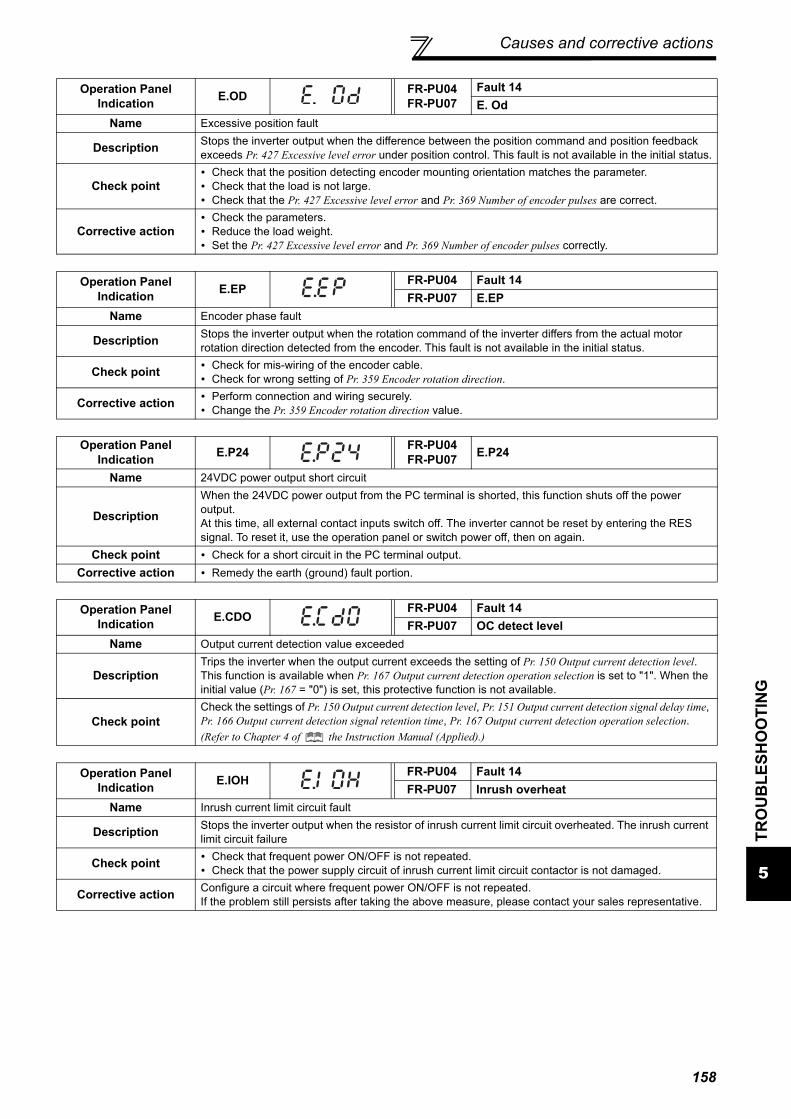
Causes and corrective actions
5
TRO
UB
LESH
OO
TIN
G
Operation Panel Indication E.OD FR-PU04
FR-PU07Fault 14E. Od
Name Excessive position fault
Description Stops the inverter output when the difference between the position command and position feedback exceeds Pr. 427 Excessive level error under position control. This fault is not available in the initial status.
Check point Check that the position detecting encoder mounting orientation matches the parameter. Check that the load is not large. Check that the Pr. 427 Excessive level error and Pr. 369 Number of encoder pulses are correct.
Corrective action Check the parameters. Reduce the load weight. Set the Pr. 427 Excessive level error and Pr. 369 Number of encoder pulses correctly.
Operation Panel Indication E.EP
FR-PU04 Fault 14FR-PU07 E.EP
Name Encoder phase fault
Description Stops the inverter output when the rotation command of the inverter differs from the actual motor rotation direction detected from the encoder. This fault is not available in the initial status.
Check point Check for mis-wiring of the encoder cable. Check for wrong setting of Pr. 359 Encoder rotation direction.
Corrective action Perform connection and wiring securely. Change the Pr. 359 Encoder rotation direction value.
Operation Panel Indication E.P24 FR-PU04
FR-PU07 E.P24
Name 24VDC power output short circuit
DescriptionWhen the 24VDC power output from the PC terminal is shorted, this function shuts off the power output.At this time, all external contact inputs switch off. The inverter cannot be reset by entering the RES signal. To reset it, use the operation panel or switch power off, then on again.
Check point Check for a short circuit in the PC terminal output.Corrective action Remedy the earth (ground) fault portion.
Operation Panel Indication E.CDO
FR-PU04 Fault 14FR-PU07 OC detect level
Name Output current detection value exceeded
DescriptionTrips the inverter when the output current exceeds the setting of Pr. 150 Output current detection level.This function is available when Pr. 167 Output current detection operation selection is set to "1". When the initial value (Pr. 167 = "0") is set, this protective function is not available.
Check pointCheck the settings of Pr. 150 Output current detection level, Pr. 151 Output current detection signal delay time, Pr. 166 Output current detection signal retention time, Pr. 167 Output current detection operation selection. (Refer to Chapter 4 of the Instruction Manual (Applied).)
Operation Panel Indication E.IOH
FR-PU04 Fault 14FR-PU07 Inrush overheat
Name Inrush current limit circuit fault
Description Stops the inverter output when the resistor of inrush current limit circuit overheated. The inrush current limit circuit failure
Check point Check that frequent power ON/OFF is not repeated. Check that the power supply circuit of inrush current limit circuit contactor is not damaged.
Corrective action Configure a circuit where frequent power ON/OFF is not repeated.If the problem still persists after taking the above measure, please contact your sales representative.
158

Causes and corrective actions
Operation Panel Indication E.SER
FR-PU04 Fault 14FR-PU07 VFD Comm error
Name Communication fault (inverter)
DescriptionThis function stops the inverter output when communication error occurs consecutively for more than permissible retry count when a value other than "9999" is set in Pr. 335 RS-485 communication retry count during RS-485 communication from the RS-485 terminals. This function also stops the inverter output if communication is broken for the period of time set in Pr. 336 RS-485 communication check time interval.
Check point Check the RS-485 terminal wiring.Corrective action Perform wiring of the RS-485 terminals properly.
Operation Panel Indication E.AIE
FR-PU04 Fault 14FR-PU07 Analog in error
Name Analog input fault
DescriptionStops the inverter output when a 30mA or higher current or a 7.5V or higher voltage is input to terminal 2 while the current input is selected by Pr.73 Analog input selection, or to terminal 4 while the current input is selected by Pr.267 Terminal 4 input selection.
Check point Check the setting of Pr. 73 Analog input selection, Pr. 267 Terminal 4 input selection and voltage/current input switch. (Refer to Chapter 4 of the Instruction Manual (Applied).)
Corrective action Either give a frequency command by current input or set Pr. 73 Analog input selection, Pr. 267 Terminal 4 input selection, and voltage/current input switch to voltage input.
Operation Panel Indication E.USB FR-PU04 Fault 14
FR-PU07 USB comm errorName USB communication fault
Description When the time set in Pr. 548 USB communication check time interval has broken, this function stops the inverter output.
Check point Check the USB communication cable.
Corrective action
Check the Pr. 548 USB communication check time interval setting. Check the USB communication cable. Increase the Pr. 548 USB communication check time interval setting. Or, change the setting to 9999.
(Refer to Chapter 4 of the Instruction Manual (Applied))
Operation Panel Indication E.4 FR-PU04
FR-PU07 Fault 4
Name Converter overcurrent
Description The current flows in the regeneration converter module exceeds the specified value, protective circuit activates and stops the inverter output.
Check point
Check that sudden acceleration/deceleration is not performed. Check for sudden load change. Check that wiring is correct. Check that instantaneous power failure did not occur. Check that the thyristor load does not exist in the same power supply system.
Corrective action Increase acceleration/deceleration time. Keep load stable. Wire the cables properly. When a thyristor load exist in the same power supply system, install an AC reactor (FR-HAL).
Operation Panel Indication E.8 FR-PU04
FR-PU07 Fault 8
Name Power supply fault
Description
When overvoltage occurs in the converter side during input phase failure detection When overvoltage occurs in the converter side during instantaneous power failure detection When fault of power supply frequency is detected When phase shift is not detectedWhen any of the above conditions applied, it is judged as power supply and the inverter output is stopped.
Check point Check the power supply and wiring.Corrective action Perform wiring correctly.
159

Causes and corrective actions
5
TRO
UB
LESH
OO
TIN
G
Operation Panel Indication E.10 FR-PU04
FR-PU07 Fault 10
Name Converter transistor protection thermal operation (electronic thermal)
DescriptionCurrent flowing in the module of the regeneration converter is less than the overcurrent shutoff level and exceeds the specified value, electronic thermal relay activates for protection and the inverter output is stopped.
Check point Check the motor for use under overload. (excess regeneration amount) Check that the thyristor load does not exist in the same power supply system.
Corrective action Reduce the load weight. When a thyristor load exists in the same power supply system, install an AC reactor (FR-HAL).
Operation Panel Indication E.11 FR-PU04
FR-PU07 Fault 11
Name Opposite rotation deceleration fault
Description
The speed may not decelerate during low speed operation if the rotation direction of the speed command and the estimated speed differ when the rotation is changing from forward to reverse or from reverse to forward during torque control under Real sensorless vector control. At this time, the inverter output is stopped if the rotation direction will not change, causing overload.This fault is not available in the initial status (V/F control). (It is available only during Real sensorless vector control.)
Check point Check that the rotation direction is not switched from forward to reverse rotation (or from reverse to forward) during torque control under Real sensorless vector control.
Corrective action Prevent the motor from switching the rotation direction from forward to reverse (or from reverse to
forward) during torque control under Real sensorless vector control. Please contact your sales representative.
Operation Panel Indication E.13 FR-PU04
FR-PU07 Fault 13
Name Internal circuit faultDescription Stop the inverter output when an internal circuit fault occurred.
Corrective action Please contact your sales representative.
Operation Panel Indication E.15 FR-PU04
FR-PU07 Fault 15
Name Converter circuit fault
Description
When a fault occurs in the peripheral circuit of the regeneration converter CPU When a fault occurs in the control power supply circuit. When a fault occurs in the inrush current limit circuit.If any of the above conditions applied, it is judged as converter circuit fault and the inverter output is stopped.
Check point Check for devices producing excess electrical noises around the inverter.
Corrective action Take measures against noises if there are devices producing excess electrical noises around the
inverter. Please contact your sales representative.
CAUTION• If protective functions of E.ILF, E.PTC, E.PE2, E.EP, E.OD, E.CDO, E.IOH, E.SER, E.AIE, E.USB are activated when using the
FR-PU04, "Fault 14" appears.Also when the faults history is checked on the FR-PU04, the display is "E.14".
• If faults other than the above appear, contact your sales representative.
160

161
Correspondences between digital and actual characters
5.4 Correspondences between digital and actual charactersThere are the following correspondences between the actual alphanumeric characters and the digital charactersdisplayed on the operation panel.
Actual Digital
0
1
2
3
4
5
6
7
8
9
Actual Digital
A
B
C
E
F
G
H
I
J
L
D
Actual Digital
M
N
O
o
P
T
U
V
r
-
S

Check and clear of the faults history
5
TRO
UB
LESH
OO
TIN
G
5.5 Check and clear of the faults history(1) Check for the faults history
* The cumulative energization time and actual operation time are accumulated from 0 to 65535 hours, then cleared, and accumulated again from0.When the operation panel (FR-DU07) is used, the time is displayed up to 65.53 (65530h) in the indication of 1h = 0.001, and thereafter, it isadded up from 0.
Faults history
Monitor/frequency setting
[Operation panel is used
for operation]
Parameter setting
[Parameter setting change]
[Operation for displaying faults history]
Eight past faults can be displayed with the setting dial.
(The latest fault is ended by ".".)
When no alarm exists, is displayed.
Output current
Flickering
Output voltage
Flickering
Flickering
Flickering
Press the
setting
dial.
Press the
setting
dial.
Press the
setting
dial.
Energization time*
Faults history number
(The number of past faults is displayed.)
Flickering
Output frequency
Flickering Flickering
162

Check and clear of the faults history
(2) Clearing procedure
POINT· The faults history can be cleared by setting "1" in Er.CL Faults history clear.
1.Screen at power-ON
The monitor display appears.
DisplayOperation
2.Press to choose the parameter
setting mode.
3. appears.
Flicker ··· Faults history clear complete!!
6.Press to set.
4.Press to read the currently set value.
" "(initial value) appears.
· Press to show the setting again.
· Press twice to show the next parameter.
· Press to read another parameter.
5.Turn to change it to the
setting value " ".
The parameter
number previously
read appears.
163

Check first when you have a trouble
5
TRO
UB
LESH
OO
TIN
G
5.6 Check first when you have a troubleRefer to troubleshooting on page 82 (speed control) in addition to the following check points.
5.6.1 Motor does not start
POINT· If the cause is still unknown after every check, it is recommended to initialize the parameters (initial value) then reset the
required parameter values and check again.· Refer to the Instruction Manual (Applied) for in "Refer to page" column.
Checkpoints Possible Cause Countermeasures
Refer to
page
Main Circuit
Appropriate power supply voltage is not applied.(Operation panel display is not provided.)
Power ON a molded case circuit breaker (MCCB), an earth leakage circuit breaker (ELB), or a magnetic contactor (MC). —Check for the decreased input voltage, input phase loss, and wiring.If only the control power is ON when using a separate power source for the control circuit, turn ON the main circuit power.
19
Motor is not connected properly.
Check the wiring between the inverter and the motor.If commercial power supply-inverter switchover function is active, check the wiring of the magnetic contactor connected between the inverter and the motor.
14
Input signal
Start signal is not input.
Check the start command source, and input a start signal.
PU operation mode: /
External operation mode : STF/STR signal
48
Both the forward and reverse rotation start signals (STF, STR) are input simultaneously.
Turn ON only one of the forward and reverse rotation start signals (STF or STR).If STF and STR signals are turned ON simultaneously in the initial setting, a stop command is given.
20
Frequency command is zero.(FWD or REV LED on the operation panel is flickering.)
Check the frequency command source and enter a frequency command.
48
AU signal is not ON when terminal 4 is used for frequency setting.(FWD or REV LED on the operation panel is flickering.)
Turn ON the AU signal.Turning ON the AU signal activates terminal 4 input.
20
Output stop signal (MRS) or reset signal (RES) is ON.(FWD or REV LED on the operation panel is flickering.)
Turn MRS or RES signal OFF.Inverter starts the operation with a given start command and a frequency command after turning OFF MRS or RES signal. Before turning OFF, ensure the safety.
20
CS signal is OFF when automatic restart after instantaneous power failure function is selected (Pr. 57 "9999").(FWD or REV LED on the operation panel is flickering. )
Turn ON the CS signal.Restart operation is enabled when restart after instantaneous power signal (CS) is ON.
Jumper connector of sink - source is wrongly selected.(FWD or REV LED on the operation panel is flickering.)
Check that the control logic switchover jumper connector is correctly installed.If it is not installed correctly, input signal is not recognized.
23
Wiring of encoder is incorrect.(Under encoder feedback control or vector control) Check the wiring of encoder. 32
Voltage/current input switch is not correctly set for analog input signal (0 to 5V/0 to 10V, 4 to 20mA).(FWD or REV LED on the operation panel is flickering.)
Set Pr. 73, Pr. 267, and a voltage/current input switch correctly, then input an analog signal in accordance with the setting.
20
164

Check first when you have a trouble
Parameter Setting
was pressed.
(Operation panel indication is (PS).)
During the External operation mode, check the method
of restarting from a input stop from PU.148
Two-wire or three-wire type connection is wrong. Check the connection.Connect STOP signal when three-wire type is used. 127
Pr. 0 Torque boost setting is improper when V/F control is used.
Increase Pr. 0 setting by 0.5% increments while observing the rotation of a motor. If that makes no difference, decrease the setting.
60
Pr. 78 Reverse rotation prevention selection is set.Check the Pr. 78 setting.Set Pr. 78 when you want to limit the motor rotation to only one direction.
116
Pr. 79 Operation mode selection setting is wrong.Select the operation mode which corresponds with input methods of start command and frequency command.
48
Bias and gain (calibration parameter C2 to C7) settings are improper.
Check the bias and gain (calibration parameter C2 to C7) settings. 121
Pr. 13 Starting frequency setting is greater than the running frequency.
Set running frequency higher than Pr. 13.The inverter does not start if the frequency setting signal is less than the value set in Pr. 13.
105
Frequency settings of various running frequency (such as multi-speed operation) are zero.Especially, Pr. 1 Maximum frequency is zero.
Set the frequency command according to the application.Set Pr. 1 higher than the actual frequency used.
61
Pr. 15 Jog frequency setting is lower than Pr. 13 Starting frequency.
Set Pr. 15 Jog frequency higher than Pr. 13 Starting frequency. 106
The Pr.359 Encoder rotation direction setting is incorrect under encoder feedback control or under vector control.
If the "REV" on the operation panel is lit even though the forward-rotation command is given, set Pr. 359 ="1." 34
Operation mode and a writing device do not match. Check Pr. 79, Pr. 338, Pr. 339, Pr. 550, Pr. 551, and select an operation mode suitable for the purpose.
63, 131
Start signal operation selection is set by the Pr. 250 Stop selection
Check Pr. 250 setting and connection of STF and STR signals. 127
Inverter decelerated to a stop when power failure deceleration stop function is selected.
When power is restored, ensure the safety, and turn OFF the start signal once, then turn ON again to restart.Inverter restarts when Pr. 261="2, 12".
128
Auto tuning is being performed.
In the PU operation, press on the operation
panel after the offline auto tuning completes.In the External operation, turn OFF the start signal (STF, STR).By this operation, offline auto tuning is cancelled, and the monitor display on the PU goes back to normal.(If this operation is not performed, you cannot proceed to the next operation.)
72
Automatic restart after instantaneous power failure function or power failure stop function is activated.(Performing overload operation during input phase loss may cause voltage insufficiency, and that may result in detection of power failure.)
Set Pr. 872 Input phase loss protection selection = "1" (input phase failure protection active).
Disable the automatic restart after instantaneous power failure function and power failure stop function.
Reduce the load. Increase the acceleration time if the automatic restart
after instantaneous power failure function or power failure stop function occurred during acceleration.
112, 128
Load Load is too heavy. Reduce the load. —Shaft is locked. Inspect the machine (motor). —
Checkpoints Possible Cause Countermeasures
Refer to
page
165

Check first when you have a trouble
5
TRO
UB
LESH
OO
TIN
G
5.6.2 Motor or machine is making abnormal acoustic noise
5.6.3 Inverter generates abnormal noiseLarger acoustic noise is generated during regenerative driving than during power driving because the inverter containsan AC reactor. This is not a fault. Connecting a single-phase power supply device or having an unbalanced power supply may cause the reactor togenerate acoustic noise even in non-operating status. This is not a fault.
Checkpoints Possible Cause Countermeasures
Refer to
pageInput signal Disturbance due to EMI when frequency command
is given from analog input (terminal 1, 2, 4).
Take countermeasures against EMI.
Parameter Setting
Increase the Pr. 74 Input filter time constant if steady operation cannot be performed due to EMI.
115
Parameter Setting
No carrier frequency noises (metallic noises) are generated.
In the initial setting, Pr. 240 Soft-PWM operation selection is enabled to change motor noise to an unoffending complex tone. Therefore, no carrier frequency noises (metallic noises) are generated.Set Pr. 240 = "0" to disable this function.
115
Resonance occurs. (output frequency)
Set Pr. 31 to Pr. 36 (Frequency jump).When it is desired to avoid resonance attributable to the natural frequency of a mechanical system, these parameters allow resonant frequencies to be jumped.
109
Resonance occurs. (carrier frequency)
Change Pr. 72 PWM frequency selection setting.Changing the PWM carrier frequency produces an effect on avoiding the resonance frequency of a mechanical system or a motor.
115
Set a notch filter.Auto tuning is not performed under Advanced magnetic flux vector control, Real sensorless vector control, or vector control.
Perform offline auto tuning. 72
Gain adjustment during PID control is insufficient.
To stabilize the measured value, change the proportional band (Pr. 129) to a larger value, the integral time (Pr. 130) to a slightly longer time, and the differential time (Pr. 134) to a slightly shorter time.Check the calibration of set point and measured value.
122
The gain is too high under Real sensorless vector control or vector control.
During speed control, check the setting of Pr. 820 (Pr. 830) speed control P gain.
137
During torque control, check the setting of Pr. 824 (Pr. 834) torque control P gain.
138
Others Mechanical loosenessAdjust machine/equipment so that there is no mechanical looseness.
—
Contact the motor manufacturer.Motor Operating with output phase loss Check the motor wiring. —
Checkpoints Possible Cause Countermeasures
Refer to
page
Fan Fan cover was not correctly installed when a cooling fan was replaced. Install a fan cover correctly. 177
166

Check first when you have a trouble
5.6.4 Motor generates heat abnormally
5.6.5 Motor rotates in the opposite direction
5.6.6 Speed greatly differs from the setting
Checkpoints Possible Cause Countermeasures
Refer to
page
MotorMotor fan is not working(Dust is accumulated.)
Clean the motor fan.Improve the environment. —
Phase to phase insulation of the motor is insufficient. Check the insulation of the motor. —Main
CircuitThe inverter output voltage (U, V, W) are unbalanced.
Check the output voltage of the inverter.Check the insulation of the motor. 173
Parameter Setting The Pr. 71 Applied motor setting is wrong. Check the Pr. 71 Applied motor setting. 114
— Motor current is large. Refer to "5.6.8 Motor current is too large" 168
Checkpoints Possible Cause Countermeasures
Refer to
pageMain
CircuitPhase sequence of output terminals U, V and W is incorrect.
Connect phase sequence of the output cables (terminal U, V, W) to the motor correctly. 13
Input signal
The start signals (forward rotation, reverse rotation) are connected improperly.
Check the wiring. (STF: forward rotation, STR: reverse rotation) 20
The polarity of the frequency command is negative during the polarity reversible operation set by Pr. 73 Analog input selection.
Check the polarity of the frequency command.
Input signal
Parameter setting
Torque command is negative during torque control under vector control. Check the torque command value.
Checkpoints Possible Cause Countermeasures
Refer to
page
Input signal
Frequency setting signal is incorrectly input. Measure the input signal level. —
The input signal lines are affected by external EMI. Take countermeasures against EMI such as using shielded wires for input signal lines.
Parameter Setting
Pr. 1, Pr. 2, Pr. 18, calibration parameter C2 to C7 settings are improper.
Check the settings of Pr. 1 Maximum frequency, Pr. 2 Minimum frequency, Pr. 18 High speed maximum frequency.
104
Check the calibration parameter C2 to C7 settings. 121Pr. 31 to Pr. 36 (frequency jump) settings are improper. Narrow down the range of frequency jump. 109
Load
Stall prevention (torque limit) function is activated due to a heavy load.
Reduce the load weight. —
Parameter Setting
Set Pr. 22 Stall prevention operation level (Torque limit level) higher according to the load. (Setting Pr. 22 too large may result in frequent overcurrent trip (E.OC).)
107 (108)
Motor Check the capacities of the inverter and the motor. —
167

Check first when you have a trouble
5
TRO
UB
LESH
OO
TIN
G
5.6.7 Acceleration/deceleration is not smooth
5.6.8 Motor current is too large
Checkpoints Possible Cause Countermeasures
Refer to
page
Parameter Setting
Acceleration/deceleration time is too short. Increase acceleration/deceleration time. 62Torque boost (Pr. 0, Pr. 46, Pr. 112) setting is improper under V/F control, so the stall prevention function is activated.
Increase/decrease Pr. 0 Torque boost setting value by 0.5% increments to the setting. 60
The base frequency setting and the motor characteristic does not match.
For V/F control, set Pr. 3 Base frequency, Pr. 47 Second V/F (base frequency), and Pr. 113 Third V/F (base frequency).
104
For vector control, set Pr. 84 Rated motor frequency. 72
Regeneration avoidance operation is performedIf the frequency becomes unstable during regeneration avoidance operation, decrease the setting of Pr. 886 Regeneration avoidance voltage gain.
140
Load
Stall prevention (torque limit) function is activated due to a heavy load.
Reduce the load weight. —
Parameter Setting
Set Pr. 22 Stall prevention operation level (Torque limit level) higher according to the load. (Setting Pr. 22 too large may result in frequent overcurrent trip (E.OC).)
107 (108)
Motor Check the capacities of the inverter and the motor. —
Checkpoints Possible Cause Countermeasures
Refer to
page
Parameter Setting
Torque boost (Pr. 0, Pr. 46, Pr. 112) setting is improper under V/F control, so the stall prevention function is activated.
Increase/decrease Pr. 0 Torque boost setting value by 0.5% increments to the setting. 60
V/F pattern is improper when V/F control is performed. (Pr. 3, Pr. 14, Pr. 19)
Set rated frequency of the motor to Pr. 3 Base frequency. Use Pr. 19 Base frequency voltage to set the base voltage (e.g. rated motor voltage).
104
Change Pr. 14 Load pattern selection according to the load characteristic. 106
Stall prevention (torque limit) function is activated due to a heavy load.
Reduce the load weight. —Set Pr. 22 Stall prevention operation level (Torque limit level) higher according to the load. (Setting Pr. 22 too large may result in frequent overcurrent trip (E.OC).)
107 (108)
Check the capacities of the inverter and the motor. —Auto tuning is not performed under Advanced magnetic flux vector control, Real sensorless vector control, or vector control.
Perform offline auto tuning. 72
168

Check first when you have a trouble
5.6.9 Speed does not accelerate
5.6.10 Motor and machine vibrate
Checkpoints Possible Cause Countermeasures
Refer to
page
Input signal
Start command and frequency command are chattering.
Check if the start command and the frequency command are correct. —
The wiring length used for analog frequency command is too long, and it is causing a voltage (current) drop.
Perform analog input bias/gain calibration.
Input signal lines are affected by external EMI. Take countermeasures against EMI, such as using shielded wires for input signal lines.
Parameter Setting
Pr. 1, Pr. 2, Pr. 18, calibration parameter C2 to C7 settings are improper.
Check the settings of Pr. 1 Maximum frequency and Pr. 2 Minimum frequency. If you want to run the motor at 120Hz or higher, set Pr. 18 High speed maximum frequency.
104
Check the calibration parameter C2 to C7 settings. 121Torque boost (Pr. 0, Pr. 46, Pr. 112) setting is improper under V/F control, so the stall prevention function is activated.
Increase/decrease Pr. 0 Torque boost setting value by0.5% increments so that stall prevention does not occur.
60
V/F pattern is improper when V/F control is performed.(Pr. 3, Pr. 14, Pr. 19)
Set rated frequency of the motor to Pr. 3 Base frequency. Use Pr. 19 Base frequency voltage to set the base voltage (e.g. rated motor voltage).
104
Change Pr. 14 Load pattern selection according to the load characteristic. 106
Auto tuning is not performed under Advanced magnetic flux vector control, Real sensorless vector control, or vector control.
Perform offline auto tuning. 72
The setting of pulse train input is improper.
Check the specification of the pulse generator (open collector output or complementary output) and check the adjustment of the pulse train and frequency (Pr. 385 and Pr. 386).
During PID control, output frequency is automatically controlled to make measured value = set point.Load
Stall prevention (torque limit) function is activated due to a heavy load.
Reduce the load weight. —
Parameter Setting
Set Pr. 22 Stall prevention operation level (Torque limit level) higher according to the load. (Setting Pr. 22 too large may result in frequent overcurrent trip (E.OC).)
107 (108)
Motor Check the capacities of the inverter and the motor. —
Checkpoints Possible Cause Countermeasures
Refer to
page
Parameter Setting
Pr.19 Base frequency voltage is improper under V/F control.
Set the rated motor voltage to Pr.19 Base frequency voltage. 104
Mechanical loosenessAdjust machine/equipment so that there is no mechanical looseness.
—
169

Check first when you have a trouble
5
TRO
UB
LESH
OO
TIN
G
5.6.11 Speed varies during operationWhen Advanced magnetic flux vector control, Real sensorless vector control, vector control or encoder feedbackcontrol is exercised, the output frequency varies with load fluctuation between 0 and 2Hz. This is a normal operationand is not a fault.
Checkpoints Possible Cause Countermeasures
Refer to
page
Load Load varies during an operation.Select Advanced magnetic flux vector control, Real sensorless vector control, vector control, or encoder feedback control.
64, 67,
Input signal
Frequency setting signal is varying. Check the frequency setting signal. —
The frequency setting signal is affected by EMI.
Set filter to the analog input terminal using Pr. 74 Input filter time constant, Pr. 822 Speed setting filter 1.
115
Take countermeasures against EMI, such as using shielded wires for input signal lines.
Malfunction is occurring due to the undesirable current generated when the transistor output unit is connected.
Use terminal PC (terminal SD when source logic) as a common terminal to prevent a malfunction caused by undesirable current.
24
Multi-speed command signal is chattering. Take countermeasures to suppress chattering. —
Feedback signal from the encoder is affected by EMI.
Place the encoder cable far from the EMI source such as main circuit and power supply voltage.Earth (ground) the shield of the encoder cable to the enclosure using a metal P-clip or U-clip.
32
Parameter Setting
Pr.80 Motor capacity and Pr.81 Number of motor poles are not appropriate for the motor capacity under Advanced magnetic flux vector control, Real sensorless vector control, or vector control.
Check the settings of Pr.80 Motor capacity and Pr.81 Number of motor poles.
64, 67
Fluctuation of power supply voltage is too large.Change the Pr. 19 Base frequency voltage setting (about 3%) under V/F control.
104
Wiring length exceeds 30m when Advanced magnetic flux vector control, Real sensorless vector control, or vector control is selected.
Perform offline auto tuning. 72
Wiring length is too long for V/F control, and the a voltage drop occurs.
Adjust the Pr. 0 Torque boost setting by increasing with 0.5% increments for the low-speed operation.
60
Change the control method to Advanced magnetic flux vector control or Real sensorless vector control.
64
Hunting occurs by the generated vibration, for example, when structural rigidity at load side is insufficient.
Disable automatic control functions, such as the energy saving operation, the fast-response current limit function, the torque limit, the regeneration avoidance function, Advanced magnetic flux vector control, Real sensorless vector control, vector control, encoder feedback control, droop control, the stall prevention, online auto tuning, the notch filter, and orientation control. During the PID control, set smaller values to Pr. 129 PID proportional band and Pr. 130 PID integral time. Lower the control gain, and adjust to increase the stability.
—
Change Pr. 72 PWM frequency selection setting. 115
170

Check first when you have a trouble
5.6.12 Operation mode is not changed properly
5.6.13 Operation panel (FR-DU07) display is not operating
5.6.14 Power lamp is not lit
5.6.15 Unable to write parameter setting
Checkpoints Possible Cause Countermeasures
Refer to
page
Input signal Start signal (STF or STR) is ON.
Check that the STF and STR signals are OFF.When either is ON, the operation mode cannot be changed.
63
Parameter Setting
Pr. 79 setting is improper.
When Pr. 79 Operation mode selection setting is "0" (initial value), the inverter is placed in the External operation mode at input power ON. To switch to the
PU operation mode, press on the operation
panel (press when the parameter unit (FR-PU04/FR-PU07) is used) . At other settings (1 to 4, 6, 7), the operation mode is limited accordingly.
63
Operation mode and a writing device do not correspond.
Check Pr. 79, Pr. 338, Pr. 339, Pr. 550, Pr. 551, and select an operation mode suitable for the purpose.
63, 131
Checkpoints Possible Cause Countermeasures
Refer to
pageMain
Circuit,Control Circuit
Power is not input. Input the power. 12
Front cover
Operation panel is not properly connected to the inverter.
Check if the inverter front cover is installed securely.The inverter cover may not fit properly when using wires whose size are 1.25mm2 or larger, or when using many wires, and this could cause a contact fault of the operation panel.
4
Checkpoints Possible Cause Countermeasures
Refer to
pageMain
Circuit,Control Circuit
Wiring or installation is improper.Check for the wiring and the installation.Power lamp is lit when power is input to the control circuit (R1/L11, S1/L21).
13
Checkpoints Possible Cause Countermeasures
Refer to
page
Input signal
Operation is being performed (signal STF or STR is ON).
Stop the operation.When Pr. 77 = "0" (initial value), write is enabled only during a stop.
116
Parameter Setting
You are attempting to set the parameter in the External operation mode.
Choose the PU operation mode.Or, set Pr. 77 = "2" to enable parameter write regardless of the operation mode.
116
Parameter is disabled by the Pr. 77 Parameter write selection setting. Check Pr. 77 Parameter write selection setting. 116
Key lock is activated by the Pr. 161 Frequency setting/key lock operation selection setting.
Check Pr. 161 Frequency setting/key lock operation selection setting. 124
Operation mode and a writing device do not correspond.
Check Pr. 79, Pr. 338, Pr. 339, Pr. 550, Pr. 551, and select an operation mode suitable for the purpose. 63, 131
171

Inspection item
6
PREC
AU
TIO
NS
FOR
MA
INTE
NA
NC
E A
ND
INSP
ECTI
ON
6 PRECAUTIONS FOR MAINTENANCE AND INSPECTION
The inverter is a static unit mainly consisting of semiconductor devices. Daily inspection must be performed to preventany fault from occurring due to the adverse effects of the operating environment, such as temperature, humidity, dust,dirt and vibration, changes in the parts with time, service life, and other factors.
Precautions for maintenance and inspectionFor some short time after the power is switched off, a high voltage remains in the smoothing capacitor. When accessingthe inverter for inspection, wait for at least 10 minutes after the power supply has been switched off, and then makesure that the voltage across the main circuit terminals P/+-N/ of the inverter is not more than 30VDC using a tester,etc.
6.1 Inspection item
6.1.1 Daily inspection
Basically, check for the following faults during operation.(1) Motor operation fault(2) Improper installation environment(3) Cooling system fault(4) Unusual vibration and noise(5) Unusual overheat and discoloration
6.1.2 Periodic inspectionCheck the areas inaccessible during operation and requiring periodic inspection.Consult us for periodic inspection.1) Check for cooling system fault ................ Clean the air filter, etc.2) Tightening check and retightening .......... The screws and bolts may become loose due to vibration, temperature
changes, etc.Tighten them according to the specified tightening torque. (Refer to page 16)
3) Check the conductors and insulating materials for corrosion and damage.4) Measure insulation resistance.5) Check and change the cooling fan and relay.
172

Inspection item
6.1.3 Daily and periodic inspection
*1 It is recommended to install a device to monitor voltage for checking the power supply voltage to the inverter.*2 One to two years of periodic inspection cycle is recommended. However, it differs according to the installation environment.
Consult us for periodic inspection.
Are
a of
In
spec
tion
Inspection Item Description
IntervalCorrective Action at Alarm Occurrence
Cust
omer
's Ch
eck
Dai
ly
Perio
dic
*2
General
Surrounding environment
Check the surrounding air temperature, humidity, dirt, corrosive gas, oil mist , etc. Improve environment.
Overall unit Check for unusual vibration and noise. Check alarm location and retighten.
Power supply voltage
Check that the main circuit voltages and control voltages are normal.*1 Inspect the power supply.
Main circuit
General
(1)Check with megger (across main circuit terminals and earth (ground) terminal). Contact the manufacturer.
(2)Check for loose screws and bolts. Retighten.(3)Check for overheat traces on the parts. Contact the manufacturer.(4)Check for stain. Clean.
Conductors, cables(1)Check conductors for distortion.(2)Check cable sheaths for breakage and
deterioration (crack, discoloration, etc.).
Contact the manufacturer.
Contact the manufacturer.
Transformer/reactor Check for unusual odor and abnormal increase in whining sound.
Stop the device and contact the manufacturer.
Terminal block Check for damage. Stop the device and contact the manufacturer.
Smoothing aluminum electrolytic capacitor
(1)Check for liquid leakage. Contact the manufacturer.(2)Check for safety valve projection and bulge. Contact the manufacturer.(3)Visual check and judge by the life check of the
main circuit capacitor. (Refer to page 174)
Relay/contactor Check that the operation is normal and no chatter is heard. Contact the manufacturer.
Resistor(1)Check for crack in resistor insulation. Contact the manufacturer.(2)Check for a break in the cable. Contact the manufacturer.
Control circuit
protective circuit
Operation check
(1)Check that the output voltages across phases with the inverter operated alone is balanced. Contact the manufacturer.
(2)Check that no fault is found in protective and display circuits in a sequence protective operation test.
Contact the manufacturer.
Parts
che
ck
Overall(1)Check for unusual odor and discoloration.
Stop the device and contact the manufacturer.
(2)Check for serious rust development. Contact the manufacturer.
Aluminum electrolytic capacitor
(1)Check for liquid leakage in a capacitor and deformation trace. Contact the manufacturer.
(2)Visual check and judge by the life check of the control circuit capacitor. (Refer to page 174.)
Cooling system
Cooling fan
(1)Check for unusual vibration and noise. Replace the fan.
(2)Check for loose screws and bolts. Fix with the fan cover fixing screws.
(3)Check for stain. Clean.
Heatsink(1)Check for clogging. Clean.(2)Check for stain. Clean.
Air filter, etc.(1)Check for clogging. Clean or replace.(2)Check for stain. Clean or replace.
DisplayIndication
(1)Check that display is normal. Contact the manufacturer.(2)Check for stain. Clean.
Meter Check that reading is normal. Stop the device and contact the manufacturer.
Load motor Operation check Check for vibration and abnormal increase in
operation noise. Stop the device and contact the manufacturer.
173

Inspection item
6
PREC
AU
TIO
NS
FOR
MA
INTE
NA
NC
E A
ND
INSP
ECTI
ON
6.1.4 Display of the life of the inverter partsThe self-diagnostic alarm is output when the lifespan of the control circuit capacitor, cooling fan, each parts of theinrush current limit circuit is near its end. It gives an indication of replacement time.
The life alarm output can be used as a guideline for life judgement.
For the life check of the main circuit capacitor, the alarm signal (Y90) will not be output if a measuring method of (2) isnot performed. (Refer to page 175.)
(1) Display of the life alarm· Pr. 255 Life alarm status display can be used to confirm that the control circuit capacitor, main circuit capacitor,
cooling fan, and each parts of the inrush current limit circuit has reached the life alarm output level.
Parts Judgement LevelMain circuit capacitor 85% of the initial capacityControl circuit capacitor Estimated 10% life remainingInrush current limit circuit Estimated 10% life remaining (Power on: 100,000 times left)Cooling fan Less than 50% of the predetermined speed
Pr. 255(decimal)
Bit(binary)
Inrush Current Limit Circuit Life
Cooling Fan Life
Main Circuit Capacitor Life
Control Circuit Capacitor Life
15 111114 111013 110112 110011 101110 10109 10018 10007 01116 01105 01014 01003 00112 00101 00010 0000
: with alarm, : without alarm
POINTLife check of the main circuit capacitor needs to be done by Pr. 259. (Refer to the following.)
0 0 0 0 0 0 0 0 0 0 0 0 1 0 0
bit0 Control circuit capacitor life
1
15bit 7 0
bit1 Main circuit capacitor life
bit2 Cooling fan life
bit3 Inrush current limit circuit life
• Pr.255 read
Bit image is displayed
in decimal
• Pr.255 setting read
174

Inspection item
(2) Measuring method of life of the main circuit capacitor· If the value of capacitor capacity measured before shipment is considered as 100%, Pr. 255 bit1 is turned ON when
the measured value falls below 85%.· Measure the capacitor capacity according to the following procedure and check the deterioration level of the
capacitor capacity. 1) Check that the motor is connected and at a stop.2) Set "1" (measuring start) in Pr. 2593) Switch power off. The inverter applies DC voltage to the motor to measure the capacitor capacity while the inverter is off.4) After confirming that the LED of the operation panel is off, power on again.5) Check that "3" (measuring completion) is set in Pr. 259, then read Pr. 258 and check the life of the main circuit capacitor.
6.1.5 Checking the inverter and converter modules<Preparation>(1) Disconnect the external power supply cables (R/L1, S/L2, T/L3) and motor cables (U, V, W).(2) Prepare a tester. (Use 100 range.)
<Checking method>Change the polarity of the tester alternately at the inverter terminals R/L1, S/L2, T/L3, U, V, W, P/+ and N/, and checkfor electric continuity.
<Module device numbers and terminals to be checked>
(Assumes the use of an analog meter.)
REMARKS· When the main circuit capacitor life is measured under the following conditions, "forced end" (Pr. 259 = "8") or "measuring error"
(Pr. 259 = "9") occurs or it remains in "measuring start" (Pr. 259 = "1"). When measuring, avoid the following conditions toperform. In addition, even when "measurement completion" (Pr. 259 = "3") is confirmed under the following conditions, normalmeasurement can not be done.(a) Terminal R1/L11, S1/L21 is connected to the terminals P/ and N/.(b) Switch power on during measuring.(c) The motor is not connected to the inverter.(d) The motor is running. (The motor is coasting.)(e) The motor capacity is two rank smaller as compared to the inverter capacity.(f) The inverter is at an alarm stop or an alarm occurred while power is off.(g) The inverter output is shut off with the MRS signal.(h) The start command is given while measuring.
· Operating environment: Surrounding air temperature (annual average 40C (free from corrosive gas, flammable gas, oil mist, dustand dirt))Output current (80% of the inverter rated current)
POINTFor accurate life measurement of the main circuit capacitor, wait 3 hours or longer after turning OFF. Thetemperature left in the main circuit capacitor affects measurement.
WARNING When measuring the main circuit capacitor capacity (Pr. 259 Main circuit capacitor life measuring = "1"), the DC voltage is applied to the motor for 1s at powering off. Never touch the motor terminal, etc. right after powering off to prevent an electric shock.
Tester Polarity Measured Value
Tester Polarity Measured Value
Con
verte
r m
odul
e
TR11R/L1 P/ Discontinuity
TR14R/L1 N/ Continuity
P/ R/L1 Continuity N/ R/L1 Discontinuity
TR13S/L2 P/ Discontinuity
TR16S/L2 N/ Continuity
P/ S/L2 Continuity N/ S/L2 Discontinuity
TR15T/L3 P/ Discontinuity
TR12T/L3 N/ Continuity
P/ T/L3 Continuity N/ T/L3 Discontinuity
Inve
rter
mod
ule
TR1U P/ Discontinuity
TR4U N/ Continuity
P/ U Continuity N/ U Discontinuity
TR3V P/ Discontinuity
TR6V N/ Continuity
P/ V Continuity N/ V Discontinuity
TR5W P/ Discontinuity
TR2W N/ Continuity
P/ W Continuity N/ W Discontinuity
Converter module Inverter module
U
V
W
R/L1
S/L2
T/L3
P/+
N/−
TR1 TR3 TR5
TR4 TR6 TR2
C
TR11 TR13 TR15
TR14 TR16 TR12
175

Inspection item
6
PREC
AU
TIO
NS
FOR
MA
INTE
NA
NC
E A
ND
INSP
ECTI
ON
6.1.6 CleaningAlways run the inverter in a clean status.When cleaning the inverter, gently wipe dirty areas with a soft cloth immersed in neutral detergent or ethanol.
6.1.7 Replacement of partsThe inverter consists of many electronic parts such as semiconductor devices.The following parts may deteriorate with age because of their structures or physical characteristics, leading to reducedperformance or fault of the inverter. For preventive maintenance, the parts must be replaced periodically.Use the life check function as a guidance of parts replacement.
*1 Estimated lifespan for when the yearly average surrounding air temperature is 40°C(without corrosive gas, flammable gas, oil mist, dust and dirt etc.)
*2 Output current : 80% of the inverter rated current
CAUTIONDo not use solvent, such as acetone, benzene, toluene and alcohol, as they will cause the inverter surface paint to peel off.The display, etc. of the operation panel (FR-DU07) and parameter unit (FR-PU04/FR-PU07) are vulnerable to detergent andalcohol. Therefore, avoid using them for cleaning.
Part Name Estimated Lifespan *1 DescriptionCooling fan 10 years Replace (as required)
Main circuit smoothing capacitor 10 years *2 Replace (as required)On-board smoothing capacitor 10 years Replace the board (as required)
Relays As required
REMARKS· Since repeated inrush currents at power ON will shorten the life of the converter circuit, frequent starts and stops of the
magnetic contactor must be avoided.
CAUTIONFor parts replacement, consult the nearest Mitsubishi Electric FA Center.
176

Inspection item
(1) Cooling fanThe replacement interval of the cooling fan used for cooling the parts generating heat such as the main circuitsemiconductor is greatly affected by the surrounding air temperature. When unusual noise and/or vibration is noticedduring inspection, the cooling fan must be replaced immediately.
Removal1) Remove a fan cover.2) After removing a fan connector, remove a fan block.3) Remove the fan.
Reinstallation1) After confirming the orientation of the fan, reinstall the fan so that the arrow on the left of "AIR FLOW" faces up.
<Fan side face>2) Install fans referring to the above figure.
Fan
Fan connection
connector
1)
2)
3)
Fan block
Fan cover
AIR FLOW
CAUTIONInstalling the fan in the opposite of air flow direction can cause the inverter life to be shorter.Prevent the cable from being caught when installing a fan.Switch the power off before replacing fans. Since the inverter circuits are charged with voltage even after power off,
replace fans only when the inverter cover is on the inverter to prevent an electric shock accident.
177

Inspection item
6
PREC
AU
TIO
NS
FOR
MA
INTE
NA
NC
E A
ND
INSP
ECTI
ON
(2) Smoothing capacitorsA large-capacity aluminum electrolytic capacitor is used for smoothing in the main circuit DC section, and an aluminumelectrolytic capacitor is used for stabilizing the control power in the control circuit. Their characteristics are deterioratedby the adverse effects of ripple currents, etc.The replacement intervals greatly vary with the surrounding air temperature and operating conditions. When theinverter is operated in air-conditioned, normal environment conditions, replace the capacitors about every 10 years.The appearance criteria for inspection are as follows:1) Case: Check the side and bottom faces for expansion2) Sealing plate: Check for remarkable warp and extreme crack.3) Check for external crack, discoloration, fluid leakage, etc. Judge that the capacitor has reached its life when the
measured capacitance of the capacitor reduced below 80% of the rating.
Refer to page 176 to perform the life check of the main circuit capacitor.(3) RelaysTo prevent a contact fault, etc., relays must be replaced according to the cumulative number of switching times(switching life).
178

Measurement of main circuit voltages, currents and powers
6.2 Measurement of main circuit voltages, currents and powersSince the voltages and currents on the inverter power supply and output sides include harmonics, measurementdata depends on the instruments used and circuits measured.When instruments for commercial frequency are used for measurement, measure the following circuits with theinstruments given on the next page.When installing meters etc. on the inverter output side
When the inverter-to-motor wiring length is large, especially in the 400V class, small-capacity models, the metersand CTs may generate heat due to line-to-line leakage current. Therefore, choose the equipment which hasenough allowance for the current rating.When measuring and indicating the output voltage and output current of the inverter, it is recommended to utilizethe terminals AM and FM output function of the inverter.
Examples of Measuring Points and Instruments
+ -
Ar
As
At
Vr
Vs
Vt
W11
W12
W13
Au
Av
Aw
Vu
Vv
Vw
W21
W22
V
U
V
W
Inverter
Three
phase
power
supply
To the motor
Instrument
types
Input voltage
Input current
Output voltage
Output current
: Moving-iron type
: Electrodynamometer type
: Moving-coil type
: Rectifier type
R/L1
S/L2
T/L3
P/+ N/-
179

Measurement of main circuit voltages,currents and powers
6
PREC
AU
TIO
NS
FOR
MA
INTE
NA
NC
E A
ND
INSP
ECTI
ON
Measuring points and instruments
*1 Use an FFT to measure the output voltage accurately. A tester or general measuring instrument cannot measure accurately.*2 When the carrier frequency exceeds 5kHz, do not use this instrument since using it may increase eddy-current losses produced in metal parts
inside the instrument, leading to burnout. If the wiring length between the inverter and motor is long, the instrument and CT may generateheat due to line-to-line leakage current.
*3 When the setting of Pr. 195 ABC1 terminal function selection is positive logic*4 A digital power meter (designed for inverter) can also be used to measure.
Item Measuring Point Measuring Instrument Remarks (Reference Measured Value)
Power supply voltageV1
Across R/L1 and S/L2, S/L2 and T/L3, T/L3 and R/L1
Moving-iron type AC voltmeter *4
Commercial power supplyWithin permissible AC voltage fluctuation (Refer to page 184)
Power supply side currentI1
R/L1, S/L2, and T/L3 line currents
Moving-iron type AC ammeter *4
Power supply side powerP1
R/L1, S/L2, T/L3 and R/L1 and S/L2, S/L2 and T/L3, T/L3 and R/L1
Digital power meter (designed for inverter) or electrodynamic type single-phase wattmeter
P1=W11+W12+W13 (3-wattmeter method)
Power supply side power factorPf1
Calculate after measuring power supply voltage, power supply side current and power supply side power.
Output side voltageV2
Across U and V, V and W and W and U
Rectifier type AC voltage meter *1 *4 (Moving-iron type cannot measure)
Difference between the phases is within ±1% of the maximum output voltage.
Output side currentI2
U, V and W line currents
Moving-iron type AC ammeter *2 *4
Difference between the phases is 10% or lower of the rated inverter current.
Output side powerP2
U, V, W and U and V, V and W
Digital power meter (designed for inverter) or electrodynamic type single-phase wattmeter
P2 = W21 + W222-wattmeter method (or 3-wattmeter method)
Output side power factorPf2
Calculate in similar manner to power supply side power factor.
Converter output Across P/ and N/ Moving-coil type (such as tester) Inverter LED display is lit. 1.35 V1
Frequency setting signal
Across 2 and 5Across 4(+) and 5
Moving-coil type (Tester and such may be
used)(Internal resistance:
50k or larger)
0 to 10VDC, 4 to 20mA
"5" is common
Across 1(+) and 5 0 to ±5VDC, 0 to ±10VDCFrequency setting power supply
Across 10 (+) and 5 5.2VDCAcross 10E(+) and 5 10VDC
Frequency meter signal
Across AM(+) and 5 Approximately 10VDC at maximum frequency(without frequency meter)
Across FM(+) and SD
Approximately 5VDC at maximum frequency (without frequency meter)
Pulse width T1:Adjusted by C0 (Pr. 900)
Pulse cycle T2: Set by Pr. 55(Valid for frequency monitoring only)
"SD" is common
Start signalSelect signal
Across SD and the following:STF, STR, RH, RM, RL, JOG, RT, AU, STOP, CS (+)
When open20 to 30VDCON voltage: 1V or less
Reset Across RES (+) and SDOutput stop Across MRS (+) and SD
Alarm signal Across A1 and C1Across B1 and C1
Moving-coil type (such as tester)
Electric continuity check*3<Normal> <Abnormal>
Across A1-C1 Discontinuity ContinuityAcross B1-C1 Continuity Discontinuity
Pf1 = ————— × 100%P1
3 V1 × I1
Pf2 = ————— × 100%P2
3 V2 × I2
8VDC
T1
T2
180

Measurement of main circuit voltages, currents and powers
6.2.1 Measurement of powers
Use digital power meters (for inverter) for the both of inverter input and output side. Alternatively, measure usingelectrodynamic type single-phase wattmeters for the both of inverter input and output side in two-wattmeter orthree-wattmeter method. As the current is liable to be imbalanced especially in the input side, it is recommended touse the three-wattmeter method.Examples of measured value differences produced by different measuring meters are shown below.An error will be produced by difference between measuring instruments, e.g. power calculation type and two- orthree-wattmeter type three-phase wattmeter. When a CT is used in the current measuring side or when the metercontains a PT on the voltage measurement side, an error will also be produced due to the frequency characteristicsof the CT and PT.
6.2.2 Measurement of voltages and use of PT
(1) Inverter input sideAs the input side voltage has a sine wave and it is extremely small in distortion, accurate measurement can bemade with an ordinary AC meter.
(2) Inverter output sideSince the output side voltage has a PWM-controlled rectangular wave, always use a rectifier type voltmeter. Aneedle type tester can not be used to measure the output side voltage as it indicates a value much greater than theactual value. A moving-iron type meter indicates an effective value which includes harmonics and therefore thevalue is larger than that of the fundamental wave. The value monitored on the operation panel is the invertercontrolled voltage itself. Hence, that value is accurate and it is recommended to monitor values (provide analogoutput) using the operation panel.
(3) PTNo PT can be used in the output side of the inverter. Use a direct-reading meter. (A PT can be used in the input sideof the inverter.)
[Measurement conditions]Constant-torque (100%) load, constant-power at 60Hzor more.3.7kW, 4-pole motor, value indicated in 3-wattmetermethod is 100%.
[Measurement conditions]Constant-torque (100%) load, constant-power at 60Hzor more.3.7kW, 4-pole motor, value indicated in 3-wattmetermethod is 100%.
Example of measuring inverter input power Example of measuring inverter output power
3-wattmeter method (Electro-dynamometer type)
2-wattmeter method (Electro-dynamometer type)
Clip AC power meter
(For balanced three-phase load)
Clamp-on wattmeter
(Hall device power arithmetic type)
0 20 40 60 80 100 120Hz
60
80
100
120
%
3-wattmeter method (Electro-dynamometer type)
2-wattmeter method (Electro-dynamometer type)
Clip AC power meter
(For balanced three-phase load)
Clamp-on wattmeter
(Hall device power arithmetic type)
0 20 40 60 80 100 120Hz
60
80
100
120
%
181

Measurement of main circuit voltages,currents and powers
6
PREC
AU
TIO
NS
FOR
MA
INTE
NA
NC
E A
ND
INSP
ECTI
ON
6.2.3 Measurement of currents
Use a moving-iron type meter on both the input and output sides of the inverter. However, if the carrier frequencyexceeds 5kHz, do not use that meter since an overcurrent losses produced in the internal metal parts of the meterwill increase and the meter may burn out. In this case, use an approximate-effective value type.As the inverter input side current is easily imbalanced, measurement of currents in all three phases isrecommended. Correct values can not be measured in one or two phases. On the other hand, the phaseimbalanced ratio of the output side current must be within 10%.When using a clamp ammeter, always use an effective value detection type. A mean value detection type producesa large error and may indicate an extremely smaller value than the actual value. The value monitored on theoperation panel is accurate if the output frequency varies, and it is recommended to monitor values (provide analogoutput) using the operation panel.An example of the measured value difference produced by different measuring meters is shown below.
6.2.4 Use of CT and transducer
A CT may be used in both the input and output sides of the inverter, but the one used should have the largestpossible VA ability because an error will increase if the frequency gets lower. When using a transducer, use the effective value calculation type which is immune to harmonics.
6.2.5 Measurement of inverter input power factor
Use the effective power and apparent power to calculate the inverter input power factor. A power-factor meter cannot indicate an exact value.
[Measurement conditions]Value indicated by moving-iron type ammeter is 100%.
[Measurement conditions]Value indicated by moving-iron type ammeter is 100%.
Example of measuring inverter input current Example of measuring inverter output current
Total power factor of the inverter =Effective powerApparent power
=Three-phase input power found by 3-wattmeter method
V (power supply voltage) I (input current effective value)
120
100
80
60
0 60Hz4020
%
Moving-iron type
Clamp-on wattmeter
current measurementClamp meter
Clip AC
power meter 120
100
80
60
0 60Hz4020
%
Moving-iron type
Clip AC
power meter
Clamp-on wattmeter
current measurement
Clamp meter
3
182

Measurement of main circuit voltages, currents and powers
6.2.6 Measurement of converter output voltage (across terminals P/+ and N/-)
The output voltage of the converter is developed across terminals P/+ - N/- and can be measured with a moving-coiltype meter (tester). Although the voltage varies according to the power supply voltage, approximately 270V to 300V(approximately 540V to 600V for the 400V class) is output when no load is connected and voltage decreases whena load is connected.When energy is regenerated from the motor during deceleration, for example, the converter output voltage rises tonearly 400VDC to 450VDC (800VDC to 900VDC for the 400V class) maximum.
6.2.7 Measurement of inverter output frequency
A pulse train proportional to the output frequency is output across the frequency meter signal output terminal FM-SD of the inverter. This pulse train output can be counted by a frequency counter, or a meter (moving-coil typevoltmeter) can be used to read the mean value of the pulse train output voltage. When a meter is used to measurethe output frequency, approximately 5VDC is indicated at the maximum frequency.For detailed specifications of the frequency meter signal output terminal FM, refer to page 22.
6.2.8 Insulation resistance test using meggerFor the inverter, conduct the insulation resistance test on the main circuit only as shown below and do not performthe test on the control circuit. (Use a 500VDC megger.)
6.2.9 Pressure testDo not conduct a pressure test. Deterioration may occur.
CAUTION• Before performing the insulation resistance test on the external circuit, disconnect the cables from all terminals of the
inverter so that the test voltage is not applied to the inverter.• For the electric continuity test of the control circuit, use a tester (high resistance range) and do not use the megger or
buzzer.
UVW
Inverter
500VDC
megger
Power
supplyIM
MotorR/L1S/L2T/L3
Earth (ground)
183

184
Rating
7
SPEC
IFIC
ATIO
NS
7 SPECIFICATIONS7.1 Rating
7.1.1 Inverter rating
200V class
*1 The applicable motor capacity indicated is the maximum capacity applicable for use of the Mitsubishi Electric 4-pole standard motor.*2 The rated output capacity indicated assumes that the output voltage is 220V.*3 The % value of the overload current rating indicated is the ratio of the overload current to the inverter's rated output current. For repeated duty,
allow time for the inverter and motor to return to or below the temperatures under 100% load.*4 The maximum output voltage does not exceed the power supply voltage. The maximum output voltage can be changed within the setting range.
However, the pulse voltage value of the inverter output side voltage remains unchanged at about that of the power supply.*5 The power supply capacity varies with the value of the power supply side inverter impedance (including those of the input reactor and cables).*6 FR-DU07: IP40 (except for the PU connector)
400V class
*1 The applicable motor capacity indicated is the maximum capacity applicable for use of the Mitsubishi Electric 4-pole standard motor.*2 The rated output capacity indicated assumes that the output voltage is 440V.*3 The % value of the overload current rating indicated is the ratio of the overload current to the inverter's rated output current. For repeated duty,
allow time for the inverter and motor to return to or below the temperatures under 100% load.*4 The maximum output voltage does not exceed the power supply voltage. The maximum output voltage can be changed within the setting range.
However, the pulse voltage value of the inverter output side voltage remains unchanged at about that of the power supply.*5 The power supply capacity varies with the value of the power supply side inverter impedance (including those of the input reactor and cables).*6 FR-DU07: IP40 (except for the PU connector)
Model FR-A721-K 5.5 7.5 11 15 18.5 22 30 37 45 55Applicable motor capacity (kW) *1 5.5 7.5 11 15 18.5 22 30 37 45 55
Out
put
Rated capacity (kVA) *2 9.2 12.6 17.6 23.3 29 34 44 55 67 82Rated current (A) 24 33 46 61 76 90 115 145 175 215
Overload current rating *3150% 60s, 200% 3s (inverse-time characteristics)
surrounding air temperature 50°CRated voltage *4 Three-phase 200 to 240VRegenerative braking torque 100% continuous 150% 60s
Pow
er s
uppl
y Rated inputAC voltage/frequency Three-phase 200 to 220V 50Hz, 200 to 240V 60Hz
Permissible AC voltage fluctuation 170 to 242V 50Hz,170 to 264V 60HzPermissible frequency fluctuation ±5%Power supply capacity (kVA) *5 12 17 20 28 34 41 52 66 80 100
Protective structure (JEM 1030) *6 Open type (IP00)Cooling system Forced air coolingApprox. mass (kg) 20 22 33 35 50 52 69 87 90 120
Model FR-A741-K 5.5 7.5 11 15 18.5 22 30 37 45 55Applicable motor capacity (kW) *1 5.5 7.5 11 15 18.5 22 30 37 45 55
Out
put
Rated capacity (kVA) *2 9.1 13 17.5 23.6 29 32.8 43.4 54 65 84Rated current (A) 12 17 23 31 38 44 57 71 86 110
Overload current rating *3150% 60s, 200% 3s (inverse-time characteristics)
surrounding air temperature 50°CRated voltage *4 Three-phase 380 to 480VRegenerative braking torque 100% continuous 150% 60s
Pow
er s
uppl
y Rated inputAC voltage/frequency Three-phase 380 to 480V 50Hz/60Hz
Permissible AC voltage fluctuation 323 to 528V 50Hz/60HzPermissible frequency fluctuation ±5%Power supply capacity (kVA) *5 12 17 20 28 34 41 52 66 80 100
Protective structure *6 Open type (IP00)Cooling system Forced air coolingApprox. mass (kg) 25 26 37 40 48 49 65 80 83 115
2
2

185
Rating
7.1.2 Motor rating
(1) SF-V5RU
*1 80% output in the high-speed range. (The output is reduced when the speed is 2400r/min or more. Contact us separately for details.)*2 Power (current) at 50Hz/60Hz.*3 Since a motor with brake has a window for gap check, the protective structure of both the cooling fan section and brake section is IP20. S of
IP23S is an additional code indicating the condition that protection from water intrusion is established only when a cooling fan is not operating.*4 The value when high carrier frequency is set (Pr.72 = 6, Pr.240 = 0).*5 The cooling fan is equipped with a thermal protector. The cooling fan stops when the coil temperature exceeds the specified value in order to
protect the fan motor. The cooling fan re-starts when the coil temperature drops to normal.
200V class (Mitsubishi Electric dedicated motor [SF-V5RU (1500r/min series)])Motor modelSF-V5RUK 3 5 7 11 15 18 22 30 37 45
Applicable inverter modelFR-A721-K
5.5 7.5 11 15 18.5 22 30 37 45 55
Rated output (kW) 3.7 5.5 7.5 11 15 18.5 22 30 *1 37 *1 45 *1
Rated torque (N·m) 23.6 35.0 47.7 70.0 95.5 118 140 191 235 286
Maximum torque 150% 60s (N·m)
35.4 52.4 71.6 105 143 176 211 287 353 429
Rated speed (r/min) 1500Maximum speed (r/min) 3000Frame No. 112M 132S 132M 160M 160L 180M 180M 200L 200L 200LInertia moment J(10-4kg·m2)
175 275 400 750 875 1725 1875 3250 3625 3625
Noise *4 75dB or less 80dB or less
Cooling fan(with thermal protector) *5
Voltage Single-phase 200V/50HzSingle-phase 200V to 230V/60Hz
Three-phase 200V/50HzThree-phase 200 to 230V/60Hz
Input *236/55W(0.26/0.32A)
22/28W(0.11/0.13A)
55/71W(0.37/0.39A)
100/156W(0.47/0.53A)
Surrounding air temperature, humidity -10 to +40°C (non-freezing), 90%RH or less (non-condensing)
Structure(Protective structure)
Totally enclosed forced draft system(Motor: IP44, cooling fan: IP23S) *3
Detector Encoder 2048P/R, A phase, B phase, Z phase +12VDC power supplyEquipment Encoder, thermal protector, fanHeat resistance class FVibration rank V10Approx. mass (kg) 41 52 62 99 113 138 160 238 255 255
400V class (Mitsubishi Electric dedicated motor [SF-V5RUH (1500r/min series)])Motor modelSF-V5RUHK 5 7 11 15 18 22 30 37 45
Applicable inverter modelFR-A741-K 7.5 11 15 18.5 22 30 37 45 55
Rated output (kW) 5.5 7.5 11 15 18.5 22 30 *1 37 *1 45 *1
Rated torque (N·m) 35.0 47.7 70.0 95.5 118 140 191 235 286
Maximum torque 150% 60s (N·m)
52.4 71.6 105 143 176 211 287 353 429
Rated speed (r/min) 1500Maximum speed (r/min) 3000Frame No. 132S 132M 160M 160L 180M 180M 200L 200L 200LInertia moment J(10-4kg·m2)
275 400 750 875 1725 1875 3250 3625 3625
Noise *4 75dB or less 80dB or less
Cooling fan(with thermal protector) *5
VoltageSingle-phase 200V/50Hz
Single-phase 200V to 230V/60Hz
Three-phase 380 to 400V/50HzThree-phase 400 to 460V/60Hz
Input *1 22/28W(0.11/0.13A)
55/71W(0.19/0.19A)
100/156W(0.27/0.30A)
Surrounding air temperature, humidity -10 to +40°C (non-freezing), 90%RH or less (non-condensing)
Structure(Protective structure)
Totally enclosed forced draft system(Motor: IP44, cooling fan: IP23S) *3
Detector Encoder 2048P/R, A phase, B phase, Z phase +12VDC power supplyEquipment Encoder, thermal protector, fanHeat resistance class FVibration rank V10Approx. mass (kg) 52 62 99 113 138 160 238 255 255

186
Common specifications
7
SPEC
IFIC
ATIO
NS
7.2 Common specifications
*1 Available only when the option (FR-A7AP/FR-A7AL) is mounted.*2 Available only when the option (FR-A7AL) is mounted.*3 Can be displayed only on the operation panel (FR-DU07).*4 Can be displayed only on the parameter unit (FR-PU07).*5 Temperature applicable for a short period in transit, etc.*6 This protective function is not available in the initial status.
Con
trol s
peci
ficat
ions
Control method Soft-PWM control/high carrier frequency PWM control (V/F control, Advanced magnetic flux vector control and Real sensorless vector control are available) / vector control *1
Output frequency range 0.2 to 400Hz (The maximum frequency is 120Hz under Real sensorless vector control and vector control.)
Frequency setting resolution
Analog input0.015Hz/60Hz (terminal 2, 4: 0 to 10V/12bit)0.03Hz/60Hz (terminal 2, 4: 0 to 5V/11bit, 0 to 20mA/about 11bit, terminal 1: 0 to ±10V/12bit)0.06Hz/60Hz (terminal 1: 0 to ±5V/11bit)
Digital input 0.01HzFrequency accuracy
Analog input Within ±0.2% of the max. output frequency (25°C±10°C)Digital input Within 0.01% of the set output frequency
Voltage/frequency characteristics Base frequency can be set from 0 to 400Hz Constant torque/variable torque pattern or adjustable 5 points V/F can be selectedStarting torque 150% at 0.3Hz (under Real sensorless vector control or vector control *1)Torque boost Manual torque boostAcceleration/deceleration time setting
0 to 3600s (acceleration and deceleration can be set individually), linear or S-pattern acceleration/deceleration mode, backlash measures acceleration/deceleration mode are available.
DC injection brake Operation frequency (0 to 120Hz), operation time (0 to 10s), operation voltage (0 to 30%) can be changedStall prevention operation level Operation current level can be set (0 to 220% adjustable), whether to use the function or not can be selectedTorque limit level Torque limit value can be set (0 to 400% variable)
Ope
ratio
n sp
ecifi
catio
ns
Frequency setting signal
Analog input • Terminal 2, 4: 0 to 10V, 0 to 5V, 4 to 20mA (0 to 20mA) can be selected• Terminal 1: -10 to +10V, -5 to +5V can be selected
Digital input Input using the setting dial of the operation panel or parameter unitFour-digit BCD or 16 bit binary (when used with option FR-A7AX)
Start signal Forward and reverse rotation or start signal automatic self-holding input (3-wire input) can be selected.
Input signals (twelve terminals)
The following signals can be assigned to Pr. 178 to Pr. 189 (input terminal function selection): multi speed selection, remote setting, stop-on-contact, second function selection, third function selection, terminal 4 input selection, JOG operation selection, selection of automatic restart after instantaneous power failure, flying start, external thermal relay input, PU operation/external inter lock signal, external DC injection brake operation start, PID control enable terminal, brake opening completion signal, PU operation/External operation switchover, load pattern selection forward rotation reverse rotation boost, V/F switching, load torque high-speed frequency, S-pattern acceleration/deceleration C switchover, pre-excitation, output stop, start self-holding selection, control mode changing, torque limit selection, start-time tuning start external input, torque bias selection 1, 2*1, P/PI control switchover, forward rotation command, reverse rotation command, inverter reset, PTC thermistor input, PID forward reverse operation switchover, PU-NET operation switchover, NET-External operation switchover, command source switchover, simple position pulse train sign*1, simple position droop pulse clear*1, magnetic flux decay output shutoff.
Pulse train input 100kpps
Operational functions
Maximum/minimum frequency setting, frequency jump operation, external thermal relay input selection, polarity reversible operation, automatic restart after instantaneous power failure operation, electronic bypass operation, forward/reverse rotation prevention, remote setting, brake sequence, second function, third function, multi-speed operation, original operation continuation at instantaneous power failure, stop-on-contact control, load torque high speed frequency control, droop control, regeneration avoidance, slip compensation, operation mode selection, offline auto tuning function, online auto tuning function, PID control, computer link operation (RS-485), motor end orientation *1, machine end orientation *2, pre-excitation, notch filter, machine analyzer *1, easy gain tuning, speed feed forward, and torque bias *1
Output signalsOpen collector output (5 terminals)relay output (1 terminal)
The following signals can be assigned to Pr. 190 to Pr. 196 (output terminal function selection): inverter running, inverter running/start command on, up-to-frequency, instantaneous power failure/undervoltage, overload warning, output frequency (speed) detection, second output frequency (speed) detection, third output frequency (speed) detection, electronic thermal relay function pre-alarm, PU operation mode, inverter operation ready, output current detection, zero current detection, PID lower limit, PID upper limit, PID forward rotation reverse rotation output, electronic bypass MC1, electronic bypass MC2, electronic bypass MC3, orientation fault *1, brake opening request, fan fault output, heatsink overheat pre-alarm, deceleration at an instantaneous power failure, PID control activated, during retry, PID output interruption, position control preparation ready *1, life alarm, fault output 1, 2, 3 (power-off signal), power savings average value update timing, current average monitor, maintenance timer alarm, remote output, forward rotation output *1, reverse rotation output *1, low speed output, torque detection, regenerative status output *1, start-time tuning completion, in-position completion *1, alarm output and fault output. Alarm code of the inverter can be output (4 bit) from the open collector.
Operating status
When used with the FR-A7AY, FR-A7AR (option)
In addition to above, the following signal can be assigned to Pr. 313 to Pr. 319 (extension output terminal function selection): control circuit capacitor life, main circuit capacitor life, cooling fan life, inrush current limit circuit life. (only positive logic can be set for extension terminals of the FR-A7AR)
Pulse train output 50kppsFor meter
Pulse train output(Max. 2.4kHz: one terminal)Analog output(Max. 10VDC: one terminal)
The following signals can be assigned to Pr. 54 FM terminal function selection (pulse train output) and Pr. 158 AM terminal function selection (analog output): output frequency, motor current (steady or peak value), output voltage, frequency setting, operation speed, motor torque, converter output voltage (steady or peak value), electronic thermal relay function load factor, input power, output power, load meter, motor excitation current, reference voltage output, motor load factor, power saving effect, PID set point, PID measured value, motor output, torque command, torque current command, and torque monitor.
Indi
catio
n
Operation panel (FR-DU07)
Parameter unit (FR-PU07)
Operating status
The following operating status can be displayed: Output frequency, motor current (steady or peak value), output voltage, frequency setting, running speed, motor torque, overload, converter output voltage (steady or peak value), electronic thermal relay function load factor, input power, output power, load meter, motor excitation current, position pulse*1, cumulative energization time, orientation status *1, actual operation time, motor load factor, cumulative power, energy saving effect, cumulative saving power, regenerative brake duty, PID set point, PID measured value, PID deviation, inverter I/O terminal monitor, input terminal option monitor*3, output terminal option monitor*3, option fitting status*4, terminal assignment status*4, torque command, torque current command, feed back pulse*1, motor output
Fault record Fault record is displayed when a fault occurs, the output voltage/current/frequency/cumulative energization time right before the fault occurs and past 8 fault records are stored.
Interactive guidance Function (help) for operation guide*4
Protective/ warning function
Protective function
Overcurrent during acceleration, overcurrent during constant speed, overcurrent during deceleration, overvoltage during acceleration, overvoltage during constant speed, overvoltage during deceleration, inverter protection thermal operation, motor protection thermal operation, heatsink overheat, instantaneous power failure occurrence, undervoltage, input phase loss *6, motor overload, output side earth (ground) fault overcurrent, output short circuit, main circuit element overheat, output phase loss, external thermal relay operation*6, PTC thermistor operation*6, option fault, parameter error, PU disconnection, retry count excess*6, CPU fault, operation panel power supply short circuit, 24VDC power output short circuit, output current detection value excess*6, inrush current limit circuit fault, communication fault (inverter), USB fault, opposite rotation deceleration fault*6, analog input fault, speed deviation large *1*6, overspeed *1*6, excessive position fault *1*6, signal loss detection *1*6, brake sequence fault*6, encoder phase error *1*6, regeneration converter overcurrent, regeneration converter circuit fault, regeneration converter transistor protection thermal, internal circuit fault, power supply fault
Warning functionFan fault, overcurrent stall prevention, overvoltage stall prevention, electronic thermal relay function prealarm, PU stop, maintenance timer alarm *6, parameter write error, copy operation error, operation panel lock, password locked, parameter copy alarm, speed limit indication
Envi
ronm
ent Surrounding air temperature -10°C to +50°C (non-freezing)
Ambient humidity 90%RH maximum (non-condensing)Storage temperature*5 -20°C to +65°CAtmosphere Indoors (without corrosive gas, flammable gas, oil mist, dust and dirt etc.)Altitude/vibration Maximum 1000m above sea level for standard operation. 5.9m/s2 or less at 10 to 55Hz (directions of X, Y, Z axes)

Outline dimension drawings
7.3 Outline dimension drawings7.3.1 Inverter outline dimension drawingsFR-A721-5.5K, 7.5KFR-A741-5.5K, 7.5K
FR-A721-11K, 15KFR-A741-11K, 15K
(Unit: mm)
(Unit: mm)
2-φ10 hole
19010
250
45
4
47
0
10
0 D1
D2
205
234
17
0
2.3
270
42
5
Inverter model D1 D2FR-A721-5.5K, A7.5K 163 90FR-A741-5.5K, A7.5K 168 85
2- φ10 hole
60
0
10220 10
57
51
5D
2D
1
255
12
5
3.2
294300
54
0
16
9
284
Inverter model D1 D2FR-A721-11K, 15K 213 64FR-A741-11K, 15K 224 53
187

Outline dimension drawings
SPEC
IFIC
ATIO
NS
FR-A721-18.5K, 22K
FR-A741-18.5K, 22K
(Unit: mm)
(Unit: mm)
290
390320
FAN
12 10
57
51
5
60
0
53
5
3.2
345
84
21
9
370
13
01
90
2-φ12 hole
2-φ12 hole
260
360
12
10
57
51
5
60
0
320
3.2
53
5
FAN
340
13
01
90
315
65
23
8
1887

Outline dimension drawings
FR-A721-30KFR-A741-30K
FR-A721-37K, 45KFR-A741-37K, 45K
(Unit: mm)
(Unit: mm)
12 350
4501
06
75
15
70
0
D1
D2
14
51
95
430
405
340
63
5
FAN
2-φ12 hole
Inverter model D1 D2FR-A721-30K 240.5 82.5FR-A741-30K 252.5 70.5
2-φ14 hole
370
470
14 15
67
01
5
70
0
63
0
3.2
450
D2
D1
405
16
3
FAN
368
20
5
Inverter model D1 D2FR-A721-37K, 45K 257.5 93.5FR-A741-37K, 45K 281.5 69.5
189

Outline dimension drawings
SPEC
IFIC
ATIO
NS
FR-A721-55KFR-A741-55K
(Unit: mm)
2-φ14 hole
405
3.2480
600
141
58
70
90
0
15
D1
D2
19
02
15
555
5808
30
FAN
Inverter model D1 D2FR-A721-55K 312 76FR-A741-55K 324.5 64
1907

Outline dimension drawings
Operation panel (FR-DU07)
(Unit: mm)
Parameter unit (option) (FR-PU07)
(Unit: mm)
2-M3 screw
Panel
Cable
Air-bleeding hole
FR-DU07
Operation panel connection connector
(FR-ADP option)
<Outline drawing> <Panel cutting dimension drawing>
78
50
44
723 3
81
33
16
25
3.2max
72
44
21
20
22
27.8
6
80.3
(14.2)2
.55
0(11.45)
25.05
13
5
83
*1
*1
*1
*1
67
51
40
56.8
57.8
26.5
4-R1
4-φ4 hole
(Effective depth of the installation
screw hole 5.0)
M3 screw *2
26.5
40
Air-bleeding hole
<Outline drawing> <Panel cutting dimension drawing>
*1 When installing FR-PU07 on the enclosure, etc., remove screws for fixing theFR-PU07 to the inverter or fix the screws to the FR-PU07 with M3 nuts.
*2 Select the installation screws whose length will not exceed the effectivedepth of the installation screw hole.
191

Outline dimension drawings
SPEC
IFIC
ATIO
NS
7.3.2 Dedicated motor outline dimension drawings
Dedicated motor (SF-V5RU(H)) outline dimension drawings (standard horizontal type)
Dimensions table (Unit: mm)
Note) 1. Install the motor on the floor and use it with the shaft horizontal.2. Leave an enough clearance between the fan suction port and wall to ensure adequate cooling.
Also, check that the ventilation direction of a fan is from the opposite load side to the load side.3 The size difference of top and bottom of the shaft center height is 4 The 400V class motor has -H at the end of its type name.
Frame Number 112M, 132S, 132MSF-V5RU(H) , ,
Frame Number 160M, 160L, 180M, 180LSF-V5RU(H) , , ,
Frame Number 200LSF-V5RU(H) , ,
SF-V5RUK
SF-V5RUK1
SF-V5RUK3
SF-V5RUK4
Frame No.
Mass(kg)
Motor Terminal Screw SizeA B C D E F H I KA KG KL(KP) L M ML N XB Q QK R S T U W U,V,W A,B,(C) G1,G2
3 — — — 112M 41 278 135 112 228 95 70 226 253 69 93 242 478 230 242 180 70 60 45 200 28j6 7 4 8 M6 M4 M45 3 — — 132S 52 303 152 132 266 108 70 265 288 75 117 256 542 256 268 180 89 80 63 239 38k6 8 5 10 M6 M4 M47 5 3 — 132M 62 322 171 132 266 108 89 265 288 94 117 256 580 256 268 218 89 80 63 258 38k6 8 5 10 M6 M4 M411 7 5 — 160M 99 412 198 160 318 127 105 316 367 105 115 330 735 310 — 254 108 — — 323 42k6 8 5 12 M8 M4 M415 11 7 3 160L 113 434 220 160 318 127 127 316 367 127 115 330 779 310 — 298 108 — — 345 42k6 8 5 12 M8 M4 M418 — — —
180M138
438.5 225.5 180 363 139.5 120.5 359 410 127 139 352 790 335 — 285 121 — — 351.5 48k6 9 5.5 14 M8 M4 M422 15 11 — 160— 18 15 5 180L 200 457.5 242.5 180 363 139.5 139.5 359 410 146 139 352 828 335 — 323 121 — — 370.5 55m6 10 6 16 M8 M4 M430 — — 7
200L238
483.5 267.5 200 406 159 152.5 401 — 145 487 (546) 909 390 — 361 133 — — 425.5 60m6 — — — M10 M4 M437, 45 22, 30 18, 22 — 255
— 37 30 11, 15 225S 320 500 277 225 446 178 143 446 — 145 533 (592) 932 428 — 342 149 — — 432 65m6 — — — M10 M4 M4
3K 5K 7K
4
12
Sliding distance
Frame leg viewed from above
S
U
T
W
Section AA
Mark for earthing
(grounding)
Earth (ground) terminal (M5)
φ27
40
EE
M
ML
6.5 C
H
I
KG
D
KL
Connector (for encoder)MS3102A20-29P
Direction of
cooling fan wind
Exhaust
Suction
XBFF
N
QKKA
QBA
R
L
A
A
For motor (U, V, W)
For cooling fan (A, B)
Thermal protector (G1, G2)
A B G2G1U V W
Earthing (grounding) terminal (M4)
11K 15K 18K 22K 30K 37K 45K
Direction of
cooling fan
wind Mark for earthing
(grounding)
Earth (ground)
terminal (M8)
With guard
wires
ExhaustSuction
Connector (for encoder)MS3102A20-29P
φ56KG
XBFF
N
90KA
110BA
R
L
50
EE
M
D
KL
8
C
H
I
A
A
Section AA
T
U
S
W
14
.5
4
Sliding distance
Frame leg viewed from above
Frame leg viewed from above
4
18
.5Sliding distance
S
W
T
U
Section AA
Connector (for encoder)MS3102A20-29P
Mark for earthing
(grounding)
Earth (ground)
terminal (M12)
With guard
wires
KG K
P
L
A
Direction of
cooling fan
wind
Exhaust
Suction
φ9
0
70
EE
M
11
C
H
D
XBFF
N
110KA
140B
R
A
A
For motor (U, V, W)
For cooling fan (A, B, C) For thermal protector (G1, G2)
Earthing (grounding)
terminal (M8)
Make sure to earth the earth terminal of the frame installation foot as well as the earth terminal in the terminal box.
0 -0.5
1927

Outline dimension drawings
Dedicated motor (SF-V5RU(H)) outline dimension drawings (standard horizontal type with brake)
Dimensions table (Unit: mm)
Note) 1. Install the motor on the floor and use it with the shaft horizontal.2. Leave an enough clearance between the fan suction port and wall to ensure adequate cooling.
Also, check that the ventilation direction of a fan is from the opposite load side to the load side.3. The size difference of top and bottom of the shaft center height is 4. The 400V class motor has -H at the end of its type name.5. Since a brake power device is a stand-alone, install it inside the enclosure.
(This device should be arranged at the customer side.)
Frame Number 112M, 132S, 132MSF-V5RU(H) , ,
Frame Number 160M, 160L, 180M, 180LSF-V5RU(H) , , ,
Frame Number 200LSF-V5RU(H) , ,
SF-V5RUK
SF-V5RUK1
SF-V5RUK3
SF-V5RUK4
Frame No.
Mass(kg)
Motor Shaft End Terminal Screw SizeA B C D E F G H I J KA KD KG KL KP L M ML N X XB Z Q QK R S T U W U,V,W A,B,(C) G1,G2 B1,B2
3 — — — 112M 53 355 135 112 228 95 70 6.5 — — 40 69 27 93 242 290 555 230 242 180 4 70 12 60 45 200 28j6 7 4 8 M6 M4 M4 M45 3 — — 132S 70 416 152 132 266 108 70 6.5 — — 40 75 27 117 256 329 655 256 268 180 4 89 12 80 63 239 38k6 8 5 10 M6 M4 M4 M47 5 3 — 132M 80 435 171 132 266 108 89 6.5 — — 40 94 27 117 256 329 693 256 268 218 4 89 12 80 63 258 38k6 8 5 10 M6 M4 M4 M411 7 5 — 160M 140 522.5 198 160 318 127 105 8 — — 50 105 56 115 330 391 845.5 310 — 254 4 108 14.5 110 90 323 42k6 8 5 12 M8 M4 M4 M415 11 7 3 160L 155 544.5 220 160 318 127 127 8 — — 50 127 56 115 330 391 889.5 310 — 298 4 108 14.5 110 90 345 42k6 8 5 12 M8 M4 M4 M418 — — —
180M185
568.5 225.5 180 363 139.5 120.5 8 — — 50 127 56 139 352 428 920 335 — 285 4 121 14.5 110 90 351.5 48k6 9 5.5 14 M8 M4 M4 M422 15 11 — 215— 18 15 5 180L 255 587.5 242.5 180 363 139.5 139.5 8 — — 50 146 56 139 352 428 958 335 — 323 4 121 14.5 110 90 370.5 55m6 10 6 16 M8 M4 M4 M430 — — 7
200L305
644.5 267.5 200 406 159 152.5 11 — — 70 145 90 487 — 546 1070 390 — 361 4 133 18.5 140 110 425.5 60m6 11 7 18 M10 M4 M4 M437, 45 22, 30 18, 22 — 330
— 37 30 11, 15 225S 395 659 277 225 446 178 143 11 — — 70 145 90 533 — 592 1091 428 — 342 4 149 18.5 140 110 432 65m6 11 7 18 M10 M4 M4 M4
3KB 5KB 7KB
Connector (for encoder)MS3102A20-29P
Earth (ground)
terminal (M5)
Mark for earthing
(grounding)
SuctionExhaust
Direction of
cooling fan wind
A
A
R
N
F F XB
CG
D
ML
M
E E
J
B Q
QKMain terminal box
A
L
Terminal box for cooling fan
φ2
2
φ27
KA
KL
KP
H
KG
Section AA
W
S
U
T
Sliding distance
Frame leg viewed from above
Z
X
1
2
1
2
VUB2B1 W G1 G2CBA
For motor (U, V, W)
For cooling fan (A, B)
For brake (B1, B2)
For thermal protector (G1, G2)
Earthing (grounding)
terminal (M4)
Main terminal box
Earthing (grounding)
terminal (M4)
Terminal box for cooling fan
11KB 15KB 18KB 22KB 30KB 37KB 45KB
Sliding distance
Frame leg viewed from above
X
Z
W
S
U
T
Section AA
Connector (for encoder)MS3102A20-29P
Earth (ground)
terminal (M8)
Mark for earthing
(grounding)
Suction
Direction of
cooling fan wind
Terminal box for cooling fan
1, 2
1
2A
A
RB 110KA
Exhaust90
N
F F XB
L
A
HC
G
D
M
E E
J
KG φ56
φ2
2
KL
KP
Main terminal box
Sliding distance
Z
X
Frame leg viewed from above
Section AA
U
TW
S
Connector (for encoder)MS3102A20-29P
Earth (ground)
terminal (M12)
Mark for earthing
(grounding)
12
D
H
C
G
M
E E
J
φ9
0
KP
KG
A
A
R
B 140
KA 110
N
F F XB
SuctionExhaust
Direction of
cooling fan wind
L
A
Terminal box for cooling fan
1, 2
φ22 Main terminal box
B2B1
U
G2G1
WV
CBA
For cooling fan (A, B, C)
For motor (U, V, W)
Earthing
(grounding)
terminal (M8)Earthing (grounding)
terminal (M4)
For brake (B1, B2) For thermal protector (G1, G2)
Main terminal box Terminal box for cooling fan
indicates an inserting position of a bolt with hex head holes for manual opening.Make sure to earth the earth terminal of the frame installation foot as well as the earth terminal in the terminal box.
0 -0.5
193

Outline dimension drawings
SPEC
IFIC
ATIO
NS
Dedicated motor (SF-V5RU(H)) outline dimension drawings (flange type)
Dimensions table (Unit: mm)
Note) 1. Install the motor on the floor and use it with the shaft horizontal.For use under the shaft, the protection structure of the cooling fan is IP20.
2. Leave an enough clearance between the fan suction port and wall to ensure adequate cooling.Also, check that the ventilation direction of a fan is from the opposite load side to the load side.
3. The size difference of top and bottom of the shaft center height is 4 The 400V class motor has -H at the end of its type name.
Frame Number 112M, 132S, 132MSF-V5RUF(H) , ,
Frame Number 160M, 160L, 180M, 180LSF-V5RUF(H) , , ,
Frame Number 200LSF-V5RUF(H) , ,
SF-V5RUK
SF-V5RUK1
SF-V5RUK3
SF-V5RUK4
Flange Number
Frame No.
Mass(kg)
Motor Shaft End Terminal Screw SizeD IE KB KD KL LA LB LC LE LG LL LN LZ LR Q QK S T U W U,V,W A,B,(C) G1,G2
3 — — — FF215 112M 46 228 141 239 27 242 215 180j6 250 4 16 448 4 14.5 60 60 45 28j6 7 4 8 M6 M4 M45 3 — — FF265 132S 65 266 156 256 27 256 265 230j6 300 4 20 484 4 14.5 80 80 63 38k6 8 5 10 M6 M4 M47 5 3 — FF265 132M 70 266 156 294 27 256 265 230j6 300 4 20 522 4 14.5 80 80 63 38k6 8 5 10 M6 M4 M411 7 5 — FF300 160M 110 318 207 318 56 330 300 250j6 350 5 20 625 4 18.5 110 110 90 42k6 8 5 12 M8 M4 M415 11 7 3 FF300 160L 125 318 207 362 56 330 300 250j6 350 5 20 669 4 18.5 110 110 90 42k6 8 5 12 M8 M4 M418 — — —
FF350 180M160
363 230 378.5 56 352 350 300j6 400 5 20 690 4 18.5 110 110 90 48k6 9 5.5 14 M8 M4 M422 15 11 — 185— 18 15 5 FF350 180L 225 363 230 416.5 56 352 350 300j6 400 5 20 728 4 18.5 110 110 90 55m6 10 6 16 M8 M4 M430 — — 7
FF400 200L270
406 255 485 90 346 400 350j6 450 5 22 823.5 8 18.5 140 140 110 60m6 11 7 18 M10 M4 M437, 45 22, 30 18, 22 — 290
3K 5K 7K
Section BB
W
U
T
S
LN LZ
KD
KL
IE
A
A
LA
Connector (for encoder)
MS3102A20-29P
Earth (ground) terminal (M5)
Mark for earthing (grounding)
LL
KB LR
LG LEQK
Q
LC
LB
Section
AA
B
B
D
Suction
Direction of
cooling fan wind
ExhaustFor motor (U, V, W)
For cooling fan (A, B)
For thermal protector (G1, G2)
A B G2G1U V W
Earthing (grounding)
terminal (M4)
11K 15K 18K 22K 30K 37K 45K
Section BB
W
S
T
U
A
A
LN LZ
LA IE
KL
KD
QK
Q
Connector (for encoder)
MS3102A20-29P
Earth (ground) terminal (M8)
Mark for earthing (grounding)
With guard wires
Section
AA
LC
LB
B
B
LRKB
LG LE
LL
D
Suction
Direction of
cooling fan wind
Exhaust
Section BB
W
S
T
U
LRQ
QK
Connector (for encoder)
MS3102A20-29P
Earth (ground) terminal (M12)
Mark for earthing (grounding)
With guard wires
Section
AA
LC
LB
B
B
KB
LG LE
LL
D
Suction
Direction of
cooling fan wind
Exhaust
A
A
LN LZ
LA IE
KL
KD
For motor (U, V, W)
For cooling fan (A, B, C) For thermal protector (G1, G2)
Earthing (grounding)
terminal (M8)
Make sure to earth the earth terminal of the flange section as well as the earth terminal in the terminal box.
0 -0.5
1947

Outline dimension drawings
Dedicated motor (SF-V5RU(H)) outline dimension drawings (flange type with brake)
Dimensions table (Unit: mm)
Note) 1. Install the motor on the floor and use it with the shaft horizontal.2. Leave an enough clearance between the fan suction port and wall to ensure adequate cooling.
Also, check that the ventilation direction of a fan is from the opposite load side to the load side.3. The size difference of top and bottom of the shaft center height is 4. The 400V class motor has -H at the end of its type name.5. Since a brake power device is a stand-alone, install it inside the enclosure.
(This device should be arranged at the customer side.)
Frame Number 112M, 132S, 132MSF-V5RUF(H) , ,
Frame Number 160M, 160L SF-V5RUF(H) ,
SF-V5RUK
SF-V5RUK1
SF-V5RUK3
SF-V5RUK4
Flange Number
Frame No.
Mass(kg)
Motor Shaft End Terminal Screw SizeD KB KD KL KP LA LB LC LE LG LL LN LZ LR Q QK S T U W U,V,W A,B,(C) B1,B2 G1,G2
3 — — — FF215 112M 58 228 239 27 242 178 215 180j6 250 4 16 525 4 14.5 60 60 45 28j6 7 4 8 M6 M4 M4 M45 3 — — FF265 132S 83 266 256 27 256 197 265 230j6 300 4 20 597 4 14.5 80 80 63 38k6 8 5 10 M6 M4 M4 M47 5 3 — FF265 132M 88 266 294 27 256 197 265 230j6 300 4 20 635 4 14.5 80 80 63 38k6 8 5 10 M6 M4 M4 M411 7 5 — FF300 160M 151 318 318 56 330 231 300 250j6 350 5 20 735.5 4 18.5 110 110 90 42k6 8 5 12 M8 M4 M4 M415 11 7 3 FF300 160L 167 318 362 56 330 231 300 250j6 350 5 20 779.5 4 18.5 110 110 90 42k6 8 5 12 M8 M4 M4 M4
3KB 5KB 7KB
Section BB
W
S
U
T
Connector (for encoder)
MS3102A20-29P
QK
Q
Earth (ground) terminal (M5)
Mark for earthing (grounding)
Suction
Exhaust
Direction of
cooling fan wind
Terminal box for cooling fan
1
2
SectionAA
LC
LB
B
B
LR
LG LE
LL
D
KB
A LN LZ
A
1
2LA
KD
KL
φ2
2
KP
Main terminal box
VUB2B1 W G1 G2CBA
For motor (U, V, W)
For cooling fan (A, B)
For brake (B1, B2)
For thermal protector (G1, G2)
Earthing (grounding) terminal (M4)
Earthing (grounding) terminal (M4)
Main terminal box Terminal box for cooling fan
11KB 15KB
Section BB
W
S
U
T
A
A
LN LZ
2
1
LA
KD
KL
φ2
2
KP
Connector (for encoder)
MS3102A20-29P
QK
Q
D
Earth (ground) terminal (M8)
Mark for earthing (grounding)
Suction
Direction of
cooling fan wind
Terminal box for cooling fan
1, 2
Section
AA
LC
LB
B
B
LL
KB LR
LG LE
Exhaust
Main terminal box
B2B1
U
G2G1
WV
CBA
For cooling fan (A, B, C)
For motor (U, V, W)
Earthing (grounding) terminal (M8)
Earthing (grounding) terminal (M4)
For brake (B1, B2) For thermal protector (G1, G2)
Terminal box for cooling fanMain terminal box
indicates an inserting position of a bolt with hex head holes for manual opening.
Make sure to earth the earth terminal of the flange section as well as the earth terminal in the terminal box.
0 -0.5
195

SPEC
IFIC
ATIO
NS
Installation of the heatsink portionoutside the enclosure for use
7.4 Installation of the heatsink portion outside the enclosure for use
When encasing the inverter in an enclosure, the generated heat amount in an enclosure can be greatly reduced byinstalling the heatsink portion of the inverter outside the enclosure. When installing the inverter in a compactenclosure, etc., this installation method is recommended.
7.4.1 Protrusion of heatsink(1) Panel cuttingCut the panel of the enclosure according to the inverter capacity.
FR-A721-5.5K to 55K, FR-A741-5.5K to 55K
Unit: mm
H1
H3
H2
H
W1
W
4-C screw
Inverter model W W1 H H1 H2 H3 CFR-A721-5.5K, 7.5KFR-A741-5.5K, 7.5K
240 190 454 434 12 8 M8
FR-A721-11K, 15KFR-A741-11K, 15K
290 220 575 548 17 10 M8
FR-A721-18.5K, 22K 376 290 575 546 17 12 M10FR-A741-18.5K, 22K 346 260 575 546 17 12 M10FR-A721-30KFR-A741-30K
436 350 675 646 17 12 M10
FR-A721-37K, 45KFR-A741-37K, 45K
456 370 670 641 17 12 M12
FR-A721-55KFR-A741-55K
586 480 870 841 17 12 M12
7196

Installation of the heatsink portion outside the enclosure for use
(2) Shift and removal of a rear side installation frame
(3) Installation of the inverterPush the inverter heatsink portion outside the enclosure and fix the enclosure and inverter with upper and lowerinstallation frame.
One installation frame is attached to each of the upper and lowerparts of the inverter. Change the position of the rear sideinstallation frame on the upper and lower sides of the inverter tothe front side as shown on the right. When changing theinstallation frames, make sure that the installation orientation iscorrect.
CAUTION· Having a cooling fan, the cooling section which comes out of the enclosure can not be used in the environment of water
drops, oil, mist, dust, etc.· Be careful not to drop screws, dust etc. into the inverter and cooling fan section.
Upper
installation
frame
Lower
installation
frameShift
Shift
Inverter
Inside the
enclosure
Enclosure
Exhausted air
Installation
frame
Dimension of
the outside of
the enclosure
Cooling wind
D1
(Unit: mm)
Inverter model D1FR-A721-5.5K, 7.5KFR-A741-5.5K, 7.5K
100
FR-A721-11K, 15KFR-A741-11K, 15K
125
FR-A721-18.5K, 22KFR-A741-18.5K, 22K
130
FR-A721-30KFR-A741-30K
145
FR-A721-37K, 45KFR-A741-37K, 45K
163
FR-A721-55KFR-A741-55K
190
197

198
APPENDICES
Appendix 1 Main differences and compatibilities with the FR-A700 seriesItem FR-A700 FR-A701
Model configuration 200V class......0.4K to 90K400V class......0.4K to 500K
200V class ..... 5.5K to 55K400V class ..... 5.5K to 55K
Regenerative braking torque
5.5/7.5K ..........100% torque 2%ED11K to 55K......20% torque continuous
100% torque/continuous 150% torque 60s
Built-in EMC filter With Without
Changed/cleared functions
Pr. 30 Regenerative function selection, Pr. 70 Special regenerative brake duty Deleted
Pr. 872 Input phase loss protection selectionInitial value "0" (without input phase protection)
The initial value is changed to "1" (with input phase failure protection)
Protective functionsE.BE
DeletedE.4, E.10, E.8, E.15 added
Stand-alone option
· AC reactor (FR-HAL)· DC reactor (FR-HEL)· High-duty brake resistor (FR-ABR)· Power regeneration common converter (FR-CV)· High power factor converter (FR-HC)· Power regeneration converter (FR-RC)
Not available(AC reactor (FR-HAL) is built-in)* Note that an AC reactor (FR-HAL) should be used only
when a thyristor load exists in the same power supply system and protective function E.4 and E.10 activate.
Outline dimensionInstallation size Not compatible

The EU Directives are issued to standardize different national regulations of the EU Member States and to facilitate freemovement of the equipment, whose safety is ensured, in the EU territory.Since 1996, compliance with the EMC Directive that is one of the EU Directives has been legally required. Since 1997,compliance with the Low Voltage Directive, another EU Directive, has been also legally required. When a manufacturerconfirms its equipment to be compliant with the EMC Directive and the Low Voltage Directive, the manufacturer must declarethe conformity and affix the CE marking.
The authorized representative in the EUThe authorized representative in the EU is shown below.Name: Mitsubishi Electric Europe B.V.Address: Mitsubishi-Electric-Platz 1, 40882 Ratingen, Germany
(1) EMC DirectiveWe declare that this inverter (400V class only), when equipped with the EMC Directive compliant EMC filter, conforms withthe EMC Directive and affix the CE marking on the inverter.
EMC Directive: 2014/30/EU Standard(s): EN61800-3:2004+A1:2012 (Second environment / PDS Category "C3")
Note: First environmentEnvironment including buildings/facilities which are directly connected to a low voltage main supply which alsosupplies residential buildings.Directly connected means that there is no intermediate transformer between these buildings.
Second environmentEnvironment including all buildings/facilities which are not directly connected to a low voltage main supply which alsosupplies residential buildings.
Note Set the EMC Directive compliant EMC filter to the inverter. Insert line noise filters and ferrite cores to the power and
control cables as required. Connect the inverter to an earthed power supply. Install a motor, the EMC Directive compliant EMC filter, and a control cable according to the instructions written in the
EMC Installation Guidelines (BCN-A21041-204). The cable length to the motor should be 20m at maximum so that the EMC Directive compliant noise filter functions
sufficiently. Confirm that the final integrated system with the inverter conforms with the EMC Directive
Appendix 2 Instructions for compliance with the EU Directives (400Vclass only)
199

(2) Low Voltage DirectiveWe have self-confirmed our inverters as products compliant to the Low Voltage Directive (Conforming standard EN 61800-5-1) and affix the CE marking on the inverters.
Outline of instructions Do not use an earth leakage circuit breaker as an electric shock protector without connecting the equipment to the earth.
Connect the equipment to the earth securely. Wire the earth (ground) terminal independently. (Do not connect two or more cables to one terminal.) Use the cable sizes on page 16 under the following conditions.Surrounding air temperature: 40°C maximum
If conditions are different from above, select appropriate wire according to EN 60204-1 and IEC 60364-5-52. Use a tinned (plating should not include zinc) crimping terminal to connect the earth cable. When tightening the screw,
be careful not to damage the threads.For use as a product compliant with the Low Voltage Directive, use PVC cable on page 16.
Use the molded case circuit breaker and magnetic contactor which conform to the EN or IEC Standard. When using an earth leakage circuit breaker, use a residual current operated protective device (RCD) of type B (breaker
which can detect both AC and DC). If not, provide double or reinforced insulation between the inverter and otherequipment, or put a transformer between the main power supply and inverter.
Use the inverter under the conditions of overvoltage category II (usable regardless of the earth (ground) condition of thepower supply), overvoltage category III (usable with the earthed-neutral system power supply) and pollution degree 2 orlower specified in IEC 60664.To use the inverter under the conditions of pollution degree 2, install it in the enclosure of IP 2X or higher.To use the inverter under the conditions of pollution degree 3, install it in the enclosure of IP54 or higher.
On the input and output of the inverter, use cables of the type and size set forth in EN 60204-1 and IEC 60364-5-52. The operating capacity of the relay outputs (terminal symbols A1, B1, C1, A2, B2, C2) should be 30VDC, 0.3A. (Relay
output has basic isolation from the inverter internal circuit.) Control circuit terminals on page 12 are safely isolated from the main circuit. Environment
Branch circuit protection must be provided in accordance with the National Electrical Code and any applicable provincialcodes.Provide the appropriate UL and cUL listed Class RK5 or Class T type fuse or UL489 molded case circuit breaker (MCCB)that is suitable for branch circuit protection in accordance with the table below. (Use a product which conforms to the ENor IEC Standard.)
*1 Maximum allowable rating by US National Electrical Code.Exact size must be chosen for each installation.
*2 Select an appropriate molded case circuit breaker with a rating that is suitable for the size of the cable.
Running In Storage During TransportationAmbient Temperature -10°C to +50°C -20°C to +65°C -20°C to +65°CHumidity 90% RH or less 90% RH or less 90% RH or lessMaximum Altitude 1000m 1000m 10000mDetails are given in the technical information "Low Voltage Directive Conformance Guide" (BCN-A21041-203). Please contact your sales representative.
FR-A721-K 5.5 7.5 11 15 18.5 22 30 37 45 55Rated fuse voltage (V) 240V or moreFuse allowable rating (A) 70 125 150 200 200 250 300 350 400 500Molded case circuit breaker (MCCB) maximum allowable rating (A)*1*2
60 80 110 150 175 225 250 350 400 500
FR-A741-K 5.5 7.5 11 15 18.5 22 30 37 45 55Rated fuse voltage (V) 480V or moreFuse allowable rating (A) 35 60 70 90 100 125 150 175 200 250
200

When using the electronic thermal relay function as motor overload protection, set the rated motor current to Pr. 9Electronic thermal O/L relay.
Short circuit ratings400V class
Suitable For Use in A Circuit Capable Of Delivering Not More Than 100kA rms Symmetrical Amperes, 528VMaximum.
(3) Low Voltage DirectiveWe have declared that our inverters are compliant to the EU RoHS Directive (2011/65/EU) and affix the CE marking on theinverters.
Electronic thermal relay function operation characteristic
This function detects the overload of the motor, stops the operation of the inverter's output transistor, and stops the output. (The operation characteristic is shown on the left)
When using the Mitsubishi Electric constant-torque motor1) Set "1" or any of "13" to "18", "50", "53", "54" in Pr. 71.
(This provides a 100% continuous torque characteristic in the low-speed range.)
2) Set the rated current of the motor in Pr. 9.*1 When a value 50% of the inverter rated output current (current
value) is set in Pr. 9 *2 The % value denotes the percentage to the inverter rated output
current. It is not the percentage to the motor rated current.*3 When you set the electronic thermal relay function dedicated to the
Mitsubishi Electric constant-torque motor, this characteristic curve applies to operation at 6Hz or higher.
CAUTION Protective function by electronic thermal relay function is reset by inverter power reset and reset signal input. Avoid
unnecessary reset and power-off. When multiple motors are operated by a single inverter, protection cannot be provided by the electronic thermal relay function.
Install an external thermal relay to each motor. When the difference between the inverter and motor capacities is large and the setting is small, the protective characteristics of
the electronic thermal relay function will be deteriorated. In this case, use an external thermal relay. A special motor cannot be protected by the electronic thermal relay function. Use the external thermal relay. Electronic thermal relay does not function when 5% or less of inverter rated current is set to electronic thermal relay setting. Motor over temperature sensing is not provided by the drive. Electronic thermal memory retention function is not provided by the drive.
For transistor protectionElectronic thermal relay function
52.5% 105%
50 100 150
60
120
180
240
50
60
70
6Hz
20Hz
10Hz
6Hz
0.5Hz
30Hz or more*3
20Hz
10Hz
0.5Hz
Pr. 9 = 50% setting of
inverter rating*1.2
Pr. 9 = 100% setting
of inverter rating*1.2
(s)
un
it d
isp
lay in
th
is r
an
ge
(min
) u
nit d
isp
lay in
this
ra
ng
e
Op
era
tio
n t
ime
(m
in)
Op
era
tio
n t
ime
(s)
Characteristic when
electronic thermal relay
function for motor
protection is turned OFF
(When Pr. 9 setting is 0(A))
30Hz or more*3
Inverter output power (%) (% to the rated input current)
Operation range Range on the right of characteristic curve Non-operation range Range on the left of characteristic curve
201

(Conforming standard UL 508C, CSA C22.2 No.14)
(1) General precautionCAUTION - Risk of Electric Shock -The bus capacitor discharge time is 10 minutes. Before starting wiring or inspection, switch power off, wait for morethan 10 minutes, and check for residual voltage between terminal P/+ and N/- with a meter etc., to avoid a hazard ofelectrical shock.
ATTENTION - Risque de choc électrique -La durée de décharge du condensateur de bus est de 10 minutes. Avant de commencer le câblage ou l’inspection,mettez l’appareil hors tension et attendez plus de 10 minutes.
(2) InstallationThis inverter is UL-listed as a product for use in an enclosure.Design an enclosure so that the inverter surrounding air temperature, humidity and atmosphere satisfy thespecifications. (Refer to page 186.)Branch circuit protectionFor installation in the United States, branch circuit protection must be provided in accordance with the NationalElectrical Code and any applicable provincial codes.For installation in Canada, branch circuit protection must be provided in accordance with the Canadian Electrical Codeand any applicable provincial codes.Provide the appropriate UL and cUL listed Class RK5 or Class T type fuse or UL489 molded case circuit breaker(MCCB) that is suitable for branch circuit protection in accordance with the table below. (The inverter will not meet UL/cUL standards if the UL489 molded case circuit breaker (MCCB) is used with the 400V class inverter.)
*1 Maximum allowable rating by US National Electrical Code.Exact size must be chosen for each installation.
*2 Select an appropriate molded case circuit breaker with a rating that is suitable for the size of the cable.
(3) Wiring of the power supply and motorRefer to the National Electrical Code (Article 310) regarding the allowable current of the cable. Select the cable size for125% of the rated current according to the National Electrical Code (Article 430).For wiring the input (R/L1, S/L2, T/L3) and output (U, V, W) terminals of the inverter, use the UL Listed copper, strandedwires (rated at 75°C) and round crimping terminals. Crimp the crimping terminals with the crimping tool recommendedby the terminal maker.
(4) Wiring of control circuitUse a 16-18AWG cupper cable and perform wiring without using crimping terminals.
Appendix 3 Instructions for UL and cUL Compliance
FR-A721-K 5.5 7.5 11 15 18.5 22 30 37 45 55Rated fuse voltage (V) 240V or moreFuse allowable rating (A) 70 125 150 200 200 250 300 350 400 500Molded case circuit breaker (MCCB) maximum allowable rating (A)*1*2
60 80 110 150 175 225 250 350 400 500
FR-A741-K 5.5 7.5 11 15 18.5 22 30 37 45 55Rated fuse voltage (V) 480V or moreFuse allowable rating (A) 35 60 70 90 100 125 150 175 200 250
Control
circuit
terminal
202

(5) Short circuit ratings 200V class
Suitable For Use in A Circuit Capable Of Delivering Not More Than 100kA rms Symmetrical Amperes, 264V Maximum. 400V class
Suitable For Use in A Circuit Capable Of Delivering Not More Than 100kA rms Symmetrical Amperes, 528V Maximum.
(6) Motor overload protectionWhen using the electronic thermal relay function as motor overload protection, set the rated motor current to Pr. 9Electronic thermal O/L relay.
Electronic thermal relay function operation characteristic
This function detects the overload (overheat) of the motor, stops the operation of the inverter's output transistor, and stops the output. (The operation characteristic is shown on the left)
When using the Mitsubishi Electric constant-torque motor1) Set "1" or any of "13" to "18", "50", "53", "54" in Pr. 71.
(This provides a 100% continuous torque characteristic in the low-speed range.)
2) Set the rated current of the motor in Pr. 9.*1 When a value 50% of the inverter rated output current (current
value) is set in Pr. 9 *2 The % value denotes the percentage to the inverter rated output
current. It is not the percentage to the motor rated current.*3 When you set the electronic thermal relay function dedicated to the
Mitsubishi Electric constant-torque motor, this characteristic curve applies to operation at 6Hz or higher.
CAUTION Protective function by electronic thermal relay function is reset by inverter power reset and reset signal input. Avoid
unnecessary reset and power-off. When multiple motors are operated by a single inverter, protection cannot be provided by the electronic thermal relay function.
Install an external thermal relay to each motor. When the difference between the inverter and motor capacities is large and the setting is small, the protective characteristics of
the electronic thermal relay function will be deteriorated. In this case, use an external thermal relay. A special motor cannot be protected by the electronic thermal relay function. Use the external thermal relay. Electronic thermal relay does not function when 5% or less of inverter rated current is set to electronic thermal relay setting. Motor over temperature sensing is not provided by the drive.
For transistor protectionElectronic thermal relay function
52.5% 105%
50 100 150
60
120
180
240
50
60
70
6Hz
20Hz
10Hz
6Hz
0.5Hz
30Hz or more*3
20Hz
10Hz
0.5Hz
Pr. 9 = 50% setting of
inverter rating*1.2
Pr. 9 = 100% setting
of inverter rating*1.2
(s)
un
it d
isp
lay in
th
is r
an
ge
(min
) u
nit d
isp
lay in
this
ra
ng
e
Op
era
tio
n t
ime
(m
in)
Op
era
tio
n t
ime
(s)
Characteristic when
electronic thermal relay
function for motor
protection is turned OFF
(When Pr. 9 setting is 0(A))
30Hz or more*3
Inverter output power (%) (% to the rated input current)
Operation range Range on the right of characteristic curve Non-operation range Range on the left of characteristic curve
203

The product certified in compliance with the Eurasian Conformity has the EAC marking.
Note: EAC markingIn 2010, three countries (Russia, Belarus, and Kazakhstan) established a Customs Union for the purposes ofrevitalizing the economy by forming a large economic bloc by abolishing or reducing tariffs and unifying regulatoryprocedures for the handling of articles.Products to be distributed over these three countries of the Customs Union must comply with the Customs UnionTechnical Regulations (CU-TR), and the EAC marking must be affixed to the products.
For information on the country of origin, manufacture year and month, and authorized sales representative (importer) inthe CU area of this product, refer to the following:
Country of origin indicationCheck the rating plate of the product. (Refer to page 1.)Example: MADE IN JAPAN
Manufactured year and monthCheck the SERIAL number indicated on the rating plate of the product. (Refer to page 1.)
Authorized sales representative (importer) in the CU areaThe authorized sales representative (importer) in the CU area is shown below.Name: Mitsubishi Electric (Russia) LLCAddress: 52, bld 1 Kosmodamianskaya Nab 115054, Moscow, RussiaPhone: +7 (495) 721-2070Fax: +7 (495) 721-2071
Appendix 4 Instructions for EAC
Rating plate example
Symbol Year Month Control numberSERIAL
The SERIAL consists of one symbol, two characters indicating the production year and month, and six characters indicating the control number. The last digit of the production year is indicated as the Year, and the Month is indicated by 1 to 9, X (October), Y (November), or Z (December).
204

The mark of restricted use of hazardous substances in electronic and electrical products is applied to the product asfollows based on the “Management Methods for the Restriction of the Use of Hazardous Substances in Electrical andElectronic Products” of the People's Republic of China.
电器电子产品有害物质限制使用标识要求
本产品中所含有的有害物质的名称、含量、含有部件如下表所示。
产品中所含有害物质的名称及含量
上表依据SJ/T11364的规定编制。 ○:表示该有害物质在该部件所有均质材料中的含量均在GB/T26572规定的限量要求以下。 ×:表示该有害物质在该部件的至少一种均质材料中的含量超出GB/T26572规定的限量要求。 *1 即使表中记载为×,根据产品型号,也可能会有有害物质的含量为限制值以下的情况。
*2 根据产品型号,一部分部件可能不包含在产品中。
This Product is designed and manufactured accordance with following Chinese standards.
Electrical safety : GB/T 12668.501EMC : GB/T 12668.3
Appendix 5 Restricted Use of Hazardous Substances in Electronic andElectrical Products
环境保护使用期限标识
部件名称*2
有害物质*1
铅(Pb)
汞(Hg)
镉(Cd)
六价铬(Cr(VI))
多溴联苯(PBB)
多溴二苯醚(PBDE)
电路板组件 (包括印刷电路板及其构成的零部件,如电阻、电容、集成电路、连接器等)、电子部件
× ○ × ○ ○ ○
金属壳体、金属部件 × ○ ○ ○ ○ ○
树脂壳体、树脂部件 ○ ○ ○ ○ ○ ○
螺丝、电线 ○ ○ ○ ○ ○ ○
Appendix 6 Referenced Standard (Requirement of Chinese standardizedlaw) (400V class only)
205

*1 These instruction codes are used for parameter read and write by using Mitsubishi inverter protocol with the RS-485 communication.
(Refer to Chapter 4 of the Instruction Manual (Applied) for RS-485 communication)*2 Validity and invalidity according to operation mode are as follows:
: Usable parameter : Unusable parameter : Parameters available only during position control set by parameter
*3 "" indicates valid and "" indicates invalid of "parameter copy", "parameter clear", and "all parameter clear".
*4 Parameters can be used with conditions. Refer to Chapter 4 of the Instruction Manual (Applied) for details.*5 When a communication option is installed, parameter clear (lock release) during password lock (Pr. 297 9999) can be performed only from the
communication option.*6 These parameters are communication parameters that are not cleared when parameter clear (all clear) is executed from RS-485 communication.
(Refer to Chapter 4 of the Instruction Manual (Applied) for RS-485 communication)Symbols in the table indicate parameters which function when an option is mounted.
........ FR-A7AX, ......... FR-A7AY, ......... FR-A7AR, ........ FR-A7AP, ......... FR-A7AL, ......... FR-A7AZ,
........ FR-A7NC, ......... FR-A7ND, ........ FR-A7NL, ......... FR-A7NP, ......... FR-A7NS
Appendix 7 Control mode-based parameter (function) correspondence table and instruction code list
Para
met
er
Name
Instruction Code * 1
Control Mode-based Correspondence Table *2
Para
met
er C
opy
*3
Para
met
er C
lear
*3
All P
aram
eter
Cle
ar *3
Rea
d
Writ
e
Exte
nded
V/FControl
Advancedmagnetic
fluxvector control
Vector control Real sensorless vector control
Speedcontrol
Torquecontrol
Positioncontrol Sp
eed
cont
rol
Torq
ueco
ntro
l
0 Torque boost 00 80 0
1 Maximum frequency 01 81 0
2 Minimum frequency 02 82 0
3 Base frequency 03 83 0
4 Multi-speed setting (high speed) 04 84 0
5 Multi-speed setting (middle speed) 05 85 0
6 Multi-speed setting (low speed) 06 86 0
7 Acceleration time 07 87 0
8 Deceleration time 08 88 0
9 Electronic thermal O/L relay 09 89 0
10 DC injection brake operation frequency 0A 8A 0
11 DC injection brake operation time 0B 8B 0
12 DC injection brake operation voltage 0C 8C 0 *4 *4
13 Starting frequency 0D 8D 0
14 Load pattern selection 0E 8E 0
15 Jog frequency 0F 8F 0
16 Jog acceleration/deceleration time 10 90 0
17 MRS input selection 11 91 0
18 High speed maximum frequency 12 92 0
19 Base frequency voltage 13 93 0
20 Acceleration/deceleration reference frequency 14 94 0
21 Acceleration/deceleration time increments 15 95 0
22 Stall prevention operation level (Torque limit level ) 16 96 0
23Stall prevention operation level compensation factor at double speed
17 97 0
24 Multi-speed setting (speed 4) 18 98 0
25 Multi-speed setting (speed 5) 19 99 0
206

26 Multi-speed setting (speed 6) 1A 9A 0
27 Multi-speed setting (speed 7) 1B 9B 0
28 Multi-speed input compensation selection 1C 9C 0
29 Acceleration/deceleration pattern selection 1D 9D 0
31 Frequency jump 1A 1F 9F 0
32 Frequency jump 1B 20 A0 0
33 Frequency jump 2A 21 A1 0
34 Frequency jump 2B 22 A2 0
35 Frequency jump 3A 23 A3 0
36 Frequency jump 3B 24 A4 0
37 Speed display 25 A5 0
41 Up-to-frequency sensitivity 29 A9 0
42 Output frequency detection 2A AA 0
43 Output frequency detection for reverse rotation 2B AB 0
44 Second acceleration/deceleration time 2C AC 0
45 Second deceleration time 2D AD 0
46 Second torque boost 2E AE 0
47 Second V/F (base frequency) 2F AF 0
48 Second stall prevention operation current 30 B0 0
49 Second stall prevention operation frequency 31 B1 0
50 Second output frequency detection 32 B2 0
51 Second electronic thermal O/L relay 33 B3 0
52 DU/PU main display data selection 34 B4 0
54 FM terminal function selection 36 B6 0
55 Frequency monitoring reference 37 B7 0
56 Current monitoring reference 38 B8 0
57 Restart coasting time 39 B9 0
58 Restart cushion time 3A BA 0
59 Remote function selection 3B BB 0
60 Energy saving control selection 3C BC 0
61 Reference current 3D BD 0
62 Reference value at acceleration 3E BE 0
63 Reference value at dcceleration 3F BF 0
64 Starting frequency for elevator mode 40 C0 0
65 Retry selection 41 C1 0
66 Stall prevention operation reduction starting frequency 42 C2 0
67 Number of retries at fault occurrence 43 C3 0
Para
met
er
Name
Instruction Code * 1
Control Mode-based Correspondence Table *2
Para
met
er C
opy
*3
Para
met
er C
lear
*3
All P
aram
eter
Cle
ar *3
Rea
d
Writ
e
Exte
nded
V/FControl
Advancedmagnetic
fluxvector control
Vector control Real sensorless vector control
Speedcontrol
Torquecontrol
Positioncontrol Sp
eed
cont
rol
Torq
ueco
ntro
l
207

68 Retry waiting time 44 C4 0
69 Retry count display erase 45 C5 0
71 Applied motor 47 C7 0
72 PWM frequency selection 48 C8 0
73 Analog input selection 49 C9 0
74 Input filter time constant 4A CA 0
75Reset selection/disconnected PU detection/PU stop selection
4B CB 0
76 Alarm code output selection 4C CC 0
77 * Parameter write selection 4D CD 0
78 Reverse rotation prevention selection 4E CE 0
79 * Operation mode selection 4F CF 0
80 Motor capacity 50 D0 0
81 Number of motor poles 51 D1 0
82 Motor excitation current 52 D2 0
83 Rated motor voltage 53 D3 0
84 Rated motor frequency 54 D4 0
89 Speed control gain (magnetic flux vector) 59 D9 0
90 Motor constant (R1) 5A DA 0
91 Motor constant (R2) 5B DB 0
92 Motor constant (L1) 5C DC 0
93 Motor constant (L2) 5D DD 0
94 Motor constant (X) 5E DE 0
95 Online auto tuning selection 5F DF 0
96 Auto tuning setting/status 60 E0 0
100 V/F1(first frequency) 00 80 1
101 V/F1(first frequency voltage) 01 81 1
102 V/F2(second frequency) 02 82 1
103 V/F2(second frequency voltage) 03 83 1
104 V/F3(third frequency) 04 84 1
105 V/F3(third frequency voltage) 05 85 1
106 V/F4(fourth frequency) 06 86 1
107 V/F4(fourth frequency voltage) 07 87 1
108 V/F5(fifth frequency) 08 88 1
109 V/F5(fifth frequency voltage) 09 89 1
110 Third acceleration/deceleration time 0A 8A 1
111 Third deceleration time 0B 8B 1
112 Third torque boost 0C 8C 1
113 Third V/F (base frequency) 0D 8D 1
114 Third stall prevention operation current 0E 8E 1
115 Thrid stall prevention operation frequency 0F 8F 1
* Read and write from communication with PU connector only is enabled.
Para
met
er
Name
Instruction Code * 1
Control Mode-based Correspondence Table *2
Para
met
er C
opy
*3
Para
met
er C
lear
*3
All P
aram
eter
Cle
ar *3
Rea
d
Writ
e
Exte
nded
V/FControl
Advancedmagnetic
fluxvector control
Vector control Real sensorless vector control
Speedcontrol
Torquecontrol
Positioncontrol Sp
eed
cont
rol
Torq
ueco
ntro
l
208

116 Third output frequency detection 10 90 1
117 PU communication station number 11 91 1 *6 *6
118 PU communication speed 12 92 1 *6 *6
119 PU communication stop bit length 13 93 1 *6 *6
120 PU communication parity check 14 94 1 *6 *6
121 Number of PU communication retries 15 95 1 *6 *6
122 PU communication check time interval 16 96 1 *6 *6
123 PU communication waiting time setting 17 97 1 *6 *6
124 PU communication CR/LF presence/absence selection 18 98 1 *6 *6
125 Terminal 2 frequency setting gain frequency 19 99 1
126 Terminal 4 frequency setting gain frequency 1A 9A 1
127 PID control automatic switchover frequency 1B 9B 1
128 PID action selection 1C 9C 1
129 PID proportional band 1D 9D 1
130 PID integral time 1E 9E 1
131 PID upper limit 1F 9F 1
132 PID lower limit 20 A0 1
133 PID action set point 21 A1 1
134 PID differential time 22 A2 1
135 Electronic bypass sequence selection 23 A3 1
136 MC switchover interlock time 24 A4 1
137 Start waiting time 25 A5 1
138 Bypass selection at a fault 26 A6 1
139Automatic switchover frequency from inverter to bypass operation
27 A7 1
140 Backlash acceleration stopping frequency 28 A8 1
141 Backlash acceleration stopping time 29 A9 1
142 Backlash deceleration stopping frequency 2A AA 1
143 Backlash deceleration stopping time 2B AB 1
144 Speed setting switchover 2C AC 1
145 PU display language selection 2D AD 1
148 Stall prevention level at 0V input 30 B0 1
149 Stall prevention level at 10V input 31 B1 1
150 Output current detection level 32 B2 1
Para
met
er
Name
Instruction Code * 1
Control Mode-based Correspondence Table *2
Para
met
er C
opy
*3
Para
met
er C
lear
*3
All P
aram
eter
Cle
ar *3
Rea
d
Writ
e
Exte
nded
V/FControl
Advancedmagnetic
fluxvector control
Vector control Real sensorless vector control
Speedcontrol
Torquecontrol
Positioncontrol Sp
eed
cont
rol
Torq
ueco
ntro
l
209

151 Output current detection signal delay time 33 B3 1
152 Zero current detection level 34 B4 1
153 Zero current detection time 35 B5 1
154Voltage reduction selection during stall prevention operation
36 B6 1
155 RT signal function validity condition selection 37 B7 1
156 Stall prevention operation selection 38 B8 1
157 OL signal output timer 39 B9 1
158 AM terminal function selection 3A BA 1
159Automatic switchover frequency range from bypass to inverter operation
3B BB 1
160 User group read selection 00 80 2
161 Frequency setting/key lock operation selection 01 81 2
162Automatic restart after instantaneous power failure selection
02 82 2
163 First cushion time for restart 03 83 2
164 First cushion voltage for restart 04 84 2
165 Stall prevention operation level for restart 05 85 2
166 Output current detection signal retention time 06 86 2
167 Output current detection operation selection 07 87 2
168Parameter for manufacturer setting. Do not set.
169170 Watt-hour meter clear 0A 8A 2
171 Operation hour meter clear 0B 8B 2
172 User group registered display/batch clear 0C 8C 2
173 User group registration 0D 8D 2 174 User group clear 0E 8E 2
178 STF terminal function selection 12 92 2
179 STR terminal function selection 13 93 2
180 RL terminal function selection 14 94 2
181 RM terminal function selection 15 95 2
182 RH terminal function selection 16 96 2
183 RT terminal function selection 17 97 2
184 AU terminal function selection 18 98 2
185 JOG terminal function selection 19 99 2
Para
met
er
Name
Instruction Code * 1
Control Mode-based Correspondence Table *2
Para
met
er C
opy
*3
Para
met
er C
lear
*3
All P
aram
eter
Cle
ar *3
Rea
d
Writ
e
Exte
nded
V/FControl
Advancedmagnetic
fluxvector control
Vector control Real sensorless vector control
Speedcontrol
Torquecontrol
Positioncontrol Sp
eed
cont
rol
Torq
ueco
ntro
l
210

186 CS terminal function selection 1A 9A 2
187 MRS terminal function selection 1B 9B 2
188 STOP terminal function selection 1C 9C 2
189 RES terminal function selection 1D 9D 2
190 RUN terminal function selection 1E 9E 2
191 SU terminal function selection 1F 9F 2
192 IPF terminal function selection 20 A0 2
193 OL terminal function selection 21 A1 2
194 FU terminal function selection 22 A2 2
195 ABC1 terminal function selection 23 A3 2
196 ABC2 terminal function selection 24 A4 2
232 Multi-speed setting (speed 8) 28 A8 2
233 Multi-speed setting (speed 9) 29 A9 2
234 Multi-speed setting (speed 10) 2A AA 2
235 Multi-speed setting (speed 11) 2B AB 2
236 Multi-speed setting (speed 12) 2C AC 2
237 Multi-speed setting (speed 13) 2D AD 2
238 Multi-speed setting (speed 14) 2E AE 2
239 Multi-speed setting (speed 15) 2F AF 2
240 Soft-PWM operation selection 30 B0 2
241 Analog input display unit switchover 31 B1 2
242Terminal 1 added compensation amount (terminal 2)
32 B2 2
243Terminal 1 added compensation amount (terminal 4)
33 B3 2
244 Cooling fan operation selection 34 B4 2
245 Rated slip 35 B5 2
246 Slip compensation time constant 36 B6 2
247 Constant-power region slip compensation selection 37 B7 2
250 Stop selection 3A BA 2
251 Output phase loss protection selection 3B BB 2
252 Override bias 3C BC 2
253 Override gain 3D BD 2
255 Life alarm status display 3F BF 2
256 Inrush current limit circuit life display 40 C0 2
Para
met
er
Name
Instruction Code * 1
Control Mode-based Correspondence Table *2
Para
met
er C
opy
*3
Para
met
er C
lear
*3
All P
aram
eter
Cle
ar *3
Rea
d
Writ
e
Exte
nded
V/FControl
Advancedmagnetic
fluxvector control
Vector control Real sensorless vector control
Speedcontrol
Torquecontrol
Positioncontrol Sp
eed
cont
rol
Torq
ueco
ntro
l
211

257 Control circuit capacitor life display 41 C1 2
258 Main circuit capacitor life display 42 C2 2
259 Main circuit capacitor life measuring 43 C3 2
261 Power failure stop selection 45 C5 2
262 Subtracted frequency at deceleration start 46 C6 2
263 Subtraction starting frequency 47 C7 2
264 Power-failure deceleration time 1 48 C8 2
265 Power-failure deceleration time 2 49 C9 2
266 Power failure deceleration time switchover frequency 4A CA 2
267 Terminal 4 input selection 4B CB 2
268 Monitor decimal digits selection 4C CC 2
269 Parameter for manufacturer setting. Do not set.
270Stop-on contact/load torque high-speed frequency control selection
4E CE 2
271 High-speed setting maximum current 4F CF 2
272 Middle-speed setting minimum current 50 D0 2
273 Current averaging range 51 D1 2
274 Current averaging filter time constant 52 D2 2
275Stop-on contact excitation current low-speed multiplying factor
53 D3 2
276 PWM carrier frequency at stop-on contact 54 D4 2
278 Brake opening frequency 56 D6 2
279 Brake opening current 57 D7 2
280 Brake opening current detection time 58 D8 2
281 Brake operation time at start 59 D9 2
282 Brake operation frequency 5A DA 2
283 Brake operation time at stop 5B DB 2
284 Deceleration detection function selection 5C DC 2
285Overspeed detection frequency (Speed deviation excess detection frequency)
5D DD 2
286 Droop gain 5E DE 2
287 Droop filter time constant 5F DF 2
288 Droop function activation selection 60 E0 2
291 Pulse train I/O selection 63 E3 2
292 Automatic acceleration/deceleration 64 E4 2
Para
met
er
Name
Instruction Code * 1
Control Mode-based Correspondence Table *2
Para
met
er C
opy
*3
Para
met
er C
lear
*3
All P
aram
eter
Cle
ar *3
Rea
d
Writ
e
Exte
nded
V/FControl
Advancedmagnetic
fluxvector control
Vector control Real sensorless vector control
Speedcontrol
Torquecontrol
Positioncontrol Sp
eed
cont
rol
Torq
ueco
ntro
l
212

293Acceleration/deceleration time individual calculation selection
65 E5 2
294 UV avoidance voltage gain 66 E6 2
296 Password lock level 68 E8 2
297 Password lock/unlock 69 E9 2 *5
299 Rotation direction detection selection at restarting 6B EB 2
300 BCD input bias 00 80 3
301 BCD input gain 01 81 3
302 BIN input bias 02 82 3
303 BIN input gain 03 83 3
304Digital input and analog input compensation enable/disable selection
04 84 3
305Read timing operation selection
05 85 3
306Analog output signal selection
06 86 3
307Setting for zero analog output
07 87 3
308Setting for maximum analog output
08 88 3
309Analog output signal voltage/current switchover
09 89 3
310Analog meter voltage output selection
0A 8A 3
311Setting for zero analog meter voltage output
0B 8B 3
312Setting for maximum analog meter voltage output
0C 8C 3
313DO0 output selection
0D 8D 3
314DO1 output selection
0E 8E 3
315DO2 output selection
0F 8F 3
316 DO3 output selection 10 90 3
317 DO4 output selection 11 91 3
318 DO5 output selection 12 92 3
319 DO6 output selection 13 93 3
320 RA1 output selection 14 94 3
321 RA2 output selection 15 95 3
322 RA3 output selection 16 96 3
323 AM0 0V adjustment 17 97 3
324 AM1 0mA adjustment 18 98 3
329Digital input increments selection
1D 9D 3
331 RS-485 communication station 1F 9F 3 *6 *6
Para
met
er
Name
Instruction Code * 1
Control Mode-based Correspondence Table *2
Para
met
er C
opy
*3
Para
met
er C
lear
*3
All P
aram
eter
Cle
ar *3
Rea
d
Writ
e
Exte
nded
V/FControl
Advancedmagnetic
fluxvector control
Vector control Real sensorless vector control
Speedcontrol
Torquecontrol
Positioncontrol Sp
eed
cont
rol
Torq
ueco
ntro
l
213

332 RS-485 communication speed 20 A0 3 *6 *6
333 RS-485 communication stop bit length 21 A1 3 *6 *6
334 RS-485 communication parity check selection 22 A2 3 *6 *6
335 RS-485 communication retry count 23 A3 3 *6 *6
336 RS-485 communication check time interval 24 A4 3 *6 *6
337 RS-485 communication waiting time setting 25 A5 3 *6 *6
338 Communication operation command source 26 A6 3 *6 *6
339 Communication speed command source 27 A7 3 *6 *6
340 Communication startup mode selection 28 A8 3 *6 *6
341 RS-485 communication CR/LF selection 29 A9 3 *6 *6
342 Communication EEPROM write selection 2A AA 3
343 Communication error count 2B AB 3 345 DeviceNet address 2D AD 3 *6 *6
346 DeviceNet baud rate 2E AE 3 *6 *6
349Communication reset selection
31 B1 3 *6 *6
350 Stop position command selection
32 B2 3
351 Orientation speed 33 B3 3
352 Creep speed 34 B4 3
353 Creep switchover position35 B5 3
354 Position loop switchover position
36 B6 3
355 DC injection brake start position
37 B7 3
356 Internal stop position command
38 B8 3
357 Orientation in-position zone
39 B9 3
358 Servo torque selection
3A BA 3
359 Encoder rotation direction3B BB 3
360 16 bit data selection 3C BC 3
361 Position shift 3D BD 3
362 Orientation position loop gain
3E BE 3
363 Completion signal output delay time
3F BF 3
364 Encoder stop check time40 C0 3
365 Orientation limit 41 C1 3
Para
met
er
Name
Instruction Code * 1
Control Mode-based Correspondence Table *2
Para
met
er C
opy
*3
Para
met
er C
lear
*3
All P
aram
eter
Cle
ar *3
Rea
d
Writ
e
Exte
nded
V/FControl
Advancedmagnetic
fluxvector control
Vector control Real sensorless vector control
Speedcontrol
Torquecontrol
Positioncontrol Sp
eed
cont
rol
Torq
ueco
ntro
l
214

366 Recheck time 42 C2 3
367 Speed feedback range
43 C3 3
368 Feedback gain 44 C4 3
369 Number of encoder pulses45 C5 3
374 Overspeed detection level 4A CA 3
376Encoder signal loss detection enable/disable selection
4C CC 3
379SSCNET III rotation direction selection
4F CF 3
380 Acceleration S-pattern 1 50 D0 3
381 Deceleration S-pattern 1 51 D1 3
382 Acceleration S-pattern 2 52 D2 3
383 Deceleration S-pattern 2 53 D3 3
384 Input pulse division scaling factor 54 D4 3
385 Frequency for 0 input pulse 55 D5 3
386 Frequency for maximum input pulse 56 D6 3
387Initial communication delay time
57 D7 3
388Send time interval at heart beat
58 D8 3
389Minimum sending time at heart beat
59 D9 3
390% setting reference frequency
5A DA 3
391Receive time interval at heart beat
5B DB 3
392Event driven detection width
5C DC 3
393 Orientation selection 5D DD 3
396 Orientation speed gain (P term)
60 E0 3
397 Orientation speed integral time
61 E1 3
398 Orientation speed gain (D term)
62 E2 3
399 Orientation deceleration ratio
63 E3 3
406High resolution analog input selection
06 86 4
407Motor temperature detection filter
07 87 4
408Motor thermistor selection
08 88 4
413 Encoder pulse division ratio
0D 8D 4
419 Position command source selection
13 93 4
Para
met
er
Name
Instruction Code * 1
Control Mode-based Correspondence Table *2
Para
met
er C
opy
*3
Para
met
er C
lear
*3
All P
aram
eter
Cle
ar *3
Rea
d
Writ
e
Exte
nded
V/FControl
Advancedmagnetic
fluxvector control
Vector control Real sensorless vector control
Speedcontrol
Torquecontrol
Positioncontrol Sp
eed
cont
rol
Torq
ueco
ntro
l
215

420 Command pulse scaling factor numerator
14 94 4
421 Command pulse scaling factor denominator
15 95 4
422 Position loop gain 16 96 4
423 Position feed forward gain17 97 4
424Position command acceleration/deceleration time constant
18 98 4
425 Position feed forward command filter
19 99 4
426 In-position width 1A 9A 4
427 Excessive level error 1B 9B 4
428 Command pulse selection1C 9C 4
429 Clear signal selection 1D 9D 4
430 Pulse monitor selection 1E 9E 4
432 Pulse train torque command bias
20 A0 4
433 Pulse train torque command gain
21 A1 4
447Digital torque command bias
2F AF 4
448Digital torque command gain
30 B0 4
449SSCNET III input filter setting
31 B1 4
450 Second applied motor 32 B2 4
451 Second motor control method selection 33 B3 4
453 Second motor capacity 35 B5 4
454 Number of second motor poles 36 B6 4
455 Second motor excitation current 37 B7 4
456 Rated second motor voltage 38 B8 4
457 Rated second motor frequency 39 B9 4
458 Second motor constant (R1) 3A BA 4
459 Second motor constant (R2) 3B BB 4
460 Second motor constant (L1) 3C BC 4
461 Second motor constant (L2) 3D BD 4
462 Second motor constant (X) 3E BE 4
463 Second motor auto tuning setting/status 3F BF 4
464Digital position control sudden stop deceleration time
40 C0 4
465 First position feed amount lower 4 digits
41 C1 4
466 First position feed amount upper 4 digits
42 C2 4
Para
met
er
Name
Instruction Code * 1
Control Mode-based Correspondence Table *2
Para
met
er C
opy
*3
Para
met
er C
lear
*3
All P
aram
eter
Cle
ar *3
Rea
d
Writ
e
Exte
nded
V/FControl
Advancedmagnetic
fluxvector control
Vector control Real sensorless vector control
Speedcontrol
Torquecontrol
Positioncontrol Sp
eed
cont
rol
Torq
ueco
ntro
l
216

467Second position feed amount lower 4 digits
43 C3 4
468Second position feed amount upper 4 digits
44 C4 4
469 Third position feed amount lower 4 digits
45 C5 4
470 Third position feed amount upper 4 digits
46 C6 4
471 Fourth position feed amount lower 4 digits
47 C7 4
472 Fourth position feed amount upper 4 digits
48 C8 4
473 Fifth position feed amount lower 4 digits
49 C9 4
474 Fifth position feed amount upper 4 digits
4A CA 4
475 Sixth position feed amount lower 4 digits
4B CB 4
476 Sixth position feed amount upper 4 digits
4C CC 4
477 Seventh position feed amount lower 4 digits
4D CD 4
478 Seventh position feed amount upper 4 digits
4E CE 4
479 Eighth position feed amount lower 4 digits
4F CF 4
480 Eighth position feed amount upper 4 digits
50 D0 4
481 Ninth position feed amount lower 4 digits
51 D1 4
482 Ninth position feed amount upper 4 digits
52 D2 4
483 Tenth position feed amount lower 4 digits
53 D3 4
484 Tenth position feed amount upper 4 digits
54 D4 4
485 Eleventh position feed amount lower 4 digits
55 D5 4
486 Eleventh position feed amount upper 4 digits
56 D6 4
487 Twelfth position feed amount lower 4 digits
57 D7 4
488 Twelfth position feed amount upper 4 digits
58 D8 4
489 Thirteenth position feed amount lower 4 digits
59 D9 4
490 Thirteenth position feed amount upper 4 digits
5A DA 4
491 Fourteenth position feed amount lower 4 digits
5B DB 4
492 Fourteenth position feed amount upper 4 digits
5C DC 4
Para
met
er
Name
Instruction Code * 1
Control Mode-based Correspondence Table *2
Para
met
er C
opy
*3
Para
met
er C
lear
*3
All P
aram
eter
Cle
ar *3
Rea
d
Writ
e
Exte
nded
V/FControl
Advancedmagnetic
fluxvector control
Vector control Real sensorless vector control
Speedcontrol
Torquecontrol
Positioncontrol Sp
eed
cont
rol
Torq
ueco
ntro
l
217

493 Fifteenth position feed amount lower 4 digits
5D DD 4
494 Fifteenth position feed amount upper 4 digits
5E DE 4
495 Remote output selection 5F DF 4
496 Remote output data 1 60 E0 4 497 Remote output data 2 61 E1 4
499SSCNET III operation selection
63 E3 4
500Communication error execution waiting time 00 80 5
501Communication error occurrence count display 01 81 5
502Stop mode selection at communication error 02 82 5
503 Maintenance timer 03 83 5
504 Maintenance timer alarm output set time 04 84 5
505 Speed setting reference 05 85 5
516 S-pattern time at a start of acceleration 10 90 5
517 S-pattern time at a completion of acceleration 11 91 5
518 S-pattern time at a start of deceleration 12 92 5
519 S-pattern time at a completion of deceleration 13 93 5
539Modbus-RTU communication check time interval
27 A7 5 *6 *6
541Frequency command sign selection (CC-Link)
29 A9 5 *6 *6
542Communication station number (CC-Link)
2A AA 5 *6 *6
543 Baud rate (CC-Link) 2B AB 5 *6 *6
544CC-Link extended setting
2C AC 5 *6 *6
547 USB communication station number 2F AF 5 *6 *6
548 USB communication check time interval 30 B0 5 *6 *6
549 Protocol selection 31 B1 5 *6 *6
550 NET mode operation command source selection 32 B2 5 *6 *6
551 PU mode operation command source selection 33 B3 5 *6 *6
555 Current average time 37 B7 5
556 Data output mask time 38 B8 5
557Current average value monitor signal output reference current
39 B9 5
Para
met
er
Name
Instruction Code * 1
Control Mode-based Correspondence Table *2
Para
met
er C
opy
*3
Para
met
er C
lear
*3
All P
aram
eter
Cle
ar *3
Rea
d
Writ
e
Exte
nded
V/FControl
Advancedmagnetic
fluxvector control
Vector control Real sensorless vector control
Speedcontrol
Torquecontrol
Positioncontrol Sp
eed
cont
rol
Torq
ueco
ntro
l
218

563 Energization time carrying-over times 3F BF 5
564 Operating time carrying-over times 40 C0 5
569 Second motor speed control gain 45 C5 5
571 Holding time at a start 47 C7 5
574 Second motor online auto tuning 4A CA 5
575 Output interruption detection time 4B CB 5
576 Output interruption detection level 4C CC 5
577 Output interruption cancel level 4D CD 5
611 Acceleration time at a restart 0B 8B 6
665 Regeneration avoidance frequency gain 41 C1 6
684 Tuning data increments switchover 54 D4 6
800 Control method selection 00 80 8
802 Pre-excitation selection 02 82 8
803Constant power range torque characteristic selection
03 83 8
804 Torque command source selection 04 84 8
805 Torque command value (RAM) 05 85 8
806 Torque command value (RAM,EEPROM) 06 86 8
807 Speed limit selection 07 87 8
808 Forward rotation speed limit 08 88 8
809 Reverse rotation speed limit 09 89 8
810 Torque limit input method selection 0A 8A 8
811 Set resolution switchover 0B 8B 8
812 Torque limit level (regeneration) 0C 8C 8
813 Torque limit level (3rd quadrant) 0D 8D 8
814 Torque limit level (4th quadrant) 0E 8E 8
815 Torque limit level 2 0F 8F 8
816 Torque limit level during acceleration 10 90 8
817 Torque limit level during deceleration 11 91 8
818 Easy gain tuning response level setting 12 92 8
819 Easy gain tuning selection 13 93 8
820 Speed control P gain 1 14 94 8
821 Speed control integral time 1 15 95 8
822 Speed setting filter 1 16 96 8
823 Speed detection filter 1 17 97 8
824 Torque control P gain 1 18 98 8
Para
met
er
Name
Instruction Code * 1
Control Mode-based Correspondence Table *2
Para
met
er C
opy
*3
Para
met
er C
lear
*3
All P
aram
eter
Cle
ar *3
Rea
d
Writ
e
Exte
nded
V/FControl
Advancedmagnetic
fluxvector control
Vector control Real sensorless vector control
Speedcontrol
Torquecontrol
Positioncontrol Sp
eed
cont
rol
Torq
ueco
ntro
l
219

825 Torque control integral time 1 19 99 8
826 Torque setting filter 1 1A 9A 8
827 Torque detection filter 1 1B 9B 8
828 Model speed control gain 1C 9C 8
829 Number of machine end encoder pulses
1D 9D 8
830 Speed control P gain 2 1E 9E 8
831 Speed control integral time 2 1F 9F 8
832 Speed setting filter2 20 A0 8
833 Speed detection filter 2 21 A1 8
834 Torque control P gain 2 22 A2 8
835 Torque control integral time 2 23 A3 8
836 Torque setting filter2 24 A4 8
837 Torque detection filter 2 25 A5 8
838DA1 terminal function selection
26 A6 8
839 DA1 output filter 27 A7 8
840 Torque bias selection 28 A8 8
841 Torque bias 1 29 A9 8
842 Torque bias 2 2A AA 8
843 Torque bias 3 2B AB 8
844 Torque bias filter 2C AC 8
845 Torque bias operation time2D AD 8
846 Torque bias balance compensation
2E AE 8
847 Fall-time torque bias terminal 1 bias
2F AF 8
848 Fall-time torque bias terminal 1 gain
30 B0 8
849 Analog input off set adjustment 31 B1 8
850 Control operation selection 32 B2 8
853 Speed deviation time 35 B5 8
854 Excitation ratio 36 B6 8
857 DA1-0V adjustment 39 B9 8
858 Terminal 4 function assignment 3A BA 8
859 Torque current 3B BB 8
860 Second motor torque current 3C BC 8
862 Notch filter time constant 3E BE 8
863 Notch filter depth 3F BF 8
864 Torque detection 40 C0 8
865 Low speed detection 41 C1 8
866 Torque monitoring reference 42 C2 8
867 AM output filter 43 C3 8
868 Terminal 1 function assignment 44 C4 8
872 Input phase failure protection selection 48 C8 8
873 Speed limit 49 C9 8
Para
met
er
Name
Instruction Code * 1
Control Mode-based Correspondence Table *2
Para
met
er C
opy
*3
Para
met
er C
lear
*3
All P
aram
eter
Cle
ar *3
Rea
d
Writ
e
Exte
nded
V/FControl
Advancedmagnetic
fluxvector control
Vector control Real sensorless vector control
Speedcontrol
Torquecontrol
Positioncontrol Sp
eed
cont
rol
Torq
ueco
ntro
l
220

874 OLT level setting 4A CA 8
875 Fault definition 4B CB 8
877Speed feed forward control/model adaptive speed control selection
4D CD 8
878 Speed feed forward filter 4E CE 8
879 Speed feed forward torque limit 4F CF 8
880 Load inertia ratio 50 D0 8
881 Speed feed forward gain 51 D1 8
882 Regeneration avoidance operation selection 52 D2 8
883 Regeneration avoidance operation level 53 D3 8
884Regeneration avoidance at deceleration detection sensitivity
54 D4 8
885Regeneration avoidance compensation frequency limit value
55 D5 8
886 Regeneration avoidance voltage gain 56 D6 8
888 Free parameter 1 58 D8 8 889 Free parameter 2 59 D9 8
891 Cumulative power monitor digit shifted times 5B DB 8
892 Load factor 5C DC 8
893 Energy saving monitor reference (motor capacity) 5D DD 8
894Control selection during commercial power supply operation
5E DE 8
895 Power saving rate reference value 5F DF 8
896 Power unit cost 60 E0 8
897 Power saving monitor average time 61 E1 8
898 Power saving cumulative monitor clear 62 E2 8
899 Operation time rate (estimated value) 63 E3 8
C0(900) FM terminal calibration 5C DC 1
C1(901) AM terminal calibration 5D DD 1
C2(902)
Terminal 2 frequency setting bias frequency 5E DE 1
C3(902)
Terminal 2 frequency setting bias 5E DE 1
125(903)
Terminal 2 frequency setting gain frequency 5F DF 1
C4(903)
Terminal 2 frequency setting gain 5F DF 1
C5(904)
Terminal 4 frequency setting bias frequency 60 E0 1
Para
met
er
Name
Instruction Code * 1
Control Mode-based Correspondence Table *2
Para
met
er C
opy
*3
Para
met
er C
lear
*3
All P
aram
eter
Cle
ar *3
Rea
d
Writ
e
Exte
nded
V/FControl
Advancedmagnetic
fluxvector control
Vector control Real sensorless vector control
Speedcontrol
Torquecontrol
Positioncontrol Sp
eed
cont
rol
Torq
ueco
ntro
l
221

C6(904)
Terminal 4 frequency setting bias 60 E0 1
126(905)
Terminal 4 frequency setting gain frequency 61 E1 1
C7(905)
Terminal 4 frequency setting gain 61 E1 1
C12(917)
Terminal 1 bias frequency (speed) 11 91 9
C13(917)
Terminal 1 bias frequency (speed) 11 91 9
C14(918)
Terminal 1 gain frequency (speed) 12 92 9
C15(918) Terminal 1 gain (speed) 12 92 9
C16(919)
Terminal 1 bias command (torque/magnetic flux) 13 93 9
C17(919)
Terminal 1 bias (torque/magnetic flux) 13 93 9
C18(920)
Terminal 1 gain command (torque/magnetic flux) 14 94 9
C19(920)
Terminal 1 gain (torque/magnetic flux) 14 94 9
C29(925)
Motor temperature detection calibration (analog input)
19 99 9
C30(926)
Terminal 6 bias frequency (speed)
1A 9A 9
C31(926) Terminal 6 bias (speed) 1A 9A 9
C32(927)
Terminal 6 gain frequency (speed)
1B 9B 9
C33(927) Terminal 6 gain (speed) 1B 9B 9
C34(928)
Terminal 6 bias command (torque)
1C 9C 9
C35(928) Terminal 6 bias (torque) 1C 9C 9
C36(929)
Terminal 6 gain command (torque)
1D 9D 9
C37(929) Terminal 6 gain (torque) 1D 9D 9
C38(932)
Terminal 4 bias command (torque/magnetic flux) 20 A0 9
C39(932)
Terminal 4 bias (torque/magnetic flux) 20 A0 9
C40(933)
Terminal 4 gain command (torque/magnetic flux) 21 A1 9
C41(933)
Terminal 4 gain (torque/magnetic flux) 21 A1 9
989 Parameter for manufacturer setting. Do not set.990 PU buzzer control 5A DA 9
991 PU contrast adjustment 5B DB 9
Para
met
er
Name
Instruction Code * 1
Control Mode-based Correspondence Table *2
Para
met
er C
opy
*3
Para
met
er C
lear
*3
All P
aram
eter
Cle
ar *3
Rea
d
Writ
e
Exte
nded
V/FControl
Advancedmagnetic
fluxvector control
Vector control Real sensorless vector control
Speedcontrol
Torquecontrol
Positioncontrol Sp
eed
cont
rol
Torq
ueco
ntro
l
222

223
WARRANTY
When using this product, make sure to understand the warranty described below.
1. Warranty period and coverageWe will repair any failure or defect (hereinafter referred to as "failure") in our FA equipment (hereinafter referred to as the "Product") arisen duringwarranty period at no charge due to causes for which we are responsible through the distributor from which you purchased the Product or our serviceprovider. However, we will charge the actual cost of dispatching our engineer for an on-site repair work on request by customer in Japan or overseascountries. We are not responsible for any on-site readjustment and/or trial run that may be required after a defective unit are repaired or replaced.
[Term]The term of warranty for Product is twelve months after your purchase or delivery of the Product to a place designated by you or eighteen months fromthe date of manufacture whichever comes first ("Warranty Period"). Warranty period for repaired Product cannot exceed beyond the original warrantyperiod before any repair work.
[Limitations](1) You are requested to conduct an initial failure diagnosis by yourself, as a general rule. It can also be carried out by us or our service company upon
your request and the actual cost will be charged.However, it will not be charged if we are responsible for the cause of the failure.
(2) This limited warranty applies only when the condition, method, environment, etc. of use are in compliance with the terms and conditions andinstructions that are set forth in the instruction manual and user manual for the Product and the caution label affixed to the Product.
(3) Even during the term of warranty, the repair cost will be charged on you in the following cases; • a failure caused by your improper storing or handling, carelessness or negligence, etc., and a failure caused by your hardware or software
problem • a failure caused by any alteration, etc. to the Product made on your side without our approval • a failure which may be regarded as avoidable, if your equipment in which the Product is incorporated is equipped with a safety device required
by applicable laws and has any function or structure considered to be indispensable according to a common sense in the industry • a failure which may be regarded as avoidable if consumable parts designated in the instruction manual, etc. are duly maintained and replaced • any replacement of consumable parts (condenser, cooling fan, etc.) • a failure caused by external factors such as inevitable accidents, including without limitation fire and abnormal fluctuation of voltage, and acts of
God, including without limitation earthquake, lightning and natural disasters • a failure generated by an unforeseeable cause with a scientific technology that was not available at the time of the shipment of the Product from
our company • any other failures which we are not responsible for or which you acknowledge we are not responsible for
2. Term of warranty after the stop of production(1) We may accept the repair at charge for another seven (7) years after the production of the product is discontinued. The announcement of the stop
of production for each model can be seen in our Sales and Service, etc.(2) Please note that the Product (including its spare parts) cannot be ordered after its stop of production.
3. Service in overseasOur regional FA Center in overseas countries will accept the repair work of the Product; however, the terms and conditions of the repair work may differdepending on each FA Center. Please ask your local FA center for details.
4. Exclusion of loss in opportunity and secondary loss from warranty liabilityRegardless of the gratis warranty term, Mitsubishi Electric shall not be liable for compensation to:(1) Damages caused by any cause found not to be the responsibility of Mitsubishi Electric.(2) Loss in opportunity, lost profits incurred to the user by Failures of Mitsubishi Electric products.(3) Special damages and secondary damages whether foreseeable or not, compensation for accidents, and compensation for damages to products
other than Mitsubishi Electric products.(4) Replacement by the user, maintenance of on-site equipment, start-up test run and other tasks.
5. Change of Product specificationsSpecifications listed in our catalogs, manuals or technical documents may be changed without notice.
6. Application and use of the Product(1) For the use of our product, its applications should be those that may not result in a serious damage even if any failure or malfunction occurs in
product, and a backup or fail-safe function should operate on an external system to product when any failure or malfunction occurs.(2) Our product is designed and manufactured as a general purpose product for use at general industries.
Therefore, applications substantially influential on the public interest for such as atomic power plants and other power plants of electric powercompanies, and also which require a special quality assurance system, including applications for railway companies and government or publicoffices are not recommended, and we assume no responsibility for any failure caused by these applications when used.In addition, applications which may be substantially influential to human lives or properties for such as airlines, medical treatments, railway service,incineration and fuel systems, man-operated material handling equipment, entertainment machines, safety machines, etc. are not recommended,and we assume no responsibility for any failure caused by these applications when used.We will review the acceptability of the abovementioned applications, if you agree not to require a specific quality for a specific application. Pleasecontact us for consultation.

224
MEMO

225
REVISIONS*The manual number is given on the bottom left of the back cover.
Revision Date *Manual Number RevisionAug. 2007 IB(NA)-0600331ENG-A First editionApr. 2008 IB(NA)-0600331ENG-B
FR-A721-18.5K to 55KApr. 2008 IB(NA)-0600331ENG-C
FR-A741-5.5K to 15KJul. 2008 IB(NA)-0600331ENG-D
FR-A741-18.5K to 55KDec. 2010 IB(NA)-0600331ENG-E
Setting values "65, 66" for Pr. 52 DU/PU main display data selection Setting value "2" for Pr. 170 Watt-hour meter clear Pr. 296 Password lock level Pr. 297 Password lock/unlock Setting value "2" for Pr. 850 Brake operation selection Password locked (LOCD) Compatibility with FR-A7AL
Appendix 2 Instructions for compliance with the EU Directives (400V classonly)
Option fault (E.OPT)Feb. 2021 IB(NA)-0600331ENG-F
Instructions for EAC Restricted Use of Hazardous Substances in Electronic and Electrical
Products Referenced Standard (Requirement of Chinese standardized law) (400V
class only)
Addition
Addition
Addition
Addition
Modification
Addition
IB(NA)-0600331ENG-F

1/1 BCN-C22005-642
FR-V500, A700, A701 SeriesInstruction Manual SupplementWhen installing a thermal relay to the cooling fan of the vector-control dedicated motors (SF-V5RU), use the following recommended thermal relay settings.
200V class (Mitsubishi dedicated motor [SF-V5RU (1500r/min series)])
400V class (Mitsubishi dedicated motor [SF-V5RUH (1500r/min series)])
*1 Power (current) at 50Hz/60Hz.*2 The cooling fan is equipped with a thermal protector. The cooling fan stops when the coil temperature exceeds
the specified value in order to protect the fan motor. A restrained cooling fan or degraded fan motor insulationmay causes the rise in coil temperature. The fan motor re-starts when the coil temperature drops to normal.
*3 The voltage and input values are the standard specifications of the cooling fan in free air. When the cooling fanis used with a motor, it requires more energy to perform its work, and thus the above input values becomeslightly larger. The cooling fan can, however, be used as it is without causing problems. When a thermal relay isto be prepared at the customer's side, use the recommended thermal relay settings.
Motor typeSF-V5RUK 1 2 3 5 7 11 15 18 22 30 37 45 55
Cooling fan (with thermal protector)*2*3
Voltage Single-phase 200V/50HzSingle-phase 200V to 230V/60Hz
Three-phase 200V/50HzThree-phase 200 to 230V/60Hz
Input *1 36/55W(0.26/0.32A)
22/28W(0.11/0.13A)
55/71W(0.37/0.39A)
100/156W(0.47/0.53A)
85/130W(0.46/0.52A)
Thermal relay settings 0.36A 0.18A 0.51A 0.69A 0.68A
Motor typeSF-V5RUHK 1 2 3 5 7 11 15 18 22 30 37 45 55
Cooling fan (with thermal protector)*2*3
Voltage Single-phase 200V/50HzSingle-phase 200V to 230V/60Hz
Three-phase 380 to 400V/50HzThree-phase 400 to 460V/60Hz
Input *1 36/55W(0.26/0.32A)
22/28W(0.11/0.13A)
55/71W(0.19/0.19A)
100/156W(0.27/0.30A)
85/130W(0.23/0.26A)
Thermal relay settings 0.36A 0.18A 0.25A 0.39A 0.34A
bcnc22005642.fm 1 ページ 2013年1月21日 月曜日 午後3時17分

1/4 BCN-C22005-646
FR-A701 SeriesInstruction Manual SupplementFor the FR-A701 series manufactured in September 2013 or later, the following specifications areadded. Check the serial number printed on the rating plate of the inverter. (For how to find theSERIAL number, refer to page 4.)
Brake sequence function (Pr.278 to Pr.285, Pr.292)When the brake sequence mode 1 or 2 (Pr.292 = "17 or 18") is selected, the brake sequence remains active even ifthe RT signal or X9 signal is turned ON to select the second or third function.
* When exercising vector control with the FR-A7AP/FR-A7AL (option), this parameter changes to excessive speed deviation detection frequency.(For details, refer to the Instruction Manual.)
ParameterNumber
NameInitialValue
SettingRange
Description
278 Brake opening frequency 3Hz 0 to 30Hz Set to the rated slip frequency of the motor + about 1.0Hz.
This parameter may be only set if Pr.278 Pr.282.
279 Brake opening current 130% 0 to 220%
Generally, set this parameter to about 50 to 90%. If the setting is too low, the load is liable to drop due to gravity at start.Suppose that the rated inverter current is 100%.
280 Brake opening currentdetection time 0.3s 0 to 2s Generally, set this parameter to about 0.1 to 0.3s.
281 Brake operation time at start 0.3s 0 to 5s
Set the mechanical delay time until the brake is loosened when Pr.292 = "7 or 17".Set the mechanical delay time until the brake is loosened + about 0.1 to 0.2s when Pr.292 = "8 or 18".
282 Brake operation frequency
6Hz 0 to 30Hz
Set the frequency to activate the mechanical brake by turning off the brake opening request signal (BOF). Generally, set this parameter to the Pr.278 setting + 3 to 4Hz.Setting is enabled only when Pr.282 Pr.278.
283 Brake operation time at stop
0.3s 0 to 5s
Set the mechanical delay time until the brake is closed + 0.1s when Pr.292 = "7 or 17".Set the mechanical delay time until the brake is closed + 0.2 to 0.3s when Pr.292 = "8 or 18".
284 Deceleration detection function selection
00 Deceleration is not detected.
1 If deceleration is not normal during deceleration operation, the inverter fault is provided.
285 Overspeed detection frequency* 9999
0 to 30HzIf (detected frequency) - (output frequency) Pr.285 during encoder feedback control, the inverter fault (E.MB1) is provided.
9999 Overspeed is not detected.
292 Automatic acceleration/deceleration
0
0 Normal operation mode
3 Optimum acceleration/deceleration mode (Refer to the Instruction Manual)
5, 6 Elevator mode (Refer to the Instruction Manual)
7 Brake sequence mode 1 Disabled when the second or third function is selected8 Brake sequence mode 2
11 Shortest acceleration/deceleration mode (Refer to the Instruction Manual)
17 Brake sequence mode 1 Enabled even if the second or third function is selected18 Brake sequence mode 2
bcnc22005646.fm 1 ページ 2013年9月9日 月曜日 午後12時49分

2/4 BCN-C22005-646
<Connection diagram>
(1) Set the brake sequence mode
Select either Real sensorless vector control, vector control (speed control) or Advanced magnetic flux vectorcontrol. The brake sequence function is valid only when the External operation mode, External/PU combinedoperation mode 1 or Network operation mode is selected.
Set "7(17) or 8(18)" (brake sequence mode) in Pr.292.To ensure more complete sequence control, it is recommended to set "7(17)" (brake opening completion signalinput) in Pr.292.
Set "15" in any of Pr.178 to Pr.189 (input terminal function selection) and assign the brake opening completion signal(BRI) to the input terminal.
Set "20 (positive logic)" or "120 (negative logic)" in any of Pr.190 to Pr.196 (output terminal function selection) andassign the brake opening request signal (BOF) to the output terminal.
(2) With brake opening completion signal input (Pr.292 = "7 or 17")
When the start signal is input to the inverter, the inverter starts running. When the internal speed commandreaches the value set in Pr.278 and the output current is not less than the value set in Pr.279, the inverter outputsthe brake opening request signal (BOF) after the time set in Pr.280 has elapsed.When the time set in Pr.281 elapses after the brake opening completion signal (BRI) was activated, the inverterincreases the output frequency to the set speed.
When the inverter decelerates to the frequency set in Pr.282 during deceleration, the inverter turns OFF the BOFsignal and decelerates further to the frequency set in Pr.278. After electromagnetic brake operation completes andinverter recognizes the turn OFF of BRI signal, the inverter holds the frequency set in Pr.278 for the time set inPr.283. And after the time set in Pr.283 passes, the inverter decelerates again. The inverter finally stops when itsfrequency reaches to Pr.13 Starting frequency setting or 0.5Hz, whichever is lower.
CAUTION When brake sequence mode is selected, automatic restart after instantaneous power failure is invalid. When using this function, set the acceleration time to 1s or longer. Changing the terminal function using any of Pr.178 to Pr.189, Pr.190 to Pr.196 may affect the other functions. Set parameters after
confirming the function of each terminal.
Mechanical brake
R/L1
S/L2
T/L3
Motor
MC
STF
RH
AU(BRI) *1
SD
MC
24VDC
Brake opening request
signal (BOF)
Start signal
Multi-speed signal
Brake opening completion signal
(BRI)
Sink logic
Pr.184 = 15
Pr.190 = 20
Power
supply
U
V
W
RUN(BOF)
SE
*2*3
MCCB
*1 The input signal terminal used differs according tothe Pr.178 to Pr.189 settings.
*2 The output signal terminal used differs according tothe Pr.190 to Pr.196 settings.
*3 The current should be within the permissible currentof transistor in the inverter. (24V 0.1ADC)
TimeON
Pr.280
Pr.281
Pr.283
Pr.279
ON
OpenedClosed Closed
ON
STF
Output current
Brake opening request
(BOF signal)
Brake opening completion
(BRI signal)
Pr.278
Pr.282
Target frequency
Pr.13
Output frequency(Hz)
Electromagnetic brake
operation
Pr.13 setting or 0.5Hz,
whichever is lower
bcnc22005646.fm 2 ページ 2013年9月9日 月曜日 午後12時49分

3/4 BCN-C22005-646
(3) Without brake opening completion signal input (Pr.292 = "8 or 18")
When the start signal is input to the inverter, the inverter starts running. When the internal speed commandreaches the value set in Pr.278 and the output current is not less than the value set in Pr.279, the inverter outputsthe brake opening request signal (BOF) after the time set in Pr.280 has elapsed.When the time set in Pr.281 elapses after the BOF signal is output, the inverter increases the output frequency tothe set speed.
When the inverter decelerates to the frequency set in Pr.282 during deceleration, the inverter turns OFF the BOFsignal and decelerates further to the frequency set in Pr.278. After the turn OFF of BOF signal, the inverter holdsthe frequency set in Pr.278 for the time set in Pr.283. And after the time set in Pr.283 passes, the inverterdecelerates again. The inverter finally stops when its frequency reaches to Pr.13 Starting frequency setting or 0.5Hz,whichever is lower.
(4) Relation between Pr.292 Automatic acceleration/deceleration and the RT, X9, or JOG signal
The table below shows when the function of each input signal becomes available depending on the Pr.292 setting.
The table below shows the relation between each input signal and the operating status depending on the Pr.292setting.
Pr.292 setting RT signal / X9 signal JOG signal0 Depending on the Pr.155 setting Always available3, 5 to 8, 11 Only during an inverter stop Only during an inverter stop17, 18 Depending on the Pr.155 setting Only during an inverter stop
Pr.292 setting Input signal statusOperating status (Automatic acceleration/deceleration / Normal operation)
During an inverter stop During inverter operation0 Normal operation Normal operation
3, 5 to 8, 11
JOG signalOFF Automatic acceleration/deceleration
(JOG invalid) Maintains the operating status before switching of the signal
ON Normal operation (JOG valid)
RT/X9 signalOFF Automatic acceleration/deceleration (RT/
X9 invalid) Maintains the operating status before switching of the signal
ON Normal operation (RT/X9 valid)
17, 18
JOG signalOFF Automatic acceleration/deceleration
(JOG invalid) Maintains the operating status before switching of the signal
ON Normal operation (JOG valid)
RT/X9 signalOFF Automatic acceleration/deceleration (RT/
X9 invalid)Automatic acceleration/deceleration (RT/X9 invalid)
ON Automatic acceleration/deceleration (RT/X9 valid)
Automatic acceleration/deceleration (RT/X9 valid)
Pr.281
Pr.280
ON
ON
Pr.283
Pr.279
Time
Closed Opened Closed
STF
Pr.278
Pr.282
Target frequency
(Hz)
Pr.13
Output frequency
Output current
Brake opening request
(BOF signal)
Pr.13 setting or 0.5Hz,
whichever is lower
Electromagnetic brake
operation
bcnc22005646.fm 3 ページ 2013年9月9日 月曜日 午後12時49分

4/4 BCN-C22005-646
(5) Protective functions
If any of the following errors occurs in the brake sequence mode, the inverter results in a fault, trips, and turns off thebrake opening request signal (BOF).
Additional notes for Instructions for UL and cUL
Motor overload protectionWhen using the electronic thermal relay function as motor overload protection, set the rated motor current in Pr.9Electronic thermal O/L relay.
General precautionCAUTION - Risk of Electric Shock -The bus capacitor discharge time is 10 minutes. Before starting wiring or inspection, switch power off, wait formore than 10 minutes.ATTENTION - Risque de choc électrique -La durée de décharge du condensateur de bus est de 10 minutes. Avant de commencer le câblage oul’inspection, mettez l’appareil hors tension et attendez plus de 10 minutes.
SERIAL number check
Check the SERIAL number indicated on the inverter rating plate or package.Refer to the inverter manual for the location of the rating plate.
Fault Display Description
E.MB1 (Detection frequency) - (output frequency) > Pr.285 during encoder feedback controlWhen Pr.285 Overspeed detection frequency = 9999, overspeed is not detected.
E.MB2 Deceleration is not normal during deceleration operation from the set frequency to the frequency set in Pr.282. (when Pr.284 =1) (except stall prevention operation)
E.MB3 Brake opening request signal (BOF) turned on though the motor is at a stop. (gravity drop prevention function)
E.MB4 Although more than 2s have elapsed after the start command (forward or reverse rotation) is input, the brake opening request signal (BOF) does not turn on.
E.MB5 Although more than 2s have elapsed after the brake opening request signal (BOF) turned on, the brake opening completion signal (BRI) does not turn on.
E.MB6 Though the inverter had turned on the brake opening request signal (BOF), the brake opening completion signal (BRI) turned off midway.
E.MB7 Although more than 2s have elapsed after the brake opening request signal (BOF) turned off at a stop, the brake opening completion signal (BRI) does not turn off.
CAUTION During deceleration, inverter output is shut OFF when the frequency reaches Pr.13 Starting frequency or 0.5Hz,
whichever is lower. For Pr.278 Brake opening frequency, set a frequency equal to or higher than the Pr.13 setting or 0.5Hz. Overspeed detection (Pr.285) is valid under encoder feedback control (used with the FR-A7AP/FR-A7AL (option)) even
if a value other than "7, 8, 17 or 18" is set in Pr. 292. Setting Pr.278 Brake opening frequency too high activates stall prevention operation and may cause E.MB4. If the sum of the time between Pr.13 Starting frequency and
Pr.278 Brake opening frequency + Pr.280 Brake opening currentdetection time is more than 2s, E.MB4 occurs.
CAUTION• Motor over temperature sensing is not provided by the drive.
Rating plate example 3 9 The SERIAL consists of one symbol, two characters indicating production year and month,
and six characters indicating control number.The last digit of the production year is indicated as the Year, and the Month is indicated by 1 to 9, X (October), Y (November), or Z (December.)
Symbol Year Month Control numberSERIAL (Serial No.)
ON
Time
Output
frequency
(Hz)
Less than 2sO
utp
ut
fre
qu
en
cy (
Hz)
Pr.278
Pr.13
Brake opening request
(BOF signal)
Pr.280
bcnc22005646.fm 4 ページ 2013年9月9日 月曜日 午後12時49分

bcnc22005635.fm 1 ページ 2014年12月11日 木曜日 午後5時59分
FR-A701 SeriesInstruction Manual SupplementFor the FR-A701 series manufactured in January 2015 or later, the following specifications are added.
Check the year and month of manufacture by the SERIAL number printed on the rating plate of the
inverter.
SERIAL number check
Refer to the inverter manual for the location of the rating plate.
In the following sections, indicates the functions that are driven by PM sensorless vector control.
1 PM sensorless vector control sIPt
Highly efficient motor control and highly accurate motor speed control can be performed by using the inverter with an
IPM (internal permanent magnet) motor, which is more efficient than an induction motor.
The motor speed is calculated based on the output voltage and current from the inverter. It does not require a speed
detector such as an encoder. The inverter drives the IPM motor with the least required current when a load is applied
in order to achieve the highest motor efficiency.
Rating plate example
5 1 Symbol Year Month Control number
SERIAL
The SERIAL consists of one symbol, two characters indicating production year and month, and six characters indicating control number. The last digit of the production year is indicated as the Year, and the Month is indicated by 1 to 9, X (October), Y (November), or Z (December).
Purpose Parameters to be Set Refer to Page
To perform IPM parameter initialization IPM parameter initialization Pr. 998 4
To select the torque characteristic in a low-speed range
Low-speed range torque characteristics
Pr. 788 14
To adjust the gain for PM sensorless vector control
Adjusting the speed control gain
Pr. 820, Pr. 821
Chapter 4 of the
Instruction Manual
(Applied)
POINT
The following conditions must be met to perform PM sensorless vector control.· For the motor model, IPM motor must be used.· The motor capacity must be equal to or one rank lower than the inverter capacity.· Single-motor operation (one motor run by one inverter) must be performed.· The overall wiring length with the motor must be 100m or less. (When the wiring length exceeds 30m,
offline auto tuning must be performed.)
CAUTION· The speed setting range for an MM-CF IPM motor is between 0 and 200Hz.· The carrier frequency is limited during PM sensorless vector control. (Refer to page 17)· Constant-speed operation cannot be performed in the low-speed range of 200r/min or less under current
synchronization operation. (Refer to page 14)· During PM sensorless vector control, the RUN signal is output about 100ms after turning ON the start command (STF,
STR). The delay is due to the magnetic pole detection.· During PM sensorless vector control, the automatic restart after instantaneous power failure function operates only
when an MM-CF IPM motor is connected. However, the frequency search may not be available at 2200 r/min orabove. The restart operation cannot be performed until the motor speed drops to a frequency where the frequencysearch is available.
P MP MP M
P MP MP M
1/28 BCN-C22005-675

bcnc22005635.fm 2 ページ 2014年12月11日 木曜日 午後5時59分
1.1 Setting procedure of PM sensorless vector control
* Two IPM parameter initialization methods are available for MM-CF IPM motors; setting Pr.998 IPM parameter initialization, and selecting (IPM parameter initialization) mode on the operation panel. One of the two methods can be selected.
To change to the PM sensorless vector control, perform IPM parameter initialization at first. If parameter initialization is performed aftersetting other parameters, some of those parameters will be initialized too. (Refer to page 6 for the parameters that are initialized.)
· This inverter is set for a general-purpose motor in the initial setting. Follow the following procedure to change thesetting for the PM sensorless vector control.
REMARKS· To use a motor capacity that is one rank lower than the inverter capacity, set Pr. 80 Motor capacity before performing
IPM parameter initialization.
P MP MP M
Test run
Perform IPM parameter initialization by selecting IPM in the parameter setting mode on the operationpanel.* (Refer to page 3)
Set the operation command. (Refer to the Instruction Manual.)
Set "3003" (MM-CF IPM motor parameter setting (rotations per minute)) in (IPM parameter initialization) to select the PM sensorless vector control.P.RUN on the operation panel (FR-DU07) is lit when PM sensorless vector control is set.
Select the start command and speed command.
Set parameters such as the acceleration/deceleration time and multi-speed setting.
Set parameters such as the acceleration/deceleration time and multi-speed setting as required.
Perform offline auto tuning for an IPM motor. (Pr.96) (Refer to page 7)
Use Pr.998 to perform IPM parameter initialization. (Refer to page 4)
Setting "8009" or "8109" in Pr. 998 IPM parameter initialization selects the IPM motor parameter settings."8009": Parameter (rotations per minute) settings for an IPM motor other than MM-CF"8109": Parameter (frequency) settings for an IPM motor other than MM-CF
To perform tuning, set "1" (offline auto tuning without rotating motor (for other than MM-CF)) in Pr. 96.
Set the motor. (Pr.9, Pr.71, Pr.80, Pr.81, Pr.83, Pr.84) (Refer to page 7)
Set "8093 (IPM motor other than MM-CF)" in Pr.71 Applied motor. Set Pr.9 Electronic thermal O/L relay, Pr.80 Motor capacity, Pr.81 Number of motor poles, Pr.83 Rated motor voltage, and Pr.84 Rated motor frequency according to the motor specifications.(Setting "9999 (initial value)" in Pr. 80 or Pr. 81 selects V/F control.)
Driving an IPM motor other than MM-CF
Driving an MM-CF IPM motor
As required for MM-CF.
· Perform offline auto tuning for an IPM motor. (Refer to page 7)
2/28 BCN-C22005-675

bcnc22005635.fm 3 ページ 2014年12月11日 木曜日 午後5時59分
(1) PM sensorless vector control setting by selecting IPM in the parameter setting
mode on the operation panel ( )
POINT
· The parameters required to drive an MM-CF IPM motor are automatically changed as a batch. (Refer to
page 6)
Operation
example
Initialize the parameter setting for an MM-CF IPM motor by selecting IPM in the parameter setting mode on the
operation panel.
Setting Description0 Parameter settings for a general-purpose motor
3003 Parameter settings for an IPM motor MM-CF (rotations per minute)
REMARKS· Performing IPM parameter initialization by selecting IPM in the parameter setting mode on the operation panel
automatically changes the Pr. 998 IPM parameter initialization setting.· In the initial parameter setting, the capacity same as the inverter capacity is set in Pr. 80 Motor capacity. (Refer to page
18.) To use a motor capacity that is one rank lower than the inverter capacity, set Pr. 80 Motor capacity beforeperforming IPM parameter initialization by selecting the mode on the operation panel.
· To set a speed or to display monitored items in frequency, set Pr. 998. (Refer to page 4.)
DisplayOperation
Flicker ... Parameter setting complete!!
Turn to read another parameter.
Press twice to show the automatic parameter setting (AUTO).
Press to show the setting again.
The parameter
number read
previously appears.
P.RUN indicator is lit.
1. Screen at power-ON
The monitor display appears.
2. Parameter setting mode
Press to choose the parameter setting
mode.
3. Selecting the parameter
Turn until (IPM parameter
initialization) appears.
4. Displaying the setting
Press to read the currently set value.
" " (initial value) appears.
5. Selecting the setting
Turn to change it to the set value
" ".
6. Parameter setting
Press to set.
3/28 BCN-C22005-675

bcnc22005635.fm 4 ページ 2014年12月11日 木曜日 午後5時59分
(2) PM sensorless vector control display and PM sensorless vector control signal
P.RUN on the operation panel (FR-DU07) is lit and the PM sensorless vector control signal (IPM) is outputduring PM sensorless vector control. For the terminal to output the PM sensorless vector control signal, assign the function by setting "57 (positive
logic)" or "157 (negative logic)" in any of Pr.190 to Pr.196 (Output terminal function selection).
(3) Loss of synchronism detection
1.2 Initializing the parameters required for the PM sensorless vector control
(Pr.998)
*1 This parameter allows its setting to be changed in any operation mode even if "0 (initial value)" is set in Pr. 77 Parameter write selection.
*2 To use an IPM motor other than MM-CF, offline auto tuning must be performed for the IPM motor.
Operation Panel
Indication
E.SOT FR-PU04 Fault 14
FR-PU07 Motor step out
Name Loss of synchronism detection
DescriptionStops the output when the operation is not synchronized. (This function is only available under PM sensorless vector control.)
Description· Check that the IPM motor is not driven overloaded.· Check if a start command is given to the inverter while the IPM motor is coasting.· Check if a motor other than the IPM motor (MM-CF series) is driven.
Corrective action
· Set the acceleration time longer.· Reduce the load.· If the inverter restarts during coasting, set Pr.57 Restart coasting time "9999," and select
the automatic restart after instantaneous power failure.· Drive an IPM motor (MM-CF series).
· By performing IPM parameter initialization, PM sensorless vector control is selected and theparameters, which are required to drive an IPM motor, are selected. Initial settings and setting rangesof the parameters are adjusted automatically to drive an IPM motor.
· Two IPM parameter initialization methods are available; setting Pr.998 IPM parameter initialization, and
selecting (IPM parameter initialization) mode on the operation panel. One of the two methodscan be selected.
Parameter number
NameInitial value
Setting range
Description
998 *1IPM parameter
initialization0
0Parameter settings for a general-purpose motor (frequency)
Initial parameter settings required to drive a general-purpose motor are set.
3003Parameter settings for an MM-CF IPM motor (rotations per minute)
Initial parameter settings required to drive an IPM motor are set.
3103Parameter settings for an MM-CF IPM motor (frequency)
8009Parameter (rotations per minute) settings for an IPM motor other than MM-CF (after tuning) *2
8109Parameter (frequency) settings for an IPM motor other than MM-CF (after tuning) *2
P MP MP M
P MP MP M
4/28 BCN-C22005-675

bcnc22005635.fm 5 ページ 2014年12月11日 木曜日 午後5時59分
(1) IPM parameter initialization (Pr.998)
· To use a motor capacity that is one rank lower than the inverter capacity, set Pr.80 Motor capacity beforeperforming IPM parameter initialization. By performing IPM parameter initialization, initial settings requiredto drive an IPM motor are set in parameters.
· When Pr. 998 = "3003," the monitor is displayed and the frequency is set using the motor rotations perminute. To use frequency to display or set, set Pr. 998 = "3103."
· Set Pr. 998 = "0" to change the PM sensorless vector control parameter settings to the parameter settingsrequired to drive a general-purpose motor.
· When using an IPM motor other than MM-CF, set Pr. 998 = "8009 or 8109" to select the parameter settingsrequired to perform PM sensorless vector control. The setting can be made after performing offline autotuning for an IPM motor.
Pr.998 Setting DescriptionOperation IPM in the
parameter setting mode0
(initial value)Parameter settings for a general-purpose motor (frequency) (IPM) Write "0"
3003 Parameter settings for an IPM motor MM-CF (rotations per minute) (IPM) Write "3003"
3103 Parameter settings for an IPM motor MM-CF (frequency)
8009Parameter (rotations per minute) settings for an IPM motor other
than MM-CF (after tuning)
8109Parameter (frequency) settings for an IPM motor other than MM-CF
(after tuning)
REMARKS· Make sure to set Pr. 998 before setting other parameters. If the Pr. 998 setting is changed after setting other
parameters, some of those parameters will be initialized too. (Refer to "(2) " for the parameters that are initialized.)· To change back to the parameter settings required to drive a general-purpose motor, perform parameter clear or all
parameter clear. · If the setting of Pr. 998 IPM parameter initialization is changed from "3003, 8009 (rotations per minute)" to "3103, 8109
(frequency)," or from "3103, 8109" to "3003, 8009," all the target parameters are initialized.
The purpose of Pr. 998 is not to change the display units. Use Pr. 144 Speed setting switchover to change the display
units between rotations per minute and frequency. Pr. 144 enables switching of display units between rotations per
minute and frequency without initializing the parameter settings.
Example) Changing the Pr. 144 setting between "6" and "106" switches the display units between frequency and
rotations per minute.
5/28 BCN-C22005-675

bcnc22005635.fm 6 ページ 2014年12月11日 木曜日 午後5時59分
(2) IPM parameter initialization listThe parameter settings in the following table are changed to the settings required to perform PM sensorlessvector control by selecting PM sensorless vector control with the IPM parameter initialization mode on theoperation panel or with Pr. 998 IPM parameter initialization setting. The changed settings differ according to theIPM motor specification (capacity).Performing parameter clear or all parameter clear sets back the parameter settings to the settings required todrive a general-purpose motor.
*1 Setting Pr. 71 Applied motor = one of "333, 334, 8093, 8094" does not change the Pr. 71 Applied motor setting.*2 Setting Pr. 80 Motor capacity "9999" does not change the Pr. 80 Motor capacity setting.*3 This parameter can be set when FR-A7NL is mounted.*4 200r/min when Pr. 788 Low-speed range torque characteristics = "0".*5 13.33Hz when Pr. 788 Low-speed range torque characteristics = "0".
Parameter Name
SettingSetting
incrementsGeneral-purpose motor
IPM motor (rotations per minute)
IPM motor (frequency)
Pr.998 0 (Initial setting)
3003(MM-CF)
8009 (other than MM-CF)
3103(MM-CF)
8109 (other than MM-CF)
3003, 8009
0, 3103, 8109
1 Maximum frequency 120Hz 3000r/min 200Hz 1r/min 0.01Hz
4 Multi-speed setting (high speed) 60Hz 2000r/min Pr. 84 133.33Hz Pr. 84 1r/min 0.01Hz
9 Electronic thermal O/L relay Rated inverter current
Rated motor current
(Refer to page 18)
Rated motor current
(Refer to page 18) 0.01A
13 Starting frequency 0.5Hz 8r/min *4 Pr. 84 10% 0.5Hz *5 Pr. 84 10% 1r/min 0.01Hz
15 Jog frequency 5Hz 200r/min Pr. 84 10% 13.33Hz Pr. 84 10% 1r/min 0.01Hz
18 High speed maximum frequency 120Hz 3000r/min 200Hz 1r/min 0.01Hz
20 Acceleration/deceleration reference frequency 60Hz 2000r/min Pr. 84 133.33Hz Pr. 84 1r/min 0.01Hz
22 Stall prevention operation level 150% 150% 0.1%
37 Speed display 0 0 1
55 Frequency monitoring reference 60Hz 2000r/min Pr. 84 133.33Hz Pr. 84 1r/min 0.01Hz
56 Current monitoring reference Rated inverter current
Rated motor current
(Refer to page 18)Pr. 859
Rated motor current
(Refer to page 18)Pr. 859 0.01A
71 Applied motor 0 330 *1 330 *1 1
80 Motor capacity 9999 Motor capacity(MM-CF) *2 Motor capacity
(MM-CF) *2 0.01kW
81 Number of motor poles 9999 8 8 1
84 Rated motor frequency 60Hz 2000r/min 133.33Hz 1r/min 0.01Hz
125 (903) Terminal 2 frequency setting gain frequency 60Hz 2000r/min Pr. 84 133.33Hz Pr. 84 1r/min 0.01Hz
126 (905) Terminal 4 frequency setting gain frequency 60Hz 2000r/min Pr. 84 133.33Hz Pr. 84 1r/min 0.01Hz
144 Speed setting switchover 4 108 Pr. 81 +100 8 Pr. 81 1
240 Soft-PWM operation selection 1 0 1
263 Subtraction starting frequency 60Hz 2000r/min Pr. 84 133.33Hz Pr. 84 1r/min 0.01Hz
266 Power failure deceleration time switchover frequency 60Hz 2000r/min Pr. 84 133.33Hz Pr. 84 1r/min 0.01Hz
374 Overspeed detection level 140Hz 3150r/min Pr. 1 (Pr. 18) 105% 210Hz Pr. 1 (Pr. 18)
105% 1r/min 0.01Hz
386 Frequency for maximum input pulse 60Hz 2000r/min Pr. 84 133.33Hz Pr. 84 1r/min 0.01Hz
390 *3 % setting reference frequency 60Hz 133.33Hz Pr. 84 133.33Hz Pr. 84 0.01Hz
505 Speed setting reference 60Hz 133.33Hz Pr. 84 133.33Hz Pr. 84 0.01Hz
557Current average value monitor signal output reference current
Rated inverter current
Rated motor current
(Refer to page 18)Pr. 859
Rated motor current
(Refer to page 18)Pr. 859 0.01A
820 Speed control P gain 1 60% 30% 1%
821 Speed control integral time 1 0.333s 0.333s 0.001s
824 Torque control P gain 1 100% 100% 1%
825 Torque control integral time 1 5ms 20ms 0.1ms
870 Speed detection hysteresis 0Hz 8r/min 0.5Hz 1r/min 0.01Hz
885 Regeneration avoidance compensation frequency limit value 6Hz 200r/min Pr. 84 10% 13.33Hz Pr. 84 10% 1r/min 0.01Hz
893 Energy saving monitor reference (motor capacity)
Rated inverter capacity Motor capacity (Pr. 80) 0.01kW
C14 (918) Terminal 1 gain frequency (speed) 60Hz 2000r/min Pr. 84 133.33Hz Pr. 84 1r/min 0.01Hz: The setting does not change.
REMARKSIf IPM parameter initialization is performed in rotations per minute (Pr. 998 = "3003" or "8009"), the parameters notlisted in the table above are also set and displayed in rotations per minute.
6/28 BCN-C22005-675

bcnc22005635.fm 7 ページ 2014年12月11日 木曜日 午後5時59分
1.3 Offline auto tuning for an IPM motor (motor constant tuning)
(Pr.1, Pr.9, Pr.18, Pr.71, Pr.80, Pr.81, Pr.83, Pr.84, Pr.90, Pr.92, Pr.93, Pr.96, Pr.684, Pr.706, Pr.707, Pr.711, Pr.712, Pr.721, Pr.724, Pr.725, Pr.859)
The offline auto tuning for an IPM motor enables the optimal operation of an IPM motor.
What is offline auto tuning?Under PM sensorless vector control, setting motor constants automatically (offline auto tuning) enablesoptimal operation of motors even when motor constants vary or when the wiring distance is long. The offlineauto tuning also enables the operation with an IPM motor other than MM-CF.
Parameter Number
Name Initial Value
Setting Range Description
1 Maximum frequency 120Hz 0 to 120Hz Set the upper limit of the output frequency.
9Electronic thermal O/L relay
Rated inverter current
0 to 500A Set the rated motor current.
18 High speed maximum frequency
120Hz 120 to 400HzSet when performing the operation at 120Hz or more. (Limited at 300Hz under PM sensorless vector control)
71 Applied motor 00 to 8, 13 to 18, 30, 33, 34, 40,
43, 44, 50, 53, 54, 330, 333, 334, 8093, 8094
Setting a motor type selects its thermal characteristic and the motor constant.
80 Motor capacity 99990.4 to 55kW Set the applied motor capacity.
9999 V/F control
81 Number of motor poles
9999
2, 4, 6, 8, 10 Set the number of motor poles.
12, 14, 16, 18, 20X18 signal-ON:V/F control
Set 10 + number of motor poles.
9999 V/F control
83 Rated motor voltage200/
400V *0 to 1000V Set the rated motor voltage (V).
84 Rated motor frequency
60Hz 10 to 300HzSet the rated motor frequency (Hz).(Limited at 120Hz when Pr. 71 is set to a motor other than IPM)
90 Motor constant (R1) 9999 0 to 50, 9999 Tuning data(The value measured by offline auto tuning is automatically set.)9999: Motor constant of the MM-CF IPM motor. (Except 9999, the set value is the motor constant.)
92 Motor constant (L1)/d-axis inductance
99990 to 50,
(0 to 1000mH), 9999
93Motor constant (L2)/q-axis inductance
99990 to 50,
(0 to 1000mH), 9999
96Auto tuning setting/status
0
0 Offline auto tuning is not performed
1Offline auto tuning is performed without motor running (other than MM-CF)
11Offline auto tuning is performed without motor running (MM-CF)
101Offline auto tuning by rotating a general-purpose motor (no tuning during PM sensorless vector control)
684 Tuning data unit switchover
00 Internal data converted value
1 Displayed in "A, , mH, %"
706 Induced voltage constant
99990 to 5000mV • s/rad
Adjust the constant if the current fluctuates during operation after tuning.
9999Constant value calculated based on the tuning data
707 Motor inertia (integer) 999910 to 999 Set the motor inertia.
9999 Uses the inertia of the MM-CF IPM motor
P MP MP M
7/28 BCN-C22005-675

bcnc22005635.fm 8 ページ 2014年12月11日 木曜日 午後5時59分
* The initial value differs according to the voltage level. (200V/400V)
(1) Before performing offline auto tuning
Check the following before performing offline auto tuning.· The PM sensorless vector control should be selected.
· A motor should be connected. Note that the motor should be at a stop at a tuning start.
· The motor capacity should be equal to or one rank lower than the inverter capacity.
· The maximum frequency under PM sensorless vector control should be 300Hz.
· Even if tuning is performed without motor running (Pr. 96 Auto tuning setting/status = "11"), the motor may
run slightly. Therefore, fix the motor securely with a mechanical brake, or before tuning, make sure that
there will be no problem in safety if the motor runs. (Caution is required especially in vertical lift
applications). Note that if the motor runs slightly, tuning performance is unaffected.
· Tuning is not available during position control under PM sensorless vector control.
711Motor d-axis inductance Ld decay ratio
9999 0 to 100%, 9999Tuning data(The value measured by offline auto tuning is automatically set.)9999: Motor constant of the MM-CF IPM motor. (Except 9999, the set value is the motor constant.)
712Motor q-axis inductance Lq decay ratio
9999 0 to 100%, 9999
721Starting magnetic pole position detection pulse width
9999 0 to 6000µs, 9999
724Motor inertia (exponent)
99991 to 7 Set the motor inertia.
9999 Uses the inertia of the MM-CF IPM motor
725Motor protection current level
99990 to 500%
Set the maximum current (OCT) level of the motor (%).
9999 Uses the maximum current of MM-CF
859 Torque current 99990 to 500A
Tuning data(The value measured by offline auto tuning is automatically set.)
9999 Uses the constant of the MM-CF IPM motor
POINT
· The settings are valid only under the PM sensorless vector control.· When the wiring length between the inverter and the motor is long (30m or longer as a reference), use the
offline auto tuning function to drive the motor in the optimum operation characteristic.· The offline auto tuning enables the operation with an IPM motor other than MM-CF.· Tuning is enabled even when a load is connected to the motor. (As the load is lighter, tuning accuracy is higher.
Tuning accuracy does not change even if the inertia is large.)· Reading/writing of motor constants tuned by offline auto tuning are enabled. You can copy the offline auto
tuning data (motor constants) to another inverter with the PU (FR-DU07/FR-PU07).· The offline auto tuning status can be monitored with the PU (FR-DU07/FR-PU07/FR-PU04).· Do not use an inverter with a surge voltage suppression filter (FR-ASF-H/FR-BMF-H) connected between the
inverter and the motor.
Parameter Number
Name Initial Value
Setting Range Description
8/28 BCN-C22005-675

bcnc22005635.fm 9 ページ 2014年12月11日 木曜日 午後5時59分
(2) Setting
To perform tuning, set the following parameters about the motor.
(3) Execution of tuning
1)When performing PU operation, press / on the operation panel.
For External operation, turn ON the start command (STF signal or STR signal). Tuning starts.
Parameter
NumberName
Setting for an IPM motor other than MM-CF
Setting for MM-CF
80 Motor capacity Motor capacity (kW)
Set by the IPM parameter initialization
(Refer to page 4.)
81 Number of motor poles Number of motor poles
1(18)Maximum frequency
(High speed maximum frequency)The maximum motor frequency (Hz)
9 Electronic thermal O/L relay Rated motor current (A)
84 Rated motor frequency Rated motor frequency (Hz)
83 Rated motor voltage Rated motor voltage (V)Rated motor voltage (V)
printed on the motor's rating plate.
707 Motor inertia (integer) Motor inertiaJm = Pr.707 10(-Pr.724 ) (kgm2)
9999 (Initial value)724 Motor inertia (exponent)
725 Motor protection current levelMaximum current (OCT) level of the
motor (%)9999 (Initial value)
71 Applied motor 8093 333
96 Auto tuning setting/status 1 11
CAUTION· Before performing tuning, check the monitor display of the operation panel (FR-DU07) or parameter unit (FR-PU04/
FR-PU07) if the inverter is in the state ready for tuning. (Refer to 2) below) Turning ON the start command while
tuning is unavailable starts the motor.
REMARKS· Satisfy the required inverter start conditions to start offline auto tuning. For example, stop the input of MRS signal.
· To force tuning to end, use the MRS or RES signal or press on the operation panel.
(Turning the start signal (STF signal or STR signal) OFF also ends tuning.)· During offline auto tuning, only the following I/O signals are valid (initial value):
· Input signals <valid signal> STOP, OH, MRS, RT, RES, STF, STR
· Output terminal RUN, OL, IPF, FM, AM, A1B1C1Note that the progress status of offline auto tuning is output in fifteen steps from AM and FM when speed andoutput frequency are selected.
· Do not perform ON/OFF switching of the second function selection signal (RT) during execution of offline autotuning. Auto tuning is not executed properly.
· Setting offline auto tuning (Pr. 96 Auto tuning setting/status = "1 or 11") will make pre-excitation invalid.
CAUTION· Since the RUN signal turns ON when tuning is started, caution is required especially when a sequence which
releases a mechanical brake by the RUN signal has been designed.· When executing offline auto tuning, input the run command after switching ON the main circuit power (R/L1, S/L2,
T/L3) of the inverter.
· While Pr. 79 = "7," turn the X12 signal ON to tune in the PU operation mode.
9/28 BCN-C22005-675

bcnc22005635.fm 10 ページ 2014年12月11日 木曜日 午後5時59分
2)Monitor is displayed on the operation panel (FR-DU07) and parameter unit (FR-PU07/FR-PU04) duringtuning as below.
3)When offline auto tuning ends, press of the operation panel during PU operation. For External
operation, turn OFF the start signal (STF signal or STR signal).This operation resets the offline auto tuning and the PU's monitor display returns to the normal indication.(Without this operation, next operation cannot be started.)
4)If offline auto tuning ended in error (see the table below), motor constants are not set.Perform an inverter reset and restart tuning.
5)When tuning is ended forcibly by pressing or turning OFF the start signal (STF or STR) during
tuning, offline auto tuning does not end properly. (The motor constants have not been set.)Perform an inverter reset and restart tuning.
Parameter Unit (FR-PU07/FR-PU04) Display
Operation Panel (FR-DU07) Display
Pr. 96 setting 1 11 1 11
(1) Setting
(2) Tuning in progress
(3) Normal end
(4) Error end(when the inverter protective function is activated)
REMARKS· The motor constants measured once in the offline auto tuning are stored as parameters and their data are held
until the offline auto tuning is performed again.· Changing Pr. 96 setting from "3 or 13" after tuning completion will invalidate the tuning data. In this case, tune
again.
Error Display Error Cause Remedy8 Forced end Set "1" or "11" in Pr. 96 and perform tuning again.9 Inverter protective function operation Make setting again.
92Converter output voltage has reached 75% of rated value.
Check for fluctuation of power supply voltage.
93Calculation errorA motor is not connected.
Check the motor wiring and make setting again.
CAUTION· An instantaneous power failure occurring during tuning will result in a tuning error.
After power is restored, the inverter goes into the normal operation mode. Therefore, when STF (STR) signal isON, the motor runs in the forward (reverse) rotation.
· Any alarm occurring during tuning is handled as in the ordinary mode. Note that even if a retry operation has beenset, retry is not performed.
· The set frequency monitor displayed during the offline auto tuning is 0Hz.
CAUTIONNote that the motor may start running suddenly.
STOP PU
1
READ:List
STOP PU
11
READ:List
FWD PU
2
STF
TUNE
FWD PU
12
STF
TUNE
STOP PU
3
STF
TUNECOMPLETION
STOP PU
13
STF
TUNECOMPETION
Flickering Flickering
STOP PU
9
STF
TUNEERROR
10/28 BCN-C22005-675

bcnc22005635.fm 11 ページ 2014年12月11日 木曜日 午後5時59分
(4) Utilizing or changing offline auto tuning data
The data measured in the offline auto tuning can be read and utilized or changed.<Operating procedure>1)Set Pr. 71 according to the motor used.
2) In the parameter setting mode, read the following parameters and set desired values.
The display units of the read motor constants can be changed with Pr. 684 Tuning data unit switchover.
Setting Pr.684 = "1" does not change the parameter settings.
If the current fluctuates after tuning, adjust the constant by referring to the induced voltage constant, which can
be found in the data sheet.
Motor Pr. 71 Setting
IPM motorMM-CF 334Other than MM-CF 8094
ParameterNumber
NameSetting Increments Read Value Setting
RangePr.684 = 0 Pr.684 = 1 Pr.71 = 334 Pr.71 = 8094
90 Motor constant (R1) Internal data 0.001 Tuned data *1 Tuned data *1 0 to ***, 9999
92Motor constant (L1)/d-
axis inductanceInternal data 0.1mH 9999 *2 Tuned data *1 0 to ***, 9999
93Motor constant (L2)/q-
axis inductanceInternal data 0.1mH 9999 *2 Tuned data *1 0 to ***, 9999
711
Motor d-axis
inductance Ld decay
ratio
Internal data 0.1% 9999 *2 Tuned data *1 0 to ***, 9999
712
Motor q-axis
inductance Lq decay
ratio
Internal data 0.1% 9999 *2 Tuned data *1 0 to ***, 9999
721
Starting magnetic pole
position detection
pulse width
Internal data 1(s) 9999 *2 Tuned data *1 0 to ***, 9999
859 Torque current Internal data 0.01A Tuned data *1 Tuned data *1 0 to ***, 9999
*1 As the motor constants measured in the offline auto tuning have been converted into internal data (****), refer to the following settingexample when making setting:Setting example To slightly increase Pr. 90 value (5%)
When Pr. 90 is displayed "2516", set 2642, i.e. 2516 1.05 = 2641.8, in Pr. 90 .(The value displayed has been converted into a value for internal use. Hence, simple addition of a given value to thedisplayed value has no significance.)
*2 Setting "9999" selects the IPM motor (MM-CF) constant.
ParameterNumber
Name Setting Range Setting Increments Initial Setting
706 Induced voltage constant 0 to 5000, 9999 0.1(mV/(rad/s)) 9999 *
* Setting "9999" sets a calculated value based on tuning.
11/28 BCN-C22005-675

bcnc22005635.fm 12 ページ 2014年12月11日 木曜日 午後5時59分
1.4 Applied motor (Pr. 71)
(1) Set the motor to be usedRefer to the following list and set this parameter according to the motor used.
Setting of the used motor selects the thermal characteristic appropriate for the motor.Setting is necessary when using a constant-torque motor. Thermal characteristic of the electronicthermal relay function suitable for the motor is set.When PM sensorless vector control is selected, the motor constants (MM-CF etc.) necessary for controlare selected as well.
Parameter
NumberName
Initial
ValueSetting Range Description
71 Applied motor 0
0 to 8, 13 to 18, 30, 33, 34, 40, 43, 44, 50, 53, 54,
330, 333, 334, 8093, 8094
Selecting the standard motor or constant-torque motor sets the corresponding motor thermal characteristic.
Pr. 71 Setting Motor
Electronic thermal relay function operation
characteristicConstant
torque IPM
330* IPM Motor MM-CF 333* IPM Motor MM-CF
Select "offline auto tuning setting"
8093 IPM Motor (other than MM-CF) 334* IPM Motor MM-CF Auto tuning data can be read,
changed, and set
8094 IPM Motor (other than MM-CF) * The setting is available for FR-A721-11K or lower.
REMARKS When performing offline auto tuning, set "3, 7, 8, 13, 17, 18, 33, 43, 53, 333, 8093" in Pr. 71.
(Refer to page 7 for offline auto tuning) For the 5.5K and 7.5K, the Pr. 0 Torque boost and Pr. 12 DC injection brake operation voltage settings are automatically
changed according to the Pr. 71 setting as follows.
Pr.71Standard Motor Setting0, 2, 3 to 8, 40, 43, 44,
330, 333, 334, 8093, 8094
Constant Torque Motor Setting
1, 13 to 18, 50, 53, 54
Pr. 0 3% 2%
Pr. 12 4% 2%
12/28 BCN-C22005-675

bcnc22005635.fm 13 ページ 2014年12月11日 木曜日 午後5時59分
1.5 Position control under PM sensorless vector control (Pr.800)
(1) Setting procedure
(2) Select the control method
* The operation for the setting of "20" is performed when a value other than "9, 13, or 14" is set.
Refer to Chapter 4 of the Instruction Manual (Applied) for the detail of the position control.
In position control, speed commands, which are calculated to eliminate the difference between thecommand pulse (parameter setting) and the estimated feedback pulse, are output to rotate the motor.
This inverter can perform simple position feed by contact input, position control by inverter simple pulseinput, and position control by FR-A7AL pulse train input.
CAUTION The carrier frequency is limited during PM sensorless vector control. (Refer to page 17.) Position deviation may occur due to motor temperature changes. In such case, shut off the inverter outputs, and restart. The Z-phase outputs cannot be made under PM sensorless vector control. When Pr.419 = "1" is set to send positioning
commands in pulses via a programmable controller positioning module and FR-A7AL, use the home position return operation that does not require Z-phase signals.
Pr.998 Pr.998 Setting Control Method Control Type Remarks
3003, 3103(MM-CF)
20 (Initial Value)
PM sensorless vector control
Speed control 9 Test operation
13 Position control
14 Speed control/position control switchover
MC signal ON: position control MC signal OFF: speed control
REMARKS Perform position control under PM sensorless vector control only when using an MM-CF IPM motor with the low-speed range
high-torque characteristic enabled ( Pr.788 = "9999 (initial value)") Position control is performed on the assumption of 4096 pulses/motor rotation.
Positioning accuracy 100 pulses/rev (no load)
P MP MP M
Test run
Selection of position command source. (Pr. 419)
Select the control mode. (Pr.800)
As required
· Set the electronic gear. (Refer to Chapter 4 of the Instruction Manual (Applied))· Setting of positioning adjustment parameter (Refer to Chapter 4 of the Instruction Manual (Applied))· Gain adjustment of position control (Refer to Chapter 4 of the Instruction Manual (Applied))
Set Pr.800 = "13" (position control) or "14" (speed/position switchover) to enable position control.
Set by IPM parameter initialization (Refer to page 4.)
Setting of parameter for position feed (Pr. 465 to Pr. 494).
(Refer to Chapter 4 of the Instruction Manual (Applied).)
Selection of command pulse form (Pr. 428).
(Refer to Chapter 4 of the Instruction Manual (Applied).)
Position command by contact inputSet "0" (initial value) in Pr. 419.
Position command by inverter pulse train inputSet "2" in Pr. 419.
Refer to the Instruction Manual of FR-A7AL.
Position command from the positioning module of the programmable controller system (through FR-A7AL)Set Pr. 419 = "1"
Set Pr.998 IPM parameter initialization = "3003 or 3103" or (IPM parameter initialization) to "3003""3003": Parameter (rotations per minute) settings for MM-CF IPM motor"3103": Parameter (frequency) settings for MM-CF IPM motor
13/28 BCN-C22005-675

bcnc22005635.fm 14 ページ 2014年12月11日 木曜日 午後5時59分
1.6 Low-speed range torque characteristics (Pr.788) ÅtÅsIPMÅt
* Current synchronization operation is always performed for IPM motors other than MM-CF, even if "9999" is set.
(1) When the low-speed range high-torque characteristic is enabled ("9999" (initialvalue))
· The high frequency superposition control provides enough torque in the low-speed range operation.
· Refer to page 19 for the torque characteristics.
(2) When the low-speed range high-torque characteristic is disabled ("0")· The current synchronization operation reduces much motor noise compared with the high frequency superposition control.
· The torque in a low-speed range is low. Use this setting for an operation with light start-up load.
· Refer to page 19 for the torque characteristics.
Torque characteristics in a low-speed range can be changed.
Parameter Number
NameInitial
SettingSetting Range
Operation
788 Low-speed range torque characteristics 9999
0Disables the low-speed range high-torque characteristic (current synchronization operation).
9999*Enables the low-speed range high-torque characteristic (high frequency superposition control)
REMARKS
Position control under PM sensorless vector control is not available when the current synchronization operation is selected.
P MP MP M
P MP MP M
14/28 BCN-C22005-675

bcnc22005635.fm 15 ページ 2014年12月11日 木曜日 午後5時59分
1.7 Setting the acceleration/deceleration time in the low-speed range (Pr.791, Pr.792)
If torque is required in a low-speed range (less than 10% of the rated motor frequency), set Pr.791 Acceleration time inlow-speed range and Pr.792 Deceleration time in low-speed range settings higher than the Pr.7 Acceleration time and Pr.8Deceleration time settings so that the mild acceleration/deceleration is performed in the low-speed range. Such a settingis especially effective when the low-speed range high-torque characteristic is disabled (Pr.788 = "0"). (For an operationwith second acceleration/deceleration times, set the acceleration/deceleration times longer than the secondacceleration/deceleration times.)
Parameter Number
NameInitial Value
Setting Range Description
791 Acceleration time in low-speed range
9999
0 to 3600/360s*
Set the acceleration time in a low-speed range (less than 10% of the rated motor frequency).
9999The acceleration time set in Pr.7 is applied. (When the second functions are enabled, the settings are applied.)
792 Deceleration time in low-speed range
9999
0 to 3600/360s*
Set the deceleration time in a low-speed range (less than 10% of the rated motor frequency).
9999The deceleration time set in Pr.8 is applied. (When the second functions are enabled, the settings are applied.)
* Depends on the Pr. 21 Acceleration/deceleration time increments setting. The initial value for the setting range is "0 to 3600s" and the settingincrements is "0.1s".
REMARKS
Set Pr.791 higher than Pr.7, and Pr.792 higher than Pr.8. If set as Pr.791 < Pr.7, the operation is performed as Pr.791 = Pr.7. Ifset as Pr.792 < Pr.8, the operation is performed as Pr.792 = Pr.8.
Refer to page 6 for the rated motor frequency of MM-CF.
P MP MP M
P MP MP M
P MP MP M
Low-speed range (rated motor frequency/10)
Acceleration time
Slope set by Pr.7
Deceleration time
Slope set by Pr.8
Deceleration time
in low-speed range
Slope set by Pr.792
Acceleration time
in low-speed range
Slope set by Pr. 791
Time
Ou
tpu
t
fre
qu
en
cy (
Hz)
15/28 BCN-C22005-675

bcnc22005635.fm 16 ページ 2014年12月11日 木曜日 午後5時59分
1.8 Braking operation selection for vector control, PM sensorless vector control (Pr.802)
• Select the braking operation when the pre-excitation is performed with Pr.802 Pre-excitation selection from either
zero speed control or servo lock.
• The relation between the DC injection brake operation and pre-excitation operation is as follows.
The pre-excitation operation selection is available under PM sensorless vector control.
Pr.802 settingPre-
excitationDescription
0(initial value)
Zero speed control
It will try to maintain 0 r/min so the motor shaft will not rotate even when a load is applied. However, it will not return to its original position when the shaft moves due to external force.It will not perform position control, but operate only with the speed control.
1 Servo lock
It will try to maintain the position of the motor shaft even if a load is applied. When the shaft moves due to external force, it will return to its original position after the external force is removed.To perform the position control, this loop gain can be adjusted with Pr.422 Position control gain.
Control methodControl mode
Pr.802 Pr.850 Deceleration stop LX-ONX13-ON
(Pr.11 = "8888")
V/F control ― ― ― DC injection brake ― DC injection brake
Advanced magnetic flux vector control
― ― ― DC injection brake ― DC injection brake
Real sensorless vector control
Speed
― 0 DC injection brakeZero speed Zero speed
― 1 Zero speed
― 2Magnetic flux decay output shutoff
Zero speed Zero speed
Torque
― 0 DC injection brakeZero speed Zero speed
― 1 Zero speed
― 2Magnetic flux decay output shutoff
Zero speed Zero speed
Vector control
Speed0 ― Zero speed Zero speed Zero speed
1 ― Servo lock Servo lock Servo lock
Torque ― ― Zero speed Zero speed Zero speed
Position ― ― ― Servo lock ―
PM sensorless vector control,low-speed range high-torque mode disabled
Speed ― ― DC injection brake ― ―
PM sensorless vector control,low-speed range high-torque mode enabled
Speed0 ― Zero speed Zero speed ―
1 ― Servo lock Servo lock ―
Position ― ― ― Servo lock ―
VectorVectorVector P MP MP M
16/28 BCN-C22005-675

bcnc22005635.fm 17 ページ 2014年12月11日 木曜日 午後5時59分
1.9 DC injection brake of the PM sensorless vector control
DC injection brake operation frequency will be fixed to 0 Hz at the time of PM sensorless vector control (low-speed
range high-torque mode disabled).
<When the low-speed range high-torque characteristic is disabled (Pr.788 = "0")>
1.10 PM sensorless vector control specification
REMARKS The X13 signal is disabled during PM sensorless vector control. Pr.12 DC injection brake operation voltage is invalid during PM sensorless vector control.
Item Specification
Control methodSensorless vector controlLow-speed range: Control method in a low-speed range can be selected by parameter (high frequency superposition control (initial setting) / current synchronization operation)
Starting torque
High frequency superposition control
150% (Used in combination with MM-CF)
Current synchronization operation
50%
Speed control range
High frequency superposition control
1:1000 (Use a one rank higher inverter for the ratio of 1:1000)
Current synchronization operation
1:10
Zero speed
High frequency superposition control
Possible (Use a one rank higher inverter for zero-speed 200%)
Current synchronization operation
Not available
Carrier frequency
High frequency superposition control
6kHz (Pr.72 = "0 to 9"), 10kHz (Pr.72 = "10 to 13"), 14kHz (Pr.72 = "14, 15")(6kHz in a low-speed range of 10kHz or higher. 2kHz is not selectable.)
Current synchronization operation
2kHz (Pr.72 = "0 to 5"), 6kHz (Pr.72 = "6 to 9"), 10kHz (Pr.72 = "10 to 13"), 14kHz (Pr.72 = "14, 15")(6kHz in a low-speed range of 10kHz or higher.)
Position control
High frequency superposition control
Possible
Current synchronization operation
Not available
Offline auto tuning for an IPM motor Possible
Applicable motor Mitsubishi MM-CF series IPM motors (3.5 to 7.0kW)IPM motors other than MM-CF (tuning required) (no capacity limit)
P MP MP M
Pr. 11 Operation time
DC injection brake
is exercised at 0Hz.
Time
TimeDC injection
brake
DC injection
brake
Operation example when DC injection
brake is exercised (Pr. 11 0)
Motor coasting
Time
Time
Ou
tpu
t
fre
qu
en
cy
(Hz)
Ou
tpu
t
fre
qu
en
cy
(Hz)
Operation example when DC injection
brake is not exercised (Pr. 11 = 0)
Pr. 10
Coasting frequency time
17/28 BCN-C22005-675

bcnc22005635.fm 18 ページ 2014年12月11日 木曜日 午後5時59分
1.11 Motor specification
(1) Specifications
*1 When the power supply voltage drops, we cannot guarantee the above output and rated speed.*2 When the load torque is 20% of the motor rating. The permissible load inertia moment ratio is smaller when the load torque is larger.
Consult us if the load inertia moment ratio exceeds the above value.*3 This does not apply to the shaft through portion.*4 Value for MM-CF2C.*5 The value for MM-CF2B is indicated in parentheses.*6 Applicable one-rank higher inverters for the lifted low-speed range torque operation.
Motor 2000r/min Series
ItemMM-CF352(C)(B) MM-CF502(C) MM-CF702(C)
Compatible inverter FR-A721-
- 5.5K 7.5K
5.5K *6 7.5K *6 11K *6
Continuous characteristics
*1
Rated output [kW] 3.5 5.0 7.0
Rated torque [N•m] 16.70 23.86 33.41
Rated speed *1 [r/min] 2000
Max. speed [r/min] 3000
Instantaneous permissible speed [r/min] 3450
Max. torque [N•m] 33.41 47.73 66.82Inertia moment J *5
[10-4kg•m2]85.6
(89.0)120.0 160.0
Recommended ratio of load inertia moment to motor shaft
inertia moment *2
50 times max.
Rated current [A] 12.5 20.5 27.0
Insulation rank Class F
Structure Totally-enclosed, self-cooling (protective system:IP44 *3, IP65 *3, *4)
Environmental conditions
Surrounding air temperature and
humidity
-10C to +40C (non-freezing) 90%RH or less (non-condensing)
Storage temperature and
humidity
-20C to +70C (non-freezing) 90%RH or less (non-condensing)
Ambience Indoors (no direct sunlight), free from corrosive gas, flammable gas, oil mist, dust and dirt
Altitude Max. 1000m above sea level
Vibration X: 9.8m/s2, Y: 24.5m/s2
Mass *5 [kg] 19 (28) 27 36
18/28 BCN-C22005-675

bcnc22005635.fm 19 ページ 2014年12月11日 木曜日 午後5時59分
(2) Torque characteristics
2 Speed detection hysteresis (Pr.870)
Low-speed range high-
torque characteristic
Torque characteristic
Enabled(Pr.788 =
“1”)
With one rank higher inverter
Disabled(Pr.788 =
“0”)
This function prevents chattering of the speed detection signals.
Parameter Number
NameInitial Value
Setting Range
Description
870 Speed detection hysteresis 0Hz* 0 to 5Hz Set the hysteresis width for the detected frequency.
* Performing IPM parameter initialization changes the settings. (Refer to page 6)
When an output frequency fluctuates, the followingsignals may repeat ON/OFF (chatters). Up to frequency (SU) Speed detection (FB, FB2, FB3) Low speed output (LS)Setting hysteresis to the detected frequency preventschattering of these signals.
REMARKS Setting a higher value to this parameter slows the response of frequency detection signals (SU, FB, FB2, FB3, and LS). The ON/OFF logic for the LS signal is opposite for the FB signal.
2000100
150
200
100
Continuous
operation region120
Instantaneous
(3s) operation region
Torque %
Speed r/min
3000
Short duration
(60s) operation region
2000100
150
200
100
Instantaneous
(3s) operation region
Continuous
operation region
Torque %
* Zero speed up to a 150% instantaneous output torque
Speed r/min
3000
Short duration
(60s) operation region
2000 3000200
150
200
100
Torque %
Speed r/min
Instantaneous
(3s) operation region
Continuous
operation region
50
Short duration
(60s) operation region
Pr.870Pr.42
ONON
ONFB
Example of the speed detection signal (FB)
Outputfrequency (Hz)
OFF OFF
19/28 BCN-C22005-675

bcnc22005635.fm 20 ページ 2014年12月11日 木曜日 午後5時59分
3 Extended parameter setting ranges (Pr. 263, Pr. 505, Pr. 885)
(1) Power failure-time deceleration-to-stop function
(2) Speed display and speed setting
(3) Regeneration avoidance function
The setting ranges of the following parameters have been extended.
Parameter Number
NameInitial Value
Setting Range
Description
263Subtraction starting frequency
60 Hz 0 to 400 Hz
When output frequency ≥ Pr. 263Decelerate from the speed obtained from output frequency minus Pr. 262.When output frequency < Pr. 263Decelerate from output frequency
9999Decelerate from the speed obtained from output frequency minus Pr. 262.
Parameter Number
NameInitial Value
Setting Range
Description
505Speed setting reference
60 Hz 1 to 400 Hz Set the reference speed for Pr. 37.
Parameter Number
NameInitial Value
Setting Range
Description
885
Regeneration avoidance compensation frequency limit value
6 Hz 0 to 30 Hz
Set the limit value of frequency which rises at activation of regeneration avoidance function.
9999 Frequency limit invalid
20/28 BCN-C22005-675

bcnc22005635.fm 21 ページ 2014年12月11日 木曜日 午後5時59分
4 Break point setting for droop control (Pr.994, Pr.995)
Set Pr.994 and Pr.995 to have a break point on a droop compensation frequency line. Setting a break point
allows the inverter to raise the droop compensation frequency for light-load (no load) operation without
raising it for heavy-load operation.
Parameter Number
NameInitial Value
Setting Range Description
994 Droop break point gain 99990.1 to 100%
Set the changing droop amount as a percentage
value of the rated motor frequency.
9999 No function
995 Droop break point torque 100% 0.1 to 100%Set the torque where the droop amount is
changed.
CAUTIONThe droop break point function is disabled when any of the following conditions is met. (Linear compensation by Pr.286 is
performed.)
Pr.995 = "100% (initial value)"
Pr.286 < Pr.994
Pr.994 Pr.995 Pr.286 / 100%
Magnetic fluxMagnetic fluxMagnetic flux SensorlessSensorlessSensorless VectorVectorVector P MP MP M
Torque100%
Droop gain
(Pr.286)
-100%
Frequency
0
Rated frequency
Increased amount of the
droop compensation
frequency
Droop compensation
frequency
Droop break point torque
(Pr.995)
Droop break point gain
(Pr.994)
21/28 BCN-C22005-675

bcnc22005635.fm 22 ページ 2014年12月11日 木曜日 午後5時59分
5 Setting multiple parameters as a batch (Pr.999)
*1 This parameter allows its setting to be changed in any operation mode even if "0 (initial value)" is set in Pr. 77 Parameter write selection.*2 The read value is always "9999."
(1) Automatic parameter setting (Pr.999) Select which parameters to be automatically set, and set that to Pr. 999. Multiple parameter settings are
changed automatically. Refer to page 23 for the list of parameters that are changed automatically.
Parameter settings are changed as a batch. Those include communication parameter settings for theMitsubishi human machine interface (GOT) connection, rated frequency settings of 50Hz/60Hz, andacceleration/deceleration time increment settings.
Multiple parameters are changed automatically. Users do not have to consider each parameternumber. (Automatic parameter setting mode)
Parameter Number Name Initial
Value Setting Range Description
999 *1 Automatic parameter setting 9999 *2
10 GOT initial setting (PU connector)11 GOT initial setting (RS-485 terminals)20 50Hz rated frequency21 60Hz rated frequency
30 Acceleration/deceleration time (0.1s increment)
31 Acceleration/deceleration time (0.01s increment)
9999 No action
Pr.999 setting Description Operation in the automatic parameter
setting mode
10 Automatically sets the communication parameters for the GOT connected with a PU connector (AUTO) (GOT) Write "1"
11 Automatically sets the communication parameters for the GOT connected with RS-485 terminals —
20 50Hz rated frequency Sets the related parameters of the rated frequency according to the power supply frequency
(AUTO) (F50) Write "1"
21 60Hz rated frequency —
30 0.1s increment Changes the setting increments of acceleration/deceleration time parameters without changing acceleration/deceleration settings
—
31 0.01s increment (AUTO) (T0.01) Write "1"
REMARKSIf the automatic setting is performed, the selected settings including the changed parameter settings will be changed.
Flickers
<Automatic parameter setting mode> Always displayed as "0" when theparameter is read.Write "1" to select the automatic setting. Pressing in the "0" setting displays the next Pr.
(Lit)
22/28 BCN-C22005-675

bcnc22005635.fm 23 ページ 2014年12月11日 木曜日 午後5時59分
(2) List of automatically-set parameters
The following tables show which parameters are changed in each of the automatic parameter settings.
GOT initial setting (PU connector) (Pr.999 = "10")
GOT initial setting (RS-485 terminals) (Pr.999 = "11")
CAUTION If the automatic setting is performed with Pr.999 or the automatic parameter setting mode, the listed settings including
the changed parameter settings (changed from the initial setting) will be automatically changed. Before performingthe automatic setting, confirm that changing the listed parameters will not cause any problem.
Parameter NameInitial value
Automatically set to Refer to
79 Operation mode selection 0 1
Chapter 4 of the Instruction Manual
(Applied)
118 PU communication speed 192 192
119 PU communication stop bit length 1 10
120 PU communication parity check 2 1
121Number of PU communication retries
1 9999
122PU communication check time interval
9999 9999
123PU communication waiting time setting
9999 0ms
124 PU communication CR/LF selection 1 1
340Communication startup mode selection
0 0
REMARKSAlways perform an inverter reset after the initial setting.
Parameter NameInitial value
Automatically set to Refer to
79 Operation mode selection 0 0
Chapter 4 of the Instruction Manual
(Applied)
332 RS-485 communication speed 96 192
333RS-485 communication stop bit length
1 10
334RS-485 communication parity check selection
2 1
335 RS-485 communication retry count 1 9999
336RS-485 communication check time interval
0s 9999
337RS-485 communication waiting time setting
9999 0ms
340Communication startup mode selection
0 1
341RS-485 communication CR/LF selection
1 1
549 Protocol selection 0 0
REMARKSAlways perform an inverter reset after the initial setting.
23/28 BCN-C22005-675

bcnc22005635.fm 24 ページ 2014年12月11日 木曜日 午後5時59分
Rated frequency (Pr. 999 = "20(50Hz), 21(60Hz)")
* This parameter can be set when the option FR-A7NL is mounted.
Acceleration/deceleration time increment (Pr.999 = "30(0.1s) or 31(0.01s)")
* The set value is changed for Pr. 21.
Parameter Name Initial value Pr.999 = "21"Pr.999 = "20"
Automatic parameter setting
Refer to
3 Base frequency 60Hz 60Hz 50Hz
Chapter 4 of the Instruction
Manual (Applied)
4 Multi-speed setting (high speed) 60Hz 60Hz 50Hz
20 Acceleration/deceleration reference frequency 60Hz 60Hz 50Hz
37 Speed display 0 0
55 Frequency monitoring reference 60Hz 60Hz 50Hz
66 Stall prevention operation reduction starting frequency 60Hz 60Hz 50Hz
116 Third output frequency detection 60Hz 60Hz 50Hz
125 (903) Terminal 2 frequency setting gain frequency 60Hz 60Hz 50Hz
126 (905) Terminal 4 frequency setting gain frequency 60Hz 60Hz 50Hz
263 Subtraction starting frequency 60Hz 60Hz 50Hz
266 Power failure deceleration time switchover frequency 60Hz 60Hz 50Hz
386 Frequency for maximum input pulse 60Hz 60Hz 50Hz
390*% setting reference frequency 60Hz 60Hz 50Hz FR-A7NL
manual505 Speed setting reference 60Hz 60Hz 50Hz Chapter 4 of
the Instruction Manual
(Applied)
808 Forward rotation speed limit 60Hz 60Hz 50Hz
C14 (918) Terminal 1 gain frequency (speed) 60Hz 60Hz 50Hz
Parameter Name Initial set increment Pr.999 = "30"
Pr.999 = "31"Automatic parameter
settingRefer to
7 Acceleration time 0.1s 0.1s 0.01s
Chapter 4 of the Instruction
Manual (Applied)
8 Deceleration time 0.1s 0.1s 0.01s
16 Jog acceleration/deceleration time 0.1s 0.1s 0.01s
21 Acceleration/deceleration time increments 1 0 * 1 *
44 Second acceleration/deceleration time 0.1s 0.1s 0.01s
45 Second deceleration time 0.1s 0.1s 0.01s
110 Third acceleration/deceleration time 0.1s 0.1s 0.01s
111 Third deceleration time 0.1s 0.1s 0.01s
264 Power-failure deceleration time 1 0.1s 0.1s 0.01s
265 Power-failure deceleration time 2 0.1s 0.1s 0.01s
791 Acceleration time in low-speed range 0.1s 0.1s 0.01s
792 Deceleration time in low-speed range 0.1s 0.1s 0.01s
REMARKS When a parameter is set as the acceleration/deceleration time (0.1s), the 0.01s increment is dropped. When a parameter is set as the acceleration/deceleration time (0.01s), the parameters are limited at the maximum
value of the parameter setting range. For example, Pr.7 = "361.0s" when 0.1s increment is selected, and Pr.7 ="360.00s" when 0.01s increment is selected.
24/28 BCN-C22005-675

bcnc22005635.fm 25 ページ 2014年12月11日 木曜日 午後5時59分
6 Setting to disable E.OLT during stop-on-contact control
7 Acceleration/deceleration time switching frequency (Pr. 147 )
• When the RT signal (X9 signal) turns ON, the acceleration/deceleration time switches to the second (third) acceleration/deceleration time even when the output frequency has not reached the Pr. 147 setting. Priority of switching is X9 signal > RT signal > Pr. 147 setting.
• If the Pr. 147 setting is lower than Pr. 10 DC injection brake operation frequency or Pr. 13 Starting frequency setting, theacceleration/deceleration time switches to the Pr. 44 (Pr. 45) setting when the output frequency exceeds the Pr. 10 or Pr.13 setting.
• Switching frequency for each control method
You can set the following parameter so that E.OLT (stall prevention stop) will not be activated duringstop-on-contact control.
Parameter Number Name Initial
ValueSetting Range
Description
270
Stop-on contact/load torque high-speed frequency control selection
0
0 Normal operation
1 Stop-on-contact control
2 Load torque high speed frequency control
3 Stop-on-contact+load torque high speed frequency control
11 Stop-on-contact control E.OLT invalid under stop-on-contact
control13 Stop-on-contact+load torque high speed frequency control
When output frequency reaches Pr. 147 Acceleration/deceleration time switching frequency or higher, theacceleration/deceleration time automatically switches to Pr. 44 Second acceleration/deceleration time andPr. 45 Second deceleration time settings.
The RT signal is not necessary for switching the acceleration/deceleration time.
Parameter Number Name Initial Value Setting Range Description
147Acceleration/deceleration time switching frequency
99990 to 400Hz Frequency when automatically switching to the
acceleration/deceleration time of Pr. 44 and Pr. 45.
9999 No function
Pr. 147 Setting Acceleration/Deceleration Time Description
9999 (initial value) Pr. 7, Pr. 8 No automatic switching of the acceleration/deceleration time
0.00Hz Pr. 44, Pr. 45 Second acceleration/deceleration time from a start
0.01Hz Pr. 147 Set frequency
Output frequency Pr. 147: Pr. 7, Pr. 8
Pr. 147 Output frequency: Pr. 44, Pr. 45
Acceleration/deceleration time automatic switching
Set frequency Pr. 147 Pr. 7, Pr. 8No automatic switching, since output frequency will not reach the switching frequency
Control Method Switching frequency
V/F control Output frequency
Advanced magnetic flux vector control Output frequency before the slip compensation
Real sensorless vector control Estimated speed converted as frequency
Vector control, encoder feedback control Actual motor speed converted as frequency
Time
Output frequency
(Hz)
Set
frequency
Slope set
by Pr. 7Slope set
by Pr. 8
Slope set
by Pr. 44
Slope set
by Pr. 44
Pr. 147setting
25/28 BCN-C22005-675

bcnc22005635.fm 26 ページ 2014年12月11日 木曜日 午後5時59分
8 USB automatic recognition (Pr. 551 PU mode operation command source selection = "9999")
9 Modbus-RTU communication stop bit length selection (Pr. 333, Pr. 334)
• When parity checking is not performed (Pr. 334 RS-485 communication parity check selection = "0"), the stop bit length
can be selected with Pr. 333 RS-485 communication stop bit length.
10 Plug-in option compatibility
(1) FR-A7AZThe motor temperature detection signal (Y55) and the motor temperature monitor output of the plug-in option FR-A7AZ is
supported. For the details of FR-A7AZ, refer to the Instruction Manual of FR-A7AZ.
(2) FR-A7ADThe plug-in option FR-A7AD is supported. The 0V voltage calibration request signal (X83) and the during 0V calibration
signal (Y83) can be used for 0V calibration of the high speed analog output. For the details of FR-A7AD, refer to the
Instruction Manual of FR-A7AD.
(3) FR-A7NCEFor the details of FR-A7NCE, refer to the Instruction Manual of FR-A7NCE.
The communication option FR-A7NCE is supported. The following monitor items are assigned to the remote registers
RWrn+71 and RWrn+72. (Refer to page 40 of the Instruction Manual of FR-A7NCE.)
For the details of FR-A7NCE, refer to the Instruction Manual of FR-A7NCE
FR-A701 can automatically recognize the USB connection and switch the command source during PU operationmode.
Parameter Number
NameInitial Value
Setting Range Description
551 *PU mode operation command source selection
9999
1 RS-485 terminals are the command source when PU operation mode.
2 PU connector is the command source when PU operation mode.
3 USB connector is the command source when PU operation mode.
9999USB automatic recognitionNormally, the PU connector is the command source. When USB is connected, the USB connector is the command source.
* This parameter allows its setting to be changed in any operation mode even if "0 (initial value)" is set in Pr. 77 Parameter write selection.When a communication option is installed, parameter setting is always enabled.
The stop bit length can be selected for the Modbus-RTU communication.
Parameter number Name Initial value Setting
range Description
333 RS-485 communication stop bit length 1
0 Stop bit length 1 bit
Valid when Pr. 334 = "0"1 Stop bit length 2 bits
10 Stop bit length 1 bit
11 Stop bit length 2 bits
334 RS-485 communication parity check selection 2
0Without parity checkStop bit length according to Pr. 333
1 With odd parityStop bit length 1 bit
2 With even parityStop bit length 1 bit
AddressDescription
Upper 8 bits Lower 8 bits
RWrn+71 Output power (with regenerative display)
RWrn+72 Cumulative regenerative power
26/28 BCN-C22005-675

bcnc22005635.fm 27 ページ 2014年12月11日 木曜日 午後5時59分
(4) FR-A7NFThe communication option FR-A7NF is supported. When the FR-A7NF is used for the FR-A701 series, the inverter is oper-
ated in the PU operation interlock (X12 signal) specification. For the details of FR-A7NF, refer to the Instruction Manual of
FR-A7NF.
(5) FR-A701 dedicated monitor code / fault code for communication optionsThe FR-A701 dedicated monitor codes and the fault codes when the communication options are used are as shown below.
• Monitor code
• Fault code (fault data)
11 Regenerative operation stop signal (X75 signal)
• The converter operation stops when the X75 signal is turned ON during an inverter stop.• When the regenerative status is entered during a converter stop, the protective function (E.OV) is activated due to
overvoltage, and the inverter trips.• To apply the X75 signal status to the converter operation, it is necessary to stop the inverter.
Code NumberMonitor Description Increments
FR-A7NCE FR-A7NFH41 H10000210 Output power (with regenerative display) 0.1kWH42 H10000212 Cumulative regenerative power 1kWh
Fault code (data) Fault indication(description) Fault name
HF4 E.4 Fault 4 (Converter overcurrent)HF8 E.8 Fault 8 (Power supply fault)HFA E.10 Fault 10 (Converter transistor protection thermal operation (electronic thermal))HFF E.15 Fault 15 (Convertor circuit fault)
The converter operation can be stopped by turning ON the X75 signal.
Parameter Number Name Initial
Value Initial signal Setting Range
178 STF terminal function selection 60 STF (Forward rotation command)
0 to 9, 12 to 20, 22 to 28, 42 to 44, 60, 62, 64 to 69, 74, 75, 9999
179 STR terminal function selection 61
STR (Reverse rotation command)
0 to 9, 12 to 20, 23 to 28, 42 to 44, 61, 62, 64 to 69, 74, 75, 9999
180 RL terminal function selection 0
RL (Low-speed operation command)
0 to 9, 12 to 20, 22 to 28, 42 to 44, 62, 64 to 69, 74, 75, 9999
181 RM terminal function selection 1
RM (Middle-speed operation command)
182 RH terminal function selection 2
RH (High-speed operation command)
183 RT terminal function selection 3 RT (Second function selection)
184 AU terminal function selection 4 AU (Terminal 4 input selection) 0 to 9, 12 to 20, 22 to 28, 42 to
44, 62 to 69, 74, 75, 9999
185 JOG terminal function selection 5 JOG (Jog operation selection)
0 to 9, 12 to 20, 22 to 28, 42 to 44, 62, 64 to 69, 74, 75, 9999
186 CS terminal function selection 6 CS (Electronic bypass function)
187 MRS terminal function selection 24 MRS (Output stop)
188 STOP terminal function selection 25
STOP (Start self-holding selection)
189 RES terminal function selection 62 RES (Inverter reset)
27/28 BCN-C22005-675

bcnc22005635.fm 28 ページ 2014年12月11日 木曜日 午後5時59分
12 Support for the PU operation mode of the brake sequence function
The brake sequence function is enabled when either the PU operation mode or the External/PU combined operation mode2 is selected.
13 Parameter for manufacturer setting• Pr. 414 to Pr. 417, Pr. 498, Pr. 506 to Pr. 515 are parameters for manufacturer setting. Do not set.• The setting value "50" of Pr. 178 to Pr. 189 (input terminal function selection) is for manufacturer setting. Do not set.
REMARKS If the X75 signal is turned ON while the inverter is running and remains ON, the X75 signal will be valid after the
inverter stops. If the inverter is reset by turning ON the RES signal while the converter operation is stopped by the X75 signal, the
converter stopped status is retained even while the reset is being processed.
Disabled
Inverter status During stop During running Output shutoff
Power RegenerativePower/regenerative driving status
X75 OFF ON
STF OFF ON
Bus voltage Protective function activation
Time
Converter operation Enabled
28/28 BCN-C22005-675

HEAD OFFICE: TOKYO BUILDING 2-7-3, MARUNOUCHI, CHIYODA-KU, TOKYO 100-8310, JAPAN
FR-A701INSTRUCTION MANUAL (BASIC)FR-A721-5.5K to 55KFR-A741-5.5K to 55K
INVERTER
IB(NA)-0600331ENG-F(2102)MEE Printed in Japan Specifications subject to change without notice.
INVER
TERFR
-A701
INSTR
UC
TION
MA
NU
AL (B
ASIC
)
F
701
1
2
3
4
5
6
7
CONTENTSOUTLINE ....................................................................................................... 1
1.1 Product checking and parts identification ........................................................................ 11.2 Inverter and peripheral devices........................................................................................ 21.3 Method of removal and reinstallation of the front cover................................................... 41.4 Installation of the inverter and enclosure design ............................................................. 6
WIRING........................................................................................................ 122.1 Terminal connection diagram......................................................................................... 122.2 Main circuit terminal specifications ................................................................................ 132.3 Control circuit specifications........................................................................................... 202.4 Connection of motor with encoder (vector control)........................................................ 29
PRECAUTIONS FOR USE OF THE INVERTER......................................... 363.1 EMC and leakage currents ............................................................................................ 363.2 Power-off and magnetic contactor (MC) ........................................................................ 423.3 Inverter-driven 400V class motor ................................................................................... 433.4 Precautions for use of the inverter ................................................................................. 443.5 Failsafe of the system which uses the inverter .............................................................. 46
DRIVING THE MOTOR ............................................................................... 484.1 Step of operation............................................................................................................ 484.2 Operation panel (FR-DU07)........................................................................................... 494.3 Before operation............................................................................................................. 574.4 Start/stop from the operation panel (PU operation mode)............................................. 844.5 Start and stop using terminals (External operation) ...................................................... 934.6 Parameter List .............................................................................................................. 101
TROUBLESHOOTING .............................................................................. 1435.1 Reset method of protective function ............................................................................ 1435.2 List of fault or alarm display ......................................................................................... 1445.3 Causes and corrective actions..................................................................................... 1455.4 Correspondences between digital and actual characters............................................ 1615.5 Check and clear of the faults history..................................................................... 1625.6 Check first when you have a trouble............................................................................ 164
PRECAUTIONS FOR MAINTENANCE AND INSPECTION..................... 1726.1 Inspection item ............................................................................................................. 1726.2 Measurement of main circuit voltages, currents and powers ...................................... 179
SPECIFICATIONS..................................................................................... 1847.1 Rating ........................................................................................................................... 1847.2 Common specifications................................................................................................ 1867.3 Outline dimension drawings......................................................................................... 1877.4 Installation of the heatsink portion outside the enclosure for use................................ 196
Thank you for choosing this Mitsubishi Electric Inverter.This Instruction Manual is intended for users who "just want to run the inverter".If you are going to utilize functions and performance, refer to the FR-A701 Series Instruction Manual (Applied) [IB-0600337ENG]. The Instruction Manual (Applied) is separately available from where you purchased the inverter oryour Mitsubishi Electric sales representative.
1
2
3
4
5
6
7
Copyright © 2022 FDOKUMEN