
a800-e fr-a802-e (separated converter type) instruction ...
139
INVERTER A800-E FR-A802-E (SEPARATED CONVERTER TYPE) INSTRUCTION MANUAL (HARDWARE) FR-A842-07700(315K) to 12120(500K) High functionality and high performance
-
Upload
khangminh22 -
Category
Documents
-
view
0 -
download
0
Transcript of a800-e fr-a802-e (separated converter type) instruction ...

INVERTER
INVER
TERA
800-EFR
-A802-E IN
STRU
CTIO
N M
AN
UA
L (HA
RD
WA
RE)
B
HEAD OFFICE: TOKYO BUILDING 2-7-3, MARUNOUCHI, CHIYODA-KU, TOKYO 100-8310, JAPAN
IB(NA)-0600631ENG-B(1903)MEE Printed in Japan Specifications subject to change without notice.
A800-EFR-A802-E (SEPARATED CONVERTER TYPE)INSTRUCTION MANUAL (HARDWARE)
FR-A842-07700(315K) to 12120(500K)
High functionality and high performance
COVER_A802-E_Hardware.fm 1 ページ 2019年3月21日 木曜日 午前11時39分

CONTENTS
Safety instructions. . . . . . . . . . . . . . . . . . . . . . . . . . . . . . . . . . . . . . . . . . . . . . . . . . . . . . . . . . . . . . . . . 4
Chapter 1 INTRODUCTION . . . . . . . . . . . . . . . . . . . . . . . . . . . . . . 12
1.1 Product checking and accessories . . . . . . . . . . . . . . . . . . . . . . . . . . . . . . . . . . . . . . . . . . . . . 13
1.2 Inverter component names . . . . . . . . . . . . . . . . . . . . . . . . . . . . . . . . . . . . . . . . . . . . . . . . . . . 15
1.3 About the related manuals. . . . . . . . . . . . . . . . . . . . . . . . . . . . . . . . . . . . . . . . . . . . . . . . . . . . 16
Chapter 2 INSTALLATION AND WIRING . . . . . . . . . . . . . . . . . . . 18
2.1 Peripheral devices . . . . . . . . . . . . . . . . . . . . . . . . . . . . . . . . . . . . . . . . . . . . . . . . . . . . . . . . . . 18
2.1.1 Inverter and peripheral devices. . . . . . . . . . . . . . . . . . . . . . . . . . . . . . . . . . . . . . . . . . . . . . . . . . . . . . . . . . . . . . . . . . . . . . 182.1.2 Peripheral devices. . . . . . . . . . . . . . . . . . . . . . . . . . . . . . . . . . . . . . . . . . . . . . . . . . . . . . . . . . . . . . . . . . . . . . . . . . . . . . . . 20
2.2 Removal and reinstallation of the operation panel or the front covers. . . . . . . . . . . . . . . . . . . 21
2.3 Installation of the inverter and enclosure design . . . . . . . . . . . . . . . . . . . . . . . . . . . . . . . . . . . 24
2.3.1 Inverter installation environment . . . . . . . . . . . . . . . . . . . . . . . . . . . . . . . . . . . . . . . . . . . . . . . . . . . . . . . . . . . . . . . . . . . . . 242.3.2 Amount of heat generated by the inverter. . . . . . . . . . . . . . . . . . . . . . . . . . . . . . . . . . . . . . . . . . . . . . . . . . . . . . . . . . . . . . 272.3.3 Cooling system types for inverter enclosure . . . . . . . . . . . . . . . . . . . . . . . . . . . . . . . . . . . . . . . . . . . . . . . . . . . . . . . . . . . . 282.3.4 Inverter installation . . . . . . . . . . . . . . . . . . . . . . . . . . . . . . . . . . . . . . . . . . . . . . . . . . . . . . . . . . . . . . . . . . . . . . . . . . . . . . . 292.3.5 Protruding the heat sink through a panel . . . . . . . . . . . . . . . . . . . . . . . . . . . . . . . . . . . . . . . . . . . . . . . . . . . . . . . . . . . . . . 30
2.4 Terminal connection diagrams. . . . . . . . . . . . . . . . . . . . . . . . . . . . . . . . . . . . . . . . . . . . . . . . . 33
2.5 Main circuit terminals . . . . . . . . . . . . . . . . . . . . . . . . . . . . . . . . . . . . . . . . . . . . . . . . . . . . . . . . 38
2.5.1 Details on the main circuit terminals of the inverter . . . . . . . . . . . . . . . . . . . . . . . . . . . . . . . . . . . . . . . . . . . . . . . . . . . . . . 382.5.2 Details on the main circuit terminals of the converter unit (FR-CC2) . . . . . . . . . . . . . . . . . . . . . . . . . . . . . . . . . . . . . . . . . 382.5.3 Terminal layout of the main circuit terminals, wiring of power supply and the motor . . . . . . . . . . . . . . . . . . . . . . . . . . . . . 392.5.4 Applicable cables and wiring length . . . . . . . . . . . . . . . . . . . . . . . . . . . . . . . . . . . . . . . . . . . . . . . . . . . . . . . . . . . . . . . . . . 402.5.5 Earthing (grounding) precautions . . . . . . . . . . . . . . . . . . . . . . . . . . . . . . . . . . . . . . . . . . . . . . . . . . . . . . . . . . . . . . . . . . . . 43
2.6 Control circuit. . . . . . . . . . . . . . . . . . . . . . . . . . . . . . . . . . . . . . . . . . . . . . . . . . . . . . . . . . . . . . 44
2.6.1 Details on the control circuit terminals of the inverter . . . . . . . . . . . . . . . . . . . . . . . . . . . . . . . . . . . . . . . . . . . . . . . . . . . . . 442.6.2 Details on the control circuit terminals of the converter unit (FR-CC2). . . . . . . . . . . . . . . . . . . . . . . . . . . . . . . . . . . . . . . . 472.6.3 Control logic (sink/source) change . . . . . . . . . . . . . . . . . . . . . . . . . . . . . . . . . . . . . . . . . . . . . . . . . . . . . . . . . . . . . . . . . . . 492.6.4 Wiring of inverter control circuit. . . . . . . . . . . . . . . . . . . . . . . . . . . . . . . . . . . . . . . . . . . . . . . . . . . . . . . . . . . . . . . . . . . . . . 512.6.5 Wiring precautions . . . . . . . . . . . . . . . . . . . . . . . . . . . . . . . . . . . . . . . . . . . . . . . . . . . . . . . . . . . . . . . . . . . . . . . . . . . . . . . 532.6.6 When using separate power supplies for the control circuit and the main circuit . . . . . . . . . . . . . . . . . . . . . . . . . . . . . . . . 542.6.7 When supplying 24 V external power to the control circuit . . . . . . . . . . . . . . . . . . . . . . . . . . . . . . . . . . . . . . . . . . . . . . . . . 562.6.8 Safety stop function. . . . . . . . . . . . . . . . . . . . . . . . . . . . . . . . . . . . . . . . . . . . . . . . . . . . . . . . . . . . . . . . . . . . . . . . . . . . . . . 58
2.7 Communication connectors and terminals. . . . . . . . . . . . . . . . . . . . . . . . . . . . . . . . . . . . . . . . 60
2.7.1 PU connector . . . . . . . . . . . . . . . . . . . . . . . . . . . . . . . . . . . . . . . . . . . . . . . . . . . . . . . . . . . . . . . . . . . . . . . . . . . . . . . . . . . 602.7.2 Ethernet connector . . . . . . . . . . . . . . . . . . . . . . . . . . . . . . . . . . . . . . . . . . . . . . . . . . . . . . . . . . . . . . . . . . . . . . . . . . . . . . . 612.7.3 USB connector . . . . . . . . . . . . . . . . . . . . . . . . . . . . . . . . . . . . . . . . . . . . . . . . . . . . . . . . . . . . . . . . . . . . . . . . . . . . . . . . . . 61
2.8 Connection to a motor with encoder (Vector control) . . . . . . . . . . . . . . . . . . . . . . . . . . . . . . . 63
1

2.9 Parameter settings for a motor with encoder . . . . . . . . . . . . . . . . . . . . . . . . . . . . . . . . . . . . . .69
2.10 Connection of stand-alone option units . . . . . . . . . . . . . . . . . . . . . . . . . . . . . . . . . . . . . . . . . .70
2.10.1 Connection of the brake unit (FR-BU2). . . . . . . . . . . . . . . . . . . . . . . . . . . . . . . . . . . . . . . . . . . . . . . . . . . . . . . . . . . . . . . . 702.10.2 Connection of the high power factor converter (FR-HC2). . . . . . . . . . . . . . . . . . . . . . . . . . . . . . . . . . . . . . . . . . . . . . . . . . 712.10.3 Connection of the power regeneration converter (MT-RC) . . . . . . . . . . . . . . . . . . . . . . . . . . . . . . . . . . . . . . . . . . . . . . . . . 73
2.11 Installing a communication option . . . . . . . . . . . . . . . . . . . . . . . . . . . . . . . . . . . . . . . . . . . . . .74
Chapter 3 PRECAUTIONS FOR USE OF THE INVERTER . . . . . 76
3.1 Electro-magnetic interference (EMI) and leakage currents . . . . . . . . . . . . . . . . . . . . . . . . . . .76
3.1.1 Leakage currents and countermeasures. . . . . . . . . . . . . . . . . . . . . . . . . . . . . . . . . . . . . . . . . . . . . . . . . . . . . . . . . . . . . . . 763.1.2 Techniques and measures for electromagnetic compatibility (EMC) . . . . . . . . . . . . . . . . . . . . . . . . . . . . . . . . . . . . . . . . . 783.1.3 Converter unit (FR-CC2) built-in EMC filter. . . . . . . . . . . . . . . . . . . . . . . . . . . . . . . . . . . . . . . . . . . . . . . . . . . . . . . . . . . . . 81
3.2 Power supply harmonics . . . . . . . . . . . . . . . . . . . . . . . . . . . . . . . . . . . . . . . . . . . . . . . . . . . . .82
3.2.1 Power supply harmonics . . . . . . . . . . . . . . . . . . . . . . . . . . . . . . . . . . . . . . . . . . . . . . . . . . . . . . . . . . . . . . . . . . . . . . . . . . . 823.2.2 Harmonic suppression guidelines in Japan. . . . . . . . . . . . . . . . . . . . . . . . . . . . . . . . . . . . . . . . . . . . . . . . . . . . . . . . . . . . . 82
3.3 Installation of a reactor . . . . . . . . . . . . . . . . . . . . . . . . . . . . . . . . . . . . . . . . . . . . . . . . . . . . . . .85
3.4 Power shutdown and magnetic contactor (MC) . . . . . . . . . . . . . . . . . . . . . . . . . . . . . . . . . . . .86
3.5 Countermeasures against deterioration of the 400 V class motor insulation . . . . . . . . . . . . . .88
3.6 Checklist before starting operation. . . . . . . . . . . . . . . . . . . . . . . . . . . . . . . . . . . . . . . . . . . . . .89
3.7 Failsafe system which uses the inverter. . . . . . . . . . . . . . . . . . . . . . . . . . . . . . . . . . . . . . . . . .92
Chapter 4 PROTECTIVE FUNCTIONS. . . . . . . . . . . . . . . . . . . . . 96
4.1 Inverter fault and alarm indications . . . . . . . . . . . . . . . . . . . . . . . . . . . . . . . . . . . . . . . . . . . . .96
4.2 Reset method for the protective functions . . . . . . . . . . . . . . . . . . . . . . . . . . . . . . . . . . . . . . . .97
4.3 Check and clear of the fault history . . . . . . . . . . . . . . . . . . . . . . . . . . . . . . . . . . . . . . . . . . . . .98
4.4 List of fault displays . . . . . . . . . . . . . . . . . . . . . . . . . . . . . . . . . . . . . . . . . . . . . . . . . . . . . . . .100
Chapter 5 PRECAUTIONS FOR MAINTENANCE AND INSPECTION . . . . . . . . . . . . . . . . . . . . . . . . . . . . . . . 104
5.1 Inspection item . . . . . . . . . . . . . . . . . . . . . . . . . . . . . . . . . . . . . . . . . . . . . . . . . . . . . . . . . . . .104
5.1.1 Daily inspection. . . . . . . . . . . . . . . . . . . . . . . . . . . . . . . . . . . . . . . . . . . . . . . . . . . . . . . . . . . . . . . . . . . . . . . . . . . . . . . . . 1045.1.2 Periodic inspection . . . . . . . . . . . . . . . . . . . . . . . . . . . . . . . . . . . . . . . . . . . . . . . . . . . . . . . . . . . . . . . . . . . . . . . . . . . . . . 104
2

CONTENTS
5.1.3 Daily and periodic inspection . . . . . . . . . . . . . . . . . . . . . . . . . . . . . . . . . . . . . . . . . . . . . . . . . . . . . . . . . . . . . . . . . . . . . . 1055.1.4 Checking the inverter and converter semiconductor devices . . . . . . . . . . . . . . . . . . . . . . . . . . . . . . . . . . . . . . . . . . . . . . 1065.1.5 Cleaning . . . . . . . . . . . . . . . . . . . . . . . . . . . . . . . . . . . . . . . . . . . . . . . . . . . . . . . . . . . . . . . . . . . . . . . . . . . . . . . . . . . . . . 1075.1.6 Replacement of parts . . . . . . . . . . . . . . . . . . . . . . . . . . . . . . . . . . . . . . . . . . . . . . . . . . . . . . . . . . . . . . . . . . . . . . . . . . . . 1075.1.7 Removal and reinstallation of the control circuit terminal block . . . . . . . . . . . . . . . . . . . . . . . . . . . . . . . . . . . . . . . . . . . . 109
5.2 Measurement of main circuit voltages, currents, and powers . . . . . . . . . . . . . . . . . . . . . . . . 111
5.2.1 Measurement of powers . . . . . . . . . . . . . . . . . . . . . . . . . . . . . . . . . . . . . . . . . . . . . . . . . . . . . . . . . . . . . . . . . . . . . . . . . . 1135.2.2 Measurement of voltages . . . . . . . . . . . . . . . . . . . . . . . . . . . . . . . . . . . . . . . . . . . . . . . . . . . . . . . . . . . . . . . . . . . . . . . . . 1135.2.3 Measurement of currents . . . . . . . . . . . . . . . . . . . . . . . . . . . . . . . . . . . . . . . . . . . . . . . . . . . . . . . . . . . . . . . . . . . . . . . . . 1145.2.4 Example of measuring converter unit (FR-CC2) input power factor . . . . . . . . . . . . . . . . . . . . . . . . . . . . . . . . . . . . . . . . . 1145.2.5 Measurement of converter output voltage (between terminals P and N) . . . . . . . . . . . . . . . . . . . . . . . . . . . . . . . . . . . . . 1145.2.6 Measurement of inverter output frequency . . . . . . . . . . . . . . . . . . . . . . . . . . . . . . . . . . . . . . . . . . . . . . . . . . . . . . . . . . . . 1145.2.7 Insulation resistance test using megger . . . . . . . . . . . . . . . . . . . . . . . . . . . . . . . . . . . . . . . . . . . . . . . . . . . . . . . . . . . . . . 1145.2.8 Withstand voltage test. . . . . . . . . . . . . . . . . . . . . . . . . . . . . . . . . . . . . . . . . . . . . . . . . . . . . . . . . . . . . . . . . . . . . . . . . . . . 115
Chapter 6 SPECIFICATIONS . . . . . . . . . . . . . . . . . . . . . . . . . . . 118
6.1 Inverter rating. . . . . . . . . . . . . . . . . . . . . . . . . . . . . . . . . . . . . . . . . . . . . . . . . . . . . . . . . . . . . 118
6.2 Common specifications . . . . . . . . . . . . . . . . . . . . . . . . . . . . . . . . . . . . . . . . . . . . . . . . . . . . . 119
6.3 Outline dimension drawings. . . . . . . . . . . . . . . . . . . . . . . . . . . . . . . . . . . . . . . . . . . . . . . . . . 121
Chapter 7 APPENDIX . . . . . . . . . . . . . . . . . . . . . . . . . . . . . . . . . 124
7.1 For customers replacing the conventional model with this inverter . . . . . . . . . . . . . . . . . . . . 124
7.1.1 Replacement of the FR-A740 series . . . . . . . . . . . . . . . . . . . . . . . . . . . . . . . . . . . . . . . . . . . . . . . . . . . . . . . . . . . . . . . . . 1247.1.2 Replacement of the FR-A500(L) series. . . . . . . . . . . . . . . . . . . . . . . . . . . . . . . . . . . . . . . . . . . . . . . . . . . . . . . . . . . . . . . 125
7.2 Comparison with FR-A840. . . . . . . . . . . . . . . . . . . . . . . . . . . . . . . . . . . . . . . . . . . . . . . . . . . 126
7.3 Instructions for compliance with the EU Directives . . . . . . . . . . . . . . . . . . . . . . . . . . . . . . . . 127
7.4 Instructions for UL and cUL . . . . . . . . . . . . . . . . . . . . . . . . . . . . . . . . . . . . . . . . . . . . . . . . . . 130
7.5 Instructions for EAC. . . . . . . . . . . . . . . . . . . . . . . . . . . . . . . . . . . . . . . . . . . . . . . . . . . . . . . . 131
7.6 Restricted Use of Hazardous Substances in Electronic and Electrical Products. . . . . . . . . . 133
7.7 Referenced Standard(Requirement of Chinese standardized law) . . . . . . . . . . . . . . . . . . . . . . . . . . . . . . . . . . . . . 133
3

Safety instructionsThank you for choosing Mitsubishi Electric inverter.This Instruction Manual describes handling and cautions about the hardware, such as installation and wiring, for the FR-A802(separated converter type) inverter that are different from the FR-A800.Information about the software, such as basic operations and parameters, is described in the FR-A800 Instruction Manual(Detailed) in the CD-ROM enclosed with the product. For the details of Ethernet communication, refer to the FR-A800-EEthernet Function Manual in the enclosed CD-ROM. In addition to this manual, read all the relevant instruction manuals on theenclosed CD-ROM carefully to ensure proper use. Do not use this product until you have a full knowledge of this product'sworkings, safety information and instructions.Please forward this Instruction Manual to the end user.Do not attempt to install, operate, maintain or inspect this product until you have read the Instruction Manuals andsupplementary documents carefully. Do not use this product until you have a full knowledge of this product mechanism, safetyinformation and instructions.Installation, operation, maintenance and inspection must be performed by qualified personnel. Here, qualified personnel meansa person who meets all the following conditions:
• A person who possesses a certification in regard with electric appliance handling, or person took a proper engineeringtraining. Such training may be available at your local Mitsubishi Electric office. Contact your local sales office for schedulesand locations.
• A person who can access operating manuals for the protective devices (for example, light curtain) connected to the safetycontrol system, or a person who has read these manuals thoroughly and familiarized themselves with the protectivedevices.
In this Instruction Manual, the safety instruction levels are classified into "WARNING" and "CAUTION".
Note that even the level may lead to a serious consequence depending on conditions. Be sure to follow the
instructions of both levels as they are critical to personnel safety.
WARNING
CAUTION
Incorrect handling may cause hazardous conditions, resulting in death or severe injury.
Incorrect handling may cause hazardous conditions, resulting in medium or slight injury,or may cause only material damage.
4

Electric shock prevention
Fire prevention
Injury prevention
WARNING Do not remove the front cover or the wiring cover while the power of this product is ON, and do not run this product with
the front cover or the wiring cover removed as the exposed high voltage terminals or the charging part of the circuitrycan be touched. Otherwise you may get an electric shock.
Even if power is OFF, do not remove the front cover except for wiring or periodic inspection as the inside of this productis charged. Otherwise you may get an electric shock.
Before wiring or inspection, check that the LED display of the operation panel is OFF. Any person who is involved inwiring or inspection shall wait for 10 minutes or longer after the power supply has been cut off, and check that there areno residual voltage using a digital multimeter or the like. The capacitor is charged with high voltage for some time afterpower OFF, and it is dangerous.
This product must be earthed (grounded). Earthing (grounding) must conform to the requirements of national and localsafety regulations and electrical code (NEC section 250, IEC 61140 class 1 and other applicable standards). A neutral-point earthed (grounded) power supply must be used to be compliant with EN standard.
Any person who is involved in wiring or inspection of this product shall be fully competent to do the work. This product body must be installed before wiring. Otherwise you may get an electric shock or be injured. Do not touch the setting dial or keys with wed hands. Doing so may cause an electric shock. Do not subject the cables to scratches, excessive stress, heavy loads or pinching. Doing so may cause an electric shock. Do not change the cooling fan while power is ON as it is dangerous. Do not touch the printed circuit board or handle the cables with wet hands. Doing so may cause an electric shock. Before wiring or inspection for a PM motor, confirm that the PM motor is stopped as a PM motor is a synchronous motor
with high-performance magnets embedded inside and high-voltage is generated at the motor terminals while the motoris running even after the power of this product is turned OFF. In an application, such as fan and blower, that the motormay be driven by the load, connect a low-voltage manual contactor at the output side of this product and keep it openduring wiring and inspection of this product. Otherwise you may get an electric shock.
CAUTION This product must be installed on a nonflammable wall without holes in it so that its components cannot be touched from
behind. Installing it on or near flammable material may cause a fire. If this product becomes faulty, the product power must be switched OFF. A continuous flow of large current may cause
a fire. Be sure to perform daily and periodic inspections as specified in the Instruction Manual. There is a possibility of
explosion, damage, or fire if this product is used without inspection.
CAUTION The voltage applied to each terminal must be as specified in the Instruction Manual. Otherwise an explosion or damage
may occur. The cables must be connected to the correct terminals. Otherwise an explosion or damage may occur. The polarity (+ and -) must be correct. Otherwise an explosion or damage may occur. While power is ON or for some time after power-OFF, do not touch this product as it will be extremely hot. Doing so may
cause burns.
5

Additional instructionsThe following instructions must be also followed. If this product is handled incorrectly, it may cause unexpected fault,an injury, or an electric shock.
CAUTIONTransportation and installation To prevent injury, wear cut-resistant gloves when opening packaging with sharp tools. Use proper lifting techniques or a trolley when carrying products. Failure to do so may lead to injuries. Do not stand or place any heavy object on this product. Do not stack the boxes containing this product higher than the number recommended. When carrying this product, do not hold it by the front cover. It may fall or break. During installation, caution must be taken not to drop this product as doing so may cause injuries. The product must be installed on a surface that withstands the weight of the product. Do not install this product on a hot surface. Ensure the mounting orientation of this product is correct. Ensure this product is mounted securely in its enclosure. Do not install or operate this product if it is damaged or has parts missing. Foreign conductive objects must be prevented from entering this product. That includes screws and metal fragments or
other flammable substance such as oil. As this product is a precision instrument, do not drop or subject it to impact. The surrounding air temperature must be between -10°C and +50°C (non-freezing) for this product at HD (heavy duty),
ND (normal duty) (initial setting), or LD (light duty) rating, and between -10°C and +40°C (non-freezing) for this productat SLD (super light duty) rating. Otherwise this product may be damaged.
The ambient humidity must be 95% RH or less (non-condensing) for this product. Otherwise the product may bedamaged. (Refer to page 24 for details.)
The temporary storage temperature (applicable to a short limited time such as a transportation time) must be between -20°C and +65°C. Otherwise this product may be damaged.
This product must be used indoors (without corrosive gas, flammable gas, oil mist, dust and dirt). Otherwise the productmay be damaged.
Do not use this product at an altitude above 2500 m. Vibration should not exceed 2.9 m/s2 at 10 to 55 Hz in X, Y, and Zdirections. Otherwise this product may be damaged. (Refer to page 24 for details.)
If halogens (including fluorine, chlorine, bromine, and iodine) contained in fumigants for wood packages enter thisproduct, the product may be damaged. Prevent the entry of fumigant residuals or use an alternative method such as heatdisinfection. Note that sterilization or disinfection of wood packages should be performed before packing the product.
Wiring Do not install a power factor correction capacitor, surge absorber, or radio noise filter on the output side of this product.
These devices may overheat or burn out. The output of this product (output terminals U, V, W) must be correctly connected to a motor. Otherwise the motor will
rotate inversely. Even with the power OFF, high voltage is still applied to the terminals U, V and W while the PM motor is running. Ensure
the PM motor has stopped before carrying out any wiring. Otherwise you may get an electric shock. Never connect a PM motor to a commercial power supply. Connecting a commercial power supply to the input terminals
(U, V, W) of a PM motor will burn it out. The PM motor must be applied a power from this product with the output terminals(U, V, W).
Test operation Before starting the test operation, confirm or adjust the parameter settings. Failure to do so may cause some machines
to make unexpected motions.
6

WARNINGUsage Stay away from the equipment after using the retry function in this product as the equipment will restart suddenly after
the output shutoff of this product. Depending on the function settings of this product, the product does not stop its output even when the STOP/RESET
key on the operation panel is pressed. To prepare for it, provide a separate circuit and switch (to turn OFF the power ofthis product, or apply a mechanical brake, etc.) for an emergency stop.
Be sure to turn OFF the start (STF/STR) signal before clearing the fault as this product will restart the motor suddenlyafter a fault is cleared.
Do not use a PM motor for an application that the motor may be driven by the load and run at a speed higher than themaximum motor speed.
Use only a three-phase induction motor or PM motor as a load on this product. Connection of any other electricalequipment to the output of this product may damage the equipment.
Performing pre-excitation (by using the LX or X13 signal) during torque control (under Real sensorless vector control)may rotate a motor at a low speed even though a start command (STF or STR) is not given. This product with the startcommand ON may also rotate the motor at a low speed when the speed limit value is set to zero. Confirm that the motorrunning does not cause any safety problems before performing pre-excitation.
Do not modify this product. Do not remove any part which is not instructed to be removed in the Instruction Manuals. Doing so may lead to a failure
or damage of this product.
7

CAUTIONUsage The electronic thermal O/L relay function may not be enough for protection of a motor from overheating. It is
recommended to install an external thermal relay or a PTC thermistor for overheat protection. Do not repeatedly start or stop this product with a magnetic contactor on its input side. Doing so may shorten the life of
this product. Use a noise filter or other means to minimize electromagnetic interference with other electronic equipment used nearby
this product. Appropriate precautions must be taken to suppress harmonics. Otherwise harmonics in power systems generated from
this product may heat/damage a power factor correction capacitor or a generator. To drive a 400 V class motor with this product, use an insulation-enhanced motor, or take measures to suppress surge
voltage. Otherwise surge voltage, which is attributed to the length and thickness of wire, may occur at the motorterminals, causing the motor insulation to deteriorate.
As all parameters return to their initial values after the Parameter clear or All parameter clear is performed, the neededparameters for this product operation must be set again before the operation is started.
This product can be easily set for high-speed operation. Therefore, consider all things related to the operation such asthe performance of a motor and equipment in a system before the setting change.
This product's brake function cannot be used as a mechanical brake. Use a separate device instead. Perform an inspection and test operation of this product if it has been stored for a long period of time. To avoid damage to this product due to static electricity, static electricity in your body must be discharged before you
touch this product. Only one PM motor can be connected to a single unit of this product. A PM motor must be used under PM sensorless vector control. Do not use a synchronous motor, induction motor, or
synchronous induction motor. Do not connect a PM motor to this product with it set to the induction motor control setting (initial setting). Do not connect
an induction motor to this product with it set to the PM sensorless vector control setting. Doing so will cause failure. As a process of starting a PM motor, turn ON the power of this product first, and then close the contactor on the output
side of this product. In order to protect the inverter and the system against unauthorized access by external systems via network, take
security measures that include firewall settings. Depending on the network environment, the inverter may not operate as intended due to delays or disconnection in
communication. Carefully consider what type of environment this product will be used in and any safety issues relatedto its use.
Emergency stop A safety backup such as an emergency brake must be provided for devices or equipment in a system to prevent
hazardous conditions in case of failure of this product or an external device controlling this product. If the breaker installed on the input side of this product trips, check for wiring faults (such as short circuits) and damage
to internal parts of this product, etc. Identify and remove the cause of the trip before resetting the tripped breaker (orbefore applying the power to this product again).
When any protective function is activated, take an appropriate corrective action before resetting this product to resumethe operation.
Maintenance, inspection and parts replacement Do not carry out a megger (insulation resistance) test on the control circuit of this product. Doing so will cause failure.
Disposal This product must be treated as industrial waste.
8

Application of caution labelsCaution labels are used to ensure safety during use of Mitsubishi Electric inverters.Apply the following labels to the inverter if the "retry function" and/or "automatic restart after instantaneous power failure"have been enabled.
For the retry function
For automatic restart after instantaneous power failure
Application of motor control labelsApply the following labels to the inverter to avoid connecting a motor different from those intended for the motor controlsetting.
Stay away from the motor and machine. They will start suddenly (after given time has elapsed) when alarm occurs.
CAUTIONRetry Function Has Been Selected
Stay away from the motor and machine. They will start suddenly (after reset time has elapsed) when instantaneous power failure occurs.
CAUTIONAutomatic Restart afterInstantaneous Power FailureHas Been Selected
Induction motor settingThe inverter is set for the induction motor control.IM LED is ON during induction motor control.Do not drive a PM motor.
PM motor control settingThe inverter is set for the PM motor control.PM LED is ON during PM motor control.Do not drive an induction motor.
General instruction For clarity, illustrations in this Instruction Manual may be drawn with covers or safety guards removed. Ensure all covers
and safety guards are properly installed prior to starting operation. For details on the PM motor, refer to the InstructionManual of the PM motor.
9

1
MEMO
0
CHAPTER 1
CH
APT
ER 1
4
5
INTRODUCTION
6
7
8
9
10
1.1 Product checking and accessories .........................................................................................................................131.2 Inverter component names .....................................................................................................................................151.3 About the related manuals......................................................................................................................................16
11

1
1 INTRODUCTIONThe contents described in this chapter must be read before using this product.Always read the instructions before use.
Abbreviations
Trademarks• Ethernet is a registered trademark of Fuji Xerox Corporation in Japan.• Other company and product names herein are the trademarks and registered trademarks of their respective owners.
Notes on descriptions in this Instruction Manual• Connection diagrams in this Instruction Manual appear with the control logic of the input terminals as sink logic, unless
otherwise specified. (For the control logic, refer to page 49.)
Harmonic Suppression GuidelinesAll the models of the inverters used by specific consumers are covered by "the Harmonic Suppression Guidelines forConsumers Who Receive High Voltage or Special High Voltage". (For details, refer to page 82.)
Item DescriptionDU Operation panel (FR-DU08)Operation panel Operation panel (FR-DU08) and LCD operation panel (FR-LU08)Parameter unit Parameter unit (FR-PU07)PU Operation panel and parameter unitInverter Mitsubishi Electric FR-A800 series inverter (separated converter type)Ethernet board Ethernet communication board (FR-A8ETH)Vector control compatible option FR-A8AP/FR-A8AL/FR-A8APA/FR-A8APR/FR-A8APS (plug-in option), FR-A8TP (control terminal option)Pr. Parameter number (Number assigned to function)PU operation Operation using the PU (operation panel / parameter unit)External operation Operation using the control circuit signalsCombined operation Combined operation using the PU (operation panel / parameter unit) and External operation
2 1. INTRODUCTION

1
2
3
4
5
6
7
8
9
10
1.1 Product checking and accessoriesUnpack the product and check the rating plate and the capacity plate of the inverter to ensure that the model agrees with theorder and the product is intact.
Inverter model
*1 Specification differs by the type as follows.
*2 Conforming to IEC 60721-3-3 3C2/3S2
Rating plate (Inverter)
Rating plate (High power factor converter)
Input rating
Output rating
SERIAL
Inverter model
Country of origin
Input rating
Output rating
SERIAL
Inverter model
Country of origin
F R - A 8 4 2 - 07700 - E1
400V classSymbol Voltage class
4CA
Symbol Type*1FM
-E2-E1
Symbol Circuit board coating*2
WithoutNone
WithWith
Plated conductorWithout
WithWithout
-06-60
Symbol Description
315K to 500K07700 to 12120
ND rated inverter capacity (kW)SLD rated inverter current (A)
Symbol Structure, functionalitySeparated converter type2
Type Monitor outputInitial setting
Control logic Rated frequency
Pr.19 Base frequency voltage
FM (terminal FM equipped model)
Terminal FM (pulse train output)Terminal AM (analog voltage output (0 to ±10 VDC))
Sink logic 60 Hz 9999 (same as the power supply voltage)
CA (terminal CA equipped model)
Terminal CA (analog current output (0 to 20 mADC))Terminal AM (analog voltage output (0 to ±10 VDC))
Source logic 50 Hz 8888 (95% of the power supply voltage)
131. INTRODUCTION1.1 Product checking and accessories

1
NOTE• In this Instruction Manual, the inverter model name consists of the applicable motor capacity and the rated current.
(Example) FR-A842-07700(315K)• By installing the FR-A8AVP, the inverter can be used as the high power factor converter. For details, refer to the FR-A8AVP
Instruction Manual (For Inverter/Converter Switching).
How to read the SERIAL number
Accessory• Earthing (grounding) cable (1): For connection with a communication option. (Refer to page 74.)• CD-ROM (1): Including the Instruction Manual (Detailed) and other documents.
The SERIAL consists of one symbol, two characters indicating the production yearand month, and six characters indicating the control number. The last digit of the production year is indicated as the Year, and the Month isindicated by 1 to 9, X (October), Y (November), or Z (December).
Rating plate example
Symbol Year Month Control numberSERIAL
4 1. INTRODUCTION1.1 Product checking and accessories

1
2
3
4
5
6
7
8
9
10
1.2 Inverter component namesComponent names are as follows.
(p)
(k)
(m)(n)
(l)
(j)
(o)
(q)(g)
(f)
(d)
(e)
(b)
(a)
(c)
(h)(i)(r)
151. INTRODUCTION1.2 Inverter component names

1
*1 For details on how to remove the Ethernet board, refer to the Ethernet Function Manual.*2 Refer to the Instruction Manual (Detailed).
1.3 About the related manualsThe manuals related to FR-A800 are as follows.
Symbol Name Description Refer to page(a) Plug-in option connector 1
Connects a plug-in option or a communication option.Instruction Manual of the option(b) Plug-in option connector 3
(c) Plug-in option connector 2The connector 2 cannot be used because the Ethernet board is installed in the initial status. The Ethernet board must be removed to install a plug-in option to the connector 2. (However, Ethernet communication is disabled in that case.)
*1
(d) Voltage/current input switch (SW2) Selects between voltage and current for the input via terminals 2 and 4. *2
(e) Ethernet communication connector Connect the Ethernet dedicated cable for connection to the network. 61
(f) Control circuit terminal block Connects cables for the control circuit. 44
(g) PU connector Connects the operation panel (FR-DU08) or the parameter unit (FR-PU07). This connector also enables the RS-485 communication. 60
(h) USB A connector Connects a USB memory device. 61
(i) USB mini B connector Connects a personal computer and enables communication with FR Configurator2. 61
(j) Front cover (upper side) Remove this cover for the installation of the product, installation of a plug-in (communication) option, switching of the voltage/current input switches, etc. 21
(k) Power lamp Stays ON while the power is supplied to the control circuit (R1/L11, S1/L21). 39(l) Alarm lamp Turns ON when the protective function of the inverter is activated. 96(m) Charge lamp Stays ON while the power is supplied to the main circuit. 39(n) Operation panel (FR-DU08) Operates and monitors the inverter. *2
(o) Front cover (lower side) Remove this cover for wiring. 21(p) Main circuit terminal block Connects cables for the main circuit. 38(q) Cooling fan Cools the inverter. 107
(r) Switches (SW3 and SW4) for manufacturer setting Do not change the initial setting (OFF ). —OFF
ON
Manual name Manual numberFR-A800 Instruction Manual (Detailed) IB-0600503ENGFR-A800-E Ethernet Function Manual IB-0600628ENGFR-CC2 Instruction Manual IB-0600543ENGFR Configurator 2 Instruction Manual IB-0600516ENGFR-A800/F800 PLC Function Programming Manual IB-0600492ENGFR-A800 Safety Stop Function Instruction Manual BCN-A23228-001
6 1. INTRODUCTION1.3 About the related manuals

CHAPTER 2
CH
APT
ER 2
4
5
INSTALLATION AND WIRING
6
7
8
9
10
2.1 Peripheral devices ..................................................................................................................................................182.2 Removal and reinstallation of the operation panel or the front covers....................................................................212.3 Installation of the inverter and enclosure design ....................................................................................................242.4 Terminal connection diagrams................................................................................................................................332.5 Main circuit terminals ..............................................................................................................................................382.6 Control circuit..........................................................................................................................................................442.7 Communication connectors and terminals..............................................................................................................602.8 Connection to a motor with encoder (Vector control) .............................................................................................632.9 Parameter settings for a motor with encoder..........................................................................................................692.10 Connection of stand-alone option units ..................................................................................................................702.11 Installing a communication option...........................................................................................................................74
17

1
2 INSTALLATION AND WIRINGThis chapter explains the installation and the wiring of this product.Always read the instructions before use.
2.1 Peripheral devices
2.1.1 Inverter and peripheral devices
Earth(Ground)
R/L1 S/L2 T/L3 N/-N/- P/+P/+ N/-P/+
P/+P/+PR
PR
: Install these options as required.
U V W U
Earth (Ground)
V W
(d) Molded case circuit breaker (MCCB) or earth leakage current breaker (ELB), fuse
(l) Noise filter(FR-BSF01, FR-BLF)
(n) ContactorExample) No-fuse switch(DSN type)
(o) PM motor
(g) Noise filter
(h) High power factor converter(FR-HC2)
(j) Resistor unit(MT-BR5)
(i) Brake unit(FR-BU2)
(e) Magnetic contactor (MC)
(a) Inverter (FR-A802)
(b) Converter unit (FR-CC2)
(c) Three-phase AC power supply
(k) USB connector
Personal computer(FR Configurator 2)
USB
USB host(A connector)
USB device(Mini B connector)
Communicationstatus indicator(LED)(USB host)
Earth(Ground)
(m) Induction motor
(f) AC reactor (FR-HAL)
IM connection PM connectionEarth
(Ground)
8 2. INSTALLATION AND WIRING2.1 Peripheral devices

1
2
3
4
5
6
7
8
9
10
NOTE• To prevent an electric shock, always earth (ground) the motor, the inverter, and the converter unit.• Do not install a power factor correction capacitor, surge suppressor, or capacitor type filter on the inverter's output side. Doing
so will cause the inverter shut off or damage the capacitor or surge suppressor. If any of the above devices is connected,immediately remove it. When installing a molded case circuit breaker on the output side of the inverter, contact themanufacturer of the molded case circuit breaker.
• Electromagnetic wave interference:The input/output (main circuit) of the inverter or the converter unit includes high frequency components, which may interferewith the communication devices (such as AM radios) used near the inverter or the converter unit. In this case, activating theEMC filter of the converter unit may minimize interference. (Refer to page 81.)
• For details of options and peripheral devices, refer to the respective Instruction Manual.• A PM motor cannot be driven by the commercial power supply.• A PM motor is a motor with permanent magnets embedded inside. High voltage is generated at the motor terminals while the
motor is running. Before closing the contactor at the output side, make sure that the inverter power is ON and the motor isstopped.
Symbol Name Overview Refer to page
(a) Inverter (FR-A802) The life of the inverter and the converter unit is influenced by the surrounding air temperature. The surrounding air temperature should be as low as possible within the permissible range. This must be noted especially when the inverter is installed in an enclosure. Incorrect wiring may lead to damage of the inverter and the converter unit. The control signal lines must be kept fully away from the main circuit lines to protect them from noise. The built-in EMC filter of the converter unit can reduce the noise.
24, 33, 81(b) Converter unit (FR-CC2)
(c) Three-phase AC power supply Must be within the permissible power supply specifications of the converter unit. 118
(d) Molded case circuit breaker (MCCB), earth leakage circuit breaker (ELB), or fuse
Must be selected carefully since an inrush current flows in the converter unit at power ON. 20
(e) Magnetic contactor (MC)Install this to ensure safety. Do not use this to start and stop the inverter. Doing so will shorten the life of the inverter and the converter unit.
86
(f) AC reactor (FR-HAL)
Install this to suppress harmonics and to improve the power factor. An AC reactor (FR-HAL) (option) is required when installing the inverter near a large power supply system (1000 kVA or more). Under such condition, the inverter and the converter unit may be damaged if you do not use a reactor. Select a reactor according to the applied motor capacity.
85
(g) Noise filter Suppresses the noise radiated from the power supply side of the converter unit. 78
(h) High power factor converter (FR-HC2)Suppresses the power supply harmonics significantly. Install this as required. When FR-HC2 is used, FR-CC2 is not required.
71
(i) Brake unit (FR-BU2) Allows the inverter to provide the optimal regenerative braking capability. Install this as required. 70
(j) Resistor unit (MT-BR5)
(k) USB connection
Connect between the inverter and a personal computer with a USB (ver. 1.1) cable. Use a USB memory device to copy parameter settings or use the trace function.
61
(l) Noise filterInstall this to reduce the electromagnetic noise generated from the inverter and the converter unit. The noise filter is effective in the range from about 0.5 to 5 MHz.
78
(m) Induction motor Connect a squirrel-cage induction motor. —
(n) ContactorExample) No-fuse switch (DSN type)
Connect this for an application where a PM motor is driven by the load even while the inverter power is OFF. Do not open or close the contactor while the inverter is running (outputting).
—
(o) PM motor A PM motor can be used. A PM motor cannot be driven by the commercial power supply. —
192. INSTALLATION AND WIRING2.1 Peripheral devices

2
2.1.2 Peripheral devicesSelecting the converter unit (FR-CC2)Select the capacity of the FR-CC2 converter unit according to the connected motor capacity.
*1 The motor capacity indicated is the maximum capacity applicable for use of the Mitsubishi Electric 4-pole standard motor.
Selecting the breaker / magnetic contactorCheck the model name of the inverter and the converter unit you purchased. Appropriate peripheral devices must be selectedaccording to the capacity.Refer to the following table to prepare appropriate peripheral devices.
• 400 V class
*1 Assumes the use of a Mitsubishi Electric 4-pole standard motor with the power supply voltage of 400 VAC 50 Hz.*2 Select an MCCB according to the power supply capacity.
Install one MCCB per converter unit. For the use in the United States or Canada, refer to page 130, and select the appropriate fuse.
*3 The matrix shows the magnetic contactor selected according to the standards of Japan Electrical Manufacturers' Association (JEM standards)for AC-1 class. The electrical durability of magnetic contactor is 500,000 times. When the MC is used for emergency stops during motor driving,the electrical durability is 25 times.When using an MC for emergency stop during driving the motor, select the MC with JEM 1038-AC-3 class rated current for the converter unitinput current. When installing an MC on the inverter output side to switch to the commercial-power supply operation while running a general-purpose motor, select the MC for the rated motor current according to the rated current against JEM 1038 standards for AC-3 class.
NOTE• When the converter unit capacity is larger than the motor capacity, select an MCCB and a magnetic contactor according to the
converter unit model, and select cables and reactors according to the motor output.• When the breaker on the converter unit's input side trips, check for the wiring fault (short circuit), damage to internal parts of
the inverter or the converter unit, etc. The cause of the output shutoff must be identified and removed before turning ON thepower of the breaker.
Motor capacity (kW) *1
Converter unit FR-CC2-[]
Inverter
SLD (superlight duty) LD (light duty) ND (normal duty, initial value) HD (heavy duty)
Model FR-A842-[]
Rated current
(A)
Model FR-A842-[]
Rated current
(A)
Model FR-A842-[]
Rated current
(A)
Model FR-A842-[]
Rated current
(A)280 H315K — — — — — — — — — 315K 07700 547315 H315K — — — — — — 315K 07700 610 355K 08660 610355 H355K — — — 315K 07700 683 355K 08660 683 400K 09620 683400 H400K 315K 07700 770 355K 08660 770 400K 09620 770 450K 10940 770450 H450K 355K 08660 866 400K 09620 866 450K 10940 866 500K 12120 866500 H500K 400K 09620 962 450K 10940 962 500K 12120 962 — — —560 H560K 450K 10940 1094 500K 12120 1094 — — — — — —630 H630K 500K 12120 1212 — — — — — — — — —
Motor output(kW)
Applicable converter model*1
Molded case circuit breaker (MCCB)*1*2 or earth leakage circuit breaker (ELB) (NF or NV type)
Magnetic contactor (MC)*1*3 on converter unit's input side
315 FR-CC2-H315K 700 A S-N600355 FR-CC2-H355K 800 A S-N600400 FR-CC2-H400K 900 A S-N800450 FR-CC2-H450K 1000 A 1000 A rated product500 FR-CC2-H500K 1200 A 1000 A rated product560 FR-CC2-H560K 1500 A 1200 A rated product630 FR-CC2-H630K 2000 A 1400 A rated product
MCCB INV
MCCB INV
M
M
0 2. INSTALLATION AND WIRING2.1 Peripheral devices

1
2
3
4
5
6
7
8
9
10
2.2 Removal and reinstallation of the operation panel or the front covers
Removal and reinstallation of the operation panel
To reinstall the operation panel, align its connector on the back with the PU connector of the inverter, and insert the operationpanel. After confirming that the operation panel is fit securely, tighten the screws. (Tightening torque: 0.40 to 0.45 N·m)
Removal of the front cover (lower side)
(a) When the mounting screws are removed, the front cover (lower side) can be removed. (The number of the mountingscrews differs by the capacity.)
(b) With the front cover (lower side) removed, wiring of the main circuit terminals can be performed.
• Loosen the two screws on the operation panel. (These screws cannot be removed.)
• Press the upper edge of the operation panel while pullingout the operation panel.
(a) (b)
212. INSTALLATION AND WIRING2.2 Removal and reinstallation of the operation panel or the front covers

2
Removal of the front cover (upper side)
(a) With the front cover (lower side) removed, loosen the mounting screws on the front cover (upper side). (These screwscannot be removed.)
(b) While holding the areas around the installation hooks on the sides of the front cover (upper side), pull out the cover usingits upper side as a support.
(c) With the front cover (upper side) removed, wiring of the control circuit and installation of the plug-in option can beperformed.
Reinstallation of the front cover
(a) Insert the upper hooks of the front cover (upper side) into the sockets of the inverter.
Securely install the front cover (upper side) to the inverter by fixing the hooks on the sides of the cover into place.
(b) Tighten the mounting screw(s) at the lower part of the front cover (upper side).
(c) Fasten the front cover (lower side) with the mounting screws. (The number of the mounting screws differs by the capacity.)
(a) (b) (c)
LoosenLoosenLoosen
(b) (c)(a)
FastenFastenFasten
FastenFastenFasten
2 2. INSTALLATION AND WIRING2.2 Removal and reinstallation of the operation panel or the front covers

1
2
3
4
5
6
7
8
9
10
NOTE• When installing the front cover (upper side), fit the connector of the operation panel securely along the guides of the PU
connector.• Fully make sure that the front cover has been reinstalled securely. Always tighten the installation screws of the front cover.
232. INSTALLATION AND WIRING2.2 Removal and reinstallation of the operation panel or the front covers

2
2.3 Installation of the inverter and enclosure designWhen designing or manufacturing an inverter enclosure, determine the structure, size, and device layout of the enclosure byfully considering the conditions such as heat generation of the contained devices and the operating environment. An inverteruses many semiconductor devices. To ensure higher reliability and long period of operation, operate the inverter in the ambientenvironment that completely satisfies the equipment specifications.
2.3.1 Inverter installation environmentThe following table lists the standard specifications of the inverter installation environment. Using the inverter in an environmentthat does not satisfy the conditions deteriorates the performance, shortens the life, and causes a failure. Refer to the followingpoints, and take adequate measures.
Standard environmental specifications of the inverter
*1 Temperature applicable for a short time, for example, in transit.*2 For installation at an altitude above 1000 m, consider a 3% reduction in the rated current per 500 m increase in altitude.
TemperatureThe permissible surrounding air temperature of the inverter is between -10°C and +50°C (-10°C and +40°C at the SLD rating).Always operate the inverter within this temperature range. Operation outside this range will considerably shorten the servicelives of the semiconductors, parts, capacitors and others. Take the following measures to keep the surrounding air temperatureof the inverter within the specified range.
Measures against high temperature• Use a forced ventilation system or similar cooling system. (Refer to page 28.)• Install the enclosure in an air-conditioned electric chamber.• Block direct sunlight.• Provide a shield or similar plate to avoid direct exposure to the radiated heat and wind of a heat source.• Ventilate the area around the enclosure well.
Measures against low temperature• Provide a space heater in the enclosure.• Do not power OFF the inverter. (Keep the start signal of the inverter OFF.)
Sudden temperature changes• Select an installation place where temperature does not change suddenly.• Avoid installing the inverter near the air outlet of an air conditioner.• If temperature changes are caused by opening/closing of a door, install the inverter away from the door.
NOTE• For the amount of heat generated by the inverter unit, refer to page 27.
Item Description
Surrounding air temperature
LD, ND (initial setting), HD -10°C to +50°C (non-freezing)
SLD -10°C to +40°C (non-freezing)
Ambient humidityWith circuit board coating (conforming to class 3C2/3S2 in IEC 60721-3-3): 95% RH or less (non-condensing)Without circuit board coating: 90% RH or less (non-condensing)
Storage temperature -20°C to +65°C*1
Atmosphere Indoors (free from corrosive gas, flammable gas, oil mist, dust and dirt)Altitude Maximum 2500 m*2
Vibration 2.9 m/s2 or less at 10 to 55 Hz (directions of X, Y, Z axes)
Measurement
position
Measurement
position
Inverter5cm 5cm
5cm
4 2. INSTALLATION AND WIRING2.3 Installation of the inverter and enclosure design

1
2
3
4
5
6
7
8
9
10
HumidityOperate the inverter within the ambient air humidity of usually 45% to 90% (up to 95% with circuit board coating). Too highhumidity will pose problems of reduced insulation and metal corrosion. On the other hand, too low humidity may cause a spatialelectrical breakdown. The humidity conditions for the insulation distance defined in JEM 1103 standard "Insulation Distancefrom Control Equipment" is 45% to 85%.
Measures against high humidity• Make the enclosure enclosed, and provide it with a hygroscopic agent.• Provide dry air into the enclosure from outside.• Provide a space heater in the enclosure.
Measures against low humidityAir with proper humidity can be blown into the enclosure from outside. Also, when installing or inspecting the unit, dischargeyour body (static electricity) beforehand, and keep your body away from the parts and patterns.
Measures against condensationCondensation may occur if frequent operation stops change the in-enclosure temperature suddenly or if the outside airtemperature changes suddenly.Condensation causes such faults as reduced insulation and corrosion.
• Take the measures against high humidity.• Do not power OFF the inverter. (Keep the start signal of the inverter OFF.)
Dust, dirt, oil mistDust and dirt will cause such faults as poor contacts, reduced insulation and cooling effect due to the moisture-absorbedaccumulated dust and dirt, and in-enclosure temperature rise due to a clogged filter. In an atmosphere where conductivepowder floats, dust and dirt will cause such faults as malfunction, deteriorated insulation and short circuit in a short time. Since oil mist will cause similar conditions, it is necessary to take adequate measures.
Countermeasure• Place the inverter in a totally enclosed enclosure.
Take measures if the in-enclosure temperature rises. (Refer to page 28.)• Purge air.
Pump clean air from outside to make the in-enclosure air pressure higher than the outside air pressure.
Corrosive gas, salt damageIf the inverter is exposed to corrosive gas or to salt near a beach, the printed board patterns and parts will corrode or the relaysand switches will result in poor contact.In such places, take the measures given in the previous paragraph.
Explosive, flammable gasesAs the inverter is non-explosion proof, it must be contained in an explosion-proof enclosure. In places where explosion may becaused by explosive gas, dust or dirt, an enclosure cannot be used unless it structurally complies with the guidelines and haspassed the specified tests. This makes the enclosure itself expensive (including the test charges). The best way is to avoidinstallation in such places and install the inverter in a non-hazardous place.
High altitudeUse the inverter at an altitude of within 2500 m. For use at an altitude above 1000 m, consider a 3% reduction in the ratedcurrent per 500 m increase in altitude.If it is used at a higher place, it is likely that thin air will reduce the cooling effect and low air pressure will deteriorate dielectricstrength.
252. INSTALLATION AND WIRING2.3 Installation of the inverter and enclosure design

2
Vibration, impactThe vibration resistance of the inverter is up to 2.9 m/s2 at 10 to 55 Hz frequency and 1 mm amplitude for the directions of X,Y, Z axes. Applying vibration and impacts for a long time may loosen the structures and cause poor contacts of connectors,even if those vibration and impacts are within the specified values.Especially when impacts are applied repeatedly, caution must be taken because such impacts may break the installation feet.
Countermeasure• Provide the enclosure with rubber vibration isolators.• Strengthen the structure to prevent the enclosure from resonance.• Install the enclosure away from the sources of the vibration.
6 2. INSTALLATION AND WIRING2.3 Installation of the inverter and enclosure design

1
2
3
4
5
6
7
8
9
10
2.3.2 Amount of heat generated by the inverter Installing the heat sink inside the enclosureWhen the heat sink is installed inside the enclosure, the amount of heat generated by the inverter unit and converter unit isshown in the following tables.
NOTE• The amount of heat generated shown assumes that the output current is the inverter rated current, and the carrier frequency
is 2 kHz.
Installing the heat sink outside the enclosureWhen the heat sink is installed outside the enclosure, the amount of heat generated by the inverter unit and the converter unitis shown in the following tables. (For the details on protruding the heat sink outside the enclosure, refer to page 30.)
NOTE• The amount of heat generated shown assumes that the output current is the inverter rated current, and the carrier frequency
is 2 kHz.
Converter FR-CC2-H[]
Amount of heat generated (W)
315K 2350355K 2600400K 3050450K 3400500K 3800560K 4400630K 4920
Inverter FR-A842-[]Amount of heat generated (W)
SLD LD ND HD315K 5800 5050 4450 3900355K 6690 5800 5100 4410400K 7370 6480 5650 4930450K 8600 7340 6500 5650500K 9810 8630 7400 6490
Converter FR-CC2-H[]
Amount of heat generated (W)Heat sink section
(outside of enclosure)Control section (inside of
enclosure)315K 1640 710355K 1820 780400K 2130 920450K 2380 1020500K 2660 1140560K 3080 1320630K 3440 1480
Inverter FR-A842-[]Amount of heat generated (W)
Heat sink section (outside of enclosure) Control section (inside of enclosure)SLD LD ND HD SLD LD ND HD
315K 4060 3530 3110 2730 1740 1520 1340 1170355K 4680 4060 3570 3080 2010 1740 1530 1330400K 5160 4530 3950 3450 2210 1950 1700 1480450K 6020 5140 4550 3950 2580 2200 1950 1700500K 6860 6040 5180 4540 2950 2590 2220 1950
272. INSTALLATION AND WIRING2.3 Installation of the inverter and enclosure design

2
2.3.3 Cooling system types for inverter enclosureFrom the enclosure that contains the inverter, the heat of the inverter and other equipment (transformers, lamps, resistors, etc.)and the incoming heat such as direct sunlight must be dissipated to keep the in-enclosure temperature lower than thepermissible temperatures of the in-enclosure equipment including the inverter.The cooling systems are classified as follows in terms of the cooling calculation method.
• Cooling by natural heat dissipation from the enclosure surface (totally enclosed type)• Cooling by heat sink (aluminum fin, etc.)• Cooling by ventilation (forced ventilation type, pipe ventilation type)• Cooling by heat exchanger or cooler (heat pipe, cooler, etc.)
Cooling system Enclosure structure Comment
Natural
Natural ventilation (enclosed type / open type)
This system is low in cost and generally used, but the enclosure size increases as the inverter capacity increases. This system is for relatively small capacities.
Natural ventilation (totally enclosed type)
Being a totally enclosed type, this system is the most appropriate for hostile environment having dust, dirt, oil mist, etc. The enclosure size increases depending on the inverter capacity.
Forced air
Heat sink coolingThis system has restrictions on the heat sink mounting position and area. This system is for relatively small capacities.
Forced ventilationThis system is for general indoor installation. This is appropriate for enclosure downsizing and cost reduction, and often used.
Heat pipe This system is a totally enclosed type, and is appropriate for enclosure downsizing.
INV
INV
INV
Heat sink
INV
INV
Heat
pipe
8 2. INSTALLATION AND WIRING2.3 Installation of the inverter and enclosure design
1
2
3
4
5
6
7
8
9
10
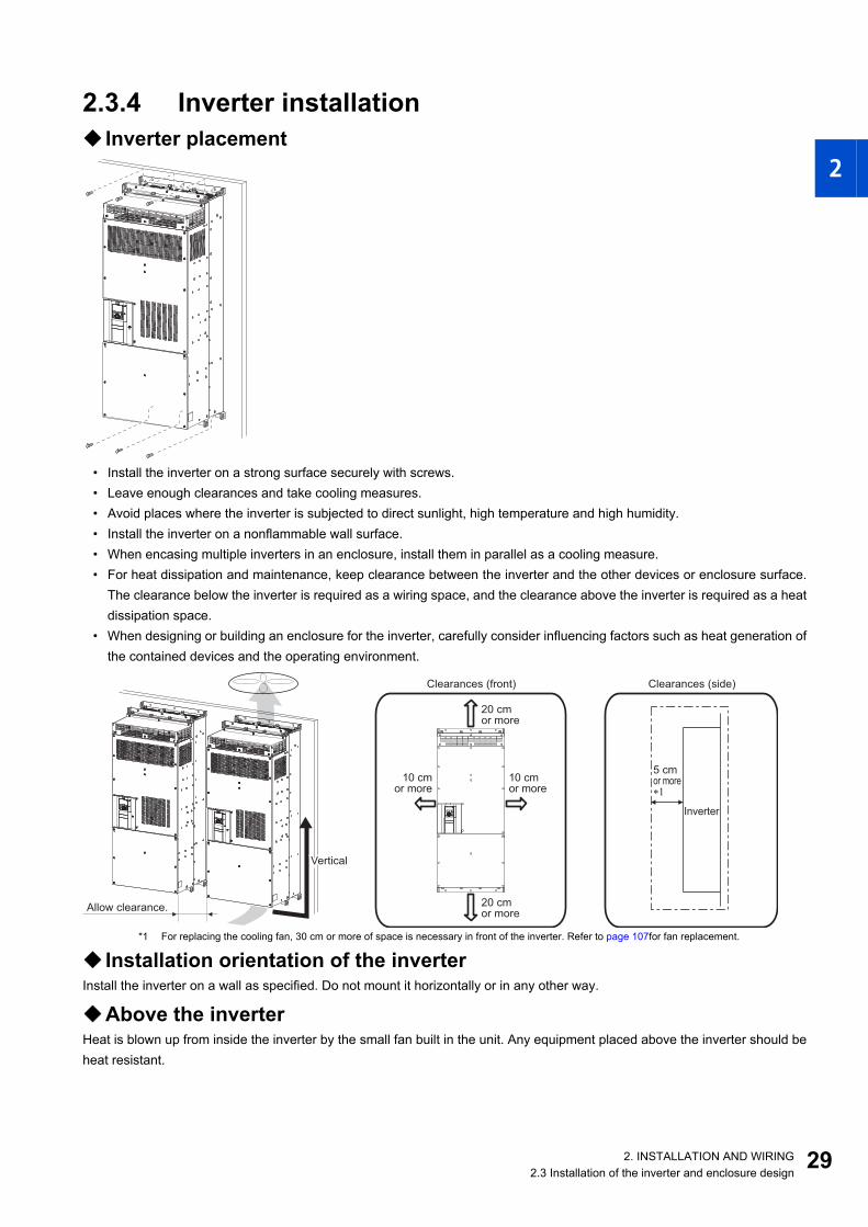
2.3.4 Inverter installation Inverter placement
• Install the inverter on a strong surface securely with screws.• Leave enough clearances and take cooling measures.• Avoid places where the inverter is subjected to direct sunlight, high temperature and high humidity.• Install the inverter on a nonflammable wall surface.• When encasing multiple inverters in an enclosure, install them in parallel as a cooling measure.• For heat dissipation and maintenance, keep clearance between the inverter and the other devices or enclosure surface.
The clearance below the inverter is required as a wiring space, and the clearance above the inverter is required as a heatdissipation space.
• When designing or building an enclosure for the inverter, carefully consider influencing factors such as heat generation ofthe contained devices and the operating environment.
*1 For replacing the cooling fan, 30 cm or more of space is necessary in front of the inverter. Refer to page 107for fan replacement.
Installation orientation of the inverterInstall the inverter on a wall as specified. Do not mount it horizontally or in any other way.
Above the inverterHeat is blown up from inside the inverter by the small fan built in the unit. Any equipment placed above the inverter should beheat resistant.
VerticalVerticalVertical
Allow clearance.
Clearances (side)Clearances (front)
Inverter
5 cmor more∗1
10 cmor more
10 cmor more
20 cmor more
20 cmor more
292. INSTALLATION AND WIRING2.3 Installation of the inverter and enclosure design
3
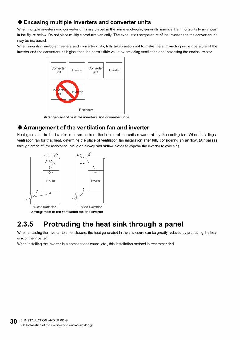
Encasing multiple inverters and converter unitsWhen multiple inverters and converter units are placed in the same enclosure, generally arrange them horizontally as shownin the figure below. Do not place multiple products vertically. The exhaust air temperature of the inverter and the converter unitmay be increased.When mounting multiple inverters and converter units, fully take caution not to make the surrounding air temperature of theinverter and the converter unit higher than the permissible value by providing ventilation and increasing the enclosure size.
Arrangement of the ventilation fan and inverterHeat generated in the inverter is blown up from the bottom of the unit as warm air by the cooling fan. When installing aventilation fan for that heat, determine the place of ventilation fan installation after fully considering an air flow. (Air passesthrough areas of low resistance. Make an airway and airflow plates to expose the inverter to cool air.)
2.3.5 Protruding the heat sink through a panelWhen encasing the inverter to an enclosure, the heat generated in the enclosure can be greatly reduced by protruding the heatsink of the inverter.When installing the inverter in a compact enclosure, etc., this installation method is recommended.
Arrangement of multiple inverters and converter units
Arrangement of the ventilation fan and inverter
Enclosure
InverterConverter
unit
InverterConverter
unit
InverterConverter
unit
Inverter Inverter
<Good example> <Bad example>
0 2. INSTALLATION AND WIRING2.3 Installation of the inverter and enclosure design

1
2
3
4
5
6
7
8
9
10
Panel cuttingCut the panel of the enclosure according to the inverter capacity.
Removal of the rear installation frameThe upper and lower installation frames are attached on the inverter (two for each position).Remove the rear installation frames on the top and bottom of the inverter as follows.
FR-A842-07700(315K)FR-A842-08660(355K)
FR-A842-09620(400K)FR-A842-10940(450K)FR-A842-12120(500K)
6-M10 screw520
Hole
2001
51
51
27
0
13
00
200
(Unit: mm)
660
Hole
240 2406-M10 screw
15
15
20
15
15
50
(Unit: mm)
Upper installation
frame (rear side)
Lower installation
frame (rear side)
312. INSTALLATION AND WIRING2.3 Installation of the inverter and enclosure design

3
Installation of the inverter on the enclosurePush the inverter heat sink part outside the enclosure, and fix the inverter to the panel with upper and lower installation frames.
NOTE• As the heat sink part protruded through the panel includes a cooling fan, this type of installation is not suitable for the
environment of water drops, oil, mist, dust, etc.• Be careful not to drop screws, dust etc. into the inverter and cooling fan section.
185mm
Exhausted air
There are finger guards behind the enclosure.
Therefore, the thickness of the panel should be
less than 10 mm (∗1) and also do not place
anything around finger guards to avoid contact
with the finger guards.
140mm
6m
m
Inverter
Inside the
enclosure
Enclosure
Installation
frame
Dimension of
the outside of
the enclosure
Cooling wind
Enclosure
Finger guard10mm∗1
2 2. INSTALLATION AND WIRING2.3 Installation of the inverter and enclosure design

1
2
3
4
5
6
7
8
9
10
2.4 Terminal connection diagrams
FM type
R1/L11S1/L21
PC
Frequency setting signals (Analog) 10E(+10V)
10(+5V)
2
(Analog common)
23
1
Auxiliaryinput
Terminal 4 input(Current input)
1
4
Frequency settingpotentiometer1/2W1kΩ
Running
Up to frequency
Overload
Frequency detection
Open collector output common Sink/source common
F/C(FM)
SD
Motor
Relay output 1(Fault output)
C1
B1
A1
UVW
Indicator(Frequency meter, etc.)
+ -
(-)
(+) Analog signal output(0 to ±10VDC)
Earth(Ground)
AM
5
0 to ±5VDC selectable0 to ±10VDC
Open collector output ∗8
Moving-coil type1mA full-scale
Calibrationresistor ∗11
Main circuit terminal
Control circuit terminal
0 to 5VDC0 to 10VDC
C2
B2
A2Relay output 2
Relay output ∗7
M
0 to 20mADC
0 to 5VDC0 to 10VDC
selectable
4 to 20mADC
SIN
K
SO
UR
CE
∗3
∗5
∗5
∗10
∗5
∗5
Connector for plug-in option connection
STF
STR
STP(STOP)
RH
RM
RL
JOG
RT
MRS X10
RES
AU
CS
SD
RUN
SU
IPF
OL
FU
SE
(+)(-)
5
(+)(-)
Sink logic
∗6
Earth (Ground)
N/-
P/+
Initial value
ONOFF
42
Safety stop signal
Safety monitor output
Safety monitor output common
So
SOC
Safety stop input (Channel 1)
Shortingwire
Safety stop input common
Safety stop input (Channel 2)
S1
S2
PC
SDSIC
+24SD
Brake unit(Option)
Jumper∗1
Connector 1 Connector 2∗12
Connector 3
24V external powersupply input
Common terminal
24VDC power supply(Common for external power supply transistor)
Forward rotation startReverse rotation start
Start self-holding selection
Middle speed
High speed
Low speed
Jog operation
Second function selection
Reset
Terminal 4 input selectionSelection of automatic restart
after instantaneous power failure
Control input signals (No voltage input allowed) ∗2
Multi-speedselection
Contact input common
Main circuit
Control circuit
PUconnector
USB A connector
USBmini Bconnector
Ethernetconnector
Voltage/currentinput switch
selectable
Initial value
Initial value
Output stop RDA
RDI
Converterunit
RSO
SE
N/-
P/+
IPF
RDB
FAN
R/L1S/L2T/L3
OH
RESSD
PC
+24C1
B1
A1
∗4
∗9
∗12
24V
24V
Output shutoffcircuit
Inverter
Fuse
332. INSTALLATION AND WIRING2.4 Terminal connection diagrams

3
*1 A jumper is installed across terminal R1/L11 and terminal P/+, and across terminal S1/L21 and terminal N/-. When using a separate power supplyfor the control circuit, remove the jumpers connected to terminals R1/L11 and S1/L21.
*2 The function of these terminals can be changed using the Input terminal function selection (Pr.178 to Pr.189).*3 Terminal JOG is also used as a pulse train input terminal. Use Pr.291 to choose JOG or pulse.*4 The X10 signal (NC contact input specification) is assigned to the terminal MRS in the initial setting. Set Pr.599 = "0" to change the input
specification of the X10 signal to NO contact.*5 Terminal input specifications can be changed by analog input specification switchover (Pr.73, Pr.267). To input voltage (0 to 5 V/0 to 10 V), set
the voltage/current input switch OFF. To input current (4 to 20 mA), set the voltage/current input switch ON. Terminals 10 and 2 are also used asa PTC input terminal. (Pr.561)
*6 It is recommended to use 2 W 1 kΩ when the frequency setting signal is changed frequently.*7 The function of these terminals can be changed using the Output terminal function selection (Pr.195 or Pr.196).*8 The function of these terminals can be changed using the Output terminal function selection (Pr.190 to Pr.194).*9 No function is assigned in the initial setting. Use Pr.192 for function assignment.*10 Terminal FM can be used to output pulse trains as open collector output by setting Pr.291.*11 Not required when calibrating the scale with the operation panel.*12 The option connector 2 cannot be used because the Ethernet board is installed in the initial status. To install a plug-in option to the option
connector 2, remove the Ethernet board. (However, Ethernet communication is disabled in that case.)
NOTE• To prevent a malfunction due to noise, keep the signal cables 10 cm or more away from the power cables. Also, keep the
cables of the main circuit for input and output separated.• After wiring, wire offcuts must not be left in the inverter.
Wire offcuts can cause a fault, failure or malfunction. Always keep the inverter clean.When drilling mounting holes in an enclosure etc., take caution not to allow chips and other foreign matter to enter the inverter.
• Set the switches of the voltage/current input selection switch assembly correctly. Incorrect setting may cause a fault, failure ormalfunction.
4 2. INSTALLATION AND WIRING2.4 Terminal connection diagrams

1
2
3
4
5
6
7
8
9
10
CA type
*1 A jumper is installed across terminal R1/L11 and terminal P/+, and across terminal S1/L21 and terminal N/-. When using separate power supplyfor the control circuit, remove the jumpers connected to terminals R1/L11 and S1/L21.
*2 The function of these terminals can be changed using the Input terminal function selection (Pr.178 to Pr.189).*3 Terminal JOG is also used as a pulse train input terminal. Use Pr.291 to choose JOG or pulse.
R1/L11S1/L21
PC
Frequency setting signals (Analog) 10E(+10V)
10(+5V)
2
(Analog common)
23
1
Auxiliaryinput
Terminal 4 input(Current input)
1
4
Frequency settingpotentiometer1/2W1kΩ
Running
Up to frequency
Overload
Frequency detection
Open collector output common Sink/source common
Motor
Relay output 1(Fault output)
C1
B1
A1
UVW
Earth(Ground)
0 to ±5VDC selectable0 to ±10VDC
Open collector output ∗8
Main circuit terminal
Control circuit terminal
0 to 5VDC0 to 10VDC
C2
B2
A2Relay output 2
Relay output ∗7
M
0 to 20mADC
0 to 5VDC0 to 10VDC
selectable
4 to 20mADC
SIN
K
SO
UR
CE
∗3
∗5
∗5
∗5
∗5
Connector for plug-in option connection
STF
STR
STP(STOP)
RH
RM
RL
JOG
RT
MRS X10
RES
AU
CS
SD
RUN
SU
IPF
OL
FU
SE
(+)(-)
5
(+)(-)
Source logic
∗6
Earth (Ground)
N/-
P/+
Initial value
ONOFF
42
Safety stop signal
Safety monitor output
Safety monitor output common
So (SO)
SOC
Safety stop input (Channel 1)
Shortingwire
Safety stop input common
Safety stop input (Channel 2)
S1
S2
PC
SDSIC
+24SD
Brake unit(Option)
Jumper∗1
Connector 1 Connector 2∗10
Connector 3
24V external powersupply input
Common terminal
24VDC power supply
Forward rotation startReverse rotation start
Start self-holding selection
Middle speed
High speed
Low speed
Jog operation
Second function selection
Reset
Terminal 4 input selection
Selection of automatic restartafter instantaneous power failure
Control input signals (No voltage input allowed) ∗2
Multi-speedselection
Contact input common
Main circuit
Control circuit
PUconnector
USB A connector
USBmini Bconnector
Voltage/currentinput switch
selectable
Initial value
Initial value
Output stop
24V
24V
Output shutoffcircuit
Common for external power supply transistor
(-)
(+) Analog signal output(0 to ±10VDC)
(-)
(+) Analog current output(0 to 20mADC)
AM
5
F/C(CA)
RDA
RDI
Converterunit
RSO
SE
N/-
P/+
IPF
RDB
FAN
R/L1S/L2T/L3
OH
RESSD
PC
+24C1
B1
A1
∗4
∗9
Ethernetconnector
∗10
Inverter
Fuse
352. INSTALLATION AND WIRING2.4 Terminal connection diagrams

3
*4 The X10 signal (NC contact input specification) is assigned to the terminal MRS in the initial setting. Set Pr.599 = "0" to change the inputspecification of the X10 signal to NO contact.
*5 Terminal input specifications can be changed by analog input specification switchover (Pr.73, Pr.267). To input voltage (0 to 5 V/0 to 10 V), setthe voltage/current input switch OFF. To input current (4 to 20 mA), set the voltage/current input switch ON. Terminals 10 and 2 are also used asa PTC input terminal. (Pr.561)
*6 It is recommended to use 2 W 1 kΩ when the frequency setting signal is changed frequently.*7 The function of these terminals can be changed using the Output terminal function selection (Pr.195 or Pr.196).*8 The function of these terminals can be changed using the Output terminal function selection (Pr.190 to Pr.194).*9 No function is assigned in the initial setting. Use Pr.192 to assign a function to the terminal.*10 The option connector 2 cannot be used because the Ethernet board is installed in the initial status. To install a plug-in option to the option
connector 2, remove the Ethernet board. (However, Ethernet communication is disabled in that case.)
NOTE• To prevent a malfunction due to noise, keep the signal cables 10 cm or more away from the power cables. Also, keep the
cables of the main circuit for input and output separated.• After wiring, wire offcuts must not be left in the inverter.
Wire offcuts can cause a fault, failure or malfunction. Always keep the inverter clean.When drilling mounting holes in an enclosure etc., take caution not to allow chips and other foreign matter to enter the inverter.
• Set the switches of the voltage/current input selection switch assembly correctly. Incorrect setting may cause a fault, failure ormalfunction.
6 2. INSTALLATION AND WIRING2.4 Terminal connection diagrams

1
2
3
4
5
6
7
8
9
10
Connection between the converter unit and the inverterWire correctly to ensure the command transmission from the converter unit to the inverter. Otherwise, the converter unit andthe inverter may be damaged.For the wiring length, refer to the following tables.
For the cable gauge of the cable across the main circuit terminals P/+ and N/- (P and P, N and N), refer to page 40.
*1 Do not install an MCCB across terminals P/+ and N/- (between terminals P and P/+ or between terminals N and N/-). Connecting the oppositepolarity of terminals N/- and P/+ will damage the inverter.
*2 For the X10 signal input, set "10" in any parameter from Pr.178 to Pr.189 (Input terminal function selection) to assign the function. (The X10signal is assigned to terminal MRS in the initial setting.)The state of contact at terminal MRS is initially set to be normally closed (NC). To change the contact state to normally open (NO), set Pr.599 = "0".
*3 For the X11 signal input, set "11" in any parameter from Pr.178 to Pr.189 (Input terminal function selection) to assign the function.For RS-485 or any other communication where the start command is only transmitted once, use the X11 signal to save the operation mode at thetime of an instantaneous power failure.
*4 Always connect terminal RDA of the converter unit and terminal MRS (X10) of the inverter, and terminal SE of the converter unit and terminal SD(sink logic) of the inverter. Otherwise, the converter unit may be damaged.
Location in the connection diagram Total wiring lengthBetween the terminals P and P and
the terminals N and N 50m or shorter
Other control signal cables 30m or shorter
InverterConverter unit
(FR-CC2)
MR1/L11S1/L21
R/L1
S/L2
T/L3
Powersupply
MCCB MCUVW
R1/L11S1/L21
P/+P/+N/-N/-
X11
RES
SD
IPF
RSO
SE
MRS(X10)∗2
RDA ∗4
∗4
∗1
∗3
RDB
372. INSTALLATION AND WIRING2.4 Terminal connection diagrams

3
2.5 Main circuit terminals
2.5.1 Details on the main circuit terminals of the inverter
2.5.2 Details on the main circuit terminals of the converter unit (FR-CC2)
Terminal symbol Terminal name Terminal function description Refer to page
U, V, W Inverter output Connect these terminals to a three-phase squirrel cage motor or a PM motor. —
R1/L11, S1/L21 Power supply for the control circuit
Connected to terminals P/+ and N/-. To retain the fault display and fault output, or to use the converter unit (FR-CC2), remove the jumpers installed in terminals R1/L11 and S1/L21, and apply external power supply to these terminals. When using a separate power supply connected to terminals R1/L11 and S1/L21, the necessary power capacity is 80 VA.
54
P/+, N/- Converter unit connection Connect the converter unit (FR-CC2), brake unit (FR-BU2), or high power factor converter (FR-HC2). 33, 70
Earth (ground) For earthing (grounding) the inverter chassis. Be sure to earth (ground) the inverter. 43
Terminal symbol Terminal name Terminal function description Refer to page
R/L1, S/L2, T/L3 AC power inputConnect these terminals to the commercial power supply. (When the converter unit is connected to the 12-phase rectifier power transformer, refer to the Instruction Manual of the FR-CC2.)
—
R1/L11, S1/L21 Power supply for the control circuit
Connected to the AC power supply terminals R/L1 and S/L2. To retain the fault display and fault output, remove the jumpers across terminals R/L1 and R1/L11 and across S/L2 and S1/L21, and apply external power to these terminals. When using a separate power supply connected to terminals R1/L11 and S1/L21, the necessary power capacity is 80 VA.
54
P/+, N/- Inverter connection Connected to the inverter terminals P/+ and N/-. 33
Earth (ground) For earthing (grounding) the converter unit chassis. This product must be earthed (grounded). 43
8 2. INSTALLATION AND WIRING2.5 Main circuit terminals

1
2
3
4
5
6
7
8
9
10
2.5.3 Terminal layout of the main circuit terminals, wiring of power supply and the motor
NOTE• Make sure the power cables are connected to the R/L1, S/L2, and T/L3 of the converter unit. (Phase need not be matched.)
Never connect the power cable to the U, V, and W of the inverter. Doing so will damage the inverter.• Connect the motor to the U, V, and W of the inverter. (The phases must be matched.)• When wiring cables to the main circuit conductor, tighten each nut from the right of the conductor as seen from the front of the
unit.When wiring two cables, place cables on both sides of the conductor. (Refer to the diagram below.)For wiring, use bolts (nuts) provided with the inverter.
• When wiring the main circuit conductor (R/L1, S/L2, T/L3) of the converter unit (FR-CC2), use bolts (nuts) for wiring the maincircuit before the conductor.
Converter unit Inverter
Jumper
Charge lamp
P/+N/-
To inverter
R1/L11 S1/L21
R/L1 S/L2 T/L3
Power supply
Charge lamp
Jumper
MMotor
N/-
P/+
To converter
unit
R1/L11 S1/L21
FR-CC2-H315K, H355K FR-CC2-H400K to H500K
Connect the cables here. Connect the cables here.
392. INSTALLATION AND WIRING2.5 Main circuit terminals

4
2.5.4 Applicable cables and wiring lengthSelect a recommended size cable to ensure that the voltage drop ratio is within 2%.If the wiring distance is long between the inverter and motor, the voltage drop in the main circuit will cause the motor torque todecrease especially at a low speed.The following tables show a selection example for the wiring length of 20 m (at 440 V input power supply).
• Converter unit (FR-CC2)
• Inverter (ND rating)
• Inverter (SLD rating)
• Inverter (LD rating)
Converter model FR-CC2-H-[]
Terminal screw size*4
Tightening torque (N·m)
Crimp terminal
Cable gauge
HIV cables, etc. (mm2)*1 AWG/MCM*2 PVC cables, etc. (mm2)*3
R/L1, S/L2, T/L3
R/L1, S/L2, T/L3 P/+, N/-
Earthing (grounding)
cable
R/L1, S/L2, T/L3
R/L1, S/L2, T/L3
Earthing (grounding)
cable315K M12 (M10) 46 150-12 2×150 2×150 100 2×300 2×150 150355K M12 (M10) 46 C2-200 2×200 2×200 100 2×350 2×185 2×95400K M12 (M10) 46 C2-200 2×200 2×200 100 2×400 2×185 2×95450K M12 (M10) 46 C2-250 2×250 2×250 100 2×500 2×240 2×120500K M12 (M10) 46 C2-200 3×200 3×200 2×100 2×500 2×240 2×120560K M12 (M10) 46 C2-200 3×200 3×200 2×100 3×350 3×185 2×150630K M12 (M10) 46 C2-200 3×200 3×200 2×100 3×400 3×185 2×150
Inverter model FR-
A842-[]
Terminal screw size*4
Tightening torque (N·m)
Crimp terminal
Cable gauge
HIV cables, etc. (mm2)*1 AWG/MCM*2 PVC cables, etc. (mm2)*3
U, V, W U, V, W P/+, N/-Earthing
(grounding) cable
U, V, W U, V, WEarthing
(grounding) cable
07700(315K) M12 (M10) 46 150-12 2×150 2×150 100 2×300 2×150 15008660(355K) M12 (M10) 46 C2-200 2×200 2×200 100 2×350 2×185 2×9509620(400K) M12 (M10) 46 C2-200 2×200 2×200 100 2×400 2×185 2×9510940(450K) M12 (M10) 46 C2-250 2×250 2×250 100 2×500 2×240 2×12012120(500K) M12 (M10) 46 C2-250 2×250 3×200 2×100 2×500 2×240 2×120
Inverter model FR-
A842-[]
Terminal screw size*4
Tightening torque (N·m)
Crimp terminal
Cable gauge
HIV cables, etc. (mm2)*1 AWG/MCM*2 PVC cables, etc. (mm2)*3
U, V, W U, V, W P/+, N/-Earthing
(grounding) cable
U, V, W U, V, WEarthing
(grounding) cable
07700(315K) M12 (M10) 46 C2-200 2×200 2×200 100 2×400 2×185 2×9508660(355K) M12 (M10) 46 C2-250 2×250 2×250 100 2×500 2×240 2×12009620(400K) M12 (M10) 46 C2-250 2×250 3×200 2×100 2×500 2×240 2×12010940(450K) M12 (M10) 46 C2-200 3×200 3×200 2×100 3×350 3×185 2×15012120(500K) M12 (M10) 46 C2-200 3×200 3×200 2×100 3×400 3×185 2×150
Inverter model FR-
A842-[]
Terminal screw size*4
Tightening torque (N·m)
Crimp terminal
Cable gauge
HIV cables, etc. (mm2)*1 AWG/MCM*2 PVC cables, etc. (mm2)*3
U, V, W U, V, W P/+, N/-Earthing
(grounding) cable
U, V, W U, V, WEarthing
(grounding) cable
07700(315K) M12 (M10) 46 C2-200 2×200 2×200 100 2×350 2×185 2×9508660(355K) M12 (M10) 46 C2-200 2×200 2×200 100 2×400 2×185 2×9509620(400K) M12 (M10) 46 C2-250 2×250 2×250 100 2×500 2×240 2×12010940(450K) M12 (M10) 46 C2-250 2×250 3×200 2×100 2×500 2×240 2×12012120(500K) M12 (M10) 46 C2-200 3×200 3×200 2×100 3×350 3×185 2×150
0 2. INSTALLATION AND WIRING2.5 Main circuit terminals

1
2
3
4
5
6
7
8
9
10
• Inverter (HD rating)
*1 The recommended cable size is that of the cable (LMFC (heat resistant flexible cross-linked polyethylene insulated cable), etc.) with continuousmaximum permissible temperature of 90°C or higher. It assumes a surrounding air temperature of 50°C or lower and in-enclosure wiring.
*2 It is the gauge of the cable with continuous maximum permissible temperature of 90°C (THHN cable). It assumes a surrounding air temperatureof 40°C or lower and in-enclosure wiring.(For the use in the United States or Canada, refer to page 130.)
*3 The recommended cable size is that of the cable (XLPE cable) with continuous maximum permissible temperature of 90°C. It assumes asurrounding air temperature of 40°C or lower and in-enclosure wiring.(Selection example mainly for use in Europe.)
*4 The screw size for terminals R/L1, S/L2, T/L3, U, V, W, P/+, N/-, and the earthing (grounding) terminal are shown.Screw size for earthing (grounding) is indicated in parentheses.
The line voltage drop can be calculated by the following formula:
Line voltage drop [V] =
Use a larger diameter cable when the wiring distance is long or when it is desired to decrease the voltage drop (torquereduction) in the low speed range.
NOTE• Tighten the terminal screw to the specified torque.
A screw that has been tightened too loosely can cause a short circuit or malfunction.A screw that has been tightened too tightly can cause a short circuit or malfunction due to the unit breakage.
• Use crimp terminals with insulation sleeves to wire the power supply and motor.
Inverter model FR-
A842-[]
Terminal screw size*4
Tightening torque (N·m)
Crimp terminal
Cable gauge
HIV cables, etc. (mm2)*1 AWG/MCM*2 PVC cables, etc. (mm2)*3
U, V, W U, V, W P/+, N/-Earthing
(grounding) cable
U, V, W U, V, WEarthing
(grounding) cable
07700(315K) M12 (M10) 46 150-12 2×125 2×150 100 2×250 2×120 15008660(355K) M12 (M10) 46 150-12 2×150 2×150 100 2×300 2×150 15009620(400K) M12 (M10) 46 C2-200 2×200 2×200 100 2×350 2×185 2×9510940(450K) M12 (M10) 46 C2-200 2×200 2×200 100 2×400 2×185 2×9512120(500K) M12 (M10) 46 C2-250 2×250 2×250 100 2×500 2×240 2×120
× wire resistance [mΩ/m] × wiring distance [m] × current [A]
1000
412. INSTALLATION AND WIRING2.5 Main circuit terminals

4
Total wiring lengthWith induction motorConnect one or more general-purpose motors within the total wiring length 500 m. (The wiring length should be 100 m or shorterunder Vector control.)
When driving a 400 V class motor by the inverter, surge voltages attributable to the wiring constants may occur at the motorterminals, deteriorating the insulation of the motor. In this case, take one of the following measure.
• Use a "400 V class inverter-driven insulation-enhanced motor" and set Pr.72 PWM frequency selection according to thewiring length.
• If the motor capacity is 280 kW or lower, connect the sine wave filter (MT-BSL/BSC) to the output side.
With PM motorUse the wiring length of 100 m or shorter when connecting a PM motor.Use one PM motor for one inverter. Multiple PM motors cannot be connected to an inverter.When the wiring length exceeds 50 m for a 400 V class motor driven by an inverter under PM sensorless vector control, set "9"(6 kHz) or less in Pr.72 PWM frequency selection.
NOTE• Especially for long-distance wiring, the inverter may be affected by a charging current caused by stray capacitances of the
wiring, leading to an activation of the overcurrent protection, malfunction of the fast-response current limit operation, or evento an inverter failure. It may also cause a malfunction or fault of the equipment connected ON the inverter output side. If thefast-response current limit function malfunctions, disable the function. (For the details of Pr.156 Stall prevention operationselection, refer to the FR-A800 Instruction Manual (Detailed).)
• A sine wave filter (MT-BSL/BSC) can be used under V/F control. Do not use the filters under different control methods.• For the details of Pr.72 PWM frequency selection, refer to the Instruction Manual (Detailed).• Refer to page 88 to drive a 400 V class motor by an inverter.• The carrier frequency is limited during PM sensorless vector control. (Refer to the Instruction Manual (Detailed).)
Total wiring length
Wiring length 100 m or shorter Wiring length longer than 100 m6 (6 kHz) or lower 4 (4 kHz) or lower
500 m or less
300 m
300 m
300 m+300 m=600 m
2 2. INSTALLATION AND WIRING2.5 Main circuit terminals

1
2
3
4
5
6
7
8
9
10
2.5.5 Earthing (grounding) precautions• Always earth (ground) the motor, the inverter, and the converter unit.
Purpose of earthing (grounding)Generally, an electrical apparatus has an earth (ground) terminal, which must be connected to the ground before use. An electrical circuit is usually insulated by an insulating material and encased. However, it is impossible to manufacture aninsulating material that can shut off a leakage current completely, and actually, a slight current flows into the case. The purposeof earthing (grounding) the case of an electrical apparatus is to prevent operators from getting an electric shock from thisleakage current when touching it. To avoid the influence of external noises, the earthing (grounding) is important to EMI-sensitive equipment that handle low-level signals or operate very fast such as audio equipment, sensors, computers.
Earthing (grounding) system to be establishedAs described previously, the purpose of earthing (grounding) is roughly classified into the electrical shock prevention and theprevention of malfunction due to the influence of electromagnetic noise. These two purposes should be clearly distinguished,and the appropriate earth (ground) system must be established to prevent the leakage current having the inverter's highfrequency components from reversing through another earth (ground) point for malfunction prevention by following theseinstructions:
• Make the separate earth (ground) connection (I) for high frequency products such as the inverter from any other devices(EMI-sensitive devices described above) wherever possible.Establishing adequate common (single-point) earth (ground) system (II) shown in the following figure is allowed only incases where the separate earth (ground) system (I) is not feasible. Do not make inadequate common (single-point) earth(ground) connection (III).As leakage currents containing many high frequency components flows into the earthing (grounding) cables of the inverterand peripheral devices (including a motor), the inverter must also be earthed (grounded) separately from EMI-sensitivedevices described above.In a high building, it may be effective to use its iron structure frames as earthing (grounding) electrode for EMI preventionin order to separate from the earth (ground) system for electric shock prevention.
• Earthing (grounding) must conform to the requirements of national and local safety regulations and electrical codes (NECsection 250, IEC 61140 class 1 and other applicable standards).A neutral-point earthed (grounded) power supply must be used to be compliant with EN standard.
• Use the thickest possible earthing (grounding) cable. The earthing (grounding) cable should be the size indicated in thetable on page 40.
• The earthing (grounding) point should be as close as possible to the inverter, and the earth (ground) wire length should beas short as possible.
• Run the earthing (grounding) cable as far away as possible from the I/O wiring of the EMI-sensitive devices and run themin parallel in the minimum distance.
NOTE• To be compliant with the EU Directive (Low Voltage Directive), refer to page 127.
Inverter/converter
unit
Other
equipment
(I) Independent earthing (grounding).......Good
Other
equipment
(II) Common earthing (grounding).......Good
Inverter/converter
unit
Inverter/converter
unit
Other
equipment
(III) Common earthing (grounding) cable.......Not allowed
432. INSTALLATION AND WIRING2.5 Main circuit terminals
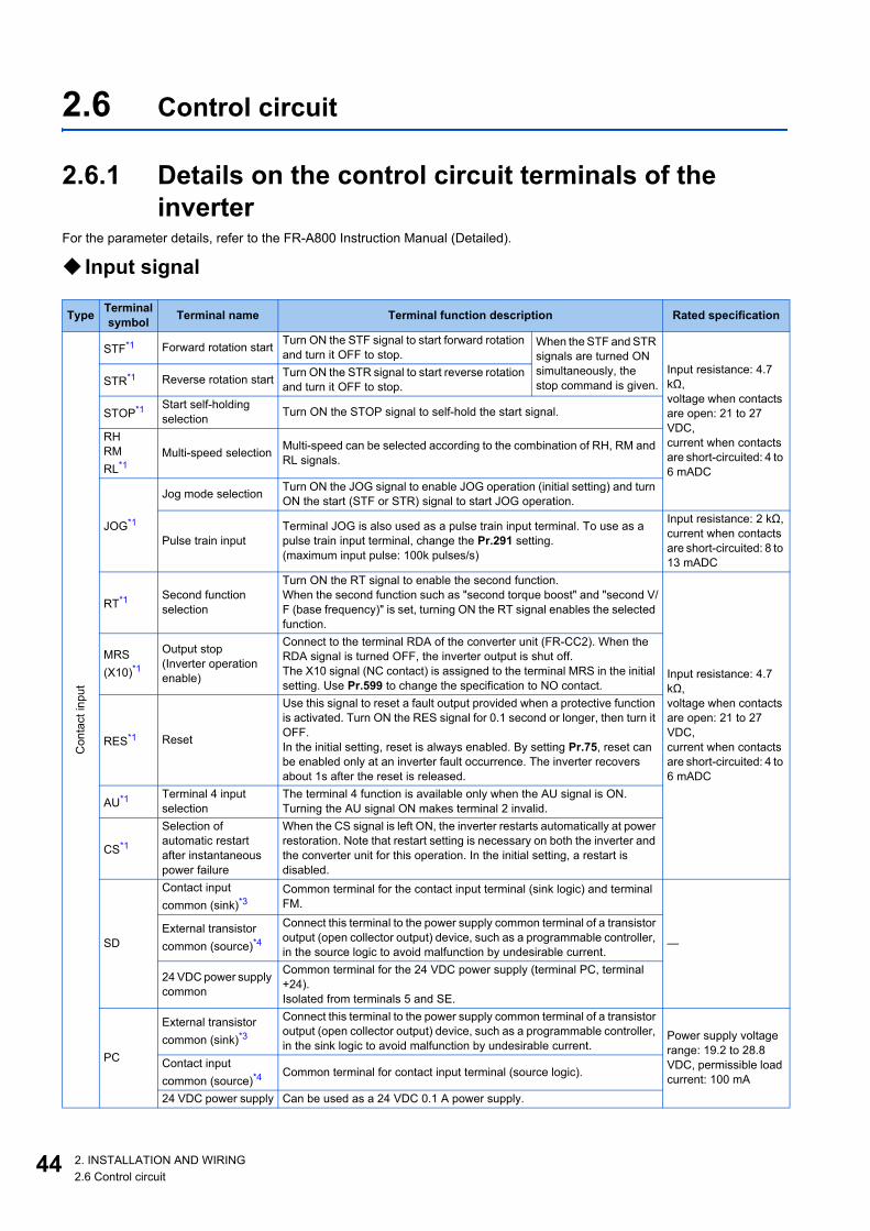
4
2.6 Control circuit
2.6.1 Details on the control circuit terminals of the inverter
For the parameter details, refer to the FR-A800 Instruction Manual (Detailed).
Input signal
Type Terminal symbol Terminal name Terminal function description Rated specification
Con
tact
inpu
t
STF*1 Forward rotation start Turn ON the STF signal to start forward rotation and turn it OFF to stop.
When the STF and STR signals are turned ON simultaneously, the stop command is given.
Input resistance: 4.7 kΩ,voltage when contacts are open: 21 to 27 VDC,current when contacts are short-circuited: 4 to 6 mADC
STR*1 Reverse rotation start Turn ON the STR signal to start reverse rotation and turn it OFF to stop.
STOP*1 Start self-holding selection Turn ON the STOP signal to self-hold the start signal.
RHRMRL*1
Multi-speed selection Multi-speed can be selected according to the combination of RH, RM and RL signals.
JOG*1
Jog mode selection Turn ON the JOG signal to enable JOG operation (initial setting) and turn ON the start (STF or STR) signal to start JOG operation.
Pulse train inputTerminal JOG is also used as a pulse train input terminal. To use as a pulse train input terminal, change the Pr.291 setting. (maximum input pulse: 100k pulses/s)
Input resistance: 2 kΩ,current when contacts are short-circuited: 8 to 13 mADC
RT*1 Second function selection
Turn ON the RT signal to enable the second function. When the second function such as "second torque boost" and "second V/F (base frequency)" is set, turning ON the RT signal enables the selected function.
Input resistance: 4.7 kΩ,voltage when contacts are open: 21 to 27 VDC,current when contacts are short-circuited: 4 to 6 mADC
MRS(X10)*1
Output stop(Inverter operation enable)
Connect to the terminal RDA of the converter unit (FR-CC2). When the RDA signal is turned OFF, the inverter output is shut off. The X10 signal (NC contact) is assigned to the terminal MRS in the initial setting. Use Pr.599 to change the specification to NO contact.
RES*1 Reset
Use this signal to reset a fault output provided when a protective function is activated. Turn ON the RES signal for 0.1 second or longer, then turn it OFF. In the initial setting, reset is always enabled. By setting Pr.75, reset can be enabled only at an inverter fault occurrence. The inverter recovers about 1s after the reset is released.
AU*1 Terminal 4 input selection
The terminal 4 function is available only when the AU signal is ON. Turning the AU signal ON makes terminal 2 invalid.
CS*1
Selection of automatic restart after instantaneous power failure
When the CS signal is left ON, the inverter restarts automatically at power restoration. Note that restart setting is necessary on both the inverter and the converter unit for this operation. In the initial setting, a restart is disabled.
SD
Contact input common (sink)*3
Common terminal for the contact input terminal (sink logic) and terminal FM.
—External transistor common (source)*4
Connect this terminal to the power supply common terminal of a transistor output (open collector output) device, such as a programmable controller, in the source logic to avoid malfunction by undesirable current.
24 VDC power supply common
Common terminal for the 24 VDC power supply (terminal PC, terminal +24). Isolated from terminals 5 and SE.
PC
External transistor common (sink)*3
Connect this terminal to the power supply common terminal of a transistor output (open collector output) device, such as a programmable controller, in the sink logic to avoid malfunction by undesirable current.
Power supply voltage range: 19.2 to 28.8 VDC, permissible load current: 100 mA
Contact input common (source)*4
Common terminal for contact input terminal (source logic).
24 VDC power supply Can be used as a 24 VDC 0.1 A power supply.
4 2. INSTALLATION AND WIRING2.6 Control circuit
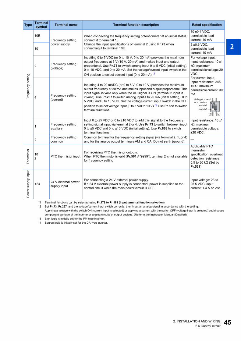
1
2
3
4
5
6
7
8
9
10
*1 Terminal functions can be selected using Pr.178 to Pr.189 (Input terminal function selection).*2 Set Pr.73, Pr.267, and the voltage/current input switch correctly, then input an analog signal in accordance with the setting.
Applying a voltage with the switch ON (current input is selected) or applying a current with the switch OFF (voltage input is selected) could causecomponent damage of the inverter or analog circuits of output devices. (Refer to the Instruction Manual (Detailed).)
*3 Sink logic is initially set for the FM-type inverter.*4 Source logic is initially set for the CA-type inverter.
Freq
uenc
y se
tting
10EFrequency setting power supply
When connecting the frequency setting potentiometer at an initial status, connect it to terminal 10. Change the input specifications of terminal 2 using Pr.73 when connecting it to terminal 10E.
10 ±0.4 VDC,permissible load current: 10 mA
105 ±0.5 VDC,permissible load current: 10 mA
2 Frequency setting (voltage)
Inputting 0 to 5 VDC (or 0 to 10 V, 0 to 20 mA) provides the maximum output frequency at 5 V (10 V, 20 mA) and makes input and output proportional. Use Pr.73 to switch among input 0 to 5 VDC (initial setting), 0 to 10 VDC, and 0 to 20 mA. Set the voltage/current input switch in the ON position to select current input (0 to 20 mA).*2
For voltage input, Input resistance: 10 ±1 kΩ, maximum permissible voltage: 20 VDC.For current input, Input resistance: 245 ±5 Ω, maximum permissible current: 30 mA.
4 Frequency setting (current)
Inputting 4 to 20 mADC (or 0 to 5 V, 0 to 10 V) provides the maximum output frequency at 20 mA and makes input and output proportional. This input signal is valid only when the AU signal is ON (terminal 2 input is invalid). Use Pr.267 to switch among input 4 to 20 mA (initial setting), 0 to 5 VDC, and 0 to 10 VDC. Set the voltage/current input switch in the OFF position to select voltage input (0 to 5 V/0 to 10 V).*2 Use Pr.858 to switch terminal functions.
1 Frequency setting auxiliary
Input 0 to ±5 VDC or 0 to ±10 VDC to add this signal to the frequency setting signal input via terminal 2 or 4. Use Pr.73 to switch between input 0 to ±5 VDC and 0 to ±10 VDC (initial setting). Use Pr.868 to switch terminal functions.
Input resistance: 10 ±1 kΩ, maximum permissible voltage: ±20 VDC.
5 Frequency setting common
Common terminal for the frequency setting signal (via terminal 2, 1, or 4) and for the analog output terminals AM and CA. Do not earth (ground). —
Ther
mis
tor
102 PTC thermistor input
For receiving PTC thermistor outputs. When PTC thermistor is valid (Pr.561 ≠ "9999"), terminal 2 is not available for frequency setting.
Applicable PTC thermistor specification, overheat detection resistance: 0.5 to 30 kΩ (Set by Pr.561)
Pow
er s
uppl
y in
put
+24 24 V external power supply input
For connecting a 24 V external power supply. If a 24 V external power supply is connected, power is supplied to the control circuit while the main power circuit is OFF.
Input voltage: 23 to 25.5 VDC, input current: 1.4 A or less
Type Terminal symbol Terminal name Terminal function description Rated specification
Voltage/current
input switch
2 4
switch1
switch2
452. INSTALLATION AND WIRING2.6 Control circuit

4
Output signal
*1 Terminal functions can be selected using Pr.190 to Pr.196 (Output terminal function selection).*2 Terminal FM is provided in the FM-type inverter.*3 Terminal CA is provided in the CA-type inverter.
Type Terminal symbol Terminal name Terminal function description Rated specification
Rel
ay
A1,B1,C1*1
Relay output 1 (fault output)
1 changeover contact output that indicates that an inverter's protective function has been activated and the outputs are stopped. Fault: discontinuity across B and C (continuity across A and C), Normal: continuity across B and C (discontinuity across A and C)
Contact capacity: 230 VAC 0.3 A(power factor = 0.4), 30 VDC 0.3 AA2,
B2,C2*1
Relay output 2 1 changeover contact output
Ope
n co
llect
or
RUN*1 Inverter runningThe output is in LOW state when the inverter output frequency is equal to or higher than the starting frequency (initial value: 0.5 Hz). The output is in HIGH state during stop or DC injection brake operation.
Permissible load: 24 VDC (27 VDC at maximum) 0.1 A(The voltage drop is 2.8 V at maximum while the signal is ON.)The open collector transistor is ON (conductive) in LOW state. The transistor is OFF (not conductive) in HIGH state.
SU*1 Up to frequency
The output is in LOW state when the output frequency is within the set frequency range ±10% (initial value). The output is in HIGH state during acceleration/deceleration and at a stop.
Fault code (4 bits) output.
OL*1 Overload alarm
The output is in LOW state when stall prevention is activated by the stall prevention function. The output is in HIGH state when stall prevention is canceled.
IPF*1 Open collector output No function is assigned in the initial setting. Use Pr.192 to assign a function to the terminal.
FU*1 Frequency detection
The output is in LOW state when the inverter output frequency is equal to or higher than the preset detection frequency, and is in HIGH state when it is less than the preset detection frequency.
SE Open collector output common Common terminal for terminals RUN, SU, OL, IPF, FU —
Puls
e
FM*2
For meter
Among several monitor items such as output frequency, select one to output it via these terminals. The signal is not output during an inverter reset. The size of output signal is proportional to the magnitude of the corresponding monitor item. Use Pr.55, Pr.56, and Pr.866 to set full scales for the monitored output frequency, output current, and torque.
Output item: output frequency (initial setting)
Permissible load current: 2 mA, pulse for full scale: 1440 pulses/s
NPN open collector output
This terminal can be used for open collector outputs by setting Pr.291.
Maximum output pulse: 50k pulses/s,permissible load current: 80 mA
Anal
og
AM Analog voltage outputOutput item: output frequency (initial setting)
Output signal: 0 ±10 VDC,permissible load current: 1 mA(load impedance 10 kΩ or more), resolution: 8 bits
CA*3 Analog current output
Load impedance: 200 to 450 Ω,output signal: 0 to 20 mADC
6 2. INSTALLATION AND WIRING2.6 Control circuit

1
2
3
4
5
6
7
8
9
10
Communication
Safety stop signal
2.6.2 Details on the control circuit terminals of the converter unit (FR-CC2).
For the parameter details, refer to the FR-CC2 Instruction Manual.
Type Terminal symbol Terminal name Terminal function description
Ethe
rnet
— Ethernet connector
Communication can be made via Ethernet.Category: 100BASE-TX/10BASE-TData transmission speed: 100 Mbps (100BASE-TX) / 10 Mbps (10BASE-T)Transmission method: BasebandMaximum segment length: 100 m between the hub and the inverterNumber of cascade connection stages: Up to 2 (100BASE-TX) / up to 4 (10BASE-T)Interface: RJ-45Number of interfaces available: 1IP version: IPv4
RS-
485
— PU connector
RS-485 communication can be made through the PU connector (For connection on a 1:1 basis only)Conforming standard: EIA-485 (RS-485)Transmission format: Multidrop linkCommunication speed: 4800 to 115200 bpsWiring length: 500 m
USB —
USB A connector
A connector (receptacle).Plug a USB memory device into this connector to copy parameter settings or use the trace function.
Interface: conforms to USB 1.1 (USB 2.0 full-speed compatible)Transmission speed: 12 Mbps
USB B connector
Mini B connector (receptacle).By connecting the inverter to a personal computer via this connector, FR Configurator2 installed on the computer can be used for setting the inverter, or monitoring or testing the inverter operation.
Terminal symbol Terminal name Terminal function description Rated specification Refer to
page
S1 Safety stop input(Channel 1)
Use terminals S1 and S2 to receive the safety stop signal input from the safety relay module. Terminals S1 and S2 can be used at a time (dual channel). The Inverter judges the condition of the internal safety circuit from the status (shorted/opened) between terminals S1 and SIC, or between S2 and SIC. When the status is opened, the inverter output is shut off. In the initial status, terminal S1 and S2 are shorted with terminal PC by shorting wires. Terminal SIC is shorted with terminal SD. Remove the shorting wires and connect the safety relay module when using the safety stop function.
Input resistance: 4.7 kΩ,input current: 4 to 6 mADC (with 24 VDC input)
58
S2 Safety stop input(Channel 2)
SIC Safety stop input terminal common Common terminal for terminals S1 and S2. —
So (SO)Safety monitor output (open collector output)
The output status varies depending on the input status of the safety stop signals. The output is in HIGH state during occurrence of the internal safety circuit failure. The output is in LOW state otherwise. (The open collector transistor is ON (conductive) in LOW state. The transistor is OFF (not conductive) in HIGH state.) Refer to the Safety Stop Function Instruction Manual if the output becomes in HIGH state even though both terminals S1 and S2 are open. (Contact your sales representative for this manual.)
Permissible load: 24 VDC (27 VDC at maximum), 0.1 A(The voltage drop is 3.4 V at maximum while the signal is ON.)
SOCSafety monitor output terminal common
Common terminal for terminal So (SO). —
472. INSTALLATION AND WIRING2.6 Control circuit

4
Input signal
*1 Terminal functions can be selected using Pr.178, Pr.187, or Pr.189 (Output terminal function selection).
Output signal
*1 Terminal functions can be selected using Pr.190 to Pr.195 (Output terminal function selection).
Type Terminal symbol Terminal name Terminal function description Rated specification
Con
tact
inpu
t
RES*1 Reset
Use this signal to reset a fault output provided when a protective function is activated. Turn ON the RES signal for 0.1 second or longer, then turn it OFF. In the initial setting, reset is always enabled. By setting Pr.75, reset can be enabled only at fault occurrence of the converter unit. The inverter recovers about 1s after the reset is released.
Input resistance: 4.7 kΩ,voltage when contacts are open: 21 to 27 VDC,current when contacts are short-circuited: 4 to 6 mADC
OH*1 External thermal relay input
The External thermal relay input (OH) signal is used when using the external thermal relay or the thermal protector built into the motor to protect the motor from overheating. When the thermal relay is activated, the inverter output is shut off by the external thermal relay operation (E.OHT).
RDI*1 Contact input Use Pr.178 to assign a function to the terminal.
SD
Contact input common (sink)
Common terminal for the contact input terminal (sink logic) and terminal FM.
—External transistor common (source)
Connect this terminal to the power supply common terminal of a transistor output (open collector output) device, such as a programmable controller, in the source logic to avoid malfunction by undesirable current.
24 VDC power supply common
Common terminal for the 24 VDC power supply (terminal PC, terminal +24). Isolated from terminals 5 and SE.
PC
External transistor common (sink)
Connect this terminal to the power supply common terminal of a transistor output (open collector output) device, such as a programmable controller, in the sink logic to avoid malfunction by undesirable current.
Power supply voltage range: 19.2 to 28.8 VDC, permissible load current: 100 mA
Contact input common (source) Common terminal for contact input terminal (source logic).
24 VDC power supply Can be used as a 24 VDC 0.1 A power supply.
Pow
er s
uppl
y in
put
+24 24 V external power supply input
For connecting a 24 V external power supply. If a 24 V external power supply is connected, power is supplied to the control circuit while the main power circuit is OFF.
Input voltage: 23 to 25.5 VDC, input current: 1.4 A or less
Type Terminal symbol Terminal name Terminal function description Rated specification
Rel
ay
A1,B1,C1*1
Relay output 1 (fault output)
1 changeover contact output that indicates that the protective function of the converter unit has been activated and the outputs are stopped. Fault: discontinuity across B and C (continuity across A and C), Normal: continuity across B and C (discontinuity across A and C)
Contact capacity: 230 VAC 0.3 A(power factor = 0.4), 30 VDC 0.3 A
88R,88S For manufacturer setting. Do not use.
Ope
n co
llect
or
RDA*1 Inverter operation enable (NO contact)
Switched to LOW when the converter unit operation is ready. Assign the signal to the terminal MRS (X10) of the inverter. The inverter can be started when the RDA status is LOW.
Permissible load: 24 VDC (27 VDC at maximum) 0.1 A(The voltage drop is 2.8 V at maximum while the signal is ON.)The open collector transistor is ON (conductive) in LOW state. The transistor is OFF (not conductive) in HIGH state.
RDB*1 Inverter operation enable (NC contact)
Switched to LOW when a converter unit fault occurs or the converter is reset. The inverter can be started when the RDB status is HIGH.
RSO*1 Inverter resetSwitched to LOW when the converter is reset (RES-ON). Assign the signal to the terminal RES of the inverter. The inverter is reset when it is connected with the RSO status LOW.
IPF*1 Instantaneous power failure Switched to LOW when an instantaneous power failure is detected.
FAN*1 Cooling fan fault Switched to LOW when a cooling fan fault occurs.
SE Open collector output common
Common terminal for terminals RDA, RDB, RSO, IPF, FAN Connect this terminal to the terminal SD (sink logic) or PC (source logic) of the inverter.
—
8 2. INSTALLATION AND WIRING2.6 Control circuit
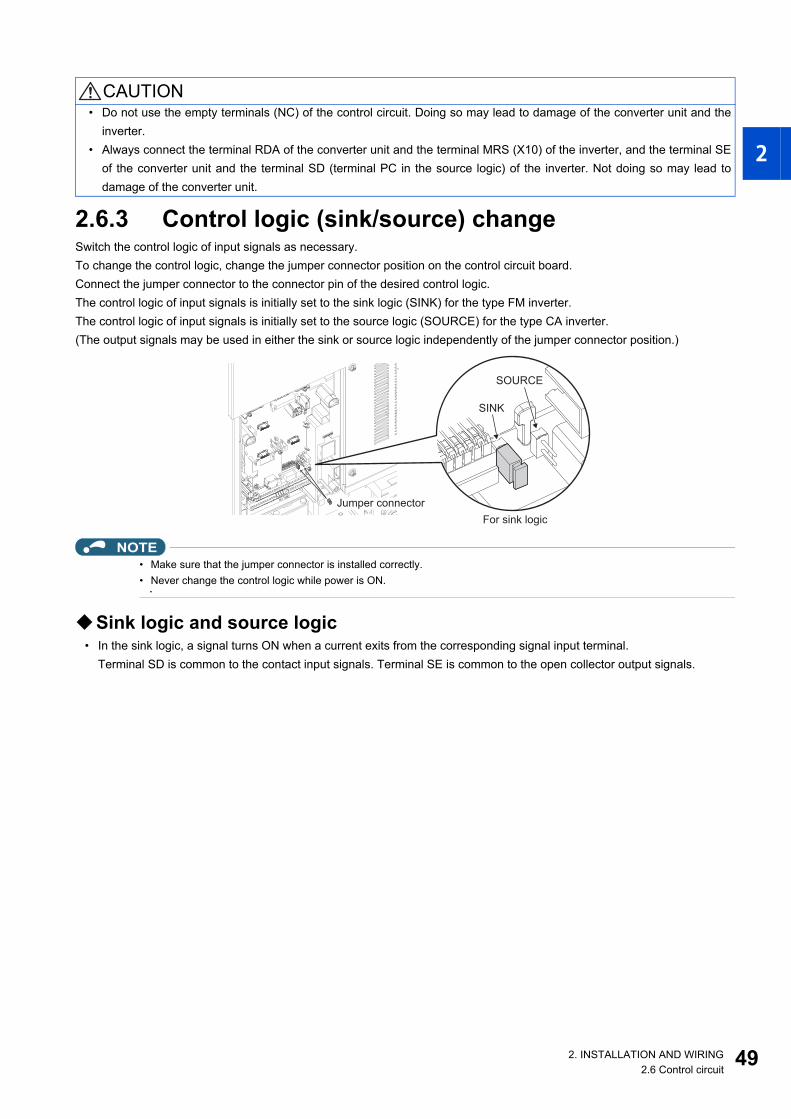
1
2
3
4
5
6
7
8
9
10
2.6.3 Control logic (sink/source) changeSwitch the control logic of input signals as necessary.To change the control logic, change the jumper connector position on the control circuit board.Connect the jumper connector to the connector pin of the desired control logic.The control logic of input signals is initially set to the sink logic (SINK) for the type FM inverter.The control logic of input signals is initially set to the source logic (SOURCE) for the type CA inverter.(The output signals may be used in either the sink or source logic independently of the jumper connector position.)
NOTE• Make sure that the jumper connector is installed correctly.• Never change the control logic while power is ON.
Sink logic and source logic• In the sink logic, a signal turns ON when a current exits from the corresponding signal input terminal.
Terminal SD is common to the contact input signals. Terminal SE is common to the open collector output signals.
CAUTION• Do not use the empty terminals (NC) of the control circuit. Doing so may lead to damage of the converter unit and the
inverter.• Always connect the terminal RDA of the converter unit and the terminal MRS (X10) of the inverter, and the terminal SE
of the converter unit and the terminal SD (terminal PC in the source logic) of the inverter. Not doing so may lead todamage of the converter unit.
Jumper connectorJumper connectorJumper connector
For sink logic
SOURCE
SINK
492. INSTALLATION AND WIRING2.6 Control circuit

5
• In the source logic, a signal turns ON when a current enters into the corresponding signal input terminal.Terminal PC is common to the contact input signals. Terminal SE is common to the open collector output signals.
• When using an external power supply for transistor output
Current
PC
STFR
STRR
Source logic
Source
connector
Current
SD
STFR
STRR
Sink
connector
Sink logic
Current flow concerning the input/output signal when sink logic is selected
Current flow concerning the input/output signal when source logic is selected
DC input (source type)
<Example: QX80>
24 VDC
RUN
SE
TB1
TB18
R
Inverter
R
Current flow
+ -+-
DC input (sink type)
<Example: QX40>
Inverter
24 VDC
RUN
SE
TB1
TB17
R
R
Current flow
Sink logicUse terminal PC as a common terminal, and perform wiring asfollows. (Do not connect terminal SD on the inverter with theterminal of 0 V for the external power supply. When usingterminals PC-SD as a 24 VDC power supply, do not install anexternal power supply in parallel with the inverter. Doing somay cause a malfunction in the inverter due to undesirablecurrents.)
Source logicUse terminal SD as a common terminal, and perform wiring asfollows. (Do not connect terminal PC on the inverter with theterminal of +24 V for the external power supply. When usingterminals PC-SD as a 24 VDC power supply, do not install anexternal power supply in parallel with the inverter. Doing somay cause a malfunction in the inverter due to undesirablecurrents.)
QY40P type transistor
output unit
TB1
TB2
TB17
TB18
24 VDC SD
PC
STR
STF
Inverter
24 VDC
(SD)
Current flow
Constant voltage circuit
QY80 type transistor
output unit
Constant
voltage
circuit
PC
TB1
TB2
TB17Fuse
TB18
STF
STR
SD
Inverter
24 VDC
(SD)
24
VD
C
Current flow
0 2. INSTALLATION AND WIRING2.6 Control circuit

1
2
3
4
5
6
7
8
9
10
2.6.4 Wiring of inverter control circuitControl circuit terminal layout
*1 This terminal operates as terminal FM for the type FM inverter. For the type CA inverter, the terminal operates as terminal CA.*2 The X10 signal is assigned to terminal MRS in the initial setting.*3 No function is assigned in the initial setting.
Wiring methodPower supply connectionFor the control circuit wiring, strip off the sheath of a cable, and use it with a blade terminal. For a single wire, strip off the sheathof the wire and apply directly.Insert the blade terminal or the single wire into a socket of the terminal.
1. Strip off the sheath for the below length. If the length of the sheath peeled is too long, a short circuit may occur withneighboring wires. If the length is too short, wires might come off.Wire the stripped cable after twisting it to prevent it from becoming loose. Do not solder it.
2. Crimp the blade terminal.Insert wires to a blade terminal, and check that the wires come out for about 0 to 0.5 mm from a sleeve.Check the condition of the blade terminal after crimping. Do not use a blade terminal of which the crimping isinappropriate, or the face is damaged.
Blade terminals commercially available (as of January 2017)• Phoenix Contact Co., Ltd.
*1 A ferrule terminal with an insulation sleeve compatible with the MTW wire which has a thick wire insulation.*2 Applicable for terminals A1, B1, C1, A2, B2, C2.
AM
2 5 4 1 F/C +24 SD SD S1 S2 PC A1 B1 C1 A2 B2 C2SICSo SOC
5 10E 10 SE SE SURUN IPF OL FU PC RL RM RH RT AU SD SD CSSTP MRS(X10)*2
RES STF STR JOG
*1
*3
Cable gauge (mm2)Ferrule terminal model Crimping tool
nameWith insulation sleeve Without insulation sleeve For UL wire*1
0.3 AI 0,34-10TQ — —
CRIMPFOX 6
0.5 AI 0,5-10WH — AI 0,5-10WH-GB0.75 AI 0,75-10GY A 0,75-10 AI 0,75-10GY-GB1 AI 1-10RD A 1-10 AI 1-10RD/1000GB1.25, 1.5 AI 1, 5-10BK A 1, 5-10 AI 1, 5-10BK/1000GB*2
0.75 (two-wire product) AI-TWIN 2×0,75-10GY — —
Cable sheath stripping length
Crumpled tip
Wires are not inserted
into the sleeve
Unstrandedwires
Damaged
Wire
Wire
Sleeve
Sleeve
0 to 0.5mm
0 to 0.5mm
512. INSTALLATION AND WIRING2.6 Control circuit

5
• NICHIFU Co., Ltd.
NOTE• When using stranded wires without a blade terminal, twist enough to avoid short circuit with a nearby terminals or wires.• Place the flathead screwdriver vertical to the open/close button. In case the blade tip slips, it may cause an inverter damage
or injury.
Wire removalPull the wire while pushing the open/close button all the way down firmly with a flathead screwdriver.
NOTE• Pulling out the wire forcefully without pushing the open/close button all the way down may damage the terminal block.• Use a small flathead screwdriver (tip thickness: 0.4 mm / tip width: 2.5 mm).
If a flathead screwdriver with a narrow tip is used, terminal block may be damaged.Commercially available products (as of February 2016)
• Place the flathead screwdriver vertical to the open/close button. In case the blade tip slips, it may cause an inverter damageor injury.
Common terminals of the control circuit (SD, PC, 5, SE)• Terminals SD (sink logic), PC (source logic), 5, and SE are common terminals (0 V) for I/O signals. (All common terminals
are isolated from each other.) Do not earth (ground) these terminals. Avoid connecting terminal SD (sink logic) withterminal 5, terminal PC (source logic) with terminal 5, and terminal SE with terminal 5.
• In the sink logic, terminal SD is a common terminal for the contact input terminals (STF, STR, STP (STOP), RH, RM, RL,
JOG, RT, MRS, RES, AU, and CS) and the pulse train output terminal (FM*1). The open collector circuit is isolated fromthe internal control circuit by photocoupler.
Cable gauge (mm2) Blade terminal product number
Insulation cap product number
Crimping tool product number
0.3 to 0.75 BT 0.75-11 VC 0.75 NH 69
3. Insert the wires into a socket. When using single wire or stranded wire without crimp terminal, push an open/close button all the way down with a flathead screw driver, and insert the wire.
Product name Model Manufacturer
Driver SZF 0- 0,4 × 2,5 Phoenix Contact Co., Ltd.
Flathead screwdriver
Open/close button
Flathead screwdriver
Open/close button
2 2. INSTALLATION AND WIRING2.6 Control circuit

1
2
3
4
5
6
7
8
9
10
• In the source logic, terminal PC is a common terminal for the contact input terminals (STF, STR, STP (STOP), RH, RM,RL, JOG, RT, MRS, RES, AU, CS). The open collector circuit is isolated from the internal control circuit by photocoupler.
• Terminal 5 is a common terminal for the frequency setting terminals (1, 2, and 4) and the analog output terminals (AM and
CA*2). It should be protected from external noise using a shielded or twisted cable.• Terminal SE is a common terminal for the open collector output terminals (RUN, SU, OL, IPF, and FU). The contact input
circuit is isolated from the internal control circuit by photocoupler.*1 Terminal FM is provided in the FM-type inverter.*2 Terminal CA is provided in the CA-type inverter.
Signal inputs by contactless switchesThe contact input terminals of the inverter (STF, STR, STP (STOP), RH, RM, RL, JOG, RT, MRS, RES, AU, and CS) can becontrolled using a transistor instead of a contact switch as follows.
2.6.5 Wiring precautions• It is recommended to use a cable of 0.3 to 0.75 mm2 for the connection to the control circuit terminals.• The wiring length should be 30 m (200 m for terminal FM) at the maximum.• Use two or more parallel micro-signal contacts or twin contacts to prevent contact faults when using contact inputs since
the control circuit input signals are micro-currents.
• To suppress EMI, use shielded or twisted cables for the control circuit terminals and run them away from the main andpower circuits (including the 200 V relay sequence circuit). For the cables connected to the control circuit terminals,connect their shields to the common terminal of the connected control circuit terminal. When connecting an external powersupply to terminal PC, however, connect the shield of the power supply cable to the negative side of the external powersupply. Do not directly earth (ground) the shield to the enclosure, etc.
• Always apply a voltage to the fault output terminals (A1, B1, C1, A2, B2, C2) via a relay coil, lamp, etc.
+24 V
STF, etc.
SDInverter
External signal input using transistor
(sink logic)
PC
RSTF, etc.
+24 V
Inverter
External signal input using transistor
(source logic)
Micro signal contacts Twin contacts
532. INSTALLATION AND WIRING2.6 Control circuit

5
• Separate the wiring of the control circuit away from the wiring of the main circuit.Make cuts in rubber bush of the inverter side and lead the wires through.
2.6.6 When using separate power supplies for the control circuit and the main circuit
Cable size for the control circuit power supply (terminals R1/L11 and S1/L21)
• Terminal screw size: M4
• Cable gauge: 0.75 to 2 mm2
• Tightening torque: 1.5 N·m
Connection methodIf a fault occurs and the electromagnetic contactor (MC) installed at the inverter's input line is opened, power supply to thecontrol circuit is also stopped and the fault signals cannot be output anymore. Terminals R1/L11 and S1/L21 of the controlcircuit are provided to keep outputting the fault signals in such a case. Follow the following steps to wire terminals R1/L11 andS1/L21 on the inverter to the power input lines of the MC.A jumper is installed across terminal R1/L11 and terminal P/+, and across terminal S1/L21 and terminal N/-. Do not connectthe power cable to incorrect terminals. Doing so may damage the inverter.Connection diagram
Rubber bush(viewed from inside)
Make cuts along the lines on
the inside with a cutter knife
<Wiring example>
InverterConverter unitMC
R/L1
S/L2
P/+
N/-
T/L3
R1/L11
S1/L21
P/+
N/-
Remove the jumper
4 2. INSTALLATION AND WIRING2.6 Control circuit

1
2
3
4
5
6
7
8
9
10
(a) Remove the upper screws.
(b) Remove the lower screws.
(c) Pull the jumper toward you to remove.
(d) Connect the separate power supply cable for the control circuit to the upper terminals (R1/L11, S1/L21).
NOTE• When using separate power supplies, always remove the jumpers connected to terminals R1/L11 and S1/L21. The inverter
may be damaged if the jumpers are not removed.• When the control circuit power is supplied from other than the input line of the MC, the voltage of the separate power supply
must be the same as that of the main control circuit .• When using a separate power supply connected to terminals R1/L11 and S1/L21, the necessary power capacity is 80 VA.• If the main circuit power is switched OFF (for 0.1 second or more) then ON again, the inverter is reset and a fault output will
not be held.
R1/L11S1/L21
Power supply terminal block
for the control circuit
(c)
(d)
(a)
(b)
Power supply terminal block
for the control circuit
552. INSTALLATION AND WIRING2.6 Control circuit

5
2.6.7 When supplying 24 V external power to the control circuit
Connect the 24 V external power supply across terminals +24 and SD to turn the I/O terminal ON/OFF operation, keep theoperation panel ON, and carry out communication during communication operation even at power-OFF state of inverter's maincircuit power supply. When the main circuit power supply is turned ON, the power supply is switched from the 24 V externalpower supply to the main circuit power supply.
Specification of the applied 24 V external power supply
Commercially available products (as of February 15)
*1 For the latest information about OMRON power supply, contact OMRON corporation.
Starting and stopping the 24 V external power supply operation• Supplying 24 V external power while the main circuit power is OFF starts the 24 V external power supply operation.
Likewise, turning OFF the main circuit power while supplying 24 V external power starts the 24 V external power supplyoperation.
• Turning ON the main circuit power stops the 24 V external power supply operation and enables the normal operation.
NOTE• When the 24 V external power is supplied while the main circuit power supply is OFF, the inverter operation is disabled.• In the initial setting, when the main power supply is turned ON during the 24 V external power supply operation, a reset is
performed in the inverter, then the power supply changes to the main circuit power supply. (The reset can be disabled usingPr.30.)
Confirming the 24 V external power supply input• During the 24 V external power supply operation, "EV" blinks on the operation panel. The alarm lamp also blinks. Thus,
the 24 V external power supply operation can be confirmed even when the operation panel is removed.
• During the 24 V external power supply operation, the 24 V external power supply operation (EV) signal is output. To usethe EV signal, set "68 (positive logic) or 168 (negative logic)" in one of Pr.190 to Pr.196 (Output terminal functionselection) to assign function to an output terminal.
Operation while the 24 V external power is supplied• Fault records and parameters can be read and parameters can be written (when the parameter write from the operation
panel is enabled) using the operation panel keys.• The safety stop function is invalid during the 24 V external power supply operation.• During the 24 V external power supply operation, the monitor items related to inputs to main circuit power supply, such as
the output current and converter output voltage, are invalid.
Item Rated specificationInput voltage 23 to 25.5 VDCInput current 1.4 A or less
Model ManufacturerS8JX-N05024C*1
Specifications: Capacity 50 W, output voltage 24 VDC, output current 2.1 AInstallation method: Front installation with cover
OMRON CorporationS8VS-06024*1
Specifications: Capacity 60 W, output voltage 24 VDC, output current 2.5 AInstallation method: DIN rail installation
POWER ALARM
Blinking
Blinking
6 2. INSTALLATION AND WIRING2.6 Control circuit
1
2
3
4
5
6
7
8
9
10
• The alarms, which have occurred when the main circuit power supply is ON, continue to be output after the power supplyis changed to the 24 V external power supply. Perform the inverter reset or turn OFF then ON the power to reset the faults.
• The output data is retained when "1 or 11" is set in Pr.495 Remote output selection.
NOTE• Inrush current equal to or higher than the 24 V external power supply specification may flow at power-ON. Confirm that the
power supply and other devices are not affected by the inrush current and the voltage drop caused by it. Depending on thepower supply, the inrush current protection may be activated to disable the power supply. Select the power supply and capacitycarefully.
• When the wiring length between the external power supply and the inverter is long, the voltage often drops. Select theappropriate wiring size and length to keep the voltage in the rated input voltage range.
• In a serial connection of several inverters, the current increases when it flows through the inverter wiring near the power supply.The increase of the current causes voltage to drop further. When connecting different inverters to different power supplies, usethe inverters after confirming that the input voltage of each inverter is within the rated input voltage range. Depending on thepower supply, the inrush current protection may be activated to disable the power supply. Select the power supply and capacitycarefully.
• "E.SAF" or "E.P24" may appear when the start-up time of the 24 V power supply is too long (less than 1.5 V/s) in the 24 Vexternal power supply operation.
• "E.P24" may appear when the 24 V external power supply input voltage is low. Check the external power supply input.• Do not touch the control circuit terminal block (circuit board) during the 24 V power supply operation (when conducted).
Otherwise you may get an electric shock or burn.
572. INSTALLATION AND WIRING2.6 Control circuit

5
2.6.8 Safety stop functionFunction descriptionThe terminals related to the safety stop function are as follows.
*1 In the initial status, terminals S1 and PC, S2 and PC, and SIC and SD are respectively shorted with shorting wires. To enable the safety stopfunction, remove all the shorting wires, and then connect a safety relay module as shown in the connection diagram.
*2 When any fault listed on the next page occurs in the internal safety circuit, the corresponding indication is shown on the operation panel.
NOTE• Terminal So (SO) can be used to display a fault indication and to prevent restarting of the inverter. The signal output from
terminal So (SO) cannot be used to input a safety stop signal to other devices.
Connection diagramTo prevent restart at failure occurrence, connect terminals So (SO) and SOC to the reset button, which are the feedback inputterminals of the safety relay module.
Terminal symbol Terminal function description
S1*1 Input terminal as the safety stop channel 1. Status of both the circuit between terminals S1 and SIC and the circuit between terminals S2 and SICOpen: Safety stop is activated.Shorted: Safety stop is not activated
S2*1 Input terminal as the safety stop channel 2.
SIC*1 Common terminal for S1 and S2.
So (SO)
Output terminal used for fault detection and fault indication display.The terminal is ON (conducted) while no internal safety circuit failure*2 exists.
OFF: Internal safety circuit fault*2
ON: No internal safety circuit failure*2
SOC Open collector output (terminal So (SO)) common
R/L1 S/L2 T/L3
U V W
M
So (SO)
SOC
S1
S2 G G
ASIC
Inverter
SIC
SD
Logic
RESET
Emergency
stop button
Safety relay module /
Safety programmable controller
PC Gate
DriverGate
Driver
IGBTs
Fuse
24 VDC
CPU
+24V
8 2. INSTALLATION AND WIRING2.6 Control circuit

1
2
3
4
5
6
7
8
9
10
Safety stop function operation
*1 The terminal ON state shows that the terminal is conducted (the line is closed), and the OFF state shows that the terminal is not conducted (theline is open).
*2 When not using the safety stop function, short across terminals S1 and PC, S2 and PC, and SIC and SD to use the inverter. (In the initial status,terminals S1 and PC, S2 and PC, and SIC and SD are respectively shorted with shorting wires.)
*3 If any of the faults shown in the following table occurs, terminal So (SO) and the SAFE signal turn OFF.
*4 When the internal safety circuit is operated normally (no faults occurs), terminal So (SO) and the SAFE signal remains ON until "E.SAF" isdisplayed. Terminal So (SO) and the SAFE signal turns OFF when "E.SAF" is displayed.
*5 "SA" is displayed when terminals S1 and S2 are identified as OFF due to a fault occurred in the internal safety circuit.*6 If another fault occurs when the fault E.SAF occurs, the other fault indication may be displayed.*7 If another warning occurs when the warning SA occurs, the other warning indication may be displayed.*8 The ON/OFF state of the output signal is the one for the positive logic. The ON and OFF are reversed for the negative logic.*9 To assign the function of the SAFE signal to an output terminal, set either value shown in the following table in any parameter from Pr.190 to
Pr.196 (Output terminal function selection).
*10 The use of SAFE signal has not been certified for compliance with safety standards.
For more details, refer to the Safety Stop Function Instruction Manual.Find a PDF file of the manual in the CD-ROM enclosed with the product.
Input power
Internal safety circuit
status
Input terminal*1*2 Output terminal
Output signal*8*9*10 Inverter operating status
Operation panel indication
S1 S2 So (SO) SAFE E.SAF*6 SA*7
OFF — — — OFF OFF Output shutoff (Safe state) Not displayed Not displayed
ON
Normal ON ON ON*3 OFF Operation enabled Not displayed Not displayed
Normal ON OFF OFF*4 OFF*4 Output shutoff (Safe state) Displayed Displayed
Normal OFF ON OFF*4 OFF*4 Output shutoff (Safe state) Displayed Displayed
Normal OFF OFF ON*3 ON*3 Output shutoff (Safe state) Not displayed Displayed
Fault ON ON OFF OFF Output shutoff (Safe state) Displayed Not displayed*5
Fault ON OFF OFF OFF Output shutoff (Safe state) Displayed DisplayedFault OFF ON OFF OFF Output shutoff (Safe state) Displayed DisplayedFault OFF OFF OFF OFF Output shutoff (Safe state) Displayed Displayed
Fault type Operation panel indication Fault type Operation panel indicationOption fault E.OPT Speed deviation excess detection E.OSDCommunication option fault E.OP1 to E.OP3 Signal loss detection E.ECTParameter storage device fault (control circuit board) E.PE Excessive position fault E.OD
Retry count excess E.RET Brake sequence fault E.MB1 to E.MB7Parameter storage device fault (main circuit board) E.PE2
CPU faultE.CPU
Operation panel power supply short circuit E.CTE
E.5 to E.7Encoder phase fault E.EP
24 VDC power fault E.P24 Magnetic pole position unknown E.MPSafety circuit fault E.SAF
Internal circuit fault E.13Overspeed occurrence E.OS
Output signalPr.190 to Pr.196 settings
Positive logic Negative logicSAFE 80 180
592. INSTALLATION AND WIRING2.6 Control circuit

6
2.7 Communication connectors and terminals
2.7.1 PU connectorMounting the operation panel or the parameter unit on the enclosure
surface• Having an operation panel or a parameter unit on the enclosure surface is convenient. With a connection cable, the
operation panel or the parameter unit can be mounted to the enclosure surface and connected to the inverter.Use the option FR-CB2[], or connectors and cables available on the market.(To mount the operation panel, the optional connector (FR-ADP) is required.)Securely insert one end of the cable into the PU connector and the other end into the connection connector on theparameter unit or the FR-ADP attached on the operation panel until the stoppers are fixed.
NOTE• Refer to the following table when fabricating the cable on the user side. Keep the total cable length within 20 m.• Commercially available products (as of February 2015)
Communication operation• Using the PU connector as a computer network port enables communication operation from a personal computer, etc.
When the PU connector is connected with a personal, FA or other computer by a communication cable, a user programcan run to monitor the inverter or read and write parameters.Communication can be performed with the Mitsubishi inverter protocol (computer link operation).For the detail, refer to the Instruction Manual (Detailed).
Parameter unit connection cable
(FR-CB2[ ]) (option)
Operation panel connection
connector (FR-ADP)
(option)
STF FWD PU
Operation panel (FR-LU08)
(option)
Parameter unit (FR-PU07)
(option) Operation panel (FR-DU08)
Name Model ManufacturerCommunication cable SGLPEV-T (Cat5e/300 m) 24AWG × 4P Mitsubishi Cable Industries, Ltd.RJ-45 connector 5-554720-3 Tyco Electronics
0 2. INSTALLATION AND WIRING2.7 Communication connectors and terminals

1
2
3
4
5
6
7
8
9
10
2.7.2 Ethernet connectorEthernet communication specifications
Connection cableUse Ethernet cables compliant with the following standards.
HubUse a hub that supports a desired transmission speed of the Ethernet.
2.7.3 USB connector
USB host communication
Document DescriptionCategory 100BASE-TX/10BASE-TData transmission speed 100 Mbps (100BASE-TX) / 10 Mbps (10BASE-T)Transmission method BasebandMaximum segment length 100 m between the hub and the inverterNumber of cascade connection stages Up to 2 (100BASE-TX) / up to 4 (10BASE-T)
Interface RJ-45Number of interfaces available 1IP version IPv4
Communication speed Cable Connector Type
100 Mbps Category 5 or higher, (shielded / STP) straight cableRJ-45 connector
100BASE-TX
10 MbpsCategory 3 or higher, (shielded / STP) straight cable
10BASE-TCategory 3 or higher, (UTP) straight cable
Place a flathead screwdriver,
etc. in a slot and push up the
cover to open.
USB host
(A connector)
USB device
(Mini B connector)
Communication status
indicator (LED)
Personal computer (FR Configurator2)
USB memory device
Interface Conforms to USB 1.1Transmission speed 12 Mbps
Wiring length Maximum 5 mConnector USB A connector (receptacle)
Compatible USB memory
Format FAT32Capacity 1 GB or more (used in the recorder mode of the trace function)
Encryption function Not available
612. INSTALLATION AND WIRING2.7 Communication connectors and terminals

6
• Different inverter data can be saved in a USB memory device.The USB host communication enables the following functions.
• When the inverter recognizes the USB memory device without any problem, is briefly displayed on the
operation panel.
• When the USB memory device is removed, is briefly displayed on the operation panel.
• The operating status of the USB host can be checked on the LED display of the inverter.
• When a device such as a USB charger is connected to the USB connector and an excessive current (500 mA or higher)
flows, USB host error " " (UF warning) is displayed on the operation panel.
• When the UF warning appears, the USB error can be canceled by removing the USB device and setting Pr.1049 = "1".(The UF warning can also be canceled by resetting the inverter power or resetting with the RES signal.)
NOTE• Do not connect devices other than a USB memory device to the inverter.• If a USB device is connected to the inverter via a USB hub, the inverter cannot recognize the USB memory device properly.• For the detail of usage, refer to the Instruction Manual (Detailed).
USB device communicationThe inverter can be connected to a personal computer with a USB (ver. 1.1) cable.Parameter setting and monitoring can be performed by using FR Configurator2.
NOTE• For the details of FR Configurator2, refer to the Instruction Manual of FR Configurator2.
Function Description
Parameter copy
• Copies the parameter settings from the inverter to the USB memory device. A maximum of 99 parameter setting files can be saved in a USB memory device.
• The parameter setting data copied in the USB memory device can be copied to other inverters. This function is useful in backing up the parameter setting or for sharing the parameter setting among multiple inverters.
• The parameter setting file can be copied onto a personal computer from the USB memory device and edited using FR Configurator2.
Trace • The monitoring data and output status of the signals can be saved in a USB memory device.• The saved data can be imported to FR Configurator2 to diagnose the operating status of the inverter.
PLC function data copy
• This function copies the PLC function project data to a USB memory device when the PLC function is used.• The PLC function project data copied in the USB memory device can be copied to other inverters.• This function is useful in backing up the parameter setting and for allowing multiple inverters to operate by the same
sequence programs.
LED display status Operating statusOFF No USB connection.ON The communication is established between the inverter and the USB device.Fast blinking The USB memory device is being accessed. (Do not remove the USB memory device.)Slow blinking Error in the USB connection.
Interface Conforms to USB 1.1Transmission speed 12 Mbps
Wiring length Maximum 5 mConnector USB mini B connector (receptacle)
Power supply Self-powered
2 2. INSTALLATION AND WIRING2.7 Communication connectors and terminals

1
2
3
4
5
6
7
8
9
10
2.8 Connection to a motor with encoder (Vector control)
Using encoder-equipped motors together with a Vector control compatible option enables speed, torque, and positioningcontrol operations under orientation control, encoder feedback control, and full-scale Vector control.This section explains wiring for use of the FR-A8AP.
Appearance and parts name of the FR-A8AP
Terminals of the FR-A8AP
NOTE• When the encoder's output voltage differs from its input power supply voltage, the signal loss detection (E.ECT) may occur.• Incorrect wiring or faulty setting to the encoder will cause a fault such as an overcurrent (E.OC[]) and an inverter overload
(E.THT). Correctly perform the encoder wiring and setting.
Front view Rear view
Terminal layout
PA2
PB
2
PZ2 SD
SD
PO
PA1
PB
1
PZ1 PG
PG
PIN
PIN and PO
are not used.
1 2 3 4
O N12
ON
SW2
SW3
SW
1
(a)
(a)
(a)(b)
(a)(a)
(a)
(e)
(d)
(f)
(c)
(h)
Symbol Name Description Refer to page(a) Mounting hole Used for installation to the inverter. —(b) Terminal block Connected with the encoder. 66
(c) Encoder type selection switch (SW3) Switches the encoder type (differential line driver/complementary). 64
(d) CON2 connector Used for extension. —
(e) Terminating resistor selection switches (SW1) Switch ON or OFF the internal terminating resistor. 64
(f) Switches (SW2) for manufacturer setting
Do not change the initial setting (both SW2-1 and SW2-2 switches: OFF ).
—
(g) Board mounted option connector Used to connect this product to the option connector on the inverter. 15(h) LED for manufacturer check Not used. —
12
ON
Terminal symbol Terminal name Description
PA1 Encoder A-phase signal input terminal
A-, B- and Z-phase signals are input from the encoder.
PA2 Encoder A-phase inverse signal input terminalPB1 Encoder B-phase signal input terminalPB2 Encoder B-phase inverse signal input terminalPZ1 Encoder Z-phase signal input terminalPZ2 Encoder Z-phase inverse signal input terminalPG Encoder power supply (positive) input terminal Input terminal for the encoder power supply.
Connect the external power supply (5 V, 12 V, 15 V, 24 V) and the encoder power cable. When the encoder output is the differential line driver type, only 5 V can be input. Make the voltage of the external power supply same as the encoder output voltage. (Check the encoder specification.)
SD Encoder power supply ground terminal
PINNot used.
PO
632. INSTALLATION AND WIRING2.8 Connection to a motor with encoder (Vector control)

6
Switches on the FR-A8AP• Encoder type selection switch (SW3)
Selects either the differential line driver or complementary setting.It is initially set to the differential line driver. Switch its position according to the output circuit.
• Use the terminating resistor selection switches (SW1) to select ON/OFF of the internal terminating resistor.Set the switches ON (initial status) when an encoder output type is differential line driver, and set OFF whencomplementary.ON: With internal terminating resistor (initial status)OFF: Without internal terminating resistor
NOTE• Set all switches to the same setting (ON/OFF).• Set the switches OFF when sharing an encoder with another unit (NC (computerized numerical controller), etc.) having a
terminating resistor under the differential line driver setting.• Prepare the power supply (5 V/12 V/15 V/24 V) for the encoder according to the encoder's output voltage. When the control
terminal option FR-A8TP is installed, 24 V power supply can be provided from the FR-A8TP. When the encoder output is thedifferential line driver type, only 5 V can be input.
• The SW2 switches are for manufacturer setting. Do not change the setting.• When the power supply of the inverter is turned OFF, also turn off the power supply of the encoder. Otherwise, the plug-in
option may be damaged.
• Encoder specification
Complementary
Differential line
driver (initial status)
1 2 3 4
O N
12
ON
SW2
SW3
SW
1
Internal terminating
resistor-ON
(initial status)
Internal terminating
resistor-OFF
1 2 3 4
O N
12
ON
SW2
SW3
SW
1
Item SpecificationResolution 0 to 4096 Pulse/Rev (setting by Pr.369)Power supply voltage 5 V, 12 V, 15 V, or 24 V
Output signal form A, B phases (90° phase shift),Z phase: 1 pulse/rev
Output circuit Differential line driver or complementary
4 2. INSTALLATION AND WIRING2.8 Connection to a motor with encoder (Vector control)

1
2
3
4
5
6
7
8
9
10
Encoder cableFR-JCBL
FR-V7CBL
• As the terminal block of the FR-A8AP is an insertion type, cables need to be treated when the encoder cables of the inverterare crimping terminals. Cut the crimp terminal of the encoder cable and strip its sheath to make its cable wires loose.Also, treat the shielding wires of the shielded twisted pair cable to ensure that they do not contact conductive areas.Wire the stripped cable after twisting it to prevent it from becoming loose. In addition, do not solder it.
F-DPEVSB 12P 0.2 mm2
Earth cable
Approx. 140 mm
60 mm
L
D/MS3057-12A
D/MS3106B20-29S
11
mm
PZ2PZ1PB2PB1PA2PA1
PGSD
PBNARC
HK
PLG
2 mm2
A BC
D
EK
FGH
J
L
M
S
N
R
PT
D/MS3106B20-29S
(As viewed from wiring side)
Positioning keyway
FR-A800
(FR-A8AP)
Model Length L (m)FR-JCBL5 5FR-JCBL15 15FR-JCBL30 30
A P clip for earthing (grounding) a shielded cable is provided.
Earth cable
F-DPEVSB 12P 0.2 mm2
L D/MS3106B20-29S
D/MS3057-12A
11
mm
60 mm
Approx. 140 mm PZ2PZ1PB2PB1PA2PA1
SDPG
GFDCBA
RS
PLG
2 mm2
FR-A800
(FR-A8AP)
AB
CD
EK
FGH
J
LM
S
N
R
PT
D/MS3106B20-29S
(As viewed from wiring side)
Positioning keyway
Model Length L (m)FR-V7CBL5 5FR-V7CBL15 15FR-V7CBL30 30
5 mm
Cable stripping size
652. INSTALLATION AND WIRING2.8 Connection to a motor with encoder (Vector control)

6
NOTE• Information on blade terminals
Commercially available products (as of January 2017)Phoenix Contact Co., Ltd.
NICHIFU Co., Ltd.
• When using a blade terminal (without insulation sleeve), take caution that the twisted wires do not come out.
• Connection terminal compatibility table
Wiring example• Speed control
Terminal screw size
Cable gauge (mm2)
Ferrule part No.Crimping tool
nameWith insulation sleeve Without insulation sleeve
M20.3 AI 0,34-6TQ A 0,34-7
CRIMPFOX 60.5 AI 0,5-6WH A 0,5-6
Terminal screw size
Cable gauge (mm2) Blade terminal part No. Insulation cap part No. Crimping tool
model No.M2 0.3 to 0.75 BT 0.75-7 VC 0.75 NH 69
Encoder cable FR-V7CBL FR-JCBL
FR-A8AP terminal
PA1 PA PAPA2 Do not connect anything to this. PARPB1 PB PBPB2 Do not connect anything to this. PBRPZ1 PZ PZPZ2 Do not connect anything to this. PZRPG PG 5ESD SD AG2
Standard motor with encoder, 5 V differential line driver Vector control dedicated motor, 12 V complementary
Motor with
encoder
U
V
W
U
V
W
E
C
∗3
∗1
∗2
∗4∗6
R
PA1FR-A8AP
PA2
PB1
PB2
PZ1
PZ2
PG
PG
SD
SD
Differential
Terminating
resistor ON
OFF
Complementary
A
N
B
P
H
K
IM
Forward rotation start
Reverse rotation start
Contact input common
STF
STR
SD
PLG
Earth
(Ground)
Inverter
10
22
3
1
Torque limit
command
(±10V)
1
Frequency command
Frequency setting
potentiometer
1/2W1kΩ 5
(+)(-)
5VDC power supply(+) (-)∗5
To converter unitP/+
N/-
∗4 ∗6∗3
PA1FR-A8AP
PA2
PB1
PB2
PZ1
PZ2
PG
∗1
OFF
Vector control
dedicated motor
U
V
W
U
V
W
E
A
∗2
B
PG
SD
SD
C
D
F
G
S
R
IM
PLG
(+) (-) ∗5
Earth
(Ground)
Inverter
12VDC power supply
Differential
Terminating
resistor
ON
Complementary
6 2. INSTALLATION AND WIRING2.8 Connection to a motor with encoder (Vector control)

1
2
3
4
5
6
7
8
9
10
• Torque control
• Position control
*1 The pin number differs according to the encoder used.Speed, control, torque control, and position control by pulse train input are available with or without the Z-phase being connected.
*2 Connect the encoder so that there is no looseness between the motor and motor shaft. Speed ratio must be 1:1.*3 Earth (ground) the shield of the encoder cable to the enclosure using a tool such as a P-clip. (Refer to page 68.)*4 For the complementary, set the terminating resistor selection switches in the OFF position. (Refer to page 64.)*5 A separate power supply of 5 V/12 V/15 V/24 V is necessary according to the encoder power specification.
When the encoder output is the differential line driver type, only 5 V can be input.Make the voltage of the external power supply same as the encoder output voltage, and connect the external power supply between PG and SD.
*6 For terminal compatibility of the FR-JCBL, FR-V7CBL, and FR-A8AP, refer to page 66.*7 Assign the function using Pr.178 to Pr.184, Pr.187 to Pr.189 (Input terminal function selection).*8 When position control is selected, terminal JOG function is invalid and simple position pulse train input terminal becomes valid.*9 Assign the function using Pr.190 to Pr.194 (Output terminal function selection).
Standard motor with encoder, 5 V differential line driver Vector control dedicated motor, 12 V complementary
Motor with
encoder
U
V
W
U
V
W
E
C
∗3
∗1
∗2
∗4∗6
R
PA1FR-A8AP
PA2
PB1
PB2
PZ1
PZ2
PG
PG
SD
SD
Differential
Terminating
resistor ON
OFF
Complementary
A
N
B
P
H
K
IM
Forward rotation start
Reverse rotation start
Contact input common
STF
STR
SD
PLG
Earth
(Ground)
Inverter
10
22
3
1
1
5
(+)(-)
5VDC power supply(+) (-)∗5
To converter unitP/+
N/-
Torque
command
(±10V)
Speed limit command
Frequency setting
potentiometer
1/2W1kΩ
∗4 ∗6∗3
PA1FR-A8AP
PA2
PB1
PB2
PZ1
PZ2
PG
∗1
OFF
Vector control
dedicated motor
U
V
W
U
V
W
E
A
∗2
B
PG
SD
SD
C
D
F
G
S
R
IM
PLG
(+) (-) ∗5
Earth
(Ground)
Inverter
12VDC power supply
Differential
Terminating
resistor
ON
Complementary
Vector control dedicated motor, 12 V complementary
Vector control
dedicated motor
Torque limit command
(±10V)1
5
(+)(-)
∗4 ∗6
∗3
PA1FR-A8AP
PA2
PB1
PB2
PZ1
PZ2
PG
PG
SD
SD
Forward stroke end
Reverse stroke end
Pre-excitation/servo on
Clear signal
Pulse train
Sign signal
Preparation ready signal
STF
STR
LX ∗7
CLR ∗7CLEAR
JOG ∗8
NP ∗7
∗1
Differential
line driver
Terminating
resistor
ON
OFF
U
V
W
U
V
W
E
A
Earth(ground)
∗2
B
C
D
F
G
S
R
IM
PLG
Inverter
Positioning unit
MELSEC-Q QD75P[]N/QD75P[]
MELSEC-L LD75P[]
12VDC power supply(+) (-) ∗5
PULSE F
PULSE R
PULSE COM
CLRCOM
RDYCOM
READY
PC
RDY ∗9
SE
FLS
RLS
DOG
STOP
COM
24VDC power supply
Complementary
P/+
N/-To converter unit
672. INSTALLATION AND WIRING2.8 Connection to a motor with encoder (Vector control)

6
Instructions for encoder cable wiring• Use shielded twisted pair cables (0.2 mm2 or larger) to connect the FR-A8AP. For the wiring to terminals PG and SD, use
several cables in parallel or use a thick cable, according to the wiring length.To protect the cables from noise, run them away from any source of noise (such as the main circuit and power supplyvoltage).
*1 When differential line driver is set and a wiring length is 30 m or more.
The wiring length can be extended to 100 m by increasing the 5 V power supply (approximately to 5.5 V) while using six or more 0.2 mm2 gauge
cables in parallel or a 1.25 mm2 or larger gauge cable. The voltage applied must be within power supply specifications of encoder.• To reduce noise of the encoder cable, earth (ground) the encoder's shielded cable to the enclosure (as close as possible
to the inverter) with a P-clip or U-clip made of metal.
• When one encoder is shared between the FR-A8AP and CNC (computerized numerical controller), its output signal shouldbe connected as follows. In this case, the wiring length between the FR-A8AP and CNC should be as short as possible,within 5 m.
NOTE• For the details of the optional encoder dedicated cable (FR-JCBL/FR-V7CBL), refer to page 65.• The FR-V7CBL is provided with a P-clip for earthing (grounding) shielded cables.
Wiring length Parallel connection Larger-size cableWithin 10 m At least two cables in parallel
Cable gauge 0.2mm2
0.4 mm2 or largerWithin 20 m At least four cables in parallel 0.75 mm2 or larger
Within 100 m*1 At least six cables in parallel 1.25 mm2 or larger
PZ2PZ1
PA1PA2FB1FB2
SDPG
GFDCBA
RS
Encoder
2 mm2
FR-A800
(FR-A8AP)
Example of parallel connectionwith two cables
(with complementary encoder output)
Encoder cable
ShieldP-clip
Earthing (grounding) example using a P-clip
NCMaximum 5 m
(two parallel cables)
Inverter
(FR-A8AP) Encoder
8 2. INSTALLATION AND WIRING2.8 Connection to a motor with encoder (Vector control)

1
2
3
4
5
6
7
8
9
10
2.9 Parameter settings for a motor with encoder
Parameter for the encoder (Pr.359, Pr.369, Pr.851, Pr.852)• Set the encoder specifications.
The parameters above can be set when a Vector control compatible option is installed.
• The following table shows parameters to be set according to the Vector control compatible option to be used.
Parameter settings for the motor under Vector control
*1 Offline auto tuning is required. (Refer to the Instruction Manual (Detailed).)*2 Set this parameter according to the motor.
Pr. Name Initial value
Setting range Description
359C141
852C241 Encoder rotation direction 1
0 Set when using a motor for which forward rotation (encoder) is clockwise (CW) viewed from the shaft
Set for the operation at 120 Hz or less.
100Set for the operation at a frequency higher than 120 Hz.
1 Set when using a motor for which forward rotation (encoder) is counterclockwise (CCW) viewed from the shaft.
Set for the operation at 120 Hz or less.
101Set for the operation at a frequency higher than 120 Hz.
369C140
851C240 Number of encoder pulses 1024 0 to 4096 Set the number of encoder pulses.
Set the number of pulses before it is multiplied by 4.
CW
CCW
Item FR-A8AP/FR-A8AL/FR-A8APA parameter FR-A8APR parameter FR-A8APS parameter FR-A8TP parameter
Encoder/Resolver rotation direction Pr.359 Pr.852
Number of detector pulses Pr.369 — (fixed pulses of 1024)— (obtained via communication from the encoder)
Pr.851
Motor model Pr.9 Electronic thermal O/L relay
Pr.71 Applied motor
Pr.80 Motor capacity
Pr.81 Number of motor poles
Pr.359/Pr.852 Encoder rotation
direction
Pr.369/Pr.851 Number of
encoder pulses
Standard motor Rated motor current 0 (3)*1 Motor capacity Number of motor
poles*2 *2
Constant-torque motor
Rated motor current 1 (13)*1 Motor capacity Number of motor
poles*2 *2
692. INSTALLATION AND WIRING2.9 Parameter settings for a motor with encoder

7
2.10 Connection of stand-alone option unitsThe inverter accepts a variety of stand-alone option units as required.Incorrect connection will cause inverter damage or accident. Connect and operate the option unit carefully in accordance withthe Instruction Manual of the corresponding option unit.
2.10.1 Connection of the brake unit (FR-BU2)Connect the brake unit (FR-BU2) as follows to improve the braking capability during deceleration.After making sure that the wiring is correct and secure, set "11 or 111" in Pr.30 Regenerative function selection.Set Pr.0 Brake mode selection = "2" in the brake unit FR-BU2.
*1 When wiring, make sure to match the terminal symbols (P/+, N/-) on the inverter and on the brake unit (FR-BU2). (Incorrect connection willdamage the inverter and brake unit.)
*2 For the FR-A842-08660(355K) or lower, up to two cables can be connected to terminals P/+ and N/-. For the FR-A842-09620(400K) or higher,up to four cables can be connected. To use more cables, use a bus bar.
*3 When the power supply is 400 V class, install a stepdown transformer.*4 The wiring distance between the inverter, brake unit (FR-BU2) and resistor unit (FR-BR) must be within 5 m. When using twisted pair cable, use
the cable within 10 m.*5 The contact between TH1 and TH2 is open in the normal status and is closed at a fault.*6 The CN8 connector used with the MT-BU5 type brake unit is not used.
P
PR
10 m or less
TH1
TH2
CR1P
N
BUE
SD
P
PR
Brake unit
FR-BU2
Resistor unit
MT-BR5
TH1
TH2
Resistor unit
MT-BR5
P
PR
TH1
TH2
Resistor unit
MT-BR5
P
PR
MC
R/L1Motor
M
Inverter/
converter
S/L2T/L3
UV
P/+
N/-
W
Three phase
AC power
supply
MCCB
MC
OFFON
MC
CR1
T
CR2
CR4
CR2 CR3 CR4
A
B
C
∗4
∗5
∗5
∗5
∗5
∗1∗2
∗3
TH1
TH2
Resistor unit
MT-BR5
P
PR
CR3
∗6
0 2. INSTALLATION AND WIRING2.10 Connection of stand-alone option units

1
2
3
4
5
6
7
8
9
10
NOTE• The warning "oL" of the stall prevention (overvoltage) is disabled while Pr.30 Regenerative function selection = "11 or 111".• For the parameter details, refer to the FR-A800 Instruction Manual (Detailed).
2.10.2 Connection of the high power factor converter (FR-HC2)
When connecting the high power factor converter (FR-HC2) to suppress power harmonics, perform wiring securely as follows.Incorrect connection will damage the high power factor converter and the inverter.After making sure that the wiring is correct and secure, set the rated motor voltage in Pr.19 Base frequency voltage (underV/F control) or Pr.83 Rated motor voltage (under other than V/F control) and "2 or 102" in Pr.30 Regenerative functionselection.
*1 Remove jumpers installed between terminals R1/L11 and S1/L21 of the inverter, and connect the power supply for the control circuit to terminalsR1/L11 and S1/L21.
*2 For wiring, the power phase must be consistent between terminals R4/L14, S4/L24, and T4/L34 and terminals R/L1, S/L2, and T/L3.*3 Do not install an MCCB across terminals P/+ and N/- (between terminals P and P/+ or between terminals N and N/-). Connecting the opposite
polarity of terminals N/- and P/+ will damage the inverter.When using the FR-HC2 with the FR-A802 series, installation of a fuse is not required.
*4 Change the FR-HC2 parameter setting to Pr.10 RDY signal logic selection = "0" (positive logic).*5 Use Pr.178 to Pr.189 (Input terminal function selection) to assign the terminals used for the X11 signal.
For RS-485 or any other communication where the start command is only transmitted once, use the X11 signal to save the operation mode at thetime of an instantaneous power failure.
*6 Assign the IPF signal to a terminal on the FR-HC2. (Refer to the Instruction Manual of the FR-HC2.)*7 Always connect between the FR-HC2 terminal RDY and the inverter terminal MRS (X10), and between the FR-HC2 terminal SE and the inverter
terminal SD. Not connecting these terminals may damage the FR-HC2.*8 Always connect terminals R/L1, S/L2, and T/L3 on the FR-HC2 to the power supply. Operating the inverter without connecting them will damage
the FR-HC2.*9 Do not install an MCCB or MC across terminals (R/L1, S/L2, T/L3) on the reactor 1 and terminals (R4/L14, S4/L24, T4/L34) on the FR-HC2. Doing
so disrupts proper operation.*10 Securely perform grounding (earthing) by using the grounding (earthing) terminal.*11 The number of connected peripheral devices differs according to the capacity. For the details, refer to the Instruction Manual of the FR-HC2.
MC1
MC2
MC3 M
R1/L11
S1/L21R4/L14
S4/L24
T4/L34
R4/L14
S4/L24
T4/L34
R3/L13
S3/L23
T3/L33
R2/
L12
S2/
L22
T2/
L32
R/L1
S/L2
T/L3
MC
UVW
88R
R/L1S/L2T/L3
88S
R1/L11S1/L21
MCBu1
MC1
MC2
MC3
ROH
SD
MC2 MC3 MCSmall
MCBu2 MC1
P/+P/+
N/-N/-
X11
RES
SD
IPF
RSO
SE
∗11
∗11
∗11
∗9 ∗9 ∗9
∗10
∗5
∗4
∗6
X10RDY∗7
∗7
∗1
∗10
∗8
∗3
∗2
Inverter
High powerfactor converter
(FR-HC2)Limit resistor
Reactor 1
(FR-HCL21)
Power
Supply
MCCB
Reactor 2
(FR-HCL22)
Earth
(Ground)
Limit MC
Buffer relay for driving MCs
MC power
supply
stepdown
transformer
Mini relay for filter
capacitor alarm detector
Buffer relay for filter capacitor alarm detectors
Auxiliary contact for
limit MCs (NO contact) 3
Filter capacitor alarm detector (NC contact) 2
Limit resistor (with thermostat) (NC contact) 3Filter capacitors 2
(FR-HCC2)
Fuse
712. INSTALLATION AND WIRING2.10 Connection of stand-alone option units

7
NOTE• The voltage phases of terminals R/L1, S/L2, and T/L3 and the voltage phases of terminals R4/L14, S4/L24, and T4/L34 must
be matched.• The control logic (sink logic/source logic) of the high power factor converter and the inverter must be matched. (Refer to page
49.)• When using a sine wave filter and FR-HC2 together, use MT-BSL-HC for the sine wave filter.• For the parameter details, refer to the Fr-A800 Instruction Manual (Detailed).
2 2. INSTALLATION AND WIRING2.10 Connection of stand-alone option units

1
2
3
4
5
6
7
8
9
10
2.10.3 Connection of the power regeneration converter (MT-RC)
When connecting the power regeneration converter (MT-RC), perform wiring securely as follows. Incorrect connection willdamage the power regeneration converter and the inverter. After making sure that the wiring is correct and secure, set "1" inPr.30 Regenerative function selection.
*1 For the FR-A842-08660(355K) or lower, up to two cables can be connected to terminals P/+ and N/-. For the FR-A842-09620(400K) orhigher, up to four cables can be connected. To use more cables, use a bus bar.
NOTE• When using the inverter with the MT-RC, install a magnetic contactor (MC) at the input side of the inverter so that power is
supplied to the inverter after one second or more has elapsed after powering ON the MT-RC. When power is supplied to theinverter prior to the MT-RC, the inverter and the MT-RC may be damaged or the MCCB may be shut off or damaged.
• When connecting the power coordination reactor and others, refer to Instruction Manual of the MT-RC for precautions.
R/L1
S/L2
T/L3
R1/L11
S1/L21
R R2 RES
U
V
W
Inverter / converter unit
MT-RCL
P/+ N/-
P N
RDY
SE
MT-RC
Reset signal
Ready signal
Three-phase
AC power
supply
MCCB MC2MC1
M
STF
SDS
T
S2
T2
R2
S2
T2
R
S
T
R1
S1
C
Alarm signalB
A
∗1
MT-RC power supply (MC1)
Inverter input power supply (MC2)
1s or more
ON
ON
732. INSTALLATION AND WIRING2.10 Connection of stand-alone option units

7
2.11 Installing a communication optionTo use a communication option, the enclosed earthing (grounding) cable needs to be installed. Install the cable according tothe following procedure.
NOTE• The number and shape of the spacers used differ depending on the communication option type. Refer to the Instruction Manual
of each communication option for details.• The earth plate enclosed with a communication option is not used.
No. Description1 Insert spacers into the mounting holes that will not be tightened with the option mounting screws.
2 Fit the connector of the communication option to the guide of the connector of the inverter, and insert the option as far as it goes. (Insert it to the inverter option connector 1.)
3 Remove the mounting screw (lower) of the Ethernet board earth plate. Fit the one terminal of the earthing (grounding) cable on the Ethernet board earth plate and fix it securely to the inverter with the mounting screw (tightening torque 0.33 to 0.40 N·m).
4Fix the left part of the communication option securely with the option mounting screw, and place another terminal of the earthing (grounding) cable on the right part of the option and fix the cable terminal and the option with the option mounting screw (tightening torque: 0.33 to 0.40 N·m). If the screw holes do not line up, the connector may not be inserted deep enough. Check the connector.
Ethernet board
earth plate
Ethernet board
earth plate
Spacer
Spacer
Option connector 1
Example of FR-A8NC
Spacer
Spacer
Mounting screw
Mounting screw
Mounting screw
Earth cable
Earth cable
4 2. INSTALLATION AND WIRING2.11 Installing a communication option

CHAPTER 3
CH
APT
ER 3
4
5
PRECAUTIONS FOR USE OF THE INVERTER
6
7
8
9
10
3.1 Electro-magnetic interference (EMI) and leakage currents ....................................................................................763.2 Power supply harmonics.........................................................................................................................................823.3 Installation of a reactor ...........................................................................................................................................853.4 Power shutdown and magnetic contactor (MC)......................................................................................................863.5 Countermeasures against deterioration of the 400 V class motor insulation..........................................................883.6 Checklist before starting operation .........................................................................................................................893.7 Failsafe system which uses the inverter .................................................................................................................92
75

7
3 PRECAUTIONS FOR USE OF THE INVERTERThis chapter explains the precautions for use of this product.Always read the instructions before use.
3.1 Electro-magnetic interference (EMI) and leakage currents
3.1.1 Leakage currents and countermeasuresCapacitances exist between the inverter I/O cables, other cables and earth and in the motor, through which a leakage currentflows. Since its value depends on the static capacitances, carrier frequency, etc., low acoustic noise operation at the increasedcarrier frequency of the inverter will increase the leakage current. Therefore, take the following countermeasures. Select theearth leakage current breaker according to its rated sensitivity current, independently of the carrier frequency setting.
To-earth (ground) leakage currentsLeakage currents may flow not only into the inverter's own line but also into the other lines through the earthing (grounding)cable, etc. These leakage currents may operate earth leakage circuit breakers and earth leakage relays unnecessarily.
Countermeasures• If the carrier frequency setting is high, decrease the Pr.72 PWM frequency selection setting.
Note that motor noise increases. Selecting Pr.240 Soft-PWM operation selection makes the sound inoffensive.• By using earth leakage circuit breakers designed for harmonic and surge suppression in the inverter's own line and other
line, operation can be performed with the carrier frequency kept high (with low noise).
To-earth (ground) leakage currents• Take caution as long wiring will increase the leakage current. Decreasing the carrier frequency of the inverter reduces the
leakage current.• High motor capacity will increase the leakage current.
Line-to-line leakage currentsHarmonics of leakage currents flowing in static capacitances between the inverter output cables may operate the externalthermal relay unnecessarily.
Countermeasures• Use Pr.9 Electronic thermal O/L relay.• If the carrier frequency setting is high, decrease the Pr.72 PWM frequency selection setting.
Note that motor noise increases. Selecting Pr.240 Soft-PWM operation selection makes the sound inoffensive.To ensure that the motor is protected against line-to-line leakage currents, it is recommended to use a temperature sensorto directly detect motor temperature.
Power
supply
Thermal relay
Line-to-line static
capacitances
MCCB MC
Line-to-line leakage currents path
Motor
Inverter M
6 3. PRECAUTIONS FOR USE OF THE INVERTER3.1 Electro-magnetic interference (EMI) and leakage currents

1
2
3
4
5
6
7
8
9
10
Installation and selection of the molded case circuit breakerInstall a molded case circuit breaker (MCCB) on the power receiving side to protect the wiring at the inverter input side. Selectan MCCB according to the inverter input side power factor, which depends on the power supply voltage, output frequency andload. Especially for a completely electromagnetic MCCB, a slightly large capacity must be selected since its operationcharacteristic varies with harmonic currents. (Check it in the data of the corresponding breaker.) As an earth leakage currentbreaker, use the Mitsubishi earth leakage current breaker designed for harmonics and surge suppression.
Selecting the rated sensitivity current for the earth leakage circuit breaker
To install the earth leakage circuit breaker on the inverter circuit, select its rated sensitivity current as follows, independently ofthe PWM carrier frequency.
• Selection example for the connection of the 400 V class
• Inverter/converter unit leakage current (mA)
• Breaker designed for harmonic and surge suppressionRated sensitivity currentIΔn ≥ 10 × (Ig1 + Ign + Igi + Ig2 + Igm)
• Standard breakerRated sensitivity currentIΔn ≥ 10 × {Ig1 + Ign + Igi + 3 × (Ig2 + Igm)}
Ig1, Ig2: Leakage currents in wire path during commercialpower supply operationIgn: Leakage current from noise filters on the input side of theinverterIgm: Leakage current from the motor during commercial powersupply operationIgi: Leakage current of inverter unit
Motor capacity (kW)
For " " connection, the amount of leakage current is appox. 1/3 of the above value.
(Three-phase three-wire delta
connection 400 V 60 Hz)
Example of leakage current per 1km during
the commercial power supply operation
when the CV cable is routed in metal conduit
Leakage current example of three-
phase induction motor during the
commercial power supply operation
(Totally-enclosed fan-cooled
type motor 400 V 60 Hz)
0
20
40
60
80
100
120
Le
aka
ge
cu
rre
nts
(m
A)
Le
aka
ge
cu
rre
nts
(m
A)
2 3.55.5
8 14223038
6080100
150
Cable size (mm2)
0. 1
0. 2
0. 3
0. 50. 7
1. 0
2. 0
1. 5 3. 72. 2
7. 5 152211
3730
55455.5 18. 5
ExampleItem
Breaker designed for harmonic and
surge suppressionStandard breaker
Leakage current Ig1 (mA)
Leakage current Ign (mA) 0 (without noise filter)
Leakage current Igi (mA) 1 (without EMC filter). For the leakage current of the inverter, refer to the following table.
Leakage current Ig2 (mA)
Motor leakage current Igm (mA) 0.36Total leakage current (mA) 2.79 6.15Rated sensitivity current (mA) (≥ Ig × 10) 30 100
Inverter/converter unit FR-A800 (Standard model)
FR-A802 (Separated converter type) Converter unit (FR-CC2)
RemarksEMC filter ON OFF — ON OFF
35 2 2 70 2Input power conditions(440 V/60 Hz, power supply imbalance within 3%)2 1 1 2 1
Noise
filterInverter
ELB
Ig1 Ign
Igi
Ig2 Igm
M
5.5 mm2 5 m 5.5 mm2 60 m
400 V2.2 kW
3φ
66 ×× = 0.111000m
5m31
66 ×× = 1.321000m60m
31
Phase
earthing
(grounding)
Earthed-neutral
system
773. PRECAUTIONS FOR USE OF THE INVERTER3.1 Electro-magnetic interference (EMI) and leakage currents

7
NOTE• Install the earth leakage circuit breaker (ELB) on the input side of the converter.
• In the connection earthed-neutral system, the sensitivity current is blunt against a ground fault in the inverter output side.Earthing (Grounding) must conform to the requirements of national and local safety regulations and electrical codes. (NECsection 250, IEC 61140 class 1 and other applicable standards)
• When the breaker is installed on the output side of the inverter, it may be unnecessarily operated by harmonics even if theeffective value is within the rating.In this case, do not install the breaker since the eddy current and hysteresis loss will increase, leading to temperature rise.
• The following models and products are standard breakers: BV-C1, BC-V, NVB, NV-L, NV-G2N, NV-G3NA, NV-2F,earth leakage relay (except NV-ZHA), NV with AA neutral wire open-phase protectionThe other models are designed for harmonic and surge suppression: NV-C/NV-S/MN series, NV30-FA, NV50-FA, BV-C2,earth leakage alarm breaker (NF-Z), NV-ZHA, and NV-H.
• For the leakage current of a 75 kW or higher motor, contact the motor manufacturer.
3.1.2 Techniques and measures for electromagnetic compatibility (EMC)
Some electromagnetic noises enter the inverter or the converter unit to cause its malfunction, and others are radiated by theinverter or the converter unit to cause the peripheral devices to malfunction. Though the inverter or the converter unit isdesigned to have high immunity performance, it handles low-level signals, so it requires the following basic techniques. Payattention to the electromagnetic noises that could be generated by the inverter since the inverter chops outputs at high carrierfrequency. If these electromagnetic noises cause peripheral devices to malfunction, EMI countermeasures should be taken tosuppress noises. These techniques differ slightly depending on EMI paths.
Basic measures• Do not run the power cables (I/O cables) and signal cables of the inverter or the converter unit in parallel with each other
and do not bundle them.• Use shielded twisted pair cables for the detector connecting and control signal cables and connect the sheathes of the
shielded cables to terminal SD.• Ground (Earth) the inverter or the converter unit, motor, etc. at one point.
Techniques to reduce electromagnetic noises that enter and cause a malfunction of the inverter or the converter unit (EMI countermeasures)
When devices that generate many electromagnetic noises (which use magnetic contactors, electromagnetic brakes, manyrelays, for example) are installed near the inverter or the converter unit and it may malfunction due to electromagnetic noises,the following countermeasures must be taken:
• Provide surge suppressors for devices that generate many electromagnetic noises to suppress electromagnetic noises.• Install data line filters (page 79) to signal cables.• Ground (Earth) the shields of the detector connection and control signal cables with cable clamp metal.
8 3. PRECAUTIONS FOR USE OF THE INVERTER3.1 Electro-magnetic interference (EMI) and leakage currents

1
2
3
4
5
6
7
8
9
10
Techniques to reduce electromagnetic noises that are radiated by the inverter or the converter unit to cause the peripheral devices to malfunction (EMI countermeasures)
Noises generated from the inverter or the converter unit are largely classified into those radiated by the cables connected tothe inverter or the converter unit and its main circuits (I/O), those electromagnetically and electrostatically induced to the signalcables of the peripheral devices close to the main circuit power supply, and those transmitted through the power supply cables.
Data line filterData line filter is effective as an EMI countermeasure. Provide a data line filter for the detector cable, etc.
• Commercially available data line filter: ZCAT3035-1330 (by TDK), ESD-SR-250 (by NEC TOKIN)
Noise directly radiated
from the inverter or the
converter unit
Inverter generated
electromagnetic
noise
Air propagated
noise
Electrical path
propagated noise
Electromagnetic
induction noise
Electrostatic
induction noise
Path (c)
Path (b)
Path (a)
Path (h)
Path (g)
Path (d), (e)
Path (f)
Noise propagated through
power supply cable
Noise radiated from
power supply cable
Noise radiated from
motor connection cable
Noise from earthing
(grounding) cable due to
leakage currentM
(a)
(b)
(c)
(c)
(h)
(g)
(e)
(g)
(d)(f)
Converter
unit
Inverter(a)
Motor
Telephone
Sensor
Instrument Receiver
Sensorpower supply
Noise propagation path Countermeasure
(a), (b), (c)
When devices that handle low-level signals and are liable to malfunction due to electromagnetic noises, e.g. instruments, receivers and sensors, are contained in the enclosure that contains the inverter or the converter unit, or when their signal cables are run near the inverter, the devices may malfunction due to by air-propagated electromagnetic noises. The following countermeasures must be taken:• Install easily affected devices as far away as possible from the inverter or the converter unit.• Run easily affected signal cables as far away as possible from the inverter or the converter unit, and its I/O cables.• Do not run the signal cables and power cables (inverter or converter unit I/O cables) in parallel with each other, and
do not bundle them.• Set the EMC filter ON/OFF connector of the converter unit to the ON position. (Refer to page 81.)• Inserting a line noise filter into the output suppresses the radiated noise from the cables.• Use shielded cables as signal cables and power cables and run them in individual metal conduits to produce further
effects.
(d), (e), (f)
When the signal cables are run in parallel with or bundled with the power cables, magnetic and static induction noises may be propagated to the signal cables to cause malfunction of the devices and the following countermeasures must be taken:• Install easily affected devices as far away as possible from the inverter or the converter unit.• Run easily affected signal cables as far away as possible from the inverter or the converter unit, and its I/O cables.• Do not run the signal cables and power cables (inverter or converter unit I/O cables) in parallel with each other, and
do not bundle them.• Use shielded cables as signal cables and power cables and run them in individual metal conduits to produce further
effects.
(g)
When the power supplies of the peripheral devices are connected to the power supply of the inverter or the converter unit in the same line, its generated noises may flow back through the power supply cables to cause malfunction of the devices and the following countermeasures must be taken:• Set the EMC filter ON/OFF connector of the converter unit to the ON position. (Refer to page 81.)• Install the line noise filter to the power cables (output cables) of the inverter.
(h)
When a closed loop circuit is formed by connecting the peripheral device wiring to the inverter or the converter unit, leakage currents may flow through the earthing (grounding) cable of the inverter or the converter unit to cause the device to malfunction. In that case, disconnecting the earthing (grounding) cable from the device may stop the malfunction of the device.
793. PRECAUTIONS FOR USE OF THE INVERTER3.1 Electro-magnetic interference (EMI) and leakage currents

8
• Specification example (ZCAT3035-1330 by TDK)
The impedance values above are reference values, and not guaranteed values.
EMI measure example
NOTE• For compliance with the EU EMC Directive, refer to page 127.
Item Description
Impedance (Ω)10 to 100 MHz 80100 to 500 MHz 150
Outline dimension drawings (mm)
34 1
TDK
39 1
Product name Lot number
30
1
Cable fixing band
mount
13
1
Converter
unit
Line noise
filter
Install filter on inverter output side.
Inverter
Sensor
Use a twisted pair shielded cable
Enclosure Decrease carrier frequency
Motor
Inverter
power
supply
Separate inverter,
converter unit and
power line by more than
30cm (at least 10cm)
from sensor circuit.
Control
power
supply
Do not earth (ground) enclosure directly.
Do not earth (ground) control cable.
Use 4-core cable for motor
power cable and use one cable
as earth (ground) cable.
Do not earth (ground) shield but
connect it to signal common cable.
EMC
filterM
Power supply for
sensor
0 3. PRECAUTIONS FOR USE OF THE INVERTER3.1 Electro-magnetic interference (EMI) and leakage currents

1
2
3
4
5
6
7
8
9
10
3.1.3 Converter unit (FR-CC2) built-in EMC filterThe converter unit (FR-CC2) is equipped with a built-in EMC filter (capacitive filter).These filters are effective in reducing air-propagated noise on the input side of the converter unit.To enable the EMC filter, set the EMC filter ON/OFF connector to the ON position.Two female connectors are initially connected to the OFF (disabled) male connectors.To enable the EMC filter, fit both of the EMC filter ON/OFF connectors to the "enabled" (ON) position.
How to enable or disable the filter• Before removing a front cover, check to make sure that the indication of the inverter operation panel is OFF, wait for at
least 10 minutes after the power supply has been switched OFF, and check that there is no residual voltage using a digitalmultimeter or the like.
• When disconnecting the connector, push the fixing tab and pull the connector straight without pulling the cable or forciblypulling the connector with the tab fixed.When installing the connector, also engage the fixing tab securely.(If it is difficult to disconnect the connector, use a pair of needle-nose pliers, etc.)
NOTE• Fit the connector to either ON or OFF position.• Enabling (turning ON) the EMC filter increases leakage current. (Refer to page 77.)
EMC filter OFF EMC filter ON
FILTER
OF
FO
N
FILTER
OF
FO
N
FILTER
OFF ON
FILTER
OFF ON
EMC filter ON/OFF connector
EMC filter ON/OFF connector
EMC filter OFF EMC filter ON
EMC filter
ON/OFF connector
(Side view)
Disengage connector fixing tab With tab disengaged,
pull up the connector straight.
WARNING• While power is ON, do not open the front cover. Otherwise you may get an electric shock.
813. PRECAUTIONS FOR USE OF THE INVERTER3.1 Electro-magnetic interference (EMI) and leakage currents

8
3.2 Power supply harmonics
3.2.1 Power supply harmonicsThe inverter may generate power supply harmonics from its converter circuit to affect the power generator, power factorcorrection capacitor etc. Power supply harmonics are different from noise and leakage currents in source, frequency band andtransmission path. Take the following countermeasure suppression techniques.
• Differences between harmonics and noises
• CountermeasuresThe harmonic current generated from the inverter to the input side differs according to various conditions such as the wiringimpedance, whether a reactor is used or not, and output frequency and output current on the load side.For the output frequency and output current, we understand that this should be calculated in the conditions under the ratedload at the maximum operating frequency.
*1 The converter unit (FR-CC2) has a built-in DC reactor.
NOTE• The power factor improving capacitor and surge suppressor on the inverter output side may be overheated or damaged by the
harmonic components of the inverter output. Also, since an excessive current flows in the inverter to activate overcurrentprotection, do not provide a capacitor and surge suppressor on the inverter output side when the motor is driven by the inverter.For power factor improvement, install a reactor on the inverter input side or in the DC circuit.
3.2.2 Harmonic suppression guidelines in JapanInverters have a converter section (rectifier circuit) and generate a harmonic current.Harmonic currents flow from the inverter to a power receiving point via a power transformer. The Harmonic SuppressionGuidelines was established to protect other consumers from these outgoing harmonic currents.The three-phase 200 V input specifications 3.7 kW or lower were previously covered by "the Harmonic Suppression Guidelinesfor Household Appliances and General-purpose Products" and other models were covered by "the Harmonic SuppressionGuidelines for Consumers Who Receive High Voltage or Special High Voltage". However, the transistorized inverter has beenexcluded from the target products covered by "the Harmonic Suppression Guidelines for Household Appliances and General-purpose Products" in January 2004 and "the Harmonic Suppression Guideline for Household Appliances and General-purposeProducts" was repealed on September 6, 2004.
Item Harmonics Noise
frequency Normally 40th to 50th degrees or less (3 kHz or less). High frequency (several 10 kHz to 1 GHz order).
Location To-electric channel, power impedance. To-space, distance, wiring path.Quantitative understanding Theoretical calculation possible. Random occurrence, quantitative grasping difficult.
Generated amount Nearly proportional to the load capacity. Changes with the current variation ratio. (Gets larger as switching speed increases.)
Affected equipment immunity Specified by standards per equipment. Different depending on maker's equipment specifications.
Countermeasure Provide a reactor. Increase distance.
DC reactor *1
Inverter/
converter unit
R
S
T Z
Y
XU
V
W
R/L1
S/L2
T/L3
M
AC reactor
(FR-HAL) Do not insert power
factor improving capacitor.
MCCB MC
Po
we
r su
pp
ly
2 3. PRECAUTIONS FOR USE OF THE INVERTER3.2 Power supply harmonics

1
2
3
4
5
6
7
8
9
10
All capacity and all models of general-purpose inverter used by specific consumers are now covered by "the HarmonicSuppression Guidelines for Consumers Who Receive High Voltage or Special High Voltage" (hereinafter referred to as "theSpecific Consumer Guidelines").
• "Specific Consumer Guidelines"This guideline sets forth the maximum harmonic currents outgoing from a high-voltage or especially high-voltage receivingconsumer who will install, add or renew harmonic generating equipment. If any of the maximum values is exceeded, thisguideline requires that consumer to take certain suppression measures.
• Maximum values of outgoing harmonic currents per 1 kW contract power
Application of the specific consumer guidelines
Conversion factor
Equivalent capacity limit
Harmonic content (when the fundamental current is considered as 100%)
Received power voltage 5th 7th 11th 13th 17th 19th 23rd Over 23rd
6.6 kV 3.5 2.5 1.6 1.3 1.0 0.9 0.76 0.7022 kV 1.8 1.3 0.82 0.69 0.53 0.47 0.39 0.3633 kV 1.2 0.86 0.55 0.46 0.35 0.32 0.26 0.24
Install, add or renew
equipment
Calculation of equivalent
capacity total
Equivalent
capacity total
Calculation of outgoing
harmonic current
Not more than
harmonic current upper
limit?
Harmonic suppression
measures unnecessary
Harmonic suppression
measures necessaryEqual to or less
than upper limit
More than upper limit
Above reference
capacity
Equal to or less
than reference
capacity
Classification Circuit type Conversion factor Ki
3 Three-phase bridge (capacitor smoothing)
With reactor (DC side) K33 = 1.8With reactors (AC, DC sides) K34 = 1.4
5 Self-excitation three-phase bridge When a high power factor converter is used K5 = 0
Received power voltage
Reference capacity
6.6 kV 50 kVA22/33 kV 300 kVA66 kV or more 2000 kVA
Reactor 5th 7th 11th 13th 17th 19th 23rd 25thUsed (DC side) 30 13 8.4 5.0 4.7 3.2 3.0 2.2Used (AC, DC sides) 28 9.1 7.2 4.1 3.2 2.4 1.6 1.4
833. PRECAUTIONS FOR USE OF THE INVERTER3.2 Power supply harmonics

8
Calculation of equivalent capacity P0 of harmonic generating equipment"Equivalent capacity" is the capacity of a 6-pulse converter converted from the capacity of consumer's harmonic generatingequipment and is calculated by the following equation. If the sum of equivalent capacities is higher than the limit (refer to page83), harmonics must be calculated by the equation in next subheading.
Calculation of outgoing harmonic currentOutgoing harmonic current = fundamental wave current (value converted from received power voltage) × operation ratio ×harmonic content
• Operation ratio: actual load factor × operation time ratio during 30 minutes• Harmonic content: Refer to page 83.
Rated capacities and outgoing harmonic currents of inverter-driven motors
Determining if a countermeasure is requiredA countermeasure for harmonics is required if the following condition is satisfied: outgoing harmonic current > maximum valueper 1 kW contract power × contract power.
Harmonic suppression techniques
P0 = Σ (Ki × Pi) [kVA] *1 Rated capacity: Determined by the capacity of the appliedmotor and found in the following table. The rated capacityused here is used to calculate the generated harmonicamount and is different from the power supply capacityrequired for actual inverter drive.
Ki: Conversion factor (Refer to page 83.)
Pi: Rated capacity of harmonic generating equipment*1[kVA]i: Number indicating the conversion circuit type
Applicable motor (kW)
Rated current (A)
Fundamental wave current
converted from 6.6 kV
(mA)
Rated capacity
(kVA)
Outgoing harmonic current converted from 6.6 kV (mA) (with a DC reactor, 100% operation ratio)
400 V 5th 7th 11th 13th 17th 19th 23rd 25th
75 123 7455 87.2 2237 969 626 373 350 239 224 16490 147 8909 104 2673 1158 748 445 419 285 267 196110 179 10848 127 3254 1410 911 542 510 347 325 239132 216 13091 153 3927 1702 1100 655 615 419 393 288160 258 15636 183 4691 2033 1313 782 735 500 469 344220 355 21515 252 6455 2797 1807 1076 1011 688 645 473250 403 24424 286 7327 3175 2052 1221 1148 782 733 537280 450 27273 319 8182 3545 2291 1364 1282 873 818 600315 506 30667 359 9200 3987 2576 1533 1441 981 920 675355 571 34606 405 10382 4499 2907 1730 1627 1107 1038 761400 643 38970 456 11691 5066 3274 1949 1832 1247 1169 857450 723 43818 512 13146 5696 3681 2191 2060 1402 1315 964500 804 48727 570 14618 6335 4093 2436 2290 1559 1462 1072560 900 54545 638 16364 7091 4582 2727 2564 1746 1636 1200630 1013 61394 718 18418 7981 5157 3070 2886 1965 1842 1351
No. Item Description
1 Reactor installation (FR-HAL)
With the DC reactor equipped on its DC side, the converter unit (FR-CC2) can suppress the outgoing harmonic current. Install an AC reactor (FR-HAL) on the AC side of the inverter to further suppress outgoing harmonic currents.
2 High power factor converter (FR-HC2)
This converter trims the current waveform to be a sine waveform by switching the rectifier circuit (converter module) with transistors. Doing so suppresses the generated harmonic amount significantly. Connect it to the DC area of an inverter. Use the high power factor converter (FR-HC2) with the accessories that come as standard.
3 Installation of power factor improving capacitor
When used with a reactor connected in series, the power factor improving correction capacitor can absorb harmonic currents.
4 Transformer multi-phase operation
Use two transformers with a phase angle difference of 30° in combinations of to Δ and Δ to Δ, to provide an effect corresponding to 12 pulses, reducing low-degree harmonic currents.
5 Passive filter (AC filter) A capacitor and a reactor are used together to reduce impedances at specific frequencies. Harmonic currents are expected to be absorbed greatly by using this technique.
6 Active filter
This filter detects the current in a circuit generating a harmonic current and generates a harmonic current equivalent to a difference between that current and a fundamental wave current to suppress the harmonic current at the detection point. Harmonic currents are expected to be absorbed greatly by using this technique.
4 3. PRECAUTIONS FOR USE OF THE INVERTER3.2 Power supply harmonics

1
2
3
4
5
6
7
8
9
10
3.3 Installation of a reactorWhen the inverter is connected near a large-capacity power transformer (1000 kVA or more) or when a power factor correctioncapacitor is to be switched over, an excessive peak current may flow in the power input circuit, damaging the converter circuit.To prevent this, always install an AC reactor (FR-HAL), which is available as an option.
MCCB MC
Inverter/
converter unit
R
S
T Z
Y
XU
V
W
R/L1
S/L2
T/L3
M
50005300
4000
3000
2000
1000
110 165 247 330 420 550 kVA
AC reactor(FR-HAL)
Power
supply
Capacities requiring
installation of
AC reactor
Inverter capacity
Po
we
r su
pp
ly s
yste
m
capacity (
kV
A)
853. PRECAUTIONS FOR USE OF THE INVERTER3.3 Installation of a reactor

8
3.4 Power shutdown and magnetic contactor (MC)
Converter unit input side magnetic contactor (MC)On the converter unit input side, it is recommended to provide an MC for the following purposes.(Refer to page 20 for selection.)
• To disconnect the inverter from the power supply at activation of a protective function or at malfunctioning of the drivingsystem (emergency stop, etc.).
• To prevent any accident due to an automatic restart at power restoration after an inverter stop made by a power failure.• To separate the inverter from the power supply to ensure safe maintenance and inspection work.
To use an MC to perform an emergency stop during operation, select the MC conforming to JEM 1038-AC-3 rated current forthe converter unit rated input current.
NOTE• Since repeated inrush currents at power ON will shorten the life of the converter circuit (switching life is about 1,000,000 times),
frequent starts and stops of the magnetic contactor must be avoided. Turn ON or OFF the start (STF/STR) signal for theinverter start control to run or stop the inverter.
• Inverter start/stop circuit exampleAs shown in the following figure, always use the start signal (turn ON or OFF the STF/STR signal) to make a start or stop.
*1 When the power supply is 400 V class, install a stepdown transformer.*2 To hold the Fault signal when the inverter's protective circuit is activated, connect the control circuit power supply terminals R1/L11 and S1/L21
to the input side of the MC. At this time, remove the jumpers connected to terminals R1/L11 and S1/L21. (Refer to page 54 for removal of thejumper.)
Handling of the magnetic contactor on the inverter's output sideSwitch the magnetic contactor between the inverter and motor only when both the inverter and motor are at a stop. When themagnetic contactor is turned ON while the inverter is operating, overcurrent protection of the inverter and such will activate.When an MC is provided to switch to a commercial power supply, for example, it is recommended to use the electronic bypassfunction Pr.135 to Pr.139. (The commercial power supply operation is not available with Vector control dedicated motors norwith PM motors.)
Handling of the manual contactor on the inverter's output sideA PM motor is a synchronous motor with high-performance magnets embedded inside. High-voltage is generated at the motorterminals while the motor is running even after the inverter power is turned OFF. In an application where the PM motor is drivenby the load even after the inverter is powered OFF, a low-voltage manual contactor must be connected at the inverter's outputside.
MCCB
Converter
unit
Power
supply
To the
motor
Inverter
Stop
Start
Operation preparation
Start/Stop
P/+
N/-
P/+
N/-
A1
B1
C1
RDA
MCR/L1
S/L2
T/L3
R1/L11
S1/L21
OFF ON
MC
RA
MCRA
MC
RA
U
V
A1
B1
C1
W
SD
STF/STR
R1/L11
S1/L21
X10
SE SD
T ∗1
∗2 ∗2
6 3. PRECAUTIONS FOR USE OF THE INVERTER3.4 Power shutdown and magnetic contactor (MC)

1
2
3
4
5
6
7
8
9
10
NOTE• Before wiring or inspection for a PM motor, confirm that the PM motor is stopped. In an application, such as fan and blower,
where the motor is driven by the load, a low-voltage manual contactor must be connected at the inverter's output side, andwiring and inspection must be performed while the contactor is open. Otherwise you may get an electric shock.
• Do not open or close the contactor while the inverter is running (outputting).
873. PRECAUTIONS FOR USE OF THE INVERTER3.4 Power shutdown and magnetic contactor (MC)

8
3.5 Countermeasures against deterioration of the 400 V class motor insulation
In the PWM type inverter, a surge voltage attributable to wiring constants is generated at the motor terminals. Especially in a400 V class motor, the surge voltage may deteriorate the insulation. When the 400 V class motor is driven by the inverter,consider the following countermeasures:
Countermeasures (with induction motor)It is recommended to take one of the following countermeasures:
Rectifying the motor insulation and limiting the PWM carrier frequency according to the wiringlength
For the 400 V class motor, use an insulation-enhanced motor.Specifically,
• Order a "400 V class inverter-driven insulation-enhanced motor".• For the dedicated motor such as the constant-torque motor and low-vibration motor, use an "inverter-driven dedicated
motor".• Set Pr.72 PWM frequency selection as indicated below according to the wiring length.
Suppressing the surge voltage on the inverter side• If the motor capacity is 280 kW or lower, connect the sine wave filter (MT-BSL/BSC) to the output side.
Countermeasures (with PM motor)When the wiring length exceeds 50 m, set "9" (6 kHz) or less in Pr.72 PWM frequency selection.
NOTE• When using an optional sine wave filter (MT-BSL/BSC), set "25" (2.5 kHz) in Pr.72.• For the details of the sine wave filter (MT-BSL/BSC), refer to the Instruction Manual of each option.• A sine wave filter (MT-BSL/BSC) can be used under V/F control. Do not use the filters under different control methods.• The carrier frequency is limited during PM sensorless vector control. (Refer to the FR-A800 Instruction Manual (Detailed).)
Wiring length100 m or shorter Longer than 100 m
Pr.72 PWM frequency selection 6 (6 kHz) or lower 4 (4 kHz) or lower
8 3. PRECAUTIONS FOR USE OF THE INVERTER3.5 Countermeasures against deterioration of the 400 V class motor insulation

1
2
3
4
5
6
7
8
9
10
3.6 Checklist before starting operationThe FR-A800 series inverter and FR-CC2 converter unit are highly reliable products, but incorrect peripheral circuit making oroperation/handling method may shorten the product life or damage the products.Before starting operation, always recheck the following points.
Checkpoint Countermeasure Refer to page
Check by user
Crimp terminals are insulated. Use crimp terminals with insulation sleeves to wire the power supply and the motor.
—
The wiring between the power supply (terminals R/L1, S/L2, T/L3) and the motor (terminals U, V, W) is correct.
Application of power to the output terminals (U, V, W) of the inverter will damage the inverter. Never perform such wiring. 39
No wire offcuts are left from the time of wiring.
Wire offcuts can cause a fault, failure, or malfunction. Always keep the inverter and the converter unit clean. When drilling mounting holes in an enclosure etc., take caution not to allow chips and other foreign matter to enter the inverter or the converter unit.
—
The main circuit cable gauge is correctly selected.
Use an appropriate cable gauge to suppress the voltage drop to 2% or less. If the wiring distance is long between the inverter and motor, a voltage drop in the main circuit will cause the motor torque to decrease especially during the output of a low frequency.
40
The total wiring length is within the specified length.
Keep the total wiring length within the specified length. In long distance wiring, charging currents due to stray capacitance in the wiring may degrade the fast-response current limit operation or cause the equipment on the inverter's output side to malfunction. Pay attention to the total wiring length.
40
Countermeasures are taken against EMI.
The input/output (main circuit) of the inverter or the converter unit includes high frequency components, which may interfere with the communication devices (such as AM radios) used near the inverter or the converter unit. In such case, enable the EMC filter (turn ON the EMC filter ON/OFF connector) to minimize interference.
81
On the inverter's output side, there is no power factor correction capacitor, surge suppressor, or radio noise filter installed.
Doing so will shut off the inverter output or damage the capacitor or surge suppressor. If any of the above devices is connected, immediately remove it. —
When performing an inspection or rewiring on the product that has been energized, the operator has waited long enough after shutting off the power supply.
For a short time after the power-OFF, a high voltage remains in the smoothing capacitor, and it is dangerous. Before performing an inspection or rewiring, wait 10 minutes or longer after the power supply turns OFF, then confirm that the voltage across the main circuit terminals P/+ and N/- of the inverter is low enough using a digital multimeter, etc.
—
The inverter's output side has no short circuit or ground fault occurring.
• A short circuit or ground fault on the inverter's output side may damage the inverter module.
• Fully check the insulation resistance of the circuit prior to inverter operation since repeated short circuits caused by peripheral circuit inadequacy or an earth (ground) fault caused by wiring inadequacy or reduced motor insulation resistance may damage the inverter module.
• Fully check the to-earth (ground) insulation and phase-to-phase insulation of the inverter's output side before power-ON. Especially for an old motor or use in hostile atmosphere, securely check the motor insulation resistance, etc.
—
The circuit is not configured to use the converter unit's input-side magnetic contactor to start/stop the inverter frequently.
Since repeated inrush currents at power ON will shorten the life of the inverter and the converter unit, frequent starts and stops of the magnetic contactor must be avoided. Turn ON or OFF the inverter's start (STF/STR) signal to run or stop the inverter.
86
The voltage applied to the I/O signal circuits of the inverter and the converter unit are within the specifications.
Application of a voltage higher than the permissible voltage to the I/O signal circuits of the inverter or the converter unit or opposite polarity may damage the I/O devices. Especially check the wiring to prevent the speed setting potentiometer from being connected incorrectly to short circuit terminals 10E and 5.
44
893. PRECAUTIONS FOR USE OF THE INVERTER3.6 Checklist before starting operation
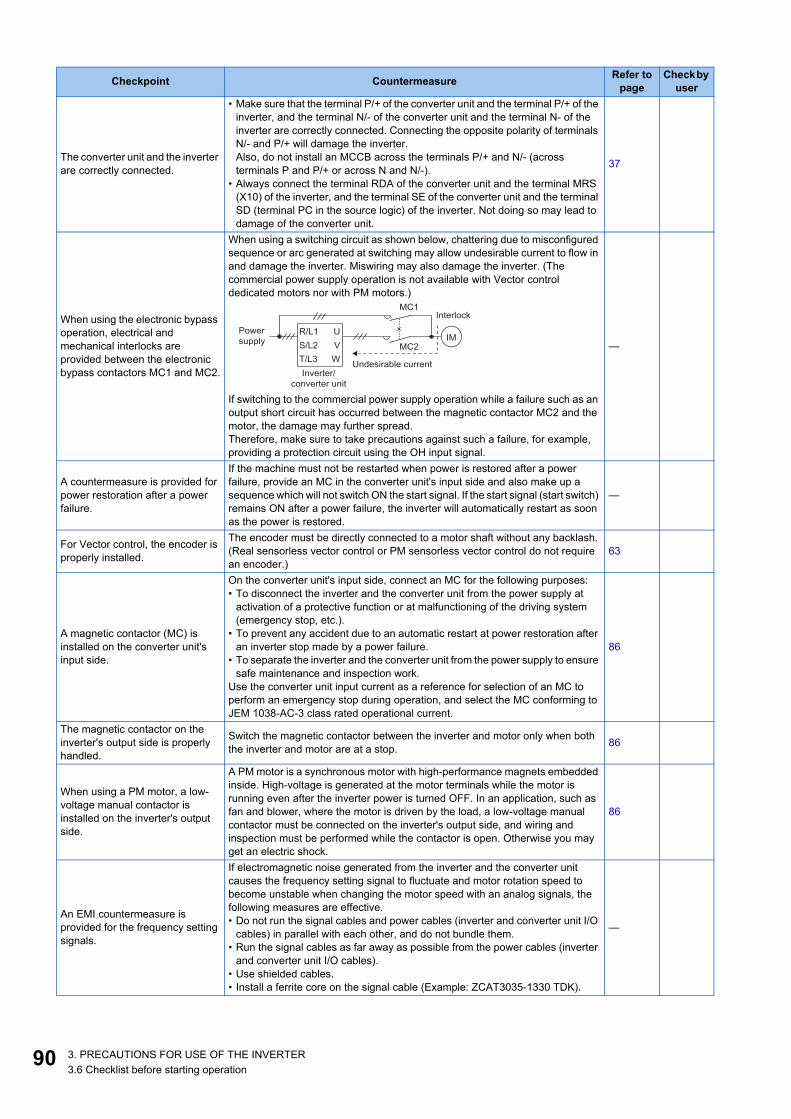
9
The converter unit and the inverter are correctly connected.
• Make sure that the terminal P/+ of the converter unit and the terminal P/+ of the inverter, and the terminal N/- of the converter unit and the terminal N- of the inverter are correctly connected. Connecting the opposite polarity of terminals N/- and P/+ will damage the inverter. Also, do not install an MCCB across the terminals P/+ and N/- (across terminals P and P/+ or across N and N/-).
• Always connect the terminal RDA of the converter unit and the terminal MRS (X10) of the inverter, and the terminal SE of the converter unit and the terminal SD (terminal PC in the source logic) of the inverter. Not doing so may lead to damage of the converter unit.
37
When using the electronic bypass operation, electrical and mechanical interlocks are provided between the electronic bypass contactors MC1 and MC2.
When using a switching circuit as shown below, chattering due to misconfigured sequence or arc generated at switching may allow undesirable current to flow in and damage the inverter. Miswiring may also damage the inverter. (The commercial power supply operation is not available with Vector control dedicated motors nor with PM motors.)
If switching to the commercial power supply operation while a failure such as an output short circuit has occurred between the magnetic contactor MC2 and the motor, the damage may further spread.Therefore, make sure to take precautions against such a failure, for example, providing a protection circuit using the OH input signal.
—
A countermeasure is provided for power restoration after a power failure.
If the machine must not be restarted when power is restored after a power failure, provide an MC in the converter unit's input side and also make up a sequence which will not switch ON the start signal. If the start signal (start switch) remains ON after a power failure, the inverter will automatically restart as soon as the power is restored.
—
For Vector control, the encoder is properly installed.
The encoder must be directly connected to a motor shaft without any backlash. (Real sensorless vector control or PM sensorless vector control do not require an encoder.)
63
A magnetic contactor (MC) is installed on the converter unit's input side.
On the converter unit's input side, connect an MC for the following purposes:• To disconnect the inverter and the converter unit from the power supply at
activation of a protective function or at malfunctioning of the driving system (emergency stop, etc.).
• To prevent any accident due to an automatic restart at power restoration after an inverter stop made by a power failure.
• To separate the inverter and the converter unit from the power supply to ensure safe maintenance and inspection work.
Use the converter unit input current as a reference for selection of an MC to perform an emergency stop during operation, and select the MC conforming to JEM 1038-AC-3 class rated operational current.
86
The magnetic contactor on the inverter's output side is properly handled.
Switch the magnetic contactor between the inverter and motor only when both the inverter and motor are at a stop. 86
When using a PM motor, a low-voltage manual contactor is installed on the inverter's output side.
A PM motor is a synchronous motor with high-performance magnets embedded inside. High-voltage is generated at the motor terminals while the motor is running even after the inverter power is turned OFF. In an application, such as fan and blower, where the motor is driven by the load, a low-voltage manual contactor must be connected on the inverter's output side, and wiring and inspection must be performed while the contactor is open. Otherwise you may get an electric shock.
86
An EMI countermeasure is provided for the frequency setting signals.
If electromagnetic noise generated from the inverter and the converter unit causes the frequency setting signal to fluctuate and motor rotation speed to become unstable when changing the motor speed with an analog signals, the following measures are effective.• Do not run the signal cables and power cables (inverter and converter unit I/O
cables) in parallel with each other, and do not bundle them.• Run the signal cables as far away as possible from the power cables (inverter
and converter unit I/O cables).• Use shielded cables.• Install a ferrite core on the signal cable (Example: ZCAT3035-1330 TDK).
—
Checkpoint Countermeasure Refer to page
Check by user
Inverter/
converter unit
MC2
MC1
U
V
W
R/L1
S/L2
T/L3
IMPower
supply
Undesirable current
Interlock
0 3. PRECAUTIONS FOR USE OF THE INVERTER3.6 Checklist before starting operation

1
2
3
4
5
6
7
8
9
10
*1 Recommended common mode choke: FT-3KM F series FINEMET® common mode choke cores manufactured by Hitachi Metals, Ltd.FINEMET is a registered trademark of Hitachi Metals, Ltd.
A countermeasure is provided for an overload operation.
When performing frequent starts/stops by the inverter, rise/fall in the temperature of the transistor element of the inverter will repeat due to a repeated flow of large current, shortening the life from thermal fatigue. Since thermal fatigue is related to the amount of current, the life can be increased by reducing current at locked condition, starting current, etc. Reducing current may extend the service life but may also cause torque shortage, which leads to a start failure. Adding a margin to the current can eliminate such a condition. For an induction motor, use an inverter and a converter unit of higher capacities (up to two ranks). For a PM motor, use an inverter and a converter unit, and PM motor of higher capacities.
—
The specifications and rating match the system requirements. Make sure that the specifications and rating match the system requirements. —
Countermeasures are taken against electrical corrosion on the motor bearing.
When a motor is driven by the inverter, axial voltage is generated on the motor shaft, which may cause electrical corrosion of the bearing in rare cases depending on the wiring, load, operating conditions of the motor or specific inverter settings (high carrier frequency and EMC filter ON). Contact your sales representative to take appropriate countermeasures for the motor. The following shows examples of countermeasures for the inverter.• Decrease the carrier frequency.• Turn OFF the EMC filter.• Provide a common mode choke*1 on the output side of the inverter. (This is
effective regardless of the EMC filter ON/OFF connector setting.)
—
Checkpoint Countermeasure Refer to page
Check by user
913. PRECAUTIONS FOR USE OF THE INVERTER3.6 Checklist before starting operation

9
3.7 Failsafe system which uses the inverterWhen a fault is detected by the protective function, the protective function activates and outputs the Fault signal. However, theFault signal may not be output at an inverter's fault occurrence when the detection circuit or output circuit fails, etc. AlthoughMitsubishi assures the best quality products, provide an interlock which uses inverter status output signals to prevent accidentssuch as damage to the machine when the inverter fails for some reason. Also at the same time consider the systemconfiguration where a failsafe from outside the inverter, without using the inverter, is enabled even if the inverter fails.
Interlock method which uses the inverter status output signalsBy combining the inverter output signals to provide an interlock as shown below, an inverter failure can be detected.
• When using various signals, assign the functions to Pr.190 to Pr.196 (Output terminal function selection) referring tothe table on the left.
NOTE• Changing the terminal assignment using Pr.190 to Pr.196 (Output terminal function selection) may affect the other
functions. Set parameters after confirming the function of each terminal.
Checking by using the Fault signal output from the inverter... (a)When the inverter's protective function activates and the inverter output is stopped, the Fault (ALM) signal is output. (The ALMsignal is assigned to terminal A1B1C1 in the initial setting). With this signal, check that the inverter operates properly. Inaddition, negative logic can be set. (ON when the inverter is normal, OFF when the fault occurs.)
Checking the inverter operating status by using the Inverter operation ready signal outputfrom the inverter ... (b)
The Inverter operation ready (RY) signal is output when the inverter power is ON and the inverter becomes operative. Checkif the RY signal is output after powering ON the inverter.
No. Interlock method Check method Used signals
a Inverter protective function operation Operation check of an alarm contact.Circuit error detection by negative logic. Fault (ALM) signal
b Inverter operating status Operation ready signal check. Inverter operation ready (RY) signal
c Inverter running status Logic check of the start signal and running signal.
Start (STF or STR) signalInverter running (RUN) signal
d Inverter running status Logic check of the start signal and output current.
Start (STF or STR) signalOutput current detection (Y12) signal
Output signal
Pr.190 to Pr.196 settingPositive logic Negative logic
ALM 99 199RY 11 111RUN 0 100Y12 12 112
ON
(about 1 s)
OFF
Reset ON
Ou
tpu
t fr
eq
ue
ncy
ALM
(when output
at NC contact)
RES
Inverter fault occurrence
(trip)
Time
OFF
ON
Reset processing
2 3. PRECAUTIONS FOR USE OF THE INVERTER3.7 Failsafe system which uses the inverter

1
2
3
4
5
6
7
8
9
10
Checking the inverter operating status by using the start signal input to the inverter and theInverter running signal output from the inverter ... (c)
The Inverter running (RUN) signal is output when the inverter is running. (The RUN signal is assigned to terminal RUN in theinitial setting.) Check if the RUN signal is output while a start signal (the STF/STR signal for forward/reverse rotation command)is input to the inverter. Even after the start signal is turned OFF, the RUN signal is kept output until the inverter makes the motorto decelerate and to stop. For the logic check, configure a sequence considering the inverter's deceleration time.
Checking the motor operating status by using the start signal input to the inverter and theOutput current detection signal output from the inverter ... (d)
The Output current detection (Y12) signal is output when the inverter operates and currents flows into the motor.Check if the Y12 signal is output while a start signal (the STF/STR signal for forward/reverse rotation command) is input to theinverter. The Y12 signal is initially set to be output at 150% inverter rated current. Adjust the level to around 20% using no loadcurrent of the motor as reference with Pr.150 Output current detection level.Like the Inverter running (RUN) signal, even after the start signal is turned OFF, the Y12 signal is kept output until the inverterstops the output to a decelerating motor. For the logic check, configure a sequence considering the inverter's deceleration time.
Backup method which does not use the inverterEven if the interlock is provided by the inverter status signal, enough failsafe is not ensured depending on the failure status ofthe inverter itself. For example, if an inverter CPU fails in a system interlocked with the inverter's Fault, start, and RUN signals,no Fault signals will be output and the RUN signal will be kept ON because the inverter CPU is down.Provide a speed detector to detect the motor speed and current detector to detect the motor current, and consider the backupsystem such as performing a check as follows according to the level of importance of the system.
Start signal and actual operation checkCheck the motor running and motor current while the start signal is input to the inverter by comparing the start signal to theinverter and detected speed of the speed detector or detected current of the current detector. Note that the current is flowingthrough the motor while the motor coasts to stop, even after the inverter's start signal is turned OFF. For the logic check,configure a sequence considering the inverter's deceleration time. In addition, it is recommended to check the three-phasecurrent when using the current detector.
Time
Power
supply
Ou
tpu
t fr
eq
ue
ncy
STF
RH
RY
Reset
processing
Pr. 13 Starting frequency
ON OFF
ON OFF
ON OFF
ON
DC injection brake
operation point
DC injection
brake operation
RUN ON OFF
933. PRECAUTIONS FOR USE OF THE INVERTER3.7 Failsafe system which uses the inverter

9
Command speed and actual operation checkCheck for a gap between the actual speed and commanded speed by comparing the inverter's speed command and the speeddetected by the speed detector.
Inverter
Controller
System failure
To the alarm detection sensor
Sensor
(speed, temperature,
air volume, etc.)
4 3. PRECAUTIONS FOR USE OF THE INVERTER3.7 Failsafe system which uses the inverter

CHAPTER 4
CH
APT
ER 4
4
5
PROTECTIVE FUNCTIONS
6
7
8
9
10
4.1 Inverter fault and alarm indications.........................................................................................................................964.2 Reset method for the protective functions ..............................................................................................................974.3 Check and clear of the fault history ........................................................................................................................984.4 List of fault displays ..............................................................................................................................................100
95

9
4 PROTECTIVE FUNCTIONSThis chapter explains the "PROTECTIVE FUNCTIONS" that operate in this product.Always read the instructions before use.
4.1 Inverter fault and alarm indications• When the inverter detects a fault, depending on the nature of the fault, the operation panel displays an error message or
warning, or a protective function is activated to shut off the inverter output.• When any fault occurs, take an appropriate corrective action, then reset the inverter, and resume the operation. Restarting
the operation without a reset may break or damage the inverter.• When a protective function is activated, note the following points.
• Inverter fault or alarm indications are categorized as follows.
NOTE• For the details of fault indications and other malfunctions, refer to the FR-A800 Instruction Manual (Detailed).• The last eight faults can be displayed on the operation panel. (Fault history) (For the operation, refer to page 98.)
Item Description
Fault output signal Opening the magnetic contactor (MC) provided on the input side of the inverter at a fault occurrence shuts off the control power to the inverter, therefore, the fault output will not be retained.
Fault or alarm indication When a protective function is activated, the operation panel displays a fault indication.
Operation restart method While a protective function is activated, the inverter output is kept shutoff. Reset the inverter to restart the operation.
Displayed item Description
Error message A message regarding operational fault and setting fault by the operation panel and the parameter unit. The inverter output is not shut off.
Warning The inverter output is not shut off even when a warning is displayed. However, failure to take appropriate measures will lead to a fault.
Alarm The inverter output is not shut off. An Alarm (LF) signal can also be output with a parameter setting.Fault When a protective function is activated, the inverter output is shut off and a Fault (ALM) signal is output.
6 4. PROTECTIVE FUNCTIONS4.1 Inverter fault and alarm indications

1
2
3
4
5
6
7
8
9
10
4.2 Reset method for the protective functionsReset the inverter by performing any of the following operations. Note that the accumulated heat value of the electronic thermalrelay function and the number of retries are cleared (erased) by resetting the inverter.The inverter recovers about 1 second after the reset is released.
• On the operation panel, press to reset the inverter.
(This may only be performed when a fault occurs.)
• Switch the power OFF once, then switch it ON again.
• Turn ON the Reset (RES) signal for 0.1 second or more. (If the RES signal is kept ON, "Err" appears (blinks) to indicatethat the inverter is in a reset status.)
NOTE• OFF status of the start signal must be confirmed before resetting the inverter fault. Resetting an inverter fault with the start
signal ON restarts the motor suddenly.
ON
OFF
SD
Inverter
RES
974. PROTECTIVE FUNCTIONS4.2 Reset method for the protective functions

9
4.3 Check and clear of the fault historyThe operation panel stores the past eight fault records which appears when a protective function is activated. (Fault history)
Check for the fault history
*1 When an overcurrent trip occurs by an instantaneous overcurrent, the monitored current value saved in the fault history may be lower than theactual current that has flowed.
*2 The cumulative energization time and actual operation time are accumulated from 0 to 65535 hours, then cleared, and accumulated again from 0.
Fault history mode
Monitor mode Parameter setting mode Function mode
[Operation for displaying fault history]
The last eight fault records can be displayed.
(On the display of the last fault record (fault record 1), a decimal point LED is ON.)
When the fault history is
empty, "E0" is displayed.
Latest fault
Second fault in past
Eighth fault in past
Fault record 1
Output frequency
Blinking Blinking
BlinkingBlinking
Blinking Blinking
BlinkingBlinking
Cumulative energization time ∗2
Fault record number
Fault record number
Fault record number
Output current ∗1
Output voltage
Fault record 2
Fault record 8
Press the
setting dial.
Press the
setting dial.
Press the
setting dial.
Time
Day
Month Year
8 4. PROTECTIVE FUNCTIONS4.3 Check and clear of the fault history

1
2
3
4
5
6
7
8
9
10
Fault history clearing procedure
• Set Err.CL Fault history clear = "1" to clear the fault history.
Operating procedure1. Turning ON the power of the inverter
The operation panel is in the monitor mode.
2. Selecting the parameter setting mode
Press to choose the parameter setting mode. (The parameter number read previously appears.)
3. Selecting the parameter number
Turn until " " (Fault history clear) appears. Press to read the present set value. " "
(initial value) appears.
4. Fault history clear
Turn to change the set value to " ". Press to start clearing.
" " and " " are displayed alternately after parameters are cleared.
• Turn to read another parameter.
• Press to show the setting again.
• Press twice to show the next parameter.
994. PROTECTIVE FUNCTIONS4.3 Check and clear of the fault history

10
4.4 List of fault displaysFor details, refer to the FR-A800 Instruction Manual (Detailed).
Error message• A message regarding operational fault and setting fault
by the operation panel and the parameter unit isdisplayed. The inverter output is not shut off.
Warning• The inverter output is not shut off even when a warning is
displayed. However, failure to take appropriate measureswill lead to a fault.
Alarm• The inverter output is not shut off. An Alarm (LF) signal
can also be output with a parameter setting.
Fault• When a protective function is activated, the inverter
output is shut off and a Fault (ALM) signal is output.• The data code is used for checking the fault detail via
communication or with Pr.997 Fault initiation.
Operation panel indication Name
HOLD Operation panel lock
LOCD Password locked
to
Er1 to Er4, Er8 Parameter write error
torE1 to rE8 Copy operation error
Err. Error
Operation panel indication Name
OL Stall prevention (overcurrent)
oL Stall prevention (overvoltage)
TH Electronic thermal relay function pre-alarm
PS PU stop
SL Speed limit indication
CF Continuous operation during communication fault
CP Parameter copy
SA Safety stop
to MT1 to MT3 Maintenance timer 1 to 3
UF USB host error
HP1 Home position return setting error
HP2 Home position return uncompleted
HP3 Home position return parameter setting error
EHR Ethernet communication fault
Operation panel indication Name
FN Fan alarm
Operation panel indication Name
E.OC1 Overcurrent trip during acceleration
E.OC2 Overcurrent trip during constant speed
E.OC3 Overcurrent trip during deceleration or stop
E.OV1 Regenerative overvoltage trip during acceleration
E.OV2 Regenerative overvoltage trip during constant speed
E.OV3 Regenerative overvoltage trip during deceleration or stop
E.THT Inverter overload trip (electronic thermal relay function)
E.THM Motor overload trip (electronic thermal relay function)
E.FIN Heat sink overheat
E.OLT Stall prevention stop
E.SOT Loss of synchronism detection
E.GF Output side earth (ground) fault overcurrent
E.LF Output phase loss
E.OHT External thermal relay operation
E.PTC PTC thermistor operation
E.OPT Option fault
E.OP1 to E.OP3 Communication option fault
E.16 to E.20
User definition error by the PLC function
E.PE Parameter storage device fault (control circuit board)
~
~
0 4. PROTECTIVE FUNCTIONS4.4 List of fault displays

1
2
3
4
5
6
7
8
9
10
Others• The fault history and the operation status of the inverter
are displayed. It is not a fault indication.
If faults other than the above appear, contact your salesrepresentative.
E.PUE PU disconnection
E.RET Retry count excess
E.PE2 Parameter storage device fault (main circuit board)
E.CPU, E. 5 to E. 7 CPU fault
E.CTE Operation panel power supply short circuit
E.P24 24 VDC power fault
E.CDO Abnormal output current detection
E.EHR Ethernet communication fault
E.AIE Analog input fault
E.USB USB communication fault
E.SAF Safety circuit fault
E.PBT, E. 13 Internal circuit fault
E.OS Overspeed occurrence
E.OSD Speed deviation excess detection
E.ECT Signal loss detection
E.OD Excessive position fault
E.MB1 to E.MB7 Brake sequence fault
E.EP Encoder phase fault
E.MP Magnetic pole position unknown
E.EF External fault during output operation
E.LCI 4 mA input fault
E.PCH Pre-charge fault
E.PID PID signal fault
E. 1 to E. 3 Option fault
E.11 Opposite rotation deceleration fault
Operation panel indication Name
E---- Fault history
E.0 No fault records
Operation panel indication Name
~
~
~
EV 24 V external power supply operation
RD Backup in progress
WR Restoration in progress
Operation panel indication Name
1014. PROTECTIVE FUNCTIONS4.4 List of fault displays

10
MEMO
2 4. PROTECTIVE FUNCTIONS4.4 List of fault displays

CHAPTER 5
CH
APT
ER 5
4
5
PRECAUTIONS FOR MAINTENANCE AND INSPECTION
6
7
8
9
10
5.1 Inspection item......................................................................................................................................................1045.2 Measurement of main circuit voltages, currents, and powers...............................................................................111
103

10
5 PRECAUTIONS FOR MAINTENANCE AND INSPECTION
This chapter explains the precautions for maintenance and inspection of this product.Always read the instructions before use.
5.1 Inspection itemThe inverter is a static unit mainly consisting of semiconductor devices. Daily inspection must be performed to prevent any faultfrom occurring due to the adverse effects of the operating environment, such as temperature, humidity, dust, dirt and vibration,changes in the parts with time, service life, and other factors.
Precautions for maintenance and inspectionWhen accessing the inverter for inspection, wait for at least 10 minutes after the power supply has been switched OFF. Then,make sure that the voltage across the main circuit terminals P/+ and N/- on the inverter is not more than 30 VDC using a digitalmultimeter, etc.
5.1.1 Daily inspectionBasically, check for the following faults during operation.
• Motor operation fault• Improper installation environment• Cooling system fault• Abnormal vibration, abnormal noise• Abnormal overheat, discoloration
5.1.2 Periodic inspectionCheck the areas inaccessible during operation and requiring periodic inspection. Consult us for periodic inspection.
NOTE• When using the safety stop function, periodic inspection is required to confirm that safety function of the safety system
operates correctly. For more details, refer to the Safety Stop Function Instruction Manual.
Check and clean the cooling system: Clean the air filter, etc.Check the tightening and retighten: The screws and bolts may become loose due to vibration, temperature
changes, etc. Check and tighten them. Tighten them according to the specified tightening torque. (Refer to page 40.)
Check the conductors and insulating materials for corrosion and damage.Measure the insulation resistance.Check and change the cooling fan and relay.
4 5. PRECAUTIONS FOR MAINTENANCE AND INSPECTION5.1 Inspection item

1
2
3
4
5
6
7
8
9
10
5.1.3 Daily and periodic inspection
*1 Oil component of the heat dissipation grease used inside the inverter may leak out. The oil component, however, is not flammable, corrosive, norconductive and is not harmful to humans. Wipe off such oil component.
*2 It is recommended to install a voltage monitoring device for checking the voltage of the power supplied to the inverter.*3 One to two years of periodic inspection cycle is recommended. However, it differs according to the installation environment.
Consult us for periodic inspection.
Area of inspection Inspection item Description
Inspection interval Corrective action at fault
occurrenceCheck
by userDaily Periodic*3
General
Surrounding environment
Check the surrounding air temperature, humidity, dirt, corrosive gas, oil mist, etc. ○ Improve the environment.
Overall unitCheck for unusual vibration and noise. ○ Check fault location and
retighten.
Check for dirt, oil, and other foreign material.*1 ○ Clean.
Power supply voltage
Check that the main circuit voltage and control circuit voltage are normal.*2
○ Inspect the power supply.
Main circuit
General
• Check with megger (between main circuit terminals and earth (ground) terminal).
○ Contact the manufacturer.
• Check for loose screws and bolts. ○ Retighten.• Check for overheat traces on the parts. ○ Contact the manufacturer.• Check for stains. ○ Clean.
Conductors and cables
• Check conductors for distortion. ○ Contact the manufacturer.• Check cable sheaths for breakage and
deterioration (crack, discoloration, etc.). ○ Contact the manufacturer.
Transformer/reactor
Check for unusual odor and abnormal increase of whining sound. ○ Stop the equipment and
contact the manufacturer.
Terminal block Check for a damage. ○ Stop the equipment and contact the manufacturer.
Smoothing aluminum electrolytic capacitor
• Check for liquid leakage. ○ Contact the manufacturer.• Check for safety valve projection and bulge. ○ Contact the manufacturer.
• Visual check ○
Relay/contactor Check that the operation is normal and no chattering sound is heard. ○ Contact the manufacturer.
Control circuit,protective circuit
Operation check
• Check for an output voltage imbalance between phases while operating the inverter alone. ○ Contact the manufacturer.
• Check that no fault is found in protective and display circuits in a sequence protective operation test.
○ Contact the manufacturer.
Com
pone
nts
chec
k
Overall• Check for unusual odor and discoloration. ○ Stop the equipment and
contact the manufacturer.• Check for serious rust development. ○ Contact the manufacturer.
Aluminum electrolytic capacitor
• Check for liquid leakage in a capacitor and deformation trace.
○ Contact the manufacturer.
• Visual check and judge by the life check of the control circuit capacitor. (Refer to the FR-A800 Instruction Manual (Detailed)).
○
Cooling system
Cooling fan
• Check for unusual vibration and noise. ○ Replace the fan.
• Check for loose screws and bolts. ○ Fix with the fan cover fixing screws.
• Check for stains. ○ Clean.
Heat sink• Check for clogging. ○ Clean.• Check for stains. ○ Clean.
DisplayIndication
• Check that indications are correct. ○ Contact the manufacturer.• Check for stains. ○ Clean.
Meter/counter Check that readouts are correct. ○ Stop the equipment and contact the manufacturer.
Load motor Operation check Check for vibration and abnormal increase in operation noise. ○ Stop the equipment and
contact the manufacturer.
1055. PRECAUTIONS FOR MAINTENANCE AND INSPECTION5.1 Inspection item

10
NOTE• Continuous use of a leaked, deformed, or degraded smoothing aluminum electrolytic capacitor (as shown in the table above)
may lead to a burst, breakage, or fire. Replace such capacitor without delay.
5.1.4 Checking the inverter and converter semiconductor devices
Preparation• Disconnect the external power supply cables (R/L1, S/L2, T/L3) and motor cables (U, V, W). (Measurement can be made
without disconnecting the cables connecting the inverter and the converter unit (FR-CC2).)• Prepare a continuity tester. (For the resistance measurement, use the 100 Ω range.)
Checking methodChange the polarity of the tester alternately at the inverter terminals R/L1, S/L2, T/L3, U, V, W, P/+, and N/- and check theelectric continuity.
NOTE• Before measurement, check that the smoothing capacitor is discharged.• At the time of electric discontinuity, the measured value is almost ∞. When there is an instantaneous electric continuity, due
to the smoothing capacitor, the tester may not indicate ∞. At the time of electric continuity, the measured value is several Ω toseveral tens of Ω. When all measured values are almost the same (although values may not be constant depending on thetester type), it shows that there are no electrical paths with problems.
Semiconductor device numbers and terminals to be checked
(Assuming that an analog meter is used.)
Tester polarity Continuity
Tester polarity Continuity
Converter unit
D1R/L1 P/+ No
D4R/L1 N/- Yes
P/+ R/L1 Yes N/- R/L1 No
D2S/L2 P/+ No
D5S/L2 N/- Yes
P/+ S/L2 Yes N/- S/L2 No
D3T/L3 P/+ No
D6T/L3 N/- Yes
P/+ T/L3 Yes N/- T/L3 No
Inverter
TR1U P/+ No
TR4U N/- Yes
P/+ U Yes N/- U No
TR3V P/+ No
TR6V N/- Yes
P/+ V Yes N/- V No
TR5W P/+ No
TR2W N/- Yes
P/+ W Yes N/- W No
Converter unit Inverter
D1 D2 D3
D4 D5 D6
TR1 TR3 TR5
TR4 TR6 TR2
U
V
W
R/L1
S/L2
T/L3
C C
P/+
N/-
P/+
N/-
6 5. PRECAUTIONS FOR MAINTENANCE AND INSPECTION5.1 Inspection item

1
2
3
4
5
6
7
8
9
10
5.1.5 CleaningAlways run the inverter in a clean status.When cleaning the inverter, gently wipe dirty areas with a soft cloth immersed in neutral detergent or ethanol.
NOTE• Do not use solvent, such as acetone, benzene, toluene and alcohol, as these will cause the inverter surface paint to peel off.• The display, etc. of the operation panel (FR-DU08) and parameter unit (FR-PU07) are vulnerable to detergent and alcohol.
Therefore, avoid using them for cleaning.
5.1.6 Replacement of partsThe inverter consists of many electronic parts such as semiconductor devices.The following parts may deteriorate with age because of their structures or physical characteristics, leading to reducedperformance or fault of the inverter. For preventive maintenance, the parts must be replaced periodically.Use the life check function as a guidance of parts replacement.
*1 Estimated lifespan for when the yearly average surrounding air temperature is 40°C.(without corrosive gas, flammable gas, oil mist, dust and dirt etc.)
*2 Output current: 80% of the inverter rating
NOTE• For parts replacement, contact the nearest Mitsubishi Electric FA center.
Inverter parts life displayThe inverter diagnoses the control circuit capacitor and the cooling fan by itself, and estimates their lives.The self-diagnostic warning is output when the life span of each part is near its end. It gives an indication of replacement time.Guideline for life judgment using the life warning output
NOTE• Refer to the Instruction Manual (Detailed) to perform the life check of the inverter parts.
Part name Estimated lifespan*1 DescriptionCooling fan 10 years Replace (as required)Main circuit smoothing capacitor 10 years*2 Replace (as required)
On-board smoothing capacitor 10 years*2 Replace the board (as required).
Relays — As requiredMain circuit fuse 10 years Replace (as required)
Part Judgment levelControl circuit capacitor Estimated remaining life 10%Cooling fan Not more than the specified speed
1075. PRECAUTIONS FOR MAINTENANCE AND INSPECTION5.1 Inspection item

10
Replacement procedure of the cooling fanThe replacement interval of the cooling fan used for cooling the parts generating heat such as the main circuit semiconductoris greatly affected by the surrounding air temperature. When unusual noise and/or vibration are noticed during inspection, thecooling fan must be replaced immediately.
Removal1. Remove the fan cover fixing screws, and remove the fan cover.
2. Disconnect the fan connector and remove the fan block.
3. Remove the fan fixing screws, and remove the fan.
*1 The number of cooling fans differs according to the inverter capacity.
Reinstallation1. After confirming the orientation of the fan, reinstall the fan so that the "AIR FLOW" faces up.
2. Install fans referring to the above figure. Tightening torque of the fan fixing screws is 0.73 N·m.
NOTE• Installing the fan in the opposite direction of air flow may shorten the inverter life.• Ensure that the cables are not caught when the fan is installed.• Switch OFF the power before starting the fan replacement work. To prevent an electric shock accident, keep the inverter with
its covers on during fans replacement since the inverter circuits are charged with voltage even after power OFF.
1)
2)
3)
Fan
Fan connectionconnector
Fan cover
Fan block
*1
<Fan side face>
AIR FLOW
8 5. PRECAUTIONS FOR MAINTENANCE AND INSPECTION5.1 Inspection item

1
2
3
4
5
6
7
8
9
10
Smoothing capacitorsA large-capacity aluminum electrolytic capacitor is used for smoothing in the DC section of the main circuit, and an aluminumelectrolytic capacitor is used for stabilizing the control power in the control circuit. Adverse effects from ripple currentsdeteriorate capacitors. Replacement intervals of capacitors vary greatly with surrounding temperatures and operatingconditions. Replace them roughly every 10 years when used in normal air-conditioned environments.Inspecting the product visually:
• Case: Check that the sides and bottom of the capacitor have not ruptured.• Rubber seal: Check for any noticeable bulging or severe cracks.• Check for external cracks, discoloration, leakage, etc. It is assumed that the capacitor has reached the end of its life when
its capacity has dropped below 80% of its rated capacity.
NOTE• The inverter diagnoses the control circuit capacitor by itself, and estimates its life. (Refer to the Instruction Manual (Detailed).)
Relay output terminals• The contacts of relays deteriorate over time. To prevent faults from occurring, relays must be replaced when they have
reached the maximum of switching operations (switching life).• The control terminal block must be replaced in case of failure of either relay connected to the relay output terminals A1,
B1, and C1, or A2, B2, and C2.
Main circuit fuseFuses are used in some inverters. Replacement intervals of capacitors vary greatly with surrounding temperatures andoperating conditions. Replace them roughly every 10 years when used in normal air-conditioned environments.
5.1.7 Removal and reinstallation of the control circuit terminal block
This product has a removable control circuit terminal block, which can be replaced with a new one or a control terminal option.
Removal and reinstallation1. Loosen the two installation screws at the both side of the control circuit terminal block. (These screws cannot be
removed.)Slide down the control circuit terminal block to remove it.
2. Be careful not to bend the pins of the inverter's control circuit connector, reinstall the control circuit terminal blockand fix it with the mounting screws.
Loosen the screws
1095. PRECAUTIONS FOR MAINTENANCE AND INSPECTION5.1 Inspection item
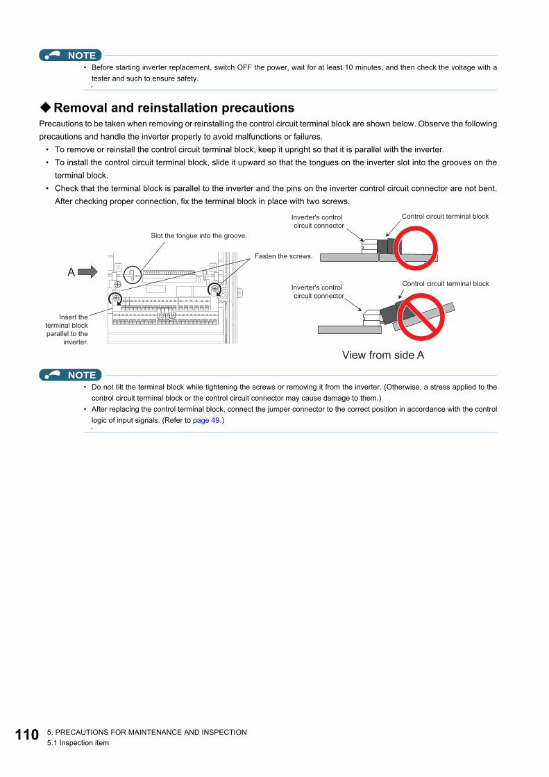
11
NOTE• Before starting inverter replacement, switch OFF the power, wait for at least 10 minutes, and then check the voltage with a
tester and such to ensure safety.
Removal and reinstallation precautionsPrecautions to be taken when removing or reinstalling the control circuit terminal block are shown below. Observe the followingprecautions and handle the inverter properly to avoid malfunctions or failures.
• To remove or reinstall the control circuit terminal block, keep it upright so that it is parallel with the inverter.• To install the control circuit terminal block, slide it upward so that the tongues on the inverter slot into the grooves on the
terminal block.• Check that the terminal block is parallel to the inverter and the pins on the inverter control circuit connector are not bent.
After checking proper connection, fix the terminal block in place with two screws.
NOTE• Do not tilt the terminal block while tightening the screws or removing it from the inverter. (Otherwise, a stress applied to the
control circuit terminal block or the control circuit connector may cause damage to them.)• After replacing the control terminal block, connect the jumper connector to the correct position in accordance with the control
logic of input signals. (Refer to page 49.)
Fasten the screws.
Control circuit terminal blockInverter's control
circuit connector
A
Slot the tongue into the groove.
Insert the
terminal block
parallel to the
inverter.
View from side A
Control circuit terminal blockInverter's control
circuit connector
0 5. PRECAUTIONS FOR MAINTENANCE AND INSPECTION5.1 Inspection item

1
2
3
4
5
6
7
8
9
10
5.2 Measurement of main circuit voltages, currents, and powers
Since the voltages and currents on the inverter power supply and output sides include harmonics, measurement data dependson the instruments used and circuits measured. When instruments for commercial frequency are used for measurement,measure the following circuits with the instruments given on the next page.
NOTE• When installing meters etc. on the inverter output side
When the inverter-to-motor wiring length is long, the meters and CTs may generate heat due to line-to-line leakage current.Therefore, choose the equipment which has enough allowance for the current rating.To measure and display the output voltage and output current of the inverter, it is recommended to use the terminal AM andFM/CA output functions of the inverter.
+ -
Ar
As
At
Vr
Vs
Vt
Au
Av
Aw
Vu
Vv
Vw
W21
V
U
V
W
Inverter/
converter unit
Three-phase
power supply To the motor
Input voltage
Input current
Output voltage
Output current
R/L1
S/L2
T/L3
P/+ N/-
W11
W12
W13 W22
1115. PRECAUTIONS FOR MAINTENANCE AND INSPECTION5.2 Measurement of main circuit voltages, currents, and powers

11
Measuring points and instrumentsItem Measuring point Measuring instrument Remarks (reference measured value)
Con
verte
r uni
t (FR
-CC
2)
Power supply voltageV1
Between R/L1 and S/L2, S/L2 and T/L3, and T/L3 and R/L1
Digital power meter (designed for inverter)
Commercial powerWithin permissible AC voltage fluctuation. (Refer to page 118.)
Input currentI1
Line current at R/L1, S/L2, and T/L3
Input powerP1
At R/L1, S/L2, and T/L3, and between R/L1 and S/L2, S/L2 and T/L3, and T/L3 and R/L1
P1 = W11 + W12 + W13 (3-wattmeter method)
Input power factorPf1
Calculate after measuring input voltage, input current and input power.
Converter output Between P/+ and N/- Digital multimeter or other tester Inverter LED indication 1.35 × V1
Operation enable signalExternal thermal relay signalReset signal
Across terminals RDI, OH, RES(+) and SD (for sink logic)
Digital multimeter or other tester, or moving-coil type instrument (internal resistance 50 kΩ or more)
Voltage when terminal is open: 20 to 30 VDC.Voltage when signal is ON: 1 V or less.
Terminal SD is a common terminal.
Alarm signal Between A1 and C1Between B1 and C1
Digital multimeter or other tester
Continuity check*3
[Normal]Across A1 and C1: DiscontinuityAcross B1 and C1: Continuity[Fault]Across A1 and C1: ContinuityAcross B1 and C1: Discontinuity
2 5. PRECAUTIONS FOR MAINTENANCE AND INSPECTION5.2 Measurement of main circuit voltages, currents, and powers

1
2
3
4
5
6
7
8
9
10
*1 Use an FFT to measure the output voltage accurately. A digital multimeter or general measuring instrument cannot measure accurately.*2 When the carrier frequency exceeds 5 kHz, do not use this instrument since using it may increase eddy current losses produced in metal parts
inside the instrument, leading to burnout. In this case, use an approximate-effective value type.*3 When the setting of Pr.195 ABC1 terminal function selection is the positive logic.
5.2.1 Measurement of powersUse a digital power meter (for inverter) for the input side of the converter unit (FR-CC2) and the output side of the inverter.
5.2.2 Measurement of voltagesConverter unit (FR-CC2) input sideUse a digital power meter for inverters for the input side voltage.
Inverter output sideAlways use a digital power meter for inverter for measurement as the output side voltage has a PWM-controlled rectangularwave.
Inve
rter
Output voltageV2
Between U and V, V and W, and W and U Digital power meter
(designed for inverter)*1
Difference between the phases must be within 1% of the maximum output voltage.
Output currentI2
Line current at U, V, and W
Difference between the phases must be within 10%.
Output powerP2
At U, V, and W, and between U and V, and V and W
Digital power meter (designed for inverter)
P2 = W21 + W222-wattmeter method (or 3-wattmeter method)
Output power factorPf2
Calculate in similar manner to the input power factor.
Frequency setting signal2, and between 4(+) and 5
Digital multimeter or other tester, or moving-coil type instrument (internal resistance 50 kΩ or more)
0 to 10 VDC, 4 to 20 mA
Terminal 5 is a common terminal.
Between 1(+) and 5 0 to ±5 VDC and 0 to ±10 VDCPower supply for a frequency setting potentiometer
Between 10(+) and 5 5.2 VDC
Between 10E(+) and 5 10 VDC
Frequency meter signal
Between AM(+) and 5Approximately 10 VDC at maximum frequency(without frequency meter)
Between CA(+) and 5 Approximately 20 mADC at maximum frequency
Between FM(+) and SD
Approximately 5 VDC at maximum frequency (without frequency meter)
Pulse width T1: Adjust with C0 (Pr.900).Pulse cycle T2: Set with Pr.55(for frequency monitor only).
Terminal SD is a common terminal.
Start signal,Select signal,Reset signal,Output stop signal
Across STF, STR, RH, RM, RL, JOG, RT, AU, STOP, CS, RES, MRS(+) and SD (for sink logic)
Voltage when terminal is open: 20 to 30 VDC.Voltage when signal is ON: 1 V or less.
Fault signal Between A1 and C1Between B1 and C1
Digital multimeter or other tester
Continuity check*3
[Normal]Across A1 and C1: DiscontinuityAcross B1 and C1: Continuity[Fault]Across A1 and C1: ContinuityAcross B1 and C1: Discontinuity
Item Measuring point Measuring instrument Remarks (reference measured value)
8VDC
T1
1135. PRECAUTIONS FOR MAINTENANCE AND INSPECTION5.2 Measurement of main circuit voltages, currents, and powers

11
The value displayed on the operation panel is the inverter-controlled voltage itself. Hence, that value is accurate and it isrecommended to monitor values using the operation panel. Monitoring values via the operation panel or by outputting theanalog signal is recommended as these values are accurate.
5.2.3 Measurement of currentsUse a digital power meter (for inverter) for the input side of the converter unit (FR-CC2) and the output side of the inverter.Since the converter unit input current tends to be unbalanced, measurement of three phases is recommended. The correctvalue cannot be obtained by measuring only one or two phases. On the other hand, the unbalanced ratio of each phase of theoutput current should be within 10%.The inverter output current can be monitored on the operation panel. The value displayed on the operation panel is accurateeven if the output frequency varies. Hence, it is recommended to monitor values on the operation panel.
5.2.4 Example of measuring converter unit (FR-CC2) input power factor
Calculate the factor from the effective power and the apparent power. A power-factor meter cannot indicate an exact value.
5.2.5 Measurement of converter output voltage (between terminals P and N)
The output voltage of the converter is output across terminals P and N, and can be measured with a voltmeter such as a digitalmultimeter. The voltage varies according to the power supply voltage. Approximately 540 to 600 VDC is output when no loadis connected. The voltage decreases when a load is applied.When energy is regenerated from the motor during deceleration, for example, the converter output voltage rises to nearly 800to 900 VDC maximum.
5.2.6 Measurement of inverter output frequencyIn the initial setting of the FM type inverter, a pulse train proportional to the output frequency is output across the pulse trainoutput terminals FM and SD on the inverter. This pulse train output can be counted by a frequency counter, or a digitalmultimeter can be used to read the mean value of the pulse train output voltage. When a digital multimeter is used to measurethe output frequency, approximately 5 VDC is indicated at the maximum frequency.For detailed specifications of the pulse train output terminal FM, refer to the FR-A800 Instruction Manual (Detailed).In the initial setting of the CA type inverter, a pulse train proportional to the output frequency is output across the analog currentoutput terminals CA and 5 on the inverter. Measure the current using a digital multimeter.For detailed specifications of the analog current output terminal CA, refer to the FR-A800 Instruction Manual (Detailed).
5.2.7 Insulation resistance test using megger• For the inverter and the converter unit (FR-CC2), conduct the insulation resistance test on the main circuit only as follows
and do not perform the test on the control circuit. (Use a 500 VDC megger.)
Total power factor of the converter unit =Effective power
Apparent power
=Three-phase input power found by the 3-wattmeter method
3 × V (power supply voltage) × I (input current effective value)√
4 5. PRECAUTIONS FOR MAINTENANCE AND INSPECTION5.2 Measurement of main circuit voltages, currents, and powers

1
2
3
4
5
6
7
8
9
10
NOTE• Before performing the insulation resistance test on the external circuit, disconnect the cables from all terminals of the inverter
and the converter unit so that the test voltage is not applied to the inverter and the converter unit.• For the continuity test of the control circuit, use a tester for high resistance range and do not use the megger or buzzer.
5.2.8 Withstand voltage testDo not conduct a withstand voltage test. Deterioration may occur.
500VDC
megger
Power
supply
MotorP/+N/-
Converter
unit
UVW
InverterIM
R/L1S/L2T/L3
P/+N/-
Earth (ground) terminal Earth (ground) terminal
500VDC
megger
1155. PRECAUTIONS FOR MAINTENANCE AND INSPECTION5.2 Measurement of main circuit voltages, currents, and powers

11
MEMO
6 5. PRECAUTIONS FOR MAINTENANCE AND INSPECTION5.2 Measurement of main circuit voltages, currents, and powers

CHAPTER 6
CH
APT
ER 6
4
5
SPECIFICATIONS
6
7
8
9
10
6.1 Inverter rating........................................................................................................................................................1186.2 Common specifications.........................................................................................................................................1196.3 Outline dimension drawings..................................................................................................................................121
117

11
6 SPECIFICATIONSThis chapter explains the specifications of this product.Always read the instructions before use.
6.1 Inverter rating
400 V class• Inverter
*1 The applicable motor capacity indicated is the maximum capacity applicable for use of the Mitsubishi Electric 4-pole standard motor.*2 The rated output capacity is the value with respect to 440 V output voltage.*3 The percentage of the overload current rating is the ratio of the overload current to the inverter's rated output current. For repeated duty, allow
time for the inverter and motor to return to or below the temperatures under 100% load.*4 The maximum output voltage does not exceed the power supply voltage. The maximum output voltage can be changed within the setting range.
However, the maximum point of the voltage waveform at the inverter output side is the power supply voltage multiplied by about .*5 Value for the ND rating*6 FR-DU08: IP40 (except for the PU connector)*7 For the power voltage exceeding 480 V, set Pr.977 Input voltage mode selection. (For details, refer to the FR-A800 Instruction Manual
(Detailed).)
Model FR-A842-[]07700 08660 09620 10940 12120315K 355K 400K 450K 500K
Applicable motor capacity (kW)*1
SLD 400 450 500 560 630LD 355 400 450 500 560ND (initial setting) 315 355 400 450 500HD 280 315 355 400 450
Out
put
Rated capacity (kVA)*2
SLD 587 660 733 834 924LD 521 587 660 733 834ND (initial setting) 465 521 587 660 733HD 417 465 521 587 660
Rated current (A)
SLD 770 866 962 1094 1212LD 683 770 866 962 1094ND (initial setting) 610 683 770 866 962HD 547 610 683 770 866
Overload current rating*3
SLD 110% 60 s, 120% 3 s (inverse-time characteristics) at surrounding air temperature of 40°CLD 120% 60 s, 150% 3 s (inverse-time characteristics) at surrounding air temperature of 50°CND (initial setting) 150% 60 s, 200% 3 s (inverse-time characteristics) at surrounding air temperature of 50°CHD 200% 60 s, 250% 3 s (inverse-time characteristics) at surrounding air temperature of 50°C
Rated voltage*4 Three-phase 380 to 500 VRegenerative braking torque*5 (when used with the converter unit (FR-CC2))
Maximum brake torque 10% torque, continuous
Inpu
t pow
er Power supply voltage 430 to 780 VDCControl power supply auxiliary input Single-phase 380 to 500 V, 50/60 Hz*7
Permissible control power supply auxiliary input fluctuation Frequency ±5%, voltage ±10%
Protection rating of structure (IEC 60529)*6 Open type (IP00)Cooling system Forced airApprox. mass (kg) 163 163 243 243 243
8 6. SPECIFICATIONS6.1 Inverter rating

1
2
3
4
5
6
7
8
9
10
6.2 Common specificationsC
ontro
l
Control methodSoft-PWM control, high carrier frequency PWM control (selectable among V/F control, Advanced magnetic flux vector control, Real sensorless vector control), Optimum excitation control, Vector control*1, and PM sensorless vector control
Output frequency range0.2 to 590 Hz (The upper-limit frequency is 400 Hz under Advanced magnetic flux vector control, Real sensorless vector control, Vector control*1, and PM sensorless vector control.)
Frequency setting resolution
Analog input
0.015 Hz/60 Hz at 0 to 10 V/12 bits (terminals 2 and 4).0.03 Hz/60 Hz at 0 to 5 V/11 bits or 0 to 20 mA/approx. 11 bits (terminals 2 and 4), at 0 to ±10 V/12 bits (terminal 1).0.06 Hz/60 Hz at 0 to ±5 V/11 bits (terminal 1).
Digital input 0.01 HzFrequency accuracy
Analog input Within ±0.2% of the maximum output frequency (25°C ±10°C)Digital input 0.01% or less of the set output frequency
Voltage/frequency characteristics
Base frequency can be set from 0 to 590 Hz. Constant-torque/variable-torque pattern or adjustable 5 points V/F can be selected.
Starting torque SLD rating: 120% 0.3 Hz, LD rating: 150% 0.3 Hz, ND rating: 200%*20.3 Hz, HD rating: 250%*20.3 Hz (under Real sensorless vector control or Vector control*1)
Torque boost Manual torque boostAcceleration/deceleration time setting
0 to 3600 s (acceleration and deceleration can be set individually), linear or S-pattern acceleration/deceleration mode, backlash countermeasures acceleration/deceleration can be selected.
DC injection brake (induction motor) Operation frequency (0 to 120 Hz), operation time (0 to 10 s), operation voltage (0 to 30%) variable
Stall prevention operation levelActivation range of stall prevention operation (SLD rating: 0 to 120%, LD rating: 0 to 150%, ND rating: 0 to 220%, HD rating: 0 to 280%). Whether to use the stall prevention or not can be selected (V/F control, Advanced magnetic flux vector control)
Torque limit level Torque limit value can be set (0% to 400% variable). (Real sensorless vector control, Vector control*1, PM sensorless vector control)
Ope
ratio
n
Frequency setting signal
Analog input Terminals 2 and 4: 0 to 10 V / 0 to 5 V / 4 to 20 mA (0 to 20 mA).Terminal 1: -10 to +10 V / -5 to +5 V.
Digital input Input using the setting dial of the operation panel or parameter unit.Input of four-digit BCD (Binary-coded decimal) or 16-bit binary (when the option FR-A8AX is installed).
Start signal Forward and reverse rotation or start signal automatic self-holding input (3-wire input) can be selected.
Input signal (12)
Low-speed operation command, Middle-speed operation command, High-speed operation command, Second function selection, Terminal 4 input selection, Jog operation selection, Selection of automatic restart after instantaneous power failure / flying start, Output stop, Start self-holding selection, Forward rotation command, Reverse rotation command, Inverter resetThe signal to be input can be changed using Pr.178 to Pr.189 (Input terminal function selection).
Pulse train input 100k pulses/s
Operational function
Maximum and minimum frequency settings, multi-speed operation, acceleration/deceleration pattern, thermal protection, DC injection brake, starting frequency, JOG operation, output stop (MRS), stall prevention, regeneration avoidance, increased magnetic excitation deceleration, frequency jump, rotation display, automatic restart after instantaneous power failure, electronic bypass sequence, remote setting, automatic acceleration/deceleration, retry function, carrier frequency selection, fast-response current limit, forward/reverse rotation prevention, operation mode selection, slip compensation, droop control, load torque high-speed frequency control, speed smoothing control, traverse, auto tuning, applied motor selection, gain tuning, RS-485 communication, Ethernet communication, PID control, PID pre-charge function, easy dancer control, cooling fan operation selection, stop selection (deceleration stop/coasting), power failure time deceleration-to-stop function, stop-on-contact control, PLC function, life diagnosis, maintenance timer, current average monitor, multiple rating, orientation control*1, speed control, torque control, position control, pre-excitation, torque limit, test run, 24 V power supply input for control circuit, safety stop function, anti-sway control
Output signalOpen collector output (five terminals)Relay output (two terminals)
Inverter running, Up to frequency, Overload warning, Output frequency detection, FaultThe signal to be output can be changed using Pr.190 to Pr.196 (Output terminal function selection). Fault codes (4 bits) of the inverter can be output from the open collector.
Pulse train output 50k pulses/s
1196. SPECIFICATIONS6.2 Common specifications

12
*1 Available when a Vector control compatible option is installed.*2 In the initial setting, the starting torque is limited to 150% by the torque limit level.*3 Applicable to conditions for a short time, for example, in transit.*4 For installation at an altitude above 1000 m, consider a 3% reduction in the rated current per 500 m increase in altitude.*5 Not activated in the inverter in the initial state.
Indi
catio
n
For indication on external meters
Pulse train output (FM type inverter)
Max. 2.4 kHz via one terminal (for the indication of inverter output frequency).
The item for monitoring can be changed using Pr.54 FM/CA terminal function selection.
Current output (CA type inverter)
Max. 20 mADC via one terminal (for the indication of inverter output frequency).
The item for monitoring can be changed using Pr.54 FM/CA terminal function selection.
Voltage outputMax. 10 VDC via one terminal (for the indication of inverter output frequency).The item for monitoring can be changed using Pr.158 AM terminal function selection.
Operation panel (FR-DU08)
Status monitoring
Output frequency, output current, output voltage, and frequency setting value are monitored.The item for monitoring can be changed using Pr.52 Operation panel main monitor selection.
Fault recordWhen a protective function is activated, a fault indication is displayed and the output voltage, output current, output frequency, cumulative energization time, date (year, month, day) and time at the occurrence of the fault are stored. Each fault is recorded and the last 8 records can be displayed.
Protective function
Fault
Overcurrent trip during acceleration, Overcurrent trip during constant speed, Overcurrent trip during deceleration or stop, Regenerative overvoltage trip during acceleration, Regenerative overvoltage trip during constant speed, Regenerative overvoltage trip during deceleration or stop, Inverter overload trip (electronic thermal relay function), Motor overload trip (electronic thermal relay function), Heat sink overheat, Stall prevention stop, Loss of synchronism detection*5, Upper limit fault detection, Lower limit fault detection, Output side earth (ground) fault overcurrent, Output phase loss, External thermal relay operation*5, PTC thermistor operation*5, Option fault, Communication option fault, Parameter storage device fault (control circuit board), Parameter storage device fault (main circuit board), PU disconnection, Retry count excess*5, CPU fault, Operation panel power supply short circuit, 24 VDC power fault, Abnormal output current detection, Ethernet communication fault, Analog input fault, USB communication fault, Safety circuit fault, Overspeed occurrence*5, Speed deviation excess detection*1*5, Signal loss detection*1*5, Excessive position fault*1*5, Brake sequence fault*5, Encoder phase fault*1*5, 4 mA input fault*5, Pre-charge fault*5, PID signal fault*5, Opposite rotation deceleration fault*5, Internal circuit fault, Magnetic pole position unknown*1, External fault during output operation*5
Alarm, Warning, Error message
Fan alarm, Stall prevention (overcurrent), Stall prevention (overvoltage), Electronic thermal relay function pre-alarm, PU stop, Speed limit indication*5, Parameter copy, Safety stop, Maintenance signal output*5, USB host error, Home position return setting error*5, Home position return uncompleted*5, Home position return parameter setting error*5, Operation panel lock*5, Password locked*5, Parameter write error, Copy operation error, 24 V external power supply operation, Continuous operation during communication fault, Ethernet communication fault*5
Envi
ronm
ent
Surrounding air temperature -10°C to +50°C (non-freezing) (LD, ND, HD ratings)-10°C to +40°C (non-freezing) (SLD rating)
Surrounding air humidity95% RH or less (non-condensing) (With circuit board coating (conforming to IEC 60721-3-3 3C2/3S2))90% RH or less (non-condensing) (Without circuit board coating)
Storage temperature*3 -20°C to +65°CAmbience Indoors (free from corrosive gas, flammable gas, oil mist, dust and dirt)Altitude/vibration Maximum 2500 m*4, 2.9 m/s2 or less at 10 to 55 Hz (in either X, Y, or Z direction)
0 6. SPECIFICATIONS6.2 Common specifications

1
2
3
4
5
6
7
8
9
10
6.3 Outline dimension drawingsFR-A842-07700(315K), FR-A842-08660(355K)
(Unit: mm)FR-A842-09620(400K), FR-A842-10940(450K), FR-A842-12120(500K)
(Unit: mm)
185
185
23
12
70 200
540 440
4.5 4.5
200 (70)
(15
)1
30
0
(17
)1
71
29
6
15
13
30
3-φ12 hole 8-φ25 hole
185
185
23
12
100 240
680 440
4.5 4.5
240 (100)
(15
)1
55
0
(17
)1
71
54
6
15
15
80
3-φ12 hole 8-φ25 hole
1216. SPECIFICATIONS6.3 Outline dimension drawings

12
Operation panel (FR-DU08, FR-LU08)
(Unit: mm)
27.8
Operation panel
66
72.5
78.5
33
3 3
72
16
17
3.2max
66
72.5
21
5
22
20
Outline drawing Panel cutting dimension drawing
2-M3 screw
Panel
Air-bleeding hole
Operation panel connection connector
(FR-ADP option)
120 or more∗
∗ Denotes the space required to connect an optional
parameter unit connection cable (FR-CB2[ ]). When
using another cable, leave the space required for the
cable specification.
Parameter unit
connection cable
(FR-CB2[ ])
(option)
2 6. SPECIFICATIONS6.3 Outline dimension drawings

CHAPTER 7
CH
APT
ER 7
4
5
APPENDIX
6
7
8
9
10
7.1 For customers replacing the conventional model with this inverter ......................................................................1247.2 Comparison with FR-A840....................................................................................................................................1267.3 Instructions for compliance with the EU Directives...............................................................................................1277.4 Instructions for UL and cUL ..................................................................................................................................1307.5 Instructions for EAC..............................................................................................................................................1317.6 Restricted Use of Hazardous Substances in Electronic and Electrical Products..................................................1337.7 Referenced Standard (Requirement of Chinese standardized law) .....................................................................133
123

12
7 APPENDIXAPPENDIX provides the reference information for use of this product.Refer to APPENDIX as required.
7.1 For customers replacing the conventional model with this inverter
7.1.1 Replacement of the FR-A740 seriesDifferences and compatibility with the FR-A740 series
Item FR-A740 FR-A842
Control method
V/F controlAdvanced magnetic flux vector controlReal sensorless vector controlVector control (with plug-in option)PM sensorless vector control (IPM motor)
V/F controlAdvanced magnetic flux vector controlReal sensorless vector controlVector control (with plug-in option)PM sensorless vector control (IPM/SPM motor)
Added functions —USB host functionSafety stop functionetc.
Max
imum
out
put f
requ
ency V/F control 400 Hz 590 Hz
Advanced magnetic flux vector control
120 Hz 400 Hz
Real sensorless vector control 120 Hz 400 Hz
Vector control 120 Hz 400 HzPM sensorless vector control 300 Hz 400 Hz
PID control Turn the X14 signal ON to enable PID control.
When the X14 signal is not assigned, just set a value in Pr.128 to enable PID control.When the X14 signal is assigned, turn the X14 signal ON while Pr.128 ≠ "0" to enable PID control.The PID pre-charge function and dancer control are added.
Automatic restart after instantaneous power
failureTurn the CS signal ON to enable restart. The CS signal does not need to be assigned. (Restart is
enabled with the Pr.57 setting only.)
Number of motor polesV/F control switching
The V/F switchover (X18) signal is valid when Pr.81 = "12 to 20" (2 to 10 poles).
Pr.81 = "12" (12 poles)The X18 signal is valid regardless of the Pr.81 setting. (The Pr.81 settings "14 to 20" are not available.)
PTC thermistor input Input through terminal AU (The function of terminal AU is switched by a switch.)
Input through terminal 2 (The function of terminal 2 is switched by the Pr.561 setting.)
USB connector B connector Mini B connectorControl circuit terminal
block Removable terminal block (screw type) Removable terminal block (spring clamp type)
Terminal response levelThe FR-A800's I/O terminals have better response level than the FR-A700's terminals. By setting Pr.289 Inverter output terminal filter and Pr.699 Input terminal filter, the terminal response level can be compatible with that of FR-A700. Set to approximately 5 to 8 ms and adjust the setting according to the system.
PU FR-DU07 (4-digit LED)FR-PU07
FR-DU08 (5-digit LED)FR-PU07 (Some functions are unavailable.)The FR-DU07 is not supported.
Plug-in option Dedicated plug-in options (not interchangeable)Communication option Connected to the connector 3 Connected to the connector 1
Installation size Installation size is not compatible. (New mounting holes are required.)Converter Built-in for all capacities The converter unit (FR-CC2) is required.DC reactor DC reactor (FR-HEL) is provided. Built in the converter unit (FR-CC2)Brake unit FR-BU2, MT-BU5 FR-BU2
4 7. APPENDIX7.1 For customers replacing the conventional model with this inverter

1
2
3
4
5
6
7
8
9
10
Installation precautions• Removal procedure of the front cover is different. (Refer to page 21.)• Plug-in options of the FR-A700 series are not compatible.• Operation panel (FR-DU07) cannot be used.
Wiring instructions• The spring clamp type terminal block has changed to the screw type. Use of blade terminals is recommended.
Instructions for continuous use of the PU07 (parameter unit) manufactured in September 2015 or earlier
• For the FR-A800 series, many functions (parameters) have been added. When setting these parameters, the parameternames and setting ranges are not displayed.
• Only the parameter with the numbers up to "999" can be read and set. The parameters with the numbers after "999" cannotbe read or set.
• Many protective functions have been added for the FR-A800 series. These functions are available, but all faults aredisplayed as "Fault". When the fault history is checked, "ERR" appears. Added faults will not appear on the parameter unit.(However, MT1 to MT3 are displayed as MT.)
• Parameter copy/verification function are not available.
Copying parameter settings• The FR-A700 series' parameter settings can be easily copied to the FR-A800 series by using the setup software (FR
Configurator2). (Not supported by the setup software FR-SW3-SETUP or older.)
7.1.2 Replacement of the FR-A500(L) series Installation precautions
• Installation size is not compatible. (New mounting holes are required.)• The optional converter unit (FR-CC2) is required.
1257. APPENDIX7.1 For customers replacing the conventional model with this inverter

12
7.2 Comparison with FR-A840
Item FR-A840 FR-A842
Pr.30 Regenerative function selection
Setting ranges: "0 to 2, 10, 11, 20, 21, 100 to 102, 110, 111, 120, 121"Initial value: "0"
Setting ranges: "2, 10, 11, 102, 110, 111"Initial value: "10"
Pr.70 Special regenerative brake duty With the parameter Without the parameter
Monitor function(Pr.52, Pr.54, Pr.158, Pr.774 to Pr.776, Pr.992, Pr.1027 to Pr.1034)
Regenerative brake duty:Available
Regenerative brake duty:Unavailable
Input terminal function selection (Pr.178 to Pr.189)
DC feeding operation permission (X70), DC feeding cancel (X71):Available
DC feeding operation permission (X70), DC feeding cancel (X71):Unavailable
Pr.187 MRS terminal function selection Initial value "24" (MRS) Initial value "10" (X10)
Output terminal function assignment selection(Pr.190 to Pr.196, Pr.313 to Pr.322)
Instantaneous power failure/undervoltage (IPF), Regenerative brake prealarm (RBP), DC current feeding (Y85), Main circuit capacitor life (Y87), Inrush current limit circuit life (Y89)Available
Instantaneous power failure/undervoltage (IPF), Regenerative brake prealarm (RBP), DC current feeding (Y85), Main circuit capacitor life (Y87), Inrush current limit circuit life (Y89)Unavailable
Pr.192 IPF terminal function selection Initial value "2" (IPF) Initial value "9999" (No function)
Inrush current limit circuit life display, Main circuit capacitor life display(Pr.256, Pr.258, Pr.259)
With the parameter Without the parameter
Pr.599 X10 terminal input selection Initial value "0" (NO contact specification) Initial value "1" (NC contact specification)
Pr.872 Input phase loss protection selection With the parameter Without the parameter
Warning, protective functions
Regenerative brake prealarm (RB), Instantaneous power failure (E.IPF), Undervoltage (E.UVT), Input phase loss (E.ILF), Brake transistor alarm detection (E.BE), Inrush current limit circuit faultAvailable
Regenerative brake prealarm (RB), Instantaneous power failure (E.IPF), Undervoltage (E.UVT), Input phase loss (E.ILF), Brake transistor alarm detection (E.BE), Inrush current limit circuit faultUnavailable
6 7. APPENDIX7.2 Comparison with FR-A840

1
2
3
4
5
6
7
8
9
10
7.3 Instructions for compliance with the EU DirectivesThe EU Directives are issued to standardize different national regulations of the EU Member States and to facilitate freemovement of the equipment, whose safety is ensured, in the EU territory.Since 1996, compliance with the EMC Directive that is one of the EU Directives has been legally required. Since 1997,compliance with the Low Voltage Directive, another EU Directive, has been also legally required. When a manufacturerconfirms its equipment to be compliant with the EMC Directive and the Low Voltage Directive, the manufacturer must declarethe conformity and affix the CE marking.
• The authorized representative in the EUThe authorized representative in the EU is shown below.Name: Mitsubishi Electric Europe B.V.Address: Mitsubishi-Electric-Platz 1, 40882 Ratingen, Germany
EMC DirectiveWe declare that this inverter conforms with the EMC Directive and affix the CE marking on the inverter.
• EMC Directive: 2014/30/EU• Standard(s): EN 61800-3:2004+A1:2012 (Second environment / PDS Category "C3")• This inverter is not intended to be used on a low-voltage public network which supplies domestic premises. When using
the inverter in a residential area, take appropriate measures and ensure the conformity of the inverter used in theresidential area.
• Radio frequency interference is expected if used on such a network.• The installer shall provide a guide for installation and use, including recommended mitigation devices.
Note:First environmentEnvironment including buildings/facilities which are directly connected to a low voltage main supply which also suppliesresidential buildings. Directly connected means that there is no intermediate transformer between these buildings.Second environmentEnvironment including all buildings/facilities which are not directly connected to a low voltage main supply which also suppliesresidential buildings.
NoteEnsure the EMC filter is enabled, install the product as stated below, and, then carry out any wiring.
• The converter unit has a built-in EMC filter (Class C3). Enable the EMC filter. (For the details, refer to page 81.)• Connect the inverter and the converter unit to an earthed (grounded) power supply.• Install the motor and controller cable found in the EMC Installation Manual (BCN-A21041-204) and Technical News (MF-
S-113) according to the instructions.• To make full use of the built-in EMC filter, motor cable lengths should not exceed 20 m.• Ensure that the finalized system which includes an inverter and converter unit complies with the EMC Directive.
Low Voltage DirectiveWe have self-confirmed our inverters as products compliant to the Low Voltage Directive and affix the CE marking on theinverters.
• Low Voltage Directive: 2014/35/EU• Conforming standard: EN 61800-5-1:2007
Outline of instructions• Do not use an earth leakage circuit breaker as an electric shock protector without connecting the equipment to the earth.
Connect the equipment to the earth (ground) securely.• Wire the earth terminal independently. (Do not connect two or more cables to one terminal.)
1277. APPENDIX7.3 Instructions for compliance with the EU Directives
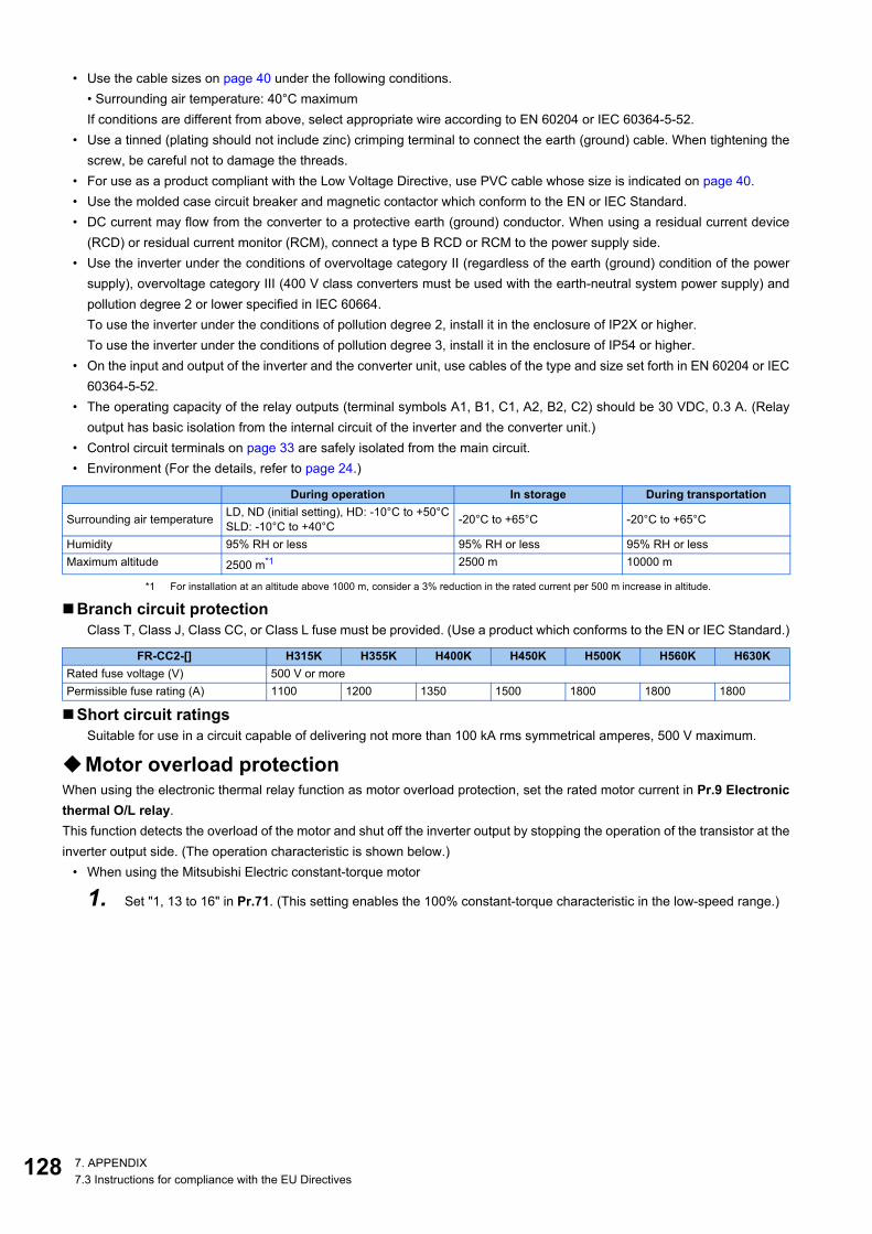
12
• Use the cable sizes on page 40 under the following conditions.• Surrounding air temperature: 40°C maximumIf conditions are different from above, select appropriate wire according to EN 60204 or IEC 60364-5-52.
• Use a tinned (plating should not include zinc) crimping terminal to connect the earth (ground) cable. When tightening thescrew, be careful not to damage the threads.
• For use as a product compliant with the Low Voltage Directive, use PVC cable whose size is indicated on page 40.• Use the molded case circuit breaker and magnetic contactor which conform to the EN or IEC Standard.• DC current may flow from the converter to a protective earth (ground) conductor. When using a residual current device
(RCD) or residual current monitor (RCM), connect a type B RCD or RCM to the power supply side.• Use the inverter under the conditions of overvoltage category II (regardless of the earth (ground) condition of the power
supply), overvoltage category III (400 V class converters must be used with the earth-neutral system power supply) andpollution degree 2 or lower specified in IEC 60664.To use the inverter under the conditions of pollution degree 2, install it in the enclosure of IP2X or higher.To use the inverter under the conditions of pollution degree 3, install it in the enclosure of IP54 or higher.
• On the input and output of the inverter and the converter unit, use cables of the type and size set forth in EN 60204 or IEC60364-5-52.
• The operating capacity of the relay outputs (terminal symbols A1, B1, C1, A2, B2, C2) should be 30 VDC, 0.3 A. (Relayoutput has basic isolation from the internal circuit of the inverter and the converter unit.)
• Control circuit terminals on page 33 are safely isolated from the main circuit.• Environment (For the details, refer to page 24.)
*1 For installation at an altitude above 1000 m, consider a 3% reduction in the rated current per 500 m increase in altitude.
Branch circuit protectionClass T, Class J, Class CC, or Class L fuse must be provided. (Use a product which conforms to the EN or IEC Standard.)
Short circuit ratingsSuitable for use in a circuit capable of delivering not more than 100 kA rms symmetrical amperes, 500 V maximum.
Motor overload protectionWhen using the electronic thermal relay function as motor overload protection, set the rated motor current in Pr.9 Electronicthermal O/L relay.This function detects the overload of the motor and shut off the inverter output by stopping the operation of the transistor at theinverter output side. (The operation characteristic is shown below.)
• When using the Mitsubishi Electric constant-torque motor
1. Set "1, 13 to 16" in Pr.71. (This setting enables the 100% constant-torque characteristic in the low-speed range.)
During operation In storage During transportation
Surrounding air temperature LD, ND (initial setting), HD: -10°C to +50°CSLD: -10°C to +40°C -20°C to +65°C -20°C to +65°C
Humidity 95% RH or less 95% RH or less 95% RH or lessMaximum altitude 2500 m*1 2500 m 10000 m
FR-CC2-[] H315K H355K H400K H450K H500K H560K H630KRated fuse voltage (V) 500 V or morePermissible fuse rating (A) 1100 1200 1350 1500 1800 1800 1800
8 7. APPENDIX7.3 Instructions for compliance with the EU Directives

1
2
3
4
5
6
7
8
9
10
2. Set the rated motor current in Pr.9.
*1 When setting Pr.9 to a value (current value) of 50% of the inverter rated output current.*2 The % value denotes the percentage to the inverter rated current. It is not the percentage to the rated motor current.*3 When you set the electronic thermal relay function dedicated to the Mitsubishi Electric constant-torque motor, this characteristic curve applies to
operation at 6 Hz or higher.*4 Transistor protection is activated depending on the temperature of the heat sink. The protection may be activated even with less than 150%
depending on the operating conditions.
NOTE• The internal accumulated heat value of the electronic thermal O/L relay is reset to the initial value by the inverter's power reset
or reset signal input. Avoid unnecessary reset and power-OFF.• Install an external thermal relay (OCR) between the inverter and motors to operate several motors, a multi-pole motor or a
dedicated motor with one inverter. When setting an external thermal relay, note that the current indicated on the motor ratingplate is affected by the line-to-line leakage current. (Refer to the Instruction Manual (Detailed).)
• The cooling effect of the motor drops during low-speed operation. Use a thermal protector or a motor with built-in thermistor.• When the difference between the inverter and motor capacities is large and the setting is small, the protective characteristics
of the electronic thermal relay function will be deteriorated. In such case, use an external thermal relay.• A dedicated motor cannot be protected by the electronic thermal relay. Use an external thermal relay.• Motor over temperature sensing is not provided by the drive.• The electronic thermal memory retention function is not provided by the drive.
Operational characteristic of the electronic thermal relay function
230
52.5% 105%
50 100 150
60
120
180
240
50
60
70
Pr.9 = 50% setting
of inverter rating∗1, 2
Pr.9 = 100% setting
of inverter rating∗2
6Hz
20Hz
10Hz
6Hz
0.5Hz
30Hz
or more∗330Hz
or more∗3
20Hz
10Hz
0.5Hz
Range for
the transistor
protection∗4
Se
co
nd
dis
pla
y in
th
is r
eg
ion
Min
ute
dis
pla
y in
this
re
gio
n
Op
era
tio
n tim
e (
min
)O
pe
ratio
n tim
e (
s)
Characteristic when
electronic thermal relay
function for motor
protection is turned off
(When Pr.9 setting is 0(A))
Inverter output power (%) (% to the inverter rated current)
Operation region Region on the right of characteristic curve Non-operation region Region on the left of characteristic curve
1297. APPENDIX7.3 Instructions for compliance with the EU Directives

13
7.4 Instructions for UL and cUL(Standard to comply with: UL 508C, CSA C22.2 No.274-13)
InstallationThe below types of inverter have been approved as products for use in enclosure.Design the enclosure so that the surrounding air temperature, humidity and ambience of the inverter will satisfy thespecifications. (Refer to page 24.)
Branch circuit protectionFor installation in the United States, Class T, Class J, Class CC, or Class L fuse must be provided, in accordance with theNational Electrical Code and any applicable local codes.For installation in Canada, Class T, Class J, Class CC, or Class L fuse must be provided, in accordance with the CanadianElectrical Code and any applicable local codes.
Wiring to the power supply and the motorRefer to the National Electrical Code (Article 310) regarding the allowable current of the cable. Select the cable size for 125%of the rated current according to the National Electrical Code (Article 430).For wiring the input (R/L1, S/L2, T/L3) terminals of the converter unit and output (U, V, W) terminals of the inverter, use the ULlisted copper, stranded wires (rated at 75°C) and round crimp terminals. Crimp the terminals with the crimping toolrecommended by the terminal manufacturer.
Short circuit ratingsSuitable for use in a circuit capable of delivering not more than 100 kA rms symmetrical amperes, 500 V maximum.
Motor overload protectionWhen using the electronic thermal relay function as motor overload protection, set the rated motor current in Pr.9 Electronicthermal O/L relay.This function detects the overload (overheat) of the motor and shut off the inverter output by stopping the operation of thetransistor at the inverter output side. (The operation characteristic is shown below.)
• When using the Mitsubishi Electric constant-torque motor
1. Set "1, 13 to 16" in Pr.71. (This setting enables the 100% constant-torque characteristic in the low-speed range.)
FR-CC2-[] H315K H355K H400K H450K H500K H560K H630KRated fuse voltage (V) 500 V or morePermissible fuse rating (A) 1100 1200 1350 1500 1800 1800 1800
0 7. APPENDIX7.4 Instructions for UL and cUL

1
2
3
4
5
6
7
8
9
10
2. Set the rated motor current in Pr.9.
*1 When setting Pr.9 to a value (current value) of 50% of the inverter rated output current.*2 The % value denotes the percentage to the inverter rated current. It is not the percentage to the rated motor current.*3 When you set the electronic thermal relay function dedicated to the Mitsubishi Electric constant-torque motor, this characteristic curve applies to
operation at 6 Hz or higher.*4 Transistor protection is activated depending on the temperature of the heat sink. The protection may be activated even with less than 150%
depending on the operating conditions.
NOTE• The internal accumulated heat value of the electronic thermal O/L relay is reset to the initial value by the inverter's power reset
or reset signal input. Avoid unnecessary reset and power-OFF.• Install an external thermal relay (OCR) between the inverter and motors to operate several motors, a multi-pole motor or a
dedicated motor with one inverter. When setting an external thermal relay, note that the current indicated on the motor ratingplate is affected by the line-to-line leakage current. (Refer to the Instruction Manual (Detailed).)
• The cooling effect of the motor drops during low-speed operation. Use a thermal protector or a motor with built-in thermistor.• When the difference between the inverter and motor capacities is large and the setting is small, the protective characteristics
of the electronic thermal relay function will be deteriorated. In such case, use an external thermal relay.• A dedicated motor cannot be protected by the electronic thermal relay. Use an external thermal relay.• Motor over temperature sensing is not provided by the drive.
7.5 Instructions for EAC
The product certified in compliance with the Eurasian Conformity has the EAC marking.
Note: EAC markingIn 2010, three countries (Russia, Belarus, and Kazakhstan) established a Customs Union for the purposes of revitalizing theeconomy by forming a large economic bloc by abolishing or reducing tariffs and unifying regulatory procedures for the handlingof articles.Products to be distributed over these three countries of the Customs Union must comply with the Customs Union TechnicalRegulations (CU-TR), and the EAC marking must be affixed to the products.
For information on the country of origin, manufacture year and month, and authorized sales representative (importer) in the CUarea of this product, refer to the following:
Operation Characteristics of electronic thermal O/L relay function
230
52.5% 105%
50 100 150
60
120
180
240
50
60
70
Pr.9 = 50% setting
of inverter rating∗1, 2
Pr.9 = 100% setting
of inverter rating∗2
6Hz
20Hz
10Hz
6Hz
0.5Hz
30Hz
or more∗330Hz
or more∗3
20Hz
10Hz
0.5Hz
Range for
the transistor
protection∗4
Se
co
nd
dis
pla
y in
th
is r
eg
ion
Min
ute
dis
pla
y in
this
re
gio
n
Op
era
tio
n tim
e (
min
)O
pe
ratio
n tim
e (
s)
Characteristic when
electronic thermal relay
function for motor
protection is turned off
(When Pr.9 setting is 0(A))
Inverter output power (%) (% to the inverter rated current)
Operation region Region on the right of characteristic curve Non-operation region Region on the left of characteristic curve
1317. APPENDIX7.5 Instructions for EAC

13
• Country of origin indicationCheck the rating plate of the product. (Refer to page 13.)Example: MADE IN JAPAN
• Manufactured year and monthCheck the SERIAL number indicated on the rating plate of the product. (Refer to page 13.)
• Authorized sales representative (importer) in the CU areaThe authorized sales representative (importer) in the CU area is shown below.Name: Mitsubishi Electric (Russia) LLCAddress: 52, bld 1 Kosmodamianskaya Nab 115054, Moscow, RussiaPhone: +7 (495) 721-2070Fax: +7 (495) 721-2071
2 7. APPENDIX7.5 Instructions for EAC

1
2
3
4
5
6
7
8
9
10
7.6 Restricted Use of Hazardous Substances in Electronic and Electrical Products
The mark of restricted use of hazardous substances in electronic and electrical products is applied to the product as followsbased on the "Management Methods for the Restriction of the Use of Hazardous Substances in Electrical and ElectronicProducts" of the People's Republic of China.
7.7 Referenced Standard(Requirement of Chinese standardized law)
This Product is designed and manufactured accordance with the following Chinese standards.
电器电子产品有害物质限制使用标识要求
本产品中所含有的有害物质的名称、含量、含有部件如下表所示。
• 产品中所含有害物质的名称及含量
上表依据 SJ/T11364 的规定编制。
○:表示该有害物质在该部件所有均质材料中的含量均在 GB/T26572 规定的限量要求以下。
×:表示该有害物质在该部件的至少一种均质材料中的含量超出 GB/T26572 规定的限量要求。
*1 即使表中记载为 ×,根据产品型号,也可能会有有害物质的含量为限制值以下的情况。
*2 根据产品型号,一部分部件可能不包含在产品中。
环境保护使用期限标识
部件名称 *2 铅(Pb)
多溴二苯醚(PBDE)
汞(Hg)
镉(Cd)
六价铬(Cr(VI))
多溴联苯(PBB)
有害物质 *1
电路板组件(包括印刷电路板及其构成的零部件,如电阻、电容、集成电路、连接器等)、电子部件
×
×
○
○
○
○
○
○
×
○
○
○
○
○
○
○
○
○
○
○
○
○
○
○
金属壳体、金属部件
树脂壳体、树脂部件
螺丝、电线
Machinery safety:
GB/T 16855.1GB/T 12668.502GB 28526GB/T 12668.3
Electrical safety: GB/T 12668.501EMC GB/T 12668.3
1337. APPENDIX7.6 Restricted Use of Hazardous Substances in Electronic and Electrical Products

13
WARRANTYWhen using this product, make sure to understand the warranty described below.
1. Warranty period and coverageWe will repair any failure or defect (hereinafter referred to as "failure") in our FA equipment (hereinafter referred to as the "Product")
arisen during warranty period at no charge due to causes for which we are responsible through the distributor from which you
purchased the Product or our service provider. However, we will charge the actual cost of dispatching our engineer for an on-site repair
work on request by customer in Japan or overseas countries. We are not responsible for any on-site readjustment and/or trial run that
may be required after a defective unit are repaired or replaced.
[Term]The term of warranty for Product is twelve months after your purchase or delivery of the Product to a place designated by you or
eighteen months from the date of manufacture whichever comes first ("Warranty Period"). Warranty period for repaired Product cannot
exceed beyond the original warranty period before any repair work.
[Limitations](1) You are requested to conduct an initial failure diagnosis by yourself, as a general rule. It can also be carried out by us or our
service company upon your request and the actual cost will be charged.
However, it will not be charged if we are responsible for the cause of the failure.
(2) This limited warranty applies only when the condition, method, environment, etc. of use are in compliance with the terms and
conditions and instructions that are set forth in the instruction manual and user manual for the Product and the caution label affixed
to the Product.
(3) Even during the term of warranty, the repair cost will be charged on you in the following cases;
• a failure caused by your improper storing or handling, carelessness or negligence, etc., and a failure caused by your hardware or
software problem
• a failure caused by any alteration, etc. to the Product made on your side without our approval
• a failure which may be regarded as avoidable, if your equipment in which the Product is incorporated is equipped with a safety
device required by applicable laws and has any function or structure considered to be indispensable according to a common
sense in the industry
• a failure which may be regarded as avoidable if consumable parts designated in the instruction manual, etc. are duly maintained
and replaced
• any replacement of consumable parts (condenser, cooling fan, etc.)
• a failure caused by external factors such as inevitable accidents, including without limitation fire and abnormal fluctuation of
voltage, and acts of God, including without limitation earthquake, lightning and natural disasters
• a failure generated by an unforeseeable cause with a scientific technology that was not available at the time of the shipment of
the Product from our company
• any other failures which we are not responsible for or which you acknowledge we are not responsible for
2. Term of warranty after the stop of production(1) We may accept the repair at charge for another seven (7) years after the production of the product is discontinued. The
announcement of the stop of production for each model can be seen in our Sales and Service, etc.
(2) Please note that the Product (including its spare parts) cannot be ordered after its stop of production.
3. Service in overseasOur regional FA Center in overseas countries will accept the repair work of the Product; however, the terms and conditions of the
repair work may differ depending on each FA Center. Please ask your local FA center for details.
4. Exclusion of loss in opportunity and secondary loss from warranty liabilityRegardless of the gratis warranty term, Mitsubishi Electric shall not be liable for compensation to:
(1) Damages caused by any cause found not to be the responsibility of Mitsubishi Electric.
(2) Loss in opportunity, lost profits incurred to the user by Failures of Mitsubishi Electric products.
(3) Special damages and secondary damages whether foreseeable or not, compensation for accidents, and compensation for
damages to products other than Mitsubishi Electric products.
(4) Replacement by the user, maintenance of on-site equipment, start-up test run and other tasks.
5. Change of Product specificationsSpecifications listed in our catalogs, manuals or technical documents may be changed without notice.
6. Application and use of the Product(1) For the use of our product, its applications should be those that may not result in a serious damage even if any failure or
malfunction occurs in product, and a backup or fail-safe function should operate on an external system to product when any failure
or malfunction occurs.
(2) Our product is designed and manufactured as a general purpose product for use at general industries.
Therefore, applications substantially influential on the public interest for such as atomic power plants and other power plants of
electric power companies, and also which require a special quality assurance system, including applications for railway companies
and government or public offices are not recommended, and we assume no responsibility for any failure caused by these
applications when used.
In addition, applications which may be substantially influential to human lives or properties for such as airlines, medical treatments,
railway service, incineration and fuel systems, man-operated material handling equipment, entertainment machines, safety
machines, etc. are not recommended, and we assume no responsibility for any failure caused by these applications when used.
We will review the acceptability of the abovementioned applications, if you agree not to require a specific quality for a specific
application. Please contact us for consultation.
4

135
About the enclosed CD-ROMThe enclosed CD-ROM contains PDF files of manuals related to this product.
Before using the enclosed CD-ROM• The copyright and other rights of the enclosed CD-ROM all belong to Mitsubishi Electric Corporation.
• No part of the enclosed CD-ROM may be copied or reproduced without the permission of Mitsubishi Electric Corporation.
• Specifications of the enclosed CD-ROM are subject to change for modification without notice.
• We are not responsible for any damages and lost earnings, etc. from use of the enclosed CD-ROM.
• Microsoft, Windows, Windows Vista, and Internet Explorer are registered trademarks of Microsoft Corporation in the UnitedStates and/or other countries.
Adobe and Adobe Reader are registered trademarks of Adobe Systems Incorporated in the United States and/or othercountries.
Intel and Pentium are registered trademarks of Intel Corporation in the United States and/or other countries.
Other company and product names herein are the trademarks and registered trademarks of their respective owners.
• Warranty
We do not provide a warranty against defects in the enclosed CD-ROM and related documents.
NOTE• This is a personal computer dedicated CD-ROM. Do not attempt to play it on ordinary audio devices. The
loud volume may damage hearing and speakers.
System requirements for the enclosed CD-ROM• The following system is required to read instruction manuals contained in the enclosed CD-ROM.
Operating method of the enclosed CD-ROM• How to read instruction manuals
Step 1. Start a computer and place the enclosed CD-ROM in the CD-ROM drive.
Step 2. The main window automatically opens by the web browser.
Step 3. Choose your language from the language choice menu.
Step 4. Click a manual you want to read in the "INSTRUCTION MANUAL" list.
Step 5. PDF manual you clicked opens.
• Manual opening of the enclosed CD-ROM
Step 1. Start a computer and place the enclosed CD-ROM in the CD-ROM drive.
Step 2. Open "index.html" file in the enclosed CD-ROM.
Step 3. The main window opens by the web browser. Operate according to the steps from "Step 3" of "How to readinstruction manuals".
• PDF data of the instruction manual are stored in "MANUAL" folder on this CD-ROM.
Item SpecificationOS Microsoft® Windows® 10, Windows® 8.1, Windows® 8, Windows® 7, Windows Vista®CPU Intel® Pentium® or better processorMemory 128MB of RAMHard disk 90MB of available hard-disk spaceCD-ROM drive Double speed or more (more than quadruple speed is recommended)Monitor 800x600 dot or more
Application Adobe® Reader® 7.0 or higherInternet Explorer® 6.0 or higher

13
REVISIONS*The manual number is given on the bottom left of the back cover.
Revision date *Manual number RevisionMay 2016 IB(NA)-0600631ENG-A First editionMar. 2019 IB(NA)-0600631ENG-B Addition
• Referenced Standard(Requirement of Chinese standardized law)
• Removal and reinstallation precautions of the control circuit terminal block• Rating plate (High power factor converter)
6
IB-0600631ENG-B
1 BCN-C22005-971
FR-A800/A800 Plus SeriesInstruction Manual Supplement
1 Internal storage device fault (E.PE6)The operation of the storage device in the inverter can be checked.If a data fault occurs in the storage device in the inverter, the protective function (E.PE6) is activated.When the read value of Pr.890 is "7" or smaller, an inverter reset after All parameter clear can return the operation tonormal. (The parameters that had been changed before All parameter clear must be set again.)
*1 For example, when parameter clear, All parameter clear, Parameter copy, or offline auto tuning is performed in the inverter, or whenparameter batch write is performed in FR Configurator2.
NOTE• "E.PE6" does not activate the retry function.• "E.PE6" outputs the Fault output 3 (Y91) signal.• "E.PE6" turns OFF the Safety monitor output (SAFE) signal.• "E.PE6" is not cleared by turning ON the Fault clear (X51) signal.• "E.PE6" is not activated during emergency drive operation.• The communication data code for "E.PE6" is 172 (HAC).
Checking faulty area in the internal storage deviceWhen E.PE6 occurs, faulty area in the internal storage device can be checked by reading Pr.890.
• Use the read value of Pr.890 to check the faulty area.• The following table shows faulty areas indicated by the read value of Pr.890. Some read values indicate that there are multiple
faulty areas. (For example, the read value "7" indicates that all the areas described in No. 1 to No. 3 are faulty.)
Operation panel indication E.PE6 FR-LU08
indication Fault
Name Internal storage device fault
DescriptionThis protective function is activated by an inverter reset if writing data fails due to power-OFF or a data fault occurs in the storage device during parameter operations*1.
Check point Check if the power was turned OFF during parameter operations.
Corrective action
Check the power supply or the devices on the power system to check that the devices have no fault.• When E.PE6 occurs due to power-OFF during parameter operations:
Check the read value of Pr.890. When the value is "7" or smaller, perform All parameter clear andthen an inverter reset. The parameters that had been changed before All parameter clear must beset again.
• When E.PE6 occurs due to other reason (such as turning OFF/ON the power or an inverter reset):Contact your sales representative.
Pr. Name Initial value Setting range Description890H325
Internal storage device status indication 0 (0 to 9999) A faulty area detected by self-check function can be
indicated in the internal storage device.
No. Read value Description
1 1, 3, 5, 7
Storage area other than the area for parameter settings is faulty (such as area for the set frequency). (When All parameter clear is performed, the set frequency, remotely-set frequency, host name for Ethernet communication, position pulse, multi-revolution counter, and offline auto tuning data are cleared.)
2 2, 3, 6, 7 Storage area for standard parameter settings is faulty.3 4, 5, 6, 7 Storage area for communication parameter settings is faulty.4 8 to 9999 Area for manufacturer setting
• Pr.890 read • Pr.890 setting read
BCN-C22005-971_ENG.fm 1 ページ 2021年9月7日 火曜日 午前10時35分

INVERTER
INVER
TERA
800-EFR
-A802-E IN
STRU
CTIO
N M
AN
UA
L (HA
RD
WA
RE)
B
HEAD OFFICE: TOKYO BUILDING 2-7-3, MARUNOUCHI, CHIYODA-KU, TOKYO 100-8310, JAPAN
IB(NA)-0600631ENG-B(1903)MEE Printed in Japan Specifications subject to change without notice.
A800-EFR-A802-E (SEPARATED CONVERTER TYPE)INSTRUCTION MANUAL (HARDWARE)
FR-A842-07700(315K) to 12120(500K)
High functionality and high performance
COVER_A802-E_Hardware.fm 1 ページ 2019年3月21日 木曜日 午前11時39分