FR-A8NS INSTRUCTION MANUAL - Suport
76
PRE-OPERATION INSTRUCTIONS 1 INSTALLATION 2 WIRING 3 SSCNET III(/H) COMMUNICATION STATUS 4 INVERTER SETTING 5 RESTRICTIONS ON THE FUNCTIONS 6 Instructions for SSCNET III(/H) communication 7 PROTECTIVE FUNCTIONS 8 TROUBLESHOOTING 9 INVERTER Plug-in option INSTRUCTION MANUAL FR-A8NS SSCNET III(/H) communication function
-
Upload
khangminh22 -
Category
Documents
-
view
3 -
download
0
Transcript of FR-A8NS INSTRUCTION MANUAL - Suport

FR-A8NS INSTRUCTION M
ANUAL
E
INVERTER
PRE-OPERATION INSTRUCTIONS 1INSTALLATION 2WIRING 3SSCNET III(/H) COMMUNICATION STATUS 4INVERTER SETTING 5RESTRICTIONS ON THE FUNCTIONS 6Instructions for SSCNET III(/H) communication 7PROTECTIVE FUNCTIONS 8TROUBLESHOOTING 9
INVERTERPlug-in option
INSTRUCTION MANUAL
INVERTER
HEAD OFFICE: TOKYO BUILDING 2-7-3, MARUNOUCHI, CHIYODA-KU, TOKYO 100-8310, JAPAN
FR-A8NS
SSCNET III(/H)communication function
IB(NA)-0600599ENG-E(1704) MEE Printed in Japan Specifications subject to change without notice.

1
Thank you for choosing this Mitsubishi Electric inverter plug-in option.orrect handling might cause an unexpectedorrectly.
s Instruction Manual and appended a full knowledge of the equipment, safetyd into "WARNING" and "CAUTION".r severe injury.
or slight injury, or may cause only material
. Both instruction levels must be followed
e front cover or the wiring cover removed. Otherwise ck.uld be when performing wiring and periodic
on who is involved in wiring or inspection shall wait ge using a tester or the like. For some time after the
lectric shock.
amage, etc. may occur.
hing these devices may cause a burn.
This Instruction Manual provides handling information and precautions for use of this product. Incfault. Before using this product, always read this Instruction Manual carefully to use this product cPlease forward this Instruction Manual to the end user.
Electric shock prevention
Injury prevention
Safety instructionsDo not attempt to install, operate, maintain or inspect the product until you have read through thidocuments carefully and can use the equipment correctly. Do not use this product until you haveinformation and instructions. In this Instruction Manual, the safety instruction levels are classifie
Incorrect handling may cause hazardous conditions, resulting in death o
Incorrect handling may cause hazardous conditions, resulting in mediumdamage.
The level may even lead to a serious consequence according to conditions
because these are important to personal safety.
WARNING While the inverter power is ON, do not remove the front cover or the wiring cover. Do not run the inverter with th
you may access the exposed high voltage terminals or the charging part of the circuitry and get an electric sho Do not remove the inverter front cover even if the power supply is disconnected. The only exception for this wo
inspection. You may accidentally touch the charged inverter circuits and get an electric shock. Before wiring or inspection, LED indication of the inverter unit operation panel must be switched OFF. Any pers
for at least 10 minutes after the power supply has been switched OFF and check that there is no residual voltapower-OFF, a high voltage remains in the smoothing capacitor, and it is dangerous.
Any person who is involved in wiring or inspection of this equipment shall be fully competent to do the work. The plug-in option must be installed before wiring. Otherwise you may get an electric shock or be injured. Do not touch the plug-in option or handle the cables with wet hands. Otherwise you may get an electric shock. Do not subject the cables to scratches, excessive stress, heavy loads or pinching. Otherwise you may get an e
CAUTION The voltage applied to each terminal must be the ones specified in the Instruction Manual. Otherwise a burst, d The cables must be connected to the correct terminals. Otherwise a burst, damage, etc. may occur. The polarity (+ and -) must be correct. Otherwise a burst or damage may occur. While power is ON or for some time after power OFF, do not touch the inverter as it will be extremely hot. Touc
WARNING
CAUTION
CAUTION

Additional instructionse unexpected fault, an injury, or an electric
ents or other flammable substance such as oil.the product will be damaged. Halogen-based ing, prevent residual fumigant components from
disinfection, etc.) for packaging. Sterilization of
machines to make unexpected motions.
e product.
tarting operations because all parameters return to
e product.
n for explanation. Never operate the inverter in this erating the inverter.
2
The following instructions must be also followed. If the product is handled incorrectly, it may causshock.
CAUTIONTransportation and installing Do not install or operate the plug-in option if it is damaged or has parts missing. Do not stand or rest heavy objects on the product. The mounting orientation must be correct. Foreign conductive objects must be prevented from entering the inverter. That includes screws and metal fragm If halogen-based materials (fluorine, chlorine, bromine, iodine, etc.) infiltrate into a Mitsubishi Electric product,
materials are often included in fumigant, which is used to sterilize or disinfest wooden packages. When packagbeing infiltrated into Mitsubishi Electric products, or use an alternative sterilization or disinfection method (heatdisinfection of wooden package should also be performed before packaging the product.
Test operation Before starting operation, each parameter must be confirmed and adjusted. A failure to do so may cause some
WARNINGUsage Do not modify the equipment. Do not perform parts removal which is not instructed in this manual. Doing so may lead to fault or damage of th
CAUTIONUsage When Parameter clear or All parameter clear is performed, the required parameters must be set again before s
their initial values. To avoid damage due to static electricity, static electricity in your body must be discharged before you touch thMaintenance, inspection and parts replacement Do not carry out a megger (insulation resistance) test.Disposal The product must be treated as industrial waste.
General instruction Many of the diagrams and drawings in this Instruction Manual show the inverter without a cover or partially ope
manner. The cover must be reinstalled and the instructions in the Instruction Manual must be followed when op

3
5..............................................................5.................................................................. 5.................................................................. 6............................................................10............................................................11............................................................12............................................................15
16............................................................16............................................................17............................................................24
25............................................................25............................................................26............................................................28................................................................ 28Ltd.......................................................... 31................................................................ 32............................................................34
35............................................................35............................................................36............................................................37
─ CONTENTS ─1 PRE-OPERATION INSTRUCTIONS1.1 Unpacking and checking the product..............................................................
1.1.1 Product confirmation ...........................................................................................1.1.2 SERIAL number check........................................................................................
1.2 Component names ............................................................................................1.3 Related manuals ................................................................................................1.4 Operation overview ...........................................................................................1.5 Communication specifications of SSCNET III and SSCNET III/H ..................
2 INSTALLATION2.1 Pre-installation instructions .............................................................................2.2 Installation procedure .......................................................................................2.3 Axis number setting ..........................................................................................
3 WIRING3.1 System configuration ........................................................................................3.2 Wiring example (when FR-A8AP is used)........................................................3.3 SSCNET III cable ................................................................................................
3.3.1 Mitsubishi Electric SSCNET III cable ..................................................................3.3.2 SSCNET III cables manufactured by Mitsubishi Electric System & Service Co., 3.3.3 Instructions for laying the SSCNET III cable.......................................................
3.4 Wiring..................................................................................................................
4 SSCNET III(/H) COMMUNICATION STATUS4.1 SSCNET III(/H) communication status monitor selection ..............................4.2 State transition diagram of the inverter...........................................................4.3 List of SSCNET III(/H) communication status .................................................

39............................................................39............................................................41................................................................ 41............................................................42............................................................43................................................................ 43................................................................ 47................................................................ 48................................................................ 49................................................................ 50................................................................ 50
54............................................................54............................................................57................................................................ 57............................................................... 65
68
69
72
73
4
5 INVERTER SETTING5.1 Parameter list .....................................................................................................5.2 Operation at communication error occurrence ..............................................
5.2.1 Fault and measures ............................................................................................5.3 Inverter reset ......................................................................................................5.4 Setting SSCNET III(/H) communication function ............................................
5.4.1 Pr.499 SSCNET III(/H) operation selection.........................................................5.4.2 SSCNET III(/H) communication disabled signal..................................................5.4.3 Pr.379 SSCNET III(/H) rotation direction selection .............................................5.4.4 Pr.449 SSCNET III(/H) input filter setting............................................................5.4.5 Input terminal function selection .........................................................................5.4.6 Control method selection ....................................................................................
6 RESTRICTIONS ON THE FUNCTIONS6.1 Function restriction list.....................................................................................6.2 Inverter parameter list .......................................................................................
6.2.1 Invalid parameters when the FR-A8NS is used ..................................................6.2.2 Invalid parameters when the FR-A8NS is used and "0 or 1" is set in Pr.499.......
7 Instructions for SSCNET III(/H) communication
8 PROTECTIVE FUNCTIONS
9 TROUBLESHOOTING
APPENDIX

ERATION INSTRUCTIONS 5
1
the product is as you ordered and intact.
viated to "SSCNET III(/H)".tative.
ection
age 20.)
PRE-OP
1 PRE-OPERATION INSTRUCTIONS
1.1 Unpacking and checking the productTake the plug-in option out of the package, check the product name, and confirm that This product is a plug-in option dedicated for the FR-A800.
1.1.1 Product confirmationCheck the enclosed items.
NOTE • In this Instruction Manual, Servo System Controller Network III(/H) is abbre • For information on applicable inverter models, contact your sales represen
Plug-in option..................................................1
Mounting screw (M3 8 mm).................. 2 (Refer to page 17.)
FR-A8AP/FR-A8AL conncable.................. 1 (Refer to p
01234 56789ABCD
EF
O N
1
2

IAL number or later. Check the SERIAL
Year Month Control number
SERIAL
of one symbol, two characters indicating the onth, and six characters indicating the
oduction year is indicated as the Year, and by 1 to 9, X (October), Y (November), or Z
SERIAL number
or later
or later
SERIAL number
or later
or later
6 PRE-OPERATION INSTRUCTIONS
1.1.2 SERIAL number checkThe FR-A8NS can be used for the inverter models listed below with the following SERnumber indicated on the inverter rating plate or package.
Rating plate example
• SSCNET III communication supported
• SSCNET III/H communication supported
Symbol
The SERIAL consists production year and mcontrol number.The last digit of the prthe Month is indicated(December).
Model Country of origin indication
FR-A820-00046(0.4K) to 04750(90K)FR-A840-00023(0.4K) to 06830(280K)FR-A842-07700(315K) to 12120(500K)FR-A846-00023(0.4K) to 03610(132K)
MADE in Japan 58
MADE in China 59
Model Country of origin indication
FR-A820-00046(0.4K) to 04750(90K)FR-A840-00023(0.4K) to 06830(280K)FR-A842-07700(315K) to 12120(500K)FR-A846-00023(0.4K) to 03610(132K)
MADE in Japan 5Y
MADE in China 5Z
SERIAL number
Country of origin
ERATION INSTRUCTIONS 7
1
• Pr.290 Monitor negative output selection and Pr.1018 Monitor with sign selection supportedSERIAL number
or later
or later
SERIAL number
or later
or later
SERIAL number
or later
or later
PRE-OP
• Settings "100" and "101" of Pr.499 SSCNET III(/H) operation selection supported(Speed control and torque control available)
• Settings "100" and "101" of Pr.499 SSCNET III(/H) operation selection supported(Speed control, torque control, and position control available)
Model Country of origin indicationFR-A820-00046(0.4K) to 04750(90K)FR-A840-00023(0.4K) to 06830(280K)FR-A842-07700(315K) to 12120(500K)FR-A846-00023(0.4K) to 03610(132K)
MADE in Japan 63
MADE in China 64
Model Country of origin indicationFR-A820-00046(0.4K) to 04750(90K)FR-A840-00023(0.4K) to 06830(280K)FR-A842-07700(315K) to 12120(500K)FR-A846-00023(0.4K) to 03610(132K)
MADE in Japan 6Y
MADE in China 6Z
Model Country of origin indicationFR-A820-00046(0.4K) to 04750(90K)FR-A840-00023(0.4K) to 06830(280K)FR-A842-07700(315K) to 12120(500K)FR-A846-00023(0.4K) to 03610(132K)
MADE in Japan 75
MADE in China 74

nd function depends on a SERIAL number of the FR-A8NS for its SERIAL number.
FR-A800 series inverter5Y or later
SSCNET III communicationSSCNET III(/H) communication
FR-A800 series inverter5Z or later
SSCNET III communicationSSCNET III(/H) communication
-A800 series inverter to
75 or later
Invalid (E.OPT occurs.)
nd torque Valid(speed control and torque control)
orque ition control)
Valid(speed control, torque control, and position control)
8 PRE-OPERATION INSTRUCTIONS
NOTE • As shown in the following table, the availability of communication methods a
combination of the applied inverter and FR-A8NS. Check the circuit board • Availability of communication methods
For the inverter manufactured in Japan
For the inverter manufactured in China
• Availability of the settings "100" and "101" of Pr.499For the inverter manufactured in Japan
SERIAL number of the FR-A8NS SERIAL number of the58 or later
A SSCNET III communicationB or later SSCNET III communication
SERIAL number of the FR-A8NS SERIAL number of the59 or later
A SSCNET III communicationB or later SSCNET III communication
SERIAL number of the FR-A8NS
SERIAL number of the FR
6X or earlier 6Y74
6X or earlier Invalid (E.OPT occurs.)
6Y to 74 Not availableValid(speed control acontrol)
75 or later Not availableValid(speed control, tcontrol, and pos

ERATION INSTRUCTIONS 9
1
NET III/H communications, refer to page
-A800 series inverter to
74 or later
Invalid (E.OPT occurs.)
nd torque Valid(speed control and torque control)
orque ition control)
Valid(speed control, torque control, and position control)
ar and month,
dicated by 1 to
PRE-OP
For the inverter manufactured in China
SERIAL number example of the FR-A8NS
• For the differences in the specifications between the SSCNET III and SSC15.
SERIAL number of the FR-A8NS
SERIAL number of the FR
6X or earlier 6Y73
6X or earlier Invalid (E.OPT occurs.)
6Y to 74 Not availableValid(speed control acontrol)
75 or later Not availableValid(speed control, tcontrol, and pos
B 5 X
Symbol Year Month Control numberThe SERIAL consists of one symbol, two characters indicating the production yeand three characters indicating the control number.The last digit of the production year is indicated as the Year, and the Month is in9, X (October), Y (November), or Z (December).

Refer to page
ng screws. 17eding axis inverter/servo amplifier. 34plifier. For the final axis, do not 34
nection cable between this A8AP or FR-A8AL. Connecting to receive encoder feedback data.
20
set.) 2417—
—
1
ON
(f)
(a)
(h)(g)
(g)
10 PRE-OPERATION INSTRUCTIONS
1.2 Component names
Symbol Name Description
a Mounting hole Fixes the option to the inverter with the mountib SSCNET III cable connector (CN1A) Connect the servo system controller, or the prec
c SSCNET III cable connector (CN1B) Connect the succeeding axis inverter/servo amremove the connector cap.
d FR-A8AP/FR-A8AL connectorConnect the enclosed FR-A8AP/FR-A8AL conconnector and the CON2 connector on the FR-the FR-A8AP/FR-A8AL enables the inverter to
e Axis number switch (SW1) Set the axis number. (In the initial setting, "0" isf Connector Connect to the inverter option connector.g Spacer Used for a stable connection to the inverter.
h Switch for manufacturer setting (SW2, SW3) Do not change the initial setting (1: OFF).
01234 56789ABCD
EF
O N
1
2
(a)
(a)
(e)(g)
(d)
(h)
(g)
(c)
(b)
Front view Rear view

ERATION INSTRUCTIONS 11
1
of each model.troller.
Manual number
IB-0300235
IB-0300237
IB-0300239
IB-0300241
IB-0300243
PRE-OP
1.3 Related manualsFor the details of the servo system controller, refer to the manual or the software Help Refer to the following manuals for information on the MELSEC iQ-R series motion con
Manual name
MELSEC iQ-R Motion Controller User's Manual
MELSEC iQ-R Motion Controller Programming Manual (Common)
MELSEC iQ-R Motion Controller Programming Manual (Program Design)
MELSEC iQ-R Motion Controller Programming Manual (Positioning Control)
MELSEC iQ-R Motion Controller Programming Manual (Advanced Synchronous Control)

ration or monitoring is enabled with a
SCNET III(/H). set in Pr.499)
r coasts.
use the FR-A8AP/FR-A8AL connection (refer to page 17). An option fault (E.OPT) is used (refer to page 70). inverter operation, the alarms such as
pending on the status of the motor current
Encoder
Emergency stopoutput shutoff
IMpeedntrol
Torquecontrol
12 PRE-OPERATION INSTRUCTIONS
1.4 Operation overviewIn communication with the Mitsubishi Electric servo system controller, the inverter opeprogram in the servo system controller.Application of optical communication method enabled high speed communication of S • Example of Vector control (When the FR-A8AP/FR-A8AL is installed and "0 or 1" is
When the Emergency stop signal is input, the inverter shuts off the output and the moto
NOTE • To operate the inverter under Vector control when "0 or 1" is set in Pr.499,
cable for connection between the FR-A8NS and the FR-A8AP or FR-A8AL occurs when any cable other than the FR-A8AP/FR-A8AL connection cable(If the FR-A8AP/FR-A8AL connection cable is accidentally detached duringovercurrent trip (E.OC3) and excessive position fault (E.OD) may occur deand droop pulses.)
Monitoring of feedback pulse / speed
Speed commandPositioncommand
Currentmonitor
FR-A8AP/FR-A8AL
Servo system controller FR-A800
Torque commandMotion control
Position commandSpeed commandTorque commandControl commandEmergency stop∗1
SSCNET ΙΙΙ (/H)
interface
SSCNETΙΙΙ (/H)
interface
Encoderinterface
FR-A8NS
Monitor dataParameter
Positioncontrol
Sco

ERATION INSTRUCTIONS 13
1
• Example of Vector control (When a feedback control option is installed and "100 or 101" is set in Pr.499)
r coasts.
r.499, the FR-A8AP/FR-A8AL connection
Feedbackdevice
Emergency stopoutput shutoff
IMeedntrol
Torquecontrol
PRE-OP
When the Emergency stop signal is input, the inverter shuts off the output and the moto
NOTE • For the inverter operation under Vector control while "100 or 101" is set in P
cable is not required.
Monitoring of feedback pulse / speed
Speed commandPositioncommand
Currentmonitor
Servo system controller FR-A800
Torque commandMotion control
Position commandSpeed commandTorque commandControl commandEmergency stop∗1
SSCNET ΙΙΙ (/H)
interface
SSCNETΙΙΙ (/H)
interface
Feedback device
interface
FR-A8NS
Monitor dataParameter
Positioncontrol
Spco

• Example of PM sensorless vector control (When the MM-CF motor is used, no feedback control option is installed, and "100
r coasts.
101" is set in Pr.499, the FR-A8AP/FR-quired.
stimates)
Emergency stopoutput shutoff
PMpeedntrol
Torquecontrol
14 PRE-OPERATION INSTRUCTIONS
or 101" is set in Pr.499)
When the Emergency stop signal is input, the inverter shuts off the output and the moto
NOTE • For the inerter operation under PM sensorless vector control while "100 or
A8AL connection cable and any encoder feedback control option are not re
Monitoring of feedback pulse / speed (e
Speed commandPositioncommand
Currentmonitor
Servo system controller FR-A800
Torque commandMotion control
Position commandSpeed commandTorque commandControl commandEmergency stop∗1
SSCNET ΙΙΙ (/H)
interface
SSCNETΙΙΙ (/H)
interface
FR-A8NS
Monitor dataParameter
Positioncontrol
Sco

ERATION INSTRUCTIONS 15
1
II and SSCNET III/HNET III/H.
ting of calculation cycle.
cle of 0.888 ms is applied.
NET III/H
-way
ms, 0.888 ms or more
FR-A8NS..
PRE-OP
1.5 Communication specifications of SSCNET I • The following table shows the communication specifications of SSCNET III and SSC
• There are some restrictions on the SSCNET III communication according to the set
If this calculation cycle is set for the system requiring 9 axes or more, the calculation cy
ItemCommunication specifications
SSCNET III SSC
Communication speed 50 Mbps for two-way 150 Mbps for two
Wiring distance between stations Up to 50 m Up to 100 m
Overall length Up to 800 m Up to 1600 m
Selectable calculation cycle 0.444 ms, 0.888 ms or more 0.222 ms, 0.444
Calculation cycle Restrictions for the SSCNET III communication
0.222 ms Not applicable.
0.444 msUp to 8 axes controlled in a system.Set the axis number between 0 to 7 using the axis number switch on theAn inverter set as the axis number between 8 to F cannot be recognized
0.888 ms or more No restriction.

er and plug-in option may be damaged.rged before you touch the product.
16 INSTALLATION
2 INSTALLATION
2.1 Pre-installation instructionsCheck that the inverter's input power and the control circuit power are both OFF.
CAUTION With input power ON, do not install or remove the plug-in option. Otherwise, the invert To avoid damage due to static electricity, static electricity in your body must be discha

INSTALLATION 17
2
f installation to connector 1
Inverter sideoption connector
2.2 Installation procedure Installation of the FR-A8NS(1) Fit the connector of the plug-in option to the guide of the
connector on the inverter unit side, and insert the plug-in option as far as it goes. (Insert it to the inverter option connector 1.)
(2) Fit the two locations of the plug-in option securely to the inverter unit by screwing in the supplied mounting screws. (tightening torque 0.33 N·m to 0.40 N·m) If the screw holes do not line up, the connector may not be inserted deep enough. Check the connector.
Example o

ctor 1
Mounting screw
Mounting screw
screws
18 INSTALLATION
Connector 3
ConneConnector 2
Insertion positions for
Do not install the FR-A8NS into the connector 2.

INSTALLATION 19
2
Install an appropriate feedback control option according to a desired control method and feedback device.
8AL installed, remove the pre-installed Ethernet
inverter.
800-E Position control
Available
Available
Available
Available
Available
Available
Not available
To perform SSCNET III(/H) communication using the FR-A800-E inverter with the FR-Aboard from the inverter.For details on how to remove the Ethernet board, refer to the Instruction Manuals of the
Control method Device Option FR-A800 FR-A
Vector control
Encoder
FR-A8AL Case 1 Case 1
FR-A8AP Case 1 Case 4
FR-A8TP Case 2 Case 2
Resolver FR-A8APR Case 3 Case 3
Endat FR-A8APS Case 3 Case 3
PM sensorless vector control(MM-CF motor)
Not required Not required
V/F control / Advanced magnetic flux vector control / PMsensorless vector control
Not required Not required

een the FR-A8AP/FR-A8AL connector acement from the former model FR-
the FR-A8TP.
the FR-A8AL is installed
FR-A8NSR-A8AL
L
L
20 INSTALLATION
Case 1: Installation of the FR-A8AP/FR-A8AL(1) Insert the FR-A8AP or FR-A8AL into the inverter option connector 2.(2) Connect the enclosed FR-A8AP/FR-A8AL connection cable (refer to page 5) betw
on the FR-A8NS and the CON2 connector on the FR-A8AP or FR-A8AL. (For replA7NS, the existing connection cables to the FR-A7NS are not applicable.)
Case 2: Installation of the FR-A8TPFollow the instructions for installation of the FR-A8TP in the Instruction Manual of The enclosed FR-A8AP/FR-A8AL connection cable is not required.
When
FR-A8NS
When the FR-A8AP is installed
FR-A8AP
CON2 connector
FR-A8AP/FR-A8AL connector
FR-A8AP/FR-A8AL connection cable
F
FR-A8AP/FR-A8Aconnector
CON2 connector
FR-A8AP/FR-A8Aconnection cable

INSTALLATION 21
2
.
Occupied by
the FR-A8NS.
Case 3: Installation of the FR-A8APR/FR-A8APSInsert the FR-A8APR or FR-A8APS into the inverter option connector 2 or 3.For details of the installation, refer to the Instruction Manual of each plug-in optionThe enclosed FR-A8AP/FR-A8AL connection cable is not required.
Use the connector 2 or 3 for
the FR-A8AP or FR-A8AL.
Connector 3
Connector 1Connector 2

pied by the FR-A8NS.
22 INSTALLATION
Case 4: Installation of the FR-A8AP in the FR-A800-EInsert the FR-A8AP into the inverter option connector 3.For details of the installation, refer to the Instruction Manual of the FR-A8AP.The enclosed FR-A8AP/FR-A8AL connection cable is not required.
Ethernet connector
Use the connector 3 for
the FR-A8AP.
Occu
Connector 3
Connector 1

INSTALLATION 23
2
not press on the parts on the option circuit
removing the plug-in option.he option connector 2 or 3, the protective
annot recognize that the option is installed
then pull it straight out. Pressure applied to
ith the FR-A8AL installed, remove the pre-
anuals of the inverter.)
NOTE • When installing/removing the plug-in option, hold the sides of the option. Do
board. Stress applied to the parts by pressing, etc. may cause a failure. • Caution must be applied to mounting screws falling off when installing and • Insert the FR-A8NS into the inverter option connector 1. If it is inserted to t
function (E.2 or E.3) is activated and the inverter will not operate.Even if the option is installed into the option connector 1, when the inverter cdue to improper installation, etc., the protective function (E.1) is activated.
• When removing the FR-A8NS, remove the two screws on the left and right, the connector and to the option board may break the option.
• To perform SSCNET III(/H) communication using the FR-A800-E inverter winstalled Ethernet board from the inverter.(For details on how to remove the Ethernet board, refer to the Instruction M
Mounted position Fault indication
Option connector 1
Option connector 2
Option connector 3

n the FR-A8NS.
to the desired axis.
you may get an electric shock.oints just a number or letter position. If the de.
ing so disables proper communication.)
24 INSTALLATION
2.3 Axis number settingSet the axis number between 0 to F using the axis number switch (refer to page 10) oThe setting is applied at the next power-on or inverter reset.
Set the switch marked with an arrow ( ) to the axis number (0-9, A-F) corresponding
NOTE • Do not change the axis number while the inverter power is ON. Otherwise • Set the axis number switch with precision so that the arrow on the switch p
switch is set between numbers, normal data communication cannot be ma
• You cannot set the same axis number to other devices on the network. (Do
Axis number Definition Axis number Definition
0 (initial status) 1st axis 8 9th axis
1 2nd axis 9 10th axis
2 3rd axis A 11th axis
3 4th axis B 12th axis
4 5th axis C 13th axis
5 6th axis D 14th axis
6 7th axis E 15th axis
7 8th axis F 16th axis
Goodexample
Badexample
0123456789ABCD
EF 0123456789ABCD
EF

WIRING 25
3
etting in a system.priate amplifier model according to your
SSCNET ΙΙΙ cable∗1
mplifier
16th axis
3 WIRING
3.1 System configuration
For selection of the SSCNET III cable, refer to page 28.
NOTE • Up to 16 inverters (with the FR-A8NS each) can be used for axis number s • When using MT Developer2, refer to the following table to select the appro
system setting on the amplifier setting screen.
Interface FR-A800 inverter type Amplifier model
SSCNETIIIFR-A800-1/-E1 (FM type) FR-A700FR-A800-2/-E2 (CA type) FR-A700
SSCNETIII/HFR-A800-1/-E1 (FM type) FR-A800-1FR-A800-2/-E2 (CA type) FR-A800-2
SSCNET ΙΙΙ cable∗1 SSCNET ΙΙΙ cable∗1
1st axis
Inverter or servo a
2nd axis
Motion controller

plementary
6∗3
12
12
12
∗1
SF-V5RU/SF-THY
UVW
U
ABC
VWE
G1G2
A
Earth(Ground)
∗2
CCB
B12
12
12
G
GD
D
CD
FG
SR
IM
FAN
Encoder
Thermal relayprotector
HD
C2W1kΩ
12 VDC power supply ∗5
(+) (-)
OCR
26 WIRING
3.2 Wiring example (when FR-A8AP is used) Vector control dedicated motor (SF-V5RU or SF-THY), 12 V com
Three-phaseAC power supply
MCCB MC
∗4 ∗
PAFR-A8APSSCNET III(/H) unitFR-A8NS
PA
PBPB
PZPZ
Differential
Terminatingresistor
ON
OFF
Complementary
R/L1S/L2T/L3
Three-phaseAC power supply
M
PAPA
PBPB
PZPZ
P
PS
S
Externalthermalrelay input ∗8
∗7
OS
Inverter
P
FR-A8AP/FR-A8ALconnector FR-A8AP/FR-A8AL
connection cable
Main circuit terminal
Control circuit terminal
Sink logic
SSCNET IIIcable connector(CN1A)
SSCNET IIIcable connector(CN1B)
SSCNET IIIcable
Servo system controller, or preceding axis inverter/servo amplifier
Succeeding axis inverter/servo amplifier
LSN∗9
X76∗9
LSP∗9
SD

WIRING 27
3
The pin number differs according to the encoder used.se.
ld be 1:1.tc.
power specification.nd connect the external power supply across PG
tion Manual of the FR-A8AP.0 V/50 Hz, 200 to 230 V/60 Hz)
al to an input terminal.o assign the function.
Manual (Detailed) of the FR-A800 inverter.AP.
PZ, PZR, PG, and SD.
R3, PZ3, PZR3, PG, and SD.
2, S4, and CM.
, CK+, and CK-.
PC
Ω)ate
nsulate
RH (OH)
To thermal protector
2-wire blade terminal
al is assigned to terminal RH (Pr.182 = "7")
Speed control and torque control are properly performed even without connecting Z pha Connect the encoder to the motor shaft so that there is no looseness. Speed ratio shou Earth (Ground) the shielded cable of the encoder cable to the enclosure with a P clip, e For the complementary, set the terminating resistor selection switch to off position. A separate power supply of 5 V/12 V/15 V/24 V is necessary according to the encoder
Make the voltage of the external power supply the same as the encoder output voltage, aand SD.
For terminal compatibility of the FR-JCBL, FR-V7CBL and FR-A8AP, refer to the Instruc For the fan of the 7.5 kW or less dedicated motor, the power supply is single phase. (20 Connect the recommended 2 W 1 k resistor between terminals
PC and OH. (Recommended product: MOS2C102J 2W1k by KOA Corporation) Insert the input line and the resistor to a 2-wire blade terminal, and connect the blade terminal to terminal OH. (For the recommended 2-wire blade terminals, refer to the Instruction Manual of the FR-A8AP.)Insulate the lead wire of the resistor, for example by applying a contraction tube, and shape the wires so that the resistor and its lead wire will not touch other cables. Caulk the lead wire securely together with the thermal protector input line using a 2-wire blade terminal. (Do not subject the lead wire's bottom area to an excessive pressure.) To use a terminal as terminal OH, assign the OH (External thermal O/L relay input) sign
Use any of Pr.178 to Pr.184 or Pr.187 to Pr.189 (Input terminal function selection) t
NOTE • For the details of the input terminals of the inverter, refer to the Instruction • For the details of the FR-A8AP, refer to the Instruction Manual of the FR-A8 • On the FR-A8AL, connect encoder cables to terminals PA, PAR, PB, PBR,
For the details, refer to the Instruction Manual of the FR-A8AL. • On the FR-A8TP, connect encoder cables to terminals PA3, PAR3, PB3, PB
For the details, refer to the Instruction Manual of the FR-A8TP. • On the FR-A8APR, connect encoder cables to terminals R1, R2, S1, S3, S
For the details, refer to the Instruction Manual of the FR-A8APR. • On the FR-A8APS, connect encoder cables to terminals UP, UN, DT+, DT-
For the details, refer to the Instruction Manual of the FR-A8APS.
Resistor (2 W 1 kInsul
I
When OH sign

T III cables manufactured by Mitsubishi ng flex life cables. (Refer to page 31.)
Flex life Application
Standard
Standard cord inside panel
Standard cable outside panel
Long flex Long-distance cable
40 50
40 50
28 WIRING
3.3 SSCNET III cableIt is recommended to use the following SSCNET III cables. Generally use the SSCNEElectric System & Service Co., Ltd. for long distance cables of up to 100 m and ultra-lo
3.3.1 Mitsubishi Electric SSCNET III cable Cable model name
[] in the type represents the cable length. (Refer to the following.)
For cable of 30 m or less, contact our company.
Model Type Cable length (m) Distance between electrodes (m)
MR-J3BUS[]MPOF
0.15, 0.3, 0.5, 1, 3 3
MR-J3BUS[]M-A 5, 10, 20 20
MR-J3BUS[]M-B HPCF 30, 40, 50 50
Symbol 015 03 05 1 3 5 10 20 30
Cable length (m) 0.15 0.3 0.5 1 3 5 10 20 30

WIRING 29
3
ess the cable to edges of equipment or others.re condition for the connector is the same as that
ow to bend it.
US[]M-A MR-J3BUS[]M-B
30 to 50
ering cord: 50 Enforced covering cord: 50Cord: 30
vering cord)980 N(Enforced covering cord)
-20 to 70°C
0.1
0.2
2.2
0.0
7
4.4 0.4
7.6 0.5
2.2
0.2
Specifications
Make sure to lay the cable with greater radius than the minimum bend radius. Do not pr This temperature range for use is the value for optical cable (cord part) only. Temperatu
for inverter. Dimension of connector fiber insert location. The distance of two cords is changed by h
Item MR-J3BUS[]M MR-J3B
Cable length (m) 0.15 0.3 to 3 5 to 20
Optical cable (cord)
Minimum bend radius (mm) 25 Enforced cov
Cord: 25
Tension strength 70 N 140 N 420 N
(Enforced co
Temperature range for use -40 to 80°C
Ambient Indoors (no direct sunlight), no solvent or oil
Cross-section dimensions (mm)
2.2±0.07
(10.16)∗34.4 0.1
2.2
0.0
7
4.4
6.0

S3M
(37.65)
(Unit: mm)
(100)
∗1
(Unit: mm)
30 WIRING
Outline drawings • MR-J3BUS015M
• MR-J3BUS03M to MR-J3BUS3M
Dimension of connector part is the same as that of MR-J3BUS015M.
Model MR-J3BUS03M MR-J3BUS05M MR-J3BUS1M MR-J3BU
L (m) 0.3 0.5 1 3
(2.3
)(1
.7)
150
(13.4)(15)(6.7)
(20.
9)8
+0
+50-0
Protective tube
(100)
L
Protective tube∗1

WIRING 31
3
• MR-J3BUS5M-A to MR-J3BUS20M-A, MR-J3BUS30M-B to MR-J3BUS50M-B
ric System & Service Co.,
Service Co., Ltd.
MR-J3BUS40M-B MR-J3BUS50M-B
40 50
L1
∗2
Dimension of connector part is the same as that of MR-J3BUS015M.
3.3.2 SSCNET III cables manufactured by Mitsubishi ElectLtd.
The cable is available per 1 [m] up to 100 [m].
Brackets [ ] in a model name indicate the cable length (1 to 100).
NOTE • For the details of the SC-J3BUS[]M-C, contact Mitsubishi Electric System &
Model MR-J3BUS5M-A MR-J3BUS10M-A MR-J3BUS20M-A MR-J3BUS30M-B
L1 (mm) 100 150
L2 (mm) 30 50
L (m) 5 10 20 30
Model Length (m) Bending life Application
SC-J3BUS[]M-C 1 to 100 Ultra-long bending life Long distance cable
L1 L2 L2
L
Protective tube∗2

, abrupt bending, haul, lateral pressure, mission.
they are exposed to fire or high ntacting with the hot sections such as
ress the cable to edges of equipment or consideration for the dimensions and e minimum bend radius if the SSCNET end radius, refer to page 29.
fiber-optic cable slightly curved so that a keep the cord from being twisted.sponge or rubber, and fasten the cord
fiber and degrade the optical the flame-retardant acetate cloth
les made from soft polyvinyl chloride material.
e fiber optics are fixed and an optical plied, this could cause disconnection of tting forced tension. For the tension
32 WIRING
3.3.3 Instructions for laying the SSCNET III cableSSCNET III cable is made of optical fiber. Application of a power such as a major shockor torsion to the fiber-optic cable will deform or break the inside, disabling optical transRead described item of this subsection carefully and handle it with caution.In addition, the optical fiber of the MR-J3BUS[]M and the MR-J3BUS[]M-A may melt iftemperature, as they are made of synthetic resin. Therefore, prevent the cable from coheatsinks of the inverter or regenerative options.
Minimum bend radiusMake sure to lay the cable with greater radius than the minimum bend radius. Do not pothers. For the SSCNET III cable, the appropriate length should be selected with due arrangement of the inverter. Ensure that the cable bend will not become smaller than thIII cable is pressed down when the door of the enclosure is closed. For the minimum b
Bundle fixingWhen fixing the SSCNET III cable using cable ties, keep a bend in the cord part of the radius of curvature of the cord stays larger than the minimum permissible radius, and In binding the cord with a cable tie, use a cushioning material such as plasticizer-free tight.Never use vinyl tape for the cord. Plasticizing material in vinyl tape may go into opticalcharacteristic, which causes wire breakage. If using adhesive tape for binding cables, adhesive tape 570F (Teraoka Seisakusho Co., Ltd.) is recommended.If laying the cable together with other wires, keep the cable away from the wires or cab(PVC), polyethylene resin (PE), fluorocarbon resin or nylon which contains plasticizing
TensionApplied tension to fiber optics causes external force to concentrate in the section wherconnector is connected, increasing transmission loss. If a larger pressure is further apoptical fibers and damage to the optical connector. For cable laying, handle without pustrength, refer to page 29.

WIRING 33
3
ure to the internal fiber, resulting in disconnected. As the same condition and (TY-RAP).
lateral pressure or bend is added. This y be disconnected.
upted and it may cause malfunctions. If
as or hydrogen chloride gas which is r specialized industrial waste disposal
chloride gas.
able. Doing so may cause eye discomfort. ISC6802 or IEC60825-1.)
Lateral pressureApplying a lateral pressure to the fiber cable deforms the cable itself and applies pressincrease in transmission loss. If a larger pressure is further applied, the cable may be also occurs at cable laying, do not tighten up optical cable with a thing such as nylon bDo not trample it down or tuck it down with the door of enclosure or others.
TwistingIf optical fiber is twisted, it will become the same stress added condition as when localcould increase a transmission loss. If a larger pressure is further applied, the cable maKeep the SSCNET III cable from being twisted during laying operations.
DustIf the end face of cord tip for the SSCNET III cable is dirty, optical transmission is interrit becomes dirty, wipe with a bonded textile, etc. Do not use solvent such as alcohol.
DisposalWhen incinerating optical cable (cord) used for SSCNET III cable, hydrogen fluoride gcorrosive and harmful may be generated. For disposal of SSCNET III cable, request foservices who has incineration facility for disposing hydrogen fluoride gas or hydrogen
NOTE • Do not look directly into the light beam emitted from SSCNET III fiber-optic c
(The light source of SSCNET III(/H) cable complies with class1 defined in J
34 WIRING
3.4 WiringRemove the inverter front cover and the connector cap of the SSCNET III cable connector (CN1A, CN1B) on the FR-A8NS to insert the SSCNET III cable to the connectors.Refer to page 28 for types of the SSCNET III cable.
NOTE • For the final axis, do not remove the connector cap of the SSCNET III cable connector (CN1B).
CAUTION After wiring, wire offcuts must not be left in the inverter. Wire offcuts can cause an alarm, failure, or malfunction.
SSCNET III cable connector (CN1A)
Connector cap
SSCNET ΙΙΙ cable
SSCNET III cable connector (CN1B)

OMMUNICATION STATUS 35
4
S
set to a value other than "9999" and the ommunication (initialized as it is in the state, the operation mode e following settings are disabled: Pr.79 r.339 Communication speed
T mode operation command source
nitored. (Refer to page 35.)
to page 36.
tor selectionel or parameter unit) when "39" is set in set in Pr.52, the SSCNET III(/H)
of FR Configurator2 when "39" is set in
age 35.
and the warning indication "CF" is r the parameter unit, both of them are
, refer to the Instruction Manual (Detailed)
SSCNET III(/H) C
4 SSCNET III(/H) COMMUNICATION STATU
When the inverter is powered ON while Pr.499 SSCNET III(/H) operation selection isX85 signal is turned OFF, the inverter is ready to start the SSCNET III(/H) initial data ccommunication). As the inverter is set in the SSCNET III(/H) operation mode as soon cannot be switched to the External operation mode or the PU operation mode. Also, thOperation mode selection, Pr.338 Communication operation command source, Pcommand source, Pr.340 Communication startup mode selection, and Pr.550 NEselection.The SSCNET III(/H) communication status with the servo system controller can be mo
For the state transition of the inverter during the SSCNET III(/H) communication, referFor the details of the SSCNET III(/H) communication status, refer to page 37.
4.1 SSCNET III(/H) communication status moniThe SSCNET III(/H) communication status can be monitored on the PU (operation panthe monitor selection parameters (Pr.52, Pr.774 to Pr.776, and Pr.992). (When "39" iscommunication status is displayed in the third monitor screen.)The SSCNET III(/H) communication status can be monitored using the graph function the analog source selection parameters (Pr.1027 to Pr.1034).For how to check the SSCNET III(/H) communication status with the master, refer to p
NOTE • If the warning "CF" is activated, the SSCNET III(/H) communication status
displayed alternately on the operation panel. On the LED operation panel odisplayed together. (For the details of warnings, refer to page 69.)
• For the details of any setting value other than "39" in the parameters aboveof the inverter.

SCNET III(/H) communication status.
The inverter protective function (for faults) is activated.
The servo system controller is made an emergency stop, the inverter protective function (for alarms or warnings) is activated, or the MRS signal is turned ON.
00
00
the SSCNET III(/H) operation mode and cannot ternal operation or PU operation mode. In
n mode setting in Pr.79 Operation mode
the reset method of the inverter protective er protective function is reset by the inverter rter recovers in the communication waiting status ain.
36 SSCNET III(/H) COMMUNICATION STATUS
4.2 State transition diagram of the inverterThe number in a box in the diagram below is the indicated monitor data of the S(Refer to page 37.)
The inverter is powered ON.
The inverter is reset after Pr.499 "9999".
Normal operation
The servo system controller is powered ON.
Waiting for power ON (SSCNET ΙΙΙ communication) of the servo system controller∗1
The servo system controller is powered ON (SSCNET ΙΙΙ communication starts).
Initial data communication with the servo system controller(initialized communication)
Ready off – Servo off
Ready on – Servo off
Ready on – Servo on
Servo on
Ready on
A fault code is displayed atoccurrence of fault.
2[][]
3[][]
4[][]
110
121
120
130140150160180
The servo system controller is powered OFF.
9
8
When the inverter protective functions or warnings/alarms are activated
When the inverter protective functions or warnings/alarms are removed∗2
The inverter is set inbe switched in the Exaddition the operatioselection is invalid.
Refer to page 46 forfunction. If the invertpower reset, the inveafter powering on ag

OMMUNICATION STATUS 37
4
s
III(/H) communication is established the X85 signal is turned ON (SSCNET III(/H)
er power is OFF controller does not match the actual setting
o system controller occurs and the indication
N
controller does not match the actual setting SCNET ΙΙΙ(/H) communication status is as
e inverter is in synchronization with the servo
llerystem controllerontrollere servo system controller
ber. is represented as 201, 301, or 401.
SSCNET III(/H) C
4.3 List of SSCNET III(/H) communication statu
SSCNET III(/H)communication
status
Inverteroperation Description
110
Duringinitialization
• When the servo system controller power is OFF after SSCNET• When Pr.499 SSCNET III(/H) operation selection = "9999" or
operation is disabled)
120
• When the inverter power is ON while the servo system controll• When the setting of the axis number switch in the servo system
of the axis number on the FR-A8NS• When an inverter failure or a communication error with the serv
of the SSCNET III(/H) communication status is as follows:"120"→"130"→"140"→"120"
• When the servo system controller is in faulty• When the first initialization has not completed after powering O
121
• During initial setting of the communication specifications• When the setting of the axis number switch in the servo system
of the axis number on the FR-A8NS and the indication of the Sfollows:"120""121"
130 When communication initialization setting has completed and thsystem controller
140 During preliminary communication with the servo system contro150 During motor and encoder data communication with the servo s160 During initial signal data communication with the servo system c180 During completion operation of initial data communication with th2[][] Ready off Ready offServo off
[][] represents the axis numFor example, the first axis3[][] Servo off Ready onServo off
4[][] Servo on Ready onServo on

eration panel, the warning indication "CF" and the w to monitor the SSCNET III(/H) communication
the servo system controller of the status.
an emergency stop of servo system
r is not supported by the inverter, or the de of the inverter do not match.
38 SSCNET III(/H) COMMUNICATION STATUS
During initialization, the warning indication "CF" may be displayed on the PU. On the opcommunication status is displayed alternately when the warning CF is activated. (For hostatus, refer to page 35.)
Only the communication status monitor displays the inverter status and does not notify
800 Warning
• A warning (inverter protective function for alarms or warnings),controller, or the MRS signal ON
• At servo-on, the control mode set in the servo system controllecontrol mode of the servo system controller and the control mo
900 Fault A fault (inverter protective function for faults)
SSCNET III(/H)communication
status
Inverteroperation Description

INVERTER SETTING 39
1
5
1
licable model of the inverter, refer to the
Minimumsetting
incrementsInitialvalue
Referto
pageation 1 0 35
1 9999 51
ation
1 60
47, 50
1 61
1 0
1 1
1 2
1 3
1 4
1 5
1 6
1 24/10
1 25
1 62
5 INVERTER SETTING
5.1 Parameter listThe following parameters are used for the FR-A8NS.Set the values according to need. For the parameter details, which depend on the appInstruction Manual (Detailed) of the inverter.
Pr. Pr.group Name Setting range
52 M100 Operation panel main monitor selection 39: SSCNET III(/H) communicstatus
81 C102 Number of motor poles 2, 4, 6, 8, 10, 12, 9999
178 T700 STF terminal function selection
76: Proximity dog85: SSCNET III(/H) communicdisabled88: Upper stroke limit89: Lower stroke limit
179 T701 STR terminal function selection
180 T702 RL terminal function selection
181 T703 RM terminal function selection
182 T704 RH terminal function selection
183 T705 RT terminal function selection
184 T706 AU terminal function selection
185 T707 JOG terminal function selection
186 T708 CS terminal function selection
187 T709 MRS terminal function selection
188 T710 STOP terminal function selection
189 T711 RES terminal function selection
verter power-ON.setting is applied after an inverter reset or power-
after an inverter reset or next power-ON.
1 0 48
1 4 49
1 9999 43
ation 1 9999
351 9999
1 9999
109 to 114 1 20 50
ation 1 0 35
ation
1 201
35
1 202
1 203
1 204
1 205
1 206
1 207
1 208
Minimumsetting
incrementsInitialvalue
Referto
page
40 INVERTER SETTING
Available when the FR-A8NS is installed. The setting is applied after the CPU reset of the servo system controller or at the next in When the Pr.499 setting is switched between "9999" and any of other than "9999", the
ON. When the Pr.800 setting is changed while "0 or 1" is set in Pr.499, the setting is applied For other settings, refer to the Instruction Manual (Detailed) of the inverter. For standard models and IP55 compatible models For separated converter types
379, N300, SSCNET III(/H) rotation direction selection 0, 1
449 N301 SSCNET III(/H) input filter setting 0 to 4
499, N302, SSCNET III(/H) operation selection 0, 1, 100, 101, 9999
774 M101 Operation panel monitor selection 139: SSCNET III(/H) communicstatus775 M102 Operation panel monitor selection 2
776 M103 Operation panel monitor selection 3
800 G200 Control method selection 0 to 6, 9 to 14, 20, 100 to 106,
992 M104 Operation panel setting dial push monitor selection
39: SSCNET III(/H) communicstatus
1027 A910 Analog source selection (1ch)
39: SSCNET III(/H) communicstatus
1028 A911 Analog source selection (2ch)
1029 A912 Analog source selection (3ch)
1030 A913 Analog source selection (4ch)
1031 A914 Analog source selection (5ch)
1032 A915 Analog source selection (6ch)
1033 A916 Analog source selection (7ch)
1034 A917 Analog source selection (8ch)
Pr. Pr.group Name Setting range

INVERTER SETTING 41
1
5
1
ce
d) of the inverter and remove the cause of the
eration mode
ternal operation PU operation
ut shutoff Output shutoff
tinued Continued
tinued Continued
Stop
ut shutoff Output shutoff
tinued Continued
tinued Continued
Stop
res
er option connector 1.ption units for poor contact, etc. and remove
5.2 Operation at communication error occurren
5.2.1 Fault and measures Inverter operation in each operation mode at error occurrences
Depends on the Pr.502 setting.
Measures at error occurrences
When faults other than the above are displayed, refer to the Instruction Manual (Detaileerror.
Location StatusOp
SSCNET III(/H) operation Ex
InverterInverter operation Output shutoff Outp
Data communication Continued Con
Communication line
Inverter operation Output shutoff Con
Data communication Stop Stop
Communication option
Communication option connection error
Inverter operation Output shutoff Outp
Data communication Continued Con
Error of communication option itself
Inverter operation Output shutoff Con
Data communication Stop Stop
Fault indication Error definition Measu
E.OP1 Communication line error Inspect the master.
E.1, E.2, E.3 Option fault• Install the communication option into the invert• Check connections between the inverter and o
the cause of the error.

unication (SSCNET III(/H) operation
made only when the protective function
operation selection at the inverter reset by
, the inverter restarts the operation in the
set command.er-ON. Therefore, be sure to perform the after the inverter reset.
42 INVERTER SETTING
5.3 Inverter resetThe following methods are available for the inverter reset during SSCNET III(/H) commmode). • Servo system controller error reset at fault occurrence in the inverter (reset can be
of the inverter is activated.) • CPU reset of the servo system controller • Turning ON the RES signal • Inverter power reset • Reset command from the PU • Reset command from the PU at fault occurrence in the inverter
NOTE • Refer to 5.4.1 Pr. 499 SSCNET III(/H) operation selection for the inverter
the servo system controller. (Refer to page 43 to 47.) • When the inverter operation in the SSCNET III(/H) operation mode is reset
same operation mode. • The inverter cannot be controlled for about one second after release of a re • The new setting of the axis number is applied after the inverter reset or pow
inverter reset again when the setting of the axis number has been changed

INVERTER SETTING 43
1
5
1
tion
tion availability or the inverter operation
III(/H) communication is disabled. (For the setting
Description
toff at occurrence of communication
e motor to a stop when "100" is set in Pr.499 que control mode.nnection occurs after the inverter protective verter is automatically reset and the fault
s also reset.)
toff at occurrence of communication munication option fault "E.OP1" is displayed r reset is necessary to restart the inverter
ation is disabled, and the inverter does not ster or the preceding or succeeding axis unit.eration mode imposes limitations on the and parameter settings of the inverter, set e these limitations.
5.4 Setting SSCNET III(/H) communication func
5.4.1 Pr.499 SSCNET III(/H) operation selectionUse Pr.499 SSCNET III(/H) operation selection to set the SSCNET III(/H) communicaat communication disconnection. The Pr.499 setting is applied after an inverter reset.
When "100 or 101" is set in Pr.499, the control method can be selected (page 50). When the SSCNET III(/H) communication disabled (X85) signal is turned ON, SSCNET
of the X85 signal, refer to page 47.)
Pr.499setting
SSCNET III(/H) communication
Inverter operation at
SSCNET III(/H) communication disconnection
Inverter reset by CPU reset of the
servo system controller
0, 100
Enabled
Output shutoff or deceleration stop Available
The inverter output is shudisconnection.The inverter decelerates thin the speed control or tor(If a communication discofunction is activated, the inindication on the inverter i
1, 101
Output shutoff, and then communication option fault (E.OP1)
Not available
The inverter output is shudisconnection, and the com(refer to page 71). (Inverteoperation.)
9999(initial value)
Disabled — —
SSCNET III(/H) communiccommunicate with the maAs the SSCNET III(/H) opoperation mode selection "9999" in Pr.499 to remov

ta, the communication option fault E.OP1
is set in Pr.499 at occurrence of annot be reset by the inverter reset, reset
44 INVERTER SETTING
NOTE • If an error such as a CRC check error, etc. occurs in the communication da
occurs regardless of the Pr.499 or X85 setting. • Refer to page 46 for the reset method of the inverter protective function. • The E.OP1 occurs in the inverter and the servo system controller when "1"
communication disconnection. If the E.OP1 in the servo system controller cthe CPU of the servo system controller.

INVERTER SETTING 45
1
5
1
ommunication is enabled
.
method
ess on the PU.
PU operation
Operation mode switchover method when the SSCNET III(/H) c(Pr.79 = "0")
The inverter starts up in the External operation mode when the X85 signal is turned ON
Symbol Operation mode switching Switchover
A External operation → PU operationPress on the PU.
B PU operation → External operation
C SSCNET III(/H) operation → External operation Turn ON the X85 signal.
D External operation → SSCNET III(/H) operation Turn OFF the X85 signal.
E SSCNET III(/H) operation → PU operation Turn ON the X85 signal, then pr
F PU operation → SSCNET III(/H) operation Turn OFF the X85 signal.
Power-ON
∗1
AB
CD
EF
External operationSSCNET III(/H) operation

Pr.79 Operation mode selection, Pr.338 peed command source, Pr.340
ion command source selection.
on = "14 (initial value) to 17", on
III(/H) operation. (PU stop)tion time. For the details of Pr.8 and Pr.75,
" is displayed on the PU.
ter reset only by power supply reset,
.16
User definition error by the PLC function
.17
.18
.19
.20
.AIE Analog input fault
.SAF Safety circuit fault
.PBTInternal circuit fault
.13
.IAH Abnormal internal temperature
.LCI 4 mA input fault
.PCH Pre-charge fault
.PID PID signal fault
Indication Name
46 INVERTER SETTING
NOTE • In the SSCNET III(/H) operation mode, the following settings are disabled:
Communication operation command source, Pr.339 Communication sCommunication startup mode selection, and Pr.550 NET mode operat
• When Pr.75 Reset selection/disconnected PU detection/PU stop selecti
the PU can be used to stop operation commands even during the SSCNET The deceleration time at this time is according to the setting of Pr.8 Decelerarefer to the Instruction Manual (Detailed) of the inverter.When stop is performed by the PU stop function, the warning indication "PS
Reset method of the inverter faults • When Pr.499 = "0 or 100"
In the SSCNET III(/H) operation mode, the following faults can be reset by the inver
turning ON the RES signal, or pressing on the PU.
They cannot be reset by the servo system controller error reset or CPU reset.
Indication NameE.BE Brake transistor alarm detection
E.GF Output side earth (ground) fault overcurrent
E.OPT Option faultE.OP2
Communication option faultE.OP3E.PE Parameter storage device faultE.CPU CPU faultE.ILF Input phase lossE.ECT Signal loss detectionE.ECA Encoder signal loss for orientationE.MB1 to 7 Brake sequence faultE.P24 24 VDC power fault
E.CTE Operation panel power supply short circuit
E.LF Output phase lossE.PE2 Parameter storage device faultE.IOH Inrush current limit circuit faultE.1
Option faultE.2E.3E.5
CPU faultE.6E.7E.11 Opposite rotation deceleration faultE.EP Encoder phase fault
Indication NameEEEEEEEEEEEEE
INVERTER SETTING 47
1
5
1
t any inverter fault.
NET III(/H) communication operation.
isabled, the inverter is automatically reset and s unit.
d with the inverter input signal, set "85" .
• When Pr.499 = "1 or 101"The inverter reset by the servo system controller error reset is also enabled to rese(The fault cannot be reset by the servo system controller CPU reset.)
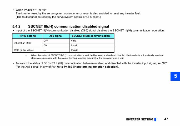
5.4.2 SSCNET III(/H) communication disabled signal • Input of the SSCNET III(/H) communication disabled (X85) signal disables the SSC
When the status of SSCNET III(/H) communication is switched between enabled and dstops communication with the master (or the preceding axis unit) or the succeeding axi
• To switch the status of SSCNET III(/H) communication between enabled and disable(for the X85 signal) in any of Pr.178 to Pr.189 (Input terminal function selection)
Pr.499 setting X85 signal SSCNET III(/H) communication
Other than 9999OFF Valid
ON Invalid
9999 (initial value) Invalid

required regardless of the control
/H) operation selection, always match (CW/CCW) of the encoder as viewed n selection.
(as viewed from the load side)
When positioning address becomes smaller
CCW
CW
CW
CCW
ckwise (CW)
48 INVERTER SETTING
5.4.3 Pr.379 SSCNET III(/H) rotation direction selectionThe rotation direction of the motor can be changed using Pr.379. (Setting of Pr.379 is method.)To operate the inverter under Vector control when "0 or 1" is set in Pr.499 SSCNET III(the setting of Pr.359 Encoder rotation direction (0, 100/1, 101) and rotation directionfrom the load side of the motor before setting Pr.379 SSCNET III(/H) rotation directio
The motor direction (CW, CCW) is as follows:
Pr.359 setting Pr.379 settingMotor rotation direction
When positioning addressbecomes greater
0, 1000 (initial value) CW
1 CCW
1 (initial value), 1010 (initial value) CCW
1 CW
Motor rotation direction Description
CW
Set when using a motor for which forward rotation (encoder) is cloviewed from the shaft
CCW
Set when using a motor for which forward rotation (encoder) is counterclockwise (CCW) viewed from the shaft
CW
CCW

INVERTER SETTING 49
1
5
1
g input signals.
"88"
"89"
"76"
5.4.4 Pr.449 SSCNET III(/H) input filter settingUse Pr.449 SSCNET III(/H) input filter setting to select a filter setting for the followin
Change in the Pr.449 setting is immediately applied.
Input signal Parameter setting
LSP (Upper stroke limit) signal Pr.178 to Pr.189 (Input terminal function selection) =
STF (Upper stroke limit) signal Pr.178 STF terminal function selection = "60"
LSN (Lower stroke limit) signal Pr.178 to Pr.189 (Input terminal function selection) =
STR (Lower stroke limit) signal Pr.179 STR terminal function selection = "61"
X76 (Proximity dog) signal Pr.178 to Pr.189 (Input terminal function selection) =
Pr.449 setting Input signal filter (maximum)
0 N/A (0.88 ms sampling)
1 0.88 ms
2 1.77 ms
3 2.66 ms
4 (initial value) 3.55 ms

o system controller via an inverter input ty dog) in any of Pr.178 to Pr.189 (Input
rminal, set "88" (for the LSP signal, Pr.189 (Input terminal function ller similarly with the STF signal (when nal (when "61" (initial value) is set in rity than the STF or STR signal.)
e as follows depending on the setting of
"9". The setting is applied after an inverter reset.
Pr. 880 Load inertia ratio.
esponse operation is applied during vector
anual (Detailed) of the inverter.on the command from the servo system controller.
speed, torque, position) Operation without motor
the servo system controllerInvalid
Valid
50 INVERTER SETTING
5.4.5 Input terminal function selection • To use home position return with proximity dog (to input the DOG signal to the serv
terminal) in SSCNET III(/H) communication, set "76" (for the X76 signal and proximiterminal function selection).
• To input the FLS or RLS signal to the servo system controller via an inverter input teupper stroke limit) or "89" (for the LSN signal, lower stroke limit) in any of Pr.178 toselection). (Though the FLS or RLS signal can be input to the servo system contro"60" (initial value) is set in Pr.178 STF terminal function selection) or the STR sigPr.179 STR terminal function selection), the LSP or LSN signal has a higher prio
5.4.6 Control method selection Pr.800 Control method selectionSpecifications of Pr.800 Control method selection when the FR-A8NS is installed arPr.499 SSCNET III(/H) operation selection.
Reset the inverter after the Pr.800 setting is switched between "9" and any of other than When "9" is set in Pr. 800, test run is available without connecting a motor. When "9" (vector control test operation) is set in Pr. 800, it is recommended to set "0" in
For the details of Pr.880, refer to the Instruction Manual (Detailed) of the inverter. Setting Pr.800 = "100 or higher" does not select the fast-response operation. (Normal-r
control.) For the setting method of the control method and control mode, refer to the Instruction M When the control mode can be switched (Pr.800 = "2", etc.), the control mode depends
Pr.499 setting Pr.800 setting Control method Control mode (
0, 101Other than 9 Vector control
As commanded by 9 Vector control test operation,
100,101 Control method depending on the parameter setting of the inverter, ,

INVERTER SETTING 51
1
5
1
: Valid, : Invalid, : Unsupported, the setting of 4 poles is applied to the operation. control for the command from the servo system
ction cable for connection between the FR-A8AP
in May 2017 or later.
Pr.499 = "100 or 101"odeSpeed control
Torque control
Position control
Availability of control mode when the FR-A8NS is used
Set Pr.81 Number of motor poles even under V/F control. When "9999" is set in Pr.81 When "6" (torque control by a variable-current limiter) is set in Pr.800, select the speed
controller. The FR-A8AP or FR-A8AL plug-in option is required. Use the FR-A8AP/FR-A8AL conne
or FR-A8AL and the FR-A8NS. A Vector control compatible option is required. To perform position control with the FR-A8AL installed, use the FR-A8AL manufactured
Control method
Pr.499 = "0 or 1"Control m
Speed control
Torque control
Position control
V/F control
Advanced magnetic flux vector control
Real sensorless vector control
Vector controlInduction motor
PM motor
PM sensorless vector control

ontrol method and the feedback control
rotation is changed, the change is applied
the transient command (encoder
Number of pulsesinginginginginging024ingf pulses actually sent from feedback deviceing
r poles / 8
52 INVERTER SETTING
The number of pulses per motor rotationThe number of pulses output by a feedback device per motor rotation depends on the coption as follows.
NOTE • When the setting of the control method or the number of pulses per motor
after the CPU of servo system controller is reset or at the next power-ON. • Use MT Developer2 to check the number of pulses per motor rotation. Use
resolution) of the optional data monitor setting function of MT Developer2.
Control method Feedback control option
Vector control
FR-A8AL Pr.862 = "0" Pr.369 settPr.862 = "1" Pr.851 sett
FR-A8AP Pr.862 = "0" Pr.369 settPr.862 = "1" Pr.851 sett
FR-A8TP Pr.862 = "0" Pr.369 settPr.862 = "1" Pr.851 sett
FR-A8APR Pr.862 = "0" Fixed to 1Pr.862 = "1" Pr.851 sett
FR-A8APS Pr.862 = "0" Number oPr.862 = "1" Pr.851 sett
PM sensorless vector control(MM-CF motor) None 1024 × number of moto
V/F controlAdvanced magnetic flux vector controlReal sensorless vector control
None Pr.369 setting

INVERTER SETTING 53
1
5
1
sition control.
ilable.
quired for data update and g of Pr.499 SSCNET III(/H) operation
by device type
r Endat IPM motor (MM-CF)
Estimates by the motor speed
Not available Not available
Data and device for position controlThe following shows the availability and difference of data by the type of devices for po
Even if an absolute multi-revolution encoder is used, only incremental positioning is ava
Data transmission delayDue to periodic data update in the inverter, data transmission is delayed by a period recommunication cycle. The required time for data update varies depending on the settinselection. The affected items and the required time are as follows.
Position information Description of information
Data
Encoder Resolve
Position feedbackAccumulated value of feedback pulses sent from a feedback device since power-ON
Actual feedback from the device
Absolute position
Once the home position is set at start-up, the current position information is retained even after power-OFF.
Not available Not available
Item Pr.499 = "0 or 1" Pr.499 = "100 or 101"Motor load factor 10 ms 10 msPosition feedback 222 μs 1.5 msPosition of the encoder within one revolution 222 μs 1.5 ms
Multi-revolution encoder counter 222 μs 1.5 ms
Load inertia moment ratio 10 ms 10 msPosition loop gain 10 ms 10 msConverter output voltage 5 ms 5 ms

s.e functions are disabled. For the details inverter.
on
ure
ration/deceleration (Pr.424)
54 RESTRICTIONS ON THE FUNCTIONS
6 RESTRICTIONS ON THE FUNCTIONS
6.1 Function restriction listInvalid inverter functions during SSCNET III(/H) communication operation are as followWhile the following functions are invalid, signal input/output and monitoring related to thof the related I/O signals and monitors, refer to the Instruction Manual (Detailed) of the
Item Functi
A: Application parameters
• Automatic restart after instantaneous power fail• Electronic bypass function• Brake sequence function• Stop-on-contact control• Load torque high-speed frequency control• Traverse function• Anti-sway control• Orientation control• PID control• Power failure time deceleration-to-stop function• Stop selection function• Inverter operation lock mode setting (Pr.415)• PLC function
B: Position control parameters
• Simple positioning function by parameters• Position control by inverter pulse train input• Position command source selection (Pr.419)• Position command constant value during accele• Clear signal selection (Pr.429)• Model position control gain (Pr.446)
C: Motor constant parameters • Offline auto tuning• Encoder position tuning

IONS ON THE FUNCTIONS 55
1
6
nd source during communication operationting, pulse train input
celeration pattern selection
sition control, and start-time hold function
agnetic flux vector control, Real sensorless
it, reverse rotation speed limit/reverse-side
on
at start
on
RESTRICT
D: Parameters for operation command and frequency command
• Operation mode selection• Operation command source and speed comma• Multi-speed setting, JOG operation, remote set
E: Environment setting parameters • IPM parameter initialization
F: Parameters for settings of acceleration/deceleration time and acceleration/deceleration pattern
• Acceleration/deceleration time, acceleration/de• Remote setting• Starting frequency during speed control or po• Automatic acceleration/deceleration• Emergency stop function (Pr.1103)
G: Control Parameters
• V/F control, adjustable 5 points V/F, Advanced mvector control, PM sensorless vector control
• DC injection brake• Brake operation selection• Output stop function• Stop selection• Regeneration avoidance function• Strengthened excitation deceleration• Torque bias
H: Protective function parameters
• Speed limit selection, forward rotation speed limspeed limit, speed limit method selection
• Torque limit level during acceleration/decelerati• Fault definition• Retry function• Ground fault detection enable/disable selection• Minimum frequency• Frequency jump• Speed limit (Pr.873)• Speed deviation excess (Pr.285)• Deceleration check time
Item Functi

III(/H) communication.
ond/third output frequency detection)
r.502)r (Pr.779)
hen Pr.800 = "100 or higher")
on
56 RESTRICTIONS ON THE FUNCTIONS
Except starting frequency during torque control Terminal 6 can be used only when the FR-A8AZ is installed. The function is enabled when "100 or 101" is set in Pr.499.
NOTE • Do not execute Parameter clear or All parameter clear during the SSCNET
T: Multi-function input terminal parameters
• Override function• Functions for terminals 1, 4, 6• Second function selection signal (RT)• Third function selection signal (X9) (except sec
N: Parameters for communication operation and its settings
• Stop mode selection at communication error (P• Operation frequency during communication erro
Parameters for vector control• Magnetic flux command• Torque command reverse selection (Pr.1114)• Fast-response operation under vector control (w
Plug-in options • FR-A8AX, FR-A8APR, FR-A8APS
Item Functi

IONS ON THE FUNCTIONS 57
1
6
26 Terminal 4 frequency setting gain frequency
27 PID control automatic switchover frequency
28 PID action selection29 PID proportional band30 PID integral time31 PID upper limit32 PID lower limit33 PID action set point34 PID differential time
35 Electronic bypass sequence selection
36 MC switchover interlock time37 Start waiting time38 Bypass selection at a fault
39 Automatic switchover frequency from inverter to bypass operation
47 Acceleration/deceleration time switching frequency
48 Stall prevention level at 0 V input49 Stall prevention level at 10 V input
55 RT signal function validity condition selection
Pr. Name
RESTRICT
6.2 Inverter parameter listThe setting of the following parameters is invalid when the FR-A8NS is installed.
6.2.1 Invalid parameters when the FR-A8NS is used
Pr. Name 4 Multi-speed setting (high speed) 5 Multi-speed setting (middle speed) 6 Multi-speed setting (low speed)15 Jog frequency16 Jog acceleration/deceleration time24 Multi-speed setting (speed 4)25 Multi-speed setting (speed 5)26 Multi-speed setting (speed 6)27 Multi-speed setting (speed 7)
28 Multi-speed input compensation selection
44 Second acceleration/deceleration time
45 Second deceleration time46 Second torque boost47 Second V/F (base frequency)
48 Second stall prevention operation level
49 Second stall prevention operation frequency
51 Second electronic thermal O/L relay57 Restart coasting time58 Restart cushion time
59 Remote function selection61 Reference current62 Reference value at acceleration63 Reference value at deceleration64 Starting frequency for elevator mode65 Retry selection67 Number of retries at fault occurrence68 Retry waiting time69 Retry count display erase73 Analog input selection74 Input filter time constant79 Operation mode selection96 Auto tuning setting/status110 Third acceleration/deceleration time111 Third deceleration time112 Third torque boost113 Third V/F (base frequency)114 Third stall prevention operation level
115 Third stall prevention operation frequency
125 Terminal 2 frequency setting gain frequency
Pr. Name
1
1
1111111
1
111
1
1
11
1

91 Pulse train I/O selection92 Automatic acceleration/deceleration
93 Acceleration/deceleration separate selection
94 UV avoidance voltage gain98 Frequency search gain
99 Rotation direction detection selection at restarting
00 BCD input bias01 BCD input gain02 BIN input bias03 BIN input gain
04Digital input and analog input compensation enable/disable selection
05 Read timing operation selection25 Terminal 40 input selection29 Digital input unit selection
38 Communication operation command source
39 Communication speed command source
40 Communication startup mode selection
45 DeviceNet address46 DeviceNet/ControlNet baud rate47 CANopen address48 CANopen baud rate
Pr. Name
58 RESTRICTIONS ON THE FUNCTIONS
159Automatic switchover frequency range from bypass to inverter operation
162 Automatic restart after instantaneous power failure selection
163 First cushion time for restart164 First cushion voltage for restart
165 Stall prevention operation level for restart
232 Multi-speed setting (speed 8)233 Multi-speed setting (speed 9)234 Multi-speed setting (speed 10)235 Multi-speed setting (speed 11)236 Multi-speed setting (speed 12)237 Multi-speed setting (speed 13)238 Multi-speed setting (speed 14)239 Multi-speed setting (speed 15)241 Analog input display unit switchover
242 Terminal 1 added compensation amount (terminal 2)
243 Terminal 1 added compensation amount (terminal 4)
248 Self power management selection250 Stop selection252 Override bias253 Override gain254 Main circuit power OFF waiting time261 Power failure stop selection
Pr. Name
262 Subtracted frequency at deceleration start
263 Subtraction starting frequency264 Power-failure deceleration time 1265 Power-failure deceleration time 2
266 Power failure deceleration time switchover frequency
267 Terminal 4 input selection
270 Stop-on contact/load torque high-speed frequency control selection
271 High-speed setting maximum current
272 Middle-speed setting minimum current
273 Current averaging range274 Current averaging filter time constant
275 Stop-on contact excitation current low-speed multiplying factor
276 PWM carrier frequency at stop-on contact
278 Brake opening frequency279 Brake opening current280 Brake opening current detection time281 Brake operation time at start282 Brake operation frequency283 Brake operation time at stop
284 Deceleration detection function selection
285 Overspeed detection frequency
Pr. Name22
2
22
2
3333
3
333
3
3
3
3333

IONS ON THE FUNCTIONS 59
1
6
50 Second applied motor
51 Second motor control method selection
53 Second motor capacity54 Number of second motor poles55 Second motor excitation current56 Rated second motor voltage57 Rated second motor frequency58 Second motor constant (R1)59 Second motor constant (R2)
60 Second motor constant (L1) / d-axis inductance (Ld)
61 Second motor constant (L2) / q-axis inductance (Lq)
62 Second motor constant (X)
63 Second motor auto tuning setting/status
64 Digital position control sudden stop deceleration time
65 First target position lower 4 digits66 First target position upper 4 digits67 Second target position lower 4 digits68 Second target position upper 4 digits69 Third target position lower 4 digits70 Third target position upper 4 digits71 Fourth target position lower 4 digits72 Fourth target position upper 4 digits73 Fifth target position lower 4 digits
Pr. Name
RESTRICT
349 Communication reset selection350 Stop position command selection351 Orientation speed352 Creep speed353 Creep switchover position354 Position loop switchover position355 DC injection brake start position356 Internal stop position command357 Orientation in-position zone358 Servo torque selection360 16-bit data selection361 Position shift362 Orientation position loop gain363 Completion signal output delay time364 Encoder stop check time365 Orientation limit366 Recheck time
373 Encoder position tuning setting/status
384 Input pulse division scaling factor385 Frequency for zero input pulse386 Frequency for maximum input pulse387 Initial communication delay time388 Send time interval at heart beat389 Minimum sending time at heart beat390 % setting reference frequency391 Receive time interval at heart beat
Pr. Name392 Event driven detection width393 Orientation selection394 Number of machine side gear teeth395 Number of motor side gear teeth396 Orientation speed gain (P term)397 Orientation speed integral time398 Orientation speed gain (D term)399 Orientation deceleration ratio
406 High resolution analog input selection
415 Inverter operation lock mode setting419 Position command source selection
420Command pulse scaling factor numerator (electronic gear numerator)
421Command pulse multiplication denominator (electronic gear denominator)
424 Position command acceleration/deceleration time constant
428 Command pulse selection429 Clear signal selection432 Pulse train torque command bias433 Pulse train torque command gain434 Network number (CC-Link IE)435 Station number (CC-Link IE)447 Digital torque command bias448 Digital torque command gain
Pr. Name4
4
4444444
4
4
4
4
4
444444444

77 Output interruption cancel level92 Traverse function selection93 Maximum amplitude amount
94 Amplitude compensation amount during deceleration
95 Amplitude compensation amount during acceleration
96 Amplitude acceleration time97 Amplitude deceleration time
06 Power failure stop external signal input selection
08 Second motor permissible load level
09 PID set point/deviation input selection
10 PID measured value input selection11 Acceleration time at a restart
35 Cumulative pulse clear signal selection
36 Cumulative pulse division scaling factor
37 Control terminal option-Cumulative pulse division scaling factor
38 Cumulative pulse storage39 Brake opening current selection40 Brake operation frequency selection
41 Second brake sequence operation selection
42 Second brake opening frequency43 Second brake opening current
Pr. Name
60 RESTRICTIONS ON THE FUNCTIONS
474 Fifth target position upper 4 digits475 Sixth target position lower 4 digits476 Sixth target position upper 4 digits477 Seventh target position lower 4 digits478 Seventh target position upper 4 digits479 Eighth target position lower 4 digits480 Eighth target position upper 4 digits481 Ninth target position lower 4 digits482 Ninth target position upper 4 digits483 Tenth target position lower 4 digits484 Tenth target position upper 4 digits485 Eleventh target position lower 4 digits
486 Eleventh target position upper 4 digits
487 Twelfth target position lower 4 digits488 Twelfth target position upper 4 digits
489 Thirteenth target position lower 4 digits
490 Thirteenth target position upper 4 digits
491 Fourteenth target position lower 4 digits
492 Fourteenth target position upper 4 digits
493 Fifteenth target position lower 4 digits
494 Fifteenth target position upper 4 digits
498 PLC function flash memory clear
Pr. Name
500 Communication error execution waiting time
501 Communication error occurrence count display
502 Stop mode selection at communication error
522 Output stop frequency541 Frequency command sign selection
542 Communication station number (CC-Link)
543 Baud rate selection (CC-Link)544 CC-Link extended setting
550 NET mode operation command source selection
551 PU mode operation command source selection
553 PID deviation limit554 PID signal operation selection560 Second frequency search gain562 ControlNet data
565 Second motor excitation current break point
566 Second motor excitation current low-speed scaling factor
569 Second motor speed control gain573 4 mA input check selection574 Second motor online auto tuning575 Output interruption detection time576 Output interruption detection level
Pr. Name555
5
5
55
6
6
6
66
6
6
6
666
6
66

IONS ON THE FUNCTIONS 61
1
6
67 Second pre-charge ending time
68 Second pre-charge upper detection level
69 Second pre-charge time limit
77 4 mA input check operation frequency
78 4 mA input check filter
79 Operation frequency during communication error
04 Torque command source selection05 Torque command value (RAM)
06 Torque command value (RAM, EEPROM)
07 Speed limit selection
08 Forward rotation speed limit/speed limit
09 Reverse rotation speed limit/reverse-side speed limit
10 Torque limit input method selection22 Speed setting filter 126 Torque setting filter 1
29 Number of machine end encoder pulses
32 Speed setting filter 233 Speed detection filter 236 Torque setting filter 237 Torque detection filter 240 Torque bias selection
Pr. Name
RESTRICT
644 Second brake opening current detection time
645 Second brake operation time at start646 Second brake operation frequency647 Second brake operation time at stop
648 Second deceleration detection function selection
650 Second brake opening current selection
651 Second brake operation frequency selection
668 Power failure stop frequency gain679 Second droop gain680 Second droop filter time constant
681 Second droop function activation selection
682 Second droop break point gain683 Second droop break point torque690 Deceleration check time
692 Second free thermal reduction frequency 1
693 Second free thermal reduction ratio 1
694 Second free thermal reduction frequency 2
695 Second free thermal reduction ratio 2
696 Second free thermal reduction frequency 3
738 Second motor induced voltage constant (phi f)
Pr. Name739 Second motor Ld decay ratio740 Second motor Lq decay ratio
741 Second starting resistance tuning compensation
742 Second motor magnetic pole detection pulse width
743 Second motor maximum frequency744 Second motor inertia (integer)745 Second motor inertia (exponent)
746 Second motor protection current level
747 Second motor low-speed range torque characteristic selection
753 Second PID action selection
754 Second PID control automatic switchover frequency
755 Second PID action set point756 Second PID proportional band757 Second PID integral time758 Second PID differential time759 PID unit selection760 Pre-charge fault selection761 Pre-charge ending level762 Pre-charge ending time763 Pre-charge upper detection level764 Pre-charge time limit765 Second pre-charge fault selection766 Second pre-charge ending level
Pr. Name7
7
7
7
7
7
88
8
8
8
8
888
8
88888

35928) Terminal 6 bias (torque)
36929) Terminal 6 gain command (torque)
37929) Terminal 6 gain (torque)
8930) Current output bias signal
9930) Current output bias current
10931) Current output gain signal
11931) Current output gain current
38932)
Terminal 4 bias command (torque/magnetic flux)
39932)
Terminal 4 bias (torque/magnetic flux)
40933)
Terminal 4 gain command (torque/magnetic flux)
41933)
Terminal 4 gain (torque/magnetic flux)
42934) PID display bias coefficient
43934) PID display bias analog value
44935) PID display gain coefficient
45935) PID display gain analog value
Pr. Name
62 RESTRICTIONS ON THE FUNCTIONS
841 Torque bias 1842 Torque bias 2843 Torque bias 3844 Torque bias filter845 Torque bias operation time846 Torque bias balance compensation847 Fall-time torque bias terminal 1 bias848 Fall-time torque bias terminal 1 gain849 Analog input offset adjustment858 Terminal 4 function assignment
860 Second motor torque current/Rated PM motor current
863 Control terminal option-Encoder pulse division ratio
868 Terminal 1 function assignment876 Thermal protector inputC2(902)
Terminal 2 frequency setting bias frequency
C3(902) Terminal 2 frequency setting bias
125(903)
Terminal 2 frequency setting gain frequency
C4(903) Terminal 2 frequency setting gain
C5(904)
Terminal 4 frequency setting bias frequency
C6(904) Terminal 4 frequency setting bias
Pr. Name126(905)
Terminal 4 frequency setting gain frequency
C7(905) Terminal 4 frequency setting gain
C12(917) Terminal 1 bias frequency (speed)
C13(917) Terminal 1 bias (speed)
C14(918) Terminal 1 gain frequency (speed)
C15(918) Terminal 1 gain (speed)
C16(919)
Terminal 1 bias command (torque/magnetic flux)
C17(919)
Terminal 1 bias (torque/magnetic flux)
C18(920)
Terminal 1 gain command (torque/magnetic flux)
C19(920)
Terminal 1 gain (torque/magnetic flux)
C30(926) Terminal 6 bias frequency (speed)
C31(926) Terminal 6 bias (speed)
C32(927) Terminal 6 gain frequency (speed)
C33(927) Terminal 6 gain (speed)
C34(928) Terminal 6 bias command (torque)
Pr. NameC(C(C(C(C(C(C(C(C(C(C(C(C(C(C(

IONS ON THE FUNCTIONS 63
1
6
231 Third positioning deceleration time232 Third positioning dwell time233 Third positioning sub-function234 Fourth positioning acceleration time235 Fourth positioning deceleration time236 Fourth positioning dwell time237 Fourth positioning sub-function238 Fifth positioning acceleration time239 Fifth positioning deceleration time240 Fifth positioning dwell time241 Fifth positioning sub-function242 Sixth positioning acceleration time243 Sixth positioning deceleration time244 Sixth positioning dwell time245 Sixth positioning sub-function
246 Seventh positioning acceleration time
247 Seventh positioning deceleration time
248 Seventh positioning dwell time249 Seventh positioning sub-function250 Eighth positioning acceleration time251 Eighth positioning deceleration time252 Eighth positioning dwell time253 Eighth positioning sub-function254 Ninth positioning acceleration time255 Ninth positioning deceleration time
Pr. Name
RESTRICT
1015 Integral stop selection at limited frequency
1072 DC brake judgment time for anti-sway control operation
1073 Anti-sway control operation selection1074 Anti-sway control frequency1075 Anti-sway control depth1076 Anti-sway control width1077 Rope length1078 Trolley weight1079 Load weight
1105 Encoder magnetic pole position offset
1109 PROFIBUS communication command source selection
1110 PROFIBUS format selection1113 Speed limit method selection1114 Torque command reverse selection1134 PID upper limit manipulated value1135 PID lower limit manipulated value1136 Second PID display bias coefficient
1137 Second PID display bias analog value
1138 Second PID display gain coefficient
1139 Second PID display gain analog value
1140 Second PID set point/deviation input selection
Pr. Name
1141 Second PID measured value input selection
1142 Second PID unit selection1143 Second PID upper limit1144 Second PID lower limit1145 Second PID deviation limit
1146 Second PID signal operation selection
1147 Second output interruption detection time
1148 Second output interruption detection level
1149 Second output interruption cancel level
1150 to 1199 User parameters 1 to 50
1220 Target position/speed selection
1221 Start command edge detection selection
1222 First positioning acceleration time1223 First positioning deceleration time1224 First positioning dwell time1225 First positioning sub-function1226 Second positioning acceleration time1227 Second positioning deceleration time1228 Second positioning dwell time1229 Second positioning sub-function1230 Third positioning acceleration time
Pr. Name111111111111111
1
1
11111111

299 Second pre-excitation selection300
o 343
Option parameter 1 to 44
350 o 359
Option information 1 to 10
400 Low-speed range speed control P gain 1
401 Low-speed range speed control P gain 2
402 Low-speed range gain corner frequency 1
403 Low-speed range gain corner frequency 2
404 Shortest-time torque startup selection
405 Overload detection time406 Inching prevention time
407 Magnetic flux command during pre-excitation
408 Brake opening current for reverse rotation
409 Second brake opening current for reverse rotation
412 Motor induced voltage constant (phi f) exponent
413 Second motor induced voltage constant (phi f) exponent
432 Ethernet communication check time interval
Pr. Name
64 RESTRICTIONS ON THE FUNCTIONS
1256 Ninth positioning dwell time1257 Ninth positioning sub-function1258 Tenth positioning acceleration time1259 Tenth positioning deceleration time1260 Tenth positioning dwell time1261 Tenth positioning sub-function
1262 Eleventh positioning acceleration time
1263 Eleventh positioning deceleration time
1264 Eleventh positioning dwell time1265 Eleventh positioning sub-function1266 Twelfth positioning acceleration time1267 Twelfth positioning deceleration time1268 Twelfth positioning dwell time1269 Twelfth positioning sub-function
1270 Thirteenth positioning acceleration time
1271 Thirteenth positioning deceleration time
1272 Thirteenth positioning dwell time1273 Thirteenth positioning sub-function
1274 Fourteenth positioning acceleration time
1275 Fourteenth positioning deceleration time
1276 Fourteenth positioning dwell time1277 Fourteenth positioning sub-function
Pr. Name
1278 Fifteenth positioning acceleration time
1279 Fifteenth positioning deceleration time
1280 Fifteenth positioning dwell time1281 Fifteenth positioning sub-function
1282 Home position return method selection
1283 Home position return speed1284 Home position return creep speed
1285 Home position shift amount lower 4 digits
1286 Home position shift amount upper 4 digits
1287 Travel distance after proximity dog ON lower 4 digits
1288 Travel distance after proximity dog ON upper 4 digits
1289 Home position return stopper torque
1290 Home position return stopper waiting time
1292 Position control terminal input selection
1293 Roll feeding mode selection1294 Position detection lower 4 digits1295 Position detection upper 4 digits1296 Position detection selection1297 Position detection hysteresis width1298 Second position control gain
Pr. Name11t11t1
1
1
1
1
1
11
1
1
1
1
1
1

IONS ON THE FUNCTIONS 65
1
6
0 or 1" is set in Pr.499
453 Ethernet command source selection IP address 3 range specification
454 Ethernet command source selection IP address 4 range specification
Pr. Name
02 V/F2 (second frequency)03 V/F2 (second frequency voltage)04 V/F3 (third frequency)05 V/F3 (third frequency voltage)06 V/F4 (fourth frequency)07 V/F4 (fourth frequency voltage)08 V/F5 (fifth frequency)09 V/F5 (fifth frequency voltage)
40 Backlash acceleration stopping frequency
41 Backlash acceleration stopping time
42 Backlash deceleration stopping frequency
43 Backlash deceleration stopping time
54 Voltage reduction selection during stall prevention operation
45 Rated slip46 Slip compensation time constant
Pr. Name
RESTRICT
6.2.2 Invalid parameters when the FR-A8NS is used and "
1449 Ethernet command source selection IP address 1
1450 Ethernet command source selection IP address 2
Pr. Name
1451 Ethernet command source selection IP address 3
1452 Ethernet command source selection IP address 4
Pr. Name
1
1
Pr. Name 0 Torque boost 2 Minimum frequency 3 Base frequency 7 Acceleration time 8 Deceleration time
10 DC injection brake operation frequency
11 DC injection brake operation time12 DC injection brake operation voltage13 Starting frequency14 Load pattern selection19 Base frequency voltage
20 Acceleration/deceleration reference frequency
21 Acceleration/deceleration time increments
23 Stall prevention operation level compensation factor at double speed
29 Acceleration/deceleration pattern selection
31 Frequency jump 1A32 Frequency jump 1B33 Frequency jump 2A34 Frequency jump 2B35 Frequency jump 3A36 Frequency jump 3B41 Up-to-frequency sensitivity60 Energy saving control selection
66 Stall prevention operation reduction starting frequency
85 Excitation current break point
86 Excitation current low speed scaling factor
89 Speed control gain (Advanced magnetic flux vector)
100 V/F1 (first frequency)101 V/F1 (first frequency voltage)
Pr. Name11111111
1
1
1
1
1
22
This parameter is used for the FR-A800-CRN. This parameter is used for the FR-A800-E.

52 Control terminal option-Encoder rotation direction
55 Control terminal option-Signal loss detection enable/disable selection
62 Encoder option selection73 Speed limit75 Fault definition
82 Regeneration avoidance operation selection
83 Regeneration avoidance operation level
84 Regeneration avoidance at deceleration detection sensitivity
85 Regeneration avoidance compensation frequency limit value
86 Regeneration avoidance voltage gain98 PM parameter initialization
002 Lq tuning target current adjustment coefficient
424 Ethernet communication network number
425 Ethernet communication station number
426 Link speed and duplex mode selection
427 Ethernet function selection 1428 Ethernet function selection 2429 Ethernet function selection 3
431 Ethernet signal loss detection function selection
Pr. Name
66 RESTRICTIONS ON THE FUNCTIONS
247 Constant-power range slip compensation selection
249 Earth (ground) fault detection at start
285 Speed deviation excess detection frequency
380 Acceleration S-pattern 1381 Deceleration S-pattern 1382 Acceleration S-pattern 2383 Deceleration S-pattern 2446 Model position control gain
516 S-pattern time at a start of acceleration
517 S-pattern time at a completion of acceleration
518 S-pattern time at a start of deceleration
519 S-pattern time at a completion of deceleration
552 Frequency jump range555 Current average time556 Data output mask time
557 Current average value monitor signal output reference current
571 Holding time at a start
617 Reverse rotation excitation current low-speed scaling factor
653 Speed smoothing control654 Speed smoothing cutoff frequency
Pr. Name
660 Increased magnetic excitation deceleration operation selection
661 Magnetic excitation increase rate
662 Increased magnetic excitation current level
665 Regeneration avoidance frequency gain
673 SF-PR slip amount adjustment operation selection
674 SF-PR slip amount adjustment gain702 Maximum motor frequency706 Induced voltage constant (phi f)711 Motor Ld decay ratio712 Motor Lq decay ratio
717 Starting resistance tuning compensation
721 Starting magnetic pole position detection pulse width
725 Motor protection current level
788 Low speed range torque characteristic selection
791 Acceleration time in low-speed range792 Deceleration time in low-speed range802 Pre-excitation selection816 Torque limit level during acceleration817 Torque limit level during deceleration850 Brake operation selection
851 Control terminal option-Number of encoder pulses
Pr. Name
8
8
888
8
8
8
8
89
1
1
1
1
111
1

IONS ON THE FUNCTIONS 67
1
6
485 Load characteristics load reference 5
486 Load characteristics maximum frequency
487 Load characteristics minimum frequency
488 Upper limit warning detection width489 Lower limit warning detection width490 Upper limit fault detection width491 Lower limit fault detection width
492Load status detection signal delay time / load reference measurement waiting time
Pr. Name
RESTRICT
NOTE • Ethernet is a registered trademark of Fuji Xerox Co., Ltd.
1434 Ethernet IP address 11435 Ethernet IP address 21436 Ethernet IP address 31437 Ethernet IP address 41438 Subnet mask 11439 Subnet mask 21440 Subnet mask 31441 Subnet mask 41442 Ethernet IP filter address 11443 Ethernet IP filter address 21444 Ethernet IP filter address 31445 Ethernet IP filter address 4
Pr. Name
1446 Ethernet IP filter address 2 range specification
1447 Ethernet IP filter address 3 range specification
1448 Ethernet IP filter address 4 range specification
1455 Keepalive time
1480 Load characteristics measurement mode
1481 Load characteristics load reference 11482 Load characteristics load reference 21483 Load characteristics load reference 31484 Load characteristics load reference 4
Pr. Name1
1
1
1111
1
This parameter is used for the FR-A800-E.

68 Instructions for SSCNET III(/H) communication
7 Instructions for SSCNET III(/H) communication
• During SSCNET III(/H) communication, the inverter parameter cannot be changed with the servo system controller. When Pr.77 Parameter write selection = "2", the parameter settings can be changed on the PU even if the inverter is set in the SSCNET III(/H) operation mode.
• The valid command for an inverter start or stop is given via the SSCNET III(/H) communication. Though the STF and STR signals are invalid, the STF signal is used as the Upper stroke limit signal and the STF signal as the Lower stroke limit signal.
• Before starting operation, always give the servo-ON signal from the host controller to the motor in order to set the motor in the servo lock state.
• Running speed depends on the command from the servo system controller. (The rotation direction depends on the setting of Pr.379 SSCNET III(/H) rotation direction selection.)
• Droop control cannot be performed when "0 or 1" is set in Pr.499 SSCNET III(/H) operation selection and "0 or 10" (droop control is disabled during acceleration/deceleration) is set in Pr.288 Droop function activation selection. Set a value other than "0 or 10" in Pr.288. (For the details, refer to the Instruction Manual (Detailed) of the inverter.)
• The fault indication "E.OC3" or "E.OV3" is displayed when the inverter stops due to an overcurrent trip or overvoltage trip during SSCNET III(/H) operation. (For the details, refer to the Instruction Manual (Detailed) of the inverter.)
• Offline auto tuning and encoder position tuning cannot be performed with the servo system controller. Perform these tunings with the inverter before starting communication.
• Before shutting off the communication temporarily by resetting the inverter power, disconnecting the SSCNET III cable, or other methods, it is necessary to perform the disconnection/reconnection function for the servo system controller. Refer to the MELSEC iQ-R Motion Controller Programming Manual (Common) for details.
• When the MRS signal is ON, create the motion SFC program that turns ON the servo-OFF command of the target axis. To turn OFF the MRS signal or the servo-OFF command signal, the motor speed must be at 20 r/min or less.
• During the SSCNET III(/H) communication, Pr.998 PM parameter initialization must be set to "0" (initial value) when "0 or 1" is set in Pr.499 SSCNET III(/H) operation selection.
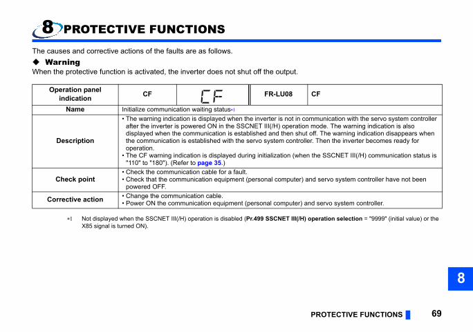
PROTECTIVE FUNCTIONS 69
8
peration selection = "9999" (initial value) or the
CF
munication with the servo system controller mode. The warning indication is also ff. The warning indication disappears when
r. Then the inverter becomes ready for
the SSCNET III(/H) communication status is
d servo system controller have not been
d servo system controller.
8 PROTECTIVE FUNCTIONS
The causes and corrective actions of the faults are as follows. WarningWhen the protective function is activated, the inverter does not shut off the output.
Not displayed when the SSCNET III(/H) operation is disabled (Pr.499 SSCNET III(/H) oX85 signal is turned ON).
Operation panel indication CF FR-LU08
Name Initialize communication waiting status
Description
• The warning indication is displayed when the inverter is not in comafter the inverter is powered ON in the SSCNET III(/H) operation displayed when the communication is established and then shut othe communication is established with the servo system controlleoperation.
• The CF warning indication is displayed during initialization (when "110" to "180"). (Refer to page 35.)
Check point• Check the communication cable for a fault.• Check that the communication equipment (personal computer) an
powered OFF.
Corrective action • Change the communication cable.• Power ON the communication equipment (personal computer) an

outputs the corresponding alarm.the inverter to take the appropriate
Option Fault
L is not inserted to the inverter option d correctly for connection between the FR- or 1" set in Pr.499.tion connector 2.nnection between the FR-A8NS and the FR-
correctly. (Refer to page 20.)tion between the FR-A8NS and the FR-01" in Pr.499.
70 PROTECTIVE FUNCTIONS
FaultWhen any of the protective functions is activated, the inverter shuts off the output and When the protective function is activated, refer to the Instruction Manual (Detailed) of corrective action and reset the inverter to perform operation again.
Operation panel indication E.OPT FR-LU08
Name Option fault
DescriptionThe warning indication is displayed when the FR-A8AP or FR-A8Aconnector 2 or the FR-A8AP/FR-A8AL connection cable is not useA8NS and the FR-A8AP or FR-A8AL to operate the inverter with "0
Check point• Check that the FR-A8AP or FR-A8AL is inserted to the inverter op• Check that the FR-A8AP/FR-A8AL connection cable is used for co
A8AP or FR-A8AL.
Corrective action• Insert the FR-A8AP or FR-A8AL to the inverter option connector 2• Use the FR-A8AP/FR-A8AL connection cable correctly for connec
A8AP or FR-A8AL. (Refer to page 20.) Alternatively, set "100 or 1

PROTECTIVE FUNCTIONS 71
8
Option1 Fault
th FR-A8NS installed and the servo system controller is too high, the output from the en the SSCNET III cable between the FR-r/servo amplifier is disconnected under the
r the servo system controller.ntroller.rter power.
he servo system controller.
Operation panel indication E.OP1 FR-LU08
Name Communication option fault
Description
When the communication line error occurs between the inverter wicontroller, or when the command frequency from the servo systeminverter is stopped. The output from the inverter is also stopped whA8NS and the servo system controller or the preceding axis invertesetting of Pr. 499 SSCNET III(/H) operation selection = "1, 101".
Check point
• Check that the SSCNET III cable is not disconnected.• Check the end of the SSCNET III cable for contamination or dirt.• Check that the SSCNET III cable is not damaged or broken.• Check that electromagnetic noise has not come in the FR-A8NS o• Check for too high command frequency from the servo system co
Corrective action
• Connect the SSCNET III cable securely after turning OFF the inve• Remove the dirt from the end of the SSCNET III cable.• Change the SSCNET III cable.• Take measures against electromagnetic noise for the inverter or t• Review the operation program of the servo system controller.

72 TROUBLESHOOTING
9 TROUBLESHOOTING
Operation mode does not switch to the SSCNET III(/H) operation modeCheck the following points. • Check that the plug-in option is correctly installed to the inverter. (Check for contact fault, cable disconnection, etc.)
Check that the FR-A8AP/FR-A8AL connection cable is used correctly for connection between the FR-A8NS and the FR-A8AP or FR-A8AL to operate the inverter with "0 or 1" set in Pr.499. (Refer to page 20.)
• Check that the SSCNET III cable is connected correctly to the SSCNET III cable connectors (CN1A and CN1B) on the FR-A8NS. (Refer to page 34.)
• Check if Pr.499 SSCNET III(/H) operation selection is set to "9999 (initial value)" or the X85 signal is turned ON. (Refer to page 43.)
73
APPENDIX
Restricted Use of Hazardous Substances in Electronic and Electrical ProductsThe mark of restricted use of hazardous substances in electronic and electrical products is applied to the product as follows based on the “Management Methods for the Restriction of the Use of Hazardous Substances in Electrical and Electronic Products” of the People's Republic of China.
电器电子产品有害物质限制使用标识要求
本产品中所含有的有害物质的名称、含量、含有部件如下表所示。
• 产品中所含有害物质的名称及含量
上表依据SJ/T11364的规定编制。
○:表示该有害物质在该部件所有均质材料中的含量均在GB/T26572规定的限量要求以下。
×:表示该有害物质在该部件的至少一种均质材料中的含量超出GB/T26572规定的限量要求。 即使表中记载为 ×,根据产品型号,也可能会有有害物质的含量为限制值以下的情况。
根据产品型号,一部分部件可能不包含在产品中。
环境保护使用期限标识
部件名称有害物质
铅(Pb) 汞(Hg) 镉(Cd) 六价铬(Cr(VI)) 多溴联苯(PBB) 多溴二苯醚(PBDE)
电路板组件(包括印刷电路板及其构成的零部件,如电阻、电容、集成电路、连接器等)、电子部件
金属壳体、金属部件
树脂壳体、树脂部件
螺丝、电线

74 IB(NA)-0600599ENG-E
REVISIONS*The manual number is given on the bottom left of the back cover.
Print date *Manual number Revision
Aug. 2015 IB(NA)-0600599ENG-A First edition
Nov. 2015 IB(NA)-0600599ENG-B Addtion• Compatibility with the SSCNET III/H communication
May 2016 IB(NA)-0600599ENG-C
Modification• Pr.290 Monitor negative output selection and Pr.1018 Monitor with sign selection
settings are valid.Addtion• APPENDIX Restricted Use of Hazardous Substances in Electronic and Electrical
Products
Oct. 2016 IB(NA)-0600599ENG-D Addtion• Setting values "100" and "101" of Pr.499 SSCNET III(/H) operation selection
Apr. 2017 IB(NA)-0600599ENG-EAddtion• Availability of position control at setting "100 or 101" in Pr.499 SSCNET III(/H)
operation selection

FR-A8NS INSTRUCTION M
ANUAL
E
INVERTER
PRE-OPERATION INSTRUCTIONS 1INSTALLATION 2WIRING 3SSCNET III(/H) COMMUNICATION STATUS 4INVERTER SETTING 5RESTRICTIONS ON THE FUNCTIONS 6Instructions for SSCNET III(/H) communication 7PROTECTIVE FUNCTIONS 8TROUBLESHOOTING 9
INVERTERPlug-in option
INSTRUCTION MANUAL
INVERTER
HEAD OFFICE: TOKYO BUILDING 2-7-3, MARUNOUCHI, CHIYODA-KU, TOKYO 100-8310, JAPAN
FR-A8NS
SSCNET III(/H)communication function
IB(NA)-0600599ENG-E(1704) MEE Printed in Japan Specifications subject to change without notice.