MR-JE-_A SERVO AMPLIFIER INSTRUCTION ... - Suport
114
General-Purpose AC Servo MR-JE-_A SERVO AMPLIFIER INSTRUCTION MANUAL(Modbus-RTU Protocol) MODEL MR-JE-_A SERVO AMPLIFIER INSTRUCTION MANUAL (Modbus-RTU Protocol) General-Purpose Interface AC Servo B B
-
Upload
khangminh22 -
Category
Documents
-
view
0 -
download
0
Transcript of MR-JE-_A SERVO AMPLIFIER INSTRUCTION ... - Suport

SH(NA)030177-B(1608)MEE Printed in Japan Specifications are subject to change without notice. This Instruction Manual uses recycled paper.
MODEL
MODELCODE
General-Purpose AC Servo
MR
-JE-_A
SE
RV
O A
MP
LIF
IER
INS
TR
UC
TIO
N M
AN
UA
L(M
od
bu
s-RT
U P
roto
col)
HEAD OFFICE : TOKYO BLDG MARUNOUCHI TOKYO 100-8310
MODEL
MR-JE-_ASERVO AMPLIFIER INSTRUCTION MANUAL(Modbus-RTU Protocol)
General-Purpose Interface AC Servo
1CW708
MR-JE-AINSTRUCTIONMANUAL(MODBUS-RTU)
B
B

A - 1
Safety Instructions Please read the instructions carefully before using the equipment.
To use the equipment correctly, do not attempt to install, operate, maintain, or inspect the equipment until you have read through this Instruction Manual, Installation guide, and appended documents carefully. Do not use the equipment until you have a full knowledge of the equipment, safety information and instructions.
In this Instruction Manual, the safety instruction levels are classified into "WARNING" and "CAUTION".
WARNING Indicates that incorrect handling may cause hazardous conditions, resulting in death or severe injury.
CAUTION Indicates that incorrect handling may cause hazardous conditions, resulting in medium or slight injury to personnel or may cause physical damage.
Note that the CAUTION level may lead to a serious consequence according to conditions.
Please follow the instructions of both levels because they are important to personnel safety. What must not be done and what must be done are indicated by the following diagrammatic symbols.
Indicates what must not be done. For example, "No Fire" is indicated by .
Indicates what must be done. For example, grounding is indicated by .
In this Instruction Manual, instructions at a lower level than the above, instructions for other functions, and so on are classified into "POINT".
After reading this Instruction Manual, keep it accessible to the operator.

A - 2
1. To prevent electric shock, note the following.
WARNING Before wiring and inspections, turn off the power and wait for 15 minutes or more until the charge lamp of the servo amplifier is off. Otherwise, an electric shock may occur. In addition, when confirming whether
the charge lamp is off or not, always confirm it from the front of the servo amplifier.
Ground the servo amplifier and servo motor securely.
Any person who is involved in wiring and inspection should be fully competent to do the work.
Do not attempt to wire the servo amplifier and servo motor until they have been installed. Otherwise, it may cause an electric shock.
Do not operate switches with wet hands. Otherwise, it may cause an electric shock.
The cables should not be damaged, stressed, loaded, or pinched. Otherwise, it may cause an electric shock. To prevent an electric shock, always connect the protective earth (PE) terminal (marked ) of the servo
amplifier to the protective earth (PE) of the cabinet.
To avoid an electric shock, insulate the connections of the power supply terminals.
2. To prevent fire, note the following.
CAUTION Install the servo amplifier, servo motor, and regenerative resistor on incombustible material. Installing them directly or close to combustibles will lead to a fire or smoke generation.
Always connect a magnetic contactor between the power supply and the power supply (L1, L2, and L3) of the servo amplifier, in order to configure a circuit that shuts down the power supply on the side of the servo amplifier’s power supply. If a magnetic contactor is not connected, continuous flow of a large
current may cause a fire or smoke generation when the servo amplifier malfunctions.
In order to configure a circuit that shuts down the power supply on the side of the servo amplifier’s power supply, always connect one molded-case circuit breaker or fuse per one servo amplifier between the
power supply and the power supply (L1, L2, and L3) of a servo amplifier. If a molded-case circuit breaker or fuse is not connected, continuous flow of a large current may cause a fire or smoke generation when the servo amplifier malfunctions.
When using a regenerative resistor, shut off the power supply using an error signal. Not doing so may cause a fire or smoke generation when a regenerative transistor malfunctions or the like may overheat the regenerative transistor.
When using a regenerative option with the MR-JE-40A to MR-JE-100A servo amplifier, remove the built-in regenerative resistor itself and wiring from the servo amplifier.
Provide adequate protection to prevent screws and other conductive matter, oil and other combustible
matter from entering the servo amplifier and servo motor.

A - 3
3. To prevent injury, note the following.
CAUTION Only the voltage specified in the Instruction Manual should be applied to each terminal. Otherwise, a burst, damage, etc. may occur.
Connect cables to the correct terminals. Otherwise, a burst, damage, etc. may occur.
Ensure that polarity (+/-) is correct. Otherwise, a burst, damage, etc. may occur.
The servo amplifier heat sink, regenerative resistor, servo motor, etc., may be hot while the power is on
and for some time after power-off. Take safety measures such as providing covers to avoid accidentally touching them by hands and parts such as cables.
4. Additional instructions The following instructions should also be fully noted. Incorrect handling may cause a malfunction, injury, electric shock, fire, etc.
(1) Transportation and installation
CAUTION Transport the products correctly according to their mass.
Stacking in excess of the specified number of product packages is not allowed.
Do not hold the lead wire of the built-in regenerative resistor when transporting the servo amplifier.
Install the servo amplifier and the servo motor in a load-bearing place in accordance with the Instruction
Manual.
Do not get on or put heavy load on the equipment.
The equipment must be installed in the specified direction.
Leave specified clearances between the servo amplifier and cabinet walls or other equipment.
Do not install or operate the servo amplifier and servo motor which have been damaged or have any parts missing.
Do not block the intake and exhaust areas of the servo amplifier. Otherwise, it may cause a malfunction.
Do not drop or strike the servo amplifier and servo motor. Isolate them from all impact loads.
When you keep or use the equipment, please fulfill the following environment.
Item Environment
Ambient temperature
Operation 0 ˚C to 55 ˚C (non-freezing)
Storage -20 ˚C to 65 ˚C (non-freezing)
Ambient humidity
Operation 5 %RH to 90 %RH (non-condensing)
Storage
Ambience Indoors (no direct sunlight); no corrosive gas, inflammable gas, oil mist or dust
Altitude 1000 m or less above sea level
Vibration resistance 5.9 m/s2, at 10 Hz to 55 Hz (directions of X, Y and Z axes)
When the product has been stored for an extended period of time, contact your local sales office.
When handling the servo amplifier, be careful about the edged parts such as corners of the servo
amplifier.
The servo amplifier must be installed in a metal cabinet.

A - 4
CAUTION When fumigants that contain halogen materials such as fluorine, chlorine, bromine, and iodine are used
for disinfecting and protecting wooden packaging from insects, they cause malfunction when entering our products. Please take necessary precautions to ensure that remaining materials from fumigant do not enter our products, or treat packaging with methods other than fumigation (heat method). Additionally,
disinfect and protect wood from insects before packing products.
(2) Wiring
CAUTION When removing the CNP1 connector of the MR-JE-40A to MR-JE-100A servo amplifier, remove the lead
wire of the built-in regenerative resistor from the CNP1 connector in advance.
Correctly and securely wire cables. Otherwise, the servo motor may operate unexpectedly.
Do not install a power capacitor, surge killer or radio noise filter (optional FR-BIF) between the servo
motor and the output side of the servo amplifier.
To avoid a malfunction of the servo motor, connect the wires to the correct phase terminals (U, V, and W) of the servo amplifier and servo motor.
Connect the servo amplifier power output (U, V, and W) to the servo motor power input (U, V, and W) directly. Do not let a magnetic contactor, etc. intervene. Otherwise, it may cause a malfunction.
U
Servo motor
MV
W
U
V
W
U
MV
W
U
V
W
Servo amplifier Servo motorServo amplifier
This instruction manual uses connection diagrams for sink interface unless otherwise described.
The surge absorbing diode installed to the DC relay for control output signals should be fitted in the
specified direction. Otherwise, the emergency stop and other protective circuits may not operate.
DOCOM
Control outputsignal
Servo amplifier
RA
For sink output interface
24 V DC
DOCOM
Control outputsignal
24 V DCServo amplifier
RA
For source output interface
When the cable is not tightened enough to the terminal block, the cable or terminal block may generate heat because of the poor contact. Be sure to tighten the cable with specified torque.
Connecting a servo motor for wrong axis to U, V, W, and CN2 of the servo amplifier connector may
cause a malfunction.
Configure a circuit to turn off EM2 or EM1 when the power supply is turned off to prevent an unexpected restart of the servo amplifier.

A - 5
(3) Test run and adjustment
CAUTION Before operation, check the parameter settings. Improper settings may cause some machines to operate
unexpectedly.
Never adjust or change parameter values drastically. Doing so leads to unstable operations.
Do not approach the moving part while the servo amplifier is in the servo-on status.
(4) Usage
CAUTION Provide an external emergency stop circuit to ensure that operation can be stopped and power switched
off immediately.
Do not disassemble, repair, or modify the equipment.
Before resetting an alarm, make sure that the run signal of the servo amplifier is off in order to prevent a
sudden restart. Otherwise, it may cause an accident.
Use a noise filter, etc. to minimize the influence of electromagnetic interference. Electromagnetic interference may be given to the electronic equipment used near the servo amplifier.
Burning or breaking a servo amplifier may cause a toxic gas. Do not burn or break it.
Use the servo amplifier with the specified servo motor.
The electromagnetic brake on the servo motor is designed to hold the motor shaft and should not be
used for ordinary braking.
For such reasons as service life and mechanical structure (e.g. where a ball screw and the servo motor are coupled via a timing belt), the electromagnetic brake may not hold the motor shaft. To ensure safety,
install a stopper on the machine side.
(5) Corrective actions
CAUTION Ensure safety by confirming the power off, etc. before performing corrective actions. Otherwise, it may
cause an accident.
When it is assumed that a hazardous condition may occur due to a power failure or product malfunction, use a servo motor with an electromagnetic brake or external brake to prevent the condition.
Configure an electromagnetic brake circuit which is interlocked with an external emergency stop switch.
Servo motor
Electromagnetic brake
B
RA
Contacts must be opened withthe emergency stop switch.
Contacts must be opened when ALM(Malfunction) or MBR (Electromagneticbrake interlock) turns off.
24 V DC
When any alarm has occurred, eliminate its cause, ensure safety, and deactivate the alarm before restarting operation.
Provide an adequate protection to prevent unexpected restart after an instantaneous power failure.

A - 6
(6) Maintenance, inspection and parts replacement
CAUTION Make sure that the emergency stop circuit operates properly such that an operation can be stopped
immediately and a power is shut off by the emergency stop switch.
It is recommended that the servo amplifier be replaced every 10 years when it is used in general environment.
When using the servo amplifier that has not been energized for an extended period of time, contact your local sales office.
(7) General instruction To illustrate details, the equipment in the diagrams of this Instruction Manual may have been drawn
without covers and safety guards. When the equipment is operated, the covers and safety guards must be installed as specified. Operation must be performed in accordance with this Instruction Manual.
DISPOSAL OF WASTE Please dispose a servo amplifier and other options according to your local laws and regulations.
EEP-ROM life
The number of write times to the EEP-ROM, which stores parameter settings, etc., is limited to 100,000. If the total number of the following operations exceeds 100,000, the servo amplifier may malfunction when the
EEP-ROM reaches the end of its useful life.
Write to the EEP-ROM due to parameter setting changes
Write to the EEP-ROM due to device changes
Write to the EEP-ROM due to point table setting changes
Write to the EEP-ROM due to program setting changes

A - 7
Compliance with global standards
For the compliance with global standards, refer to app. 2 of "MELSERVO-JE-_A Servo Amplifier Instruction Manual".
«About the manual»
You must have this Instruction Manual and the following manuals to use this servo. Ensure to prepare them to use the servo safely.
Relevant manuals
Manual name Manual number
MELSERVO MR-JE-_A Servo Amplifier Instruction Manual SH(NA)030128
MELSERVO MR-JE-_A Servo Amplifier Instruction Manual (Positioning Mode) SH(NA)030150
MELSERVO-JE Servo Amplifier Instruction Manual (Troubleshooting) SH(NA)030166
MELSERVO HG-KN_/HG-SN_ Servo Motor Instruction Manual SH(NA)030135
EMC Installation Guidelines IB(NA)67310
«U.S. customary units»
U.S. customary units are not shown in this manual. Convert the values if necessary according to the following table.
Quantity SI (metric) unit U.S. customary unit
Mass 1 [kg] 2.2046 [lb]
Length 1 [mm] 0.03937 [inch]
Torque 1 [N•m] 141.6 [oz•inch]
Moment of inertia 1 [(× 10-4 kg•m2)] 5.4675 [oz•inch2]
Load (thrust load/axial load) 1 [N] 0.2248 [lbf]
Temperature N [°C] × 9/5 + 32 N [°F]

A - 8
MEMO

1
CONTENTS
1. FUNCTIONS AND CONFIGURATION 1- 1 to 1- 4
1.1 Summary ........................................................................................................................................... 1- 1 1.2 Function List ...................................................................................................................................... 1- 2 1.3 Communication Specifications .......................................................................................................... 1- 2 1.4 System Configuration ....................................................................................................................... 1- 3
1.4.1 Diagrammatic sketch .................................................................................................................. 1- 3 1.4.2 Cable connection diagram ......................................................................................................... 1- 4
2. PARAMETER 2- 1 to 2- 6
2.1 Detailed list of parameters ................................................................................................................ 2- 2 2.2 Restrictions on using Modbus-RTU communication ........................................................................ 2- 5
3. MODBUS PROTOCOL 3- 1 to 3-10
3.1 Modbus-RTU Message Format ........................................................................................................ 3- 1 3.2 Broadcast Communication ................................................................................................................ 3- 1 3.3 Modbus-RTU Communication Message Frame ............................................................................... 3- 2 3.4 Function Codes ................................................................................................................................. 3- 3
3.4.1 List of function codes ................................................................................................................. 3- 3 3.4.2 Read Holding Registers (Reading data in holding registers: 03h)............................................. 3- 4 3.4.3 Diagnostics (Function diagnostics: 08h) .................................................................................... 3- 6 3.4.4 Preset Multiple Registers (Writing data in multiple holding registers: 10h) ............................... 3- 8 3.4.5 Processing at occurrence of an error ........................................................................................ 3-10
4. MODBUS REGISTERS 4- 1 to 4-22
4.1 List of Available Registers ................................................................................................................ 4- 1 4.2 Monitor (Address: 2B01h to 2B7Fh) ................................................................................................. 4- 2
4.2.1 List of registers ........................................................................................................................... 4- 2 4.2.2 Directions for use ....................................................................................................................... 4- 3
4.3 Parameter Setting (Address: 2001h to 27FFh) ................................................................................. 4- 4 4.3.1 List of registers ........................................................................................................................... 4- 4 4.3.2 Directions for use ....................................................................................................................... 4- 4
4.4 Point Table Setting (Address: 2801h to 281Fh) ............................................................................... 4- 5 4.4.1 List of registers ........................................................................................................................... 4- 5 4.4.2 Directions for use ....................................................................................................................... 4- 5
4.5 Writing Command to EEP-ROM (Address: 1010h) .......................................................................... 4- 5 4.5.1 List of registers ........................................................................................................................... 4- 5 4.5.2 Directions for use ....................................................................................................................... 4- 6
4.6 Alarm Information (Address: 1001h) ................................................................................................. 4- 7 4.6.1 List of registers ........................................................................................................................... 4- 7 4.6.2 Directions for use ....................................................................................................................... 4- 7
4.7 Alarm Number (Address: 2A41h) ..................................................................................................... 4- 7 4.7.1 List of registers ........................................................................................................................... 4- 7 4.7.2 Directions for use ....................................................................................................................... 4- 7
4.8 Alarm Occurrence Monitor (Address: 2B81h to 2BFFh) ................................................................... 4- 8 4.8.1 List of registers ........................................................................................................................... 4- 8

2
4.8.2 Directions for use ....................................................................................................................... 4- 9 4.9 Alarm History (Address: 2A00h to 2A0Fh) ...................................................................................... 4-10
4.9.1 List of registers .......................................................................................................................... 4-10 4.9.2 Directions for use ...................................................................................................................... 4-10
4.10 Alarm History Clear (Address: 2A40h) .......................................................................................... 4-10 4.10.1 List of registers ........................................................................................................................ 4-10 4.10.2 Directions for use .................................................................................................................... 4-10
4.11 Parameter Error Count (Address: 2A44h) ..................................................................................... 4-11 4.11.1 List of registers ........................................................................................................................ 4-11 4.11.2 Directions for use .................................................................................................................... 4-11
4.12 Parameter Error List (Address: 2A45h) ......................................................................................... 4-11 4.12.1 List of registers ........................................................................................................................ 4-11 4.12.2 Directions for use .................................................................................................................... 4-11
4.13 Point Table Error (Address: 2A43h) .............................................................................................. 4-12 4.13.1 List of registers ........................................................................................................................ 4-12 4.13.2 Directions for use .................................................................................................................... 4-12
4.14 External Input Pin Status (Address: 2C10h) .................................................................................. 4-13 4.14.1 List of registers ........................................................................................................................ 4-13 4.14.2 Directions for use .................................................................................................................. 4-13
4.15 External Output Pin Status (Address: 2C11h) ............................................................................... 4-14 4.15.1 List of registers ........................................................................................................................ 4-14 4.15.2 Directions for use .................................................................................................................... 4-14
4.16 Input Device Status (Address: 2C12h) .......................................................................................... 4-14 4.16.1 List of registers ........................................................................................................................ 4-14 4.16.2 Directions for use .................................................................................................................... 4-15
4.17 Output Device Status (Address: 2C13h) ....................................................................................... 4-16 4.17.1 List of registers ........................................................................................................................ 4-16 4.17.2 Directions for use .................................................................................................................... 4-17
4.18 Servo Amplifier Model (Address: 1008h) ....................................................................................... 4-18 4.18.1 List of registers ........................................................................................................................ 4-18 4.18.2 Directions for use .................................................................................................................... 4-18
4.19 Servo Amplifier Software Version (Address: 100Ah) ..................................................................... 4-18 4.19.1 List of registers ........................................................................................................................ 4-18 4.19.2 Directions for use .................................................................................................................... 4-18
4.20 Broadcast Setting (Address: 2D98h) ............................................................................................. 4-19 4.20.1 List of registers ........................................................................................................................ 4-19 4.20.2 Directions for use .................................................................................................................... 4-19
4.21 Servo Motor Rated Speed (Address: 2D28h) ................................................................................ 4-19 4.21.1 List of registers ........................................................................................................................ 4-19 4.21.2 Directions for use .................................................................................................................... 4-19
4.22 Servo Motor Maximum Speed (Address: 2D29h) .......................................................................... 4-19 4.22.1 List of registers ........................................................................................................................ 4-19 4.22.2 Directions for use .................................................................................................................. 4-19
4.23 SDO Abort Code (Address: 2A60h) ............................................................................................... 4-20 4.23.1 List of registers ........................................................................................................................ 4-20 4.23.2 Directions for use .................................................................................................................... 4-20
4.24 Access Log 1 (Address: 2A64h) .................................................................................................... 4-20 4.24.1 List of registers ........................................................................................................................ 4-20 4.24.2 Directions for use .................................................................................................................... 4-20
4.25 Access Log 2 (Address: 2A65h) .................................................................................................... 4-21

3
4.25.1 List of registers ........................................................................................................................ 4-21 4.25.2 Directions for use .................................................................................................................... 4-21
4.26 Communication Error Count (Address: 2A68h) ............................................................................. 4-21 4.26.1 List of registers ........................................................................................................................ 4-21 4.26.2 Directions for use .................................................................................................................... 4-21
4.27 Supported Profile Information (Address: 1000h) ........................................................................... 4-22 4.27.1 List of registers ........................................................................................................................ 4-22 4.27.2 Directions for use .................................................................................................................... 4-22
4.28 Device Information (Address: 1018h) ............................................................................................ 4-22 4.28.1 List of registers ........................................................................................................................ 4-22 4.28.2 Directions for use .................................................................................................................... 4-22
5. DRIVING MOTOR 5- 1 to 5-46
5.1 Device Control .................................................................................................................................. 5- 2 5.1.1 Function description ................................................................................................................... 5- 2 5.1.2 Related registers ........................................................................................................................ 5- 3 5.1.3 Details of registers ..................................................................................................................... 5- 3 5.1.4 Directions for use ....................................................................................................................... 5- 4
5.2 Control Mode .................................................................................................................................... 5- 5 5.2.1 Function description ................................................................................................................... 5- 5 5.2.2 Related registers ........................................................................................................................ 5- 5 5.2.3 Details of registers ..................................................................................................................... 5- 5 5.2.4 Directions for use ....................................................................................................................... 5- 7
5.3 Home Position Return Mode ............................................................................................................. 5- 7 5.3.1 Function description ................................................................................................................... 5- 7 5.3.2 Related registers ........................................................................................................................ 5- 8 5.3.3 Details of registers ..................................................................................................................... 5- 8 5.3.4 Directions for use ...................................................................................................................... 5-12
5.4 JOG Operation Mode ....................................................................................................................... 5-13 5.4.1 Function description .................................................................................................................. 5-13 5.4.2 Related registers ....................................................................................................................... 5-13 5.4.3 Details of registers .................................................................................................................... 5-14 5.4.4 Directions for use ...................................................................................................................... 5-17
5.5 Point Table Operation Mode ............................................................................................................ 5-18 5.5.1 Function description .................................................................................................................. 5-18 5.5.2 Related registers ....................................................................................................................... 5-18 5.5.3 Details of registers .................................................................................................................... 5-19 5.5.4 Directions for use ...................................................................................................................... 5-22
5.6 Program Operation Mode ................................................................................................................ 5-24 5.6.1 Function description .................................................................................................................. 5-24 5.6.2 Related registers ....................................................................................................................... 5-24 5.6.3 Details of registers .................................................................................................................... 5-25 5.6.4 Directions for use ...................................................................................................................... 5-27
5.7 Touch Probe (Address: 60B8h to 60BBh) ....................................................................................... 5-28 5.7.1 Function description .................................................................................................................. 5-28 5.7.2 List of registers .......................................................................................................................... 5-28 5.7.3 Details of registers .................................................................................................................... 5-29 5.7.4 Directions for use ...................................................................................................................... 5-31
5.8 Function common to the modes ...................................................................................................... 5-33 5.8.1 List of registers .......................................................................................................................... 5-33

4
5.8.2 Control input (2D01h to 2D09h) ................................................................................................ 5-33 5.8.3 Control output (2D11h to 2D19h) .............................................................................................. 5-38 5.8.4 Simultaneous start bit setting (2D9Ah) ..................................................................................... 5-43 5.8.5 Controller force stop (2D9Bh) ................................................................................................... 5-43 5.8.6 Override (2DB0h) ...................................................................................................................... 5-44 5.8.7 Forward torque limit value (60E0h) ........................................................................................... 5-44 5.8.8 Reverse torque limit value (60E1h) ........................................................................................... 5-44 5.8.9 Current position (6064h) ........................................................................................................... 5-44 5.8.10 Current speed (606Ch) ........................................................................................................... 5-44 5.8.11 Current torque (6077h) ........................................................................................................... 5-45 5.8.12 Cam number setting (2D80h) .................................................................................................. 5-45 5.8.13 Current cam number (2D82h) ................................................................................................. 5-45 5.8.14 Cam axis one-cycle length setting (2D84h) ............................................................................ 5-45 5.8.15 Cam stroke length setting (2D85h) ......................................................................................... 5-45 5.8.16 Request store CAM (2D88h) ................................................................................................... 5-46 5.8.17 CAM area (2D89h) .................................................................................................................. 5-46 5.8.18 CAM data in CAM area (2D8Bh) ............................................................................................. 5-46
6. LIST OF MODBUS REGISTERS 6- 1 to 6- 4
7. APPLICATION OF FUNCTIONS 7- 1 to 7- 4
7.1 Connection with GOT2000 series ..................................................................................................... 7- 1 7.1.1 Access to Modbus registers ....................................................................................................... 7- 1

1. FUNCTIONS AND CONFIGURATION
1 - 1
1. FUNCTIONS AND CONFIGURATION
This instruction manual describes the communication with the MR-JE-_A servo amplifiers using the Modbus-RTU communication protocol. Refer to "MELSERVO-JE-_A Servo Amplifier Instruction Manual" and "MELSERVO-JE-_A Servo Amplifier Instruction Manual (Positioning Mode)" for the items not given in this manual. 1.1 Summary
POINT
The Modbus-RTU communication function is supported by servo amplifiers manufactured in May 2015 or later.
Note that using the Modbus-RTU communication function prevents the RS-422/RS-485 communication function (Mitsubishi general-purpose AC servo protocol) from being used, and vice versa. They cannot be used together.
The Modbus protocol developed for programmable controllers is provided by Modicon Inc. The Modbus protocol uses dedicated message frames for the serial communication between a master and slaves. Using the functions in the message frames enables to read or write data from/to parameters, write input commands, and check operation status of servo amplifiers. For MR-JE-_A servo amplifier, Modbus registers are assigned like the address assignment of CiA 402 drive profile. A Modbus-compatible controller, the master, can communicate with the MR-JE-_A servo amplifiers that are slaves by accessing assigned holding registers. The ASCII (American Standard Code for Information Interchange) mode and the RTU (Remote Terminal Unit) mode are provided as the serial transmission modes of the Modbus protocol. The MR-JE-_A servo amplifiers support only the RTU mode.

1. FUNCTIONS AND CONFIGURATION
1 - 2
1.2 Function List
The following table lists the functions that can be used in the Modbus-RTU communication.
Function Description Detailed explanation
Status monitor Reads the items in "Display all", the monitor function of MR Configurator2, such as the servo motor speed and droop pulses.
Section 4.2
Parameter setting Reads and writes data from/to parameters. Section 4.3
Point table setting Reads and writes point table data. Section 4.4
Current alarm read Reads alarm numbers that currently exist. Section 4.7
Alarm history read Reads the history of up to 16 alarms. Section 4.9
Parameter error number read Reads the parameter number at occurrence of a parameter error. Section 4.11
Point table error number read Reads the point table number at occurrence of a point table error. Section 4.13
I/O monitor Reads the ON/OFF state of external I/O signals and the status of the I/O devices
Section 4.14 Section 4.15 Section 4.16 Section 4.17
Servo amplifier information read Reads the servo amplifier model and software version. Section 4.18 Section 4.19
Motor drive By accessing to holding registers which are assigned like the address assignment of CiA 402 drive profile, the servo motors are driven.
Chapter 5
1.3 Communication Specifications
The following table shows the communication specifications. For parameters, refer to chapter 2.
Item Description Remark
Communication protocol Modbus-RTU protocol When using, select the protocol with [Pr. PC71].
Conformed standard EIA-485 (RS-485)
Number of connectable modules
1: n (up to 32 modules), Setting: Station 1 to station 247 (Station 0: Station number for the broadcast communication) Up to 32 modules including other slave devices such as inverters can be connected.
Set station numbers with [Pr. PC70].
Communication baud rate [bps] 4800/9600/19200/38400/57600/115200 Select this item with [Pr. PC71].
Control procedure Asynchronous serial communication
Communication method Half duplex
Communication specifications
Character method Binary (fixed to 8 bits)
Start bit 1 bit
Stop bit length Select from the following three types. Even parity, stop bit length of 1 bit (Initial setting) Odd parity, stop bit length of 1 bit No parity, stop bit length of 2 bits
Select this item with [Pr. PC71]. Parity check
Error check CRC-16 method
Terminator None
Waiting time setting None
Master/slave type Slave
The following shows a communication data format of 1 frame for Modbus-RTU communication.
1 frame (11 bits)
Data
Start 0 1 2 3 4 5 6 7 Parity StopNextstart
(LSB) (MSB)

1. FUNCTIONS AND CONFIGURATION
1 - 3
1.4 System Configuration
1.4.1 Diagrammatic sketch
Up to 32 axes of servo amplifiers can be operated and controlled on one bus.
nth axis (station n)(n = 1 to 32)
2nd axis(station 2)
1st axis(station 1)
Servo amplifier
CN1
Servo amplifier
CN1
Servo amplifier
CN1
Modbus-compatiblecontroller
Terminalblock
Terminalblock

1. FUNCTIONS AND CONFIGURATION
1 - 4
1.4.2 Cable connection diagram
(1) Half duplex wiring Wire the system as shown below.
13
Plate
39
14
31
40
3,28,30,34
SDP
SD
RDP
SDN
TRE (Note 2)
RDN
LG
(Note 1)Connector for
1st servo amplifier CN1
Modbus-compatiblecontroller
(Note 1)Connector for
2nd servo amplifier CN1
(Note 1)
(Note 4)
13
Plate
39
14
31
40
3,28,30,34
SDP
SD
RDP
SDN
TRE
RDN
LG
13
Plate
39
14
31
40
3,28,30,34
SDP
SD
RDP
SDN
TRE
RDN
LG
Connector for nth(n = 1 to 32) (last axis)
servo amplifier CN1
(Note 3) 30 m or shorter
Note 1. Connector set MR-J3CN1 (3M or equivalent) Connector: 10150-3000PE Shell kit: 10350-52F0-008
2. Connect TRE and RDN on the last axis. 3. The total extension length should be 30 m or shorter in a low-noise environment. 4. When a Modbus-compatible controller does not have a termination resistor, terminate the wire ends with a register of 150 Ω.
(2) Full duplex wiring Wire the system as shown below.
13
Plate
39
14
31
40
3,28,30,34
SDP
SD
RDP
SDN
TRE (Note 2)
RDN
LG
(Note 1)Connector for
1st servo amplifier CN1
Modbus-compatiblecontroller
(Note 3) 30 m or shorter
(Note 1)Connector for
2nd servo amplifier CN1
(Note 1)
(Note 4)
13
Plate
3914
31
40
3,28,30,34
SDP
SD
RDPSDN
TRE
RDN
LG
13
Plate
3914
31
40
3,28,30,34
SDP
SD
RDPSDN
TRE
RDN
LG
Connector for nth(n = 1 to 32) (last axis)
servo amplifier CN1
Note 1. Connector set MR-J3CN1 (3M or equivalent) Connector: 10150-3000PE Shell kit: 10350-52F0-008
2. Connect TRE and RDN on the last axis. 3. The total extension length should be 30 m or shorter in a low-noise environment. 4. When a Modbus-compatible controller does not have a termination resistor, terminate the wire ends with a register of 150 Ω.

2. PARAMETER
2 - 1
2. PARAMETER
CAUTION
Never adjust or change parameter values drastically. Doing so leads to unstable operations.
If fixed values are written in the digits of a parameter, do not change these values.
Do not change parameters for manufacturer setting.
Do not set any values other than the described setting values to each parameter.
This chapter describes the parameters used for the communication with the MR-JE-_A servo amplifiers using the Modbus-RTU communication protocol. Refer to "MELSERVO-JE-_A Servo Amplifier Instruction Manual" and "MELSERVO-JE-_A Servo Amplifier Instruction Manual (Positioning Mode)" for the items not given in this chapter.
POINT
To enable a parameter whose symbol is preceded by *, turn off and on the power after setting a value.
The symbols in the control mode column mean as follows. P: Position control mode S: Speed control mode T: Torque control mode CP: Positioning mode (point table method) CL: Positioning mode (program method)
Setting a value out of the setting range in each parameter will trigger [AL. 37 Parameter error].
Set a value to each "x" in the "Setting digit" columns.

2. PARAMETER
2 - 2
2.1 Detailed list of parameters
(1) Extension setting parameters ([Pr. PC_ _ ])
No./Symbol/Name Setting digit Function Initial value
[unit]
Control mode
P S T CP CL
PC70 *SNOM Modbus-RTU communication station number setting
Set a station number for the Modbus-RTU communication. The station number "0" does not send a response data to the master (controller). When a response from a slave (servo amplifier) is required, set a value other than "0". Setting range: 0 to 247
0
PC71 *COPF Function selection C-F
_ _ _ x Communication protocol selection Select the communication protocol used. 0: RS-422/RS-485 communication (Mitsubishi general-purpose AC servo protocol) 1: Modbus-RTU protocol To perform the Modbus-RTU communication, select "1". Set "Modbus-RTU communication Input device selection" in [Pr. PC71] suitable for your usage. (Refer to table 2.1.)
0h
_ _ x _ Modbus-RTU communication baud rate selection 0: 9600 [bps] 1: 19200 [bps] 2: 38400 [bps] 3: 57600 [bps] 4: 115200 [bps] 6: 4800 [bps]
4h
_ x _ _ Modbus-RTU communication Input device selection Select input devices for the Modbus-RTU communication. Refer to table 2.1 for details. 0: Operating input devices via the Modbus-RTU
communication 1: Operating input devices via DI When driving a motor using a Modbus register, set "0".
0h
x _ _ _ Control switching method selection Select a control switching method. 0: Automatic selection 1: Input device (LOP (control switching)) 2: Modbus register (6060h) When "0" is selected for this digit, the control switching method is selected according to "Modbus-RTU communication Input device selection" in [Pr. PC71] as follows.
When "Operating input devices via DI (_ 1 _ _ )" is selected: LOP (Control switching)
When "Operating input devices via the Modbus-RTU communication ( _ 0 _ _ )" is selected: Modbus register (6060h)
0h

2. PARAMETER
2 - 3
No./Symbol/Name Setting digit Function Initial value
[unit]
Control mode
P S T CP CL
PC71 *COPF Function selection C-F
Table 2.1 Setting of [Pr. PC71] for the Modbus-RTU communication
[Pr. PA01]
Modbus-RTU communication
For operating input devices via DI
For operating input devices via the Modbus-RTU communication
_ _ _ 0 (Position control mode)
_ _ _ 1 (Position control mode and speed control mode)
_ _ _ 2 (Speed control mode) Unavailable
_ _ _ 3 (Speed control mode and torque control mode) _ 1 _ 1 (Note 1)
_ _ _ 4 (Torque control mode)
_ _ _ 5 (Torque control mode and position control mode)
_ _ _ 6 (Positioning mode (point table method)) _ 0 _ 1 (Note 2)
_ _ _ 7 (Positioning mode (program method))
Note 1. Refer to section 2.2 (1) for the restrictions on operating input devices via DI.
2. Refer to section 2.2 (2) for the restrictions on operating input devices via the Modbus-RTU
communication.
PC72 *COPG Function selection C-G
_ _ _ x Modbus-RTU communication Communication endian selection 0: Standard endian 1: Big endian Endian indicates the order of data with the unit of 2 bytes. For example, the following shows the order of 4-byte data "12345678h". 0 (Standard endian): 56781234 1 (Big endian): 12345678
0h
Order of transmitting/
receiving byte Standard endian Big endian
1 56h 12h
2 78h 34h
3 12h 56h
4 34h 78h
_ _ x _ For manufacturer setting 0h
_ x _ _ 0h
x _ _ _ 0h

2. PARAMETER
2 - 4
(2) Extension setting 3 parameters ([Pr. PF_ _ ])
No./Symbol/Name Setting digit Function Initial value
[unit]
Control mode
P S T CP CL
PF45 *FOP12 Function selection F-12
_ _ _ x Modbus-RTU communication Parity selection 0: Even parity, stop bit length of 1 bit 1: Odd parity, stop bit length of 1 bit 2: No parity, stop bit length of 2 bits
0h
_ _ x _ For manufacturer setting 0h
_ x _ _ 0h
x _ _ _ 0h
PF46 MIC Modbus-RTU communication time out selection
Set the communication timeout time in the Modbus-RTU communication. When "0" is set, communication timeout is not checked. Setting range: 0 to 60
0 [s]
(3) Positioning control parameters ([Pr. PT_ _ ])
No./symbol/name Setting digit Function Initial value
[Unit]
Control mode
P S T CP CL
PT45 *CZTY Home position return type 2
_ _ x x Home position return method 2 Set the home position return method. 00: Home position return set in the first digit of [Pr. PT04] is
enabled. 07: Home position neighborhood input and home position
signal type (forward rotation) (Homing on home switch and index pulse)
08: Home position neighborhood input and home position signal type (forward rotation) (Homing on home switch and index pulse)
0B: Home position neighborhood input and home position signal type (reverse rotation) (Homing on home switch and index pulse)
0C: Home position neighborhood input and home position signal type (reverse rotation) (Homing on home switch and index pulse)
17: Home position non-signal type (forward rotation) (Homing without index pulse)
1B: Home position non-signal type (reverse rotation) (Homing without index pulse)
23: Current position type (Homing on current position) 25: Current position type (Homing on current position)
00h
_ x _ _ For manufacturer setting 0h
x _ _ _ 0h

2. PARAMETER
2 - 5
2.2 Restrictions on using Modbus-RTU communication
(1) Restrictions on operating input devices via DI When the input devices are operated via DI ([Pr. PC71]: _ 1 _ 1), the Modbus registers shown in table 2.2 cannot be used in the Modbus-RTU communication.
Table 2.2 Unusable registers when the input devices are operated via DI
Address Modbus register
6040h Control command
6081h Command speed
2D01h to 2D09h Control input
2D60h Point table specification
2D70h Program number specification
2D9Ah Simultaneous start bit setting
2DB0h Override
60E0h Forward rotation torque limit
60E1h Reverse rotation torque limit
(2) Restrictions on operating input devices via the Modbus-RTU communication
When the input devices are operated via the Modbus-RTU communication ([Pr. PC71]: _ 0 _ 1), the Modbus registers shown in table 2.2 can be used. However, only the input devices shown in table 2.3 can be used via DI.
Table 2.3 Input devices which can be used via DI
Device name Symbol
Forward rotation stroke end LSP
Reverse rotation stroke end LSN
Proximity dog DOG
Mark detection MSD
Forced stop 2/Forced stop 1 EM2/EM1
Program input 1 PI1
Program input 2 PI2
Program input 3 PI3
Current position latch input LPS
Clutch command CLTC (Note)
Cam position compensation request CPCD (Note) Note. This is available with servo amplifiers with software version C1 or later.

2. PARAMETER
2 - 6
MEMO

3. MODBUS PROTOCOL
3 - 1
3. MODBUS PROTOCOL
3.1 Modbus-RTU Message Format
In the Modbus-RTU communication, a command sent from a master (controller) to a slave (servo amplifier) is called "Query Message", and a command that the slave (servo amplifier) returns to the master (controller) is called "Response Message". The servo amplifier that received a Query Message processes the command only after it passes through a dataless section of 3.5 bytes or larger. The servo amplifier will send a Response Message to the controller after the servo amplifier's response time has passed. When the controller sent a Query Message without securing a dataless section of 3.5 bytes or larger, the servo amplifier does not respond. Execute processing so that the controller sends the next Query Message only after it receives a Response Message sent from the servo amplifier.
Master (controller) Query Message
Dataless section (3.5 bytes or larger)
Slave (servo amplifier)
Servo amplifier response time (Note)
Response Message
Query Message
Note. The servo amplifier response time differs depending on the command to send.
3.2 Broadcast Communication
The Modbus-RTU communication supports the broadcast communication in which a Query Message is sent from the master (controller) to all slaves (all axes of servo amplifiers). In this case, the servo amplifiers do not return a Response Message. Execute processing so that the master sends the next Query Message after the slave processing time has passed. The broadcast communication supports only the function code: "10h" (Preset Multiple Registers).
Waiting period before sending Query Message (Note)
Master (controller) Query Message
Dataless section (3.5 bytes or larger)
Slave (servo amplifier)
Query Message
Note. The waiting period before sending Query Message varies depending on a command to be sent. Refer to the following table.
Condition No. of Registers
(Number of registers to write) Waiting time for sending
query message
For writing data of 4 bytes 2 12 [ms]
For writing data of 244 bytes 122 300 [ms]

3. MODBUS PROTOCOL
3 - 2
3.3 Modbus-RTU Communication Message Frame
Query Messages sent from the master (controller) and Response Messages sent from the slaves (servo amplifiers) are both sent in the following message frame format.
Master(controller)
Response Message
Query Message
Slave(servo amplifier)
Address
Function
Data
Error Check
Address
Function
Data
Error Check
A message frame is composed of four message fields. When a slave (servo amplifier) received a Query Message sent from the master (controller) without errors, the Function Code in the Query Message is copied into the Function in a Response Message. When a slave (servo amplifier) received a Query Message with an error, the slave returns a value obtained by adding "80h" to the Function Code value in the Query Message to the master. Judge the occurrence of an error by checking the Function Code in the Response Message on the controller side. During the dataless time of 3.5 bytes before and after the reception of a Query Message, the servo amplifier recognizes the received Query Message. Message frame
START Address Function Data Error Check
END L H
3.5 bytes 8 bits 8 bits n × 8 bits 8 bits 8 bits 3.5 bytes
Message field Size Communication
path Description
Address
8 bits
Master → Slave Set a station number. Set a value within 0 to 247 with 1-byte length (8 bits). When 0 is set, the broadcast communication is executed.
Slave → Master The station number of a slave (servo amplifier) is returned.
Function
8 bits
Master → Slave Set a function code. Set a function code to request to the slave.
Slave → Master Send the function code requested by the master. When a communication error has occurred, send a value obtained by adding "80h" to the function code requested by the master.
Data n × 8 bits
Master → Slave The format changes depending on the function code selected. Refer to section 3.4 for details. Slave → Master
Error Check 16 bits
Master → Slave Send data to perform the CRC check of a received message frame.
Slave → Master

3. MODBUS PROTOCOL
3 - 3
3.4 Function Codes
3.4.1 List of function codes
The MR-JE-_A servo amplifier supports the following function codes.
Code Function name Description Broadcast communication
03h Read Holding Registers Reading data in holding registers The data in the registered holding registers can be read from the master.
Not supported
08h Diagnostics
Function diagnostics When this function code is sent from the master to a slave, the slave returns the received data to the master without any changes. Communication checks can be performed.
Not supported
10h Preset Multiple Registers Writing data in multiple holding registers Continuous multiple data sets can be written in the registered holding registers from the master.
Supported

3. MODBUS PROTOCOL
3 - 4
3.4.2 Read Holding Registers (Reading data in holding registers: 03h)
Data in consecutive registers is read for the specified number of data points starting from the specified register address. (1) Message frame Query Message
Slave Address Function Starting Address No. of Points CRC Check
H L H L L H
(8 bits) 03h (8 bits) (8 bits) (8 bits) (8 bits) (8 bits) (8 bits)
Message Size Description
Slave Address 8 bits
Set a station number to which the message is sent. The number "0" (station number for broadcast sending) cannot be set.
Function 8 bits Set "03h".
Starting Address (Note 2) 16 bits Set a start address of the holding registers to read.
No. of Points
16 bits
Set the number of points of data to read starting from the start address of the holding registers from which data is read. Set the number of read points described in the list of holding registers. To read the data in continuous registers, set a value obtained by adding the number of read points of the target registers to this number.
CRC Check 16 bits
Data for CRC error check This data is calculated automatically by a controller.
Response Message
Slave Address Function Byte Count Data CRC Check
H L to H L L H
(8 bits) (8 bits) (8 bits) (8 bits) (8 bits) to (8 bits) (8 bits) (8 bits) (8 bits)
Message Size Description
Slave Address 8 bits The station number of a slave (servo amplifier) is returned.
Function 8 bits When the message was received without errors, "03h" is returned.
Byte Count 8 bits
The Data frame size (in units of bytes) is returned. A value obtained by multiplying the value set for No. of Points in the Query Message by 2 is returned.
Data (Note 1) 16 bits × n
Data starting from the start address specified in the Query Message is returned. Data is read in order of H (higher bits) and L (lower bits). Data is read in order starting from the start address.
CRC Check 16 bits
Data for CRC error check This data is calculated automatically by a servo amplifier, and the result of the calculation is returned.
Note 1. Higher 8 bits of 1-byte data are set to "0h" when this data is returned. To use the signed 1-byte data as 2-byte data, perform
sign extension on the master (controller) side.
2. Registers can be classified into two types: registers that can be continuously accessed and particular registers that cannot be
continuously accessed.
To read particular registers, read only the target registers.
For the details on whether the target registers can be continuously accessed or not, refer to the directions for use of each
function of the Modbus registers described in chapter 4.

3. MODBUS PROTOCOL
3 - 5
(2) Usage example
The following shows a setting example of when Modbus registers 2B05h (Command pulse frequency) to 2B07h (Analog torque limit voltage) in the slave address "02" are read.
Index Name Data type Read/write No. of Points
(Number of read points) Continuous read/write
Register value (Read data)
2B05h Command pulse frequency 4 bytes Read 2 12345678h
2B06h Analog speed command voltage
Analog speed limit voltage 2 bytes Read 1 1000h
2B07h Analog torque limit voltage
Analog torque command voltage 2 bytes Read 1 2000h
Query Message
Slave Address Function Starting Address No. of Points CRC Check
H L H L L H
02h 03h 2Bh 05h 00h 04h (8 bits) (8 bits)
Set the following values to each Query Message.
Message Description
Slave Address Set the station number "02h".
Function Set "03h".
Starting Address Set "2B05h", the start address to read.
No. of Points Set "04h", because the total number of read points from Modbus registers 2B05h to 2B07h is 4.
CRC Check Data for CRC error check This data is calculated automatically by a controller.
Response Message
Slave Address Function Byte Count Data CRC Check
H L H L H L H L L H
02h 03h 08h 56h 78h 12h 34h 10h 00h 20h 00h (8 bits) (8 bits)
The following shows the information in each Response Message.
Message Description
Slave Address The station number "02h" is returned.
Function The value "03h" is returned. This means that the message was received without errors.
Byte Count The value "08h" is returned. This means that data of 8 frames is returned.
Data Data starting from the start address is returned. Lower-bit value of the register 2B05h: "5678h" Higher-bit value of the register 2B05h: "1234h" Value of the register 2B06h: "1000h" Value of the register 2B07h: "2000h" The endian setting of 4-byte data can be configured using [Pr. PC72]. This example shows the case when the standard endian (initial value) is set.
CRC Check Data for CRC error check This data is calculated automatically by a servo amplifier, and the result of the calculation is returned.

3. MODBUS PROTOCOL
3 - 6
3.4.3 Diagnostics (Function diagnostics: 08h)
Use this register when performing the communication check from the master (controller). When a slave (servo amplifier) received a Query Message, the slave sends the received data as a Response Message without any changes to the master (controller). (1) Message frame Query Message
Slave Address Function Sub Function Data CRC Check
H L H L L H
(8 bits) 08h 00h 00h (8 bits) (8 bits) (8 bits) (8 bits)
Message Size Description
Slave Address 8 bits Set a station number to which the message is sent. The number "0" (station number for broadcast sending) cannot be set.
Function 8 bits Set "08h".
Sub Function 16 bits Set "0000h". When a value other than "0000h" is set, a communication error occurs.
Data 16 bits Set 2-byte length data.
CRC Check 16 bits Data for CRC error check This data is calculated automatically by a controller.
Response Message
Slave Address Function Sub Function Data CRC Check
H L H L L H
(8 bits) 08h 00h 00h (8 bits) (8 bits) (8 bits) (8 bits)
Message Size Description
Slave Address 8 bits The station number of a slave (servo amplifier) is returned.
Function 8 bits When the Query Message was received without errors, "08h" is returned.
Sub Function 16 bits The value "0000h" is returned.
Data 16 bits The data set in the Query Message is returned.
CRC Check 16 bits Data for CRC error check This data is calculated automatically by a servo amplifier, and the result of the calculation is returned.

3. MODBUS PROTOCOL
3 - 7
(2) Usage example
The following shows a setting example of when the function diagnostics of the slave address "03h" is executed.
Query Message
Slave Address Function Sub Function Data CRC Check
H L H L L H
03h 08h 00h 00h 12h 34h (8 bits) (8 bits)
Set the following values to each Query Message.
Message Description
Slave Address Set the station number "03h".
Function Set "08h".
Sub Function Set "0000h".
Data When setting 1234h, set values as follows: H: "12h" L: "34h"
CRC Check Data for CRC error check This data is calculated automatically by a controller.
Response Message
Slave Address Function Sub Function Data CRC Check
H L H L L H
03h 08h 00h 00h 12h 34h (8 bits) (8 bits)
The following shows the information in each Response Message.
Message Description
Slave Address The station number "03h" is returned.
Function The value "08h" is returned. This means that the message was received without errors.
Sub Function The value "0000h" is returned.
Data The value "1234h" set in the Query Message is returned. H: "12h" L: "34h"
CRC Check Data for CRC error check This data is calculated automatically by a servo amplifier, and the result of the calculation is returned.
3. MODBUS PROTOCOL
3 - 8
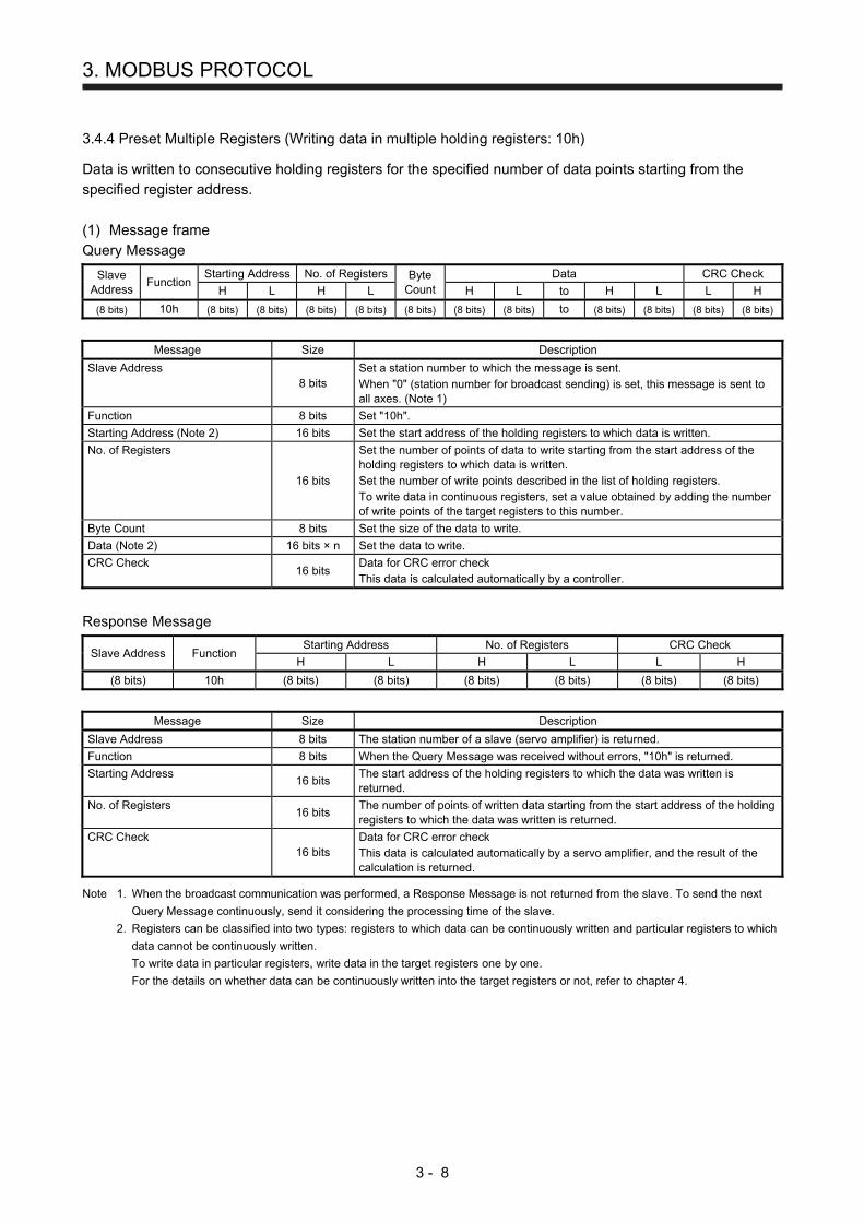
3.4.4 Preset Multiple Registers (Writing data in multiple holding registers: 10h)
Data is written to consecutive holding registers for the specified number of data points starting from the specified register address. (1) Message frame Query Message
Slave Address
Function Starting Address No. of Registers Byte
Count Data CRC Check
H L H L H L to H L L H
(8 bits) 10h (8 bits) (8 bits) (8 bits) (8 bits) (8 bits) (8 bits) (8 bits) to (8 bits) (8 bits) (8 bits) (8 bits)
Message Size Description
Slave Address 8 bits
Set a station number to which the message is sent. When "0" (station number for broadcast sending) is set, this message is sent to all axes. (Note 1)
Function 8 bits Set "10h".
Starting Address (Note 2) 16 bits Set the start address of the holding registers to which data is written.
No. of Registers
16 bits
Set the number of points of data to write starting from the start address of the holding registers to which data is written. Set the number of write points described in the list of holding registers. To write data in continuous registers, set a value obtained by adding the number of write points of the target registers to this number.
Byte Count 8 bits Set the size of the data to write.
Data (Note 2) 16 bits × n Set the data to write.
CRC Check 16 bits
Data for CRC error check This data is calculated automatically by a controller.
Response Message
Slave Address Function Starting Address No. of Registers CRC Check
H L H L L H
(8 bits) 10h (8 bits) (8 bits) (8 bits) (8 bits) (8 bits) (8 bits)
Message Size Description
Slave Address 8 bits The station number of a slave (servo amplifier) is returned.
Function 8 bits When the Query Message was received without errors, "10h" is returned.
Starting Address 16 bits
The start address of the holding registers to which the data was written is returned.
No. of Registers 16 bits
The number of points of written data starting from the start address of the holding registers to which the data was written is returned.
CRC Check 16 bits
Data for CRC error check This data is calculated automatically by a servo amplifier, and the result of the calculation is returned.
Note 1. When the broadcast communication was performed, a Response Message is not returned from the slave. To send the next
Query Message continuously, send it considering the processing time of the slave.
2. Registers can be classified into two types: registers to which data can be continuously written and particular registers to which
data cannot be continuously written.
To write data in particular registers, write data in the target registers one by one.
For the details on whether data can be continuously written into the target registers or not, refer to chapter 4.

3. MODBUS PROTOCOL
3 - 9
(2) Usage example
The following shows a setting example for writing "0100h" in the Modbus register 2102h ([Pr. PC02]) of the slave address "02h".
Index Name Data type Read/write No. of Registers
(Number of registers to write) Continuous read/write
Setting value
2102h PC02 4 bytes Read/write 2 00000100h
Query Message
Slave Address
Function Starting Address No. of Registers Byte
Count Data CRC Check
H L H L H L H L L H
02h 10h 21h 02h 00h 02h 04h 01h 00h 00h 00h (8 bits) (8 bits)
Set the following values to each Query Message.
Message Description
Slave Address Set the station number "02h".
Function Set "10h".
Starting Address Set "2102h", the start address of the registers to which data is written.
No. of Registers Set "02h", because the total number of write points of the Modbus register 2102h is 2.
Byte Count Set "04h". This means that data of 4 frames is sent.
Data Set values in order starting from the start address. Lower-bit value of the register 2102h: "0100h" Higher-bit value of the register 2102h: "0000h" The endian setting of 4-byte data can be configured using [Pr. PC72]. This example shows the case when the standard endian (initial value) is set.
CRC Check Data for CRC error check This data is calculated automatically by a controller.
Response Message
Slave Address Function Starting Address No. of Registers CRC Check
H L H L L H
02h 10h 21h 02h 00h 02h (8 bits) (8 bits)
The following shows the information in each Response Message.
Message Description
Slave Address The station number "02h" is returned.
Function The value "10h" is returned. This means that the message was received without errors.
Starting Address The value "2102h", the start address of the holding registers to which the data was written is returned. H: "21h" L: "02h"
No. of Registers The number of registers to write "02h" is returned.
CRC Check Data for CRC error check This data is calculated automatically by a servo amplifier, and the result of the calculation is returned.

3. MODBUS PROTOCOL
3 - 10
3.4.5 Processing at occurrence of an error
In the Modbus-RTU communication, when the Query Message sent from the master (controller) includes an incorrect value, the slave (servo amplifier) returns an exception response to the master (controller). When a parity error, CRC error, overrun error, or framing error occurs, the slave (servo amplifier) does not return a message to the master (controller). When an exception response occurs, a value obtained by adding "80h" to the function code sent in the Query Message is returned with an exception code. However, no exception response occurs in the following cases.
When the function code "03h" (Read Holding Registers) is used When data can be read from even one of continuous registers, no exception response occurs. In this case, "0" is returned to the register data that cannot be read.
When the function code "10h" (Preset Multiple Registers) is used When data can be written into even one of continuous registers, no exception response occurs.
The following shows the Response Message to be sent at occurrence of an exception response. Response Message
Slave Address Function Exception
Code CRC Check
L H
(8 bits) (8 bits) (8 bits) (8 bits) (8 bits)
Message Size Description
Slave Address 8 bits The station number of a slave (servo amplifier) is returned.
Function
8 bits
A value obtained by adding "80h" to the function code of the Query Message is returned. When Function is "03h": "83h" When Function is "08h": "88h" When Function is "10h": "90h" When an unsupported Function (example: "01h") is used, "Function + 80h" (example: "81h") is returned.
Exception Code 8 bits
An exception code is set. For details of exception codes, refer to the following "List of exception codes".
CRC Check 16 bits
Data for CRC error check This data is calculated automatically by a servo amplifier, and the result of the calculation is returned.
List of exception codes
Code Error name Description
01h ILLEGAL FUNCTION The Query Message sent from the master set a function code that the slave does not support.
02h ILLEGAL DATA ADDRESS The Query Message sent from the master set a register address that the slave does not support. (Ex: No register address is set, or reading or writing data from/to registers is not available.)
03h ILLEGAL DATA VALUE The Query Message sent from the master set data that the register cannot handle. (Ex: A value out of the setting range is set, or "0" is set to No. of Registers.)
When an exception code is generated, a CRC error may occur at the same time.

4. MODBUS REGISTERS
4 - 1
4. MODBUS REGISTERS
POINT
For details on the registers for driving a motor, refer to chapter 5.
4.1 List of Available Registers
By reading and writing data in the registers that are compatible with the Modbus-RTU communication, the following functions can be performed using the MR-JE-_A servo amplifier.
Function Description Reference
Monitor Each status in the servo amplifier can be monitored. Section 4.2
Parameter setting Data can be read and written from/to parameters. Section 4.3
Point table setting Point table data can be read and written. Section 4.4
Writing command to EEP-ROM The set servo parameters and point table data can be saved in EEP-ROM. Section 4.5
Alarm information The alarm status of the servo amplifier can be read. Section 4.6
Alarm number The current alarm number can be read. Section 4.7
Alarm occurrence monitor Each monitor information at occurrence of an error can be read. Section 4.8
Alarm history The alarm history at occurrence of an error can be read. Section 4.9
Alarm history clear The history of alarms can be cleared. Section 4.10
Parameter error count The parameter error count can be read. Section 4.11
Parameter error number Parameter error numbers can be read. Section 4.12
Point table error Point table error numbers can be read. Section 4.13
External input pin status The ON/OFF state of the external input pins input to the servo amplifier can be read.
Section 4.14
External output pin status The ON/OFF state of external output pins output from the servo amplifier can be read.
Section 4.15
Input device status The current input device status can be read. Section 4.16
Output device status The current output device status can be read. Section 4.17
Servo amplifier model The model name of the currently-connected servo amplifier can be read. Section 4.18
Servo amplifier software version The software version of the currently connected servo amplifier can be read. Section 4.19
Broadcast setting The disabling setting of the broadcast communication of the Modbus-RTU communication can be configured.
Section 4.20
Servo motor rated speed The servo motor rated speed can be read. Section 4.21
Servo motor maximum speed The servo motor maximum speed can be read. Section 4.22
SDO Abort Code The SDO Abort Code that is currently occurring can be read. Section 4.23
Access log 1 The access log 1 can be read. Section 4.24
Access log 2 The access log 2 can be read. Section 4.25
Communication error count The Modbus-RTU communication error count can be read. Section 4.26
Supported profile information The supported profile information can be read. Section 4.27
Device information The device information can be read. Section 4.28

4. MODBUS REGISTERS
4 - 2
4.2 Monitor (Address: 2B01h to 2B7Fh)
Each status in the servo amplifier can be monitored. For the items that can be monitored, refer to the list of registers. 4.2.1 List of registers
The following items can be monitored. Refer to "MELSERVO-JE-_A Servo Amplifier Instruction Manual" and "MELSERVO-JE-_A Servo Amplifier Instruction Manual (Positioning Mode)" for each of the following items.
Address Name Unit Data type Read/write No. of points/
No. of registers Continuous read/ continuous write
2B01h Cumulative feedback pulses pulse 4 bytes Read 2 Possible
2B02h Servo motor speed r/min 4 bytes Read 2 Possible
2B03h Droop pulses pulse 4 bytes Read 2 Possible
2B04h Cumulative command pulses pulse 4 bytes Read 2 Possible
2B05h Command pulse frequency kpulse/s 4 bytes Read 2 Possible
2B06h Analog speed command voltage Analog speed limit voltage
0.01 V 2 bytes Read 1 Possible
2B07h Analog torque limit voltage Analog torque command voltage
0.01 V 2 bytes Read 1 Possible
2B08h Regenerative load ratio % 2 bytes Read 1 Possible
2B09h Effective load ratio % 2 bytes Read 1 Possible
2B0Ah Peak load ratio % 2 bytes Read 1 Possible
2B0Bh Instantaneous torque % 2 bytes Read 1 Possible
2B0Ch Position within one-revolution pulse 4 bytes Read 2 Possible
2B0Dh ABS counter rev 4 bytes Read 2 Possible
2B0Eh Load to motor inertia ratio 0.01 times 2 bytes Read 1 Possible
2B0Fh Bus voltage V 2 bytes Read 1 Possible
2B10h to 2B24h
Reserved
2B25h Encoder inside temperature °C 2 bytes Read 1 Possible
2B26h Settling time ms 2 bytes Read 1 Possible
2B27h Oscillation detection frequency Hz 2 bytes Read 1 Possible
2B28h Number of tough operations times 2 bytes Read 1 Possible
2B29h Reserved
2B2Ah
2B2Bh
2B2Ch
2B2Dh Unit power consumption W 2 bytes Read 1 Possible
2B2Eh Unit total power consumption Wh 4 bytes Read 2 Possible
2B2Fh Current position 0.001 mm
(Note 1) 4 bytes Read 2 Possible
2B30h Command position 0.001 mm
(Note 1) 4 bytes Read 2 Possible
2B31h Remaining command distance 0.001 mm
(Note 1) 4 bytes Read 2 Possible
2B32h Point table No./Program No. 2 bytes Read 1 Possible
2B33h Step No. 2 bytes Read 1 Possible
2B34h Override voltage 0.01 V 2 bytes Read 1 Possible
2B35h Override level % 2 bytes Read 1 Possible
2B36h Reserved
2B37h
2B38h Current position in one cycle of CAM axis 0.001 mm
(Note 2) 4 bytes Read 2 Possible
2B39h Basis position of CAM 0.001 mm
(Note 1) 4 bytes Read 2 Possible

4. MODBUS REGISTERS
4 - 3
Address Name Unit Data type Read/write No. of points/
No. of registers Continuous read/ continuous write
2B3Ah Feed current position of CAM 0.001 mm
(Note 1) 4 bytes Read 2 Possible
2B3Bh CAM No. 2 bytes Read 1 Possible
2B3Ch Stroke movement of CAM 0.001 mm
(Note 1) 4 bytes Read 2 Possible
2B3Dh Current position of main axis 0.001 mm
(Note 2) 4 bytes Read 2 Possible
2B3Eh Current position in one cycle of main axis 0.001 mm
(Note 2) 4 bytes Read 2 Possible
2B3Fh to 2B7Fh
Reserved
Note 1. The unit and magnification change depending on the setting values of [Pr. PT01] and [Pr. PT03].
2. The unit and magnification change depending on the setting values of [Pr. PT01] and [Pr. PT03], or the setting of [Cam control
data No. 14].
4.2.2 Directions for use
Set the address of the item to be monitored using the function code "03h" (Read Holding Registers). The value of the specified monitor item is returned from the servo amplifier. Data in these registers can be continuously read. Data in continuous registers can be read at once. An error occurs if the register for manufacturer setting.

4. MODBUS REGISTERS
4 - 4
4.3 Parameter Setting (Address: 2001h to 27FFh)
Data can be read and written from/to parameters. 4.3.1 List of registers
Data can be read and written from/to the following parameters. Refer to "MELSERVO-JE-_A Servo Amplifier Instruction Manual" and "MELSERVO-JE-_A Servo Amplifier Instruction Manual (Positioning Mode)" for the setting of each parameter.
Address Name Data type Read/write No. of points/
No. of registers Continuous read/ continuous write
2001h to 2020h
PA01 to PA32 4 bytes Read/write 2 Possible
2021h to 2080h
Reserved
2081h to 20C0h
PB01 to PB64 4 bytes Read/write 2 Possible
20C1h to 2100h
Reserved
2101h to 2150h
PC01 to PC80 4 bytes Read/write 2 Possible
2151h to 2180h
Reserved
2181h to 21B0h
PD01 to PD48 4 bytes Read/write 2 Possible
21B1h to 2200h
Reserved
2201h to 2240h
PE01 to PE64 4 bytes Read/write 2 Possible
2241h to 2280h
Reserved
2281h to 22B0h
PF01 to PF48 4 bytes Read/write 2 Possible
22B1h to 2480h
Reserved
2481h to 24B0h
PT01 to PT48 4 bytes Read/write 2 Possible
24B1h to 27FFh
Reserved
4.3.2 Directions for use
Read the parameter values using the function code "03h" (Read Holding Registers). Write the parameter values using the function code "10h" (Preset Multiple Registers). Reading and writing of data from/to parameters depend on the setting of [Pr. PA19 Parameter writing inhibit]. Even though parameter setting values are changed with these registers, the set values are deleted at power-off if no setting for holding values is configured. To hold parameter setting values even after power-off, configure the setting to save the values in EEP-ROM using Store Parameters (Register: 1010h) after the parameter setting values are changed.

4. MODBUS REGISTERS
4 - 5
4.4 Point Table Setting (Address: 2801h to 281Fh)
Point table data can be read and written. 4.4.1 List of registers
Point table data can be read and written from/to the following registers. For details of point tables, refer to "MELSERVO-JE-_A Servo Amplifier Instruction Manual (Positioning Mode)".
Address Name Data type Read/write No. of points/
No. of registers Continuous read/ continuous write
2801h to 281Fh
Point Table No.1 to No.31 (Point table No.1 to No.31)
Number of entries (Note 1) 1 byte
Read/write 9 Impossible
Point data 4 bytes
Speed 2 bytes
Acceleration 2 bytes
Deceleration 2 bytes
Dwell 2 bytes
Sub 1 byte
M code (Note 2) 1 byte
Note 1. This item is enabled only at reading. At reading, "07h" is returned.
2. M code will be available in the future.
4.4.2 Directions for use
Read point table data using the function code "03h" (Read Holding Registers). At this time, "07h" is returned to Number of entries. Write point table data using the function code "10h" (Preset Multiple Registers). Set "00h" or "07h" for Number of entries. Reading and writing of the point table data are executed by each point table number. Thus, changing only position data of the particular point table number cannot be performed. In that case, overwrite all the setting data values of the particular point table number with new data. Data cannot be continuously read and written from/to these registers. Set values for each point table number. Even though setting values are changed with these registers, the set values are deleted at power-off if no setting for holding values is configured. To hold setting values even after power-off, configure the setting to save the values in EEP-ROM using Store Parameters (Register: 1010h) after the setting values are changed. 4.5 Writing Command to EEP-ROM (Address: 1010h)
Parameter and point table setting values can be saved in EEP-ROM. 4.5.1 List of registers
Address Name Data type Read/write No. of points/
No. of registers Continuous read/ continuous write
1010h Store Parameters
Number of entries 1 byte
Read/write 11 Impossible
Save all parameters 4 bytes
Save communication Parameters
4 bytes
Save application Parameters
4 bytes
Save manufacturer defined parameters
4 bytes
Save Point table 4 bytes

4. MODBUS REGISTERS
4 - 6
4.5.2 Directions for use
Using the function code "03h" (Read Holding Registers) reads the information that shows whether each command can be used or not. The following table shows the returned values of each item.
Item Saved parameter Returned value
Number of entries 05h
Save all parameters Address: 2001h to 27FFh Address: 2801h to 281Fh
00000001h (Supported)
Save communication parameters Address: 1000h to 1FFFh 00000000h (Unsupported)
Save application Parameters Address: 2001h to 27FFh Address: 2801h to 281Fh
00000001h (Supported)
Save manufacturer defined parameters Address: 2001h to 27FFh 00000001h (Supported)
Save Point table Address: 2801h to 281Fh 00000001h (Supported)
Select the items to be saved in EEP-ROM using the function code "10h" (Preset Multiple Registers). At this time, set "00h" or "05h" for Number of entries. To save servo amplifier parameters and point table data in EEP-ROM, configure required settings following the table below. When bit 1 (EEP-ROM write completed) of the control output (register: 2D11h) is "1", saving data in EEP-ROM has been completed. Writing a value other than "65766173h" and "00000000h" to each item results in an error.
Item Setting value Write to EEP-ROM
Parameter Point table
Number of entries 05h
Save all parameters
00000000h Invalid Invalid
65766173h ("save") Valid Valid
Other than the values above Error Error
Save communication parameters
00000000h Invalid Invalid
65766173h ("save") Invalid Invalid
Other than the values above Error Error
Save application Parameters
00000000h Invalid Invalid
65766173h ("save") Valid Valid
Other than the values above Error Error
Save manufacturer defined parameters
00000000h Invalid Invalid
65766173h ("save") Valid Invalid
Other than the values above Error Error
Save Point table
00000000h Invalid Invalid
65766173h ("save") Invalid Valid
Other than the values above Error Error

4. MODBUS REGISTERS
4 - 7
4.6 Alarm Information (Address: 1001h)
The error status can be checked. 4.6.1 List of registers
Address Name Data type Read/write No. of points/
No. of registers Continuous read/ continuous write
1001h Error Register 1 byte Read 1 Impossible
4.6.2 Directions for use
The occurrence of an alarm can be read using the function code "03h" (Read Holding Registers). The following table shows the response data.
Response data Status
00h No alarms or warnings
01h Alarms and warnings
When an alarm or a warning has occurred, alarm numbers, warning numbers, and detail numbers can be read from the register "2A41h". 4.7 Alarm Number (Address: 2A41h)
Alarm numbers, warning numbers, and detail numbers that currently exist can be read. 4.7.1 List of registers
Address Name Data type Read/write No. of points/
No. of registers Continuous read/ continuous write
2A41h Current alarm 4 bytes Read 2 Impossible
4.7.2 Directions for use
Alarm numbers, warning numbers, and detail numbers that currently exist can be read using the function code "03h" (Read Holding Registers). An alarm number or warning number is stored in the higher bits of the response data, and a detail number is stored in the lower bits of the response data.
Address Response data When [AL 20.3] has occurred
Higher 2 bytes of 2A41h Alarm number or warning number 0020h
Lower 2 bytes of 2A41h Detail number 0003h
When data in this register is read while no error has occurred, "00000000h" is returned.

4. MODBUS REGISTERS
4 - 8
4.8 Alarm Occurrence Monitor (Address: 2B81h to 2BFFh)
Each monitor information at occurrence of an error can be read. 4.8.1 List of registers
Address Name Unit Data type Read/write No. of points/
No. of registers Continuous read/ continuous write
2B81h Cumulative feedback pulses pulse 4 bytes Read 2 Possible
2B82h Servo motor speed r/min 4 bytes Read 2 Possible
2B83h Droop pulses pulse 4 bytes Read 2 Possible
2B84h Cumulative command pulses pulse 4 bytes Read 2 Possible
2B85h Command pulse frequency kpulse/s 4 bytes Read 2 Possible
2B86h Analog speed command voltage Analog speed limit voltage
0.01 V 2 bytes Read 1 Possible
2B87h Analog torque limit voltage Analog torque command voltage
0.01 V 2 bytes Read 1 Possible
2B88h Regenerative load ratio % 2 bytes Read 1 Possible
2B89h Effective load ratio % 2 bytes Read 1 Possible
2B8Ah Peak load ratio % 2 bytes Read 1 Possible
2B8Bh Instantaneous torque % 2 bytes Read 1 Possible
2B8Ch Position within one-revolution pulse 4 bytes Read 2 Possible
2B8Dh ABS counter rev 4 bytes Read 2 Possible
2B8Eh Load to motor inertia ratio 0.01 times 2 bytes Read 1 Possible
2B8Fh Bus voltage V 2 bytes Read 1 Possible
2B90h to 2BA4h
Reserved
2BA5h Encoder inside temperature °C 2 bytes Read 1 Possible
2BA6h Settling time ms 2 bytes Read 1 Possible
2BA7h Oscillation detection frequency Hz 2 bytes Read 1 Possible
2BA8h Number of tough operations times 2 bytes Read 1 Possible
2BA9h Reserved
2BAAh
2BABh
2BACh
2BADh Unit power consumption W 2 bytes Read 1 Possible
2BAEh Unit total power consumption Wh 4 bytes Read 2 Possible
2BAFh Current position 0.001 mm
(Note 1) 4 bytes Read 2 Possible
2BB0h Command position 0.001 mm
(Note 1) 4 bytes Read 2 Possible
2BB1h Remaining command distance 0.001 mm
(Note 1) 4 bytes Read 2 Possible
2BB2h Point table No./Program No. 2 bytes Read 1 Possible

4. MODBUS REGISTERS
4 - 9
Address Name Unit Data type Read/write No. of points/
No. of registers Continuous read/ continuous write
2BB3h Step No. 2 bytes Read 1 Possible
2BB4h Override voltage 0.01 V 2 bytes Read 1 Possible
2BB5h Override level % 2 bytes Read 1 Possible
2BB6h Reserved
2BB7h
2BB8h Current position in one cycle of CAM axis 0.001 mm
(Note 2) 4 bytes Read 2 Possible
2BB9h Basis position of CAM 0.001 mm
(Note 1) 4 bytes Read 2 Possible
2BBAh Feed current position of CAM 0.001 mm
(Note 1) 4 bytes Read 2 Possible
2BBBh CAM No. 2 bytes Read 1 Possible
2BBCh Stroke movement of CAM 0.001 mm
(Note 1) 4 bytes Read 2 Possible
2BBDh Current position of main axis 0.001 mm
(Note 2) 4 bytes Read 2 Possible
2BBEh Current position in one cycle of main axis 0.001 mm
(Note 2) 4 bytes Read 2 Possible
2BBFh to 2BFFh
Reserved
Note 1. The unit and magnification change depending on the setting values of [Pr. PT01] and [Pr. PT03].
2. The unit and magnification change depending on the setting values of [Pr. PT01] and [Pr. PT03], or the setting of [Cam control
data No. 14].
4.8.2 Directions for use
Set the address of the item to be monitored using the function code "03h" (Read Holding Registers). The value of the specified monitor item is returned from the servo amplifier. Data in these registers can be continuously read. Data in continuous registers can be read at once. An error occurs if the register for manufacturer setting.

4. MODBUS REGISTERS
4 - 10
4.9 Alarm History (Address: 2A00h to 2A0Fh)
The history of up to 16 alarms can be read. 4.9.1 List of registers
Address Name Data type Read/write No. of points/
No. of registers Continuous read/ continuous write
2A00h to 2A0Fh
Alarm History0 to Alarm History15
Number of entries 1 byte
Read 5 Impossible Alarm No. 4 bytes
Alarm time (Hour) 4 bytes
4.9.2 Directions for use
The history of alarms can be read using the function code "03h" (Read Holding Registers). At this time, "02h" is returned to Number of entries. The alarm number of a specified alarm history is returned to Alarm No. The alarm number or warning number is returned to the higher 2 bytes, and the detail number is returned to the lower 2 bytes. When no alarm history exists, "00000000h" is returned.
Alarm No. Response data When [AL 20.3] has occurred
Higher 2 bytes Alarm number or warning number 0020h
Lower 2 bytes Detail number 0003h
The alarm time (Unit: hour) of a specified alarm history is returned to Alarm time. When no alarm history exists, "00000000h" is returned. 4.10 Alarm History Clear (Address: 2A40h)
The alarm history can be cleared. 4.10.1 List of registers
Address Name Data type Read/write No. of points/
No. of registers Continuous read/ continuous write
2A40h Clear alarm history 2 bytes Writing 1 Impossible
4.10.2 Directions for use
The history of alarms can be cleared by writing "1EA5h" using the function code "10h" (Preset Multiple Registers). When a value other than "1EA5h" is written, the history of alarms cannot be cleared.

4. MODBUS REGISTERS
4 - 11
4.11 Parameter Error Count (Address: 2A44h)
When [AL. 37 parameter error] has occurred, the number of parameters where parameter errors have occurred can be read. 4.11.1 List of registers
Address Name Data type Read/write No. of points/
No. of registers Continuous read/ continuous write
2A44h Parameter error No. 1 byte Read 1 Impossible
4.11.2 Directions for use
Read the parameter error number count using the function code "03h" (Read Holding Registers). When no parameter error has occurred, "00h" is returned. 4.12 Parameter Error List (Address: 2A45h)
The error numbers of the currently existing parameter errors can be read. 4.12.1 List of registers
Address Name Data type Read/write No. of points/
No. of registers Continuous read/ continuous write
2A45h Parameter error list
Number of entries 1 byte Read
1 + Number of read points
Impossible Parameter error 1 to Parameter error 32
2 bytes × 32
4.12.2 Directions for use
Read the parameter error numbers using the function code "03h" (Read Holding Registers). At this time, set the value read with the parameter error count (2A44h) for Number of entries. Note that up to 32 parameter errors can be read. Parameter error 1 to Parameter error 32 store parameter error numbers. Parameter group numbers are stored in the higher 8 bits, and parameter numbers are stored in the lower 8 bits. The following table lists parameter group numbers.
Parameter group Number
Basic setting parameters [Pr. PA_ _] 00
Gain/filter setting parameters [Pr. PB_ _] 01
Extension setting parameters [Pr. PC_ _] 02
I/O setting parameters [Pr. PD_ _] 03
Extension setting 2 parameters [Pr. PE_ _] 04
Extension setting 3 parameters [Pr. PF_ _] 05
Positioning control parameters [Pr. PT_ _] 0C

4. MODBUS REGISTERS
4 - 12
4.13 Point Table Error (Address: 2A43h)
When a point table error [AL. 37] has occurred, the detail of the point table where the point table error has occurred can be read. 4.13.1 List of registers
Address Name Data type Read/write No. of points/
No. of registers Continuous read/ continuous write
2A43h Point Table error No.
Number of entries 1 byte
Read 4 Impossible Point Table Error No. 2 bytes
Point Table Error Factor 4 bytes
4.13.2 Directions for use
Read a point table error number using the function code "03h" (Read Holding Registers). At this time, "02h" is returned to Number of entries. The factor of the error that has occurred in the point table with the number read with Point Table Error No. is stored in Point Table Error Factor. The following table describes the assignment of bits for point table error factors. The values in the areas marked with diagonal lines are indefinite.
Bit Error factor bit details
0 0: No error 1: Target position
1
2 0: No error 1: Servo motor speed
3 0: No error 1: Acceleration time constant
4 0: No error 1: Deceleration time constant
5 0: No error 1: Dwell
6 0: No error 1: Sub function
7 0: No error 1: M code (Note)
8 to 31
Note. M code will be available in the future.

4. MODBUS REGISTERS
4 - 13
4.14 External Input Pin Status (Address: 2C10h)
The ON/OFF state of the external input pins input to the servo amplifier can be read. 4.14.1 List of registers
Address Name Data type Read/write No. of points/
No. of registers Continuous read/ continuous write
2C10h External Input pin display
Number of entries 1 byte Read 3 Impossible External Input pin
display1 4 bytes
4.14.2 Directions for use
Read the ON/OFF state of external input pins using the function code "03h" (Read Holding Registers). At this time, "02h" is returned to Number of entries. External Input pin display1 displays the input pin status of the MR-JE-_A servo amplifier. The following table shows the details. When the input of the target pin is on, "1" is returned. When the input of the target pin is off, "0" is returned. The values in the areas marked with diagonal lines are indefinite.
Bit CN1 connector pin Bit CN1 connector pin Bit CN1 connector pin Bit CN1 connector pin
0 43 8 16 24
1 44 9 17 25
2 42 10 18 26
3 15 11 19 27
4 19 12 20 28
5 41 13 21 29
6 10 14 22 30
7 35 15 23 31

4. MODBUS REGISTERS
4 - 14
4.15 External Output Pin Status (Address: 2C11h)
The ON/OFF state of external output pins output from the servo amplifier can be read. 4.15.1 List of registers
Address Name Data type Read/write No. of points/
No. of registers Continuous read/ continuous write
2C11h External Output pin display
Number of entries 1 byte Read 3 Impossible External Output pin
display1 4 bytes
4.15.2 Directions for use
Read the ON/OFF state of external output pins using the function code "03h" (Read Holding Registers). At this time, "02h" is returned to Number of entries. External Output pin display1 displays the output pin status of the MR-JE-_A servo amplifier. The following table shows the details. When the output of the target pin is on, "1" is returned. When the output of the target pin is off, "0" is returned. The values in the areas marked with diagonal lines are indefinite.
Bit CN1 connector pin Bit CN1 connector pin Bit CN1 connector pin Bit CN1 connector pin
0 49 8 16 24
1 24 9 17 25
2 23 10 18 26
3 11 19 27
4 12 20 28
5 48 13 21 29
6 33 14 22 30
7 15 23 31
4.16 Input Device Status (Address: 2C12h)
The current input device status can be read. 4.16.1 List of registers
Address Name Data type Read/write No. of points/
No. of registers Continuous read/ continuous write
2C12h External Input signal display
Number of entries 1 byte
Read 9 Impossible
External Input signal display1
4 bytes
External Input signal display2
4 bytes
External Input signal display3
4 bytes
External Input signal display4
4 bytes

4. MODBUS REGISTERS
4 - 15
4.16.2 Directions for use
Read the ON/OFF state of input devices using the function code "03h" (Read Holding Registers). At this time, "04h" is returned to Number of entries. External Input signal display1 (Input device status 1) to External Input signal display4 (Input device status 4) display the ON/OFF state of each input device of the MR-JE-_A servo amplifier. The following table shows the details. When the input of the target device is on, "1" is returned. When the input of the target device is off, "0" is returned. The values in the areas marked with diagonal lines are indefinite.
Bit Input device abbreviation (Note 1)
Input device status 1 Input device status 2 Input device status 3
0 SON MD0
1 LSP
2 LSN
3 TL TCH
4 TL1 TP0
5 PC TP1
6 RES OVR
7 CR
8 SP1
9 SP2 DOG
10 SP3
11 ST1/RS2
12 ST2/RS1
13 CMX1
14 CMX2
15 LOP
16 MSD LPS
17 PI1
18 EM2/EM1 PI2
19 PI3
20 STAB2 CAMC
21 CI0
22 CI1
23 CI2
24 TSTP CI3 DI0
25 CLTC (Note 2) DI1
26 CPCD (Note 2) DI2
27 CDP DI3
28 DI4
29
30
31
Note 1. Refer to "MELSERVO-JE-_A Servo Amplifier Instruction Manual" and "MELSERVO-
JE-_A Servo Amplifier Instruction Manual (Positioning Mode)" for the details on the
abbreviation.
2. This is available with servo amplifiers with software version C1 or later.

4. MODBUS REGISTERS
4 - 16
4.17 Output Device Status (Address: 2C13h)
The current output device status can be read. 4.17.1 List of registers
Address Name Data type Read/write No. of points/
No. of registers Continuous read/ continuous write
2C13h External Output signal display
Number of entries 1 byte
Read 9 Impossible
External Output signal display1
4 bytes
External Output signal display2
4 bytes
External Output signal display3
4 bytes
External Output signal display4
4 bytes

4. MODBUS REGISTERS
4 - 17
4.17.2 Directions for use
Read the ON/OFF state of output devices using the function code "03h" (Read Holding Registers). At this time, "04h" is returned to Number of entries. External Output signal display1 (Output device status 1) to External Output signal display4 (Output device status 4) display the ON/OFF state of each output device of the MR-JE-_A servo amplifier. The following table shows the details. When the output of the target device is on, "1" is returned. When the output of the target device is off, "0" is returned. The values in the areas marked with diagonal lines are indefinite.
Bit Output device abbreviation (Note 1)
Output device status 1 Output device status 2 Output device status 3
0 RD
1 SA
2 ZSP
3 TLC CPO
4 VLC ZP
5 INP POT
6 PUS
7 WNG MEND
8 ALM
9 OP
10 MBR
11 DB
12 ALCD0 PED
13 ALCD1
14 ALCD2
15
16
17 ALMWNG
18
19 MSDH
20 MSDL
21 SOUT
22 OUT1
23 OUT2
24 OUT3 PT0
25 CDPS CAMS PT1
26 CLTS (Note 2) PT2
27 CLTSM (Note 2) PT3
28 CPCC (Note 2) PT4
29
30
31 MTTR
Note 1. Refer to "MELSERVO-JE-_A Servo Amplifier Instruction Manual" and "MELSERVO-
JE-_A Servo Amplifier Instruction Manual (Positioning Mode)" for the details on the
abbreviation.
2. This is available with servo amplifiers with software version C1 or later.

4. MODBUS REGISTERS
4 - 18
4.18 Servo Amplifier Model (Address: 1008h)
The model name of the currently-connected servo amplifier can be read. 4.18.1 List of registers
Address Name Data type Read/write No. of points/
No. of registers Continuous read/ continuous write
1008h Manufacture Device Name 32 bytes Read 16 Impossible
4.18.2 Directions for use
Read the model name of the servo amplifier using the function code "03h" (Read Holding Registers). The model name of the servo amplifier is returned in ASCII codes. The ASCII codes are read in order from the lower address. 4.19 Servo Amplifier Software Version (Address: 100Ah)
The software version of the currently-connected servo amplifier can be read. 4.19.1 List of registers
Address Name Data type Read/write No. of points/
No. of registers Continuous read/ continuous write
100Ah Manufacture Software Version 16 bytes Read 8 Impossible
4.19.2 Directions for use
Read the software version of the servo amplifier using the function code "03h" (Read Holding Registers). The software version of the servo amplifier is returned in ASCII codes. The ASCII codes are read in order from the lower address.

4. MODBUS REGISTERS
4 - 19
4.20 Broadcast Setting (Address: 2D98h)
The setting of the broadcast communication of the Modbus-RTU communication can be configured. The broadcast command can be disabled for each axis using this register. 4.20.1 List of registers
Address Name Data type Read/write No. of points/
No. of registers Continuous read/ continuous write
2D98h Select behavior of broadcast message 1 byte Read/write 1 Impossible
4.20.2 Directions for use
The current broadcast communication setting can be read using the function code "03h" (Read Holding Registers). Configure the broadcast communication setting using the function code "10h" (Preset Multiple Registers). The following table lists the setting values for this register. Do not set any value other than "00h" and "01h".
Setting value Description
0 Broadcast instruction enabled
1 Broadcast instruction disabled
4.21 Servo Motor Rated Speed (Address: 2D28h)
The servo motor rated speed ([r/min]) can be read. 4.21.1 List of registers
Address Name Data type Read/write No. of points/
No. of registers Continuous read/ continuous write
2D28h Motor rated speed 4 bytes Read 2 Impossible
4.21.2 Directions for use
Read the servo motor rated speed ([r/min]) using the function code "03h" (Read Holding Registers). 4.22 Servo Motor Maximum Speed (Address: 2D29h)
The servo motor maximum speed ([r/min]) can be read. 4.22.1 List of registers
Address Name Data type Read/write No. of points/
No. of registers Continuous read/ continuous write
2D29h Motor max speed 4 bytes Read 2 Impossible
4.22.2 Directions for use
Read the servo motor maximum speed ([r/min]) using the function code "03h" (Read Holding Registers).

4. MODBUS REGISTERS
4 - 20
4.23 SDO Abort Code (Address: 2A60h)
The latest SDO Abort Code can be read. The access to registers can be checked by reading the latest SDO Abort Code. When an error is found by reading SDO Abort Codes, change the method to access registers. 4.23.1 List of registers
Address Name Data type Read/write No. of points/
No. of registers Continuous read/ continuous write
2A60h SDO Abort Code 4 bytes Read 2 Impossible
4.23.2 Directions for use
Read SDO Abort Codes using the function code "03h" (Read Holding Registers). The following table lists the SDO Abort Codes.
SDO Abort Code Description
0000 0000h No error
0504 0001h Client/server command specifier not valid or unknown.
0601 0000h Unsupported access to an object.
0601 0001h Attempt to read a write only object.
0601 0002h Attempt to write a read only object.
0602 0000h Object does not exist in the object dictionary.
0607 0010h Data type does not match, length of service parameter does not match.
0609 0011h Sub-index does not exist.
0609 0030h Value range of parameter exceeded (only for write access).
0609 0031h Value of parameter written too high.
0609 0032h Value of parameter written too low.
0800 0000h Generic error.
0800 0021h Data cannot be transferred or stored to the application because of local control.
0800 0022h Data cannot be transferred or stored to the application because of the present device state.
0800 0024h No data available.
4.24 Access Log 1 (Address: 2A64h)
The access log 1 can be read. 4.24.1 List of registers
Address Name Data type Read/write No. of points/
No. of registers Continuous read/ continuous write
2A64h Access log 1 4 bytes Read 2 Impossible
4.24.2 Directions for use
Read the access log 1 using the function code "03h" (Read Holding Registers). The access log 1 displays the Index and SubIndex that were lastly accessed using the Modbus-RTU communication.
Access log 1 Response data
Higher 2 bytes Index: xxxxh
Lower 2 bytes SubIndex: 00yyh
For example, when the access to a point table (address: 2801h) succeeded, the read value of the access log 1 is "28010007h".

4. MODBUS REGISTERS
4 - 21
4.25 Access Log 2 (Address: 2A65h)
The access log 2 can be read. 4.25.1 List of registers
Address Name Data type Read/write No. of points/
No. of registers Continuous read/ continuous write
2A65h Access log 2 2 bytes Read 1 Impossible
4.25.2 Directions for use
Read the access log 2 using the function code "03h" (Read Holding Registers). The access log 2 displays the number of addresses that were lastly accessed using the Modbus-RTU communication. Use this register when an access error has occurred in the continuous read/write. For example, when an error has occurred while the registers for monitoring (address: 2B01h to 2B0Ah) are continuously read, the error has occurred at the address 2B07h because the read value of the access log 2 is "0006h". 4.26 Communication Error Count (Address: 2A68h)
The Modbus-RTU communication error count can be read. 4.26.1 List of registers
Address Name Data type Read/write No. of points/
No. of registers Continuous read/ continuous write
2A68h Communication error count 2 bytes Read 1 Impossible
4.26.2 Directions for use
The total count of the following communication errors can be read using the function code "03h" (Read Holding Registers).
Errors detected by hardware (parity error, overrun error, and framing error)
Message frame length error
CRC error Executing Clear alarm history clears the error count. For details of Clear alarm history, refer to section 4.10.

4. MODBUS REGISTERS
4 - 22
4.27 Supported Profile Information (Address: 1000h)
The supported profile information can be read. 4.27.1 List of registers
Address Name Data type Read/write No. of points/
No. of registers Continuous read/ continuous write
1000h Device type 4 bytes Read 2 Impossible
4.27.2 Directions for use
Read the supported profile information using the function code "03h" (Read Holding Registers). The following table shows the response data.
Device type Response data
Higher 2 bytes 0002h (Servo drive)
Lower 2 bytes 0192h (CiA 402)
4.28 Device Information (Address: 1018h)
The device information can be read. 4.28.1 List of registers
Address Name Data type Read/write No. of points/
No. of registers Continuous read/ continuous write
1018h Device type
Number of entries 1 byte
Read 9 Impossible
Vendor ID 4 bytes
Product code 4 bytes
Revision number 4 bytes
Serial number 4 bytes
4.28.2 Directions for use
Read the device information using the function code "03h" (Read Holding Registers). The following table shows the response data.
Item Response data
Number of entries 04h
Vendor ID 00000A1Eh
Product code 00000203h
Revision number 00010000h
Serial number 00000000h

5. DRIVING MOTOR
5 - 1
5. DRIVING MOTOR
POINT
Use a servo motor after setting [Pr. PF46 Modbus-RTU communication time out selection]. The servo motor may continue to operate after the communication is disabled due to a communication shut-off or other causes.
This chapter describes how to drive a servo motor in the Modbus-RTU communication. For MR-JE-_A servo amplifier, Modbus registers are assigned like the address assignment of CiA 402 drive profile. The servo motors are driven.by Modbus compatible controller as master accessing to the assigned holding registers. The following shows a list of functions that can be used.
Function Description Detailed explanation
Device control The master (controller) can control the state machine of the slave (servo amplifier) to drive the servo motor.
Section 5.1
Control mode The following modes can be selected: each control mode, home position return mode, JOG operation mode, point table mode, and program drive mode.
Section 5.2
Home position return mode In this mode, the servo amplifier performs a home position return operation using the method directed by the master (controller).
Section 5.3
JOG operation mode In this mode, the servo motor is manually driven at a speed set by the master (controller).
Section 5.4
Point table operation mode In this mode, the servo motor is driven with a prespecified point table. Section 5.5
Program drive mode In this mode, the servo motor is driven with a prespecified program. Section 5.6
Touch probe The current position latch data at the rising edge and falling edge of sensor inputs can be read.
Section 5.7
Function common to the modes This function uses the common registers that can be used for the home position return mode, JOG operation mode, point table operation mode, and program operation mode.
Section 5.8
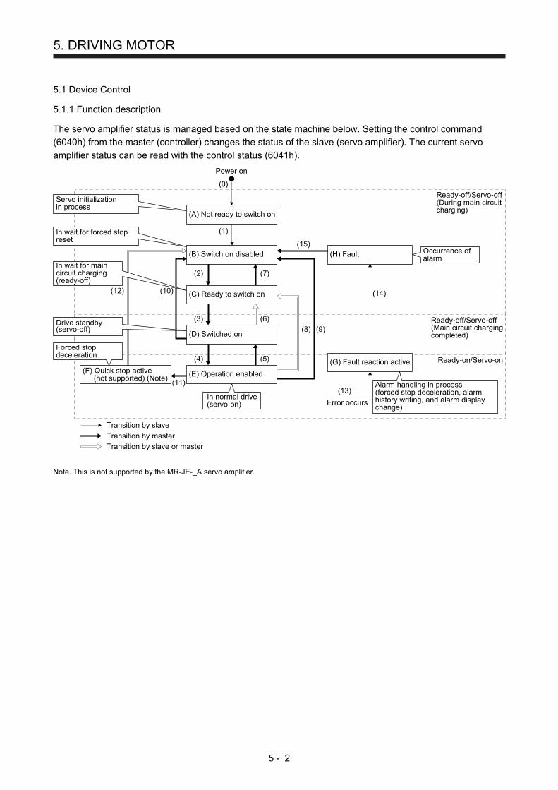
5. DRIVING MOTOR
5 - 2
5.1 Device Control
5.1.1 Function description
The servo amplifier status is managed based on the state machine below. Setting the control command (6040h) from the master (controller) changes the status of the slave (servo amplifier). The current servo amplifier status can be read with the control status (6041h).
Power on
(14)
(13)
Ready-off/Servo-off(Main circuit chargingcompleted)
Ready-off/Servo-off(During main circuitcharging)
Ready-on/Servo-on
(9)(8)
(12)
(11)
(H) Fault
Error occurs
Transition by slave
Transition by master
Transition by slave or master
(10)
(2)
(0)
(1)
(7)
(15)
(3) (6)
(4) (5) (G) Fault reaction active
Servo initializationin process
In wait for forced stopreset
Forced stopdeceleration
Occurrence ofalarm
In normal drive(servo-on)
Alarm handling in process(forced stop deceleration, alarmhistory writing, and alarm displaychange)
Drive standby(servo-off)
In wait for maincircuit charging(ready-off)
(A) Not ready to switch on
(B) Switch on disabled
(C) Ready to switch on
(D) Switched on
(E) Operation enabled(F) Quick stop active(not supported) (Note)
Note. This is not supported by the MR-JE-_A servo amplifier.

5. DRIVING MOTOR
5 - 3
5.1.2 Related registers
Address Name Data type Read/write No. of points/
No. of registers Continuous read/ continuous write
6040h Controlword 2 bytes Read/write 1 Impossible
6041h Statusword 2 bytes Read 1 Impossible
5.1.3 Details of registers
(1) Control command (Controlword: 6040h) This register issues a command from the master (controller) to the slave (servo amplifier).
Address Name Data type Read/write No. of points/
No. of registers Continuous read/ continuous write
6040h Controlword 2 bytes Read/write 1 Impossible
The current control command status can be checked using the function code "03h" (Read Holding Registers). A control command can be written using the function code "10h" (Preset Multiple Registers). The following table lists the bits of this register. The slave can be controlled with bit 0 to bit 3 and bit 7.
Bit Description
0 Switch On
1 Enable Voltage
2 Quick Stop
3 Enable Operation
4 to 6 Operation Mode Specific (Note 1)
7 Fault Reset
8 Halt
9 to 15 Reserved (Note 2)
Note 1. The description changes depending on the control mode.
2. The value at reading is undefined. Set "0" at writing.
The following table lists the commands issued to the servo amplifier. Turn on the bit that corresponds to the command.
Command Bit 7 Bit 3 Bit 2 Bit 1 Bit 0
Shutdown 0 1 1 0
Switch On 0 0 1 1 1
Disable voltage 0 0
Quick stop (not supported) (Note)
0 0 1
Disable operation 0 0 1 1 1
Enable operation 0 1 1 1 1
Fault reset 0 → 1 Note. This is not supported by the MR-JE-_A servo amplifier.

5. DRIVING MOTOR
5 - 4
(2) Control status (Statusword: 6041h)
Address Name Data type Read/write No. of points/
No. of registers Continuous read/ continuous write
6041h Statusword 2 bytes Read 1 Impossible
The current control status can be checked using the function code "03h" (Read Holding Registers). The following table lists the bits of this register. The status can be checked with bit 0 to bit 7.
Bit Description
0 Ready To Switch On
1 Switched On
2 Operation Enabled
3 Fault
4 Voltage Enabled
5 Quick Stop
6 Switch On Disabled
7 Warning
8 Reserved (Note 2)
9 Remote
10 Target reached
11 Internal Limit Active
12 to 13 Operation Mode Specific (Note 1)
14 to 15 Reserved (Note 2)
Note 1. The description changes depending on the control mode.
2. The value at reading is undefined.
The following table lists the servo amplifier statuses that can be read with bit 0 to bit 7.
Bit 7 Bit 6 Bit 5 Bit 4 Bit 3 Bit 2 Bit 1 Bit 0 Status
0 0 0 0 0 Not ready to switch on
1 0 0 0 0 Switch on disable
0 1 0 0 0 1 Ready to switch on
0 1 0 0 1 1 Switch on
0 1 0 1 1 1 Operation enabled
0 0 0 1 1 1 Quick stop active (not supported) (Note)
0 1 1 1 1 Fault reaction active
0 1 0 0 0 Fault
1 Main power on
1 Warning Note. This is not supported by the MR-JE_A servo amplifier.
Bit 9 turns on when the control command (Controlword) is enabled in the Modbus-RTU communication. Bit 11 turns on when the stroke limit, software limit, or positioning command is outside the range.
5.1.4 Directions for use
The function code "10h" (Preset Multiple Registers) allows a transition to the target status, skipping the statuses in between. The statuses can transition as shown in the following table, for example. (Refer to the figure in section 5.1.1.)
Current status Command Status after transition
(B) Switch on disabled Switch on (D) Switched on
(B) Switch on disabled Enable operation (E) Operation enabled
(C) Ready to switch on Enable operation (E) Operation enabled

5. DRIVING MOTOR
5 - 5
5.2 Control Mode
This section describes the control modes that the MR-JE-_A servo amplifier supports. 5.2.1 Function description
The MR-JE-_A servo amplifier supports various control modes. A control mode can be selected with the control mode (Modes of operation: 6060h). The following table shows the correspondence between the control modes before and after switching.
Control mode after switching
Position Speed Torque Point table Program Home
position return
JOG operation
Control mode before
switching
Position Speed Torque
Point table Program
Home position return (Note) (Note) JOG operation (Note) (Note)
: Switchable : Non-switchable
Note. Use [Pr. PA01] to switch the mode between the point table and program.
After switching control modes, check that the control modes have been switched by monitoring the control mode display (Modes of operation Display: 6061h). Switch control modes while the servo motor is being stopped. 5.2.2 Related registers
Address Name Data type Read/write No. of points/
No. of registers Continuous read/ continuous write
6060h Modes of operation 1 byte Read/write 1 Impossible
6061h Modes of operation Display 1 byte Read 1 Impossible
6502h Supported Drive Modes 4 bytes Read 2 Impossible
5.2.3 Details of registers
(1) Control mode (Modes of operation: 6060h)
Address Name Data type Read/write No. of points/
No. of registers Continuous read/ continuous write
6060h Modes of operation 1 byte Read/write 1 Impossible
The current control mode setting can be checked using the function code "03h" (Read Holding Registers). Control modes can be switched by setting a control mode using the function code "10h" (Preset Multiple Registers). The following table shows the correspondence between control modes and setting values.
Control mode Setting value
Position control -20
Speed control -21
Torque control -22
Point table -101
Program operation -102
Home position return 6
JOG operation -100

5. DRIVING MOTOR
5 - 6
(2) Control mode display (Modes of operation Display: 6061h)
Address Name Data type Read/write No. of points/
No. of registers Continuous read/ continuous write
6061h Modes of operation Display 1 byte Read 1 Impossible
The current control mode can be read using the function code "03h" (Read Holding Registers). The following table shows the correspondence between control modes and setting values.
Control mode Setting value
Position control -20
Speed control -21
Torque control -22
Point table -101
Program operation -102
Home position return 6
JOG operation -100
Test mode: JOG operation -1
Test mode: Positioning operation -2
Test mode: DO forced output -4
Test mode: Machine analyzer -6
Test mode: One-step feed (in point table operation)
-10
Test mode: One-step feed (in program operation)
-11
(3) Supported control mode (Supported Drive Modes: 6502h)
Address Name Data type Read/write No. of points/
No. of registers Continuous read/ continuous write
6502h Supported Drive Modes 4 bytes Read 2 Impossible
Supported control modes can be read using the function code "03h" (Read Holding Registers). The return value is 00070020h. The following table shows the details.
Bit Supported Modes Defined value
0 Profile Position mode 0
1 Velocity mode 0
2 Profile Velocity mode 0
3 Torque Profile mode 0
4 Reserved 0
5 Homing Mode 1: Supported
6 Interpolated Position mode 0
7 Cyclic Sync Position mode 0
8 Cyclic Sync Velocity mode 0
9 Cyclic Sync Torque mode 0
10 to 15 Reserved 0
16 JOG mode 1: Supported
17 Point table mode 1: Supported
18 Program drive mode 1: Supported
19 to 31 Reserved 0

5. DRIVING MOTOR
5 - 7
5.2.4 Directions for use
(1) Positioning with point table operation ([Pr. PA01]: "_ _ _ 6") After performing a home position return operation, perform a point table operation. Use the control mode (Modes of operation: 6060h) when switching the mode to the home position return or point table operation.
(2) Registering the destination position data by a JOG operation ([Pr. PA01]: "_ _ _ 6") as the position data
in a point table After performing a home position return operation, perform a JOG operation to reach the target position and register the position data to a point table. Use the control mode (Modes of operation: 6060h) when switching the mode to the home position return or JOG operation.
(3) Performing speed control ([Pr. PA01]: "_ _ _ 1") when [Pr. PC71] is "21_1"
Use the control mode (Modes of operation: 6060h) to switch the mode to the speed control, torque control, or position control.
5.3 Home Position Return Mode
This section describes how to perform a home position return operation in the Modbus-RTU communication. 5.3.1 Function description
Perform a home position return operation following the instruction below. After setting the home position return method (Homing method: 6098h), home position return speed (Homing speed: 6099h), and home position return acceleration/deceleration time constant, start the operation with the control command (Controlword: 6040h). The specified home position return operation is performed. The completion of the home position return operation can be checked with the control status (Statusword: 6041h).
Controlword (6040h)
Homing method (6098h)
Homing modeHoming speed (6099h)
Homing acceleration (Note)
Statusword (6041h)
Note. In the point table mode, use the acceleration time constant and deceleration time
constant in point table No. 1 (2801h).
In the program drive mode, Use [Pr. PC30] (211Eh) and [Pr. PC31] (211Fh).

5. DRIVING MOTOR
5 - 8
5.3.2 Related registers
Address Name Data type Read/write No. of points/
No. of registers Continuous read/ continuous write
6040h Controlword 2 bytes Read/write 1 Impossible
6098h Homing method 1 byte Read/write 1 Impossible
6099h Homing speed
Number of entries 1 byte
Read/write 5 Impossible Speed during search for switch 4 bytes
Speed during search for zero 4 bytes
6041h Statusword 2 bytes Read 1 Impossible
For details of the change to the acceleration time constant or deceleration time constant in point table No. 1 used for a home position return operation in the point table mode, refer to Section 4.4. For details of the change to the acceleration time constant parameter [Pr. PC30] and deceleration time constant parameter [Pr. PC31] used for a home position return operation in the program mode, refer to Section 4.3. 5.3.3 Details of registers
(1) Control command (Controlword: 6040h)
Address Name Data type Read/write No. of points/
No. of registers Continuous read/ continuous write
6040h Controlword 2 bytes Read/write 1 Impossible
The status of the current control command input can be checked using the function code "03h" (Read Holding Registers). A control command can be written using the function code "10h" (Preset Multiple Registers). The bits of this register that relate to the home position return operation are shown below.
Bit Description
0 to 3 Refer to section 5.1.3.
4 Homing Operation Start
5 to 6 Reserved (Note)
7 Refer to section 5.1.3.
8 Halt
9 to 15 Refer to section 5.1.3.
Note. The value at reading is undefined. Set "0" at writing.
To start a home position return operation, turn bit 4 from "0" to "1". When the home position return operation is completed or an alarm is issued during the operation, turn bit 4 from "1" to "0". When bit 8 (Halt) of the control command (6040h) is set to "1", the servo motor decelerates to a stop. Then, when bit 8 (Halt) is set to "0" and bit 4 is turned from "0" to "1", the home position return operation resumes.
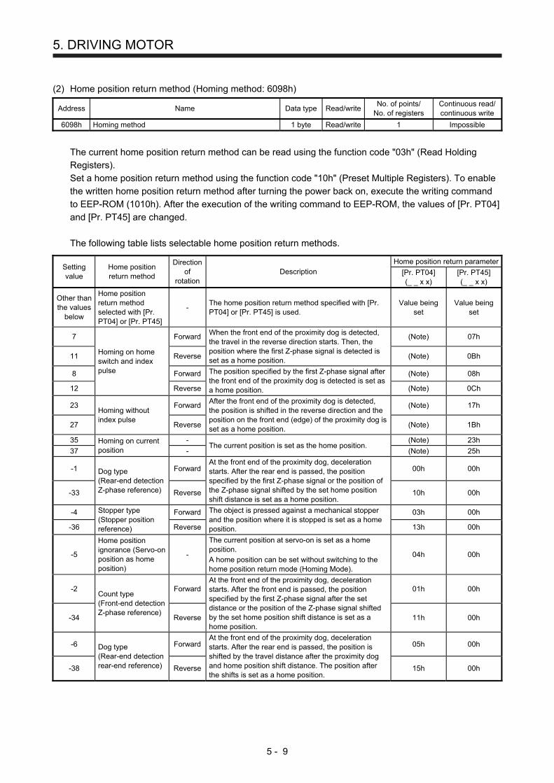
5. DRIVING MOTOR
5 - 9
(2) Home position return method (Homing method: 6098h)
Address Name Data type Read/write No. of points/
No. of registers Continuous read/ continuous write
6098h Homing method 1 byte Read/write 1 Impossible
The current home position return method can be read using the function code "03h" (Read Holding Registers). Set a home position return method using the function code "10h" (Preset Multiple Registers). To enable the written home position return method after turning the power back on, execute the writing command to EEP-ROM (1010h). After the execution of the writing command to EEP-ROM, the values of [Pr. PT04] and [Pr. PT45] are changed.
The following table lists selectable home position return methods.
Setting value
Home position return method
Direction of
rotation Description
Home position return parameter
[Pr. PT04] (_ _ x x)
[Pr. PT45] (_ _ x x)
Other than the values
below
Home position return method selected with [Pr. PT04] or [Pr. PT45]
- The home position return method specified with [Pr. PT04] or [Pr. PT45] is used.
Value being set
Value being set
7
Homing on home switch and index pulse
Forward When the front end of the proximity dog is detected, the travel in the reverse direction starts. Then, the position where the first Z-phase signal is detected is set as a home position.
(Note) 07h
11 Reverse (Note) 0Bh
8 Forward The position specified by the first Z-phase signal after the front end of the proximity dog is detected is set as a home position.
(Note) 08h
12 Reverse (Note) 0Ch
23 Homing without index pulse
Forward After the front end of the proximity dog is detected, the position is shifted in the reverse direction and the position on the front end (edge) of the proximity dog is set as a home position.
(Note) 17h
27 Reverse (Note) 1Bh
35 Homing on current position
- The current position is set as the home position.
(Note) 23h
37 - (Note) 25h
-1 Dog type (Rear-end detection Z-phase reference)
Forward At the front end of the proximity dog, deceleration starts. After the rear end is passed, the position specified by the first Z-phase signal or the position of the Z-phase signal shifted by the set home position shift distance is set as a home position.
00h 00h
-33 Reverse 10h 00h
-4 Stopper type (Stopper position reference)
Forward The object is pressed against a mechanical stopper and the position where it is stopped is set as a home position.
03h 00h
-36 Reverse 13h 00h
-5
Home position ignorance (Servo-on position as home position)
-
The current position at servo-on is set as a home position. A home position can be set without switching to the home position return mode (Homing Mode).
04h 00h
-2 Count type (Front-end detection Z-phase reference)
Forward At the front end of the proximity dog, deceleration starts. After the front end is passed, the position specified by the first Z-phase signal after the set distance or the position of the Z-phase signal shifted by the set home position shift distance is set as a home position.
01h 00h
-34 Reverse 11h 00h
-6 Dog type (Rear-end detection rear-end reference)
Forward At the front end of the proximity dog, deceleration starts. After the rear end is passed, the position is shifted by the travel distance after the proximity dog and home position shift distance. The position after the shifts is set as a home position.
05h 00h
-38 Reverse 15h 00h

5. DRIVING MOTOR
5 - 10
Setting value
Home position return method
Direction of
rotation Description
Home position return parameter
[Pr. PT04] (_ _ x x)
[Pr. PT45] (_ _ x x)
-7 Count type (Front-end detection front-end reference)
Forward At the front end of the proximity dog, deceleration starts. The position is shifted by the travel distance after the proximity dog and home position shift distance. The position after the shifts is set as a home position.
06h 00h
-39 Reverse 16h 00h
-8 Dog cradle type
Forward The position specified by the first Z-phase signal after the front end of the proximity dog is detected is set as a home position.
07h 00h
-40 Reverse 17h 00h
-9
Dog type last Z-phase reference
Forward
When the front end of the proximity dog is detected, the travel in the reverse direction starts. Then, the position where the first Z-phase signal is detected is set as a home position or the position after a shift by the home position shift distance from the position specified by the first Z-phase signal is set as a home position.
08h 00h
-41 Reverse 18h 00h
-10 Dog type front end reference
Forward From the front end of the proximity dog, the position is shifted by the travel distance after proximity dog and home position shift distance. The position after the shifts is set as a home position.
09h 00h
-42 Reverse 19h 00h
-11 Dogless Z-phase reference
Forward The position specified by the first Z-phase signal or position of the first Z-phase signal shifted by the home position shift distance is set as a home position.
0Ah 00h
-43 Reverse 1Ah 00h
Note. Regardless of the [Pr. PT04] setting, the home position return type is determined only by the [Pr. PT45] setting.
(3) Home position return speed (Homing speed: 6099h)
Address Name Data type Read/write No. of points/
No. of registers Continuous read/ continuous write
6099h Homing speed
Number of entries 1 byte
Read/write 5 Impossible Speed during search for switch 4 bytes
Speed during search for zero 4 bytes
The current home position return speed can be read using the function code "03h" (Read Holding Registers). At this time, "02h" is returned to Number of entries. The current home position return speed is returned to Speed during search for switch in units of r/min. The current creep speed is returned to Speed during search for zero in units of r/min.
Set a home position return speed using the function code "10h" (Preset Multiple Registers). At this time, write "02h" in Number of entries. Set a home position return speed in Speed during search for switch in units of r/min. Set a creep speed in Speed during search for zero in units of r/min.

5. DRIVING MOTOR
5 - 11
(4) Control status (Statusword: 6041h)
Address Name Data type Read/write No. of points/
No. of registers Continuous read/ continuous write
6041h Statusword 2 bytes Read 1 Impossible
The current control status can be checked using the function code "03h" (Read Holding Registers). The bits of this register that relate to the home position return operation are shown below.
Bit Description
0 to 9 Refer to section 5.1.3.
10 Target reached
11 Refer to section 5.1.3.
12 Homing attained
13 Homing error
14 to 15 Refer to section 5.1.3.
(a) Bit 10 of the control status (6041h) (Target reached)
Bit 10 turns on (1) when the command position is reached. If bit 8 (Halt) of the control command is set to "1", bit 10 turns on (1) when a deceleration stop is completed. If a command is input again, bit 10 turns off (0).
(b) Bit 12 of the control status (6041h) (Homing attained)
Bit 12 turns off (0) when a home position return operation is started and turns on (1) when the operation is completed.
(c) Bit 13 of the control status (6041h) (Homing error)
Bit 13 turns on (1) when an alarm or warning ([AL 90.2], [AL 90.3], [AL 90.5], [AL 96.1], [AL 96.2], or [AL 96.3]) occurs during a home position return operation.
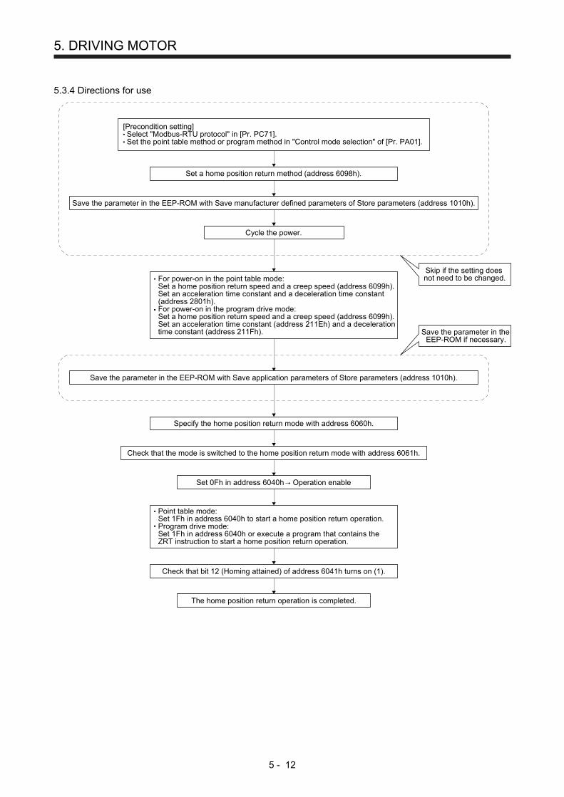
5. DRIVING MOTOR
5 - 12
5.3.4 Directions for use
Set a home position return method (address 6098h).
For power-on in the point table mode:Set a home position return speed and a creep speed (address 6099h).Set an acceleration time constant and a deceleration time constant(address 2801h).For power-on in the program drive mode:Set a home position return speed and a creep speed (address 6099h).Set an acceleration time constant (address 211Eh) and a decelerationtime constant (address 211Fh).
Cycle the power.
Specify the home position return mode with address 6060h.
The home position return operation is completed.
Set 0Fh in address 6040h→ Operation enable
Check that bit 12 (Homing attained) of address 6041h turns on (1).
Check that the mode is switched to the home position return mode with address 6061h.
Save the parameter in the EEP-ROM with Save application parameters of Store parameters (address 1010h).
Point table mode:Set 1Fh in address 6040h to start a home position return operation.Program drive mode:Set 1Fh in address 6040h or execute a program that contains theZRT instruction to start a home position return operation.
Save the parameter in the EEP-ROM with Save manufacturer defined parameters of Store parameters (address 1010h).
Skip if the setting doesnot need to be changed.
Save the parameter in theEEP-ROM if necessary.
[Precondition setting]Select "Modbus-RTU protocol" in [Pr. PC71].Set the point table method or program method in "Control mode selection" of [Pr. PA01].

5. DRIVING MOTOR
5 - 13
5.4 JOG Operation Mode
This section describes how to perform a JOG operation in the Modbus-RTU communication. 5.4.1 Function description
Perform a JOG operation following the instruction below. After setting the command speed (Profile Velocity: 6081h), acceleration time constant (Point Table No. 1: Acceleration: 2801h/Profile Acceleration: 6083h), deceleration time constant (Point Table No. 1: Deceleration: 2801h/Profile Deceleration: 6084h), and software limit (Software Position Limit: 607Dh), start the operation with the control command (Controlword: 6040h). The servo motor starts rotating at a specified speed. The current servo motor status can be checked with the control status (Statusword: 6041h).
Controlword (6040h)
Profile Velocity (6081h)
Jog ModeSoftware Position Limit (607Dh)
Point Table No. 1: Acceleration (2801h)/Profile Acceleration (6083h) (Note)
Point Table No. 1: Deceleration (2801h)/Profile Deceleration (6084h) (Note)
Statusword (6041h)
Note. For the point table method ([Pr. PA01] = _ _ _ 6), set the acceleration time constant to
Point Table No. 1: Acceleration (2801h), and the deceleration time constant to Point Table
No. 1: Deceleration (2801h).
For the program method ([Pr. PA01] = _ _ _ 7), set the acceleration time constant to Profile
Acceleration: 6083h, and the deceleration time constant to Profile Deceleration: 6084h.
5.4.2 Related registers
Address Name Data type Read/write No. of points/
No. of registers Continuous read/ continuous write
6040h Controlword 2 bytes Read/write 1 Impossible
6081h Profile Velocity 4 bytes Read/write 2 Impossible
6083h Profile Acceleration (Note) 4 bytes Read/write 2 Impossible
6084h Profile Deceleration (Note) 4 bytes Read/write 2 Impossible
2801h Point Table No.1
Number of entries 1 byte
Read/write 9 Impossible
Point data 4 bytes
Speed 2 bytes
Acceleration (Note) 2 bytes
Deceleration (Note) 2 bytes
Dwell 2 bytes
Auxiliary 1 byte
Reserved 1 byte
607Dh Software Position Limit
Number of entries 1 byte
Read/write 5 Impossible Min Position Limit 4 bytes
Max Position Limit 4 bytes
6041h Statusword 2 bytes Read 1 Impossible Note. For the point table method ([Pr. PA01] = _ _ _ 6), set the acceleration time constant to Point Table No. 1: Acceleration (2801h),
and the deceleration time constant to Point Table No. 1: Deceleration (2801h).
For the program method ([Pr. PA01] = _ _ _ 7), set the acceleration time constant to Profile Acceleration: 6083h, and the
deceleration time constant to Profile Deceleration: 6084h.

5. DRIVING MOTOR
5 - 14
5.4.3 Details of registers
(1) Control command (Controlword: 6040h)
Address Name Data type Read/write No. of points/
No. of registers Continuous read/ continuous write
6040h Controlword 2 bytes Read/write 1 Impossible
The status of the current control command input can be checked using the function code "03h" (Read Holding Registers). A control command can be written using the function code "10h" (Preset Multiple Registers). The bits of this register that relate to the JOG operation are shown below.
Bit Description
0 to 3 Refer to section 5.1.3.
4 Rotation Start
5 Direction
6 Reserved (Note)
7 Refer to section 5.1.3.
8 Halt
9 to 15 Refer to section 5.1.3.
Note. The value at reading is undefined. Set "0" at writing.
The servo motor can be started with bit 4 (Rotation Start) of the control command (6040h). If "1" is set, the servo motor starts rotating. If "0" is set, the servo motor stops. The rotation direction of the servo motor can be set with bit 5 of (Direction) of the control command (6040h). The servo motor rotates in the forward direction if "0" is set, and in the reverse direction if "1" is set. If the direction of the rotation is reversed while the servo motor is rotating, the servo motor once stops and then starts rotating in the opposite direction. Use bit 8 (Halt) of the control command (6040h) to forcibly stop the servo motor. If "1" is set, a deceleration stop is performed. If "0" is set, the operation resumes.
(2) Command speed (Profile Velocity: 6081h)
Address Name Data type Read/write No. of points/
No. of registers Continuous read/ continuous write
6081h Profile Velocity 4 bytes Read/write 2 Impossible
The current speed command value can be read using the function code "03h" (Read Holding Registers). A speed command value can be set using the function code "10h" (Preset Multiple Registers). Set a value in units of r/min.
(3) Acceleration time constant (Profile Acceleration: 6083h)
Address Name Data type Read/write No. of points/
No. of registers Continuous read/ continuous write
6083h Profile Acceleration 4 bytes Read/write 2 Impossible
The current acceleration time constant can be read using the function code "03h" (Read Holding Registers). An acceleration time constant can be set using the function code "10h" (Preset Multiple Registers). Set the length of time until the servo motor accelerates to the rated speed in units of ms.

5. DRIVING MOTOR
5 - 15
(4) Deceleration time constant (Profile Deceleration: 6084h)
Address Name Data type Read/write No. of points/
No. of registers Continuous read/ continuous write
6084h Profile Deceleration 4 bytes Read/write 2 Impossible
The current deceleration time constant can be read using the function code "03h" (Read Holding Registers). A deceleration time constant can be set using the function code "10h" (Preset Multiple Registers). Set the length of time until the servo motor decelerates from the rated speed to a stop in units of ms.
(5) Software limit (Software Position Limit: 607Dh)
Address Name Data type Read/write No. of points/
No. of registers Continuous read/ continuous write
607Dh Software Position Limit
Number of entries 1 byte
Read/write 5 Impossible Min Position Limit 4 bytes
Max Position Limit 4 bytes
The current software limit setting value can be read using the function code "03h" (Read Holding Registers). At this time, "02h" is returned to Number of entries. The stroke limit value in the reverse direction is returned to Min Position Limit (stroke limit -) in units of commands. The stroke limit value in the forward direction is returned to Max Position Limit (stroke limit +) in units of commands. The current software limit setting can be written using the function code "10h" (Preset Multiple Registers). At this time, set "02h" for Number of entries. Set the stroke limit value in the reverse direction in Min Position Limit (stroke limit -) in units of commands. Set the stroke limit value in the forward direction in Max Position Limit (stroke limit +) in units of commands. If Min Position Limit (stroke limit -) and Max Position Limit (stroke limit +) are set to the same value, the software limit function is disabled.
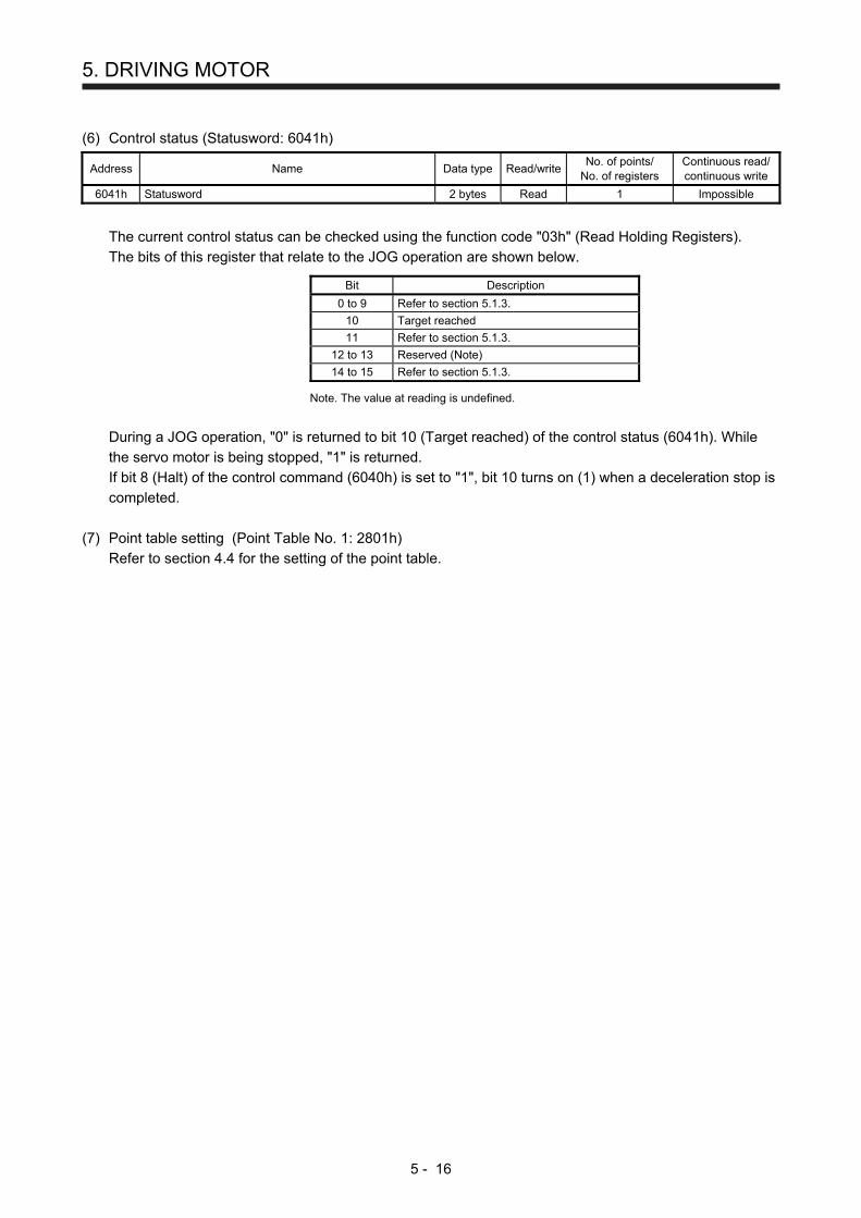
5. DRIVING MOTOR
5 - 16
(6) Control status (Statusword: 6041h)
Address Name Data type Read/write No. of points/
No. of registers Continuous read/ continuous write
6041h Statusword 2 bytes Read 1 Impossible
The current control status can be checked using the function code "03h" (Read Holding Registers). The bits of this register that relate to the JOG operation are shown below.
Bit Description
0 to 9 Refer to section 5.1.3.
10 Target reached
11 Refer to section 5.1.3.
12 to 13 Reserved (Note)
14 to 15 Refer to section 5.1.3.
Note. The value at reading is undefined.
During a JOG operation, "0" is returned to bit 10 (Target reached) of the control status (6041h). While the servo motor is being stopped, "1" is returned. If bit 8 (Halt) of the control command (6040h) is set to "1", bit 10 turns on (1) when a deceleration stop is completed.
(7) Point table setting (Point Table No. 1: 2801h)
Refer to section 4.4 for the setting of the point table.

5. DRIVING MOTOR
5 - 17
5.4.4 Directions for use
Set a command value limit minimum value and a command value limit maximum value (address 607Dh).
Specify the JOG mode with address 6060h.
Save the parameter in the EEP-ROM with Save manufacturer defined parameters of Store parameters (address 1010h).
Set 0Fh in address 6040h→ Operation enable
Set 0Fh in address 6040h to stop the travel.
Set 1Fh in address 6040h to start travelin the forward direction. (Note 2)
Set 3Fh in address 6040h to start travelin the reverse direction. (Note 2)
Check that the mode is switched to the JOG mode with address 6061h.
Set a command speed (address 6081h).Set an acceleration time constant (address 2801h or 6083h). (Note 1)Set a deceleration time constant (address 2801h or 6084h). (Note 1)
Skip if not using software.
[Precondition setting] Select "Modbus-RTU protocol" in [Pr. PC71].Set the point table method or program method in "Control mode selection" of [Pr. PA01].
Note 1. For the point table method ([Pr. PA01] = _ _ _ 6), set the acceleration time constant to Point Table No. 1: Acceleration (2801h),
and the deceleration time constant to Point Table No. 1: Deceleration (2801h).
For the program method ([Pr. PA01] = _ _ _ 7), set the acceleration time constant to Profile Acceleration: 6083h, and the
deceleration time constant to Profile Deceleration: 6084h.
2. [The operations are performed when [Pr. PT01] (address 2481h) is set to "_ _ _ 1" (incremental value command method).
When [Pr. PT01] (address 2481h) is set to "_ _ _ 0" (absolute value command method), setting 1Fh in address 6040h starts
travel to the target position.

5. DRIVING MOTOR
5 - 18
5.5 Point Table Operation Mode
This section describes how to perform a point table data operation. 5.5.1 Function description
Perform a point table data operation following the instruction below. After setting the point table (Point Table: 2801h to 281Fh), point table specification (Target Point Table: 2D60h), and Software Position Limit (607Dh), start the operation with the control command (Controlword: 6040h). The point table operation is performed. During a point table operation, the current status can be acquired with the control status (Statusword: 6041h), the point table number used for the current operation can be acquired with the point table request (Point Demand Value: 2D68h), and the latest point number on which the operation is completed can be acquired with the current point table (Point Actual Value: 2D69h).
Controlword (6040h)
Software Position Limit (607Dh)
Point Table ModePoint Table (2801h to 281Fh)
Target Point Table (2D60h)
Statusword (6041h)
Point Demand Value (2D68h)
Point Actual Value (2D69h)
Point Table Error No. (2A43h)
5.5.2 Related registers
Address Name Data type Read/write No. of points/
No. of registers Continuous read/ continuous write
6040h Controlword 2 bytes Read/write 1 Impossible
607Dh Software Position Limit
Number of entries 1 byte
Read/write 5 Impossible Min Position Limit 4 bytes
Max Position Limit 4 bytes
2801h to 281Fh
Point Table No. 1 to No. 31 (Point table No. 1 to No. 31)
Number of entries 1 byte
Read/write 9 Impossible
Point data 4 bytes
Speed 2 bytes
Acceleration 2 bytes
Deceleration 2 bytes
Dwell 2 bytes
Sub function 1 byte
M code (Note) 1 byte
2D60h Target Point Table 2 bytes Read/write 1 Impossible
6041h Statusword 2 bytes Read/write 1 Impossible
2D68h Point Demand Value 2 bytes Read/write 1 Impossible
2D69h Point Actual Value 2 bytes Read/write 1 Impossible
2A43h Point Table Error
Number of entries 1 byte
Read 4 Impossible Point Table Error No. 2 bytes
Point Table Error Factor 4 bytes Note. M code will be available in the future.

5. DRIVING MOTOR
5 - 19
5.5.3 Details of registers
(1) Control command (Controlword: 6040h)
Address Name Data type Read/write No. of points/
No. of registers Continuous read/ continuous write
6040h Controlword 2 bytes Read/write 1 Impossible
The status of the current control command input can be checked using the function code "03h" (Read Holding Registers). A control command can be written using the function code "10h" (Preset Multiple Registers). The bits of this register that relate to the point table operation are shown below.
Bit Description
0 to 3 Refer to section 5.1.3.
4 New Set Point
5 Direction
6 Reserved (Note)
7 Refer to section 5.1.3.
8 Halt
9 to 15 Refer to section 5.1.3.
Note. The value at reading is undefined. Set "0" at writing.
Use bit 4 (New Set Point) of the control command (6040h) to apply point table data. If "1" is set, new point table data is applied. To restart the operation after the servo motor is stopped, set "0" before setting "1" again. For [Pr. PT01] (address 2481h) = "_ _ _ 1" (incremental value command method), the rotation direction of the servo motor can be set with bit 5 of (Direction) of the control command (6040h). The servo motor rotates in the forward direction if "0" is set, and in the reverse direction if "1" is set. If the direction of the rotation is reversed while the servo motor is rotating, the servo motor once stops and then starts rotating in the opposite direction. Use bit 8 (Halt) of the control command (6040h) to forcibly stop the servo motor. If "1" is set, a deceleration stop is performed. If "0" is set, the operation resumes.
(2) Software limit (Software Position Limit: 607Dh)
Address Name Data type Read/write No. of points/
No. of registers Continuous read/ continuous write
607Dh Software Position Limit
Number of entries 1 byte
Read/write 5 Impossible Min Position Limit 4 bytes
Max Position Limit 4 bytes
The current software limit setting value can be read using the function code "03h" (Read Holding Registers). At this time, "02h" is returned to Number of entries. The stroke limit value in the reverse direction is returned to Min Position Limit (stroke limit -) in units of commands. The stroke limit value in the forward direction is returned to Max Position Limit (stroke limit +) in units of commands.

5. DRIVING MOTOR
5 - 20
The current software limit setting can be written using the function code "10h" (Preset Multiple Registers). At this time, set "02h" for Number of entries. Set the stroke limit value in the reverse direction in Min Position Limit (stroke limit -) in units of commands. Set the stroke limit value in the forward direction in Max Position Limit (stroke limit +) in units of commands. If Min Position Limit (stroke limit -) and Max Position Limit (stroke limit +) are set to the same value, the software limit function is disabled.
(3) Point table setting (Point Table No. 1 to No. 31: 2801h to 281Fh)
For the setting method, refer to Section 4.4.
Address Name Data type Read/write No. of points/
No. of registers Continuous read/ continuous write
Number of entries 1 byte
Point data 4 bytes
Point Table No. 1 to No. 31
Speed 2 bytes
2801h to 281Fh
Acceleration 2 bytes Read/write 9 Impossible
Deceleration 2 bytes
Dwell 2 bytes
Sub function 1 byte
M code (Note) 1 byte Note. M code will be available in the future.
(4) Point table specification (Target Point Table: 2D60h)
Address Name Data type Read/write No. of points/
No. of registers Continuous read/ continuous write
2D60h Target Point Table 2 bytes Read/write 1 Impossible
The point table specification number can be read using the function code "03h" (Read Holding Registers). A point table specification number can be set using the function code "10h" (Preset Multiple Registers).
(5) Control status (Statusword: 6041h)
Address Name Data type Read/write No. of points/
No. of registers Continuous read/ continuous write
6041h Statusword 2 bytes Read/write 1 Impossible
The current point table operation status can be read using the function code "03h" (Read Holding Registers). The bits of this register that relate to the point table operation are shown below.
Bit Description
0 to 9 Refer to section 5.1.3.
10 Target reached
11 Refer to section 5.1.3.
12 Set Point Acknowledge
13 Reserved (Note)
14 to 15 Refer to section 5.1.3.
Note. The value at reading is undefined. Set "0" at writing.

5. DRIVING MOTOR
5 - 21
(a) Bit 10 of the control status (6041h) (Target reached)
Bit 10 turns on (1) when the command position is reached. If bit 8 (Halt) of the control command is set to "1", bit 10 turns on (1) when a deceleration stop is completed. If a command is input again, bit 10 turns off (0).
(b) Bit 12 (Set Point Acknowledge) of the control status (6041h)
When bit 4 of the control command (6040h) is set to "1" and the servo amplifier completes accepting the command, bit 12 turns on (1).
(6) Point table request (Point Demand Value: 2D68h)
Address Name Data type Read/write No. of points/
No. of registers Continuous read/ continuous write
2D68h Point Demand Value 2 bytes Read/write 1 Impossible
The currently commanded point table number can be read using the function code "03h" (Read Holding Registers). While the servo motor is being stopped, the value of the point table specification (Target Point Table: 2D60h) is returned.
(7) Current point table (Point Actual Value: 2D69h)
Address Name Data type Read/write No. of points/
No. of registers Continuous read/ continuous write
2D69h Point Actual Value 2 bytes Read/write 1 Impossible
The point table number on which the operation is already completed is read using the function code "03h" (Read Holding Registers). When a home position return operation is completed, "0" is returned.
(8) Point table error (Point Table Error: 2A43h)
When a point table setting error occurs, the point table number and setting item that have caused the error are returned. For the reading method, refer to Section 4.13.
Address Name Data type Read/write No. of points/
No. of registers Continuous read/ continuous write
2A43h Point Table Error
Number of entries 1 byte
Read 4 Impossible Point Table Error No. 2 bytes
Point Table Error Factor 4 bytes
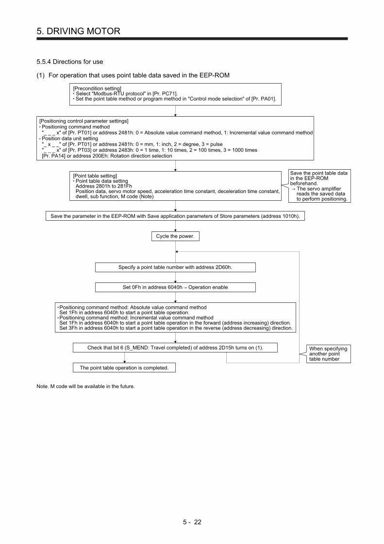
5. DRIVING MOTOR
5 - 22
5.5.4 Directions for use
(1) For operation that uses point table data saved in the EEP-ROM
[Positioning control parameter settings]Positioning command method"_ _ _ x" of [Pr. PT01] or address 2481h: 0 = Absolute value command method, 1: Incremental value command methodPosition data unit setting"_ x _ _" of [Pr. PT01] or address 2481h: 0 = mm, 1: inch, 2 = degree, 3 = pulse"_ _ _ x" of [Pr. PT03] or address 2483h: 0 = 1 time, 1: 10 times, 2 = 100 times, 3 = 1000 times[Pr. PA14] or address 200Eh: Rotation direction selection
[Point table setting]Point table data settingAddress 2801h to 281FhPosition data, servo motor speed, acceleration time constant, deceleration time constant,dwell, sub function, M code (Note)
Positioning command method: Absolute value command methodSet 1Fh in address 6040h to start a point table operation.Positioning command method: Incremental value command methodSet 1Fh in address 6040h to start a point table operation in the forward (address increasing) direction.Set 3Fh in address 6040h to start a point table operation in the reverse (address decreasing) direction.
Cycle the power.
Save the parameter in the EEP-ROM with Save application parameters of Store parameters (address 1010h).
The point table operation is completed.
Check that bit 6 (S_MEND: Travel completed) of address 2D15h turns on (1).
Specify a point table number with address 2D60h.
Set 0Fh in address 6040h→ Operation enable
When specifyinganother pointtable number
Save the point table datain the EEP-ROMbeforehand.→ The servo amplifier
reads the saved datato perform positioning.
[Precondition setting] Select "Modbus-RTU protocol" in [Pr. PC71].Set the point table method or program method in "Control mode selection" of [Pr. PA01].
Note. M code will be available in the future.

5. DRIVING MOTOR
5 - 23
(2) For operation that uses point table data sequentially sent to the servo amplifier (Method of saving point
table data in RAM)
[Positioning control parameter settings]Positioning command method"_ _ _ x" of [Pr. PT01] or address 2481h: 0 = Absolute value command method, 1: Incremental value command methodPosition data unit setting"_ x _ _" of [Pr. PT01] or address 2481h: 0 = mm, 1: inch, 2 = degree, 3 = pulse"_ _ _ x" of [Pr. PT03] or address 2483h: 0 = 1 time, 1: 10 times, 2 = 100 times, 3 = 1000 times[Pr. PA14] or address 200Eh: Rotation direction selection
[Point table data setting]Point table data settingAddress 2801h to 281FhPosition data, servo motor speed, acceleration time constant,deceleration time constant, dwell, sub function, M code (Note)
Positioning command method: Absolute value command methodSet 1Fh in address 6040h to start a point table operation.Positioning command method: Incremental value command methodSet 1Fh in address 6040h to start a point table operation in the forward (address increasing) direction.Set 3Fh in address 6040h to start a point table operation in the reverse (address decreasing) direction.
Cycle the power.
Save the parameter in the EEP-ROM with Save manufacturer defined parameters of Store parameters (address 1010h).
The point table operation is completed.
Check that bit 6 (S_MEND: Travel completed) ofaddress 2D15h turns on (1).
Check that bit 12 (Set-point acknowledge)of address 6041h turns on (1).
Set 0Fh in address 6040h→ Operation enable
For operation with the second and successive point table numbersspecifiedCheck that bit 6 (S_MEND: Travel completed) of address 2D15hturns on (1).
Specify a point table number with address 2D60h.
Send the point table data oneafter another to the servoamplifier.→ The servo amplifier saves
the point table data itreceived in the RAM toperform positioning.
When specifyinganother point tablenumberThe operations
on all pointtable data arecompleted.
[Precondition setting] Select "Modbus-RTU protocol" in [Pr. PC71].Set the point table method or program method in "Control mode selection" of [Pr. PA01].
Note. M code will be available in the future.

5. DRIVING MOTOR
5 - 24
5.6 Program Operation Mode
This section describes how to perform a program operation. 5.6.1 Function description
Set a program beforehand, and then set a program number in the program number specification (Target Program No.: 2D70h) and start the operation with the control command (Controlword: 6040h). The specified program starts running. The current status can be checked with the control status (Statusword: 6041h). The currently running program number can be read with the program number request (Program No. Demand Value: 2D78h). The current step number can be read with the program step number (Program Step No.: 2D79h).
Controlword (6040h)
Software Position Limit (607Dh) Program DriveMode
Target Program No. (2D70h)
Statusword (6041h)
Program No. Demand Value (2D78h)
Program Step No. (2D79h)
5.6.2 Related registers
Address Name Data type Read/write No. of points/
No. of registers Continuous read/ continuous write
6040h Controlword 2 bytes Read/write 1 Impossible
607Dh Software Position Limit
Number of entries 1 byte
Read/write 5 Impossible Min Position Limit 4 bytes
Max Position Limit 4 bytes
2D70h Target Program No. 2 bytes Read/write 1 Impossible
6041h Statusword 2 bytes Read 1 Impossible
2D78h Program No. Demand Value 2 bytes Read 1 Impossible
2D79h Program Step No. 2 bytes Read 1 Impossible

5. DRIVING MOTOR
5 - 25
5.6.3 Details of registers
(1) Control command (Controlword: 6040h)
Address Name Data type Read/write No. of points/
No. of registers Continuous read/ continuous write
6040h Controlword 2 bytes Read/write 1 Impossible
The status of the current control command input can be checked using the function code "03h" (Read Holding Registers). A control command can be written using the function code "10h" (Preset Multiple Registers). The bits of this register that relate to the program operation are shown below.
Bit Description
0 to 3 Refer to section 5.1.3.
4 New Set Program
5 Reserved (Note)
6 Stop
7 Refer to section 5.1.3.
8 Halt
9 to 15 Refer to section 5.1.3.
Note. The value at reading is undefined. Set "0" at writing.
Use bit 4 (New Set Program) of the control command (6040h) to start a program operation. When the bit is set to "1", the specified program number setting takes effect. To restart the operation after the servo motor is stopped, set "0" before setting "1" again. If "1" is set to bit 6 (Stop) of the control command (6040h), the program ends during the processing. Use bit 8 (Halt) of the control command (6040h) to forcibly stop the servo motor. If "1" is set, a deceleration stop is performed. If "0" is set, the operation resumes. However, a deceleration stop is not performed when the ZRT command is executed.
(2) Software limit (Software Position Limit: 607Dh)
Address Name Data type Read/write No. of points/
No. of registers Continuous read/ continuous write
607Dh Software Position Limit
Number of entries 1 byte
Read/write 5 Impossible Min Position Limit 4 bytes
Max Position Limit 4 bytes
The current software limit setting value can be read using the function code "03h" (Read Holding Registers). At this time, "02h" is returned to Number of entries. The stroke limit value in the reverse direction is returned to Min Position Limit (stroke limit -) in units of commands. The stroke limit value in the forward direction is returned to Max Position Limit (stroke limit +) in units of commands.

5. DRIVING MOTOR
5 - 26
The current software limit setting can be written using the function code "10h" (Preset Multiple Registers). At this time, set "02h" for Number of entries. Set the stroke limit value in the reverse direction in Min Position Limit (stroke limit -) in units of commands. Set the stroke limit value in the forward direction in Max Position Limit (stroke limit +) in units of commands. If Min Position Limit (stroke limit -) and Max Position Limit (stroke limit +) are set to the same value, the software limit function is disabled.
(3) Program number specification (Target Program No.: 2D70h)
Address Name Data type Read/write No. of points/
No. of registers Continuous read/ continuous write
2D70h Target Program No. 2 bytes Read/write 1 Impossible
The currently specified program number can be read using the function code "03h" (Read Holding Registers). A program number can be set using the function code "10h" (Preset Multiple Registers).
(4) Control status (Statusword: 6041h)
Address Name Data type Read/write No. of points/
No. of registers Continuous read/ continuous write
6041h Statusword 2 bytes Read 1 Impossible
The current program operation status can be read using the function code "03h" (Read Holding Registers). The bits of this register that relate to the program operation are shown below.
Bit Description
0 to 9 Refer to section 5.1.3.
10 Target reached
11 Refer to section 5.1.3.
12 Program Running
13 Reserved (Note)
14 to 15 Refer to section 5.1.3.
Note. The value at reading is undefined.
(a) Bit 10 of the control status (6041h) (Target reached)
Bit 10 turns on (0) when the start signal turns on. Bit 10 turns on (1) when the command position is reached. If bit 8 (Halt) of the control command is set to "1", bit 10 turns on (1) when a deceleration stop is completed.
(b) Bit 12 (Program Running) of the control status (6041h)
During a program operation, bit 12 is on (1). When the program stops running or has ended, the bit turns off (0).

5. DRIVING MOTOR
5 - 27
(5) Program number request (Program No. Demand Value: 2D78h)
Address Name Data type Read/write No. of points/
No. of registers Continuous read/ continuous write
2D78h Program No. Demand Value 2 bytes Read 1 Impossible
The currently commanded program number can be read using the function code "03h" (Read Holding Registers). While the servo motor is being stopped, the value set for the program number specification (Target Program No.: 2D70h) is returned.
(6) Program step number (Program Step No.: 2D79h)
Address Name Data type Read/write No. of points/
No. of registers Continuous read/ continuous write
2D79h Program Step No. 2 bytes Read 1 Impossible
The currently running program step number can be read using the function code "03h" (Read Holding Registers). While no program is running, "0" is returned.
5.6.4 Directions for use
[Positioning control parameter settings]Positioning command method"_ _ _ x" of [Pr. PT01] or address 2481h: 0 = Absolute value command method, 1: Incremental value command methodPosition data unit setting"_ x _ _" of [Pr. PT01] or address 2481h: 0 = mm, 1: inch, 2 = degree, 3 = pulse"_ _ _ x" of [Pr. PT03] or address 2483h: 0 = 1 time, 1: 10 times, 2 = 100 times, 3 = 1000 times
[Program setting]Set a program with MR Configurator2.
Set 1Fh in address 6040h to start the program operation.
Cycle the power.
Save the parameter in the EEP-ROM with Save manufacturer defined parameters of Store parameters (address 1010h).
The program operation is completed.
Check that bit 12 (Program running) of address 6041h turns off (0).
Set 0Fh in address 6040h→ Operation enable
Specify a program number with address 2D70h.
When specifyinganother programnumber
[Precondition setting] Select "Modbus-RTU protocol" in [Pr. PC71].Set the point table method or program method in "Control mode selection" of [Pr. PA01].

5. DRIVING MOTOR
5 - 28
5.7 Touch Probe (Address: 60B8h to 60BBh)
The current position latch data at the time of MSD (Mark detection) input can be read. 5.7.1 Function description
When the touch probe function (60B8h) is set, and MSD (Mark detection), an external signal, is turned on/off, the current position at the rising and falling edges are latched. The latch status of the current position data can be checked with the touch probe status (60B9h). The latched current data can be read with the touch probe position positive value (60BAh) and the touch probe position negative value (60BBh).
Touch probe function (60B8h)
Touch probeMSD (Mark detection) (Note)
Touch probe status (60B9h)
Touch probe positionpositive value (60BAh)
Touch probe positionnegative value (60BBh)
Note. Input with an external signal.
5.7.2 List of registers
Address Name Data type Read/write No. of points/
No. of registers Continuous read/ continuous write
60B8h Touch probe function 2 bytes Read/write 1 Possible
60B9h Touch probe status 2 bytes Read 1 Possible
60BAh Touch probe position positive value 4 bytes Read 2 Possible
60BBh Touch probe position negative value 4 bytes Read 2 Possible

5. DRIVING MOTOR
5 - 29
5.7.3 Details of registers
(1) Touch probe function setting (Touch probe function: 60B8h)
Address Name Data type Read/write No. of points/
No. of registers Continuous read/ continuous write
60B8h Touch probe function 2 bytes Read/write 1 Possible
The current setting of the touch probe function can be checked using function code "03h" (Read Holding Registers). The touch probe function is set using function code "10h" (Preset Multiple Registers). The following table lists the setting of this register.
Bit Description
0 0: Latch function disabled 1: Latch function enabled
1 0: Latch with the first trigger 1: Continuously latch with trigger inputs
2 The value at reading is undefined. Set "0" when writing.
3
4 0: Stop sampling at the rising edge of touch probe 1: Start sampling at the rising edge of touch probe
5 0: Stop sampling at the falling edge of touch probe 1: Start sampling at the falling edge of touch probe
6 to 15 The value at reading is undefined. Set "0" when writing.
Select enable/disable for the latch function with bit 0. Select "1" when using the touch probe function. Select a trigger condition for the touch probe function with bit 1. Set "0" to latch just once when MSD (Mark detection) is input. Set "1" to latch every time MSD (Mark detection) is input. Set a condition for the rising edge of the MSD (Mark detection) with bit 4. Set "1" to latch at the rising edge. Set a condition for the falling edge of the MSD (Mark detection) with bit 5. Set "1" to latch at the falling edge.

5. DRIVING MOTOR
5 - 30
(2) Status of the touch probe function (Touch probe status: 60B9h)
Address Name Data type Read/write No. of points/
No. of registers Continuous read/ continuous write
60B9h Touch probe status 2 bytes Read 1 Possible
The current status of the touch probe function can be checked using function code "03h" (Read Holding Registers). The following table lists the setting of this register.
Bit Description
0 0: Latch function of touch probe is disabled. 1: Latch function of touch probe is enabled.
1 (Note) 0: Latch is incomplete at the rising edge with the latch function of the touch probe. 1: Latch is complete at the rising edge with the latch function of the touch probe.
2 (Note) 0: Latch is incomplete at the falling edge with the latch function of the touch probe. 1: Latch is complete at the falling edge with the latch function of the touch probe.
3 to 5 The value at reading is undefined.
6 MSDH (Latch completed at rising edge of Mark detection) status 0: Latch is incomplete at the rising edge with the latch function of the touch probe. 1: Latch is complete at the rising edge with the latch function of the touch probe.
7 MSDL (Latch completed at falling edge of Mark detection) status 0: Latch is incomplete at the falling edge with the latch function of the touch probe. 1: Latch is complete at the falling edge with the latch function of the touch probe.
8 to 15 The value at reading is undefined.
Note. This is available with servo amplifiers with software version C1 or later.
Bit 0 indicates the status of the touch probe function. 0 indicates disabled, and 1 enabled. With bit 1, if the data is latched at the rising edge of the touch probe can be checked. Latched data can be read when this bit is set to "1". When this bit turns on, it remains on until bit 4 of the touch probe setting (60B8h) is set to "0". With bit 2, if the data is latched at the falling edge of the touch probe can be checked. Latched data can be read when this bit is set to "1". When this bit turns on, it remains on until bit 5 of the touch probe setting (60B8h) is set to "0". Bit 6 indicates the status of MSDH (Latch completed at rising edge of Mark detection). When bit 0 is set to "1" and bit 6 is set to "1", the position of the touch probe rising edge is updated. Bit 7 indicates the status of MSDH (Latch completed at falling edge of Mark detection). When bit 0 is set to "1" and bit 7 is set to "1", the position of the touch probe falling edge is updated.
(3) Rising edge position of touch probe (Touch probe position positive value: 60BAh)
Address Name Data type Read/write No. of points/
No. of registers Continuous read/ continuous write
60BAh Touch probe position positive value 4 bytes Read 2 Possible
The current position of the touch probe rising edge can be checked using function code "03h" (Read Holding Registers).

5. DRIVING MOTOR
5 - 31
(4) Falling edge position of touch probe (Touch probe position negative value: 60BBh)
Address Name Data type Read/write No. of points/
No. of registers Continuous read/ continuous write
60BBh Touch probe position negative value 4 bytes Read 2 Possible
The current position of the touch probe falling edge can be checked using function code "03h" (Read Holding Registers).
5.7.4 Directions for use
The following explains for latching the current position at the rising edge of MSD (Mark detection). (1) Set "0013h" to the touch probe setting (Touch probe function: 60B8h) to store data at rising edge of
MSD (Mark detection). (2) At this time, the touch probe status (Touch probe status: 60B9h) is set to "0001h", and the latched data
has not been stored yet. (3) Turn on MSD (Mark detection) with an external signal. (4) The touch probe status (Touch probe status: 60B9h) changes to "0043h", and the current position at the
time of MSD (Mark detection) on will be stored to the rising edge position of touch probe (Touch probe position positive value: 60BAh).
(5) Turn off MSD (Mark detection) with an external signal. (6) The touch probe status (Touch probe status: 60B9h) changes to "0083h", and the current position at the
time of MSD (Mark detection) off will not be stored to the falling edge position of touch probe (Touch probe position negative value: 60BBh).
(7) Latching can be continued from (3).

5. DRIVING MOTOR
5 - 32
The following shows a timing chart.
60B8h bit 010
(1) 60B8h = 0013h
(4) 60B9h = 0043h
(2) 60B9h = 0001h
(3) MSD on (5) MSD off
(6) 60B9h = 0083h (7) Latches continuously
10
10
A0
0
B C
10
10
10
10
10
10
ONOFF
60B8h bit 1
60B8h bit 4
60B8h bit 5
60B9h bit 0
60B9h bit 1
60B9h bit 2
60B9h bit 6
60B9h bit 7
MSD (mark detection)
60BAh
60BBh
(Touch probe signal)

5. DRIVING MOTOR
5 - 33
5.8 Function common to the modes
This section describes the registers that can be used for the home position return mode, JOG mode, point table mode, and program operation mode. 5.8.1 List of registers
Function Description Read/write Detailed
explanation
Control input (2D01h to 2D09h)
The control input of the servo amplifier can be specified. Read/write Section 5.8.2
Control output (2D11h to 2D19h)
The control output status of the servo amplifier can be read. Read Section 5.8.3
Simultaneous start bit setting (2D9Ah)
Bit 4 of the control command (Controlword: 6040h) can be set. Writing Section 5.8.4
Controller force stop (2D9Bh)
The controller force stop can be specified. Writing Section 5.8.5
Override (2DB0h) An override value can be set. Read/write Section 5.8.6
Forward torque limit value (60E0h)
The torque limit value for the forward operation can be set. Read/write Section 5.8.7
Reverse torque limit value (60E1h)
The torque limit value for the reverse operation can be set. Read/write Section 5.8.8
Current position (6064h) The current position can be read. Read Section 5.8.9
Current speed (606Ch) The current speed can be read. Read Section 5.8.10
Current torque (6077h) The current torque can be read. Read Section 5.8.11
Cam number setting (2D80h)
A cam number can be set. Read/write Section 5.8.12
Current cam number (2D82h)
The cam number being used in the cam control operation can be read. Read Section 5.8.13
Cam axis one-cycle length setting (2D84h)
One-cycle length of a cam axis can be written in the RAM space in the servo amplifier.
Writing Section 5.8.14
Cam stroke length setting (2D85h)
The cam stroke length can be written in the RAM space in the servo amplifier.
Writing Section 5.8.15
Request store CAM (2D88h) Cam data can be written in the RAM space in the servo amplifier. Writing Section 5.8.16
CAM area (2D89h) The storage area for cam data to be read or written can be set. Read/write Section 5.8.17
CAM data in CAM area (2D8Bh)
Cam data in the area specified by using the CAM area (2D89h) can be read or written.
Read/write Section 5.8.18
5.8.2 Control input (2D01h to 2D09h)
Address Name Data type Read/write No. of points/
No. of registers Continuous read/ continuous write
2D01h to 2D09h
Control DI1 to Control DI9 2 bytes Read/write 1 Possible
The input device status (ON or OFF) can be read using the function code "03h" (Read Holding Registers). Input devices can be turned on or off using the function code "10h" (Preset Multiple Registers).

5. DRIVING MOTOR
5 - 34
The following table lists readable and writable input devices.
Bit definition of control DI1
Bit Abbreviation Description
0 C_EM1/2 Forced stop 1/2
1
The value at reading is undefined. Set "0" at writing. 2
3
4 C_CDP Gain switching
5
The value at reading is undefined. Set "0" at writing. 6
7
8 C_TL1
Internal torque limit selection The smallest value among Object 60E0h/60E1h and the torque limits in the table below is applied as the torque limit value.
Bit 8 Description
0 Parameter 1
1 Parameter 1 and 2
Parameter 1: [Pr. PA11], [Pr. PA12] Parameter 2: [Pr. PA35]
9
The value at reading is undefined. Set "0" at writing.
10
11
12
13
14
15
Bit definition of control DI2
Bit Abbreviation Description
0
The value at reading is undefined. Set "0" at writing.
1
2
3
4
5 C_CAMC Cam control command
6 The value at reading is undefined. Set "0" at writing.
7
8 C_PC Proportional control
9 The value at reading is undefined. Set "0" at writing.
10
11 C_CLTC (Note)
Clutch command
12 The value at reading is undefined. Set "0" at writing.
13 C_CPCD
(Note) Cam position compensation requirement
14 The value at reading is undefined. Set "0" at writing.
15
Note. This is available with servo amplifiers with software version C1 or later.

5. DRIVING MOTOR
5 - 35
Bit definition of control DI3
Bit Abbreviation Description
0 The value at reading is undefined. Set "0" at writing.
1
2 C_CM1 Electronic gear selection 1
3 C_CM2 Electronic gear selection 2
4
The value at reading is undefined. Set "0" at writing.
5
6
7
8
9
10
11 C_CR Clear
12 The value at reading is undefined. Set "0" at writing.
13 C_STAB2 Second acceleration/deceleration selection
14 The value at reading is undefined. Set "0" at writing.
15
Bit definition of control DI4
Bit Abbreviation Description
0
The value at reading is undefined. Set "0" at writing.
1
2
3
4
5
6
7
8
9
10
11
12
13
14
15

5. DRIVING MOTOR
5 - 36
Bit definition of control DI5
Bit Abbreviation Description
0
The value at reading is undefined. Set "0" at writing.
1
2
3
4
5
6
7
8
9
10
11
12
13
14
15
Bit definition of control DI6
Bit Abbreviation Description
0
The value at reading is undefined. Set "0" at writing.
1
2
3
4
5
6
7
8
9
10
11
12
13
14
15

5. DRIVING MOTOR
5 - 37
Bit definition of control DI7
Bit Abbreviation Description
0 C_PI1 Program input 1
1 C_PI2 Program input 2
2 C_PI3 Program input 3
3 C_TCH Teach
4 C_TP0 Generator multiplication 1
5 C_TP1 Generator multiplication 2
6 The value at reading is undefined. Set "0" at writing.
7 C_OVR Analog override selection
8 C_LPS Current position latch input
9 The value at reading is undefined. Set "0" at writing.
10 C_STAB Speed acceleration/deceleration selection
11
The value at reading is undefined. Set "0" at writing.
12
13
14
15
Bit definition of control DI8
Bit Abbreviation Description
0
The value at reading is undefined. Set "0" at writing.
1
2
3
4
5
6
7
8
9
10
11
12
13
14
15

5. DRIVING MOTOR
5 - 38
Bit definition of control DI9
Bit Abbreviation Description
0
The value at reading is undefined. Set "0" at writing.
1
2
3
4
5
6
7
8
9
10
11
12
13
14
15
5.8.3 Control output (2D11h to 2D19h)
Address Name Data type Read/write No. of points/
No. of registers Continuous read/ continuous write
2D11h to 2D19h
Status DO1 to Status DO9 2 bytes Read 1 Possible
The output device status (ON or OFF) can be read using the function code "03h" (Read Holding Registers). The following table lists readable output devices.
Bit definition of status DO1
Bit Abbreviation Description
0 The value at reading is undefined.
1 S_ERF EEP-ROM write completed 0: EEP-ROM write in process 1: EEP-ROM write completed
2 S_SA Speed reached
3 The value at reading is undefined.
4 S_CDPS Variable gain selection
5 The value at reading is undefined.
6
7 S_TL Analog torque limit selection in process
8 S_TL1 Torque limit selection in process
9
The value at reading is undefined. 10
11
12 S_INP In-position
13 S_TLC Limiting torque
14 The value at reading is undefined.
15

5. DRIVING MOTOR
5 - 39
Bit definition of status DO2
Bit Abbreviation Description
0 S_ZPAS Z-phase already passed
1 The value at reading is undefined.
2
3 S_ZSP Under zero speed
4 S_VLC Under speed limit
5 S_CAMS Under cam control
6 The value at reading is undefined.
7
8 S_PC Under proportional control
9 The value at reading is undefined.
10
11 S_CLTS (Note)
Clutch ON/OFF status
12 S_CLTSM
(Note) Clutch smoothing status
13 S_CPCC
(Note) Cam position compensation completed
14 The value at reading is undefined.
15
Note. This is available with servo amplifiers with software version C1 or later.
Bit definition of status DO3
Bit Abbreviation Description
0
1
2
3
4
5 The value at reading is undefined.
6
7
8
9
10
11 S_MTTR During tough drive
12
13 The value at reading is undefined.
14
15

5. DRIVING MOTOR
5 - 40
Bit definition of status DO4
Bit Abbreviation Description
0
The value at reading is undefined.
1
2
3
4
5
6
7
8
9
10
11
12
13
14
15
Bit definition of status DO5
Bit Abbreviation Description
0
The value at reading is undefined.
1
2
3
4
5 S_CPO Rough match
6 S_MEND Travel completed
7 S_ZP Home position return operation completed
8 S_PUS Pause
9
The value at reading is undefined.
10
11
12
13
14
15

5. DRIVING MOTOR
5 - 41
Bit definition of status DO6
Bit Abbreviation Description
0
The value at reading is undefined.
1
2
3
4
5
6
7
8
9
10
11
12
13
14
15
Bit definition of status DO7
Bit Abbreviation Description
0 S_ALMWNG Failure/warning
1 The value at reading is undefined.
2 S_POT Position range output
3 S_PED Position end
4 S_SOUT SYNC synchronous output
5 The value at reading is undefined.
6 S_OUT1 Program output 1
7 S_OUT2 Program output 2
8 S_OUT3 Program output 3
9
The value at reading is undefined.
10
11
12
13
14
15

5. DRIVING MOTOR
5 - 42
Bit definition of status DO8
Bit Abbreviation Description
0
The value at reading is undefined.
1
2
3
4
5
6
7
8
9
10
11
12
13
14
15
Bit definition of status DO9
Bit Abbreviation Description
0
The value at reading is undefined.
1
2
3
4
5
6
7
8
9
10
11
12
13
14
15

5. DRIVING MOTOR
5 - 43
5.8.4 Simultaneous start bit setting (2D9Ah)
Multiple axis system with different operation modes (for example, point table operation and program operation) can be started simultaneously using the broadcast communication. This setting is not needed when the same operation mode is used. (1) List of registers
Address Name Data type Read/write No. of points/
No. of registers Continuous read/ continuous write
2D9Ah Set Controlword bit4 1 byte Writing 1 Impossible
(2) Usage
Before setting this register, set the following items for all stations to be started simultaneously, and prepare for simultaneous start.
(a) Specify the point table No. or the program No.
(b) Set "000Fh" or "002Fh" to register 6040h to make the servo amplifier status "Operation enabled".
Use function code "10h" (Preset Multiple Registers) when setting. The setting is shown as follows:
Bit Description
0 Turn off the simultaneous start signal.
1 Turn on the simultaneous start signal.
Simultaneous start is executed by setting "1" to this register. When the operation is complete, change the point table No. or the program No. after setting "0" to this register. Simultaneous start will be executed again by setting "1" to this register.
5.8.5 Controller force stop (2D9Bh)
Address Name Data type Read/write No. of points/
No. of registers Continuous read/ continuous write
2D9Bh C_EM1/2 command 1 byte Writing 1 Impossible
Controller operations can be forcibly stopped using the function code "10h" (Preset Multiple Registers). The following table lists the setting values of this register.
Bit Description
0 Controller force stop OFF
1 Controller force stop ON
Controller force stop is performed without reference to the broadcast setting (2D98h). Use this register to forcibly stop the servo amplifiers of all axes in the broadcast communication.

5. DRIVING MOTOR
5 - 44
5.8.6 Override (2DB0h)
Address Name Data type Read/write No. of points/
No. of registers Continuous read/ continuous write
2DB0h Override 2 bytes Read/write 1 Impossible
Turning on OVR (override selection) enables the setting. The override value can be read using the function code "03h" (Read Holding Registers). An override value can be set using the function code "10h" (Preset Multiple Registers). Set the override value between 0% and 200% in the unit of %. 5.8.7 Forward torque limit value (60E0h)
Address Name Data type Read/write No. of points/
No. of registers Continuous read/ continuous write
60E0h Positive torque limit value 2 bytes Read/write 1 Impossible
The forward torque limit value can be read using the function code "03h" (Read Holding Registers). A forward torque limit value can be set using the function code "10h" (Preset Multiple Registers). Set a forward torque limit value in units of 0.1%. 5.8.8 Reverse torque limit value (60E1h)
Address Name Data type Read/write No. of points/
No. of registers Continuous read/ continuous write
60E1h Negative torque limit value 2 bytes Read/write 1 Impossible
The reverse torque limit value can be read using the function code "03h" (Read Holding Registers). A reverse torque limit value can be set using the function code "10h" (Preset Multiple Registers). Set a reverse torque limit value in units of 0.1%. 5.8.9 Current position (6064h)
Address Name Data type Read/write No. of points/
No. of registers Continuous read/ continuous write
6064h Position actual value 4 bytes Read 2 Impossible
The current position can be read using the function code "03h" (Read Holding Registers). The read value is the same as the one in the address 2B2Fh for monitoring (refer to section 4.2). 5.8.10 Current speed (606Ch)
Address Name Data type Read/write No. of points/
No. of registers Continuous read/ continuous write
606Ch Velocity actual value 4 bytes Read 2 Impossible
The current speed can be read using the function code "03h" (Read Holding Registers). The read data is in the unit of r/min.

5. DRIVING MOTOR
5 - 45
5.8.11 Current torque (6077h)
Address Name Data type Read/write No. of points/
No. of registers Continuous read/ continuous write
6077h Torque actual value 2 bytes Read 1 Impossible
The current torque value can be read using function code "03h" (Read Holding Registers). The read data is in the unit of 0.1%. 5.8.12 Cam number setting (2D80h)
Address Name Data type Read/write No. of points/
No. of registers Continuous read/ continuous write
2D80h Target CAM No. 1 byte Read/write 1 Impossible
A set cam number can be read using the function code "03h" (Read Holding Registers). A cam number can be set using the function code "10h" (Preset Multiple Registers). If [Cam control data No. 49 - Cam No.] is "0", the cam number setting with "2D80h" is enabled. If the cam number is not "0", the setting of [Cam control data No. 49] is enabled. For details of cam control data numbers, refer to "MR-JE-_A Servo Amplifier Instruction Manual (Positioning Mode). 5.8.13 Current cam number (2D82h)
Address Name Data type Read/write No. of points/
No. of registers Continuous read/ continuous write
2D82h CAM actual No. 1 byte Read 1 Impossible
While a cam control operation is being performed (when "1" is set in bit 5 of 2D12h), the cam number being used in the operation can be read using the function code "03h" (Read Holding Registers). 5.8.14 Cam axis one-cycle length setting (2D84h)
Address Name Data type Read/write No. of points/
No. of registers Continuous read/ continuous write
2D84h One cycle length of CAM axis 4 bytes Read/write 2 Impossible
The one-cycle length of a cam axis can be written in the RAM space in the servo amplifier using the function code "10h" (Preset Multiple Registers). 5.8.15 Cam stroke length setting (2D85h)
Address Name Data type Read/write No. of points/
No. of registers Continuous read/ continuous write
2D85h Stroke movement of CAM 4 bytes Read/write 2 Impossible
A cam stroke length can be written in the RAM space in the servo amplifier using the function code "10h" (Preset Multiple Registers).

5. DRIVING MOTOR
5 - 46
5.8.16 Request store CAM (2D88h)
Address Name Data type Read/write No. of points/
No. of registers Continuous read/ continuous write
2D88h Request store CAM 1 bytes Writing 1 Impossible
Cam data can be written in the RAM space in the servo amplifier using the function code "10h" (Preset Multiple Registers). Always set "0". 5.8.17 CAM area (2D89h)
Address Name Data type Read/write No. of points/
No. of registers Continuous read/ continuous write
2D89h CAM area 2 bytes Read/write 1 Impossible
The storage area of cam data to be read or written can be set using the function code "10h" (Preset Multiple Registers). 5.8.18 CAM data in CAM area (2D8Bh)
Address Name Data type Read/write No. of points/
No. of registers Continuous read/ continuous write
2D8Bh CAM data in CAM area 64 bytes Read/write 32 Impossible
Cam data can be read using function code "03h" (Read Holding Registers). Cam data in the area specified by using the CAM area (2D89h) can be read. Cam data can be written in the RAM space in the servo amplifier using the function code "10h" (Preset Multiple Registers). Specify the space in which cam data is written with the CAM area (2D89h).

6. LIST OF MODBUS REGISTERS
6 - 1
6. LIST OF MODBUS REGISTERS
The following shows the data types used for the Modbus registers.
Data type Abbreviation Size Range
Unsigned8 UINT8 1 byte 0 to 31
Unsigned16 UINT16 2 bytes 0 to 65535
Unsigned32 UINT32 4 bytes 0 to 4294967295
Interger8 INT8 1 byte -128 to 127
Interger16 INT16 2 bytes -32768 to 32767
Interger32 INT32 4 bytes -2147483648 to 2147483647
Visible string VS
The following shows the list of the Modbus registers supported in the Modbus-RTU communication for the MR-JE-_A servo amplifier.
Register No. Function Data type Reference
1000h Supported profile information 4 bytes (UINT32) Section 4.27
1001h Alarm Information 1 byte (UINT8) Section 4.6
1008h Servo amplifier model 1 byte × 32 (VS) Section 4.18
100Ah Servo amplifier software version 1 byte × 16 (VS) Section 4.19
1010h Writing command to EEP-ROM 1 byte (UINT8) Section 4.5
4 bytes (UINT32)
4 bytes (UINT32)
4 bytes (UINT32)
4 bytes (UINT32)
4 bytes (UINT32)
1018h Device information 1 byte (UINT8) Section 4.28
4 bytes (UINT32)
4 bytes (UINT32)
4 bytes (UINT32)
4 bytes (UINT32)
2001h to 2020h PA01 to PA32 4 bytes (INT32) Section 4.3
2081h to 20C0h PB01 to PB64 4 bytes (INT32) Section 4.3
2101h to 2150h PC01 to PC80 4 bytes (INT32) Section 4.3
2181h to 21B0h PD01 to PD48 4 bytes (INT32) Section 4.3
2201h to 2240h PE01 to PE64 4 bytes (INT32) Section 4.3
2281h to 22B0h PF01 to PF48 4 bytes (INT32) Section 4.3
2481h to 24B0h PT01 to PT48 4 bytes (INT32) Section 4.3
2801h to 281Fh Point table setting 1 byte (UINT8) Section 4.4
4 bytes (INT32)
2 bytes (UINT16)
2 bytes (UINT16)
2 bytes (UINT16)
2 bytes (UINT16)
1 byte (UINT8)
1 byte (UINT8)
2A00h to 2A0Fh Alarm history 1 byte (UINT8) Section 4.9
4 bytes (UINT32)
4 bytes (UINT32)
2A40h Alarm history clear 2 bytes (UINT16) Section 4.10
2A43h Point table error 1 byte (UINT8) Section 4.13 2 bytes (UINT16) 4 bytes (UINT32)
2A44h Parameter error count 2 bytes (UINT16) Section 4.11

6. LIST OF MODBUS REGISTERS
6 - 2
Register No. Function Data type Reference
2A45h Parameter error list 1 byte (UINT8) Section 4.12
2 bytes (UINT16) × 32
2A60h SDO Abort Code 4 bytes (UINT32) Section 4.23
2A64h Access Log 1 4 bytes (UINT32) Section 4.24
2A65h Access Log 2 4 bytes (UINT32) Section 4.25
2A68h Communication error count 2 bytes (UINT16) Section 4.26
2B01h Cumulative feedback pulses 4 bytes (INT32) Section 4.2
2B02h Servo motor speed 4 bytes (INT32) Section 4.2
2B03h Droop pulses 4 bytes (INT32) Section 4.2
2B04h Cumulative command pulses 4 bytes (INT32) Section 4.2
2B05h Command pulse frequency 4 bytes (INT32) Section 4.2
2B06h Analog speed command voltage Analog speed limit voltage
2 bytes (INT16) Section 4.2
2B07h Analog torque limit voltage Analog torque command voltage
2 bytes (INT16) Section 4.2
2B08h Regenerative load ratio 2 bytes (UINT16) Section 4.2
2B09h Effective load ratio 2 bytes (UINT16) Section 4.2
2B0Ah Peak load ratio 2 bytes (UINT16) Section 4.2
2B0Bh Instantaneous torque 2 bytes (INT16) Section 4.2
2B0Ch Position within one-revolution 4 bytes (INT32) Section 4.2
2B0Dh Multi-revolution counter 4 bytes (INT32) Section 4.2
2B0Eh Load to motor inertia ratio 2 bytes (UINT16) Section 4.2
2B0Fh Bus voltage 2 bytes (UINT16) Section 4.2
2B25h Encoder inside temperature 2 bytes (INT16) Section 4.2
2B26h Settling time 2 bytes (INT16) Section 4.2
2B27h Oscillation detection frequency 2 bytes (INT16) Section 4.2
2B28h Number of tough drive operations 2 bytes (UINT16) Section 4.2
2B2Dh Unit power consumption 2 bytes (INT16) Section 4.2
2B2Eh Unit total power consumption 4 bytes (INT32) Section 4.2
2B2Fh Current position 4 bytes (INT32) Section 4.2
2B30h Command position 4 bytes (INT32) Section 4.2
2B31h Command remaining distance 4 bytes (INT32) Section 4.2
2B32h Point table No./Program No. 2 bytes (INT16) Section 4.2
2B33h Step No. 2 bytes (INT16) Section 4.2
2B34h Analog override voltage 2 bytes (INT16) Section 4.2
2B35h Override level 2 bytes (INT16) Section 4.2
2B38h Current position in one cycle of CAM axis
4 bytes (INT32) Section 4.2
2B39h Basis position of CAM 4 bytes (INT32) Section 4.2
2B3Ah Feed current position of CAM 4 bytes (INT32) Section 4.2
2B3Bh Executed CAM No. 2 bytes (INT16) Section 4.2
2B3Ch Stroke movement of executed CAM 4 bytes (INT32) Section 4.2
2B3Dh Current position of main axis 4 bytes (INT32) Section 4.2
2B3Eh Current position in one cycle of main axis
4 bytes (INT32) Section 4.2
2C10h External input pin status 1 byte (UINT8) Section 4.14
4 bytes (UINT32)
2C11h External output pin status 1 byte (UINT8) Section 4.15
4 bytes (UINT32)
2C12h Input device status 1 byte (UINT8) Section 4.16
4 bytes (UINT32)
4 bytes (UINT32)
4 bytes (UINT32)
4 bytes (UINT32)

6. LIST OF MODBUS REGISTERS
6 - 3
Register No. Function Data type Reference
2C13h Output device status 1 byte (UINT8) Section 4.17
4 bytes (UINT32)
4 bytes (UINT32)
4 bytes (UINT32)
4 bytes (UINT32)
2D01h to 2D09h Control input 2 bytes (UINT16) Section 5.8.2
2D11h to 2D19h Control output 2 bytes (UINT16) Section 5.8.3
2D28h Servo motor rated speed 4 bytes (UINT32) Section 4.21
2D29h Servo motor maximum speed 4 bytes (UINT32) Section 4.22
2D60h Point table specification 2 bytes (INT16) Section 5.5
2D68h Point table request 2 bytes (INT16) Section 5.5
2D69h Current point table 2 bytes (INT16) Section 5.5
2D70h Program number specification 2 bytes (INT16) Section 5.6
2D78h Program number request 2 bytes (INT16) Section 5.6
2D79h Program step number 2 bytes (INT16) Section 5.6
2D80h Cam number setting 1 byte (UINT8) Section 5.8.12
2D82h Current cam number 1 byte (UINT8) Section 5.8.13
2D84h Cam axis one cycle length setting 4 bytes (INT32) Section 5.8.14
2D85h Cam stroke length setting 4 bytes (INT32) Section 5.8.15
2D88h Request store CAM 1 byte (UINT8) Section 5.8.16
2D89h CAM area 2 bytes (UINT16) Section 5.8.17
2D8Bh CAM data in CAM area 64 bytes Section 5.8.18
2D98h Broadcast Setting 1 byte (UINT8) Section 4.20
2D9Ah Simultaneous start bit setting 1 byte (UINT8) Section 5.8.4
2D9Bh Controller force stop 1 byte (UINT8) Section 5.8.5
2DB0h Override 2 bytes (UINT16) Section 5.8.6
6040h Control command 2 bytes (UINT16) Section 5.1
6041h Control status 2 bytes (UINT16) Section 5.1
6060h Control mode 1 byte (INT8) Section 5.2
6061h Control mode display 1 byte (INT8) Section 5.2
6064h Current position 4 bytes (UINT32) Section 5.8.9
606Ch Current speed 4 bytes (UINT32) Section 5.8.10
6077h Current torque 2 bytes (UINT16) Section 5.8.11
607Dh Software limit 1 byte (UINT8) Section 5.4
4 bytes (UINT32)
4 bytes (UINT32)
6081h Command speed 4 bytes (UINT32) Section 5.4
6083h Acceleration time constant 4 bytes (UINT32) Section 5.4
6084h Deceleration time constant 4 bytes (UINT32) Section 5.4
6098h Home position return method 1 byte (INT8) Section 5.3
6099h Home position return speed 1 byte (UINT8) Section 5.3
4 bytes (UINT32)
4 bytes (UINT32)
60B8h Touch probe function setting 2 bytes (UINT16) Section 5.7
60B9h Touch probe function status 2 bytes (UINT16) Section 5.7
60BAh Rising edge position of touch probe 2 bytes (UINT16) Section 5.7
60BBh Falling edge position of touch probe 2 bytes (UINT16) Section 5.7
60E0h Forward torque limit value 2 bytes (UINT16) Section 5.8.7
60E1h Reverse torque limit value 2 bytes (UINT16) Section 5.8.8
6502h Supported control mode 4 bytes (UINT32) Section 5.2

6. LIST OF MODBUS REGISTERS
6 - 4
MEMO

7. APPLICATION OF FUNCTIONS
7 - 1
7. APPLICATION OF FUNCTIONS
This chapter explains application of using servo amplifier functions. 7.1 Connection with GOT2000 series
POINT
For the details of the device data transfer, refer to section 9.4 of "GT Designer3 (GOT2000) Screen Design Manual".
For the details of conversion of Modbus register addresses, refer to chapter 5 of "GOT2000 Series Connection Manual (Microcomputers, MODBUS/Fieldbus Products, Peripherals)".
7.1.1 Access to Modbus registers
(1) Reading data from Modbus registers When reading data from a 4-byte Modbus register or a Modbus register containing multiple elements, use the device data transfer function to store the data in GOT data register (GD). Converting the data type of a GD device enables to read data from a 4-byte Modbus register or a Modbus register containing multiple elements.
(a) Transferring device data to GOT data registers (GD)
POINT
When reading/writing data from/to a Modbus register with one GD, use different device data transfer IDs for reading and writing.
Set the following items 1) to 3) in the device data transfer window.
1)
2)
3)

7. APPLICATION OF FUNCTIONS
7 - 2
1) Points
Set the number of Modbus registers (No. of Points).
2) Source device Set a servo amplifier station number and a Modbus register address. The address must be converted into the device number readable on GT Designer3 before setting.
Example of converting a Modbus register address into a device number readable on GT Designer3: Reading the data of Modbus register address "2801h"
a) Convert the Modbus register address into decimal. Modbus register address "2801h" is equal
to "10241" in decimal.
b) Use the following equation to convert the Modbus register address into the device number readable on GT Designer3. Device number on GT Designer3 = 400000 + Modbus register address in decimal + 1
Based on a) and b) above, for "2801h", the device number on GT Designer3 is calculated as follows: 400000 + 10241 + 1 = 410242
3) Destination device
Set a GOT data register (GD) for storing the data of a Modbus register.
(b) Setting the data type of a GD device Set the data type of a GD device. For a 1-byte or 2-byte Modbus register, set 16-bit data type. For a 4-byte Modbus register, set 32-bit data type. For a Modbus register containing multiple elements, set the data type according to the elements.

7. APPLICATION OF FUNCTIONS
7 - 3
(2) Writing data to Modbus registers
POINT
When reading/writing data from/to a Modbus register with one GOT data register (GD), use different device data transfer IDs for reading and writing.
When writing data to a 4-byte Modbus register or a Modbus register containing multiple elements, store the data in consecutive GD devices.
When writing data to a 4-byte Modbus register or a Modbus register containing multiple elements, use the device data transfer function to store the data of a GD device in the Modbus register.
Set the following items 1) to 3) in the device data transfer window.
1)
2)
3)
1) Points Set the number of Modbus registers (No. of Registers).
2) Source device
Set a GOT data register (GD) in which the data of a Modbus register is stored.
3) Destination device Set a servo amplifier station number and a Modbus register address. The address must be converted into the device number readable on GT Designer3 before setting. For how to convert Modbus register addresses, refer to section 7.1.1 (1) (a) 2).

7. APPLICATION OF FUNCTIONS
7 - 4
MEMO

REVISIONS
*The manual number is given on the bottom left of the back cover. Print Data *Manual Number Revision
Jun. 2015 SH(NA)030177-A First edition
Aug. 2016 SH(NA)030177-B The simple cam function is supported, and chapter 7 is added.
3. To prevent injury, note the
following
4. Additional instructions
(2) Wiring
(5) Corrective actions
(6) Maintenance, inspection
and parts replacement
Section 1.1
Section 2.1
Section 3.4.2
Section 3.4.4
Section 3.4.5
Section 4.3.1
Section 4.16.2
Section 4.17.2
Section 4.23.2
Section 4.28.2
Section 5.1.1
Section 5.1.3
Section 5.3.3
Section 5.4.1
Section 5.4.2
Section 5.4.3 (1)
Section 5.4.3 (7)
Section 5.4.4
Section 5.5.2
Section 5.5.3
Section 5.6.2
Section 5.6.3
Section 5.7.3 (2)
Section 5.7.4
Section 5.8.1
Section 5.8.4 (2)
Section 5.8.12
Section 5.8.13
Section 5.8.16
Section 5.8.17
Section 5.8.18
Chapter 6
Chapter 7
Partially changed.
Partially added.
Partially added.
Partially added and partially changed.
Partially changed.
Partially added and partially changed.
Partially changed.
Partially changed.
Partially changed.
Partially changed.
The table is changed.
The table is changed.
Partially added.
Partially changed.
Partially changed.
Partially changed.
Partially changed.
Partially changed.
Partially changed.
Partially changed.
Newly added.
Partially added and partially changed.
Partially changed.
Partially changed.
Partially changed.
Partially changed.
Partially changed.
Partially changed.
Partially added.
Partially changed.
Partially changed.
Partially changed.
Newly added.
Newly added.
Newly added.
Partially added and partially changed.
Newly added.
This manual confers no industrial property rights or any rights of any other kind, nor does it confer any patent licenses. Mitsubishi Electric Corporation cannot be held responsible for any problems involving industrial property rights which may occur as a result of using the contents noted in this manual.
2015 MITSUBISHI ELECTRIC CORPORATION

MEMO

MELSERVO is a trademark or registered trademark of Mitsubishi Electric Corporation in Japan and/or other countries. Modbus is registered trademark of SCHNEIDER ELECTRIC USA, INC. All other product names and company names are trademarks or registered trademarks of their respective companies.
Country/Region Sales office Tel/Fax USA Mitsubishi Electric Automation, Inc.
500 Corporate Woods Parkway, Vernon Hills, IL 60061, U.S.A.
Tel Fax
: +1-847-478-2100 : +1-847-478-2253
Mexico Mitsubishi Electric Automation, Inc. Mexico Branch Mariano Escobedo #69, Col. Zona Industrial, Tlalnepantla Edo. Mexico, C.P.54030
Tel Fax
: +52-55-3067-7500 : –
Brazil Mitsubishi Electric do Brasil Comercio e Servicos Ltda. Avenida Adelino Cardana, 293, 21 andar, Bethaville, CEP 06401-147, Barueri SP, Brazil
Tel Fax
: +55-11-4689-3000 : +55-11-4689-3016
Germany Mitsubishi Electric Europe B.V. German Branch Mitsubishi-Electric-Platz 1, 40882 Ratingen, Germany
Tel Fax
: +49-2102-486-0 : +49-2102-486-1120
UK Mitsubishi Electric Europe B.V. UK Branch Travellers Lane, UK-Hatfield, Hertfordshire, AL10 8XB, U.K.
Tel Fax
: +44-1707-28-8780 : +44-1707-27-8695
Italy Mitsubishi Electric Europe B.V. Italian Branch Centro Direzionale Colleoni - Palazzo Sirio, Viale Colleoni 7, 20864 Agrate Brianza (MB), Italy
Tel Fax
: +39-039-60531 : +39-039-6053-312
Spain Mitsubishi Electric Europe B.V. Spanish Branch Carretera de Rubi, 76-80-Apdo. 420, 08190 Sant Cugat del Valles (Barcelona), Spain
Tel Fax
: +34-935-65-3131 : +34-935-89-1579
France Mitsubishi Electric Europe B.V. French Branch 25, Boulevard des Bouvets, 92741 Nanterre Cedex, France
Tel Fax
: +33-1-55-68-55-68 : +33-1-55-68-57-57
Czech Republic Mitsubishi Electric Europe B.V. Czech Branch Avenir Business Park, Radlicka 751/113e, 158 00 Praha 5, Czech Republic
Tel Fax
: +420-251-551-470 : +420-251-551-471
Poland Mitsubishi Electric Europe B.V. Polish Branch ul. Krakowska 50, 32-083 Balice, Poland
Tel Fax
: +48-12-347-65-00 : +48-12-630-47-01
Russia Mitsubishi Electric (Russia) LLC St. Petersburg Branch Piskarevsky pr. 2, bld 2, lit “Sch”, BC “Benua”, office 720; 195027 St. Petersburg, Russia
Tel Fax
: +7-812-633-3497 : +7-812-633-3499
Sweden Mitsubishi Electric Europe B.V. (Scandinavia) Fjelievagen 8, SE-22736 Lund, Sweden
Tel Fax
: +46-8-625-10-00 : +46-46-39-70-18
Turkey Mitsubishi Electric Turkey A.S. Umraniye Branch Serifali Mahallesi Nutuk Sokak No:5, TR-34775 Umraniye / Istanbul, Turkey
Tel Fax
: +90-216-526-3990 : +90-216-526-3995
UAE Mitsubishi Electric Europe B.V. Dubai Branch Dubai Silicon Oasis, P.O.BOX 341241, Dubai, U.A.E.
Tel Fax
: +971-4-3724716 : +971-4-3724721
South Africa Adroit Technologies 20 Waterford Office Park, 189 Witkoppen Road, Fourways, South Africa
Tel Fax
: +27-11-658-8100 : +27-11-658-8101
China Mitsubishi Electric Automation (China) Ltd. Mitsubishi Electric Automation Center, No.1386 Hongqiao Road, Shanghai, China
Tel Fax
: +86-21-2322-3030 : +86-21-2322-3000
Taiwan SETSUYO ENTERPRISE CO., LTD. 6F, No.105, Wugong 3rd Road, Wugu District, New Taipei City 24889, Taiwan
Tel Fax
: +886-2-2299-2499 : +886-2-2299-2509
Korea Mitsubishi Electric Automation Korea Co., Ltd. 7F-9F, Gangseo Hangang Xi-tower A, 401, Yangcheon-ro, Gangseo-Gu, Seoul 07528, Korea
Tel Fax
: +82-2-3660-9510 : +82-2-3664-8372/8335
Singapore Mitsubishi Electric Asia Pte. Ltd. 307 Alexandra Road, Mitsubishi Electric Building, Singapore 159943
Tel Fax
: +65-6473-2308 : +65-6476-7439
Thailand Mitsubishi Electric Factory Automation (Thailand) Co., Ltd. 12th Floor, SV.City Building, Office Tower 1, No. 896/19 and 20 Rama 3 Road, Kwaeng Bangpongpang, Khet Yannawa, Bangkok 10120, Thailand
Tel Fax
: +66-2682-6522 to 6531 : +66-2682-6020
Indonesia PT. Mitsubishi Electric Indonesia Gedung Jaya 11th Floor, JL. MH. Thamrin No.12, Jakarta Pusat 10340, Indonesia
Tel Fax
: +62-21-3192-6461 : +62-21-3192-3942
Vietnam Mitsubishi Electric Vietnam Company Limited Unit 01-04, 10th Floor, Vincom Center, 72 Le Thanh Ton Street, District 1, Ho Chi Minh City, Vietnam
Tel Fax
: +84-8-3910-5945 : +84-8-3910-5947
India Mitsubishi Electric India Pvt. Ltd. Pune Branch Emerald House, EL-3, J Block, M.I.D.C., Bhosari, Pune - 411026, Maharashtra, India
Tel Fax
: +91-20-2710-2000 : +91-20-2710-2100
Australia Mitsubishi Electric Australia Pty. Ltd. 348 Victoria Road, P.O. Box 11, Rydalmere, N.S.W 2116, Australia
Tel Fax
: +61-2-9684-7777 : +61-2-9684-7245

Warranty
1. Warranty period and coverage We will repair any failure or defect hereinafter referred to as "failure" in our FA equipment hereinafter referred to as the "Product" arisen during warranty period at no charge due to causes for which we are responsible through the distributor from which you purchased the Product or our service provider. However, we will charge the actual cost of dispatching our engineer for an on-site repair work on request by customer in Japan or overseas countries. We are not responsible for any on-site readjustment and/or trial run that may be required after a defective unit are repaired or replaced.
[Term]
The term of warranty for Product is twelve (12) months after your purchase or delivery of the Product to a place designated by you or eighteen (18) months from the date of manufacture whichever comes first (“Warranty Period”). Warranty period for repaired Product cannot exceed beyond the original warranty period before any repair work.
[Limitations]
(1) You are requested to conduct an initial failure diagnosis by yourself, as a general rule. It can also be carried out by us or our service company upon your request and the actual cost will be charged. However, it will not be charged if we are responsible for the cause of the failure.
(2) This limited warranty applies only when the condition, method, environment, etc. of use are in compliance with the terms and
conditions and instructions that are set forth in the instruction manual and user manual for the Product and the caution label affixed to the Product.
(3) Even during the term of warranty, the repair cost will be charged on you in the following cases;
(i) a failure caused by your improper storing or handling, carelessness or negligence, etc., and a failure caused by your
hardware or software problem
(ii) a failure caused by any alteration, etc. to the Product made on your side without our approval
(iii) a failure which may be regarded as avoidable, if your equipment in which the Product is incorporated is equipped with a
safety device required by applicable laws and has any function or structure considered to be indispensable according to a common sense in the industry
(iv) a failure which may be regarded as avoidable if consumable parts designated in the instruction manual, etc. are duly
maintained and replaced
(v) any replacement of consumable parts (battery, fan, smoothing capacitor, etc.)
(vi) a failure caused by external factors such as inevitable accidents, including without limitation fire and abnormal fluctuation of
voltage, and acts of God, including without limitation earthquake, lightning and natural disasters
(vii) a failure generated by an unforeseeable cause with a scientific technology that was not available at the time of the shipment
of the Product from our company
(viii) any other failures which we are not responsible for or which you acknowledge we are not responsible for
2. Term of warranty after the stop of production (1) We may accept the repair at charge for another seven (7) years after the production of the product is discontinued. The
announcement of the stop of production for each model can be seen in our Sales and Service, etc.
(2) Please note that the Product (including its spare parts) cannot be ordered after its stop of production.
3. Service in overseas countries Our regional FA Center in overseas countries will accept the repair work of the Product. However, the terms and conditions of the repair work may differ depending on each FA Center. Please ask your local FA center for details.
4. Exclusion of loss in opportunity and secondary loss from warranty liability
Regardless of the gratis warranty term, Mitsubishi shall not be liable for compensation to:
(1) Damages caused by any cause found not to be the responsibility of Mitsubishi.
(2) Loss in opportunity, lost profits incurred to the user by Failures of Mitsubishi products.
(3) Special damages and secondary damages whether foreseeable or not, compensation for accidents, and compensation for damages to products other than Mitsubishi products.
(4) Replacement by the user, maintenance of on-site equipment, start-up test run and other tasks.
5. Change of Product specifications
Specifications listed in our catalogs, manuals or technical documents may be changed without notice.
6. Application and use of the Product (1) For the use of our General-Purpose AC Servo, its applications should be those that may not result in a serious damage even if any
failure or malfunction occurs in General-Purpose AC Servo, and a backup or fail-safe function should operate on an external system to General-Purpose AC Servo when any failure or malfunction occurs.
(2) Our General-Purpose AC Servo is designed and manufactured as a general purpose product for use at general industries.
Therefore, applications substantially influential on the public interest for such as atomic power plants and other power plants of electric power companies, and also which require a special quality assurance system, including applications for railway companies and government or public offices are not recommended, and we assume no responsibility for any failure caused by these applications when used In addition, applications which may be substantially influential to human lives or properties for such as airlines, medical treatments, railway service, incineration and fuel systems, man-operated material handling equipment, entertainment machines, safety machines, etc. are not recommended, and we assume no responsibility for any failure caused by these applications when used. We will review the acceptability of the abovementioned applications, if you agree not to require a specific quality for a specific application. Please contact us for consultation.
SH(NA)030177-B

SH(NA)030177-B(1608)MEE Printed in Japan Specifications are subject to change without notice. This Instruction Manual uses recycled paper.
MODEL
MODELCODE
General-Purpose AC Servo
MR
-JE-_A
SE
RV
O A
MP
LIF
IER
INS
TR
UC
TIO
N M
AN
UA
L(M
od
bu
s-RT
U P
roto
col)
HEAD OFFICE : TOKYO BLDG MARUNOUCHI TOKYO 100-8310
MODEL
MR-JE-_ASERVO AMPLIFIER INSTRUCTION MANUAL(Modbus-RTU Protocol)
General-Purpose Interface AC Servo
1CW708
MR-JE-AINSTRUCTIONMANUAL(MODBUS-RTU)
B
B