MR-J4-_A_-RJ/MR-J4-03A6-RJ SERVO AMPLIFIER ... - Suport
554
General-Purpose AC Servo MODEL MR-J4-_A_-RJ MR-J4-03A6-RJ B General-Purpose Interface AC Servo SERVO AMPLIFIER INSTRUCTION MANUAL (POSITIONING MODE)
-
Upload
khangminh22 -
Category
Documents
-
view
0 -
download
0
Transcript of MR-J4-_A_-RJ/MR-J4-03A6-RJ SERVO AMPLIFIER ... - Suport

SH (NA) 030143-B (1508) MEE Printed in Japan Specifications are subject to change without notice. This Instruction Manual uses recycled paper.
MODEL
MODELCODE
General-Purpose AC Servo
MR-J4-_A_-RJ MR-J4-03A6-RJ SERVO AMPLIFIER INSTRUCTION MANUAL (POSITIONING MODE)
HEAD OFFICE : TOKYO BLDG MARUNOUCHI TOKYO 100-8310
MODEL
MR-J4-_A_-RJMR-J4-03A6-RJ
B
General-Purpose Interface AC Servo
1CW819
SERVO AMPLIFIER INSTRUCTION MANUAL(POSITIONING MODE)
MR-J4-A-RJ INSTRUCTIONMANUAL(ITIGIME)
B

A - 1
Safety Instructions Please read the instructions carefully before using the equipment.
To use the equipment correctly, do not attempt to install, operate, maintain, or inspect the equipment until
you have read through this Instruction Manual, Installation guide, and appended documents carefully. Do not
use the equipment until you have a full knowledge of the equipment, safety information and instructions.
In this Instruction Manual, the safety instruction levels are classified into "WARNING" and "CAUTION".
WARNING Indicates that incorrect handling may cause hazardous conditions,
resulting in death or severe injury.
CAUTION Indicates that incorrect handling may cause hazardous conditions,
resulting in medium or slight injury to personnel or may cause physical
damage.
Note that the CAUTION level may lead to a serious consequence according to conditions.
Please follow the instructions of both levels because they are important to personnel safety.
What must not be done and what must be done are indicated by the following diagrammatic symbols.
Indicates what must not be done. For example, "No Fire" is indicated by .
Indicates what must be done. For example, grounding is indicated by .
In this Instruction Manual, instructions at a lower level than the above, instructions for other functions, and so
on are classified into "POINT".
After reading this Instruction Manual, keep it accessible to the operator.

A - 2
1. To prevent electric shock, note the following
WARNING Before wiring or inspection, turn off the power and wait for 15 minutes or more until the charge lamp
turns off. Then, confirm that the voltage between P+ and N- is safe with a voltage tester and others.
Otherwise, an electric shock may occur. In addition, when confirming whether the charge lamp is off or
not, always confirm it from the front of the servo amplifier.
Ground the servo amplifier and servo motor securely.
Any person who is involved in wiring and inspection should be fully competent to do the work.
Do not attempt to wire the servo amplifier and servo motor until they have been installed. Otherwise, it
may cause an electric shock.
Do not operate switches with wet hands. Otherwise, it may cause an electric shock.
The cables should not be damaged, stressed, loaded, or pinched. Otherwise, it may cause an electric
shock.
During power-on or operation, do not open the front cover of the servo amplifier. Otherwise, it may cause
an electric shock.
Do not operate the servo amplifier with the front cover removed. High-voltage terminals and charging
area are exposed and you may get an electric shock.
Except for wiring and periodic inspection, do not remove the front cover of the servo amplifier even if the
power is off. The servo amplifier is charged and you may get an electric shock. To prevent an electric shock, always connect the protective earth (PE) terminal (marked ) of the servo
amplifier to the protective earth (PE) of the cabinet.
To avoid an electric shock, insulate the connections of the power supply terminals.
2. To prevent fire, note the following
CAUTION Install the servo amplifier, servo motor, and regenerative resistor on incombustible material. Installing
them directly or close to combustibles will lead to a fire or smoke generation.
Always connect a magnetic contactor between the power supply and the main circuit power supply (L1,
L2, and L3) of the servo amplifier, in order to configure a circuit that shuts down the power supply on the
side of the servo amplifier’s power supply. If a magnetic contactor is not connected, continuous flow of a
large current may cause smoke or a fire when the servo amplifier malfunctions.
In order to configure a circuit that shuts down the power supply on the side of the servo amplifier's
power supply, always connect one molded-case circuit breaker or fuse per one servo amplifier between
the power supply and the main circuit power supply (L1, L2, and L3) of a servo amplifier. If a molded-
case circuit breaker or fuse is not connected, continuous flow of a large current may cause smoke or a
fire when the servo amplifier malfunctions.
When using the regenerative resistor, switch power off with the alarm signal. Otherwise, a regenerative
transistor malfunction or the like may overheat the regenerative resistor, causing smoke or a fire.
Provide adequate protection to prevent screws and other conductive matter, oil and other combustible
matter from entering the servo amplifier and servo motor.

A - 3
3. To prevent injury, note the following
CAUTION Only the voltage specified in the Instruction Manual should be applied to each terminal. Otherwise, a
burst, damage, etc. may occur.
Connect cables to the correct terminals. Otherwise, a burst, damage, etc. may occur.
Ensure that polarity (+/-) is correct. Otherwise, a burst, damage, etc. may occur.
The servo amplifier heat sink, regenerative resistor, servo motor, etc. may be hot while power is on or for
some time after power-off. Take safety measures, e.g. provide covers, to avoid accidentally touching the
parts (cables, etc.) by hand.
4. Additional instructions The following instructions should also be fully noted. Incorrect handling may cause a malfunction, injury,
electric shock, fire, etc.
(1) Transportation and installation
CAUTION Transport the products correctly according to their mass.
Stacking in excess of the specified number of product packages is not allowed.
Do not hold the front cover when transporting the servo amplifier. Otherwise, it may drop.
Install the servo amplifier and the servo motor in a load-bearing place in accordance with the Instruction
Manual.
Do not get on or put heavy load on the equipment.
The equipment must be installed in the specified direction.
Leave specified clearances between the servo amplifier and the cabinet walls or other equipment.
Do not install or operate the servo amplifier and servo motor which have been damaged or have any
parts missing.
Do not block the intake and exhaust areas of the servo amplifier. Otherwise, it may cause a malfunction.
Do not drop or strike the servo amplifier and servo motor. Isolate them from all impact loads.
When you keep or use the equipment, please fulfill the following environment.
Item Environment
Ambient temperature
Operation 0 ˚C to 55 ˚C (non-freezing)
Storage -20 ˚C to 65 ˚C (non-freezing)
Ambient humidity
Operation 90 %RH or less (non-condensing)
Storage
Ambience Indoors (no direct sunlight), free from corrosive gas, flammable gas, oil mist, dust, and dirt
Altitude 2000 m or less above sea level (Contact your local sales office for the altitude for options.)
Vibration resistance 5.9 m/s2, at 10 Hz to 55 Hz (directions of X, Y and Z axes)
When the product has been stored for an extended period of time, contact your local sales office.
When handling the servo amplifier, be careful about the edged parts such as corners of the servo
amplifier.
The servo amplifier must be installed in a metal cabinet.

A - 4
CAUTION When fumigants that contain halogen materials such as fluorine, chlorine, bromine, and iodine are used
for disinfecting and protecting wooden packaging from insects, they cause malfunction when entering our
products. Please take necessary precautions to ensure that remaining materials from fumigant do not
enter our products, or treat packaging with methods other than fumigation (heat method). Additionally,
disinfect and protect wood from insects before packing products.
(2) Wiring
CAUTION Wire the equipment correctly and securely. Otherwise, the servo motor may operate unexpectedly.
Do not install a power capacitor, surge killer, or radio noise filter (optional FR-BIF-(H)) on the servo
amplifier output side.
To avoid a malfunction, connect the wires to the correct phase terminals (U, V, and W) of the servo
amplifier and servo motor.
Connect the servo amplifier power output (U, V, and W) to the servo motor power input (U, V, and W)
directly. Do not let a magnetic contactor, etc. intervene. Otherwise, it may cause a malfunction.
U
Servo motor
MV
W
U
V
W
U
MV
W
U
V
W
Servo amplifier Servo motorServo amplifier
The connection diagrams in this instruction manual are shown for sink interfaces, unless stated
otherwise.
The surge absorbing diode installed to the DC relay for control output should be fitted in the specified
direction. Otherwise, the emergency stop and other protective circuits may not operate.
DOCOM(DOCOMD)
Control outputsignal
Servo amplifieror MR-D01
RA
For sink output interface
24 V DC
DOCOM(DOCOMD)
Control outputsignal
24 V DC
Servo amplifieror MR-D01
RA
For source output interface
When the cable is not tightened enough to the terminal block, the cable or terminal block may generate
heat because of the poor contact. Be sure to tighten the cable with specified torque.
Connecting a servo motor of the wrong axis to U, V, W, or CN2 of the servo amplifier may cause a
malfunction.

A - 5
(3) Test run and adjustment
CAUTION Before operation, check the parameter settings. Improper settings may cause some machines to operate
unexpectedly.
Never make a drastic adjustment or change to the parameter values as doing so will make the operation
unstable.
Do not get close to moving parts during the servo-on status.
(4) Usage
CAUTION When it is assumed that a hazardous condition may occur due to a power failure or product malfunction,
use a servo motor with an external brake to prevent the condition.
Do not disassemble, repair, or modify the equipment.
CAUTION Before resetting an alarm, make sure that the run signal of the servo amplifier is off in order to prevent a
sudden restart. Otherwise, it may cause an accident.
Use a noise filter, etc. to minimize the influence of electromagnetic interference. Electromagnetic
interference may be given to the electronic equipment used near the servo amplifier.
Burning or breaking a servo amplifier may cause a toxic gas. Do not burn or break it.
Use the servo amplifier with the specified servo motor.
The electromagnetic brake on the servo motor is designed to hold the motor shaft and should not be
used for ordinary braking.
For such reasons as service life and mechanical structure (e.g. where a ball screw and the servo motor
are coupled via a timing belt), the electromagnetic brake may not hold the motor shaft. To ensure safety,
install a stopper on the machine side.
(5) Corrective actions
CAUTION When it is assumed that a hazardous condition may occur due to a power failure or product malfunction,
use a servo motor with an electromagnetic brake or external brake to prevent the condition.
Configure an electromagnetic brake circuit so that it is activated also by an external emergency stop
switch.
Servo motor
Electromagnetic brake
B
RA
Contacts must be openedwith the emergency stop switch.
Contacts must be opened when ALM (Malfunction)or MBR (Electromagnetic brake interlock) turns off.
24 V DC

A - 6
CAUTION When any alarm has occurred, eliminate its cause, ensure safety, and deactivate the alarm before
restarting operation.
Provide an adequate protection to prevent unexpected restart after an instantaneous power failure.
(6) Maintenance, inspection and parts replacement
CAUTION With age, the electrolytic capacitor of the servo amplifier will deteriorate. To prevent a secondary
accident due to a malfunction, it is recommended that the electrolytic capacitor be replaced every 10
years when it is used in general environment. Please contact your local sales office.
When using the servo amplifier that has not been energized for an extended period of time, contact your
local sales office.
(7) General instruction To illustrate details, the equipment in the diagrams of this Instruction Manual may have been drawn
without covers and safety guards. When the equipment is operated, the covers and safety guards must
be installed as specified. Operation must be performed in accordance with this Instruction Manual.
DISPOSAL OF WASTE
Please dispose a servo amplifier, battery (primary battery) and other options according to your local laws and
regulations.
EEP-ROM life
The number of write times to the EEP-ROM, which stores parameter settings, etc., is limited to 100,000. If
the total number of the following operations exceeds 100,000, the servo amplifier may malfunction when the
EEP-ROM reaches the end of its useful life.
Write to the EEP-ROM due to parameter setting changes
Write to the EEP-ROM due to device changes
Write to the EEP-ROM due to point table changes
Write to the EEP-ROM due to program changes
STO function of the servo amplifier
When using the STO function of the servo amplifier, refer to chapter 13 of "MR-J4-_A_(-RJ) Servo Amplifier
Instruction Manual".
For the MR-J3-D05 safety logic unit, refer to appendix 5 of "MR-J4-_A_(-RJ) Servo Amplifier Instruction
Manual".

A - 7
Compliance with global standards
For the compliance with global standards, refer to appendix 4 of "MR-J4-_A_(-RJ) Servo Amplifier Instruction
Manual".
«About the manual»
You must have this Instruction Manual and the following manuals to use this servo. Ensure to prepare
them to use the servo safely.
Relevant manuals
Manual name Manual No.
MELSERVO MR-J4-_A_(-RJ) Servo Amplifier Instruction Manual SH(NA)030107
MELSERVO MR-J4-_A_-RJ Servo Amplifier Instruction Manual (Modbus-RTU Protocol) (Note 5)
SH(NA)030175
MELSERVO MR-J4-DU_(-RJ)/MR-CR55K_ Instruction Manual (Note 6) SH(NA)030153
MELSERVO-J4 MR-J4 Servo Amplifier Instruction Manual (Troubleshooting) SH(NA)030109
MELSERVO Servo Motor Instruction Manual (Vol. 3) (Note 1) SH(NA)030113
MELSERVO Linear Servo Motor Instruction Manual (Note 2) SH(NA)030110
MELSERVO Direct Drive Motor Instruction Manual (Note 3) SH(NA)030112
MELSERVO Linear Encoder Instruction Manual (Note 2, 4) SH(NA)030111
EMC Installation Guidelines IB(NA)67310
Parameter Unit MR-PRU03 Instruction Manual (MR-J4) SH(NA)030186
Note 1. It is necessary for using a rotary servo motor.
2. It is necessary for using a linear servo motor.
3. It is necessary for using a direct drive motor.
4. It is necessary for using a fully closed loop system.
5. It is necessary for using the Modbus-RTU communication function.
6. It is necessary for using the MR-J4-DU_A_(-RJ) drive unit or MR-CR55K_ converter unit.
This Instruction Manual does not describe the following items. The followings are the same as MR-J4-
_A_-RJ Servo amplifiers. For details of the items, refer to each chapter/section of the detailed explanation
field. "MR-J4-_A_" means "MR-J4-_A_(-RJ) Servo Amplifier Instruction Manual".
Item Detailed explanation
Installation MR-J4-_A_ chapter 2
Normal gain adjustment MR-J4-_A_ chapter 6
Special adjustment functions MR-J4-_A_ chapter 7
Dimensions MR-J4-_A_ chapter 9
Characteristics MR-J4-_A_ chapter 10
ABSOLUTE POSITION DETECTION SYSTEM (only 12.1 Summary and 12.2 Battery)
MR-J4-_A_ chapter 12
USING STO FUNCTION MR-J4-_A_ chapter 13
USING A LINEAR SERVO MOTOR MR-J4-_A_ chapter 15
USING A DIRECT DRIVE MOTOR MR-J4-_A_ chapter 16
FULLY CLOSED LOOP SYSTEM MR-J4-_A_ chapter 17
MR-J4-03A6-RJ SERVO AMPLIFIER MR-J4-_A_ chapter 18
«Wiring»
Wires mentioned in this Instruction Manual are selected based on the ambient temperature of 40 ˚C.

A - 8
«U.S. customary units»
U.S. customary units are not shown in this manual. Convert the values if necessary according to the
following table.
Quantity SI (metric) unit U.S. customary unit
Mass 1 [kg] 2.2046 [lb]
Length 1 [mm] 0.03937 [inch]
Torque 1 [N•m] 141.6 [oz•inch]
Moment of inertia 1 [(× 10-4 kg•m2)] 5.4675 [oz•inch2]
Load (thrust load/axial load) 1 [N] 0.2248 [lbf]
Temperature N [°C] × 9/5 + 32 N [°F]

1
CONTENTS
1. FUNCTIONS AND CONFIGURATION 1- 1 to 1-10
1.1 For proper use of the positioning mode ............................................................................................ 1- 1
1.2 Positioning mode specification list .................................................................................................... 1- 2
1.3 Function list ....................................................................................................................................... 1- 5
1.4 Configuration including peripheral equipment .................................................................................. 1- 9
2. SIGNALS AND WIRING 2- 1 to 2-46
2.1 I/O signal connection example .......................................................................................................... 2- 3
2.1.1 MR-J4-_A_-RJ 100 W or more .................................................................................................. 2- 3
2.1.2 MR-J4-03A6-RJ ......................................................................................................................... 2- 9
2.2 Connectors and pin assignment ...................................................................................................... 2-15
2.3 Signal (device) explanations ............................................................................................................ 2-22
2.4 Analog override ................................................................................................................................ 2-38
2.5 Internal connection diagram ............................................................................................................ 2-40
2.6 Power-on sequence ......................................................................................................................... 2-45
2.6.1 MR-J4-_A_-RJ 100 W or more ................................................................................................. 2-45
2.6.2 MR-J4-03A6-RJ ........................................................................................................................ 2-46
3. DISPLAY AND OPERATION SECTIONS 3- 1 to 3-54
3.1 MR-J4-_A_-RJ 100 W or more ......................................................................................................... 3- 1
3.1.1 Display sequence ....................................................................................................................... 3- 1
3.1.2 Status display ............................................................................................................................. 3- 3
3.1.3 Diagnostic mode ....................................................................................................................... 3-12
3.1.4 Alarm mode ............................................................................................................................... 3-15
3.1.5 Point table setting ...................................................................................................................... 3-17
3.1.6 Parameter mode ....................................................................................................................... 3-21
3.1.7 External I/O signal display ......................................................................................................... 3-23
3.1.8 Output signal (DO) forced output .............................................................................................. 3-24
3.1.9 Single-Step feed ........................................................................................................................ 3-25
3.1.10 Teaching function ................................................................................................................... 3-27
3.2 MR-J4-03A6-RJ ............................................................................................................................... 3-28
3.2.1 Display flowchart ....................................................................................................................... 3-28
3.2.2 Status display mode .................................................................................................................. 3-29
3.2.3 Diagnostic mode ....................................................................................................................... 3-34
3.2.4 Alarm mode ............................................................................................................................... 3-38
3.2.5 Point table setting ...................................................................................................................... 3-40
3.2.6 Parameter mode ....................................................................................................................... 3-44
3.2.7 External I/O signal display ......................................................................................................... 3-49
3.2.8 Output signal (DO) forced output .............................................................................................. 3-50
3.2.9 Step feed ................................................................................................................................... 3-51
3.2.10 Teaching function ................................................................................................................... 3-53
4. HOW TO USE THE POINT TABLE 4- 1 to 4-74
4.1 Startup .............................................................................................................................................. 4- 2

2
4.1.1 Power on and off procedures ..................................................................................................... 4- 2
4.1.2 Stop ............................................................................................................................................ 4- 2
4.1.3 Test operation ............................................................................................................................ 4- 3
4.1.4 Parameter setting ....................................................................................................................... 4- 4
4.1.5 Point table setting ....................................................................................................................... 4- 5
4.1.6 Actual operation ......................................................................................................................... 4- 5
4.1.7 Troubleshooting at start-up ........................................................................................................ 4- 5
4.2 Automatic operation mode ................................................................................................................ 4- 7
4.2.1 Automatic operation mode ......................................................................................................... 4- 7
4.2.2 Automatic operation using point table ....................................................................................... 4-12
4.3 Manual operation mode ................................................................................................................... 4-42
4.3.1 JOG operation ........................................................................................................................... 4-42
4.3.2 Manual pulse generator operation ............................................................................................ 4-44
4.4 Home position return mode ............................................................................................................. 4-46
4.4.1 Outline of home position return ................................................................................................. 4-46
4.4.2 Dog type home position return .................................................................................................. 4-49
4.4.3 Count type home position return ............................................................................................... 4-51
4.4.4 Data set type home position return ........................................................................................... 4-53
4.4.5 Stopper type home position return ............................................................................................ 4-54
4.4.6 Home position ignorance (servo-on position as home position) ............................................... 4-56
4.4.7 Dog type rear end reference home position return ................................................................... 4-57
4.4.8 Count type front end reference home position return ............................................................... 4-59
4.4.9 Dog cradle type home position return ....................................................................................... 4-60
4.4.10 Dog type last Z-phase reference home position return ......................................................... 4-62
4.4.11 Dog type front end reference home position return type ....................................................... 4-64
4.4.12 Dogless Z-phase reference home position return type .......................................................... 4-66
4.4.13 Automatic retract function used for the home position return ................................................ 4-67
4.4.14 Automatic positioning to home position function .................................................................... 4-68
4.5 Roll feed mode using the roll feed display function ......................................................................... 4-69
4.6 Point table setting method ............................................................................................................... 4-71
4.6.1 Setting procedure ...................................................................................................................... 4-71
4.6.2 Detailed setting window ............................................................................................................ 4-73
5. HOW TO USE THE PROGRAM 5- 1 to 5-68
5.1 Startup .............................................................................................................................................. 5- 1
5.1.1 Power on and off procedures ..................................................................................................... 5- 1
5.1.2 Stop ............................................................................................................................................ 5- 2
5.1.3 Test operation ............................................................................................................................ 5- 3
5.1.4 Parameter setting ....................................................................................................................... 5- 4
5.1.5 Actual operation ......................................................................................................................... 5- 5
5.1.6 Troubleshooting at start-up ........................................................................................................ 5- 5
5.2 Program operation method ............................................................................................................... 5- 6
5.2.1 Program operation method ........................................................................................................ 5- 6
5.2.2 Program language ...................................................................................................................... 5- 7
5.2.3 Basic settings of signals and parameters ................................................................................. 5-30
5.2.4 Timing chart of the program operation ...................................................................................... 5-32
5.3 Manual operation mode ................................................................................................................... 5-34
5.3.1 JOG operation ........................................................................................................................... 5-34
5.3.2 Manual pulse generator operation ............................................................................................ 5-35
5.4 Home position return mode ............................................................................................................. 5-37

3
5.4.1 Summary of home position return ............................................................................................. 5-37
5.4.2 Dog type home position return .................................................................................................. 5-40
5.4.3 Count type home position return ............................................................................................... 5-42
5.4.4 Data set type home position return ........................................................................................... 5-44
5.4.5 Stopper type home position return ............................................................................................ 5-45
5.4.6 Home position ignorance (servo-on position as home position) ............................................... 5-46
5.4.7 Dog type rear end reference home position return ................................................................... 5-47
5.4.8 Count type front end reference home position return ............................................................... 5-49
5.4.9 Dog cradle type home position return ....................................................................................... 5-51
5.4.10 Dog type last Z-phase reference home position return ......................................................... 5-53
5.4.11 Dog type front end reference home position return type ....................................................... 5-55
5.4.12 Dogless Z-phase reference home position return type .......................................................... 5-57
5.4.13 Automatic retract function used for the home position return ................................................ 5-58
5.5 Serial communication operation ...................................................................................................... 5-59
5.5.1 Positioning operation using the program .................................................................................. 5-59
5.5.2 Multi-drop method (RS-422 communication) ............................................................................ 5-60
5.5.3 Group specification ................................................................................................................... 5-61
5.6 Incremental value command method .............................................................................................. 5-63
5.7 Roll feed mode using the roll feed display function ......................................................................... 5-64
5.8 Program setting method .................................................................................................................. 5-65
5.8.1 Setting procedure ...................................................................................................................... 5-65
5.8.2 Window for program edit ........................................................................................................... 5-66
5.8.3 Indirect addressing window ....................................................................................................... 5-67
6. HOW TO USE INDEXER 6- 1 to 6-30
6.1 Startup .............................................................................................................................................. 6- 1
6.1.1 Power on and off procedures ..................................................................................................... 6- 1
6.1.2 Stop ............................................................................................................................................ 6- 2
6.1.3 Test operation ............................................................................................................................ 6- 3
6.1.4 Parameter setting ....................................................................................................................... 6- 4
6.1.5 Actual operation ......................................................................................................................... 6- 5
6.1.6 Troubleshooting at start-up ........................................................................................................ 6- 5
6.2 Automatic operation mode ................................................................................................................ 6- 7
6.2.1 Automatic operation mode ......................................................................................................... 6- 7
6.2.2 Automatic operation mode 1 (rotation direction specifying indexer) .......................................... 6- 8
6.2.3 Automatic operation mode 2 (shortest rotating indexer) ........................................................... 6-12
6.3 Manual operation mode ................................................................................................................... 6-15
6.3.1 Station JOG operation ............................................................................................................... 6-15
6.3.2 JOG operation ........................................................................................................................... 6-18
6.4 Home position return mode ............................................................................................................. 6-20
6.4.1 Outline of home position return ................................................................................................. 6-20
6.4.2 Torque limit changing dog type home position return ............................................................... 6-22
6.4.3 Torque limit changing data set type .......................................................................................... 6-24
6.4.4 Backlash compensation and digital override ............................................................................ 6-26
6.4.5 Safety precautions .................................................................................................................... 6-29
7. PARAMETERS 7- 1 to 7-98
7.1 Parameter list .................................................................................................................................... 7- 2
7.1.1 Basic setting parameters ([Pr. PA_ _ ]) ...................................................................................... 7- 3

4
7.1.2 Gain/filter setting parameters ([Pr. PB_ _ ]) ............................................................................... 7- 4 7.1.3 Extension setting parameters ([Pr. PC_ _ ]) .............................................................................. 7- 6 7.1.4 I/O setting parameters ([Pr. PD_ _ ]) ......................................................................................... 7- 9 7.1.5 Extension setting 2 parameters ([Pr. PE_ _ ]) ........................................................................... 7-10 7.1.6 Extension setting 3 parameters ([Pr. PF_ _ ]) ........................................................................... 7-12 7.1.7 Linear servo motor/DD motor setting parameters ([Pr. PL_ _ ]) ............................................... 7-13 7.1.8 Option setting parameters ([Pr. Po_ _ ]) ................................................................................... 7-14 7.1.9 Positioning control parameters ([Pr. PT_ _ ]) ............................................................................ 7-15
7.2 Detailed list of parameters ............................................................................................................... 7-16 7.2.1 Basic setting parameters ([Pr. PA_ _ ]) ..................................................................................... 7-17 7.2.2 Gain/filter setting parameters ([Pr. PB_ _ ]) .............................................................................. 7-30 7.2.3 Extension setting parameters ([Pr. PC_ _ ]) ............................................................................. 7-42 7.2.4 I/O setting parameters ([Pr. PD_ _ ]) ........................................................................................ 7-56 7.2.5 Extension setting 2 parameters ([Pr. PE_ _ ]) ........................................................................... 7-68 7.2.6 Extension setting 3 parameters ([Pr. PF_ _ ]) ........................................................................... 7-71 7.2.7 Linear servo motor/DD motor setting parameters ([Pr. PL_ _ ]) ............................................... 7-73 7.2.8 Option setting parameters ([Pr. Po_ _ ]) ................................................................................... 7-75 7.2.9 Positioning control parameters ([Pr. PT_ _ ]) ............................................................................ 7-83
7.3 How to set the electronic gear ......................................................................................................... 7-92 7.3.1 Electronic gear settings in the point table method and program method ................................. 7-92 7.3.2 Electronic gear setting in the indexer method ........................................................................... 7-94
7.4 Software limit ................................................................................................................................... 7-95 7.5 Stop method for LSP (Forward rotation stroke end) off or LSN (Reverse rotation stroke end) off . 7-96 7.6 Stop method at software limit detection ........................................................................................... 7-97
8. TROUBLESHOOTING 8- 1 to 8- 8
8.1 Explanation for the lists ..................................................................................................................... 8- 1 8.2 Alarm list ........................................................................................................................................... 8- 2 8.3 Warning list ....................................................................................................................................... 8- 7
9. OPTIONS AND PERIPHERAL EQUIPMENT 9- 1 to 9- 4
9.1 MR-HDP01 manual pulse generator ................................................................................................ 9- 2
10. COMMUNICATION FUNCTION (MITSUBISHI GENERAL-PURPOSE AC SERVO PROTOCOL) 10- 1 to 10-40
10.1 Command and data No. list .......................................................................................................... 10- 1 10.1.1 Reading command ................................................................................................................. 10- 2 10.1.2 Writing commands ................................................................................................................ 10-12
10.2 Detailed explanations of commands ............................................................................................ 10-16 10.2.1 External I/O signal status (DIO diagnosis) ............................................................................ 10-16 10.2.2 Input device on/off ................................................................................................................. 10-21 10.2.3 Input device on/off (for test operation) .................................................................................. 10-22 10.2.4 Test operation mode ............................................................................................................. 10-23 10.2.5 Output signal pin on/off (output signal (DO) forced output) .................................................. 10-25 10.2.6 Point table ............................................................................................................................. 10-26
10.3 Settings equivalent to previous models ....................................................................................... 10-34 10.3.1 Relevant matters to monitor information ............................................................................... 10-34 10.3.2 Relevant matters to input/output ........................................................................................... 10-36

5
11. MR-D01 EXTENSION I/O UNIT 11- 1 to 11-80
11.1 Function block diagram ................................................................................................................. 11- 2
11.2 Structure ....................................................................................................................................... 11- 4
11.2.1 Parts identification .................................................................................................................. 11- 4
11.2.2 Installation and removal of the MR-D01 extension I/O unit ................................................... 11- 5
11.3 Configuration including peripheral equipment .............................................................................. 11- 9
11.4 Installation direction and clearances ........................................................................................... 11-11
11.5 Signals and wiring ........................................................................................................................ 11-13
11.5.1 I/O signal connection diagram .............................................................................................. 11-14
11.5.2 Connectors and pin assignment ........................................................................................... 11-41
11.5.3 Signal (device) explanations ................................................................................................. 11-43
11.5.4 Interfaces .............................................................................................................................. 11-57
11.6 Monitor display with MR Configurator2 ........................................................................................ 11-61
11.7 Operation ..................................................................................................................................... 11-63
11.7.1 Operation mode and selecting method ................................................................................. 11-63
11.7.2 When using MR-DS60 (6-digit digital switch) for automatic operation with BCD
(3-digit × 2) inputs ................................................................................................................. 11-63
11.7.3 When using a programmable controller for automatic operation with BCD
(3 digits × 2) inputs ................................................................................................................ 11-67
11.7.4 Home position return in the BCD (3 digits × 2) input operation ............................................ 11-70
11.8 Dimensions .................................................................................................................................. 11-71
11.8.1 MR-D01 extension I/O unit .................................................................................................... 11-71
11.8.2 When an MR-D01 extension IO unit is connected to a servo amplifier ................................ 11-71
11.9 Options and peripheral equipment .............................................................................................. 11-72
11.9.1 Combinations of cable/connector sets .................................................................................. 11-72
11.9.2 MR-DS60 (6-digit digital switch) ............................................................................................ 11-73
11.9.3 PS7DW-20V14B-F (Junction terminal block) (recommended) ............................................. 11-76
11.9.4 MR-TB50 (Junction terminal block)....................................................................................... 11-78
12. APPLICATION OF FUNCTIONS 12- 1 to 12-22
12.1 Simple cam function ..................................................................................................................... 12- 1
12.1.1 Outline of simple cam function ............................................................................................... 12- 1
12.1.2 Simple cam function block ..................................................................................................... 12- 2
12.1.3 Control of simple cam function ............................................................................................... 12- 3
12.1.4 Simple cam specification list .................................................................................................. 12- 4
12.1.5 Operation in combination with the simple cam ...................................................................... 12- 5
12.1.6 Setting list ............................................................................................................................... 12- 8
12.1.7 Data to be used with simple cam function ............................................................................. 12- 9
12.1.8 Function block diagram for displaying state of simple cam control ...................................... 12-12
12.1.9 Operation .............................................................................................................................. 12-12
12.2 Mark detection ............................................................................................................................. 12-13
12.2.1 Current position latch function .............................................................................................. 12-13
12.2.2 Interrupt positioning function ................................................................................................. 12-19
12.3 Infinite feed function (setting degree) .......................................................................................... 12-22

6
MEMO

1. FUNCTIONS AND CONFIGURATION
1 - 1
1. FUNCTIONS AND CONFIGURATION
The following items are the same as MR-J4-_A_-RJ servo amplifiers. For the details of the items, refer to
each chapter/section (in "MR-J4-_A_(-RJ) Servo Amplifier Instruction Manual") indicated in the detailed
explanation field.
Item Detailed explanation
MR-J4-_A_-RJ 100 W or more
MR-J4-03A6-RJ
Combinations of servo amplifiers and servo motors Section 1.4 Section 18.1.4
Model code definition Section 1.6 Section 18.1.6
Structure (parts identification) Section 1.7 Section 18.1.7
1.1 For proper use of the positioning mode
(1) Servo amplifier/MR Configurator2
The positioning mode is used by the servo amplifier and MR Configurator2 with the following software
versions.
Product name Model Software version
Servo amplifier MR-J4-_A_-RJ 100 W or more B3 or later
MR-J4-03A6-RJ Does not depend on the software version.
MR Configurator2 SW1DNC-MRC2-_ 1.34L or later
(2) Parameter setting
(a) Selection of the positioning mode
Select a positioning mode with [Pr. PA01 Operation mode] to use.
Control mode selection6: Positioning mode (point table method)7: Positioning mode (program method)8: Positioning mode (indexer method)
[Pr. PA01]
(b) Positioning control parameters ([Pr. PT_ _ ])
To enable read/write the positioning control parameters ([Pr. PT_ _ ]), set [Pr. PA19 Parameter
writing inhibit] to "0 0 A B".
(c) Assigning recommended input/output devices
Assign recommended input/output devices to the pins of CN1 in accordance with each chapter of
point table/program/indexer method.

1. FUNCTIONS AND CONFIGURATION
1 - 2
1.2 Positioning mode specification list
The specifications only of the positioning mode are listed here. For other specifications, refer to section 1.3
and 18.1.3 of "MR-J4-_A_(-RJ) Servo Amplifier Instruction Manual".
Item Description
Servo amplifier model MR-J4-_A_-RJ 100 W or more/MR-J4-03A6-RJ
Pos
ition
ing
mod
e
Com
man
d m
etho
d
Poi
nt t
able
Operational specifications Positioning with specification of point table No. (255 points) (Note 6, 7)
Position command input (Note 1)
Absolute value command method
Set in the point table. Setting range of feed length per point: -999999 to 999999 [×10STM μm],
-99.9999 to 99.9999 [×10 STM inch], -999999 to 999999 [pulse], Setting range of rotation angle: -360.000 to 360.000 [degree]
Incremental value command method
Set in the point table. Setting range of feed length per point: 0 to 999999 [×10STM μm],
0 to 99.9999 [×10 STM inch], 0 to 999999 [pulse], Setting range of rotation angle: 0 to 999.999 [degree]
Speed command input Set the acceleration/deceleration time constants in the point table.
Set the S-pattern acceleration/deceleration time constants with [Pr. PC03].
System Signed absolute value command method/incremental value command method
Analog override 0 V DC to ±10 V DC/0% to 200%
Torque limit Set with parameter or external analog input (0 V DC to +10 V DC/maximum torque)
BCD input
Pos
ition
com
man
d in
put
(Not
e 1)
Abs
olut
e va
lue
com
man
d m
etho
d
Signed 6-digit BCD digital switch or contact input Setting range of feed length: -999999 to 999999 [×10STM μm], -99.9999 to 99.9999 [×10STM inch], -999999 to 999999 [pulse], Setting range of rotation angle: -360.000 to 360.000 [degree]
Incr
emen
tal
valu
e co
mm
and
met
hod
Signed 6-digit BCD digital switch or contact input Setting range of feed length: 0 to 999999 [×10STM μm],
0 to 99.9999 [×10STM inch], 0 to 999999 [pulse], Setting range of rotation angle: 0 to 999.999 [degree]
Speed command input
Selects the rotation speeds and acceleration/deceleration times of the point table No. 1 to 15 by a contact input.
Set the S-pattern acceleration/deceleration time constants with [Pr. PC03].
System Signed absolute value command method/incremental value command method
Pos
ition
com
man
d da
ta in
put
RS
-422
/RS
-485
com
mun
icat
ion
(Not
e 5)
Pos
ition
com
man
d in
put
(Not
e 1)
Abs
olut
e va
lue
com
man
d m
etho
d
Setting of position command data with RS-422/RS-485 communication Setting range of feed length per point: -999999 to 999999 [×10STM μm],
-99.9999 to 99.9999 [×10STM inch], -999999 to 999999 [pulse], Setting range of rotation angle: -360.000 to 360.000 [degree]
Incr
emen
tal
valu
e co
mm
and
met
hod
Setting of position command data with RS-422/RS-485 communication Setting range of feed length per point: 0 to 999999 [×10STM μm],
0 to 99.9999 [×10STM inch], 0 to 999999 [pulse], Setting range of rotation angle: 0 to 999.999 [degree]
Speed command input
Selects the rotation speed and acceleration/deceleration time constant through RS-422/RS-485 communication.
Set the S-pattern acceleration/deceleration time constants with [Pr. PC03].
System Signed absolute value command method/incremental value command method
Pro
gram
Operational specifications Program language (program with MR Configurator2)
Program capacity: 640 steps (256 programs)
Position command input (Note 1)
Absolute value command method
Set with program language. Setting range of feed length: -999999 to 999999 [×10STM μm], -99.9999 to 99.9999 [×10STM inch], -999999 to 999999 [pulse], Setting range of rotation angle: -360.000 to 360.000 [degree]
Incremental value command method
Set with program language. Setting range of feed length: -999999 to 999999 [×10STM μm], -99.9999 to 99.9999 [×10STM inch], -999999 to 999999 [pulse], Setting range of rotation angle: -999.999 to 999.999 [degree]
Speed command input Set servo motor speed, acceleration/deceleration time constants,
and S-pattern acceleration/deceleration time constants with program language. S-pattern acceleration/deceleration time constants are also settable with [Pr. PC03].
System Signed absolute value command method/signed incremental value command method
Analog override Set with external analog input (0 V DC to ±10 V DC/0% to 200%)
Torque limit Set with parameter or external analog input (0 V DC to +10 V DC/maximum torque)

1. FUNCTIONS AND CONFIGURATION
1 - 3
Item Description
Pos
ition
ing
mod
e
Com
man
d m
etho
d
Inde
xer
Operational specifications Positioning by specifying the station position (Note 7)
The maximum number of divisions: 255
Speed command input Selects the rotation speed and acceleration/deceleration time constant by a contact input.
System Rotation direction specifying indexer/shortest rotating indexer
Digital override Selects the override multiplying factor by a contact input.
Torque limit Set with parameter or external analog input (0 V DC to +10 V DC/maximum torque)
Ope
ratio
n m
ode
Aut
omat
ic o
pera
tion
mod
e
Point table
Each positioning operation
Point table No. input method/position data input method
Operates each positioning based on position command and speed command.
Automatic continuous positioning operation
Varying-speed operation (2 to 255 speeds)/automatic continuous positioning operation (2 to 255 points)/ Automatic continuous operation to a point table selected at startup/
automatic continuous operation to the point table No. 1
Program Depends on settings of program language.
Indexer
Rotation direction specifying indexer
Positions to the specified station. Rotation direction settable
Shortest rotating indexer Positions to the specified station. Rotates in the shorter direction from the current position.
Man
ual o
pera
tion
mod
e
Point table/ program
JOG operation Executes a contact input or an inching operation with the RS-422/RS-485 communication function based on
speed command set with parameters.
Manual pulse generator operation
Manual feeding is executed with a manual pulse generator.
Command pulse multiplication: select from ×1, ×10, and ×100 with a parameter.
Indexer JOG operation Decelerates to a stop regardless of the station.
Hom
e po
sitio
n re
turn
mod
e
Poi
nt t
able
/pro
gram
Dog type
Returns to home position upon Z-phase pulse after passing through the proximity dog.
home position address settable/home position shift amount settable\home position return direction selectable/
automatic retract on dog back to home position/automatic stroke retract function
Count type
Returns to home position upon the encoder pulse count after touching the proximity dog.
Home position return direction selectable/home position shift amount settable/home position address settable/
automatic retract on dog back to home position/automatic stroke retract function
Data set type Returns to home position without dog.
Sets any position as a home position using manual operation, etc./home position address settable
Stopper type Returns to home position upon hitting the stroke end.
Home position return direction selectable/home position address settable
Home position ignorance (servo-on position as home position)
Sets a home position where SON (Servo-on) signal turns on.
Home position address settable
Dog type rear end reference
Returns to home position based on the rear end of the proximity dog.
Home position return direction selectable/home position shift amount settable/home position address settable/
automatic retract on dog back to home position/automatic stroke retract function
Count type front end reference
Returns to home position based on the front end of the proximity dog.
Home position return direction selectable/home position shift amount settable/home position address settable/
automatic retract on dog back to home position/automatic stroke retract function
Dog cradle type Returns to home position upon the first Z-phase pulse based on the front end of the proximity dog.
Home position return direction selectable/home position shift amount settable/home position address settable/
automatic retract on dog back to home position/automatic stroke retract function
Dog type last Z-phase reference (Note 4)
Returns to home position upon the Z-phase pulse right before the proximity dog based on the front end of the proximity dog.
Home position return direction selectable/home position shift amount settable/home position address settable/
automatic retract on dog back to home position/automatic stroke retract function
Dog type front end reference
Returns to home position to the front end of the dog based on the front end of the proximity dog.
Home position return direction selectable/home position shift amount settable/home position address settable/
automatic retract on dog back to home position/automatic stroke retract function
Dogless Z-phase reference (Note 4)
Returns to home position to the Z-phase pulse with respect to the first Z-phase pulse.
Home position return direction selectable/home position shift amount settable/home position address settable
Inde
xer
Torque limit changing dog type
Returns to home position upon Z-phase pulse after passing through the front end of the proximity dog.
Home position return direction selectable/home position shift amount settable/home position address settable
Torque limit automatic changing function
Torque limit changing data set type
Returns to home position without dog.
Sets any position as home position/home position address settable/torque limit automatic changing function
Automatic positioning to home position function (Note 2) High-speed automatic positioning to a defined home position
Other functions Absolute position detection/backlash compensation/overtravel prevention with external limit switch
(LSP/LSN)/software stroke limit/mark detection function (Note 3)/override

1. FUNCTIONS AND CONFIGURATION
1 - 4
Note 1. STM is the ratio to the setting value of the position data. STM can be changed with [Pr. PT03 Feeding function selection].
2. The automatic positioning to home position function is not available with the program method and the indexer method.
3. Indexer method does not have the mark detection function.
4. Dog type last Z-phase reference home position return and dogless Z-phase reference home position return type are not
compatible with direct drive motors and incremental linear encoders.
5. For MR-J4-_A_-RJ servo amplifiers with a capacity of 100 W or more, the RS-485 communication is available with the servo
amplifiers manufactured in November, 2014 or later.
6. For MR-J4-03A6-RJ servo amplifiers, point table No. 1 to No. 99 can be set with the operation section (4 push buttons). Use
MR Configurator2 to set point table No. 100 to 255. (Refer to section 3.2.5.)
7. For MR-J4-03A6-RJ servo amplifiers, up to six points of DO are available; therefore, PT0 (Point table No. output 1) to PT7
(Point table No. output 8) or PS0 (Station output 1) to PS7 (Station output 8) cannot be outputted simultaneously.

1. FUNCTIONS AND CONFIGURATION
1 - 5
1.3 Function list
POINT
The symbols in the control mode column mean as follows.
CP: Positioning mode (point table method)
CL: Positioning mode (program method)
PS: Positioning mode (indexer method)
The following table lists the functions of this servo. For details of the functions, refer to each section
indicated in the detailed explanation field. "MR-J4-_A_" means "MR-J4-_A_(-RJ) Servo Amplifier Instruction
Manual".
Function Description
Control mode
Detailed explanation
CP
/BC
D
CL
PS
Model adaptive control
This function achieves a high response and stable control following the ideal model. The two-degrees-of-freedom model adaptive control enables you to set a response to the command and response to the disturbance separately. Additionally, this function can be disabled. To disable this function, refer to section 7.5 of "MR-J4-_A_(-RJ) Servo Amplifier Instruction Manual". This is available with servo amplifiers with software version B4 or later. Check the software version using MR Configurator2.
Positioning mode (point table method)
Set 1 to 255 point tables in advance, and select any point table to perform operation in accordance with the set values. To select point tables, use external input signals or communication function.
Chapter 4
Positioning mode (program method)
Set 1 to 256 programs in advance and select any program to perform operation in accordance with the programs. To select programs, use external input signals or communication function.
Chapter 5
Positioning mode (indexer method)
Set 2 to 255 divided stations in advance to perform operation to the station positions. To select station positions, use external input signals or communication function.
Chapter 6
Roll feed display function Positions based on specified travel distance from a status display "0" of current/command positions at start. Section 4.5
Mark detection
Current position latch function
When the mark detection signal turns on, the current position is latched. The latched data can be read with communication commands.
Section 12.2.1
Interrupt positioning function
When MSD (Mark detection) turns on, this function converts the remaining distance to the travel amount set in [Pr. PT30] and [Pr. PT31] (Mark sensor stop travel distance). This is available with servo amplifiers with software version B7 or later.
Section 12.2.2
Infinite feed function (setting degree)
When the unit of position data of the automatic operation or manual operation is set to degree, the detection of [AL. E3.1 Multi-revolution counter travel distance excess warning] is disabled and the home position is retained even if the servo motor rotates 32768 revolutions or more are in the same direction. Thus, the current position is restored after the power is cycled. This function can be used with the absolute position detection system. This is available with servo amplifiers with software version B7 or later.
Section 12.3
Simple cam function
This function enables synchronous control by using software instead of controlling mechanically with cam. Synchronous operation and synchronous interpolation operation between two axes can be performed using the encoder following function, the mark sensor input compensation function, and the positioning data. This function is not available with the servo amplifier to which the MR-D30 unit has been connected. This is available with servo amplifiers with software version B7 or later. This function will be available with MR-J4-03A6-RJ servo amplifiers in the future.
Section 12.1

1. FUNCTIONS AND CONFIGURATION
1 - 6
Function Description
Control mode
Detailed explanation
CP
/BC
D
CL
PS
home position return
Dog type/count type/data setting type/stopper type/home position ignorance/dog type rear end reference/count type front end reference/dog cradle type/dog type last Z-phase reference/dog type Z-phase reference/dogless Z-phase reference
Section 4.4 Section 5.4
Torque limit changing dog type/torque limit changing data set type Section 6.4
High-resolution encoder
Rotary servo motors compatible with MELSERVO-J4 series are equipped with high-resolution encoders of 4194304 pulses/rev. However, the encoder resolution of the rotary servo motor compatible with MR-J4-03A6-RJ servo amplifiers will be 262144 pulses/rev.
Absolute position detection system
Setting a home position once makes home position return unnecessary at every power-on. Only 12.1 Summary and 12.2 Battery will be appropriate references for the positioning mode.
MR-J4-_A_ chapter 12
Gain switching function You can switch gains during rotation/stop, and can use input devices to switch gains during operation.
MR-J4-_A_ section 7.2
Advanced vibration suppression control II
This function suppresses vibration at the arm end or residual vibration. MR-J4-_A_ section 7.1.5
Machine resonance suppression filter
This is a filter function (notch filter) which decreases the gain of the specific frequency to suppress the resonance of the mechanical system.
MR-J4-_A_ section 7.1.1
Shaft resonance suppression filter
When a load is mounted to the servo motor shaft, resonance by shaft torsion during driving may generate a mechanical vibration at high frequency. The shaft resonance suppression filter suppresses the vibration.
MR-J4-_A_ section 7.1.3
Adaptive filter II Servo amplifier detects mechanical resonance and sets filter characteristics automatically to suppress mechanical vibration.
MR-J4-_A_ section 7.1.2
Low-pass filter Suppresses high-frequency resonance which occurs as servo system response is increased.
MR-J4-_A_ section 7.1.4
Machine analyzer function
Analyzes the frequency characteristic of the mechanical system by simply connecting an MR Configurator2 installed personal computer and servo amplifier. MR Configurator2 is necessary for this function.
Robust filter This function provides better disturbance response in case low response level that load to motor inertia ratio is high for such as roll send axes. [Pr. PE41]
Slight vibration suppression control
Suppresses vibration of ±1 pulse generated at a servo motor stop. [Pr. PB24]
Electronic gear Position commands can be multiplied by 1/864 to 33935. [Pr. PA06]
[Pr. PA07] Position commands can be multiplied by 1/9999 to 9999.
Auto tuning Automatically adjusts the gain to optimum value if load applied to the servo motor shaft varies.
MR-J4-_A_ section 6.3
Brake unit
Used when the regenerative option cannot provide enough regenerative power. Can be used for the 5 kW or more servo amplifier. This is not available with MR-J4-03A6-RJ servo amplifiers.
MR-J4-_A_ section 11.3
Power regeneration converter
Used when the regenerative option cannot provide enough regenerative power. Can be used for the 5 kW or more servo amplifier. This is not available with MR-J4-03A6-RJ servo amplifiers.
MR-J4-_A_ section 11.4
Regenerative option Used when the built-in regenerative resistor of the servo amplifier does not have sufficient regenerative capability for the regenerative power generated. This is not available with MR-J4-03A6-RJ servo amplifiers.
MR-J4-_A_ section 11.2
Alarm history clear Alarm history is cleared. [Pr. PC18]
Input signal selection (device settings)
ST1 (Forward rotation start), ST2 (Reverse rotation start), and SON (Servo-on) and other input device can be assigned to any pins.
[Pr. PD04] [Pr. PD06] [Pr. PD08] [Pr. PD10] [Pr. PD12] [Pr. PD14] [Pr. PD18] [Pr. PD20] [Pr. PD22] [Pr. PD44] [Pr. PD46]

1. FUNCTIONS AND CONFIGURATION
1 - 7
Function Description
Control mode
Detailed explanation
CP
/BC
D
CL
PS
Output signal selection (device settings)
The output devices including MBR (Electromagnetic brake interlock) can be assigned to certain pins of the CN1 connector. However, [Pr. PD47] is not available with MR-J4-03A6-RJ servo amplifiers.
[Pr. PD23] to [Pr. PD26] [Pr. PD28] [Pr. PD47]
Output signal (DO) forced output
Output signal can be forced on/off independently of the servo status. Use this function for checking output signal wiring, etc.
MR-J4-_A_ section 4.5.8section 18.5.9
Command pulse selection Supports only A-axis/B-axis pulse trains. [Pr. PA13]
Torque limit Servo motor torque can be limited to any value. [Pr. PA11] [Pr. PA12]
Status display Servo status is shown on the 5-digit, 7-segment LED display. For MR-J4-03A6-RJ servo amplifiers, the servo status is shown on the 3-digit, 7-segment LED display.
Section 3.1.2 Section 3.2.2
External I/O signal display On/off statuses of external I/O signals are shown on the display.
Section 3.1.7 Section 3.2.7
Alarm code output If an alarm has occurred, the corresponding alarm number is outputted in 3-bit code. Chapter 8
Test operation mode
Jog operation/positioning operation/motor-less operation/DO forced output/program operation/single-step feed However, MR Configurator2 is necessary for positioning operation, program operation, and single-step feed.
Section 3.1.8 Section 3.1.9 Section 3.2.8 Section 3.2.9 MR-J4-_A_ section 4.5.9section 18.5.10
Analog monitor output Servo status is outputted in terms of voltage in real time. [Pr. PC14] [Pr. PC15]
MR Configurator2 Using a personal computer, you can perform the parameter setting, test operation, monitoring, and others.
MR-J4-_A_ section 11.7
Linear servo system Linear servo system can be configured using a linear servo motor and linear encoder. This is not available with MR-J4-03A6-RJ servo amplifiers.
MR-J4-_A_ chapter 15
Direct drive servo system The direct drive servo system can be configured to drive a direct drive motor. This is not available with MR-J4-03A6-RJ servo amplifiers.
MR-J4-_A_ chapter 16
Fully closed loop system Fully closed loop system can be configured using the load-side encoder. This is not available with MR-J4-03A6-RJ servo amplifiers.
MR-J4-_A_ chapter 17
One-touch tuning Gain adjustment is performed just by one click on a certain button on MR Configurator2 or operation section.
MR-J4-_A_ section 6.2 section 18.5.4
SEMI-F47 function
This function which complies with the SEMI-F47 standard enables to avoid triggering [AL. 10 Undervoltage] using the electrical energy charged in the capacitor in case that an instantaneous power failure occurs during operation. This is not available with MR-J4-03A6-RJ servo amplifiers.
MR-J4-_A_ section 7.4 [Pr. PA20] [Pr. PE25]
Tough drive function
This function makes the equipment continue operating even under the condition that an alarm occurs. The tough drive function includes two types: the vibration tough drive and the instantaneous power failure tough drive. MR-J4-03A6-RJ servo amplifiers are not compatible with the instantaneous power failure tough drive.
MR-J4-_A_ section 7.3

1. FUNCTIONS AND CONFIGURATION
1 - 8
Function Description
Control mode
Detailed explanation
CP
/BC
D
CL
PS
Drive recorder function
This function continuously monitors the servo status and records the status transition before and after an alarm for a fixed period of time. You can check the recorded data on the drive recorder window on MR Configurator2 by clicking the "Graph" button. However, the drive recorder will not operate on the following conditions. 1. You are using the graph function of MR Configurator2. 2. You are using the machine analyzer function. 3. [Pr. PF21] is set to "-1".
[Pr. PA23]
STO function This amplifier complies with the STO function as functional safety of IEC/EN 61800-5-2. You can create a safety system for the equipment easily. This is not available with MR-J4-03A6-RJ servo amplifiers.
MR-J4-_A_ chapter 13
Servo amplifier life diagnosis function
You can check the cumulative energization time and the number of on/off times of the inrush relay. This function gives an indication of the replacement time for parts of the servo amplifier including a capacitor and a relay before they malfunction. MR Configurator2 is necessary for this function.
Power monitoring function This function calculates the power running energy and the regenerative power from the data in the servo amplifier such as speed and current. Power consumption and others are displayed on MR Configurator2.
Machine diagnosis function
From the data in the servo amplifier, this function estimates the friction and vibrational component of the drive system in the equipment and recognizes an error in the machine parts, including a ball screw and bearing. MR Configurator2 is necessary for this function.
Limit switch Limits travel intervals using LSP (Forward rotation stroke end) and LSN (Reverse rotation stroke end).
S-pattern acceleration/deceleration
Enables smooth acceleration and deceleration. Set S-pattern acceleration/deceleration time constants with [Pr. PC03]. Compared with linear acceleration/deceleration, the acceleration/deceleration time will be longer for the S-pattern acceleration/deceleration time constants regardless of command speed.
[Pr. PC03] section 5.2.2
Software limit Limits travel intervals by address using parameters. Enables the same function with the limit switch by setting parameters.
section 7.4
Analog override Limits a servo motor speed with analog inputs. A value can be changed from 0% to 200% for a set speed.
section 2.4
Digital override A commanded speed multiplied by an override value selected with OVR (Override selection) will be an actual servo motor speed. A value can be changed from 0% to 360% for a set speed.
[Pr. PT42] [Pr. PT43] section 6.4.4 (2)
Teaching function After an operation travels to a target position with a JOG operation or manual pulse generator operation, pushing the SET button of the operation part or turning on TCH (Teach) will import position data.
Section 3.1.10 Section 3.2.10
MR-D01 extension I/O unit MR-D01 is an extension I/O unit that can extend the input/output signals of MR-J4-_A_-RJ servo amplifiers. Chapter 12
Modbus-RTU communication function
The Modbus protocol uses dedicated message frames for the serial communication between a master and slaves. The dedicated message frames have functions for reading and writing data, and you can write parameters from servo amplifiers and check the operation status of the servo amplifiers by using this function. When the indexer method is used, there are functional restrictions. This function is supported by MR-J4-_A_-RJ servo amplifiers with a capacity of 100 W or more manufactured in November, 2014 or later. This function will be available with MR-J4-03A6-RJ servo amplifiers in the future.
MR-J4-_A_-RJ Servo Amplifier Instruction Manual (Modbus-RTU Protocol)
High-resolution analog input (VC)
The analog input resolution can be increased to 16 bits. This function is available with servo amplifiers manufactured in November 2014 or later. This is not available with MR-J4-03A6-RJ servo amplifiers.
[Pr. PC60]

1. FUNCTIONS AND CONFIGURATION
1 - 9
1.4 Configuration including peripheral equipment
CAUTION Connecting a servo motor of the wrong axis to U, V, W, or CN2 of the servo
amplifier may cause a malfunction.
POINT
Equipment other than the servo amplifier and servo motor are optional or
recommended products.
(1) MR-J4-_A_-RJ 100 W or more
The following illustration is an example of MR-J4-20A-RJ.
CN4
Line noise filter(FR-BSF01)
CN5
Regenerativeoption
P+
C
L11
L21
P3
P4
Personalcomputer
MR Configurator2
CN3
CN6
CN8
CN1
CN2
W
V
UL1
L2
L3
(Note 3)Magneticcontactor(MC)
(Note 1)
Power factorimproving DCreactor(FR-HEL)
Molded-casecircuit breaker(MCCB)
To safety relay orMR-J3-D05 safetylogic unit
Analog monitor
Junction terminal block
Manual pulse generator
(Note 2)Power supply
Battery
To RS-422/RS-485 communicationcontroller, parameter unit, etc.
CN2L (Note 4)Servo motor
R S T
Note 1. The power factor improving AC reactor can also be used. In this case, the power factor improving DC reactor cannot be used. When not using the power factor improving DC reactor, short P3 and P4.
2. A 1-phase 200 V AC to 240 V AC power supply may be used with the servo amplifier of MR-J4-70A-RJ or less. For 1-phase 200 V AC to 240 V AC, connect the power supply to L1 and L3. Leave L2 open. For power supply specifications, refer to section 1.3 of "MR-J4-_A_(-RJ) Servo Amplifier Instruction Manual".
3. Depending on the main circuit voltage and operation pattern, bus voltage decreases, and that may cause the forced stop deceleration to shift to the dynamic brake deceleration. When dynamic brake deceleration is not required, slow the time to turn off the magnetic contactor.
4. When using MR-J4-_A_-RJ servo amplifiers with a capacity of 100 W or more in the linear servo system or in the fully closed loop system, connect an external encoder to this connector. Refer to Table 1.1 of "MR-J4-_A_(-RJ) Servo Amplifier Instruction Manual" and "Linear Encoder Instruction Manual" for the connectible external encoders.

1. FUNCTIONS AND CONFIGURATION
1 - 10
(2) MR-J4-03A6-RJ
Personalcomputer
CN3
CN2
CNP1
MR Configurator2
240
PM
Relay
Circuitprotector
- +
24 V DCpowersupply
+ -
48 V DCpowersupply
Circuitprotector
- +
24 V DCpowersupply
PM 0 24
48 V DC main circuit power supply
24 V DC main circuit power supply
Servo motor
CN4
MR-BAT6V1SET-A
CNP1(Note)
CN1
Junction terminal block
Manual pulse generator
Note. For details, refer to section 18.3.2 of "MR-J4-_A_(-RJ) Servo Amplifier Instruction Manual".

2. SIGNALS AND WIRING
2 - 1
2. SIGNALS AND WIRING
WARNING
Any person who is involved in wiring should be fully competent to do the work. Before wiring, turn off the power and wait for 15 minutes or more until the charge lamp turns off. Then, confirm that the voltage between P+ and N- is safe with a voltage tester and others. Otherwise, an electric shock may occur. In addition, when confirming whether the charge lamp is off or not, always confirm it from the front of the servo amplifier. Ground the servo amplifier and servo motor securely. Do not attempt to wire the servo amplifier and servo motor until they have been installed. Otherwise, it may cause an electric shock. The cables should not be damaged, stressed, loaded, or pinched. Otherwise, it may cause an electric shock. To avoid an electric shock, insulate the connections of the power supply terminals.
CAUTION
Wire the equipment correctly and securely. Otherwise, the servo motor may operate unexpectedly, resulting in injury. Connect cables to the correct terminals. Otherwise, a burst, damage, etc. may occur. Ensure that polarity (+/-) is correct. Otherwise, a burst, damage, etc. may occur. The surge absorbing diode installed to the DC relay for control output should be fitted in the specified direction. Otherwise, the emergency stop and other protective circuits may not operate.
DOCOM(DOCOMD)
Control outputsignal
Servo amplifieror MR-D01
RA
For sink output interface
24 V DC
DOCOM(DOCOMD)
Control outputsignal
24 V DC
Servo amplifieror MR-D01
RA
For source output interface
Use a noise filter, etc. to minimize the influence of electromagnetic interference. Electromagnetic interference may be given to the electronic equipment used near the servo amplifier. Do not install a power capacitor, surge killer or radio noise filter (optional FR-BIF-(H)) with the power line of the servo motor. When using the regenerative resistor, switch power off with the alarm signal. Otherwise, a transistor fault or the like may overheat the regenerative resistor, causing a fire. Do not modify the equipment. Connect the servo amplifier power output (U, V, and W) to the servo motor power input (U, V, and W) directly. Do not let a magnetic contactor, etc. intervene. Otherwise, it may cause a malfunction.
U
Servo motor
MV
W
U
V
W
U
MV
W
U
V
W
Servo amplifier Servo motorServo amplifier
Connecting a servo motor of the wrong axis to U, V, W, or CN2 of the servo amplifier may cause a malfunction.

2. SIGNALS AND WIRING
2 - 2
The following items are the same as MR-J4-_A_-RJ servo amplifiers. For the details of the items, refer to
each chapter/section (in "MR-J4-_A_(-RJ) Servo Amplifier Instruction Manual") indicated in the detailed
explanation field.
Item Detailed explanation
MR-J4-_A_-RJ 100 W or more
MR-J4-03A6-RJ
Input power supply circuit Section 3.1 Section 18.3.1
Explanation of power supply system (except section 2.6 Power-on sequence)
Section 3.3 Section 18.3.2
Detailed explanation of signals Section 3.6
Forced stop deceleration function Section 3.7
Alarm occurrence timing chart Section 3.8 Section 18.3.8
Interface (except for section 2.5 Internal connection diagram)
Section 3.9
Servo motor with an electromagnetic brake Section 3.10
Grounding Section 3.11 Section 18.3.10

2. SIGNALS AND WIRING
2 - 3
2.1 I/O signal connection example
2.1.1 MR-J4-_A_-RJ 100 W or more
(1) Point table method
POINT
Assign the following output devices to CN1-22, CN1-23, and CN1-25 pins with
[Pr. PD23], [Pr. PD24], and [Pr. PD26].
CN1-22: CPO (Rough match)
CN1-23: ZP (Home position return completion)
CN1-25: MEND (Travel completion)
CN8
(Note 12)Short-circuit connector(Packed with the servo amplifier)
(Note 1)
(Note 2)
(Note 7)CN1
(Note 7)CN1
Plate
Servo amplifier
(Note 7)CN6
2 m or shorter
3 MO1
1 LG
2 MO2
47 DOCOM
48 ALM
22 CPO
23 ZP
25 MEND
24 INP
4 LA
5 LAR
6 LB
7 LBR
34 LG
33 OP
SD
2 m or shorter
8 LZ
9 LZR
20DICOM
21DICOM
2
1
2 m or shorter
Upper limitsetting
28
27
Plate
Upper limitsetting
VC
SD
TLA
LG
P15R
+
(Note 10)USB cable(option)
CN5
(Note 9)MR Configurator2
Personalcomputer
24 V DC (Note 4, 14)
RA1
RA2
RA3
RA4
RA6
42
15
16
44
19
41
10
1718
EM2
SON
MD0
LSN
DI0
DI1
DI2
ST1
ST2
Reverse rotation stroke end
Forced stop 2
Servo-on
Forward rotation stroke end
(Note 3, 5)
(Note 5)
± 10 V DC
± 10 V DC
Analog monitor 1
Analog monitor 2
Encoder A-phase pulse(differential line driver)
Encoder B-phase pulse(differential line driver)
Control common
Encoder Z-phase pulse(open-collector)
Encoder Z-phase pulse(differential line driver)
Malfunction (Note 6)
10 m or shorter
(Note 13)Main circuit
power supply
46 DOCOM
10 m or shorter
24 V DC (Note 4, 14)
49
13
14
RD
(Note 16)
(Note 16)
Rough match
Home positionreturn completion
Travel completion
In-position
Ready
(Note 17)
RA5
DOG
LSP
DI3
45
43
35
Operation mode selection 1
Forward rotation start
Reverse rotation start
Proximity dog
Point table No. selection 1
Point table No. selection 2
Point table No. selection 3
Point table No. selection 4(Note 18, 19)
(Note 15)
(Note 11) Analog override±10 V/0% to 200%
(Note 8) Analog torque limit+10 V/maximum torque
Control common
12OPC

2. SIGNALS AND WIRING
2 - 4
Note 1. To prevent an electric shock, always connect the protective earth (PE) terminal (marked ) of the servo amplifier to the
protective earth (PE) of the cabinet.
2. Connect the diode in the correct direction. If it is connected reversely, the servo amplifier will malfunction and will not output
signals, disabling EM2 (Forced stop 2) and other protective circuits.
3. The forced stop switch (normally closed contact) must be installed.
4. Supply 24 V DC ± 10% to interfaces from outside. The total current capacity is up to 500 mA. 500 mA is the value applicable
when all I/O signals are used. The current capacity can be decreased by reducing the number of I/O points. Refer to section
3.9.2 (1) of "MR-J4-_A_(-RJ) Servo Amplifier Instruction Manual" that gives the current value necessary for the interface. A 24
V DC power supply can be used for both input signal and output signal.
5. When starting operation, always turn on EM2 (Forced stop 2), LSP (Forward rotation stroke end) and LSN (Reverse rotation
stroke end) (normally closed contact).
6. ALM (Malfunction) turns on in normal alarm-free condition (normally closed contact).
7. The pins with the same signal name are connected in the servo amplifier.
8. TLA will be available when TL (External torque limit selection) is enabled with [Pr. PD04], [Pr. PD06], [Pr. PD08], [Pr. PD10],
[Pr. PD12], [Pr. PD14], [Pr. PD18], [Pr. PD20], [Pr. PD22], [Pr. PD44], and [Pr. PD46]. (Refer to section 3.6.1 (5) of "MR-J4-
_A_(-RJ) Servo Amplifier Instruction Manual".)
9. Use SW1DNC-MRC2-_. (Refer to section 11.7 of "MR-J4-_A_(-RJ) Servo Amplifier Instruction Manual".)
10. Controllers or parameter units can also be connected via the CN3 connector with the RS-422/RS-485 communication. Note
that using the USB communication function (CN5 connector) prevents the RS-422/RS-485 communication function (CN3
connector) from being used, and vice versa. They cannot be used together.
PRU03
MR-PRU03parameter unit
CN3
Servo amplifier
or
10BASE-T cable, etc. (EIA568-compliant)
RS-422/RS-485compatible controller
11. Use an external power supply when inputting a negative voltage.
12. When not using the STO function, attach the short-circuit connector came with a servo amplifier.
13. Configure a circuit to turn off EM2 when the main circuit power is turned off to prevent an unexpected restart of the servo
amplifier.
14. This diagram shows sink I/O interface.
15. The device can be changed with [Pr. PD04], [Pr. PD06], [Pr. PD08], [Pr. PD10], [Pr. PD12], [Pr. PD14], [Pr. PD18], [Pr. PD20],
[Pr. PD22], [Pr. PD44], and [Pr. PD46].
16. Output device are not assigned by default. Assign the output device with [Pr. PD47] as necessary.
17. These device are recommended assignments. The device can be changed by [Pr. PD23] to [Pr. PD26], and [Pr. PD28].
18. DI2 and DI3 are assigned to the CN1-10 and CN1-35 pins by default. When connecting a manual pulse generator, change
them with [Pr. PD44] and [Pr. PD46]. Refer to section 9.1 for details of the manual pulse generator.
19. Supply + of 24 V DC to OPC (Power input for open-collector sink interface) when input devices are assigned to the CN1-10 pin
and the CN1-35 pin. They are not used with source input interface. For the positioning mode, input devices (DI2 and DI3) are
assigned by default.

2. SIGNALS AND WIRING
2 - 5
(2) Program method
POINT
Assign the following output devices to CN1-22, CN1-23, and CN1-25 pins with
[Pr. PD23], [Pr. PD24], and [Pr. PD26].
CN1-22: CPO (Rough match)
CN1-23: ZP (Home position return completion)
CN1-25: MEND (Travel completion)
CN8
(Note 12)Short-circuit connector(Packed with the servo amplifier)
(Note 1)
(Note 2)
(Note 7)CN1
(Note 7)CN1
Plate
Servo amplifier
(Note 7)CN6
2 m or shorter
3 MO1
1 LG
2 MO2
47 DOCOM
48 ALM
22 CPO
23 ZP
25 MEND
24 INP
4 LA
5 LAR
6 LB
7 LBR
34 LG
33 OP
SD
2 m or shorter
8 LZ
9 LZR
20DICOM
21DICOM
2
1
2 m or shorter
Upper limitsetting
28
27
Plate
Upper limitsetting
VC
SD
TLA
LG
P15R
+
(Note 10)USB cable(option)
CN5
(Note 9)MR Configurator2
Personalcomputer
24 V DC (Note 4, 14)
RA1
RA2
RA3
RA4
RA6
42
15
16
44
19
41
10
1718
EM2
SON
MD0
LSN
DI0
DI1
DI2
ST1
ST2
Reverse rotation stroke end
Forced stop 2
Servo-on
Forward rotation stroke end
(Note 3, 5)
(Note 5)
± 10 V DC
± 10 V DC
Analog monitor 1
Analog monitor 2
Encoder A-phase pulse(differential line driver)
Encoder B-phase pulse(differential line driver)
Control common
Encoder Z-phase pulse(open-collector)
Encoder Z-phase pulse(differential line driver)
Malfunction (Note 6)
10 m or shorter
(Note 13)Main circuit
power supply
46 DOCOM
10 m or shorter
24 V DC (Note 4, 14)
49
13
14
RD
(Note 16)
(Note 16)
Rough match
Home positionreturn completion
Travel completion
In-position
Ready
(Note 17)
RA5
DOG
LSP
DI3
45
43
35
Operation mode selection 1
Forward rotation start
Reverse rotation start
Proximity dog
Program No. selection 1
Program No. selection 2
Program No. selection 3
Program No. selection 4(Note 18, 19)
(Note 15)
(Note 11) Analog override±10 V/0% to 200%
(Note 8) Analog torque limit+10 V/maximum torque
Control common
12OPC

2. SIGNALS AND WIRING
2 - 6
Note 1. To prevent an electric shock, always connect the protective earth (PE) terminal (marked ) of the servo amplifier to the
protective earth (PE) of the cabinet.
2. Connect the diode in the correct direction. If it is connected reversely, the servo amplifier will malfunction and will not output
signals, disabling EM2 (Forced stop 2) and other protective circuits.
3. The forced stop switch (normally closed contact) must be installed.
4. Supply 24 V DC ± 10% to interfaces from outside. The total current capacity is up to 500 mA. 500 mA is the value applicable
when all I/O signals are used. The current capacity can be decreased by reducing the number of I/O points. Refer to section
3.9.2 (1) of "MR-J4-_A_(-RJ) Servo Amplifier Instruction Manual" that gives the current value necessary for the interface. A 24
V DC power supply can be used for both input signal and output signal.
5. When starting operation, always turn on EM2 (Forced stop 2), LSP (Forward rotation stroke end) and LSN (Reverse rotation
stroke end) (normally closed contact).
6. ALM (Malfunction) turns on in normal alarm-free condition (normally closed contact).
7. The pins with the same signal name are connected in the servo amplifier.
8. TLA will be available when TL (External torque limit selection) is enabled with [Pr. PD04], [Pr. PD06], [Pr. PD08], [Pr. PD10],
[Pr. PD12], [Pr. PD14], [Pr. PD18], [Pr. PD20], [Pr. PD22], [Pr. PD44], and [Pr. PD46]. (Refer to section 3.6.1 (5) of "MR-J4-
_A_(-RJ) Servo Amplifier Instruction Manual".)
9. Use SW1DNC-MRC2-_. (Refer to section 11.7 of "MR-J4-_A_(-RJ) Servo Amplifier Instruction Manual".)
10. Controllers or parameter units can also be connected via the CN3 connector with the RS-422/RS-485 communication. Note
that using the USB communication function (CN5 connector) prevents the RS-422/RS-485 communication function (CN3
connector) from being used, and vice versa. They cannot be used together.
PRU03
MR-PRU03parameter unit
CN3
Servo amplifier
or
10BASE-T cable, etc. (EIA568-compliant)
RS-422/RS-485compatible controller
11. Use an external power supply when inputting a negative voltage.
12. When not using the STO function, attach the short-circuit connector came with a servo amplifier.
13. Configure a circuit to turn off EM2 when the main circuit power is turned off to prevent an unexpected restart of the servo
amplifier.
14. This diagram shows sink I/O interface.
15. The device can be changed with [Pr. PD04], [Pr. PD06], [Pr. PD08], [Pr. PD10], [Pr. PD12], [Pr. PD14], [Pr. PD18], [Pr. PD20],
[Pr. PD22], [Pr. PD44], and [Pr. PD46].
16. Output device are not assigned by default. Assign the output device with [Pr. PD47] as necessary.
17. These device are recommended assignments. The device can be changed by [Pr. PD23] to [Pr. PD26], and [Pr. PD28].
18. DI2 and DI3 are assigned to the CN1-10 and CN1-35 pins by default. When connecting a manual pulse generator, change
them with [Pr. PD44] and [Pr. PD46]. Refer to section 9.1 for details of the manual pulse generator.
19. Supply + of 24 V DC to OPC (Power input for open-collector sink interface) when input devices are assigned to the CN1-10 pin
and the CN1-35 pin. They are not used with source input interface. For the positioning mode, input devices (DI2 and DI3) are
assigned by default.

2. SIGNALS AND WIRING
2 - 7
(3) Indexer method
POINT
In the indexer method, assign the following input device to CN1-18 pin with [Pr.
PD10].
CN1-18: MD1 (Operation mode selection 2)
Assign the following output devices to CN1-22, CN1-23, and CN1-25 pins with
[Pr. PD23], [Pr. PD24], and [Pr. PD26].
CN1-22: CPO (Rough match)
CN1-23: ZP (Home position return completion)
CN1-25: MEND (Travel completion)
CN8
(Note 11)Short-circuit connector(Packed with the servo amplifier) (Note 1)
(Note 2)
(Note 7)CN1
(Note 7)CN1
Plate
Servo amplifier
(Note 7)CN6
2 m or shorter
3 MO1
1 LG
2 MO2
47 DOCOM
48 ALM
22 CPO
23 ZP
25 MEND
24 INP
(4 LA
5 LAR
6 LB
7 LBR
34 LG
33 OP
SD
2 m or shorter
(8 LZ
9 LZR
20DICOM
21DICOM
1
2 m or shorter
Upper limitsetting
28
27
PlateSD
TLA
LG
P15R
+
(Note 10)USB cable(option)
CN5
(Note 9)MR Configurator2
Personalcomputer
24 V DC (Note 4, 13)
RA1
RA2
RA3
RA4
RA6
42
15
16
44
19
41
10
17
18
EM2
SON
MD0
LSN
DI0
DI1
DI2
ST1
MD1
Reverse rotation stroke end
Forced stop 2Servo-on
Forward rotation stroke end
(Note 3, 5)
(Note 5)
± 10 V DC
± 10 V DC
Analog monitor 1
Analog monitor 2
Encoder A-phase pulse(differential line driver)
Encoder B-phase pulse(differential line driver)
Control common
Encoder Z-phase pulse(open-collector)
Encoder Z-phase pulse(differential line driver)
Malfunction (Note 6)
10 m or shorter
(Note 12)Main circuit
power supply
46 DOCOM
10 m or shorter
24 V DC (Note 4, 13)
49
13
14
RD
(Note 15)
(Note 15)
Rough match
Home positionreturn completion
Travel completion
In-position
Ready
(Note 16)
RA5
SIG
LSP
DI3
45
43
35
Operation mode selection 1
Forward rotation start
Operation mode selection 2External limit/Rotation direction decision/Automatic speed selection
Next station No. selection 1
Next station No. selection 2
Next station No. selection 3
Next station No. selection 4(Note 17, 18)
(Note 14)
(Note 8) Analog torque limit+10 V/maximum torque
Control common
12OPC

2. SIGNALS AND WIRING
2 - 8
Note 1. To prevent an electric shock, always connect the protective earth (PE) terminal (marked ) of the servo amplifier to the
protective earth (PE) of the cabinet.
2. Connect the diode in the correct direction. If it is connected reversely, the servo amplifier will malfunction and will not output
signals, disabling EM2 (Forced stop 2) and other protective circuits.
3. The forced stop switch (normally closed contact) must be installed.
4. Supply 24 V DC ± 10% to interfaces from outside. The total current capacity is up to 500 mA. 500 mA is the value applicable
when all I/O signals are used. The current capacity can be decreased by reducing the number of I/O points. Refer to section
3.9.2 (1) of "MR-J4-_A_(-RJ) Servo Amplifier Instruction Manual" that gives the current value necessary for the interface. A 24
V DC power supply can be used for both input signal and output signal.
5. When starting operation, always turn on EM2 (Forced stop 2), LSP (Forward rotation stroke end) and LSN (Reverse rotation
stroke end) (normally closed contact).
6. ALM (Malfunction) turns on in normal alarm-free condition (normally closed contact).
7. The pins with the same signal name are connected in the servo amplifier.
8. TLA will be available when TL (External torque limit selection) is enabled with [Pr. PD04], [Pr. PD06], [Pr. PD08], [Pr. PD10],
[Pr. PD12], [Pr. PD14], [Pr. PD18], [Pr. PD20], [Pr. PD22], [Pr. PD44], and [Pr. PD46]. (Refer to section 3.6.1 (5) of "MR-J4-
_A_(-RJ) Servo Amplifier Instruction Manual".)
9. Use SW1DNC-MRC2-_ (Refer to section 11.7 of "MR-J4-_A_(-RJ) Servo Amplifier Instruction Manual".)
10. Controllers or parameter units can also be connected via the CN3 connector with the RS-422/RS-485 communication.
Note that using the USB communication function (CN5 connector) prevents the RS-422/RS-485 communication function (CN3
connector) from being used, and vice versa. They cannot be used together.
PRU03
MR-PRU03parameter unit
CN3
Servo amplifier
or
10BASE-T cable, etc. (EIA568-compliant)
RS-422/RS-485compatible controller
11. When not using the STO function, attach the short-circuit connector came with a servo amplifier.
12. Configure a circuit to turn off EM2 when the main circuit power is turned off to prevent an unexpected restart of the servo
amplifier.
13. This diagram shows sink I/O interface.
14. The signals can be changed with [Pr. PD04], [Pr. PD06], [Pr. PD08], [Pr. PD10], [Pr. PD12], [Pr. PD14], [Pr. PD18], [Pr. PD20],
[Pr. PD22], [Pr. PD44], and [Pr. PD46].
15. Output device are not assigned by default. Assign the output device with [Pr. PD47] as necessary.
16. These device are recommended assignments. The device can be changed by [Pr. PD23] to [Pr. PD26], and [Pr. PD28].
17. DI2 and DI3 are assigned to the CN1-10 and CN1-35 pins by default. When connecting a manual pulse generator, change
them with [Pr. PD44] and [Pr. PD46]. Refer to section 9.1 for details of the manual pulse generator.
18. Supply + of 24 V DC to OPC (Power input for open-collector sink interface) when input devices are assigned to the CN1-10 pin
and the CN1-35 pin. They are not used with source input interface. For the positioning mode, input devices (DI2 and DI3) are
assigned by default.

2. SIGNALS AND WIRING
2 - 9
2.1.2 MR-J4-03A6-RJ
(1) Point table method
POINT
Assign the following output devices to CN1-22, CN1-23, and CN1-25 pins with
[Pr. PD23], [Pr. PD24], and [Pr. PD26].
CN1-22: CPO (Rough match)
CN1-23: ZP (Home position return completion)
CN1-25: MEND (Travel completion)
(Note 2)
(Note 7)CN1
(Note 7)CN1
Plate
Servo amplifier
(Note 7)CN1
2 m or less
26 MO1
28 LG
29 MO2
47 DOCOM
48 ALM
22 CPO
23 ZP
25 MEND
24 INP
4 LA
5 LAR
6 LB
7 LBR
34 LG
33 OP
SD
2 m or less
8 LZ
9 LZR
20DICOM
21DICOM
2
1
2 m or less
Upper limitsetting
28
27
Plate
Upper limitsetting
VC
SD
TLA
LG
P15R
+
(Note 10)USB cable
(option)CN3
(Note 9)MR Configurator2
Personalcomputer
24 V DC (Note 4, 13)
RA1
RA2
RA3
RA4
RA6
42
15
16
44
19
41
10
1718
EM2
SON
MD0
LSN
DI0
DI1
DI2
ST1
ST2
Reverse rotation stroke end
Forced stop 2
Servo-on
Forward rotation stroke end
(Note 3, 5)
(Note 5)
5 V DC ± 4 V DC
5 V DC ± 4 V DC
Analog monitor 1
Analog monitor 2
Encoder A-phase pulse(differential line driver)
Encoder B-phase pulse(differential line driver)
Control common
Encoder Z-phase pulse(open-collector)
Encoder Z-phase pulse(differential line driver)
Malfunction (Note 6)
10 m or less
(Note 12)Main circuit power supply
46 DOCOM
10 m or less
24 V DC (Note 4, 13)
49 RD
Rough match
Home positionreturn completion
Travel completion
In-position
Ready
(Note 15)
RA5
DOG
LSP
DI3
45
43
35
Operation mode selection 1
Forward rotation start
Reverse rotation start
Proximity dog
Point table No. selection 1
Point table No. selection 2
Point table No. selection 3
Point table No. selection 4(Note 16, 17)
(Note 14)
(Note 11) Analog override±10 V/0% to 200%
(Note 8) Analog torque limit+10 V/maximum torque
Control common
12OPC
(Note 1)CNP16
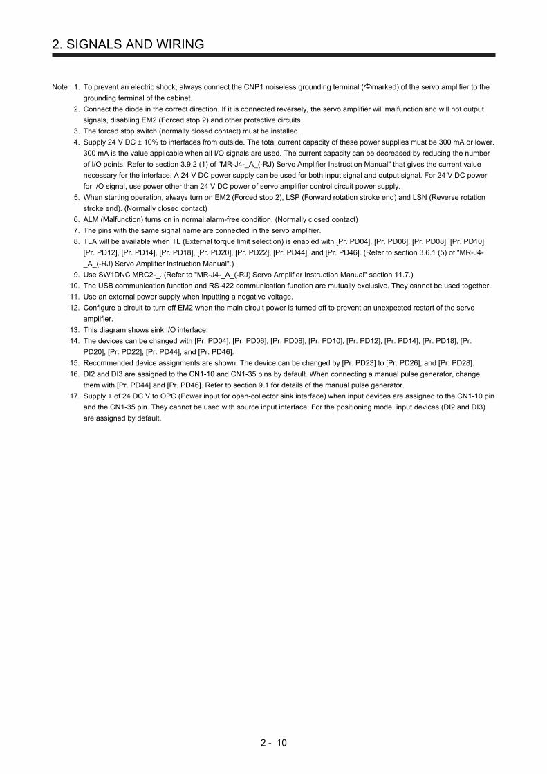
2. SIGNALS AND WIRING
2 - 10
Note 1. To prevent an electric shock, always connect the CNP1 noiseless grounding terminal ( marked) of the servo amplifier to the
grounding terminal of the cabinet.
2. Connect the diode in the correct direction. If it is connected reversely, the servo amplifier will malfunction and will not output
signals, disabling EM2 (Forced stop 2) and other protective circuits.
3. The forced stop switch (normally closed contact) must be installed.
4. Supply 24 V DC ± 10% to interfaces from outside. The total current capacity of these power supplies must be 300 mA or lower.
300 mA is the value applicable when all I/O signals are used. The current capacity can be decreased by reducing the number
of I/O points. Refer to section 3.9.2 (1) of "MR-J4-_A_(-RJ) Servo Amplifier Instruction Manual" that gives the current value
necessary for the interface. A 24 V DC power supply can be used for both input signal and output signal. For 24 V DC power
for I/O signal, use power other than 24 V DC power of servo amplifier control circuit power supply.
5. When starting operation, always turn on EM2 (Forced stop 2), LSP (Forward rotation stroke end) and LSN (Reverse rotation
stroke end). (Normally closed contact)
6. ALM (Malfunction) turns on in normal alarm-free condition. (Normally closed contact)
7. The pins with the same signal name are connected in the servo amplifier.
8. TLA will be available when TL (External torque limit selection) is enabled with [Pr. PD04], [Pr. PD06], [Pr. PD08], [Pr. PD10],
[Pr. PD12], [Pr. PD14], [Pr. PD18], [Pr. PD20], [Pr. PD22], [Pr. PD44], and [Pr. PD46]. (Refer to section 3.6.1 (5) of "MR-J4-
_A_(-RJ) Servo Amplifier Instruction Manual".)
9. Use SW1DNC MRC2-_. (Refer to "MR-J4-_A_(-RJ) Servo Amplifier Instruction Manual" section 11.7.)
10. The USB communication function and RS-422 communication function are mutually exclusive. They cannot be used together.
11. Use an external power supply when inputting a negative voltage.
12. Configure a circuit to turn off EM2 when the main circuit power is turned off to prevent an unexpected restart of the servo
amplifier.
13. This diagram shows sink I/O interface.
14. The devices can be changed with [Pr. PD04], [Pr. PD06], [Pr. PD08], [Pr. PD10], [Pr. PD12], [Pr. PD14], [Pr. PD18], [Pr.
PD20], [Pr. PD22], [Pr. PD44], and [Pr. PD46].
15. Recommended device assignments are shown. The device can be changed by [Pr. PD23] to [Pr. PD26], and [Pr. PD28].
16. DI2 and DI3 are assigned to the CN1-10 and CN1-35 pins by default. When connecting a manual pulse generator, change
them with [Pr. PD44] and [Pr. PD46]. Refer to section 9.1 for details of the manual pulse generator.
17. Supply + of 24 DC V to OPC (Power input for open-collector sink interface) when input devices are assigned to the CN1-10 pin
and the CN1-35 pin. They cannot be used with source input interface. For the positioning mode, input devices (DI2 and DI3)
are assigned by default.

2. SIGNALS AND WIRING
2 - 11
(2) Program method
POINT
Assign the following output devices to CN1-22, CN1-23, and CN1-25 pins with
[Pr. PD23], [Pr. PD24], and [Pr. PD26].
CN1-22: CPO (Rough match)
CN1-23: ZP (Home position return completion)
CN1-25: MEND (Travel completion)
(Note 2)
(Note 7)CN1
(Note 7)CN1
Plate
Servo amplifier
(Note 7)CN1
2 m or less
26 MO1
28 LG
29 MO2
47 DOCOM
48 ALM
22 CPO
23 ZP
25 MEND
24 INP
4 LA
5 LAR
6 LB
7 LBR
34 LG
33 OP
SD
2 m or less
8 LZ
9 LZR
20DICOM
21DICOM
2
1
2 m or less
Upper limitsetting
28
27
Plate
Upper limitsetting
VC
SD
TLA
LG
P15R
+
(Note 10)USB cable
(option)CN3
(Note 9)MR Configurator2
Personalcomputer
24 V DC (Note 4, 13)
RA1
RA2
RA3
RA4
RA6
42
15
16
44
19
41
10
1718
EM2
SON
MD0
LSN
DI0
DI1
DI2
ST1
ST2
Reverse rotation stroke end
Forced stop 2
Servo-on
Forward rotation stroke end
(Note 3, 5)
(Note 5)
5 V DC ± 4 V DC
5 V DC ± 4 V DC
Analog monitor 1
Analog monitor 2
Encoder A-phase pulse(differential line driver)
Encoder B-phase pulse(differential line driver)
Control common
Encoder Z-phase pulse(open-collector)
Encoder Z-phase pulse(differential line driver)
Malfunction (Note 6)
10 m or less
(Note 12)Main circuit power supply
46 DOCOM
10 m or less
24 V DC (Note 4, 13)
49 RD
Rough match
Home positionreturn completion
Travel completion
In-position
Ready
(Note 15)
RA5
DOG
LSP
DI3
45
43
35
Operation mode selection 1
Forward rotation start
Reverse rotation start
Proximity dog
Program No. selection 1
Program No. selection 2
Program No. selection 3
Program No. selection 4(Note 16, 17)
(Note 14)
(Note 11) Analog override±10 V/0% to 200%
(Note 8) Analog torque limit+10 V/maximum torque
Control common
12OPC
(Note 1)CNP16

2. SIGNALS AND WIRING
2 - 12
Note 1. To prevent an electric shock, always connect the CNP1 noiseless grounding terminal ( marked) to the grounding terminal of
the cabinet.
2. Connect the diode in the correct direction. If it is connected reversely, the servo amplifier will malfunction and will not output
signals, disabling EM2 (Forced stop 2) and other protective circuits.
3. The forced stop switch (normally closed contact) must be installed.
4. Supply 24 V DC ± 10% to interfaces from outside. The total current capacity of these power supplies must be 300 mA or lower.
300 mA is the value applicable when all I/O signals are used. The current capacity can be decreased by reducing the number
of I/O points. Refer to section 3.9.2 (1) of "MR-J4-_A_(-RJ) Servo Amplifier Instruction Manual" that gives the current value
necessary for the interface. A 24 V DC power supply can be used for both input signal and output signal. For 24 V DC power
for I/O signal, use power other than 24 V DC power of servo amplifier control circuit power supply.
5. When starting operation, always turn on EM2 (Forced stop 2), LSP (Forward rotation stroke end) and LSN (Reverse rotation
stroke end). (Normally closed contact)
6. ALM (Malfunction) turns on in normal alarm-free condition. (Normally closed contact)
7. The pins with the same signal name are connected in the servo amplifier.
8. TLA will be available when TL (External torque limit selection) is enabled with [Pr. PD04], [Pr. PD06], [Pr. PD08], [Pr. PD10],
[Pr. PD12], [Pr. PD14], [Pr. PD18], [Pr. PD20], [Pr. PD22], [Pr. PD44], and [Pr. PD46]. (Refer to section 3.6.1 (5) of "MR-J4-
_A_(-RJ) Servo Amplifier Instruction Manual".)
9. Use SW1DNC MRC2-_. (Refer to "MR-J4-_A_(-RJ) Servo Amplifier Instruction Manual" section 11.7.)
10. The USB communication function and RS-422 communication function are mutually exclusive. They cannot be used together.
11. Use an external power supply when inputting a negative voltage.
12. Configure a circuit to turn off EM2 when the main circuit power is turned off to prevent an unexpected restart of the servo
amplifier.
13. This diagram shows sink I/O interface.
14. The devices can be changed with [Pr. PD04], [Pr. PD06], [Pr. PD08], [Pr. PD10], [Pr. PD12], [Pr. PD14], [Pr. PD18], [Pr.
PD20], [Pr. PD22], [Pr. PD44], and [Pr. PD46].
15. Recommended device assignments are shown. The device can be changed by [Pr. PD23] to [Pr. PD26], and [Pr. PD28].
16. DI2 and DI3 are assigned to the CN1-10 and CN1-35 pins by default. When connecting a manual pulse generator, change
them with [Pr. PD44] and [Pr. PD46]. Refer to section 9.1 for details of the manual pulse generator.
17. Supply + of 24 DC V to OPC (Power input for open-collector sink interface) when input devices are assigned to the CN1-10 pin
and the CN1-35 pin. They cannot be used with source input interface. For the positioning mode, input devices (DI2 and DI3)
are assigned by default.

2. SIGNALS AND WIRING
2 - 13
(3) Indexer method
POINT
In the indexer method, assign the following input device to CN1-18 pin with [Pr.
PD10].
CN1-18: MD1 (Operation mode selection 2)
Assign the following output devices to CN1-22, CN1-23, and CN1-25 pins with
[Pr. PD23], [Pr. PD24], and [Pr. PD26].
CN1-22: CPO (Rough match)
CN1-23: ZP (Home position return completion)
CN1-25: MEND (Travel completion)
(Note 2)
(Note 7)CN1
(Note 7)CN1
Plate
Servo amplifier
(Note 7)CN1
2 m or less
26 MO1
28 LG
29 MO2
47 DOCOM
48 ALM
22 CPO
23 ZP
25 MEND
24 INP
4 LA
5 LAR
6 LB
7 LBR
34 LG
33 OP
SD
2 m or less
8 LZ
9 LZR
20DICOM
21DICOM
1
2 m or less
Upper limitsetting
28
27
PlateSD
TLA
LG
P15R
+
(Note 10)USB cable
(option)CN3
(Note 9)MR Configurator2
Personalcomputer
24 V DC (Note 4, 12)
RA1
RA2
RA3
RA4
RA6
42
15
16
44
19
41
10
17
18
EM2
SON
MD0
LSN
DI0
DI1
DI2
ST1
MD1
Reverse rotation stroke end
Forced stop 2
Servo-on
Forward rotation stroke end
(Note 3, 5)
(Note 5)
5 V DC ± 4 V DC
5 V DC ± 4 V DC
Analog monitor 1
Analog monitor 2
Encoder A-phase pulse(differential line driver)
Encoder B-phase pulse(differential line driver)
Control common
Encoder Z-phase pulse(open-collector)
Encoder Z-phase pulse(differential line driver)
Malfunction (Note 6)
10 m or less
(Note 11)Main circuit power supply
46 DOCOM
10 m or less
24 V DC (Note 4, 12)
49 RD
Rough match
Home positionreturn completion
Travel completion
In-position
Ready
(Note 14)
RA5
SIG
LSP
DI3
45
43
35
Operation mode selection 1
Forward rotation startOperation mode selection 2External limit/Rotation direction decision/Automatic speed selection
Next station No. selection 1
Next station No. selection 2
Next station No. selection 3
Next station No. selection 4(Note 15, 16)
(Note 13)
(Note 8) Analog torque limit+10 V/maximum torque
Control common
12OPC
(Note 1)CNP16

2. SIGNALS AND WIRING
2 - 14
Note 1. To prevent an electric shock, always connect the CNP1 noiseless grounding terminal ( marked) to the grounding terminal of
the cabinet.
2. Connect the diode in the correct direction. If it is connected reversely, the servo amplifier will malfunction and will not output
signals, disabling EM2 (Forced stop 2) and other protective circuits.
3. The forced stop switch (normally closed contact) must be installed.
4. Supply 24 V DC ± 10% to interfaces from outside. The total current capacity of these power supplies must be 300 mA or lower.
300 mA is the value applicable when all I/O signals are used. The current capacity can be decreased by reducing the number
of I/O points. Refer to section 3.9.2 (1) of "MR-J4-_A_(-RJ) Servo Amplifier Instruction Manual" that gives the current value
necessary for the interface. A 24 V DC power supply can be used for both input signal and output signal. For 24 V DC power
for I/O signal, use power other than 24 V DC power of servo amplifier control circuit power supply.
5. When starting operation, always turn on EM2 (Forced stop 2), LSP (Forward rotation stroke end) and LSN (Reverse rotation
stroke end). (Normally closed contact)
6. ALM (Malfunction) turns on in normal alarm-free condition. (Normally closed contact)
7. The pins with the same signal name are connected in the servo amplifier.
8. TLA will be available when TL (External torque limit selection) is enabled with [Pr. PD04], [Pr. PD06], [Pr. PD08], [Pr. PD10],
[Pr. PD12], [Pr. PD14], [Pr. PD18], [Pr. PD20], [Pr. PD22], [Pr. PD44], and [Pr. PD46]. (Refer to section 3.6.1 (5) of "MR-J4-
_A_(-RJ) Servo Amplifier Instruction Manual".)
9. Use SW1DNC MRC2-_. (Refer to "MR-J4-_A_(-RJ) Servo Amplifier Instruction Manual" section 11.7.)
10. The USB communication function and RS-422 communication function are mutually exclusive. They cannot be used together.
11. Configure a circuit to turn off EM2 when the main circuit power is turned off to prevent an unexpected restart of the servo
amplifier.
12. This diagram shows sink I/O interface.
13. The devices can be changed with [Pr. PD04], [Pr. PD06], [Pr. PD08], [Pr. PD10], [Pr. PD12], [Pr. PD14], [Pr. PD18], [Pr.
PD20], [Pr. PD22], [Pr. PD44], and [Pr. PD46].
14. Recommended device assignments are shown. The device can be changed by [Pr. PD23] to [Pr. PD26], and [Pr. PD28].
15. DI2 and DI3 are assigned to the CN1-10 and CN1-35 pins by default. When connecting a manual pulse generator, change
them with [Pr. PD44] and [Pr. PD46]. Refer to section 9.1 for details of the manual pulse generator.
16. Supply + of 24 DC V to OPC (Power input for open-collector sink interface) when input devices are assigned to the CN1-10 pin
and the CN1-35 pin. They cannot be used with source input interface. For the positioning mode, input devices (DI2 and DI3)
are assigned by default.

2. SIGNALS AND WIRING
2 - 15
2.2 Connectors and pin assignment
POINT
The pin assignment of the connectors is as viewed from the cable connector
wiring section.
For the STO I/O signal connector (CN8), refer to chapter 13 of "MR-J4-_A_(-RJ)
Servo Amplifier Instruction Manual".
For the CN1 connector, securely connect the external conductor of the shielded
cable to the ground plate and fix it to the connector shell.
Screw
Screw
Ground plate
Cable
PP (CN1-10 pin) /NP (CN1-35 pin) and PP2 (CN1-37 pin) /NP2 (CN1-38 pin)
are exclusive. They cannot be used together.

2. SIGNALS AND WIRING
2 - 16
(1) MR-J4-_A_-RJ 100 W or more
The servo amplifier front view shown is that of the MR-J4-20A-RJ or less. For other views of servo
amplifiers, connector arrangements, and details, refer to chapter 9 of "MR-J4-_A_(-RJ) Servo Amplifier
Instruction Manual".
2
LG
3
MO2
1
MO1
CN6
CN1
The frame of the CN1 connector is connectedto the PE (grounding) terminal in the servoamplifier.
CN5 (USB connector)Refer to "MR-J4-_A_(-RJ) ServoAmplifier Instruction Manual"section 11.7.
CN3 (RS-422/RS485 connector)Refer to "MR-J4-_A_(-RJ) Servo AmplifierInstruction Manual" chapter 14.
This is a connector of 3M.
4MRR
2LG 8
6
1P5
5
10
3MR
79
BAT
(Note 2) CN2
MXR
MX
2
4
6
8
10
12
14
16
18
20
22
24
1
3
5
7
9
11
13
15
17
19
21
23
27
29
31
33
35
37
39
41
43
45
47
49
26
28
30
32
34
36
38
40
42
44
46
48
25 50
CN8For the STO I/O signal connector,refer to chapter 13.2 of"MR-J4-_A_(-RJ) Servo AmplifierInstruction Manual".
CN4 (battery connector)Refer to "MR-J4-_A_(-RJ)Servo Amplifier InstructionManual" section 11.8.
4MRR2
2LG 8
6
1P5
5
10
3MR2
79
(Note 1, 2) CN2L(using serial encoder)
MXR2
THM2
THM1
MX2
BAT
4PAR
2LG 8
6
1P5
PBR PSEL
PB5
10
3PA
79
(Note 1, 2) CN2L(using A/B/Z-phase pulse encoder)
PZR
PZ
Note 1. This CN2L is a connector of 3M.
When using any other connector, refer to each servo motor instruction manual.
2. For the connection with external encoders, refer to table 1.1 of "MR-J4-_A_(-RJ) Servo Amplifier Instruction
Manual".
The device assignment of CN1 connector pins changes depending on the control mode. For the pins
which are given parameters in the related parameter column, their devices will be changed using those
parameters.

2. SIGNALS AND WIRING
2 - 17
Pin No. (Note 1)
I/O
(Note 2) I/O signals in control modes Related parameter CP/BCD
(Note 7) CL PS
1 P15R P15R P15R
2 I VC VC
3 LG LG LG
4 O LA LA LA
5 O LAR LAR LAR
6 O LB LB LB
7 O LBR LBR LBR
8 O LZ LZ LZ
9 O LZR LZR LZR
10 (Note 8) I (Note 10) DI2 (Note 10) DI2 (Note 10) DI2 Pr. PD44 (Note 9)
11 I PG PG PG
12 OPC OPC OPC
13 O (Note 4) (Note 4) (Note 4) Pr. PD47
14 O (Note 4) (Note 4) (Note 4) Pr. PD47
15 I SON SON SON Pr. PD04
16 I MD0 MD0 MD0 Pr. PD06
17 I ST1 ST1 ST1 Pr. PD08
18 I ST2 ST2 (Note 5)
MD1 Pr. PD10
19 I DI0 DI0 DI0 Pr. PD12
20 DICOM DICOM DICOM
21 DICOM DICOM DICOM
22 O (Note 6)
CPO (Note 6)
CPO (Note 6)
CPO Pr. PD23
23 O (Note 6) ZP (Note 6) ZP (Note 6) ZP Pr. PD24
24 or less
O INP INP INP Pr. PD25
25 O (Note 6) MEND
(Note 6) MEND
(Note 6) MEND
Pr. PD26
26
27 I (Note 3)
TLA (Note 3)
TLA (Note 3)
TLA
28 LG LG LG
29
30 LG LG LG
31
32
33 O OP OP OP
34 LG LG LG
35 (Note 8) I (Note 10) DI3 (Note 10) DI3 (Note 10) DI3 Pr. PD46 (Note 9)
36 I NG NG NG
37 (Note 12)
I (Note 11) (Note 11) (Note 11) Pr. PD44 (Note 9)
38 (Note 12)
I (Note 11) (Note 11) (Note 11) Pr. PD46 (Note 9)
39
40
41 I DI1 DI1 DI1 Pr. PD14
42 I EM2 EM2 EM2
43 I LSP LSP LSP Pr. PD18
44 I LSN LSN LSN Pr. PD20
45 I DOG DOG SIG Pr. PD22
46 DOCOM DOCOM DOCOM
47 DOCOM DOCOM DOCOM
48 O ALM ALM ALM
49 O RD RD RD Pr. PD28
50

2. SIGNALS AND WIRING
2 - 18
Note 1. I: input signal, O: output signal
2. CP: Positioning mode (point table method)
BCD: Positioning mode (point table method in the BCD input positioning operation)
This method is available only when the MR-D01 unit is connected. Refer to
chapter 12 for details.
CL: Positioning mode (program method)
PS: Positioning mode (indexer method)
3. TLA will be available when TL (External torque limit selection) is enabled with [Pr.
PD04], [Pr. PD06], [Pr. PD08], [Pr. PD10], [Pr. PD12], [Pr. PD14], [Pr. PD18], [Pr.
PD20], [Pr. PD22], [Pr. PD44], and [Pr. PD46].
4. Assign any device with [Pr. PD47].
5. In the indexer method, assign the following input device to CN1-18 pin with [Pr. PD10].
CN1-18: MD1 (Operation mode selection 2)
6. Assign the following output devices to CN1-22, CN1-23, and CN1-25 pins with [Pr.
PD23], [Pr. PD24], and [Pr. PD26].
CN1-22: CPO (Rough match)
CN1-23: ZP (Home position return completion)
CN1-25: MEND (Travel completion)
7. For BCD input, refer to chapter 12.
8. Supply + of 24 V DC to OPC (power input for open-collector sink interface) when using
the CN1-10 pin and CN1-35 pin for DI.
9. This parameter is available with servo amplifiers with software version B7 or later.
10. This signal is used with sink interface. Input devices are not assigned by default. Assign
the input devices with [Pr. PD44] and [Pr. PD46] as necessary. In addition, supply + of
24 DC V to the CN1-12 pin of OPC (Power input for open-collector sink interface). This
is available with servo amplifiers with software version B7 or later.
11. This signal is used with source interface. Input devices are not assigned by default.
Assign the input devices with [Pr. PD44] and [Pr. PD46] as necessary.
12. These pins are available with servo amplifiers having software version B7 or later, and
manufactured in January 2015 or later.

2. SIGNALS AND WIRING
2 - 19
(2) MR-J4-03A6-RJ
For the views of servo amplifiers, connector arrangements, and details, refer to section 18.6 of "MR-J4-
_A_(-RJ) Servo Amplifier Instruction Manual".
CN1
1BCN2
MRR
2B
3B
4BLG5BBAT
4AP55ASHD
1AMR2A
3A
50
48
46
44
42
40
38
36
34
32
30
28
49
47
45
43
41
39
37
35
33
31
29
25
23
21
19
17
15
13
11
9
7
5
3
24
22
20
18
16
14
12
10
8
6
4
27 226 1The frame of the CN1 connector is connected to the
noiseless grounding terminal in the servo amplifier.
CN4(Battery connector)Refer to "MR-J4-_A_(-RJ)Servo Amplifier InstructionManual" section 11.8.
CN3 (USB connector)Refer to "MR-J4-_A_(-RJ) Servo AmplifierInstruction Manual" section 11.7.

2. SIGNALS AND WIRING
2 - 20
The device assignment of the CN1 connector pins changes depending on the control mode. For the pins
which are given parameters in the related parameter column, their devices can be changed using those
parameters.
Pin No. (Note 1)
I/O (Note 2) I/O signals in control modes
Related parameter CP CL PS
1 P15R P15R P15R
2 I VC VC
3 LG LG LG
4 O LA LA LA
5 O LAR LAR LAR
6 O LB LB LB
7 O LBR LBR LBR
8 O LZ LZ LZ
9 O LZR LZR LZR
10 (Note 6) I (Note 8) (Note 8) (Note 8) Pr. PD44 (Note 7)
11 I PG PG PG
12 OPC OPC OPC
13 O SDP SDP SDP
14 O SDN SDN SDN
15 I SON SON SON Pr. PD04
16 I MD0 MD0 MD0 Pr. PD06
17 I ST1 ST1 ST1 Pr. PD08
18 I ST2 ST2 (Note 4) MD1 Pr. PD10
19 I DI0 DI0 DI0 Pr. PD12
20 DICOM DICOM DICOM
21 DICOM DICOM DICOM
22 O (Note 5)
CPO (Note 5)
CPO (Note 5)
CPO Pr. PD23
23 O (Note 5) ZP (Note 5) ZP (Note 5) ZP Pr. PD24
24 O INP INP INP Pr. PD25
25 O (Note 5) MEND
(Note 5) MEND
(Note 5) MEND
Pr. PD26
26 O MO1 MO1 MO1 Pr. PC14
27 I (Note 3) TLA (Note 3) TLA (Note 3) TLA
28 LG LG LG
29 O MO2 MO2 MO2 Pr. PC15
30 LG LG LG
31 I TRE TRE TRE
32
33 O OP OP OP
34 LG LG LG
35 (Note 6) I (Note 8) (Note 8) (Note 8) Pr. PD46 (Note 7)
36 I NG NG NG
37 I (Note 9) (Note 9) (Note 9) Pr. PD44 (Note 7)
38 I (Note 9) (Note 9) (Note 9) Pr. PD46 (Note 7)
39 I RDP RDP RDP
40 I RDN RDN RDN
41 I DI1 DI1 DI1 Pr. PD14
42 I EM2 EM2 EM2
43 I LSP LSP LSP Pr. PD18
44 I LSN LSN LSN Pr. PD20
45 I DOG DOG SIG Pr. PD22
46 DOCOM DOCOM DOCOM
47 DOCOM DOCOM DOCOM
48 O ALM ALM ALM
49 O RD RD RD Pr. PD28
50

2. SIGNALS AND WIRING
2 - 21
Note 1. I: input signal, O: output signal
2. CP: Positioning mode (point table method)
CL: Positioning mode (program method)
PS: Positioning mode (indexer method)
3. TLA will be available when TL (External torque limit selection) is enabled with [Pr.
PD04], [Pr. PD06], [Pr. PD08], [Pr. PD10], [Pr. PD12], [Pr. PD14], [Pr. PD18], [Pr.
PD20], [Pr. PD22], [Pr. PD44], and [Pr. PD46].
4. In the indexer method, assign the following input device to CN1-18 pin with [Pr. PD10].
CN1-18: MD1 (Operation mode selection 2)
5. Assign the following output devices to CN1-22, CN1-23, and CN1-25 pins with [Pr.
PD23], [Pr. PD24], and [Pr. PD26].
CN1-22: CPO (Rough match)
CN1-23: ZP (Home position return completion)
CN1-25: MEND (Travel completion)
6. Supply + of 24 V DC to OPC (power input for open-collector sink interface) when using
the CN1-10 and CN1-35 pins for DI.
7. This is available with servo amplifiers with software version B7 or later.
8. This is used with sink interface. Input devices are not assigned by default. Assign the
input devices with [Pr. PD44] and [Pr. PD46] as necessary. In addition, supply + of 24
DC V to the CN1-12 pin of OPC (Power input for open-collector sink interface).
9. This is used with source interface. Input devices are not assigned by default. Assign the
input devices with [Pr. PD44] and [Pr. PD46] as necessary.

2. SIGNALS AND WIRING
2 - 22
2.3 Signal (device) explanations
The pin numbers in the connector pin No. column are those in the initial status.
For the I/O interfaces (symbols in I/O division column in the table), refer to section 2.5. The symbols in the
control mode field of the table shows the followings.
CP: Positioning mode (point table method)
BCD: Positioning mode (point table method in the BCD input positioning operation)
This method is available only when the MR-D01 unit is connected. Refer to chapter 12 for details.
CL: Positioning mode (program method)
PS: Positioning mode (indexer method)
" " and " " of the table shows the followings.
: Usable device by default.
: Usable device by setting the following parameters.
[Pr. PD04], [Pr. PD06], [Pr. PD08], [Pr. PD10], [Pr. PD12], [Pr. PD14], [Pr. PD18], [Pr. PD20], [Pr. PD22] to
[Pr. PD26], [Pr. PD28], [Pr. PD44], [Pr. PD46], and [Pr. PD47]
(1) I/O device
(a) Input device
Device Symbol Connector
pin No. Function and application
I/O
division
Control mode
CP
/BC
D
CL
PS
Forced stop 2 EM2 CN1-42 Turn off EM2 (open between commons) to decelerate the servo motor to a stop with commands. Turn EM2 on (short between commons) in the forced stop state to reset that state. The following shows the setting of [Pr. PA04].
DI-1
[Pr. PA04] setting
EM2/EM1Deceleration method
EM2 or EM1 is off Alarm occurred
0 _ _ _ EM1
MBR (Electromagnetic brake interlock) turns off without the forced stop deceleration.
MBR (Electromagnetic brake interlock) turns off without the forced stop deceleration.
2 _ _ _ EM2
MBR (Electromagnetic brake interlock) turns off after the forced stop deceleration.
MBR (Electromagnetic brake interlock) turns off after the forced stop deceleration.
EM2 and EM1 are mutually exclusive.
Forced stop 1 EM1 (CN1-42) When using EM1, set [Pr. PA04] to "0 _ _ _" to enable EM1. Turn EM1 off (open between commons) to bring the motor to a forced stop state. The base circuit is shut off, the dynamic brake is operated and decelerates the servo motor to a stop. Turn EM1 on (short between commons) in the forced stop state to reset that state.
DI-1
Servo-on SON CN1-15 Turn SON on to power on the base circuit and make the servo amplifier ready to operate. (servo-on status) Turn it off to shut off the base circuit and coast the servo motor. Set "_ _ _ 4" in [Pr. PD01] to switch this signal on (keep terminals connected) automatically in the servo amplifier.
DI-1
Reset RES Turn on RES for more than 50 ms to reset the alarm. Some alarms cannot be deactivated by RES (Reset). Refer to chapter 8. Turning RES on in an alarm-free status shuts off the base circuit. The base circuit is not shut off when " _ _ 1 _ " is set in [Pr. PD30]. This device is not designed to make a stop. Do not turn it on during operation.
DI-1

2. SIGNALS AND WIRING
2 - 23
Device Symbol Connector
pin No. Function and application
I/O
division
Control mode
CP
/BC
D
CL
PS
Forward rotation stroke end
LSP CN1-43 To start operation, turn on LSP and LSN. Turn it off to bring the motor to a sudden stop and make it servo-locked. Setting [Pr. PD30] to " _ _ _ 1" will enable "Slow stop (home position erased)".
DI-1
Reverse rotation stroke end
LSN CN1-44 (Note) Input device Operation
LSP LSN
CCW direction Positive direction
CW direction Negative direction
1 1
0 1
1 0
0 0
Note. 0: Off 1: On
The stop method can be changed with [Pr. PD30]. Set [Pr. PD01] as indicated below to switch on the signals (keep terminals connected) automatically in the servo amplifier.
[Pr. PD01] Status
LSP LSN
_ 4 _ _
Automatic on
_ 8 _ _
Automatic on
_ C _ _
Automatic on
Automatic on
When LSP or LSN turns off, [AL. 99 Stroke limit warning] occurs, and WNG (Warning) turns on. When using WNG, enable it by setting [Pr. PD23] to [Pr. PD26], [Pr. PD28], and [Pr. PD47]. However, [Pr. PD47] is not available with MR-J4-03A6-RJ servo amplifiers.
External torque limit selection
TL Turning off TL will enable [Pr. PA11 Forward torque limit] and [Pr. PA12 Reverse torque limit], and turning on it will enable TLA (Analog torque limit). For details, refer to section 3.6.1 (5) of "MR-J4-_A_(-RJ) Servo Amplifier Instruction Manual". For the indexer method, [Pr. PC35 Internal torque limit 2] will be enabled automatically depending on operation status. Refer to each timing chart in section 6.2 and section 6.4.5.
DI-1
Internal torque limit selection
TL1 To select [Pr. PC35 Internal torque limit 2/internal thrust limit 2], enable TL1 with [Pr. PD04], [Pr. PD06], [Pr. PD08], [Pr. PD10], [Pr. PD12], [Pr. PD14], [Pr. PD18], [Pr. PD20], [Pr. PD22], [Pr. PD44], and [Pr. PD46]. For details, refer to section 3.6.1 (5) of "MR-J4-_A_(-RJ) Servo Amplifier Instruction Manual". For the indexer method, [Pr. PC35 Internal torque limit 2] will be enabled automatically depending on operation status. Refer to each timing chart in section 6.2 and section 6.4.5.
DI-1

2. SIGNALS AND WIRING
2 - 24
Device Symbol Connector
pin No. Function and application
I/O
division
Control mode
CP
/BC
D
CL
PS
Operation mode selection 1
MD0 CN1-16 Point table method/program method Turning on MD0 will be automatic operation mode, off will be manual operation mode. Changing an operation mode during operation will clear the command remaining distance and the motor will decelerate to stop. MD1 cannot be used. Indexer method Select an operation mode with combinations of MD0 and MD1. Refer to the following table for combinations. Changing an operation mode during operation will clear the command remaining distance and the motor will decelerate to stop.
DI-1
Operation mode selection 2
MD1 DI-1
Device (Note) Operation mode
MD1 MD0
0 0 Home position return mode
0 1 Manual operation mode
1 0
Automatic operation mode 1 (rotation direction specifying
indexer)
1 1
Automatic operation mode 2 (shortest rotating indexer)
Note. 0: Off 1: On

2. SIGNALS AND WIRING
2 - 25
Device Symbol Connector
pin No. Function and application
I/O division
Control mode
CP
/BC
D
CL
PS
Forward rotation start
ST1 CN1-17 Point table method1. Absolute value command method
Turning on ST1 during automatic operation will execute one positioning based on position data set in point tables. Turning on ST1 during home position return will also start home position return. Turning on ST1 during JOG operation will rotate the motor in the forward rotation direction while it is on. The forward rotation means address increasing direction. Turning on both ST1 and ST2 during JOG operation will stop the servo motor.
2. Incremental value command method Turning on ST1 during automatic operation will execute one positioning in the forward rotation direction based on position data set in point tables. Turning on ST1 during home position return will also start home position return. Turning on ST1 during JOG operation will rotate the motor in the forward rotation direction while it is on. The forward rotation means address increasing direction. Turning on both ST1 and ST2 during JOG operation will stop the servo motor.
DI-1
Program method1. Automatic operation mode
Turning on ST1 will execute a program operation selected with DI0 to DI7. The forward rotation means address increasing direction. Turning on both ST1 and ST2 during manual operation mode will stop the servo motor.
2. Manual operation mode Turning on ST1 will rotate the motor in the forward rotation direction while it is on. The forward rotation means address increasing direction. Turning on both ST1 and ST2 during manual operation mode will stop the servo motor.
Indexer method1. Automatic operation mode 1 or automatic operation mode 2
Turning on ST1 will execute one positioning to the specified station No. 2. Manual operation mode
Turning on ST1 with the station JOG operation will rotate the motor in the specified direction with SIG only while it is on. Turning off ST1 will execute a positioning to a station which can be decelerated to a stop. Turning on ST1 with JOG operation will rotate the motor in the direction specified with SIG only while it is on. Turning off will decelerate the motor to a stop regardless of stations.
3. Home position return mode Turning on ST1 will also start home position return.
Reverse rotation start
ST2 CN1-18 Point table methodUse this device with the incremental value command method. Turning on ST2 during automatic operation will execute one positioning in the reverse rotation direction based on position data set in point tables. Turning on ST2 during JOG operation will rotate the motor in the reverse rotation direction while it is on. Turning on both ST1 and ST2 will stop the servo motor. Turning on ST2 during in the home position return mode will execute an automatic positioning to the home position. The reverse rotation means address decreasing direction. Turning on both ST1 and ST2 during JOG operation will stop the servo motor.
DI-1
Program methodTurning on ST2 with JOG operation in the manual operation mode will rotate the motor in the reverse rotation direction while it is on. Turning on both ST1 and ST2 will stop the servo motor. The reverse rotation means address decreasing direction. Turning on both ST1 and ST2 during manual operation mode will stop the servo motor. ST2 will be disabled in the automatic operation mode. Indexer methodThis device is not used.

2. SIGNALS AND WIRING
2 - 26
Device Symbol Connector
pin No. Function and application I/O
division
Control mode
CP
/BC
D
CL
PS
Temporary stop/restart
TSTP Turning on TSTP during automatic operation will temporarily stop the motor. Turning on TSTP again will restart. Turning on ST1 (Forward rotation start)/ST2 (Reverse rotation start) during a temporary stop will not rotate the motor. Changing the automatic operation mode to manual operation mode during a temporary stop will erase a travel remaining distance. The temporary stop/restart input will not function during home position return/JOG operation.
DI-1
Proximity dog DOG CN1-45 Turning off DOG will detect a proximity dog. The polarity for dog detection can be changed with [Pr. PT29].
DI-1
[Pr. PT29]
Polarity for proximity dog detection
_ _ _ 0 Detection with off
_ _ _ 1 Detection with on
External limit/ Rotation direction decision/ Automatic speed selection
SIG CN1-45 The function varies depending on the operation mode.
1. Home position return mode (MD1 = 0, MD0 = 0) You can use SIG as an input device of external limit. This operation mode is enabled when the home position return type of the torque limit changing dog type is selected.
2. Manual operation mode (MD1 = 0, MD0 = 1) You can use this as an input device for specifying a rotation direction of the servo motor. The rotation direction varies depending on the setting of [Pr. PA14 Rotation direction selection]. (Refer to section 2.1.)
3. Automatic operation mode 1 (rotation direction specifying indexer) (MD1 = 1, MD0 = 0) You can use this as an input device for specifying a rotation direction of the servo motor. The rotation direction varies depending on the setting of [Pr. PA14 Rotation direction selection]. (Refer to section 2.1.)
4. Automatic operation mode 2 (shortest rotating indexer) (MD1 = 1, MD0 = 1) You can use SIG as an input device for selecting a speed of the servo motor.
Table 2.1 Rotation direction selection
DI-1
[Pr. PA14] SIG (Note)
Servo motor rotation direction
0 0 CCW direction
0 1 CW direction
1 0 CW direction
1 1 CCW direction
Note. 0: Off 1: On
Manual pulse generator multiplication 1
TP0 Select a multiplication of the manual pulse generator. When a multiplication is not selected, the setting of [Pr. PT03] will be enabled.
DI-1
Manual pulse generator multiplication 2
TP1 Device (Note) Manual pulse generator multiplication
DI-1
TP1 TP0
0 0 [Pr. PT03] setting
0 1 × 1
1 0 × 10
1 1 × 100
Note. 0: Off 1: On

2. SIGNALS AND WIRING
2 - 27
Device Symbol Connector
pin No. Function and application
I/O
division
Control mode
CP
/BC
D
CL
PS
Analog override selection
OVR
Turning on OVR will enable VC (Analog override). DI-1
Teach TCH Use this for teaching. Turning on TCH in the point table method will rewrite a position data of the selected point table No. to the current position.
DI-1
Program input 1 PI1 Turning on PI1 will restart a step which was suspended with the SYNC (1) command during programming.
DI-1
Program input 2 PI2 Turning on PI2 will restart a step which was suspended with the SYNC (2) command during programming.
DI-1
Program input 3 PI3 Turning on PI3 will restart a step which was suspended with the SYNC (3) command during programming.
DI-1
Current position latch input
LPS Turning on LPS during execution of the LPOS command will latch a current position with its rising edge. The latched current position can be read with communication commands.
DI-1
Point table No./program No. selection 1
DI0 CN1-19 Point table method Select point tables and home position return mode with DI0 to DI7.
DI-1
Point table No./program No. selection 2
DI1 CN1-41 Device (Note) Selection contents
DI7 DI6 DI5 DI4 DI3 DI2 DI1 DI0
0 0 0 0 0 0 0 0 Home position return mode
Point table No./program No. selection 3
DI2 CN1-10 0 0 0 0 0 0 0 1 Point table No. 1
0 0 0 0 0 0 1 0 Point table No. 2
Point table No./program No. selection 4
DI3 CN1-35
0 0 0 0 0 0 1 1 Point table No. 3
Point table No./program No. selection 5
DI4
Point table No./program No. selection 6
DI5 1 1 1 1 1 1 1 0 Point table No. 254
1 1 1 1 1 1 1 1 Point table No. 255
Point table No./program No. selection 7
DI6
Note. 0: Off 1: On
Point table No./program No. selection 8
DI7 Program method Select program Nos. with DI0 to DI7.
Device (Note) Selection contents
DI7 DI6 DI5 DI4 DI3 DI2 DI1 DI0
0 0 0 0 0 0 0 0 Program No. 1
0 0 0 0 0 0 0 1 Program No. 2
0 0 0 0 0 0 1 0 Program No. 3
0 0 0 0 0 0 1 1 Program No. 4
1 1 1 1 1 1 1 0 Program No. 255
1 1 1 1 1 1 1 1 Program No. 256
Note. 0: Off 1: On

2. SIGNALS AND WIRING
2 - 28
Device Symbol Connector
pin No. Function and application
I/O
division
Control mode
CP
/BC
D
CL
PS
Next station No. selection 1
DI0 CN1-19 Indexer method Select next station Nos. with DI0 to DI7. A setting value at ST1 on will be enabled.
DI-1
Next station No. selection 2
DI1 CN1-41 Device (Note 1) Selection contents
DI7 DI6 DI5 DI4 DI3 DI2 DI1 DI0
Next station No. selection 3
DI2 CN1-10 0 0 0 0 0 0 0 0 Next station No. 0
Next station No. selection 4
DI3 CN1-35 0 0 0 0 0 0 0 1 Next station No. 1
Next station No. selection 5
DI4 0 0 0 0 0 0 1 0 Next station No. 2
Next station No. selection 6
DI5 0 0 0 0 0 0 1 1 Next station No. 3
Next station No. selection 7
DI6
Next station No. selection 8
DI7
1 1 1 1 1 1 1 0 Next station No. 254
1 1 1 1 1 1 1 1 Setting inhibited (Note 2)
Note 1. 0: Off
1: On 2. [AL. 97.2 Next station position warning] will occur.
Second acceleration/deceleration selection
RT Turning on ST1 with RT-off will select acceleration/deceleration time constants set with [Pr. PC01 Acceleration time constant 1] and [Pr. PC02 Deceleration time constant 1]. Turning on ST1 with RT-on will select acceleration/deceleration time constants set with [Pr. PC30 Acceleration time constant 2] and [Pr. PC31 Deceleration time constant 2]. RT will not be accepted during operation.
DI-1
Device (Note) Description
RT
Acceleration time constant
Deceleration time constant
0 [Pr. PC01] [Pr. PC02]
1 [Pr. PC30] [Pr. PC31]
Note. 0: Off 1: On
Second acceleration/deceleration gain selection
RTCDP This has two functions of CDP (Gain switching) and RT (Second acceleration/deceleration selection). When RTCDP is off, the servo control gain set with [Pr. PB06], [Pr. PB08] to [Pr. PB10] will be selected. Turning on ST1 (Forward rotation start) will select acceleration/deceleration time constants set with [Pr. PC01 Acceleration time constant 1] and [Pr. PC02 Deceleration time constant 1]. When RTCDP is on, the servo control gain set with [Pr. PB29] to [Pr. PB32] will be selected. Turning on ST1 (Forward rotation start) will select acceleration/deceleration time constants set with [Pr. PC30 Acceleration time constant 2] and [Pr. PC31 Deceleration time constant 2].
DI-1

2. SIGNALS AND WIRING
2 - 29
Device Symbol Connector
pin No. Function and application
I/O
division
Control mode
CP
/BC
D
CL
PS
Digital override selection 1
OV0 To enable the digital override function, set [Pr. PT38] to "_ _ 1 _". This signal is for multiplying a command speed by the digital override (multiplying factor). A command speed multiplied by the digital override value selected with this signal will be an actual servo motor speed. If the servo motor speed multiplied by the digital override value exceeds the servo motor maximum speed, the speed will be limited at the maximum speed. The following table shows an example of setting "50" to [Pr. PT42] and "5" to [Pr. PT43].
DI-1
Digital override selection 2
OV1
Digital override selection 3
OV2
Digital override selection 4
OV3
Device (Note) Description
OV3 OV2 OV1 OV0
0 0 0 0 100 [%] of command speed
0 0 0 1 50 [%] of command speed
0 0 1 0 55 [%] of command speed
0 0 1 1 60 [%] of command speed
0 1 0 0 65 [%] of command speed
0 1 0 1 70 [%] of command speed
0 1 1 0 75 [%] of command speed
0 1 1 1 80 [%] of command speed
1 0 0 0 85 [%] of command speed
1 0 0 1 90 [%] of command speed
1 0 1 0 95 [%] of command speed
1 0 1 1 100 [%] of command speed
1 1 0 0 105 [%] of command speed
1 1 0 1 110 [%] of command speed
1 1 1 0 115 [%] of command speed
1 1 1 1 0 [%] of command speed
Note. 0: Off 1: On
Mark detection MSD The current position latch function by sensor input can be used. For the current position latch function, refer to section 12.2.1. For the current position latch function, refer to section 12.2.2.
DI-1

2. SIGNALS AND WIRING
2 - 30
Device Symbol Connector pin No.
Function and application I/O division
Control mode
CP
/BC
D
CL
PS
Proportion control
PC Turn PC on to switch the speed amplifier from the proportional integral type to the proportional type. If the servo motor at a stop is rotated even one pulse due to any external factor, it generates torque to compensate for a position shift. When the servo motor shaft is to be locked mechanically after positioning completion (stop), switching on the PC (Proportion control) upon positioning completion will suppress the unnecessary torque generated to compensate for a position shift. When the shaft is to be locked for a long time, switch on the PC (Proportion control) and TL (External torque limit selection) at the same time to make the torque less than the rated by TLA (Analog torque limit).
DI-1
Clear CR Turn CR on to clear the position control counter droop pulse on its leading edge. The pulse width should be 10 ms or longer. The delay amount set in [Pr. PB03 Position command acceleration/deceleration time constant] is also cleared. When " _ _ _1 " is set to [Pr. PD32], the pulses are always cleared while CR is on.
DI-1
Gain switching CDP Turn on CDP to use the values of [Pr. PB29] to [Pr. PB36] and [Pr. PB56] to [Pr. PB60] as the load to motor inertia ratio and gain values.
DI-1
Fully closed loop selection
CLD Not used with the positioning mode. DI-1
Motor-side/load-side deviation counter clear
MECR Turn on MECR to clear the motor-side/load-side position deviation counter to zero.
It operates during the fully closed loop control. It does not affect the position control droop pulses. Turning on this device during the semi closed loop control does not affect the operation. Turning on this device while the fully closed loop control error detection function is disabled in [Pr. PE03] does not affect the operation.
This device is not available with MR-J4-03A6-RJ servo amplifiers.
DI-1
Cam control command
CAMC When using CAMC, set [Pr. PT35] to "_ 1 _ _" to enable it. Turning CAMC on switches the control from the normal positioning control to the cam control.
DI-1
Cam position compensation request
CPCD Turning CPCD on compensates the cam axis one cycle current value to be in the position set in "Cam control data No. 60 - Cam position compensation target position".
DI-1
Clutch command CLTC This is used to turning on/off the main shaft clutch command. This is used when "Cam control data No. 36 - Main shaft clutch control setting" is set to "_ _ _ 1".
DI-1
Cam No. selection 0
CI0 Select cam No. This is enabled when "Cam control data No. 49 - Cam No." is set to "0". Set the cam control data on the cam setting window of MR Configurator2.
DI-1
Cam No. selection 1
CI1 Device (Note 1) Selection contents
CI3 CI2 CI1 CI0
Cam No. selection 2
CI2 0 0 0 0 Linear cam 0 0 0 1 Cam No. 1
Cam No. selection 3
CI3 0 0 1 0 Cam No. 2 0 0 1 1 Cam No. 3
1 0 0 0 Cam No. 8
1 0 0 1
Setting inhibited (Note 2)
1 1 1 1
Note 1. 0: Off
1: On
2. [AL. F6.5 Cam No. external error] occurs.

2. SIGNALS AND WIRING
2 - 31
(b) Output device
Device Symbol Connector pin No.
Function and application I/O division
Control mode
CP
/BC
D
CL
PS
Malfunction ALM CN1-48 When an alarm occurs, ALM will turn off. When an alarm does not occur, ALM will turn on after 4 s to 5 s after power-on. When [Pr. PD34] is "_ _ 1 _", an alarming or warning will turn off ALM.
DO-1
Malfunction/Warning
ALM WNG
When an alarm occurs, ALMWNG will turn off. When a warning (except [AL. 9F Battery warning]) occurs on and off will be repeated every 1 s. When an alarm/warning is not occurring, turning on the power will turn on ALMWNG after 4 s to 5 s.
DO-1
Warning WNG When warning has occurred, WNG turns on. When a warning is not occurring, turning on the power will turn off WNG after 4 s to 5 s.
DO-1
Battery warning BWNG BWNG turns on when [AL. 92 Battery cable disconnection warning] or [AL. 9F Battery warning] has occurred. When the battery warning is not occurring, turning on the power will turn off BWNG after 4 s to 5 s.
DO-1
AL9F warning BW9F When [AL. 9F Battery warning] occurs, BW9F will turn on. DO-1Dynamic brake interlock
DB When using the signal, enable it by setting [Pr. PD23] to [Pr. PD26], [Pr. PD28], and [Pr. PD47]. DB turns off when the dynamic brake needs to operate. When using an external dynamic brake with the servo amplifier of 11 kW or more, this device is required. (Refer to "MR-J4-_A_(-RJ) Servo Amplifier Instruction Manual" section 11.17.) For the servo amplifier of 7 kW or less, it is not necessary to use this device.
DO-1
Ready RD CN1-49 Enabling servo-on to make the servo amplifier ready to operate will turn on RD.
DO-1
In-position INP CN1-24 When the number of droop pulses is in the preset in-position range, INP will turn on. The in-position range can be changed using [Pr. PA10]. When the in-position range is increased, INP may be on during low-speed rotation. INP turns on when servo-on turns on.
DO-1
Limiting torque TLC CN1-25 TLC turns on when a generated torque reaches a value set with any of [Pr. PA11 Forward torque limit], [Pr. PA12 Reverse torque limit], or TLA (Analog torque limit).
DO-1
Zero speed detection
ZSP CN1-23 ZSP turns on when the servo motor speed is zero speed (50r/min) or less. Zero speed can be changed with [Pr. PC17].
OFF
ON
Servo motorspeed
20 r/min(Hysteresis width)
[Pr. PC17]
20 r/min(Hysteresis width)
OFF level-70 r/min
ON level-50 r/min
ON level50 r/min
OFF level70 r/min
0 r/min
[Pr. PC17]
ZSP(Zero speeddetection)
1)3)
2)
4)
Forwardrotationdirection
Reverserotationdirection
ZSP will turn on when the servo motor is decelerated to 50 r/min (at 1)), and will turn off when the servo motor is accelerated to 70 r/min again (at 2)). ZSP will turn on when the servo motor is decelerated again to 50 r/min (at 3)), and will turn off when the servo motor speed has reached -70 r/min (at 4)). The range from the point when the servo motor speed has reached on level, and ZSP turns on, to the point when it is accelerated again and has reached off level is called hysteresis width. Hysteresis width is 20 r/min for this servo amplifier.
DO-1

2. SIGNALS AND WIRING
2 - 32
Device Symbol Connector pin No.
Function and application I/O division
Control mode
CP
/BC
D
CL
PS
Electromagnetic brake interlock
MBR When using the device, set operation delay time of the electromagnetic brake in [Pr. PC16]. When a servo-off status or alarm occurs, MBR will turn off.
DO-1
Speed command reached
SA When a command speed is within a target speed at servo-on status, SA will be on. When the command speed is 0 r/min (mm/s), this will be continuously on. When the command speed is in acceleration/deceleration or at servo-off status, SA will be off.
DO-1
Home position return completion
ZP When a home position return completes normally, ZP (Home position return completion) will be on. This will be off with the following conditions in the incremental system. 1) SON (Servo-on) is off. 2) EM2 (Forced stop 2) is off. 3) RES (Reset) is on. 4) At alarm occurrence 5) LSP (Forward rotation stroke end) or LSN (Reverse rotation stroke end)
is off. 6) Home position return is not being executed. 7) Software limit is being detected. 8) Home position return is in progress. If once home position return is completed in the absolute position detection system, ZP (Home position return completion) will be the same output status as RD (Ready). However, it will be off with the above 1) to 8) and the following conditions. 9) The home position return is not performed after [AL. 25 Absolute
position erased] or [AL. E3 Absolute position counter warning] occurred. 10) The home position return is not performed after the electronic gear
([Pr. PA06] or [Pr. PA07]) was changed. 11) The home position return is not performed after the setting of [Pr.
PA03 Absolute position detection system selection] was changed from "Disabled" to "Enabled".
12) [Pr. PA14 Rotation direction selection/travel direction selection] was changed.
13) [Pr. PA01 Operation mode] was changed. 14) [Pr. PT08 Home position return position data] or [Pr. PT28 Number of
stations per rotation] was changed.
DO-1
Rough match CPO When a command remaining distance is lower than the rough match output range set with [Pr. PT12], CPO will be on. This is not outputted during base circuit shut-off. CPO turns on with servo-on.
DO-1
Position range output
POT When an actual current position is within the range set with [Pr. PT21] and [Pr. PT22], POT will be on. This will be off when a home position return does not complete or base circuit shut-off is in progress.
DO-1
Temporary stop PUS When a deceleration begins for a stop, PUS will be on by TSTP (Temporary stop/restart). When you enable TSTP (Temporary stop/restart) again and start operation, PUS will be off.
DO-1
Travel completion
MEND When the droop pulses are within the in-position output range set with [Pr. PA10] and the command remaining distance is "0", MEND will be on. MEND turns on with servo-on. MEND is off at servo-off status. However, MEND will not be off in the indexer method.
DO-1
Position end PED When the droop pulses are within the position end output range set with [Pr. PA10] and the command remaining distance is "0", PED will be on. When MEND (Travel completion) is on and ZP (Home position return completion) is on, PED (Position end) will be on. When ZP (Home position return completion) is on with servo-on status, PED will be on. PED is off at servo-off status.
DO-1
SYNC synchronous output
SOUT When the status is waiting for input of the program SYNC (1 to 3), SOUT will be on. When PI1 (Program input 1) to PI3 (Program input 3) turn on, SOUT will be off.
DO-1

2. SIGNALS AND WIRING
2 - 33
Device Symbol Connector
pin No. Function and application
I/O
division
Control mode
CP
/BC
D
CL
PS
Program output 1
OUT1 OUT1 will turn on with the OUTON (1) command during programming. The OUTOF (1) command will turn off OUT1. You can also set time to off with [Pr. PT23].
DO-1
Program output 2
OUT2 OUT2 will turn on with the OUTON (2) command during programming. The OUTOF (2) command will turn off OUT2. You can also set time to off with [Pr. PT24].
DO-1
Program output 3
OUT3 OUT3 will turn on with the OUTON (3) command during programming. The OUTOF (3) command will turn off OUT3. You can also set time to off with [Pr. PT25].
DO-1
Point table No. output 1
PT0 The signals output point table Nos. in 8 bit code simultaneously with MEND (Travel completion) on.
DO-1
Point table No. output 2
PT1 Device (Note 1, 2) Description
PT7 PT6 PT5 PT4 PT3 PT2 PT1 PT0
Point table No. output 3
PT2 0 0 0 0 0 0 0 1 Point table No. 1
Point table No. output 4
PT3 0 0 0 0 0 0 1 0 Point table No. 2
Point table No. output 5
PT4 0 0 0 0 0 0 1 1 Point table No. 3
Point table No. output 6
PT5
Point table No. output 7
PT6
1 1 1 1 1 1 1 0 Point table No. 254
Point table No. output 8
PT7
1 1 1 1 1 1 1 1 Point table No. 255
Note 1. 0: Off 1: On
2. For MR-J4-03A6-RJ servo amplifiers, up to six points of DO are
available; therefore, PT0 to PT7 cannot be outputted
simultaneously.
Station output 1 PS0 The signals output station Nos. simultaneously with MEND on while an alarm is not occurring.
DO-1
Station output 2 PS1 Device (Note 1, 2) Description
PS7 PS6 PS5 PS4 PS3 PS2 PS1 PS0
Station output 3 PS2 0 0 0 0 0 0 0 0 In-position out of range
Station output 4 PS3 1 1 1 1 1 1 1 1 Next station No. 0
Station output 5 PS4 1 1 1 1 1 1 1 0 Next station No. 1
Station output 6 PS5 1 1 1 1 1 1 0 1 Next station No. 2
Station output 7 PS6 1 1 1 1 1 1 0 0 Next station No. 3
Station output 8 PS7
0 0 0 0 0 0 1 0 Next station No. 253
0 0 0 0 0 0 0 1 Next station No. 254
Note 1. 0: Off 1: On
2. For MR-J4-03A6-RJ servo amplifiers, up to six points of DO are
available; therefore, PS0 to PS7 cannot be outputted
simultaneously.

2. SIGNALS AND WIRING
2 - 34
Device Symbol Connector
pin No. Function and application
I/O
division
Control mode
CP
/BC
D
CL
PS
M code 1 (bit 0) MCD00 This device can be used in the point table method. These signals can be checked with output devices of the communication function. (Refer to section 10.2 (1).) To use these signals, set " _ _ 1 _" in [Pr. Po12]. The signals output M code simultaneously with CPO (Rough match) on. Set M code with point tables. The code represents one digit of decimal using four digits of binary. The following shows correspondence of each digit and device.
bit3 bit2 bit1 bit0 bit3 bit2 bit1 bit0
MCD00
MCD01
MCD02
MCD03
MCD10
MCD11
MCD12
MCD13
Second digit First digit
DO-1
M code 2 (bit 1) MCD01 DO-1
M code 3 (bit 2) MCD02 DO-1
M code 4 (bit 3) MCD03 DO-1
M code 5 (bit 4) MCD10 DO-1
M code 6 (bit 5) MCD11 DO-1
M code 7 (bit 6) MCD12 DO-1
M code 8 (bit 7) MCD13 DO-1
M code Device (Note)
First/second digit
MCD03/MCD13
MCD02/MCD12
MCD01/MCD11
MCD00/ MCD10
0 0 0 0 0
1 0 0 0 1
2 0 0 1 0
3 0 0 1 1
4 0 1 0 0
5 0 1 0 1
6 0 1 1 0
7 0 1 1 1
8 1 0 0 0
9 1 0 0 1
Note. 0: Off 1: On
MCD00 to MCD03 and MCD10 to MCD13 will turn off with the following status.
Power on Servo-off Manual operation mode At alarm occurrence

2. SIGNALS AND WIRING
2 - 35
Device Symbol Connector
pin No. Function and application
I/O
division
Control mode
CP
/BC
D
CL
PS
Mark detection rising latch completed
MSDH Turning on MSD (Mark detection) will turn on MSDH. DO-1
Mark detection falling latch completed
MSDL After MSD (Mark detection) is turned on, turning off MSD will turn on MSDL.
DO-1
Alarm code ACD0 (CN1-24) To use these signals, set " _ _ _ 1" in [Pr. PD34]. This signal is outputted when an alarm occurs. When an alarm is not occurring, respective ordinary signals are outputted. For details of the alarm codes, refer to chapter 8.
DO-1
ACD1 (CN1-23)
ACD2 (CN1-22)
Variable gain selection
CDPS CDPS turns on during gain switching. DO-1
Absolute position undetermined
ABSV ABSV turns on when the absolute position is undetermined. DO-1
During tough drive
MTTR When a tough drive is "Enabled" in [Pr. PA20], activating the instantaneous power failure tough drive will turn on MTTR. This device is not available with MR-J4-03A6-RJ servo amplifiers.
DO-1
During fully closed loop control
CLDS CLDS turns on during fully closed loop control. This device is not available with MR-J4-03A6-RJ servo amplifiers.
DO-1
Under cam control
CAMS It turns on when the control switches to the cam control. It turns off when the control switches to the normal positioning control.
DO-1
Cam position compensation execution completed
CPCC It turns on when the com compensation execution is enabled. It turns on when the position compensation is not being executed during the cam control.
DO-1
Clutch on/off status
CLTS It turns on with clutch-on. It is always off when "Cam control data No. 36 - Main shaft clutch control setting" is set to "_ _ _ 0".
DO-1
Clutch smoothing status
CLTSM It outputs clutch smoothing status. The output depends on the setting in "Cam control data No. 42 - Main shaft clutch smoothing system" as follows: 0: Direct
Always off 1: Time constant method (index)
Always on in clutch-on status It turns off when the clutch is off and the smoothing is complete.
DO-1
(2) Input signal
Device Symbol Connector
pin No. Function and application
I/O
division
Control mode
CP
/BC
D
CL
PS
Manual pulse generator
PP (CN1-10) Connect the manual pulse generator (MR-HDP01). When using the signal, enable PP and NP with [Pr. PD44] and [Pr. PD46].
DI-2
NP (CN1-35)

2. SIGNALS AND WIRING
2 - 36
Device Symbol Connector
pin No. Function and application
I/O
division
Control mode
CP
/BC
D
CL
PS
Analog torque limit
TLA CN1-27 When using the signal, enable TL (External torque limit selection) with [Pr. PD04], [Pr. PD06], [Pr. PD08], [Pr. PD10], [Pr. PD12], [Pr. PD14], [Pr. PD18], [Pr. PD20], [Pr. PD22], [Pr. PD44], and [Pr. PD46]. When TLA is enabled, torque is limited in the full servo motor output torque range. Apply 0 V to +10 V DC between TLA and LG. Connect the positive terminal of the power supply to TLA. The maximum torque is generated at +10 V. (Refer to section 3.6.1 (5) of "MR-J4-_A_(-RJ) Servo Amplifier Instruction Manual".) If a value equal to or larger than the maximum torque is inputted to TLA, the value is clamped at the maximum torque. Resolution: 10 bits
Analog
input
Analog override VC CN1-2 The signal controls the servo motor setting speed by applying -10 V to +10V to between VC and LG. The percentage will be 0% with -10 V, 100% with 0 V, and 200% with +10 V to the setting speed of the servo motor. Resolution: 14 bits or equivalent For MR-J4-_A_-RJ 100 W or more servo amplifiers, setting [Pr. PC60] to "_ _ 1 _" increases the analog input resolution to 16 bits. This function is available with servo amplifiers manufactured in November 2014 or later.
Analog
input
(3) Output signal
(a) MR-J4-_A_-RJ 100 W or more
Device Symbol Connector
pin No. Function and application
I/O
division
Control mode
CP
/BC
D
CL
PS
Encoder A-phase pulse (differential line driver)
LA LAR
CN1-4 CN1-5
These devices output pulses of encoder output pulse set in [Pr. PA15] in the differential line driver type. In CCW rotation of the servo motor, the encoder B-phase pulse lags the encoder A-phase pulse by a phase angle of π/2. The relation between rotation direction and phase difference of the A-phase and B-phase pulses can be changed with [Pr. PC19].
DO-2
Encoder B-phase pulse (differential line driver)
LB LBR
CN1-6 CN1-7
Encoder Z-phase pulse (differential line driver)
LZ LZR
CN1-8 CN1-9
The encoder zero-point signal is outputted in the differential line driver type. One pulse is outputted per servo motor revolution. This turns on when the zero-point position is reached. (negative logic) The minimum pulse width is about 400 μs. For home position return using this pulse, set the creep speed to 100 r/min or less.
DO-2
Encoder Z-phase pulse (open-collector)
OP CN1-33 The encoder zero-point signal is outputted in the open-collector type. DO-2
Analog monitor 1 MO1 CN6-3 This is used to output the data set in [Pr. PC14] to between MO1 and LG in terms of voltage. Output voltage: ±10 V Resolution: 10 bits or equivalent
Analog
output
Analog monitor 2 MO2 CN6-2 This signal outputs the data set in [Pr. PC15] to between MO2 and LG in terms of voltage. Output voltage: ±10 V Resolution: 10 bits or equivalent
Analog
output

2. SIGNALS AND WIRING
2 - 37
(b) MR-J4-03A6-RJ
Device Symbol Connector
pin No. Function and application
I/O
division
Control mode
CP
CL
PS
Encoder A-phase pulse (differential line driver)
LA LAR
CN1-4 CN1-5
These devices output pulses of encoder output pulse set in [Pr. PA15] in the differential line driver type. In CCW rotation of the servo motor, the encoder B-phase pulse lags the encoder A-phase pulse by a phase angle of π/2. The relation between rotation direction and phase difference of the A-phase and B-phase pulses can be changed with [Pr. PC19].
DO-2
Encoder B-phase pulse (differential line driver)
LB LBR
CN1-6 CN1-7
Encoder Z-phase pulse (differential line driver)
LZ LZR
CN1-8 CN1-9
The encoder zero-point signal is outputted in the differential line driver type. One pulse is outputted per servo motor revolution. This turns on when the zero-point position is reached. (negative logic) The minimum pulse width is about 400 μs. For home position return using this pulse, set the creep speed to 100 r/min or less.
DO-2
Encoder Z-phase pulse (open-collector)
OP CN1-33 The encoder zero-point signal is outputted in the open-collector type. DO-2
Analog monitor 1 MO1 CN1-26 This is used to output the data set in [Pr. PC14] to between MO1 and LG in terms of voltage. Output voltage: 5 V ± 4 V Resolution: 10 bits or equivalent
Analog
output
Analog monitor 2 MO2 CN1-29 This signal outputs the data set in [Pr. PC15] to between MO2 and LG in terms of voltage. Output voltage: 5 V ± 4 V Resolution: 10 bits or equivalent
Analog
output
(4) Communication
(a) MR-J4-_A_-RJ 100 W or more
Device Symbol Connector
pin No. Function and application
I/O
division
Control mode
CP
/BC
D
CL
PS
RS-422/RS-485 I/F
SDP CN3-5 These are terminals for RS-422/RS-485 communication.
SDN CN3-4
RDP CN3-3
RDN CN3-6
(b) MR-J4-03A6-RJ
Device Symbol Connector
pin No. Function and application
I/O
division
Control mode
CP
CL
PS
RS-422 I/F SDP CN1-13 These are terminals for RS-422 communication.
SDN CN1-14
RDP CN1-39
RDN CN1-40
TRE CN1-31

2. SIGNALS AND WIRING
2 - 38
2.4 Analog override
POINT
The override function has two types. One is analog override by using analog
voltage input and another is digital override by using parameter settings.
Target method of analog override: Point table method/Program method
Target method of digital override: Indexer method
OVR (Analog override selection) is for the analog override. The digital override
does not depend on OVR (Analog override selection).
Refer to [Pr. PT38], [Pr. PT42], and [Pr. PT43] for the digital override.
When using the analog override in the point table method or program method,
enable OVR (Analog override selection).
The following shows functions whether usable or not with the analog override.
(1) Analog override usable
Automatic operation mode (point table method/program method)
JOG operation in the manual operation mode
Automatic positioning to home position function in the point table method
(2) Analog override unusable
Manual pulse generator operation in the manual operation mode
Home position return mode
Test operation mode using MR Configurator2 (positioning operation/JOG
operation)
You can change the servo motor speed by using VC (Analog override). The following table shows signals
and parameters related to the analog override.
Item Name Remark
Analog input signal VC (Analog override)
Contact input signal OVR (Analog override selection) Turning on OVR will enable VC (Analog override) setting value.
Parameter [Pr. PC37 Analog override offset] -9999 to 9999 [mV]
(1) VC (Analog override)
You can continuously set changed values from outside by applying voltage (-10 V to +10 V) to VC
(Analog override). The following shows percentage of the actual speed to input voltage and set speed.
-10 0 10 [V]0
100
200[%]
VC (Analog override voltage) applied voltage
OVRDICOM
VC
LG
SD
Servo amplifier
OVR (Analog override selection)
VC (Analog override)
-10 V to +10 V
(Note)24 V DC
Pe
rce
nta
ge
of t
he
act
ua
lsp
ee
d to
se
t sp
ee
d.
Note. This diagram shows sink input interface.

2. SIGNALS AND WIRING
2 - 39
(2) OVR (Analog override selection)
Select enabled/disabled of VC (Analog override).
Analogoverride
OVR (Analog override selection)
VC (Analog override)-10 V to +10 V
Servomotor
Servo amplifier
Positioncontrol
Speedcontrol
Select a changed value using OVR (Analog override selection).
(Note) External input signal
Speed change value
0 No change
1 Setting of VC (Analog override) is enabled.
Note. 0: Off
1: On
(3) Analog override offset ([Pr. PC37])
You can set an offset voltage to the input voltage of VC (Analog override) with [Pr. PC37]. The setting
value is from -9999 to +9999 [mV].

2. SIGNALS AND WIRING
2 - 40
2.5 Internal connection diagram
POINT
For details of interface and source I/O interface, refer to section 3.9 of "MR-J4-
_A_(-RJ) Servo Amplifier Instruction Manual".
For the CN8 connector, refer to section 13.3.1 of "MR-J4-_A_(-RJ) Servo
Amplifier Instruction Manual".
The following shows an example of internal connection diagram of the point table method.

2. SIGNALS AND WIRING
2 - 41
(1) MR-J4-_A_-RJ 100 W or more
3
SON
CN1
15
16
ST1 17
ST2 18DI0 19
DI1 41
EM2 42LSP 43
LSN 44
DOG 45
OPC 12
20
21
DI2 10
DI3 35
DICOM
DICOM
CN1
46
22
23
24
25
48
49
DOCOM
47 DOCOM
CPO
ZP
INP
MEND
RD
ALM
CN1
4
5
6
7
8
9
33
34
5
4
3
6
1
7
CN3
LA
LAR
LB
LBR
LZ
LZR
OP
LG
SDP
SDN
RDP
RDN
LG
LG
CN6
MO1
MO2
LG
3
2
1
Differential linedriver output(35 mA or lower)
Open-collectoroutput
Approx.100 Ω
Approx.1.2 kΩ
Approx.100 Ω
Approx.1.2 kΩ
CN1
2VC
27TLA
1P15R
3LG
28LG
30LGCaseSD
(Note 2)
Insulated
15 V DC
Approx.6.2 kΩ
Approx.6.2 kΩ
RS-422/RS-485
Analog monitor
Servo amplifier
(Note 4)24 V DC
(Note 4)24 V DC
CN2
2
4
7
8
MR
MRR
MX
MXR
LG
Encoder
E
Servo motor
(Note 3)(Note 3)
USB D+
GND
D- 2
3
5
CN5
± 10 V DC
± 10 V DC
RA
RA
M
3
(Note 5) CN2L
2
4
7
8MR2MRR2
MX2MXR2
LG
Encoder
External encoder
13
14 (Note 1)
(Note 1)
MD0

2. SIGNALS AND WIRING
2 - 42
Note 1. Output signals are not assigned by default. Assign the output signals with [Pr. PD47] as necessary.
2. Refer to section 9.1 for the connection of manual pulse generator.
3. This diagram shows sink I/O interface. For source I/O interface, refer to section 3.9.3 of "MR-J4-_A_(-RJ) Servo Amplifier
Instruction Manual".
4. The illustration of the 24 V DC power supply is divided between input signal and output signal for convenience. However, they
can be configured by one.
5. For the connection with external encoders, refer to table 1.1 of "MR-J4-_A_(-RJ) Servo Amplifier Instruction Manual".
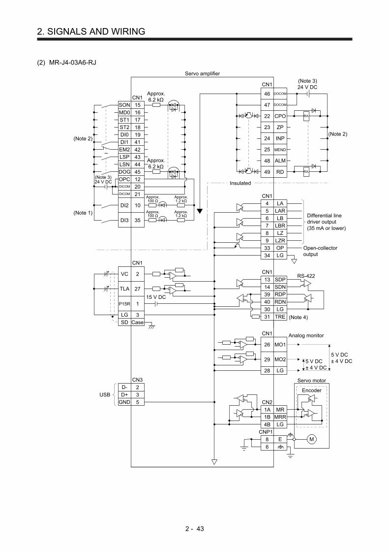
2. SIGNALS AND WIRING
2 - 43
(2) MR-J4-03A6-RJ
1A
SON
CN1
15
16
ST1 17
ST2 18DI0 19
DI1 41
EM2 42LSP 43
LSN 44
DOG 45
OPC 12
20
21
DI2 10
DI3 35
DICOM
DICOM
CN1
46
22
23
24
25
48
49
DOCOM
47 DOCOM
CPO
ZP
INP
MEND
RD
ALM
CN1
4
5
6
7
8
9
33
34
13
14
39
40
30
31
CN1
LA
LAR
LB
LBR
LZ
LZR
OP
LG
SDP
SDN
RDP
RDN
LG
TRE
CN1
MO1
MO2
LG
26
29
28
Differential linedriver output(35 mA or lower)
Open-collectoroutput
Approx.100 Ω
Approx.1.2 kΩ
Approx.100 Ω
Approx.1.2 kΩ
CN1
2VC
27TLA
1P15R
3LG
CaseSD
(Note 1)
Insulated
15 V DC
Approx.6.2 kΩ
Approx.6.2 kΩ
RS-422
Analog monitor
Servo amplifier
(Note 3)24 V DC
(Note 3)24 V DC
CN2
4B
1B
MR
MRR
LG
Encoder
Servo motor
(Note 2)(Note 2)
USB D+
GND
D- 2
3
5
CN3
5 V DC± 4 V DC5 V DC
± 4 V DC
RA
RA
M
MD0
(Note 4)
CNP1
8
6
E

2. SIGNALS AND WIRING
2 - 44
Note 1. Refer to section 9.1 for the connection of a manual pulse generator.
2. This diagram shows sink I/O interface. For source I/O interface, refer to section 3.9.3 of "MR-J4-_A_(-RJ) Servo Amplifier
Instruction Manual".
3. The illustration of the 24 V DC power supply is divided between input signal and output signal for convenience. However, they
can be configured by one. For 24 V DC power for I/O signal, use power other than 24 V DC power of servo amplifier control
circuit power supply.
4. To use the RS-422 communication function, connect between TRE and RDN of the final axis servo amplifier. (Refer to "MR-J4-
_A_(-RJ) Servo Amplifier Instruction Manual" section 18.9.)

2. SIGNALS AND WIRING
2 - 45
2.6 Power-on sequence
POINT
The voltage of analog monitor output, output signal, etc. may be unstable at
power-on.
2.6.1 MR-J4-_A_-RJ 100 W or more
(1) Power-on procedure
1) Always use a magnetic contactor for the main circuit power supply wiring (L1, L2, and L3) as
shown in section 3.1 of "MR-J4-_A_(-RJ) Servo Amplifier Instruction Manual". Configure an
external sequence to switch off the magnetic contactor as soon as an alarm occurs.
2) Switch on the control circuit power supply (L11 and L21) simultaneously with the main circuit
power supply or before switching on the main circuit power supply. If the main circuit power
supply is not on, the display shows the corresponding warning. However, by switching on the
main circuit power supply, the warning disappears and the servo amplifier will operate properly.
3) The servo amplifier receives the SON (Servo-on) 4 s to 5 s after the main circuit power supply is
switched on. Therefore, when SON (Servo-on) is switched on simultaneously with the main circuit
power supply, the base circuit will switch on in about 4 s to 5 s, and the RD (Ready) will switch on
in further about 5 ms, making the servo amplifier ready to operate. (Refer to (2) of this section.)
4) When RES (Reset) is switched on, the base circuit is shut off and the servo motor shaft coasts.
(2) Timing chart
95 ms
95 ms
RD (Ready)
RES (Reset)
SON (Servo-on)OFF
ON
OFF
ON
ON
OFF
Base circuitOFF
ON
power supplyOFF
ON
(Note)
10 ms5 ms
10 ms
10 ms5 ms
10 ms
5 ms 10 ms
(4 s to 5 s)
SON (Servo-on) accepted
Main circuit
Alarming (OFF)
No alarming (ON)ALM (Malfunction)
4 s to 5 s
Control circuit
Note. The time will be longer during the magnetic pole detection of a linear servo motor and direct drive motor.

2. SIGNALS AND WIRING
2 - 46
2.6.2 MR-J4-03A6-RJ
(1) Power-on procedure
1) When wiring the power supply, always use a circuit protector for the power supply (24/PM).
Configure up an external sequence so that the relay connected to PM turns off when an alarm
occurs.
2) Switch on the control circuit power supply (24/0) simultaneously with the main circuit power
supply (PM/0) or before switching on the main circuit power supply. If the main circuit power
supply is not on, the display shows the corresponding warning. However, by switching on the
main circuit power supply, the warning disappears and the servo amplifier will operate properly.
3) The servo amplifier receives the SON (Servo-on) within 4 s to 5 s after the main circuit power
supply is switched on. Therefore, when SON (Servo-on) is switched on simultaneously with the
main circuit power supply, the base circuit will switch on in about 4 s to 5 s, and the RD (Ready)
will switch on in further about 5 ms, making the servo amplifier ready to operate. (Refer to (2) of
this section.)
4) When RES (Reset) is switched on, the base circuit is shut off and the servo motor shaft coasts.
(2) Timing chart
95 ms
95 ms
RD (Ready)
RES (Reset)
SON (Servo-on)OFF
ON
OFF
ON
ON
OFF
Base circuitOFF
ON
Power supplyOFF
ON
10 ms5 ms
10 ms
10 ms5 ms
10 ms
5 ms 10 ms
(4 s to 5 s)
SON (Servo-on) accepted
Main circuitControl circuit
Alarming (OFF)
No alarming (ON)ALM (Malfunction)
4 s to 5 s

3. DISPLAY AND OPERATION SECTIONS
3 - 1
3. DISPLAY AND OPERATION SECTIONS
The following items are the same as MR-J4-_A_-RJ servo amplifiers. For the details of the items, refer to
each chapter/section (in "MR-J4-_A_(-RJ) Servo Amplifier Instruction Manual") indicated in the detailed
explanation field.
Item
Detailed explanation
MR-J4-_A_-RJ 100 W or more
MR-J4-03A6-RJ
Test operation mode Section 4.5.9 Section 18.5.10
3.1 MR-J4-_A_-RJ 100 W or more
3.1.1 Display sequence
Press the "MODE" button once to shift to the next display mode. Refer to section 3.1.2 and later for the
description of the corresponding display mode.

3. DISPLAY AND OPERATION SECTIONS
3 - 2
Display mode transition Initial screen Function Reference
Status display
Diagnosis
Point table setting
Basic settingparameters
Gain/filterparameters
Extension settingparameters
Extension setting 2parameters
Extension setting 3parameters
I/O settingparameters
buttonMODE
One-touch tuning
Positioning controlparameters
Linear/DD motorsetting parameter
Option settingparameters
Alarm
Servo status display.
For the point table and program,
is displayed at power-on.
For indexer, will be displayed.
(Note)
Section 3.1.2
One-touch tuning Select this when performing the one-touch tuning.
MR-J4-_A_(-RJ) Servo
Amplifier Instruction
Manual section 6.2
Sequence display, drive recorder enabled/disabled display, external I/O signal display, output signal (DO) forced output, test operation, software version display, VC automatic offset, servo motor series ID display, servo motor type ID display, servo motor encoder ID display, teaching function
Section 3.1.3
Current alarm display, alarm history display and parameter error No./point table error No. display
Section 3.1.4
Display and setting of point table data. The screen is displayed only in the point table method, and is not displayed in other control mode.
Section 3.1.5
Display and setting of basic setting parameters.
Section 3.1.6
Display and setting of gain/filter parameters.
Display and setting of extension setting parameters.
Display and setting of I/O setting parameters.
Display and setting of extension setting 2 parameters.
Display and setting of extension setting 3 parameters.
Display and setting of linear/DD motor setting parameters.
Display and setting of option setting parameters.
Display and setting of positioning control parameters.
Note. When the axis name is set to the servo amplifier using MR Configurator2, the axis name is displayed and the servo status is then
displayed.

3. DISPLAY AND OPERATION SECTIONS
3 - 3
3.1.2 Status display
The servo status during operation is shown on the 5-digit, 7-segment LED display. Press the "UP" or
"DOWN" button to change display data as desired. When the required data is selected, the corresponding
symbol is displayed. Press the "SET" button to display that data. At only power-on, however, data appears
after the symbol of the status display selected in [Pr. PC36] has been shown for 2 s.
(1) Display transition
After selecting the status display mode with the "MODE" button, pressing the "UP" or "DOWN" button
changes the display as shown below.

3. DISPLAY AND OPERATION SECTIONS
3 - 4
(a) Standard control mode (rotary servo motor)/DD motor control mode
Regenerative load ratio
Cumulative feedbackpulses
Effective load ratio
Peak load ratio
Instantaneous torque
Position withinone-revolution(increment of 1 pulse)
Servo motor speed/linear servo motorspeed
Position withinone-revolution(increment of 1000 pulses)
Droop pulses
ABS counter
Cumulative commandpulses
Load to motor inertia ratio
Command pulsefrequency
Bus voltage
Number of tough driveoperations
Unit powerconsumption 1(increment of 1 W)
Unit total powerconsumption 1(increment of 1 Wh)
Unit powerconsumption 2(increment of 1 kW)
Unit total powerconsumption 2(increment of 100 kWh)
Current position
Command position
Command remainingdistance
Point table/program No./command station position
Step No.
Analog override voltage
Override level
Cam axis onecycle currentvalue
Cam standardposition
Cam axis feedcurrent value
Cam No. inexecution
Cam strokeamount inexecution
(Note)
Main axiscurrent value
Cumulative feedback pulses
Main axis onecycle currentvalue
Main axis one cycle current position
Analog speed commandvoltageAnalog speed limitvoltage
Analog torque limitvoltageAnalog torque commandvoltage
DOWN
UP
Settling time
Oscillation detectionfrequency
Encoder inside temperature
Note. Supported by servo amplifiers with software version B7 or above.

3. DISPLAY AND OPERATION SECTIONS
3 - 5
(b) Fully closed loop control mode
Cumulative feedbackpulses
(Note 1)
(Note 2)
Unit total powerconsumption 2(increment of100 kWh)
Main axis one cycle current value
Current position
Main axis one cyclecurrent value
Override level
Load-side encoder cumulativefeedback pulses
Load-side encoder droop pulses
Load-side encoder information 1(increment of 1 pulse)
Load-side encoder information 1(increment of 100000 pulses)
Load-side encoder information 2
Cumulative feedback pulses
Note 1. The displays in the frames are from the cumulative feedback pulses of positioning
mode to unit total power consumption 2 (increment of 100 kWh) with some
displays omitted.
2. The displays in the frames are from the current position of positioning mode to
override level with some displays omitted.

3. DISPLAY AND OPERATION SECTIONS
3 - 6
(c) Linear servo motor control mode
Cumulative feedbackpulses
(Note 1)
(Note 2)
Unit total powerconsumption 2(increment of100 kWh)
Main axis one cycle current value
Current position
Override level
Electrical angle low
Electrical angle high
Cumulative feedback pulses
Z-phase counter low
Z-phase counter high
Main axis one cyclecurrent value
Note 1. The displays in the frames are from the cumulative feedback pulses of positioning
mode to unit total power consumption 2 (increment of 100 kWh) with some
displays omitted.
2. The displays in the frames are from the current position of positioning mode to
override level with some displays omitted.

3. DISPLAY AND OPERATION SECTIONS
3 - 7
(2) Status display list
The following table lists the servo statuses that may be shown.
Status display Symbol Unit Description
Control mode
(Note 1)
Operation mode (Note 3)
CP
/BC
D
CL
PS
Sta
ndar
d
Ful
l.
Lin.
DD
Cumulative feedback pulses
C pulse
Feedback pulses from the servo motor encoder are counted and displayed.
The values in excess of ±99999 can be counted. However, the counter shows only the lower five digits of the actual value since the servo amplifier display is five digits.
Press the "SET" button to reset the display value to zero.
The value of minus is indicated by the lit decimal points in the upper four digits.
Servo motor speed/ linear servo motor speed
r r/min The servo motor speed or linear servo motor speed is displayed.
It is displayed rounding off 0.1 r/min (0.1 mm/s) unit.
Droop pulses E pulse
The number of droop pulses in the deviation counter are displayed.
The decimal points in the upper four digits are lit for reverse rotation pulses.
The values in excess of ±99999 can be counted. However, the counter shows only the lower five digits of the actual value since the servo amplifier display is five digits.
The number of pulses displayed is in the encoder pulse unit.
Cumulative command pulses
P pulse Not used with the positioning mode. "0" is always displayed.
Command pulse frequency
n kpulse/s Not used with the positioning mode. "0" is always displayed.
Analog speed command voltage
Analog speed limit voltage
F V Not used with the positioning mode. An applied voltage to the CN1 connector is displayed.
Analog torque command voltage
U V
Not used with the positioning mode. An applied voltage to the CN1 connector is displayed.
Analog torque limit voltage
Voltage of TLA (Analog torque limit) voltage is displayed.
Regenerative load ratio L % The ratio of regenerative power to permissible regenerative power is displayed in %.
Effective load ratio J % The continuous effective load current is displayed.
The effective value in the past 15 s is displayed relative to the rated current of 100 %.
Peak load ratio b % The maximum occurrence torque is displayed.
The highest value in the past 15 s is displayed relative to the rated torque of 100 %.
Instantaneous torque T % The instantaneous torque is displayed.
The value of torque being occurred is displayed in real time considering a rated torque as 100%.
Position within one-revolution
(1 pulse unit) Cy1 pulse
Position within one revolution is displayed in encoder pulses.
The values in excess of ±99999 can be counted. However, the counter shows only the lower five digits of the actual value since the servo amplifier display is five digits.
When the servo motor rotates in the CCW direction, the value is added.
Position within one-revolution
(1000 pulse unit) Cy2
1000 pulses
The within one-revolution position is displayed in 1000 pulse increments of the encoder.
When the servo motor rotates in the CCW direction, the value is added.
ABS counter LS rev
The travel distance from the home position is displayed as multi-revolution counter value of the absolution position encoder in the absolution position detection system.
The travel distance from the home position is displayed as load side multi-revolution counter value in the absolution position detection system.
Load to motor inertia ratio
dC Multiplier The estimated ratio of the load inertia moment to the servo motor shaft inertia moment is displayed.
Bus voltage Pn V The voltage of main circuit converter (between P+ and N-) is displayed.
Encoder inside temperature
ETh °C Inside temperature of encoder detected by the encoder is displayed.

3. DISPLAY AND OPERATION SECTIONS
3 - 8
Status display Symbol Unit Description
Control mode
(Note 1)
Operation mode (Note 3)
CP
/BC
D
CL
PS
Sta
ndar
d
Ful
l.
Lin.
DD
Settling time ST ms Settling time is displayed. When it exceeds 1000 ms, "1000" will be displayed.
Oscillation detection frequency
oF Hz Frequency at the time of oscillation detection is displayed.
Number of tough drive operations
Td times The number of tough drive functions activated is displayed.
Unit power consumption 1 (increment of 1 W)
PC1 W
Unit power consumption is displayed by increment of 1 W. Positive value indicates power running, and negative value indicates regeneration. The values in excess of ±99999 can be counted. However, the counter shows only the lower five digits of the actual value since the servo amplifier display is five digits.
Unit power consumption 2 (increment of 1 kW)
PC2 kW Unit power consumption is displayed by increment of 1 kW. Positive value indicates power running, and negative value indicates regeneration.
Unit total power consumption 1 (increment of 1 Wh)
TPC1 Wh
Unit total power consumption is displayed by increment of 1 Wh. Positive value is cumulated during power running and negative value during regeneration. The values in excess of ±99999 can be counted. However, the counter shows only the lower five digits of the actual value since the servo amplifier display is five digits.
Unit total power consumption 2
(increment of 100 kWh) TPC2 100 kWh
Unit total power consumption is displayed by increment of 100 kWh. Positive value is cumulated during power running and negative value during regeneration.
Load-side encoder
Cumulative feedback pulses
FC pulse
Feedback pulses from the load-side encoder are counted and displayed.
The values in excess of ±99999 can be counted. However, the counter shows only the lower five digits of the actual value since the servo amplifier display is five digits.
Press the "SET" button to reset the display value to zero.
The value of minus is indicated by the lit decimal points in the upper four digits.
Load-side encoder
Droop pulses FE pulse
Droop pulses of the deviation counter between a load-side encoder and a command are displayed. When the count exceeds ±99999, it starts from 0.
Negative value is indicated by the lit decimal points in the upper four digits.
The display shows the average droop pulse value of 128-time sampling at the rate of 444 [μs].
Load-side encoder information 1
(1 pulse unit) FCy1 pulse
The Z-phase counter of a load-side encoder is displayed in the encoder pulse unit.
For an incremental linear encoder, the Z-phase counter is displayed. The value is counted up from 0 based on the home position (reference mark). For an absolute position linear encoder, the encoder absolute position is displayed.
When the count exceeds 99999, it starts from 0.
Load-side encoder information 1
(100000 pulses unit) FCy2 100000 pulses
The Z-phase counter of a load-side encoder is displayed by increments of 100000 pulses.
For an incremental linear encoder, the Z-phase counter is displayed. The value is counted up from 0 based on the home position (reference mark). For an absolute position linear encoder, the encoder absolute position is displayed.
When the count exceeds 99999, it starts from 0.
Load-side encoder information 2
FL5 rev
When an incremental linear encoder is used as the load-side encoder, the display shows 0.
When an absolute position linear encoder is used as the load-side encoder, the display shows 0.
When a rotary encoder is used as the load-side encoder, the display shows the multi-revolution counter value of the encoder.
Z-phase counter low FCy1 pulse
The Z-phase counter is displayed in the encoder pulse unit.
For an incremental linear encoder, the Z-phase counter is displayed. The value is counted up from 0 based on the home position (reference mark). For an absolute position linear encoder, the encoder absolute position is displayed.
When the count exceeds 99999, it starts from 0.

3. DISPLAY AND OPERATION SECTIONS
3 - 9
Status display Symbol Unit Description
Control mode
(Note 1)
Operation mode (Note 3)
CP
/BC
D
CL
PS
Sta
ndar
d
Ful
l.
Lin.
DD
Z-phase counter high FCy2 100000 pulses
The Z-phase counter is displayed by increments of 100000 pulses.
For an incremental linear encoder, the Z-phase counter is displayed. The value is counted up from 0 based on the home position (reference mark). For an absolute position linear encoder, the encoder absolute position is displayed.
When the count exceeds 99999, it starts from 0.
Electrical angle low ECy1 pulse The servo motor electrical angle is displayed.
Electrical angle high ECy2 100000 pulses The servo motor electrical angle is displayed by increments of 100000 pulses.
Current position PoS
10STMμm 10(STM-4) inch 10-3 degree
pulse (Note 2)
When "_ _ 0 _" (positioning display) is set in [Pr. PT26], the current position is displayed as machine home position is 0.
When "_ _ 1 _" (roll feed display) is set in [Pr. PT26], the actual current position is displayed as start position is 0.
The values in excess of ±99999 can be counted. However, the counter shows only the lower five digits of the actual value since the servo amplifier display is five digits.
Command position CPoS
10STMμm 10(STM-4) inch 10-3 degree
pulse (Note 2)
When "_ _ 0 _" (positioning display) is set in [Pr. PT26], the command current position is displayed as machine home position is 0.
When "_ _ 1 _" (roll feed display) is set in [Pr. PT26], turning on the start signal starts counting from 0 and a command current position to the target position is displayed in the automatic mode.
The command positions of the selected point table are displayed at a stop. At the manual mode, the command positions of the selected point table are displayed.
The values in excess of ±99999 can be counted. However, the counter shows only the lower five digits of the actual value since the servo amplifier display is five digits.
Command remaining distance
rn
10STMμm 10(STM-4) inch 10-3 degree
pulse (Note2)
Indicates the remaining distance to the command position of the currently selected point table, program and station.
The values in excess of ±99999 can be counted. However, the counter shows only the lower five digits of the actual value since the servo amplifier display is five digits.
Point table No./program No./command station position
Pno
For the point table method and program method, the point table and program No. currently being executed are displayed. The selected number is displayed during a temporary stop or manual operation.
For the indexer method, the command next station position is displayed.
Step No. Sno The step No. of the program currently being executed is displayed. At a stop, 0 is displayed.
Analog override voltage oru V The analog override voltage is displayed.
Override level or % The setting value of the override is displayed.
When the override is disabled, 100% is displayed.
Cam axis one cycle current value
CCyC
10STM μm 10(STM-4) inch 10-3 degree
pulse
(Note 4)
The current position in one cycle of CAM axis is displayed with the range of "0 to (cam axis one cycle length - 1)", the cam axis one cycle current value which is calculated from the travel distance inputted to the cam axis. When the simple cam function is disabled, 0 is always displayed.
The values in excess of ±99999 can be counted. However, the counter shows only the lower five digits of the actual value since the servo amplifier display is five digits.
Refer to section 12.1.8 for detecting point.
Cam standard position CbAS
10STM μm 10(STM-4) inch 10-3 degree
pulse
(Note 3)
A feed current value which is the standard position of the cam operation is displayed. When the simple cam function is disabled, 0 is always displayed.
The values in excess of ±99999 can be counted. However, the counter shows only the lower five digits of the actual value since the servo amplifier display is five digits.
Refer to section 12.1.8 for detecting point.

3. DISPLAY AND OPERATION SECTIONS
3 - 10
Status display Symbol Unit Description
Control mode
(Note 1)
Operation mode (Note 3)
CP
/BC
D
CL
PS
Sta
ndar
d
Ful
l.
Lin.
DD
Cam axis feed current value
CCMd
10STM μm 10(STM-4) inch 10-3 degree
pulse
(Note 3)
A feed current value during the cam axis control is displayed. When the simple cam function is disabled, 0 is always displayed.
The values in excess of ±99999 can be counted. However, the counter shows only the lower five digits of the actual value since the servo amplifier display is five digits.
Refer to section 12.1.8 for detecting point.
Cam No. in execution Cno
Cam No. in execution is displayed.
When the simple cam function is disabled, 0 is always displayed.
Refer to section 12.1.8 for detecting point.
Cam stroke amount in execution
CSTK
10STM μm 10(STM-4) inch 10-3 degree
(Note 3)
Cam stroke amount in execution is displayed. When the simple cam function is disabled, 0 is always displayed.
The values in excess of ±99999 can be counted. However, the counter shows only the lower five digits of the actual value since the servo amplifier display is five digits.
Refer to section 12.1.8 for detecting point.
Main axis current value MCMd
10STM μm 10(STM-4) inch 10-3 degree
(Note 4)
A current value of the input axis (synchronous encoder axis or servo input axis) is displayed. Unit is increment of input axis position. When the simple cam function is disabled, 0 is always displayed.
The values in excess of ±99999 can be counted. However, the counter shows only the lower five digits of the actual value since the servo amplifier display is five digits.
Refer to section 12.1.8 for detecting point.
Main axis one cycle current value
MCyC
10STM μm 10(STM-4) inch 10-3 degree
pulse
(Note 4)
The input travel amount of the input axis is displayed within the range of "0 and (cam axis one cycle length setting - 1)". Unit is an increment of cam axis one cycle. When the simple cam function is disabled, 0 is always displayed.
The values in excess of ±99999 can be counted. However, the counter shows only the lower five digits of the actual value since the servo amplifier display is five digits.
Refer to section 12.1.8 for detecting point.
Note 1. CP: Positioning mode (point table method)
BCD: Positioning mode (point table method in the BCD input positioning operation)
This method is available only when the MR-D01 unit is connected. Refer to chapter 12 for details.
CL: Positioning mode (program method)
PS: Positioning mode (indexer method)
2. The unit can be selected from μm/inch/degree/pulse with [Pr. PT01].
3. Standard: Standard (semi closed loop system) use of the rotary servo motor Full.: Fully closed loop system use of the rotary servo motor Lin.: Linear servo motor use
DD: Direct drive (DD) motor use
4. The unit can be changed with "Cam control data No. 14" to μm/inch/degree/pulse.

3. DISPLAY AND OPERATION SECTIONS
3 - 11
(3) Changing the status display screen
The status display item of the servo amplifier display shown at power-on can be changed by changing
[Pr. PC36] settings. The item displayed in the initial status changes with the control mode as follows.
Control mode Status display
Position Cumulative feedback pulses
Position/speed Cumulative feedback pulses/servo motor speed
Speed Servo motor speed
Speed/torque Servo motor speed/analog torque command voltage
Torque Analog torque command voltage
Torque/position Analog torque command voltage/cumulative feedback
pulses
Positioning (point table method/program method)
Current position
Positioning (indexer method) Cumulative feedback pulses

3. DISPLAY AND OPERATION SECTIONS
3 - 12
3.1.3 Diagnostic mode
The display can show diagnosis contents. Press the "UP" or "DOWN" button to change display data as
desired.
(1) Display transition
Machine analyzeroperation
Sequence
For manufactureradjustment
Single-step feed
Software version: lower
Software version: upper
Drive recorder enabled/disabled display
External I/O signal display
Output signal (DO)forced output
JOG operation
Automatic VC offset
Servo motor series ID
Servo motor type ID
Servo motor encoder ID
For manufacturer adjustment
For manufacturer adjustment
Teaching function
Positioning operation
Motor-less operation
UP
DOWN

3. DISPLAY AND OPERATION SECTIONS
3 - 13
(2) Diagnosis display list
Name Display Description
Sequence
Not ready
Indicates that the servo amplifier is being initialized or an alarm has occurred.
Ready
Indicates that the servo was switched on after completion of initialization and the servo amplifier is ready to operate.
Drive recorder enabled/disabled display
Drive recorder enabled
When an alarm occurs in the status, the drive recorder will operate and write the status of occurrence.
Drive recorder disabled
The drive recorder will not operate on the following conditions.
1.You are using the graph function of MR Configurator2.
2.You are using the machine analyzer function.
3.[Pr. PF21] is set to "-1".
External I/O signal display Refer to section 3.1.7.
This Indicates the on/off status of external I/O signal.
The upper segments correspond to the input signals and the lower segments to the output signals.
Output signal (DO) forced output
This allows digital output signal to be switched on/off forcibly.
Refer to section 3.1.8 for details.
Test operation mode
JOG operation
JOG operation can be performed when there is no command from an external controller.
For details, refer to section 4.5.9 (2) of "MR-J4-_A_(-RJ) Servo Amplifier Instruction Manual".
Positioning operation
Positioning operation can be performed when there is no command from an external controller.
MR Configurator2 is required to perform positioning operation.
For details, refer to section 4.5.9 (3) of "MR-J4-_A_(-RJ) Servo Amplifier Instruction Manual".
Motor-less operation
Without connecting the servo motor, output signals or status display can be provided in response to the input device as if the servo motor is actually running.
For details, refer to section 4.5.9 (4) of "MR-J4-_A_(-RJ) Servo Amplifier Instruction Manual".
Machine analyzer operation
Merely connecting the servo amplifier allows the resonance point of the mechanical system to be measured.
MR Configurator2 is required to perform machine analyzer operation.
For details, refer to section 11.7 of "MR-J4-_A_(-RJ) Servo Amplifier Instruction Manual".
For manufacturer adjustment
This is for manufacturer adjustment.
Single-step feed
This function is available only in the point table method and program method. When the positioning operation is executed in accordance with the point table or program set by MR Configurator2, the diagnosis display changes to "d-06" during single-step feed. For other control mode, the display does not change to "d-06". Refer to section 3.1.9 for details.
The status will be displayed with the "MODE" button. The "UP" and "DOWN" buttons are disabled.

3. DISPLAY AND OPERATION SECTIONS
3 - 14
Name Display Description
Software version - Lower
Indicates the version of the software.
Software version - Upper
Indicates the system number of the software.
Automatic VC offset (Note)
If offset voltages in the analog circuits inside and outside the servo amplifier cause the servo motor setting speed not to be the designated value at VC or OVC of 0 V, a zero-adjustment of offset voltages will be automatically performed. When using the VC automatic offset, enable it in the following procedures.
1) Press the "SET" once.
2) Set the number in the first digit to 1 with "UP"/"DOWN".
3) Press the "SET".
This function cannot be used if the input voltage of VC or OVC is -0.4 V or less, or +0.4 V or more.
When the VC automatic offset is enabled, the following automatic offset voltage is applied according to the setting of [Pr. Po11].
Pr. Po11 Offset voltage to be
automatically adjusted
_ _ 0 _ Offset voltage set with [Pr. PC37] (Servo amplifier side)
_ _ 1 _ Offset voltage set with [Pr. Po21] (MR-D01 side)
Servo motor series ID
Push the "SET" button to show the series ID of the servo motor currently connected.
For indication details, refer to appendix 1 of "Servo Motor Instruction Manual (Vol. 3)".
Servo motor type ID
Push the "SET" button to show the type ID of the servo motor currently connected.
For indication details, refer to appendix 1 of "Servo Motor Instruction Manual (Vol. 3)".
Servo motor encoder ID
Push the "SET" button to show the encoder ID of the servo motor currently connected.
For indication details, refer to appendix 1 of "Servo Motor Instruction Manual (Vol. 3)".
For manufacturer adjustment
This is for manufacturer adjustment.
For manufacturer adjustment
This is for manufacturer adjustment.
Teaching function Refer to section 3.1.10.
After an operation travels to a target position (MEND (Travel completion) is turned on) with a JOG operation or manual pulse generator operation, pushing the "SET" button of the operation part or turning on TCH (Teach) will import position data. This function is available only in the point table method. For other control mode, the display remains the same.
Note. Even if VC automatic offset is performed and 0 V is inputted, the speed may not completely be the set value.

3. DISPLAY AND OPERATION SECTIONS
3 - 15
3.1.4 Alarm mode
The current alarm, past alarm history and parameter error are displayed. The lower 2 digits on the display
indicate the alarm number that has occurred or the parameter number in error.
Name Display (Note 1) Description
Current alarm
Indicates no occurrence of an alarm.
Indicates the occurrence of [AL. 33.1 Main circuit voltage error].
Flickers at alarm occurrence.
Alarm history
Indicates that the last alarm is [AL. 50.1 Thermal overload error 1 during operation].
Indicates the second last alarm is [AL. 33.1 Main circuit voltage error].
Indicates the third last alarm is [AL. 10.1 Voltage drop in the control circuit power].
Indicates that there is no tenth alarm in the past.
Indicates that there is no eleventh alarm in the past.
Indicates that there is no twelfth alarm in the past.
Indicates that there is no sixteenth alarm in the past.
Parameter error No./point table error No.
(Note 2)
This indicates no occurrence of [AL. 37 Parameter error].
The data content error of [Pr. PA12 Reverse rotation torque limit].
The value of the point table is over the setting range.
The error point table No. (intermediate digit "2") and item (lower digit "d") are displayed.
The following shows the items.
P: position data, d: motor speed, A: acceleration time constant, b: deceleration time constant, n: dwell, H: sub function, M: M code
Note 1. If a parameter error and point table error occur simultaneously, the display shows the parameter error.
2. The display shows only when the current alarm is [AL. 37 Parameter error].

3. DISPLAY AND OPERATION SECTIONS
3 - 16
The following shows the functions that can be used at occurrence of an alarm.
(1) Any mode screen displays the current alarm.
(2) Even during alarm occurrence, the other screen can be viewed by pressing the button in the operation
area. At this time, the decimal point in the fourth digit remains flickering.
(3) For any alarm, remove its cause and clear it in any of the following methods. (Refer to chapter 8 for the
alarms that can be cleared.) )
(a) Switch power off, then on.
(b) Push the "SET" button on the current alarm screen.
(c) Turn on RES (Reset).
(4) Use [Pr. PC18] to clear the alarm history.
(5) Push "UP" or "DOWN" to move to the next history.

3. DISPLAY AND OPERATION SECTIONS
3 - 17
3.1.5 Point table setting
You can set the target position, servo motor speed, acceleration time constant, deceleration time constant,
dwell, sub function and M code.
(1) Display transition
Target position
Servo motor speed
Deceleration timeconstant
Dwell
Sub function
M code
Acceleration timeconstant
UP
DOWN
Point table No. 1
Point table transition
Point table No. 2
Point table No. 253
Point table No. 254
Point table No. 255
Point table No. 3
UP
DOWN
SET button
MODE button
Setting item transition

3. DISPLAY AND OPERATION SECTIONS
3 - 18
(2) Setting list
The following table indicates the point table settings that may be displayed.
Status display Symbol Unit Description Indication
range
Point table No. Po001 Specify the point table to set the target position, servo motor speed, acceleration time constant, deceleration time constant, dwell, sub function and M code.
1 to 255
Target position PoS
10STM μm
10(STM-4) inch
10-3 degree
pulse
(Note 1)
Set the travel distance. -999999
to 999999
Servo motor speed SPd
r/min mm/s
(Note 2)
Set the command speed of the servo motor for execution of positioning. The setting value must be within the permissible speed of the servo motor used. If a value equal to or larger than the permissible speed is set, the value is clamped at the permissible speed.
0
to
Permissible speed
Acceleration time constant STA ms Set a time until the servo motor rotates at the rated speed. 0 to 20000
Deceleration time constant STb ms Set a time from when the servo motor rotates at the rated speed until when the motor stops.
0 to 20000
Dwell TLn ms
This function is enabled when you select the point table by input signal.
To make the dwell invalid, set "0" or "2" to the sub function. To perform varying-speed operation, set "1", "3", "8", or "9" to the sub function and 0 to the dwell. When the dwell is set, the position command of the selected point table is completed. After the set dwell has elapsed, start the position command of the next point table.
0 to 20000
Sub function H
This function is enabled when you select the point table by input signal.
(1) When using this point table under the absolute value command method
0: Automatic operation is performed in accordance with a single point table selected.
1: Executes automatic continuous operation without stopping for the next point table.
8: Automatic continuous operation is performed to the point table selected at start-up.
9: Automatic continuous operation is performed to point table No. 1.
(2) When using this point table under the incremental value command method
2: Automatic operation is performed in accordance with a single point table selected.
3: Executes automatic continuous operation without stopping for the next point table.
10: Automatic continuous operation is performed to the point table selected at start-up.
11: Automatic continuous operation is performed to point table No. 1.
When a different rotation direction is set, smoothing zero (command output) is confirmed and then the rotation direction is reversed.
When "1" or "3" is set to the point table No. 255, [AL. 61] will occur at the time of point table execution.
0 to 3, 8 to 11
M code MCd This is the code output at the completion of positioning.
Outputs the first digit and the second digit of the M code in 4-bit binary respectively.
0 to 99
Note 1. The unit can be selected from μm/inch/degree/pulse with [Pr. PT01].
2. The unit will be "mm/s" for linear control mode.

3. DISPLAY AND OPERATION SECTIONS
3 - 19
(3) Operation method
POINT
After changing and defining the setting values of the specified point table, the
defined setting values of the point table are displayed. After defining the values,
pressing the "MODE" button for 2 s or more to discard the changed setting
values, and the previous setting values are displayed. Keep pressing the "UP" or
"DOWN" button to continuously change the most significant digit of the setting
values.
(a) Setting of 5 or less digits
The following example is the operation method at power-on to set "1" to the sub function of the point
table No. 1.
The setting value of sub function of specified Pointtable No. flickers.
During flickering, the set value can be changed.
Set using the "UP" or "DOWN" button.
Press the "MODE" button four times.
A point table No. is displayed.
Press the "UP" or "DOWN" button to selectpoint table No. 1.
Press the "SET" button once.
Press the "UP" button five times.
Press the "SET" button twice.
Press the "UP" button once.
Press "SET" to enter.
To the next item setting
Press the "UP" "DOWN" button to switch to other item of the same point table No.
Press the "MODE" button to switch to the next point table No.

3. DISPLAY AND OPERATION SECTIONS
3 - 20
(b) Setting of 6 or more digits
The following example is the operation method to change the position data of the point table No. 1 to
"123456".
The screen flickers.
Press the "SET" button once.
Press the "SET" buttononce.
Setting of upper 1 digit
Change the setting valueusing the "UP" or"DOWN" button.
Press the "SET" buttononce.
Enter the setting.
Press the "MODE" button once.
Press the "MODE" buttononce.
Setting of lower 4 digits
Press the "MODE" button four times.
A point table No. is displayed.
Press the "UP" or "DOWN" button to selectpoint table No. 1.
Press the "SET" button once.

3. DISPLAY AND OPERATION SECTIONS
3 - 21
3.1.6 Parameter mode
(1) Parameter mode transition
After selecting the corresponding parameter mode with the "MODE" button, pressing the "UP" or
"DOWN" button changes the display as shown below.
[Pr. PB01]
[Pr. PA02]
[Pr. PA01]
I/O settingparameters
[Pr. PD01]
[Pr. PD02]
[Pr. PD47]
[Pr. PD48]
[Pr. PC01]
[Pr. PC02]
[Pr. PC79]
Extension settingparameters
[Pr. PC80]
[Pr. PB02]
[Pr. PB63]
[Pr. PB64]
To status displaymode
[Pr. PA31]
Basic settingparameters
[Pr. PA32]
Extension setting 2parameters
[Pr. PE01]
[Pr. PE02]
[Pr. PE63]
[Pr. PE64]
Extension setting 3parameters
[Pr. PF01]
[Pr. PF02]
[Pr. PF47]
[Pr. PF48]
Gain/filterparameters
MODE
Positioningcontrol parameters
[Pr. PT01]
[Pr. PT02]
[Pr. PT47]
[Pr. PT48]
Linear/DD motorsetting parameter
[Pr. PL01]
[Pr. PL02]
[Pr. PL47]
[Pr. PL48]
UP
DOWN
From alarm mode
Option settingparameters
[Pr. Po01]
[Pr. Po02]
[Pr. Po31]
[Pr. Po32]
(2) Operation method
(a) Parameters of 5 or less digits
The following example shows the operation procedure performed after power-on to change the
control mode to the positioning mode (point table method) with [Pr. PA01 Operation mode]. Press
"MODE" to switch to the basic setting parameter screen.
The parameter number is displayed.Press "UP" or "DOWN" to change the number.
The set value of the specified parameter number flickers.
Press "SET" twice.
Press "SET" to enter.
Press the "UP" button six times.
During flickering, the set value can be changed.Use "UP" or "DOWN".( _ _ _ 6: Positioning mode (point table method))
To shift to the next parameter, press the "UP" or "DOWN" button.
When changing the [Pr. PA01] setting, change its setting value, then switch power off once and
switch it on again to enable the new value.

3. DISPLAY AND OPERATION SECTIONS
3 - 22
(b) Parameters of 6 or more digits
The following example gives the operation procedure to change the electronic gear numerator to
"123456" with [Pr. PA06 Electronic gear numerator].
The screen flickers.
Press "MODE" to switch to the basic setting parameter screen.Press "UP" or "DOWN" to select [Pr. PA06].
Press "SET" once.
Press "SET" once.
Setting of upper 1 digit
Press "UP" or "DOWN" tochange the setting.
Press "SET" once.
Enter the setting.
Press "MODE" once.
Press "MODE" once.Setting of lower 4 digits
…… ……
…… …

3. DISPLAY AND OPERATION SECTIONS
3 - 23
3.1.7 External I/O signal display
POINT
The I/O signal settings can be changed using the I/O setting parameters [Pr.
PD04] to [Pr. PD28].
The on/off states of the digital I/O signals connected to the servo amplifier can be confirmed.
(1) Operation
The display screen at power-on. Using the "MODE" button, display the diagnostic screen.
Press the "UP" button twice.
……External I/O signal display screen
(2) Display definition
The 7-segment LED segments and CN1 connector pins correspond as shown below.
Input signal
Output signal
Always lit
CN1-16 CN1-41
CN1-22CN1-48
CN1-19 CN1-15 CN1-44 CN1-43
CN1-23CN1-25 CN1-49CN1-24
Light on: onLight off: off
CN1-18 CN1-17
CN1-33
CN1-45CN1-42
CN1-10 (Note 1)/CN1-37 (Note 2)
CN1-35 (Note 1)/CN1-38 (Note 2)
CN1-13CN1-14
Note 1. This pin is available with servo amplifiers having software version B3 or later, and manufactured in
November 2014 or later.
2. This pin is available with servo amplifiers having software version B7 or later, and manufactured in
January 2015 or later.
The LED segment corresponding to the pin is lit to indicate on, and is extinguished to indicate off.
For each pin signal in control modes, refer to section 2.2 (1).

3. DISPLAY AND OPERATION SECTIONS
3 - 24
3.1.8 Output signal (DO) forced output
POINT
When the servo system is used in a vertical lift application, turning on MBR
(Electromagnetic brake interlock) by the DO forced output after assigning it to
connector CN1 will release the electromagnetic brake, causing a drop. Take
drop preventive measures on the machine side.
Output signals can be switched on/off forcibly independently of the servo status. This function can be used
for output signal wiring check, etc. This operation must be performed in the servo off state by turning off
SON (Servo-on).
The display screen at power-on. Using the "MODE" button, display the diagnostic screen.
……
……
……
……
……
Switch on/off the signal below the lit segment.
Indicates on/off of output signal. Definitions ofon/off are the same as those for the external I/Osignals. (Light on: on, light off: off)
Press the "UP" button three times.
Press the "SET" button for 2 s or more.
CN133
CN148
CN122
CN125
CN123
CN124
CN149
Press the "MODE" button once.
Press the "UP" button once.
CN1-24 switches on.(Between CN1-24 and DOCOM are connected.)
The lit LED moves to the upper LED of CN1-24.
Press the "DOWN" button once.
CN1-24 switches off.
Press the "SET" button for 2 s or more.
Always lit
CN114
CN113

3. DISPLAY AND OPERATION SECTIONS
3 - 25
3.1.9 Single-Step feed
CAUTION The test operation mode is designed for checking servo operation. Do not use it
for actual operation.
If the servo motor operates unexpectedly, use EM2 (Forced stop 2) to stop it.
POINT
MR Configurator2 is required to perform single-step feed.
Test operation cannot be performed if SON (Servo-on) is not turned off.
The positioning operation can be performed in accordance with the point table No. or program No. set by MR
Configurator2.
Select the test operation/single-step feed by the menu of MR Configurator2. When the single-step feed
window is displayed, input the following items and operate.
(c) (d) (e) (f)
(a)
(c) (d) (e) (f)
(b)
Point table operation Program operation
(1) Point table No. or program No. setting
Input a point table No. into the input box (a) "Point table No.", or a program No. into the input box (b)
"Program No.".
(2) Forward/reverse the servo motor
Click the "Operation Start" button (c) to rotate the servo motor.
(3) Pause the servo motor
Click the "Pause" button (d) to temporarily stop the servo motor.
While the servo motor is temporarily stopped, click the "Operation Start" button (c) to restart the rotation
by the amount of the remaining travel distance.
While the servo motor is temporarily stopped, click the "Stop" button (e) to clear the remaining travel
distance.
(4) Stop the servo motor
Click the "Stop" button (e) to stop the servo motor. At this time, the remaining travel distance is cleared.
Click the "Operation Start" (c) button to restart the rotation.

3. DISPLAY AND OPERATION SECTIONS
3 - 26
(5) Forced stop of the servo motor software
Click the "Forced Stop" (f) button to make an instantaneous stop. When the "Forced Stop" button is
enabled, "Operation Start" button cannot be used. Click the "Forced Stop" button again to enable the
"Operation Start" button.
(6) Switch to the normal operation mode
Before switching from the test operation mode to the normal operation mode, turn off the servo amplifier.

3. DISPLAY AND OPERATION SECTIONS
3 - 27
3.1.10 Teaching function
After an operation travels to a target position (MEND (Travel completion) is turned on) with a JOG operation
or manual pulse generator operation, pushing the "SET" button of the operation part or turning on TCH
(Teach) will import position data. This function is available only in the point table method. For other control
mode, the display remains the same.
(1) Teaching preparation
Teaching setting initial screen
Press the "SET" button for approximately 2 s to switch to the teaching setting
mode.
When the lower three digits flicker, press the "UP" or "DOWN" button to select
the point table.
When the lower three digits flicker, press the "SET" button to complete the
teaching setting preparation. The upper two digits on the display will flicker on
completion of proper preparation
(2) Position data setting method
After an operation travels to a target position (MEND (Travel completion) is turned on) with a JOG
operation or manual pulse generator operation, pushing the "SET" button of the operation part or turning
on TCH (Teach) will set the positioning address as position data.
When the upper two digits flicker, the current position is written to the selected
point table by pressing the "SET" button.
When the upper two digits or the lower two digits flicker, the display returns to the teaching setting initial
screen by pressing the "MODE" button.
The following shows the conditions for when the teaching function operates.
(a) When the "positioning command method" of [Pr. PT01] is set to absolute value command method (_
_ _ 0)
(b) Home position return completion (ZP (Home position return completion) is turned on)
(c) While the servo motor is stopped (command output = 0, MEND (Travel completion) is turned on)

3. DISPLAY AND OPERATION SECTIONS
3 - 28
3.2 MR-J4-03A6-RJ
3.2.1 Display flowchart
Press the "MODE" button once to shift to the next display mode. Refer to section 3.2.2 and later for the
description of the corresponding display mode.
Display mode transition Initial screen Function Reference
Status display
Diagnosis
Point table setting
Basic settingparameters
Gain/filterparameters
Extension settingparameters
Extension setting 2parameters
Extension setting 3parameters
I/O settingparameters
ButtonMODE
One-touch tuning
Positioning controlparameters
Option settingparameters
Alarm
Servo status display.
For the point table and program, is
displayed at power-on.
For indexer, will be displayed. (Note)
Section 3.1.2
One-touch tuning Select this when performing the one-touch tuning.
MR-J4-_A_(-RJ) Servo Amplifier
Instruction Manual
section 6.2
Section 18.5.4
Sequence display, drive recorder enabled/disabled display, external I/O signal display, output signal (DO) forced output, test operation, software version display, VC automatic offset, servo motor series ID display, servo motor type ID display, servo motor encoder ID display, teaching function
Section 3.2.3
Current alarm display, alarm history display, and parameter error No./point table error No. display
Section 3.2.4
Display and setting of point table data. This is displayed only in the point table method, not in other control modes.
Section 3.2.5
Display and setting of basic setting parameters.
Section 3.2.6
Display and setting of gain/filter parameters.
Display and setting of extension setting parameters.
Display and setting of I/O setting parameters.
Display and setting of extension setting 2 parameters.
Display and setting of extension setting 3 parameters.
Display and setting of option setting parameters.
Display and setting of positioning control parameters.
Note. When the axis name is set to the servo amplifier using MR Configurator2, the servo status is displayed after the axis name is
displayed.

3. DISPLAY AND OPERATION SECTIONS
3 - 29
3.2.2 Status display mode
The servo status during operation is shown on the 3-digit, 7-segment LED display. Press the "UP" or
"DOWN" button to change the display data as desired. When a servo status is selected, the corresponding
symbol is displayed. Press the "SET" button to display its data. However, only when the power is turned on,
the data will be displayed after the status symbol selected with [Pr. PC36] is displayed for 2 s.
(1) Display transition
After selecting the status display mode with the "MODE" button, pressing the "UP" or "DOWN" button
changes the display as follows:

3. DISPLAY AND OPERATION SECTIONS
3 - 30
Cumulative commandpulses(1000 pulses unit)
Cumulative feedbackpulses(pulse unit)
Command pulsefrequency(kpulses/s unit)
Command pulsefrequency(1000 kpulses/s unit)
Analog speedcommand voltageAnalog speedlimit voltage
Analog torquelimit voltageAnalog torquecommand voltage
Cumulative feedbackpulses(1000 pulse unit)
Servo motor speed(10 r/min unit)
Servo motor speed(r/min unit)
Droop pulses(pulse unit)
Override level
Droop pulses(1000 pulses unit)
Cumulative commandpulses (pulse unit)
DOWN
UP
ABS counter(1000 rev unit)
Load to motorinertia ratio(0.1 times)
Load to motorinertia ratio(100 times)
Bus voltage
Encoder insidetemperature
Instantaneous torque
Position withinone-revolution(pulse unit)
Position withinone-revolution(1000 pulses unit)
Position withinone-revolution(1000000 pulses unit)
ABS counter(rev unit)
DOWN
UP
DOWN
Unit total powerconsumption 2(increment of 1 kWh)
Unit total powerconsumption 3(increment of1000 kWh)
Unit powerconsumption 1(increment of 1 W)
Unit powerconsumption 2(increment of 1 kW)
Unit total powerconsumption 1(increment of 1 Wh)
Cumulative feedbackpulses (pulse unit)
Regenerativeload ratio
Settling time
Effectiveload ratio
Peak load ratio
Oscillationdetection frequency(1 Hz unit)
Oscillationdetection frequency(1 kHz unit)
Number of toughdrive operations(times)
Number of toughdrive operations(1000 times)
Command position:Low
Command position:High
Current position:Low
Current position:High
Point table/programNo./command stationposition
Step No.
Command remainingdistance: Low
Command remainingdistance: High
Analog overridevoltage
Override level

3. DISPLAY AND OPERATION SECTIONS
3 - 31
(2) Status display list
The following table lists the servo statuses that may be shown.
Status display Symbol Unit Description
Control mode
(Note 1)
CP
CL
PS
Cumulative feedback pulses
(1 pulse unit) CL pulse
Feedback pulses from the servo motor encoder are counted and displayed.
When the count exceeds ±999, it starts from 0.
Negative value is indicated by the lit decimal points in the upper two digits.
Press the "SET" button to reset the display value to zero.
The internal counter subtracts 500000000 when the number exceeds 2000000000. The internal counter adds 500000000 when the number exceeds -2000000000.
Cumulative feedback pulses (1000 pulse unit)
Ch 1000 pulses
Servo motor speed (10 r/min unit)
r1 10 r/min
The servo motor speed is displayed.
Negative value is indicated by the lit decimal points in the upper two digits.
Displayed in increments of 10 r/min.
Servo motor speed (1 r/min unit)
r r/min The servo motor speed is displayed.
Negative value is indicated by the lit decimal points in the upper two digits.
Droop pulses (1 pulse unit)
EL pulse The number of droop pulses in the deviation counter is displayed.
When the count exceeds ±999, it starts from 0.
The value displayed is not multiplied by the electronic gear (CMX/CDV).
Negative value is indicated by the lit decimal points in the upper two digits. Droop pulses (1000 pulses unit)
Eh 1000 pulses
Cumulative command pulses (1 pulse unit)
PL pulse
Not used with the positioning mode. "0" is always displayed.
Cumulative command pulses (1000 pulses unit)
Ph 1000 pulses
Command pulse frequency (1 kpulse/s unit)
nL kpulse/s
Not used with the positioning mode. "0" is always displayed.
Command pulse frequency (1000 kpulses/s unit)
nh 1000 kpulses/s
Analog speed command voltage Analog speed limit voltage
F V Not used with the positioning mode. An applied voltage to the CN1 connector is displayed.
Analog torque command voltage
U V
Not used with the positioning mode. An applied voltage to the CN1 connector is displayed.
Analog torque limit voltage
Voltage of TLA (Analog torque limit) is displayed.
Regenerative load ratio L % The ratio of regenerative power to permissible regenerative power is displayed in %.
Effective load ratio J % The continuous effective load current is displayed.
The effective value in the past 15 s is displayed, with the rated current being 100 %.
Peak load ratio b % The maximum torque generated is displayed.
The highest value in the past 15 s is displayed, with the rated torque being 100 %.
Instantaneous torque T % The instantaneous torque is displayed.
The torque generated is displayed in real time, with the rated torque being 100%.
Position within one-revolution (1 pulse unit)
Cy1 pulse
Position within one revolution is displayed in encoder pulses.
When the count exceeds 999, it starts from 0.
When the servo motor rotates in the CCW direction, the value is added.
Position within one-revolution (1000 pulses unit)
Cy2 1000 pulses
The within one-revolution position is displayed in 1000 pulse increments of the encoder.
When the count exceeds 999, it starts from 0.
When the servo motor rotates in the CCW direction, the value is added.
Position within one-revolution (1000000 pulses unit)
Cy3 1000000 pulses
The within one-revolution position is displayed in 1000000 pulse increments of the encoder.
When the count exceeds 999, it starts from 0.
When the servo motor rotates in the CCW direction, the value is added.
ABS counter (1 rev unit) LSL rev The travel distance from the home position is displayed as multi-revolution counter value of the absolution position encoder in the absolution position detection system.
Negative value is indicated by the lit decimal points in the upper two digits.
ABS counter (1000 rev unit)
LSh 1000 rev

3. DISPLAY AND OPERATION SECTIONS
3 - 32
Status display Symbol Unit Description
Control mode
(Note 1)
CP
CL
PS
ABS counter (1 rev unit) LSL rev The travel distance from the home position is displayed as load side multi-revolution counter value in the absolute position detection system.
Negative value is indicated by the lit decimal points in the upper two digits.
ABS counter (1000 rev unit)
LSh 1000 rev
Load to motor inertia ratio (0.1 times)
dCL 0.1 time The estimated ratio of the load inertia moment to the servo motor shaft inertia moment is displayed. Load to motor inertia ratio
(100 times) dCh 100 times
Bus voltage Pn V The voltage of main circuit converter is displayed.
It is displayed rounding off 0.1 V unit.
Encoder inside temperature
ETh °C Inside temperature of encoder detected by the encoder is displayed.
Settling time ST ms Displays settling time. When it exceeds 999 ms, "999" will be displayed.
Oscillation detection frequency (1 Hz unit)
oFL Hz
Frequency at the time of oscillation detection is displayed. Oscillation detection frequency (1 kHz unit)
oFh kHz
The number of tough drive operations (time)
Td1 times
The number of tough drive functions activated is displayed. The number of tough drive operations (1000 times)
Td2 1000 times
Unit power consumption 1 (increment of 1 W)
PC1 W
Unit power consumption is displayed by increment of 1 W. Positive value indicate power running, and negative value indicate regeneration. The values in excess of ±999 can be counted. However, the counter shows only the lower three digits of the actual value since the servo amplifier display is three digits.
Negative value is indicated by the lit decimal points in the upper two digits.
Unit power consumption 2 (increment of 1 kW)
PC2 kW
Unit power consumption is displayed by increment of 1 kW. Positive value indicate power running, and negative value indicate regeneration. The values in excess of ±99 can be counted. However, the counter shows only the lower three digits of the actual value since the servo amplifier display is three digits.
Negative value is indicated by the lit decimal points in the upper two digits.
Unit total power consumption 1 (increment of 1 Wh)
TP1 Wh
Unit total power consumption is displayed by increment of 1 Wh. Positive value is cumulated during power running and negative value during regeneration. The values in excess of ±999 can be counted. However, the counter shows only the lower three digits of the actual value since the servo amplifier display is three digits.
Negative value is indicated by the lit decimal points in the upper two digits.
Unit total power consumption 2 (increment of 1 kWh)
TP2 kWh
Unit total power consumption is displayed by increment of 1 kWh. Positive value is cumulated during power running and negative value during regeneration. The values in excess of ±999 can be counted. However, the counter shows only the lower three digits of the actual value since the servo amplifier display is three digits.
Negative value is indicated by the lit decimal points in the upper two digits.
Unit total power consumption 3 (increment of 1000 kWh)
TP3 1000 kWh
Unit total power consumption is displayed by increment of 1000 kWh. Positive value is cumulated during power running and negative value during regeneration. The values in excess of ±99 can be counted. However, the counter shows only the lower three digits of the actual value since the servo amplifier display is three digits.
Negative value is indicated by the lit decimal points in the upper two digits.
Current position - Low PSL
µm 0.0001 inch
0.001 degree pulse (Note 2)
When "_ _ 0 _" (positioning display) is set in [Pr. PT26], the current position is displayed as machine home position is 0.
When "_ _ 1 _" (roll feed display) is set in [Pr. PT26], the actual current position is displayed as start position is 0.
Current position - High PSh
1000 µm 0.1 inch degree
1000 pulse (Note 2)

3. DISPLAY AND OPERATION SECTIONS
3 - 33
Status display Symbol Unit Description
Control mode
(Note 1)
CP
CL
PS
Command position - Low CPL
µm 0.0001 inch
0.001 degree pulse
(Note 2)
When "_ _ 0 _" (positioning display) is set in [Pr. PT26], the command current position is displayed as machine home position is 0.
When "_ _ 1 _" (roll feed display) is set in [Pr. PT26], turning on the start signal starts counting from 0 and a command current position to the target position is displayed in the automatic mode.
The command positions of the selected point table are displayed at a stop. At the manual mode, the command positions of the selected point table are displayed.
Negative value is indicated by the lit decimal points in the upper two digits.
Command position - High CPh
1000 µm 0.1 inch degree
1000 pulse (Note 2)
Command remaining distance - Low
rnL
µm 0.0001 inch
0.001 degree pulse
(Note 2) The remaining distance to the command position of the currently selected point table/program is displayed.
Negative value is indicated by the lit decimal points in the upper two digits.
Command remaining distance - High
rnh
1000 µm 0.1 inch degree
1000 pulse (Note 2)
Point table No./program No./command station position
Pno
For the point table method and program method, the point table and program No. currently being executed are displayed. The selected number is displayed during a temporary stop or manual operation.
For the indexer method, the command next station position is displayed.
Step No. Sno The step No. of the program currently being executed is displayed. At a stop, 0 is displayed.
Analog override voltage oru V The analog override voltage is displayed.
Override level or % The setting value of the override is displayed.
When the override is disabled, 100% is displayed. Note 1. CP: Positioning mode (point table method)
CL: Positioning mode (program method)
PS: Positioning mode (indexer method)
2. The unit can be selected from μm/inch/degree/pulse with [Pr. PT01].
(3) Changing the status display screen
The status display on the servo amplifier at power-on can be changed with [Pr. PC36]. The status
displayed by default varies depending on the control mode as follows:
Control mode Status display
Position Cumulative feedback pulses (pulse unit)
Position/speed Cumulative feedback pulses (pulse unit)/
Servo motor speed (r/min unit)
Speed Servo motor speed (r/min unit)
Speed/torque Servo motor speed (r/min unit)/Instantaneous torque
Torque Instantaneous torque
Torque/position Instantaneous torque/Cumulative feedback pulses (pulse unit)
Positioning (point table method/program method)
Current position - Low
Positioning (indexer method) Cumulative feedback pulses (pulse unit)

3. DISPLAY AND OPERATION SECTIONS
3 - 34
3.2.3 Diagnostic mode
Diagnosis contents can be displayed on the display. Press the "UP" or "DOWN" button to change the display
data as desired.
(1) Display transition
For manufactureradjustment
Sequence
Single-step feed
Software version:lower
Software version:upper
Drive recorderenabled/disableddisplay
External I/O signaldisplay
Output signal (DO)forced output
Positioningoperation
Motor-less operation
Machine analyzeroperation
DOWN
UP
JOG operation
Automatic VC offset
Servo motor series ID
Servo motor type ID
Servo motor encoder ID
For manufacturer adjustment
For manufacturer adjustment
Teaching function

3. DISPLAY AND OPERATION SECTIONS
3 - 35
(2) Diagnosis display list
Name Display Description
Sequence
Not ready
Indicates that the servo amplifier is being initialized or an alarm has occurred.
Ready
Indicates that initialization is completed, and the servo amplifier is in servo-on state and ready to operate.
Drive recorder enabled/disabled display
Drive recorder enabled
When an alarm occurs in this state, the drive recorder will operate and record the status of occurrence.
Drive recorder disabled
The drive recorder will not operate on the following conditions.
1.The graph function of MR Configurator2 is being used.
2.The machine analyzer function is being used.
3.[Pr. PF21] is set to "-1".
External I/O signal display Refer to section 3.2.7. This Indicates the on/off status of external I/O signal.
Output signal (DO) forced output
This allows digital output signal to be switched on/off forcibly.
Refer to section 3.2.8 for details.
Test operation mode
JOG operation
JOG operation can be performed when there is no command from an external controller.
For details, refer to section 18.5.10 (2) of "MR-J4-_A_(-RJ) Servo Amplifier Instruction Manual".
Positioning operation
Positioning operation can be performed when there is no command from an external controller.
MR Configurator2 is required to perform positioning operation.
For details, refer to section 4.5.9 (3) of "MR-J4-_A_(-RJ) Servo Amplifier Instruction Manual".
Motor-less operation
Without connecting the servo motor, output signals or status display can be provided in response to the input device as if the servo motor is actually running.
For details, refer to section 4.5.9 (4) of "MR-J4-_A_(-RJ) Servo Amplifier Instruction Manual".
Machine analyzer operation
Merely connecting the servo amplifier allows the resonance point of the mechanical system to be measured.
MR Configurator2 is required to perform machine analyzer operation.
For details, refer to section 11.7 of "MR-J4-_A_(-RJ) Servo Amplifier Instruction Manual".
For manufacturer adjustment
This is for manufacturer adjustment.
Single-step feed
This function is available only in the point table method and program method. When the positioning operation is executed in accordance with the point table or program set by MR Configurator2, the diagnosis display changes to "d-6" during single-step feed. For other control mode, the display does not change to "d-6". Refer to section 3.2.9 for details.
The status will be displayed with the "MODE" button. The "UP" and "DOWN" buttons are disabled.

3. DISPLAY AND OPERATION SECTIONS
3 - 36
Name Display Description
Software version: lower "SET"
Indicates the version of the software. The software version is displayed while the "SET" button is pressed and held. Press the "MODE" button to shift to the next display mode. Press the "UP" or "DOWN" button to shift to the next diagnosis menu.
Software version: upper "SET"
Indicates the system number of the software. The software system number is displayed while the "SET" button is pressed and held. Press the "MODE" button to shift to the next display mode. Press the "UP" or "DOWN" button to shift to the next diagnosis menu.
Automatic VC offset
If offset voltages in the analog circuits inside and outside the servo amplifier cause the servo motor setting speed not to be the designated value at VC (Analog override) of 0 V, a zero-adjustment of offset voltages will be automatically performed. When using this function, enable the function in the following procedure. When it is enabled, [Pr. PC37] value changes to the automatically adjusted offset voltage. 1) Press the "SET" button once. 2) Set the number in the first digit to "1" with
the "UP" button. 3) Press the "SET" button. This function cannot be used if the input voltage of VC is -0.4 V or less, or +0.4 V or more. (Note)
Note. Even if VC automatic offset is performed and 0 V is inputted, the speed may not completely be the set value.

3. DISPLAY AND OPERATION SECTIONS
3 - 37
Name Display Description
Servo motor series ID "SET"
Displays the series ID of the servo motor currently connected. Press the "SET" button to show the lower 3 digits of servo motor series ID. For indication details, refer to appendix 1 of "Servo Motor Instruction Manual (Vol. 3)". Press the "UP" or "DOWN" button to shift to the next diagnosis menu.
Servo motor type ID "SET"
Displays the type ID of the servo motor currently connected. Press the "SET" button to show the lower 3 digits of servo motor type ID. For indication details, refer to appendix 1 of "Servo Motor Instruction Manual (Vol. 3)". Press the "UP" or "DOWN" button to shift to the next diagnosis menu.
Servo motor encoder ID "SET"
Displays the servo motor encoder ID of the servo motor currently connected. Press the "SET" button to show the lower 3 digits of servo motor encoder ID. For indication details, refer to appendix 1 of "Servo Motor Instruction Manual (Vol. 3)". Press the "UP" or "DOWN" button to shift to the next diagnosis menu.
For manufacturer adjustment
This is for manufacturer adjustment.
For manufacturer adjustment
This is for manufacturer adjustment.
Teaching function Refer to section 3.2.10.
After an operation travels to a target position (MEND (Travel completion) is turned on) with a JOG operation or manual pulse generator operation, pushing the "SET" button of the operation area or turning on TCH (Teach) will import the position data. This function is available only in the point table method. In other control modes, the display remains the same.

3. DISPLAY AND OPERATION SECTIONS
3 - 38
3.2.4 Alarm mode
The current alarm, past alarm history, and parameter error are displayed. The alarm number that has
occurred or the parameter numbers in error are displayed on the display.
Name Display (Note 1) Description
Current alarm
Indicates no occurrence of an alarm.
2 sinterval
Indicates the occurrence of [AL. 33.1 Main circuit voltage error]. Flickers at alarm occurrence. The alarm number and detail number are displayed alternately by intervals of 2 s.
Alarm history
"SET"
Indicates that the last alarm is [AL. 50.1 Thermal overload error 1 during operation]. When an alarm is recorded to alarm history, the second digit decimal point flickers. Press the "SET" button to display the detail number of [AL. 50].
"SET"
Indicates the second last alarm is [AL. 33.1 Main circuit voltage error]. When an alarm is recorded to alarm history, the second digit decimal point flickers. Press the "SET" button to display the detail number of [AL. 33].
"SET"
"SET"
Indicates that there is no third alarm in the past. If there is no alarm history, the display will be as shown as in the left, when the "SET" button is pressed.
Indicates that there is no sixteenth alarm in the past.

3. DISPLAY AND OPERATION SECTIONS
3 - 39
Name Display (Note 1) Description
Parameter error No./point table error No. (Note 2)
This indicates no occurrence of [AL. 37 Parameter error].
"SET"
The data content error of [Pr. PA12 Reverse rotation torque limit]. The parameter group in which the parameter error has occurred is displayed. Press and hold the "SET" button to show the parameter number with the error.
"SET"
This indicates that the position data of the point table No. 23 has exceeded the setting range. An error item of the point table is displayed. The point table No. having the error is displayed while the "SET" button is being pressed and held. The following shows the items of a point table: P: position data, d: motor speed, A: acceleration time constant, b: deceleration time constant, n: dwell, H: sub function, M: M code
Note 1. If a parameter error and point table error occur simultaneously, the display shows the parameter error.
2. The display shows only when the current alarm is [AL. 37 Parameter error].
Functions at occurrence of an alarm
(1) The current alarm is displayed in any mode.
(2) Even during an alarm occurrence, the other display can be viewed by pressing the button in the
operation area. At this time, the decimal point in the third digit remains flickering.
(3) Remove the cause of the alarm and clear it with any of the following methods. (Refer to chapter 8 for the
alarms that can be cleared.)
(a) Cycle the power.
(b) Press the "SET" button on the current alarm display.
(c) Turn on RES (Reset).
(4) Use [Pr. PC18] to clear the alarm history.
(5) Press the "UP" or "DOWN" button to move to the next history.

3. DISPLAY AND OPERATION SECTIONS
3 - 40
3.2.5 Point table setting
POINT
Point table No. 1 to No. 99 can be set with the operation section of the servo
amplifier. To set point table No. 100 to No. 255, use MR Configurator2.
You can set the target position, servo motor speed, acceleration time constant, deceleration time constant,
dwell, sub function and M code.
(1) Display transition
Target position
Servo motor speed
Deceleration time constant
Dwell
Sub function
M code
Acceleration time constant
UP
DOWN
Point table No. 1
Point table transition
Point table No. 2
Point table No. 98
Point table No. 99
Point table No. 3
UP
DOWN
SET button
MODE button
Setting item transition

3. DISPLAY AND OPERATION SECTIONS
3 - 41
(2) Setting list
The following point table setting can be displayed.
Status display Symbol Unit Description Indication
range
Point table No. P01 Specify the point table to set the target position, servo motor speed, acceleration time constant, deceleration time constant, dwell, sub function, and M code.
1 to 255
Target position PoS
10STM μm
10(STM-4) inch
10-3 degree
pulse
(Note)
Set the travel distance. -999999
to 999999
Servo motor speed SPd r/min
Set the command speed of the servo motor for execution of positioning. The setting value must be within the permissible speed of the servo motor used. If a value equal to or larger than the permissible speed is set, the value will be clamped at the permissible speed.
0
to
Permissible speed
Acceleration time constant STA ms Set a time for the servo motor to reach the rated speed. 0 to 20000
Deceleration time constant STb ms Set a time for the servo motor to stop from the rated speed. 0 to 20000
Dwell TLn ms
This function is enabled when you select the point table by input signal.
To disable the dwell, set "0" or "2" to the sub function. To perform a varying-speed operation, set "1", "3", "8", or "9" to the sub function and "0" to the dwell. When the dwell is set, the position command of the selected point table is completed. After the set dwell has elapsed, start the position command of the next point table.
0 to 20000
Sub function H
This function is enabled when you select the point table by input signal.
(1) When using the point table with the absolute value command method
0: Executes automatic operation for a selected point table.
1: Executes automatic continuous operation without stopping for the next point table.
8: Executes automatic continuous operation without stopping for the point table selected at the start.
9: Automatic continuous operation is performed to point table No. 1.
(2) When using this point table with the incremental value command method
2: Executes automatic operation for a selected point table.
3: Executes automatic continuous operation without stopping for the next point table.
10: Executes automatic continuous operation without stopping for the point table selected at the start.
11: Automatic continuous operation is performed to point table No. 1.
When an opposite rotation direction is set, the servo motor rotates in the opposite direction after smoothing zero (command output) is confirmed.
When "1" or "3" is set to the point table No. 255, [AL. 61] will occur at the time of point table execution.
0 to 3, 8 to 11
M code MCd This is the code output at the completion of positioning.
The first digit and the second digit of the M code are outputted in 4-bit binary respectively.
0 to 99
Note. The unit can be selected from μm/inch/degree/pulse with [Pr. PT01].

3. DISPLAY AND OPERATION SECTIONS
3 - 42
(3) Operation method
POINT
After changing and defining the setting values of the specified point table, the
defined setting values of the point table are displayed. To discard the changed
setting, press the "MODE" button for 2 s or more. The setting before the change
will be displayed. Keep pressing the "UP" or "DOWN" button to continuously
change the most significant digit of the setting values.
(a) Setting of 3 or less digits
The following example is the operation method at power-on to set "1" to the sub function of the point
table No. 1.
……The setting value of sub function of specified Point tableNo. flickers.
……During flickering, the set value can be changed.
Set using the "UP" or "DOWN" button.
Press the "MODE" button four times.
……A point table No. is displayed.
Press the "UP" or "DOWN" button to selectpoint table No. 1.
Press the "SET" button once.
Press the "UP" button five times.
Press the "SET" button twice.
Press the "UP" button once.
Press "SET" to enter.
To the next item setting
Press the "UP" or "DOWN" button to switch to other item of the same point table No.
Press the "MODE" button to switch to the next point table No.

3. DISPLAY AND OPERATION SECTIONS
3 - 43
(b) Setting of 4 to 6 digits
The following example is the operation method to change the position data of the point table No. 1 to
"123456".
The screen flickers.
Press the "SET" button once.
Press the "SET" buttononce.
Upper 3 digits
Change the setting valueusing the "UP" or "DOWN"button.
Press the "SET" buttononce.
The setting isdetermined.(Note 2)
Press the "MODE" buttononce.
Press the "MODE"button once.
Lower 3 digits
…… ……
……… ………
(Note 1)
Press the "MODE" button four times.
……A point table No. is displayed.
Press the "UP" or "DOWN" button toselect point table No. 1.
Press the "SET" button once.
Note 1. Pressing the "SET" button in either upper or lower 3-digit display makes the
display flicker.
2. Press the "SET" button to confirm on upper 3-digits or lower 3-digits screen.
The display can be switched between upper and lower 3-digit by pressing the "MODE" button.
Switching the display between upper and lower 3-digit is also possible by pressing the "MODE"
button while the display is flickering.
The changed value will be canceled when the "MODE" button is pressed for 2 s or more while
flickering.
Press the "UP" or "DOWN" button to switch to other item of the same point table No.
Press the "MODE" button to switch to the next point table No.

3. DISPLAY AND OPERATION SECTIONS
3 - 44
3.2.6 Parameter mode
(1) Parameter mode transition
After selecting the corresponding parameter mode with the "MODE" button, pressing the "UP" or
"DOWN" button changes the display as follows.
I/O settingparameters
Extension settingparameters
To status display mode
Basic settingparameters
Extension setting 2parameters
Extension setting 3parameters
Gain/filterparameters
MODE
Positioning controlparameters
From alarm mode
Option settingparameters
[Pr. PB01]
[Pr. PA02]
[Pr. PA01] [Pr. PD01]
[Pr. PD02]
[Pr. PD47]
[Pr. PD48]
[Pr. PC01]
[Pr. PC02]
[Pr. PC79]
[Pr. PC80]
[Pr. PB02]
[Pr. PB63]
[Pr. PB64]
[Pr. PA31]
[Pr. PA32]
[Pr. PE01]
[Pr. PE02]
[Pr. PE63]
[Pr. PE64]
[Pr. PF01]
[Pr. PF02]
[Pr. PF47]
[Pr. PF48]
[Pr. Po01]
[Pr. Po02]
[Pr. Po31]
[Pr. Po32]
[Pr. PT01]
[Pr. PT02]
[Pr. PT47]
[Pr. PT48]
UP
DOWN

3. DISPLAY AND OPERATION SECTIONS
3 - 45
(2) Operation method
(a) Parameters of 3 or less decimal digits.
The following example gives the operation procedure to change [Pr. PA Reverse rotation torque
limit].
Press the "MODE" button to switch to the basic setting parameters screen.
Parameter number selection
Select a parameter number with the "UP" or "DOWN" button.
Press the "SET" button to display the item to be set to the selected
parameter number.
Displaying the parameter contents
Press the "UP" or "DOWN" button to shift to the setting display of the next
parameter number.
Press the "MODE" button to shift to the next display.
Press the "SET" button once to display the setting.
Press the "SET" button once when the setting is displayed. The setting
flickers and is possible to be changed.
Changing the parameter contents
Press the "UP" or "DOWN" button to change the value and press the "SET"
button to fix the setting. The setting will be displayed as it is after the setting
is fixed.
To cancel the setting data, press the "MODE" button for 2 s while the display
is flickering. The setting before the change will be displayed.
Press and hold the "UP" or "DOWN" button to change the data continuously.
In that case, only the highest digit changes.
Example of pressing and holding the "UP" button
The first digit increasesfrom 0 to 9.
The first digit does notchange from 0. Thesecond digit increasesfrom 0 to 9.
The first and seconddigits do not changefrom 0. The third digitincreases from 0 to 9.
Example of pressing and holding the "DOWN" button
The first digit decreasesfrom 9 to 0.
The first digit does notchange from 0. Thesecond digit decreasesfrom 9 to 0.
The first and seconddigits do not changefrom 0. The third digitdecreases from 9 to 0.

3. DISPLAY AND OPERATION SECTIONS
3 - 46
(b) Parameters of 4 to 6 decimal digits
The following example gives the operation procedure to change [Pr. PB03 Positioning command
acceleration/deceleration time constants (position smoothing)] to "65535".
Press the "MODE" button to switch to the gain/filter setting parameters screen.
Press the "UP" or "DOWN" button to select [Pr. PB03].
The screen flickers.
Press the "SET" button once.
Press the "SET" buttononce.
Upper 3 digits
Change the setting valueusing the "UP" or "DOWN"button.
Press the "SET" buttononce.
The setting isdetermined.(Note 2)
Press the "MODE" buttononce.
Press the "MODE" buttononce.
Lower 3 digits
…… ……
……… ………
(Note 1)
Note 1. Pressing the "SET" button in either upper or lower 3-digit display makes the
display flicker.
2. Press the "SET" button to confirm on upper 3-digits or lower 3-digits screen.
The display can be switched between upper and lower 3-digit by pressing the "MODE" button.
Switching the display between upper and lower 3-digit is also possible by pressing the "MODE"
button while the display is flickering.
The changed value will be canceled when the "MODE" button is pressed for 2 s or more while
flickering.
To shift to the next parameter number, press the "UP" or "DOWN" button.
To change the screen to another, press the "UP" or "DOWN" button to change the screen to another
parameter number display screen and press the "MODE" button.

3. DISPLAY AND OPERATION SECTIONS
3 - 47
(c) Parameters of 7 or more decimal digits
The following example gives the operation procedure to change the [Pr. PA06 Electronic gear
numerator (command pulse multiplication numerator)] to "12345678".
Press the "MODE" button to switch to the basic setting parameters screen.
The screen flickers.
Press the "SET" button once.
Press the "SET" buttononce.
Upper 3 digits
Change the setting valueusing the "UP" or "DOWN"button.
Press the "SET" buttononce.
The setting isdetermined.(Note 2)
Press the "MODE" button once.
Press the "MODE"button once.
Middle 3 digits
…… ……
……… ………
(Note 1)The screen flickers.
Press the "SET" buttononce.
Change the setting valueusing the "UP" or "DOWN"button.
Press the "SET" buttononce.
The setting isdetermined.(Note 2)
Press the "MODE"button once.
Lower 3 digits
…… ……
……… ………
(Note 1)
Note 1. Pressing the "SET" button in upper, middle, or lower 3-digit display makes the display flicker.
2. Pressing the "SET" button in upper, middle, or lower 3-digit display fixes the setting.
The display can be switched among upper, middle, and lower 3-digits by pressing the "MODE"
button.
Switching the display between upper, middle, and lower 3-digit is also possible by pressing the
"MODE" button while the display is flickering.
The changed value will be canceled when the "MODE" button is pressed for 2 s or more while
flickering.
To shift to the next parameter number, press the "UP" or "DOWN" button.
To change the screen to another, press the "UP" or "DOWN" button to change the screen to another
parameter number display screen and press the "MODE" button.

3. DISPLAY AND OPERATION SECTIONS
3 - 48
(d) Parameter of hexadecimal
The following example gives the operation procedure to change the [Pr. PA01 Operation mode] to
"1234".
Press the "MODE" button to switch to the basic setting parameters screen.
Press the "UP" or "DOWN" button to select [Pr. PA01].
The screen flickers.
Press the "SET" button once.
Press the "SET" buttononce.
Upper 2 digits
Change the setting valueusing the "UP" or "DOWN"button.
Press the "SET" buttononce.
The setting isdetermined.(Note 2)
Press the "MODE" buttononce.
Press the "MODE"button once.
Lower 2 digits
…… ……
……… ………
(Note 1)
Note 1. Pressing the "SET" button in upper, middle, or lower 2-digit display makes the
display flicker.
2. Press the "SET" button to confirm on upper 2-digits or lower 2-digits screen.
The display can be switched among upper, middle, and lower 2-digits by pressing the "MODE"
button.
Switch the display between upper, middle, and lower 2-digit is also possible by pressing the "MODE"
button while the display is flickering.
The changed value will be canceled when the "MODE" button is pressed for 2 s or more while
flickering.
To shift to the next parameter number, press the "UP" or "DOWN" button.
To change the screen to another, press the "UP" or "DOWN" button to change the screen to another
parameter number display screen and press the "MODE" button.

3. DISPLAY AND OPERATION SECTIONS
3 - 49
3.2.7 External I/O signal display
POINT
The I/O signal settings can be changed using I/O setting parameters [Pr. PD04]
to [Pr. PD28].
The on/off states of the digital I/O signals connected to the servo amplifier can be confirmed.
(1) Operation
The display at power-on. Use the "MODE" button to display the diagnostic screen.
Press the "UP" button twice.
……External I/O signal display screen
(2) Display definition
The 7-segment LED segments and CN1 connector pins correspond as shown below.
Input signal
Output signal
CN1-35/CN1-38
CN1-15 CN1-43
CN1-49CN1-23
Light on: onLight off: off
CN1-16 CN1-19
CN1-22
CN1-17CN1-45
CN1-48CN1-33
CN1-10/CN1-37 CN1-42
CN1-25
CN1-18 CN1-41 CN1-44
CN1-24
The LED segment corresponding to the pin is lit to indicate on, and is extinguished to indicate off. The
decimal point in the second digit flickers continuously.
For each pin signal in control modes, refer to section 2.2 (2).

3. DISPLAY AND OPERATION SECTIONS
3 - 50
3.2.8 Output signal (DO) forced output
POINT
When the servo system is used in a vertical lift application, turning on MBR
(Electromagnetic brake interlock) by the DO forced output after assigning it to
connector CN1 will release the electromagnetic brake, causing a drop. Take
drop preventive measures on the machine side.
Output signals can be switched on/off forcibly independently of the servo status. Use this function for
checking output signal wiring, etc. This operation must be performed in the servo off state by turning off SON
(Servo-on).
The display at power-on. Use the "MODE" button to display the diagnostic screen.
……
……
……
……
Switch on/off the signal below the lit segment.
Indicates on/off of output signal. Definitions of on/offare the same as those for the external I/O signals.(Light on: on, light off: off)
Press the "UP" button three times.
Press the "SET" button for 2 s or more.
CN1-33CN1-48
CN1-22CN1-25 CN1-23
CN1-49
Press the "MODE" button once.
Press the "UP" button once.
CN1-24 switches on.(Between CN1-24 and DOCOM are connected.)
The lit LED moves to the upper LED of CN1-24.
Press the "DOWN" button once.
CN1-24 switches off.
Press the "SET" button for 2 s or more.
Always lit
CN1-24
……

3. DISPLAY AND OPERATION SECTIONS
3 - 51
3.2.9 Step feed
CAUTION The test operation mode is designed for checking servo operation. Do not use it
for an actual operation.
If the servo motor operates unexpectedly, use EM2 (Forced stop 2) to stop it.
POINT
MR Configurator2 is required to perform single-step feed.
Test operation cannot be performed unless SON (Servo-on) is not turned off.
The positioning operation can be performed in accordance with the point table No. or the program No. set by
MR Configurator2.
Select the test operation/single-step feed from the menu of MR Configurator2. When the single-step feed
window is displayed, input the following items and operate.
(c) (d) (e) (f)
(a)
(c) (d) (e) (f)
(b)
Point table operation Program operation
(1) Point table No. or program No. setting
Enter a point table No. in the input box (a) "Point table No.", or a program No. in the input box (b)
"Program No.".
(2) Starting the servo motor
Click "Operation Start" button (c) to rotate the servo motor.
(3) Temporarily stopping the servo motor
Click "Pause" button (d) to temporarily stop the servo motor.
While the servo motor is temporarily stopped, click the "Operation Start" button (c) to restart the rotation
of the remaining travel distance.
While the servo motor is temporarily stopped, click the "Stop" button (e) to clear the remaining travel
distance.
(4) Stopping the servo motor
Click the "Stop" button (e) to stop the servo motor. At this time, the remaining travel distance will be
cleared. Click the "Operation Start" (c) button to restart the rotation.

3. DISPLAY AND OPERATION SECTIONS
3 - 52
(5) Forcibly stopping the servo motor software
Click the "Forced Stop" (f) button to make an instantaneous stop. When the "Forced Stop" button is
enabled, the "Operation Start" button cannot be used. Click the "Forced Stop" button again to enable the
"Operation Start" button.
(6) Switching to the normal operation mode
Before switching from the test operation mode to the normal operation mode, turn off the servo amplifier.

3. DISPLAY AND OPERATION SECTIONS
3 - 53
3.2.10 Teaching function
After an operation travels to a target position (MEND (Travel completion) is turned on) with a JOG operation
or manual pulse generator operation, pushing the "SET" button of the operation area or turning on TCH
(Teach) will import the position data. This function is available only in the point table method. In other control
modes, the display remains the same.
(1) Teaching preparation
Teaching setting initial display
Press the "SET" button for approximately 2 s to switch to the teaching setting
mode.
Select the point table No. with the "UP" or "DOWN" button when the first digit
on the display flickers.
When the first digit on the display flickers, press the "SET" button to complete
the teaching setting preparation. When the preparation is properly completed,
the first digit on the display is lit and the third digit flickers.
(2) Position data setting method
After an operation travels to a target position (MEND (Travel completion) is turned on) with a JOG
operation or manual pulse generator operation, pushing the "SET" button of the operation part or turning
on TCH (Teach) will set the positioning address as position data.
When the third digit on the display flickers, the current position is written to the
selected point table by pressing the "SET" button.
When the first or third digit on the display flickers, the display returns to the teaching setting initial screen
by pressing the "MODE" button.
The following shows the conditions for when the teaching function operates.
(a) When the "positioning command method" of [Pr. PT01] is set to absolute value command method (_
_ _ 0)
(b) Home position return completion (ZP (Home position return completion) is turned on)
(c) While the servo motor is being stopped (command output = 0, MEND (Travel completion) is turned
on)

3. DISPLAY AND OPERATION SECTIONS
3 - 54
MEMO

4. HOW TO USE THE POINT TABLE
4 - 1
4. HOW TO USE THE POINT TABLE
The following items are the same as MR-J4-_A_-RJ servo amplifiers. For the details of the items, refer to
each chapter/section (in "MR-J4-_A_(-RJ) Servo Amplifier Instruction Manual") indicated in the detailed
explanation field.
Item Detailed explanation
MR-J4-_A_-RJ 100 W or more
MR-J4-03A6-RJ
Switching power on for the first time Section 4.1 Section 18.4
POINT
When you use a linear servo motor, replace the following left words to the right
words.
Load to motor inertia ratio → Load to motor mass ratio
Torque → Thrust
(Servo motor) speed → (Linear servo motor) speed
For the mark detection function (Current position latch), refer to section 12.2.1.
For the mark detection function (Interrupt positioning), refer to section 12.2.2.
For the infinite feed function (setting degree), refer to section 12.3.

4. HOW TO USE THE POINT TABLE
4 - 2
4.1 Startup
4.1.1 Power on and off procedures
When the servo amplifier is powered on for the first time, the control mode is set to position control mode.
(Refer to section 4.2.1 of "MR-J4-_A_(-RJ) Servo Amplifier Instruction Manual".)
This section provides a case where the servo amplifier is powered on after setting the positioning mode.
(1) Power-on
Switch power on in the following procedure. Always follow this procedure at power-on.
1) Switch off SON (Servo-on).
2) Make sure that ST1 (Forward rotation start) and ST2 (Reverse rotation start) are off.
3) Switch on the main circuit power supply and control circuit power supply.
The display shows "PoS" ("PSL" for MR-J4-03A6-RJ servo amplifiers), and in 2 s later, shows
data.
MR-J4-_A_-RJ 100 W or more
MR-J4-03A6-RJ
(2) Power-off 1) Switch off ST1 (Forward rotation start) and ST2 (Reverse rotation start).
2) Switch off SON (Servo-on).
3) Switch off the main circuit power supply and control circuit power supply.
4.1.2 Stop
If any of the following situations occurs, the servo amplifier suspends the running of the servo motor and brings it to a stop. Refer to section 3.10 of "MR-J4-_A_(-RJ) Servo Amplifier Instruction Manual" for the servo motor with an electromagnetic brake.
Operation/command Stopping condition
SON (Servo-on) off The base circuit is shut off and the servo motor coasts.
Alarm occurrence The servo motor decelerates to a stop with the command. With some alarms, however, the dynamic brake operates to bring the servo motor to a stop. (Refer to chapter 8. (Note 1))
EM2 (Forced stop 2) off The servo motor decelerates to a stop with the command. [AL. E6 Servo forced stop warning] occurs. Refer to section 2.3 for EM1.
STO (STO1, STO2) off (Note 2) The base circuit is shut off and the dynamic brake operates to bring the servo motor to a stop.
LSP (Forward rotation stroke end) off, LSN (Reverse rotation stroke end) off
It will bring the motor to a sudden stop and make it servo-locked. It can be run in the opposite direction.
Note 1. Only a list of alarms and warnings is listed in chapter 8. Refer to "MELSERVO-J4 Servo Amplifier Instruction Manual
(Troubleshooting)" for details of alarms and warnings.
2. MR-J4-03A6-RJ servo amplifiers are not compatible with the STO function.

4. HOW TO USE THE POINT TABLE
4 - 3
4.1.3 Test operation
Before starting actual operation, perform test operation to make sure that the machine operates normally.
Refer to section 4.1 for how to power on and off the servo amplifier.
Test operation of the servo motoralone in JOG operation of test
operation mode
Manual operation of the servo motoralone in test operation mode
Test operation with the servo motorand machine connected
Automatic operation bythe point table
In this step, confirm that the servo amplifier and servo motor operate
normally.
With the servo motor disconnected from the machine, use the test operation
mode and check whether the servo motor correctly rotates at the slowest
speed. For the test operation mode, refer to section 3.1.8, 3.1.9, 3.2.8, and
3.2.9 in this manual, and section 4.5.9 and 18.5.10 of "MR-J4-_A_(-RJ)
Servo Amplifier Instruction Manual".
In this step, confirm that the servo motor correctly rotates at the slowest
speed in the manual operation mode.
Make sure that the servo motor rotates in the following procedure. 1) Switch on EM2 (Forced stop 2) and SON (Servo-on). When the servo
amplifier is put in a servo-on status, RD (Ready) switches on. 2) Switch on LSP (Forward rotation stroke end) and LSN (Reverse rotation
stroke end). 3) When MD0 (Operation mode selection 1) is switched off from the
controller and ST1 (Forward rotation start) or ST2 (Reverse rotation
start) is switched on in the manual operation mode, the servo motor
starts rotating. Set a low speed to the point table at first, make the servo
motor operate, and check the rotation direction of the motor, etc. If the
motor does not operate in the intended direction, check the input signal.
In this step, connect the servo motor with the machine and confirm that the
machine operates normally under the commands from the controller.
Make sure that the servo motor rotates in the following procedure.
1) Switch on EM2 (Forced stop 2) and SON (Servo-on). When the servo
amplifier is put in a servo-on status, RD (Ready) switches on. 2) Switch on LSP (Forward rotation stroke end) and LSN (Reverse rotation
stroke end). 3) When MD0 (Operation mode selection 1) is switched off from the
controller and ST1 (Forward rotation start) or ST2 (Reverse rotation
start) is switched on in the manual operation mode, the servo motor
starts rotating. Set a low speed to the point table at first, make the servo
motor operate, and check the rotation direction of the machine, etc. If the
machine does not operate in the intended direction, check the input
signal. In the status display, check for any problems of the servo motor
speed, load ratio, etc. Check automatic operation from the controller.

4. HOW TO USE THE POINT TABLE
4 - 4
4.1.4 Parameter setting
POINT
The following encoder cables are of four-wire type. When using any of these
encoder cables, set [Pr. PC22] to "1 _ _ _" to select the four-wire type. Incorrect
setting will result in [AL. 16 Encoder initial communication error 1].
MR-EKCBL30M-L
MR-EKCBL30M-H
MR-EKCBL40M-H
MR-EKCBL50M-H
When you use the servo under the point table method, set [Pr. PA01] to "_ _ _ 6" (Positioning mode (point
table method)). Under the point table method, the servo can be used by merely changing the basic setting
parameters ([Pr. PA _ _ ]) and positioning control parameters ([Pr. PT _ _ ]) mainly.
Set other parameters as necessary.
The following table shows the necessary setting of [Pr. PA _ _ ] and [Pr. PT _ _ ] under the point table
method.
Operation mode selection itemOperation mode
Parameter setting Input device setting
[Pr. PA01] [Pr. PT04] MD0 (Note) DI0 to DI7 (Note)
Automatic operation mode under point table method
Each positioning operation
_ _ _ 6
On
Set the point table No. to be reached. (Refer to (2) (b) of
4.2.1.)
Automatic continuous operation
Varying-speed operation
Automatic continuous positioning operation
Manual operation mode
JOG operation Off Manual pulse generator
operation
Home position return mode
Dog type _ _ _ 0
On All off
Count type _ _ _ 1
Data set type _ _ _ 2
Stopper type _ _ _ 3
Home position ignorance (servo-on position as home position)
_ _ _ 4
Dog type rear end reference _ _ _ 5
Count type front end reference _ _ _ 6
Dog cradle type _ _ _ 7
Dog type last Z-phase reference _ _ _ 8
Dog type front end reference _ _ _ 9
Dogless Z-phase reference _ _ _ A
Note. MD0: Operation mode selection 1, DI0 to DI7: Point table No. selection 1 to Point table No. selection 8

4. HOW TO USE THE POINT TABLE
4 - 5
4.1.5 Point table setting
Set the data for operation to the point table. The following shows the items to be set.
Item Main description
Position data Set the position data for movement.
Servo motor speed
Set the command speed of the servo motor for execution of positioning.
Acceleration time constant
Set the acceleration time constant.
Deceleration time constant
Set the deceleration time constant.
Dwell Set the waiting time when performing automatic continuous operation.
Sub function Set when performing automatic continuous operation.
M code Outputs the first digit and the second digit of the M code in 4-bit binary respectively.
Refer to section 4.2.2 for details of the point table.
4.1.6 Actual operation
Start actual operation after confirmation of normal operation by test operation and completion of the
corresponding parameter settings.
4.1.7 Troubleshooting at start-up
CAUTION Never make a drastic adjustment or change to the parameter values as doing so
will make the operation unstable.
POINT
Using MR Configurator2, you can refer to the reason for rotation failure, etc.
The following faults may occur at start-up. If any of such faults occurs, take the corresponding action.
"MR-J4-_A_" means "MR-J4-_A_(-RJ) Servo Amplifier Instruction Manual".
No. Start-up sequence Fault Investigation Possible cause Reference
1 Power on The 7-segment LED display does not turn on. The 7-segment LED display flickers.
Not improved even if CN1, CN2, and CN3 connectors are disconnected.
1. Power supply voltage fault 2. The servo amplifier is
malfunctioning.
Improved when CN1 connector is disconnected.
Power supply of CN1 cabling is shorted.
Improved when CN2 connector is disconnected.
1. Power supply of encoder cabling is shorted.
2. Encoder is malfunctioning.
Improved when CN3 connector is disconnected.
Power supply of CN3 cabling is shorted.
Alarm occurs. Refer to chapter 8 and remove the cause. Chapter 8 (Note)
2 Switch on SON (Servo-on).
Alarm occurs. Refer to chapter 8 and remove the cause. Chapter 8 (Note)
Servo motor shaft is not servo-locked. (Servo motor shaft is free.)
1. Check the display to see if the servo amplifier is ready to operate.
2. Check the external I/O signal indication (section 3.1.7 or 3.2.7) to see if SON (Servo-on) is on.
1. SON (Servo-on) is not input. (wiring mistake)
2. 24 V DC power is not supplied to DICOM.
Section 3.1.7
Section 3.2.7

4. HOW TO USE THE POINT TABLE
4 - 6
No. Start-up sequence Fault Investigation Possible cause Reference
3 Perform a home position return.
Servo motor does not rotate.
Call the external I/O signal display and check the on/off status of the input signal. (Refer to section 3.1.7 or 3.2.7.)
LSP, LSN, and ST1 are off. Section 3.1.7
Section 3.2.7
Check [Pr. PA11 Forward rotation torque limit] and [Pr. PA12 Reverse rotation torque limit].
Torque limit level is too low as compared to the load torque.
Section 7.2.1
When TLA (Analog torque limit) is usable, check the input voltage on the status display.
Torque limit level is too low as compared to the load torque.
Section 3.1.2
Section 3.2.2
The home position return is not completed.
Call the external I/O signal display and check the on/off status of input signal DOG. (Refer to section 3.1.7 or 3.2.7.)
The proximity dog is set incorrectly.
Section 3.1.7
Section 3.2.7
4 Switch on ST1 (Forward rotation start) or ST2 (Reverse rotation start).
Servo motor does not rotate.
Call the external I/O signal display (section 3.1.7 or 3.2.7) and check the on/off status of the input signal.
LSP, LSN, ST1, and ST2 are off. Section 3.1.7
Section 3.2.7
Check [Pr. PA11 Forward rotation torque limit] and [Pr. PA12 Reverse rotation torque limit].
Torque limit level is too low as compared to the load torque.
Section 7.2.1
When TLA (Analog torque limit) is usable, check the input voltage on the status display.
Torque limit level is too low as compared to the load torque.
Section 3.1.2
Section 3.2.2
5 Gain adjustment Rotation ripples (speed fluctuations) are large at low speed.
Make gain adjustment in the following procedure. 1. Increase the auto tuning
response level. 2. Repeat acceleration/
deceleration more than three times to complete auto tuning.
Gain adjustment fault MR-J4-_A_
Chapter 6
Large load inertia moment causes the servo motor shaft to oscillate side to side.
If the servo motor may be driven with safety, repeat acceleration and deceleration three times or more to complete the auto tuning.
Gain adjustment fault MR-J4-_A_
Chapter 6
Note. Only a list of alarms and warnings is listed in chapter 8. Refer to "MELSERVO-J4 Servo Amplifier Instruction Manual
(Troubleshooting)" for details of alarms and warnings.
4. HOW TO USE THE POINT TABLE
4 - 7
4.2 Automatic operation mode
4.2.1 Automatic operation mode
(1) Command method
Start operation using ST1 (Forward rotation start) or ST2 (Reverse rotation start). Absolute value
command method and incremental value command method are provided in automatic operation mode.
(a) Absolute value command method
As position data, set the target address to be reached.
1) Millimeter, inch, and pulse unit
Setting range: -999999 to 999999 [×10STM μm] (STM = Feed length multiplication [Pr. PT03])
-999999 to 999999 [×10(STM-4) inch] (STM = Feed length multiplication [Pr. PT03])
-999999 to 999999 [pulse]
Setting range of the position data[×10STMμm] / [×10(STM-4) inch] / [pulse]
-999999 999999
2) Degree unit
Set the target position by indicating the CCW direction with a "+" sign and the CW direction with a
"-" sign.
Under the absolute value command method, the rotation direction can be specified with a "+" or
"-" sign.
An example of setting is shown below.
0(-360)
180(-180)
Setting range ofthe position data
[degree]
90(-270)
270(-90)
Coordinate system in degrees
The coordinate is determined by referring to the position
of 0 degree.
+ direction: 0 → 90 → 180 → 270 → 0
- direction: 0 → -90 → -180 → -270 → -360
The positions of 270 degrees and -90 degrees are the
same.
The positions of 0 degree, 360 degrees and -360
degrees are the same.
The travel direction to the target position is set with [Pr. PT03].
[Pr. PT03] setting Servo motor rotation direction
_ 0 _ _ The servo motor rotates to the target position in a direction specified with a sign of the position data.
_ 1 _ _ The servo motor rotates from the current position to the target position in the shorter direction. If the distances from the current position to the target position are the same for CCW and CW, the servo motor rotates in the CCW direction.

4. HOW TO USE THE POINT TABLE
4 - 8
a) When using the Rotation direction specifying ([Pr. PT03] = "_ 0 _ _")
When the position data of 270.000 degrees is specified, the servo motor rotates in the CCW
direction.
Targetposition
Currentposition
When the position data of -90.000 degrees is specified, the servo motor rotates in the CW
direction.
Targetposition
Currentposition
When the position data of -360.000 degrees is specified, the servo motor rotates in the CW
direction. (A)
When you specify 360.000 degrees or 0 degree to the position data, the servo motor rotates in
the CCW direction. (B)
Target position(-360)
Current position
(B)
(A)

4. HOW TO USE THE POINT TABLE
4 - 9
b) When using the shortest rotation specification ([Pr. PT03] = _ 1 _ _)
When the position data of 270.000 degrees is specified, the servo motor rotates in the CCW
direction.
Targetposition(270)
Currentposition
When the position data of -90.000 degrees is specified, the servo motor rotates in the CCW
direction.
Targetposition
(-90)
Currentposition
If the position data of 270.000 degrees is specified when the current position is at 90, the
distances in the CCW and CW are the same. In such a case, the servo motor rotates in the
CCW direction.
Targetposition
(270)
Currentposition
(90)

4. HOW TO USE THE POINT TABLE
4 - 10
(b) Incremental value command method
As position data, set the travel distance from the current address to the target address.
1) Millimeter, inch, and pulse unit
Setting range: 0 to 999999 [×10STM μm] (STM = Feed length multiplication [Pr. PT03])
-999999 to 999999 [×10(STM-4) inch] (STM = Feed length multiplication [Pr. PT03])
-999999 to 999999 [pulse]
Current address Target address
Position data = |Target address - Current address|
2) Degree unit
Target address
Here, Travel distance = -170 degrees
Position data = Travel distance from current address to target address
270 degrees
80 degrees
0 degree
Current address

4. HOW TO USE THE POINT TABLE
4 - 11
(2) Point table
(a) Point table setting
1 to 255 point tables can be set. To use point table No. 16 to 255, enable DI4 (Point table No.
selection 5) to DI7 (Point table No. selection 8) with "Device Setting" on MR Configurator2.
Set point tables using MR Configurator2 or the operation section of the servo amplifier.
The following table lists what to set. Refer to section 4.2.2 for details of the settings.
Item Main description
Position data Set the position data for movement.
Servo motor speed
Set the command speed of the servo motor for execution of positioning.
Acceleration time constant
Set the acceleration time constant.
Deceleration time constant
Set the deceleration time constant.
Dwell Set the waiting time when performing automatic continuous operation.
Sub function Set when performing automatic continuous operation.
M code Outputs the first digit and the second digit of the M code in 4-bit binary respectively.
(b) Selection of point tables
Using the input signal or the communication function, select the point table No. with the
communication command from the controller such as a personal computer.
The following table lists the point table No. selected in response to the input signal and the
communication command.
However, when using the input signal to select the point table No., you can only use point table No. 1
to 15 in the initial status.
To use point table No. 16 to 255, enable input signals DI4 (Point table No. selection 5) to DI7 (Point
table No. selection 8) with "Device Setting" on MR Configurator2.
When using the communication function to select the point table No., refer to chapter 10.
Input signal (Note) Selected point table No. DI7 DI6 DI5 DI4 DI3 DI2 DI1 DI0
0 0 0 0 0 0 0 0 0 (for home position
return)
0 0 0 0 0 0 0 1 1
0 0 0 0 0 0 1 0 2
0 0 0 0 0 0 1 1 3
0 0 0 0 0 1 0 0 4
1 1 1 1 1 1 1 0 254
1 1 1 1 1 1 1 1 255
Note. 0: Off
1: On

4. HOW TO USE THE POINT TABLE
4 - 12
4.2.2 Automatic operation using point table
(1) Absolute value command method
By the sub function of the point table, you can set a point table used under the absolute value command
method or the incremental value command method.
(a) Point table
Set the point table values using MR Configurator2 or the operation section.
Set the position data, servo motor speed, acceleration time constant, deceleration time constant,
dwell and sub function to the point table.
To use the point table under the absolute value command method, set "0", "1", "8", or "9" to the sub
function. To use the point table under the incremental value command method, set "2", "3", "10", or
"11" to the sub function.
When you set a value outside this range to the point table, the set value will be clamped with the
maximum or minimum value. When changing the command unit or the connected motor results in
the set value outside this range, [AL. 37] will occur.
Item Setting range Unit Description
Position data -999999 to 999999 (Note 1)
×10STM μm ×10(STM-4) inch×10-3 degree
pulse
(1) When using this point table under the absolute value command method Set the target address (absolute value). The teaching function is available for setting this value.
(2) When using this point table under the incremental value command method Set the travel distance. A "-" sign indicates a reverse rotation command. The teaching function is not available. When teaching is executed, the setting will not be completed.
Servo motor speed
0 to permissible speed
r/min mm/s (Note 2)
Set the command speed of the servo motor for execution of positioning. The setting value must be within the permissible instantaneous speed of the servo motor used.
Acceleration time constant
0 to 20000 ms Set a time until the servo motor rotates at the rated speed.
Deceleration time constant
0 to 20000 ms Set a time from when the servo motor rotates at the rated speed until when the motor stops.
Dwell 0 to 20000 ms
Set the dwell. To disable the dwell, set "0" or "2" to the sub function. To perform continuous operation, set "1", "3", "8", "9", "10" or "11" to the sub function and 0 to the dwell. When the dwell is set, the position command of the selected point table is completed, and after the set dwell has elapsed, the position command of the next point table is started.

4. HOW TO USE THE POINT TABLE
4 - 13
Item Setting range Unit Description
Sub function 0 to 3, 8 to 11
Set the sub function. (1) When using this point table under the absolute value command method
0: Automatic operation is performed in accordance with a single point table selected.
1: Automatic continuous operation is performed to the next point table without a stop.
8: Automatic continuous operation is performed without a stop to the point table selected at start-up.
9: Automatic continuous operation is performed without stopping a point table No. 1.
(2) When using this point table under the incremental value command method 2: Automatic operation is performed in accordance with a single point table
selected. 3: Automatic continuous operation is performed to the next point table
without a stop. 10: Automatic continuous operation is performed to the point table selected
at start-up. 11: Automatic continuous operation is performed without stopping a point
table No. 1. When a different rotation direction is set, smoothing zero (command output) is confirmed and then the rotation direction is reversed. Setting "1" or "3" to point table No.255 results in an error. Refer to (3) (b) of this section.
M code 0 to 99 Outputs the first digit and the second digit of the M code in 4-bit binary respectively.
Note 1. The setting range of the position data in degrees is -360.000 to 360.000. When the unit of the position data is μm or inch, the
location of the decimal point is changed according to the STM setting.
2. The unit will be "mm/s" in the linear control mode.
(b) Parameter setting
Set the following parameters to perform automatic operation.
1) Command method selection ([Pr. PT01])
Select the absolute value command method as shown below.
[Pr. PT01]
0
Absolute value command method
2) Rotation direction selection ([Pr. PA14])
Select the servo motor rotation direction when ST1 (Forward rotation start) is switched on.
[Pr. PA14] setting Servo motor rotation direction when
ST1 (Forward rotation start) is switched on
0 CCW rotation with + position data CW rotation with - position data
1 CW rotation with + position data CCW rotation with - position data
CW
CCW

4. HOW TO USE THE POINT TABLE
4 - 14
3) Position data unit ([Pr. PT01])
Set the unit of the position data.
[Pr. PT01] setting Position data unit
_ 0 _ _ mm
_ 1 _ _ inch
_ 2 _ _ degree
_ 3 _ _ pulse
4) Feed length multiplication ([Pr. PT03])
Set the feed length multiplication (STM) of the position data.
[Pr. PT03] setting Position data input range
[mm] [inch] [degree] (Note 1) [pulse] (Note 1)
_ _ _ 0 - 999.999 to + 999.999 - 99.9999 to + 99.9999
_ _ _ 1 - 9999.99 to + 9999.99 - 999.999 to + 999.999 - 360.000 to + 360.000 (Note 2)
- 999999 to + 999999 _ _ _ 2 - 99999.9 to + 99999.9 - 9999.99 to + 9999.99
_ _ _ 3 - 999999 to + 999999 - 99999.9 to + 99999.9 Note 1. The feed length multiplication setting ([Pr. PT03]) is not applied to the unit multiplication factor.
Adjust the unit multiplication factor in the electronic gear setting ([Pr. PA06] and [Pr. PA07]).
2. The "-" sign has different meanings under the absolute value command method and the incremental value command method.
Refer to section 4.2.1 for details.
(c) Operation
Selecting DI0 to DI7 for the point table and switching on ST1 starts positioning to the position data at
the set speed, acceleration time constant and deceleration time constant. At this time, ST2 (Reverse
rotation start) is invalid.
Item Used device Description
Automatic operation mode selection
MD0 (Operation mode selection 1) Switch on MD0.
Point table selection
DI0 (Point table No. selection 1) DI1 (Point table No. selection 2) DI2 (Point table No. selection 3) DI3 (Point table No. selection 4) DI4 (Point table No. selection 5) DI5 (Point table No. selection 6) DI6 (Point table No. selection 7) DI7 (Point table No. selection 8)
Refer to (2) (b) of 4.2.1.
Start ST1 (Forward rotation start) Switch on ST1 to start.

4. HOW TO USE THE POINT TABLE
4 - 15
(2) Incremental value command method
(a) Point table
Set the point table values using MR Configurator2 or the operation section.
Set the position data, servo motor speed, acceleration time constant, deceleration time constant,
dwell and sub function to the point table.
When you set a value outside the setting range to the point table, the set value will be clamped with
the maximum or minimum value. When changing the command unit or the connected motor results
in the set value outside the setting range, [AL. 37] will occur.
Item Setting range Unit Description
Position data 0 to 999999 (Note 1)
×10STM μm ×10(STM-4) inch×10-3 degree
pulse
Set the travel distance. The teaching function is not available. When teaching is executed, the setting will not be completed. The unit can be changed by [Pr. PT03] (Feed length multiplication).
Servo motor speed
0 to permissible speed
r/min mm/s (Note 2)
Set the command speed of the servo motor for execution of positioning. The setting value must be the permissible instantaneous speed or less of the servo motor used.
Acceleration time constant
0 to 20000 ms Set a time until the servo motor rotates at the rated speed.
Deceleration time constant
0 to 20000 ms Set a time from when the servo motor rotates at the rated speed until when the motor stops.
Dwell 0 to 20000 ms
Set the dwell. To disable the dwell, set "0" to the sub function. To perform continuous operation, set "1", "8" or "9" to the sub function and 0 to the dwell. When the dwell is set, the position command of the selected point table is completed, and after the set dwell has elapsed, the position command of the next point table is started.
Sub function 0, 1, 8 to 9
Set the sub function. 0: Automatic operation is performed in accordance with a single point table selected. 1: Automatic continuous operation is performed to the next point table without
a stop. 8: Automatic continuous operation is performed without a stop to the point
table selected at start-up. 9: Automatic continuous operation is performed without stopping a point table
No. 1. Refer to section 4.2.2 for details.
M code 0 to 99 Outputs the first digit and the second digit of the M code in 4-bit binary respectively.
Note 1. The setting range of the position data in degrees is 0 to 999.999. When the unit of the position data is μm or inch, the location
of the decimal point is changed according to the STM setting.
2. The unit will be "mm/s" in the linear control mode.

4. HOW TO USE THE POINT TABLE
4 - 16
(b) Parameter setting
Set the following parameters to perform automatic operation.
1) Command method selection ([Pr. PT01])
Select the incremental value command method as shown below.
[Pr. PT01]
1
Incremental value command method
2) Rotation direction selection ([Pr. PA14])
Select the servo motor rotation direction when ST1 (Forward rotation start) or ST2 (Reverse
rotation start) is switched on.
[Pr. PA14] setting Servo motor rotation direction
ST1 (Forward rotation start) ST2 (Reverse rotation start)
0 CCW rotation (address increase) CW rotation (address decrease)
1 CW rotation (address increase) CCW rotation (address decrease)
[Pr. PA14]: 0 [Pr. PA14]: 1
CWST2: on
CWST1: on
ST2: onCCW
ST1: onCCW
3) Position data unit ([Pr. PT01])
Set the unit of the position data.
[Pr. PT01] setting Position data unit
_ 0 _ _ mm
_ 1 _ _ inch
_ 2 _ _ degree
_ 3 _ _ pulse
4) Feed length multiplication ([Pr. PT03])
Set the feed length multiplication (STM) of the position data.
[Pr. PT03] setting Position data input range
[mm] [inch] [degree] (Note) [pulse] (Note)
_ _ _ 0 0 to + 999.999 0 to + 99.9999
_ _ _ 1 0 to + 9999.99 0 to + 999.999 0 to + 999.999 0 to + 999999
_ _ _ 2 0 to + 99999.9 0 to + 9999.99
_ _ _ 3 0 to + 999999 0 to + 99999.9 Note. The feed length multiplication setting ([Pr. PT03]) is not applied to the unit multiplication factor.
Adjust the unit multiplication factor in the electronic gear setting ([Pr. PA06] and [Pr. PA07]).

4. HOW TO USE THE POINT TABLE
4 - 17
(c) Operation
Selecting DI0 to DI7 for the point table and switching on ST1 starts a forward rotation of the motor
over the travel distance of the position data at the set speed, acceleration time constant and
deceleration time constant.
Switching on ST2 starts a reverse rotation of the motor in accordance with the values set to the
selected point table.
When the positioning operation is performed consecutively under the incremental value command
method, the servo motor rotates in the same direction only.
To change the travel direction during continuous operation, perform the operation under the absolute
value command method.
Item Used device Description
Automatic operation mode selection
MD0 (Operation mode selection 1) Switch on MD0.
Point table selection
DI0 (Point table No. selection 1) DI1 (Point table No. selection 2) DI2 (Point table No. selection 3) DI3 (Point table No. selection 4) DI4 (Point table No. selection 5) DI5 (Point table No. selection 6) DI6 (Point table No. selection 7) DI7 (Point table No. selection 8)
Refer to (2) (b) of 4.2.1.
Start ST1 (Forward rotation start) ST2 (Reverse rotation start)
Switch on ST1 to start. Switch on ST2 to start.

4. HOW TO USE THE POINT TABLE
4 - 18
(3) Automatic operation timing chart
(a) Automatic individual positioning operation
1) Absolute value command method ([Pr. PT01] = _ _ _ 0)
While the servo motor is stopped under servo-on state, switching on ST1 (Forward rotation start)
starts the automatic positioning operation.
The following shows a timing chart.
MD0(Operation mode selection 1)
ONOFF
ONOFF
SON (Servo-on)
ONOFF
ST1(Forward rotation start)
ST2(Reverse rotation start)
ONOFF
Point table No.
Forward rotation0 r/minReverse rotation
Servo motorspeed
ONOFF
INP (In-position)
ONOFF
CPO (Rough match)
MEND(Travel completion)
ONOFF
PT0 (Point table No.output 1) to PT7 (Pointtable No. output 8)(Note 2)
M code output
ONOFF
RD (Ready)
ALM (Malfunction) ONOFF
(Note 1)3 ms orlonger
3 ms orlonger
Point tableNo. 1
Point tableNo. 2
1 2
1 2
M code of point table No. 1
3 ms or shorter
5 ms orlonger
5 ms orlonger
Note 1. The detection of external input signals is delayed by the set time in the input filter setting of [Pr. PD29].
Considering the output signal sequence from the controller and signal variations due to hardware, configure a
sequence that changes the point table selection earlier.
2. For MR-J4-03A6-RJ servo amplifiers, up to six points of DO are available; therefore, PT0 to PT7 cannot be
outputted simultaneously.

4. HOW TO USE THE POINT TABLE
4 - 19
2) Incremental value command method ([Pr. PT01] = _ _ _ 1)
While the servo motor is stopped under servo-on state, switching on ST1 (Forward rotation start)
or ST2 (Reverse rotation start) starts the automatic positioning operation.
The following shows a timing chart.
MD0(Operation mode selection 1)
ONOFF
ONOFF
SON (Servo-on)
ONOFF
ST1 (Forward rotation start)
ST2 (Reverse rotation start) ONOFF
Point table No.
Forward rotation0 r/minReverse rotation
Servo motor speed
ONOFF
INP (In-position)
ONOFF
CPO (Rough match)
MEND (Travel completion)ONOFF
PT0 (Point table No. output 1)to PT7 (Point table No. output 8)(Note 2)
M code output
ONOFFRD (Ready)
ALM (Malfunction)ONOFF
(Note 1)3 ms orlonger
3 ms orlonger
Point tableNo. 1
Point tableNo. 2
1 2
1 2
M code of point table No. 1
3 ms or shorter
5 ms or longer
5 ms or longer
Note 1. The detection of external input signals is delayed by the set time in the input filter setting of [Pr. PD29].
Considering the output signal sequence from the controller and signal variations due to hardware, configure a
sequence that changes the point table selection earlier.
2. For MR-J4-03A6-RJ servo amplifiers, up to six points of DO are available; therefore, PT0 to PT7 cannot be
outputted simultaneously.

4. HOW TO USE THE POINT TABLE
4 - 20
(b) Automatic continuous positioning operation
By merely selecting a point table and switching on ST1 (Forward rotation start) or ST2 (Reverse
rotation start), the operation can be performed in accordance with the point tables having
consecutive numbers.
1) Absolute value command method ([Pr. PT01] = _ _ _ 0)
By specifying the absolute value command or the incremental value command in the sub function
of the point table, the automatic continuous operation can be performed.
The following shows how to set.
Point table setting
Dwell Sub function
When position data is absolute value When position data is incremental
value
1 or more 1 3
a) Positioning in a single direction
The following shows an operation example with the set values listed in the table below.
In this example, point table No. 1 and point table No. 3 are under the absolute value command
method, and point table No. 2 is under the incremental value command method.
Point table No.
Position data [10STM μm]
Servo motor speed [r/min]
Acceleration time constant
[ms]
Deceleration time constant
[ms] Dwell [ms] Sub function M code
1 5.00 3000 100 150 100 1 05
2 5.00 2000 150 200 200 3 10
3 15.00 1000 300 100 Disabled 0 (Note) 15 Note. Always set "0" or "2" to the sub function of the last point table among the consecutive point tables.
0: When using the point table under the absolute value command method
2: When using the point table under the incremental value command method
Servo motor speedForward rotation0 r/minReverse rotation
Position address
Point table No. to select
ST1 (Forward rotation start) ONOFF
PT0 (Point table No. output 1)to PT7 (Point table No. output 8)(Note)
M code output
Dwell time100 ms
Speed(3000)
Acceleration/deceleration timeconstant of point table No. 1
Acceleration/deceleration timeconstant of point table No. 2
Speed(2000) Speed (1000)
Acceleration/deceleration timeconstant of point table No. 3
Dwell time200 ms5.00
0 5.00 10.00 15.00
1
1
05
Note. For MR-J4-03A6-RJ servo amplifiers, up to six points of DO are available; therefore, PT0 to PT7 cannot be outputted
simultaneously.
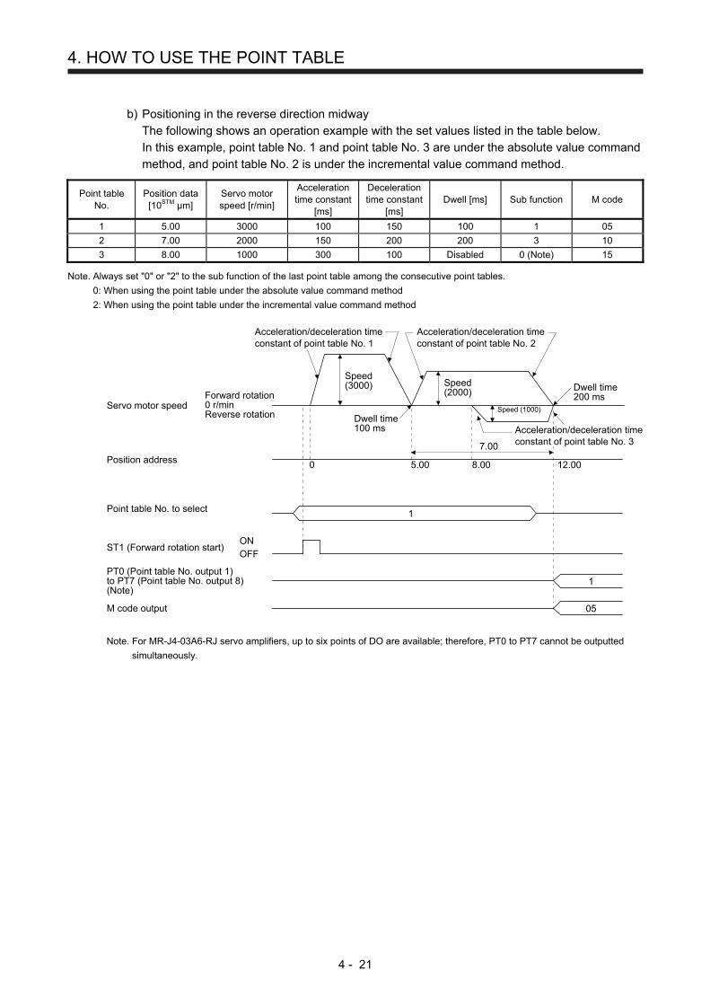
4. HOW TO USE THE POINT TABLE
4 - 21
b) Positioning in the reverse direction midway
The following shows an operation example with the set values listed in the table below.
In this example, point table No. 1 and point table No. 3 are under the absolute value command
method, and point table No. 2 is under the incremental value command method.
Point table No.
Position data [10STM μm]
Servo motor speed [r/min]
Acceleration time constant
[ms]
Deceleration time constant
[ms] Dwell [ms] Sub function M code
1 5.00 3000 100 150 100 1 05
2 7.00 2000 150 200 200 3 10
3 8.00 1000 300 100 Disabled 0 (Note) 15 Note. Always set "0" or "2" to the sub function of the last point table among the consecutive point tables.
0: When using the point table under the absolute value command method
2: When using the point table under the incremental value command method
Servo motor speedForward rotation0 r/minReverse rotation
Position address
Point table No. to select
ST1 (Forward rotation start)ONOFF
PT0 (Point table No. output 1)to PT7 (Point table No. output 8)(Note)
M code output
Dwell time100 ms
Speed(3000)
Acceleration/deceleration timeconstant of point table No. 1
Acceleration/deceleration timeconstant of point table No. 2
Speed(2000)
Speed (1000)
Dwell time200 ms
7.00
0 5.00 8.00 12.00
1
1
05
Acceleration/deceleration timeconstant of point table No. 3
Note. For MR-J4-03A6-RJ servo amplifiers, up to six points of DO are available; therefore, PT0 to PT7 cannot be outputted
simultaneously.

4. HOW TO USE THE POINT TABLE
4 - 22
c) Position data in degrees
The following shows an operation example with the set values listed in the table below.
In this example, point table No. 1, point table 2, and point table No. 4 are under the absolute
value command method, and point table No. 3 is under the incremental value command
method.
Point table No.
Position data [degree]
Servo motor speed [r/min]
Acceleration time constant
[ms]
Deceleration time constant
[ms] Dwell [ms] Sub function M code
1 120.000 1000 100 150 100 1 05 2 -320 .000 500 150 100 200 1 10 3 -230.000 3000 200 300 150 3 15 4 70.000 1500 300 100 Disabled 0 (Note) 20
Note. Always set "0" or "2" to the sub function of the last point table among the consecutive point tables.
0: When using the point table under the absolute value command method 2: When using the point table under the incremental value command method
Home position → Point table No. 1
120(-240)
40(-320)
230
Point table No. 2 → No. 3
170(-190)
70(-290)
170(-190)
Point table No. 3 → No. 4
120(-240)
40(-320)
Point table No. 1 → No. 20 0
00
Servo motor speedForward rotation0 r/minReverse rotation
Point table No. to select
ST1 (Forward rotation start)ONOFF
PT0 (Point table No. output 1)to PT7 (Point table No. output 8)(Note)
M code output
Point table No. 2
Point table No. 4
1
1
05
Point table No. 3
Point table No. 1
Note. For MR-J4-03A6-RJ servo amplifiers, up to six points of DO are available; therefore, PT0 to PT7 cannot be
outputted simultaneously.

4. HOW TO USE THE POINT TABLE
4 - 23
2) Incremental value command method ([Pr. PT01] = _ _ _ 1)
The position data of the incremental value command method is the sum of the position data of
consecutive point tables.
The following shows how to set.
Point table setting
Dwell Sub function
1 or more 1
a) Positioning in a single direction
The following shows an operation example with the set values listed in the table below.
Point table No.
Position data [10STM μm]
Servo motor speed [r/min]
Acceleration time constant
[ms]
Deceleration time constant
[ms] Dwell [ms] Sub function M code
1 5.00 3000 100 150 100 1 05
2 6.00 2000 150 200 200 1 10
3 3.00 1000 300 100 Disabled 0 (Note) 15 Note. Always set "0" to the sub function of the last point table among the consecutive point tables.
Servo motor speedForward rotation0 r/minReverse rotation
Position address
Point table No. to select
ST1 (Forward rotation start)(Note 1)
ONOFF
PT0 (Point table No. output 1)to PT7 (Point table No. output 8)(Note 2)
M code output
Speed(3000)
Acceleration/deceleration timeconstant of point table No. 1 Acceleration/deceleration time
constant of point table No. 2
Speed(2000) Speed
(1000)
Acceleration/deceleration timeconstant of point table No. 3
6.00
0 5.00 11.00 14.00
1
1
05
3.00
Note 1. Switching on ST2 (Reverse rotation start) starts positioning in the reverse rotation direction.
2. For MR-J4-03A6-RJ servo amplifiers, up to six points of DO are available; therefore, PT0 to PT7 cannot be outputted
simultaneously.

4. HOW TO USE THE POINT TABLE
4 - 24
b) Position data in degrees
The following shows an operation example with the set values listed in the table below.
Point table No.
Position data [degree]
Servo motor speed [r/min]
Acceleration time constant
[ms]
Deceleration time constant
[ms] Dwell [ms] Sub function M code
1 120 .000 3000 100 150 0 1 05
2 60.000 1500 150 100 0 1 10
3 90 .000 1000 300 100 Disabled 0 (Note) 15 Note. Always set "0" or "2" to the sub function of the last point table among the consecutive point tables.
0: When using the point table under the absolute value command method
2: When using the point table under the incremental value command method
120(-240)
0
9060
120
Point table No. 1
270(-90)
Point table No. 3
180(-180)
Point table No. 2
Servo motor speedForward rotation0 r/minReverse rotation
Point table No. to select
ST1 (Forward rotation start)
PT0 (Point table No. output 1)to PT7 (Point table No. output 8)(Note)
ONOFF
M code output
Point table No. 1
1
1
05
Point table No. 2Point table No. 3
Note. For MR-J4-03A6-RJ servo amplifiers, up to six points of DO are available; therefore, PT0 to PT7 cannot be outputted
simultaneously.

4. HOW TO USE THE POINT TABLE
4 - 25
(c) Varying-speed operation
By setting the sub function of the point table, the servo motor speed during positioning can be
changed. Point tables are used by the number of the set speed.
1) Absolute value command method ([Pr. PT01] = _ _ _ 0)
Set "1" or "3" to the sub function to execute the positioning at the speed set in the following point
table.
At this time, the position data selected at start is valid, and the acceleration/deceleration time
constant set in the next and subsequent point tables is invalid.
By setting "1" or "3" to sub functions until point table No. 254, the operation can be performed at
maximum 255 speeds.
Always set "0" or "2" to the sub function of the last point table.
To perform varying-speed operation, always set "0" to the dwell.
Setting "1" or more will enables the automatic continuous positioning operation.
The following table shows an example of setting.
Point table No.
Dwell [ms] (Note 1)
Sub function Varying-speed operation
1 0 1
Consecutive point table data2 0 3
3 Disabled 0 (Note 2)
4 0 3
Consecutive point table data5 0 1
6 Disabled 2 (Note 2)
Note 1. Always set "0".
2. Always set "0" or "2" to the sub function of the last point table among the
consecutive point tables.

4. HOW TO USE THE POINT TABLE
4 - 26
a) Positioning in a single direction
The following shows an operation example with the set values listed in the table below.
In this example, point table No. 1 and point table No. 3 are under the absolute value command
method, and point table No. 2 is under the incremental value command method.
Point table No.
Position data [10STM μm]
Servo motor speed [r/min]
Acceleration time constant
[ms]
Deceleration time constant
[ms]
Dwell [ms] (Note 1)
Sub function M code
1 5.00 3000 100 150 0 1 05
2 3.00 2000 Disabled Disabled 0 3 10
3 10.00 1000 Disabled Disabled 0 1 15
4 6.00 500 Disabled Disabled Disabled 2 (Note 2) 20 Note 1. Always set "0".
2. Always set "0" or "2" to the sub function of the last point table among the consecutive point tables.
0: When using the point table under the absolute value command method
2: When using the point table under the incremental value command method
Deceleration time constant(150) of point table No. 1
Servo motor speed
Position address
Point table No. to select
ST1 (Forward rotation start)ONOFF
0 5.00 8.00 16.00
Speed(3000) Speed
(2000)
(1000)
1
Forward rotation0 r/minReverse rotation
Acceleration time constant(100) of point table No. 1
3.00 6.00
10.00
Speed
Speed(500)
1PT0 (Point table No. output 1)to PT7 (Point table No. output 8)(Note)
05M code output
Note. For MR-J4-03A6-RJ servo amplifiers, up to six points of DO are available; therefore, PT0 to PT7 cannot be outputted
simultaneously.

4. HOW TO USE THE POINT TABLE
4 - 27
b) Positioning in the reverse direction midway
The following shows an operation example with the set values listed in the table below.
In this example, point table No. 1 and point table No. 3 are under the absolute value command
method, and point table No. 2 is under the incremental value command method.
Point table No.
Position data [10STM μm]
Servo motor speed [r/min]
Acceleration time constant
[ms]
Deceleration time constant
[ms]
Dwell [ms] (Note 1)
Sub function M code
1 5.00 3000 100 150 0 1 05
2 7.00 2000 Disabled Disabled 0 3 10
3 8.00 1000 Disabled Disabled Disabled 0 (Note 2) 15 Note 1. Always set "0".
2. Always set "0" or "2" to the sub function of the last point table among the consecutive point tables.
0: When using the point table under the absolute value command method
2: When using the point table under the incremental value command method
Servo motor speedForward rotation0 r/minReverse rotation
Position address
Point table No. to select
ST1 (Forward rotation start)ONOFF
PT0 (Point table No. output 1)to PT7 (Point table No. output 8)(Note)
M code output
Speed(3000)
Acceleration time constant(100) of point table No. 1
Deceleration time constant(150) of point table No. 1
Speed(2000)
Speed(1000)
7.00
0 5.00 8.00 12.00
1
1
05
Acceleration timeconstant (100) ofpoint table No. 1
Note. For MR-J4-03A6-RJ servo amplifiers, up to six points of DO are available; therefore, PT0 to PT7 cannot be outputted
simultaneously.

4. HOW TO USE THE POINT TABLE
4 - 28
2) Incremental value command method ([Pr. PT01] = _ _ _ 1)
Setting "1" to the sub function executes positioning at the speed set in the following point table.
At this time, the position data selected at start is valid, and the acceleration/deceleration time
constant set in the next and subsequent point tables is invalid.
By setting "1" to sub functions until point table No. 254, the operation can be performed at
maximum 255 speeds.
Always set "0" to the sub function of the last point table.
To perform varying-speed operation, always set "0" to the dwell.
Setting "1" or more will enables the automatic continuous positioning operation.
The following table shows an example of setting.
Point table No.
Dwell [ms] (Note 1)
Sub function Varying-speed operation
1 0 1
Consecutive point table data2 0 1
3 Disabled 0 (Note 2)
4 0 1
Consecutive point table data5 0 1
6 Disabled 0 (Note 2)
Note 1. Always set "0".
2. Always set "0" to the sub function of the last point table among the consecutive
point tables.
The following shows an operation example with the set values listed in the table below.
Point table No.
Position data [10STM μm]
Servo motor speed [r/min]
Acceleration time constant
[ms]
Deceleration time constant
[ms]
Dwell [ms] (Note 1)
Sub function M code
1 5.00 3000 100 150 0 1 05
2 3.00 2000 Disabled Disabled 0 1 10
3 2.00 1000 Disabled Disabled 0 1 15
4 6.00 500 Disabled Disabled Disabled 0 (Note 2) 20 Note 1. Always set "0".
2. Always set "0" to the sub function of the last point table among the consecutive point tables.
Servo motor speedForward rotation0 r/minReverse rotation
Position address
Point table No. to select
ST1 (Forward rotation start)ONOFF
PT0 (Point table No. output 1)to PT7 (Point table No. output 8)(Note)
M code output
Speed(3000)
Acceleration time constant(100) of point table No. 1
Deceleration time constant(150) of point table No. 1
Speed(2000)
Speed(1000)
6.00
0 5.00 8.00 10.00
1
1
05
Speed(500)
5.00 3.00 2.00
16.00
Note. For MR-J4-03A6-RJ servo amplifiers, up to six points of DO are available; therefore, PT0 to PT7 cannot be outputted
simultaneously.

4. HOW TO USE THE POINT TABLE
4 - 29
(d) Automatic repeat positioning operation
By setting the sub function of the point table, the operation pattern of the set point table No. can be
returned to, and the positioning operation can be performed repeatedly.
1) Absolute value command method ([Pr. PT01] = _ _ _ 0)
Setting "8" or "10" to the sub function performs automatic continuous operation or varying-speed
operation until that point table, and after the completion of positioning, performs the operation
again from the operation pattern of the point table No. used at start-up.
Setting "9" or "11" to the sub function performs automatic continuous operation or varying-speed
operation until that point table, and after the completion of positioning, performs the operation
again from the operation pattern of point table No. 1.
a) Automatic repeat positioning operation by absolute value command method
Example 1. Operations when "8" is set to the sub function of point table No. 4
Point table No.
Position data [10STM μm]
Servo motor speed [r/min]
Acceleration time constant
[ms]
Deceleration time constant
[ms] Dwell [ms] Sub function M code
1 4.00 1500 200 100 150 1 01
2 5.00 3000 100 150 100 1 05
3 5.00 2000 150 200 200 3 10
4 15.00 1000 300 100 150 8 15
Operation sequence
1) Starting with point table No. 2
2) Executing point table No. 3
3) Executing point table No. 4
4) Executing again point table No.2 used at start-up when "8" is set to the sub function of point
table No. 4
5) Repeating the above execution in the sequence of 2) to 3) to 4) to 2) to 3) to 4)
Servo motor speedForward rotation0 r/minReverse rotation
Position address
Point table No. to select
ST1 (Forward rotation start)ONOFF
PT0 (Point table No. output 1)to PT7 (Point table No. output 8)(Note)
M code output (Note)
Speed(3000)
Point table No. 2 Point table No. 3
Speed(2000) Speed (1000)
Point table No. 4
Point table No. 25.00
1) 2)
3)
4)
0 5.00 10.00 15.00
2
Speed(3000)
Note. PT0 to PT7 and M code are not outputted in automatic continuous operation.

4. HOW TO USE THE POINT TABLE
4 - 30
Example 2. Operations when "9" is set to the sub function of point table No. 3
Point table No.
Position data [10STM μm]
Servo motor speed [r/min]
Acceleration time constant
[ms]
Deceleration time constant
[ms] Dwell [ms] Sub function M code
1 0.00 3000 100 150 100 1 05
2 5.00 2000 150 200 200 1 10
3 15.00 1000 300 100 150 9 15
Operation sequence
1) Starting with point table No. 2
2) Executing point table No. 3
3) Executing point table No.1 when "9" is set to the sub function of point table No. 3
4) Repeating the above execution in the sequence of 1) to 2) to 3) to 1) to 2) to 3)
Servo motor speedForward rotation0 r/minReverse rotation
Position address
Point table No. to select
ST1 (Forward rotation start)ONOFF
PT0 (Point table No. output 1)to PT7 (Point table No. output 8)(Note)
M code output (Note)
Speed(2000)
Point table No. 2
Speed (1000)
Point table No. 3
Point table No. 15.00
1) 2)
3)
0 5.00 15.00
2
Speed(3000)
Note. PT0 to PT7 and M code are not outputted in automatic continuous operation.

4. HOW TO USE THE POINT TABLE
4 - 31
b) Automatic repeat positioning operation by incremental value command method
Example 1. Operations when "10" is set to the sub function of point table No. 4
Point table No.
Position data [10STM μm]
Servo motor speed [r/min]
Acceleration time constant
[ms]
Deceleration time constant
[ms] Dwell [ms] Sub function M code
1 4.00 1500 200 100 150 1 01
2 5.00 3000 100 150 100 3 05
3 10.00 2000 150 200 200 1 10
4 5.00 1000 300 100 150 10 15
Operation sequence
1) Starting with point table No. 2
2) Executing point table No. 3
3) Executing point table No. 4
4) Executing again point table No.2 used at start-up when "10" is set to the sub function of
point table No. 4
5) Repeating the above execution in the sequence of 1) to 2) to 3) to 4) to 2) to 3) to 4)
Servo motor speedForward rotation0 r/minReverse rotation
Position address
Point table No. to select
ST1 (Forward rotation start)ONOFF
PT0 (Point table No. output 1)to PT7 (Point table No. output 8)(Note)
M code output (Note)
Speed(3000)
Point table No. 2 Point table No. 3
Speed(2000) Speed (1000)
Point table No. 4
5.00
0 5.00
1)
2)
2)
3)4)
10.00 15.00
2
Speed(2000)
Speed(3000)
Point table No. 2
5.005.00
Point table No. 3
Note. PT0 to PT7 and M code are not outputted in automatic continuous operation.

4. HOW TO USE THE POINT TABLE
4 - 32
Example 2. Operations when "11" is set to the sub function of point table No. 3
Point table No.
Position data [10STM μm]
Servo motor speed [r/min]
Acceleration time constant
[ms]
Deceleration time constant
[ms] Dwell [ms] Sub function M code
1 5.00 3000 100 150 100 3 05
2 10.00 2000 150 200 200 1 10
3 5.00 1000 300 100 150 11 15
Operation sequence
1) Starting with point table No. 2
2) Executing point table No. 3
3) Executing point table No.1 when "11" is set to the sub function of point table No. 3
4) Repeating the above execution in the sequence of 1) to 2) to 3) to 1) to 2) to 3)
Servo motor speedForward rotation0 r/minReverse rotation
Position address
Point table No. to select
ST1 (Forward rotation start)ONOFF
PT0 (Point table No. output 1)to PT7 (Point table No. output 8)(Note)
M code output (Note)
Point table No. 2
Speed(2000) Speed (1000)
Point table No. 3
5.00
1)
1)
2)3)
0 10.00 15.00
2
Speed(2000)
Speed(3000)
Point table No. 1
5.00
Point table No. 2
Note. PT0 to PT7 and M code are not outputted in automatic continuous operation.

4. HOW TO USE THE POINT TABLE
4 - 33
c) Varying-speed operation by absolute value command method
Example. Operations when "8" is set to the sub function of point table No. 3
Point table No.
Position data [10STM μm]
Servo motor speed [r/min]
Acceleration time constant
[ms]
Deceleration time constant
[ms] Dwell [ms] Sub function M code
1 5.00 3000 100 150 0 1 05
2 5.00 2000 Disabled Disabled 0 3 10
3 15.00 1000 Disabled Disabled 0 8 15
Operation sequence
1) Starting with point table No. 1
2) Varying the speed and executing point table No. 2
3) Varying the speed and executing point table No. 3
4) Executing point table No.1 used at start-up in CW direction when "8" is set to the sub
function of point table No. 3
5) Repeating the above execution in the sequence of 1) to 2) to 3) to 4) to 2) to 3) to 4)
Servo motor speedForward rotation0 r/minReverse rotation
Position address
Point table No. to select
ST1 (Forward rotation start)ONOFF
PT0 (Point table No. output 1)to PT7 (Point table No. output 8)(Note)
M code output (Note)
Speed(3000)
Acceleration time constant(100) of point table No. 1
Deceleration time constant(150) of point table No. 1
Speed(2000) Speed (1000)
Acceleration timeconstant (100) ofpoint table No. 15.00
0 5.00 10.00
1)
2) 3)
4)
15.00
1
Speed(3000)
Point table No. 1
Point table No. 2
Point table No. 3
Deceleration time constant (150) of point table No. 1
Note. PT0 to PT7 and M code are not outputted in automatic continuous operation.

4. HOW TO USE THE POINT TABLE
4 - 34
d) Varying-speed operation by incremental value command method
Example. Operations when "10" is set to the sub function of point table No. 3
Point table No.
Position data [10STM μm]
Servo motor speed [r/min]
Acceleration time constant
[ms]
Deceleration time constant
[ms] Dwell [ms] Sub function M code
1 5.00 3000 100 150 0 3 05
2 10.00 2000 150 200 0 1 10
3 5.00 1000 300 100 0 10 15
Operation sequence
1) Starting with point table No. 1
2) Varying the speed and executing point table No. 2
3) Varying the speed and executing point table No. 3
4) Varying the speed, and executing point table No.1 when "10" is set to the sub function of
point table No. 3
5) Repeating the above execution in the sequence of 1) to 2) to 3) to 4) to 2) to 3) to 4)
Servo motor speedForward rotation0 r/minReverse rotation
Position address
Point table No. to select
ST1 (Forward rotation start)ONOFF
PT0 (Point table No. output 1)to PT7 (Point table No. output 8)(Note)
M code output (Note)
Speed(3000)
Acceleration time constant(100) of point table No. 1
Deceleration time constant(150) of point table No. 1
Speed(2000) Speed (1000)
5.00
0 5.00
1)2)
2)
3)4)
10.00 15.00
1
Speed(2000)
Speed(3000)
Acceleration timeconstant (100) ofpoint table No. 1
5.005.00
Deceleration timeconstant (150) ofpoint table No. 1
Point table No. 3
Point table No. 2
Point table No. 1
Point table No. 2
Point table No. 1
Note. PT0 to PT7 and M code are not outputted in automatic continuous operation.

4. HOW TO USE THE POINT TABLE
4 - 35
2) Incremental value command method ([Pr. PT01] = _ _ _ 1)
Setting "8" to the sub function performs automatic continuous operation or varying-speed
operation until that point table, and after the completion of positioning, performs the operation
again from the operation pattern of the set point table.
Setting "9" to the sub function performs automatic continuous operation or varying-speed
operation until that point table, and after the completion of positioning, performs the operation
again from the operation pattern of point table No. 1.
a) Automatic repeat positioning operation by incremental value command method
Example 1. Operations when "8" is set to the sub function of point table No. 3
Point table No.
Position data [10STM μm]
Servo motor speed [r/min]
Acceleration time constant
[ms]
Deceleration time constant
[ms] Dwell [ms] Sub function M code
1 4.00 1500 200 100 150 1 01
2 5.00 3000 100 150 100 1 05
3 6.00 2000 150 200 200 8 10
Operation sequence
1) Starting with point table No. 2
2) Executing point table No. 3
3) Executing again point table No.2 used at start-up when "8" is set to the sub function of point
table No. 3
4) Repeating the above execution in the sequence of 1) to 2) to 3) to 2) to 3)
Servo motor speedForward rotation0 r/minReverse rotation
Position address
Point table No. to select
ST1 (Forward rotation start) ONOFF
PT0 (Point table No. output 1)to PT7 (Point table No. output 8)(Note)
M code output (Note)
Speed(3000)
Point table No. 2
Speed(2000)
5.00
0 5.00 11.00
2
5.00
1)2) 2)
3)
6.00
16.00
Speed(3000) Speed
(2000)
Point table No. 3
Note. PT0 to PT7 and M code are not outputted in automatic continuous operation.

4. HOW TO USE THE POINT TABLE
4 - 36
Example 2. Operations when "9" is set to the sub function of point table No. 2
Point table No.
Position data [10STM μm]
Servo motor speed [r/min]
Acceleration time constant
[ms]
Deceleration time constant
[ms] Dwell [ms] Sub function M code
1 5.00 3000 100 150 100 1 05
2 6.00 2000 150 200 200 9 10
Operation sequence
1) Starting with point table No. 2
2) Executing point table No.1 when "9" is set to the sub function of point table No. 2
3) Repeating the above execution in the sequence of 1) to 2) to 1) to 2)
Servo motor speedForward rotation0 r/minReverse rotation
Position address
Point table No. to select
ST1 (Forward rotation start) ONOFF
PT0 (Point table No. output 1)to PT7 (Point table No. output 8)(Note)
M code output (Note)
Speed(3000)
Point table No. 1
Speed(2000)
6.00
0 6.00
1) 2) 2)1)
11.00
2
6.00 5.00
17.00
Point table No. 2
Speed(3000)Speed
(2000)
Note. PT0 to PT7 and M code are not outputted in automatic continuous operation.
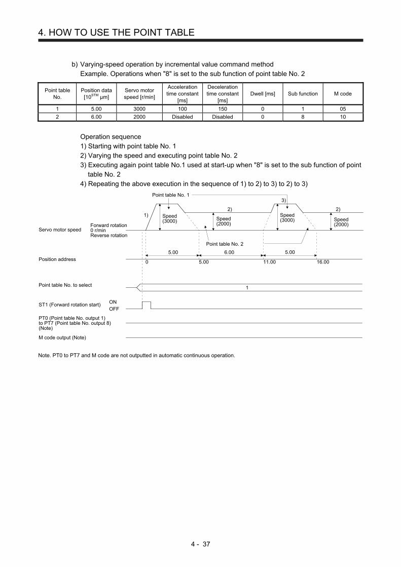
4. HOW TO USE THE POINT TABLE
4 - 37
b) Varying-speed operation by incremental value command method
Example. Operations when "8" is set to the sub function of point table No. 2
Point table No.
Position data [10STM μm]
Servo motor speed [r/min]
Acceleration time constant
[ms]
Deceleration time constant
[ms] Dwell [ms] Sub function M code
1 5.00 3000 100 150 0 1 05
2 6.00 2000 Disabled Disabled 0 8 10
Operation sequence
1) Starting with point table No. 1
2) Varying the speed and executing point table No. 2
3) Executing again point table No.1 used at start-up when "8" is set to the sub function of point
table No. 2
4) Repeating the above execution in the sequence of 1) to 2) to 3) to 2) to 3)
Servo motor speedForward rotation0 r/minReverse rotation
Position address
Point table No. to select
ST1 (Forward rotation start) ONOFF
PT0 (Point table No. output 1)to PT7 (Point table No. output 8)(Note)
M code output (Note)
Speed(3000)
Point table No. 1
Speed(2000)
5.00
0 5.00 11.00
1
5.00
1)2) 2)
3)
6.00
16.00
Speed(3000) Speed
(2000)
Point table No. 2
Note. PT0 to PT7 and M code are not outputted in automatic continuous operation.

4. HOW TO USE THE POINT TABLE
4 - 38
(e) Temporary stop/restart
When TSTP (Temporary stop/restart) is switched on during automatic operation, the servo motor
decelerates with the deceleration time constant of the point table being executed, and then stops
temporarily.
Switching on TSTP (Temporary stop/restart) again restarts the servo motor rotation for the remaining
distance.
During a temporary stop, ST1 (Forward rotation start) or ST2 (Reverse rotation start) does not
function even if it is switched on.
When automatic operation mode is changed to manual operation mode during a temporary stop, the
remaining travel distance is cleared at the time of servo-off or inputting the clear signal.
The temporary stop/restart input does not function during a home position return or JOG operation.
The temporary stop/restart input functions in the following states.
Operation status Automatic operation
Manual operation Home position
return
During a stop
During acceleration
Temporary stop
At a constant speed
Temporary stop
During deceleration
During a temporary stop
Restart
1) When the servo motor is rotating
ONOFF
ONOFF
ONOFF
Deceleration time constantof point table No. n
No. n
OFF
OFF
ON
ON
Acceleration time constantof point table No. n
Remainingdistance
OFFON
ST1 (Forward rotation start)or ST2 (Reverse rotation start)
Point table
TSTP (Temporary stop/restart)
PUS (Temporary stop)
CPO (Rough match)
INP (In-position)
MEND (Travel completion)
PT0 (Point table No. output 1)to PT7 (Point table No. output 8)(Note)
No. n
Forward rotation0 r/minReverse rotation
Servo motor speed
Note. For MR-J4-03A6-RJ servo amplifiers, up to six points of DO are available; therefore,
PT0 to PT7 cannot be outputted simultaneously.

4. HOW TO USE THE POINT TABLE
4 - 39
2) During dwell
ONOFF
ONOFF
ONOFF
OFF
OFF
ON
ON
OFFON
ST1 (Forward rotation start)or ST2 (Reverse rotation start)
Point table No.n+1Point table No. n
Dwell = ta + tb
ta tb
No. n
No. nPT0 (Point table No. output 1)to PT7 (Point table No. output 8)(Note)
MEND (Travel completion)
INP (In-position)
CPO (Rough match)
PUS (Temporary stop)
TSTP (Temporary stop/restart)
Point table
Forward rotation0 r/minReverse rotation
Servo motor speed
Note. For MR-J4-03A6-RJ servo amplifiers, up to six points of DO are available; therefore,
PT0 to PT7 cannot be outputted simultaneously.
(f) Suspension of automatic operation
Suspend the automatic operation or change the operation pattern in the following procedure.
For the suspension during positioning, bring the motor to a stop with TSTP (Temporary stop/restart),
then switch off MD0 (Operation mode selection 1) and set the operation to manual mode. At that
time, the remaining travel distance is cleared.
Remaining distance clear
Remaining distance
Point table No. n
No. n
Forward rotation0 r/minReverse rotation
Point table No.ONOFF
ST1 (Forward rotationstart) or ST2 (Reverserotation start)
ONOFFPUS (Temporary stop)
TSTP (Temporary stop/restart)
ONOFF
ONOFF
Servo motorspeed
MD0 (Operation modeselection 1)
(g) Handling of control unit "degree"
1) Current position/command position address
The current position/command position address is of ring-address type.
0 0 0
359.999 359.999

4. HOW TO USE THE POINT TABLE
4 - 40
2) Software limit activation/deactivation setting
POINT
After changing the "+" or "-" sign of an axis with the software limit activation
setting, perform a home position return.
When activating the software limit in an incremental system, perform a home
position return after power-on.
a) Setting range
When the unit is "degree", the setting range of the software limit is 0 degree (lower limit) to
359.999 degrees (upper limit).
When you set a value other than 0 degree to 359.999 degrees in [Pr. PT15] to [Pr. PT18], the
set value is converted as follows. (It will be clamped between 0 degree and 359.999 degrees.)
Software limit value After conversion
360.000 degrees to 999.999 degrees The remainder of the set value divided by
360
-0.001 degrees to -359.999 degrees The sum of the set value and 360
-360.000 degrees to -999.999 degrees The sum of 360 and the quotient of the set
value divided by 360
b) When the software limit is activated
Set the software limit - ([Pr. PT17] and [Pr. PT18]) for the start position and the software limit +
([Pr. PT15] and [Pr. PT16]) for the target position.
The movable range is the section from - to + in the CCW direction.
90
0
315
Section A
CCW
90
0
315CCW
Section B
Set the movable range of section A as follows.
Software limit - ··· 315.000 degrees
Software limit + ··· 90.000 degrees
Set the movable range of section B as follows.
Software limit - ··· 90.000 degrees
Software limit + ··· 315.000 degrees

4. HOW TO USE THE POINT TABLE
4 - 41
c) When the software limit is deactivated
When deactivating the software limit, set the same values to the software limit - ([Pr. PT17]
and [Pr. PT18]) and the software limit + ([Pr. PT15] and [Pr. PT16]).
Control can be performed independently of the software limit setting.
3) Position range output activation/deactivation setting
a) Setting range
When the unit is "degree", the setting range of the position range output is 0 degree (lower
limit) to 359.999 degrees (upper limit).
When you set a value other than 0 degree to 359.999 degrees in [Pr. PT19] to [Pr. PT22], the
set value is converted as follows. (It will be clamped between 0 degree and 359.999 degrees.)
Position range output address After conversion
360.000 degrees to 999.999 degrees The remainder of the set value divided by
360
-0.001 degrees to -359.999 degrees The sum of the set value and 360
-360.000 degrees to -999.999 degrees The sum of 360 and the quotient of the set
value divided by 360
b) Effective setting of position range output
Set the position range output address - ([Pr. PT21] and [Pr. PT22]) for the start position and
the position range output address + ([Pr. PT19] and [Pr. PT20]) for the target position.
The movable range is the section from - to + in the CCW direction.
90
0
315
Section A
CCW
90
0
315CCW
Section B
Set the movable range of section A as follows.
Position range output address - ··· 315.000 degrees
Position range output address + ··· 90.000 degrees
Set the movable range of section B as follows.
Position range output address - ··· 90.000 degrees
Position range output address + ··· 315.000 degrees

4. HOW TO USE THE POINT TABLE
4 - 42
4.3 Manual operation mode
For the machine adjustment, matching of home position, or the like, the JOG operation or the manual pulse
generator operation can be used for movement to an arbitrary position.
4.3.1 JOG operation
(1) Setting
According to the purpose of use, set input devices and parameters as shown below. In this case, DI0
(Point table No. selection 1) to DI7 (Point table No. selection 8) are invalid.
Item Used device/parameter Setting
Manual operation mode selection
MD0 (Operation mode selection 1) Switch off MD0.
Servo motor rotation direction [Pr. PA14] Refer to (2) of this section.
JOG speed [Pr. PT13] Set the servo motor speed.
Acceleration/deceleration time constant
Point table No. 1 Use the acceleration/deceleration time constant of point table No. 1.
(2) Servo motor rotation direction
[Pr. PA14] setting Servo motor rotation direction
ST1 (Forward rotation start) on ST2 (Reverse rotation start) on
0 CCW rotation CW rotation
1 CW rotation CCW rotation
Pr. PA14: 0 Pr. PA14: 1
CWST2: on
CWST1: on
ST2: onCCW
ST1: onCCW
(3) Operation
Switching on ST1 (Forward rotation start) performs the operation at the JOG speed set by a parameter
and the acceleration/deceleration constant of point table No. 1. For the rotation direction, refer to (2) of
this section. Switching on ST2 (Reverse rotation start) starts the rotation in the reverse direction of ST1
(Forward rotation start).
Simultaneously switching on or off ST1 (Forward rotation start) and ST2 (Reverse rotation start) stops
the operation.

4. HOW TO USE THE POINT TABLE
4 - 43
(4) Timing chart
ONOFF
RD (Ready)ONOFF
ALM (Malfunction)ONOFF
MEND (Travel completion)
CPO (Rough match)
ONOFF
ONOFF
SON (Servo-on)
Servo motorspeed
ONOFF
Forward rotation0 r/minReverse rotation
ONOFF
ONOFF
80 ms
Forward rotation JOG
Reverse rotation JOG
ST1 (Forward rotation start)
ST2 (Reverse rotation start)
MD0(Operation mode selection 1)

4. HOW TO USE THE POINT TABLE
4 - 44
4.3.2 Manual pulse generator operation
(1) Setting
POINT
To enhance noise immunity, set "_ 2 _ _" to [Pr. PA13] when the command
pulse frequency is 500 kpulse/s or less, or set "_3_ _" to [Pr. PA13] when the
command pulse frequency is 200 kpulse/s or less.
According to the purpose of use, set input devices and parameters as shown below. In this case, DI0
(Point table No. selection 1) to DI7 (Point table No. selection 8) are invalid.
Item Device/parameter to be used Setting
Manual operation mode selection
MD0 (Operation mode selection 1) Switch off MD0.
Manual pulse generator multiplication
[Pr. PT03] Set the multiplication factor for the pulses generated from the manual pulse generator. For details, refer to (3) of this section.
Servo motor rotation direction [Pr. PA14] Refer to (2) of this section.
Command input pulse train input form
[Pr. PA13] Set "_ _ _ 2" (A/B-phase pulse train).
Pulse train filter selection [Pr. PA13] Set other than "_ 0 _ _" and "_ 1 _ _".
(2) Servo motor rotation direction
[Pr. PA14] setting
Servo motor rotation direction
Manual pulse generator operation: forward rotation
Manual pulse generator operation: reverse rotation
0 CCW rotation CW rotation
1 CW rotation CCW rotation
CW
CCW
Forward rotation

4. HOW TO USE THE POINT TABLE
4 - 45
(3) Manual pulse generator multiplication
(a) Using the input signals (devices) for setting
In "Device setting" of MR Configurator2, set TP0 (Pulse generator multiplication 1) and TP1 (Pulse
generator multiplication 2) to input signals.
TP1 (Pulse generator multiplication 2)
(Note)
TP0 (Pulse generator multiplication 1)
(Note)
Servo motor rotation multiplication to manual pulse generator rotation
amount
Travel distance
[mm] [inch] [degree] [pulse]
0 0 [Pr. PT03] setting valid
0 1 1 time 0.001 0.0001 0.001 1
1 0 10 times 0.01 0.001 0.01 10
1 1 100 times 0.1 0.01 0.1 100 Note. 0: Off
1: On
(b) Using the parameter for setting
Use [Pr. PT03] to set the servo motor rotation multiplication to the rotation amount of the manual
pulse generator.
[Pr. PT03] setting Servo motor rotation multiplication to manual pulse
generator rotation amount
Travel distance
[mm] [inch] [degree] [pulse]
_ _ 0 _ 1 time 0.001 0.0001 0.001 1
_ _ 1 _ 10 times 0.01 0.001 0.01 10
_ _ 2 _ 100 times 0.1 0.01 0.1 100
(4) Operation
Turning the manual pulse generator starts the servo motor rotation. For the rotation direction of the
servo motor, refer to (2) of this section. When you turn the manual pulse generator during a JOG
operation, the commands inputted from the manual pulse generator are adjusted by the commands of
JOG operation.
4. HOW TO USE THE POINT TABLE
4 - 46
4.4 Home position return mode
Point
Before performing the home position return, make sure that the limit switch
operates.
Check the home position return direction. An incorrect setting will cause a
reverse running.
Check the input polarity of the proximity dog. Otherwise, it may cause an
unexpected operation.
In the following cases, make sure that the Z-phase has been passed through
once before performing a home position return.
When an incremental linear encoder is used in the linear servo motor control
mode
When an incremental external encoder is used in the fully closed loop control
mode
When a servo amplifier is used in the DD motor control mode
Z-phase unpassed will trigger [AL. 90.5 Home position return incomplete
warning].
For servo amplifiers with software version B6 or earlier, the dog type last Z-
phase reference home position return and the dogless Z-phase reference home
position return cannot be used in the following operation modes.
Fully closed loop control mode using a incremental linear encoder
Linear servo motor control mode using a incremental linear encoder
Direct drive motor control mode
Setting [Pr. PT04 Home position return type] to "_ _ _ 8" or "_ _ _ A" will trigger
[AL. 37 Parameter error].
4.4.1 Outline of home position return
A home position return is performed to match the command coordinates with the machine coordinates.
Under the incremental method, every time switching on the input power supply, you have to perform the
home position return. Contrastingly, in the absolute position detection system, once you have performed the
home position return at machine installation, the current position will be retained even if the power supply is
shut off. Thereafter, the home position return is unnecessary when the power supply is switched on.
This section shows the home position return methods of the servo amplifier. Select the optimum method
according to the configuration and uses of the machine.
This servo amplifier has a home position return automatic retract function. When the machine stops on or
beyond the proximity dog, this function automatically backs the machine to the proper position and then
performs the home position return. Manually moving the machine by the JOG operation or others is
unnecessary.

4. HOW TO USE THE POINT TABLE
4 - 47
(1) Home position return types
Select the optimum home position return type according to the machine type or others.
Type Home position return method Feature
Dog type
Deceleration starts at the proximity dog front end. After the rear end is passed, the position specified by the first Z-phase signal, or the position of the first Z-phase signal shifted by the home position shift distance is used as the home position.
General home position return method using a proximity dog The repeatability of the home position return is high. The machine is less loaded. Used when the width of the proximity dog can be set equal to or greater than the deceleration distance of the servo motor.
Count type
Deceleration starts at the proximity dog front end. After the proximity dog is passed, the motor travels the specified travel distance. Then, the position specified by the first Z-phase signal, or the position of the first Z-phase signal shifted by the home position shift distance is used as the home position.
Home position return method using a proximity dog Used to minimize the length of the proximity dog.
Data set type An arbitrary position is used as the home position.
No proximity dog is required.
Stopper type A workpiece is pressed against a mechanical stopper, and the position where it is stopped is set as the home position.
The home position return speed must be low enough because of the collision with the mechanical stopper. The strength of the machine and its stopper must be increased.
Home position ignorance (servo-on position as home position)
The position where the servo is switched on is used as the home position.
Dog type rear end reference
Deceleration starts at the proximity dog front end. After the rear end is passed, the position is shifted by the travel distance after proximity dog and the home position shift distance. The position after the shifts is set as the home position.
The Z-phase signal is not required.
Count type front end reference
Deceleration starts at the proximity dog front end. The position is shifted by the travel distance after proximity dog and the home position shift distance. The position after the shifts is set as the home position.
The Z-phase signal is not required.
Dog cradle type After the proximity dog front end is detected, the position specified by the first Z-phase signal is used as the home position.
Dog type last Z-phase reference
After the proximity dog front end is detected, the position is shifted away from the proximity dog in the reverse direction. Then, the position specified by the first Z-phase signal, or the position of the first Z-phase signal shifted by the home position shift distance is used as the home position.
Dog type front end reference
From the proximity dog front end, the position is shifted by the travel distance after proximity dog and the home position shift distance. The position after the shifts is set as the home position.
The Z-phase signal is not required.
Dogless Z-phase reference
The position specified by the first Z-phase signal, or the position of the first Z-phase signal shifted by the home position shift distance is used as the home position.

4. HOW TO USE THE POINT TABLE
4 - 48
(2) Parameters for home position return
To perform the home position return, set each parameter as follows.
(a) Select the home position return type with [Pr. PT04 Home position return type].
Home position return type0: Dog type (rear end detection, Z-phase reference)1: Count type (front end detection, Z-phase reference)2: Data set type3: Stopper type4: Home position ignorance (servo-on position as home position)5: Dog type (rear end detection, rear end reference)6: Count type (front end detection, front end reference)7: Dog cradle type8: Dog type (front end detection, Z-phase reference)9: Dog type (front end detection, front end reference)A: Dogless type (Z-phase reference)
0
[Pr. PT04]
0 0
(b) Select the starting direction for the home position return with [Pr. PT04 Home position return type].
Setting "0" starts the home position return in the address increase direction from the current position.
Setting "1" starts the home position return in the address decrease direction from the current
position.
Home position return direction0: Address increasing direction1: Address decreasing direction
0
[Pr. PT04]
0 0
(c) Select the polarity where the proximity dog is detected with the DOG (Proximity dog) polarity
selection of [Pr. PT29 Function selection T-3]. Setting "0" detects the dog when DOG (Proximity dog)
is off. Setting "1" detects the dog when DOG (Proximity dog) is on.
0 00
[Pr. PT29]
DOG (Proximity dog) polarity selection0: Detection with off1: Detection with on

4. HOW TO USE THE POINT TABLE
4 - 49
4.4.2 Dog type home position return
This home position return type uses a proximity dog. Deceleration starts at the proximity dog front end. After
the rear end is passed, the position specified by the first Z-phase signal, or the position of the first Z-phase
signal shifted by the specified home position shift distance is used as the home position.
(1) Device/parameter
Set input devices and parameters as follows.
Item Used device/parameter Setting
Home position return mode selection
MD0 (Operation mode selection 1) Switch on MD0.
DI0 (Point table No. selection 1) to DI7 (Point table No. selection 8)
Switch off DI0 to DI7.
Dog type home position return
[Pr. PT04] _ _ _ 0: Select the dog type.
Home position return direction
[Pr. PT04] Refer to section 4.4.1 (2) to select the home position return direction.
Dog input polarity [Pr. PT29] Refer to section 4.4.1 (2) to select the proximity dog input polarity.
Home position return speed [Pr. PT05] Set the rotation speed until the dog is detected.
Creep speed [Pr. PT06] Set the rotation speed after the dog is detected.
Home position shift distance [Pr. PT07] Set this item to shift the home position specified by the first Z-phase signal after passage of proximity dog rear end.
Home position return acceleration/deceleration time constant
Point table No. 1 Use the acceleration/deceleration time constant of point table No. 1.
Home position return position data
[Pr. PT08] Set the current position at the home position return completion.
(2) Proximity dog length
To generate the Z-phase signal of the servo motor during the DOG (Proximity dog) detection, the
proximity dog length should satisfy formulas (4.1) and (4.2).
L1 ≥ V60 •
td2 ················································································································ (4.1)
L1: Proximity dog length [mm]
V: Home position return speed [mm/min]
td: Deceleration time [s]
L2 ≥ 2 • ∆S ··················································································································· (4.2)
L2: Proximity dog length [mm]
∆S: Travel distance per servo motor revolution [mm] (Note)
Note. For linear servo motor: travel distance per stop interval selection at the home position return of [Pr. PL01]

4. HOW TO USE THE POINT TABLE
4 - 50
(3) Timing chart
ONOFF
MEND (Travel completion)ONOFF
CPO (Rough match)ONOFF
Servo motor speed
MD0(Operation mode selection 1)
Forward rotation0 r/minReverse rotation
ONOFF
ONOFF
Z-phase
DOG (Proximity dog)
ZP(Home position return completion)
ONOFF
ONOFF
ONOFF
ST1 (Forward rotation start)
ST2 (Reverse rotation start)
3 ms or shorter
Home position return speedDeceleration time constant
Creep speed Home position
Home position returnposition data
td
Proximity dog
5 ms or longer
Acceleration timeconstant
Home position shift distance
The setting value of [Pr. PT08 Home position return position data] is used as the position address at the
home position return completion.
(4) Adjustment
For the dog type home position return, adjust the setting to ensure the Z-phase signal generation during
the dog detection. Locate the DOG (Proximity dog) rear end almost at the center between the generation
positions of two consecutive Z-phase signals.
The generation position of the Z-phase signal can be checked with "Position within one-revolution" of
"Status Display" on MR Configurator2.
OFF
0 Resolution/2 0
Servo motor Z-phase
DOG (Proximity dog) ON
Proximitydog

4. HOW TO USE THE POINT TABLE
4 - 51
4.4.3 Count type home position return
In the count type home position return, after the proximity dog front end is detected, the motor travels the
distance set with [Pr. PT09 Travel distance after proximity dog]. Then, the position specified by the first Z-
phase signal is used as the home position. Therefore, when DOG (Proximity dog) is on for 10 ms or longer,
the proximity dog length has no restrictions. When the required proximity dog length for using the dog type
home position return cannot be reserved, or when DOG (Proximity dog) is entered electrically from the
controller or the like, use the count type home position return.
(1) Device/parameter
Set input devices and parameters as follows.
Item Used device/parameter Setting
Home position return mode selection
MD0 (Operation mode selection 1) Switch on MD0.
DI0 (Point table No. selection 1) to DI7 (Point table No. selection 8)
Switch off DI0 to DI7.
Count type home position return
[Pr. PT04] _ _ _ 0: Select the count type.
Home position return direction
[Pr. PT04] Refer to section 4.4.1 (2) to select the home position return direction.
Dog input polarity [Pr. PT29] Refer to section 4.4.1 (2) to select the dog input polarity.
Home position return speed [Pr. PT05] Set the rotation speed until the dog is detected.
Creep speed [Pr. PT06] Set the rotation speed after the dog is detected.
Home position shift distance [Pr. PT07]
Set this item to shift the home position starting at the first Z-phase signal after passage of proximity dog front end and motion over the specified travel distance.
Travel distance after proximity dog
[Pr. PT09] Set the travel distance after passage of proximity dog front end.
Home position return acceleration/deceleration time constant
Point table No. 1 Use the acceleration/deceleration time constant of point table No. 1.
Home position return position data
[Pr. PT08] Set the current position at the home position return completion.

4. HOW TO USE THE POINT TABLE
4 - 52
(2) Timing chart
ONOFF
MEND (Travel completion)ONOFF
CPO (Rough match)ONOFF
Servo motor speed
MD0 (Operation mode selection 1)
Forward rotation0 r/minReverse rotation
ONOFF
ONOFF
Z-phase
DOG (Proximity dog)
ZP(Home position return completion)
ONOFF
ONOFF
ONOFF
ST1 (Forward rotation start)
ST2 (Reverse rotation start)
3 ms or shorter
Home position return speedDeceleration time constant
Creep speed
Home positionshift distance
Home position
Home position return position dataProximity dog
5 ms or longer
Acceleration time constant
Travel distance afterproximity dog
The setting value of [Pr. PT08 Home position return position data] is used as the position address at the
home position return completion.

4. HOW TO USE THE POINT TABLE
4 - 53
4.4.4 Data set type home position return
To set an arbitrary position as the home position, use the data set type home position return. The JOG
operation, manual pulse generator operation, or the like can be used for movement. You can perform the
data set type home position return at servo-on only.
(1) Device/parameter
Set input devices and parameters as follows.
Item Used device/parameter Setting
Home position return mode selection
MD0 (Operation mode selection 1) Switch on MD0.
DI0 (Point table No. selection 1) to DI7 (Point table No. selection 8)
Switch off DI0 to DI7.
Data set type home position return
[Pr. PT04] _ _ _ 2: Select the data set type.
Home position return position data
[Pr. PT08] Set the current position at the home position return completion.
(2) Timing chart
SON (Servo-on)ONOFF
ZP(Home position return completion)
ONOFF
Forward rotation0 r/minReverse rotation
ONOFF
Servo motor speed
ST1 (Forward rotation start)
MD0 (Operation mode selection 1)ONOFF
ONOFF
ST2 (Reverse rotation start)
3 ms or shorter
Home position returnposition data
5 ms or longer
MEND (Travel completion)ONOFF
CPO (Rough match) ONOFF
Travel to home position Execution of data set type home position return
The setting value of [Pr. PT08 Home position return position data] is used as the position address at the
home position return completion.

4. HOW TO USE THE POINT TABLE
4 - 54
4.4.5 Stopper type home position return
For the stopper type home position return, by using the JOG operation, manual pulse generator operation, or
others, a workpiece is pressed against a mechanical stopper, and the position where it is stopped is used as
the home position.
(1) Device/parameter
Set input devices and parameters as follows.
Item Used device/parameter Setting
Home position return mode selection
MD0 (Operation mode selection 1) Switch on MD0.
DI0 (Point table No. selection 1) to DI7 (Point table No. selection 8)
Switch off DI0 to DI7.
Stopper type home position return
[Pr. PT04] _ _ _ 3: Select the stopper type.
Home position return direction
[Pr. PT04] Refer to section 4.4.1 (2) to select the home position return direction.
Home position return speed [Pr. PT05] Set the rotation speed until the workpiece is pressed against the mechanical stopper.
Stopper time [Pr. PT10]
Set the time from when the home position data is obtained after the workpiece is pressed against the mechanical stopper until when ZP (home position return completion) is output.
Stopper type home position return torque limit value
[Pr. PT11] Set the servo motor torque limit value at the execution of the stopper type home position return.
Home position return acceleration time constant
Point table No. 1 The acceleration/deceleration time constant of point table No. 1 is used.
Home position return position data
[Pr. PT08] Set the current position at the home position return completion.

4. HOW TO USE THE POINT TABLE
4 - 55
(2) Timing chart
ONOFF
MEND (Travel completion)ONOFF
CPO (Rough match)ONOFF
ST2 (Reverse rotation start)
MD0(Operation mode selection 1)
ONOFF
ONOFFTLC (Limiting torque)
Torque limit value
ZP(Home position return completion)
ONOFF
Servo motor speedForward rotation0 r/minReverse rotation
ST1 (Forward rotation start)ONOFF
Acceleration timeconstant Home position return speed Home position return
position data
3 ms or shorter
5 ms or longer
Stopper time
[Pr. PC35] [Pr. PT11] (Note 1) [Pr. PC35]
(Note 2)
Stopper
Note 1. The following torque limits are enabled.
Input device (0: Off, 1: On)
Limit value status Enabled torque limit
value TL1 TL
0 0 Pr. PT11
0 1 TLA > Pr. PT11 Pr. PT11
TLA < Pr. PT11 TLA
1 0 Pr. PC35 > Pr. PT11 Pr. PT11
Pr. PC35 < Pr. PT11 Pr. PC35
1 1 TLA > Pr. PT11 Pr. PT11
TLA < Pr. PT11 TLA
2. TLC turns on when a generated torque reaches a value set with any of [Pr. PA11 Forward rotation torque limit], [Pr. PA12
Reverse rotation torque limit], or [Pr. PC35 Internal torque limit 2].
The setting value of [Pr. PT08 Home position return position data] is used as the position address at the
home position return completion.
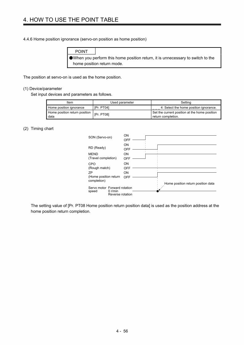
4. HOW TO USE THE POINT TABLE
4 - 56
4.4.6 Home position ignorance (servo-on position as home position)
POINT
When you perform this home position return, it is unnecessary to switch to the
home position return mode.
The position at servo-on is used as the home position.
(1) Device/parameter
Set input devices and parameters as follows.
Item Used parameter Setting
Home position ignorance [Pr. PT04] _ _ _ 4: Select the home position ignorance.
Home position return position data
[Pr. PT08] Set the current position at the home position return completion.
(2) Timing chart
ONOFF
RD (Ready)ONOFF
MEND(Travel completion)
ONOFF
CPO(Rough match)
ZP(Home position returncompletion)
ONOFF
Forward rotation0 r/minReverse rotation
SON (Servo-on)
Servo motorspeed
Home position return position data
ONOFF
The setting value of [Pr. PT08 Home position return position data] is used as the position address at the
home position return completion.

4. HOW TO USE THE POINT TABLE
4 - 57
4.4.7 Dog type rear end reference home position return
POINT
This home position return method depends on the timing of reading DOG
(Proximity dog) that has detected the rear end of a proximity dog. Therefore,
when a home position return is performed at a creep speed of 100 r/min, the
home position has an error of 6400 pulses (for HG series servo motor). The
higher the creep speed, the greater the error of the home position.
Deceleration starts at the front end of a proximity dog. After the rear end is passed, the position is shifted by
the travel distance after proximity dog and the home position shift distance. The position after the shifts is
used as the home position. The home position return is available independently of the Z-phase signal.
Changing the creep speed may change the home position.
(1) Device/parameter
Set input devices and parameters as follows.
Item Used device/parameter Setting
Home position return mode selection
MD0 (Operation mode selection 1) Switch on MD0.
DI0 (Point table No. selection 1) to DI7 (Point table No. selection 8)
Switch off DI0 to DI7.
Dog type rear end reference home position return
[Pr. PT04] _ _ _ 5: Select the dog type (rear end detection/rear end reference).
Home position return direction
[Pr. PT04] Refer to section 4.4.1 (2) to select the home position return direction.
Dog input polarity [Pr. PT29] Refer to section 4.4.1 (2) to select the dog input polarity.
Home position return speed [Pr. PT05] Set the rotation speed until the dog is detected.
Creep speed [Pr. PT06] Set the rotation speed after the dog is detected.
Home position shift distance [Pr. PT07] Set this item to shift the home position, which is specified after the rear end of a proximity dog is passed.
Travel distance after proximity dog
[Pr. PT09] Set the travel distance specified after the rear end of a proximity dog is passed.
Home position return acceleration/deceleration time constant
Point table No. 1 Use the acceleration/deceleration time constant of point table No. 1.
Home position return position data
[Pr. PT08] Set the current position at the home position return completion.

4. HOW TO USE THE POINT TABLE
4 - 58
(2) Timing chart
ONOFF
MEND (Travel completion)ONOFF
CPO (Rough match)ONOFF
Servo motor speed
MD0(Operation mode selection 1)
Forward rotation0 r/minReverse rotation
ONOFF
DOG (Proximity dog)
ZP(Home position return completion)
ONOFF
ONOFF
ONOFF
ST1 (Forward rotation start)
ST2 (Reverse rotation start)
3 ms or shorter
Home position return speedDeceleration time constant
Creep speed
Travel distance afterproximity dog
+Home positionshift distance
Home position returnposition dataProximity dog
5 ms or longer
Acceleration timeconstant
The setting value of [Pr. PT08 Home position return position data] is used as the position address at the
home position return completion.

4. HOW TO USE THE POINT TABLE
4 - 59
4.4.8 Count type front end reference home position return
POINT
This home position return method depends on the timing of reading DOG
(Proximity dog) that has detected the front end of a proximity dog. Therefore,
when a home position return is performed with the creep speed of 100 r/min, the
home position has an error of 6400 pulses (for HG series servo motor). The
higher the creep speed, the greater the error of the home position.
After the front end of a proximity dog is detected, when a home position return
ends without reaching the creep speed, [AL. 90] occurs. Set the travel distance
after proximity dog and the home position shift distance enough for deceleration
from the home position return speed to the creep speed.
Deceleration starts at the front end of a proximity dog. The position is shifted by the travel distance after
proximity dog and the home position shift distance. The position after the shifts is used as the home position.
The home position return is available independently of the Z-phase signal. Changing the creep speed may
change the home position.
(1) Device/parameter
Set input devices and parameters as follows.
Item Used device/parameter Setting
Home position return mode selection
MD0 (Operation mode selection 1) Switch on MD0.
DI0 (Point table No. selection 1) to DI7 (Point table No. selection 8)
Switch off DI0 to DI7.
Count type front end reference home position return
[Pr. PT04] _ _ _ 6: Select the count type (front end detection/front end reference).
Home position return direction
[Pr. PT04] Refer to section 4.4.1 (2) to select the home position return direction.
Dog input polarity [Pr. PT29] Refer to section 4.4.1 (2) to select the dog input polarity.
Home position return speed [Pr. PT05] Set the rotation speed until the dog is detected.
Creep speed [Pr. PT06] Set the rotation speed after the dog is detected.
Home position shift distance [Pr. PT07] Set this to shift the home position, which is specified after the front end of a proximity dog is passed.
Travel distance after proximity dog
[Pr. PT09] Set the travel distance specified after the front end of the proximity dog is passed.
Home position return acceleration/deceleration time constant
Point table No. 1 Use the acceleration/deceleration time constant of point table No. 1.
Home position return position data
[Pr. PT08] Set the current position at the home position return completion.

4. HOW TO USE THE POINT TABLE
4 - 60
(2) Timing chart
ONOFF
MEND (Travel completion)ONOFF
CPO (Rough match)ONOFF
Servo motor speed
MD0(Operation mode selection 1)
Forward rotation0 r/minReverse rotation
ONOFF
DOG (Proximity dog)
ZP(Home position return completion)
ONOFF
ONOFF
ONOFF
ST1 (Forward rotation start)
ST2 (Reverse rotation start)
3 ms or shorter
Home position return speedDeceleration time constant
Creep speed
Travel distance afterproximity dog
+Home positionshift distance
Home position returnposition dataProximity dog
5 ms or longer
Acceleration timeconstant
The setting value of [Pr. PT08 Home position return position data] is used as the position address at the
home position return completion.
4.4.9 Dog cradle type home position return
You can use the position, which is specified by the first Z-phase signal after the front end of a proximity dog
is detected, as the home position.
(1) Device/parameter
Set input devices and parameters as follows.
Item Used device/parameter Setting
Home position return mode selection
MD0 (Operation mode selection 1) Switch on MD0.
DI0 (Point table No. selection 1) to DI7 (Point table No. selection 8)
Switch off DI0 to DI7.
Dog cradle type home position return
[Pr. PT04] _ _ _ 7: Select the dog cradle type.
Home position return direction
[Pr. PT04] Refer to section 4.4.1 (2) to select the home position return direction.
Dog input polarity [Pr. PT29] Refer to section 4.4.1 (2) to select the dog input polarity.
Home position return speed [Pr. PT05] Set the rotation speed until the dog is detected.
Creep speed [Pr. PT06] Set the rotation speed after the dog is detected.
Home position shift distance [Pr. PT07] Set this item to shift the home position, which is specified by the Z-phase signal.
Home position return acceleration/deceleration time constant
Point table No. 1 Use the acceleration/deceleration time constant of point table No. 1.
Home position return position data
[Pr. PT08] Set the current position at the home position return completion.

4. HOW TO USE THE POINT TABLE
4 - 61
(2) Timing chart
ONOFF
MEND (Travel completion)ONOFF
CPO (Rough match)ONOFF
Servo motor speed
MD0(Operation mode selection 1)
Forward rotation0 r/minReverse rotation
ONOFF
DOG (Proximity dog)
ZP(Home position return completion)
ONOFF
ONOFF
ONOFF
ST1 (Forward rotation start)
ST2 (Reverse rotation start)
3 ms or shorter
Home position return speedDeceleration time constant
Creep speed
Home positionshift distance
Home position returnposition data
5 ms or longer
Acceleration timeconstant
Proximity dog
ONOFF
Z-phase
The setting value of [Pr. PT08 Home position return position data] is used as the position address at the
home position return completion.

4. HOW TO USE THE POINT TABLE
4 - 62
4.4.10 Dog type last Z-phase reference home position return
After the front end of a proximity dog is detected, the position is shifted away from the proximity dog at the
creep speed in the reverse direction and then specified by the first Z-phase signal. The position of the first Z-
phase signal is used as the home position.
(1) Device/parameter
Set input devices and parameters as follows.
Item Used device/parameter Setting
Home position return mode selection
MD0 (Operation mode selection 1) Switch on MD0.
DI0 (Point table No. selection 1) to DI7 (Point table No. selection 8)
Switch off DI0 to DI7.
Dog type last Z-phase reference home position return
[Pr. PT04] _ _ _ 8: Select the dog type last Z-phase reference.
Home position return direction
[Pr. PT04] Refer to section 4.4.1 (2) to select the home position return direction.
Dog input polarity [Pr. PT29] Refer to section 4.4.1 (2) to select the dog input polarity.
Home position return speed [Pr. PT05] Set the rotation speed until the dog is detected.
Creep speed [Pr. PT06] Set the rotation speed after the dog is detected.
Home position shift distance [Pr. PT07] Set this item to shift the home position, which is specified by the Z-phase signal.
Home position return acceleration/deceleration time constant
Point table No. 1 Use the acceleration/deceleration time constant of point table No. 1.
Home position return position data
[Pr. PT08] Set the current position at the home position return completion.

4. HOW TO USE THE POINT TABLE
4 - 63
(2) Timing chart
ONOFF
MEND (Travel completion) ONOFF
CPO (Rough match)ONOFF
Servo motor speed
MD0(Operation mode selection 1)
Forward rotation0 r/minReverse rotation
ONOFFDOG (Proximity dog)
ZP(Home position return completion)
ONOFF
ONOFF
ONOFF
ST1 (Forward rotation start)
ST2 (Reverse rotation start)
3 ms or shorter
Home position return speedDeceleration time constant
Home position shift distance
Home position return position data
5 ms or longer
Acceleration timeconstant
ONOFFZ-phase
Proximity dogCreep speed
The setting value of [Pr. PT08 Home position return position data] is used as the position address at the
home position return completion.

4. HOW TO USE THE POINT TABLE
4 - 64
4.4.11 Dog type front end reference home position return type
POINT
This home position return method depends on the timing of reading DOG
(Proximity dog) that has detected the front end of a proximity dog. Therefore,
when a home position return is performed at a creep speed of 100 r/min, the
home position has an error of 6400 pulses (for HG series servo motor). The
higher the creep speed, the greater the error of the home position.
Starting from the front end of a proximity dog, the position is shifted by the travel distance after proximity dog
and the home position shift distance. The position after the shifts is used as the home position.
The home position return is available independently of the Z-phase signal. Changing the creep speed may
change the home position.
(1) Device/parameter
Set input devices and parameters as follows.
Item Used device/parameter Setting
Home position return mode selection
MD0 (Operation mode selection 1) Switch on MD0.
DI0 (Point table No. selection 1) to DI7 (Point table No. selection 8)
Switch off DI0 to DI7.
Dog type front end reference home position return
[Pr. PT04] _ _ _ 9: Select the dog type front end reference.
Home position return direction
[Pr. PT04] Refer to section 4.4.1 (2) to select the home position return direction.
Dog input polarity [Pr. PT29] Refer to section 4.4.1 (2) to select the dog input polarity.
Home position return speed [Pr. PT05] Set the rotation speed until the dog is detected.
Creep speed [Pr. PT06] Set the rotation speed after the dog is detected.
Home position shift distance [Pr. PT07] Set this item to shift the home position, which is specified by the Z-phase signal.
Home position return acceleration/deceleration time constant
Point table No. 1 Use the acceleration/deceleration time constant of point table No. 1.
Home position return position data
[Pr. PT08] Set the current position at the home position return completion.

4. HOW TO USE THE POINT TABLE
4 - 65
(2) Timing chart
ONOFF
MEND (Travel completion)ONOFF
CPO (Rough match)ONOFF
Servo motor speed
MD0(Operation mode selection 1)
Forward rotation0 r/minReverse rotation
ONOFFDOG (Proximity dog)
ZP(Home position return completion)
ONOFF
ONOFF
ONOFF
ST1 (Forward rotation start)
ST2 (Reverse rotation start)
3 ms or shorter
Deceleration time constant
Creep speed
Travel distance after proximity dog+
Home position shift distance
Proximity dog
5 ms or longer
Acceleration timeconstant
Home positionreturn speed
Home position return position data
The setting value of [Pr. PT08 Home position return position data] is used as the position address at the
home position return completion.
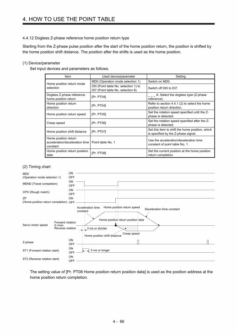
4. HOW TO USE THE POINT TABLE
4 - 66
4.4.12 Dogless Z-phase reference home position return type
Starting from the Z-phase pulse position after the start of the home position return, the position is shifted by
the home position shift distance. The position after the shifts is used as the home position.
(1) Device/parameter
Set input devices and parameters as follows.
Item Used device/parameter Setting
Home position return mode selection
MD0 (Operation mode selection 1) Switch on MD0.
DI0 (Point table No. selection 1) to DI7 (Point table No. selection 8)
Switch off DI0 to DI7.
Dogless Z-phase reference home position return
[Pr. PT04] _ _ _ A: Select the dogless type (Z-phase reference).
Home position return direction
[Pr. PT04] Refer to section 4.4.1 (2) to select the home position return direction.
Home position return speed [Pr. PT05] Set the rotation speed specified until the Z-phase is detected.
Creep speed [Pr. PT06] Set the rotation speed specified after the Z-phase is detected.
Home position shift distance [Pr. PT07] Set this item to shift the home position, which is specified by the Z-phase signal.
Home position return acceleration/deceleration time constant
Point table No. 1 Use the acceleration/deceleration time constant of point table No. 1.
Home position return position data
[Pr. PT08] Set the current position at the home position return completion.
(2) Timing chart
ONOFF
MEND (Travel completion)ONOFF
CPO (Rough match)ONOFF
Servo motor speed
MD0(Operation mode selection 1)
Forward rotation0 r/minReverse rotation
ONOFF
Z-phase
ZP(Home position return completion)
ONOFF
ONOFF
ONOFF
ST1 (Forward rotation start)
ST2 (Reverse rotation start)
3 ms or shorter
Deceleration time constant
5 ms or longer
Acceleration timeconstant
Home position return speed
Home position shift distanceCreep speed
Home position return position data
The setting value of [Pr. PT08 Home position return position data] is used as the position address at the
home position return completion.

4. HOW TO USE THE POINT TABLE
4 - 67
4.4.13 Automatic retract function used for the home position return
For a home position return using the proximity dog, when the home position return is started from the
position on or beyond the proximity dog, the home position return is performed after the machine moves
back to the position where the home position can be performed.
(1) When the current position is on the proximity dog
When the current position is on the proximity dog, the machine moves backward automatically, and the
home position return is performed.
Proximity dogHome positionreturn direction
Home position start position
After retracting to before proximity dog,the home position return starts from here.
Servo motor speedReverserotation
0 r/min
(2) When the current position is beyond the proximity dog
At start-up, the operation is performed in the direction of the home position return. When LSP (Forward
rotation stroke end) or LSN (Reverse rotation stroke end) is detected, the machine moves backward
automatically. The machine passes and stops before the proximity dog, and the home position return is
performed from the position again. If the proximity dog cannot be detected, the machine stops at LSP or
LSN on the opposite side, and [AL. 90 Home position return incomplete warning] will occur.
Proximity dogLSP (Forward rotation stroke end) orLSN (Reverse rotation stroke end)
After retracting to before proximity dog,the home position return starts from here.
Home positionreturn direction
Home position start position
Servo motor speed
Forwardrotation
Reverserotation
0 r/min
The software limit cannot be used with these functions.

4. HOW TO USE THE POINT TABLE
4 - 68
4.4.14 Automatic positioning to home position function
POINT
The automatic positioning to the home position cannot be performed from
outside the setting range of position data. In this case, perform the home
position return again using the home position return.
After power-on, if the home position return is performed again after the home position return is performed to
define the home position, this function enables automatic positioning to the home position rapidly. For the
absolute position detection system, the home position return is unnecessary after the power-on.
When the automatic positioning to the home position is performed at home position return incompletion, [AL.
90.1] will occur.
After the power-on, perform the home position return in advance.
Set input devices and parameters as follows.
Item Used device/parameter Setting
Home position return mode selection
MD0 (Operation mode selection 1) Switch on MD0.
DI0 (Point table No. selection 1) to DI7 (Point table No. selection 8)
Switch off DI0 to DI7.
Home position return speed [Pr. PT05] Set the servo motor speed to travel to the home position.
Home position return acceleration/deceleration time constant
Point table No. 1 Use the acceleration/deceleration time constant of point table No. 1.
Home position return direction
[Pr. PT04] Set the rotation direction in degrees.
Set the home position return speed of the automatic positioning to home position function with [Pr. PT05].
The data of point table No.1 is used for acceleration/deceleration time constants. Switching on ST2 (Reverse
rotation start) enables high-speed automatic return.
Set the rotation direction at the time of degree unit setting with home position return direction of [Pr. PT04].
Deceleration timeconstantHome position
return speed
Acceleration timeconstant
3 ms or shorter
5 ms or longer
Servo motor speedForward rotation0 r/minReverse rotation
ONOFF
ONOFF
ST1 (Forward rotation start)
ST2 (Reverse rotation start)
ONOFF
MD0 (Operation mode selection 1)
Home position

4. HOW TO USE THE POINT TABLE
4 - 69
4.5 Roll feed mode using the roll feed display function
The roll feed display function can change the current position of the status monitor and command position
display.
Using the roll feed display function can use this servo amplifier as the roll feed mode. The roll feed mode can
be used in the incremental system. Using the override function can change the feed speed during operation.
Refer to section 2.4 for details.
(1) Parameter setting
No. Name Setting digit Setting item Setting value Setting
PA03 Absolute position detection system
_ _ _ x Absolute position detection system
_ _ _ 0 (initial value)
Always set the incremental system. It cannot be used by the absolute position detection system.
PT26 Current position/command position display selection
_ _ x _ Current position/command position display selection
_ _ 1 _ Select the roll feed display.
PT26 Electronic gear fraction clear selection
_ _ _ x Electronic gear fraction clear selection
_ _ _ 1 Clear a fraction of the previous command by the electronic gear at start of the automatic operation. Always set "_ _ _ 1" (enabled) in the electronic gear fraction clear.
(2) Roll feed display function
When the roll feed display function is used, the status display of the current position and command
position at start will be 0.
ST1 (Forward rotation start)
TSTP (Temporary stop/restart)
Servo motor speed
INP (In-position)
Display of current/command position
Forward rotation0 r/minReverse rotation
CR (Clear)
Starting renews displayfrom 0.
A point table is selectedwhose feed length is setto 8.
Temporary stop positionis displayed. Remainingdistance clear will notchange the display.
Next starting renewsdisplay from 0.
008.000
Remaining distanceclear
Quick stopby CR
Remaining distanceclear
0
ONOFF
ONOFF
ONOFFONOFF
10.00 8.00 5.90 6.50

4. HOW TO USE THE POINT TABLE
4 - 70
(3) Position data unit
The display unit is expressed in the unit set in [Pr. PT26], and the feed length multiplication is expressed
in the unit set in [Pr. PT03].
When the unit is set in degrees, the roll feed display function is disabled.
Refer to section 4.2.2 for details.
(4) Operation method
Only the status display of the current position and command position changes. The operation method is
the same as each operation mode.
Operation mode Detailed explanation
Automatic operation Automatic operation using the point table Section 4.2.2
Manual operation JOG operation Section 4.3.1
Manual pulse generator operation Section 4.3.2
Home position return mode Section 4.4

4. HOW TO USE THE POINT TABLE
4 - 71
4.6 Point table setting method
The following shows the setting method of point tables using MR Configurator2.
4.6.1 Setting procedure
Click "Positioning-data" in the menu bar and click "Point Table" in the menu.
The following window will be displayed by clicking.
(a)(g)(f)(d)(c)(m)(l)(i)
(h)
(j)
(k)
(e) (b) (n)
(1) Writing point table data (a)
Select changed point table data and click "Selected Items Write" to write the changed point table data to
the servo amplifier.
(2) Writing all point table data (b)
Click "Write All" to write all the point table data to the servo amplifier.
(3) Reading all point table data (c)
Click the "Read" button to read and display all the point table data from the servo amplifier.
(4) Initial setting of point table data (d)
Click the "Set to default" button to initialize all the data of point table No. 1 to 255. This button also
initializes data currently being changed.

4. HOW TO USE THE POINT TABLE
4 - 72
(5) Verifying point table data (e)
Click the "Verify" button to verify all the data displayed and data of the servo amplifier.
(6) Detailed setting of point table data (f)
Click the "Detailed Setting" to change position data range and unit in the point table window. Refer to
section 4.6.2 for details.
(7) Single-step feed (g)
Click "Single-step Feed" to perform the single-step feed test operation. Refer to section 3.1.9 or 3.2.9 for
details.
(8) Copy and paste of point table data (h)
Click "Copy" to copy the point table data. Click "Paste" to paste the copied point table data.
(9) Inserting point table data (i)
Click the "Insert" button to insert a block to the previous row from the selected point table No. The
selected point table No. and lower rows will be shifted down one by one.
(10) Deleting point table data (j)
Click the "Delete" button to delete all the data of the point table No. selected. The lower rows of the
selected point table No. will be shifted up one by one.
(11) Changing point table data (k)
After selecting the data to be changed, enter a new value, and click "Enter". You can change the
displayed range and unit with "(6) Detailed setting of point table data" of this section.
(12) Reading point table data (l)
Click "Open" to read the point table data.
(13) Saving point table data (m)
Click "Save As" to save the point table data.
(14) Updating project (n)
Click "Update Project" to update the point table data to a project.

4. HOW TO USE THE POINT TABLE
4 - 73
4.6.2 Detailed setting window
You can change position data range and unit with the detailed setting for the point table window. For the
position data range and unit of [Pr. PT01] setting, refer to section 4.2.2. To reflect the setting for the
corresponding parameter, click the "Update Project" button in the point table window.
1)
2)
3)
(1) Command method selection (PT01 *CTY) 1)
Select a positioning command method from the absolute position command method and incremental
value command method.
(2) Miscellaneous
(a) Feed length multiplication parameter setting STM (PT03 *FTY) 2)
Select any feed length multiplication from 1/10/100/1000.
(b) Position data unit setting (PT01 *CTY) 3)
Select any unit of position data from mm/inch/degree/pulse. While degree or pulse is selected,
setting of feed length multiplication will be disabled.

4. HOW TO USE THE POINT TABLE
4 - 74
MEMO

5. HOW TO USE THE PROGRAM
5 - 1
5. HOW TO USE THE PROGRAM
The following items are the same as MR-J4-_A_-RJ servo amplifiers. For the details of the items, refer to
each chapter/section (in "MR-J4-_A_(-RJ) Servo Amplifier Instruction Manual") indicated in the detailed
explanation field.
Item Detailed explanation
MR-J4-_A_-RJ 100 W or more
MR-J4-03A6-RJ
Switching power on for the first time Section 4.1 Section 18.4
POINT
When you use a linear servo motor, replace the following left words to the right
words.
Load to motor inertia ratio → Load to motor mass ratio
Torque → Thrust
(Servo motor) speed → (Linear servo motor) speed
For the mark detection function (Current position latch), refer to section 12.2.1.
For the mark detection function (Interrupt positioning), refer to section 12.2.2.
For the infinite feed function (setting degree), refer to section 12.3.
5.1 Startup
5.1.1 Power on and off procedures
When the servo amplifier is powered on for the first time, the amplifier enters the position control mode.
(Refer to section 4.2.1 of "MR-J4-_A_(-RJ) Servo Amplifier Instruction Manual".)
This section provides a case where the servo amplifier is powered on after the positioning mode setting.
(1) Power-on
Switch power on in the following procedure. Always follow this procedure at power-on.
1) Switch off SON (Servo-on).
2) Make sure that ST1 (Forward rotation start) is off.
3) Switch on the main circuit power supply and control circuit power supply.
The display shows "PoS" ("PSL" for MR-J4-03A6-RJ servo amplifiers), and in 2 s later, shows
data.
MR-J4-_A_-RJ 100 W or more
MR-J4-03A6-RJ
(2) Power-off 1) Switch off ST1 (Forward rotation start).
2) Switch off SON (Servo-on).
3) Switch off the main circuit power supply and control circuit power supply.

5. HOW TO USE THE PROGRAM
5 - 2
5.1.2 Stop
If any of the following situations occurs, the servo amplifier suspends the running of the servo motor and
brings it to a stop.
Refer to section 3.10 of "MR-J4-_A_(-RJ) Servo Amplifier Instruction Manual" for the servo motor with an
electromagnetic brake.
Operation/command Stopping condition
Switch off SON (Servo-on). The base circuit is shut off and the servo motor coasts.
Alarm occurrence The servo motor decelerates to a stop with the command. With some alarms, however, the dynamic brake operates to bring the servo motor to a stop. (Refer to chapter 8. (Note 1))
EM2 (Forced stop 2) off The servo motor decelerates to a stop with the command. [AL. E6 Servo forced stop warning] occurs. Refer to section 2.3 for EM1.
STO (STO1, STO2) off (Note 2) The base circuit is shut off and the dynamic brake operates to bring the servo motor to a stop.
LSP (Forward rotation stroke end) off, LSN (Reverse rotation stroke end) off
It will bring the motor to a sudden stop and make it servo-locked. It can be run in the opposite direction.
Note 1. Only a list of alarms and warnings is listed in chapter 8. Refer to "MELSERVO-J4 Servo Amplifier Instruction Manual
(Troubleshooting)" for details of alarms and warnings.
2. MR-J4-03A6-RJ servo amplifiers are not compatible with the STO function.

5. HOW TO USE THE PROGRAM
5 - 3
5.1.3 Test operation
Before starting actual operation, perform test operation to make sure that the machine operates normally.
Refer to section 5.1.1 for how to power on and off the servo amplifier.
Test operation of the servo motoralone in JOG operation of test
operation mode
Test operation of the servomotor alone
Test operation with the servomotor and machine connected
Automatic operationwith programming
In this step, confirm that the servo amplifier and servo motor operate
normally.
With the servo motor disconnected from the machine, use the test operation
mode and check whether the servo motor correctly rotates at the slowest
speed. For the test operation mode, refer to section 3.1.8, 3.1.9, 3.2.8, and
3.2.9 in this manual, and section 4.5.9 and 18.5.10 of "MR-J4-_A_(-RJ)
Servo Amplifier Instruction Manual".
In this step, confirm that the servo motor correctly rotates at the slowest
speed in the manual operation mode.
Make sure that the servo motor rotates in the following procedure. 1) Switch on EM2 (Forced stop 2) and SON (Servo-on). When the servo
amplifier is put in a servo-on status, RD (Ready) is switched on. 2) Switch on LSP (Forward rotation stroke end) and LSN (Reverse rotation
stroke end). 3) When MD0 (Operation mode selection 1) is switched off from the
controller and ST1 (Forward rotation start) or ST2 (Reverse rotation
start) is switched on in the manual operation mode, the servo motor
starts rotating. Give a low speed command at first and check the rotation
direction, etc. of the servo motor. If the servo motor does not operate in
the intended direction, check the input signal.
In this step, connect the servo motor with the machine and confirm that the
machine operates normally under the commands from the controller.
Make sure that the servo motor rotates in the following procedure. 1) Switch on EM2 (Forced stop 2) and SON (Servo-on). When the servo
amplifier is put in a servo-on status, RD (Ready) is switched on. 2) Switch on LSP (Forward rotation stroke end) and LSN (Reverse rotation
stroke end). 3) When MD0 (Operation mode selection 1) is switched off from the
controller and ST1 (Forward rotation start) or ST2 (Reverse rotation
start) is switched on in the manual operation mode, the servo motor
starts rotating. Give a low speed command at first and check the
operation direction, etc. of the machine. If the machine does not operate
in the intended direction, check the input signal. In the status display,
check for any problems of the servo motor speed, load ratio, etc. Select a program from the controller, and check automatic operation.

5. HOW TO USE THE PROGRAM
5 - 4
5.1.4 Parameter setting
POINT
The following encoder cables are of four-wire type. When using any of these
encoder cables, set [Pr. PC22] to "1 _ _ _" to select the four-wire type. Incorrect
setting will result in [AL. 16 Encoder initial communication error 1].
MR-EKCBL30M-L
MR-EKCBL30M-H
MR-EKCBL40M-H
MR-EKCBL50M-H
When using this servo by the program method, set [Pr. PA01] to "_ _ _ 7" (Positioning mode (program
method)). For the program method, the servo can be used by merely changing the basic setting parameters
([Pr. PA _ _ ]) and positioning control parameters ([Pr. PT _ _ ]) mainly.
As necessary, set other parameters.
The following table shows [Pr. PA _ _ ] and [Pr. PT _ _ ] settings required for the program method.
Operation mode selection item Operation mode
Parameter setting Input device setting
[Pr. PA01] [Pr. PT04] MD0
(Note 1) DI0 to DI7 (Note 1)
Automatic operation mode of the program method
On Any
Manual operation mode
JOG operation Off
Manual pulse generator operation
Dog type _ _ _ 0
Count type _ _ _ 1
Data set type _ _ _ 2
Stopper type _ _ _ 7
_ _ _ 3
Home position ignorance (servo-on position as home position)
_ _ _ 4
Home position return Dog type rear end reference _ _ _ 5 On Any (Note 2)
Count type front end reference _ _ _ 6
Dog cradle type _ _ _ 7
Dog type last Z-phase reference _ _ _ 8
Dog type front end reference _ _ _ 9
Dogless Z-phase reference _ _ _ A Note 1. MD0: Operation mode selection 1, DI0 to DI7: Program No. selection 1 to Program No. selection 8
2. Select a program containing a "ZRT" command, which performs the home position return.

5. HOW TO USE THE PROGRAM
5 - 5
5.1.5 Actual operation
Start actual operation after confirmation of normal operation by test operation and completion of the
corresponding parameter settings.
5.1.6 Troubleshooting at start-up
CAUTION Never make a drastic adjustment or change to the parameter values as doing so
will make the operation unstable.
POINT
Using MR Configurator2, you can refer to the reason for rotation failure, etc.
The following faults may occur at start-up. If any of such faults occurs, take the corresponding action.
"MR-J4-_A_" means "MR-J4-_A_(-RJ) Servo Amplifier Instruction Manual".
No. Start-up sequence Fault Investigation Possible cause Reference
1 Power on The 7-segment LED display does not turn on. The 7-segment LED display flickers.
Not improved even if CN1, CN2, and CN3 connectors are disconnected.
1. Power supply voltage fault 2. The servo amplifier is
malfunctioning.
Improved when CN1 connector is disconnected.
Power supply of CN1 cabling is shorted.
Improved when CN2 connector is disconnected.
1. Power supply of encoder cabling is shorted.
2. Encoder is malfunctioning.
Improved when CN3 connector is disconnected.
Power supply of CN3 cabling is shorted.
Alarm occurs. Refer to chapter 8 and remove the cause. Chapter 8 (Note)
2 Switch on SON (Servo-on).
Alarm occurs. Refer to chapter 8 and remove the cause. Chapter 8 (Note)
Servo motor shaft is not servo-locked. (Servo motor shaft is free.)
1. Check the display to see if the servo amplifier is ready to operate.
2. Check the external I/O signal indication (section 3.1.7 or 3.2.7) to see if SON (Servo-on) is on.
1. SON (Servo-on) is not input. (wiring mistake)
2. 24 V DC power is not supplied to DICOM.
Section 3.1.7
Section 3.2.7
3 Perform a home position return.
Servo motor does not rotate.
Call the external I/O signal display and check the on/off status of the input signal. (Refer to section 3.1.7 or 3.2.7.)
LSP, LSN, and ST1 are off. Section 3.1.7
Section 3.2.7
Check [Pr. PA11 Forward rotation torque limit] and [Pr. PA12 Reverse rotation torque limit].
Torque limit level is too low as compared to the load torque.
Section 7.2.1
When TLA (Analog torque limit) is usable, check the input voltage on the status display.
Torque limit level is too low as compared to the load torque.
Section 3.1.2
Section 3.2.2
The home position return is not completed.
Call the external I/O signal display and check the on/off status of input signal DOG. (Refer to section 3.1.7 or 3.2.7.)
The proximity dog is set incorrectly.
Section 3.1.7
Section 3.2.7

5. HOW TO USE THE PROGRAM
5 - 6
No. Start-up sequence Fault Investigation Possible cause Reference
4 Switch on ST1 (Forward rotation start).
Servo motor does not rotate.
Call the external I/O signal display (Section 3.1.7 or 3.2.7) and check the on/off status of the input signal.
LSP, LSN, and ST1 are off. Section 3.1.7
Section 3.2.7
Check [Pr. PA11 Forward rotation torque limit] and [Pr. PA12 Reverse rotation torque limit].
Torque limit level is too low as compared to the load torque.
Section 7.2.1
When TLA (Analog torque limit) is usable, check the input voltage on the status display.
Torque limit level is too low as compared to the load torque.
Section 3.1.2
Section 3.2.2
5 Gain adjustment Rotation ripples (speed fluctuations) are large at low speed.
Make gain adjustment in the following procedure. 1. Increase the auto tuning
response level. 2. Repeat acceleration/
deceleration more than three times to complete auto tuning.
Gain adjustment fault MR-J4-_A_
Chapter 6
Large load inertia moment causes the servo motor shaft to oscillate side to side.
If the servo motor may be driven with safety, repeat acceleration and deceleration three times or more to complete the auto tuning.
Gain adjustment fault MR-J4-_A_
Chapter 6
Note. Only a list of alarms and warnings is listed in chapter 8. Refer to "MELSERVO-J4 Servo Amplifier Instruction Manual
(Troubleshooting)" for details of alarms and warnings.
5.2 Program operation method
5.2.1 Program operation method
In advance, select a program created on MR Configurator2 by using an input signal or communication to
start operation with ST1 (Forward rotation start).
This servo amplifier is factory set to the absolute value command method.
For the position data, you can set the absolute value travel command ("MOV" command), which specifies
the target address, and the incremental value travel command ("MOVI" command), which specifies the travel
distance. Refer to section 4.2.1 (1) and 5.2.3 (1) (a) for the movable range and the setting unit.

5. HOW TO USE THE PROGRAM
5 - 7
5.2.2 Program language
The maximum number of steps of a program is 640. Up to 256 programs can be created; however, the total
number of the steps of all programs must be 640 or less.
A set program is selectable by using DI0 (Program No. selection 1) to DI7 (Program No. selection 8).
(1) Command list
Command Name Setting Setting range Unit
Indirect specif-ication
(Note 7)
Description
SPN (Note 2)
Servo motor speed
SPN (Setting value)
0 to permissible instantaneous speed
r/min or
mm/s (Note 9)
Set the servo motor speed for positioning using this command.
The setting value must be the permissible instantaneous speed or less of the servo motor used.
If the setting value is unspecified, the servo motor rotates at 50 r/min.
STA (Note 2)
Acceleration time constant
STA (Setting value)
0 to 20000 ms
Set the acceleration time constant. The setting value is the time from when the used servo motor stops until when its speed reaches the rated speed.
The value cannot be changed during a command output.
If the setting value is unspecified, 1000 ms is applied.
STB (Note 2)
Deceleration time constant
STB (Setting value)
0 to 20000 ms
Set the deceleration time constant. The setting value is the time from when the used servo motor rotates at the rated speed until when the motor stops.
The value cannot be changed during a command output.
If the setting value is unspecified, 1000 ms is applied.
STC (Note 2)
Acceleration/deceleration time constant
STC (Setting value)
0 to 20000 ms
Set the acceleration/deceleration time constants.
The setting value is a time period that the servo motor reaches the rated speed from a stop, and stops from the rated speed.
When this command is used, the acceleration time constant and the deceleration time constant become the same.
To set the acceleration/deceleration time constants individually, use the "STA" and "STB" commands.
The value cannot be changed during a command output.
If the setting value is unspecified, 1000 ms is applied.
STD (Note 2, 5)
S-pattern acceleration/deceleration time constant
STD (Setting value)
0 to 1000 ms
Set the S-pattern acceleration/deceleration time constants.
Set this command to insert S-pattern acceleration/deceleration time constants against the acceleration/deceleration time constants of the program.
MOV Absolute value travel command
MOV (Setting value)
-999999
to 999999 (Note 6)
×10STM μm(Note 6)
The servo motor rotates using the set value as the absolute value.
MOVA Absolute value continuous travel command
MOV (Setting value)
-999999
to 999999 (Note 6)
×10STM μm(Note 6)
The servo motor rotates continuously using the set value as the absolute value. Make sure to describe this command after the "MOV" command.
MOVI Incremental value travel command
MOVI (Setting value)
-999999
to 999999 (Note 6)
×10STM μm(Note 6)
The servo motor rotates using the set value as the incremental value.
When a negative value is set, the servo motor rotates in the reverse rotation direction.
For the reverse rotation, the servo motor rotates in the address decreasing direction.
MOVIA Incremental value continuous travel command
MOVIA (Setting value)
-999999
to 999999 (Note 6)
×10STM μm(Note 6)
The servo motor rotates continuously using the set value as the incremental value. Make sure to describe this command after the "MOVI" command.
SYNC (Note 1)
External signal on wait
SYNC (Setting value)
1 to 3
The following steps stop after SOUT (SYNC synchronous output) is output until PI1 (Program input 1) to PI3 (Program input 3) are switched on.
Setting value Input signal
1 PI1 (Program input 1)
2 PI2 (Program input 2)
3 PI3 (Program input 3)

5. HOW TO USE THE PROGRAM
5 - 8
Command Name Setting Setting range Unit
Indirect specif-ication
(Note 7)
Description
OUTON (Note 1, 3)
External signal on output
OUTON (Setting value)
1 to 3
Switch on OUT1 (Program output 1) to OUT3 (Program output 3).
By setting the on time by using [Pr. PT23] to [Pr. PT25], you can switch off the input signals after the set time elapses.
Setting value Input signal
1 OUT1 (Program output 1) 2 OUT2 (Program output 2)
3 OUT3 (Program output 3)
OUTOF (Note 1)
External signal off output
OUTOF (Setting value)
1 to 3
Switch off OUT1 (Program output 1) to OUT3 (Program output 3), which have been on by the "OUTON" command.
Setting value Input signal
1 OUT1 (Program output 1)
2 OUT2 (Program output 2)
3 OUT3 (Program output 3)
TRIP (Note 1)
Absolute value trip point specification
TRIP (Setting value)
-999999
to 999999
(Note 6)
×10STM μm
(Note 6)
When the servo motor rotates for the travel distance set by the "TRIP" command after the "MOV" or "MOVA" command is initiated, the next step is executed. Make sure to describe this command after the "MOV" or "MOVA" command.
TRIPI (Note 1)
Incremental value trip point specification
TRIPI (Setting value)
-999999
to 999999
(Note 6)
×10STM μm
(Note 6)
When the servo motor rotates for the travel distance set by the "TRIPI" command after the "MOVI" or "MOVIA" command is initiated, the next step is executed. Make sure to describe this command after the "MOVI" or "MOVIA" command.
ITP (Note 1, 4)
Interrupt positioning
ITP (Setting value)
0 to 999999
(Note 6)
×10STM μm
(Note 6)
An interrupt signal stops the servo motor when the motor rotates the set travel distance. Make sure to describe this command after the "SYNC" command.
COUNT (Note 1)
External pulse count
COUNT (Setting value)
-999999
to 999999 pulse
When the pulse counter value becomes larger than the count value set for the "COUNT" command, the next step is executed. "COUNT (0)" clears the pulse counter to 0.
FOR NEXT
Step repeat command
FOR (Setting value) NEXT
0, 1 to 10000 times
The servo motor repeats the operation of the steps, which are set between a "FOR (Setting value) command and a "NEXT" command, the set number of times.
Setting "0" repeats the steps endlessly.
Do not describe a "FOR" command between the "FOR" and "NEXT" commands. Otherwise, an error occurs.
LPOS (Note 1)
Current position latch
LPOS
Latch the current position at the rising edge of LPS (Current position latch).
The latched current position data can be read with communication commands.
When the servo motor starts rotating, the latched position varies according to the motor speed and the sampling of input signals.
TIM Dwell TIM (Setting value)
1 to 20000 ms Wait for the next step until the set time elapses.
ZRT Home position return
ZRT Perform a home position return.
TIMES
Number of program executions command
TIMES (Setting value)
0, 1 to 10000 times
Position a "TIMES (Setting value)" command at the start of the program, and set the number of program executions. To execute the program only one time, no setting is required. Setting "0" repeats the program endlessly.
STOP Program stop STOP Stop the running program.
Make sure to describe this command in the final row.

5. HOW TO USE THE PROGRAM
5 - 9
Command Name Setting Setting range Unit
Indirect specif-ication
(Note 7)
Description
TLP (Note 8)
Forward rotation torque limit
TLP (Setting value)
to 1000 0.1 %
Using the maximum torque as 100%, limit the generated torque of the servo motor in the CCW power running or CW regeneration.
The setting value is valid until the program stops.
Specifying the setting value to "0" enables the [Pr. PA11] setting.
TLN (Note 8)
Reverse rotation torque limit
TLN (Setting value)
0, 1 to 1000 0.1 %
Using the maximum torque as 100%, limit the generated torque of the servo motor in the CW power running or CCW regeneration.
The setting value is valid until the program stops.
Specifying the setting value to "0" enables the [Pr. PA12] setting.
TQL (Note 8)
Torque limit TQL (Setting value)
0, 1 to 1000 0.1 %
Using the maximum torque as 100%, limit the generated torque of the servo motor.
The setting value is valid until the program stops.
Specifying the setting value to "0" enables the [Pr. PA11] and [Pr. PA12] settings.
Note 1. The "SYNC", "OUTON", "OUTOF", "TRIP", "TRIPI", "COUNT", "LPOS", and "ITP" commands are valid even during a
command output.
2. The "SPN" command is valid while the "MOV", "MOVA", "MOVI", or "MOVIA" command is executed. The "STA", "STB", "STC",
and "STD" commands are valid while the "MOV" or "MOVI" command is executed.
3. When the on time is set using [Pr. PT23] to [Pr. PT25], the next command is executed after the set time elapses.
4. When the remaining distance is the set value or less, or while the servo motor stops or decelerates, the program skips the
"ITP" command and proceeds to the next step.
5. The parameter value is valid normally. However, the value set for the command is valid after the command is executed until
the program stops.
6. The unit of the position command data input can be changed with [Pr. PT01]. For the setting range for each unit, refer to
section 5.2.3 (1) (a).
7. For the explanation of the indirect specification, refer to section 5.2.2 (2) (j).
8. The parameter value is valid normally. However, the value set for the command is valid after the command is executed until
the program stops.
9. The unit will be "mm/s" in the linear control mode.
(2) Detailed explanations of commands
(a) Positioning conditions (SPN/STA/STB/STC/STD)
POINT
Once values are set for the "SPN", "STA", "STB" and "STC" commands, the
values are valid without resetting them. (The values are not initialized at the
program startup.) The settings are valid in the other programs.
The value set for the "STD" command is valid in the same program only. The
value is initialized to the setting value of [Pr. PC03] at the program startup, and
therefore the value is invalid in the other programs.
The "SPN", "STA", "STB", "STC", and "STD" commands are valid while the "MOV" or "MOVA"
command is executed.

5. HOW TO USE THE PROGRAM
5 - 10
1) Program example 1
When executing two operations where the servo motor speeds, acceleration time constants, and
deceleration time constants are the same and the travel commands are different
Command Description
SPN (1000) Servo motor speed 1000 [r/min] a)
STA (200) Acceleration time constant 200 [ms] b)
STB (300) Deceleration time constant 300 [ms] c)
MOV (1000) Absolute value travel command 1000 [×10STM μm] d)
TIM (100) Dwell 100 [ms] e)
MOV (2000) Absolute value travel command 2000 [×10STM μm] f) STOP Program stop
b) Acceleration timeconstant (200 ms)
c) Deceleration timeconstant (300 ms)
a) Servo motorspeed(1000r/min)
Forward rotation0 r/minReverse rotation
Servo motorspeed
d) Absolute valuetravel command(1000 × 10STMμm)
e) Dwell (100 ms)
b) Acceleration timeconstant (200 ms)
a) Servo motor speed(1000 r/min)
c) Deceleration timeconstant (300 ms)
f) Absolute valuetravel command(2000 × 10STMμm)
2) Program example 2
When executing two operations where the servo motor speeds, acceleration time constants,
deceleration time constants, and travel commands are different
Command Description
SPN (1000) Servo motor speed 1000 [r/min] a)
STA (200) Acceleration time constant 200 [ms] b)
STB (300) Deceleration time constant 300 [ms] c)
MOV (1000) Absolute value travel command 1000 [×10STM μm] d)
TIM (100) Dwell 100 [ms] e)
SPN (500) Servo motor speed 500 [r/min] f)
STC (200) Acceleration/deceleration time constant
200 [ms] g)
MOV (1500) Absolute value travel command 1500 [×10STM μm] h) STOP Program stop
b) Acceleration timeconstant (200 ms)
a) Servo motorspeed(1000 r/min)
Servo motorspeed
Forward rotation0 r/minReverse rotation
c) Deceleration timeconstant (300 ms)
e) Dwell(100 ms)d) Absolute value travel command
(1000 × 10STMμm)
g) Acceleration/decelerationtime constant(200 ms)
f) Servo motor speed(500 r/min)
h) Absolute value travel command(1500 × 10STMμm)

5. HOW TO USE THE PROGRAM
5 - 11
3) Program example 3
Using the S-pattern acceleration/deceleration time constants reduces abrupt movements at
acceleration or deceleration. When the "STD" command is used, [Pr. PC03 S-pattern
acceleration/deceleration time constant] does not function.
Command Description
SPN (1000) Servo motor speed 1000 [r/min] a)
STC (100) Acceleration/deceleration time
constant 1000 [ms] b)
STD (10) S-pattern acceleration/deceleration time constant
10 [ms] c)
MOV (2000) Absolute value travel command 2000 [×10STM μm] d) STOP Program stop
c) c)
c)
a) Servo motor speed(1000 r/min)
b) Acceleration/decelerationtime constant (1000 ms) b) Acceleration/deceleration
time constant (1000 ms)
d) Absolute value travel command(2000 × 10STMμm)
c) S-pattern acceleration/deceleration time constant(10 ms)
Servo motorspeed
Forward rotation0 r/minReverse rotation

5. HOW TO USE THE PROGRAM
5 - 12
(b) Continuous travel commands (MOVA/MOVIA)
POINT
You cannot use a combination of "MOV" and "MOVIA" commands and a
combination of "MOVI" and "MOVA" commands.
The "MOVA" command is a continuous travel command against the "MOV" command. Upon
executing the travel command by the "MOV" command, the travel command by the "MOVA"
command is executed continuously without a stop.
The varying speed point under the "MOVA" command is at the deceleration start position of the
operation by the preceding "MOV" or "MOVA" command.
The acceleration/deceleration time constants of the "MOVA" command are set to the values at the
execution of the preceding "MOV" command.
The "MOVIA" command is a continuous travel command against the "MOVI" command. Upon
executing the travel command by the "MOVI" command, the travel command by the "MOVIA"
command is executed continuously without a stop.
The varying speed point under the "MOVIA" command is at the deceleration start position of the
operation by the preceding "MOVI" or "MOVIA" command.
The acceleration/deceleration time constants of the "MOVIA" command are set to the values at the
execution of the preceding "MOVI" command.
Command Name Setting Unit Description
MOV Absolute value travel command
MOV (Setting value) ×10STMμm Absolute value travel command
MOVA Absolute value continuous travel command
MOVA (Setting value) ×10STMμm Absolute value continuous travel command
MOVI Incremental value travel command
MOVI (Setting value) ×10STMμm Incremental value travel command
MOVIA Incremental value continuous travel command
MOVIA (Setting value) ×10STMμm Incremental value continuous travel command

5. HOW TO USE THE PROGRAM
5 - 13
1) Program example 1
When using the absolute value travel command under the absolute value command method
Command Description
SPN (500) Servo motor speed 500 [r/min] a)
STA (200) Acceleration time constant 200 [ms] b)
STB (300) Deceleration time constant 300 [ms] c)
MOV (500) Absolute value travel command 500 [×10STM μm] d)
SPN (1000) Servo motor speed 1000 [r/min] e)
MOVA (1000) Absolute value continuous travel command
1000 [×10STM μm] f)
MOVA (0) Absolute value continuous travel command
0 [×10STM μm] g)
STOP Program stop
b) Acceleration timeconstant (200 ms)
a) Servo motor speed(500 r/min)
d) Absolute valuetravel command(500 × 10STMμm)
e) Servo motorspeed(1000 r/min)
c) Deceleration timeconstant (300 ms)
f) Absolute valuecontinuous travelcommand(1000 × 10STMμm)
b) Acceleration timeconstant(200 ms)
e) Servo motor speed(1000 r/min) g) Absolute value
continuous travelcommand(0 × 10STMμm)
Servo motorspeed
Forward rotation0 r/minReverse rotation

5. HOW TO USE THE PROGRAM
5 - 14
2) Program example 2 (Incorrect usage)
For continuous operations, the acceleration time constant and the deceleration time constant
cannot be changed at each change of the servo motor speed. Therefore, even if you insert an
"STA", "STB", or "STD" command at a speed change, the command is invalid.
Command Description
SPN (500) Servo motor speed 500 [r/min] a)
Disabled
Disabled
STA (200) Acceleration time constant 200 [ms] b)
STB (300) Deceleration time constant 300 [ms] c)
MOV (500) Absolute value travel command 500 [×10STM μm] d)
SPN (1000) Servo motor speed 1000 [r/min] e)
STC (500) Acceleration/deceleration time constant
500 [ms] f)
MOVA (1000) Absolute value continuous travel command
1000 [×10STM μm] g)
SPN (1500) Servo motor speed 1500 [r/min] h)
STC (100) Acceleration/deceleration time constant
100 [ms] i)
MOVA (0) Absolute value continuous travel command
0 [×10STM μm] j)
STOP Program stop
b) Acceleration time constant(200 ms)
a) Servo motor speed(500 r/min)
e) Servo motorspeed(1000 r/min)
c) Deceleration time constant(300 ms)
h) Servo motorspeed(1500 r/min)
j) Absolute value continuoustravel command(0 × 10STM μm)
g) Absolute valuecontinuous travelcommand(1000 × 10STMμm)
d) Absolute valuetravel command(500 × 10STMμm)
b) Acceleration time constant(200 ms)
Forward rotation0 r/minReverse rotation
Servo motorspeed

5. HOW TO USE THE PROGRAM
5 - 15
(c) Input/output commands (OUTON/OUTOF) and trip point commands (TRIP/TRIPI)
POINT
Using [Pr. PT23] to [Pr. PT25], you can set the time until OUT1 (Program output
1) to OUT3 (Program output 3) are switched off. The commands are switched off
under the following conditions.
The commands are switched off by the OUTOF command.
The commands are switched off by a program stop.
The "TRIP" and "TRIPI" commands have the following restrictions.
The "MOV" or "MOVA" command cannot be used in combination with the
"TRIPI" command.
The "MOVI" or "MOVIA" command cannot be used in combination with the
"TRIP" command.
The "TRIP" and "TRIPI" commands do not execute the next step until the
servo motor passes the set address or travel distance. Set the commands
within the travel command range.
Determine whether the servo motor has passed the set address or travel
distance by checking the actual position (for each command). Additionally,
determine whether the servo motor has passed the set address or travel
distance by checking both edges of the address increasing/decreasing
directions.
1) Program example 1
OUT1 (Program output 1) is switched on upon a program execution. When the program ends,
OUT1 (Program output 1) is switched off.
Command Description
SPN (1000) Servo motor speed 1000 [r/min] STA (200) Acceleration time constant 200 [ms] STB (300) Deceleration time constant 300 [ms] MOV (500) Absolute value travel command 500 [×10STM μm] OUTON (1) Switch on OUT1 (Program output 1). a) TIM (100) Dwell 100 [ms] MOV (250) Absolute value travel command 250 [×10STM μm] TIM (50) Dwell 50 [ms] STOP Program stop b)
OUT1(Program output 1)
ONOFF
Dwell(100 ms)
Dwell(50 ms)
a) b)
Servo motor speedForward rotation0 r/minReverse rotation

5. HOW TO USE THE PROGRAM
5 - 16
2) Program example 2
Using [Pr. PT23] to [Pr. PT25], you can switch off OUT1 (Program output 1) to OUT3 (Program
output 3) automatically.
Parameter Name Setting value
Description
Pr. PT23 OUT1 output setting time
20 Switch off OUT1 200 [ms] later. a)
Pr. PT24 OUT2 output setting time
10 Switch off OUT2 100 [ms] later. b)
Pr. PT25 OUT3 output setting time
50 Switch off OUT3 500 [ms] later. c)
Command Description
SPN (500) Servo motor speed 500 [r/min] STA (200) Acceleration time constant 200 [ms] STB (300) Deceleration time constant 300 [ms] MOV (1000) Absolute value travel command 1000 [×10STM μm] OUTON (1) Switch on OUT1 (Program output 1). OUTON (2) Switch on OUT2 (Program output 2). OUTON (3) Switch on OUT3 (Program output 3). STOP Program stop
ONOFF
ONOFF
ONOFF
a) 200 ms
b) 100 ms
c) 500 ms
OUT1(Program output 1)
OUT2(Program output 2)
OUT3(Program output 3)
Servo motor speedForward rotation0 r/minReverse rotation

5. HOW TO USE THE PROGRAM
5 - 17
3) Program example 3
When setting the position address where the "OUTON" or "OUTOF" command is executed by
using the "TRIP" or "TRIPI" command
Command Description
SPN (1000) Servo motor speed 1000 [r/min] STA (200) Acceleration time constant 200 [ms] STB (300) Deceleration time constant 300 [ms] MOV (500) Absolute value travel command 500 [×10STM μm] TRIP (250) Absolute value trip point specification 250 [×10STM μm] a) OUTON (2) Switch on OUT2 (Program output 2). b) TRIP (400) Absolute value trip point specification 400 [×10STM μm] c) OUTOF (2) Switch off OUT2 (Program output 2). d) TIM (100) Dwell 100 [ms] MOVI (500) Incremental value travel command 500 [×10STM μm] TRIPI (300) Incremental value trip point
specification 300 [×10STM μm] e)
OUTON (2) Switch on OUT2 (Program output 2). f) STOP Program stop g)
a) 250 × 10STMμm
ONOFF
OUT2(Program output 2)
100 ms
e) 300 × 10STMμmc) 400 × 10STMμm
b) d) f) g)
Servo motor speedForward rotation0 r/minReverse rotation

5. HOW TO USE THE PROGRAM
5 - 18
4) Program example 4
Command Description
SPN (500) Servo motor speed 500 [r/min] STA (200) Acceleration time constant 200 [ms] STB (300) Deceleration time constant 300 [ms] MOVI (600) Incremental value travel command 600 [×10STM μm] a) TRIPI (300) Incremental value trip point
specification 300 [×10STM μm] b)
OUTON (3) Switch on OUT3 (Program output 3). c) SPN (700) Servo motor speed 700 [r/min] MOVIA (700) Incremental value continuous travel
command 700 [×10STM μm] d)
TRIPI (300) Incremental value trip point specification
300 [×10STM μm] e)
OUTOF (3) Switch off OUT3 (Program output 3). f) STOP Program stop
a) Incremental value travel command(600 × 10STMμm)
ONOFF
OUT3(Program output 3)
b) 300 × 10STMμm
c) f)
900 × 10STMμm(a) MOVI (600) + e) TRIPI (300))
d) Incremental valuecontinuous travelcommand(700 ×10STMμm)
Servo motor speedForward rotation0 r/minReverse rotation
(d) Dwell (TIM)
Using the "TIM (setting value)" command, set the time from when the remaining distance under the
command is "0" until when the next step is executed.
The following shows operation examples of using this command in combination with the other
commands for reference.
1) Program example 1
Command Description
TIM (200) Dwell 200 [ms] a) SPN (1000) Servo motor speed 1000 [r/min] STC (20) Acceleration/deceleration time
constant 20 [ms]
MOV (1000) Absolute value travel command 1000 [×10STM μm] STOP Program stop
a) 200 ms
ONOFF
ST1(Forward rotation start)
Servo motor speedForward rotation0 r/minReverse rotation

5. HOW TO USE THE PROGRAM
5 - 19
2) Program example 2
Command Description
SPN (1000) Servo motor speed 1000 [r/min] STC (20) Acceleration/deceleration time
constant 20 [ms]
MOVI (1000) Incremental value travel command 1000 [×10STM μm] TIM (200) Dwell 200 [ms] a) OUTON (1) Switch on OUT1 (Program output 1). b) MOVI (500) Incremental value travel command 500 [×10STM μm] STOP Program stop
b)
a) 200 ms
ONOFF
OUT1(Program output 1)
Servo motor speedForward rotation0 r/minReverse rotation
3) Program example 3
Command Description
SPN (1000) Servo motor speed 1000 [r/min] STC (20) Acceleration/deceleration time
constant 20 [ms]
MOVI (1000) Incremental value travel command 1000 [×10STM μm] OUTON (1) Switch on OUT1 (Program output 1). a) TIM (200) Dwell 200 [ms] b) MOVI (500) Incremental value travel command 500 [×10STM μm] STOP Program stop
a)
b) 200 ms
ONOFF
OUT1(Program output 1)
Servo motor speedForward rotation0 r/minReverse rotation
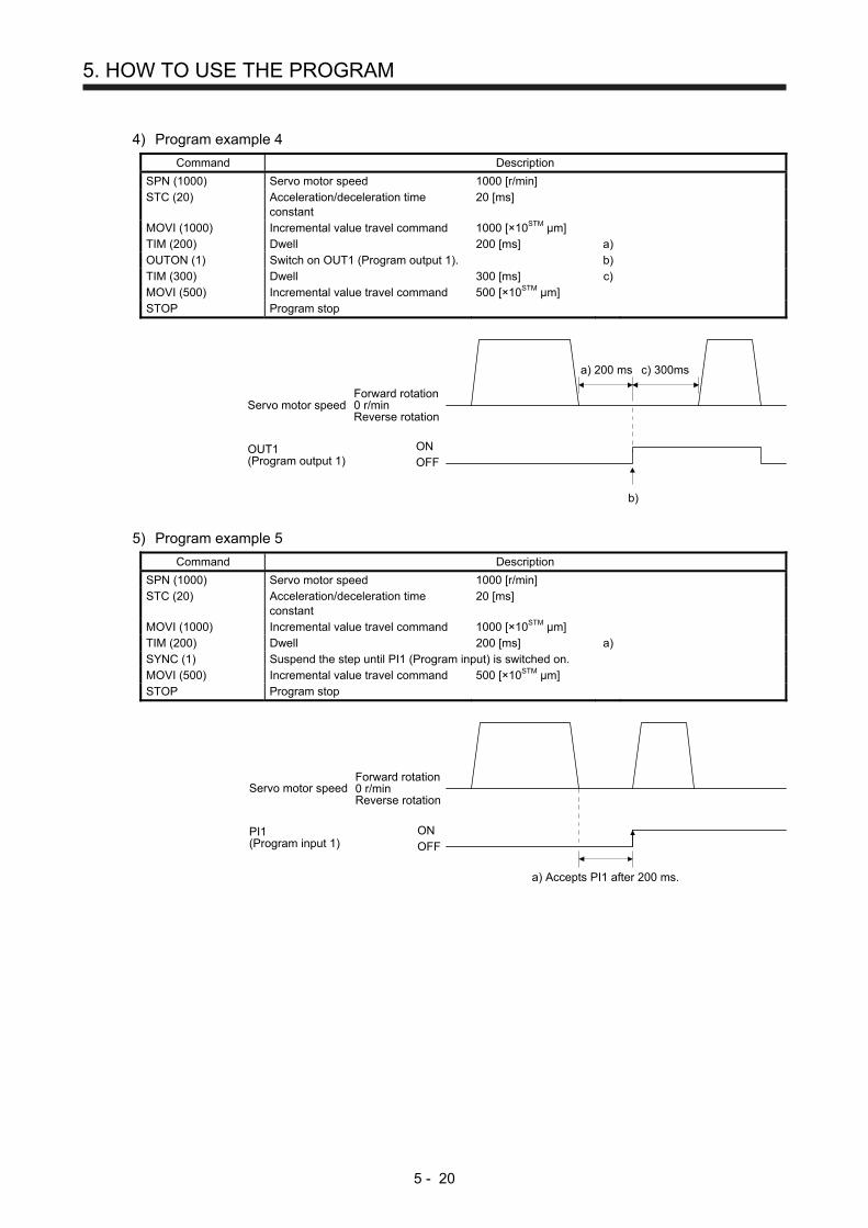
5. HOW TO USE THE PROGRAM
5 - 20
4) Program example 4
Command Description
SPN (1000) Servo motor speed 1000 [r/min] STC (20) Acceleration/deceleration time
constant 20 [ms]
MOVI (1000) Incremental value travel command 1000 [×10STM μm] TIM (200) Dwell 200 [ms] a) OUTON (1) Switch on OUT1 (Program output 1). b) TIM (300) Dwell 300 [ms] c) MOVI (500) Incremental value travel command 500 [×10STM μm] STOP Program stop
b)
a) 200 ms
ONOFF
OUT1(Program output 1)
c) 300ms
Servo motor speedForward rotation0 r/minReverse rotation
5) Program example 5
Command Description
SPN (1000) Servo motor speed 1000 [r/min] STC (20) Acceleration/deceleration time
constant 20 [ms]
MOVI (1000) Incremental value travel command 1000 [×10STM μm] TIM (200) Dwell 200 [ms] a) SYNC (1) Suspend the step until PI1 (Program input) is switched on. MOVI (500) Incremental value travel command 500 [×10STM μm] STOP Program stop
a) Accepts PI1 after 200 ms.
ONOFF
PI1(Program input 1)
Servo motor speedForward rotation0 r/minReverse rotation

5. HOW TO USE THE PROGRAM
5 - 21
6) Program example 6
Command Description
SPN (1000) Servo motor speed 1000 [r/min] STC (20) Acceleration/deceleration time
constant 20 [ms]
MOVI (1000) Incremental value travel command 1000 [×10STM μm] SYNC (1) Suspend the step until PI1 (Program input) is switched on. TIM (200) Dwell 200 [ms] a) MOVI (500) Incremental value travel command 500 [×10STM μm] STOP Program stop
a) 200 ms
ONOFF
PI1(Program input 1)
Servo motor speedForward rotation0 r/minReverse rotation
(e) Interrupt positioning (ITP)
POINT
For positioning with the "ITP" command, the stop position varies depending on
the servo motor speed when the "ITP" command becomes enabled.
In the following cases, the program does not execute the "ITP" command and
proceeds to the next step.
When the setting value of the "ITP" command is smaller than that of the travel
command set by the "MOV", "MOVI", or "MOVA" command
When the remaining distance under the "ITP" command is equal to or less
than the travel distance under the "ITP" command
While the servo motor decelerates
When an "ITP" command is used in the program, starting from the position where PI1 (Program input
1) to PI3 (Program input 3) are switched on, the servo motor rotates a distance of the set value and
stops.
When using the "ITP" command, make sure to position the command preceding a "SYNC"
command.
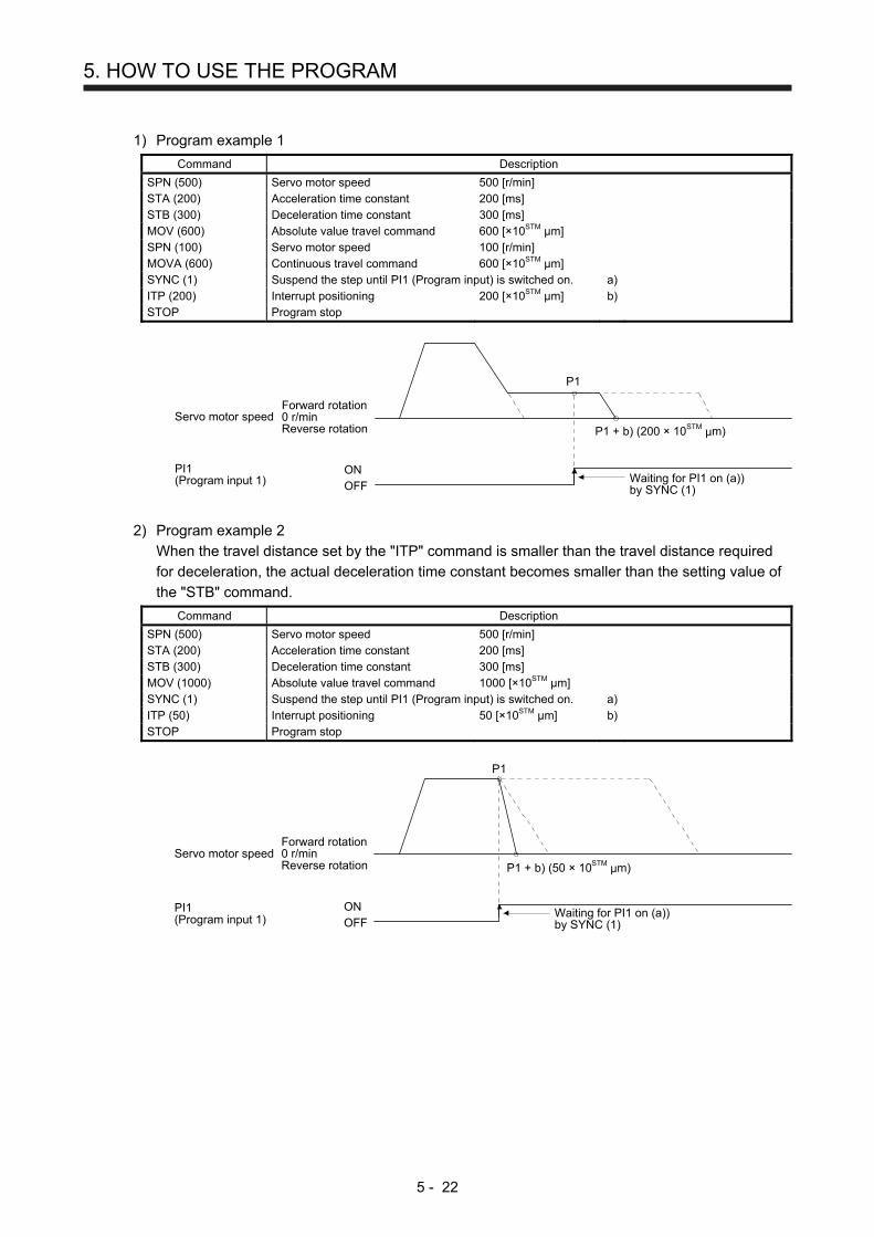
5. HOW TO USE THE PROGRAM
5 - 22
1) Program example 1
Command Description
SPN (500) Servo motor speed 500 [r/min] STA (200) Acceleration time constant 200 [ms] STB (300) Deceleration time constant 300 [ms] MOV (600) Absolute value travel command 600 [×10STM μm] SPN (100) Servo motor speed 100 [r/min] MOVA (600) Continuous travel command 600 [×10STM μm] SYNC (1) Suspend the step until PI1 (Program input) is switched on. a) ITP (200) Interrupt positioning 200 [×10STM μm] b) STOP Program stop
Waiting for PI1 on (a))by SYNC (1)
P1
ONOFF
PI1(Program input 1)
P1 + b) (200 × 10STM μm)Servo motor speed
Forward rotation0 r/minReverse rotation
2) Program example 2
When the travel distance set by the "ITP" command is smaller than the travel distance required
for deceleration, the actual deceleration time constant becomes smaller than the setting value of
the "STB" command.
Command Description
SPN (500) Servo motor speed 500 [r/min] STA (200) Acceleration time constant 200 [ms] STB (300) Deceleration time constant 300 [ms] MOV (1000) Absolute value travel command 1000 [×10STM μm] SYNC (1) Suspend the step until PI1 (Program input) is switched on. a) ITP (50) Interrupt positioning 50 [×10STM μm] b) STOP Program stop
Waiting for PI1 on (a))by SYNC (1)
P1
ONOFF
PI1(Program input 1)
P1 + b) (50 × 10STM μm)Servo motor speed
Forward rotation0 r/minReverse rotation

5. HOW TO USE THE PROGRAM
5 - 23
(f) External pulse count (COUNT)
When the number of input pulses of the manual pulse generator becomes larger than the value set
for the "COUNT" command, the next step is executed. Setting "0" clears cumulative input pulses.
Command Description
COUNT (500) Wait for the next step until the number of input pulses of the manual pulse generator reaches 500 [pulse]. a)
SPN (500) Servo motor speed 500 [r/min] STA (200) Acceleration time constant 200 [ms] STB (300) Deceleration time constant 300 [ms] MOV (1000) Absolute value travel command 1000 [×10STM μm] TRIP (500) Trip point specification 500 [×10STM μm] b) COUNT (0) Clear cumulative input pulses. c) STOP Program stop
c) Clear cumulative input pulses.
b) 500 [×10STM μm]
Manual pulse generatorCumulative input pulses
a) 500 [pulse]
Servo motor speedForward rotation0 r/minReverse rotation

5. HOW TO USE THE PROGRAM
5 - 24
(g) Step repeat command (FOR...NEXT)
POINT
You cannot insert "FOR...NEXT" commands between a "FOR" command and a
"NEXT" command.
The servo motor repeats the operation of the steps, which are set between a "FOR (Setting value)
command and a "NEXT" command, the number of set times. Setting "0" repeats the steps endlessly.
For how to stop the program, which the steps have been repeated endlessly in, refer to section 5.2.4
(4).
Command Description
SPN (1000) Servo motor speed 1000 [r/min] STC (20) Acceleration/deceleration time
constant 20 [ms]
MOV (1000) Absolute value travel command 1000 [×10STM μm] TIM (100) Dwell 100 [ms] FOR (3) Start of step repeat command 3 [time] a) MOVI (100) Incremental value travel command 100 [×10STM μm] b) TIM (100) Dwell 100 [ms] NEXT End of step repeat command c) FOR (2) Start of step repeat command 2 [time] d) MOVI (200) Incremental value travel command 200 [×10STM μm] e) TIM (100) Dwell 100 [ms] NEXT End of step repeat command f) STOP Program stop
b) Incremental valuetravel command(100 × 10STMμm)
d) Incremental valuetravel command(200 × 10STMμm)
a) c) e) f)
1000 1100 1200 1300 1500 1700Servo motor speed
Forward rotation0 r/minReverse rotation

5. HOW TO USE THE PROGRAM
5 - 25
(h) Number of program executions command (TIMES)
By setting the number of program executions for the "TIMES (Setting value)" command, which is
positioned at the start of the program, you can repeat the execution of the program. To execute the
program one time, the "TIMES" command is not required. Setting "0" repeats the program endlessly.
For how to stop the program, which has been repeated endlessly, refer to section 5.2.4 (4).
Command Description
TIMES (2) Number of program executions command
2 [time] a)
SPN (1000) Servo motor speed 1000 [r/min] STC (20) Acceleration/deceleration time
constant 20 [ms]
MOVI (1000) Incremental value travel command 1000 [×10STM μm] b) TIM (100) Dwell 100 [ms] STOP Program stop
b) Incremental value travel command(100 × 10STMμm)
a)
1000 1200Servo motor speed
Forward rotation0 r/minReverse rotation

5. HOW TO USE THE PROGRAM
5 - 26
(i) Current position latch (LPOS)
POINT
When the current position is stored using LPS (Current position latch input), the
value varies depending on the servo motor speed at switch-on of LPS.
The program does not proceeds to the next step until LPS (Current position
latch input) is switched on.
The stored data is not cleared without power-off of the servo amplifier.
After the input of LPS (Current position latch input) becomes valid by the
"LPOS" command, the input is cleared in the following conditions.
When the rising edge of LPS (Current position latch input) is detected
When the program ends
When the operation mode is changed
When the servo motor forcibly stops
When an alarm occurs
When the servo motor enters the servo-off status
The current position at switch-on of LPS (Current position latch input) is stored. The stored position
data can be read with the communication function.
The current position latch function, which is set during the execution of the program, is reset when
the program ends. The function is also reset at an operation mode change, forced stop, alarm
occurrence, or servo-off. The function is not reset at a temporary stop only.
Command Description
SPN (500) Servo motor speed 500 [r/min] STA (200) Acceleration time constant 200 [ms] STB (300) Deceleration time constant 300 [ms] MOV (1000) Absolute value travel command 1000 [×10STM μm] LPOS Set a current position latch. a) STOP Program stop
LPS turns on at on edgeby LPOS. (a))
1000
ONOFF
Current positionLPS (Latch input)
Current position300 [×10STM μm]is memorized.
Servo motor speedForward rotation0 r/minReverse rotation

5. HOW TO USE THE PROGRAM
5 - 27
(j) Indirect specification with general purpose registers (R1 to R4, D1 to D4)
You can indirectly specify the setting values of the "SPN", "STA", "STB", "STC", "STD", "MOV",
"MOVI", "MOVA", "MOVIA", "TIM", and "TIMES" commands.
The value, which is stored in each general purpose register (R1 to R4, D1 to D4), is used as the
setting value of each command.
While the program is not executed by a communication command, you can change the general
purpose registers by using MR Configurator2 or a communication command.
The data of the general purpose registers is erased at power-off of the servo amplifier. Note that you
can store the data of the general purpose registers (R1 to R4) in EEP-ROM.
The setting range of each general purpose register is that of the command for which each register is
used.
The following explains a case where the general purpose registers are set as shown below before
the execution of the program.
General purpose register Setting
R1 1000
R2 2000
D1 200
D2 300
Command Description
SPN (1000) Servo motor speed 1000 [r/min] a) STA (D1) Acceleration time constant D1 = 200 [ms] b) STB (D2) Deceleration time constant D2 = 300 [ms] c) MOVI (R1) Incremental value travel command R1 = 1000 [×10STM μm] d) TIM (100) Dwell 100 [ms] e) MOVI (R2) Incremental value travel command R2 = 2000 [×10STM μm] f) STOP Program stop
d) R1 = 1000 × 10STMμm e) Dwell (100 ms)
f) R2 = 2000 × 10STMμm
a) 1000 r/minb) D1 = 200 ms c) D2 = 300 ms b) D1 = 200 ms c) D2 = 300 ms
Servo motor speedForward rotation0 r/minReverse rotation

5. HOW TO USE THE PROGRAM
5 - 28
(k) Home position return command (ZRT)
Perform a home position return.
Set the home position with a parameter. (Refer to section 5.4.)
With the "ZRT" command, the program proceeds to the next step after the home position return
completion.
POINT
If the home position return has not completed successfully, [AL. 96 Home
position return incomplete warning] occurs. In this case, the program proceeds
to the next step without a stop. Since the home position return is incomplete, the
travel command is invalid.
Command Description
SPN (500) Servo motor speed 500 [r/min] a) STA (200) Acceleration time constant 200 [ms] b) STB (300) Deceleration time constant 300 [ms] c) ZRT Home position return d) MOV (500) Absolute value travel command 500 [×10STM μm] e) STOP Program stop
Item Used parameter Setting
Dog type home position return
[Pr. PT04] "_ _ _ 0"
Home position return direction
[Pr. PT04] "_ _ 0 _" (Address increasing direction)
Dog input polarity [Pr. PT29] "_ _ _ 1" (Detects dog when DOG (proximity dog) is on.)
Home position return speed [Pr. PT05] 100 [r/min]
Creep speed [Pr. PT06] 50 [r/min]
Home position shift distance [Pr. PT07] 0 [×10STMμm]
Home position return acceleration time constant
[Pr. PC30] 100 [ms]
Home position return deceleration time constant
[Pr. PC31] 200 [ms]
Home position return position data
[Pr. PT08] 0
Home position return speed(100 r/min)
Acceleration time constantof home position return(100 ms)
Z-phase
Proximity dog
Position address
Deceleration time constantof home position return(200 ms)
Creep speed(50 r/min)
b) Acceleration time constant(200 ms)
a) Servo motor speed(500 r/min)
c) Deceleration timeconstant(300 ms)
Home position return completion
0 500e) Absolute value travel command(500 × 10STMμm)
d) Home position return command
Servo motorspeed
Forward rotation0 r/minReverse rotation

5. HOW TO USE THE PROGRAM
5 - 29
(l) Torque limit value switching (TLP/TLN/TQL)
Using the maximum torque as 100.0%, limit the generated torque of the servo motor.
1) Program example
Command Description
SPN (1500) STA (100) STB (200) MOV (1000)
Servo motor speed Acceleration time constant Deceleration time constant Absolute value travel command
1500 [r/min] 100 [ms] 200 [ms] 1000 [×10STM μm]
SYNC (1) Suspend the step until PI1 (Program input) is switched on. a) TLP (800) Forward rotation torque limit 800 [0.1%] b) SYNC (2) Suspend the step until PI2 (Program input) is switched on. c) TLN (500) TIM (100) MOV (500)
Reverse rotation torque limit Dwell Absolute value travel command
500 [0.1%] 100 [ms] 1000 [×10STM μm]
d) e)
SYNC (3) Suspend the step until PI3 (Program input) is switched on. f) TQL (300) STOP
Torque limit Program stop
300 [0.1%]
g) h)
[Pr. PA11] setting [Pr. PA11] setting
h) Program stop
g) Torque limit
g) Torque limit Torque limit valuereturns to parametersetting value byprogram stop.
d) Reverse rotationtorque limit
b) Forward rotation torque limit
Forward rotation torque limit
Reverse rotation torque limit
PI1 (Program input 1)
PI2 (Program input 2)
PI3 (Program input 3)
Servo motor speed
a) PI1-on
f) PI3-on
c) PI2-on
80.0% 30.0%
e) 100 ms
[Pr. PA12] setting
Forwardrotation0 r/minReverserotation
ONOFF
ONOFF
ONOFF
[Pr. PA12] setting50.0% 30.0%

5. HOW TO USE THE PROGRAM
5 - 30
5.2.3 Basic settings of signals and parameters
(1) Parameter
(a) Setting range of the position data
The following shows the setting of [Pr. PA01].
Command method Travel command
[Pr. PT01]
Position data input range Positioning command method
Position data unit
Absolute value command method
Absolute value travel command
("MOV", "MOVA")
_ _ _ 0
_ 0 _ _ [mm] -999999 to 999999 [×10STM μm]
_ 1 _ _ [inch] -999999 to 999999 [×10 (STM-4) inch]
_ 2 _ _ [degree] -360.000 to 360.000
_ 3 _ _ [pulse] -999999 to 999999
Incremental value travel command
("MOVI", "MOVIA")
_ 0 _ _ [mm] -999999 to 999999 [×10STM μm]
_ 1 _ _ [inch] -999999 to 999999 [×10 (STM-4) inch]
_ 2 _ _ [degree] -999.999 to 999.999
_ 3 _ _ [pulse] -999999 to 999999
Incremental value command method
Incremental value travel command
("MOVI", "MOVIA") _ _ _ 1
_ 0 _ _ [mm] -999999 to 999999 [×10STM μm]
_ 1 _ _ [inch] -999999 to 999999 [×10 (STM-4) inch]
_ 2 _ _ [degree] -999.999 to 999.999
_ 3 _ _ [pulse] -999999 to 999999
(b) Rotation direction selection/travel direction selection ([Pr. PA14])
Select the servo motor rotation direction when ST1 (Forward rotation start) is switched on.
[Pr. PA14] setting Servo motor rotation direction when ST1 (Forward rotation
start) is switched on
0 (Initial value)
CCW rotation with + position dataCW rotation with - position data
1 CW rotation with + position data CCW rotation with - position data
Forward rotation(CCW)
Reverse rotation(CW)

5. HOW TO USE THE PROGRAM
5 - 31
(c) Feed length multiplication ([Pr. PT03])
Set the feed length multiplication factor (STM) of the position data.
[Pr. PT03] setting Position data input range
[mm] [inch] [degree] (Note) [pulse] (Note)
_ _ _ 0 (Initial value)
-999.999 to 999.999 -99.9999 to 99.9999
-360.000 to 360.000 -999999 to 999999 _ _ _ 1 -9999.99 to 9999.99 -999.999 to 999.999
_ _ _ 2 -99999.9 to 99999.9 -9999.99 to 9999.99
_ _ _ 3 -999999 to 999999 -99999.9 to 99999.9
Note. The feed length multiplication setting ([Pr. PT03]) is not applied to the unit multiplication factor. Adjust the unit
multiplication factor in the electronic gear setting ([Pr. PA06] and [Pr. PA07]).
(2) Signal
Select a program with DI0 to DI7 and switch on ST1 to perform the positioning operation according to
the set program. At this time, ST2 (Reverse rotation start) is invalid.
Item Used device Setting
Program operation method selection
MD0 (Operation mode selection 1) Switch on MD0.
Program selection
DI0 (Program No. selection 1) DI1 (Program No. selection 2) DI2 (Program No. selection 3) DI3 (Program No. selection 4) DI4 (Program No. selection 5) DI5 (Program No. selection 6) DI6 (Program No. selection 7) DI7 (Program No. selection 8)
Refer to section 2.3 (1).
Start ST1 (Forward rotation start) Switch on ST1 to execute the program operation.

5. HOW TO USE THE PROGRAM
5 - 32
5.2.4 Timing chart of the program operation
(1) Operation condition
The following shows a timing chart when the program below is executed after the home position return
completion under the absolute value command method.
Program No. Description
SPN (1000) Servo motor speed 1000 [r/min] STC (100) Acceleration/deceleration time
constant 100 [ms]
MOV (5000) Absolute value travel command 5000 [×10STM μm] Travel command 1 SYNC (1) Suspend the step until PI1 (Program input) is switched on. STC (50) Acceleration/deceleration time
constant 50 [ms]
MOV (7500) Absolute value travel command 7500 [×10STM μm] Travel command 2 STOP Program stop
Program No. Description
SPN (1000) Servo motor speed 1000 [r/min] STC (100) Acceleration/deceleration time
constant 100 [ms]
MOV (2500) Absolute value travel command 2500 [×10STM μm] Travel command 3 SYNC (1) Suspend the step until PI1 (Program input) is switched on. STC (50) Acceleration/deceleration time
constant 50 [ms]
MOV (5000) Absolute value travel command 5000 [×10STM μm] Travel command 4 STOP Program stop
(2) Timing chart
ONOFF
SON (Servo-on)ONOFF
ST1 (Forward rotation start)ONOFF
Program No.
MD0(Operation mode selection 1)
Forward rotation0 r/minReverse rotation
ONOFF
PED (Position end)
PI1 (Program input 1) ONOFF
ONOFF
ONOFF
RD (Ready)
ALM (Malfunction)
3 ms orshorter
3 ms orshorter
Travelcommand 2
3 ms orshorter
3 ms orshorter
Travelcommand 4
(Note)3 ms orlonger
5 ms orlonger
(Note)3 ms orlonger
5 ms or longer 5 ms or longer
Travelcommand 1
Travelcommand 3
Servo motor speed
5 ms orlonger
1 2
Note. The detection of external input signals is delayed by the set time in the input filter setting of [Pr. PD29]. Considering the output
signal sequence from the controller and signal variations due to hardware, configure a sequence that changes the program
selection earlier.

5. HOW TO USE THE PROGRAM
5 - 33
(3) Temporary stop/restart
When TSTP is switched on during the automatic operation, deceleration is performed using the
deceleration time constant under the executing travel command to make a temporary stop. Then,
switching off and then on TSTP (On-edge detection) restarts the operation for the remaining distance.
This function will not operate even if ST1 (Forward rotation start) is switched on during the temporary
stop. When the operation mode is changed from the automatic mode to the manual mode during the
temporary stop, the remaining travel distance is cleared and the program ends. Switching on TSTP
again will not restart the program. To start the program, switch on ST1 (Forward rotation start) again.
The temporary stop/restart input does not function during a home position return or JOG operation.
The timing chart is the same as that of the point table operation mode. Refer to 4.2.2 (3) (e).
(4) How to stop the program
To stop the executing program, switch on TSTP (Temporary stop/restart) to stop the positioning
operation, and then switch on CR (Clear). At this time, the remaining distance under the command is
cleared, and the program ends.
Switching on TSTP again will not restart the positioning operation.
To start the program, switch on ST1 (Forward rotation start) again.
(5) Program termination condition
The following shows the conditions for terminating the executing program.
Termination condition Restart condition
Execution of STOP (Program stop) Switch on ST1 (Forward rotation start). The program starts from the beginning.
When switching the automatic operation mode to the manual operation mode
After switching the mode to the automatic operation mode, switch on ST1. The program starts from the beginning.
When the hardware stroke limit is detected
After LSP and LSN are switched on, switch on ST1. The program starts from the beginning.
When the software stroke limit is detected ([Pr. PT15] to [Pr. PT18])
After the machine travels to the software stroke limit range, switch on ST1. The program starts from the beginning.
At base circuit shut-off After resetting the base circuit shut-off, switch on ST1. The program starts from the beginning.

5. HOW TO USE THE PROGRAM
5 - 34
5.3 Manual operation mode
For the machine adjustment, home position adjustment, and others, you can shift the position to any position
with a JOG operation or manual pulse generator.
5.3.1 JOG operation
(1) Setting
According to the purpose of use, set input signals and parameters as shown below. In this case, DI0
(Program No. selection 1) to DI7 (Program No. selection 8) are invalid.
Item Used device/parameter Setting
Manual operation mode selection
MD0 (Operation mode selection 1) Switch off MD0.
Servo motor rotation direction [Pr. PA14] Refer to (2) of this section.
JOG speed [Pr. PT13] Set the servo motor speed.
Acceleration time constant [Pr. PC01] Set the acceleration time constant.
Deceleration time constant [Pr. PC02] Set the deceleration time constant.
S-pattern acceleration/deceleration time constant
[Pr. PC03] Set the S-pattern acceleration/deceleration time constants.
(2) Servo motor rotation direction
[Pr. PA14] setting Servo motor rotation direction
ST1 (Forward rotation start) on
ST2 (Reverse rotation start) on
0 CCW rotation CW rotation
1 CW rotation CCW rotation
ST2: onForward rotation (CCW)
Reverse rotation (CW)ST1: on
ST1: onForward rotation (CCW)
Reverse rotation (CW)ST2: on
[Pr. PA14] = 0 [Pr. PA14] = 1
(3) Operation
When ST1 is switched on, the servo motor rotates using the JOG speed set in [Pr. PT13] and the
acceleration/deceleration constants set with [Pr. PC02] and [Pr. PC03]. For the rotation direction, refer to
(2) of this section. Switching on ST2 rotates the servo motor opposite to the direction of ST1 (Forward
rotation start).

5. HOW TO USE THE PROGRAM
5 - 35
(4) Timing chart
ONOFF
RD (Ready)ONOFF
ALM (Malfunction)ONOFF
Servo motor speed
SON (Servo-on)
Forward rotation0 r/minReverse rotation
PED(Position end)
MD0(Operation mode selection 1)
ONOFF
ONOFF
ONOFF
ST1 (Forward rotation start)
ST2 (Reverse rotation start)
Forward rotation JOG
ONOFF
Reverse rotation JOG
80 ms
5.3.2 Manual pulse generator operation
(1) Setting
POINT
To enhance noise immunity, set "_ 2_ _" to [Pr. PA13] when the command pulse
frequency is 500 kpulse/s or less, or set "_ 3 _ _" to [Pr. PA13] when the
command pulse frequency is 200 kpulse/s or less.
According to the purpose of use, set input signals and parameters as shown below. In this case, DI0
(Program No. selection 1) to DI7 (Program No. selection 8) are invalid.
Item Setting method Setting
Manual operation mode selection
MD0 (Operation mode selection 1) Switch off MD0.
Manual pulse generator multiplication
[Pr. PT03] Set the multiplication factor for the pulses generated from the manual pulse generator. For details, refer to (3) of this section.
Servo motor rotation direction [Pr. PA14] Refer to (2) of this section.
Command input pulse train input form
[Pr. PA13] Set "_ _ _ 2" (A/B-phase pulse train).
Pulse train filter selection [Pr. PA13] Set other than "_ 0 _ _" and "_ 1 _ _".

5. HOW TO USE THE PROGRAM
5 - 36
(2) Servo motor rotation direction
[Pr. PA14] setting Servo motor rotation direction
Manual pulse generator operation: forward rotation
Manual pulse generator operation: reverse rotation
0 CCW rotation CW rotation
1 CW rotation CCW rotation
Forward rotation (CCW)
Reverse rotation (CW)
Forward rotation
(3) Manual pulse generator multiplication
(a) Setting with input signals
In "Device setting" of MR Configurator2, set TP0 (Manual pulse generator multiplication 1) and TP1
(Manual pulse generator multiplication 2) for input signals.
TP1 (Pulse generator multiplication 2)
(Note)
TP0 (Pulse generator multiplication 1)
(Note)
Servo motor rotation multiplication to manual pulse generator rotation
amount
Travel distance
[mm] [inch] [degree] [pulse]
0 0 [Pr. PT03] setting valid
0 1 1 time 0.001 0.0001 0.001 1
1 0 10 times 0.01 0.001 0.01 10
1 1 100 times 0.1 0.01 0.1 100 Note. 0: Off
1: On
(b) Setting with a parameter
Using [Pr. PT03], set the servo motor rotation multiplication factor for the rotation amount of the
manual pulse generator.
[Pr. PT03] setting Servo motor rotation multiplication to manual pulse
generator rotation amount
Travel distance
[mm] [inch] [degree] [pulse]
_ _ 0 _ 1 time 0.001 0.0001 0.001 1
_ _ 1 _ 10 times 0.01 0.001 0.01 10
_ _ 2 _ 100 times 0.1 0.01 0.1 100
(4) Operation
Turning the manual pulse generator rotates the servo motor. For the rotation direction of the servo
motor, refer to (2) of this section.

5. HOW TO USE THE PROGRAM
5 - 37
5.4 Home position return mode
CAUTION
Check the input polarity of the proximity dog. Otherwise, it may cause an overrun
and malfunction.
POINT
Before performing the home position return, make sure that the limit switch
operates.
Check the home position return direction. An incorrect setting will cause a
reverse running.
In the following cases, make sure that the Z-phase has been passed through
once before performing a home position return.
When an incremental linear encoder is used in the linear servo motor control
mode
When an incremental external encoder is used in the fully closed loop control
mode
When a servo amplifier is used in the DD motor control mode
Z-phase unpassed will trigger [AL. 90.5 Home position return incomplete
warning].
For servo amplifiers with software version B6 or earlier, the dog type last Z-
phase reference home return and dogless Z-phase reference home position
return cannot be used in the following operation modes.
Fully closed loop control mode using an incremental linear encoder
Linear servo motor control mode using an incremental linear encoder
Direct drive motor control mode
Setting [Pr. PT04 Home position return type] to "_ _ _ 8" or "_ _ _ A" will trigger
[AL. 37 Parameter error].
5.4.1 Summary of home position return
A home position return is performed to match the command coordinates with the machine coordinates.
Under the incremental method, each power-on of the input power supply requires the home position return.
In the absolute position detection system, once you have performed the home position return at machine
installation, the current position will be retained even if the power supply is shut off. Therefore, the home
position return is unnecessary when the power supply is switched on again.
This section shows the home position return methods of the servo amplifier. Select the optimum method
according to the configuration and uses of the machine.
This servo amplifier has the home position return automatic retract function. When the machine stops
beyond or on a proximity dog, this function automatically moves the machine back to the proper position to
perform the home position return. Manually moving the machine by the JOG operation or others is
unnecessary.

5. HOW TO USE THE PROGRAM
5 - 38
(1) Home position return type
Select the optimum home position return type according to the machine type or others.
Type Home position return method Feature
Dog type Deceleration starts at the front end of a proximity dog. After the rear end is passed, the position specified by the first Z-phase signal or the position of the first Z-phase signal shifted by the specified home position shift distance is used as the home position. The servo amplifier internally recognizes the Z-phase signal one time per servo motor revolution. The Z-phase signal cannot be used as an output signal.
General home position return method using a proximity dog The repeatability of the home position return is high. The machine is less loaded. Used when the width of the proximity dog can be set equal to or greater than the deceleration distance of the servo motor.
Count type Deceleration starts at the front end of a proximity dog. After the rear end is passed, the position is shifted by the travel distance. Then, the position specified by the first Z-phase signal or the position of the Z-phase signal shifted by the specified home position shift distance is used as the home position.
Home position return method using a proximity dog Used to minimize the length of the proximity dog.
Data set type The position shifted by any distance manually is used as the home position.
No proximity dog is required.
Stopper type A workpiece is pressed against a mechanical stopper, and the position where it is stopped is used as the home position.
Since the workpiece collides with the mechanical stopper, the home position return speed must be low enough. The strength of the machine and stopper must be increased.
Home position ignorance (servo-on position as home position)
The position at servo-on is used as the home position.
Dog type rear end reference Deceleration starts at the front end of a proximity dog. After the rear end is passed, the position is shifted by the travel distance after proximity dog and the home position shift distance. The position after the shifts is used as the home position.
The Z-phase signal is not required.
Count type front end reference
Deceleration starts at the front end of a proximity dog. The position is shifted by the travel distance after proximity dog and the home position shift distance. The position after the shifts is used as the home position.
The Z-phase signal is not required.
Dog cradle type After the front end of a proximity dog is detected, the position specified by the first Z-phase signal is used as the home position.
Dog type last Z-phase reference
After the front end of a proximity dog is detected, the position is shifted away from the proximity dog in the reverse direction. Then, the position specified by the first Z-phase signal or the position of the first Z-phase signal shifted by the home position shift distance is used as the home position.
Dog type front end reference Starting from the front end of a proximity dog, the position is shifted by the travel distance after proximity dog and the home position shift distance. The position after the shifts is used as the home position.
The Z-phase signal is not required.
Dogless Z-phase reference The position specified by the first Z-phase signal, or the position of the first Z-phase signal shifted by the home position shift distance is used as the home position.

5. HOW TO USE THE PROGRAM
5 - 39
(2) Parameters for home position return
To perform the home position return, set each parameter as follows.
(a) Select the home position return type with [Pr. PT04 Home position return type].
Home position return type0: Dog type (rear end detection, Z-phase reference)1: Count type (front end detection, Z-phase reference)2: Data set type3: Stopper type4: Home position ignorance (servo-on position as home position)5: Dog type (rear end detection, rear end reference)6: Count type (front end detection, front end reference)7: Dog cradle type8: Dog type (front end detection, Z-phase reference)9: Dog type (front end detection, front end reference)A: Dogless type (Z-phase reference)
0
[Pr. PT04]
0 0
(b) Select the starting direction for the home position return with [Pr. PT04 Home position return type].
Setting "0" starts the home position return in the address increase direction from the current position.
Setting "1" starts the home position return in the address decrease direction from the current
position.
Home position return direction0: Address increasing direction1: Address decreasing direction
0
[Pr. PT04]
0 0
(c) Select the polarity where the proximity dog is detected with the DOG (Proximity dog) polarity
selection of [Pr. PT29 Function selection T-3]. Setting "0" detects the dog when DOG (Proximity dog)
is off. Setting "1" detects the dog when DOG (Proximity dog) is on.
0 00
[Pr. PT29]
DOG (Proximity dog) polarity selection0: Detection with off1: Detection with on
(3) Program
Select a program containing a "ZRT" command, which performs the home position return.

5. HOW TO USE THE PROGRAM
5 - 40
5.4.2 Dog type home position return
This is a home position return method using a proximity dog. Deceleration starts at the front end of the
proximity dog. After the rear end is passed, the position specified by the first Z-phase signal, or the position
of the first Z-phase signal shifted by the specified home position shift distance is used as the home position.
(1) Device/parameter
Set input devices and parameters as shown below.
Item Used device/parameter Setting
Automatic operation mode of the program method
MD0 (Operation mode selection 1) Switch on MD0.
Dog type home position return
[Pr. PT04] _ _ _ 0: Select the dog type (rear end detection/Z-phase reference).
Home position return direction
[Pr. PT04] Refer to (2) of section 5.4.1 to select the home position return direction.
Dog input polarity [Pr. PT29] Refer to (2) of section 5.4.1 to select the dog input polarity.
Home position return speed [Pr. PT05] Set the rotation speed specified until a dog is detected.
Creep speed [Pr. PT06] Set the rotation speed specified after a dog is detected.
Home position shift distance [Pr. PT07] Set this item to shift the home position, which is specified by the first Z-phase signal after the rear end of a proximity dog is passed.
Home position return acceleration time constant
[Pr. PC30] The acceleration time constant set for [Pr. PC30] is used.
Home position return deceleration time constant
[Pr. PC31] The deceleration time constant set for [Pr. PC31] is used.
Home position return position data
[Pr. PT08] Set the current position at the home position return completion.
Program DI0 (Program No. selection 1) to DI7 (Program No. selection 8)
Select a program containing a "ZRT" command, which performs the home position return.
(2) Length of the proximity dog
To generate the Z-phase signal of the servo motor during the detection of DOG (Proximity dog), set the
length of the proximity dog that satisfies equations (5.1) and (5.2).
L1 ≥ V60
td2 ··············································································································· (5.1)
L1: Length of the proximity dog [mm]
V: Home position return speed [mm/min]
td: Deceleration time [s]
L2 ≥ 2 S················································································································· (5.2)
L2: Length of the proximity dog [mm]
S: Travel distance per servo motor revolution [mm]

5. HOW TO USE THE PROGRAM
5 - 41
(3) Timing chart
The following shows a timing chart after a program containing a "ZRT" command is selected.
ONOFF
MEND (Travel completion) ONOFF
ONOFF
CPO (Rough match) ONOFF
Servo motor speed
MD0 (Operation mode selection 1)
Forward rotation0 r/minReverse rotation
ONOFF
ONOFF
Z-phase
DOG (Proximity dog)
ZP(Home position return completion)
ONOFF
ONOFF
ONOFF
ST1 (Forward rotation start)
ST2 (Reverse rotation start)
3 ms or shorter
Home position return speedDeceleration time constant
Creep speed
Home position shift distanceHome position
Home position return position data
td
Proximity dog
5 ms or longer
Acceleration time constant
PED (Position end)
The setting value of [Pr. PT08 Home position return position data] is used as the position address at the
home position return completion.
(4) Adjustment
For the dog type home position return, adjust the setting so that the Z-phase signal is always generated
during the detection of a dog. Make an adjustment so that the rear end of DOG (Proximity dog) is
positioned almost at the center between the position specified by a Z-phase signal and the position
specified by the next Z-phase signal.
The generation position of the Z-phase signal can be checked with "Position within one-revolution" of
"Status Display" on MR Configurator2.
Servo motor Z-phase
ONOFF
DOG (Proximity dog)
0 Resolution/2 0
Proximity dog
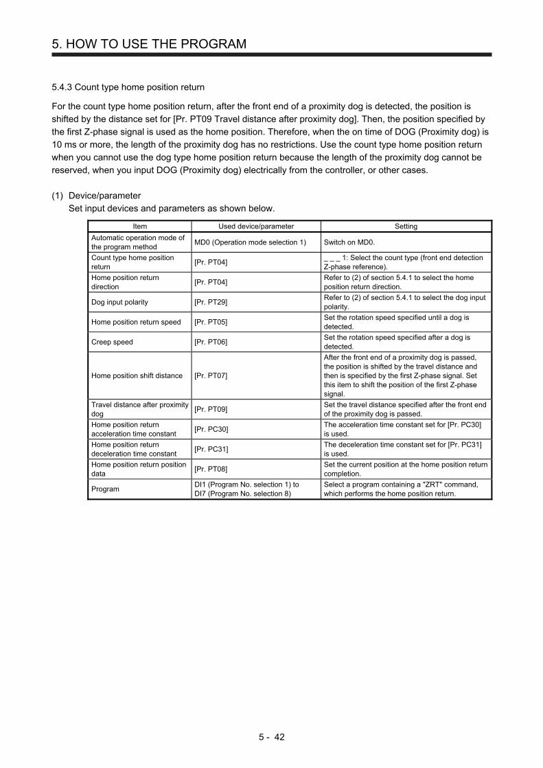
5. HOW TO USE THE PROGRAM
5 - 42
5.4.3 Count type home position return
For the count type home position return, after the front end of a proximity dog is detected, the position is
shifted by the distance set for [Pr. PT09 Travel distance after proximity dog]. Then, the position specified by
the first Z-phase signal is used as the home position. Therefore, when the on time of DOG (Proximity dog) is
10 ms or more, the length of the proximity dog has no restrictions. Use the count type home position return
when you cannot use the dog type home position return because the length of the proximity dog cannot be
reserved, when you input DOG (Proximity dog) electrically from the controller, or other cases.
(1) Device/parameter
Set input devices and parameters as shown below.
Item Used device/parameter Setting
Automatic operation mode of the program method
MD0 (Operation mode selection 1) Switch on MD0.
Count type home position return
[Pr. PT04] _ _ _ 1: Select the count type (front end detection Z-phase reference).
Home position return direction
[Pr. PT04] Refer to (2) of section 5.4.1 to select the home position return direction.
Dog input polarity [Pr. PT29] Refer to (2) of section 5.4.1 to select the dog input polarity.
Home position return speed [Pr. PT05] Set the rotation speed specified until a dog is detected.
Creep speed [Pr. PT06] Set the rotation speed specified after a dog is detected.
Home position shift distance [Pr. PT07]
After the front end of a proximity dog is passed, the position is shifted by the travel distance and then is specified by the first Z-phase signal. Set this item to shift the position of the first Z-phase signal.
Travel distance after proximity dog
[Pr. PT09] Set the travel distance specified after the front end of the proximity dog is passed.
Home position return acceleration time constant
[Pr. PC30] The acceleration time constant set for [Pr. PC30] is used.
Home position return deceleration time constant
[Pr. PC31] The deceleration time constant set for [Pr. PC31] is used.
Home position return position data
[Pr. PT08] Set the current position at the home position return completion.
Program DI1 (Program No. selection 1) to DI7 (Program No. selection 8)
Select a program containing a "ZRT" command, which performs the home position return.
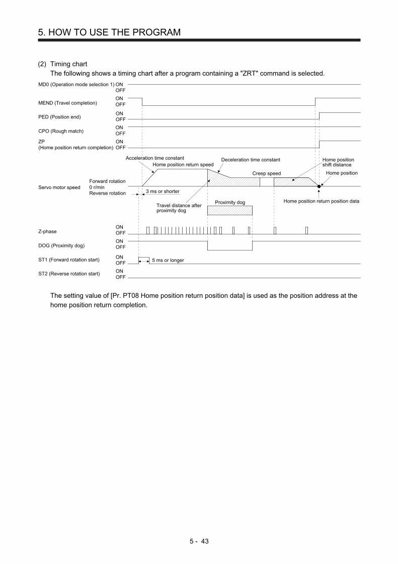
5. HOW TO USE THE PROGRAM
5 - 43
(2) Timing chart
The following shows a timing chart after a program containing a "ZRT" command is selected.
ONOFF
MEND (Travel completion)ONOFF
CPO (Rough match)ONOFF
Servo motor speed
MD0 (Operation mode selection 1)
Forward rotation0 r/minReverse rotation
ONOFF
ONOFF
Z-phase
DOG (Proximity dog)
ZP(Home position return completion)
ONOFF
ONOFF
ONOFF
ST1 (Forward rotation start)
ST2 (Reverse rotation start)
3 ms or shorter
Home position return speedDeceleration time constant
Creep speed
Home positionshift distance
Home position
Home position return position dataProximity dog
5 ms or longer
Acceleration time constant
Travel distance afterproximity dog
PED (Position end)ONOFF
The setting value of [Pr. PT08 Home position return position data] is used as the position address at the
home position return completion.

5. HOW TO USE THE PROGRAM
5 - 44
5.4.4 Data set type home position return
To specify any position as the home position, use the data set type home position return. To shift the
position, you can use the JOG operation, the manual pulse generator operation, or others. The data set type
home position return is available at servo-on only.
(1) Device/parameter
Set input devices and parameters as shown below.
Item Used device/parameter Setting
Automatic operation mode of the program method
MD0 (Operation mode selection 1) Switch on MD0.
Data set type home position return
[Pr. PT04] _ _ _ 2: Select the data set type.
Home position return position data
[Pr. PT08] Set the current position at the home position return completion.
Program DI1 (Program No. selection 1) to DI7 (Program No. selection 8)
Select a program containing a "ZRT" command, which performs the home position return.
(2) Timing chart
SON (Servo-on)ONOFF
ZP(Home position return completion)
ONOFF
Forward rotation0 r/minReverse rotation
ONOFF
Servo motor speed
ST1 (Forward rotation start)
MD0 (Operation mode selection 1)ONOFF
ONOFFST2 (Reverse rotation start)
3 ms or shorter
Home position returnposition data
5 ms or longer
MEND (Travel completion)ONOFF
CPO (Rough match) ONOFF
Travel to home position Execution of data set type home position return
PED (Position end)ONOFF
The setting value of [Pr. PT08 Home position return position data] is used as the position address at the
home position return completion.

5. HOW TO USE THE PROGRAM
5 - 45
5.4.5 Stopper type home position return
For the stopper type home position return, by using the JOG operation, manual pulse generator operation, or
others, a workpiece is pressed against a mechanical stopper, and the position where it is stopped is used as
the home position.
(1) Device/parameter
Set input devices and parameters as shown below.
Item Used device/parameter Setting
Automatic operation mode of the program method
MD0 (Operation mode selection 1) Switch on MD0.
Stopper type home position return
[Pr. PT04] _ _ _ 3: Select the stopper type.
Home position return direction
[Pr. PT04] Refer to (2) of section 5.4.1 to select the home position return direction.
Home position return speed [Pr. PT05] Set the rotation speed until the workpiece is pressed against the mechanical stopper.
Stopper time [Pr. PT10]
Set the time from when the home position data is obtained after the workpiece is pressed against the stopper until when ZP (home position return completion) is outputted.
Stopper type home position return torque limit value
[Pr. PT11] Set the servo motor torque limit value at the execution of the stopper type home position return.
Home position return acceleration time constant
[Pr. PC30] The acceleration time constant set for [Pr. PC30] is used.
Home position return deceleration time constant
[Pr. PC31] The deceleration time constant set for [Pr. PC31] is used.
Home position return position data
[Pr. PT08] Set the current position at the home position return completion.
Program DI1 (Program No. selection 1) to DI7 (Program No. selection 8)
Select a program containing a "ZRT" command, which performs the home position return.
(2) Timing chart
The following shows a timing chart after a program containing a "ZRT" command is selected.
ONOFF
MEND (Travel completion)ONOFF
CPO (Rough match)ONOFF
ST2 (Reverse rotation start)
MD0 (Operation mode selection 1)
ONOFF
ONOFF
TLC (Limiting torque)
Torque limit value
ZP(Home position return completion)
ONOFF
Servo motor speedForward rotation0 r/minReverse rotation
ST1 (Forward rotation start)ONOFF
Acceleration time constantHome position return speed Home position return
position data
3 ms or shorter
5 ms or longer
Stopper time
[Pr. PC35] [Pr. PT11] (Note) [Pr. PC35]
PED (Position end)ONOFF
Stopper
Note. The following torque limits are enabled.

5. HOW TO USE THE PROGRAM
5 - 46
Input device (0: Off, 1: On)
Limit value status Enabled torque limit
value TL1 TL
0 0 Pr. PT11
0 1 TLA > Pr. PT11 Pr. PT11
TLA < Pr. PT11 TLA
1 0 Pr. PC35 > Pr. PT11 Pr. PT11
Pr. PC35 < Pr. PT11 Pr. PC35
1 1 TLA > Pr. PT11 Pr. PT11
TLA < Pr. PT11 TLA
The setting value of [Pr. PT08 Home position return position data] is used as the position address at the
home position return completion.
5.4.6 Home position ignorance (servo-on position as home position)
POINT
To perform a home position return by using the home position ignorance,
selecting a program containing a "ZRT" command is not required.
The position at servo-on is used as the home position.
(1) Device/parameter
Set input devices and parameters as shown below.
Item Used device/parameter Setting
Home position ignorance [Pr. PT04] _ _ _ 4: Select the home position ignorance (servo-on position as home position).
Home position return position data
[Pr. PT08] Set the current position at the home position return completion.
(2) Timing chart
ONOFF
RD (Ready)ONOFF
MEND (Travel completion)ONOFF
CPO (Rough match)
ZP(Home position return completion)
ONOFF
Forward rotation0 r/minReverse rotation
SON (Servo-on)
Servo motor speed
Home position return position data
ONOFF
PED (Position end)ONOFF
The setting value of [Pr. PT08 Home position return position data] is used as the position address at the
home position return completion.

5. HOW TO USE THE PROGRAM
5 - 47
5.4.7 Dog type rear end reference home position return
POINT
This home position return method depends on the timing of reading DOG
(Proximity dog) that has detected the rear end of a proximity dog. Therefore,
when a home position return is performed at a creep speed of 100 r/min, the
home position has an error of 6400 pulses (for HG series servo motor). The
higher the creep speed, the greater the error of the home position.
Deceleration starts at the front end of a proximity dog. After the rear end is passed, the position is shifted by
the travel distance after proximity dog and the home position shift distance. The position after the shifts is
used as the home position. The home position return is available independently of the Z-phase signal.
(1) Device/parameter
Set input devices and parameters as shown below.
Item Used device/parameter Setting
Automatic operation mode of the program method
MD0 (Operation mode selection 1) Switch on MD0.
Dog type rear end reference home position return
[Pr. PT04] _ _ _ 5: Select the dog type (rear end detection/rear end reference).
Home position return direction
[Pr. PT04] Refer to (2) of section 5.4.1 to select the home position return direction.
Dog input polarity [Pr. PT29] Refer to (2) of section 5.4.1 to select the dog input polarity.
Home position return speed [Pr. PT05] Set the rotation speed specified until a dog is detected.
Creep speed [Pr. PT06] Set the rotation speed specified after a dog is detected.
Home position shift distance [Pr. PT07] Set this item to shift the home position, which is specified after the rear end of a proximity dog is passed.
Travel distance after proximity dog
[Pr. PT09] Set the travel distance specified after the rear end of a proximity dog is passed.
Home position return acceleration time constant
[Pr. PC30] The acceleration time constant set for [Pr. PC30] is used.
Home position return deceleration time constant
[Pr. PC31] The deceleration time constant set for [Pr. PC31] is used.
Home position return position data
[Pr. PT08] Set the current position at the home position return completion.
Program DI1 (Program No. selection 1) to DI7 (Program No. selection 8)
Select a program containing a "ZRT" command, which performs the home position return.

5. HOW TO USE THE PROGRAM
5 - 48
(2) Timing chart
The following shows a timing chart after a program containing a "ZRT" command is selected.
ONOFF
MEND (Travel completion)ONOFF
CPO (Rough match)ONOFF
Servo motor speed
MD0 (Operation mode selection 1)
Forward rotation0 r/minReverse rotation
ONOFFDOG (Proximity dog)
ZP(Home position return completion)
ONOFF
ONOFF
ONOFF
ST1 (Forward rotation start)
ST2 (Reverse rotation start)
3 ms or shorter
Home position return speedDeceleration time constant
Creep speed
Travel distance afterproximity dog
+Home positionshift distance
Home position return position dataProximity dog
5 ms or longer
Acceleration timeconstant
PED (Position end)ONOFF
The setting value of [Pr. PT08 Home position return position data] is used as the position address at the
home position return completion.

5. HOW TO USE THE PROGRAM
5 - 49
5.4.8 Count type front end reference home position return
POINT
This home position return method depends on the timing of reading DOG
(Proximity dog) that has detected the front end of a proximity dog. Therefore,
when a home position return is performed at a creep speed of 100 r/min, the
home position has an error of 6400 pulses (for HG series servo motor). The
higher the creep speed, the greater the error of the home position.
After the front end of a proximity dog is detected, when a home position return
ends without reaching the creep speed, [AL. 90.2] occurs. Set the travel
distance after proximity dog and the home position shift distance enough for
deceleration from the home position return speed to the creep speed.
(1) Device/parameter
Set input devices and parameters as shown below.
Item Used device/parameter Setting
Automatic operation mode of the program method
MD0 (Operation mode selection 1) Switch on MD0.
Count type front end reference home position return
[Pr. PT04] _ _ _ 6: Select the count type (front end detection/front end reference).
Home position return direction
[Pr. PT04] Refer to (2) of section 5.4.1 to select the home position return direction.
Dog input polarity [Pr. PT29] Refer to (2) of section 5.4.1 to select the dog input polarity.
Home position return speed [Pr. PT05] Set the rotation speed specified until a dog is detected.
Creep speed [Pr. PT06] Set the rotation speed specified after a dog is detected.
Home position shift distance [Pr. PT07] Set this to shift the home position, which is specified after the front end of a proximity dog is passed.
Travel distance after proximity dog
[Pr. PT09] Set the travel distance specified after the front end of the proximity dog is passed.
Home position return acceleration time constant
[Pr. PC30] The acceleration time constant set for [Pr. PC30] is used.
Home position return deceleration time constant
[Pr. PC31] The deceleration time constant set for [Pr. PC31] is used.
Home position return position data
[Pr. PT08] Set the current position at the home position return completion.
Program DI1 (Program No. selection 1) to DI7 (Program No. selection 8)
Select a program containing a "ZRT" command, which performs the home position return.

5. HOW TO USE THE PROGRAM
5 - 50
(2) Timing chart
The following shows a timing chart after a program containing a "ZRT" command is selected.
ONOFF
MEND (Travel completion)ONOFF
CPO (Rough match) ONOFF
Servo motor speed
MD0 (Operation mode selection 1)
Forward rotation0 r/minReverse rotation
ONOFF
DOG (Proximity dog)
ZP(Home position return completion)
ONOFF
ONOFF
ONOFF
ST1 (Forward rotation start)
ST2 (Reverse rotation start)
3 ms or shorter
Home position return speedDeceleration time constant
Creep speed
Travel distance afterproximity dog
+Home positionshift distance
Home position return position dataProximity dog
5 ms or longer
Acceleration time constant
PED (Position end) ONOFF
The setting value of [Pr. PT08 Home position return position data] is used as the position address at the
home position return completion.

5. HOW TO USE THE PROGRAM
5 - 51
5.4.9 Dog cradle type home position return
You can use the position, which is specified by the first Z-phase signal after the front end of a proximity dog
is detected, as the home position.
(1) Device/parameter
Set input devices and parameters as shown below.
Item Used device/parameter Setting
Automatic operation mode of the program method
MD0 (Operation mode selection 1) Switch on MD0.
Dog cradle type home position return
[Pr. PT04] _ _ _ 7: Select the dog cradle type.
Home position return direction
[Pr. PT04] Refer to (2) of section 5.4.1 to select the home position return direction.
Dog input polarity [Pr. PT29] Refer to (2) of section 5.4.1 to select the dog input polarity.
Home position return speed [Pr. PT05] Set the rotation speed specified until a dog is detected.
Creep speed [Pr. PT06] Set the rotation speed specified after a dog is detected.
Home position shift distance [Pr. PT07] Set this item to shift the home position, which is specified by the Z-phase signal.
Home position return acceleration time constant
[Pr. PC30] The acceleration time constant set for [Pr. PC30] is used.
Home position return deceleration time constant
[Pr. PC31] The deceleration time constant set for [Pr. PC31] is used.
Home position return position data
[Pr. PT08] Set the current position at the home position return completion.
Program DI1 (Program No. selection 1) to DI7 (Program No. selection 8)
Select a program containing a "ZRT" command, which performs the home position return.

5. HOW TO USE THE PROGRAM
5 - 52
(2) Timing chart
The following shows a timing chart after a program containing a "ZRT" command is selected.
ONOFF
MEND (Travel completion)ONOFF
CPO (Rough match)ONOFF
Servo motor speed
MD0 (Operation mode selection 1)
Forward rotation0 r/minReverse rotation
ONOFFDOG (Proximity dog)
ZP(Home position return completion)
ONOFF
ONOFF
ONOFF
ST1 (Forward rotation start)
ST2 (Reverse rotation start)
3 ms or shorter
Home position return speedDeceleration time constant
Creep speed
Home positionshift distance
Home position return position data
5 ms or longer
Acceleration time constant
Proximity dog
ONOFFZ-phase
PED (Position end)ONOFF
The setting value of [Pr. PT08 Home position return position data] is used as the position address at the
home position return completion.

5. HOW TO USE THE PROGRAM
5 - 53
5.4.10 Dog type last Z-phase reference home position return
After the front end of a proximity dog is detected, the position is shifted away from the proximity dog at the
creep speed in the reverse direction and then specified by the first Z-phase signal. The position of the first Z-
phase signal is used as the home position.
(1) Device/parameter
Set input devices and parameters as shown below.
Item Used device/parameter Setting
Automatic operation mode of the program method
MD0 (Operation mode selection 1) Switch on MD0.
Dog type last Z-phase reference home position return
[Pr. PT04] _ _ _ 8: Select the dog type (front end detection/Z-phase reference).
Home position return direction
[Pr. PT04] Refer to (2) of section 5.4.1 to select the home position return direction.
Dog input polarity [Pr. PT29] Refer to (2) of section 5.4.1 to select the dog input polarity.
Home position return speed [Pr. PT05] Set the rotation speed specified until a dog is detected.
Creep speed [Pr. PT06] Set the rotation speed specified after a dog is detected.
Home position shift distance [Pr. PT07] Set this item to shift the home position, which is specified by the Z-phase signal.
Home position return acceleration time constant
[Pr. PC30] The acceleration time constant set for [Pr. PC30] is used.
Home position return deceleration time constant
[Pr. PC31] The deceleration time constant set for [Pr. PC31] is used.
Home position return position data
[Pr. PT08] Set the current position at the home position return completion.
Program DI1 (Program No. selection 1) to DI7 (Program No. selection 8)
Select a program containing a "ZRT" command, which performs the home position return.

5. HOW TO USE THE PROGRAM
5 - 54
(2) Timing chart
The following shows a timing chart after a program containing a "ZRT" command is selected.
ONOFF
MEND (Travel completion)ONOFF
CPO (Rough match)ONOFF
Servo motor speed
MD0 (Operation mode selection 1)
Forward rotation0 r/minReverse rotation
ONOFF
DOG (Proximity dog)
ZP(Home position return completion)
ONOFF
ONOFF
ONOFF
ST1 (Forward rotation start)
ST2 (Reverse rotation start)
3 ms or shorter
Home position return speed Deceleration time constant
Creep speedHome position shift distance
Home position return position data
5 ms or longer
Acceleration time constant
ONOFF
Z-phase
Proximity dog
PED (Position end)ONOFF
The setting value of [Pr. PT08 Home position return position data] is used as the position address at the
home position return completion.

5. HOW TO USE THE PROGRAM
5 - 55
5.4.11 Dog type front end reference home position return type
POINT
This home position return method depends on the timing of reading DOG
(Proximity dog) that has detected the front end of a proximity dog. Therefore,
when a home position return is performed at a creep speed of 100 r/min, the
home position has an error of 6400 pulses (for HG series servo motor). The
higher the creep speed, the greater the error of the home position.
The home position is where the machine moves the travel distance after proximity dog and the home
position shift distance from the front end of a proximity dog.
The home position return is available independently of the Z-phase signal. Changing the creep speed may
change the home position.
(1) Device/parameter
Set input devices and parameters as follows.
Item Used device/parameter Setting
Automatic operation mode of the program method
MD0 (Operation mode selection 1) Switch on MD0.
Dog type front end reference home position return
[Pr. PT04] _ _ _ 9: Select the dog type (front end detection/ front end reference).
Home position return direction
[Pr. PT04] Refer to section 5.4.1 (2) to select the home position return direction.
Dog input polarity [Pr. PT29] Refer to section 5.4.1 (2) to select the dog input polarity.
Home position return speed [Pr. PT05] Set the rotation speed until a dog is detected.
Creep speed [Pr. PT06] Set the rotation speed after a dog is detected.
Home position shift distance [Pr. PT07] Set this item to move the home position set when the Z-phase signal is given.
Travel distance after proximity dog
[Pr. PT09] Set the travel distance specified after the front end of the proximity dog is passed.
Home position return acceleration time constant
[Pr. PC30] The acceleration time constant set for [Pr. PC30] is used.
Home position return deceleration time constant
[Pr. PC31] The deceleration time constant set for [Pr. PC31] is used.
Home position return position data
[Pr. PT08] Set a current position at home position return completion.
Program DI0 (Program No. selection 1) to DI7 (Program No. selection 8)
Select a program containing "ZRT" command that performs a home position return.

5. HOW TO USE THE PROGRAM
5 - 56
(2) Timing chart
The following shows a timing chart after a program containing a "ZRT" command is selected.
ONOFF
MEND (Travel completion)ONOFF
CPO (Rough match)ONOFF
Servo motor speed
MD0 (Operation mode selection 1)
Forward rotation0 r/minReverse rotation
ONOFFDOG (Proximity dog)
ZP(Home position return completion)
ONOFF
ONOFF
ONOFF
ST1 (Forward rotation start)
ST2 (Reverse rotation start)
3 ms or shorter
Deceleration time constant
Creep speed
Travel distance after proximity dog+
Home position shift distance
Proximity dog
5 ms or longer
Acceleration timeconstant
Home position return speed
PED (Position end)ONOFF
Home position return position data
The setting value of [Pr. PT08 Home position return position data] is used as the position address at the
home position return completion.

5. HOW TO USE THE PROGRAM
5 - 57
5.4.12 Dogless Z-phase reference home position return type
Starting from the Z-phase pulse position after the start of the home position return, the position is shifted by
the home position shift distance. The position after the shifts is used as the home position.
(1) Device/parameter
Set input devices and parameters as follows.
Item Used device/parameter Setting
Automatic operation mode of the program method
MD0 (Operation mode selection 1) Switch on MD0.
Dogless Z-phase reference home position return
[Pr. PT04] _ _ _ A: Select the dogless type (Z-phase reference).
Home position return direction
[Pr. PT04] Refer to section 5.4.1 (2) to select the home position return direction.
Dog input polarity [Pr. PT29] Refer to section 5.4.1 (2) to select the dog input polarity.
Home position return speed [Pr. PT05] Set the rotation speed until a dog is detected.
Creep speed [Pr. PT06] Set the rotation speed after a dog is detected.
Home position shift distance [Pr. PT07] Set this item to move the home position set when the Z-phase signal is given.
Home position return acceleration time constant
[Pr. PC30] The acceleration time constant set for [Pr. PC30] is used.
Home position return deceleration time constant
[Pr. PC31] The deceleration time constant set for [Pr. PC31] is used.
Home position return position data
[Pr. PT08] Set a current position at home position return completion.
Program DI0 (Program No. selection 1) to DI7 (Program No. selection 8)
Select a program containing "ZRT" command that performs a home position return.
(2) Timing chart
The following shows a timing chart after a program containing a "ZRT" command is selected.
ONOFF
MEND (Travel completion)ONOFF
CPO (Rough match)ONOFF
Servo motor speed
MD0 (Operation mode selection 1)
Forward rotation0 r/minReverse rotation
ONOFF
Z-phase
ZP (Home position return completion)ONOFF
ONOFF
ONOFF
ST1 (Forward rotation start)
ST2 (Reverse rotation start)
3 ms or shorter
Deceleration time constant
5 ms or longer
Acceleration timeconstant
Home position return speed
Home position shift distanceCreep speed
PED (Position end)ONOFF
Home position return position data
The setting value of [Pr. PT08 Home position return position data] is used as the position address at the
home position return completion.

5. HOW TO USE THE PROGRAM
5 - 58
5.4.13 Automatic retract function used for the home position return
For a home position return using the proximity dog, when the home position return is started from the
position on or beyond the proximity dog, the home position return is performed after the machine moves
back to the position where the home position can be performed.
(1) When the current position is on the proximity dog
When the current position is on the proximity dog, the machine moves backward automatically, and the
home position return is performed.
Proximity dogHome positionreturn direction
Home position start position
After retracting to before proximity dog,the home position return starts from here.
Servo motor speedReverserotation
0 r/min
(2) When the current position is beyond the proximity dog
At start-up, the operation is performed in the direction of the home position return. When LSP (Forward
rotation stroke end) or LSN (Reverse rotation stroke end) is detected, the machine moves backward
automatically. The machine passes and stops before the proximity dog, and the home position return is
performed from the position again. If the proximity dog cannot be detected, the machine stops at LSP or
LSN on the opposite side, and [AL. 90 Home position return incomplete warning] will occur.
Proximity dogLSP (Forward rotation stroke end) orLSN (Reverse rotation stroke end)
After retracting to before proximity dog,the home position return starts from here.
Home positionreturn direction
Home position start position
Servo motor speed
Forwardrotation
Reverserotation
0 r/min
The software limit cannot be used with these functions.

5. HOW TO USE THE PROGRAM
5 - 59
5.5 Serial communication operation
Using the RS-422 communication function, you can use to operate a servo amplifier from the controller such
as a personal computer.
This section explains the data communication procedure. Refer to chapter 10 for details of the connection
between the controller and servo amplifier and of communication data.
5.5.1 Positioning operation using the program
Using the communication function can select program Nos., perform the positioning operation using the
program by switching on ST1 (Forward rotation start).
(1) Program selection
Select program No. 1 to 256 using the forced output of the device from the controller (command [9] [2]
and data No. [6] [0]).
(2) Timing chart
Transmission data 1) 4) 2) 4)5) 3) 4)5) 5)
5 ms or longer 5 ms or longer 5 ms or longer
Servo motor speed
Program No. 2 Program No. 1 Program No. 3
3 ms
No. Transmission data description Command Data No.
1) Select Program No. 2. [9] [2] [6] [0]
2) Select Program No. 1. [9] [2] [6] [0]
3) Select Program No. 3. [9] [2] [6] [0]
4) Switch on ST1 (Forward rotation start). [9] [2] [6] [0]
5) Switch off ST1 (Forward rotation start). [9] [2] [6] [0]

5. HOW TO USE THE PROGRAM
5 - 60
5.5.2 Multi-drop method (RS-422 communication)
Using the RS-422 communication function can use to operate multiple servo amplifiers on the same bus. In
this case, set station numbers to the servo amplifier because the controller recognizes that the data currently
being sent is for which servo amplifier. Set station Nos. with [Pr. PC20 Station number setting].
Always set one station No. to one servo amplifier. Setting one station number to multiple servo amplifiers will
disable a normal communication. When you use to operate multiple servo amplifiers under one command,
use the group specification function in section 5.5.3.
(1) MR-J4-_A_-RJ 100 W or more
RS-422/232C conversion cableDSV-CABV (Diatrend)
(Note 1)
(Note 2)
(Note 1)(Note 1)
Servo amplifier
CN3
Servo amplifier
CN3
Servo amplifier
CN3
Axis No. 1(station 0)
Axis No. 2(station 1)
Axis No. 32(station 31)RS-422/RS-485
compatible controller
Note 1. The BMJ-8 (Hachiko Electric) is recommended as the branch connector.
2. The final axis must be terminated between RDP (pin No.3) and RDN (pin No.6) on the receiving side (servo
amplifier) with a 150 Ω resistor.
(2) MR-J4-03A6-RJ
Axis No. 32 (station 31)Axis No. 2 (station 1)Axis No. 1 (station 0)
Servo amplifier
CN1
Servo amplifier Servo amplifier
CN1 CN1
RS-422 compatiblecontroller

5. HOW TO USE THE PROGRAM
5 - 61
5.5.3 Group specification
CAUTION Set only one servo amplifier capable of returning data in a group. If multiple servo
amplifiers return data under commands from the controller, the servo amplifiers
may malfunction.
When using multiple servo amplifiers, you can set parameters with commands per group.
Up to 6 groups of a to f can be set. Set groups for each station with the communication commands of
Mitsubishi general-purpose AC servo protocol.
(1) Group setting example
The following shows a configuration diagram of MR-J4-_A_-RJ 100 W or more servo amplifiers.
For cable connection diagram, refer to section14.1.1 of "MR-J4-_A_(-RJ) Servo AmplifierInstruction Manual".
CN3CN3CN3
Axis No. 3(station 2)
Axis No. 4(station 3)
Axis No. 5(station 4)
RS-422/RS-485compatible controller
CN3CN3
Axis No. 1(station 0)
Axis No. 2(station 1)
CN3CN3CN3
Axis No. 8(station 7)
Axis No. 7(station 6)
Axis No. 6(station 5)
CN3CN3
Axis No. 10(station 9)
Axis No. 9(station 8)
Group a Group b
Group d Group c
Servo amplifier station No.
Group setting
Station 0
Station 1 a
Station 2
Station 3
Station 4 b
Station 5
Station 6 c
Station 7
Station 8 d
Station 9

5. HOW TO USE THE PROGRAM
5 - 62
(2) Timing chart
The following shows a timing chart of operation for each group performed with setting values set in
program No. 1.
1) 2) 3) 4) 5) 6) 7) 8) 9) 10) 11) 12)Transmission data
Station 0Servo motorspeed
Group a
Station 4Servo motorspeed
Group b
Station 1Servo motorspeed
Station 2Servo motorspeed
Station 3Servo motorspeed
Station 5Servo motorspeed
Station 6Servo motorspeed
Station 7Servo motorspeed
Station 8Servo motorspeed
Station 9Servo motorspeed
Group c
Group d
No. Transmission data description Command Data No.
1) Select Program No. 1 in group a. [9] [2] [6] [0]
2) Switch on ST1 (Forward rotation start). [9] [2] [6] [0]
3) Switch off ST1 (Forward rotation start). [9] [2] [6] [0]
4) Select Program No. 1 in group b. [9] [2] [6] [0]
5) Switch on ST1 (Forward rotation start). [9] [2] [6] [0]
6) Switch off ST1 (Forward rotation start). [9] [2] [6] [0]
7) Select Program No. 1 in group c. [9] [2] [6] [0]
8) Switch on ST1 (Forward rotation start). [9] [2] [6] [0]
9) Switch off ST1 (Forward rotation start). [9] [2] [6] [0]
10) Select Program No. 1 in group d. [9] [2] [6] [0]
11) Switch on ST1 (Forward rotation start). [9] [2] [6] [0]
12) Switch off ST1 (Forward rotation start). [9] [2] [6] [0]
Besides this, you can perform simultaneous writing of parameters common to stations of each group,
reset alarms, etc.

5. HOW TO USE THE PROGRAM
5 - 63
5.6 Incremental value command method
When using this servo amplifier under the incremental value command method, you must change the setting
of [Pr. PT01].
As position data, set the travel distance from the current address to the target address. The incremental
value command method enables infinitely long constant rate of feeding.
Setting range: -999999 to 999999 [×10STM μm] (STM = Feed length multiplication [Pr. PT03])
-999999 to 999999 [×10(STM-4) inch] (STM = Feed length multiplication [Pr. PT03])
-999999 to 999999 [pulse]
Position data = |Target address - Current address|
Current address Target address
This section indicates contents different from the absolute value command method (factory setting) when
this servo amplifier is used under the incremental value command method.
(1) Parameter setting
Set [Pr. PT01] to select the incremental value command method as shown below.
[Pr. PT01]
Incremental value command method
1
(2) Command
The command contents of "MOV" and "MOVA" are changed as follows. There are no changes in other
command. Thus, the command contents are the same between "MOV" and "MOVI", and between
"MOVA" and "MOVIA".
Command Name Setting Setting range Unit Indirect
specification
Description
MOV Incremental value travel command
MOV (setting value)
-999999 to 999999
×10STM μm
The servo motor rotates using the set value as the incremental value.
The same as "MOVI" command
MOVA
Incremental value continuous travel command
MOVA (setting value)
-999999 to 999999
×10STM μm
The servo motor rotates continuously as the set incremental value.
Make sure to describe this command after the "MOV" command. If this command is described after other command, an error will occur.
The same as "MOVIA" command

5. HOW TO USE THE PROGRAM
5 - 64
(3) Program example
Command Description
SPN (1000) Servo motor speed 1000 [r/min] a)
STA (200) Acceleration time constant 200 [ms] b)
STB (300) Deceleration time constant 300 [ms] c)
MOVI (1000) Incremental value travel command 1000 [×10STM μm] d)
TIM (100) Dwell 100 [ms] e)
SPN (500) Servo motor speed 500 [r/min] f)
STA (200) Acceleration/deceleration time constant
200 [ms] g)
STB (300) Deceleration time constant 300 [ms] h)
MOVI (1000) Incremental value travel command 1000 [×10STM μm] i)
SPN (1000) Servo motor speed 1000 [r/min] j)
MOVIA (1000) Incremental value continuous travel command
1000 [×10STM μm] k)
STOP Program stop
a) Servo motorspeed(1000 r/min) f) Servo motor speed
(500 r/min)
g) Acceleration time constant(200 ms)
c) Deceleration timeconstant (300 ms)
b) Acceleration timeconstant (200 ms)
d) Incremental valuetravel command(1000 × 10STMμm)
e) Dwell(100 ms)
j) Servo motorspeed(1000 r/min)
h) Deceleration timeconstant (300 ms)
k) Incremental valuetravel command(1000 × 10STMμm)
i) Incremental valuetravel command(1000 × 10STMμm)
Servo motorspeed
Forward rotation0 r/minReverse rotation
5.7 Roll feed mode using the roll feed display function
Refer to section 4.5 for parameter settings of roll feed display function, position data unit and operation
method.
When the roll feed display function is used, the status display of the current position at start will be 0.
ST1 (Forward rotation start)
TSTP (Temporary stop/restart)
Servo motor speed
INP (In-position)
Current position
Forward rotation0 r/minReverse rotation
CR (Clear)
Remaining distanceclear
Always "0"
Quick stopby CR input
Remaining distanceclear
ONOFF
ONOFF
ONOFFONOFF

5. HOW TO USE THE PROGRAM
5 - 65
5.8 Program setting method
The following shows the setting method of programs using MR Configurator2.
5.8.1 Setting procedure
Click "Positioning-data" in the menu bar and click "Program" in the menu.
The following window will be displayed by clicking.
(f)
(j)
(b)
(d)(c)(a)
(g)
(h)
(e)
(i)
(1) Reading program (a)
Click the "Read" button to read and display programs stored in the servo amplifier.
(2) Writing program (b)
Click the "Write" button to write the changed programs to the servo amplifier.
(3) Verifying program (c)
Click the "Verify" button to verify the contents of programs in the personal computer with contents of
programs of the servo amplifier.
(4) Single-step feed (d)
Click "Single-step Feed" to perform the single-step feed test operation. Refer to section 3.1.9 or 3.2.9 for
details.
(5) Number of steps (e)
Used number of steps in all programs and remained steps are displayed.
(6) Editing program (f)
You can edit any program. Click the "Edit" button to open the window for program edit. For the rotation
direction, refer to section 5.8.2.
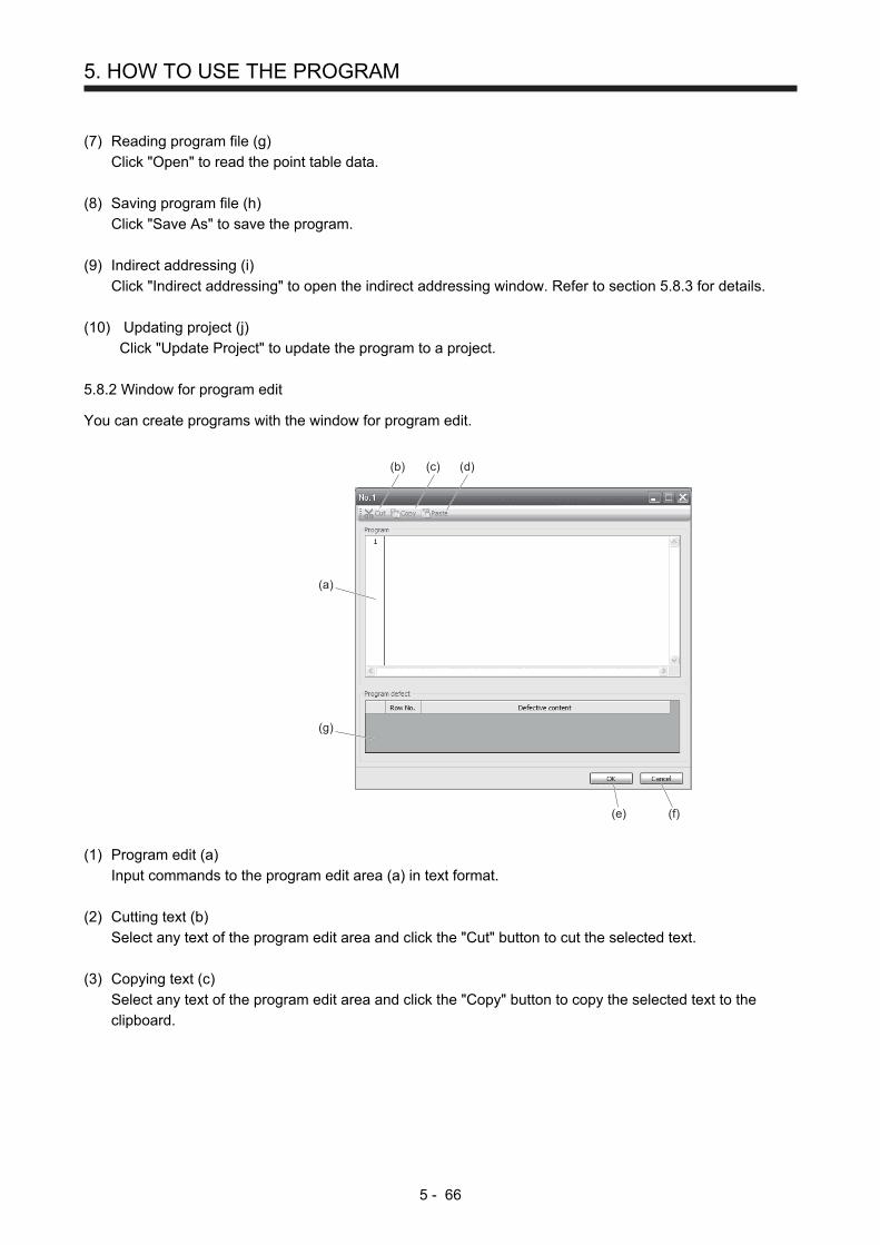
5. HOW TO USE THE PROGRAM
5 - 66
(7) Reading program file (g)
Click "Open" to read the point table data.
(8) Saving program file (h)
Click "Save As" to save the program.
(9) Indirect addressing (i)
Click "Indirect addressing" to open the indirect addressing window. Refer to section 5.8.3 for details.
(10) Updating project (j)
Click "Update Project" to update the program to a project.
5.8.2 Window for program edit
You can create programs with the window for program edit.
(a)
(e) (f)
(b) (c) (d)
(g)
(1) Program edit (a)
Input commands to the program edit area (a) in text format.
(2) Cutting text (b)
Select any text of the program edit area and click the "Cut" button to cut the selected text.
(3) Copying text (c)
Select any text of the program edit area and click the "Copy" button to copy the selected text to the
clipboard.
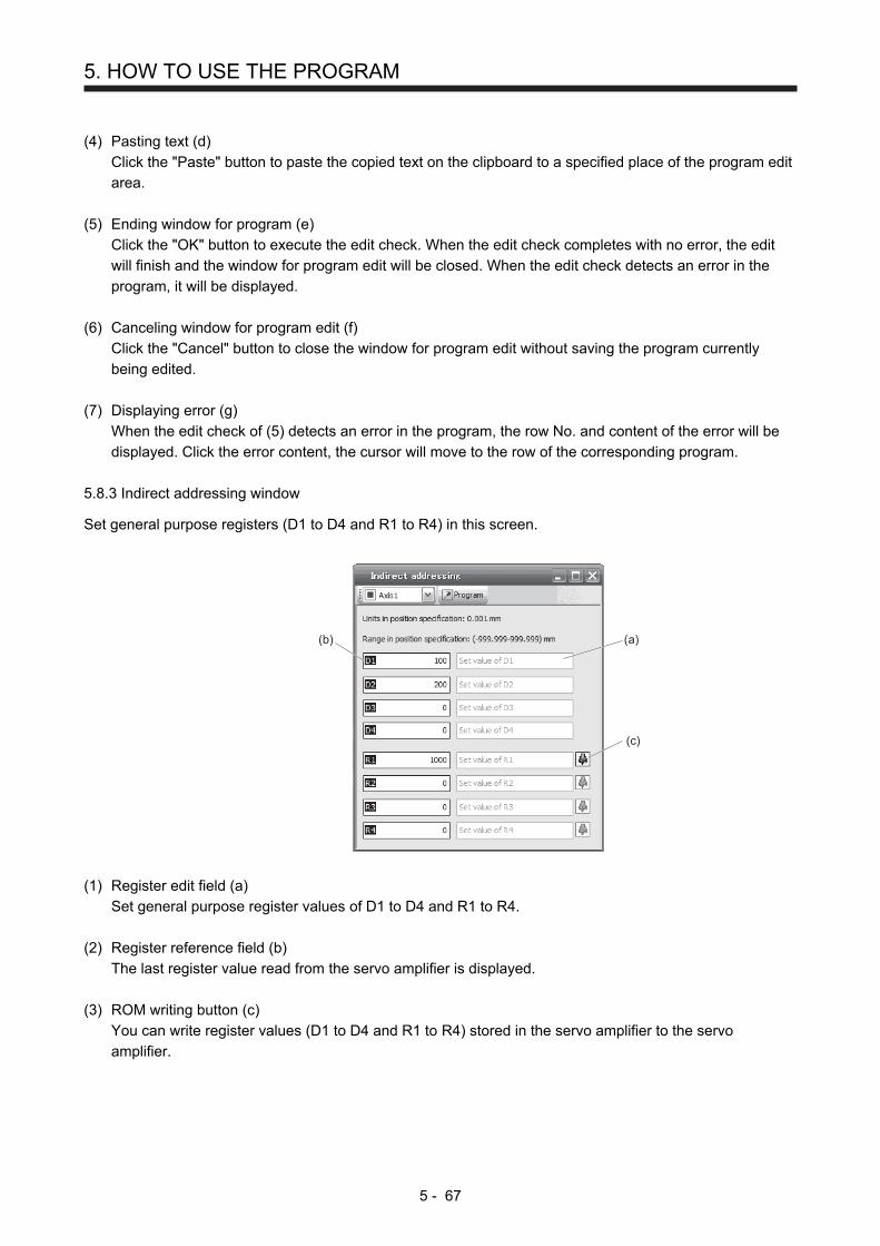
5. HOW TO USE THE PROGRAM
5 - 67
(4) Pasting text (d)
Click the "Paste" button to paste the copied text on the clipboard to a specified place of the program edit
area.
(5) Ending window for program (e)
Click the "OK" button to execute the edit check. When the edit check completes with no error, the edit
will finish and the window for program edit will be closed. When the edit check detects an error in the
program, it will be displayed.
(6) Canceling window for program edit (f)
Click the "Cancel" button to close the window for program edit without saving the program currently
being edited.
(7) Displaying error (g)
When the edit check of (5) detects an error in the program, the row No. and content of the error will be
displayed. Click the error content, the cursor will move to the row of the corresponding program.
5.8.3 Indirect addressing window
Set general purpose registers (D1 to D4 and R1 to R4) in this screen.
(b)
(c)
(a)
(1) Register edit field (a)
Set general purpose register values of D1 to D4 and R1 to R4.
(2) Register reference field (b)
The last register value read from the servo amplifier is displayed.
(3) ROM writing button (c)
You can write register values (D1 to D4 and R1 to R4) stored in the servo amplifier to the servo
amplifier.

5. HOW TO USE THE PROGRAM
5 - 68
MEMO

6. HOW TO USE INDEXER
6 - 1
6. HOW TO USE INDEXER
The following item is the same as that of MR-J4-_A_-RJ servo amplifiers. For the details of the items, refer to
each chapter/section (in "MR-J4-_A_(-RJ) Servo Amplifier Instruction Manual") indicated in the detailed
explanation field.
Item Detailed explanation
MR-J4-_A_-RJ 100 W or more
MR-J4-03A6-RJ
Switching power on for the first time Section 4.1 Section 18.4
POINT
In the absolute position detection system, rotating the shaft one revolution or
more during power-off may erase a home position. Therefore, do not rotate the
shaft one revolution or more during power-off. When a home position is erased,
[AL. 90 Home position return incomplete warning] will occur. Then, execute the
home position return again.
The indexer method cannot be used in the fully closed loop system and linear
servo system. The combination of the indexer method and fully closed loop
system/linear servo system triggers [AL. 37 Parameter error].
6.1 Startup
6.1.1 Power on and off procedures
When the servo amplifier is powered on for the first time, the control mode is set to position control mode.
(Refer to section 4.2.1 of "MR-J4-_A_(-RJ) Servo Amplifier Instruction Manual".)
This section provides a case where the servo amplifier is powered on after setting the positioning mode.
(1) Power-on
Switch power on in the following procedure. Always follow this procedure at power-on.
1) Switch off SON (Servo-on).
2) Make sure that ST1 (Forward rotation start) is off.
3) Switch on the main circuit power supply and control circuit power supply.
The display shows "C" ("CL" for MR-J4-03A6-RJ servo amplifiers), and in 2 s later, shows data.
MR-J4-_A_-RJ 100 W or more
MR-J4-03A6-RJ
(2) Power-off
1) Switch off ST1 (Forward rotation start).
2) Switch off SON (Servo-on).
3) Switch off the main circuit power supply and control circuit power supply.

6. HOW TO USE INDEXER
6 - 2
6.1.2 Stop
If any of the following situations occurs, the servo amplifier suspends the running of the servo motor and
brings it to a stop.
Refer to section 3.10 of "MR-J4-_A_(-RJ) Servo Amplifier Instruction Manual" for the servo motor with an
electromagnetic brake.
Operation/command Stopping condition
Switch off SON (Servo-on). The base circuit is shut off and the servo motor coasts.
Alarm occurrence The servo motor decelerates to a stop with the command. With some alarms, however, the dynamic brake operates to bring the servo motor to a stop. (Refer to chapter 8. (Note 1))
EM2 (Forced stop 2) off The servo motor decelerates to a stop with the command. [AL. E6 Servo forced stop warning] occurs. Refer to section 2.3 for EM1.
STO (STO1, STO2) off (Note 2) The base circuit is shut off and the dynamic brake operates to bring the servo motor to a stop.
LSP (Forward rotation stroke end) off, LSN (Reverse rotation stroke end) off
It will bring the motor to a sudden stop and make it servo-locked. It can be run in the opposite direction.
Note 1. Only a list of alarms and warnings is listed in chapter 8. Refer to "MELSERVO-J4 Servo Amplifier Instruction Manual
(Troubleshooting)" for details of alarms and warnings.
2. MR-J4-03A6-RJ servo amplifiers are not compatible with the STO function.

6. HOW TO USE INDEXER
6 - 3
6.1.3 Test operation
Before starting actual operation, perform test operation to make sure that the machine operates normally.
Refer to section 6.1.1 for how to power on and off the servo amplifier.
Test operation of the servo motoralone in JOG operation of
test operation mode
Manual operation of the servomotor alone in test
operation mode
Test operation with the servomotor and machine connected
Automatic operation by indexer
In this step, confirm that the servo amplifier and servo motor operate
normally.
With the servo motor disconnected from the machine, use the test operation
mode and check whether the servo motor correctly rotates at the slowest
speed. For the test operation mode, refer to section 3.1.8 and 3.2.8 in this
manual, and section 4.5.9 and 18.5.10 of "MR-J4-_A_(-RJ) Servo Amplifier
Instruction Manual".
In this step, confirm that the servo motor correctly rotates at the slowest
speed in the manual operation mode.
Make sure that the servo motor rotates in the following procedure. 1) Switch on EM2 (Forced stop 2) and SON (Servo-on). When the servo
amplifier is put in a servo-on status, RD (Ready) switches on. 2) Switch on LSP (Forward rotation stroke end) and LSN (Reverse rotation
stroke end). 3) To rotate the servo motor, turn on ST1 (Forward rotation start) in the
manual operation mode with the controller. Set a low speed to [Pr. PT13]
at first, make the servo motor operate, and check the rotation direction of
the motor, etc. If the machine does not operate in the intended direction,
check the input signal.
In this step, connect the servo motor with the machine and confirm that the
machine operates normally under the commands from the controller.
Make sure that the servo motor rotates in the following procedure. 1) Switch on EM2 (Forced stop 2) and SON (Servo-on). When the servo
amplifier is put in a servo-on status, RD (Ready) switches on. 2) Switch on LSP (Forward rotation stroke end) and LSN (Reverse rotation
stroke end). 3) To rotate the servo motor, turn on ST1 (Forward rotation start) in the
manual operation mode with the controller. Set a low speed to [Pr. PT13]
at first, make the servo motor operate, and check the operation direction
of the machine, etc. If the machine does not operate in the intended
direction, check the input signal. In the status display, check for any
problems of the servo motor speed, load ratio, etc. Check automatic operation from the controller.

6. HOW TO USE INDEXER
6 - 4
6.1.4 Parameter setting
POINT
The following encoder cables are of four-wire type. When using any of these
encoder cables, set [Pr. PC22] to "1 _ _ _" to select the four-wire type. Incorrect
setting will result in [AL. 16 Encoder initial communication error 1].
MR-EKCBL30M-L
MR-EKCBL30M-H
MR-EKCBL40M-H
MR-EKCBL50M-H
When using this servo in the indexer method, set [Pr. PA01] to "_ _ _ 8" (Positioning mode (indexer
method)). For the indexer method, the servo can be used by merely changing the basic setting parameters
([Pr. PA _ _ ]) and positioning control parameters ([Pr. PT _ _ ]) mainly.
As necessary, set other parameters.
The following table shows [Pr. PA _ _ ] and [Pr. PT _ _ ] settings required for the indexer method.
Operation mode selection item Operation mode
Parameter setting Input device setting
[Pr. PA01][Pr. PT04] (Note 2)
[Pr. PT27]MD0
(Note 1) MD1
(Note 1) DI0 to DI7 (Note 1)
Automatic operation mode
Automatic operation mode 1 (Rotation direction specifying indexer)
_ _ _ 8
Off On Set any next station No. (Refer to section
6.2.2 (3).) Automatic operation mode 2 (Shortest rotating indexer)
On On
Manual operation mode
Station JOG operation
_ _ 0 _ On Off Any
JOG operation _ _ 1 _
Home position return mode
Dog type/Torque limit changing dog type
_ _ _ 0
Off Off Any Data set type/torque limit changing data set type
_ _ _ 2
Note 1. MD0: Operation mode selection 1, MD1: Operation mode selection 2, DI0 to DI7: Next station No. selection 1 to 8
2. Setting other than "_ _ _ 0" and "_ _ _ 2" will trigger [AL.37 Parameter error].

6. HOW TO USE INDEXER
6 - 5
6.1.5 Actual operation
Start actual operation after confirmation of normal operation by test operation and completion of the
corresponding parameter settings.
6.1.6 Troubleshooting at start-up
CAUTION Never make a drastic adjustment or change to the parameter values as doing so
will make the operation unstable.
POINT
Using MR Configurator2, you can refer to reason for rotation failure, etc.
The following faults may occur at start-up. If any of such faults occurs, take the corresponding action.
"MR-J4-_A_" means "MR-J4-_A_(-RJ) Servo Amplifier Instruction Manual".
No. Start-up sequence Fault Investigation Possible cause Reference
1 Power on The 7-segment LED display does not turn on. The 7-segment LED display flickers.
Not improved even if CN1, CN2, and CN3 connectors are disconnected.
1. Power supply voltage fault 2. The servo amplifier is
malfunctioning.
Improved when CN1 connector is disconnected.
Power supply of CN1 cabling is shorted.
Improved when CN2 connector is disconnected.
1. Power supply of encoder cabling is shorted.
2. Encoder is malfunctioning.
Improved when CN3 connector is disconnected.
Power supply of CN3 cabling is shorted.
Alarm occurs. Refer to chapter 8 and remove the cause. Chapter 8 (Note)
2 Switch on SON (Servo-on).
Alarm occurs. Refer to chapter 8 and remove the cause. Chapter 8 (Note)
Servo motor shaft is not servo-locked. (Servo motor shaft is free.)
1. Check the display to see if the servo amplifier is ready to operate.
2. Check the external I/O signal indication (section 3.1.7 or 3.2.7) to see if SON (Servo-on) is on.
1. SON (Servo-on) is not input. (wiring mistake)
2. 24 V DC power is not supplied to DICOM.
Section 3.1.7
Section 3.2.7
3 Perform a home position return.
Servo motor does not rotate.
Call the external I/O signal display and check the on/off status of the input signal. (Refer to section 3.1.7 or 3.2.7.)
LSP, LSN, and ST1 are off. Section 3.1.7
Section 3.2.7
Check [Pr. PA11 Forward rotation torque limit] and [Pr. PA12 Reverse rotation torque limit].
Torque limit level is too low as compared to the load torque.
Section 7.2.1
When TLA (Analog torque limit) is usable, check the input voltage on the status display.
Torque limit level is too low as compared to the load torque.
Section 3.1.2
Section 3.2.2
The home position return is not completed.
Call the external I/O signal display and check the on/off status of DOG. (Refer to section 3.1.7 or 3.2.7.)
The proximity dog is set incorrectly.
Section 3.1.7
Section 3.2.7

6. HOW TO USE INDEXER
6 - 6
No. Start-up sequence Fault Investigation Possible cause Reference
4 Switch on ST1 (Forward rotation start).
Servo motor does not rotate.
Call the external I/O signal display (Section 3.1.7 or 3.2.7) and check the on/off status of the input signal.
LSP, LSN, and ST1 are off. Section 3.1.7
Section 3.2.7
Check [Pr. PA11 Forward rotation torque limit] and [Pr. PA12 Reverse rotation torque limit].
Torque limit level is too low as compared to the load torque.
Section 7.2.1
When TLA (Analog torque limit) is usable, check the input voltage on the status display.
Torque limit level is too low as compared to the load torque.
Section 3.1.2
Section 3.2.2
5 Gain adjustment Rotation ripples (speed fluctuations) are large at low speed.
Make gain adjustment in the following procedure. 1. Increase the auto tuning
response level. 2. Repeat acceleration/
deceleration more than three times to complete auto tuning.
Gain adjustment fault MR-J4-_A_
Chapter 6
Large load inertia moment causes the servo motor shaft to oscillate side to side.
If the servo motor may be driven with safety, repeat acceleration and deceleration three times or more to complete the auto tuning.
Gain adjustment fault MR-J4-_A_
Chapter 6
Note. Only a list of alarms and warnings is listed in chapter 8. Refer to "MELSERVO-J4 Servo Amplifier Instruction Manual
(Troubleshooting)" for details of alarms and warnings.

6. HOW TO USE INDEXER
6 - 7
6.2 Automatic operation mode
POINT
There are the following conditions between the number of gear teeth on
machine side ([Pr. PA06 Number of gear teeth on machine side]) and servo
motor speed (N).
When CMX ≤ 2000, N < 3076.7 r/min
When CMX > 2000, N < 3276.7 - CMX r/min
When the servo motor is operated at servo motor speed higher than the limit
value, [AL. E3 Absolute position counter warning] occurs.
When the same next station No. is specified as station No. of the current
position and a positioning operation is executed, the motor does not start
because the travel distance is decided as "0".
6.2.1 Automatic operation mode
(1) Logic of indexer
The positioning is executed like this. A station, which one of the divided circumference (360 degrees)
into 255 at most on the machine side, is selected by using 8-bit devices of the DI0 (Next station No.
selection 1) to DI7 (Next station No. selection 8). The following diagram is an example for when [Pr.
PA14] is set to "0".
Station No. 0
Station No. 254
Station No. 253Station No. 2
Station No. 1
CW direction
The station No. 0 is set as a home position. The number of divisions is set with [Pr. PT28].
(2) Rotation direction
There are two operation methods: Rotation direction specifying indexer, which always rotates in a fixed
direction and execute positioning to a station; Shortest rotating indexer, which automatically changes a
rotation direction to the shortest distance and execute positioning to a station
Rotation direction specifying indexer Shortest rotating indexer

6. HOW TO USE INDEXER
6 - 8
6.2.2 Automatic operation mode 1 (rotation direction specifying indexer)
In this operation mode, the servo motor rotates in a fixed direction to execute positioning to a station.
The positioning is executed by selecting a station No. using 8-bit devices of the DI0 (Next station No.
selection 1) to DI7 (Next station No. selection 8). For the servo motor speed and acceleration/deceleration
time constant during operation, the values set in the point tables are used.
(1) Device/parameter
Set input devices and parameters as follows.
Item Used device/parameter Setting
Selecting indexer method Control mode selection of [Pr. PA01] Select "_ _ _ 8" (positioning mode (indexer method)).
Next station position DI0 (Next station No. selection 1) to DI7 (Next station No. selection 8)
Set any next station No. (Refer to (3) of this section.)
Selecting automatic operation mode 1 (rotation direction specifying indexer)
MD0 (Operation mode selection 1) Switch off MD0.
MD1 (Operation mode selection 2) Switch on MD1.
Rotation direction selection SIG (External limit/Rotation direction decision/Automatic speed selection)
The rotation direction to a station No. will be as follows. Off: Station No. decreasing direction On: Station No. increasing direction
Servo motor speed [Pr. PC05] Set a servo motor speed.
Acceleration time constant/Deceleration time constant
RT (Second acceleration/deceleration selection)
1. When RT is turned off Acceleration time constant: setting value of [Pr. PC01 Acceleration time constant 1] Deceleration time constant: setting value of [Pr. PC02 Deceleration time constant 1]
2. When RT is turned on Acceleration time constant: setting value of [Pr. PC30 Acceleration time constant 2] Deceleration time constant: setting value of [Pr. PC31 Deceleration time constant 2]
Torque limit (Note)
[Pr. PA11] [Pr. PA12]
Set a torque limit value for during operation.
[Pr. PC35] Set a torque limit value for during stop.
[Pr. PT39] Set time to switch the torque limit value from during operation until during stop.
Note. The torque limit will change from [Pr. PC35 Internal torque limit 2] to the setting value of [Pr. PA11 Forward rotation
torque limit] or [Pr. PA12 Reverse rotation torque limit] when ST1 (Forward rotation start) is inputted. After MEND
(Travel completion) is outputted, the time has passed set with [Pr. PT39] and the torque limit will change from [Pr.
PA11 Forward rotation torque limit] or [Pr. PA12 Reverse rotation torque limit] to the setting value of [Pr. PC35 Internal
torque limit 2].

6. HOW TO USE INDEXER
6 - 9
(2) Other parameter settings
(a) Setting assignment direction of station No.
Select an assignment direction of station No. with [Pr. PA14].
CW
CCW
[Pr. PA14] setting Servo motor rotation direction
ST1 (Forward rotation start) is on.
0 Next station No. will be assigned in CW direction in order of 1, 2, 3…
1 Next station No. will be assigned in CCW direction in order of 1, 2, 3…
Station No. 1234
CW direction
Station No.1 2 3 4
CCW direction
[Pr. PA14]: 0 (initial value) [Pr. PA14]: 1
(b) Setting number of stations
Set a number of stations to [Pr. PT28].
[Pr. PT28] setting
Number of stations
2 3 4 255
Station No.
No. 0
No. 1
No. 2No. 1
No. 0
No. 3
No. 0
No. 1
No. 2
No. 0 No. 254No. 1

6. HOW TO USE INDEXER
6 - 10
(3) Operation
Select a target station No. using 8-bit devices of the DI0 (Next station No. selection 1) to DI7 (Next
station No. selection 8) for positioning.
Device (Note 1) Selection contents
DI7 DI6 DI5 DI4 DI3 DI2 DI1 DI0
0 0 0 0 0 0 0 0 Next station No. 0
0 0 0 0 0 0 0 1 Next station No. 1
0 0 0 0 0 0 1 0 Next station No. 2
0 0 0 0 0 0 1 1 Next station No. 3
1 1 1 1 1 1 1 0 Next station No. 254
1 1 1 1 1 1 1 1 Setting inhibited
(Note 2)
Note 1. 0: Off
1: On
2. [AL. 97.2 Next station position warning] will occur.
(4) Timing chart
POINT
Always perform a home position return. Executing positioning operation without
home position return will trigger [AL. 90 Home position return incomplete
warning] and ST1 (Forward rotation start) will be disabled.
When a next station position is over the setting value of [Pr. PT28 Number of
stations per rotation], [AL. 97 Next station position warning] will occur and ST1
(Forward rotation start) will be disabled.

6. HOW TO USE INDEXER
6 - 11
The following timing chart shows that an operation is performed at a stop of the station No. 0 when
servo-on.
2
10
7
6
54
3
2
10
7
6
54
3
2
10
7
6
54
3
Power supplyONOFF
ONOFF
ONOFF
ALM (Malfunction)
MEND (Travel completion)
PS0 (Station output 1) toPS7 (Station output 8)
DI0 (Next station No. selection 1) toDI7 (Next station No. selection 8)(Note 5)
Servo motor speedForward rotation0 r/minReverse rotation
ONOFF
ST1 (Forward rotation start)
ONOFF
SIG(External limit/Rotation directiondecision/Automatic speed selection)
ONOFF
RT(Second acceleration/deceleration selection)
ONOFF
MD0 (Operation mode selection 1)
ONOFF
MD1 (Operation mode selection 2)
Torque limit
5 ms orlonger
[Pr. PC30]setting time
Torque limit value of[Pr. PA11] and [Pr. PA12]
Torque limit value of[Pr. PA11] and [Pr. PA12]
Torque limit valueof [Pr. PC35]
Torque limit valueof [Pr. PC35]
Torque limit valueof [Pr. PC35]
Torque limit value of[Pr. PA11] and [Pr. PA12]
Station positionNo. 3
Automaticoperationspeed 2
5 ms orlonger
All off (Note 4) All off (Note 4) All off (Note 4)
Stationoutput 1
Number of stations: 8
5 ms orlonger
5 ms orlonger
[Pr. PC31]setting time
[Pr. PT39] setting time (Note 3)
Station positionNo. 1
Automaticoperationspeed 1
Next station No. 3
[Pr. PC02]setting time
[Pr. PC01]setting time
Station positionNo. 1
Next station No. 1
Next station No. 1
Station output 1 Station output 3
Ignored (Note 2)
Ignored (Note 1)
Automatic operationspeed 1
Note 1. When the rest of command travel distance is other than "0", ST1 (Forward rotation start) will not be accepted. Refer to section
6.4.5 (1).
2. RT (Second acceleration/deceleration selection) will not be accepted during operation. Selection of the servo motor speed and
acceleration/deceleration time constants will be enabled by on-edge of ST1 (Forward rotation start). However, when the rest of
command travel distance is other than "0", turning on ST1 (Forward rotation start) will not be enabled.
3. Counting will start when the rest of command travel distance becomes "0".
4. When MEND (Travel completion) is off, the station position outputs will be "0" (all off).
5. For MR-J4-03A6-RJ servo amplifiers, up to six points of DO are available; therefore, PS0 to PS7 cannot be outputted
simultaneously.

6. HOW TO USE INDEXER
6 - 12
6.2.3 Automatic operation mode 2 (shortest rotating indexer)
This operation mode automatically changes a rotation direction to the shortest distance to execute
positioning to a station.
The positioning is executed by selecting a station No. using 8-bit devices of the DI0 (Next station No.
selection 1) to DI7 (Next station No. selection 8). For the servo motor speed and acceleration/deceleration
time constant during operation, the values set in the point tables are used.
(1) Device/parameter
Set input devices and parameters as follows.
Item Used device/parameter Setting
Selecting indexer method Control mode selection of [Pr. PA01] Select "_ _ _ 8" (positioning mode (indexer method)).
Next station position DI0 (Next station No. selection 1) to DI7 (Next station No. selection 8)
Set any next station No. (Refer to (3) of this section.)
Automatic operation mode 2 (shortest rotating indexer) selection
MD0 (Operation mode selection 1) Switch on MD0.
MD1 (Operation mode selection 2) Switch on MD1.
Servo motor speed SIG (External limit/Rotation direction decision/Automatic speed selection)
The servo motor speed will be as follows. Off: setting value of [Pr. PC05 Automatic operation speed 1] On: setting value of [Pr. PC06 Automatic operation speed 2]
Acceleration time constant/Deceleration time constant
RT (Second acceleration/deceleration selection)
1. When RT is turned off Acceleration time constant: setting value of [Pr. PC01 Acceleration time constant 1] Deceleration time constant: setting value of [Pr. PC02 Deceleration time constant 1]
2. When RT is turned on Acceleration time constant: setting value of [Pr. PC30 Acceleration time constant 2] Deceleration time constant: setting value of [Pr. PC31 Deceleration time constant 2]
(2) The other parameter setting (number of stations)
Set a number of stations to [Pr. PT28]. The setting is the same as that of automatic operation mode 1.
Refer to section 6.2.2 (2) (b).
[Pr. PA14 Rotation direction selection] is not used in the automatic operation mode 2.

6. HOW TO USE INDEXER
6 - 13
(3) Operation
Select a target station No. using 8-bit devices of the DI0 (Next station No. selection 1) to DI7 (Next
station No. selection 8) for positioning.
Device (Note 1) Selection contents
DI7 DI6 DI5 DI4 DI3 DI2 DI1 DI0
0 0 0 0 0 0 0 0 Next station No. 0
0 0 0 0 0 0 0 1 Next station No. 1
0 0 0 0 0 0 1 0 Next station No. 2
0 0 0 0 0 0 1 1 Next station No. 3
1 1 1 1 1 1 1 0 Next station No. 254
1 1 1 1 1 1 1 1 Setting inhibited
(Note 2)
Note 1. 0: Off
1: On
2. [AL. 97.2 Next station position warning] will occur.

6. HOW TO USE INDEXER
6 - 14
(4) Timing chart
POINT
Always perform a home position return. Executing positioning operation without
home position return will trigger [AL. 90 Home position return incomplete
warning] and ST1 (Forward rotation start) will be disabled.
When travel distances are the same to a target station position from CCW and
from CW, the shaft will rotate to the station No. increasing direction.
The following timing chart shows that an operation is performed at a stop of the station No. 0 when
servo-on.
Power supplyONOFF
ONOFF
ONOFF
ALM (Malfunction)
MEND (Travel completion)
PS0 (Station output 1) toPS7 (Station output 8)(Note 5)
DI0 (Next station No. selection 1) toDI7 (Next station No. selection 8)
Servo motorspeed
Forward rotation0 r/minReverse rotation
ONOFF
ST1 (Forward rotation start)
ONOFF
SIG(External limit/Rotation directiondecision/Automatic speed selection)
ONOFF
RT(Second acceleration/deceleration selection)
ONOFF
MD0(Operation mode selection 1)
ONOFF
MD1(Operation mode selection 2)
Torque limit
5 ms orlonger
Torque limit value of[Pr. PA11] and [Pr. PA12]
Torque limit value of[Pr. PA11] and [Pr. PA12]
Torque limit valueof [Pr. PC35]
Torque limit valueof [Pr. PC35]
Torque limit valueof [Pr. PC35]
Torque limit value of[Pr. PA11] and [Pr. PA12]
5 ms orlonger
All off (Note 4) All off (Note 4) All off (Note 4)
Stationoutput 1
Number of stations: 8
5 ms orlonger
5 ms orlonger
[Pr. PC31]setting time
[Pr. PT39] setting time (Note 3)
Station positionNo. 1
Next station No. 3
[Pr. PC02]setting time
[Pr. PC01]setting time
Station positionNo. 3
Automatic operation speed 2
2
10
7
6
54
3
2
10
7
6
54
3
2
10
7
6
54
3
Ignored (Note 2)
[Pr. PC30]setting time
StationpositionNo. 1
Next station No. 1
Next station No. 1
Station output 1 Station output 3
Automaticoperationspeed 2
Automatic operation speed 1
Ignored (Note 1)

6. HOW TO USE INDEXER
6 - 15
Note 1. When the rest of command travel distance is other than "0", ST1 (Forward rotation start) will not be accepted. Refer to section
6.4.5 (1).
2. RT (Second acceleration/deceleration selection) will not be accepted during operation. Selection of the servo motor speed and
acceleration/deceleration time constants will be enabled by on-edge of ST1 (Forward rotation start). However, when the rest of
command travel distance is other than "0", turning on ST1 (Forward rotation start) will not be enabled.
3. Counting will start when the rest of command travel distance becomes "0".
4. When MEND (Travel completion) is off, the station position outputs will be "0" (all off).
5. For MR-J4-03A6-RJ servo amplifiers, up to six points of DO are available; therefore, PS0 to PS7 cannot be outputted
simultaneously.
6.3 Manual operation mode
POINT
When the operation mode is changed during operation, inputting ST1 (Forward
rotation start) is disabled until the operation stops. Switch on ST1 (Forward
rotation start) after the operation stops.
For the machine adjustment, home position adjustment, and others, you can shift the position to any position
with the station JOG operation or JOG operation.
6.3.1 Station JOG operation
(1) Setting
According to the purpose of use, set devices and parameters as shown below. With this operation, DI0
(Next station No. selection 1) to DI7 (Next station No. selection 8) are disabled.
Item Used device/parameter Setting
Selecting indexer method Control mode selection of [Pr. PA01] Select "_ _ _ 8" (positioning mode (indexer method)).
Manual operation mode selection
MD0 (Operation mode selection 1) Switch on MD0.
MD1 (Operation mode selection 2) Switch off MD1.
Station JOG operation selection
[Pr. PT27] Select "_ _ 0 _" (Station JOG operation).
Rotation direction selection SIG (External limit/Rotation direction decision/Automatic speed selection)
The rotation direction to a station No. will be as follows. Off: Station No. decreasing direction On: Station No. increasing direction
Servo motor speed [Pr. PC07] Set a servo motor speed.
Acceleration time constant/Deceleration time constant
RT (Second acceleration/deceleration selection)
1. When RT is turned off Acceleration time constant: setting value of [Pr. PC01 Acceleration time constant 1] Deceleration time constant: setting value of [Pr. PC02 Deceleration time constant 1]
2. When RT is turned on Acceleration time constant: setting value of [Pr. PC30 Acceleration time constant 2] Deceleration time constant: setting value of [Pr. PC31 Deceleration time constant 2]

6. HOW TO USE INDEXER
6 - 16
(2) Setting assignment direction of station No.
Select an assignment direction of station No. with [Pr. PA14].
CW
CCW
[Pr. PA14] setting Servo motor rotation direction
ST1 (Forward rotation start) is on.
0 Next station No. will be assigned in CW direction in order of 1, 2, 3…
1 Next station No. will be assigned in CCW direction in order of 1, 2, 3…
Station No. 1234
CW direction
Station No.1 2 3 4
CCW direction
[Pr. PA14]: 0 (initial value) [Pr. PA14]: 1
(3) Operation
Turning on ST1 (Forward rotation start) will start rotation to a direction specified with the rotation
direction decision and turning off it will execute a positioning to the closest station position which is
possible to decelerate to a stop. However, the shaft stops based on a set time constant depending on
the setting value of deceleration time constant. The speed may not reach the specified speed.

6. HOW TO USE INDEXER
6 - 17
(4) Timing chart
The following timing chart shows that a JOG operation is performed at a stop of the station No. 0 when
servo-on.
Power supplyONOFF
ONOFF
ONOFF
ALM (Malfunction)
MEND (Travel completion)
PS0 (Station output 1) toPS7 (Station output 8)(Note 5)
Current station position
Servo motor speed
ONOFF
ST1 (Forward rotation start)
ONOFF
SIG (External limit/Rotation directiondecision/Automatic speed selection)
ONOFF
RT (Second acceleration/decelerationselection)
ONOFF
MD0 (Operation mode selection 1)
ONOFF
MD1 (Operation mode selection 2)
Torque limit
5 ms orlonger
Torque limit value of[Pr. PA11] and [Pr. PA12]
Torque limit value of[Pr. PA11] and [Pr. PA12]
Torque limit valueof [Pr. PC35]
Torque limit valueof [Pr. PC35]
Torque limit valueof [Pr. PC35]
Torque limit value of[Pr. PA11] and [Pr. PA12]
All off (Note 4) All off (Note 4) All off (Note 4)
Stationoutput 1
Number of stations: 8
5 ms orlonger
[Pr. PC31]setting time
[Pr. PT39] setting time (Note 3)
Manual operationspeed 2
[Pr. PC02]setting time
Manual operationspeed 1
[Pr. PC01]setting time
Manualoperationspeed 1
5 ms or longer
Ignored(Note 2)
2
10
7
6
54
3
2
10
7
6
54
3
2
10
7
6
54
3
1 2 3 3 4 5 60 7 7 6 5 4
Station output 3Station output 1
[Pr. PC30]setting time
Ignored (Note 1)
Ignored (Note 2)
Forward rotation0 r/minReverse rotation
Note 1. When the rest of command travel distance is other than "0", ST1 (Forward rotation start) will not be accepted. Refer to section
6.4.5 (1).
2. SIG and RT (Second acceleration/deceleration selection) will not be accepted during operation. Selection of the servo motor
speed and acceleration/deceleration time constants will be enabled by on-edge of ST1 (Forward rotation start). However, when
the rest of command travel distance is other than "0", turning on ST1 (Forward rotation start) will not be enabled.
3. Counting will start when the rest of command travel distance becomes "0".
4. When MEND (Travel completion) is off, the station position outputs will be "0" (all off).
5. For MR-J4-03A6-RJ servo amplifiers, up to six points of DO are available; therefore, PS0 to PS7 cannot be outputted
simultaneously.

6. HOW TO USE INDEXER
6 - 18
6.3.2 JOG operation
(1) Setting
According to the purpose of use, set devices and parameters as shown below. With this operation, DI0
(Next station No. selection 1) to DI7 (Next station No. selection 8) are disabled.
Item Used device/parameter Setting
Selecting indexer method Control mode selection of [Pr. PA01] Select "_ _ _ 8" (positioning mode (indexer method)).
Manual operation mode selection
MD0 (Operation mode selection 1) Switch on MD0.
MD1 (Operation mode selection 2) Switch off MD1.
JOG operation selection [Pr. PT27] Select "_ _ 1 _" (JOG operation).
Rotation direction selection SIG (External limit/Rotation direction decision/Automatic speed selection)
The rotation direction to a station No. will be as follows. Off: Station No. decreasing direction On: Station No. increasing direction
Servo motor speed [Pr. PC07] Set a servo motor speed.
Acceleration time constant/Deceleration time constant
RT (Second acceleration/deceleration selection)
1. When RT is turned off Acceleration time constant: setting value of [Pr. PC01 Acceleration time constant 1] Deceleration time constant: setting value of [Pr. PC02 Deceleration time constant 1]
2. When RT is turned on Acceleration time constant: setting value of [Pr. PC30 Acceleration time constant 2] Deceleration time constant: setting value of [Pr. PC31 Deceleration time constant 2]
(2) Operation
Turning on ST1 (Forward rotation start) will start rotation to a direction specified with the rotation
direction decision and turning off it will decelerate to a stop regardless of the station position.

6. HOW TO USE INDEXER
6 - 19
(3) Timing chart
The following timing chart shows that a JOG operation is performed at a stop of the station No. 0 when
servo-on.
Power supplyONOFF
ONOFF
ONOFF
ALM (Malfunction)
MEND (Travel completion)
PS0 (Station output 1) toPS7 (Station output 8)(Note 4)
Current station position
Servo motor speedForward rotation0 r/minReverse rotation
ONOFF
ST1 (Forward rotation start)
ONOFF
SIG (External limit/Rotation directiondecision/Automatic speed selection)
ONOFF
RT (Second acceleration/decelerationselection)
ONOFFMD0 (Operation mode selection 1)
ONOFFMD1 (Operation mode selection 2)
Torque limit
5 ms orlonger
Torque limit value of [Pr. PA11] and [Pr. PA12]
Torque limit value of [Pr. PC35] Torque limit value of [Pr. PC35]
Torque limit value of[Pr. PA11] and [Pr. PA12]
All off (Note 3) All off (Note 3)
Number of stations: 8
[Pr. PC31]setting time
[Pr. PT39] setting time (Note 2)
[Pr. PC02]setting time
Manual operation speed 1
[Pr. PC01]setting time
Manual operationspeed 1
5 ms or longer
5 4
(Note 3)
2
10
7
6
54
3
2
1 07
6
54
3
2
1 07
6
54
3
[Pr. PC30]setting time
Ignored (Note 1)
1 2 3 3 4 5 60 7 7 6
Manualoperationspeed 2
Station output 1 Station output 3
Ignored (Note 1)
Note 1. SIG and RT (Second acceleration/deceleration selection) will not be accepted during operation. Selection of the servo motor
speed and acceleration/deceleration time constants will be enabled by on-edge of ST1 (Forward rotation start). However,
when the rest of command travel distance is other than "0", turning on ST1 (Forward rotation start) will not be enabled.
2. Counting will start when the rest of command travel distance becomes "0".
3. MEND (Travel completion) is off because the shaft does not stop within the in-position range of each next station position.
When MEND (Travel completion) turns off, PS0 (Station output 1) to PS7 (Station output 8) will not be outputted. Additionally,
the station position outputs will be "0" (all off) during home position return incompletion.
4. For MR-J4-03A6-RJ servo amplifiers, up to six points of DO are available; therefore, PS0 to PS7 cannot be outputted
simultaneously.

6. HOW TO USE INDEXER
6 - 20
6.4 Home position return mode
POINT
Before performing the home position return, check that the limit switch operates
and SIG turns on.
Check the home position return direction. An incorrect setting will cause a
reverse running.
Check the input polarity of the external limit. Otherwise, it may cause an
unexpected operation.
In the following cases, make sure that the Z-phase has been passed through
once before performing a home position return.
When a servo amplifier is used in the DD motor control mode
Z-phase unpassed will trigger [AL. 90.5 Home position return incomplete
warning].
6.4.1 Outline of home position return
A home position return is performed to match the command coordinates with the machine coordinates.
Under the incremental method, each power-on of the input power supply requires the home position return.
Contrastingly, in the absolute position detection system, once you have performed the home position return
at machine installation, the current position will be retained even if the power supply is shut off. Therefore,
the home position return is unnecessary when the power supply is switched on again.
This section shows the home position return methods of the servo amplifier. Select the optimum method
according to the configuration and uses of the machine.
(1) Home position return types
Select the optimum home position return type according to the machine type or others.
System Home position return method Feature
Torque limit changing dog type
Deceleration starts at the external limit front end. After the rear end is passed, the position specified by the first Z-phase signal, or the position of the first Z-phase signal shifted by the home position shift distance is used as the home position.
This is a typical home position return method using an external limit. The repeatability of the home position return is high. The machine is less loaded. Used when the width of the external limit can be set equal to or greater than the deceleration distance of the servo motor.
Torque limit changing data set type
An arbitrary position is used as the home position.
An external limit is not required.

6. HOW TO USE INDEXER
6 - 21
(2) Parameters for home position return
To perform the home position return, set each parameter as follows.
(a) Select the home position return type with [Pr. PT04 Home position return type].
Home position return method0: Torque limit changing dog type1: Not for indexer method2: Torque limit changing data set type3:4:5:6:7:8:9:A:
0
[Pr. PT04]
Not for indexer method
0 0
(b) Select the starting direction for the home position return with [Pr. PT04 Home position return type].
Setting "0" starts the home position return in the address increasing direction from the current
position. Setting "1" starts the home position return in the address decreasing direction from the
current position.
Home position return direction0: Address increasing direction1: Address decreasing direction
0
[Pr. PT04]
0 0
(c) Select the polarity where the external limit is detected with the SIG polarity selection of [Pr. PT29
Function selection T-3].
Setting "0" is for detection with normally open contact and setting "1" is for detection with normally
closed contact.
0 00
[Pr. PT29]
SIG (External limit/Rotation direction decision/Automatic speed selection) polarity selection0: Normally open contact1: Normally closed contact

6. HOW TO USE INDEXER
6 - 22
6.4.2 Torque limit changing dog type home position return
This is a home position return method using an external limit. Deceleration starts at the external limit
detection. After the rear end is passed, the position specified by the first Z-phase signal, or the position of
the first Z-phase signal shifted by the home position shift distance is used as the home position.
(1) Device/parameter
Set input devices and parameters as follows.
Item Used device/parameter Setting
Home position return mode selection
MD0 (Operation mode selection 1) Switch off MD0. MD1 (Operation mode selection 2) Switch off MD1.
Torque limit changing dog type home position return
[Pr. PT04] Select "_ _ _ 0" (Torque limit changing dog type).
Home position return speed [Pr. PT05] Set the rotation speed specified until an external limit is detected.
Creep speed [Pr. PT06] Set the rotation speed specified after an external limit is detected.
Home position shift distance [Pr. PT07] Set this item to shift the home position, which is specified by the first Z-phase signal after the external limit is detected.
Acceleration time constant/Deceleration time constant
RT (Second acceleration/deceleration selection)
1. When RT is turned off Acceleration time constant: setting value of [Pr. PC01 Acceleration time constant 1] Deceleration time constant: setting value of [Pr. PC02 Deceleration time constant 1]
2. When RT is turned on Acceleration time constant: setting value of [Pr. PC30 Acceleration time constant 2] Deceleration time constant: setting value of [Pr. PC31 Deceleration time constant 2]
Station home position shift distance (Note 1, 2)
[Pr. PT40] Set a shift distance of the station home position (station No. 0) for the home position return completion.
Note 1. The setting of the station home position shift distance is disabled at home position return. Cycling the power will
enable the setting.
2. [Pr. PT40 Station home position shift distance] is enabled as an offset to the position that the home position return
is performed. If a larger value than the in-position range is set to [Pr. PT40], the completion output of positioning will
not turn on (short circuit) at the first power on after home position return.

6. HOW TO USE INDEXER
6 - 23
(2) Timing chart
ONOFF
ALM (Malfunction)ONOFF
MEND (Travel completion)ONOFF
Servo motor speed
Power supply
Forward rotation0 r/minReverse rotation
ONOFF
ONOFF
ST1 (Forward rotation start)
SIG (External limit/Rotation directiondecision/Automatic speed selection)
Home position return completion flagONOFF
ONOFF
ONOFF
MD0 (Operation mode selection 1)
MD1 (Operation mode selection 2)
Home positionshift distance
[Pr. PC01]setting time
[Pr. PC02]setting time
[Pr. PT39] setting time (Note 2)
5 ms or longer
Torque limit value of [Pr. PA11] and [Pr. PA12] Torque limit value of [Pr. PC35]Torque limit valueof [Pr. PC35]
In-position out of range
Station output 0
Station output 0
Creep speed
Home position return speed
PS0 (Station output 1) toPS7 (Station output 8)(Note 3)
Z-phase
Torque limit
Position where the stationhome position shift distanceis added
5 ms or longerIgnored (Note 1)
Note 1. When the rest of command travel distance is other than "0", turning on ST1 (Forward rotation start) will not be enabled.
2. Counting will start when the rest of command travel distance becomes "0".
3. For MR-J4-03A6-RJ servo amplifiers, up to six points of DO are available; therefore, PS0 to PS7 cannot be outputted
simultaneously.

6. HOW TO USE INDEXER
6 - 24
6.4.3 Torque limit changing data set type
POINT
When the data set type home position return is selected, [AL. 52] and [AL. 42]
will not be detected.
If the servo motor is rotated in the home position return mode and the mode is
changed to automatic mode without home position return, the following may
occur.
1. [AL. 42] or [AL. 52] can occur.
2. Even though [AL. 42] or [AL. 52] does not occur, the motor will try to
compensate a position gap to the command position at start signal input
because the current position is out of position with the command position.
Watch out for the servo motor rotation due to the compensation the gap to
zero between command position and current position.
When [AL. 90] is occurring, performing home position return will automatically
cancel the alarm.
When [AL. 25] is occurring, cycling the power will cancel the alarm.
When setting any position as home, use the torque limit changing data set type home position return. The
JOG operation, manual pulse generator operation, and others can be used for the travel. With this home
position return, torque will not be generated simultaneously at switching to the home position return mode.
The shaft can be rotated with an external force to set any home position.
Additionally, SIG is not used. SIG is disabled even if turn off.
(1) Device/parameter
Set input devices and parameters as follows.
Item Used device/parameter Setting
Home position return mode selection
MD0 (Operation mode selection 1) Switch off MD0.
MD1 (Operation mode selection 2) Switch off MD1.
Data set type home position return
[Pr. PT04] Select "_ _ _ 2" (Select the torque limit changing data set type.).
Station home position shift distance (Note 1, 2)
[Pr. PT40] Set a shift distance of the station home position (station No. 0) for the home position return completion.
Note 1. The setting of the station home position shift distance is disabled at home position return. Cycling the power
will enable the setting.
2. [Pr. PT40 Station home position shift distance] is enabled as an offset to the position that the home position
return is performed. If a larger value than the in-position range is set to [Pr. PT40], the completion output of
positioning will not turn on (short circuit) at the first power on after home position return.

6. HOW TO USE INDEXER
6 - 25
(2) Timing chart
Power supply
ALM (Malfunction)
MEND (Travel completion)
ONOFFST1 (Forward rotation start)
5 ms orlonger
Ignored (Note 1)
Torque limit valueof [Pr. PC35]
Torque limit value of [Pr. PC35]Torque limit value 0
Station output 0
ONOFF
ONOFF
ONOFF
ONOFF
SIG (External limit/Rotation directiondecision/Automatic speed selection)
ONOFF
MD0 (Operation mode selection 1)
ONOFF
MD1 (Operation mode selection 2)
Torque limit
ONOFF
Home position return completion flag
PS0 (Station output 1) toPS7 (Station output 8)(Note 2)
Note 1. When a data set type home position return is performed, SIG will be disabled.
2. For MR-J4-03A6-RJ servo amplifiers, up to six points of DO are available; therefore, PS0 to PS7 cannot be outputted
simultaneously.

6. HOW TO USE INDEXER
6 - 26
6.4.4 Backlash compensation and digital override
(1) Backlash compensation
When executing a positioning reversely to the direction to the home position return, set [Pr. PT14
Backlash compensation] to stop the shaft at the compensated position for the setting value.
When the travel distance between stations is set to 1000 and the backlash compensation is set to 10 in
the absolute position detection system, the timing chart is as follows.
(a) Torque limit changing dog type home position return
Servo motor speed
ZP(Home position return completion)
ONOFF
ONOFF
Forward rotation0 r/minReverse rotation
Power supply
DI0 (Next station No. selection 1) toDI7 (Next station No. selection 8)
Servo motor current position 1000 2000 2000 20003000 2000-10 1000-10 1000-10
No. 1No. 1No. 1 No. 3 No. 2No. 2 No. 2No. 2
Backlash compensation
(b) Torque limit changing data set type
Servo motor speed
ZP(Home position return completion)
ONOFF
ONOFF
Forward rotation0 r/minReverse rotation
Power supply
DI0 (Next station No. selection 1) toDI7 (Next station No. selection 8)
Servo motor current position 1000 2000 2000 20003000 2000-10 1000-10 1000-10
No. 1No. 1No. 1 No. 3 No. 2No. 2 No. 2No. 2
Backlash compensation
1)
Backlash is compensated to the direction set with [Pr. PT38] regardless of a JOG operation ( 1)) or
disturbance after power-on.
[Pr. PT38] setting Backlash compensation
"0 _ _ _" Executes backlash compensation assuming a command to the CW rotation direction before home position return.
"1 _ _ _" Executes backlash compensation assuming a command to the CCW rotation direction before home position return.

6. HOW TO USE INDEXER
6 - 27
(2) Digital override
Setting [Pr. PT38] to "_ _ 1 _" enables the digital override function.
Actual servo motor speed will be the value multiplying the command speed by the digital override
selected with OV0 (Digital override selection 1) to OV3 (Digital override selection 4). This is enabled with
all the operation modes.
Example) [Pr. PT42]: 50, [Pr. PT43]: 5
(Note) Device Description
OV3 OV2 OV1 OV0
0 0 0 0 100 [%] of parameter setting speed
0 0 0 1 50 [%] of parameter setting speed
0 0 1 0 55 [%] of parameter setting speed
0 0 1 1 60 [%] of parameter setting speed
1 1 0 1 110 [%] of parameter setting speed
1 1 1 0 115 [%] of parameter setting speed
1 1 1 1 0 [%] of parameter setting speed
Note. 0: Off
1: On
(a) When [Pr. PT42] is set to 50 and [Pr. PT43] to 5 in the automatic operation mode 1 (Rotation
direction specifying indexer), the chart will be as follows.
Servo motor speed
ALM (Malfunction)
ONOFF
ONOFF
MEND (Travel completion) ONOFF
PS0 (Station output 1) toPS7 (Station output 8)(Note)
ST1 (Forward rotation start) ONOFF
SIG (External limit/Rotation directiondecision/Automatic speed selection)
ONOFF
MD0 (Operation mode selection 1)ONOFF
MD1 (Operation mode selection 2)
OV0 (Digital override selection 1) toOV3 (Digital override selection 4)
ONOFF
Forward rotation0 r/minReverse rotation
Power supply
DI0 (Next station No. selection 1) toDI7 (Next station No. selection 8)
Stationposition No. 3
Stationposition No. 1
Station positionNo. 3
All off All off All off All off
Digital override: 100% Digital override: 50% Digital override: 115%Digital override:85%
3.5 ms or shorter
Next station No. 1 Next station No. 3 Next station No. 1 Next station No. 3
Digital override: 115%Digital override: 100%
Digital override: 50%
Stationoutput 1
Stationoutput 3 Station output 1
Station position No. 1
Digital override: 85%
Note. For MR-J4-03A6-RJ servo amplifiers, up to six points of DO are available; therefore, PS0 to PS7 cannot be outputted
simultaneously.

6. HOW TO USE INDEXER
6 - 28
POINT
Speed changes with the digital override function are enabled with the following
conditions.
Automatic operation mode
Manual operation mode
Home position return is in progress.
(b) When [Pr. PT42] is set to 50 and [Pr. PT43] to 5 in the station JOG operation, the chart will be as
follows.
Servo motor speed
ALM (Malfunction)
ONOFF
ONOFF
MEND (Travel completion) ONOFF
PS0 (Station output 1) toPS7 (Station output 8)(Note 3)
ST1 (Forward rotation start) ONOFF
MD0 (Operation mode selection 1) ONOFF
MD1 (Operation mode selection 2)
OV0 (Digital override selection 1) toOV3 (Digital override selection 4)
ONOFF
Forward rotation0 r/minReverse rotation
Power supply
Stationoutput 8
All off All off
Digital override:100%Digital override: 50%
Digital override: 100%
1 2 2 3 4 5 6 7 8(Note 2)
Digital override:85%
Digital override:0%
Digital override:0%
5 ms orlonger
(Note 1)
Digital override: 50%
Station output 1
Current station position
Digital override: 85%
Station output 2
Note 1. In the manual operation mode, when turning on/off ST1 (Forward rotation start) with 0% digital override and change the digital
override to other than 0%, the shaft will stop at the closest station regardless of ST1 (Forward rotation start) off.
2. Changing the digital override to 0% during operation will decelerate to a stop. Then, the digital override is changed to 0%, JOG
operation will start again. In that case, the shaft stops at the closest station regardless of ST1 (Forward rotation start) off.
3. For MR-J4-03A6-RJ servo amplifiers, up to six points of DO are available; therefore, PS0 to PS7 cannot be outputted
simultaneously.

6. HOW TO USE INDEXER
6 - 29
6.4.5 Safety precautions
(1) I/O signal
(a) When a home position return is not executed in the absolute position detection system and
incremental system...
The station output signals will not be outputted (all off).
(b) When one or more home position returns is completed...
1) At power-on and forced stop, corresponding station output signal will be outputted if only it is
within the in-position range of each next station position.
2) After power-on or during servo motor driving after forced stop, PS0 (Station output 1) to PS7
(Station output 8) will be off without change with a command travel distance other than "0" even if
it is within the in-position range of target next station.
3) After power-on or after servo motor driving after forced stop canceled, corresponding station
output signal will be outputted if only it is within the in-position range of target next station to stop
with the rest of command travel distance "0".
(2) Torque limit
The torque limit will change from the setting value of [Pr. PC35 Internal torque limit 2] to the setting value
of [Pr. PA11 Forward rotation torque limit] or [Pr. PA12 Reverse rotation torque limit] at inputting ST1
(Forward rotation start) of the automatic operation mode 1, automatic operation mode 2, manual
operation, and torque limit changing dog type home position return. Additionally, after positioning
completed signal is outputted, the time has passed set with [Pr. PT39] and the torque limit will change
from [Pr. PA11 Forward rotation torque limit] or [Pr. PA12 Reverse rotation torque limit] to the setting
value of [Pr. PC35 Internal torque limit 2].
(3) Test operation
Always turn off the power after the JOG test operation, positioning test operation, and machine analyzer
function operation. The shaft cannot stop at the next station position because the coordinate system has
a gap for the shaft control.
(4) Deceleration to a stop function
When the operation is stopped with the deceleration to a stop function during each operation mode of
the rotation direction specifying indexer, shortest rotating indexer, and station JOG, the shaft will stop
regardless of the station position.

6. HOW TO USE INDEXER
6 - 30
MEMO

7. PARAMETERS
7 - 1
7. PARAMETERS
CAUTION
Never make a drastic adjustment or change to the parameter values as doing so
will make the operation unstable.
If fixed values are written in the digits of a parameter, do not change these values.
Do not change parameters for manufacturer setting.
Do not set a value other than the described values to each parameter.
POINT
The following parameters are not available with MR-J4-03A6-RJ servo amplifiers.
[Pr. PA02 Regenerative option]
[Pr. PA17 Servo motor series setting]
[Pr. PA18 Servo motor type setting]
[Pr. PA26 Function selection A-5]
[Pr. PC44 Function selection C-9]
[Pr. PC45 Function selection C-A]
[Pr. PD47 Output device selection 7]
[Pr. PE03 Fully closed loop function selection 2]
[Pr. PE04 Fully closed loop control - Feedback pulse electronic gear 1 -
Numerator]
[Pr. PE05 Fully closed loop control - Feedback pulse electronic gear 1 -
Denominator]
[Pr. PE06 Fully closed loop control - Speed deviation error detection level]
[Pr. PE07 Fully closed loop control - Position deviation error detection level]
[Pr. PE08 Fully closed loop dual feedback filter]
[Pr. PE10 Fully closed loop function selection 3]
[Pr. PE34 Fully closed loop control - Feedback pulse electronic gear 2 -
Numerator]
[Pr. PE35 Fully closed loop control - Feedback pulse electronic gear 2 -
Denominator]
[Pr. PF25 SEMI-F47 function - Instantaneous power failure detection time]
[Pr. PF34 RS-422 communication function selection 3]
Linear servo motor/DD motor setting parameters ([Pr. PL_ _ ]) cannot be used
with MR-J4-03A6-RJ servo amplifiers.
7. PARAMETERS
7 - 2
7.1 Parameter list
POINT
To enable a parameter whose symbol is preceded by *, cycle the power after
setting it.
Abbreviations of operation modes indicate the followings.
Standard: Standard (semi closed loop system) use of the rotary servo motor
Full.: Fully closed loop system use of the rotary servo motor
Lin.: Linear servo motor use
DD: Direct drive (DD) motor use
For MR-J4-03A6-RJ servo amplifiers, the operation mode is available only in
standard (semi closed loop system).
The symbols in the control mode column mean as follows.
CP: Positioning mode (point table method)
BCD: Positioning mode (point table method in the BCD input positioning
operation)
This method is available only when the MR-D01 unit is connected. Refer to
chapter 12 for details.
CL: Positioning mode (program method)
PS: Positioning mode (indexer method)
Setting a value out of the setting range in each parameter will trigger [AL. 37
Parameter error].

7. PARAMETERS
7 - 3
7.1.1 Basic setting parameters ([Pr. PA_ _ ])
POINT
To enable the following parameters in a positioning mode, cycle the power after
setting.
[Pr. PA06 Electronic gear numerator (command pulse multiplication
numerator)/Number of gear teeth on machine side]
[Pr. PA06 Electronic gear denominator (command pulse multiplication
denominator)/Number of gear teeth on servo motor side]
The following parameter cannot be used in the positioning mode.
[Pr. PA05 Number of command input pulses per revolution]
No. Symbol Name Initial value Unit
Operation mode
Control mode
Sta
ndar
d
Ful
l.
Lin.
DD
CP
/BC
D
CL
PS
PA01 *STY Operation mode 1000h PA02 *REG Regenerative option 0000h PA03 *ABS Absolute position detection system 0000h PA04 *AOP1 Function selection A-1 2000h PA05 *FBP Number of command input pulses per revolution 10000
PA06 *CMX Electronic gear numerator (command pulse multiplication numerator)
1
Number of gear teeth on machine side 1
PA07 *CDV Electronic gear denominator (command pulse multiplication denominator)
1
Number of gear teeth on servo motor side 1
PA08 ATU Auto tuning mode 0001h PA09 RSP Auto tuning response 16 PA10 INP In-position range 100 [μm]/
10-4 [inch]/ 10-3 [degree]/
[pulse]
PA11 TLP Forward rotation torque limit/positive direction thrust limit 100.0 [%] PA12 TLN Reverse rotation torque limit/negative direction thrust limit 100.0 [%] PA13 *PLSS Command pulse input form 0100h PA14 *POL Rotation direction selection/travel direction selection 0 PA15 *ENR Encoder output pulses 4000 [pulse/rev] PA16 *ENR2 Encoder output pulses 2 1 PA17 *MSR Servo motor series setting 0000h
PA18 *MTY Servo motor type setting 0000h
PA19 *BLK Parameter writing inhibit 00AAh PA20 *TDS Tough drive setting 0000h PA21 *AOP3 Function selection A-3 0001h
PA22 For manufacturer setting 0000h
PA23 DRAT Drive recorder arbitrary alarm trigger setting 0000h PA24 AOP4 Function selection A-4 0000h PA25 OTHOV One-touch tuning - Overshoot permissible level 0 [%] PA26 *AOP5 Function selection A-5 0000h PA27 For manufacturer setting 0000h
PA28 0000h
PA29 0000h
PA30 0000h
PA31 0000h
PA32 0000h
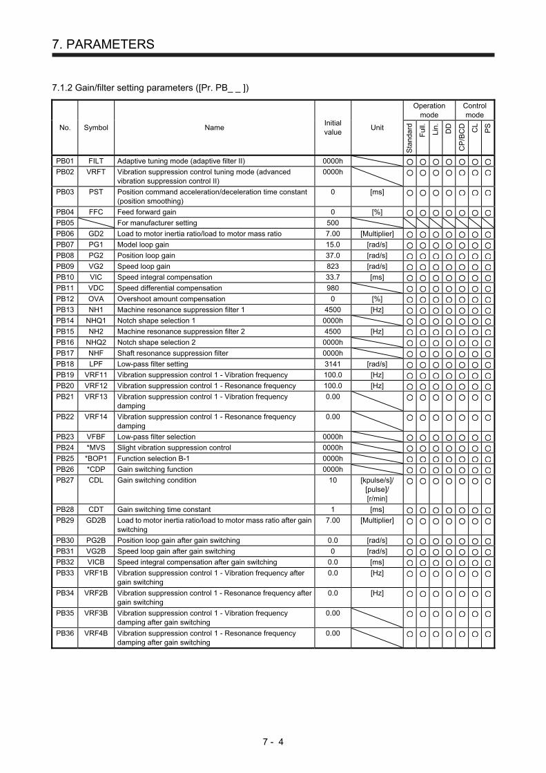
7. PARAMETERS
7 - 4
7.1.2 Gain/filter setting parameters ([Pr. PB_ _ ])
No. Symbol Name Initial value
Unit
Operation mode
Control mode
Sta
ndar
d
Ful
l.
Lin.
DD
CP
/BC
D
CL
PS
PB01 FILT Adaptive tuning mode (adaptive filter II) 0000h PB02 VRFT Vibration suppression control tuning mode (advanced
vibration suppression control II) 0000h
PB03 PST Position command acceleration/deceleration time constant (position smoothing)
0 [ms]
PB04 FFC Feed forward gain 0 [%] PB05 For manufacturer setting 500
PB06 GD2 Load to motor inertia ratio/load to motor mass ratio 7.00 [Multiplier] PB07 PG1 Model loop gain 15.0 [rad/s] PB08 PG2 Position loop gain 37.0 [rad/s] PB09 VG2 Speed loop gain 823 [rad/s] PB10 VIC Speed integral compensation 33.7 [ms] PB11 VDC Speed differential compensation 980 PB12 OVA Overshoot amount compensation 0 [%] PB13 NH1 Machine resonance suppression filter 1 4500 [Hz] PB14 NHQ1 Notch shape selection 1 0000h PB15 NH2 Machine resonance suppression filter 2 4500 [Hz] PB16 NHQ2 Notch shape selection 2 0000h PB17 NHF Shaft resonance suppression filter 0000h PB18 LPF Low-pass filter setting 3141 [rad/s] PB19 VRF11 Vibration suppression control 1 - Vibration frequency 100.0 [Hz] PB20 VRF12 Vibration suppression control 1 - Resonance frequency 100.0 [Hz] PB21 VRF13 Vibration suppression control 1 - Vibration frequency
damping 0.00
PB22 VRF14 Vibration suppression control 1 - Resonance frequency damping
0.00
PB23 VFBF Low-pass filter selection 0000h PB24 *MVS Slight vibration suppression control 0000h PB25 *BOP1 Function selection B-1 0000h PB26 *CDP Gain switching function 0000h PB27 CDL Gain switching condition 10 [kpulse/s]/
[pulse]/ [r/min]
PB28 CDT Gain switching time constant 1 [ms] PB29 GD2B Load to motor inertia ratio/load to motor mass ratio after gain
switching 7.00 [Multiplier]
PB30 PG2B Position loop gain after gain switching 0.0 [rad/s] PB31 VG2B Speed loop gain after gain switching 0 [rad/s] PB32 VICB Speed integral compensation after gain switching 0.0 [ms] PB33 VRF1B Vibration suppression control 1 - Vibration frequency after
gain switching 0.0 [Hz]
PB34 VRF2B Vibration suppression control 1 - Resonance frequency after gain switching
0.0 [Hz]
PB35 VRF3B Vibration suppression control 1 - Vibration frequency damping after gain switching
0.00
PB36 VRF4B Vibration suppression control 1 - Resonance frequency damping after gain switching
0.00

7. PARAMETERS
7 - 5
No. Symbol Name Initial value
Unit
Operation mode
Control mode
Sta
ndar
d
Ful
l.
Lin.
DD
CP
/BC
D
CL
PS
PB37
For manufacturer setting 1600
PB38 0.00
PB39 0.00
PB40 0.00
PB41 0000h
PB42 0000h
PB43 0000h
PB44 0.00
PB45 CNHF Command notch filter 0000h PB46 NH3 Machine resonance suppression filter 3 4500 [Hz] PB47 NHQ3 Notch shape selection 3 0000h PB48 NH4 Machine resonance suppression filter 4 4500 [Hz] PB49 NHQ4 Notch shape selection 4 0000h PB50 NH5 Machine resonance suppression filter 5 4500 [Hz] PB51 NHQ5 Notch shape selection 5 0000h PB52 VRF21 Vibration suppression control 2 - Vibration frequency 100.0 [Hz] PB53 VRF22 Vibration suppression control 2 - Resonance frequency 100.0 [Hz] PB54 VRF23 Vibration suppression control 2 - Vibration frequency
damping 0.00
PB55 VRF24 Vibration suppression control 2 - Resonance frequency damping
0.00
PB56 VRF21B Vibration suppression control 2 - Vibration frequency after gain switching
0.0 [Hz]
PB57 VRF22B Vibration suppression control 2 - Resonance frequency after gain switching
0.0 [Hz]
PB58 VRF23B Vibration suppression control 2 - Vibration frequency damping after gain switching
0.00
PB59 VRF24B Vibration suppression control 2 - Resonance frequency damping after gain switching
0.00
PB60 PG1B Model loop gain after gain switching 0.0 [rad/s] PB61 For manufacturer setting 0.0
PB62 0000h
PB63 0000h
PB64 0000h

7. PARAMETERS
7 - 6
7.1.3 Extension setting parameters ([Pr. PC_ _ ])
POINT
To enable the following parameters in a positioning mode, cycle the power after
setting.
[Pr. PC03 S-pattern acceleration/deceleration time constant]
The following parameter cannot be used in the positioning mode.
[Pr. PC04 Torque command time constant/thrust command time constant]
[Pr. PC08 Internal speed command 4/internal speed limit 4]
[Pr. PC09 Internal speed command 5/internal speed limit 5]
[Pr. PC10 Internal speed command 6/internal speed limit 6]
[Pr. PC11 Internal speed command 7/internal speed limit 7]
[Pr. PC12 Analog speed command - Maximum speed/Analog speed limit -
Maximum speed]
[Pr. PC13 Analog torque/thrust command maximum output]
[Pr. PC23 Function selection C-2]
[Pr. PC32 Command input pulse multiplication numerator 2]
[Pr. PC33 Command input pulse multiplication numerator 3]
[Pr. PC34 Command input pulse multiplication numerator 4]
The following parameters are used for Modbus-RTU communication. For details,
refer to "MR-J4-_A_-RJ Servo Amplifier Instruction Manual (Modbus-RTU
communication)".
[Pr. PC70 Modbus-RTU communication station number setting]
[Pr. PC71 Function selection C-F]
[Pr. PC72 Function selection C-G]
No. Symbol Name Initial value
Unit
Operation mode
Control mode
Sta
ndar
d
Ful
l.
Lin.
DD
CP
/BC
D
CL
PS
PC01 STA JOG operation acceleration time constant 0 [ms]
Acceleration time constant 1
PC02 STB JOG operation deceleration time constant 0 [ms]
Deceleration time constant 1
PC03 *STC S-pattern acceleration/deceleration time constant 0 [ms]
PC04 TQC Torque command time constant/thrust command time constant
0
PC05 SC1 Automatic operation speed 1 100 [r/min]
PC06 SC2 Automatic operation speed 2 500 [r/min]
PC07 SC3 Manual operation speed 1 1000 [r/min]
PC08 SC4 Internal speed command 4 200 [r/min]/ [mm/s]
Internal speed limit 4
PC09 SC5 Internal speed command 5 300 [r/min]/ [mm/s] Internal speed limit 5
PC10 SC6 Internal speed command 6 500 [r/min]/ [mm/s] Internal speed limit 6
PC11 SC7 Internal speed command 7 800 [r/min]/ [mm/s] Internal speed limit 7
PC12 VCM Analog speed command - Maximum speed 0 [r/min]/ [mm/s] Analog speed limit - Maximum speed
PC13 TLC Analog torque/thrust command maximum output 100.0 [%]

7. PARAMETERS
7 - 7
No. Symbol Name Initial value
Unit
Operation mode
Control mode
Sta
ndar
d
Ful
l.
Lin.
DD
CP
/BC
D
CL
PS
PC14 MOD1 Analog monitor 1 output 0000h PC15 MOD2 Analog monitor 2 output 0001h PC16 MBR Electromagnetic brake sequence output 0 [ms] PC17 ZSP Zero speed 50 [r/min]/
[mm/s]
PC18 *BPS Alarm history clear 0000h PC19 *ENRS Encoder output pulse selection 0000h PC20 *SNO Station No. setting 0 [station] PC21 *SOP RS-422 communication function selection 0000h PC22 *COP1 Function selection C-1 0000h PC23 *COP2 Function selection C-2 0000h
PC24 *COP3 Function selection C-3 0000h PC25 For manufacturer setting 0000h
PC26 *COP5 Function selection C-5 0000h PC27 *COP6 Function selection C-6 0000h PC28 *COP7 Function selection C-7 0000h
PC29 For manufacturer setting 0000h
PC30 STA2 Home position return acceleration time constant 0 [ms]
Acceleration time constant 2
PC31 STB2 Home position return deceleration time constant 0 [ms]
Deceleration time constant 2
PC32 CMX2 Command input pulse multiplication numerator 2 1
PC33 CMX3 Command input pulse multiplication numerator 3 1
PC34 CMX4 Command input pulse multiplication numerator 4 1
PC35 TL2 Internal torque limit 2/internal thrust limit 2 100.0 [%] PC36 *DMD Status display selection 0000h PC37 VCO Analog override offset 0 [mV]
PC38 TPO Analog torque limit offset 0 [mV] PC39 MO1 Analog monitor 1 offset 0 [mV] PC40 MO2 Analog monitor 2 offset 0 [mV] PC41
For manufacturer setting 0
PC42 0
PC43 ERZ Error excessive alarm detection level 0 [rev]/[mm] PC44 *COP9 Function selection C-9 0000h
PC45 *COPA Function selection C-A 0000h
PC46
For manufacturer setting 0
PC47 0
PC48 0
PC49 0
PC50 0000h
PC51 RSBR Forced stop deceleration time constant 100 [ms] PC52
For manufacturer setting 0
PC53 0
PC54 RSUP1 Vertical axis freefall prevention compensation amount 0 [0.0001rev]/ [0.01mm]
PC55
For manufacturer setting 0
PC56 100
PC57 0000h
PC58 0
PC59 0000h
PC60 *COPD Function selection C-D 0000h

7. PARAMETERS
7 - 8
No. Symbol Name Initial value
Unit
Operation mode
Control mode
Sta
ndar
d
Ful
l.
Lin.
DD
CP
/BC
D
CL
PS
PC61 For manufacturer setting 0000h PC62 0000h PC63 0000h PC64 0000h PC65 0000h PC66 LPSPL Mark detection range + (lower three digits) 0 10STM [µm]/
10-(STM-4) [inch]/ 10-3 [degree]/
[pulse]
PC67 LPSPH Mark detection range + (upper three digits) 0 10STM [µm]/ 10-(STM-4) [inch]/ 10-3 [degree]/
[pulse]
PC68 LPSNL Mark detection range - (lower three digits) 0 10STM [µm]/ 10-(STM-4) [inch]/ 10-3 [degree]/
[pulse]
PC69 LPSNH Mark detection range - (upper three digits) 0 10STM [µm]/ 10-(STM-4) [inch]/ 10-3 [degree]/
[pulse]
PC70 *SNOM Modbus-RTU communication station number setting 0
PC71 *COPF Function selection C-F 0040h
PC72 *COPG Function selection C-G 0000h
PC73 ERW Error excessive warning level 0
PC74 For manufacturer setting 0000h
PC75 0000h
PC76 0000h
PC77 0000h
PC78 0000h
PC79 0000h
PC80 0000h

7. PARAMETERS
7 - 9
7.1.4 I/O setting parameters ([Pr. PD_ _ ])
POINT
The following parameter cannot be used in the positioning mode.
[Pr. PD03 Input device selection 1L]
[Pr. PD05 Input device selection 2L]
[Pr. PD07 Input device selection 3L]
[Pr. PD09 Input device selection 4L]
[Pr. PD11 Input device selection 5L]
[Pr. PD13 Input device selection 6L]
[Pr. PD17 Input device selection 8L]
[Pr. PD19 Input device selection 9L]
[Pr. PD21 Input device selection 10L]
[Pr. PD43 Input device selection 11L]
[Pr. PD45 Input device selection 12L]
No. Symbol Name Initial value
Unit
Operation mode
Control mode
Sta
ndar
d
Ful
l.
Lin.
DD
CP
/BC
D
CL
PS
PD01 *DIA1 Input signal automatic on selection 1 0000h PD02 For manufacturer setting 0000h
PD03 *DI1L Input device selection 1L 0202h
PD04 *DI1H Input device selection 1H 0202h PD05 *DI2L Input device selection 2L 2100h
PD06 *DI2H Input device selection 2H 2021h PD07 *DI3L Input device selection 3L 0704h
PD08 *DI3H Input device selection 3H 0707h PD09 *DI4L Input device selection 4L 0805h
PD10 *DI4H Input device selection 4H 0808h PD11 *DI5L Input device selection 5L 0303h
PD12 *DI5H Input device selection 5H 3803h PD13 *DI6L Input device selection 6L 2006h
PD14 *DI6H Input device selection 6H 3920h PD15 For manufacturer setting 0000h
PD16 0000h
PD17 *DI8L Input device selection 8L 0A0Ah
PD18 *DI8H Input device selection 8H 0A00h PD19 *DI9L Input device selection 9L 0B0Bh
PD20 *DI9H Input device selection 9H 0B00h PD21 *DI10L Input device selection 10L 2323h
PD22 *DI10H Input device selection 10H 2B23h PD23 *DO1 Output device selection 1 0004h PD24 *DO2 Output device selection 2 000Ch PD25 *DO3 Output device selection 3 0004h PD26 *DO4 Output device selection 4 0007h PD27 For manufacturer setting 0003h
PD28 *DO6 Output device selection 6 0002h PD29 *DIF Input filter setting 0004h PD30 *DOP1 Function selection D-1 0000h PD31 *DOP2 Function selection D-2 0000h
PD32 *DOP3 Function selection D-3 0000h PD33 *DOP4 Function selection D-4 0000h PD34 DOP5 Function selection D-5 0000h

7. PARAMETERS
7 - 10
No. Symbol Name Initial value
Unit
Operation mode
Control mode
Sta
ndar
d
Ful
l.
Lin.
DD
CP
/BC
D
CL
PS
PD35 For manufacturer setting 0000h
PD36 0000h
PD37 0000h
PD38 0
PD39 0
PD40 0
PD41 *DIA3 Input signal automatic on selection 3 0000h PD42 *DIA4 Input signal automatic on selection 4 0000h PD43 *DI11L Input device selection 11L 0000h
PD44 *DI11H Input device selection 11H 3A00h PD45 *DI12L Input device selection 12L 0000h
PD46 *DI12H Input device selection 12H 3B00h PD47 *DO7 Output device selection 7 0000h PD48 For manufacturer setting 0000h
7.1.5 Extension setting 2 parameters ([Pr. PE_ _ ])
POINT
The following parameter cannot be used in the positioning mode.
[Pr. PE01 Fully closed loop function selection 1]
No. Symbol Name Initial value
Unit
Operation mode
Control mode
Sta
ndar
d
Ful
l.
Lin.
DD
CP
/BC
D
CL
PS
PE01 *FCT1 Fully closed loop function selection 1 0000h
PE02 For manufacturer setting 0000h
PE03 *FCT2 Fully closed loop function selection 2 0003h
PE04 *FBN Fully closed loop control - Feedback pulse electronic gear 1 - Numerator
1
PE05 *FBD Fully closed loop control - Feedback pulse electronic gear 1 - Denominator
1
PE06 BC1 Fully closed loop control - Speed deviation error detection level
400 [r/min]
PE07 BC2 Fully closed loop control - Position deviation error detection level
100 [kpulse]
PE08 DUF Fully closed loop dual feedback filter 10 [rad/s]
PE09 For manufacturer setting 0000h
PE10 FCT3 Fully closed loop function selection 3 0000h
PE11 For manufacturer setting 0000h
PE12 0000h
PE13 0000h
PE14 0111h
PE15 20
PE16 0000h
PE17 0000h
PE18 0000h
PE19 0000h
PE20 0000h
PE21 0000h

7. PARAMETERS
7 - 11
No. Symbol Name Initial value
Unit
Operation mode
Control mode
Sta
ndar
d
Ful
l.
Lin.
DD
CP
/BC
D
CL
PS
PE22
For manufacturer setting 0000h
PE23 0000h
PE24 0000h
PE25 0000h
PE26 0000h
PE27 0000h
PE28 0000h
PE29 0000h
PE30 0000h
PE31 0000h
PE32 0000h
PE33 0000h
PE34 *FBN2 Fully closed loop control - Feedback pulse electronic gear 2 - Numerator
1
PE35 *FBD2 Fully closed loop control - Feedback pulse electronic gear 2 - Denominator
1
PE36 For manufacturer setting 0.0
PE37 0.00
PE38 0.00
PE39 20
PE40 0000h
PE41 EOP3 Function selection E-3 0000h PE42 For manufacturer setting 0
PE43 0.0
PE44 LMCP Lost motion compensation positive-side compensation value selection
0 [0.01%]
PE45 LMCN Lost motion compensation negative-side compensation value selection
0 [0.01%]
PE46 LMFLT Lost motion filter setting 0 [0.1 ms] PE47 TOF Torque offset 0 [0.01%]
PE48 *LMOP Lost motion compensation function selection 0000h PE49 LMCD Lost motion compensation timing 0 [0.1 ms] PE50 LMCT Lost motion compensation non-sensitive band 0 [pulse]/
[kpulse]
PE51 For manufacturer setting 0000h
PE52 0000h
PE53 0000h
PE54 0000h
PE55 0000h
PE56 0000h
PE57 0000h
PE58 0000h
PE59 0000h
PE60 0000h
PE61 0.00
PE62 0.00
PE63 0.00
PE64 0.00

7. PARAMETERS
7 - 12
7.1.6 Extension setting 3 parameters ([Pr. PF_ _ ])
POINT
The following parameters are used for Modbus-RTU communication. For details,
refer to "MR-J4-_A_-RJ Servo Amplifier Instruction Manual (Modbus-RTU
communication)".
[Pr. PF45 Function selection F-12]
[Pr. PF46 Modbus-RTU communication time-out selection]
No. Symbol Name Initial value
Unit
Operation mode
Control mode
Sta
ndar
d
Ful
l.
Lin.
DD
CP
/BC
D
CL
PS
PF01
For manufacturer setting 0000h
PF02 0000h
PF03 0000h
PF04 0
PF05 0
PF06 0000h
PF07 1
PF08 1
PF09 *FOP5 Function selection F-5 0000h
PF10
For manufacturer setting 0000h
PF11 0000h
PF12 10000
PF13 100
PF14 100
PF15 DBT Electronic dynamic brake operating time 2000 [ms]
PF16
For manufacturer setting 0000h
PF17 10
PF18 0000h
PF19 0000h
PF20 0000h
PF21 DRT Drive recorder switching time setting 0 [s] PF22 For manufacturer setting 200
PF23 OSCL1 Vibration tough drive - Oscillation detection level 50 [%] PF24 *OSCL2 Vibration tough drive function selection 0000h PF25 CVAT SEMI-F47 function - Instantaneous power failure detection
time 200 [ms]
PF26
For manufacturer setting 0
PF27 0
PF28 0
PF29 0000h
PF30 0
PF31 FRIC Machine diagnosis function - Friction judgement speed 0 [r/min]/ [mm/s]
PF32
For manufacturer setting 50
PF33 0000h
PF34 *SOP3 RS-422 communication function selection 3 0000h

7. PARAMETERS
7 - 13
No. Symbol Name Initial value
Unit
Operation mode
Control mode
Sta
ndar
d
Ful
l.
Lin.
DD
CP
/BC
D
CL
PS
PF35
For manufacturer setting 0000h
PF36 0000h
PF37 0000h
PF38 0000h
PF39 0000h
PF40 0
PF41 0
PF42 0
PF43 0
PF44 0
PF45 *FOP12 Function selection F-12 0000h
PF46 MIC Modbus-RTU communication time out selection 0
PF47
For manufacturer setting 0000h
PF48 0000h
7.1.7 Linear servo motor/DD motor setting parameters ([Pr. PL_ _ ])
No. Symbol Name Initial value
Unit
Operation mode
Control mode
Sta
ndar
d
Ful
l.
Lin.
DD
CP
/BC
D
CL
PS
PL01 *LIT1 Linear servo motor/DD motor function selection 1 0301h PL02 *LIM Linear encoder resolution - Numerator 1000 [µm]
PL03 *LID Linear encoder resolution - Denominator 1000 [µm]
PL04 *LIT2 Linear servo motor/DD motor function selection 2 0003h PL05 LB1 Position deviation error detection level 0 [mm]/
[0.01rev]
PL06 LB2 Speed deviation error detection level 0 [r/min]/ [mm/s]
PL07 LB3 Torque/thrust deviation error detection level 100 [%] PL08 *LIT3 Linear servo motor/DD motor function selection 3 0010h PL09 LPWM Magnetic pole detection voltage level 30 [%] PL10 For manufacturer setting 5
PL11 100
PL12 500
PL13 0000h
PL14 0000h
PL15 20
PL16 0
PL17 LTSTS Magnetic pole detection - Minute position detection method - Function selection
0000h
PL18 IDLV Magnetic pole detection - Minute position detection method - Identification signal amplitude
0 [%]
PL19 For manufacturer setting 0
PL20 0
PL21 0
PL22 0
PL23 0000h
PL24 0
PL25 0000h
PL26 0000h
PL27 0000h

7. PARAMETERS
7 - 14
No. Symbol Name Initial value
Unit
Operation mode
Control mode
Sta
ndar
d
Ful
l.
Lin.
DD
CP
/BC
D
CL
PS
PL28 For manufacturer setting 0000h
PL29 0000h
PL30 0000h
PL31 0000h
PL32 0000h
PL33 0000h
PL34 0000h
PL35 0000h
PL36 0000h
PL37 0000h
PL38 0000h
PL39 0000h
PL40 0000h
PL41 0000h
PL42 0000h
PL43 0000h
PL44 0000h
PL45 0000h
PL46 0000h
PL47 0000h
PL48 0000h
7.1.8 Option setting parameters ([Pr. Po_ _ ])
No. Symbol Name Initial value
Unit
Operation mode
Control mode
Sta
ndar
d
Ful
l.
Lin.
DD
CP
/BC
D
CL
PS
Po01 For manufacturer setting 0000h
Po02 *ODI1 MR-D01 input device selection 1 0302h Po03 *ODI2 MR-D01 input device selection 2 0905h Po04 *ODI3 MR-D01 input device selection 3 2524h Po05 *ODI4 MR-D01 input device selection 4 2026h Po06 *ODI5 MR-D01 input device selection 5 0427h Po07 *ODI6 MR-D01 input device selection 6 0807h Po08 *ODO1 MR-D01 output device selection 1 2726h Po09 *ODO2 MR-D01 output device selection 2 0423h Po10 *OOP1 Function selection O-1 2001h Po11 *OOP2 Function selection O-2 0000h Po12 *OOP3 Function selection O-3 0000h
Po13 *OMOD1 MR-D01 analog monitor 1 output selection 0000h
Po14 *OMOD2 MR-D01 analog monitor 2 output selection 0000h
Po15 OMO1 MR-D01 analog monitor 1 offset 0 [mV] Po16 OMO2 MR-D01 analog monitor 2 offset 0 [mV]
Po17
For manufacturer setting 0000h
Po18 0000h
Po19 0000h
Po20 0000h
Po21 OVCO MR-D01 override offset 0 [mV]
Po22 OTLO MR-D01 override offset 0 [mV]

7. PARAMETERS
7 - 15
No. Symbol Name Initial value
Unit
Operation mode
Control mode
Sta
ndar
d
Ful
l.
Lin.
DD
CP
/BC
D
CL
PS
Po23
For manufacturer setting 0000h
Po24 0000h
Po25 0000h
Po26 0000h
Po27 *ODI7 MR-D01 input device selection 7 2D2Ch
Po28 *ODI8 MR-D01 input device selection 8 002Eh
Po29
For manufacturer setting 0000h
Po30 0000h
Po31 0000h
Po32 0000h
7.1.9 Positioning control parameters ([Pr. PT_ _ ])
POINT
The following parameters are used for Modbus-RTU communication. For details,
refer to "MR-J4-_A_-RJ Servo Amplifier Instruction Manual (Modbus-RTU
communication)".
[Pr. PT45 Home position return type 2]
No. Symbol Name Initial value
Unit
Operation mode
Control mode
Sta
ndar
d
Ful
l.
Lin.
DD
CP
/BC
D
CL
PS
PT01 *CTY Command mode selection 0000h PT02 *TOP1 Function selection T-1 0000h PT03 *FTY Feeding function selection 0000h PT04 *ZTY Home position return type 0010h PT05 ZRF Home position return speed 100 [r/min]/[mm/s] PT06 CRF Creep speed 10 [r/min]/
[mm/s]
PT07 ZST Home position shift distance 0 [μm]/ 10-4 [inch]/ 10-3
[degree]/ [pulse]
PT08 *ZPS Home position return position data 0 10STM [μm]/ 10-(STM-4) [inch]/ 10-3 [degree]/
[pulse]
PT09 DCT Travel distance after proximity dog 1000 10STM [μm]/ 10-(STM-4) [inch]/ 10-3 [degree]/
[pulse]
PT10 ZTM Stopper type home position return stopper time 100 [ms]
PT11 ZTT Stopper type home position return torque limit value 15.0 [%]
PT12 CRP Rough match output range 0 10STM [μm]/ 10-(STM-4) [inch]/ 10-3 [degree]/
[pulse]
PT13 JOG JOG operation 100 [r/min]/ [mm/s]
PT14 *BKC Backlash compensation 0 [pulse]

7. PARAMETERS
7 - 16
No. Symbol Name Initial value
Unit
Operation mode
Control mode
Sta
ndar
d
Ful
l.
Lin.
DD
CP
/BC
D
CL
PS
PT15 LMPL Software limit + 0 10STM [μm]/ 10-(STM-4) [inch]/ 10-3 [degree]/
[pulse]
PT16 LMPH
PT17 LMNL Software limit - 0 10STM [μm]/ 10-(STM-4) [inch]/ 10-3 [degree]/
[pulse]
PT18 LMNH
PT19 *LPPL Position range output address + 0 10STM [μm]/ 10-(STM-4) [inch]/ 10-3 [degree]/
[pulse]
PT20 *LPPH
PT21 *LNPL Position range output address - 0 10STM [μm]/ 10-(STM-4) [inch]/ 10-3 [degree]/
[pulse]
PT22 *LNPH
PT23 OUT1 OUT1 output setting time 0 [ms]
PT24 OUT2 OUT2 output setting time 0 [ms]
PT25 OUT3 OUT3 output setting time 0 [ms]
PT26 *TOP2 Function selection T-2 0000h
PT27 *ODM Operation mode selection 0000h
PT28 *STN Number of stations per rotation 8 [stations]
PT29 *TOP3 Function selection T-3 0000h PT30 MSTL Mark sensor stop travel distance 0 10STM [µm]/
10-(STM-4) [inch]/ 10-3 [degree]/
[pulse]
PT31 MSTH 0
PT32 For manufacturer setting 0000h
PT33 0000h
PT34 *PDEF Point table/program default 0000h
PT35 For manufacturer setting 0000h
PT36 0000h
PT37 10
PT38 *TOP7 Function selection T-7 0000h
PT39 INT Torque limit delay time 100 [ms]
PT40 *SZS Station home position shift distance 0 [pulse]
PT41 ORP Home position return inhibit function selection 0000h PT42 *OVM Digital override minimum multiplication 0 [%]
PT43 *OVS Digital override pitch width 0 [%]
PT44 For manufacturer setting 0000h
PT45 *CZTY Home position return type 2 0000h
PT46 For manufacturer setting 0000h
PT47 0000h
PT48 0000h
7.2 Detailed list of parameters
POINT
Set a value to each "x" in the "Setting digit" columns.

7. PARAMETERS
7 - 17
7.2.1 Basic setting parameters ([Pr. PA_ _ ])
No./ symbol/name
Setting digit
Function Initial value [unit]
Control mode
CP
/BC
D
CL
PS
PA01 *STY Operation mode
_ _ _ x Control mode selection Select a control mode. 0 to 5: Not used for positioning mode. 6: Positioning mode (point table method) 7: Positioning mode (program method) 8: Positioning mode (indexer method)
0h
_ _ x _ Operation mode selection 0: Standard control mode 1: Fully closed loop control mode 4. Linear servo motor control mode 6: DD motor control mode (except 400 V class servo amplifiers) The following settings will trigger [AL. 37 Parameter error].
A value is set other than "0", "1", "4", and "6" to this digit.
"1" or "4" is set to this digit with the indexer method. "1" or "4" is set to this digit when "Position data unit" is set to [degree] in [Pr. PT01].
For MR-J4-03A6-RJ servo amplifiers, this digit cannot be used other than the initial value.
0h
_ x _ _ For manufacturer setting 0h
x _ _ _ 1h
PA02 *REG Regenerative option
_ _ x x Regenerative option Select a regenerative option. Incorrect setting may cause the regenerative option to burn. If a selected regenerative option is not for use with the servo amplifier, [AL. 37 Parameter error] occurs. 00: Regenerative option is not used.
For the servo amplifiers of 100 W, a regenerative resistor is not used. For servo amplifier of 0.2 kW to 7 kW, built-in regenerative resistor is used. Supplied regenerative resistors or regenerative option is used with the servo amplifier of 11 kW to 22 kW.
01: FR-RC-(H)/FR-CV-(H)/FR-BU2-(H) When you use FR-RC-(H) or FR-CV-(H), select "Mode 2 (_ _ _ 1)" of "Undervoltage alarm detection mode selection" in [Pr. PC27].
02: MR-RB032 03: MR-RB12 04: MR-RB32 05: MR-RB30 06: MR-RB50 (Cooling fan is required.) 08: MR-RB31 09: MR-RB51 (Cooling fan is required.) 0B: MR-RB3N 0C: MR-RB5N (Cooling fan is required.) 80: MR-RB1H-4 81: MR-RB3M-4 (Cooling fan is required.) 82: MR-RB3G-4 (Cooling fan is required.) 83: MR-RB5G-4 (Cooling fan is required.) 84: MR-RB34-4 (Cooling fan is required.) 85: MR-RB54-4 (Cooling fan is required.) 91: MR-RB3U-4 (Cooling fan is required.) 92: MR-RB5U-4 (Cooling fan is required.) FA: When the supplied regenerative resistors or the regenerative option is cooled by
the cooling fan to increase the ability with the servo amplifier of 11 kW to 22 kW. For MR-J4-03A6-RJ servo amplifiers, this digit cannot be used other than the initial value.
00h
_ x _ _ For manufacturer setting 0h
x _ _ _ 0h

7. PARAMETERS
7 - 18
No./ symbol/name
Setting digit
Function Initial value [unit]
Control mode
CP
/BC
D
CL
PS
PA03 *ABS Absolute position detection system
_ _ _ x Absolute position detection system selection Set this digit when using the absolute position detection system. 0: Disabled (incremental system) 1:Enabled (absolute position detection system) 2: Not used for positioning mode. Setting a value other than "0" and "1" will trigger [AL. 37 Parameter error].
0h
_ _ x _ For manufacturer setting 0h
_ x _ _ 0h
x _ _ _ 0h
PA04 _ _ _ x For manufacturer setting 0h
*AOP1 _ _ x _ 0h
Function selection A-1
_ x _ _ 0h
x _ _ _ Forced stop deceleration function selection 0: Forced stop deceleration function disabled (EM1) 2: Forced stop deceleration function enabled (EM2) Refer to table 7.1 for details.
2h
Table 7.1 Deceleration method
Setting value
EM2/EM1 Deceleration method
EM2 or EM1 is off Alarm occurred
0 _ _ _ EM1 MBR (Electromagnetic brake interlock) turns off without the forced stop deceleration.
MBR (Electromagnetic brake interlock) turns off without the forced stop deceleration.
2 _ _ _ EM2 MBR (Electromagnetic brake interlock) turns off after the forced stop deceleration.
MBR (Electromagnetic brake interlock) turns off after the forced stop deceleration.

7. PARAMETERS
7 - 19
No./ symbol/name
Setting digit
Function Initial value [unit]
Control mode
CP
/BC
D
CL
PS
PA06 *CMX Electronic gear numerator (command pulse multiplication numerator)
Set an electronic gear numerator. (Refer to section 7.3.1.) To enable the parameter values in the positioning mode, cycle the power after setting. To enable the parameter, select "Electronic gear (0 _ _ _)", "J3 electronic gear setting value compatibility mode (2 _ _ _)", or "J2S electronic gear setting value compatibility mode (3 _ _ _)" of "Electronic gear selection" in [Pr. PA21]. For MR-J4-03A6-RJ servo amplifiers, "J3 electronic gear setting value compatibility mode (2 _ _ _)" and "J2S electronic gear setting value compatibility mode (3 _ _ _)" cannot be selected. Set the electronic gear within the following range. Setting out of the range will trigger [AL. 37 Parameter error].
1
Pr. PA21 Electronic gear setting range
0 _ _ _ 1/865 < CMX/CDV < 271471
2 _ _ _ 1/13825 < CMX/CDV < 16967
3 _ _ _ 1/27649 < CMX/CDV < 8484
Setting range: 1 to 16777215
PA06 *CMX Number of gear teeth on machine side
Set the number of gear teeth on machine side. (Refer to section 7.3.2.) To enable the parameter values in the positioning mode, cycle the power after setting. Set the electronic gear within the following range. (1) 1 ≤ CMX ≤ 16384, 1 ≤ CDV ≤ 16384
(2) 1
9999 ≤
CMX
CDV ≤ 9999
(3) CDV × STN ≤ 32767 (STN: Number of stations per rotation [Pr. PT28]) (4) CMX × CDV ≤ 100000 Setting out of the range will trigger [AL. 37 Parameter error]. When a small value is set to the electronic gear ratio with the manual operation mode, the servo motor may not drive at the set servo motor speed.
Travel distance of 1 station = Pt (servo motor resolution) × 1
STN ×
CMX
CDV
Setting range: 1 to 16777215
1
PA07 *CDV Electronic gear denominator (command pulse multiplication denominator)
Set an electronic gear denominator. (Refer to section 7.3.1.) To enable the parameter values in the positioning mode, cycle the power after setting. To enable the parameter, select "Electronic gear (0 _ _ _)", "J3 electronic gear setting value compatibility mode (2 _ _ _)", or "J2S electronic gear setting value compatibility mode (3 _ _ _)" of "Electronic gear selection" in [Pr. PA21]. For MR-J4-03A6-RJ servo amplifiers, "J3 electronic gear setting value compatibility mode (2 _ _ _)" and "J2S electronic gear setting value compatibility mode (3 _ _ _)" cannot be selected. Set the electronic gear within the range of [Pr. PA06]. Setting out of the range will trigger [AL. 37 Parameter error]. Setting range: 1 to 16777215
1
PA07 *CDV Number of gear teeth on servo motor side
Set the number of gear teeth on servo motor side. (Refer to section 7.3.2.) To enable the parameter values in the positioning mode, cycle the power after setting. Set the electronic gear within the range of [Pr. PA06]. Setting out of the range will trigger [AL. 37 Parameter error]. Setting range: 1 to 16777215
1

7. PARAMETERS
7 - 20
No./ symbol/name
Setting digit
Function Initial value [unit]
Control mode
CP
/BC
D
CL
PS
PA08 ATU Auto tuning mode
_ _ _ x Gain adjustment mode selection Select the gain adjustment mode. 0: 2 gain adjustment mode 1 (interpolation mode) 1: Auto tuning mode 1 2: Auto tuning mode 2 3: Manual mode 4: 2 gain adjustment mode 2 Refer to table 7.2 for details.
1h
_ _ x _ For manufacturer setting 0h
_ x _ _ 0h
x _ _ _ 0h
Table 7.2 Gain adjustment mode selection
Setting value
Gain adjustment mode Automatically adjusted parameter
_ _ _ 0 2 gain adjustment mode 1 (interpolation mode)
[Pr. PB06 Load to motor inertia ratio] [Pr. PB08 Position loop gain] [Pr. PB09 Speed loop gain] [Pr. PB10 Speed integral compensation]
_ _ _ 1 Auto tuning mode 1 [Pr. PB06 Load to motor inertia ratio] [Pr. PB07 Model loop gain] [Pr. PB08 Position loop gain] [Pr. PB09 Speed loop gain] [Pr. PB10 Speed integral compensation]
_ _ _ 2 Auto tuning mode 2 [Pr. PB07 Model loop gain] [Pr. PB08 Position loop gain] [Pr. PB09 Speed loop gain] [Pr. PB10 Speed integral compensation]
_ _ _ 3 Manual mode
_ _ _ 4 2 gain adjustment mode 2
[Pr. PB08 Position loop gain] [Pr. PB09 Speed loop gain] [Pr. PB10 Speed integral compensation]

7. PARAMETERS
7 - 21
No./ symbol/name
Setting digit
Function Initial value [unit]
Control mode
CP
/BC
D
CL
PS
PA09 RSP Auto tuning response
Set the auto tuning response.
16
Setting value
Machine characteristic
Setting value
Machine characteristic
Response
Guideline for machine
resonance frequency [Hz]
Response
Guideline for machine
resonance frequency [Hz]
1 Low
response 2.7 21
Middle response
67.1
2
3.6 22
75.6
3 4.9 23 85.2
4 6.6 24 95.9
5 10.0 25 108.0
6 11.3 26 121.7
7 12.7 27 137.1
8 14.3 28 154.4
9 16.1 29 173.9
10 18.1 30 195.9
11 20.4 31 220.6
12 23.0 32 248.5
13 25.9 33 279.9
14 29.2 34 315.3
15 32.9 35 355.1
16 37.0 36 400.0
17 41.7 37 446.6
18 47.0 38 501.2
19 52.9 39 571.5
20 Middle
response 59.6 40
High response
642.7
Setting range: 1 to 40
PA10 INP In-position range
Set an in-position range per command. To change it to the servo motor encoder pulse unit, set [Pr. PC24].
100 Refer to Function column for unit.
Pr. PA01 In-position setting range
_ _ _ 6 (positioning mode (point table method)) The range where MEND (Travel completion), PED (Position end) and INP (In-position) are inputted.
_ _ _ 7 (Positioning mode (program method))
_ _ _ 8 (Positioning mode (indexer method))
The range where MEND (Travel completion) and INP (In-position) are inputted.
The unit will be as follows depending on the positioning mode.
Point table method or program method Select from [μm], 10-4 [inch], 10-3 [degree], or [pulse] with [Pr. PT01] Indexer method Command unit [pulse] (a load-side rotation expressed by the number of encoder resolution pulses) For example, when making an in-position range "± 1 degree" for the rotation angle on the load side, set 4194304 × (1/360) = 11650 pulses.
Setting range: 0 to 65535

7. PARAMETERS
7 - 22
No./ symbol/name
Setting digit
Function Initial value [unit]
Control mode
CP
/BC
D
CL
PS
PA11 TLP Forward rotation torque limit/positive direction thrust limit
You can limit the torque or thrust generated by the servo motor. Set the parameter referring section 3.6.1 (5) of "MR-J4-_A_(-RJ) Servo Amplifier Instruction Manual". When you output torque or thrust with analog monitor output, the larger value of [Pr. PA11 Forward rotation torque limit/positive direction thrust limit value] or [Pr. PA12 Reverse rotation torque limit/negative direction thrust limit value] will be the maximum output voltage (8 V). Set the parameter on the assumption that the maximum torque or thrust is 100.0 [%]. The parameter is for limiting the torque of the servo motor in the CCW power running or CW regeneration, or limiting the thrust of the linear servo motor in the positive direction power running or negative direction regeneration. Set this parameter to "0.0" to generate no torque or thrust. Setting range: 0.0 to 100.0
100.0 [%]
PA12 TLN Reverse rotation torque limit/negative direction thrust limit
You can limit the torque or thrust generated by the servo motor. Set the parameter referring section 3.6.1 (5) of "MR-J4-_A_(-RJ) Servo Amplifier Instruction Manual". When you output torque or thrust with analog monitor output, the larger value of [Pr. PA11 Forward rotation torque limit/positive direction thrust limit value] or [Pr. PA12 Reverse rotation torque limit/negative direction thrust limit value] will be the maximum output voltage (8 V). Set the parameter on the assumption that the maximum torque or thrust is 100.0 [%]. The parameter is for limiting the torque of the servo motor in the CW power running or CCW regeneration, or limiting the thrust of the linear servo motor in the positive direction power running or negative direction regeneration. Set this parameter to "0.0" to generate no torque or thrust. Setting range: 0.0 to 100.0
100.0 [%]
PA13 *PLSS Command pulse input form
_ _ _ x Command input pulse train form selection 0: Forward/reverse rotation pulse train 1: Signed pulse train 2: A-phase/B-phase pulse train (The servo amplifier imports input pulses after multiplying by four.) When connecting the manual pulse generator MR-HDP01 in the positioning mode, set "2" to this digit. Refer to table 7.3 for settings.
0h
_ _ x _ Pulse train logic selection 0: Positive logic 1: Negative logic Select the same one as logic of command pulse train from controller to connect. Refer to POINT of section 3.6.1 of "MR-J4-_A_(-RJ) Servo Amplifier Instruction Manual" for logic of MELSEC iQ-R series/MELSEC-Q series/MELSEC-L series/MELSEC-F series. When connecting the manual pulse generator MR-HDP01 in the positioning mode, set "0" to this digit. Refer to table 7.3 for settings.
0h

7. PARAMETERS
7 - 23
No./ symbol/name
Setting digit
Function Initial value [unit]
Control mode
CP
/BC
D
CL
PS
PA13 *PLSS Command pulse input form
_ x _ _ Command input pulse train filter selection Selecting proper filter enables to enhance noise tolerance. 0: Command input pulse train is 4 Mpulses/s or less. 1: Command input pulse train is 1 Mpulse/s or less. 2: Command input pulse train is 500 kpulses/s or less. 3: Command input pulse train is 200 kpulses/s or less. 1 Mpulse/s or lower commands are supported by "1". When inputting commands over 1 Mpulse/s and 4 Mpulses/s or lower, set "0". When connecting the manual pulse generator MR-HDP01 in the positioning mode, set "2" or "3" to this digit. Incorrect setting may cause the following malfunctions.
Setting a value higher than actual command will lower noise tolerance. Setting a value lower than actual command will cause a position mismatch.
1h
x _ _ _ For manufacturer setting 0h
Table 7.3 Command input pulse train form selection
Setting value
Pulse train form Forward rotation (positive
direction)command
Reverse rotation (negative
direction)command
_ _ 1 0
Neg
ativ
e lo
gic
Forward rotation pulse train
(positive direction pulse train)
Reverse rotation pulse train
(negative direction pulse train)
NP
PP
_ _ 1 1
Signed pulse train
PP
L HNP
_ _ 1 2 A-phase pulse train
B-phase pulse train
PP
NP
_ _ 0 0
Po
sitiv
e lo
gic
Forward rotation pulse train
(positive direction pulse train)
Reverse rotation pulse train
(negative direction pulse train)
NP
PP
_ _ 0 1
Signed pulse train
LH
PP
NP
_ _ 0 2 A-phase pulse train
B-phase pulse train
PP
NP
Arrows in the table indicate the timing of importing pulse trains. A-phase/B-phase pulse trains are imported after they
have been multiplied by 4. When connecting the manual pulse generator MR-HDP01 in the positioning mode, set "_ _ 02h".

7. PARAMETERS
7 - 24
No./ symbol/name
Setting digit
Function Initial value [unit]
Control mode
CP
/BC
D
CL
PS
PA14 *POL Rotation direction selection/travel direction selection
Select a rotation direction of the servo motor or travel direction of the linear servo motor for when turning on ST1 (Forward rotation start) or ST2 (Reverse rotation start).
0
Setting value
Servo motor rotation direction/linear servo motor travel direction
When positioning address increases
When positioning address decreases
0 CCW or positive direction CW or negative direction
1 CW or negative direction CCW or positive direction
The following shows the servo motor rotation directions.
Forward rotation (CCW)
Reverse rotation (CW)
The positive/negative directions of the linear servo motor are as follows.
Secondary side
Primary side
Positive direction
Negative direction
LM-H3/LM-F series
Negative direction
Positive direction
Secondary side
Primary side
LM-U2 series
Negative direction
Positive direction
Table
Primary side
Secondary side
LM-K2 series
Setting range: 0,1
PA15 *ENR Encoder output pulses
Set the encoder output pulses from the servo amplifier by using the number of output pulses per revolution, dividing ratio, or electronic gear ratio. (after multiplication by 4) Set a numerator of the electronic gear, for when selecting "A-phase/B-phase pulse electronic gear setting (_ _ 3 _)" of "Encoder output pulse setting selection" in [Pr. PC19]. The maximum output frequency is 4.6 Mpulses/s. Set the parameter within this range. Setting range: 1 to 4194304
4000 [pulse/
rev]
PA16 *ENR2 Encoder output pulses 2
Set a denominator of the electronic gear for the A/B-phase pulse output. Set a denominator of the electronic gear, for when selecting "A-phase/B-phase pulse electronic gear setting (_ _ 3 _)" of "Encoder output pulse setting selection" in [Pr. PC19]. Setting range: 1 to 4194304
1

7. PARAMETERS
7 - 25
No./ symbol/name
Setting digit
Function Initial value [unit]
Control mode
CP
/BC
D
CL
PS
PA17 *MSR Servo motor series setting
When using a linear servo motor, select any linear servo motor with [Pr. PA17] and [Pr. PA18]. Set this and [Pr. PA18] at a time. Refer to the following table for settings. This parameter is not available with MR-J4-03A6-RJ servo amplifiers.
0000h
Linear servo motor
series Linear servo motor
(primary side)
Parameter
[Pr. PA17] setting
[Pr. PA18] setting
LM-H3P2A-07P-BSS0 2101h
LM-H3P3A-12P-CSS0 3101h
LM-H3P3B-24P-CSS0 3201h
LM-H3P3C-36P-CSS0 3301h
LM-H3 LM-H3P3D-48P-CSS0 00BBh 3401h
LM-H3P7A-24P-ASS0 7101h
LM-H3P7B-48P-ASS0 7201h
LM-H3P7C-72P-ASS0 7301h
LM-H3P7D-96P-ASS0 7401h
LM-U2PAB-05M-0SS0 A201h
LM-U2PAD-10M-0SS0 A401h
LM-U2PAF-15M-0SS0 A601h
LM-U2PBB-07M-1SS0 B201h
LM-U2 LM-U2PBD-15M-1SS0 00B4h B401h
LM-U2PBF-22M-1SS0 2601h
LM-U2P2B-40M-2SS0 2201h
LM-U2P2C-60M-2SS0 2301h
LM-U2P2D-80M-2SS0 2401h

7. PARAMETERS
7 - 26
No./ symbol/name
Setting digit
Function Initial value [unit]
Control mode
CP
/BC
D
CL
PS
PA17 *MSR Servo motor series setting
Linear servo motor
series Linear servo motor
(primary side)
Parameter
[Pr. PA17] setting
[Pr. PA18] setting
LM-FP2B-06M-1SS0 (natural cooling)
2201h
LM-FP2D-12M-1SS0 (natural cooling)
2401h
LM-FP2F-18M-1SS0 (natural cooling)
2601h
LM-FP4B-12M-1SS0 (natural cooling)
4201h
LM-FP4D-24M-1SS0 (natural cooling)
4401h
LM-FP4F-36M-1SS0 (natural cooling)
4601h
LM-FP4H-48M-1SS0 (natural cooling)
00B2h
4801h
LM-F
LM-FP5H-60M-1SS0 (natural cooling)
5801h
LM-FP2B-06M-1SS0 (liquid-cooling)
2202h
LM-FP2D-12M-1SS0 (liquid-cooling)
2402h
LM-FP2F-18M-1SS0 (liquid-cooling)
2602h
LM-FP4B-12M-1SS0 (liquid-cooling)
4202h
LM-FP4D-24M-1SS0 (liquid-cooling)
4402h
LM-FP4F-36M-1SS0 (liquid-cooling)
4602h
LM-FP4H-48M-1SS0 (liquid-cooling)
4802h
LM-FP5H-60M-1SS0 (liquid-cooling)
5802h
LM-K2P1A-01M-2SS1 1101h
LM-K2P1C-03M-2SS1 1301h
LM-K2P2A-02M-1SS1 2101h
LM-K2 LM-K2P2C-07M-1SS1 00B8h 2301h
LM-K2P2E-12M-1SS1 2501h
LM-K2P3C-14M-1SS1 3301h
LM-K2P3E-24M-1SS1 3501h

7. PARAMETERS
7 - 27
No./ symbol/name
Setting digit
Function Initial value [unit]
Control mode
CP
/BC
D
CL
PS
PA18 *MTY Servo motor type setting
When using a linear servo motor, select any linear servo motor with [Pr. PA17] and [Pr. PA18]. Set this and [Pr. PA17] at a time. Refer to the table of [Pr. PA17] for settings. This parameter is not available with MR-J4-03A6-RJ servo amplifiers.
0000h
PA19 *BLK Parameter writing inhibit
Select a reference range and writing range of the parameter. To enable read/write the positioning control parameters ([Pr. PT_ _ ]), set [Pr. PA19] to "0 0 A B" in the positioning mode. Refer to table 7.4 for settings. Linear servo motor/DD motor setting parameters ([Pr. PL_ _ ]) cannot be used with MR-J4-03A6-RJ servo amplifiers.
00AAh
Table 7.4 [Pr. PA19] setting value and reading/writing range
PA19
Setting operation
PA PB PC PD PE PF PL Po PT
Other than
below
Reading
Writing
000Ah
Reading Only 19
Writing Only 19
000Bh
Reading
Writing
000Ch
Reading
Writing
00AAh (initial value)
Reading
Writing
00ABh
Reading
Writing
100Bh
Reading
Writing Only 19
100Ch
Reading
Writing Only 19
10AAh
Reading
Writing Only 19
10ABh
Reading
Writing Only 19

7. PARAMETERS
7 - 28
No./ symbol/name
Setting digit
Function Initial value [unit]
Control mode
CP
/BC
D
CL
PS
PA20 *TDS Tough drive setting
Alarms may not be avoided with the tough drive function depending on the situations of the power supply and load fluctuation. You can assign MTTR (During tough drive) to pins CN1-13, CN1-14, CN1-22 to CN1-25, and CN1-49 with [Pr. PD23] to [Pr. PD26], [Pr. PD28], and [Pr. PD47]. For MR-J4-03A6-RJ servo amplifiers, MTTR (During tough drive) cannot be assigned.
_ _ _ x For manufacturer setting 0h
_ _ x _ Vibration tough drive selection 0: Disabled 1: Enabled Selecting "1" enables to suppress vibrations by automatically changing setting values of [Pr. PB13 Machine resonance suppression filter 1] and [Pr. PB15 Machine resonance suppression filter 2] in case that the vibration exceed the value of the oscillation level set in [Pr. PF23]. To output the oscillation detection alarm as a warning, set [Pr. PF24 Vibration tough drive function selection]. For details, refer to section 7.3 of "MR-J4-_A_(-RJ) Servo Amplifier Instruction Manual".
0h
_ x _ _ SEMI-F47 function selection 0: Disabled 1: Enabled Selecting "1" enables to avoid triggering [AL. 10 Undervoltage] using the electrical energy charged in the capacitor in case that an instantaneous power failure occurs during operation. In [Pr. PF25 SEMI-F47 function - Instantaneous power failure detection time], set the time until the occurrence of [AL. 10.1 Voltage drop in the control circuit power]. For MR-J4-03A6-RJ servo amplifiers, this digit cannot be used other than the initial value.
0h
x _ _ _ For manufacturer setting 0h
PA21 *AOP3 Function selection A-3
_ _ _ x One-touch tuning function selection 0: Disabled 1: Enabled When the digit is "0", the one-touch tuning is not available.
1h
_ _ x _ For manufacturer setting 0h
_ x _ _ 0h
x _ _ _ Electronic gear selection When this digit is changed, the home position will be changed. Execute the home position return again. 0: Electronic gear ([Pr. PA06] and [Pr. PA07]) 1: Not used for positioning mode.
Setting this will trigger [AL. 37 Parameter error]. 2: J3 electronic gear setting value compatibility mode
(Electronic gear ([Pr. PA06] and [Pr. PA07] × 16)) The electronic gear setting value can be used set with MR-J3.
3: J2S electronic gear setting value compatibility mode (Electronic gear ([Pr. PA06] and [Pr. PA07] × 32)) The electronic gear setting value can be used set with MR-J2S. For MR-J4-03A6-RJ servo amplifiers, "2" and "3" cannot be selected for this digit.
0h

7. PARAMETERS
7 - 29
No./ symbol/name
Setting digit
Function Initial value [unit]
Control mode
CP
/BC
D
CL
PS
PA23 DRAT Drive recorder arbitrary alarm trigger setting
_ _ x x Alarm detail No. setting Set the digits when you execute the trigger with arbitrary alarm detail No. for the drive recorder function. When these digits are "0 0", only the arbitrary alarm No. setting will be enabled.
00h
x x _ _ Alarm No. setting Set the digits when you execute the trigger with arbitrary alarm No. for the drive recorder function. When "0 0" are set, arbitrary alarm trigger of the drive recorder will be disabled.
00h
Setting example: To activate the drive recorder when [AL. 50 Overload 1] occurs, set "5 0 0 0". To activate the drive recorder when [AL. 50.3 Thermal overload error 4 during operation] occurs, set "5 0 0 3".
PA24 AOP4 Function selection A-4
_ _ _ x Vibration suppression mode selection 0: Standard mode 1: 3 inertia mode 2: Low response mode When you select the standard mode or low response mode, "Vibration suppression control 2" is not available. When you select the 3 inertia mode, the feed forward gain is not available.
0h
_ _ x _ For manufacturer setting 0h
_ x _ _ 0h
x _ _ _ 0h
PA25 OTHOV One-touch tuning - Overshoot permissible level
Set a permissible value of overshoot amount for one-touch tuning as a percentage of the in-position range. However, setting "0" will be 50%.
0 [%]
PA26 *AOP5 Function selection A-5
_ _ _ x Torque limit function selection at instantaneous power failure (instantaneous power failure tough drive selection) 0: Disabled 1: Enabled When an instantaneous power failure occurs during operation, you can save electric energy charged in the capacitor in the servo amplifier by limiting torque at acceleration. You can also delay the time until [AL. 10.2 Voltage drop in the main circuit power] occurs with instantaneous power failure tough drive function. Doing this will enable you to set a longer time in [Pr. PF25 SEMI-F47 function - Instantaneous power failure detection time]. The torque limit function at instantaneous power failure is enabled when "SEMI-F47 function selection" in [Pr. PA20] is "Enabled (_ 1 _ _)". For MR-J4-03A6-RJ servo amplifiers, this digit cannot be used other than the initial value.
0h
_ _ x _ For manufacturer setting 0h
_ x _ _ 0h
x _ _ _ 0h

7. PARAMETERS
7 - 30
7.2.2 Gain/filter setting parameters ([Pr. PB_ _ ])
No./ symbol/name
Setting digit
Function Initial value [unit]
Control mode
CP
/BC
D
CL
PS
PB01 FILT Adaptive tuning mode (adaptive filter II)
_ _ _ x Filter tuning mode selection Set the adaptive filter tuning. Select the adjustment mode of the machine resonance suppression filter 1. For details, refer to section 7.1.2 of "MR-J4-_A_(-RJ) Servo Amplifier Instruction Manual". 0: Disabled 1: Automatic setting 2: Manual setting
0h
_ _ x _ For manufacturer setting 0h
_ x _ _ 0h
x _ _ _ 0h
PB02 VRFT Vibration suppression control tuning mode (advanced vibration suppression control II)
_ _ _ x Vibration suppression control 1 tuning mode selection Select the tuning mode of the vibration suppression control 1. For details, refer to section 7.1.5 of "MR-J4-_A_(-RJ) Servo Amplifier Instruction Manual". 0: Disabled 1: Automatic setting 2: Manual setting
0h
_ _ x _ Vibration suppression control 2 tuning mode selection Select the tuning mode of the vibration suppression control 2. To enable the digit, select "3 inertia mode (_ _ _ 1)" of "Vibration suppression mode selection" in [Pr. PA24]. For details, refer to section 7.1.5 of "MR-J4-_A_(-RJ) Servo Amplifier Instruction Manual". 0: Disabled 1: Automatic setting 2: Manual setting
0h
_ x _ _ For manufacturer setting 0h
x _ _ _ 0h
PB03 PST Position command acceleration/deceleration time constant (position smoothing)
This is used to set the constant of a primary delay to the position command. You can select a control method from "Primary delay" or "Linear acceleration/deceleration" in [Pr. PB25 Function selection B-1]. The setting range of "Linear acceleration/deceleration" is 0 ms to 10 ms. Setting of longer than 10 ms will be recognized as 10 ms. (Example) When a command is given from a synchronizing encoder, synchronous
operation will start smoothly even if it starts during line operation.
Synchronizingencoder
Start Servo motorServo amplifier
ONOFF
Without timeconstant setting
Without timeconstant setting
Servo motorspeed
Start
t
Setting range: 0 to 65535
0 [ms]

7. PARAMETERS
7 - 31
No./ symbol/name
Setting digit
Function Initial value [unit]
Control mode
CP
/BC
D
CL
PS
PB04 FFC Feed forward gain
Set the feed forward gain. When the setting is 100%, the droop pulses during operation at constant speed are nearly zero. However, sudden acceleration/deceleration will increase the overshoot. As a guideline, when the feed forward gain setting is 100%, set 1 s or more as the acceleration time constant up to the rated speed. Setting range: 0 to 100
0 [%]
PB06 GD2 Load to motor inertia ratio/load to motor mass ratio
This is used to set the load to motor inertia ratio or load to motor mass ratio. Setting a value considerably different from the actual load moment of inertia may cause an unexpected operation such as an overshoot. The setting of the parameter will be the automatic setting or manual setting depending on the [Pr. PA08] setting. Refer to the following table for details. When the parameter is automatic setting, the value will vary between 0.00 and 100.00. Setting range: 0.00 to 300.00
7.00 [Multiplier]
Pr. PA08 This parameter
_ _ _ 0 (2 gain adjustment mode 1 (interpolation mode)
Automatic setting
_ _ _ 1: (Auto tuning mode 1)
_ _ _ 2: (Auto tuning mode 2) Manual setting
_ _ _ 3 (Manual mode)
_ _ _ 4: (2 gain adjustment mode 2)
PB07 PG1 Model loop gain
Set the response gain up to the target position. Increasing the setting value will also increase the response level to the position command but will be liable to generate vibration and/or noise. The setting of the parameter will be the automatic setting or manual setting depending on the [Pr. PA08] setting. Refer to the following table for details. Setting range: 1.0 to 2000.0
15.0 [rad/s]
Pr. PA08 This parameter
_ _ _ 0 (2 gain adjustment mode 1 (interpolation mode)
Manual setting
_ _ _ 1: (Auto tuning mode 1) Automatic setting _ _ _ 2: (Auto tuning mode 2) _ _ _ 3 (Manual mode) Manual setting _ _ _ 4: (2 gain adjustment mode 2)
PB08 PG2 Position loop gain
This is used to set the gain of the position loop. Set this parameter to increase the position response to level load disturbance. Increasing the setting value will also increase the response level to the load disturbance but will be liable to generate vibration and/or noise. The setting of the parameter will be the automatic setting or manual setting depending on the [Pr. PA08] setting. Refer to the following table for details. Setting range: 1.0 to 2000.0
37.0 [rad/s]
Pr. PA08 This parameter
_ _ _ 0 (2 gain adjustment mode 1 (interpolation mode)
Automatic setting
_ _ _ 1: (Auto tuning mode 1) _ _ _ 2: (Auto tuning mode 2) _ _ _ 3 (Manual mode) Manual setting _ _ _ 4: (2 gain adjustment mode 2) Automatic setting

7. PARAMETERS
7 - 32
No./ symbol/name
Setting digit
Function Initial value [unit]
Control mode
CP
/BC
D
CL
PS
PB09 VG2 Speed loop gain
This is used to set the gain of the speed loop. Set this parameter when vibration occurs on machines of low rigidity or large backlash. Increasing the setting value will also increase the response level but will be liable to generate vibration and/or noise. The setting of the parameter will be the automatic setting or manual setting depending on the [Pr. PA08] setting. Refer to the table of [Pr. PB08] for details. Setting range: 20 to 65535
823 [rad/s]
PB10 VIC Speed integral compensation
Set the integral time constant of the speed loop. Decreasing the setting value will increase the response level but will be liable to generate vibration and/or noise. The setting of the parameter will be the automatic setting or manual setting depending on the [Pr. PA08] setting. Refer to the table of [Pr. PB08] for details. Setting range: 0.1 to 1000.0
33.7 [ms]
PB11 VDC Speed differential compensation
Set the differential compensation. To enable the setting value, turn on PC (proportional control). Setting range: 0 to 1000
980
PB12 OVA Overshoot amount compensation
Set a percentage of viscous friction torque against the servo motor rated value or thrust against the linear servo motor rated value. When the response level is low or when the torque/thrust is limited, the efficiency of the parameter may be lower. Setting range: 0 to 100
0 [%]
PB13 NH1 Machine resonance suppression filter 1
Machine resonance suppression filter 1 Set the notch frequency of the machine resonance suppression filter 1. When "Automatic setting (_ _ _ 1)" of "Filter tuning mode selection" is selected in [Pr. PB01], this parameter will be adjusted automatically. When you select "Manual setting (_ _ _ 2)" of "Filter tuning mode selection" in [Pr. PB01], the setting value will be enabled. Setting range: 10 to 4500
4500 [Hz]
PB14 NHQ1 Notch shape selection 1
Set forms of the machine resonance suppression filter 1. When "Automatic setting (_ _ _ 1)" of "Filter tuning mode selection" is selected in [Pr. PB01], this parameter will be adjusted automatically. Set manually for the manual setting.
_ _ _ x For manufacturer setting 0h
_ _ x _ Notch depth selection 0: -40 dB 1: -14 dB 2: -8 dB 3: -4 dB
0h
_ x _ _ Notch width selection 0: α = 2 1: α = 3 2: α = 4 3: α = 5
0h
x _ _ _ For manufacturer setting 0h
PB15 NH2 Machine resonance suppression filter 2
Set the notch frequency of the machine resonance suppression filter 2. To enable the setting value, select "Enabled (_ _ _ 1)" of "Machine resonance suppression filter 2 selection" in [Pr. PB16]. Setting range: 10 to 4500
4500 [Hz]

7. PARAMETERS
7 - 33
No./ symbol/name
Setting digit
Function Initial value [unit]
Control mode
CP
/BC
D
CL
PS
PB16 NHQ2 Notch shape selection 2
Set forms of the machine resonance suppression filter 2.
_ _ _ x Machine resonance suppression filter 2 selection 0: Disabled 1: Enabled
0h
_ _ x _ Notch depth selection 0: -40 dB 1: -14 dB 2: -8 dB 3: -4 dB
0h
_ x _ _ Notch width selection 0: α = 2 1: α = 3 2: α = 4 3: α = 5
0h
x _ _ _ For manufacturer setting 0h
PB17 NHF Shaft resonance suppression filter
Set the shaft resonance suppression filter. This is used to suppress a low-frequency machine vibration. When you select "Automatic setting (_ _ _ 0)" of "Shaft resonance suppression filter selection" in [Pr. PB23], the value will be calculated automatically from the servo motor you use and load to motor inertia ratio. It will not be automatically calculated for the linear servo motor. Set manually for "Manual setting (_ _ _ 1)". When "Shaft resonance suppression filter selection" is "Disabled (_ _ _ 2)" in [Pr. PB23], the setting value of this parameter will be disabled. When you select "Enabled (_ _ _ 1)" of "Machine resonance suppression filter 4 selection" in [Pr. PB49], the shaft resonance suppression filter is not available.
_ _ x x Shaft resonance suppression filter setting frequency selection Refer to table 7.5 for settings. Set the value closest to the frequency you need.
00h
_ x _ _ Notch depth selection 0: -40 dB 1: -14 dB 2: -8 dB 3: -4 dB
0h
x _ _ _ For manufacturer setting 0h
Table 7.5 Shaft resonance suppression filter setting
frequency selection
Setting value
Frequency [Hz] Setting
value Frequency [Hz]
_ _ 0 0 Disabled _ _ 1 0 562
_ _ 0 1 Disabled _ _ 1 1 529
_ _ 0 2 4500 _ _ 1 2 500
_ _ 0 3 3000 _ _ 1 3 473
_ _ 0 4 2250 _ _ 1 4 450
_ _ 0 5 1800 _ _ 1 5 428
_ _ 0 6 1500 _ _ 1 6 409
_ _ 0 7 1285 _ _ 1 7 391
_ _ 0 8 1125 _ _ 1 8 375
_ _ 0 9 1000 _ _ 1 9 360
_ _ 0 A 900 _ _ 1 A 346
_ _ 0 B 818 _ _ 1 B 333
_ _ 0 C 750 _ _ 1 C 321
_ _ 0 D 692 _ _ 1 D 310
_ _ 0 E 642 _ _ 1 E 300
_ _ 0 F 600 _ _ 1 F 290

7. PARAMETERS
7 - 34
No./ symbol/name
Setting digit
Function Initial value [unit]
Control mode
CP
/BC
D
CL
PS
PB18 LPF Low-pass filter setting
Set the low-pass filter. The following shows a relation of a required parameter to this parameter. Setting range: 100 to 18000
3141 [rad/s]
[Pr. PB23] [Pr. PB18]
_ _ 0 _ (Initial value) Automatic setting
_ _ 1 _ Setting value enabled
_ _ 2 _ Setting value disabled
PB19 VRF11 Vibration suppression control 1 - Vibration frequency
Set the vibration frequency for vibration suppression control 1 to suppress low-frequency machine vibration. When "Vibration suppression control 1 tuning mode selection" is "Automatic setting (_ _ _ 1)" in [Pr. PB02], this parameter will be set automatically. Set manually for "Manual setting (_ _ _ 2)". For details, refer to section 7.1.5 of "MR-J4-_A_(-RJ) Servo Amplifier Instruction Manual". Setting range: 0.1 to 300.0
100.0 [Hz]
PB20 VRF12 Vibration suppression control 1 - Resonance frequency
Set the resonance frequency for vibration suppression control 1 to suppress low-frequency machine vibration. When "Vibration suppression control 1 tuning mode selection" is "Automatic setting (_ _ _ 1)" in [Pr. PB02], this parameter will be set automatically. Set manually for "Manual setting (_ _ _ 2)". For details, refer to section 7.1.5 of "MR-J4-_A_(-RJ) Servo Amplifier Instruction Manual". Setting range: 0.1 to 300.0
100.0 [Hz]
PB21 VRF13 Vibration suppression control 1 - Vibration frequency damping
Set a damping of the vibration frequency for vibration suppression control 1 to suppress low-frequency machine vibration. When "Vibration suppression control 1 tuning mode selection" is "Automatic setting (_ _ _ 1)" in [Pr. PB02], this parameter will be set automatically. Set manually for "Manual setting (_ _ _ 2)". For details, refer to section 7.1.5 of "MR-J4-_A_(-RJ) Servo Amplifier Instruction Manual". Setting range: 0.00 to 0.30
0.00
PB22 VRF14 Vibration suppression control 1 - Resonance frequency damping
Set a damping of the resonance frequency for vibration suppression control 1 to suppress low-frequency machine vibration. When "Vibration suppression control 1 tuning mode selection" is "Automatic setting (_ _ _ 1)" in [Pr. PB02], this parameter will be set automatically. Set manually for "Manual setting (_ _ _ 2)". For details, refer to section 7.1.5 of "MR-J4-_A_(-RJ) Servo Amplifier Instruction Manual". Setting range: 0.00 to 0.30
0.00
PB23 VFBF Low-pass filter selection
_ _ _ x Shaft resonance suppression filter selection Select the shaft resonance suppression filter. 0: Automatic setting 1: Manual setting 2: Disabled When you select "Enabled (_ _ _ 1)" of "Machine resonance suppression filter 4 selection" in [Pr. PB49], the shaft resonance suppression filter is not available.
0h
_ _ x _ Low-pass filter selection Select the low-pass filter. 0: Automatic setting 1: Manual setting 2: Disabled
0h
_ x _ _ For manufacturer setting 0h
x _ _ _ 0h

7. PARAMETERS
7 - 35
No./ symbol/name
Setting digit
Function Initial value [unit]
Control mode
CP
/BC
D
CL
PS
PB24 *MVS Slight vibration suppression control
_ _ _ x Slight vibration suppression control selection Select the slight vibration suppression control. 0: Disabled 1: Enabled To enable the slight vibration suppression control, select "Manual mode (_ _ _ 3)" of "Gain adjustment mode selection" in [Pr. PA08].
0h
_ _ x _ For manufacturer setting 0h
_ x _ _ 0h
x _ _ _ 0h
PB25 *BOP1 Function selection B-1
_ _ _ x For manufacturer setting 0h
_ _ x _ Position acceleration/deceleration filter type selection Select the position acceleration/deceleration filter type. 0: Primary delay 1: Linear acceleration/deceleration
0h
_ x _ _ For manufacturer setting 0h
x _ _ _ 0h
PB26 *CDP Gain switching function
Select the gain switching condition. Set conditions to enable the gain switching values set in [Pr. PB29] to [Pr. PB36] and [Pr. PB56] to [Pr. PB60].
_ _ _ x Gain switching selection 0: Disabled 1: Input device (gain switching (CDP)) 2: Command frequency (Note) 3: Droop pulses 4: Servo motor speed/linear servo motor speed
0h
Note. This will be a frequency of the servo motor side (load side for the fully closed loop
control) command pulse unit. _ _ x _ Gain switching condition selection
0: Gain after switching is enabled with gain switching condition or more 1: Gain after switching is enabled with gain switching condition or less
0h
_ x _ _ For manufacturer setting 0h
x _ _ _ 0h
PB27 CDL Gain switching condition
This is used to set the value of gain switching (command frequency, droop pulses, and servo motor speed/linear servo motor speed) selected in [Pr. PB26]. The set value unit differs depending on the switching condition item. (Refer to "MR-J4-_A_(-RJ) Servo Amplifier Instruction Manual" section 7.2.3.) The unit "r/min" will be "mm/s" for linear servo motors. Setting range: 0 to 9999
10 [kpulse/s]/
[pulse]/
[r/min]
PB28 CDT Gain switching time constant
Set the time constant at which the gains will change in response to the conditions set in [Pr. PB26] and [Pr. PB27]. Setting range: 0 to 100
1 [ms]
PB29 GD2B Load to motor inertia ratio/load to motor mass ratio after gain switching
Set the load to motor inertia ratio/load to motor mass ratio for when gain switching is enabled. This parameter is enabled only when you select "Manual mode (_ _ _ 3)" of "Gain adjustment mode selection" in [Pr. PA08]. Setting range: 0.00 to 300.00
7.00 [Multipli
er]
PB30 PG2B Position loop gain after gain switching
Set the position loop gain for when the gain switching is enabled. When you set a value less than 1.0 rad/s, the value will be the same as [Pr. PB08]. This parameter is enabled only when you select "Manual mode (_ _ _ 3)" of "Gain adjustment mode selection" in [Pr. PA08]. Setting range: 0.0 to 2000.0
0.0 [rad/s]

7. PARAMETERS
7 - 36
No./ symbol/name
Setting digit
Function Initial value [unit]
Control mode
CP
/BC
D
CL
PS
PB31 VG2B Speed loop gain after gain switching
Set the speed loop gain for when the gain switching is enabled. When you set a value less than 20 rad/s, the value will be the same as [Pr. PB09]. This parameter is enabled only when you select "Manual mode (_ _ _ 3)" of "Gain adjustment mode selection" in [Pr. PA08]. Setting range: 0 to 65535
0 [rad/s]
PB32 VICB Speed integral compensation after gain switching
Set the speed integral compensation for when the gain switching is enabled. When you set a value less than 0.1 ms, the value will be the same as [Pr. PB10]. This parameter is enabled only when you select "Manual mode (_ _ _ 3)" of "Gain adjustment mode selection" in [Pr. PA08]. Setting range: 0.0 to 5000.0
0.0 [ms]
PB33 VRF1B Vibration suppression control 1 - Vibration frequency after gain switching
Set the vibration frequency for vibration suppression control 1 for when the gain switching is enabled. When you set a value less than 0.1 Hz, the value will be the same as [Pr. PB19]. This parameter will be enabled only when the following conditions are fulfilled.
"Gain adjustment mode selection" in [Pr. PA08] is "Manual mode (_ _ _ 3)". "Vibration suppression control 1 tuning mode selection" in [Pr. PB02] is "Manual setting (_ _ _ 2)". "Gain switching selection" in [Pr. PB26] is "Input device (gain switching (CDP)) (_ _ _ 1)".
Switching during driving may cause a shock. Be sure to switch them after the servo motor or linear servo motor stops. Setting range: 0.0 to 300.0
0.0 [Hz]
PB34 VRF2B Vibration suppression control 1 - Resonance frequency after gain switching
Set the resonance frequency for vibration suppression control 1 for when the gain switching is enabled. When you set a value less than 0.1 Hz, the value will be the same as [Pr. PB20]. This parameter will be enabled only when the following conditions are fulfilled.
"Gain adjustment mode selection" in [Pr. PA08] is "Manual mode (_ _ _ 3)".
"Vibration suppression control 1 tuning mode selection" in [Pr. PB02] is "Manual
setting (_ _ _ 2)".
"Gain switching selection" in [Pr. PB26] is "Input device (gain switching (CDP)) (_ _
_ 1)". Switching during driving may cause a shock. Be sure to switch them after the servo motor or linear servo motor stops. Setting range: 0.0 to 300.0
0.0 [Hz]
PB35 VRF3B Vibration suppression control 1 - Vibration frequency damping after gain switching
Set a damping of the vibration frequency for vibration suppression control 1 when the gain switching is enabled. This parameter will be enabled only when the following conditions are fulfilled.
"Gain adjustment mode selection" in [Pr. PA08] is "Manual mode (_ _ _ 3)".
"Vibration suppression control 1 tuning mode selection" in [Pr. PB02] is "Manual
setting (_ _ _ 2)".
"Gain switching selection" in [Pr. PB26] is "Input device (gain switching (CDP)) (_ _
_ 1)". Switching during driving may cause a shock. Be sure to switch them after the servo motor or linear servo motor stops. Setting range: 0.00 to 0.30
0.00

7. PARAMETERS
7 - 37
No./ symbol/name
Setting digit
Function Initial value [unit]
Control mode
CP
/BC
D
CL
PS
PB36 VRF4B Vibration suppression control 1 - Resonance frequency damping after gain switching
Set a damping of the resonance frequency for vibration suppression control 1 when the gain switching is enabled. This parameter will be enabled only when the following conditions are fulfilled.
"Gain adjustment mode selection" in [Pr. PA08] is "Manual mode (_ _ _ 3)".
"Vibration suppression control 1 tuning mode selection" in [Pr. PB02] is "Manual
setting (_ _ _ 2)".
"Gain switching selection" in [Pr. PB26] is "Input device (gain switching (CDP)) (_ _
_ 1)". Switching during driving may cause a shock. Be sure to switch them after the servo motor or linear servo motor stops. Setting range: 0.00 to 0.30
0.00

7. PARAMETERS
7 - 38
No./ symbol/name
Setting digit
Function Initial value [unit]
Control mode
CP
/BC
D
CL
PS
PB45 CNHF Command notch filter
Set the command notch filter.
_ _ x x Command notch filter setting frequency selection Refer to table 7.6 for the relation of setting values to frequency.
00h
_ x _ _ Notch depth selection Refer to table 7.7 for details.
0h
x _ _ _ For manufacturer setting 0h
Table 7.6 Command notch filter setting frequency selection
Setting value
Frequency [Hz] Setting value
Frequency [Hz] Setting value
Frequency [Hz]
_ _ 0 0 Disabled _ _ 2 0 70 _ _ 4 0 17.6 _ _ 0 1 2250 _ _ 2 1 66 _ _ 4 1 16.5 _ _ 0 2 1125 _ _ 2 2 62 _ _ 4 2 15.6 _ _ 0 3 750 _ _ 2 3 59 _ _ 4 3 14.8 _ _ 0 4 562 _ _ 2 4 56 _ _ 4 4 14.1 _ _ 0 5 450 _ _ 2 5 53 _ _ 4 5 13.4 _ _ 0 6 375 _ _ 2 6 51 _ _ 4 6 12.8 _ _ 0 7 321 _ _ 2 7 48 _ _ 4 7 12.2 _ _ 0 8 281 _ _ 2 8 46 _ _ 4 8 11.7 _ _ 0 9 250 _ _ 2 9 45 _ _ 4 9 11.3 _ _ 0 A 225 _ _ 2 A 43 _ _ 4 A 10.8 _ _ 0 B 204 _ _ 2 B 41 _ _ 4 B 10.4 _ _ 0 C 187 _ _ 2 C 40 _ _ 4 C 10 _ _ 0 D 173 _ _ 2 D 38 _ _ 4 D 9.7 _ _ 0 E 160 _ _ 2 E 37 _ _ 4 E 9.4 _ _ 0 F 150 _ _ 2 F 36 _ _ 4 F 9.1 _ _ 1 0 140 _ _ 3 0 35.2 _ _ 5 0 8.8 _ _ 1 1 132 _ _ 3 1 33.1 _ _ 5 1 8.3 _ _ 1 2 125 _ _ 3 2 31.3 _ _ 5 2 7.8 _ _ 1 3 118 _ _ 3 3 29.6 _ _ 5 3 7.4 _ _ 1 4 112 _ _ 3 4 28.1 _ _ 5 4 7.0 _ _ 1 5 107 _ _ 3 5 26.8 _ _ 5 5 6.7 _ _ 1 6 102 _ _ 3 6 25.6 _ _ 5 6 6.4 _ _ 1 7 97 _ _ 3 7 24.5 _ _ 5 7 6.1 _ _ 1 8 93 _ _ 3 8 23.4 _ _ 5 8 5.9 _ _ 1 9 90 _ _ 3 9 22.5 _ _ 5 9 5.6 _ _ 1 A 86 _ _ 3 A 21.6 _ _ 5 A 5.4 _ _ 1 B 83 _ _ 3 B 20.8 _ _ 5 B 5.2 _ _ 1 C 80 _ _ 3 C 20.1 _ _ 5 C 5.0 _ _ 1 D 77 _ _ 3 D 19.4 _ _ 5 D 4.9 _ _ 1 E 75 _ _ 3 E 18.8 _ _ 5 E 4.7 _ _ 1 F 72 _ _ 3 F 18.2 _ _ 5 F 4.5
Table 7.7 Notch depth selection
Setting value
Depth [dB] Setting value
Depth [dB]
_ 0 _ _ -40.0 _ 8 _ _ -6.0 _ 1 _ _ -24.1 _ 9 _ _ -5.0 _ 2 _ _ -18.1 _ A _ _ -4.1 _ 3 _ _ -14.5 _ B _ _ -3.3 _ 4 _ _ -12.0 _ C _ _ -2.5 _ 5 _ _ -10.1 _ D _ _ -1.8 _ 6 _ _ -8.5 _ E _ _ -1.2 _ 7 _ _ -7.2 _ F _ _ -0.6
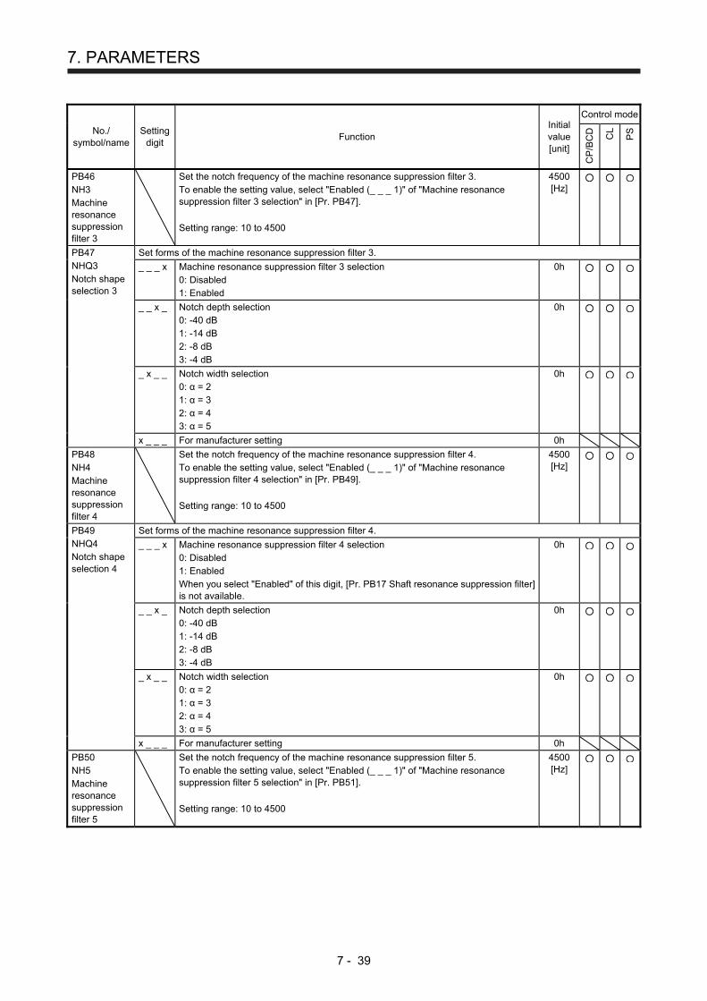
7. PARAMETERS
7 - 39
No./ symbol/name
Setting digit
Function Initial value [unit]
Control mode
CP
/BC
D
CL
PS
PB46 NH3 Machine resonance suppression filter 3
Set the notch frequency of the machine resonance suppression filter 3. To enable the setting value, select "Enabled (_ _ _ 1)" of "Machine resonance suppression filter 3 selection" in [Pr. PB47]. Setting range: 10 to 4500
4500 [Hz]
PB47 NHQ3 Notch shape selection 3
Set forms of the machine resonance suppression filter 3.
_ _ _ x Machine resonance suppression filter 3 selection 0: Disabled 1: Enabled
0h
_ _ x _ Notch depth selection 0: -40 dB 1: -14 dB 2: -8 dB 3: -4 dB
0h
_ x _ _ Notch width selection 0: α = 2 1: α = 3 2: α = 4 3: α = 5
0h
x _ _ _ For manufacturer setting 0h
PB48 NH4 Machine resonance suppression filter 4
Set the notch frequency of the machine resonance suppression filter 4. To enable the setting value, select "Enabled (_ _ _ 1)" of "Machine resonance suppression filter 4 selection" in [Pr. PB49]. Setting range: 10 to 4500
4500 [Hz]
PB49 NHQ4 Notch shape selection 4
Set forms of the machine resonance suppression filter 4.
_ _ _ x Machine resonance suppression filter 4 selection 0: Disabled 1: Enabled When you select "Enabled" of this digit, [Pr. PB17 Shaft resonance suppression filter] is not available.
0h
_ _ x _ Notch depth selection 0: -40 dB 1: -14 dB 2: -8 dB 3: -4 dB
0h
_ x _ _ Notch width selection 0: α = 2 1: α = 3 2: α = 4 3: α = 5
0h
x _ _ _ For manufacturer setting 0h
PB50 NH5 Machine resonance suppression filter 5
Set the notch frequency of the machine resonance suppression filter 5. To enable the setting value, select "Enabled (_ _ _ 1)" of "Machine resonance suppression filter 5 selection" in [Pr. PB51]. Setting range: 10 to 4500
4500 [Hz]

7. PARAMETERS
7 - 40
No./ symbol/name
Setting digit
Function Initial value [unit]
Control mode
CP
/BC
D
CL
PS
PB51 NHQ5 Notch shape selection 5
Set forms of the machine resonance suppression filter 5. When you select "Enabled (_ _ _ 1)" of "Robust filter selection" in [Pr. PE41], the machine resonance suppression filter 5 is not available.
_ _ _ x Machine resonance suppression filter 5 selection 0: Disabled 1: Enabled
0h
_ _ x _ Notch depth selection 0: -40 dB 1: -14 dB 2: -8 dB 3: -4 dB
0h
_ x _ _ Notch width selection 0: α = 2 1: α = 3 2: α = 4 3: α = 5
0h
x _ _ _ For manufacturer setting 0h
PB52 VRF21 Vibration suppression control 2 - Vibration frequency
Set the vibration frequency for vibration suppression control 2 to suppress low-frequency machine vibration. When "Vibration suppression control 2 tuning mode selection" is "Automatic setting (_ _ 1 _)" in [Pr. PB02], this parameter will be set automatically. Set manually for "Manual setting (_ _ 2 _)". To enable the digit, select "3 inertia mode (_ _ _ 1)" of "Vibration suppression mode selection" in [Pr. PA24]. Setting range: 0.1 to 300.0
100.0 [Hz]
PB53 VRF22 Vibration suppression control 2 - Resonance frequency
Set the resonance frequency for vibration suppression control 2 to suppress low-frequency machine vibration. When "Vibration suppression control 2 tuning mode selection" is "Automatic setting (_ _ 1 _)" in [Pr. PB02], this parameter will be set automatically. Set manually for "Manual setting (_ _ 2 _)". To enable the digit, select "3 inertia mode (_ _ _ 1)" of "Vibration suppression mode selection" in [Pr. PA24]. Setting range: 0.1 to 300.0
100.0 [Hz]
PB54 VRF23 Vibration suppression control 2 - Vibration frequency damping
Set a damping of the vibration frequency for vibration suppression control 2 to suppress low-frequency machine vibration. When "Vibration suppression control 2 tuning mode selection" is "Automatic setting (_ _ 1 _)" in [Pr. PB02], this parameter will be set automatically. Set manually for "Manual setting (_ _ 2 _)". To enable the digit, select "3 inertia mode (_ _ _ 1)" of "Vibration suppression mode selection" in [Pr. PA24]. Setting range: 0.00 to 0.30
0.00
PB55 VRF24 Vibration suppression control 2 - Resonance frequency damping
Set a damping of the resonance frequency for vibration suppression control 2 to suppress low-frequency machine vibration. When "Vibration suppression control 2 tuning mode selection" is "Automatic setting (_ _ 1 _)" in [Pr. PB02], this parameter will be set automatically. Set manually for "Manual setting (_ _ 2 _)". To enable the digit, select "3 inertia mode (_ _ _ 1)" of "Vibration suppression mode selection" in [Pr. PA24]. Setting range: 0.00 to 0.30
0.00

7. PARAMETERS
7 - 41
No./ symbol/name
Setting digit
Function Initial value [unit]
Control mode
CP
/BC
D
CL
PS
PB56 VRF21B Vibration suppression control 2 - Vibration frequency after gain switching
Set the vibration frequency for vibration suppression control 2 for when the gain switching is enabled. When you set a value less than 0.1 Hz, the value will be the same as [Pr. PB52]. This parameter will be enabled only when the following conditions are fulfilled.
"Gain adjustment mode selection" in [Pr. PA08] is "Manual mode (_ _ _ 3)".
"Vibration suppression mode selection" in [Pr. PA24] is "3 inertia mode (_ _ _ 1)".
"Vibration suppression control 2 tuning mode selection" in [Pr. PB02] is "Manual
setting (_ _ 2 _)".
"Gain switching selection" in [Pr. PB26] is "Input device (gain switching (CDP)) (_ _
_ 1)". Switching during driving may cause a shock. Be sure to switch them after the servo motor or linear servo motor stops. Setting range: 0.0 to 300.0
0.0 [Hz]
PB57 VRF22B Vibration suppression control 2 - Resonance frequency after gain switching
Set the resonance frequency for vibration suppression control 2 for when the gain switching is enabled. When you set a value less than 0.1 Hz, the value will be the same as [Pr. PB53]. This parameter will be enabled only when the following conditions are fulfilled.
"Gain adjustment mode selection" in [Pr. PA08] is "Manual mode (_ _ _ 3)".
"Vibration suppression mode selection" in [Pr. PA24] is "3 inertia mode (_ _ _ 1)".
"Vibration suppression control 2 tuning mode selection" in [Pr. PB02] is "Manual
setting (_ _ 2 _)".
"Gain switching selection" in [Pr. PB26] is "Input device (gain switching (CDP)) (_ _
_ 1)". Switching during driving may cause a shock. Be sure to switch them after the servo motor or linear servo motor stops. Setting range: 0.0 to 300.0
0.0 [Hz]
PB58 VRF23B Vibration suppression control 2 - Vibration frequency damping after gain switching
Set a damping of the vibration frequency for vibration suppression control 2 when the gain switching is enabled. This parameter will be enabled only when the following conditions are fulfilled.
"Gain adjustment mode selection" in [Pr. PA08] is "Manual mode (_ _ _ 3)".
"Vibration suppression mode selection" in [Pr. PA24] is "3 inertia mode (_ _ _ 1)".
"Vibration suppression control 2 tuning mode selection" in [Pr. PB02] is "Manual
setting (_ _ 2 _)".
"Gain switching selection" in [Pr. PB26] is "Input device (gain switching (CDP)) (_ _
_ 1)". Switching during driving may cause a shock. Be sure to switch them after the servo motor or linear servo motor stops. Setting range: 0.00 to 0.30
0.00
PB59 VRF24B Vibration suppression control 2 - Resonance frequency damping after gain switching
Set a damping of the resonance frequency for vibration suppression control 2 when the gain switching is enabled. This parameter will be enabled only when the following conditions are fulfilled.
"Gain adjustment mode selection" in [Pr. PA08] is "Manual mode (_ _ _ 3)".
"Vibration suppression mode selection" in [Pr. PA24] is "3 inertia mode (_ _ _ 1)".
"Vibration suppression control 2 tuning mode selection" in [Pr. PB02] is "Manual
setting (_ _ 2 _)".
"Gain switching selection" in [Pr. PB26] is "Input device (gain switching (CDP)) (_ _
_ 1)". Switching during driving may cause a shock. Be sure to switch them after the servo motor or linear servo motor stops. Setting range: 0.00 to 0.30
0.00

7. PARAMETERS
7 - 42
No./ symbol/name
Setting digit
Function Initial value [unit]
Control mode
CP
/BC
D
CL
PS
PB60 PG1B Model loop gain after gain switching
Set the model loop gain for when the gain switching is enabled. When you set a value less than 1.0 rad/s, the value will be the same as [Pr. PB07]. This parameter will be enabled only when the following conditions are fulfilled.
"Gain adjustment mode selection" in [Pr. PA08] is "Manual mode (_ _ _ 3)". "Gain switching selection" in [Pr. PB26] is "Input device (gain switching (CDP)) (_ _ _ 1)".
Switching during driving may cause a shock. Be sure to switch them after the servo motor or linear servo motor stops. Setting range: 0.0 to 2000.0
0.0 [rad/s]
7.2.3 Extension setting parameters ([Pr. PC_ _ ])
No./ symbol/name
Setting digit
Function Initial value [unit]
Control mode
CP
/BC
D
CL
PS
PC01 STA JOG operation acceleration time constant
Set an acceleration time constant for the JOG operation of the program method. Set an acceleration time from 0 r/min or 0 mm/s to the rated speed.
If the preset speed command is lowerthan the rated speed, acceleration/deceleration time will be shorter.
Time
[Pr. PC02] setting
0 r/min
Ratedspeed
Speed
[Pr. PC01] setting(0 mm/s)
For example for the servo motor of 3000 r/min rated speed, set 3000 (3 s) to increase speed from 0 r/min to 1000 r/min in 1 s. Additionally, when 20000 ms or more value is set, it will be clamped to 20000 ms. Setting range: 0 to 50000
0 [ms]
PC01 STA Acceleration time constant 1
Set an acceleration time constant for the automatic operation of the indexer method. Set an acceleration time from 0 r/min to the rated speed.
If the preset speed commandis lower than the rated speed,acceleration/deceleration timewill be shorter.
Time
[Pr. PC02] setting
0 r/min
Rated speed
Speed
[Pr. PC01] setting
For example for the servo motor of 3000 r/min rated speed, set 3000 (3 s) to increase speed from 0 r/min to 1000 r/min in 1 s. Additionally, when 20000 ms or more value is set, it will be clamped to 20000 ms. Setting range: 0 to 50000
0 [ms]
PC02 STB JOG operation deceleration time constant
Set a deceleration time constant for the JOG operation of the program method. Set a deceleration time from the rated speed to 0 r/min or 0 mm/s. Additionally, when 20000 ms or more value is set, it will be clamped to 20000 ms. Setting range: 0 to 50000
0 [ms]

7. PARAMETERS
7 - 43
No./ symbol/name
Setting digit
Function Initial value [unit]
Control mode
CP
/BC
D
CL
PS
PC02 STB Deceleration time constant 1
Set a deceleration time constant for the automatic operation of the indexer method. Set a deceleration time from the rated speed to 0 r/min. Additionally, when 20000 ms or more value is set, it will be clamped to 20000 ms. Setting range: 0 to 50000
0 [ms]
PC03 *STC S-pattern acceleration/ deceleration time constant
This enables to start/stop the servo motor or linear servo motor smoothly. Set the time of the arc part for S-pattern acceleration/deceleration. Servo is usually operated with linear acceleration and deceleration; however, smooth start and stop are enabled by setting [Pr. PC03 S-pattern acceleration/deceleration time constants]. When the S-pattern acceleration/deceleration time constants are set, smooth positioning is enabled as shown in the following figure. Note that when it is set, a time period from the start to output of MEND (Travel completion) is longer by the S-pattern acceleration/deceleration time constants.
Accelerationtime constant
Servo motorspeed
0 [r/min]
Decelerationtime constant
Ta
Ta + STC Tb
Tb + STC
Rated speed
Preset speed
Ta: Time until presetspeed is reached
Tb: Time until stop
When the STC value is set longer than the constant speed time, the speed may not reach to the command speed. Additionally, when a value of 1000 ms or more is set, it will be clamped to 1000 ms. Setting range: 0 to 5000
0 [ms]
PC05 SC1 Automatic operation speed 1
Set a positioning speed for the automatic operation speed 1, 2 of the indexer method. Setting range: 0 to permissible instantaneous speed
100 [r/min]
PC06 SC2 Automatic operation speed 2
Set a positioning speed for the automatic operation speed 1, 2 of the indexer method. Setting range: 0 to permissible instantaneous speed
500 [r/min]
PC07 SC3 Manual operation speed 1
Set a JOG speed of the manual operation mode, JOG operation, and home position return mode of the indexer method. Setting range: 0 to permissible instantaneous speed
1000 [r/min]

7. PARAMETERS
7 - 44
No./ symbol/name
Setting digit
Function Initial value [unit]
Control mode
CP
/BC
D
CL
PS
PC14 MOD1 Analog monitor 1 output
_ _ x x Analog monitor 1 output selection Select a signal to output to MO1 (Analog monitor 1). Refer to appendix 8.3 of "MR-J4-_A_(-RJ) Servo Amplifier Instruction Manual" for detection points of output selection. Refer to table 7.8 or 7.9 for settings.
00h
_ x _ _ For manufacturer setting 0h
x _ _ _ 0h
Table 7.8 Analog monitor setting value (MR-J4-_A_-RJ 100 W or more)
Setting value
Item
Operation mode (Note 1)
Sta
ndar
d
Ful
l.
Lin.
DD
_ _ 0 0 (Linear) servo motor speed (±8 V/max. speed)
_ _ 0 1 Torque or thrust (±8 V/max. torque or max. thrust) (Note 3)
_ _ 0 2 (Linear) servo motor speed (+8 V/max. speed)
_ _ 0 3 Torque or thrust (+8 V/max. torque or max. thrust) (Note 3)
_ _ 0 4 Current command (±8 V/max. current command)
_ _ 0 5 Command pulse frequency (±10 V/±4 Mpulses/s)
_ _ 0 6 Servo motor-side droop pulses (±10 V/100 pulses) (Note 2)
_ _ 0 7 Servo motor-side droop pulses (±10 V/1000 pulses) (Note 2)
_ _ 0 8 Servo motor-side droop pulses (±10 V/10000 pulses) (Note 2)
_ _ 0 9 Servo motor-side droop pulses (±10 V/100000 pulses) (Note 2)
_ _ 0 A Feedback position (±10 V/1 Mpulses) (Note 2)
_ _ 0 B Feedback position (±10 V/10 Mpulses) (Note 2)
_ _ 0 C Feedback position (±10 V/100 Mpulses) (Note 2)
_ _ 0 D Bus voltage (200 V class and 100 V class: +8 V/400 V, 400 V class: +8 V/800 V)
_ _ 0 E Speed command 2 (±8 V/max. speed)
_ _ 1 0 Load-side droop pulses (±10 V/100 pulses) (Note 2)
_ _ 1 1 Load-side droop pulses (±10 V/1000 pulses) (Note 2)
_ _ 1 2 Load-side droop pulses (±10 V/10000 pulses) (Note 2)
_ _ 1 3 Load-side droop pulses (±10 V/100000 pulses) (Note 2)
_ _ 1 4 Load-side droop pulses (±10 V/1 Mpulses) (Note 2)
_ _ 1 5 Servo motor-side/load-side position deviation (±10 V/100000 pulses)
_ _ 1 6 Servo motor-side/load-side speed deviation (±8 V/max. speed)
_ _ 1 7 Encoder inside temperature (±10 V/±128 ˚C)
Note 1. Items with are available for each operation mode.
Standard: Standard (semi closed loop system) use of the rotary servo motor
Full.: Fully closed loop system use of the rotary servo motor
Lin.: Linear servo motor use
DD: Direct drive (DD) motor use 2. Encoder pulse unit 3. The value in [Pr. PA11] or [Pr. PA12] whichever is higher is applied for the maximum torque or
maximum thrust.

7. PARAMETERS
7 - 45
No./ symbol/name
Setting digit
Function Initial value [unit]
Control mode
CP
/BC
D
CL
PS
PC14 MOD1 Analog monitor 1 output
Table 7.9 Analog monitor setting value (MR-J4-03A6-RJ)
Setting value
Item
_ _ 0 0 Servo motor speed (5 V ± 3 V/max. speed)
_ _ 0 1 Torque (5 V ± 3 V/max. torque) (Note 2)
_ _ 0 2 Servo motor speed (5 V + 3 V/max. speed)
_ _ 0 3 Torque (5 V + 3 V/max. torque) (Note 2)
_ _ 0 4 Current command (5 V ± 3 V/max. current command)
_ _ 0 5 Command pulse frequency (5 V ± 4 V/±4 Mpulses/s)
_ _ 0 6 Servo motor-side droop pulses (5 V ± 4 V/100 pulses) (Note 1)
_ _ 0 7 Servo motor-side droop pulses (5 V ± 4 V/1000 pulses) (Note 1)
_ _ 0 8 Servo motor-side droop pulses (5 V ± 4 V/10000 pulses) (Note 1)
_ _ 0 9 Servo motor-side droop pulses (5 V ± 4 V/100000 pulses)(Note 1)
_ _ 0 A Feedback position (5 V ± 4 V/1 Mpulses) (Note 1)
_ _ 0 B Feedback position (5 V ± 4 V/10 Mpulses) (Note 1)
_ _ 0 C Feedback position (5 V ± 4 V/100 Mpulses) (Note 1)
_ _ 0 D Bus voltage (5 V + 4 V/100 V)
_ _ 0 E Speed command 2 (5 V ± 3 V/max. speed)
_ _ 1 7 Encoder inside temperature (5 V ± 4 V/±128 ˚C)
Note 1. Encoder pulse unit 2. The value in [Pr. PA11] or [Pr. PA12] whichever is higher is applied for the maximum torque. PC15 MOD2 Analog monitor 2 output
_ _ x x Analog monitor 2 output selection Select a signal to output to MO2 (Analog monitor 2). Refer to appendix 8.3 of "MR-J4-_A_(-RJ) Servo Amplifier Instruction Manual" for detection points of output selection. Refer to [Pr. PC14] for settings.
01h
_ x _ _ For manufacturer setting 0h
x _ _ _ 0h
PC16 MBR Electromagnetic brake sequence output
Set the delay time between MBR (Electromagnetic brake interlock) and the base drive circuit is shut-off. Setting range: 0 to 1000
0 [ms]
PC17 ZSP Zero speed
Set an output range of ZSP (Zero speed detection). ZSP (Zero speed detection) has hysteresis of 20 r/min or 20 mm/s. Setting range: 0 to 10000
50 [r/min]/ [mm/s]
PC18 *BPS Alarm history clear
_ _ _ x Alarm history clear selection Used to clear the alarm history. 0: Disabled 1: Enabled When you select "Enabled", the alarm history will be cleared at next power-on. After the alarm history is cleared, the setting is automatically disabled.
0h
_ _ x _ For manufacturer setting 0h
_ x _ _ 0h
x _ _ _ 0h

7. PARAMETERS
7 - 46
No./ symbol/name
Setting digit
Function Initial value [unit]
Control mode
CP
/BC
D
CL
PS
PC19 *ENRS Encoder output pulse selection
_ _ _ x Encoder output pulse phase selection Select an encoder pulse direction. 0: Increasing A-phase 90° in CCW or positive direction 1: Increasing A-phase 90° in CW or negative direction
0h
Setting value
Servo motor rotation direction/linear servo motor travel direction
CCW or positive direction CW or negative direction
0
A-phase
B-phase
A-phase
B-phase
1
A-phase
B-phase
A-phase
B-phase
_ _ x _ Encoder output pulse setting selection 0: Output pulse setting 1: Division ratio setting 2: The same output pulse setting as command pulse 3: A-phase/B-phase pulse electronic gear setting 4: A/B-phase pulse through output setting 5: Command pulse input through output setting When you select "1", the settings of [Pr. PA16 Encoder output pulses 2] will be disabled. When you select "2", the settings of [Pr. PA15 Encoder output pulses] and [Pr. PA16 Encoder output pulses 2] will be disabled. Additionally, it will be the servo motor side pulse unit for the indexer method. When you select the setting, do not change the settings in [Pr. PA06] and [Pr. PA07] after the power-on. Setting "4" will be enabled only when A/B/Z-phase differential output linear encoder is used. And "Encoder output pulse phase selection (_ _ _ x)" will be disabled. When another encoder is connected, [AL. 37 Parameter error] will occur. Setting "Standard control mode (_ _ 0 _)" in [Pr. PA01] will trigger [AL. 37 Parameter error]. When "5" is set, the settings of [Pr. PA15 Encoder output pulses] and [Pr. PA16 Encoder output pulses 2] will be disabled. "Encoder output pulse phase selection (_ _ _x)" and "Encoder selection for encoder output pulse (x _ _ _)" will be also disabled. When [Pr. PA01] is set to other than "Point table method (_ _ _ 6)" and "Program method (_ _ _ 7)", [AL. 37 Parameter error] occurs. When "5" is set, assign PP/PP2 with [Pr. PD44] and NP/NP2 with [Pr. PD46].
0h
_ x _ _ Selection of the encoders for encoder output pulse Select an encoder used the encoder output pulses which the servo amplifier outputs. 0: Servo motor encoder 1: Load-side encoder When "_ 1 0 _" is set to this parameter, [AL. 37 Parameter error] will occur. This is only for the fully closed loop system. If "1" is set other than in the fully closed loop system, [AL. 37 Parameter error] will occur.
0h
x _ _ _ For manufacturer setting 0h
PC20 *SNO Station No. setting
Specify a station No. of the servo amplifier for RS-422 and USB communication. Always set one station to one axis of the servo amplifier. Setting one station number to two or more stations will disable a normal communication. Setting range: 0 to 31
0 [Station]

7. PARAMETERS
7 - 47
No./ symbol/name
Setting digit
Function Initial value [unit]
Control mode
CP
/BC
D
CL
PS
PC21 *SOP RS-422 communication function selection
Select the details of RS-422 communication function.
_ _ _ x For manufacturer setting 0h
_ _ x _ RS-422 communication baud rate selection When using the parameter unit, set "1 _ _ _" in [Pr. PF34]. 0: 9600 [bps] 1: 19200 [bps] 2: 38400 [bps] 3: 57600 [bps] 4: 115200 [bps]
0h
_ x _ _ RS-422 communication response delay time selection 0: Disabled 1: Enabled (responding after 800 μs or longer delay time)
0h
x _ _ _ For manufacturer setting 0h
PC22 *COP1 Function selection C-1
_ _ _ x For manufacturer setting 0h
_ _ x _ 0h
_ x _ _ 0h
x _ _ _ Encoder cable communication method selection Select how to execute the encoder cable communication method. 0: Two-wire type 1: Four-wire type When using an encoder of A/B/Z-phase differential output method, set "0". If the setting is incorrect, [AL. 16 Encoder initial communication error 1] or [AL. 20 Encoder normal communication error 1] occurs. For MR-J4-03A6-RJ servo amplifiers, this digit cannot be used other than the initial value. Also, it does not comply with encoders of A/B/Z-phase differential output method.
0h
PC24 *COP3 Function selection C-3
_ _ _ x In-position range unit selection Select a unit of in-position range. 0: Command unit 1: Servo motor encoder pulse unit
0h
_ _ x _ For manufacturer setting 0h
_ x _ _ 0h
x _ _ _ Error excessive alarm level unit selection Select a setting unit of the error excessive alarm level set in [Pr. PC43]. 0: Per 1 rev or 1 mm 1: Per 0.1 rev or 0.1 mm 2: Per 0.01 rev or 0.01 mm 3: Per 0.001 rev or 0.001 mm
0h
PC26 *COP5 Function selection C-5
_ _ _ x [AL. 99 Stroke limit warning] selection Select [AL. 99 Stroke limit warning]. 0: Enabled 1: Disabled
0h
_ _ x _ For manufacturer setting 0h
_ x _ _ 0h
x _ _ _ 0h

7. PARAMETERS
7 - 48
No./ symbol/name
Setting digit
Function Initial value [unit]
Control mode
CP
/BC
D
CL
PS
PC27 *COP6 Function selection C-6
_ _ _ x [AL. 10 Undervoltage] detection method selection Set this parameter when [AL. 10 Undervoltage] occurs due to distorted power supply voltage waveform while using FR-RC-(H) or FR-CV-(H). 0: [AL. 10] not occurrence 1: [AL. 10] occurrence This digit is not available with MR-J4-03A6-RJ servo amplifiers.
0h
_ _ x _ Main circuit power supply selection Select a voltage to be connected to the main circuit power supply with an MR-J4-03A6-RJ servo amplifier. 0: 48 V DC 1: 24 V DC When using 24 V DC for the main circuit power supply, set "1" to this digit. This digit is not available with MR-J4-_A_-RJ 100 W or more servo amplifiers. The characteristics of the servo motor vary depending on whether 48 V DC or 24 V DC is used. For details, refer to "Servo Motor Instruction Manual (Vol. 3)".
0h
_ x _ _ Undervoltage alarm selection Select the alarm and warning that occurs when the bus voltage drops to the undervoltage alarm level. 0: [AL. 10] regardless of servo motor speed 1: [AL. E9] at servo motor speed 50 r/min (50 mm/s) or less, [AL. 10] at over 50 r/min
(50 mm/s)
0h
x _ _ _ For manufacturer setting 0h
PC28 *COP7 Function selection C-7
_ _ _ x For manufacturer setting 0h
_ _ x _ 0h
_ x _ _ 0h
x _ _ _ Linear scale multipoint Z-phase input function selection When two or more reference marks exist during the full stroke of the linear encoder, set "1". 0: Disabled 1: Enabled This parameter setting is used by servo amplifiers with software version A5 or later. This digit is not available with MR-J4-03A6-RJ servo amplifiers.
0h
PC30 STA2 Home position return acceleration time constant
This parameter is used when a home position return is executed with the program method. Set the acceleration time constant at the home position return. Set an acceleration time from 0 r/min or 0 mm/s to the rated speed. Additionally, when 20000 ms or more value is set, it will be clamped to 20000 ms. Setting range: 0 to 50000
0 [ms]
PC30 STA2 Acceleration time constant 2
Set an second acceleration time constant for the automatic operation of the indexer method. Set an acceleration time from 0 r/min to the rated speed. Additionally, when 20000 ms or more value is set, it will be clamped to 20000 ms. Setting range: 0 to 50000
0 [ms]
PC31 STB2 Home position return deceleration time constant
This parameter is used when a home position return is executed with the program method. Set the deceleration time constant at the home position return. Set a deceleration time from the rated speed to 0 r/min or 0 mm/s. Additionally, when 20000 ms or more value is set, it will be clamped to 20000 ms. Setting range: 0 to 50000
0 [ms]

7. PARAMETERS
7 - 49
No./ symbol/name
Setting digit
Function Initial value [unit]
Control mode
CP
/BC
D
CL
PS
PC31 STB2 Deceleration time constant 2
Set an second deceleration time constant for the automatic operation of the indexer method. Set a deceleration time from the rated speed to 0 r/min. Additionally, when 20000 ms or more value is set, it will be clamped to 20000 ms. Setting range: 0 to 50000
0 [ms]
PC35 TL2 Internal torque limit 2/internal thrust limit 2
Set the parameter on the assumption that the maximum torque or thrust is 100.0 %. The parameter is set for limiting the torque of the servo motor or the thrust of the linear servo motor. No torque or thrust is generated when this parameter is set to "0.0". When TL1 (Internal torque limit selection) is turned on, Internal torque limits 1 and 2 are compared and the lower value will be enabled. Set the parameter referring to section 3.6.1 (5) of "MR-J4-_A_(-RJ) Servo Amplifier Instruction Manual" and section 11.5.3 (6) of this Instruction Manual. Setting range: 0.0 to 100.0
100.0 [%]

7. PARAMETERS
7 - 50
No./ symbol/name
Setting digit
Function Initial value [unit]
Control mode
CP
/BC
D
CL
PS
PC36 *DMD Status display selection
_ _ x x Status display selection at power-on Select a status display shown at power-on. 00: Cumulative feedback pulse 01: Servo motor speed/linear servo motor speed 02: Droop pulses 03: Cumulative command pulses 04: Command pulse frequency 05: Analog speed command voltage (not used for the positioning mode) 06: Analog torque limit voltage 07: Regenerative load ratio 08: Effective load ratio 09: Peak load ratio 0A: Instantaneous torque/instantaneous thrust 0B: Position within one-revolution/virtual position within one-revolution (1 pulse unit) 0C: Position within one-revolution/virtual position within one-revolution (1000 pulses unit) 0D: ABS counter/virtual ABS counter 0E: Load to motor inertia ratio/load to motor mass ratio 0F: Bus voltage 10: Encoder inside temperature 11: Settling time 12: Oscillation detection frequency 13: Number of tough drives 14: Unit power consumption (increment of 1 W) 15: Unit power consumption (increment of 1 kW) 16: Unit total power consumption (increment of 1 Wh) 17: Unit total power consumption (increment of 100 kWh) 18: Load-side cumulative feedback pulses (Note 1, 3) 19: Load-side droop pulses (Note 1, 3) 1A: Load-side encoder information 1 (1 pulse unit) (Note 1, 3) 1B: Load-side encoder information 1 (100000 pulses unit) (Note 1, 3) 1C: Load-side encoder ABS counter (Note 1, 3) 1D: Z-phase counter (1 pulse unit) (Note 2, 3) 1E: Z-phase counter (100000 pulses unit) (Note 2, 3) 1F: Electrical angle (1 pulse unit) (Note 2, 3) 20: Electrical angle (100000 pulses unit) (Note 2, 3) 21: Current position 22: Command position 23: Command remaining distance 24: Point table No./Program No./Station position No. 25: Step No. 26: Override voltage 27: Override level 28: Cam axis one cycle current value 29: Cam standard position 2A: Cam axis feed current value 2B: Cam No. in execution 2C: Cam stroke amount in execution 2D: Main axis current value 2E: Main axis one cycle current value
00h
Note 1. Setting "18 to 1C" will trigger [AL. 37] in the mode other than the fully closed
loop control mode.
2. Setting 1D to 20 will trigger [AL. 37] in the mode other than the linear servo
motor control mode.
3. This is not available with the MR-J4-03A6-RJ servo amplifier.

7. PARAMETERS
7 - 51
No./ symbol/name
Setting digit
Function Initial value [unit]
Control mode
CP
/BC
D
CL
PS
PC36 *DMD Status display selection
_ x _ _ Status display at power-on in corresponding control mode 0: Depends on the control mode
0h
Control mode Status display at power-on
Positioning (point table method) Current position
Positioning (program method) Current position
Positioning (indexer method) Cumulative feedback pulses
1: Depends on the last two digit setting of the parameter
x _ _ _ For manufacturer setting 0h
PC37 VCO Analog override Offset
Set an offset voltage of VC (Override input). This will be automatic setting by executing VC automatic offset. Setting range: -9999 to 9999
0 [mV]
PC38 TPO Analog torque limit offset
Set the offset voltage of TLA (Analog torque limit).
Setting range: -9999 to 9999
0 [mV]
PC39 MO1 Analog monitor 1 offset
Set the offset voltage of MO1 (Analog monitor 1). Setting range: -9999 to 9999
0 [mV]
PC40 MO2 Analog monitor 2 offset
Set the offset voltage of MO2 (Analog monitor 2). Setting range: -9999 to 9999
0 [mV]
PC43 ERZ Error excessive alarm level
Set an error excessive alarm level. You can change the setting unit with "Error excessive alarm level" in [Pr. PC24]. Set this per rev. for rotary servo motors and direct drive motors. Set this per mm for linear servo motors. Setting "0" will be "3 rev" for rotary servo motors and direct drive motors and "100 mm" for linear servo motors. Setting over 200 rev will be clamped with 200 rev. Setting range: 0 to 1000
0 [rev]/ [mm]
PC44 *COP9 Function selection C-9
_ _ _ x For manufacturer setting 0h
_ _ x _ 0h
_ x _ _ 0h
x _ _ _ Load-side encoder cable communication method selection Select an encoder cable to be connected to the CN2L connector of MR-J4-_A_-RJ. 0: Two-wire type 1: Four-wire type When using an encoder of A/B/Z-phase differential output method, set "0". Incorrect setting will trigger [AL. 70] and [AL. 71]. This digit is not available with MR-J4-03A6-RJ servo amplifiers.
0h

7. PARAMETERS
7 - 52
No./ symbol/name
Setting digit
Function Initial value [unit]
Control mode
CP
/BC
D
CL
PS
PC45 *COPA Function selection C-A
_ _ _ x Encoder pulse count polarity selection Select a polarity of the linear encoder or load-side encoder. 0: Encoder pulse increasing direction in the servo motor CCW or positive direction 1: Encoder pulse decreasing direction in the servo motor CCW or positive direction This digit is not available with MR-J4-03A6-RJ servo amplifiers.
0h
_ _ x _ For manufacturer setting 0h
_ x _ _ Selection of A/B/Z-phase input interface encoder Z-phase connection judgement function Select the non-signal detection status for the pulse train signal from the A/B/Z-phase input interface encoder used as a linear encoder or load-side encoder. This function is enabled only when you use an A/B/Z-phase input interface encoder. This digit is not available with MR-J4-03A6-RJ servo amplifiers.
0h
Setting value
Detection of disconnection
Alarm status
Z-phase-side non-signal
Full. Lin.
_ 0 _ _ Enabled [AL. 71.6] (Z-phase)
[AL. 20.6] (Z-phase)
_ 1 _ _ Disabled
x _ _ _ For manufacturer setting 0h
PC51 RSBR Forced stop deceleration time constant
Set a deceleration time constant when you use the forced stop deceleration function. Set the time per ms from the rated speed to 0 r/min or 0 mm/s.
Forced stop deceleration
[Pr. PC51]0 r/min
Servo motor speed
Rated speedDynamic brakedeceleration
(Linear servomotor speed)
(0 mm/s)
[Precautions]
If the servo motor torque or linear servo motor thrust is saturated at the maximum
value during forced stop deceleration because the set time is too short, the time to
stop will be longer than the set time constant.
[AL. 50 Overload alarm 1] or [AL. 51 Overload alarm 2] may occur during forced
stop deceleration, depending on the set value.
After an alarm that leads to a forced stop deceleration, if an alarm that does not lead
to a forced stop deceleration occurs or if the control circuit power supply is cut,
dynamic braking will start regardless of the deceleration time constant setting. Setting range: 0 to 20000
100 [ms]

7. PARAMETERS
7 - 53
No./ symbol/name
Setting digit
Function Initial value [unit]
Control mode
CP
/BC
D
CL
PS
PC54 RSUP1 Vertical axis freefall prevention compensation amount
Set the compensation amount of the vertical axis freefall prevention function. Set it per servo motor rotation amount or linear servo motor travel distance. When setting a positive value, the servo motor/linear servo motor will pull in the direction of the servo motor rotation direction/linear servo motor travel direction at positioning address increasing with the servo motor rotation amount/linear servo motor travel distance unit. When setting a negative value, the servo motor/linear servo motor will pull in the direction of the servo motor rotation direction/linear servo motor travel direction at positioning address decreasing with the servo motor rotation amount/linear servo motor travel distance unit. For example, if a positive compensation amount is set when the [Pr. PA14 Rotation direction selection/travel direction selection] setting is "1", the axis will be pulled to the CW direction. The vertical axis freefall prevention function is performed when all of the following conditions are met. 1) The value of the parameter is other than "0". 2) The forced stop deceleration function is enabled. 3) Alarm occurs or EM2 turns off when the (linear) servo motor speed is zero speed or
less. 4) MBR (Electromagnetic brake interlock) was enabled in [Pr. PD23] to [Pr. PD26],
[Pr. PD28], and [Pr. PD47], and the base circuit shut-off delay time was set in [Pr. PC16].
Setting range: -25000 to 25000
0 [0.0001
rev]/ [0.01 mm]
PC60 *COPD Function selection C-D
_ _ _ x Motor-less operation selection Set the motor-less operation. This is not used in the linear servo motor control mode, fully closed loop control, and DD motor control mode. 0: Disabled 1: Enabled
0h
_ _ x _ High-resolution analog input selection Select the resolution of VC (Analog override). When you change parameters, perform offset adjustment with [Pr. PC37 Analog override offset]. The offset adjustment can be performed by executing VC automatic offset. Setting "1" while using a servo amplifier other than MR-J4-_A_-RJ, MR-J4-_A_-RU, and MR-J4-_A_-RZ will trigger [AL. 37]. 0: Disabled 1: Enabled This digit is available with servo amplifiers manufactured in November 2014 or later. This digit is not available with MR-J4-03A6-RJ servo amplifiers.
0h
_ x _ _ For manufacturer setting 0h
x _ _ _ [AL. 9B Error excessive warning] selection 0: [AL. 9B Error excessive warning] is disabled. 1: [AL. 9B Error excessive warning] is enabled. This parameter is available with servo amplifiers with software version B4 or later.
0h

7. PARAMETERS
7 - 54
No./ symbol/name
Setting digit
Function Initial value [unit]
Control mode
CP
/BC
D
CL
PS
PC66 LPSPL Mark detection range + (lower three digits)
Set the upper limit of the mark detection. Upper and lower are a set. When the roll feed display is enabled, set this value with the travel distance from the starting position. Setting address:
Upper3 digits
Lower 3digits
[Pr. PC66]
[Pr. PC67]
The unit will be changed to 10STM [μm], 10-(STM-4) [inch], 10-3 [degree], or [pulse] with the setting of [Pr. PT01]. Set a same sign for [Pr. PC66] and [Pr. PC67]. A different sign will be recognized as minus sign data. When changing the direction to address decreasing, change it from the - side of the mark detection ([Pr. PC68] and [Pr. PC69]). An incorrect order of the setting will trigger [AL. 37]. Therefore, cycling power may be required after [Pr. PC66] to [Pr. PC69] are all set. This parameter setting is available with servo amplifiers with software version B7 or later. Setting range: -999 to 999
0 Refer to Function column for unit.
PC67 LPSPH Mark detection range + (upper three digits)
PC68 LPSNL Mark detection range - (lower three digits)
Set the lower limit of the mark detection. Upper and lower are a set. When the roll feed display is enabled, set this value with the travel distance from the starting position. Setting address:
Upper3 digits
Lower3 digits
[Pr. PC68]
[Pr. PC69]
The unit will be changed to 10STM [μm], 10-(STM-4) [inch], 10-3 [degree], or [pulse] with the setting of [Pr. PT01]. Set a same sign for [Pr. PC68] and [Pr. PC69]. A different sign will be recognized as minus sign data. When changing the direction to address increasing, change it from the + side of the mark detection ([Pr. PC66] and [Pr. PC67]). An incorrect order of the setting will trigger [AL. 37]. Therefore, cycling power may be required after [Pr. PC66] to [Pr. PC69] are all set. This parameter setting is available with servo amplifiers with software version B7 or later. Setting range: -999 to 999
0 Refer to Function column for unit.
PC69 LPSNH Mark detection range - (upper three digits)

7. PARAMETERS
7 - 55
No./ symbol/name
Setting digit
Function Initial value [unit]
Control mode
CP
/BC
D
CL
PS
PC73 ERW Error excessive warning level
Set an error excessive warning level. To enable the parameter, set "[AL. 9B Error excessive warning] selection" to "Enabled (1 _ _ _)" in [Pr. PC60]. The setting unit can be changed with "Error excessive alarm/error excessive warning level unit selection" in [Pr. PC24]. Set this per rev. for rotary servo motors and direct drive motors. When "0" is set, 1 rev will be applied. Setting over 200 rev will be clamped to 200 rev. Set this per mm for linear servo motors. Setting "0" will be 50 mm. When an error reaches the set value, [AL. 9B Error excessive warning] will occur. When the error decreases lower than the set value, the warning will be canceled automatically. The minimum pulse width of the warning signal is 100 [ms]. Set as follows: [Pr. PC73 Error excessive warning level] < [Pr. PC43 Error excessive alarm level] When you set as [Pr. PC73 Error excessive warning level] ≥ [Pr. PC43 Error excessive alarm level], [AL. 52 Error excessive] will occur earlier than the warning. This parameter setting is available with servo amplifiers with software version B4 or later. Setting range: 0 to 1000
0 [rev]/ [mm]

7. PARAMETERS
7 - 56
7.2.4 I/O setting parameters ([Pr. PD_ _ ])
No./ symbol/name
Setting digit
Function Initial value [unit]
Control mode
CP
/BC
D
CL
PS
PD01 *DIA1 Input signal automatic on selection 1
Select input devices to turn on them automatically.
_ _ _ x (HEX)
_ _ _ x (BIN): For manufacturer setting 0h
_ _ x _ (BIN): For manufacturer setting
_ x _ _ (BIN): SON (Servo-on)
0: Disabled (Use for an external input signal.)
1: Enabled (automatic on)
x _ _ _ (BIN): For manufacturer setting
_ _ x _ (HEX)
_ _ _ x (BIN): PC (Proportional control) 0h
0: Disabled (Use for an external input signal.)
1: Enabled (automatic on)
_ _ x _ (BIN): TL (External torque/external thrust limit selection)
0: Disabled (Use for an external input signal.)
1: Enabled (automatic on)
_ x _ _ (BIN): For manufacturer setting
x _ _ _ (BIN): For manufacturer setting
_ x _ _ (HEX)
_ _ _ x (BIN): For manufacturer setting 0h
_ _ x _ (BIN): For manufacturer setting
_ x _ _ (BIN): LSP (Forward rotation stroke end)
0: Disabled (Use for an external input signal.)
1: Enabled (automatic on)
x _ _ _ (BIN): LSN (Reverse rotation stroke end)
0: Disabled (Use for an external input signal.)
1: Enabled (automatic on)
x _ _ _ (HEX)
_ _ _ x (BIN): EM2 (Forced stop 2)/EM1 (Forced stop 1) 0: Disabled (Use for an external input signal.) 1: Enabled (automatic on)
0h
_ _ x _ (BIN): For manufacturer setting
_ x _ _ (BIN): For manufacturer setting
x _ _ _ (BIN): For manufacturer setting

7. PARAMETERS
7 - 57
No./ symbol/name
Setting digit
Function Initial value [unit]
Control mode
CP
/BC
D
CL
PS
PD01 *DIA1 Input signal automatic on selection 1
Convert the setting value into hexadecimal as follows.
0
Initial value
BIN HEXSignal name
0
0
0
0
SON (Servo-on)
0
Initial value
BIN HEXSignal name
0
0
0
0
PC (Proportional control)
TL (External torque/external thrustlimit selection)
0
BIN 0: Use for an external input signal.BIN 1: Automatic on
Initial value
BIN HEXSignal name
0
0
0
0
LSP (Forward rotation stroke end)
LSN (Reverse rotation stroke end)
0
Initial value
BIN HEXSignal name
0
0
0
0
EM2 (Forced stop 2)/EM1(Forced stop 1)

7. PARAMETERS
7 - 58
No./ symbol/name
Setting digit
Function Initial value [unit]
Control mode
CP
/BC
D
CL
PS
PD04 *DI1H Input device selection 1H
Any input device can be assigned to the CN1-15 pin.
_ _ x x Not used with the positioning mode. 02h
x x _ _ Positioning mode - Device selection Refer to table 7.10 for settings.
02h
Table 7.10 Selectable input devices
Setting value
Input device (Note 1) CP/BCD CL PS 0 2 _ _ SON SON SON 0 3 _ _ RES RES RES 0 4 _ _ PC PC PC 0 5 _ _ TL TL TL 0 6 _ _ CR CR CR 0 7 _ _ ST1 ST1 ST1 0 8 _ _ ST2 ST2 0 9 _ _ TL1 TL1 TL1 0 A _ _ LSP LSP LSP 0 B _ _ LSN LSN LSN 0 D _ _ CDP CDP CDP
0 F _ _ (Note 2)
MECR MECR
1 2 _ _ MSD MSD 1 E _ _ CLTC (Note 3) CLTC (Note 3) 1 F _ _ CPCD (Note 3) CPCD (Note 3) 2 0 _ _ MD0 MD0 MD0 2 1 _ _ CAMC (Note 3) CAMC (Note 3) MD1 2 3 _ _ TCH 2 4 _ _ TP0 TP0 2 5 _ _ TP1 TP1 2 6 _ _ OVR OVR 2 7 _ _ TSTP TSTP 2 9 _ _ CI0 (Note 3) CI0 (Note 3) 2 A _ _ CI1 (Note 3) CI1 (Note 3) 2 B _ _ DOG DOG SIG 2 C _ _ SPD1 (Note 3) 2 D _ _ SPD2 (Note 3) 2 E _ _ SPD3 (Note 3) 2 F _ _ SPD4 (Note 3) 3 0 _ _ LPS 3 1 _ _ CI2 (Note 3) CI2 (Note 3) RT 3 2 _ _ RTCDP 3 4 _ _ PI1 OV0 3 5 _ _ PI2 OV1 3 6 _ _ PI3 OV2 3 7 _ _ CI3 (Note 3) CI3 (Note 3) OV3 3 8 _ _ DI0 DI0 DI0 3 9 _ _ DI1 DI1 DI1 3 A _ _ DI2 DI2 DI2 3 B _ _ DI3 DI3 DI3 3 C _ _ DI4 DI4 DI4 3 D _ _ DI5 DI5 DI5 3 E _ _ DI6 DI6 DI6 3 F _ _ DI7 DI7 DI7
Note 1. CP: Positioning mode (point table method) BCD: Positioning mode (point table method in the BCD input positioning operation)
This method is available only when the MR-D01 unit is connected. Refer to chapter 12 for details.
CL: Positioning mode (program method) PS: Positioning mode (indexer method) The diagonal lines indicate manufacturer settings. Never change the setting.
2. It cannot be set with MR-J4-03A6-RJ servo amplifiers. 3. This is available with servo amplifiers with software version B7 or later.

7. PARAMETERS
7 - 59
No./ symbol/name
Setting digit
Function Initial value [unit]
Control mode
CP
/BC
D
CL
PS
PD06 *DI2H Input device selection 2H
Any input device can be assigned to the CN1-16 pin.
_ _ x x Not used with the positioning mode. 21h
x x _ _ Positioning mode - Device selection Refer to table 7.10 in [Pr. PD04] for settings.
20h
PD08 *DI3H Input device selection 3H
Any input device can be assigned to the CN1-17 pin.
_ _ x x Not used with the positioning mode. 07h
x x _ _ Positioning mode - Device selection Refer to table 7.10 in [Pr. PD04] for settings.
07h
PD10 *DI4H Input device selection 4H
Any input device can be assigned to the CN1-18 pin.
_ _ x x Not used with the positioning mode. 08h
x x _ _ Positioning mode - Device selection Refer to table 7.10 in [Pr. PD04] for settings.
08h
PD12 *DI5H Input device selection 5H
Any input device can be assigned to the CN1-19 pin.
_ _ x x Not used with the positioning mode. 03h
x x _ _ Positioning mode - Device selection Refer to table 7.10 in [Pr. PD04] for settings.
38h
PD14 *DI6H Input device selection 6H
Any input device can be assigned to the CN1-41 pin.
_ _ x x Not used with the positioning mode. 20h
x x _ _ Positioning mode - Device selection Refer to table 7.10 in [Pr. PD04] for settings.
39h
PD18 *DI8H Input device selection 8H
Any input device can be assigned to the CN1-43 pin.
_ _ x x Not used with the positioning mode. 00h
x x _ _ Positioning mode - Device selection Refer to table 7.10 in [Pr. PD04] for settings.
0Ah
PD20 *DI9H Input device selection 9H
Any input device can be assigned to the CN1-44 pin.
_ _ x x Not used with the positioning mode. 00h
x x _ _ Positioning mode - Device selection Refer to table 7.10 in [Pr. PD04] for settings.
0Bh
PD22 *DI10H Input device selection 10H
Any input device can be assigned to the CN1-45 pin.
_ _ x x Not used with the positioning mode. 23h
x x _ _ Positioning mode - Device selection Refer to table 7.10 in [Pr. PD04] for settings.
2Bh

7. PARAMETERS
7 - 60
No./ symbol/name
Setting digit
Function Initial value [unit]
Control mode
CP
/BC
D
CL
PS
PD23 *DO1 Output device selection 1
_ _ x x Device selection Any output device can be assigned to the CN1-22 pin. Refer to table 7.11 for settings.
04h
_ x _ _ For manufacturer setting 0h
x _ _ _ 0h
Table 7.11 Selectable output devices
Setting value
Output device (Note 1)
CP/BCD CL PS
_ _ 0 0 Always off Always off Always off
_ _ 0 2 RD RD RD
_ _ 0 3 ALM ALM ALM
_ _ 0 4 INP INP INP
_ _ 0 5 MBR MBR MBR
_ _ 0 6 (Note 2)
DB DB DB
_ _ 0 7 TLC TLC TLC
_ _ 0 8 WNG WNG WNG
_ _ 0 9 BWNG BWNG BWNG
_ _ 0 A SA SA Always off
_ _ 0 B Always off Always off Always off
_ _ 0 C ZSP ZSP ZSP
_ _ 0 D (Note 2)
MTTR MTTR MTTR
_ _ 0 F CDPS CDPS CDPS
_ _ 1 0 (Note 2)
CLDS CLDS CLDS
_ _ 1 1 ABSV ABSV ABSV
_ _ 1 F (Note 2)
CPCC (Note 4)
CPCC (Note 4)
_ _ 2 3 CPO CPO CPO
_ _ 2 4 ZP ZP ZP
_ _ 2 5 POT POT Always off
_ _ 2 6 PUS PUS Always off
_ _ 2 7 MEND MEND MEND
_ _ 2 9 (Note 2)
CLTS (Note 4)
CLTS (Note 4)
_ _ 2 B (Note 2)
CLTSM (Note 4)
CLTSM (Note 4)
_ _ 2 C PED PED
_ _ 2 D SOUT
_ _ 2 E OUT1
_ _ 2 F OUT2
_ _ 3 0 OUT3
_ _ 3 1 ALMWNG ALMWNG ALMWNG
_ _ 3 2 BW9F BW9F BW9F
_ _ 3 3 MSDH MSDH
_ _ 3 4 MSDL MSDL
_ _ 3 7 (Note 2)
CAMS (Note 4)
CAMS (Note 4)

7. PARAMETERS
7 - 61
No./ symbol/name
Setting digit
Function Initial value [unit]
Control mode
CP
/BC
D
CL
PS
PD23 *DO1 Output device selection 1
Setting value
Output device (Note 1)
CP/BCD CL PS
_ _ 3 8 (Note 3)
PT0 PS0
_ _ 3 9 (Note 3)
PT1 PS1
_ _ 3 A (Note 3)
PT2 PS2
_ _ 3 B (Note 3)
PT3 PS3
_ _ 3 C (Note 3)
PT4 PS4
_ _ 3 D (Note 3)
PT5 PS5
_ _ 3 E (Note 3)
PT6 PS6
_ _ 3 F (Note 3)
PT7 PS7
Note 1. CP: Positioning mode (point table method)
CL: Positioning mode (program method)
PS: Positioning mode (indexer method)
The diagonal lines indicate manufacturer settings. Never change the
setting.
2. It cannot be set with MR-J4-03A6-RJ servo amplifiers.
3. For MR-J4-03A6-RJ servo amplifiers, up to six points of DO are available;
therefore, PT0 to PT7 or PS0 to PS7 cannot be output simultaneously.
4. This is available with servo amplifiers with software version B7 or later.
PD24 *DO2 Output device selection 2
_ _ x x Device selection Any output device can be assigned to the CN1-23 pin. Refer to table 7.11 in [Pr. PD23] for settings.
0Ch
_ x _ _ For manufacturer setting 0h
x _ _ _ 0h
PD25 *DO3 Output device selection 3
_ _ x x Device selection Any output device can be assigned to the CN1-24 pin. Refer to table 7.11 in [Pr. PD23] for settings.
04h
_ x _ _ For manufacturer setting 0h
x _ _ _ 0h
PD26 *DO4 Output device selection 4
_ _ x x Device selection Any output device can be assigned to the CN1-25 pin. Refer to table 7.11 in [Pr. PD23] for settings.
07h
_ x _ _ For manufacturer setting 0h
x _ _ _ 0h
PD28 *DO6 Output device selection 6
_ _ x x Device selection Any output device can be assigned to the CN1-49 pin. Refer to table 7.11 in [Pr. PD23] for settings.
02h
_ x _ _ For manufacturer setting 0h
x _ _ _ 0h

7. PARAMETERS
7 - 62
No./ symbol/name
Setting digit
Function Initial value [unit]
Control mode
CP
/BC
D
CL
PS
PD29 *DIF Input filter setting
Select a filter for the input signal.
_ _ _ x Input signal filter selection If external input signal causes chattering due to noise, etc., input filter is used to suppress it. 0: None 1: 0.888 [ms] 2: 1.777 [ms] 3: 2.666 [ms] 4: 3.555 [ms] 5: 4.444 [ms] 6: 5.333 [ms]
4h
_ _ x _ RES (Reset) dedicated filter selection 0: Disabled 1: Enabled (50 [ms])
0h
_ x _ _ CR (Clear) dedicated filter selection 0: Disabled 1: Enabled (50 [ms])
0h
x _ _ _ For manufacturer setting 0h

7. PARAMETERS
7 - 63
No./ symbol/name
Setting digit
Function Initial value [unit]
Control mode
CP
/BC
D
CL
PS
PD30 *DOP1 Function selection D-1
_ _ _ x Stop method selection for LSP (Forward rotation stroke end) off or LSN (Reverse rotation stroke end) off Select a stop method for LSP (Forward rotation stroke end) off or LSN (Reverse rotation stroke end) off. (Refer to section 7.5.)
0h
Setting value
Control mode
CP/BCD/CL PS
0 Quick stop (home position erased)
1 Slow stop (home position erased)
2
Slow stop (deceleration to a stop by deceleration time constant)
Slow stop (home position erased)
3
Quick stop (stop by clearing remaining distance)
Quick stop (home position erased)
_ _ x _ Base circuit status selection for RES (Reset) on 0: Base circuit shut-off 1: No base circuit shut-off
0h
_ x _ _ Stop method selection at software limit detection Select a stop method selection at software limit detection. (Refer to section 7.6.) 0: Quick stop (home position erased) 1: Slow stop (home position erased) 2: Slow stop (deceleration to a stop by deceleration time constant) 3: Quick stop (stop by clearing remaining distance)
0h
x _ _ _ Servo motor thermistor or linear servo motor enabled/disabled selection 0: Enabled 1: Disabled The setting in this digit will be disabled when using a servo motor or linear servo motor without thermistor.
0h
PD31 *DOP2 Function selection D-2
_ _ _ x For manufacturer setting 0h
_ _ x _ 0h
_ x _ _ 0h
x _ _ _ Mark detection fast input signal filter selection 0: Standard 0.166 [ms] 1: 0.055 [ms] 2: 0.111 [ms] 3: 0.166 [ms] 4: 0.222 [ms] 5: 0.277 [ms] 6: 0.333 [ms] 7: 0.388 [ms] 8: 0.444 [ms] 9 to E: Disabled (Setting this will be the same as "F".) F: Non-filter This digit will be enabled when MSD (Mark detection) is assigned to the CN1-10 pin with [Pr. PD44].
0h
PD32 *DOP3 Function selection D-3
_ _ _ x CR (Clear) selection This is used to set CR (Clear). 0: Deleting droop pulses by turning on the device 1: Continuous deleting of droop pulses during the device on 2: Disabled
0h
_ _ x _ For manufacturer setting 0h
_ x _ _ 0h
x _ _ _ 0h

7. PARAMETERS
7 - 64
No./ symbol/name
Setting digit
Function Initial value [unit]
Control mode
CP
/BC
D
CL
PS
PD33 *DOP4 Function selection D-4
_ _ _ x For manufacturer setting 0h
_ _ x _ 0h
_ x _ _ Rotation direction selection to enable torque limit/travel direction selection to enable thrust limit Select a direction which enables internal torque limit 2 or external torque limit. 0: Both of "CCW or positive direction" and "CW or negative direction" are enabled. 1: Enabled with "CCW or positive direction" 2: Enabled with "CW or negative direction"
0h
x _ _ _ For manufacturer setting 0h
PD34 *DOP5 Function selection D-5
_ _ _ x Alarm code output Select an output alarm codes. Alarm codes are outputted to pins CN1-22, CN1-23, and CN1-24. 0: Disabled 1: Enabled For details of the alarm codes, refer to chapter 8.
0h
_ _ x _ Selection of output device at warning occurrence Select ALM (Malfunction) output status for when an warning occurs.
0h
Setting value
Device status
0
OFFON
OFFON
WNG
ALM
Warning occurrence
1
OFFON
OFFON
WNG
ALM
Warning occurrence
_ x _ _ For manufacturer setting 0h
x _ _ _ 0h

7. PARAMETERS
7 - 65
No./ symbol/name
Setting digit
Function Initial value [unit]
Control mode
CP
/BC
D
CL
PS
PD41 *DIA3 Input signal automatic on selection 3
Select input devices to turn on them automatically.
_ _ _ x _ _ _ x (BIN): MD0 (operation mode selection 1) 0h
(HEX) 0: Disabled (Use for an external input signal.)
1: Enabled (automatic on)
_ _ x _ (BIN): MD1 (operation mode selection 2) 0: Disabled (Use for an external input signal.) 1: Enabled (automatic on)
_ x _ _ (BIN): For manufacturer setting
x _ _ _ (BIN): For manufacturer setting
_ _ x _ _ _ _ x (BIN): For manufacturer setting 0h
(HEX) _ _ x _ (BIN): For manufacturer setting
_ x _ _ (BIN): OVR (Analog override selection)
0: Disabled (Use for an external input signal.)
1: Enabled (automatic on)
x _ _ _ (BIN): For manufacturer setting
_ x _ _ _ _ _ x (BIN): For manufacturer setting 0h
(HEX) _ _ x _ (BIN): For manufacturer setting
_ x _ _ (BIN): For manufacturer setting
x _ _ _ (BIN): For manufacturer setting
x _ _ _ _ _ _ x (BIN): For manufacturer setting 0h
(HEX) _ _ x _ (BIN): For manufacturer setting
_ x _ _ (BIN): For manufacturer setting
x _ _ _ (BIN): For manufacturer setting
Convert the setting value into hexadecimal as follows.
0
Initial value
BIN HEXInput device
0
0
0 0
0
0
MD0 (Operation mode selection 1)
MD1 (Operation mode selection 2)
0
Initial value
BIN HEXInput device
0
0
0OVR (Analog override selection)
BIN 0: Use for an external input signal.BIN 1: Automatic on
0
PD42 *DIA4 Input signal automatic on selection 4
Select input devices to turn on them automatically.
_ _ _ x _ _ _ x (BIN): For manufacturer setting 0h
(HEX) _ _ x _ (BIN): RT (Second acceleration/deceleration selection) 0: Disabled (Use for an external input signal.) 1: Enabled (automatic on)
_ x _ _ (BIN): RTCDP (Second acceleration/deceleration gain selection) 0: Disabled (Use for an external input signal.) 1: Enabled (automatic on)
x _ _ _ (BIN): For manufacturer setting
_ _ x _ _ _ _ x (BIN): For manufacturer setting 0h
(HEX) _ _ x _ (BIN): For manufacturer setting
_ x _ _ (BIN): For manufacturer setting
x _ _ _ (BIN): For manufacturer setting

7. PARAMETERS
7 - 66
No./ symbol/name
Setting digit
Function Initial value [unit]
Control mode
CP
/BC
D
CL
PS
PD42 *DIA4 Input signal automatic on selection 4
_ x _ _ (HEX)
_ _ _ x (BIN): DI0 (point table No/Program No./next station No. selection 1) 0h
0: Disabled (Use for an external input signal.)
1: Enabled (automatic on)
_ _ x _ (BIN): DI1 (point table No/program No./next station No. selection 2)
0: Disabled (Use for an external input signal.) 1: Enabled (automatic on)
_ x _ _ (BIN): DI2 (point table No/program No./next station No. selection 3) 0: Disabled (Use for an external input signal.) 1: Enabled (automatic on)
x _ _ _ (BIN): DI3 (point table No/program No./next station No. selection 4) 0: Disabled (Use for an external input signal.) 1: Enabled (automatic on)
x _ _ _ (HEX)
_ _ _ x (BIN): DI4 (point table No/Program No./next station No. selection 5) 0h
0: Disabled (Use for an external input signal.) 1: Enabled (automatic on)
_ _ x _ (BIN): DI5 (point table No/program No./next station No. selection 6) 0: Disabled (Use for an external input signal.) 1: Enabled (automatic on)
_ x _ _ (BIN): DI6 (point table No/program No./next station No. selection 7) 0: Disabled (Use for an external input signal.) 1: Enabled (automatic on)
x _ _ _ (BIN): DI7 (point table No/program No./next station No. selection 8) 0: Disabled (Use for an external input signal.) 1: Enabled (automatic on)
Convert the setting value into hexadecimal as follows.
0
Initial value
BIN HEXInput device
0
0
0
0
0
DI2 (Point table No/Program No./Next station No. selection 3)
DI0 (Point table No/Program No./Next station No. selection 1)
DI1 (Point table No/Program No./Next station No. selection 2)
DI3 (Point table No/Program No./Next station No. selection 4)
0
Initial value
BIN HEXInput device
0
0
00
RTCDP (Second acceleration/deceleration gain selection)
RT (Second acceleration/deceleration selection)
0
Initial value
BIN HEXInput device
0
0
0
0
DI4 (Point table No/Program No./Next station No. selection 5)
DI5 (Point table No/Program No./Next station No. selection 6)
DI6 (Point table No/Program No./Next station No. selection 7)
DI7 (Point table No/Program No./Next station No. selection 8)
BIN 0: Use for an external input signal.BIN 1: Automatic on

7. PARAMETERS
7 - 67
No./ symbol/name
Setting digit
Function Initial value [unit]
Control mode
CP
/BC
D
CL
PS
PD44 *DI11H Input device selection 11H
Any input device can be assigned to the CN1-10 pin/CN1-37 pin.
_ _ x x Not used with the positioning mode. 00h
x x _ _ Positioning mode - Device selection Refer to table 7.10 in [Pr. PD04] for setting values. When "00" is set, PP/PP2 (Forward rotation pulse/Manual pulse generator) will be assigned. The CN1-37 pin is available with servo amplifiers having software version B7 or later, and manufactured in January, 2015 or later.
3Ah
PD46 *DI12H Input device selection 12H
Any input device can be assigned to the CN1-35 pin and the CN1-38 pin.
_ _ x x Not used with the positioning mode. 00h
x x _ _ Positioning mode - Device selection Refer to table 7.10 in [Pr. PD04] for setting values. When "00" is set, NP/NP2 (Reverse rotation pulse/Manual pulse generator) will be assigned. The CN1-38 pin is available with servo amplifiers having software version B7 or later, and manufactured in January, 2015 or later.
3Bh
PD47 *DO7 Output device selection 7
Any output device can be assigned to the CN1-13 pin and CN1-14 pin. This parameter is not available with MR-J4-03A6-RJ servo amplifiers.
_ _ x x Device selection Any output device can be assigned to the CN1-13 pin. Refer to table 7.11 in [Pr. PD23] for setting values.
00h
x x _ _ Device selection Any output device can be assigned to the CN1-14 pin. Refer to table 7.11 in [Pr. PD23] for setting values.
00h

7. PARAMETERS
7 - 68
7.2.5 Extension setting 2 parameters ([Pr. PE_ _ ])
No./ symbol/name
Setting digit
Function Initial value [unit]
Control mode
CP
/BC
D
CL
PS
PE03 *FCT2 Fully closed loop function selection 2
_ _ x x Fully closed loop control error detection function selection Select the fully closed loop control error detection function. This digit is not available with MR-J4-03A6-RJ servo amplifiers.
: Abnormal detection enabled -: Abnormal detection disabled
03h
Setting value
Speed deviation error
Position deviation error
During servo-on During servo-off
With command 0 command
_ _ 0 0 - - - -
_ _ 0 1 - - -
_ _ 0 2 -
_ _ 0 3
_ _ 1 0 - - - -
_ _ 1 1 - - -
_ _ 1 2 - - -
_ _ 1 3 - -
_ _ 2 0 - - - -
_ _ 2 1 - - -
_ _ 2 2 - -
_ _ 2 3 -
_ x _ _ For manufacturer setting 0h
x _ _ _ Fully closed loop control error reset selection 0: Reset disabled (reset by powering off/on enabled) 1: Reset enabled This digit is not available with MR-J4-03A6-RJ servo amplifiers.
0h
PE04 *FBN Fully closed loop control - Feedback pulse electronic gear 1 - Numerator
Set a numerator of electronic gear for the servo motor encoder pulse at the fully closed loop control. Set the electronic gear so that the number of servo motor encoder pulses for one servo motor revolution is converted to the resolution of the load-side encoder. This parameter is not available with MR-J4-03A6-RJ servo amplifiers. Setting range: 1 to 65535
1
PE05 *FBD Fully closed loop control - Feedback pulse electronic gear 1 - Denominator
Set a denominator of electronic gear for the servo motor encoder pulse at the fully closed loop control. Set the electronic gear so that the number of servo motor encoder pulses for one servo motor revolution is converted to the resolution of the load-side encoder. This parameter is not available with MR-J4-03A6-RJ servo amplifiers. Setting range: 1 to 65535
1
PE06 BC1 Fully closed loop control - Speed deviation error detection level
Set [AL. 42.9 Fully closed loop control error by speed deviation] of the fully closed loop control error detection. When the speed deviation between the servo motor encoder and load-side encoder becomes larger than the setting value, the alarm will occur. This parameter is not available with MR-J4-03A6-RJ servo amplifiers. Setting range: 1 to 50000
400 [r/min]/ [mm/s]

7. PARAMETERS
7 - 69
No./ symbol/name
Setting digit
Function Initial value [unit]
Control mode
CP
/BC
D
CL
PS
PE07 BC2 Fully closed loop control - Position deviation error detection level
Set [AL. 42.8 Fully closed loop control error by position deviation] of the fully closed loop control error detection. When the position deviation between the servo motor encoder and load-side encoder becomes larger than the setting value, the alarm will occur. This parameter is not available with MR-J4-03A6-RJ servo amplifiers. Setting range: 1 to 20000
100 [kpulse]
PE08 DUF Fully closed loop dual feedback filter
Set a dual feedback filter band. For details, refer to section 17.3.1 (5) of "MR-J4-_A_(-RJ) Servo Amplifier Instruction Manual". This parameter is not available with MR-J4-03A6-RJ servo amplifiers. Setting range: 1 to 4500
10 [rad/s]
PE10 FCT3 Fully closed loop function selection 3
_ _ _ x For manufacturer setting 0h
_ _ x _ Fully closed loop control - Position deviation error detection level - Unit selection 0: 1 kplulse unit 1: 1 pulse unit This digit is not available with MR-J4-03A6-RJ servo amplifiers.
0h
_ x _ _ For manufacturer setting 0h
x _ _ _ 0h
PE34 *FBN2 Fully closed loop control - Feedback pulse electronic gear 2 - Numerator
Set a numerator of electronic gear for the servo motor encoder pulse at the fully closed loop control. Set the electronic gear so that the number of servo motor encoder pulses for one servo motor revolution is converted to the resolution of the load-side encoder. For details, refer to section 17.3.1 (5) of "MR-J4-_A_(-RJ) Servo Amplifier Instruction Manual". This parameter is not available with MR-J4-03A6-RJ servo amplifiers. Setting range: 1 to 65535
1
PE35 *FBD2 Fully closed loop control - Feedback pulse electronic gear 2 - Denominator
Set a denominator of electronic gear for the servo motor encoder pulse at the fully closed loop control. Set the electronic gear so that the number of servo motor encoder pulses for one servo motor revolution is converted to the resolution of the load-side encoder. For details, refer to section 17.3.1 (5) of "MR-J4-_A_(-RJ) Servo Amplifier Instruction Manual". This parameter is not available with MR-J4-03A6-RJ servo amplifiers. Setting range: 1 to 65535
1
PE41 EOP3 Function selection E-3
_ _ _ x Robust filter selection 0: Disabled 1: Enabled When you select "Enabled" of this digit, the machine resonance suppression filter 5 set in [Pr. PB51] is not available.
0h
_ _ x _ For manufacturer setting 0h
_ x _ _ 0h
x _ _ _ 0h
PE44 LMCP Lost motion compensation positive-side compensation value selection
Set the lost motion compensation for when reverse rotation (CW) switches to forward rotation (CCW) in increments of 0.01% assuming the rated torque as 100%. This parameter is available with servo amplifiers with software version B4 or later. Setting range: 0 to 30000
0 [0.01%]

7. PARAMETERS
7 - 70
No./ symbol/name
Setting digit
Function Initial value [unit]
Control mode
CP
/BC
D
CL
PS
PE45 LMCN Lost motion compensation negative-side compensation value selection
Set the lost motion compensation for when forward rotation (CCW) switches to reverse rotation (CW) in increments of 0.01% assuming the rated torque as 100%. This parameter is available with servo amplifiers with software version B4 or later. Setting range: 0 to 30000
0 [0.01%]
PE46 LMFLT Lost motion filter setting
Set the time constant of the lost motion compensation filter in increments of 0.1 ms. If the time constant is 0, the torque is compensated with the value set in [Pr. PE44] and [Pr. PE45]. If the time constant is other than 0, the torque is compensated with the high-pass filter output value of the set time constant, and the lost motion compensation will continue. This parameter is available with servo amplifiers with software version B4 or later. Setting range: 0 to 30000
0 [0.1 ms]
PE47 TOF Torque offset
Set this when canceling unbalanced torque of vertical axis. Set this assuming the rated torque of the servo motor as 100%. The torque offset does not need to be set for a machine not generating unbalanced torque. The torque offset cannot be used for linear servo motors and direct drive motors. Set "0". This parameter is available with servo amplifiers with software version B4 or later. Setting range: -10000 to 10000
0 [0.01%]
PE48 *LMOP Lost motion compensation function selection
_ _ _ x Lost motion compensation selection 0: Lost motion compensation disabled 1: Lost motion compensation enabled This parameter is available with servo amplifiers with software version B4 or later.
0h
_ _ x _ Unit setting of lost motion compensation non-sensitive band 0: 1 pulse unit 1: 1 kplulse unit This parameter is available with servo amplifiers with software version B4 or later.
0h
_ x _ _ For manufacturer setting 0h
x _ _ _ 0h
PE49 LMCD Lost motion compensation timing
Set the lost motion compensation timing in increments of 0.1 ms. You can delay the timing to perform the lost motion compensation for the set time. This parameter is available with servo amplifiers with software version B4 or later. Setting range: 0 to 30000
0 [0.1 ms]
PE50 LMCT Lost motion compensation non-sensitive band
Set the lost motion compensation non-sensitive band. When the model position droop is the setting value or less, the speed will be 0. Setting can be changed in [Pr. PE48]. Set the parameter per encoder unit. This parameter is available with servo amplifiers with software version B4 or later. Setting range: 0 to 65535
0 [pulse]/ [kpulse]

7. PARAMETERS
7 - 71
7.2.6 Extension setting 3 parameters ([Pr. PF_ _ ])
No./ symbol/name
Setting digit
Function Initial value [unit]
Control mode
CP
/BC
D
CL
PS
PF09 *FOP5 Function selection F-5
_ _ _ x Electronic dynamic brake selection 0: Enabled only for specified servo motors 2: Disabled Refer to the following table for the specified servo motors.
0h
Series Servo motor
HG-KR HG-KR053/HG-KR13/HG-KR23/HG-KR43
HG-MR HG-MR053/HG-MR13/HG-MR23/HG-MR43
HG-SR HG-SR51/HG-SR52
HG-AK HG-AK0136/HG-AK0236/HG-AK0336
_ _ x _ For manufacturer setting 0h
_ x _ _ 0h
x _ _ _ 0h
PF15 DBT Electronic dynamic brake operating time
Set an operating time for the electronic dynamic brake. Setting range: 0 to 10000
2000 [ms]
PF21 DRT Drive recorder switching time setting
Set a drive recorder switching time. When a USB communication is cut during using a graph function or a graph function is terminated, the function will be changed to the drive recorder function after the setting time of this parameter. When a value from "1" to "32767" is set, it will switch after the setting value. However, when "0" is set, it will switch after 600 s. When "-1" is set, the drive recorder function is disabled. Setting range: -1 to 32767
0 [s]
PF23 OSCL1 Vibration tough drive - Oscillation detection level
Set a filter readjustment sensitivity of [Pr. PB13 Machine resonance suppression filter 1] and [Pr. PB15 Machine resonance suppression filter 2] while the vibration tough drive is enabled. However, setting "0" will be 50%. Example: When you set "50" to the parameter, the filter will be readjusted at the time of 50% or more oscillation level. Setting range: 0 to 100
50 [%]
PF24 *OSCL2 Vibration tough drive function selection
_ _ _ x Oscillation detection alarm selection Select alarm or warning when an oscillation continues at a filter readjustment sensitivity level of [Pr. PF23]. The digit is continuously enabled regardless of the vibration tough drive in [Pr. PA20]. 0: [AL. 54 Oscillation detection] will occur at oscillation detection. 1: [AL. F3.1 Oscillation detection warning] will occur at oscillation detection. 2: Oscillation detection function disabled
0h
_ _ x _ For manufacturer setting 0h
_ x _ _ 0h
x _ _ _ 0h
PF25 CVAT SEMI-F47 function - Instantaneous power failure detection time
Set the time of the [AL. 10.1 Voltage drop in the control circuit power] occurrence. To disable the parameter, set "Disabled (_ 0 _ _)" of "SEMI-F47 function selection" in [Pr. PA20]. This parameter is not available with MR-J4-03A6-RJ servo amplifiers. Setting range: 30 to 200
200 [ms]

7. PARAMETERS
7 - 72
No./ symbol/name
Setting digit
Function Initial value [unit]
Control mode
CP
/BC
D
CL
PS
PF31 FRIC Machine diagnosis function - Friction judgement speed
Set a (linear) servo motor speed that divides a friction estimation area into high and low during the friction estimation process of the machine diagnosis. Setting "0" will set a value half of the rated speed. When your operation pattern is under the rated speed, we recommend that you set a half value of the maximum speed.
Forward rotationdirection(Positive direction)
0 r/min
Operation pattern
[Pr. PF31] setting
Maximum speed in operation
Servo motorspeed(Linear servomotor speed)
Reverse rotationdirection(Negative direction)
(0 mm/s)
Setting range: 0 to permissible speed
0 [r/min]/ [mm/s]
PF34 *SOP3 RS-422 communication function selection 3
_ _ _ x For manufacturer setting 0h
_ _ x _ 0h
_ x _ _ 0h
x _ _ _ MR-PRU03 selection Select this if using an MR-PRU03. 0: Disabled 1: Enabled This digit is not available with MR-J4-03A6-RJ servo amplifiers.
0h

7. PARAMETERS
7 - 73
7.2.7 Linear servo motor/DD motor setting parameters ([Pr. PL_ _ ])
POINT
The linear servo motor/DD motor setting parameters ([Pr. PL_ _ ]) can be used
with the direct drive servo system for the indexer method.
Linear servo motor/DD motor setting parameters ([Pr. PL_ _ ]) cannot be used
with MR-J4-03A6-RJ servo amplifiers.
No./ symbol/name
Setting digit
Function Initial value [unit]
Control mode
CP
/BC
D
CL
PS
PL01 *LIT1 Linear servo motor/DD motor function selection 1
_ _ _ x Linear servo motor/DD motor magnetic pole detection selection The setting value "0" will be enabled only with absolute position linear encoders. 0: Magnetic pole detection disabled 1: Magnetic pole detection at first servo-on 5: Magnetic pole detection at every servo-on
1h
_ _ x _ For manufacturer setting 0h
_ x _ _ Stop interval selection at the home position return Set a stop interval for the dog type home position return. The digit is enabled only for linear servo motors. 0: 213 (= 8192) pulses 1: 217 (= 131072) pulses 2: 218 (= 262144) pulses 3: 220 (= 1048576) pulses 4: 222 (= 4194304) pulses 5: 224 (= 16777216) pulses 6: 226 (= 67108864) pulses
3h
x _ _ _ For manufacturer setting 0h
PL02 *LIM Linear encoder resolution - Numerator
Set a linear encoder resolution per µm with [Pr. PL02] and [Pr. PL03]. Set a numerator to [Pr. PL02]. This is enabled only for linear servo motors. Setting range: 1 to 65535
1000 [μm]
PL03 *LID Linear encoder resolution - Denominator
Set a linear encoder resolution per µm with [Pr. PL02] and [Pr. PL03]. Set a denominator to [Pr. PL03]. This is enabled only for linear servo motors. Setting range: 1 to 65535
1000 [μm]
PL04 *LIT2 Linear servo motor/DD motor function selection 2
_ _ _ x [AL. 42 Servo control error] detection function selection Refer to the following table.
3h
Setting value
Thrust/torque deviation error (Note)
Speed deviation error (Note)
Position deviation error (Note)
0 Disabled
Disabled
1 Disabled
Enabled
2 Enabled
Disabled
3 Enabled
4 Disabled
Disabled
5 Enabled
Enabled
6 Enabled
Disabled
7 Enabled
Note. For the details of each deviation error, refer to chapter 15 and 16 of
"MR-J4-_A_(-RJ) Servo Amplifier Instruction Manual".

7. PARAMETERS
7 - 74
No./ symbol/name
Setting digit
Function Initial value [unit]
Control mode
CP
/BC
D
CL
PS
PL04 *LIT2 Linear servo motor/DD motor function selection 2
_ _ x _ For manufacturer setting 0h
_ x _ _ For manufacturer setting 0h
x _ _ _ [AL. 42 Servo control error] detection function controller reset condition selection 0: Reset disabled (reset by powering off/on enabled) 1: Reset enabled
0h
PL05 LB1 Position deviation error detection level
Set a position deviation error detection level of the servo control error detection. When the deviation between a model feedback position and actual feedback position is larger than the setting value, [AL. 42 Servo control error] will occur. However, when "0" is set, the level varies depending on the operation mode in [Pr. PA01]. Linear servo motor: 50 mm Direct drive motor: 0.09 rev Setting range: 0 to 1000
0 [mm]/ [0.01 rev]
PL06 LB2 Speed deviation error detection level
Set a speed deviation error detection level of the servo control error detection. When the deviation between a model feedback speed and actual feedback speed is larger than the setting value, [AL. 42 Servo control error] will occur. However, when "0" is set, the level varies depending on the operation mode in [Pr. PA01]. Linear servo motor: 1000 mm/s Direct drive motor: 100 r/min Setting range: 0 to 5000
0 [mm/s]/ [r/min]
PL07 LB3 Torque/thrust deviation error detection level
Set a torque/thrust deviation error detection level of the servo control error detection. When the deviation between a current command and current feedback is larger than the setting value, [AL. 42.3 Servo control error by torque/thrust deviation] will occur. Setting range: 0 to 1000
100 [%]
PL08 *LIT3 Linear servo motor/DD motor function selection 3
_ _ _ x Magnetic pole detection method selection 0: Position detection method 4: Minute position detection method
0h
_ _ x _ For manufacturer setting 1h
_ x _ _ Magnetic pole detection - Stroke limit enabled/disabled selection 0: Enabled 1: Disabled
0h
x _ _ _ For manufacturer setting 0h
PL09 LPWM Magnetic pole detection voltage level
Set a direct current exciting voltage level during the magnetic pole detection. If [AL. 32 Overcurrent], [AL. 50 Overload 1], or [AL. 51 Overload 2] occurs during the magnetic pole detection, decrease the setting value. If [AL. 27 Initial magnetic pole detection error] occurs during the magnetic pole detection, increase the setting value. Setting range: 0 to 100
30 [%]
PL17 LTSTS Magnetic pole detection - Minute position detection method - Function selection
_ _ _ x Response selection Set a response of the minute position detection method. When reducing a travel distance at the magnetic pole detection, increase the setting value. Refer to table 7.12 for settings.
0h
_ _ x _ Load to motor mass ratio/load to motor inertia ratio selection Select a load to mass of the linear servo motor primary-side ratio or load to mass of the direct drive motor inertia ratio used at the minute position detection method. Set a closest value to the actual load. Refer to table 7.13 for settings.
0h
_ x _ _ For manufacturer setting 0h
x _ _ _ 0h

7. PARAMETERS
7 - 75
No./ symbol/name
Setting digit
Function Initial value [unit]
Control mode
CP
/BC
D
CL
PS
PL17 LTSTS Magnetic pole detection - Minute position detection method - Function selection
Table 7.12 Response of minute position detection method at
magnetic pole detection
Setting value Response Setting value Response
_ _ _ 0 Low response _ _ _ 8 Middle response
_ _ _ 1
_ _ _ 9
_ _ _ 2 _ _ _ A
_ _ _ 3 _ _ _ B
_ _ _ 4 _ _ _ C
_ _ _ 5 _ _ _ D
_ _ _ 6 _ _ _ E
_ _ _ 7 Middle response _ _ _ F High response
Table 7.13 Load to motor mass ratio/load to motor inertia ratio
Setting value
Load to motor mass ratio/load to motor
inertia ratio
Setting value
Load to motor mass ratio/load to motor
inertia ratio
_ _ 0 _ 10 times or less _ _ 8 _ 80 times
_ _ 1 _ 10 times _ _ 9 _ 90 times
_ _ 2 _ 20 times _ _ A _ 100 times
_ _ 3 _ 30 times _ _ B _ 110 times
_ _ 4 _ 40 times _ _ C _ 120 times
_ _ 5 _ 50 times _ _ D _ 130 times
_ _ 6 _ 60 times _ _ E _ 140 times
_ _ 7 _ 70 times _ _ F _ 150 times or more
PL18 IDLV Magnetic pole detection - Minute position detection method - Identification signal amplitude
Set an identification signal amplitude used in the minute position detection method. This parameter is enabled only when the magnetic pole detection is the minute position detection method. However, setting "0" will be 100% amplitude. Setting range: 0 to 100
0 [%]
7.2.8 Option setting parameters ([Pr. Po_ _ ])
No./ symbol/name
Setting digit
Function Initial value [unit]
Control mode
CP
/BC
D
CL
PS
Po02 *ODI1 MR-D01 input device selection 1
Any input device can be assigned to the CN10-21 pin and CN10-26 pin. _ _ x x CN10-21 selection
Select an input signal function of the CN10-21 pin. Refer to table 7.14 for settings. This parameter setting is available with servo amplifiers with software version B7 or later.
02h
x x _ _ CN10-26 selection Select an input signal function of the CN10-26 pin. Refer to table 7.14 for settings. This parameter setting is available with servo amplifiers with software version B7 or later.
03h

7. PARAMETERS
7 - 76
No./ symbol/name
Setting digit
Function Initial value [unit]
Control mode
CP
/BC
D
CL
PS
Po02 *ODI1 MR-D01 input device selection 1
Table 7.14 Selectable input devices
Setting value
Input device (Note) CP/BCD CL PS
02 SON SON SON 03 RES RES RES 04 PC PC PC 05 TL TL TL 06 CR CR CR 07 ST1 ST1 ST1 08 ST2 ST2 09 TL1 TL1 TL1 0A LSP LSP LSP 0B LSN LSN LSN 0D CDP CDP CDP 0F MECR MECR 12 MSD MSD 1E CLTC CLTC 1F CPCD CPCD 20 MD0 MD0 MD0 21 CAMC CAMC MD1 23 TCH 24 TP0 TP0 25 TP1 TP1 26 OVR OVR 27 TSTP TSTP 29 CI0 CI0 2A CI1 CI1 2B DOG DOG SIG 2C SPD1 2D SPD2 2E SPD3 2F SPD4 30 LPS 31 CI2 CI2 RT 32 RTCDP 34 PI1 OV0 35 PI2 OV1 36 PI3 OV2 37 CI3 CI3 OV3 38 DI0 DI0 DI0 39 DI1 DI1 DI1 3A DI2 DI2 DI2 3B DI3 DI3 DI3 3C DI4 DI4 DI4 3D DI5 DI5 DI5 3E DI6 DI6 DI6 3F DI7 DI7 DI7
Note. CP: Positioning mode (point table method) BCD: Positioning mode (point table method in the BCD input positioning operation)
CL: Positioning mode (program method)
PS: Positioning mode (indexer method)
The diagonal lines indicate manufacturer settings. Never change the setting.

7. PARAMETERS
7 - 77
No./ symbol/name
Setting digit
Function Initial value [unit]
Control mode
CP
/BC
D
CL
PS
Po03 *ODI2 MR-D01 input device selection 2
Any input device can be assigned to the CN10-27 pin and CN10-28 pin.
_ _ x x CN10-27 selection Select an input signal function of the CN10-27 pin. Refer to table 7.14 in [Pr. Po02] for setting values. This parameter setting is available with servo amplifiers with software version B7 or later.
05h
x x _ _ CN10-28 selection Select an input signal function of the CN10-28 pin. Refer to table 7.14 in [Pr. Po02] for setting values. This parameter setting is available with servo amplifiers with software version B7 or later.
09h
Po04 *ODI3 MR-D01 input device selection 3
Any input device can be assigned to the CN10-29 pin and CN10-30 pin.
_ _ x x CN10-28 selection Select an input signal function of the CN10-28 pin. Refer to table 7.14 in [Pr. Po02] for setting values. This parameter setting is available with servo amplifiers with software version B7 or later.
24h
x x _ _ CN10-30 selection Select an input signal function of the CN10-30 pin. Refer to table 7.14 in [Pr. Po02] for setting values. This parameter setting is available with servo amplifiers with software version B7 or later.
25h
Po05 *ODI4 MR-D01 input device selection 4
Any input device can be assigned to the CN10-31 pin and CN10-32 pin.
_ _ x x CN10-31 selection Select an input signal function of the CN10-31 pin. Refer to table 7.14 in [Pr. Po02] for setting values. This parameter setting is available with servo amplifiers with software version B7 or later.
26h
x x _ _ CN10-32 selection Select an input signal function of the CN10-32 pin. Refer to table 7.14 in [Pr. Po02] for setting values. This parameter setting is available with servo amplifiers with software version B7 or later.
20h
Po06 *ODI5 MR-D01 input device selection 5
Any input device can be assigned to the CN10-33 pin and CN10-34 pin.
_ _ x x CN10-33 selection Select an input signal function of the CN10-33 pin. Refer to table 7.14 in [Pr. Po02] for setting values. This parameter setting is available with servo amplifiers with software version B7 or later.
27h
x x _ _ CN10-34 selection Select an input signal function of the CN10-34 pin. Refer to table 7.14 in [Pr. Po02] for setting values. This parameter setting is available with servo amplifiers with software version B7 or later.
04h
Po07 *ODI6 MR-D01 input device selection 6
Any input device can be assigned to the CN10-35 pin and CN10-36 pin.
_ _ x x CN10-35 selection Select an input signal function of the CN10-35 pin. Refer to table 7.14 in [Pr. Po02] for setting values. This parameter setting is available with servo amplifiers with software version B7 or later.
07h
x x _ _ CN10-36 selection Select an input signal function of the CN10-36 pin. Refer to table 7.14 in [Pr. Po02] for setting values. This parameter setting is available with servo amplifiers with software version B7 or later.
08h

7. PARAMETERS
7 - 78
No./ symbol/name
Setting digit
Function Initial value [unit]
Control mode
CP
/BC
D
CL
PS
Po08 *ODO1 MR-D01 output device selection 1
Any output device can be assigned to the CN10-46 pin and CN10-47 pin.
_ _ x x CN10-46 selection Select an output signal function of the CN10-46 pin. Refer to table 7.15 for settings. This parameter setting is available with servo amplifiers with software version B7 or later.
26h
x x _ _ CN10-47 selection Select an output signal function of the CN10-47 pin. Refer to table 7.15 for settings. This parameter setting is available with servo amplifiers with software version B7 or later.
27h

7. PARAMETERS
7 - 79
No./ symbol/name
Setting digit
Function Initial value [unit]
Control mode
CP
/BC
D
CL
PS
Po08 *ODO1 MR-D01 output device selection 1
Table 7.15 Selectable output devices
Setting value
Output device (Note) CP/BCD CL PS
00 Always off Always off Always off 02 RD RD RD 03 ALM ALM ALM 04 INP INP INP 05 MBR MBR MBR 06 DB DB DB 07 TLC TLC TLC 08 WNG WNG WNG 09 BWNG BWNG BWNG 0A SA SA Always off 0B Always off Always off Always off 0C ZSP ZSP ZSP 0D MTTR MTTR MTTR 0F CDPS CDPS CDPS 10 CDLS CDLS CDLS 11 ABSV ABSV ABSV 1F CPCC CPCC 23 CPO CPO CPO 24 ZP ZP ZP 25 POT POT Always off 26 PUS PUS Always off 27 MEND MEND MEND 29 CLTS CLTS 2B CLTSM CLTSM 2C PED PED 2D SOUT 2E OUT1 2F OUT2 30 OUT3 31 ALMWNG ALMWNG ALMWNG 32 BW9F BW9F BW9F 33 MSDH MSDH 34 MSDL MSDL 37 CAMS CAMS 38 PT0 PS0 39 PT1 PS1 3A PT2 PS2 3B PT3 PS3 3C PT4 PS4 3D PT5 PS5 3E PT6 PS6 3F PT7 PS7
Note. CP: Positioning mode (point table method)
BCD: Positioning mode (point table method in the BCD input positioning operation)
CL: Positioning mode (program method)
PS: Positioning mode (indexer method)
The diagonal lines indicate manufacturer settings. Never change the setting.

7. PARAMETERS
7 - 80
No./ symbol/name
Setting digit
Function Initial value [unit]
Control mode
CP
/BC
D
CL
PS
Po09 *ODO9 MR-D01 output device selection 2
Any output device can be assigned to the CN10-48 pin and CN10-49 pin.
_ _ x x CN10-48 selection Select an output signal function of the CN10-48 pin. Refer to table 7.15 in [Pr. Po08] for settings. This parameter setting is available with servo amplifiers with software version B7 or later.
23h
x x _ _ CN10-49 selection Select an output signal function of the CN10-49 pin. Refer to table 7.15 in [Pr. Po08] for settings. This parameter setting is available with servo amplifiers with software version B7 or later.
04h
Po10 *OOP1 Function selection O-1
Always set this parameter when using MR-D01. Set the MR-D01 input device selection, select whether to enable or disable position data input signs, and set a data establishment condition.
_ _ _ x MR-D01 DI0 to DI14 input signal device selection 0: Disabled 1: Point table: 255 points 2: BCD 3 digits × 2 inputs This parameter setting is available with servo amplifiers with software version B7 or later.
1h
_ _ x _ For manufacturer setting 0h
_ x _ _ MR-D01 position data input sign +/- 0: Disabled 1: Enabled This parameter setting is available with servo amplifiers with software version B7 or later.
0h
x _ _ _ MR-D01 data establishment condition 0: Strobe signal enabled (when the PLC is used) 2: 3.55 ms data matching time (Strobe signal disabled) This parameter setting is available with servo amplifiers with software version B7 or later.
2h
Po11 *OOP2 Function selection O-2
Select the input devices of the override input and torque limit.
_ _ _ x For manufacturer setting 0h
_ _ x _ Override input CN1-2/CN20-2 switching selection 0: CN1-2 pin enabled 1: CN20-2 pin enabled Setting "1" when no MR-D01 has been connected will trigger [AL. 37].
0h
_ x _ _ Torque limit CN1-27/CN20-12 switching selection 0: CN1-27 pin enabled 1: CN20-12 pin enabled Setting "1" when no MR-D01 has been connected will trigger [AL. 37].
0h
x _ _ _ For manufacturer setting 0h
Po12 *OOP3 Function selection O-3
Select an alarm code output setting and an M code output setting.
_ _ _ x MR-D01 alarm code output 0: Disabled 1: Enabled Selecting "1" in this digit will output an alarm code when an alarm occurs. This parameter setting is available with servo amplifiers with software version B7 or later.
0h
_ _ x _ M code output selection 0: Disabled 1: Enabled Selecting "1" in this digit will enable you to check outputs according to M codes (0 to 99) set with point tables by using output devices of the communication function.
0h
_ x _ _ For manufacturer setting 0h
x _ _ _ 0h

7. PARAMETERS
7 - 81
No./ symbol/name
Setting digit
Function Initial value [unit]
Control mode
CP
/BC
D
CL
PS
Po13 *OMOD1 MR-D01 analog monitor 1 output selection
Set a signal to output to Analog monitor 1.
_ _ x x Analog monitor 1 output selection Refer to table 7.16 for settings. This parameter setting is available with servo amplifiers with software version B7 or later.
00h
_ x _ _ For manufacturer setting 0h
x _ _ _ 0h
Table 7.16 Analog monitor setting value
Setting value
Item
Operation mode (Note 1)
Sta
ndar
d
Ful
l.
Lin.
DD
_ _ 0 0 (Linear) servo motor speed (±8 V/max. speed)
_ _ 0 1 Torque or thrust (±8 V/max. torque or max. thrust) (Note 3)
_ _ 0 2 (Linear) servo motor speed (+8 V/max. speed)
_ _ 0 3 Torque or thrust (+8 V/max. torque or max. thrust) (Note 3)
_ _ 0 4 Current command (±8 V/max. current command)
_ _ 0 5 Command pulse frequency (±10 V/±4 Mpulses/s)
_ _ 0 6 Servo motor-side droop pulses (±10 V/100 pulses) (Note 2)
_ _ 0 7 Servo motor-side droop pulses (±10 V/1000 pulses) (Note 2)
_ _ 0 8 Servo motor-side droop pulses (±10 V/10000 pulses) (Note 2)
_ _ 0 9 Servo motor-side droop pulses (±10 V/100000 pulses) (Note 2)
_ _ 0 A Feedback position (±10 V/1 Mpulses) (Note 2)
_ _ 0 B Feedback position (±10 V/10 Mpulses) (Note 2)
_ _ 0 C Feedback position (±10 V/100 Mpulses) (Note 2)
_ _ 0 D Bus voltage (200 V class and 100 V class: +8 V/400 V, 400 V class: +8 V/800 V)
_ _ 0 E Speed command 2 (±8 V/max. speed)
_ _ 1 0 Load-side droop pulses (±10 V/100 pulses) (Note 2)
_ _ 1 1 Load-side droop pulses (±10 V/1000 pulses) (Note 2)
_ _ 1 2 Load-side droop pulses (±10 V/10000 pulses) (Note 2)
_ _ 1 3 Load-side droop pulses (±10 V/100000 pulses) (Note 2)
_ _ 1 4 Load-side droop pulses (±10 V/1M pulses) (Note 2)
_ _ 1 5 Servo motor-side/load-side position deviation (±10 V/100000 pulses)
_ _ 1 6 Servo motor-side/load-side speed deviation (±8 V/max. speed)
_ _ 1 7 Encoder inside temperature (±10 V/±128 ˚C)
Note 1. Items with are available for each operation mode. Standard: Standard (semi closed loop system) use of the rotary servo motor Full.: Fully closed loop system use of the rotary servo motor Lin.: Linear servo motor use DD: Direct drive (DD) motor use
2. Encoder pulse unit 3. 8 V is outputted at the maximum torque. However, when [Pr. PA11] and [Pr. PA12] are set to limit
torque, 8 V is output at the torque highly limited.

7. PARAMETERS
7 - 82
No./ symbol/name
Setting digit
Function Initial value [unit]
Control mode
CP
/BC
D
CL
PS
Po14 OMOD2 MR-D01 analog monitor 2 output selection
Set a signal to output to Analog monitor 2.
_ _ x x Analog monitor 2 output selection Select a signal to output to MO2 (Analog monitor 2). Refer to [Pr. Po13] for settings. This parameter setting is available with servo amplifiers with software version B7 or later.
00h
_ x _ _ For manufacturer setting 0h
x _ _ _ 0h
Po15 OMO1 MR-D01 analog monitor 1 offset
This is used to set the offset voltage of MO1 (Analog monitor 1). This parameter setting is available with servo amplifiers with software version B7 or later. Setting range: -9999 to 9999
0 [mV]
Po16 OMO2 MR-D01 analog monitor 2 offset
This is used to set the offset voltage of MO2 (Analog monitor 2). This parameter setting is available with servo amplifiers with software version B7 or later. Setting range: -9999 to 9999
0 [mV]
Po21 OVCO MR-D01 override offset
This is used to set the offset voltage of the override. This parameter setting is available with servo amplifiers with software version B7 or later. Setting range: -9999 to 9999
0 [mV]
Po22 OTLO MR-D01 Analog torque limit offset
This is used to set the offset voltage of the analog torque limit. This parameter setting is available with servo amplifiers with software version B7 or later. Setting range: -9999 to 9999
0 [mV]
Po27 *ODI7 MR-D01 input device selection 7
Any input device can be assigned to the CN10-18 pin and CN10-19 pin.
_ _ x x CN10-18 selection Select an input signal function of the CN10-18 pin. Refer to table 7.14 in [Pr. Po02] for setting values. This parameter setting is available with servo amplifiers with software version B7 or later.
2Ch
x x _ _ CN10-19 selection Select an input signal function of the CN10-19 pin. Refer to table 7.14 in [Pr. Po02] for setting values. This parameter setting is available with servo amplifiers with software version B7 or later.
2Dh
Po28 *ODI8 MR-D01 input device selection 8
Any input device can be assigned to the CN10-20 pin.
_ _ x x CN10-20 selection Select an input signal function of the CN10-20 pin. Refer to table 7.14 in [Pr. Po02] for setting values. This parameter setting is available with servo amplifiers with software version B7 or later.
2Eh
x x _ _ For manufacturer setting 00h

7. PARAMETERS
7 - 83
7.2.9 Positioning control parameters ([Pr. PT_ _ ])
No./ symbol/name
Setting digit
Function Initial value [unit]
Control mode
CP
/BC
D
CL
PS
PT01 *CTY Command mode selection
_ _ _ x Positioning command method selection 0: Absolute value command method 1: Incremental value command method
0h
_ _ x _ For manufacturer setting 0h
_ x _ _ Position data unit 0: mm 1: inch 2: degree 3: pulse For the simple cam function, set a command unit of the cam axis one cycle input during the cam control. The setting unit is applied to the cam axis one cycle length setting and the cam axis one cycle current value.
0h
x _ _ _ RS-422 communication - Previous model equivalent selection 0: Disabled (MR-J4 standard) 1: Enabled (equivalent to MR-J3-T) 2: Enabled (equivalent to MR-J2S-CP) 3: Enabled (equivalent to MR-J2S-CL) For the communication command of the Mitsubishi general-purpose AC servo protocol, the status display and read/write commands of input/output devices can be used with the data Nos. and bit assignment of the same as previous models. When this digit is "1" or "2", MR Configurator2 cannot be used with the USB communication.
0h
PT02 *TOP1 Function selection T-1
_ _ _ x Follow-up of SON (Servo-on) off/EM2 (Forced stop 2) off with absolute value command method in incremental system 0: Disabled (Home position is erased at servo-off or EM2 off.) 1: Enabled (Home position is not erased even if servo-off, EM2 off, or alarm
occurrence which can be canceled with reset. The operation can be continued.)
0h
_ _ x _ For manufacturer setting 0h
_ x _ _ 0h
x _ _ _ Point table/program writing inhibit 0: Allow 1: Inhibit
0h
PT03 *FTY Feeding function selection
_ _ _ x Feed length multiplication [STM] 0: × 1 1: × 10 2: × 100 3: × 1000 This digit will be disabled when [degree] or [pulse] of "Position data unit" is set in [Pr. PT01].
0h
_ _ x _ Manual pulse generator multiplication 0: × 1 1: × 10 2: × 100
0h
_ x _ _ Shortest rotation selection per degree 0: Rotation direction specifying 1: Shortest rotation This parameter setting is available with servo amplifiers with software version B7 or later.
0h
x _ _ _ For manufacturer setting 0h

7. PARAMETERS
7 - 84
No./ symbol/name
Setting digit
Function Initial value [unit]
Control mode
CP
/BC
D
CL
PS
PT04 *ZTY Home position return type
_ _ _ x Home position return method 0: Dog type (rear end detection, Z-phase reference)/torque limit changing dog type 1: Count type (front end detection, Z-phase reference) (Note 1) 2: Data set type/torque limit changing data set type 3: Stopper type (Note 1) 4: Home position ignorance (servo-on position as home position) (Note 1) 5: Dog type (rear end detection, rear end reference) (Note 1) 6: Count type (front end detection, front end reference) (Note 1) 7: Dog cradle type (Note 1) 8: Dog type (front end detection, Z-phase reference) (Note 1, 2) 9: Dog type (front end detection, front end reference) (Note 1) A: Dogless type (Z-phase reference) (Note 1, 2)
0h
Note 1. Setting "1" and "3" to "A" will trigger [AL. 37 Parameter error] for the indexer
method.
2. This type is available when a linear encoder or a DD motor is used with servo
amplifiers with software version B7 or later. This type is not available when a
linear encoder or a DD motor is not used with servo amplifiers with software
version B6 or earlier. Setting this type will trigger [AL. 37 Parameter error].
_ _ x _ Home position return direction 0: Address increasing direction 1: Address decreasing direction d Setting "2" or more to this digit will be recognized as "1: Address decreasing direction".
1h
_ x _ _ Home position shift distance multiplication Set a multiplication of [Pr. PT07 Home position shift distance]. 0: × 1 1: × 10 2: × 100 3: × 1000 "0" to "3" can be used for the indexer method. When [degree] of "Position data unit" is set in [Pr. PT01] in the point table method or program method, "0" and "1" can be used. ("2" or more will be recognized as "1".)
0h
x _ _ _ For manufacturer setting 0h
PT05 ZRF Home position return speed
Set a (linear) servo motor speed at home position return. Setting range: 0 to permissible instantaneous speed
100 [r/min]/ [mm/s]
PT06 CRF Creep speed
Set a creep speed after proximity dog at home position return. Setting range: 0 to permissible instantaneous speed
10 [r/min]/ [mm/s]

7. PARAMETERS
7 - 85
No./ symbol/name
Setting digit
Function Initial value [unit]
Control mode
CP
/BC
D
CL
PS
PT07 ZST Home position shift distance
Set a shift distance from the Z-phase pulse detection position in the encoder. The unit will be as follows depending on the positioning mode.
Point table method or program method It will be change to [μm], 10-4 [inch], 10-3 [degree], or [pulse] with [Pr. PT01]. Indexer method It will be command unit [pulse]. (unit of a load-side rotation expressed by the number of encoder resolution pulses) Refer to the Function column of [Pr. PA10] for the command unit [pulse]. Additionally, when "Home position shift distance multiplication" is set in [Pr. PT04], it is used with "×10n".
Setting range: 0 to 65535
0 Refer to Function column for unit.
PT08 *ZPS Home position return position data
Set a current position at home position return completion. The unit will be changed to 10STM [μm], 10-(STM-4) [inch], 10-3 [degree], or [pulse] with the setting of [Pr. PT01]. Additionally, when the following parameters are changed, the home position return position data will be changed. Execute the home position return again.
"Position data unit" in [Pr. PT01] "Feed length multiplication (STM)" in [Pr. PT03] "Home position return type" in [Pr. PT04]
Setting range: -32768 to 32767
0 Refer to Function column for unit.
PT09 DCT Travel distance after proximity dog
Set a travel distance after proximity dog at home position return for the count type, dog type rear end reference, count type front end reference, and dog type front end reference. The unit will be changed to 10STM [μm], 10-(STM-4) [inch], 10-3 [degree], or [pulse] with the setting of [Pr. PT01]. Setting range: 0 to 65535
1000 Refer to Function column for unit.
PT10 ZTM Stopper type home position return stopper time
Set time from a moving part touches the stopper and torques reaches to the torque limit of [Pr. PT10 Stopper type home position return - Torque limit value] to a home position set for the stopper type home position return. Setting "0" to "4" will be the same as setting "5". Setting range: 0 to 1000
100 [ms]
PT11 ZTT Stopper type home position return torque limit value
Set a torque limit value with [%] to the maximum torque at stopper type home position return. Setting "0.0" will be the same as setting "1.0". Setting range: 0 to 1000
15.0 [%]
PT12 CRP Rough match output range
Set a range of the command remaining distance which outputs CPO (Rough match). The unit will be as follows depending on the positioning mode.
Point table method or program method The unit will be changed to 10STM [μm], 10-(STM-4) [inch], 10-3 [degree], or [pulse] with the setting of [Pr. PT01]. Indexer method It will be command unit [pulse]. (unit of a load-side rotation expressed by the number of encoder resolution pulses) Refer to the Function column of [Pr. PA10] for the command unit [pulse].
Setting range: 0 to 65535
0 Refer to Function column for unit.
PT13 JOG Jog speed
Set a JOG speed. Setting range: 0 to permissible instantaneous speed
100 [r/min]/ [mm/s]

7. PARAMETERS
7 - 86
No./ symbol/name
Setting digit
Function Initial value [unit]
Control mode
CP
/BC
D
CL
PS
PT14 *BKC Backlash compensation
Set a backlash compensation for reversing command direction. This parameter compensates backlash pulses against the home position return direction. For the home position ignorance (servo-on position as home position), this turns on SON (Servo-on) and decides a home position, and compensates backlash pulses against the first rotation direction. The unit [pulse] will be the command pulse per revolution. Setting range: 0 to 65535
0 [pulse]
PT15 LMPL Software limit + (third least significant digit)
Set an address increasing side of the software stroke limit. Upper and lower are a set. Setting address:
Upper3 digits
Lower3 digits
[Pr. PT15]
[Pr. PT16]
The stop method depends on "Stop method selection at software limit detection" of [Pr. PD30]. The initial value is "Quick stop (home position erased)". Setting a same value with "Software limit -" will disable the software stroke limit. (Refer to section 7.4.) Set a same sign for [Pr. PT15] and [Pr. PT16]. A different sign will be recognized as minus sign data. When changing the direction to address decreasing, change it from the - side of the software limit ([Pr. PT17] and [Pr. PT18]). An incorrect order of the setting will trigger [AL. 37]. Therefore, cycling power may be required after [Pr. PT15] to [Pr. PT18] are all set. The unit will be changed to 10STM [μm], 10-(STM-4) [inch], 10-3 [degree], or [pulse] with the setting of [Pr. PT01]. Setting range: -999999 to 999999
0 Refer to Function column for unit.
PT16 LMPH Software limit + (third most significant digit)
PT17 LMNL Software limit - (third least significant digit)
Set an address decreasing side of the software stroke limit. Upper and lower are a set. Setting address:
Upper3 digits
Lower3 digits
[Pr. PT17]
[Pr. PT18]
The stop method depends on "Stop method selection at software limit detection" of [Pr. PD30]. The initial value is "Quick stop (home position erased)". Setting a same value with "Software limit +" will disable the software stroke limit. (Refer to section 7.4.) Set a same sign for [Pr. PT17] and [Pr. PT18]. A different sign will be recognized as minus sign data. When changing the direction to the address increasing direction, change it from the + side of the software limit ([Pr. PT15] and [Pr. PT16]). An incorrect order of the setting will trigger [AL. 37]. Therefore, cycling power may be required after [Pr. PT15] to [Pr. PT18] are all set. The unit will be changed to 10STM [μm], 10-(STM-4) [inch], 10-3 [degree], or [pulse] with the setting of [Pr. PT01]. Setting range: -999999 to 999999
0 Refer to Function column for unit.
PT18 LMNH Software limit - (third most significant digit)

7. PARAMETERS
7 - 87
No./ symbol/name
Setting digit
Function Initial value [unit]
Control mode
CP
/BC
D
CL
PS
PT19 *LPPL Position range output address + (third least significant digit)
Set an address increasing side of the position range output address. Upper and lower are a set. Set a range which POT (Position range) turns on with [Pr. PT19] to [Pr. PT22]. Setting address:
Upper3 digits
Lower3 digits
[Pr. PT19]
[Pr. PT20]
The unit will be changed to 10STM [μm], 10-(STM-4) [inch], 10-3 [degree], or [pulse] with the setting of [Pr. PT01]. Set a same sign for [Pr. PT19] and [Pr. PT20]. Setting a different sign will trigger [AL. 37 Parameter error]. When changing a setting, always set the third least significant digit before setting the third most significant digit. When changing the direction to address decreasing, change it from the - side of the position range output address ([Pr. PT21] and [Pr. PT22]). An incorrect order of the setting will trigger [AL. 37]. Therefore, cycling power may be required after [Pr. PT19] to [Pr. PT22] are all set. Setting range: -999999 to 999999
0 Refer to Function column for unit.
PT20 *LPPH Position range output address + (third most significant digit)
PT21 *LNPL Position range output address - (third least significant digit)
Set an address decreasing side of the position range output address. Upper and lower are a set. Set a range which POT (Position range) turns on with [Pr. PT19] to [Pr. PT22]. Setting address:
Upper3 digits
Lower3 digits
[Pr. PT21]
[Pr. PT22]
The unit will be changed to 10STM [μm], 10-(STM-4) [inch], 10-3 [degree], or [pulse] with the setting of [Pr. PT01]. Set a same sign for [Pr. PT21] and [Pr. PT22]. Setting a different sign will trigger [AL. 37 Parameter error]. When changing a setting, always set the third least significant digit before setting the third most significant digit. When changing the direction to address increasing, change it from the + side of the position range output address ([Pr. PT19] and [Pr. PT20]). An incorrect order of the setting will trigger [AL. 37]. Therefore, cycling power may be required after [Pr. PT19] to [Pr. PT22] are all set. Setting range: -999999 to 999999
0 Refer to Function column for unit.
PT22 *LNPH Position range output address - (third most significant digit)
PT23 OUT1 OUT1 output setting time
Set an output time for when OUT1 (Program output 1) is turned on with the OUTON command. Setting "0" will keep on-state. To turn it off, use the OUTOF command. Setting range: 0 to 20000
0 [ms]
PT24 OUT2 OUT2 output setting time
Set an output time for when OUT2 (Program output 2) is turned on with the OUTON command. Setting "0" will keep on-state. To turn it off, use the OUTOF command. Setting range: 0 to 20000
0 [ms]
PT25 OUT3 OUT3 output setting time
Set an output time for when OUT3 (Program output 3) is turned on with the OUTON command. Setting "0" will keep on-state. To turn it off, use the OUTOF command. Setting range: 0 to 20000
0 [ms]

7. PARAMETERS
7 - 88
No./ symbol/name
Setting digit
Function Initial value [unit]
Control mode
CP
/BC
D
CL
PS
PT26 *TOP2 Function selection T-2
_ _ _ x Electronic gear fraction clear selection 0: Disabled 1: Enabled Selecting "Enabled" will clear a fraction of the previous command by the electronic gear at start of the automatic operation. Setting "2" or more to this digit will be "Disabled".
0h
_ _ x _ Current position/command position display selection Select how to display a current position and command position.
0h
Setting value
Displayed data
Operation mode
Status display
Current position
Command position
_ _ 0 _
Positioning display
Auto/Manual
Actual current position will be displayed as machine home position is 0.
Command current position will be displayed as machine home position is 0.
_ _ 1 _
Roll feed display
Auto Actual current position will be displayed as automatic operation start position is 0.
When ST1 (Forward rotation start) or ST2 (Reverse rotation start) is turned on, counting starts from 0 and a command current position to the target position will be displayed. When a stop, a point table command position for the point table method will be displayed and 0 will be continuously displayed for the program method.
Manual 0 will be continuously displayed.
This digit will be disabled when [degree] of "Position data unit" is set in [Pr. PT01]. Additionally, setting "2" or more will be "positioning display".
_ x _ _ For manufacturer setting 0h
x _ _ _ Mark detection function selection 0: Current position latch function 1: Interrupt positioning function (Note)
0h
Note. The interrupt positioning function is available with servo amplifiers with software
version B7 or later.
PT27 *ODM Operation mode selection
_ _ _ x For manufacturer setting 0h
_ _ x _ Manual operation method selection 0: Station JOG operation 1: JOG operation
0h
_ x _ _ For manufacturer setting 0h
x _ _ _ 0h

7. PARAMETERS
7 - 89
No./ symbol/name
Setting digit
Function Initial value [unit]
Control mode
CP
/BC
D
CL
PS
PT28 *STN Number of stations per rotation
Set the number of stations per rotation (number of indexer stations). Setting "2" or less will be "2". Setting range: 0 to 255
8 [Station
s]
PT29 *TOP3 Function selection T-3
Set a polarity of DOG, SIG, PI1, PI2, and PI3.
_ _ _ x (HEX)
_ _ _ x (BIN): DOG (Proximity dog) polarity selection 0: Dog detection with off 1: Dog detection with on
0h
_ _ _ x (BIN): SIG (External limit/Rotation direction decision/Automatic speed selection) polarity selection 0: Normally open contact 1: Normally closed contact
_ _ x _ (BIN): For manufacturer setting
_ x _ _ (BIN): For manufacturer setting
x _ _ _ (BIN): Mark detection input polarity Select MSD (Mark detection) input polarity. 0: Normally closed contact 1: Normally open contact This is available with servo amplifiers with software version B7 or later.
_ _ x _ (HEX)
_ _ _ x (BIN): PI1 (Program input 1) polarity selection 0: Positive logic 1: Negative logic
0h
_ _ x _ (BIN): PI2 (Program input 2) polarity selection 0: Positive logic 1: Negative logic
_ x _ _ (BIN): PI3 (Program input 3) polarity selection 0: Positive logic 1: Negative logic
x _ _ _ (BIN): For manufacturer setting
_ x _ _ For manufacturer setting 0h
x _ _ _ For manufacturer setting 0h
Convert the setting value into hexadecimal as follows.
0
Initial value
BIN HEXSetting
0
0
00
0
0
DOG (Proximity dog) polarity selection or SIG(External limit/Rotation direction decision/Automatic speed selection) polarity selection
0
Initial value
BIN HEXSetting
0
0
0
0
PI1 (Program input 1) polarity selection
PI2 (Program input 2) polarity selection
PI3 (Program input 3) polarity selection
Mark detection input polarity

7. PARAMETERS
7 - 90
No./ symbol/name
Setting digit
Function Initial value [unit]
Control mode
CP
/BC
D
CL
PS
PT30 MSTL Mark sensor stop travel distance (lower three digits)
Set a mark sensor stop travel distance. Upper and lower are a set. When MSD (Mark detection) is on, the remaining distance will be changed to the travel distance that is set with this parameter. Setting address:
Upper3 digits
Lower3 digits
[Pr. PT30]
[Pr. PT31]
When changing the setting, be sure to set the lower three digits first. Then, set the upper three digits. An incorrect order of the setting will trigger [AL. 37]. Therefore, cycling power may be required after [Pr. PT30] to [Pr. PT31] are all set. The unit will be changed to 10STM [μm], 10-(STM-4) [inch], 10-3 [degree], or [pulse] with the setting of [Pr. PT01]. This parameter setting is available with servo amplifiers with software version B7 or later. Setting range: 0 to 999
0 Refer to Function column for unit.
PT31 MSTH Mark sensor stop travel distance (upper three digits)
PT34 *PDEF Point table/program default
Use this parameter when initializing a point table and program. A point table and program will be the following status by initializing. Point table: All "0" Program: Erased Initialize them with the following procedures. 1) Set "5001h" to this parameter. 2) Cycle the power of the servo amplifier. After the servo amplifier power is on, it takes about 20 s to complete the initialization. "dEF" will be displayed on the display (five-digit, seven-segment LED) during the initialization. After the initialization, the setting of this parameter will be "0000h" automatically.
0000h
PT38 *TOP7 Function selection T-7
_ _ _ x For manufacturer setting 0h
_ _ x _ Digital override selection 0: Override function is disabled with DI input 1: Override function is enabled with DI input
0h
_ x _ _ For manufacturer setting 0h
x _ _ _ Backlash compensation direction selection at data set type home position return 0: Executes backlash compensation assuming a command to the CW rotation
direction before home position return. 1: Executes backlash compensation assuming a command to the CCW rotation
direction before home position return. When setting this digit, execute a home position return again.
0h
PT39 INT Torque limit delay time
Set delay time from outputting INP (In-position) to enabling [Pr. PC35 Internal torque limit 2/internal thrust limit 2]. Setting range: 0 to 1000
100 [ms]

7. PARAMETERS
7 - 91
No./ symbol/name
Setting digit
Function Initial value [unit]
Control mode
CP
/BC
D
CL
PS
PT40 *SZS Station home position shift distance
Set a shift distance of the station home position with encoder pulse unit at home position return. Setting this parameter enables to shift the station home position (station No. 0) to the position for home position return. The following shows cautions for the setting.
The setting of the station home position shift distance is disabled at home position return. Cycling the power will enable the setting. When a home position shift distance is longer than the in-position range, INP (In-position) will not be on regardless of cycle of the power after home position return.
Setting range: -32000 to 32000
0 [pulse]
PT41 ORP Home position return inhibit function selection
_ _ _ x Home position return inhibit selection 0: Disabled (home position return allowed) 1: Enabled (home position return inhibited) Selecting "1" for this digit will disable the home position return regardless of turning on ST1 in the home position return mode.
0h
_ _ x _ For manufacturer setting 0h
_ x _ _ 0h
x _ _ _ 0h
PT42 *OVM Digital override minimum multiplication
Set a minimum speed for when the digital override function is enabled. When you use the digital override function, multiplication can be set with [Pr. PT42] and [Pr. PT43]. Set this and [Pr. PT43] at a time. Refer to the following table for how to calculate multiplication value. Setting "0" will be recognized as "1". Setting range: 0 to 100
0 [%]
(Note) Input device Multiplication [%]
OV3 OV2 OV1 OV0
0 0 0 0 Fixed to 100
0 0 0 1 [Pr. PT42]
0 0 1 0 [Pr. PT42] + [Pr. PT43] × 1
0 0 1 1 [Pr. PT42] + [Pr. PT43] × 2
0 1 0 0 [Pr. PT42] + [Pr. PT43] × 3
0 1 0 1 [Pr. PT42] + [Pr. PT43] × 4
0 1 1 0 [Pr. PT42] + [Pr. PT43] × 5
0 1 1 1 [Pr. PT42] + [Pr. PT43] × 6
1 0 0 0 [Pr. PT42] + [Pr. PT43] × 7
1 0 0 1 [Pr. PT42] + [Pr. PT43] × 8
1 0 1 0 [Pr. PT42] + [Pr. PT43] × 9
1 0 1 1 [Pr. PT42] + [Pr. PT43] × 10
1 1 0 0 [Pr. PT42] + [Pr. PT43] × 11
1 1 0 1 [Pr. PT42] + [Pr. PT43] × 12
1 1 1 0 [Pr. PT42] + [Pr. PT43] × 13
1 1 1 1 Fixed to 0
Note. 0: Off
1: On
PT43 *OVS Digital override pitch width
Set an override pitch width for when the digital override function is enabled. When you use the digital override function, multiplication can be set with [Pr. PT42] and [Pr. PT43]. Set this and [Pr. PT42] at a time. Refer to the table of [Pr. PT42] for settings. Setting "0" will be recognized as "1". Setting range: 0 to 20
0 [%]

7. PARAMETERS
7 - 92
7.3 How to set the electronic gear
7.3.1 Electronic gear settings in the point table method and program method
(1) Setting [mm], [inch], or [pulse] with "Position data unit" of [Pr. PT01].
Adjust [Pr. PA06] and [Pr. PA07] so that the servo motor setting matches with the travel distance of the
machine.
CDV
Travel distance
"0" (initial value) CMX
CDV
CMXDeviation counter
+
-
Electronic gear([Pr. PA06] [Pr. PA07])
Servo motor
Encoder
M
X32
X16"2"
CDV
CMX"3"
Electronic gear selection(x _ _ _ ) ([Pr. PA21]) (Note)
Pt: Servo motor encoder resolution: 4194304 [pulse/rev]ΔS: Travel distance per servo motor revolution [mm/rev]/[inch/rev]/[pulse/rev]CMX/CDV = Pt/ΔS
Note. For MR-J4-03A6-RJ servo amplifiers, "2 _ _ _" or "3 _ _ _" cannot be set to [Pr. PA21].
Set the electronic gear within the following range. Setting out of the range will trigger [AL. 37 Parameter
error].
Pr. PA21 Electronic gear setting range
0 _ _ _ 1/865 < CMX/CDV < 271471
2 _ _ _ 1/13825 < CMX/CDV < 16967
3 _ _ _ 1/27649 < CMX/CDV < 8484
The following setting example explains how to calculate the electronic gear.
POINT
To calculate the electronic gear, the following specification symbols are required.
Pb: Ball screw lead [mm]
1/n: Reduction ratio
Pt: Servo motor encoder resolution [pulse/rev]
∆S: Travel distance per servo motor revolution [mm/rev]
(a) Setting example of a ball screw
Machine specifications
Ball screw lead Pb = 10 [mm]
Reduction ratio: 1/n = Z1/Z2 = 1/2
Z1: Number of gear teeth on servo motor side
Z2: Number of gear teeth on load gear
Servo motor encoder resolution4194304 [pulse/rev]
Pb = 10 [mm]Z1
1/n = Z1/Z2 = 1/2Z2
1/n

7. PARAMETERS
7 - 93
Servo motor encoder resolution Pt = 4194304 [pulse/rev]
CMXCDV
Pt= ΔS
Pt=
n Pb α (Note)4194304
=1/2 10 1000
4194304=
5000524288
=625
Note. Because the command unit is "mm", α = 1000 is set. When the unit is "inch", convert the setting into α = 10000. When the
unit is "pulse", convert the setting into α = 1.
Therefore, set CMX = 524288 and CDV = 625.
(b) Setting example of a conveyor
Machine specifications
Pulley diameter: r = 160 [mm]
Reduction ratio: 1/n = Z1/Z2 = 1/3
Z1: Number of gear teeth on servo motor side
Z2: Number of gear teeth on load gear
Servo motor encoder resolution4194304 [pulse/rev]
Z1Z2
1/n = Z1/Z2 = 1/3
1/n
r = 160 [mm]
Servo motor encoder resolution Pt = 4194304 [pulse/rev]
CMXCDV
Pt= ΔS
Pt=
n r π α (Note)4194304
=1/3 160 π 1000
4194304=
167551.6152428820944
Note. Because the command unit is "mm", α = 1000 is set. When the unit is "inch", convert the setting into α = 10000. When the
unit is "pulse", convert the setting into α = 1.
Reduce CMX and CDV to within the setting range or lower and round off each value to the closest
whole number.
Therefore, set CMX = 524288 and CDV = 20944.
(2) Setting [degree] with "Position data unit" of [Pr. PT01].
Set the number of gear teeth on machine side to [Pr. PA06] and number of gear teeth on servo motor side
to [Pr. PA07].
CDV
Travel distance
"0" (initial value) CMX
CDV
CMXDeviation counter
+
-
Electronic gear([Pr. PA06] [Pr. PA07])
Servo motor
Encoder
M
X32
X16"2"
CDV
CMX"3"
Electronic gear selection(x _ _ _ ) ([Pr. PA21]) (Note)
Pt: Servo motor encoder resolution: 4194304 [pulse/rev]
360000
Pt
Note. For MR-J4-03A6-RJ servo amplifiers, "2 _ _ _" or "3 _ _ _" cannot be set to [Pr. PA21].

7. PARAMETERS
7 - 94
Set the electronic gear within the following range. Setting out of the range will trigger [AL. 37 Parameter
error].
(a) Set values to make numerator and denominator 16384 or lower if the electronic gear (CMX/CDV) is
reduced to its lowest terms.
(b) Set values to make numerator and denominator 16777216 or lower if (CMX × Pt)/(CDV × 360000) is
reduced to its lowest terms.
The following shows a setting example of the electronic gear.
Number of gear teeth on machine side: 25, number of gear teeth on servo motor side: 11
Set [Pr. PA06] = 25 and [Pr. PA07] = 11.
Pt (Servo motor resolution): 4194304 pulses/revZ1: Number of gear teeth on servo motor sideZ2: Number of gear teeth on machine sideZ1: Z2 = 11:25
Servo motor
Machine
Z2
Z1
7.3.2 Electronic gear setting in the indexer method
Adjust [Pr. PA06] and [Pr. PA07] to align the rotation amount "m" of the servo motor shaft necessary to rotate
the load side for "n" times. The following shows a setting example of the electronic gear.
(1) Number of pulley teeth on machine side: 50, number of pulley teeth on servo motor side: 20
Set [Pr. PA06] = 50 and [Pr. PA07] = 20.
Number of pulley teethon machine side: 50
Servo motor
Number of pulley teethon servo motor side: 20
(2) Number of pulley teeth on machine side: 50, number of pulley teeth on servo motor side: 20, with geared
servo motor of 1/9
Set [Pr. PA06] = 450 and [Pr. PA07] = 20.
Number of pulley teethon machine side: 50
Number of pulley teethon servo motor side: 20
Servo motor
Reduction ratio of geared servo motor: 1/9
5020
× 91
= 45020

7. PARAMETERS
7 - 95
7.4 Software limit
The limit stop with the software limit ([Pr. PT15] to [Pr. PT18]) is the same as the motion of the stroke
end. Exceeding a setting range will stop and servo-lock the shaft. This will be enabled at power-on and will be
disabled at home position return. Setting a same value to "Software limit +" and "Software limit -" will disable
this function. Setting a larger value to "Software limit -" than "Software limit +" will trigger [AL. 37.2 Parameter
combination error].
Current position
Travelimpossible
Inhibited range
Software limit
Movable range
Travel possible
The software limit is disabled in the indexer method.

7. PARAMETERS
7 - 96
7.5 Stop method for LSP (Forward rotation stroke end) off or LSN (Reverse rotation stroke end) off
Select a servo motor stop method for when LSP (Forward rotation stroke end) or LSN (Reverse rotation stroke
end) is off with the first digit of [Pr. PD30].
Stop method selection for LSP (Forward rotation stroke end) off or LSN(Reverse rotation stroke end) off0: Quick stop (home position erased)1: Slow stop (home position erased)2: Slow stop (deceleration to a stop by deceleration time constant)3: Quick stop (stop by clearing remaining distance)
[Pr. PD30]
[Pr. PD30] setting
Operation status Remark
During rotation at constant speed During deceleration to a stop
_ _ _ 0 (initial value)
Servo motor speed(linear servo motorspeed)
0 r/min(0 mm/s)
ONOFF
No S-pattern acceleration/decelerationWith S-pattern acceleration/deceleration
LSPorLSN
Servo motor speed(linear servo motorspeed)
0 r/min(0 mm/s)
ONOFF
No S-pattern acceleration/decelerationWith S-pattern acceleration/deceleration
LSPorLSN
Erases the droop pulses and stops the motor. Erases the home position. A difference will be generated between command position and current position. Perform a home position return again.
_ _ _ 1
Servo motor speed(linear servo motorspeed)
0 r/min(0 mm/s)
ONOFF
Part of drooppulses
No S-pattern acceleration/decelerationWith S-pattern acceleration/deceleration
LSPorLSN
Servo motor speed(linear servo motorspeed)
0 r/min(0 mm/s)
ONOFF
Part ofdrooppulses
No S-pattern acceleration/decelerationWith S-pattern acceleration/deceleration
LSPorLSN
Erases the droop pulse portion and stops the motor. Erases the home position. A difference will be generated between command position and current position. Perform a home position return again.
_ _ _ 2 (Note 1)
Servo motor speed(linear servo motorspeed)
0 r/min(0 mm/s)
ONOFF
Decelerates to stop.
Acceleration/decelerationtime constant
Acceleration/deceleration time
constant+
S-patternacceleration/
deceleration timeconstant
No S-pattern acceleration/decelerationWith S-pattern acceleration/deceleration
LSPorLSN
Servo motor speed(linear servo motorspeed)
0 r/min(0 mm/s)
ON
OFF
Continuesdecelerationto stop.
No S-pattern acceleration/decelerationWith S-pattern acceleration/deceleration
LSPorLSN
Decelerates to a stop with the deceleration time constant currently selected with the point table or the program. Continues operation for a delay portion of the S-pattern acceleration/deceleration time constants. Maintains the home position.
_ _ _ 3 (Note 2)
Servo motor speed(linear servo motorspeed)
0 r/min(0 mm/s)
ON
OFF
Part of drooppulses
Part of S-patternacceleration/
deceleration timeconstants
+Part of droop
pulses
No S-pattern acceleration/decelerationWith S-pattern acceleration/deceleration
LSPorLSN
Servo motor speed(linear servo motorspeed)
0 r/min(0 mm/s)
ONOFF
Part of drooppulses
Part of S-patternacceleration/
deceleration timeconstants
+Part of droop
pulses
No S-pattern acceleration/decelerationWith S-pattern acceleration/deceleration
LSPorLSN
Erases the droop pulse portion and stops the motor. Continues operation for a delay portion of the S-pattern acceleration/deceleration time constants. Maintains the home position.
Note 1. This will be the same motion as setting "_ _ _ 1" to [Pr. PD30] in the indexer method.
2. This will be the same motion as setting "_ _ _ 0" to [Pr. PD30] in the indexer method.

7. PARAMETERS
7 - 97
7.6 Stop method at software limit detection
Select a stop method of the servo motor for when a software limit ([Pr. PT15] to [Pr. PT18]) is detected with the
setting of the third digit in [Pr. PD30]. The software limit limits a command position controlled in the servo
amplifier. Therefore, actual stop position will not reach the set position of the software limit.
The software limit is disabled in the indexer method.
Stop method selection at software limit detection0: Quick stop (home position erased)1: Slow stop (home position erased)2: Slow stop (deceleration to a stop by deceleration time constant)3: Quick stop (stop by clearing remaining distance)
[Pr. PD30]
[Pr. PD30] setting
Operation status Remark
During rotation at constant speed During deceleration to a stop
_ 0 _ _ (initial value)
Servo motor speed(linear servo motor speed)
0 r/min(0 mm/s)
Software limit detection
No S-pattern acceleration/decelerationWith S-pattern acceleration/deceleration
Servo motor speed(linear servo motor speed)
0 r/min(0 mm/s)
Software limit detection
No S-pattern acceleration/decelerationWith S-pattern acceleration/deceleration
Erases the droop pulses and stops the motor. Erases the home position. A difference will be generated between command position and current position. Perform a home position return again.
_ 1 _ _
Servo motor speed(linear servo motor speed)
0 r/min(0 mm/s)
Software limit detection
Part of drooppulses
No S-pattern acceleration/decelerationWith S-pattern acceleration/deceleration
Servo motor speed(linear servo motor speed)
0 r/min(0 mm/s)
Software limit detection
Part of drooppulses
No S-pattern acceleration/decelerationWith S-pattern acceleration/deceleration
Erases the droop pulse portion and stops the motor. Erases the home position. A difference will be generated between command position and current position. Perform a home position return again.
_ 2 _ _
Servo motor speed(linear servo motor speed)
0 r/min(0 mm/s)
Software limit detection
Acceleration/decelerationtime constant
+S-pattern
acceleration/decelerationtime constant
Decelerates to stop.
Acceleration/decelerationtime constant
No S-pattern acceleration/decelerationWith S-pattern acceleration/deceleration
Servo motor speed(linear servo motor speed)
0 r/min(0 mm/s)
Software limit detection
Continuesdecelerationto stop.
No S-pattern acceleration/decelerationWith S-pattern acceleration/deceleration
Decelerates to a stop with the deceleration time constant currently selected with the point table or the program. Continues operation for a delay portion of the S-pattern acceleration/deceleration time constants. Keeps the home position.
_ 3 _ _
Servo motor speed(linear servo motor speed)
0 r/min(0 mm/s)
Part of drooppulses
Part of S-patternacceleration/
deceleration timeconstants
+Part of droop
pulses
No S-pattern acceleration/decelerationWith S-pattern acceleration/deceleration
Software limit detection
Servo motor speed(linear servo motor speed)
0 r/min(0 mm/s)
Software limit detection
Part of S-patternacceleration/
deceleration timeconstants
+Part of droop
pulses
Part of drooppulses
No S-pattern acceleration/decelerationWith S-pattern acceleration/deceleration
Erases the droop pulse portion and stops the motor. Continues operation for a delay portion of the S-pattern acceleration/deceleration time constants. Keeps the home position.

7. PARAMETERS
7 - 98
MEMO

8. TROUBLESHOOTING
8 - 1
8. TROUBLESHOOTING
POINT
Refer to "MELSERVO-J4 Servo Amplifier Instruction Manual (Troubleshooting)"
for details of alarms and warnings.
As soon as an alarm occurs, turn SON (Servo-on) off and interrupt the power.
[AL. 37 Parameter error] and warnings (except [AL. F0 Tough drive warning])
are not recorded in the alarm history.
When an error occurs during operation, the corresponding alarm or warning is displayed. When the alarm or
the warning is displayed, refer to "MELSERVO-J4 Servo Amplifier Instruction Manual (Troubleshooting)" to
remove the failure. When an alarm occurs, ALM will turn off.
8.1 Explanation for the lists
(1) No./Name/Detail No./Detail name
Indicates each No./Name/Detail No./Detail name of alarms or warnings.
(2) Stop method
For the alarms and warnings in which "SD" is written in the stop method column, the servo motor stops
with the dynamic brake after forced stop deceleration. For the alarms and warnings in which "DB" or
"EDB" is written in the stop method column, the servo motor stops with the dynamic brake without forced
stop deceleration.
(3) Alarm deactivation
After its cause has been removed, the alarm can be deactivated in any of the methods marked in the
alarm deactivation column. Warnings are automatically canceled after the cause of occurrence is
removed. Alarms are deactivated with alarm reset or cycling the power.
Alarm deactivation Explanation
Alarm reset 1. Turning on RES (Reset) with input device 2. Pushing the "SET" button while the display of the servo amplifier is the current
alarm display status 3. Pushing the "Occurring Alarm Reset" button in the "Alarm Display" window of MR
Configurator2
Cycling the power Turning off the power and on again
(4) Alarm code
To output alarm codes, set [Pr. PD34] to "_ _ _ 1". Alarm codes are outputted by on/off of bit 0 to bit 2.
Warnings ([AL. 90] to [AL. F3]) do not have alarm codes. The alarm codes in the following table will be
outputted when they occur. The alarm codes will not be outputted in normal condition.

8. TROUBLESHOOTING
8 - 2
8.2 Alarm list
No. Name Detail No. Detail name
Stop method (Note 2,
3)
Alarm deactivation Alarm code
Alarm reset
Cycling the
power
CN1 22
(Bit 2)
CN123
(Bit 1)
CN124
(Bit 0)
Ala
rm
10 Undervoltage 10.1 Voltage drop in the control circuit power EDB
0 1 0 10.2 Voltage drop in the main circuit power SD
12 Memory error 1 (RAM)
12.1 RAM error 1 DB
0 0 0 12.2 RAM error 2 DB
12.4 RAM error 4 DB 12.5 RAM error 5 DB
13 Clock error 13.1 Clock error 1 DB
0 0 0 13.2 Clock error 2 DB
14 Control process error
14.1 Control process error 1 DB
0 0 0
14.2 Control process error 2 DB 14.3 Control process error 3 DB 14.4 Control process error 4 DB 14.5 Control process error 5 DB 14.6 Control process error 6 DB 14.7 Control process error 7 DB 14.8 Control process error 8 DB 14.9 Control process error 9 DB 14.A Control process error 10 DB
15 Memory error 2 (EEP-ROM) 15.1 EEP-ROM error at power on DB
0 0 0 15.2 EEP-ROM error during operation DB 15.4 Home position information read error DB
16 Encoder initial communication error 1
16.1 Encoder initial communication - Receive data error 1 DB
1 1 0
16.2 Encoder initial communication - Receive data error 2 DB
16.3 Encoder initial communication - Receive data error 3 DB
16.5 Encoder initial communication - Transmission data error 1 DB
16.6 Encoder initial communication - Transmission data error 2 DB
16.7 Encoder initial communication - Transmission data error 3 DB
16.A Encoder initial communication - Process error 1 DB 16.B Encoder initial communication - Process error 2 DB 16.C Encoder initial communication - Process error 3 DB 16.D Encoder initial communication - Process error 4 DB 16.E Encoder initial communication - Process error 5 DB 16.F Encoder initial communication - Process error 6 DB
17 Board error 17.1 Board error 1 DB
0 0 0 17.3 Board error 2 DB 17.4 Board error 3 DB
19 Memory error 3 (Frash-ROM) 19.1 Frash-ROM error 1 DB
0 0 0 19.2 Frash-ROM error 2 DB 1A.1 Servo motor combination error 1 DB 1A Servo motor combination error 1A.2 Servo motor control mode combination error DB 1 1 0 1A.4 Servo motor combination error 2 DB
1E Encoder initial communication error 2
1E.1 Encoder malfunction DB 1 1 0
1E.2 Load-side encoder malfunction DB
1F Encoder initial communication error 3
1F.1 Incompatible encoder DB 1 1 0
1F.2 Incompatible load-side encoder DB
20 Encoder normal communication error 1
20.1 Encoder normal communication - Receive data error 1 EDB
1 1 0
20.2 Encoder normal communication - Receive data error 2 EDB
20.3 Encoder normal communication - Receive data error 3 EDB
20.5 Encoder normal communication - Transmission data error 1 EDB
20.6 Encoder normal communication - Transmission data error 2 EDB
20.7 Encoder normal communication - Transmission data error 3 EDB
20.9 Encoder normal communication - Receive data error 4 EDB
20.A Encoder normal communication - Receive data error 5 EDB

8. TROUBLESHOOTING
8 - 3
No. Name Detail No.
Detail name
Stop
method
(Note 2, 3)
Alarm deactivation
Alarm code
Alarm reset
Cycling the
power
CN1
22
(Bit 2)
CN1
23
(Bit 1)
CN1
24
(Bit 0)
Ala
rm
21 Encoder normal
communication error 2
21.1 Encoder data error 1 EDB
1 1 0
21.2 Encoder data update error EDB
21.3 Encoder data waveform error EDB
21.4 Encoder non-signal error EDB
21.5 Encoder hardware error 1 EDB
21.6 Encoder hardware error 2 EDB
21.9 Encoder data error 2 EDB
24 Main circuit error
24.1 Ground fault detected by hardware detection circuit
DB 1 0 0
24.2
Ground fault detected by software detection function
DB
25 Absolute position erased 25.1 Servo motor encoder - Absolute position erased DB 1 1 0
27 Initial magnetic pole detection
error
27.1 Initial magnetic pole detection - Abnormal termination
DB
1 1 0
27.2 Initial magnetic pole detection - Time out error DB
27.3 Initial magnetic pole detection - Limit switch error DB
27.4 Initial magnetic pole detection - Estimated error DB
27.5
Initial magnetic pole detection - Position deviation error
DB
27.6
Initial magnetic pole detection - Speed deviation error
DB
27.7 Initial magnetic pole detection - Current error DB
28 Linear encoder error 2 28.1 Linear encoder - Environment error EDB 1 1 0
2A Linear encoder error 1
2A.1 Linear encoder error 1-1 EDB
1 1 0
2A.2 Linear encoder error 1-2 EDB
2A.3 Linear encoder error 1-3 EDB
2A.4 Linear encoder error 1-4 EDB
2A.5 Linear encoder error 1-5 EDB
2A.6 Linear encoder error 1-6 EDB
2A.7 Linear encoder error 1-7 EDB
2A.8 Linear encoder error 1-8 EDB
2B Encoder counter error
2B.1 Encoder counter error 1 EDB 1 1 0
2B.2 Encoder counter error 2 EDB
30 Regenerative error
30.1 Regeneration heat error DB (Note 1)
(Note 1)
0 0 1
30.2 Regeneration signal error DB (Note 1)
(Note 1)
30.3 Regeneration feedback signal error DB
(Note 1)
(Note 1)
31 Overspeed 31.1 Abnormal motor speed SD 1 0 1
32 Overcurrent
32.1 Overcurrent detected at hardware detection circuit (during operation)
DB
1 0 0
32.2
Overcurrent detected at software detection function (during operation)
DB
32.3
Overcurrent detected at hardware detection circuit (during a stop)
DB
32.4
Overcurrent detected at software detection function (during a stop)
DB
33 Overvoltage 33.1 Main circuit voltage error EDB 0 0 1
35 Command frequency error 35.1 Command frequency error SD 1 0 1
37 Parameter error
37.1 Parameter setting range error DB
0 0 0 37.2 Parameter combination error DB
37.3 Point table setting error DB
39 Program error
39.1 Program error DB
0 0 0 39.2 Command argument external error DB
39.3 Register No. error DB
39.4 Non-correspondence command error DB
3A
Inrush current suppression circuit error
3A.1 Inrush current suppression circuit error EDB 0 0 0
3E Operation mode error 3E.6 Operation mode switch error DB 0 0 0
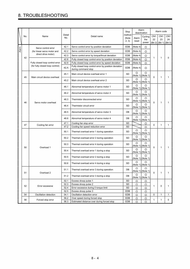
8. TROUBLESHOOTING
8 - 4
No. Name Detail No.
Detail name
Stop
method
(Note 2, 3)
Alarm deactivation
Alarm code
Alarm reset
Cycling the
power
CN1
22
(Bit 2)
CN1
23
(Bit 1)
CN1
24
(Bit 0)
Ala
rm
42
Servo control error
(for linear servo motor and direct drive motor)
42.1 Servo control error by position deviation EDB (Note 4)
1 1 0
42.2 Servo control error by speed deviation EDB (Note 4)
42.3 Servo control error by torque/thrust deviation EDB (Note 4)
Fully closed loop control error
(for fully closed loop control)
42.8 Fully closed loop control error by position deviation EDB (Note 4)
42.9 Fully closed loop control error by speed deviation EDB (Note 4)
42.A
Fully closed loop control error by position deviation during command stop
EDB (Note 4)
45 Main circuit device overheat
45.1 Main circuit device overheat error 1 SD (Note 1)
(Note 1)
0 1 1
45.2 Main circuit device overheat error 2 SD (Note 1)
(Note 1)
46 Servo motor overheat
46.1 Abnormal temperature of servo motor 1 SD (Note 1)
(Note 1)
0 1 1
46.2 Abnormal temperature of servo motor 2 SD (Note 1)
(Note 1)
46.3 Thermistor disconnected error SD (Note 1)
(Note 1)
46.4 Thermistor circuit error SD (Note 1)
(Note 1)
46.5 Abnormal temperature of servo motor 3 DB (Note 1)
(Note 1)
46.6 Abnormal temperature of servo motor 4 DB (Note 1)
(Note 1)
47 Cooling fan error
47.1 Cooling fan stop error SD 0 1 1
47.2 Cooling fan speed reduction error SD
50 Overload 1
50.1 Thermal overload error 1 during operation SD (Note 1)
(Note 1)
0 1 1
50.2 Thermal overload error 2 during operation SD (Note 1)
(Note 1)
50.3 Thermal overload error 4 during operation SD (Note 1)
(Note 1)
50.4 Thermal overload error 1 during a stop SD (Note 1)
(Note 1)
50.5 Thermal overload error 2 during a stop SD (Note 1)
(Note 1)
50.6 Thermal overload error 4 during a stop SD (Note 1)
(Note 1)
51 Overload 2
51.1 Thermal overload error 3 during operation DB (Note 1)
(Note 1)
0 1 1
51.2 Thermal overload error 3 during a stop DB (Note 1)
(Note 1)
52 Error excessive
52.1 Excess droop pulse 1 SD
1 0 1 52.3 Excess droop pulse 2 SD
52.4 Error excessive during 0 torque limit SD
52.5 Excess droop pulse 3 EDB
54 Oscillation detection 54.1 Oscillation detection error EDB 0 1 1
56 Forced stop error
56.2 Over speed during forced stop EDB 1 1 0
56.3 Estimated distance over during forced stop EDB

8. TROUBLESHOOTING
8 - 5
No. Name Detail No.
Detail name
Stop method(Note 2,
3)
Alarm deactivation
Alarm code
Alarm reset
Cycling the
power
CN1 22
(Bit 2)
CN1 23
(Bit 1)
CN1 24
(Bit 0)
Ala
rm 61 Operation error 61.1 Point table setting range error DB 1 0 1
63 STO timing error 63.1 STO1 off DB
1 1 0 63.2 STO2 off DB
70.1 Load-side encoder initial communication - Receive data error 1
DB
70.2 Load-side encoder initial communication - Receive data error 2
DB
70.3 Load-side encoder initial communication - Receive data error 3
DB
70.5 Load-side encoder initial communication - Transmission data error 1
DB
70.6 Load-side encoder initial communication - Transmission data error 2
DB
70
Load-side encoder initial communication error 1
70.7 Load-side encoder initial communication - Transmission data error 3
DB 1 1 0
70.A Load-side encoder initial communication - Process error 1
DB
70.B Load-side encoder initial communication - Process error 2
DB
70.C Load-side encoder initial communication - Process error 3
DB
70.D Load-side encoder initial communication - Process error 4
DB
70.E Load-side encoder initial communication - Process error 5
DB
70.F Load-side encoder initial communication - Process error 6
DB
71.1 Load-side encoder normal communication - Receive data error 1
EDB
71.2 Load-side encoder normal communication - Receive data error 2
EDB
71.3 Load-side encoder normal communication - Receive data error 3
EDB
71
Load-side encoder normal communication error 1
71.5 Load-side encoder normal communication - Transmission data error 1
EDB 1 1 0
71.6 Load-side encoder normal communication - Transmission data error 2
EDB
71.7 Load-side encoder normal communication - Transmission data error 3
EDB
71.9 Load-side encoder normal communication - Receive data error 4
EDB
71.A Load-side encoder normal communication - Receive data error 5
EDB
72.1 Load-side encoder data error 1 EDB
72.2 Load-side encoder data update error EDB
72 Load-side encoder normal
communication error 2
72.3 Load-side encoder data waveform error EDB
72.4 Load-side encoder non-signal error EDB 1 1 0
72.5 Load-side encoder hardware error 1 EDB 72.6 Load-side encoder hardware error 2 EDB
72.9 Load-side encoder data error 2 EDB
8A USB communication time-out
error/serial communication time-out error
8A.1 USB communication time-out error/serial communication time-out error
SD 0 0 0
8E USB communication
error/serial communication error
8E.1 USB communication receive error/serial communication receive error
SD
8E.2 USB communication checksum error/serial communication checksum error
SD
8E.3 USB communication character error/serial communication character error
SD 0 0 0
8E.4 USB communication command error/serial communication command error
SD
8E.5 USB communication data number error/serial communication data number error
SD
88888 Watchdog 8888._ Watchdog DB

8. TROUBLESHOOTING
8 - 6
Note 1. Leave for about 30 minutes of cooling time after removing the cause of occurrence.
2. The following shows three stop methods of DB, EDB, and SD.
DB: Stops with dynamic brake. (Coasts for the servo amplifier without dynamic brake.)
MR-J4-03A6-RJ servo amplifiers coast. Note that EDB is applied when an alarm below occurs; [AL. 30.1], [AL. 32.2], [AL.
32.4], [AL. 51.1], [AL. 51.2]
EDB: Electronic dynamic brake stop (available with specified servo motors)
Refer to the following table for the specified servo motors. The stop method for other than the specified servo motors will
be DB. Series Servo motor
HG-KR HG-KR053/HG-KR13/HG-KR23/HG-KR43 HG-MR HG-MR053/HG-MR13/HG-MR23/HG-MR43 HG-SR HG-SR51/HG-SR52 HG-AK HG-AK0136/HG-AK0236/HG-AK0336
SD: Forced stop deceleration
3. This is applicable when [Pr. PA04] is set to the initial value. The stop system of SD can be changed to DB using [Pr. PA04].
4. The alarm can be canceled by setting as follows:
For the fully closed loop control: set [Pr. PE03] to "1 _ _ _".
When a linear servo motor or direct drive motor is used: set [Pr. PL04] to "1 _ _ _".

8. TROUBLESHOOTING
8 - 7
8.3 Warning list
No. Name Detail No.
Detail name
Stop method(Note 2,
3)
War
ning
90 Home position return incomplete warning
90.1 Home position return incomplete
90.2 Home position return abnormal termination
90.5 Z-phase unpassed
91 Servo amplifier overheat
warning (Note 1) 91.1 Main circuit device overheat warning
92
Battery cable disconnection warning
92.1 Encoder battery cable disconnection warning
92.3 Battery degradation
93 ABS data transfer warning 93.1 ABS data transfer requirement warning during magnetic pole detection
95 STO warning
95.1 STO1 off detection DB
95.2 STO2 off detection DB
96 Home position setting warning
96.1 In-position warning at home positioning
96.2 Command input warning at home positioning
96.3 Servo off warning at home positioning
96.4 Home positioning warning during magnetic pole detection
97
Program operation disabled/next station position
warning
97.1 Program operation disabled warning
97.2 Next station position warning
98 Software limit warning
98.1 Forward rotation-side software stroke limit reached
98.2 Reverse rotation-side software stroke limit reached
99 Stroke limit warning
99.1 Forward rotation stroke end off (Note
4)
99.2 Reverse rotation stroke end off (Note
4)
9A
Optional unit input data error warning
9A.1 Optional unit input data sign error
9A.2 Optional unit BCD input data error
9F Battery warning
9F.1 Low battery
9F.2 Battery degradation warning
E0 Excessive regeneration
warning E0.1 Excessive regeneration warning
E1 Overload warning 1
E1.1 Thermal overload warning 1 during operation
E1.2 Thermal overload warning 2 during operation
E1.3 Thermal overload warning 3 during operation
E1.4 Thermal overload warning 4 during operation
E1.5 Thermal overload error 1 during a stop
E1.6 Thermal overload error 2 during a stop
E1.7 Thermal overload error 3 during a stop
E1.8 Thermal overload error 4 during a stop
E2 Servo motor overheat warning E2.1 Servo motor temperature warning
E3 Absolute position counter
warning
E3.1 Multi-revolution counter travel distance excess warning
E3.2 Absolute position counter warning
E3.4 Absolute positioning counter EEP-ROM writing frequency warning
E3.5 Encoder absolute positioning counter warning
E5 ABS time-out warning
E5.1 Time-out during ABS data transfer
E5.2 ABSM off during ABS data transfer
E5.3 SON off during ABS data transfer
E6 Servo forced stop warning E6.1 Forced stop warning SD
E8
Cooling fan speed reduction warning
E8.1 Decreased cooling fan speed warning
E8.2 Cooling fan stop
E9 Main circuit off warning
E9.1 Servo-on signal on during main circuit off DB
E9.2 Bus voltage drop during low speed operation DB
EA ABS servo-on warning EA.1 ABS servo-on warning
EC Overload warning 2 EC.1 Overload warning 2
ED Output watt excess warning ED.1 Output watt excess warning
F0 Tough drive warning F0.1 Instantaneous power failure tough drive warning
F0.3 Vibration tough drive warning
F2
Drive recorder - Miswriting warning
F2.1 Drive recorder - Area writing time-out warning
F2.2 Drive recorder - Data miswriting warning
F3 Oscillation detection warning F3.1 Oscillation detection warning

8. TROUBLESHOOTING
8 - 8
No. Name Detail No.
Detail name
Stop method(Note 2,
3)
War
ning
F5 Simple cam function - Cam
data miswriting warning
F5.1 Cam data - Area writing time-out warning
F5.2 Cam data - Area miswriting warning
F5.3 Cam data checksum error
F6 Simple cam function - Cam
control warning
F6.1 Cam axis one cycle current value restoration failed
F6.2 Cam axis feed current value restoration failed
F6.3 Cam unregistered error
F6.4 Cam control data setting range error
F6.5 Cam No. external error
F6.6 Cam control inactive Note 1. Leave for about 30 minutes of cooling time after removing the cause of occurrence. 2. The following shows two stop methods of DB and SD.
DB: Stops with dynamic brake. (Coasts for the servo amplifier without dynamic brake.) MR-J4-03A6-RJ servo amplifiers coast.
SD: Forced stop deceleration 3. This is applicable when [Pr. PA04] is set to the initial value. The stop system of SD can be changed to DB using [Pr. PA04]. 4. Quick stop or slow stop can be selected using [Pr. PD30].

9. OPTIONS AND PERIPHERAL EQUIPMENT
9 - 1
9. OPTIONS AND PERIPHERAL EQUIPMENT
WARNING
Before connecting any option or peripheral equipment, turn off the power and wait
for 15 minutes or more until the charge lamp turns off. Then, confirm that the
voltage between P+ and N- is safe with a voltage tester and others. Otherwise, an
electric shock may occur. In addition, when confirming whether the charge lamp is
off or not, always confirm it from the front of the servo amplifier.
Configure MR-HDP01 with sink interface.
CAUTION Use the specified peripheral equipment and options to prevent a malfunction or a
fire.
The following items are the same as MR-J4-_A_-RJ servo amplifiers. For the details of the items, refer to
each chapter/section (in "MR-J4-_A_(-RJ) Servo Amplifier Instruction Manual") indicated in the detailed
explanation field.
Item Detailed explanation
MR-J4-_A_-RJ 100 W or more
MR-J4-03A6-RJ
Cable/connector sets Section 11.1 Section 18.8.1
Regenerative option Section 11.2
FR-BU2- (H) brake unit Section 11.3
FR-RC-(H) power regeneration converter Section 11.4
FR-CV-(H) power regeneration common converter Section 11.5
Junction terminal block MR-TB50 (recommended) Section 11.6
MR Configurator2 Section 11.7
Battery Section 11.8
Selection example of wires Section 11.9 Section 18.8.3
Molded-case circuit breakers, fuses, magnetic contactors Section 11.10
Power factor improving DC reactor Section 11.11
Power factor improving AC reactor Section 11.12
Relay (recommended) Section 11.13
Noise reduction techniques Section 11.14
Earth-leakage current breaker Section 11.15
EMC filter (recommended) Section 11.16
External dynamic brake Section 11.17
Panel through attachment (MR-J4ACN15K/MR-J3ACN) Section 11.18
Circuit protector Section 18.8.4

9. OPTIONS AND PERIPHERAL EQUIPMENT
9 - 2
9.1 MR-HDP01 manual pulse generator
POINT
When using an MR-HDP01, set [Pr. PA13 Command pulse input form] to "_ 2 _
2" or "_ 3 _ 2".
You can operate servo motors by using MR-HDP01 manual pulse generator. A multiplication to pulse signals
which MR-HDP01 generates with external input signals can be changed with TP0 (Manual pulse generator
multiplication 1) and TP1 (Manual pulse generator multiplication 2).
(1) Specifications
Item Specifications
Power supply Voltage 4.5 V DC to 13.2 V DC
Consumption current 60 mA or less
Interface Maximum output current: 20mA for open collector output
Pulse signal form A-phase/B-phase, 2 signals of 90˚ phase difference
Pulse resolution 100 pulses/rev
Maximum speed Instantaneous maximum: 600 r/min, normal: 200 r/min
Temperature range for operation -10 °C to 60 °C
Temperature range for storage -30 °C to 80 °C
(2) Connection example
Servo amplifier
PP
NP
Plate
35
SD
CN1
46DOCOM
TP1
(Note 2)TP0
(Note 2)
+5 to 12V
A
0V
B
Manual pulse generator multiplication 1
Manual pulse generator multiplication 2
5 V DC
MR-HDP01Manual pulse generator 10
20DICOM
CN1
12OPC24 V DC
24 V DC
(Note 1)
(Note 1)
Note 1. To assign PP and NP, set [Pr. PD44] and [Pr. PD46] to "0 0 _ _".
2. To use this as an input device, assign to specified pin of the CN1 connector with [Pr.
PD04] to [Pr. PD22].

9. OPTIONS AND PERIPHERAL EQUIPMENT
9 - 3
(3) Terminal assignment
0V+5 to12V A B
Signal name Description
+5 to 12V Power supply input
0V Common for power and
signal
A A-phase output pulse
B B-phase output pulse
(4) Mounting
[Unit: mm]
φ62
+2 0
3-φ4.8Equal intervals
Panel cut
φ72 ± 0.2
(5) Dimensions
[Unit: mm]
φ50
φ70
3.6 Packing t2.0
16 20 8.89 7.6
Invalid to use except M3 × 6
3-M4 stud L10
P.C.D72 Equal intervals
0.27 ± 0.5
φ60
± 0.
1
φ80
± 1

9. OPTIONS AND PERIPHERAL EQUIPMENT
9 - 4
MEMO

10. COMMUNICATION FUNCTION (MITSUBISHI GENERAL-PURPOSE AC SERVO PROTOCOL)
10 - 1
10. COMMUNICATION FUNCTION (MITSUBISHI GENERAL-PURPOSE AC SERVO PROTOCOL)
The following items are the same as those of MR-J4-_A_-RJ servo amplifiers. For the details of the items,
refer to each chapter/section (in "MR-J4-_A_(-RJ) Servo Amplifier Instruction Manual") indicated in the
detailed explanation field.
Item Detailed explanation
MR-J4-_A_-RJ 100 W or more
MR-J4-03A6-RJ
Structure Section 14.1 Section 18.9
Communication specifications Section 14.2
Protocol Section 14.3
Data processing Section 14.5.1
Status display Section 14.5.2
Parameter Section 14.5.3
Prohibiting/canceling I/O devices (DIO) Section 14.5.6
Alarm history Section 14.5.10
Current alarm Section 14.5.11
Other commands Section 14.5.12
POINT
Creating and reading programs are not available with Mitsubishi general-
purpose AC servo protocol (RS-422 communication). Use MR Configurator2.
A personal computer cannot be connected to the CN30 connector of MR-D01.
10.1 Command and data No. list
POINT
Even if a command or data No. is the same between different model servo
amplifiers, its description may differ.
The symbols in the control mode column mean as follows.
CP: Positioning mode (point table method)
BCD: Positioning mode (point table method in the BCD input positioning
operation)
This method is available only when the MR-D01 unit is connected. Refer
to chapter 12 for details.
CL: Positioning mode (program method)
PS: Positioning mode (indexer method)

10. COMMUNICATION FUNCTION (MITSUBISHI GENERAL-PURPOSE AC SERVO PROTOCOL)
10 - 2
10.1.1 Reading command
(1) Status display (command [0] [1])
Command Data No. Description Status display
Control mode
Frame length
CP
/BC
D
CL
PS
[0] [1] [0] [0] Status display symbol and unit Cumulative feedback pulses Servo motor-side cumulative feedback pulses (after gear)
16
[0] [1] Servo motor speed Servo motor speed
[0] [2] Droop pulses Servo motor-side droop pulses
[0] [3] Cumulative command pulses
[0] [4] Command pulse frequency
[0] [5] Analog speed command voltage Analog speed limit voltage
[0] [6] Analog torque limit voltage Analog torque command voltage
[0] [7] Regenerative load ratio
[0] [8] Effective load ratio
[0] [9] Peak load ratio
[0] [A] Instantaneous torque Instantaneous thrust
[0] [B] Position within one-revolution Servo motor encoder position within one-revolution Virtual position within one-revolution
[0] [C] ABS counter Servo motor encoder ABS counter Virtual ABS counter
[0] [D] Load to motor inertia ratio Load to motor mass ratio
[0] [E] Bus voltage
[0] [F] (Note) Load-side cumulative feedback pulses
[1] [0] (Note) Load-side droop pulses
[1] [1] (Note) Load-side encoder information 1 Z-phase counter
[1] [2] (Note) Load-side encoder information 2
[1] [6] (Note) Temperature of servo motor thermistor
[1] [7] (Note) Servo motor-side cumulative feedback pulses (before gear)
[1] [8] (Note) Electrical angle
[1] [E] (Note) Servo motor-side/load-side position deviation
[1] [F] (Note) Servo motor-side/load-side speed deviation
[2] [0] Encoder inside temperature
[2] [1] Settling time
[2] [2] Oscillation detection frequency
[2] [3] Number of tough drive operations
[2] [8] Unit power consumption
[2] [9] Unit total power consumption
[2] [A] Current position
[2] [B] Command position
[2] [C] Command remaining distance
[2] [D] Point table No./Program No./Station position No.
Note. This is not available with the MR-J4-03A6-RJ servo amplifier.

10. COMMUNICATION FUNCTION (MITSUBISHI GENERAL-PURPOSE AC SERVO PROTOCOL)
10 - 3
Command Data No. Description Status display
Control mode
Frame length
CP
/BC
D
CL
PS
[0] [1] [2] [E] Status display symbol and unit Step No. 16
[2] [F] Analog override voltage
[3] [0] Override level
[3] [3] Cam axis one cycle current value
[3] [4] Cam standard position
[3] [5] Cam axis feed current value
[3] [6] Cam No. in execution
[3] [7] Cam stroke amount in execution
[3] [8] Main axis current value
[3] [9] Main axis one cycle current value
[8] [0] Status display data value and processing information
Cumulative feedback pulses Servo motor-side cumulative feedback pulses (after gear)
12
[8] [1] Servo motor speed Servo motor speed
[8] [2] Droop pulses Servo motor-side droop pulses
[8] [3] Cumulative command pulses
[8] [4] Command pulse frequency
[8] [5] Analog speed command voltage Analog speed limit voltage
[8] [6] Analog torque limit voltage Analog torque command voltage
[8] [7] Regenerative load ratio [8] [8] Effective load ratio [8] [9] Peak load ratio [8] [A] Instantaneous torque
Instantaneous thrust
[8] [B] Position within one-revolution Servo motor encoder position within one-revolution Virtual position within one-revolution
[8] [C] ABS counter Servo motor encoder ABS counter Virtual ABS counter
[8] [D] Load to motor inertia ratio Load to motor mass ratio
[8] [E] Bus voltage [8] [F] (Note) Load-side cumulative feedback pulses
[9] [0] (Note) Load-side droop pulses
[9] [1] (Note) Load-side encoder information 1 Z-phase counter
[9] [2] (Note) Load-side encoder information 2
[9] [6] (Note) Temperature of servo motor thermistor
[9] [7] (Note) Servo motor-side cumulative feedback pulses (before gear)
[9] [8] (Note) Electrical angle
[9] [E] (Note) Servo motor-side/load-side position deviation
[9] [F] (Note) Servo motor-side/load-side speed deviation
[A] [0] Encoder inside temperature
[A] [1] Settling time
[A] [2] Oscillation detection frequency Note. This is not available with the MR-J4-03A6-RJ servo amplifier.

10. COMMUNICATION FUNCTION (MITSUBISHI GENERAL-PURPOSE AC SERVO PROTOCOL)
10 - 4
Command Data No. Description Status display
Control mode
Frame length
CP
/BC
D
CL
PS
[0] [1] [A] [3] Status display data value and processing information
Number of tough drive operations 12
[A] [8] Unit power consumption
[A] [9] Unit total power consumption
[A] [A] Current position
[A] [B] Command position
[A] [C] Command remaining distance
[A] [D] Point table No./Program No./ Station position No.
[A] [E] Step No.
[A] [F] Analog override voltage
[B] [0] Override level
[B] [3] Cam axis one cycle current value
[B] [4] Cam standard position
[B] [5] Cam axis feed current value
[B] [6] Cam No. in execution
[B] [7] Cam stroke amount in execution
[B] [8] Main axis current value
[B] [9] Main axis one cycle current value
(2) Parameter (command [0] [4], [1] [5], [1] [6], [1] [7], [0] [8], and [0] [9])
Command Data No. Description
Control mode
Frame length
CP
/BC
D
CL
PS
[0] [4] [0] [1] Reading parameter group 0000: Basic setting parameters ([Pr. PA_ _ ]) 0001: Gain/filter parameters ([Pr. PB_ _ ]) 0002: Extension setting parameters ([Pr. PC_ _ ]) 0003: I/O setting parameters ([Pr. PD_ _ ]) 0004: Extension setting 2 parameters ([Pr. PE_ _ ]) 0005: Extension setting 3 parameters ([Pr. PF_ _ ]) 0009: Option setting parameters ([Pr. Po_ _ ]) 000B: Linear servo motor/DD motor setting parameters ([Pr. PL_ _ ]) (Note) 000C: Positioning control parameters ([Pr. PT_ _ ]) Reads the parameter group specified with the command [8] [5] + data No. [0] [0]. Before reading the current values, therefore, always specify the parameter group with the command [8] [5] + data No. [0] [0].
4
[1] [5] [0] [1] to [F] [F] Current value of each parameter Reads the current values of the parameters in the parameter group specified with the command [8] [5] + data No. [0] [0]. Before reading the current values, therefore, always specify the parameter group with the command [8] [5] + data No. [0] [0]. The decimal equivalent of the data No. (hexadecimal) value corresponds to the parameter No.
12
[1] [6] [0] [1] to [F] [F] Upper limit value of each parameter setting range Reads the permissible upper limit values of the parameters in the parameter group specified with the command [8] [5] + data No. [0] [0]. Before reading the upper limit values, therefore, always specify the parameter group with the command [8] [5] + data No. [0] [0]. The decimal equivalent of the data No. (hexadecimal) value corresponds to the parameter No.

10. COMMUNICATION FUNCTION (MITSUBISHI GENERAL-PURPOSE AC SERVO PROTOCOL)
10 - 5
Command Data No. Description
Control mode
Frame length
CP
/BC
D
CL
PS
[1] [7] [0] [1] to [F] [F] Lower limit value of each parameter setting range Reads the permissible lower limit values of the parameters in the parameter group specified with the command [8] [5] + data No. [0] [0]. Before reading the lower limit values, therefore, always specify the parameter group with the command [8] [5] + data No. [0] [0]. The decimal equivalent of the data No. (hexadecimal) value corresponds to the parameter No.
12
[0] [8] [0] [1] to [F] [F] Each parameter symbol Reads the symbols of the parameters in the parameter group specified with the command [8] [5] + data No. [0] [0]. Before reading the symbols, therefore, always specify the parameter group with the command [8] [5] + data No. [0] [0]. The decimal equivalent of the data No. (hexadecimal) value corresponds to the parameter No.
[0] [9] [0] [1] to [F] [F] Writing enable/disable of parameters Reads writing enable/disable of the parameters in the parameter group specified with the command [8] [5] + data No. [0] [0]. Before reading writing enable/disable, therefore, always specify the parameter group with the command [8] [5] + data No. [0] [0]. 0000: Writing enabled 0001: Writing disabled
4
Note. This is not available with the MR-J4-03A6-RJ servo amplifier.
(3) External I/O signals (command [1] [2])
Command Data No. Description
Control mode
Frame length
CP
/BC
D
CL
PS
[1] [2] [0] [0] to [0] [2] Input device status 8
[4] [0] External input pin status
[6] [0] to [6] [2] Status of input device turned on by communication
[8] [0] to [8] [3] Output device status
[C] [0] External output pin status
(4) Current position latch display (command [1] [A])
Command Data No. Description
Control mode
Frame length
CP
/BC
D
CL
PS
[1] [A] [0] [0] MSD (Mark detection) rising latch data (data part) 8
[0] [1] MSD (Mark detection) falling latch data (data part)
[0] [2] MSD (Mark detection) rising latch data (data part + additional information) 12 or less
[0] [3] MSD (Mark detection) falling latch data (data part + additional information)

10. COMMUNICATION FUNCTION (MITSUBISHI GENERAL-PURPOSE AC SERVO PROTOCOL)
10 - 6
(5) Alarm history (command [3] [3])
Command Data No. Description Alarm occurrence sequence
Control mode
Frame length
CP
/BC
D
CL
PS
[3] [3] [1] [0] Alarm No. in alarm history Most recent alarm 4
[1] [1] First alarm in past
[1] [2] Second alarm in past
[1] [3] Third alarm in past
[1] [4] Fourth alarm in past
[1] [5] Fifth alarm in past
[1] [6] Sixth alarm in past
[1] [7] Seventh alarm in past
[1] [8] Eighth alarm in past
[1] [9] Ninth alarm in past
[1] [A] Tenth alarm in past
[1] [B] Eleventh alarm in past
[1] [C] Twelfth alarm in past
[1] [D] Thirteenth alarm in past
[1] [E] Fourteenth alarm in past
[1] [F] Fifteenth alarm in past
[2] [0] Alarm occurrence time in alarm history Most recent alarm 8
[2] [1] First alarm in past
[2] [2] Second alarm in past
[2] [3] Third alarm in past
[2] [4] Fourth alarm in past
[2] [5] Fifth alarm in past
[2] [6] Sixth alarm in past
[2] [7] Seventh alarm in past
[2] [8] Eighth alarm in past
[2] [9] Ninth alarm in past
[2] [A] Tenth alarm in past
[2] [B] Eleventh alarm in past
[2] [C] Twelfth alarm in past
[2] [D] Thirteenth alarm in past
[2] [E] Fourteenth alarm in past
[2] [F] Fifteenth alarm in past
(6) Current alarm (command [0] [2])
Command Data No. Description
Control mode
Frame length
CP
/BC
D
CL
PS
[0] [2] [0] [0] Current alarm No. 4

10. COMMUNICATION FUNCTION (MITSUBISHI GENERAL-PURPOSE AC SERVO PROTOCOL)
10 - 7
(7) Status display at alarm occurrence (command [3] [5])
Command Data No. Description Status display
Control mode
Frame length
CP
/BC
D
CL
PS
[3] [5] [0] [0] Status display symbol and unit Cumulative feedback pulses Servo motor-side cumulative feedback pulses (after gear)
16
[0] [1] Servo motor speed Servo motor speed
[0] [2] Droop pulses Servo motor-side droop pulses
[0] [3] Cumulative command pulses
[0] [4] Command pulse frequency
[0] [5] Analog speed command voltage Analog speed limit voltage
[0] [6] Analog torque limit voltage Analog torque command voltage
[0] [7] Regenerative load ratio [0] [8] Effective load ratio [0] [9] Peak load ratio [0] [A] Instantaneous torque
Instantaneous thrust
[0] [B] Position within one-revolution Servo motor encoder position within one-revolution Virtual position within one-revolution
[0] [C] ABS counter Servo motor encoder ABS counter Virtual ABS counter
[0] [D] Load to motor inertia ratio Load to motor mass ratio
[0] [E] Bus voltage
[0] [F] (Note) Load-side cumulative feedback pulses
[1] [0] (Note) Load-side droop pulses
[1] [1] (Note) Load-side encoder information 1 Z-phase counter
[1] [2] (Note) Load-side encoder information 2
[1] [6] (Note) Temperature of servo motor thermistor
[1] [7] (Note) Servo motor-side cumulative feedback pulses (before gear)
[1] [8] (Note) Electrical angle
[1] [E] (Note) Servo motor-side/load-side position deviation
[1] [F] (Note) Servo motor-side/load-side speed deviation
[2] [0] Encoder inside temperature
[2] [1] Settling time
[2] [2] Oscillation detection frequency
[2] [3] Number of tough drive operations
[2] [8] Unit power consumption
[2] [9] Unit total power consumption
[2] [A] Current position
[2] [B] Command position
[2] [C] Command remaining distance
[2] [D] Point table No./Program No./ Station position No.
Note. This is not available with the MR-J4-03A6-RJ servo amplifier.
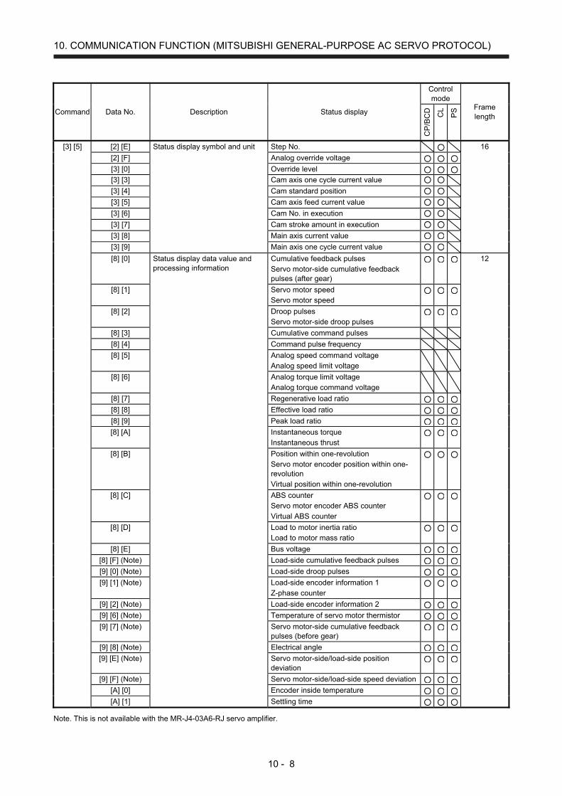
10. COMMUNICATION FUNCTION (MITSUBISHI GENERAL-PURPOSE AC SERVO PROTOCOL)
10 - 8
Command Data No. Description Status display
Control mode
Frame length
CP
/BC
D
CL
PS
[3] [5] [2] [E] Status display symbol and unit Step No. 16
[2] [F] Analog override voltage
[3] [0] Override level
[3] [3] Cam axis one cycle current value
[3] [4] Cam standard position
[3] [5] Cam axis feed current value
[3] [6] Cam No. in execution
[3] [7] Cam stroke amount in execution
[3] [8] Main axis current value
[3] [9] Main axis one cycle current value
[8] [0] Status display data value and processing information
Cumulative feedback pulses Servo motor-side cumulative feedback pulses (after gear)
12
[8] [1] Servo motor speed Servo motor speed
[8] [2] Droop pulses Servo motor-side droop pulses
[8] [3] Cumulative command pulses
[8] [4] Command pulse frequency
[8] [5] Analog speed command voltage Analog speed limit voltage
[8] [6] Analog torque limit voltage Analog torque command voltage
[8] [7] Regenerative load ratio [8] [8] Effective load ratio [8] [9] Peak load ratio [8] [A] Instantaneous torque
Instantaneous thrust
[8] [B] Position within one-revolution Servo motor encoder position within one-revolution Virtual position within one-revolution
[8] [C] ABS counter Servo motor encoder ABS counter Virtual ABS counter
[8] [D] Load to motor inertia ratio Load to motor mass ratio
[8] [E] Bus voltage [8] [F] (Note) Load-side cumulative feedback pulses
[9] [0] (Note) Load-side droop pulses
[9] [1] (Note) Load-side encoder information 1 Z-phase counter
[9] [2] (Note) Load-side encoder information 2
[9] [6] (Note) Temperature of servo motor thermistor
[9] [7] (Note) Servo motor-side cumulative feedback pulses (before gear)
[9] [8] (Note) Electrical angle
[9] [E] (Note) Servo motor-side/load-side position deviation
[9] [F] (Note) Servo motor-side/load-side speed deviation
[A] [0] Encoder inside temperature
[A] [1] Settling time Note. This is not available with the MR-J4-03A6-RJ servo amplifier.

10. COMMUNICATION FUNCTION (MITSUBISHI GENERAL-PURPOSE AC SERVO PROTOCOL)
10 - 9
Command Data No. Description Status display
Control mode
Frame length
CP
/BC
D
CL
PS
[3] [5] [A] [2] Status display data value and processing information
Oscillation detection frequency 12
[A] [3] Number of tough drive operations
[A] [8] Unit power consumption
[A] [9] Unit total power consumption
[A] [A] Current position
[A] [B] Command position
[A] [C] Command remaining distance
[A] [D] Point table No./Program No./ Station position No.
[A] [E] Step No.
[A] [F] Analog override voltage
[B] [0] Override level
[B] [3] Cam axis one cycle current value
[B] [4] Cam standard position
[B] [5] Cam axis feed current value
[B] [6] Cam No. in execution
[B] [7] Cam stroke amount in execution
[B] [8] Main axis current value
[B] [9] Main axis one cycle current value
(8) Point table setting data (command [4] [0], [4] [5], [5] [0], [5] [4], [5] [8], [6] [0], [6] [4])
Command Data No. Description
Control mode
Frame length
CP
/BC
D
CL
PS
[4] [0] [0] [0] to [F] [F] Reading position data of each point table
The decimal equivalent of the data No. value (hexadecimal) corresponds to the point table No.
8
[4] [5] [0] [0] to [F] [F] Reading M code of each point table The decimal equivalent of the data No. value (hexadecimal) corresponds to the point table No.
[5] [0] [0] [0] to [F] [F] Reading speed data of each point table The decimal equivalent of the data No. value (hexadecimal) corresponds to the point table No.
[5] [4] [0] [0] to [F] [F] Reading acceleration time constant of each point table The decimal equivalent of the data No. value (hexadecimal) corresponds to the point table No.
[5] [8] [0] [0] to [F] [F] Reading deceleration time constant of each point table The decimal equivalent of the data No. value (hexadecimal) corresponds to the point table No.
[6] [0] [0] [0] to [F] [F] Reading dwell of each point table The decimal equivalent of the data No. value (hexadecimal) corresponds to the point table No.
[6] [4] [0] [0] to [F] [F] Reading sub function of each point table The decimal equivalent of the data No. value (hexadecimal) corresponds to the point table No.

10. COMMUNICATION FUNCTION (MITSUBISHI GENERAL-PURPOSE AC SERVO PROTOCOL)
10 - 10
(9) Position data unit/Current position latch data (command [6] [C])
Command Data No. Description
Control mode
Frame length
CP
/BC
D
CL
PS
[6] [C] [0] [0] Reading position data unit _ _ _ x 0: mm, 1: inch, 2: pulse, 3: degree _ _ x _ 0: Enabled, 1: Disabled
4
[0] [1] Reading current position latch data Reads data latched at rising edge of LPS signal using LPOS command in the program operation.
12
(10) General purpose register (Rx) value (command [6] [D])
Command Data No. Description
Control mode
Frame length
CP
/BC
D
CL
PS
[6] [D] [0] [1] Reading general purpose register (R1) value 8
[0] [2] Reading general purpose register (R2) value
[0] [3] Reading general purpose register (R3) value
[0] [4] Reading general purpose register (R4) value
(11) General purpose register (Dx) value (command [6] [E])
Command Data No. Description
Control mode
Frame length
CP
/BC
D
CL
PS
[6] [E] [0] [1] Reading general purpose register (D1) value 8
[0] [2] Reading general purpose register (D2) value
[0] [3] Reading general purpose register (D3) value
[0] [4] Reading general purpose register (D4) value
(12) General purpose register number (command [6] [F])
Command Data No. Description
Control mode
Frame length
CP
/BC
D
CL
PS
[6] [F] [0] [0] Reading general purpose register (Rx) number 8
[0] [1] Reading general purpose register (Dx) number

10. COMMUNICATION FUNCTION (MITSUBISHI GENERAL-PURPOSE AC SERVO PROTOCOL)
10 - 11
(13) Others (command [0] [0], [0] [2])
Command Data No. Description
Control mode
Frame length
CP
/BC
D
CL
PS
[0] [0] [1] [2] Reading test operation mode 0000: Normal mode (not test operation mode) 0001: JOG operation 0002: Positioning operation 0004: Output signal (DO) forced output 0005: Single-step feed operation
(Note)
4
[1] [D] Reading EEP-ROM stored data type 0000: Initial state 0001: Point table method 0002: Program method
[1] [E] Reading control mode 0006: Positioning mode (point table method) 0007: Positioning mode (program method) 0008: Positioning mode (indexer method)
[0] [2] [9] [0] Servo motor-side pulse unit absolute position 8
[9] [1] Command unit absolute position
[7] [0] Software version 16 Note. "0005 (single-step feed operation)" is not available in the indexer method.

10. COMMUNICATION FUNCTION (MITSUBISHI GENERAL-PURPOSE AC SERVO PROTOCOL)
10 - 12
10.1.2 Writing commands
(1) Status display (command [8] [1])
Command Data No. Description Setting range
Control mode
Frame length
CP
/BC
D
CL
PS
[8] [1] [0] [0] Status display data deletion 1EA5 4
(2) Parameter (command [9] [4], [8] [5])
Command Data No. Description Setting range
Control mode
Frame length
CP
/BC
D
CL
PS
[9] [4] [0] [1] to [F] [F] Writing each parameter Writes the values of the parameters in the parameter group specified with the command [8] [5] + data No. [0] [0]. Before writing the values, therefore, always specify the parameter group with the command [8] [5] + data No. [0] [0]. The decimal equivalent of the data No. (hexadecimal) value corresponds to the parameter No.
Depending on the parameter
12
[8] [5] [0] [0] Parameter group writing 0000: Basic setting parameters ([Pr. PA_ _ ]) 0001: Gain/filter parameters ([Pr. PB_ _ ]) 0002: Extension setting parameters ([Pr. PC_ _ ]) 0003: I/O setting parameters ([Pr. PD_ _ ]) 0004: Extension setting 2 parameters ([Pr. PE_ _ ]) 0005: Extension setting 3 parameters ([Pr. PF_ _ ]) 0009: Option setting parameters ([Pr. Po_ _ ]) 000B: Linear servo motor/DD motor setting parameters ([Pr.
PL_ _ ]) (Note) 000C: Positioning control parameters ([Pr. PT_ _ ])
0000 to 000C 4
Note. This is not available with the MR-J4-03A6-RJ servo amplifier.
(3) External I/O signals (command [9] [2])
Command Data No. Description Setting range
Control mode
Frame length
CP
/BC
D
CL
PS
[9] [2] [6] [0] to [6] [2] Communication input device signal Refer to section 10.2.2.
8
(4) Alarm history (command [8] [2])
Command Data No. Description Setting range
Control mode
Frame length
CP
/BC
D
CL
PS
[8] [2] [2] [0] Alarm history clear 1EA5 4

10. COMMUNICATION FUNCTION (MITSUBISHI GENERAL-PURPOSE AC SERVO PROTOCOL)
10 - 13
(5) Current alarm (command [8] [2])
Command Data No. Description Setting range
Control mode
Frame length
CP
/BC
D
CL
PS
[8] [2] [0] [0] Alarm clear 1EA5 4
(6) I/O device prohibition (command [9] [0])
Command Data No. Description Setting range
Control mode
Frame length
CP
/BC
D
CL
PS
[9] [0] [0] [0] Turns off the input device, external analog input signal, and pulse train input, except EM2, LSP and LSN, independently of the external on/off statuses.
1EA5 4
[0] [3] Prohibits all output devices (DO). 1EA5 [1] [0] Cancels the prohibition of the input device, external analog
input signal and pulse train input, except EM2, LSP and LSN. 1EA5
[1] [3] Cancels the prohibition of the output device. 1EA5
(7) Operation mode selection (command [8] [B])
Command Data No. Description Setting range
Control mode
Frame length
CP
/BC
D
CL
PS
[8] [B] [0] [0] Selection of test operation mode 0000: Test operation mode cancel 0001: JOG operation 0002: Positioning operation 0004: Output signal (DO) forced output 0005: Single-step feed operation
0000 to 0002, 0004, 0005
(Note)
4
Note. "0005 (single-step feed operation)" is not available in the indexer method.
(8) Test operation mode data (command [9] [2], [A] [0])
Command Data No. Description Setting range
Control mode
Frame length
CP
/BC
D
CL
PS
[9] [2] [0] [0] to [0] [2] Input signal for test operation (Refer to section 14.5.7 of "MR-J4-_A_(-RJ) Servo Amplifier Instruction Manual".)
8
[A] [0] Forced output of signal pin (Refer to section 14.5.9 of "MR-J4-_A_(-RJ) Servo Amplifier Instruction Manual".)

10. COMMUNICATION FUNCTION (MITSUBISHI GENERAL-PURPOSE AC SERVO PROTOCOL)
10 - 14
Command Data No. Description Setting range
Control mode
Frame length
CP
/BC
D
CL
PS
[A] [0] [1] [0] Writes the servo motor speed in the test operation mode (JOG operation and positioning operation).
0000 to 7FFF 4
[1] [1] Writes the acceleration/deceleration time constant in the test operation mode (JOG operation and positioning operation).
00000000 to 7FFFFFFF
8
[2] [0] Set the travel distance of the test operation mode (positioning operation).
00000000 to 7FFFFFFF
[2] [1] Select the positioning direction of the test operation (positioning operation).
0: Forward rotation direction1: Reverse rotation direction
0: Command pulse unit1: Encoder pulse unit
0 0
0000 to 0101 4
[4] [0] This is a start command of the test operation (positioning operation).
1EA5
[4] [1] This is used to make a temporary stop during test operation (positioning operation). "" in the data indicates a blank. STOP: Temporary stop GO: Restart for remaining distance CLR: Remaining distance clear
STOP GO CLR
(9) Point table setting data (command [C] [0], [C] [2], [C] [6], [C] [7], [C] [8], [C] [A], [C] [B])
Command Data No. Description Setting range
Control mode
Frame length
CP
/BC
D
CL
PS
[C] [0] [0] [0] to [F] [F] Writing position data of each point table The decimal equivalent of the data No. value (hexadecimal) corresponds to the point table No.
-999999 to 999999
8
[C] [2] [0] [0] to [F] [F] Writing M code of each point table The decimal equivalent of the data No. value (hexadecimal) corresponds to the point table No.
0 to 99
[C] [6] [0] [0] to [F] [F] Writing speed data of each point table The decimal equivalent of the data No. value (hexadecimal) corresponds to the point table No.
0 to permissible speed
[C] [7] [0] [0] to [F] [F] Writing acceleration time constant of each point table The decimal equivalent of the data No. value (hexadecimal) corresponds to the point table No.
0 to 20000
[C] [8] [0] [0] to [F] [F] Writing deceleration time constant of each point table The decimal equivalent of the data No. value (hexadecimal) corresponds to the point table No.
0 to 20000
[C] [A] [0] [0] to [F] [F] Writing dwell of each point table The decimal equivalent of the data No. value (hexadecimal) corresponds to the point table No.
0 to 20000
[C] [B] [0] [0] to [F] [F] Writing sub function of each point table The decimal equivalent of the data No. value (hexadecimal) corresponds to the point table No.
0 to 3, 8 to 11

10. COMMUNICATION FUNCTION (MITSUBISHI GENERAL-PURPOSE AC SERVO PROTOCOL)
10 - 15
(10) General purpose register (Rx) value (command [B] [9])
Command Data No. Description Setting range
Control mode
Frame length
CP
/BC
D
CL
PS
[B] [9] [0] [1] Writing general purpose register (R1) value Depends on commands to use. Refer to section 5.2.2.
8
[0] [2] Writing general purpose register (R2) value
[0] [3] Writing general purpose register (R3) value
[0] [4] Writing general purpose register (R4) value
(11) General purpose register (Dx) value (command [B] [A])
Command Data No. Description Setting range
Control mode
Frame length
CP
/BC
D
CL
PS
[B] [A] [0] [1] Writing general purpose register (D1) value Depends on commands to use. Refer to section 5.2.2.
8
[0] [2] Writing general purpose register (D2) value
[0] [3] Writing general purpose register (D3) value
[0] [4] Writing general purpose register (D4) value

10. COMMUNICATION FUNCTION (MITSUBISHI GENERAL-PURPOSE AC SERVO PROTOCOL)
10 - 16
10.2 Detailed explanations of commands
10.2.1 External I/O signal status (DIO diagnosis)
(1) Reading input device status
The current input device status can be read.
(a) Transmission
Transmit command [1] [2] + data No. [0] [0] to [0] [3].
Command Data No.
[1] [2] [0] [0] to [0] [3]
(b) Return
The slave station returns the status of the input devices.
b31 b1b0
1: On0: Off
Command of each bit is transmitted to the master station as hexadecimal data.
Bit Symbol
Data No. [0] [0] Data No. [0] [1] Data No. [0] [2] Data No. [0] [3]
0 SON MD0 POS00
1 LSP ABSM MD1 POS01
2 LSN ABSR POS02
3 TL TCH POS03
4 TL1 TP0 POS10
5 PC TP1 POS11
6 RES OVR POS12
7 CR POS13
8 SP1 STAB POS20
9 SP2 DOG/SIG POS21
10 SP3 SPD1 POS22
11 ST1/RS2 SPD2 POS23
12 ST2/RS1 SPD3 POSP
13 CMX1 SPD4 POSN
14 CMX2 STRB
15 LOP
16 MSD LPS
17 PI1 RT
18 EM2/EM1 PI2 RTCDP
19 PI3
20 STAB2 CAMC OV0
21 CI0 OV1
22 CI1 OV2
23 CI2 OV3
24 TSTP CI3 DI0
25 CLTC DI1
26 CPCD DI2
27 CDP DI3
28 CLD DI4
29 MECR (Note) DI5
30 DI6
31 DI7
Note. This is not available with the MR-J4-03A6-RJ servo amplifier.

10. COMMUNICATION FUNCTION (MITSUBISHI GENERAL-PURPOSE AC SERVO PROTOCOL)
10 - 17
(2) Reading external input pin status
Reads the on/off statuses of the external input pins.
(a) Transmission
Transmit command [1] [2] + data No. [4] [0], [4] [1].
Command Data No.
[1] [2] [4] [0], [4] [1]
(b) Return
The on/off statuses of the input pins are returned.
b31 b1b0
1: On0: Off
Command of each bit is transmitted to the master station as hexadecimal data.
Bit CN1 connector pin CN10 connector pin Bit CN1 connector pin CN10 connector pin
0 43 1 16 19
1 44 2 17 20
2 42 3 18 21
3 15 4 19 26
4 19 5 20 27
5 41 6 21 28
6 16 7 22 29
7 17 8 23 30
8 18 9 24 31
9 45 10 25 32
10 10 (Note) 11 26 33
11 35 (Note) 12 27 34
12 15 28 35
13 16 29 36
14 17 30
15 18 31 Note. When the pulse train input is selected with [Pr. PD44] or [Pr. PD46], this bit will continuously be "0" (off).

10. COMMUNICATION FUNCTION (MITSUBISHI GENERAL-PURPOSE AC SERVO PROTOCOL)
10 - 18
(3) Reading the status of input devices switched on with communication
Reads the on/off statuses of the input devices switched on with communication.
(a) Transmission
Transmit command [1] [2] + data No. [6] [0] to [6] [3].
Command Data No.
[1] [2] [6] [0] to [6] [3]
(b) Return
The slave station returns the status of the input devices.
b31 b1b0
1: On0: Off
Command of each bit is transmitted to the master station as hexadecimal data.
Bit Symbol
Data No. [6] [0] Data No. [6] [1] Data No. [6] [2] Data No. [6] [3]
0 SON MD0 POS00
1 LSP ABSM MD1 POS01
2 LSN ABSR POS02
3 TL TCH POS03
4 TL1 TP0 POS10
5 PC TP1 POS11
6 RES OVR POS12
7 CR POS13
8 SP1 STAB POS20
9 SP2 DOG/SIG POS21
10 SP3 SPD1 POS22
11 ST1/RS2 SPD2 POS23
12 ST2/RS1 SPD3 POSP
13 CMX1 SPD4 POSN
14 CMX2 STRB
15 LOP
16 MSD LPS
17 PI1 RT
18 EM2/EM1 PI2 RTCDP
19 PI3
20 STAB2 CAMC OV0
21 CI0 OV1
22 CI1 OV2
23 CI2 OV3
24 TSTP CI3 DI0
25 CLTC DI1
26 CPCD DI2
27 CDP DI3
28 CLD DI4
29 MECR (Note) DI5
30 DI6
31 DI7
Note. This is not available with the MR-J4-03A6-RJ servo amplifier.

10. COMMUNICATION FUNCTION (MITSUBISHI GENERAL-PURPOSE AC SERVO PROTOCOL)
10 - 19
(4) Reading external output pin status
Reads the on/off statuses of the external output pins.
(a) Transmission
Transmit command [1] [2] + data No. [C] [0], [C] [1].
Command Data No.
[1] [2] [C] [0], [C] [1]
(b) Return
The slave station returns the status of the output devices.
b31 b1b0
1: On0: Off
Command of each bit is transmitted to the master station as hexadecimal data.
Bit CN1 connector pin CN10 connector pin Bit CN1 connector pin CN10 connector pin
0 49 22 16
1 24 23 17
2 23 24 18
3 25 25 19
4 22 38 20
5 48 39 21
6 33 40 22
7 13 (Note) 41 23
8 14 (Note) 42 24
9 43 25
10 44 26
11 45 27
12 46 28
13 47 29
14 48 30
15 49 31 Note. This is not available with the MR-J4-03A6-RJ servo amplifier.

10. COMMUNICATION FUNCTION (MITSUBISHI GENERAL-PURPOSE AC SERVO PROTOCOL)
10 - 20
(5) Reading output device status
Reads the on/off statuses of the output devices.
(a) Transmission
Transmit command [1] [2] + data No. [8] [0] to [8] [3].
Command Data No.
[1] [2] [8] [0] to [8] [3]
(b) Return
The slave station returns the status of the input/output devices.
b31 b1b0
1: On0: Off
Command of each bit is transmitted to the master station as hexadecimal data.
Bit Symbol
Data No. [8] [0] Data No. [8] [1] Data No. [8] [2] Data No. [8] [3]
0 RD MCD00
1 SA MCD01
2 ZSP MCD02
3 TLC CPO MCD03
4 VLC ZP MCD10
5 INP POT MCD11
6 PUS MCD12
7 WNG MEND MCD13
8 ALM ACD0
9 OP ACD1
10 MBR ACD2
11 DB (Note) ACD3
12 ALCD0 PED PRQ0
13 ALCD1 PRQ1
14 ALCD2
15 BWNG
16
17 ALMWNG
18 BW9F
19 MSDH
20 MSDL
21 SOUT
22 OUT1
23 OUT2
24 OUT3 PT0/PS0
25 CDPS CAMS PT1/PS1
26 CLDS (Note) CLTS PT2/PS2
27 ABSV CLTSM PT3/PS3
28 CLTS PT4/PS4
29 PT5/PS5
30 PT6/PS6
31 MTTR (Note) PT7/PS7
Note. This is not available with the MR-J4-03A6-RJ servo amplifier.

10. COMMUNICATION FUNCTION (MITSUBISHI GENERAL-PURPOSE AC SERVO PROTOCOL)
10 - 21
10.2.2 Input device on/off
POINT
The on/off statuses of all devices in the servo amplifier are the status of the data
received at last. Therefore, when there is a device which must be kept on,
transmit data which turns the device on every time.
Each input device can be switched on/off. However, when the device to be switched off is in the external
input signal, also switch off the input signal.
Transmit command [9] [2] + data No. [6] [0] to [6] [3].
Command Data No. Setting data
[9] [2] [6] [0] to [6] [3] See below.
b31 b1b0
1: On0: Off
Command of each bit is transmitted to the master station as hexadecimal data.
Bit Symbol
Data No. [6] [0] Data No. [6] [1] Data No. [6] [2] Data No. [6] [3]
0 SON MD0 POS00
1 LSP ABSM MD1 POS01
2 LSN ABSR POS02
3 TL TCH POS03
4 TL1 TP0 POS10
5 PC TP1 POS11
6 RES OVR POS12
7 CR POS13
8 SP1 STAB POS20
9 SP2 DOG/SIG POS21
10 SP3 SPD1 POS22
11 ST1/RS2 SPD2 POS23
12 ST2/RS1 SPD3 POSP
13 CMX1 SPD4 POSN
14 CMX2 STRB
15 LOP
16 MSD LPS
17 PI1 RT
18 EM2/EM1 PI2 RTCDP
19 PI3
20 STAB2 CAMC OV0
21 CI0 OV1
22 CI1 OV2
23 CI2 OV3
24 TSTP CI3 DI0
25 CLTC DI1
26 CPCD DI2
27 CDP DI3
28 CLD DI4
29 MECR (Note) DI5
30 DI6
31 DI7
Note. This is not available with the MR-J4-03A6-RJ servo amplifier.

10. COMMUNICATION FUNCTION (MITSUBISHI GENERAL-PURPOSE AC SERVO PROTOCOL)
10 - 22
10.2.3 Input device on/off (for test operation)
Each input devices can be turned on/off for test operation. However, when the device to be switched off is in
the external input signal, also switch off the input signal.
Transmit command [9] [2] + data No. [0] [0] to [0] [3].
Command Data No. Setting data
[9] [2] [0] [0] to [0] [3] See below.
b31 b1b0
1: On0: Off
Command of each bit is transmitted to the master station as hexadecimal data.
Bit Symbol
Data No. [0] [0] Data No. [0] [1] Data No. [0] [2] Data No. [0] [3]
0 SON MD0 POS00
1 LSP ABSM MD1 POS01
2 LSN ABSR POS02
3 TL TCH POS03
4 TL1 TP0 POS10
5 PC TP1 POS11
6 RES OVR POS12
7 CR POS13
8 SP1 STAB POS20
9 SP2 DOG/SIG POS21
10 SP3 SPD1 POS22
11 ST1/RS2 SPD2 POS23
12 ST2/RS1 SPD3 POSP
13 CMX1 SPD4 POSN
14 CMX2 STRB
15 LOP
16 MSD LPS
17 PI1 RT
18 EM2/EM1 PI2 RTCDP
19 PI3
20 STAB2 CAMC OV0
21 CI0 OV1
22 CI1 OV2
23 CI2 OV3
24 TSTP CI3 DI0
25 CLTC DI1
26 CPCD DI2
27 CDP DI3
28 CLD DI4
29 MECR (Note) DI5
30 DI6
31 DI7
Note. This is not available with the MR-J4-03A6-RJ servo amplifier.

10. COMMUNICATION FUNCTION (MITSUBISHI GENERAL-PURPOSE AC SERVO PROTOCOL)
10 - 23
10.2.4 Test operation mode
POINT
The test operation mode is used to check operation. Do not use it for actual
operation.
If communication stops for longer than 0.5 s during test operation, the servo
amplifier decelerates to a stop, resulting in servo-lock. To prevent this, keep the
communication all the time by checking the status display, etc.
Even during operation, you can switch the servo amplifier to the test operation
mode. In this case, switching to the test operation mode will shut off the base
circuit to coast the motor.
(1) How to prepare and cancel the test operation mode
(a) Preparing the test operation mode
Set the test operation mode type with the following procedure.
1) Selection of test operation mode
Transmit the command [8] [B] + data No. [0] [0] + data to select the test operation mode.
Command Data No. Transmission
data Selection of test operation mode
[8] [B] [0] [0] 0004 Output signal (DO) forced output (Note)
0005 Single-step feed
Note. Refer to section 10.2.5 for the output signal (DO) forced output.
2) Check of test operation mode
Read the test operation mode set for the slave station, and check that it is set correctly.
a) Transmission
Transmit command [0] [0] + data No. [1] [2].
Command Data No.
[0] [0] [1] [2]
b) Return
The slave station returns the preset operation mode.
0 0
Reading test operation mode0: Normal mode (not test operation mode)1: JOG operation2: Positioning operation3: Motor-less operation4: Output signal (DO) forced output5: Single-step feed
0

10. COMMUNICATION FUNCTION (MITSUBISHI GENERAL-PURPOSE AC SERVO PROTOCOL)
10 - 24
(b) Cancel of test operation mode
To stop the test operation mode, transmit the command [8] [B] + data No. [0] [0] + data. Before
switching from the test operation mode to the normal operation mode, turn off the servo amplifier
once.
Command Data No. Transmission
data Selection of test operation mode
[8] [B] [0] [0] 0000 Test operation mode canceled
(2) Single-step feed
Set each value of target point tables for the single-step feed before executing single-step feed. Transmit
command and data No. to execute single-step feed.
Enabling input deviceEnabling input device
Start (Note 1) Start (Note 1)
End
When LSP/LSN are turned off with anexternal input signal...
Point table No. setting
Command: [9] [2]Data No.: [0] [2]Data: Writes point table No. in
hexadecimal.
Select the single-step feed in the testoperation mode.
Command: [8] [B]Data No.: [0] [0]Data: 0005 (Single-step feed)
Start
Command: [9] [2]Data No.: [0] [0]Data: 00000807
(ST1 is on.)
Command: [9] [2]Data No.: [0] [0]Data: 00000801
(ST1 is on.)
Command: [8] [B]Data No.: [0] [0]Data: 0000
(Single-step feed canceled)
Set a point table No.
When LSP/LSN are turned on orautomatically turned on...
Command: [9] [2]Data No.: [0] [0]Data: 00000007
(SON/LSP/LSN are on.)
Command: [9] [2]Data No.: [0] [2]Data: _ _ 000001 (Note 2)
(MD0 is on.)
Command: [9] [2]Data No.: [0] [2]Data: _ _ 000001 (Note 2)
(MD0 is on.)
Command: [9] [2]Data No.: [0] [0]Data: 00000001
(SON is on.)Turn on SON (Servo-on) to make theservo amplifier ready.
Start.
Cancel the single-step feed.
Turn the power off/on of the servo amplifier. Cancel the test operation mode.
Note 1. After checking ZP (Home position return completion), start it. See the 4 bit of the read data with the command [1] [2] and data
No. [8] [2].
2. A point table No. in hexadecimal will be entered to "_ _".

10. COMMUNICATION FUNCTION (MITSUBISHI GENERAL-PURPOSE AC SERVO PROTOCOL)
10 - 25
10.2.5 Output signal pin on/off (output signal (DO) forced output)
In the test operation mode, the output signal pins can be turned on/off regardless of the servo status. Disable
the external input signals in advance with command [9] [0].
(1) Selecting the output signal (DO) forced output of the test operation mode
Transmit command + [8] [B] + data No. [0] [0] + data "0004" to select the output signal (DO) forced
output.
0 0 4
Selection of test operation mode4: Output signal (DO) forced output
0
(2) External output signal on/off
Transmit the following communication commands.
Command Data No. Setting data
[9] [2] [A] [0], [A] [1] See below.
b31 b1b0
1: On0: Off
Command of each bit is transmitted to the master station as hexadecimal data.
Bit CN1 connector pin CN10 connector pin Bit CN1 connector pin CN10 connector pin
0 49 22 16
1 24 23 17
2 23 24 18
3 25 25 19
4 22 38 20
5 48 39 21
6 33 40 22
7 13 (Note) 41 23
8 14 (Note) 42 24
9 43 25
10 44 26
11 45 27
12 46 28
13 47 29
14 48 30
15 49 31 Note. This is not available with the MR-J4-03A6-RJ servo amplifier.
(3) Output signal (DO) forced output
To stop the output signal (DO) forced output, transmit command [8] [B] + data No. [0] [0] + data. Before
switching from the test operation mode to the normal operation mode, turn off the servo amplifier once.
Command Data No. Transmission
data Selection of test operation mode
[8] [B] [0] [0] 0000 Test operation mode canceled

10. COMMUNICATION FUNCTION (MITSUBISHI GENERAL-PURPOSE AC SERVO PROTOCOL)
10 - 26
10.2.6 Point table
(1) Reading data
(a) Position data
Reads position data of point tables.
1) Transmission
Transmits the command [4] [0] + the data No. [0] [1] to [F] [F] corresponding to the point tables to
read. Refer to section 10.1.1.
2) Return
The slave station returns the position data of point table requested.
Decimal point position0: No decimal point1: First least significant digit (not used normally)2: Second least significant digit3: Third least significant digit4: Forth least significant digit5: Fifth least significant digit6: Sixth least significant digit
Data is transferred in hexadecimal.
Display type0: Data is used unchanged in hexadecimal.1: Data must be converted into decimal.
Position data writing type0: Enabled after writing1: Enabled when power is cycled after writing
0 0
(b) Speed data
Reads speed data of point tables.
1) Transmission
Transmits the command [5] [0] + the data No. [0] [1] to [F] [F] corresponding to the point tables to
read. Refer to section 10.1.1.
2) Return
The slave station returns the speed data of point table requested.
Data is transferred in hexadecimal.
Display type0: Data is used unchanged in hexadecimal.1: Data must be converted into decimal.
Position data writing type0: Enabled after writing1: Enabled when power is cycled after writing
0 0
0

10. COMMUNICATION FUNCTION (MITSUBISHI GENERAL-PURPOSE AC SERVO PROTOCOL)
10 - 27
(c) Acceleration time constant
Reads acceleration time constant of point tables.
1) Transmission
Transmits the command [5] [4] + the data No. [0] [1] to [F] [F] corresponding to the point tables to
read. Refer to section 10.1.1.
2) Return
The slave station returns the acceleration time constant of point table requested.
Data is transferred in hexadecimal.
Display type0: Data is used unchanged in hexadecimal.1: Data must be converted into decimal.
Position data writing type0: Enabled after writing1: Enabled when power is cycled after writing
0 0
0
(d) Deceleration time constant
Reads deceleration time constant of point tables.
1) Transmission
Transmits the command [5] [8] + the data No. [0] [1] to [F] [F] corresponding to the point tables to
read. Refer to section 10.1.1.
2) Return
The slave station returns the deceleration time constant of point table requested.
Data is transferred in hexadecimal.
Display type0: Data is used unchanged in hexadecimal.1: Data must be converted into decimal.
Position data writing type0: Enabled after writing1: Enabled when power is cycled after writing
0 0
0

10. COMMUNICATION FUNCTION (MITSUBISHI GENERAL-PURPOSE AC SERVO PROTOCOL)
10 - 28
(e) Dwell
Reads dwell of point tables.
1) Transmission
Transmits the command [6] [0] + the data No. [0] [1] to [F] [F] corresponding to the point tables to
read. Refer to section 10.1.1.
2) Return
The slave station returns the dwell of point table requested.
Data is transferred in hexadecimal.
Display type0: Data is used unchanged in hexadecimal.1: Data must be converted into decimal.
Position data writing type0: Enabled after writing1: Enabled when power is cycled after writing
0 0
0
(f) Sub function
Reads sub function of point tables.
1) Transmission
Transmits the command [6] [4] + the data No. [0] [1] to [F] [F] corresponding to the point tables to
read. Refer to section 10.1.1.
2) Return
The slave station returns the sub function of point table requested.
Data is transferred in hexadecimal.
Display type0: Data is used unchanged in hexadecimal.1: Data must be converted into decimal.
Position data writing type0: Enabled after writing1: Enabled when power is cycled after writing
0 0
0

10. COMMUNICATION FUNCTION (MITSUBISHI GENERAL-PURPOSE AC SERVO PROTOCOL)
10 - 29
(g) M code
Reads M code of point tables.
1) Transmission
Transmits the command [4] [5] + the data No. [0] [1] to [F] [F] corresponding to the point tables to
read. Refer to section 10.1.1.
2) Return
The slave station returns the M code of point table requested.
Data is transferred in hexadecimal.
Display type0: Data is used unchanged in hexadecimal.1: Data must be converted into decimal.
Position data writing type0: Enabled after writing1: Enabled when power is cycled after writing
0 0
0

10. COMMUNICATION FUNCTION (MITSUBISHI GENERAL-PURPOSE AC SERVO PROTOCOL)
10 - 30
(2) Writing data
CAUTION
If setting values need to be changed with a high frequency (i.e. once or more per
one hour), write the setting values to the RAM, not to the EEP-ROM. The EEP-
ROM has a limitation in the number of write times and exceeding this limitation
causes the servo amplifier to malfunction. Note that the number of write times to
the EEP-ROM is limited to approximately 100,000.
(a) Position data
Writes position data of point tables.
Transmits the command [C] [0] + the data No. [0] [1] to [F] [F] corresponding to the point tables to
write + data. Refer to section 10.1.1.
Command Data No. Data
[C] [0] [0] [1] to [F] [F] Refer to the following diagram.
Data is transferred in hexadecimal.
Writing mode0: Writing to EEP-ROM/RAM1: Writing to RAM
Decimal point position0: No decimal point1: First least significant digit (not used normally)2: Second least significant digit3: Third least significant digit4: Forth least significant digit5: Fifth least significant digit6: Sixth least significant digit
Select the same decimal point position asthe set feed length multiplication (STM) in[Pr. PT03].If a different decimal point position is set,slave stations will not receive data.
When the position data is changed frequently using communication, set "1" to the mode to change
only the RAM data in the servo amplifier.
When changing data once or more within an hour, do not write it to the EEP-ROM.

10. COMMUNICATION FUNCTION (MITSUBISHI GENERAL-PURPOSE AC SERVO PROTOCOL)
10 - 31
(b) Speed data
Writes speed data of point tables.
Transmits the command [C] [6] + the data No. [0] [1] to [F] [F] corresponding to the point tables to
write + data. Refer to section 10.1.1.
Command Data No. Data
[C] [6] [0] [1] to [F] [F] Refer to the following diagram.
Hexadecimal
Writing mode0: Writing to EEP-ROM/RAM1: Writing to RAM
0
When the speed data is changed frequently using communication, set "1" to the mode to change
only the RAM data in the servo amplifier.
When changing data once or more within an hour, do not write it to the EEP-ROM.
(c) Acceleration time constant
Writes acceleration time constant of point tables.
Transmits the command [C] [7] + the data No. [0] [1] to [F] [F] corresponding to the point tables to
write + data. Refer to section 10.1.1.
Command Data No. Data
[C] [7] [0] [1] to [F] [F] Refer to the following diagram.
Hexadecimal
Writing mode0: Writing to EEP-ROM/RAM1: Writing to RAM
0
When the acceleration time constant is changed frequently using communication, set "1" to the
mode to change only the RAM data in the servo amplifier.
When changing data once or more within an hour, do not write it to the EEP-ROM.

10. COMMUNICATION FUNCTION (MITSUBISHI GENERAL-PURPOSE AC SERVO PROTOCOL)
10 - 32
(d) Deceleration time constant
Writes deceleration time constant of point tables.
Transmits the command [C] [8] + the data No. [0] [1] to [F] [F] corresponding to the point tables to
write + data. Refer to section 10.1.1.
Command Data No. Data
[C] [8] [0] [1] to [F] [F] Refer to the following diagram.
Hexadecimal
Writing mode0: Writing to EEP-ROM/RAM1: Writing to RAM
0
When the deceleration time constant is changed frequently using communication, set "1" to the
mode to change only the RAM data in the servo amplifier.
When changing data once or more within an hour, do not write it to the EEP-ROM.
(e) Dwell
Writes dwell of point tables.
Transmits the command [C] [A] + the data No. [0] [1] to [F] [F] corresponding to the point tables to
write + data. Refer to section 10.1.1.
Command Data No. Data
[C] [A] [0] [1] to [F] [F] Refer to the following diagram.
Hexadecimal
Writing mode0: Writing to EEP-ROM/RAM1: Writing to RAM
0
When the dwell is changed frequently using communication, set "1" to the mode to change only the
RAM data in the servo amplifier.
When changing data once or more within an hour, do not write it to the EEP-ROM.

10. COMMUNICATION FUNCTION (MITSUBISHI GENERAL-PURPOSE AC SERVO PROTOCOL)
10 - 33
(f) Sub function
Writes sub function of point tables.
Transmits the command [C] [B] + the data No. [0] [1] to [F] [F] corresponding to the point tables to
write + data. Refer to section 10.1.1.
Command Data No. Data
[C] [B] [0] [1] to [F] [F] Refer to the following diagram.
Hexadecimal
Writing mode0: Writing to EEP-ROM/RAM1: Writing to RAM
0
When the sub function is changed frequently using communication, set "1" to the mode to change
only the RAM data in the servo amplifier.
When changing data once or more within an hour, do not write it to the EEP-ROM.
(g) M code
Writes M code of point tables.
Transmits the command [C] [2] + the data No. [0] [1] to [F] [F] corresponding to the point tables to
write + data. Refer to section 10.1.1.
Command Data No. Data
[C] [2] [0] [1] to [F] [F] Refer to the following diagram.
Hexadecimal
Writing mode0: Writing to EEP-ROM/RAM1: Writing to RAM
0
When the M code is changed frequently using communication, set "1" to the mode to change only
the RAM data in the servo amplifier.
When changing data once or more within an hour, do not write it to the EEP-ROM.

10. COMMUNICATION FUNCTION (MITSUBISHI GENERAL-PURPOSE AC SERVO PROTOCOL)
10 - 34
10.3 Settings equivalent to previous models
You can change the status monitor display and DIO function map to communication commands of MR-J3-T or MR-J2S-CP with "RS-422 communication - Previous model equivalent selection" in [Pr. PT01]. 10.3.1 Relevant matters to monitor information
You can use the commands and data Nos. for previous models (MR-J3-T/MR-J2S-CP) as they are.
Command Data No. [Pr. PT01]: "0 _ _ _" (MR-J4 standard)
[Pr. PT01]: "1 _ _ _" (equivalent to MR-J3-T)
[Pr. PT01]: "2 _ _ _" (equivalent to MR-J2S-CP)
[Pr. PT01]: "3 _ _ _" (equivalent to MR-J2S-CL)
[0] [1] [0] [E] [3] [5] [3] [E] [8] [1]
[0] [0]/[8] [0] Cumulative feedback pulses
Current position Current position Current position
[0] [1]/[8] [1] Servo motor speed/ Linear servo motor speed
Command position Command position Command position
[0] [2]/[8] [2] Droop pulses Command remaining distance
Command remaining distance
Command remaining distance
[0] [3]/[8] [3] Cumulative command pulses
Point table No./ Program No./
Station position No.
Point table No./ Program No./
Station position No.
Point table No./ Program No./
Station position No.
[0] [4]/[8] [4] Command pulse frequency Cumulative feedback pulses
Cumulative feedback pulses
Step No.
[0] [5]/[8] [5] Analog speed command voltage/
Analog speed limit voltage
Servo motor speed/ Linear servo motor speed
Servo motor speed/ Linear servo motor
speed
Cumulative feedback pulses
[0] [6]/[8] [6] Analog speed limit voltage/ Analog speed command
voltage
Droop pulses Droop pulses Servo motor speed
[0] [7]/[8] [7] Regenerative load ratio Analog override voltage Override level Droop pulses
[0] [8]/[8] [8] Effective load ratio Override level Analog speed limit voltage/
Analog speed command voltage
Override level
[0] [9]/[8] [9] Peak load ratio Analog speed limit voltage/Analog speed command
voltage
Regenerative load ratio Analog torque limit voltage
Analog torque command voltage
[0] [A]/[8] [A] Instantaneous torque Regenerative load ratio Effective load ratio Regenerative load ratio
[0] [B]/[8] [B] Position within one-revolution
Effective load ratio Peak load ratio Effective load ratio
[0] [C]/[8] [C] ABS counter Peak load ratio Instantaneous torque Peak load ratio
[0] [D]/[8] [D] Load to motor inertia ratio Instantaneous torque Position within one-revolution [Lower]
Instantaneous torque
[0] [E]/[8] [E] Bus voltage Position within one-revolution
ABS counter Position within one-revolution [Lower]
[0] [F]/[8] [F] (Note)
Load-side encoder cumulative feedback
pulses
ABS counter Load to motor inertia ratio ABS counter
[1] [0]/[9] [0] (Note)
Load-side encoder droop pulses
Load to motor inertia ratio Bus voltage Load to motor inertia ratio
[1] [1]/[9] [1] (Note)
Load-side encoder information 1
Bus voltage Bus voltage
[1] [2]/[9] [2] (Note)
Load-side encoder information 2
[1] [3]/[9] [3]
[1] [4]/[9] [4]
[1] [5]/[9] [5]
[1] [6]/[9] [6] (Note)
Temperature of servo motor thermistor

10. COMMUNICATION FUNCTION (MITSUBISHI GENERAL-PURPOSE AC SERVO PROTOCOL)
10 - 35
Command Data No. [Pr. PT01]: "0 _ _ _" (MR-J4 standard)
[Pr. PT01]: "1 _ _ _" (equivalent to MR-J3-T)
[Pr. PT01]: "2 _ _ _" (equivalent to MR-J2S-CP)
[Pr. PT01]: "3 _ _ _" (equivalent to MR-J2S-CL)
[0] [1] [0] [E] [3] [5] [3] [E] [8] [1]
[1] [7]/[9] [7] (Note)
Cumulative feedback pulses
(servo motor-side unit)
[1] [8]/[9] [8] (Note)
Electrical angle
[1] [9]/[9] [9]
[1] [A]/[9] [A]
[1] [B]/[9] [B]
[1] [C]/[9] [C]
[1] [D]/[9] [D]
[1] [E]/[9] [E] (Note)
Servo motor-side/load-side position deviation
[1] [F]/[9] [F] (Note)
Servo motor-side/load-side speed deviation
[2] [0]/[A] [0] Encoder inside temperature
[2] [1]/[A] [1] Settling time
[2] [2]/[A] [2] Oscillation detection frequency
[2] [3]/[A] [3] Number of tough drive operations
[2] [4]/[A] [4]
[2] [5]/[A] [5]
[2] [6]/[A] [6]
[2] [7]/[A] [7]
[2] [8]/[A] [8] Unit power consumption
[2] [9]/[A] [9] Unit total power consumption
[2] [A]/[A] [A] Current position
[2] [B]/[A] [B] Command position
[2] [C]/[A] [C] Command remaining distance
[2] [D]/[A] [D] Point table No./ Program No./
Station position No.
[2] [E]/[A] [E] Step No.
[2] [F]/[A] [F] Analog override voltage
[3] [0]/[B] [0] Override level
[3] [1]/[B] [1]
[3] [3]/[B] [3] Cam axis one cycle current value
[3] [4]/[B] [4] Cam standard position
[3] [5]/[B] [5] Cam axis feed current value
[3] [6]/[B] [6] Cam No. in execution
[3] [7]/[B] [7] Cam stroke amount in execution
[3] [8]/[B] [8] Main axis current value
[3] [9]/[B] [9] Main axis one cycle current value
Note. This is not available with the MR-J4-03A6-RJ servo amplifier.

10. COMMUNICATION FUNCTION (MITSUBISHI GENERAL-PURPOSE AC SERVO PROTOCOL)
10 - 36
10.3.2 Relevant matters to input/output
(1) Input signal (command [1] [2], [9] [2])
(a) "0 _ _ _" (MR-J4 standard) is set to [Pr. PT01]
Bit Symbol
Data No. [0] [0] Data No. [0] [1] Data No. [0] [2] Data No. [0] [3]
0 SON MD0 POS00
1 LSP ABSM MD1 POS01
2 LSN ABSR POS02
3 TL TCH POS03
4 TL1 TP0 POS10
5 PC TP1 POS11
6 RES OVR POS12
7 CR POS13
8 SP1 POS20
9 SP2 DOG/SIG POS21
10 SP3 SPD1 POS22
11 ST1/RS2 SPD2 POS23
12 ST2/RS1 SPD3 POSP
13 CMX1 SPD4 POSN
14 CMX2 STRB
15 LOP
16 MSD LPS
17 PI1 RT
18 EM2/EM1 PI2 RTCDP
19 PI3
20 STAB2 CAMC OV0
21 CI0 OV1
22 CI1 OV2
23 CI2 OV3
24 TSTP CI3 DI0
25 CLTC DI1
26 CPCD DI2
27 CDP DI3
28 CLD DI4
29 MECR (Note) DI5
30 DI6
31 DI7
Note. This is not available with the MR-J4-03A6-RJ servo amplifier.

10. COMMUNICATION FUNCTION (MITSUBISHI GENERAL-PURPOSE AC SERVO PROTOCOL)
10 - 37
(b) "1 _ _ _" (equivalent to MR-J3-T) is set to [Pr. PT01]
Bit Symbol
Data No. [0] [0] Data No. [0] [1] Data No. [0] [2]
0 SON POS00
1 LSP POS01
2 LSN POS02
3 TL POS03
4 TL1 POS10
5 PC POS11
6 RES POS12
7 CR POS13
8 POS20
9 POS21
10 POS22
11 ST1/RS2 POS23
12 ST2/RS1 POSP
13 POSN
14 STRB
15
16
17 MD0
18 DOG/SIG
19
20 SPD1
21 SPD2
22 SPD3
23 OVR SPD4
24 TSTP DI0
25 TP0 DI1
26 TP1 DI2
27 CDP DI3
28 DI4
29 DI5
30 DI6
31 DI7
(c) "2 _ _ _" (equivalent to MR-J2S-CP) is set to [Pr. PT01]
Bit Symbol
Bit Symbol
Data No. [0] [0] Data No. [0] [0]
0 SON 16 EM2/EM1
1 LSP 17 MD0
2 LSN 18 DOG/SIG
3 TL 19 DI0
4 TL1 20 DI1
5 PC 21 DI2
6 RES 22 DI3
7 23 OVR
8 24 TSTP
9 25 TP0
10 26 TP1
11 ST1/RS2 27 CDP
12 ST2/RS1 28
13 29 DI4
14 30 TCH
15 31

10. COMMUNICATION FUNCTION (MITSUBISHI GENERAL-PURPOSE AC SERVO PROTOCOL)
10 - 38
(d) "3 _ _ _" (equivalent to MR-J2S-CL) is set to [Pr. PT01]
Bit Symbol
Bit Symbol
Data No. [0] [0] Data No. [0] [0]
0 SON 16 EM2/EM1
1 LSP 17 MD0
2 LSN 18 DOG/SIG
3 TL 19 DI0
4 TL1 20 DI1
5 PC 21 DI2
6 RES 22 DI3
7 23 OVR
8 24 TSTP
9 25 TP0
10 LPS 26 TP1
11 ST1/RS2 27 CDP
12 ST2/RS1 28
13 29 PI1
14 30 PI2
15 31 PI3
(2) Output signal (command [1] [2])
(a) "0 _ _ _" (MR-J4 standard) is set to [Pr. PT01]
Bit Symbol
Data No. [0] [0] Data No. [0] [1] Data No. [0] [2] Data No. [0] [3]
0 RD MCD00
1 SA MCD01
2 ZSP MCD02
3 TLC CPO MCD03
4 VLC ZP MCD10
5 INP POT MCD11
6 PUS MCD12
7 WNG MEND MCD13
8 ALM ACD0
9 OP ACD1
10 MBR ACD2
11 DB (Note) ACD3
12 ALCD0 PED PRQ0
13 ALCD1 PRQ1
14 ALCD2
15 BWNG
16
17 ALMWNG
18 BW9F
19 MSDH
20 MSDL
21 SOUT
22 OUT1
23 OUT2
24 OUT3 PT0/PS0
25 CDPS CAMS PT1/PS1
26 CLDS (Note) CLTS PT2/PS2
27 ABSV CLTSM PT3/PS3
28 CLTS PT4/PS4
29 PT5/PS5
30 PT6/PS6
31 MTTR (Note) PT7/PS7
Note. This is not available with the MR-J4-03A6-RJ servo amplifier.

10. COMMUNICATION FUNCTION (MITSUBISHI GENERAL-PURPOSE AC SERVO PROTOCOL)
10 - 39
(b) "1 _ _ _" (equivalent to MR-J3-T) is set to [Pr. PT01]
Bit Symbol
Data No. [0] [0] Data No. [0] [1] Data No. [0] [2]
0 RD ABSB0 MCD00
1 ABSB1 MCD01
2 ZSP ABST MCD02
3 TLC MCD03
4 ALMWNG MCD10
5 INP BW9F MCD11
6 MCD12
7 WNG MCD13
8 ALM ACD0
9 ACD1
10 MBR ACD2
11 DB (Note) ACD3
12 PRQ0
13 PRQ1
14
15 BWNG
16 CPO
17 ZP
18 POT
19 PUS
20
21
22
23
24 PT0/PS0
25 CDPS PT1/PS1
26 PT2/PS2
27 PT3/PS3
28 MEND PT4/PS4
29 PT5/PS5
30 PT6/PS6
31 PT7/PS7
Note. This is not available with the MR-J4-03A6-RJ servo amplifier.
(c) "2 _ _ _" (equivalent to MR-J2S-CP) is set to [Pr. PT01]
Bit Symbol
Bit Symbol
Data No. [0] [0] Data No. [0] [0]
0 RD 16 CPO
1 17 ZP
2 18 POT
3 TLC 19 PUS
4 20 PT0/PS0
5 INP 21 PT1/PS1
6 22 PT2/PS2
7 WNG 23 PT3/PS3
8 ALM 24 PT4/PS4
9 25
10 MBR 26
11 DB (Note) 27
12 28 MEND
13 29
14 30
15 BWNG 31
Note. This is not available with the MR-J4-03A6-RJ servo amplifier.

10. COMMUNICATION FUNCTION (MITSUBISHI GENERAL-PURPOSE AC SERVO PROTOCOL)
10 - 40
(d) "3 _ _ _" (equivalent to MR-J2S-CL) is set to [Pr. PT01]
Bit Symbol
Bit Symbol
Data No. [0] [0] Data No. [0] [0]
0 RD 16
1 17 ZP
2 18 POT
3 TLC 19 PUS
4 20 OUT1
5 INP 21 OUT2
6 22 OUT3
7 WNG 23 SOUT
8 ALM 24 PED
9 25
10 MBR 26
11 DB (Note) 27
12 28
13 29
14 30
15 BWNG 31
Note. This is not available with the MR-J4-03A6-RJ servo amplifier.

11. MR-D01 EXTENSION I/O UNIT
11 - 1
11. MR-D01 EXTENSION I/O UNIT
MR-D01 is an extension I/O unit that can extend the input/output signals of MR-J4-_A_-RJ servo amplifiers.
POINT
MR-D01 cannot be used with the MR-J4-_(-RJ) drive unit.
MR-D01 cannot be used with MR-J4-03A6(-RJ) servo amplifiers.

11. MR-D01 EXTENSION I/O UNIT
11 - 2
11.1 Function block diagram
The function block diagram of this servo is shown below.
The following illustration is an example of MR-J4-20A-RJ.
U U
U
Model position
Currentcontrol
Actualpositioncontrol
Actualspeedcontrol
Virtualmotor
Virtualencoder
L11
L21
Cooling fan(Note 3)
Encoder
Electro-magneticbrake
(Note 4)
(Note 5)
N-C D
L3
L2
L1
Dynamicbrakecircuit
Power factorimproving DC reactor
Currentdetection
Overcurrentprotection
Voltagedetection
(Note 2)Powersupply
MCMCCB
Baseamplifier
STOcircuit
Positioncommand
input
Servo amplifier
U
V
W
U
V
W
P3 P4
Diodestack Relay
P+
+
+ B
RA
24 V DC
B1
B2
Battery(for absolute positiondetection system)
CN
4
STOswitch
Model speed Model torque
M
CN
2CN
8
Controlcircuitpowersupply
Modelpositioncontrol
Modelspeedcontrol
Servo motor
Chargelamp
Regene-rativeTR
Currentdetector
Regenerativeoption
CN5 CN3 CN6
Analog monitor(2 channels)
I/F
USB RS-422RS-485
D/AA/D
USB
RS-422RS-485
Controller
Personalcomputer
Analog(2 channels)
D I/O control
CN1
Step-downcircuit
CN
2L External encoder
MR-D01
CN10 CN20
DI/O control
Analog inputAnalog output
CN7
Servo-onCommand pulse train inputStartMalfunction, etc.
(Note 1)

11. MR-D01 EXTENSION I/O UNIT
11 - 3
Note 1. The built-in regenerative resistor is not provided for MR-J4-10A-RJ.
2. For power supply specifications, refer to section 1.3 of "MR-J4-_A_(-RJ) Servo Amplifier Instruction Manual".
3. Servo amplifiers MR-J4-70A-RJ or more have a cooling fan.
4. MR-J4 servo amplifier has P3 and P4 in the upstream of the inrush current suppression circuit. They are different from P1 and
P2 of MR-J3 servo amplifiers.
5. The power factor improving AC reactor can also be used. In this case, the power factor improving DC reactor cannot be used.
When not using the power factor improving DC reactor, short P3 and P4.

11. MR-D01 EXTENSION I/O UNIT
11 - 4
11.2 Structure
11.2.1 Parts identification
(1) Interface
The following figure shows the interface of when MR-J4-20A-RJ and MR-D01 have been connected. For
servo amplifiers, refer to section 1.7.1 of "MR-J4-_A_(-RJ) Servo Amplifier Instruction Manual".
Analog input signal connector (CN20)Connect analog input signals of analog torque limit andoverride.
Name/Application Detailedexplanation
Manufacturer setting connector (CN30)This connector is attached on the MR-D01, but not for use.
I/O signal connector (CN10)Connect digital I/O signal and analog output signal.
Section11.5.1
Section11.5.1
(2) Rating plate
The following shows an example of the rating plate for explanation of each item.
Model
The year and month of manufacture
Country of origin
KC certification number
Serial numberMODEL MR-D01 SER.A4X001001IP20 MAN.: IB(NA)0300120
INPUT : 24VDC 0.8A
Max. Surrounding Air Temp. 55°CKCC-REI-MEK-TC350A110G51
DATE:2014-10TOKYO 100-8310, JAPAN MADE IN JAPAN

11. MR-D01 EXTENSION I/O UNIT
11 - 5
11.2.2 Installation and removal of the MR-D01 extension I/O unit
WARNING
Before installing or removing MR-D01, turn off the power and wait for 15 minutes
or more until the charge lamp turns off. Then, confirm that the voltage between P+
and N- is safe with a voltage tester and others. Otherwise, an electric shock may
occur. In addition, when confirming whether the charge lamp is off or not, always
confirm it from the front of the servo amplifier.
CAUTION
Avoid installing and removing MR-D01 repeatedly. Any contact failure of the
connector may be caused.
Avoid unsealing MR-D01 to be free of dust and dirt against the connector except
installing. Make sure to use the pre-packing when storing.
Avoid using MR-D01 of which the hook and knobs for fixing are damaged. Any
contact failure of the connector may be caused.
When mounting/dismounting MR-D01 to/from MR-J4-500A-RJ to MR-J4-22KA-RJ
and MR-J4-350A4-RJ to MR-J4-22KA4-RJ servo amplifiers, avoid dropping out
the installing screw inside it. Otherwise, it may cause a malfunction.
When mounting MR-D01 to MR-J4-500A-RJ to MR-J4-22KA-RJ and MR-J4-
350A4-RJ to MR-J4-22KA4-RJ servo amplifiers, avoid damaging the control
board by the fixing plate. Otherwise, it may cause a malfunction.
Make sure to tighten MR-D01 with the enclosed installing screws when installing.
POINT
The internal circuits of the servo amplifier and MR-D01 may be damaged by
static electricity. Always take the following precautions.
Ground human body and work bench.
Do not touch the conductive areas, such as connector pins and electrical
parts, directly by hand.

11. MR-D01 EXTENSION I/O UNIT
11 - 6
(1) For MR-J4-200A(4)-RJ or less and MR-J4-350A-RJ
(a) Installation of MR-D01
2)
2)
Guide pin
Guide hole
MR-D01
1)
1) Remove the covers of CN7 and CN9 connectors. Make sure to store the removed cover.
2) Find the guide hole on the side of the servo amplifier. To the guide hole, insert the MR-D01's guide pins.
Knob
4)
3)
3) Push the four corners of the side of MR-D01 simultaneously to the servo amplifier until the four knobs click so that the CN7 connector is connected straight.
4) Tighten the unit with the enclosed installing screw (M4).
(b) Removal of MR-D01
1)
d)
c)
a)
2)
b)
1) Remove the installing screw. 2) Keep pushing the knobs ( a) ,b), c), d)) and pull out MR-D01
to the arrow direction. Avoid pulling out MR-D01 while it is tightened with the installation screw.
3)
3) After removing MR-D01, make sure to cap the CN7 and CN9 connectors to avoid dust and dirt.

11. MR-D01 EXTENSION I/O UNIT
11 - 7
(2) MR-J4-500A-RJ to MR-J4-700A-RJ and MR-J4-350A4-RJ to MR-J4-700A4-RJ
(a) Removal of the side cover
b)
a)
1)
1) Keep pushing the knobs ( a), b)) and pull out the side cover to the arrow direction.
(b) Installation of MR-D01
1)
1)
Guide pin
Guide hole
1)
1) Find the guide hole on the side of the servo amplifier. To the guide hole, insert the MR-D01's guide pins.
3)
2)
Knob
2) Push the four corners of the side of MR-D01 simultaneously to the servo amplifier until the four knobs click so that the CN7 connector is connected straight.
3) Tighten the unit with the enclosed installing screw (M4).
(c) Removal of MR-D01
b)
1)2)
a)
d)
c)
1) Remove the installing screw. 2) Keep pushing the knobs ( a) ,b), c), d)) and pull out MR-D01
to the arrow direction. Avoid pulling out MR-D01 while it is tightened with the installation screw.

11. MR-D01 EXTENSION I/O UNIT
11 - 8
(d) Installation of the side cover
Side cover setting tab
1)
1)
a)
a)
1) Insert the side cover setting tabs into the sockets a) of the servo amplifier.
2)
Knob
2) Push the side cover at the supporting point a) until the knobs click.
(3) MR-J4-11KA(4)-RJ to MR-J4-22KA(4)-RJ
CAUTION Avoid touching any remained burr after cutting off the part a) of the case.
Otherwise, it may cause injury.
The installing screw holes for the MR-J4-11KA(4)-RJ to MR-J4-22KA(4)-RJ are covered and the screw
holes for mounting are not shown at shipping. When installing the unit for the first time, cut off the part a)
of the case after removing the side cover.
When cutting off the part a), avoid damaging the case of the servo amplifier. After cutting off it, inside of
the servo amplifier has been exposed even though the side cover and the unit are installed. Avoid
unwanted parts from entering through the opened area into the servo amplifier.
For installing or removing the unit, refer to (2) in this section. The side cover structure is the same for
MR-J4-11KA(4)-RJ to MR-J4-22KA(4)-RJ and for this unit. Install or remove the side cover with the
same way as for the unit.
a)

11. MR-D01 EXTENSION I/O UNIT
11 - 9
11.3 Configuration including peripheral equipment
CAUTION Connecting a servo motor of the wrong axis to U, V, W, or CN2 of the servo
amplifier may cause a malfunction.
POINT
Equipment other than the servo amplifier and servo motor are optional or
recommended products.
The diagram shows MR-J4-20A-RJ.
CN4
Line noisefilter(FR-BSF01)
CN5
Regenerativeoption
P+
C
L11
L21
P3
P4
Personalcomputer
MR Configurator2
CN3
CN6
CN8
CN1
CN2
Magneticcontactor(MC)
L1
L2
L3
(Note 3)
Power factorimproving DCreactor(FR-HEL)
Molded-casecircuit breaker(MCCB)
To safety relay orMR-J3-D05 safetylogic unit
Analog monitor
Junction terminalblock
Powersupply
(Note 2)
Battery
To RS-422/RS-485 communicationcontroller, parameter unit, etc.
CN2L (Note 4)
Servo motor
R S T
W
V
U
D (Note 5)
I/O signalCN10
Analog output signalCN20
(Note 1)

11. MR-D01 EXTENSION I/O UNIT
11 - 10
Note 1. The power factor improving AC reactor can also be used. In this case, the power factor improving DC reactor cannot be used.
When not using the power factor improving DC reactor, short P3 and P4.
2. A 1-phase 200 V AC to 240 V AC power supply may be used with the servo amplifier of MR-J4-70A-RJ or less. For 1-phase
200 V AC to 240 V AC, connect the power supply to L1 and L3. Leave L2 open. For power supply specifications, refer to
section 1.3 of "MR-J4-_A_(-RJ) Servo Amplifier Instruction Manual".
3. Depending on the main circuit voltage and operation pattern, a bus voltage may drop, causing dynamic brake deceleration
during forced stop deceleration. When dynamic brake deceleration is not required, delay the time to turn off the magnetic
contactor.
4. This is for the MR-J4-_A-RJ servo amplifier. The MR-J4-_A servo amplifier does not have the CN2L connector. When using an
MR-J4-_A-RJ servo amplifier in the linear servo system or in the fully closed loop system, connect an external encoder to this
connector. Refer to Table 1.1 and "Linear Encoder Instruction Manual" for the compatible external encoders.
5. Always connect between P+ and D terminals. When using the regenerative option, refer to section 11.2.

11. MR-D01 EXTENSION I/O UNIT
11 - 11
11.4 Installation direction and clearances
CAUTION
The equipment must be installed in the specified direction. Otherwise, it may
cause malfunction.
Leave specified clearances between the servo amplifier and cabinet walls or other
equipment. Otherwise, it may cause malfunction.
(1) Installation clearances of the servo amplifier
(a) Installation of one servo amplifier
40 mmor more
10 mmor more
10 mmor more(Note 2)
40 mmor more(Note 1)
Servoamplifier
Cabinet Cabinet
80 mm or more
Wiring allowance
Top
Bottom
Note 1. For the 11 kW to 22 kW servo amplifiers, the clearance between the bottom and the ground will be 120 mm or more.
2. For the MR-J4-500A-RJ, the clearance between the left side and wall will be 25 mm or more.

11. MR-D01 EXTENSION I/O UNIT
11 - 12
(b) Installation of two or more servo amplifiers
POINT
Close mounting is possible depending on the capacity of the servo amplifier. For
the possibility of close mounting, refer to section 1.3 of "MR-J4-_A_(-RJ) Servo
Amplifier Instruction Manual".
When mounting the servo amplifiers closely, do not install the servo amplifier
whose depth is larger than that of the left side servo amplifier since CNP1,
CNP2, and CNP3 connectors cannot be disconnected.
Leave a large clearance between the top of the servo amplifier and the cabinet walls, and install a
cooling fan to prevent the internal temperature of the cabinet from exceeding the environmental
conditions.
When mounting the servo amplifiers closely, leave a clearance of 1 mm between the adjacent servo
amplifiers in consideration of mounting tolerances. In this case, operate the servo amplifiers at the
ambient temperature of 0 ˚C to 45 ˚C or at 75% or less of the effective load ratio.
100 mm or more10 mm or more(Note 2)
30 mmor more
30 mmor more
40 mm or more(Note 1)
Cabinet
Top
Bottom
100 mm or more
1 mm 30 mmor more
40 mm or more
Cabinet
1 mm
Leaving clearance Mounting closely
Note 1. For the 11 kW to 22 kW servo amplifiers, the clearance between the bottom and the ground will be 120 mm or more.
2. When you install MR-J4-500A-RJ on the right side, the clearance between the left side and the wall will be 25 mm or more.
(2) Others
When using heat generating equipment such as the regenerative option, install them with full
consideration of heat generation so that the servo amplifier is not affected.
Install the servo amplifier on a perpendicular wall in the correct vertical direction.

11. MR-D01 EXTENSION I/O UNIT
11 - 13
11.5 Signals and wiring
POINT
Input signals of the servo amplifier are valid even when the MR-D01 has been
connected. When the same input devices have been assigned to the servo
amplifier and MR-D01 and both input signals are turned on, the input signal that
has turned on first is enabled. Even though turning off one of the input signals
that have been turned on is attempted, the input signal cannot be turned off.
Refer to the following table for details. The following table shows ST1 (Forward
rotation start) as an example.
Device
(Note) Servo amplifier
(Note) MR-D01
Servo motor
ST1
0 0 Stop
0 1
Forward rotation
1 0
Forward rotation
1 1
Forward rotation
Note.
0: Off
1: On
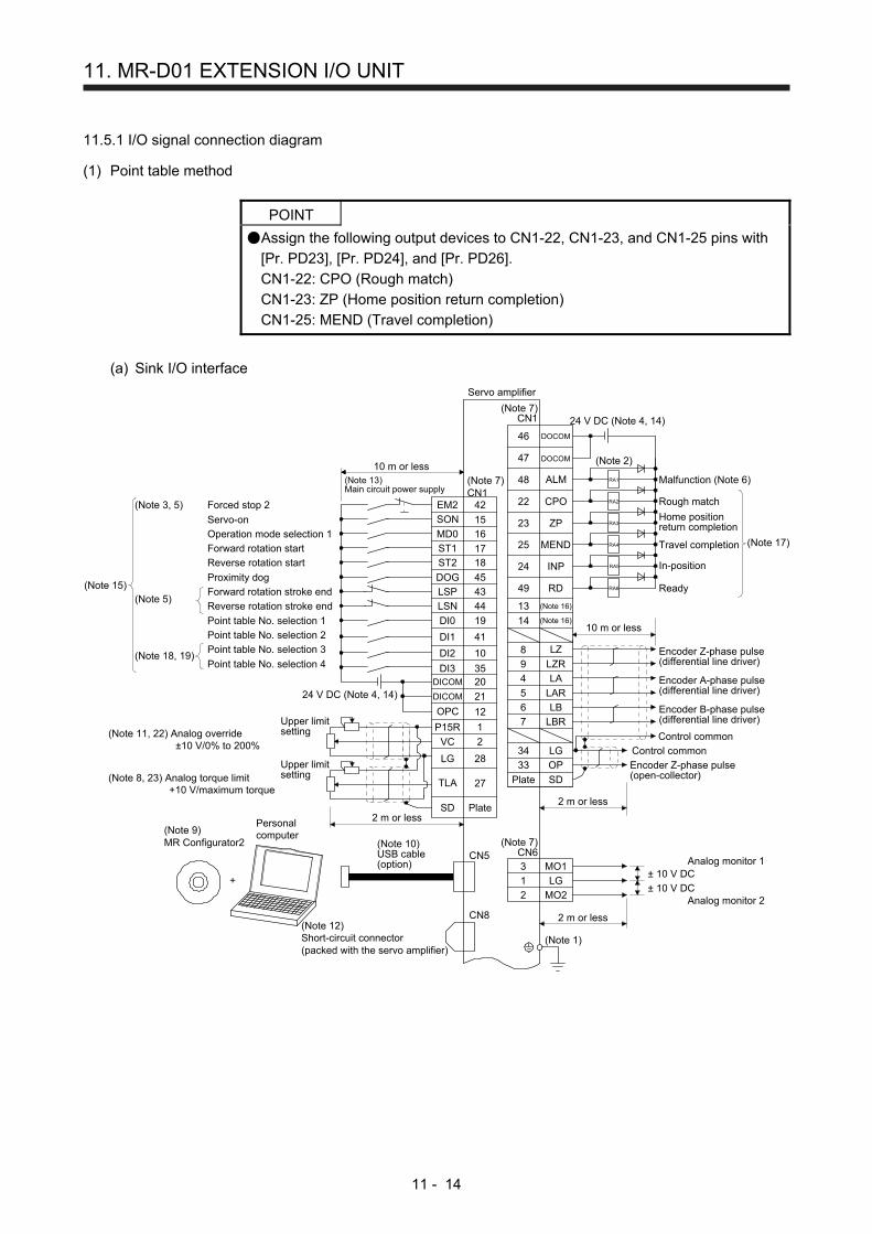
11. MR-D01 EXTENSION I/O UNIT
11 - 14
11.5.1 I/O signal connection diagram
(1) Point table method
POINT
Assign the following output devices to CN1-22, CN1-23, and CN1-25 pins with
[Pr. PD23], [Pr. PD24], and [Pr. PD26].
CN1-22: CPO (Rough match)
CN1-23: ZP (Home position return completion)
CN1-25: MEND (Travel completion)
(a) Sink I/O interface
CN8(Note 12)Short-circuit connector(packed with the servo amplifier)
(Note 1)
(Note 2)
(Note 7)CN1
(Note 7)CN1
Plate
Servo amplifier
(Note 7)CN6
2 m or less
3 MO1
1 LG
2 MO2
47 DOCOM
48 ALM
22 CPO
23 ZP
25 MEND
24 INP
4 LA
5 LAR
6 LB
7 LBR
34 LG
33 OP
SD
2 m or less
8 LZ
9 LZR
20DICOM
21DICOM
2
1
2 m or less
Upper limitsetting
28
27
Plate
Upper limitsetting
VC
SD
TLA
LG
P15R
+
(Note 10)USB cable(option)
CN5
(Note 9)MR Configurator2
Personalcomputer
24 V DC (Note 4, 14)
RA1
RA2
RA3
RA4
RA6
42
15
16
44
19
41
10
1718
EM2
SON
MD0
LSN
DI0
DI1
DI2
ST1
ST2
Reverse rotation stroke end
Forced stop 2
Servo-on
Forward rotation stroke end
(Note 3, 5)
(Note 5)
± 10 V DC
± 10 V DC
Analog monitor 1
Analog monitor 2
Encoder A-phase pulse(differential line driver)
Encoder B-phase pulse(differential line driver)
Control common
Encoder Z-phase pulse(open-collector)
Encoder Z-phase pulse(differential line driver)
Malfunction (Note 6)
10 m or less
(Note 13)Main circuit power supply
46 DOCOM
10 m or less
24 V DC (Note 4, 14)
49
13
14
RD
(Note 16)
(Note 16)
Rough match
Home positionreturn completion
Travel completion
In-position
Ready
(Note 17)
RA5
DOG
LSP
DI3
45
43
35
Operation mode selection 1
Forward rotation start
Reverse rotation start
Proximity dog
Point table No. selection 1
Point table No. selection 2
Point table No. selection 3
Point table No. selection 4(Note 18, 19)
(Note 15)
(Note 11, 22) Analog override±10 V/0% to 200%
(Note 8, 23) Analog torque limit+10 V/maximum torque
Control common
12OPC

11. MR-D01 EXTENSION I/O UNIT
11 - 15
RA7
RA8
RA9
RA10
RA11
RA12
RA13
RA16
RA17
RA18
RA19
RA20
RA21
RA22
MR-D01
Point table No. selection 1
10 m or less
1
2
3
CN10
Point table No. selection 2
Point table No. selection 3
Point table No. selection 4 4
13
14
DI0
DI1
DI2
DI3
DICOMD
DICOMD
(Note 25)
Point table No. selection 5 5
6
7
Point table No. selection 6
Point table No. selection 7
Point table No. selection 8 8
DI4
DI5
DI6
DI7
Servo-on
18
19
Reset
External torque limit selection
Internal torque limit selection
Manual pulse generator multiplication 1 29
30
31
Manual pulse generator multiplication 2
Override selection
Operation mode selection 1 32
TP0
TP1
OVR
MD0
Temporary stop/restart 33
34
35
Proportional control
Forward rotation start
Reverse rotation start 36
TSTP
PCST1
ST2
37
24 V DC (Note 20, 21)
DOCOMD
22 ACD0
CN10
Alarmcode
10 m or less
24
23 ACD1
ACD2
25 ACD3
M code
39
38 MCD00
MCD01
40 MCD02
44
43 MCD11
MCD12
45 MCD13
During a temporarystop46 PUS
48 Rough match
47 MEND
CPO
49 INP
Travel completion
(Note 23, 24) Analog torque limit+10 V/maximum torque
Upper limitsetting(Note 22) Analog override
±10 V/0% to 200%
2 m or less
Upper limitsetting 12
SD
OTLA
Plate
13
2
P15R
OVCN12R 15
CN20
4 OMO1
1 LG
14 OMO2
CN20
Plate SDLG 9
Lower limitsetting
24 V DC (Note 20, 21)
2 m or less
21
26
27
28
SON
RES
TL
TL1
RA14
RA1542
41 MCD03
MCD10
(Note 2)
In-position
± 10 V DC
± 10 V DC
Analog monitor 1
Analog monitor 2

11. MR-D01 EXTENSION I/O UNIT
11 - 16
Note 1. To prevent an electric shock, always connect the protective earth (PE) terminal (marked ) of the servo amplifier to the
protective earth (PE) of the cabinet. 2. Connect the diode in the correct direction. If it is connected reversely, the servo amplifier will malfunction and will not output
signals, disabling EM2 (Forced stop 2) and other protective circuits. 3. The forced stop switch (normally closed contact) must be installed. 4. Supply 24 V DC ± 10% to interfaces from outside. The total current capacity of these power supplies must be 500 mA or lower.
500 mA is the value applicable when all I/O signals are used. The current capacity can be decreased by reducing the number of I/O points. Refer to section 3.9.2 (1) of "MR-J4-_A_(-RJ) Servo Amplifier Instruction Manual" that gives the current value necessary for the interface. A 24 V DC power supply can be used for both input signal and output signal.
5. When starting operation, always turn on EM2 (Forced stop 2), LSP (Forward rotation stroke end) and LSN (Reverse rotation stroke end). (Normally closed contact)
6. ALM (Malfunction) turns on in normal alarm-free condition. (Normally closed contact) 7. The pins with the same signal name are connected in the servo amplifier. 8. TLA will be available when TL (External torque limit selection) is enabled with [Pr. PD04], [Pr. PD06], [Pr. PD08], [Pr. PD10],
[Pr. PD12], [Pr. PD14], [Pr. PD18], [Pr. PD20], [Pr. PD22], [Pr. PD44], and [Pr. PD46]. (Refer to section 3.6.1 (5) of "MR-J4-_A_(-RJ) Servo Amplifier Instruction Manual".)
9. Use SW1DNC MRC2-_. (Refer to "MR-J4-_A_(-RJ) Servo Amplifier Instruction Manual" section 11.7.) 10. Controllers or parameter units can also be connected via the CN3 connector with the RS-422/RS-485 communication. Note
that using the USB communication function (CN5 connector) prevents the RS-422/RS-485 communication function (CN3 connector) from being used, and vice versa. They cannot be used together.
PRU03
MR-PRU03parameter unit
CN3
Servo amplifier
or
10BASE-T cable, etc. (EIA568-compliant)
RS-422/RS-485compatible controller
11. Use an external power supply when inputting a negative voltage. 12. When not using the STO function, attach the short-circuit connector came with a servo amplifier. 13. Configure a circuit to turn off EM2 when the main circuit power is turned off to prevent an unexpected restart of the servo
amplifier. 14. This diagram shows sink I/O interface. 15. The devices can be changed with [Pr. PD04], [Pr. PD06], [Pr. PD08], [Pr. PD10], [Pr. PD12], [Pr. PD14], [Pr. PD18], [Pr.
PD20], [Pr. PD22], [Pr. PD44], and [Pr. PD46]. 16. Output devices are not assigned by default. Assign the output devices with [Pr. PD47] as necessary. 17. Recommended device assignments are shown. The devices can be changed by [Pr. PD23] to [Pr. PD26], and [Pr. PD28]. 18. DI2 and DI3 are assigned to the CN1-10 and CN1-35 pins by default. When connecting a manual pulse generator, change
them with [Pr. PD44] and [Pr. PD46]. Refer to section 9.1 for details of the manual pulse generator. 19. Supply + of 24 DC V to OPC (Power input for open-collector sink interface) when input devices are assigned to the CN1-10 pin
and the CN-35 pin. They cannot be used with source input interface. For the positioning mode, input devices (DI2 and DI3) are assigned with the initial values.
20. Supply 24 V DC ± 10% to interfaces of the MR-D01 from outside. The total current capacity of these power supplies must be 800 mA or lower. 800 mA is the value applicable when all I/O signals are used. The current capacity can be decreased by reducing the number of I/O points. For the current required for the interface, refer to section 3.8.2 (1) of "MR-J4-_A_(-RJ) Servo Amplifier Instruction Manual".
21. As the 24 V DC for the input/output signals, one 24 V DC power supply can be used to supply to the servo amplifier and MR-D01. In this case, select an appropriate power supply capacity depending on the number of points of the input/output signals to be used.
22. The CN1-2 pin and CN20-2 pin are exclusive. The CN1-2 pin is set by default. Select this item with [Pr. Po11]. 23. The CN1-27 pin and CN20-12 pin are exclusive. The CN1-27 pin is set by default. Select this item with [Pr. Po11]. 24. OTLA will be available when TL (External torque limit selection) is enabled with [Pr. Po02] to [Pr. Po07]. (Refer to section
11.5.3 (6).) 25. The devices can be changed by [Pr. Po02] to [Pr. Po07].

11. MR-D01 EXTENSION I/O UNIT
11 - 17
(b) Source I/O interface
POINT
For notes, refer to (1) (a) of this section.
CN8
3 MO1
1 LG
2 MO2
47 DOCOM
48 ALM
22 CPO
23 ZP
25 MEND
24 INP
4 LA
5 LAR
6 LB
7 LBR
34 LG
33 OP
SD
8 LZ
9 LZR
20DICOM
21DICOM
2
1
28
27
VC
SD
TLA
LG
P15R
+
CN5
RA1
RA2
RA3
RA4
RA6
42
15
16
44
19
41
10
1718
EM2
SON
MD0
LSN
DI0
DI1
DI2
ST1
ST2
46 DOCOM
49
13
14
RD
RA5
DOG
LSP
DI3
45
43
35
12OPC
(Note 12)Short-circuit connector(packed with the servo amplifier)
(Note 1)
(Note 2)
(Note 7)CN1
(Note 7)CN1
Plate
Servo amplifier
(Note 7)CN6
2 m or less
2 m or less
2 m or less
Upper limitsetting
Plate
Upper limitsetting
(Note 10)USB cable(option)
(Note 9)MR Configurator2
Personalcomputer
24 V DC (Note 4, 14)
Reverse rotation stroke end
Forced stop 2
Servo-on
Forward rotation stroke end
(Note 3, 5)
(Note 5)
± 10 V DC
± 10 V DC
Analog monitor 1
Analog monitor 2
Encoder A-phase pulse(differential line driver)
Encoder B-phase pulse(differential line driver)
Control common
Encoder Z-phase pulse(open-collector)
Encoder Z-phase pulse(differential line driver)
Malfunction (Note 6)
10 m or less
(Note 13)Main circuit power supply
10 m or less
24 V DC (Note 4, 14)
(Note 16)
(Note 16)
Rough match
Home positionreturn completion
Travel completion
In-position
Ready
(Note 17)Operation mode selection 1
Forward rotation start
Reverse rotation start
Proximity dog
Point table No. selection 1
Point table No. selection 2
Point table No. selection 3
Point table No. selection 4(Note 18, 19)
(Note 15)
(Note 11, 22) Analog override±10 V/0% to 200%
(Note 8, 23) Analog torque limit+10 V/maximum torque
Control common

11. MR-D01 EXTENSION I/O UNIT
11 - 18
RA7
RA8
RA9
RA10
RA11
RA12
RA13
RA16
RA17
RA18
RA19
RA20
RA21
RA22
MR-D01
1
2
3
CN10
4
13
14
DI0
DI1
DI2
DI3
DICOMD
DICOMD
5
6
7
8
DI4
DI5
DI6
DI7
18
19
29
30
31
32
TP0
TP1
OVR
MD0
33
34
35
36
TSTP
PCST1
ST2
37 DOCOMD
22 ACD0
CN10
24
23 ACD1
ACD2
25 ACD3
39
38 MCD00
MCD01
40 MCD02
44
43 MCD11
MCD12
45 MCD13
46 PUS
48
47 MEND
CPO
49 INP
12
SD
OTLA
13
2
P15R
OVCN12R 15
CN20
4 OMO1
1 LG
14 OMO2
CN20
SDLG 9
21
26
27
28
SON
RES
TL
TL1
RA14
RA1542
41 MCD03
MCD10
Point table No. selection 1
10 m or less
Point table No. selection 2
Point table No. selection 3
Point table No. selection 4
(Note 25)
Point table No. selection 5
Point table No. selection 6
Point table No. selection 7
Point table No. selection 8
Servo-on
Reset
External torque limit selection
Internal torque limit selection
Manual pulse generator multiplication 1
Manual pulse generator multiplication 2
Override selection
Operation mode selection 1
Temporary stop/restartProportional control
Forward rotation start
Reverse rotation start
24 V DC (Note 20, 21)
Alarmcode
10 m or less
M code
During a temporarystop
Rough match
Travel completion
(Note 23, 24) Analog torque limit+10 V/maximum torque
Upper limitsetting(Note 22) Analog override
±10 V/0% to 200%
2 m or less
Upper limitsetting
PlatePlate
Lower limitsetting
24 V DC (Note 20, 21)
2 m or less
(Note 2)
In-position
± 10 V DC
± 10 V DC
Analog monitor 1
Analog monitor 2

11. MR-D01 EXTENSION I/O UNIT
11 - 19
(2) Point table method in the BCD input positioning operation
POINT
Assign the following output devices to CN1-22, CN1-23, and CN1-25 pins with
[Pr. PD23], [Pr. PD24], and [Pr. PD26].
CN1-22: CPO (Rough match)
CN1-23: ZP (Home position return completion)
CN1-25: MEND (Travel completion)

11. MR-D01 EXTENSION I/O UNIT
11 - 20
(a) When using a digital switch
1) Sink I/O interface
CN8(Note 12)Short-circuit connector(packed with the servo amplifier)
(Note 1)
(Note 2)
(Note 7)CN1
(Note 7)CN1
Plate
Servo amplifier
(Note 7)CN6
2 m or less
3 MO1
1 LG
2 MO2
47 DOCOM
48 ALM
22 CPO
23 ZP
25 MEND
24 INP
4 LA
5 LAR
6 LB
7 LBR
34 LG
33 OP
SD
2 m or less
8 LZ
9 LZR
20DICOM
21DICOM
2
1
2 m or less
Upper limitsetting
28
27
Plate
Upper limitsetting
VC
SD
TLA
LG
P15R
+
(Note 10)USB cable(option)
CN5
(Note 9)MR Configurator2
Personalcomputer
24 V DC (Note 4, 14)
RA1
RA2
RA3
RA4
RA6
42
15
16
44
19
41
10
17
18
EM2
SON
MD0
LSN
DI0
DI1
DI2
ST1
ST2
Reverse rotation stroke end
Forced stop 2
Servo-on
Forward rotation stroke end
(Note 3, 5)
(Note 5)
± 10 V DC
± 10 V DC
Analog monitor 1
Analog monitor 2
Encoder A-phase pulse(differential line driver)
Encoder B-phase pulse(differential line driver)
Control common
Encoder Z-phase pulse(open-collector)
Encoder Z-phase pulse(differential line driver)
Malfunction (Note 6)
10 m or less
(Note 13)Main circuit power supply
46 DOCOM
10 m or less
24 V DC (Note 4, 14)
49
13
14
RD
(Note 16)
(Note 16)
Rough matchHome positionreturn completion
Travel completion
In-position
Ready
(Note 17)
RA5
DOG
LSP
DI3
45
43
35
Operation mode selection 1
Forward rotation start
Reverse rotation start
Proximity dog
Position data input 1
Position data input 2
Position data input 3
Position data input 4(Note 18, 19)
(Note 15)
(Note 11, 22) Analog override±10 V/0% to 200%
(Note 8, 23) Analog torque limit+10 V/maximum torque
Control common
12OPC
(Note 23, 24) Analog torque limit+10 V/maximum torque
Upper limitsetting(Note 22) Analog override
±10 V/0% to 200%
2 m or less
Upper limitsetting
12
SD
OTLA
Plate
132
P15R
OVC
N12R 15
CN20
LG 9
Lower limitsetting
MR-D01
4 OMO1
1 LG
14 OMO2
CN20
SD
24 V DC (Note 20, 21)CN10
10 m or less
DOCOMD37
During a temporary stop46 PUS
48 Rough match
In-position
47 MEND
CPO
49 INP
Travel completion
Plate
RA7
RA8
RA9
RA10
2 m or less
(Note 2)
± 10 V DC
± 10 V DC
Analog monitor 1
Analog monitor 2

11. MR-D01 EXTENSION I/O UNIT
11 - 21
MR-D01
10 m or less
CN1013
14
DICOMD
DICOMD
Servo-on 21
26
27
Reset
External torque limit selection
Internal torque limit selection 28
SON
RES
TL
TL1
Manual pulse generator multiplication 1 29
30
31
Manual pulse generator multiplication 2
Override selection
Operation mode selection 1 32
TP0
TP1
OVR
MD0
Temporary stop/restart 33
34
35
Proportional control
Forward rotation start
Reverse rotation start 36
TSTP
PC
ST1
ST2
18SPD1
19SPD2
20SPD3
1
2
3
4
POS00
POS01
POS02
POS03
5
6
7
8
POS10
POS11
POS12
POS13
44
45
PRQ1
PRQ2
9
10
POS20
POS21
11
12
15
16
POS22
POS23
POSP
POSN
6A
6B
7A
7B
4A
4B
5A
5B
9A
9B
2A
2B
3A
3B
1A
1B
CON1
SD Plate
6A
6B
7A
7B
4A
4B
5A
5B
9A
9B
2A
2B
3A
3B
1A
1B
CON2
MR-DS60
6A
6B
7A
7B
4A
4B
5A
5B
9A
9B
2A
2B
3A
3B
1A
1B
CON1
6A
6B
7A
7B
4A
4B
5A
5B
9A
9B
2A
2B
3A
3B
1A
1B
CON2
MR-DS60
Digital switchselect switch
20 m or less
Speed selection 2
Speed selection 1
Speed selection 3
Do not connect them when using aplurality of digital switches.
Up to 10 digital switchescan be installed.
(Note 25)
MR-DSCBL_M-GMR-DSCBL_
DC
M1
DC
M2
CO
M2
CO
M1
DC
M1
DC
M2
CO
M2
CO
M1
CN10 24 V DC (Note 20, 21)
37
22 ACD0
24
23
25
AlarmcodeACD1
ACD2
ACD3
DOCOMD
RA11
RA12
RA13
RA14
24 V DC (Note 20, 21)(Note 2)

11. MR-D01 EXTENSION I/O UNIT
11 - 22
Note 1. To prevent an electric shock, always connect the protective earth (PE) terminal (marked ) of the servo amplifier to the
protective earth (PE) of the cabinet. 2. Connect the diode in the correct direction. If it is connected reversely, the servo amplifier will malfunction and will not output
signals, disabling EM2 (Forced stop 2) and other protective circuits. 3. The forced stop switch (normally closed contact) must be installed. 4. Supply 24 V DC ± 10% to interfaces from outside. The total current capacity of these power supplies must be 500 mA or lower.
500 mA is the value applicable when all I/O signals are used. The current capacity can be decreased by reducing the number of I/O points. Refer to section 3.9.2 (1) of "MR-J4-_A_(-RJ) Servo Amplifier Instruction Manual" that gives the current value necessary for the interface. A 24 V DC power supply can be used for both input signal and output signal.
5. When starting operation, always turn on EM2 (Forced stop 2), LSP (Forward rotation stroke end) and LSN (Reverse rotation stroke end). (Normally closed contact)
6. ALM (Malfunction) turns on in normal alarm-free condition. (Normally closed contact) 7. The pins with the same signal name are connected in the servo amplifier. 8. TLA will be available when TL (External torque limit selection) is enabled with [Pr. PD04], [Pr. PD06], [Pr. PD08], [Pr. PD10],
[Pr. PD12], [Pr. PD14], [Pr. PD18], [Pr. PD20], [Pr. PD22], [Pr. PD44], and [Pr. PD46]. (Refer to section 3.6.1 (5) of "MR-J4-_A_(-RJ) Servo Amplifier Instruction Manual".)
9. Use SW1DNC MRC2-_. (Refer to "MR-J4-_A_(-RJ) Servo Amplifier Instruction Manual" section 11.7.) 10. Controllers or parameter units can also be connected via the CN3 connector with the RS-422/RS-485 communication. Note
that using the USB communication function (CN5 connector) prevents the RS-422/RS-485 communication function (CN3 connector) from being used, and vice versa. They cannot be used together.
PRU03
MR-PRU03parameter unit
CN3
Servo amplifier
or
10BASE-T cable, etc. (EIA568-compliant)
RS-422/RS-485compatible controller
11. Use an external power supply when inputting a negative voltage. 12. When not using the STO function, attach the short-circuit connector came with a servo amplifier. 13. Configure a circuit to turn off EM2 when the main circuit power is turned off to prevent an unexpected restart of the servo
amplifier. 14. This diagram shows sink I/O interface. 15. The devices can be changed with [Pr. PD04], [Pr. PD06], [Pr. PD08], [Pr. PD10], [Pr. PD12], [Pr. PD14], [Pr. PD18], [Pr.
PD20], [Pr. PD22], [Pr. PD44], and [Pr. PD46]. 16. Output devices are not assigned by default. Assign the output devices with [Pr. PD47] as necessary. 17. Recommended device assignments are shown. The devices can be changed by [Pr. PD23] to [Pr. PD26], and [Pr. PD28]. 18. DI2 and DI3 are assigned to the CN1-10 and CN1-35 pins by default. When connecting a manual pulse generator, change
them with [Pr. PD44] and [Pr. PD46]. Refer to section 9.1 for details of the manual pulse generator. 19. Supply + of 24 DC V to OPC (Power input for open-collector sink interface) when input devices are assigned to the CN1-10 pin
and the CN-35 pin. They cannot be used with source input interface. For the positioning mode, input devices (DI2 and DI3) are assigned with the initial values.
20. Supply 24 V DC ± 10% to interfaces of the MR-D01 from outside. The total current capacity of these power supplies must be 800 mA or lower. 800 mA is the value applicable when all I/O signals are used. The current capacity can be decreased by reducing the number of I/O points. For the current required for the interface, refer to section 3.8.2 (1) of "MR-J4-_A_(-RJ) Servo Amplifier Instruction Manual".
21. As the 24 V DC for the input/output signals, one 24 V DC power supply can be used to supply to the servo amplifier and MR-D01. In this case, select an appropriate power supply capacity depending on the number of points of the input/output signals to be used.
22. The CN1-2 pin and CN20-2 pin are exclusive. The CN1-2 pin is set by default. Select this item with [Pr. Po11]. 23. The CN1-27 pin and CN20-12 pin are exclusive. The CN1-27 pin is set by default. Select this item with [Pr. Po11]. 24. OTLA will be available when TL (External torque limit selection) is enabled with [Pr. Po02] to [Pr. Po07]. (Refer to section
11.5.3 (6).) 25. The devices can be changed by [Pr. Po02] to [Pr. Po07].

11. MR-D01 EXTENSION I/O UNIT
11 - 23
2) Source I/O interface
POINT
For notes, refer to (2) (a) 1) of this section.
CN8
3 MO1
1 LG
2 MO2
47 DOCOM
48 ALM
22 CPO
23 ZP
25 MEND
24 INP
4 LA
5 LAR
6 LB
7 LBR
34 LG
33 OP
SD
8 LZ
9 LZR
20DICOM
21DICOM
2
1
28
27
VC
SD
TLA
LG
P15R
+
CN5
RA1
RA2
RA3
RA4
RA6
42
15
16
44
19
41
10
17
18
EM2
SON
MD0
LSN
DI0
DI1
DI2
ST1
ST2
46 DOCOM
49
13
14
RD
RA5
DOG
LSP
DI3
45
43
35
12OPC
12
SD
OTLA
132
P15R
OVC
N12R 15
CN20
LG 9
MR-D01
4 OMO1
1 LG
14 OMO2
CN20
SD
CN10
DOCOMD37
46 PUS
48
47 MEND
CPO
49 INP
RA7
RA8
RA9
RA10
(Note 12)Short-circuit connector(packed with the servo amplifier)
(Note 1)
(Note 2)
(Note 7)CN1
(Note 7)CN1
Plate
Servo amplifier
(Note 7)CN6
2 m or less
2 m or less
2 m or less
Upper limitsetting
Plate
Upper limitsetting
(Note 10)USB cable(option)
(Note 9)MR Configurator2
Personalcomputer
24 V DC (Note 4, 14)
Reverse rotation stroke end
Forced stop 2
Servo-on
Forward rotation stroke end
(Note 3, 5)
(Note 5)
± 10 V DC
± 10 V DC
Analog monitor 1
Analog monitor 2
Encoder A-phase pulse(differential line driver)
Encoder B-phase pulse(differential line driver)
Control common
Encoder Z-phase pulse(open-collector)
Encoder Z-phase pulse(differential line driver)
Malfunction (Note 6)
10 m or less
(Note 13)Main circuit power supply
10 m or less
24 V DC (Note 4, 14)
(Note 16)
(Note 16)
Rough matchHome positionreturn completion
Travel completion
In-position
Ready
(Note 17)Operation mode selection 1
Forward rotation start
Reverse rotation start
Proximity dog
Position data input 1
Position data input 2
Position data input 3
Position data input 4(Note 18, 19)
(Note 15)
(Note 11, 22) Analog override±10 V/0% to 200%
(Note 8, 23) Analog torque limit+10 V/maximum torque
Control common
(Note 23, 24) Analog torque limit+10 V/maximum torque
Upper limitsetting(Note 22) Analog override
±10 V/0% to 200%
2 m or less
Upper limitsetting
Plate
Lower limitsetting
24 V DC (Note 20, 21)
10 m or less
During a temporary stop
Rough match
In-position
Travel completion
Plate2 m or less
(Note 2)
± 10 V DC
± 10 V DC
Analog monitor 1
Analog monitor 2

11. MR-D01 EXTENSION I/O UNIT
11 - 24
MR-D01
CN1013
14
DICOMD
DICOMD
21
26
27
28
SON
RES
TL
TL1
29
30
31
32
TP0
TP1
OVR
MD0
33
34
35
36
TSTP
PC
ST1
ST2
18SPD1
19SPD2
20SPD3
1
2
3
4
POS00
POS01
POS02
POS03
5
6
7
8
POS10
POS11
POS12
POS13
44
45
PRQ1
PRQ2
9
10
POS20
POS21
11
12
15
16
POS22
POS23
POSP
POSN
6A
6B
7A
7B
4A
4B
5A
5B
9A
9B
2A
2B
3A
3B
1A
1B
CON1
SD
6A
6B
7A
7B
4A
4B
5A
5B
9A
9B
2A
2B
3A
3B
1A
1B
CON2
MR-DS60
6A
6B
7A
7B
4A
4B
5A
5B
9A
9B
2A
2B
3A
3B
1A
1B
CON1
6A
6B
7A
7B
4A
4B
5A
5B
9A
9B
2A
2B
3A
3B
1A
1B
CON2
MR-DS60
MR-DSCBL_M-GMR-DSCBL_
DC
M1
DC
M2
CO
M2
CO
M1
DC
M1
DC
M2
CO
M2
CO
M1
CN10
37
22 ACD0
24
23
25
ACD1
ACD2
ACD3
DOCOMD
RA11
RA12
RA13
RA14
10 m or less
Servo-on
Reset
External torque limit selectionInternal torque limit selection
Manual pulse generator multiplication 1
Manual pulse generator multiplication 2
Override selection
Operation mode selection 1
Temporary stop/restart
Proportional control
Forward rotation start
Reverse rotation start
Plate
Digital switchselect switch
20 m or less
Speed selection 2
Speed selection 1
Speed selection 3
Do not connect them when using aplurality of digital switches.
Up to 10 digital switchescan be installed.
(Note 25)
24 V DC (Note 20, 21)
Alarmcode
24 V DC (Note 20, 21)(Note 2)

11. MR-D01 EXTENSION I/O UNIT
11 - 25
POINT
Assign the following output devices to CN1-22, CN1-23, and CN1-25 pins with
[Pr. PD23], [Pr. PD24], and [Pr. PD26].
CN1-22: CPO (Rough match)
CN1-23: ZP (Home position return completion)
CN1-25: MEND (Travel completion)

11. MR-D01 EXTENSION I/O UNIT
11 - 26
(b) When using programmable controllers
1) Sink I/O interface
CN8(Note 12)Short-circuit connector(packed with the servo amplifier)
(Note 1)
(Note 2)
(Note 7)CN1
(Note 7)CN1
Plate
Servo amplifier
(Note 7)CN6
2 m or less
3 MO1
1 LG
2 MO2
47 DOCOM
48 ALM
22 CPO
23 ZP
25 MEND
24 INP
4 LA
5 LAR
6 LB
7 LBR
34 LG
33 OP
SD
2 m or less
8 LZ
9 LZR
20DICOM
21DICOM
2
1
2 m or less
Upper limitsetting
28
27
Plate
Upper limitsetting VC
SD
TLA
LG
P15R
+
(Note 10)USB cable(option)
CN5
(Note 9)MR Configurator2
Personalcomputer
24 V DC (Note 4, 14)
RA1
RA2
RA3
RA4
RA6
42
15
16
44
19
41
10
17
18
EM2
SON
MD0
LSN
DI0
DI1
DI2
ST1
ST2
Reverse rotation stroke end
Forced stop 2
Servo-on
Forward rotation stroke end
(Note 3, 5)
(Note 5)
± 10 V DC
± 10 V DC
Analog monitor 1
Analog monitor 2
Encoder A-phase pulse(differential line driver)
Encoder B-phase pulse(differential line driver)
Control common
Encoder Z-phase pulse(open-collector)
Encoder Z-phase pulse(differential line driver)
Malfunction (Note 6)
10 m or less
(Note 13)Main circuit power supply
46 DOCOM
10 m or less
24 V DC (Note 4, 14)
49
13
14
RD
(Note 16)
(Note 16)
Rough match
Home positionreturn completion
Travel completion
In-position
Ready
(Note 17)
RA5
DOG
LSP
DI3
45
43
35
Operation mode selection 1
Forward rotation start
Reverse rotation start
Proximity dog
Position data input 1
Position data input 2
Position data input 3
Position data input 4(Note 18, 19)
(Note 15)
(Note 11, 22) Analog override±10 V/0% to 200%
(Note 8, 23) Analog torque limit+10 V/maximum torque
Control common
12OPC
MR-D01
24 V DC (Note 20, 21)CN10
10 m or less
DOCOMD37
44 PRQ1
45 PRQ2
During a temporary stop46 PUS
48 Rough match
In-position
47 MEND
CPO
49 INP
Travel completion
Position data request 2
Position data request 1
(Note 23, 24) Analog torque limit+10 V/maximum torque
Upper limitsetting(Note 22) Analog override
±10 V/0% to 200%
2 m or less
Upper limitsetting 12
SD
OTLA
Plate
13
2P15ROVC
N12R 15
CN20
LG 9
Lower limitsetting
Plate
RA7
RA8
RA9
RA10
RA11
4 OMO1
1 LG
14 OMO2
CN20
SD2 m or less
(Note 2)
RA12
± 10 V DC
± 10 V DC
Analog monitor 1
Analog monitor 2

11. MR-D01 EXTENSION I/O UNIT
11 - 27
22 ACD0
24
23
25
ACD1
ACD2
ACD3
MR-D01
CN10
Servo-on
Reset
External torque limit selection
Internal torque limit selection
Manual pulse generator multiplication 1
Manual pulse generator multiplication 2
Override selection
Automatic/manual selection
Temporary stop/restart
Proportional control
Forward rotation start
Reverse rotation start
Speed selection 2
Speed selection 1
Speed selection 3
44
45
1
2
3
45
6
7
8
9
10
PRQ1
PRQ2
POS00
POS01
POS02
POS03
POS10
11
12
15
16
17
DICOMD 13DOCOMD 37
SON 21
RES 26
TL 27
TL1 28
TP0 29
TP1 30
OVR 31
MD0 32
TSTP 33
PC 34ST1 35
ST2 36
SP0 18SP1 19
SP2 20
POS11
POS12
POS13
POS20
POS21
POS22
POS23
POSP
POSN
STRB
X00
X01
X02
X0F
COM
Y01
Y02
Y03
Y04
Y05
Y06
Y07
Y08
Y09
Y0A
Y0B
Y0C
Y0D
Y0E
Y0F12/24VDC
COM
Y00
24 V DC (Note 20, 21)
(Note 25)
CN10 24 V DC (Note 20, 21)
DICOMD37
Alarmcode
RA13
RA14
RA15
RA16
(Note 2)
RY40NT5P output module
RX40C7 input module

11. MR-D01 EXTENSION I/O UNIT
11 - 28
Note 1. To prevent an electric shock, always connect the protective earth (PE) terminal (marked ) of the servo amplifier to the
protective earth (PE) of the cabinet. 2. Connect the diode in the correct direction. If it is connected reversely, the servo amplifier will malfunction and will not output
signals, disabling EM2 (Forced stop 2) and other protective circuits. 3. The forced stop switch (normally closed contact) must be installed. 4. Supply 24 V DC ± 10% to interfaces from outside. The total current capacity of these power supplies must be 500 mA or lower.
500 mA is the value applicable when all I/O signals are used. The current capacity can be decreased by reducing the number of I/O points. Refer to section 3.9.2 (1) of "MR-J4-_A_(-RJ) Servo Amplifier Instruction Manual" that gives the current value necessary for the interface. A 24 V DC power supply can be used for both input signal and output signal.
5. When starting operation, always turn on EM2 (Forced stop 2), LSP (Forward rotation stroke end) and LSN (Reverse rotation stroke end). (Normally closed contact)
6. ALM (Malfunction) turns on in normal alarm-free condition. (Normally closed contact) 7. The pins with the same signal name are connected in the servo amplifier. 8. TLA will be available when TL (External torque limit selection) is enabled with [Pr. PD04], [Pr. PD06], [Pr. PD08], [Pr. PD10],
[Pr. PD12], [Pr. PD14], [Pr. PD18], [Pr. PD20], [Pr. PD22], [Pr. PD44], and [Pr. PD46]. (Refer to section 3.6.1 (5) of "MR-J4-_A_(-RJ) Servo Amplifier Instruction Manual".)
9. Use SW1DNC MRC2-_. (Refer to "MR-J4-_A_(-RJ) Servo Amplifier Instruction Manual" section 11.7.) 10. Controllers or parameter units can also be connected via the CN3 connector with the RS-422/RS-485 communication. Note
that using the USB communication function (CN5 connector) prevents the RS-422/RS-485 communication function (CN3 connector) from being used, and vice versa. They cannot be used together.
PRU03
MR-PRU03parameter unit
CN3
Servo amplifier
or
10BASE-T cable, etc. (EIA568-compliant)
RS-422/RS-485compatible controller
11. Use an external power supply when inputting a negative voltage. 12. When not using the STO function, attach the short-circuit connector came with a servo amplifier. 13. Configure a circuit to turn off EM2 when the main circuit power is turned off to prevent an unexpected restart of the servo
amplifier. 14. This diagram shows sink I/O interface. 15. The devices can be changed with [Pr. PD04], [Pr. PD06], [Pr. PD08], [Pr. PD10], [Pr. PD12], [Pr. PD14], [Pr. PD18], [Pr.
PD20], [Pr. PD22], [Pr. PD44], and [Pr. PD46]. 16. Output devices are not assigned by default. Assign the output devices with [Pr. PD47] as necessary. 17. Recommended device assignments are shown. The devices can be changed by [Pr. PD23] to [Pr. PD26], and [Pr. PD28]. 18. DI2 and DI3 are assigned to the CN1-10 and CN1-35 pins by default. When connecting a manual pulse generator, change
them with [Pr. PD44] and [Pr. PD46]. Refer to section 9.1 for details of the manual pulse generator. 19. Supply + of 24 DC V to OPC (Power input for open-collector sink interface) when input devices are assigned to the CN1-10 pin
and the CN-35 pin. They cannot be used with source input interface. For the positioning mode, input devices (DI2 and DI3) are assigned with the initial values.
20. Supply 24 V DC ± 10% to interfaces of the MR-D01 from outside. The total current capacity of these power supplies must be 800 mA or lower. 800 mA is the value applicable when all I/O signals are used. The current capacity can be decreased by reducing the number of I/O points. For the current required for the interface, refer to section 3.8.2 (1) of "MR-J4-_A_(-RJ) Servo Amplifier Instruction Manual".
21. As the 24 V DC for the input/output signals, one 24 V DC power supply can be used to supply to the servo amplifier and MR-D01. In this case, select an appropriate power supply capacity depending on the number of points of the input/output signals to be used.
22. The CN1-2 pin and CN20-2 pin are exclusive. The CN1-2 pin is set by default. Select this item with [Pr. Po11]. 23. The CN1-27 pin and CN20-12 pin are exclusive. The CN1-27 pin is set by default. Select this item with [Pr. Po11]. 24. OTLA will be available when TL (External torque limit selection) is enabled with [Pr. Po02] to [Pr. Po07]. (Refer to section
11.5.3 (6).) 25. The devices can be changed by [Pr. Po02] to [Pr. Po07].

11. MR-D01 EXTENSION I/O UNIT
11 - 29
2) Source I/O interface
POINT
For notes, refer to (2) (b) 1) of this section.
CN8
3 MO1
1 LG
2 MO2
47 DOCOM
48 ALM
22 CPO
23 ZP
25 MEND
24 INP
4 LA
5 LAR
6 LB
7 LBR
34 LG
33 OP
SD
8 LZ
9 LZR
20DICOM
21DICOM
2
1
28
27
VC
SD
TLA
LG
P15R
+
CN5
RA1
RA2
RA3
RA4
RA6
42
15
16
44
19
41
10
17
18
EM2
SON
MD0
LSN
DI0
DI1
DI2
ST1
ST2
46 DOCOM
49
13
14
RD
RA5
DOG
LSP
DI3
45
43
35
12OPC
MR-D01
CN10
DOCOMD37
44 PRQ1
45 PRQ2
46 PUS
48
47 MEND
CPO
49 INP
12
SD
OTLA
13
2P15ROVC
N12R 15
CN20
LG 9
RA7
RA8
RA9
RA10
RA11
RA12
4 OMO1
1 LG
14 OMO2
CN20
SD
(Note 12)Short-circuit connector(packed with the servo amplifier)
(Note 1)
(Note 2)
(Note 7)CN1
(Note 7)CN1
Plate
Servo amplifier
(Note 7)CN6
2 m or less
2 m or less
2 m or less
Upper limitsetting
Plate
Upper limitsetting
(Note 10)USB cable(option)
(Note 9)MR Configurator2
Personalcomputer
24 V DC (Note 4, 14)
Reverse rotation stroke end
Forced stop 2
Servo-on
Forward rotation stroke end
(Note 3, 5)
(Note 5)
± 10 V DC
± 10 V DC
Analog monitor 1
Analog monitor 2
Encoder A-phase pulse(differential line driver)
Encoder B-phase pulse(differential line driver)
Control common
Encoder Z-phase pulse(open-collector)
Encoder Z-phase pulse(differential line driver)
Malfunction (Note 6)
10 m or less
(Note 13)Main circuit power supply
10 m or less
24 V DC (Note 4, 14)
(Note 16)
(Note 16)
Rough match
Home positionreturn completion
Travel completion
In-position
Ready
(Note 17)Operation mode selection 1
Forward rotation start
Reverse rotation start
Proximity dog
Position data input 1
Position data input 2
Position data input 3
Position data input 4(Note 18, 19)
(Note 15)
(Note 11, 22) Analog override±10 V/0% to 200%
(Note 8, 23) Analog torque limit+10 V/maximum torque
Control common
24 V DC (Note 20, 21)
10 m or less
During a temporary stop
Rough match
In-position
Travel completion
Position data request 2
Position data request 1
(Note 23, 24) Analog torque limit+10 V/maximum torque
Upper limitsetting(Note 22) Analog override
±10 V/0% to 200%
2 m or less
Upper limitsetting
Plate
Lower limitsetting
Plate2 m or less
(Note 2)
± 10 V DC
± 10 V DC
Analog monitor 1
Analog monitor 2

11. MR-D01 EXTENSION I/O UNIT
11 - 30
22 ACD0
24
23
25
ACD1
ACD2
ACD3
MR-D01
CN1044
45
1
2
3
45
6
7
8
9
10
PRQ1
PRQ2
POS00
POS01
POS02
POS03
POS10
11
12
15
16
17
DICOMD 13DOCOMD 37
SON 21
RES 26
TL 27
TL1 28
TP0 29
TP1 30
OVR 31
MD0 32
TSTP 33
PC 34ST1 35
ST2 36
SP0 18SP1 19
SP2 20
POS11
POS12
POS13
POS20
POS21
POS22
POS23
POSP
POSN
STRB
X00
X01
X02
X0F
COM
Y01
Y02
Y03
Y04
Y05
Y06
Y07
Y08
Y09
Y0A
Y0B
Y0C
Y0D
Y0E
Y0F12/24VDC
COM
Y00
CN10
DICOMD37
RA13
RA14
RA15
RA16
Servo-on
Reset
External torque limit selection
Internal torque limit selection
Manual pulse generator multiplication 1
Manual pulse generator multiplication 2
Override selection
Automatic/manual selection
Temporary stop/restart
Proportional control
Forward rotation start
Reverse rotation start
Speed selection 2
Speed selection 1
Speed selection 3
24 V DC (Note 20, 21)
(Note 25)
24 V DC (Note 20, 21)
Alarmcode
(Note 2)
RY40NT5P output module
RX40C7 input module

11. MR-D01 EXTENSION I/O UNIT
11 - 31
(3) Program method
POINT
Assign the following output devices to CN1-22, CN1-23, and CN1-25 pins with
[Pr. PD23], [Pr. PD24], and [Pr. PD26].
CN1-22: CPO (Rough match)
CN1-23: ZP (Home position return completion)
CN1-25: MEND (Travel completion)
(a) Sink I/O interface
CN8
(Note 12)Short-circuit connector(packed with the servo amplifier)
(Note 1)
(Note 2)
(Note 7)CN1
(Note 7)CN1
Plate
Servo amplifier
(Note 7)CN6
2 m or less
3 MO1
1 LG
2 MO2
47 DOCOM
48 ALM
22 CPO
23 ZP
25 MEND
24 INP
4 LA
5 LAR
6 LB
7 LBR
34 LG
33 OP
SD
2 m or less
8 LZ
9 LZR
20DICOM
21DICOM
2
1
2 m or less
Upper limitsetting
28
27
Plate
Upper limitsetting
VC
SD
TLA
LG
P15R
+
(Note 10)USB cable(option)
CN5
(Note 9)MR Configurator2
Personalcomputer
24 V DC (Note 4, 14)
RA1
RA2
RA3
RA4
RA6
42
15
16
44
19
41
10
1718
EM2
SON
MD0
LSN
DI0
DI1
DI2
ST1
ST2
Reverse rotation stroke end
Forced stop 2
Servo-on
Forward rotation stroke end
(Note 3, 5)
(Note 5)
± 10 V DC
± 10 V DC
Analog monitor 1
Analog monitor 2
Encoder A-phase pulse(differential line driver)
Encoder B-phase pulse(differential line driver)
Control common
Encoder Z-phase pulse(open-collector)
Encoder Z-phase pulse(differential line driver)
Malfunction (Note 6)
10 m or less
(Note 13)Main circuit power supply
46 DOCOM
10 m or less
24 V DC (Note 4, 14)
49
13
14
RD
(Note 16)
(Note 16)
Rough match
Home positionreturn completion
Travel completion
In-position
Ready
(Note 17)
RA5
DOG
LSP
DI3
45
43
35
Operation mode selection 1
Forward rotation start
Reverse rotation start
Proximity dog
Program No. selection 1
Program No. selection 2
Program No. selection 3
Program No. selection 4(Note 18, 19)
(Note 15)
(Note 11, 22) Analog override±10 V/0% to 200%
(Note 8, 23) Analog torque limit+10 V/maximum torque
Control common
12OPC

11. MR-D01 EXTENSION I/O UNIT
11 - 32
RA7
RA8
RA9
MR-D01
Program No. selection 1
10 m or less
1
2
3
CN10
Program No. selection 2
Program No. selection 3
Program No. selection 4 4
13
14
DI0
DI1
DI2
DI3
DICOMD
DICOMD
(Note 25)
Program No. selection 5 5
6
7
Program No. selection 6
Program No. selection 7
Program No. selection 8 8
DI4
DI5
DI6
DI7
Servo-on
Reset
External torque limit selection
Internal torque limit selection
Manual pulse generator multiplication 1 29
30
31
Manual pulse generator multiplication 2
Override selection
Operation mode selection 1 32
TP0
TP1
OVR
MD0
Temporary stop/restart 33
34
35Proportional control
Forward rotation startReverse rotation start 36
TSTP
PCST1
ST2
37
24 V DC (Note 20, 21)
DOCOMD
22 ACD0
CN10
Alarmcode
10 m or less
24
23 ACD1
ACD2
25 ACD3
39
38 OUT1
OUT2
40 OUT3
49
48 CPO
INP
Program output 1
Program output 3
Program output 2
(Note 23, 24) Analog torque limit+10 V/maximum torque
Upper limitsetting(Note 22) Analog override
±10 V/0% to 200%
2 m or less
Upper limitsetting 12
SD
OTLA
Plate
13
2
P15R
OVCN12R 15
CN204 OMO1
1 LG
14 OMO2
CN20
Plate SD
LG 9
Lower limitsetting
24 V DC (Note 20, 21)
2 m or less
21
26
27
28
SON
RES
TL
TL1
47
46 PUS
MEND
(Note 2)
During a temporarystop
Program input 1
Program input 2
Program input 3
18
19
20
PI1
PI2
PI3
RA11
RA12
RA13
RA14
RA17
RA15
RA16
RA10
Travel completion
In-position
Rough match
± 10 V DC
± 10 V DC
Analog monitor 1
Analog monitor 2

11. MR-D01 EXTENSION I/O UNIT
11 - 33
Note 1. To prevent an electric shock, always connect the protective earth (PE) terminal (marked ) of the servo amplifier to the
protective earth (PE) of the cabinet.
2. Connect the diode in the correct direction. If it is connected reversely, the servo amplifier will malfunction and will not output
signals, disabling EM2 (Forced stop 2) and other protective circuits.
3. The forced stop switch (normally closed contact) must be installed.
4. Supply 24 V DC ± 10% to interfaces from outside. The total current capacity of these power supplies must be 500 mA or lower.
500 mA is the value applicable when all I/O signals are used. The current capacity can be decreased by reducing the number
of I/O points. Refer to section 3.9.2 (1) of "MR-J4-_A_(-RJ) Servo Amplifier Instruction Manual" that gives the current value
necessary for the interface. A 24 V DC power supply can be used for both input signal and output signal.
5. When starting operation, always turn on EM2 (Forced stop 2), LSP (Forward rotation stroke end) and LSN (Reverse rotation
stroke end). (Normally closed contact)
6. ALM (Malfunction) turns on in normal alarm-free condition. (Normally closed contact)
7. The pins with the same signal name are connected in the servo amplifier.
8. TLA will be available when TL (External torque limit selection) is enabled with [Pr. PD04], [Pr. PD06], [Pr. PD08], [Pr. PD10],
[Pr. PD12], [Pr. PD14], [Pr. PD18], [Pr. PD20], [Pr. PD22], [Pr. PD44], and [Pr. PD46]. (Refer to section 3.6.1 (5) of "MR-J4-
_A_(-RJ) Servo Amplifier Instruction Manual".)
9. Use SW1DNC MRC2-_. (Refer to "MR-J4-_A_(-RJ) Servo Amplifier Instruction Manual" section 11.7.)
10. Controllers or parameter units can also be connected via the CN3 connector with the RS-422/RS-485 communication. Note
that using the USB communication function (CN5 connector) prevents the RS-422/RS-485 communication function (CN3
connector) from being used, and vice versa. They cannot be used together.
PRU03
MR-PRU03parameter unit
CN3
Servo amplifier
or
10BASE-T cable, etc. (EIA568-compliant)
RS-422/RS-485compatible controller
11. Use an external power supply when inputting a negative voltage.
12. When not using the STO function, attach the short-circuit connector came with a servo amplifier.
13. Configure a circuit to turn off EM2 when the main circuit power is turned off to prevent an unexpected restart of the servo
amplifier.
14. This diagram shows sink I/O interface.
15. The devices can be changed with [Pr. PD04], [Pr. PD06], [Pr. PD08], [Pr. PD10], [Pr. PD12], [Pr. PD14], [Pr. PD18], [Pr.
PD20], [Pr. PD22], [Pr. PD44], and [Pr. PD46].
16. Output devices are not assigned by default. Assign the output devices with [Pr. PD47] as necessary.
17. Recommended device assignments are shown. The devices can be changed by [Pr. PD23] to [Pr. PD26], and [Pr. PD28].
18. DI2 and DI3 are assigned to the CN1-10 and CN1-35 pins by default. When connecting a manual pulse generator, change
them with [Pr. PD44] and [Pr. PD46]. Refer to section 9.1 for details of the manual pulse generator.
19. Supply + of 24 DC V to OPC (Power input for open-collector sink interface) when input devices are assigned to the CN1-10 pin
and the CN-35 pin. They cannot be used with source input interface. For the positioning mode, input devices (DI2 and DI3) are
assigned with the initial values. 20. Supply 24 V DC ± 10% to interfaces of the MR-D01 from outside. The total current capacity of these power supplies must be
800 mA or lower. 800 mA is the value applicable when all I/O signals are used. The current capacity can be decreased by
reducing the number of I/O points. For the current required for the interface, refer to section 3.8.2 (1) of "MR-J4-_A_(-RJ)
Servo Amplifier Instruction Manual". 21. As the 24 V DC for the input/output signals, one 24 V DC power supply can be used to supply to the servo amplifier and MR-
D01. In this case, select an appropriate power supply capacity depending on the number of points of the input/output signals to
be used. 22. The CN1-2 pin and CN20-2 pin are exclusive. The CN1-2 pin is set by default. Select this item with [Pr. Po11]. 23. The CN1-27 pin and CN20-12 pin are exclusive. The CN1-27 pin is set by default. Select this item with [Pr. Po11].

11. MR-D01 EXTENSION I/O UNIT
11 - 34
(b) Source I/O interface
POINT
For notes, refer to (3) (a) of this section.
CN8
3 MO1
1 LG
2 MO2
47 DOCOM
48 ALM
22 CPO
23 ZP
25 MEND
24 INP
4 LA
5 LAR
6 LB
7 LBR
34 LG
33 OP
SD
8 LZ
9 LZR
20DICOM
21DICOM
2
1
28
27
VC
SD
TLA
LG
P15R
+
CN5
RA1
RA2
RA3
RA4
RA6
42
15
16
44
19
41
10
1718
EM2
SON
MD0
LSN
DI0
DI1
DI2
ST1
ST2
46 DOCOM
49
13
14
RD
RA5
DOG
LSP
DI3
45
43
35
12OPC
(Note 12)Short-circuit connector(packed with the servo amplifier)
(Note 1)
(Note 2)
(Note 7)CN1
(Note 7)CN1
Plate
Servo amplifier
(Note 7)CN6
2 m or less
2 m or less
2 m or less
Upper limitsetting
Plate
Upper limitsetting
(Note 10)USB cable(option)
(Note 9)MR Configurator2
Personalcomputer
24 V DC (Note 4, 14)
Reverse rotation stroke end
Forced stop 2
Servo-on
Forward rotation stroke end
(Note 3, 5)
(Note 5)
± 10 V DC
± 10 V DC
Analog monitor 1
Analog monitor 2
Encoder A-phase pulse(differential line driver)
Encoder B-phase pulse(differential line driver)
Control common
Encoder Z-phase pulse(open-collector)
Encoder Z-phase pulse(differential line driver)
Malfunction (Note 6)
10 m or less
(Note 13)Main circuit power supply
10 m or less
24 V DC (Note 4, 14)
(Note 16)
(Note 16)
Rough match
Home positionreturn completion
Travel completion
In-position
Ready
(Note 17)Operation mode selection 1
Forward rotation start
Reverse rotation start
Proximity dog
Program No. selection 1
Program No. selection 2
Program No. selection 3
Program No. selection 4(Note 18, 19)
(Note 15)
(Note 11, 22) Analog override±10 V/0% to 200%
(Note 8, 23) Analog torque limit+10 V/maximum torque
Control common

11. MR-D01 EXTENSION I/O UNIT
11 - 35
RA7
RA8
RA9
MR-D01
1
2
3
CN10
4
13
14
DI0
DI1
DI2
DI3
DICOMD
DICOMD
5
6
7
8
DI4
DI5
DI6
DI7
29
30
31
32
TP0
TP1
OVR
MD0
33
34
35
36
TSTP
PCST1
ST2
37 DOCOMD
22 ACD0
CN10
24
23 ACD1
ACD2
25 ACD3
39
38 OUT1
OUT2
40 OUT3
49
48 CPO
INP
12
SD
OTLA
13
2
P15R
OVCN12R 15
CN204 OMO1
1 LG
14 OMO2
CN20
SD
LG 9
21
26
27
28
SON
RES
TL
TL1
47
46 PUS
MEND
18
19
20
PI1
PI2
PI3
RA11
RA12
RA13
RA14
RA17
RA15
RA16
RA10
Program No. selection 1
10 m or less
Program No. selection 2
Program No. selection 3
Program No. selection 4
(Note 25)
Program No. selection 5
Program No. selection 6
Program No. selection 7
Program No. selection 8
Servo-on
Reset
External torque limit selection
Internal torque limit selection
Manual pulse generator multiplication 1
Manual pulse generator multiplication 2
Override selection
Operation mode selection 1
Temporary stop/restart
Proportional control
Forward rotation startReverse rotation start
24 V DC (Note 20, 21)
Alarmcode
10 m or less
Program output 1
Program output 3
Program output 2
(Note 23, 24) Analog torque limit+10 V/maximum torque
Upper limitsetting(Note 22) Analog override
±10 V/0% to 200%
2 m or less
Upper limitsetting
Plate
Plate
Lower limitsetting
24 V DC (Note 20, 21)
2 m or less
(Note 2)
During a temporarystop
Program input 1
Program input 2
Program input 3
Travel completion
In-position
Rough match
± 10 V DC
± 10 V DC
Analog monitor 1
Analog monitor 2

11. MR-D01 EXTENSION I/O UNIT
11 - 36
(4) Indexer method
POINT
Use MD1 (Operation mode selection 2) in the indexer method. When using MD1
with the servo amplifier, assign MD1 (Operation mode selection 2) to the CN1-
18 pin with [Pr. PD10]. When using MD1 with the MR-D01, assign MD1
(Operation mode selection 2) to the CN10-36 pin with [Pr. Po07].
Assign the following output devices to CN1-22, CN1-23, and CN1-25 pins with
[Pr. PD23], [Pr. PD24], and [Pr. PD26].
CN1-22: CPO (Rough match)
CN1-23: ZP (Home position return completion)
CN1-25: MEND (Travel completion)
(a) Sink I/O interface
CN8
(Note 11)Short-circuit connector(packed with the servo amplifier) (Note 1)
(Note 2)
(Note 7)CN1
(Note 7)CN1
Plate
Servo amplifier
(Note 7)CN6
2 m or less
3 MO1
1 LG
2 MO2
47 DOCOM
48 ALM
22 CPO
23 ZP
25 MEND
24 INP
4 LA
5 LAR
6 LB
7 LBR
34 LG
33 OP
SD
2 m or less
8 LZ
9 LZR
20DICOM
21DICOM
1
2 m or less
Upper limitsetting
28
27
PlateSD
TLA
LG
P15R
+
(Note 10)USB cable(option)
CN5
(Note 9)MR Configurator2
Personalcomputer
24 V DC (Note 4, 13)
RA1
RA2
RA3
RA4
RA6
42
15
16
44
19
41
10
17
18
EM2
SON
MD0
LSN
DI0
DI1
DI2
ST1
MD1
Reverse rotation stroke end
Forced stop 2
Servo-on
Forward rotation stroke end
(Note 3, 5)
(Note 5)
± 10 V DC
± 10 V DC
Analog monitor 1
Analog monitor 2
Encoder A-phase pulse(differential line driver)
Encoder B-phase pulse(differential line driver)
Control common
Encoder Z-phase pulse(open-collector)
Encoder Z-phase pulse(differential line driver)
Malfunction (Note 6)
10 m or less
(Note 12)Main circuit power supply
46 DOCOM
10 m or less
24 V DC (Note 4, 13)
49
13
14
RD
(Note 15)
(Note 15)
Rough match
Home positionreturn completion
Travel completion
In-position
Ready
(Note 16)
RA5
SIG
LSP
DI3
45
43
35
Operation mode selection 1Forward rotation startOperation mode selection 2External limit/Rotation direction decision/Automatic speed selection
Next station No. selection 1
Next station No. selection 2
Next station No. selection 3
Next station No. selection 4(Note 17, 18)
(Note 14)
(Note 8, 22) Analog torque limit+10 V/maximum torque
Control common
12OPC

11. MR-D01 EXTENSION I/O UNIT
11 - 37
RA7
RA8
RA9
MR-D01
Next station No. selection 1
10 m or less
1
2
3
CN10
Next station No. selection 2
Next station No. selection 3
Next station No. selection 4 4
13
14
DI0
DI1
DI2
DI3
DICOMD
DICOMD
(Note 23)
Next station No. selection 5 5
6
7
Next station No. selection 6
Next station No. selection 7
Next station No. selection 8 8
DI4
DI5
DI6
DI7
Override selection 1 18
19Override selection 2
Override selection 3
Servo-on
Reset
External torque limit selection
Internal torque limit selectionOperation mode selection 1 32MD0
Proportional control 34
35Forward rotation startOperation mode selection 2 36
PC
ST1
MD1
37
24 V DC (Note 19, 20)
DOCOMD
22 ACD0
CN10
Alarmcode
10 m or less
24
23 ACD1
ACD2
25 ACD3
39
38 PS0
PS1
40 PS2
44
43 PS5
PS6
45 PS7
Station No. output 1
48
Station No. output 3
49 INP
Station No. output 2
(Note 21) Analog torque limit+10 V/maximum torque
2 m or less
Upper limitsetting
12
SD
OTLA
Plate
13P15RN12R 15
CN20
4 OMO1
1 LG
14 OMO2
CN20
Plate SD
LG 9
24 V DC (Note 19, 20)
2 m or less
21
26
27
28
SON
RES
TL
TL1
42
41 PS3
PS4
(Note 2)
In-position
RA11
RA12
RA13
RA14
RA17
RA18
RA19
RA20
RA15
RA16
RA10
OV0
OV1
OV2 20
Station No. output 4
Station No. output 6
Station No. output 5
Station No. output 8
Station No. output 7
± 10 V DC
± 10 V DC
Analog monitor 1
Analog monitor 2

11. MR-D01 EXTENSION I/O UNIT
11 - 38
Note 1. To prevent an electric shock, always connect the protective earth (PE) terminal (marked ) of the servo amplifier to the
protective earth (PE) of the cabinet.
2. Connect the diode in the correct direction. If it is connected reversely, the servo amplifier will malfunction and will not output
signals, disabling EM2 (Forced stop 2) and other protective circuits.
3. The forced stop switch (normally closed contact) must be installed.
4. Supply 24 V DC ± 10% to interfaces from outside. The total current capacity of these power supplies must be 500 mA or lower.
500 mA is the value applicable when all I/O signals are used. The current capacity can be decreased by reducing the number
of I/O points. Refer to section 3.9.2 (1) of "MR-J4-_A_(-RJ) Servo Amplifier Instruction Manual" that gives the current value
necessary for the interface. A 24 V DC power supply can be used for both input signal and output signal.
5. When starting operation, always turn on EM2 (Forced stop 2), LSP (Forward rotation stroke end) and LSN (Reverse rotation
stroke end). (Normally closed contact)
6. ALM (Malfunction) turns on in normal alarm-free condition. (Normally closed contact)
7. The pins with the same signal name are connected in the servo amplifier.
8. TLA will be available when TL (External torque limit selection) is enabled with [Pr. PD04], [Pr. PD06], [Pr. PD08], [Pr. PD10],
[Pr. PD12], [Pr. PD14], [Pr. PD18], [Pr. PD20], [Pr. PD22], [Pr. PD44], and [Pr. PD46]. (Refer to section 3.6.1 (5) of "MR-J4-
_A_(-RJ) Servo Amplifier Instruction Manual".)
9. Use SW1DNC MRC2-_. (Refer to "MR-J4-_A_(-RJ) Servo Amplifier Instruction Manual" section 11.7.)
10. Controllers or parameter units can also be connected via the CN3 connector with the RS-422/RS-485 communication. Note
that using the USB communication function (CN5 connector) prevents the RS-422/RS-485 communication function (CN3
connector) from being used, and vice versa. They cannot be used together.
PRU03
MR-PRU03parameter unit
CN3
Servo amplifier
or
10BASE-T cable, etc. (EIA568-compliant)
RS-422/RS-485compatible controller
11. When not using the STO function, attach the short-circuit connector came with a servo amplifier.
12. Configure a circuit to turn off EM2 when the main circuit power is turned off to prevent an unexpected restart of the servo
amplifier.
13. This diagram shows sink I/O interface.
14. The devices can be changed with [Pr. PD04], [Pr. PD06], [Pr. PD08], [Pr. PD10], [Pr. PD12], [Pr. PD14], [Pr. PD18], [Pr.
PD20], [Pr. PD22], [Pr. PD44], and [Pr. PD46].
15. Output devices are not assigned by default. Assign the output devices with [Pr. PD47] as necessary.
16. Recommended device assignments are shown. The devices can be changed by [Pr. PD23] to [Pr. PD26], and [Pr. PD28].
17. DI2 and DI3 are assigned to the CN1-10 and CN1-35 pins by default. When connecting a manual pulse generator, change
them with [Pr. PD44] and [Pr. PD46]. Refer to section 9.1 for details of the manual pulse generator.
18. Supply + of 24 DC V to OPC (Power input for open-collector sink interface) when input devices are assigned to the CN1-10 pin
and the CN-35 pin. They cannot be used with source input interface. For the positioning mode, input devices (DI2 and DI3) are
assigned with the initial values.
19. Supply 24 V DC ± 10% to interfaces of the MR-D01 from outside. The total current capacity of these power supplies must be
800 mA or lower. 800 mA is the value applicable when all I/O signals are used. The current capacity can be decreased by
reducing the number of I/O points. For the current required for the interface, refer to section 3.8.2 (1) of "MR-J4-_A_(-RJ)
Servo Amplifier Instruction Manual". 20. As the 24 V DC for the input/output signals, one 24 V DC power supply can be used to supply to the servo amplifier and MR-
D01. In this case, select an appropriate power supply capacity depending on the number of points of the input/output signals to
be used. 21. The CN1-27 pin and CN20-12 pin are exclusive. The CN1-27 pin is set by default. Select with [Pr. Po11]. 22. When using Operation mode selection 2 (MD1) in the unit, change [Pr. PD10] to "2108" to assign Operation mode selection 2
(MD1) to the CN1-18 pin in advance.

11. MR-D01 EXTENSION I/O UNIT
11 - 39
(b) Source I/O interface
POINT
For notes, refer to (4) (a) of this section.
CN8
3 MO1
1 LG
2 MO2
47 DOCOM
48 ALM
22 CPO
23 ZP
25 MEND
24 INP
4 LA
5 LAR
6 LB
7 LBR
34 LG
33 OP
SD
8 LZ
9 LZR
20DICOM
21DICOM
1
28
27
SD
TLA
LG
P15R
+
CN5
RA1
RA2
RA3
RA4
RA6
42
15
16
44
19
41
10
17
18
EM2
SON
MD0
LSN
DI0
DI1
DI2
ST1
MD1
46 DOCOM
49
13
14
RD
RA5
SIG
LSP
DI3
45
43
35
12OPC
(Note 11)Short-circuit connector(packed with the servo amplifier) (Note 1)
(Note 2)
(Note 7)CN1
(Note 7)CN1
Plate
Servo amplifier
(Note 7)CN6
2 m or less
2 m or less2 m or less
Upper limitsetting
Plate
(Note 10)USB cable(option)
(Note 9)MR Configurator2
Personalcomputer
24 V DC (Note 4, 13)
Reverse rotation stroke end
Forced stop 2
Servo-on
Forward rotation stroke end
(Note 3, 5)
(Note 5)
± 10 V DC
± 10 V DC
Analog monitor 1
Analog monitor 2
Encoder A-phase pulse(differential line driver)
Encoder B-phase pulse(differential line driver)
Control common
Encoder Z-phase pulse(open-collector)
Encoder Z-phase pulse(differential line driver)
Malfunction (Note 6)
10 m or less
(Note 12)Main circuit power supply
10 m or less
24 V DC (Note 4, 13)
(Note 15)
(Note 15)
Rough match
Home positionreturn completion
Travel completion
In-position
Ready
(Note 16)Operation mode selection 1Forward rotation startOperation mode selection 2External limit/Rotation direction decision/Automatic speed selection
Next station No. selection 1
Next station No. selection 2
Next station No. selection 3
Next station No. selection 4(Note 17, 18)
(Note 14)
(Note 8, 22) Analog torque limit+10 V/maximum torque
Control common

11. MR-D01 EXTENSION I/O UNIT
11 - 40
RA7
RA8
RA9
MR-D01
1
2
3
CN10
4
13
14
DI0
DI1
DI2
DI3
DICOMD
DICOMD
5
6
7
8
DI4
DI5
DI6
DI7
18
19
32MD0
34
35
36
PC
ST1
MD1
37 DOCOMD
22 ACD0
CN10
24
23 ACD1
ACD2
25 ACD3
39
38 PS0
PS1
40 PS2
44
43 PS5
PS6
45 PS7
48
49 INP
12
SD
OTLA
13P15RN12R 15
CN20
4 OMO1
1 LG
14 OMO2
CN20
SD
LG 9
21
26
27
28
SON
RES
TL
TL1
42
41 PS3
PS4
RA11
RA12
RA13
RA14
RA17
RA18
RA19
RA20
RA15
RA16
RA10
OV0
OV1
OV2 20
Next station No. selection 1
10 m or less
Next station No. selection 2
Next station No. selection 3
Next station No. selection 4
(Note 23)
Next station No. selection 5
Next station No. selection 6
Next station No. selection 7
Next station No. selection 8
Override selection 1
Override selection 2
Override selection 3
Servo-on
Reset
External torque limit selection
Internal torque limit selectionOperation mode selection 1
Proportional control
Forward rotation startOperation mode selection 2
24 V DC (Note 19, 20)
Alarmcode
10 m or less
Station No. output 1
Station No. output 3
Station No. output 2
(Note 21) Analog torque limit+10 V/maximum torque
2 m or less
Upper limitsetting
PlatePlate
24 V DC (Note 19, 20)
2 m or less
(Note 2)
In-position
Station No. output 4
Station No. output 6
Station No. output 5
Station No. output 8
Station No. output 7
± 10 V DC
± 10 V DC
Analog monitor 1
Analog monitor 2

11. MR-D01 EXTENSION I/O UNIT
11 - 41
11.5.2 Connectors and pin assignment
POINT
The pin assignment of the connectors is as viewed from the cable connector
wiring section.
The CN30 connector is for manufacturer setting. This connector is attached on
the MR-D01 servo amplifier, but not for use.
For the pin assignment of the CN10 connector, refer to (2) in this section.
For details of each signal (device), refer to section 11.5.3.
(1) Pin assignment
The following is the front view of MR-J4-10A-RJ or MR-D01.
CN10
2
4
6
8
10
12
14
16
18
20
22
24
1
3
5
7
9
11
13
15
17
19
21
23
27
29
31
33
35
37
39
41
43
45
47
49
26
28
30
32
34
36
38
40
42
44
46
48
2550
CN20
111
212
LG
OVC
313
414
5
6
8
10
7
9
16
18
20
15
17
19
OTLA
LG
P15R
N12R
For the pin assignment, refer to (3)of this section.
OMO1OMO2
LG
CN30Formanufacturersetting

11. MR-D01 EXTENSION I/O UNIT
11 - 42
(2) Pin assignment of the CN10 connector
Pin No. (Note 1)
I/O (Note 2) I/O signals in control modes
Related parameter CP BCD CL PS
1 I DI0 POS00 DI0 DI0
2 I DI1 POS01 DI1 DI1
3 I DI2 POS02 DI2 DI2
4 I DI3 POS03 DI3 DI3
5 I DI4 POS10 DI4 DI4
6 I DI5 POS11 DI5 DI5
7 I DI6 POS12 DI6 DI6
8 I DI7 POS13 DI7 DI7
9 I POS20
10 I POS21
11 I POS22
12 I POS23
13 DICOMD DICOMD DICOMD DICOMD
14 DICOMD DICOMD DICOMD DICOMD
15 I POSP
16 I POSN
17 I STRB
18 I SPD1 Pr. Po27
19 I SPD2 Pr. Po27
20 I SPD3 Pr. Po28
21 I SON SON SON SON Pr. Po02
22 O ACD0 ACD0 ACD0 ACD0
23 O ACD1 ACD1 ACD1 ACD1
24 O ACD2 ACD2 ACD2 ACD2
25 O ACD3 ACD3 ACD3 ACD3
26 I RES RES RES RES Pr. Po02
27 I TL TL TL TL Pr. Po03
28 I TL1 TL1 TL1 TL1 Pr. Po03
29 I TP0 TP0 TP0 Pr. Po04
30 I TP1 TP1 TP1 Pr. Po04
31 I OVR OVR OVR Pr. Po05
32 I MD0 MD0 MD0 MD0 Pr. Po05
33 I TSTP TSTP TSTP Pr. Po06
34 I PC PC PC PC Pr. Po06
35 I ST1 ST1 ST1 ST1 Pr. Po07
36 I ST2 ST2 ST2 MD1 Pr. Po07
37 DOCOMD DOCOMD DOCOMD DOCOMD
38 O MCD00 OUT1 PS0
39 O MCD01 OUT2 PS1
40 O MCD02 OUT3 PS2
41 O MCD03 PS3
42 O MCD10 PS4
43 O MCD11 PS5
44 O MCD12 PRQ1 PS6
45 O MCD13 PRQ2 PS7
46 O PUS PUS PUS Pr. Po08
47 O MEND MEND MEND MEND Pr. Po08
48 O CPO CPO CPO CPO Pr. Po09
49 O INP INP INP INP Pr. Po09
50 SD SD SD SD
Note 1. I: Input signal, O: Output signal 2. CP: Positioning mode (point table method)
BCD: Positioning mode (point table method in the BCD input positioning operation) CL: Positioning mode (program method) PS: Positioning mode (indexer method)

11. MR-D01 EXTENSION I/O UNIT
11 - 43
11.5.3 Signal (device) explanations
This section describes the signals (devices) of the MR-D01 extension I/O unit.
The connector pin No. column in the table lists the pin Nos. which devices are assigned to by default.
For the I/O interfaces (symbols in the I/O division column in the table), refer to section 2.5. The symbols in
the control mode field of the table shows the followings.
CP: Positioning mode (point table method)
BCD: Positioning mode (point table method in the BCD input positioning operation)
CL: Positioning mode (program method)
PS: Positioning mode (indexer method)
" " and " " of the table shows the followings.
: Usable device by default.
: Usable device by setting the following parameters.
[Pr. Po02] to [Pr. Po09], [Pr. Po27], and [Pr. Po28]

11. MR-D01 EXTENSION I/O UNIT
11 - 44
(1) I/O device
(a) Input device
Device Symbol Connector
pin No. Function and application
I/O
division
Control mode
CP
BC
D
CL
PS
Servo-on SON CN10-21 Same as the one of when used with only a servo amplifier. Refer to section 2.3 (1) (a).
DI-1
Reset RES CN10-26 DI-1
Forward rotation stroke end
LSP DI-1
Reverse rotation stroke end
LSN
External torque limit selection
TL CN10-27 DI-1
Internal torque limit selection
TL1 CN10-28 DI-1
Operation mode selection 1
MD0 CN10-32 Automatic operation mode is set by turning MD0 on, and manual operation mode by turning it off. Changing an operation mode during operation will clear the command remaining distance and the motor will decelerate to stop.
DI-1
Select an operation mode with combinations of MD0 and MD1. Refer to the following table for combinations. Changing an operation mode during operation will clear the command remaining distance and the motor will decelerate to stop.
Device (Note 1) Operation mode
MD1 MD0
0 0 Home position return mode
0 1 Manual operation mode
1 0
Automatic operation mode 1 (rotation direction specifying)
1 1
Automatic operation mode 2 (shortest rotating)
The following table shows the actions of when the operation mode is changed during operation.
Operation mode
Operation mode change
Home position return mode Disabled (Note 2)
Manual operation
mode
Station JOG operation Disabled (Note 2)
JOG operation
Deceleration to a stop
Automatic operation mode 1 (rotation direction specifying)
Disabled (Note 2)
Automatic operation mode 2 (shortest rotating)
Disabled (Note 2)
Note 1. 0: Off 1: On
2. After the completion of the operation, the operation mode change will be accepted.

11. MR-D01 EXTENSION I/O UNIT
11 - 45
Device Symbol Connector
pin No. Function and application
I/O
division
Control mode
CP
BC
D
CL
PS
Operation mode selection 2
MD1 Select an operation mode with combinations of MD0 and MD1. For the combinations, refer to the table of Operation mode 1.
DI-1
Forward rotation start
ST1 CN10-35 Same as the one of when used with only a servo amplifier. Refer to section 2.3 (1) (a).
DI-1
Reverse rotation start
ST2 CN10-36 DI-1
Temporary stop/restart
TSTP CN10-33 DI-1
Proximity dog DOG DI-1
External limit/Rotation direction decision/Automatic speed selection
SIG DI-1
Manual pulse generator multiplication 1
TP0 CN10-29 DI-1
Manual pulse generator multiplication 2
TP1 CN10-30 DI-1
Analog override selection
OVR CN10-31 DI-1
Teach TCH DI-1
Program input 1 PI1 DI-1
Program input 2 PI2 DI-1
Program input 3 PI3 DI-1
Current position latch input
LPS DI-1
Point table No. 1/Program No. selection 1/Next station No. selection 1
DI0 CN10-1 DI-1
Point table No. 2/Program No. selection 2/Next station No. selection 2
DI1 CN10-2 DI-1
Point table No. 3/Program No. selection 3/Next station No. selection 3
DI2 CN10-3 DI-1
Point table No. 4/Program No. selection 4/Next station No. selection 4
DI3 CN10-4 DI-1
Point table No. 5/Program No. selection 5/Next station No. selection 5
DI4 CN10-5 DI-1
Point table No. 6/Program No. selection 6/Next station No. selection 6
DI5 CN10-6 DI-1

11. MR-D01 EXTENSION I/O UNIT
11 - 46
Device Symbol Connector
pin No. Function and application
I/O
division
Control mode
CP
BC
D
CL
PS
Point table No. 7/Program No. selection 7/Next station No. selection 7
DI6 CN10-7 Same as the one of when used with only a servo amplifier. Refer to section 2.3 (1) (a).
DI-1
Point table No. 8/Program No. selection 8/Next station No. selection 8
DI7 CN10-8 DI-1

11. MR-D01 EXTENSION I/O UNIT
11 - 47
Device Symbol Connector
pin No. Function and application
I/O
division
Control mode
CP
BC
D
CL
PS
Position data input 1 (1st/4th digit, bit 0)
POS00 CN10-1 This device can be used when an MR-D01 has been connected. To use these signals, set [Pr. Po10] to "_ _ _2". Input the 6-digit (3-digit BCD × 2) position data with POS00 to POS03, POS10 to POS13, and POS20 to POS23. The code represents one digit of decimal using four digits of binary. The following shows correspondence of each digit and device.
bit3 bit2 bit1 bit0 bit3 bit2 bit1 bit0
POS00
POS01
POS02
POS03
POS10
POS11
POS12
POS13
Second/fifth digit First/fourth digit
bit3 bit2 bit1 bit0
POS20
POS21
POS22
POS23
Third/sixth digit
DI-1
Position data input 2 (1st/4th digit, bit 1)
POS01 CN10-2 DI-1
Position data input 3 (1st/4th digit, bit 2)
POS02 CN10-3 DI-1
Position data input 4 (1st/4th digit, bit 3)
POS03 CN10-4 DI-1
Position data input 5 (2nd/5th digit, bit 0)
POS10 CN10-5 DI-1
Position data input 6 (2nd/5th digit, bit 1)
POS11 CN10-6 DI-1
Position data input 7 (2nd/5th digit, bit 2)
POS12 CN10-7 DI-1
Position data input 8 (2nd/5th digit, bit 3)
POS13 CN10-8 DI-1
Position data input 9 (3rd/6th digit, bit 0)
POS20 CN10-9 DI-1
Position data input 10 (3rd/6th digit, bit 1)
POS21 CN10-10 DI-1
Position data input 11 (3rd/6th digit, bit 2)
POS22 CN10-11 DI-1
Position data input 12 (3rd/6th digit, bit 3)
POS23 CN10-12 DI-1
Device (Note 1)
Setting (decimal)
POS03 POS13 POS23
POS02 POS12 POS22
POS01 POS11 POS21
POS00 POS10 POS20
0 0 0 0 0
0 0 0 1 1
0 0 1 0 2
0 0 1 1 3
0 1 0 0 4
0 1 0 1 5
0 1 1 0 6
0 1 1 1 7
1 0 0 0 8
1 0 0 1 9
1 0 1 0
Setting inhibited (Note 2)
1 0 1 1
1 1 0 0
1 1 0 1
1 1 1 0
1 1 1 1
Note 1. 0: Off 1: On
2. If these devices are set, [AL. A9A.2 Optional unit input data error warning] occurs.

11. MR-D01 EXTENSION I/O UNIT
11 - 48
Device Symbol Connector
pin No. Function and application
I/O
division
Control mode
CP
BC
D
CL
PS
Position data input sign +
POSP CN10-15 Input + signs of 3-digit BCD × 2 inputs. If + and - signs are set at the same time or different signs are set to the 1st to 3rd digits and 4th digit to 6th digit, [AL. 9A.2 Optional unit input data error warning] occurs.
DI-1
Position data input sign -
POSN CN10-16 Input - signs of 3-digit BCD × 2 inputs. If + and - signs are set at the same time or different signs are set to the 1st to 3rd digits and 4th digit to 6th digit, [AL. 9A.2 Optional unit input data error warning] occurs.
DI-1
Strobe input STRB CN10-17 This strobe signal is used when 3-digit BCD × 2 is input from a programmable controller.
DI-1
Speed selection 1
SPD1 CN10-18 This device can be used when an MR-D01 has been connected. To use these signals, set [Pr. Po10] to "_ _ _2". Select point tables and home position return mode with SPD1 to SPD4. The values of the rotation speed, acceleration/deceleration time constants, and deceleration time constant of the selected point table become speed commands in a positioning operation by 3-digit BCD × 2 inputs.
DI-1
Speed selection 2
SPD2 CN10-19 DI-1
Speed selection 3
SPD3 CN10-20 DI-1
Speed selection 4
SPD4 DI-1
Device (Note) Selection contents
SPD4 SPD3 SPD2 SPD1
0 0 0 0
Home position return mode
0 0 0 1 Point table No. 1
0 0 1 0 Point table No. 2
1 1 1 0
Point table No. 14
1 1 1 1
Point table No. 15
Note. 0: Off 1: On
Second acceleration/deceleration selection
RT Same as the one of when used with only a servo amplifier. Refer to section 2.3 (1) (a).
DI-1
Second acceleration/deceleration gain selection
RTCDP DI-1
Digital override selection 1
OV0 DI-1
Digital override selection 2
OV1
Digital override selection 3
OV2
Digital override selection 4
OV3
Mark detection MSD DI-1
Proportional control
PC CN10-34 DI-1
Clear CR DI-1
Gain switching CDP DI-1
Fully closed loop selection
CLD Not used with the positioning mode. DI-1
Motor-side/load-side deviation counter clear
MECR Same as the one of when used with only a servo amplifier. Refer to section 2.3 (1) (a).
DI-1

11. MR-D01 EXTENSION I/O UNIT
11 - 49
Device Symbol Connector
pin No. Function and application
I/O
division
Control mode
CP
BC
D
CL
PS
Cam control command
CAMC When using CAMC, set [Pr. PT35] to "_ 1 _ _" to enable it. Turning CAMC on switches the control from the normal positioning control to the cam control.
DI-1
Cam position compensation request
CPCD Turning CPCD on compensates the cam axis one cycle current value to be in the position set in "Cam control data No. 60 - Cam position compensation target position".
DI-1
Clutch command CLTC This is used to turning on/off the main shaft clutch command. This is used when "Cam control data No. 36 - Main shaft clutch control setting" is set to "_ _ _ 1".
DI-1
Cam control command
CAMC When using CAMC, set [Pr. PT35] to "_ 1 _ _" to enable it. Turning CAMC on switches the control from the normal positioning control to the cam control.
DI-1
Cam No. selection 0
CI0 Select cam No. This is enabled when "Cam control data No. 49 - Cam No." is set to "0".
DI-1
Cam No. selection 1
CI1 Device (Note 1)
Selection contents
Cam No. selection 2
CI2 CI3 CI2 CI1 CI0
Cam No. selection 3
CI3 0 0 0 0 Linear cam
0 0 0 1 Cam No. 1
0 0 1 0 Cam No. 2
0 0 1 1 Cam No. 3
1 0 0 0 Cam No. 8
1 0 0 1
Setting prohibited (Note 2)
1 1 1 1
Note 1. 0: Off
1: On
2. [AL. F6.5 Cam No. external error] occurs.

11. MR-D01 EXTENSION I/O UNIT
11 - 50
(b) Output device
Device Symbol Connector
pin No. Function and application
I/O
division
Control mode
CP
BC
D
CL
PS
Malfunction ALM Same as the one of when used with only a servo amplifier. Refer to section 2.3 (1) (b).
DO-1
Alarm/warning ALM WNG
DO-1
Warning WNG DO-1
Battery warning BWNG DO-1
AL9F Warning BW9F DO-1
Dynamic brake interlock
DB DO-1
Ready RD DO-1
In-position INP DO-1
Limiting torque TLC DO-1
Zero speed detection
ZSP DO-1
Electromagnetic brake interlock
MBR DO-1
Speed command reached
SA DO-1
Home position return completion
ZP DO-1
Rough match CPO CN10-48 DO-1
Position range output
POT DO-1
During a temporary stop
PUS CN10-46 DO-1
Travel completion
MEND DO-1
Position end PED DO-1
SYNC synchronous output
SOUT CN10-19 DO-1
Program output 1
OUT1 CN10-38 DO-1
Program output 2
OUT2 CN10-39 DO-1
Program output 3
OUT3 CN10-40 DO-1
Point table No. output 1
PT0 DO-1
Point table No. output 2
PT1 DO-1
Point table No. output 3
PT2 DO-1
Point table No. output 4
PT3 DO-1
Point table No. output 5
PT4 DO-1
Point table No. output 6
PT5 DO-1
Point table No. output 7
PT6 DO-1
Point table No. output 8
PT7 DO-1
Station output 1 PS0 CN10-38 DO-1
Station output 2 PS1 CN10-39 DO-1
Station output 3 PS2 CN10-40 DO-1

11. MR-D01 EXTENSION I/O UNIT
11 - 51
Device Symbol Connector
pin No. Function and application
I/O
division
Control mode
CP
BC
D
CL
PS
Station output 4 PS3 CN10-41 Same as the one of when used with only a servo amplifier. Refer to section 2.3 (1) (b).
DO-1
Station output 5 PS4 CN10-42 DO-1
Station output 6 PS5 CN10-43 DO-1
Station output 7 PS6 CN10-44 DO-1
Station output 8 PS7 CN10-45 DO-1
M code 1 (bit 0) MCD00 CN10-38 DO-1
M code 2 (bit 1) MCD01 CN10-39 DO-1
M code 3 (bit 2) MCD02 CN10-40 DO-1
M code 4 (bit 3) MCD03 CN10-41 DO-1
M code 5 (bit 4) MCD10 CN10-42 DO-1
M code 6 (bit 5) MCD11 CN10-43 DO-1
M code 7 (bit 6) MCD12 CN10-44 DO-1
M code 8 (bit 7) MCD13 CN10-45 DO-1
Position data request 1
PRQ1 CN10-44 When signs and positioning data of 4th to 6th digits are required with 3-digit BCD × 2 inputs, PRQ1 turns on.
DO-1
Position data request 2
PRQ2 CN10-45 When signs and positioning data of 1st to 3rd digits are required with 3-digit BCD × 2 inputs, PRQ2 turns on.
DO-1
Mark detection rising latch completed
MSDH Same as the one of when used with only a servo amplifier. Refer to section 2.3 (1) (b).
DO-1
Mark detection falling latch completed
MSDL DO-1
Alarm code 0 ACD0 CN10-38 CN10-22
To use these signals, set [Pr. Po12] to "_ _ _1". In the indexer method, Alarm codes 0 to 3 are output to CN10-38 to CN10-41. For details of the alarm codes, refer to chapter 8.
DO-1
Alarm code 1 ACD1 CN10-39 CN10-23
DO-1
Alarm code 2 ACD2 CN10-40 CN10-24
DO-1
Alarm code 3 ACD3 CN10-41 CN10-25
DO-1
Variable gain selection
CDPS Same as the one of when used with only a servo amplifier. Refer to section 2.3 (1) (b).
DO-1
Absolute position undetermined
ABSV DO-1
During tough drive
MTTR DO-1
During fully closed loop control
CLDS DO-1
Under cam control
CAMS It turns on when the control switches to the cam control. It turns off when the control switches to the normal positioning control.
DO-1
Cam position compensation execution completed
CPCC It turns on when the com compensation execution is enabled. It turns on when the position compensation is not being executed during the cam control.
DO-1
Clutch on/off status
CLTS It turns on with clutch-on. It is always off when "Cam control data No. 36 - Main shaft clutch control setting" is set to "_ _ _ 0".
DO-1
Clutch smoothing status
CLTSM It outputs clutch smoothing status. The output depends on the setting in "Cam control data No. 42 - Main shaft clutch smoothing system" as follows: 0: Direct
Always off 1: Time constant method (index)
Always on in clutch-on status It turns off when the clutch is off and the smoothing is complete.
DO-1

11. MR-D01 EXTENSION I/O UNIT
11 - 52
(2) Input signal
Device Symbol Connector
pin No. Function and application
I/O
division
Control mode
CP
BC
D
CL
PS
Analog torque limit
OTLA CN20-12 To use this signal, set [Pr. Po11] to "_1_ _". When OTLA is enabled, torque is limited in the full servo motor output torque range. Apply 0 V to +10 V DC between OTLA and LG. Connect + of the power supply to OTLA. The maximum torque is generated at +10 V. Resolution: 12 bits
Analog
input
Analog override OVC CN20-2 To use this signal, set [Pr. Po11] to "_ _1_". The signal controls the servo motor setting speed by applying -10 V to +10V DC to between VC and LG. The percentage will be 0% with -10 V, 100% with 0 V, and 200% with +10 V to the servo motor setting speed. Resolution: 12 bits
Analog
input
(3) Output signal
Device Symbol Connector
pin No. Function and application
I/O
division
Control mode
CP
BC
D
CL
PS
Analog monitor 1 OMO1 CN20-4 This signal outputs the data set in [Pr. Po13] to between OMO1 and LG in terms of voltage. Resolution: 12 bits or equivalent
Analog
output
Analog monitor 2 OMO2 CN20-14 This signal outputs the data set in [Pr. Po14] to between OMO2 and LG in terms of voltage. Resolution: 12 bits or equivalent
Analog
output
(4) Power supply
Device Symbol Connector
pin No. Function and application
I/O
division
Control mode
CP
BC
D
CL
PS
MR-D01 digital I/F power supply input
DICOMD CN10-13 CN10-14
Input 24 V DC (24 V DC ± 10% 800 mA) for I/O interface. The power supply capacity changes depending on the number of I/O interface points to be used. For sink interface, connect + of 24 V DC external power supply. For source interface, connect - of 24 V DC external power supply.
MR-D01 digital I/F common
DOCOMD CN10-37 Common terminal of input signals such as SON, RES, and others of the servo amplifier. This is separated from LG. For sink interface, connect - of 24 V DC external power supply. For source interface, connect + of 24 V DC external power supply.
15 V DC power supply
P15R CN20-13 This outputs 15 V DC to between P15R and LG. This is available as the power for OTLA and OVC. Permissible current: 30 mA
-12 V DC power supply
N12R CN20-15 This outputs -12 V DC to between N12R and LG. This is available as the power for VC. However, the voltage varies within the range of -12 V to -15 V. Permissible current: 30 mA
Control common LG CN20-1 CN20-9
CN20-11
This is a common terminal for OTLA, OVC, OMO1, OMO2, and P15R. Pins are connected internally.
Shield SD CN10-50 plate
Connect the external conductor of the shielded wire.

11. MR-D01 EXTENSION I/O UNIT
11 - 53
(5) Analog override
POINT
To use OVC (analog override), set [Pr. Po11] to "_ _ 1 _".
The override function has two types. One is analog override by using analog
voltage input and another is digital override by using parameter settings.
Analog override target method: Point table method/program method
Digital override target method: Indexer method
OVR (Analog override selection) is for the analog override. The digital override
does not depend on OVR (Analog override selection).
Refer to [Pr. PT38], [Pr. PT42], and [Pr. PT43] for the digital override.
When using the analog override in the point table method or program method,
enable OVR (Analog override selection).
The following shows usable functions and non-usable functions.
(1) Analog override usable
Automatic operation mode (point table method/program method)
JOG operation in the manual operation mode
Automatic positioning to home position function in the point table method
(2) Analog override unusable
Manual pulse generator operation in the manual operation mode
Home position return mode
Test operation mode using MR Configurator2 (positioning operation/JOG
operation)
You can change the servo motor speed by using OVC (Analog override). The following table shows
signals and parameters related to the analog override.
Item Name Remark
Analog input signal OVC (Analog override) To use OVC (analog override), set [Pr. Po11] to "_ _ 1 _".
Contact input signal OVR (Analog override selection) Turning on OVR enables the OVC (Analog override) setting value.
Parameter [Pr. Po21 D01 override offset] -9999 to 9999 [mV]
(a) OVC (Analog override)
You can continuously set changed values from outside by applying voltage (-10 to +10 V) to OVC
(Analog override). The following shows percentage of the actual speed to input voltage and set
speed.
-10 0 10 [V]0
100
200[%]
OVC (Analog override) applied voltage
OVRDICOMD
OVC
LG
SD
MR-D01
OVR (Analog override selection)
OVC (Analog override)
-10 V to +10 VPer
cent
age
of th
e ac
tual
spee
d to
set
spe
ed
(Note)24 V DC
Note. This diagram shows sink input interface.

11. MR-D01 EXTENSION I/O UNIT
11 - 54
(b) OVR (Analog override selection)
Enable or disable OVC (Analog override).
Analogoverride
OVR (Analog override selection)
OVC (Analog override)-10 V to +10 V
Servomotor
Servo amplifier
Positioncontrol
Speedcontrol
Select a changed value by using OVR (Analog override selection).
(Note) External input signal
Speed change value
0 No change
1 Setting of OVC (Analog override) is enabled.
Note. 0: Off
1: On
(c) Analog override offset ([Pr. Po21])
You can set an offset voltage to the input voltage of OVC (Analog override) with [Pr. Po21]. The
setting value ranges from -9999 to +9999 [mV].

11. MR-D01 EXTENSION I/O UNIT
11 - 55
(6) Torque limit
CAUTION
If the torque limit is canceled during servo-lock, the servo motor may suddenly
rotate according to position deviation in respect to the command position.
When using the torque limit, check that [Pr. PB06 Load to motor inertia ratio] is
set properly. Improper settings may cause an unexpected operation such as an
overshoot.
POINT
To use OTLA (Analog torque limit), set [Pr. Po11] to "_ 1 _ _".
(a) Torque limit and torque
By setting [Pr. PA11 Forward rotation torque limit] or [Pr. PA12 Reverse rotation torque limit], torque
is always limited to the maximum value during operation. A relation between the limit value and
servo motor torque is as follows.
Torque limit valuein [Pr.PA11]
Maximumtorque
Tor
que
0 100 [%]Torque limit valuein [Pr. PA12]
100
CCW directionCW direction
A relation between the applied voltage of OTLA (Analog torque limit) and the torque limit value of the
servo motor is as follows. Torque limit values will vary about 5% relative to the voltage depending on
products. At the voltage of less than 0.05 V, torque may vary as it may not be limited sufficiently.
Therefore, use this function at the voltage of 0.05 V or more.
(Note)
±5%
Connection example
Equivalent to RRS10(Japan Resistor)
OTLA applied voltage vs. torque limit value
OTLA applied voltage [V]
Maximum torque
Tor
que
00
0.05
TLDICOMD
P15R
OTLA
LG
SD
MR-D01
2 kΩ 2 kΩ
24 V DC
Note. This diagram shows sink I/O interface. For source I/O interface, refer to section
11.5.5 (5).
(b) Torque limit value selection
The following shows how to select a torque limit using TL (External torque limit selection) from [Pr.
PA11 Forward torque limit] or [Pr. PA12 Reverse torque limit] and OTLA (Analog torque limit).
When TL1 (Internal torque limit selection) is enabled with [Pr. Po02] to [Pr. Po07], [Pr. Po27], and
[Pr. Po28], you can select [Pr. PC35 internal torque limit 2/Internal thrust limit 2].
However, if [Pr. PA11] and [Pr. PA12] value is less than the limit value selected by TL/TL1, [Pr.
PA11] and [Pr. PA12] value will be enabled.

11. MR-D01 EXTENSION I/O UNIT
11 - 56
(Note) Input device
Limit value status Enabled torque limit value
TL1 TL CCW power running/
CW regeneration CW power running/ CCW regeneration
0 0 Pr. PA11 Pr. PA12
0 1
OTLA > Pr. PA11 Pr. PA12
Pr. PA11 Pr. PA12
OTLA < Pr. PA11 Pr. PA12
OTLA OTLA
1 0
Pr. PC35 > Pr. PA11 Pr. PA12
Pr. PA11 Pr. PA12
Pr. PC35 < Pr. PA11 Pr. PA12
Pr. PC35 Pr. PC35
1 1 OTLA > Pr. PC35 Pr. PC35 Pr. PC35
OTLA < Pr. PC35 OTLA OTLA
Note. 0: Off
1: On
(c) TLC (Limiting torque)
TLC turns on when the servo motor torque reaches the torque limited using the forward rotation
torque limit, reverse rotation torque limit or analog torque limit.

11. MR-D01 EXTENSION I/O UNIT
11 - 57
11.5.4 Interfaces
(1) Internal connection diagram
The following shows an example of internal connection diagram of the point table method in a BCD input
positioning operation. For the internal connection diagram of the servo amplifier, refer to section 2.5.1.
-12 V DC
CN20
2OVC
12OTLA
13P15R
9LG
PlateSD
15N12R+15 V DC
CN20
OMO1
OMO2
LG
4
14
11
Analog monitor
± 10 V DC
± 10 V DC
LG1
CN10
14
22
23
49
DICOMD
ACD0
ACD1
INP
POS00
CN10
1
2
3
4
Approx.5.6 kΩ
13
37
DICOMD24 V DC
5
6
7
8
9
10
11
12
15POSP
16POSN
21RES 26TL 27TL1 28TP0 29TP1 30OVR 31MD0 32
TSTP 33PC 34ST1 35ST2 36
SPD1 18SPD2 19SPD3 20
Approx.5.6 kΩ
DOCOMD
POS01
POS02
POS03POS10
POS11
POS12
POS13
POS20
POS21
POS22
POS23
SON
24 ACD2
25 ACD3
44
45
46 PUS
47 MEND
48 CPO
(Note 1)
(Note 2)
(Note 1)
(Note 2)PRO0
PRO1
RA
RA
17STRB
<Insulated>
MR-D01
Note 1. The devices can be changed by [Pr. Po02] to [Pr. Po07], [Pr. Po27], and [Pr. PD28].
2. This diagram shows sink I/O interface. For source I/O interface, refer to section 2.5.3.
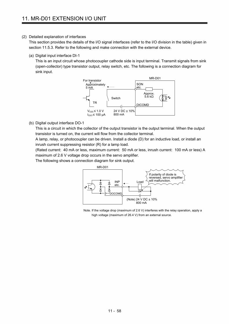
11. MR-D01 EXTENSION I/O UNIT
11 - 58
(2) Detailed explanation of interfaces
This section provides the details of the I/O signal interfaces (refer to the I/O division in the table) given in
section 11.5.3. Refer to the following and make connection with the external device.
(a) Digital input interface DI-1
This is an input circuit whose photocoupler cathode side is input terminal. Transmit signals from sink
(open-collector) type transistor output, relay switch, etc. The following is a connection diagram for
sink input.
Approx.5.6 kΩ
Approximately5 mA
TR
24 V DC ± 10%800 mA
Switch
For transistorSONetc.
MR-D01
DICOMD
VCES ≤ 1.0 VICEO≤ 100 µA
(b) Digital output interface DO-1
This is a circuit in which the collector of the output transistor is the output terminal. When the output
transistor is turned on, the current will flow from the collector terminal.
A lamp, relay, or photocoupler can be driven. Install a diode (D) for an inductive load, or install an
inrush current suppressing resistor (R) for a lamp load.
(Rated current: 40 mA or less, maximum current: 50 mA or less, inrush current: 100 mA or less) A
maximum of 2.6 V voltage drop occurs in the servo amplifier.
The following shows a connection diagram for sink output.
(Note) 24 V DC ± 10%800 mA
If polarity of diode isreversed, servo amplifierwill malfunction.
MR-D01
INPetc.
Load
DOCOMD
Note. If the voltage drop (maximum of 2.6 V) interferes with the relay operation, apply a
high voltage (maximum of 26.4 V) from an external source.

11. MR-D01 EXTENSION I/O UNIT
11 - 59
(3) Analog input
Input impedance
10 kΩ to 12 kΩ
2 kΩOTLA
LG
P15R
SD
Approx.10 kΩ
+15 V DC
Upper limitsetting: 2 kΩ
MR-D01
2 kΩOVC
N12R
P15R
SD
Approx.10 kΩ
+15 V DC
Upper limitsetting: 2 kΩ
MR-D01
Lower limitsetting: 2 kΩ
- 12 V DC
(4) Analog output
Output voltage: ±10 V (Note)Maximum output current: 1 mAResolution: 12 bits or equivalentLG
OMO1(OMO2)
MR-D01
Note. Output voltage range varies depending on the monitored signal. When connecting
analog output to an external device, use the withstand voltage of 15 V DC or higher.

11. MR-D01 EXTENSION I/O UNIT
11 - 60
(5) Source I/O interface
In this servo amplifier, source type I/O interfaces can be used.
(a) Digital input interface DI-1
This is an input circuit in which the anode of the photocoupler is the input terminal. Transmit signals
from a source (open-collector) type transistor output, relay switch, etc.
Approx.5.6 kΩ
24 V DC ± 10%800 mA
Switch
For transistorSONetc.
MR-D01
DOCOMD
Approximately5 mAVCES≤ 1.0 VICEO ≤ 100 µA
TR
(b) Digital output interface DO-1
This is a circuit in which the emitter of the output transistor is the output terminal. When the output
transistor is turned on, the current will flow from the output terminal to a load.
A maximum of 2.6 V voltage drop occurs in the servo amplifier.
(Note) 24 V DC ± 10%800 mA
MR-D01
INPetc.
DOCOMD
Load
If polarity of diode isreversed, servo amplifierwill malfunction.
Note. If the voltage drop (maximum of 2.6 V) interferes with the relay operation, apply a
high voltage (maximum of 26.4 V) from an external source.

11. MR-D01 EXTENSION I/O UNIT
11 - 61
11.6 Monitor display with MR Configurator2
The following shows how to display the input/output monitor with MR Configurator2 when MR-D01 has been
connected.
(1) Initial setting
When MR-D01 has been connected, click "MR-D01" from the "Option unit" menu in the creating new
project window of MR Configurator2.
(2) How to open the optional unit monitor window
Click "Monitor" in the menu bar and "I/O Monitor" from the menu.

11. MR-D01 EXTENSION I/O UNIT
11 - 62
The following window is displayed. Click "Option unit monitor" in the menu bar.
The following window is displayed. The input/output monitor on the MR-D01 side can be checked.

11. MR-D01 EXTENSION I/O UNIT
11 - 63
11.7 Operation
The following items are same as those of MR-J4-_A_-RJ servo amplifiers. For the details of the items, refer
to each chapter/section indicated in the detailed explanation field.
Item Detailed explanation
Startup (except parameter setting) Section 4.1
11.7.1 Operation mode and selecting method
When MR-D01 is used, the following automatic operation modes in the following table can be selected.
Select an operation mode used in the parameter and input device.
Operation mode selection item
Operation mode
[Pr. Po10] setting
Input device setting (Note) Detailed
explanation MD0 SPD1 to
SPD4
Automatic
operation
mode
When using a MR-DS60 digital switch for automatic operation with BCD (3 digits × 2) inputs
_ _ _ 2 On Any
Section 12.6.2
When using a programmable controller for automatic operation with BCD (3 digits × 2) inputs
Section 12.6.3
Note. MD0: Automatic/manual selection, SPD1 to SPD4: Speed selection 1 to 4
11.7.2 When using MR-DS60 (6-digit digital switch) for automatic operation with BCD (3-digit × 2) inputs
POINT
The speed change with the analog override function is enabled in both of the
automatic operation mode and manual operation mode. However, it is disabled
under the following conditions.
During home position return
During deceleration or stop with TSTP (Temporary stop/restart)
Based on the position data set with MR-DS60 (6-digit digital switch) and the selected speed command,
positioning is executed. For a connection example of MR-DS60 (6-digit digital switch) and servo amplifier,
refer to section 11.5.1 (2) (a).

11. MR-D01 EXTENSION I/O UNIT
11 - 64
(1) Parameter setting
Set the parameters to use BCD (3-digit × 2) inputs with [Pr. Po10]. Refer to the following table and set
the parameters as necessary.
No. Name Setting digit Setting item Setting value Setting
[Pr. Po10] Function selection O-1
_ _ _ x Operation method _ _ _ 2
Always set this item. Enable the input/output devices required for BCD input. For the devices to be enabled, refer to section 11.5.2.
x _ _ _ Strobe 2 _ _ _ (initial value)
STRB (Strobe) is not used. Do not change the initial value.
_ x _ _ Sign of the position data for BCD positioning
_ 0 _ _ 6-digit position data without signs (+/-)
_ 1 _ _ (initial value)
6-digit position data with signs (+/-)
[Pr. PT01] Command mode selection
_ _ _ x Positioning command method selection
_ _ _ 0 (initial value)
Absolute value command method
_ _ _ 1 Incremental value command method
[Pr. PT03] Feeding function selection
_ _ _ x Feed length multiplication [STM]
Refer to section 7.2.9.
[Pr. PA14]
Rotation direction selection/ Travel direction selection
Servo motor rotation direction
0 (initial value)
ST1 (Forward rotation start) on: Rotates the servo motor in the CCW direction. ST2 (Reverse rotation start) on: Rotates the servo motor in the CW direction.
1
ST1 (Forward rotation start) on: Rotates the servo motor in the CW direction. ST2 (Reverse rotation start) on: Rotates the servo motor in the CCW direction.
(2) Operation
Set position data with the MR-DS60 (6-digit digital switch) and turn on ST1 (Forward rotation start) to
move the travel distance of the position data in the forward direction with the rotation speed, acceleration
time constant, and deceleration time constant set in the point table selected with SPD1 (Speed selection
1) to SPD4 (Speed selection 4). In the incremental value command method, turning on ST2 (Reverse
rotation start) moves the travel distance in the reverse direction.
Select point tables as follows with SPD1 (Speed selection 1) to SPD4 (Speed selection 4) and execute
the positioning based on the set rotation speed, acceleration time constant, and deceleration time
constant.
In this case, the position data set to the point table is not used.
(Note) Device Selected Point table No. SPD4 SPD3 SPD2 SPD1
0 0 0 1 1
0 0 1 0 2
1 1 0 1 13
1 1 1 0 14
1 1 1 1 15
Note. 0: Off
1: On

11. MR-D01 EXTENSION I/O UNIT
11 - 65
(3) Timing chart
5 ms orlonger
ON
OFFRD (Ready)
ON
OFFMEND (Travel completion)
ON
OFFCPO (Rough match)
ON
OFFINP (In-position)
Servo motor speed
Forwardrotation0 r/min
3 ms or less
Position 1 + Speed 1
ON
OFFMD0 (Automatic/manualselection)
ONSON (Servo-on)
ON
OFFSTRB (Strobe)
Position data BCD(3 digits × 2)
SPD1 (Speed selection 1) toSPD4 (Speed selection 4) Speed 1 (Note 3)
Position 1lower 3 digits
Position 1upper 3 digits
OFF
ON
OFFST1 (Forward rotation start)(Note 1)
4 ms or longer (Note 2)
ON
OFF
ON
OFF
PRQ1 (Position datarequest 1) (Note 4)
PRQ2 (Position datarequest 2) (Note 5)
5 ms orlonger
5 ms or longer(Note 2)
3 ms or longer (Note 2)
5 ms or longer (Note 6)
Note 1. In the incremental value command method, ST2 (Reverse rotation start) can be used. In this case, the timing chart is the
same as the one for ST1.
2. The detection of external input signals is delayed by the time set in the input filter setting of [Pr. PD29]. Considering the
output signal sequence from the controller and signal variations due to hardware, configure a sequence that changes the
position data earlier.
3. The speed command selected in Speed selection 1 (SPD1) to 4 (SPD4)
4. This signal is off when the power is on.
5. This signal is on when the power is on.
6. The lower three digits or upper three digits of the position data is changed with "x _ _ _" of [Pr. Po10 MR-D01 data
establishment condition].

11. MR-D01 EXTENSION I/O UNIT
11 - 66
(4) Temporary stop/restart during automatic operation
When TSTP (Temporary stop/restart) is switched on during automatic operation, the servo motor
decelerates with the deceleration time constant of the point table being executed, and then stops
temporarily. Switching on TSTP (Temporary stop/restart) again restarts the servo motor rotation for the
remaining distance.
During a temporary stop, ST1 (Forward rotation start) or ST2 (Reverse rotation start) does not function
even if it is switched on.
Changing the automatic mode to manual mode during a temporary stop will erase a travel remaining
distance.
The TSTP (Temporary stop/restart) does not function during a home position return or JOG operation.
ONOFF
ONOFF
ONOFF
Servo motorspeed
Deceleration time constantof point table No. 1 (Note)
OFF
OFF
ON
ON
Acceleration time constantof point table No. 1 (Note)
Remainingdistance
OFFON
ST1 (Forward rotation start) orST2 (Reverse rotation start)
BCD input
PUS (Temporary stop)
CPO (Rough match)
INP (In-position)
MEND (Travel completion)
Forwardrotation0 r/minReverserotation
TSTP (Temporary stop/restart)
Note. When SPD1 (Speed selection 1) to SPD4 (Speed selection 4) are used, the
acceleration/deceleration time constants of the point table selected at the start are used.

11. MR-D01 EXTENSION I/O UNIT
11 - 67
11.7.3 When using a programmable controller for automatic operation with BCD (3 digits × 2) inputs
POINT
The speed change with the analog override function is enabled in both of the
automatic operation mode and manual operation mode. However, it is disabled
under the following conditions.
During home position return
During deceleration or stop with TSTP (Temporary stop/restart)
Based on the position data set with the programmable controller and the selected speed command,
positioning is executed. For a connection example of the programmable controller and servo amplifier, refer
to section 11.5.1 (2) (b).
(1) Parameter setting
Set the parameters to use BCD (3 digits × 2) inputs and STRB (Strobe) with [Pr. Po10]. Refer to the
following table and set the parameters as necessary.
No. Name Setting digit Setting item Setting value Setting
[Pr. Po10] Function selection O-1
_ _ _ x Operation method _ _ _ 2
Always set this item. Enable the input/output devices required for BCD input. For the devices to be enabled, refer to section 3.4.
x _ _ _ Strobe 0 _ _ _ Always set this item. When using a programmable controller, STRB (Strobe) is required.
_ x _ _ Sign of the position data for BCD positioning
_ 0 _ _ 6-digit position data without signs (+/-)
_ 1 _ _ (initial value)
6-digit position data with signs (+/-)
[Pr. PT01] Command mode selection
_ _ _ x Positioning command method selection
_ _ _ 0 (initial value)
Absolute value command method
_ _ _ 1 Incremental value command method
[Pr. PT03] Feeding function selection
_ _ _ x Feed length multiplication [STM]
Refer to section 7.2.9.
[Pr. PA14]
Rotation direction selection/ Travel direction selection
Servo motor rotation direction
0 (initial value)
ST1 (Forward rotation start) on: Rotates the servo motor in the CCW direction. ST2 (Reverse rotation start) on: Rotates the servo motor in the CW direction.
1
ST1 (Forward rotation start) on: Rotates the servo motor in the CW direction. ST2 (Reverse rotation start) on: Rotates the servo motor in the CCW direction.

11. MR-D01 EXTENSION I/O UNIT
11 - 68
(2) Operation
Set position data with the programmable controller and turn on ST1 (Forward rotation start) to move the
travel distance of the position data with the rotation speed, acceleration time constant, and deceleration
time constant set in the point table selected with SPD1 (Speed selection 1) to SPD4 (Speed selection 4).
In the incremental value command method, turning on ST2 (Reverse rotation start) moves the travel
distance in the reverse direction.
Select point tables as follows with SPD1 (Speed selection 1) to SPD4 (Speed selection 4) and execute
the positioning based on the set rotation speed, acceleration time constant, and deceleration time
constant.
(Note) Device Selected Point table No. SPD4 SPD3 SPD2 SPD1
0 0 0 1 1
0 0 1 0 2
1 1 0 1 13
1 1 1 0 14
1 1 1 1 15
Note. 0: Off
1: On

11. MR-D01 EXTENSION I/O UNIT
11 - 69
(3) Timing chart
5 ms or longer
ON
OFFRD (Ready)
ON
OFFMEND (Travel completion)
ON
OFFCPO (Rough match)
ON
OFFINP (In-position)
Servo motor speed
Forwardrotation0 r/min
3 ms or less
Position 1 + Speed 1
ON
OFFMD0 (Automatic/manualselection)
ONSON (Servo-on)
ON
OFFSTRB (Strobe)
Position data BCD(3 digits × 2)
SPD1 (Speed selection 1) toSPD4 (Speed selection 4)
Speed 1 (Note 3)
Position 1lower 3 digits
Position 1upper 3 digits
OFF
ON
OFFST1 (Forward rotation start)(Note 1)
5 ms orlonger
5 ms orlonger
4 ms or longer (Note 2)
ON
OFF
ON
OFF
PRQ1 (Position datarequest 1) (Note 4)
PRQ2 (Position datarequest 2) (Note 5)
5 ms orlonger
5 ms or longer(Note 2)
3 ms or longer (Note 2)
Note 1. In the incremental value command method, ST2 (Reverse rotation start) can be used. In this case, the timing chart is the
same as the one for ST1.
2. The detection of external input signals is delayed by the time set in the input filter setting of [Pr. PD29]. Considering the
output signal sequence from the controller and signal variations due to hardware, configure a sequence that changes the
position data earlier.
3. The speed command selected in Speed selection 1 (SPD1) to 4 (SPD4)
4. This signal is off when the power is on.
5. This signal is on when the power is on.

11. MR-D01 EXTENSION I/O UNIT
11 - 70
(4) Temporary stop/restart during automatic operation
When TSTP (Temporary stop/restart) is switched on during automatic operation, the servo motor
decelerates with the deceleration time constant of the point table being executed, and then stops
temporarily. Switching on TSTP again restarts the servo motor rotation for the remaining distance.
During a temporary stop, ST1 (Forward rotation start) or ST2 (Reverse rotation start) does not function
even if it is switched on.
Changing the automatic mode to manual mode during a temporary stop will erase a travel remaining
distance.
The TSTP (Temporary stop/restart) does not function during a home position return or JOG operation.
ONOFF
ONOFF
ONOFF
Servo motorspeed
Deceleration time constantof point table No. 1 (Note)
OFF
OFF
ON
ON
Acceleration time constantof point table No. 1 (Note)
Remainingdistance
OFFON
ST1 (Forward rotation start) orST2 (Reverse rotation start)
BCD input
PUS (Temporary stop)
CPO (Rough match)
INP (In-position)
MEND (Travel completion)
Forwardrotation0 r/minReverserotation
TSTP (Temporary stop/restart)
Note. When SPD1 (Speed selection 1) to SPD4 (Speed selection 4) are used, the
acceleration/deceleration time constants of the point table selected at the start are used.
11.7.4 Home position return in the BCD (3 digits × 2) input operation
The home position return in the BCD (3 digits × 2) input operation is the same as the one in the point table
method. Refer to section 4.4. For the devices, refer to the following table.
Item Device to be used Setting
Home position return mode selection
MD0 (Operation mode selection 1) Switch on MD0.
SPD1 (Speed selection 1) to SPD4 (Speed selection 4)
Turn off SPD1 to SPD4.
ST1 (Forward rotation start) Turn on ST1 for the manual home position return.
ST2 (Reverse rotation start) Turn on ST2 for automatic positioning to the home position.

11. MR-D01 EXTENSION I/O UNIT
11 - 71
11.8 Dimensions
11.8.1 MR-D01 extension I/O unit
[Unit: mm]
(80)
CN20
20
103
98
94
79.5
161
114.
55
97
24.5
CN30
CN10
11.8.2 When an MR-D01 extension IO unit is connected to a servo amplifier
Servo amplifierServo amplifier
L
L
MR-D01 MR-D01
100 V/200 V 0.1 kW to 3.5 kW400 V 0.6 kW to 2 kW
200 V 5 kW/7 kW400 V 3.5 kW to 7 kW
Servo amplifier L [mm]
MR-J4-10A1-RJ to MR-J4-40A1-RJ MR-J4-10A-RJ to MR-J4-100A-RJ MR-J4-60A4-RJ to MR-J4-100A4-RJ
20
MR-J4-200A-RJ/MR-J4-350A-RJ MR-J4-200A4-RJ
15
MR-J4-500A-RJ/MR-J4-700A-RJ MR-J4-350A4-RJ to MR-J4-700A4-RJ
10
MR-J4-11KA-RJ to MR-J4-22KA-RJ MR-J4-11KA4-RJ to MR-J4-22KA4-RJ
0

11. MR-D01 EXTENSION I/O UNIT
11 - 72
11.9 Options and peripheral equipment
11.9.1 Combinations of cable/connector sets
Servo amplifier
CN30
CN20
CN10
MR-D01
Digital switch
5)
1)
6)
2)
3)
7)
4)
CN5
CN6
CN3
CN8
CN1
CN2
CN4
No. Product name Model Description Application
1) Connector set MR-CCN1
Connector: 10120-3000PE Shell kit: 10320-52F0-008 (3M or equivalent)
2) Connector set MR-J3CN1
Connector set: 10150-3000PE Shell kit: 10350-52F0-008 (3M or equivalent)
3) Digital switch cable
MR-DSCBL_M-G
Refer to section 11.5.1 (2) (a) and 11.9.2 for details.
For digital switch
4) Digital switch cable
MR-DSCBL_
Refer to section 11.5.1 (2) (a) and 11.9.2 for details.
For digital switch junction
5) Junction terminal block (recommended)
MR-J2HBUS_M
PS7DW-20V14B-F(Toho Technology Corp.)
Junction terminal block PS7DW-20V14B-F is not option. For using the junction terminal block, option MR-J2HBUS_M is necessary. Refer to section 11.9.3 for details.
6) Junction terminal block Cable
MR-J2M-CN1TBL_M Cable length: 0.5/1 m (Refer to section 11.9.4.)
Junction terminal block connector Connector: D7950-B500FL (3M)
CN10 connector Connector: 10150-6000EL Shell kit: 10350-3210-000 (3M or equivalent)
For junction terminal block connection
7) Junction terminal block
MR-TB50 Refer to section 11.9.4.

11. MR-D01 EXTENSION I/O UNIT
11 - 73
11.9.2 MR-DS60 (6-digit digital switch)
Position data can be provided with BCD signals by using MR-DS60 (6-digit digital switch). For the
connection of MR-DS60 and MR-D01, refer to section 11.5.1 (2) (a).
(1) Parameter setting
When using MR-DS60, set [Pr. Po10] to "2 _ 0 2".
MR-D01 DI0 to DI14 input signal device selection2: 3-digit BCD × 2 inputs
2 0[Pr. Po10]
2
MR-D01 position data input sign (+/-)0: Disabled
+/- sign is not used.1: Enabled
MR-D01 data establishment condition2: 3.55 ms data matching time (Strobe signal disabled)
+/- sign is used.
(2) Specifications of MR-DS60
Item Specifications
Model MR-DS60
Number of digits Signed 6-digit BCD
Electrical characteristics
28 V DC (0.5 A)
Withstand voltage 500 Vr.m.s
Contact resistance 100 mΩ or lower
Life 1,000,000 times
Temperature range for operation
0 °C to 60 °C
Storage temperature
-5 °C to 70 °C
(3) Digital switch cable
Use the following digital switch cables and connect them with MR-D01.
Cable model Cable length
Application 0.25 m 1 m 3 m 5 m 10 m
MR-DSCBL_M-G 3 5 10 Between MR-DS60 and MR-D01
MR-DSCBL_ 25 100 Between MR-DS60 and MR-DS60

11. MR-D01 EXTENSION I/O UNIT
11 - 74
(4) Terminal assignment
CON1, CON2 Signal
name Pin No. Description
DCM2
COM2
DCM1
COM1
TB
DO04 9A Common output 1 sign, ×1000,
×10000,
10B 10A Common output on ×100000 side
DO04 DO05 DO05 9B Common output 2 signs, ×1, ×10,
×100 side
Common output
DI03 DI02 DI00 6A ×1, ×1000 bit 0
DI01 DI00 DI01 6B ×1, ×1000 bit 1
DI07 DI06 DI02 7A ×1, ×1000 bit 2
DI05 DI04 DI03 7B ×1, ×1000 bit 3
DI11 DI10 DI04 4A ×10, ×10000 bit 0
DI09 DI08 DI05 4B ×10, ×10000 bit 1 Signal
name Description
1B DI13 DI12 1A DI06 5A ×10, ×10000 bit 2 DCM2 Common input 2
DI07 5B ×10, ×10000 bit 3 Connect this signal with COM2 at
block selection.
DI08 2A ×100, ×100000 bit 0 COM2 Common output 2
DI09 2B ×100, ×100000 bit 1 Common 2 at switching multi steps
DI10 3A ×100, ×100000 bit 2 DCM1 Common input 1
DI11 3B ×100, ×100000 bit 3 Connect this signal with COM1 at
block selection.
DI12 1A Sign bit 0+ COM1 Common output 1
DI13 1B Sign bit 1- Common 1 at switching multi steps
(5) Dimensions
[Unit: mm]
100
5 50
93
46
80
37
9.5
9.5
9.5
14.8
1.6
3.5
28.4
1.6
52

11. MR-D01 EXTENSION I/O UNIT
11 - 75
(6) Mounting
[Unit: mm]
Front installation Internal installation
Panel cut
2 × φ5
85
48
68
34
93
Square holeSquare hole
Panel cut
2 × φ5
93

11. MR-D01 EXTENSION I/O UNIT
11 - 76
11.9.3 PS7DW-20V14B-F (Junction terminal block) (recommended)
(1) Usage
Always use the PS7DW-20V14B-F (Junction terminal block) (Yoshida Electric Industry)) with the option
cable (MR-J2HBUS_M) as a set. A connection example is shown below.
AERSBAN-ESET(Cable clamp fitting)
PS7DW-20V14B-F(Junction terminal block)
CN20MR-J2HBUS_M
MR-D01
Ground the option cable on the junction terminal block side with AERSBAN-ESET (cable clamp fitting).
For how to use the cable clamp fitting, refer to section 11.14 (2) (c) of "MR-J4-_A_(-RJ) Servo Amplifier
Instruction Manual".
(2) Connection of MR-J2HBUS_M cable and junction terminal block
OVC
1
2
3
4
8
7
9
SD Shell
(Note 1) MR-J2HBUS_M
5
6
10
LG
OTLA
11
12
P15R 13
14
18
17
19
15
16
20
N12R
Shell Shell Shell
1
2
3
4
8
7
9
5
6
10
11
12
13
14
18
17
19
15
16
20
1
2
3
4
8
7
9
5
6
10
11
12
13
14
18
17
19
15
16
20
1
2
3
4
8
7
9
5
6
10
11
12
13
14
18
17
19
15
16
20
OVC
SD
LG
OTLA
P15R
N12R
E
MR-D01
CN20
PS7DW-20V14B-F(Junction terminal block)
Connector: 10120-6000EL (3M)Shell kit: 10320-3210-000 (3M)
CN (Note 2) Terminal block
1
2
3
4
8
7
9
5
6
10
11
12
13
14
18
17
19
15
16
20
OMO1
LG
OMO2
OMO1
LG
OMO2
Note 1. Symbol indicating cable length is put in _.
05: 0.5 m
1: 1 m
5: 5 m
2. Do not connect anything to the terminal where no signal has been assigned.

11. MR-D01 EXTENSION I/O UNIT
11 - 77
(3) Dimensions of junction terminal block
[Unit: mm]
M3 × 6L
M3 × 5L
36.5
27.8
18.8
7.62
44.11
54
63
φ4.5
4.5
5
460509.3
27
TB.E (φ6)
1.426.2

11. MR-D01 EXTENSION I/O UNIT
11 - 78
11.9.4 MR-TB50 (Junction terminal block)
(1) Usage
Always use MR-TB50 (Junction terminal block) with MR-J2M-CN1TBL_M (Junction terminal block cable)
as a set.
MR-D01
CN10
Junction terminal blockMR-TB50
MR-J2M-CN1TBL_M
Cable clamp
Ground the junction terminal block cable on the junction terminal block side with the supplied
AERSBAN-ESET (cable clamp fitting). For how to use the cable clamp fitting, refer to section 11.14 (2)
(c) of "MR-J4-_A_(-RJ) Servo Amplifier Instruction Manual".
(2) Dimensions of MR-TB50
235
50
25A
ppro
x.25
9
21
5049
[Unit: mm]
MITSUBISHIMR-TB50
2-φ4.5
Terminal screw: M3.5Applicable wire: 2 mm2
Crimp terminal width: 7.2 mm or less
244 2.5
46.5
1 3 5 7 9 1113 15 1719 212325 2729 3133
2 4 6 8 1012141618 20 2224 262830 32
35 3739 4143 454749
34363840 4244 4648 50

11. MR-D01 EXTENSION I/O UNIT
11 - 79
(3) Connection diagram of MR-J2M-CN1TBL_M cable and MR-TB50
The following connection diagram shows BCD input as an example.
SDSD Plate
Symbol
(Note 1)MR-J2M-CN1TBL_M
CN10
123456789
1011121314151617181920212223242526272829303132333435363738394041424344454647484950
MR-D01
1234567891011121314151617181920212223242526272829303132333435363738394041424344454647484950
MR-TB50
DOCOMD
PUSMENDCPOINP
POS00
POS02POS03POS10POS11POS12POS13
DICOMDPOSP
SP1
POSNSTRBSP0
POS01123456789
1011121314151617181920212223242526272829303132333435363738394041424344454647484950
1234567891011121314151617181920212223242526272829303132333435363738394041424344454647484950
(Note 2)Terminal block
D7950-B500FL10150-6000EL
PRQ2PRQ1
ST2ST1PC
TSTPMD0OVRTP1TP0TL1TL
RESACD3ACD2ACD1ACD0SONSP2
DICOMD
POS20POS21POS22POS23
Note 1. Symbol indicating cable length is put in _.
05: 0.5 m
1: 1 m
2. Do not connect anything to the terminal where no signal has been assigned.

11. MR-D01 EXTENSION I/O UNIT
11 - 80
MEMO

12. APPLICATION OF FUNCTIONS
12 - 1
12. APPLICATION OF FUNCTIONS
This chapter explains about application of using positioning function of servo amplifier.
CAUTION
Note that the number of write times to the Flash-ROM where the cam data is
stored is limited to approximately 1000. If the total number of write times exceeds
1000, the servo amplifier may malfunction when the Flash-ROM reaches the end
of its useful life.
12.1 Simple cam function
POINT
The simple cam function is available with servo amplifiers with software version
B7 or later.
The simple cam function can be used with the point table method and the
program method.
This function is not available with the servo amplifier to which the MR-D30 unit
has been connected.
12.1.1 Outline of simple cam function
Simple cam function enables synchronous control by using software instead of controlling mechanically with
cam.
The following shows a movement trajectory when the cam below is used and the input axis is rotated once.
Output axis
Input axis
28
13 7
4
5
6
Cam strokeamount
Bottom deadcenter
Input axis
Cam onecyclelength
0
360°
Cam axis onecycle currentvalue
Feed currentvalue
1 2 3 4 5 6 7 8 1
Cam axis one cycle
0° 45° 90° 135° 180° 225° 270° 315° 360°
Output axis
Cam strokeamount
By setting cam data and cam control data, the simple cam function enables synchronous control with an
input axis (external pulse command input, point table command, or program positioning command) with a
start of positioning.
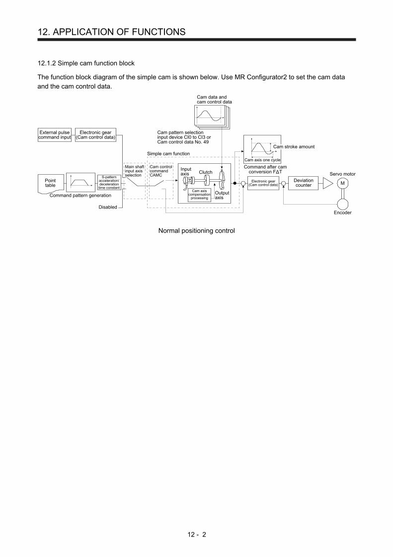
12. APPLICATION OF FUNCTIONS
12 - 2
12.1.2 Simple cam function block
The function block diagram of the simple cam is shown below. Use MR Configurator2 to set the cam data
and the cam control data.
External pulsecommand input
Pointtable
Command pattern generation
Disabled
S-patternacceleration/decelerationtime constant
Electronic gear(Cam control data)
Main shaftinput axisselection
Cam controlcommandCAMC
Cam data andcam control data
Cam axis one cycle
Command after camconversion FΔT
Cam pattern selectioninput device CI0 to CI3 orCam control data No. 49
Simple cam function
Inputaxis
Cam axiscompensation
processingOutputaxis
Clutch
Deviationcounter M
Servo motor
Encoder
Cam stroke amount
Electronic gear(Cam control data)
Normal positioning control

12. APPLICATION OF FUNCTIONS
12 - 3
12.1.3 Control of simple cam function
The following three cam controls are available by setting the cam data and the cam control data with MR
Configurator2.
Cam control method
Description Actual movement
To-and-fro control
Reciprocates within a specified cam stroke.
t
t
Cam data and camcontrol data
(Cam created by users)
Cam axis onecycle currentvalue (Input)
Cam conversionprocessing
Feed currentvalue (Output)
Feed control
Updates a cam standard position per cycle.
t
t
Cam data and camcontrol data
(Cam created by users)
Cam standardposition(First cycle)
Cam standardposition(Second cycle)
Cam standardposition(Third cycle)
Cam axis onecycle currentvalue (Input)
Cam conversionprocessing
Feed currentvalue (Output)
Linear control
Performs linear control to keep one-cycle ratio as 100%.
t
t
Cam data and camcontrol data
(Linear cam: Cam No. 0)Cam standardposition(First cycle)
Cam standardposition(Second cycle)
Cam standardposition(Third cycle)
Stroke amount × 100%
Cam axis onecycle currentvalue (Input)
Cam conversionprocessing
Feed currentvalue (Output)

12. APPLICATION OF FUNCTIONS
12 - 4
The feed current value of the cam axis is calculated as follows:
(1) Stroke ratio data type
Feed current value = Cam standard position + (Cam stroke amount × Stroke ratio to cam axis one cycle
current value)
(2) Coordinate data type
Feed current value = Cam standard position + Output value to cam axis one cycle current value
When the cam axis one cycle current value is in the middle of the specified stroke ratio data, the
intermediate value is calculated using the cam data before and after the value.
Cam axis onecycle currentvalue
Cam data
Resolution unitor between 2
An intermediatevalue is calculatedusing the data beforeand after the value
12.1.4 Simple cam specification list
(1) Specification list
Item MR-J4-_A
Memory capacity (Note 1)
Storage area for cam data
8 Kbytes (Flash-ROM)
Working area for cam data
8 Kbytes (RAM) (Note 2)
Number of registration Max. 8
Comment Max. 32 single-byte characters for each cam data
Cam data and cam control data
Stroke ratio data type
Cam resolution 256/512/1024/2048
Stroke ratio -100.000 to 100.000 [%]
Coordinate data type
Number of coordinate
2 to 1024
Coordinate data Input value: 0 to 999999 Output value: -999999 to 999999
Cam curve
12 types (constant speed/constant acceleration/5th curve/single hypotenuse/cycloid/distorted trapezoid/distorted sine/distorted constant speed/trapecloid/reverse trapecloid/double hypotenuse/reverse double hypotenuse)
Note 1. The memory capacity includes a use area (storage area for cam data) for storing in the servo
amplifier and an actual operation area (working area for cam data).
2. This can be always changed by using Modbus-RTU communication during servo-off.

12. APPLICATION OF FUNCTIONS
12 - 5
(2) Cam resolution
(a) Stroke ratio data type
Cam resolution Max. number of
registration
256 8
512 4
1024 2
2048 1
(b) Coordinate data type
Number of coordinate
Max. number of registration
128 8
256 4
512 2
1024 1
12.1.5 Operation in combination with the simple cam
(1) Encoder following function
The servo amplifier receives A/B-phase output signal from a synchronous encoder and starts the servo
motor with the signal.
Up to 4 Mpulses/s of input from synchronous encoder is compatible with the servo amplifier.
The current position of the conveyor axis isused as the input axis for driving the rotaryknife axis.
A/B-phase pulse train
Cam control
Cam axis
Axis 1
Synchronous encoder
Conveyor axis Rotary knife axis
Servo motor
Inverter
(Drives conveyor axis by speed control)

12. APPLICATION OF FUNCTIONS
12 - 6
(2) Mark sensor input compensation function
The servo amplifier receives input signals from a mark sensor, calculates compensation amounts, and
corrects position errors of the rotary knife axis.
2) Calculates a compensation amount in the servo amplifier Compensation amount calculation
The compensation amount iscalculated from the differencebetween the original sensor inputposition set to the cam control dataand the cam axis one cycle currentvalue.
Synchronousencoder
1) Turns on the cam position compensation request by detection of mark sensorMark sensor
Conveyor axis Rotary knife axis
Inverter
Cutting length set
(Drives conveyor axis by speed control)
Axis 1
Mechanism of cam position compensation
Conveyor axisCompensation isperformed in responseto the compensationexecution request.Compensation axis(only forcompensation)
The compensation amount is smoothedwith time constant and added to theconveyor axis input.
Compensation time constant
Rotary knifeaxis
Item Specifications
Number of mark detection setting
One setting (one input)
Input signal detection direction
Detected by rising edge of an external input signal
Detection accuracy (compensation cycle)
Max. 888 μs

12. APPLICATION OF FUNCTIONS
12 - 7
(3) Synchronous operation using positioning data
A synchronous operation is enabled by setting the same positioning data and starting the positioning
simultaneously. For example, to synchronize the vertical motion of the vertical axis (axis 2) with the
position of the horizontal axis (axis 1), input the positioning commands for axis 1 to axis 2 as well.
Flow of belt conveyors
Line
Axis 2 (vertical axis)
Robot
Axis 1 (horizontal axis)
Servomotorspeed
Perform the simultaneousstart with DI input orModbus-RTUcommunicationcommands.Point table setting
Set the same point table for the axis1 and 2.
(Note)
Cam data created byusers and cam controldata
Commandposition
Commandposition
Axis 1 operation (normal positioning)
Cam axis one cycle length
Positioningcontrol
Start the axis 1and 2 simultaneously.
Cam control
Axis 1
Axis 2
Axis 2 moves vertically synchronized withthe reciprocating operation of axis 1. The backand forth motions are symmetrical.
Axis 2 operation (cam operation)
Note. Input the same positioning commands (point table data) to the driven shaft (axis 2) as those for the main shaft (axis 1).

12. APPLICATION OF FUNCTIONS
12 - 8
(4) Operation example of synchronous interpolation between two axes
To move a part from point P1 to P3 making a detour to avoid work A, axis 2 starts moving after the travel
completion signal of axis 1 is checked at point P2. However, by using the cam control, checking of the
travel completion signal is not necessary, shortening the positioning time.
P3
P2
P1
Axis 1
Workpiece A
Axis 2
Axis 1 Motor speed
• Conventional operation
• Operation with the cam
Axis 1 Travelcompletion signal
Axis 2 Motor speed
Axis 1 Motor speed
Axis 2 Motor speed
Time can be shortened.
Cam dataand camcontrol data
Cam dataand camcontrol data
Axis 1 Start
Axis 1 Start
Axis 2 Start
Axis 2 StartCam axis one cycle length
(5) Cam data transmission through Modbus-RTU
Rewriting cam data is possible by transmitting the cam data through Modbus-RTU communication if over
eight cam data exceeding the maximum number of registration need to be used. In this case, be sure to
rewrite the cam data in servo-off state.
12.1.6 Setting list
(1) List of items set with MR Configurator2
Set the following on the cam setting window of MR Configurator2.
Setting item Setting
Cam control data
Main shaft input axis selection
Select a command input method for the cam axis. Select from "Encoder following (external pulse input)" and "Internal point table".
Cam No. selection
Select the number to create the cam control data.
Resolution setting
Set the cam resolution. Select from 256/512/1024/2048.
Cam axis one cycle length
Set a travel amount of cam one cycle. Command unit is used as an input unit.
Cam stroke amount
Set a cam stroke amount for the stroke ratio of 100% when using the stroke ratio data type cam control.
Cam data Create the cam data on the cam creating window of MR Configurator2. After the data is created, write the cam data to the servo amplifier.
(2) List of items set with parameters of the servo amplifier
Set the following with the parameters of the servo amplifier.
Setting item Setting
Operation mode selection Select "Positioning mode (point table method or program method)" with [Pr. PA01 Operation mode].
Cam function setting Enable the cam function with [Pr. PT35 Function selection T-5].
Cam data selection Select the cam data to be executed with CI0 (Cam No. selection 0) to CI3 (Cam No. selection 3). Selecting the cam data for execution is also possible with "Cam control data No. 49 Cam No.".
Device setting Assign CAMC (Cam control command input), CAMS (Output in cam control), and CI0 (Cam No. selection 0) to CI3 (Cam No. selection 3) with I/O setting parameters ([Pr. PD_ _ ]).
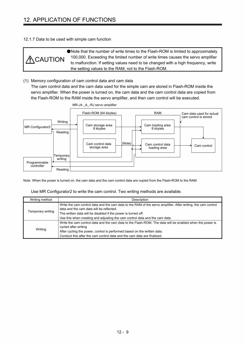
12. APPLICATION OF FUNCTIONS
12 - 9
12.1.7 Data to be used with simple cam function
CAUTION Note that the number of write times to the Flash-ROM is limited to approximately
100,000. Exceeding the limited number of write times causes the servo amplifier
to malfunction. If setting values need to be changed with a high frequency, write
the setting values to the RAM, not to the Flash-ROM.
(1) Memory configuration of cam control data and cam data
The cam control data and the cam data used for the simple cam are stored in Flash-ROM inside the
servo amplifier. When the power is turned on, the cam data and the cam control data are copied from
the Flash-ROM to the RAM inside the servo amplifier, and then cam control will be executed.
Cam data used for actualcam control is stored
MR-J4-_A_-RJ servo amplifier
Reading
Flash-ROM (64 kbytes) RAM
Cam storage area8 kbytes
Cam loading area8 kbytes
Cam control datastorage area
Cam control dataloading area
Cam control
Writing
MR Configurator2
Programmablecontroller
Reading
Temporarywriting
(Note)
Note. When the power is turned on, the cam data and the cam control data are copied from the Flash-ROM to the RAM.
Use MR Configurator2 to write the cam control. Two writing methods are available.
Writing method Description
Temporary writing
Write the cam control data and the cam data to the RAM of the servo amplifier. After writing, the cam control data and the cam data will be reflected. The written data will be disabled if the power is turned off. Use this when creating and adjusting the cam control data and the cam data.
Writing
Write the cam control data and the cam data to the Flash-ROM. The data will be enabled when the power is cycled after writing After cycling the power, control is performed based on the written data. Conduct this after the cam control data and the cam data are finalized.

12. APPLICATION OF FUNCTIONS
12 - 10
(2) Cam data and cam control data
The following two types are available for the cam data and cam control data.
Cam data and cam control data type
Description
Stroke ratio data type Cam curve of one cycle is divided equally by the number of cam resolution and defined. The cam curve will be created according to the stroke ratio data of the number of cam resolution.
Coordinate data type Data in which cam curve of one cycle is defined with two or more points. The coordinate data is defined as "(input value, output value)". The input value will be the cam axis one cycle current value, and the output value will be the stroke value from the cam standard position.
(a) Stroke ratio data type
The following are set in the stroke ratio data type.
Set these on the cam setting window of MR Configurator2.
Setting item Setting Setting range
Cam No. Set a Cam No. 0: Linear cam
1 to 8: User-created cam
Cam data and cam control data type
Set "1: Stroke ratio data type".
Cam resolution Set the number of divisions for the cam curve of one cycle. Select from
256/512/1024/2048.
Cam data and cam control data start position
Set the positions of the cam data and cam control data to the position of when "Cam axis one cycle current value" is "0".
0 to "Cam resolution - 1"
Stroke ratio data Set the stroke ratio from the first to the last point. -100.000 to 100.000
The following shows a setting example for "cam resolution = 512" in the stroke ratio data type.
100.000
-100.000
0
Cam axis one cycle length [Cam axis cycle unit]
Stroke ratio [%] (Can be set within the range of -100.000% and 100.000%)
(Cam standardposition)
Zeroth point 512th point(Last point)
0

12. APPLICATION OF FUNCTIONS
12 - 11
(b) Coordinate data type
The following are set in the coordinate data type. Set these on the cam setting window of MR
Configurator2.
Setting item Setting Setting range
Cam No. Set a Cam No. 0: Linear cam
1 to 8: User-created cam
Cam data and cam control data type
Set "2: Coordinate data type".
Number of coordinate Set the number of coordinates for the cam curve of one cycle. The number of coordinates includes 0th point.
2 to 1024
Cam data and cam control data start position
Setting is not necessary.
Coordinate data
Set the coordinate data as "(input value Xn, output value Yn)" for the number of coordinates. Set from the 0th coordinate data as "(X0, Y0)". Set an input value larger than that of the coordinate data.
-999.999 to 999.999
The following is a setting example for the coordinate data type.
999.999
-999.999
Output value: Y[Output axis position unit]
Input value: X(X0,Y0)
(X1,Y1)
(X2,Y2)
(X3,Y3)
(X4,Y4)
(X5,Y5)(X9,Y9)
(X10,Y10)
(X6,Y6)(X7,Y7)
(X8,Y8)
Cam axis one cycle length [Cam axis cycle unit]
0(Cam standard
position)
If "input value = 0" and "input value = cam axis one cycle length" are not set in the coordinate data, a
control is executed by the line connecting the closest two points.
999.999
-999.999
Output value: Y[Output axis position unit]
Input value: X
(X0,Y0)(X1,Y1)
(X2,Y2)
(X3,Y3)
(X4,Y4)
(X5,Y5)(X9,Y9)
(X10,Y10)
(X6,Y6)(X7,Y7)
(X8,Y8)
Cam axis one cycle length [Cam axis cycle unit]
0(Cam standard
position)
Line created by connecting(X0, Y0) and (X1, Y1)
Line created by connecting(X9, Y9) and (X10, Y10)

12. APPLICATION OF FUNCTIONS
12 - 12
12.1.8 Function block diagram for displaying state of simple cam control
CDV
CMXECDV
ECMX+
-
+
- M
Input pulse ofsynchronousencoder
Point tablecommand
Servo motor
Encoder
Clutch
Cam positioncompensation
processing
Camconversionprocessing
Cam axis one cycle current valueCam standard positionCam axis feed current valueCam stroke amount in execution
Cam No. in executionMain axis current valueMain axis one cyclecurrent value
12.1.9 Operation
For operation method, contact your local sales office.

12. APPLICATION OF FUNCTIONS
12 - 13
12.2 Mark detection
12.2.1 Current position latch function
POINT
The current position latch function can be used with the point table method and
the program method. However, the current position latch function is disabled in
the following condition.
Home position return
Manual operation (excluding home position return)
The latched actual current position data can be read with communication
commands.
For the servo amplifiers with software version B6 or earlier, the latched position
data is not compatible with the current position of the state monitor when the roll
feed display function is enabled. Disable the roll feed display function to
compare the current data of the state monitor and the latched position data.
For the servo amplifiers with software version B7 or later, the read latched
position data is equal to the travel distance as the starting point is set to "0"
when the roll reed display function is enabled. The output value is the same as
the current position of the state monitor.
When the mark detection signal turns on, the current position is latched. The latched data can be read with
communication commands.
(1) Communication command
Reads mark detection data.
Command Data No. Description
Control mode
Frame length
CP
/BC
D
CL
PS
[1] [A] [0] [0] MSD (Mark detection) rising latch data (data part) 8
[0] [1] MSD (Mark detection) falling latch data (data part)
[0] [2] MSD (Mark detection) rising latch data (data part + additional information) 12
[0] [3] MSD (Mark detection) falling latch data (data part + additional information)

12. APPLICATION OF FUNCTIONS
12 - 14
(2) Reading data
(a) Rising latch data or falling latch data (data part)
Reads MSD (Mark detection) rising latch data or MSD (Mark detection) falling latch data.
1) Transmission
Transmit command [1] [A] and latch data No. to be read [0] [0] or [0] [1]. Refer to section 10.1.1.
2) Return
The slave station returns the requested latch data.
Data will be received in hexadecimal per set command.Hexadecimal should be changed to decimal.ExampleData "000186A0" will be 100.000 mm in the command-side unit.A decimal point position depends on setting contents of [Pr. PT01] and [Pr. PT03].
(b) Rising latch data or falling latch data (data part + additional information)
Reads MSD (Mark detection) rising latch data or MSD (Mark detection) falling latch data.
1) Transmission
Transmit command [1] [A] and latch data No. to be read [0] [2] or [0] [3]. Refer to section 10.1.1.
2) Return
The slave station returns the requested latch data.
Data will be received in hexadecimal per set command.Hexadecimal should be changed to decimal.ExampleData "0040000186A0" will be 100.000 mm in the command-side unit.Decide the decimal point position with [Pr. PT01] and [Pr. PT03].
Display type0: Data must be converted into decimal.1: Data is used unchanged in hexadecimal.
Decimal point position0: No decimal point1: First least significant digit (not used normally)2: Second least significant digit3: Third least significant digit4: Forth least significant digit5: Fifth least significant digit

12. APPLICATION OF FUNCTIONS
12 - 15
(3) Parameter
Set the parameters as follows:
Item Parameter to be used Setting
Mark detection function selection
[Pr. PT26] Set the mark detection function selection as follows: 0 _ _ _: Current position latch function
Mark detection range + (lower three digits)
[Pr. PC66]
Set the upper limit of the latch data in the current position latch function. When the roll feed display is enabled, set this value with the travel distance from the starting position. Set the same sign for [Pr. PC66] and [Pr. PC67]. A different sign will be recognized as minus sign data. When changing the direction to address decreasing, change it from the - side of the mark detection ([Pr. PC68] and [Pr. PC69]). An incorrect order of the setting will trigger [AL. 37]. Therefore, cycling power may be required after [Pr. PC66] to [Pr. PC69] are all set. This parameter setting is available with servo amplifiers with software version B7 or later.
Mark detection range + (upper three digits)
[Pr. PC67]
Mark detection range - (lower three digits)
[Pr. PC68]
Set the lower limit of the latch data in the current position latch function. When the roll feed display is enabled, set this value with the travel distance from the starting position. Set the same sign for [Pr. PC68] and [Pr. PC69]. A different sign will be recognized as minus sign data. When changing the direction to address increasing, change it from the + side of the mark detection ([Pr. PC66] and [Pr. PC67]). An incorrect order of the setting will trigger [AL. 37]. Therefore, cycling power may be required after [Pr. PC66] to [Pr. PC69] are all set. This parameter setting is available with servo amplifiers with software version B7 or later.
Mark detection range - (upper three digits)
[Pr. PC69]

12. APPLICATION OF FUNCTIONS
12 - 16
(4) Latch data range setting
The current position is latched only within the range set in [Pr. PC66] to [Pr. PC69]. (The valid range
includes the upper limit value and lower limit value set to the parameters.)
When a same value is set for the upper and lower limits, the current value will be latched for a whole
range.
(a) mm, inch, and pulse unit
The current position latch function is enabled when Upper limit value > Lower limit value. The valid
range is the same for the absolute value command method ([Pr. PT01]: _ _ _ 0) and the incremental
value command method ([Pr. PT01]: _ _ _ 1).
[AL. 37 occurs] when Upper limit value < Lower limit value.
-999999 99999
Lower limit value Upper limit value
1) When the roll feed display is disabled ([Pr. PT26]: _ _ 0 _)
Set the valid range with the distance from the home position.
When the starting position is at 100000, [Pr. PC66] and [Pr. PC67] are set to 500000, and [Pr.
PC68] and [Pr. PC69] are set to 300000, the valid range is between the actual current position of
300000 and 500000 as set in the parameters.
100000 90000300000 5000000
Lower limit value Upper limit value
Homeposition
Startposition
Target position
Actual currentposition
2) When the roll feed display is enabled ([Pr. PT26]: _ _ 1 _)
When the roll feed display is enabled, the valid range is calculated as the starting position is 0.
Set the valid range with the travel distance from the starting position.
When the starting position is at 100000, [Pr. PC66] and [Pr. PC67] are set to 500000, and [Pr.
PC68] and [Pr. PC69] are set to 300000, the valid range is between the feed current position of
300000 and 500000 from the start position (between the actual current position of 400000 and
600000).
100000 90000300000 500000
0 400000 600000800000
Lower limit value Upper limit value
Homeposition
Start position Target position
Actual current positionFeed current position

12. APPLICATION OF FUNCTIONS
12 - 17
(b) Degree unit
When the unit is set to [degree], the setting range of the current position latch is from 0 degree
(upper limit) to 359.999 degrees (lower limit).
When you set a value other than 0 degree to 359.999 degrees in the current position latch +/- [Pr.
PC66] to [Pr. PC69], the set value is converted as follows.
Current position latch range After conversion
360.000 degrees to 999.999 degrees (Setting value) % 360
-0.001 degrees to -359.999 degrees 360 + (setting value)
-360.000 degrees to -999.999 degrees (setting value) % 360 + 360
The valid range of the current position latch varies depending on the setting of the upper and lower
limits.
The valid range remains unchanged even if the rotation direction is reversed.
90
0
270
CCW
180
Effective range
Lower limitvalue
Upper limitvalue
90
0
270
CCW
180
Effective rangeUpper limit
value
Lower limitvalue
Upper limit value > Lower limit value Lower limit value > Upper limit value
To enable the current position latch function of section A in the figure, set the parameters as follows:
Current position latch range -: 315.000 degrees ([Pr. PC68]: 0, [Pr. PC69]: 315)
Current position latch range +: 90.000 degrees ([Pr. PC66]: 0, [Pr. PC67]: 90)
To enable the current position latch function of section B in the figure, set the parameter as follows:
Current position latch range -: 90.000 degrees ([Pr. PC68]: 0, [Pr. PC69]: 90)
Current position latch range +: 315.000 degrees ([Pr. PC66]: 0, [Pr. PC67]: 315)
0
CCW
90
315
Section B
Section A

12. APPLICATION OF FUNCTIONS
12 - 18
(5) Timing chart
Device falling position data
MSD (Mark detection)
MSDH(Mark detection rising latchcompleted)MSDL(Mark detection falling latchcompleted)
Device rising position data
Current position data
Within 5 ms (Note 1)Within 5 ms (Note 1)
Within 3 ms
Within 3 ms
0 A E
0 B F
AB E F
ONOFF
ONOFF
ONOFF
Latch data rangeUpper limit value
Latch data rangeLower limit value
0.4 ms or longerDisabled(Note 2)
Disabled(Note 2)
Not changed Not changed
C D
(Note 3)
Note 1. When MSD (Mark detection) is assigned to the CN1-10 pin with [Pr. PD44], current position data can be obtained in high
speed (within 0.4 ms). When assigning MSD (Mark detection) to the CN1-10 pin, set "Mark detection fast input signal filter
selection" in [Pr. PD31].
2. The position data will not be changed from the previous value.
3. MSDH (Latch completed at rising edge of mark detection) turns off at the same timing as MSDL (Latch completed at falling
edge of mark detection) turns on. Set as MSDL turns on/off within the range of the latch data.
If MSD (Mark detection) was turned on again when the previous falling was out of the valid range,
MSDH (Latch completed at rising edge of mark detection) will not change, but the position data will be
updated. Refer to the following timing chart.
0 A
A
B
C D
C
D0Device falling position data
MSD (Mark detection)
MSDH(Mark detection rising latchcompleted)MSDL(Mark detection falling latchcompleted)
Device rising position data
Current position data
ONOFF
ONOFF
ONOFF
Latch data rangeUpper limit value
Latch data rangeLower limit value
Not changed
Not changed
Disabled
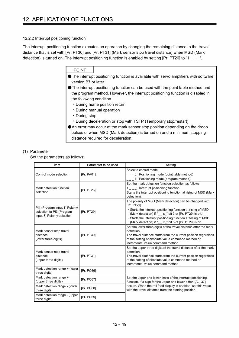
12. APPLICATION OF FUNCTIONS
12 - 19
12.2.2 Interrupt positioning function
The interrupt positioning function executes an operation by changing the remaining distance to the travel
distance that is set with [Pr. PT30] and [Pr. PT31] (Mark sensor stop travel distance) when MSD (Mark
detection) is turned on. The interrupt positioning function is enabled by setting [Pr. PT26] to "1 _ _ _".
POINT
The interrupt positioning function is available with servo amplifiers with software
version B7 or later.
The interrupt positioning function can be used with the point table method and
the program method. However, the interrupt positioning function is disabled in
the following condition.
During home position return
During manual operation
During stop
During deceleration or stop with TSTP (Temporary stop/restart)
An error may occur at the mark sensor stop position depending on the droop
pulses of when MSD (Mark detection) is turned on and a minimum stopping
distance required for deceleration.
(1) Parameter
Set the parameters as follows:
Item Parameter to be used Setting
Control mode selection [Pr. PA01] Select a control mode. _ _ _ 6: Positioning mode (point table method) _ _ _ 7: Positioning mode (program method)
Mark detection function selection
[Pr. PT26]
Set the mark detection function selection as follows: 1 _ _ _: Interrupt positioning function Starts the interrupt positioning function at rising of MSD (Mark detection).
PI1 (Program input 1) Polarity selection to PI3 (Program input 3) Polarity selection
[Pr. PT29]
The polarity of MSD (Mark detection) can be changed with [Pr. PT29].
Starts the interrupt positioning function at rising of MSD (Mark detection) if "_ _ x_" bit 3 of [Pr. PT29] is off. Starts the interrupt positioning function at falling of MSD (Mark detection) if "_ _ x_" bit 3 of [Pr. PT29] is on.
Mark sensor stop travel distance (lower three digits)
[Pr. PT30]
Set the lower three digits of the travel distance after the mark detection. The travel distance starts from the current position regardless of the setting of absolute value command method or incremental value command method.
Mark sensor stop travel distance (upper three digits)
[Pr. PT31]
Set the upper three digits of the travel distance after the mark detection. The travel distance starts from the current position regardless of the setting of absolute value command method or incremental value command method.
Mark detection range + (lower three digits)
[Pr. PC66]
Set the upper and lower limits of the interrupt positioning function. If a sign for the upper and lower differ, [AL. 37] occurs. When the roll feed display is enabled, set this value with the travel distance from the starting position.
Mark detection range + (upper three digits)
[Pr. PC67]
Mark detection range - (lower three digits)
[Pr. PC68]
Mark detection range - (upper three digits)
[Pr. PC69]

12. APPLICATION OF FUNCTIONS
12 - 20
(2) Rotation direction
[Pr. PA14] setting Servo motor rotation direction ST1 (Forward rotation start) on
_ _ _ 0 CCW rotation with + position data CW rotation with - position data
_ _ _ 1 CW rotation with + position data CCW rotation with - position data
(3) Operation
Travels for the interrupt positioning travel distance ([Pr. PT30] and [Pr. PT31]) starting from the position
where MSD (Mark detection) is turned on. The operation after a stop complies with the operation mode
and the operation pattern.
(4) Timing chart
ONOFF
Servo motorspeed
Forward rotation0 r/minReverse rotation
MSD (Mark detection)ONOFF
MD0(Operation modeselection 1)
ST1(Forward rotation start)
ONOFF
Deceleration time constant (Note)
0.888 ms
Interrupt positioning travel distance
Note. Deceleration time constant of the point table at the time of start is applied for the point table method, and
deceleration time constant set by the program in execution is applied for the program method.
The movement other than above is as follows:
(a) When the interrupt positioning travel distance is smaller than the travel distance required for the
deceleration, the actual deceleration time constant will be shorter than the set time constant.
ONOFF
ONOFF
ONOFF
Recalculated deceleration time constant0.888 ms
Servo motorspeed
MSD (Mark detection)
MD0(Operation modeselection 1)
ST1(Forward rotation start)
Forward rotation0 r/minReverse rotation
Interrupt positioning travel distance

12. APPLICATION OF FUNCTIONS
12 - 21
(b) When the interrupt travel distance is large during acceleration, the servo motor stops with the
deceleration time constant after rotating with the command speed at which MSD (Mark detection)
turned on.
ONOFF
ONOFF
ONOFF
0.888 ms
Interrupt positioning travel distance ([Pr. PT30] and [Pr. PT31])
Speed when MSD is on
Deceleration time constant (Note)
Servo motorspeed
MSD (Mark detection)
MD0(Operation modeselection 1)
ST1(Forward rotation start)
Forward rotation0 r/minReverse rotation
Note. Deceleration time constant of the point table at the time of start is applied for the point table method, and
deceleration time constant set by the program in execution is applied for the program method.
(c) When the interrupt travel distance is large during deceleration, the servo motor stops with the
deceleration time constant after rotating with the command speed at which MSD (Mark detection)
turned on.
ONOFF
ONOFF
ONOFF
Interrupt positioning traveldistance
Speed when MSD is on
0.888 ms
Deceleration timeconstant (Note)
Servo motorspeed
MSD (Mark detection)
MD0(Operation modeselection 1)
ST1(Forward rotation start)
Forward rotation0 r/minReverse rotation
Note. Deceleration time constant of the point table at the time of start is applied for the point table method, and
deceleration time constant set by the program in execution is applied for the program method.
(d) When MSD (Mark detection) is turned on again during the interrupt positioning, the input will be
disabled.
ONOFF
ONOFF
ONOFF
Interrupt positioning travel distance
0.888 ms
Decelerationtime constant(Note)
Disabled
Servo motorspeed
MSD (Mark detection)
MD0(Operation modeselection 1)
ST1(Forward rotation start)
Forward rotation0 r/minReverse rotation
Note. Deceleration time constant of the point table at the time of start is applied for the point table method, and
deceleration time constant set by the program in execution is applied for the program method.

12. APPLICATION OF FUNCTIONS
12 - 22
(5) Using together with other functions
Availability of other functions during the interrupt positioning is as follows:
Function Availability (Note 1)
S-pattern acceleration/deceleration Stroke limit Software limit Temporary stop/restart Speed change value Analog override (Note 2)
Backlash Rough match Electronic gear Roll feed display function Mark detection function (current position latch function)
Note 1. : enabled, : disabled, : enabled with condition
2. Enabled only in a constant speed
ITP (Interrupt positioning) is available in the program method.
Because the interrupt positioning function with MSD (Mark detection) input signal is prioritized, the
interrupt positioning function with MSD (Mark detection) can be used during the interrupt positioning
function with ITP (Interrupt positioning). However, ITP (Interrupt positioning) cannot be used during the
interrupt positioning with MSD (Mark detection).
12.3 Infinite feed function (setting degree)
POINT
This function can be used with the absolute position detection system.
The infinite feed function (setting degree) is available with servo amplifiers with
software version B7 or later.
The infinite feed function (setting degree) can be used in the point table method
and the program method.
When degree is set as the position data unit at the automatic operation or manual operation in the point table
method or program method, [AL. E3.1 Multi-revolution counter travel distance excess warning] does not
occur and the home position is not erased even if the servo motor rotates 32768 rev or more in the same
direction. Thus, the current position is restored after the power is cycled. For other command units, [AL. E3.1
Multi-revolution counter travel distance excess warning] occurs and the home position is erased if the servo
motor rotates 32768 rev or more in the same direction.
The following shows differences depending on the position data unit when the servo motor rotates 32768 rev
or more in the same direction.
Parameter Name Setting digit Setting value
Unit [AL. E3.1] Home position
erasure
Current position
restoration
PT01 Position data unit _ x _ _
0 [mm] It occurs. Supported Not supported
1 [inch] It occurs. Supported Not supported
2 [degree] It does not
occur. (Note) None (Note)
Supported (Note)
3 [pulse] It occurs. Supported Not supported Note. For the servo amplifiers with software version B6 or earlier, [AL. E3.1] occurs and the home position is erased.

REVISION
*The manual number is given on the bottom left of the back cover. Print Data *Manual Number Revision
Apr. 2014 SH(NA)030143-A First edition
Aug. 2015 SH(NA)030143-B MR-J4-03A6-RJ servo amplifier, MR-D01, compatibility to source pulses, interrupt positioning
function, and infinite feed function (setting degree) are added.
Safety Instructions
Relevant manuals
Chapter 1
Section 1.1
Section 1.2
Section 1.3
Section 1.4
Chapter 2
Section 2.1
Section 2.2
Section 2.3
Section 2.3 (1)
Section 2.3 (2)
Section 2.3 (3) (b)
Section 2.3 (4) (b)
Section 2.4
Section 2.5
Section 2.5.2
Section 2.5.3
Section 2.6
Chapter 3
Section 3.2
Chapter 4
Section 4.1
Section 4.2
Section 4.3
Section 4.4
Section 4.5
Section 4.6
Chapter 5
Section 5.1
Section 5.2
Section 5.3
Section 5.4
Section 5.5
Section 5.6
Section 5.8
Chapter 6
Section 6.1
Section 6.2
Section 6.3
Section 6.4
Chapter 7
Partially added and partially changed.
Relevant manuals are added.
Partially changed.
Partially added and partially changed.
Partially added and partially changed.
Partially added and partially changed.
Using MR-J4-03A6-RJ is added.
Partially changed.
Page arrangement is changed as MR-J4-03A6-RJ is added.
Sentences are added in the POINT, and using MR-J4-03A6-RJ are
added.
Partially added.
Partially added and partially changed.
Partially added.
Using MR-J4-03A6-RJ is added.
Using MR-J4-03A6-RJ is added.
Partially changed.
The title is changed, a sentence is added in the POINT, and internal
circuit of MR-J4-03A6-RJ is added.
Deleted.
Deleted.
Using MR-J4-03A6-RJ is added.
Page arrangement is changed as MR-J4-03A6-RJ is added.
Partially changed.
Using MR-J4-03A6-RJ is added.
Sentences are added in the POINT.
Partially changed.
Partially added and partially changed.
Partially added and partially changed.
Partially changed.
Partially changed.
Partially changed.
Partially changed.
Sentences are added in the POINT.
Partially changed.
Partially changed.
Partially added and partially changed.
Partially changed.
Sentences are partially deleted from the POINT.
Partially changed.
Partially added and partially changed.
Partially added and partially changed.
Partially changed.
Partially changed.
Partially added and partially changed.
Partially added and partially changed.
Partially added and partially changed.
Sentences are partially changed in the POINT.
Partially changed.
POINT is added.

Print Data *Manual Number Revision
Aug. 2015 SH(NA)030143-B Section 7.1
Section 7.2
Section 7.3.1
Section 7.3.2
Section 7.5
Section 7.6
Chapter 8
Section 8.2
Section 8.3
Chapter 9
Chapter 10
Section 10.1
Section 10.2
Section 10.2.7
Section 10.3
Chapter 11
Chapter 12
Sentences are added in the POINT.
Partially added and partially changed.
Partially added and partially changed.
POINT is added.
Partially changed.
Partially changed.
Partially changed.
Partially changed.
Partially changed.
Partially changed.
Partially added.
Partially changed.
The title is changed.
Partially changed.
Partially added and partially changed.
Partially added and partially changed.
Deleted.
Partially added and partially changed.
Fully changed.
Newly added.
This manual confers no industrial property rights or any rights of any other kind, nor does it confer any patent licenses. Mitsubishi Electric Corporation cannot be held responsible for any problems involving industrial property rights which may occur as a result of using the contents noted in this manual.
2014 MITSUBISHI ELECTRIC CORPORATION

MELSERVO is a trademark or registered trademark of Mitsubishi Electric Corporation in Japan and/or other countries. Modbus is registered trademark of SCHNEIDER ELECTRIC USA, INC. All other product names and company names are trademarks or registered trademarks of their respective companies.
Country/Region Sales office Tel/Fax USA MITSUBISHI ELECTRIC AUTOMATION, INC.
500 Corporate Woods Parkway, Vernon Hills, IL 60061, U.S.A.
Tel Fax
: +1-847-478-2100: +1-847-478-2253
Mexico MITSUBISHI ELECTRIC AUTOMATION, INC. Mexico BranchMariano Escobedo #69, Col. Zona Industrial, Tlalnepantla Edo, C.P.54030, Mexico
Tel Fax
: +52-55-3067-7500: –
Brazil MITSUBISHI ELECTRIC DO BRASIL COMÉRCIO E SERVIÇOS LTDA. Rua Jussara, 1750- Bloco B Anexo, Jardim Santa Cecilia, CEP 06465-070, Barueri - SP, Brasil
Tel Fax
: +55-11-4689-3000: +55-11-4689-3016
Germany MITSUBISHI ELECTRIC EUROPE B.V. German BranchGothaer Strasse 8, D-40880 Ratingen, Germany
Tel Fax
: +49-2102-486-0: +49-2102-486-1120
UK MITSUBISHI ELECTRIC EUROPE B.V. UK BranchTravellers Lane, Hatfield, Hertfordshire, AL10 8XB, U.K.
Tel Fax
: +44-1707-28-8780: +44-1707-27-8695
Italy MITSUBISHI ELECTRIC EUROPE B.V. Italian BranchCentro Direzionale Colleoni - Palazzo Sirio Viale Colleoni 7, 20864 Agrate Brianza (Milano) Italy
Tel Fax
: +39-039-60531: +39-039-6053-312
Spain MITSUBISHI ELECTRIC EUROPE, B.V. Spanish BranchCarretera de Rubí, 76-80-Apdo. 420, 08173 Sant Cugat del Vallés (Barcelona), Spain
Tel Fax
: +34-935-65-3131: +34-935-89-1579
France MITSUBISHI ELECTRIC EUROPE B.V. French Branch25, Boulevard des Bouvets, F-92741 Nanterre Cedex, France
Tel Fax
: +33-1-55-68-55-68: +33-1-55-68-57-57
Czech Republic MITSUBISHI ELECTRIC EUROPE B.V. Czech BranchAvenir Business Park, Radlicka 751/113e, 158 00 Praha5, Czech Republic
Tel Fax
: +420-251-551-470: +420-251-551-471
Poland MITSUBISHI ELECTRIC EUROPE B.V. Polish Branchul. Krakowska 50, 32-083 Balice, Poland
Tel Fax
: +48-12-630-47-00: +48-12-630-47-01
Russia MITSUBISHI ELECTRIC EUROPE B.V. Russian Branch St. Petersburg officePiskarevsky pr. 2, bld 2, lit “Sch”, BC “Benua”, office 720; RU-195027 St. Petersburg, Russia
Tel Fax
: +7-812-633-3497: +7-812-633-3499
Sweden MITSUBISHI ELECTRIC EUROPE B.V. (Scandinavia) Fjelievägen 8, SE-22736 Lund, Sweden
Tel Fax
: +46-8-625-10-00: +46-46-39-70-18
Turkey MITSUBISHI ELECTRIC TURKEY A.Ş Ümraniye BranchŞerifali Mahallesi Nutuk Sokak No:5, TR-34775 Ümraniye, İstanbul, Türkey
Tel Fax
: +90-216-526-3990: +90-216-526-3995
UAE MITSUBISHI ELECTRIC EUROPE B.V. Dubai Branch Dubai Silicon Oasis, P.O.BOX 341241, Dubai, U.A.E.
Tel Fax
: +971-4-3724716: +971-4-3724721
South Africa ADROIT TECHNOLOGIES 20 Waterford Office Park, 189 Witkoppen Road, Fourways, Johannesburg, South Africa
Tel Fax
: +27-11-658-8100: +27-11-658-8101
China MITSUBISHI ELECTRIC AUTOMATION (CHINA) LTD.No.1386 Hongqiao Road, Mitsubishi Electric Automation Center, Shanghai, China
Tel Fax
: +86-21-2322-3030: +86-21-2322-3000
Taiwan SETSUYO ENTERPRISE CO., LTD.6F, No.105, Wugong 3rd Road, Wugu District, New Taipei City 24889, Taiwan, R.O.C.
Tel Fax
: +886-2-2299-2499: +886-2-2299-2509
Korea MITSUBISHI ELECTRIC AUTOMATION KOREA CO., LTD. 7F-9F, Gangseo Hangang Xi-tower A, 401, Yangcheon-ro, Gangseo-Gu, Seoul 157-801, Korea
Tel Fax
: +82-2-3660-9510: +82-2-3664-8372/8335
Singapore MITSUBISHI ELECTRIC ASIA PTE. LTD.307, Alexandra Road, Mitsubishi Electric Building, Singapore 159943
Tel Fax
: +65-6473-2308: +65-6476-7439
Thailand MITSUBISHI ELECTRIC FACTORY AUTOMATION (THAILAND) CO., LTD.12th Floor, SV.City Building, Office Tower 1, No. 896/19 and 20 Rama 3 Road, Kwaeng Bangpongpang, Khet Yannawa, Bangkok 10120, Thailand
Tel Fax
: +66-2682-6522 to 6531: +66-2682-6020
Indonesia PT. MITSUBISHI ELECTRIC INDONESIAGedung Jaya 11th Floor, JL. MH. Thamrin No.12, Jakarta Pusat 10340, Indonesia
Tel Fax
: +62-21-3192-6461: +62-21-3192-3942
Vietnam MITSUBISHI ELECTRIC VIETNAM COMPANY LIMITED Unit 01-04, 10th Floor, Vincom Center, 72 Le Thanh Ton Street, District 1, Ho Chi Minh City, Vietnam
Tel Fax
: +84-8-3910-5945: +84-8-3910-5947
India MITSUBISHI ELECTRIC INDIA PVT. LTD. Pune BranchEmerald House, EL -3, J Block, M.I.D.C Bhosari, Pune - 411026, Maharashtra, India
Tel Fax
: +91-20-2710-2000: +91-20-2710-2100
Australia MITSUBISHI ELECTRIC AUSTRALIA PTY. LTD.348 Victoria Road, P.O. Box 11, Rydalmere, N.S.W 2116, Australia
Tel Fax
: +61-2-9684-7777: +61-2-9684-7245

Warranty
1. Warranty period and coverage We will repair any failure or defect hereinafter referred to as "failure" in our FA equipment hereinafter referred to as the "Product" arisen during warranty period at no charge due to causes for which we are responsible through the distributor from which you purchased the Product or our service provider. However, we will charge the actual cost of dispatching our engineer for an on-site repair work on request by customer in Japan or overseas countries. We are not responsible for any on-site readjustment and/or trial run that may be required after a defective unit are repaired or replaced.
[Term]
The term of warranty for Product is twelve (12) months after your purchase or delivery of the Product to a place designated by you or eighteen (18) months from the date of manufacture whichever comes first (“Warranty Period”). Warranty period for repaired Product cannot exceed beyond the original warranty period before any repair work.
[Limitations]
(1) You are requested to conduct an initial failure diagnosis by yourself, as a general rule. It can also be carried out by us or our service company upon your request and the actual cost will be charged. However, it will not be charged if we are responsible for the cause of the failure.
(2) This limited warranty applies only when the condition, method, environment, etc. of use are in compliance with the terms and
conditions and instructions that are set forth in the instruction manual and user manual for the Product and the caution label affixed to the Product.
(3) Even during the term of warranty, the repair cost will be charged on you in the following cases;
(i) a failure caused by your improper storing or handling, carelessness or negligence, etc., and a failure caused by your
hardware or software problem
(ii) a failure caused by any alteration, etc. to the Product made on your side without our approval
(iii) a failure which may be regarded as avoidable, if your equipment in which the Product is incorporated is equipped with a
safety device required by applicable laws and has any function or structure considered to be indispensable according to a common sense in the industry
(iv) a failure which may be regarded as avoidable if consumable parts designated in the instruction manual, etc. are duly
maintained and replaced
(v) any replacement of consumable parts (battery, fan, smoothing capacitor, etc.)
(vi) a failure caused by external factors such as inevitable accidents, including without limitation fire and abnormal fluctuation of
voltage, and acts of God, including without limitation earthquake, lightning and natural disasters
(vii) a failure generated by an unforeseeable cause with a scientific technology that was not available at the time of the shipment
of the Product from our company
(viii) any other failures which we are not responsible for or which you acknowledge we are not responsible for
2. Term of warranty after the stop of production (1) We may accept the repair at charge for another seven (7) years after the production of the product is discontinued. The
announcement of the stop of production for each model can be seen in our Sales and Service, etc.
(2) Please note that the Product (including its spare parts) cannot be ordered after its stop of production.
3. Service in overseas countries
Our regional FA Center in overseas countries will accept the repair work of the Product. However, the terms and conditions of the repair work may differ depending on each FA Center. Please ask your local FA center for details.
4. Exclusion of responsibility for compensation against loss of opportunity, secondary loss, etc.
Whether under or after the term of warranty, we assume no responsibility for any damages arisen from causes for which we are not responsible, any losses of opportunity and/or profit incurred by you due to a failure of the Product, any damages, secondary damages or compensation for accidents arisen under a specific circumstance that are foreseen or unforeseen by our company, any damages to products other than the Product, and also compensation for any replacement work, readjustment, start-up test run of local machines and the Product and any other operations conducted by you.
5. Change of Product specifications
Specifications listed in our catalogs, manuals or technical documents may be changed without notice.
6. Application and use of the Product (1) For the use of our General-Purpose AC Servo, its applications should be those that may not result in a serious damage even if any
failure or malfunction occurs in General-Purpose AC Servo, and a backup or fail-safe function should operate on an external system to General-Purpose AC Servo when any failure or malfunction occurs.
(2) Our General-Purpose AC Servo is designed and manufactured as a general purpose product for use at general industries.
Therefore, applications substantially influential on the public interest for such as atomic power plants and other power plants of electric power companies, and also which require a special quality assurance system, including applications for railway companies and government or public offices are not recommended, and we assume no responsibility for any failure caused by these applications when used In addition, applications which may be substantially influential to human lives or properties for such as airlines, medical treatments, railway service, incineration and fuel systems, man-operated material handling equipment, entertainment machines, safety machines, etc. are not recommended, and we assume no responsibility for any failure caused by these applications when used. We will review the acceptability of the abovementioned applications, if you agree not to require a specific quality for a specific application. Please contact us for consultation.
SH(NA)030143-B

SH (NA) 030143-B (1508) MEE Printed in Japan Specifications are subject to change without notice. This Instruction Manual uses recycled paper.
MODEL
MODELCODE
General-Purpose AC Servo
MR-J4-_A_-RJ MR-J4-03A6-RJ SERVO AMPLIFIER INSTRUCTION MANUAL (POSITIONING MODE)
HEAD OFFICE : TOKYO BLDG MARUNOUCHI TOKYO 100-8310
MODEL
MR-J4-_A_-RJMR-J4-03A6-RJ
B
General-Purpose Interface AC Servo
1CW819
SERVO AMPLIFIER INSTRUCTION MANUAL(POSITIONING MODE)
MR-J4-A-RJ INSTRUCTIONMANUAL(ITIGIME)
B