
Technical instruction - Industrial inverter VFNC3 - Lovato Electric
Upload
independentCategory
view
0download
0
INSTRUCTION MANUAL (Applied)
INVERTER
INVER
TERFR
-F700IN
STRU
CTIO
N M
AN
UA
L (Applied)
F
HEAD OFFICE: TOKYO BUILDING 2-7-3, MARUNOUCHI, CHIYODA-KU, TOKYO 100-8310, JAPAN
IB(NA)-0600177ENG-F (0909)MEE Printed in Japan Specifications subject to change without notice.
3PRECAUTIONS FOR USEOF THE INVERTER
4PARAMETERS
5PROTECTIVE FUNCTIONS
6PRECAUTIONS FORMAINTENANCE AND INSPECTION
7SPECIFICATIONS
WIRING
OUTLINE
2
1
FR-F720-0.75K to 110KFR-F740-0.75K to 560K
MODEL FR-F700INSTRUCTION MANUAL (Applied)
MODELCODE 1A2-P14

Thank you for choosing this Mitsubishi Inverter.This Instruction Manual (applied) provides instructions for advanced use of the FR-F700 series inverters.Incorrect handling might cause an unexpected fault. Before using the inverter, always read this instruction manual and the instructionmanual (basic) [IB-0600176ENG] packed with the product carefully to use the equipment to its optimum.
1. Electric Shock Prevention
2. Fire Prevention
3. Injury Prevention
4. Additional InstructionsAlso the following points must be noted to prevent an accidental failure,injury, electric shock, etc.
This section is specifically about safety mattersDo not attempt to install, operate, maintain or inspect the inverteruntil you have read through Instruction Manual (Basic) andappended documents carefully and can use the equipmentcorrectly. Do not use the inverter until you have a full knowledgeof the equipment, safety information and instructions. In thisInstruction Manual, the safety instruction levels are classified into"WARNING" and "CAUTION".
Incorrect handling may cause hazardousconditions, resulting in death or severeinjury.Incorrect handling may cause hazardous conditions, resulting in medium or slight injury, or may cause only material damage.
The level may even lead to a serious consequenceaccording to conditions. Both instruction levels must be followedbecause these are important to personal safety.
• While power is ON or when the inverter is running, do not openthe front cover. Otherwise you may get an electric shock.
• Do not run the inverter with the front cover or wiring coverremoved.Otherwise you may access the exposed high-voltage terminalsor the charging part of the circuitry and get an electric shock.
• Even if power is off, do not remove the front cover except forwiring or periodic inspection. You may access the chargedinverter circuits and get an electric shock.
• Before wiring, inspection or switching EMC filter ON/OFFconnector, power must be switched OFF. To confirm that, LEDindication of the operation panel must be checked. (It must beOFF.) Any person who is involved in wiring, inspection orswitching EMC filter ON/OFF connector shall wait for at least10 minutes after the power supply has been switched OFF andcheck that there are no residual voltage using a tester or thelike. The capacitor is charged with high voltage for some timeafter power OFF, and it is dangerous.
• This inverter must be earthed (grounded). Earthing (grounding)must conform to the requirements of national and local safetyregulations and electrical code (NEC section 250, IEC 536class 1 and other applicable standards).A neutral-point earthed (grounded) power supply for 400Vclass inverter in compliance with EN standard must be used.
• Any person who is involved in wiring or inspection of thisequipment shall be fully competent to do the work.
• The inverter must be installed before wiring. Otherwise youmay get an electric shock or be injured.
• Setting dial and key operations must be performed with dryhands to prevent an electric shock. Otherwise you may get anelectric shock.
• Do not subject the cables to scratches, excessive stress,heavy loads or pinching. Otherwise you may get an electricshock.
• Do not replace the cooling fan while power is on. It isdangerous to replace the cooling fan while power is on.
• Do not touch the printed circuit board with wet hands. You mayget an electric shock.
• When measuring the main circuit capacitor capacity (Pr. 259Main circuit capacitor life measuring = "1"), the DC voltage isapplied to the motor for 1s at powering off. Never touch themotor terminal, etc. right after powering off to prevent anelectric shock.
WARNING
CAUTION
CAUTION
WARNING
• Inverter must be installed on a nonflammable wall withoutholes (so that nobody touches the inverter heatsink on the rearside, etc.). Mounting it to or near flammable material can causea fire.
• If the inverter has become faulty, the inverter power must beswitched OFF. A continuous flow of large current could cause afire.
• Do not connect a resistor directly to the DC terminals P/+ andN/-. Doing so could cause a fire.
• The voltage applied to each terminal must be the onesspecified in the Instruction Manual. Otherwise burst, damage,etc. may occur.
• The cables must be connected to the correct terminals.Otherwise burst, damage, etc. may occur.
• Polarity must be correct. Otherwise burst, damage, etc. mayoccur.
• While power is ON or for some time after power-OFF, do nottouch the inverter since the inverter will be extremely hot.Doing so can cause burns.
(1) Transportation and installation
• The product must be transported in correct method thatcorresponds to the weight. Failure to do so may lead to injuries.
• Do not stack the boxes containing inverters higher than thenumber recommended.
• The product must be installed to the position where withstandsthe weight of the product according to the information in theInstruction Manual.
• Do not install or operate the inverter if it is damaged or hasparts missing. This can result in breakdowns.
• When carrying the inverter, do not hold it by the front cover orsetting dial; it may fall off or fail.
• Do not stand or rest heavy objects on the product.• The inverter mounting orientation must be correct.• Foreign conductive bodies must be prevented to enter the
inverter. That includes screws and metal fragments or otherflammable substance such as oil.
• As the inverter is a precision instrument, do not drop or subjectit to impact.
• The inverter must be used under the following environment:Otherwise the inverter may be damaged.
*1 Temperature applicable for a short time, e.g. in transit.*2 2.9m/s2 or less for the 185K or more.
CAUTION
CAUTION
CAUTION
Env
ironm
ent
Surrounding air temperature -10°C to +50°C (non-freezing)
Ambient humidity 90% RH or less (non-condensing)Storage temperature -20°C to +65°C *1
Atmosphere Indoors (free from corrosive gas, flammable gas, oil mist, dust and dirt)
Altitude, vibrationMaximum 1000m above sea level for standard operation. 5.9m/s2 or less at 10 to 55Hz (directions of X, Y, Z axes) *2
A-1

(2) Wiring• Do not install a power factor correction capacitor, surge
suppressor or capacitor type filter on the inverter output side.These devices on the inverter output side may be overheatedor burn out.
• The connection orientation of the output cables U, V, W to themotor affects the rotation direction of the motor.
(3) Test operation and adjustment
• Before starting operation, each parameter must be confirmedand adjusted. A failure to do so may cause some machines tomake unexpected motions.
(4) Operation• Any person must stay away from the equipment when the retry
function is set as it will restart suddenly after trip.
• Since pressing key may not stop output depending on
the function setting status, separate circuit and switch thatmake an emergency stop (power OFF, mechanical brakeoperation for emergency stop, etc.) must be provided.
• OFF status of the start signal must be confirmed beforeresetting the inverter fault. Resetting inverter alarm with thestart signal ON restarts the motor suddenly.
• The inverter must be used for three-phase induction motors.Connection of any other electrical equipment to the inverteroutput may damage the equipment.
• Do not modify the equipment.• Do not perform parts removal which is not instructed in this
manual. Doing so may lead to fault or damage of the inverter.
• The electronic thermal relay function does not guaranteeprotection of the motor from overheating. It is recommended toinstall both an external thermal and PTC thermistor foroverheat protection.
• Do not use a magnetic contactor on the inverter input forfrequent starting/stopping of the inverter. Otherwise the life ofthe inverter decreases.
• The effect of electromagnetic interference must be reduced byusing a noise filter or by other means. Otherwise nearbyelectronic equipment may be affected.
• Appropriate measures must be taken to suppress harmonics.Otherwise power supply harmonics from the inverter may heat/damage the power factor correction capacitor and generator.
• When driving a 400V class motor by the inverter, the motormust be an insulation-enhanced motor or measures must betaken to suppress surge voltage. Surge voltage attributable tothe wiring constants may occur at the motor terminals,deteriorating the insulation of the motor.
• When parameter clear or all parameter clear is performed, therequired parameters must be set again before startingoperations because all parameters return to the initial value.
• The inverter can be easily set for high-speed operation. Beforechanging its setting, the performances of the motor andmachine must be fully examined.
• Stop status cannot be hold by the inverter's brake function. Inaddition to the inverter's brake function, a holding device mustbe installed to ensure safety.
• Before running an inverter which had been stored for a longperiod, inspection and test operation must be performed.
• For prevention of damage due to static electricity, nearby metalmust be touched before touching this product to eliminatestatic electricity from your body.
CAUTION
CAUTION
WARNING
CAUTION
(5) Emergency stop• A safety backup such as an emergency brake must be
provided to prevent hazardous condition to the machine andequipment in case of inverter failure.
• When the breaker on the inverter input side trips, the wiringmust be checked for fault (short circuit), and internal parts ofthe inverter for a damage, etc. The cause of the trip must beidentified and removed before turning ON the power of thebreaker.
• When any protective function is activated, appropriatecorrective action must be taken, and the inverter must be resetbefore resuming operation.
(6) Maintenance, inspection and parts replacement
• Do not carry out a megger (insulation resistance) test on thecontrol circuit of the inverter. It will cause a failure.
(7) Disposing of the inverter
• The inverter must be treated as industrial waste.
General instructionsMany of the diagrams and drawings in this Instruction Manualshow the inverter without a cover or partially open forexplanation. Never operate the inverter in this manner. Thecover must be always reinstalled and the instruction in thisInstruction Manual must be followed when operating the inverter.
CAUTION
CAUTION
CAUTION
A-2

CO
NT
EN
TS
CONTENTS
1 OUTLINE 11.1 Product checking and parts identification ........................................................ 2
1.2 Inverter and peripheral devices.......................................................................... 3
1.2.1 Peripheral devices ..................................................................................................................... 4
1.3 Method of removal and reinstallation of the front cover.................................. 6
1.4 Installation of the inverter and enclosure design ............................................. 8
1.4.1 Inverter installation environment................................................................................................ 81.4.2 Cooling system types for inverter enclosure............................................................................ 101.4.3 Inverter placement ................................................................................................................... 10
2 WIRING 13
2.1 Wiring.................................................................................................................. 14
2.1.1 Terminal connection diagram .................................................................................................. 142.1.2 EMC filter ................................................................................................................................. 15
2.2 Main circuit terminal specifications ................................................................. 16
2.2.1 Specification of main circuit terminal ....................................................................................... 162.2.2 Terminal arrangement of the main circuit terminal, power supply and the motor wiring ......... 162.2.3 Cables and wiring length ......................................................................................................... 202.2.4 When connecting the control circuit and the main circuit separately to the power supply....... 24
2.3 Control circuit specifications ........................................................................... 26
2.3.1 Control circuit terminals ........................................................................................................... 262.3.2 Changing the control logic ....................................................................................................... 292.3.3 Control circuit terminal layout .................................................................................................. 312.3.4 Wiring instructions ................................................................................................................... 322.3.5 When connecting the operation panel using a connection cable ............................................ 332.3.6 RS-485 terminal block ............................................................................................................. 342.3.7 Communication operation........................................................................................................ 34
2.4 Connection of stand-alone option units .......................................................... 35
2.4.1 Connection of the brake unit (FR-BU2) ................................................................................... 352.4.2 Connection of the brake unit (FR-BU/MT-BU5)....................................................................... 372.4.3 Connection of the brake unit (BU type) ................................................................................... 392.4.4 Connection of the high power factor converter (FR-HC/MT-HC)............................................. 392.4.5 Connection of the power regeneration common converter (FR-CV)(55K or less) ................... 412.4.6 Connection of the power regeneration converter (MT-RC) (75K or more) .............................. 422.4.7 Connection of the power factor improving DC reactor (FR-HEL) ............................................ 42
3 PRECAUTIONS FOR USE OF THE INVERTER 43
3.1 EMC and leakage currents ................................................................................ 44
I

3.1.1 Leakage currents and countermeasures ................................................................................. 443.1.2 EMC measures........................................................................................................................ 463.1.3 Power supply harmonics ......................................................................................................... 483.1.4 Harmonic suppression guideline ............................................................................................. 49
3.2 Installation of a reactor ..................................................................................... 52
3.3 Power-off and magnetic contactor (MC) .......................................................... 52
3.4 Inverter-driven 400V class motor ..................................................................... 53
3.5 Precautions for use of the inverter .................................................................. 54
3.6 Failsafe of the system which uses the inverter .............................................. 56
4 PARAMETERS 59
4.1 Operation panel (FR-DU07) ............................................................................... 60
4.1.1 Parts of the operation panel (FR-DU07) .................................................................................. 604.1.2 Basic operation (factory setting) .............................................................................................. 614.1.3 Changing the parameter setting value..................................................................................... 624.1.4 Setting dial push ...................................................................................................................... 62
4.2 Parameter list ..................................................................................................... 63
4.2.1 Parameter list .......................................................................................................................... 63
4.3 Adjustment of the output torque (current) of the motor ............................... 74
4.3.1 Manual torque boost (Pr. 0, Pr. 46) ........................................................................................ 744.3.2 Simple magnetic flux vector control (Pr.80, Pr.90) ................................................................. 754.3.3 Slip compensation (Pr. 245 to Pr. 247)................................................................................... 764.3.4 Stall prevention operation
(Pr. 22, Pr. 23, Pr. 48, Pr. 49, Pr. 66, Pr. 148, Pr. 149, Pr. 154, Pr. 156, Pr. 157) ................. 77
4.4 Limiting the output frequency ......................................................................... 82
4.4.1 Maximum/minimum frequency (Pr. 1, Pr. 2, Pr. 18) ............................................................... 824.4.2 Avoiding mechanical resonance points (Frequency jump) (Pr. 31 to Pr. 36) ......................... 83
4.5 V/F pattern ......................................................................................................... 84
4.5.1 Base frequency, voltage (Pr. 3, Pr. 19, Pr. 47)....................................................................... 844.5.2 Load pattern selection (Pr. 14) ............................................................................................... 864.5.3 Adjustable 5 points V/F (Pr. 71, Pr. 100 to Pr. 109) ............................................................... 87
4.6 Frequency setting by external terminals ........................................................ 88
4.6.1 Multi-speed setting operation (Pr. 4 to Pr. 6, Pr. 24 to Pr. 27, Pr. 232 to Pr. 239) ................. 884.6.2 Jog operation (Pr. 15, Pr. 16) ................................................................................................. 904.6.3 Input compensation of multi-speed and remote setting (Pr. 28)............................................. 924.6.4 Remote setting function (Pr. 59)............................................................................................. 93
4.7 Setting of acceleration/deceleration time and acceleration/deceleration pattern.................................................................... 96
II

CO
NT
EN
TS
4.7.1 Setting of the acceleration and deceleration time (Pr.7, Pr.8, Pr.20, Pr.21, Pr.44, Pr.45)...... 964.7.2 Starting frequency and start-time hold function (Pr.13, Pr.571) ............................................. 984.7.3 Acceleration/deceleration pattern (Pr.29, Pr.140 to Pr.143)................................................... 99
4.8 Selection and protection of a motor ............................................................. 101
4.8.1 Motor protection from overheat (Electronic thermal relay function) (Pr. 9, Pr. 51) ............... 1014.8.2 Applied motor (Pr. 71) .......................................................................................................... 105
4.9 Motor brake and stop operation .................................................................... 106
4.9.1 DC injection brake (Pr. 10 to Pr. 12)..................................................................................... 1064.9.2 Selection of a regenerative brake and DC feeding (Pr. 30, Pr. 70) ...................................... 1074.9.3 Stop selection (Pr. 250) ........................................................................................................ 1124.9.4 Output stop function (Pr.522) ............................................................................................... 113
4.10 Function assignment of external terminal and control ............................... 115
4.10.1 Input terminal function selection (Pr. 178 to Pr. 189) ........................................................... 1154.10.2 Inverter output shutoff signal (MRS signal, Pr. 17)............................................................... 1174.10.3 Condition selection of function validity by the second function selection signal (RT) (RT signal,
Pr. 155)................................................................................................................................. 1184.10.4 Start signal selection (STF, STR, STOP signal, Pr. 250) ..................................................... 1194.10.5 Output terminal function selection (Pr. 190 to Pr. 196)......................................................... 1214.10.6 Detection of output frequency (SU, FU, FU2 signal, Pr. 41 to Pr. 43, Pr. 50) ...................... 1254.10.7 Output current detection function
(Y12 signal, Y13 signal, Pr. 150 to Pr. 153, Pr. 166, Pr. 167) .............................................. 1264.10.8 Remote output function (REM signal, Pr. 495 to Pr. 497) .................................................... 1284.10.9 Pulse train output of output power (Y79 signal, Pr. 799) ...................................................... 129
4.11 Monitor display and monitor output signal .................................................. 130
4.11.1 Speed display and speed setting (Pr. 37, Pr. 144) ............................................................... 1304.11.2 DU/PU monitor display selection
(Pr. 52, Pr. 54, Pr. 158, Pr. 170, Pr. 171, Pr. 268, Pr. 563, Pr. 564, Pr. 891)....................... 1314.11.3 FM, AM terminal function selection (Pr.55, Pr.56, Pr.867) ................................................... 1364.11.4 Terminal FM, AM calibration
(Calibration parameter C0 (Pr. 900), C1 (Pr. 901)) .............................................................. 138
4.12 Operation selection at power failure and instantaneous power failure..... 141
4.12.1 Automatic restart after instantaneous power failure / flying start(Pr. 57, Pr. 58, Pr. 162 to Pr. 165, Pr. 299, Pr. 611)............................................................. 141
4.12.2 Power failure-time deceleration-to-stop function (Pr. 261 to Pr. 266 ).................................. 145
4.13 Operation setting at fault occurrence ........................................................... 148
4.13.1 Retry function (Pr. 65, Pr. 67 to Pr. 69) ................................................................................ 1484.13.2 Fault code output selection (Pr.76)....................................................................................... 1504.13.3 Input/output phase loss protection selection (Pr. 251, Pr. 872)............................................ 151
4.14 Energy saving operation and energy saving monitor ................................. 152
4.14.1 Energy saving control and Optimum excitation control (Pr. 60) ........................................... 1524.14.2 Energy saving monitor (Pr. 891 to Pr. 899) .......................................................................... 153
III

4.15 Motor noise, EMI measures, mechanical resonance................................... 158
4.15.1 PWM carrier frequency and Soft-PWM control (Pr. 72, Pr. 240, Pr. 260) ............................ 1584.15.2 Speed smoothing control (Pr. 653, Pr. 654) ......................................................................... 159
4.16 Frequency setting by analog input (terminal 1, 2, 4) ................................... 160
4.16.1 Analog input selection (Pr. 73, Pr. 267)................................................................................ 1604.16.2 Analog input compensation (Pr. 73, Pr. 242, Pr. 243, Pr. 252, Pr. 253)............................... 1654.16.3 Response level of analog input and noise elimination (Pr. 74)............................................. 1664.16.4 Bias and gain of frequency setting voltage (current)
(Pr. 125, Pr. 126, Pr. 241, C2(Pr. 902) to C7(Pr. 905)) ........................................................ 167
4.17 Misoperation prevention and parameter setting restriction ....................... 172
4.17.1 Reset selection/disconnected PU detection/PU stop selection (Pr. 75) ............................... 1724.17.2 Parameter write selection (Pr. 77) ........................................................................................ 1744.17.3 Reverse rotation prevention selection (Pr. 78) ..................................................................... 1754.17.4 Display of applied parameters and user group function (Pr. 160, Pr. 172 to Pr. 174) .......... 175
4.18 Selection of operation mode and operation location .................................. 177
4.18.1 Operation mode selection (Pr. 79)........................................................................................ 1774.18.2 Operation mode at power on (Pr. 79, Pr. 340) ..................................................................... 1854.18.3 Start command source and speed command source during
communication operation (Pr. 338, Pr. 339, Pr. 550, Pr. 551).............................................. 186
4.19 Communication operation and setting ......................................................... 191
4.19.1 Wiring and configuration of PU connector ............................................................................ 1914.19.2 Wiring and arrangement of RS-485 terminals ...................................................................... 1934.19.3 Initial settings and specifications of RS-485 communication
(Pr. 117 to Pr. 124, Pr. 331 to Pr. 337, Pr. 341, Pr. 549)...................................................... 1964.19.4 Communication EEPROM write selection (Pr. 342) ............................................................. 1974.19.5 Mitsubishi inverter protocol (computer link communication) ................................................. 1984.19.6 Modbus-RTU communication specifications
(Pr. 331, Pr. 332, Pr. 334, Pr. 343, Pr. 539, Pr. 549)............................................................ 209
4.20 Special operation and frequency control ..................................................... 221
4.20.1 PID control (Pr. 127 to Pr. 134, Pr. 241, Pr. 553, Pr. 554, Pr. 575 to Pr. 577, C42 (Pr. 934) to C45 (Pr. 935)) ............................................................................................ 221
4.20.2 Bypass-inverter switchover function (Pr. 135 to Pr. 139, Pr. 159) ........................................ 2334.20.3 Regeneration avoidance function (Pr. 882 to Pr. 886) ......................................................... 238
4.21 Useful functions.............................................................................................. 240
4.21.1 Cooling fan operation selection (Pr. 244) ............................................................................. 2404.21.2 Display of the life of the inverter parts (Pr. 255 to Pr .259)................................................... 2414.21.3 Maintenance timer alarm (Pr. 503, Pr. 504) ......................................................................... 2444.21.4 Current average value monitor signal (Pr. 555 to Pr. 557) ................................................... 2454.21.5 Free parameter (Pr. 888, Pr. 889) ........................................................................................ 247
4.22 Setting from the parameter unit, operation panel........................................ 248
4.22.1 PU display language selection (Pr. 145) .............................................................................. 248
IV

CO
NT
EN
TS
4.22.2 Operation panel frequency setting/key lock selection (Pr. 161) ........................................... 2484.22.3 Buzzer control (Pr. 990)........................................................................................................ 2504.22.4 PU contrast adjustment (Pr. 991) ......................................................................................... 250
4.23 Parameter clear ............................................................................................... 251
4.24 All parameter clear.......................................................................................... 252
4.25 Parameter copy and parameter verification ................................................. 253
4.25.1 Parameter copy .................................................................................................................... 2534.25.2 Parameter verification........................................................................................................... 254
4.26 Check and clear of the faults history ............................................................ 255
5 PROTECTIVE FUNCTIONS 257
5.1 Reset method of protective function ............................................................. 258
5.2 List of fault or alarm display ........................................................................... 259
5.3 Causes and corrective actions ....................................................................... 260
5.4 Correspondences between digital and actual characters ........................... 271
5.5 Check first when you have a trouble ............................................................. 272
5.5.1 Motor does not start............................................................................................................... 2725.5.2 Motor or machine is making abnormal acoustic noise........................................................... 2745.5.3 Inverter generates abnormal noise........................................................................................ 2745.5.4 Motor generates heat abnormally.......................................................................................... 2745.5.5 Motor rotates in the opposite direction .................................................................................. 2755.5.6 Speed greatly differs from the setting.................................................................................... 2755.5.7 Acceleration/deceleration is not smooth................................................................................ 2755.5.8 Speed varies during operation............................................................................................... 2765.5.9 Operation mode is not changed properly .............................................................................. 2765.5.10 Operation panel (FR-DU07) display is not operating............................................................. 2775.5.11 Motor current is too large....................................................................................................... 2775.5.12 Speed does not accelerate.................................................................................................... 2785.5.13 Unable to write parameter setting.......................................................................................... 2785.5.14 Power lamp is not lit .............................................................................................................. 278
6 PRECAUTIONS FOR MAINTENANCE AND INSPECTION 279
6.1 Inspection item................................................................................................. 280
6.1.1 Daily inspection ..................................................................................................................... 2806.1.2 Periodic inspection ................................................................................................................ 2806.1.3 Daily and periodic inspection................................................................................................. 2816.1.4 Display of the life of the inverter parts ................................................................................... 2826.1.5 Checking the inverter and converter modules ....................................................................... 2826.1.6 Cleaning ................................................................................................................................ 283
V

6.1.7 Replacement of parts ............................................................................................................ 2836.1.8 Inverter replacement.............................................................................................................. 287
6.2 Measurement of main circuit voltages, currents and powers ..................... 288
6.2.1 Measurement of voltages and currents ................................................................................. 2886.2.2 Measurement of powers ........................................................................................................ 2906.2.3 Measurement of voltages and use of PT............................................................................... 2906.2.4 Measurement of currents....................................................................................................... 2916.2.5 Use of CT and transducer ..................................................................................................... 2916.2.6 Measurement of inverter input power factor .......................................................................... 2916.2.7 Measurement of converter output voltage (across terminals P/+ - N/-) ................................. 2926.2.8 Measurement of inverter output frequency............................................................................ 2926.2.9 Insulation resistance test using megger ................................................................................ 2926.2.10 Pressure test ......................................................................................................................... 292
7 SPECIFICATIONS 293
7.1 Rating................................................................................................................ 294
7.2 Common specifications .................................................................................. 296
7.3 Outline dimension drawings........................................................................... 298
7.3.1 Inverter outline dimension drawings ...................................................................................... 298
7.4 Heatsink protrusion attachment procedure .................................................. 309
7.4.1 When using a heatsink protrusion attachment (FR-A7CN) ................................................... 3097.4.2 Protrusion of heatsink of the FR-F740-185K or more............................................................ 309
APPENDICES 311
Appendix 1 For customers who are replacing the conventional model with this inverter................................................................................. 312
Appendix 1-1 Replacement of the FR-F500 series ......................................................................... 312
Appendix 1-2 Replacement of the FR-A100 <EXCELENT> series ................................................. 313
Appendix 2 Parameter clear, parameter copy and instruction code list ........... 314
Appendix 3 Specification change ......................................................................... 322Appendix 3-1 SERIAL number check .............................................................................................. 322
Appendix 3-2 Changed functions .................................................................................................... 322
VI

1
OUTLINE3
4
5
6
1
2
This chapter describes the basic "OUTLINE" for use of thisproduct.Always read the instructions before using the equipment.
1.1 Product checking and parts identification................21.2 Inverter and peripheral devices...............................31.3 Method of removal and reinstallation of the front
cover .......................................................................61.4 Installation of the inverter and enclosure design .....8
<Abbreviations>DU ..........................................Operation panel (FR-DU07)PU................................................Operation panel (FR-DU07) and parameter unit (FR-PU04/
FR-PU07)Inverter ...................................Mitsubishi inverter FR-F700 seriesFR-F700 .................................Mitsubishi inverter FR-F700 seriesPr. ...........................................Parameter NumberPU operation...........................Operation using the PU (FR-DU07/FR-PU04/FR-PU07).External operation ..................Operation using the control circuit signalsCombined operation ...............Combined operation using the PU (FR-DU07/FR-PU04/
FR-PU07) and external operation.Mitsubishi standard motor ......SF-JRMitsubishi constant-torque motor.SF-HRCA<Trademarks>• Microsoft and Visual C++ are registered trademarks of Microsoft Corporation in the
United States and/or other countries.• LONWORKS® is a registered trademark of Echelon Corporation in the U.S.A and other
countries.• DeviceNetTM is a registered trademark of ODVA (Open DeviceNet Vender
Association, Inc.).• Other company and product names herein are the trademarks and registered
trademarks of their respective owners.
17
2
Product checking and parts identification
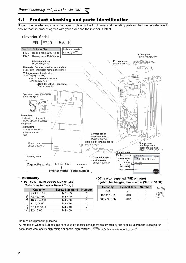
1.1 Product checking and parts identificationUnpack the inverter and check the capacity plate on the front cover and the rating plate on the inverter side face toensure that the product agrees with your order and the inverter is intact.
Harmonic suppression guidelineAll models of General-purpose inverters used by specific consumers are covered by "Harmonic suppression guideline for consumers who receive high voltage or special high voltage". ( For further details, refer to page 49.)
Operation panel (FR-DU07)
Front cover
EMC filter ON/OFF connector
Control circuit
terminal block
AU/PTC switchover switch
Main circuit terminal blockCharge lampLit when power issupplied to the maincircuit
Power lamp
Lit when the control circuit
(R1/L11, S1/L21) is supplied
with power.
Cooling fan
PU connectorRS-485 terminals
Connector for plug-in option connection
(Refer to the instruction manual of options.)
Alarm lamp
Lit when the inverter is
in the alarm status
(fault).
Capacity plate
Inverter model Serial number
Capacity plate
Rating plate
Voltage/current input switch
K5.5
Indicate inverter
capacity (kW)
FR-F740-5.5K
FR - -F740
Symbol
F740
Voltage Class
Three-phase 400V class
F720 Three-phase 200V class
Rating plateInverter model
Input ratingOutput rating
Serial number
FR-F740-5.5KApplied motor
capacity
• Inverter Model
Combed shaped
wiring cover
(Refer to page 33)(Refer to page 34)
(Refer to page 6)
(Refer to page 15)
(Refer to page 16)
(Refer to page 284)
(Refer to page 26)
(Refer to page 104)
• Accessory· Fan cover fixing screws (30K or less)
(Refer to the Instruction Manual (basic) )Capacity Screw Size (mm) Number
200V
2.2K to 5.5K M3 × 35 17.5K to 15K M4 × 40 218.5K to 30K M4 × 50 1
400V
3.7K, 5.5K M3 × 35 17.5K to 18.5K M4 × 40 222K, 30K M4 × 50 1
(Refer to page 16)
(Refer to page 6)
(Refer to page 19)
· DC reactor supplied (75K or more)· Eyebolt for hanging the inverter (37K to 315K)
Capacity Eyebolt Size Number37K M8 2
45K to 160K M10 2185K to 315K M12 2
(Refer to page 14, 160)

3
Inverter and peripheral devices
1
OU
TLIN
E
1.2 Inverter and peripheral devices
CAUTION· Do not install a power factor correction capacitor, surge suppressor or capacitor type filter on the inverter output side. This will
cause the inverter to trip or the capacitor, and surge suppressor to be damaged. If any of the above devices are connected,immediately remove them.
· Electromagnetic wave interferenceThe input/output (main circuit) of the inverter includes high frequency components, which may interfere with the communicationdevices (such as AM radios) used near the inverter. In this case, set the EMC filter valid to minimize interference.(Refer topage 15.)
· Refer to the instruction manual of each option and peripheral devices for details of peripheral devices.
Power regeneration
common converter
(FR-CV*1)
Power regeneration
converter (MT-RC*2)
Resistor unit
(FR-BR*1, MT-BR5*2)
Brake unit
(FR-BU2, FR-BU*1, MT-BU5*2)
High power factor
converter
(FR-HC*1, MT-HC*2)
P/+
P/+
PR
PR
Programmable controller
Three-phase AC power supply
AC reactor
(FR-HAL)DC reactor (FR-HEL)
R/L1 S/L2 T/L3P/+ N/-P/+P1U V W
Moulded case circuit
breaker (MCCB)
or earth leakage circuit
breaker (ELB), fuse
Magnetic contactor(MC)
RS-485 terminal block
EMC filter
(ferrite core)
(FR-BSF01, FR-BLF)
Motor
Devices connected to the output
Use within the permissible power supply
specifications of the inverter.
The regeneration braking
capability of the inverter can be
exhibited fully.
Install this as required.
Install the magnetic contactor to ensure safety.
Do not use this magnetic contactor to start and
stop the inverter.
Doing so will cause the inverter life to be shorten.
The inverter can be
connected with computers
such as programmable
controller.
It supports Mitsubishi inverter
protocol and Modbus-RTU
(binary) protocol.
Do not install a power factor correction capacitor,
surge suppressor or EMC filter (capacitor) on the
output side of the inverter.
When installing a moulded case circuit breaker on the
output side of the inverter, contact each manufacturer
for selection of the moulded case circuit breaker.
Power supply harmonics
can be greatly suppressed.
Install this as required.
Greater braking capability
is obtained.
Install this as required.
The breaker must be selected carefully since
an in-rush current flows in the inverter at
power on.
Install an EMC filter (ferrite
core) to reduce the
electromagnetic noise
generated from the inverter.
Effective in the range from
about 1MHz to 10MHz.
A wire should be wound four
turns at a maximum.
Earth
(Ground)
Earth
(Ground)
Earth (Ground)To prevent an electric shock, always earth
(ground) the motor and inverter.
Reactor (FR-HAL, FR-HEL)Reactors (option) should be used when power
harmonics measures are taken, the power factor is
to be improved or the inverter is installed near a
large power supply system (1000kVA or more). The
inverter may be damaged if you do not use reactors.
Select the reactor according to the model.
For the 55K or less, remove the jumpers across
terminals P/+-P1 to connect to the DC reactor.
EMC filter (ferrite core)(FR-BLF)The 55K or less
has a built-in common
mode choke.
For the 75K or more, a DC
reactor is supplied.
Always install the reactor.
*1 Compatible with the 55K or less.*2 Compatible with the 75K or more.
(Refer to page 294)
(Refer to page 4)
(Refer to page 4)
(Refer topage 4.)
Inverter(FR-F700)The life of the inverter is influenced by surroundingair temperature. The surrounding air temperatureshould be as low as possible within the permissiblerange. Especially when mounting the inverterinside an enclosure, take cautions of thesurrounding air temperature. (Refer to page 10)Wrong wiring might lead to damage of the inverter.The control signal lines must be kept fully awayfrom the main circuit to protect them fromnoise.(Refer to page 14)Refer to page 15 for the built-in EMC filter.

Inverter and peripheral devices
1.2.1 Peripheral devices
Check the inverter model of the inverter you purchased. Appropriate peripheral devices must be selected accordingto the capacity. Refer to the following list and prepare appropriate peripheral devices:
200V class
Motor Output (kW)
*1
Applicable Inverter ModelBreaker Selection*2
Input Side Magnetic Contactor*3
Without reactor connection
With reactor connection
Without reactor connection
With reactor connection
0.75 FR-F720-0.75K 30AF 10A 30AF 10A S-N10 S-N101.5 FR-F720-1.5K 30AF 15A 30AF 15A S-N10 S-N102.2 FR-F720-2.2K 30AF 20A 30AF 15A S-N10 S-N103.7 FR-F720-3.7K 30AF 30A 30AF 30A S-N20, S-N21 S-N105.5 FR-F720-5.5K 50AF 50A 50AF 40A S-N25 S-N20, S-N217.5 FR-F720-7.5K 100AF 60A 50AF 50A S-N25 S-N2511 FR-F720-11K 100AF 75A 100AF 75A S-N35 S-N3515 FR-F720-15K 225AF 125A 100AF 100A S-N50 S-N50
18.5 FR-F720-18.5K 225AF 150A 225AF 125A S-N65 S-N5022 FR-F720-22K 225AF 175A 225AF 150A S-N80 S-N6530 FR-F720-30K 225AF 225A 225AF 175A S-N95 S-N8037 FR-F720-37K 400AF 250A 225AF 225A S-N150 S-N12545 FR-F720-45K 400AF 300A 400AF 300A S-N180 S-N15055 FR-F720-55K 400AF 400A 400AF 350A S-N220 S-N18075 FR-F720-75K ⎯ 400AF 400A ⎯ S-N30090 FR-F720-90K ⎯ 400AF 400A ⎯ S-N300110 FR-F720-110K ⎯ 600AF 500A ⎯ S-N400
*1 Selections for use of the Mitsubishi 4-pole standard motor with power supply voltage of 200VAC 50Hz.*2 Select the MCCB according to the power supply capacity.
Install one MCCB per inverter.For using commercial-power supply operation, select a breaker with capacity which allows the motor to bedirectly power supplied.For the use in the United States or Canada, provide the appropriate UL and cUL listed Class RK5 or ClassL type fuse or UL 489 molded case circuit breaker (MCCB) that is suitable for branch circuit protection. (Refer to the Instruction Manual (basic).)
*3 Magnetic contactor is selected based on the AC-1 class. The electrical durability of magnetic contactor is 500,000 times. When the magneticcontactor is used for emergency stop during motor driving, the electrical durability is 25 times.When using the MC for emergency stop during motor driving or using on the motor side during commercial-power supply operation, select theMC with class AC-3 rated current for the motor rated current.
CAUTION⋅ When the inverter capacity is larger than the motor capacity, select an MCCB and a magnetic contactor according to the
inverter model and cable and reactor according to the motor output.⋅ When the breaker on the inverter primary side trips, check for the wiring fault (short circuit), damage to internal parts of the
inverter, etc. Identify the cause of the trip, then remove the cause and power on the breaker.
MCCB INV
MCCB INV
IM
IM
4

Inverter and peripheral devices
1
OU
TLIN
E
400V classMotor Output (kW)
*1
Applicable Inverter ModelBreaker Selection*2
Input Side Magnetic Contactor*3
Without reactor connection
With reactor connection
Without reactor connection
With reactor connection
0.75 FR-F740-0.75K 30AF 5A 30AF 5A S-N10 S-N101.5 FR-F740-1.5K 30AF 10A 30AF 10A S-N10 S-N102.2 FR-F740-2.2K 30AF 10A 30AF 10A S-N10 S-N103.7 FR-F740-3.7K 30AF 20A 30AF 15A S-N10 S-N105.5 FR-F740-5.5K 30AF 30A 30AF 20A S-N20, S-N21 S-N11, S-N127.5 FR-F740-7.5K 30AF 30A 30AF 30A S-N20, S-N21 S-N20, S-N2111 FR-F740-11K 50AF 50A 50AF 40A S-N20, S-N21 S-N20, S-N2115 FR-F740-15K 100AF 60A 50AF 50A S-N25 S-N20, S-N21
18.5 FR-F740-18.5K 100AF 75A 100AF 60A S-N25 S-N2522 FR-F740-22K 100AF 100A 100AF 75A S-N35 S-N2530 FR-F740-30K 225AF 125A 100AF 100A S-N50 S-N5037 FR-F740-37K 225AF 150A 225AF 125A S-N65 S-N5045 FR-F740-45K 225AF 175A 225AF 150A S-N80 S-N6555 FR-F740-55K 225AF 200A 225AF 175A S-N80 S-N8075 FR-F740-75K ⎯ 225AF 225A ⎯ S-N9590 FR-F740-90K ⎯ 225AF 225A ⎯ S-N150110 FR-F740-110K ⎯ 225AF 225A ⎯ S-N180132 FR-F740-132K ⎯ 400AF 400A ⎯ S-N220150 FR-F740-160K ⎯ 400AF 400A ⎯ S-N300160 FR-F740-160K ⎯ 400AF 400A ⎯ S-N300185 FR-F740-185K ⎯ 400AF 400A ⎯ S-N300220 FR-F740-220K ⎯ 600AF 500A ⎯ S-N400250 FR-F740-250K ⎯ 600AF 600A ⎯ S-N600280 FR-F740-280K ⎯ 600AF 600A ⎯ S-N600315 FR-F740-315K ⎯ 800AF 700A ⎯ S-N600355 FR-F740-355K ⎯ 800AF 800A ⎯ S-N600400 FR-F740-400K ⎯ 1000AF 900A ⎯ S-N800
450 FR-F740-450K ⎯ 1000AF 1000A ⎯1000ARated product
500 FR-F740-500K ⎯ 1200AF 1200A ⎯ 1000ARated product
560 FR-F740-560K ⎯ 1600AF 1500A ⎯ 1200ARated product
*1 Selections for use of the Mitsubishi 4-pole standard motor with power supply voltage of 400VAC 50Hz.*2 Select the MCCB according to the power supply capacity.
Install one MCCB per inverter.For using commercial-power supply operation, select a breaker with capacity which allows the motor to bedirectly power supplied.For the use in the United States or Canada, provide the appropriate UL and cUL listed Class RK5 or ClassL type fuse or UL 489 molded case circuit breaker (MCCB) that is suitable for branch circuit protection. (Refer to the Instruction Manual (basic).)
*3 Magnetic contactor is selected based on the AC-1 class. The electrical durability of magnetic contactor is 500,000 times. When the magneticcontactor is used for emergency stop during motor driving, the electrical durability is 25 times.When using the MC for emergency stop during motor driving or using on the motor side during commercial-power supply operation, select theMC with class AC-3 rated current for the motor rated current.
CAUTION⋅ When the inverter capacity is larger than the motor capacity, select an MCCB and a magnetic contactor according to the
inverter model and cable and reactor according to the motor output.⋅ When the breaker on the inverter primary side trips, check for the wiring fault (short circuit), damage to internal parts of the
inverter, etc. Identify the cause of the trip, then remove the cause and power on the breaker.
MCCB INV
MCCB INV
IM
IM
5

Method of removal and reinstallation of the front cover
1.3 Method of removal and reinstallation of the front cover•Removal of the operation panel
1) Loosen the two screws on the operation panel.(These screws cannot be removed.)
2) Push the left and right hooks of the operation paneland pull the operation panel toward you to remove.
When reinstalling the operation panel, insert it straight to reinstall securely and tighten the fixed screws of theoperation panel.
FR-F720-30K or less, FR-F740-30K or less•Removal
•Reinstallation
Installation hook
Front cover Front cover
1) Loosen the installation screws of the front cover.
2) Pull the front cover toward you to remove by pushing an installation hook using left fixed hooks as supports.
Front cover Front cover
Front cover
1) Insert the two fixed hooks on the left side of the front cover into the sockets of the inverter.
2) Using the fixed hooks as supports, securely press the front cover against the inverter.(Although installation can be done with the operation panel mounted, make sure that a connector is securely fixed.)
3) Tighten the installation screws and fix the front cover.
6

Method of removal and reinstallation of thefront cover
1
OU
TLIN
E
FR-F720-37K or more, FR-F740-37K or more•Removal
•Reinstallation
CAUTION1. Fully make sure that the front cover has been reinstalled securely. Always tighten the installation screws of the front cover.2. The same serial number is printed on the capacity plate of the front cover and the rating plate of the inverter. Before reinstalling the
front cover, check the serial numbers to ensure that the cover removed is reinstalled to the inverter from where it was removed.
Front cover 2
Front cover 1
Installation hook
1) Remove installation screws on the front cover 1 to remove the front cover 1.
2) Loosen the installation screws of the front cover 2.
3) Pull the front cover 2 toward you to remove by pushing an installation hook on the right side using left fixed hooks as supports.
Front cover 2 Front cover 2
Front cover 2Front cover 1
1) Insert the two fixed hooks on the left side of the front cover 2 into the sockets of the inverter.
2) Using the fixed hooks as supports, securely press the front cover 2 against the inverter. (Although installation can be done with the operation panel mounted, make sure that a connector is securely fixed.)
3) Fix the front cover 2 with the installation screws.
4) Fix the front cover 1 with the installation screws.
REMARKS⋅ For the FR-F740-185K or more, the front cover 1 is separated into two parts.
7

Installation of the inverter and enclosure design
1.4 Installation of the inverter and enclosure designWhen an inverter enclosure is to be designed and manufactured, heat generated by contained equipment, etc., theenvironment of an operating place, and others must be fully considered to determine the enclosure structure, size andequipment layout. The inverter unit uses many semiconductor devices. To ensure higher reliability and long period ofoperation, operate the inverter in the ambient environment that completely satisfies the equipment specifications.
1.4.1 Inverter installation environmentAs the inverter installation environment should satisfy the standard specifications indicated in the following table,operation in any place that does not meet these conditions not only deteriorates the performance and life of theinverter, but also causes a failure. Refer to the following points and take adequate measures.
*1 2.9m/s2 or less for the 185K or more.
(1) TemperatureThe permissible surrounding air temperature of the inverter is between -10°C and +50°C. Always operate the inverterwithin this temperature range. Operation outside this range will considerably shorten the service lives of thesemiconductors, parts, capacitors and others. Take the following measures so that the surrounding air temperature ofthe inverter falls within the specified range.1)Measures against high temperature
• Use a forced ventilation system or similar cooling system. (Refer to page 10.)• Install the enclosure in an air-conditioned electrical chamber.• Block direct sunlight.• Provide a shield or similar plate to avoid direct exposure to the radiated heat and wind of a heat source.• Ventilate the area around the enclosure well.
2)Measures against low temperature• Provide a space heater in the enclosure.• Do not power off the inverter. (Keep the start signal of the inverter off.)
3)Sudden temperature changes• Select an installation place where temperature does not change suddenly.• Avoid installing the inverter near the air outlet of an air conditioner.• If temperature changes are caused by opening/closing of a door, install the inverter away from the door.
(2) HumidityNormally operate the inverter within the 45 to 90% range of the ambient humidity. Too high humidity will pose problemsof reduced insulation and metal corrosion. On the other hand, too low humidity may produce a spatial electricalbreakdown. The insulation distance specified in JEM1103 "Control Equipment Insulator" is defined as humidity 45 to85%.1)Measures against high humidity
• Make the enclosure enclosed, and provide it with a hygroscopic agent.• Take dry air into the enclosure from outside.• Provide a space heater in the enclosure.
2)Measures against low humidityWhat is important in fitting or inspection of the unit in this status is to discharge your body (static electricity)beforehand and keep your body from contact with the parts and patterns, besides blowing air of proper humidity intothe enclosure from outside.
3)Measures against condensationCondensation may occur if frequent operation stops change the in-enclosure temperature suddenly or if the outside-air temperature changes suddenly.Condensation causes such faults as reduced insulation and corrosion.• Take the measures against high humidity in 1).• Do not power off the inverter. (Keep the start signal of the inverter off.)
Environmental standard specifications of inverterItem Description
Surrounding air temperature -10 to +50°C (non-freezing)Ambient humidity 90% RH maximum (non-condensing)
Atmosphere Free from corrosive and explosive gases, dust and dirtMaximum Altitude 1,000m or less
Vibration 5.9m/s2 or less at 10 to 55Hz (directions of X, Y, Z axes) *1
8

Installation of the inverter andenclosure design
1
OU
TLIN
E
(3) Dust, dirt, oil mistDust and dirt will cause such faults as poor contact of contact points, reduced insulation or reduced cooling effect dueto moisture absorption of accumulated dust and dirt, and in-enclosure tempearture rise due to clogged filter.In the atmosphere where conductive powder floats, dust and dirt will cause such faults as malfunction, deterioratedinsulation and short circuit in a short time.Since oil mist will cause similar conditions, it is necessary to take adequate measures.
Countermeasures• Place in a totally enclosed enclosure.
Take measures if the in-enclosure temperature rises. (Refer to page 10.)• Purge air.
Pump clean air from outside to make the in-enclosure pressure higher than the outside-air pressure.
(4) Corrosive gas, salt damageIf the inverter is exposed to corrosive gas or to salt near a beach, the printed board patterns and parts will corrode orthe relays and switches will result in poor contact.In such places, take the measures given in Section (3).
(5) Explosive, flammable gasesAs the inverter is non-explosion proof, it must be contained in an explosion proof enclosure.In places where explosion may be caused by explosive gas, dust or dirt, an enclosure cannot be used unless itstructurally complies with the guidelines and has passed the specified tests. This makes the enclosure itself expensive(including the test charges).The best way is to avoid installation in such places and install the inverter in a non-hazardous place.
(6) HighlandUse the inverter at the altitude of within 1000m. If it is used at a higher place, it is likely that thin air will reduce the cooling effect and low air pressure will deterioratedielectric strength.
(7) Vibration, impact
The vibration resistance of the inverter is up to 5.9m/s2 (2.9m/s2 for the 185K or more) at 10 to 55Hz frequency(directions of X, Y, Z axes) and 1mm amplitude.Vibration or impact, if less than the specified value, applied for a long time may make the mechanism loose or causepoor contact to the connectors.Especially when impact is imposed repeatedly, caution must be taken as the part pins are likely to break.
Countermeasures• Provide the enclosure with rubber vibration isolators.• Strengthen the structure to prevent the enclosure from resonance.• Install the enclosure away from sources of vibration.
9

Installation of the inverter and enclosure design
1.4.2 Cooling system types for inverter enclosure
From the enclosure that contains the inverter, the heat of the inverter and other equipment (transformers, lamps,resistors, etc.) and the incoming heat such as direct sunlight must be dissipated to keep the in-enclosure temperaturelower than the permissible temperatures of the in-enclosure equipment including the inverter.The cooling systems are classified as follows in terms of the cooling calculation method.1) Cooling by natural heat dissipation from the enclosure surface (Totally enclosed type)2) Cooling by heat sink (Aluminum fin, etc.)3) Cooling by ventilation (Forced ventilation type, pipe ventilation type)4) Cooling by heat exchanger or cooler (Heat pipe, cooler, etc.)
1.4.3 Inverter placement
(1) Installation of the Inverter
Cooling System Enclosure Structure Comment
Natural cooling
Natural ventilation (Enclosed, open type)
Low in cost and generally used, but the enclosure size increases as the inverter capacity increases. For relatively small capacities.
Natural ventilation (Totally enclosed type)
Being a totally enclosed type, the most appropriate for hostile environment having dust, dirt, oil mist, etc. The enclosure size increases depending on the inverter capacity.
Forced cooling
Heatsink cooling Having restrictions on the heatsink mounting position and area, and designed for relative small capacities.
Forced ventilationFor general indoor installation. Appropriate for enclosure downsizing and cost reduction, and often used.
Heat pipe Totally enclosed type for enclosure downsizing.
Installation on the enclosure30K or less 37K or more
INV
INV
INV
heatsink
INV
INV
Heat
pipe
CAUTIONWhen encasing multiple inverters, install them in parallel asa cooling measure. Install the inverter vertically.
Vertical
*
*Refer to the clearances on the next page.
Fix six positions for the FR-F740-185K to 400K and fix eight positionsfor the FR-F740-450K to 560K.
10
Installation of the inverter andenclosure design
1
OU
TLIN
E
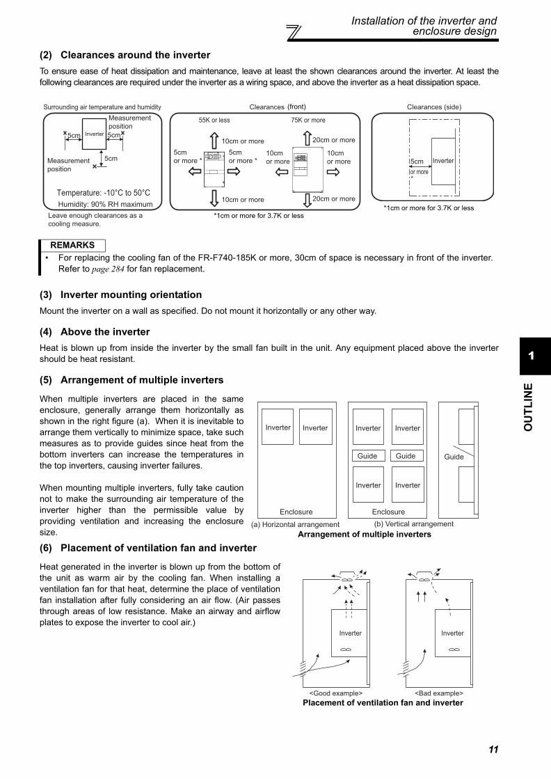
(2) Clearances around the inverterTo ensure ease of heat dissipation and maintenance, leave at least the shown clearances around the inverter. At least thefollowing clearances are required under the inverter as a wiring space, and above the inverter as a heat dissipation space.
(3) Inverter mounting orientationMount the inverter on a wall as specified. Do not mount it horizontally or any other way.
(4) Above the inverterHeat is blown up from inside the inverter by the small fan built in the unit. Any equipment placed above the invertershould be heat resistant.
(5) Arrangement of multiple inverters
(6) Placement of ventilation fan and inverter
REMARKS• For replacing the cooling fan of the FR-F740-185K or more, 30cm of space is necessary in front of the inverter.
Refer to page 284 for fan replacement.
When multiple inverters are placed in the sameenclosure, generally arrange them horizontally asshown in the right figure (a). When it is inevitable toarrange them vertically to minimize space, take suchmeasures as to provide guides since heat from thebottom inverters can increase the temperatures inthe top inverters, causing inverter failures.
When mounting multiple inverters, fully take cautionnot to make the surrounding air temperature of theinverter higher than the permissible value byproviding ventilation and increasing the enclosuresize. Arrangement of multiple inverters
Heat generated in the inverter is blown up from the bottom ofthe unit as warm air by the cooling fan. When installing aventilation fan for that heat, determine the place of ventilationfan installation after fully considering an air flow. (Air passesthrough areas of low resistance. Make an airway and airflowplates to expose the inverter to cool air.)
Placement of ventilation fan and inverter
ClearancesSurrounding air temperature and humidity
Measurement
position
Measurement
position
Inverter
Leave enough clearances as a
cooling measure.
Humidity: 90% RH maximum
55K or less 75K or more
5cm 5cm
5cm
10cm or more 20cm or more
20cm or more10cm or more
5cm
or more *
5cm
or more *10cm
or more
10cm
or more
Temperature: -10°C to 50°C
(front)
*1cm or more for 3.7K or less
Clearances (side)
*
Inverter5cm
or more
*1cm or more for 3.7K or less
Guide Guide
Enclosure Enclosure
Guide
(a) Horizontal arrangement (b) Vertical arrangement
Inverter
InverterInverterInverter Inverter
Inverter
Inverter Inverter
<Good example> <Bad example>
11

12
MEMO

2
WIRING3
4
5
6
1
2
This chapter explains the basic "WIRING" for use of this product.Always read the instructions before using the equipment.
2.1 Wiring ......................................................................142.2 Main circuit terminal specifications..........................162.3 Control circuit specifications....................................262.4 Connection of stand-alone option units ...................35
137

Wiring
2.1 Wiring2.1.1 Terminal connection diagram
CAUTION· To prevent a malfunction due to noise, keep the signal cables more than 10cm away from the power cables. Also separate the
main circuit wire of the input side and the output side.· After wiring, wire offcuts must not be left in the inverter.
Wire offcuts can cause an alarm, failure or malfunction. Always keep the inverter clean.When drilling mounting holes in an enclosure etc., take care not to allow chips and other foreign matter to enter the inverter.
· Set the voltage/current input switch correctly. Operation with a wrong setting may cause a fault, failure or malfunction.
Three-phase AC
power supply
MCCB
Jumper
R/L1
S/L2
T/L3
R1/L11
S1/L21
PC
10E(+10V)
10(+5V)
23
1
1
4
Control input signals (No voltage input allowed)
Jumper
Motor
Relay output 1
(Fault output)
C1
B1
A1
U
V
W
AM
5
*1
Main circuit terminal
Control circuit terminal
MC
Main circuit
Control circuit
C2
B2
A2
Relay output 2
Relay output
IM
AU
PTC
TXD+
TXD-
RXD+
RXD-
SG
SIN
K
SO
UR
CE
Terminal functions vary with the output terminal assignment (Pr. 195, Pr. 196)
Terminal functions vary with the output terminal assignment (Pr. 190 to Pr. 194)
Terminal functions vary with the input terminal assignment (Pr. 178 to Pr. 189)
*3
STF
STR
STOP
RH
RM
RL
JOG
RT
MRS
RES
AU
CS
SD
RUN
SU
IPF
OL
FU
SE
EMC filter
ON/OFF
connector
ON
OFF
VCC
Frequency setting signal (Analog)
Frequency setting
potentiometer1/2W1kΩ
Auxiliary
input(+)(-)
2
(Analog common)
0 to 5VDC0 to 10VDC selected0 to 20mADC
*45
PU
connector
Terminal
4 input
(Current
input)
Terminating resistor
Connector
for plug-in option
connection
*5. It is recommended to use 2W1kΩ when the frequency setting signal is changed frequently.
(+)(-)
0 to 5VDC0 to 10VDC
selected *4
GND
RS-485 terminals
Data transmission
Data reception
4 to 20mADC
*4selected0 to ±5VDC
0 to ±10VDC (-)
(+)
(0 to 10VDC)
Analog signal output
Frequency detection
Open collector output common
Sink/source common
Running
Up to frequency
Instantaneous power failure
Overload
Open collector output
Terminal 4 input selection(Current input selection)
Selection of automatic restart after instantaneous
power failure
Output stop
Reset
*3. AU terminal can be
used as PTC input
terminal.
Middle speed
High speed
Low speed
Jog mode
Second function selection
Multi-speed
selection
Forwardrotation
startReverserotation
start
Start self-holding selection
PR*7 PX*7
Jumper *7.
*5
(Permissible load
current 100mA)
5V
*2. To supply power to the control circuit separately, remove the jumper across R1/L11 and S1/L21.
*2
Do not use PR and PX terminals.
Please do not remove the jumper
connected to terminal PR and PX.
Initialvalue
Initialvalue
Initial value
*4. Terminal input specifications can be changed by analog input specifications switchover (Pr. 73, Pr. 267). Set the voltage/current input switch in the OFF position to select voltage input (0 to 5V/0 to 10V) and ON to select current input (0 to 20mA).
ON4 2
OFF
Voltage/current input switch
*4
Resistor unit(Option)
Brake unit
(Option)
CN8*6
24V
Inrush current
limit circuit
N/-P/+
Option connector 1
P1
Sink logic
Earth
(Ground)
Earth (ground) cable
Earth (ground)
+ -Indicator
(Frequency meter, etc.)
Moving-coil type
1mA full-scale
Calibration
resistor *9SD
FM
24VDC power supply
(Common for external power supply transistor)
Contact input common
*1. DC reactor (FR-HEL)Be sure to connect the DC reactor supplied with the 75K or more.When a DC reactor is connected to the 55K or less, remove the jumper across P1-P/+.
*6. A CN8 (for MT-BU5)
connector is provided
with the 75K or more.
*9. It is not necessary when calibrating the indicator from the operation panel.
*8.The 200V class 0.75K and 1.5K
are not provided with the ON/OFF
connector EMC filter.
*8
(Refer to page 115)(Refer to page 121)
(Refer to page 121)
(Refer to page 160)
14

Wiring
2
WIR
ING
2.1.2 EMC filter
This inverter is equipped with a built-in EMC filter (capacitive filter) and common mode choke.The EMC filter is effective for reduction of air-propagated noise on the input side of the inverter.The EMC filter is factory-set to disable (OFF). To enable it, fit the EMC filter ON/OFF connector to the ON position.The input side common mode choke, built-in the 55K or less inverter, is always valid regardless of ON/OFF of the EMCfilter ON/OFF connector.
The FR-F720-0.75K and 1.5K are not provided with the EMC filter ON/OFF connector. (Always ON)<How to disconnect the connector>(1) Before removing a front cover, check to make sure that the indication of the inverter operation panel is off, wait for
at least 10 minutes after the power supply has been switched off, and check that there are no residual voltageusing a tester or the like. (For the front cover removal method, refer to page 6.)
(2) When disconnecting the connector, push the fixing tab and pull the connector straight without pulling the cable orforcibly pulling the connector with the tab fixed. When installing the connector, also engage the fixing tab securely.If it is difficult to disconnect the connector, use a pair of long-nose pliers, etc.
CAUTION⋅ Fit the connector to either ON or OFF.⋅ Enabling (turning on) the EMC filter increase leakage current. (Refer to page 45)
WARNINGWhile power is on or when the inverter is running, do not open the front cover. Otherwise you may get an electric shock.
EMC filter OFF EMC filter OFF EMC filter OFFEMC filter ON EMC filter ON EMC filter ON
VU W
(initial setting) (initial setting) (initial setting)
EMC filter
ON/OFF
connector
0.75K to 5.5K 7.5K, 11K 15K or more
FR-F720-2.2K to 5.5KFR-F740-0.75K to 5.5K
FR-F720-7.5K, 11KFR-F740-7.5K, 11K
FR-F720-15KFR-F740-15K, 18.5K
FR-F720-18.5K to 30KFR-F740-22K, 30K
FR-F720-37K or moreFR-F740-37K or more
EMC filter
ON/OFF connector
(Side view)
Disengage connector fixing tab With tab disengaged,
pull up connector straight.
15

Main circuit terminal specifications
2.2 Main circuit terminal specifications2.2.1 Specification of main circuit terminal
2.2.2 Terminal arrangement of the main circuit terminal, power supply and the motor wiring
200V class
Terminal Symbol Terminal Name Description
R/L1, S/L2, T/L3
AC power inputConnect to the commercial power supply.Keep these terminals open when using the high power factor converter (FR-HC, MT-HC) or power regeneration common converter (FR-CV).
U, V, W Inverter output Connect a three-phase squirrel-cage motor.
R1/L11, S1/L21
Power supply for control circuit
Connected to the AC power supply terminals R/L1 and S/L2. To retain the fault display and fault output or when using the high power factor converter (FR-HC, MT-HC) or power regeneration common converter (FR-CV), remove the jumpers from terminals R/L1-R1/L11 and S/L2-S1/L21 and apply external power to these terminals.The power capacity necessary when separate power is supplied from R1/L11 and S1/L21 differs according to the inverter capacity.
P/+, N/- Brake unit connection
Connect the brake unit (FR-BU2, FR-BU, BU and MT-BU5), power regeneration common converter (FR-CV), high power factor converter (FR-HC and MT-HC) or power regeneration converter (MT-RC).
P/+, P1 DC reactor connection
For the 55K or less, remove the jumper across terminals P/+ - P1 and connect the DC reactor. (Be sure to connect the DC reactor supplied with the 75K or more.)
PR, PX Please do not remove or use terminals PR and PX or the jumper connected.
Earth (ground) For earthing (grounding) the inverter chassis. Must be earthed (grounded).
FR-F720-0.75K, 1.5K FR-F720-2.2K to 5.5K
15K or less 18.5K 22K or more200V class 60VA 80VA 80VA400V class 60VA 60VA 80VA
R/L1 S/L2 T/L3
N/- P/+
PR
PXR1/L11 S1/L21
Charge lamp
As this is an inside cover fixing screw,
do not remove it.
JumperScrew size (M4)
Screw size
(M4)
Jumper
MotorPower supply
IM
R/L1 S/L2 T/L3 N/- P/+ PR
PXR1/L11 S1/L21
IMCharge lamp
Jumper
Screw size (M4)
Screw size
(M4)
Jumper
MotorPowersupply
16

Main circuit terminal specifications
2
WIR
ING
FR-F720-7.5K, 11K FR-F720-15K
FR-F720-18.5K to 30K FR-F720-37K to 55K
FR-F720-75K to 110K
R/L1 S/L2 T/L3
N/- P/+ PR
PX
R1/L11 S1/L21
IM
Screw size
(M5)
Screw size (M5)
JumperJumper
Charge lamp
MotorPower supply
* *
*
*
* Screw size of terminal
R1/L11, S1/L21, PR
and PX is M4.
R1/L11 S1/L21
R/L1 S/L2 T/L3 N/-
P/+
PR
Charge lamp
Jumper
Jumper
Screw size (M4)
Screw size (M5)
Screw size (M5)
Power supply
IMMotor
R/L1 S/L2 T/L3 N/- P/+
PR
R1/L11 S1/L21
IM
Screw size (M4)
Screw size (M6)
Jumper
Jumper
Charge lamp
MotorPower supply
Screw size
(18.5K:M6, 22K/30K:M8)
R/L1 S/L2 T/L3 N/- P/+
R1/L11 S1/L21
IM
Screw size
(M4)
Jumper
Jumper
Charge lamp
MotorPowersupply
Screw size
(37K:M6, 45K/55K:M8)
Screw size(37K:M8, 45K/55K:M10)
R/L1 S/L2 T/L3 N/-
P/+
R1/L11 S1/L21
P/+
P/+
IM
Screw size (M4)
Screw size (M12)
Screw size (M10)
Jumper
Charge lamp
MotorPower supply
Screw size (M12)
(for option)
DC reactor
17

Main circuit terminal specifications
400V classFR-F740-0.75K to 5.5K FR-F740-7.5K, 11K
FR-F740-15K, 18.5K FR-F740-22K, 30K
FR-F740-37K to 55K FR-F740-75K to 110K
R/L1 S/L2 T/L3 N/- P/+ PR
PXR1/L11 S1/L21
IMCharge lamp
Jumper
Screw size (M4)
Screw size
(M4)
Jumper
MotorPowersupply
R/L1 S/L2 T/L3
N/- P/+ PR
PX
R1/L11 S1/L21
IM
Screw size
(M4)
Screw size
(M4)
Jumper Jumper
Charge lamp
MotorPower supply
R1/L11 S1/L21
R/L1 S/L2 T/L3 N/-
P/+
PR
Charge lamp
Jumper
Jumper
Screw size (M4)
Screw size (M5)
Screw size (M5)
Power supply
IMMotor
R/L1 S/L2 T/L3 N/- P/+
PR
R1/L11 S1/L21
IM
Screw size (M4)
Screw size (M6)
Screw size (M6)
Jumper
Jumper
Charge lamp
Power supply Motor
IM
Jumper
Jumper
Charge lamp
Screw size(M4)
Powersupply
Motor
R/L1 S/L2 T/L3 N/- P/+
R1/L11 S1/L21
Screw size
(37K: M6, 45K/55K: M8)
Screw size (37K: M6, 45K/55K: M8)
IM
R/L1 S/L2 T/L3 N/- P/+
R1/L11 S1/L21
DC reactor
Screw size (M10)
Screw size (M4)
Powersupply
Motor
Jumper
Charge lamp
P/+
Screw size
(75K: M8, 90K/110K: M10)
Screw size
(75K: M8,
90K/110K: M10)
Screw size
(75K: M8, 90K/110K: M10)
18

Main circuit terminal specifications
2
WIR
ING
FR-F740-132K to 220K FR-F740-250K to 560K
CAUTION· The power supply cables must be connected to R/L1, S/L2, T/L3. (Phase sequence needs not to be matched.) Never connect
the power cable to the U, V, W of the inverter. Doing so will damage the inverter.· Connect the motor to U, V, W. At this time, turning on the forward rotation switch (signal) rotates the motor in the
counterclockwise direction when viewed from the motor shaft.· When wiring the inverter main circuit conductor of the 250K or more, tighten a nut from the right side of the conductor. When
wiring two wires, place wires on both sides of the conductor. (Refer to the drawing below.) For wiring, use bolts (nuts) providedwith the inverter.
• Handling of the wiring cover(FR-F720-18.5K, 22K, FR-F740-22K, 30K)For the hook of the wiring cover, cut off the necessaryparts using a pair of long-nose pliers etc.
IM
R/L1 S/L2 T/L3 N/-
P/+
R1/L11 S1/L21
P/+
P/+
Screw size (M4)
Jumper
Charge lamp
Screw size(M10)
Motor
Screw size (M12)
(for option)
Power supply
DC reactor
Screw size (132K/160K: M10185K/220K: M12)
IM
R/L1 S/L2 T/L3 N/-
R1/L11 S1/L21
P/+
P/+
Screw size (M4)
Jumper
Charge lamp
MotorPower supplyDC reactor
Screw size (M12)
Screw size (M10)
CAUTIONCut off the same number of lugs as wires. If parts whereno wire is put through has been cut off (10mm or more),protective structure (JEM1030) becomes an open type(IP00).
19

Main circuit terminal specifications
2.2.3 Cables and wiring length(1) Applicable cable sizeSelect the recommended cable size to ensure that a voltage drop will be 2% max.If the wiring distance is long between the inverter and motor, a main circuit cable voltage drop will cause the motortorque to decrease especially at the output of a low frequency.The following table indicates a selection example for the wiring length of 20m.200V class (when input power supply is 220V)
Applicable Inverter Type
Terminal Screw Size *4
Tightening Torque
N·m
Crimping Terminal
Cable SizesHIV, etc. (mm2) *1 AWG/MCM *2 PVC, etc. (mm2) *3
R/L1, S/L2, T/L3
U, V, WR/L1, S/L2, T/L3
U, V, WEarth
(Ground)cable
R/L1, S/L2, T/L3
U, V, WR/L1, S/L2, T/L3
U, V, WEarth
(Ground)cable
FR-F720-0.75K to 2.2K M4 1.5 2-4 2-4 2 2 2 14 14 2.5 2.5 2.5
FR-F720-3.7K M4 1.5 5.5-4 5.5-4 3.5 3.5 3.5 12 12 4 4 4FR-F720-5.5K M4 1.5 5.5-4 5.5-4 5.5 5.5 5.5 10 10 6 6 6FR-F720-7.5K M5 2.5 14-5 8-5 14 8 5.5 6 8 16 10 16FR-F720-11K M5 2.5 14-5 14-5 14 14 14 6 6 16 16 16FR-F720-15K M5 2.5 22-5 22-5 22 22 14 4 6 (*5) 25 25 16FR-F720-18.5K M6 4.4 38-6 38-6 38 38 22 2 2 35 35 25FR-F720-22K M8 (M6) 7.8 38-8 38-8 38 38 22 2 2 35 35 25FR-F720-30K M8 (M6) 7.8 60-8 60-8 60 60 22 1/0 1/0 50 50 25FR-F720-37K M8 (M6) 7.8 80-8 80-8 80 80 22 3/0 3/0 70 70 35FR-F720-45K M10 (M8) 14.7 100-10 100-10 100 100 38 4/0 4/0 95 95 50FR-F720-55K M10 (M8) 14.7 100-10 100-10 100 100 38 4/0 4/0 95 95 50FR-F720-75K M12 (M10) 24.5 150-12 150-12 125 125 38 MCM250 MCM250 ⎯ ⎯ ⎯FR-F720-90K M12 (M10) 24.5 150-12 150-12 150 150 38 2×4/0 2×4/0 ⎯ ⎯ ⎯FR-F720-110K M12 (M10) 24.5 100-12 100-12 2×100 2×100 38 2×4/0 2×4/0 ⎯ ⎯ ⎯*1 The cable size is that of the cable (HIV cable (600V class 2 vinyl-insulated cable) etc.) with continuous maximum permissible temperature of
75°C. Assumes that the surrounding air temperature is 50°C or less and the wiring distance is 20m or less. *2 The recommended cable size is that of the cable (THHW cable) with continuous maximum permissible temperature of 75°C. Assumes that the
surrounding air temperature is 40°C or less and the wiring distance is 20m or less. (Selection example for use mainly in the United States.)
*3 For the 15K or less, the recommended cable size is that of the cable (PVC cable) with continuous maximum permissible temperature of 70°C.Assumes that the surrounding air temperature is 40°C or less and the wiring distance is 20m or less.For the 18.5K or more, the recommended cable size is that of the cable (XLPE cable) with continuous maximum permissible temperature of90°C. Assumes that the surrounding air temperature is 40°C or less and wiring is performed in an enclosure. (Selection example for use mainly in Europe.)
*4 The terminal screw size indicates the terminal size for R/L1, S/L2, T/L3, U, V, W, and a screw for earthing (grounding).A screw for earthing (grounding) of the 22K or more is indicated in ( ).
*5 When connecting the option unit to P/+, P1, N/-, use THHN cables for the option and terminals R/L1, S/L2, T/L3, U, V, W.
20

Main circuit terminal specifications
2
WIR
ING
400V class (when input power supply is 440V)
The line voltage drop can be calculated by the following formula:
line voltage drop [V]=
Use a larger diameter cable when the wiring distance is long or when it is desired to decrease the voltage drop (torquereduction) in the low speed range.
Applicable Inverter Type
Terminal Screw Size *4
Tightening Torque
N·m
Crimping(Compression)
Terminal
Cable Sizes
HIV, etc. (mm2) *1 AWG/MCM *2 PVC, etc. (mm2) *3
R/L1, S/L2, T/L3 U, V, W R/L1, S/L2,
T/L3 U, V, WEarth
(Ground) cable
R/L1, S/L2, T/L3 U, V, W R/L1, S/L2,
T/L3 U, V, WEarth
(Ground) cable
FR-F740-0.75K to 3.7K M4 1.5 2-4 2-4 2 2 2 14 14 2.5 2.5 2.5
FR-F740-5.5K M4 1.5 2-4 2-4 2 2 3.5 12 14 2.5 2.5 4FR-F740-7.5K M4 1.5 5.5-4 5.5-4 3.5 3.5 3.5 12 12 4 4 4FR-F740-11K M4 1.5 5.5-4 5.5-4 5.5 5.5 8 10 10 6 6 10FR-F740-15K M5 2.5 8-5 8-5 8 8 8 8 8 10 10 10FR-F740-18.5K M5 2.5 14-5 8-5 14 8 14 6 8 16 10 16FR-F740-22K M6 4.4 14-6 14-6 14 14 14 6 6 16 16 16FR-F740-30K M6 4.4 22-6 22-6 22 22 14 4 4 25 25 16FR-F740-37K M6 4.4 22-6 22-6 22 22 14 4 4 25 25 16FR-F740-45K M8 7.8 38-8 38-8 38 38 22 1 2 50 50 25FR-F740-55K M8 7.8 60-8 60-8 60 60 22 1/0 1/0 50 50 25FR-F740-75K M8 7.8 60-8 60-8 60 60 38 1/0 1/0 50 50 25FR-F740-90K M10 14.7 60-10 60-10 60 60 38 3/0 3/0 50 50 25FR-F740-110K M10 14.7 80-10 80-10 80 80 38 3/0 3/0 70 70 35FR-F740-132K M10 14.7 100-10 100-10 100 100 38 4/0 4/0 95 95 50FR-F740-160K M10 14.7 150-10 150-10 125 125 38 250 250 120 120 70FR-F740-185K M12 (M10) 24.5 150-12 150-12 150 150 38 300 300 150 150 95FR-F740-220K M12 (M10) 24.5 100-12 100-12 2×100 2×100 38 2×4/0 2×4/0 2×95 2×95 95FR-F740-250K M12 (M10) 24.5 100-12 100-12 2×100 2×100 38 2×4/0 2×4/0 2×95 2×95 95FR-F740-280K M12 (M10) 24.5 150-12 150-12 2×125 2×125 38 2×250 2×250 2×120 2×120 120FR-F740-315K M12 (M10) 24.5 150-12 150-12 2×150 2×150 38 2×300 2×300 2×150 2×150 150FR-F740-355K M12 (M10) 24.5 200-12 200-12 2×200 2×200 60 2×350 2×350 2×185 2×185 2×95FR-F740-400K M12 (M10) 24.5 C2-200 C2-200 2×200 2×200 60 2×400 2×400 2×185 2×185 2×95FR-F740-450K M12 (M10) 24.5 C2-250 C2-250 2×250 2×250 60 2×500 2×500 2×240 2×240 2×120FR-F740-500K M12 (M10) 24.5 C2-250 C2-250 2×250 2×250 100 2×500 2×500 2×240 2×240 2×120FR-F740-560K M12 (M10) 24.5 C2-200 C2-200 3×200 3×200 100 3×350 3×350 3×185 3×185 2×150*1 For the FR-F740-55K or less, the recommended cable size is that of the cable (e.g. HIV cable (600V class 2 vinyl-insulated cable)) with continuous
maximum permissible temperature of 75°C. Assumes that the surrounding air temperature is 50°C or less and the wiring distance is 20m or less.For the FR-F740-75K or more, the recommended cable size is that of the cable (e.g. LMFC (heat resistant flexible cross-linked polyethylene insulatedcable)) with continuous maximum permissible temperature of 90°C. Assumes that the surrounding air temperature is 50°C or less and wiring is performedin an enclosure.
*2 For the FR-F740-45K or less, the recommended cable size is that of the cable (THHW cable) with continuous maximum permissible temperature of 75°C.Assumes that the surrounding air temperature is 40°C or less and the wiring distance is 20m or less.For the FR-F740-55K or more, the recommended cable size is that of the cable (THHN cable) with continuous maximum permissible temperature of 90°C.Assumes that the surrounding air temperature is 40°C or less and wiring is performed in an enclosure.(Selection example for use mainly in the United States.)
*3 For the FR-F740-45K or less, the recommended cable size is that of the cable (PVC cable) with continuous maximum permissible temperature of 70°C.Assumes that the surrounding air temperature is 40°C or less and the wiring distance is 20m or less.For the FR-F740-55K or more, the recommended cable size is that of the cable (XLPE cable) with continuous maximum permissible temperature of 90°C.Assumes that the surrounding air temperature is 40°C or less and wiring is performed in an enclosure.(Selection example for use mainly in the Europe.)
*4 The terminal screw size indicates the terminal size for R/L1, S/L2, T/L3, U, V, W, and a screw for earthing (grounding).A screw for earthing (grounding) of the 185K or more is indicated in ( ).
CAUTION· Tighten the terminal screw to the specified torque.
A screw that has been tighten too loosely can cause a short circuit or malfunction.A screw that has been tighten too tightly can cause a short circuit or malfunction due to the unit breakage.
· Use crimping terminals with insulation sleeve to wire the power supply and motor.
3 × wire resistance[mΩ/m] × wiring distance[m] × current[A]
1000
21

Main circuit terminal specifications
(2) Notes on earthing (grounding)Always earth (ground) the motor and inverter.1)Purpose of earthing (grounding)
Generally, an electrical apparatus has an earth (ground) terminal, which must be connected to the groundbefore use. An electrical circuit is usually insulated by an insulating material and encased. However, it is impossible tomanufacture an insulating material that can shut off a leakage current completely, and actually, a slight currentflow into the case. The purpose of earthing (grounding) the case of an electrical apparatus is to preventoperator from getting an electric shock from this leakage current when touching it. To avoid the influence of external noises, this earthing (grounding) is important to audio equipment, sensors,computers and other apparatuses that handle low-level signals or operate very fast.
2)Earthing (grounding) methods and earthing (grounding) workAs described previously, earthing (grounding) is roughly classified into an electrical shock prevention type and anoise-affected malfunction prevention type. Therefore, these two types should be discriminated clearly, and thefollowing work must be done to prevent the leakage current having the inverter's high frequency componentsfrom entering the malfunction prevention type earthing (grounding):(a) If possible, use (l) independent earthing (grounding) in figure below for the inverter. If independent earthing
(grounding) is not available, use (ll) joint earthing (grounding) in the figure below which the inverter isconnected with the other equipment at an earthing (grounding) point.The (lll) common earthing (grounding) as in the figure below, which inverter shares a common earth(ground) cable with the other equipment, must be avoided.A leakage current including many high frequency components flows in the earth (ground) cables of theinverter and inverter-driven motor. Therefore, use the independent earthing (grounding) and separated theearthing (grounding) cable of the inverter from equipments sensitive to EMI.In a high building, it may be effective to use the EMI prevention type earthing (grounding) connecting to aniron structure frame, and electric shock prevention type earthing (grounding) with the independent earthing(grounding) together.
(b) This inverter must be earthed (grounded). Earthing (Grounding) must conform to the requirements ofnational and local safety regulations and electrical code (NEC section 250, IEC 536 class 1 and otherapplicable standards).A neutral-point earthed (grounded power supply for 400V class inverter in compliance with EN standardmust be used.
(c) Use the thickest possible earth (ground) cable. The earth (ground) cable should be of not less than the sizeindicated in the above table on the previous page.
(d) The earthing (grounding) point should be as near as possible to the inverter, and the earthing (grounding)wire length should be as short as possible.
(e) Run the earth (ground) cable as far away as possible from the I/O wiring of equipment sensitive to noisesand run them in parallel in the minimum distance.
To be compliant with the EU Directive (Low Voltage Directive), refer to the Instruction Manual (basic).
InverterOther
equipment
(I) Independent earthing.......Best
InverterOther
equipment
(II) Joint earthing.......Good
InverterOther
equipment
(III) Joint earthing.......Not allowed
22

Main circuit terminal specifications
2
WIR
ING
(3) Total wiring lengthThe overall wiring length for connection of a single motor or multiple motors should be within the value in the table below.
* For the 75K or more, the setting range of Pr. 72 PWM frequency selection is "0 to 6".
When driving a 400V class motor by the inverter, surge voltages attributable to the wiring constants may occur at themotor terminals, deteriorating the insulation of the motor.Refer to page 53 for measures against deteriorated insulation.
(4) Cable size of the control circuit power supply (terminal R1/L11, S1/L21)· Terminal Screw Size: M4· Cable size: 0.75mm2 to 2mm2
· Tightening torque: 1.5N·m
Pr. 72 PWM frequency selection Setting (carrier frequency) 0.75K 1.5K 2.2K or More
2 (2kHz) or less 300m 500m 500m3 to 15 (3kHz to 14.5kHz) * 200m 300m 500m
Total wiring length (1.5K or more)
CAUTION· Especially for long-distance wiring, the inverter may be affected by a charging current caused by the stray capacitances of the
wiring, leading to a malfunction of the overcurrent protective function or fast response current limit function or a malfunction or faultof the equipment connected on the inverter output side. If fast-response current limit function malfunctions, disable this function.(For Pr.156 Stall prevention operation selection, refer to page 77.)
· For details of Pr. 72 PWM frequency selection , refer to page 158. (When using an optional sine wave filter (MT-BSL/BSC) for the75K or more, set "25" in Pr.72 (2.5kHz)).
500m or less
300m
300m
300m + 300m = 600m
23

Main circuit terminal specifications
2.2.4 When connecting the control circuit and the main circuit separately to the power supply
• FR-F720-0.75K to 5.5K, FR-F740-0.75K to 5.5K
• FR-F720-7.5K, 11K, FR-F740-7.5K, 11K
<Connection diagram> When fault occurs, opening of the electromagnetic contactor (MC) on theinverter power supply side results in power loss in the control circuit,disabling the fault output signal retention. Terminals R1/L11 and S1/L21 areprovided for when retention of a fault signal is required. In this case, connectthe power supply terminals R1/L11 and S1/L21 of the control circuit to theprimary side of the MC.Do not connect the power cable to incorrect terminals. Doing so maydamage the inverter.
1)Loosen the upper screws.2)Remove the lower screws.3)Remove the jumper4)Connect the separate power
supply cable for the control circuit to the lower terminals (R1/L11, S1/L21).
1)Remove the upper screws.2)Remove the lower screws.3)Remove the jumper.4)Connect the separate power
supply cable for the control circuit to the upper terminals (R1/L11, S1/L21).
Inverter
MC
R/L1
S/L2
T/L3
R1/L11
S1/L21
Remove the jumper
Main circuit terminal block
R1/L11S1/L21
3)
1)
2)
4)
S/L2T/L3
R1/L11S1/L21
R/L1
3)
4)
1)
2)
Main circuit
terminal block
S1/L21R1/L11
S/L2 T/
L3
R/L1
R1/L11S1/L21
24

Main circuit terminal specifications
2
WIR
ING
• FR-F720-15K, FR-F740-15K or more1)Remove the upper screws.2)Remove the lower screws.3)Pull the jumper toward you to
remove.4)Connect the separate power supply
cable for the control circuit to the upper terminals (R1/L11, S1/L21).
CAUTION· Be sure to use the inverter with the jumpers across terminals R/L1-R1/L11 and S/L2-S1/L21 removed when supplying power
from other sources. The inverter may be damaged if you do not remove the jumper.· The voltage should be the same as that of the main control circuit when the control circuit power is supplied from other than the
primary side of the MC.· The power capacity necessary when separate power is supplied from R1/L11 and S1/L21 differs according to the inverter
capacity.
· If the main circuit power is switched off (for 0.1s or more) then on again, the inverter resets and a fault output will not be held.
S1/L21R1/L11
3)
4)
1)
2)
Power supply
terminal block for
the control circuit
Power supply terminal block
for the control circuitR/L1S/L2 T/L3
R1/
L11
S1/
L21 Power supply
terminal block
for the control circuit
Main power supply
MC
VU W
FR-F720-15KFR-F740-15K, 18.5K
FR-F720-18.5K to 30KFR-F740-22K, 30K
FR-F720-37K or moreFR-F740-37K or more
15K or less 18.5K 22K or more200V class 60VA 80VA 80VA400V class 60VA 60VA 80VA
25

Control circuit specifications
2.3 Control circuit specifications
2.3.1 Control circuit terminals
indicates that terminal functions can be selected using Pr. 178 to Pr. 196 (I/O terminal function selection) (Refer to page 115.)
(1) Input signals
Type Terminal
SymbolTerminal
Name Description Rated Specifications Refer to
Con
tact
inpu
t
STF Forward rotation start
Turn on the STF signal to start forward rotation and turn it off to stop.
When the STF and STR signals are turned on simultaneously, the stop command is given.
Input resistance 4.7kΩVoltage at opening: 21 to 27VDCContacts at short-circuited: 4 to 6mADC
115STR Reverse
rotation startTurn on the STR signal to start reverse rotation and turn it off to stop.
STOPStart self-holding selection
Turn on the STOP signal to self-hold the start signal. 115
RH, RM, RL
Multi-speed selection
Multi-speed can be selected according to the combination of RH, RM and RL signals. 115
JOG Jog mode selection
Turn on the JOG signal to select Jog operation (initial setting) and turn on the start signal (STF or STR) to start Jog operation. 115
RTSecond function selection
Turn on the RT signal to select second function.When the second function such as "second torque boost" and "second V/F (base frequency)" are set, turning on the RT signal selects these functions.
115
MRS Output stop
Turn on the MRS signal (20ms or more) to stop the inverter output.Use to shut off the inverter output when stopping the motor by electromagnetic brake.
115
RES Reset
Used to reset fault output provided when fault occurs.Turn on the RES signal for more than 0.1s, then turn it off.Initial setting is for reset always. By setting Pr.75, reset can be set to enabled only at fault occurrence. Inverter recovers about 1s after the reset is released.
115
AU
Terminal 4 input selection
Terminal 4 is valid only when the AU signal is turned on. (The frequency setting signal can be set between 0 and 20mADC.)Turning the AU signal on makes terminal 2 (voltage input) invalid.
160
PTC inputAU terminal is used as PTC input terminal (thermal protection of the motor). When using it as PTC input terminal, set the AU/PTC switch to PTC.
104
CS
Selection of automatic restart after instantaneous power failure
When the CS signal is left on, the inverter restarts automatically at power restoration. Note that restart setting is necessary for this operation. In the initial setting, a restart is disabled.(Refer to Pr. 57 Restart coasting time page 141)
115
SD
Contact input common (sink) (initial setting)
Common terminal for contact input terminal (sink logic) and terminal FM.
-------------------- —External transistor common (source)
When connecting the transistor output (open collector output), such as a programmable controller, when source logic is selected, connect the external power supply common for transistor output to this terminal to prevent a malfunction caused by undesirable currents.
24VDC power supply common
Common output terminal for 24VDC 0.1A power supply (PC terminal).Isolated from terminals 5 and SE.
PC
External transistor common (sink) (initial setting)
When connecting the transistor output (open collector output), such as a programmable controller, when sink logic is selected, connect the external power supply common for transistor output to this terminal to prevent a malfunction caused by undesirable currents.
Power supply voltage range 19.2 to 28.8VDCPermissible load current 100mA
30Contact input common (source)
Common terminal for contact input terminal (source logic).
24VDC power supply Can be used as 24VDC 0.1A power supply.
26

Control circuit specifications
2
WIR
ING
*1 Set Pr. 73, Pr. 267, and a voltage/current input switch correctly, then input an analog signal in accordance with the setting.Applying a voltage signal with voltage/current input switch on (current input is selected) or a current signal with switch off (voltage input isselected) could cause component damage of the inverter or analog circuit of signal output devices. (For details, refer to page 160.)
Freq
uenc
y se
tting
10EFrequency setting power supply
When connecting the frequency setting potentiometer at an initial status, connect it to terminal 10.Change the input specifications of terminal 2 when connecting it to terminal 10E. (Refer to Pr. 73 Analog input selection inpage 165.)
10VDC±0.4VPermissible load
current 10mA160
105.2VDC±0.2V
Permissible load current 10mA
160
2Frequency setting(voltage)
Inputting 0 to 5VDC (or 0 to 10V, 0 to 20mA) provides the maximum output frequency at 5V (10V, 20mA) and makes input and output proportional. Use Pr. 73 to switch from among input 0 to 5VDC (initial setting), 0 to 10VDC, and 0 to 20mA.Set the voltage/current input switch in the ON position to select current input (0 to 20mA).*1
Voltage input:Input resistance 10kΩ ± 1kΩ Maximum permissible voltage 20VDCCurrent input:Input resistance 245Ω ± 5Ω Maximum permissible current 30mA
160
4Frequency setting(current)
Inputting 4 to 20mADC (or 0 to 5V, 0 to 10V) provides the maximum output frequency at 20mA (5V, 10V) makes input and output proportional. This input signal is valid only when the AU signal is on (terminal 2 input is invalid). Use Pr. 267 to switch from among input 4 to 20mA (initial setting), 0 to 5VDC, and 0 to 10VDC. Set the voltage/current input switch in the OFF position to select voltage input (0 to 5V/0 to 10V).*1
160
1Frequency setting auxiliary
Inputting 0 to ±5 VDC or 0 to ±10VDC adds this signal to terminal 2 or 4 frequency setting signal. Use Pr.73 to switch between the input 0 to ±5VDC and 0 to ±10VDC (initial setting).
Input resistance 10kΩ ± 1kΩ Maximum permissible voltage ± 20VDC
160
5Frequency setting common
Common terminal for frequency setting signal (terminal 2, 1 or 4) and analog output terminal AM. Do not earth (ground). -------------------- 160
Type Terminal
SymbolTerminal
Name Description Rated Specifications Refer to
Voltage/current
input switch
24
Switch 1Switch 2
27

Control circuit specifications
(2) Output signals
(3) Communication
Type Terminal
SymbolTerminal
Name Description Rated Specifications Refer to
Rel
ay
A1,B1,C1
Relay output 1 (Fault output)
1 changeover contact output indicates that the inverter protective function has activated and the output stopped.Fault: No conduction across B-C (Across A-C Continuity), Normal: Across B-C Continuity (No conduction across A-C)
Contact capacity: 230VAC 0.3A (Power factor=0.4)30VDC 0.3A
121
A2,B2,C2
Relay output 2 1 changeover contact output 121
Ope
n co
llect
or
RUN Inverter running
Switched low when the inverter output frequency is equal to or higher than the starting frequency (initial value 0.5Hz). Switched high during stop or DC injection brake operation. Permissible load
24VDC (27VDC maximum) 0.1A(A voltage drop is 3.4V maximum when the signal is on.)
Low is when the open collector output transistor is on (conducts).High is when the transistor is off (does not conduct).
121
SU Up to frequency
Switched low when the output frequency reaches within the range of ±10% (initial value) of the set frequency. Switched high during acceleration/deceleration and at a stop.
Alarm code (4bit) output
121
OL Overload warning
Switched low when stall prevention is activated by the stall prevention function. Switched high when stall prevention is cancelled.
121
IPF Instantaneous power failure
Switched low when an instantaneous power failure and under voltage protections are activated.
121
FU Frequency detection
Switched low when the inverter output frequency is equal to or higher than the preset detected frequency and high when less than the preset detected frequency.
121
SE Open collector output common Common terminal for terminals RUN, SU, OL, IPF, FU -------------------- -----
Pul
se
FM For meterSelect one e.g. output frequency from monitor items. (Not output during inverter reset.)The output signal is proportional to the magnitude of the corresponding monitoring item.
Output item: Output frequency (initial setting)
Permissible load current 2mA1440 pulses/s at 60Hz
136
AM Analog signal output
Output item: Output frequency (initial setting)
Output signal 0 to 10VDCPermissible load current 1mA(load impedance 10kΩ or more) Resolution 8 bit
136
Type Terminal
SymbolTerminal
Name Description Refer to
RS
-485
— PU connector
With the PU connector, communication can be made through RS-485.(for connection on a 1:1 basis only)Conforming standard : EIA-485 (RS-485)Transmission format : Multidrop linkCommunication speed : 4800 to 38400bpsOverall length : 500m
191
RS
-485
term
inal
s TXD+ Inverter transmission terminal
With the RS-485 terminals, communication can be made through RS-485.Conforming standard : EIA-485 (RS-485)Transmission format : Multidrop linkCommunication speed : 300 to 38400bpsOverall length : 500m
193
TXD-
RXD+ Inverter reception terminalRXD-
SG Earth (Ground)
28

Control circuit specifications
2
WIR
ING
2.3.2 Changing the control logic
The input signals are set to sink logic (SINK) when shipped from the factory.To change the control logic, the jumper connector on the back of the control circuit terminal block must be moved to theother position.(The output signals may be used in either the sink or source logic independently of the jumper connector position.)1)Loosen the two installation screws in both ends of the control circuit terminal block. (These screws cannot be
removed.)Pull down the terminal block from behind the control circuit terminals.
2)Change the jumper connector set to the sink logic (SINK) on the rear panel of the control circuit terminal block tosource logic (SOURCE).
3)Using care not to bend the pins of the inverter's control circuit connector, reinstall the control circuit terminal blockand fix it with the mounting screws.
CAUTION1. Make sure that the control circuit connector is fitted correctly.2. While power is on, never disconnect the control circuit terminal block.
Jumper connector
29
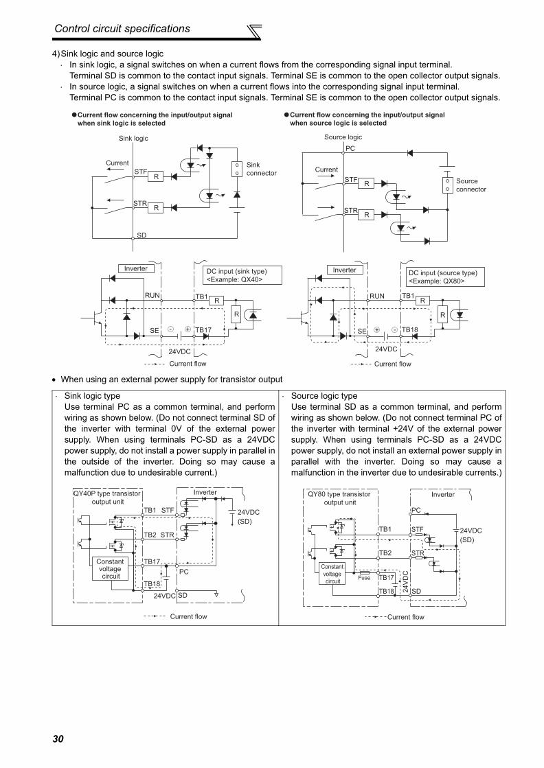
Control circuit specifications
4)Sink logic and source logic⋅ In sink logic, a signal switches on when a current flows from the corresponding signal input terminal.
Terminal SD is common to the contact input signals. Terminal SE is common to the open collector output signals.⋅ In source logic, a signal switches on when a current flows into the corresponding signal input terminal.
Terminal PC is common to the contact input signals. Terminal SE is common to the open collector output signals.
• When using an external power supply for transistor output
⋅ Sink logic typeUse terminal PC as a common terminal, and performwiring as shown below. (Do not connect terminal SD ofthe inverter with terminal 0V of the external powersupply. When using terminals PC-SD as a 24VDCpower supply, do not install a power supply in parallel inthe outside of the inverter. Doing so may cause amalfunction due to undesirable current.)
⋅ Source logic typeUse terminal SD as a common terminal, and performwiring as shown below. (Do not connect terminal PC ofthe inverter with terminal +24V of the external powersupply. When using terminals PC-SD as a 24VDCpower supply, do not install an external power supply inparallel with the inverter. Doing so may cause amalfunction in the inverter due to undesirable currents.)
Current
PC
STFR
STRR
Source logic
Source
connector
Current
SD
STFR
STRR
Sink
connector
Sink logic
Current flow concerning the input/output signal
when sink logic is selected
Current flow concerning the input/output signal
when source logic is selected
DC input (source type)
<Example: QX80>
24VDC
RUN
SE
TB1
TB18
R
Inverter
R
Current flow
+ -+-
DC input (sink type)
<Example: QX40>
Inverter
24VDC
RUN
SE
TB1
TB17
R
R
Current flow
TB1
TB2
TB17
TB18
24VDC SD
PC
STR
STF 24VDC
(SD)
QY40P type transistor
output unit
Constant voltage circuit
Current flow
Inverter
PC
TB1
TB2
TB17
TB18
STF
STR
SD
24VDC
(SD)
24
VD
C
QY80 type transistor
output unit
Constant
voltage
circuitFuse
Current flow
Inverter
30

Control circuit specifications
2
WIR
ING
2.3.3 Control circuit terminal layout
(1) Common terminals of the control circuit (SD, 5, SE)Terminals SD, 5, and SE are all common terminals (0V) for I/O signals and are isolated from each other. Do notearth(ground) these terminals.Avoid connecting the terminal SD and 5 and the terminal SE and 5.Terminal SD is a common terminal for the contact input terminals (STF, STR, STOP, RH, RM, RL, JOG, RT, MRS, RES,AU, CS) and frequency output signal (FM).The open collector circuit is isolated from the internal control circuit by photocoupler.Terminal 5 is a common terminal for frequency setting signal (terminal 2, 1 or 4) and analog output terminal AM.It should be protected from external noise using a shielded or twisted cable.Terminal SE is a common terminal for the open collector output terminal (RUN, SU, OL, IPF, FU).The contact input circuit is isolated from the internal control circuit by photocoupler.
(2) Signal inputs by contactless switchesThe contacted input terminals of the inverter (STF, STR, STOP,RH, RM, RL, JOG, RT, MRS, RES, AU, CS) can be controlledusing a transistor instead of a contacted switch as shown on theright.
External signal input using transistor
A1 B1 C1 A2
STOPAURTRHRMRL
OLIPFSURUN
B2 C2 10E 10
SDRESMRS
STFSDSDFU PCCSJOGSTR
2 5 4
1AMFM
SE
Control circuit terminalTerminal screw size: M3.5Tightening torque: 1.2N.m
+24V
STF, etc
Inverter
SD
31

Control circuit specifications
2.3.4 Wiring instructions
1) It is recommended to use the cables of 0.75mm2 gauge for connection to the control circuit terminals.If the cable gauge used is 1.25mm2 or more, the front cover may be lifted when there are many cables running orthe cables are run improperly, resulting in an operation panel contact fault.
2) The maximum wiring length should be 30m (200m for terminal FM).3) Use two or more parallel micro-signal contacts or twin contacts to
prevent a contact faults when using contact inputs since thecontrol circuit input signals are micro-currents.
4) Use shielded or twisted cables for connection to the control circuit terminals and run them away from the main andpower circuits (including the 200V relay sequence circuit).
5) Do not apply a voltage to the contact input terminals (e.g. STF) of the control circuit.6) Always apply a voltage to the fault output terminals (A, B, C) via a relay coil, lamp, etc.
Wiring of the control circuit of the 75K or moreFor wiring of the control circuit of the 75K or more, separate away from wiring of the main circuit.Make cuts in rubber bush of the inverter side and lead wires.
Micro signal contacts Twin contacts
<Wiring>
Rubber bush
(view from the inside)
Make cuts along the lines inside with
a cutter knife and such.
32

Control circuit specifications
2
WIR
ING
2.3.5 When connecting the operation panel using a connection cable
Having an operation panel on the enclosure surface is convenient. With a connection cable, you can mount theoperation panel (FR-DU07) to the enclosure surface, and connect it to the inverter.
Refer to page 196 for RS-485 communication.
REMARKS· Overall wiring length when the operation panel is connected: 20m· Refer to the following when fabricating the cable on the user side.
Commercially available product examples(as of Oct. 2008)
Parameter unit connection cable
(FR-CB2��)(option)
Operation panel(FR-DU07)
Operation panel connection connector
(FR-ADP)(option)
* Do not use pins No. 2, 8 of the communication cable.
Product Type Maker
1) Communication cable SGLPEV-T (Cat5e/300m) 24AWG × 4P* Mitsubishi Cable Industries, Ltd.
2) RJ-45 connector 5-554720-3 Tyco Electronics Corporation
33

Control circuit specifications
2.3.6 RS-485 terminal block
2.3.7 Communication operation
Using the PU connector or RS-485 terminal, you can perform communication operation from a personal computer etc.When the PU connector is connected with a personal, FA or other computer by a communication cable, a user programcan run and monitor the inverter or read and write to parameters.For the Mitsubishi inverter protocol (computer link operation), communication can be performed with the PU connectorand RS-485 terminal.For the Modbus RTU protocol, communication can be performed with the RS-485 terminal.For further details, refer to page 191.
⋅ Conforming standard: EIA-485(RS-485)⋅ Transmission format: Multidrop link⋅ Communication speed: MAX 38400bps⋅ Overall length: 500m⋅ Connection cable:Twisted pair cable
(4 pairs)
RXDRDA1(RXD1+)
RDB1(RXD1-)
RDA2(RXD2+)
RDB2(RXD2-)
SDA1(TXD1+)
SDB1(TXD1-)
SDA2(TXD2+)
SDB2(TXD2-)
P5S(VCC)
SG(GND)
P5S(VCC)
SG(GND) VCC
TXD
OPEN
100Ω
Terminating resistor switch
Factory-set to "OPEN".
Set only the terminating resistor switch of
the remotest inverter to the "100Ω" position.
34

Connection of stand-alone option units
2
WIR
ING
2.4 Connection of stand-alone option unitsThe inverter accepts a variety of stand-alone option units as required.Incorrect connection will cause inverter damage or accident. Connect and operate the option unit carefully inaccordance with the corresponding option unit manual.
2.4.1 Connection of the brake unit (FR-BU2)Connect the brake unit (FR-BU2) as shown below to improve the braking capability at deceleration.(1) Connection example with the GRZG type discharging resistor
<Recommended external thermal relay>
*1 Connect the inverter terminals (P/+, N/-) and brake unit (FR-BU2) terminals so that their terminal names match with each other.(Incorrect connection will damage the inverter and brake unit.)
*2 When the power supply is 400V class, install a step-down transformer.*3 Keep a wiring distance of within 5m between the inverter, brake unit (FR-BU2) and discharging resistor. Even when the wiring
is twisted, the cable length must not exceed 10m.*4 It is recommended to install an external thermal relay to prevent overheat of discharging resistors.*5 Refer to FR-BU2 manual for connection method of discharging resistor.
Brake Unit Discharging Resistor Recommended External Thermal RelayFR-BU2-1.5K GZG 300W-50Ω (one) TH-N20CXHZ 1.3AFR-BU2-3.7K GRZG 200-10Ω (three in series) TH-N20CXHZ 3.6AFR-BU2-7.5K GRZG 300-5Ω (four in series) TH-N20CXHZ 6.6AFR-BU2-15K GRZG 400-2Ω (six in series) TH-N20CXHZ 11AFR-BU2-H7.5K GRZG 200-10Ω (six in series) TH-N20CXHZ 3.6AFR-BU2-H15K GRZG 300-5Ω (eight in series) TH-N20CXHZ 6.6AFR-BU2-H30K GRZG 400-2Ω (twelve in series) TH-N20CXHZ 11A
CAUTION⋅ Set "1" in Pr. 0 Brake mode selection of the FR-BU2 to use GRZG type discharging resistor.⋅ Do not remove a jumper across terminal P/+ and P1 except when connecting a DC reactor.
U
V
W
P/+
N/-
R/L1
S/L2
T/L3
Motor
IM
InverterPR
N/-
BUE
SD
P/+
A
B
C
FR-BU2
GRZG type discharging resistor
External thermal relay
RR
Three-phase AC power supply
MCCB MC
OFFON
MCT
*1
*3
*3
*2
MC
*4
*5
OCR contact
OCR
5m or less
To the brake
unit terminal P/+
To a resistor
TH-N20
1/L1 5/L3
2/T1 6/T3
35

Connection of stand-alone option units
(2) FR-BR-(H) connection example with resistor unit
(3) Connection example with MT-BR5 type resistor unit
*1 Connect the inverter terminals (P/+, N/-) and brake unit (FR-BU2) terminals so that their terminal names match with each other.(Incorrect connection will damage the inverter and brake unit.)
*2 When the power supply is 400V class, install a step-down transformer.*3 The wiring distance between the inverter, brake unit (FR-BU) and resistor unit (FR-BR) should be within 5m. Even when the
wiring is twisted, the cable length must not exceed 10m.*4 Normal: across TH1-TH2...close, Alarm: across TH1-TH2...open
CAUTION⋅ Do not remove a jumper across terminal P/+ and P1 except when connecting a DC reactor.
*1 Connect the inverter terminals (P/+, N/-) and brake unit (FR-BU2) terminals so that their terminal names match with each other.(Incorrect connection will damage the inverter and brake unit.)
*2 When the power supply is 400V class, install a step-down transformer.*3 The wiring distance between the inverter, brake unit (FR-BU2) and resistor unit (MT-BR5) should be within 5m. If twisted wires
are used, the distance should be within 10m.*4 Normal: across TH1-TH2...open, Alarm: across TH1-TH2...close*5 CN8 connector used with the MT-BU5 type brake unit is not used.
CAUTION⋅ Set "2" in Pr. 0 Brake mode selection of the FR-BU2 to use MT-BR5 type resistor unit.
U
V
W
P/+
N/-
R/L1
S/L2
T/L3
Motor
IM
InverterPR
N/-
BUE
SD
P/+
P
A
B
C
FR-BU2
FR-BR
TH2
TH1
PRThree phase AC power supply
MCCB MC
MC
OFFON
MCT
*1
*4
5m or less*3
*3
*2
MCR/L1
Motor
IM
Inverter
S/L2T/L3
UV
P/+N/-
PPR
5m or less
W
Three phase AC power supply
MCCB
TH1
TH2
MC
CR1
OFFON
MC
CR1
T
*3
*1
*3
*5
*4
PN
BUESD
PPR
Brake unit FR-BU2
Resistor unit MT-BR5
*2
36

Connection of stand-alone option units
2
WIR
ING
2.4.2 Connection of the brake unit (FR-BU/MT-BU5)When connecting the brake unit (FR-BU(H)/MT-BU5) to improve the brake capability at deceleration, make connectionas shown below.(1) Connection with the FR-BU (55K or less)
*1 Connect the inverter terminals (P/+, N/-) and brake unit (FR-BU (H)) terminals so that their terminal signals matchwith each other. (Incorrect connection will damage the inverter.)
*2 When the power supply is 400V class, install a step-down transformer.*3 The wiring distance between the inverter, brake unit (FR-BU) and resistor unit (FR-BR) should be within 5m. If
twisted wires are used, the distance should be within 10m.
CAUTION⋅ If the transistors in the brake unit should become faulty, the resistor can be unusually hot, causing a fire. Therefore, install a
magnetic contactor on the inverter’s input side to configure a circuit so that a current is shut off in case of fault.⋅ Do not remove a jumper across terminal P/+ and P1 except when connecting a DC reactor.
U
V
W
P/+
N/−
R/L1
S/L2
T/L3
Motor
IM
Inverter
PR
N/−
P/+
P
HA
HB
HC
FR-BU
FR-BR
TH2
TH1
PR
*1
Three-phase AC
power supply
MCCB MC
OFFON
MC
T *2
MC
*3
5m or less
37

Connection of stand-alone option units
(2) Connection with the MT-BU5 (75K or more)After making sure that the wiring is correct, set "1" in Pr.30 Regenerative function selection. (Refer to page 107)
<Inserting the CN8 connector>Make cuts in rubber bush of the upper portion of the inverter and lead a cable.1) Make cuts in the rubber bush for leading the CN8 connector cable with a nipper or cutter knife.
2) Insert a connector on the MT-BU5 side through a rubber bush to connect to a connector on the inverter side.
*1 When the power supply is 400V class, install a step-down transformer.*2 The wiring length between the resistor unit and brake resistor should be 10m maximum when wires are
twisted and 5m maximum when wires are not twisted.
CAUTION⋅ Install the brake unit in a place where a cooling air reaches the brake unit heatsink and within a distance of the cable supplied
with the brake unit reaches the inverter.⋅ For wiring of the brake unit and inverter, use an accessory cable supplied with the brake unit. Connect the main circuit cable to
the inverter terminals P/+ and N/- and connect the control circuit cable to the CN8 connector inside by making cuts in therubber bush at the top of the inverter for leading the cable.
⋅ The brake unit which uses multiple resistor units has terminals equal to the number of resistor units. Connect one resistor unitto one pair of terminal (P, PR).
CAUTIONClamp the CN8 connector cable on the inverter side with a wire clamp securely.
MC
R/L1Motor
IM
Inverter
Brake unit
MT-BU5
Resistor unit
MT-BR5
S/L2
T/L3
U
V
P/+
N/P
PR
P
PR
P
PR
P TH1
TH2
PR
CN8
W
Three-phase
AC power
supply
MCCB
TH1
TH2
MC
OFFON
MC
CR1 CR2
CR1
CR2
T *1
5m or
less
*2
Rubber bushes
Make cuts in
rubber bush
Insert the connector until
you hear a click sound.
CN8 connectorWire clamp
38

Connection of stand-alone option units
2
WIR
ING
2.4.3 Connection of the brake unit (BU type)Connect the brake unit (BU type) correctly as shown below. Incorrect connection will damage the inverter. Remove the jumperacross terminals HB-PC and terminals TB-HC of the brake unit and fit it to across terminals PC-TB.
2.4.4 Connection of the high power factor converter (FR-HC/MT-HC)When connecting the high power factor converter (FR-HC) to suppress power harmonics, perform wiring securely as shown below.Incorrect connection will damage the high power factor converter and inverter.After making sure that the wiring is correct, set "2" in Pr. 30 Regenerative function selection. (Refer to page 107.)(1) Connection with the FR-HC (55K or less)
*1 When the power supply is 400V class, install a step-down transformer.
CAUTION⋅ The wiring distance between the inverter, brake unit and discharging resistor should be within 2m. If twisted wires are used, the
distance should be within 5m. ⋅ If the transistors in the brake unit should become faulty, the resistor can be unusually hot, causing a fire. Therefore, install a
magnetic contactor on the inverter's power supply side to shut off a current in case of fault.⋅ Do not remove a jumper across terminal P/+ and P1 except when connecting a DC reactor.
*1 Remove the jumpers across the inverter terminals R/L1-R1/L11, S/L2-S1/L21, and connect the control circuit power supply to the R1/L11 and S1/L21 terminals. Always keep the power input terminals R/L1, S/L2, T/L3 open. Incorrect connection will damage the inverter. (E.OPT (option fault)will occur. (Refer to page 268.))
*2 Do not insert the MCCB between terminals P/+ − N/- (P/+ − P/+, N/- − N/-). Opposite polarity of terminals N/-, P/+ will damage the inverter.*3 Use Pr. 178 to Pr. 189 (input terminal function selection) to assign the terminals used for the X10 (X11) signal. (Refer to page 115.)
For communication where the start command is sent only once, e.g. RS-485 communication operation, use the X11 signal when making setting tohold the mode at occurrence of an instantaneous power failure. (Refer to page 107.)
*4 Be sure to connect terminal RDY of the FR-HC to the X10 signal or MRS signal assigned terminal of the inverter, and connect terminal SE of theFR-HC to terminal SD of the inverter. Without proper connecting, FR-HC will be damaged.
CAUTION⋅ The voltage phases of terminals R/L1, S/L2, T/L3 and terminals R4, S4, T4 must be matched.⋅ Use sink logic (initial setting) when the FR-HC is connected. The FR-HC cannot be connected when source logic is selected.⋅ Do not remove a jumper across terminal P/+ and P1 except when connecting a DC reactor.
U
V
W
IM Brake unit
(BU type)
Discharging
resistor
R/L1
S/L2
T/L3
N/-
P/+
MC
P
PR
OCR
N
Remove the
jumper
Fit a jumper
HC
HB
HA
TB
OCR
PC
MC
OFFON
MC
T*1
Three-phase
AC power
supply
MCCBInverter
Motor
Inverter
Outside box
Three-phase
AC power
supply
MCCB
High power factor converter
(FR-HC)(FR-HCB)
Reactor2
(FR-HCL02)
R/L1Reactor1
(FR-HCL01)
phase
detection
S/L2
T/L3
P/+
N/-
X11 *3
X10 *3
RES
U
VW
P
N
Y1orY2
RDY
RSO
MC1
MC2
R4
S4
T4
R
S
T
R4
S4
T4
R3
S3
T3
R3
S3
T3
R2
S2
T2
R2
S2
T2
R
S
T
MC1
MC2
SDSE
R1/L11
S1/L21
MC
*1
*1
*2
*4
Motor
I M
39

Connection of stand-alone option units
(2) Connection with the MT-HC (75K or more)
*1 Remove the jumper across terminals R-R1, S-S1 of the inverter, and connect the control circuit powersupply to the R1 and S1 terminals. The power input terminals R/L1, S/L2, T/L3 must be open. Incorrectconnection will damage the inverter. (E.OPT (option fault) will occur. (Refer to page 268.)
*2 Do not insert the MCCB between terminals P/+ − N/- (P/+ − P/+, N/- − N/-). Opposite polarity of terminalsN, P will damage the inverter.
*3 Use Pr. 178 to Pr. 189 (input terminal function selection) to assign the terminals used for the X10 (X11) signal.(Refer to page 115.) For communication where the start command is sent only once, e.g. RS-485communication operation, use the X11 signal when making setting to hold the mode at occurrence of aninstantaneous power failure. (Refer to page 107.)
*4 Connect the power supply to terminals R1 and S1 of the MT-HC via an isolated transformer.*5 Be sure to connect terminal RDY of the MT-HC to the X10 signal or MRS signal assigned terminal of the
inverter, and connect terminal SE of the MT-HC to terminal SD of the inverter. Without proper connecting,MT-HC will be damaged.
CAUTION⋅ Use sink logic (initial setting) when the MT-HC is connected. The MT-HC cannot be connected when source logic is
selected.⋅ The voltage phases of terminals R/L1, S/L2, T/L3 and terminals R4, S4, T4 must be matched.⋅ When connecting the inverter to the MT-HC, do not connect the DC reactor provided to the inverter.
Three-phase
AC power
supply
MCCBMT-HCL01 MT-HCB
R1 S1
R1 S1R1/L11
S1/L21
MT-HCL02 MT-HC Inverter
MT-HCTRIsolated transformer
R
S
T
R/L1
S/L2
T/L3
U
V
W
R2
S2
T2
R2
S2
T2
R3
S3
T3
R3
S3
T3
R4
S4
T4
R4
S4
T4
R
S
T
88R
88S
88R
88S*2
RDY
RSO
SE
X10
RES
SD
*3*5
*1
*1
*4
Motor
IM
P
N
P/+
N/
MC
40

Connection of stand-alone option units
2
WIR
ING
2.4.5 Connection of the power regeneration common converter (FR-CV)(55K or less)
When connecting the power regeneration common converter (FR-CV), make connection so that the inverter terminals(P/+, N/-) and the terminal symbols of the power regeneration common converter (FR-CV) are the same.After making sure that the wiring is correct, set "2" in Pr. 30 Regenerative function selection. (Refer to page 107.)
*1 Remove the jumpers across terminals R/L1-R1/L11 and S/L2-S1/L21 of the inverter, and connect thecontrol circuit power supply across terminals R1/L11-S1/L21. Always keep the power input terminals R/L1, S/L2, T/L3 open. Incorrect connection will damage the inverter. (E.OPT (option fault) will occur. (Referto page 268.))
*2 Do not insert an MCCB between the terminals P/+ − N/- (between P/L+ − P/+, between N/L- − N/-).Opposite polarity of terminals N/-, P/+ will damage the inverter.
*3 Assign the terminal for X10 signal using any of Pr. 178 to Pr. 189 (input terminal function selection).(Refer to page 115)
*4 Be sure to connect the power supply and terminals R/L11, S/L21, T/MC1.Operating the inverter without connecting them will damage the power regeneration common converter.
*5 Be sure to connect terminal RDYB of the FR-CV to the X10 signal or MRS signal assigned terminal of theinverter, and connect terminal SE of the FR-CV to terminal SD of the inverter. Without proper connecting,FR-CV will be damaged.
CAUTION⋅ The voltage phases of terminals R/L11, S/L21, T/MC1 and terminals R2/L1, S2/L2, T2/L3 must be matched.⋅ Use sink logic (initial setting) when the FR-CV is connected. The FR-CV cannot be connected when source logic is
selected.⋅ Do not remove a jumper across terminal P/+ and P1.
R/L11
Dedicated stand-alonereactor (FR-CVL)
S/L21
T/L31
R2/L12
S2/L22
T2/L32
R2/L1
S2/L2
T2/L3
R/L11
S/L21
T/MC1
P/L+
U
V
W
IM
FR-CV typePower regeneration common converter
Inverter
PC
SD
X10 *3
RES
P24
SD
RDYB
RSO
SE
RDYA
N/L−*2
*5
*4
R/L1
S/L2
T/L3
R1/L11
S1/L21
P/+
N/−
*1
Three-phaseAC power
supply
MCCB MC1
41
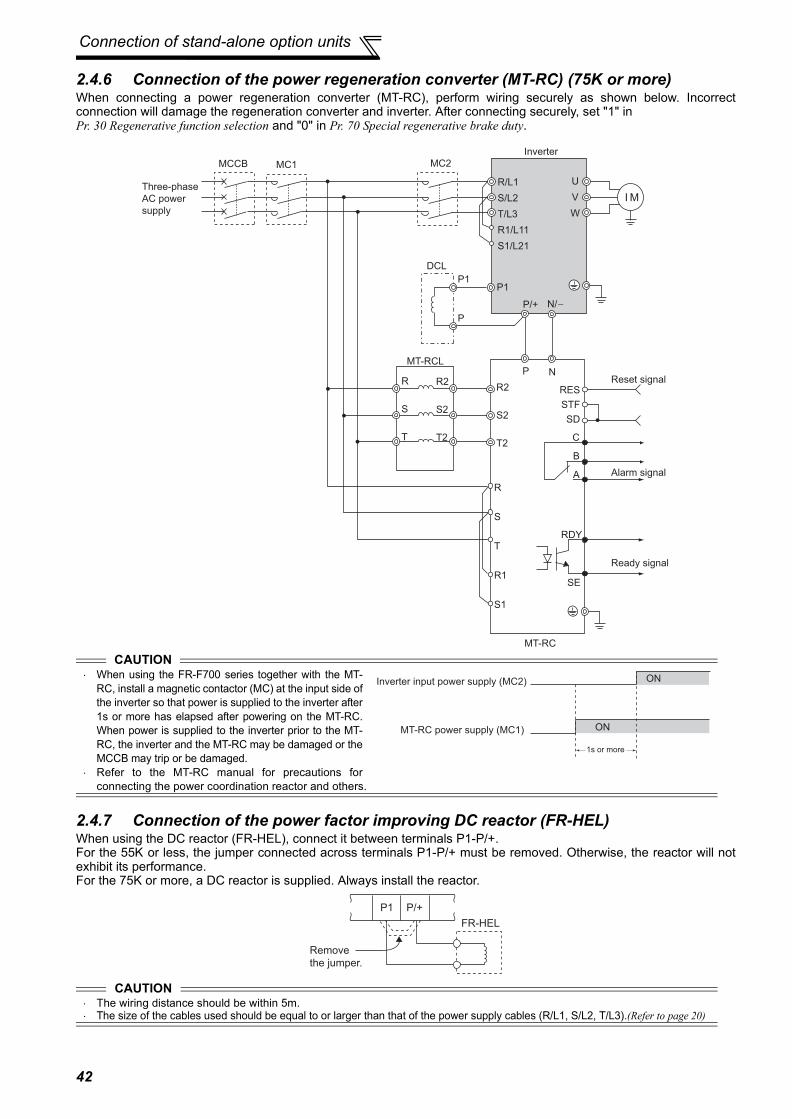
Connection of stand-alone option units
2.4.6 Connection of the power regeneration converter (MT-RC) (75K or more)When connecting a power regeneration converter (MT-RC), perform wiring securely as shown below. Incorrectconnection will damage the regeneration converter and inverter. After connecting securely, set "1" in Pr. 30 Regenerative function selection and "0" in Pr. 70 Special regenerative brake duty.
2.4.7 Connection of the power factor improving DC reactor (FR-HEL)When using the DC reactor (FR-HEL), connect it between terminals P1-P/+.For the 55K or less, the jumper connected across terminals P1-P/+ must be removed. Otherwise, the reactor will notexhibit its performance.For the 75K or more, a DC reactor is supplied. Always install the reactor.
CAUTION⋅ When using the FR-F700 series together with the MT-
RC, install a magnetic contactor (MC) at the input side ofthe inverter so that power is supplied to the inverter after1s or more has elapsed after powering on the MT-RC.When power is supplied to the inverter prior to the MT-RC, the inverter and the MT-RC may be damaged or theMCCB may trip or be damaged.
⋅ Refer to the MT-RC manual for precautions forconnecting the power coordination reactor and others.
CAUTION⋅ The wiring distance should be within 5m.⋅ The size of the cables used should be equal to or larger than that of the power supply cables (R/L1, S/L2, T/L3).(Refer to page 20)
DCL
P1P1
R/L1
S/L2
T/L3
R1/L11
S1/L21
R
S
T
R
S
T
R1
S1
R2
S2
T2
R2
S2
T2
RES
STF
SD
C
B
A
U
V
W
Inverter
MT-RCL
P
P/+ N/
P N
RDY
SE
MT-RC
Reset signal
Alarm signal
Ready signal
Three-phase
AC power
supply
MCCB MC2
I M
MC1
MT-RC power supply (MC1)
Inverter input power supply (MC2) ON
ON
1s or more
P1
FR-HEL
Remove
the jumper.
P/+
42

3
PRECAUTIONS FOR USE OF THE INVERTER3
4
5
6
1
2
This chapter explains the "PRECAUTIONS FOR USE OF THEINVERTER" for use of this product.Always read the instructions before using the equipment.
3.1 EMC and leakage currents......................................443.2 Installation of a reactor ............................................523.3 Power-off and magnetic contactor (MC)..................523.4 Inverter-driven 400V class motor ............................533.5 Precautions for use of the inverter ..........................543.6 Failsafe of the system which uses the inverter .......56
437

EMC and leakage currents
3.1 EMC and leakage currents3.1.1 Leakage currents and countermeasuresCapacitances exist between the inverter I/O cables, other cables and earth and in the motor, through which a leakagecurrent flows. Since its value depends on the static capacitances, carrier frequency, etc., low acoustic noise operationat the increased carrier frequency of the inverter will increase the leakage current. Therefore, take the followingmeasures. Select the earth leakage circuit breaker according to its rated sensitivity current, independently of the carrierfrequency setting.(1) To-earth (ground) leakage currentsLeakage currents may flow not only into the inverter's own line but also into the other lines through the earth (ground)cable, etc. These leakage currents may operate earth (ground) leakage circuit breakers and earth leakage relaysunnecessarily.
Suppression technique⋅ If the carrier frequency setting is high, decrease the Pr. 72 PWM frequency selection setting. Note that motor noise
increases.Selecting Pr. 240 Soft-PWM operation selection makes the sound inoffensive.⋅ By using earth leakage circuit breakers designed for harmonic and surge suppression in the inverter's own line and
other line, operation can be performed with the carrier frequency kept high (with low noise).To-earth (ground) leakage currents⋅ Take caution as long wiring will increase the leakage current. Decreasing the carrier frequency of the inverter
reduces the leakage current.⋅ Increasing the motor capacity increases the leakage current. The leakage current of the 400V class is larger than
that of the 200V class.(2) Line-to-line leakage currentsHarmonics of leakage currents flowing in static capacitances between the inverter output cables may operate theexternal thermal relay unnecessarily. When the wiring length is long (50m or more) for the 400V class small-capacitymodel (7.5K or less), the external thermal relay is likely to operate unnecessarily because the ratio of the leakagecurrent to the rated motor current increases.
Line-to-line leakage current data example (200V class)
*The leakage currents of the 400V class are about twice as large.
Measures⋅ Use Pr. 9 Electronic thermal O/L relay.⋅ If the carrier frequency setting is high, decrease the Pr. 72 PWM frequency selection setting. Note that motor noise
increases.Selecting Pr. 240 Soft-PWM operation selection makes the sound inoffensive. To ensure that the motor isprotected against line-to-line leakage currents, it is recommended to use a temperature sensor to directly detectmotor temperature.
Installation and selection of moulded case circuit breakerInstall a moulded case circuit breaker (MCCB) on the power receiving side to protect the wiring of the inverter inputside. Select the MCCB according to the inverter input side power factor (which depends on the power supply voltage,output frequency and load). Especially for a completely electromagnetic MCCB, one of a slightly large capacity mustbe selected since its operation characteristic varies with harmonic currents. (Check it in the data of the correspondingbreaker.) As an earth leakage circuit breaker, use the Mitsubishi earth leakage circuit breaker designed forharmonics and surge suppression.
Motor Capacity
(kW)
Rated Motor Current(A)
Leakage Currents(mA)
Wiring length 50m Wiring length 100m
0.4 1.8 310 5000.75 3.2 340 5301.5 5.8 370 5602.2 8.1 400 5903.7 12.8 440 6305.5 19.4 490 6807.5 25.6 535 725
⋅Motor: SF-JR 4P⋅Carrier frequency: 14.5kHz⋅Used wire: 2mm2, 4coresCabtyre cable
Power
supply
Thermal relay
Line-to-line static capacitances
MCCB MC
Line-to-line leakage currents path
Motor
Inverter IM
44

EMC and leakage currents
3
ECA
UTI
ON
S FO
R U
SE O
F TH
E IN
VER
TER
(3) Selection of rated sensitivity current of earth leakage circuit breakerWhen using the earth leakage current breaker with the inverter circuit, select its rated sensitivity current as follows,independently of the PWM carrier frequency:
ExampleSelection example (in the case of the left figure (400V class connection))
Inverter leakage current (with and without EMC filter)Input power conditions(200V class: 220V/60Hz, 400V class: 440V/60Hz, power supply unbalance within 3%)
⋅ Breaker designed for harmonic and surge suppressionRated sensitivity current: IΔn ≥ 10 × (Ig1 + Ign + Igi + Ig2 + Igm)
⋅ Standard breakerRated sensitivity current: IΔn ≥ 10 × {Ig1 + Ign + Igi + 3 × (Ig2 + Igm)}
Ig1, Ig2: Leakage currents in wire path during commercialpower supply operation
Ign: Leakage current of inverter input side noise filterIgm: Leakage current of motor during commercial power
supply operationIgi: Leakage current of inverter unit
Breaker Designed for Harmonic and Surge
SuppressionStandard Breaker
Leakage current Ig1 (mA) × 66 ×5m
= 0.111000m
Leakage current Ign (mA) 0 (without noise filter)
Leakage current Igi (mA) 1 (without EMC filter)Refer to the following table for the leakage current of the inverter*
Leakage current Ig2 (mA) × 66 ×60m
= 1.321000m
Motor leakage current Igm (mA) 0.36Total leakage current (mA) 2.79 6.15
Rated sensitivity current (mA) 30 100* Refer to page 15 for the presence/absence of the EMC filter.
Voltage(V)
EMC FilterON (mA) OFF (mA)
200 22(1)* 1
400 30 1
400 1 1
*For the FR-F720-0.75K and 1.5K, the EMC filter is always valid.The leakage current is 1mA.
CAUTION⋅ Install the earth leakage circuit breaker (ELB) on the input side of the inverter.⋅ In the connection earthed-neutral system, the sensitivity current is blunt against an earth (ground) fault in the inverter output side.
Earthing (Grounding) must conform to the requirements of national and local safety regulations and electrical codes. (NEC section250, IEC 536 class 1 and other applicable standards)
⋅ When the breaker is installed on the output side of the inverter, it may be unnecessarily operated by harmonics even if the effectivevalue is less than the rating.In this case, do not install the breaker since the eddy current and hysteresis loss will increase, leading totemperature rise.
⋅ The following models are standard breakers....BV-C1, BC-V, NVB, NV-L, NV-G2N, NV-G3NA and NV-2F earth leakage relay (exceptNV-ZHA), NV with AA neutral wire open-phase protectionThe other models are designed for harmonic and surge suppression....NV-C/NV-S/MN series, NV30-FA, NV50-FA, BV-C2, earthleakage alarm breaker (NF-Z), NV-ZHA, NV-H
(200V 60Hz)(200V 60Hz)
1. 5 3. 72. 2
7. 5 152211
3730
55455.5 18. 5
0. 1
0. 2
0. 3
0. 50. 7
1. 0
2. 0
0
20
40
60
80
100
120
2 3.55.5
8 14223038
6080100
150
Motor capacity (kW)
Example of leakage current ofcable path per 1km during thecommercial power supply operationwhen the CV cable is routed in metal conduit
Leakage current example ofthree-phase induction motorduring the commercialpower supply operation
Leakage c
urr
ents
(m
A)
Leakage c
urr
ents
(m
A)
Cable size (mm2)Motor capacity (kW)
For " " connection, the amount of leakage current is appox.1/3 of the above value.
(Three-phase three-wire delta connection 400V60Hz)
Example of leakage current per 1km during the commercial power supply operation when the CV cable is routed in metal conduit
Leakage current example of three-phase induction motor during the commercial power supply operation
(Totally-enclosed fan-cooled type motor 400V60Hz)
0
20
40
60
80
100
120
leakage c
urr
ents
(m
A)
leakage c
urr
ents
(m
A)
2 3.55.5
8 14223038
6080100
150
Cable size (mm2)
0. 1
0. 2
0. 3
0. 50. 7
1. 0
2. 0
1. 5 3. 72. 2
7. 5 152211
3730
55455.5 18. 5
Noise filter
Inverter
ELB
Ig1 Ign
Igi
Ig2 Igm
IM
5.5mm2 ×
5m 5.5mm2 ×
60m
400V2.2kW
3φ
13
13
Phase
grounding
Earthed-neutral
system
45
PR

EMC and leakage currents
3.1.2 EMC measures
Some electromagnetic noises enter the inverter to malfunction it and others are radiated by the inverter to malfunctionperipheral devices. Though the inverter is designed to have high immunity performance, it handles low-level signals, so itrequires the following basic techniques. Also, since the inverter chops outputs at high carrier frequency, that could generateelectromagnetic noises. If these electromagnetic noises cause peripheral devices to malfunction, EMI measures should betaken to suppress noises. These techniques differ slightly depending on EMI paths.
1)Basic techniques⋅ Do not run the power cables (I/O cables) and signal cables of the inverter in parallel with each other and do not
bundle them.⋅ Use twisted pair shielded cables for the detector connection and control signal cables, and connect the sheathes
of the shield cables to terminal SD.⋅ Earth (Ground) the inverter, motor, etc. at one point.
2)Techniques to reduce electromagnetic noises that enter and malfunction the inverter (Immunity measures)When devices that generate many electromagnetic noises (which use magnetic contactors, magnetic brakes, manyrelays, for example) are installed near the inverter and the inverter may be malfunctioned by electromagnetic noises,the following measures must be taken:⋅ Provide surge suppressors for devices that generate many electromagnetic noises to suppress electromagnetic
noises.⋅ Fit data line filters to signal cables.⋅ Earth (Ground) the shields of the detector connection and control signal cables with cable clamp metal.
3)Techniques to reduce electromagnetic noises that are radiated by the inverter to malfunction peripheral devices (EMImeasures)Inverter-generated electromagnetic noises are largely classified into those radiated by the cables connected to theinverter and inverter main circuits (I/O), those electromagnetically and electrostatically induced to the signal cables ofthe peripheral devices close to the main circuit power supply, and those transmitted through the power supply cables.
Noise propagated through
power supply cable
Path 3)
Path 2)
Path 1)Noise directly
radiated from inverter
Path 4), 5)
Air propagated
noise
Path 6)
Electrical path
propagated noise
Path 8)
Path 7)
Inverter generated
electromagnetic
noise
Electromagnetic
induction noise
Electrostatic
induction noise
Noise radiated from
power supply cable
Noise radiated from motor connection cable
Noise from earth (ground)cable due to leakagecurrent
Instrument Receiver
IMMotor
Telephone
Sensor
1)
2)
3)
3)
8)
7)
5)
7)
4)6)
Inverter
1)
Sensor
power supply
46

EMC and leakage currents
3
ECA
UTI
ON
S FO
R U
SE O
F TH
E IN
VER
TER
Data line filterData line filter is effective as an EMC measure. Provide a data line filter for the detector cable, etc.
EMC measures
Propagation Path Measures
1) 2) 3)
When devices that handle low-level signals and are liable to malfunction due to electromagnetic noises, e.g. instruments, receivers and sensors, are contained in the enclosure that contains the inverter or when their signal cables are run near the inverter, the devices may be malfunctioned by air-propagated electromagnetic noises. The following measures must be taken:(1) Install easily affected devices as far away as possible from the inverter.(2) Run easily affected signal cables as far away as possible from the inverter and its I/O cables.(3) Do not run the signal cables and power cables (inverter I/O cables) in parallel with each other and do
not bundle them.(4) Set the EMC filter ON/OFF connector of the inverter to the ON position. (Refer to page 15)(5) Insert a common mode filters into I/O and capacitors between the input lines to suppress cable-
radiated noises.(6) Use shield cables as signal cables and power cables and run them in individual metal conduits to
produce further effects.
4) 5) 6)
When the signal cables are run in parallel with or bundled with the power cables, magnetic and static induction noises may be propagated to the signal cables to malfunction the devices and the following measures must be taken:(1) Install easily affected devices as far away as possible from the inverter.(2) Run easily affected signal cables as far away as possible from the I/O cables of the inverter.(3) Do not run the signal cables and power cables (inverter I/O cables) in parallel with each other and do
not bundle them.(4) Use shield cables as signal cables and power cables and run them in individual metal conduits to
produce further effects.
7)
When the power supplies of the peripheral devices are connected to the power supply of the inverter in the same line, inverter-generated noises may flow back through the power supply cables to malfunction the devices and the following measures must be taken:(1) Set the EMC filter ON/OFF connector of the inverter to the ON position. (Refer to page 15)(2) Install the common mode filter (FR-BLF, FR-BSF01) to the power cables (output cable) of the inverter.
8)When a closed loop circuit is formed by connecting the peripheral device wiring to the inverter, leakage currents may flow through the earth (ground) cable of the inverter to malfunction the device. In such a case, disconnection of the earth (ground) cable of the device may cause the device to operate properly.
REMARKSFor compliance with the EU EMC directive, refer to the Instruction Manual (basic).
Sensor
Use a twisted pair shielded cable
Inverter power supply
Control power supply
EnclosureDecrease carrier frequency
MotorIMFR-BLF
Install common mode filter (FR-BLF, FR-BSF01) on the inverter output side
Power supply for sensor
EMC filter Inverter
Do not earth (ground) shield but connect it to signal common cable.
Do not earth (ground) enclosure directly
Do not earth (ground) control cable
Use 4-core cable for motor power cable and use one cable as earth (ground) cable.
Separate the inverter and power line by more than 30cm (at least 10cm) from sensor circuit.
47
PR

48
EMC and leakage currents
3.1.3 Power supply harmonics
The inverter may generate power supply harmonics from its converter circuit to affect the power generator, powercapacitor etc. Power supply harmonics are different from noise and leakage currents in source, frequency band andtransmission path. Take the following countermeasure suppression techniques.
The differences between harmonics and noises are indicated below:
Measures
Item Harmonics Noise
Frequency Normally number 40 to 50 max. (3kHz or less) High frequency (several 10kHz to 1GHz order)
Environment To-electric channel, power impedance To-space, distance, wiring pathQuantitative understanding Theoretical calculation possible Random occurrence, quantitative grasping difficult
Generated amount Nearly proportional to load capacity Depending on the current fluctuation ratio (larger as switching is faster)
Affected equipment immunity Specified in standard per equipment Different depending on maker's equipment specifications
Suppression example Provide reactor. Increase distance.
The harmonic current generated from the inverterto the input side differs according to variousconditions such as the wiring impedance, whethera reactor is used or not, and output frequency andoutput current on the load side.For the output frequency and output current, weunderstand that they should be calculated in theconditions under the rated load at the maximumoperating frequency.
CAUTIONThe power factor improving capacitor and surge suppressor on the inverter output side may be overheated or damaged by thehigh frequency components of the inverter output. Also, since an excessive current flows in the inverter to activate overcurrentprotection, do not provide a capacitor and surge suppressor on the inverter output side when the motor is driven by the inverter.For power factor improvement, install a reactor on the inverter input side or in the DC circuit.
AC reactor
(FR-HAL)
DC reactor
(FR-HEL)
Do not insert power
factor improving capacitor.
MCCB MC
Inverter
Po
we
r su
pp
ly
R
S
T Z
Y
XU
V
W
P1
R/L1
S/L2
T/L3
P/+
IM

EMC and leakage currents
3
ECA
UTI
ON
S FO
R U
SE O
F TH
E IN
VER
TER
3.1.4 Harmonic suppression guidelineHarmonic currents flow from the inverter to a power receiving point via a power transformer. The harmonic suppressionguideline was established to protect other consumers from these outgoing harmonic currents.The three-phase 200V input specifications 3.7kW or less are previously covered by "Harmonic suppression guidelinefor household appliances and general-purpose products" and other models are covered by "Harmonic suppressionguideline for consumers who receive high voltage or special high voltage". However, the general-purpose inverter hasbeen excluded from the target products covered by "Harmonic suppression guideline for household appliances andgeneral-purpose products" in January 2004. Later, this guideline was repealed on September 6, 2004. All capacities ofall models are now target products of "Harmonic suppression guideline for consumers who receive high voltage orspecial high voltage".
"Guideline for specific consumers"This guideline sets forth the maximum values of harmonic currents outgoing from a high-voltage or especially high-voltage consumer who will install, add or renew harmonic generating equipment. If any of the maximum values isexceeded, this guideline requires that consumer to take certain suppression measures.
(1) Application of the harmonic suppression guideline for specific consumers
Table 1 Maximum Values of Outgoing Harmonic Currents per 1kW Contract PowerReceived Power
Voltage 5th 7th 11th 13th 17th 19th 23rd Over 23rd
6.6kV 3.5 2.5 1.6 1.3 1.0 0.9 0.76 0.7022kV 1.8 1.3 0.82 0.69 0.53 0.47 0.39 0.3633kV 1.2 0.86 0.55 0.46 0.35 0.32 0.26 0.24
Table 2 Conversion factors for FR-F700 seriesClass Circuit Type Conversion Factor (Ki)
3 Three-phase bridge(Capacitor smoothing)
Without reactor K31 = 3.4With reactor (AC side) K32 = 1.8With reactor (DC side) K33 = 1.8With reactor (AC, DC sides) K34 = 1.4
5 Self-exciting three-phase bridge When high power factor converter is used K5 = 0
Table 3 Equivalent Capacity LimitsReceived Power Voltage Reference Capacity
6.6kV 50kVA22/33kV 300kVA
66kV or more 2000kVA
Table 4 Harmonic content (Values of the fundamental current is 100%)Reactor 5th 7th 11th 13th 17th 19th 23rd 25th
Not used 65 41 8.5 7.7 4.3 3.1 2.6 1.8Used (AC side) 38 14.5 7.4 3.4 3.2 1.9 1.7 1.3Used (DC side) 30 13 8.4 5.0 4.7 3.2 3.0 2.2Used (AC, DC sides) 28 9.1 7.2 4.1 3.2 2.4 1.6 1.4
Install, add or renew
equipment
Calculation of equivalent
capacity total
Equivalent capacity total
Calculation of outgoing
harmonic current
Not more than harmonic current upper
limit?
Harmonic suppression
measures unnecessary
Harmonic suppression
measures necessaryEqual to or less than upper limit
More than upper limit
Above reference
capacity
Equal to or less than reference capacity
49
PR

EMC and leakage currents
1)Calculation of equivalent capacity P0 of harmonic generating equipmentThe "equivalent capacity" is the capacity of a 6-pulse converter converted from the capacity of consumer's harmonicgenerating equipment and is calculated with the following equation.If the sum of equivalent capacities is higher thanthe limit in Table 3, harmonics must be calculated with the following procedure:
2)Calculation of outgoing harmonic currentOutgoing harmonic current = fundamental wave current (value converted from received power voltage) × operationratio × harmonic content⋅Operation ratio: Operation ratio = actual load factor × operation time ratio during 30 minutes⋅Harmonic content: Found in Table.
P0 = Σ (Ki × Pi) [kVA]* Rated capacity: Determined by the capacity of the applied motor and
found in Table 5. It should be noted that the rated capacity used hereis used to calculate generated harmonic amount and is different fromthe power supply capacity required for actual inverter drive.
Ki: Conversion Factor(According to Table 2)Pi: Rated capacity of harmonic generating equipment* [kVA]i : Number indicating the conversion circuit type
Table 5 Rated capacities and outgoing harmonic currents of inverter-driven motors
AppliedMotor (kW)
Rated Current (A)
Fundamental Wave Current
Converted from 6.6kV
(mA)
Rated Capacity
(kVA)
Outgoing Harmonic Current Converted from 6.6kV (mA)(No reactor, 100% operation ratio)
200V 400V 5th 7th 11th 13th 17th 19th 23rd 25th
0.75 2.74 1.37 83 0.97 53.95 34.03 7.055 6.391 3.569 2.573 2.158 1.4941.5 5.5 2.75 167 1.95 108.6 68.47 14.20 12.86 7.181 5.177 4.342 3.0062.2 7.93 3.96 240 2.81 156.0 98.40 20.40 18.48 10.32 7.440 6.240 4.3203.7 13.0 6.50 394 4.61 257.1 161.5 33.49 30.34 16.94 12.21 10.24 7.0925.5 19.1 9.55 579 6.77 376.1 237.4 49.22 44.58 24.90 17.95 15.05 10.427.5 25.6 12.8 776 9.07 504.4 318.2 65.96 59.75 33.37 24.06 20.18 13.9711 36.9 18.5 1121 13.1 728.7 459.6 95.29 86.32 48.20 34.75 29.15 20.1815 49.8 24.9 1509 17.6 980.9 618.7 128.3 116.2 64.89 46.78 39.24 27.16
18.5 61.4 30.7 1860 21.8 1209 762.6 158.1 143.2 79.98 57.66 48.36 33.4822 73.1 36.6 2220 25.9 1443 910.2 188.7 170.9 95.46 68.82 57.72 39.9630 98.0 49.0 2970 34.7 1931 1218 252.5 228.7 127.7 92.07 77.22 53.4637 121 60.4 3660 42.8 2379 1501 311.1 281.8 157.4 113.5 95.16 65.8845 147 73.5 4450 52.1 2893 1825 378.3 342.7 191.4 138.0 115.7 80.1055 180 89.9 5450 63.7 3543 2235 463.3 419.7 234.4 169.0 141.7 98.10
AppliedMotor (kW)
Rated Current (A)
Fundamental Wave Current
Converted from 6.6kV
(mA)
Rated Capacity
(kVA)
Outgoing Harmonic Current Converted from 6.6kV (mA)(With DC reactor, 100% operation ratio)
200V 400V 5th 7th 11th 13th 17th 19th 23rd 25th
75 245 123 7455 87.2 2237 969 626 373 350 239 224 16490 293 147 8909 104 2673 1158 748 445 419 285 267 196110 357 179 10848 127 3254 1410 911 542 510 347 325 239132 — 216 13091 153 3927 1702 1100 655 615 419 393 288160 — 258 15636 183 4691 2033 1313 782 735 500 469 344220 — 355 21515 252 6455 2797 1807 1076 1011 688 645 473250 — 403 24424 286 7327 3175 2052 1221 1148 782 733 537280 — 450 27273 319 8182 3545 2291 1364 1282 873 818 600315 — 506 30667 359 9200 3987 2576 1533 1441 981 920 675355 — 571 34606 405 10382 4499 2907 1730 1627 1107 1038 761400 — 643 38970 456 11691 5066 3274 1949 1832 1247 1169 857450 — 723 43818 512 13146 5696 3681 2191 2060 1402 1315 964500 — 804 48727 570 14618 6335 4093 2436 2290 1559 1462 1072560 — 900 54545 638 16364 7091 4582 2727 2564 1746 1636 1200
50

EMC and leakage currents
3
ECA
UTI
ON
S FO
R U
SE O
F TH
E IN
VER
TER
3)Harmonic suppression technique requirementIf the outgoing harmonic current is higher than the maximum value per 1kW (contract power) × contract power, aharmonic suppression technique is required.
4)Harmonic suppression techniques
No. Item Description
1 Reactor installation(FR-HAL, FR-HEL)
Install an AC reactor (FR-HAL) on the AC side of the inverter or a DC reactor (FR-HEL) on its DC side or both to suppress outgoing harmonic currents.
2 High power factor converter(FR-HC, MT-HC)
The converter circuit is switched on-off to convert an input current waveform into a sine wave, suppressing harmonic currents substantially. The high power factor converter (FR-HC, MT-HC) is used with the standard accessory.
3 Installation of power factor improving capacitor
When used with a series reactor, the power factor improving capacitor has an effect of absorbing harmonic currents.
4 Transformer multi-phase operation
Use two transformers with a phase angle difference of 30° as in - , - combination to provide an effect corresponding to 12 pulses, reducing low-degree harmonic currents.
5 Passive filter(AC filter)
A capacitor and a reactor are used together to reduce impedances at specific frequencies, producing a great effect of absorbing harmonic currents.
6 Active filter
This filter detects the current of a circuit generating a harmonic current and generates a harmonic current equivalent to a difference between that current and a fundamental wave current to suppress a harmonic current at a detection point, providing a great effect of absorbing harmonic currents.
51
PR

Installation of a reactor
3.2 Installation of a reactorWhen the inverter is connected near a large-capacity power transformer (1000kVA or more) or when a power capacitor is tobe switched over, an excessive peak current may flow in the power input circuit, damaging the converter circuit. To preventthis, always install the AC reactor (FR-HAL)
3.3 Power-off and magnetic contactor (MC)(1) Inverter input side magnetic contactor (MC)On the inverter input side, it is recommended to provide an MC for the following purposes.( Refer to page 4 for selection.)1)To release the inverter from the power supply when the fault occurs or when the drive is not functioning (e.g.
emergency stop operation).2)To prevent any accident due to an automatic restart at restoration of power after an inverter stop made by a power failure3)While the power is ON, inverter is consuming a little power even during inverter stop. When stopping the inverter for
an extended period of time, powering OFF the inverter will save power slightly.4)To separate the inverter from the power supply to ensure safe maintenance and inspection work
The inverter's input side MC is used for the above purpose, select class JEM1038-AC3MC for the inverter input sidecurrent when making an emergency stop during normal operation.
(2) Handling of the inverter output side magnetic contactorSwitch the magnetic contactor between the inverter and motor only when both the inverter and motor are at a stop.When the magnetic contactor is turned on while the inverter is operating, overcurrent protection of the inverter andsuch will activate. When an MC is provided to switch to a commercial power supply, for example, it is recommended touse bypass operation Pr. 135 to Pr. 139 (Refer to page 233).
REMARKSThe wiring length between the FR-HEL and inverter should be 5m maximum and minimized. Use the same wire size as that of thepower supply wire (R/L1, S/L2, T/L3). (Refer to page 20)
REMARKSSince repeated inrush current at power on will shorten the life of the converter circuit (switching life is 100 million times (about500,000 times for the 200V class 37K or more)), frequent starts/stops must be avoided. Turn on/off the inverter start controllingterminals (STF, STR) to run/stop the inverter.
• Inverter start/stop circuit exampleAs shown on the left, always use the start signal(ON or OFF of STF (STR) signal) to make a startor stop. (Refer to page 119)*1 When the power supply is 400V class, install a step-
down transformer.*2 Connect the power supply terminals R1/L11, S1/L21
of the control circuit to the primary side of the MC tohold an alarm signal when the inverter's protectivecircuit is activated. At this time, remove jumpersacross terminals R/L1-R1/L11 and S/L2-S1/L21.(Refer to page 24 for removal of the jumper.)
MCCB MCInverter
AC reactor(FR-HAL)
Power
supply
R
S
T Z
Y
XU
V
W
P1
DC reactor (FR-HEL) *
R/L1
S/L2
T/L3
P/+
IM
50005300
4000
3000
2000
1000
110165 247 330 420 550 kVA
Capacities requiring installation of AC reactor
Inverter capacity
Po
we
r su
pp
ly s
yste
m
capacity
(kVA)
* When connecting the FR-HEL to the 55K or less, remove the jumper across terminals P/+ - P1. For the 75K or more, a DC reactoris supplied. Always install the reactor.
Power
supply
MCCB
RA
U
V
A1
B1
C1
W
To the
motor
Inverter
MC
STF(STR)
R/L1
S/L2
T/L3
R1/L11
S1/L21
OFF ON
MC
Stop
Start
RA
MC
Operation preparation
Start/Stop
MC
RASD
T *1
*2
52

Inverter-driven 400V class motor
3
ECA
UTI
ON
S FO
R U
SE O
F TH
E IN
VER
TER
3.4 Inverter-driven 400V class motorIn the PWM type inverter, a surge voltage attributable to wiring constants is generated at the motor terminals.Especially for a 400V class motor, the surge voltage may deteriorate the insulation. When the 400V class motor isdriven by the inverter, consider the following measures:
MeasuresIt is recommended to take either of the following measures:
(1) Rectifying the motor insulation and limiting the PWM carrier frequency according to the wiring lengthFor the 400V class motor, use an insulation-enhanced motor.Specifically,1)Specify the "400V class inverter-driven insulation-enhanced motor".2)For the dedicated motor such as the constant-torque motor and low-vibration motor, use the "inverter-driven,
dedicated motor".3)Set Pr. 72 PWM frequency selection as indicated below according to the wiring length
(2) Suppressing the surge voltage on the inverter sideConnect the surge voltage suppression filter (FR-ASF-H) to the 55K or less and the sine wave filter (MT-BSL/BSC)to the 75K or more on the inverter output side.
Wiring Length50m or less 50m to 100m exceeding 100m
Pr. 72 PWM frequency selection 15(14.5kHz) or less 9(9kHz) or less 4(4kHz) or less
CAUTION· For details of Pr. 72 PWM frequency selection , refer to page 158. (When using an optional sine wave filter (MT-BSL/BSC) for the or
more, set "25" in Pr.72 (2.5kHz).)· For explanation of surge voltage suppression filter (FR-ASF-H) and sine wave filter (MT-BSL/BSC), refer to the manual of each
option.
53
PR

Precautions for use of the inverter
3.5 Precautions for use of the inverterThe FR-F700 series is a highly reliable product, but incorrect peripheral circuit making or operation/handling methodmay shorten the product life or damage the product.Before starting operation, always recheck the following items.
(1) Use crimping terminals with insulation sleeve to wire the power supply and motor.
(2) Application of power to the output terminals (U, V, W) of the inverter will damage the inverter. Never perform such wiring.
(3) After wiring, wire offcuts must not be left in the inverter.Wire offcuts can cause an alarm, failure or malfunction. Always keep the inverter clean. When drilling mounting holes inan enclosure etc., take care not to allow chips and other foreign matter to enter the inverter.
(4) Use cables of the size to make a voltage drop 2% maximum.If the wiring distance is long between the inverter and motor, a main circuit cable voltage drop will cause the motor torqueto decrease especially at the output of a low frequency.Refer to page 20 for the recommended cable sizes.
(5) The overall wiring length should be 500m maximum.Especially for long distance wiring, the fast-response current limit function may decrease or the equipment connected to thesecondary side may malfunction or become faulty under the influence of a charging current due to the stray capacity of thewiring. Therefore, note the overall wiring length. (Refer to page 23.)
(6) Electromagnetic wave interferenceThe input/output (main circuit) of the inverter includes high frequency components, which may interfere with thecommunication devices (such as AM radios) used near the inverter. In this case, set the EMC filter valid to minimizeinterference.
(7) Do not install a power factor correction capacitor, surge suppressor or capacitor type filter on the inverter output side.This will cause the inverter to trip or the capacitor and surge suppressor to be damaged. If any of the above devices isinstalled, immediately remove it.
(8) For some short time after the power is switched off, a high voltage remains in the smoothing capacitor. When accessing theinverter for inspection, wait for at least 10 minutes after the power supply has been switched off, and then make sure thatthe voltage across the main circuit terminals P/+-N/- of the inverter is not more than 30VDC using a tester, etc.
(9) A short circuit or earth (ground) fault on the inverter output side may damage the inverter modules.· Fully check the insulation resistance of the circuit prior to inverter operation since repeated short circuits caused by
peripheral circuit inadequacy or an earth (ground) fault caused by wiring inadequacy or reduced motor insulationresistance may damage the inverter modules.
· Fully check the to-earth (ground) insulation and phase to phase insulation of the inverter output side before power-on.Especially for an old motor or use in hostile atmosphere, securely check the motor insulation resistance etc.
(10) Do not use the inverter input side magnetic contactor to start/stop the inverter.Always use the start signal (ON/OFF of STF and STR signals) to start/stop the inverter.
(11) Do not apply a voltage higher than the permissible voltage to the inverter I/O signal circuits.Application of a voltage higher than the permissible voltage to the inverter I/O signal circuits or opposite polarity maydamage the I/O devices. Especially check the wiring to prevent the speed setting potentiometer from being connectedincorrectly to short terminals 10E-5.
(12) Provide electrical and mechanical interlocks for MC1 andMC2 which are used for bypass operation.When the wiring is incorrect or if there is an electronicbypass circuit as shown on the right, the inverter will bedamaged when the power supply is connected to theinverter U, V, W terminals due to arcs generated at the timeof switch-over or chattering caused by a sequence error.
(Refer to page 15)
(Refer to page 14)
Power
supply
InverterUndesirable current
MC2
MC1Interlock
U
V
W
R/L1
S/L2
T/L3
IM
54

Precautions for use of the inverter
3
REC
AU
TIO
NS
FOR
USE
OF
THE
INVE
RTE
R
(13) If the machine must not be restarted when power is restored after a power failure, provide a magnetic contactor in theinverter's input side and also make up a sequence which will not switch on the start signal.If the start signal (start switch) remains on after a power failure, the inverter will automatically restart as soon as thepower is restored.
(14) Instructions for overload operationWhen performing an operation of frequent start/stop of the inverter, increase/decrease in the temperature of thetransistor element of the inverter may repeat due to a continuous flow of large current, shortening the life from thermalfatigue. Since thermal fatigue is related to the amount of current, the life can be increased by reducing bound current,starting current, etc. Decreasing current may increase the life. However, decreasing current will result in insufficienttorque and the inverter may not start. Therefore, increase the inverter capacity to have enough allowance for current.
(15) Make sure that the specifications and rating match the system requirements.
(16) If electromagnetic noise generated from the inverter causes frequency setting signal to fluctuate and motor rotationspeed to be unstable when changing motor speed with analog signal, the following countermeasures are effective.· Do not run the signal cables and power cables (inverter I/O cables) in parallel with each other and do not bundle them.· Run signal cables as far away as possible from power cables (inverter I/O cables).· Use shield cables as signal cables.· Install a ferrite core on the signal cable (Example: ZCAT3035-1330 TDK).
55
P

Failsafe of the system which uses the inverter
3.6 Failsafe of the system which uses the inverterWhen a fault occurs, the inverter trips to output a fault signal. However, a fault output signal may not be output at an inverterfault occurrence when the detection circuit or output circuit fails, etc. Although Mitsubishi assures best quality products,provide an interlock which uses inverter status output signals to prevent accidents such as damage to machine when theinverter fails for some reason and at the same time consider the system configuration where failsafe from outside the inverter,without using the inverter, is enabled even if the inverter fails.
(1) Interlock method which uses the inverter status output signals By combining the inverter status output signals to provide an interlock as shown below, an inverter alarm can bedetected.
No Interlock Method Check Method Used Signals Refer to Page
1) Inverter protective function operation
Operation check of an alarm contactCircuit error detection by negative logic
Fault output signal ALM signal 121
2) Inverter running status Operation ready signal check Operation ready signal (RY signal) 121
3) Inverter running status Logic check of the start signal and running signal
Start signal (STF signal, STR signal)Running signal (RUN signal)
119, 121
4) Inverter running status Logic check of the start signal and output current
Start signal (STF signal, STR signal)Output current detection signal Y12 signal
119, 126
1) Check by the output of the inverter fault signalWhen the fault occurs and the inverter trips, the fault outputsignal (ALM signal) is output (ALM signal is assigned toterminal A1B1C1 in the initial setting).Check that the inverter functions properly.In addition, negative logic can be set (on when the inverter isnormal, off when the fault occurs).
2) Checking the inverter operating status by the inverteroperation ready completion signalOperation ready signal (RY signal) is output when theinverter power is on and the inverter becomes operative.Check if the RY signal is output after powering on theinverter.
3) Checking the inverter operating status by the start signalinput to the inverter and inverter running signal.The inverter running signal (RUN signal) is output when theinverter is running (RUN signal is assigned to terminal RUNin the initial setting).Check if RUN signal is output when inputting the start signalto the inverter (forward signal is STF signal and reversesignal is STR signal). For logic check, note that RUN signalis output for the period from the inverter decelerates untiloutput to the motor is stopped, configure a sequenceconsidering the inverter deceleration time
ON
Reset processing
(about 1s)
OFF
Reset ON
Ou
tpu
t fr
eq
ue
ncy
ALM
(when output
at NC contact)
RES
Inverter fault occurrence
(trip)
Time
OFF
ON
Time
Power
supply
Ou
tpu
t fr
eq
ue
ncy
STF
RH
RY
Reset
processing
Pr. 13 Starting frequency
ON OFF
ON OFF
ON OFF
ON
DC injection brake
operation point
DC injection
brake operation
RUN ON OFF
56

Failsafe of the system which usesthe inverter
3
REC
AU
TIO
NS
FOR
USE
OF
THE
INVE
RTE
R
(2) Backup method outside the inverterEven if the interlock is provided by the inverter status signal, enough failsafe is not ensured depending on the failurestatus of the inverter itself. For example, when the inverter CPU fails, even if the interlock is provided using the inverterfault signal, start signal and RUN signal, there is a case where a fault signal is not output and RUN signal is kept outputeven if an inverter fault occurs.Provide a speed detector to detect the motor speed and current detector to detect the motor current and consider thebackup system such as checking up as below according to the level of importance of the system.
1) Start signal and actual operation checkCheck the motor running and motor current while the start signal is input to the inverter by comparing the start signal tothe inverter and detected speed of the speed detector or detected current of the current detector. Note that the motorcurrent runs as the motor is running for the period until the motor stops since the inverter starts decelerating even if thestart signal turns off. For the logic check, configure a sequence considering the inverter deceleration time. In addition, it isrecommended to check the three-phase current when using the current detector.
2) Command speed and actual operation checkCheck if there is no gap between the actual speed and commanded speed by comparing the inverter speed commandand detected speed of the speed detector.
4) Checking the motor operating status by the start signal input to the inverter and inverter output current detection signal.The output current detection signal (Y12 signal) is output when the inverter operates and currents flows in the motor.Check if Y12 signal is output when inputting the start signal to the inverter (forward signal is STF signal and reversesignal is STR signal). Note that the current level at which Y12 signal is output is set to 120% of the inverter rated currentin the initial setting, it is necessary to adjust the level to around 20% using no load current of the motor as reference withPr.150 Output current detection level.For logic check, as same as the inverter running signal (RUN signal), the inverter outputs for the period from the inverterdecelerates until output to the motor is stopped, configure a sequence considering the inverter deceleration time.
Output Signal
Pr. 190 to Pr. 196 SettingWhen using various signals, assign functions to Pr. 190 to Pr.196 (output terminal function selection) referring to the table onthe left.
Positive logic Negative logicALM 99 199RY 11 111
RUN 0 100Y12 12 112
CAUTION⋅ Changing the terminal assignment using Pr. 190 to Pr. 196 (output terminal function selection) may affect the other functions. Make
setting after confirming the function of each terminal.
Inverter
Controller
System failure
To the alarm detection sensor
Sensor
(speed, temperature,
air volume, etc.)
57
P

58
MEMO
4
PARAMETERS3
4
5
6
1
2
This chapter explains the "PARAMETERS" for use of thisproduct.Always read the instructions before using the equipment.
597

Operation panel (FR-DU07)
4.1 Operation panel (FR-DU07)
4.1.1 Parts of the operation panel (FR-DU07)
Setting dial(Setting dial: Mitsubishi inverter
dial)
Used to change the
frequency setting and
parameter values.
Operation mode switchoverUsed to switch between the PU and External operation mode.
When using the External operation mode (operation using a separately
connected frequency setting potentiometer and start signal), press this key to
light up the EXT indication. (Change the Pr.79 value to use the combined mode.)
PU: PU operation mode
EXT: External operation mode
Monitor(4-digit LED)
Shows the frequency, parameter
number, etc.
No function
Monitor indicationLit to indicate monitoring mode.
PU: Lit to indicate PU operation mode.
EXT: Lit to indicate External operation mode.
NET: Lit to indicate Network operation mode.
Rotation direction indication
REV: Lit during reverse rotationFWD: Lit during forward rotation
Start command forward rotation
Start command reverse rotation
Stop operation
Used to stop Run command.
Fault can be reset when
protective function is
activated (fault).
Mode
switchoverUsed to change
each setting mode.
Unit indication· Hz: Lit to indicate frequency.
· A: Lit to indicate current.
· V: Lit to indicate voltage.
(Flicker when the set frequency monitor is
displayed.)
* Energy saving monitor is displayed when the
energy saving monitor of Pr. 52 is set.
Used to set each setting.
If pressed during operation, monitor
changes as below;
Running frequency
Output current
Output voltage
Operation mode indication
On: Forward/reverse operation
Flickering: When the frequency command is
not given even if the
forward/reverse command is given.
When the MRS signal is input.
*
60

Operation panel (FR-DU07)
4PA
RA
MET
ERS
4.1.2 Basic operation (factory setting)
At powering on (External operation mode)
PU operation mode(output frequency monitor)
Parameter setting mode
PU Jog operation mode
Output current monitor Output voltage monitor
Displays the present setting
Value change
Value change
Parameter write is completed!!
Parameter and a setting value flicker alternately.
Parameter clear Parameterall clear
Fault clear
Parameter copy
(Example)
(Example)
Frequency setting has been written and completed!!
and frequency flicker.
[Operation for displaying faults history]
Past eight faults can be displayed.(The latest fault is ended by ".".)
When no fault history exists, is displayed.
Operation mode switchover
Par
amet
er s
ettin
gFa
ults
his
tory
Mon
itor/f
requ
ency
set
ting
(Refer to page 255)
(Refer to page 62)
61

62
Operation panel (FR-DU07)
4.1.3 Changing the parameter setting value
4.1.4 Setting dial push
Push the setting dial ( ) to display the set frequency currently set.
Changing example Change the Pr. 1 Maximum frequency .
are displayed ... Why?
appears. ...... Write disable error appears. ...... Write error during operation appears. ...... Calibration error appears. ..... Mode designation error
For details refer to page 260.
REMARKS⋅ The number of digits displayed on the operation panel (FR-DU07) is four. Only the upper four digits of values can be displayed
and set. If the values to be displayed have five digits or more including decimal places, the fifth or later numerals cannot bedisplayed nor set.
(Example) When Pr.1When 60Hz is set, 60.00 is displayed.When 120Hz is set, 120.0 is displayed. The second decimal places cannot be displayed nor set.
1.Screen at powering on
The monitor display appears.
DisplayOperation
3.Press to choose the parameter
setting mode.
4. Pr. 1) appears.
Flicker ··· Parameter setting complete!!
7.Press to set.
5.Press to read the present set value.
" "(initial value) appears.
6.Turn to change it to the set
value " ".
PU indication is lit.2.Press to choose the PU operation
mode.
· Press to show the setting again.
· Press twice to show the next parameter.
· Turn to read another parameter.
The parameter
number read
previously appears.
· Press twice to return the monitor to frequency monitor.
to

Para
met
er L
ist
Parameter list
4PA
RA
MET
ERS
4.2 Parameter list
4.2.1 Parameter list
In the initial setting, only the simple mode parameters are displayed.Set Pr. 160 User group read selection as required.
Parameter Name Initial Value
Setting Range Remarks
160 User group read selection 9999
9999 Only the simple mode parameters can be displayed.
0 Simple mode and extended mode parameters can be displayed.
1 Only the parameters registered in the user group can be displayed.
REMARKS⋅ The parameters marked are the simple mode parameters.
⋅ The parameters marked with in the table allow its setting to be changed during operation even if "0" (initialvalue) is set in Pr. 77 Parameter write selection.
⋅ Refer to the appendix 2 (page 314) for instruction codes for communication and availability of parameter clear, all clear, andparameter copy of each parameter.
⋅ Parameters with have different specifications according to the date assembled. Refer to page 322 to check theSERIAL number.
Function Parameters Name Setting RangeMinimum Setting
Increments
Initial Value
Refer to
Page
Customer Setting
Bas
ic fu
nctio
ns
0 Torque boost 0 to 30% 0.1% 6/4/3/2/1.5/1% 74
1 Maximum frequency 0 to 120Hz 0.01Hz 120/60Hz 82
2 Minimum frequency 0 to 120Hz 0.01Hz 0Hz 82
3 Base frequency 0 to 400Hz 0.01Hz 60Hz 84
4 Multi-speed setting (high speed) 0 to 400Hz 0.01Hz 60Hz 88
5 Multi-speed setting (middle speed) 0 to 400Hz 0.01Hz 30Hz 88
6 Multi-speed setting (low speed) 0 to 400Hz 0.01Hz 10Hz 88
7 Acceleration time 0 to 3600/ 360s 0.1/0.01s 5s/15s 96
8 Deceleration time 0 to 3600/ 360s 0.1/0.01s 10s/30s 96
9 Electronic thermal O/L relay 0 to 500/0 to 3600A 0.01/0.1ARated
inverter current
101
DC
inje
ctio
n br
ake
10 DC injection brake operation frequency 0 to 120Hz, 9999 0.01Hz 3Hz 106
11 DC injection brake operation time 0 to 10s 0.1s 0.5s 106
12 DC injection brake operation voltage 0 to 30% 0.1% 4/2/1% 106
⎯ 13 Starting frequency 0 to 60Hz 0.01Hz 0.5Hz 98⎯ 14 Load pattern selection 0, 1 1 1 86
Jog
oper
atio
n 15 Jog frequency 0 to 400Hz 0.01Hz 5Hz 90
16 Jog acceleration/deceleration time 0 to 3600/360s 0.1/0.01s 0.5s 90
⎯ 17 MRS input selection 0, 2 1 0 117⎯ 18 High speed maximum frequency 120 to 400Hz 0.01Hz 120/60Hz 82⎯ 19 Base frequency voltage 0 to 1000V, 8888, 9999 0.1V 9999 84
63

Parameter list
Acc
eler
atio
n/de
cele
ratio
n tim
es 20 Acceleration/deceleration reference frequency 1 to 400Hz 0.01Hz 60Hz 96
21 Acceleration/deceleration time increments 0, 1 1 0 96
Stal
l pr
even
tion 22 Stall prevention operation level 0 to 150%, 9999 0.1% 120% 77
23 Stall prevention operation level compensation factor at double speed 0 to 200%, 9999 0.1% 9999 77
Mul
ti-sp
eed
setti
ng
24to27
Multi-speed setting (4 speed to 7 speed) 0 to 400Hz, 9999 0.01Hz 9999 88
⎯ 28 Multi-speed input compensation selection 0, 1 1 0 92
⎯29 Acceleration/deceleration pattern
selection 0, 1, 2, 3, 6 1 0 99
⎯30
Regenerative function selection 0, 2, 10, 20/0, 1, 2, 10, 11, 20, 21 1 0 107
Freq
uenc
y ju
mp
31 Frequency jump 1A 0 to 400Hz, 9999 0.01Hz 9999 83
32 Frequency jump 1B 0 to 400Hz, 9999 0.01Hz 9999 83
33 Frequency jump 2A 0 to 400Hz, 9999 0.01Hz 9999 83
34 Frequency jump 2B 0 to 400Hz, 9999 0.01Hz 9999 83
35 Frequency jump 3A 0 to 400Hz, 9999 0.01Hz 9999 83
36 Frequency jump 3B 0 to 400Hz, 9999 0.01Hz 9999 83⎯ 37 Speed display 0, 1 to 9998 1 0 130
Freq
uenc
y de
tect
ion 41 Up-to-frequency sensitivity 0 to 100% 0.1% 10% 125
42 Output frequency detection 0 to 400Hz 0.01Hz 6Hz 125
43 Output frequency detection for reverse rotation 0 to 400Hz, 9999 0.01Hz 9999 125
Sec
ond
func
tions
44 Second acceleration/deceleration time 0 to 3600/360s 0.1/0.01s 5s 96
45 Second deceleration time 0 to 3600/360s, 9999 0.1/0.01s 9999 96
46 Second torque boost 0 to 30%, 9999 0.1% 9999 74
47 Second V/F (base frequency) 0 to 400Hz, 9999 0.01Hz 9999 84
48 Second stall prevention operation current 0 to 150% 0.1% 120% 77
49 Second stall prevention operation frequency 0 to 400Hz, 9999 0.01Hz 0Hz 77
50 Second output frequency detection 0 to 400Hz 0.01Hz 30Hz 125
51 Second electronic thermal O/L relay 0 to 500A, 9999/0 to 3600A, 9999 0.01/0.1A 9999 101
M
onito
r fun
ctio
ns
52 DU/PU main display data selection 0, 5, 6, 8 to 14, 17, 20, 23 to 25, 50 to 57, 100 1 0 131
54 FM terminal function selection 1 to 3, 5, 6, 8 to 14, 17, 21, 24, 50, 52, 53 1 1 131
55 Frequency monitoring reference 0 to 400Hz 0.01Hz 60Hz 136
56 Current monitoring reference 0 to 500A/0 to 3600A 0.01/0.1ARated
inverter current
136
Function Parameters Name Setting RangeMinimum Setting
Increments
Initial Value
Refer to
Page
Customer Setting
64

Para
met
er L
ist
Parameter list
4PA
RA
MET
ERS
Aut
omat
ic
rest
art f
unct
ions 57 Restart coasting time 0, 0.1 to 5s, 9999/
0, 0.1 to 30s, 9999 0.1s 9999 141
58 Restart cushion time 0 to 60s 0.1s 1s 141
⎯59
Remote function selection 0, 1, 2, 3, 11, 12, 13 1 0 93
⎯ 60 Energy saving control selection 0, 4, 9 1 0 152⎯ 65 Retry selection 0 to 5 1 0 148
⎯ 66 Stall prevention operation reduction starting frequency 0 to 400Hz 0.01Hz 60Hz 77
Ret
ry
67 Number of retries at fault occurrence 0 to 10, 101 to 110 1 0 148
68 Retry waiting time 0 to 10s 0.1s 1s 148
69 Retry count display erase 0 1 0 148⎯ 70 Special regenerative brake duty 0 to 10% 0.1% 0% 107⎯ 71 Applied motor 0, 1, 2, 20 1 0 105⎯ 72 PWM frequency selection 0 to 15/0 to 6, 25 1 2 158⎯ 73 Analog input selection 0 to 7, 10 to 17 1 1 160⎯ 74 Input filter time constant 0 to 8 1 1 166
⎯ 75 Reset selection/disconnected PU detection/PU stop selection 0 to 3, 14 to 17 1 14 172
⎯ 76 Fault code output selection 0, 1, 2 1 0 150⎯ 77 Parameter write selection 0, 1, 2 1 0 174⎯ 78 Reverse rotation prevention selection 0, 1, 2 1 0 175⎯ 79 Operation mode selection 0, 1, 2, 3, 4, 6, 7 1 0 177
Sim
ple
mag
netic
flu
x ve
ctor
con
trol
80 Motor capacity(Simple magnetic flux vector control)
0.4 to 55kW, 9999/0 to 3600kW, 9999 0.01/0.1kW 9999 75
90 Motor constant (R1) 0 to 50Ω, 9999/0 to 400mΩ, 9999
0.001Ω/0.01mΩ
9999 75
Adj
usta
ble
5 po
ints
V/F
100 V/F1(first frequency) 0 to 400Hz, 9999 0.01Hz 9999 87
101 V/F1(first frequency voltage) 0 to 1000V 0.1V 0V 87
102 V/F2(second frequency) 0 to 400Hz, 9999 0.01Hz 9999 87
103 V/F2(second frequency voltage) 0 to 1000V 0.1V 0V 87
104 V/F3(third frequency) 0 to 400Hz, 9999 0.01Hz 9999 87
105 V/F3(third frequency voltage) 0 to 1000V 0.1V 0V 87
106 V/F4(fourth frequency) 0 to 400Hz, 9999 0.01Hz 9999 87
107 V/F4(fourth frequency voltage) 0 to 1000V 0.1V 0V 87
108 V/F5(fifth frequency) 0 to 400Hz, 9999 0.01Hz 9999 87
109 V/F5(fifth frequency voltage) 0 to 1000V 0.1V 0V 87
PU
con
nect
or c
omm
unic
atio
n 117 PU communication station number 0 to 31 1 0 196
118 PU communication speed 48, 96, 192, 384 1 192 196
119 PU communication stop bit length 0, 1, 10, 11 1 1 196
120 PU communication parity check 0, 1, 2 1 2 196
121 Number of PU communication retries 0 to 10, 9999 1 1 196
122 PU communication check time interval 0, 0.1 to 999.8s, 9999 0.1s 9999 196
123 PU communication waiting time setting 0 to 150ms, 9999 1 9999 196
124 PU communication CR/LF selection 0, 1, 2 1 1 196
Function Parameters Name Setting RangeMinimum Setting
Increments
Initial Value
Refer to
Page
Customer Setting
65

Parameter list
⎯ 125 Terminal 2 frequency setting gain frequency 0 to 400Hz 0.01Hz 60Hz 167
⎯ 126 Terminal 4 frequency setting gain frequency 0 to 400Hz 0.01Hz 60Hz 167
PID
ope
ratio
n
127 PID control automatic switchover frequency 0 to 400Hz, 9999 0.01Hz 9999 221
128PID action selection
10, 11, 20, 21, 50, 51, 60, 61, 110, 111, 120, 121
1 10 221
129 PID proportional band 0.1 to 1000%, 9999 0.1% 100% 221
130 PID integral time 0.1 to 3600s, 9999 0.1s 1s 221
131 PID upper limit 0 to 100%, 9999 0.1% 9999 221
132 PID lower limit 0 to 100%, 9999 0.1% 9999 221
133 PID action set point 0 to 100%, 9999 0.01% 9999 221
134 PID differential time 0.01 to 10.00s, 9999 0.01s 9999 221
Byp
ass
135 Electronic bypass sequence selection 0, 1 1 0 233
136 MC switchover interlock time 0 to 100s 0.1s 1s 233
137 Start waiting time 0 to 100s 0.1s 0.5s 233
138 Bypass selection at a fault 0, 1 1 0 233
139 Automatic switchover frequency from inverter to bypass operation 0 to 60Hz, 9999 0.01Hz 9999 233
Bac
klas
h m
easu
res 140 Backlash acceleration stopping
frequency 0 to 400Hz 0.01Hz 1Hz 99
141 Backlash acceleration stopping time 0 to 360s 0.1s 0.5s 99
142 Backlash deceleration stopping frequency 0 to 400Hz 0.01Hz 1Hz 99
143 Backlash deceleration stopping time 0 to 360s 0.1s 0.5s 99
⎯ 144 Speed setting switchover 0, 2, 4, 6, 8, 10, 102, 104, 106, 108, 110 1 4 130
PU 145 PU display language selection 0 to 7 1 0 248
Cur
rent
det
ectio
n
148 Stall prevention level at 0V input 0 to 150% 0.1% 120% 77
149 Stall prevention level at 10V input 0 to 150% 0.1% 150% 77
150 Output current detection level 0 to 150% 0.1% 120% 126
151 Output current detection signal delay time 0 to 10s 0.1s 0s 126
152 Zero current detection level 0 to 150% 0.1% 5% 126
153Zero current detection time 0 to 10s 0.01s 0.5s 126
⎯ 154 Voltage reduction selection during stall prevention operation 0, 1 1 1 77
⎯ 155 RT signal function validity condition selection 0, 10 1 0 118
⎯ 156 Stall prevention operation selection 0 to 31, 100, 101 1 0 77⎯ 157 OL signal output timer 0 to 25s, 9999 0.1s 0s 77
⎯ 158 AM terminal function selection 1 to 3, 5, 6, 8 to 14, 17, 21, 24, 50, 52, 53 1 1 131
⎯ 159Automatic switchover frequency range from bypass to inverter operation
0 to 10Hz, 9999 0.01Hz 9999 233
Function Parameters Name Setting RangeMinimum Setting
Increments
Initial Value
Refer to
Page
Customer Setting
66

Para
met
er L
ist
Parameter list
4PA
RA
MET
ERS
⎯ 160 User group read selection 0, 1, 9999 1 9999 175
⎯ 161 Frequency setting/key lock operation selection 0, 1, 10, 11 1 0 248
Aut
omat
ic re
star
t fu
nctio
ns
162 Automatic restart after instantaneous power failure selection 0, 1, 10, 11 1 0 141
163 First cushion time for restart 0 to 20s 0.1s 0s 141
164 First cushion voltage for restart 0 to 100% 0.1% 0% 141
165 Stall prevention operation level for restart 0 to 150% 0.1% 120% 141
Cur
rent
de
tect
ion 166 Output current detection signal
retention time 0 to 10s, 9999 0.1s 0.1s 126
167 Output current detection operation selection 0, 1, 10, 11 1 0 126
⎯ 168 Parameter for manufacturer setting.Do not set.⎯ 169
Cum
ulat
ive
mon
itor c
lear 170 Watt-hour meter clear 0, 10, 9999 1 9999 131
171 Operation hour meter clear 0, 9999 1 9999 131
Use
r gro
up 172 User group registered display/batch clear 9999, (0 to 16) 1 0 175
173 User group registration 0 to 999, 9999 1 9999 175
174 User group clear 0 to 999, 9999 1 9999 175
Inpu
t ter
min
al fu
nctio
n as
sign
men
t
178STF terminal function selection
0 to 8, 10 to 12, 14, 16, 24, 25, 60, 62, 64 to 67, 70 to 72, 9999
1 60 115
179STR terminal function selection
0 to 8, 10 to 12, 14, 16, 24, 25, 61, 62, 64 to 67, 70 to 72, 9999
1 61 115
180RL terminal function selection
0 to 8, 10 to 12, 14, 16, 24, 25, 62, 64 to 67, 70 to 72, 9999
1 0 115
181RM terminal function selection 1 1 115
182RH terminal function selection 1 2 115
183RT terminal function selection 1 3 115
184AU terminal function selection
0 to 8, 10 to 12, 14, 16, 24, 25, 62 to 67, 70 to 72, 9999
1 4 115
185JOG terminal function selection
0 to 8, 10 to 12, 14, 16, 24, 25, 62, 64 to 67, 70 to 72, 9999
1 5 115
186CS terminal function selection 1 6 115
187MRS terminal function selection 1 24 115
188STOP terminal function selection 1 25 115
189RES terminal function selection 1 62 115
Function Parameters Name Setting RangeMinimum Setting
Increments
Initial Value
Refer to
Page
Customer Setting
67

Parameter list
Out
put t
erm
inal
func
tion
assi
gnm
ent
190RUN terminal function selection
0 to 5, 7, 8, 10 to 19, 25, 26, 45 to 48, 64, 70, 79, 85, 90 to 96, 98, 99, 100 to 105, 107, 108, 110 to 116, 125, 126, 145 to 148, 164, 170, 179, 185, 190 to 196, 198, 199, 9999
1 0 121
191SU terminal function selection 1 1 121
192IPF terminal function selection 1 2 121
193OL terminal function selection 1 3 121
194FU terminal function selection 1 4 121
195ABC1 terminal function selection
0 to 5, 7, 8, 10 to 19, 25, 26, 45 to 48, 64, 70, 79, 85, 90, 91, 94 to 96, 98, 99,100 to 105, 107, 108,110 to 116, 125, 126,145 to 148, 164, 170, 179, 185, 190, 191, 194 to 196, 198, 199, 9999
1 99 121
196ABC2 terminal function selection 1 9999 121
Mul
ti-sp
eed
setti
ng
232to
239
Multi-speed setting (8 speed to 15 speed) 0 to 400Hz, 9999 0.01Hz 9999 88
⎯ 240 Soft-PWM operation selection 0, 1 1 1 158⎯ 241 Analog input display unit switchover 0, 1 1 0 167
⎯ 242 Terminal 1 added compensation amount (terminal 2) 0 to 100% 0.1% 100% 165
⎯ 243 Terminal 1 added compensation amount (terminal 4) 0 to 100% 0.1% 75% 165
⎯ 244 Cooling fan operation selection 0, 1 1 1 240
Slip
co
mpe
nsat
ion 245 Rated slip 0 to 50%, 9999 0.01% 9999 76
246 Slip compensation time constant 0.01 to 10s 0.01s 0.5s 76
247 Constant-power range slip compensation selection 0, 9999 1 9999 76
⎯ 250 Stop selection0 to 100s, 1000 to 1100s, 8888, 9999
0.1s 9999 112
⎯ 251 Output phase loss protection selection 0, 1 1 1 151
Freq
uenc
y co
mpe
nsat
ion
func
tion
252 Override bias 0 to 200% 0.1% 50% 165
253 Override gain 0 to 200% 0.1% 150% 165
Life
che
ck
255 Life alarm status display (0 to 15) 1 0 241
256 Inrush current limit circuit life display (0 to 100%) 1% 100% 241
257 Control circuit capacitor life display (0 to 100%) 1% 100% 241
258 Main circuit capacitor life display (0 to 100%) 1% 100% 241
259 Main circuit capacitor life measuring 0, 1 1 0 241⎯ 260 PWM frequency automatic switchover 0, 1 1 1 158
Function Parameters Name Setting RangeMinimum Setting
Increments
Initial Value
Refer to
Page
Customer Setting
68

Para
met
er L
ist
Parameter list
4PA
RA
MET
ERS
Pow
er fa
ilure
sto
p
261Power failure stop selection 0, 1, 2, 21, 22 1 0 145
262 Subtracted frequency at deceleration start 0 to 20Hz 0.01Hz 3Hz 145
263 Subtraction starting frequency 0 to 120Hz, 9999 0.01Hz 60Hz 145
264 Power-failure deceleration time 1 0 to 3600/ 360s 0.1/0.01s 5s 145
265 Power-failure deceleration time 2 0 to 3600/ 360s, 9999 0.1/0.01s 9999 145
266 Power failure deceleration time switchover frequency 0 to 400Hz 0.01Hz 60Hz 145
⎯ 267 Terminal 4 input selection 0, 1, 2 1 0 160⎯ 268 Monitor decimal digits selection 0, 1, 9999 1 9999 131
⎯ 269 Parameter for manufacturer setting.Do not set.
⎯ 299 Rotation direction detection selection at restarting 0, 1, 9999 1 9999 141
RS
-485
com
mun
icat
ion
331 RS-485 communication station number 0 to 31(0 to 247) 1 0 196
332 RS-485 communication speed 3, 6, 12, 24, 48, 96, 192, 384 1 96 196
333 RS-485 communication stop bit length 0, 1, 10, 11 1 1 196
334 RS-485 communication parity check selection 0, 1, 2 1 2 196
335 RS-485 communication retry count 0 to 10, 9999 1 1 196
336 RS-485 communication check time interval 0 to 999.8s, 9999 0.1s 0s 196
337 RS-485 communication waiting time setting 0 to 150ms, 9999 1 9999 196
338 Communication operation command source 0, 1 1 0 186
339 Communication speed command source 0, 1, 2 1 0 186
340 Communication startup mode selection 0, 1, 2, 10, 12 1 0 185
341 RS-485 communication CR/LF selection 0, 1, 2 1 1 196
342 Communication EEPROM write selection 0, 1 1 0 197
343 Communication error count ⎯ 1 0 209
Rem
ote
outp
ut
495Remote output selection 0, 1, 10, 11 1 0 128
496 Remote output data 1 0 to 4095 1 0 128
497 Remote output data 2 0 to 4095 1 0 128
Mai
nten
ance 503 Maintenance timer 0 (1 to 9998) 1 0 244
504 Maintenance timer alarm output set time 0 to 9998, 9999 1 9999 244
⎯522
Output stop frequency 0 to 400Hz, 9999 0.01Hz 9999 113
⎯ 539 Modbus-RTU communication check time interval 0 to 999.8s, 9999 0.1s 9999 209
Function Parameters Name Setting RangeMinimum Setting
Increments
Initial Value
Refer to
Page
Customer Setting
69

Parameter list
Com
mun
icat
ion 549 Protocol selection 0, 1 1 0 209
550 NET mode operation command source selection 0, 1, 9999 1 9999 186
551 PU mode operation command source selection 1, 2 1 2 186
PID
op
erat
ion 553
PID deviation limit 0 to 100.0%, 9999 0.1% 9999 221
554PID signal operation selection 0 to 3, 10 to 13 1 0 221
Curre
nt a
vera
ge
mon
itor
555 Current average time 0.1 to 1.0s 0.1s 1s 245
556 Data output mask time 0.0 to 20.0s 0.1s 0s 245
557 Current average value monitor signal output reference current 0 to 500A/0 to 3600A 0.01/0.1A
Rated inverter current
245
⎯ 563 Energization time carrying-over times (0 to 65535) 1 0 131⎯ 564 Operating time carrying-over times (0 to 65535) 1 0 131⎯ 571 Holding time at a start 0.0 to 10.0s, 9999 0.1s 9999 98
PID
con
trol 575 Output interruption detection time 0 to 3600s, 9999 0.1s 1s 221
576 Output interruption detection level 0 to 400Hz 0.01Hz 0Hz 221
577 Output interruption cancel level 900 to 1100% 0.1% 1000% 221
⎯ 611 Acceleration time at a restart 0 to 3600s, 9999 0.1s 5/15s 141
Spee
d sm
ooth
ing
cont
rol
653Speed smoothing control 0 to 200% 0.1% 0 159
654Speed smoothing cutoff frequency 0 to 120Hz 0.01Hz 20Hz 159
⎯799 Pulse increment setting for output
power0.1kWh, 1kWh, 10kWh, 100kWh, 1000kWh 0.1 1kWh 129
⎯ 867 AM output filter 0 to 5s 0.01s 0.01s 136⎯ 872 Input phase loss protection selection 0, 1 1 0 151
Reg
ener
atio
n av
oida
nce
func
tion 882 Regeneration avoidance operation
selection 0, 1, 2 1 0 238
883 Regeneration avoidance operation level 300 to 800V 0.1V 380V/
760VDC 238
884 Regeneration avoidance at deceleration detection sensitivity 0 to 5 1 0 238
885 Regeneration avoidance compensation frequency limit value 0 to 10Hz, 9999 0.01Hz 6Hz 238
886 Regeneration avoidance voltage gain 0 to 200% 0.1% 100% 238
Free
pa
ram
eter 888 Free parameter 1 0 to 9999 1 9999 247
889 Free parameter 2 0 to 9999 1 9999 247
Function Parameters Name Setting RangeMinimum Setting
Increments
Initial Value
Refer to
Page
Customer Setting
70

Para
met
er L
ist
Parameter list
4PA
RA
MET
ERS
Ene
rgy
savi
ng m
onito
r
891 Cumulative power monitor digit shifted times 0 to 4, 9999 1 9999 153
892 Load factor 30 to 150% 0.1% 100% 153
893 Energy saving monitor reference (motor capacity)
0.1 to 55kW/0 to 3600kW 0.01/0.1kW Inverter rated
capacity 153
894 Control selection during commercial power-supply operation 0, 1, 2, 3 1 0 153
895 Power saving rate reference value 0, 1, 9999 1 9999 153
896 Power unit cost 0 to 500, 9999 0.01 9999 153
897 Power saving monitor average time 0, 1 to 1000h, 9999 1h 9999 153
898 Power saving cumulative monitor clear 0, 1, 10, 9999 1 9999 153
899 Operation time rate (estimated value) 0 to 100%, 9999 0.1% 9999 153
Cal
ibra
tion
para
met
ers
C0(900) FM terminal calibration ⎯ ⎯ ⎯ 138
C1(901) AM terminal calibration ⎯ ⎯ ⎯ 138
C2(902)
Terminal 2 frequency setting bias frequency 0 to 400Hz 0.01Hz 0Hz 167
C3(902) Terminal 2 frequency setting bias 0 to 300% 0.1% 0% 167
125(903)
Terminal 2 frequency setting gain frequency 0 to 400Hz 0.01Hz 60Hz 167
C4(903) Terminal 2 frequency setting gain 0 to 300% 0.1% 100% 167
C5(904)
Terminal 4 frequency setting bias frequency 0 to 400Hz 0.01Hz 0Hz 167
C6(904) Terminal 4 frequency setting bias 0 to 300% 0.1% 20% 167
126(905)
Terminal 4 frequency setting gain frequency 0 to 400Hz 0.01Hz 60Hz 167
C7(905) Terminal 4 frequency setting gain 0 to 300% 0.1% 100% 167
PID
ope
ratio
n
C42(934) PID display bias coefficient 0 to 500.00, 9999 0.01 9999 221
C43(934) PID display bias analog value 0 to 300.0% 0.1% 20% 221
C44(935) PID display gain coefficient 0 to 500.00, 9999 0.01 9999 221
C45(935) PID display gain analog value 0 to 300.0% 0.1% 100% 221
⎯ 989 Parameter copy alarm release 10/100 1 10/100 253
PU 990 PU buzzer control 0, 1 1 1 250
991 PU contrast adjustment 0 to 63 1 58 250
Cle
arpa
ram
eter
Pr.CL Parameter clear 0, 1 1 0 251
ALLC All parameter clear 0, 1 1 0 252
Er.CL Faults history clear 0, 1 1 0 255
PCPY Parameter copy 0, 1, 2, 3 1 0 253
Function Parameters Name Setting RangeMinimum Setting
Increments
Initial Value
Refer to
Page
Customer Setting
71

Parameters according to purposes
4.3 Adjustment of the output torque (current) of the motor 744.3.1 Manual torque boost (Pr. 0, Pr. 46) ........................................................................................................................... 744.3.2 Simple magnetic flux vector control (Pr.80, Pr.90).................................................................................................... 754.3.3 Slip compensation (Pr. 245 to Pr. 247) ..................................................................................................................... 764.3.4 Stall prevention operation
(Pr. 22, Pr. 23, Pr. 48, Pr. 49, Pr. 66, Pr. 148, Pr. 149, Pr. 154, Pr. 156, Pr. 157) .................................................. 774.4 Limiting the output frequency 82
4.4.1 Maximum/minimum frequency (Pr. 1, Pr. 2, Pr. 18) ................................................................................................. 824.4.2 Avoiding mechanical resonance points (Frequency jump) (Pr. 31 to Pr. 36).......................................................... 83
4.5 V/F pattern 844.5.1 Base frequency, voltage (Pr. 3, Pr. 19, Pr. 47) ......................................................................................................... 844.5.2 Load pattern selection (Pr. 14)................................................................................................................................... 864.5.3 Adjustable 5 points V/F (Pr. 71, Pr. 100 to Pr. 109).................................................................................................. 87
4.6 Frequency setting by external terminals 884.6.1 Multi-speed setting operation (Pr. 4 to Pr. 6, Pr. 24 to Pr. 27, Pr. 232 to Pr. 239) .................................................. 884.6.2 Jog operation (Pr. 15, Pr. 16)..................................................................................................................................... 904.6.3 Input compensation of multi-speed and remote setting (Pr. 28) .............................................................................. 924.6.4 Remote setting function (Pr. 59) ................................................................................................................................ 93
4.7 Setting of acceleration/deceleration time and acceleration/deceleration pattern 96
4.7.1 Setting of the acceleration and deceleration time (Pr.7, Pr.8, Pr.20, Pr.21, Pr.44, Pr.45)...................................... 964.7.2 Starting frequency and start-time hold function (Pr.13, Pr.571)............................................................................... 984.7.3 Acceleration/deceleration pattern (Pr.29, Pr.140 to Pr.143)..................................................................................... 99
4.8 Selection and protection of a motor 1014.8.1 Motor protection from overheat (Electronic thermal relay function) (Pr. 9, Pr. 51)................................................ 1014.8.2 Applied motor (Pr. 71) .............................................................................................................................................. 105
4.9 Motor brake and stop operation 1064.9.1 DC injection brake (Pr. 10 to Pr. 12)........................................................................................................................ 1064.9.2 Selection of a regenerative brake and DC feeding (Pr. 30, Pr. 70)........................................................................ 1074.9.3 Stop selection (Pr. 250)............................................................................................................................................ 1124.9.4 Output stop function (Pr.522)................................................................................................................................... 113
4.10 Function assignment of external terminal and control 1154.10.1 Input terminal function selection (Pr. 178 to Pr. 189).............................................................................................. 1154.10.2 Inverter output shutoff signal (MRS signal, Pr. 17) ................................................................................................. 1174.10.3 Condition selection of function validity by the second function selection signal (RT) (RT signal, Pr. 155) .......... 1184.10.4 Start signal selection (STF, STR, STOP signal, Pr. 250) ....................................................................................... 1194.10.5 Output terminal function selection (Pr. 190 to Pr. 196)........................................................................................... 1214.10.6 Detection of output frequency (SU, FU, FU2 signal, Pr. 41 to Pr. 43, Pr. 50) ....................................................... 1254.10.7 Output current detection function
(Y12 signal, Y13 signal, Pr. 150 to Pr. 153, Pr. 166, Pr. 167)................................................................................ 1264.10.8 Remote output function (REM signal, Pr. 495 to Pr. 497) ...................................................................................... 1284.10.9 Pulse train output of output power (Y79 signal, Pr. 799)........................................................................................ 129
4.11 Monitor display and monitor output signal 1304.11.1 Speed display and speed setting (Pr. 37, Pr. 144) ................................................................................................. 1304.11.2 DU/PU monitor display selection
(Pr. 52, Pr. 54, Pr. 158, Pr. 170, Pr. 171, Pr. 268, Pr. 563, Pr. 564, Pr. 891)........................................................ 1314.11.3 FM, AM terminal function selection (Pr.55, Pr.56, Pr.867)..................................................................................... 1364.11.4 Terminal FM, AM calibration
(Calibration parameter C0 (Pr. 900), C1 (Pr. 901))................................................................................................. 1384.12 Operation selection at power failure and instantaneous power failure 141
4.12.1 Automatic restart after instantaneous power failure / flying start(Pr. 57, Pr. 58, Pr. 162 to Pr. 165, Pr. 299, Pr. 611)............................................................................................... 141
4.12.2 Power failure-time deceleration-to-stop function (Pr. 261 to Pr. 266 )................................................................... 1454.13 Operation setting at fault occurrence 148
4.13.1 Retry function (Pr. 65, Pr. 67 to Pr. 69) ................................................................................................................... 1484.13.2 Fault code output selection (Pr.76).......................................................................................................................... 1504.13.3 Input/output phase loss protection selection (Pr. 251, Pr. 872).............................................................................. 151
72

4PA
RA
MET
ERS
4.14 Energy saving operation and energy saving monitor 1524.14.1 Energy saving control and Optimum excitation control (Pr. 60)............................................................................. 1524.14.2 Energy saving monitor (Pr. 891 to Pr. 899)............................................................................................................. 153
4.15 Motor noise, EMI measures, mechanical resonance 1584.15.1 PWM carrier frequency and Soft-PWM control (Pr. 72, Pr. 240, Pr. 260) ............................................................. 1584.15.2 Speed smoothing control (Pr. 653, Pr. 654)............................................................................................................ 159
4.16 Frequency setting by analog input (terminal 1, 2, 4) 1604.16.1 Analog input selection (Pr. 73, Pr. 267)................................................................................................................... 1604.16.2 Analog input compensation (Pr. 73, Pr. 242, Pr. 243, Pr. 252, Pr. 253)................................................................ 1654.16.3 Response level of analog input and noise elimination (Pr. 74) .............................................................................. 1664.16.4 Bias and gain of frequency setting voltage (current)
(Pr. 125, Pr. 126, Pr. 241, C2(Pr. 902) to C7(Pr. 905)) .......................................................................................... 1674.17 Misoperation prevention and parameter setting restriction 172
4.17.1 Reset selection/disconnected PU detection/PU stop selection (Pr. 75) ................................................................ 1724.17.2 Parameter write selection (Pr. 77) ........................................................................................................................... 1744.17.3 Reverse rotation prevention selection (Pr. 78)........................................................................................................ 1754.17.4 Display of applied parameters and user group function (Pr. 160, Pr. 172 to Pr. 174) .......................................... 175
4.18 Selection of operation mode and operation location 1774.18.1 Operation mode selection (Pr. 79)........................................................................................................................... 1774.18.2 Operation mode at power on (Pr. 79, Pr. 340)........................................................................................................ 1854.18.3 Start command source and speed command source during
communication operation (Pr. 338, Pr. 339, Pr. 550, Pr. 551) ............................................................................... 1864.19 Communication operation and setting 191
4.19.1 Wiring and configuration of PU connector............................................................................................................... 1914.19.2 Wiring and arrangement of RS-485 terminals ........................................................................................................ 1934.19.3 Initial settings and specifications of RS-485 communication
(Pr. 117 to Pr. 124, Pr. 331 to Pr. 337, Pr. 341, Pr. 549)........................................................................................ 1964.19.4 Communication EEPROM write selection (Pr. 342)............................................................................................... 1974.19.5 Mitsubishi inverter protocol (computer link communication)................................................................................... 1984.19.6 Modbus-RTU communication specifications
(Pr. 331, Pr. 332, Pr. 334, Pr. 343, Pr. 539, Pr. 549).............................................................................................. 2094.20 Special operation and frequency control 221
4.20.1 PID control (Pr. 127 to Pr. 134, Pr. 241, Pr. 553, Pr. 554, Pr. 575 to Pr. 577, C42 (Pr. 934) to C45 (Pr. 935))................................................................................................................................ 221
4.20.2 Bypass-inverter switchover function (Pr. 135 to Pr. 139, Pr. 159) ......................................................................... 2334.20.3 Regeneration avoidance function (Pr. 882 to Pr. 886) ........................................................................................... 238
4.21 Useful functions 2404.21.1 Cooling fan operation selection (Pr. 244)................................................................................................................ 2404.21.2 Display of the life of the inverter parts (Pr. 255 to Pr .259)..................................................................................... 2414.21.3 Maintenance timer alarm (Pr. 503, Pr. 504)............................................................................................................ 2444.21.4 Current average value monitor signal (Pr. 555 to Pr. 557)..................................................................................... 2454.21.5 Free parameter (Pr. 888, Pr. 889) ........................................................................................................................... 247
4.22 Setting from the parameter unit, operation panel 2484.22.1 PU display language selection (Pr. 145) ................................................................................................................. 2484.22.2 Operation panel frequency setting/key lock selection (Pr. 161)............................................................................. 2484.22.3 Buzzer control (Pr. 990) ........................................................................................................................................... 2504.22.4 PU contrast adjustment (Pr. 991) ............................................................................................................................ 250
4.23 Parameter clear 251
4.24 All parameter clear 252
4.25 Parameter copy and parameter verification 2534.25.1 Parameter copy ........................................................................................................................................................ 2534.25.2 Parameter verification .............................................................................................................................................. 254
4.26 Check and clear of the faults history 255
73

74
Adjustment of the output torque (current) of the motor
4.3 Adjustment of the output torque (current) of the motor
4.3.1 Manual torque boost (Pr. 0, Pr. 46)
(2) Set multiple torque boost (RT signal, Pr. 46)⋅ Use the second torque boost when changing the torque boost according to application or when using multiple
motors by switching between them by one inverter.⋅ Pr. 46 Second torque boost is valid when the RT signal turns on.
Purpose Parameter that must be Set Refer to PageSet starting torque manually Manual torque boost Pr. 0, Pr. 46 74Automatically control output current according to load
Simple magnetic flux vector control Pr. 71, Pr. 80, Pr. 90 75
Compensate for motor slip to secure low-speed torque Slip compensation Pr. 245 to Pr. 247 76
Limit output current to prevent inverter trip Stall prevention operation Pr. 22, Pr. 23, Pr. 66,
Pr. 154, Pr. 156, Pr. 157 77
You can compensate for a voltage drop in the low-frequency range to improve motor torque reduction in the low-speed range.
Motor torque in the low-frequency range can be adjusted to the load to increase the starting motor torque.The starting torque boost can be changed by switching terminals.
Parameter Number Name Initial Value Setting
Range Description
0 Torque boost
0.75K 6%
0 to 30% Set the output voltage at 0Hz as %.
1.5K to 3.7K 4%5.5K, 7.5K 3%11K to 37K 2%45K, 55K 1.5%
75K or more 1%
46 *1Second torque boost 9999
0 to 30% Set the torque boost value when the RT signal is on.
9999 Without second torque boost*1 They can be set when Pr. 160 User group read selection = "0". (Refer to page 175.)
(1) Starting torque adjustment⋅ On the assumption that Pr. 19 Base frequency voltage is
100%, set the output voltage at 0Hz in % in Pr. 0 (Pr. 46).⋅ Adjust the parameter little by little (about 0.5%), and check
the motor status each time. If the setting is too large, themotor will overheat. The guideline is about 10% at thegreatest.
REMARKS⋅ The RT signal acts as the second function selection signal and makes the other second functions valid. (Refer to page 117)⋅ The RT signal is assigned to the RT terminal in the default setting. By setting "3" to any of Pr. 178 to Pr. 189 (Input terminal function
selection), you can assign the RT signal to the other terminal.
CAUTION⋅ Increase the setting when the distance between the inverter and motor is long or when motor torque is insufficient in the low-
speed range. If the setting is too large, an overcurrent trip may occur.⋅ The Pr. 0 and Pr. 46 settings are valid only when V/F control is selected.⋅ When using the inverter dedicated motor (constant-torque motor) with the 5.5K or 7.5K, set the torque boost value to 2%. If the
initial set Pr. 71 value is changed to the setting for use with a constant-torque motor, the Pr. 0 setting changes to thecorresponding value in above.
⋅ Changing the terminal assignment using Pr. 178 to Pr. 189 (input terminal function selection) may affect the other functions. Pleasemake setting after confirming the function of each terminal.
♦ Parameters referred to ♦Pr. 3 Base frequency, Pr. 19 Base frequency voltage Refer to page 84Pr. 71 Applied motor Refer to page 105Pr. 80 Motor capacity Refer to page 75Pr. 178 to Pr. 189 (Input terminal function selection) Refer to page 115
Output
voltage
Pr.0Pr.46
Setting
range
Base frequency
0
100%
Output frequency(Hz)

Adjustment of the output torque (current) of the motor
4PA
RA
MET
ERS
4.3.2 Simple magnetic flux vector control (Pr.80, Pr.90)
The above parameters can be set when Pr. 160 User group read selection = "0". (Refer to page 175)
(1) Automatically control optimum torque (Pr.80)⋅ When Simple magnetic flux vector control is not used, set "9999" (initial value) in Pr.80.⋅ Set the used motor capacity (equal to or one rank higher than the inverter capacity).
(2) Set the motor constant (Pr.90)⋅ Normally setting is not necessary. When you need more torque under Simple magnetic flux vector control for other
manufacturer’s motor, set the motor primary resistance value (R1) for connection. When the setting value is"9999" (initial value), the motor constant is based on the Mitsubishi motor constant (SF-JR, SF-HRCA).
Providing optimum excitation to the motor can also produce high torque in a low-speed range. (Simple magnetic flux vector control)
Parameter Number Name Initial
Value Setting Range Description
80 Motor capacity(Simple magnetic flux vector control) 9999
55K or less 0.4 to 55kW Set the capacity of the motor used to
select simple magnetic flux vector control.75K or more 0 to
3600kW9999 V/F control is performed
90 Motor constant (R1) 9999
55K or less 0 to 50Ω Used to set the motor primary resistance value.(Normally setting is not necessary.)75K or more 0 to
400mΩ
9999 Use the Mitsubishi motor (SF-JR, SF-HRCA) constants
POINT⋅ The number of motor poles should be any of 2, 4 and 6 poles.⋅ Single-motor operation (One motor for one inverter)⋅ The wiring length from inverter to motor should be within 30m
REMARKSWhen using a constant-torque motor, set Pr. 71 Applied motor to "1" (constant-torque motor).
CAUTION⋅ When Simple magnetic flux vector control is selected, the rated motor frequency is set in Pr. 3 and the rated motor voltage is set in
Pr. 19. The base frequency voltage is handled as 200V class : 200V, 400V class : 400V when "9999" or "8888" is set in Pr. 19 .⋅ Adjustable 5 points V/F, energy saving operation mode, Optimum excitation control function only under V/F control. They do not
function for Simple magnetic flux vector control.
♦ Parameters referred to ♦Pr. 3 Base frequency, Pr. 19 Base frequency voltage Refer to page 84Pr. 60 Energy saving control selection Refer to page 152Pr. 71 Applied motor Refer to page 105Pr. 77 Parameter write selection Refer to page 174
75

Adjustment of the output torque (current) of the motor
4.3.3 Slip compensation (Pr. 245 to Pr. 247)
⋅ Slip compensation is validated when the motor rated slip calculated by the following formula is set in Pr. 245. Slipcompensation is not made when Pr. 245 = "0" or "9999".
The inverter output current may be used to assume motor slip to keep the motor speed constant.
Parameter Number Name Initial Value Setting Range Description
245 Rated slip 99990.01 to 50% Used to set the rated motor slip.
0, 9999 No slip compensation
246 Slip compensation time constant 0.5s 0.01 to 10s
Used to set the slip compensation response time. When the value is made smaller, response will be faster. However, as load inertia is greater, a regenerative overvoltage (E.OV ) fault is more liable to occur.
247 Constant-power range slip compensation selection 9999
0Slip compensation is not made in the constant power range (frequency range above the frequency set in Pr. 3)
9999 Slip compensation is made in the constant power range.
The above parameters can be set when Pr. 160 User group read selection = "0". (Refer to page 175)
Rated slip = Synchronous speed at base frequency - rated speed × 100[%]Synchronous speed at base frequencyREMARKS
When performing slip compensation, the output frequency may become greater than the set frequency. Set the Pr. 1 Maximumfrequency value a little higher than the set frequency.
♦ Parameters referred to ♦Pr. 1 Maximum frequency Refer to page 82Pr. 3 Base frequency Refer to page 84
76

Adjustment of the output torque (current) of the motor
4PA
RA
MET
ERS
4.3.4 Stall prevention operation(Pr. 22, Pr. 23, Pr. 48, Pr. 49, Pr. 66, Pr. 148, Pr. 149, Pr. 154, Pr. 156, Pr. 157)
The above parameters can be set when Pr. 160 User group read selection = "0". (Refer to page 175)
This function monitors the output current and automatically changes the output frequency to prevent the inverterfrom coming to trip due to overcurrent, overvoltage, etc. It can also limit stall prevention and fast-responsecurrent limit operation during acceleration/deceleration, driving or regeneration.
Stall preventionIf the output current exceeds the stall prevention operation level, the output frequency of the inverter isautomatically varied to reduce the output current.Also the second stall prevention function can restrict the output frequency range in which the stall preventionfunction is valid.Fast-response current limitIf the current exceeds the limit value, the output of the inverter is shut off to prevent an overcurrent.
Parameter Number Name Initial Value Setting
Range Description
22 Stall prevention operation level 120%
0 Stall prevention operation selection becomes invalid.
0.1 to 150% Set the current value at which stall prevention operation will be started.
9999 Analog variable
23Stall prevention operation level compensation factor at double speed
9999 0 to 200% The stall operation level can be reduced when operating at a high speed above the rated frequency.
9999 Constant according to Pr. 22
48 Second stall prevention operation current 120% 0 Second stall prevention operation invalid
0.1 to 150% The second stall prevention operation level can be set.
49 Second stall prevention operation frequency 0Hz
0 Second stall prevention operation invalid
0.01 to 400Hz Set the frequency at which stall prevention operation of Pr. 48 is started.
9999 Pr. 48 is valid when the RT signal is on.
66 Stall prevention operation reduction starting frequency 60Hz 0 to 400Hz Set the frequency at which the stall operation level is
started to reduce.
148 Stall prevention level at 0V input 120% 0 to 150% Stall prevention operation level can be changed by
the analog signal input to terminal 1.149 Stall prevention level at 10V input 150% 0 to 150%
154Voltage reduction selection during stall prevention operation
10 With voltage reduction You can select whether to use
output voltage reduction during stall prevention operation or not.1 Without voltage reduction
156 Stall prevention operation selection 0 0 to 31,
100, 101You can select whether stall prevention operation and fast-response current limit operation will be performed or not.
157 OL signal output timer 0s 0 to 25s Set the output start time of the OL signal output when stall prevention is activated.
9999 Without the OL signal output
(1) Setting of stall prevention operation level (Pr. 22)⋅ Set in Pr. 22 the ratio of the output current to the rated inverter current at
which stall prevention operation will be performed. Normally set 120% (initial value).
⋅ Stall prevention operation stops acceleration (makes deceleration) during acceleration, makes deceleration during constant speed, and stops deceleration during deceleration.
⋅ When stall prevention operation is performed, the OL signal is output.
CAUTION⋅ If an overload status lasts long, an inverter trip (e.g. electronic thermal relay function (E.THM)) may occur.⋅ When Pr. 156 has been set to activate the fast-response current limit (initial setting), the Pr. 22 setting should not be higher than
140%. The torque will not be developed by doing so.
Stall prevention operation example
Pr.22
OL
Output current
Output frequency
Acceler
ation
Constant speed
Deceleration
Time
77

Adjustment of the output torque (current) of the motor
(2) Stall prevention operation signal output and output timing adjustment (OL signal, Pr. 157)⋅ When the output current exceeds the stall prevention operation level and stall prevention is activated, the stall
prevention operation signal (OL signal) turns on for longer than 100ms. When the output current falls to or belowthe stall prevention operation level, the output signal turns off.
⋅ Use Pr. 157 OL signal output timer to set whether the OL signal is output immediately or after a preset period of time.
⋅ This operation is also performed when the regeneration avoidance function (overvoltage stall) is executed.
(3) Setting of stall prevention operation in high frequency range (Pr. 22, Pr. 23, Pr. 66)
⋅ During high-speed operation above the rated motor frequency, acceleration may not be made because the motorcurrent does not increase. If operation is performed in a high frequency range, the current at motor lockupbecomes smaller than the rated output current of the inverter, and the protective function (OL) is not executed if themotor is at a stop.To improve the operating characteristics of the motor in this case, the stall prevention level can be reduced in thehigh frequency range. This function is effective for performing operation up to the high-speed range on a centrifugalseparator etc. Normally, set 60Hz in Pr. 66 and 100% in Pr. 23.
⋅ Formula for stall prevention operation level
⋅ When Pr. 23 Stall prevention operation level compensation factor at double speed = "9999" (initial value), the stallprevention operation level is kept constant at the Pr. 22 setting up to 400Hz.
Pr. 157 Setting Description0
(initial value) Output immediately.
0.1 to 25 Output after the set time (s) has elapsed.9999 Not output.
REMARKS⋅ The OL signal is assigned to the terminal OL in the initial setting. The OL signal can also be assigned to the other terminal by
setting "3 (positive logic) or 103 (negative logic)" to any of Pr. 190 to Pr. 196 (output terminal function selection).
CAUTION· If the frequency has fallen to 0.5Hz by stall prevention operation and remains for 3s, a fault (E.OLT) appears to shutoff the
inverter output.· Changing the terminal assignment using Pr. 190 to Pr. 196 (output terminal function selection) may affect the other functions.
Please make setting after confirming the function of each terminal.
Stall prevention operation level in high frequency range (%) = A + B × [
Pr. 22 - A] × [
Pr. 23 - 100]
Pr. 22 - B 100
However, A =Pr. 66(Hz) × Pr. 22(%)
, B =Pr. 66(Hz) × Pr. 22(%)
Output frequency (H) 400Hz
Overload state
(OL operation)
OL output signal
Pr.157 Set time(s)
Output frequency (Hz)
Pr. 22When Pr. 23 = 9999
Pr. 66 400Hz
Sta
ll p
reve
ntio
n o
pe
ratio
n
leve
l (%
)
Stall prevention operation level as set in Pr. 23
When Pr. 23 = "9999", the stall prevention operation level is as set in Pr. 22 to 400Hz.
Output frequency (Hz)
Setting example
Sta
ll p
reve
ntio
n
op
era
tio
n le
ve
l (%
)
Pr.22 = 120%
Pr.23 = 100%
Pr.66 = 60Hz120
72
362418
600 100 200 300 400
78

Adjustment of the output torque (current) of the motor
4PA
RA
MET
ERS
(4) Set multiple stall prevention operation levels (Pr. 48, Pr. 49)⋅ Setting "9999" in Pr. 49 Second stall prevention operation frequency and turning the RT signal on make Pr. 48 Second stall
prevention operation current valid.⋅ In Pr. 48, you can set the stall prevention operation level at the output frequency from 0Hz to that set in Pr. 49.
During acceleration, however, the operation level is as set in Pr. 22.⋅ This function can also be used for stop-on-contact or similar operation by decreasing the Pr. 48 setting to weaken the
deceleration torque (stopping torque).
(5) Stall prevention operation level setting by terminal 1 (analog variable) (Pr. 148, Pr. 149)
REMARKS⋅ When Pr. 49 ≠ "9999" (level changed according to frequency) and Pr. 48 = "0%", the stall prevention operation level is 0% at or
higher than the frequency set in Pr. 49.⋅ In the initial setting, the RT signal is assigned to the RT terminal. By setting "3" to any of Pr. 178 to Pr. 189 (input terminal function
selection), you can assign the RT signal to the other terminal.
CAUTION⋅ Changing the terminal assignment using Pr. 178 to Pr. 189 (input terminal function selection) may affect the other functions. Please
make setting after confirming the function of each terminal.⋅ The RT signal acts as the second function selection signal and makes the other second functions valid. (Refer to page 118)
⋅ Set Pr. 22 Stall prevention operation level to "9999".Input 0 to 5V (or 0 to 10V) to terminal 1. Select 5V or 10V using Pr. 73 Analog inputselection. When Pr. 73 = "1" (initial value), 0 to±10V is input.
⋅ Set the current limit level at the input voltage of 0V in Pr. 148 Stall prevention level at 0V input.
⋅ Set the current limit level at the input voltage of10V or 5V in Pr. 149 Stall prevention level at 10V input
REMARKS⋅ The fast-response current limit level cannot be set.⋅ When Pr. 22 = 9999 (analog variable), functions other than the terminal 1 (auxiliary input, override function, PID control) are not
executed.
Sta
ll p
reve
ntio
n
op
era
tio
n c
urr
en
t
During acceleration
Running frequency
Pr.48
Pr.49
During deceleration/constant speedDuring deceleration/constant speedDuring deceleration/constant speed
Pr. 49 Setting Operation0(initial value) The second stall prevention operation is not performed.
0.01Hz to 400HzIf the output frequency is equal to or less than the frequency set in Pr. 49, the second stall prevention function activates. (during constant speed or deceleration)*1
9999 *2
The second stall prevention function is performed according to the RT signal.RT signal ON ... Stall level Pr. 48RT signal OFF ... Stall level Pr. 22
*1 The smaller setting of the stall prevention operation levels set in Pr. 22 and Pr. 48 has a higherpriority.
*2 When Pr. 22 = "9999" (Stall prevention operation level analog input), the stall preventionoperation level also switches from the analog input (terminal 1 input) to the stall preventionoperation level of Pr. 48 when the RT signal turns on.(The second stall prevention operation level cannot be input in an analog form.)
Pr. 22 used
Output frequency (Hz) Output
frequency
Stall prevention level
Set frequency
Time
Pr.49
Set frequency exceeds Pr. 49
Pr. 48 used
Pr. 22 used
Output frequency (Hz)
Output frequency
Set frequency
Time
Pr.49
Pr. 48 used
Set frequency is Pr. 49 or less
100%
50%
Current limit level (%)
(5VDC/10V)(-5VDC/10V)
Input voltage (V)
Current limit level at input voltage 10V/5V.
Set using Pr. 149.
Current limit level at input voltage 0V.
Set using Pr. 148.
0
150%
120%Initial setting
79

Adjustment of the output torque (current) of the motor
(6) To further prevent a trip (Pr. 154)⋅ When Pr. 154 is set to "0", the output voltage reduces during stall prevention operation. By making setting to reduce
the output voltage, an overcurrent trip can further become difficult to occur.⋅ Use this function where a torque decrease will not pose a problem.
(7) Limit the stall prevention operation and fast-response current limit operation according tothe operating status (Pr. 156)
⋅ Refer to the following table and select whether fast-response current limit operation will be performed or not andthe operation to be performed at OL signal output.
*1 When "Operation not continued at signal output" is selected, the " " fault code (stopped by stall prevention) is displayed and operationstopped.
*2 Since both fast-response current limit and stall prevention are not activated, OL signal and E.OLT are not output.*3 The settings "100" and "101" allow operations to be performed in the driving and regeneration modes, respectively. The setting "101" disables the
fast-response current limit in the driving mode.
Pr. 154 Setting Description0 Output voltage reduced1
(initial value) Output voltage not reduced
Pr. 156 Setting
Fast-response Current Limit
: Activated: Not
activated
Stall Prevention Operation Selection
:Activated:Not activated
OL Signal Output
:Operation continued
:Operation not continued
*1
Pr. 156 Setting
Fast-response Current Limit
:Activated: Not
activated
Stall Prevention Operation Selection
:Activated:Not activated
OL Signal Output
:Operation continued
:Operation not continued
*1
Acce
lerati
on
Con
stan
t sp
eed
Dece
lerati
on
Acce
lerati
on
Con
stan
t sp
eed
Dece
lerati
on
0(initial value)
16
1 172 183 194 205 216 227 238 249 2510 2611 2712 2813 2914 3015 ⎯ *2 31 ⎯ *2
100*3
Driv
ing
101*3
Driv
ing
Rege
nerat
ion
⎯ *2
Rege
nerat
ion
⎯ *2
CAUTION⋅ When the load is heavy, the elevator is predetermined, or the acceleration/deceleration time is short, stall prevention is activated
and acceleration/deceleration may not be made according to the preset acceleration/deceleration time. Set Pr. 156 and stallprevention operation level to the optimum values.
⋅ In vertical lift applications, make setting so that the fast-response current limit is not activated. Torque may not be produced,causing a drop due to gravity.
80

Adjustment of the output torque (current) of the motor
4PA
RA
MET
ERS
CAUTIONDo not set a small value as the stall prevention operation current.Otherwise, torque generated will reduce. Always perform test operation.Stall prevention operation during acceleration may increase the acceleration time.Stall prevention operation performed during constant speed may cause sudden speed changes.Stall prevention operation during deceleration may increase the deceleration time, increasing the deceleration distance.
♦ Parameters referred to ♦⋅ Pr. 73 Analog input selection Refer to page 160⋅ Pr. 178 to Pr. 189 (Input terminal function selection) Refer to page 115⋅ Pr. 190 to Pr. 196 (output terminal function selection) Refer to page 121
81

Limiting the output frequency
4.4 Limiting the output frequency
4.4.1 Maximum/minimum frequency (Pr. 1, Pr. 2, Pr. 18)
* The parameters can be set when Pr. 160 User group read selection = "0". (Refer to page 175)
(2) Set minimum frequency⋅ Use Pr. 2 Minimum frequency to set the lower limit of the output frequency.⋅ The output frequency is clamped by the Pr. 2 setting even the set frequency is lower than the Pr. 2 setting (The
frequency will not decrease to the Pr. 2 setting.)
Purpose Parameter that must be Set Refer to PageSet upper limit and lower limit of output frequency
Maximum/minimum frequency Pr. 1, Pr. 2, Pr. 18 82
Perform operation by avoiding mechanical resonance points Frequency jump Pr. 31 to Pr. 36 83
You can limit the motor speed. Clamp the upper and lower limits of the output frequency.
Parameter Number Name Initial Value Setting Range Description
1 Maximum frequency55K or less 120Hz
0 to 120Hz Set the upper limit of the output frequency.75K or more 60Hz
2 Minimum frequency 0Hz 0 to 120Hz Set the lower limit of the output frequency.
18 *High speed maximum frequency
55K or less 120Hz120 to 400Hz Set when performing the
operation at 120Hz or more.75K or more 60Hz
(1) Set maximum frequency⋅ Set the upper limit of the output frequency in Pr. 1 Maximum
frequency. If the frequency of the frequency command entered ishigher than the setting, the output frequency is clamped at themaximum frequency.
⋅ When you want to perform operation above 120Hz, set the upperlimit of the output frequency to Pr. 18 High speed maximumfrequency. (When Pr. 18 is set, Pr. 1 automatically switches to thefrequency of Pr. 18. When Pr. 18 is set, Pr. 18 automaticallyswitches to the frequency of Pr. 1.)
REMARKS⋅ When performing operation above 60Hz using the frequency setting analog signal, change Pr. 125 (Pr. 126) (frequency setting
gain). If only Pr. 1 or Pr. 18 is changed, operation above 60Hz cannot be performed
REMARKS⋅ When Pr. 15 Jog frequency is equal to or less than Pr. 2, the Pr. 15 setting has precedence over the Pr. 2 setting.⋅ When stall prevention is activated to decrease the output frequency, the output frequency may drop to Pr. 2 or below.
CAUTIONIf the Pr. 2 setting is higher than the Pr. 13 Starting frequency value, note that the motor will run at the set frequency according to the acceleration time setting by merely switching the start signal on, without entry of the command frequency.
♦ Parameters referred to ♦Pr. 13 Starting frequency Refer to page 98Pr. 15 Jog frequency Refer to page 90Pr. 125 Terminal 2 frequency setting gain frequency, Pr. 126 Terminal 4 frequency setting gain frequency Refer to page 167
Output frequency
(Hz)
Pr.1
Pr.18
Pr.2 Frequency setting
Clamped at the
maximum frequency
Clamped at theminimum frequency
5, 10V(20mA)
0(4mA)
82

Limiting the output frequency
4PA
RA
MET
ERS
4.4.2 Avoiding mechanical resonance points (Frequency jump) (Pr. 31 to Pr. 36)
The above parameters can be set when Pr. 160 User group read selection = "0". (Refer to page 175)
When it is desired to avoid resonance attributable to the natural frequency of a mechanical system, these parametersallow resonant frequencies to be jumped.
Parameter Number Name Initial Value Setting Range Description
31 Frequency jump 1A 9999 0 to 400Hz, 9999
1A to 1B, 2A to 2B, 3A to 3B is frequency jumps9999: Function invalid
32 Frequency jump 1B 9999 0 to 400Hz, 999933 Frequency jump 2A 9999 0 to 400Hz, 999934 Frequency jump 2B 9999 0 to 400Hz, 999935 Frequency jump 3A 9999 0 to 400Hz, 999936 Frequency jump 3B 9999 0 to 400Hz, 9999
⋅ Up to three areas may be set, with the jump frequencies setto either the top or bottom point of each area.
⋅ The settings of frequency jumps 1A, 2A, 3A are jump points,and operation is performed at these frequencies in the jumpareas.
Example 1 To fix the frequency to 30Hz in the range 30Hz to 35Hz, set 35Hz in Pr. 34and 30Hz in Pr. 33.
Example 2 To jump the frequency to 35Hz in the range 30Hz to 35Hz, set 35Hz in Pr.33 and 30Hz in Pr. 34.
CAUTION⋅ During acceleration/deceleration, the running frequency within the set area is valid.
Pr.31
Frequency jump
Pr.32
Pr.33
Pr.34
Pr.35
Pr.36
Se
t fr
eq
ue
ncy (
Hz)
Pr.34:35Hz
Pr.33:30Hz
Pr.33:35Hz
Pr.34:30Hz
83

V/F pattern
4.5 V/F pattern
4.5.1 Base frequency, voltage (Pr. 3, Pr. 19, Pr. 47)
* The parameters can be set when Pr. 160 User group read selection = "0" (Refer to page 175)
(2) Set multiple base frequencies (Pr. 47)⋅ When you want to change the base frequency when switching two motors with one inverter, use the Pr. 47 Second V/F
(base frequency).⋅ Pr. 47 Second V/F (base frequency) is valid when the RT signal is on.
Purpose Parameter that must be Set Refer to Page
Set motor ratings Base frequency, base frequency voltage Pr. 3, Pr. 19, Pr. 47 84
Select a V/F pattern according to applications Load pattern selection Pr. 14 86
Use special motor Adjustable 5 points V/F Pr. 71, Pr. 100 to Pr. 109 87
Used to adjust the inverter outputs (voltage, frequency) to the motor rating.
Parameter Number Name Initial Value Setting Range Description
3 Base frequency 60Hz 0 to 400Hz Set the frequency when the motor rated torque is generated. (50Hz/60Hz)
19 * Base frequency voltage 99990 to 1000V Set the base voltage.
8888 95% of power supply voltage9999 Same as power supply voltage
47 * Second V/F (base frequency) 99990 to 400Hz Set the base frequency when the RT
signal is on.9999 Second V/F invalid
(1) Setting of base frequency (Pr. 3)⋅ When operating a standard motor, generally set the rated
frequency of the motor to Pr. 3 Base frequency. When runningthe motor using bypass operation, set Pr. 3 to the same valueas the power supply frequency.
⋅ If the frequency given on the motor rating plate is "50Hz" only,always set to "50Hz". Leaving the base frequency unchangedfrom "60Hz" may make the voltage too low and the torqueinsufficient. It may result in an inverter trip due to overload.Caution must be taken especially when Pr. 14 Load patternselection = "1" (variable torque load).
⋅ When using the Mitsubishi constant-torque motor, set Pr. 3 to60Hz.
REMARKS⋅ The RT signal acts as the second function selection signal and makes the other second functions valid. (Refer to page 118)⋅ In the initial setting, the RT signal is assigned to the RT terminal. By setting "3" to any of Pr. 178 to Pr. 189 (Input terminal function
selection), you can assign the RT signal to the other terminal.
Pr.19
Ou
tpu
t vo
lta
ge
(V
)
Output frequency
(Hz)
Pr.3
Pr.47
84

V/F pattern
4PA
RA
MET
ERS
(3) Base frequency voltage setting (Pr. 19)⋅ Use Pr. 19 Base frequency voltage to set the base voltage (e.g. rated motor voltage).⋅ If the setting is equal to or less than the power supply voltage, the maximum output voltage of the inverter is as set in
Pr. 19.⋅ Pr. 19 can be utilized in the following cases.
(a) When regeneration frequency is high (e.g. continuous regeneration)During regeneration, the output voltage becomes higher than the reference and may cause an overcurrent trip(E.OC ) due to an increased motor current.
(b) When power supply voltage variation is largeWhen the power supply voltage exceeds the rated voltage of the motor, speed variation or motor overheat maybe caused by excessive torque or increased motor current.
CAUTION⋅ When Pr. 71 Applied motor is set to "2" (adjustable 5 points V/F characteristic), the Pr. 47 setting becomes invalid. In addition, you
cannot set "8888" or "9999" in Pr. 19.⋅ Changing the terminal assignment using Pr. 178 to Pr. 189 (input terminal function selection) may affect the other functions. Make
setting after confirming the function of each terminal.
♦ Parameters referred to ♦Pr. 14 Load pattern selection Refer to page 86Pr. 29 Acceleration/deceleration pattern selection Refer to page 99Pr. 71 Applied motor Refer to page 105Pr. 80 Motor capacity(Simple magnetic flux vector control) Refer to page 75.Pr. 178 to Pr. 189 (input terminal function selection) Refer to page 115.
85

V/F pattern
4.5.2 Load pattern selection (Pr. 14)
You can select the optimum output characteristic (V/F characteristic) for the application and load characteristics.
Parameter Number Name Initial Value Setting Range Description
14 Load pattern selection 10 For constant-torque load1 For variable-torque loads
The above parameters can be set when Pr. 160 User group read selection = "0". (Refer to page 175)
(1) For constant-torque load (setting "0")⋅ At or less than the base frequency voltage, the output voltage varies linearly with the
output frequency.⋅ Set this value when driving the load whose load torque is constant if the speed varies,
e.g. conveyor, cart or roll drive.
(2) For variable-torque load (setting "1", initial value)⋅ At or less than the base frequency voltage, the output voltage varies with the output
frequency in a square curve.⋅ Set this value when driving the load whose load torque varies in proportion to the
square of the speed, e.g. fan or pump.
REMARKS⋅ The RT signal is assigned to the terminal RT in the initial setting. By setting "3" in any of Pr. 178 to Pr. 189 (input terminal function
selection), you can assign the RT signal to the other terminal.
♦ Parameters referred to ♦Pr. 3 Base frequency Refer to page 84Pr. 178 to Pr. 189 (Input terminal function selection) Refer to page 115
100%
Ou
tpu
t vo
lta
ge
Pr.3 Base frequency
Output frequency (Hz)
POINT
If the load is a fan or pump, select "For rated torque load (setting "0")" in any of thefollowing cases.⋅ When a blower of large moment of inertia (J) is accelerated in a short time⋅ For constant-torque load such as rotary pump or gear pump⋅ When load torque increases at low speed, e.g. screw pump
100%
Ou
tpu
t vo
lta
ge
Pr.3 Base frequency
Output frequency (Hz)
86

87
V/F pattern
4PA
RA
MET
ERS
4.5.3 Adjustable 5 points V/F (Pr. 71, Pr. 100 to Pr. 109)
The above parameters can be set when Pr. 160 User group read selection = "0". (Refer to page 175)
A dedicated V/F pattern can be made by freely setting the V/F characteristic between a startup and the basefrequency and base voltage under V/F control (frequency voltage/frequency).The torque pattern that is optimum for the machine's characteristic can be set.
Parameter Number Name Initial Value Setting Range Description
71 Applied motor 0 0, 1, 2, 20 Set "2" for adjustable 5 points V/F control.
100 V/F1(first frequency) 9999 0 to 400Hz, 9999
Set each points (frequency, voltage) of V/F pattern.9999: No V/F setting
101 V/F1(first frequency voltage) 0V 0 to 1000V102 V/F2(second frequency) 9999 0 to 400Hz, 9999103 V/F2(second frequency voltage) 0V 0 to 1000V104 V/F3(third frequency) 9999 0 to 400Hz, 9999105 V/F3(third frequency voltage) 0V 0 to 1000V106 V/F4(fourth frequency) 9999 0 to 400Hz, 9999107 V/F4(fourth frequency voltage) 0V 0 to 1000V108 V/F5(fifth frequency) 9999 0 to 400Hz, 9999109 V/F5(fifth frequency voltage) 0V 0 to 1000V
⋅ Any V/F characteristic can be provided by presetting the parameters ofV/F1 (first frequency voltage/first frequency) to V/F5.
⋅ For a machine of large static friction coefficient and small dynamicstatic friction coefficient, for example, set a V/F pattern that willincrease the voltage only in a low-speed range since such a machinerequires large torque at a start.
(Setting procedure)1)Set the rated motor current in Pr. 19 Base frequency voltage. (No
function at the setting of "9999" (initial value) or "8888".)2)Set Pr. 71 Applied motor to "2" (Adjustable 5 points V/F
characteristic).3)Set the frequency and voltage you want to set in Pr. 100 to Pr. 109.
CAUTION⋅ Adjustable 5 points V/F characteristics function only under V/F control or Optimum excitation control. They do not function for
Simple magnetic flux vector control.⋅ When Pr. 19 Base frequency voltage = "8888" or "9999", Pr. 71 cannot be set to "2". To set Pr. 71 to "2", set the rated voltage value in Pr. 19.⋅ When the frequency values at each point are the same, a write disable error ( ) appears.⋅ Set the points (frequencies, voltages) of Pr. 100 to Pr. 109 within the ranges of Pr. 3 Base frequency and Pr. 19 Base frequency voltage.⋅ When "2" is set in Pr. 71, Pr. 47 Second V/F (base frequency) will not function.⋅ When Pr. 71 is set to "2", the electronic thermal relay function makes calculation as a standard motor.
REMARKS⋅ A greater energy saving effect can be expected by combining Pr. 60 Energy saving control selection and adjustable 5 points V/F.⋅ For the 5.5K and 7.5K, the Pr.0 Torque boost and Pr.12 DC injection brake operation voltage settings are automatically changed
according to the Pr. 71 setting.
♦ Parameters referred to ♦⋅ Pr. 3 Base frequency, Pr. 19 Base frequency voltage Refer to page 84⋅ Pr. 12 DC injection brake operation voltage Refer to page 106⋅ Pr. 47 Second V/F (base frequency) Refer to page 84⋅ Pr. 60 Energy saving control selection Refer to page 152⋅ Pr. 71 Applied motor Refer to page 105⋅ Pr. 80 Motor capacity(Simple magnetic flux vector control), Pr. 90 Motor constant (R1) Refer to page 75
Base frequency
voltage
Pr.19
Base frequencyPr.3
Torque boost
Pr.0
V/F Characteristic0
V/F5
V/F4
V/F3
V/F2
V/F1
Frequency
Voltage
CAUTIONSet this parameter correctly according to the motor used. Incorrect setting may cause the motor to overheat and burn.
Pr. 71 Standard Motor Setting0, 2, 20
Constant-torque Motor Setting1
Pr. 0 3% 2%Pr. 12 4% 2%

Frequency setting by external terminals
4.6 Frequency setting by external terminals
4.6.1 Multi-speed setting operation (Pr. 4 to Pr. 6, Pr. 24 to Pr. 27, Pr. 232 to Pr. 239)
The above parameters allow its setting to be changed during operation in any operation mode even if "0" (initial value) is set in Pr. 77 Parameter write selection.* The above parameters can be set when Pr. 160 User group read selection = "0". (Refer to page 175)
(1) Multi-speed setting (Pr. 4 to Pr. 6)⋅ Operation is performed at the frequency set in Pr. 4 when the RH signal turns on, Pr. 5 when the RM signal turns on,
and Pr. 6 when the RL signal turns on.
Purpose Parameter that must be Set Refer to PageMake frequency setting by combination of terminals Multi-speed operation Pr. 4 to Pr. 6, Pr. 24 to Pr. 27,
Pr. 232 to Pr. 239 88
Perform jog operation Jog operation Pr. 15, Pr. 16 90Added compensation for multi-speed setting and remote setting
Multi-speed input compensation selection Pr. 28 92
Infinitely variable speed setting by terminals Remote setting function Pr. 59 93
Can be used to change the preset speed in the parameter with the contact terminals.Any speed can be selected by merely turning on-off the contact signals (RH, RM, RL, REX signals).
Parameter Number Name Initial
Value Setting Range Description
4 Multi-speed setting (high speed) 60Hz 0 to 400Hz Set the frequency when RH turns on.5 Multi-speed setting (middle speed) 30Hz 0 to 400Hz Set the frequency when RM turns on.6 Multi-speed setting (low speed) 10Hz 0 to 400Hz Set the frequency when RL turns on.
24 * Multi-speed setting (speed 4) 9999 0 to 400Hz, 9999
Frequency from speed 4 to speed 15 can be set according to the combination of the RH, RM, RL and REX signals.9999: not selected
25 * Multi-speed setting (speed 5) 9999 0 to 400Hz, 9999
26 * Multi-speed setting (speed 6) 9999 0 to 400Hz, 9999
27 * Multi-speed setting (speed 7) 9999 0 to 400Hz, 9999232 * Multi-speed setting (speed 8) 9999 0 to 400Hz, 9999233 * Multi-speed setting (speed 9) 9999 0 to 400Hz, 9999234 * Multi-speed setting (speed 10) 9999 0 to 400Hz, 9999235 * Multi-speed setting (speed 11) 9999 0 to 400Hz, 9999236 * Multi-speed setting (speed 12) 9999 0 to 400Hz, 9999237 * Multi-speed setting (speed 13) 9999 0 to 400Hz, 9999238 * Multi-speed setting (speed 14) 9999 0 to 400Hz, 9999239 * Multi-speed setting (speed 15) 9999 0 to 400Hz, 9999
REMARKS⋅ In the initial setting, if two or three speeds are simultaneously selected, priority is given to the set frequency of the lower signal.
For example, when the RH and RM signals turn on, the RM signal (Pr. 5) has a higher priority.⋅ The RH, RM, RL signals are assigned to the terminal RH, RM, RL in the initial setting.
By setting "0 (RL)", "1 (RM)", "2 (RH)" in any of Pr.178 to Pr.189 (input terminal function assignment), you can assign the signals toother terminals.
ON
ON
ON
Ou
tpu
t fr
eq
ue
ncy (
Hz) Speed 1
(High speed)
Speed 2
(Middle speed)Speed 3
(Low speed)
RH
RM
RL
88

Frequency setting by external terminals
4PA
RA
MET
ERS
(2) Multi-speed setting higher than speed 4 (Pr. 24 to Pr. 27, Pr. 232 to Pr. 239)⋅ Frequency from speed 4 to speed 15 can be set according to the combination of the RH, RM, RL and REX signals. Set
the running frequencies in Pr. 24 to Pr. 27, Pr. 232 to Pr. 239. (In the initial value setting, speed 4 to speed 15 are invalid.)⋅ For the terminal used for REX signal input, set "8" in any of Pr. 178 to Pr. 186 to assign the function.
* When "9999" is set in Pr.232 Multi-speed setting (speed 8), operation is performed at frequency set in Pr.6 when RH, RM and RL are turned off andREX is turned on.
REMARKS⋅ The priorities of the frequency commands by the external signals are "jog operation > multi-speed operation > terminal 4 analog
input > terminal 2 analog input". (Refer to page 160 for the frequency command by analog input)⋅ Valid in External operation mode or PU/external combined operation mode (Pr. 79 = "3" or "4").⋅ Multi-speed parameters can also be set in the PU or External operation mode.⋅ Pr. 24 to Pr. 27 and Pr. 232 to Pr. 239 settings have no priority between them.⋅ When a value other than "0" is set in Pr. 59 Remote function selection, the RH, RM and RL signals are used as the remote setting
signals and the multi-speed setting becomes invalid.⋅ When making analog input compensation, set "1" in Pr. 28 Multi-speed input compensation selection.
CAUTION⋅ The RH, RM, RL, REX signals can be assigned to the input terminal using any of Pr. 178 to Pr. 189 (input terminal function
selection). Changing the terminal assignment using Pr. 178 to Pr. 189 (input terminal function selection) may affect the otherfunctions. Make setting after confirming the function of each terminal.
♦ Parameters referred to ♦Pr. 1 Maximum frequency, Pr. 2 Minimum frequency Refer to page 82Pr. 15 Jog frequency Refer to page 90Pr. 28 Multi-speed input compensation selection Refer to page 92Pr. 59 Remote function selection Refer to page 93Pr. 178 to Pr. 189 (input terminal function selection) Refer to page 115
Multi-Speed Operation Connection Example
10
2
5
Inverter
STF
REX
RH
RM
RL
Mu
lti-sp
ee
d s
ele
ctio
n
Fre
qu
en
cy s
ett
ing
po
ten
tio
me
ter
Forward
rotation
SD
Time
Speed 8
Ou
tpu
t fr
eq
ue
ncy
(Hz)
*
Speed 9
Speed 10
Speed 11
Speed 12
Speed 13
Speed 14
Speed 15
Speed 4
Speed 5
Speed 6
Speed 7
ONON ON ON ON ON ON ON
ON ON ON ON
ON ON ON ON
ON ON ON ONRH
RM
RL
REX
ON ON ON
ON ON
ONON
ON
89

Frequency setting by external terminals
4.6.2 Jog operation (Pr. 15, Pr. 16)
The above parameters are displayed as simple mode parameters only when the parameter unit (FR-PU04/FR-PU07) is connected. When theoperation panel (FR-DU07) is connected, the above parameters can be set only when Pr. 160 User group read selection = "0". (Refer to page 175)* When the setting of Pr. 21 Acceleration/deceleration time increments is "0" (initial value), the setting range is "0 to 3600s" and the setting increments are
"0.1s", and when the setting is "1", the setting range is "0 to 360s" and the setting increments are "0.01s"(1) Jog operation from outside
⋅ When the jog signal is on, a start and stop can be made by the start signal (STF, STR). (The JOG signal isassigned to the terminal JOG in the initial setting)
You can set the frequency and acceleration/deceleration time for jog operation. Jog operation can be performedfrom either the outside or PU.Can be used for conveyor positioning, test operation, etc.
Parameter Number Name Initial
Value Setting Range Description
15 Jog frequency 5Hz 0 to 400Hz Set the frequency for jog operation.
16
Jog acceleration/deceleration time
0.5s 0 to 3600/360s*
Set the acceleration/deceleration time for jog operation. As the acceleration/deceleration time set the time taken to reach the frequency set in Pr. 20 Acceleration/deceleration reference frequency. (Initial value is 60Hz)The acceleration and deceleration times cannot be set separately.
REMARKS⋅ When you want to change the running frequency, change Pr. 15 Jog frequency . (initial value "5Hz")⋅ When you want to change the running frequency, change Pr. 16 Jog acceleration/deceleration time . (initial value "0.5"s)
Output
frequency(Hz)
Pr.20
Pr.15
Jog frequency
setting range
Pr.16
Forward
rotation
Reverse
rotation
Time
ON
ON
ON
JOG signal
Forward
rotation STF
Reverse
rotation STR
STF
10
2
5
JOG
Motor
Inverter
R/L1
S/L2
T/L3
UVW
Connection diagram for external jog operation
STR
Three-phase AC
power supply
Forward rotation start
Reverse rotation start
JOG signal
SD
1.Screen at powering on
Confirm that the External operation mode is selected.
([EXT] lit)
If not displayed, press to change to the
external [EXT] operation mode.
If the operation mode still does not change,
set Pr. 79 to change to the External operation mode.
IndicationOperation
2.Turn the JOG switch on.ON
Forward rotation
Forward rotation
Reverse rotation
Reverse rotation
Rotates while ON
Stop
3.Turn the start switch (STF or STR) on.
The motor rotates while start switch
(STF or STR) is ON.
Rotates at 5Hz. (Initial value of Pr. 15)
4.Turn the start switch (STF or STR) off.
ON
OFF
90

Frequency setting by external terminals
4PA
RA
MET
ERS
(2) Jog operation from PU⋅ Set the PU (FR-DU07/FR-PU04/FR-PU07) to the jog operation mode. Operation is performed only while the start button is pressed.
CAUTION⋅ When Pr. 29 Acceleration/deceleration pattern selection = "1" (S-pattern acceleration/deceleration A), the acceleration/
deceleration time is the period of time required to reach Pr. 3 Base frequency.⋅ The Pr. 15 setting should be equal to or higher than the Pr. 13 Starting frequency setting.⋅ The JOG signal can be assigned to the input terminal using any of Pr. 178 to Pr. 189 (input terminal function selection). Changing the
terminal assignment using Pr. 178 to Pr. 189 (input terminal function selection) may affect the other functions. Make settingafter confirming the function of each terminal.
⋅ During jog operation, the second acceleration/deceleration via the RT signal cannot be selected. (The other secondfunctions are valid. (Refer to page 117))
⋅ When Pr. 79 Operation mode selection = "4", push / of the PU (FR-DU07/FR-PU04/FR-PU07) to make a start or
push to make a stop.⋅ This function is invalid when Pr. 79 = "3".
♦ Parameters referred to ♦⋅ Pr. 13 Starting frequency Refer to page 98⋅ Pr. 29 Acceleration/deceleration pattern selection Refer to page 99⋅ Pr. 20 Acceleration/deceleration reference frequency, Pr. 21 Acceleration/deceleration time increments Refer to page 96⋅ Pr. 79 Operation mode selection Refer to page 177⋅ Pr. 178 to Pr. 189 (input terminal function selection) Refer to page 115
Motor
Inverter
R/L1
S/L2
T/L3
UVW
FR-DU07
Three-phase AC power supply
1.
2.
6.
7.
8.
5.
9.
10.
IndicationOperation
Stop
The parameter
number read
previously
appears.
Press to choose the
PU JOG operation mode.
3. Press (or ).
4. Release (or ).
The monitor mode should have been selected.
The inverter should be at a stop.
While (or ) is pressed, the
motor rotates.
Rotates at 5Hz. (initial value of Pr. 15)
Hold down.
Press to set.
Flicker Parameter setting complete!!
Release
Press to choose the parameter
setting mode.
Perform the operations in steps 1 to 4.
The motor rotates at 10Hz.
Turn until Pr. 15 Jog frequency
appears.
Turn to set the value to
" ". (10Hz)
Press to show the present set
value. (5Hz)
Confirmation of the RUN indication and
operation mode indication
[When changing the frequency of PU JOG
operation]
91

Frequency setting by external terminals
4.6.3 Input compensation of multi-speed and remote setting (Pr. 28)
The above parameters can be set when Pr. 160 User group read selection = "0". (Refer to page 175)
By inputting the frequency setting compensation signal (terminal 1, 2), the speed (frequency) can becompensated for relative to the multi-speed setting or the speed setting by remote setting function.
Parameter Number Name Initial Value Setting Range Description
28 Multi-speed input compensation selection 0
0 Without compensation1 With compensation
REMARKS⋅ Select the compensation input voltage (0 to ±5V, 0 to ±10V) and used terminal (terminal 1, 2) using Pr. 73 Analog input
selection.
♦ Parameters referred to ♦Pr. 4 to Pr. 6, Pr. 24 to Pr. 27, Pr. 232 to Pr. 239 (multi-speed operation) Refer to page 88Pr. 73 Analog input selection Refer to page 160Pr. 59 Remote function selection Refer to page 93
92

Frequency setting by external terminals
4PA
RA
MET
ERS
4.6.4 Remote setting function (Pr. 59)
The above parameters can be set when Pr. 160 User group read selection = "0". (Refer to page 175)....Specifications differ according to the date assembled. Refer to page 322 to check the SERIAL number.
* External operation frequency (other than multi-speed) or PU running frequency
Even if the operation panel is located away from the enclosure, you can use contact signals to performcontinuous variable-speed operation, without using analog signals.By merely setting this parameter, you can use the acceleration, deceleration and setting clear functions ofthe motorized speed setter (FR-FK).
Parameter Number Name Initial
ValueSetting Range
Description
RH, RM, RL Signal Function
Frequency Setting Storage Function
Deceleration to the Frequency Lower
Than the Set Frequency
59 Remote function selection 0
0 Multi-speed setting ⎯ ⎯1 Remote setting Used Disabled2 Remote setting Not used Disabled
3 Remote setting
Not used(Turning STF/STR
OFF clears remotely- set frequency.)
Disabled
11 Remote setting Used Enabled12 Remote setting Not used Enabled
13 Remote setting
Not used(Turning STF/STR
OFF clears remotely-set frequency.)
Enabled
Acceleration
Deceleration
Clear
Inverter
STF
RH
RM 10
2
5
RL
Connection diagram for remote setting
Forward
rotation
SD
Deceleration
(RM)
Clear (RL)
Acceleration
(RH)
Forward
rotation (STF)ON ON
Power supply ON
0Hz
*
ON
ON
ON
ON
ON
ON
When Pr. 59 = 1, 11
When Pr. 59 = 2, 3, 12, 13
ON
ON
Ou
tpu
t fr
eq
ue
ncy
(Hz)
When Pr. 59 = 1, 2, 11, 12
When Pr. 59 = 3, 13
Time
93

Frequency setting by external terminals
(1) Remote setting function⋅ Use Pr. 59 to select whether to use the remote setting function or not and whether to use the frequency setting
storage function in the remote setting mode or not.When Pr. 59 setting is any of "1 to 3, 11 to 13" (remote setting function valid), the functions of the RH, RM and RLsignals are changed to acceleration (RH), deceleration (RM) and clear (RL).
⋅ When the remote function is used, the output frequency of the inverter can be compensated for as follows:External operation ...Frequency set with RH and RM operation + external operation frequency other than multi-
speed (PU operation frequency when Pr.79 = "3" (external, PU combined)) and terminal 4input(When making analog input compensation, set "1" to Pr. 28 Multi-speed input compensationselection.When Pr. 28 is set to "0" and acceleration/deceleration is made to reach the set frequency ofthe analog voltage input (terminal 2 or terminal 4) by RH/RM, the auxiliary input by terminal 1becomes invalid.)
PU operation............Frequency set by RH/RM operation + PU running frequency⋅ By setting Pr. 59 = "11 to 13", the speed can be decelerated to the frequency lower than the main speed (set by the
external operation frequency (except multi-speed setting) or PU operation frequency).
(2) Frequency setting storage⋅ The frequency setting storage function stores the remotely-set frequency (frequency set by RH/RM operation) into
the memory (EEPROM). When power is switched OFF once, then ON, operation is resumed with the remotely setfrequency. (Pr. 59 =1, 11)
<Frequency setting storage conditions>⋅ The frequency when the start signal (STF or STR) turns OFF⋅ Remotely-set frequency is stored every minute after turning OFF (ON) the RH (acceleration) and RM
(deceleration) signals together. (The frequency is overwritten if the latest frequency is different from theprevious frequency when comparing the two. The state of the RL signal does not affect writing.)
CAUTION⋅ The range of frequency change by RH (acceleration) and RM
(deceleration) is 0 to maximum frequency (Pr. 1 or Pr. 18 setting).Note that the maximum value of set frequency is (main speed +maximum frequency).
⋅ When the acceleration or deceleration signal switches ON, acceleration/deceleration time is as set in Pr. 44 Second acceleration/deceleration time and Pr. 45 Second deceleration time. Note that when the time set in Pr. 7 or Pr. 8 is longer than the time set in Pr.44 or Pr. 45, the acceleration/deceleration time is as set in Pr. 7 or Pr. 8. (when RT signal is OFF)When the RT signal is ON, acceleration/deceleration is made in the time set to Pr. 44 Second acceleration/deceleration time and Pr.45 Second deceleration time, regardless of the Pr. 7 or Pr. 8 setting.
⋅ Even if the start signal (STF or STR) is OFF, turning ON the acceleration (RH) or deceleration (RM) signal changes the presetfrequency.
⋅ When switching the start signal from ON to OFF, or changing frequency by the RH or RM signal frequently, set the frequencysetting value storage function (write to EEPROM) invalid (Pr. 59 ="2, 3, 12, 13"). If set valid (Pr. 59 ="1, 11"), frequency is writtento EEPROM frequently, and this will shorten the life of the EEPROM.
⋅ The RH, RM, RL signals can be assigned to the input terminal using any of Pr. 178 to Pr. 189 (input terminal function selection).Changing the terminal assignment using Pr. 178 to Pr. 189 (input terminal function selection) may affect the other functions. Makesetting after confirming the function of each terminal.
⋅ This parameter can be also used for the Network operation mode.
0
ON
ON
ON
Main speed
Output frequency
(Hz)
Minimum frequency
Forward rotation (STF)
Acceleration (RH)
Deceleration (RM)
Time
When Pr. 59 = 1, 2, 3
Decelerates to the main speed
When Pr. 59 = 11, 12, 13
Decelerates to the minimum frequency
Deceleration(RM)
Acceleration(RH)
Forward rotation(STF)
0Hz
ONTime
(Hz)
Main speed setting
Pr.1
The set frequency is clamped at (main speed + Pr.1 )
Output frequency is clamped at Pr.1
Set frequency
Output frequency
ON
ON
When Pr.59 = 1, 2, 3
When Pr.59 = 11, 12, 13
94

Frequency setting by external terminals
4PA
RA
MET
ERS
REMARKSDuring jog operation or PID control operation, the remote setting function is invalid.
⋅ Even when the remotely-set frequency is cleared by turning on the RL (clear) signal after turn off (on) of both the RH and RM signals, the inverter operates at the remotely-set frequency stored in the last operation if power is reapplied before one minute has elapsed since turn off (on) of both the RH and RM signals
⋅ When the remotely-set frequency is cleared by turning on the RL (clear) signal after turn off (on) of both the RH and RM signals, the inverter operates at the frequency in the remotely-set frequency cleared state if power is reapplied after one minute has elapsed since turn off (on) of both the RH and RM signals.
CAUTIONWhen selecting this function, re-set the maximum frequency according to the machine.
♦ Parameters referred to ♦Pr. 1 Maximum frequency, Pr. 18 High speed maximum frequency Refer to page 82Pr. 7 Acceleration time, Pr. 8 Deceleration time, Pr. 44 Second acceleration/deceleration time, Pr. 45 Second deceleration time. Refer to page 96Pr. 28 Multi-speed input compensation selection Refer to page 92Pr. 178 to Pr. 189 (input terminal function selection) Refer to page 115
Setting frequency is "0"
Clear (RL)
Acceleration (RH)
ON
Power supply ON
ON
ON
ON
ON
Within 1 minute
Remotely-set frequency stored last time
Time
Remotely-set frequency stored last time
Deceleration (RM)OFF
Outp
ut fr
equency
(Hz)
Forward rotation (STF)
Clear (RL)
Acceleration (RH)
Forward rotation (STF) ON
Power supply ON
ON
ON
ON
ON
Time
Remotely-set frequency stored last timeOne minute
Deceleration (RM)OFF
Outp
ut fr
equency
(Hz) More than
one minuteOperation is performed at the set
frequency 0Hz.
95

Setting of acceleration/deceleration time and acceleration/deceleration pattern
4.7 Setting of acceleration/deceleration time and acceleration/deceleration pattern
4.7.1 Setting of the acceleration and deceleration time (Pr.7, Pr.8, Pr.20, Pr.21, Pr.44, Pr.45)
Purpose Parameter that must be set Refer to pageMotor acceleration/deceleration time setting Acceleration/deceleration times Pr.7, Pr.8, Pr.20, Pr.21,
Pr.44, Pr.45 96
Starting frequency Starting frequency and start-time hold Pr.13, Pr.571 98
Set acceleration/deceleration pattern suitable for application
Acceleration/deceleration pattern and backlash measures Pr.29, Pr.140 to Pr.143 99
Used to set motor acceleration/deceleration time.Set a larger value for a slower speed increase/decrease or a smaller value for a faster speed increase/decrease.For the acceleration time at automatic restart after instantaneous power failure, refer to Pr. 611 Accelerationtime at a restart (page 141).
Parameter Number Name Initial Value Setting Range Description
7 Acceleration time7.5K or less 5s
0 to 3600/ 360s *2 Set the motor acceleration time.11K or more 15s
8 Deceleration time7.5K or less 10s
0 to 3600/ 360s *2 Set the motor deceleration time.11K or more 30s
20 *1Acceleration/deceleration reference frequency
60Hz 1 to 400Hz
Set the frequency that will be the basis of acceleration/deceleration time. As acceleration/deceleration time, set the frequency change time from stop to Pr. 20.
21 *1Acceleration/deceleration time increments
0
0 Increments: 0.1sRange: 0 to 3600s
Increments and setting range of acceleration/deceleration time setting can be changed.
1 Increments: 0.01sRange: 0 to 360s
44 *1Second acceleration/deceleration time
5s 0 to 3600/360s *2Set the acceleration/deceleration time when the RT signal is on.
45 *1Second deceleration time 9999
0 to 3600/360s *2Set the deceleration time when the RT signal is on.
9999 Acceleration time = deceleration time*1 The parameters can be set when Pr. 160 User group read selection = "0" (Refer to page 175)*2 Depends on the Pr. 21 Acceleration/deceleration time increments setting. The initial value for the setting range is "0 to 3600s" and the setting
increments is "0.1s".
(1) Acceleration time setting (Pr.7, Pr.20)⋅ Use Pr. 7 Acceleration time to set the acceleration time required to reach Pr.
20 Acceleration/deceleration reference frequency from 0Hz.⋅ Set the acceleration time according to the following formula.
Example) How to find the setting value for Pr.7 when increasing the output frequency to the maximum frequency of 50Hz in 10s with Pr.20 = 60Hz (initial setting) and Pr.13 = 0.5Hz.
Acceleration time setting =
Pr.20×
Acceleration time from stop to maximum operating frequencyMaximum operating
frequency - Pr. 13
Running
frequency
Acceleration
time
Deceleration
time
Time
Pr.20
Pr.7 Pr.8
Ou
tpu
t
fre
qu
en
cy (
Hz)
(60Hz)
Pr.7 =60Hz
× 10s 12.1s50Hz - 0.5Hz
96

Setting of acceleration/deceleration timeand acceleration/deceleration pattern
4PA
RA
MET
ERS
(2) Deceleration time setting (Pr.8, Pr.20)⋅ Use Pr. 8 Deceleration time to set the deceleration time required to reach 0Hz from Pr. 20 Acceleration/deceleration
reference frequency.⋅ Set the deceleration time according to the following formula.
(3) Change the setting range and increments of the acceleration/deceleration time (Pr.21)⋅ Use Pr. 21 to set the acceleration/deceleration time and minimum setting range.
Setting "0" (initial value)......................0 to 3600s (minimum setting increments 0.1s)Setting "1" ...........................................0 to 360s (minimum setting increments 0.01s)
(4) Set multiple acceleration/deceleration time (RT signal, Pr.44, Pr.45)⋅ Pr. 44 and Pr. 45 are valid when the RT signal is on. ⋅ When "9999" is set in Pr. 45, the deceleration time becomes equal to the acceleration time (Pr. 44).
Example) How to find the setting value for Pr.8 when decreasing theoutput frequency from the maximum frequency of 50Hz in 10swith Pr.20 = 120Hz and Pr.10 = 3Hz.
CAUTION⋅ Changing the Pr. 21 setting changes the acceleration/deceleration time setting (Pr. 7, Pr. 8, Pr. 16, Pr. 44, Pr. 45).
(The Pr. 611 Acceleration time at a restart setting is not affected.)<Example>When Pr. 21 = "0", setting "5.0" s in Pr. 7 and "1" in Pr. 21 automatically changes the Pr. 7 setting to "0.5" s.
CAUTION⋅ In S-shaped acceleration/deceleration pattern A (refer to page 99), the set time is the period required to reach the base
frequency set in Pr.3 Base frequency.⋅ Acceleration/deceleration time formula when the set frequency is the base frequency or higher
⋅ The RT signal can be assigned to the input terminal using any of Pr. 178 to Pr. 189 (Input terminal function selection). Changingthe terminal assignment using Pr. 178 to Pr. 189 (input terminal function selection) may affect the other functions. Make settingafter confirming the function of each terminal.
REMARKS⋅ The RT signal acts as the second function selection signal and makes the other second function valid. (Refer to page 118)⋅ The RT signal is assigned to the RT terminal in the default setting. By setting "3" to any of Pr. 178 to Pr. 189 (Input terminal
function selection), you can assign the RT signal to the other terminal.⋅ If the Pr. 20 setting is changed, the Pr. 125 and Pr. 126 (frequency setting signal gain frequency) settings do not change. Set Pr.
125 and Pr. 126 to adjust the gains.⋅ When the Pr. 7, Pr. 8, Pr. 44 and Pr. 45 settings are 0.03s or less, the acceleration/deceleration time is 0.04s. At that time, set
Pr. 20 to "120Hz" or less.⋅ If the acceleration/deceleration time is set, the actual motor acceleration/deceleration time cannot be made shorter than the
shortest acceleration/deceleration time determined by the mechanical system J (moment of inertia) and motor torque.
♦ Parameters referred to ♦Pr. 3 Base frequency Refer to page 84Pr. 10 DC injection brake operation frequency Refer to page 106Pr. 29 Acceleration/deceleration pattern selection Refer to page 99Pr. 125, Pr. 126 (Frequency setting gain frequency) Refer to page 167Pr. 178 to Pr.189 (Input terminal function selection) Refer to page 115
Deceleration time setting =
Pr.20×
Deceleration time from maximum operating frequency to stop.Maximum operating
frequency - Pr. 10
Pr.8 =120Hz
× 10s 25.5s50Hz - 3Hz
⋅ Guideline for acceleration/deceleration time when Pr. 3 Base frequency = 60Hz (0Hz to set frequency)
t = 4
×T
× f2 +5
T T: Acceleration/deceleration time setting value(s)f : Set frequency(Hz)9 (Pr.3)2 9
Frequency setting (Hz)60 120 200 400Acceleration/
deceleration time (s)5 5 12 27 102
15 15 35 82 305
97

Setting of acceleration/deceleration time and acceleration/deceleration pattern
4.7.2 Starting frequency and start-time hold function (Pr.13, Pr.571)
The above parameters can be set when Pr. 160 User group read selection = "0". (Refer to page 175)
You can set the starting frequency and hold the set starting frequency for a certain period of time.Set these functions when you need the starting torque or want to smooth motor drive at a start.
Parameter Number Name Initial Value Setting Range Description
13 Starting frequency 0.5Hz 0 to 60Hz
Frequency at start can be set in the range 0 to 60Hz.You can set the starting frequency at which the start signal is turned on.
571 Holding time at a start 99990.0 to 10.0s Set the holding time of Pr. 13
Starting frequency.9999 Holding function at a start is invalid
(1) Starting frequency setting (Pr.13)⋅ Frequency at start can be set in the range 0 to 60Hz.⋅ You can set the starting frequency at which the start signal is
turned on.
CAUTIONThe inverter will not start if the frequency setting signal is less than the value set in Pr. 13.For example, when 5Hz is set in Pr. 13, the motor will not start running until the frequency setting signal reaches 5Hz.
(2) Start-time hold function (Pr.571)⋅ This function holds the output frequency set in Pr. 13 Starting
frequency during the period set in Pr. 571.⋅ This function performs initial excitation to smooth the motor
drive at a start.
CAUTION⋅ When the start signal was turned off during start-time hold, deceleration is started at that point.⋅ At switching between forward rotation and reverse rotation, the starting frequency is valid but the start-time hold function is
invalid.
CAUTIONNote that when Pr. 13 is set to any value lower than Pr. 2 Minimum frequency, simply turning on the start signal will run the motor at the preset frequency even if the command frequency is not input.
♦ Parameters referred to ♦Pr.2 Minimum frequency Refer to page 82
Output
frequency
(Hz)
Time
60
Pr.13
Se
ttin
g r
an
ge
STFON
0
Output
frequency
(Hz)
Time
Pr. 13
Pr. 571 setting time
STFON
0
60
Se
ttin
g r
an
ge
REMARKSWhen Pr. 13 = "0Hz", the starting frequency is held at 0.01Hz.
98

Setting of acceleration/deceleration timeand acceleration/deceleration pattern
4PA
RA
MET
ERS
4.7.3 Acceleration/deceleration pattern (Pr.29, Pr.140 to Pr.143)
The above parameters can be set when Pr. 160 User group read selection = "0". (Refer to page 175)....Specifications differ according to the date assembled. Refer to page 322 to check the SERIAL number.
You can set the acceleration/deceleration pattern suitable for application.You can also set the backlash measures that stop acceleration/deceleration once at the parameter-setfrequency and time during acceleration/deceleration.
Parameter Number Name Initial
ValueSetting Range Description
29 Acceleration/deceleration pattern selection 0
0 Linear acceleration/ deceleration1 S-pattern acceleration/deceleration A2 S-pattern acceleration/deceleration B3 Backlash measures
6 Variable-torque acceleration/deceleration
140 Backlash acceleration stopping frequency 1Hz 0 to 400HzSet the stopping frequency and time for backlash measures.Valid when Pr. 29 = 3
141 Backlash acceleration stopping time 0.5s 0 to 360s142 Backlash deceleration stopping frequency 1Hz 0 to 400Hz143 Backlash deceleration stopping time 0.5s 0 to 360s
(1) Linear acceleration/ deceleration (Pr. 29 = "0", initial value)⋅ When the frequency is changed for acceleration, deceleration, etc. in inverter
operation, the output frequency is changed linearly (linear acceleration/deceleration) to reach the set frequency without straining the motor andinverter. Linear acceleration/deceleration has a uniform frequency/time slope.
(2) S-pattern acceleration/deceleration A (Pr. 29 = "1")⋅ For machine tool spindle applications, etc.
Used when acceleration/deceleration must be made in a short time to a high-speed range of not lower than the base frequency. In this acceleration/deceleration pattern, Pr. 3 Base frequency (fb) is the inflection point of the Spattern and you can set the acceleration/deceleration time appropriate for motortorque reduction in a constant-power operation range of base frequency (fb) orhigher.
CAUTION⋅ As the acceleration/deceleration time of S-pattern acceleration/deceleration A, set the time taken until Pr. 3 Base frequency
is reached, not Pr. 20 Acceleration/deceleration reference frequency.
(3) S-pattern acceleration/deceleration B (Pr. 29 = "2")⋅ For prevention of load shifting in conveyor and other applications. Since
acceleration/deceleration is always made in an S shape from currentfrequency (f2) to target frequency (f1), this function eases shock producedat acceleration/deceleration and is effective for load collapse prevention,etc.
(4) Backlash measures (Pr. 29 = "3", Pr. 140 to Pr. 143)⋅ What is backlash?
Reduction gears have an engagement gap and have a dead zone betweenforward rotation and reverse rotation. This dead zone is called backlash, andthis gap disables a mechanical system from following motor rotation.More specifically, a motor shaft develops excessive torque when thedirection of rotation changes or when constant-speed operation shifts todeceleration, resulting in a sudden motor current increase or regenerativestatus.
⋅ To avoid backlash, acceleration/deceleration is temporarily stopped. Set the acceleration/deceleration stopping frequency and time in Pr. 140 toPr. 143.
Setting value "0"[Linear acceleration/ deceleration]
Ou
tpu
t fr
eq
ue
ncy
(Hz)
Time
fb
Ou
tpu
t fr
eq
ue
ncy
(Hz)
Setting value "1"
Time
[S-pattern acceleration
/deceleration A]
f1
Setting value "2"[S-pattern acceleration
/deceleration B]
f2
Time
Se
t fr
eq
ue
ncy
(Hz)
Ou
tpu
t fr
eq
ue
ncy
(Hz)
Pr. 142
Pr. 143Pr. 141
Pr. 140Pr. 13
Ou
tpu
t fr
eq
ue
ncy (
Hz)
[Anti-backlash measure
function]
Setting value "3"
Time
99

Setting of acceleration/deceleration time and acceleration/deceleration pattern
(5) Variable-torque acceleration/deceleration (Pr.29 = "6")⋅ This function is useful for variable-torque load such as a fan and blower to
accelerate/decelerate in short time.In areas where output frequency > base frequency, the speed accelerates/decelerates linearly.
CAUTIONSetting the backlash measures increases the acceleration/deceleration time by the stopping time.
♦ Parameters referred to ♦Pr. 3 Base frequency Refer to page 84Pr. 7 Acceleration time, Pr. 8 Deceleration time, Pr. 20 Acceleration/deceleration reference frequency Refer to page 96Pr. 14 Load pattern selection Refer to page 86
Setting value "6"
[Variable-torque
acceleration/deceleration]
Pr.3
Base frequency
Setting
frequency
Pr.7 Acceleration time
TimePr.8 Deceleration time
CAUTION⋅ As the acceleration/deceleration time of variable-torque acceleration/deceleration,
set the time taken to reach Pr. 3 Base frequency, not Pr. 20 Acceleration/decelerationreference frequency.
REMARKS⋅ When the base frequency is not 45 to 65Hz, the speed accelerates/decelerates
linearly even though Pr. 29 = "6".⋅ Variable-torque acceleration/deceleration overrides Pr. 14 = "1" setting (for variable-
torque load). Thus, when Pr. 14 = "1" while variable-torque acceleration/deceleration isvalid, inverter operates as Pr. 14 = "0" (for constant-torque load).
100

Selection and protection of a motor
4PA
RA
MET
ERS
4.8 Selection and protection of a motor
4.8.1 Motor protection from overheat (Electronic thermal relay function) (Pr. 9, Pr. 51)
*1 The parameters can be set when Pr. 160 User group read selection = "0" (Refer to page 175)*2 When parameter is read using the FR-PU04, a parameter name different from an actual parameter is displayed.
(1) Electronic thermal relay function operation characteristic (THM)
Purpose Parameter that must be Set Refer to pageMotor protection from overheat Electronic thermal O/L relay Pr. 9, Pr. 51 101Use the constant-torque motor Applied motor Pr. 71 105
Set the current of the electronic thermal O/L relay to protect the motor from overheat. This feature provides theoptimum protective characteristics, including reduced motor cooling capability, at low speed.
Parameter Number Name Initial Value Setting Range Description
9 Electronic thermal O/L relay
Rated inverter current
55K or less 0 to 500ASet the rated motor current.
75K or more 0 to 3600A
51 *2 Second electronic thermal O/L relay *3 9999
55K or less 0 to 500A Valid when the RT signal is on.Set the rated motor current.75K or more 0 to 3600A
9999 Second electronic thermal O/L relay invalid
[Electronic thermal relay function operation characteristic (E.THM)] This function detects the overload (overheat) of themotor and the inverter trips. (The operationcharacteristic is shown on the left)⋅ Set the rated current [A] of the motor in Pr. 9.
(If the motor has both 50Hz and 60Hz rating andthe Pr.3 Base frequency is set to 60 Hz, set the 1.1times of the 60Hz rated motor current.)
⋅ Set "0" in Pr. 9 when you do not want to activate theelectronic thermal relay function, e.g. when usingan external thermal relay with the motor. (Note thatthe output transistor protection of the inverterfunctions (E.THT).)
⋅ When using the Mitsubishi constant-torque motor1) Set "1" in Pr. 71. (This provides a 100%
continuous torque characteristic in the low-speedrange.)
2) Set the rated current of the motor in Pr. 9.*1 When 50% of the inverter rated output current (current value) is
set in Pr. 9 *2 The % value denotes the percentage to the inverter rated
current. It is not the percentage to the motor rated current.*3 When you set the electronic thermal relay function dedicated to
the Mitsubishi constant-torque motor, this characteristic curveapplies to operation at 6Hz or higher.
CAUTION⋅ Protective function by electronic thermal relay function is reset by inverter power reset and reset signal input. Avoid
unnecessary reset and power-off.⋅ When multiple motors are operated by a single inverter, protection cannot be provided by the electronic thermal relay function.
Install an external thermal relay to each motor.⋅ When the difference between the inverter and motor capacities is large and the setting is small, the protective characteristics of
the electronic thermal relay function will be deteriorated. In this case, use an external thermal relay.⋅ A special motor cannot be protected by the electronic thermal relay function. Use the external thermal relay.⋅ If electric thermal is set to 5% or lower of the inverter rated current, electronic thermal may not operate.
120
Electronic thermal relay
function for transistor
protection
52.5% 105%
50 100 150
60
120
180
240
50
60
70
6Hz
20Hz
10Hz
6Hz
0.5Hz
30Hz or more*3
20Hz
10Hz
0.5Hz
Pr. 9 = 50% setting of
inverter rating*1.2
Pr. 9 = 100% setting
of inverter rating*1.2
(s)
un
it d
isp
lay in
th
is r
an
ge
(min
) u
nit d
isp
lay in
this
ra
ng
e
Op
era
tio
n t
ime
(m
in)
Op
era
tio
n t
ime
(s)
Characteristic when
electronic thermal relay
function for motor
protection is turned off
(When Pr. 9 setting is 0(A))
30Hz or more*3
Inverter output current(%) (% to the rated inverter current)
Operation range Range on the right of characteristic curve Non-operation range Range on the left of characteristic curve
101

Selection and protection of a motor
(2) Electronic thermal relay function operation characteristic (THT)Electronic thermal relay function (transistor protection thermal) operation characteristics of the inverter when the ratioof the motor current to the inverter rated current is presented as transverse is shown. Transverse is calculated asfollows: (motor current [A]/inverter rated current [A]) × 100 [%].
Optimum ConditionsInverter Capacity
55K or less 75K or more
Running frequency : 1Hz or moreCarrier frequency: 2kHz
Running frequency : 1Hz or lessCarrier frequency: 2kHz
CAUTION⋅ Protective function by electronic thermal relay function is reset by inverter power reset and reset signal input. Avoid
unnecessary reset and power-off.⋅ The operation time of the transistor protection thermal relay shortens when the Pr. 72 PWM frequency selection setting increases
0
30
60
90
120
150
0 25 50 75 100 125 150 175 200
Ratio of the motor current
to the inverter rated current (%)
Op
era
tio
n t
ime
(S
)
0
30
60
90
120
150
0 25 50 75 100 125 150 175 200
Ratio of the motor current
to the inverter rated current (%)
Op
era
tio
n t
ime
(S
)
0
3
6
9
12
15
0 25 50 75 100 125 150 175 200
Ratio of the motor current
to the inverter rated current (%)
Op
era
tio
n t
ime
(S
)
0
3
6
9
12
15
0 25 50 75 100 125 150 175 200
Ratio of the motor current
to the inverter rated current (%)
Op
era
tio
n t
ime
(S
)
102

Selection and protection of a motor
4PA
RA
MET
ERS
(3) Set multiple electronic thermal relay functions (Pr. 51)
(4) Electronic thermal relay function plealarm (TH) and alarm signal (THP signal)
(5) External thermal relay input (OH signal)
Use this function when rotating two motors of different rated currents individually by asingle inverter. (When rotating two motors together, use external thermal relays.)⋅ Set the rated current of the second motor in Pr. 51.⋅ When the RT signal is on, thermal protection is provided based on the Pr. 51 setting.
100%: Electronic thermal relay function alarm operation value ⋅ The alarm signal (THP) is output and electronic thermal relayfunction prealarm (TH) is displayed when the electronicthermal value reaches 85% of the level set in Pr. 9 or Pr. 51. Ifit reaches 100% of the Pr. 9 Electronic thermal O/L relaysetting, an electronic thermal relay protection (E.THM/E.THT)activates.
⋅ The inverter does not trip even when the alarm signal (THP)is output.
⋅ For the terminal used for the THP signal output, assign thefunction by setting "8" (positive logic) or "108" (negative logic)in any of Pr. 190 to Pr. 196 (output terminal function selection).
CAUTION⋅ Changing the terminal assignment using Pr. 190 to Pr. 196 (output terminal function selection) may affect the other functions. Make
setting after confirming the function of each terminal.
External thermal relay input connection example
⋅ To protect the motor against overheat, use the OH signal when using an externalthermal relay or the built-in thermal protector of the motor.
⋅ When the thermal relay operates, the inverter trips and outputs the fault signal(E.OHT).
⋅ For the terminal used for OH signal input, assign the function by setting "7" in any ofPr. 178 to Pr. 189 (input terminal function selection)
CAUTION⋅ Changing the terminal assignment using Pr. 178 to Pr. 189 (input terminal function selection) may affect the other functions. Make
setting after confirming the function of each terminal.
REMARKS⋅ The RT signal acts as the second function selection signal and makes the other second
functions valid. (Refer to page 117)⋅ The RT signal is assigned to the RT terminal in the initial setting. By setting "3" in any of Pr. 178
to Pr. 189 (input terminal function selection), you can assign the RT signal to the other terminal.RT
MC
MC
WVU
IM
IM
SD
OFF ON
100%85%
Time
ON
Electronic thermal
relay function
operation level
Electronic thermal O/L
relay alarm (THP)
Inverter
UVWOH
Thermal relay protector
Motor
IM
SD
103

Selection and protection of a motor
(6) PTC thermistor input (PTC signal)
Built-in PTC thermistor of the motor can be input to the PTC signal (AU terminal).⋅ For the terminal used for PTC signal input, assign the function by setting "63" in Pr. 184 AU terminal function selection
and also set the AU/PTC switchover switch to the PTC terminal function. (The initial setting is the AU terminalfunction.)
⋅ If a motor overheat state is detected for more than 10s according to the input from the PTC thermistor, the invertershuts off the output and outputs the PTC thermal fault signal (E.PTC).
PTC thermistor input connection example
⋅ The input specifications of the PTC thermistorare shown on the right.
Motor Temperature PTC Thermistor Resistance Value (Ω)Normal 0 to 500
Boundary 500 to 4kOverheat 4k or higher
CAUTION⋅ When the PTC signal was not assigned to Pr. 184 and the AU/PTC switchover switch was set to the PTC terminal function, the
function assigned to the AU terminal is always off. Reversely, when the PTC signal was assigned to Pr. 184 and the AU/PTCswitchover switch was set to the AU terminal function, a PTC thermal error (E.PTC) occurs since the function is always in amotor overheat state.
⋅ When you want to input a current, assign the AU signal to the other signal.⋅ Changing the terminal assignment using Pr. 178 to Pr. 189 (input terminal function selection) may affect the other functions. Make
setting after confirming the function of each terminal.
♦ Parameters referred to ♦Pr. 71 Applied motor Refer to page 105Pr. 72 PWM frequency selection Refer to page 158Pr. 178 to Pr. 189 (Input terminal function selection) Refer to page 115Pr. 190 to Pr. 196 (Output terminal function selection) Refer to page 121Specifications of the AU terminal Refer to page 26
Inverter
UAU
PTC
VW
AU(PTC)
Motor
SD
Inverter
AU/PTC switchover switch
AU
PTC
Factory-set to "AU".
Set to the "PTC" position to
validate the PTC signal input.
104

Selection and protection of a motor
4PA
RA
MET
ERS
4.8.2 Applied motor (Pr. 71)
The above parameters can be set when Pr. 160 User group read selection = "0". (Refer to page 175)
Refer to the following list and set this parameter according to the motor used.
Setting of the used motor selects the thermal characteristic appropriate for the motor.Setting is necessary when using a constant-torque motor. Thermal characteristic of the electronic thermal relayfunction suitable for the motor is set.
Parameter Number Name Initial Value Setting Range Description
71 Applied motor 0 0, 1, 2, 20Selecting the standard motor or constant-torque motor sets the corresponding motor thermal characteristic.
Pr. 71 Setting Thermal Characteristic of the Electronic Thermal Relay Function
Motor ( : used motor)Standard
(SF-JR, etc.)Constant-torque(SF-HRCA, etc.)
0(initial value) Thermal characteristics of a standard motor
1 Thermal characteristics of the Mitsubishi constant-torque motor
2 Thermal characteristics of a standard motorAdjustable 5 points V/F(Refer to page 87)
20 Mitsubishi standard motor SF-JR 4P(1.5kW or less)
REMARKS⋅ For the 5.5K and 7.5K, the Pr. 0 Torque boost and Pr. 12 DC injection brake operation voltage settings are automatically changed
according to the Pr. 71 setting as follows.
CAUTIONSet this parameter correctly according to the motor used.Incorrect setting may cause the motor to overheat and burn.
♦ Parameters referred to ♦Pr. 0 Torque boost Refer to page 74Pr. 12 DC injection brake operation voltage Refer to page 106Pr. 100 to Pr. 109 (Adjustable 5 points V/F) Refer to page 87
Pr. 71 Standard Motor Setting0, 2, 20
Constant-torque Motor Setting1
Pr. 0 3% 2%Pr. 12 4% 2%
105

Motor brake and stop operation
4.9 Motor brake and stop operation
4.9.1 DC injection brake (Pr. 10 to Pr. 12)
The above parameters can be set when Pr. 160 User group read selection = "0". (Refer to page 175)
(3) Operation voltage (torque) setting (Pr. 12)⋅ Use Pr. 12 to set the percentage to the power supply voltage.⋅ When Pr. 12 = "0%", the DC injection brake is disabled. (At a stop, the motor coasts.)⋅ When using the constant-torque motor (SF-JRCA) and energy saving motor (SF-HR, SF-HRCA), change the Pr. 12
setting as follows. SF-JRCA: 3.7K or less ...4%, 5.5K to 55K...2%SF-HR, SF-HRCA: 3.7K or less...4%, 5.5K and 7.5K...3%, 11K to 55K...2% (30K...1.5%)
Purpose Parameter that must be set Refer to PageMotor braking torque adjustment DC injection brake Pr. 10 to Pr. 12 106Improve the motor braking torque with an option Selection of a regenerative brake Pr. 30, Pr. 70 107
Performing operation by DC current input DC current feeding mode Pr. 30 107
Coast the motor to a stop Selection of motor stopping method Pr. 250 112Output stop function Pr. 522 113
The DC injection brake can be operated at a motor stop to adjust the stop timing and braking torque.In DC injection brake operation, DC voltage is directly applied to the motor to prevent the motor shaft fromrotating when a motor decelerates to stop.The motor will not return to the original position if the motor shaft rotates due to external force.
Parameter Number Name Initial Value Setting
Range Description
10 DC injection brake operation frequency 3Hz 0 to 120Hz Set the operation frequency of the DC injection
brake.9999 Operated at Pr. 13 or less.
11 DC injection brake operation time 0.5s
0 DC injection brake disabled
0.1 to 10s Set the operation time of the DC injection brake.
12 DC injection brake operation voltage
7.5K or less 4%0 to 30% Set the DC injection brake voltage (torque). When
"0" is set, DC injection brake is disabled.11K to 55K 2%75K or more 1%
(1) Operation frequency setting (Pr. 10)⋅ When the frequency at which the DC injection brake will be operated is set
to Pr. 10, the DC voltage is applied to the motor upon reaching to the setfrequency during deceleration.
⋅ At the Pr. 10 setting of "9999", the DC injection brake is operated whendeceleration is made to the frequency set in Pr. 13 Starting frequency.
(2) Operation time setting (Pr. 11)⋅ In Pr. 11, set the time of the DC injection brake.⋅ When Pr. 11 = "0s", the DC injection brake is disabled. (At a stop, the
motor coasts.)⋅ When the motor does not stop due to large load moment (J), increasing
the setting produces an effect.
REMARKS⋅ For the 5.5K and 7.5K, when the Pr. 12 setting is as below, changing the Pr. 71 Applied motor setting changes the Pr. 12 setting
automatically, it is not necessary to change the Pr. 12 setting.(a)When Pr. 12 is 4% (initial value)
The Pr. 12 setting is automatically changed to 2% if the Pr. 71 value is changed from the value selecting the standard motor(0, 2) to the value selecting the constant motor (1).
(b)When Pr. 12 is 2%The Pr. 12 setting is automatically changed to 4% if the Pr. 71 value is changed from the value selecting the constant motor(1) to the value selecting the standard motor (0, 2).
⋅ Even if the Pr. 12 setting is increased, braking torque is limited so that the output current is within the rated inverter current.
CAUTIONAs stop holding torque is not produced, install a mechanical brake.
♦ Parameters referred to ♦Pr. 13 Starting frequency Refer to page 98Pr. 71 Applied motor Refer to page 105
Time
Pr.
10 O
pe
ratio
n
fre
qu
en
cy
Time
Pr.12
Operation voltagevoltage
Pr. 11 Operation time
Ou
tpu
t fr
eq
ue
ncy (
Hz)
DC injection
brake
106

Motor brake and stop operation
4PA
RA
MET
ERS
4.9.2 Selection of a regenerative brake and DC feeding (Pr. 30, Pr. 70)
The above parameters can be set when Pr. 160 User group read selection = "0". (Refer to page 175)....Specifications differ according to the date assembled. Refer to page 322 to check the SERIAL number.
<55K or less>
<75K or more>
When making frequent starts/stops, use the optional brake unit (FR-BU2, BU, FR-BU, MT-BU) to increase theregenerative brake duty.Use a power regeneration common converter (FR-CV) or power regeneration converter (MT-RC) forcontinuous operation in regenerative status. Use a high power factor converter (FR-HC, MT-HC) to reduce harmonics, improve the power factor, orcontinuously use the regenerative mode.You can select DC feeding mode 1, which operates with DC power supply (terminal P/+, N/-), or DC feedingmode 2, which normally operates with AC power supply (terminal R/L1, S/L2, T/L3) and with DC power supplysuch as battery at power failure occurrence.
Parameter Number Name Initial
Value Setting Range Description
30 Regenerative function selection 0
Regeneration unit Terminal for power supply to the inverter
0Inverter without regenerative function, brake unit (FR-BU2, FR-BU, BU type)
R/L1, S/L2, T/L3
10 P/+, N/-(DC feeding mode 1)
20 R/L1, S/L2, T/L3 - P/+, N/-(DC feeding mode 2)
1Brake unit (MT-BU5), power regeneration converter (MT-RC)
R/L1, S/L2, T/L3
11 P/+, N/-(DC feeding mode 1)
21 R/L1, S/L2, T/L3 - P/+, N/-(DC feeding mode 2)
2
High power factor converter (FR-HC, MT-HC), power regeneration common converter (FR-CV)
P/+, N/-
70 Special regenerative brake duty 0% 0 to 10%
Set the %ED of the brake transistor operation when using a brake unit (MT-BU5).(Setting can be made only for the 75K or more)
Regeneration Unit Power Supply to the Inverter
Pr. 30 Setting
Inverter without regenerative function, brake unit (FR-BU2, FR-BU, BU)
R/L1, S/L2, T/L3 0(initial value)
P/+, N/- 10R/L1, S/L2, T/L3 - P/+, N/- 20
High power factor converter (FR-HC),power regeneration common converter (FR-CV)
P/+, N/- 2
Regeneration Unit Power Supply to the Inverter
Pr. 30 Setting
Pr. 70 Setting
Brake unit (FR-BU2)R/L1, S/L2, T/L3 0
(initial value)⎯P/+, N/- 10
R/L1, S/L2, T/L3 - P/+, N/- 20
Power regeneration converter (MT-RC) R/L1, S/L2, T/L3 1 0%(initial value)
Brake unit (MT-BU5)R/L1, S/L2, T/L3 1
10%P/+, N/- 11R/L1, S/L2, T/L3 - P/+, N/- 21
High power factor converter (FR-HC) P/+, N/- 2 ⎯
107

Motor brake and stop operation
(1) When the brake unit (FR-BU2, BU, FR-BU) is used⋅ Set "0 (initial value), 10 or 20" in Pr. 30. The Pr. 70 setting is invalid.
(2) When using a brake unit (MT-BU5) and power regeneration converter (MT-RC) (75K ormore)
⋅ Set "1, 11 or 21" in Pr. 30.⋅ Set "10%" In Pr. 70 when using a brake unit (MT-BU5).⋅ Set "0%" in Pr. 70 when using a power regeneration converter (MT-RC).
(3) When using the high power factor converter (FR-HC, MT-HC) or power regenerationcommon converter (FR-CV)
⋅ Set "2" in Pr. 30. The Pr. 70 setting is made invalid.⋅ Use any of Pr. 178 to Pr. 189 (Input terminal function assignment) to assign the following signals to the contact input
terminals.(a) X10 signal: FR-HC, MT-HC connection, FR-CV connection (inverter operation enable signal)
To make protective coordination with the FR-HC, MT-HC or FR-CV, use the inverter operation enable signalto shut off the inverter output. Input the RDY signal of the FR-HC, MT-HC (RDYB signal of the FR-CV).
(b) X11 signal: FR-HC, MT-HC connection (instantaneous power failure detection signal)When the setting has been made to hold the mode at occurrence of an instantaneous power failure for RS-485 communication operation, use this signal to hold the mode. Input the Y1 or Y2 signal (instantaneouspower failure detection signal) of the FR-HC, MT-HC.
⋅ For the terminal used for X10 or X11 signal input, assign its function by setting "10" (X10) or "11" (X11) in any of Pr.178 to Pr. 189.
(4) DC feeding mode 1 (Pr. 30 = "10, 11")⋅ Setting "10, 11" in Pr. 30 enables DC power supply operation.⋅ Leave the AC power supply connection terminal R/L1, S/L2, and T/L3 open and connect the DC power supply to
terminal P/+ and N/-. Also, remove jumpers across terminal R/L1 and R1/L11 as well as S/L2 and S1/L21, andconnect terminals R1/L11 and S1/L21 to terminal P/+ and N/-.
⋅ The diagram below is a connection example.
CAUTION⋅ Set "1" in Pr. 0 Brake mode selection of the FR-BU2 to use GRZG type discharging resistor.⋅ Do not operate the MT-BU5 type brake unit and FR-BU2 in parallel. Doing so could cause an alarm or brake unit failure. Use the
FR-BU2 only when performing parallel operation.
CAUTION⋅ Set "2" in Pr. 0 Brake mode selection of the FR-BU2 to use MT-BR5 type resistor unit.
REMARKS⋅ When Pr. 30 = "2", "Err" is displayed on the operation panel as the inverter is reset by the setting.
R/L1
S/L2
T/L3
U
V
W
P/+
N/-
IM
STF
STR
R1/L11
S1/L21
10
22
3
1 5
(+)
(-)
MC
Inrush current
limit circuit
DC power
Forward rotation start
Reverse rotation start
Contact input common
Frequency command
Frequency setting
potentiometer
1/2W1kΩ
Earth
(Ground)
Inverter
SD
108
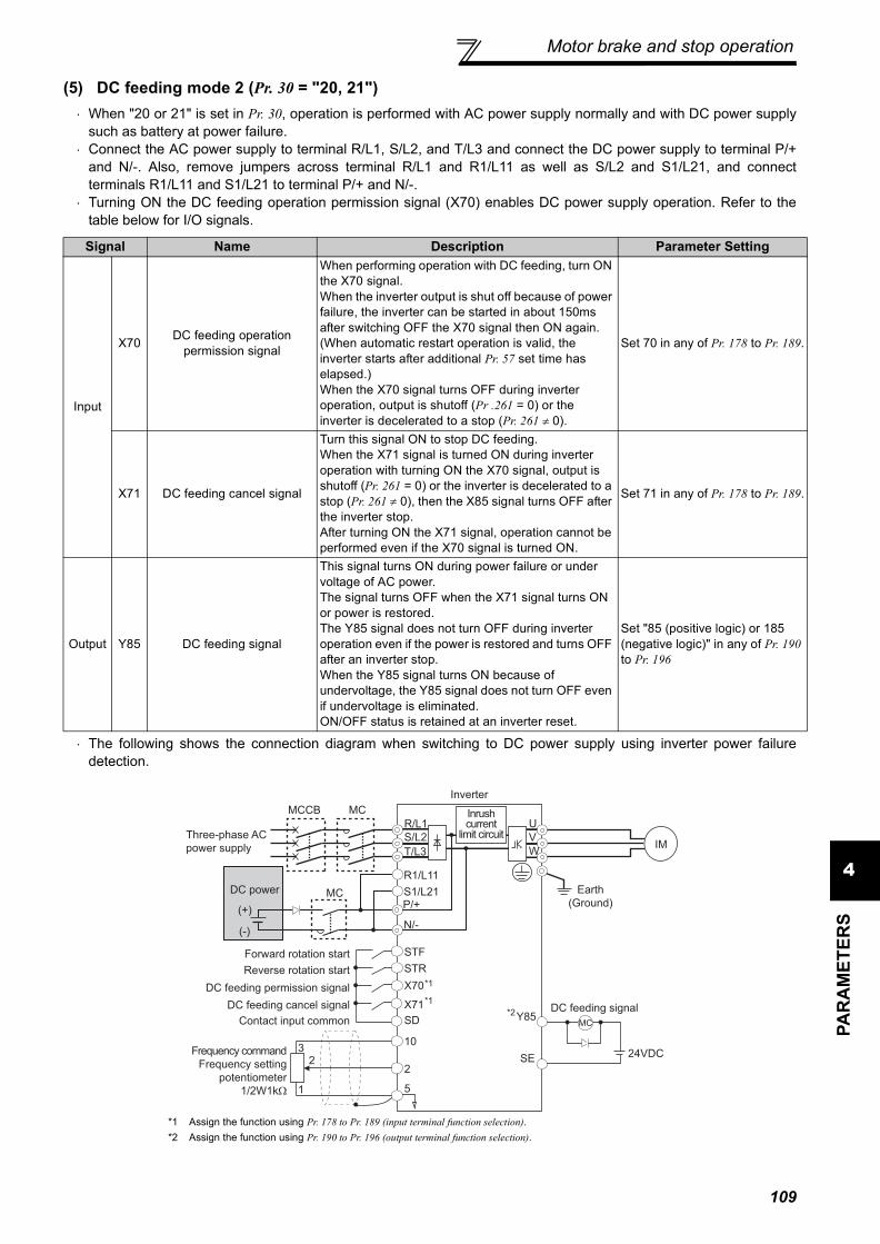
Motor brake and stop operation
4PA
RA
MET
ERS
(5) DC feeding mode 2 (Pr. 30 = "20, 21")⋅ When "20 or 21" is set in Pr. 30, operation is performed with AC power supply normally and with DC power supply
such as battery at power failure.⋅ Connect the AC power supply to terminal R/L1, S/L2, and T/L3 and connect the DC power supply to terminal P/+
and N/-. Also, remove jumpers across terminal R/L1 and R1/L11 as well as S/L2 and S1/L21, and connectterminals R1/L11 and S1/L21 to terminal P/+ and N/-.
⋅ Turning ON the DC feeding operation permission signal (X70) enables DC power supply operation. Refer to thetable below for I/O signals.
⋅ The following shows the connection diagram when switching to DC power supply using inverter power failuredetection.
*1 Assign the function using Pr. 178 to Pr. 189 (input terminal function selection).*2 Assign the function using Pr. 190 to Pr. 196 (output terminal function selection).
Signal Name Description Parameter Setting
Input
X70 DC feeding operation permission signal
When performing operation with DC feeding, turn ON the X70 signal. When the inverter output is shut off because of power failure, the inverter can be started in about 150ms after switching OFF the X70 signal then ON again. (When automatic restart operation is valid, the inverter starts after additional Pr. 57 set time has elapsed.)When the X70 signal turns OFF during inverter operation, output is shutoff (Pr .261 = 0) or the inverter is decelerated to a stop (Pr. 261 ≠ 0).
Set 70 in any of Pr. 178 to Pr. 189.
X71 DC feeding cancel signal
Turn this signal ON to stop DC feeding. When the X71 signal is turned ON during inverter operation with turning ON the X70 signal, output is shutoff (Pr. 261 = 0) or the inverter is decelerated to a stop (Pr. 261 ≠ 0), then the X85 signal turns OFF after the inverter stop.After turning ON the X71 signal, operation cannot be performed even if the X70 signal is turned ON.
Set 71 in any of Pr. 178 to Pr. 189.
Output Y85 DC feeding signal
This signal turns ON during power failure or under voltage of AC power. The signal turns OFF when the X71 signal turns ON or power is restored. The Y85 signal does not turn OFF during inverter operation even if the power is restored and turns OFF after an inverter stop. When the Y85 signal turns ON because of undervoltage, the Y85 signal does not turn OFF even if undervoltage is eliminated. ON/OFF status is retained at an inverter reset.
Set "85 (positive logic) or 185 (negative logic)" in any of Pr. 190 to Pr. 196
DC power
MCCB MC
R/L1
S/L2
T/L3
U
V
W
P/+
N/-
SE
Y85
IM
STF
STR
X70
X71
SD
R1/L11
S1/L21 Earth
(Ground)
10
22
3
1 5
(+)
(-)
*1
MC
MC
Three-phase AC
power supply
DC feeding permission signal
DC feeding cancel signal
Contact input common
Reverse rotation start
Forward rotation start
*1
*2
Inverter
Inrush current
limit circuit
Frequency command
Frequency setting
potentiometer
1/2W1kΩ
24VDC
DC feeding signal
109

Motor brake and stop operation
⋅ Operation example 1 at power failure
⋅ Operation example 2 at power failure (when DC power is restored)
⋅ Operation example 3 at power failure (when continuous operation is performed)
Time
ON ON
Back up operation
Motor
coasting
STF(STR)
DC power supplyAC power supply
ONAC power supply
ONY85(MC)
ONX70
ONX71
Control power
supply
Output
frequency
(Hz)
Approx. 150ms
Time
ON ON
Back up operation
Motor
coastingOutput
frequency
(Hz)
STF(STR)
DCAC ACControl power
supply
ON Power restorationAC power supply
ONY85(MC)
ON
OFF
X70
X71
Turns off after stop while running
Approx. 150ms
Time
ON
Back up operation
Output
frequency
(Hz)
STF(STR)
DCAC ACControl power
supply
ON Power restorationAC power supply
ONY85(MC)
ON
OFF
X70
X71
Remains on while running
110

Motor brake and stop operation
4PA
RA
MET
ERS
(6) Power supply specification at DC feeding
(7) Regenerative brake duty alarm output and alarm signal (RBP signal) (75K or more)
200V classRated input DC voltage 283VDC to 339VDCPermissible fluctuation 240VDC to 373VDC
400V classRated input DC voltage 537VDC to 679VDCPermissible fluctuation 457VDC to 740VDC
CAUTION⋅ As voltage between P/+, N/- becomes 415V (830V) or more temporarily at regeneration, make selection of DC power supply
carefully.
100%: regenerative overvoltage protection operation value ⋅ [RB] appears on the operation panel and an alarm signal (RBP) isoutput when 85% of the regenerative brake duty set in Pr. 70 isreached. If the regenerative brake duty reaches 100% of the Pr.70 setting, a regenerative overvoltage (E.OV1 to E.OV3) occurs.
⋅ The inverter does not shut off the output when the alarm signal isoutput.
⋅ For the terminal used for the RBP signal output, assign thefunction by setting "7" (positive logic) or "107" (negative logic) inany of Pr. 190 to Pr. 196 (output terminal function selection).
REMARKS⋅ The MRS signal can also be used instead of the X10 signal. (Refer to page 115.)⋅ Refer to pages 35 to 42 for connection of the brake unit, high power factor converter (FR-HC, MT-HC) and power regeneration
common converter (FR-CV).⋅ When AC power is connected to terminal R/L1, S/L2, T/L3 during DC feeding with "2, 10 or 11" (DC feeding) set in Pr. 30, an
option alarm (E.OPT) occurs.⋅ When DC feeding operation is performed with "2, 10, 11, 20, or 21" (DC feeding) set in Pr. 30, undervoltage protection (E.UVT)
and instantaneous power failure (E.IPF) are not detected.
CAUTION⋅ Changing the terminal assignment using Pr. 178 to Pr. 189 (input terminal function selection) may affect the other functions. Please
make setting after confirming the function of each terminal.
WARNINGThe value set in Pr. 70 must not exceed the setting of the brake resistor used.Otherwise, the resistor can overheat.
♦ Parameters referred to ♦Pr. 57 Restart coasting time Refer to page 141Pr. 178 to Pr.189 (input terminal function selection) Refer to page 115Pr. 190 to Pr.196 (output terminal function selection) Refer to page 121Pr. 261 Power failure stop selection Refer to page 145
Ratio of brake duty
to the Pr. 70 setting
Regenerative
brake prealarm
(RBP) OFF ON
100%85%
TimON
111

Motor brake and stop operation
4.9.3 Stop selection (Pr. 250)
The above parameters can be set when Pr. 160 User group read selection = "0". (Refer to page 175)
Used to select the stopping method (deceleration to a stop or coasting) when the start signal turns off. Usedto stop the motor with a mechanical brake, etc. together with switching off of the start signal.You can also select the operations of the start signals (STF/STR). (Refer to page 119 for start signal selection)
Parameter Number Name Initial Value Setting Range
DescriptionStart Signal (STF/STR)
(Refer to page 119) Stop Operation
250 Stop selection 9999
0 to 100s
STF signal: Forward rotation start
STR signal: Reverse rotation start
The motor is coasted to a stop when the preset time elapses after the start signal is turned off.The motor is coasted to a stop (Pr. 250 - 1000)s after the start signal is turned off.
1000s to 1100sSTF signal: Start signalSTR signal: Forward/
reverse signal
9999
STF signal: Forward rotation start
STR signal: Reverse rotation start
When the start signal is turned off, the motor decelerates to stop.
8888STF signal: Start signalSTR signal: Forward/
reverse signal
(1) Decelerate the motor to a stop⋅ Set Pr. 250 to "9999" (initial value) or "8888".⋅ The motor decelerates to a stop when the start
signal (STF/STR) turns off.
(2) Coast the motor to a stop.⋅ Use Pr. 250 to set the time from when the start signal
turns off until the output is shut off. When any of"1000" to "1100" is set, the output is shut off after(Pr. 250 − 1000)s.
⋅ The output is shut off when the time set in Pr. 250has elapsed after the start signal had turned off.Themotor coasts to a stop.
⋅ The RUN signal turns off when the output stops.
REMARKSStop selection is invalid when the following functions are activated.
⋅ Power failure stop function (Pr. 261)⋅ PU stop (Pr. 75)⋅ Deceleration stop because of communication error (Pr. 502)⋅ Emergency stop by LONWORKS communication
When setting of Pr. 250 is not 9999 nor 8888, acceleration/deceleration is performed according to the frequency command, untilstart signal is OFF and output is shutoff.
CAUTION⋅ When the start signal is turned on again during motor coasting, the motor starts at Pr. 13 Starting frequency.
♦ Parameters referred to ♦Pr. 7 Acceleration time , Pr. 8 Deceleration time Refer to page 96Pr. 13 Starting frequency Refer to page 98
Time
ON OFFStart
signal
Deceleration starts
when start signal turns off
Deceleration time
(Time set in Pr. 8, etc.)
DC brake
Ou
tpu
t fr
eq
ue
ncy
(Hz)
ON OFFRUN
signal
OFFONStart signal
Output is shut off when set
time elapses after start signal
turns offPr.250
Motor coasts to stop
Time
OFFRUN signal
Ou
tpu
t fr
eq
ue
ncy
(Hz)
ON
112

Motor brake and stop operation
4PA
RA
MET
ERS
4.9.4 Output stop function (Pr.522)
⋅ When both of the frequency setting signal and output frequency falls to the frequency set in Pr. 522 or lower, theinverter stops the output and the motor coasts to a stop.
⋅ After a stop, the inverter output re-starts when the frequency signal is set higher than Pr.522 + 2Hz. The motor re-accelerates at the Pr.13 Starting frequency.
* The output frequency before the slip compensation is compared with the Pr.522 setting.
*1 After a stop, inverter re-starts accelerating at Pr.13 Starting frequency.*2 The output frequency before the slip compensation is compared with the Pr.522 setting.*3 Steepness of the slope depends on the acceleration/deceleration time settings such as Pr.7.
The motor coasts to a stop (inverter output shutoff) when inverter output frequency falls to Pr. 522 setting or lower.
ParameterNumber Name Initial
ValueSetting Range Description
522Output stop frequency 9999
0 to 400Hz Set the frequency to start coasting to a stop (output shutoff).9999 No function
The above parameters can be set when Pr. 160 User group read selection = "0". (Refer to page 175)
....Specifications differ according to the date assembled. Refer to page 322 to check the SERIAL number.
Output frequency*
Pr.522
Pr.13
STF
TimeInverter output shutoff
RUN
Pr.522+2Hz
Target frequency
(fixed)
Example of when target frequency>Pr.522+2Hz, and start signal is ON/OFF
Pr.522
Pr.13
STF
*1
Output frequency*2
*1
Time
RUN
Pr.522+2Hz
Analog input command
Pr.522
Time
Pr.522+2Hz
Inverter output shutoff
Inverter output shutoff
target frequency = analog input command,
start signal always ON
Example of:
*3*3
113

Motor brake and stop operation
REMARKS⋅ When Pr.522 ≠ "9999", output stop function disables DC injection brake operation, so the motor coasts to a stop when the output
frequency falls to Pr.522 or lower.⋅ Output stop function is disabled during PID control, JOG control, and power failure stop.⋅ Output stop function does not operate during reverse rotation deceleration. However, when the frequency setting signal and
output frequency falls to Pr.522 or lower, the inverter coasts to a stop.⋅ During the output stop due to the output stop function (when forward/reverse command is given, but frequency command is not
given), FWD/REV LED indication on the operation panel flickers fast.
♦ Parameters referred to ♦Pr. 10 DC injection brake operation frequency , Pr. 11 DC injection brake operation time , Pr. 12 DC injection brake operation voltage Refer to page 106Pr. 13 Starting frequency Refer to page 98
114

Function assignment of externalterminal and control
4PA
RA
MET
ERS
4.10 Function assignment of external terminal and control
4.10.1 Input terminal function selection (Pr. 178 to Pr. 189)
The above parameters can be set when Pr. 160 User group read selection = "0". (Refer to page 175)....Specifications differ according to the date assembled. Refer to page 322 to check the SERIAL number.
(1) Input terminal function assignment⋅ Use Pr. 178 to Pr. 189 to set the functions of the input terminals.⋅ Refer to the following table and set the parameters:
Purpose Parameter That Must be Set Refer to Page
Assign function to input terminal Input terminal function selection Pr. 178 to Pr. 189 115
Set MRS signal (output shutoff) to NC contact specification MRS input selection Pr. 17 117
Make the second function valid only during constant speed operation.
RT signal function validity condition selection Pr. 155 118
Assign start signal and forward/reverse command to other signals
Start signal (STF/STR) operation selection Pr. 250 119
Assign function to output terminal Output terminal function assignment Pr. 190 to Pr. 196 121
Detect output frequency. Up-to-frequency sensitivityOutput frequency detection Pr. 41 to Pr. 43, Pr. 50 125
Detect output current. Output current detectionZero current detection
Pr. 150 to Pr. 153, Pr. 166, Pr. 167 126
Remote output function Remote output Pr. 495 to Pr. 497 128
Detect specified output power Pulse train output of output power Pr. 799 129
Use these parameters to select/change the input terminal functions.
ParameterNumber Name Initial
Value Initial Signal Setting Range
178 STF terminal function selection 60 STF (forward rotation command)0 to 8, 10 to 12, 14, 16, 24, 25, 60, 62, 64 to 67, 70 to 72, 9999
179 STR terminal function selection 61 STR (reverse rotation command)0 to 8, 10 to 12, 14, 16, 24, 25, 61, 62, 64 to 67, 70 to 72, 9999
180 RL terminal function selection 0 RL (low-speed operation command)0 to 8, 10 to 12, 14, 16, 24, 25, 62, 64 to 67, 70 to 72, 9999
181 RM terminal function selection 1 RM (middle-speed operation command)
182 RH terminal function selection 2 RH (high speed operation command)
183 RT terminal function selection 3 RT (second function selection)
184 AU terminal function selection 4 AU (terminal 4 input selection) 0 to 8, 10 to 12, 14, 16, 24, 25, 62 to 67, 70 to 72, 9999
185 JOG terminal function selection 5 JOG (Jog operation selection)
0 to 8, 10 to 12, 14, 16, 24, 25, 62, 64 to 67, 70 to 72, 9999
186 CS terminal function selection 6 CS (selection of automatic restartafter instantaneous power failure)
187 MRS terminal function selection 24 MRS (output stop)
188 STOP terminal function selection 25 STOP (start self-holding selection)
189 RES terminal function selection 62 RES (inverter reset)
Setting Signal Name Function Related Parameters Refer to
Page
0 RL Pr. 59 = 0 (initial value) Low-speed operation command Pr. 4 to Pr. 6, Pr. 24 to Pr. 27, Pr. 232 to Pr. 239 88
Pr. 59 ≠ 0 *1 Remote setting (setting clear) Pr. 59 93
1 RM Pr. 59 = 0 (initial value) Middle-speed operation command Pr. 4 to Pr. 6, Pr. 24 to Pr. 27, Pr. 232 to Pr. 239 88
Pr. 59 ≠ 0 *1 Remote setting (deceleration) Pr. 59 93
115

Function assignment of external terminal and control
*1 When Pr. 59 Remote function selection ≠ "0", the functions of the RL, RM and RH signals change as listed above.*2 The OH signal turns on when the relay contact "opens".
2 RH Pr. 59 = 0 (initial value) High-speed operation command Pr. 4 to Pr. 6, Pr. 24 to Pr. 27, Pr. 232 to Pr. 239 88
Pr. 59 ≠ 0 *1 Remote setting (acceleration) Pr. 59 933 RT Second function selection Pr. 44 to Pr. 51 1184 AU Terminal 4 input selection Pr. 267 1605 JOG Jog operation selection Pr. 15, Pr. 16 90
6 CS
Selection of automatic restart after instantaneous power failure, flying start
Pr. 57, Pr. 58, Pr.162 to Pr.165, Pr. 299, Pr. 611 141
Electronic bypass function Pr. 57, Pr. 58 Pr. 135 to Pr. 139, Pr. 159 233
7 OH External thermal relay input *2 Pr. 9 101
8 REX 15 speed selection (combination with three speeds RL, RM, RH) Pr. 4 to Pr. 6, Pr. 24 to Pr. 27, Pr.232 to Pr.239 88
10 X10 Inverter operation enable signal (FR-HC, MT-HC/FR-CV connection) Pr. 30 10711 X11 FR-HC or MT-HC connection, instantaneous power failure detection Pr. 30 10712 X12 PU operation external interlock Pr. 79 177
14 X14 PID control valid terminal Pr. 127 to Pr. 134, Pr. 575 to Pr. 577 221
16 X16 PU-external operation switchover(external operation when X16 turns on) Pr. 79, Pr. 340 183
24 MRSOutput stop Pr. 17 117
Electronic bypass function Pr. 57, Pr. 58, Pr. 135 to Pr. 139, Pr. 159 233
25 STOP Start self-holding selection ⎯ 119
60 STF Forward rotation command(assigned to STF terminal (Pr. 178) only) ⎯ 119
61 STR Reverse rotation command(assigned to STR terminal (Pr. 179) only) ⎯ 119
62 RES Inverter reset ⎯ ⎯63 PTC PTC thermistor input (assigned to AU terminal (Pr. 184) only) Pr. 9 10164 X64 PID forward/reverse action switchover Pr. 127 to Pr. 134 221
65 X65 PU-NET operation switchover(PU operation when X65 turns on) Pr. 79, Pr. 340 185
66 X66 External-NET operation switchover(NET operation when X66 turns on) Pr. 79, Pr. 340 185
67 X67 Command source switchover(Pr.338 and Pr.339 commands are valid when X67 turns on) Pr. 338, Pr. 339 186
70 X70 DC feeding operation permission Pr. 30, Pr. 70 10771 X71 DC feeding cancel Pr. 30, Pr. 70 107
72 X72 PID integral value resetPr. 127 to Pr. 134, Pr. 241, Pr. 553, Pr. 554, Pr. 575 to Pr. 577, C42 to C45
221
9999 ⎯ No function ⎯ ⎯
REMARKS⋅ Same function can be assigned to two or more terminals. In this case, the logic of terminal input is OR.⋅ The priorities of the speed commands are in order of jog > multi-speed setting (RH, RM, RL, REX) > PID (X14).⋅ When the X10 signal (FR-HC, MT-HC, FR-CV connection - inverter operation enable signal) is not set or when the PU
operation external interlock (X12) signal is not assigned at the Pr. 79 Operation mode selection setting of "7", the MRS signalshares this function.
⋅ Same signal is used to assign multi-speeds (7 speeds) and remote setting. They cannot be set individually.(Same signal is used since multi-speed (7 speeds) setting and remote setting are not used to set speed at the same time .)
CAUTION⋅ Changing the terminal assignment using Pr. 178 to Pr. 189 (input terminal function selection) may affect the other functions. Also
check that wiring is correct, since the terminal name and the signal function became different. Please make setting afterconfirming the function of each terminal.
Setting Signal Name Function Related Parameters Refer to
Page
116

Function assignment of externalterminal and control
4PA
RA
MET
ERS
(2) Response time of each signal⋅ The response time of the X10 signal is within 2ms. However, when the X10 signal is not assigned at the Pr. 30
Regenerative function selection setting of "2" (FR-HC/MT-HC/FR-CV connection), the response time of the MRSsignal is within 2ms. Pr. 17 MRS input selection is made invalid.
4.10.2 Inverter output shutoff signal (MRS signal, Pr. 17)
Pr. 30Setting
MRS Assignment
X10 Assignment
Response TimePr. 17MRS X10
2× Within 2ms ⎯ Invalid
× ⎯ Within 2ms ⎯Within 20ms Within 2ms Valid
Other than 2× Within 20ms ⎯ Valid
× ⎯ ⎯ ⎯Within 20ms ⎯ Valid
The inverter output can be shut off from the MRS signal. The logic of the MRS signal can also be selected.
Parameter Number Name Initial
ValueSetting Range Description
17 MRS input selection 00 Open input always2 Close input always (NC contact input specifications)
The above parameters can be set when Pr. 160 User group read selection = "0". (Refer to page 175)
(1) Output shutoff signal (MRS signal)⋅ Turning on the output shutoff signal (MRS) during inverter running
shuts off the output immediately.⋅ Terminal MRS may be used as described below.(a)When mechanical brake (e.g. electromagnetic brake) is used to
stop motorThe inverter output is shut off when the mechanical brakeoperates.
(b)To provide interlock to disable operation by the inverterWith the MRS signal on, the inverter cannot be operated if thestart signal is entered into the inverter.
(c) Coast the motor to a stop. When the start signal is turned off, the inverter decelerates themotor to a stop in the preset deceleration time, but when the MRSsignal is turned on, the motor coasts to a stop.
(2) MRS signal logic inversion (Pr. 17)⋅ When Pr. 17 is set to "2", the MRS signal (output stop) can be
changed to the normally closed (NC contact) input specification.When the MRS signal turns on (opens), the inverter shuts off theoutput.
REMARKS⋅ The MRS signal is assigned to the terminal MRS in the initial setting. By setting "24" in any of Pr. 178 to Pr. 189 (input terminal
function selection), the RT signal can be assigned to the other terminal.⋅ The MRS signal can shut off the output, independently of the PU, external or network operation mode.
CAUTION⋅ Changing the terminal assignment using Pr. 178 to Pr. 189 (input terminal function selection) may affect the other functions. Please
make setting after confirming the function of each terminal.
♦ Parameters referred to ♦Pr. 178 to Pr. 189 (Input terminal function selection) Refer to page 115
ON
ON
MRS signal
STF (STR) signal
Motor coasts
to stop
Time
(Initial value)
Output
stop
Output
stop
MRS
Inverter
MRS
Inverter
Setting value "0" Setting value "2"
SD SD
117

Function assignment of external terminal and control
4.10.3 Condition selection of function validity by the second function selection signal (RT) (RT signal, Pr. 155)
⋅ When the RT signal turns on, the second function becomes valid.⋅ The second function has the following applications.
(a) Switching between normal use and emergency use(b) Switching between heavy load and light load(c) Changing of acceleration/deceleration time by broken line acceleration/deceleration(d) Switching of characteristic between main motor and sub motor
⋅ Functions that can be set as second functions
You can select the second function using the external terminal (RT signal).You can also set the RT signal operation condition (reflection time).
Parameter Number Name Initial Value Setting Range Description
155 RT signal function validity condition selection 0
0 Second function is immediately valid with on of the RT signal.
10Second function is valid only during the RT siganl is on and constant speed operation. (invalid during acceleration/deceleration)
The above parameters can be set when Pr. 160 User group read selection = "0". (Refer to page 175)
Second function connection diagram
Second acceleration/deceleration time example
Function First Function Parameter Number
Second Function Parameter Number
Refer to Page
Torque boost Pr. 0 Pr. 46 74Base Frequency Pr. 3 Pr. 47 84Acceleration time Pr. 7 Pr. 44 96Deceleration time Pr. 8 Pr. 44, Pr. 45 96Electronic thermal relay function Pr. 9 Pr. 51 101Stall prevention Pr. 22 Pr. 48, Pr. 49 77Output frequency detection Pr. 42(Pr. 43) Pr. 50 125
REMARKS⋅ The RT signal is assigned to the RT terminal in the initial setting. By setting "3" in any of Pr. 178 to Pr. 189 (input terminal function
selection), the RT signal can be assigned to the other terminal.⋅ When the RT signal is on, the other functions such as the second acceleration/deceleration time are also selected.
CAUTION⋅ Changing the terminal assignment using Pr. 178 to Pr. 189 (input terminal function selection) may affect the other functions. Please
make setting after confirming the function of each terminal.
♦ Parameters referred to ♦Pr. 178 to Pr.189 (input terminal function selection) Refer to page 115
STF(STR)
Inverter
Start
Second function selection
RT
High speed RH
Middle speed RM
SD
(initial value)
RT
Ou
tpu
t fr
eq
ue
ncy
Setting value "0"
RH
RM
Acceleration
time is reflectedTime
118

Function assignment of externalterminal and control
4PA
RA
MET
ERS
4.10.4 Start signal selection (STF, STR, STOP signal, Pr. 250)
The above parameters can be set when Pr. 160 User group read selection = "0". (Refer to page 175)
(1) 2-wire type (STF, STR signal)⋅ A two-wire type connection is shown below.⋅ In the initial setting, the forward/reverse rotation signals (STF/STR) are used as start and stop signals. Turn on
either of the forward and reverse rotation signals to start the motor in the corresponding direction. If both are turnedoff (or on) during operation, the inverter decelerates to a stop.
⋅ The speed setting signal may either be given by entering 0 to 10VDC across the speed setting input terminal 2-5,by setting the required values in Pr. 4 to Pr. 6 Multi-speed setting (high, middle, low speeds), etc. (For multi-speedoperation, refer to page 88)
⋅ When Pr. 250 is set in any of "1000 to 1100, 8888", the STF signal becomes a start command and the STR signal aforward/reverse command.
You can select the operation of the start signal (STF/STR).Used to select the stopping method (deceleration to a stop or coasting) when the start signal turns off.Used to stop the motor with a mechanical brake, etc. together with switching off of the start signal.(Refer to page 112 for stop selection)
Parameter Number Name Initial
ValueSetting Range
Description
Start Signal (STF/STR) Stop Operation(Refer to page 112)
250 Stop selection 9999
0 to 100s
STF signal: Forward rotation start
STR signal: Reverse rotation start
The motor is coasted to a stop when the preset time elapses after the start signal is turned off. When the setting is any of 1000s to 1100s, the inverter coasts to a stop in (Pr. 250 - 1000)s.
1000s to 1100s
STF signal: Start signalSTR signal: Forward/reverse
rotation signal
9999
STF signal: Forward rotation start
STR signal: Reverse rotation start
When the start signal is turned off, the motor decelerates to stop.
8888STF signal: Start signalSTR signal: Forward/reverse
rotation signal
2-wire connection example (Pr. 250 = "9999") 2-wire connection example (Pr. 250 = "8888")
REMARKS⋅ When Pr. 250 is set in any of "0 to 100, 1000 to 1100", the motor coasts to a stop if the start command is turned off. (Refer to page
112)⋅ The STF and STR signals are assigned to the STF and STR terminals in the initial setting. The STF signal can be assigned to
Pr. 178 STF terminal function selection and the STR signal to Pr. 179 STR terminal function selection only.
Forward
rotation start
Reverse
rotation start
STFON
Time
STF
STR Inverter
Ou
tpu
t fr
eq
ue
ncy
ONSTR
10
2
5
Fo
rwa
rd
rota
tio
nR
eve
rse
rota
tio
n
SD
Start signal
Forward/
reverse
signal
STF
Time
STF
STR Inverter
Ou
tpu
t fr
eq
ue
ncy
STR
10
2
5
Fo
rwa
rd
rota
tio
nR
eve
rse
rota
tio
n
ON
ON
SD
119

Function assignment of external terminal and control
(2) 3-wire type (STF, STR, STOP signal)⋅ A 3-wire type connection is shown below.⋅ The start self-holding selection becomes valid when the STOP signal is turned on. In this case, the forward/reverse
rotation signal functions only as a start signal.⋅ If the start signal (STF or STR) is turned on and then off, the start signal is held and makes a start. When changing
the direction of rotation, turn STR (STF) on once and then off.⋅ To stop the inverter, turning off the STOP signal once decelerates it to a stop.
(3) Start signal selection
3-Wire Type Connection Example (Pr. 250 ="9999") 3-Wire Type Connection Example (Pr. 250 ="8888")
REMARKS⋅ The STOP signal is assigned to the terminal STOP in the initial setting. By setting "25" in Pr. 178 to Pr. 189, the STOP signal can
also be assigned to the other terminal.⋅ When the JOG signal is turned on to enable jog operation, the STOP signal becomes invalid.⋅ If the MRS signal is turned on to stop the output, the self-holding function is not canceled.
STF STRPr. 250 Setting Inverter Status
0 to 100s, 9999 1000s to 1100s, 8888OFF OFF Stop
StopOFF ON Reverse rotationON OFF Forward rotation Forward rotationON ON Stop Reverse rotation
♦ Parameters referred to ♦Pr. 4 to Pr. 6 (Multi-speed setting) Refer to page 88Pr. 178 to Pr. 189 (Input terminal function selection) Refer to page 115
Stop Forward
rotation start
Reverse
rotation start
STF
STR
STOP
Inverter
Time
STF
STR
ON
STOP
OFF
Ou
tpu
t fr
eq
ue
ncy
ON
Fo
rwa
rd
rota
tio
n
Re
ve
rse
rota
tio
n
OFF
ON
SD
Time
Stop
Forward rotation
/reverse rotation
Start
STF
STR
ON
STOP ON
STF
STR
STOP
Inverter
Ou
tpu
t fr
eq
ue
ncy
ON
ON
OFF OFF
Fo
rwa
rd
rota
tio
nR
eve
rse
rota
tio
n
SD
120

Function assignment of externalterminal and control
4PA
RA
MET
ERS
4.10.5 Output terminal function selection (Pr. 190 to Pr. 196)
(1) Output signal list⋅ You can set the functions of the output terminals.⋅ Refer to the following table and set the parameters: (0 to 99: Positive logic, 100 to 199: Negative logic)
You can change the functions of the open collector output terminal and relay output terminal.
Parameter Number Name Initial
Value Initial Signal Setting Range
190 RUN terminal function selection
Open collector output
terminal
0 RUN (inverter running)
0 to 5, 7, 8, 10 to 19, 25, 26, 45 to 48, 64, 70, 79, 85, 90 to 96, 98, 99, 100 to 105, 107, 108, 110 to 116, 125, 126, 145 to 148, 164, 170, 179, 185, 190 to 196, 198, 199, 9999
191 SU terminal function selection 1 SU (up to frequency)
192 IPF terminal function selection 2 IPF (instantaneous power
failure, undervoltage)
193 OL terminal function selection 3 OL (overload alarm)
194 FU terminal function selection 4 FU (output frequency
detection)
195 ABC1 terminal function selection Relay
output terminal
99 ALM (fault output)0 to 5, 7, 8, 10 to 19, 25, 26, 45 to 48, 64, 70, 79, 85, 90, 91, 94 to 96, 98, 99, 100 to 105, 107, 108, 110 to 116, 125, 126, 145 to 148, 164, 170, 179, 185, 190, 191, 194 to 196, 198, 199, 9999
196 ABC2 terminal function selection 9999 No function
The above parameters can be set when Pr. 160 User group read selection = "0". (Refer to page 175)... Specifications differ according to the date assembled. Refer to page 322 to check the SERIAL number.
Setting Signal Name Function Operation Related
ParametersRefer
to PagePositive Logic
Negative Logic
0 100 RUN Inverter runningOutput during operation when the inverter output frequency rises to or above Pr. 13 Starting frequency.
⎯ 123
1 101 SU Up to frequency *1 Output when the output frequency is reached to the set frequency. Pr. 41 125
2 102 IPF Instantaneous power failure/undervoltage
Output at occurrence of an instantaneous power failure or when undervoltage protection is activated.
Pr. 57 141
3 103 OL Overload alarm Output while stall prevention function is activated.
Pr. 22, Pr. 23, Pr. 66, Pr. 148, Pr. 149, Pr. 154
77
4 104 FU Output frequency detection
Output when the output frequency reaches the frequency setting in Pr. 42 (Pr. 43 for reverse rotation).
Pr. 42, Pr. 43 125
5 105 FU2 Second output frequency detection
Output when the output frequency reaches the frequency setting in Pr. 50. Pr. 50 125
7 107 RBP Regenerative brake pre-alarm
Output when 85% of the regenerative brake duty set in Pr. 70 is reached.Setting can be made for the 75K or more.
Pr. 70 107
8 108 THP Electronic thermal O/L relay pre-alarm
Output when the electronic thermal value reaches 85% of the trip level.(Electronic thermal relay function protection (E.THT/E.THM) actirates, when the value reached 100%.)
Pr. 9 103
10 110 PU PU operation mode Output when the PU operation mode is selected. Pr. 79 177
11 111 RY Inverter operation ready
Output when the reset process is completed (when the inverter can be started by switching the start signal on or while it is running) after powering on the inverter.
⎯ 123
12 112 Y12 Output current detection
Output when the output current is higher than the Pr. 150 setting for longer than the time set in Pr. 151.
Pr. 150, Pr. 151 126
121

Function assignment of external terminal and control
13 113 Y13 Zero current detection
Output when the output power is lower than the Pr. 152 setting for longer than the time set in Pr. 153.
Pr. 152, Pr. 153 126
14 114 FDN PID lower limit Output when the feedback value falls below the lower limit of PID control.
Pr. 127 to Pr. 134, Pr. 575 to Pr. 577 22115 115 FUP PID upper limit Output when the feedback value rises above
the upper limit of PID control
16 116 RL PID forward/reverse rotation output
Output when forward rotation is performed in PID control.
17 ⎯ MC1 Electric bypass MC1Used when the bypass-inverter switchover function is used.
Pr. 135 to Pr. 139, Pr. 159 23318 ⎯ MC2 Electric bypass MC2
19 ⎯ MC3 Electric bypass MC325 125 FAN Fan fault output Output at the time of a fan alarm. Pr. 244 240
26 126 FIN Heatsink overheat pre-alarm
Output when the heatsink temperature reaches about 85% of the heatsink overheat protection operation temperature.
⎯ 266
45 145 RUN3During inverter running and start command is on
Output when the inverter is running and start command is on. ⎯ 123
46 146 Y46During deceleration at occurrence of power failure
Output when the power failure-time deceleration function is executed.(retained until release)
Pr. 261 to Pr. 266 145
47 147 PID During PID control activated Output during PID control. Pr. 127 to Pr. 134,
Pr. 575 to Pr. 577 221
48 148 Y48 PID deviation limit Output when the absolute value of deviation exceeds the limit value.
Pr. 127 to Pr. 134, Pr. 241, Pr. 553, Pr. 554, Pr. 575 to Pr. 577, C42 to C45
221
64 164 Y64 During retry Output during retry processing. Pr. 65 to Pr. 69 148
70 170 SLEEP PID output interruption
Output when the PID output interruption function is executed.
Pr. 127 to Pr. 134, Pr. 575 to Pr. 577 221
79 179 Y79 Pulse train output of output power
Output in pulses every time the accumulated output power of the inverter reaches the Pr.799 setting.
Pr. 799 129
85 185 Y85 DC feeding Output during power failure or under voltage of AC power. Pr. 30, Pr. 70 107
90 190 Y90 Life alarm
Output when any of the control circuit capacitor, main circuit capacitor and inrush current limit circuit or the cooling fan approaches the end of its service life.
Pr. 255 to Pr. 259 241
91 191 Y91 Fault output 3 (power-off signal)
Output when a fault occurs due to the internal circuit failure of inverter wiring mistake.
⎯ 124
92 192 Y92Power saving average value updated timing
Turned on and off alternately every time the power saving average value is updated when the power saving monitor is used.Cannot be set to Pr. 195 and Pr. 196 (relay output terminal).
Pr. 52, Pr. 54, Pr. 158, Pr. 891 to Pr. 899
153
93 193 Y93 Current average value monitor signal
Average current value and maintenance timer value are output as pulses.Cannot be set to Pr. 195 and Pr. 196 (relay output terminal).
Pr. 555 to Pr. 557 245
94 194 ALM2 Fault output 2
Output when the fault occurs. Continues outputting the signal during inverter reset and stops outputting after reset is cancelled. *2
⎯ 124
95 195 Y95 Maintenance timer signal
Output when Pr. 503 rises to or above the Pr. 504 setting. Pr. 503, Pr. 504 244
96 196 REM Remote output Output to the terminal when a value is set to the parameter. Pr. 495 to Pr. 497 128
98 198 LF Alarm output Output when an alarm (fan failure or communication error warning) occurs. Pr. 121, Pr. 244 196,
240
Setting Signal Name Function Operation Related
ParametersRefer
to PagePositive Logic
Negative Logic
122

Function assignment of externalterminal and control
4PA
RA
MET
ERS
(2) Inverter operation ready signal (RY signal) and inverter running signal (RUN, RUN3 signal)
*1 This signal turns off during power failure or undervoltage.
99 199 ALM Fault output Output when the fault occurs. The signal output is stopped when the fault is reset. ⎯ 124
9999 ⎯ No function ⎯ ⎯ ⎯
*1 Note that when the frequency setting is varied using an analog signal or of the operation panel (FR-DU07), the output of the SU (up to
frequency) signal may alternate on and off depending on that varying speed and the timing of the varying speed due to acceleration/deceleration time setting. (The output will not alternate on and off when the acceleration/deceleration time setting is "0s".)
*2 When a power supply reset is performed, the fault output 2 signal (ALM2) turns off as soon as the power supply switches off.
REMARKS⋅ The same function may be set to more than one terminal.⋅ When the function is executed, the terminal conducts at the setting of any of "0" to "99", and does not conduct at the setting of
any of "100" to "199".⋅ When Pr. 76 Fault code output selection = "1", the output signals of the terminals SU, IPF, OL and FU are switched as set in Pr. 76.
(When an inverter fault occurs, the signal output is switched to the fault code output.)⋅ The output assignment of the terminal RUN and fault output relay are as set above regardless of Pr. 76.
CAUTION⋅ Changing the terminal assignment using Pr. 190 to Pr. 196 (output terminal function selection) may affect the other functions.
Please make setting after confirming the function of each terminal.⋅ Do not assign signals which repeat frequent ON/OFF to A1, B1, C1, A2, B2, C2. Otherwise, the life of the relay contact decreases.
⋅ When the inverter is ready to operate, the output of the operationready signal (RY) is on. It is also on during inverter running.
⋅ When the output frequency of the inverter rises to or above Pr. 13 Starting frequency, the output of the inverter running signal (RUN) is turned on. During an inverter stop or DC injection brake operation, the output is off.
⋅ The output of the RUN3 signal is on when the inverter runningand start signals are on.(For the RUN3 signal, output is on if the starting command ison even when a fault occurs or the MRS signal is on.
⋅ When using the RY, RUN and RUN3 signals, assign functions toPr. 190 to Pr. 196 (output terminal selection function) referring to thetable below.
InverterStatus
OutputSignal
Start Signal is
OFF (during stop)
Start Signal is
ON (during stop)
Start Signal is
ON (during
running)
Under DC Injection
Brake
At Fault Occurrence or MRS Signal is on (output shutoff)
Automatic Restart after Instantaneous Power Failure
CoastingRestartingStart signal
is ONStart signal
is OFFStart signal
is ONStart signal
is OFFRY ON ON ON ON OFF ON *1 ON
RUN OFF OFF ON OFF OFF OFF ONRUN3 OFF ON ON ON ON OFF ON OFF ON
REMARKS⋅ Run signal is assigned to the terminal RUN in the initial setting.
Setting Signal Name Function Operation Related
ParametersRefer
to PagePositive Logic
Negative Logic
RUN
Power
supply
Ou
tpu
t fr
eq
ue
ncy
STF
RH
RY
RUN3
Pr. 13
Starting
frequency
DC injection brake operation point
DC injection brake operation
Reset processing
Time
ON
ON
ON
ON
ON
ON
OFF
OFF
OFF
OFF
OFF
Output Signal
Pr. 190 to Pr. 196 SettingPositive logic Negative logic
RY 11 111RUN 0 100RUN3 45 145
123

Function assignment of external terminal and control
(3) Fault output signal (ALM, ALM2 signal)
(4) Input MC shutoff signal (Y91 signal)⋅ The Y91 signal is output at occurrence of a fault attributable to the failure of the inverter circuit or a fault caused by
a wiring mistake.⋅ When using the Y91 signal, set "91 (positive logic)" or "191 (negative logic)" in any of Pr. 190 to Pr. 196 (output
terminal function selection) to assign the function to the output terminal.⋅ The following table indicates the faults that will output the Y91 signal. (Refer to page 260 for the fault description.)
⋅ If the inverter comes to trip, the ALM and ALM2 signals are output.
⋅ The ALM2 signal remains on during a reset period after fault occurrence.
⋅ When using the ALM2 signal, set "94 (positive logic)" or "194 (negative logic)" to any of Pr. 190 to Pr. 196 (output terminal function selection) to assign the function to the output terminal.
⋅ The ALM signal is assigned to the A1B1C1 contact in the initial setting.
REMARKSRefer to page 260 for the inverter fault description.
Fault DefinitionInrush current limit circuit fault (E.IOH)CPU fault (E.CPU)CPU fault (E.5)CPU fault (E.6)CPU fault (E.7)Parameter storage device fault (E.PE)Parameter storage device fault (E.PE2)24VDC power output short circuit (E.P24)Power supply short circuit for operation panel, power supply short circuit for RS-485 (E.CTE)Output side earth(ground) fault overcurrent (E.GF)Output phase loss (E.LF)Brake transistor alarm detection/internal circuit error (E.BE)
♦ Parameters referred to ♦Pr. 13 Starting frequency Refer to page 98Pr. 76 Fault code output selection Refer to page 150
ON OFF
ON
ON OFF
Reset ON
Ou
tpu
t fr
eq
ue
ncy
Fault output signal(ALM)
Fault output 2 signal(ALM2)
Reset signal(RES)
OFF
Inverter fault occurrence
(trip)
Reset processing (about 1s)
Time
124

125
Function assignment of externalterminal and control
4PA
RA
MET
ERS
4.10.6 Detection of output frequency (SU, FU, FU2 signal, Pr. 41 to Pr. 43, Pr. 50)
The inverter output frequency is detected and output to the output signal.
Parameter Number Name Initial
ValueSetting Range Description
41 Up-to-frequency sensitivity 10% 0 to 100% Set the level where the SU signal turns on.42 Output frequency detection 6Hz 0 to 400Hz Set the frequency where the FU signal turns on.
43 Output frequency detection for reverse rotation 9999
0 to 400Hz Set the frequency where the FU signal turns on in reverse rotation.
9999 Same as Pr. 42 setting
50 Second output frequency detection 30Hz 0 to 400Hz Set the frequency where the FU2 signal turns on.
The above parameters can be set when Pr. 160 User group read selection = "0". (Refer to page 175)
(1) Up-to-frequency sensitivity (SU signal, Pr. 41)⋅ When the output frequency reaches the set frequency, the up-to-frequency
signal (SU) is output.⋅ The Pr. 41 value can be adjusted within the range ±1% to ±100% on the
assumption that the set frequency is 100%.⋅ This parameter can be used to ensure that the set frequency has been
reached to provide the operation start signal etc. for related equipment.
(2) Output frequency detection (FU signal, FU2signal, Pr. 42, Pr. 43, Pr. 50)
⋅ When the output frequency rises to or above the Pr. 42setting, the output frequency detection signal (FU) isoutput.
⋅ This function can be used for electromagnetic brakeoperation, open signal, etc.
⋅ Frequency detection that is dedicated to reverseoperation can be set by setting detection frequency to Pr.43. This function is effective for switching the timing ofelectromagnetic brake operation between forwardrotation (rise) and reverse rotation (fall) during vertical liftoperation, etc.
⋅ When Pr. 43 ≠ "9999", the Pr. 42 setting applies toforward rotation and the Pr. 43 setting applies to reverserotation.
⋅ When outputting a frequency detection signal besidesthe FU signal, set the detection frequency in Pr. 50. TheFU2 signal output when the output frequency reaches orexceeds the Pr. 50 setting.
⋅ For each signal, assign functions to Pr. 190 to Pr. 196(output terminal function selection) referring to the lefttable.
CAUTION⋅ Changing the terminal assignment using Pr. 190 to Pr. 196 (output terminal function selection) may affect the other functions.
Please make setting after confirming the function of each terminal.
♦ Parameters referred to ♦Pr. 190 to Pr. 196 (output terminal function selection) Refer to page 121
Ou
tpu
t fr
eq
ue
ncy
(Hz)
ON
Set frequency Adjustment range Pr.41
SU
Time
OFFOFF
REMARKSThe output frequency compared with the set frequency changes dependingon the control method.
Control Method Compared Output FrequencyV/F control Output frequencySimple magnetic flux vector control Output frequency before slip compensation
Outputsignal
Forwardrotation
Reverserotation
Time
Ou
tpu
t fr
eq
ue
ncy
(Hz)
ON ONOFF OFFOFF
OFF OFF OFFON ONFU2
Pr.50
Pr.43
Pr.50Pr.42
FU
Parameter Number
Output Signals
Pr. 190 to Pr. 196 SettingPositive
logicNegative
logic42, 43 FU 4 104
50 FU2 5 105

Function assignment of external terminal and control
4.10.7 Output current detection function (Y12 signal, Y13 signal, Pr. 150 to Pr. 153, Pr. 166, Pr. 167)
The output current during inverter running can be detected and output to the output terminal.
Parameter Number Name Initial Value Setting
Range Description
150 Output current detection level 120% 0 to 150% Set the output current detection level. 100% is the
rated inverter current.
151 Output current detection signal delay time 0s 0 to 10s
Set the output current detection period. Set the time from when the output current has risen above the setting until the output current detection signal (Y12) is output.
152 Zero current detection level 5% 0 to 150% Set the zero current detection level. The rated inverter current is assumed to be 100%.
153Zero current detection time 0.5s 0 to 10s
Set the time period from when the output current drops below the Pr. 152 value until when the zero current detection signal (Y13) is output.
166 Output current detection signal retention time 0.1s
0 to 10s Set the retention time when the Y12 signal is on.
9999 The Y12 signal on status is retained. The signal is turned off at the next start.
167 Output current detection operation selection 0
0Y12 Signal - ON Y13 Signal - ON
Operation continued Operation continued1 Fault stop (E.CDO) Operation continued10 Operation continued Fault stop (E.CDO)11 Fault stop (E.CDO) Fault stop (E.CDO)
The above parameters can be set when Pr. 160 User group read selection = "0". (Refer to page 175)... Specifications differ according to the date assembled. Refer to page 322 to check the SERIAL number.
(1) Output current detection (Y12 signal, Pr. 150, Pr.151, Pr. 166, Pr. 167)
⋅ The output power detection function can be used for excessivetorque detection, etc.
⋅ If the output current remains higher than the Pr. 150 setting duringinverter operation for longer than the time set in Pr. 151, theoutput current detection signal (Y12) is output from the inverter'sopen collector or relay output terminal.
⋅ When the Y12 signal turns ON, the ON state is held for the timeset in Pr. 166 .
⋅ When Pr. 166 = "9999", the ON state is held until a next start.⋅ At the Pr. 167 setting of "1" or "11", the inverter output is stopped
and the output current detection fault (E.CDO) is displayed whenthe Y12 signal turns ON. When a fault stop occurs, the Y12signal is ON for the time set in Pr. 166 at the Pr. 166 setting ofother than "9999", and remains ON until a reset is made at the Pr.166 setting of "9999". Setting Pr. 167 = "1" or "11" at Y12 signalON does not cause E.CDO. Setting to Pr. 167 becomes effectiveafter Y12 is turned OFF.
⋅ For the X12 signal, set "12 (positive logic)" or "112 (negativelogic)" in any of Pr. 190 to Pr. 196 (output terminal function selection)and assign the function to the output terminal.
Time
Pr. 150
OFF ON OFFOutput current
detection signal
(Y12)
Pr. 166
Minimum 0.1s
(initial value)
Output current
Pr. 166 9999, Pr. 167 = 0
Pr. 151
126

Function assignment of externalterminal and control
4PA
RA
MET
ERS
(2) Zero current detection (Y13 signal, Pr. 152, Pr.153, Pr. 167)
⋅ If the output current remains lower than the Pr. 152 settingduring inverter operation for longer than the time set in Pr.153, the zero current detection (Y13) signal is output fromthe inverter's open collector or relay output terminal.
⋅ When the inverter's output current falls to "0", torque will notbe generated. This may cause a drop due to gravity whenthe inverter is used in vertical lift application. To prevent this,the output current zero signal (Y13) can be output from theinverter to close the mechanical brake when the outputcurrent has fallen to "0".
⋅ When Pr.167 = "10" or "11", turning Y13 signal ON stops theinverter output and causes output current detection fault(E.CDO) to be displayed. ON status of Y13 signal is held for0.1s at the fault. Setting Pr. 167 = "10" or "11" while Y13signal is ON does not cause E.CDO. Setting to Pr. 167becomes effective after Y13 is turned OFF.
⋅ For the Y13 signal, set "13 (positive logic)" or "113 (negativelogic)" in any of Pr. 190 to Pr. 196 (output terminal functionselection) to assign the function to the output terminal.
CAUTION⋅ The response time of Y12 and Y13 signals is approximately 0.1s. Note that the response time changes according to the load
condition. When Pr. 152 = "0", detection is disabled.
⋅ Changing the terminal assignment using Pr. 190 to Pr. 196 (output terminal function selection) may affect the other functions.Please make setting after confirming the function of each terminal.
CAUTIONThe zero current detection level setting should not be too high, and the zero current detection time setting not too long. Otherwise, the detection signal may not be output when torque is not generated at a low output current.To prevent the machine and equipment from resulting in hazardous conditions by use of the zero current detection signal, install a safety backup such as an emergency brake.
♦ Parameters referred to ♦Pr. 190 to Pr. 196 (output terminal function selection) Refer to page 121
OFF ONStart signal
Time
Output
current
OFF ONZero current
detection time
(Y13) Pr. 153
Detection time
Pr. 153
Detection time
Pr.152
OFF ON
0[A]0.1s*
Pr.152
* Once turned on, the zero current detection time
signal (Y13) is held on for at least 0.1s.
Pr. 167 = 0 or 1
127

Function assignment of external terminal and control
4.10.8 Remote output function (REM signal, Pr. 495 to Pr. 497)You can utilize the on/off of the inverter's output signals instead of the remote output terminal of theprogrammable controller.
Parameter Number Name Initial
ValueSetting Range Description
495Remote output selection 0
0 Remote output data clear at powering off Remote output data clear at
inverter reset1 Remote output data retention even at powering off
10 Remote output data clear at powering off Remote output data retention
even at inverter reset11 Remote output data retention even at powering off
496 * Remote output data 1 0 0 to 4095Refer to the following diagram.497 * Remote output data 2 0 0 to 4095
The above parameters can be set when Pr. 160 User group read selection = "0". (Refer to page 175)... Specifications differ according to the date assembled. Refer to page 322 to check the SERIAL number.
* The above parameters allow its setting to be changed during operation in any operation mode even if "0" (initial value) is set in Pr. 77 Parameter writeselection.
<Remote output data>Pr. 496
Pr. 497
*1 As desired*2 Y0 to Y6 are available only when the extension output option (FR-
A7AY) is fitted*3 RA1 to RA3 are available only when the relay output option (FR-
A7AR) is fitted
⋅ The output terminal can be turned on/off depending onthe Pr. 496 or Pr. 497 setting. The remote outputselection can be controlled on/off by computer linkcommunication from the PU connector or RS-485 portor by communication from the communication option.
⋅ Set "96" (positive logic) or "196" (negative logic) in anyof Pr. 190 to Pr. 196 (output terminal function selection),and assign the remote output (REM) signal to theterminal used for remote output,
⋅ When you refer to the left diagram and set 1 to theterminal bit (terminal where the REM signal has beenassigned) of Pr. 496 or Pr. 497, the output terminal turnson (off for negative logic). By setting 0, the outputterminal turns off (on for negative logic).
Example)When "96" (positive logic) is set to Pr. 190 RUN terminal function selection and "1" (H01) is set to Pr. 496,the terminal RUN turns on.
ON/OFF example for positive logic ⋅ When Pr. 495 = "0 (initial value), 10", performing a powersupply reset (including a power failure) clears the REM signaloutput. (The ON/OFF status of the terminals are as set in Pr.190 to Pr. 196.) The Pr. 496 and Pr. 497 settings are also "0".When Pr. 495 = "1, 11", the remote output data before powersupply-off is stored into the EEPROM, so the signal output atpower recovery is the same as before power supply-off.However, it is not stored when the inverter is reset (terminalreset, reset request through communication). (See the chart on the left)
⋅ When Pr. 495 = "10, 11", the signal before reset is held even aninverter reset is made.
REMARKS⋅ The output terminal where the REM signal is not assigned using any of Pr. 190 to Pr. 196 does not turn on/off if 0/1 is set to the
terminal bit of Pr. 496 or Pr. 497. (It turns on/off with the assigned function.)⋅ When the inverter is reset (terminal reset, reset request through communication), Pr. 496 and Pr. 497 values turn to "0". When Pr.
495 = "1, 11", however, they are the settings at power supply-off. (The settings are stored at power supply-off.) When Pr. 495 ="10, 11", they are the same as before an inverter reset is made.
CAUTION⋅ When Pr. 495="1, 11"(remote output data retention at power OFF), connect R1/11 with P/+, and S1/L21 with N/- so that the
control power is retained. If you do not take such a step, the output signals provided after power-on are not guaranteed.
♦ Parameters referred to ♦⋅ Pr. 190 to Pr. 196 (output terminal function selection) Refer to page 121
b11 b0
AB
C1
AB
C2
*1*1*1*1*1
FU
OL
IPF
SU
RU
N
b11 b0
Y5
*2
Y6
*2
RA
1 *3
RA
2 *3
RA
3 *3
*1*1
Y4
*2
Y3
*2
Y2
*2
Y1
*2
Y0
*2
Power
supplyPower
supplyOFF OFF
ONOFF REMREM
REM signal clear REM signal held
Inverter
reset time
(about 1s)
Pr. 495 = 0, 10 Pr. 495 = 1, 11
128

Function assignment of externalterminal and control
4PA
RA
MET
ERS
4.10.9 Pulse train output of output power (Y79 signal, Pr. 799)
(1) Pulse increment setting for output power (Y79 signal, Pr.799)⋅ After power ON or inverter reset, output signal (Y79 signal) is output in pulses every time accumulated output
power of the inverter exceeds Pr.799 Pulse increment setting for output power.⋅ The inverter continues to count the output power at retry function or when automatic restart after instantaneous
power failure function works without power OFF of output power (not power failure of inverter control circuit power),and it does not reset the count.
⋅ If power failure occurs, output power is counted from 0kWh again.⋅ Assign pulse output of output power (Y79: setting value 79 (positive logic), 179 (negative logic)) to any of Pr.190 to
Pr.196 (Output terminal function selection).
After power ON or inverter reset, output signal (Y79 signal) is output in pulses every time accumulated outputpower, which is counted after the Pr.799 Pulse increment setting for output power is set, reaches the specified value(or its integral multiples).
ParameterNumber Name Initial
Value Setting Range Description
799 Pulse increment setting for output power 1kWh 0.1kWh, 1kWh, 10kWh,
100kWh, 1000kWhPulse train output of output power (Y79) is output in pulses at every output power (kWh) that is specified.
The above parameters can be set when Pr. 160 User group read selection = "0". (Refer to the page 175)....Specifications differ according to the date assembled. Refer to page 322 to check the SERIAL number.
CAUTION⋅ Because the accumulated data in the inverter is cleared when control power is lost by power failure or at an inverter reset, the
value on the monitor cannot be used to charge electricity bill.⋅ Changing the terminal assignment using Pr. 190 to Pr. 196 (output terminal function selection) may affect the other functions. Please
make setting after confirming the function of each terminal. (Refer to page 121)
REMARKS⋅ When parameter copy is performed, Pr.799 = "9999" might be set. However, the inverter operates as Pr.799 were at "1kWh"
(initial value) in such case.
When Pr.799 = 10
10kWh
20kWh
TimeOFF ON
ON for 0.15s (0.1 to 0.2s)
Output power
Pulse output of output power
(Y79)
129

130
Monitor display and monitor output signal
4.11 Monitor display and monitor output signal
4.11.1 Speed display and speed setting (Pr. 37, Pr. 144)
*1 The maximum value of the setting range differs according to the Pr.1 Maximum frequency and it can be calculated from the following formula.
Note that Pr.37 (set maximum value) is 9998 if the result of the above formula exceeds 9998.*2 The above parameters can be set when Pr. 160 User group read selection = "0". (Refer to page 175)
⋅ To display the machine speed, set in Pr. 37 the machine speed for 60Hz operation.⋅ When displaying the motor speed, set the number of motor poles (2, 4, 6, 8, 10) or number of motor poles + 100
(102, 104, 106, 108, 110) to Pr. 144.⋅ When both Pr. 37 and Pr. 144 have been set, their priorities are as given below.
Pr. 144, 102 to 110 > Pr. 37, 1 to 9998 > Pr. 144, 2 to 10⋅ When the running speed monitor is selected, each monitor and setting are determined by the combination of Pr. 37
and Pr. 144 as listed below. (The units within the thick frame are the initial values.)
Purpose Parameter that must be set Refer to Page
Display motor speedSet speed Speed display and speed setting Pr. 37, Pr. 144 130
Change PU monitor display data DU/PU main display data selectionCumulative monitor clear
Pr. 52, Pr. 170, Pr. 171, Pr. 268, Pr. 891 131
Change of the monitor output from terminal FM and AM Terminal FM, AM function selection Pr. 54, Pr. 158, Pr. 867 131
Set the reference of the monitor output from terminal FM and AM Setting of reference of terminal FM and AM Pr. 55, Pr. 56, Pr. 867 136
Adjust terminal FM, AM outputs Terminal FM, AM calibration Pr. 900, Pr. 901 138
You can change the PU (FR-DU07/FR-PU04/FR-PU07) monitor display or frequency setting to motor speed ormachine speed.
Parameter Number Name Initial Value Setting Range Description
37 Speed display 00 Frequency display, setting
1 to 9998 *1 Set the machine speed at 60Hz.
144 Speed setting switchover 4 0, 2, 4, 6, 8, 10, 102, 104, 106, 108, 110
Set the number of motor poles when displaying the motor speed.
Pr.37 (set maximum value) < 65535 x 60 (Hz)Pr.1(Hz)
Pr. 37Setting
Pr. 144Setting
Output Frequency Monitor
Set Frequency Monitor
Running Speed Monitor
Frequency Setting Parameter Setting
0(initial value)
0 Hz Hz r/min *3 Hz2 to 10 Hz Hz r/min *3 Hz
102 to 110 r/min *3 r/min *3 r/min *3 r/min *3
1 to 99980 Hz Hz Machine speed *3 Hz
2 to 10 Machine speed *3 Machine speed *3 Machine speed *3 Machine speed *3102 to 110 Hz Hz r/min *3 Hz
*3 Motor speed r/min conversion formula............ frequency × 120/number of motor poles (Pr. 144)Machine speed conversion formula ...................Pr. 37 × frequency/60HzFor Pr. 144 in the above formula, the value is "Pr. 144-100" when "102 to 110" is set in Pr. 144 and the value is "4" when Pr. 37 = 0 and Pr. 144 = 0.
*4 The increments for Hz are 0.01Hz, machine speed are 1m/min, and r/min are 1r/min.
CAUTION⋅ Under V/F control, the output frequency of the inverter is displayed in terms of synchronous speed, and therefore, displayed
value = actual speed + motor slip.⋅ When the running speed display is selected at the setting of Pr. 37 "0" and Pr. 144 "0", the monitor display is provided on the
assumption that the number of motor poles is 4. (1800r/min is displayed at 60Hz)⋅ Refer to Pr. 52 when you want to change the PU main monitor (PU main display).⋅ Since the panel display of the operation panel (FR-DU07) is 4 digits in length, the monitor value of more than "9999" is
displayed "----".⋅ When an optional FR-A7ND or FR-A7NL card is mounted, frequency is displayed regardless of Pr. 37 and Pr. 144 setting.
CAUTIONMake sure that the settings of the running speed and number of motor poles are correct. Otherwise, the motor might run at extremely high speed, damaging the machine.
♦ Parameters referred to ♦Pr. 52 DU/PU main display data selection Refer to page 131

Monitor display and monitor output signal
4PA
RA
MET
ERS
4.11.2 DU/PU monitor display selection (Pr. 52, Pr. 54, Pr. 158, Pr. 170, Pr. 171, Pr. 268, Pr. 563, Pr. 564, Pr. 891)
(1) Monitor description list (Pr. 52)⋅ Set the monitor to be displayed on the operation panel (FR-DU07) and parameter unit (FR-PU04/FR-PU07) in Pr.
52 DU/PU main display data selection.⋅ Set the monitor to be output to the terminal FM(pulse train output) in Pr. 54 FM terminal function selection.⋅ Set the monitor to be output to the terminal AM (analog output (0 to 10VDC voltage output)) in Pr. 158 AM terminal
function selection.⋅ Refer to the following table and set the monitor to be displayed. (The signals marked × cannot be selected for
monitoring)
The monitor to be displayed on the main screen of the operation panel (FR-DU07)/parameter unit (FR-PU04/FR-PU07) can be selected.
Parameter Number Name Initial Value Setting Range Description
52 DU/PU main display data selection
0(output
frequency)
0, 5, 6, 8 to 14, 17, 20, 23 to 25,
50 to 57, 100
Select the monitor to be displayed on the operation panel and parameter unit.Refer to the following table for monitor description.
54 FM terminal function selection 1
(output frequency)
1 to 3, 5, 6, 8 to 14, 17, 21, 24,
50, 52, 53
Select the monitor output to terminal FM.
158 AM terminal function selection Select the monitor output to terminal AM.
170 Watt-hour meter clear 9999
0 Set "0" to clear the watt-hour meter monitor.
10 Set the maximum value when monitoring from communication to 0 to 9999kWh.
9999 Set the maximum value when monitoring from communication to 0 to 65535kWh.
171 Operation hour meter clear 9999 0, 9999 Set "0" to clear the operation time monitor.Setting "9999" has no effect.
268 * Monitor decimal digits selection 9999
0 Displayed as integral value.1 Displayed in 0.1 increments.
9999 No function
563 Energization time carrying-over times 0 0 to 65535
(reading only)Displays the numbers of cumulative energization time monitor exceeded 65535h. Reading only
564 Operating time carrying-over times 0 0 to 65535
(reading only)Displays the numbers of operation time monitor exceeded 65535h. Reading only
891 Cumulative power monitor digit shifted times 9999
0 to 4Set the number of times to shift the cumulative power monitor digit.Clamps the monitor value at maximum.
9999No shiftClears the monitor value when it exceeds the maximum value.
The above parameters can be set when Pr. 160 User group read selection = "0". (Refer to page 175)* The above parameters allow its setting to be changed during operation in any operation mode even if "0" (initial value) is set in
Pr. 77 Parameter write selection.
Types of Monitor Increments
Pr. 52 Parameter Setting Value
Pr. 54 (FM) Pr. 158 (AM) Parameter
Setting Value
Full-scale value of the terminal FM
and AMDescription
DU LED PU mainmonitor
Output frequency 0.01Hz 0/100 1 Pr. 55 Displays the inverter output frequency
Output current 0.01A/0.1A *5
0/100 2 Pr. 56 Displays the inverter output current effective value
Output voltage 0.1V 0/100 3
200V class: 400V400V class: 800V
Displays the inverter output voltage
Fault display ⎯ 0/100 × ⎯ Displays 8 past faults individuallyFrequency setting value 0.01Hz 5 *1 5 Pr. 55 Displays the set frequency
131

Monitor display and monitor output signal
Running speed 1(r/min) 6 *1 6
The value converted with the Pr. 37 value from Pr. 55
Displays the motor speed (The display differs depending on the Pr. 37 and Pr. 144 settings.) (For details, refer to page 130 .)
Converter output voltage 0.1V 8 *1 8
200V class: 400V400V class: 800V
Displays the DC bus voltage value
Regenerative brake duty 0.1% 9 *1 9 Pr. 70 Brake duty set in Pr. 30 and Pr. 70 (Setting
can be made for the 75K or more)Electronic thermal relay function load factor
0.1% 10 *1 10 100%Displays the motor thermal cumulative value on the assumption that the thermal operation level is 100%.
Output current peak value
0.01A/0.1A *5
11 *1 11 Pr. 56Retains the peak value of the output current monitor and displays (clears at every start)
Converter output voltage peak value 0.1V 12 *1 12
200V class: 400V400V class: 800V
Retains the peak value of the DC bus voltage value and displays (clears at every start)
Input power 0.01kW/0.1kW *5 13 *1 13 Rated inverter
power × 2 Displays power of the inverter input side
Output power 0.01kW/0.1kW *5 14 *1 14 Rated inverter
power × 2 Displays power of the inverter output side
Load meter 0.1% 17 17 100% Displays the torque current in % on the assumption that the Pr. 56 setting is 100%
Cumulative energization time *2 1h 20 × ⎯
Displays the cumulative energization time since the inverter shipmentYou can check the numbers of the monitor value exceeded 65535h with Pr. 563.
Reference voltage output ⎯ ⎯ 21 ⎯ Terminal FM:1440 pulse/s is output
Terminal AM: 10V is output
Actual operation time *2*3
1h 23 × ⎯
Displays the cumulative inverter running time.You can check the numbers of the monitor value exceeded 65535h with Pr. 564.Use Pr. 171 to clear the value. (Refer to page 135 .)
Motor load factor 0.1% 24 24 200%
Displays the output current value in % on the assumption that the rated inverter current value is 100%.Monitor value = output current monitor value/rated inverter current × 100 [%]
Cumulative power *6
0.01kWh/0.1kWh *4, *5
25 × ⎯
Displays the cumulative power amount according to the output power monitorUse Pr. 170 to clear the value. (Refer to page 135.)
Power saving effect Variable
according to
parameters
50 50 Inverter capacity
Displays energy saving effect monitorYou can change the monitor to power saving, power saving average value, charge display and % display using parameters.(For details, refer to page 154.)
Cumulative saving power *6 51 × ⎯
PID set point 0.1% 52 52 100%/C42 or C44 Displays the set point, measured value and
deviation during PID control (For details, refer to page 228.)
PID measured value 0.1% 53 53 100%/
C42 or C44PID deviation 0.1% 54 × ⎯
Input terminal status ⎯
55
*1 × ⎯Displays ON/OFF status of the input terminal on the PU (Refer to page 134 for DU display)
Output terminal status ⎯ *1 × ⎯
Displays ON/OFF status of the output terminal on the PU (Refer to page 134 for DU display)
Types of Monitor Increments
Pr. 52 Parameter Setting Value
Pr. 54 (FM) Pr. 158 (AM) Parameter
Setting Value
Full-scale value of the terminal FM
and AMDescription
DU LED PU mainmonitor
132

Monitor display and monitor output signal
4PA
RA
MET
ERS
*1 Frequency setting to output terminal status on the PU main monitor are selected by "other monitor selection" of the parameter unit (FR-PU04, FR-PU07).*2 The cumulative energization time and actual operation time are accumulated from 0 to 65535 hours, then cleared, and accumulated again from 0.
When the operation panel (FR-DU07) is used, the time is displayed up to 65.53 (65530h) in the indication of 1h = 0.001, and thereafter, it is addedup from 0.
*3 The actual operation time is not added up if the cumulative operation time before power supply-off is less than 1h.*4 When using the parameter unit (FR-PU04/FR-PU07), "kW" is displayed.*5 The setting depends on capacities. 55K or less/75K or more)*6 Since the panel display of the operation panel is 4 digits in length, the monitor value of more than "9999" is displayed as "----".
Option input terminal status ⎯ 56 × × ⎯
Displays ON/OFF status of the input terminal of the digital input option (FR-A7AX) on the DU (refer to page 134 for details)
Option output terminal status ⎯ 57 × × ⎯
Displays ON/OFF status of the output terminal of the digital output option (FR-A7AY) and relay output option (FR-A7AR) on the DU (refer to page 134 for details)
REMARKS
⋅ By setting "0" in Pr. 52, the monitoring of output speed to fault display can be selected in sequence by .
⋅ When the operation panel (FR-DU07) is used, the displayed units are Hz, V and A only and the others are not displayed.⋅ The monitor set in Pr. 52 is displayed in the third monitor position. (The output voltage monitor is changed.)
* The monitor displayed at powering on is the first monitor. Display the monitor you want to display on the first monitor and hold
down for 1s. (To return to the output frequency monitor, hold down for 1s after displaying the output frequency
monitor.)
Example)When Pr. 52 is set to "20" (cumulative energization time), the monitor is displayed on the operation panel as describedbelow.
(2) Display set frequency during stop(Pr. 52)
⋅ When Pr. 52 is set to "100", the set frequency monitor is displayed during a stop and the output frequency monitor is displayed during operation. (LED of Hz flickers during stop and is lit during running.)When Pr.52="100", the set frequency displayed at a stop indicates frequency to be output when the start command is on.Different from the frequency setting based on displayed when Pr.52="5", the value maximum/minimum frequency and frequency jump is displayed.
Pr. 520 100
During running/stop During stop During
running
Output frequency Output frequency
Set frequency
Output frequency
Output current Output current
Output voltage Output voltage
Fault display Fault display
REMARKS⋅ During an error, the output frequency at error occurrence appears.⋅ During MRS, the values displayed are the same as during a stop.
Types of Monitor Increments
Pr. 52 Parameter Setting Value
Pr. 54 (FM) Pr. 158 (AM) Parameter
Setting Value
Full-scale value of the terminal FM
and AMDescription
DU LED PU mainmonitor
Initial value
• Power-on monitor (first monitor) • Second monitor • Third monitor • Fault monitor
With fault
Output current monitor Output voltage monitorOutput frequency monitor
• Power-on monitor (first monitor) • Second monitor • Third monitor • Fault monitor
With fault
Output current monitorOutput frequency monitor Cumulative energization time monitor
133

Monitor display and monitor output signal
(3) Operation panel (FR-DU07) I/O terminal monitor (Pr. 52)⋅ When Pr. 52 is set to any of "55 to 57", the I/O terminal states can be monitored on the operation panel (FR-DU07).⋅ The I/O terminal monitor is displayed on the third monitor.⋅ The LED is on when the terminal is on, and the LED is off when the terminal is off. The center line of LED is always
on.
⋅ On the unit I/O terminal monitor (Pr. 52 = "55"), the upper LEDs denote the input terminal states and the lower theoutput terminal states.
⋅ On the input option terminal monitor (Pr. 52= "56"), the decimal point LED of the first digit LED is on.
⋅ On the input option terminal monitor (Pr. 52= "57"), the decimal point LED of the second digit LED is on.
Pr. 52 Setting Monitor Description55 Displays the I/O and output terminal ON/OFF states of the inverter unit.
56 * Displays the input terminal ON/OFF states of the digital input option (FR-A7AX).
57 * Displays the output terminal ON/OFF states of the digital output option (FR-A7AY) or relay output option (FR-A7AR).* You can set "56" or "57" even if the option is not fitted. When the option is not fitted, the monitor displays are all off.
RM
RL
RH
RT MRS STR
AU RES JOG
SUIPF
OLRUNFU
Free
FreeFree Free
FreeABC1
ABC2
STOP STF CS
Center line is always on
Input Terminals
- Display example -
When signals STF,
RH and RUN are on
Output terminal
MON P.RUN
EXT NETPU
FWDREV
Hz
A
V
X1
X0
X2
X3 X6 X9
X4 X7
X13X14
X15X12
Free
FreeDY
Free
Free
FreeX10X11
X5 X8
Center line is always on
Decimal point LED of first digit LED is always on
Y1
Y0
Y2
Y3 Y6
Y4
RA3RA1
RA2
Y5
Center line is always on
Decimal point LED of second digit LED is always on
FR-A7AY
FR-A7AR
134

Monitor display and monitor output signal
4PA
RA
MET
ERS
(4) Cumulative power monitor and clear (Pr. 170, Pr. 891)⋅ On the cumulative power monitor (Pr. 52 = "25"), the output power monitor value is added up and is updated in 1h
increments.⋅ The operation panel (FR-DU07), parameter unit (FR-PU04/FR-PU07) and communication (RS-485 communication,
communication option) display units and display ranges are as indicated below.
⋅ The monitor data digit can be shifted to the right by the number of Pr. 891 settings.For example, if the cumulative power value is 1278.56kWh when Pr. 891 = "2", the PU/DU display is 12.78 (displayin 100kWh increments) and the communication data is 12.
⋅ If the maximum value exceeded at Pr. 891 = "0 to 4", the power is clamped at the maximum value, indicating that adigit shift is necessary. If the maximum value exceeded at Pr. 891 = "9999", the power returns to 0 and is recounted.If the maximum value is exceeded at Pr. 891 = "9999", the power returns to 0 and is recounted.
⋅ Writing "0" in Pr. 170 clears the cumulative power monitor.
(5) Cumulative energization time and actual operation time monitor (Pr. 171, Pr. 563, Pr. 564)⋅ On the cumulative energization time monitor (Pr. 52 = "20"), the inverter running time is added up every hour.⋅ On the actual operation time monitor (Pr. 52 = "23"), the inverter running time is added up every hour. (Time is not
added up during a stop.)⋅ If the numbers of monitor value exceeds 65535, it is added up from 0. You can check the numbers of cumulative
energization time monitor exceeded 65535h with Pr. 563 and the numbers of actual operation time monitorexceeded 65535h with Pr. 564.
⋅ Writing "0" in Pr. 171 clears the actual operation time monitor. (Energization time monitor cannot be cleared.)
(6) You can select the decimal digits of the monitor (Pr. 268)⋅ As the operation panel (FR-DU07) display is 4 digits long, the decimal places may vary at analog input, etc. The
decimal places can be hidden by selecting the decimal digits.In such a case, the decimal digits can be selected by Pr. 268.
Operation Panel *1 Parameter Unit *2 Communication
Range Unit Range UnitRange
UnitPr. 170 = 10 Pr. 170 = 9999
0 to 99.99kWh 0.01kWh 0 to 999.99kWh 0.01kWh0 to 9999kWh 0 to 65535kWh
(initial value) 1kWh100.0 to 999.9kWh 0.1kWh 1000.0 to 9999.9kWh 0.1kWh1000 to 9999kWh 1kWh 10000 to 99999kWh 1kWh
*1 Power is measured in the range 0 to 9999.99kWh, and displayed in 4 digits.When the monitor value exceeds "99.99", a carry occurs, e.g. "100.0", so the value is displayed in 0.1kWh increments.
*2 Power is measured in the range 0 to 99999.99.99kWh, and displayed in 5 digits.When the monitor value exceeds "999.99", a carry occurs, e.g. "1000.0", so the value is displayed in 0.1kWh increments.
REMARKS⋅ If "0" is written in Pr. 170 and Pr. 170 is read again, "9999" or "10" is displayed.
REMARKS⋅ The actual operation time is not added up unless the inverter is operated one or more hours continuously.⋅ If "0" is written in Pr. 171 and Pr. 171 is read again, "9999" is always displayed. Setting "9999" does not clear the actual operation
time meter.
Pr. 268 Setting Description9999 (initial value) No function
0When 1 or 2 decimal places (0.1 increments or 0.01 increments) are monitored, the decimal places are dropped and the monitor displays an integer value (1 increments).The monitor value of 0.99 or less is displayed as 0.
1When 2 decimal places (0.01 increments) are monitored, the 0.01 decimal place is dropped and the monitor displays the first decimal place (0.1 increments).When the monitor display digit is originally in 1 increments, it is displayed unchanged in 1 increments.
REMARKS⋅ The number of display digits on the cumulative energization time (Pr. 52 = "20"), actual operation time (Pr. 52 = "23"), cumulative
power (Pr. 52 = "25") or cumulative saving power monitor (Pr. 52 = "51") does not change.
♦ Parameters referred to ♦Pr. 37 Speed display, Pr. 144 Speed setting switchover Refer to page 130Pr. 55 Frequency monitoring reference, Pr. 56 Current monitoring reference Refer to page 136
135

Monitor display and monitor output signal
4.11.3 FM, AM terminal function selection (Pr.55, Pr.56, Pr.867)
(1) Frequency monitoring reference (Pr.55)• Set the full scale value when outputting the frequency monitor from terminal FM or AM.• For the calibration of terminal FM, set the full-scale value of the connected meter when the pulse speed of terminal
FM is 1440 pulse/s.Set the frequency to be indicated as the full scale value on the frequency meter (1mA analog meter) connectedbetween terminal FM and SD. (For example, 60Hz or 120Hz.)Pulse speed is proportional to the output frequency of the inverter. (Maximum pulse train output is 2400 pulse/s.
• For the calibration of terminal AM, set the full-scale value of the connected meter when output voltage of terminalAM is 10VDC.Set the frequency to be indicated as the full scale value on the meter (10VDC voltmeter) connected betweenterminal AM and 5. (For example, 60Hz or 120Hz)Output voltage is proportional to the frequency. (Maximum output voltage is 10VDC.)
For signal output, two different output terminals are available: pulse train output terminal FM and analogoutput terminal AM.You can select the signals output to the terminals FM, AM.
Parameter Number Name Initial Value Setting Range Description
55 * Frequency monitoring reference 60Hz 0 to 400Hz
Full-scale value when frequency monitor value is output to terminal FM and AM.
56 * Current monitoring reference
Rated inverter current
55K or less 0 to 500A
Full-scale value when current monitor value is output to terminal FM and AM.75K or
more0 to
3600A867 AM output filter 0.01s 0 to 5s Set the output filter of terminal AM.
The above parameters can be set when Pr. 160 User group read selection = "0". (Refer to page 175)* The above parameters allow its setting to be changed during operation in any operation mode even if "0" (initial value) is set
in Pr. 77 Parameter write selection.
2400
1440
1Hz Output frequency 400Hz
Setting range of Pr. 55
Pu
lse
sp
ee
d (
pu
lse
s/s
)
60Hz
(initial value)
Setting range of Pr. 55
1Hz 400Hz60Hz
(initial value)
Ou
tpu
t vo
lta
ge
10VDC
136

Monitor display and monitor output signal
4PA
RA
MET
ERS
(2) Current monitoring reference (Pr.56)• Set the full scale value when outputting the current monitor from terminal FM or AM.• For calibration of terminal FM, set the full-scale value of the connected current meter when the pulse speed of
terminal FM is 1440 pulse/s.Set the current to be indicated as the full scale value on the meter (1mA analog meter) connected between terminalFM and SD.Pulse speed is proportional to the monitored value of output current. (Maximum pulse train output is 2400 pulse/s.)
• For the calibration of terminal AM, set the full-scale value of the connected current meter when the output voltageof terminal AM is 10VDC.Set the current to be indicated as the full scale value on the meter (10VDC voltmeter) connected between terminalAM and 5.Output voltage is proportional to the monitored value of output current. (Maximum output voltage is 10VDC.)
(3) Terminal AM response adjustment (Pr.867)• Using Pr. 867, the output voltage response of the terminal AM can be adjusted within the range 0 to 5s.• Increasing the setting stabilizes the terminal AM output more but reduces the response level. (Setting "0" sets the
response level to 7ms)
♦ Parameters referred to ♦Pr. 37 Speed display Refer to page 130
2400
1440
Rated output current
(initial value)
500A
Setting range of Pr. 56
Pu
lse
sp
ee
d (
pu
lse
s/s
)
Setting range of Pr. 56
Rated output current
(initial value)
10VDC
500A
Ou
tpu
t vo
lta
ge
137

Monitor display and monitor output signal
4.11.4 Terminal FM, AM calibration (Calibration parameter C0 (Pr. 900), C1 (Pr. 901))
(1) FM terminal calibration (C0(Pr.900))⋅ The terminal FM is preset to output pulses. By setting the Calibraton parameter C0 (Pr. 900), the meter connected to
the inverter can be calibrated by parameter setting without use of a calibration resistor.⋅ Using the pulse train output of the terminal FM, a digital display can be provided by a digital counter. The monitor
value is 1440 pulses/s output at the full-scale value of the table on the previous page (Pr. 54 FM terminal function selection).
⋅ Calibrate the terminal FM in the following procedure.1) Connect an indicator (frequency meter) across the terminals FM-SD of the inverter. (Note the polarity. The
terminal FM is positive.)2) When a calibration resistor has already been connected, adjust the resistance to "0" or remove the resistor.3) Refer to the monitor description list (page 131) and set Pr. 54. When you selected the running frequency or
inverter output current as the monitor, preset the running frequency or current value, at which the output signalwill be 1440 pulses/s, to Pr. 55 Frequency monitoring reference or Pr. 56 Current monitoring reference. At 1440 pulses/s, the meter generally deflects to full-scale.
By using the operation panel or parameter unit, you can calibrate terminal FM and terminal AM to full scaledeflection.
Parameter Number Name Initial Value Setting Range Description
C0(900) FM terminal calibration ⎯ ⎯Calibrates the scale of the meter connected to terminal FM.
C1(901) AM terminal calibration ⎯ ⎯Calibrates the scale of the analog meter connected to terminal AM.
*1 The above parameters can be set when Pr. 160 User group read selection = "0". (Refer to page 175.)*2 The parameter number in parentheses is the one for use with the parameter unit (FR-PU04/FR-PU07).*3 The above parameters allow its setting to be changed during operation in any operation mode even if "0" (initial value) is set in Pr. 77 Parameter
write selection.
*1 Not needed when the operation panel (FR-DU07) or parameter unit (FR-PU04/FR-PU07) is used for calibration. This resistor is used when calibration must be made near the frequency meter for such a reason as a remote frequency meter. Note that the needle of the frequency meter may not deflect to full-scale when the calibration resistor is connected. In this case, usethis resistor and perform calibration of operation panel or parameter unit.
*2 The initial settings are 1mA full-scale and 1440 pulses/s terminal FM frequency at 60Hz.
REMARKS⋅ When calibrating a monitor output signal, which cannot be adjusted to 100% value without an actual load and a measurement
equipment, set Pr. 54 to "21" (reference voltage output). 1440 pulses/s are output from the terminal FM. 1440 pulses/s are outputfrom the terminal FM.
⋅ The wiring length of the terminal FM should be 200m maximum.
CAUTION⋅ The initial value of the calibration parameter C0 (Pr. 900) is set to 1mA full-scale and 1440 pulses/s FM output frequency
at 60Hz. The maximum pulse train output of terminal FM is 2400 pulses/s. ⋅ When a frequency meter is connected to across terminals FM-SD to monitor the running frequency, the FM terminal output
is filled to capacity at the initial setting if the maximum output frequency reaches or exceeds 100Hz. In this case, the Pr. 55setting must be changed to the maximum frequency.
8VDC
T2
T1
Pulse width T1: Adjust using calibration parameter C0
Pulse cycle T2: Set with Pr. 55 (frequency monitor)Set with Pr.56 (current monitor)
(Digital indicator)
(-)1440 pulses/s(+)FM
SD
Indicator
1mA full-scale
analog meter
(+)
1mAFM
SD
Calibration
resistor*1
(-)
138

Monitor display and monitor output signal
4PA
RA
MET
ERS
(2) AM terminal calibration (C1(Pr.901))
⋅ Calibrate the AM terminal in the following procedure.1) Connect a 0-10VDC meter (frequency meter) to across inverter terminals AM-5. (Note the polarity. The terminal
AM is positive.)2) Refer to the monitor description list (page 131) and set Pr. 158.
When you selected the running frequency or inverter output current as the monitor, preset the running frequencyor current value, at which the output signal will be 10V, to Pr. 55 or Pr. 56.
3) When outputting the item that cannot achieve a 100% value easily by operation, e.g. output current, set "21"(reference voltage output) in Pr. 158 and perform the following operation. After that, set "2" (output current, forexample) in Pr. 158.
⋅ Terminal AM is factory-set to provide a 10VDC output in the full-scalestatus of the corresponding monitor item. Calibration parameter C1 (Pr.901) allows the output voltage ratios (gains) to be adjusted accordingto the meter scale. Note that the maximum output voltage is 10VDC.
REMARKS⋅ When calibrating a monitor output signal, which cannot be adjusted to 100% value without an actual load and a measurement
equipment, set Pr. 158 to "21" (reference voltage output).10VDC is output from the terminal AM.
AM
Inverter
10VDC
5
139

Monitor display and monitor output signal
(3) How to calibrate the terminal FM when using the operation panel (FR-DU07)
REMARKS⋅ Calibration can also be made for external operation. Set the frequency in External operation mode, and make calibration in
the above procedure.⋅ Calibration can be made even during operation.⋅ For the operating procedure using the parameter unit (FR-PU04/FR-PU07), refer to the parameter unit instruction manual.
♦ Parameters referred to ♦Pr. 54 FM terminal function selection Refer to page 136Pr. 55 Frequency monitoring reference Refer to page 136Pr.56 Current monitoring reference Refer to page 136Pr.158 AM terminal function selection Refer to page 136
Press to return to the indication (step 8).
13. Press . Setting is complete.
2. Press to choose the parameter
setting mode.
3.
Flicker...Parameter setting complete!!
Flicker...Parameter setting complete!!
Analog indicator
6. Press to set.
7. Turn until appears.
5. Turn to change it
to the setting value of " ".
4. Press to read the present set value.
" " (initial value) appears.
1.Confirmation of the RUN indication and
operation mode indication
8. Press to display .
10. Press to enable setting.
11. If the inverter is at a stop, (press
or ) to start the inverter.
(Motor needs not be connected.)
12. Turn to adjust the indicator needle
to the desired position.
( )
By turning , you can read another parameter.
+
-
The parameter
number read
previously appears.
(When Pr. 54=1)
Press twice to show the next parameter ( ).
DisplayOperation
9.Turn until appears.
Set to C0 FM terminal calibration.
C0 to C7
setting
is enabled.
The monitor set to Pr. 54 FM terminal
function selection is displayed.
140

Operation selection at power failureand instantaneous power failure
4PA
RA
MET
ERS
4.12 Operation selection at power failure and instantaneous power failure
4.12.1 Automatic restart after instantaneous power failure / flying start(Pr. 57, Pr. 58, Pr. 162 to Pr. 165, Pr. 299, Pr. 611)
Purpose Parameter that must be Set Refer to PageAt instantaneous power failure occurrence, restart inverter without stopping motor
Automatic restart operation after instantaneous power failure / flying start
Pr. 57, Pr. 58, Pr. 162 to Pr. 165, Pr. 299, Pr. 611 141
When undervoltage or a power failure occurs, the inverter can be decelerated to a stop.
Power failure-time deceleration-to-stop function
Pr. 261 to Pr. 266 145
You can restart the inverter without stopping the motor in the following cases.⋅ when bypass operation is switched to inverter operation⋅ when power comes back on after an instantaneous power failure⋅ when motor is coasting at start
Parameter Number Name Initial Value Setting Range Description
57 Restart coasting time 9999
0
1.5K or less............................................. 0.5s2.2K to 7.5K............................................ 1s11K to 55K ............................................. 3.0s75K or more............................................ 5.0sThe above times are coasting time.
55K or less 0.1 to 5s Set the waiting time for inverter-triggered restart
after an instantaneous power failure.75K or more 0.1 to
30s9999 No restart
58 Restart cushion time 1s 0 to 60s Set a voltage starting time at restart.
162
Automatic restart after instantaneous power failure selection
0
0 With frequency search
1 Without frequency search (Reduced voltage system)
10 Frequency search at every start11 Reduced voltage system at every start
163 First cushion time for restart 0s 0 to 20s
Set a voltage starting time at restart.Consider using these parameters according to the load (moment of inertia, torque) magnitude.164
First cushion voltage for restart
0% 0 to 100%
165Stall prevention operation level for restart
120% 0 to 150%Considers the rated inverter current as 100% and set the stall prevention operation level during restart operation.
299
Rotation direction detection selection at restarting
9999
0 Without rotation direction detection1 With rotation direction detection
9999When Pr. 78="0", the rotation direction is detected.When Pr. 78="1","2", the rotation direction is not detected.
611 Acceleration time at a restart
55K or less 5s
0 to 3600s, 9999
Set the acceleration time to reach Pr. 20 Acceleration/deceleration reference frequency at a restart.Acceleration time for restart is the normal acceleration time (e.g. Pr. 7) when "9999" is set.
75K or more 15s
The above parameters can be set when Pr. 160 User group read selection = "0". (Refer to page 175)
141

Operation selection at power failure and instantaneous power failure
(1) Automatic restart after instantaneous power failure operation⋅ When Instantaneous power failure protection (E.IPF) and undervoltage
protection (E.UVT) are activated, the inverter output is shut off. (Refer topage 266 for E.IPF and E.UVT.)When automatic restart after instantaneous power failure operation is set,the motor can be restarted if power is restored after an instantaneouspower failure and under voltage. (E.IPF and E.UVT are not activated.)
⋅ When E.IPF and E.UVT are activated, instantaneous power failure/undervoltage signal (IPF) is output.
⋅ The IPF signal is assigned to the terminal IPF in the initial setting. The IPFsignal can also be assigned to the other terminal by setting "2 (positivelogic) or 102 (negative logic)" in any of Pr. 190 to Pr. 196 (output terminalfunction selection).
(2) Connection (CS signal)⋅ When the automatic restart after instantaneous power failure
selection signal (CS) is turned on, automatic restart operation isenabled.
⋅ When Pr. 57 is set to other than "9999" (automatic restartoperation enabled), the inverter will not operate if used with theCS signal remained off.
(3) Automatic restart operation selection (Pr. 162, Pr. 299)With frequency searchWhen "0 (initial value), 10" is set in Pr. 162, the invertersmoothly starts after detecting the motor speed upon powerrestoration.
⋅ During reverse rotation, the inverter can be restarted smoothlyas the direction of rotation is detected.
⋅ You can select whether to make rotation direction detection ornot with Pr. 299 "Rotation direction detection selection at restarting".When capacities of the motor and inverter differ, set "0" (withoutrotation direction detection) in Pr. 299.
ONPower
supply OFF
15ms to 100ms
ONIPF OFF
STF
IM
MCCB
CS
CS
S1/L21R1/L11
T/L3S/L2R/L1
MC1
MC2
MC3
WVU
MC
switchover
sequence
SD
SD
For use for onlyautomatic restartafter instantaneouspower failure or flying start,short CS-SD in advance.
REMARKS⋅ The CS signal is assigned to the terminal CS in the initial setting. By
setting "6" in any of Pr. 178 to Pr. 189 (input terminal function selection),you can assign the CS signal to the other terminal.
Instantaneous (power failure) time
Power supply
(R/L1,S/L2,T/L3)
Motor
speed N (r/min)
Inverter
output frequency
f (Hz)
Inverter
output voltage
E (V)
Coasting
time (Pr.57)
Speed
detection time+
Acceleration time at a restart (Pr. 611 setting)
Restart cushion time (Pr. 58 setting)
* The output shut off timing differs according
to the load condition.
*
When Pr. 162 = 0, 10 (with frequency search)
: with rotation direction detection× : with rotation direction detection
Pr.299 SettingPr.78 Setting
0 1 29999 (initial value) × ×
0 × × ×1
REMARKS⋅ Speed detection time (frequency search) changes according to
the motor speed. (maximum 500ms)⋅ When the inverter capacity is two rank or more larger than the
motor capacity, the inverter may not start due to overcurrenttrip (E.OC ).
⋅ If two or more motors are connected to one inverter, theinverter functions abnormally. (The inverter does not startsmoothly.)
⋅ Since the DC injection brake is operated instantaneously whenthe speed is detected at a restart, the speed may reduce if themoment of inertia of the load is small.
⋅ When reverse rotation is detected when Pr. 78="1" (reverserotation disabled), the rotation direction is changed to forwardrotation after decelerates in reverse rotation when the startcommand is forward rotation. The inverter will not start whenthe start command is reverse rotation.
142

Operation selection at power failureand instantaneous power failure
4PA
RA
MET
ERS
(4) Restart coasting time (Pr. 57)⋅ Coasting time is the time from when the motor speed is detected until automatic restart control is started.⋅ Set Pr. 57 to "0" to perform automatic restart operation. The coasting time is automatically set to the value below.
Generally this setting will pose no problems.1.5K or less...... 0.5s, 2.2K to 7.5K...... 1s, 11K to 55K...... 3.0s, 75K or more...... 5.0s⋅ Operation may not be performed well depending on the magnitude of the moment of inertia(J) of the load or
operation frequency. Adjust the coasting time between 0.1s and 5s according to the load specifications.
(5) Restart cushion time (Pr. 58)⋅ Cushion time is the length of time taken to raise the voltage appropriate to the detected motor speed (output
frequency prior to instantaneous power failure when Pr. 162 = "1" or "11).⋅ Normally the initial value need not be changed for operation, but adjust it according to the magnitude of the
moment of inertia(J) of the load or torque magnitude.
Without frequency searchWhen Pr. 162 = "1, 11", automatic restart operation is performedin a reduced voltage system, where the voltage is graduallyrisen with the output frequency unchanged from prior to aninstantaneous power failure independently of the coastingspeed of the motor.
Restart operation at every startWhen Pr. 162 = "10" or "11", automatic restart operation is alsoperformed every start, in addition to the automatic restart afterinstantaneous power failure. When Pr. 162 = "0", automaticrestart operation is performed at the first start after powersupply-on, but not performed at the second time or later.
(6) Automatic restart operation adjustment (Pr. 163 toPr. 165, Pr. 611)
⋅ Using Pr. 163 and Pr. 164, you can adjust the voltage rise time ata restart as shown on the left.
⋅ Using Pr. 165, you can set the stall prevention operation level ata restart.
⋅ Using Pr. 611, you can set the acceleration time until Pr. 20Acceleration/deceleration reference frequency is reached afterautomatic restart operation is performed besides the normalacceleration time.
CAUTION⋅ Changing the terminal assignment using Pr. 178 to Pr. 196 (I/O terminal function selection) may affect the other functions. Make
setting after confirming the function of each terminal.⋅ When automatic restart operation is selected, undervoltage protection (E.UVT) and instantaneous power failure protection
(E.IPF) among the fault output signals will not be provided at occurrence of an instantaneous power failure.⋅ The SU and FU signals are not output during a restart. They are output after the restart cushion time has elapsed.⋅ Automatic restart operation will also be performed after a reset when a retry is made by the retry function.
Instantaneous (power failure) time
Coasting time
Pr. 57 setting Restart cushion
time
Pr. 58 setting
Power supply
(R/L1,S/L2,T/L3)
Motor speed N
(r/min)
Inverter
output frequency
f (Hz)
Inverter
output voltage
E (V)
* The output shut off timing differs according
to the load condition.
*
When Pr. 162 = 1, 11 (without frequency search)
REMARKS⋅ This system stores the output frequency prior to an instantaneous
power failure and increases the voltage. Therefore, if the instantaneous power failure time exceeds 0.2s, the inverter starts at Pr. 13 Starting frequency (initial value = 0.5Hz) since the stored output frequency cannot be retained.
Voltage
100%
Pr.164
(Pr.163) Pr.58 Time
REMARKS⋅ If the setting of Pr. 21 Acceleration/deceleration time increments is
changed, the setting increments of Pr. 611 do not change.
143

Operation selection at power failure and instantaneous power failure
CAUTIONProvide mechanical interlocks for MC1 and MC2. The inverter will be damaged if the power supply is input to the inverter output section.When automatic restart after instantaneous power failure has been selected, the motor and machine will start suddenly (after the reset time has elapsed) after occurrence of an instantaneous power failure. Stay away from the motor and machine. When you have selected automatic restart after instantaneous power failure function, apply in easily visible places the CAUTION stickers supplied to the instruction manual (basic).
♦ Parameters referred to ♦Pr. 7 Acceleration time, Pr. 21 Acceleration/deceleration time increments Refer to page 96Pr. 13 Starting frequency Refer to page 98Pr. 65, Pr. 67 to Pr. 69 Retry function Refer to page 148Pr. 78 Reverse rotation prevention selection Refer to page 175Pr. 178 to Pr. 189 (input terminal function selection) Refer to page 115
144

Operation selection at power failureand instantaneous power failure
4PA
RA
MET
ERS
4.12.2 Power failure-time deceleration-to-stop function (Pr. 261 to Pr. 266 )
The above parameters can be set when Pr. 160 User group read selection = "0". (Refer to page 175)....Specifications differ according to the date assembled. Refer to page 322 to check the SERIAL number.
* When the setting of Pr. 21 Acceleration/deceleration time increments is "0" (initial value), the setting range is "0 to 3600s" and the setting increments are"0.1s", and when the setting is "1", the setting range is "0 to 360s" and the setting increments are "0.01s"
When a power failure or undervoltage occurs, the inverter can be decelerated to a stop or can be deceleratedand re-accelerated to the set frequency.
Parameter Number Name Initial
ValueSetting Range Description
261 Power failure stop selection 0
Operation at undervoltage or
power failure
At power restoration during power failure
deceleration
Deceleration time to a stop
0 Coasts to a stop Coasts to a stop —
1 Decelerates to a stop Decelerates to a stop Depends on Pr. 262 to Pr. 266 settings
2 Decelerates to a stop Accelerates again Depends on Pr. 262 to Pr. 266 settings
21 Decelerates to a stop Decelerates to a stop Automatically adjusts the deceleration time
22 Decelerates to a stop Accelerates again Automatically adjusts the deceleration time
262 Subtracted frequency at deceleration start 3Hz 0 to 20Hz
Normally operation can be performed with the initial value unchanged. But adjust the frequency according to the magnitude of the load specifications (moment of inertia, torque).
263 Subtraction starting frequency 60Hz
0 to 120Hz
When output frequency ≥ Pr. 263Decelerate from the speed obtained from output frequency minus Pr. 262.
When output frequency < Pr. 263 Decelerate from output frequency
9999 Decelerate from the speed obtained from output frequency minus Pr. 262.
264 Power-failure deceleration time 1 5s 0 to 3600/
360s * Set a deceleration slope down to the frequency set in Pr. 266.
265 Power-failure deceleration time 2 9999
0 to 3600/ 360s * Set a deceleration slope below the frequency set in Pr. 266.
9999 Same slope as in Pr. 264
266Power failure deceleration time switchover frequency
60Hz 0 to 400Hz
Set the frequency at which the deceleration slope is switched from the Pr. 264 setting to the Pr. 265 setting.
(1) Connection and parameter setting⋅ Remove the jumpers across terminals R/L1-R1/L11 and
across terminals S/L2-S1/L21, and connect terminals R1/L11 and P/+ and terminals S1/L21 and N/-.
⋅ When setting of Pr. 261 is not "0", the inverter decelerates toa stop if an undervoltage, power failure or input phase loss(when Pr. 872 ="1"(input phase loss enabled)) occurs.
(2) Operation outline of deceleration to stop atpower failure
⋅ If an undervoltage or power failure occurs, the outputfrequency is dropped by the frequency set in Pr. 262 .
⋅ Deceleration is made in the deceleration time set in Pr. 264.(The deceleration time setting is the time required from Pr. 20Acceleration/deceleration reference frequency to a stop.)
⋅ When the frequency is low and enough regenerative energyis not provided, for example, the deceleration time (slope)from Pr. 265 to a stop can be changed.
Power supply
Remove the jumper
Inverter
S/L2T/L3
S1/L21P/+N/−
R1/L11
R/L1
Connect terminal
R1/L11 and P/+
and terminal
S1/L21 and N/-.
Pr.264Power-failure deceleration time 1
Pr.265Power-failure deceleration time 2
Time
Power supply
Outputfrequency
Subtractedfrequency atdeceleration startPr.262
Power-failure deceleration time switchover frequencyPr.266
145

Operation selection at power failure and instantaneous power failure
(4) Operation continuation at instantaneous power failure function (Pr. 261 = "2")⋅ When power is restored during deceleration after an instantaneous power failure, acceleration is made again up to
the set frequency.⋅ When this function is used in combination with the automatic restart after instantaneous power failure operation,
deceleration can be made at a power failure and acceleration can be made again after power restoration. Whenpower is restored after a stop by deceleration at an instantaneous power failure, automatic restart operation isperformed if automatic restart after instantaneous power failure has been selected (Pr. 57 ≠ "9999")
(5) Power failure stop function (with DC bus voltage constant control) (Pr. 261 = "21").
(3) Power failure stop function (Pr. 261 = "1")⋅ If power is restored during power failure deceleration, deceleration
to a stop is continued and the inverter remains stopped. To restart,turn off the start signal once, then turn it on again.
.
⋅ Deceleration time is automatically adjusted to keep (DC bus)voltage constant in the converter when the inverterdecelerates to a stop. Even if power is restored during powerfailure deceleration, deceleration to a stop is continued andthe inverter remains stopped. To restart, turn OFF the startsignal once, then turn it ON again.
⋅ Setting Pr. 261 = "21" disables the settings of Pr. 262 to Pr. 266.
During deceleration at occurrence of power failure
During stop at occurrence of power failure
STF
Y46
Time
Turn off STF once to make acceleration again
Power
supply
Ou
tpu
t fr
eq
ue
ncy
Pr.261 = 1
REMARKS
⋅ When automatic restart after instantaneous power failure is selected (Pr. 57 ≠ "9999"), deceleration to stop function is invalid and the restart after instantaneous power failure operation is performed.
⋅ After a power failure stop, the inverter will not start even if the power is restarted with the start signal (STF/STR) input. After switching on the power supply, turn off the start signal once and then on again to make a start.
STF
Power supply
Y46
Not started as inverter is stopped due to power failure
ON
OFF ON
Outputfrequency
Time
IPFPower
supply
Time
Output
frequency
Y46
During deceleration at occurrence of power failure
Reacceleration*
When power is restored during
deceleration at occurrence of
power failure
Pr. 261 = 2
* Acceleration time depends on Pr. 7 (Pr. 44 ).
During power failure
Power
supply
Output
frequency
Y46
During deceleration at occurrence of power failure
Automatic restart
after instantaneous
power failure
Reset time + Pr.57
Pr.261 = 2, Pr.57 9999When used with automatic restart
after instantaneous power failure
Time
During deceleration at occurrence of power failure Deceleration time: automatically adjusted
During stop at occurrence of power failure
STF
Y46
Time
Turn OFF STF once to make acceleration again
Power
supply
Ou
tpu
t fr
eq
ue
ncy
Pr.261 = 21
REMARKS
⋅ When automatic restart after instantaneous power failure is selected (Pr. 57 ≠ "9999"), deceleration to stop function is invalid and the restart after instantaneous power failure operation is performed.
⋅ After a power failure stop, the inverter will not start if the power supply is switched ON with the start signal (STF/STR) input. After switching ON the power supply, turn OFF the start signal once and then ON again to make a start.
STF
Power supply
Y46
Not started as inverter is stopped due to power failure
ON
OFF ON
Outputfrequency
Time
146

Operation selection at power failureand instantaneous power failure
4PA
RA
MET
ERS
(6) Operation continuation at instantaneous power failure function (with DC bus voltageconstant control) (Pr. 261 = "22")
⋅ Deceleration time is automatically adjusted to keep (DC bus) voltage constant in the converter when the inverterdecelerates to a stop. When power is restored during deceleration after an instantaneous power failure,acceleration is made again up to the set frequency.
⋅ When this function is used in combination with the automatic restart after instantaneous power failure operation,deceleration can be made at a power failure and acceleration can be made again after power restoration. Whenpower is restored after a stop by deceleration at an instantaneous power failure, automatic restart operation isperformed if automatic restart after instantaneous power failure has been selected (Pr. 57 ≠ "9999").
⋅ Setting Pr. 261 = "22" disables the settings of Pr. 262 to Pr. 266.
(7) Power failure deceleration signal (Y46 signal)⋅ After a power failure stop, inverter cannot start even if power is restored and the start command is given. In this
case, check the power failure deceleration signal (Y46 signal). (at occurrence of input phase loss protection(E.ILF), etc.)
⋅ The Y46 signal is on during deceleration at an instantaneous power failure or during a stop after deceleration at aninstantaneous power failure.
⋅ For the Y46 signal, set "46 (forward action)" or "146 (reverse action)" in any of Pr. 190 to Pr. 196 (output terminalfunction selection) to assign the function.
REMARKS⋅ Stop selection function is disabled while inverter decelerates due to a power failure, even though stop selection (Pr.250) is set.
CAUTION⋅ When Pr. 30 Regenerative function selection = "2" (FR-HC, MT-HC, FR-CV is used), the power failure deceleration function is
invalid.⋅ When the (output frequency - Pr. 262) at undervoltage or power failure occurrence is negative, the calculation result is regarded
as 0Hz. (DC injection brake operation is performed without deceleration).⋅ During a stop or trip, the power failure stop selection is not performed.⋅ Y46 signal turns on when undervoltage occurs even when the motor is not decelerating at an instantaneous power failure. For
this reason, Y46 signal outputs instantly at powering off, which is not a fault.⋅ When power failure deceleration stop function is selected, undervoltage protection (E.UVT), instantaneous power failure
protection (E.IPF), and input phase loss protection (E.ILF) do not function.⋅ Changing the terminal assignment using Pr. 190 to Pr. 196 (output terminal function selection) may affect the other terminals. Please
make setting after confirming the function of each terminal.
CAUTIONEven if the power failure stop function is valid, some loads may cause the inverter to trip and the motor to coast. The motor will coast if enough regenerative energy is given from the motor.
♦ Parameters referred to ♦Pr. 12 DC injection brake operation voltage Refer to page 106Pr. 20 Acceleration/deceleration reference frequency, Pr. 21 Acceleration/deceleration time increments Refer to page 96Pr. 30 Regenerative function selection Refer to page 107Pr. 57 Restart coasting time Refer to page 141Pr. 190 to Pr. 196 (output terminal function selection) Refer to page 121Pr. 872 Input phase loss protection selection Refer to page 151
IPFPower
supply
Time
Output
frequency
Y46
Reacceleration*
When power is restored during
deceleration at occurrence of
power failure
Pr. 261 = 22
* Acceleration time depends on Pr. 7 (Pr. 44 ).
During deceleration at occurrence of power failure Deceleration time: automatically adjusted
During power failurePower
supply
Output
frequency
Y46
Automatic restart
after instantaneous
power failure
Reset time + Pr.57
Pr.261 = 22, Pr.57 9999When used with automatic restart
after instantaneous power failure
Time
During deceleration at occurrence of power failure Deceleration time: automatically adjusted
147

Operation setting at fault occurrence
4.13 Operation setting at fault occurrence
4.13.1 Retry function (Pr. 65, Pr. 67 to Pr. 69)
⋅ Retry operation automatically resets a fault andrestarts the inverter at the starting frequency when thetime set in Pr. 68 elapses after the inverter is tripped.
⋅ Retry operation is performed by setting Pr. 67 to anyvalue other than "0". Set the number of retries at faultoccurrence in Pr. 67.
⋅ When retries fail consecutively more than the numberof times set in Pr. 67, a retry count excess fault (E.RET)occurs, resulting in inverter trip.(Refer to retry failure example)
⋅ Use Pr. 68 to set the waiting time from when theinverter trips until a retry is made in the range 0 to 10s.
⋅ Reading the Pr. 69 value provides the cumulativenumber of successful restart times made by retry. Thecumulative count in Pr. 69 is increased by 1 when aretry is regarded as successful after normal operationcontinues without faults occurring for more than fourtimes longer than the time set in Pr. 68 after a retrystart.(When retry is successful, cumulative number of retryfailure is cleared.)
⋅ Writing "0" in Pr. 69 clears the cumulative count.⋅ During a retry, the Y64 signal is on. For the Y64 signal,
assign the function by setting "64 (positive operation)"or "164 (negative operation)" in any of Pr. 190 to Pr. 196(output terminal function selection) .
Purpose Parameter that must be Set Refer to Page
Recover by retry operation at fault occurrence Retry operation Pr. 65, Pr. 67 to Pr. 69 148
Output fault code from terminal Fault code output function Pr. 76 150
Do not input/output phase loss alarm Input/output phase loss protection selection Pr. 251, Pr. 872 151
If a fault occurs, the inverter resets itself automatically to restart. You can also select the fault for a retry.When automatic restart after instantaneous power failure is selected (Pr. 57 Restart coasting time ≠ "9999"), restartoperation is performed at retry operation as at an instantaneous power failure. (Refer to page 141 for the restartfunction.)
Parameter Number Name Initial
ValueSetting Range Description
65 Retry selection 0 0 to 5 A fault for retry can be selected. (Refer to the next page)
67 Number of retries at fault occurrence 0
0 No retry function
1 to 10 Set the number of retries at fault occurrence.A fault output is not provided during retry operation.
101 to 110Set the number of retries at fault occurrence. (The setting value of minus 100 is the number of retries.)A fault output is provided during retry operation.
68 Retry waiting time 1s 0 to 10s Set the waiting time from when an inverter fault occurs until a retry is made.
69 Retry count display erase 0 0 Clear the number of restarts succeeded by retry.The above parameters can be set when Pr. 160 User group read selection = "0". (Refer to page 175)
CAUTIONChanging the terminal assignment using Pr. 190 to Pr. 196(output terminal function selection) may affect the otherfunctions. Make setting after confirming the function of eachterminal.
Retry failure example
Inverter
output
frequency
Fault
occurrence
First
retry Fault
occurrence
Second
retry Fault
occurrence
Third
retry Retry failure
(E.RET)
ON
0
Fault signal
(ALM)
Pr.68 Pr.68 Pr.68
Time
Y64 ON ON ON
Inverter
output
frequency
0
Y64
Pr.68
Pr.68 5
Retry successRetry success example
Success count + 1
Time
ON
Fault occurrence
Retry success count
Retry start
148

Operation setting at fault occurrence
4PA
RA
MET
ERS
⋅ Use Pr. 65 to select the fault to be activated for retries. No retry will be made for the fault not indicated. (Refer to page260 for the fault description.)
indicates the errors selected for retry.
Fault for Retry
Pr. 65 Setting Fault for Retry
Pr. 65 Setting0 1 2 3 4 5 0 1 2 3 4 5
E.OC1 E. GFE.OC2 E.OHTE.OC3 E.OLTE.OV1 E.OPTE.OV2 E.OP1E.OV3 E. PEE.THM E.PTCE.THT E.CDOE.IPF E.SERE.UVT E.ILFE.BE E.PID
CAUTION⋅ For a retry error, only the description of the first fault is stored.⋅ When an inverter fault is reset by the retry function at the retry time, the accumulated data of the electronic thermal relay
function, regenerative brake duty etc. are not cleared. (Different from the power-on reset.)⋅ Retry is not performed if E.PE (Parameter storage device fault) occurred at power on.
CAUTIONWhen you have selected the retry function, stay away from the motor and machine in the case of the inverter is tripped. The motor and machine will start suddenly (after the reset time has elapsed) after the inverter trip.When you have selected the retry function, apply in easily visible places the CAUTION stickers supplied.
♦ Parameters referred to ♦Pr. 57 Restart coasting time Refer to page 141
149

Operation setting at fault occurrence
4.13.2 Fault code output selection (Pr.76)
⋅ By setting Pr. 76 to "1" or "2", the fault code can be output to the output terminals.⋅ When the setting is "2", a fault code is output at only fault occurrence, and during normal operation, the terminals
output the signals assigned to Pr. 191 to Pr. 194 (output terminal function selection).⋅ The following table indicates fault codes to be output. (0: output transistor off, 1: output transistor on)
At fault occurrence, its description can be output as a 4-bit digital signal from the open collector output terminals.The fault code can be read by a programmable controller, etc., and its corrective action can be shown on adisplay, etc.
Parameter Number Name Initial Value Setting Range Description
76 Fault code output selection 0
0 Without fault code output
1 With fault code output(Refer to the following table)
2 Fault code output at fault occurrence only (Refer to the following table)
The above parameters can be set when Pr. 160 User group read selection = "0". (Refer to page 175)
Operation Panel Indication(FR-DU07)
Output of Output TerminalsFault Code
SU IPF OL FU
Normal * 0 0 0 0 0E.OC1 0 0 0 1 1E.OC2 0 0 1 0 2E.OC3 0 0 1 1 3
E.OV1 to E.OV3 0 1 0 0 4E.THM 0 1 0 1 5E.THT 0 1 1 0 6E.IPF 0 1 1 1 7E.UVT 1 0 0 0 8E.FIN 1 0 0 1 9E. BE 1 0 1 0 AE. GF 1 0 1 1 BE.OHT 1 1 0 0 CE.OLT 1 1 0 1 DE.OPT 1 1 1 0 EE.OP1 1 1 1 0 E
Other than the above 1 1 1 1 F* When Pr. 76 = "2", the output terminals output the signals assigned to Pr. 191 to Pr. 194 .
CAUTION⋅ When a value other than "0" is set in Pr.76
When a fault occurs, the output terminals SU, IPF, OL, FU output the signal in the above table, independently of the Pr. 191 toPr. 194 (output terminal function selection) settings. Please be careful when inverter control setting has been made with the outputsignals of Pr. 191 to Pr. 194.
♦ Parameters referred to ♦Pr. 191 to Pr. 194 (output terminal function selection) Refer to page 121
150

Operation setting at fault occurrence
4PA
RA
MET
ERS
4.13.3 Input/output phase loss protection selection (Pr. 251, Pr. 872)
(1) Output phase loss protection selection (Pr. 251)⋅ When Pr. 251 is set to "0", output phase loss protection (E.LF) becomes invalid.
(2) Input phase loss protection selection (Pr. 872)⋅ When Pr. 872 is set to "1", input phase loss protection (E.ILF) is provided if a phase loss of one phase among the
three phases is detected for 1s continuously.
You can disable the output phase loss protection function that stops the inverter output if one phase of theinverter output side (load side) three phases (U, V, W) is lost.The input phase loss protection selection of the inverter input side (R/L1, S/L2, T/L3) can be valid.
Parameter Number Name Initial Value Setting Range Description
251 Output phase loss protection selection 1
0 Without output phase loss protection1 With output phase loss protection
872 Input phase loss protection selection 0
0 Without input phase loss protection1 With input phase loss protection
The above parameters can be set when Pr. 160 User group read selection = "0". (Refer to page 175)
REMARKSIf input phase is lost when Pr. 872 = "1" (with input phase loss protection) and Pr. 261 ≠ "0" (power failure stop function valid),input phase loss protection (E.ILF) is not provided but power-failure deceleration is made.
CAUTION⋅ When an input phase loss occurs in the R/L1 and S/L2 phases, input phase loss protection is not provided but the inverter
output is shut off.⋅ If an input phase loss continues for a long time, the converter section and capacitor lives of the inverter will be shorter.
♦ Parameters referred to ♦Pr. 261 Power failure stop selection Refer to page 145
151

Energy saving operation and energy saving monitor
4.14 Energy saving operation and energy saving monitor
4.14.1 Energy saving control and Optimum excitation control (Pr. 60)
(1) Energy saving operation mode (Setting "4")⋅ When "4" is set in Pr. 60, the inverter operates in the energy saving operation mode.⋅ In the energy saving operation mode, the inverter automatically controls the output voltage to minimize the inverter
output voltage during a constant operation.
(2) Optimum excitation control mode (Setting "9")⋅ When "9" is set in Pr. 60, the inverter operates in the Optimum excitation control mode.⋅ The Optimum excitation control mode is a control method which controls excitation current to improve the motor
efficiency to maximum and determines output voltage as an energy saving method.
Purpose Parameter that must be Set Refer to Page
Energy saving operation Energy saving operation and Optimum excitation control Pr. 60 152
How much energy can be saved Energy saving monitor Pr. 52, Pr. 54, Pr. 158, Pr. 891 to Pr. 899 153
Without a fine parameter setting, the inverter automatically performs energy saving control.This inverter is optimum for fan and pump applications.
Parameter Number Name Initial Value Setting Range Description
60 Energy saving control selection * 00 Normal operation mode4 Energy saving operation mode9 Optimum excitation control mode
* When parameter is read using the FR-PU04, a parameter name different from an actual parameter is displayed.
REMARKS⋅ For applications a large load torque is applied to or machines repeat frequent acceleration/deceleration, an energy saving effect
is not expected.
REMARKS⋅ When the motor capacity is too small as compared to the inverter capacity or two or more motors are connected to the inverter,
the energy saving effect is not expected.
CAUTION⋅ When the energy saving mode and Optimum excitation control mode are selected, deceleration time may be longer than the
setting value. Since overvoltage fault tends to occur as compared to the constant-torque load characteristics, set a longerdeceleration time.
⋅ The energy saving operation mode and Optimum excitation control function only under V/F control. When a value other than"9999" is set in Pr. 80 Motor capacity(Simple magnetic flux vector control), the energy saving mode and Optimum excitation controlare invalid.
⋅ Since output voltage is controlled in energy saving operation mode and by Optimum excitation control, output current mayslightly increase.
♦ Parameters referred to Pr. 80 Motor capacity(Simple magnetic flux vector control) Refer to page 75
152

Energy saving operation and energy saving monitor
4PA
RA
MET
ERS
4.14.2 Energy saving monitor (Pr. 891 to Pr. 899)
From the power consumption estimated value during commercial power supply operation, the energy savingeffect by use of the inverter can be monitored/output.
Parameter Number Name Initial Value Setting Range Description
52 DU/PU main display data selection
0(output
frequency)
0, 5, 6, 8 to 14, 17, 20, 23 to 25, 50 to 57, 100
50:Power saving monitor51:Cumulative saving power monitor
54 FM terminal function selection 1
(output frequency)
1 to 3, 5, 6, 8 to 14, 17, 21, 24, 50, 52, 53 50:Power saving monitor
158 AM terminal function selection
891 Cumulative power monitor digit shifted times 9999
0 to 4
Set the number of times to shift the cumulative power monitor digitClamps the monitor value at maximum.
9999No shiftClears the monitor value when it exceeds the maximum value.
892 Load factor 100% 30 to 150%
Set the load factor for commercial power-supply operation. Multiplied by the power consumption rate (page 156) during commercial power supply operation.
893 Energy saving monitor reference (motor capacity)
Inverter rated capacity
55K or less 0.1 to 55kW Set the motor capacity (pump capacity). Set when calculating power saving rate, power saving rate average value, commercial operation power.
75K or more 0 to 3600kW
894Control selection during commercial power-supply operation
0
0 Discharge damper control (fan)1 Inlet damper control (fan)2 Valve control (pump)
3 Commercial power-supply drive (fixed value)
895 Power saving rate reference value 9999
0 Consider the value during commercial power-supply operation as 100%
1 Consider the Pr. 893 setting as 100%.9999 No function
896 Power unit cost 9999 0 to 500
Set the power unit cost. Displays the power saving amount charge on the energy saving monitor.
9999 No function
897 Power saving monitor average time 9999
0 Average for 30 minutes1 to 1000h Average for the set time
9999 No function
898 Power saving cumulative monitor clear 9999
0 Cumulative monitor value clear1 Cumulative monitor value hold
10 Accumulation continued(communication data upper limit 9999)
9999Accumulation continued(communication data upper limit 65535)
899 Operation time rate (estimated value) 9999
0 to 100%
Use for calculation of annual power saving amount. Set the annual operation ratio (consider 365 days × 24hr as 100%).
9999 No functionThe above parameters can be set when Pr. 160 User group read selection = "0". (Refer to page 175)The above parameters allow its setting to be changed during operation in any operation mode even if "0" (initial value) is set in Pr. 77 Parameter write selection.
153

Energy saving operation and energy saving monitor
(1) Energy saving monitor list⋅ The following items are monitored by the power saving monitor (Pr. 52, Pr. 54, Pr. 158 = "50").
(Only 1) Power saving and 3) Power saving average value can be output to Pr. 54 (terminal FM) and Pr. 158(terminal AM))
⋅ The following shows the items which can be monitored by the cumulative saving power monitor (Pr. 52 = "51").(The monitor value of the cumulative monitor can be shifted to the right with Pr. 891 Cumulative power monitor digitshifted times.)
Energy Saving Monitor Item Description and Formula Unit Parameter Setting
Pr. 895 Pr. 896 Pr. 897 Pr. 899
1) Power saving
Difference between the estimated value of power necessary for commercial power supply operation and the input power calculated by the inverterPower during commercial power supply operation − input power monitor
0.01kW/0.1kW *3 9999
⎯ 9999
⎯
2) Power saving rate
Ratio of power saving on the assumption that power during commercial power supply operation is 100%
× 100
0.1%
0
Ratio of power saving on the assumption that Pr. 893 is 100%
× 1001
3) Power saving average value
Average value of power saving amount per hour during predetermined time (Pr. 897) 0.01kWh
/0.1kWh *3
9999
99990 to
1000h4) Power saving rate average value
Ratio of power saving average value on the assumption that the value during commercial power supply operation is 100%
× 1000.1%
0
Ratio of power saving average value on the assumption that Pr. 893 is 100%
× 1001
5) Power saving amount average value
Power saving average value represented in terms of charge3) Power saving average value × Pr. 896
0.01/0.1 *3
⎯0 to 500
Energy Saving Monitor Item Description and Formula Unit
Parameter SettingPr. 895 Pr. 896 Pr. 897 Pr. 899
6) Power saving amount
Power saving is added up per hour.Σ ( 1) Power saving × Δt)
0.01kWh/0.1kWh
*1*2*3
⎯ 9999
⎯
9999
7) Power saving amount charge
Power saving amount represented in terms of charge6) Power saving amount × Pr. 896
0.01/0.1
*1*3⎯
0 to 500
8) Annual power saving amount
Estimated value of annual power saving amount
× 24 × 365 × 0.01kWh/0.1kWh
*1*2*3
⎯ 99990 to
100%
9)Annual power saving amount charge
Annual power saving amount represented in terms of charge8) Annual power saving amount × Pr. 896
0.01/0.1
*1*3⎯
0 to 500
*1 For communication (RS-485 communication, communication option), the display increments are 1. For example, 10.00kWh indicates thatcommunication data is 10.
*2 When using the parameter unit (FR-PU04/FR-PU07), "kW" is displayed.*3 The setting depends on capacities. (55K or less/75K or more)
REMARKS⋅ Since four digits are displayed on the operation panel (FR-DU07), the value is displayed in 0.1 increments when a monitor
value in 0.01 increments exceeds 99.99, then rounded up to 100.0. The maximum display is "9999".⋅ As the operation panel (FR-PU04/FR-PU07) is 5-digit display, it displays in 0.1 increments since a carry occurs, e.g.
"1000.0", when a monitor value in 0.01 increments exceeds "999.99". The maximum display is "99999".⋅ The upper limit of communication (RS-485 communication, communication option) is "65535" when Pr. 898 Power saving cumulative
monitor clear = "9999". The upper limit of 0.01 increments monitor is "655.35" and that of 0.1 increments monitor is "6553.5".
Power during commercial power supply operation
1) Power saving
1) Power savingPr. 893
Σ ( 1) Power saving × Δt)Pr. 897
Σ ( 2) Power saving rate × Δt)Pr. 897
3) Power saving average valuePr. 893
6) Power saving amountOperation time during accumulation
of power saving amount
Pr. 899100
154

Energy saving operation and energy saving monitor
4PA
RA
MET
ERS
(2) Power saving instantaneous monitor ( 1) power savings, 2) power saving rate )⋅ On the power saving monitor ( 1)), an energy saving effect as compared to the power consumption during
commercial power supply operation (estimated value) is calculated and displays on the main monitor. ⋅ In the following case, the power saving monitor ( 1)) is "0".
(a)Calculated values of the power saving monitor are negative values.(b)During the DC injection brake operation(c)Motor is not connected (output current monitor is 0A)
⋅ On the power saving rate monitor ( 2)), setting "0" in Pr. 895 Power saving rate reference value displays the powersaving rate on the assumption that power (estimated value) during commercial power supply operation is 100%.When Pr. 895 = "1", the power saving rate on the assumption that the Pr. 893 Energy saving monitor reference (motorcapacity) value is 100% is displayed.
(3) Power saving average value monitor ( 3) power saving average value, 4) average powersaving rate average value, 5) power saving amount average value)
⋅ Power saving average value monitor is displayed by setting a value other than "9999" in Pr. 897 Power savingmonitor average time.
⋅ The power saving average value monitor ( 3)) displays the unit time average value of the power saving amount ataveraging.
⋅ The average value is updated every time an average time has elapsed after the Pr. 897 setting is changed, power isturned on or the inverter is reset, assuming as a starting point. The power savings average value update timingsignal (Y92) is inverted every time the average value is updated.
⋅ The power saving average value monitor ( 4)) displays the average value per unit time of power saving rate ( 2)) atevery average time by setting "0" or "1" in Pr. 895 Power saving rate reference value.
⋅ By setting the charge (power unit) per 1kWh of power amount in Pr. 896 Power unit cost, the power saving amountaverage value monitor ( 5)) displays the charge relative to the power saving average value (power saving averagevalue ( 3)) × Pr. 896).
(4) Cumulative saving power monitor ( 6) power saving amount, 7) power saving amountcharge, 8) annual power saving amount, 9) annual power saving amount charge)
⋅ On the cumulative saving power monitor, the monitor data digit can be shifted to the right by the number of Pr. 891Cumulative power monitor digit shifted times settings. For example, if the cumulative power value is 1278.56kWhwhen Pr. 891 = "2", the PU/DU display is 12.78 (display in 100kWh increments) and the communication data is 12.If the maximum value is exceeded at Pr. 891 = "0 to 4", the power is clamped at the maximum value, indicating thata digit shift is necessary. If the maximum value exceeded at Pr. 891 = "9999", the power returns to 0 and isrecounted. The other monitors are clamped at the display maximum value.
⋅ The cumulative saving power monitor ( 6)) can measure the power amount during a predetermined period.Measure according to the following steps1) Write "9999" or "10" in Pr. 898 Power saving cumulative monitor clear.2) Write "0" in Pr. 898 at measurement start timing to clear the cumulative saving power monitor value and start
accumulation of power saving.3) Write "1" in Pr. 898 at measurement end timing to hold the cumulative saving power monitor value.
REMARKS⋅ The cumulative saving power monitor value is stored every hour. Hence, when the power supply is switched off within one
hour, and switched on again, the previously stored monitor value is displayed and accumulation starts. (The cumulativemonitor value may decrease)
0 4 8 12 16 20 T
When Pr.897=4 [Hr]
Power saving
instantaneous
value [kW]
Pr. 897 setting
Power saving
average value
[kW]
Y92: power saving
average value
update timing signal
Operation start
0 in the first measurement
Average Average
During stop
Average
Average
Power
is off
Last value
Stores Hi/Low when the power is off and starts.
40 8 12 16 0 4
155

Energy saving operation and energy saving monitor
(5) Power estimated value of commercial power supply operation (Pr. 892, Pr. 893, Pr. 894)⋅ Select the commercial power supply operation pattern from among the four patterns of discharge damper control
(fan), inlet damper control (fan), valve control (pump) and commercial power supply drive, and set it to Pr. 894Control selection during commercial power-supply operation.
⋅ Set the motor capacity (pump capacity) in Pr. 893 Energy saving monitor reference (motor capacity).⋅ The power consumption rate (%) during commercial power supply operation is estimated from the operation
pattern and the ratio of speed to rating (current output frequency/Pr. 3 Base frequency) in the following chart.
⋅ From the motor capacity set in Pr. 893 and Pr. 892 Load factor, the power estimated value (kW) during commercialpower supply operation is found by the following formula.
Power estimated value (kW) during commercial power supply operation
= Pr. 893 (kW) × ×
REMARKS⋅ Since the speed does not increase above the power supply frequency in commercial power supply operation, it becomes
constant when the output frequency rises to or above Pr. 3 Base frequency.
0
10
20
30
40
50
60
70
80
90
100
110
0 10 20 30 40 50 60 70 80 90100110
Ratio of speed to rating [%]
Discharge side
damper control
(fan)
Inlet damper control
(fan)
Valve control(pump)
Commercial power-supply drive
Po
we
r co
nsu
mp
tio
n [
%]
Power consumption (%)100
Pr. 892 (%)100
156

Energy saving operation and energy saving monitor
4PA
RA
MET
ERS
(6) Annual power saving amount, power charge (Pr. 899)⋅ By setting the operation time rate [%] (ratio of time when the motor is actually driven by the inverter during a year)
in Pr. 899, the annual energy saving effect can be predicted.⋅ When the operation pattern is predetermined to some degree, the estimated value of the annual power saving
amount can be found by measurement of the power saving amount during a given measurement period.⋅ Refer to the following and set the operation time rate.
1) Predict the average time [h/day] of operation in a day.2) Find the annual operation days [days/year]. (Monthly average operation days × 12 months)3) Calculate the annual operation time [h/year] from 1) and 2).
4) Calculate the operation time rate and set it to Pr. 899.
⋅ Calculate the annual power saving amount from Pr. 899 Operation time rate (estimated value) and power savingaverage value monitor
⋅ The annual power saving amount charge can be monitored by setting the power charge per hour in Pr. 896 Powerunit cost.Calculate the annual power saving amount charge in the following method.
Annual operation time (h/year) = Average time (h/day) × Operation days (days/year)
Operation time rate (%) = × 100(%)
REMARKS⋅ Operation time rate setting example: When operation is performed for about 21 hours per day and the monthly average
operation days are 16 daysAnnual operation time = 21 (h/day) × 16 (days/month) × 12 months = 4032 (h/year)
Operation time rate (%) = × 100(%) = 46.03%
Set 46.03% to Pr. 899.
Annual power saving amount (kWh/year) = × 24h × 365 days ×
Annual power saving amount charge = Annual power saving amount (kWh/year) × Pr. 896
REMARKSIn the regeneration mode, make calculation on the assumption that "power saving = power during commercial power supplyoperation (input power = 0)".
♦ Parameters referred to ♦Pr. 3 Base frequency Refer to page 84Pr. 52 DU/PU main display data selection Refer to page 131Pr. 54 FM terminal function selection Refer to page 136Pr. 158 AM terminal function selection Refer to page 136
Annual operation time (h/year)24 (h/day) x 365 (days/year)
4032 (h/year)24 (h/day)× 365 (days/year)
Power saving average value (kW) during accumulation when Pr. 898 = 10 or 9999
Pr. 899100
157

Motor noise, EMI measures, mechanical resonance
4.15 Motor noise, EMI measures, mechanical resonance
4.15.1 PWM carrier frequency and Soft-PWM control (Pr. 72, Pr. 240, Pr. 260)
(1) PWM carrier frequency changing (Pr. 72)⋅ You can change the PWM carrier frequency of the inverter.⋅ Changing the PWM carrier frequency produces an effect on avoiding the resonance frequency of a mechanical system or
motor or on EMI measures or on leakage current reduction caused by the PWM switching.⋅ When using an option sine wave filter (MT-BSL/BSC) for the 75K or more, set "25"(2.5kHz) in Pr. 72.
(2) Soft-PWM control (Pr. 240)⋅ Soft-PWM control is a control method that changes the motor noise from a metallic tone into an unoffending
complex tone.
(3) PWM carrier frequency automatic reduction function (Pr. 260)⋅ When continuous operation is performed at 85% or more of the inverter rated current (the parenthesized value of
the rated output current on page 294 or more) with the carrier frequency of the inverter set to 3kHz or more (Pr. 72 ≥"3"), the carrier frequency is automatically reduced to 2kHz to protect the output transistor of the inverter. (Motornoise increases, but it is not a failure)
⋅ When Pr. 260 is set to"0", the carrier frequency becomes constant (Pr. 72 setting) independently of the load, makingthe motor sound uniform.Note that continuous operation should be performed at less than 85% of the inverter rating.
Purpose Parameter that must be Set Refer to Page
Reduction of the motor noiseMeasures against EMI and leakage currents
Carrier frequency and Soft-PWM selection Pr. 72, Pr. 240, Pr. 260 158
Reduce mechanical resonance Speed smoothing control Pr. 653, Pr. 654 159
You can change the motor sound.
Parameter Number Name Initial
Value Setting Range Description
72 * PWM frequency selection 2
55K or less 0 to 15 PWM carrier frequency can be changed. The
setting displayed is in [kHz]. Note that 0 indicates 0.7kHz, 15 indicates 14.5kHz and 25 indicates 2.5kHz.(25 is exclusively for a sine wave filter.)
75K or more 0 to 6, 25
240 * Soft-PWM operation selection 1
0 Soft-PWM is invalid
1 When Pr. 72 = "0 to 5" ("0 to 4" for 75K or more), soft-PWM is valid.
260 PWM frequency automatic switchover 1
0
PWM carrier frequency is constant independently of load.When the carrier frequency is set to 3kHz or more (Pr. 72 ≥ "3"), perform continuous operation at less than 85% of the rated inverter current.
1 Decreases PWM carrier frequency automatically when load increases.
The above parameters can be set when Pr. 160 User group read selection = "0". (Refer to page 175.)* The above parameters allow its setting to be changed during operation in any operation mode even if "0" (initial value) is set in Pr.
77 Parameter write selection.
CAUTION⋅ Decreasing the PWM carrier frequency effect on EMI measures and on leakage current reduction, but increases motor noise.⋅ When PWM carrier frequency is set to 1kHz or less (Pr.72≤1), fast-response current limit may function prior to stall prevention
operation due to increase in ripple currents, resulting in insufficient torque. In such case, set fast-response current limitoperation invalid using Pr.156 Stall prevention operation selection.
♦ Parameters referred to ♦Pr.156 Stall prevention operation selection Refer to page 77
158

Motor noise, EMI measures, mechanical resonance
4PA
RA
MET
ERS
4.15.2 Speed smoothing control (Pr. 653, Pr. 654)
(1) Control block diagram
(2) Setting methodIf vibration due to mechanical resonance occurs, set 100% in Pr. 653, run the inverter at the frequency whichgenerates maximum vibration and check if the vibration will be reduced or not after several seconds.If effect is not produced, gradually increase the Pr. 653 setting and check the effect repeatedly until the mosteffective value is set in Pr. 653.If vibration becomes large by increasing the Pr. 653 setting, gradually decrease the Pr. 653 setting from 100% tocheck the effect in a similar manner.When the vibrational frequency due to the mechanical resonance (fluctuation of torque, speed, and converteroutput voltage) is known using a tester and such, set 1/2 to 1 time of the vibrational frequency to Pr.654. (Settingvibrational frequency range can suppress the vibration better.)
Vibration due to mechanical resonance influences the inverter control, causing the output current (torque) to beunstable. In this case, the output current (torque) fluctuation can be reduced to ease vibration by changing theoutput frequency.
ParameterNumber Name Initial
ValueSetting Range Description
653Speed smoothing control 0 0 to 200% The torque fluctuation is reduced to reduce vibration due to
mechanical resonance.
654 Speed smoothing cutoff frequency 20Hz 0 to 120Hz Set the minimum value for the torque variation cycle
(frequency).
The above parameters can be set when Pr. 160 User group read selection = "0". (Refer to page 175)....Specifications differ according to the date assembled. Refer to page 322 to check the SERIAL number.
CAUTION⋅ Depending on the machine, vibration may not be reduced enough or an effect may not be produced.
Acceleration/deceleration
processing
Speed
commandV/F control
Current for torque
Frequency output
Voltage output
+
-
Proportional gain
Pr.653
Output frequency
Cutoff frequency
Pr.654
Speed smoothing control
0 Vibrational frequency159Hz (fixed)
Torque fluctuation
detection range
Cutoff frequency
Pr.654
Current for
torque
159

Frequency setting by analog input (terminal 1, 2, 4)
4.16 Frequency setting by analog input (terminal 1, 2, 4)
4.16.1 Analog input selection (Pr. 73, Pr. 267)
Purpose Parameter that must be Set Refer to PageSelection of voltage/current input (terminal 1, 2, 4) Perform forward/reverse rotation by analog input.
Analog input selection Pr. 73, Pr. 267 160
Adjust the main speed by analog auxiliary input.
Analog auxiliary input and compensation (added compensation and override function)
Pr. 73, Pr. 242, Pr. 243, Pr. 252, Pr. 253 165
Noise elimination at the analog input Input filter Pr. 74 166Adjustment (calibration) of analog input frequency and voltage (current)
Bias and gain of frequency setting voltage (current)
Pr. 125, Pr. 126, Pr. 241, C2 to C7 (Pr. 902 to Pr. 905) 167
You can select the function that switches between forward rotation and reverse rotation according to the analoginput terminal selection specifications, the override function and the input signal polarity.
Parameter Number Name Initial
ValueSetting Range
DescriptionVoltage/current
input switch
73 Analog input selection 1
0 to 5, 10 to 15
Switch 2 - OFF (initial status)
You can select the input specifications of terminal 2 (0 to 5V, 0 to 10V, 0 to 20mA) and input specifications of terminal 1 (0 to ±5V, 0 to ±10V).Override and reversible operation can be selected.
6, 7, 16, 17 Switch 2 - ON
267 Terminal 4 input selection 00 Switch 1 - ON
(initial status) Terminal 4 input 4 to 20mA
1Switch 1 - OFF
Terminal 4 input 0 to 5V2 Terminal 4 input 0 to 10V
The above parameters can be set when Pr. 160 User group read selection = "0". (Refer to page 175)
160

Frequency setting by analog input (terminal 1, 2, 4)
4PA
RA
MET
ERS
(1) Selection of analog input selection⋅ For the terminals 2, 4 used for analog input, voltage input (0 to 5V, 0 to 10V) or current input (4 to 20mA) can be
selected.Change parameters (Pr.73, Pr.267) and a voltage/current input switch (switch 1, 2) to change input specifications.
⋅ Rated specifications of terminal 2 and 4 change according to the voltage/current input switch setting.Voltage input: Input resistance 10kΩ ± 1kΩ, Maximum permissible voltage 20VDCCurrent input: Input resistance 245Ω ± 5Ω, Maximum permissible current 30mA
Switch 1:Terminal 4 inputON: Current input (initial status)OFF: Voltage input
Switch 2: Terminal 2 inputON: Current inputOFF: Voltage input (initial status)
CAUTION⋅ Set Pr.73, Pr.267, and a voltage/current input switch correctly, then input an analog signal in accordance with the
setting. Incorrect setting as in the table below could cause component damage. Incorrect settings other thanbelow can cause abnormal operation.
Voltage/current
input switch
24
Switch 1
Switch 2
Setting Causing Component DamageOperation
Switch setting Terminal input
ON(Current input) Voltage input
This could cause component damage to the analog signal output circuit of signal output devices. (electrical load in the analog signal output circuit of signal output devices increases)
OFF(Voltage input) Current input This could cause component damage of the inverter signal input circuit. (output
power in the analog signal output circuit of signal output devices increases)
161

Frequency setting by analog input (terminal 1, 2, 4)
⋅ Refer to the following table and set Pr. 73 and Pr. 267. ( indicates the main speed setting)
⎯ : Invalid
⋅ Set the voltage/current input switch referring to the table below.
Pr. 73Setting
Terminal 2 Input
Terminal 1 Input
Terminal 4 Input Pr. 73Setting
Compensation Input Terminal and
Compensation MethodPolarity
ReversibleAU signal
0 0 to 10V 0 to ±10V
Off ⎯
0
Terminal 1Added compensation
No(Indicates that a frequency command signal of negative
polarity is not accepted.)
1 (initial value) 0 to to 5V 0 to ±10V 1
(initial value)2 0 to 10V 0 to ±5V 23 0 to 5V 0 to ±5V 34 0 to 10V 0 to ±10V 4 Terminal 2
Override5 0 to 5V 0 to ±5V 56 0 to 20mA 0 to ±10V 6
Terminal 1Added compensation
7 0 to 20mA 0 to ±5V 710 0 to 10V 0 to ±10V 10
Yes
11 0 to 5V 0 to ±10V 1112 0 to 10V 0 to ±5V 1213 0 to 5V 0 to ±5V 1314 0 to 10V 0 to ±10V 14 Terminal 2
Override15 0 to 5V 0 to ±5V 1516 0 to 20mA 0 to ±10V 16 Terminal 1
Added compensation17 0 to 20mA 0 to ±5V 170
⎯
0 to ±10V
On
According to Pr. 267 setting0: 4 to 20mA
(initial value)1: 0 to 5V2: 0 to 10V
0
Terminal 1Added compensation
No(Indicates that a frequency command signal of negative
polarity is not accepted.)
1 (initial value) 0 to ±10V 1
(initial value)2 0 to ±5V 23 0 to ±5V 34 0 to 10V
⎯4 Terminal 2
Override5 0 to 5V 56
⎯0 to ±10V 6
Terminal 1Added compensation
7 0 to ±5V 710
⎯
0 to ±10V 10
Yes
11 0 to ±10V 1112 0 to ±5V 1213 0 to ±5V 1314 0 to 10V
⎯14 Terminal 2
Override15 0 to 5V 1516
⎯0 to ±10V 16 Terminal 1
Added compensation17 0 to ±5V 17
Terminal 2 Input Specifications Pr. 73 Setting Switch 2 Terminal 4 Input
Specifications Pr. 267 Setting Switch 1
Voltage input (0 to 10V) 0, 2, 4, 10, 12, 14 OFF Voltage input (0 to 10V) 2 OFFVoltage input (0 to 5V) 1 (initial value), 3, 5, 11, 13, 15 OFF Voltage input (0 to 5V) 1 OFFCurrent input (0 to 20mA) 6, 7, 16, 17 ON Current input (0 to 20mA) 0 (initial value) ON
CAUTION⋅ Turn the AU signal on to make terminal 4 valid.⋅ Match the setting of parameter and switch. A different setting may cause a fault, failure or malfunction.⋅ The terminal 1 (frequency setting auxiliary input) signal is added to the main speed setting signal of the terminal 2 or 4.⋅ When an override is selected, the terminal 1 or 4 is used for the main speed setting and the terminal 2 for the override signal
(50% to 150% at 0 to 5V or 0 to 10V). (When the main speed of the terminal 1 or terminal 4 is not input, compensation by theterminal 2 is made invalid.))
⋅ Use Pr. 125 (Pr. 126) (frequency setting gain) to change the maximum output frequency at input of the maximum output frequencycommand voltage (current). At this time, the command voltage (current) need not be input. Also, the acceleration/deceleration time, which is a slope up/down to the acceleration/deceleration reference frequency, is notaffected by the change in Pr. 73 setting.
⋅ When Pr. 22 Stall prevention operation level = "9999", the value of the terminal 1 is as set to the stall prevention operation level.
indicates an initial value.
162

Frequency setting by analog input (terminal 1, 2, 4)
4PA
RA
MET
ERS
(2) Perform operation by analog input voltage⋅ The frequency setting signal inputs 0 to 5VDC (or 0 to 10VDC) to across
the terminals 2-5. The 5V (10V) input is the maximum output frequency.The maximum output frequency is reached when 5V (10V) is input.
⋅ The power supply 5V (10V) can be input by either using the internalpower supply or preparing an external power supply. The internal powersupply outputs 5VDC across terminals 10-5, or 10V across terminals10E-5.
⋅ When inputting 10VDC to the terminal 2, set any of "0, 2, 4, 10, 12, 14"in Pr. 73. (The initial value is 0 to 5V)
⋅ Setting "1 (0 to 5VDC)" or "2 (0 to 10VDC)" in Pr. 267 changes theterminal 4 to the voltage input specification. When the AU signal turnson, the terminal 4 input becomes valid.
(3) Perform operation by analog input current⋅ When the pressure or temperature is controlled constant by a fan, pump,
etc., automatic operation can be performed by inputting the output signal4 to 20mADC of the adjuster to across the terminals 4-5.
⋅ The AU signal must be turned on to use the terminal 4.
⋅ Setting any of "6, 7, 16, 17" in Pr. 73 changes the terminal 2 to thecurrent input specification. At this time, the AU signal need not be turnedon.
STFInverterForward
rotation
Frequency
setting
0 to 5VDC10
2
5
Connection diagram usingterminal 2 (0 to 5VDC)
Voltage/current
input switchSD
24
STFInverter
Forward
rotation
Frequency
setting
0 to 10VDC10E
2
5
Connection diagram using terminal 2 (0 to 10VDC)
Voltage/current
input switch
SD 24
Terminal Inverter Built-in Power Supply Voltage
Frequency Setting Resolution
Pr. 73 (terminal 2 input voltage)
10 5VDC 0.030Hz/60Hz 0 to 5VDC input10E 10VDC 0.015Hz/60Hz 0 to 10VDC input
STF
SD
AU
DC0 to 5V10
4
5
24
Forward rotation
Frequency
setting
Terminal 4 input selection
Inverter
Voltage/current
input switch
Connection diagram using terminal 4 (0 to 5VDC)
REMARKSThe wiring length of the terminal 10, 2, 5 should be 30m maximum.
STF
Inverter
Forward
rotation
Frequency
setting
4
5
AU
Connection diagram using
terminal 4 (4 to 20mADC)
4 to 20mADCCurrent
input
equipment
Voltage/current
input switch
24SD
STF
SD
2
5
24
Forward
rotation
Frequency
setting
Current input
equipment
Inverter
Voltage/current
input switch
Connection diagram using
terminal 2 (4 to 20mADC)
4 to 20mADC
163

Frequency setting by analog input (terminal 1, 2, 4)
Compensation input characteristic when STF is on
(4) Perform forward/reverse rotation by analog input(polarity reversible operation)
⋅ Setting any of "10 to 17" in Pr. 73 enables polarity reversible operation.⋅ Providing ± input (0 to ±5V or 0 to ±10V) to the terminal 1 enables
forward/reverse rotation operation according to the polarity.
♦ Parameters referred to ♦Pr. 22 Stall prevention operation level Refer to page 77Pr. 125 Terminal 2 frequency setting gain frequency, Pr. 126 Terminal 4 frequency setting gain frequency Refer to page 167Pr. 252, Pr. 253 Override bias/gain Refer to page 165
Not reversible
Forward
rotation
Reverse
rotation
Reversible
Terminal 1 input (V)
+5(+10)
-5(-10)
0
60
Set frequency (Hz)
164
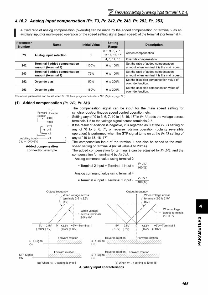
Frequency setting by analog input (terminal 1, 2, 4)
4PA
RA
MET
ERS
4.16.2 Analog input compensation (Pr. 73, Pr. 242, Pr. 243, Pr. 252, Pr. 253)
The above parameters can be set when Pr. 160 User group read selection = "0". (Refer to page 175)
(1) Added compensation (Pr. 242, Pr. 243)
Auxiliary input characteristics
A fixed ratio of analog compensation (override) can be made by the added compensation or terminal 2 as anauxiliary input for multi-speed operation or the speed setting signal (main speed) of the terminal 2 or terminal 4.
Parameter Number Name Initial Value Setting
Range Description
73 Analog input selection 10 to 3, 6, 7, 10 to 13, 16, 17 Added compensation
4, 5, 14, 15 Override compensation
242 Terminal 1 added compensation amount (terminal 2) 100% 0 to 100% Set the ratio of added compensation
amount when terminal 2 is the main speed.
243 Terminal 1 added compensation amount (terminal 4) 75% 0 to 100% Set the ratio of added compensation
amount when terminal 4 is the main speed.
252 Override bias 50% 0 to 200% Set the bias side compensation value of override function.
253 Override gain 150% 0 to 200% Set the gain side compensation value of override function.
Added compensation connection example
⋅ The compensation signal can be input for the main speed setting forsynchronous/continuous speed control operation, etc.
⋅ Setting any of "0 to 3, 6, 7, 10 to 13, 16, 17" in Pr. 73 adds the voltage acrossterminals 1-5 to the voltage signal across terminals 2-5.
⋅ If the result of addition is negative, it is regarded as 0 at the Pr. 73 setting ofany of "0 to 3, 6, 7", or reverse rotation operation (polarity reversibleoperation) is performed when the STF signal turns on at the Pr. 73 setting ofany of "10 to 13, 16, 17".
⋅ The compensation input of the terminal 1 can also be added to the multi-speed setting or terminal 4 (initial value 4 to 20mA).
⋅ The added compensation for terminal 2 can be adjusted by Pr. 242, and thecompensation for terminal 4 by Pr. 243.
Analog command value using terminal 2
= Terminal 2 input + Terminal 1 input ×
Analog command value using terminal 4
= Terminal 4 input + Terminal 1 input ×
10
2
5
Forward
rotationInverter
STF
1Auxiliary input
0 to 10V( 5V)
SD
Pr. 242100(%)
Pr. 243100(%)
Output frequency
When voltage across
terminals 2-5 is 2.5V
(5V)
When voltage
across terminals
2-5 is 0V
+5V
(+10V)
Terminal 10-2.5V
(-5V)
-5V
(-10V)
STF Signal
ON
STF Signal
ON
Forward rotation
Forward rotation
(a) When Pr. 73 setting is 0 to 5
Output frequency
When voltage across
terminals 2-5 is 2.5V
(5V)
When voltage
across terminals
2-5 is 0V
+5V
(+10V)
Terminal 10-2.5V
(-5V)
-5V
(-10V)
Forward rotation
Forward rotation
(b) When Pr. 73 setting is 10 to 15
Reverse rotation
Reverse rotation
+2.5V
(+5V)
+2.5V
(+5V)
STF Signal
ON
STF Signal
ON
165

Frequency setting by analog input (terminal 1, 2, 4)
(2) Override function (Pr. 252, Pr. 253)
4.16.3 Response level of analog input and noise elimination (Pr. 74)
The above parameters can be set when Pr. 160 User group read selection = "0". (Refer to page 175)
⋅ Effective for eliminating noise in the frequency setting circuit.⋅ Increase the filter time constant if steady operation cannot be performed due to noise. A larger setting results in
slower response. (The time constant can be set between approximately 10ms to 1s with the setting of 0 to 8.)
Override connection diagram
⋅ Use the override function to change the main speed at a fixed ratio.⋅ Set any of "4, 5, 14, 15" in Pr. 73 to select an override.⋅ When an override is selected, the terminal 1 or terminal 4 is used for the main
speed setting and the terminal 2 for the override signal. (When the main speed ofthe terminal 1 or terminal 4 is not input, compensation made by the terminal 2becomes invalid.)
⋅ Using Pr. 252 and Pr. 253, set the override range.⋅ How to find the set frequency for override
Set frequency (Hz) = Main speed set frequency (Hz) ×
Main speed set frequency (Hz): Terminal 1, 4 input, multi-speed settingCompensation amount (%): Terminal 2 input
Example)When Pr. 73 = "5"The set frequency changes as shown below according to theterminal 1 (main speed) and terminal 2 (auxiliary) inputs.
CAUTION⋅ When the Pr. 73 setting was changed, check the voltage/current input switch setting. Different setting may cause a fault, failure
or malfunction. (Refer to page 160 for setting.)
REMARKS⋅ The AU signal must be turned on to use the terminal 4.⋅ When inputting compensation to multi-speed operation or remote setting, set "1" (compensation made) to Pr. 28 Multi-speed
input compensation selection. (Initial value is "0")
♦ Parameters referred to ♦Pr. 28 Multi-speed input compensation selection Refer to page 92Pr. 73 Analog input selection Refer to page 160
The time constant of the primary delay filter relative to external frequency command (analog input (terminal 1,2, 4) signal) can be set.
Parameter Number Name Initial Value Setting Range Description
74 Input filter time constant 1 0 to 8
Set the primary delay filter time constant for the analog input. A larger setting results in slower response.
10
2
5
Forward
rotation
Main
speed
Inverter
STF
1(-)
(+)
Override
setting
SD
Compensation amount (%)100(%)
Pr.252
0V 2.5V
(5V)
5V
(10V)
0
50
100
150
200
Initial value
(50% to 150%)
Voltage across terminals 2-5
Pr.253
Ove
rrid
e v
alu
e (
%)
0 2.5 5
0
Terminal 1 input voltage (V)
Se
t fr
eq
ue
ncy (
Hz)
Terminal 2 5VDC
input(150%)
Terminal 2 0V
input(50%)
Terminal 2 2.5VDC
input(100%)
30
15
60
45
90
166
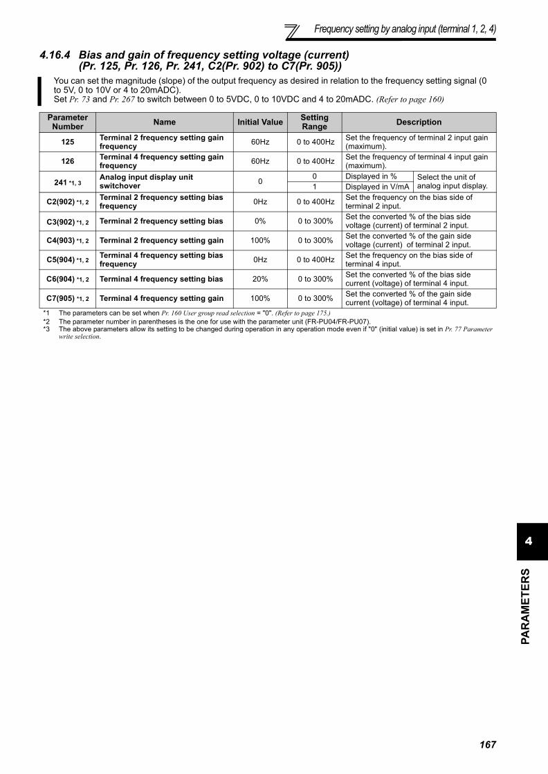
Frequency setting by analog input (terminal 1, 2, 4)
4PA
RA
MET
ERS
4.16.4 Bias and gain of frequency setting voltage (current) (Pr. 125, Pr. 126, Pr. 241, C2(Pr. 902) to C7(Pr. 905))
You can set the magnitude (slope) of the output frequency as desired in relation to the frequency setting signal (0to 5V, 0 to 10V or 4 to 20mADC).Set Pr. 73 and Pr. 267 to switch between 0 to 5VDC, 0 to 10VDC and 4 to 20mADC. (Refer to page 160)
Parameter Number Name Initial Value Setting
Range Description
125 Terminal 2 frequency setting gain frequency 60Hz 0 to 400Hz Set the frequency of terminal 2 input gain
(maximum).
126 Terminal 4 frequency setting gain frequency 60Hz 0 to 400Hz Set the frequency of terminal 4 input gain
(maximum).
241 *1, 3Analog input display unit switchover 0
0 Displayed in % Select the unit of analog input display.1 Displayed in V/mA
C2(902) *1, 2Terminal 2 frequency setting bias frequency 0Hz 0 to 400Hz Set the frequency on the bias side of
terminal 2 input.
C3(902) *1, 2 Terminal 2 frequency setting bias 0% 0 to 300% Set the converted % of the bias side voltage (current) of terminal 2 input.
C4(903) *1, 2 Terminal 2 frequency setting gain 100% 0 to 300% Set the converted % of the gain side voltage (current) of terminal 2 input.
C5(904) *1, 2Terminal 4 frequency setting bias frequency 0Hz 0 to 400Hz Set the frequency on the bias side of
terminal 4 input.
C6(904) *1, 2 Terminal 4 frequency setting bias 20% 0 to 300% Set the converted % of the bias side current (voltage) of terminal 4 input.
C7(905) *1, 2 Terminal 4 frequency setting gain 100% 0 to 300% Set the converted % of the gain side current (voltage) of terminal 4 input.
*1 The parameters can be set when Pr. 160 User group read selection = "0". (Refer to page 175.)*2 The parameter number in parentheses is the one for use with the parameter unit (FR-PU04/FR-PU07).*3 The above parameters allow its setting to be changed during operation in any operation mode even if "0" (initial value) is set in Pr. 77 Parameter
write selection.
167

Frequency setting by analog input (terminal 1, 2, 4)
(3) Analog input display unit changing (Pr. 241)⋅ You can change the analog input display unit (%/V/mA) for analog input bias/gain calibration.⋅ Depending on the terminal input specification set to Pr. 73 and Pr. 267, the display units of C3 (Pr. 902), C4 (Pr. 903),
C6 (Pr. 904) C7 (Pr. 905) change as shown below.
(1) Change the frequency at maximumanalog input. (Pr. 125, Pr. 126)
⋅ Set a value in Pr. 125 (Pr. 126) when changing onlythe frequency setting (gain) of the maximum analoginput power (current). (C2 (Pr. 902) to C7 (Pr. 905)setting need not be changed)
(2) Analog input bias/gain calibration (C2(Pr.902) to C7(Pr. 905), )
⋅ The "bias" and "gain" functions are used to adjust therelationship between the input signal entered fromoutside the inverter to set the output frequency, e.g. 0to 5V, 0 to 10V or 0 to 20mADC, and the outputfrequency.
⋅ Set the bias frequency of the terminal 2 input usingC2 (Pr. 902). (initial set to the frequency at 0V)
⋅ Using Pr. 125, set the output frequency relative to thefrequency command voltage (current) set in Pr. 73Analog input selection.
⋅ Set the bias frequency of the terminal 4 input usingC5 (Pr. 904). (initial set to the frequency at 4mA)
⋅ Using Pr. 126, set the output frequency relative to20mA of the frequency command current (0 to20mA).
⋅ There are three methods to adjust the frequencysetting voltage (current) bias/gain.(a) Method to adjust any point by application of
voltage (current) to across the terminals 2-5 (4-5). page 169
(b) Method to adjust any point without application of avoltage (current) to across terminals 2-5(4-5).
page 170(c) Adjusting only the frequency without adjusting the
voltage (current). page 171CAUTION
⋅ When the terminal 2 is calibrated to change the inclination of the set frequency, the setting of the terminal 1 is also changed.⋅ When a voltage is input to the terminal 1 to make calibration, (terminal 2 (4) analog value + terminal 1 analog value) is the analog
calibration value.⋅ When the voltage/current input specifications were changed using Pr. 73 and Pr. 267, be sure to make calibration.
Analog Command (terminal 2, 4)
(according to Pr. 73, Pr. 267 )Pr. 241 = 0 (initial value) Pr. 241 = 1
0 to 5V input 0 to 5V → displayed in 0 to 100%(0.1%). 0 to 100% → displayed in 0 to 5V(0.01V).0 to 10V input 0 to 10V → displayed in 0 to 100%(0.1%). 0 to 100% → displayed in 0 to 10V(0.01V).
4 to 20mA input 0 to 20mA → displayed in 0 to 100%(0.1%). 0 to 100% → displayed in 0 to 20mA(0.01mA).
REMARKS⋅ Analog input display is not displayed correctly if voltage is applied to terminal 1 when terminal 1 input specifications (0 to ±5V, 0
to ±10V) and main speed (terminal 2, terminal 4 input) specifications (0 to 5V, 0 to 10V, 0 to 20mA) differ. (For example, 5V(100%) is analog displayed when 0V and 10V are applied to terminal 2 and terminal 1 respectively in the initial status.
⋅ Set "0" (initial value is 0% display) in Pr. 241 to use.
Ou
tpu
t fr
eq
ue
ncy
(Hz)
Pr.125
0
0Frequency setting signal
100%
10V
Initial value
BiasGain
0 5V
C2
(Pr. 902)
C3 (Pr. 902) C4 (Pr. 903)
60HzO
utp
ut
fre
qu
en
cy
(Hz)
Pr. 126
0
Frequency setting signal
100%
Initial value
Bias
Gain
0
20
4 20mA
C5
(Pr. 904)
C6 (Pr. 904) C7 (Pr. 905)
60Hz
168

Frequency setting by analog input (terminal 1, 2, 4)
4PA
RA
MET
ERS
(4) Frequency setting signal (current) bias/gain adjustment method(a)Method to adjust any point by application of voltage (current) across the terminals 2-5 (4-5).
REMARKS⋅ If the frequency meter (indicator) connected to across terminals FM-SD does not indicate exactly 60Hz, set calibration parameter
C0 FM terminal calibration. (Refer to page 138)⋅ If the gain and bias of frequency setting voltage (current) are too close, an error ( ) may be displayed at setting.
5. Turn to change it to the setting value
of " ".
4. Press to read the present set value.
" " (initial value) appears.
3. Turn until appears.
Display
Analog voltage (current)
value (%) across terminals 2-5
(across terminals 4-5)
Flicker...Parameter setting complete!!
Flicker...Parameter setting complete!!
*
*
*The value is nearly 100 (%) in the maximum
position of the potentiometer.
*The value is nearly 100 (%) in the maximum
position of the potentiometer.
CAUTIONAfter performing the operation in step 10, do not touch until
completion of calibration.
(Adjustment completed)
Press twice to show the next parameter ( ).
C0 to C7 setting
is enabled.
Terminal 2 input Terminal 4 input
By turning , you can read another parameter.
Press to return to the indication (step 8).
The parameter
number read
previously appears.
1. Confirm the RUN indication and operation mode indication The inverter must be at a stop. The inverter must be in the PU operation
mode.(Using )
2. Press to choose the parameter
setting mode.
6. Press to set.
7.
8. Press to display .
9. Turn until ( ) appears.
Set to C4 Terminal 2 frequency setting
gain.
10. Press to display the analog voltage
(current) value (%).
11. Apply a 5V (20mA) voltage (current).
(Turn the external potentiomerter
connected across terminals 2-5 (across
terminals 4-5) to maximum (any
position).)
12. Press to set.
Operation
Terminal 4 inputTerminal 2 input
169

Frequency setting by analog input (terminal 1, 2, 4)
(b) Method to adjust any point without application of a voltage (current) to across terminals 2-5(4-5). (To change from 4V (80%) to 5V (100%))
REMARKS
By pressing after step 10, you can confirm the current frequency setting bias/gain setting.
It cannot be confirmed after execution of step 11.
Press twice to show the next parameter ( ).
By turning , you can read another parameter.
Press to return to the indication (step 8).
Flicker...Parameter setting complete!!(Adjustment completed)
Flicker...Parameter setting complete!!
C0 to C7 setting
is enabled.
Analog voltage (current)
value (%) across terminals 2-5
(across terminals 4-5)
5. Turn to change it to the setting value
of " ".
4. Press to read the present set value.
" " (initial value) appears.
6. Press to set.
7. Turn until appears.
8. Press to display .
9. Turn until ( )
appears. Set to C4 Terminal 2 frequency
setting gain.
10. Press to display the analog voltage
(current) value (%).
The parameter
number read
previously appears.
1. Confirm the RUN indication and operation mode indication The inverter must be at a stop. The inverter must be in the PU operation
mode.(Using )
2. Press to choose the parameter
setting mode.
DisplayOperation
The gain frequency is
reached when the analog
voltage (current) value across
terminals 2-5 (across terminals
4-5) is 100%.
11. Turn to set the gain voltage (%).
"0V (0mA) equals to 0%, 5V (10V, 20mA) to
100%"
REMARKS
The current setting at the instant of
turning is displayed.
3. until appears.Turn
Terminal 2 input Terminal 4 input
12. Press to set.
Terminal 2 input Terminal 4 input
170

Frequency setting by analog input (terminal 1, 2, 4)
4PA
RA
MET
ERS
(c) Method to adjust only the frequency without adjustment of a gain voltage (current).(When changing the gain frequency from 60Hz to 50Hz)
REMARKS⋅ Changing C4 (Pr. 903) or C7 (Pr. 905) (gain adjustment) value will not change the Pr. 20 value. The input of terminal 1 (frequency
setting auxiliary input) is added to the speed setting signal.⋅ For the operating procedure using the parameter unit (FR-PU04/FR-PU07), refer to the FR-PU04/FR-PU07 instruction manual.⋅ When setting the value to 120Hz or more, it is necessary to set Pr. 18 High speed maximum frequency to 120Hz or more. (Refer to
page 82)⋅ Make the bias frequency setting using calibration parameter C2 (Pr. 902) or C5 (Pr. 904). (Refer to page 168)
CAUTIONBe cautious when setting any value other than "0" as the bias frequency at 0V (0mA). Even if a speed command is not given, merely turning on the start signal will start the motor at the preset frequency.
♦ Parameters referred to ♦Pr. 20 Acceleration/deceleration reference frequency Refer to page 96Pr. 73 Analog input selection, Pr. 267 Terminal 4 input selection Refer to page 160Pr. 79 Operation mode selection Refer to page 177
DisplayOperation
Flicker...Parameter setting complete!!
1. Pr. 125) or
(Pr. 126) appears.
4. Press to set.
5. Mode/monitor check
Press twice to choose the
monitor/frequency monitor.
or
Terminal 2 input Terminal 4 input
Terminal 2 input Terminal 4 input
3. Turn to change the set value to
" ". (50.00Hz)
2. Press to show the present set value.
(Rated motor frequency (initial value))
6. Apply a voltage across the drive unit
terminals 2-5 (across 4-5) and turn on the
start command (STF, STR).
Operation starts at 50Hz.
171

Misoperation prevention and parameter setting restriction
4.17 Misoperation prevention and parameter setting restriction
4.17.1 Reset selection/disconnected PU detection/PU stop selection (Pr. 75)
(1) Reset selection• You can select the enable condition of reset function (RES signal, reset command through communication) input.• When Pr. 75 is set to any of "1, 3, 15, 17", a reset can be input only when a fault occurs.
Purpose Parameter that must be Set Refer to Page
Limit reset functionTrips stop when PU is disconnectedStop from PU
Reset selection/disconnected PU detection/PU stop selection Pr. 75 172
Prevention of parameter rewrite Parameter write selection Pr. 77 174Prevention of reverse rotation of the motor
Reverse rotation prevention selection Pr. 78 175
Display necessary parameters Display of applied parameters and user group function Pr. 160, Pr. 172 to Pr. 174 175
Control of parameter write by communication EEPROM write selection Pr. 342 197
You can select the reset input acceptance, disconnected PU (FR-DU07/FR-PU04/FR-PU07) connector detectionfunction and PU stop function.
Parameter Number Name Initial
Value Setting Range Description
75 Reset selection/disconnected PU detection/PU stop selection 14 0 to 3, 14 to 17
For the initial value, reset always enabled, without disconnected PU detection, and with PU stop function are set.
⋅The above parameters can be set when Pr. 160 User group read selection = "0". (Refer to page 175)⋅The Pr. 75 value can be set any time. Also, if parameter (all) clear is executed, this setting will not return to the initial value.
Pr. 75Setting Reset Selection Disconnected PU Detection PU Stop Selection
0 Reset input normally enabled.If the PU is disconnected, operationwill be continued.
Pressing decelerates the motor to
a stop only in the PU operation mode.
1 Reset input enabled only when theprotective function is activated
2 Reset input normally enabled.When the PU is disconnected, theinverter output is shut off.3 Reset input enabled only when the
protective function is activated14
(initial value)
Reset input normally enabled.If the PU is disconnected, operationwill be continued. Pressing decelerates the motor to
a stop in any of the PU, external andcommunication operation modes.
15 Reset input enabled only when theprotective function is activated
16 Reset input normally enabled.When the PU is disconnected, theinverter output is shut off.17 Reset input enabled only when the
protective function is activated
CAUTION⋅ When the reset signal (RES) is input during operation, the motor coasts since the inverter being reset shuts off the output.
Also, the cumulative value of the electronic thermal relay function is cleared.⋅ The reset key of the PU is valid only when a fault occurs, independently of the Pr. 75 setting.
172

Misoperation prevention and parametersetting restriction
4PA
RA
MET
ERS
(2) Disconnected PU detection• This function detects that the PU (FR-DU07/FR-PU04/FR-PU07) has been disconnected from the inverter for
longer than 1s and causes the inverter to provide a fault output (E.PUE) and come to trip.• When Pr. 75 is set to any of "0, 1, 14, 15", operation is continued if the PU is disconnected.
(3) PU stop selection• In any of the PU operation, external operation and network operation modes, the motor can be stopped by pressing
of the PU.
• When the inverter is stopped by the PU stop function, " " is displayed. A fault signal is not provided.
• When Pr. 75 is set to any of "0 to 3", deceleration to a stop by is valid only in the PU operation mode.
(4) How to restart the motor stopped by input from the PU in External operation mode (PUstop (PS) reset method)
• The motor can be restarted by making a reset using a power supply reset or RES signal.
CAUTION⋅ When the PU has been disconnected since before power-on, it is not judged as a fault.⋅ To make a restart, confirm that the PU is connected and then reset the inverter.⋅ The motor decelerates to a stop when the PU is disconnected during PU jog operation with Pr. 75 set to any of "0, 1, 14, 15"
(which selects operation is continued if the PU is disconnected).⋅ When RS-485 communication operation is performed through the PU connector, the reset selection/PU stop selection function
is valid but the disconnected PU detection function is invalid.
REMARKS
The motor will also decelerate to a stop (PU stop) when is input during operation in the PU mode through RS-485
communication with Pr. 551 PU mode operation command source selection set to "1" (PU mode RS-485 terminals).
(a) When operation panel (FR- DU07) is used1)After the motor has decelerated to a stop, turn off the
STF or STR signal.
2)Press to display .••••••( canceled)
3)Press to return to .
4)Turn on the STF or STR signal.
(b) Connection of the parameter unit (FR-PU04/FR-PU07)
1)After the motor has decelerated to a stop, turn off theSTF or STR signal.
2)Press .••••••( canceled)3)Turn on the STF or STR signal.
CAUTION⋅ Even if Pr. 250 Stop selection is set to other than "9999" to select coasting to a stop, the motor will not coast to a stop but
decelerate to a stop by the PU stop function during external operation.
CAUTIONDo not reset the inverter with the start signal on. Doing so will cause the inverter to start immediately after a reset, leading to hazardous conditions.
♦ Parameters referred to ♦Pr. 250 Stop selection Refer to page 112
Speed
Time
Key
Key
Stop/restart example for external operation
Operation
panel
STF ON(STR) OFF
EXT
173

174
Misoperation prevention and parameter setting restriction
4.17.2 Parameter write selection (Pr. 77)
(1) Write parameters only at a stop (setting "0", initial value)⋅ Parameters can be written only during a stop in the PU operation mode.⋅ The parameters marked in the parameter list (page 63) can always be written, regardless of the operation
mode and operating status. However, Pr. 72 PWM frequency selection and Pr. 240 Soft-PWM operation selection can bewritten during operation in the PU operation mode, but cannot be written in External operation mode.
(3) Write parameters during operation (setting "2")⋅ Parameters can always be written.⋅ The following parameters cannot be written during operation if Pr. 77 = "2". Stop operation when changing their
parameter settings.
You can select whether write to various parameters can be performed or not. Use this function to preventparameter values from being rewritten by misoperation.
Parameter Number Name Initial Value Setting
Range Description
77 Parameter write selection 0
0 Write is enabled only during a stop.1 Parameter write is not enabled.
2 Parameter write is enabled in any operation mode regardless of operating status.
The above parameters can be set when Pr. 160 User group read selection = "0". (Refer to page 175.)Pr. 77 can be always set independently of the operation mode and operating status.
(2) Disable parameter write (setting "1")⋅ Parameter write is not enabled. (Reading is
enabled.)⋅ Parameter clear and all parameter clear cannot
be performed, either.⋅ The parameters given on the right can be
written if Pr. 77 = "1".
Parameter Number Name
22 Stall prevention operation level75 Reset selection/disconnected PU detection/PU stop selection77 Parameter write selection79 Operation mode selection160 User group read selection
Parameter Number Name
23 Stall prevention operation level compensation factor at double speed48 Second stall prevention operation current49 Second stall prevention operation frequency60 Energy saving control selection66 Stall prevention operation reduction starting frequency71 Applied motor79 Operation mode selection80 Motor capacity(Simple magnetic flux vector control)90 Motor constant (R1)
100 to 109 (Adjustable 5 points V/F parameter)135 Electronic bypass sequence selection136 MC switchover interlock time137 Start waiting time138 Bypass selection at a fault139 Automatic switchover frequency from inverter to bypass operation
178 to 196 (I/O terminal function selection)255 Life alarm status display256 Inrush current limit circuit life display257 Control circuit capacitor life display258 Main circuit capacitor life display329 Digital input unit selection (Parameter for the plug-in option FR-A7AX)343 Communication error count563 Energization time carrying-over times564 Operating time carrying-over times
♦ Parameters referred to ♦Pr. 79 Operation mode selection Refer to page 177

Misoperation prevention and parametersetting restriction
4PA
RA
MET
ERS
4.17.3 Reverse rotation prevention selection (Pr. 78)
⋅ Set this parameter when you want to limit the motor rotation to only one direction.⋅ This parameter is valid for all of the reverse rotation and forward rotation keys of the operation panel (FR-DU07),
parameter unit (FR-PU04/FR-PU07), signals (STF, STR signals) via external terminals, and the forward and reverserotation commands through communication.
4.17.4 Display of applied parameters and user group function (Pr. 160, Pr. 172 to Pr. 174)
(1) Display of simple mode parameters and extended parameters (Pr. 160)⋅ When Pr. 160 = "9999" (initial value), only the simple mode parameters can be displayed on the operation panel
(FR-DU07) and parameter unit (FR-PU04/FR-PU07). (Refer to the parameter list, pages 63 to 71, for the simplemode parameters.)
⋅ Set "0" in Pr. 160 to display of the simple mode parameters and extended parameters.
This function can prevent reverse rotation fault resulting from the incorrect input of the start signal.
Parameter Number Name Initial Value Setting Range Description
78 Reverse rotation prevention selection 0
0 Both forward and reverse rotations allowed
1 Reverse rotation disabled2 Forward rotation disallowed
The above parameters can be set when Pr. 160 User group read selection = "0". (Refer to page 175.)
Parameter which can be read from the operation panel and parameter unit can be restricted.In the initial setting, only the simple mode parameters are displayed.
Parameter Number Name Initial Value Setting Range Description
160 User group read selection 9999
9999 Only the simple mode parameters can be displayed.
0 The simple mode and extended parameters can be displayed
1 Only parameters registered in the user group can be displayed.
172 *1 User group registered display/batch clear 0
(0 to 16) Displays the number of cases registered as a user group (Read only)
9999 Batch clear the user group registration
173 *1, 2 User group registration 9999 0 to 999, 9999 Set the parameter numbers to be registered to the user group.
174 *1, 2 User group clear 9999 0 to 999, 9999 Set the parameter numbers to be cleared from the user group.
*1 They can be set when Pr. 160 User group read selection = "0".*2 The values read from Pr. 173 and Pr. 174 are always "9999".
REMARKS⋅ When a plug-in option is fitted to the inverter, the option parameters can also be read.⋅ When reading the parameters using the communication option, all parameters can be read regardless of the Pr. 160 setting.
⋅ Pr. 15 Jog frequency, Pr. 16 Jog acceleration/deceleration time, Pr. 991 PU contrast adjustment are displayed as simple modeparameters when the parameter unit (FR-PU04/FR-PU07) is mounted.
⋅ When reading the parameters using the RS-485 terminals, all parameters can be read regardless of the Pr. 160 setting by setting Pr.550 NET mode operation command source selection and Pr. 551 PU mode operation command source selection.
* OP indicates a communication option
Pr.551 Pr.550 Pr.160 Valid/Invalid1 (RS-485) ⎯ Valid
2(PU)
(initial value)
0(OP) Valid1(RS-485) Invalid (all readable)
9999(auto-detect)(initial value)
With OP: validWithout OP: invalid(all readable)
175
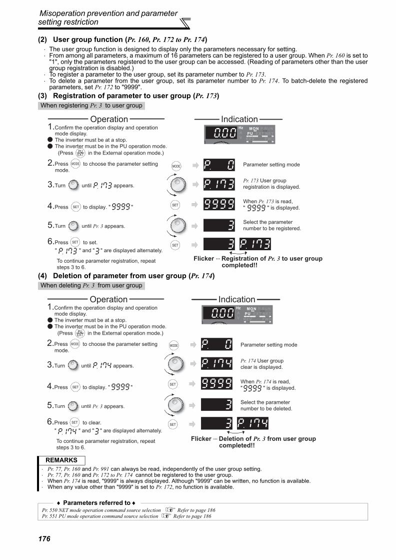
Misoperation prevention and parameter setting restriction
(2) User group function (Pr. 160, Pr. 172 to Pr. 174)⋅ The user group function is designed to display only the parameters necessary for setting.⋅ From among all parameters, a maximum of 16 parameters can be registered to a user group. When Pr. 160 is set to
"1", only the parameters registered to the user group can be accessed. (Reading of parameters other than the usergroup registration is disabled.)
⋅ To register a parameter to the user group, set its parameter number to Pr. 173.⋅ To delete a parameter from the user group, set its parameter number to Pr. 174. To batch-delete the registered
parameters, set Pr. 172 to "9999".(3) Registration of parameter to user group (Pr. 173)
(4) Deletion of parameter from user group (Pr. 174)
When registering Pr. 3 to user group
When deleting Pr. 3 from user group
REMARKS⋅ Pr. 77, Pr. 160 and Pr. 991 can always be read, independently of the user group setting.⋅ Pr. 77, Pr. 160 and Pr. 172 to Pr. 174 cannot be registered to the user group.⋅ When Pr. 174 is read, "9999" is always displayed. Although "9999" can be written, no function is available.⋅ When any value other than "9999" is set to Pr. 172, no function is available.
♦ Parameters referred to ♦Pr. 550 NET mode operation command source selection Refer to page 186Pr. 551 PU mode operation command source selection Refer to page 186
IndicationOperation
Parameter setting mode
Pr. 173 User group
registration is displayed.
When Pr. 173 is read,
" " is displayed.
Select the parameter
number to be registered.
Flicker ··· Registration of Pr. 3 to user group completed!!
1.Confirm the operation display and operation mode display.
The inverter must be at a stop.
The inverter must be in the PU operation mode.
(Press in the External operation mode.)
2.Press to choose the parameter setting
mode.
3.Turn until appears.
5.Turn until Pr. 3 appears.
6.Press to set.
" " and " " are displayed alternately.
To continue parameter registration, repeat
steps 3 to 6.
4.Press to display. " "
Operation1.Confirm the operation display and operation mode display.
The inverter must be at a stop.
The inverter must be in the PU operation mode.
(Press in the External operation mode.)
2.Press to choose the parameter setting
mode.
3.Turn until appears.
5.Turn until Pr. 3 appears.
6.Press to clear.
" " and " " are displayed alternately.
To continue parameter registration, repeat
steps 3 to 6.
4.Press to display. " "
Indication
Parameter setting mode
Pr. 174 User group
clear is displayed.
When Pr. 174 is read,
" " is displayed.
Select the parameter
number to be deleted.
Flicker ··· Deletion of Pr. 3 from user group completed!!
176

Selection of operation mode andoperation location
4PA
RA
MET
ERS
4.18 Selection of operation mode and operation location
4.18.1 Operation mode selection (Pr. 79)
The above parameters can be changed during a stop in any operation mode.* The priorities of the frequency commands when Pr. 79 = "3" are "Multi-speed operation (RL/RM/RH/REX) > PID control (X14) > terminal 4 analog
input (AU) > digital input from the operation panel".
Purpose Parameter that must be set Refer to pageOperation mode selection Operation mode selection Pr. 79 177Started in network operation mode Operation mode at power on Pr. 79, Pr. 340 185
Selection of operation locationSelection of start command source, speed command source and operation location during communication operation
Pr. 338, Pr. 339, Pr. 550, Pr. 551 186
Used to select the operation mode of the inverter.Mode can be changed as desired between operation using external command signals (external operation),operation from the PU (FR-DU07/FR-PU04/FR-PU07), combined operation of PU operation and externaloperation (external/PU combined operation, and network operation (when RS-485 terminals or a communicationoption is used).
Parameter Number Name Initial
ValueSetting Range Description
LED Indication: Off: On
79Operation mode selection
0
0Use external/PU switchover mode (press to switch
between the PU and External operation mode. At power on, the inverter is in the External operation mode.
External operation mode
PU operation mode
1 Fixed to PU operation mode
2Fixed to External operation modeOperation can be performed by switching between the Externaland NET operation mode.
External operation mode
NET operation mode
3
External/PU combined operation mode 1Running Command Start Command
PU (FR-DU07/FR-PU04/FR-PU07) setting or External signal input (multi-speed setting, across terminals 4-5 (valid when AU signal turns on)). *
External signal input (terminal STF, STR)
4
External/PU combined operation mode 2Running Command Start Command
External signal input(Terminal 2, 4, 1, JOG, multi-speed selection, etc.)
Input from the PU (FR-DU07/FR-PU04/FR-PU07)
( , )
6
Switch-over modeSwitchover between PU operation, external operation, andNET operation can be done while keeping the same operationstatus.
PU operation mode
External operation mode
NET operation mode
7
External operation mode (PU operation interlock)X12 signal ON
Operation mode can be switched to the PU operation mode.(output stop during external operation)
X12 signal OFFOperation mode cannot be switched to the PU operationmode.
PU operation mode
External operation mode
177

Selection of operation mode and operation location
(1) Operation mode basics
(2) Operation mode switching method
⋅ The operation mode specifies the source of the startcommand and the frequency command for theinverter.
⋅ Basically, there are following operation modes.⋅ External operation mode: For inputting start
command and frequency command by an externalpotentiometer and switches which are connectedto the control circuit terminal.
⋅ PU operation mode: For inputting start commandand frequency command by operation panel (FR-DU07), parameter unit (FR-PU04/FR-PU07) andRS-485 communication with PU connector.
⋅ Network operation mode (NET operationmode): For inputting start command andfrequency command by RS-485 terminal andcommunication options.
⋅ The operation mode can be selected from theoperation panel or with the communicationinstruction code.
REMARKS⋅ Either "3" or "4" may be set to select the PU/external combined operation, and these settings differ in starting method.
⋅ In the initial setting, the stop function by of the PU (FR-DU07/FR-PU07) (PU stop selection) is valid also in other than the
PU operation mode. (Pr. 75 Reset selection/disconnected PU detection/PU stop selection. Refer to page 172.)
REMARKS⋅ For switching of operation by external terminals, refer to the following:
PU operation external interlock signal (X12 signal) . page 182PU-external operation switch-over signal (X16) page 183PU-NET operation switchover signal (X65), External-NET operation switchover signal (X66) page 184Pr. 340 Communication startup mode selection page 185
12
34
5 6
7
8
9
10
Network operation mode
Network operation
mode
External
operation
mode
PU operation
mode
Personal
computer
Personal
computer
Operation
panel
Programmable
controller
Potentiometer Switch
RS-485
terminals
Inverter
Communication
option
External terminal
Switching from the network
Switch to the network operation
mode from the network.
Switch to the External
operation mode from
the network.
External operation
Switching from the PU
Press of
the PU to light
Network operation PU operation
Network operation PU operation
When "0, 1, or 2" is set in Pr. 340
When "10 or 12" is set in Pr. 340Press of the PU to light
Press of
the PU to light
Press of the PU to light
178

Selection of operation mode andoperation location
4PA
RA
MET
ERS
(3) Operation mode selection flowIn the following flowchart, select the basic parameter setting and terminal connection related to the operation mode.START Connection Parameter setting Operation
Where is the start command source?
From external (STF/STR terminal)
Where is the frequency set?
From external (Terminal 2, 4, JOG, multi-speed, etc.)
STF (forward rotation)/STR (reverse rotation)(Refer to page 115.)Terminal 2, 4-5 (analog), RL, RM, RH, JOG, etc.
Frequency setting terminal ONSTF(STR) ON
From PU (Digital setting) STF (forward rotation)/STR (reverse rotation)(Refer to page 115.)
Pr. 79 = "3"(External/PU combined
operation 1)DU digital setting
STF(STR) ON
From communication (RS-485 terminals/communication option)
RS-485 terminals or communication option?
RS-485 terminals STF (forward rotation)/STR (reverse rotation)(Refer to page 115.)
Connection of RS-485 terminals(Refer to page 193.)
Pr. 338 = "1"Pr. 340 = "1, 2"
Communication frequency setting command sending
STF(STR) ON
Communication option Connection of communication option
(Refer to the corresponding communication option instruction manual)
Pr. 338 = "1"Pr. 340 = "1"
Communication frequency setting command sending
STF(STR) ONFrom PU (FWD/REV key)
Where is the frequency set?
From external (Terminal 2, 4, JOG, multi-speed, etc.) Terminal 2, 4-5 (analog), RL, RM,
RH, JOG, etc.Pr. 79 = "4"
(External/PU combined operation 2)
Frequency setting terminal ONFWD/REV key ON
From PU (Digital setting) Pr. 79 = "1"(Fixed to PU operation)
Digital settingFWD/REV key ONFrom communication
(RS-485 terminals/communication option)
From communication (RS-485 terminals/communication option)
RS-485 terminals or communication option?
RS-485 terminalsWhere is the frequency
set?From external (Terminal 2, 4, JOG, multi-speed, etc.)
Connection of RS-485 terminals(Refer to page 193.)Terminal 2, 4-5 (analog), RL, RM, RH, JOG, etc.
Pr. 339 = "1"Pr. 340 = "1, 2"
Frequency setting terminal ONCommunication start command
sending
From PU (Digital setting)
From communicationRS-485 terminals
Connection of RS-485 terminals(Refer to page 193.) Pr. 340 = "1, 2"
Communication frequency setting command sending
Communication start command sendingCommunication option
Where is the frequency set?
From external (Terminal 2, 4, JOG, multi-speed, etc.)Connection of communication option(Refer to the corresponding communication option instruction manual)Terminal 2, 4-5 (analog), RL, RM, RH, JOG, etc.
Pr. 339 = "1"Pr. 340 = "1"
Frequency setting terminal ONCommunication start command
sending
From PU (Digital setting)
From communication (communication option)
Connection of communication option(Refer to the corresponding communication
option instruction manual)Pr. 340 = "1"
Communication frequency setting command sending
Communication start command sending
Disabled
Disabled
Disabled
179

Selection of operation mode and operation location
(4) External operation mode (setting "0" (initial value), "2")
(5) PU operation mode (setting "1")
⋅ Select the External operation mode when the startcommand and the frequency command are appliedfrom a frequency setting potentiometer, start switch, etc.externally and connecting them to the control circuitterminals of the inverter.
⋅ Basically, parameter changing is disabled in Externaloperation mode. (Some parameters can be changed.Refer to page 63 for the parameter list.)
⋅ When "0" or "2" is selected for Pr. 79, the inverter entersthe External operation mode at power on. (When usingthe network operation mode, refer to page 185.)
⋅ When parameter changing is seldom necessary, setting"2" fixes the operation mode to External operationmode. When frequent parameter changing isnecessary, setting "0" (initial value) allows the operationmode to be changed easily to PU operation mode by
pressing of the operation panel. When you
switched to PU operation mode, always return toExternal operation mode.
⋅ The STF and STR signal are used as a start command,and the voltage or current signal to terminal 2, 4, multi-speed signal, JOG signal, etc. are used as frequencycommand.
⋅ Select the PU operation mode when applying start andspeed command by the key operation of the operationpanel (FR-DU07) or parameter unit (FR-PU04/FR-PU07) alone. Also select the PU operation mode whenmaking communication using the PU connector.
⋅ When "1" is selected for Pr. 79, the inverter enters thePU operation mode at power on. You cannot change tothe other operation mode.
⋅ The setting dial of the operation panel can be used forsetting like a potentiometer. (Pr. 161 Frequency setting/keylock operation selection, refer to page 248.)
⋅ When PU operation mode is selected, the PU operationmode signal (PU) can be output.For the terminal used for the PU signal output, assignthe function by setting "10 (positive logic) or 110(negative logic)" in any of Pr. 190 to Pr. 196 (outputterminal function selection).
34
5 6
7
8
9
10Hz
5
102
STFSTRSD
Reverse rotation start
Frequency setting
potentiometer
Inverter
Forward rotation start
Operation panel
(FR-DU07)
180

Selection of operation mode andoperation location
4PA
RA
MET
ERS
(6) PU/External combined operation mode 1 (setting "3")
(7) PU/External combined operation mode 2 (setting "4")
⋅ Select the PU/external combined operation mode 1when applying frequency command from the operationpanel (FR-DU07) or parameter unit (FR-PU04/FR-PU07) and inputting the start command with theexternal start switch.
⋅ Select "3" for Pr. 79. You cannot change to the otheroperation mode.
⋅ When a frequency is input from the external signal bymulti-speed setting, it has a higher priority than thefrequency setting from the PU. When AU is on, thecommand signal to terminal 4 is used.
⋅ Select the PU/External combined operation mode 2when applying frequency command from the externalpotentiometer, multi-speed or JOG signal and inputtingthe start command by key operation of the operationpanel (FR-DU07) or parameter unit (FR-PU04/FR-PU07).
⋅ Select "4" for Pr. 79. You cannot change to the otheroperation mode.
Operation panel
(FR-DU07)
SD
STF
STRForward rotation startReverse rotation start
Inverter
34
5 6
7
8
9
10
Hz
Operation panel
(FR-DU07)
5
10
2
Inverter
Frequency setting
potentiometer
181

Selection of operation mode and operation location
(8) Switch-over mode (Setting "6")⋅ While continuing operation, you can switch among PU operation, External operation and Network operation (when
RS-485 terminals or communication option is used).
(9) PU operation interlock (Setting "7")⋅ The PU operation interlock function is designed to forcibly change the operation mode to External operation mode
when the PU operation interlock signal (X12) input turns off. This function prevents the inverter from beinginoperative by the external command if the mode is accidentally left unswitched from the PU operation mode.
⋅ Set "7" (PU operation interlock) in Pr. 79.⋅ For the terminal used for X12 signal (PU operation interlock signal) input, set "12" in any of Pr. 178 to Pr. 189 (input
terminal function selection) to assign the function. (Refer to page 115 for Pr. 178 to Pr. 189.)⋅ When the X 12 signal has not been assigned, the function of the MRS signal switches from MRS (output stop) to
the PU operation interlock signal.
<Function/operation changed by switching ON/OFF the X12 (MRS) signal>
Operation Mode Switching Switching Operation/Operating Status
External operation → PU operation
Select the PU operation mode with the operation panel or parameter unit.⋅ Rotation direction is the same as that of external operation.⋅ The frequency set with the potentiometer (frequency setting command), etc. is used unchanged. (Note
that the setting will disappear when power is switched off or the inverter is reset.)
External operation → NET operation
Send the mode change command to Network operation mode through communication.⋅ Rotation direction is the same as that of external operation.⋅ The value set with the setting potentiometer (frequency setting command) or like is used unchanged.
(Note that the setting will disappear when power is switched off or the inverter is reset.)
PU operation → external operation
Press the external operation key of the operation panel, parameter unit.⋅ The rotation direction is determined by the input signal of the external operation.⋅ The set frequency is determined by the external frequency command signal.
PU operation → NET operation
Send the mode change command to Network operation mode through communication.⋅ Rotation direction and set frequency are the same as those of PU operation.
NET operation → external operation
Send the mode change command to External operation mode through communication.⋅ Rotation direction is determined by the external operation input signal.⋅ The set frequency is determined by the external frequency command signal.
NET operation → PU operation
Select the PU operation mode with the operation panel or parameter unit.⋅ The rotation direction and frequency command in Network operation mode are used unchanged.
X12 (MRS) Signal
Function/OperationOperation mode Parameter write
ONOperation mode (external, PU, NET) switching enabledOutput stop during external operation
Parameter write enabled (Pr. 77 Parameter write selection, depending on the corresponding parameter write condition (Refer to page 63 for the parameter list))
OFFForcibly switched to External operation modeExternal operation allowed.Switching to PU or NET operation mode disabled
Parameter write disabled with exception of Pr. 79
Operating Condition X12 (MRS) Signal
Operation Mode Operating Status
Switching to PU, NET
Operation ModeOperation
mode Status
PU/NETDuring stop ON→OFF *1
External *2 If external operation frequency setting and start signalare entered, operation is performed in that status.
DisallowedRunning ON→OFF *1 Disallowed
ExternalDuring stop
OFF→ON
External *2During stop
EnableON→OFF Disallowed
RunningOFF→ON During operation → output stop DisallowedON→OFF Output stop → operation Disallowed
*1 The operation mode switches to External operation mode independently of whether the start signal (STF, STR) is on or off. Therefore, themotor is run in External operation mode when the X12 (MRS) signal is turned off with either of STF and STR on.
*2 At fault occurrence, pressing of the operation panel resets the inverter.
CAUTION⋅ If the X12 (MRS) signal is on, the operation mode cannot be switched to PU operation mode when the start signal (STF, STR) is on.⋅ When the MRS signal is used as the PU interlock signal, the MRS signal serves as the normal MRS function (output stop) by
turning on the MRS signal and then changing the Pr. 79 value to other than "7" in the PU operation mode. Also as soon as "7"is set in Pr. 79, the signal acts as the PU interlock signal.
⋅ When the MRS signal is used as the PU operation interlock signal, the logic of the signal is as set in Pr. 17. When Pr. 17 = "2",read ON as OFF and OFF as ON in the above explanation.
⋅ Changing the terminal assignment using Pr. 178 to Pr. 189 (input terminal function selection) may affect the other functions. Pleasemake setting after confirming the function of each terminal.
182

Selection of operation mode andoperation location
4PA
RA
MET
ERS
(10) Switching of operation mode by external signal (X16 signal)⋅ When external operation and operation from the operation panel are used together, use of the PU-external
operation switching signal (X16) allows switching between the PU operation mode and External operation modeduring a stop (during a motor stop, start command off).
⋅ When Pr. 79 = any of "0, 6, 7", the operation mode can be switched between the PU operation mode and Externaloperation mode. (Pr. 79 = "6" At switchover mode, operation mode can be changed during operation)
⋅ For the terminal used for X16 signal input, set "16" in any of Pr. 178 to Pr. 189 (input terminal function selection) toassign the function.
Pr. 79Setting
X16 Signal State Operation ModeRemarks
ON (external) OFF (PU)
0 (initial value) External operation mode PU operation mode Can be switched to external, PU or NET operation mode
1 PU operation mode Fixed to PU operation mode
2 External operation mode Fixed to External operation mode (Can be switched to NET operation mode)
3, 4 External/PU combined operation mode External/PU combined mode fixed
6 External operation mode PU operation mode Can be switched to external, PU or NET operation mode with
operation continued
7
X12(MRS)ON
External operation mode PU operation mode Can be switched to external, PU or NET operation mode (Output
stop in External operation mode)X12(MRS)
OFF External operation mode Fixed to External operation mode (Forcibly switched to External operation mode)
REMARKS⋅ The operation mode status changes depending on the setting of Pr. 340 Communication startup mode selection and the ON/OFF
states of the X65 and X66 signals. (For details, refer to page 184.)⋅ The priorities of Pr. 79, Pr. 340 and signals are Pr. 79 > X12 > X66 > X65 > X16 > Pr. 340.
CAUTION⋅ Changing the terminal assignment using Pr. 178 to Pr. 189 (input terminal function selection) may affect the other functions. Please
make setting after confirming the function of each terminal.
183

Selection of operation mode and operation location
(11) Switching of operation mode by external signal (X65, X66 signals)⋅ When Pr. 79 = any of "0, 2, 6", the operation mode switching signals (X65, X66) can be used to change the PU or
External operation mode to network operation mode during a stop (during a motor stop or start command off). (Pr.79 = "6" switch-over mode can be changed during operation)
⋅ When switching between the network operation mode and PU operation mode1) Set Pr. 79 to "0" (initial value) or "6".2) Set "10 or 12" in Pr. 340 Communication startup mode selection.3) Set "65" in any of Pr. 178 to Pr. 189 to assign the PU-NET operation switchover signal (X65) to the terminal.4) The operation mode changes to PU operation mode when the X65 signal turns on, or to network operation mode
when the X65 signal turns off.
⋅ When switching between the network operation mode and External operation mode1) Set Pr. 79 to "0" (initial value), "2", "6" or "7". (At the Pr. 79 setting of "7", the operation mode can be switched when the
X12 (MRS) signal turns on.)2) Set "0 (initial value), 1 or 2" in Pr. 340 Communication startup mode selection.3) Set "66" in any of Pr. 178 to Pr. 189 to assign the External-NET operation switching signal (X66) to the terminal.4) The operation mode changes to network operation mode when the X66 signal turns on, or to External operation mode
when the X66 signal turns off.
Pr. 340Setting
Pr. 79Setting
X65 Signal StateRemarks
ON (PU) OFF (NET)
10, 12
0 (initial value) PU operation mode *1 NET operation mode *2Switching to External operation mode is disabled.
1 PU operation mode Fixed to PU operation mode2 NET operation mode Fixed to NET operation mode
3, 4 External/PU combined operation mode External/PU combined mode fixed
6 PU operation mode *1 NET operation mode *2
Switching operation mode is enabled while running.Switching to External operation mode is disabled.
7X12(MRS)ON Switching among the external and PU operation mode is
enabled *3 Output stop in External operation mode
X12(MRS)OFF External operation mode Forcibly switched to External operation mode*1 NET operation mode when the X66 signal is on.*2 PU operation mode when the X16 signal is off. PU operation mode also when Pr. 550 NET mode operation command source selection = "0"
(communication option command source) and the communication option is not fitted.*3 External operation mode when the X16 signal is on.
Pr. 340Setting
Pr. 79Setting
X66 Signal StateRemarks
ON (NET) OFF(external)
0 (initial value),
1, 2
0 (initial value) NET operation mode *1 External operation mode *2
1 PU operation mode Fixed to PU operation mode2 NET operation mode *1 External operation mode Switching to PU operation mode is disabled.
3, 4 External/PU combined operation mode External/PU combined mode fixed
6 NET operation mode *1 External operation mode *2 Switching operation mode is enabled while running.
7X12(MRS)ON NET operation mode *1 External operation mode *2 Output stop in External operation modeX12(MRS)OFF External operation mode Forcibly switched to External operation mode
*1 PU operation mode is selected when Pr. 550 NET mode operation command source selection = "0" (communication option command source) andthe communication option is not fitted.
*2 PU operation is selected when the X16 signal is off. When the X65 signal has been assigned, the operation mode changes with the ON/OFFstate of the X65 signal.
REMARKS⋅ The priorities of Pr. 79, Pr. 340 and signals are Pr. 79 > X12 > X66 > X65 > X16 > Pr. 340.
CAUTION⋅ Changing the terminal assignment using Pr. 178 to Pr. 189 (input terminal function selection) may affect the other functions. Please
make setting after confirming the function of each terminal.
♦ Parameters referred to ♦Pr. 15 Jog frequency Refer to page 90.Pr. 4 to 6, Pr. 24 to 27, Pr. 232 to Pr. 239 Multi-speed operation Refer to page 88.Pr. 75 Reset selection/disconnected PU detection/PU stop selection Refer to page 172.Pr. 161 Frequency setting/key lock operation selection Refer to page 248.Pr. 178 to Pr. 189 (Input terminal function selection) Refer to page 115.Pr. 190 to Pr. 196 (Output terminal function selection) Refer to page 121.Pr. 340 Communication startup mode selection Refer to page 185.Pr. 550 NET mode operation command source selection Refer to page 186.
184

Selection of operation mode andoperation location
4PA
RA
MET
ERS
4.18.2 Operation mode at power on (Pr. 79, Pr. 340)
(1) Specify operation mode at power on (Pr. 340)⋅ Depending on the Pr. 79 and Pr. 340 settings, the operation mode at power on (reset) changes as described below.
When power is switched on or when power comes back on after instantaneous power failure, the inverter can bestarted up in network operation mode.After the inverter has started up in the network operation mode, parameter write and operation can be performedfrom a program.Set this mode for communication operation using the RS-485 terminals or communication option.
Parameter Number Name Initial
ValueSetting Range Description
79 Operation mode selection 0 0 to 4, 6, 7 Select the operation mode. (Refer to page 179.)
340 * Communication startup mode selection 0
0 As set in Pr. 79.
1, 2
Started in network operation mode.When the setting is "2", it will resume the pre-instantaneous power failure operation mode after an instantaneous power failure occurs.
10, 12
Started in network operation mode. Operation mode can be changed between the PU operation mode and network operation mode from the operation panel. When the setting is "12", it will resume the pre-instantaneous power failure operation mode after an instantaneous power failure occurs.
The above parameters can be changed during a stop in any operation mode.* The parameters can be set when Pr. 160 User group read selection = "0". However, the parameters can be set whenever the communication option is
connected. (Refer to page 175.).
Pr. 340Setting
Pr. 79Setting
Operation Mode at Power on, Power Restoration, Reset Operation Mode Switching
0(initial value)
0(initial value)
External operation mode Switching among the External, PU, and NET operation mode is enabled *2
1 PU operation mode Fixed to PU operation mode
2 External operation modeSwitching between the External and Net operation mode is enabledSwitching to PU operation mode is disabled
3, 4 External/PU combined operation mode Operation mode switching is disabled
6 External operation mode Switching among the External, PU, and NET operation mode is enabled while running
7External operation mode when X12 (MRS) signal ON Switching among the External, PU, and NET operation mode
is enabled *2
External operation mode when X12 (MRS) signal OFF Fixed to External operation mode (Forcibly switched to External operation mode.)
1, 2 *1
0 NET operation mode
Same as when Pr. 340 = "0"
1 PU operation mode2 NET operation mode
3, 4 External/PU combined operation mode6 NET operation mode
7NET operation mode when X12 (MRS) signal ONExternal operation mode when X12 (MRS) signal OFF
10, 12 *1
0 NET operation mode Switching between the PU and NET operation mode is enabled *3
1 PU operation mode Same as when Pr. 340 = "0"2 NET operation mode Fixed to NET operation mode
3, 4 External/PU combined operation mode Same as when Pr. 340 = "0"
6 NET operation mode Switching between the PU and NET operation mode is enabled while running *3
7 External operation mode Same as when Pr. 340 = "0"*1 The Pr. 340 setting "2" or "12" is mainly used for communication operation using the inverter RS-485 terminals. When a value other than "9999" (selection
of automatic restart after instantaneous power failure) is set in Pr. 57 Restart coasting time, the inverter will resume the same operation state which was inbefore after power has been restored from an instantaneous power failure.When Pr. 340 = "1, 10", a start command turns off if power failure has occurred and then restored during a start command is on.
*2 The operation mode cannot be switched directly between the PU operation mode and network operation mode.
*3 Operation mode can be changed between the PU operation mode and network operation mode with key of the operation panel (FR-DU07) and X65 signal.
♦ Parameters referred to ♦Pr. 57 Restart coasting time Refer to page 141.Pr. 79 Operation mode selection Refer to page 177.
185

Selection of operation mode and operation location
4.18.3 Start command source and speed command source during communication operation (Pr. 338, Pr. 339, Pr. 550, Pr. 551)
(1) Select the command source of the network operation mode (Pr. 550)⋅ Either the RS-485 terminals or communication option can be specified as the command source in network
operation mode.⋅ For example, set Pr. 550 to "1" when executing parameter write, start command or frequency command from the
inverter RS-485 terminals in the network operation mode independently of whether the communication option isconnected or not.
(2) Select the command source of the PU operation mode (Pr. 551)⋅ Either the PU connector or RS-485 terminals can be specified as the source in the PU operation mode.⋅ When performing parameter write, giving start command and frequency command from communication with the
RS-485 terminals in PU operation mode, set "1" in Pr. 551.
*1 The Modbus-RTU protocol cannot be used in the PU operation mode. When using the Modbus-RTU protocol, set Pr. 551 to "2".*2 When the communication option is not fitted, the operation mode cannot be switched to network operation mode.
When the RS-485 terminals or communication option is used, the external start command and frequencycommand can be valid. Also, the command source in the PU operation mode can be selected.
Parameter Number Name Initial
ValueSetting Range Description
338 Communication operation command source 0
0 Start command source communication1 Start command source external
339 Communication speed command source 0
0 Frequency command source communication1 Frequency command source external
2Frequency command source external (Frequency command from communication is valid, frequency command from terminal 2 is invalid)
550 *NET mode operation command source selection
9999
0The communication option is the command source when NET operation mode.
1 RS-485 terminals are the command source when NET operation mode.
9999
Automatic communication option recognitionNormally, RS-485 terminals are the command source. When a communication option is mounted, the communication option is the command source.
551 *PU mode operation command source selection 2
1 RS-485 terminals are the command source when PU operation mode.2 PU connector is the command source when PU operation mode.
The above parameters can be set when Pr. 160 User group read selection = "0". However, the parameters can be set whenever the communicationoption is connected. (Refer to page 175.)* Pr 550 and Pr. 551 are always write-enabled.
CAUTION⋅ Since Pr. 550 = "9999" (automatic recognition of the communication option) in the initial setting, parameter write, start command
and frequency command cannot be executed by communication using the inverter RS-485 terminals when the communicationoption is fitted. (Monitor and parameter read can be performed.)
CAUTION⋅ The PU operation mode has a higher priority when Pr. 550 = "1" (NET mode RS-485 terminals) and Pr. 551 = "1" (PU mode RS-485
terminals). When the communication option is not fitted, therefore, the operation mode cannot be switched to network operationmode.
Pr. 550Setting
Pr. 551Setting
Command SourceRemarks
PU connector RS-485 terminals Communication option
01 × PU operation mode *1 NET operation mode *2
2 (initial value) PU operation mode × NET operation mode *2
11 × PU operation mode *1 ×
Switching to NET operation mode disabled
2 (initial value) PU operation mode NET operation mode ×
9999(initial value)
1 × PU operation mode *1 NET operation mode *2
2 (initial value) PU operation mode× NET operation mode Communication option fitted
NET operation mode ×Communication option not fitted
186

Selection of operation mode andoperation location
4PA
RA
MET
ERS
(3) Controllability through communication
*1 As set in Pr. 338 Communication operation command source and Pr. 339 Communication speed command source. (Refer to page 186)*2 At occurrence of RS-485 communication error, the inverter cannot be reset from the computer.*3 Enabled only when stopped by the PU. At a PU stop, PS is displayed on the operation panel. As set in Pr. 75 PU stop selection . (Refer to page 172)*4 Some parameters may be write-disabled according to the Pr. 77 Parameter write selection setting and operating status. (Refer to page 174)*5 Some parameters are write-enabled independently of the operation mode and command source presence/absence. When Pr. 77 = 2, write is
enabled. (Refer to page 63 for the parameter list)Parameter clear is disabled.*6 When Pr. 550 NET mode operation command source selection = 1 (RS-485 terminals valid) or Pr. 550 NET mode operation command source selection =
9999 and the communication option is not fitted.*7 When Pr. 550 NET mode operation command source selection = 0 (communication option valid) or Pr. 550 NET mode operation command source selection
= 9999 and the communication option is fitted.
Operation Location
Condition(Pr. 551 Setting)
OperationMode
Item
PU Operation
External Operation
External/PU Combined
Operation Mode 1
(Pr. 79 = 3)
External/PU Combined Operation
Mode 2 (Pr. 79 = 4)
NET Operation (when RS-485 terminals are
used) *6
NET Operation (when
communication option is used) *7
Con
trol b
y R
S-4
85 c
omm
unic
atio
n fro
m P
U c
onne
ctor
2 (PU
connector)
Run command (start) × × ×Run command (stop) *3 *3 *3Running frequency setting × × ×
MonitorParameter write *4 × *5 *4 *4 × *5Parameter readInverter reset
Except for 2
Run command (start) × × × × ×Run command (stop) *3 *3 *3 *3 *3Running frequency setting × × × × ×
MonitorParameter write × *5 × *5 × *5 × *5 × *5Parameter read
Inverter reset
Con
trol b
y co
mm
unic
atio
n fro
m
RS
-485
term
inal
s
1 (RS-485
terminals)
Run command(start, stop) × × ×
Running frequency setting × × ×
MonitorParameter write *4 × *5 *4 *4 × *5Parameter readInverter reset
Except for 1
Run command(start, stop) × × × × *1 ×
Running frequency setting × × × × *1 ×
MonitorParameter write × *5 × *5 × *5 × *5 *4 × *5Parameter readInverter reset × × × × *2 ×
Con
trol b
y co
mm
unic
atio
n fro
m c
omm
unic
atio
n op
tion
⎯
Run command(start, stop) × × × × × *1
Running frequency setting × × × × × *1
MonitorParameter write × *5 × *5 × *5 × *5 × *5 *4Parameter read
Inverter reset × × × × × *2
Cont
rol c
ircui
t ex
tern
al te
rmin
als
⎯
Inverter resetRun command(start, stop) × × × *1
Frequency setting × × × *1
: Enabled, ×: Disabled, : Some are enabled
187

Selection of operation mode and operation location
(4) Operation at error occurrence
*1 Can be selected using Pr. 75 Reset selection/disconnected PU detection/PU stop selection*2 Can be selected using Pr. 122 PU communication check time interval or Pr. 336 RS-485 communication check time interval*3 As controlled by the communication option.*4 In the PU jog operation mode, operation is always stopped when the PU is disconnected. Whether fault (E.PUE) occurrence is allowed or not is as
set in Pr. 75 Reset selection/disconnected PU detection/PU stop selection.*5 When Pr. 550 NET mode operation command source selection = 1 (RS-485 terminals valid) or Pr. 550 NET mode operation command source selection =
9999 and the communication option is not fitted*6 When Pr. 550 NET mode operation command source selection = 0 (communication option valid) or Pr. 550 NET mode operation command source selection
= 9999 and the communication option is fitted
Error Definition
OperationMode
Condition(Pr. 551 setting)
PU Operation
External Operation
External/PU Combined Operation
Mode 1(Pr. 79 =3)
External/PU Combined
Operation Mode 2
(Pr. 79 =4)
NET Operation(when RS-485 terminals are
used) *5
NET Operation (when
communication option is used)
*6
Inverter fault ⎯ StopPU disconnection of the PU connector
2 (PU connector) Stop/continued *1, 4
1 (RS-485 terminals) Stop/continued *1
Communication error of PU connector
2 (PU connector)Stop/
continued *2
Continued Stop/continued *2
Continued
1 (RS-485 terminals) Continued
Communication error of RS-485 terminals
1 (RS-485 terminals)Stop/
continued *2
Continued Stop/continued *2
Continued
2 (PU connector) Continued Stop/continued *2
Continued
Communication error of communication option
⎯ Continued Stop/continued *3
Continued
188

Selection of operation mode andoperation location
4PA
RA
MET
ERS
(5) Selection of command source in Network operation mode (Pr. 338, Pr. 339)⋅ There are two control sources: operation command source, which controls the signals related to the inverter start
command and function selection, and speed command source, which controls signals related to frequency setting.⋅ In Network operation mode, the commands from the external terminals and communication (RS-485 terminals or
communication option) are as listed below.
[Explanation of table]External : Command only from control terminal signal is valid.NET : Command only from communication is validCombined : Command from either of external terminal and communication is valid.⎯ : Command from either of external terminal and communication is invalid.Compensation : Command by signal from external terminal is only valid when Pr. 28 Multi-speed input compensation selection = "1"
Operation Location Selection
Pr. 338 Communication operation command source 0: NET 1: ExternalRemarks
Pr. 339 Communication speed command source 0: NET 1:External 2:External 0: NET 1:External 2:External
Fixed function (Terminal-equivalent function)
Running frequency from communication NET ⎯ NET NET ⎯ NET
Terminal 2 ⎯ External ⎯ ⎯ External ⎯Terminal 4 ⎯ External ⎯ ExternalTerminal 1 Compensation
Sele
ctiv
e fu
nctio
n
Pr. 1
78 to
Pr.
189
setti
ng
0 RL Low speed operation command/remote setting clear NET External NET External
Pr. 59 = "0" (multi-speeds)
Pr. 59 = "1 , 2" (remote)
1 RM Middle-speed operation command/remote setting deceleration NET External NET External
2 RH High speed operation command/remote setting acceleration NET External NET External
3 RT Second function selection NET External4 AU Terminal 4 input selection ⎯ Combined ⎯ Combined
5 JOG Jog operation selection ⎯ External
6 CS Selection of automatic restart after instantaneous power failure External
7 OH External thermal relay input External
8 REX Fifteen speed selection NET External NET External Pr. 59 = "0" (multi-speeds)
10 X10 Inverter operation enable signal External
11 X11 FR-HC or MT-HC connection, instantaneous power failure detection External
12 X12 PU operation external interlock External14 X14 PID control valid terminal NET External NET External16 X16 PU-external operation switchover External
24 MRS
Output stop Combined External Pr. 79 ≠ "7"
PU operation interlock ExternalPr. 79 = "7"
When X12 signal is not assigned
25 STOP Start self-holding selection ⎯ External60 STF Forward rotation command NET External61 STR Reverse rotation command NET External62 RES Reset External63 PTC PTC thermistor input External64 X64 PID forward action switchover NET External NET External65 X65 PU-NET operation switchover External66 X66 External-NET operation switchover External67 X67 Command source switchover External70 X70 DC feeding operation permission NET External71 X71 DC feeding cancel NET External72 X72 PID integral value reset NET External NET External
REMARKS⋅ The command source of communication is as set in Pr. 550 and Pr. 551.⋅ The Pr. 338 and Pr. 339 settings can be changed while the inverter is running when Pr. 77 = "2". Note that the setting change is
reflected after the inverter has stopped. Until the inverter has stopped, communication operation command source andcommunication speed command source before the setting change are valid.
189

Selection of operation mode and operation location
(6) Switching of command source by external terminal (X67)⋅ In Network operation mode, the command source switching signal (X67) can be used to switch the start command
source and speed command source. This signal can be utilized to control the signal input from both the controlterminal and communication.
⋅ Set "67" in any of Pr. 178 to Pr. 189 (input terminal function selection) to assign the X67 signal to the control terminal.⋅ When the X67 signal is off, the start command source and speed command source are control terminal.
X67 Signal State Start Command Source Speed Command SourceNo signal assignment
According to Pr. 338 According to Pr. 339ONOFF Command is valid only from control terminal signal.
REMARKS⋅ The ON/OFF state of the X67 signal is reflected only during a stop. It is reflected after a stop when the terminal is switched while
the inverter is running.⋅ When the X67 signal is off, a reset via communication is disabled.
CAUTION⋅ Changing the terminal assignment using Pr. 178 to Pr. 189 (input terminal function selection) may affect the other functions. Please
make setting after confirming the function of each terminal.
♦ Parameters referred to ♦Pr. 28 Multi-speed input compensation selection Refer to page 92.Pr. 59 Remote function selection Refer to page 93.Pr. 79 Operation mode selection Refer to page 177.
190

Communication operation and setting
4PA
RA
MET
ERS
4.19 Communication operation and setting
4.19.1 Wiring and configuration of PU connector
Using the PU connector, you can perform communication operation from a personal computer etc.When the PU connector is connected with a personal, FA or other computer by a communication cable, a user programcan run and monitor the inverter or read and write to parameters.
(1) PU connector pin-outs
Purpose Parameter that must be Set Refer to Page
Communication operation from PU connector
Initial setting of computer link communication (PU connector) Pr. 117 to Pr. 124
196
Communication operation from RS-485 terminals
Initial setting of computer link communication (RS-485 terminals)
Pr. 331 to Pr. 337, Pr. 341
Modbus-RTU communication specifications
Pr. 331, Pr. 332, Pr. 334, Pr. 343, Pr. 549 209
Restrictions on parameter write through communication
Communication EEPROM write selection Pr. 342 197
Pin Number Name Description
1) SG Earth (Ground) (connected to terminal 5)
2) ⎯ Operation panel power supply3) RDA Inverter receive+4) SDB Inverter send-5) SDA Inverter send+6) RDB Inverter receive-
7) SG Earth (Ground)(connected to terminal 5)
8) ⎯ Operation panel power supply
CAUTION⋅ Pins No. 2 and 8 provide power to the operation panel or parameter unit. Do not use these pins for RS-485 communication.⋅ Do not connect the PU connector to the computer's LAN board, FAX modem socket or telephone modular connector. The
product could be damaged due to differences in electrical specifications.
8)
to
1)
Inverter
(Receptacle side)
Front view
191

Communication operation and setting
(2) PU connector communication system configuration and wiringSystem configuration
Connection with RS-485 computer
* Make connections in accordance with the manual of the computer used. Fully check the terminal numbers of the computer sincethey change with the model.
REMARKS⋅ Refer to the following when fabricating the cable on the user side.
Commercially available product examples (as of October 2008)
* Do not use pins No. 2, 8 of the communication cable.
CAUTIONWhen performing RS-485 communication with multiple inverters, use the RS-485 terminals. (Refer to page 194)
PU
connector
Inverter
Station 0Computer
PU
connector
Inverter
FR-DU07
Communication cable 1)
RJ-45 connector 2)RJ-45 connector 2)
PU
connector
Inverter
Station 0Computer
Communication cable 1)Communication cable 1)
RS-232C-RS-485
converter
RS-232C
cable
Operation panel connector FR-ADP (option)
RS-485 interface/ terminals
RJ-45 connector 2)
RJ-45 connector 2)
Maximum 15m
RS-232C connector
Computer Side Terminals
Send data
Send data
Receive data
Receive data
Description
Frame ground
Signal ground
Clear to send
Clear to send
Request to send
Request to send
SDB
SDA
RDB
RDA
Signal name
FG
SG
CSB
CSA
RSB
RSA
RDB
RDA
SDB
SDA
PU connector
RS-485 terminal
SG
Inverter
*
0.2mm2 or more
Cable connection and signal direction
Communication cable
Product Type Maker
1)Communication cable
SGLPEV-T (Cat5e/300m) 24AWG × 4P ∗
Mitsubishi Cable Industries, Ltd.
2) RJ-45 connector 5-554720-3 Tyco Electronics Corporation
192

Communication operation and setting
4PA
RA
MET
ERS
4.19.2 Wiring and arrangement of RS-485 terminals
(1) RS-485 terminal layout
(2) Connection of RS-485 terminals and wiresLoosen the terminal screw and insert the cable into the terminal.
Name DescriptionRDA1
(RXD1+) Inverter receive+
RDB1(RXD1-) Inverter receive-
RDA2(RXD2+)
Inverter receive+(for branch)
RDB2(RXD2-)
Inverter receive-(for branch)
SDA1(TXD1+) Inverter send+
SDB1(TXD1-) Inverter send-
SDA2(TXD2+)
Inverter send+(for branch)
SDB2(TXD2-)
Inverter send-(for branch)
P5S(VCC)
5VPermissible load current 100mA
SG(GND)
Earth (Ground)(connected to terminal SD)
Screw size M2 Wire the stripped cable after twisting it to prevent it from becoming loose. In addition, do not solder it.
Use a blade terminal as necessary.
Tightening torque 0.22N•m to 0.25N•m
Cable size 0.3mm2 to 0.75mm2
Screwdriver Small flathead screwdriver (Tip thickness: 0.4mm /tip width: 2.5mm)
CAUTIONUndertightening can cause signal loss or malfunction. Overtightening can cause a short circuit or malfunction due to damage tothe screw or unit.
REMARKSInformation on blade terminalsIntroduced products (as of March 2008)
Phoenix Contact Co.,Ltd.
NICHIFU Co.,Ltd.
Use shielded or twisted cables for connection to the control circuit terminals and run them away from the main and power circuits(including the 200V relay sequence circuit).
When using the blade terminal (without insulation sleeve), use care so that the stranded wires do not come out.
RXDRDA1(RXD1+)
RDB1(RXD1-)
RDA2(RXD2+)
RDB2(RXD2-)
SDA1(TXD1+)
SDB1(TXD1-)
SDA2(TXD2+)
SDB2(TXD2-)
P5S(VCC)
SG(GND)
P5S(VCC)
SG(GND) VCC
TXD
OPEN
100Ω
Terminating resistor switch
Factory-set to "OPEN".
Set only the terminating resistor switch of
the remotest inverter to the "100Ω" position.
5mm
Terminal Screw Size Wire Size (mm2)
Blade Terminal Model Blade terminalcrimping toolwith insulation sleeve without insulation sleeve
M2 0.3, 0.5 AI 0,5-6WH A 0,5-6 CRIMPFOX ZA3
Terminal Screw Size Wire Size (mm2)
Blade terminal product number
Insulation product number
Blade terminalcrimping tool
M2 0.3 to 0.75 BT 0.75-7 VC 0.75 NH 67
193

Communication operation and setting
(3) RS-485 terminal system configurationConnection of a computer to the inverter (1:1 connection)
Combination of computer and multiple inverters (1:n connection)
Computer
Twisted pair cable Twisted pair cable
*Set the terminating resistor switch to the "100Ω" position.
Inverter
RS-485
terminals*
Computer
Converter
RS-232C
cable
Inverter
RS-485
terminals*
RS-485
interface/
terminals
Maximum 15m
Computer
Twisted pair cable
Twisted pair cable
RS-485
interface terminals
Inverter
RS-485
terminals
*
Inverter
RS-485
terminals
*
Inverter
RS-485
terminals
*
Station 0 Station 1 Station n
*Set only the terminating resistor switch of the
remotest inverter to the "100Ω" position.
*Set only the terminating resistor switch of the
remotest inverter to the "100Ω" position.
Computer
RS-232C
converter
RS-232C
cable
Maximum
15m
Converter
InverterInverterInverter
Station 0 Station 1 Station n
RS-485
terminals
*
RS-485
terminals
*
RS-485
terminals
*
194
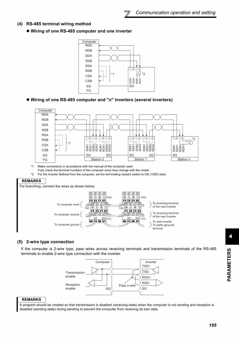
Communication operation and setting
4PA
RA
MET
ERS
(4) RS-485 terminal wiring methodWiring of one RS-485 computer and one inverter
Wiring of one RS-485 computer and "n" inverters (several inverters)
*1 Make connections in accordance with the manual of the computer used.Fully check the terminal numbers of the computer since they change with the model.
*2 For the inverter farthest from the computer, set the terminating resistor switch to ON (100Ω side).
(5) 2-wire type connectionIf the computer is 2-wire type, pass wires across receiving terminals and transmission terminals of the RS-485terminals to enable 2-wire type connection with the inverter.
REMARKSFor branching, connect the wires as shown below.
REMARKSA program should be created so that transmission is disabled (receiving state) when the computer is not sending and reception isdisabled (sending state) during sending to prevent the computer from receiving its own data.
*1
Computer
RDA
RDB
SDA
SDB
RSA
SG
RSB
CSA
CSB
FG
SG
*2
- + - +
SD
B1
SD
A1
RD
B1
RD
A1
*1
Computer
RDA
RDB
SDA
SDB
RSA
SG
RSB
CSA
CSB
FG Station 0
SG SG
- + - + - + - +
Station 1
SG SG
- + +- - + +-
Station n
SG
*2- +
SD
B1
SD
A1
RD
B1
RD
A1
RD
A2
RD
B2
SD
A2
SD
B2
SD
B1
SD
A1
RD
B1
RD
A1
SD
B1
SD
A1
RD
B1
RD
A1
RD
A2
RD
B2
SD
A2
SD
B2
- +
To computer send
To computer receive
To computer ground
TXD
RXD
VCC
RXD
VCC
TXD
SGSG SGSG
+ - +
-
+ - + -
+ - ++++++ --- + -
+ - ++ - + -
To receiving terminal
of the next inverter
To receiving terminal
of the next inverter
To next inverter
To earth (ground)
terminal
TXD+
TXD-
RXD+
RXD-
SGSG
InverterComputer
Pass a wire
Transmission
enable
Reception
enable
195

Communication operation and setting
4.19.3 Initial settings and specifications of RS-485 communication (Pr. 117 to Pr. 124, Pr. 331 to Pr. 337, Pr. 341, Pr. 549)
[PU connector communication related parameter]
Used to perform required settings for communication between the inverter and personal computer.There are two different communications: communication using the PU connector of the inverter andcommunication using the RS-485 terminals.You can perform parameter setting, monitor, etc. from the PU connector or RS-485 terminals of the inverterusing the Mitsubishi inverter protocol (computer link communication).To make communication between the personal computer and inverter, initialization of the communicationspecifications must be made to the inverter.Data communication cannot be made if the initial settings are not made or there is any setting error.
Parameter Number Name Initial Value Setting Range Description
117 PU communication station number 0 0 to 31
Specifies the inverter station number.Set the inverter station numbers when two or more inverters are connected to one personal computer.
118 PU communication speed 192 48, 96, 192, 384
Set the communication speed.The setting value × 100 equals the communication speed.For example, the communication speed is 19200bps when the setting value is "192".
119 PU communication stop bit length 1
Stop bit length Data length0 1bit
8bit1 2bit
10 1bit7bit
11 2bit
120 PU communication parity check 2
0 Without parity check1 With odd parity check2 With even parity check
121 Number of PU communication retries 1
0 to 10
Set the permissible number of retries atoccurrence of a data receive error. If thenumber of consecutive errors exceeds thepermissible value, the inverter will come totrip.
9999 If a communication error occurs, the inverterwill not come to trip.
122 PU communication check time interval 9999
0 No PU connector communication
0.1 to 999.8s
Set the interval of communication check time.If a no-communication state persists forlonger than the permissible time, the inverterwill come to trip.
9999 No communication check
123 PU communication waiting time setting 9999
0 to 150ms Set the waiting time between datatransmission to the inverter and response.
9999 Set with communication data.
124 PU communication CR/LF selection 1
0 Without CR/LF1 With CR2 With CR/LF
The above parameters can be set when Pr. 160 User group read selection = "0". (Refer to page 175)
196

Communication operation and setting
4PA
RA
MET
ERS
[RS-485 terminal communication related parameter]
4.19.4 Communication EEPROM write selection (Pr. 342)
⋅ When changing the parameter values frequently, set "1" in Pr. 342 to write them to the RAM. The life of the EEPROMwill be shorter if parameter write is performed frequently with the setting unchanged from "0 (initial value)" (EEPROMwrite).
Parameter Number Name Initial
Value Setting Range Description
331 RS-485 communication station number 0 0 to 31 (0 to 247)
*1
Set the inverter station number. (same specifications as Pr. 117)
332 RS-485 communication speed 96 3, 6, 12, 24, 48, 96, 192, 384
Used to select the communication speed. (same specifications as Pr. 118)
333 *2 RS-485 communication stop bit length 1 0, 1, 10, 11 Select stop bit length and data length. (same
specifications as Pr. 119)
334 RS-485 communication parity check selection 2 0, 1, 2 Select the parity check specifications. (same
specifications as Pr. 120)
335 *3 RS-485 communication retry count 1 0 to 10, 9999
Set the permissible number of retries atoccurrence of a data receive error. (same specifications as Pr. 121)
336 *3 RS-485 communication check time interval 0s
0RS-485 communication can be made, but theinverter will come to trip in the NET operationmode.
0.1 to 999.8s Set the interval of communication check time.(same specifications as Pr. 122)
9999 No communication check
337 *3 RS-485 communication waiting time setting 9999 0 to 150ms,
9999
Set the waiting time between datatransmission to the inverter and response.(same specifications as Pr. 123)
341 *3 RS-485 communication CR/LF selection 1 0, 1, 2 Select presence/absence of CR/LF.
(same specifications as Pr. 124)
549 Protocol selection 00 Mitsubishi inverter (computer link) protocol1 Modbus-RTU protocol *4
*1 When "1" (Modbus-RTU protocol) is set in Pr. 549, the setting range within parenthesis is applied.*2 For the Modbus-RTU protocol, the data length is always 8 bits and the stop bit depends on the Pr. 334 setting. (Refer to page 209)*3 The Modbus-RTU protocol becomes invalid.*4 The Modbus-RTU protocol is valid for only communication from the RS-485 terminals.*5 The above parameters can be set when Pr. 160 User group read selection = "0". (Refer to page 175)
CAUTION⋅ If communication is made without Pr. 336 RS-485 communication check time interval being changed from "0" (initial value), monitor,
parameter read, etc. can be performed, but the inverter results in an alarm as soon as it is switched to the NET operation mode.If the operation mode at power on is the network operation mode, a communication fault (E.SER) occurs after firstcommunication. When performing operation or parameter write through communication, set "9999" or more to Pr. 336. (The setting depends onthe computer side program.) (Refer to page 202)
⋅ Always reset the inverter after making the initial settings of the parameters. After you have changed the communication-relatedparameters, communication cannot be made until the inverter is reset.
When parameter write is performed from PU connector, RS-485 terminal, and communication option connectedto the inverter, parameter’s storage device can be changed from EEPROM + RAM to only RAM. Set thisparameter when frequent parameter changes are required.
Parameter Number Name Initial Value Setting
Range Description
342 Communication EEPROM write selection 0
0 Parameter values written by communicationare written to the EEPROM and RAM.
1 Parameter values written by communicationare written to the RAM.
The above parameters can be set when Pr. 160 User group read selection = "0". However, it can be set any time when the communication option is connected. (Refer to page 175)
REMARKS⋅ When Pr. 342 is set to "1" (only RAM write), the new values of the parameters will be cleared at power supply-off of the inverter.
Therefore, the parameter values available when power is switched on again are the values stored in EEPROM previously.
197

Communication operation and setting
4.19.5 Mitsubishi inverter protocol (computer link communication)
(1) Communication specifications⋅ The communication specifications are given below.
(2) Communication procedure
*1 If a data error is detected and a retry must be made, execute retry operation with the user program. The inverter comes to trip if the number ofconsecutive retries exceeds the parameter setting.
*2 On receipt of a data error occurrence, the inverter returns "reply data 3)" to the computer again. The inverter comes to trip if the number ofconsecutive data errors reaches or exceeds the parameter setting.
You can perform parameter setting, monitor, etc. from the PU connector or RS-485 terminals of the inverterusing the Mitsubishi inverter protocol (computer link communication).
Item Description Related Parameters
Communication protocol Mitsubishi protocol (computer link) Pr. 551Conforming standard EIA-485 (RS-485) ⎯
Number of inverters connected 1:N (maximum 32 units), setting is 0 to 31 stations Pr. 117Pr. 331
Communication speed
PU connector Selected from among 4800/9600/19200 and 38400bps Pr. 118
RS-485 terminal Can be selected from 300, 600, 1200, 2400, 4800, 9600, 19200 and 38400bps Pr. 332
Control protocol Asynchronous system ⎯Communication method Half-duplex system ⎯
Communication specifications
Character system ASCII (7 bits or 8 bits can be selected) Pr. 119Pr. 333
Start bit 1bit ⎯
Stop bit length 1 bit or 2 bits can be selected Pr. 119Pr. 333
Parity check Check (even, odd) or no check can be selected Pr. 120Pr. 334
Error check Sum code check ⎯
Terminator CR/LF (presence or absence can be selected) Pr. 124Pr. 341
Waiting time setting Selectable between presence and absence Pr. 123Pr. 337
⋅ Data communication between the computer andinverter is made in the following procedure.
1)Request data is sent from the computer to theinverter. (The inverter will not send data unlessrequested.)
2)After waiting for the waiting time3)The inverter sends return data to the computer in
response to the computer request.4)After having waited for the time taken for inverter
processing5)Answer from computer in response to reply data
3) is sent. (Even if 5) is not sent, subsequentcommunication is made property.)
When data is read
When data is written
1) 5)4)
3)2)
*1
*2
Computer(Data flow)
Inverter
Computer
(Data flow)
InverterTime
198

Communication operation and setting
4PA
RA
MET
ERS
(3) Communication operation presence/absence and data format types⋅ Data communication between the computer and inverter is made in ASCII code (hexadecimal code).⋅ Communication operation presence/absence and data format types are as follows:
1)Communication request data from the computer to the inverter
3)Reply data from the inverter to the computer⋅ When data is written
⋅ When data is read
5)Send data from the computer to the inverter during data read
*1 Indicate a control code*2 Specify the inverter station numbers between H00 and H1F (stations 0 to 31) in hexadecimal.*3 When Pr. 123, Pr. 337 (waiting time setting) ≠ "9999", create the communication request data without "waiting time" in the data format. (The number
of characters decreases by 1.)*4 CR, LF code
When data is transmitted from the computer to the inverter, CR (carriage return) and LF (line feed) codes are automatically set at the end of a datagroup on some computers. In this case, setting must also be made on the inverter according to the computer. Whether the CR and LF codes willbe present or absent can be selected using Pr. 124 or Pr. 341 (CR/LF selection).
Symbol Operation Run Command
Running Frequency
Parameter Write
Inverter Reset Monitor Parameter
Read
1)Communication request is sent to theinverter in accordance with the userprogram in the computer.
AA’ A A A B B
2) Inverter data processing time Present Present Present Absent Present Present
3)Reply data from the inverter (Data 1) is checked for error)
No error *1(Request accepted)
C C C C *2 EE’ E
With error.(Request rejected) D D D D *2 D D
4) Computer processing delay time 10ms or more
5)
Answer from computer in response to reply data 3) (Data 3) is checked for error)
No error *1(No inverter processing)
Absent Absent Absent Absent Absent (C)
Absent (C)
With error(Inverter re-outputs 3))
Absent Absent Absent Absent F F
*1 In the communication request data from the computer to the inverter, 10ms or more is also required after "no data error (ACK)". (Refer topage 200)
*2 The inverter response to the inverter reset request can be selected. (Refer to page 205)
Format Number of Characters1 2 3 4 5 6 7 8 9 10 11 12 13
A(Data write)
ENQ *1
Inverter station number *2 Instruction code Waiting
time *3 Data Sum check *4
A'(Data write)
ENQ *1
Inverter station number *2 Instruction code Waiting
time *3 Data Sum check *4
B(Data read)
ENQ *1
Inverter station number *2 Instruction code Waiting
time *3 Sum check *4
Format Number of Characters1 2 3 4 5
C(No data error detected)
ACK *1
Inverter station number *2
*4
D(Data error detected)
NAK *1
Inverter station number *2
Error Code
*4
Format Number of Characters1 2 3 4 5 6 7 8 9 10 11
E(No data error detected)
STX*1
Inverter station number *2 Read data ETX
*1Sum check *4
E'(No data error detected)
STX*1
Inverter station number *2 Read data ETX
*1Sum check *4
D(Data error detected)
NAK *1
Inverter station number *2
Error Code
*4
Format Number of Characters1 2 3 4
C(No data error detected)
ACK*1
Inverter station number *2
*4
F(Data error detected)
NAK *1
Inverter station number *2
*4
199

Communication operation and setting
(4) Data definitions1) Control codes
2) Inverter station numberSpecify the station number of the inverter which communicates with the computer.
3) Instruction codeSpecify the processing request, e.g. operation or monitoring, given by the computer to the inverter. Hence, theinverter can be run and monitored in various ways by specifying the instruction code as appropriate. (Refer to page 63)
4) DataIndicates the data such as frequency and parameters transferred to and from the inverter. The definitions andranges of set data are determined in accordance with the instruction codes. (Refer to page 63)
5) Waiting timeSpecify the waiting time between the receipt of data at the inverter from the computer and the transmission ofreply data. Set the waiting time in accordance with the response time of the computer between 0 and 150ms in10ms increments (e.g. 1 = 10ms, 2 = 20ms).
6) Sum check codeThe sum check code is 2-digit ASCII (hexadecimal) representing the lower 1 byte (8 bits) of the sum (binary)derived from the checked ASCII data
Signal Name ASCII Code DescriptionSTX H02 Start Of Text (start of data)ETX H03 End Of Text (end of data)ENQ H05 Enquiry (communication request)ACK H06 Acknowledge (no data error detected)LF H0A Line FeedCR H0D Carriage Return
NAK H15 Negative Acknowledge (data error detected)
REMARKS⋅ When Pr. 123, Pr. 337 (waiting time setting) ≠ "9999", create the communication request data without "waiting time" in the data
format. (The number of characters decreases by 1.)⋅ The data check time changes depending on the instruction code. (Refer to page 201)
Computer
Inverter
Inverter
Computer
Inverter data processing time
= +Waiting time
(setting 10ms)
data check time
(About 10 to 30ms,
which depends on the
instruction code)
(Example 1)
Computer InverterENQ
*Wa
itin
g
tim
e
1
Instruction codeStation
number
0 1
Data
E 1 0 7 A D F 4
H05 H30 H31 H31H45 H31 H30 H37 H41 H44 H46 H34
Binary code
H30+H31+H45+H31+H31+H30+H37+H41+H44
=H1F4
Sum
(Example 2)
STXData read
Station
number
0 1 1 7 0 3 0
H02 H30 H31 H37H31 H37 H30 H03 H33 H30
Sum
ETX
7
* When the Pr. 123 "waiting time setting" "9999", create the communication request
data without "waiting time" in the data format. (The number of characters decreases by 1.)
Inverter
ASCII Code
ASCII Code
Binary code
H30+H31+H31+H37+H37+H30
= H130
Sum
check
code
Sum
check
codeComputer
200

Communication operation and setting
4PA
RA
MET
ERS
7) Error CodeIf any error is found in the data received by the inverter, its definition is sent back to the computer together with theNAK code.
(5) Response time
[Formula for data sending time]
Communication specifications Data check time
Error Code Error Item Error Definition Inverter Operation
H0 Computer NAK errorThe number of errors consecutively detected in communicationrequest data from the computer is greater than allowed number ofretries.
Brought to trip if error occurs continuously more than the allowable number of retries. (E.PUE/E.SER)
H1 Parity error The parity check result does not match the specified parity.
H2 Sum check error The sum check code in the computer does not match that of thedata received by the inverter.
H3 Protocol errorThe data received by the inverter has a grammatical mistake.Alternatively, data receive is not completed within thepredetermined time. CR or LF is not as set in the parameter.
H4 Framing error The stop bit length differs from the initial setting.
H5 Overrun error New data has been sent by the computer before the invertercompletes receiving the preceding data.
H6 ⎯ ⎯ ⎯
H7 Character error The character received is invalid (other than 0 to 9, A to F, controlcode).
Does not accept received data but is not brought to trip.
H8 ⎯ ⎯ ⎯H9 ⎯ ⎯ ⎯
HA Mode errorParameter write was attempted in other than the computer linkoperation mode, when operation command source is not selectedor during inverter operation. Does not accept
received data but is not brought to trip.HB Instruction code error The specified command does not exist.
HC Data range error Invalid data has been specified for parameter write, frequencysetting, etc.
HD ⎯ ⎯ ⎯HE ⎯ ⎯ ⎯HF ⎯ ⎯ ⎯
1×
Number of data characters
(Refer to page 199)×
Communication specifications(total number of bits) = Data send time (s)(See below.)
Communication speed (bps)
Name Number of Bits Item Check Time
Stop bit length 1 bit2 bits
Various monitors, run command, frequency setting (RAM) <12ms
Data length 7 bits8 bits
Parameter read/write, frequency setting (EEPROM) <30ms
Parity checkYes 1 bit Parameter clear/all clear <5sNo 0 Reset command No answer
In addition to the above, 1 start bit is necessary.Minimum number of total bits....... 9 bitsMaximum number of total bits...... 12 bits
10ms or more necessary
Computer
Inverter
Inverter
Computer
Data sending time (Refer to the following formula)
Inverter data processing time
Data sending time (Refer to the following formula)
Waiting time
(setting 10ms)
Data check time
(depends on the
instruction code (see the
following table))Time
201

Communication operation and setting
(6) Retry count setting (Pr. 121, Pr. 335)⋅ Set the permissible number of retries at occurrence of a data receive error. (Refer to page 201 for data receive error
for retry)⋅ When data receive errors occur consecutively and exceed the permissible number of retries set, an inverter trip
(E.PUE) may occur and stops the motor.⋅ When "9999" is set, an inverter will not trip even if data receive error occurs but an alarm output signal (LF) is output.
For the terminal used for the LF signal output, assign the function by setting "98 (positive logic) or 198 (negative logic)" in any of Pr. 190 to Pr. 196 (output terminal function selection).
(7) Signal loss detection (Pr. 122, Pr. 336 RS-485 communication check time interval)⋅ If a signal loss (communication stop) is detected between the inverter and computer as a result of signal loss
detection, a communication fault (PU connector communication: E.PUE, RS-485 terminal communication: E.SER) occurs and the inverter trips.
⋅ Signal loss detection is made when the setting is any of "0.1s" to "999.8s". To make a signal loss detection, it is necessary to send data (control code refer to page 200) from the computer within the communication check time interval. (The send data has nothing to do with the station number)
⋅ Communication check is started at the first communication in the operation mode having the command source (PU operation mode for PU connector communication in the initial setting or network operation mode for RS-485 terminal communication).
⋅ When the setting is "9999", communication check (a signal loss detection) is not made.⋅ When the setting is "0", communication from the PU connector cannot be performed. For communication via the RS-
485 terminals, monitor, parameter read, etc. can be performed, but a communication error (E.SER) occurs as soon as the inverter is switched to network operation mode.
Computer
Operation mode
Example: PU connector communication, Pr. 121 = "1" (initial value)
Example: PU connector communication, Pr. 121 = "9999"
Reception error Reception error
Fault (E.PUE)
Inverter
Inverter
Computer
EN
Q
AC
K
NA
K
NA
K
Computer
Operation mode
LF OFF OFF
Reception error Reception error
Inverter
Inverter
Computer
EN
Q
AC
K
NA
K
NA
KON
Wrong
Wrong EN
Q
AC
K
NormalEN
Q
Wrong
EN
Q
Wrong
Computer
Operation Mode
Example: PU connector communication, Pr. 122 = "0.1 to 999.8s"
External PU
Check start
Fault (E.PUE)
Time
InverterInverter
Computer
Pr.122
EN
Q
Communication
check counter
202

Communication operation and setting
4PA
RA
MET
ERS
(8) Instructions for the program1) When data from the computer has any error, the inverter does not accept that data. Hence, in the user program,
always insert a retry program for data error.2) All data communication, e.g. run command or monitoring, are started when the computer gives a communication
request. The inverter does not return any data without the computer's request. Hence, design the program so thatthe computer gives a data read request for monitoring, etc. as required.
3) Program exampleTo change the operation mode to computer link operation
Programming example of Microsoft® Visual C++® (Ver.6.0)#include <stdio.h>#include <windows.h>
void main(void){ HANDLE hCom; // Communication handle
DCB hDcb; // Structure for communication settingCOMMTIMEOUTS hTim; // Structure for time out setting
char szTx[0x10]; // Send bufferchar szRx[0x10]; // Receive bufferchar szCommand[0x10];// Commandint nTx,nRx; // For buffer size storingint nSum; // For sum code calculationBOOL bRet;int nRet;int i;
//∗∗∗∗ Opens COM1 port∗∗∗∗hCom = CreateFile ("COM1", (GENERIC_READ | GENERIC_WRITE), 0, NULL, OPEN_EXISTING, FILE_ATTRIBUTE_NORMAL, NULL);if (hCom != NULL) {
//∗∗∗∗ Makes a communication setting of COM1 port∗∗∗∗GetCommState(hCom,&hDcb); // Retrieves current communication informationhDcb.DCBlength = sizeof(DCB); // Structure size settinghDcb.BaudRate = 19200; // Communication speed=09200bpshDcb.ByteSize = 8; // Data length=8bithDcb.Parity = 2; // Even parityhDcb.StopBits = 2; // Stop bit=2bitbRet = SetCommState(hCom,&hDcb); // Sets the changed communication dataif (bRet == TRUE) {
//∗∗∗∗ Makes a time out setting of COM1 port∗∗∗∗Get CommTimeouts(hCom,&hTim); // Obtains the current time out value hTim.WriteTotalTimeoutConstant = 1000; // Write time out 1shTim.ReadTotalTimeoutConstant = 1000; // Read time out 1sSetCommTimeouts(hCom,&hTim); // Changed time out value setting//∗∗∗∗ Sets the command to switch the operation mode of the station 1 inverter to the network operation mode ∗∗∗∗sprintf(szCommand,"01FB10000"); // Send data (NET operation write)nTx = strlen(szCommand); //Send data size//∗∗∗∗ Generates sum code∗∗∗∗nSum = 0; // Initialization of sum datafor (i = 0;i < nTx;i++) {
nSum += szCommand[i]; // Calculates sum codenSum &= (0xff); // Masks data
}
//∗∗∗∗ Generates send data∗∗∗∗memset(szTx,0,sizeof(szTx)); // Initialization of send buffermemset(szRx,0,sizeof(szRx)); // Initialization of receive buffersprintf(szTx,"\5%s%02X",szCommand,nSum);// ENQ code+send data+sum codenTx = 1 + nTx + 2; // Number of ENQ code+number of send data+number of sum code
nRet = WriteFile(hCom,szTx,nTx,&nTx,NULL);//∗∗∗∗ Sending ∗∗∗∗if(nRet != 0) {
nRet = ReadFile(hCom,szRx,sizeof(szRx),&nRx,NULL);//∗∗∗∗ Receiving ∗∗∗∗
if(nRet != 0) {//∗∗∗∗ Displays the receive data ∗∗∗∗for(i = 0;i < nRx;i++) {
printf("%02X ",(BYTE)szRx[i]);// Consol output of receive data// Displays ASCII coder in hexadecimal. Displays 30 when "0"
}printf("\n\r");
}}
}CloseHandle(hCom); // Close communication port
}}
203

Communication operation and setting
General flowchart
Port open
Communication setting
Time out setting
Send data processingData settingSum code calculationData transmission
Receive data waiting
Receive data processingData retrievalScreen display
CAUTIONAlways set the communication check time interval before starting operation to prevent hazardous conditions.Data communication is not started automatically but is made only once when the computer provides a communication request. If communication is disabled during operation due to signal loss etc., the inverter cannot be stopped. When the communication check time interval has elapsed, the inverter will come to trip (E.PUE, E.SER). The inverter can be coasted to a stop by switching on its RES signal or by switching power off.If communication is broken due to signal loss, computer fault etc., the inverter does not detect such a fault. This should be fully noted.
204

Communication operation and setting
4PA
RA
MET
ERS
(9) Setting items and set dataAfter completion of parameter setting, set the instruction codes and data then start communication from the computerto allow various types of operation control and monitoring.
No. Item Read/write
Instruction Code Data Description
Number of Data Digits
(format)
1 Operation ModeRead H7B H0000: Network operation
H0001: External operationH0002: PU operation
(RS-485 communication operation via PU connector)
4 digits(B.E/D)
Write HFB 4 digits(A,C/D)
2
Mon
itor
Output frequency/speed
Read H6FH0000 to HFFFF: Output frequency in 0.01Hz incrementsSpeed in 1r/min increments (when Pr. 37 = 1 to 9998 or Pr. 144 = 2 to 10, 102 to 110)
4 digits(B.E/D)
Output current Read H70H0000 to HFFFF: Output current (hexadecimal) in 0.01A
increments (55K or less) / 0.1A increments (75K or more)
4 digits (B.E/D)
Output voltage Read H71 H0000 to HFFFF: Output voltage (hexadecimal) in 0.1V increments
4 digits(B.E/D)
Special monitor Read H72 H0000 to HFFFF: Monitor data selected in instruction code
HF34 digits(B.E/D)
Special monitor selection No.
Read H73H01 to H36: Monitor selection dataRefer to the special monitor No. table (page 207)
2digits(B.E'/D)
Write HF3 2digits(A',C/D)
Fault definition Read H74 to H77
H0000 to HFFFF: Two most recent fault definitions
Refer to the fault data table (page 207)
4 digits(B.E/D)
3
Run command (extended) Write HF9 You can set the control input commands such as the forward
rotation signal (STF) and reverse rotation signal (STR). (Refer to page 208 for details)
4 digits(A,C/D)
Run command Write HFA 2digits(A',C/D)
4
Inverter status monitor (extended) Read H79 You can monitor the states of the output signals such as
forward rotation, reverse rotation and inverter running (RUN). (Refer to page 208 for details)
4 digits(B.E/D)
Inverter status monitor Read H7A 2digits
(B.E'/D)
5
Set frequency (RAM)
ReadH6D Read the set frequency/speed from the RAM or EEPROM.
H0000 to HFFFF: Set frequency in 0.01Hz incrementsSpeed in 1r/min increments (When Pr. 37 = 1 to 9998 or Pr. 144 = 2 to 10, 102 to 110)
4 digits(B.E/D)Set frequency
(EEPROM) H6E
Set frequency (RAM)
Write
HEDWrite the set frequency/speed into the RAM or EEPROM.H0000 to H9C40 (0 to 400.00Hz) : frequency in 0.01HzincrementsH0000 to H270E (0 to 9998) : speed in r/min increments (when Pr. 37 = 1 to 9998 or Pr. 144 = 2 to 10, 102 to 110)⋅ To change the running frequency consecutively, write data to
the inverter RAM. (Instruction code: HED)
4 digits(A,C/D)Set frequency
(RAM, EEPROM) HEE
6 Inverter reset Write HFD
H9696: Resets the inverter.⋅ As the inverter is reset at start of communication by the
computer, the inverter cannot send reply data back to the computer.
4 digits(A,C/D)
H9966: Resets the inverter.⋅ When data is sent normally, ACK is returned to the computer
and then the inverter is reset.
4 digits(A,D)
Refer to page 199 for data formats (A, A', B, B', C, D)
b15 b8 b7 b0
Latest faultSecond fault in past
Third fault in pastFourth fault in past
Fifth fault in pastSixth fault in past
Seventh fault in pastEighth fault in past
H74
H75
H76
H77
205

Communication operation and setting
Example) When reading the C3 (Pr. 902) and C6 (Pr. 904) settings from the inverter of station No. 0
To read/write C3 (Pr. 902) and C6 (Pr. 904) after inverter reset or parameter clear, execute from 1) again.
7 Fault definition all clear Write HF4 H9696: Faults history batch clear 4 digits
(A,C/D)
8 Parameter clearAll parameter clear Write HFC
All parameters return to the initial values.Whether to clear communication parameters or not can be selected according to data. ( : clear, ×: not clear)Refer to page 314 for parameter clear, all clear, and communication parameters.
When clear is executed for H9696 or H9966, communication-related parameter settings also return to the initial values.When resuming operation, set the parameters again.Executing clear will clear the instruction code HEC, HF3, andHFF settings.
4 digits(A,C/D)
9Parameters
Read H00 to H63
Refer to the instruction code (page 314) and write and/or readthe values as required.When setting Pr.100 and later, link parameter expansion settingmust be set.
4 digits(B.E/D)
10 Write H80 to HE3
4 digits(A,C/D)
11 Link parameter extended setting
Read H7F Parameter description is changed according to the H00 to H09setting.For details of the setting, refer to the instruction code (page314).
2digits(B.E'/D)
Write HFF 2digits(A',C/D)
12
Second parameter changing (instruction code HFF=1)
Read H6C
When setting the calibration parameters *1
H00:Frequency *2H01: Parameter-set analog valueH02: Analog value input from terminal*1 Refer to the list of calibration parameters on the next page for
calibration parameters.*2 The gain frequency can also be written using Pr. 125 (instruction
code H99) or Pr. 126 (instruction code H9A).
2digits(B.E'/D)
Write HEC 2digits(A',C/D)
REMARKS⋅ Set 65520 (HFFF0) as a parameter value "8888" and 65535 (HFFFF) as "9999".⋅ For the instruction codes HFF, HEC and HF3, their values are held once written but cleared to zero when an inverter reset or all
clear is performed.
Computer Send Data Inverter Send Data Description1) ENQ 00 FF 0 01 82 ACK 00 Set "H01" in the extended link parameter.2) ENQ 00 EC 0 01 7E ACK 00 Set "H01" in second parameter changing.3) ENQ 00 5E 0 0F STX 00 0000 ETX 25 C3 (Pr. 902) is read. 0% is read.4) ENQ 00 60 0 FB STX 00 0000 ETX 25 C6 (Pr. 904) is read. 0% is read.
No. Item Read/write
Instruction Code Data Description
Number of Data Digits
(format)
Refer to page 199 for data formats (A, A', B, B', C, D)
Clear type Data Communication parameters
Parameter clearH9696H5A5A ×
All parameter clearH9966H55AA ×
206

Communication operation and setting
4PA
RA
MET
ERS
List of calibration parameters
[Special monitor selection No.]Refer to page 131 for details of the monitor description.
*1 Input terminal monitor details
*2 Output terminal monitor details
[Fault data]Refer to page 259 for details of fault description.
b15 b0⎯ ⎯ ⎯ ⎯ CS RES STOP MRS JOG RH RM RL RT AU STR STF
b15 b0⎯ ⎯ ⎯ ⎯ ⎯ ⎯ ⎯ ⎯ ⎯ ABC2 ABC1 FU OL IPF SU RUN
*3 The setting depends on capacities. (55K or less/75K or more)*4 When Pr.37 = "1 to 9998" or Pr. 144 = "2 to 10, 102 to 110," the unit is an integral value (one increment). (Refer to page 130)
Parameter Name
Instruction codeRead Write Extended
C2(902)
Terminal 2 frequency setting bias frequency 5E DE 1
C3(902)
Terminal 2 frequency setting bias 5E DE 1
125(903)
Terminal 2 frequency setting gain frquency 5F DF 1
C4(903)
Terminal 2 frequency setting gain 5F DF 1
C5(904)
Terminal 4 frequency setting bias frequency 60 E0 1
C6(904)
Terminal 4 frequency setting bias 60 E0 1
126(905)
Terminal 4 frequency setting gain frequency 61 E1 1
C7(905)
Terminal 4 frequency setting gain 61 E1 1
C42(934) PID display bias coefficient 22 A2 9
C43(934)
PID display bias analog value 22 A2 9
C44(935) PID display gain coefficient 23 A3 9
C45(935)
PID display gain analog value 23 A3 9
Parameter Name
Instruction codeRead Write Extended
Data Description UnitH01 Output frequency/speed *4 0.01Hz/1H02 Output current 0.01A/0.1A *3H03 Output voltage 0.1V
H05 Frequency setting value/speed setting *4
0.01Hz/1
H06 Running speed 1r/minH08 Converter output voltage 0.1VH09 Regenerative brake duty 0.1%
H0A Electronic thermal relay function load factor 0.1%
H0B Output current peak value 0.01A/0.1A *3H0C Converter output voltage peak value 0.1V
H0D Input power 0.01kW/0.1kW *3
H0E Output power 0.01kW/0.1kW *3
H0F Input terminal status *1 ⎯H10 Output terminal status *2 ⎯H11 Load meter 0.1%H14 Cumulative energization time 1hH17 Actual operation time 1hH18 Motor load factor 0.1%H19 Cumulative power 1kWhH32 Power saving effect VariableH33 Cumulative saving power VariableH34 PID set point 0.1%H35 PID measured value 0.1%H36 PID deviation 0.1%
Data Description Unit
Data DescriptionH00 No faultH10 OC1H11 OC2H12 OC3H20 OV1H21 OV2H22 OV3H30 THTH31 THMH40 FIN
H50 IPFH51 UVTH52 ILFH60 OLTH70 BEH80 GFH81 LFH90 OHTH91 PTCHA0 OPT
Data DescriptionHA1 OP1HB0 PEHB1 PUEHB2 RETHB3 PE2HC0 CPUHC1 CTEHC2 P24HC4 CDOHC5 IOH
Data DescriptionHC6 SERHC7 AIEHE6 PIDHF1 E.1HF5 E.5HF6 E.6HF7 E.7HFD E.13
Data DescriptionFault description display example (instruction code H74)
For read data H30A0
(Previous fault ...... THT)
(Latest fault ...... OPT)
0 10 1 0 0 0 0 0 0 00001 1
b15 b8 b7 b0
Latest fault
(HA0)
Previous fault
(H30)
207
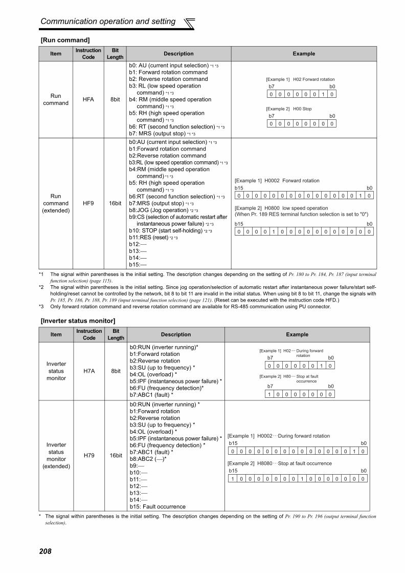
Communication operation and setting
[Run command]
*1 The signal within parentheses is the initial setting. The description changes depending on the setting of Pr. 180 to Pr. 184, Pr. 187 (input terminalfunction selection) (page 115).
*2 The signal within parentheses is the initial setting. Since jog operation/selection of automatic restart after instantaneous power failure/start self-holding/reset cannot be controlled by the network, bit 8 to bit 11 are invalid in the initial status. When using bit 8 to bit 11, change the signals withPr. 185, Pr. 186, Pr. 188, Pr. 189 (input terminal function selection) (page 121). (Reset can be executed with the instruction code HFD.)
*3 Only forward rotation command and reverse rotation command are available for RS-485 communication using PU connector.
[Inverter status monitor]
* The signal within parentheses is the initial setting. The description changes depending on the setting of Pr. 190 to Pr. 196 (output terminal functionselection).
Item Instruction Code
Bit Length Description Example
Run command HFA 8bit
b0: AU (current input selection) *1 *3
b1: Forward rotation commandb2: Reverse rotation commandb3: RL (low speed operation
command) *1 *3
b4: RM (middle speed operation command) *1 *3
b5: RH (high speed operation command) *1 *3
b6: RT (second function selection) *1 *3
b7: MRS (output stop) *1 *3
Run command (extended)
HF9 16bit
b0:AU (current input selection) *1 *3
b1:Forward rotation commandb2:Reverse rotation commandb3:RL (low speed operation command) *1 *3
b4:RM (middle speed operation command) *1 *3
b5: RH (high speed operation command) *1 *3
b6:RT (second function selection) *1 *3
b7:MRS (output stop) *1 *3
b8:JOG (Jog operation) *2 *3
b9:CS (selection of automatic restart after instantaneous power failure) *2 *3
b10: STOP (start self-holding) *2 *3
b11:RES (reset) *2 *3
b12:⎯b13:⎯b14:⎯b15:⎯
Item Instruction Code
Bit Length Description Example
Inverter status
monitorH7A 8bit
b0:RUN (inverter running)*b1:Forward rotationb2:Reverse rotationb3:SU (up to frequency) *b4:OL (overload) *b5:IPF (instantaneous power failure) *b6:FU (frequency detection)* b7:ABC1 (fault) *
Inverter status
monitor(extended)
H79 16bit
b0:RUN (inverter running) *b1:Forward rotationb2:Reverse rotationb3:SU (up to frequency) *b4:OL (overload) *b5:IPF (instantaneous power failure) *b6:FU (frequency detection) *b7:ABC1 (fault) *b8:ABC2 (⎯)*b9:⎯b10:⎯b11:⎯b12:⎯b13:⎯b14:⎯b15: Fault occurrence
0 0 0 0 0 0 1 0
b7 b0
[Example 1] H02 Forward rotation
[Example 2] H00 Stop
0 0 0 0 0 0 0 0
b7 b0
0 0 0 0 0 0 1 0
b0
[Example 1] H0002 Forward rotation
0 0 0 0 0 0 0 0
b15
0 0 0 0 0 0 0 0
b0
[Example 2] H0800 low speed operation
(When Pr. 189 RES terminal function selection is set to "0")
0 0 0 0 1 0 0 0
b15
0 0 0 0 0 0 1 0
b7 b0
1 0 0 0 0 0 0 0
b7 b0
[Example 2] H80
[Example 1] H02
Stop at fault occurrence
During forward rotation
0 0 0 0 0 0 1 0
b0
0 0 0 0 0 0 0 0
b15
[Example 1] H0002 During forward rotation
1 0 0 0 0 0 0 0
b0
1 0 0 0 0 0 0 0
b15
[Example 2] H8080 Stop at fault occurrence
208

Communication operation and setting
4PA
RA
MET
ERS
4.19.6 Modbus-RTU communication specifications (Pr. 331, Pr. 332, Pr. 334, Pr. 343, Pr. 539, Pr. 549)
(1) Communication specifications⋅ The communication specifications are given below.
Using the Modbus-RTU communication protocol, communication operation or parameter setting can beperformed from the RS-485 terminals of the inverter.
Parameter Number Name Initial
Value Setting Range Description
331RS-485 communication station number
0
0 Broadcast communication is selected.
1 to 247Specifies the inverter station number.Set the inverter station numbers when two or more inverters are connected to one personal computer.
332RS-485 communication speed
96 3, 6, 12, 24, 48, 96, 192, 384
Set the communication speed.The setting value × 100 equals the communication speed.For example, the communication speed is 9600bps when the setting value is "96".
334RS-485 communication parity check selection
2
0 Without parity checkStop bit length 2bits
1 With odd parity checkStop bit length 1bit
2 With even parity checkStop bit length 1bit
343 Communication error count 0 ⎯ Displays the number of communication errors during
Modbus-RTU communication. Reading only
539Modbus-RTU communication check time interval
9999
0 Modbus-RTU communication can be made, but the inverter will come to trip in the NET operation mode.
0.1 to 999.8s Set the interval of communication check time.(same specifications as Pr. 122)
9999 No communication check (signal loss detection)
549 Protocol selection 00 Mitsubishi inverter (computer link) protocol1 Modbus-RTU protocol
The above parameters can be set when Pr. 160 User group read selection = "0". (Refer to page 175)
CAUTIONWhen Modbus-RTU communication is performed from the master with address 0 (station 0) set, broadcast communication isselected and the inverter does not send a response message to the master.When response from the inverter is necessary, set a value other than "0" in Pr. 331.Some functions are invalid for broadcast communication. (Refer to page 211.)
REMARKS⋅ When using the Modbus-RTU protocol, set Pr. 549 Protocol selection to "1".⋅ When the communication option is fitted with Pr. 550 NET mode operation command source selection set to "9999" (initial value), the
command source (e.g. run command) from the RS-485 terminals is invalid. (Refer to page 186)
Item Description Related Parameters
Communication protocol Modbus-RTU protocol Pr. 549Conforming standard EIA-485 (RS-485) ⎯Number of inverters connected 1: N (maximum 32 units), setting is 0 to 247 stations Pr. 331Communication speed Can be selected from 300, 600, 1200, 2400, 4800, 9600, 19200 and 38400bps Pr. 332Control protocol Asynchronous system ⎯Communication method Half-duplex system ⎯
Communication specifications
Character system Binary(fixed to 8 bits) ⎯Start bit 1bit ⎯
Stop bit length Select from the following three types⋅ No parity, stop bit length 2 bits⋅ Odd parity, stop bit length 1 bit⋅ Even parity, stop bit length 1 bit
Pr. 334Parity check
Error check CRC code check ⎯Terminator Not used ⎯
Waiting time setting Not used ⎯
209
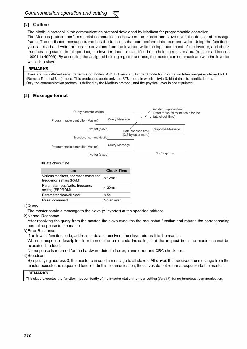
Communication operation and setting
(2) OutlineThe Modbus protocol is the communication protocol developed by Modicon for programmable controller.The Modbus protocol performs serial communication between the master and slave using the dedicated messageframe. The dedicated message frame has the functions that can perform data read and write. Using the functions,you can read and write the parameter values from the inverter, write the input command of the inverter, and checkthe operating status. In this product, the inverter data are classified in the holding register area (register addresses40001 to 49999). By accessing the assigned holding register address, the master can communicate with the inverterwhich is a slave.
(3) Message format
Data check time
1)QueryThe master sends a message to the slave (= inverter) at the specified address.
2)Normal ResponseAfter receiving the query from the master, the slave executes the requested function and returns the correspondingnormal response to the master.
3)Error ResponseIf an invalid function code, address or data is received, the slave returns it to the master.When a response description is returned, the error code indicating that the request from the master cannot beexecuted is added.No response is returned for the hardware-detected error, frame error and CRC check error.
4)BroadcastBy specifying address 0, the master can send a message to all slaves. All slaves that received the message from themaster execute the requested function. In this communication, the slaves do not return a response to the master.
REMARKSThere are two different serial transmission modes: ASCII (American Standard Code for Information Interchange) mode and RTU(Remote Terminal Unit) mode. This product supports only the RTU mode in which 1-byte (8-bit) data is transmitted as-is.Only the communication protocol is defined by the Modbus protocol, and the physical layer is not stipulated.
Item Check TimeVarious monitors, operation command, frequency setting (RAM) < 12ms
Parameter read/write, frequency setting (EEPROM) < 30ms
Parameter clear/all clear < 5sReset command No answer
REMARKSThe slave executes the function independently of the inverter station number setting (Pr. 331) during broadcast communication.
Query communication
Broadcast communication
Query Message
Query Message
Response Message
Inverter (slave)
Inverter (slave)
Programmable controller (Master)
Programmable controller (Master)
No Response
Inverter response time
(Refer to the following table for the
data check time)
Data absence time
(3.5 bytes or more)
210
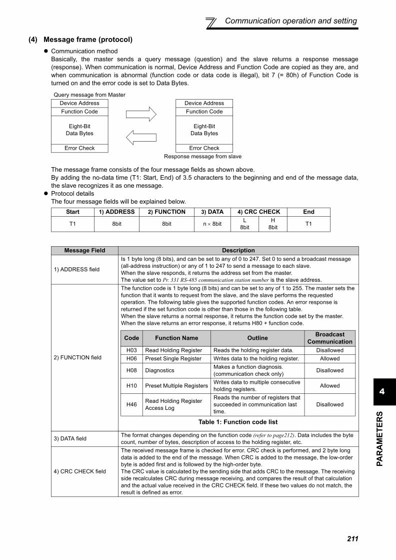
Communication operation and setting
4PA
RA
MET
ERS
(4) Message frame (protocol)Communication methodBasically, the master sends a query message (question) and the slave returns a response message(response). When communication is normal, Device Address and Function Code are copied as they are, andwhen communication is abnormal (function code or data code is illegal), bit 7 (= 80h) of Function Code isturned on and the error code is set to Data Bytes.
The message frame consists of the four message fields as shown above.By adding the no-data time (T1: Start, End) of 3.5 characters to the beginning and end of the message data,the slave recognizes it as one message.Protocol detailsThe four message fields will be explained below.
Query message from MasterDevice Address Device AddressFunction Code Function Code
Eight-BitData Bytes
Eight-BitData Bytes
Error Check Error CheckResponse message from slave
Start 1) ADDRESS 2) FUNCTION 3) DATA 4) CRC CHECK End
T1 8bit 8bit n × 8bit L8bit
H8bit T1
Message Field Description
1) ADDRESS field
Is 1 byte long (8 bits), and can be set to any of 0 to 247. Set 0 to send a broadcast message (all-address instruction) or any of 1 to 247 to send a message to each slave.When the slave responds, it returns the address set from the master.The value set to Pr. 331 RS-485 communication station number is the slave address.
2) FUNCTION field
The function code is 1 byte long (8 bits) and can be set to any of 1 to 255. The master sets the function that it wants to request from the slave, and the slave performs the requested operation. The following table gives the supported function codes. An error response is returned if the set function code is other than those in the following table.When the slave returns a normal response, it returns the function code set by the master. When the slave returns an error response, it returns H80 + function code.
3) DATA field The format changes depending on the function code (refer to page212). Data includes the byte count, number of bytes, description of access to the holding register, etc.
4) CRC CHECK field
The received message frame is checked for error. CRC check is performed, and 2 byte long data is added to the end of the message. When CRC is added to the message, the low-order byte is added first and is followed by the high-order byte.The CRC value is calculated by the sending side that adds CRC to the message. The receiving side recalculates CRC during message receiving, and compares the result of that calculation and the actual value received in the CRC CHECK field. If these two values do not match, the result is defined as error.
Code Function Name Outline Broadcast Communication
H03 Read Holding Register Reads the holding register data. DisallowedH06 Preset Single Register Writes data to the holding register. Allowed
H08 Diagnostics Makes a function diagnosis. (communication check only) Disallowed
H10 Preset Multiple Registers Writes data to multiple consecutive holding registers. Allowed
H46 Read Holding Register Access Log
Reads the number of registers that succeeded in communication last time.
Disallowed
Table 1: Function code list
211

Communication operation and setting
(5) Message format typesThe message formats corresponding to the function codes in Table 1 on page 211 will be explained.
Read holding register data (H03 or 03)Can read the description of 1) system environment variables, 2) real-time monitor, 3) faults history, and 4)inverter parameters assigned to the holding register area (refer to the register list (page 217)).
Query Message
Response message
⋅ Query message setting
⋅ Description of normal response
1) Slave Address 2) Function 3) Starting Address 4) No. of Points CRC Check
(8bit) H03(8bit)
H(8bit)
L(8bit)
H(8bit)
L(8bit)
L(8bit)
H(8bit)
1) Slave Address 2) Function 5) Byte Count 6) Data CRC Check
(8bit) H03(8bit) (8bit) H
(8bit)L
(8bit)...
(n × 16bit)L
(8bit)H
(8bit)
Message Setting Description
1)Slave Address Set the address to which the message will be sent. Broadcast communication cannot be made (0 is invalid)
2) Function Set H03.
3)Starting Address
Set the address at which holding register data read will be started.Starting address = starting register address (decimal) − 40001For example, setting of the starting address 0001 reads the data of the holding register 40002.
4)No. of Points Set the number of holding registers from which data will be read. The number of registers from which data can be read is a maximum of 125.
Message Setting Description
5)Byte Count The setting range is H02 to H14 (2 to 20).Twice greater than the No. of Points specified at 4) is set.
6)DataThe number of data specified at 4) is set. Data are read in order of Hi byte and Lo byte, and set in order of starting address data, starting address + 1 data, starting address + 2 data, ...
Example) To read the register values of 41004 (Pr. 4) to 41006 (Pr. 6) from the slave address 17 (H11)
Query message
Normal response (Response message)
Read valueRegister 41004 (Pr. 4): H1770 (60.00Hz)Register 41005 (Pr. 5): H0BB8 (30.00Hz)Register 41006 (Pr. 6): H03E8 (10.00Hz)
Slave Address Function Starting Address No. of Points CRC CheckH11(8bit)
H03(8bit)
H03(8bit)
HEB(8bit)
H00(8bit)
H03(8bit)
H77(8bit)
H2B(8bit)
Slave Address Function Byte Count Data CRC CheckH11(8bit)
H03(8bit)
H06(8bit)
H17(8bit)
H70(8bit)
H0B(8bit)
HB8(8bit)
H03(8bit)
HE8(8bit)
H2C(8bit)
HE6(8bit)
212

Communication operation and setting
4PA
RA
MET
ERS
Write multiple holding register data (H06 or 06)You can write the description of 1) system environment variables and 4) inverter parameters assigned to theholding register area (refer to the register list (page 217)).
Query message
Normal response (Response message)
⋅ Query message setting
⋅ Description of normal response1) to 4) (including CRC check) of the normal response are the same as those of the query message.No response is made for broadcast communication.
1) Slave Address 2) Function 3) Register Address 4) Preset Data CRC Check
(8bit) H06(8bit) H (8bit) L (8bit) H (8bit) L (8bit) L (8bit) H (8bit)
1) Slave Address 2) Function 3) Register Address 4) Preset Data CRC Check
(8bit) H06(8bit) H (8bit) L (8bit) H (8bit) L (8bit) L (8bit) H (8bit)
Message Setting Description
1)Slave Address Set the address to which the message will be sent. Setting of address 0 enables broadcast communication
2)Function Set H06.
3)Register Address
Set the address of the holding register to which data will be written.Register address = holding register address (decimal) − 40001For example, setting of register address 0001 writes data to the holding register address 40002.
4)Preset Data Set the data that will be written to the holding register. The written data is always 2 bytes.
Example) To write 60Hz (H1770) to 40014 (running frequency RAM) at slave address 5 (H05).
CAUTIONFor broadcast communication, no response is returned in reply to a query. Therefore, the next query must be madewhen the inverter processing time has elapsed after the previous query.
Query message
Normal Response (Response message)Same data as the query message
Slave Address Function Register Address Preset Data CRC CheckH05(8bit)
H06(8bit)
H00(8bit)
H0D(8bit)
H17(8bit)
H70(8bit)
H17(8bit)
H99(8bit)
213

Communication operation and setting
Function diagnosis (H08 or 08)A communication check can be made since the query message sent is returned unchanged as a responsemessage (function of subfunction code H00). Subfunction code H00 (Return Query Data)Query Message
Normal Response (Response message)
⋅ Query message setting
⋅ Description of normal response1) to 4) (including CRC check) of the normal response are the same as those of the query message.
Write multiple holding register data (H10 or 16)You can write data to multiple holding registers.
Query message
Normal Response (Response message)
⋅ Query message setting
1) Slave Address 2) Function 3) Subfunction 4) Date CRC Check
(8bit) H08(8bit)
H00(8bit)
H00(8bit)
H(8bit)
L(8bit)
L(8bit)
H(8bit)
1) Slave Address 2) Function 3) Subfunction 4) Date CRC Check
(8bit) H08(8bit)
H00(8bit)
H00(8bit)
H(8bit)
L(8bit)
L(8bit)
H(8bit)
Message Setting Description
1)Slave Address Set the address to which the message will be sent. Broadcast communication cannot be made (0 is invalid)
2)Function Set H08.3)Subfunction Set H0000.
4)DataAny data can be set if it is 2 bytes long. The setting range is H0000 to HFFFF.
CAUTIONFor broadcast communication, no response is returned in reply to a query. Therefore, the next query must be made whenthe inverter processing time has elapsed after the previous query.
1) SlaveAddress
2)Function
3) Starting Address
4) No. of Registers
5) ByteCount 6) Data CRC Check
(8bit) H10(8bit)
H(8bit)
L(8bit)
H(8bit)
L(8bit) (8bit) H
(8bit)L
(8bit)...
(n × 2 × 8bit)L
(8bit)H
(8bit)
1) Slave Address 2) Function 3) Starting Address 4) No. of Registers CRC Check
(8bit) H10(8bit)
H(8bit)
L(8bit)
H(8bit)
L(8bit)
L(8bit)
H(8bit)
Message Setting Description
1)Slave Address Set the address to which the message will be sent. Setting of address 0 enables broadcast communication
2)Function Set H10.
3)Starting Address
Set the address where holding register data write will be started.Starting address = starting register address (decimal) − 40001For example, setting of the starting address 0001 reads the data of the holding register 40002.
4)No. of Points Set the number of holding registers where data will be written. The number of registers where data can be written is a maximum of 125.
5)Byte Count The setting range is H02 to HFA (0 to 250).Set twice greater than the value specified at 4).
6)DataSet the data specified by the number specified at 4). The written data are set in order of Hi byte and Lo byte, and arranged in order of the starting address data, starting address + 1 data, starting address + 2 data ...
214

Communication operation and setting
4PA
RA
MET
ERS
⋅ Description of normal response1) to 4) (including CRC check) of the normal response are the same as those of the query message.
Read holding register access log (H46 or 70)A response can be made to a query made by the function code H03 or H10.The starting address of the holding registers that succeeded in access during previous communication and thenumber of successful registers are returned.In response to the query for other than the above function code, 0 is returned for the address and number ofregisters.
Query Message
Normal Response (Response message)
⋅ Query message setting
⋅ Description of normal response
Example) To write 0.5s (H05) to 41007 (Pr. 7) at the slave address 25 (H19) and 1s (H0A) to 41008 (Pr. 8).
1) Slave Address 2) Function CRC Check
(8bit) H46(8bit)
L(8bit)
H(8bit)
1) Slave Address 2) Function 3) Starting Address 4) No. of Points CRC Check
(8bit) H46(8bit)
H(8bit)
L(8bit)
H(8bit)
L(8bit)
L(8bit)
H(8bit)
Message Setting Description
1)Slave Address Set the address to which the message will be sent. Broadcast communication cannot be made (0 is invalid)
2)Function Set H46.
Message Setting Description
3)Starting Address
The starting address of the holding registers that succeeded in access is returned.Starting address = starting register address (decimal) − 40001For example, when the starting address 0001 is returned, the address of the holding register that succeeded in access is 40002.
4)No. of Points The number of holding registers that succeeded in access is returned.
Example) To read the successful register starting address and successful count from the slave address 25 (H19).
Query Message
Response message (Response message)
SlaveAddress Function Starting
Address No. of Points Byte Count Data CRC Check
H19(8bit)
H10(8bit)
H03(8bit)
HEE(8bit)
H008bit)
H02(8bit)
H04(8bit)
H00(8bit)
H05(8bit)
H00(8bit)
H0A(8bit)
H86(8bit)
H3D(8bit)
SlaveAddress Function Starting
Address No. of Points CRC Check
H19(8bit)
H10(8bit)
H03(8bit)
HEE(8bit)
H00(8bit)
H02(8bit)
H22(8bit)
H61(8bit)
Query Message
Normal Response (Response message)
Success of two registers at starting address 41007 (Pr. 7) is returned.
Slave Address Function CRC CheckH19(8bit)
H46(8bit)
H8B(8bit)
HD2(8bit)
Slave Address Function Starting Address No. of Points CRC CheckH19(8bit)
H10(8bit)
H03(8bit)
HEE(8bit)
H00(8bit)
H02(8bit)
H22(8bit)
H61(8bit)
215

Communication operation and setting
Error responseAn error response is returned if the query message received from the master has an illegal function, address ordata. No response is returned for a parity, CRC, overrun, framing or busy error.
Error response (Response message)
Error code list
*1 An error will not occur in the following cases.1) Function code H03 (Read Holding Register Data )
When the No. of Points is 1 or more and there is one or more holding registers from which data can be read2) Function code H10 (Write Multiple Holding Register Data)
When the No. of Points is 1 or more and there is 1 or more holding registers to which data can be writtenNamely, when the function code H03 or H10 is used to access multiple holding registers, an error will not occur if a non-existing holdingregister or read disabled or write disabled holding register is accessed.
⋅ Message data mistake detectionTo detect the mistakes of message data from the master, they are checked for the following errors. If an erroris detected, a trip will not occur.
Error check item
CAUTIONNo response message is sent in the case of broadcast communication also.
1) Slave Address 2) Function 3) Exception Code CRC Check
(8bit) H80 + Function(8bit) (8bit) L
(8bit)H
(8bit)
Message Setting Description1)Slave address Set the address received from the master.2)Function The master-requested function code + H80 is set.3)Exception code The code in the following table is set.
Code Error Item Error Definition
01 ILLEGAL FUNCTION The set function code in the query message from the master cannot be handled by the slave.
02 ILLEGAL DATA ADDRESS *1The set register address in the query message from the master cannot be handled by the inverter.(No parameter, parameter read disabled, parameter write disabled)
03 ILLEGAL DATA VALUEThe set data in the query message from the master cannot be handled by the inverter.(Out of parameter write range, mode specified, other error)
REMARKSAn error will occur if all accessed holding registers do not exist.Data read from a non-existing holding register is 0, and data written there is invalid.
Error Item Error Definition Inverter Side Operation
Parity error The data received by the inverter differs from the specified parity (Pr. 334 setting).
1)Pr. 343 is increased by 1 at error occurrence.
2)The terminal LF is output at error occurrence.
Framing error The data received by the inverter differs from the specified stop bit length (Pr. 334).
Overrun error The following data was sent from the master before the inverter completes data receiving.
Message frame error
The message frame data length is checked, and the received data length of less than 4 bytes is regarded as an error.
CRC check errorA mismatch found by CRC check between the message frame data and calculation result is regarded as an error.
216

Communication operation and setting
4PA
RA
MET
ERS
(6) Modbus registersSystem environment variable
*1 The communication parameter values are not cleared.*2 For write, set the data as a control input instruction. For read, data is read as an inverter operating status.*3 For write, set data as the operation mode setting. For read, data is read as the operation mode status.
Real-time monitorRefer to page 131 for details of the monitor description.
*1 Input terminal monitor details
*2 Output terminal monitor details
Register Definition Read/Write Remarks40002 Inverter reset Write Any value can be written40003 Parameter clear Write Set H965A as a written value.40004 All parameter clear Write Set H99AA as a written value.40006 Parameter clear *1 Write Set H5A96 as a written value.40007 All parameter clear *1 Write Set HAA99 as a written value.40009 Inverter status/control input instruction *2 Read/write See below.40010 Operation mode/inverter setting *3 Read/write See below.40014 Running frequency (RAM value) Read/write According to the Pr. 37 and Pr. 144 settings, the
frequency and selectable speed are in 1r/min increments.40015 Running frequency (EEPROM value) Write
b15 b0⎯ ⎯ ⎯ ⎯ CS RES STOP MRS JOG RH RM RL RT AU STR STF
b15 b0⎯ ⎯ ⎯ ⎯ ⎯ ⎯ ⎯ ⎯ ⎯ ABC2 ABC1 FU OL IPF SU RUN
*3 The setting depends on capacities. (55K or less/75K or more)*4 When Pr.37 = "1 to 9998" or Pr. 144 = "2 to 10, 102 to 110," the unit is an integral value (one increment). (Refer to page 130)
<Inverter status/control input instruction>
*1 The signal within parentheses is the initial setting. The description changes depending on the setting of Pr. 180 to Pr. 189 (inputterminal function selection) (page115). Each assigned signal is valid or invalid depending on NET. (Refer to page 186)
*2 The signal within parentheses is the initial setting. The description changes depending on the setting of Pr. 190 to Pr. 196 (outputterminal function selection) (page121).
Bit DefinitionControl input instruction Inverter status
0 Stop command RUN (inverter running) *21 Forward rotation command Forward rotation2 Reverse rotation command Reverse rotation3 RH (high speed operation command) *1 SU (up to frequency) *24 RM (middle speed operation command) *1 OL (overload) *25 RL (low speed operation command) *1 IPF (instantaneous power failure) *26 JOG (Jog operation) *1 FU (frequency detection) *27 RT (second function selection) *1 ABC1 (fault) *28 AU (current input selection) *1 ABC2 (⎯) *2
9CS
(selection of automatic restart after instantaneous power failure) *1
0
10 MRS (output stop) *1 011 STOP (start self-holding) *1 012 RES (reset) *1 013 0 014 0 015 0 Fault occurrence
<Operation mode/inverter setting>
The restrictions depending on the operation mode changes according to the computer link specifications.
Mode Read Value
Written Value
EXT H0000 H0010PU H0001 ⎯
EXTJOG H0002 ⎯
PUJOG H0003 ⎯
NET H0004 H0014PU+EXT H0005 ⎯
Register Description Increments40201 Output frequency/Speed*4 0.01Hz/140202 Output current 0.01A/0.1A*3
40203 Output voltage 0.1V
40205 Frequency setting value/Speed
setting*40.01Hz/1
40206 Running speed 1r/min40208 Converter output voltage 0.1V40209 Regenerative brake duty 0.1%
40210 Electronic thermal relay function load factor 0.1%
40211 Output current peak value 0.01A/0.1A*3
40212 Converter output voltage peak value 0.1V
40213 Input power 0.01kW/0.1kW *3
40214 Output power 0.01kW/0.1kW *3
40215 Input terminal status *1 ⎯40216 Output terminal status *2 ⎯40217 Load meter 0.1%40220 Cumulative energization time 1h40223 Actual operation time 1h40224 Motor load factor 0.1%40225 Cumulative power 1kWh40250 Power saving effect Variable40251 Cumulative saving power Variable40252 PID set point 0.1%40253 PID measured value 0.1%40254 PID deviation 0.1%
Register Description Increments
217

Communication operation and setting
Parameter
Parameters Register Parameter Name Read/Write Remarks
0 to 999 41000 to 41999
Refer to the parameter list (page 63) for the parameter names. Read/write The parameter number + 41000 is the
register number.
C2(902) 41902 Terminal 2 frequency setting bias (frequency) Read/write
C3(902)42092 Terminal 2 frequency setting
bias (analog value) Read/write The analog value (%) set to C3 (902) is read.
43902 Terminal 2 frequency setting bias (terminal analog value) Read The analog value (%) of the voltage (current)
applied to the terminal 2 is read.
125(903) 41903 Terminal 2 frequency setting gain (frequency) Read/write
C4(903)42093 Terminal 2 frequency setting
gain (analog value) Read/write The analog value (%) set to C4 (903) is read.
43903 Terminal 2 frequency setting gain (terminal analog value) Read The analog value (%) of the voltage
(current) applied to the terminal 2 is read.
C5(904) 41904 Terminal 4 frequency setting bias (frequency) Read/write
C6(904)42094 Terminal 4 frequency setting
bias (analog value) Read/write The analog value (%) set to C6 (904) is read.
43904 Terminal 4 frequency setting bias (terminal analog value) Read The analog value (%) of the current (voltage)
applied to the terminal 4 is read.
126(905) 41905 Terminal 4 frequency setting gain (frequency) Read/write
C7(905)42095 Terminal 4 frequency setting
gain (analog value) Read/write The analog value (%) set to C7 (905) is read.
43905 Terminal 4 frequency setting gain (terminal analog value) Read The analog value (%) of the current (voltage)
applied to the terminal 4 is read.C42(934) 41934 PID display bias coefficient Read/write
C43(934)42124 PID display bias analog value Read/write
The analog value (%) set to C43 (934) is read.
43934 PID display bias analog value (terminal analog value) Read
The analog value (%) of the current (voltage) applied to the terminal 4 is read.
C44(935) 41935 PID display gain coefficient Read/write
C45(935)42125 PID display gain analog value Read/write
The analog value (%) set to C45 (935) is read.
43935 PID display gain analog value (terminal analog value) Read
The analog value (%) of the current (voltage) applied to the terminal 4 is read.
218
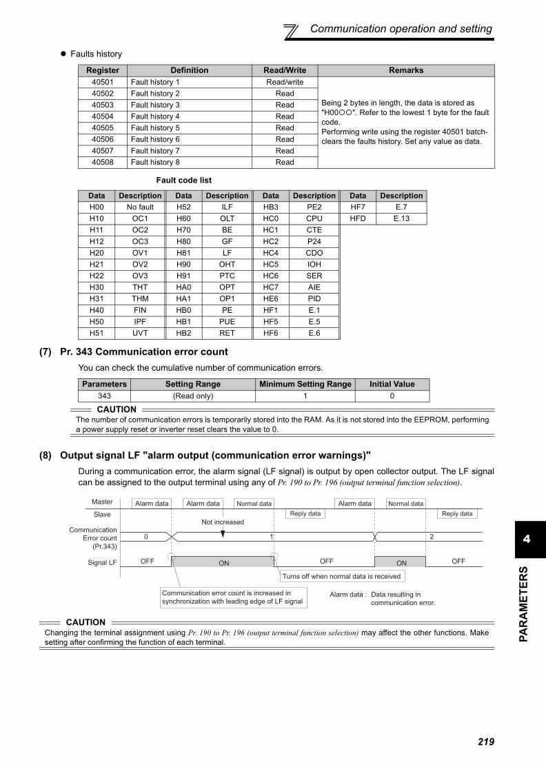
Communication operation and setting
4PA
RA
MET
ERS
Faults history
Fault code list
(7) Pr. 343 Communication error countYou can check the cumulative number of communication errors.
(8) Output signal LF "alarm output (communication error warnings)"During a communication error, the alarm signal (LF signal) is output by open collector output. The LF signalcan be assigned to the output terminal using any of Pr. 190 to Pr. 196 (output terminal function selection).
Register Definition Read/Write Remarks40501 Fault history 1 Read/write
Being 2 bytes in length, the data is stored as "H00 ". Refer to the lowest 1 byte for the faultcode.Performing write using the register 40501 batch-clears the faults history. Set any value as data.
40502 Fault history 2 Read40503 Fault history 3 Read40504 Fault history 4 Read40505 Fault history 5 Read40506 Fault history 6 Read40507 Fault history 7 Read40508 Fault history 8 Read
Data Description Data Description Data Description Data DescriptionH00 No fault H52 ILF HB3 PE2 HF7 E.7H10 OC1 H60 OLT HC0 CPU HFD E.13H11 OC2 H70 BE HC1 CTEH12 OC3 H80 GF HC2 P24H20 OV1 H81 LF HC4 CDOH21 OV2 H90 OHT HC5 IOHH22 OV3 H91 PTC HC6 SERH30 THT HA0 OPT HC7 AIEH31 THM HA1 OP1 HE6 PIDH40 FIN HB0 PE HF1 E.1H50 IPF HB1 PUE HF5 E.5H51 UVT HB2 RET HF6 E.6
Parameters Setting Range Minimum Setting Range Initial Value343 (Read only) 1 0
CAUTIONThe number of communication errors is temporarily stored into the RAM. As it is not stored into the EEPROM, performinga power supply reset or inverter reset clears the value to 0.
CAUTIONChanging the terminal assignment using Pr. 190 to Pr. 196 (output terminal function selection) may affect the other functions. Makesetting after confirming the function of each terminal.
Alarm data
Reply data
Master
Slave
0
Signal LF
Normal dataAlarm data Alarm data
1 2
OFF ON OFF OFFON
Not increased
Turns off when normal data is received
Alarm data :
Normal data
Reply data
Communication error count is increased in
synchronization with leading edge of LF signalData resulting in
communication error.
Communication
Error count
(Pr.343)
219
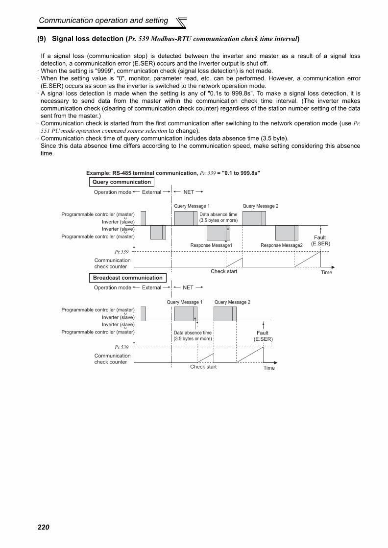
Communication operation and setting
(9) Signal loss detection (Pr. 539 Modbus-RTU communication check time interval)
If a signal loss (communication stop) is detected between the inverter and master as a result of a signal lossdetection, a communication error (E.SER) occurs and the inverter output is shut off.
· When the setting is "9999", communication check (signal loss detection) is not made.· When the setting value is "0", monitor, parameter read, etc. can be performed. However, a communication error
(E.SER) occurs as soon as the inverter is switched to the network operation mode.· A signal loss detection is made when the setting is any of "0.1s to 999.8s". To make a signal loss detection, it is
necessary to send data from the master within the communication check time interval. (The inverter makescommunication check (clearing of communication check counter) regardless of the station number setting of the datasent from the master.)
· Communication check is started from the first communication after switching to the network operation mode (use Pr.551 PU mode operation command source selection to change).
· Communication check time of query communication includes data absence time (3.5 byte). Since this data absence time differs according to the communication speed, make setting considering this absencetime.
Operation mode
Example: RS-485 terminal communication, Pr. 539 = "0.1 to 999.8s"
External NET
Check start Time
Inverter (slave)
Inverter (slave)
Communication
check counter
Pr.539
Programmable controller (master)
Programmable controller (master)
Query Message 1 Query Message 2
Data absence time
(3.5 bytes or more)
Response Message1 Response Message2
Fault
(E.SER)
Operation mode External NET
Check start Time
Inverter (slave)
Inverter (slave)
Communication
check counter
Pr.539
Programmable controller (master)
Programmable controller (master)
Query Message 2
Fault
(E.SER)
Data absence time
(3.5 bytes or more)
Query Message 1
Query communication
Broadcast communication
220

Special operation and frequency control
4PA
RA
MET
ERS
4.20 Special operation and frequency control
4.20.1 PID control (Pr. 127 to Pr. 134, Pr. 241, Pr. 553, Pr. 554, Pr. 575 to Pr. 577, C42 (Pr. 934) to C45 (Pr. 935))
Purpose Parameter that must be Set Refer to Page
Perform process control such as pump and air volume. PID control
Pr. 127 to Pr. 134, Pr. 241, Pr. 553, Pr. 554, Pr. 575 to Pr. 577, C42 (Pr. 934) to C45 (Pr. 935)
221
Switch between the inverter operation and bypass operation to operate.
Bypass-inverter switchover function Pr. 135 to Pr. 139, Pr. 159 233
Avoid overvoltage alarm due to regeneration by automatic adjustment of output frequency
Regeneration avoidance function Pr. 882 to Pr. 886 238
The inverter can be used to exercise process control, e.g. flow rate, air volume or pressure.The terminal 2 input signal or parameter setting is used as a set point and the terminal 4 input signal used as afeedback value to constitute a feedback system for PID control.
Parameter Number Name Initial
ValueSetting Range Description
127 PID control automatic switchover frequency 9999
0 to 400Hz Set the frequency at which the control is automatically changed to PID control.
9999 Without PID automatic switchover function
128PID action selection 10
10, 110 *2 PID reverse action Deviation value signal input(terminal 1 *4)11, 111 *2 PID forward action
20, 120 *2 PID reverse action Measured value (terminal 4 *5) Set point (terminal 2 *4 or Pr. 133)21, 121 *2 PID forward action
50 *2 PID reverse action Deviation value signal input(LONWORKS , CC-Link communication)51 *2 PID forward action
60 *2 PID reverse action Measured value, set point input(LONWORKS , CC-Link communication)61 *2 PID forward action
129 *1 PID proportional band 100%0.1 to 1000%
If the proportional band is narrow (parameter setting is small),the manipulated variable varies greatly with a slight change ofthe measured value. Hence, as the proportional band narrows,the response sensitivity (gain) improves but the stabilitydeteriorates, e.g. hunting occurs. Gain Kp = 1/proportional band
9999 No proportional control
130 *1 PID integral time 1s0.1 to 3600s
When deviation step is input, time (Ti) is the time required for integral (I) action to provide the same manipulated variable as proportional (P) action. As the integral time decreases, the set point is reached earlier but hunting occurs more easily.
9999 No integral control.
131 PID upper limit 9999 0 to 100% *3
Set the upper limit value. If the feedback value exceeds the setting, the FUP signal is output. The maximum input (20mA/5V/10V) of the measured value (terminal 4) is equivalent to 100%.
9999 No function
132 PID lower limit 9999 0 to 100% *3
Set the lower limit value. If the measured value falls below the setting range, the FDN signal is output. The maximum input (20mA/5V/10V) of the measured value (terminal 4) is equivalent to 100%.
9999 No function
133 *1 PID action set point 9999 0 to 100% *3 Used to set the set point for PID control.
9999 Terminal 2 input is the set point.
134 *1 PID differential time 99990.01 to 10.00s
When deviation lamp is input, time (Td) is the time required to provide the manipulated variable of only the proportional (P) action. As the differential time increases, greater response is made to a deviation change.
9999 No differential control.
241 *1 Analog input display unit switchover 0
0 Displayed in %Select the unit of analog input display.
1 Displayed in V/mA
221

Special operation and frequency control
(1) PID control basic configuration⋅ Pr. 128 = "10, 11, 110, 111" (Deviation value signal input)
⋅ Pr. 128 = "20, 21, 120, 121" (Measured value input)
553PID deviation limit 9999
0 to 100.0%*3Y48 signal is output when the absolute value of deviation amount exceeds the deviation limit value.
9999 No function
554 PID signal operation selection 0 0 to 3,
10 to 13
Select the operation to be performed at the detection of upper, lower, and deviation limit for the measured value input. The operation for PID output suspension function can be selected.
575Output interruption detection time
1s 0 to 3600s
The inverter stops operation if the output frequency after PID operation remains at less than the Pr. 576 setting for longer than the time set in Pr. 575.
9999 Without output interruption function
576 Output interruption detection level 0Hz 0 to 400Hz Set the frequency at which the output interruption processing is
performed.
577 Output interruption cancel level 1000% 900 to 1100% Set the level (Pr. 577 minus 1000%) to release the PID output
interruption function.C42
(934) *6 PID display bias coefficient 9999
0 to 500.00 Set the coefficient on bias (minimum) side of terminal 4 input.
9999 Displayed in %.
C43(934) *6 PID display bias
analog value 20% 0 to 300.0% Set the converted % on bias (minimum) side current /voltage of terminal 4 input.
C44(935) *6 PID display gain
coefficient 99990 to 500.00 Set the coefficient on gain (maximum) side of the terminal 4
input.9999 Displayed in %.
C45(935) *6 PID display gain
analog value 100% 0 to 300.0% Set the converted % on gain (maximum) side of current/voltage of terminal 4 input.
The above parameters can be set when Pr. 160 User group read selection = "0". (Refer to page 175)... Specifications differ according to the date assembled. Refer to page 322 to check the SERIAL number.
*1 The above parameters allow its setting to be changed during operation in any operation mode even if "0" (initial value) is set in Pr. 77 Parameterwrite selection.
*2 PID control is available without turning X14 signal ON when Pr.128 = "50, 51, 60, 61, 110, 111, 120, 120".*3 Setting values of Pr.131 to Pr.133, Pr.553, Pr.577 are without unit when "9999" is set to both of C42(Pr.934) and C44(Pr.935). (The values set to
Pr.553 and Pr.577 indicate deviation range whether the unit is % or is not indicated.)*4 Input specification for the terminals are determined by Pr.73 Analog input selection.*5 Input specification for the terminal is determined by Pr.267 Terminal 4 input selection.*6 The parameter number in parentheses is the one for use with the parameter unit (FR-PU04/FR-PU07).
Parameter Number Name Initial
ValueSetting Range Description
+- IMDeviation signal
Feedback signal (measured value)
Ti S
11+ +Td SKp
PID operation
To outside
Set point
Inverter circuit
Motor
Terminal 1
0 to 10VDC
(0 to 5V)
Kp: Proportionality constant Ti: Integral time S: Operator Td: Differential time
Manipulated
variable
*
+- IMTi SKp 1+ +Td S
1
PID operationPr. 133 or
terminal 2
Set point
Inverter circuit
Motor
Feedback signal (measured value)
Terminal 4
Kp: Proportionality constant Ti: Integral time S: Operator Td: Differential time
Manipulated
variable
0 to 5VDC
(0 to 10V, 4 to 20mA)
4 to 20mADC (0 to 5V, 0 to 10V)
*1
*2
222
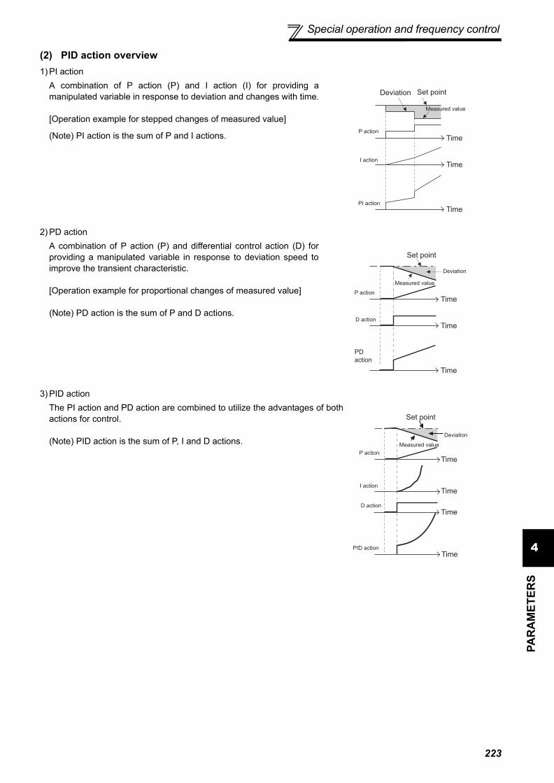
Special operation and frequency control
4PA
RA
MET
ERS
(2) PID action overview1) PI action
2) PD action
3) PID action
A combination of P action (P) and I action (I) for providing amanipulated variable in response to deviation and changes with time.
[Operation example for stepped changes of measured value]
(Note) PI action is the sum of P and I actions.
A combination of P action (P) and differential control action (D) forproviding a manipulated variable in response to deviation speed toimprove the transient characteristic.
[Operation example for proportional changes of measured value]
(Note) PD action is the sum of P and D actions.
The PI action and PD action are combined to utilize the advantages of bothactions for control.
(Note) PID action is the sum of P, I and D actions.
Deviation Set point
Measured value
Time
Time
TimePI action
I action
P action
Deviation
Set point
Measured value
Time
Time
Time
PD
action
D action
P action
Deviation
Set point
Measured value
Time
Time
TimePID action
D action
P action
I actionTime
223

Special operation and frequency control
4)Reverse actionIncreases the manipulated variable (output frequency) if deviation X = (set point - measured value) is positive, anddecreases the manipulated variable if deviation is negative.
5)Forward actionIncreases the manipulated variable (output frequency) if deviation X = (set point - measured value) is negative, anddecreases the manipulated variable if deviation is positive.
Relationships between deviation and manipulated variable (output frequency)
(3) Connection diagram
DeviationPositive Negative
Reverse actionForward action
⋅ Sink logic⋅ Pr. 128 = 20⋅ Pr. 183 = 14⋅ Pr. 191 = 47⋅ Pr. 192 = 16⋅ Pr. 193 = 14⋅ Pr. 194 = 15
*1 The power supply must be selected in accordance with the power specifications of the detector used.*2 The used output signal terminal changes depending on the Pr. 190 to Pr. 196 (output terminal selection) setting.*3 The used input signal terminal changes depending on the Pr. 178 to Pr. 189 (input terminal selection) setting.*4 The AU signal need not be input.
Set
point
X>0
X<0
Feedback signal
(measured value)
+
-
[Heating]
Deviation Set point
Measured value
Cold
Hot
Increase
Decrease
Set
point
X>0
X<0
Feedback signal
(measured value)
+
-
[Cooling]
Deviation
Set point
Measured value
Too cold
Hot
Decrease
Increase
Power supply
MCCB Inverter
Forward rotationReverse rotation
PID control selection
Setting Potentiometer
(Set point setting)
0 24VPower supply *1
AC1φ200/220V 50/60Hz
R/L1S/L2T/L3
STF
STR
RT(X14)*3
10
2
5
4*4
UVW
*2(FUP)FU
*2(FDN)OL
SE
(Measured value) 4 to 20mA
Motor
IM
Pump
P
Upper limit
*2(PID)SU During PID action
Lower limit
Output signal common
2-wire type
Detector
3-wire type
-+ + +-
(OUT) (24V)
Forward rotation outputReverse rotation output
*2(RL)IPF
1 (COM)
MC
SD
224

Special operation and frequency control
4PA
RA
MET
ERS
(4) I/O signals and parameter setting⋅ Turn on the X14 signal to perform PID control. When this signal is off, PID action is not performed and normal
inverter operation is performed. (However, turning X14 ON is not necessary when Pr.128 = "50, 51, 60, 61, 110,111, 120, 121".)
⋅ Enter the set point across inverter terminals 2-5 or into Pr. 133 and enter the measured value signal across inverterterminals 4-5. At this time, set any of "20, 21, 120, 121" in Pr. 128.
⋅ When entering the externally calculated deviation signal, enter it across terminals 1-5. At this time, set any of "10,11, 110, 111" in Pr. 128.
Signal Terminal Used Function Description Parameter Setting
Inpu
t
X14
Depending onPr. 178 to Pr.189
PID control selection Turn ON X14 to perform PID control. Set 14 in any of Pr. 178 to Pr. 189.
X64PID forward/reverse action switchover
By turning ON X64, forward action can beselected for PID reverse action (Pr. 128 =10, 20, 110, 120), and reverse action forforward action (Pr. 128 = 11, 21, 111, 121).
Set 64 in any of Pr. 178 to Pr. 189.
X72 PID integral value reset
ON: Integral and differential values areresetOFF: Normal processing
Set 72 in any of Pr. 178 to Pr. 189.
2 2 Set point input
Enter the set point for PID control. Pr. 128 = 20, 21, 120, 121 Pr. 133 =9999
0 to 5V................0 to 100% Pr. 73 = 1 *1, 3, 5, 11, 13, 150 to 10V..............0 to 100% Pr. 73 = 0, 2, 4, 10, 12, 140 to 20mA...........0 to 100% Pr. 73 = 6, 7, 16, 17
PU ⎯ Set point input Set the set value (Pr. 133) from theoperation panel or parameter unit.
Pr. 128 = 20, 21, 120, 121 Pr. 133 = 0 to 100%
1 1 Deviation signal input
Input the deviation signal calculatedexternally. Pr. 128 = 10 *1, 11, 110, 111
-5V to +5V ..........-100% to +100% Pr. 73 = 2, 3, 5, 7, 12, 13, 15, 17
-10V to +10V ......-100% to +100% Pr. 73 = 0, 1 *1, 4, 6, 10, 11, 14, 16
4 4 Measured value input
Input the signal from the detector(measured value signal). Pr. 128 = 20, 21, 120, 121
4 to 20mA...........0 to 100% Pr. 267 = 0 *10 to 5V................0 to 100% Pr. 267 = 10 to 10V..............0 to 100% Pr. 267 = 2
Communi-cation
*2
⎯
Deviation value input
Input the deviation value from LONWORKS, CC-Link communication. Pr. 128 = 50, 51
Set value, measured value input
Input the set value and measured value from LONWORKS , CC-Link communication.
Pr. 128 = 60, 61
Out
put
FUP
Depending onPr. 190 to Pr.196
Upper limit outputOutput to indicate that the measuredvalue signal exceeded the upper limitvalue (Pr. 131).
Pr. 128 =20, 21, 60, 61, 120, 121Pr. 131 ≠ 9999Set 15 or 115 in any of Pr. 190 to Pr. 196. *3
FDN Lower limit output Output when the measured value signalfalls below the lower limit (Pr. 132).
Pr. 128 =20, 21, 60, 61, 120, 121Pr. 132 ≠ 9999Set 14 or 114 in any of Pr. 190 to Pr. 196. *3
RLForward (reverse) rotation direction output
"Hi" is output to indicate that the outputindication of the parameter unit is forwardrotation (FWD), and "Low" to indicate thatit is reverse rotation (REV) or stop (STOP).
Set 16 or 116 in any of Pr. 190 to Pr. 196. *3
PID During PID control activated Turns ON during PID control. Set 47 or 147 in any of Pr. 190 to Pr.
196. *3
SLEEP PID output interruption
Turns ON when the PID outputinterruption function is performed.
Pr. 575 ≠ 9999Set 70 or 170 in any of Pr. 190 to Pr. 196. *3
Y48 PID deviation limit Output when the absolute value ofdeviation exceeds the limit value.
Pr. 553 ≠ 9999Set 48 or 148 in any of Pr. 190 to Pr. 196. *3
SE SE Output terminal common
Common terminal for terminals assignedto FUP signal, FDN signal, RL signal, PIDsignal, SLEEP signal, and Y48 signal
225

Special operation and frequency control
(5) PID control automatic switchover control (Pr. 127)⋅ The inverter can be started up without PID control mode only at a start.⋅ When the frequency is set to Pr. 127 PID control automatic switchover frequency within the range 0 to 400Hz, the
system starts up without PID operation from a start until output frequency is reached Pr. 127, and then it shifts toPID control operation mode. Once the system has entered PID control operation, it continues PID control if theoutput frequency falls to or below Pr. 127.
(6) Selecting operation to be performed at the output of Upper limit signal, Lower limit signal,and PID deviation limit signal (FUP signal, FDN signal, Y48 signal, Pr.554)
You can select the operation to be performed at the detection of upper, lower and deviation limit for the measuredvalue input. With Pr. 554 PID signal operation selection, signal output or signal output + alarm stop (E.PID) can beselected for each of upper limit output signal (FUP signal), lower limit output signal (FDN signal), and PIDdeviation limit signal (Y48 signal).
*1 The shaded area indicates the parameter initial value.*2 For the setting method via LONWORKS communication, refer to the LONWORKS communication option (FR-A7NL) instruction manual.
For the setting method via CC-Link communication, refer to the CC-Link communication option (FR-A7NC) instruction manual.*3 When 100 or larger value is set to any of Pr. 190 to Pr. 196 (output terminal function selection), the terminal output has negative logic. (Refer to
page 121 for details)
CAUTION⋅ Changing the terminal function using any of Pr. 178 to Pr. 189, 190 to Pr. 196 may affect the other functions. Please make setting
after confirming the function of each terminal.
Pr. 554 Setting FUP Signal, FDN Signal * Y48 Signal * SLEEP Function0 (Initial value) Only signal output
Only signal output Inverter coasts to a stop at the
start of SLEEP operation1 Signal output + stop by fault (E.PID)2 Only signal output Signal output + stop by fault
(E.PID)3 Signal output + stop by fault (E.PID)10 Only signal output
Only signal output Inverter decelerates to a stop at
the start of SLEEP operation11 Signal output + stop by fault (E.PID)12 Only signal output Signal output + stop by fault
(E.PID)13 Signal output + stop by fault (E.PID)* When the settings for Pr.131 PID upper limit, Pr.132 PID lower limit, and Pr.553 PID deviation limit, which corresponds with FUP, FDN, and Y48 signals, are
"9999" (no function), the signal is not output, or the alarm stop is not performed.
Output frequency
Pr.127
STF
Time
PID
PID control
Without
PID control
226

Special operation and frequency control
4PA
RA
MET
ERS
(7) PID output suspension function (SLEEP function) (SLEEP signal, Pr. 554, Pr. 575 to Pr. 577 )⋅ The inverter stops operation if the output frequency after PID control remains at less than the Pr. 576 Output
interruption detection level setting for longer than the time set in Pr. 575 Output interruption detection time. (At this time,if "0 to 3" is set to Pr.554 PID signal operation selection, output is shut off (the inverter coasts to stop) when SLEEPoperation starts. If "10 to 13" is set, the inverter decelerates to a stop in the deceleration time set in Pr.8 whenSLEEP operation starts.)This function can reduce energy consumption in the low-efficiency, low-speed range.
⋅ When the deviation (= set value - measured value) reaches the PID output shutoff cancel level (Pr. 577 setting -1000%) while the PID output interruption function is on, the PID output interruption function is canceled and PIDcontrol operation is resumed automatically.
⋅ While the PID output interruption function is on, the PID output interruption signal (SLEEP) is output. At this time,the inverter running signal (RUN) is off and the PID control operating signal (PID) is on.
⋅ For the terminal used for the SLEEP signal output, assign the function by setting "70" (positive logic) or "170"(negative logic) in Pr. 190 to Pr. 196 (output terminal function selection).
* When the output rises to the output interruption cancel level during deceleration to a stop, output interruption gets cancelled, and the inverteraccelerates again to continue PID control. Pr.576 Output interruption detection level is invalid during deceleration.
Pr.554 Setting SLEEP Function FUP Signal, FDN Signal Y48 Signal0 (Initial value)
Inverter coasts to a stop at the start of SLEEP operation
Only signal output Only signal output
1 Signal output + stop by fault (E.PID)2 Only signal output Signal output + stop by fault
(E.PID)3 Signal output + stop by fault (E.PID)10
Inverter decelerates to a stop at the start of SLEEP operation
Only signal output Only signal output
11 Signal output + stop by fault (E.PID)12 Only signal output Signal output + stop by fault
(E.PID)13 Signal output + stop by fault (E.PID)
Output frequency
Deviation
Pr.576
Pr.577 - 1000%
RUN
Time
ON
OFF
SLEEP
Less than Pr. 575Pr. 575 or more SLEEP period
PID
Cancel
level
When Pr.554 = "0 to 3", reverse action (Pr.128 = "10")
Output frequency
Deviation When Pr.554 = "10 to 13", reverse action (Pr.128 = "10")
Pr.576
Pr.577 - 1000%
RUN
Time
ON
OFF
SLEEP
Less than Pr. 575Pr. 575 or more SLEEP period
PID
Cancel
level
Decelerates
to a stop*
227

Special operation and frequency control
(8) PID monitor function⋅ The PID control set value, measured value and deviation value can be displayed on the operation panel and output
from terminal FM, AM.⋅ The deviation monitor can display a negative value on the assumption that 1000 is 0%. (The deviation monitor
cannot be output from the terminal FM, AM.)⋅ For the monitors, set the following values in Pr. 52 DU/PU main display data selection, Pr. 54 FM terminal function
selection, and Pr. 158 AM terminal function selection.
* When neither of C42(Pr.934) nor C44(Pr.935) setting is "9999", minimum increment changes from % to no unit, and the full scale value forterminal FM/AM changes from 100% to the larger value between C42(Pr.934) PID display bias coefficient and C44(Pr.935) PID display gaincoefficient. (The smaller value between C42(Pr.934) and C44(Pr.935) becomes the minimum value.)
(9) Adjustment procedure
Setting Monitor Description MinimumIncrements*
Terminal FM, AM Full Scale* Remarks
52 PID set point0.1 100%/C42(Pr.934) or
C44(Pr.935)For deviation input (Pr. 128 = 10, 11, 110, 111), the monitor value is always displayed as 0.
53 PID measured value
54 PID deviation 0.1 — Value cannot be set to Pr. 54 or Pr. 158.The PID deviation value of 0% is displayed as 1000.
Parameter setting Adjust the PID control parameters, Pr. 127 to Pr. 134, Pr. 553, Pr. 554, and Pr. 575 to Pr. 577.
Terminal setting Set the I/O terminals for PID control. (Pr. 178 to Pr. 189 (Input terminal function selection), Pr. 190 to Pr. 196 (output terminal function selection))
Turn on the X14 signal. PID control is available without turning X14 signal ON when Pr.128 = "50, 51, 60, 61, 110, 111, 120, 121".
Operation
228
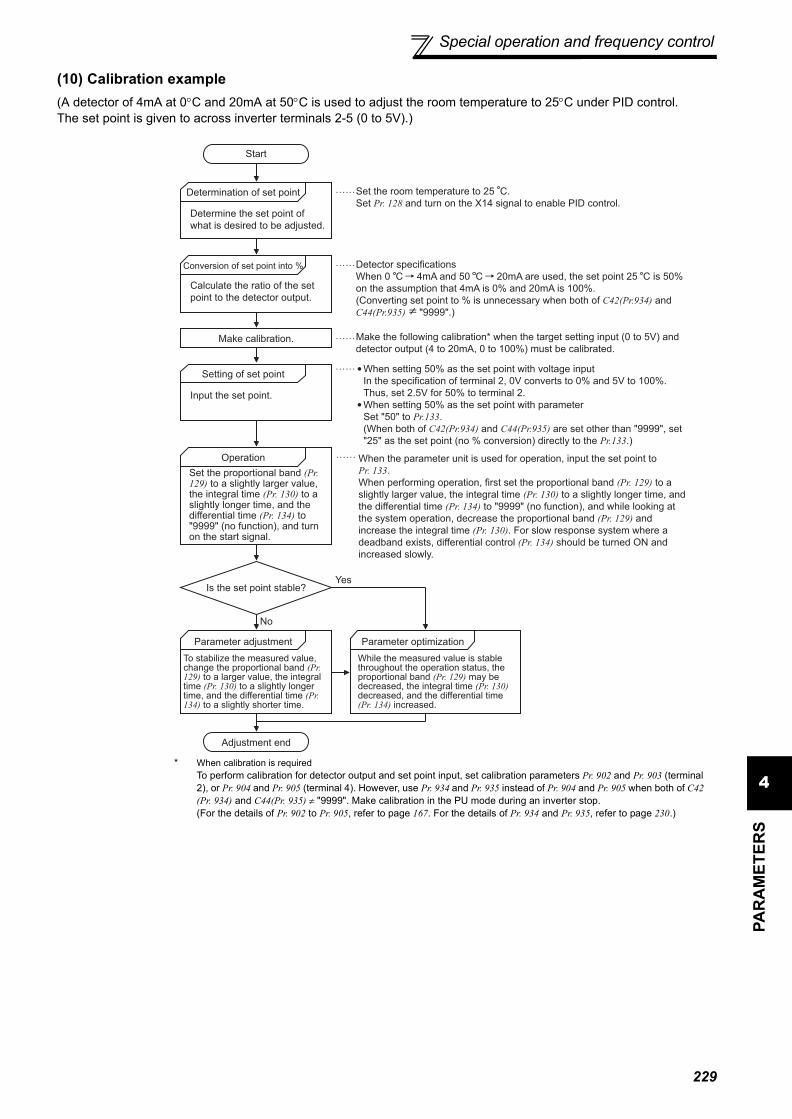
Special operation and frequency control
4PA
RA
MET
ERS
(10) Calibration example(A detector of 4mA at 0°C and 20mA at 50°C is used to adjust the room temperature to 25°C under PID control.The set point is given to across inverter terminals 2-5 (0 to 5V).)
Start
Determination of set point
Conversion of set point into %
Make calibration.
Setting of set point
Operation
Is the set point stable?
Parameter adjustment Parameter optimization
Adjustment end
Yes
No
When the parameter unit is used for operation, input the set point to
Pr. 133.
When performing operation, first set the proportional band (Pr. 129) to a
slightly larger value, the integral time (Pr. 130) to a slightly longer time, and
the differential time (Pr. 134) to "9999" (no function), and while looking at
the system operation, decrease the proportional band (Pr. 129) and
increase the integral time (Pr. 130). For slow response system where a
deadband exists, differential control (Pr. 134) should be turned ON and
increased slowly.
Determine the set point of
what is desired to be adjusted.
Calculate the ratio of the set
point to the detector output.
Input the set point.
To stabilize the measured value, change the proportional band (Pr. 129) to a larger value, the integral time (Pr. 130) to a slightly longer time, and the differential time (Pr. 134) to a slightly shorter time.
While the measured value is stable throughout the operation status, the proportional band (Pr. 129) may be decreased, the integral time (Pr. 130) decreased, and the differential time (Pr. 134) increased.
Set the proportional band (Pr. 129) to a slightly larger value, the integral time (Pr. 130) to a slightly longer time, and the differential time (Pr. 134) to "9999" (no function), and turn on the start signal.
Make the following calibration* when the target setting input (0 to 5V) and
detector output (4 to 20mA, 0 to 100%) must be calibrated.
Set the room temperature to 25 C.
Set Pr. 128 and turn on the X14 signal to enable PID control.
Detector specifications
When 0 C 4mA and 50 C 20mA are used, the set point 25 C is 50%
on the assumption that 4mA is 0% and 20mA is 100%.
(Converting set point to % is unnecessary when both of C42(Pr.934) and
C44(Pr.935) "9999".)
When setting 50% as the set point with voltage input
In the specification of terminal 2, 0V converts to 0% and 5V to 100%.
Thus, set 2.5V for 50% to terminal 2.
When setting 50% as the set point with parameter
Set "50" to Pr.133.
(When both of C42(Pr.934) and C44(Pr.935) are set other than "9999", set
"25" as the set point (no % conversion) directly to the Pr.133.)
* When calibration is requiredTo perform calibration for detector output and set point input, set calibration parameters Pr. 902 and Pr. 903 (terminal 2), or Pr. 904 and Pr. 905 (terminal 4). However, use Pr. 934 and Pr. 935 instead of Pr. 904 and Pr. 905 when both of C42 (Pr. 934) and C44(Pr. 935) ≠ "9999". Make calibration in the PU mode during an inverter stop.(For the details of Pr. 902 to Pr. 905, refer to page 167. For the details of Pr. 934 and Pr. 935, refer to page 230.)
229

Special operation and frequency control
<Set point input calibration>1) Setting with terminal 2 input
1. Apply the input voltage of 0% set point setting (e.g. 0V) across terminals 2-5.2. Enter in C2 (Pr. 902) the frequency which should be output by the inverter at the deviation of 0% (e.g. 0Hz).3. In C3 (Pr. 902), set the voltage value at 0%.4. Apply the voltage of 100% set point (e.g. 5V) to across terminals 2-5.5. Enter in Pr. 125 the frequency which should be output by the inverter at the deviation of 100% (e.g. 60Hz).6. In C4 (Pr. 903), set the voltage value at 100%.
2) Setting with Pr. 133When both or one of C42 (Pr.934) and C44 (Pr.935) is "9999".For the set point, set a % converted value in the range of 0 to 100%.
When both of C42 (Pr.934) and C44 (Pr.935) ≠ "9999".For the set point, set PID coefficient, which corresponds with 0 to 100%.
<Measured value calibration>1) When both or one of C42 (Pr.934) and C44 (Pr.935) is "9999".
1. Apply the input current of 0% measured value (e.g. 4mA) across terminals 4-5.2. Make calibration using C6 (Pr. 904).3. Apply the input current of 100% measured value (e.g. 20mA) across terminals 4-5.4. Make calibration using C7 (Pr. 905).
2) When both of C42 (Pr.934) and C44 (Pr.935) ≠ "9999".1. Apply the input current of 0% measured value (e.g. 4mA) across terminals 4 and 5.2. Set PID display value at 0% measured value (example: 15(°C)) to C42 (Pr.934) , and calibrate C43 (Pr.934).3. Apply the input current of 100% measured value (e.g. 20mA) across terminals 4 and 5.4. Set PID display value at 100% measured value (example: 35(°C)) to C44 (Pr.935), and calibrate C45 (Pr.935).
The results of the above calibration are as shown below:
REMARKS⋅ The frequency set in C5 (Pr. 904) and Pr. 126 should be the same as set in C2 (Pr. 902) and Pr. 125.
Pr.133Setting
Pr.934, Pr.935
SettingSet Point Setting Measured Value
(Terminal 4) Manipulated Variable
9999 —
(Terminal 2)
Other than 9999
Both or one is 9999
(Pr.133)
Other than 9999
(Pr.133)
Set PID coefficient corresponding with 0 to 100%.
100
0
0 5 (V)
Set point signal input
Set point
(%)
100
0
0 20
C7(Pr.905)
(mA)
Measured value
input signal
Measured
Value
(%)
4
C6(Pr.904)
60(Pr.125)
0C2(Pr.902)
0 100Deviation(%)
Manipulated
Variable(Hz)100
0
C5(Pr.904) Pr.126
Set point setting
Set point
(%)
100
0
C42(Pr.934) C44(Pr.935)
Set point
(%)100
0
0 20
C45(Pr.935)
(mA)
Measured value
input signal
Measured
value
(%)
4
C43(Pr.934)
230

Special operation and frequency control
4PA
RA
MET
ERS
CAUTION⋅ If the multi-speed (RH, RM, RL signal) or Jog operation (JOG signal) is entered with the X14 signal on, PID control is stopped
and multi-speed or jog operation is started.⋅ If the setting is as follows, PID control becomes invalid.
Pr. 22 Stall prevention operation level = "9999" (analog variable)Pr. 79 Operation mode selection = "6" (switchover mode))
⋅ When the Pr. 128 setting is "20, 21, 120, 121", note that the input across inverter terminals 1-5 is added to the set value acrossterminals 2-5.
⋅ Changing the terminal function using any of Pr. 178 to Pr. 189, Pr. 190 to Pr. 196 may affect the other functions. Please makesetting after confirming the function of each terminal.
⋅ When PID control is selected, the minimum frequency is the frequency set in Pr. 902 and the maximum frequency is thefrequency set in Pr. 903. (Pr. 1 Maximum frequency and Pr. 2 Minimum frequency settings are also valid.)
⋅ The remote operation function is invalid during PID operation.⋅ When the control is switched to PID control during
normal operation, the frequency command valuecalculated by PID operation using 0Hz as standard isused without the frequency during the operation.
PID action
Frequency
command
PID set point
Frequency command
during normal operation
ON
Operation when control is switched to PID control during normal operation
Normal operation PID operation Normal operation
231

Special operation and frequency control
(11) Bias and gain for PID displayed values(C42(Pr. 934) to C45(Pr. 935))When both of C42(Pr.934) and C44(Pr.935) ≠ "9999", bias/gain calibration is available for analog value of set point,measured value, deviation value to perform PID control.1) Bias/gain calibration for PID displayed value(C42(Pr. 934) to C45(Pr. 935))
⋅ "Bias" / "gain" function can adjust the relation between PID displayed coefficient and measured value inputsignal. Examples of measured value input signals are 0 to 5VDC, 0 to 10VDC, or 4 to 20mADC, and they areexternally input.
⋅ Set PID display bias coefficient for terminal 4 input with C42(Pr.934).(Initial value is the coefficient for 4mA.)
⋅ Set PID display gain coefficient for 20mA of the frequency command current (4 to 20mA) with C44(Pr.935).⋅ When both of C42(Pr.934) and C44(Pr.935) ≠ "9999" and Pr.133 is set as the set point, the setting of C42(Pr.934)
is treated as 0%, and C44(Pr.935) as 100%.
⋅ Three methods of bias/gain adjustment for PID displayed values are the following.(a)Method to adjust any point by application of voltage (current) across the terminals 4 and 5.(b)Method to adjust any point without application of voltage (current) across terminals 4 and 5.(c)Method to adjust only the frequency without adjusting the voltage (current).(For the detail of (a) to (c), refer to page 167. Make adjustment by assuming C7 (Pr.905) as C45 (Pr.935), and Pr.126 as C44 (Pr.935).)
2) Analog input display unit changing (Pr. 241)⋅ You can change the analog input display unit (%/V, mA) for analog input bias/gain calibration.⋅ Depending on the terminal input specification set to Pr. 73, Pr. 267, and voltage/current input switch the display
units of C3(Pr. 902), C4(Pr. 903), C43(Pr. 934), C45(Pr. 935) change as shown below.
CAUTION⋅ When the voltage/current input specifications are changed with voltage/current input switch and using Pr. 73 and Pr. 267, be sure
to make calibration.
Analog Command (Terminal 4)(according to Pr. 73, Pr. 267, and Voltage/Current
Input Switch)Pr. 241 = 0 (Initial Value) Pr. 241 = 1
0 to 5V input 0 to 5V → displayed in 0 to 100%(0.1%).
0 to 100% → displayed in 0 to 5V(0.01V).
0 to 10V input 0 to 10V → displayed in 0 to 100%(0.1%).
0 to 100% → displayed in 0 to 10V(0.01V).
4 to 20mA input 0 to 20mA → displayed in 0 to 100%(0.1%).
0 to 100% → displayed in 0 to 20mA(0.01mA).
♦ Parameters referred to ♦Pr. 59 Remote function selection Refer to page 93Pr. 73 Analog input selection Refer to page 160Pr. 79 Operation mode selection Refer to page 177Pr. 178 to Pr. 189 (input terminal function selection) Refer to page 115Pr. 190 to Pr. 196 (output terminal function selection) Refer to page 121C2 (Pr. 902) to C7 (Pr. 905) Frequency setting voltage (current) bias/gain Refer to page 167
100
0
Frequency setting signal
100%
Initial value
Bias
C42(Pr.934)
Gain
C44(Pr.935)
0
20
4 20mA
Co
effic
ien
t
C43(Pr.934) C45(Pr.935)
232

Special operation and frequency control
4PA
RA
MET
ERS
4.20.2 Bypass-inverter switchover function (Pr. 135 to Pr. 139, Pr. 159)
⋅ When the motor is operated at 60Hz (or 50Hz), more efficient operation can be performed by the commercial powersupply than by the inverter. When the motor cannot be stopped for a long time for the maintenance/inspection of theinverter, it is recommended to provide the commercial power supply circuit.
⋅ To avoid commercial power supply being applied to the inverter output side when switching between inverteroperation and commercial power supply operation, provide an interlock which the MC of the commercial powersupply side turns on only when the MC of the inverter output side is off. Using the electronic bypass sequencefunction that outputs the timing signal for operation of the magnetic contactor, a complicated commercial powersupply switchover interlock can be provided by the inverter.
The complicated sequence circuit for bypass operation is built in the inverter. Hence, merely inputting the start,stop or automatic switchover selection signal facilitates the interlock operation of the switchover magneticcontactor.
Parameter Number Name Initial
ValueSetting Range Description
135 Electronic bypass sequence selection 0
0 Without electronic bypass sequence1 With electronic bypass sequence
136 MC switchover interlock time 1s 0 to 100s Set the operation interlock time of MC2 and MC3.
137 Start waiting time 0.5s 0 to 100sSet the time slightly longer (0.3 to 0.5s or so) than thetime from when the ON signal enters MC3 until itactually turns on.
138 Bypass selection at a fault 0
0 Inverter output is stopped (motor coast) at inverter fault.
1
Operation is automatically switched to bypass operation at inverter fault (Not switched when an external thermal relay operation (E.OHT) or CPU fault (E.CPU) occurs).
139 Automatic switchover frequency from inverter to bypass operation 9999
0 to 60Hz
Set the frequency to switch inverter operation to bypass operation.Inverter operation is performed from a start until Pr. 139 is reached, and when the output frequency is at or above Pr. 139, inverter operation is automatically switched to bypass operation.
9999 Without automatic switchover
159Automatic switchover frequency range from bypass to inverter operation
9999
0 to 10Hz
Valid during automatic switchover operation (Pr. 139 ≠ 9999)When the frequency command decreases below (Pr. 139 - Pr. 159) after operation is switched from inverter operation to bypass operation, the inverter automatically switches operation to inverter operation and operates at the frequency of frequency command. When the inverter start command (STF/STR) is turned off, operation is switched to inverter operation also.
9999
Valid during automatic switchover operation (Pr. 139 ≠ 9999)When the inverter start command (STF/STR) is turned off after operation is switched from inverter operation to bypass operation, operation is switched to inverter operation and the motor decelerates to stop.
The above parameters can be set when Pr. 160 User group read selection = "0". (Refer to page 175.)
233

Special operation and frequency control
(1) Connection diagram⋅ The following shows the connection diagram of a typical electronic bypass sequence. Sink logic, Pr. 185 = "7", Pr.
192 = "17", Pr. 193 = "18", Pr. 194 = "19"
⋅ Operations of magnetic contactors (MC1, MC2, MC3)
Electronic bypass sequence connection diagram
*1 Take caution for the capacity of the sequence output terminal.The used terminal changes depending on the setting of Pr. 190 toPr. 196 (output terminal function selection).
*2 When connecting a DC power supply, insert a protective diode.When connecting an AC power supply, connect a relay outputoption (FR-A7AR) and use a contact output.
*3 The used terminal changes depending on the setting of Pr. 180 toPr. 189 (input terminal function selection).
CAUTION⋅ Use the bypass operation function in External operation mode. Be sure to connect the other power supply since the function is
not performed normally unless the connection terminals R1/L11, S1/L21 are not connected to the other power supply (powersupply that does not pass MC1).
⋅ Be sure to provide mechanical interlocks for MC2 and MC3.
Magnetic Contactor Installation Place
Operation ( : Shorted, ×: Open)
Bypass operation During inverter operation
At an inverter fault occurrence
MC1 Between power supply and inverter input
×(Shorted by reset)
MC2 Between power supply andmotor ×
×(Can be selected using
Pr. 138, always open when external thermal
relay is on)
MC3 Between inverter output and motor × ×
Inverter start (forward rotation)
MC1
R/L1S/L2T/L3
STF
R1/L11
S1/L21
CSMRS
RES
1025
UVW
External
thermal relay
IM
(MC1)IPF
(MC2)OL
SE
MC3
MC2
24VDC
MC1
External
thermal reset
Frequency
setting signal
(MC3)FU
Inverter/bypass operationinterlock
MC2
MC3
*3
*1
*2*1
*1
JOG(OH)
MCCB
MC2
MC3
SD
Output Terminal Capacity Output Terminal Permissble Load
Inverter open collector output (RUN, SU, IPF, OL, FU) 24VDC 0.1A
Inverter relay output (A1-C1, B1-C1, A2-B2, B2-C2)Relay output option (FR-A7AR)
230VAC 0.3A30VDC 0.3A
234

Special operation and frequency control
4PA
RA
MET
ERS
⋅ The input signals are as indicated below.
⋅ The output signals are as indicated below.
Signal Terminal Used Function OperationMC Operation *6
MC1 *5 MC2 MC3
MRS MRSOperation enable/disable selection *1
ON .....Bypass-inverter operation enabled
⎯ ⎯
OFF ...Bypass-inverter operation disabled
×No
change
CS CS Inverter/bypass *2ON...... Inverter operation ×
OFF ...Bypass operation ×
STF(STR) STF(STR)
Inverter operation command (Invalid for bypass) *3
ON......Forward rotation (reverse rotation)
×
OFF....Stop ×
OH Set "7" in any of Pr. 180 to Pr. 189. External thermal relay input
ON .....Motor normal ⎯ ⎯
OFF....Motor abnormal × × ×
RES RES Operating status initialization *4
ON...... Initialization No change ×
No change
OFF....Normal operation ⎯ ⎯*1 Unless the MRS signal is turned on, neither bypass operation nor inverter operation can be performed.*2 The CS signal functions only when the MRS signal is on.*3 STF (STR) functions only when both the MRS signal and CS signal are on.*4 The RES signal enables reset input acceptance selection using Pr. 75 Reset selection/disconnected PU detection/PU stop selection.*5 MC1 turns off when an inverter fault occurs.*6 MC operation
: MC-ON× : MC-OFF⎯ : Inverter operation .................................................. MC2 is off and MC3 is on
Bypass operation................................................... MC2 is on and MC3 is offNo change : The status before the signal turns on or off is held.
Signal Terminal Used(Pr. 190 to Pr. 196 setting) Description
MC1 17 Control signal output of inverter input side magnetic contactor MC1
MC2 18 Control signal output of bypass operation magnetic contactor MC2
MC3 19 Control signal output of inverter output side magnetic contactor MC3
235

Special operation and frequency control
(2) Electronic bypass operation sequence⋅ Operation sequence example when there is no automatic switchover sequence (Pr. 139 = "9999")
⋅ Operation sequence example when there is automatic switchover sequence (Pr. 139 ≠ "9999", Pr. 159 = "9999")
⋅ Operation sequence example when there is automatic switchover sequence (Pr. 139 ≠ "9999", Pr. 159 ≠ "9999")
ON
OFFPower supply
ON
OFF
Operation interlock
ON
OFF
Inverter run command
ON
OFF
(MRS)
(STF)
ON
OFF
Inverter input side MC(MC1)
ON
OFF
ON
OFF
Each timer
Coasting StopCoasting
ON : Operation enabled
OFF: Operation disabled
ON : Forward rotation
OFF: Stop
ON : Inverter operation
OFF: Bypass operation
Pr.136 MC switchover interlock time
Pr.137 MC3 start (waiting time)
Pr.57 reset time
Pr.58 Switchover cushion time
Off only at inverter fault
Inverter output side MC(MC3)
Pr.136Pr.57 Pr.136 Pr.57
Pr.58Pr.137
Inverter/bypass (CS)
MC for bypass operation (MC2)
Operating status (motor speed)
INV operation
Bypass operation
INV operation
Indicates the delay time until the MC turns on (off).
STF
Frequency command
Output frequency Pr.139
Time
Time
Actual motor speed
A : Pr.136 MC switchover interlock time B : Pr.137 Start waiting time
C : Pr.57 Restart coasting time D : Pr.58 Restart cushion time
MC3ON
OFF
ON
OFF
MC2ON
OFF
C A A B C D
INV operation
Bypass operation
STF
Frequency command
Output frequency Pr.139Pr.159
Time
Time
Actual motor speed
A : Pr.136 MC switchover interlock time B : Pr.137 Start waiting time
C : Pr.57 Restart coasting time D : Pr.58 Restart cushion time
MC3ON
OFF
ON
OFF
MC2ON
OFF
C A A B C D A A B C D
INV operation
Bypass operation
236

Special operation and frequency control
4PA
RA
MET
ERS
(3) Operating procedure⋅ Procedure for operation
Operation pattern
2)Signal ON/OFF after parameter setting
MRS CS STF MC1 MC2 MC3 Remarks
Power supply ON
OFF(OFF)
OFF(OFF)
OFF(OFF)
OFF → ON(OFF → ON)
OFF(OFF)
OFF → ON(OFF → ON)
External operation mode(PU operation mode)
At start (inverter) OFF → ON OFF → ON OFF → ON ON OFF ON
At constant speed(commercial power supply)
ON ON → OFF ON ON OFF → ON ON → OFF
MC2 turns on after MC3 turns off(coasting status during this period)Waiting time 2s
Switched to inverter for deceleration (inverter)
ON OFF → ON ON ON ON → OFF OFF → ON
MC3 turns on after MC2turns off(coasting status during thisperiod)Waiting time 4s
Stop ON ON ON → OFF ON OFF ON
CAUTION⋅ Connect the control power supply (R1/L11, S1/L21) in front of input side MC1. If the control power supply is connected behind
input side MC1, the electronic bypass sequence function is not executed.⋅ The electronic bypass sequence function is valid only when Pr. 135 = "1" in the external operation or combined operation mode
(PU speed command, external operation command Pr. 79 = "3"). When Pr. 135 = "1" in the operation mode other than the above,MC1 and MC3 turn on.
⋅ When the MRS and CS signals are on and the STF (STR) signal is off, MC3 is on, but when the motor was coasted to a stopfrom bypass operation last time, a start is made after the time set to Pr. 137 has elapsed.
⋅ Inverter operation can be performed when the MRS, STF (STR) and CS signals turn on. In any other case (MRS signal - ON),bypass operation is performed.
⋅ When the CS signal is turned off, the motor switches to bypass operation. However, when the STF (STR) signal is turned off,the motor is decelerated to a stop in the inverter operation mode.
⋅ When both MC2 and MC3 are off and either MC2 or MC3 is then turned on, there is a waiting time set in Pr. 136.⋅ If electronic bypass sequence is valid (Pr. 135 = "1"), the Pr. 136 and Pr. 137 settings are ignored in the PU operation mode. The
input terminals (STF, CS, MRS, OH) of the inverter return to their normal functions.⋅ When the electronic bypass sequence function (Pr. 135 = "1") and PU operation interlock function (Pr. 79 = "7") are used
simultaneously, the MRS signal is shared by the PU operation external interlock signal unless the X12 signal is assigned.(When the MRS and CS signals turn on, inverter operation is enabled)
⋅ Changing the terminal function using any of Pr. 178 to Pr. 189, 190 to Pr. 196 may affect the other functions. Please make settingafter confirming the function of each terminal.
♦ Parameters referred to ♦Pr. 11 DC injection brake operation time Refer to page 106Pr. 57 Restart coasting time Refer to page 141Pr. 58 Restart cushion time Refer to page 141Pr. 79 Operation mode selection Refer to page 177Pr. 178 to Pr. 189 (Input terminal function selection) Refer to page 115Pr. 190 to Pr. 196 (Output terminal function selection) Refer to page 121
Power supply ON
Setting the parameters
Start inverter operation
Constant-speed bypass operation
Deceleration (stop) inverter operation
⋅ Pr. 135 = "1" (open collector output terminal of inverter)⋅ Pr. 136 = "2.0s"⋅ Pr. 137 = "1.0s" (Set the time longer than the time from when
MC3 actually turns on until the inverter and motor are connected. If the time is short, a restart may not function properly.)
⋅ Pr. 57 = "0.5s"⋅ Pr. 58 = "0.5s" (Be sure to set this parameter when bypass
operation is switched to inverter operation.)
237

Special operation and frequency control
4.20.3 Regeneration avoidance function (Pr. 882 to Pr. 886)
(1) What is regeneration avoidance function? (Pr. 882, Pr. 883)⋅ When the regeneration status is serious, the DC bus voltage rises and an overvoltage fault (E. OV ) may occur.
When this bus voltage rise is detected and the bus voltage level reaches or exceeds Pr. 883, increasing the frequency avoids the regeneration status.
⋅ The regeneration avoidance operation, you can select whether it is always activated or activated only a constantspeed.
⋅ Setting Pr. 882 to "1, 2" validates the regeneration avoidance function.
This function detects a regeneration status and increases the frequency to avoid the regeneration status.Possible to avoid regeneration by automatically increasing the frequency and continue operation if the fanhappens to rotate faster than the set speed due to the effect of another fan in the same duct.
Parameter Number Name Initial
ValueSetting Range Description
882Regeneration avoidance operation selection
0
0 Regeneration avoidance function invalid1 Regeneration avoidance function valid
2 Regeneration avoidance function is valid only during a constant speed operation
883Regeneration avoidance operation level
380VDC/760VDC * 300 to 800V
Set the bus voltage level at which regeneration avoidance operates. When the bus voltage level is set to low, overvoltage error will be less apt to occur. However, the actual deceleration time increases. The set value must be higher than the power supply voltage × .* The initial value differs according to the voltage level. (200V /
400V)
884
Regeneration avoidance at deceleration detection sensitivity
0
0 Regeneration avoidance by bus voltage change ratio is invalid
1 to 5Set sensitivity to detect the bus voltage change ratioSetting 1 5Detection sensitivity low high
885
Regeneration avoidance compensation frequency limit value
6Hz 0 to 10Hz Set the limit value of frequency which rises at activation of
regeneration avoidance function.
9999 Frequency limit invalid
886Regeneration avoidance voltage gain
100% 0 to 200%Adjusts responsiveness at activation of regeneration avoidance. A larger setting will improve responsiveness to the bus voltage change. However, the output frequency could become unstable.
The above parameters can be set when Pr. 160 User group read selection = "0". (Refer to page 175)
REMARKS⋅ The inclination of the frequency increased or decreased by the regeneration avoidance function changes depending on the
regeneration status.⋅ The DC bus voltage of the inverter is normally about times greater than the input voltage.
When the input voltage is 220VAC, the bus voltage is about 311VDC.When the input voltage is 440VAC, the bus voltage is about 622VDC.
However, it varies with the input power waveform.⋅ The Pr. 883 setting should be kept higher than the DC bus voltage level. Otherwise, the regeneration avoidance function is always on
even in the non-regeneraion status and the frequency increases.⋅ While overvoltage stall ( ) is activated only during deceleration and stops the decrease in output frequency, the regeneration
avoidance function is always on (Pr. 882 = 1) or activated only during a constant speed (Pr. 882 = 2) and increases the frequencyaccording to the regeneration amount.
⋅ Note that when coping parameters to the inverter without this function (inverter assembled in and before September 2005),copied Pr.882 ="2" is regarded as Pr.882 ="0"(regeneration avoidance function invalid).
2
Pr.883
Time
Time
Regeneration avoidance operation
example for acceleration
Bu
s v
olta
ge
(VD
C)
Ou
tpu
t
fre
qu
en
cy(H
z)
During regeneration
avoidance function operation
Pr.883
Time
Time
Regeneration avoidance operation example for constant speed
Bu
s v
olta
ge
(VD
C)
Ou
tpu
t
fre
qu
en
cy(H
z)
During regeneration avoidance function operation
Pr.883
Time
Time
Bu
s v
olta
ge
(VD
C)
Ou
tpu
t
fre
qu
en
cy(H
z)
During regeneration
avoidance function operation
Regeneration avoidance operation example for deceleration
2
238

Special operation and frequency control
4PA
RA
MET
ERS
(2) To detect the regeneration status during deceleration faster (Pr. 884)⋅ As the regeneration avoidance function cannot respond to an abrupt voltage change by detection of the bus
voltage level, the ratio of bus voltage change is detected to stop deceleration if the bus voltage is less than Pr. 883Regeneration avoidance operation level.Set that detectable bus voltage change ratio to Pr. 884 as detection sensitivity.Increasing the setting raises the detection sensitivity
(4) Regeneration avoidance function adjustment (Pr. 886)⋅ If the frequency becomes unstable during regeneration avoidance operation, decrease the setting of Pr. 886
Regeneration avoidance voltage gain. Reversely, if sudden regeneration causes an overvoltage fault, increase thesetting.
CAUTIONToo small setting (low detection sensitivity) will disable detection, and too large setting will turn on the regeneration avoidancefunction if the bus voltage is varied by an input power change, etc.
(3) Limit regeneration avoidance operation frequency(Pr. 885)
You can limit the output frequency compensated for (increased) bythe regeneration avoidance function.⋅ The frequency is limited to the output frequency (frequency prior to
regeneration avoidance operation) + Pr. 885 Regeneration avoidancecompensation frequency limit value during acceleration or constantspeed. If the frequency increased by regeneration avoidancefunction exceeds the limit value during deceleration, the limit valueis held until the output frequency falls to 1/2 of Pr. 885.
⋅ When the frequency increased by regeneration avoidance functionhas reached Pr. 1 Maximum frequency, it is limited to the maximumfrequency.
⋅ Pr. 885 is set to "9999", regeneration avoidance function operationfrequency setting is invalid.
CAUTION⋅ When regeneration avoidance operation is performed, (overvoltage stall) is displayed and the OL signal is output.⋅ When regeneration avoidance operation is performed, stall prevention is also activated.⋅ The regeneration avoidance function cannot shorten the actual deceleration time taken to stop the motor. The actual
deceleration time depends on the regenerative energy consumption capability. When shortening the deceleration time,consider using the regeneration unit (FR-BU2, BU, FR-BU, MT-BU5, FR-CV, FR-HC, MT-HC) to consume regenerative energyat constant speed.
⋅ When using a regeneration unit (FR-BU2, BU, FR-BU, MT-BU5, FR-CV, FR-HC, MT-HC) to consume regenerative energy atconstant speed, set Pr. 882 = "0 (initial value)" (Regenerative avoidance function invalid). When using the regeneration unit, etc.to consume regenerative energy at deceleration, set Pr. 882 = "2" (regeneration avoidance function valid only at a constantspeed).
⋅ When regeneration avoidance operation is performed, the OL signal output item of Pr. 156 also becomes the target of
(overvoltage stall). Pr. 157 OL signal output timer also becomes the target of (overvoltage stall).
♦ Parameters referred to ♦Pr. 1 Maximum frequency Refer to page 82Pr. 8 Deceleration time Refer to page 96Pr. 22 Stall prevention operation level Refer to page 77
Limit level
Time
Pr.885
Output frequency (Hz)
Pr.885/2
Ou
tpu
t fr
eq
ue
ncy(H
z)
239

240
Useful functions
4.21 Useful functions
4.21.1 Cooling fan operation selection (Pr. 244)
⋅ In either of the following cases, fan operation is regarded as faulty, [FN] is shown on the operation panel, and the fanalarm output (FAN) and alarm (LF) signals are output.⋅Pr. 244 = "0"When the fan comes to a stop with power on.
⋅Pr. 244 = "1"When the fan stops during the fan ON command while the inverter is running.
⋅ For the terminal used for the FAN signal output, set "25" (positive logic) or "125" (negative logic) in any of Pr. 190 toPr. 196 (output terminal function selection), and for the LF signal, set "98" (positive logic) or "198" (negative logic).
Purpose Parameter that must be Set Refer to Page
Increase cooling fan life Cooling fan operation selection Pr. 244 240
To determine the maintenance time of parts.
Inverter part life display Pr. 255 to Pr. 259 241Maintenance output function Pr. 503, Pr. 504 244Current average value monitor signal Pr. 555 to Pr. 557 245
Freely available parameter Free parameter Pr. 888, Pr. 889 247
You can control the operation of the cooling fan (FR-F720-2.2K or more, FR-F740-3.7K or more) built in theinverter.
Parameter Number Name Initial Value Setting Range Description
244 Cooling fan operation selection 1
0Operates at power onCooling fan on/off control invalid (Thecooling fan is always on at power on)
1
Cooling fan on/off control validThe fan is always on while the inverter isrunning. During a stop, the inverter statusis monitored and the fan switches on-offaccording to the temperature.
The above parameters can be set when Pr. 160 User group read selection = "0". (Refer to page 175)
CAUTION⋅ Changing the terminal assignment using Pr. 190 to Pr. 196 (output terminal function selection) may affect the other functions.
Please make setting after confirming the function of each terminal.
♦ Parameters referred to ♦Pr. 190 to Pr. 196 (output terminal function selection) Refer to page 121

Useful functions
4PA
RA
MET
ERS
4.21.2 Display of the life of the inverter parts (Pr. 255 to Pr .259)
Degrees of deterioration of main circuit capacitor, control circuit capacitor, cooling fan and inrush current limitcircuit can be diagnosed by monitor.When any part has approached the end of its life, an alarm can be output by self diagnosis to prevent a fault.(Use the life check of this function as a guideline since the life except the main circuit capacitor is calculatedtheoretically.)For the life check of the main circuit capacitor, the alarm signal (Y90) will not be output if a measuring method of(4) is not performed.
Parameter Number Name Initial Value Setting Range Description
255 Life alarm status display 0 (0 to 15)
Displays whether the control circuit capacitor, main circuit capacitor, cooling fan, and each parts of the inrush current limit circuit has reached the life alarm output level or not. Reading only
256 Inrush current limit circuit life display 100% (0 to 100%) Displays the deterioration degree of the inrush
current limit circuit. Reading only
257 Control circuit capacitor life display 100% (0 to 100%) Displays the deterioration degree of the control
circuit capacitor. Reading only
258 Main circuit capacitor life display 100% (0 to 100%)
Displays the deterioration degree of the main circuit capacitor. Reading onlyDisplays the value measured by Pr. 259.
259 Main circuit capacitor life measuring 0 0, 1
(2, 3, 8, 9)
Setting "1" and switching the power supply off starts the measurement of the main circuit capacitor life.When the Pr. 259 value is "3" after powering on again, the measuring is completed. Reads the deterioration degree in Pr. 258.
The above parameters can be set when Pr. 160 User group read selection = "0". (Refer to page 175.)
REMARKS⋅ Since repeated inrush currents at power ON will shorten the life of the converter circuit, frequent starts and stops of the
magnetic contactor must be avoided.
241

Useful functions
(1) Life alarm display and signal outuput (Y90 signal, Pr. 255)⋅ Whether any of the control circuit capacitor, main circuit capacitor, cooling fan and inrush current limit circuit has reached
the life alarm output level or not can be checked by Pr. 255 Life alarm status display and life alarm signal (Y90).
⋅ The life alarm signal (Y90) turns on when any of the control circuit capacitor, main circuit capacitor, cooling fan andinrush current limit circuit reaches the life alarm output level.
⋅ For the terminal used for the Y90 signal, set "90" (positive logic) or "190" (negative logic) in any of Pr. 190 to Pr. 196(output terminal function selection).
(2) Life display of the inrush current limit circuit (Pr. 256)⋅ The life of the inrush current limit circuit (relay, contactor and inrush resistor) is displayed in Pr. 259.⋅ The number of contact (relay, contactor, thyristor) ON times is counted, and it is counted down from 100% (0 times)
every 1%/10,000 times. As soon as 10% (900,000 times) is reached, Pr. 255 bit 3 is turned on and also an alarm isoutput to the Y90 signal.
(3) Control circuit capacitor life display (Pr. 257)⋅ The deterioration degree of the control circuit capacitor is displayed in Pr. 257 as a life.⋅ In the operating status, the control circuit capacitor life is calculated from the energization time and temperature,
and is counted down from 100%. As soon as the control circuit capacitor life falls below 10%, Pr. 255 bit 0 is turnedon and also an alarm is output to the Y90 signal.
Pr. 255(decimal)
Bit(binary)
Inrush Current Limit Circuit Life
Cooling Fan Life
Main Circuit Capacitor Life
Control Circuit Capacitor Life
15 111114 1110 ×13 1101 ×12 1100 × ×11 1011 ×10 1010 × ×9 1001 × ×8 1000 × × ×7 0111 ×6 0110 × ×5 0101 × ×4 0100 × × ×3 0011 × ×2 0010 × × ×1 0001 × × ×0 0000 × × × ×
: With warnings, ×: Without warnings
REMARKS⋅ The digital output option (FR-A7AY, FR-A7AR, FR-A7NC) allows the control circuit capacitor life signal (Y86), main circuit
capacitor life signal (Y87), cooling fan life signal (Y88) and inrush current limit circuit life signal (Y89) to be output individually.
CAUTION⋅ Changing the terminal assignment using Pr. 190 to Pr. 196 (output terminal function selection) may affect the other functions.
Please make setting after confirming the function of each terminal.
0 0 0 0 0 0 0 0 0 0 0 0 1 0 0
bit0 Control circuit capacitor life
1
15bit 7 0
bit1 Main circuit capacitor life
bit2 Cooling fan life
bit3 Inrush current limit circuit life
• Pr.255 read
Bit image is displayed
in decimal
• Pr.255 setting read
242

Useful functions
4PA
RA
MET
ERS
(4) Main circuit capacitor life display (Pr. 258, Pr. 259)⋅ The deterioration degree of the main circuit capacitor is displayed in Pr. 258 as a life.⋅ On the assumption that the main circuit capacitor capacitance at factory shipment is 100%, the capacitor life is
displayed in Pr. 258 every time measurement is made. When the measured value falls to or below 85%, Pr. 255 bit 1is turned on and also an alarm is output to the Y90 signal.
⋅ Measure the capacitor capacity according to the following procedure and check the deterioration level of thecapacitor capacity.1) Check that the motor is connected and at a stop.2) Set "1" (measuring start) in Pr. 2593) Switch power off. The inverter applies DC voltage to the motor to measure the capacitor capacity while the
inverter is off.4) After making sure that the power lamp is off, switch on the power supply again.5) Check that "3" (measuring completion) is set in Pr. 259, read Pr .258, and check the deterioration degree of the
main circuit capacitor.
(5) Cooling fan life display⋅ The cooling fan speed of 50% or less is detected and "FN" is displayed on the operation panel (FR-DU07) and
parameter unit (FR-PU04/FR-PU07). As an alarm display, Pr. 255 bit 2 is turned on and also an alarm is output tothe Y90 signal.
Pr. 259 Description Remarks0 No measurement Initial value
1 Measurement start Measurement starts when the power supply is switched off.
2 During measurementOnly displayed and cannot be set
3 Measurement complete8 Forced end9 Measurement error
REMARKS⋅ When the main circuit capacitor life is measured under the following conditions, "forced end" (Pr. 259 = "8") or "measuring error"
(Pr. 259 ="9") occurs or it remains in "measuring start" (Pr. 259 = "1"). When measuring, avoid the following conditions beforehand. In addition, even when "measurement completion" (Pr. 259 = "3")is confirmed under the following conditions, proper measurement can not be taken.(a)The FR-HC, MT-HC, FR-CV, MT-RC or sine wave filter is connected(b)Terminals R1/L11, S1/L21 or DC power supply is connected to the terminal P/+ and N/-.(c) Switch power on during measuring.(d)The motor is not connected to the inverter.(e)The motor is running. (The motor is coasting.)(f) The motor capacity is two rank smaller as compared to the inverter capacity.(g)The inverter is tripped or a fault occurred while power is off.(h)The inverter output is shut off with the MRS signal.(i) The start command is given while measuring.
⋅ Operating environment: Surrounding air temperature (annual average 40°C (free from corrosive gas, flammable gas, oil mist,dust and dirt))Output current (80% of the inverter rated current)
POINTFor the accurate life measuring of the main circuit capacitor, perform after more than 3h passed since the turn off ofthe power as it is affected by the capacitor temperature.
WARNING When measuring the main circuit capacitor capacity (Pr. 259 Main circuit capacitor life measuring = "1"), the DC voltage is applied to the motor for 1s at powering off. Never touch the motor terminal, etc. right after powering off to prevent an electric shock.
REMARKS⋅ When the inverter is mounted with two or more cooling fans, "FN" is displayed with one or more fans with speed of 50% or less.
CAUTION⋅ For replacement of each part, contact the nearest Mitsubishi FA center.
243

Useful functions
4.21.3 Maintenance timer alarm (Pr. 503, Pr. 504)
⋅ The cumulative energization time of the inverter is stored into the EEPROM every hour and indicated in Pr. 503Maintenance timer in 100h increments. Pr. 503 is clamped at 9998 (999800h).
⋅ When the Pr. 503 value reaches the time set in Pr. 504 Maintenance timer alarm output set time (100h increments), themaintenance timer alarm output signal (Y95) is output.
⋅ For the terminal used for the Y95 signal output, assign the function by setting "95" (positive logic) or "195" (negativelogic) in any of Pr. 190 to Pr. 196 (output terminal function selection).
When the cumulative energization time of the inverter reaches the parameter set time, the maintenance timer
output signal (Y95) is output. (MT) is displayed on the operation panel (FR-DU07).This can be used as a guideline for the maintenance time of peripheral devices.
Parameter Number Name Initial Value Setting Range Description
503 Maintenance timer 0 0 (1 to 9998)
Displays the cumulative energization time of the inverter in 100h increments.Reading onlyWriting the setting of "0" clears the cumulative energization time.
504 Maintenance timer alarm output set time 9999
0 to 9998Set the time taken until when the maintenance timer alarm output signal (Y95) is output.
9999 No functionThe above parameters can be set when Pr. 160 User group read selection = "0". (Refer to page 175.)
CAUTION⋅ The cumulative energization time is counted every hour. The energization time of less than 1h is not counted.⋅ Changing the terminal assignment using Pr. 190 to Pr. 196 (output terminal function selection) may affect the other functions.
Please make setting after confirming the function of each terminal.
♦ Parameters referred to ♦Pr. 190 to Pr. 196(output terminal function selection) Refer to page 121
First power ON
Maintenance
timer
(Pr. 503)
Set "0" in Pr.503
Y95 signal
MT display
OFF ON
Time
ON
Pr.504
9998
(999800h)
244

Useful functions
4PA
RA
MET
ERS
4.21.4 Current average value monitor signal (Pr. 555 to Pr. 557)
⋅ The pulse output of the current average value monitor signal (Y93) is shown above.⋅ For the terminal used for the Y93 signal output, assign the function by setting "93" (positive logic) or "193" (negative
logic) in any of Pr. 190 to Pr. 194 (output terminal function selection). (The function can not be assigned to Pr. 195 ABC1 terminal function selection and Pr. 196 ABC2 terminal function selection.)
(1) Setting of Pr. 556 Data output mask timeThe output current is unstable (transient state) right after the operation is changed from the acceleration/deceleration state to the constant speed operation. Set the time for not obtaining (mask) transient state data in Pr.556.
(2) Setting of the Pr. 555 Current average timeThe average output current is calculated during Hi output of start bit (1s). Set the time taken to average the currentduring start bit output in Pr. 555.
The average value of the output current duringconstant speed operation and the maintenancetimer value are output as a pulse to the currentaverage value monitor signal (Y93).The pulse width output to the I/O module of theprogrammable controller or the like can be used as aguideline due to abrasion of machines andelongation of belt and for aged deterioration ofdevices to know the maintenance time.The current average value monitor signal (Y93) isoutput as pulse for 20s as 1 cycle and repeatedlyoutput during constant speed operation.
Parameter Number Name Initial
Value Setting Range Description
555 Current average time 1s 0.1 to 1.0sSet the time taken to average the current during start bit output (1s).
556 Data output mask time 0s 0.0 to 20.0s Set the time for not obtaining (mask) transient state data.
557Current average value monitor signal output reference current
Rated inverter current
55K or less 0 to 500A Set the reference (100%) for outputting the signal of the current average value.75K or more 0 to 3600A
The above parameters can be set when Pr. 160 User group read selection= "0". (Refer to page 175)The above parameters allow its setting to be changed during operation in any operation mode even if "0" (initial value) is set in Pr. 77 Parameter write selection.
Programmable
controller
Output
unit
Input
unit
maintenance
time
parts have
reached their life
Inverter
Y93 signal
1) Data output mask time
2) Start pulse
1 cycle (20s)
3) Output current average value pulse
Next cycleTime
Output
frequency
From acceleration to constant speed operation
Signal output time=output current average value (A)
Pr. 557 (A)5s
4) Maintenance timer pulse
Signal output time= 5s40000h
5) End pulse
The averaged current value is output as low pulse shape for
0.5 to 9s (10 to 180%) during start bit output.
When the speed has changed to constant
from acceleration/deceleration, Y93 signal is
not output for Pr. 556 time.
Pr. 503 100h
output as low pulse shape for 1 to 16.5s
The maintenance timer value (Pr. 503) is output as Hi output pulse shape for 2 to 9s (16000h to 72000h).
Output as Hi pulse shape for 1s (fixed)
Time set in Pr. 555 and output current are averaged.
245

Useful functions
(3) Setting of Pr. 557 Current average value monitor signal output reference currentSet the reference (100%) for outputting the signal of the current average value. Obtain the time to output the signalfrom the following calculation.
(4) Output of Pr. 503 Maintenance timer
Note that the output time range is 0.5 to 9s, and it is 0.5s when the output currentaverage value is less than 10% of the setting value of Pr. 557 and 9s when exceeds180%.Example)When Pr. 557 = 10A and the average value of output current is 15A
As 15A/10A × 5s = 7.5, the current average value monitor signal is outputas low pulse shape for 7.5s.
After the output current average value is output as low pulse shape, themaintenance timer value is output as high pulse shape. The output time of themaintenance timer value is obtained from the following calculation.
Note that the output time range is 2 to 9s, and it is 2s when Pr. 503 is less than16000h and 9s when exceeds 72000h.
REMARKS⋅ Mask of data output and sampling of output current are not performed during acceleration/deceleration.
⋅ When the speed is changed to acceleration/decelerationfrom constant speed during start bit output, the data isjudged as invalid, the start bit is output as high pulseshape for 3.5s, and the end signal is output as low pulseshape for 16.5s.The signal is output for at least 1 cycle even whenacceleration/deceleration state continues after the start bitoutput is completed.
⋅ When the output current value (inverter output current monitor) is 0A on completion of the 1 cycle signal output, the signal is notoutput until the speed becomes constant next time
⋅ The current average value monitor signal (Y93) is output as low pulse shape for 20s (without data output) under the followingcondition.(a)When the motor is in the acceleration/deceleration state on completion of the 1 cycle signal output(b)When 1-cycle signal output was ended during restart operation with the setting of automatic restart after instantaneous power
failure (Pr. 57 ≠ "9999")(c)When automatic restart operation was being performed with automatic restart after instantaneous power failure selected (Pr.
57 ≠ "9999") on completion of the data output mask
CAUTION⋅ Changing the terminal assignment using Pr. 190 to Pr. 196 (output terminal function selection) may affect the other functions.
Please make setting after confirming the function of each terminal.
♦ Parameters referred to ♦Pr. 190 to Pr. 196(output terminal function selection) Refer to page 121Pr. 503 Maintenance timer Refer to page 244Pr. 57 Restart coasting time Refer to page 141
Output current average value × 5s (output current average value 100%/5s)Pr. 557 setting
9
0.5
10 (%)
(s)
Output current average value180
Sig
na
l o
utp
ut
tim
e
Pr. 503 × 100 × 5s (maintenance timer value 100%/5s) 40000h
9
2
16000 (h)
(s)
Maintenance timer value72000
Sig
na
l o
utp
ut
tim
e
5) End signal
Y93
signal
2) Start bit
Invalid cycle (20s) Next cycleTime
Output frequencyThe speed is changed to deceleration from
the constant speed during start bit output
Previous cycle
Output as high
pulse shape for
3.5s
Output as low pulse
shape for 16.5s
246

Useful functions
4PA
RA
MET
ERS
4.21.5 Free parameter (Pr. 888, Pr. 889)
Parameters you can use for your own purposes.You can input any number within the setting range 0 to 9999.For example, the number can be used:⋅ As a unit number when multiple units are used.⋅ As a pattern number for each operation application when multiple units are used.⋅ As the year and month of introduction or inspection.
Parameter Number Name Initial Value Setting Range Description
888 Free parameter 1 9999 0 to 9999 Desired values can be input. Data isheld even if the inverter power isturned off.889 Free parameter 2 9999 0 to 9999
The above parameters can be set when Pr. 160 User group read selection = "0". (Refer to page 175)The above parameters allow its setting to be changed during operation in any operation mode even if "0" (initial value) is set in Pr. 77 Parameter write selection.
REMARKSPr. 888 and Pr. 889 do not influence the inverter operation.
247

Setting from the parameter unit, operation panel
4.22 Setting from the parameter unit, operation panel
4.22.1 PU display language selection (Pr. 145)
The above parameters can be set when Pr. 160 User group read selection = "0". (Refer to page 175.)
4.22.2 Operation panel frequency setting/key lock selection (Pr. 161)
The above parameters can be set when Pr. 160 User group read selection = "0". (Refer to page 175.)
Purpose Parameter that must be Set Refer to Page
Switch the display language of the parameter unit
PU display language selection Pr. 145 248
Use the setting dial of the operation panel like a potentiometer for frequency setting.Key lock of operation panel
Operation panel operation selection Pr. 161 248
Control of the parameter unit, operation panel buzzer PU buzzer control Pr. 990 250
Adjust the LCD contrast of the parameter unit PU contrast adjustment Pr. 991 250
The display language of the parameter unit (FR-PU04/FR-PU07) can be changed to other languages.
Parameter Number Name Initial Value Setting Range Definition
145 PU display language selection 0
0 Japanese1 English2 Germany3 French4 Spanish5 Italian6 Swedish7 Finnish
The setting dial of the operation panel (FR-DU07) can be used like a potentiometer to perform operation.The key operation of the operation panel can be disabled.
Parameter Number Name Initial Value Setting
Range Description
161 Frequency setting/key lock operation selection 0
0 Setting dial frequency setting mode
Key lock invalid1 Setting dial potentiometer
mode
10 Setting dial frequency setting mode
Key lock valid11 Setting dial potentiometer
mode
248
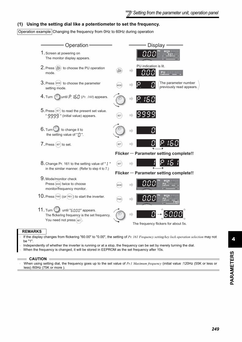
Setting from the parameter unit, operation panel
4PA
RA
MET
ERS
(1) Using the setting dial like a potentiometer to set the frequency.Operation example Changing the frequency from 0Hz to 60Hz during operation
REMARKS⋅ If the display changes from flickering "60.00" to "0.00", the setting of Pr. 161 Frequency setting/key lock operation selection may not
be "1".⋅ Independently of whether the inverter is running or at a stop, the frequency can be set by merely turning the dial. ⋅ When the frequency is changed, it will be stored in EEPROM as the set frequency after 10s.
CAUTION⋅ When using setting dial, the frequency goes up to the set value of Pr.1 Maximum frequency (initial value :120Hz (55K or less or
less) /60Hz (75K or more ).
DisplayOperation
PU indication is lit.
Flicker ··· Parameter setting complete!!
7. Press to set.
The parameter number
previously read appears.
1. Screen at powering on
The monitor display appears.
2. Press to choose the PU operation
mode.
3. Press to choose the parameter
setting mode.
11. Turn until " " appears.
The flickering frequency is the set frequency.
You need not press .The frequency flickers for about 5s.
Flicker ··· Parameter setting complete!!
8. Change Pr. 161 to the setting value of " "
in the similar manner. (Refer to step 4 to 7.)
9. Mode/monitor check
Press twice to choose
monitor/frequency monitor.
10. Press (or ) to start the inverter.
4. Turn until (Pr. 160) appears.
5. Press to read the present set value.
" " (initial value) appears.
6. Turn to change it to
the setting value of " ".
249

Setting from the parameter unit, operation panel
(2) Disable the setting dial and key operation of the operation panel (Press [MODE] long (2s))⋅ Operation using the setting dial and key of the operation panel can be made invalid to prevent parameter change,
and unexpected start or frequency setting.
⋅ Set "10 or 11" in Pr. 161, then press for 2s to make the setting dial and key operation invalid.
⋅ When the setting dial and key operation are invalid, appears on the operation panel. If dial or key
operation is attempted while dial and key operation are invalid, appears (When dial or key is nottouched for 2s, monitor display appears. )
⋅ To make the setting dial and key operation valid again, press for 2s.
4.22.3 Buzzer control (Pr. 990)
The above parameters can be set when Pr. 160 User group read selection = "0". (Refer to page 175.)The above parameters allow its setting to be changed during operation in any operation mode even if "0" (initial value) is set in Pr. 77 Parameter write selection.
4.22.4 PU contrast adjustment (Pr. 991)
The above parameters are displayed as simple mode parameters only when the parameter unit (FR-PU04/FR-PU07) is connected. When the operation panel is connected, they can be set only when Pr. 160 User group read selection = "0". (Refer to page 175.)
REMARKS
⋅ Even if the setting dial and key operation are disabled, the monitor display is valid.
You can make the buzzer "beep" when you press key of the operation panel (FR-DU07) and parameter unit (FR-PU04/FR-PU07).
Parameter Number Name Initial Value Setting Range Description
990 PU buzzer control 10 Without buzzer1 With buzzer
Contrast adjustment of the LCD of the parameter unit (FR-PU04/FR-PU07) can be performed.Decreasing the setting value makes contrast light.
Parameter Number Name Initial Value Setting Range Description
991 PU contrast adjustment 58 0 to 630 : Light↓63: Dark
250

251
Parameter clear
4PA
RA
MET
ERS
4.23 Parameter clear
POINT
· Set "1" in Pr. CL parameter clear to initialize parameters. (Parameters are not cleared when "1" is set in Pr. 77Parameter write selection. In addition, calibration parameters are not cleared.)
Setting Description0 Not executed.
1Returns all parameters to the initial values except for calibration parameters, terminal function selection parameters, etc.Refer to the list of parameters on page 314 for availability of parameter clear.
and are displayed alternately ... Why?The inverter is not in the PU operation mode.
1. Press .
is lit and the monitor (4 digit LED) displays "0" (Pr. 79 = "0" (initial value)).2. Carry out operation from step 6 again.
1.Screen at powering on
The monitor display appears.
DisplayOperation
3.Press to choose the parameter
setting mode.
Flicker ··· Parameter setting complete!!
7.Press to set.
5.Press to read the present set value.
" "(initial value) appears.
PU indication is lit.2.Press to choose the PU operation
mode.
· Turn to read another parameter.
· Press twice to show the next parameter.
· Press to show the setting again.
4.Turn until " " (parameter clear)
appears.
6.Turn to change it to
the setting value " ".
The parameter
number read
previously appears.

252
All parameter clear
4.24 All parameter clear
POINT
· Set "1" in ALLC all parameter clear to initialize all parameters. (Parameters are not cleared when "1" is set in Pr.77 Parameter write selection.)
Setting Description0 Not executed.
1 All parameters return to the initial values. Refer to the list of parameters on page 314 for availability of parameter clear.
and are displayed alternately ... Why?The inverter is not in the PU operation mode.
1. Press .
is lit and the monitor (4 digit LED) displays "0" (Pr. 79 = "0" (initial value)).2. Carry out operation from step 6 again.
1.Screen at powering on
The monitor display appears.
DisplayOperation
3.Press to choose the parameter
setting mode.
Flicker ··· Parameter setting complete!!
7.Press to set.
5.Press to read the present set
value.
" "(initial value) appears.
PU indication is lit.2.Press to choose the PU operation
mode.
· Press to read another parameter.
· Press twice to show the next parameter.
· Press to show the setting again.
4.Turn until (all parameter
clear) appears.
6.Turn to change it to
the setting value " ".
The parameter
number read
previously appears.

Parameter copy and parameter verification
4PA
RA
MET
ERS
4.25 Parameter copy and parameter verification
4.25.1 Parameter copy
PCPY Setting Description0 Cancel1 Copy the source parameters to the operation panel.2 Write the parameters copied to the operation panel into the destination inverter.3 Verify parameters in the inverter and operation panel. (Refer to page 254.)
Parameter settings can be copied to multiple inverters.
REMARKS· When the copy destination inverter is not the FR-F700 series or parameter copy write is performed after parameter copy read is
stopped, "model error ( )" is displayed.· Refer to the parameter list on page 314 and later for availability of parameter copy.· When the power is turned off or an operation panel is disconnected, etc. during parameter copy write, perform write again or check the
values by parameter verification.
1.Connect the operation panel to the
copy source inverter.
• Connect it during a stop.
DisplayOperation
2.Press to choose the parameter
setting mode.
Flicker ··· Parameter copy complete!!
6.Press to copy the source parameters
to the operation panel.
4.Press to to read the present set value.
" "(initial value) appears.
Flicker ··· Parameter copy complete!!
9.Press to write the parameters copied to
the operation panel to the destination inverter.
3.Turn until (parameter copy)
appears.
5.Turn to change it to
the setting value " ".
The frequency flickers
for about 30s
The frequency flickers
for about 30s
About 30s later
10.When copy is completed,
" " and " " flicker.
11.After writing the parameter values to the copy
destination inverter, always reset the inverter,
e.g. switch power off once, before starting operation.
7.Connect the operation panel to the
copy source inverter.
8.After performing steps 2 to 5,
turn to change it to " ".
The parameter
number previously
read appears.
253

Parameter copy and parameter verification
4.25.2 Parameter verification
appears...Why? Parameter read error. Perform operation from step 3 again. appears...Why? Parameter write error. Perform operation from step 8 again.
and flicker alternatelyAppears when parameters are copied between the inverter of 55K or less and 75K or more.1. Set "0" in Pr. 160 User group read selection.2. Set the following setting (initial value) in Pr. 989 Parameter copy alarm release.
3. Reset Pr. 9, Pr. 30, Pr. 51, Pr. 52, Pr. 54, Pr. 56, Pr. 57, Pr. 70, Pr. 72, Pr. 80, Pr. 90, Pr. 158, Pr. 190 to Pr. 196, Pr. 557,Pr. 893.
Whether same parameter values are set in other inverters or not can be checked.
REMARKSWhen the copy destination inverter is not the FR-F700 series, "model error ( )" is displayed.
flickers ... Why?Set frequencies, etc. may be different. Check set frequencies.
55K or less 75K or morePr. 989 Setting 10 100
• Hold down to verify.
2.Screen at powering on
The monitor display appears.
DisplayOperation
7.Press to read the parameter setting
of the verified inverter to the operation panel.
1.Move the operation panel to the
inverter to be verified.
• Move it during a stop.
Flicker ··· Parameter verification complete!!
4.Turn until (parameter copy)
appears.
6.Turn to change it to the set value
" "(parameter copy verification mode).
8.If there is no difference, and
flicker to complete verification.
The frequency flickers
for about 30s
Flickering
• If different parameters exist, different
parameter numbers and flicker.
The parameter
number read
previously appears.
5.Press to read the present set
value.
" "(initial value) appears.
3.Press to choose the parameter
setting mode.
254

Check and clear of the faults history
4PA
RA
MET
ERS
4.26 Check and clear of the faults history(1) Check for the faults history
* The cumulative energization time and actual operation time are accumulated from 0 to 65535 hours, then cleared, and accumulated againfrom 0. When the operation panel (FR-DU07) is used, the time is displayed up to 65.53 (65530h) in the indication of 1h = 0.001, andthereafter, it is added up from 0.
Faults history
Monitor/frequency setting
[Operation panel is used
for operation]
Parameter setting
[Parameter setting change]
[Operation for displaying faults history]
Eight past faults can be displayed with the setting dial.
(The latest fault is ended by ".".)
When no fault exists, is displayed.
Output current
Flickering
Output voltage
Flickering
Flickering
Flickering
Press the
setting
dial.
Press the
setting
dial.
Press the
setting
dial.
Energization time *
Faults history number
(The number of past faults is displayed.)
Flickering
Output frequency
Flickering Flickering
255

Check and clear of the faults history
(2) Clearing procedure
POINT
· The faults history can be cleared by setting "1" in Er.CL Faults history clear.
1.Screen at powering on
The monitor display appears.
DisplayOperation
2.Press to choose the parameter
setting mode.
3.Turn until (faults history clear)
appears.
Flicker ··· Faults history clear complete!!
6.Press to set.
4.Press to read the present set value.
" "(initial value) appears.
· Press to show the setting again.
· Press twice to show the next parameter.
· Press to read another parameter.
5.Turn to change
it to the setting value " ".
The parameter
number previously
read appears.
256

5
PROTECTIVE FUNCTIONS3
4
5
6
1
2
This chapter describes the basic "PROTECTIVE FUNCTION" foruse of this product.Always read the instructions before using the equipment.
5.1 Reset method of protective function........................2585.2 List of fault or alarm display ....................................2595.3 Causes and corrective actions ................................2605.4 Correspondences between digital and actual
characters ...............................................................2715.5 Check first when you have a trouble .......................272
2577

Reset method of protective function
When a fault occurs in the inverter, the inverter trips and the PU display automatically changes to any of the followingfault or alarm indications.If the fault does not correspond to any of the following faults or if you have any other problem, please contact your salesrepresentative or distributor.• Retention of fault output signal.................When the magnetic contactor (MC) provided on the input side of the
inverter is opened when a fault occurs, the inverter's control power will belost and the fault output will not be held.
• Fault or alarm indication ...........................When a fault or alarm occurs, the operation panel display automaticallyswitches to the fault or alarm indication
• Resetting method .....................................When a fault occurs, the inverter output is kept stopped. Unless reset,therefore, the inverter cannot restart. (Refer to page 258.)
• When any fault occurs, take the appropriate corrective action, then reset the inverter, and resume operation.Not doing so may lead to the inverter fault and damage.
Inverter fault or alarm indications are roughly divided as below.
(1) Error messageA message regarding operational fault and setting fault by the operation panel (FR-DU07) and parameter unit (FR-PU04 /FR-PU07) is displayed. The inverter does not trip.
(2) WarningsThe inverter does not trip even when a warning is displayed. However, failure to take appropriate measures willlead to a fault.
(3) AlarmThe inverter does not trip. You can also output an alarm signal by making parameter setting.
(4) FaultWhen a fault occurs, the inverter trips and a fault signal is output.
5.1 Reset method of protective function(1) Resetting the inverterThe inverter can be reset by performing any of the following operations. Note that the internal thermal integrated valueof the electronic thermal relay function and the number of retries are cleared (erased) by resetting the inverter.Inverter recovers about 1s after the reset is released.
Operation 1: ..... Using the operation panel, press to reset the inverter.(This may only be performed when a fault occurs. (Refer to page 264 forfault.))
Operation 2:...... Switch OFF the power once, then switch it ON again after the indicatorof the operation panel turns OFF.
Operation 3: ..... Turn on the reset signal (RES) for more than 0.1s. (If the RES signal iskept on, "Err." appears (flickers) to indicate that the inverter is in a resetstatus.)
ON
OFF
Inverter
RES
SD
258

List of fault or alarm display
5
PRO
TEC
TIVE
FU
NC
TIO
NS
5.2 List of fault or alarm display
* If an error occurs when using the FR-PU04/FR-PU07, "Fault 14" isdisplayed on the FR-PU04/FR-PU07.
Operation Panel Indication Name Refer
to
Err
or m
essa
ge
E--- Faults history 255
HOLD Operation panel lock 260
Er1 to 4 Parameter write error 260
rE1 to 4 Copy operation error 260
Err. Error 261
War
ning
s
OL Stall prevention (overcurrent) 262
oL Stall prevention (overvoltage) 262
RB Regenerative brake prealarm 263
TH Electronic thermal relay function prealarm 263
PS PU stop 262
MT Maintenance signal output 263
CP Parameter copy 263
Alar
m
FN Fan alarm 263
Faul
t
E.OC1 Overcurrent trip during acceleration 264
E.OC2 Overcurrent trip during constant speed 264
E.OC3 Overcurrent trip during deceleration or stop 264
E.OV1 Regenerative overvoltage trip during acceleration 265
E.OV2 Regenerative overvoltage trip during constant speed 265
E.OV3 Regenerative overvoltage trip during deceleration or stop 265
E.THT Inverter overload trip(electronic thermal relay function) 265
E.THM Motor overload trip(electronic thermal relay function) 266
E.FIN Fin overheat 266
E.IPF Instantaneous power failure 266
E.BE Brake transistor alarm detection/internal circuit fault 266
E.UVT Undervoltage 267
E.ILF* Input phase loss 267
E.OLT Stall prevention 267
to
to
Faul
t
E.GF Output side earth (ground) fault overcurrent 267
E.LF Output phase loss 267
E.OHT External thermal relay operation *2
267
E.PTC* PTC thermistor operation 268
E.OPT Option fault 268
E.OP1 Communication option fault 268
E. 1 Option fault 268
E.PE Parameter storage device fault 268
E.PUE PU disconnection 269
E.RET Retry count excess 269
E.PE2* Parameter storage device fault 269
//
E. 5 / E. 6 / E. 7 /
E.CPU
CPU fault 269
E.CTEOperation panel power supply short circuit, RS-485 terminal power supply short circuit
269
E.P24 24VDC power output short circuit 270
E.CDO* Output current detection value exceeded 270
E.IOH* Inrush current limit circuit fault 270
E.SER* Communication fault (inverter) 270
E.AIE* Analog input fault 270
E.PID* PID signal fault 270
E.13 Internal circuit fault 271
Operation Panel Indication Name Refer
to
259

Causes and corrective actions
5.3 Causes and corrective actions(1) Error Message
A message regarding operational troubles is displayed. Output is not shut off.Operation Panel
Indication HOLD
Name Operation panel lock
Description Operation lock mode is set. Operation other than is invalid. (Refer to page 250.)
Check point --------------
Corrective action Press for 2s to release lock.
Operation Panel Indication Er1
Name Write disable error
Description
1. You attempted to make parameter setting when Pr. 77 Parameter write selection has been set to disable parameter write.
2. Frequency jump setting range overlapped.3. Adjustable 5 points V/F settings overlapped4. The PU and inverter cannot make normal communication
Check point
1. Check the setting of Pr. 77 Parameter write selection (Refer to page 174.)2. Check the settings of Pr. 31 to 36 (frequency jump). (Refer to page 83.)3. Check the settings of Pr. 100 to Pr. 109 (Adjustable 5 points V/F). (Refer to page 87.)4. Check the connection of the PU and inverter.
Operation Panel Indication Er2
Name Write error during operation
Description When parameter write was performed during operation with a value other than "2" (writing is enabled independently of operating status in any operation mode) is set in Pr. 77 and the STF (STR) is on.
Check point 1. Check the Pr. 77 setting. (Refer to page 174.)2. Check that the inverter is not operating.
Corrective action 1. Set "2" in Pr. 77.2. After stopping operation, make parameter setting.
Operation Panel Indication Er3
Name Calibration errorDescription Analog input bias and gain calibration values are too close.Check point Check the settings of C3, C4, C6 and C7 (calibration functions). (Refer to page 167.)
Operation Panel Indication Er4
Name Mode designation error
Description· You attempted to make parameter setting in the NET operation mode when Pr. 77 is not "2".· If a parameter write was performed when the command source is not at the operation panel (FR-
DU07).
Check point1. Check that operation mode is "PU operation mode".2. Check the Pr. 77 setting. (Refer to page 174.)3. Check the Pr. 551 setting.
Corrective action
1. After setting the operation mode to the "PU operation mode", make parameter setting. (Refer to page 174.)
2. After setting "2" in Pr. 77, make parameter setting.3. Set Pr.551 = "2 (initial setting)". (Refer to page 186.)
Operation Panel Indication rE1
Name Parameter read errorDescription An error occurred in the EEPROM on the operation panel side during parameter copy reading.Check point --------------
Corrective action · Make parameter copy again. (Refer to page 253.)· Check for an operation panel (FR-DU07) failure. Please contact your sales representative.
260

Causes and corrective actions
5
PRO
TEC
TIVE
FU
NC
TIO
NS
Operation Panel Indication rE2
Name Parameter write error
Description 1. You attempted to perform parameter copy write during operation.2. An error occurred in the EEPROM on the operation panel side during parameter copy writing.
Check point Is the FWD or REV LED of the operation panel (FR-DU07) lit or flickering?
Corrective action 1. After stopping operation, make parameter copy again. (Refer to page 253.)2. Check for an operation panel (FR-DU07) failure. Please contact your sales representative.
Operation Panel Indication rE3
Name Parameter verification error
Description 1. Data on the operation panel side and inverter side are different.2. An error occurred in the EEPROM on the operation panel side during parameter verification.
Check point Check for the parameter setting of the source inverter and inverter to be verified.
Corrective action1. Press to continue verification.
Make parameter verification again. (Refer to page 254.)2. Check for an operation panel (FR-DU07) failure. Please contact your sales representative.
Operation Panel Indication rE4
Name Model error
Description 1. A different model was used for parameter write and verification during parameter copy.2. When parameter copy write is stopped after parameter copy read is stopped
Check point1. Check that the verified inverter is the same model.2. Check that the power is not turned off or an operation panel is not disconnected, etc. during
parameter copy read.
Corrective action 1. Use the same model (FR-F700 series) for parameter copy and verification.2. Perform parameter copy read again.
Operation Panel Indication Err.
Description
1. The RES signal is on2. The PU and inverter cannot make normal communication (contact fault of the connector)3. When the voltage drops in the inverter's input side.4. When the control circuit power (R1/L11, S1/L21) and the main circuit power(R/L1, S/L2, T/L3) are
connected to a separate power, it may appear at turning on of the main circuit. It is not a fault.
Corrective action1. Turn off the RES signal.2. Check the connection of the PU and inverter.3. Check the voltage on the inverter's input side.
261

Causes and corrective actions
(2) WarningsWhen the protective function is activated, the output is not shut off.Operation Panel
Indication OL FR-PU04FR-PU07 OL
Name Stall prevention (overcurrent)
Description
During acceleration
When the output current of the inverter exceeds the stall prevention operation level (Pr. 22 Stall prevention operation level, etc.), this function stops the increase in frequency until the overload current decreases to prevent the inverter from resulting in overcurrent trip.When the overload current has decreased below stall prevention operation level, this function increases the frequency again.
During constant-speed operation
When the output current of the inverter exceeds the stall prevention operation level (Pr. 22 Stall prevention operation level, etc.), this function lowers the frequency until the overload current decreases to prevent overcurrent trip. When the overload current has decreased below stall prevention operation level, this function increases the frequency up to the set value.
During deceleration
When the output current of the inverter exceeds the stall prevention operation level (Pr. 22 Stall prevention operation level, etc.), this function stops the decrease in frequency until the overload current decreases to prevent the inverter from resulting in overcurrent trip.When the overload current has decreased below stall prevention operation level, this function decreases the frequency again.
Check point
1. Check that the Pr. 0 Torque boost setting is not too large.2. Check that the Pr. 7 Acceleration time and Pr. 8 Deceleration time settings are not too small.3. Check that the load is not too heavy.4. Are there any failure in peripheral devices?5. Check that the Pr. 13 Starting frequency is not too large.
· Check the motor for use under overload.6. Check that the Pr. 22 Stall prevention operation level is appropriate.
Corrective action
1. Increase or decrease the Pr. 0 Torque boost value by 1% and check the motor status. (Refer to page 74.)2. Set a larger value in Pr. 7 Acceleration time and Pr. 8 Deceleration time. (Refer to page 96.)3. Reduce the load weight.4. Try Simple magnetic flux vector control (Pr. 80).5. Change the Pr. 14 Load pattern selection setting.6. Set stall prevention operation current in Pr. 22 Stall prevention operation level. (The initial value is
120%.) The acceleration/deceleration time may change. Increase the stall prevention operation level with Pr. 22 Stall prevention operation level, or disable stall prevention with Pr. 156 Stall prevention operation selection. (Use Pr. 156 to set either operation continued or not at OL operation.)
Operation Panel Indication oL FR-PU04
FR-PU07 oL
Name Stall prevention (overcurrent)
Description During deceleration
· If the regenerative energy of the motor becomes excessive and exceeds the regenerative energy consumption capability, this function stops the decrease in frequency to prevent overvoltage trip. As soon as the regenerative energy has decreased, deceleration resumes.
· If the regenerative energy of the motor becomes excessive when regeneration avoidance function is selected (Pr. 882 = 1), this function increases the speed to prevent overvoltage trip. (Refer to page 174.)
Check point · Check for sudden speed reduction.· Regeneration avoidance function (Pr. 882 to Pr. 886) is being used? (Refer to page 238.)
Corrective action The deceleration time may change.Increase the deceleration time using Pr. 8 Deceleration time.
Operation Panel Indication PS FR-PU04
FR-PU07 PS
Name PU stop
Description Stop with of the PU is set in Pr. 75 Reset selection/disconnected PU detection/PU stop selection. (For Pr.
75, refer to page 172.)
Check point Check for a stop made by pressing of the operation panel.
Corrective action Turn the start signal off and release with .
262

Causes and corrective actions
5
PRO
TEC
TIVE
FU
NC
TIO
NS
(3) AlarmWhen an alarm occurs, the output is not shut off. You can also output an alarm signal by making parametersetting. (Set "98" in any of Pr. 190 to Pr. 196 (output terminal function selection). (Refer to page 121.)
Operation Panel Indication RB FR-PU04
FR-PU07 RB
Name Regenerative brake prealarm
Description
Appears if the regenerative brake duty reaches or exceeds 85% of the Pr. 70 Special regenerative brake duty value. When the setting of Pr. 70 Special regenerative brake duty is the initial value (Pr. 70 ="0"), this warning does not occur. If the regenerative brake duty reaches 100%, a regenerative overvoltage (E. OV_) occurs.The RBP signal can be simultaneously output with the [RB] display. For the terminal used for the RBP signal output, assign the function by setting "7" (positive logic) or "107" (negative logic) in any of Pr. 190 to Pr. 196 (output terminal function selection). (Refer to page 121)Appears only for the 75K or more.
Check point• Check that the brake resistor duty is not high.• Check that the Pr. 30 Regenerative function selection and Pr. 70 Special regenerative brake duty values are
correct.
Corrective action • Increase the deceleration time.• Check the Pr. 30 Regenerative function selection and Pr. 70 Special regenerative brake duty values.
Operation Panel Indication TH FR-PU04
FR-PU07 TH
Name Electronic thermal relay function prealarm
Description
Appears if the cumulative value of the Pr. 9 Electronic thermal O/L relay reaches or exceeds 85% of the preset level. If it reaches 100% of the Pr. 9 Electronic thermal O/L relay setting, a motor overload trip (E. THM) occurs.The THP signal can be simultaneously output with the [TH] display. For the terminal used for the THP signal output, assign the function by setting "8" (positive logic) or "108" (negative logic) in any of Pr. 190 to Pr. 196 (output terminal function selection). (Refer to page 121)
Check point 1. Check for large load or sudden acceleration.2. Is the Pr. 9 Electronic thermal O/L relay setting is appropriate? (Refer to page 101.)
Corrective action 1. Reduce the load weight or the number of operation times.2. Set an appropriate value in Pr. 9 Electronic thermal O/L relay. (Refer to page 101.)
Operation Panel Indication MT FR-PU04 ————
FR-PU07 MTName Maintenance signal output
DescriptionIndicates that the cumulative energization time of the inverter has reached a given time.When the setting of Pr. 504 Maintenance timer alarm output set time is the initial value (Pr. 504 = "9999"), this protective function does not function.
Check point The Pr. 503 Maintenance timer setting is larger than the Pr. 504 Maintenance timer alarm output set time setting. (Refer to page 244.)
Corrective action Setting "0" in Pr. 503 Maintenance timer erases the signal.
Operation Panel Indication CP FR-PU04 ————
FR-PU07 CPName Parameter copy
Description Appears when parameters are copied between models with capacities of 55K or less and 75K or more.
Check point Resetting of Pr.9, Pr.30, Pr.51, Pr.52, Pr.54, Pr.56, Pr.57, Pr.70, Pr.72, Pr.80, Pr.90, Pr.158, Pr.190 to Pr.196, Pr.557 and Pr.893 is necessary.
Corrective action Set the initial value in Pr. 989 Parameter copy alarm release.
Operation Panel Indication FN FR-PU04
FR-PU07 FN
Name Fan alarm
Description For the inverter that contains a cooling fan, appears on the operation panel when the cooling fan stops due to a fault or different operation from the setting of Pr. 244 Cooling fan operation selection.
Check point Check the cooling fan for an alarm.Corrective action Check for fan failure. Please contact your sales representative.
263

Causes and corrective actions
(4) FaultWhen a fault occurs, the inverter trips and a fault signal is output.
Operation Panel Indication E.OC1 FR-PU04
FR-PU07 OC During Acc
Name Overcurrent trip during acceleration
Description When the inverter output current reaches or exceeds approximately 170% of the rated current during acceleration, the protective circuit is activated to stop the inverter output.
Check point
1. Check for sudden acceleration.2. Check that the downward acceleration time is not long in vertical lift application.3. Check for output short circuit.4. Check that the Pr. 3 Base frequency setting is not 60Hz when the motor rated frequency is 50Hz.5. Check that stall prevention operation is correct.6. Check that the regeneration is not performed frequently. (Check that the output voltage becomes
larger than the V/F reference voltage at regeneration and overcurrent occurs due to the highvoltage.)
Corrective action
1. Increase the acceleration time.(Shorten the downward acceleration time in vertical lift application.)
2. When "E.OC1" is always lit at starting, disconnect the motor once and start the inverter.If "E.OC1" is still lit, contact your sales representative.
3. Check the wiring to make sure that output short circuit does not occur.4. Set the Pr. 3 Base frequency to 50Hz. (Refer to page 84.)5. Perform a correct stall prevention operation. (Refer to page 77.)6. Set base voltage (rated voltage of the motor, etc.) in Pr. 19 Base frequency voltage. (Refer to page
84.)
Operation Panel Indication E.OC2 FR-PU04
FR-PU07 Stedy Spd OC
Name Overcurrent trip during constant speed
Description When the inverter output current reaches or exceeds approximately 170% of the rated current during constant speed operation, the protective circuit is activated to stop the inverter output.
Check point1. Check for sudden load change.2. Check for output short circuit.3. Check that stall prevention operation is correct.
Corrective action
1. Keep load stable.2. Check the wiring to avoid output short circuit.3. Check that stall prevention operation setting is correct.
(Refer to page 77.)
Operation Panel Indication E.OC3 FR-PU04
FR-PU07 OC During Dec
Name Overcurrent trip during deceleration or stop
DescriptionWhen the inverter output current reaches or exceeds approximately 170% of the rated inverter current during deceleration (other than acceleration or constant speed), the protective circuit is activated to stop the inverter output.
Check point
1. Check for sudden speed reduction.2. Check for output short circuit.3. Check for too fast operation of the motor's mechanical brake.4. Check that stall prevention operation setting is correct.
Corrective action
1. Increase the deceleration time.2. Check the wiring to avoid output short circuit.3. Check the mechanical brake operation.4. Check that stall prevention operation setting is correct.
(Refer to page 77.)
264

Causes and corrective actions
5
PRO
TEC
TIVE
FU
NC
TIO
NS
Operation Panel Indication E.OV1 FR-PU04
FR-PU07 OV During Acc
Name Regenerative overvoltage trip during acceleration
DescriptionIf regenerative energy causes the inverter's internal main circuit DC voltage to reach or exceed the specified value, the protective circuit is activated to stop the inverter output. The circuit may also be activated by a surge voltage produced in the power supply system.
Check point 1. Check for too slow acceleration. (e.g. during descending acceleration with lifting load)2. Check that the Pr. 22 Stall prevention operation level is not lower than the no load current.
Corrective action
1. · Decrease the acceleration time.· Use regeneration avoidance function (Pr. 882 to Pr. 886).
(Refer to page 238.)2. Set a value larger than the no load current in Pr. 22 Stall prevention operation level.
Operation Panel Indication E.OV2 FR-PU04
FR-PU07 Stedy Spd OV
Name Regenerative overvoltage trip during constant speed
DescriptionIf regenerative energy causes the inverter's internal main circuit DC voltage to reach or exceed the specified value, the protective circuit is activated to stop the inverter output. The circuit may also be activated by a surge voltage produced in the power supply system.
Check point 1. Check for sudden load change.2. Check that the Pr. 22 Stall prevention operation level is not lower than the no load current.
Corrective action
1. · Keep load stable.· Use regeneration avoidance function (Pr. 882 to Pr. 886).
(Refer to the page 238.)· Use the brake unit or power regeneration common converter (FR-CV) as required.
2. Set a value larger than the no load current in Pr. 22 Stall prevention operation level.
Operation Panel Indication E.OV3 FR-PU04
FR-PU07 OV During Dec
Name Regenerative overvoltage trip during deceleration or stop
DescriptionIf regenerative energy causes the inverter's internal main circuit DC voltage to reach or exceed the specified value, the protective circuit is activated to stop the inverter output. The circuit may also be activated by a surge voltage produced in the power supply system.
Check point Check for sudden speed reduction.
Corrective action
· Increase the deceleration time. (Set the deceleration time which matches the moment of inertia of the load)· Longer the brake cycle.· Use regeneration avoidance function (Pr. 882 to Pr. 886). (Refer to the page 238.)· Use the brake unit or power regeneration common converter (FR-CV) as required.
Operation Panel Indication E.THT FR-PU04
FR-PU07 Inv. Overload
Name Inverter overload trip (electronic thermal relay function) *1
DescriptionIf a current not less than 120% of the rated output current flows and overcurrent trip does not occur (170% or less), the electronic thermal relay activates to stop the inverter output in order to protect the output transistors. (Overload capacity 120% 60s inverse-time characteristic)
Check point
· Check that acceleration/deceleration time is not too short.· Check that torque boost setting is not too large (small).· Check that load pattern selection setting is appropriate for the load pattern of the using machine.· Check the motor for use under overload.
Corrective action
· Increase acceleration/deceleration time.· Adjust the torque boost setting.· Set the load pattern selection setting according to the load pattern of the using machine.· Reduce the load weight.
*1 Resetting the inverter initializes the internal thermal integrated data of the electronic thermal relay function.
265

Causes and corrective actions
Operation Panel Indication E.THM FR-PU04
FR-PU07 Motor Ovrload
Name Motor overload trip (electronic thermal relay function) *1
Description
The electronic thermal relay function in the inverter detects motor overheat due to overload or reduced cooling capability during constant-speed operation and pre-alarm (TH display) is output when the integrated value reaches 85% of the Pr. 9 Electronic thermal O/L relay setting and the protection circuit is activated to stop the inverter output when the integrated value reaches the specified value. When running a special motor such as a multi-pole motor or multiple motors, provide a thermal relay on the inverter output side since such motor(s) cannot be protected by the electronic thermal relay function.
Check point1. Check the motor for use under overload.2. Check that the setting of Pr. 71 Applied motor for motor selection is correct. (Refer to page 105.)3. Check that stall prevention operation setting is correct.
Corrective action1. Reduce the load weight.2. For a constant-torque motor, set the constant-torque motor in Pr. 71 Applied motor.3. Check that stall prevention operation setting is correct. (Refer to page 77.)
*1 Resetting the inverter initializes the internal thermal integrated data of the electronic thermal relay function.
Operation Panel Indication E.FIN FR-PU04
FR-PU07 H/Sink O/Temp
Name Fin overheat
Description
If the heatsink overheats, the temperature sensor is actuated to stop the inverter output.The FIN signal can be output when the temperature becomes approximately 85% of the heatsink overheat protection operation temperature.For the terminal used for the FIN signal output, assign the function by setting "26" (positive logic) or "126" (negative logic) in any of Pr. 190 to Pr. 196 (output terminal function selection). (Refer to page 121)
Check point1. Check for too high surrounding air temperature.2. Check for heatsink clogging.3. Check that the cooling fan is stopped. (Check that is displayed on the operation panel.)
Corrective action1. Set the surrounding air temperature to within the specifications.2. Clean the heatsink.3. Replace the cooling fan.
Operation Panel Indication E.IPF FR-PU04
FR-PU07 Inst. Pwr. Loss
Name Instantaneous power failure
Description
If a power failure occurs for longer than 15ms (this also applies to inverter input shut-off), the instantaneous power failure protective function is activated to trip the inverter in order to prevent the control circuit from malfunctioning. If a power failure persists for longer than 100ms, the fault output is not provided, and the inverter restarts if the start signal is on upon power restoration. (The inverter continues operating if an instantaneous power failure is within 15ms.) In some operating status (load magnitude, acceleration/deceleration time setting, etc.), overcurrent or other protection may be activated upon power restoration.When instantaneous power failure protection is activated, the IPF signal is output. (Refer to page 141)
Check point Find the cause of instantaneous power failure occurrence.
Corrective action· Remedy the instantaneous power failure.· Prepare a backup power supply for instantaneous power failure.· Set the function of automatic restart after instantaneous power failure (Pr. 57). (Refer to page
141.)
Operation Panel Indication E.BE FR-PU04
FR-PU07 Br. Cct. Fault
Name Brake transistor alarm detection/internal circuit fault
Description
This function stops the inverter output if a fault occurs in the brake circuit, e.g. damaged brake transistors when using functions of the 75K or more.In this case, the inverter must be powered off immediately.For the 55K or less, it appears when an internal circuit error occurred.
Check point· Reduce the load inertia.· Check that the frequency of using the brake is proper.· Check that the brake resistor selected is correct.
Corrective actionFor the 75K or more, when the protective function is activated even if the above measures are taken, replace the brake unit with a new one.For the 55K or less, replace the inverter.
266

Causes and corrective actions
5
PRO
TEC
TIVE
FU
NC
TIO
NS
Operation Panel Indication E.UVT FR-PU04
FR-PU07 Under Voltage
Name Undervoltage
Description
If the power supply voltage of the inverter decreases, the control circuit will not perform normal functions.In addition, the motor torque will be insufficient and/or heat generation will increase. To prevent this, if the power supply voltage decreases below about 150V (300VAC for the 400V class), this function stops the inverter output.When a jumper is not connected across P/+-P1, the undervoltage protective function is activated.When undervoltage protection is activated, the IPF signal is output. (Refer to page 141)
Check point 1. Check for start of large-capacity motor.2. Check that a jumper or DC reactor is connected across terminals P/+-P1.
Corrective action1. Check the power supply system equipment such as the power supply.2. Connect a jumper or DC reactor across terminals P/+-P1.3. If the problem still persists after taking the above measure, please contact your sales representative.
Operation Panel Indication E.ILF FR-PU04 Fault 14
FR-PU07 Input phase lossName Input phase loss
DescriptionThis fault is output when function valid setting (=1) is set in Pr. 872 Input phase loss protection selection and one phase of the three phase power input is lost. When the setting of Pr. 872 Input phase loss protection selection is the initial value (Pr. 872 = "0"), this fault does not occur. (Refer to page 151.)
Check point Check for a break in the cable for the three-phase power supply input.
Corrective action· Wire the cables properly.· Repair a break portion in the cable.· Check the Pr. 872 Input phase loss protection selection setting.
Operation Panel Indication E.OLT FR-PU04
FR-PU07Stll Prev STP ( OL shown during stall prevention operation)
Name Stall prevention
Description If the frequency has fallen to 0.5Hz by stall prevention operation and remains for 3s, a fault (E.OLT) appears and trips the inverter. OL appears while stall prevention is being activated.
Check point · Check the motor for use under overload. (Refer to page 78.)Corrective action · Reduce the load weight.
Operation Panel Indication E.GF FR-PU04
FR-PU07 Ground Fault
Name Output side earth (ground) fault overcurrent
Description This function stops the inverter output if an earth (ground) fault overcurrent flows due to an earth (ground) fault that occurred on the inverter's output (load) side.
Check point Check for an earth (ground) fault in the motor and connection cable.Corrective action Remedy the earth (ground) fault portion.
Operation Panel Indication E.LF FR-PU04 E. LFFR-PU07
Name Output phase loss
Description This function stops the inverter output if one of the three phases (U, V, W) on the inverter's output side (load side) is lost.
Check point · Check the wiring (Check that the motor is normal.)· Check that the capacity of the motor used is not smaller than that of the inverter.
Corrective action · Wire the cables properly.· Check the Pr. 251 Output phase loss protection selection setting.
Operation Panel Indication E.OHT FR-PU04
FR-PU07 OH Fault
Name External thermal relay operation
DescriptionIf the external thermal relay provided for motor overheat protection, or the internally mounted temperature relay in the motor, etc. switches on (contacts open), the inverter output is stopped.Functions when "7" (OH signal) is set to any of Pr. 178 to Pr. 189 (input terminal function selection). When the initial value (without OH signal assigned) is set, this protective function does not function.
Check point· Check for motor overheating.· Check that the value of 7 (OH signal) is set correctly in any of Pr. 178 to Pr. 189 (input terminal function
selection).
Corrective action · Reduce the load and operating duty.· Even if the relay contacts are reset automatically, the inverter will not restart unless it is reset.
267

Causes and corrective actions
Operation Panel Indication E.PTC FR-PU04 Fault 14
FR-PU07 PTC activatedName PTC thermistor operation
Description
Trips when the motor overheat status is detected for 10s or more by the external PTC thermistor input connected to the terminal AU.This fault functions when "63" is set in Pr. 184 AU terminal function selection and AU/PTC switchover switch is set in PTC side. When the initial value (Pr. 184 = "4") is set, this protective function does not function.
Check point· Check the connection between the PTC thermistor switch and thermal relay protector.· Check the motor for operation under overload.· Is valid setting ( = 63) selected in Pr. 184 AU terminal function selection ? (Refer to page 104, 115.)
Corrective action Reduce the load weight.
Operation Panel Indication E.OPT FR-PU04
FR-PU07 Option Fault
Name Option fault
DescriptionAppears when the AC power supply is connected to the terminal R/L1, S/L2, T/L3 accidentally when a high power factor converter is connected. Appears when the switch for the manufacturer setting of the plug-in option is changed.
Check point· Check that the AC power supply is not connected to the terminal R/L1, S/L2, T/L3 when a high
power factor converter (FR-HC, MT-HC) or power regeneration common converter (FR-CV) is connected.
Corrective action
· Check the parameter (Pr. 30) setting and wiring.· The inverter may be damaged if the AC power supply is connected to the terminal R/L1, S/L2, T/L3
when a high power factor converter is connected. Please contact your sales representative.· Return the switch for the manufacturer setting of the plug-in option to the initial status. (Refer to
instruction manual of each option)
Operation Panel Indication E.OP1 FR-PU04
FR-PU07 Option 1 Fault
Name Communication option faultDescription Stops the inverter output when a communication line fault occurs in the communication option.
Check point· Check for a wrong option function setting and operation.· Check that the plug-in option is plugged into the connector securely.· Check for a break in the communication cable.· Check that the terminating resistor is fitted properly.
Corrective action· Check the option function setting, etc.· Connect the plug-in option securely.· Check the connection of communication cable.
Operation Panel Indication E. 1 FR-PU04
FR-PU07 Fault 1
Name Option fault
DescriptionStops the inverter output if a contact fault or the like of the connector between the inverter and communication option occurs.Appears when the switch for the manufacturer setting of the plug-in option is changed.
Check point 1. Check that the plug-in option is plugged into the connector securely.2. Check for excess electrical noises around the inverter.
Corrective action
1. Connect the plug-in option securely.2. Take measures against noises if there are devices producing excess electrical noises around the
inverter.If the problem still persists after taking the above measure, please contact your sales representative or distributor.
3. Return the switch position for the manufacturer setting of the plug-in option to the initial status. (Refer to instruction manual of each option)
Operation Panel Indication E.PE FR-PU04
FR-PU07 Corrupt Memry
Name Parameter storage device fault (control circuit board)Description Trips when a fault occurred in the parameter stored. (EEPROM failure)Check point Check for too many number of parameter write times.
Corrective actionPlease contact your sales representative.When performing parameter write frequently for communication purposes, set "1" in Pr. 342 to enable RAM write. Note that powering off returns the inverter to the status before RAM write.
268

Causes and corrective actions
5
PRO
TEC
TIVE
FU
NC
TIO
NS
Operation Panel Indication E.PE2 FR-PU04 Fault 14
FR-PU07 PR storage alarmName Parameter storage device fault (main circuit board)
Description Trips when a fault occurred in the parameter stored. (EEPROM failure)Check point ——————
Corrective action Please contact your sales representative.
Operation Panel Indication E.PUE FR-PU04
FR-PU07 PU Leave Out
Name PU disconnection
Description
· This function stops the inverter output if communication between the inverter and PU is suspended, e.g. the operation panel and parameter unit is disconnected, when "2", "3", "16" or "17" was set in Pr. 75 Reset selection/disconnected PU detection/PU stop selection.
· This function stops the inverter output when communication errors occurred consecutively for more than permissible number of retries when a value other than "9999" is set in Pr. 121 Number of PU communication retries during the RS-485 communication with the PU connector.
· This function stops the inverter output if communication is broken for the period of time set in Pr. 122 PU communication check time interval during the RS-485 communication with the PU connector.
Check point · Check that the FR-DU07 or parameter unit (FR-PU04/FR-PU07) is fitted tightly.· Check the Pr. 75 setting.
Corrective action Fit the FR-DU07 or parameter unit (FR-PU04/FR-PU07) securely.
Operation Panel Indication E.RET FR-PU04
FR-PU07 Retry No Over
Name Retry count excess
DescriptionIf operation cannot be resumed properly within the number of retries set, this function trips the inverter.Functions only when Pr. 67 Number of retries at fault occurrence is set. When the initial value (Pr. 67 = "0") is set, this fault does not occur.
Check point Find the cause of fault occurrence.Corrective action Eliminate the cause of the fault preceding this error indication.
Operation Panel Indication
E. 5
FR-PU04FR-PU07
Fault 5
E. 6 Fault 6
E. 7 Fault 7
E.CPU CPU Fault
Name CPU faultDescription Stops the inverter output if the communication fault of the built-in CPU occurs.Check point Check for devices producing excess electrical noises around the inverter.
Corrective action· Take measures against noises if there are devices producing excess electrical noises around the
inverter.· Please contact your sales representative.
Operation Panel Indication E.CTE FR-PU04 ————
FR-PU07 E.CTEName Operation panel power supply short circuit, RS-485 terminal power supply short circuit
Description
When the operation panel power supply (PU connector) is shorted, this function shuts off the power output and stops the inverter output. At this time, the operation panel (parameter unit) cannot be used and RS-485 communication from the PU connector cannot be made. When the internal power supply for RS-485 terminals are shorted, this function shuts off the power output.At this time, communication from the RS-485 terminals cannot be made.To reset, enter the RES signal or switch power off, then on again.
Check point 1. Check for a short circuit in the PU connector cable.2. Check that the RS-485 terminals are connected correctly.
Corrective action 1. Check the PU and cable.2. Check the connection of the RS-485 terminals
269

Causes and corrective actions
Operation Panel Indication E.P24 FR-PU04
FR-PU07 E.P24
Name 24VDC power output short circuit
DescriptionWhen the 24VDC power output from the PC terminal is shorted, this function shuts off the power output.At this time, all external contact inputs switch off. The inverter cannot be reset by entering the RES signal. To reset it, use the operation panel or switch power off, then on again.
Check point · Check for a short circuit in the PC terminal output.Corrective action · Remedy the earth (ground) fault portion.
Operation Panel Indication E.CDO FR-PU04 Fault 14
FR-PU07 OC detect levelName Output current detection value exceeded
Description
This functions stops the inverter output when the output current exceeds the setting of Pr.150 Output current detection level, or the output current falls below the setting of Pr.152 Zero current detection level. This function is active when Pr. 167 Output current detection operation selection is set to "1, 10, 11". When the initial value (Pr. 167 = "0") is set, this fault does not occur.
Check pointCheck the settings of Pr. 150 Output current detection level, Pr. 151 Output current detection signal delay time, Pr. 152 Zero current detection level, Pr. 153 Zero current detection time, Pr. 166 Output current detection signal retention time, Pr. 167 Output current detection operation selection. (Refer to page 126.)
Operation Panel Indication E.IOH FR-PU04 Fault 14
FR-PU07 Inrush overheatName Inrush current limit circuit fault
Description Trips when the resistor of the inrush current limit circuit overheats. The inrush current limit circuit fault
Check point
· Check that frequent power ON/OFF is not repeated.· Check that no meltdown is found in the primary side fuse (5A) in the power supply circuit of the
inrush current suppression circuit contactor (FR-F740-132K or more) or no fault is found in the power supply circuit of the contactor.
· Check that the power supply circuit of inrush current limit circuit contactor is not damaged.
Corrective action Configure a circuit where frequent power ON/OFF is not repeated.If the problem still persists after taking the above measure, please contact your sales representative.
Operation Panel Indication E.SER FR-PU04 Fault 14
FR-PU07 VFD Comm errorName Communication fault (inverter)
DescriptionThis function stops the inverter output when communication error occurs consecutively for more than permissible retry count when a value other than "9999" is set in Pr. 335 RS-485 communication retry count during RS-485 communication from the RS-485 terminals. This function also stops the inverter output if communication is broken for the period of time set in Pr. 336 RS-485 communication check time interval.
Check point Check the RS-485 terminal wiring.Corrective action Perform wiring of the RS-485 terminals properly.
Operation Panel Indication E.AIE FR-PU04 Fault 14
FR-PU07 Analog in errorName Analog input fault
Description Trips when 30mA or more is input or a voltage (7.5V or more) is input with the terminal 2/4 set to current input.
Check point Check the setting of Pr. 73 Analog input selection and Pr. 267 Terminal 4 input selection. (Refer to page 160.)
Corrective action Either give a frequency command by current input or set Pr. 73 Analog input selection or Pr. 267 Terminal 4 input selection to voltage input.
Operation Panel Indication E.PID FR-PU04 Fault 14
FR-PU07 FaultName PID signal fault
Description
If any of PID upper limit (FUP), PID lower limit (FDN), and PID deviation limit (Y48) turns ON during PID control, inverter shuts off the output. This function is active under the following parameter settings: Pr.554 PID signal operation selection ≠ "0,10", Pr.131 PID upper limit ≠ "9999", Pr.132 PID lower limit ≠ "9999", and Pr.553 PID deviation limit ≠ "9999". This protective function is not active in the initial setting (Pr.554 = "0", Pr.131 = "9999", Pr.132 = "9999", Pr.553 = "9999").
Check Point Check if the measured PID value is greater than the upper limit (Pr.131) or smaller than the lower limit (Pr.132). Check if the absolute PID deviation value is greater than the limit value (Pr.553).
Corrective Action Make correct settings for Pr.131 PID upper limit, Pr.132 PID lower limit, Pr.553 PID deviation limit. (Refer to page 221)
270

Correspondences between digital andactual characters
5
PRO
TEC
TIVE
FU
NC
TIO
NS
5.4 Correspondences between digital and actual charactersThere are the following correspondences between the actual alphanumeric characters and the digital charactersdisplayed on the operation panel.
Operation Panel Indication E.13 FR-PU04
FR-PU07 Fault 13
Name Internal circuit faultDescription Trips when an internal circuit error occurred.
Corrective action Please contact your sales representative.
CAUTION• If protective functions of E.ILF, E.PTC, E.PE2, E.CDO, E.IOH, E.SER, E.AIE, E.PID are activated when using the FR-PU04,
"Fault 14" appears.Also when the faults history is checked on the FR-PU04, the display is "E.14".
• If faults other than the above appear, contact your sales representative.
Actual Digital
0
1
2
3
4
5
6
7
8
9
Actual Digital
A
B
C
E
F
G
H
I
J
L
D
Actual Digital
M
N
O
o
P
T
U
V
r
-
S
271

Check first when you have a trouble
5.5 Check first when you have a trouble
5.5.1 Motor does not start
Checkpoints
Possible Cause CountermeasuresRefer
to page
Main Circuit
Appropriate power supply voltage is not applied.(Operation panel display is not provided.)
Power ON a moulded case circuit breaker (MCCB), an earth leakage circuit breaker (ELB), or a magnetic contactor (MC). —Check for the decreased input voltage, input phase loss, and wiring.If only the control power is ON when using a separate power source for the control circuit, turn ON the main circuit power.
24
Motor is not connected properly.
Check the wiring between the inverter and the motor.If commercial power supply-inverter switchover function is active, check the wiring of the magnetic contactor connected between the inverter and the motor.
16
The jumper across P/+ and P1 is disconnected.(55K or less)
Securely fit a jumper across P/+ and P1.When using a DC reactor (FR-HEL), remove the jumper across P/+ and P1, and then connect the DC reactor.
16
Input Signal
Start signal is not input.
Check the start command source, and input a start
signal.
PU operation mode: /
External operation mode : STF/STR signal
179
Both the forward and reverse rotation start signals (STF, STR) are input simultaneously.
Turn ON only one of the forward and reverse rotation start signals (STF or STR).If STF and STR signals are turned ON simultaneously in the initial setting, a stop command is given.
26
Frequency command is zero.(FWD or REV LED on the operation panel is flickering.)
Check the frequency command source and enter a frequency command.
179
AU signal is not ON when terminal 4 is used for frequency setting.(FWD or REV LED on the operation panel is flickering.)
Turn ON the AU signal.Turning ON the AU signal activates terminal 4 input.
160
Output stop signal (MRS) or reset signal (RES) is ON.(FWD or REV LED on the operation panel is flickering.)
Turn MRS or RES signal OFF.Inverter starts the operation with a given start command and a frequency command after turning OFF MRS or RES signal. Before turning OFF, ensure the safety.
141
CS signal is OFF when automatic restart after instantaneous power failure function is selected (Pr. 57 ≠ "9999").(FWD or REV LED on the operation panel is flickering. )
Turn ON the CS signal.Restart operation is enabled when restart after instantaneous power signal (CS) is ON.
141
Jumper connector of sink - source is wrongly selected.(FWD or REV LED on the operation panel is flickering.)
Check that the control logic switchover jumper connector is correctly installed.If it is not installed correctly, input signal is not recognized.
29
Voltage/current input switch is not correctly set for analog input signal (0 to 5V/0 to 10V, 4 to 20mA).(FWD or REV LED on the operation panel is flickering.)
Set Pr. 73, Pr. 267, and a voltage/current input switch correctly, then input an analog signal in accordance with the setting.
26
was pressed.
(Operation panel indication is (PS).)
During the External operation mode, check the method
of restarting from a input stop from PU.262
Two-wire or three-wire type connection is wrong.Check the connection.Connect STOP signal when three-wire type is used.
119
272

Check first when you have a trouble
5
PRO
TEC
TIVE
FU
NC
TIO
NS
Parameter Setting
Pr. 0 Torque boost setting is improper when V/F control is used.
Increase Pr. 0 setting by 0.5% increments while observing the rotation of a motor. If that makes no difference, decrease the setting.
74
Pr. 78 Reverse rotation prevention selection is set.Check the Pr. 78 setting.Set Pr. 78 when you want to limit the motor rotation to only one direction.
175
Pr. 79 Operation mode selection setting is wrong.Select the operation mode which corresponds with input methods of start command and frequency command.
177
Bias and gain (calibration parameter C2 to C7) settings are improper.
Check the bias and gain (calibration parameter C2 to C7) settings.
167
Pr. 13 Starting frequency setting is greater than the running frequency.
Set running frequency higher than Pr. 13.The inverter does not start if the frequency setting signal is less than the value set in Pr. 13.
98
Frequency settings of various running frequency (such as multi-speed operation) are zero.Especially, Pr. 1 Maximum frequency is zero.
Set the frequency command according to the application.Set Pr. 1 higher than the actual frequency used.
82
Pr. 15 Jog frequency setting is lower than Pr. 13 Starting frequency.
Set Pr. 15 Jog frequency higher than Pr. 13 Starting frequency.
90
Operation mode and a writing device do not match.Check Pr. 79, Pr. 338, Pr. 339, Pr. 550, Pr. 551, and select an operation mode suitable for the purpose.
177, 186
Start signal operation selection is set by the Pr. 250 Stop selection
Check Pr. 250 setting and connection of STF and STR signals.
119
Inverter decelerated to a stop when power failure deceleration stop function is selected.
When power is restored, ensure the safety, and turn OFF the start signal once, then turn ON again to restart.Inverter restarts when Pr. 261="2, 22".
145
Automatic restart after instantaneous power failure function or power failure stop function is activated.(Performing overload operation during input phase loss may cause voltage insufficiency, and that may result in detection of power failure.)
Set Pr. 872 Input phase loss protection selection = "1" (input phase failure protection active).Disable the automatic restart after instantaneous power failure function and power failure stop function.Reduce the load.Increase the acceleration time if the automatic restart after instantaneous power failure function or power failure stop function occurred during acceleration.
141, 145, 151
LoadLoad is too heavy. Reduce the load. —Shaft is locked. Inspect the machine (motor). —
Checkpoints
Possible Cause CountermeasuresRefer
to page
273

Check first when you have a trouble
5.5.2 Motor or machine is making abnormal acoustic noise When operating the inverter with the carrier frequency of 3kHz or more set in Pr. 72, the carrier frequency will automaticallydecrease if the output current of the inverter exceeds the value in parenthesis of the rated output current on page 294. Thismay cause the motor noise to increase. But it is not a fault.
5.5.3 Inverter generates abnormal noise
5.5.4 Motor generates heat abnormally
Checkpoints
Possible Cause CountermeasuresRefer
to page
Input signal Disturbance due to EMI when frequency command is
given from analog input (terminal 1, 2, 4).
Take countermeasures against EMI. 44
Parameter Setting
Increase the Pr. 74 Input filter time constant if steady operation cannot be performed due to EMI.
166
Parameter Setting
No carrier frequency noises (metallic noises) are generated.
In the initial setting, Pr. 240 Soft-PWM operation selection is enabled to change motor noise to an unoffending complex tone. Therefore, no carrier frequency noises (metallic noises) are generated.Set Pr. 240 = "0" to disable this function.
158
Resonance occurs. (output frequency)
Set Pr. 31 to Pr. 36 (Frequency jump).When it is desired to avoid resonance attributable to the natural frequency of a mechanical system, these parameters allow resonant frequencies to be jumped.
83
Resonance occurs. (carrier frequency)
Change Pr. 72 PWM frequency selection setting.Changing the PWM carrier frequency produces an effect on avoiding the resonance frequency of a mechanical system or a motor.
158
Gain adjustment during PID control is insufficient.
To stabilize the measured value, change the proportional band (Pr. 129) to a larger value, the integral time (Pr. 130) to a slightly longer time, and the differential time (Pr. 134) to a slightly shorter time.Check the calibration of set point and measured value.
221
OthersMechanical looseness
Adjust machine/equipment so that there is no mechanical looseness.
—
Contact the motor manufacturer.Motor Operating with output phase loss Check the motor wiring. —
Checkpoints
Possible Cause CountermeasuresRefer
to page
FanFan cover was not correctly installed when a cooling fan was replaced.
Install a fan cover correctly. 284
Checkpoints
Possible Cause CountermeasuresRefer
to page
MotorMotor fan is not working(Dust is accumulated.)
Clean the motor fan.Improve the environment.
—
Phase to phase insulation of the motor is insufficient. Check the insulation of the motor. —Main
CircuitThe inverter output voltage (U, V, W) are unbalanced.
Check the output voltage of the inverter.Check the insulation of the motor.
281
Parameter Setting
The Pr. 71 Applied motor setting is wrong. Check the Pr. 71 Applied motor setting. 105
— Motor current is large. Refer to "5.5.11 Motor current is too large" 277
274

Check first when you have a trouble
5
PRO
TEC
TIVE
FU
NC
TIO
NS
5.5.5 Motor rotates in the opposite direction
5.5.6 Speed greatly differs from the setting
5.5.7 Acceleration/deceleration is not smooth
Checkpoints
Possible Cause CountermeasuresRefer
to page
Main Circuit
Phase sequence of output terminals U, V and W is incorrect.
Connect phase sequence of the output cables (terminal U, V, W) to the motor correctly
16
Input signal
The start signals (forward rotation, reverse rotation) are connected improperly.
Check the wiring. (STF: forward rotation , STR: reverse rotation)
26
The polarity of the frequency command is negative during the polarity reversible operation set by Pr. 73 Analog input selection.
Check the polarity of the frequency command. 160
Checkpoints
Possible Cause CountermeasuresRefer
to page
Input signal
Frequency setting signal is incorrectly input. Measure the input signal level. —
The input signal lines are affected by external EMI.Take countermeasures against EMI such as using shielded wires for input signal lines.
46
Parameter Setting
Pr. 1, Pr. 2, Pr. 18, calibration parameter C2 to C7 settings are improper.
Check the settings of Pr. 1 Maximum frequency, Pr. 2 Minimum frequency, Pr. 18 High speed maximum frequency.
82
Check the calibration parameter C2 to C7 settings. 167Pr. 31 to Pr. 36 (frequency jump) settings are improper. Narrow down the range of frequency jump. 83
Load
Stall prevention function is activated due to a heavy load.
Reduce the load weight. —
Parameter Setting
Set Pr. 22 Stall prevention operation level higher according to the load. (Setting Pr. 22 too large may result in frequent overcurrent trip (E.OC ).)
77
Motor Check the capacities of the inverter and the motor. —
Checkpoints
Possible Cause CountermeasuresRefer
to page
Parameter Setting
Acceleration/deceleration time is too short. Increase acceleration/deceleration time. 96Torque boost (Pr. 0, Pr. 46) setting is improper under V/F control, so the stall prevention function is activated.
Increase/decrease Pr. 0 Torque boost setting value by 0.5% increments to the setting.
74
The base frequency does not match the motor characteristics.
For V/F control, set Pr. 3 Base frequency and Pr. 47 Second V/F (base frequency).
84
Regeneration avoidance operation is performedIf the frequency becomes unstable during regeneration avoidance operation, decrease the setting of Pr. 886 Regeneration avoidance voltage gain.
238
Load
Stall prevention function is activated due to a heavy load.
Reduce the load weight. —
Parameter Setting
Set Pr. 22 Stall prevention operation level higher according to the load. (Setting Pr. 22 too large may result in frequent overcurrent trip (E.OC ).)
77
Motor Check the capacities of the inverter and the motor. —
275

Check first when you have a trouble
5.5.8 Speed varies during operation
5.5.9 Operation mode is not changed properly
Checkpoints
Possible Cause CountermeasuresRefer
to page
Load Load varies during an operation. Select Simple magnetic flux vector control 75
Input signal
Frequency setting signal is varying. Check the frequency setting signal. —
The frequency setting signal is affected by EMI.
Set filter to the analog input terminal using Pr. 74 Input filter time constant.
166
Take countermeasures against EMI, such as using shielded wires for input signal lines.
46
Malfunction is occurring due to the undesirable current generated when the transistor output unit is connected.
Use terminal PC (terminal SD when source logic) as a common terminal to prevent a malfunction caused by undesirable current.
30
Multi-speed command signal is chattering. Take countermeasures to suppress chattering. —
Parameter Setting
Fluctuation of power supply voltage is too large.Change the Pr. 19 Base frequency voltage setting (about 3%) under V/F control.
84
Pr. 80 Motor capacity setting is improper for the capacities of the inverter and the motor for Simple magnetic flux vector control.
Check the Pr. 80 Motor capacity setting. 75
Wiring length is too long for V/F control, and a voltage drop occurs.
Adjust Pr. 0 Torque boost by increasing with 0.5% increments for low-speed operation.
74
Change to Simple magnetic flux vector control. 75
Hunting occurs by the generated vibration, for example, when structural rigidity at load side is insufficient.
Disable automatic control functions, such as energy saving operation, fast-response current limit function, regeneration avoidance function, Simple magnetic flux vector control and stall prevention.Adjust so that the control gain decreases and the level of safety increases.
—
Change Pr. 72 PWM frequency selection setting. 158
Checkpoints
Possible Cause CountermeasuresRefer
to page
Input signal
Start signal (STF or STR) is ON.Check that the STF and STR signals are OFF.When either is ON, the operation mode cannot be changed.
177
Parameter Setting
Pr. 79 setting is improper.
When Pr. 79 Operation mode selection setting is "0" (initial
value), the inverter is placed in the External operation
mode at input power ON. To switch to the PU operation
mode, press on the operation panel (press
when the parameter unit (FR-PU04/FR-PU07) is used) .
At other settings (1 to 4, 6, 7), the operation mode is
limited accordingly.
177
Operation mode and a writing device do not correspond.
Check Pr. 79, Pr. 338, Pr. 339, Pr. 550, Pr. 551, and select an operation mode suitable for the purpose.
, 177, 186
276

Check first when you have a trouble
5
PRO
TEC
TIVE
FU
NC
TIO
NS
5.5.10 Operation panel (FR-DU07) display is not operating
5.5.11 Motor current is too large
Checkpoints
Possible Cause CountermeasuresRefer
to page
Main Circuit,Control Circuit
Power is not input. Input the power. 14
Front cover
Operation panel is not properly connected to the inverter.
Check if the inverter front cover is installed securely.The inverter cover may not fit properly when using wires
whose size are 1.25mm2 or larger, or when using many wires, and this could cause a contact fault of the operation panel.
6
Checkpoints
Possible Cause CountermeasuresRefer
to page
Parameter Setting
Torque boost (Pr. 0, Pr. 46) setting is improper under V/F control, so the stall prevention function is activated.
Increase/decrease Pr. 0 Torque boost setting value by 0.5% increments to the setting.
74
V/F pattern is improper when V/F control is performed.(Pr. 3, Pr. 14, Pr. 19)
Set rated frequency of the motor to Pr. 3 Base frequency.Use Pr. 19 Base frequency voltage to set the base voltage (e.g. rated motor voltage).
84
Change Pr. 14 Load pattern selection according to the load characteristic.
86
Stall prevention function is activated due to a heavy load.
Reduce the load weight. —Set Pr. 22 Stall prevention operation level higher according to the load. (Setting Pr. 22 too large may result in frequent overcurrent trip (E.OC ).)
77
Check the capacities of the inverter and the motor. —
277

Check first when you have a trouble
5.5.12 Speed does not accelerate
5.5.13 Unable to write parameter setting
5.5.14 Power lamp is not lit
Checkpoints
Possible Cause CountermeasuresRefer
to page
Input signal
Start command and frequency command are chattering.Check if the start command and the frequency command are correct.
—
The wiring length used for analog frequency command is too long, and it is causing a voltage (current) drop.
Perform analog input bias/gain calibration. 167
Input signal lines are affected by external EMI.Take countermeasures against EMI, such as using shielded wires for input signal lines.
46
Parameter Setting
Pr. 1, Pr. 2, Pr. 18, calibration parameter C2 to C7 settings are improper.
Check the settings of Pr. 1 Maximum frequency and Pr. 2 Minimum frequency. If you want to run the motor at 120Hz or higher, set Pr. 18 High speed maximum frequency.
82
Check the calibration parameter C2 to C7 settings. 167Torque boost (Pr. 0, Pr. 46) setting is improper under V/F control, so the stall prevention function is activated.
Increase/decrease Pr. 0 Torque boost setting value by 0.5% increments so that stall prevention does not occur.
74
V/F pattern is improper when V/F control is performed.(Pr. 3, Pr. 14, Pr. 19)
Set rated frequency of the motor to Pr. 3 Base frequency.Use Pr. 19 Base frequency voltage to set the base voltage (e.g. rated motor voltage).
84
Change Pr. 14 Load pattern selection according to the load characteristic.
86
Stall prevention function is activated due to a heavy load.
Reduce the load weight. —Set Pr. 22 Stall prevention operation level higher according to the load. (Setting Pr. 22 too large may result in frequent overcurrent trip (E.OC ).)
77
Check the capacities of the inverter and the motor. —During PID control, output frequency is automatically controlled to make measured value = set point. 221
Checkpoints
Possible Cause CountermeasuresRefer
to page
Input signal
Operation is being performed (signal STF or STR is ON).
Stop the operation.When Pr. 77 = "0" (initial value), write is enabled only during a stop.
174
Parameter Setting
You are attempting to set the parameter in the External operation mode.
Choose the PU operation mode.Or, set Pr. 77 = "2" to enable parameter write regardless of the operation mode.
174
Parameter is disabled by the Pr. 77 Parameter write selection setting.
Check Pr. 77 Parameter write selection setting. 174
Key lock is activated by the Pr. 161 Frequency setting/key lock operation selection setting.
Check Pr. 161 Frequency setting/key lock operation selection setting.
248
Operation mode and a writing device do not correspond.
Check Pr. 79, Pr. 338, Pr. 339, Pr. 550, Pr. 551, and select an operation mode suitable for the purpose.
177, 186
Checkpoints
Possible Cause CountermeasuresRefer
to page
Main Circuit,Control Circuit
Wiring or installation is improper.Check for the wiring and the installation.Power lamp is lit when power supply is input to the control circuit (R1/L11, S1/L21).
16
278

6
PRECAUTIONS FOR MAINTENANCE AND INSPECTION3
4
5
6
1
2
This chapter describes the "PRECAUTIONS FOR MAINTENANCEAND INSPECTION" of this product.Always read the instructions before using the equipment.
6.1 Inspection item ........................................................2806.2 Measurement of main circuit voltages, currents and
powers.....................................................................288
2797

Inspection item
The inverter is a static unit mainly consisting of semiconductor devices. Daily inspection must be performed to preventany fault from occurring due to the adverse effects of the operating environment, such as temperature, humidity, dust,dirt and vibration, changes in the parts with time, service life, and other factors.
• Precautions for maintenance and inspectionFor some short time after the power is switched off, a high voltage remains in the smoothing capacitor. When accessingthe inverter for inspection, wait for at least 10 minutes after the power supply has been switched off, and then makesure that the voltage across the main circuit terminals P/+-N/− of the inverter is not more than 30VDC using a tester,etc.
6.1 Inspection item
6.1.1 Daily inspection
Basically, check for the following faults during operation.(1) Motor operation fault(2) Improper installation environment(3) Cooling system fault(4) Unusual vibration and noise(5) Unusual overheat and discoloration
6.1.2 Periodic inspectionCheck the areas inaccessible during operation and requiring periodic inspection.Consult us for periodic inspection.1) Check for cooling system fault...............Clean the air filter, etc.2) Tightening check and retightening.........The screws and bolts may become loose due to vibration, temperature
changes, etc.Tighten them according to the specified tightening torque. (Refer to page 20.)
3) Check the conductors and insulating materials for corrosion and damage.4) Measure insulation resistance.5) Check and change the cooling fan and relay.
280

Inspection item
6
PREC
AU
TIO
NS
FOR
MA
INTE
NA
NC
E A
ND
INSP
ECTI
ON
6.1.3 Daily and periodic inspection
*1 It is recommended to install a device to monitor voltage for checking the power supply voltage to the inverter.*2 One to two years of periodic inspection cycle is recommended. However, it differs according to the installation environment.
Consult us for periodic inspection.
Are
a of
In
spec
tion
Inspection Item Inspection Item
IntervalCorrective Action at Alarm Occurrence
Cust
omer
's
Chec
k
Dai
ly
Perio
dic
*2
General
Surrounding environment
Check the surrounding air temperature, humidity, dirt, corrosive gas, oil mist , etc Improve environment
Overall unit Check for unusual vibration and noise Check alarm location and retighten
Power supply voltage
Check that the main circuit voltages and control voltages are normal *1 Inspect the power supply
Main circuit
General
(1)Check with megger (across main circuit terminals and earth (ground) terminal). Contact the manufacturer
(2)Check for loose screws and bolts. Retighten(3)Check for overheat traces on the parts. Contact the manufacturer(4)Check for stain Clean
Conductors, cables(1)Check conductors for distortion.(2)Check cable sheaths for breakage and
deterioration (crack, discoloration, etc.)
Contact the manufacturer
Contact the manufacturer
Transformer/reactor Check for unusual odor and abnormal increase in whining sound.
Stop the device and contact the manufacturer.
Terminal block Check for damage. Stop the device and contact the manufacturer.
Smoothing aluminum electrolytic capacitor
(1)Check for liquid leakage. Contact the manufacturer(2)Check for safety valve projection and bulge. Contact the manufacturer(3)Visual check and judge by the life check of the
main circuit capacitor (Refer to page 282)
Relay/contactor Check that the operation is normal and no chatter is heard. Contact the manufacturer
Control circuit
protective circuit
Operation check
(1)Check that the output voltages across phases with the inverter operated alone is balanced Contact the manufacturer
(2)Check that no fault is found in protective and display circuits in a sequence protective operation test.
Contact the manufacturer
Par
ts c
heck
Overall(1)Check for unusual odor and discoloration. Stop the device and contact
the manufacturer.(2)Check for serious rust development Contact the manufacturer
Aluminum electrolytic capacitor
(1)Check for liquid leakage in a capacitor and deformation trance Contact the manufacturer
(2)Visual check and judge by the life check of the control circuit capacitor. (Refer to page 282.)
Cooling system
Cooling fan(1)Check for unusual vibration and noise. Replace the fan(2)Check for loose screws and bolts Retighten(3)Check for stain Clean
Heatsink(1)Check for clogging Clean(2)Check for stain Clean
Air filter, etc.(1)Check for clogging Clean or replace(2)Check for stain Clean or replace
DisplayIndication
(1)Check that display is normal. Contact the manufacturer(2)Check for stain Clean
Meter Check that reading is normal Stop the device and contact the manufacturer.
Load motor Operation check Check for vibration and abnormal increase in
operation noiseStop the device and contact the manufacturer.
281

Inspection item
6.1.4 Display of the life of the inverter partsThe self-diagnostic alarm is output when the life span of the control circuit capacitor, cooling fan, each parts of theinrush current limit circuit is near its end. It gives an indication of replacement time .
The life alarm output can be used as a guideline for life judgement.
Refer to page 241 to perform the life check of the inverter parts.
6.1.5 Checking the inverter and converter modules<Preparation>(1) Disconnect the external power supply cables (R/L1, S/L2, T/L3) and motor cables (U, V, W).(2) Prepare a tester. (Use 100Ω range.)
<Checking method>Change the polarity of the tester alternately at the inverter terminals R/L1, S/L2, T/L3, U, V, W, P/+ and N/−, and checkfor continuity.
<Module device numbers and terminals to be checked>
(Assumes the use of an analog meter.)
Parts Judgement levelMain circuit capacitor 85% of the initial capacityControl circuit capacitor Estimated 10% life remainingInrush current limit circuit Estimated 10% life remaining (Power on: 100,000 times left)Cooling fan Less than 50% of the predetermined speed
CAUTION1. Before measurement, check that the smoothing capacitor is discharged.2. At the time of discontinuity, due to the smoothing capacitor, the tester may not indicate ∞. At the time of continuity, the
measured value is several to several ten-of ohms depending on the module type, circuit tester type, etc. If all measuredvalues are almost the same, the modules are without fault.
Tester Polarity Measured Value
Tester Polarity Measured Value
Con
verte
r m
odul
e
D1R/L1 P/+ Discontinuity
D4R/L1 N/− Continuity
P/+ R/L1 Continuity N/− R/L1 Discontinuity
D2S/L2 P/+ Discontinuity
D5S/L2 N/− Continuity
P/+ S/L2 Continuity N/− S/L2 Discontinuity
D3T/L3 P/+ Discontinuity
D6T/L3 N/− Continuity
P/+ T/L3 Continuity N/− T/L3 Discontinuity
Inve
rter
mod
ule
TR1U P/+ Discontinuity
TR4U N/− Continuity
P/+ U Continuity N/− U Discontinuity
TR3V P/+ Discontinuity
TR6V N/− Continuity
P/+ V Continuity N/− V Discontinuity
TR5W P/+ Discontinuity
TR2W N/− Continuity
P/+ W Continuity N/− W Discontinuity
Converter module Inverter module
D1 D2 D3
D4 D5 D6
TR1 TR3 TR5
TR4 TR6 TR2
U
V
W
R/L1
S/L2
T/L3
C
P/+
N/−
282

Inspection item
6
PREC
AU
TIO
NS
FOR
MA
INTE
NA
NC
E A
ND
INSP
ECTI
ON
6.1.6 CleaningAlways run the inverter in a clean status.When cleaning the inverter, gently wipe dirty areas with a soft cloth immersed in neutral detergent or ethanol.
6.1.7 Replacement of partsThe inverter consists of many electronic parts such as semiconductor devices.The following parts may deteriorate with age because of their structures or physical characteristics, leading to reducedperformance or fault of the inverter. For preventive maintenance, the parts must be replaced periodically.Use the life check function as a guidance of parts replacement.
*1 Replacement years for when the yearly average surrounding air temperature is 40°C(without corrosive gas, flammable gas, oil mist, dust and dirt etc)
*2 Output current : 80% of the inverter rated current
CAUTIONDo not use solvent, such as acetone, benzene, toluene and alcohol, as they will cause the inverter surface paint to peel off.The display, etc. of the operation panel (FR-DU07) and parameter unit (FR-PU04/FR-PU07) are vulnerable to detergent andalcohol. Therefore, avoid using them for cleaning.
Part Name Standard Replacement Interval *1 DescriptionCooling fan 10 years Replace (as required)
Main circuit smoothing capacitor 10 years *2 Replace (as required)On-board smoothing capacitor 10 years Replace the board (as required)
Relays − as requiredFuse (185K or more) 10 years Replace the fuse (as required)
CAUTIONFor parts replacement, consult the nearest Mitsubishi FA Center.
283

Inspection item
(1) Cooling fanThe replacement interval of the cooling fan used for cooling the parts generating heat such as the main circuitsemiconductor is greatly affected by the surrounding air temperature. When unusual noise and/or vibration isnoticed during inspection, the cooling fan must be replaced immediately.
CAUTIONFor parts replacement, consult the nearest Mitsubishi FA Center.
Inverter Model Fan Type Units
F720
2.2K to 5.5K MMF-06F24ES-RP1 BKO-CA1638H01 17.5K to 15K MMF-08D24ES-RP1 BKO-CA1639H01 218.5K, 22K MMF-12D24DS-RP1 BKO-CA1619H01 1
30KMMF-06F24ES-RP1 BKO-CA1638H01 1MMF-12D24DS-RP1 BKO-CA1619H01 1
37K to 55K MMF-12D24DS-RP1 BKO-CA1619H01 275K to 110K MMF-12D24DS-RP1 BKO-CA1619H01 3
F740
3.7K, 5.5K MMF-06F24ES-RP1 BKO-CA1638H01 17.5K, 18.5K MMF-08D24ES-RP1 BKO-CA1639H01 222K, 30K MMF-12D24DS-RP1 BKO-CA1619H01 137K MMF-09D24TS-RP1 BKO-CA1640H01 245K to 75K
MMF-12D24DS-RP1 BKO-CA1619H012
90K to 160K 3185K, 220K
9LB1424H5H033
250K to 315K 4355K, 400K 5450K to 560K 9LB1424S5H04 6
The FR-F720-0.75K, 1.5K, FR-F740-0.75K to 2.2K are not provided with a cooling fan.
• Removal (FR-F720-2.2K to 110K, FR-F740-3.7K to 160K)1)Push the hooks from above and remove the fan cover.
2)Disconnect the fan connectors.3)Remove the fan.
* The number of cooling fans differs according to the inverter capacity. (Refer to page 284)
FR-F720-2.2K to 5.5KFR-F740-3.7K, 5.5K
FR-F720-7.5K to 30KFR-F740-7.5K to 30K
FR-F720-37K or moreFR-F740-37K to 160K
Fan coverFan cover
Fan cover
Fan
FanFan
Fan connection
connector
Fan connection
connector
Fan connection
connector
FR-F720-2.2K to 5.5KFR-F740-3.7K, 5.5K
FR-F720-7.5K to 30KFR-F740-7.5K to 30K
FR-F720-37K or moreFR-F740-37K to 160K
**
284

Inspection item
6
PREC
AU
TIO
NS
FOR
MA
INTE
NA
NC
E A
ND
INSP
ECTI
ON
• Reinstallation (FR-F720-2.2K to 110K, FR-F740-3.7K to 160K)1)After confirming the orientation of the fan, reinstall the fan so that the arrow on the left of "AIR FLOW" faces up.
2)Reconnect the fan connectors.
3)Reinstall the fan cover.
<Fan side face>
AIR FLOW
FR-F720-7.5K to 15KFR-F740-7.5K to 18.5KFR-F720-2.2K to 5.5K
FR-F740-3.7K, 5.5K
FR-F720-30K FR-F720-18.5K, 22KFR-F740-22K, 30K
FR-F720-37K to 110KFR-F740-37K to 160K
2. Insert hooks until
you hear a click
sound.1. Insert hooks into
holes.
FR-F720-2.2K to 5.5KFR-F740-3.7K, 5.5K
2. Insert hooks until
you hear a click
sound.
1. Insert hooks into
holes.
FR-F720-7.5K to 30KFR-F740-7.5K to 30K
2. Insert hooks until
you hear a click
sound.
1. Insert hooks into
holes.
FR-F720-37K to 110KFR-F740-37K to 160K
CAUTION• Installing the fan in the opposite of air flow direction can cause the inverter life to be shorter.• When installing the fan, use care to prevent wires from being caught between the inverter and fan.• Switch the power off before replacing fans. Since the inverter circuits are charged with voltage even after power off,
replace fans only when the inverter cover is on the inverter to prevent an electric shock accident.
285
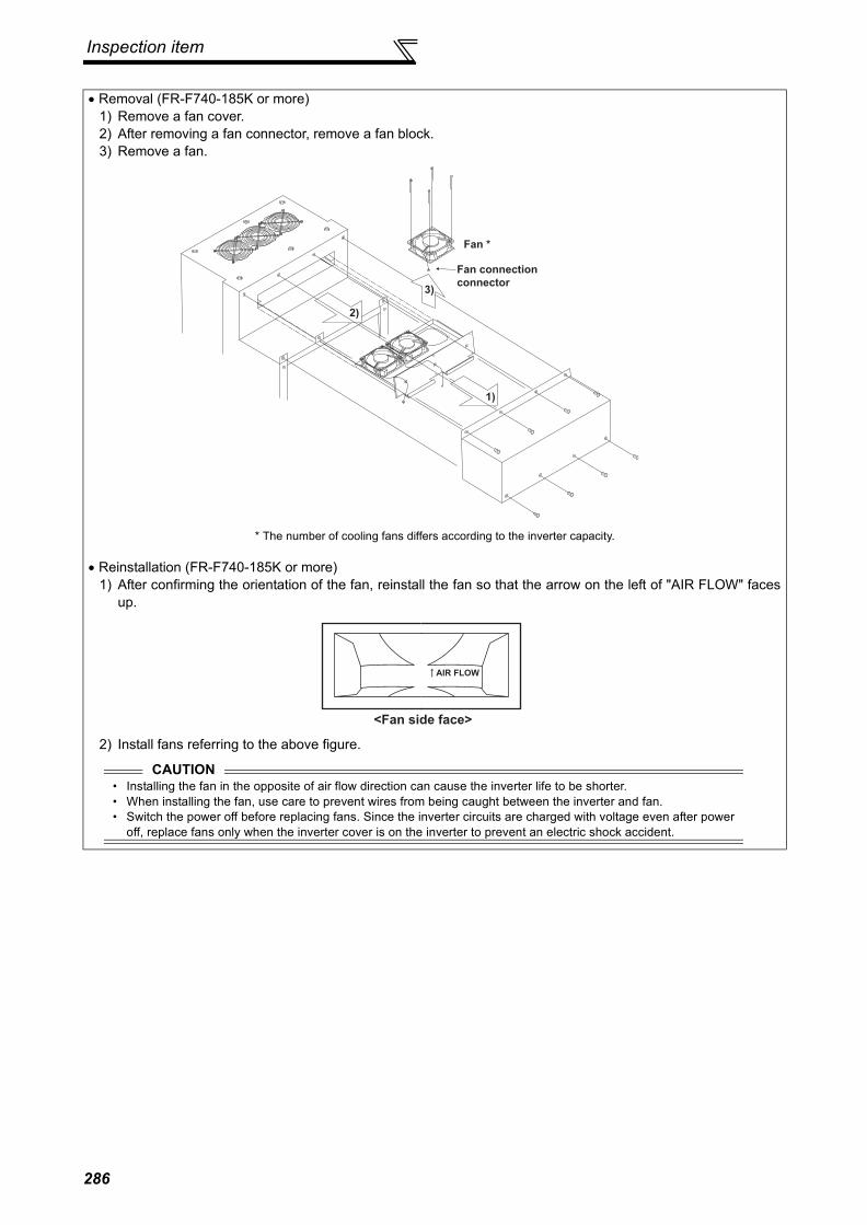
Inspection item
• Removal (FR-F740-185K or more)1) Remove a fan cover.2) After removing a fan connector, remove a fan block.3) Remove a fan.
* The number of cooling fans differs according to the inverter capacity.
• Reinstallation (FR-F740-185K or more)1) After confirming the orientation of the fan, reinstall the fan so that the arrow on the left of "AIR FLOW" faces
up.
2) Install fans referring to the above figure.
Fan *
Fan connection
connector
1)
2)
3)
<Fan side face>
AIR FLOW
CAUTION• Installing the fan in the opposite of air flow direction can cause the inverter life to be shorter.• When installing the fan, use care to prevent wires from being caught between the inverter and fan.• Switch the power off before replacing fans. Since the inverter circuits are charged with voltage even after power
off, replace fans only when the inverter cover is on the inverter to prevent an electric shock accident.
286

Inspection item
6
PREC
AU
TIO
NS
FOR
MA
INTE
NA
NC
E A
ND
INSP
ECTI
ON
(2) Replacement procedure of the cooling fan when using a heatsink protrusion attachment(FR-A7CN)
(3) Smoothing capacitorsA large-capacity aluminum electrolytic capacitor is used for smoothing in the main circuit DC section, and analuminum electrolytic capacitor is used for stabilizing the control power in the control circuit. Their characteristicsare deteriorated by the adverse effects of ripple currents, etc.The replacement intervals greatly vary with the surrounding air temperature and operating conditions. When theinverter is operated in air-conditioned, normal environment conditions, replace the capacitors about every 10 years.The appearance criteria for inspection are as follows:1) Case: Check the side and bottom faces for expansion2) Sealing plate: Check for remarkable warp and extreme crack.3) Check for external crack, discoloration, fluid leakage, etc. Judge that the capacitor has reached its life when the
measured capacitance of the capacitor reduced below 80% of the rating.
Refer to page 283 to perform the life check of the main circuit capacitor.
(4) RelaysTo prevent a contact fault, etc., relays must be replaced according to the cumulative number of switching times(switching life).
6.1.8 Inverter replacementThe inverter can be replaced with the control circuit wiring kept connected. Before replacement, remove the wiringcover of the inverter.1) Loosen the two installation screws in both ends of the control circuit terminal block. (These screws cannot be removed.)
Pull down the terminal block from behind the control circuit terminals.
2)Using care not to bend the pins of the inverter's control circuit connector, reinstall the control circuit terminal blockand fix it with the mounting screws.
When replacing a cooling fan, remove a top cover of theheatsink protrusion attachment and perform replacement.After replacing the cooling fan, replace the top cover in theoriginal position.
CAUTIONBefore starting inverter replacement, switch power off, wait for at least 10 minutes, and then check the voltage with a testerand such to ensure safety.
Top cover
287

Measurement of main circuit voltages, currents and powers
6.2 Measurement of main circuit voltages, currents and powers
6.2.1 Measurement of voltages and currents
Since the voltages and currents on the inverter power supply and output sides include harmonics, measurementdata depends on the instruments used and circuits measured.When instruments for commercial frequency are used for measurement, measure the following circuits with theinstruments given on the next page.
When installing meters etc. on the inverter output sideWhen the inverter-to-motor wiring length is large, especially in the 400V class, small-capacity models, the metersand CTs may generate heat due to line-to-line leakage current. Therefore, choose the equipment which hasenough allowance for the current rating.When measuring and indicating the output voltage and output current of the inverter, it is recommended to utilizethe AM-5 and FM-SD terminal output function of the inverter.
Examples of Measuring Points and Instruments
+ -
Ar
As
At
Vr
Vs
Vt
W11
W12
W13
Au
Av
Aw
Vu
Vv
Vw
W21
W22
V
U
V
W
Inverter
Three
phase
power
supply
To the motor
Instrument
types
Input voltage
Input current
Output voltage
Output current
: Moving-iron type
: Electrodynamometer type
: Moving-coil type
: Rectifier type
R/L1
S/L2
T/L3
P/+ N/-
288

Measurement of main circuit voltages,currents and powers
6
PREC
AU
TIO
NS
FOR
MA
INTE
NA
NC
E A
ND
INSP
ECTI
ON
Measuring Points and Instruments
*1 Use an FFT to measure the output voltage accurately. A tester or general measuring instrument cannot measure accurately.*2 When the carrier frequency exceeds 5kHz, do not use this instrument since using it may increase eddy-current losses produced in metal parts
inside the instrument, leading to burnout. If the wiring length between the inverter and motor is long, the instrument and CT may generateheat due to line-to-line leakage current.
*3 When the setting of Pr. 195 ABC1 terminal function selection is positive logic*4 A digital power meter (designed for inverter) can also be used to measure.
Item Measuring Point Measuring Instrument Remarks (Reference Measured Value)
Power supply voltageV1
Across R/L1-S/L2, S/L2-T/L3, T/L3-R/L1
Moving-iron type AC voltmeter *4Commercial power supplyWithin permissible AC voltage fluctuation Refer to page 294.
Power supply side currentI1
R/L1, S/L2, and T/L3 line currents Moving-iron type AC ammeter *4
Power supply side powerP1
R/L1, S/L2, T/L3 and R/L1-S/L2, S/L2-T/L3, T/L3-R/L1
Digital power meter (designed for inverter) or electrodynamic type single-phase wattmeter
P1=W11+W12+W13 (3-wattmeter method)
Power supply side power factorPf1
Calculate after measuring power supply voltage, power supply side current and power supply side power.
Output side voltageV2
Across U-V, V-W and W-U
Rectifier type AC voltage meter *1 *4(Moving-iron type cannot measure)
Difference between the phases is within ±1% of the maximum output voltage.
Output side currentI2
U, V and W line currents Moving-iron type AC ammeter *2 *4 Difference between the phases is 10% or lower
of the rated inverter current.
Output side powerP2
U, V, W and U-V, V-W
Digital power meter (designed for inverter) or electrodynamic type single-phase wattmeter
P2 = W21 + W222-wattmeter method (or 3-wattmeter method)
Output side power factorPf2
Calculate in similar manner to power supply side power factor.
Converter output Across P/+-N/− Moving-coil type (such as tester) Inverter LED display is lit. 1.35 × V1
Frequency setting signal
Across 2, 4(+)-5
Moving-coil type (Tester and such may be used)
(Internal resistance: 50kΩ or larger)
0 to 10VDC, 4 to 20mA
"5" is common
Across 1(+)-5 0 to ±5VDC, 0 to ±10VDCFrequency setting power supply
Across 10 (+) -5 5.2VDCAcross 10E(+)-5 10VDC
Frequency meter signal
Across AM(+)-5Approximately 10VDC at maximum frequency (without frequency meter)
Across FM(+)-SD
Approximately 5VDC at maximum frequency (without frequency meter)
Pulse width T1:Adjusted by C0 (Pr. 900)
Pulse cycle T2: Set by Pr. 55(Valid for frequency monitoring only)
"SD" is common
Start signalSelect signal
Across STF, STR, RH, RM, RL, JOG, RT, AU, STOP, CS (+) -SD
When open20 to 30VDCON voltage: 1V or lessReset Across RES (+) -SD
Output stop Across MRS (+) -SD
Fault signal Across A1-C1Across B1-C1
Moving-coil type (such as tester)
Continuity check*3<Normal> <Fault>
Across A1-C1 Discontinuity ContinuityAcross B1-C1 Continuity Discontinuity
Pf1 = ————— × 100%P1
3 V1 × I1
Pf2 = ————— × 100%P2
3 V2 × I2
8VDC
T1
T2
289

Measurement of main circuit voltages,currents and powers
6.2.2 Measurement of powers
Use digital power meters (for inverter) for the both of inverter input and output side. Alternatively, measure usingelectrodynamic type single-phase wattmeters for the both of inverter input and output side in two-wattmeter or three-wattmeter method. As the current is liable to be imbalanced especially in the input side, it is recommended to use thethree-wattmeter method.Examples of measured value differences produced by different measuring meters are shown below.An error will be produced by difference between measuring instruments, e.g. power calculation type and two- or three-wattmeter type three-phase wattmeter. When a CT is used in the current measuring side or when the meter contains aPT on the voltage measurement side, an error will also be produced due to the frequency characteristics of the CT andPT.
6.2.3 Measurement of voltages and use of PT
(1) Inverter input sideAs the input side voltage has a sine wave and it is extremely small in distortion, accurate measurement can be madewith an ordinary AC meter.
(2) Inverter output sideSince the output side voltage has a PWM-controlled rectangular wave, always use a rectifier type voltmeter. A needletype tester can not be used to measure the output side voltage as it indicates a value much greater than the actualvalue. A moving-iron type meter indicates an effective value which includes harmonics and therefore the value is largerthan that of the fundamental wave. The value monitored on the operation panel is the inverter-controlled voltage itself.Hence, that value is accurate and it is recommended to monitor values (provide analog output) using the operationpanel.
(3) PTNo PT can be used in the output side of the inverter. Use a direct-reading meter. (A PT can be used in the input side ofthe inverter.)
[Measurement conditions]Constant-torque (100%) load, constant-power at 60Hzor more.3.7kW, 4-pole motor, value indicated in 3-wattmetermethod is 100%.
[Measurement conditions]Constant-torque (100%) load, constant-power at 60Hzor more.3.7kW, 4-pole motor, value indicated in 3-wattmetermethod is 100%.
Example of measuring inverter input power Example of measuring inverter output power
3-wattmeter method (Electro-dynamometer type)
2-wattmeter method (Electro-dynamometer type)
Clip AC power meter
(For balanced three-phase load)
Clamp-on wattmeter
(Hall device power arithmetic type)
0 20 40 60 80 100 120Hz
60
80
100
120
%
3-wattmeter method (Electro-dynamometer type)
2-wattmeter method (Electro-dynamometer type)
Clip AC power meter
(For balanced three-phase load)
Clamp-on wattmeter
(Hall device power arithmetic type)
0 20 40 60 80 100 120Hz
60
80
100
120
%
290

6
PREC
AU
TIO
NS
FOR
MA
INTE
NA
NC
E A
ND
INSP
ECTI
ON
Measurement of main circuit voltages,currents and powers
6.2.4 Measurement of currents
Use moving-iron type meters on both the input and output sides of the inverter. However, if the carrier frequencyexceeds 5kHz, do not use that meter since an overcurrent losses produced in the internal metal parts of the meter willincrease and the meter may burn out. In this case, use an approximate-effective value type.As the inverter input side current is easily imbalanced, measurement of currents in all three phases is recommended.Correct values can not be measured in one or two phases. On the other hand, the phase imbalanced ratio of the outputside current must be within 10%.When a clamp ammeter is used, always use an effective value detection type. A mean value detection type produces alarge error and may indicate an extremely smaller value than the actual value. The value monitored on the operationpanel is accurate if the output frequency varies, and it is recommended to monitor values (provide analog output) usingthe operation panel.An example of the measured value difference produced by different measuring meters is shown below.
6.2.5 Use of CT and transducer
A CT may be used in both the input and output sides of the inverter, but the one used should have the largest possibleVA ability because an error will increase if the frequency gets lower. When using a transducer, use the effective value calculation type which is immune to harmonics.
6.2.6 Measurement of inverter input power factor
Use the effective power and apparent power to calculate the inverter input power factor. A power-factor meter can notindicate an exact value.
[Measurement conditions]Value indicated by moving-iron type ammeter is 100%.
[Measurement conditions]Value indicated by moving-iron type ammeter is 100%.
Example of measuring Inverter Input Current Example of measuring Inverter Output Current
Total power factor of the inverter =Effective powerApparent power
=Three-phase input power found by 3-wattmeter method
× V (power supply voltage) × I (input current effective value)
120
100
80
60
0 60Hz4020
%
Moving-iron type
Clamp-on wattmeter
current measurementClamp meter
Clip AC
power meter 120
100
80
60
0 60Hz4020
%
Moving-iron type
Clip AC
power meter
Clamp-on wattmeter
current measurement
Clamp meter
3
291

Measurement of main circuit voltages,currents and powers
6.2.7 Measurement of converter output voltage (across terminals P/+ - N/-)
The output voltage of the converter is developed across terminals P/+ - N/- and can be measured with a moving-coiltype meter (tester). Although the voltage varies according to the power supply voltage, approximately 270V to 300V(approximately 540V to 600V for the 400V class) is output when no load is connected and voltage decreases when aload is connected.When regenerative energy is returned from the motor during deceleration, for example, the converter output voltagerises to nearly 400V to 450V (800V to 900V for the 400V class) maximum.
6.2.8 Measurement of inverter output frequency
A pulse train proportional to the output frequency is output across the frequency meter signal output terminal FM-SD ofthe inverter. This pulse train output can be counted by a frequency counter, or a meter (moving-coil type voltmeter) canbe used to read the mean value of the pulse train output voltage. When a meter is used to measure the outputfrequency, approximately 5VDC is indicated at the maximum frequency.For detailed specifications of the frequency meter signal output terminal FM, refer to page 138.
6.2.9 Insulation resistance test using meggerFor the inverter, conduct the insulation resistance test on the main circuit only as shown below and do not perform thetest on the control circuit. (Use a 500VDC megger.)
6.2.10 Pressure testDo not conduct a pressure test. Deterioration may occur.
CAUTION• Before performing the insulation resistance test on the external circuit, disconnect the cables from all terminals of the
inverter so that the test voltage is not applied to the inverter.• For the continuity test of the control circuit, use a tester (high resistance range) and do not use the megger or buzzer.
UVW
Inverter
500VDC
megger
Power
supplyIM
MotorR/L1S/L2T/L3
Earth (ground) terminal
292

7
SPECIFICATIONS3
4
5
6
1
2
This chapter provides the "SPECIFICATIONS" of this product.Always read the instructions before using the equipment.
7.1 Rating......................................................................2947.2 Common specifications ...........................................2967.3 Outline dimension drawings ....................................2987.4 Heatsink protrusion attachment procedure .............309
2937

Rating
7.1 Rating•200V class
Type FR-F720- K 0.75 1.5 2.2 3.7 5.5 7.5 11 15 18.5 22 30 37 45 55 75 90 110Applicable motor capacity (kW)*1
0.75 1.5 2.2 3.7 5.5 7.5 11 15 18.5 22 30 37 45 55 75 90 110
Out
put
Rated capacity (kVA)*2 1.6 2.7 3.7 5.8 8.8 11.8 17.1 22.1 27 32 43 53 65 81 110 132 165
Rated current (A)*34.2(3.6)
7.0(6.0)
9.6(8.2)
15.2(13)
23(20)
31(26)
45(38)
58(49)
70(60)
85(72)
114(97)
140(119)
170(145)
212(180)
288(245)
346(294)
432(367)
Overload current rating*4
120% for 60s, 150% for 3s (inverse-time characteristics)
Voltage*5 Three-phase 200 to 240V
Pow
er s
uppl
y
Rated input AC voltage/frequency Three-phase 200 to 220V 50Hz, 200 to 240V 60Hz
Permissible AC voltage fluctuation 170 to 242V 50Hz, 170 to 264V 60Hz
Permissible frequency fluctuation ±5%
Power supply system capacity (kVA)*6
Without DC reactor 2.1 4.0 4.8 8.0 11.5 16 20 27 32 41 52 65 79 99 - - -
With DC reactor 1.2 2.6 3.3 5.0 8.1 10 16 19 24 31 41 50 61 74 110 132 165
Protective structure(JEM 1030)*8
Enclosed type (IP20)*7 Open type (IP00)
Cooling system Self-cooling Forced air cooling
Approx. mass (kg) 1.8 2.2 3.5 3.5 3.5 6.5 6.5 7.8 13 13 14 23 35 35 67 70 70*1 The applicable motor capacity indicated is the maximum capacity applicable for use of the Mitsubishi 4-pole standard motor.*2 The rated output capacity indicated assumes that the output voltage is 220V.*3 When operating the inverter with the carrier frequency set to 3kHz or more, the carrier frequency automatically decreases if the inverter
output current exceeds the value in parenthesis of the rated current. This may cause the motor noise to increase.*4 The % value of the overload current rating indicated is the ratio of the overload current to the inverter's rated output current. For repeated
duty, allow time for the inverter and motor to return to or below the temperatures under 100% load.*5 The maximum output voltage does not exceed the power supply voltage. The maximum output voltage can be changed within the setting
range. However, the pulse voltage value of the inverter output side voltage remains unchanged at about that of the power supply.*6 The power supply capacity varies with the value of the power supply side inverter impedance (including those of the input reactor and
cables).*7 When the hook of the inverter front cover is cut off for installation of the plug-in option, the inverter changes to an open type ().*8 FR-DU07: IP40 (except for the PU connector)
2
294

Rating
SPEC
IFIC
ATIO
NS
•400V classType FR-F740- K 0.75 1.5 2.2 3.7 5.5 7.5 11 15 18.5 22 30 37 45 55
Applicable motor capacity (kW)*1 0.75 1.5 2.2 3.7 5.5 7.5 11 15 18.5 22 30 37 45 55
Out
put
Rated capacity (kVA)*2 1.6 2.7 3.7 5.8 8.8 12.2 17.5 22.1 26.7 32.8 43.4 53.3 64.8 80.8
Rated current (A)*3 2.1(1.8)
3.5(3.0)
4.8(4.1)
7.6(6.4)
11.5(9.8)
16(13)
23(19)
29(24)
35(30)
43(36)
57(48)
70(60)
85(72)
106(90)
Overload current rating*4 120% 60s, 150% 3s (inverse-time characteristics)Voltage*5 Three-phase 380 to 480V
Pow
er s
uppl
y
Rated input AC voltage/frequency Three-phase 380 to 480V 50Hz/60HzPermissible AC voltage fluctuation 323 to 528V 50Hz/60HzPermissible frequency fluctuation ±5%
Power supply system capacity (kVA)*6
Without DC reactor 2.1 4.0 4.8 8.0 11.5 16 20 27 32 41 52 65 79 99
With DC reactor 1.2 2.6 3.3 5.0 8.1 10 16 19 24 31 41 50 61 74
Protective structure(JEM 1030)*8
Enclosed type (IP20)*7 Open type (IP00)
Cooling system Self-cooling Forced air coolingApprox. mass (kg) 3.5 3.5 3.5 3.5 3.5 6.5 6.5 7.5 7.5 13 13 23 35 35
Type FR-F740- K 75 90 110 132 160 185 220 250 280 315 355 400 450 500 560Applicable motor capacity (kW)*1 75 90 110 132 160 185 220 250 280 315 355 400 450 500 560
Out
put
Rated capacity (kVA)*2 110 137 165 198 247 275 329 366 416 464 520 586 659 733 833
Rated current (A)*3 144 (122)
180 (153)
216 (183)
260 (221)
325 (276)
361(306)
432(367)
481(408)
547(464)
610(518)
683(580)
770(654)
866(736)
962(817)
1094(929)
Overload current rating*4120% 60s, 150% 3s
(inverse-time characteristics)Voltage*5 Three-phase 380 to 480V
Pow
er s
uppl
y
Rated input AC voltage/frequency Three-phase 380 to 480V 50Hz/60HzPermissible AC voltage fluctuation 323 to 528V 50Hz/60HzPermissible frequency fluctuation ±5%Power supply system capacity (kVA)*6
Without DC reactor - - - - - - - - - - - - - - -
With DC reactor 110 137 165 198 247 275 329 366 416 464 520 586 659 733 833
Protective structure(JEM 1030)*8
Open type (IP00)
Cooling system Forced air coolingApprox. mass (kg) 37 50 57 72 72 110 110 175 175 175 260 260 370 370 370*1 The applicable motor capacity indicated is the maximum capacity applicable for use of the Mitsubishi 4-pole standard motor.*2 The rated output capacity indicated assumes that the output voltage is 440V.*3 When operating the inverter with the carrier frequency set to 3kHz or more, the carrier frequency automatically decreases if the inverter output
current exceeds the value in parenthesis of the rated current. This may cause the motor noise to increase.*4 The % value of the overload current rating indicated is the ratio of the overload current to the inverter's rated output current. For repeated duty,
allow time for the inverter and motor to return to or below the temperatures under 100% load.*5 The maximum output voltage does not exceed the power supply voltage. The maximum output voltage can be changed within the setting range.
However, the pulse voltage value of the inverter output side voltage remains unchanged at about that of the power supply.*6 The power supply capacity varies with the value of the power supply side inverter impedance (including those of the input reactor and cables).*7 When the hook of the inverter front cover is cut off for installation of the plug-in option, protective structure of the inverter changes to an open
type (IP00).*8 FR-DU07: IP40 (except for the PU connector)
2
2957

Common specifications
7.2 Common specificationsC
ontro
l spe
cific
atio
ns
Control method High carrier frequency PWM control (V/F control)/Optimum excitation control/Simple magnetic flux vector control
Output frequency range 0.5 to 400Hz
Frequency setting resolution
Analog input0.015Hz/60Hz (terminal 2, 4: 0 to 10V/12bit)0.03Hz/60Hz (terminal 2, 4: 0 to 5V/11bit, 0 to 20mA/11bit, terminal 1: 0 to ±10V/12bit)0.06Hz/60Hz (terminal 1: 0 to ±5V/11bit)
Digital input 0.01HzFrequency accuracy
Analog input Within ±0.2% of the max. output frequency (25°C ± 10°C)Digital input Within 0.01% of the set output frequency
Voltage/frequency characteristics
0 to 400Hz of the base frequency can be set from constant-torque/adjustable 5 points V/F can be selected.
Starting torque 120% (at 3Hz) when Simple magnetic flux vector control and slip compensation are setAcceleration/deceleration time setting
0 to 3600s (acceleration and deceleration can be set individually), linear or S-pattern acceleration/deceleration modes are available.
DC injection brake Operation frequency (0 to 120Hz), operation time (0 to 10s), operation voltage (0 to 30%) can be changed
Stall prevention operation level Operation current level can be set (0 to 150% variable), whether to use the function or not can be set.
Ope
ratio
n sp
ecifi
catio
ns
Frequency setting signal
Analog input Terminal 2, 4: 0 to 10V, 0 to 5V, 4 to 20mA are available.Terminal 1: -10 to +10V, -5 to 5V are available.
Digital input Four-digit BCD or16-bit binary using the setting dial of the operation panel or parameter unit (when used with the option FR-A7AX)
Start signal Forward and reverse rotation or start signal automatic self-holding input (3-wire input) can be selected.
Input signals (twelve terminals)
The following signals can be assigned to Pr. 178 to Pr.189 (input terminal function selection): multi speed selection, second function selection, terminal 4 input selection, JOG operation selection, selection of automatic restart after instantaneous power failure, external thermal relay input, HC connection (inverter operation enable signal), HC connection (instantaneous power failure detection), PU operation/external interlock signal, PID control enable terminal, PU operation, external operation switchover, output stop, start self-holding selection, forward rotation command, reverse rotation command, inverter reset, PTC thermistor input, PID forward reverse operation switchover, PU-NET operation switchover, External-NET operation switchover, command source switchover, DC feeding operation permission, DC feeding cancel, and PID integral value reset.
Operational functions
Maximum and minimum frequency settings, frequency jump operation, external thermal relay input selection, polarity reversible operation, automatic restart after instantaneous power failure operation, original operation continuation at an instantaneous power failure, electronic bypass operation, forward/reverse rotation prevention, operation mode selection, PID control, computer link operation (RS-485).
Output signalOpen collector output (five terminals)Relay output (two terminals)
The following signals can be assigned to Pr.190 to Pr.196 (output terminal function selection): inverter running, up-to-speed, instantaneous power failure /undervoltage, overload warning, output frequency detection, second output frequency detection, regenerative brake prealarm*4, electronic thermal relay function pre-alarm, PU operation mode, inverter operation ready, output current detection, zero current detection, PID lower limit, PID upper limit, PID forward rotation reverse rotation output, bypass operation-inverter switchover MC1 to MC3, fan alarm output, heatsink overheat pre-alarm, inverter running start command on, deceleration at an instantaneous power failure, PID control activated, PID deviation limit, during retry, during PID output suspension, pulse train output of output power, DC current feeding, life alarm, fault output 3 (power-off signal), power savings average value update timing, current average monitor, fault output 2, maintenance timer alarm, remote output, alarm output, and fault output.
Operating status
When used with the FR-A7AY, FR-A7AR (option)
In addition to above, the following signal can be assigned to Pr.313 to Pr. 319 (extension output terminal function selection): control circuit capacitor life, main circuit capacitor life, cooling fan life and inrush current limit circuit fault. (Only positive logic can be set for extension terminals of the FR-A7AR.)
For meterPulse train output(Max. 2.4kHz: one terminal)Analog output(Max. 10VDC: one terminal)
The following signals can be assigned to Pr.54 FM terminal function selection and Pr. 158 AM terminal function selection: output frequency, motor current (steady or peak value), output voltage, frequency setting value, running speed, converter output voltage (steady or peak value), electronic thermal relay function load factor, input power, output power, load meter, reference voltage output, motor load factor, power saving effect, regenerative brake duty*4, PID set value, and PID measured value.
296

Common specifications
SPEC
IFIC
ATIO
NS
*1 Can be displayed only on the operation panel (FR-DU07).*2 This operation guide is only available with option parameter unit (FR-PU07).*3 Temperature applicable for a short period in transit, etc.*4 Only the 75K or more functions.*5 2.9m/s2 or less for the 185K or more.*6 This protective function does not function in the initial status.
Indi
catio
n
Operation panel (FR-DU07)
Parameter unit (FR-PU07)
Operating status
The following operating status can be displayed: output frequency, motor current (steady or peak value), output voltage, alarm indication, frequency setting, running speed, converter output voltage (steady or peak value), electronic thermal relay function load factor, input power, output power, load meter, cumulative energization time, actual operation time, motor load factor, cumulative power, power saving effect, cumulative saving power, regenerative brake duty*4,PID set point, PID measured value, PID deviation value, inverter I/O terminal monitor, input terminal option monitor*1, output terminal option monitor*1, option fitting status monitor*2, terminal assignment status*2
Fault definition Fault definition is displayed when a fault occurs. Past 8 fault definitions (output voltage/current/frequency/cumulative energization time right before the fault occurs) are stored.
Interactive guidance Function (help) for operation guide *2
Protective/warning function
Protective function
Overcurrent during acceleration, overcurrent during constant speed, overcurrent during deceleration, overvoltage during acceleration, overvoltage during constant speed, overvoltage during deceleration, inverter protection thermal operation, motor protection thermal operation, heatsink overheat, instantaneous power failure occurrence, undervoltage, input phase loss *6, motor overload, output side earth (ground) fault overcurrent, output phase loss, external thermal relay operation *6, PTC thermistor operation *6, option fault, parameter error, PU disconnection, retry count excess *6, CPU fault, operation panel power supply short circuit, 24VDC power output short circuit, output current detection value excess *6, inrush current limit circuit fault, communication fault (inverter), analog input fault, PID signal fault *6, internal circuit fault (15V power supply), brake transistor alarm detection *4,
Warning function
Fan alarm, overcurrent stall prevention, overvoltage stall prevention, regenerative brake prealarm *6, electronic thermal relay function prealarm, PU stop, maintenance timer alarm *1*6, parameter write error, copy operation error, operation panel lock, parameter copy
Env
ironm
ent
Surrounding air temperature -10°C to +50°C (non-freezing)Ambient humidity 90%RH or less (non-condensing)Storage temperature*3 -20°C to +65°CAtmosphere Indoors (without corrosive gas, flammable gas, oil mist, dust and dirt etc.)
Altitude, vibrationMaximum 1000m above sea level for standard operation. After that derate by 3% for every extra 500m up to 2500m (92%) 5.9m/s2 or less at 10 to 55Hz (directions of X, Y, Z axes) *5
2977

Outline dimension drawings
7.3 Outline dimension drawings7.3.1 Inverter outline dimension drawings• FR-F720-0.75K, 1.5K
• FR-F720-2.2K, 3.7K, 5.5K• FR-F740-0.75K, 1.5K, 2.2K, 3.7K, 5.5K
(Unit: mm)
2-φ6 hole
D
26
02
45
7.5
6
110
95 5
7.5
D1
Inverter Model D D1FR-F720-0.75K 110 21FR-F720-1.5K 125 36
26
0
150125
6
14057
.57
.52
45
2-φ6 hole
144
45
.5
* The FR-F740-0.75K to 2.2K are not provided with cooling fans.
298

Outline dimension drawings
SPEC
IFIC
ATIO
NS
• FR-F720-7.5K, 11K, 15K• FR-F740-7.5K, 11K, 15K, 18.5K
• FR-F720-18.5K, 22K, 30K• FR-F740-22K, 30K
(Unit: mm)
(Unit: mm)
H1 H
D
2-φ6 hole
7.5
220
195
211
106
7.5
D1
Inverter Model H H1 D D1FR-F720-7.5K, 11KFR-F740-7.5K, 11K 260 245 170 84
FR-F720-15KFR-F740-15K, 18.5K 300 285 190 101.5
10230250
380
10
10
400
19010.5
101.5
250
2-φ10 hole
* The FR-F720-30K is not provided with a wiring cover.
2997

Outline dimension drawings
• FR-F720-37K, 45K, 55K• FR-F740-37K, 45K, 55K
(Unit: mm)
W2
W
W1
H
D
2-φd hole
H1
55
0
10 3.2
Inverter Model W W1 W2 H H1 d DFR-F720-37KFR-F740-37K 325 270 10 530 10 10 195
FR-F720-45K, 55KFR-F740-45K, 55K 435 380 12 525 15 12 250
300

Outline dimension drawings
SPEC
IFIC
ATIO
NS
• FR-F740-75K, 90K
• DC reactor supplied
(Unit: mm)
W
W1H H1
D
2-φ12 hole
15
10 3.212
Inverter Model W W1 H H1 DFR-F740-75K 435 380 525 550 250FR-F740-90K 465 400 595 620 300
(for M6 screw)4-installation hole
(for M6 screw)Earth (ground) terminal
Rating plate2-terminal
E
P1 P P1, P
(for M12 bolt)
Within D
W1
H1
H
10
W 2
DC reactor Model W W1 H H1 D Mass (kg)
FR-HEL-H75K (FR-F740-75K) 140 120 320 295 185 16FR-HEL-H90K (FR-F740-90K) 150 130 340 310 190 20
3017

Outline dimension drawings
• FR-F720-75K, 90K, 110K• FR-F740-132K, 160K
• FR-F740-110K
(Unit: mm)
(Unit: mm)
E
P1
P
P1
P
130
150
Rating plate
(for M6 screw)4-installation hole
(for M6 screw)Earth (ground) terminal
Within 195
(for M12 bolt)
2-terminal
340
1
0
310
1
0
300
3.2
465
400
620
595
10
15
2-φ12 hole • DC reactor supplied
DC reactor Model Mass (kg)
FR-HEL-H110K(FR-F740-110K) 22
360
715
740
465400
10
15
3.2
2-φ12 hole
DC reactor Model W W1 H H1 D S S1 Mass (kg)
FR-HEL-75K(FR-F720-75K) 150 130 340 310 190 M6 M6 17FR-HEL-90K(FR-F720-90K) 150 130 340 310 200 M6 M6 19FR-HEL-110K(FR-F720-110K) 175 150 400 365 200 M8 M6 20FR-HEL-H132K(FR-F740-132K) 175 150 405 370 200 M8 M6 26FR-HEL-H160K(FR-F740-160K) 175 150 405 370 205 M8 M6 28
E
P1
P
P1
P
W1
Rating plate
(for S screw)4-installation hole
(for S1 screw)Earth (ground) terminal
Within D
(for M12 bolt)
2-terminal
H
10
H1
1
0
W 2
• DC reactor supplied
302

Outline dimension drawings
SPEC
IFIC
ATIO
NS
• FR-F740-185K, 220K
• DC reactor supplied
(Unit: mm)
15
985
10
1010
4920020049
498
12
380
3.2
4501
48
.52
14
.5
18
5
3-φ12 hole
DC reactor Model Mass (kg)
FR-HEL-H185K (FR-F740-185K) 29FR-HEL-H220K (FR-F740-220K) 30
E
P1
P
P1
P
37
0
10
40
5
10
Earth (ground) terminal
(for M6 screw)
Rating plate
2-M6 eye nut (only for FR-HEL-H220K)
* Remove the eye nut after installation of the product.
4-installation hole
(for M8 screw) Within 240
2-terminal (for M12 bolt)
150 1
175 2
3037

Outline dimension drawings
• FR-F740-250K, 280K, 315K
• DC reactor supplied
(Unit: mm)
R/L1
S/L2
T/L3
N/-
P1
P/+
U
V
W
98
4
10
10
12
300 300
680
3.2
3801
48
214
3-φ12 holes
DC reactor Model W W1 H H1 D S S1 S2 φ Mass (kg)
FR-HEL-H250K (FR-F740-250K) 190 165 440 400 250 M8 M8 M8 M12 35FR-HEL-H280K (FR-F740-280K) 190 165 440 400 255 M8 M8 M8 M16 38FR-HEL-H315K (FR-F740-315K) 210 185 495 450 250 M10 M8 M8 M16 42
E
P1
P
P1
P
H1
1
0
H
10
Earth (ground) terminal
(for S1 screw)
Rating plate
2-S2 eye nut
* Remove the eye nut after installation of the product.
4-installation hole
(for S screw) Within D
2-terminal (for bolt)
W1 1
W 2
304

Outline dimension drawings
SPEC
IFIC
ATIO
NS
• FR-F740-355K, 400K
(Unit: mm)
3-φ12 hole
R/L1
S/L2
T/L3
N/-
P1
P/+
U W
V
790 440
4.5 4.5
18
5
22
21
94
13
00
13
30
315
12
315
E
P
P1
P1
P
75
40
40
500 10
455 10
220
195
Rating plate
2-M8 eye nut2-terminal
4- 15 hole
* Remove the eye nut after installation of the product.
Earth (ground) terminal
(for M8 screw)
Within 250
Within 235
4-installation hole
(for M10 screw)
E
P1
P
P1
P
185
210
450 1
0
495 1
0
Earth (ground) terminal
(for M8 screw)
Rating plate
2-M8 eye nut
* Remove the eye nut after installation of the product.
4-installation hole
(for M10 screw) Within 250
2-terminal (for M16 bolt)
DC reactor Model Mass (kg)
FR-HEL-H400K (FR-F740-400K) 50
• DC reactor supplied• DC reactor supplied
DC reactor Model Mass (kg)
FR-HEL-H355K (FR-F740-355K) 46
3057

Outline dimension drawings
• FR-F740-450K
• DC reactor supplied
(Unit: mm)
R/L1 S/L2 T/L3 N/- VU W
30012
995
15
80
440
15
50
P1 P/+
18
5
4-φ12 hole
4.5300 300
9501
89
22
7
4.5
E
P
P1
P1
P
75
40
40
50
0
1
0
45
5
1
0
220
195
Rating plate
2-M8 eye nut2-terminal
4- 15 hole
* Remove the eye nut after installation of the product.
Earth (ground) terminal
(for M8 screw)
Within 270
Within 240
4-installation hole
(for M10 screw)
DC reactor Model Mass (kg)
FR-HEL-H450K (FR-F740-450K) 57
306

Outline dimension drawings
SPEC
IFIC
ATIO
NS
• FR-F740-500K, 560K
• DC reactor supplied
(Unit: mm)
R/L1 S/L2 T/L3 N/- VU W
30012
995
1580
440
1550
P1 P/+
185
4-φ12 hole
4.5300 300
950
189
227
4.5
P
P1
P P1
E
40
75
40
150
215
D1 10
D 10
* Remove the eye nut after installation of the product.
Rating plate
2-terminal
4- 15 hole
Earth (ground) terminal
(for M12 screw)
Within 245
With
in H
2-M12 eye nut
4-installation hole
(for M10 screw)
DC reactor Model H D D1 Mass (kg)
FR-HEL-H500K (FR-F740-500K) 345 455 405 67FR-HEL-H560K (FR-F740-560K) 360 460 410 85
3077

Outline dimension drawings
• Operation panel (FR-DU07)
• Parameter unit (option) (FR-PU07)
2-M3 screw
Panel
Cable
Air-bleeding hole
FR-DU07
Operation panel connection connector
(FR-ADP option)
<Outline drawing> <Panel cutting dimension drawing>
78
50
44
723 3
81
33
16
25
3.2max
72
44
21
20
22
27.8
6
80.3
(14.2)2
.55
0(11.45)
25.05
13
5
83
*1
*1
*1
*1
67
51
40
56
.8
57
.8
26.5
4-R1
4-φ4 hole
(Effective depth of the installation
screws hole 5.0)
M3 screw *2
26.5
40
Air-bleeding hole
<Outline drawing> <Panel cutting dimension drawing>
(Unit: mm)
*1 When installing the FR-PU07 on the enclosure, etc., remove screws forfixing the FR-PU07 to the inverter or fix the screws to the FR-PU07 withM3 nuts.
*2 Select the installation screws whose length will not exceed the effectivedepth of the installation screw hole.
308

Heatsink protrusion attachment procedure
SPEC
IFIC
ATIO
NS
7.4 Heatsink protrusion attachment procedure
When encasing the inverter in an enclosure, the generated heat amount in an enclosure can be greatly reduced byinstalling the heatsink portion of the inverter outside the enclosure. When installing the inverter in a compactenclosure, etc., this installation method is recommended.
7.4.1 When using a heatsink protrusion attachment (FR-A7CN)For the FR-F720-2.2K to 110K, FR-F740-0.75K to 160K, a heatsink can be protruded outside the enclosure using aheatsink protrusion attachment (FR-A7CN). For a panel cut dimension drawing and an installation procedure of theheatsink protrusion attachment (FR-A7CN) to the inverter, refer to a manual of "heatsink protrusion attachment (FR-A7CN01 to 11)".
7.4.2 Protrusion of heatsink of the FR-F740-185K or more(1) Panel cuttingCut the panel of the enclosure according to the inverter capacity.
• FR-F740-185K, 220K
(Unit: mm)
• FR-F740-250K, 280K, 315K
(Unit: mm)• FR-F740-355K, 400K
(Unit: mm)
• FR-F740-450K, 500K, 560K
(Unit: mm)
200 200
484
13
95
41
8
98
5 Hole
6-M10 screw
Hole
300 300
662
15
95
41
5
98
4
6-M10 screw
6-M10 screw771
13
00
21
12
58
21
Hole
315 315
8-M10 screw
300 300 300
976
21
15
08
21
15
50
Hole
3097
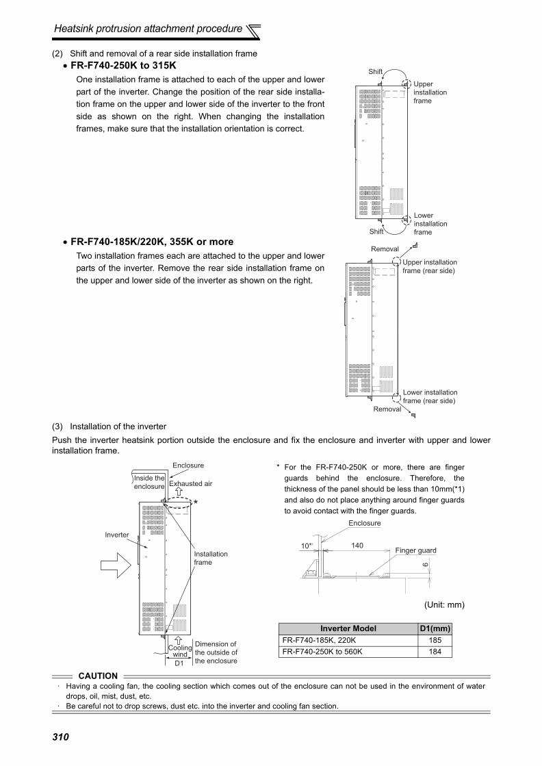
Heatsink protrusion attachment procedure
(2) Shift and removal of a rear side installation frame
(3) Installation of the inverterPush the inverter heatsink portion outside the enclosure and fix the enclosure and inverter with upper and lowerinstallation frame.
• FR-F740-250K to 315KOne installation frame is attached to each of the upper and lowerpart of the inverter. Change the position of the rear side installa-tion frame on the upper and lower side of the inverter to the frontside as shown on the right. When changing the installationframes, make sure that the installation orientation is correct.
• FR-F740-185K/220K, 355K or moreTwo installation frames each are attached to the upper and lowerparts of the inverter. Remove the rear side installation frame onthe upper and lower side of the inverter as shown on the right.
CAUTION· Having a cooling fan, the cooling section which comes out of the enclosure can not be used in the environment of water
drops, oil, mist, dust, etc.· Be careful not to drop screws, dust etc. into the inverter and cooling fan section.
Upper
installation
frame
Lower
installation
frame
Shift
Shift
Removal
Upper installation
frame (rear side)
Removal
Lower installation
frame (rear side)
Inverter
Inside the
enclosure
Enclosure
Exhausted air
Installation
frame
Dimension of
the outside of
the enclosure
Cooling wind
D1
*
Inverter Model D1(mm) FR-F740-185K, 220K 185FR-F740-250K to 560K 184
* For the FR-F740-250K or more, there are fingerguards behind the enclosure. Therefore, thethickness of the panel should be less than 10mm(*1)and also do not place anything around finger guardsto avoid contact with the finger guards.
(Unit: mm)
Enclosure
Finger guard10*1 140
6
310

This chapter provides the "APPENDICES" of this product.Always read the instructions before using the equipment.
311

For customers who are replacing the conventional model with this inverter
Appendix 1-1 Replacement of the FR-F500 series(1) Instructions for installation
1)Removal procedure of the front cover was changed. (with screws) Please note. (Refer to page 6.)2)Removal procedure of the operation panel was changed. (with screws) Please note. (Refer to page 6.)3)Plug-in options of the F500 series are not compatible4)Operation panel (FR-DU04) can not be used.5)Setup software (FR-SW0-SETUP) can not be used.
(2) Wiring instructions1)The control circuit terminal block can be used for the FR-F700 series without removing wiring.
Note that the wiring cover (0.75K to 30K) is not compatible.
(Note that the relay output 2 (A2, B2, C2) specific for the FR-F700 series can not be used with the FR-F500 seriesterminals.)
(3) Instructions for continuous use of the FR-PU04 (parameter unit)1)For the FR-F700 series, many functions (parameters) have been added. When setting these parameters, the
parameter name and setting range are not displayed. Parameter list, change list, initial value list, initial value list2 and parameter clear of the HELP function can not be used.
2)For the FR-F700 series, many protective functions have been added. These functions activate, but all faults aredisplayed as "Fault 14". When the faults history has been checked, "E.14" appears. Added faults display will notappear on the parameter unit.
3) User initial value setting can not be used.4) User registration/clear (user group 2) can not be used.5) Parameter copy/verification function can not be used.
Appendix 1 For customers who are replacing the conventional model with this inverter
FR-F500 series
FR-F700 series
312

For customers who are replacing the conventional model with this inverter
(4) Main differences and compatibilities with the FR-F500(L) series
Appendix 1-2 Replacement of the FR-A100 <EXCELENT> seriesInstructions for installation• When using the installation holes of the FR-A100(E) series, FR-A5AT (intercompatibility attachment) is necessary.
Item FR-F500(L) FR-F700
Changed/cleared functions
Simple mode parameters 61 Simple mode parameters 15
Pr. 0 Torque boost initial value11K to 55K: 2%
Pr. 0 Torque boost initial valueinitial value11K to 37K: 2%, 45K, 55K: 1.5%(When the torque boost value of the FR-F500 series used was the initial value, it is not necessary to change the torque boost value from the initial value when replacing with the FR-F700 series.)
User group 1 (16), user group 2 (16)(Pr. 160, Pr. 173 to Pr. 175)
User group (16) onlySetting methods were partially changed (Pr. 160, Pr. 172 to Pr. 173)
User initial value setting (Pr. 199)"User initial value setting" (Pr. 199) was clearedSubstitutable with the copy function of the operation panel (FR-DU07)
DC injection brake function with terminal (X13 signal)(Pr. 11 setting value 8888, Pr. 180 to Pr. 186 setting value 13)
DC injection brake function with terminal was clearedStart in reverse rotation is possible with flying start function (frequency search of automatic restart after instantaneous power failure function)
Long wiring mode(Pr. 240 setting 10, 11)
Setting is not necessary(Pr. 240 settings "10" and "11" were cleared)
Intelligent optimum acceleration/deceleration(Pr. 60 setting "3" and Pr. 61 to Pr. 63)
Function was clearedFor deceleration time, overvoltage fault can be avoided with regeneration avoidance function (Pr. 882 to Pr. 885).
Automatic torque boost(Pr. 38, Pr. 39)
Automatic torque boost was cleared because of addition of "Simple magnetic flux vector" (Pr. 80)
Performing parameter clear and all clear (H5A96, HAA99) with the FR-A7ND clears Pr. 345 and Pr. 346.
Pr. 345 and Pr. 346 are not cleared.
Terminal block Removable terminal blockRemovable terminal blockUpward compatibility (Terminal block of the F500 can be mounted)
PU FR-PU04, DU04
FR-PU07FR-DU07FR-DU04 unavailable (Partly restricted when the FR-PU04 is used. Refer to page 312.)
Plug-in option
Dedicated plug-in option (not compatible)Computer link, relay output optionFR-A5NR
Built into the inverter(RS-485 terminal, relay output 2 points)
Three boards can be mounted One board can be mounted
Installation sizeFR-F720-0.75K, 2.2K, 3.7K, 7.5K, 18.5K, 22K, 37K, 45K,
FR-F740-0.75K to 3.7K, 7.5K, 22K, 37K to 55K are compatible in mounting dimensionsFor other capacities, an optional intercompatibility attachment (FR-AAT) is necessary.
313

*1 These instruction codes are used for parameter read and write by using Mitsubishi inverter protocol with the RS-485 communication.(Refer to page 196 for RS-485 communication)
*2 " " indicates valid and "×" indicates invalid of "parameter copy", "parameter clear", and "all parameter clear". *3 These parameters are communication parameters that are not cleared when parameter clear (all clear) is executed from RS-485 communication.
(Refer to page 196 for RS-485 communication)Symbols in the table indicate parameters which function when an option is mounted.
.......FR-A7AX, ....... FR-A7AY, ........ FR-A7AR, ........FR-A7NC, ....... FR-A7ND,
.......FR-A7NL, ....... FR-A7NP, ........ FR-A7NF
Appendix 2 Parameter clear, parameter copy and instruction code list
Parameter NameInstruction Code * 1 Parameter
Copy *2Parameter
Clear *2All Parameter
Clear *2Read Write Extended 0 Torque boost 00 80 0
1 Maximum frequency 01 81 0
2 Minimum frequency 02 82 0
3 Base frequency 03 83 0
4 Multi-speed setting (high speed) 04 84 0
5 Multi-speed setting (middle speed) 05 85 0
6 Multi-speed setting (low speed) 06 86 0
7 Acceleration time 07 87 0
8 Deceleration time 08 88 0
9 Electronic thermal O/L relay 09 89 0
10 DC injection brake operation frequency 0A 8A 0
11 DC injection brake operation time 0B 8B 0
12 DC injection brake operation voltage 0C 8C 0
13 Starting frequency 0D 8D 0
14 Load pattern selection 0E 8E 0
15 Jog frequency 0F 8F 0
16 Jog acceleration/deceleration time 10 90 0
17 MRS input selection 11 91 0
18 High speed maximum frequency 12 92 0
19 Base frequency voltage 13 93 0
20 Acceleration/deceleration reference frequency 14 94 0
21 Acceleration/deceleration time increments 15 95 0
22 Stall prevention operation level(Torque limit level ) 16 96 0
23 Stall prevention operation level compensation factor at double speed 17 97 0
24 Multi-speed setting (speed 4) 18 98 0
25 Multi-speed setting (speed 5) 19 99 0
26 Multi-speed setting (speed 6) 1A 9A 0
27 Multi-speed setting (speed 7) 1B 9B 0
28 Multi-speed input compensation selection 1C 9C 0
29 Acceleration/deceleration pattern selection 1D 9D 0
30 Regenerative function selection 1E 9E 0
31 Frequency jump 1A 1F 9F 0
32 Frequency jump 1B 20 A0 0
33 Frequency jump 2A 21 A1 0
34 Frequency jump 2B 22 A2 0
35 Frequency jump 3A 23 A3 0
36 Frequency jump 3B 24 A4 0
37 Speed display 25 A5 0
41 Up-to-frequency sensitivity 29 A9 0
42 Output frequency detection 2A AA 0
43 Output frequency detection for reverse rotation 2B AB 0
314

44 Second acceleration/deceleration time 2C AC 0
45 Second deceleration time 2D AD 0
46 Second torque boost 2E AE 0
47 Second V/F (base frequency) 2F AF 0
48 Second stall prevention operation current 30 B0 0
49 Second stall prevention operation frequency 31 B1 0
50 Second output frequency detection 32 B2 0
51 Second electronic thermal O/L relay 33 B3 0
52 DU/PU main display data selection 34 B4 0
54 FM terminal function selection 36 B6 0
55 Frequency monitoring reference 37 B7 0
56 Current monitoring reference 38 B8 0
57 Restart coasting time 39 B9 0
58 Restart cushion time 3A BA 0
59 Remote function selection 3B BB 0
60 Energy saving control selection 3C BC 0
61 Reference current 3D BD 0
62 Reference value at acceleration 3E BE 0
63 Reference value at deceleration 3F BF 0
64 Starting frequency for elevator mode 40 C0 0
65 Retry selection 41 C1 0
66 Stall prevention operation reduction starting frequency 42 C2 0
67 Number of retries at fault occurrence 43 C3 0
68 Retry waiting time 44 C4 0
69 Retry count display erase 45 C5 0
70 Special regenerative brake duty 46 C6 0
71 Applied motor 47 C7 0
72 PWM frequency selection 48 C8 0
73 Analog input selection 49 C9 0
74 Input filter time constant 4A CA 0
75 Reset selection/disconnected PU detection/PU stop selection 4B CB 0 × ×
76 Fault code output selection 4C CC 0
77 * Parameter write selection 4D CD 0
78 Reverse rotation prevention selection 4E CE 0
79 * Operation mode selection 4F CF 0
80 Motor capacity 50 D0 0
90 Motor constant (R1) 5A DA 0 ×
100 V/F1(first frequency) 00 80 1
101 V/F1(first frequency voltage) 01 81 1
102 V/F2(second frequency) 02 82 1
103 V/F2(second frequency voltage) 03 83 1
104 V/F3(third frequency) 04 84 1
105 V/F3(third frequency voltage) 05 85 1
106 V/F4(fourth frequency) 06 86 1
107 V/F4(fourth frequency voltage) 07 87 1
108 V/F5(fifth frequency) 08 88 1
109 V/F5(fifth frequency voltage) 09 89 1
* Read and write from communication with PU connector only is enabled.
Parameter NameInstruction Code * 1 Parameter
Copy *2Parameter
Clear *2All Parameter
Clear *2Read Write Extended
315

117 PU communication station number 11 91 1 *3 *3
118 PU communication speed 12 92 1 *3 *3
119 PU communication stop bit length 13 93 1 *3 *3
120 PU communication parity check 14 94 1 *3 *3
121 Number of PU communication retries 15 95 1 *3 *3
122 PU communication check time interval 16 96 1 *3 *3
123 PU communication waiting time setting 17 97 1 *3 *3
124 PU communication CR/LF selection 18 98 1 *3 *3
125 Terminal 2 frequency setting gain frequency 19 99 1 ×
126 Terminal 4 frequency setting gain frequency 1A 9A 1 ×
127 PID control automatic switchover frequency 1B 9B 1
128 PID action selection 1C 9C 1
129 PID proportional band 1D 9D 1
130 PID integral time 1E 9E 1
131 PID upper limit 1F 9F 1
132 PID lower limit 20 A0 1
133 PID action set point 21 A1 1
134 PID differential time 22 A2 1
135 Electronic bypass sequence selection 23 A3 1
136 MC switchover interlock time 24 A4 1
137 Start waiting time 25 A5 1
138 Bypass selection at a fault 26 A6 1
139 Automatic switchover frequency from inverter to bypass operation 27 A7 1
140 Backlash acceleration stopping frequency 28 A8 1
141 Backlash acceleration stopping time 29 A9 1
142 Backlash deceleration stopping frequency 2A AA 1
143 Backlash deceleration stopping time 2B AB 1
144 Speed setting switchover 2C AC 1
145 PU display language selection 2D AD 1 × ×148 Stall prevention level at 0V input 30 B0 1
149 Stall prevention level at 10V input 31 B1 1
150 Output current detection level 32 B2 1
151 Output current detection signal delay time 33 B3 1
152 Zero current detection level 34 B4 1
153 Zero current detection time 35 B5 1
154 Voltage reduction selection during stall prevention operation 36 B6 1
155 RT signal function validity condition selection 37 B7 1
156 Stall prevention operation selection 38 B8 1
157 OL signal output timer 39 B9 1
158 AM terminal function selection 3A BA 1
159 Automatic switchover frequency range from bypass to inverter operation 3B BB 1
160 User group read selection 00 80 2
161 Frequency setting/key lock operation selection 01 81 2 ×
162 Automatic restart after instantaneous power failure selection 02 82 2
163 First cushion time for restart 03 83 2
164 First cushion voltage for restart 04 84 2
Parameter NameInstruction Code * 1 Parameter
Copy *2Parameter
Clear *2All Parameter
Clear *2Read Write Extended
316
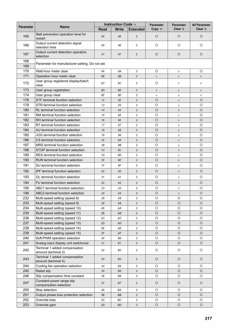
165 Stall prevention operation level for restart 05 85 2
166 Output current detection signal retention time 06 86 2
167 Output current detection operation selection 07 87 2
168Parameter for manufacturer setting. Do not set.
169170 Watt-hour meter clear 0A 8A 2 ×171 Operation hour meter clear 0B 8B 2 × × ×
172 User group registered display/batch clear 0C 8C 2 × ×
173 User group registration 0D 8D 2 × × ×174 User group clear 0E 8E 2 × × ×178 STF terminal function selection 12 92 2 ×179 STR terminal function selection 13 93 2 ×180 RL terminal function selection 14 94 2 ×181 RM terminal function selection 15 95 2 ×182 RH terminal function selection 16 96 2 ×183 RT terminal function selection 17 97 2 ×184 AU terminal function selection 18 98 2 ×185 JOG terminal function selection 19 99 2 ×186 CS terminal function selection 1A 9A 2 ×187 MRS terminal function selection 1B 9B 2 ×188 STOP terminal function selection 1C 9C 2 ×189 RES terminal function selection 1D 9D 2 ×190 RUN terminal function selection 1E 9E 2 ×191 SU terminal function selection 1F 9F 2 ×
192 IPF terminal function selection 20 A0 2 ×
193 OL terminal function selection 21 A1 2 ×
194 FU terminal function selection 22 A2 2 ×195 ABC1 terminal function selection 23 A3 2 ×196 ABC2 terminal function selection 24 A4 2 ×232 Multi-speed setting (speed 8) 28 A8 2
233 Multi-speed setting (speed 9) 29 A9 2
234 Multi-speed setting (speed 10) 2A AA 2
235 Multi-speed setting (speed 11) 2B AB 2
236 Multi-speed setting (speed 12) 2C AC 2
237 Multi-speed setting (speed 13) 2D AD 2
238 Multi-speed setting (speed 14) 2E AE 2
239 Multi-speed setting (speed 15) 2F AF 2
240 Soft-PWM operation selection 30 B0 2
241 Analog input display unit switchover 31 B1 2
242 Terminal 1 added compensation amount (terminal 2) 32 B2 2
243 Terminal 1 added compensation amount (terminal 4) 33 B3 2
244 Cooling fan operation selection 34 B4 2
245 Rated slip 35 B5 2
246 Slip compensation time constant 36 B6 2
247 Constant-power range slip compensation selection 37 B7 2
250 Stop selection 3A BA 2
251 Output phase loss protection selection 3B BB 2
252 Override bias 3C BC 2
253 Override gain 3D BD 2
Parameter NameInstruction Code * 1 Parameter
Copy *2Parameter
Clear *2All Parameter
Clear *2Read Write Extended
317

255 Life alarm status display 3F BF 2 × × ×256 Inrush current limit circuit life display 40 C0 2 × × ×257 Control circuit capacitor life display 41 C1 2 × × ×258 Main circuit capacitor life display 42 C2 2 × × ×259 Main circuit capacitor life measuring 43 C3 2
261 Power failure stop selection 45 C5 2
262 Subtracted frequency at deceleration start 46 C6 2
263 Subtraction starting frequency 47 C7 2
264 Power-failure deceleration time 1 48 C8 2
265 Power-failure deceleration time 2 49 C9 2
266 Power failure deceleration time switchover frequency 4A CA 2
267 Terminal 4 input selection 4B CB 2 ×268 Monitor decimal digits selection 4C CC 2
269 Parameter for manufacturer setting. Do not set.
299 Rotation direction detection selection at restarting 6B EB 2
300 BCD input bias 00 80 3
301 BCD input gain 01 81 3
302 BIN input bias 02 82 3
303 BIN input gain 03 83 3
304Digital input and analog input compensation enable/disable selection
04 84 3
305 Read timing operation selection 05 85 3
306 Analog output signal selection 06 86 3
307 Setting for zero analog output 07 87 3
308 Setting for maximum analog output 08 88 3
309Analog output signal voltage/current switchover
09 89 3
310Analog meter voltage output selection
0A 8A 3
311Setting for zero analog meter voltage output
0B 8B 3
312Setting for maximum analog meter voltage output
0C 8C 3
313 DO0 output selection 0D 8D 3
314 DO1 output selection 0E 8E 3
315 DO2 output selection 0F 8F 3
316 DO3 output selection 10 90 3
317 DO4 output selection 11 91 3
318 DO5 output selection 12 92 3
319 DO6 output selection 13 93 3
320 RA1 output selection 14 94 3
321 RA2 output selection 15 95 3
322 RA3 output selection 16 96 3
323 AM0 0V adjustment 17 97 3 ×
324 AM1 0mA adjustment 18 98 3 ×
329 Digital input unit selection 1D 9D 3 ×331 RS-485 communication station 1F 9F 3 *3 *3
332 RS-485 communication speed 20 A0 3 *3 *3
333 RS-485 communication stop bit length 21 A1 3 *3 *3
Parameter NameInstruction Code * 1 Parameter
Copy *2Parameter
Clear *2All Parameter
Clear *2Read Write Extended
318

334 RS-485 communication parity check selection 22 A2 3 *3 *3
335 RS-485 communication retry count 23 A3 3 *3 *3
336 RS-485 communication check time interval 24 A4 3 *3 *3
337 RS-485 communication waiting time setting 25 A5 3 *3 *3
338 Communication operation command source 26 A6 3 *3 *3
339 Communication speed command source 27 A7 3 *3 *3
340 Communication startup mode selection 28 A8 3 *3 *3
341 RS-485 communication CR/LF selection 29 A9 3 *3 *3
342 Communication EEPROM write selection 2A AA 3
343 Communication error count 2B AB 3 × × ×345 DeviceNet address 2D AD 3 *3 *3
346 DeviceNet baud rate 2E AE 3 *3 *3
349Communication reset selection
31 B1 3 *3 *3
387 Initial communication delay time 57 D7 3
388 Send time interval at heart beat 58 D8 3
389Minimum sending time at heart beat
59 D9 3
390 % setting reference frequency 5A DA 3
391 Receive time interval at heart beat 5B DB 3
392 Event driven detection width 5C DC 3
495 Remote output selection 5F DF 4
496 Remote output data 1 60 E0 4 × × ×497 Remote output data 2 61 E1 4 × × ×
500Communication error execution waiting time
00 80 5 *3 *3
501Communication error occurrence count display
01 81 5 ×
502Stop mode selection at communication error
02 82 5 *3 *3
503 Maintenance timer 03 83 5 × × ×
504 Maintenance timer alarm output set time 04 84 5 ×
522 Output stop frequency 16 96 5
539 Modbus-RTU communication check time interval 27 A7 5 *3 *3
542Communication station number (CC-Link)
2A AA 5 *3 *3
543 Baud rate (CC-Link) 2B AB 5 *3 *3
544 CC-Link extended setting 2C AC 5 *3 *3
549 Protocol selection 31 B1 5 *3 *3
550 NET mode operation command source selection 32 B2 5 *3 *3
551 PU mode operation command source selection 33 B3 5 *3 *3
553 PID deviation limit 35 B5 5
554 PID signal operation selection 36 B6 5
555 Current average time 37 B7 5
556 Data output mask time 38 B8 5
Parameter NameInstruction Code * 1 Parameter
Copy *2Parameter
Clear *2All Parameter
Clear *2Read Write Extended
319

557 Current average value monitor signal output reference current 39 B9 5
563 Energization time carrying-over times 3F BF 5 × × ×564 Operating time carrying-over times 40 C0 5 × × ×571 Holding time at a start 47 C7 5
575 Output interruption detection time 4B CB 5
576 Output interruption detection level 4C CC 5
577 Output interruption cancel level 4D CD 5
611 Acceleration time at a restart 0B 8B 6
653 Speed smoothing control 35 B5 6
654 Speed smoothing cutoff frequency 36 B6 6
799 Pulse increment setting for output power 63 E3 7
867 AM output filter 43 C3 8
872 Input phase loss protection selection 48 C8 8
882 Regeneration avoidance operation selection 52 D2 8
883 Regeneration avoidance operation level 53 D3 8
884 Regeneration avoidance at deceleration detection sensitivity 54 D4 8
885 Regeneration avoidance compensation frequency limit value 55 D5 8
886 Regeneration avoidance voltage gain 56 D6 8
888 Free parameter 1 58 D8 8 × ×889 Free parameter 2 59 D9 8 × ×
891 Cumulative power monitor digit shifted times 5B DB 8
892 Load factor 5C DC 8
893 Energy saving monitor reference (motor capacity) 5D DD 8
894 Control selection during commercial power-supply operation 5E DE 8
895 Power saving rate reference value 5F DF 8
896 Power unit cost 60 E0 8
897 Power saving monitor average time 61 E1 8
898 Power saving cumulative monitor clear 62 E2 8 ×899 Operation time rate (estimated value) 63 E3 8
C0(900) FM terminal calibration 5C DC 1 ×
C1(901) AM terminal calibration 5D DD 1 ×
C2(902)
Terminal 2 frequency setting bias frequency 5E DE 1 ×
C3(902) Terminal 2 frequency setting bias 5E DE 1 ×
125(903)
Terminal 2 frequency setting gain frequency 5F DF 1 ×
C4(903) Terminal 2 frequency setting gain 5F DF 1 ×
C5(904)
Terminal 4 frequency setting bias frequency 60 E0 1 ×
C6(904) Terminal 4 frequency setting bias 60 E0 1 ×
126(905)
Terminal 4 frequency setting gain frequency 61 E1 1 ×
C7(905) Terminal 4 frequency setting gain 61 E1 1 ×
Parameter NameInstruction Code * 1 Parameter
Copy *2Parameter
Clear *2All Parameter
Clear *2Read Write Extended
320

C42(934) PID display bias coefficient 22 A2 9 ×
C43(934) PID display bias analog value 22 A2 9 ×
C44(935) PID display gain coefficient 23 A3 9 ×
C45(935) PID display gain analog value 23 A3 9 ×
989 Parameter copy alarm release 59 D9 9 ×990 PU buzzer control 5A DA 9
991 PU contrast adjustment 5B DB 9 ×
Parameter NameInstruction Code * 1 Parameter
Copy *2Parameter
Clear *2All Parameter
Clear *2Read Write Extended
321

Appendix 3-1 SERIAL number checkRefer to page 2 for the location of the rating plate.
Appendix 3-2 Changed functions(1) Settings "10" and "11" of Pr.495 are valid for the inverter assembled after the following SERIAL.
The inverters whose communication parameters (Pr.345 and Pr.346) are not cleared when parameter clear/all clearis executed using Class 0x2A instance1 Attribute ID105 and 106 are assembled after the following SERIAL.Refer to the table below to check the SERIAL indicated on the inverter rating plate or package.
200V class
Appendix 3 Specification change
Rating plate example7 SERIAL (Serial No.)Symbol Year Month Control number
TC A G TC numberThe SERIAL consists of 1 version symbol, 2 numeric characters or 1 numeric character and 1 alphabet letter indicating year and month, and 6 numeric characters indicating control number.Last digit of the production year is indicated as the Year, and the Month is indicated by 1 to 9, X (October), Y (November), and Z (December).
Inverter Type Label on Product Package Identification Symbol
10th and 11th Digits of TC Number on Rating Plate
SERIAL (First 2 Digits of SERIAL)
FR-F720-0.75K/1.5KWithout G5 E7
<G> G7 C7
FR-F720-2.2K to 5.5KWithout G5 D7
<G> G7 C7
FR-F720-7.5K/11KWithout G5 W7
<G> G7 C7
FR-F720-15KWithout G5 Z7
<G> G7 D7
FR-F720-18.5K to 30KWithout G5 E7
<G> G7 F7
FR-F720-37KWithout G5 C7
<G> G7 C7
FR-F720-45K/55KWithout G5 A7
<G> G7 C7
FR-F720-75K to 110KWithout G5 S7
<G> G7 B7
Bar code
Input rating
7
Identification SymbolInverter Model
SERIAL (Serial No.)
The SERIAL (Serial No.) indicated on the label of the
product package consists of six digits including the first
three digits of the control number and a symbol.
Label on the product package
322

400V class
Inverter Type Label on Product Package Identification Symbol
Lower Third and Second Number of TC
Number on Rating Plate
SERIAL (Upper Second Numbers of SERIAL)
FR-F740-0.75KWithout G5 K7
<G> G7 D7
FR-F740-1.5K/2.2KWithout G5 L7
<G> G7 D7
FR-F740-3.7K/5.5KWithout G5 M7
<G> G7 D7
FR-F740-7.5K to 18.5KWithout G5 C7
<G> G7 E7
FR-F740-22KWithout G5 F7
<G> G7 H7
FR-F740-30KWithout G5 H7
<G> G7 H7
FR-F740-37KWithout G5 F7
<G> G7 E7
FR-F740-45K/55KWithout G5 F7
<G> G7 E7
FR-F740-75KWithout G5 V7
<G> G7 C7
FR-F740-90KWithout G5 V7
<G> G7 D7
FR-F740-110KWithout G5 S7
<G> G7 D7
FR-F740-132K/160KWithout G5 T7
<G> G7 D7
FR-F740-185KWithout G5 R7
<G> G7 D7
FR-F740-220KWithout G5 Q7
<G> G7 D7
FR-F740-250KWithout G5 L7
<G> G7 D7
FR-F740-280KWithout G5 M7
<G> G7 D7
FR-F740-315KWithout G5 L7
<G> G7 D7
FR-F740-355K to 560KWithout G5 M7
<G> G7 B7
323

(2) The following functions can be used with the inverter produced in June 2009 or later.Check the serial number printed on the rating plate or on package.
Item Changed Functions
Added parameter setting values
Pr. 29 Acceleration/deceleration pattern selection setting value "6"Pr. 30 Regenerative function selection setting value "10", "11", "20", "21"Pr. 59 Remote function selection setting value "11 ", "12 ", "13 "Pr.128 PID action selection setting value "110", "111", "120", "121"Pr.167 Output current detection operation selection setting value "10", "11"Pr. 178 to Pr. 189 Input terminal function selection setting value "70", "71", "72"Pr. 190 to Pr. 196 Input terminal function selection setting value "48", "79", "85", "148", "179", "185"Pr. 261 Power failure stop selection setting value "21", "22"
Added parameters
Pr.522 Output stop frequencyPr.553 PID deviation limitPr.554 PID signal operation selectionPr.653 Speed smoothing controlPr.654 Speed smoothing cutoff frequencyPr.799 Pulse increment setting for output powerC42 (Pr.934) PID display bias coefficientC43 (Pr.934) PID display bias analog valueC44 (Pr.935) PID display gain coefficientC45 (Pr.935) PID display gain analog value
Changed parameter setting ranges Pr.153 Zero current detection time setting range "0 to 1s" → "0 to 10s"
324

325
MEMO

326
REVISIONS*The manual number is given on the bottom left of the back cover.
Print Date *Manual Number RevisionMay 2004 IB(NA)-0600177ENG-A First editionOct. 2004 IB(NA)-0600177ENG-B
⋅ FR-F720 - 0.75K to 55K⋅ FR-F740 - 110K to 160K⋅ Pr.299 Rotation direction detection selection at restarting
Mar. 2005 IB(NA)-0600177ENG-C⋅ FR-F720 - 75K to 110K⋅ FR-F740 - 185K to 560K
Jul. 2006 IB(NA)-0600177ENG-D⋅ Pr. 539 Modbus-RTU communication check time interval⋅ Voltage/current input switch⋅ Setting value "2" of Pr. 882 Regeneration avoidance operation selection
Apr. 2008 IB(NA)-0600177ENG-E⋅ Additional explanation to "Causes and Corrective Actions"⋅ Addition of setting values, "10" and "11" to Pr. 495 Remote output selection
Sep. 2009 IB(NA)-0600177ENG-F
・ Pr. 59 Remote function selection setting value "11 ", "12 ", "13 "・ Pr. 29 Acceleration/deceleration pattern selection setting value "6"・ Pr. 30 Regenerative function selection setting value "10", "11", "20", "21"・ Pr.128 PID action selection setting value "110", "111", "120", "121"・ Pr.167 Output current detection operation selection setting value "10", "11"・ Pr. 261 Power failure stop selection setting value "21", "22"・ Pr.522 Output stop frequency・ Pr.653 Speed smoothing control、Pr.654 Speed smoothing cutoff frequency・ Pr.553 PID deviation limit、Pr.554 PID signal operation selection、C42 (Pr.934) PID dis-
play bias coefficient、C43 (Pr.934) PID display bias analog value、C44 (Pr.935) PID dis-play gain coefficient、C45 (Pr.935) PID display gain analog value
・ Pr.799 Pulse increment setting for output power・DC feeding operation permission signal (X70), DC feeding cancel signal
(X71), PID integral value reset signal (X72)・PID deviation limit signal (Y48), pulse output of output power signal (Y79),
DC feeding signal (Y85)
・ Pr.153 Zero current detection time setting range "0 to 10s"・ 5.5 Check first when you have a trouble
Additions
Additions
Additions
Additions
Additions
Partial changes
IB(NA)-0600177ENG-F
Copyright © 2022 FDOKUMEN