RH-5AH/10AH/15AH Series - Suport
127
MITSUBISHI Mitsubishi Industrial Robot RH-5AH/10AH/15AH Series Standard Specifications Manual (CR2A-572 Controller) BFP-A8174-E
-
Upload
khangminh22 -
Category
Documents
-
view
0 -
download
0
Transcript of RH-5AH/10AH/15AH Series - Suport

MITSUBISHIMitsubishi Industrial Robot
RH-5AH/10AH/15AH SeriesStandard Specifications Manual
(CR2A-572 Controller)
BFP-A8174-E

All teaching work must be carried out by an operator who has received special training. (This also applies to maintenance work with the power source turned ON.)→ Enforcement of safety training
For teaching work, prepare a work plan related to the methods and procedures of oper-ating the robot, and to the measures to be taken when an error occurs or when restart-ing. Carry out work following this plan. (This also applies to maintenance work with the power source turned ON.)→ Preparation of work plan
Prepare a device that allows operation to be stopped immediately during teaching work. (This also applies to maintenance work with the power source turned ON.)→ Setting of emergency stop switch
During teaching work, place a sign indicating that teaching work is in progress on the start switch, etc. (This also applies to maintenance work with the power source turned ON.)→ Indication of teaching work in progress
Provide a fence or enclosure during operation to prevent contact of the operator and robot.→ Installation of safety fence
Establish a set signaling method to the related operators for starting work, and follow this method.→ Signaling of operation start
As a principle turn the power OFF during maintenance work. Place a sign indicating that maintenance work is in progress on the start switch, etc.→ Indication of maintenance work in progress
Before starting work, inspect the robot, emergency stop switch and other related devices, etc., and confirm that there are no errors.→ Inspection before starting work
CAUTION
CAUTION
WARNING
CAUTION
WARNING
CAUTION
CAUTION
CAUTION
Always read the following precautions and the separate "SafetyManual" before starting use of the robot to learn the requiredmeasures to be taken.
Safety Precautions

The points of the precautions given in the separate "Safety Manual" are given below.Refer to the actual "Safety Manual" for details.
Use the robot within the environment given in the specifications. Failure to do so could lead to a drop or reliability or faults. (Temperature, humidity, atmosphere, noise environ-ment, etc.)
Transport the robot with the designated transportation posture. Transporting the robot in a non-designated posture could lead to personal injuries or faults from dropping.
Always use the robot installed on a secure table. Use in an instable posture could lead to positional deviation and vibration.
Wire the cable as far away from noise sources as possible. If placed near a noise source, positional deviation or malfunction could occur.
Do not apply excessive force on the connector or excessively bend the cable. Failure to observe this could lead to contact defects or wire breakage.
Make sure that the workpiece weight, including the hand, does not exceed the rated load or tolerable torque. Exceeding these values could lead to alarms or faults.
Securely install the hand and tool, and securely grasp the workpiece. Failure to observe this could lead to personal injuries or damage if the object comes off or flies off during operation.
Securely ground the robot and controller. Failure to observe this could lead to malfunc-tioning by noise or to electric shock accidents.
Indicate the operation state during robot operation. Failure to indicate the state could lead to operators approaching the robot or to incorrect operation.
When carrying out teaching work in the robot's movement range, always secure the pri-ority right for the robot control. Failure to observe this could lead to personal injuries or damage if the robot is started with external commands.
Keep the jog speed as low as possible, and always watch the robot. Failure to do so could lead to interference with the workpiece or peripheral devices.
After editing the program, always confirm the operation with step operation before starting automatic operation. Failure to do so could lead to interference with peripheral devices because of programming mistakes, etc.
Make sure that if the safety fence entrance door is opened during automatic operation, the door is locked or that the robot will automatically stop. Failure to do so could lead to personal injuries.
Never carry out modifications based on personal judgments, or use non-designated maintenance parts. Failure to observe this could lead to faults or failures.
When the robot arm has to be moved by hand from an external area, do not place hands or fingers in the openings. Failure to observe this could lead to hands or fingers catching depending on the posture.
Do not stop the robot or apply emergency stop by turning the robot controller's main power OFF.If the robot controller main power is turned OFF during automatic operation, the robot accuracy could be adversely affected.
CAUTION
CAUTION
CAUTION
CAUTION
CAUTION
CAUTION
WARNING
WARNING
CAUTION
WARNING
CAUTION
CAUTION
CAUTION
CAUTION
WARNING
CAUTION

For using RH-5AH/10AH/15AH.While pressing the brake releasing switch on the robot arm, beware of the arm which may drop with its own weight.
Dropping of the hand could lead to a collision with the peripheral equipment or catch the hands or fingers.
WARNING
■ Revision history
Date of print Specifications No. Details of revisions
2001-03-28 BFP-A8174Z First print
2001-09-25 BFP-A8174 Formal style.
2001-10-30 BFP-A8174-A The explanation of the RH-5AH series was added.
Error in writing correction.
2001-12-17 BFP-A8174-B The parameter "Select the function of singular point adjacent alarm (MESNGLSW)" was
added.
Error in construction equipment of hand output cable(1N-GR35S) was corrected.
The parameter RLNG was removed.
2002-02-06 BFP-A8174-C RLNG parameter was added.
The installation method of memory cassette was modified.
Error in writing correction.
2002-04-01 BFP-A8174-D CR2A-MB (controller protection box) was added.
Error in writing correction.
2002-06-27 BFP-A8174-E The description of input/output circuit terminal was corrected.
Error in writing correction.

■ IntroductionThe RH-5AH/10AH/15AH Series offers small-size industrial robots developed using Mitsubishi's latest technol-ogy. They are especially designed to handle and assemble mechanical parts. They are Mitsubishi's answer to the customer's need to achieve a compact manufacturing facility capable of highly flexible production, as necessitated by the diffusion of high-density product groups and the shorter product life cycles that have become common-place in recent years.
However, to comply with the target application, a work system having a well-balanced robot arm, peripheral devices or robot and hand section must be structured.
When creating these standard specifications, we have edited them so that the Mitsubishi robot's characteristics and specifications can be easily understood by users considering the implementation of robots. However, if there are any unclear points, please contact your nearest Mitsubishi branch or dealer.
Mitsubishi hopes that you will consider these standard specifications and use our robots.
In this manual, the specifications regarding the robot arm are given in Page 7, "2 Robot arm" and following, and the specifications regarding the controller are given in Page 57, "3 Controller" and following. Refer to the correspond-ing sections for details on the specifications, options and maintenance parts, etc.
Note:
・ No part of this manual may be reproduced by any means or in any form, without prior consent from Mitsubishi.・ The contents of this manual are subject to change without notice.・ The specifications values are based on Mitsubishi standard testing methods.・ The information contained in this document has been written to be accurate as much as possible. Please inter-
pret that items not described in this document "cannot be performed." Though this specifications is produced with extreme care, please contact your nearest dealer if you find any doubtful, wrong or skipped point.

Contents
i
Page
1 General configuration ................................................................................................................................................................................... 1-1
1.1 Structural equipment ............................................................................................................................................................................ 1-11.1.1 Standard structural equipment ................................................................................................................................................. 1-11.1.2 Shipping special specifications ................................................................................................................................................. 1-11.1.3 Options ............................................................................................................................................................................................... 1-11.1.4 Maintenance parts ......................................................................................................................................................................... 1-1
1.2 Contents of the structural equipment .......................................................................................................................................... 1-21.2.1 Robot arm .......................................................................................................................................................................................... 1-2
1.3 Controller .................................................................................................................................................................................................. 1-3
1.4 Contents of the Option equipment and special specification ............................................................................................. 1-4
2 Robot arm ......................................................................................................................................................................................................... 2-7
2.1 Standard specifications ....................................................................................................................................................................... 2-7
2.2 Definition of specifications ................................................................................................................................................................ 2-92.2.1 Pose repeatability and distance accuracy ........................................................................................................................... 2-92.2.2 Mass capacity and the allowable moment ........................................................................................................................ 2-102.2.3 Relationships Among Mass Capacity, Speed, and Acceleration/Deceleration Speed ................................... 2-10
(1) Setting Load Capacity and Size (Hand Conditions) ................................................................................................. 2-10(2) Relationship Between Mass Capacity and Speed ..................................................................................................... 2-11(3) Relationship Between Height of Shaft (J3 Axis) and Acceleration/Deceleration Speed ........................ 2-11(4) Time to reach the position repeatability (only for RH-15AH85) ........................................................................ 2-12
2.2.4 Protection specifications and working environment ..................................................................................................... 2-13(1) Types of protection specifications .................................................................................................................................. 2-13(2) About the use with the bad environment .................................................................................................................... 2-13
2.2.5 Clean specifications (RH-5AH series) ............................................................................................................................... 2-14(1) Types of clean specifications ............................................................................................................................................ 2-14
2.3 Names of each part of the robot .................................................................................................................................................. 2-15
2.4 Outside dimensions ・ Operating range diagram ..................................................................................................................... 2-162.4.1 Outside dimensions ・ Operating range diagram of RH-5AH series ....................................................................... 2-16
(1) RH-5AH35 ................................................................................................................................................................................. 2-16(2) RH-5AHM35 .............................................................................................................................................................................. 2-17(3) RH-5AHC35-SA ...................................................................................................................................................................... 2-18(4) RH-5AH45 ................................................................................................................................................................................. 2-19(5) RH-5AHM45 .............................................................................................................................................................................. 2-20(6) RH-5AHC45-SA ...................................................................................................................................................................... 2-21(7) RH-5AH55 ................................................................................................................................................................................. 2-22(8) RH-5AHM55 .............................................................................................................................................................................. 2-23(9) RH-5AHC55-SA ...................................................................................................................................................................... 2-24
2.4.2 Outside dimensions, Operating range diagram of RH-10AH Series ...................................................................... 2-25(1) RH-10AH55 ............................................................................................................................................................................... 2-25(2) RH-10AHM55 ........................................................................................................................................................................... 2-26(3) RH-10AH70 ............................................................................................................................................................................... 2-27(4) RH-10AHM70 ........................................................................................................................................................................... 2-28(5) RH-10AH85/RH-15AH85 .................................................................................................................................................... 2-29(6) RH-10AHM85/RH-15AHM85 ............................................................................................................................................ 2-30
2.4.3 Change the operating range .................................................................................................................................................... 2-312.4.4 Mechanical interface and Installation surface ................................................................................................................. 2-33
(1) Mechanical interface and Installation surface of RH-5AH series ...................................................................... 2-33(2) Mechanical interface and Installation surface of RH-10AH/15AH series ...................................................... 2-34
2.5 Tooling ..................................................................................................................................................................................................... 2-352.5.1 Wiring and piping for hand ........................................................................................................................................................ 2-352.5.2 Internal air piping ......................................................................................................................................................................... 2-362.5.3 Internal wiring for the pneumatic hand output cable ................................................................................................... 2-362.5.4 Internal wiring for the hand check input cable ............................................................................................................... 2-362.5.5 Precautions for piping to the flexible cable ..................................................................................................................... 2-362.5.6 About the Installation of Tooling Wiring and Piping (Examples of Wiring and Piping) ..................................... 2-372.5.7 Electrical specifications of hand input/output ............................................................................................................... 2-422.5.8 Air supply circuit example for the hand ............................................................................................................................. 2-43
2.6 Shipping special specifications, options, and maintenance parts ................................................................................... 2-44

ii
Page
2.6.1 Shipping special specifications .............................................................................................................................................. 2-44(1) Machine cable extension ..................................................................................................................................................... 2-45
2.7 Options .................................................................................................................................................................................................... 2-47(1) Solenoid valve set .................................................................................................................................................................. 2-48(2) Hand input cable (Hand chack cable) ............................................................................................................................. 2-52(3) Hand output cable .................................................................................................................................................................. 2-53(4) Hand curl tube ......................................................................................................................................................................... 2-54
2.8 Maintenance parts .............................................................................................................................................................................. 2-55
3 Controller ....................................................................................................................................................................................................... 3-57
3.1 Standard specifications .................................................................................................................................................................... 3-573.1.1 Standard specifications ............................................................................................................................................................ 3-573.1.2 Protection specifications and operating supply ............................................................................................................. 3-58
3.2 Names of each part ........................................................................................................................................................................... 3-59
3.3 Outside dimensions/Installation dimensions ........................................................................................................................... 3-613.3.1 Outside dimensions .................................................................................................................................................................... 3-613.3.2 Installation dimensions .............................................................................................................................................................. 3-62
3.4 External input/output ....................................................................................................................................................................... 3-633.4.1 Types ................................................................................................................................................................................................ 3-633.4.2 Explanation ..................................................................................................................................................................................... 3-63
3.5 Dedicated input/output .................................................................................................................................................................... 3-64
3.6 Emergency stop input/output ....................................................................................................................................................... 3-663.6.1 Connection of the external emergency stop ................................................................................................................... 3-663.6.2 Door switch function ................................................................................................................................................................. 3-67
3.7 Parallel input/output unit ................................................................................................................................................................ 3-68
3.8 Options .................................................................................................................................................................................................... 3-72(1) Teaching pendant (T/B) ...................................................................................................................................................... 3-73(2) Pneumatic hand interface ................................................................................................................................................... 3-76(3) Controller protection box .................................................................................................................................................... 3-78(4) Parallel I/O unit ....................................................................................................................................................................... 3-81(5) External I/O cable .................................................................................................................................................................. 3-89(6) Personal computer cable ..................................................................................................................................................... 3-91(7) Extension memory cassette ............................................................................................................................................... 3-92(8) Personal computer support software/Personal computer support software mini ..................................... 3-94
3.9 Maintenance parts .............................................................................................................................................................................. 3-96
4 Software ......................................................................................................................................................................................................... 4-97
4.1 List of commands ............................................................................................................................................................................... 4-97(1) The procedure of robot language selection ................................................................................................................. 4-97(2) MELFA-BASIC Ⅳ commands ........................................................................................................................................... 4-98(3) MOVEMASTER commands ............................................................................................................................................... 4-100
4.2 List of parameters ............................................................................................................................................................................ 4-103(1) List of parameters ................................................................................................................................................................ 4-103(2) Change the display language / 表示言語の切り替え .......................................................................................... 4-105
5 Safety ............................................................................................................................................................................................................ 5-107
5.1 Safety .................................................................................................................................................................................................... 5-1075.1.1 Self-diagnosis stop functions .............................................................................................................................................. 5-1075.1.2 External input/output signals that can be used for safety protection measures ......................................... 5-1075.1.3 Precautions for using robot .................................................................................................................................................. 5-1085.1.4 Safety measures for automatic operation ...................................................................................................................... 5-1085.1.5 Safety measures for teaching .............................................................................................................................................. 5-1085.1.6 Safety measures for maintenance and inspections, etc. ......................................................................................... 5-1085.1.7 Examples of safety measures .............................................................................................................................................. 5-109
5.2 Working environment ....................................................................................................................................................................... 5-110
5.3 Precautions for handling ................................................................................................................................................................ 5-1106Appendix .........................................................................................................................................................................................Appendix-111
Appendix 1 : Specifications discussion material ....................................................................................................... Appendix-111

1General configuration
Structural equipment 1-1
1 General configuration
1.1 Structural equipment
Structural equipment consists of the following types.
1.1.1 Standard structural equipmentThe following items are enclosed as a standard.
(1) Robot arm (2) Controller(3) Machine cable(4) Robot arm installation bolts(5) Instruction manual, Safety manual(6) Guarantee card
1.1.2 Shipping special specificationsPart of the standard structural equipment is changed at the time of factory shipment. Consequently, kindly con-firm the delivery date.
To make changes to the specifications after shipment, service work must be performed at the work site or the robot must be returned for service.
1.1.3 OptionsInstallation is possible after shipment. Customer needs to perform the installation work.
1.1.4 Maintenance partsConsumable parts and spare parts for maintenance use.
For items not listed, contact the dealer where you made your purchase.

1-2 Contents of the structural equipment
1General configuration
1.2 Contents of the structural equipment
1.2.1 Robot armThe devices shown below can be installed on the robot arm.
Fig.1-1 : Structural equipment (Robot arm)
Horizontal four-axis multiple-jointed type
RH-5AH series RH-5AH:General environment RH-5AHM:Protection spesification RH-5AHC:Clean spesificationRH-10AH/15AH series RH-10AH/15AH:General environment RH-10AHM/15AHM:Protection spesification
Machine cable fixed type 5m・ 1A-5CBL-1(RH-5AH series)・ 1E-5CBL-N(RH-10AH/15AH series)
Machine cable extensionRH-5AH series
・ Fixed type:1A- □□ CBL-1・ Flexed type:1A- □□ LCBL-1
RH-10AH/15AH series・ Fixed type:1E- □□ CBL-N・ Flexed type:1E- □□ LCBL-N
Note) □□ refer the length.Refer to section "1.4" for datails.
Hand output cable・ 1N-GR35S
Hand input cable・ 1A-HC35C
RH-5AH series<sink type>・ 1 set : 1E-VD01・ 2 set : 1E-VD02・ 3 set : 1E-VD03・ 4 set : 1E-VD04<source type>・ 1 set : 1E-VD01E・ 2 set : 1E-VD02E・ 3 set : 1E-VD03E・ 4 set : 1E-VD04E
RH-10AH/15AH series<sink type>・ 1 set : 1N-VD01・ 2 set : 1N-VD02・ 3 set : 1N-VD03・ 4 set : 1N-VD04<source type>・ 1 set : 1N-VD01E・ 2 set : 1N-VD02E・ 3 set : 1N-VD03E・ 4 set : 1N-VD04E
RH-5AH series<sink type>・ 1 set : 1A-VD01M-01・ 2 set : 1A-VD02M-01・ 3 set : 1A-VD03M-01・ 4 set : 1A-VD04M-01・ Solenoid valve box<source type>・ 1 set : 1A-VD01ME-01・ 2 set : 1A-VD02ME-01・ 3 set : 1A-VD03ME-01・ 4 set : 1A-VD04ME-01・ Solenoid valve box
Solenoid valve set (General environment)
RH-10AH/15AH series<sink type>・ 1 set : 1A-VD01M-02・ 2 set : 1A-VD02M-02・ 3 set : 1A-VD03M-02・ 4 set : 1A-VD04M-02・ Solenoid valve box<source type>・ 1 set : 1A-VD01ME-02・ 2 set : 1A-VD02ME-02・ 3 set : 1A-VD03ME-02・ 4 set : 1A-VD04ME-02・ Solenoid valve box
Solenoid valve set (Protection spesification)
Note) With installation bolts.
Hand curl tube・ 1 set, 2pc. : 1E-ST0402C-300・ 2 set, 4pc. : 1E-ST0404C-300・ 3 set, 6pc. : 1E-ST0406C-300・ 4 set, 8pc. : 1E-ST0408C-300
Pneu
mat
ic h
and
cust
om
er-
man
ufa
ctur
ed
part
s
��������������� ��������������������������������������������������������
�
[Caution]Standard configuration
Special shipping
Option
equipment
specifications
Prepared by customer
1General configuration
Controller 1-3
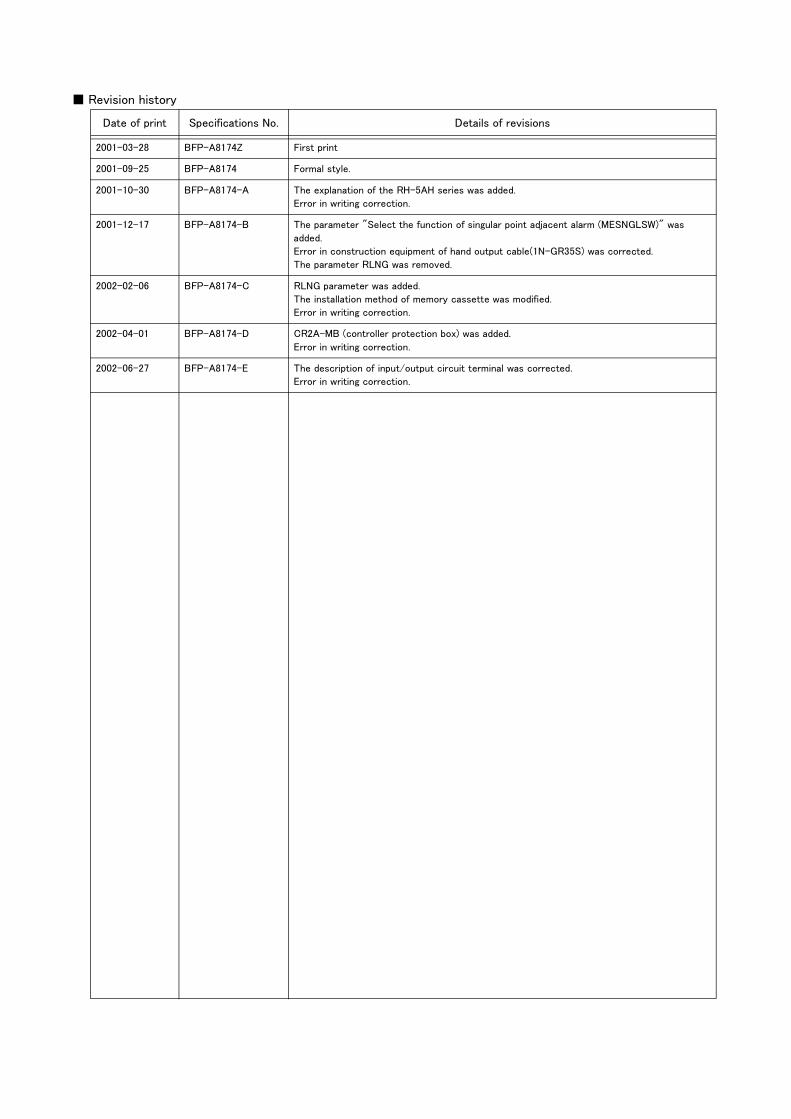
1.3 Controller
The devices shown below can be installed on the controller.
Fig.1-2 : Structural equipment(Controller)
PLC(Programmable Logic Controller)External device
Prepared by customer
Controller・ CR2A-572
Pneumatic I/F・ 2A-RZ365 (Sink)・ 2A-RZ375 (Source)
Personal computer cable・ RS-MAXY-CBL
Personal computer support software(MS-Windows95/98/NT4.0)・ 3A-01C-WINE(CD-ROM)Personal computer support software mini(MS-Windows95/98/NT4.0)・ 3A-02C-WINE(CD-ROM)
Teaching pendant(T/B)・ R28TB
Parallel I/O unit・ 2A-RZ361 (Sink)・ 2A-RZ371 (Source)
External I/O cable・ 2A-CBL05 (5m)・ 2A-CBL15 (15m)
Extended serial I/F・ 2A-RZ581E
ETHERNET I/F・ 2A-HR533E
CC-LINK I/F・ 2A-HR575E
Additional axis I/F・ 2A-RZ541E
Personal computerPreparedby customer
Extended memory Cassette.・ 2A-HR432
Controller protection box・ CR2A-MB
���������������� �������������� ����������������������������������������������
����
[Caution]Standard configuration
Special shipping
Option
equipment
specifications
Prepared by customer

1-4 Contents of the Option equipment and special specification
1General configuration
1.4 Contents of the Option equipment and special specification
A list of all Optional equipments and special specifications are shown below.
Table 1-1 : The list of Option equipment and special specification (RH-5AH series)
Note1) In the classification column, ○ refers to an option,and □ to a Sipping special specifications.
Note2) Use this option for solenoid valve set when use with the bad environment such as oil mist. The solenoid valve box which protects the solenoid valve is attached to this option.Note3) A procedure for securing protection and cleanliness is required for customers. For more details, refer to the Page 44, "2.6 Shipping special specifications, options, and maintenance parts".Note4) Use this option to protect the controller from the oil mist when the controller will be installed in the environment such as the oil mist.
Item Type SpecificationsClassific
ation Note1)
Descripsion
Solenoid valve setStandard specification 1E-VD01 1 set(Sink type) ○
The solenoid valve set is for the pneumatic hand prepared by customer.
1E-VD02 2 set(Sink type) ○ 1E-VD03 3 set(Sink type) ○ 1E-VD04 4 set(Sink type) ○ 1E-VD01E 1 set(Source type) ○ 1E-VD02E 2 set(Source type) ○ 1E-VD03E 3 set(Source type) ○ 1E-VD04E 4 set(Source type) ○
Protection spesification Note2) 1A-VD01M-01 1 set(Sink type) ○ 1A-VD02M-01 2 set(Sink type) ○ 1A-VD03M-01 3 set(Sink type) ○ 1A-VD04M-01 4 set(Sink type) ○ 1A-VD01ME-01 1 set(Source type) ○ 1A-VD02ME-01 2 set(Source type) ○ 1A-VD03ME-01 3 set(Source type) ○ 1A-VD04ME-01 4 set(Source type) ○
Hand input cable Note3) 1A-HC35C Length 1,150mm with robot side con-nector. One terminal is not treated.
○ The cable is to connect with the hand sensor, etcby customer.
Hand output cable Note3) 1N-GR35S Length 350mm with robot side con-nector. One terminal is not treated.
○ The cable is to connect with the solenoid valve prepared by customer and output connector
Hand curl tube Note3) 1E-ST0402C-300 For solenoid valve 1set.:Φ4x2 ○
Curl type air tube1E-ST0404C-300 For solenoid valve 2set.:Φ4x4 ○1E-ST0406C-300 For solenoid valve 3set :Φ4x6 ○1E-ST0408C-300 For solenoid valve 4set :Φ4x8 ○
Extended machine cable 1A-10CBL-1 For fixing(Two sets for power and signal)
□ 10m1A-15CBL-1 □ 15m1A-05LCBL-1
For flexing(Two sets for power and signal)
□ 5m1A-10LCBL-1 □ 10m1A-15LCBL-1 □ 15m
Teaching pendant R28TB Cable length 7m ○ With 3-position deadman switch/ IP 65
R28TB-15Cable length 15m(special specification)
○
Pneumatic hand interface 2A-RZ365 DO: 8 point (Sink type) ○ It is necessary when the hand output signal of the robot arm is used. (Integrated in the controller.)2A-RZ375 DO: 8 point (Source type) ○
Parallel I/O interface2A-RZ361
DO: 32 point (Sink type)/DI : 32 point (Sink type)
○The unit for expansion the external input/output. Electrical isolated Type(100mA/Point)
2A-RZ371 DO: 32 point (Source type)/DI : 32 point (Source type)
○
External I/O cable 2A-CBL05 5m ○ Use to connect the external peripheral device to the parallel input/output unit2A-CBL15 15m ○
Personal computer cableRS-MAXY-CBL
RS-232C cable 3m for PC-AT com-patible model
○
Personal computerSupport software
3A-01C-WINE CD-ROM ○ MS-Windows95/98/NT4.0 (With the simulation function)
Personal computerSupport software mini
3A-02C-WINE CD-ROM ○ MS-Windows95/98/NT4.0 (Without the simulation function)
Extended serial interface2A-RZ581E
RS-232C x 1RS-232C or RS-422 x 1
○
CC-Link interface 2A-HR575E Local station (The local station alone is supported.)
○for MELSEC PLC with CC-Link connection.
ETHERNET interface 2A-HR533E ETHERNET x 1 ○
Additional axis interface 2A-RZ541E SSC x 1Up to 8 axises can be added
○MR-J2 servoAmplifer Unit connection. CR-EB3 is need.
Extended memory cassette 2A-HR432 Teaching point is 25,400 points.○
Expand the teaching point up to 27,900 points, including 2,500 points of standard
Controller protection box CR2A-MB IP54 □The controller protection box is used to pro-tect the controller from an oil mist or other operating environment. Note4)

1General configuration
Contents of the Option equipment and special specification 1-5
Table 1-2 : The list of Option equipment and special specification (RH-10AH/15AH series)
Note1) In the classification column, ○ refers to an option,and □ to a Sipping special specifications. Note2)Use this option for solenoid valve set when use with the bad environment such as oil mist. The solenoid valve box which protects the solenoid valve is attached to this option.Note3) A procedure for securing protection is required for customers. For more details, refer to the Page 44, "2.6 Shipping special specifications, options, and maintenance parts".Note4) Use this option to protect the controller from the oil mist when the controller will be installed in the environment such as the oil mist.
Item Type SpecificationsClassific
ation Note1)
Descripsion
Solenoid valve setStandard specification 1N-VD01 1 set(Sink type) ○
The solenoid valve set is for the pneumatic hand prepared by customer.
1N-VD02 2 set(Sink type) ○ 1N-VD03 3 set(Sink type) ○ 1N-VD04 4 set(Sink type) ○ 1N-VD01E 1 set(Source type) ○ 1N-VD02E 2 set(Source type) ○ 1N-VD03E 3 set(Source type) ○ 1N-VD04E 4 set(Source type) ○
Protection spesification Note2) 1A-VD01M-02 1 set(Sink type) ○ 1A-VD02M-02 2 set(Sink type) ○ 1A-VD03M-02 3 set(Sink type) ○ 1A-VD04M-02 4 set(Sink type) ○ 1A-VD01ME-02 1 set(Source type) ○ 1A-VD02ME-02 2 set(Source type) ○ 1A-VD03ME-02 3 set(Source type) ○ 1A-VD04ME-02 4 set(Source type) ○
Hand input cable 1A-HC35C Length 1,150mm with robot side con-nector. One terminal is not treated.
○ The cable is to connect with the hand sensor, etcby customer.
Hand output cable Note3) 1N-GR35S Length 350mm with robot side con-nector. One terminal is not treated.
○ The cable is to connect with the solenoid valve prepared by customer and output connector
Hand curl tube 1E-ST0402C-300 For solenoid valve 1set.:Φ4x2 ○
Curl type air tube1E-ST0404C-300 For solenoid valve 2set.:Φ4x4 ○1E-ST0406C-300 For solenoid valve 3set :Φ4x6 ○1E-ST0408C-300 For solenoid valve 4set :Φ4x8 ○
Extended machine cable 1E-10CBL-N For fixing(Two sets for power and signal)
□ 10m1E-15CBL-N □ 15m1E-05LCBL-N
For flexing(Two sets for power and signal)
□ 5m1E-10LCBL-N □ 10m1E-15LCBL-N □ 15m
Teaching pendant R28TB Cable length 7m ○ With 3-position deadman switch/ IP 65
R28TB-15Cable length 15m(special specification)
○
Pneumatic hand interface 2A-RZ365 DO: 8 point (Sink type) ○ It is necessary when the hand output signal of the robot arm is used. (Integrated in the controller.)2A-RZ375 DO: 8 point (Source type) ○
Parallel I/O interface2A-RZ361
DO: 32 point (Sink type)/DI : 32 point (Sink type)
○The unit for expansion the external input/output. Electrical isolated Type(100mA/Point)
2A-RZ371 DO: 32 point (Source type)/DI : 32 point (Source type)
○
External I/O cable 2A-CBL05 5m ○ Use to connect the external peripheral device to the parallel input/output unit2A-CBL15 15m ○
Personal computer cableRS-MAXY-CBL
RS-232C cable 3m for PC-AT com-patible model
○
Personal computerSupport software
3A-01C-WINE CD-ROM ○ MS-Windows95/98/NT4.0 (With the simulation function)
Personal computerSupport software mini
3A-02C-WINE CD-ROM ○ MS-Windows95/98/NT4.0 (Without the simulation function)
Extended serial interface2A-RZ581E
RS-232C x 1RS-232C or RS-422 x 1
○
CC-Link interface 2A-HR575E Local station (The local station alone is supported.)
○for MELSEC PLC with CC-Link connection.
ETHERNET interface 2A-HR533E ETHERNET x 1 ○
Additional axis interface 2A-RZ541E SSC x 1Up to 8 axises can be added
○MR-J2 servoAmplifer Unit connection. CR-EB3 is need.
Extended memory cassette 2A-HR432 Teaching point is 25,400 points.○
Expand the teaching point up to 27,900 points, including 2,500 points of standard
Controller protection box CR2A-MB IP54 □The controller protection box is used to pro-tect the controller from an oil mist or other operating environment. Note4)

1-6 Contents of the Option equipment and special specification
1General configuration
2Robot arm
Standard specifications 2-7
2 Robot arm
2.1 Standard specifications
2.1.1 Standard specifications
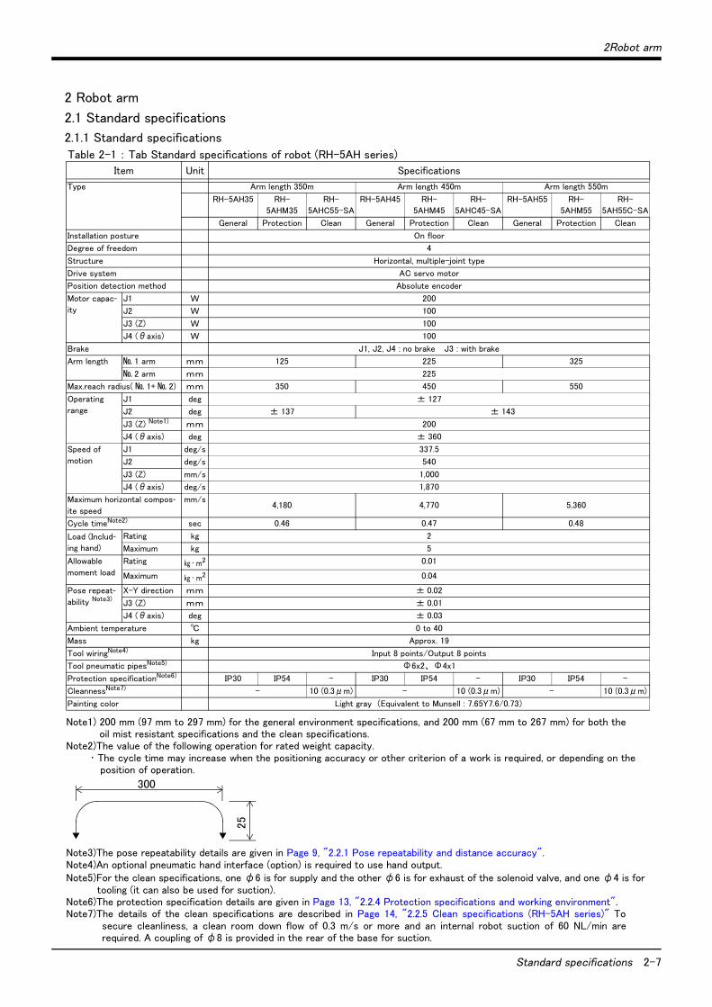
Table 2-1 : Tab Standard specifications of robot (RH-5AH series)
Item Unit Specifications
Type Arm length 350m Arm length 450m Arm length 550m
RH-5AH35 RH-
5AHM35
RH-
5AHC55-SA
RH-5AH45 RH-
5AHM45
RH-
5AHC45-SA
RH-5AH55 RH-
5AHM55
RH-
5AH55C-SA
General Protection Clean General Protection Clean General Protection Clean
Installation posture On floor
Degree of freedom 4
Structure Horizontal, multiple-joint type
Drive system AC servo motor
Position detection method Absolute encoder
Motor capac-ity
J1 W 200
J2 W 100
J3 (Z) W 100
J4 (θaxis) W 100
Brake J1, J2, J4 : no brake J3 : with brake
Arm length № 1 arm mm 125 225 325
№ 2 arm mm 225
Max.reach radius( № 1+ № 2) mm 350 450 550
Operating
range
J1 deg ± 127
J2 deg ± 137 ± 143
J3 (Z) Note1)
Note1) 200 mm (97 mm to 297 mm) for the general environment specifications, and 200 mm (67 mm to 267 mm) for both theoil mist resistant specifications and the clean specifications.
mm 200
J4 (θaxis) deg ± 360
Speed of
motion
J1 deg/s 337.5
J2 deg/s 540
J3 (Z) mm/s 1,000
J4 (θaxis) deg/s 1,870
Maximum horizontal compos-ite speed
mm/s4,180 4,770 5,360
Cycle timeNote2)
Note2)The value of the following operation for rated weight capacity.・ The cycle time may increase when the positioning accuracy or other criterion of a work is required, or depending on the
position of operation.
sec 0.46 0.47 0.48
Load (Includ-ing hand)
Rating kg 2
Maximum kg 5
Allowable
moment load
Rating kg ・ m2 0.01
Maximum kg ・ m2 0.04
Pose repeat-ability Note3)
Note3)The pose repeatability details are given in Page 9, "2.2.1 Pose repeatability and distance accuracy".
X-Y direction mm ± 0.02
J3 (Z) mm ± 0.01
J4 (θaxis) deg ± 0.03
Ambient temperature ℃ 0 to 40
Mass kg Approx. 19
Tool wiringNote4)
Note4)An optional pneumatic hand interface (option) is required to use hand output.
Input 8 points/Output 8 points
Tool pneumatic pipesNote5)
Note5)For the clean specifications, one φ6 is for supply and the other φ6 is for exhaust of the solenoid valve, and one φ4 is for tooling (it can also be used for suction).
Φ6x2、 Φ4x1
Protection specificationNote6)
Note6)The protection specification details are given in Page 13, "2.2.4 Protection specifications and working environment".
IP30 IP54 - IP30 IP54 - IP30 IP54 -
CleannessNote7)
Note7)The details of the clean specifications are described in Page 14, "2.2.5 Clean specifications (RH-5AH series)" Tosecure cleanliness, a clean room down flow of 0.3 m/s or more and an internal robot suction of 60 NL/min arerequired. A coupling of φ8 is provided in the rear of the base for suction.
- 10 (0.3μm) - 10 (0.3μm) - 10 (0.3μm)
Painting color Light gray (Equivalent to Munsell : 7.65Y7.6/0.73)
300
25

2-8 Standard specifications
2Robot arm
Table 2-2 : Tab Standard specifications of robot (RH-10AH/15AH series)
Item Unit Specifications
Type Arm length 550m Arm length 700m Arm length 850m Arm length 850m
RH-
10AH55
RH-
10AHM55
RH-
10AH70
RH-
10AHM70
RH-
10AH85
RH-
10AHM85
RH-
15AH85
RH-
15AHM85
General Protection General Protection General Protection General Protection
Installation posture On floor
Degree of freedom 4
Structure Horizontal, multiple-joint type
Drive system AC servo motor
Position detection method Absolute encoder
Motor capacity J1 W 400
J2 W 200
J3 (Z) W 200
J4 (θaxis) W 100
Brake J1, J2, J4 : no brake J3 : with brake (RH-10AH55/70/85)
J1, J2 : no brake J3, J4 : with brake (RH-15AH85)
Arm length № 1 arm mm 225 375 525
№ 2 arm mm 325
Max.reach radius ( № 1+ № 2) mm 550 700 850
Operating range J1 deg ± 140
J2 deg ± 145 ± 153
J3 (Z) Note1)
Note1) 350 mm (-10 mm to 340 mm) for the general environment specifications, and 300 mm (-10 mm to 290 mm) for the oilmist resistant specifications.
mm 350 300 350 300 350 300 350 300
J4 (θaxis) deg ± 360
Speed of motion J1 deg/s 315 252
J2 deg/s 337.5
J3 (Z) mm/s 1,125 1,000
J4 (θaxis) deg/s 1,274
Maximum horizontal composite speed mm/s 4,930 5,760 5,650
Cycle timeNote2)
Note2)These values are for the rated weight capacity. The cycle time may increase when a higher work positioning accuracy is required, or depending on the operating position.
sec 0.49 0.5 0.52 0.57
Load
(Including hand)
Rating kg 2 5
Maximum kg 10 15
Allowable
moment load
Rating kg ・ m2 0.02
Maximum kg ・ m2 0.1 0.2
Pose repeatability Note3)
Note3)The pose repeatability details are given in Page 9, "2.2.1 Pose repeatability and distance accuracy".
X-Y composition mm ± 0.02 ± 0.025
J3 (Z) mm ± 0.01
J4 (θaxis) deg ± 0.03
Mass kg 38 39 40 42
Ambient temperature ℃ 0 to 40
Tool wiringNote4)
Note4)An optional puneumatic hand interface (option) is required to use hand output.
Input 8 points/Output 8 points
Tool pneumatic pipes Φ6x2, Φ4x1
Protection specificationsNote5)
Note5)The protection specification details are given in Page 13, "2.2.4 Protection specifications and workingenvironment".
IP30 IP54 IP30 IP54 IP30 IP54 IP30 IP54
Painting color Light gray (Equivalent to Munsell : 7.65Y7.6/0.73)

2 Robot arm
Definition of specifications 2-9
2.2 Definition of specifications
The accuracy of pose repeatability mentioned in catalogs and in the specification manual is defined as follows.
2.2.1 Pose repeatability and distance accuracyThis robot, the pose repeatability and distance accuracy are defined and calculated in Table 2-3.
(1) The pose accuracy in terms of coordinates (XYZ) for the standard point which is obtained repeatedly under the same conditions and motions when the robot is on an operating course.
(2) The standard point is the intersection between the J4 axis and the flange surface for tooling installation.
Table 2-3 : Specified accuracy
Fig.2-1 : Specified accuracy
[Caution] The pose accuracy given in the specifications is the accuracy measured under the same conditions. Itdoes not include the effect of the robot working environment or conditions. Thus, even when used onthe same path, the repeatability according to the presence of a workpiece, or the repeatability when thetemperature changes will cause arm slack or expansion, so the accuracy will drop slightly. This alsoapplies to when the teaching speed and actual speed are different or when the coordinates set with val-ues.
Item Specified conditionds
Pose repeatability The value equal to the average of the maximum value and the minimum value of the group of
attained poses, with (+) or (-) added.
Distance accuracy The distance from the teaching point to the point that is equal to the average of the maximum
value and the minimum value of the group of attained poses.
Double of pose repeatability
Distanceaccuracy
Programmed pose
Group of attained poses
(X, Y, Z)
Max.Min. Measuring conditions
Load ................................................................A load equal to the rated load at the mass capacity reference point
The number of repitition and speed ..100 times at 100% speed
Measuring instrument ..............................Non-contact displace-ment meter

2-10 Definition of specifications
2 Robot arm
2.2.2 Mass capacity and the allowable momentThe robot's mass capacity is expressed solely in terms of mass, but even for tools and works of similar mass, eccentric loads will have some restrictions. When designing the tooling or when selecting a robot, consider the fol-lowing issues.
(1) The tooling should have the value less or equal than the smaller of the allowable moment found in Page 7, "Table 2-1 : Tab Standard specifications of robot (RH-5AH series)" and Page 8, "Table 2-2 : Tab Stan-dard specifications of robot (RH-10AH/15AH series)".
[CAUTION]The mass capacity and the allowable moment of inertia are significantly affected by the operatingspeed and operating posture of the robot. Even when these values are within the allowable rangedescribed above, an overload or overcurrent alarm may occur. In such cases, the acceleration/decel-eration time settings, operating speed and/or operating posture must be adjusted.
[CAUTION]The overhang amount of the load, such as the mass capacity and the allowable moment of inertiadefined in this section, are dynamic limit values determined by the capacity of the motor that drivesaxes or the capacity of the speed reducer. Therefore, it does not guarantee the accuracy on all areasof tooling. Guaranteed accuracy is measured from the center point of the mechanical interface sur-face. Please note that if the point of operation is kept away from the flange surface by long and low-rigid tooling, the positioning accuracy may deteriorate or may cause vibration.
2.2.3 Relationships Among Mass Capacity, Speed, and Acceleration/Deceleration SpeedThis robot automatically sets the optimum acceleration and deceleration speeds and maximum speed, according to the load capacity and size that have been set, and operates using these automatically set speeds.To achieve that, it is necessary to correctly set the actual load data (mass and size of hand and work) to be used. However, vibration and errors such as excessive margin of error and overload may occur, depending on the robot operation pattern or ambient temperature. In such a case, change the setting value to the +20% range. If a setting is performed in such a way that it falls below the mounted load, the life span of the mechanism elements used in the robot may be shortened. In the case of a work requiring a high degree of accuracy, set up the load correctly and use the robot by lowering the ratios of the acceleration and deceleration speeds.
(1) Setting Load Capacity and Size (Hand Conditions)Set up the capacity and size of the hand with the "HNDDAT*" parameter (optimum acceleration/deceleration setting parameter), and set up the capacity and size of the work with the "WRKDAT*" parameter. Numbers 1 to 8 can be used for the asterisk (*) part. Designate the "HNDDAT*" and "WRKDAT*" parameters to be used using the "LOADSET" command in a program.
For more details, refer to the CR1/CR2/CR4/CR7/CR8 INSTRUCTION MANUAL entitled "Detailed explanations of functions and operations."
<Factor default settings>
Note 1)The center-of-gravity position is located at the center of the lower edge surface of the shaft. X, Y and Z set the center-of-gravity position in the tool's coordinate direction.(For the center-of-gravity position Z, the downward direction is the minus direction.)
Hand mass(kg)
size X(mm)
size Y(mm)
size Z(mm)
center-of-gravity position X (mm)
center-of-gravity position Y (mm)
center-of-gravity position Z (mm)
RH-5AH series
HNDDAT* 5.0 219.0 219.0 60.0 0.0 0.0 -30.0
WRKDAT* 0.0 0.0 0.0 0.0 0.0 0.0 0.0
RH-10AH/15AH series
HNDDAT* 10.0 100.0 100.0 60.0 0.0 0.0 -30.0
WRKDAT* 0.0 0.0 0.0 0.0 0.0 0.0 0.0

2 Robot arm
Definition of specifications 2-11
(2) Relationship Between Mass Capacity and SpeedA function to optimize the maximum speed of each axis according to the setting value of the load capacity will be activated (Refer to Fig. 2-2). However, this function does not work with the setting of 2kg (5kg in the case of RH-15AH85) or lighter load mass.When the setting of the load mass is changed to 2kg (5kg in the case of RH-15AH85) or heavier, the maximum speed is compensated according to the load mass.
Fig.2-2 : Automatic compensation of speed
(3) Relationship Between Height of Shaft (J3 Axis) and Acceleration/Deceleration SpeedA function to optimize the acceleration/deceleration speed according to the height of the shaft (Refer to Fig. 2-4) will be activated. However, this function will not be activated if the shaft (J3 axis) operates at a position higher than the position indicated by Fig. 2-3.If the center of gravity position of the load mass is at the tip of the shaft, the acceleration and deceleration speeds are compensated at the position 50 mm below the top edge of the stroke (200 mm), i.e., 150 mm, in the case of RH-5AH.
For more details, refer to the "Fig. 2-3Area in which acceleration/deceleration speed is compensated".
Fig.2-3 : Area in which acceleration/deceleration speed is compensated
Fig.2-4 : Automatic compensation of acceleration/deceleration speed
For RH-15AH85
100
65
0
0
43
5 10 15
Max
imum
spee
d ra
tio (
%)
Load capacity (kg)
100
70
00
2 5
Load capacity (kg)
Max
imum
spee
d ra
tio (
%)
For RH-5AH35/45/55 For RH-10AH55/70/85
100
65
0
0 2 10
Max
imum
spee
d ra
tio (
%)
Load capacity (kg)
Lmm→
→
Amm(stroke's top edge)
Bmm(stroke's lower edge)
Area in which speed and acceleration/deceleration speed are not compensated
Area in which speed and acceleration/deceleration speed are compensated Shaft (J3 axis)
A (mm)
RH-10AH
RH-15AH340
RH-5AH 200
L (mm)
92
20
50
B (mm)
-10
0
Type
100
40
23
0
200 150 24 -120
Acc
eler
atio
n/D
ecel
erat
ion
Spee
d ra
tio (%)
Shaft position (mm)
For RH-5AH35/45/55 For RH-10AH55/70/85
100
24
0340 248 -10140
16
Acc
eler
atio
n/D
ecel
erat
ion
Spe
ed r
atio
(%)
Shaft position (mm)
For RH-15AH85
340 320 140 -10
100
24
09
Acc
eler
atio
n/D
ecel
erat
ion
Spe
ed r
atio
(%)
Shaft position (mm)

2-12 Definition of specifications
2 Robot arm
(4) Time to reach the position repeatability (only for RH-15AH85)When using this robot, the time to reach the position repeatability may be prolonged due to the effect of residual vibration at the time of stopping. If this happens, take the following measures:
1) Change the operation position of the Z axis to the location near the top as much as possible.2) Increase the operation speed prior to stopping.3) When positioning the work near the bottom edge of the Z axis, if no effectiveness is achieved in step <2>
above, perform operation <1> (robot path: O -> A -> C). In the case of operation 2 (robot path: O -> B -> C), residual vibration may occur. (Refer to Fig. 2-5.)
Fig.2-5 : Recommended path when positioning at the bottom edge of the Z axis
A
B
C
O
150m
m o
r m
ore <1>
<2>
Teaching position

2 Robot arm
Definition of specifications 2-13
2.2.4 Protection specifications and working environment(1) Types of protection specifications
The robot arm has protection specifications that comply with the IEC Standards. The protection specifications and applicable fields are shown in Table 2-4. Because the products with the protection specifications are pro-duced upon receiving an order, please check the delivery schedule.Table 2-4 : Protection specifications and applicable fields
Note) Both the fixed and flexible machine cables are compatible with IP54 (drip-proof type).
The controller (CR2A-572) of this robot is a general environment specification.Use the controller protection box (CR2A-MB) optional to protect the controller from the environment when the controller will be used in the environment such as the oil mist shown in the Table 2-4. Refer to the section Page 78, "(3) Controller protection box"for details on the controller protection box.
The IEC IP symbols define the degree of protection against solids and fluids, and do not indicate a protectivestructure against the entry of oil or water.The evaluation regarding oil mist specifications has been confirmed with Mitsubishi's standard testing methodsusing the cutting oils shown in Table 2-5.
Table 2-5 : Tested cutting oil for oil mist specifications
【Information】
・ The IEC IP30
IP30 refers to a protective structure with which the tip of a solid object, such as a tool or wire, having a diameter or thickness exceeding 2.5mm cannot enter. No particular protection is provided against the entry of water.
・ The IEC IP54
The IEC IP54 standard refers to protection structure designed to prevent any harmful effects by fresh water scattering vertically onto the testing equipment in a radius of 180 degrees from a distance of 300 to 500 mm, with 10 ± 0.5 liters of water every minute, at a water pressure of 80 to 100kPa , covering the entire area of the robot with the exception of the installation section at 1 m2 per minute, for a total of 5 minutes or more.
(2) About the use with the bad environmentThe protection specifications robot has protection methods that conform to IEC's IP54 standards (splashproof type). It has protection structure designed to prevent harmful effects caused by splashing water coming from var-ious directions, as the robot is operating.Recommended usage conditions
1) The robot is designed for use in combination with machining device.2) Please examine cutting oil referring to Table 2-5 used by a standard examination of our company.3) Take measures so that water, oil, and chips do not directly fall on the robot.
The warranty is invalid for any faults that occur when the robot is used under the following conditions.Refer to Page 109, "5.1.7 Examples of safety measures" together.
1) In surroundings that generate inflammable gases or corrosive gasses.2) Robot is used for cutting.3) Atmosphere used excluding cutting oil shown in Table 2-5.4) In surroundings where water, oil, and chips fall directly on the robot.5) In surroundings where chips fall directly on the robot.In surroundings where the minimum diameter of chips
is less than 0.5mm.6) Mist atmosphere exceeding the specification.
TypeProtection
specifications (IEC Standards value)
Classification Applicable field Remarks
RH-5AH35/45/55RH-10AH55/70/85,RH-15AH85
IP30 General environment specifications
General assemblySlightly dusty environment
RH-5AHM35/45/55RH-10AHM55/70/85,RH-15AHM85
IP54 (drip-proof type)
Protection environment specifications
Machine tool (cutting)Machine shop with heavy oil mistDusty work shop
Note that if the cutting machine contains abrasive materials, the machine line will be shortened
Name Maker Relevant JIS Main characteristics Application
Emulcut
FA-800
Kyodo Yushi Co., Ltd Equivalent to
Class W 1 No. 1
Water soluble cutting oil
・ Base oil ..................................................... 50-60 %
・ Surfactant and rust inhibitor ........... 30-40 %
・ Additives .................................................. 5 %or less
・ Water ......................................................... The rest
Water soluble cutting oil
Emulcut
CAUTION

2-14 Definition of specifications
2 Robot arm
2.2.5 Clean specifications (RH-5AH series)(1) Types of clean specifications
Because the products with the clean specifications are produced upon receiving an order, please check the deliv-ery schedule.Table 2-6 : Clean specifications
■ Precautions for use1) When using a device that moves or rotates the robot arm, the down flow may not be secured because of the
air flow. In this case, the degree of cleanliness cannot be ensured.2) For suction inside the robot arm, couplings of φ8 are provided in the base section of the robot arm. Con-
nect these couplings with your vacuum generating valve or vacuum pump.3) Moreover, in order to prevent the exhaust of the vacuum generating valve from impairing the cleanness,
install the vacuum generating valve on the downstream side of the down flow or attach the filter to the exhaust section as possible.
Table 2-7 : Specifications of vacuum generation valve
Recommended filter: Exhaust filter EF300-02, Koganei Corporation
* If any vacuum pump is prepared by the customer, assure the flow rate of internal suction: 60 NL/min. or more.
4) When using the Mitsubishi standard option solenoid valve set, use the spare piping (φ6 pneumatic hose) of the primary piping to exhaust the air. Be aware that exhausting near the solenoid valve set installation area may give adverse effects on cleanli-ness.
Controllers with the RH-5AHC**-SA clean specifications are of the general environment specifications. When installing these controllers, be sure to install them at locations where cleanliness is not affected.
Clean specifications Type Degree of cleanliness Internal suction Remarks
Type SA RH-5AHC35-SA
RH-5AHC45-SA
RH-5AHC55-SA
10(0.3μm) Internal suction Internal suction: 60 NL/min
*Prepare the above suction by customer.
Type Maker Air pressure
MEDT 14 Koganei 0.2 to 0.6 MPa
CAUTION

2 Robot arm
Names of each part of the robot 2-15
2.3 Names of each part of the robot
Fig.2-6 : Names of each part of the robot
J4-axis J2-axis
Base
Shaft
J3-axis No.1 arm
No.2 arm
Cable
J1-axis
+-
+-
+-
Brake release switch (J3-axis)
+
-

2-16 Outside dimensions ・ Operating range diagram
2 Robot arm
2.4 Outside dimensions ・ Operating range diagram
2.4.1 Outside dimensions ・ Operating range diagram of RH-5AH series(1) RH-5AH35
Fig.2-7 : Outside dimensions, Operating range diagram of RH-5AH35
Installation surface
(Move
ment
range
lim
it)
Appro
x. 7
10
Note) Refer to Fig. 2-24 for the hand installation flange section and installation base section dimensions.
*1 Maintenance space necessary for connecting cables between equipment and changing the backup battery.
*1

2 Robot arm
Outside dimensions ・ Operating range diagram 2-17
(2) RH-5AHM35
Fig.2-8 : Outside dimensions, Operating range diagram of RH-5AHM35
200
67
210
137°
127°
137°
127°
R350
R158.5
125225
22543 125 165
130
112
104
125.6
796
246
63
33
345 200st
67
312
R52
55
φ20h7(φ14 through hole)
706
Installation surface
(Move
ment
range
lim
it)
Solenoid valve box (option)
200
Note) Refer to Fig. 2-24 for the hand installation flange section and installation base section dimensions.
*1 Maintenance space necessary for connecting cables between equipment and changing the backup battery.
*1

2-18 Outside dimensions ・ Operating range diagram
2 Robot arm
(3) RH-5AHC35-SA
Fig.2-9 : Outside dimensions, Operating range diagram of RH-5AHC35-SA
210
137°
127°
137°
127°
R350
R158.5
125225
22543 125 165
130
112
104
125.
6
796
246
6333
345
312
R52
55
φ20h7
706
200
67
200s
t67
(φ14 through hole)
Installation surface
(Mov
ement
ran
ge lim
it)
200
Primary air supply port (φ6) and dust suction port (φ8)
Note) Refer to Fig. 2-24 for the hand installation flange section and installation base section dimensions.
*1 Maintenance space necessary for connecting cables between equipment and changing the backup battery.
*1

2 Robot arm
Outside dimensions ・ Operating range diagram 2-19
(4) RH-5AH45
Fig.2-10 : Outside dimensions, Operating range diagram of RH-5AH45
Installation surface
(Move
ment
range
lim
it)
Appr
ox. 71
0
*1
Note) Refer to Fig. 2-24 for the hand installation flange section and installation base section dimensions.
*1 Maintenance space necessary for connecting cables between equipment and changing the backup battery.

2-20 Outside dimensions ・ Operating range diagram
2 Robot arm
(5) RH-5AHM45
Fig.2-11 : Outside dimensions, Operating range diagram of RH-5AHM45
200
67
143°
127°
143
°
127°
R450R1
42.8
225 225
22543 225 165
130
112
125.6
104
796
246
63
33
345
200st
67
312
R52
55
φ20h7
706
210
(φ14 through hole)
Installation surface
(Move
men
t ra
nge
lim
it)
Solenoid valve box (option)
200
Note) Refer to Fig. 2-24 for the hand installation flange section and installation base section dimensions.
*1 Maintenance space necessary for connecting cables between equipment and changing the backup battery.
*1

2 Robot arm
Outside dimensions ・ Operating range diagram 2-21
(6) RH-5AHC45-SA
Fig.2-12 : Outside dimensions, Operating range diagram for RH-5AHC45-SA
143°
127°
143°
127°
R450R1
42.8
225 225
22543 225 165
130
112
125
.6
104
796
246
63
33
345 312
R52
55
φ20h7
706
200
67
200st
67
210
(φ14 through hole)
Installation surface
(Move
men
t ra
nge
lim
it)
200
Primary air supply port (φ6) and dust suction port (φ8)
Note) Refer to Fig. 2-24 for the hand installation flange section and installation base section dimensions.
*1 Maintenance space necessary for connecting cables between equipment and changing the backup battery.
*1

2-22 Outside dimensions ・ Operating range diagram
2 Robot arm
(7) RH-5AH55
Fig.2-13 : Outside dimensions, Operating range diagram of RH-5AH55
160
Installation surface
(Move
ment
range
lim
it)
Appro
x. 7
10
*1
Note) Refer to Fig. 2-24 for the hand installation flange section and installation base section dimensions.
*1 Maintenance space necessary for connecting cables between equipment and changing the backup battery.

2 Robot arm
Outside dimensions ・ Operating range diagram 2-23
(8) RH-5AHM55
Fig.2-14 : Outside dimensions, Operating range diagram of RH-5AHM55
200
67
127°
225 325
143°
143°
127°
R550
R198.6
22543 325 165
130
112
125
.6
104
63
33
φ20h7
200st
67
312
R52
55 706
796
246
345
30
(φ14 through hole)
Installation surface
210 (M
ove
ment
range
lim
it)
Solenoid valve box (option)
200
Note) Refer to Fig. 2-24 for the hand installation flange section and installation base section dimensions.
*1
*1 Maintenance space necessary for connecting cables between equipment and changing the backup battery.

2-24 Outside dimensions ・ Operating range diagram
2 Robot arm
(9) RH-5AHC55-SA
Fig.2-15 : Outside dimensions, Operating range diagram of RH-5AHC55-SA
127°
225 325
143°
143°
127°
R550
R198
.6
33
φ20h7
312
R52
55 706
30
63
796
246
345
22543 325 165
130
112
125.6
104
200
67
200s
t67
(φ14 through hole)
Installation surface
210 (
Move
ment
range
lim
it)
200
Primary air supply port (φ6) and dust suction port (φ8)
Note) Refer to Fig. 2-24 for the hand installation flange section and installation base section dimensions.
*1
*1 Maintenance space necessary for connecting cables between equipment and changing the backup battery.

2 Robot arm
Outside dimensions ・ Operating range diagram 2-25
2.4.2 Outside dimensions, Operating range diagram of RH-10AH Series(1) RH-10AH55
Fig.2-16 : Outside dimensions, Operating range diagram of RH-10AH55
max
145°
145°
70
(Move
men
t ra
nge
lim
it)
Installation surface
240
Note) Refer to Fig. 2-25 for the hand installation flange section and installation base section dimensions.
*1
*1 Maintenance space necessary for connecting cables between equipment and changing the backup battery.

2-26 Outside dimensions ・ Operating range diagram
2 Robot arm
(2) RH-10AHM55
Fig.2-17 : Outside dimensions, Operating range diagram of RH-10AHM55
300st
10
325 225
145°
145°
240
R19
0.9R
550
140°
300
385
995
9040
8033
4
R76
300st
10
240
796
max
840
155.4
210
178
22532570
164
140°
2 x 3 - M4 screw,depth 8
(Mov
em
ent
range
lim
it)
Installation surface
(For tooling)
Primary air supply port
Solenoid valve box (option)
Note) Refer to Fig. 2-25 for the hand installation flange section and installation base section dimensions.
*1
*1 Maintenance space necessary for connecting cables between equipment and changing the backup battery.

2 Robot arm
Outside dimensions ・ Operating range diagram 2-27
(3) RH-10AH70
Fig.2-18 : Outside dimensions, Operating range diagram of RH-10AH70
max
240
70
(Move
men
t ra
nge
lim
it)
Installation surface
240
Note) Refer to Fig. 2-25 for the hand installation flange section and installation base section dimensions.
*1
*1 Maintenance space necessary for connecting cables between equipment and changing the backup battery.

2-28 Outside dimensions ・ Operating range diagram
2 Robot arm
(4) RH-10AHM70
Fig.2-19 : Outside dimensions, Operating range diagram of RH-10AHM70
300st
10
325 375
145°
240
R21
5.8
R700
140°
140°
145°
32570 375 210
155.4
178
164 9
95 300
385
90
40
300st
10
R76
334
80
796
max
. 84
0
2 x 3 - M4 screw,depth 8
(Move
men
t ra
nge
lim
it)
Installation surface
(For tooling)
Primary air supply port
240
Solenoid valve box (option)
Note) Refer to Fig. 2-25 for the hand installation flange section and installation base section dimensions.
*1
*1 Maintenance space necessary for connecting cables between equipment and changing the backup battery.

2 Robot arm
Outside dimensions ・ Operating range diagram 2-29
(5) RH-10AH85/RH-15AH85
Fig.2-20 : Outside dimensions, Operating range diagram of RH-10AH85/15AH85
max
70
Installation surface
240
Note) Refer to Fig. 2-25 for the hand installation flange section and installation base section dimensions.
*1
*1 Maintenance space necessary for connecting cables between equipment and changing the backup battery.
2-30 Outside dimensions ・ Operating range diagram
2 Robot arm
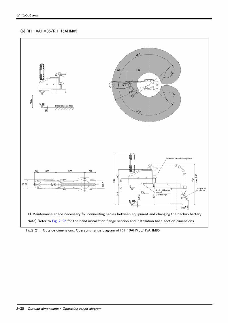
(6) RH-10AHM85/RH-15AHM85
Fig.2-21 : Outside dimensions, Operating range diagram of RH-10AHM85/15AHM85
300st
10
325
R850
140°
R277.8
153°
153°
140°
525
32570 525 210
178
164
155
.4 995
300
385
4090
1030
0st
R76
334
80
796
max
. 840
240
2 x 3 - M4 screw,depth 8
Installation surface
(For tooling)
Primary air supply port
Solenoid valve box (option)
Note) Refer to Fig. 2-25 for the hand installation flange section and installation base section dimensions.
*1
*1 Maintenance space necessary for connecting cables between equipment and changing the backup battery.

2 Robot arm
Outside dimensions ・ Operating range diagram 2-31
2.4.3 Change the operating range
The operating ranges of both the J1 and J2 axes can be limited. Change the mechanical stopper and the operating range to be set inside of that area.If the operating range must be limited for example, to avoid interference with peripheral devices or to ensure safety--set up the operating range as shown below.
■ Operating range changeable angleThe operating range must be set up at angels indicated by Table 2-8.
Table 2-8 : Operating range changeable angle
Note1) The changeable angle shown in Table 2-8 indicates the operation range by the software.The mechanical stopper angle in the table shows the limit angle by the mechanical stopper. Use caution when laying out the robot during the designing stage.
Note2) The changeable angle can be set independently on the + side and - side.
Note3) Refer to Fig. 2-22 and Fig. 2-23 for mechanical stopper position.
Axis Type Direction Standard Changeable angle
RH-5AH series
J1 RH-5AH35/45/55 + side +127 deg. +90 deg. +60 deg. +30 deg. +0 deg.Any one point
shown at the leftMechanical stopper angle +130 deg. +95 deg. +65 deg. +35 deg. +5 deg.
Mechanical stopper position P11 P12 P13 P14 P15
- side -127 deg. -90 deg. -60 deg. -30 deg. -0 deg.Any one point
shown at the leftMechanical stopper angle -130 deg. -95 deg. -65 deg. -35 deg. -5 deg.
Mechanical stopper position N11 N12 N13 N14 N15
J2 RH-5AH35 + side +137 deg. +117 deg. +97 deg.
- -Any one point
shown at the leftMechanical stopper angle +140 deg. +120 deg. +100 deg.
Mechanical stopper position P21 P22 P23
- side -137 deg. -117 deg. -97 deg.
- -Any one point
shown at the leftMechanical stopper angle -140 deg. -120 deg. -100 deg.
Mechanical stopper position N21 N22 N23
RH-5AH45/55 + side +143 deg. +123 deg. +103 deg.
- -Any one point
shown at the leftMechanical stopper angle +146 deg. +126 deg. +106 deg.
Mechanical stopper position P21 P22 P23
- side -143 deg. -123 deg. -103 deg.
- -Any one point
shown at the leftMechanical stopper angle -146 deg. -126 deg. -106 deg.
Mechanical stopper position N21 N22 N23
RH-10AH/15AH series
J1 RH-10AH55/70/85
RH-15AH85
+ side +140 deg. +105 deg. +75 deg. +45 deg. +15 deg.Any one point
shown at the leftMechanical stopper angle +143 deg. +110 deg. +80 deg. +50 deg. +20 deg.
Mechanical stopper position P11 P12 P13 P14 P15
- side -140 deg. -105 deg. -75 deg. -45 deg. -15 deg.Any one point
shown at the leftMechanical stopper angle -143 deg. -110 deg. -80 deg. -50 deg. -20 deg.
Mechanical stopper position N11 N12 N13 N14 N15
J2 RH-10AH55/70 + side +145 deg. +125 deg.
- - -Any one point
shown at the leftMechanical stopper angle +150 deg. +130 deg.
Mechanical stopper position P21 P22
- side -145 deg. -125 deg.
- - -Any one point
shown at the leftMechanical stopper angle -150 deg. -130 deg.
Mechanical stopper position N21 N22
RH-10AH85
RH-15AH85
+ side +153 deg. +125 deg.
- - -Any one point
shown at the leftMechanical stopper angle +155 deg. +130 deg.
Mechanical stopper position P21 P22
- side -153 deg. -125 deg.
- - -Any one point
shown at the leftMechanical stopper angle -155 deg. -130 deg.
Mechanical stopper position N21 N22

2-32 Outside dimensions ・ Operating range diagram
2 Robot arm
■ Changing the operating range(1) Installing the mechanical stopper
1) Turn the controller power OFF.2) Refer to Table 2-8 and Fig. 2-22 and Fig. 2-23, install the hexagonal socket head bolts in the screw holes
corresponding to the angles to be set. Fig. 2-22 shows the mechanical stopper position and bolt size of the J1 axis, and Fig. 2-23 shows those of the J2 axis. If the screw holes are hidden behind the arms, slowly move the No. 1 and No. 2 arms.
Fig.2-22 : Mechanical stopper position (J1 axis)
Fig.2-23 : Mechanical stopper position (J2 axis)
(2) Setting the operation range parameterSet up the operation range (Changeable angle in Table 2-8) to the Joint movement range parameter MEJAR.
1) Turn the controller power ON.2) Set up the changed operation range to the Joint movement range parameter.
MEJAR: (J1 plus side movement range, J1 minus side movement range, J2 plus side movement range, J2 minus side movement range, ........)
(3) Setting the mechanical stopper origin parameterIf the movement range of either the minus (-) side of the J1 axis or the plus (+) side of the J2 axis has been changed, change the mechanical stopper origin parameter MORG.
1) Change the parameter MORG to the angle of the mechanical stopper position that has been set.MORG: (J1 minus side mechanical stopper position, J1 plus side mechanical stopper position, ........)
(4) Confirming the operation rangeWhen completed changing the parameters, turn the controller power OFF and ON. Move the changed axis to the operation range limit with joint jog operation, and confirm that the limit over occurs and the robot stops at the angle changed for both the +/- side.
This completes the changing the operating range.
N11N12N13
P12P13
N14
N15
P15
P14P11
N11N12N13N14
N15
P12P13
P15
P14 P11
For RH-10AH/15AH seriesFor RH-5H series
*Hexagon socket bolt = M12 x 25*Hexagon socket bolt = M8 x 16
N22N21
P21
P22
N22N23
N21
P21
P22P23
N22N23
N21
P21
P22P23
For RH-10AH/15AH seriesFor RH-5AH45/55 series
*Hexagon socket bolt = M8 x 16
For RH-5AH35 series

2 Robot arm
Outside dimensions ・ Operating range diagram 2-33
2.4.4 Mechanical interface and Installation surface(1) Mechanical interface and Installation surface of RH-5AH series
Fig.2-24 : Mechanical interface and Installation surface of RH-5AH series
Detail of Mechanical interface
92
180
150
92
180
150
Installation dimension details
Installation reference surface
4-φ16(Installation hole)
Inst
alla
tion
refe
rence
surf
ace
6.3a
6.3a
19
19
Section of Z-Z
φ14 through hole
ZZ
10(1
0)(1
0)
30
φ20H7
φ39.5

2-34 Outside dimensions ・ Operating range diagram
2 Robot arm
(2) Mechanical interface and Installation surface of RH-10AH/15AH series
Fig.2-25 : Mechanical interface and Installation surface of RH-10AH/15AH series
200
240
Detail of Mechanical interface
Installation dimension details
24
24φ18 through hole
Installation reference surface
4-φ16(Installation hole)Installed using M12 x 40 provided
122
240
200
122
φ50
ZZ
10(1
0)
(10)
30
φ25H7
Section of Z-Z
6.3a

2 Robot arm
Tooling 2-35
2.5 Tooling
2.5.1 Wiring and piping for handShows the wiring and piping configuration for a standard-equipped hand.
Fig.2-26 : Wiring and piping for hand
(4)Primary piping coupling (φ4)
Spare piping, electrical wiring opening (grommet)(φ18)
(1)Hand input signal connector
For hand connector pin
Solenoid valve set(optional)installation section
「GR1」~「GR8」
(2)Hand output primary cable
Machine cable connector (for signals)
Machine cable connector (power supply)
Primary piping pneumatic hoses(φ6×2,φ4×1)
(3)Primary piping coupling (φ6)
Note 1) An optional puneumatic hand interface (2A-RZ365/375) is required to use hand output. Note 2) Please provide φ4 and φ6 air hoses that are connected to the solenoid valve set by customer.
Hand interface section
60 NL/min suction
<General/Oil mist specifications> <Clean specifications>
AIR IN1 AIR IN2 AIR IN3
SPAREWIREINLET AIR IN1 AIR IN2 AIR IN3 VACUUM
(6)Primary piping air coupling(φ4)
(5)Primary piping air coupling(φ6)
Spare cable inlet (grommet)
(5)Primary piping air coupling(φ6)
(6)Primary piping air coupling(φ4)
(RH-5AHC series only)
(7) Coupling (φ8) for internal suction
Spare wiring AWG#22 (0.3mm 2 )×4
Connector and pneumatic coupling
No Name Qty.
Robot side(Robot arm side) Counter side (customer-prepared)
ManufacturerConnectors, couplings
Connector pins Connector Connector pins
(1) Connector 1 HR10A-10WTR-12S HR10A-10WTP-12P Hirose
(2)Connector 8 SMP-02V-BC BHF-001GI-0.8BS SMR-02V-B BYM-001T-0.6 Japan solderless
terminal MFG. Co.,LTD
(3) Coupling 2 UK6M - - - Koganei
(4) Coupling 1 UK4M - - - Koganei
(5) Coupling 2 UKBL6 - - - Koganei
(6) Coupling 1 UKBL4 - - - Koganei
(7) Coupling 1 UKBL8 - - - Koganei

2-36 Tooling
2 Robot arm
2.5.2 Internal air piping(1) For piping, two φ6 x 4 urethane hoses and one φ4 x 2.5 urethane hose are preinstalled from the air suc-
tion port of the base section to the No. 2 arm's rear section.(2) Two pneumatic couplings for the φ6 hoses and one pneumatic coupling for the φ4 hose are provided at
the hose end section on both the base and No. 2 arm sides.(3) The φ8 hose coupling (VACUUM) is used especially for centralized suction only in the case of the RH-
5AHC**.(4) A solenoid valve set (optional) with a maximum of four sets can be attached to the rear section of the No.
2 arm. (5) Refer to Page 48, "Solenoid valve set" for details on the electronic valve set (optional).
2.5.3 Internal wiring for the pneumatic hand output cable(1) The wiring of the hand output cable (eight wires of AWG#24(0.2 mm2) x 2 cores) extends into the No. 2 arm,
ending in an 8-point connector. These eight points of connections are named "GR1" through "GR8."The hand output cable is located outside at the time of shipping. If this cable is not used, place the connec-tors for GR1 to GR8 inside, and install the attached grommet. For the protection specifications, fill the fringe of the grommet with silicon rubber.
2.5.4 Internal wiring for the hand check input cable(1) The wiring of the hand input cable extends from the base to the eight points in the hand input signal con-
nector on the back of the No. 2 arm.
2.5.5 Precautions for piping to the flexible cableIf the piping of the hand is performed to the flexible cable of this robot, be sure to perform wiring and piping by fol-lowing the precautions listed below so that they will not interfere with the functionality of the flexible cable.
If many hand cables are installed to the flexible cable and depending on the manner of installation, excessive force may be applied to the flexible cable and the life span of the flexible cable may be shortened and also the mounting nuts of the flexible cable may come loose.
Point: When installing to the flexible cable, be sure to allocate some room.
Flexible cable
Point: Be sure that the base part and the tooling wiring do not make contact.
Tooling wiring (max φ6 x 2 wires)
Point: When a cable tie is used to fasten, do not tighten with it excessively.

2 Robot arm
Tooling 2-37
2.5.6 About the Installation of Tooling Wiring and Piping (Examples of Wiring and Piping)The customer is required to provide tooling wiring, piping and metal fixtures. Screw holes are provided on the robot arm for the installation of tooling wiring, piping and metal fixtures. (See the drawing below.)The length of wiring and piping and the installation position on the robot must be adjusted according to the work to be done by the robot. Please use the following example as reference. Pay extra attention to the precautions and interfering points described in the example during the adjustment.
・ A hand input cable and a hand curl cable are available as optional accessories for your convenience.・ After performing wiring and piping to the robot, operate the robot at low speed to make sure that each part does
not interfere with the robot arm and the peripheral devices. (Interfering points and precautions are indicated in the example.)
・ When used with the RH-5AHC** clean specifications, be careful that dust may be generated if wiring or piping touches the robot arm.
70
70
100 100
100 100
View from C
2x3-M4 screw
20
M4 screw- two places.
View from B
φ50
45
2x4-M4 screw(4-20 pitch)
2x3-M4 screw depth 8
3 - M4 depth 15A
B
C
30
View from A
2-M4 screw
RH-10AH/15AH series
RH-5AH series
φ40
A
B
C
41
2x3-M4 screw depth 8
45
45
40 40
40 40 80
8
40
View from C
2x3-M4 screw
2-M4x10 screw
Valve plate installation line
30
View from A
2-M4 screw
20
M4 screw- two places.
View from B

2-38 Tooling
2 Robot arm
(1) Example of wiring and piping <1>This method is effective when the rotation of the hand is small (within ± 90 deg.) and provides easy maintenance of the robot arm as well as during the replacement of wiring and piping.
(2) Wiring and piping example <2>If wiring and piping are fed through the hollow section of the shaft, the wiring and piping to the hand can be
streamlined.
Point: 2When the robot is in operation, the wiring and piping must be at the position where they are away from the hand (shaft) and do not wrap around it.Also, adjust the bracket position and the length of wiring and piping so that they are not caught by the No. 1 and No. 2 arms.
Point: 1Be sure that the wiring and piping do not interfere with the flexible cable of the robot when the robot is in operation.
Flexible cable
Hand (customer-prepared)
・Hand input cable ・Hand carl tube
Example of flange design
2-M4 to M5 set screw
M4 slotted set screw
30
φ50
Wiring and piping are customer-prepared or optional
Example of metal fixture design
40
20
RH-5AH series
2-M5 to M6 set screw
M5 slotted set screw
30
φ60
RH-10AH/15AH series
Bracket A (customer-prepared)
Point: 2
Point: 1
No.1 arm
Flexible cable
No.2 arm
Point: 3
Point: 4
The top part of the shaft enters the cover when it is lowered to the bottom.Be sure that the wiring, piping and bracket provided by the customer do not interfere with the cover.
45
Be careful with the interference with the area above the unit (ceiling).
Bracket B (customer-prepared)
Be sure that the wiring and piping do not interfere with the flexible cable of the robot when the robot is in operation.Also, in the case of the protection specifications, install the bracket with two M4 screws, and then fill the bolt with silicon rubber.
When the robot is in operation, the wiring and piping must be at the position where they are away from the hand (shaft) and do not wrap around it.There should be no interference at the edge to bracket B.Also, adjust the bracket position and the length of wiring and piping so that they are not caught by the No. 1 and No. 2 arms.

2 Robot arm
Tooling 2-39
[Precautions for the protection specification and clean specification]・ Bellows are attached to the tips so confirm not interfering in the tooling wiring, piping, and the flexible tube.・ Please use wiring materials that are sufficiently flexible. Furthermore, please perform the wiring in such a waythat the bending radii of the selection tube and wires will not become less than the minimum values allowed whilethe robot is operating.
[Precautions for the clean specification]The top and bottom parts of the through hole of the tip shaft are taped at shipment.
Perform the following actions as necessary in order to ensure that the robot is sufficiently clean during the operation:
1) When the through hole of the shaft is not used・ Keep the tip shaft taped while the robot is in use.
2) When the through hole of the shaft is used for wiring.・ Peel the tape of the tip shaft off and perform the necessary wiring. Once the wiring is completed, seal the tip shaft using liquid seal in order to avoid accumulation of dust.・Perform the wiring in such a way that the wires around the area below the tip shaft will not get into contact with other parts while the robot is operating.
Flexible cable
Tool wiring
Example of tool piping
Cable
150mm or more
(Prepared by customer)
Shaft
Cable supporter
Cable
Liquid seal
Liquid seal
(Reference value)
Bellow

2-40 Tooling
2 Robot arm
Fig.2-27 : Wiring and piping system diagram for hand and example the solenoid valve installation(Sink type)
Hand prepared by customer
<Hand check 1><Hand check 2><Hand check 3><Hand check 4><+24V><0V(COM)><Hand check 5><Hand check 6><Hand check 7><Hand check 8>
1 2 3 4 5 6 9 10
Robotcontroller
primary air
φ6 quick coupling
AIR IN1AIR IN2AIR IN3
1112
Wirin
g re
lay
boar
d of th
e r
obot
arm
GR1
GR2
GR3
GR4
GR5
GR6
GR7
GR8
12
12
12
12
12
12
12
Solenoid valve set (optional)<RH-5AH series>1E‐VD01/1E‐VD021E‐VD03/1E‐VD04 etc.<RH-10AH/15AH series>1N‐VD01/1N‐VD021N‐VD03/1N‐VD04 etc.
φ4 quick coupling
φ6 quick coupling
φ4 quick coupling
Hand output cable 1N-GR35S(This is not required if an optional solenoid valve set is used.)
12
Hand input cable1A-HC35C
prepared by customer
WhiteBlackWhiteBlackWhiteBlackWhiteBlackWhiteBlack
White Black
White Black
White Black
BlackWhite
BlackWhite
BlackWhite
White Black
BlackWhite
AIR OUT1AIR OUT2AIR OUT3
φ6φ6φ4
φ8 quick coupling for internal suction only when used with RH-5AHC**(VACUUM)
Spare wiring (from base to No.2 arm)AWG#22(0.3mm2) x 4White BlackWhite Black
1.Refer to Fig. 2-29 for an example of a supply air circuit.
2.The pneumatic hand interface (optional) is necessary when using hand output (GR 1 to GR 8).
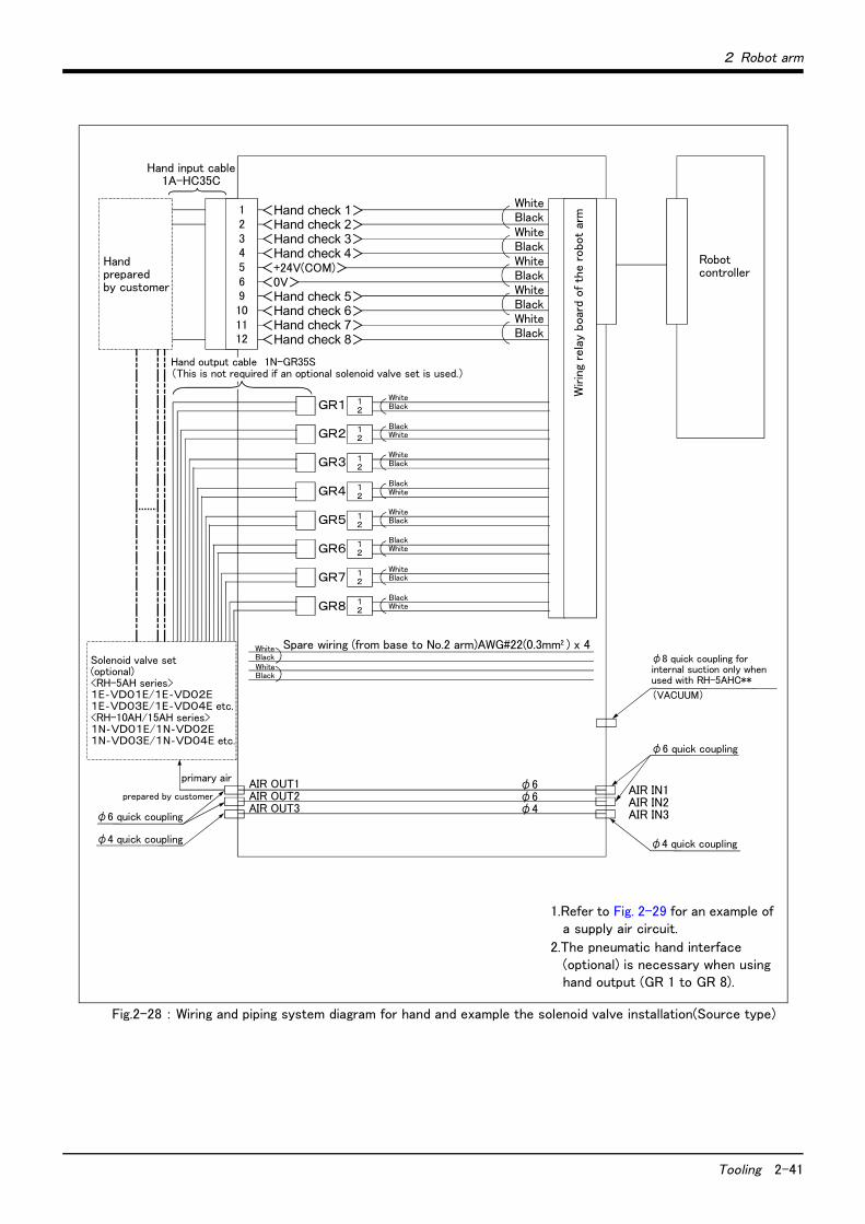
2 Robot arm
Tooling 2-41
Fig.2-28 : Wiring and piping system diagram for hand and example the solenoid valve installation(Source type)
Hand prepared by customer
<Hand check 1><Hand check 2><Hand check 3><Hand check 4><+24V(COM)><0V><Hand check 5><Hand check 6><Hand check 7><Hand check 8>
1 2 3 4 5 6 9 10
Robotcontroller
primary air
φ6 quick coupling
AIR IN1AIR IN2AIR IN3
1112
Wirin
g re
lay
boar
d of th
e r
obo
t ar
m
GR1
GR2
GR3
GR4
GR5
GR6
GR7
GR8
12
12
12
12
12
12
12
φ4 quick coupling
φ6 quick coupling
φ4 quick coupling
Hand output cable 1N-GR35S(This is not required if an optional solenoid valve set is used.)
12
Hand input cable1A-HC35C
prepared by customer
WhiteBlackWhiteBlackWhiteBlackWhiteBlackWhiteBlack
White Black
White Black
White Black
BlackWhite
BlackWhite
BlackWhite
White Black
BlackWhite
Solenoid valve set (optional)<RH-5AH series>1E‐VD01E/1E‐VD02E1E‐VD03E/1E‐VD04E etc.<RH-10AH/15AH series>1N‐VD01E/1N‐VD02E1N‐VD03E/1N‐VD04E etc.
AIR OUT1AIR OUT2AIR OUT3
φ6φ6φ4
(VACUUM)
φ8 quick coupling for internal suction only when used with RH-5AHC**
Spare wiring (from base to No.2 arm)AWG#22(0.3mm2 ) x 4White
BlackWhite Black
1.Refer to Fig. 2-29 for an example of a supply air circuit.
2.The pneumatic hand interface (optional) is necessary when using hand output (GR 1 to GR 8).

2-42 Tooling
2 Robot arm
2.5.7 Electrical specifications of hand input/output
Table 2-9 : Electrical specifications of input circuit
Table 2-10 : Electrical specifications of output circuit
Note) The pneumatic hand interface (2A-RZ365/RZ375) is necessary when using hand output.
Item Specifications Internal circuit
Type DC input <Sink type>
<Source type>
* HCn = HC1 ~ 8
No. of input points 8
Insulation method Photo-coupler insulation
Rated input voltage 12VDC/24VDC
Rated input current Approx. 3mA/approx. 7mA
Working voltage range DC10.2 to 26.4V(ripple rate within 5)
ON voltage/ON current 8VDC or more/2mA or more
OFF voltage/OFF current 4VDC or more/1mA or less
Input resistance Approx. 3.3kΩ
Response time
OFF-ON 10ms or less(DC24V)
ON-OFF 10ms or less(DC24V)
Item Specification Internal circuit
Type Transistor output <Sink type>
<Source type>
* GRn = GR1 ~ GR8
No. of output points 8
Insulation method Photo coupler insulation
Rated load voltage DC24V
Rated load voltage range DC21.6 to 26.4VDC
Max. current load 0.1A/ 1 point (100%)
Current leak with power OFF 0.1mA or less
Maximum voltage drop with power ON DC0.9V(TYP.)
Response time OFF-ON 2ms or less (hardware response time)
ON-OFF 2 ms or less (resistance load) (hardware response time)
Fuse rating Fuses 1.6A (each one common) Cannot be exchanged
3.3K
24V
0V(COM)
820HCn*
24V
3.3K
820
0V
24V
HCn*
24V(COM)
24V
(Internal power supply)
* GRn
Fuse 1.6A
0V
Fuse1.6A
* GRn
24V
0V

2 Robot arm
2-43
2.5.8 Air supply circuit example for the handFig. 2-29 shows an example of pneumatic supply circuitry for the hand.
(1) Place diodes parallel to the solenoid coil.(2) When the factory pneumatic pressure drops, as a result of the hand clamp strength weakening, there can be
damage to the work. To prevent it, install a pressure switch to the source of the air as shown in Fig. 2-29 and use the circuit described so that the robot stops when pressure drops. Use a hand with a spring-pressure clamp, or a mechanical lock-type hand, that can be used in cases where the pressure switch becomes dam-aged.
(3) The optional hand and solenoid valve are of an oilless type. If they are used, don't use any lubricator.
Fig.2-29 : Air supply circuit example for the hand
Pressure switch
To the solenoid valve primary air supply port
(0.5MPa ±10%)
Pneumatic source
0.7MPa less Filter Regurater

2-44 Shipping special specifications, options, and maintenance parts
2 Robot arm
2.6 Shipping special specifications, options, and maintenance parts
2.6.1 Shipping special specifications
■ What are Sipping special specifications?Shipping special specifications are changed at the time of shipment from the factory. Consequently, customer need to confirm the delivery date.
To make changes to the specifications after shipment, service work must be performed at the work site or the robot must be returned for service.
■ How to order(1) Confirm beforehand when the Factory special specifications can be shipped, because they may not be
immediately available.(2) Order before the factory shipping date.(3) Specified method …… Specify the part name, model, and robot model type.
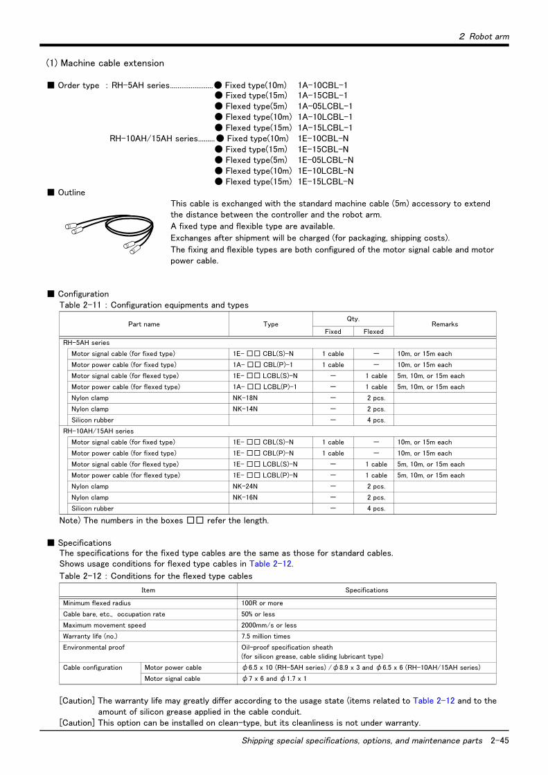
2 Robot arm
Shipping special specifications, options, and maintenance parts 2-45
(1) Machine cable extension
■ Order type : RH-5AH series.......................● Fixed type(10m) 1A-10CBL-1● Fixed type(15m) 1A-15CBL-1● Flexed type(5m) 1A-05LCBL-1● Flexed type(10m) 1A-10LCBL-1● Flexed type(15m) 1A-15LCBL-1
RH-10AH/15AH series.........● Fixed type(10m) 1E-10CBL-N● Fixed type(15m) 1E-15CBL-N● Flexed type(5m) 1E-05LCBL-N● Flexed type(10m) 1E-10LCBL-N● Flexed type(15m) 1E-15LCBL-N
■ OutlineThis cable is exchanged with the standard machine cable (5m) accessory to extend the distance between the controller and the robot arm.
A fixed type and flexible type are available.
Exchanges after shipment will be charged (for packaging, shipping costs).
The fixing and flexible types are both configured of the motor signal cable and motor power cable.
■ ConfigurationTable 2-11 : Configuration equipments and types
Note) The numbers in the boxes □□ refer the length.
■ SpecificationsThe specifications for the fixed type cables are the same as those for standard cables.Shows usage conditions for flexed type cables in Table 2-12.
Table 2-12 : Conditions for the flexed type cables
[Caution] The warranty life may greatly differ according to the usage state (items related to Table 2-12 and to theamount of silicon grease applied in the cable conduit.
[Caution] This option can be installed on clean-type, but its cleanliness is not under warranty.
Part name TypeQty.
RemarksFixed Flexed
RH-5AH series
Motor signal cable (for fixed type) 1E- □□ CBL(S)-N 1 cable - 10m, or 15m each
Motor power cable (for fixed type) 1A- □□ CBL(P)-1 1 cable - 10m, or 15m each
Motor signal cable (for flexed type) 1E- □□ LCBL(S)-N - 1 cable 5m, 10m, or 15m each
Motor power cable (for flexed type) 1A- □□ LCBL(P)-1 - 1 cable 5m, 10m, or 15m each
Nylon clamp NK-18N - 2 pcs.
Nylon clamp NK-14N - 2 pcs.
Silicon rubber - 4 pcs.
RH-10AH/15AH series
Motor signal cable (for fixed type) 1E- □□ CBL(S)-N 1 cable - 10m, or 15m each
Motor power cable (for fixed type) 1E- □□ CBL(P)-N 1 cable - 10m, or 15m each
Motor signal cable (for flexed type) 1E- □□ LCBL(S)-N - 1 cable 5m, 10m, or 15m each
Motor power cable (for flexed type) 1E- □□ LCBL(P)-N - 1 cable 5m, 10m, or 15m each
Nylon clamp NK-24N - 2 pcs.
Nylon clamp NK-16N - 2 pcs.
Silicon rubber - 4 pcs.
Item Specifications
Minimum flexed radius 100R or more
Cable bare, etc., occupation rate 50% or less
Maximum movement speed 2000mm/s or less
Warranty life (no.) 7.5 million times
Environmental proof Oil-proof specification sheath
(for silicon grease, cable sliding lubricant type)
Cable configuration Motor power cable φ6.5 x 10 (RH-5AH series) /φ8.9 x 3 and φ6.5 x 6 (RH-10AH/15AH series)
Motor signal cable φ7 x 6 and φ1.7 x 1

2-46 Shipping special specifications, options, and maintenance parts
2 Robot arm
■ Cable configurationThe configuration of the flexible cable is shown in Table 2-13. Refer to this table when selecting the cable bare.
Table 2-13 : Cable configuration
Note) The square in the cable name indicates the cable length.
■ Fixing the flexible cable(1) Connect the connector to the robot arm and controller.(2) Wind the silicon rubber around the cable at a position 300mm to 400mm from the robot arm and controller as
shown in Fig. 2-30, and fix with the nylon clamp to protect the cable from external stress.
Fig.2-30 : Fixing the flexible cable
Item Motor signal cable Motor power cable
RH-5AH series
Model 1E- □□ LCBL(S)-N 1A- □□ LCBL(P)-1
No. of cores AWG#24(0.2mm2)-4P AWG#18(0.75mm2) AWG#18(0.75mm2)
Finish dimensions Approx. φ7mm Approx. φ1.7mm Approx. φ6.5mm
No. of cables used 6 cables 1 cable 10 cables
Total 7 cables 10 cables
RH-10AH/15AH series
Model 1E- □□ LCBL(S)-N 1E- □□ LCBL(P)-N
No. of cores AWG#24(0.2mm2)-4P AWG#18(0.75mm2) AWG#16(1.25mm2)-4C AWG#18(0.75mm2)-4C
Finish dimensions Approx. φ7mm Approx. φ1.7mm Approx. φ8.9mm Approx. φ6.5mm
No. of cables used 6 cables 1 cable 3 cables 6 cables
Total 7 cables 9 cables
1E-□□LCBL(S)-N
Nylon clamp NK-16N
Nylon clampNK-24N
Nylon clamp NK-16N
Nylon clamp NK-24N
300~400mm
300~400mm
1E-□□LCBL(P)-N
1A-□□LCBL(P)-1
300~400mm
NK-14N
NK-18N
~ ~~~
1A-□□LCBL(P)-1
1E-□□LCBL(S)-N
300~400mm
NK-14N
NK-18N
~ ~~~
Nylon clamp
Nylon clamp
Nylon clamp
Nylon clamp
Silicon rubber
Nylon clamp
RH-5AH series RH-10AH/15AH series

2 Robot arm
Options 2-47
2.7 Options
■ What are options?There are a variety of options for the robot designed to make the setting up process easier for customer needs.
customer installation is required for the options. Options come in two types: "set options" and "single options".
1. Set options ...................................... A combination of single options and parts that together, from a set for servingsome purpose.
2. Single options ................................. That are configured from the fewest number of required units of a part.Please choose customer's purpose additionally.

2-48 Options
2 Robot arm
(1) Solenoid valve set
■ Order type: RH-5AH series..................General enveronment specifications ● One set: 1E-VD01(Sink type)/1E-VD01E(Source type)
● Two sets: 1E-VD02(Sink type)/1E-VD02E(Source type)
● Three sets: 1E-VD03(Sink type)/1E-VD03E(Source type)
● Four sets: 1E-VD04(Sink type)/1E-VD04E(Source type)
Protection enveronment specifications (IP54)
● One set: 1A-VD01M-01(Sink type)/1A-VD01ME-01(Source type)
● Two sets: 1A-VD02M-01(Sink type)/1A-VD02ME-01(Source type)
● Three sets: 1A-VD03M-01(Sink type)/1A-VD03ME-01(Source type)
● Four sets: 1A-VD04M-01(Sink type)/1A-VD04ME-01(Source type)
RH-10AH/15AH seies....General enveronment specifications (RH-10AH/15AH)
● One set: 1N-VD01(Sink type)/1N-VD01E(Source type)
● Two sets: 1N-VD02(Sink type)/1N-VD02E(Source type)
● Three sets: 1N-VD03(Sink type)/1N-VD03E(Source type)
● Four sets: 1N-VD04(Sink type)/1N-VD04E(Source type)
Protection enveronment specifications (IP54)
● One set: 1A-VD01M-02(Sink type)/1A-VD01ME-02(Source type)
● Two sets: 1A-VD02M-02(Sink type)/1A-VD02ME-02(Source type)
● Three sets: 1A-VD03M-02(Sink type)/1A-VD03ME-02(Source type)
● Four sets: 1A-VD04M-02(Sink type)/1A-VD04ME-02(Source type)
■ OutlineThe solenoid valve set is an option that is used for controlling toolings when various toolings, such as the hand, are installed at the end of the arm. All have double sole-noid specification, and either one, two, three, or four sets can be selected. This sole-noid valve set has a hand output cable attached to the solenoid valve. Also, for easy installation of this electromaagnetic set onto the robot, it comes equipped with a manifold, couplings, silencers, among other things.When using the robot arm's hand output signal, the pneumatic hand interface option must be installed on the separate controller. This solenoid valve set is installed in robots with the clean specifications. However, it is necessary to discharge the solenoid valve exhaust to the outside of the machine (outside of the clean room) using a spare pipe, for example. In operating environ-ments where substantial oil mist and dust are present, use the protection specifica-tions that include the solenoid valve box.
Example of "1N-VD04".

2 Robot arm
Options 2-49
■ Configuration
Table 2-14 : Configuration equipment
■ SpecificationsTable 2-15 : Valve specifications
Table 2-16 : Solenoid specifications
Part nameType Qty.
RemarkSink type/Source type 1 set 2 sets 3 sets 4 sets
RH-5AH series general enveronment specifications
Connecting the Page 53, "(3) Hand out-put cable".
<RH-5AH series>
M3x25 2 screws (Installation screws)
<RH-10AH/15AH series>
M4x45 4 screws (Installation screws)
Solenoid valve set (1 set) 1E-VD01/1E-VD01E 1 pc. - - -
Solenoid valve set (2 sets) 1E-VD02/1E-VD02E - 1 pc. - -
Solenoid valve set (3 sets) 1E-VD03/1E-VD03E - - 1 pc. -
Solenoid valve set (4 sets) 1E-VD04/1E-VD04E - - - 1 pc.
RH-5AH series protection specifications
Solenoid valve set (1 set) 1A-VD01M-01/1A-VD01ME-01 1 pc. - - -
Solenoid valve set (2 sets) 1A-VD02M-01/1A-VD02ME-01 - 1 pc. - -
Solenoid valve set (3 sets) 1A-VD03M-01/1A-VD03ME-01 - - 1 pc. -
Solenoid valve set (4 sets) 1A-VD04M-01/1A-VD04ME-01 - - - 1 pc.
Solenoid valve box 1 pc. 1 pc. 1 pc. 1 pc.
RH-10AH/15AH series general enveronment specifications
Solenoid valve set (1 set) 1N-VD01/1N-VD01E 1 pc. - - -
Solenoid valve set (2 sets) 1N-VD02/1N-VD02E - 1 pc. - -
Solenoid valve set (3 sets) 1N-VD03/1N-VD03E - - 1 pc. -
Solenoid valve set (4 sets) 1N-VD04/1N-VD04E - - - 1 pc.
RH-10AH/15AH series protection specifications
Solenoid valve set (1 set) 1A-VD01M-02/1A-VD01ME-02 1 pc. - - -
Solenoid valve set (2 sets) 1A-VD02M-02/1A-VD02ME-02 - 1 pc. - -
Solenoid valve set (3 sets) 1A-VD03M-02/1A-VD03ME-02 - - 1 pc. -
Solenoid valve set (4 sets) 1A-VD04M-02/1A-VD04ME-02 - - - 1 pc.
Solenoid valve box 1 pc. 1 pc. 1 pc. 1 pc.
Item Specifications
RH-5AH series RH-10AH/15AH series
Number of positions 2
Port 5
Valve function Double solenoid
Operating fluid Clean air
Operating method Pilot type
Effective sectional area (CV value) 1.5mm(0.08) 10.2mm(0.57)
Oiling Unnecessary
Operating pressure range 0.2 to 0.7MPa 0.15 to 0.7MPa
Guaranteed proof of pressure 1.0MPa or more
Response time 12msec or less (DC24V) 25msec or less
Max. operating frequency 5c/s
Ambient temperature 5 to 50 ℃
Item Specifications
RH-5AH series RH-10AH/15AH series
Method Built-in fly-wheel diodes with surge protection
Operation voltage DC24V ± 10%
Current value 40mA 60mA
Insulation B type
Insulation resistance 100MΩ or more
Surge protection Fly-wheel diode

2-50 Options
2 Robot arm
Fig.2-31 : Outside dimensional drawing of RH-5AH series
35.6
or less
(45)
(28)
(24)
(30)
(82)
L1
L2 or less
(20)
(1)(4) (2) (6)
(5)
(3)
(7)(8)
(1)
2- φ3.3
GR5
GR1
GR3
GR2
GR6
GR4
SOL1ASOL2A
GR7
SOL3ASOL4A
GR8
SOL2BSOL1B SOL3B
SOL4B
1 set 2 sets 3 sets 4 sets
L1 L228.4 36.428.4 36.438.6 46.648.8 56.8
72.3 110.6
23.0
Outside dimensions of solenoid valve boxNote)
Note)The solenoid valve box is provided only for the protection specifications.
Partno. Part name 1 set 2 sets 3 sets 4 sets Specifications
(1) Solenoid valve 1 2 3 4
(2) Manifold block 1 1 1 1
(3) Quick coupling 2 4 6 8 φ4
(4) Block plate 1 0 0 0
(5) Quick coupling 1 1 1 1 φ6
(6) Silencer 1 1 1 1
(7) Connector 2 4 6 8 SMR-02V-B
(8) Contact 4 8 12 16 SYM-001T-0.6
- Solenoid valve box 1 1 1 1
- Installation screw 2 2 2 2 M3 × 25
1 Hand1ON
2 +24G
1 Hand1OFF
2
1 Hand2ON
2
1 Hand2OFF 2
GR1
GR2
GR3
GR4
Connector name
SOL1A
SOL1B
SOL2A
SOL2B
+24G
+24G
+24G
1 Hand3ON
2 +24G
1 Hand3OFF 2
1 Hand4ON
2
1 Hand4OFF 2
GR5
GR6
GR7
GR8
SOL3A
SOL3B
SOL4A
SOL4B
+24G
+24G
+24G
BlackRed
BlackRed
BlackRed
BlackRed
BlackRed
BlackRed
BlackRed
BlackRed
<Source type>
General purposes output 900
General purposes output 901
General purposes output 902
General purposes output 903
General purposes output 904
General purposes output 905
General purposes output 906
General purposes output 907
1 Hand1ON
2 +24V
1 Hand1OFF
2
1 Hand2ON
2
1 Hand2OFF 2
GR1
GR2
GR3
GR4
Connector name
SOL1A
SOL1B
SOL2A
SOL2B
+24V
+24V
+24V
1 Hand3ON
2 +24V
1 Hand3OFF
2
1 Hand4ON
2
1 Hand4OFF 2
GR5
GR6
GR7
GR8
SOL3A
SOL3B
SOL4A
SOL4B
+24V
+24V
+24V
<Sink type>
BlackRed
BlackRed
BlackRed
BlackRed
BlackRed
BlackRed
BlackRed
BlackRed
General purposes output 900
General purposes output 901
General purposes output 902
General purposes output 903
General purposes output 904
General purposes output 905
General purposes output 906
General purposes output 907
RH-5AH series

2 Robot arm
Options 2-51
Fig.2-32 : Outside dimensional drawing of RH-10AH/15AH series
(1)(4) (2) (5) (6)
2-φ4.3
88
98
5
130
(32)
20
74
149
(3)
68
(28)40
74
GR1~GR8(7)(8)
Note)The solenoid valve box is provided only for the protection specifications.
Partno. Part name 1 set 2 sets 3 sets 4 sets Specifications
(1) Solenoid valve 1 2 3 4
(2) Manifold block 1 1 1 1
(3) Quick coupling 2 4 6 8 φ4
(4) Block plate 3 2 1 0
(5) Quick coupling 1 1 1 1 φ6
(6) Silencer 2 2 2 2
(7) Connector 2 4 6 8 SMR-02V-B
(8) Contact 4 8 12 16 SYM-001T-0.6
- Solenoid valve box 1 1 1 1
- Installation screw 4 4 4 4 M4 × 45
1 Hand1ON
2 +24G
1 Hand1OFF
2
1 Hand2ON
2
1 Hand2OFF
2
GR1
GR2
GR3
GR4
Connector name
SOL1A
SOL1B
SOL2A
SOL2B
+24G
+24G
+24G
1 Hand3ON
2 +24G
1 Hand3OFF
2
1 Hand4ON
2
1 Hand4OFF
2
GR5
GR6
GR7
GR8
SOL3A
SOL3B
SOL4A
SOL4B
+24G
+24G
+24G
BlackRed
BlackRed
BlackRed
BlackRed
BlackRed
BlackRed
BlackRed
BlackRed
<Source type>
General purposes output 900
General purposes output 901
General purposes output 902
General purposes output 903
General purposes output 904
General purposes output 905
General purposes output 906
General purposes output 907
1 Hand1ON
2 +24V
1 Hand1OFF
2
1 Hand2ON
2
1 Hand2OFF
2
GR1
GR2
GR3
GR4
Connector name
SOL1A
SOL1B
SOL2A
SOL2B
+24V
+24V
+24V
1 Hand3ON
2 +24V
1 Hand3OFF
2
1 Hand4ON
2
1 Hand4OFF
2
GR5
GR6
GR7
GR8
SOL3A
SOL3B
SOL4A
SOL4B
+24V
+24V
+24V
<Sink type>
BlackRed
BlackRed
BlackRed
BlackRed
BlackRed
BlackRed
BlackRed
BlackRed
General purposes output 900
General purposes output 901
General purposes output 902
General purposes output 903
General purposes output 904
General purposes output 905
General purposes output 906
General purposes output 907
Outside dimensions of solenoid valve boxNote)
180102.5
307
RH-10AH/15AH series

2-52 Options
2 Robot arm
(2) Hand input cable (Hand chack cable)
■ Order type: 1A-HC35C
■ Outline
The hand input cable is used for customer-designed pneumatic hands.
It is necessary to use this to receive the hand's open/close confirmation signals and grasping confirmation signals, at the controller.
One end of the cable connects to the connector for hand input signals, which is in the No.2 arm back side. The other end of the cable connects to the sensor inside the hand customer designed.
■ ConfigurationTable 2-17 : Configuration equipment
■ Specifications
Table 2-18 : Specifications
Fig.2-33 : Outside dimensional drawing and pin assignment
[Caution] This option can be installed on clean-type, but its cleanliness is not under warranty.
Part name Type Qty. Remarks
Hand input cable 1A-HC35C 1 cable
Item Specifications Remarks
Size x cable core AWG#24(0.2mm2) x 12 cores
Total length 1,150mm (Including the curl section, which is 300mmlong)
φ25
400 ±10 350 ±10 400 ±10
HR10A-10WTP-12P
HC1 HC2 HC3 HC4 +24V 0V(COM) Reserved
HC5 HC6 HC7HC8
1 2 3 4 5 6 7 8 9 10 11 12
(Hirose)
(Yellow)(Purple)(Brown)(Blue)(Black)(Green)(Red)(White)(Gray)(Pink)(Orange)(Light blue)
Reserved
Sinktype
Sourcetype
HC1 HC2 HC3 HC4 +24V(COM) 0VReserved
HC5 HC6 HC7HC8
Reserved

2 Robot arm
Options 2-53
(3) Hand output cable
■ Order type: 1N-GR35S
■ OutlineThe hand output cable (solenoid valve connection cable) is an option that is used
when an solenoid valve other than one of the solenoid valve set options, is used.
One end of the cable has a connector that connects to the input terminal inside the
robot. The other end of the cable is connected.
■ ConfigurationTable 2-19 : Configuration equipment
■ SpecificationsTable 2-20 : Specifications
Fig.2-34 : Outline dimensional drawing and pin assignment
[Caution] To install this option to a machine with either the protection or clean specifications, the customer needsto seal the robot outlet by the silicon rubber.
[Caution] This option can be installed on clean-type, but its cleanliness is not under warranty.
Part name Type Qty. Remarks
Hand output cable 1N-GR35S 1 cable
Item Specifications Remarks
Size x Cable core AWG#22(0.3mm2) x 2 cores x 8 sets (total 16 cores) One side connector and one side cable connection
Total length 350mm
* End cable connection
350
* * *
(3)
(1)(2)
GR1
GR2
GR3
GR4
Connector
Hand1ON
24V
Hand1OFF
24V
Hand2ON
24V
Hand2OFF
24V
Hand3ON
24V
Hand3OFF
Hand4ON
Hand4OFF
24V
GR5
GR6
GR7
GR8
White Black
White Black
White Black
White Black
White Black
White Black
White Black
White Black
12
12
12
12
12
12
12
12
24V
24V
Hand1ON
24G
Hand1OFF
24G
Hand2ON
24G
Hand2OFF
24G
Hand3ON
24G
Hand3OFF
Hand4ON
Hand4OFF
24G
24G
24G
Sink type
Source type
・ Configuration
Part no. Part name Qty. Specifications
( 1 ) Connector 8 SMR-02V-B
( 2 ) Contact 16 BYM-001T-0.6
( 3 ) Twisted cable 8 AWG#22(0.3mm2)x 2 cores

2-54 Options
2 Robot arm
(4) Hand curl tube
■ Order type: One set (2 pcs.) : 1E-ST0402C-300Two sets (4 pcs.) : 1E-ST0404C-300
Three sets (6 pcs.) : 1E-ST0406C-300
Four sets (8 pcs.) : 1E-ST0408C-300
■ Outline
The hand curl tube is a curl tube for the pneumatic hand.
■ ConfigurationTable 2-21 : Configuration equipment
■ SpecificationsThis option can be installed on clean-type, but its cleanliness is not under warranty.
Table 2-22 : Specifications
Fig.2-35 : Outline dimensional drawing
[Caution] This option can be installed on clean-type, but its cleanliness is not under warranty.
Part name Type Qty. Remarks
Hans curl tube (One set: 2 pcs.) 1E-ST0402C-300 1 pc. Φ4 tube, 2pcs.
Hans curl tube (Two set: 4 pcs.) 1E-ST0404C-300 1 pc. Φ4 tube, 4pcs.
Hans curl tube (Three set: 6 pcs.) 1E-ST0406C-300 1 pc Φ4 tube, 6pcs.
Hand curl tube (Four set: 8 pcs.) 1E-ST0408C-300 1 pc. Φ4 tube, 8pcs.
Item Specifications
Material Urethane
Size Outside diameter: Φ4 x Inside diameterΦ2.5
φ28
(O
ne s
et),
φ36
(Tw
o se
ts,
thr
ee s
ets,
an
d fo
ur s
ets)
600
300
100

2 Robot arm
Maintenance parts 2-55
2.8 Maintenance parts
The consumable parts used in the robot arm are shown in Table 2-23. Purchase these parts from the designated maker or dealer when required. Some Mitsubishi-designated parts differ from the maker's standard parts. Thus, confirm the part name, robot arm and controller serial No. and purchase the parts from the dealer.
Table 2-23 : Consumable part list
No. Part name Type Usage place Qty. Supplier
RH-5AH series RH-10AH/15AH series
1 Grease SK-1A J 1 , J2, J4 axis:Reduction
gears
Reduction gears of each
axisAs needed
Mitsubishi Electric2 Marutenpu PS No.2 Ball screw, linear guide of
J3 axis
ShaftAs needed
3 Lithium battery A6BAT Inside the battery cover of
bese
Rear section of the base4

2-56 Maintenance parts
2 Robot arm

3Controller
Standard specifications 3-57
3 Controller
3.1 Standard specifications
3.1.1 Standard specificationsTable 3-1 : Standard specifications of controller
Item Unit Specification Remarks
Type CR2A-572
Number of control axis Simultaneously 4
CPU 64 bit RISC, and DSP
Memory capacity
Programmed positions and No. of steps
pointstep
2,5005,000
Number of programs 88
Robot language MELFA-BASIC Ⅳor
MOVEMASTER COMMAND
Teaching method Pose teaching method ,MDI method
External input and output
input and output point 32/32 Max. 256/256Note1)
Note1) It is the value when seven maximums expand (224/224) the Parallel I/O unit. (2A-RZ361 or 2A-RZ371:Input 32 points / Output 32 points.)
Dedicated input/output point Assigned with general-purpose input/output "STOP" 1 point is fixed
Hand open/close input/output point Input 8 point/Output 0 point
Up to 8 output points can be added
as an optionNote2)
Note2) It is when an pneumatic hand interface (2A-RZ365 or 2A-RZ375) is installed.
Emergency stop input/output point 1 Dual emergency line
Door switch input point 1 Dual door switch line
Interface RS-232C port1
For expansion such as the personal cpmputer, Vision sensor
RS-422 port 1 Dedicated for T/B
Hand dedicated slot slot 1Dedicated for pneumatic hand inter-face
Expansion slot slot 3
Robot input/output link channel 1Used for general-purpose input/out-put (Max. 256/256)
Power source
Input voltage range V 1-phase, AC180 to 253 Note3)
Note3) 1-phase,AC180 to 253. This specification is changed for CE-Marking model.
Power capacity KVA 0.7 (RH-5AH series)3.5 (RH-10AH/15AH series)
Does not include rush current Note4)
Note4) The power capacity (0.7 or 3.5 kVA) is the maximum rating value for normal operation. The power capacity does not include the rush current when the power is turned ON. The power capacity is a guideline and the actual operation is affected by the input power voltage.
Outline dimensions mm 400(W) x 400(D) x 200(H) The height includes the length of the foot.
Mass kg Approx. 18
Construction Self-contained floor type, Opened type Note5)
Note5) The controller (CR2A-572) of this robot is a general environment specification. If the robot is used in an oil mist environment, use the optional controller protection box (CR2A-MB) to protect the controller from the oil mist environment. (Refer to Page 8, "2.2.3 Protection specifications and working environment")
Install to the place not to influence the cleanliness when using in the clean environment. (Refer to Page 14, "2.2.5 Clean specifications (RH-5AH series)")
Operating temperature range deg. 0 to 40
Ambient humidity %RH 45 to 85 Without dew drops
Grounding Ω 100 or less D class grounding earthNote6)
Note6) The robot must be grounded by the customer.
Paint color Light gray Munsell 7.65Y7.64/0.73

3-58 Standard specifications
3Controller
3.1.2 Protection specifications and operating supplyA protection method complying with the IEC Standard IP20 (Opened type) is adopted for the controller.
IEC's IP symbols refer only to the degree of protection between the solid and the fluids, and don't indicated that any special protection has been constructed for the prevention against oil and water.
Refer to the section Page 110, "5.2 Working environment" for details on the working environment.
If the robot is used in an oil mist environment, use the optional contorller protection box (CR2A-MB) to protect the controller from the oil mist environment.
Refer to the section Page 78, "(3) Controller protection box"for details on the controller protection box.
CAUTION

3Controller
Names of each part 3-59
3.2 Names of each part
Fig.3-1 : Names of controller parts
1) POWER switch..................................... This turns the control power ON/OFF. 2) START button...................................... This executes the program and operates the robot. The program is run continuously.3) STOP button ........................................ This stops the robot immediately. The servo does not turn OFF.4) RESET button ...................................... This resets the error. This also resets the program's halted state and resets the program.5) Emergency stop switch.................... This stops the robot in an emergency state. The servo turns OFF.6) T/B remove switch............................ This is used to connect/disconnect the T/B without turning OFF the controller's control
power.7) CHNGDISP button ............................. This changes the details displayed on the display panel in the order of "Override" → "Pro-
gram No." → "Line No.".8) END button............................................ This stops the program being executed at the last line or END statement.9) SVO.ON button.................................... This turns ON the servo power. (The servo turns ON.)10) SVO.OFF button............................... This turns OFF the servo power. (The servo turns OFF.)11) STATUS NUMBER (display panel)...................................... The alarm No., program No., override value (%), etc., are displayed.12) T/B connection connector ......... This is a dedicated connector for connecting the T/B.13) Personal computer connection connector...................... This is an RS-232C specification connector for connecting the personal computer.14) MODE key switch............................. This changes the robot's operation mode. Note)
AUTO (Op.).................................. Only operations from the controller are valid. Operations for which the operation modemust be at the external device or T/B are not possible.
TEACH .......................................... When the T/B is valid, only operations from the T/B are valid. Operations for which theoperation mode must be at the external device or controller are not possible.
AUTO (Ext.)................................. Only operations from the external device are valid. Operations for which the operationmode must be at the T/B or controller are not possible.
15) UP/DOWN button ............................ This scrolls up or down the details displayed on the "STATUS. NUMBER" display panel.
Note) The servo will turn OFF when the controller's [MODE] switch is changed.Note that axes not provided with brakes could drop with their own weight.
12)10)
13)
3) 8)
6)
5)15)
4)
7)
2)9)
11)14)
Front operation panel1)
<Front> <Front side of operation panel>
CAUTION

3-60 Names of each part
3Controller
Carry out the following operations to prevent the servo from turning OFF when the [MODE] switch is changed.(Only CR2A-572 controller)
The servo on status can be maintained by changing the mode with keeping pressing lightly the deadman switch of T/B. The operating method is shown below.
(1) When the mode is changed from TEACH to AUTO.1) While holding down the deadman switch on the T/B, set the [ENABLE/DIS-
ABLE] switch to "DISABLE".2) While holding down the deadman switch on the T/B, set the controller [MODE]
switch to "AUTO".3) Release the T/B deadman switch.
(2) When the mode is changed from AUTO to TEACH.1) While the [ENABLE/DISABLE] switch on the T/B is "DISABLE", hold down the
deadman switch.2) While holding down the deadman switch on the T/B, set the controller [MODE]
switch to "TEACH".3) While holding down the deadman switch on the T/B, set the [ENABLE/DIS-
ABLE] switch to "ENABLE", then do the operation of T/B that you wish.
Fig.3-2 : Names of each controller part (Rear side)
(1) Machine cable connector (for motor power ) ....... Connects to the robot arm base. (CN1 connector)(2) Machine cable connector (for motor signals)........ Connects to the robot arm base. (CN2 connector)(3) External input/output signal connector.(4) Network cable connector for parallel I/O unit expansion.(5) Emergency stop switch and door switch terminals.
(2)(3) (4)(5)
(1)

3Controller
Outside dimensions/Installation dimensions 3-61
3.3 Outside dimensions/Installation dimensions
3.3.1 Outside dimensions
Fig.3-3 : Outside dimensions of controller
<CR2A-572>
36
710
25
210
17
7
400
45 310 45
400
436
(36)
185
38
401
449
10
71
260
400

3-62 Outside dimensions/Installation dimensions
3Controller
3.3.2 Installation dimensions
Fig.3-4 : Installation of controller
150 150
250 or more
7 o
r m
ore
Horizontal placement
Use the rubber foot (4 positions) at the bottom of the controller as it is, or put the spacer, and leave the space between the installation side and the controller installation side more than 7mm when you fix the controller with the installation screw.In the other case, the air intake hole at the bottom of the controller is occupied, and temperature rises in the board, and causes the trouble.
CAUTION

3Controller
External input/output 3-63
3.4 External input/output
3.4.1 Types(1) Dedicated input/output...............................These inputs and outputs carry out the robot remote operation and
status display.(2) General-purpose input/output.................These are inputs and outputs that the customer can program for
peripheral device control.(3) Hand input/output .........................................These are inputs and outputs related to the hand that the customer can
program. (The hand output is an option. The Page 76, "(2) Pneumatic hand interface" is required.)
3.4.2 ExplanationThe parallel input/output unit uses connector bridging. Purchase the "External I/O cable" for connection with external devices.
The hand output is an option. Refer to Page 76, "(2) Pneumatic hand interface" for details
The parallel input/output unit can be expanded outside of the controller.The expansion parallel input/output unit is connected with the control unit in the controller using a robot I/O link cable. Parallel input and output units can be expand as an option to seven maximums. With allows up to input 256 points and output 256 points of maximums can be used including 32 points input and 32 points output of standard.
Refer to Page 81, "(4) Parallel I/O unit" for details on the parallel input/output unit.
Class NameNo. of input/output points Connection
formatInput Output
Standard Emergency stop 1 1 Terminal block
Standard Door switch 1
Standard Parallel input/output Occupies 32 general-purpose points/(6)
dedicated points in general-purpose
Occupies 32 general-purpose points/(4)
dedicated points in general-purposeConnector

3-64 Dedicated input/output
3Controller
3.5 Dedicated input/output
Show the main function of dedicated input/output in the Table 3-2. Refer to attached instruction manual "CR1/CR2/CR4/CR7/CR8 Controller Detailed explanations of functions and operations" in the product for the other functions . Each parameter indicated with the parameter name is used by designated the signal No., assigned in the order of input signal No. and output signal No. If the number of dedicated inputs and general-purpose input points used exceeds the standard No. of input/output points, install the parallel input /output unit (1st to 7th sta-tion: option).
Table 3-2 : Dedicated input/output list
Parameter name
Input Note1) Output
Name Function Level Name Function
TEACHMD None Teaching mode out-put signal
Outputs that the teaching mode is
entered.
ATTOPMD None Automatic mode out-put signal
Outputs that the automatic mode is
entered.
ATEXTMD None Remote mode output
signal
Outputs that the remote mode is
entered.
AUTOENA Automatic opera-tion enabled input
signal
Disables automatic operation when
inactive, and enables automatic
operation when active.
L
Automatic operation
enabled output signal
Outputs the automatic operation
enabled state.
START Start input signal Starts all slots.E
Operating output sig-nal
Outputs that the slot is operating.
STOP Stop input signal Stops all slots.
The input signal No. is fixed to 0.
Note) Use the emergency stop
input for stop inputs related
to safety.
L
Wait output signal Outputs that the slot is temporarily
stopped.
SLOTINIT Slot initialization
input signal
Resets the wait state, and initial-izes all slots.
EProgram selection
enabled output signal
Outputs that the slot is in the program
selection enabled state.
ERRRESET Error reset input
signal
Resets the error state.E
Error occurring out-put signal
Outputs that an error has occurred.
CYCLE Cycle stop input
signal
Carries out cycle stop.E
In cycle stop opera-tion output signal
Outputs that the cycle stop is operat-ing.
SRVOFF Servo ON enabled
input signal
Sets all mechanisms to servo ON
enabled.L
Servo ON enabled
output signal
Outputs the servo ON enabled state.
(Echo back)
SRVON Servo ON input
signal
Turns the servo ON for all mecha-nisms.
EIn servo ON output
signal
Outputs the servo ON state.
IOENA Operation rights
input signal
Requests the operation rights for
the external signal control.E
Operation rights out-put signal
Outputs the operation rights valid state
for the external signal control.
MELOCK Machine lock input
signal
Sets/resets the machine lock
state for all mechanisms.E
In machine lock out-put signal
Outputs the machine lock state.
SAFEPOS Evasion point
return input signal
Requests the evasion point return
operation.E
In evasion point
return output signal
Outputs that the evasion point return
is taking place.
OUTRESET General-purpose
output signal reset
Resets the general-purpose output
signal.E None
EMGERRNone
Emergency stop out-put signal
Outputs that an emergency stop has
occurred.
S1START
:
S32START
Start input Starts each slot. E In operation outputOutputs the operating state for each
slot.
S1STOP
:
S32STOP
Stop input Stops each slot. L In wait outputOutputs that each slot is temporarily
stopped.
PRGSEL Program selection
input signal
esignates the setting value for the
program No. with numeric value
input signals.
E None
OVRDSEL Override selection
input signal
esignates the setting value for the
override with the numeric value
input signals.
E None

3Controller
Dedicated input/output 3-65
IODATANote2)
Numeric value input
(start No., end No.)
Used to designate the program No.,
override value., mechanism value.L
Numeric value output
(start No., end No.)
Used to output the program No., over-ride value., mechanism No.
PRGOUT Program No. out-put request
Requests output of the program
No. EProgram No. output
signal
Outputs that the program No. is being
output to the numeric value output sig-nal.
LINEOUT Line No. output
request
Requests output of the line No.E Line No. output signal
Outputs that the line No. is being out-put to the numeric value output signal.
OVRDOUT Override value out-put request
Requests the override output.
E
Override value out-put signal
Outputs that the override value is being
output to the numeric value output sig-nal.
ERROUT Error No. output
request
Requests the error No. output.E
Error No. output sig-nal
Outputs that the error No. is being out-put to the numeric value output signal.
JOGENA Jog valid input sig-nal
Validates jog operation with the
external signalsE
Jog valid output sig-nal
Outputs that the jog operation with
external signals is valid.
JOGM Jog mode input 2-
bit
Designates the jog mode.L
Jog mode output 2-
bit
Outputs the current jog mode.
JOG+ Jog feed + side for
8-axesRequests the + side jog operation. L None
JOG- Jog feed - side for
8-axesRequests the - side jog operation. L None
HNDERR1
:
HNDERR5
Mechanism 1 hand
error input signal
:
Mechanism 5 hand
error input signal
Requests the hand error occur-rence.
L
Mechanism 1 hand
error output signal
:
Mechanism 5 hand
error output signal
Outputs that a hand error is occurring.
AIRERR1
:
AIRERR5
Mechanism 1 pneu-matic pressure
error input signal
:
Mechanism 5 pneu-matic pressure
error input signal
Request the pneumatic pressure
error occurrence.L
Mechanism 1 pneu-matic pressure error
output signal.
:
Mechanism 5 pneu-matic pressure error
output signal.
Outputs that a pneumatic pressure
error is occurring.
USER-AREANote3) None
User-designated area
8-points
Outputs that the robot is in the user-
designated area.
Note1) The level indicates the signal level.L: Level signal → The designated function is validated when the signal is ON, and is invalidated when the
signal is OFF.E: Edge signal → The designated function is validated when the signal changes from the OFF to ON state,
and the function maintains the original state even when the signal then turns OFF.Note2) Four elements are set in the order of input signal start No., end No., output signal start No. and end No.Note3) Up to eight points can be set successively in order of start output signal No. and end output signal No.
Parameter name
Input Note1) Output
Name Function Level Name Function

3-66 Emergency stop input/output
3Controller
3.6 Emergency stop input/output
This signal is input from the "emergency stop input" terminal in the controller.
Table 3-3 : Dedicated input terminals in controller
3.6.1 Connection of the external emergency stopThe external emergency stop input and door switch input are short-circuited with a short cable at shipment as shown in Fig. 3-5.Connect the external emergency stop switch and door switch with the following procedure.
1) Prepare the "emergency stop switch" and "door switch".2) Remove the two short pieces 1 and 2.3) Securely connect the external emergency stop's contacts across "1)-2), and the door switch's contacts
across 3)-4)" on the terminal block.
Fig.3-5 : Connection of the external emergency stop
[Note] Refer to Page 109, "5.1.7 Examples of safety measures" together, and carry out wiring to the emergency stop.
Class Name Details
Input Emergency stop Applies the emergency stop (Dual emergency line.)
Input Door switch The servo turns OFF.
Output Emergency stop This output indicates that the emergency stop input or the door switch input is turned on.
RG (24G)
24V
EMG. STOP
DOOR Switch
RA4
1
2
3
4
5
6
RA1
RA4
RA3
Emergency stop input
Composition of external emergency stop and door switch
Emergency stop output
Door switch input
RG (24G)
Short piece 1
24V
1
2
3
4
5
6
Note1)
Upside terminal block
Short piece 2
System emergencystop line(Prepared by cusotmer)
RG (24G)
24V
EMG. STOP
DOOR Switch
1
2
3
4
5
6RA41
RA11
RA31
RG (24G)
24V
1
2
3
4
5
6
RA41
Bottom side terminal block
①②③④⑤⑥
Controller rear side
Emergency stop input
Door switch input
Short piece 1
Short piece 2
Emergency stop outputNote1)
System emergencystop line(Prepared by cusotmer)
Composition of external emergency stop and door switch Example of wiring for external emergency stop and door switch
Wire fixing screw
Wire insert
Terminal block array of external emergency stop (Same for both top and bottom outputs)
Note 1) Emergency stop output opens when either one of the emergency stop switches shown below or an input signal turns on.
・Emergency stop switch of the controller・Emergency stop switch of the T/B (option)・External emergency stop input・External door input
Example of wiring for external emergency stop and door switch

3Controller
Emergency stop input/output 3-67
3.6.2 Door switch functionThis function retrieves the status of the switch installed on the door of the safety fence, etc., and stops the robot when the door is opened. This differs from an emergency stop in that the servo turns OFF when the door is opened and an error does not occur. Follow the wiring example shown in Fig. 3-5, and wire so that the contact closes when the door is closed. Details of this function according to the robot status are shown below.
�During automatic operation ............. When the door is opened, the servo turns OFF and the robot stops. An error occurs.The process of the restoration : Close the door, reset the alarm, turn on the servo, and restart
�During teaching ...................................... Even when the door is opened, the servo can be turned ON and the robot moved using the teaching pendant.
Fig.3-6 : Door switch function
Safeguard
Turns OFF the servo
STOP!!
Open
TEACH
AUTO (Ext.)
AUTO (Op.)
Open
TEACH
AUTO (Ext.)
AUTO (Op.)
The servo can be turned ON/Off by turning the deadman switch ON/OFF.
Safeguard
Teaching pendant
Robot arm (Example)
Robot arm (Example)
① Auto executing
② Teaching

3-68 Parallel input/output unit
3Controller
3.7 Parallel input/output unit
・ A parallel input/output card is mounted as a standard in the controller's control unit.・ The external input/output circuit specifications are shown in Table 3-4 and Table 3-5.・ The correspondence of the external input/output connector pin No. and the colors of the connected "external
input/output cable" wires (separate option) is as shown in Page 70, "Table 3-6"and Table 3-7. Refer to Page 89, "(5) External I/O cable" for details of external I/O cable.
・ Pin Nos. described as both general-purpose signal and dedicated signal can be shared.・ The other dedicated input/output signals that are not assigned can be assigned to required general-purpose
input/output pins when creating the program.・ If the standard inputs and outputs are insufficient, install the parallel input/output unit connection option out-
side the controller.
Table 3-4 : Electrical specifications of input circuit
Table 3-5 : Electrical specifications of output circuit
Item Specifications Internal circuit
Type DC input <Sink type>
<Source type>
No. of input points 32
Insulation method Photo-coupler insulation
Rated input voltage 12VDC/24VDC
Rated input current Approx. 3mA/approx. 7mA
Working voltage range 10.2VDC to 26.4VDC(ripple rate within 5%)
ON voltage/ON current 8VDC or more/2mA or more
OFF voltage/OFF current 4VDC or less/1mA or less
Input resistance Approx. 3.3kΩ
Response time
OFF-ON 10ms or less(DC24V)
ON-OFF 10ms or less(DC24V)
Common method 8 points per common
External wire connection
methodConnector
Item Specifications Internal circuit
Type Transistor output <Sink type>
<Source type>
No. of output points 32
Insulation method Photo-coupler insulation
Rated load voltage DC12V/DC24V
Rated load voltage range DC10.2 ~ 30V(peak voltage 30VDC)
Max. load current 0.1A/point (100%)
Leakage current at OFF 0.1mA or less
Max. voltage drop at ON DC0.9V(TYP.)
Response time
OFF-ON 2ms or less
(hardware response time)
ON-OFF 2ms or less
(Resistance load) (hardware response time)
Fuse rating Fuse 3.2A (one per common) Replacement not pos-sible
Common method 4 points per common (common terminal: 4 points)
External wire connection
method Connector
External power
supply
Voltage DC12/24V(DC10.2 ~ 30V)
Current60mA (TYP. 24VDC per common)
(base drive current)
3.3K Input
820
24V/12V(COM)
3.3K Input
820
0V(COM)
(24/12V)
Outline
(0V)Fuse
Fuse (24/12V)
Outline
(0V)

3Controller
Parallel input/output unit 3-69
Fig.3-7 : Connection with a Mitsubishi PLC (Example of sink type)
*The input/output circuit external power supply (24 VDC) must be prepared by the customer.
Fig.3-8 : Connection with a Mitsubishi PLC (Example of source type)
*The input/output circuit external power supply (24 VDC) must be prepared by the customer.
<Sink type>
60mA (24/12V)
Output
Fuse(0V)
(COM)
AX41C(Mitsubishi programmablecontroller)
AY51C(Mitsubishi programmablecontroller)
+24V
24V
COM
X
Y
24V
……
Input
Parallel I/O interface (Output)
(Input)
3.3K
CTL+
Output
Input
Externalpower supply
CTLG24G
COM
Externalpower supply
24G24V
……
60mA (24/12V)
Output
Output
Fuse
(0V)
(COM)
AX81C
AY81C
+24V
24G
24V
COM
24G
External power supply
X
Y
24V
24V
(Output)
(Input)
3.3K
CTLG
CTL+
External power supply
Input
Input
……
……
<Source type>

3-70 Parallel input/output unit
3Controller
Table 3-6 : Standard parallel I/O interface CN100pin No. and signal assignment list (2A-CBL □□ )
Table 3-7 : Standard parallel I/O interface CN300pin No. and signal assignment list (2A-CBL □□ )
PinNo.
Line color
Function name PinNo.
Line color
Function name
General-purpose Dedicated/power supply, common General-purpose Dedicated/power supply,
common
1 Orange/Red A FG 26 Orange/Blue A FG
2 Gray/Red A 0V:For pins 4-7 27 Gray/Blue A 0V:For pins 29-32
3 White/Red A 12V/24V:For pins 4-7 28 White/Blue A 12V/24V:For pins 29-32
4 Yellow/Red A General-purpose output 0 Running 29 Yellow/Blue A General-purpose output 4
5 Pink/Red A General-purpose output 1 Servo on 30 Pink/Blue A General-purpose output 5
6 Orange/Red B General-purpose output 2 Error 31 Orange/Blue B General-purpose output 6
7 Gray/Red B General-purpose output 3 Operation rights 32 Gray/Blue B General-purpose output 7
8 White/Red B 0V:For pins 10-13 33 White/Blue B 0V:For pins 35-38
9 Yellow/Red B 12V/24V:For pins 10-13 34 Yellow/Blue B 12V/24V:For pins 35-38
10 Pink/Red B General-purpose output 8 35 Pink/Blue B General-purpose output 12
11 Orange/Red C General-purpose output 9 36 Orange/Blue C General-purpose output 13
12 Gray/Red C General-purpose output 10 37 Gray/Blue C General-purpose output 14
13 White/Red C General-purpose output 11 38 White/Blue C General-purpose output 15
14 Yellow/Red C COM0:For pins 15-22 Note1)
Note1)Sink type:24V/12V(COM), Source type:0V(COM)
39 Yellow/Blue C COM1:For pins 40-47 Note1)
15 Pink/Red C General-purpose input 0 Stop(All slot) Note2)
Note2)The assignment of the dedicated input signal "STOP" is fixed.
40 Pink/Blue C General-purpose input 8
16 Orange/Red D General-purpose input 1 Servo off 41 Orange/Blue D General-purpose input 9
17 Gray/Red D General-purpose input 2 Error reset 42 Gray/Blue D General-purpose input 10
18 White/Red D General-purpose input 3 Start 43 White/Blue D General-purpose input 11
19 Yellow/Red D General-purpose input 4 Servo on 44 Yellow/Blue D General-purpose input 12
20 Pink/Red D General-purpose input 5 Operation rights 45 Pink/Blue D General-purpose input 13
21 Orange/Red E General-purpose input 6 46 Orange/Blue E General-purpose input 14
22 Gray/Red E General-purpose input 7 47 Gray/Blue E General-purpose input 15
23 White/Red E Reserved 48 White/Blue E Reserved
24 Yellow/Red E Reserved 49 Yellow/Blue E Reserved
25 Pink/Red E Reserved 50 Pink/Blue E Reserved
PinNo.
Line color
Function name PinNo.
Line color
Function name
General-purpose Dedicated/power supply,
common General-purpose
Dedicated/power supply, common
1 Orange/Red A FG 26 Orange/Blue A FG
2 Gray/Red A 0V:For pins 4-7 27 Gray/Blue A 0V:For pins 29-32
3 White/Red A 12V/24V:For pins 4-7 28 White/Blue A 12V/24V:For pins 29-32
4 Yellow/Red A General-purpose output 16 29 Yellow/Blue A General-purpose output 20
5 Pink/Red A General-purpose output 17 30 Pink/Blue A General-purpose output 21
6 Orange/Red B General-purpose output 18 31 Orange/Blue B General-purpose output 22
7 Gray/Red B General-purpose output 19 32 Gray/Blue B General-purpose output 23
8 White/Red B 0V:For pins 10-13 33 White/Blue B 0V:For pins 35-38
9 Yellow/Red B 12V/24V:For pins 10-13 34 Yellow/Blue B 12V/24V:For pins 35-38
10 Pink/Red B General-purpose output 24 35 Pink/Blue B General-purpose output 28
11 Orange/Red C General-purpose output 25 36 Orange/Blue C General-purpose output 29
12 Gray/Red C General-purpose output 26 37 Gray/Blue C General-purpose output 30
13 White/Red C General-purpose output 27 38 White/Blue C General-purpose output 31
14 Yellow/Red C COM0:For pins 15-22 Note1)
Note1)Sink type:24V/12V(COM), Source type:0V(COM)
39 Yellow/Blue C COM1:For pins 40-47 Note1)
15 Pink/Red C General-purpose input 16 40 Pink/Blue C General-purpose input 24
16 Orange/Red D General-purpose input 17 41 Orange/Blue D General-purpose input 25
17 Gray/Red D General-purpose input 18 42 Gray/Blue D General-purpose input 26
18 White/Red D General-purpose input 19 43 White/Blue D General-purpose input 27
19 Yellow/Red D General-purpose input 20 44 Yellow/Blue D General-purpose input 28
20 Pink/Red D General-purpose input 21 45 Pink/Blue D General-purpose input 29
21 Orange/Red E General-purpose input 22 46 Orange/Blue E General-purpose input 30
22 Gray/Red E General-purpose input 23 47 Gray/Blue E General-purpose input 31
23 White/Red E Reserved 48 White/Blue E Reserved
24 Yellow/Red E Reserved 49 Yellow/Blue E Reserved
25 Pink/Red E Reserved 50 Pink/Blue E Reserved

3Controller
Parallel input/output unit 3-71
・The signals assigned as dedicated inputs can be used as general-purpose inputs during program execution. Notethat for safety proposes, these should not be shared with the general-purpose inputs other than for numericvalue inputs. The signals assigned as dedicated outputs cannot be used in the program. An alarm will occur dur-ing operation if used.
Fig.3-9 : Parallel input/output unit (in the control unit) connection and pin layout
50
1
25
26
Controller back side
Input 16~31 Output 16~31
<CN300> Input 0~15 Output 0~15
<CN100>
Connector pin layout
*The I/O card in the control unit is equal to the PIO unit of the option.
(Input 32/Output 32 points)

3-72 Options
3Controller
3.8 Options
■ What are options?There are a variety of options for the robot designed to make the setting up process easier for user needs.
User installation is required for the options. Options come in two types: "set options" and "single options".
1. Set options......................................A combination of single options and parts that together, form a set for servingsome purpose.
2. Single options.................................That are configured from the fewest number of required units of a part.Please choose user's purpose additionally.

3Controller
Options 3-73
(1) Teaching pendant (T/B)
■ Order type: R28TB :Cable length 7mR28TB-15 :Cable length 15m
Note) There is a cable length 15m as special spcification. Confirm the delivery date.
■ OutlineThis is used to create, edit and control the program, teach the operation position and for jog feed, etc.
For safety proposes, a 3-position deadman switch is mounted.Note1)
If there are several robots, one teaching pendant can be used by connecting it to the respective robot.
■ ConfigurationTable 3-8 : Configuration device
■ SpecificationsTable 3-9 : Specifications
Note2) The manual operation section of the teaching pendant has a protection method that complies with the IEC Standards IP65 (protection type).
[Reference] The IEC Standards IP65 refers to installing the test device in the testing room, and suspending talc powder,which passes through a nominal dimension 75μm mesh sieve, as specified with JISZ8001 (standard sieve).This powder is continuously suspended around the device at a rate of 2kg per 1m3 volume of the testingroom. The air in the testing device is discharged at a discharge rate less than 60-times the volume perhour. When the air is discharged at 80-times the test device capacity, the talc powder does not accumu-late inside the test device even after eight hours.
Note1) <3-position deadman switch>
In ISO/10218 (1992) and JIS-B8433 (1993), this is defined as an "enable device". These standards specify that the robot operation using the teaching pendant is enabled only when the "enable device" is at a specified position.
With the Mitsubishi Electric industrial robot, the above "enable device" is configured of an "Enable/Disable switch" and "Deadman switch".
The 3-position deadman switch has three statuses. The following modes are entered according to the switch state.
"Not pressed"................................The robot does not operate. *)
"Pressed lightly"...........................The robot can be operated and teaching is possible.
"Pressed with force"..................The robot does not operate. *)
*) Operations, such as program editing and status display, other than robot operation are possible.Safety is secured as the servo power is turned OFF simultaneously with the input of the emergency stop.
Part name Type Qty. Remarks
Teaching pendant R28TB Either one pc. Cable length is 7m. Hand strap is attached.
R28TB-15 Cable length is 15m. Hand strap is attached.
Items Specifications Remarks
Outline dimensions 95(W) x 236(H) x 34(D) (refer to outline drawing)
Body color Light gray (reference Munsell color: 7.65Y7.64/0.73)
Mass Approx. 0.5kg (only arm, excluding cable)
Connection method Connection with controller and round connector (30-pin)
Interface RS-422
Display method LCD method: 16 characters x 4 lines, LCD illumination: with backlight
Operation section 28 keys
Protection specifications IP65 Note2)

3-74 Options
3Controller
Fig.3-10 : Outside dimensions of teaching pendant
■ Installation methodThe teaching pendant is connected to the T/B connector on the front of the controller.
Hand strap
Hand strap
Enable/Disable switch
Emergency stopswitch
Cable(with connection connector)
Contrast adjustingswitch
Dead man switch
<Side> <Back> <Front>
55 153
203
Display LCD
R28TB
DISABLE
EMG.STOP
TOOL
=*/
STEP
MOVE
+
FORWD
-
BACKWD
ADD
↑
RPL
↓
DEL
←
HAND
→
INP
EXE
COND
ERROR
RESET
POS
CHAR
JOINT
( )?
XYZ
$" :
MENU
STOP
-X
(J1)
+ X
(J1)
-Y
(J2)
+ Y
(J2)
-Z
(J3)
+ Z
(J3)
-A
(J4)
+ A
(J4)
-B
(J5)
+ B
(J5)
-C
(J6)
+ C
(J6)
SVO ON
ENABLE
# % !
Operation keys
Teaching pendant
70

3Controller
Options 3-75
■ Key layout and main functions
Fig.3-11 : Teaching pendant key layout and main functions
R28TBR28TBR28TBR28TB
1)
6)
5)
13)
2)
14)
15)
16)
17)
10)
3)
4)
12)
11)
18)
7)
8)
9)
DISABLEDISABLEDISABLEDISABLE
EMG.STOPEMG.STOPEMG.STOPEMG.STOP
TOOLTOOLTOOLTOOL
= = = =****////
STEP STEP STEP STEP
MOVEMOVEMOVEMOVE
++++
FORWDFORWDFORWDFORWD
----
BACKWDBACKWDBACKWDBACKWD
ADD ADD ADD ADD
↑↑↑↑
RPL RPL RPL RPL
↓↓↓↓
DEL DEL DEL DEL
←←←←
HAND HAND HAND HAND
→→→→
INP INP INP INP
EXEEXEEXEEXE
CONDCONDCONDCOND
ERROR ERROR ERROR ERROR
RESETRESETRESETRESET
POS POS POS POS
CHARCHARCHARCHAR
JOINTJOINTJOINTJOINT
( ( ( ( ))))????
XYZXYZXYZXYZ
$" : $" : $" : $" :
MENUMENUMENUMENU
STOPSTOPSTOPSTOP
---- X X X X
(J1)(J1)(J1)(J1)
++++ X X X X
(J1)(J1)(J1)(J1)
---- Y Y Y Y
(J2)(J2)(J2)(J2)
++++ Y Y Y Y
(J2)(J2)(J2)(J2)
---- Z Z Z Z
(J3)(J3)(J3)(J3)
++++ Z Z Z Z
(J3)(J3)(J3)(J3)
---- A A A A
(J4)(J4)(J4)(J4)
++++ A A A A
(J4)(J4)(J4)(J4)
---- B B B B
(J5)(J5)(J5)(J5)
++++ B B B B
(J5)(J5)(J5)(J5)
---- C C C C
(J6)(J6)(J6)(J6)
++++ C C C C
(J6)(J6)(J6)(J6)
SVO ONSVO ONSVO ONSVO ON
ENABLEENABLEENABLEENABLE
# % ! # % ! # % ! # % !19)
Back
1) : Emergency stop switch...................The robot servo turns OFF and the operation stops immediately.2) : T/B enable/disable changeover switch ............................This switch changes the T/B key operation between enable and dis-
able.3) : LCD display panel .............................The robot status and various menus are displayed.4) : <TOOL, JOINT, XYZ> key .............This selects the jog mode (JOINT, XYZ, 3-AXIS XYZ, CYLINDER,
TOOL).5) : <MENU> key........................................This returns the display screen to the menu screen.6) : <STOP> key ........................................This stops the program and decelerates the robot to a stop.7) : <STEP/MOVE> key..........................Jog operation is carried out when this key is pressed simultaneously
with the jog operation key. This also turns the Servo ON and carries out step jump.
8) : <( + FORWD> key............................This carries out step feed and increases the override.9) : <( - BACKWD> key.........................This carries out step return (return along operation path) and
decreases the override.10) : <COND> key .....................................This sets the program.11) : <ERROR RESET> key...................This resets the error, and releases the software limit.12) : Jog operation key ...........................This operates the robot according to the jog mode. When inputting
numeric values, this inputs each numeric value.13) : <ADD/ ↑ > key...............................This additionally registers the position data. It also moves the cursor
upward.14) : <RPL/ ↓ > key................................This corrects the position data. It also moves the cursor downward.15) : <DEL/ ← > key................................This deletes the position data. It also moves the cursor to the left.16) : <HAND/ → > key............................This opens and closes the hand. It also moves the cursor to the right.17) : <INP/EXE> key................................This inputs the program, and carries out step feed/return.18) : <POS CHAR> key...........................This changes the edit screen, and changes between numbers and
alphabetic characters.19) : Deadman switch ..............................When the [Enable/Disable] switch "2)" is enabled, and this key is
released or pressed with force, the servo will turn OFF, and the oper-ating robot will stop immediately.

3-76 Options
3Controller
(2) Pneumatic hand interface
■ Order type: 2A-RZ365(Sink type)2A-RZ375(Source type)
■ OutlineThis interface is required to use the robot arm's hand output signals.
・ Up to eight hand output points can be used with this interface.・ The eight hand input points can be used without this interface.・ When using more than eight hand input/output points, install the "Parallel I/O
unit". Refer to Page 81, "Parallel I/O unit" for detail.
■ ConfigurationTable 3-10 : Configuration device
■ SpecificationsTable 3-11 : Specifications
Part name Type Qty. Remarks
Pneumatic hand interface 2A-RZ365/
2A-RZ3751pc. Output 8 point expansion. 2A-RZ365 is the sink type.
2A-RZ375 is the source type.
Item Specification Internal circuit
Type Transistor output <Sink type>
<Source type>
* GRn = GR1 ~ GR8
No. of output points 8
Insulation method Photo coupler insulation
Rated load voltage DC24V
Rated load voltage range DC21.6 to 26.4VDC
Max. current load 0.1A/ 1 point (100%)
Current leak with power OFF 0.1mA or less
Maximum voltage drop with power ON DC0.9V(TYP.)
Response time OFF-ON 2ms or less (hardware response time)
ON-OFF 2 ms or less (resistance load) (hardware response time)
Fuse rating Fuses 1.6A (each one common)
Common method 8 points, 1 common
External cable connection method Connector (Connected from RZ326A/RZ327)
Supply voltage DC5V (Supplied from RZ326A/RZ327)
24V
(Internal power supply)
* GRn
Fuse 1.6A
0V
Fuse1.6A
* GRn
24V
0V

3Controller
Options 3-77
■ Installation methodThis is mounted on the control unit (RZ326A/RZ327 card) in the controller.
Securely insert the pneumatic hand interface (2A-RZ365/375) into the CNHNDOUT/CNHND connector on the control unit. Refer to separate "Instruction Manual/CR2/CR2A controller Controller setup, basic operation,
and maintenance" for details on the installing method.
Fig.3-12 : Installation of pneumatic hand interface
Note)The hand output doesn't work correctly in the case of "RZ386" + "RZ365" or "RZ387" + "RZ375" combi-nation.Choose either of sink type/source type properly, and use it.
ARZ326A/327 card
Pneumatic hand interface
View A
<RZ326A/327> CNHNDOUT
CNHNDOUT
CNHND
CNHND2A-RZ365/375

3-78 Options
3Controller
(3) Controller protection box
■ Order type : ● CR2A-MB
■ Outline
The controller protection box is used to protect the CR2A-572 controller from an oil mist or other operating environment. Put the controller in controller protection box, and use it. Since the front cover of the controller protection box can be removed, it is possible to operate the controller's front panel and to install and remove the T/B.
■ ConfigurationTable 3-12 : Configuration device
■ SpecificationsTable 3-13 : Specifications
(1) The installation of the controller and wiring are constructed by customer.(2) Prepare the 2 power cable and 1 grounding cable (both AWG#14(2mm2) or more).
[Note] While the primary power supply is being supplied, the fan rotate through of ON/OFF of the controller power supply.
(3) The emergency stop box does not come with a cable clamp (wiring connector). The cable clamp must be provided by the customer according to the size of the cable. The following table shows recommended cable clamps for your reference.
Table 3-14 : Cable clamp for external emergency stop box (recommendation)
Part name Type Qty. Remarks
Controller protection box CR2A-MB 1 unit
Serial number posting label 1
Protection seal transparent 1 Protection for the serial number posting label.
Cable tie 2
Power supply wiring cable 1 For connecting the power relay terminal and the controller inside the box.
Grounding cable 1 For connecting the FG terminal and the controller inside the box.
Rubber foot installation screw M4 × 10 4 For changing the rubber foot.
External emergency stop box
(Controll box)
HW1X-BV402R 1 unit Dual emergency line. Install at a location outside the controller protection
box where operation can be performed easily. The outside dimensions is
shown in Fig. 3-15.
Item Unit Specifications Remarks
Outside dimensions mm 276(W) × 646(D) × 500(H) Excluding protrusions
Mass Kg 16
Structure Self-contained floor type IP54
Grounding D class grounding earth
Coating color Light gray Munsell 7.65Y7.64/0.73
Type JIS wiring tube Adaptation cable outside diameter Manufacturer
OA-W1606
G1/2
4 ~ 6φ
OHM electric Corp
OA-W1608 6 ~ 8φ
OA-W1609 7 ~ 9φ
OA-W1611 9 ~ 11φ
OA-W1613 11 ~ 13φ

3Controller
Options 3-79
■ Names of each part
Fig.3-13 : Names of controller parts
■ The outside dimension and controller layout
Fig.3-14 : The outside dimension and controller layout
Side cover
<Front> <Back>
Rear side cable outlet
Front panel
Window
Corner type catch clip
Cable cover
(Machine cable for power)
Cable cover(Machine cable for signal) Heat exchanger
Rear panel
276
Window
540(54) (52)
487
(13)
319
(33) (33)210
646
500
150
CR2A-572 controller arrangement place
Cable cover
Metal fittings for fixing the controller (two places)
Rubber foot installation screw M4
Metal fittings for fixing the controller Hight of rubber foot 15

3-80 Options
3Controller
■ The outside dimensions and installation dimensions of emergency stop box
Fig.3-15 : The outside dimensions and installation dimensions of emergency stop box
■ Installation dimensions
Fig.3-16 : Installation of controller
Operation switch
TOP
32.0 58.0□
70.
0
BOX cover BOX base
BOX cover installation screwφ23.0 conduit(Knockout)
*The M4 screw prepared by customer
TOP
2-φ4.6(Two M4 installation screw holes)
58.0
42.
4
Panel installation dimension
150mm or more
150mm or more Note)150mm or more Note)Note)Keep the space of 150mm or more for opening and closing the corner type catch clip.

3Controller
Options 3-81
(4) Parallel I/O unit
■ Order type: 2A-RZ361(Sink type)2A-RZ371(Source type)
■ OutlineThis is used to expand the external inputs and outputs.
・ The connection cable is not included. Prepare the optional external input/output cable (2A-CBL05 or 2A-CBL15).
■ ConfigurationTable 3-15 : Configuration device
■ Specifications1) Up to eight stations can be connected to this unit. (One station occupies one unit.)
One unit is built into the controller as a standard, so up to seven units can be installed as expansions.2) The power supply (24V) must be prepared by the customer and connected with the power connection cable
(DCcable-2)A separate 24V power supply is required for the input/output circuit wiring.
The detailed specifications of the input/output circuit are the same as the parallel input/output unit mounted as a standard. Refer to Page 68, "3.7 Parallel input/output unit" for details.
Table 3-16 : Electrical specifications of input circuits
Part name Type Qty. Remarks
Parallel I/O unit 2A-RZ361/ 2A-RZ371
1Input/output 32 points/32 points2A-RZ361 is the sink type.2A-RZ371 is the source type.
Robot I/O link connection connectorNETcable-1 2 sets
Connector with pins.The cable must be prepared and wired by the customer.
Power connection connectorDCcable-2 1 sets
Connector with pins.The cable must be prepared and wired by the customer.
Terminator R-TM 1 150Ω(1/4W)
Item Specification Internal circuit
Type DC input <Sink type>
<Source type>
Number of input points 32
Insulation method Photo coupler insulation
Rated input voltage DC12V/DC24V
Rated input current Approx 3mA/7mA
Working voltage range DC10.2 to 26.4V(Ripple factor should be less than 5%.)
ON voltage/ON current 8VDC or more/ 2mA or more
OFF voltage/ OFF current 4VDC or less/ 1mA or less
Input resistance Approx. 3.3kΩ
Response time OFF-ON 10ms or less (24VDC)
ON-OFF 10ms or less (24VDC)
Common method 8 point 1 common
External cable connection method Connector
3.3K Input
820
24V/12V(COM)
3.3K Input
820
0V(COM)

3-82 Options
3Controller
Table 3-17 : Electrical specifications for the output circuits
Fig.3-17 : Spacifications for the connection cable
Item Specification Internal circuit
Type Transistor output <Sink type>
<Source type>
No. of output points 32
Insulation method Photo-coupler insulation
Rated load voltage DC12V/DC24V
Rated load voltage range DC10.2 ~ 30V(peak voltage 30VDC)
Max. load current 0.1A/point (100%)
Leakage current at OFF 0.1mA or less
Max. voltage drop at ON DC0.9V(TYP.)
Response time
OFF-ON 2ms or less
(hardware response time)
ON-OFF 2ms or less
(Resistance load) (hardware response time)
Fuse rating Fuse 3.2A (one per common) Replacement not possible
Common method 4 points per common (common terminal: 4 points)
External wire connection
method Connector
External power
supply
Voltage DC12/24V(DC10.2 ~ 30V)
Current 60mA (TYP. 24VDC per common) (base drive current)
(24/12V)
Outline
(0V)Fuse
Fuse (24/12V)
Outline
(0V)
NETcable-1 (Network cable)
Pin No. RIO1/2 RIO1/2 Pin No.
1 TXRXH TXRXH 1
2 TXRXL TXRXL 2
3 SG(GND) SG(GND) 3
FG
DCcable-2 (Power cable)
Pin No. DCIN
1 24V +24V Power
2 24G(RG) -
3 FG(PE)
Connected the frame ground or protect ground
R-TM (Terminator)
Pin No. RIO1/2 150Ω
1 TXRXH
2 TXRXL
3 SG(GND)
List of parts and manufacturer
Type Connector type Contact type Resistant Manufacturer
NETcable-1 1-178288-3 (2) 175218-3 (6) - AMP
DCcable-2 2-178288-3 (1) 175218-3 (3) - AMP
R-TM 1-178288-3 (1) 175218-3 (2) 150Ω(1/4W) (1) Equivalent to KOA.
Note 2)
Note 1)
Note 1) The 24V power supply is prepared by customer (The power consumption is approx. 0.3A.)
Note 2) The cable for general purpose can be used to the network cable. However, use the twisted shield cable of
AWG#22(0.3mm2) or more.

3Controller
Options 3-83
■ Installation methodThe expansion parallel input/output unit is installed outside of the controller. Connect with the network connec-tion cable (NETcable-1) from the RIO1 connector in the rear of the controller.(Terminator is connected at the time of shipment)
Fig.3-18 : Installing the parallel input/output unit
Control panel installation dimensions
6054 6
Rad
iation
/wirin
g sp
ace
150
6156
2-M5 screw
6
168
Hea
t ra
diat
ion
spac
e
128
(175)
100
upside
Wiringspace
(40)
downside
<2A-RZ361><2A-RZ371>
Installation dimensions of 2A-RZ361/2A-RZ371
6
RIO1 connector
(The controller outside installation.)

3-84 Options
3Controller
Fig.3-19 : Connection method of expansion parallel input/output unit
<CN100><CN300>
<CN100>
<CN300>
DCIN connector
DCcable-2cable
RIO1 connector
RIO1 connector
NETcable-1cable
DCcable-2cable
RIO2 connector
RIO1 connector
DCIN connector
Front
FGFG
Note)
Controller back sideParallel I/O unit 1 . . . 6 Parallel I/O unit 7
Station No. setting 1 . . . 6
NETcable-1cable
Note)
RIO2 connector RIO2 connectorRIO1 connector
R-TMterminator
Station No. setting 7
I/O unit the bottomConnecta layout
DCIN connector
Connect the NET cable-1 to the RIO1 connector on the back of the controller. Each unit isconnected to from a daisy chain.Always install a terminator (R-TM) to the last unit.Note) Use a shield cable for NET cable-1 as a measure against noise.
Always connect the shield to FG.The unit could malfunction because of noise if the shield cable is not used.

3Controller
Options 3-85
■ Parallel I/O interface (First expansion unit)Table 3-18 : Connector CN100pin No. and signal assignment list (2A-CBL □□ )
Table 3-19 : Connector CN300pin No. and signal assignment list (2A-CBL □□ )
PinNo.
Line color
Function name PinNo.
Line color
Function name
General-purpose Dedicated/power supply,
common General-purpose
Dedicated/power supply, common
1 Orange/Red A FG 26 Orange/Blue A FG
2 Gray/Red A 0V:For pins 4-7 27 Gray/Blue A 0V:For pins 29-32
3 White/Red A 12V/24V:For pins 4-7 28 White/Blue A 12V/24V:For pins 29-32
4 Yellow/Red A General-purpose output 32 29 Yellow/Blue A General-purpose output 36
5 Pink/Red A General-purpose output 33 30 Pink/Blue A General-purpose output 37
6 Orange/Red B General-purpose output 34 31 Orange/Blue B General-purpose output 38
7 Gray/Red B General-purpose output 35 32 Gray/Blue B General-purpose output 39
8 White/Red B 0V:For pins 10-13 33 White/Blue B 0V:For pins 35-38
9 Yellow/Red B 12V/24V:For pins 10-13 34 Yellow/Blue B 12V/24V:For pins 35-38
10 Pink/Red B General-purpose output 40 35 Pink/Blue B General-purpose output 44
11 Orange/Red C General-purpose output 41 36 Orange/Blue C General-purpose output 45
12 Gray/Red C General-purpose output 42 37 Gray/Blue C General-purpose output 46
13 White/Red C General-purpose output 43 38 White/Blue C General-purpose output 47
14 Yellow/Red C COM0:For pins 15-22 Note1)
Note1)Sink type:24V/12V(COM), Source type:0V(COM)
39 Yellow/Blue C COM1:For pins 40-47 Note1)
15 Pink/Red C General-purpose input 32 40 Pink/Blue C General-purpose input 40
16 Orange/Red D General-purpose input 33 41 Orange/Blue D General-purpose input 41
17 Gray/Red D General-purpose input 34 42 Gray/Blue D General-purpose input 42
18 White/Red D General-purpose input 35 43 White/Blue D General-purpose input 43
19 Yellow/Red D General-purpose input 36 44 Yellow/Blue D General-purpose input 44
20 Pink/Red D General-purpose input 37 45 Pink/Blue D General-purpose input 45
21 Orange/Red E General-purpose input 38 46 Orange/Blue E General-purpose input 46
22 Gray/Red E General-purpose input 39 47 Gray/Blue E General-purpose input 47
23 White/Red E Reserved 48 White/Blue E Reserved
24 Yellow/Red E Reserved 49 Yellow/Blue E Reserved
25 Pink/Red E Reserved 50 Pink/Blue E Reserved
PinNo.
Line color
Function name PinNo.
Line color
Function name
General-purpose Dedicated/power supply,
common General-purpose
Dedicated/power supply, common
1 Orange/Red A FG 26 Orange/Blue A FG
2 Gray/Red A 0V:For pins 4-7 27 Gray/Blue A 0V:For pins 29-32
3 White/Red A 12V/24V:For pins 4-7 28 White/Blue A 12V/24V:For pins 29-32
4 Yellow/Red A General-purpose output 48 29 Yellow/Blue A General-purpose output 52
5 Pink/Red A General-purpose output 49 30 Pink/Blue A General-purpose output 53
6 Orange/Red B General-purpose output 50 31 Orange/Blue B General-purpose output 54
7 Gray/Red B General-purpose output 51 32 Gray/Blue B General-purpose output 55
8 White/Red B 0V:For pins 10-13 33 White/Blue B 0V:For pins 35-38
9 Yellow/Red B 12V/24V:For pins 10-13 34 Yellow/Blue B 12V/24V:For pins 35-38
10 Pink/Red B General-purpose output 56 35 Pink/Blue B General-purpose output 60
11 Orange/Red C General-purpose output 57 36 Orange/Blue C General-purpose output 61
12 Gray/Red C General-purpose output 58 37 Gray/Blue C General-purpose output 62
13 White/Red C General-purpose output 59 38 White/Blue C General-purpose output 63
14 Yellow/Red C COM0:For pins 15-22 Note1)
Note1)Sink type:24V/12V(COM), Source type:0V(COM)
39 Yellow/Blue C COM1:For pins 40-47 Note1)
15 Pink/Red C General-purpose input 48 40 Pink/Blue C General-purpose input 56
16 Orange/Red D General-purpose input 49 41 Orange/Blue D General-purpose input 57
17 Gray/Red D General-purpose input 50 42 Gray/Blue D General-purpose input 58
18 White/Red D General-purpose input 51 43 White/Blue D General-purpose input 59
19 Yellow/Red D General-purpose input 52 44 Yellow/Blue D General-purpose input 60
20 Pink/Red D General-purpose input 53 45 Pink/Blue D General-purpose input 61
21 Orange/Red E General-purpose input 54 46 Orange/Blue E General-purpose input 62
22 Gray/Red E General-purpose input 55 47 Gray/Blue E General-purpose input 63
23 White/Red E Reserved 48 White/Blue E Reserved
24 Yellow/Red E Reserved 49 Yellow/Blue E Reserved
25 Pink/Red E Reserved 50 Pink/Blue E Reserved

3-86 Options
3Controller
Fig.3-20 : Parallel input/output unit <2A-RZ361/2A-RZ371:First expansion> connection and pin layout
[*1] For the 1st expansion unit, set the channel No. to "1".The channel No. of 8 to F is used for the maker test. If any value of 8 to F is set, it may be dangerous since the robot unexpectedly moves. Don't set any value of 8 to F.
50
26
25
1
Channel No. setting
TXD LED display
Input 32 to 47Output 32 to 47
<CN100>
<CN300> Input 48 to 63Output 48 to 63
(Set channel No. to 1.)
*The 2A-RZ361/2A-RZ371 has 32 input and 32 output points unit (Occupies one channel)
[*1]
CAUTION

3Controller
Options 3-87
■ Parallel I/O interface (Second expansion unit)Table 3-20 : Connector CN100pin No. and signal assignment list (2A-CBL □□ )
Table 3-21 : Connector CN300pin No. and signal assignment list (2A-CBL □□ )
PinNo.
Line color
Function name PinNo.
Line color
Function name
General-purpose Dedicated/power supply,
common General-purpose
Dedicated/power supply, common
1 Orange/Red A FG 26 Orange/Blue A FG
2 Gray/Red A 0V:For pins 4-7 27 Gray/Blue A 0V:For pins 29-32
3 White/Red A 12V/24V:For pins 4-7 28 White/Blue A 12V/24V:For pins 29-32
4 Yellow/Red A General-purpose output 64 29 Yellow/Blue A General-purpose output 68
5 Pink/Red A General-purpose output 65 30 Pink/Blue A General-purpose output 69
6 Orange/Red B General-purpose output 66 31 Orange/Blue B General-purpose output 70
7 Gray/Red B General-purpose output 67 32 Gray/Blue B General-purpose output 71
8 White/Red B 0V:For pins 10-13 33 White/Blue B 0V:For pins 35-38
9 Yellow/Red B 12V/24V:For pins 10-13 34 Yellow/Blue B 12V/24V:For pins 35-38
10 Pink/Red B General-purpose output 72 35 Pink/Blue B General-purpose output 76
11 Orange/Red C General-purpose output 73 36 Orange/Blue C General-purpose output 77
12 Gray/Red C General-purpose output 74 37 Gray/Blue C General-purpose output 78
13 White/Red C General-purpose output 75 38 White/Blue C General-purpose output 79
14 Yellow/Red C COM0:For pins 15-22 Note1)
Note1)Sink type:24V/12V(COM), Source type:0V(COM)
39 Yellow/Blue C COM1:For pins 40-47 Note1)
15 Pink/Red C General-purpose input 64 40 Pink/Blue C General-purpose input 72
16 Orange/Red D General-purpose input 65 41 Orange/Blue D General-purpose input 73
17 Gray/Red D General-purpose input 66 42 Gray/Blue D General-purpose input 74
18 White/Red D General-purpose input 67 43 White/Blue D General-purpose input 75
19 Yellow/Red D General-purpose input 68 44 Yellow/Blue D General-purpose input 76
20 Pink/Red D General-purpose input 69 45 Pink/Blue D General-purpose input 77
21 Orange/Red E General-purpose input 70 46 Orange/Blue E General-purpose input 78
22 Gray/Red E General-purpose input 71 47 Gray/Blue E General-purpose input 79
23 White/Red E Reserved 48 White/Blue E Reserved
24 Yellow/Red E Reserved 49 Yellow/Blue E Reserved
25 Pink/Red E Reserved 50 Pink/Blue E Reserved
PinNo.
Line color
Function name PinNo.
Line color
Function name
General-purpose Dedicated/power supply,
common General-purpose
Dedicated/power supply, common
1 Orange/Red A FG 26 Orange/Blue A FG
2 Gray/Red A 0V:For pins 4-7 27 Gray/Blue A 0V:For pins 29-32
3 White/Red A 12V/24V:For pins 4-7 28 White/Blue A 12V/24V:For pins 29-32
4 Yellow/Red A General-purpose output 80 29 Yellow/Blue A General-purpose output 84
5 Pink/Red A General-purpose output 81 30 Pink/Blue A General-purpose output 85
6 Orange/Red B General-purpose output 82 31 Orange/Blue B General-purpose output 86
7 Gray/Red B General-purpose output 83 32 Gray/Blue B General-purpose output 87
8 White/Red B 0V:For pins 10-13 33 White/Blue B 0V:For pins 35-38
9 Yellow/Red B 12V/24V:For pins 10-13 34 Yellow/Blue B 12V/24V:For pins 35-38
10 Pink/Red B General-purpose output 88 35 Pink/Blue B General-purpose output 92
11 Orange/Red C General-purpose output 89 36 Orange/Blue C General-purpose output 93
12 Gray/Red C General-purpose output 90 37 Gray/Blue C General-purpose output 94
13 White/Red C General-purpose output 91 38 White/Blue C General-purpose output 95
14 Yellow/Red C COM0:For pins 15-22 Note1)
Note1)Sink type:24V/12V(COM), Source type:0V(COM)
39 Yellow/Blue C COM1:For pins 40-47 Note1)
15 Pink/Red C General-purpose input 80 40 Pink/Blue C General-purpose input 88
16 Orange/Red D General-purpose input 81 41 Orange/Blue D General-purpose input 89
17 Gray/Red D General-purpose input 82 42 Gray/Blue D General-purpose input 90
18 White/Red D General-purpose input 83 43 White/Blue D General-purpose input 91
19 Yellow/Red D General-purpose input 84 44 Yellow/Blue D General-purpose input 92
20 Pink/Red D General-purpose input 85 45 Pink/Blue D General-purpose input 93
21 Orange/Red E General-purpose input 86 46 Orange/Blue E General-purpose input 94
22 Gray/Red E General-purpose input 87 47 Gray/Blue E General-purpose input 95
23 White/Red E Reserved 48 White/Blue E Reserved
24 Yellow/Red E Reserved 49 Yellow/Blue E Reserved
25 Pink/Red E Reserved 50 Pink/Blue E Reserved

3-88 Options
3Controller
Fig.3-21 : Parallel input/output unit <2A-RZ361/2A-RZ371:Second expansion unit> connection and pin layout
[*1] For the 2nd expansion unit, set the channel No. to "2".The channel No. of 8 to F is used for the maker test. If any value of 8 to F is set, it may be dangerous since the robot unexpectedly moves. Don't set any value of 8 to F.
50
26
25
1
Channel No. setting
TXD LED display
Input 64 to 79Output 64 to 79
<CN100>
<CN300> Input 80 to 95Output 80 to 95
(Set channel No. to 2.)
*The 2A-RZ361/2A-RZ371 has 32 input and 32 output points unit (Occupies one Channel)
[*1]
CAUTION

3Controller
Options 3-89
(5) External I/O cable
■ Order type: 2A-CBL □□ Note) The numbers in the boxes □□ refer to the length. (05: 5m、 15: 15m)
■ OutlineThis is the dedicated cable used to connect an external peripheral device to the con-nector on the parallel input/output unit.
One end matches the connector on the parallel input/output unit, and the other end is free. Connect the peripheral device's input/output signal using the free end.
One cable correspond to the input 16 points and output 16 points.
Two cables are needed to connection of (input 32 points and output 32 points) with built-in standard.
■ ConfigurationTable 3-22 : Configuration device
■ SpecificationsTable 3-23 : Specifications
■ Connector pin numbers and cable colorsTable 3-24 : Connector pin numbers and cable colors
Part name Type Qty. Remarks
External I/O cable 2A-CBL □□ 1pc. 5m or 15m
Items Specifications
Number of cables x cable size 50 pairs x AWG #28
Total length 5m or 15m
Pin no. Cable colors Pin
no. Cable colors Pin no. Cable colors Pin
no. Cable colors Pin no. Cable colors
1 Orange/Red A 11 Orange/Red C 21 Orange/Red E 31 Orange/Blue B 41 Orange/Blue D
2 Gray/Red A 12 Gray/Red C 22 Gray/Red E 32 Gray/Blue B 42 Gray/Blue D
3 White/Red A 13 White/Red C 23 White/Red E 33 White/Blue B 43 White/Blue D
4 Yellow/Red A 14 Yellow/Red C 24 Yellow/Red E 34 Yellow/Blue B 44 Yellow/Blue D
5 Pink/Red A 15 Pink/Red C 25 Pink/Red E 35 Pink/Blue B 45 Pink/Blue D
6 Orange/Red B 16 Orange/Red D 26 Orange/Blue A 36 Orange/Blue C 46 Orange/Blue E
7 Gray/Red B 17 Gray/Red D 27 Gray/Blue A 37 Gray/Blue C 47 Gray/Blue E
8 White/Red B 18 White/Red D 28 White/Blue A 38 White/Blue C 48 White/Blue E
9 Yellow/Red B 19 Yellow/Red D 29 Yellow/Blue A 39 Yellow/Blue C 49 Yellow/Blue E
10 Pink/Red B 20 Pink/Red D 30 Pink/Blue A 40 Pink/Blue C 50 Pink/Blue E

3-90 Options
3Controller
■ Connections and outside dimensionsThe sheath of each signal cable (50 lines) is color indicated and marked with dots. Refer to the cable color speci-fications in "Table 3-24Connector pin numbers and cable colors" when making the connections.
Fig.3-22 : Connections and outside dimensions
(Eg.) Pin number: color indication
1 : Orange / Red / A
Type of dot mark (see figure below)
Color of dot mark
Color of sheath
Type of dot mark
A type
B type
C type
D type
E type
F type
G type
H type
I type
J type
Dot pattern
Receptacle type (PCB side):57AE-40500-21D(D8)
Plug type (cable side):57YE-30500-2(D8)
……DDK
Maker
……DDK
26
5000
66
50 25
1
18.5
1
18.5
18.5
Continuous
18.5
1.5
1.5
1.5
1.5
18.5
3
3
3
18.5
18.5
18.5
7.5
7.5
Continuous
35.7
13.54
16.2 9.27
76.7
4
64.5
3
51.8
16
2.1
59
Type of dot mark Dot pattern
Note1) The type of the plug shows the specification of this cable. The following connector is recommended when user make the cable. ・Plug type (cable side) : 57E series (Soldering type).....................................................DDK 57FE series (Flat cable pressure connection type)......DDK
Note1)

3Controller
Options 3-91
(6) Personal computer cable
■ Order type: ● For PC/AT : RS-MAXY-CBL
■ OutlineThis is the RS-232C interface cable used for connecting the controller with a personal computer. The personal computer on hand may be usable with the above interface cable. Confirm the connection specifications when placing an order.
Personal computer cables for the PC/AT compatible model is available.
The cable for the NEC PC9821 (half-pitch 14-pin) must be manufactured by the customer.
■ ConfigurationTable 3-25 : Configuration device
■ Specifications
Fig.3-23 : Personal computer cabe connection
Fig.3-24 : Personal computer cabe connector
Part name Type Qty. Remarks
Personal computer cable (for PC/AT) RS-MAXY-CBL 1pc. 3m, D-SUB 9 pinNote1)
Note1)The personal computer cable is the same as that for use with "Movemaster M1/M2/E/EN series".
Controller side
(Signal name, pin No.) Personal computer side(Signal name, pin No.)
(FG) 1
(SD) 2
(RD) 3
(RS) 4
(CS) 5
(DR) 6
(ER)20
(SG) 7
1 (CD)
2 (RD)
3 (SD)
4 (DTR)
6 (DSR)
8 (CTS)
7 (RTS)
5 (GND)
(FG) 1
(SD) 2
(RD) 3
(RS) 4
(CS) 5
(DR) 6
(ER)20
(SG) 7
1 (FG)
2 (SD)
3 (RD)
4 (RS)
5 (CS)
6 (DR)
20 (ER)
7 (SG)
Controller side
(Signal name, pin No.)
Personal computer side25 pin connector
(Signal name, pin No.)
RS-MAXY-CBL
(1) For PC/AT
(2) For PC98
RS-MAXY-CBL
54
15 1539
31
1
13
25
14
Robot side
P/C side
Type:17JE-23250(D8A6) (DDK)
16
95

3-92 Options
3Controller
(7) Extension memory cassette
■ Order type: ● 2A-HR432
■ OutlineUsed to increase the total number of teaching points in the robot program.
■ ConfigurationTable 3-26 : Configuration device
■ SpecificationsTable 3-27 : Specifications
[CAUTION]・ Inserting and removing the memory cassette
A memory cassette cannot be inserted or removed while the control power is on. Please turn off the control power before handling the memory cassette to avoid destroying the memory information in the cassette.
・ Memory backupRetaining the contents of memory in a memory cassette is not covered by the warrantee when the memory cassette is removed from the control unit. Nonetheless, memory is retained under the following conditions.
(Conditions) If the power has been on for at least a half-hour before the power is turned off and the cassette is removed, the contents of memory can be retained for approximately one hour. (Not covered by the warrantee.)
Part name Type Qty. Remarks
Extension memory cassette 2A-HR432 127,900 total teaching points
With a battery backup feature
Items Specifications Remarks
External dimensions Approx. 95(W)X65(D)X15(H) mm Excluding the connection connector
Mass Approx. 0.2 kg
Connection method Connection using a special connector
Memory size 25,400 teaching points Can be increased up to 27,900 points together with
the standard 2,500 points.Note1)
Note1) As for the standard 2,500 points, after adding an expansion memory cassette, the information in allbackup memory areas in the controller is copied into the expansion memory cassette. Therefore,please note that if the expansion memory cassette is removed after it has been added, there will beno program left in the controller.
Backup Backup using the controller's internal battery

3Controller
Options 3-93
■ InstallationThe installation method to the CR2A-572 controller is shown below.
1) Completely back up the memory information in the robot controller using the personal computer support software. (This must be performed as a preventive measure in case the contents of the internal memory are destroyed while inserting a memory cassette.)
2) Turn off the controller power.3) Remove the dust-proof cover installed in the rear of the controller. 4) Install the attached fixing plate of memory cassette with the screw which fixed the dust-proof cover.5) Attach a memory cassette to the controller.
・ As shown in Fig. 3-25, insert the memory cassette all the way to the back with the ” ▲L ” facing up.
・ Securely tighten the fixing screws. Note) Be careful not to over-tighten the screws, as it may deform the memory cassette.
6) Turn on the controller power. This should generate a "C.0011"error. Press the reset button to clear the error.
At this point, a new file system has been created in the memory cassette.
[CAUTION]The programs that are stored in the control unit will be copied into the memory cassette; they will be deleted from the memory in the control unit. Please be careful not to remove the memory cassette, since if you remove it, there will be no program information residing in the controller (the information is in the memory cassette).
Although the program information (****.MB4) is copied into the memory cassette, the parameter information (****.PRM) is still stored in the control unit.
Fig.3-25 : Installation method of extension memory cassette
Dust-proof cover Remove
▲L
Memory cassette
M4 screw (2)
(Option)
Fixing plate of memory cassette (Attachment)
Fixing screw two places
CR2A-572 controller

3-94 Options
3Controller
(8) Personal computer support software/Personal computer support software mini
■ Order type : ● Personal computer support software*For windows CD-ROM : 3A-01C-WINE
● Personal computer support software mini
*For windows CD-ROM : 3A-02C-WINE
■ OutlineThis is handy software that fully uses the personal computer functions. It can be used in various stages from the robot specifications study (tact study, etc.) to the design support (creation and editing of programs), start up support (execution, control and debugging of program), and maintenance (remote maintenance.)The "personal computer support software" which supports these function fully, and the "personal computer support software mini" which does not have the simulation function are available. Select according to the required application.
■ ConfigurationTable 3-28 : Product configuration
■ Features(1) Simple operation with guidance method and menu method
The Windows standard is used for windows operation, so the controller initialization and startup operations can be carried out easily by following the instructions given on the screen. Even a beginner can easily carry out the series of operations from program creation to execution.
(2) Increased work efficiency with ample support functionsThe work efficiency is greatly improved with the multi-window method that carries out multiple steps and dis-plays in parallel. The renumbering function, and copy, search, syntax check and step execution are especially sufficient, and are extremely useful when editing or debugging the program.With the simulation function support, the program can be debugged and the tact checked before starting the machine at the site. This allows the on-site startup work efficiently to be greatly improved.
(3) Increased maintenance efficiency with remote maintenance functionWith remote operations over a telephone line, the robot's operation status can be monitored without going to the site. Losses incurred while moving to the site can be reduced, and the time required to investigate the trouble and determine measures to be taken can be shortened.
Part name Type Medium Remarks
Personal computer support software 3A-01C-WINE CD-ROM One operation manual included
Personal computer support software mini 3A-02C-WINE CD-ROM One operation manual included

3Controller
Options 3-95
■ FunctionsTable 3-29 : Functions
Function Functional existenceNote1)
Note1)The functions included with the personal computer support software and the personal computer support software mini are shown below. ○ : Function provided × : Function not provided
Details
Compatible model ○ ○ Personal computer running Microsoft Windows 95/98/NT 4.0
Program editing
functions
Editing functions
○ ○
・ MELFA BASIC IV language compatible
・ Multiple editing screen simultaneously display
・ Command input, comment writing
・ Position data editing
・ File operation (writing to controller, floppy disk, personal computer)
・ Search and replace function (using characters, line Nos., labels)
・ Copy, cut, paste, insert (per character, line), undo (per command
statement, position conversion)
・ Line No. automatic generation, renumbering
・ Batch syntax check
・ Command template
・ Position conversion batch editing
・ Position variable template
・ Print, print preview
Control func-tions
○ ○・ Program file control (list, copy, movement, delete, content compari-son, name change, protect)
Debugging func-tions
○ ○
・ Direct editing of program in controller
・Confirmation of robot program operation (step execution, direct exe-cution)
・ Tact time measurementNote2)
Note2)When using the "personal computer support software mini", connect with the controller and measure.
Simulation func-tionNote3)
Note3)A simulation function is available only with "MELFA-BASIC Ⅳ ".
○ ×
・ Off-line simulation of robot program operation using CG (computer
graphics)
・ Tact time calculation
Monitor func-tions
○ ○
・ Robot operation monitor (robot operation state, stop signal, error
monitor, program monitor (execution program, variables), general-pur-pose input/output signals (forced output possible), dedicated input/
output signals, operation confirmation (operation range, current posi-tion, hand, etc.)
・ Operation monitor (working time statistics, production information,
robot version)
・ Servo monitor (position, speed, current, load, power)
Maintenance
function ○ ○
・ Parameter setting
・ Batch, divided backup
Remote mainte-nance function ○ ○
・Monitoring and maintenance of robot state at remote site using tele-phone line.
(A separate modem is required for this function.)
Personal computer support software mini
(3A-01C-WINE)
Personal computer support software
(3A-02C-WINE)

3-96 Maintenance parts
3Controller
3.9 Maintenance parts
The consumable parts used in the controller are shown in Table 3-30. Purchase these parts from your dealer when required. Some Mitsubishi-designated parts differ from the maker's standard parts. Thus, confirm the part name, robot arm and controller serial No. and purchase the parts from your dealer.
Table 3-30 : Contloller consumable parts list
No. Part name Type Qty. Usage place Manufacturer
1 Lithium battery ER6 BKO-NC2157H01 1 Control unit Mitsubishi Electric
2 Filter mat BKO-FA0688H01 1 Control unit

4Software
List of commands 4-97
4 Software
4.1 List of commands
The robot language to use can choose "MELFA-BASIC Ⅳ " (default setting) or "MOVEMASTER language (MOVEMASTER commands)" by changing the parameter.
Use of "MELFA-BASIC IV" is recommended to effectively use this controller's functions.
The available new functions in MELFA-BASIC IV are given in Table 4-1.
Table 4-1 : The available new functions in MELFA-BASIC IV
(1) The procedure of robot language selectionTable 4-2 : Robot language parameter
Note 1) "MELFA-BASIC Ⅳ " is default setting.
Note 2) Refer to the separate manual "Explanation of MOVEMASTER COMMANDS"(BFP-A8056) for details of "MOVEMASTER COMMAND". Order to dealer when using the "MOVEMASTER COMMAND".
Class Command example Function
Robot Status Variable P_TOOL keep current tool length
M_SPD keep current speed (linear/circular interpolation)
Built-in functions ABS Produces the absolute value
VAL Converts a character string into a numeric value
ATN Calculates the arc tangent
STR$ Converts the numeric expression value into a decimal character string
ZONE Check current position area
Operation function P1=P1*P2 Relative calculation of position data
M1=M1*M2 Multiplication of numerical variable
P1.X=10 Operation of the position element data
Conditional branching SELECT CASE More than one condition branch
ON GOSUB Condition branch by the value
WHILE WEND Repeat with condition
Optimum acceleration/
deceleration control
LOADSET Load condition setting
OADL valid/invalid setting for the optimum acceleration/deceleration
Float control
(compliance in the XYZ
coordinate system)
CMP POS Compliance control
CMPG Force control
Parallel execution
(Multitask)
XRUN, XSTP, XRST,
XLOAD
Parallel executions of another task, the stops, the resets, and, the loads
Conveyor trucking
[Special specification]
TRKON, TRKOFF Valid/invalid of the trucking
TRBASE Setting the base coordinate for the trucking
ParameterParameter
nameNo. of arrays
No. of charactersDetails explanation
Factory setting
Robot language RLNG Integer 1Select the robot language to use
1 : MELFA-BASIC Ⅳ0 : MOVEMASTER COMMAND
1
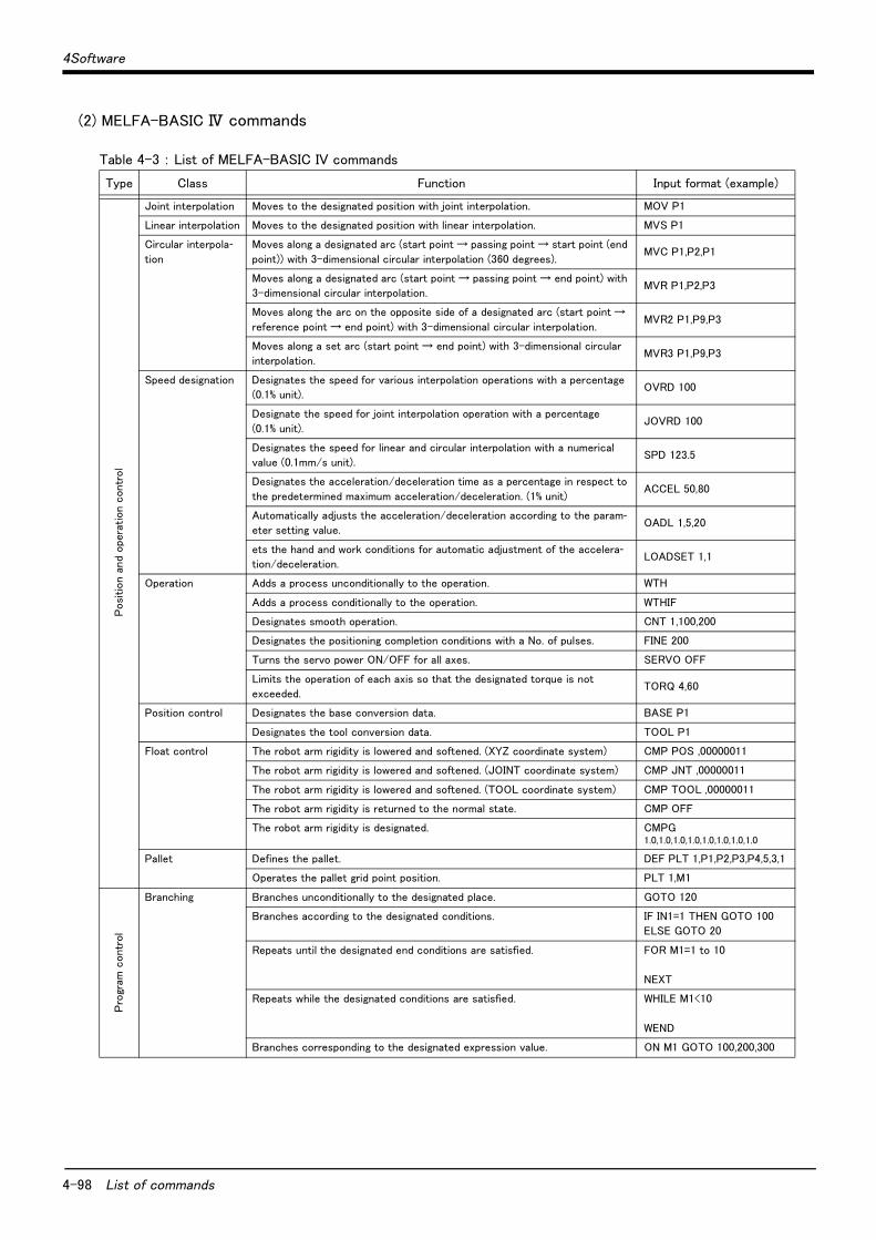
4-98 List of commands
4Software
(2) MELFA-BASIC Ⅳ commands
Table 4-3 : List of MELFA-BASIC IV commands
Type Class Function Input format (example)
Posi
tion a
nd
opera
tion c
ontr
ol
Joint interpolation Moves to the designated position with joint interpolation. MOV P1
Linear interpolation Moves to the designated position with linear interpolation. MVS P1
Circular interpola-tion
Moves along a designated arc (start point → passing point → start point (end
point)) with 3-dimensional circular interpolation (360 degrees).MVC P1,P2,P1
Moves along a designated arc (start point → passing point → end point) with
3-dimensional circular interpolation.MVR P1,P2,P3
Moves along the arc on the opposite side of a designated arc (start point →
reference point → end point) with 3-dimensional circular interpolation.MVR2 P1,P9,P3
Moves along a set arc (start point → end point) with 3-dimensional circular
interpolation.MVR3 P1,P9,P3
Speed designation Designates the speed for various interpolation operations with a percentage
(0.1% unit).OVRD 100
Designate the speed for joint interpolation operation with a percentage
(0.1% unit).JOVRD 100
Designates the speed for linear and circular interpolation with a numerical
value (0.1mm/s unit).SPD 123.5
Designates the acceleration/deceleration time as a percentage in respect to
the predetermined maximum acceleration/deceleration. (1% unit)ACCEL 50,80
Automatically adjusts the acceleration/deceleration according to the param-eter setting value.
OADL 1,5,20
ets the hand and work conditions for automatic adjustment of the accelera-tion/deceleration.
LOADSET 1,1
Operation Adds a process unconditionally to the operation. WTH
Adds a process conditionally to the operation. WTHIF
Designates smooth operation. CNT 1,100,200
Designates the positioning completion conditions with a No. of pulses. FINE 200
Turns the servo power ON/OFF for all axes. SERVO OFF
Limits the operation of each axis so that the designated torque is not
exceeded.TORQ 4,60
Position control Designates the base conversion data. BASE P1
Designates the tool conversion data. TOOL P1
Float control The robot arm rigidity is lowered and softened. (XYZ coordinate system) CMP POS ,00000011
The robot arm rigidity is lowered and softened. (JOINT coordinate system) CMP JNT ,00000011
The robot arm rigidity is lowered and softened. (TOOL coordinate system) CMP TOOL ,00000011
The robot arm rigidity is returned to the normal state. CMP OFF
The robot arm rigidity is designated. CMPG 1.0,1.0,1.0,1.0,1.0,1.0,1.0,1.0
Pallet Defines the pallet. DEF PLT 1,P1,P2,P3,P4,5,3,1
Operates the pallet grid point position. PLT 1,M1
Pro
gram
contr
ol
Branching Branches unconditionally to the designated place. GOTO 120
Branches according to the designated conditions. IF IN1=1 THEN GOTO 100
ELSE GOTO 20
Repeats until the designated end conditions are satisfied. FOR M1=1 to 10
NEXT
Repeats while the designated conditions are satisfied. WHILE M1<10
WEND
Branches corresponding to the designated expression value. ON M1 GOTO 100,200,300

4Software
List of commands 4-99
Pro
gram
contr
ol
Branching Executes program block corresponding to the designated expression value.. SELECT
CASE 1
CASE 2
END SELECT
Moves the program process to the next line. SKIP
Subroutine Executes the designated subroutine. (Within program) GOSUB 200
Returns from the subroutine. RETURN
Executes the designated program. CALLP "P10",M1,P1
Defines the program argument executed with the CALLP command. FPRM M10,P10
Executes the subroutine corresponding to the designated expression value. ON M1 GOSUB 100,200,300
Interrupt Defines the interrupt conditions and process. DEF ACT 1 IN1=1 GOTO 100
Enables/disables the interrupt. ACT 1=1
Defines the start line of the program to be executed when an interrupt is
generated from the communication line.ON COM(1) GOSUB 100
Enables the interrupt from the communication line. COM(1) ON
Disables the interrupt from the communication line. COM(1) OFF
Stops the interrupt from the communication line. COM(1) STOP
Wait Designates the wait time, and the output signal pulse output time. (0.01s unit) DLY 0.5
Waits until the variable becomes the designated value. WAIT M_IN(1)=1
Stop Stops the program execution. HLT
Generates an error. During program execution, continue, stop or servo OFF
can be designated.ERROR 9000
End Ends the program execution. END
Han
d Hand open Opens the designated hand. HOPEN
Hand close Closes the designated hand. HCLOSE
Input/
outp
ut Assignment Defines the input/output variables. DEF IO PORT1=BIT,0
Input Retrieves the general-purpose input signal. M1=IN 1
Output Calls out the general-purpose output signal.OUT 1=0
Par
alle
l exe
cution
Mechanism desig-nation
Acquires the mechanism with the designated mechanism No. GETM 1
Releases the mechanism with the designated mechanism No. RELM 1
Selection Selects the designated program for the designated slot. XLOAD 2,"P102"
Start/stop Carries out parallel execution of the designated program. XRUN 3,"100",0
Stops parallel execution of the designated program. XSTP 3
Returns the designated program's execution line to the head and enters the
program selection enabled state.XRST 3
Oth
ers
Definition Defines the integer type or real number type variable. DEF INT KAISUU
Defines the character string variable. DEF CHAR MESSAGE
efines the layout variable. (Up to 3-dimensional possible) DIM PDATA(2,3)
Defines the joint variable. DEF JNT TAIHI
Defines the position variable. DEF POS TORU
Defines the function. DEF FNTASU(A,B)=A+B
Clear Clears the general-purpose output signal, variables in program, variables
between programs, etc.CLR 1
File Opens a file. OPEN "COM1:" AS #1
Closes a file. CLOSE #1
Inputs data from a file. INPUT# 1,M1
Outputs data to a file. PRINT# 1,M1
Comment Describes a comment. REM "ABC"
Label Indicates the branching destination. *SUB1
Type Class Function Input format (example)

4-100 List of commands
4Software
(3) MOVEMASTER commandsTable 4-4 : List of MOVEMASTER command
Type Class Function Input format (example)
Posi
tion a
nd
opera
tion c
ontr
ol
Joint inter-polation
Moves to the designated position variable with joint interpolation. MO 1
Moves to the designated position with joint interpolation. MP 100,200,125.3,0,90
Moves to a position obtained by adding two position variables. MA 1,2
Turns the joint by the specified angle from the current position. MJ 10,20,0,0,0,0
Moves the axis by the designated amount from the current position. DJ 1,15
Moves by the specified distance from current position. DW 100,80,0
Moves to the next position in number from current position. IP
Moves to the previous position in number from current position. DP
Moves to a position separated by the designated distance (+/- direction) in the Z axis direc-tion of the tool coordinates from the designated position variable's position.
MT 1,-50
Moves to the origin in the axis order designated in the parameters. NT
Moves to the user specified origin position. OG
Linear
interpola-tion
Moves to the designated position variable with linear interpolation. MS 1
Moves by the specified distance from current position. DS 10,20,0
Continuously moves the position variable with linear interpolation between the two designated
position variables.MC 10,20
Moves to a position separated by the designated distance (+/- direction) in the Z axis direc-tion of the tool coordinates from the designated position variable position.
MTS 1,-50
Circular
interpola-tion
Moves along a designated arc (start point → transient point → end point) with three-dimen-sional circular interpolation.
MR 1,2,3
Moves with circular interpolation with the position data of two MRA commands designated
previously or subsequently.MRA 4
Speed des-ignation
Establishes program over-ride。 (0.1% unit) OVR 100
Designate the speed level and acceleration/deceleration rate for various interpolation opera-tions.
SP 25,H
Designate the speed, time constant, acceleration/deceleration rate and CNT setting validity
for linear and circular interpolation.SD 123.5,50,50,0
Position
control
It establishes die length to hand nose from hand installation. TL 128
Designates the tool matrix. TLM 0,0,128,0,0,0
Waits for in position till all axis ring inward pulse appointing. PW 10
Adds ± 360 degrees to current R axis joint position and rewrites current position. JRC +1
Memorizes current position as the position number. HE 1
Memorizes current position as the origin. HO
Sets the designated coordinate value (x, y, z, a, b, c) in the designated position variable. PD 1,100,200,300,0,90,0
Deletes the position variable between two designated position variables. PC 1,20
Changes the pose of the robot at position。 CF 1,R,A,F
Pallet Defines the pallet. PA 1,5,3
Operates the designated pallet No. grid point position, and substitutes into the corresponding
position variable.PT 1

4Software
List of commands 4-101
Pro
gram
contr
ol
Branching Jump to line number. GT 120
Jump to line number if internal register value/strings equals specified value/strings. EQ 20,120
EQ "OK",120
Jump to line number if internal register value/strings does not equal specified value/strings. NE 20,120
NE "NG",120
Jump to line number if internal register value/strings is greater than specified value/strings. LG 20,120
LG "NG",120
Jump to line number if internal register value/strings is smaller than specified value/strings. SM 20,120
SM "NG",120
Jump to line number by internal register bit status. TB +5,100
Jump to line number by external input signal bit status. TBD +5,100
Repeats the loop specified by command NX. RC 8
Specifies the range of a loop in a program by command RC. NX
Subroutine Executes the subroutine of the line designated in the designated program. GS 3,10
Returns from the subroutine. (The return line No. can be designated.) RT
RT 200
Pro
gram
contr
ol
Interrupt Validates the interrupt by the bit designated by the external input terminal, and designated
the branching method and branching line at the interrupt.EA +16,100,1
Disables interrupt by the bit of external input signal. DA 16
Wait Stops the operation for the designated time. (0.1 sec unit) TI 50
Select Selects the program. N 1
Start Executes the program between the designated line numbers. RN 10,50
Stop Halts the program. HLT
End Ends the program. ED
Han
d
Open Opens the specified hand. GO
Close Closes the specified hand. GC
Setting Sets the motorized hand's gripping force and open/close time. GP 40,30,50
Sets the hand open/close state when the "PD" command is executed. GF 1
Input/
outp
ut Input Gets signal from external input. ID
Output Outputs data to external output signal. OD 20
Outputs the counter value to external output signal. OC 1
Sets the output signal bit status. OB +16
Opera
tion/Subst
itution
addition Adds the designated value to the internal register value. ADD 10
Adds 1 to the designated number's counter. IC 5
Adds the coordinate values of the designated position variable to the coordinate values of the
designated position variable.SF 1,2
Subtraction Subtracts the designated value from the designated register value. SUB 10
Subtracts one from the designated number's counter. DC 5
Multiplica-tion
Multiples the designated value to the internal register value.MUL 2
Division Divides the internal register value by the designated value. DIV 10
AND Logical AND of the internal register value and specified value. AN 7
OR Logical OR of the internal register value and specified value. OR 3
XOR Logical exclusive OR of the internal register value and specified value. XO 2
Substitution Substitutes the designated value (character string) in the designated counter. SC 1,10
SC $1,"OK"
Substitutes the designated position variable coordinate value in the designated position vari-able.
PL 1,2
Substitutes the internal register value (character string) in the designated number's counter. CL 1
Sets the designated number's counter value (character string) in the internal register. CP 1
Exchange Exchanges the coordinate values of two designated position variables. PX 1,2
Type Class Function Input format (example)

4-102 List of commands
4Software
Oth
er
RS-232C
read
Reads the selected program No. or designated program information. QN 1
Reads the program of specified line number. LR 10
Reads the program of specified step number. STR 10
Reads the coordinate value of specified position number. PR 1
Reads the value/strings of specified counter number. CR 1
Reads the hand input signal, internal register value and the 16-bit width data from the desig-nated external output signal bit.
DR 16
Reads the current error No. or error history. ER 10
Reads the coordinate value of current position. WH
Reads the value of current tool length. WT
Reads the current tool matrix. WTM
Reads the name of system software version. VR
Reads the value of specified parameter. PMR "HANDINIT"
Clear Deletes the program between the designated line numbers. DL 10,90
Deletes the selected program and position variables. NW
File Opens the file. OPEN 1,1
Reads the data from the file. INP 1,2,0
Sends the value to the file. PRN 2
Sets the contents of the designated parameter. PMW 1,0,1,0,1,0,1,0
Reset Resets the error, or program line number. RS
Comment Describes a comment. '
Type Class Function Input format (example)

4Software
List of parameters 4-103
4.2 List of parameters
(1) List of parametersshow the main parameter in the Table 4-5.
Table 4-5 : List of parameters
Parameter Details
Standard tool coordinates. MEXTL Set the default value for the tool data.
Unit: mm or deg.
Standard base coordinates MEXBS Set the relation of the world coordinate system and robot coordinate system.
Unit: mm or deg.
XYZ operation range MEPAR Designate the overrun limit value for the world coordinate system.
JOINT operation range MEJAR Set the overrun limit value for each joint axis.
Free plane limit This is the overrun limit set with the free plane.
Create a plane with the three coordinates x1, y1, z1 to x3, y3, z3, and set the outer side of the
plane as the outside operation range (error). The following three types of parameters are used.
SFC1P
:
SFC8P
Eight types of free plane limits can be set in SFC1P to SFC8P.
There are nine elements, set in the order of x1, y1, z1, x2, y2, z2, x3, y3, z3.
SFC1ME
:
SFC8ME
Designate which mechanism to use eight types of set free plane limits.
The mechanism No. to use is set with 1 to 8.
SFC1AT
:
SFC8AT
Set the validity of the eight types of set free plane limits.
(Valid/invalid = 1/0)
User-defined area An area (cube) defined with two XYZ coordinate points can be designated and that area set as
the outside operation range. Furthermore, a signal can be output when the axis enters that
area. Up to eight types of area can be designated.
AREA1P1
:
AREA8P1
Designated the 1st point of the area.
There are eight elements, set in the order of x, y, z, a, b, c, L1, L2.
(L1 and L2 are the additional axes.)
AREA1P2
:
AREA8P2
Designated the 2nd point of the area.
There are eight elements, set in the order of x, y, z, a, b, c, L1, L2.
(L1 and L2 are the additional axes.)
AREA1ME
:
AREA8ME
Designate which mechanism to use the eight types of set area.
The mechanism No. to use is set with 1 to 8
AREA1AT
:
AREA8AT
Designate the area check type.
(Invalid/zone/interference = 0/1/2)
Zone: The dedicated output signal USRAREA turns ON.
Interference: An error occurs..
Automatic return setting RETPATH Set to restart the program after returning to the interrupt position when resuming operation
after an interruption.
Buzzer ON/OFF BZR Designate whether to the turn buzzer ON or OFF.
Automatic operation speed. SPI Designate the initial level for the automatic operation speed.
Automatic operation override EOV Designate the initial override for automatic operation.
(External override, program override)
Jog setting JOGJSP Designate the joint jog and step operation speed.
(Set dimension H/L amount, max. override.)
JOGPSP Designate the linear jog and step operation speed.
(Set dimension H/L amount, max. override.)
Jog speed limit value JOGSPMX Limit the operation speed during the teaching mode. Max. 250[mm/s]
Hand type HANDTYPE Set the hand type of the single/double solenoid, and the signal No.
(Single/double = S/D)
Set the signal No. after the hand type. Example) D900
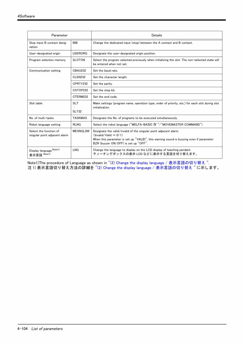
4-104 List of parameters
4Software
Stop input B contact desig-nation
INB Change the dedicated input (stop) between the A contact and B contact.
User-designated origin USERORG Designate the user-designated origin position.
Program selection memory SLOTON Select the program selected previously when initializing the slot. The non-selected state will
be entered when not set.
Communication setting CBAU232 Set the baud rate.
CLEN232 Set the character length.
CPRTY232 Set the parity.
CSTOP232 Set the stop bit.
CTERM232 Set the end code.
Slot table SLT
:
SLT32
Make settings (program name, operation type, order of priority, etc.) for each slot during slot
initialization.
No. of multi-tasks TASKMAX Designate the No. of programs to be executed simultaneously.
Robot language setting RLNG Select the robot language ("MELFA-BASIC Ⅳ "/"MOVEMASTER COMMAND")
Select the function of
singular point adjacent alarm
MESNGLSW Designate the valid/invalid of the singular point adjacent alarm.
(Invalid/Valid = 0/1)
When this parameter is set up "VALID", this warning sound is buzzing even if parameter:
BZR (buzzer ON/OFF) is set up "OFF".
Display language.Note1)
表示言語 Note1)
LNG Change the language to display on the LCD display of teaching pendant.
テ ィ ーチングボ ッ ク スの表示 LCD などに表示する言語を切り替えます。
Note1)The procedure of Language as shown in "(2) Change the display language / 表示言語の切り替え ". 注 1) 表示言語切り替え方法の詳細を "(2) Change the display language / 表示言語の切り替え " に示し ます。
Parameter Details

4Software
List of parameters 4-105
(2) Change the display language / 表示言語の切り替えThe language to display on the LCD display of teaching pendant can be changed by "the display language parameter". (Japanese or English) Show the details of the parameter in the Table 4-5. Refer to the separate "Instruction Manual/Detailed Explanation of Functions and Operations" for details on changing the parameter. The parameter is set up based on the order specifications before shipment. Order to dealer when the instruction manual of the other language is necessity. More, the caution seals that stuck on the robot arm and the controller are made based on the language of the order specification. Use it carefully when selecting the other language.
表示言語設定パラ メ ータによ っ て、 テ ィ ーチングボ ッ クスの表示 LCD などに表示する言語を切り替えるこ とができます。 (日本語、 または英語) Table 4-5 にそのパラ メ ータの詳細を示し ます。 パラ メ ータの変更方法は、 別冊の 「取扱説明書/機能と操作の詳細解説」 を参照願います。なお、 出荷時はご注文仕様に基づき弊社で設定いた し ます。 別の言語の取扱説明書をご希望の場合はご用命願います。また、 ロボ ッ ト 本体と コ ン ト ローラに貼り付けてある注意シールは、 ご注文仕様に基づいた言語で製作いた し ます。 本パラ メ ータ を変更し て言語を切り替えてご使用の場合はご注意願います。
Table 4-5 : Display language parameter / 表示言語設定パラ メ ータ
Parameterパラ メ ータ
Parameter name
パラ メ ータ名
No. of arraysNo. of characters
配列数文字数
Details explanation内容説明
Default setting出荷時設定
Display lan-guage
表示言語設定
LNG Character string 1文字列 1
Set up the display language. "JPN" : Japanese"ENG" : English
The following language is changed. (1)The display LCD of teaching pendant. (2) Personal computer support software.
*alarm message of the robot. *Parameter explanation list.
(3)Alarm message that read from the robot with external communication. (Standard RS232C, Extended serial I/F, Ethernet I/F)
表示言語を設定し ます。"JPN" : 日本語表示"ENG" : 英語表示
以下に示す表示言語が変更されます。(1) テ ィ ーチングボ ッ クスの表示 LCD(2) パソ コ ンサポー ト ソ フ ト ウェ ア
・ ロボ ッ ト のアラームメ ッ セージ・ パラ メ ータ説明リ ス ト
(3) 外部通信でロボ ッ ト から読み出し たア ラーム メ ッセージ (標準 RS232C、 増設シ リ アルイ ン タフ ェース、 イーサネ ッ ト イン タ フ ェース)
1

4-106 List of parameters
4Software

5Safety
Safety 5-107
5 Safety
5.1 Safety
Measures to be taken regarding safety of the industrial robot are specified in the "Labor Safety and Sanitation Rules". Always follow these rules when using the robot to ensure safety.
5.1.1 Self-diagnosis stop functionsThis robot has the self-diagnosis stop functions shown in Table 5-1 and the stop functions shown in Table 5-2 for safe use.
Table 5-1 : Self-diagnosis stop functions
Table 5-2 : List of stop functions
5.1.2 External input/output signals that can be used for safety protection measures
Table 5-3 : External input/output signals that can be used for safety protection measures
[Caution] The external emergency stop input is prepared as a b contact for safety proposes. Thus, if the emer-gency stop input circuit is opened when the robot is started up, the robot will not operate. Refer to"Fig. 5-1 Example of safety measures"for details.
No. Function Details Remarks
1 Overload protection func-tion
Activates when the total servo current time exceeds the specified value.
The drive circuit is shut off. The robot stops, and an alarm displays.
2 Overcurrent diagnosis function
Activates when an overcurrent flows to the motor circuit.
The drive circuit is shut off. The robot stops, and an alarm displays.
3 Encoder disconnection diagnosis function
Activates when the encoder cable is disconnected. The drive circuit is shut off. The robot stops, and an alarm displays.
4 Deflection over diagnosis function
Activates when an error occurs between the com-mand value and actual position, and the error exceeds the specified amount.
The drive circuit is shut off. The robot stops, and an alarm displays.
5 AC power voltage drop diagnosis function
Activates when the AC power voltage drops below the specified value.
The drive circuit is shut off. The robot stops, and an alarm displays.
6 CPU error detection func-tion
Activates when an error occurs in the CPU. The drive circuit is shut off. The robot stops, and an alarm displays.
7 Overrun prevention function
Software limit detection
This is the limit provided by the software to enable operation only in the operation range.
The drive circuit is shut off. The robot stops, and an alarm displays.
Mechanical stopper
This is the mechanical stopper provided outside the software.
The robot mechanically stops, and function 1 or 2 activates.
Stopfunction
Operationpanel
Teaching pendant
Externalinput
Details
Emergencystop
◯ ◯ ◯ This is the stop with the highest degree of emergency. The servo power is shut off, and the mechanical brakes (all axes) activate to stop the robot.To recover, reset the alarm, and turn the servo ON with the servo ON command.
Stop ◯ ◯ ◯
This is a stop operation with a high degree of emergency. The robot immediately decelerates and stops.Note that the servo power is not shut off. Use this when using the collision evasion sensor, etc.
Signal Command Functions Usage method
Input
External emer-gency stop
(Input signal) This servo power is shut off, and the robot
stops immediately.
Externally installed emergency stop switch.
Door switch on safety protection fence.
Stopping at high-level error occurrence.
Stop STOP The program execution is stopped, and the
robot stops. The servo power is not shut off.
The robot is stopped when a peripheral device
fault occurs. The servo power is not shut off.
Servo OFF SRVOFF The servo power can be shut off. The robot is stopped when a peripheral device
fault occurs. The servo power is not shut off.
Automatic opera-tion enable
AUTOENA Disables automatic operation when inactive. Door switch on safety protection fence
Outp
ut
In servo ON SRVON The servo power ON/OFF state is output. The servo power ON/OFF state is shown and alerted with the display lamps.
Waiting STOP Outputs that the robot is temporarily stopped. The temporary stop state is shown and alerted with the display lamps.
In alarm ERRRESET Outputs when an alarm occurs in the robot. The alarm state is shown and alerted with the dis-play lamps.

5-108 Safety
5Safety
5.1.3 Precautions for using robotThe safety measures for using the robot are specified in the "Labor Safety and Sanitation Rules". An outline of the rules is given below.
(1) Robot installation・ Secure sufficient work space required to safely perform work such as teaching and maintenance related to the
robot.・ Install the controller outside the robot's motion space. (If a safety fence is provided, install outside the fence.)・ Install the controller where the entire robot operation can be viewed.・ Install display lamps, etc., to indicate the robot's operation state.・ Securely fix the robot arm onto the fixing table with the designated bolts.
(2) Prevention of contact with operator・ Install a safety fence or enclosure so that the operator cannot easily enter the robot's motion space.・ Install an interlock function that will stop the robot if the safety fence or enclosure door is opened.
(3) Work procedures・ Create and observe work procedures for the robot teaching, operation, inspection and emergencies.・ Create hand signals to be followed when several operators are working together.・ Create displays such as "Teaching in Progress" and "Inspection in Progress" to be put up when an operator is
in the robot's motion space so that other operators will not operate the operation panel (controller, controlpanel).
(4) Training・ Train the operators about the operations, maintenance and safety required for the robot work.・ Only trained and registered operators must operate the robot.
Participation in the "Special training for industrial robots" sponsored by the Labor Safety and Sanitation Com-mittee, etc., is recommended for safety training.
(5) Daily inspection and periodic inspection・ lways inspect the robot before starting daily operations and confirm that there are no abnormalities.・ Set the periodic inspection standards in view of the robot's ambient environment and operation frequency, and
perform periodic inspections.・ Make records when periodic inspections and repairs have been done, and store the records for three or more
years.
5.1.4 Safety measures for automatic operation(1) Install safety fences so that operators will not enter the operation area during operation and indicate that
automatic operation is in progress with lamps, etc.(2) Create signals to be given when starting operation, assign a person to give the signal, and make sure that the
operator follows the signals.
5.1.5 Safety measures for teachingObserve the following measures when teaching, etc., in the robot's operation range.(1) Specify and follow items such as procedures related to teaching work, etc. (2) Take measures so that operation can be stopped immediately in case of trouble, and measures so that oper-
ation can be restarted.(3) Take measures with the robot start switch, etc., to indicate that teaching work is being done.(4) Always inspect that stop functions such as the emergency stop device before starting the work.(5) Immediately stop the work when trouble occurs, and correct the trouble.(6) Take measures so that the work supervisor can immediately stop the robot operation when trouble occurs.(7) The teaching operator must have completed special training regarding safety. (Training regarding industrial
robots and work methods, etc.)(8) Create signals to be used when several operators are working together.
5.1.6 Safety measures for maintenance and inspections, etc.Turn the power OFF and take measures to prevent operators other than the relevant operator from pressing the start switch when performing inspections, repairs, adjustments, cleaning or oiling.If operation is required, take measures to prevent hazards caused by unintentional or mistaken operations.(1) Specify and follow items such as procedures related to maintenance work, etc. (2) Take measures so that operation can be stopped immediately in case of trouble, and measures so that oper-
ation can be restarted.(3) Take measures with the robot start switch, etc., to indicate that work is being done.(4) Take measures so that the work supervisor can immediately stop the robot operation when trouble occurs.(5) The operator must have completed special training regarding safety. (Training regarding industrial robots and
work methods, etc.)(6) Create signals to be used when several operators are working together.

5Safety
Safety 5-109
5.1.7 Examples of safety measuresEmergency stop input circuits are prepared on the user wiring terminal block of the controller. Create a circuit as shown below for safety measures
.
Fig.5-1 : Example of safety measures
(1) Use a 2-contact type switch for all switches.(2) Install a limit switch on the safety fence's door. With a constantly open contact (a contact), wire to the door
switch input terminal so that the switch turns ON (is conducted) when the door is closed, and turns OFF (is opened) when the door is open.
(3) Use a 2b contact manual-return type operator emergency stop switch.(4) Classify the faults into minor faults (faults that are easily restored and that do not have a great effect) and
major faults (faults that cause the entire system to stop immediately, and that require care in restoration), and wire accordingly.
[Caution] The emergency stop input(terminal block) on the user wiring in the controller can be used for safetymeasures as shown in Fig. 5-1. Note that there are limits to the No. of switch contacts, capacity andcable length, so refer to the following and install.
・ Switch contact ......Prepare a 2-contact type.・ Switch contact capacity....... Use a contact that operates with a switch contact capacity of approx.
1mA to 100mA/24V.・ Cable length............................... The length of the wire between the switch and terminal block must be
max. 15m or less.[Reference] The specifications of the RA1 and RA2 coil shown in Fig. 5-1 are as follow.
・ Rated voltage ............................ DC24V ± 10%・ Rated excitation current ...... 12.5mA ± 10% (at25 deg.)
* Note that these specifications are subject to change without prior notice for modification purposes.
1
2
3
4
5
6
RA1
24V
RA3
S/W-EMG
RA2 RA2
RA4
RA1
1
2
3
4
5
6
RA11
24V
MC1
+
RA21
RA41
RA11
RA21
MC2
MC2
RA11
RA31
MC2
RA21
MC1
RA1
RA3
MC1
RA2
RA31
<Customer-prepared wiring> <Robot controller system>
To servo main circuit power
External emergencystop input
Teaching pendantdeadman switch
Operation panelemergency stop
Teaching pendantemergency stop
Teaching pendantdeadman switch
Software emergencystop
External emergencystop output
T/B removeswitch
Door switchinput
External emergencystop
Door switch
External emergencystop output
Software emergencystop
Teaching pendantdeadman switch
Door switchinput
Teaching pendantdeadman switch
T/B removeswitch
Teaching pendantemergency stop
Operation panelemergency stop
External emergencystop input
[Caution] Some information has been omitted for explanation proposes, so some parts may differ.

5-110 Working environment
5Safety
5.2 Working environment
Avoid installation in the following places as the equipment's life and operation will be affected by the ambient environment conditions. When using in the following conditions, the customer must pay special attention to the preventive measures.
(1) Power supply・ Where the voltage fluctuation will exceed the input voltage range.・ Where a momentary power failure exceeding 20ms may occur.・ Where the power capacity cannot be sufficiently secured.
(2) Noise・ Where a surge voltage exceeding 1000V, 1μs may be applied on the primary voltage. Near large inverters, highoutput frequency oscillator, large contactors and welding machines. Static noise may enter the lines when thisproduct is used near radios or televisions. Keep the robot away from these items.
(3) Temperature and humidity・ Where the atmospheric temperature exceeds 40 degree , lower than 0 degree.・ Where the relative humidity exceeds 85%, lower than 45%, and where dew may condense.・ Where the robot will be subject to direct sunlight or near heat generating sources such as heaters.
(4) Vibration・ Where excessive vibration or impact may be applied. (Use in an environment of 34m/s2 or less during transpor-tation and 5m/s2 or less during operation.)
(5) Installation environment・ Where strong electric fields or magnetic fields are generated.・ Where the installation surface is rough. (Avoid installing the robot on a bumpy or inclined floor.)
5.3 Precautions for handling
(1) This robot has brakes on J3 axis. The RH-15AH85 has brakes on J3 and J4 axes. The precision of the robot may drop, looseness may occur and the reduction gears may be damaged if the robot is moved with force with the brakes applied.
(2) Avoid moving the robot arm by hand. When unavoidable, gradually move the arm. If moved suddenly, the accu-racy may drop due to an excessive backlash, or the backed up data may be destroyed.
(3) Note that depending on the posture, even when within the movement range, the shaft section could interfere with the base section. Take care to prevent interference during jog. Note1)
(4) The robot arm is configured of precision parts such as bearings. Grease is used for lubricating these parts. When cold starting at low temperatures or starting operation after long-term stoppage, the position accuracy may drop or servo alarms may occur. If these types of phenomena occur, run the robot with row-speed opera-tion for a short time.
(5) The robot arm and controller must be grounded with Class D grounding to secure the noise resistance and to prevent electric shocks.
(6) The items described in these specifications are conditions for carrying out the periodic maintenance and inspections described in the instruction manual.
(7) When using the robot arm on a mobile axis or elevating table, the machine cables enclosed as standard config-uration may break due to the fixed installation specifications. In this case, use the machine cable extension (for flexed)" factory shipment special specifications or options.
(8) If this robot interferes with the workpiece or peripheral devices during operation, the position may deviate, etc. Take care to prevent interference with the workpiece or peripheral devices during operation.
(9) Do not attach a tape or a label to the robot arm and the controller. If a tape or a label with strong adhesive power, such as a packaging tape, is attached to the coated surfaces of the robot arm and controller, the coated surface may be damaged when such tape or label is peeled off.
Note1)Jog operation refers to operating the robot manually using the teaching pendant.

6Appendix
Specifications discussion material Appendix-111
6 Appendix
Appendix 1 : Specifications discussion material
■ Customer information
■ Purchased mode
■ Shipping special specifications (Settings can be made only at time of shipment)
■ Options (Installable after shipment)
Note1) Up to eight units, including the one unit mounted as a standard.
■ Maintenance parts (Consumable parts)
■ Robot selection check list
Copy this page and use the copy.
Company name Name
Address Telephone
Specification Type
Standard specification □ RH-5AH35 □ RH-5AH45 □ RH-5AH55□ RH-10AH55 □ RH-10AH70 □ RH-10AH85 □ RH-15AH85
Protection specifications □ RH-5AHM35 □ RH-5AHM45 □ RH-5AHM55□ RH-10AHM55 □ RH-10AHM70 □ RH-10AHM85 □ RH-15AHM85
Clean specifications □ RH-5AHC35-SA □ RH-5AHC45-SA □ RH-5AHC55-SA
Item Standard specifications Special shipping specifications
Robot arm Machine cable □ 5m type □ 10m fixed type □ 15m fixed type □ 5m flexed type □ 10m flexed type □ 15m flexed type
Controller Controller structure □ Floor type
Item Provision, and specifications when provided.
Robot
arm
Solenoid valve set
(Standard specification:RH-5AH)
1E-VD0 □ /VD0 □ E □ Not provided 1E-VD0 □ : □ 1 set □ 2 sets □ 3 sets □ 4 sets
1E-VD0 □ E: □ 1 set □ 2 sets □ 3 sets □ 4 sets
Solenoid valve set (Protection
specifications:RH-5AH)
1A-VD0 □ M-01/
1A-VD0 □ ME-01
□ Not provided 1A-VD0 □ M-01 : □ 1 set □ 2 sets □ 3 sets □ 4 sets
1A-VD0 □ ME-01: □ 1 set □ 2 sets □ 3 sets □ 4 sets
Solenoid valve set (Standard
specification:RH-10AH/15AH)
1N-VD0 □ /VD0 □ E □ Not provided 1N-VD0 □ : □ 1 set □ 2 sets □ 3 sets □ 4 sets
1N-VD0 □ E: □ 1 set □ 2 sets □ 3 sets □ 4 sets
Solenoid valve set (Protection
specifications:RH-10AH/15AH)
1A-VD0 □ M-02/
1A-VD0 □ ME-02
□ Not provided 1A-VD0 □ M-02 : □ 1 set □ 2 sets □ 3 sets □ 4 sets
1A-VD0 □ ME-02: □ 1 set □ 2 sets □ 3 sets □ 4 sets
Hand input cable 1A-HC35C □ Not provided □ Provided
Hand output cable 1N-GR35S □ Not provided □ Provided
Hand curl tube 1E-ST040 □ C-300 □ Not provided □ 1 pc. □ 2 pc. □ 3 pc. □ 4 pc.
Contr
olle
r
Teaching pendant R28TB- □□ □ Not provided □ 7m □ 15m
Pneumatic hand interface 2A-RZ365/2A-RZ375 □ Not provided □ Provided
Parallel I/O interface 2A-RZ361/2A-RZ371 □ Not provided □ 1pc. □ 2pc. □ 3pc. □ 4pc. □ 5pc. □ 6pc. □ 7pc.
External I/O cable 2A-CBL □□ □ Not provided □ 5m-1pc. □ 5m-2pc. □ 5m-3pc.□ 15m-1pc. □ 15m-2pc. □ 15m-3pc.
CC-LINK interface 2A-HR575E □ Not provided □ Provided
ETHERNET interface 2A-HR533E □ Not provided □ Provided
Extended serial interface 2A-RZ581E □ Not provided □ Provided
Additional axis interface 2A-RZ541E □ Not provided □ Provided
Extended memory cassette 2A-HR432 □ Not provided □ Provided
Personal computer cable RS-MAXY-CBL □ Not provided □ Provided
Personal computer supportsoftware
3A-01C-WINE□ Not provided □ Windows95/98/NT4.0 CD-ROM
Personal computer supportsoftware mini
3A-02C-WINE□ Not provided □ Windows95/98/NT4.0 CD-ROM
Controller protection box CR2A-MB □ Not provided □ Provided
Maintenance parts□ Backup batteries A6BAT ( ) pcs. □ Backup batteries ER6 ( ) pcs. □ Grease SK-1 ( ) cans. □ Grease Marutenpu PS2 ( ) cans.
Work description □ Material handring □ Assembly □ Machining L/UL □ Sealing □ Testing and inspection □ Other ( )
Workpiece mass ( ) g Hand mass ( ) g Atmosphere □ General enveronment □ Clean □ Dust provided □ Other( )
Remarks

Appendix-112 Specifications discussion material
6Appendix


JUL..2002 MEE Printed in Japan on recycled paper. Specifications are subject to change without notice.
HEAD OFFICE : MITSUBISHI DENKI BLDG MARUNOUCHI TOKYO 100-8310 TELEX : J24532 CABLE MELCO TOKYO NAGOYA WORKS : 1-14, YADA-MINAMI 5, HIGASHI-KU, NAGOYA, JAPAN