The Weldability of Duplex Stainless-Steel in Structural ... - MDPI
Upload
khangminh22Category
view
1download
0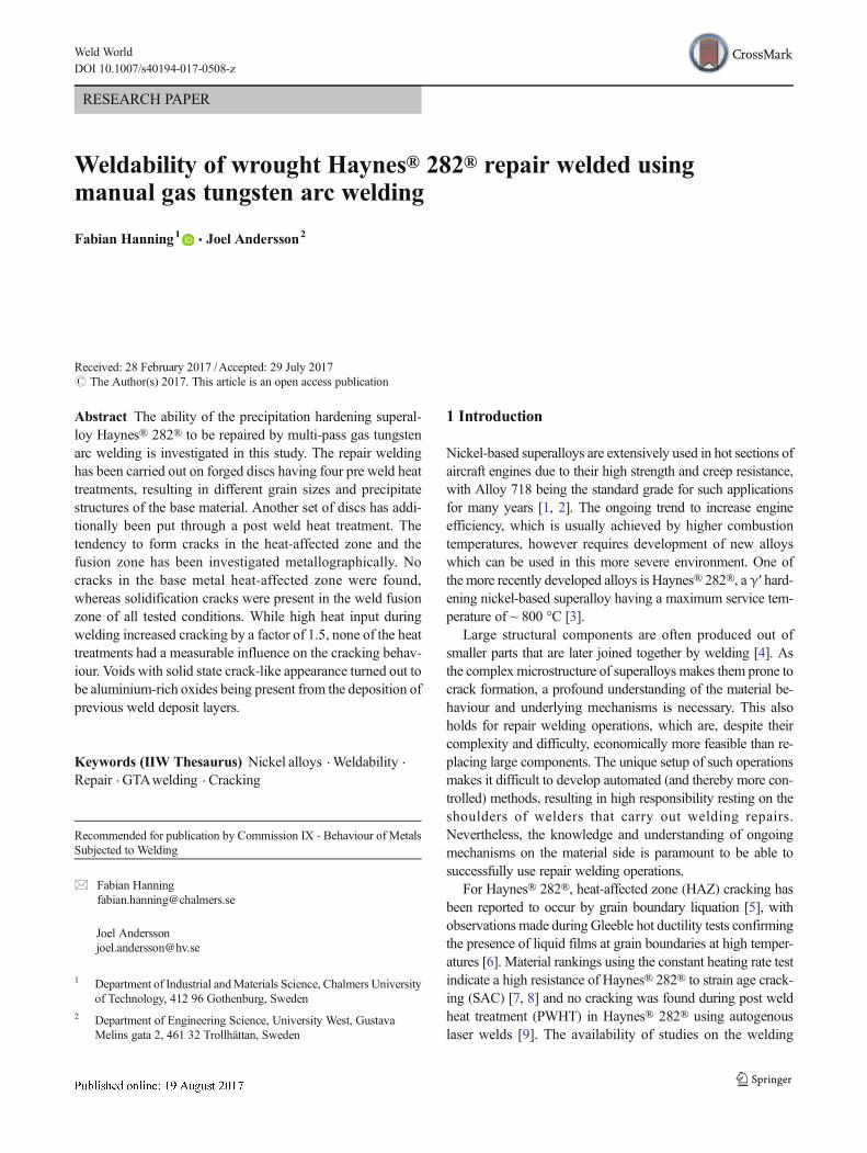
RESEARCH PAPER
Weldability of wrought Haynes® 282® repair welded usingmanual gas tungsten arc welding
Fabian Hanning1 & Joel Andersson2
Received: 28 February 2017 /Accepted: 29 July 2017# The Author(s) 2017. This article is an open access publication
Abstract The ability of the precipitation hardening superal-loy Haynes® 282® to be repaired by multi-pass gas tungstenarc welding is investigated in this study. The repair weldinghas been carried out on forged discs having four pre weld heattreatments, resulting in different grain sizes and precipitatestructures of the base material. Another set of discs has addi-tionally been put through a post weld heat treatment. Thetendency to form cracks in the heat-affected zone and thefusion zone has been investigated metallographically. Nocracks in the base metal heat-affected zone were found,whereas solidification cracks were present in the weld fusionzone of all tested conditions. While high heat input duringwelding increased cracking by a factor of 1.5, none of the heattreatments had a measurable influence on the cracking behav-iour. Voids with solid state crack-like appearance turned out tobe aluminium-rich oxides being present from the deposition ofprevious weld deposit layers.
Keywords (IIW Thesaurus) Nickel alloys .Weldability .
Repair . GTAwelding . Cracking
1 Introduction
Nickel-based superalloys are extensively used in hot sections ofaircraft engines due to their high strength and creep resistance,with Alloy 718 being the standard grade for such applicationsfor many years [1, 2]. The ongoing trend to increase engineefficiency, which is usually achieved by higher combustiontemperatures, however requires development of new alloyswhich can be used in this more severe environment. One ofthe more recently developed alloys is Haynes® 282®, a γ′ hard-ening nickel-based superalloy having a maximum service tem-perature of ~ 800 °C [3].
Large structural components are often produced out ofsmaller parts that are later joined together by welding [4]. Asthe complexmicrostructure of superalloys makes them prone tocrack formation, a profound understanding of the material be-haviour and underlying mechanisms is necessary. This alsoholds for repair welding operations, which are, despite theircomplexity and difficulty, economically more feasible than re-placing large components. The unique setup of such operationsmakes it difficult to develop automated (and thereby more con-trolled) methods, resulting in high responsibility resting on theshoulders of welders that carry out welding repairs.Nevertheless, the knowledge and understanding of ongoingmechanisms on the material side is paramount to be able tosuccessfully use repair welding operations.
For Haynes® 282®, heat-affected zone (HAZ) cracking hasbeen reported to occur by grain boundary liquation [5], withobservations made during Gleeble hot ductility tests confirmingthe presence of liquid films at grain boundaries at high temper-atures [6]. Material rankings using the constant heating rate testindicate a high resistance of Haynes® 282® to strain age crack-ing (SAC) [7, 8] and no cracking was found during post weldheat treatment (PWHT) in Haynes® 282® using autogenouslaser welds [9]. The availability of studies on the welding
Recommended for publication by Commission IX - Behaviour of MetalsSubjected to Welding
* Fabian [email protected]
Joel [email protected]
1 Department of Industrial andMaterials Science, Chalmers Universityof Technology, 412 96 Gothenburg, Sweden
2 Department of Engineering Science, University West, GustavaMelins gata 2, 461 32 Trollhättan, Sweden
Weld WorldDOI 10.1007/s40194-017-0508-z

response of Haynes® 282® is however still very sparse and noinformation on multi-pass repair welding is available for thisalloy yet. This study aims to fill this gap by investigating theinfluence of different pre and post weld heat treatments onHAZand fusion zone (FZ) cracking during manual multi-pass repairwelding. Furthermore, the effect of the welding process hasbeen evaluated by varying the heat input through adjustingthe welding current.
2 Experimental
2.1 Material and heat treatments
Wrought Haynes® 282® in the form of a 100-mm-diameterforged bar has been used for this study, with the nominalchemical composition given in Table 1. The as-received,solutionised condition had a grain size of ASTM 5.5(51 ± 7 μm) and a hardness of 315 ± 7 HV with the micro-structure showing strings of primary carbides typical for thethermomechanical history of the material (cf. Fig. 1a). Grainboundary carbides were not present in this material condition.
In total, eight discs with a thickness of 15 mm were cut fromthe bar and subsequently heat treated in a vacuum furnace with aheating rate of 4–11 °C/min and argon forced convectioncooling down to 500 °C to minimise precipitation (coolingrate > 50 °C/min). The parameters are summarised in Table 2.Four heat treatment conditions have been selected to investigatethe influence of pre weld material condition on weld crackingduring repair welding. While the heat treatment at 1010 °C waschosen to just above the dissolution temperature of the γ′ phasein the material (997 °C [3]) without dissolving secondary car-bides, the treatment at 1120 °C was selected to obtain a carbidedistribution similar to the one obtained by using the recommend-ed solutionising parameters. This temperature is the lower limitof the solution annealing window, which results in the removalof M23C6 carbides (1019 °C) from the grain boundaries, whileM6C and MC carbides remain in the material [3, 10]. Thehighest temperature was used to produce a coarse-grained ma-terial. The temperature represents the upper limit of the solutionannealingwindow and together with the longer exposure time of2 h (cf. 0.5 h for 1120 °C), an increase in grain size could beexpected. Fully age hardened material has been reported to bemore susceptible to weld cracking especially when it comes toSAC due to the localisation of strain to the HAZ [11]. One disc
has hence been put through a complete age hardening cycle(788 °C for 8 h) before being repair welded. Another four discshave been put through a post weld heat treatment after complet-ing the repair welding operation. Direct ageing has been chosenopposed to the conventionally applied heating to solution treat-ment temperature to subject the material to more severe condi-tions. The reasoning here was that direct ageing results in alonger exposure time in the precipitation temperature rangewithout heating to solution annealing temperature, where mostof the stress relaxation occurs.
2.2 Repair welding
Five circular repair welding grooves with a diameter of 25 mm,a depth of 10 mm, and a bottom radius of 5 mm have beenmachined into the discs after the pre weld heat treatments, asindicated in Fig. 2a. To maximise welding restraint, the discswere fixed to 25-mm-thick stainless steel discs by a circumfer-ential weld (cf. Fig. 2b). Repair welding has been carried out byexperienced welders using manual gas tungsten arc welding(GTAW) with a tungsten-2% thorium (WT-20) electrode.Argon was used as shielding gas, with a nozzle gas flow of8–15 l/min. Filler material in the form of 1.14-mm wire withmatching chemistry has been used to fill the grooves. Two outof the five grooves have been filled using negative polarity anda welding current of 120 A, while 140 A have been used for theremaining ones. The former is typical for such a repair opera-tion, whereas the higher weld current represents tougher condi-tions due to the higher heat input. The grooves have been filledwith 7 to 8 layers, while the material was quenched by argonafter the deposition of each layer to an inter-pass temperature ofapproximately 50 °C. The grooves have been filled one by one,but without specific sequence and no brushing between layerdeposition.
2.3 Weld examination and microstructural analysis
Three cross sections have been cut out of each welded grooveby abrasive waterjet cutting and subsequently mounted in hotmounting resin for automated metallographic preparation.Cross section positioning was transverse to the welding direc-tion. One cross section was cut out from the centre line, whilethe remaining two were positioned parallel to the centre posi-tion with a distance of approximately 5 mm. Since the discswere cut off from a forged bar, the cross sections taken for weldexamination show the base material in longitudinal direction.The cross sections were subsequently visually inspected forcracks and other imperfections by scanning over the polishedsurface at ×200 magnification using an Olympus BX60M lightoptical microscope. The relative position of found imperfec-tions was recorded and images taken. For better identification,the samples were then electrolytically etched with 10 wt%oxalic acid at 3 V DC for 3–5 s, followed by re-inspecting the
Table 1 Nominal chemical composition in weight percentage ofHaynes® 282®
Ni Cr Co Mo Ti Al Fe Mn Si C B
Bal 20 10 8.5 2.1 1.5 0.15a 0.3a 0.15a 0.06 0.005
aMax
Weld World

previously recorded imperfections. Imperfections were classi-fied as either cracks, pores or lack of fusion (LoF) based on theirappearance. A criterion for the latter was the smooth and curvedshape and their sheer size.
Microhardness has beenmeasured on representative sampleswith a force of 0.5 kgf (HV0.5) using a Shimadzu HMV-2microhardness tester. Measured values represent the averageof five indentations together with the respective standard devi-ation as a measure for the error. Grain size has been measuredby the lineal intercept method according to ASTM E112 [12].Selected samples were further investigated with electron mi-croscopy, including backscattered (BSD) and secondary elec-tron (SE) imaging and energy-dispersive X-ray spectroscopy(EDS), for which a Leo 1550 FEG SEM equipped with anOxford Instruments EDS detector has been used.
3 Results
3.1 Heat treatments
The microstructures obtained with the different heat treatmentsare shown in Fig. 1b–i together with the respective grain size
Table 2 Pre and post weld heat treatment conditions
Discno.
Pre weldheat treatment
Post weldheat treatment
1 1010 °C—1 h –
2 1120 °C—0.5 h + 1010 °C—2 h +788 °C—8 h
–
3 1120 °C—0.5 h –
4 1150 °C—2 h –
5 1010 °C—1 h 788 °C—8 h
6 1010 °C—1 h 1010 °C—2 h +788 °C—8 h
7 1120 °C—0.5 h 788 °C—8 h
8 1150 °C—2 h 788 °C—8 h
Fig. 1 Microstructure of the base material after different heat treatments, including respective grain size and hardness values
Weld World

and hardness values. Grain size varied within one ASTMnum-ber for the different heat treatments, except for the discs heatedto 1150 °C, which is above the secondary carbide solvus tem-perature. This led to significant grain growth, as indicated inFig. 1e, i. The larger grain size did not have a measurable effecton the hardness. All age-hardened samples show hardnessvalues between 370 and 380 HV. As expected, neither heattreatment was able to change the string-like carbide alignmentpresent from the forging process (cf. Fig. 1). Based on themicrostructural evaluation, the heat treatments of disc 1(1010 °C 1 h) and disc 3 (1120 °C 0.5 h) show no strikingdifference, with the amount and distribution of carbides, whilenot quantified, appearing to be the same. The hardness valuesof the base material of discs 1 and 3 however were exceedingthose being expected for precipitate-free material.
3.2 Repair welding
The general appearance of the repair-welded grooves is shownin Fig. 3, with the weld deposit layers being indicated bydashed lines. The groove’s depth of 10 mm has been filledwith seven to eight welding deposit layers, leading to an av-erage layer thickness of 1.5 ± 0.3 mm. It has to be noted thatthe apparent layer thickness is lower than right after deposit-ing, since some re-melting occurs during subsequent layerdeposition. The welding deposits are further referred to asfusion zone, while the term heat-affected zone describes the
heat-affected zone of the base material. The post weld heat-treated discs show a uniform hardness distribution over thewhole weld area (120 A 402 ± 13 HV, 140 A 393 ± 15 HV),whereas a hardness drop below 300 HV is visible for the topfusion zone layers in the discs without PWHT, as visible inFig. 4a. While this drop in hardness occurs in both weldingconditions, the higher heat input of the samples welded with140 Awelding current led to a somewhat delayed but sharperreduction in hardness. The same hardness drop also occurs inthe base metal HAZ, measurable on the side walls of thegrooves, cf. Fig. 4b. The hardening response is howeversomewhat more rapid, since values below 300 HV were onlymeasured adjacent to the 2 to 2.5 topmost layers.
3.3 Weld examination
No cracking has been observed in the heat-affected zone, ir-respective of the pre and post weld heat treatment conditions.However, cracking was found in the fusion zone. As the basematerial condition did not show a measurable effect on thecracking behaviour in the fusion zone, the results weregrouped based only on the heat input, further referred to as140- and 120-A welding conditions. The metallographic ex-amination of the weld fusion zone revealed a total of 23 cracksin the pre weld heat-treated discs (140 A 16; 120 A 7), whilefor the discs that have been put through a post weld heattreatment, a total number of 24 cracks was found (140 A 17;120 A 7). Note that those numbers relate to the total number ofgrooves investigated. For comparison of the two welding con-ditions, the normalised number of cracks for the 140-Awelding condition (10.67 and 11.33) should be used, sincethe sample ratio of 120-A and 140-A welding condition is2:3 and hence the investigated cross section area is not thesame (2 grooves 120 A vs. 3 grooves 140 A). The cracksrun vertically along solidification grain boundaries and werehence classified as solidification cracks. No liquation cracks inthe heat-affected zone between layers were found, while intotal, 65 voids appear in these regions that show no signs ofliquation. Initially believed to be strain age cracks, the voidsappear to be Al-rich oxide inclusions, as will be discussed
a bFig. 2 a Sample design. b Discwith filled grooves. Note therestraint maximising stainlesssteel disc welded onto the bottomof the Haynes® 282® disc
Fig. 3 Macro image of an etched cross sectionwith several weld depositsvisible in the fusion zone (as indicated by dashed lines)
Weld World
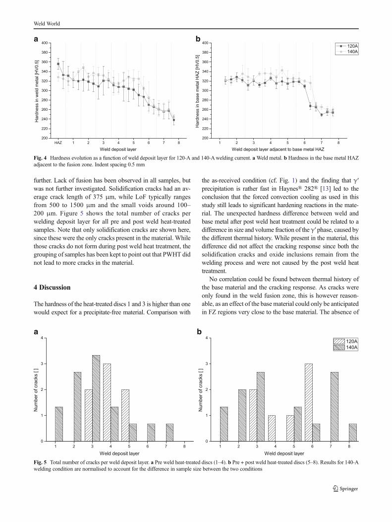
further. Lack of fusion has been observed in all samples, butwas not further investigated. Solidification cracks had an av-erage crack length of 375 μm, while LoF typically rangesfrom 500 to 1500 μm and the small voids around 100–200 μm. Figure 5 shows the total number of cracks perwelding deposit layer for all pre and post weld heat-treatedsamples. Note that only solidification cracks are shown here,since these were the only cracks present in the material. Whilethose cracks do not form during post weld heat treatment, thegrouping of samples has been kept to point out that PWHT didnot lead to more cracks in the material.
4 Discussion
The hardness of the heat-treated discs 1 and 3 is higher than onewould expect for a precipitate-free material. Comparison with
the as-received condition (cf. Fig. 1) and the finding that γ′precipitation is rather fast in Haynes® 282® [13] led to theconclusion that the forced convection cooling as used in thisstudy still leads to significant hardening reactions in the mate-rial. The unexpected hardness difference between weld andbase metal after post weld heat treatment could be related to adifference in size and volume fraction of theγ′ phase, caused bythe different thermal history. While present in the material, thisdifference did not affect the cracking response since both thesolidification cracks and oxide inclusions remain from thewelding process and were not caused by the post weld heattreatment.
No correlation could be found between thermal history ofthe base material and the cracking response. As cracks wereonly found in the weld fusion zone, this is however reason-able, as an effect of the base material could only be anticipatedin FZ regions very close to the base material. The absence of
a b
Fig. 4 Hardness evolution as a function of weld deposit layer for 120-A and 140-Awelding current. aWeld metal. b Hardness in the base metal HAZadjacent to the fusion zone. Indent spacing 0.5 mm
a b
Fig. 5 Total number of cracks per weld deposit layer. a Pre weld heat-treated discs (1–4). b Pre + post weld heat-treated discs (5–8). Results for 140-Awelding condition are normalised to account for the difference in sample size between the two conditions
Weld World
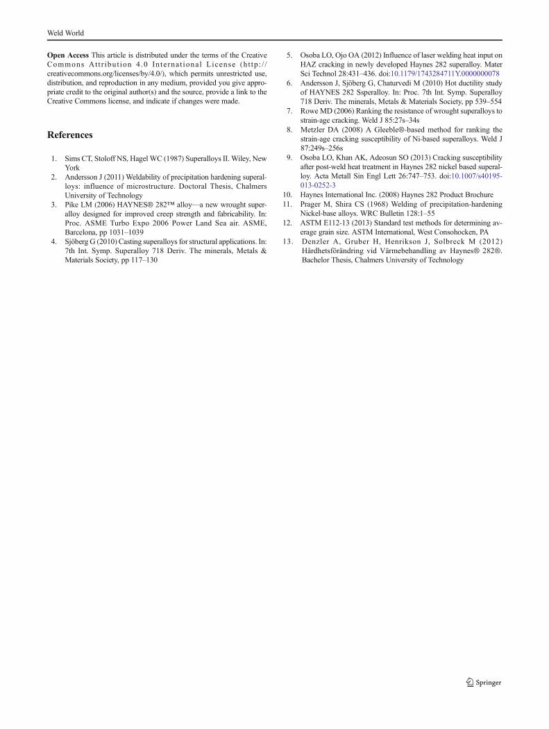
cracks in the base metal HAZ would indicate that, irrespectiveof the material condition, wrought Haynes® 282® exhibits agenerally good response to repair welding operations. This ishowever different for the fusion zone, where in total 47 crackshave been observed in the 40 investigated grooves. Weldingwith higher heat input increased cracking by a factor of 1.5,with no clear pattern being evident regarding overall crackdistribution over the welding deposit layers. While stresslevels have not been quantified within this study, it can bereasonably assumed that higher thermal stresses were presentduring welding with 140-Awelding current and hence facili-tating crack formation. SEM investigations of found cracksrevealed the dendritic structure formed during the solidifica-tion process without signs of decohesion, as shown in Fig. 6.This further supports the assumption that those cracks areindeed solidification cracks.
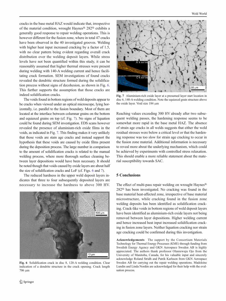
The voids found in bottom regions of weld deposits appear tobe cracks when viewed under an optical microscope, lying hor-izontally, i.e. parallel to the fusion boundary. Most of them arelocated at the interface between columnar grains on the bottomand equiaxed grains on top (cf. Fig. 7). No signs of liquationcould be found during SEM investigation. EDS scans howeverrevealed the presence of aluminium-rich oxide films in thevoids, as indicated in Fig. 7. This finding makes it very unlikelythat those voids are stain age cracks and instead support thehypothesis that these voids are caused by oxide films presentduring the deposition process. The large number in comparisonto the amount of solidification cracks is related to the manualwelding process, where more thorough surface cleaning be-tween layer depositions would have been necessary. It shouldbe noted though that voids caused by oxide layers are about halfthe size of solidification cracks and LoF (cf. Figs. 6 and 7).
The reduced hardness in the upper weld deposit layers in-dicates that three to four subsequently deposited layers arenecessary to increase the hardness to above 300 HV.
Reaching values exceeding 300 HV already after two subse-quent welding passes, the hardening response seems to besomewhat more rapid in the base metal HAZ. The absenceof strain age cracks in all welds suggests that either the weldresidual stresses were below a critical level or that the harden-ing response was too slow for strain age cracking to occur inthe fusion zone material. Additional information is necessaryto reveal more about the underlying mechanism, which couldbe achieved by experiments with controlled stress relaxation.This should enable a more reliable statement about the mate-rial susceptibility towards SAC.
5 Conclusions
The effect of multi-pass repair welding on wrought Haynes®282® has been investigated. No cracking was found in thebase material heat-affected zone, irrespective of base materialmicrostructure, while cracking found in the fusion zonewelding deposits has been identified as solidification crack-ing. Crack-like voids in bottom regions of weld deposit layershave been identified as aluminium-rich oxide layers not beingremoved between layer depositions. Higher welding currentand hence increased heat input increased solidification crack-ing in fusion zone layers. Neither liquation cracking nor strainage cracking could be confirmed during this investigation.
Acknowledgements The support by the Consortium MaterialsTechnology for Thermal Energy Processes (KME) through funding fromSwedish Energy Agency and GKN Aerospace Sweden AB is highlyappreciated. The authors thank professor Olanrewaju Ojo from theUniversity of Manitoba, Canada, for his valuable input and sincerelyacknowledge Roland Stridh and Patrik Karlsson from GKN AerospaceSweden AB for carrying out the repair welding operations. MadeleineLundin and Linda Nordén are acknowledged for their help with the eval-uation process.
Fig. 7 Aluminium-rich oxide layer at a presumed layer start location indisc 6, 140-Awelding condition. Note the equiaxed grain structure abovethe oxide layer. Void size 184 μm
Fig. 6 Solidification crack in disc 8, 120-A welding condition. Clearindication of a dendrite structure in the crack opening. Crack length706 μm
Weld World
Open Access This article is distributed under the terms of the CreativeCommons At t r ibut ion 4 .0 In te rna t ional License (h t tp : / /creativecommons.org/licenses/by/4.0/), which permits unrestricted use,distribution, and reproduction in any medium, provided you give appro-priate credit to the original author(s) and the source, provide a link to theCreative Commons license, and indicate if changes were made.
References
1. Sims CT, Stoloff NS, Hagel WC (1987) Superalloys II. Wiley, NewYork
2. Andersson J (2011) Weldability of precipitation hardening superal-loys: influence of microstructure. Doctoral Thesis, ChalmersUniversity of Technology
3. Pike LM (2006) HAYNES® 282™ alloy—a new wrought super-alloy designed for improved creep strength and fabricability. In:Proc. ASME Turbo Expo 2006 Power Land Sea air. ASME,Barcelona, pp 1031–1039
4. Sjöberg G (2010) Casting superalloys for structural applications. In:7th Int. Symp. Superalloy 718 Deriv. The minerals, Metals &Materials Society, pp 117–130
5. Osoba LO, Ojo OA (2012) Influence of laser welding heat input onHAZ cracking in newly developed Haynes 282 superalloy. MaterSci Technol 28:431–436. doi:10.1179/1743284711Y.0000000078
6. Andersson J, Sjöberg G, Chaturvedi M (2010) Hot ductility studyof HAYNES 282 Ssperalloy. In: Proc. 7th Int. Symp. Superalloy718 Deriv. The minerals, Metals & Materials Society, pp 539–554
7. Rowe MD (2006) Ranking the resistance of wrought superalloys tostrain-age cracking. Weld J 85:27s–34s
8. Metzler DA (2008) A Gleeble®-based method for ranking thestrain-age cracking susceptibility of Ni-based superalloys. Weld J87:249s–256s
9. Osoba LO, Khan AK, Adeosun SO (2013) Cracking susceptibilityafter post-weld heat treatment in Haynes 282 nickel based superal-loy. Acta Metall Sin Engl Lett 26:747–753. doi:10.1007/s40195-013-0252-3
10. Haynes International Inc. (2008) Haynes 282 Product Brochure11. Prager M, Shira CS (1968) Welding of precipitation-hardening
Nickel-base alloys. WRC Bulletin 128:1–5512. ASTM E112-13 (2013) Standard test methods for determining av-
erage grain size. ASTM International, West Consohocken, PA13. Denzler A, Gruber H, Henrikson J, Solbreck M (2012)
Hårdhetsförändring vid Värmebehandling av Haynes® 282®.Bachelor Thesis, Chalmers University of Technology
Weld World
Copyright © 2022 FDOKUMEN