RR® and RD® piles
56
DESIGN AND INSTALLATION MANUAL This manual deals with driven and jacked SSAB’s RR and RRs piles, shaft grouted driven CSG-RR piles and drilled RD and RDs piles. It covers all SSAB’s steel pile sizes. The manual is based on the piling instructions of the Finnish Piling Manual PO-2016 and the Eurocodes system. The manual describes the basics of the design and dimensioning of SSAB’s steel piles and pile foundations according to Finnish application of Eurocodes, gives recommendations on the selection of pile type and size and provides advice on the handling and installation, quality control, measurements and documentation of piling. The manual includes pre-calculated dimensioning tables and design and implementation examples to facilitate the design and implementation of piling. When SSAB steel piles are used outside Finland, national requirements (implementation and national annexes of Eurocodes) shall be taken into account in design and execution of piles. SSAB’s RR, RRs, RD and RDs piles have European Technical Assessment ETA 12/0526. Applications: • 1 and 2 family houses • single- and multi-storey commercial, office, industrial and storage buildings • multi-storey residential buildings • sports arenas • underpinning of foundations • bridges • pile slabs and other structures for transport infrastructure and municipal engineering • noise barriers and fences • ports • wind turbines and other power plants ETA 12/0526 RR ® and RD ® piles www.ssab.com/infra SSAB is a Nordic and US-based steel company. SSAB offers value added products and services developed in close cooperation with its customers to create a stronger, lighter and more sustainable world. SSAB has employees in over 50 countries. SSAB has production facilities in Sweden, Finland and the US. SSAB is listed on the NASDAQ OMX Nordic Exchange in Stockholm and has a secondary listing on the NASDAQ OMX in Helsinki. www.ssab.com. NOTE: This English manual follows the national regulations of Finland.
-
Upload
khangminh22 -
Category
Documents
-
view
2 -
download
0
Transcript of RR® and RD® piles

DESIGN AND INSTALLATION MANUAL
This manual deals with driven and jacked SSAB’s RR and RRs piles, shaft grouted driven CSG-RR piles and drilled RD and RDs piles. It covers all SSAB’s steel pile sizes. The manual is based on the piling instructions of the Finnish Piling Manual PO-2016 and the Eurocodes system. The manual describes the basics of the design and dimensioning of SSAB’s steel piles and pile foundations according to Finnish application of Eurocodes, gives recommendations on the selection of pile type and size and provides advice on the handling and installation, quality control, measurements and documentation of piling. The manual includes pre-calculated dimensioning tables and design and implementation examples to facilitate the design and implementation of piling. When SSAB steel piles are used outside Finland, national requirements (implementation and national annexes of Eurocodes) shall be taken into account in design and execution of piles. SSAB’s RR, RRs, RD and RDs piles have European Technical Assessment ETA 12/0526.
Applications:• 1 and 2 family houses• single- and multi-storey commercial, office, industrial and storage buildings • multi-storey residential buildings• sports arenas • underpinning of foundations• bridges • pile slabs and other structures for transport infrastructure and
municipal engineering• noise barriers and fences• ports • wind turbines and other power plants ETA 12/0526
RR® and RD® piles
www.ssab.com/infra
SSAB is a Nordic and US-based steel company. SSAB offers value added products and services developed in close cooperation with its customers to create a stronger, lighter and more sustainable world. SSAB has employees in over 50 countries. SSAB has production facilities in Sweden, Finland and the US. SSAB is listed on the NASDAQ OMX Nordic Exchange in Stockholm and has a secondary listing on the NASDAQ OMX in Helsinki. www.ssab.com.
NOTE: This English manual follows the national regulations of Finland.

2
CONTENTS
1. GENERAL . . . . . . . . . . . . . . . . . . . . . . . . . . . . . . . . . . . . . . . . . . . . . . . . . . . . . . . . . . . . . . . . . . . . . . . . . . . . . . . . . . . . . . . . . . . . . . . . . . . . . 42. SSAB’s STEEL PILES . . . . . . . . . . . . . . . . . . . . . . . . . . . . . . . . . . . . . . . . . . . . . . . . . . . . . . . . . . . . . . . . . . . . . . . . . . . . . . . . . . . . . . . . . . . 4 2.1 General . . . . . . . . . . . . . . . . . . . . . . . . . . . . . . . . . . . . . . . . . . . . . . . . . . . . . . . . . . . . . . . . . . . . . . . . . . . . . . . . . . . . . . . . . . . . . . . . . . . . 4 2.2 Steel grades and standards . . . . . . . . . . . . . . . . . . . . . . . . . . . . . . . . . . . . . . . . . . . . . . . . . . . . . . . . . . . . . . . . . . . . . . . . . . . . . . . . 4 2.3 Small diameter RR and RRs piles. . . . . . . . . . . . . . . . . . . . . . . . . . . . . . . . . . . . . . . . . . . . . . . . . . . . . . . . . . . . . . . . . . . . . . . . . . . . 5 2.3.1 Structure, steel grades and identification . . . . . . . . . . . . . . . . . . . . . . . . . . . . . . . . . . . . . . . . . . . . . . . . . . . . . . . . . . . . . . 5 2.3.2 Pile elements, pipes and splices . . . . . . . . . . . . . . . . . . . . . . . . . . . . . . . . . . . . . . . . . . . . . . . . . . . . . . . . . . . . . . . . . . . . . . . 5 2.3.3 Pile shoes. . . . . . . . . . . . . . . . . . . . . . . . . . . . . . . . . . . . . . . . . . . . . . . . . . . . . . . . . . . . . . . . . . . . . . . . . . . . . . . . . . . . . . . . . . . .6 2.4 Large diameter RR piles . . . . . . . . . . . . . . . . . . . . . . . . . . . . . . . . . . . . . . . . . . . . . . . . . . . . . . . . . . . . . . . . . . . . . . . . . . . . . . . . . . . . 7 2.4.1 Structure, dimensions and availability of steel grades. . . . . . . . . . . . . . . . . . . . . . . . . . . . . . . . . . . . . . . . . . . . . . . . . . . 7 2.4.2 Pile shoes . . . . . . . . . . . . . . . . . . . . . . . . . . . . . . . . . . . . . . . . . . . . . . . . . . . . . . . . . . . . . . . . . . . . . . . . . . . . . . . . . . . . . . . . . . .8 2.5 RD and RDs piles . . . . . . . . . . . . . . . . . . . . . . . . . . . . . . . . . . . . . . . . . . . . . . . . . . . . . . . . . . . . . . . . . . . . . . . . . . . . . . . . . . . . . . . . . .9 2.5.1 Structure, dimensions, steel grade selection and identification . . . . . . . . . . . . . . . . . . . . . . . . . . . . . . . . . . . . . . . . . .9 2.5.2 Splicing and steel grade selection of RD piles . . . . . . . . . . . . . . . . . . . . . . . . . . . . . . . . . . . . . . . . . . . . . . . . . . . . . . . . . 10 2.6 Shaft grouted RR piles (CSG-RR piles) . . . . . . . . . . . . . . . . . . . . . . . . . . . . . . . . . . . . . . . . . . . . . . . . . . . . . . . . . . . . . . . . . . . . . 11 2.7 Bearing plates . . . . . . . . . . . . . . . . . . . . . . . . . . . . . . . . . . . . . . . . . . . . . . . . . . . . . . . . . . . . . . . . . . . . . . . . . . . . . . . . . . . . . . . . . . . . 12 2.8 Pile dimensions and geometrical sectional properties . . . . . . . . . . . . . . . . . . . . . . . . . . . . . . . . . . . . . . . . . . . . . . . . . . . . . . . 123. DESIGN STANDARDS AND IMPLEMENTATION CONTROL. . . . . . . . . . . . . . . . . . . . . . . . . . . . . . . . . . . . . . . . . . . . . . . . . . . . . . . . . 144. RECOMMENDATIONS FOR THE SELECTION AND DESIGN OF PILE TYPE, PILE SIZE AND PILING CLASS FOR DIFFERENT APPLICATIONS . . . . . . . . . . . . . . . . . . . . . . . . . . . . . . . . . . . . . . . . . . . . . . . . . . . . . . . . . . . . . . . . . 145. STRUCTURAL AND GEOTECHNICAL DESIGN OF PILES. . . . . . . . . . . . . . . . . . . . . . . . . . . . . . . . . . . . . . . . . . . . . . . . . . . . . . . . . . . 15 5.1 Limit states of pile foundations to be considered . . . . . . . . . . . . . . . . . . . . . . . . . . . . . . . . . . . . . . . . . . . . . . . . . . . . . . . . . . . . 15 5.2 Design process of a steel pile foundation . . . . . . . . . . . . . . . . . . . . . . . . . . . . . . . . . . . . . . . . . . . . . . . . . . . . . . . . . . . . . . . . . . . 15 5.3 Actions and design situations . . . . . . . . . . . . . . . . . . . . . . . . . . . . . . . . . . . . . . . . . . . . . . . . . . . . . . . . . . . . . . . . . . . . . . . . . . . . . . 16 5.4 Geotechnical investigations . . . . . . . . . . . . . . . . . . . . . . . . . . . . . . . . . . . . . . . . . . . . . . . . . . . . . . . . . . . . . . . . . . . . . . . . . . . . . . . 16 5.5 Dimensioning methods and analyses of geotechnical resistance . . . . . . . . . . . . . . . . . . . . . . . . . . . . . . . . . . . . . . . . . . . . . 16 5.5.1 Selection of geotechnical dimensioning method for steel piles . . . . . . . . . . . . . . . . . . . . . . . . . . . . . . . . . . . . . . . . . 16 5.5.2 Stiffness of a piled structure . . . . . . . . . . . . . . . . . . . . . . . . . . . . . . . . . . . . . . . . . . . . . . . . . . . . . . . . . . . . . . . . . . . . . . . . . 16 5.5.3 Resistances determined by stress wave analysis . . . . . . . . . . . . . . . . . . . . . . . . . . . . . . . . . . . . . . . . . . . . . . . . . . . . . . 17 5.5.4 Resistances determined by dynamic load tests . . . . . . . . . . . . . . . . . . . . . . . . . . . . . . . . . . . . . . . . . . . . . . . . . . . . . . . 17 5.5.5 Resistances determined by pile driving formulas . . . . . . . . . . . . . . . . . . . . . . . . . . . . . . . . . . . . . . . . . . . . . . . . . . . . . . 17 5.5.6 Resistances determined on the basis of ground test results. . . . . . . . . . . . . . . . . . . . . . . . . . . . . . . . . . . . . . . . . . . . 17 5.5.7 Resistances determined by static load tests . . . . . . . . . . . . . . . . . . . . . . . . . . . . . . . . . . . . . . . . . . . . . . . . . . . . . . . . . . 19 5.6 Geotechnical dimensioning of tension piles. . . . . . . . . . . . . . . . . . . . . . . . . . . . . . . . . . . . . . . . . . . . . . . . . . . . . . . . . . . . . . . . . 19 5.7 Structural resistance . . . . . . . . . . . . . . . . . . . . . . . . . . . . . . . . . . . . . . . . . . . . . . . . . . . . . . . . . . . . . . . . . . . . . . . . . . . . . . . . . . . . . . 19 5.7.1 Resistance of RR piles during installation. . . . . . . . . . . . . . . . . . . . . . . . . . . . . . . . . . . . . . . . . . . . . . . . . . . . . . . . . . . . . . 19 5.7.2 Structural resistance during service . . . . . . . . . . . . . . . . . . . . . . . . . . . . . . . . . . . . . . . . . . . . . . . . . . . . . . . . . . . . . . . . . 20 5.7.3 Corrosion . . . . . . . . . . . . . . . . . . . . . . . . . . . . . . . . . . . . . . . . . . . . . . . . . . . . . . . . . . . . . . . . . . . . . . . . . . . . . . . . . . . . . . . . . . 20 5.8 Vertical displacements of pile foundation. . . . . . . . . . . . . . . . . . . . . . . . . . . . . . . . . . . . . . . . . . . . . . . . . . . . . . . . . . . . . . . . . . 22 5.9 Considering downdrag (negative skin friction) in dimensioning. . . . . . . . . . . . . . . . . . . . . . . . . . . . . . . . . . . . . . . . . . . . . . 22 5.10 Transversely loaded steel piles. . . . . . . . . . . . . . . . . . . . . . . . . . . . . . . . . . . . . . . . . . . . . . . . . . . . . . . . . . . . . . . . . . . . . . . . . . . .23 5.11 Short piles . . . . . . . . . . . . . . . . . . . . . . . . . . . . . . . . . . . . . . . . . . . . . . . . . . . . . . . . . . . . . . . . . . . . . . . . . . . . . . . . . . . . . . . . . . . . . . .23 5.12 Dimensioning tables for RR and RRs piles, pile sizes RR75 to RR320/12.5. . . . . . . . . . . . . . . . . . . . . . . . . . . . . . . . . . . .23 5.13 Dimensioning tables for RD and RDs piles, RD/RDs90 to RD320/12.5. . . . . . . . . . . . . . . . . . . . . . . . . . . . . . . . . . . . . . . .236. DESIGN OF PILE FOUNDATIONS . . . . . . . . . . . . . . . . . . . . . . . . . . . . . . . . . . . . . . . . . . . . . . . . . . . . . . . . . . . . . . . . . . . . . . . . . . . . . . 26 6.1 Attachment of piles to superstructure . . . . . . . . . . . . . . . . . . . . . . . . . . . . . . . . . . . . . . . . . . . . . . . . . . . . . . . . . . . . . . . . . . . . . 26 6.2 Centre-to-centre distances between steel piles . . . . . . . . . . . . . . . . . . . . . . . . . . . . . . . . . . . . . . . . . . . . . . . . . . . . . . . . . . . 26 6.3 Distance between side of pile footing and piles . . . . . . . . . . . . . . . . . . . . . . . . . . . . . . . . . . . . . . . . . . . . . . . . . . . . . . . . . . . . 26 6.4 Distances between piles and other structures . . . . . . . . . . . . . . . . . . . . . . . . . . . . . . . . . . . . . . . . . . . . . . . . . . . . . . . . . . . . . 26 6.5 Pile inclinations . . . . . . . . . . . . . . . . . . . . . . . . . . . . . . . . . . . . . . . . . . . . . . . . . . . . . . . . . . . . . . . . . . . . . . . . . . . . . . . . . . . . . . . . . . .27 6.6. Allowed positional and angular deviations . . . . . . . . . . . . . . . . . . . . . . . . . . . . . . . . . . . . . . . . . . . . . . . . . . . . . . . . . . . . . . . . .27 6.7 Impact of piling on previously installed piles, other foundation structures and immediate surroundings . . . . . . . 28 7. PILING 28 7.1 Material needed for piling: working plan and quality plan. . . . . . . . . . . . . . . . . . . . . . . . . . . . . . . . . . . . . . . . . . . . . . . . . . . . 28 7.2 Storage, handling, inspection and erection of steel piles. . . . . . . . . . . . . . . . . . . . . . . . . . . . . . . . . . . . . . . . . . . . . . . . . . . . 28 7.3 Installation of RR piles. . . . . . . . . . . . . . . . . . . . . . . . . . . . . . . . . . . . . . . . . . . . . . . . . . . . . . . . . . . . . . . . . . . . . . . . . . . . . . . . . . . . 29 7.3.1 Piling equipment. . . . . . . . . . . . . . . . . . . . . . . . . . . . . . . . . . . . . . . . . . . . . . . . . . . . . . . . . . . . . . . . . . . . . . . . . . . . . . . . . . . . 29 7.3.2 Start of installation. . . . . . . . . . . . . . . . . . . . . . . . . . . . . . . . . . . . . . . . . . . . . . . . . . . . . . . . . . . . . . . . . . . . . . . . . . . . . . . . . . 31 7.3.3 Penetration blows and allowed driving stresses. . . . . . . . . . . . . . . . . . . . . . . . . . . . . . . . . . . . . . . . . . . . . . . . . . . . . . . . 31

3
7.3.4 Additional installation instructions and splicing of RR75 to RR220 piles . . . . . . . . . . . . . . . . . . . . . . . . . . . . . . . .32 7.3.5 Additional instructions for the installation of RR270 to RR1200 piles . . . . . . . . . . . . . . . . . . . . . . . . . . . . . . . . . . .32 7.3.6 Additional instructions for rock shoes with hollow dowel . . . . . . . . . . . . . . . . . . . . . . . . . . . . . . . . . . . . . . . . . . . . . . .32 7.3.7 End of driving of an end-bearing pile with a drop or hydraulic hammer. . . . . . . . . . . . . . . . . . . . . . . . . . . . . . . . . .33 7.3.8 End of driving of an end-bearing pile with a hydraulic ram or pneumatic hammer . . . . . . . . . . . . . . . . . . . . . . .33 7.3.9 Preparation of end-of-driving instructions for large diameter piles in piling classes PTL3 and PTL2 . . . . . .34 7.3.10 Final blows on friction piles. . . . . . . . . . . . . . . . . . . . . . . . . . . . . . . . . . . . . . . . . . . . . . . . . . . . . . . . . . . . . . . . . . . . . . . . . .34 7.3.11 Project-specific driving instructions. . . . . . . . . . . . . . . . . . . . . . . . . . . . . . . . . . . . . . . . . . . . . . . . . . . . . . . . . . . . . . . . . .34 7.3.12 Installation of jacked-RR piles. . . . . . . . . . . . . . . . . . . . . . . . . . . . . . . . . . . . . . . . . . . . . . . . . . . . . . . . . . . . . . . . . . . . . . .34 7.4. Installation of RD piles . . . . . . . . . . . . . . . . . . . . . . . . . . . . . . . . . . . . . . . . . . . . . . . . . . . . . . . . . . . . . . . . . . . . . . . . . . . . . . . . . . . .34 7.4.1 Piling equipment and drilling methods . . . . . . . . . . . . . . . . . . . . . . . . . . . . . . . . . . . . . . . . . . . . . . . . . . . . . . . . . . . . . . . .34 7.4.2 Start of installation. . . . . . . . . . . . . . . . . . . . . . . . . . . . . . . . . . . . . . . . . . . . . . . . . . . . . . . . . . . . . . . . . . . . . . . . . . . . . . . . . .35 7.4.3 Drilling of RD piles . . . . . . . . . . . . . . . . . . . . . . . . . . . . . . . . . . . . . . . . . . . . . . . . . . . . . . . . . . . . . . . . . . . . . . . . . . . . . . . . . . .35 7.4.4 Handling and installation of threaded RDT pile elements and threaded sleeves . . . . . . . . . . . . . . . . . . . . . . . . .37 7.5 Splicing of steel pipe piles by welding. . . . . . . . . . . . . . . . . . . . . . . . . . . . . . . . . . . . . . . . . . . . . . . . . . . . . . . . . . . . . . . . . . . . . . .38 7.5.1 Welding Plan . . . . . . . . . . . . . . . . . . . . . . . . . . . . . . . . . . . . . . . . . . . . . . . . . . . . . . . . . . . . . . . . . . . . . . . . . . . . . . . . . . . . . . . .38 7.5.2 Welding quality requirements . . . . . . . . . . . . . . . . . . . . . . . . . . . . . . . . . . . . . . . . . . . . . . . . . . . . . . . . . . . . . . . . . . . . . . . .38 7.5.3 Qualification of Welders . . . . . . . . . . . . . . . . . . . . . . . . . . . . . . . . . . . . . . . . . . . . . . . . . . . . . . . . . . . . . . . . . . . . . . . . . . . . .39 7.5.4 Welding Procedures . . . . . . . . . . . . . . . . . . . . . . . . . . . . . . . . . . . . . . . . . . . . . . . . . . . . . . . . . . . . . . . . . . . . . . . . . . . . . . . . 40 7.5.5 Welding Consumables . . . . . . . . . . . . . . . . . . . . . . . . . . . . . . . . . . . . . . . . . . . . . . . . . . . . . . . . . . . . . . . . . . . . . . . . . . . . . . 40 7.5.6 Welding Conditions. . . . . . . . . . . . . . . . . . . . . . . . . . . . . . . . . . . . . . . . . . . . . . . . . . . . . . . . . . . . . . . . . . . . . . . . . . . . . . . . . 40 7.5.7 Joint Preparation . . . . . . . . . . . . . . . . . . . . . . . . . . . . . . . . . . . . . . . . . . . . . . . . . . . . . . . . . . . . . . . . . . . . . . . . . . . . . . . . . . . . 41 7.5.8 Preheating. . . . . . . . . . . . . . . . . . . . . . . . . . . . . . . . . . . . . . . . . . . . . . . . . . . . . . . . . . . . . . . . . . . . . . . . . . . . . . . . . . . . . . . . . 42 7.5.9 Welding . . . . . . . . . . . . . . . . . . . . . . . . . . . . . . . . . . . . . . . . . . . . . . . . . . . . . . . . . . . . . . . . . . . . . . . . . . . . . . . . . . . . . . . . . . . 42 7.5.10 Inspection of Welded splices . . . . . . . . . . . . . . . . . . . . . . . . . . . . . . . . . . . . . . . . . . . . . . . . . . . . . . . . . . . . . . . . . . . . . . . 42 7.6 Pile cut-off . . . . . . . . . . . . . . . . . . . . . . . . . . . . . . . . . . . . . . . . . . . . . . . . . . . . . . . . . . . . . . . . . . . . . . . . . . . . . . . . . . . . . . . . . . . . . . .43 7.7 Pile cleaning . . . . . . . . . . . . . . . . . . . . . . . . . . . . . . . . . . . . . . . . . . . . . . . . . . . . . . . . . . . . . . . . . . . . . . . . . . . . . . . . . . . . . . . . . . . . . .43 7.8 Reinforcement and concreting of piles . . . . . . . . . . . . . . . . . . . . . . . . . . . . . . . . . . . . . . . . . . . . . . . . . . . . . . . . . . . . . . . . . . . . .43 7.9 Bearing plate installation . . . . . . . . . . . . . . . . . . . . . . . . . . . . . . . . . . . . . . . . . . . . . . . . . . . . . . . . . . . . . . . . . . . . . . . . . . . . . . . . . 44 7.10 Installation of shaft grouted CSG-RR piles. . . . . . . . . . . . . . . . . . . . . . . . . . . . . . . . . . . . . . . . . . . . . . . . . . . . . . . . . . . . . . . . 44 7.10.1 Installation equipment . . . . . . . . . . . . . . . . . . . . . . . . . . . . . . . . . . . . . . . . . . . . . . . . . . . . . . . . . . . . . . . . . . . . . . . . . . . . . 44 7.10.2 Driving of pile into soil and its splicing . . . . . . . . . . . . . . . . . . . . . . . . . . . . . . . . . . . . . . . . . . . . . . . . . . . . . . . . . . . . . . 44 7.10.3 Grout injection . . . . . . . . . . . . . . . . . . . . . . . . . . . . . . . . . . . . . . . . . . . . . . . . . . . . . . . . . . . . . . . . . . . . . . . . . . . . . . . . . . . . 448. SUPERVISION AND QUALITY CONTROL OF PILING WORK, MEASUREMENTS . . . . . . . . . . . . . . . . . . . . . . . . . . . . . . . . . . . . .45 8.1 Supervision and monitoring of piling work. . . . . . . . . . . . . . . . . . . . . . . . . . . . . . . . . . . . . . . . . . . . . . . . . . . . . . . . . . . . . . . . . . .45 8.2 Quality control of materials. . . . . . . . . . . . . . . . . . . . . . . . . . . . . . . . . . . . . . . . . . . . . . . . . . . . . . . . . . . . . . . . . . . . . . . . . . . . . . . .45 8.3 Monitoring measurements during installation. . . . . . . . . . . . . . . . . . . . . . . . . . . . . . . . . . . . . . . . . . . . . . . . . . . . . . . . . . . . . . .45 8.4 Testing of piles. . . . . . . . . . . . . . . . . . . . . . . . . . . . . . . . . . . . . . . . . . . . . . . . . . . . . . . . . . . . . . . . . . . . . . . . . . . . . . . . . . . . . . . . . . . 469. DOCUMENTATION OF PILING WORK . . . . . . . . . . . . . . . . . . . . . . . . . . . . . . . . . . . . . . . . . . . . . . . . . . . . . . . . . . . . . . . . . . . . . . . . . . 46 9.1 General . . . . . . . . . . . . . . . . . . . . . . . . . . . . . . . . . . . . . . . . . . . . . . . . . . . . . . . . . . . . . . . . . . . . . . . . . . . . . . . . . . . . . . . . . . . . . . . . . . 46 9.2 Piling records. . . . . . . . . . . . . . . . . . . . . . . . . . . . . . . . . . . . . . . . . . . . . . . . . . . . . . . . . . . . . . . . . . . . . . . . . . . . . . . . . . . . . . . . . . . . 46 9.3 Outcome drawing and other piling documents . . . . . . . . . . . . . . . . . . . . . . . . . . . . . . . . . . . . . . . . . . . . . . . . . . . . . . . . . . . . . 4610. WORK SAFETY AND ENVIRONMENTAL PROTECTION. . . . . . . . . . . . . . . . . . . . . . . . . . . . . . . . . . . . . . . . . . . . . . . . . . . . . . . . . . 4611. END-OF-DRIVING TABLES . . . . . . . . . . . . . . . . . . . . . . . . . . . . . . . . . . . . . . . . . . . . . . . . . . . . . . . . . . . . . . . . . . . . . . . . . . . . . . . . . . . .47 11.1 General . . . . . . . . . . . . . . . . . . . . . . . . . . . . . . . . . . . . . . . . . . . . . . . . . . . . . . . . . . . . . . . . . . . . . . . . . . . . . . . . . . . . . . . . . . . . . . . . . .47 11.2 Drop and hydraulic hammers . . . . . . . . . . . . . . . . . . . . . . . . . . . . . . . . . . . . . . . . . . . . . . . . . . . . . . . . . . . . . . . . . . . . . . . . . . . . . .47 11.2.1 Basics of modelling. . . . . . . . . . . . . . . . . . . . . . . . . . . . . . . . . . . . . . . . . . . . . . . . . . . . . . . . . . . . . . . . . . . . . . . . . . . . . . . . . .47 11.2.2 Instructions for use of end-of-driving tables . . . . . . . . . . . . . . . . . . . . . . . . . . . . . . . . . . . . . . . . . . . . . . . . . . . . . . . . .47 11.3 Hydraulic rams and pneumatic hammers. . . . . . . . . . . . . . . . . . . . . . . . . . . . . . . . . . . . . . . . . . . . . . . . . . . . . . . . . . . . . . . . . . 48 11.3.1 Principles of modelling. . . . . . . . . . . . . . . . . . . . . . . . . . . . . . . . . . . . . . . . . . . . . . . . . . . . . . . . . . . . . . . . . . . . . . . . . . . . . . 48 11.3.2 Instructions for use of end-of-driving graphs and tables . . . . . . . . . . . . . . . . . . . . . . . . . . . . . . . . . . . . . . . . . . . . . 48Appendix 1. Rc;max values of driven piles and informative design values Rd of large diameter RR piles . . . . . . . . . . . . . . . . . 50Appendix 2. End-of-driving tables and curves for different pile driving equipment
(can be downloaded from www.ssab.com/infra) Appendix 3. Standard piling log sheets for SSAB piles (only in Finnish) (can be downloaded from www.ssab.com/infra)Appendix 4. Tables for design resistances of piles manufactured of S440J2H steel grade (only in Finnish) (can be downloaded from www.ssab.com/infra)Appendix 5. RR and RD piles, Preheating and cooling of splice welds (can be downloaded from www.ssab.com/infra)

4
Table 1. Standard steel grades of SSAB’s steel piles, against special order, the piles may also be delivered in X grades ac-cording to API5L standard.
Steel gradeCarbon
equivalentChemical composition, max. Mechanical properties
Impact strength
CEV max. C Mn P S fy min fu A5min T* KV min
[%] [%] [%] [%] [%] [MPa] [MPa] [%] [°C] [J]
S355J2H 0.45 0.22 1.6 0.03 0.03 355 470-630 20 -20 27
S440J2H 0.45 0.16 1.6 0.02 0.02 440 490-630 17 -20 27
S460MH 0.46 0.16 1.7 0.035 0.03 460 530-720 17 -30 27
S550J2H 0.47 0.12 1.9 0.02 0.02 550 605-760 14 -20 27
*) Testing temperature may also be -40 °C. Demanded impact energy remains the same.
1. GENERAL
This manual deals with driven and jacked SSAB's RR and RRs piles, shaft grouted driven CSG-RR piles and drilled RD and RDs piles. It covers all pile sizes from RR75 to RR/RD1200. This manual describes the basics of the design of SSAB's steel piles and provides advice on their handling and installation, quality control, measurements and documentation. This manual is supplemented by product brochures on RR and RRs piles and RD and RDs piles, which describe the applications, materials, structures and dimensions of steel piles on a general level.
This manual is based on the Finnish Piling Manual PO-2016 (RIL 254-2016). This manual is used when the site has been designed according to the Eurocodes system. If the piling of a site is designed using the maximum allowed pile loads method, the RR and RD Piling Instructions are followed in the design of steel piles. The installation, handling and end-of-driving instructions presented here can be used where applicable if the site has been designed based on maximum allowed pile loads.
This manual applies to both individual piles and pile groups. They can be applied to the design and implementation of support structures made of SSAB's steel piles, such as the RD pile wall, various Combi wall structures, and driven or drilled steel pipe piles used in other retaining walls.
2. SSAB’S STEEL PILES
2.1 General
SSAB has CE marking, based on European Technical Assessment (ETA 12/0526), which is the most comprehensive CE marking to be granted to pile structures made of structural steel. It covers the entire pile structure, manifests the requirements and conformity
of the mechanical splices, and establishes that the product has been manufactured specifically for piling.
The approval is based on detailed load tests, especially on splices, continuous quality control during the various phases of production, and traceability of materials. Use of SSAB's CE marked piles in a construction project ensures the durability and performance of foundations. Tested products guarantee problem-free site installation.
SSAB's steel piles meet the requirements presented in Finnish Piling Manual PO-2016 (RIL 254-2016) for pile materials and accessories.
SSAB's steel piles have SP Technical Research Institute of Sweden quality certificate – P-mark (0656/94).
2.2 Steel grades and standards
The steel grades and chemical composition and mechanical properties of SSAB's steel piles are presented in Table 1.
The availability of steel grades by pile types and diameter and wall thickness are presented in Secs. 2.3.1 and 2.4.1. Against special order, the piles may also be delivered in X grades according to API5L standard.
The technical delivery terms of the piles comply with standard EN 10219-1. Dimensions and tolerances comply with standard EN 10219-2. SSAB's steel piles with mechanical splices are manufactured to tolerances stricter than those of standard EN 10219-2. A material certificate of type 3.1 specified in EN 10204 is provided for the pile material.
5
2.3 Small diameter RR and RRs piles
2.3.1 Structure, steel grades and identification
The structure and members of RR and RRs piles are shown in Figure 1.
The basic steel grade of RR piles is S460MH and that of RRs piles S550J2H. Against special order, the piles may also be delivered in S420MH steel grade. RR270 to RR320 piles made of steel grade S355J2H are also available.
RR and RRs piles have mechanical friction splices and pile shoes up to pile size RR220/12.5. RR270 and RR320 piles are spliced, if necessary, by welding, and the pile shoe is attached by welding.
SSAB's RR small diameter piles are identified by a marking on the side of the pile. In addition, identification tape is attached to splices of RR pile elements or next to them. Pile bundles are delivered with product descriptions that indicate, besides pile manufacturer and dimensions, the steel grade of the RR piles.
2.3.2 Pile elements, pipes and splices
A pile element consists of a pile pipe and the attached external splice sleeve. The mill lengths of RR pile elements and pile pipes without external splice sleeves are presented in Table 2.
All pile sizes RR75 to RR220 made of steel grade S460MH can be spliced using external splice sleeves. RRs piles are manufactured in seven different sizes. All RRs pile sizes can be joined by external splice sleeves.
External splice
Rock shoe
Bottom plate
Bearing plate
Figure 1. Structure and parts of RR piles, pile sizes RR75 to RR220.
The splices meet the requirements of PO-2016 for rigid splices and those of the national annex to standardEN 1993-5: Design of steel structures, Steel piles (Table 3). Since the splices meet the requirements, pile splices do not limit the structural capacity of the pile, and piles can be installed as straight as possible in all soil conditions.
Table 2. Mill dimensions of RR and RRs pile elements and pile pipes.
Length of pile element (incl. splice) Length of pile pipe (excl. splice)
Pile type 12 m 6 m 4 m 3 m 2 m 1.5 m 1.2 m 1.0 m 6 m 12 m 16 mRR75 - X O O O O O O X O -RR90 - X O O O O O O X O -RR115/6.3 O X O O O O O O X O -RR115/8 O X O O O O O O O X ORR140/8 X X O O O O O O O X ORR140/10 X X O O O O O O O X ORR170/10 X X O O O O O O O X ORR170/12.5 X O O O O O O O O X ORR220/10 X O O O - - - - O X ORR220/12.5 X O O O - - - - O X O
RRs115/8 O X O O O O O O O X ORRs125/6.3 X X O O - - - - O X -RRs140/8 X X O O O O O O O X ORRs140/10 X O O O O O O O O X ORRs170/10 X O O O O O O O O X ORRs220/10 X O O O - - - - O X ORRs220/12.5 X O O O - - - - O X O
X = stock size O = project-specific size – = not in production

6
Table 3. Minimum strength and stiffness requirements of RR and RRs pile splices
Pile typeTensile
strength[kN]
Com-pression strength
Yield moment
M
Flexuralstiffness EI (0.3-0.8 M)
RR75 95
Ppile Mpile 0.75xEIpile
RR90 113
RR115/6.3 147
RR115/8 184
RRs115/8 220
RRs125/6.3 197
RR140/8 228
RRs140/8 273
RR140/10 281
RRs140/10 336
RR170/10 343
RRs170/10 410
RR170/12.5 422
RR220/10 453
RRs220/10 542
RR220/12.5 560
RRs220/12.5 669
2.3.3 Pile shoes
The mechanically attached pile shoes of RR and RRs piles, bottom plates and rock shoes, meet the requirements given in PO-2016. The rock shoe dowel is made of hardened special steel, which ensures good penetration into bedrock. Rock shoe is always the recommended shoe type for driven pile. Based on justification by the foundation designer, also other shoe types can be used (bottom plate, open ended pile, etc.). According to PO-2016 the justified reason can be for example soil layers with low stone content (GEO class d<60 mm) and piles resting in soil layer with no big stones (GEO class d<200 mm). Rock shoes make it possible for piles to penetrate compact or rocky soil layers better and remain straighter. SSAB's pile shoes are dimensioned to withstand the stresses from pile installation and use, provided that the instructions of Sec. 7.3 are observed in installation.
Jacked RR micropiles can be equipped with a special shoe through which post-grouting can be done after jacking to improve point, and to some extent, shaft resistance.
The shoes used with RR270 to RR320 piles are rock shoes with hardened rock dowels. Against special order, the pile tip can be protected by a bottom plate or a rock shoe different from the standard rock shoe. All shoes of RR270 to RR320 piles are attached to the pipe pile by welding. Pipe piles are delivered to site with welded-on rock shoes.
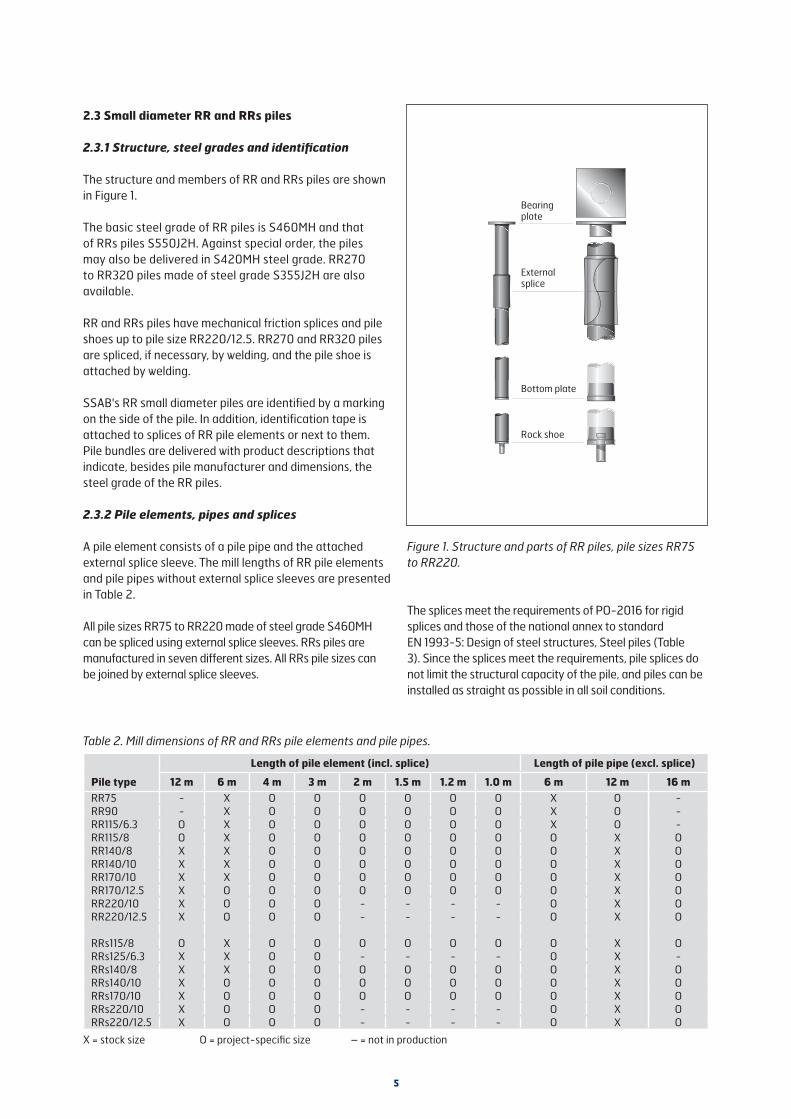
The design resistance values of standard rock shoes for RR270 to RR320 piles are presented in Table 4. The most
Figure 2. Large diameter RR pile
7
important dimensioning factor for rock shoes are the end blows and/or dynamic load test. Moreover addition, the installation instructions of Sec. 7.3 must be followed in installation, especially if the pile tip encounters a boulder or an inclined bedrock surface.
RR270 to RR320 rock shoes have the Finnish Transport Infrastructure Agency's permission for use (565/090/201, 4.10.2011).
With steel grade S460MH, the calculated resistance of the rock shoe limits the ultimate geotechnical resistance Rc of pile sizes RR270/12.5 and RR320/12.5 to that presented in Table 4 and with steel grade S550J2H and all pile dimensions RR270 to RR320 to the Rd,L values presented in Table 4.
Table 4. Structural resistances of RR270 and RR320 standard rock shoes
Pile Rd,L [kN]
RR270 4073
RR320 4777
Rd,L = design value of ultimate limit state of the structural resistance of a rock shoe for a centric vertical load at the installation stage (impact and PDA measurement)
2.4 Large diameter RR piles
2.4.1 Structure, dimensions and availability of steel grades
Large diameter RR piles are made of spirally welded steel pipes. It is possible to manufacture single-element piles up to 39 metres long. Piles are usually ordered in specific lengths. The standard stocked sizes are presented in Table 5.
Table 5. Large diameter RR piles in stock (L=12 m)
Dimensionsdiameter x wall thickness [mm]
Steel grade
406 x 12.5 S440J2H (S355J2H)
508 x 12.5 S440J2H (S355J2H)
610 x 12.5 S355J2H
711 x 12.5 S355J2H
813 x 12.5 S355J2H
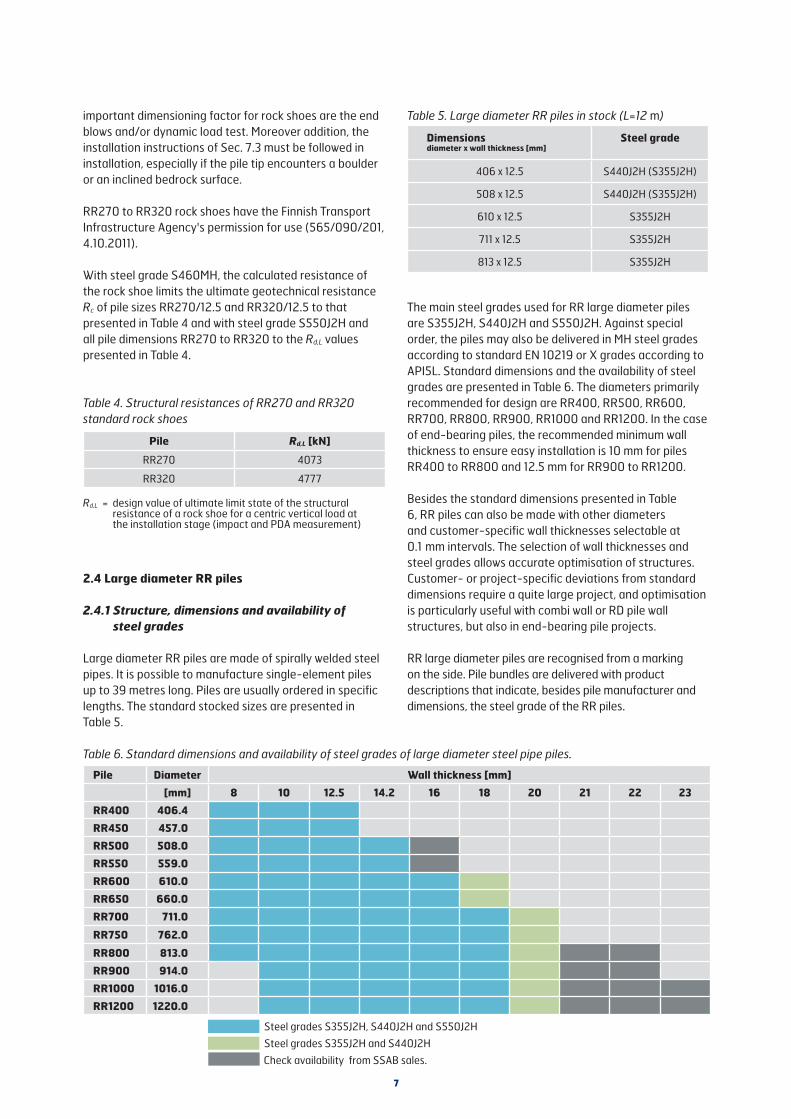
The main steel grades used for RR large diameter piles are S355J2H, S440J2H and S550J2H. Against special order, the piles may also be delivered in MH steel grades according to standard EN 10219 or X grades according to API5L. Standard dimensions and the availability of steel grades are presented in Table 6. The diameters primarily recommended for design are RR400, RR500, RR600, RR700, RR800, RR900, RR1000 and RR1200. In the case of end-bearing piles, the recommended minimum wall thickness to ensure easy installation is 10 mm for piles RR400 to RR800 and 12.5 mm for RR900 to RR1200.
Besides the standard dimensions presented in Table 6, RR piles can also be made with other diameters and customer-specific wall thicknesses selectable at 0.1 mm intervals. The selection of wall thicknesses and steel grades allows accurate optimisation of structures. Customer- or project-specific deviations from standard dimensions require a quite large project, and optimisation is particularly useful with combi wall or RD pile wall structures, but also in end-bearing pile projects.
RR large diameter piles are recognised from a marking on the side. Pile bundles are delivered with product descriptions that indicate, besides pile manufacturer and dimensions, the steel grade of the RR piles.
Table 6. Standard dimensions and availability of steel grades of large diameter steel pipe piles.
Pile Diameter Wall thickness [mm]
[mm] 8 10 12.5 14.2 16 18 20 21 22 23
RR400 406.4
RR450 457.0
RR500 508.0
RR550 559.0
RR600 610.0
RR650 660.0
RR700 711.0
RR750 762.0
RR800 813.0
RR900 914.0
RR1000 1016.0
RR1200 1220.0
Steel grades S355J2H, S440J2H and S550J2H
Steel grades S355J2H and S440J2H
Check availability from SSAB sales.

8
structure used as a wharf where the penetration level of the piles is close to the bottom of the waterway and piles are subject to considerable horizontal loads. There, rock dowels drilled through the hollow dowel ensure the stability of the retaining structure. Rock shoes with a hollow dowel are also used at sites where piles are subject to tension forces. A pull anchor can be installed through the hole.
In conditions of no or few stones, where the pile tip is designed to bear on soil layers, the tip of the pile can be protected by a so-called reinforced bottom plate. The recommended solution for such conditions, however, is to use standard rock shoes with structural steel dowels.
Open ended piles are often equipped with a so-called reinforcement ring to protect the lower end. The reinforcement ring is usually a 150 to 500 mm wide steel band welded onto the lower end of the pile. The sheet thickness of the steel band is usually 10, 15 or 20 mm. Both reinforcement rings and reinforced bottom plates are manufactured to the client’s project-specific designs.
Rock shoes are preheated before welding and assembly welding is carried out by robots. The rock shoes are numbered to ensure the traceability of the manufacture and raw-materials of the shoes.
The design resistance values of standard rock shoes for RR large diameter piles are presented in Table 7. The most important criterion for rock shoes are the end blows and/or the dynamic load test. Project specific rock shoes with different capacities are analyzed numerically by the requirements of Finnish Transport Infrastructure Agency. Moreover, the installation instructions of Sec. 7.3 must be followed in installation, especially if the pile tip encounters a boulder or an inclined rock surface.
At the design stage, however, the maximum impact resistance of each pile size should be limited to its/the Rd,L value.
Figure 3. Shoe types of large diameter RR piles.
Rock shoe with structural steel dowel
Rock shoe with hardened steel dowel
Rock shoe with hollow dowel
Toe reinforcement
2.4.2 Pile shoes
In soil conditions typical of the Nordic countries, RR large diameter piles are usually equipped with RR rock shoes. SSAB's standard rock shoes were granted the Finnish Transport Agency’s use permission (565/090/201, 4 October 2011) and the manufactured rock shoes are CE marked. Rock shoes are used to protect the lower end of the pile against installation stresses, to centre the stresses on the pile tip as evenly as possible across the pile pipe cross-section, and to prevent lateral sliding of the pile tip.
There are three types of RR rock shoes (Figure 3). The most common ones are rock shoes fitted with a structural steel dowel or a hardened rock dowel. SSAB also delivers rock shoes fitted with a hollow dowel, which allows drilling, for example, a dowel bar to be grouted to bedrock through the concrete filled hollow dowel of the rock shoe.
A rock shoe with a structural steel dowel is used in conditions where the target level of the piles is within coarse-grained or moraine soil layers, or in conditions where the bedrock surface is relatively even and there are supporting compact soil layers on top of the bedrock. A rock shoe with a structural steel dowel endures well penetration to the surface of the bedrock and into it.
A rock shoe with a hardened rock dowel is used in conditions where the bedrock surface is inclined or there are no compact coarse-grained or moraine soil layers on top of the bedrock – or the soil layers are thin and the pile tip is to be driven to the bedrock surface. Rock shoes with a hardened rock dowel can prevent lateral sliding of the pile tip in most conditions.
Rock shoes with a hollow dowel can be used in conditions where it is desired to ensure the staying in place of the pile tip by a grouted steel dowels drilled through the hollow dowel into bedrock. A typical application is a combi-wall

9
Table 7. Design values of ultimate limit state of the structural resistance of a rock shoes for a centric vertical load at the installation stage (impact and PDA measurement)
Pile Structural steel dowel
Rd,L [kN]
Hardened steel dowel
Rd,L [kN]
Hollow dowel
Rd,L [kN]
RR400 5033 4982
RR450 6057 6032
RR500 7672 7545
RR550 7994 7940
RR600 9677 9681 9285
RR650 10084 10062
RR700 11993 11605 11370
RR750 12387 12342
RR800 12653 12610 12188
RR900 14910 14887 14512
RR1000 18751 15691 18371
RR1200 19317 19260
2.5 RD and RDs piles
2.5.1 Structure, dimensions, steel grade selection and identification
The structure of the RD pile is shown in Figure 4. The standard steel grade of RD90 to RD220 piles is S460MH. The steel grade of RDs piles is S550J2H. Against special order, the piles may also be delivered in S420MH steel grade. RD270 to RD320 piles made of S355J2H steel grade are also available. All steel grades of SSAB's steel pile products can be used as steel grades of RD400 to RD1200 piles. The pile sizes and availability of steel grades
Threaded pile element
Threaded RDT splice sleeve
Bearing plate
Welded splice (beveled ends)
Casing shoe / ring bit
Figure 4. Structure of RD micropile.
of RD piles are presented in Table 8. Dimensions RD400, RD500, RD600, RD700, RD800, RD900, RD1000 and RD1200 are recommended for RD large diameter piles.
Table 8. Standard dimensions and availability of steel grades of RD piles.
Pile Diameter Wall thickness [mm][mm] 6.3 8 10 12.5 14.2 16 18 20 21 22 23
RD90 88.9RD115 114.3RDs125 127.0RD140 139.7RD170 168.3RD220 219.1RD270 273.0RD320 323.9RD400 406.4RD450 457.0RD500 508.0RD550 559.0RD600 610.0RD650 660.0RD700 711.0RD750 762.0RD800 813.0RD900 914.0RD1000 1016.0RD1200 1220.0
Steel grades S440J2H and S550J2HSteel grade S550J2HSteel grades S355J2H, S460MH and S550J2HSteel grade S460MH
Steel grades S355J2H, S440J2H and S550J2H Steel grades S355J2H and S440J2HCheck availability from SSAB sales.
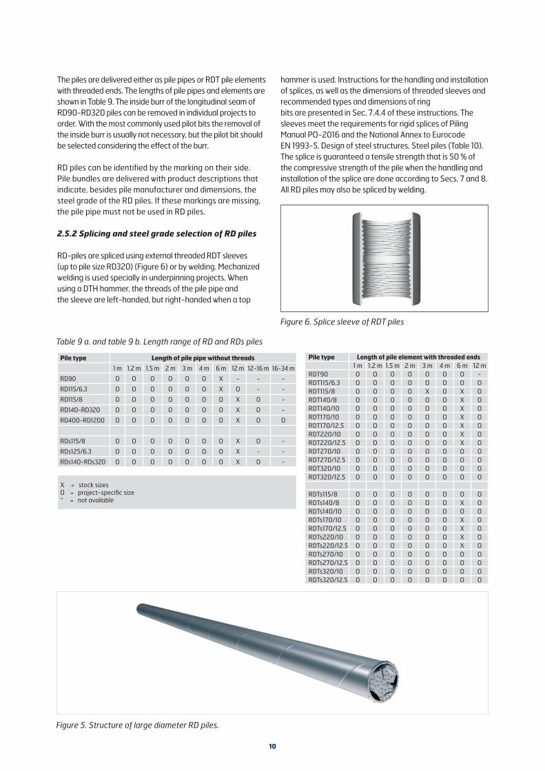
10
Figure 5. Structure of large diameter RD piles.
hammer is used. Instructions for the handling and installation of splices, as well as the dimensions of threaded sleeves and recommended types and dimensions of ring bits are presented in Sec. 7.4.4 of these instructions. The sleeves meet the requirements for rigid splices of Piling Manual PO-2016 and the National Annex to Eurocode EN 1993-5, Design of steel structures, Steel piles (Table 10). The splice is guaranteed a tensile strength that is 50 % of the compressive strength of the pile when the handling and installation of the splice are done according to Secs. 7 and 8. All RD piles may also be spliced by welding.
The piles are delivered either as pile pipes or RDT pile elements with threaded ends. The lengths of pile pipes and elements are shown in Table 9. The inside burr of the longitudinal seam of RD90-RD320 piles can be removed in individual projects to order. With the most commonly used pilot bits the removal of the inside burr is usually not necessary, but the pilot bit should be selected considering the effect of the burr.
RD piles can be identified by the marking on their side. Pile bundles are delivered with product descriptions that indicate, besides pile manufacturer and dimensions, the steel grade of the RD piles. If these markings are missing, the pile pipe must not be used in RD piles.
2.5.2 Splicing and steel grade selection of RD piles
RD-piles are spliced using external threaded RDT sleeves (up to pile size RD320) (Figure 6) or by welding. Mechanized welding is used specially in underpinning projects. When using a DTH hammer, the threads of the pile pipe and the sleeve are left-handed, but right-handed when a top
Figure 6. Splice sleeve of RDT piles
Table 9 a. and table 9 b. Length range of RD and RDs piles
Pile type Length of pile pipe without threads
1 m 1.2 m 1.5 m 2 m 3 m 4 m 6 m 12 m 12-16 m 16-34 m
RD90 O O O O O O X - - -
RD115/6.3 O O O O O O X O - -
RD115/8 O O O O O O O X O -
RD140-RD320 O O O O O O O X O -
RD400-RD1200 O O O O O O O X O O
RDs115/8 O O O O O O O X O -
RDs125/6.3 O O O O O O O X - -
RDs140-RDs320 O O O O O O O X O -
X = stock sizesO = project-specific size- = not available
Pile type Length of pile element with threaded ends1 m 1.2 m 1.5 m 2 m 3 m 4 m 6 m 12 m
RDT90 O O O O O O O -RDT115/6.3 O O O O O O O ORDT115/8 O O O O X O X ORDT140/8 O O O O O O X ORDT140/10 O O O O O O X ORDT170/10 O O O O O O X ORDT170/12.5 O O O O O O X ORDT220/10 O O O O O O X ORDT220/12.5 O O O O O O X ORDT270/10 O O O O O O O ORDT270/12.5 O O O O O O O ORDT320/10 O O O O O O O ORDT320/12.5 O O O O O O O O
RDTs115/8 O O O O O O O ORDTs140/8 O O O O O O X ORDTs140/10 O O O O O O O ORDTs170/10 O O O O O O X ORDTs170/12.5 O O O O O O X ORDTs220/10 O O O O O O X ORDTs220/12.5 O O O O O O X ORDTs270/10 O O O O O O O ORDTs270/12.5 O O O O O O O ORDTs320/10 O O O O O O O ORDTs320/12.5 O O O O O O O O

11
Grouting, pressurised if necessary
RR pile element
Splice
Grout mantle
Grouting holes
Collar
Pile toe
2.6 Shaft grouted RR piles (CSG-RR piles)
Shaft grouted RR® piles are for the most part shaft-bearing micropiles where the geotechnical bearing capacity of the pile shaft is improved by Continuous Shaft Grouting using cement grout. Shaft grouted piles are suitable for use in friction soil layers where their high shaft resistance can be used to shorten pile length considerably.
Shaft grouted RR piles have all the mechanical components of RR micropiles as well as a so-called collar. The splice type is the external RR pile splice sleeve. The length of a pile element is usually 6 metres, but the other element lengths presented in Table 2 are also possible. The most common shaft grouted pile sizes are RR90 to RR140. The standard steel grade of shaft grouted RR piles is S460MH. RRs115/8, RRs125/6.3, RRs140/8, RRs140/10 and RRs170/10 pile elements of steel grade S550J2H may also be used. The pile structure is shown in Figure 7.
Shaft grouted driven RR piles are equipped either with a bottom plate or a rock shoe, usually a bottom plate. A rock shoe is used especially to ensure contact between the pile tip and bedrock or penetration of compact soil/fill layers in top soil. The lower end of a shaft grouted driven RR pile has a collar larger than the pile pipe. The purpose of the collar is to keep the grouting holes open during installation and to make a hole larger than the pile pipe in the ground. A guide device directs the tip of the pile and protects the collar from possible obstructions. The length of the guide device is usually 0.5 to 1.0 m. Table 11 shows the diameters of pre-dimensioned shoe collars. The collar of a pre-dimensioned shoe is detachable and installed in the shoe at the beginning of the installation stage. If necessary, the collars and shoes can be designed case by case. It is recommended that the outer diameter of the collar is at least 40 mm larger than the diameter of the pile pipe.
Table 10. Strengths of threaded RDT splices.
Figure 7. Grouted RR pile (CSG-RR pile)
Table 11. Diameters of CSG-RR pile collars.
Pile size
Pile diameter d [mm]
Diameter of standard
collar [mm]
CSG-RR75 76.1 127.0
CSG-RR90 88.9 139.7
CSG-RR115/6.3 and CSG-RR115/8 114.3 159
CSG-RRs125/6.3 127.0 168.3
CSG-RR140/8 and CSG-RR140/10 139.7 193.7
CSG-RR170/10 and CSG-RR170/12.5 168.3 219.1
PileTensile
strength [kN]
PileTensile
strength [kN]
Compression strength
Bending strength
Flexural stiffness EI(0.3-0.8 M)"
RDT90* 380
Ppile Mpile 0.75 x EIpile
RDT115/6.3* 490
RDT115/8 620 RDTs115/8 750
RDT140/8 770 RDTs140/8 910
RDT140/10 940 RDTs140/10 1120
RDT170/10 1150 RDTs170/10 1370
RDT170/12.5 1410 RDTs170/12.5 1680
RDT220/10 1520 RDTs220/10 1810
RDT220/12.5 1870 RDTs220/12.5 2230
RDT270/10 1900 RDTs270/10 2270
RDT270/12.5 2350 RDTs270/12.5 2810
RDT320/10 2270 RDTs320/10 2720
RDT320/12.5 2820 RDTs320/12.5 3370
*) With these pile sizes the maximum bending resistance of threaded RDT splice equals to the elastic bending resistance Mel of the pile pipe.

12
2.7 Bearing plates
Usually a bearing plate is installed at the upper end of RR/RRs, RD/RDs and CSG-RR micropiles to transfer loads from the superstructure to the pile. Standard bearing plates are centralized on the pile shaft by an internal sleeve, which serves to keep the bearing plate in place during the construction phase. It is not designed to withstand possible horizontal loads of the pile. The plate of standard bearing plates is made of steel S355J2. The standard sizes of bearing plates are shown in Table 12.
Table 12 presents the suggested design strengths Rd of the bearing plates. It is recommended that the strength of the bearing plate be verified both as to the steel structure of the bearing plate and the compressive strength and punching shear capacity of the concrete on top of the bearing plate when the design value of load is about 90 to 100% of the design value of the strength of the bearing plate and when using concrete strengths C30/37 to C35/45.
Bearing plates may also be made based on specific site designs in dimensions and shapes different from standard bearing plates, for example, with a hole.
2.8 Pile dimensions and geometrical sectional properties
The dimensions and geometrical sectional properties of longitudinally welded RR and RD micropiles are presented in Table 13 and those of spirally welded large diameter RR and RD piles in Table 14.
Table 13. Dimensions and geometrical sectional properties of RR® and RD® micropiles.
AAu
Ab
= Area of steel cross-section= Pile surface area= Area of pile toe
ZI
Wel
= Pile impedance= Moment of inertia= Elastic modulus
Sectional properties incl. corrosion allowancesof 1.2 mm and 2.0 mm
D[mm]
t [mm]
M [kg/m]
A [mm2]
Au [m2/m]
Ab [mm2]
Wel [cm3]
I [cm4]
EI [kNm2]
Z [kNs/m]
A1,2 [mm2]
A2,0 [cm4]
I1,2 [cm4]
I2,0 [cm4]
EI1,2 [kNm2]
EI2,0 [kNm2]
76.1 6.3 10.8 1382 0.24 4548 22.3 84.8 178 56.1 1099 916 65.0 52.8 137 111
88.9 6.3 12.8 1635 0.28 6207 31.6 140.2 295 66.4 1304 1089 108.4 88.7 228 186
114.3 6.3 16.8 2138 0.36 10261 54.7 312.7 657 86.8 1711 1432 244.5 201.4 514 423
114.3 8.0 21.0 2672 0.36 10261 66.4 379.5 797 108.5 2245 1966 311.3 268.2 654 563
127.0 6.3 18.7 2389 0.40 12667 68.7 436.2 916 96.9 1914 1603 342.3 282.7 719 593
139.7 8.0 26.0 3310 0.44 15328 103.1 720.3 1513 134.4 2788 2445 595.1 515.2 1250 1082
139.7 10.0 32.0 4075 0.44 15328 123.4 861.9 1810 165.4 3553 3210 736.7 656.8 1547 1379
168.3 10.0 39.0 4973 0.53 22246 185.9 1564.0 3284 201.9 4343 3928 1344.1 1202.7 2823 2526
168.3 12.5 48.0 6118 0.53 22246 222.0 1868.4 3924 248.4 5488 5073 1648.5 1507.1 3462 3165
219.1 10.0 51.6 6569 0.69 37703 328.5 3598.4 7557 266.7 5748 5205 3110.9 2794.7 6533 5869
219.1 12.5 63.7 8113 0.69 37703 396.6 4344.6 9124 329.4 7292 6749 3857.0 3540.9 8100 7436
273.0 10.0 64.9 8262 0.86 58535 524.1 7154.1 15024 335.5 7238 6560 6207.9 5590.9 13037 11741
273.0 12.5 80.3 10230 0.86 58535 637.2 8697.4 18265 415.3 9205 8527 7751.2 7134.2 16278 14982
323.9 10.0 77.4 9861 1.02 82397 750.7 12158.3 25533 400.4 8645 7839 10574.7 9538.5 22207 20031
323.9 12.5 96.0 12229 1.02 82397 916.7 14846.5 31178 496.5 11012 10206 13262.9 12226.7 27852 25676
Table 12. Dimensions of standard bearing plates, suggested design strengths of bearing plates.
PileBearing plate
dimensions [mm x mm x mm]
Suggested design
resistance Rd [kN]
RR75** 150 x 150 x 15 380
RR/RD90** 150 x 150 x 15 450
RR/RD115/6.3** 200 x 200 x 20 780
RR/RD115/8** 250 x 250 x 25 910
RRs125/6.3 200 x 200 x 20250 x 250 x 25
9501080
RR/RD140/8 and RR/RD140/10** 250 x 250 x 25 1240
RR/RD170/10 and RR/RD170/12.5** 300 x 300 x 30 1810
RR/RD220/10** 300 x 300 x 30 2090
RR/RD220/12.5 300 x 300 x 30 2090
RRs/RDs220/12.5 350 x 350 x 35 2700
RR/RD270/10 350 x 350 x 35* 2700
RR/RD270/12.5 350 x 350 x 35* 2700
RR/RD320/10 400 x 400 x 30* 3480
RR/RD320/12.5 400 x 400 x 30* 3480
RR/RD270/10 S550J2H 400 x 400 x 30* 2950
RR/RD270/12.5 S550J2H 450 x 450 x 40* 3750
RR/RD320/10 S550J2H 450 x 450 x 40* 4050
RR/RD320/12.5 S550J2H 500 x 500 x 40* 4520
*) Product not in stock**) Pile sizes RR75 to RR220/10 of steel grades S440J2H
and S550J2H with same bearing plates
13
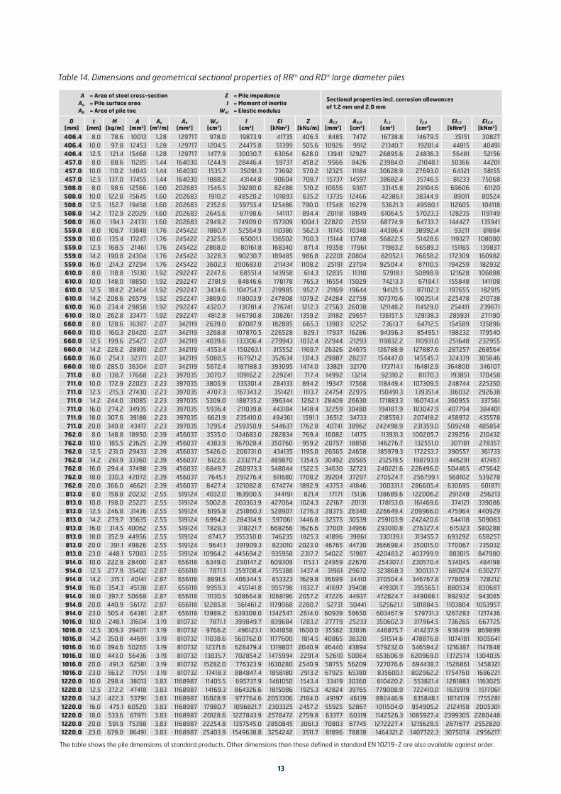
Table 14. Dimensions and geometrical sectional properties of RR® and RD® large diameter piles
AAu
Ab
= Area of steel cross-section= Pile surface area= Area of pile toe
ZI
Wel
= Pile impedance= Moment of inertia= Elastic modulus
Sectional properties incl. corrosion allowancesof 1.2 mm and 2.0 mm
D[mm]
t [mm]
M [kg/m]
A [mm2]
Au [m2/m]
Ab [mm2]
Wel [cm3]
I [cm4]
EI [kNm2]
Z [kNs/m]
A1,2 [mm2]
A2,0 [cm4]
I1,2 [cm4]
I2,0 [cm4]
EI1,2 [kNm2]
EI2,0 [kNm2]
406.4 8.0 78.6 10013 1.28 129717 978.0 19873.9 41735 406.5 8485 7472 16738.8 14679.5 35151 30827406.4 10.0 97.8 12453 1.28 129717 1204.5 24475.8 51399 505.6 10926 9912 21340.7 19281.4 44815 40491406.4 12.5 121.4 15468 1.28 129717 1477.9 30030.7 63064 628.0 13941 12927 26895.6 24836.3 56481 52156457.0 8.0 88.6 11285 1.44 164030 1244.9 28446.4 59737 458.2 9566 8426 23984.0 21048.1 50366 44201457.0 10.0 110.2 14043 1.44 164030 1535.7 35091.3 73692 570.2 12325 11184 30628.9 27693.0 64321 58155457.0 12.5 137.0 17455 1.44 164030 1888.2 43144.8 90604 708.7 15737 14597 38682.4 35746.5 81233 75068508.0 8.0 98.6 12566 1.60 202683 1546.5 39280.0 82488 510.2 10656 9387 33145.8 29104.6 69606 61120508.0 10.0 122.8 15645 1.60 202683 1910.2 48520.2 101893 635.2 13735 12466 42386.1 38344.9 89011 80524508.0 12.5 152.7 19458 1.60 202683 2352.6 59755.4 125486 790.0 17548 16279 53621.3 49580.1 112605 104118508.0 14.2 172.9 22029 1.60 202683 2645.6 67198.6 141117 894.4 20118 18849 61064.5 57023.3 128235 119749508.0 16.0 194.1 24731 1.60 202683 2949.2 74909.0 157309 1004.1 22820 21551 68774.9 64733.7 144427 135941559.0 8.0 108.7 13848 1.76 245422 1880.7 52564.9 110386 562.3 11745 10348 44386.4 38992.4 93211 81884559.0 10.0 135.4 17247 1.76 245422 2325.6 65001.1 136502 700.3 15144 13748 56822.5 51428.6 119327 108000559.0 12.5 168.5 21461 1.76 245422 2868.0 80161.8 168340 871.4 19358 17961 71983.2 66589.3 151165 139837559.0 14.2 190.8 24304 1.76 245422 3228.3 90230.7 189485 986.8 22201 20804 82052.1 76658.2 172309 160982559.0 16.0 214.3 27294 1.76 245422 3602.3 100683.0 211434 1108.2 25191 23794 92504.4 87110.5 194259 182932610.0 8.0 118.8 15130 1.92 292247 2247.6 68551.4 143958 614.3 12835 11310 57918.1 50898.9 121628 106888610.0 10.0 148.0 18850 1.92 292247 2781.9 84846.6 178178 765.3 16554 15029 74213.3 67194.1 155848 141108610.0 12.5 184.2 23464 1.92 292247 3434.6 104754.7 219985 952.7 21169 19644 94121.5 87102.3 197655 182915610.0 14.2 208.6 26579 1.92 292247 3869.0 118003.9 247808 1079.2 24284 22759 107370.6 100351.4 225478 210738610.0 16.0 234.4 29858 1.92 292247 4320.7 131781.4 276741 1212.3 27563 26038 121148.2 114129.0 254411 239671610.0 18.0 262.8 33477 1.92 292247 4812.8 146790.8 308261 1359.2 31182 29657 136157.5 129138.3 285931 271190660.0 8.0 128.6 16387 2.07 342119 2639.0 87087.9 182885 665.3 13903 12252 73613.7 64712.5 154589 135896660.0 10.0 160.3 20420 2.07 342119 3268.8 107870.5 226528 829.1 17937 16286 94396.3 85495.1 198232 179540660.0 12.5 199.6 25427 2.07 342119 4039.6 133306.4 279943 1032.4 22944 21293 119832.2 110931.0 251648 232955660.0 14.2 226.2 28810 2.07 342119 4553.4 150263.1 315552 1169.7 26326 24675 136788.9 127887.6 287257 268564660.0 16.0 254.1 32371 2.07 342119 5088.5 167921.2 352634 1314.3 29887 28237 154447.0 145545.7 324339 305646660.0 18.0 285.0 36304 2.07 342119 5672.4 187188.3 393095 1474.0 33821 32170 173714.1 164812.9 364800 346107
711.0 8.0 138.7 17668 2.23 397035 3070.7 109162.2 229241 717.4 14992 13214 92310.2 81170.3 193851 170458711.0 10.0 172.9 22023 2.23 397035 3805.9 135301.4 284133 894.2 19347 17568 118449.4 107309.5 248744 225350711.0 12.5 215.3 27430 2.23 397035 4707.3 167343.2 351421 1113.7 24754 22975 150491.3 139351.4 316032 292638711.0 14.2 244.0 31085 2.23 397035 5309.0 188735.2 396344 1262.1 28409 26630 171883.3 160743.4 360955 337561711.0 16.0 274.2 34935 2.23 397035 5936.4 211039.8 443184 1418.4 32259 30480 194187.9 183047.9 407794 384401711.0 18.0 307.6 39188 2.23 397035 6621.9 235410.0 494361 1591.1 36512 34733 218558.1 207418.2 458972 435578711.0 20.0 340.8 43417 2.23 397035 7295.4 259350.9 544637 1762.8 40741 38962 242498.9 231359.0 509248 485854
762.0 8.0 148.8 18950 2.39 456037 3535.0 134683.0 282834 769.4 16082 14175 113931.3 100205.7 239256 210432762.0 10.0 185.5 23625 2.39 456037 4383.9 167028.4 350760 959.2 20757 18850 146276.7 132551.0 307181 278357762.0 12.5 231.0 29433 2.39 456037 5426.0 206731.0 434135 1195.0 26565 24658 185979.3 172253.7 390557 361733762.0 14.2 261.9 33360 2.39 456037 6122.6 233271.2 489870 1354.5 30492 28585 212519.5 198793.9 446291 417467762.0 16.0 294.4 37498 2.39 456037 6849.7 260973.3 548044 1522.5 34630 32723 240221.6 226496.0 504465 475642762.0 18.0 330.3 42072 2.39 456037 7645.1 291276.4 611680 1708.2 39204 37297 270524.7 256799.1 568102 539278762.0 20.0 366.0 46621 2.39 456037 8427.4 321082.8 674274 1892.9 43753 41846 300331.1 286605.4 630695 601871813.0 8.0 158.8 20232 2.55 519124 4032.0 163900.5 344191 821.4 17171 15136 138689.6 122006.2 291248 256213813.0 10.0 198.0 25227 2.55 519124 5002.8 203363.9 427064 1024.3 22167 20131 178153.0 161469.6 374121 339086813.0 12.5 246.8 31436 2.55 519124 6195.8 251860.3 528907 1276.3 28375 26340 226649.4 209966.0 475964 440929813.0 14.2 279.7 35635 2.55 519124 6994.2 284314.9 597061 1446.8 32575 30539 259103.9 242420.6 544118 509083813.0 16.0 314.5 40062 2.55 519124 7828.3 318221.7 668266 1626.6 37001 34966 293010.8 276327.4 615323 580288813.0 18.0 352.9 44956 2.55 519124 8741.7 355350.0 746235 1825.3 41896 39861 330139.1 313455.7 693292 658257813.0 20.0 391.1 49826 2.55 519124 9641.1 391909.3 823010 2023.0 46765 44730 366698.4 350015.0 770067 735032813.0 23.0 448.1 57083 2.55 519124 10964.2 445694.2 935958 2317.7 54022 51987 420483.2 403799.9 883015 847980914.0 10.0 222.9 28400 2.87 656118 6349.0 290147.2 609309 1153.1 24959 22670 254307.1 230570.4 534045 484198914.0 12.5 277.9 35402 2.87 656118 7871.1 359708.4 755388 1437.4 31961 29672 323868.3 300131.7 680124 630277914.0 14.2 315.1 40141 2.87 656118 8891.6 406344.5 853323 1629.8 36699 34410 370504.4 346767.8 778059 728212914.0 16.0 354.3 45138 2.87 656118 9959.3 455141.8 955798 1832.7 41697 39408 419301.7 395565.1 880534 830687914.0 18.0 397.7 50668 2.87 656118 11130.5 508664.8 1068196 2057.2 47226 44937 472824.7 449088.1 992932 943085914.0 20.0 440.9 56172 2.87 656118 12285.8 561461.2 1179068 2280.7 52731 50441 525621.1 501884.5 1103804 1053957914.0 23.0 505.4 64381 2.87 656118 13989.2 639308.0 1342547 2614.0 60939 58650 603467.9 579731.3 1267283 1217436
1016.0 10.0 248.1 31604 3.19 810732 7871.1 399849.7 839684 1283.2 27779 25233 350602.3 317964.5 736265 6677251016.0 12.5 309.3 39407 3.19 810732 9766.2 496123.1 1041858 1600.0 35582 33036 446875.7 414237.9 938439 8698991016.0 14.2 350.8 44691 3.19 810732 11038.6 560762.0 1177600 1814.5 40865 38320 511514.6 478876.8 1074181 10056411016.0 16.0 394.6 50265 3.19 810732 12371.6 628479.4 1319807 2040.9 46440 43894 579232.0 546594.2 1216387 11478481016.0 18.0 443.0 56436 3.19 810732 13835.7 702854.2 1475994 2291.4 52610 50064 653606.9 620969.0 1372574 13040351016.0 20.0 491.3 62581 3.19 810732 15282.0 776323.9 1630280 2540.9 58755 56209 727076.6 694438.7 1526861 14583211016.0 23.0 563.2 71751 3.19 810732 17418.3 884847.4 1858180 2913.2 67925 65380 835600.1 802962.2 1754760 16862211220.0 10.0 298.4 38013 3.83 1168987 11405.5 695737.9 1461050 1543.4 33419 30360 610420.2 553821.4 1281883 11630251220.0 12.5 372.2 47418 3.83 1168987 14169.3 864326.6 1815086 1925.3 42824 39765 779008.9 722410.0 1635919 15170611220.0 14.2 422.3 53791 3.83 1168987 16028.9 977764.6 2053306 2184.0 49197 46139 892446.9 835848.1 1874139 17552811220.0 16.0 475.1 60520 3.83 1168987 17980.7 1096821.7 2303325 2457.2 55925 52867 1011504.0 954905.2 2124158 20053011220.0 18.0 533.6 67971 3.83 1168987 20128.6 1227843.9 2578472 2759.8 63377 60319 1142526.3 1085927.4 2399305 22804481220.0 20.0 591.9 75398 3.83 1168987 22254.8 1357545.0 2850845 3061.3 70803 67745 1272227.4 1215628.5 2671677 25528201220.0 23.0 679.0 86491 3.83 1168987 25403.9 1549638.8 3254242 3511.7 81896 78838 1464321.2 1407722.3 3075074 2956217
The table shows the pile dimensions of standard products. Other dimensions than those defined in standard EN 10219-2 are also available against order.

14
3. DESIGN STANDARDS AND IMPLEMENTATION CONTROL
The Eurocode standards are followed in building construction projects according to the decrees of the Ministry of the Environment. In civil engineering projects, the Eurocode standards are applied according to the instructions of the Finnish Transport Infrastructure Agency. Instructions of other authorities (such as municipalities/cities) are observed where necessary.
The geotechnical class (GL1, GL2, GL3) of the site is selected according to PO-2016 and RIL 207 (Application Eurocode 7). The foundation engineer responsible for the site determines the geotechnical class.
GL1 sites do not normally require piling. Most soil conditions and sites belong to geotechnical class GL2. Owing to the good and versatile properties of steel piles, they have many applications at geotechnical class GL3 sites.Piling class (PTL1, PTL2 or PTL3) is determined on the ba-sis of consequence class (CC1 to CC3, cf. EN 1990 National Annex) and geotechnical class.
4. RECOMMENDATIONS FOR THE SELECTION AND DESIGN OF PILE TYPE, PILE SIZE AND PILING CLASS FOR DIFFERENT APPLICATIONS
Various applications and advantages of different SSAB's steel pile types are presented in brochures on RR and RRs piles, RD and RDs piles and RD pile walls.
The selection of a suitable pile type should be based primarily on soil conditions, but superstructures and ambient structures also play a major role. Some instructions and recommendations for the selection of pile type, pile size and piling class are given below.
Pile loadsSSAB's steel piles can be divided according to pile sizes and applications based on pile loads, for example, as follows:
RR75–RR/RD140/8 1 & 2 family houses and other struc-tures subject to relatively light loads
RR/RD140/8–RR/RD270 multi-storey buildings of about 3 to 8 storeys
RR/RD220–RR/RD500 heavy multi-storey buildings (>5 storeys) or industrial building projects
RR/RD140–RR/RD270 pile slab projects
RR/RD220–RR/RD400 noise barrier piles (single pile foundations)
RR/RD500–RR/RD1200 bridge and harbour construction and buildings of more than 10 to 15 storeys
When selecting between RR and RD pile sizes, it should be noted that the design strength of RD piles bearing on solid bedrock is typically clearly higher (about 1.2 to 2.0 times) than that of an RR pile of corresponding size. Owing to the comprehensive pile size range, foundation structures can always be optimised by using several (typically two or three) pile sizes at a site. Installability of pilesRD piles can be installed in all soil conditions. In very exacting conditions, such as those involving thick fill layers containing large boulders, the smallest RD piles (pile sizes around RD90 to RD140) may pose the risk of slightly higher pile bending in comparison to large diameter RD piles. If the bedrock surface is particularly inclined, close to ground level (<3 to 5 m), and in conditions where there are no supporting friction soil layers on top of the bedrock surface, an RD pile is a risk-free solution in terms of support for the lower end of the pile.
The penetrability of driven RR and RRs piles increases with increasing pile size. When the amount/size of stones and boulders in soil and fill layers – or the density or thickness of the soil layer – increases, the risk of deviations in the positions and verticality of driven piles increases. The risk that piles bend or fail to reach a load-bearing soil layer also increases. RR large diameter piles have successfully penetrated rock fills several metres thick, even ones over 20 metres thick. An RR170 or RR220 pile is often rigid enough to penetrate relatively thick layers of rocky fill and moraine all the way to a bearing basal formation, provided that the size and amount of stones and boulders is not exceptionally large. A rock shoe improves the penetrability of a pile. When building 1 & 2 family houses on thick moraine soils containing stones it is recommended to use at least pile size RR115/6.3.
Positional and verticality tolerances of pilesWhen a structure is set strict positional and verticality tolerances, like, for instance, railway bridges built using the bridge-moving technique, where a large diameter pile is attached to the deck and also acts as a column, the RD pile is the least risky alternative. It is also the most recommendable alternative for corresponding building construction projects where the pile also acts as a column. Strict tolerances may also be required in foundation underpinning or industrial building projects.
Environmental impacts of piling and nearby structuresThe environmental impacts of piling and issues related to the selection of pile type are discussed in Sec. 6.7 of these instructions.

15
Selection of piling classIn most projects, the piling class can be either PTL2 or PTL3. In consequence class CC3 projects related to geotechnical classes GL2 and GL3, piling class PTL3 is always required.
Piling class PTL2 is recommended for 1 & 2 family house projects to ensure correct pile loads and geotechnical resistance. PTL3 may be applicable to these projects if the soil conditions are exceptional and/or the number of piles is large (a project involving several 1 & 2 family houses).
PTL3 should be considered with RR and RRs piles, when the number of piles is at least moderate and it is desired to minimise the environmental impacts of the piling. Then, the number of piles can be reduced due to the higher design value of pile strength by a maximum of 15 to 20% compared to PTL2. With large diameter piles, load-bearing capacity must always be ensured by dynamic load tests. In their case it is often recommendable to choose piling class PTL3 to optimise the structures.
With RD piles, the lowest piling class allowed by the consequence class and geotechnical class is recommended.
Considering installation equipment in design and selection of pile size
RR/RRs piles can be installed using light basic equipment (<20 to 25 t) up to a pile size of about RR170, and RD/ RDs piles up to about RD270 to RD320. Light basic equipment allows using essentially thinner piling platforms, especially in very soft subsoils, compared to heavy (>40 to 60 t) piling equipment. The environmental impacts of light installation equipment (mainly vibration) also remain low.
5. STRUCTURAL AND GEOTECHNICAL DESIGN OF PILES
5.1 Limit states of pile foundations to be considered
The limit states specified in PO-2016, Sec. 4.1, should be considered in the design of a pile foundation, considering the properties of the site.
5.2 Design process of a steel pile foundation
At conventional sites, where the piles are mainly subject to axial loading, the design of a steel pile foundation includes:
1) Selection of pile type suitable for the site:
• soil conditions; pile drivability/installability and functioning of the pile foundation
• loads from the superstructure and actions due to ground displacement
• structures and conditions in the piling area and its surroundings
2) Selection of piling class PTL1 to 3 based on geotechnical class (GL1 to 3) and consequence class (CC1 to 3)
3) Determination of the geotechnical resistance of piles Rd,geo according to Sec. 5.5
• with RR75 to RR320 end-bearing piles, apply Table 22, end-of-driving instructions, and with PTL3 also dynamic load tests
• with RD piles, geotechnical resistance is usually not a dimensioning factor
• RR large diameter piles, dynamic load tests • stiffness of structure (non-stiff or stiff structure)
4) Determination of the design value Rd,str of structural resistance of piles according to Sec. 5.7
• determination of corrosion allowance • RR75 to RR320 and RD90 to RD320 normal cases,
Tables 22 and 23 • dimensioning program for RR and RD piles
(www.ssab.com/infra) • end-of-driving instructions (Sec. 11) are observed
with driven piles to ensure that impact stresses stay within allowed limits
• the structural resistance of rock shoes for RR270 to RR1200 piles (Tables 4 and 7) may determine the maximum impact and structural resistance
5) Determining the design value for resistance to an action
• the design value of resistance Rd is the smaller of geotechnical Rd,geo and structural resistance Rd,str
6) Calculation of pile foundation displacements, if necessary (Sec. 5.8)
• vertical displacement of an individual pile and displacements of pile groups
7) Assessment of and preparation for environmental impacts of piling
• assessment of vibration, soil displacement, increase in pore water pressure and compaction of subsoil due to piling
• preparation for environmental impacts - selection of pile type - piling sequence - monitoring measurements - special measures

16
8) Structural design of a pile foundation • Pile foundations are always designed together with
the structures to be supported on it, which allows selecting the most suitable shape, dimensions and stiffness for the entire structure. Things to be considered in the structural design of the pile foundation include - joints between piles and superstructure - determination of positional and verticality
tolerances on the basis of pile type, soil conditions and superstructure
- elevation of pile group foundation - centre-to-centre pile spacing - pile inclinations - distances of piles to nearby structures - distance from side of the foundation to side of the pile - other structural aspects to be considered
9) Foundation engineering print-outs • Building specification (work schedule)
- soil conditions - geotechnical works
° Work stages prior to piling and measures affecting the work phases, piling platforms, excavations, etc.
° Site-specific instructions related to piling, such as instructions for installation, piling sequence, quality control measurements, special measures
- Foundation structures • Pile foundation drawings • Geotechnical and structural dimensioning calculations
- normally dimensioning calculations for the structure of an axially loaded pile can be made and printed out easily using the pile dimensioning program for RR and RD piles
• As-built drawing
5.3 Actions and design situations
The design actions of loads must correspond to those specified in all parts of standard EN 1991 and the national annexes to them. They are included in publication RIL 201-1-2008 with their application instructions. Actions caused by subsoil displacement, such as downdrag (negative skin friction), are treated in dimensioning as permanent actions on the pile (for more details, see 5.9).
5.4 Geotechnical investigations
Geotechnical investigations for the design of steel piles are generally regulated by the Finnish Building Code and standards EN 1997-1 and EN 1997-2. PO-2016 presents the general requirements for geotechnical investigations in building construction, requirements and recommendations for different geotechnical classes and foundation underpinning sites, as well as requirements and instructions for the presentation of geotechnical
information. Valid guidelines of the Finnish Transport Infrastructure Agency are observed in infrastructure construction. Geotechnical investigations must be complemented with sufficiently extensive investigations of nearby structures (ducts, pipes, cables, underground structures, etc.), their location and condition, foundation methods, as well as sensitivity to displacement and vibration.
Geotechnical information and its assessment are presented in the ground investigation report according to PO-2016, Ch 1, Sec. 3.3. The ground investigation report should indicate the following points most essential for the design and dimensioning of steel piles: • the characteristic value of the undrained shear
strength of soil used in dimensioning – by soil layers, if necessary, and/or with the site divided into different zones if the site is large and/or the undrained shear strength of soil varies considerably
• corrosion allowance used in dimensioning • estimated pile length and basis of estimate • estimate of subsoil properties affecting piling, such
as the quality, stoniness and thickness of fills, dense/stony intermediate layers, density and stoniness of moraine, inclination of bedrock surface
• shoe type of driven pile used at site • estimate of the occurrence of downdrag (negative
skin friction) and determination of the design value of downdrag for different pile dimensions and different areas of the site, if necessary
Depending on the site, the following may also be needed: • axial spring constant of pile for service state
displacement analysis (see Sec. 5.8), is in principle always required in PTL3 but also in PTL2 in the case of long piles
• geotechnical parameters of soil layers to determine extreme values of modulus of subgrade reaction and lateral resistance, when piles are subject to a horizontal load and/or moment.
5.5 Dimensioning methods and analyses of geotechnical resistance
5.5.1 Selection of geotechnical dimensioning method for steel piles
The geotechnical compressive strength of steel piles can be determined according to PO-2016 in several ways, whose applicability is shown in Table 15.
5.5.2 Stiffness of a piled structure
The stiffness of a piled structure is taken into account in building construction projects according to the instructions of PO-2016 and in civil engineering projects according to those of NCCI7. The correlation coefficients presented in these instructions and the design values based on them assume that the structures are not so-called rigid structures.
17
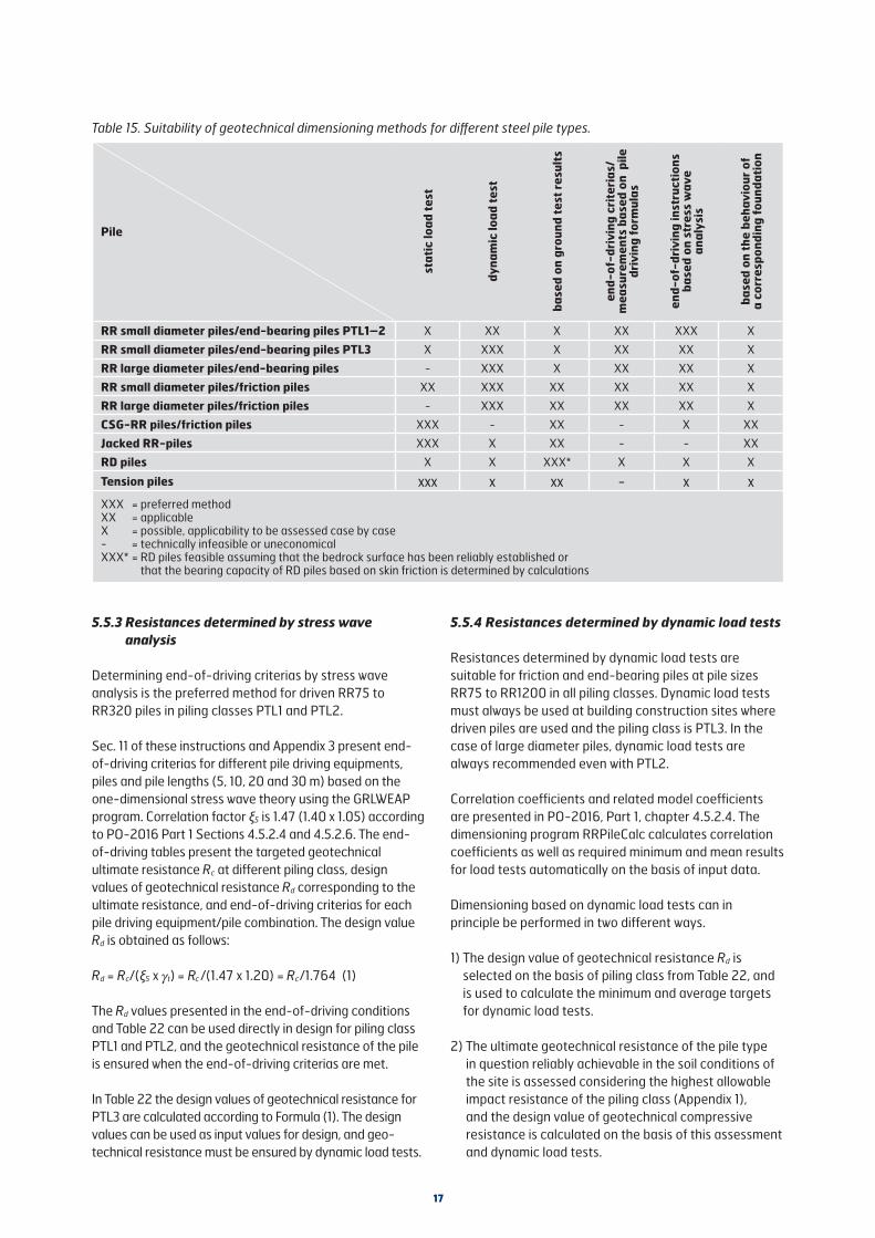
5.5.3 Resistances determined by stress wave analysis
Determining end-of-driving criterias by stress wave analysis is the preferred method for driven RR75 to RR320 piles in piling classes PTL1 and PTL2.
Sec. 11 of these instructions and Appendix 3 present end-of-driving criterias for different pile driving equipments, piles and pile lengths (5, 10, 20 and 30 m) based on the one-dimensional stress wave theory using the GRLWEAP program. Correlation factor ξ5 is 1.47 (1.40 x 1.05) according to PO-2016 Part 1 Sections 4.5.2.4 and 4.5.2.6. The end-of-driving tables present the targeted geotechnical ultimate resistance Rc at different piling class, design values of geotechnical resistance Rd corresponding to the ultimate resistance, and end-of-driving criterias for each pile driving equipment/pile combination. The design value Rd is obtained as follows:
Rd = Rc/(ξ5 x t) = Rc /(1.47 x 1.20) = Rc/1.764 (1)
The Rd values presented in the end-of-driving conditions and Table 22 can be used directly in design for piling class PTL1 and PTL2, and the geotechnical resistance of the pile is ensured when the end-of-driving criterias are met.
In Table 22 the design values of geotechnical resistance for PTL3 are calculated according to Formula (1). The design values can be used as input values for design, and geo-technical resistance must be ensured by dynamic load tests.
5.5.4 Resistances determined by dynamic load tests
Resistances determined by dynamic load tests are suitable for friction and end-bearing piles at pile sizes RR75 to RR1200 in all piling classes. Dynamic load tests must always be used at building construction sites where driven piles are used and the piling class is PTL3. In the case of large diameter piles, dynamic load tests are always recommended even with PTL2.
Correlation coefficients and related model coefficients are presented in PO-2016, Part 1, chapter 4.5.2.4. The dimensioning program RRPileCalc calculates correlation coefficients as well as required minimum and mean results for load tests automatically on the basis of input data.
Dimensioning based on dynamic load tests can in principle be performed in two different ways.
1) The design value of geotechnical resistance Rd is selected on the basis of piling class from Table 22, and is used to calculate the minimum and average targets for dynamic load tests.
2) The ultimate geotechnical resistance of the pile type in question reliably achievable in the soil conditions of the site is assessed considering the highest allowable impact resistance of the piling class (Appendix 1), and the design value of geotechnical compressive resistance is calculated on the basis of this assessment and dynamic load tests.
Table 15. Suitability of geotechnical dimensioning methods for different steel pile types.
Pile
stat
ic lo
ad t
est
dyna
mic
load
tes
t
base
d on
gro
und
test
res
ults
end-
of-d
rivi
ng c
rite
rias
/ m
easu
rem
ents
bas
ed o
n p
ile
driv
ing
form
ulas
end-
of-d
rivi
ng in
stru
ctio
ns
base
d on
str
ess
wav
e
anal
ysis
base
d on
the
beh
avio
ur o
f a
corr
espo
ndin
g fo
unda
tion
RR small diameter piles/end-bearing piles PTL1–2 X XX X XX XXX X
RR small diameter piles/end-bearing piles PTL3 X XXX X XX XX X
RR large diameter piles/end-bearing piles - XXX X XX XX X
RR small diameter piles/friction piles XX XXX XX XX XX X
RR large diameter piles/friction piles - XXX XX XX XX X
CSG-RR piles/friction piles XXX - XX - X XX
Jacked RR-piles XXX X XX - - XX
RD piles X X XXX* X X X
Tension piles xxx x xx - x xXXX = preferred method XX = applicable X = possible, applicability to be assessed case by case- = technically infeasible or uneconomicalXXX* = RD piles feasible assuming that the bedrock surface has been reliably established or
that the bearing capacity of RD piles based on skin friction is determined by calculations

18
5.5.5 Resistances determined by pile driving formulas
Pile driving formulas can be used in piling class PTL1 or PTL2, for example, in situations where, according to the end-of-driving table, the used pile driver is not able to mobilise sufficient ultimate geotechnical resistance and geotechnical resistance is ensured by a separate test loading hammer without a dynamic load test. The pile driving formulas are used according to PO-2016, Ch. 1, Sec. 4.5.2.5.
5.5.6 Resistances determined on the basis of ground test results
Geotechnical resistance is determined on the basis of ground test results according to PO-2016, Ch. 1, Sec. 4.5.2.3. It is recommended that the so-called alternative method is used in design, where a model factor of ≥1.6 is used for end-bearing and friction piles and ≥1.95 for cohesion piles in long-term loading and ≥1.40 in short-term loading.
As concerns steel piles, the capacity of both smooth and grouted friction piles can be determined on the basis of ground investigation results, but it is recommended that the capacity is also determined by static or dynamic load tests. This method is highly suitable for calculating the geotechnical compressive strength of foundation piles of lightweight noise barriers.
The point and shaft resistance of piles can be estimated either on the basis of the angle of friction or cohesion of soil or directly based on sounding resistance according to PO-2016.
5.5.6.1 Special features of the geotechnical resistance of open ended steel pipe piles
In preliminary analyses of open ended steel piles with point reinforcement ring (a steel collar over the shaft), external shaft resistance can be estimated to decrease by 50 % in a dense coarse-grained soil layer or moraine layer, and 25 % in a loose layer compared to the table values presented in PO-2016 or static capacity formulas. Point resistance increases with increasing pile-point area.
If no plugging occurs in the pile, internal shaft resistance can be assumed to be half of external shaft resistance in preliminary analyses. However, the capacity consisting of internal shaft resistance and point resistance of the area of the steel cross-section of the pile must not exceed the capacity of a plugged pile of corresponding size due to point resistance.
5.5.6.2 Geotechnical resistance of grouted CSG-RR piles bearing on a soil layer
The dimensioning geotechnical diameter of shaft grouted piles (dd) may be larger than the diameter of the collar (d0) used with the pile. The increase in diameter is caused by the pressurising effect of grout with this installation method, which makes the grout both displace and mix with the soil layers surrounding the pile.
The dimensioning geotechnical diameter can be determined, for example, by measurements on a test pile or by using information on shaft grouted micropiles in corresponding soil conditions. The magnitude of the dimensioning diameter can be evaluated using Formula 2.
dd = a ·d0 (2)
where dd is the dimensioning geotechnical diameter; a is the coefficient that depends on soil type, grout
pressure, etc. and d0 is the diameter of the collar used with the pile in question
The coefficient can vary with different soil types as follows: clay a = 1.0 silt a = 1.0 to 1.1 sand, gravel a = 1.1 to 1.2 moraine a = 1.0 to 1.2
With shaft grouted CSG-RR piles the shaft resistance factors of Table 16 can be used as shaft resistance factor Kstanφa, and the dimensioning of point resistance is the same as with non-grouted piles. Values based on sounding resistance may also be used to evaluate shaft and point resistance, see PO-2016, Ch. 1, Tables 4.6 and 4.8.
5.5.6.3 Geotechnical resistance of RD piles drilled into bedrock
The point resistance of a pile bearing on solid Finnish bedrock is usually not a dimensioning factor, but resistance is determined on the basis of the structural resistance of the pile.
The tip of the pile is assumed to bear on bedrock when both drilling observations and geotechnical investigations confirm it.
Table 16. Shaft resistance factor Kstanφa for grouted piles in coarse-grained soil types.
Internal angle of friction of soil [o]
28 30 32 34 36 38 40 42
Kstanφa 1.2 1.3 1.5 1.7 2.1 2.5 2.9 3.4

19
The quality of the rock contact of RD piles is ensured by drilling the pile at least 3 . d deep, but no less than 0.5 m, in solid bedrock. With larger drilled piles, over 300 mm in diameter, 3 . d can be considered a safe drilling depth into bedrock, but drilling the pile more than 1.5 m into bedrock is usually not practical in Finland. In bridge projects of the Finnish Transport Infrastructure Agency, the dimensioning and implementation instructions of the publication ”Sillan geotekninen suunnittelu” (Geotechnical design of a bridge) for joint stiffness and drilling depth of RD piles into bedrock are followed.
Drilling piles more than 1.5 m into solid bedrock may be appropriate, for instance, when excavation or blasting takes place after installation of piles in their immediate vicinity. Three metres below the excavation level can be considered a safe target level for piles in bedrock in the case of conventional blasting. If the target level is 3 metres higher than above, the properties of the rock and its breaking during blasting must be considered carefully in the planning and execution of the work.
The rock contact of the tip of RD piles installed by the concentric drilling method remains after rock penetration. When the RD pile is filled completely or partly with grouting mortar or concrete, loads from the pile to the bedrock are transmitted across the entire area of the pile bottom.
In fragmented bedrock piles are drilled deeper all the way to solid bedrock, or the rock is grouted or geotechnical resistance is evaluated case by case. Geotechnical resistance can be determined by calculations if the strength properties of the fragmented rock can be estimated or determined reliably enough.
The contact of RD piles with rock after the end of drilling is ensured by applying ”final or control blows” by a drill hammer to the top of each pile.
The shaft resistance of a pile in bedrock can be made use of in geotechnical dimensioning of RD piles. It can be used, for example, if the pile bears on a weakness zone in bedrock or is subject to tensile loads. With vertically loaded RD piles dimensioned to be shaft-bearing, the distance between the hole in the rock and the reinforcement must be at least 15 mm. The shaft resistance of RD piles in bedrock can be utilised, for example, by drilling the RD pile first to the surface of bedrock, and then continuing to drill with a smaller drill bit deeper into bedrock. The drill hole is flushed clean, filled with concrete, grouting mortar or injection grout, and then a steel pipe equipped with centralisers, at least 30 mm smaller in outer diameter than the diameter of the hole in the bedrock, is installed in the hole. The bond stress values between steel and grouting mortar and grouting mortar and rock are presented in PO2016, Ch. 1, Table 4.9.
5.5.7 Resistances determined by static load tests
Static load tests are used mainly in the geotechnical dimensioning of shaft grouted CSG-RR piles, jacked RR-piles and tension piles. In rapid load tests, the correlation coefficients of PO-2016, Ch. 1, Tables 4.1 and 4.2 are multiplied by 1.2. Even in rapid loading, the displacement during the load step of the highest load must be monitored for at least 5 minutes. The rate of settlement during the last 5 minutes of the monitoring period must be less than half of that of the first 5 minutes.
5.6 Geotechnical dimensioning of tension piles
The geotechnical dimensioning of tension piles is carried out according to PO-2016, Sec. 4.5.3.
If mechanical splices are used in pile splicing, the design value of tensile strength must be limited to that of the splice, which in the case of driven RR piles is 15% of compressive strength and with RD piles 50% of compressive strength.
In the case of RD piles with conventional casing shoes and ring bits, the grouting mortar or concrete possibly penetrating between the hole in the bedrock and the pile pipe after concreting cannot be taken into account in dimensioning without a closer analysis.
If anchors are used with the piles, the entire tensile force on the pile must be taken by the anchor.
5.7 Structural resistance
5.7.1 Resistance of RR piles during installation
The structural resistance of driven piles in different piling classes must be limited according to PO-2016 as follows:
Table 17. Maximum characteristic value of geotechnical resistance for driven piles and maximum centric impact force.
Maximum allowed centric impact force causing
compression stress during installation*
Nimpact (-)
Maximum characteristic value of resistance
Rc;max
≤ 0.9 × fyk × As
PTL3: Rc;max ≤ Nimpact(-)
PTL2: Rc;max ≤ 0.8 × Nimpact(-)
PTL1: Rc;max ≤ 0.6 × Nimpact(-)
* when stresses/impact force are measured during driving, the above stress level cannot be exceeded by more than 20 % (impact stress ≤ 1.08 x fy) (EN 12699).

20
Appendix 1 presents the maximum resistance Rc;max values during driving for all RR piles in various piling classes.
5.7.2 Structural resistance during service
The structural resistance of a pile is verified in terms of both pile structure and soil failure according to Piling Manual PO-2016.
The compressive resistance of piles against buckling is determined in conditions where piles may buckle due to the lack of sufficient lateral support. The lateral support of soil is usually not utilised if the shear strength of the organic soil layer around the pile is less than 5 kN/m2. Then, the pile is dimensioned as a column and the unbraced length is determined on the basis of soil conditions and the structural joint between the upper and lower ends of the pile.
The ultimate buckling resistance of an axially loaded pile is calculated by the method presented in PO-2016, Sec. 4.7.5, where the pile is assumed to be surrounded by a fine-grained soil layer over its entire unbraced length. A constant spring value is used for subsoil along the entire unbraced length in dimensioning. In a coarse-grained soil layer, the above calculation method can be utilised by estimating the unbraced length and using, for example, a conservative spring value for frictional soil along the entire unbraced length.
Initial deflection after installation prior to loading is taken into account in buckling analyses of axially loaded piles. At the design stage, values Lcr/200 to Lcr/800 of the table can be used as the value of the geometric initial deflection of a pile. The values of the greater divisor of the table, that is, the larger radius of curvature, can be used when the installation conditions are expected to be easy, and the smaller radius of curvature values when the installation conditions are expected to be difficult. The value recommended for a spliced pile is used only if the splice is located along the unbraced length Lcr in a soft soil layer.
Table 18. Initial deflection values used with SSAB’s steel piles in design.
Unspliced pile
Spliced pile
Initial deflection g [m], RR and RRs piles and CSG-RR piles
Lcr/300–Lcr/600 Lcr/200–Lcr/400
Initial deflection g [m], RD and RDs piles
Lcr/500–Lcr/800 Lcr/300–Lcr/600
If the straightness of the pile is measured, for example, with a torch or an inclinometer, the radius of curvature determined on the basis of the measurements can be used in design. The dimensioning program for RR and RD piles can be used for easy calculation of the radius of curvature used in the dimensioning of a pile. The calculated radius of curvature depends on the critical unbraced length, which, in turn, depends on the stiffness of the pile, the modulus of subgrade reaction and effective width of the pile.
According to PO-2016 and in the dimensioning program for RR and RD piles, the partial safety factor for strength of soil is applied to the ultimate stress limit of lateral resistance at the end of the calculation.
Steel cross-section classes are taken into account according to standards EN 1993-1-1 and EN 1994-1-1 in the calculation of the ultimate bending moment capacity of the pile structure.
With CSG-RR piles, the effective width of the pile is based on the width of the collar. An external grout mantle is not taken into account in determining the ultimate bending moment capacity of the structure.
If a pile is loaded by an external bending moment and/or a torque and/or a shear force, besides a normal force, the pile or the part of it subject to the stress in question must be dimensioned for the combined stresses.
Secs. 5.12 and 5.13 of these instructions present pre-calculated dimensioning values for structural resistance at corrosion allowances of 1.2 mm and 2.0 mm.
5.7.3 Corrosion
The average corrosion rate of unprotected steel piles in normal conditions underground can be assumed to be at least 1.2 mm in a hundred years in the case of the external surfaces susceptible to corrosion. Corrosion of the inner surfaces of steel pipe piles with a closed lower end or ones filled with concrete can be ignored.
Corrosion rate depends on ambient conditions. Table 19 presents some indicative values for average surface corrosion of steel piles in some conditions. The recommendations of the table were originally presented in standard EN 1993-5.
Alternatively, the corrosion rate of piles not filled with concrete can in certain normal conditions be estimated on the basis of the values presented in Table 20. The table is based on statistical processing of corrosion observations, where the risk related to conditions is taken into account by using the so-called pit corrosion factor and possible internal corrosion by theoretical calculations.
If soil conditions prove unusual, Table 19 can be applied where applicable.

21
Table 20. Dimensioning corrosion of unconcreted micropiles in 100 years in different conditions.*
Conditions Corrosion in 100 years [mm]
Homogeneous natural soil conditions above and below ground water level 1.2
Compacted mineral soil fills above and below ground water level 1.5
Non-compacted mineral soil fills above and below ground water level 2.0
* Jouko Törnqvist: Corrosion steel pipe piles. Dimensioning based on empirical material VTT Technical Research Centre of Finland (2005). • Espoo (2005)
Table 21. Recommended values for thickness reduction of bearing piles and sheet piling installed in fresh or sea water due to corrosion [mm] (EN 1993-5).
Design life required in designs 5 years 25 years 50 years 75 years 100 years
Normal fresh water (river, navigable channel, ...) in a high stress (water line)
0.15 0.55 0.90 1.15 1.40
Badly polluted fresh water (sewage, industrial waste water...) in a high stress area (water line)
0.30 1.30 2.30 3.30 4.30
Sea water in temperate climate in high stress area (shallow water and splash zones)
0.55 1.90 3.75 5.60 7.50
Sea water in temperate climate in areas permanently under water and tidal zones.
0.25 0.90 1.75 2.60 3.50
Note:1) Corrosion rate is usually highest in a splash or tidal zone at low tide level. In most cases, however, the highest flexural stresses occur
in areas permanently under water.2) Values for 5 and 25 years are based on measurements, while others have been extrapolated.
Table 19. Average surface corrosion [mm] of unprotected steel piles in soil above and below ground water level (EN 1993-5).
Target service life 5 years 25 years 50 years 75 years 100 years
Normal conditionsUndisturbed natural soils (sand, silt, clay, …)Non-compacted, non-aggressive mineral soil fills (clay, sand, silt, …)
0.00
0.18
0.30
0.70
0.60
1.20
0.90
1.70
1.20
2.20
Exceptional or aggressive conditionsContaminated natural soils and soils in industrial areasAggressive natural soils (swamp, marsh, peat, …)Non-compacted aggressive fills (ash, slag, …)
0.150.200.50
0.751.002.00
1.501.753.25
2.252.504.50
3.003.255.75
Note: Corrosion rates are lower in compacted than in non-compacted fills. In the case of compacted fills, the values for non-compacted fills can be divided by two. The values are indicative. Local conditions must be taken into account. The values for a service life of 5 and 25 years are based on measurements, other values have been extrapolated. Corrosion in air in one hundred years: 1 mm in normal climate and 2 mm near the sea.

22
In uncertain cases it is advisable to overdimension excessively or use corrosion protection.
The usualness of conditions is established on the basis of geotechnical investigations and historical data on the area when there is no reason to assume the soil to be contaminated. Special investigations can be carried out in uncertain situations to ascertain that the separately determined limit values for aggressive conditions are not exceeded. The instructions of the publication ”Sillan geotekniset suunnitteluperusteet” (Geotechnical design criteria for bridges) are followed in corrosion dimensioning and corrosion investigations in bridge projects commissioned by the Finnish Transport Infrastructure Agency. Use of filter fabric or plastic sheeting or pipes is recommended around unprotected steel piles to prevent direct contact between granules and steel in lightweight aggregate fills.
The corrosion of piles installed in water can be estimated on the basis of the values presented in Table 21. Higher corrosion values must be used in unusual conditions including sites where pile surfaces are subject to mechanical stress caused, for example, by propeller slipstreams of ships. The recommendations of the Table were originally presented in standard EN 1993-5.
When cement-based injection grout, grouting mortar or concrete is used as corrosion protection of steel piles, corrosion dimensioning and determination of the correct protective coating thickness can be based on Tables 4.25 ja 4.26 of PO-2016, Ch. 1.
External coatings can be used as corrosion protection on steel piles, although overdimensioning of wall thickness is generally the recommended method. Possible external coatings are protective paint or 3-layer HDPE coating. The selected coating must be able to withstand stresses during installation. Protective painting is highly suitable for piles that are installed in water where the purpose of the protective painting is to prolong service life, for instance, in the most aggressive splash zone areas. The service life of protective painting can be assessed in the case of the protective paint systems specified in standard EN 12944-5. There is always the risk of damage to the coating of piles driven into soil unless special measures are taken. In the case of drilled piles, when there are no stones or boulders in the soil, it may be possible to use the strong 3-layer HDPE coatings specified in DIN 30670 without the coatings being damaged. Even then, the use of a coating should be considered case by case and the durability of the coating ensured, for example, by test installations.
In the case of electric protection methods, the electric current required by the system and the replaceability/service life of galvanic anodes must be taken into account.
5.8 Vertical displacements of pile foundation
If necessary, vertical displacements of pile foundations are analysed according to PO-2016, Sec. 4.5.4. An analysis of settlements is generally not needed with steel piles bearing on dense moraine or bedrock, if ultimate limit state analyses of the piles have been conducted. However, for example, at foundation underpinning sites, especially with long piles, the elastic compression of piles may become a dimensioning factor, which is why the piles are often prestressed.
The assessment of vertical displacements must cover both the settlement of individual piles and settlement due to group effect as well as structural rotations and changes in inclination possibly caused by uneven settlement.
In the case of tension piles, upward displacements should be assessed on the basis of the same principles. If very strict criteria have been set for the service limit state, a separate analysis of upward displacements is needed.
5.9 Considering downdrag (negative skin friction) in dimensioning
Negative skin friction is taken into account according to PO-2016, Ch. 4.2.2.2 as a downward acting load.
In building construction projects, the design value of downdrag load is obtained by multiplying the characteristic value of negative skin friction by a factor of 1.2. When the design value of short-term loads exceeds the design load of downdrag, downdrag load is not taken into account in ultimate limit state analysis.
In infrastructure projects, the characteristic value is multiplied by the partial safety factors of dead load (Load Combination 6.10a). Downdrag load does not affect the pile simultaneously with compressive stresses from traffic loads.
Small diameter steel pipe piles have dimensioning advantages over conventional pile types in terms of negative skin friction, since the skin area is small and the downdrag load on the piles is often smaller than short-term loads. On the other hand, due to their low soil displacement, driven small diameter piles, even large RD piles when installed carefully, do not cause soil heave and subsequent settlement in normally consolidated clay. Thus, installation of piles does not cause significant displacement of soil or lead to a situation where negative skin friction should be taken into account according to PO-2016.

23
Accurate determination of the negative skin friction on an individual pile requires calculating the settlements of both the pile and soil layers. Normally it can be simply assumed that negative skin friction occurs across the entire compressed layer and that its magnitude [of skin friction] can be estimated on the basis of undrained shear strength and the adhesion coefficient.
5.10 Transversely loaded steel piles
Laterally loaded piles are dimensioned according to the principles of PO-2016, Ch. 1, Sec. 4.6. Usually a dimensioning program is used, which can take into account the stiffness of the pile, attachment of the upper and lower ends of the pile, and the properties of soil layers. Flexural stiffnesses (EI) of steel piles, either unconcreted or concreted and reinforced, can be easily calculated by the dimensioning program for RR and RD piles.
5.11 Short piles
It must be borne in mind in design that the shortest allowable lengths of driven RR piles in soil are: RR75 to RR220: 1.5 m RR270 to RR320: 2.0 m RR400 to RR600: 2.5 m RR650 to RR1200: 3.0 m
If the penetration depth of an RR pile is less than 5 metres, it must be estimated whether the soil provides sufficient lateral support for the pile. Lateral support can often be improved by using rock shoes to attach the pile tip to bedrock. If the soil does not provide sufficient lateral support, the sufficiency of lateral support vs. allowed deviations in inclination (lateral component acting on inclined pile vs. lateral resistance) is checked. In consequence class CC1, and with caution also at CC2 sites, it is also possible to reduce the design value of the compressive resistance of piles by a factor of 0.6 to 1.0 (pile length 3 to 5 m) in lieu of more accurate calculations. Piles shorter than 3 metres are usually attached rigidly to the superstructure according to Sec. 6.1.
RD piles have no minimum penetration depth, but pile length is determined according to site properties and the portion to be drilled into bedrock according to Sec. 5.5.6.3. When short RD pile (pile length less than 3 m) is drilled at least 4·d into the bedrock, the rigid connection with superstructure is not needed.
5.12 Dimensioning tables for RR and RRs piles, pile sizes RR75 to RR320/12.5
The design values of the geotechnical resistance of RR and RRs piles have been determined according to Sec. 5.5.4 to correspond to the end-of-driving criteria based on stress wave analysis. In piling class PTL3 geotechnical resistance must be ensured by dynamic test loadings according to Sec. 5.5.5.
Coefficient of modulus of subgrade reaction used to calculate the spring constant of soil is 50 (ks = 50 x cu,k/deff) and that used to calculate the extreme value of lateral resistance is 9 (pm = (9 x cu,k) / g R,e).
The buckling analysis of piles has been performed by a structural model where the partial safety factor of soil resistance is applied to the characteristic values of the resistances of the springs representing the soil. The springs themselves have been calculated on the basis of characteristic soil values. The partial safety factor of soil resistance has been set to the default value of gR,e = 1.5 (RIL 207-2009). The partial safety factor of steel has been set to gsi = 1.0 according to EN 1993-1-1. The structure of the pile has been dimensioned as a steel structure. Calculation method of dimensioning the structural resistance of pile’s cross-section is presented in detail in the RRPileCalc program manual.
If the input values differ from the above or those presented in Table 22, the axial structural resistance of piles can be easily determined with RRPileCalc program.
The design values of the geotechnical resistance of piles are independent of the used corrosion allowance. If driven RR or RRs piles are concreted and dimensioned as a composite structure, the design values of RD piles (Sec. 5.13) can be used as design values of the pile structure, or they can be determined by the dimensioning program for RR and RD piles.
5.13 Dimensioning tables for RD and RDs piles, RD/RDs90 to RD320/12.5
Coefficient of modulus of subgrade reaction used in calculating the spring constant of soil is 50 (ks = 50 x cu,k/deff) and that used in the calculation of the extreme value of lateral resistance is 9 (pm = (9 x cu,k) / gR,e).
Buckling analysis of piles has been performed by a structural model where the partial safety factor for soil resistance is applied to the characteristic values of the resistances of the springs representing soil. The springs themselves have been calculated on the basis of characteristic values of soil. The partial safety factor for soil resistance has been set to the default value of gR,e = 1.5 (RIL 207-2009). The partial safety factor of steel has been set to gsi = 1.0 in both steel structure dimensioning according to EN 1993-1-1 and composite structure dimensioning according to EN 1994-1-1. The partial safety factor for the strength of concrete/grouting mortar is gci = 1.5 according to EN 1992-1-1. Concrete strength has been C30/37. Calculation method of dimensioning the structural resistance of pile’s cross-section is presented in detail in the RRPileCalc program manual.
Concrete creep and the share of dead load of the overall load is considered in determining the effective elastic modulus of concrete/grouting mortar (Ec,eff) according to standard EN 1992-1-1. The creep factor used in the calculations is t =1.5 and the default value of dead load share is 0.5.
If the input values change, the structural axial resistance of piles can be easily determined with RRPileCalc program.

24
Corrosion allowance 1.2 mm
Pile Steel grade Initial deflection Design value of structural compression resistance Rd [kN]
undrained shear strength cuk [kPa]Design values of geo-
technical resistance Rd [kN]g 5 7 10 15 20 30 PTL1 PTL2 PTL3
RR75 S460MH Lcr/400 210 257 318 359 377 398 195 259 324Lcr/600 245 298 346 377 395 415RR90 S460MH Lcr/400 274 336 406 439 458 481 230 307 384Lcr/600 320 389 427 460 479 501RR115/6.3 S460MH Lcr/400 421 516 562 600 622 648 301 401 502Lcr/600 489 550 590 628 649 672RR115/8 S460MH Lcr/400 464 568 694 751 786 826 376 502 627Lcr/600 541 657 730 788 822 860RRs115/8 S550J2H Lcr/400 464 568 703 854 903 961 450 600 749Lcr/600 541 657 807 896 946 1002RRs125/6.3 S550J2H Lcr/400 504 616 729 787 821 859 402 536 670Lcr/600 582 704 766 823 856 892RR140/8 S460MH Lcr/400 653 799 901 965 1004 1048 466 621 777Lcr/600 758 877 947 1011 1047 1088RRs140/8 S550J2H Lcr/400 653 799 988 1107 1162 1225 557 743 929Lcr/600 758 921 1066 1160 1214 1275RR140/10 S460MH Lcr/400 710 870 1078 1177 1233 1299 574 765 956Lcr/600 829 1007 1140 1236 1291 1353RRs140/10 S550J2H Lcr/400 710 870 1078 1334 1414 1509 686 915 1143Lcr/600 829 1007 1237 1401 1482 1577RR170/10 S460MH Lcr/400 975 1194 1384 1488 1549 1621 700 934 1167Lcr/600 1134 1343 1455 1559 1618 1684RRs170/10 S550J2H Lcr/400 975 1194 1477 1700 1789 1893 837 1116 1396Lcr/600 1134 1377 1632 1784 1872 1971RR170/12.5 S460MH Lcr/400 1057 1295 1604 1797 1887 1992 862 1149 1436Lcr/600 1234 1501 1736 1887 1976 2076RR220/10 S460MH Lcr/400 1519 1802 1929 2048 2118 2199 925 1233 1542Lcr/600 1751 1895 2023 2139 2204 2277RRs220/10 S550J2H Lcr/400 1519 1858 2193 2365 2466 2582 1106 1475 1843Lcr/600 1756 2117 2302 2474 2572 2679RR220/12.5 S460MH Lcr/400 1654 2026 2331 2505 2607 2726 1142 1523 1904Lcr/600 1922 2265 2451 2624 2722 2832RRs220/12.5 S550J2H Lcr/400 1654 2026 2506 2865 3013 3185 1366 1821 2277Lcr/600 1922 2336 2752 3004 3151 3315
RR270/10S460MH Lcr/400 2188 2674 2518 2651 2728 2817 1163 1551 1939Lcr/600 2332 2494 2635 2760 2831 2910S550J2H Lcr/400 2188 2396 2540 2671 2748 2835 1391 1855 2319Lcr/600 2351 2514 2655 2779 2848 2926
RR270/12.5S460MH Lcr/400 2391 2867 3074 3268 3382 3513 1441 1921 2401Lcr/600 2767 3016 3225 3414 3520 3639S550J2H Lcr/400 2391 2926 3491 3770 3934 4123 1722 2296 2871Lcr/600 2767 3359 3665 3945 4104 4280
RR320/10S460MH Lcr/400 2432 2555 2663 2763 2821 2889 1389 1852 2314Lcr/600 2553 2672 2773 2862 2913 2972S550J2H Lcr/400 2739 2908 3056 3192 3270 3361 1660 2214 2767Lcr/600 2877 3045 3187 3312 3381 3460
RR320/12.5S460MH Lcr/400 3177 3559 3786 3997 4120 4261 1722 2296 2870Lcr/600 3483 3740 3966 4166 4279 4405S550J2H Lcr/400 3177 3883 4331 4636 4813 5016 2059 2745 3432Lcr/600 3663 4211 4542 4842 5010 5195
Corrosion allowance 2.0 mmRR75 S460MH Lcr/400 191 234 284 307 321 338 195 259 324Lcr/600 223 271 299 323 336 351RR90 S460MH Lcr/400 251 308 350 376 391 408 230 307 384Lcr/600 292 341 368 393 408 424RR115/6.3 S460MH Lcr/400 388 453 484 513 530 550 301 401 502Lcr/600 441 476 507 536 551 569RR115/8 S460MH Lcr/400 435 532 623 671 699 732 376 502 627Lcr/600 506 604 655 703 730 761RRs115/8 S550J2H Lcr/400 435 532 659 766 807 851 450 600 749Lcr/600 506 614 734 803 844 890RRs125/6.3 S550J2H Lcr/400 464 567 631 676 701 731 402 536 670Lcr/600 535 614 662 706 730 757RR140/8 S460MH Lcr/400 613 751 808 861 892 928 466 621 777Lcr/600 711 791 848 900 930 962RRs140/8 S550J2H Lcr/400 613 751 915 991 1036 1088 557 743 929Lcr/600 711 863 961 1038 1082 1131RR140/10 S460MH Lcr/400 675 827 999 1080 1128 1185 574 765 956Lcr/600 787 956 1051 1133 1180 1232RRs140/10 S550J2H Lcr/400 675 827 1024 1228 1298 1380 686 915 1143Lcr/600 787 956 1171 1289 1359 1438RR170/10 S460MH Lcr/400 929 1138 1274 1364 1417 1479 700 934 1167Lcr/600 1079 1242 1339 1428 1478 1535RRs170/10 S550J2H Lcr/400 929 1138 1407 1564 1641 1730 837 1116 1396Lcr/600 1079 1310 1509 1640 1715 1799RR170/12.5 S460MH Lcr/400 1016 1245 1542 1682 1762 1855 862 1149 1436Lcr/600 1185 1441 1630 1765 1844 1932RR220/10 S460MH Lcr/400 1451 1663 1773 1876 1936 2005 925 1233 1542Lcr/600 1623 1748 1858 1957 2012 2075RRs220/10 S550J2H Lcr/400 1451 1774 2024 2172 2259 2358 1106 1475 1843Lcr/600 1675 1962 2123 2271 2353 2444RR220/12.5 S460MH Lcr/400 1594 1952 2187 2343 2434 2540 1142 1523 1904Lcr/600 1850 2132 2299 2452 2539 2636RRs220/12.5 S550J2H Lcr/400 1594 1952 2414 2687 2819 2971 1366 1821 2277Lcr/600 1850 2248 2590 2816 2946 3091
RR270/10S460MH Lcr/400 2050 2188 2312 2426 2492 2569 1163 1551 1939Lcr/600 2156 2297 2417 2542 2583 2651S550J2H Lcr/400 2055 2192 2313 2423 2487 2561 1391 1855 2319Lcr/600 2160 2297 2415 2517 2575 2640
RR270/12.5S460MH Lcr/400 2308 2696 2881 3055 3156 3273 1441 1921 2401Lcr/600 2626 2835 3022 3188 3282 3387S550J2H Lcr/400 2308 2823 3282 3532 3678 3845 1722 2296 2871Lcr/600 2667 3174 3444 3693 3834 3988
RR320/10S460MH Lcr/400 2221 2325 2416 2499 2548 2606 1389 1852 2314Lcr/600 2328 2427 2511 2586 2629 2678S550J2H Lcr/400 2508 2651 2775 2888 2954 3030 1660 2214 2767Lcr/600 2632 2772 2889 2992 3050 3116
RR320/12.5S460MH Lcr/400 3069 3343 3546 3734 3843 3969 1722 2296 2870Lcr/600 3281 3512 3712 3889 3989 4101S550J2H Lcr/400 3069 3375 3579 3766 3875 3999 2059 2745 3432Lcr/600 3310 3542 3742 3919 4017 4128
Table 22. Design values for structural compressive resistances of RR and RRs piles and geotechnical resistances in different piling work classes. The compressive strength of the structure is dimensioned for a steel structure.
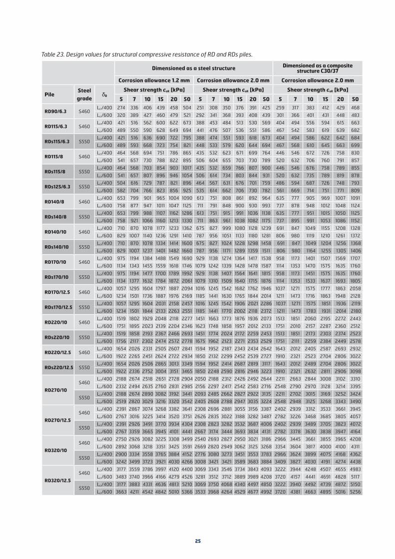
25
Table 23. Design values for structural compressive resistance of RD and RDs piles.
Dimensioned as a steel structure Dimensioned as a composite structure C30/37
Corrosion allowance 1.2 mm Corrosion allowance 2.0 mm Corrosion allowance 2.0 mm
PileSteel grade
0
Shear strength cuk [kPa] Shear strength cuk [kPa] Shear strength cuk [kPa]
5 7 10 15 20 50 5 7 10 15 20 50 5 7 10 15 20 50
RD90/6.3 S460Lcr/400 274 336 406 439 458 504 251 308 350 376 391 425 259 317 383 412 429 468
Lcr/600 320 389 427 460 479 521 292 341 368 393 408 439 301 366 401 431 448 483
RD115/6.3 S460Lcr/400 421 516 562 600 622 673 388 453 484 513 530 569 404 494 556 594 615 663
Lcr/600 489 550 590 628 649 694 441 476 507 536 551 586 467 542 583 619 639 682
RDs115/6.3 S550Lcr/400 421 516 636 690 722 795 388 474 551 593 618 673 404 494 586 622 642 684
Lcr/600 489 593 668 723 754 821 448 533 579 620 644 694 467 568 610 645 663 699
RD115/8 S460Lcr/400 464 568 694 751 786 865 435 532 623 671 699 764 446 546 672 726 758 830
Lcr/600 541 657 730 788 822 895 506 604 655 703 730 789 520 632 706 760 791 857
RDs115/8 S550Lcr/400 464 568 703 854 903 1017 435 532 659 766 807 900 446 546 676 758 789 855
Lcr/600 541 657 807 896 946 1054 506 614 734 803 844 931 520 632 735 789 819 878
RDs125/6.3 S550Lcr/400 504 616 729 787 821 896 464 567 631 676 701 759 486 594 687 726 748 793
Lcr/600 582 704 766 823 856 925 535 614 662 706 730 782 561 669 714 751 771 809
RD140/8 S460Lcr/400 653 799 901 965 1004 1090 613 751 808 861 892 964 635 777 905 969 1007 1091
Lcr/600 758 877 947 1011 1047 1125 711 791 848 900 930 993 737 878 948 1012 1048 1124
RDs140/8 S550Lcr/400 653 799 988 1107 1162 1286 613 751 915 991 1036 1138 635 777 951 1015 1050 1125
Lcr/600 758 921 1066 1160 1213 1330 711 863 961 1038 1082 1175 737 895 991 1053 1086 1152
RD140/10 S460Lcr/400 710 870 1078 1177 1233 1362 675 827 999 1080 1128 1239 691 847 1049 1155 1208 1328
Lcr/600 829 1007 1140 1236 1291 1410 787 956 1051 1133 1180 1281 806 980 1119 1210 1261 1372
RDs140/10 S550Lcr/400 710 870 1078 1334 1414 1600 675 827 1024 1228 1298 1458 691 847 1049 1204 1256 1368
Lcr/600 829 1007 1237 1401 1482 1660 787 956 1171 1289 1359 1511 806 980 1164 1255 1305 1406
RD170/10 S460Lcr/400 975 1194 1384 1488 1549 1690 929 1138 1274 1364 1417 1538 958 1173 1401 1507 1569 1707
Lcr/600 1134 1343 1455 1559 1618 1746 1079 1242 1339 1428 1478 1587 1114 1353 1470 1575 1635 1760
RDs170/10 S550Lcr/400 975 1194 1477 1700 1789 1992 929 1138 1407 1564 1641 1815 958 1173 1451 1575 1635 1760
Lcr/600 1134 1377 1632 1784 1872 2061 1079 1310 1509 1640 1715 1876 1114 1353 1533 1637 1693 1805
RD170/12.5 S460Lcr/400 1057 1295 1604 1797 1887 2094 1016 1245 1542 1682 1762 1946 1037 1271 1575 1777 1863 2058
Lcr/600 1234 1501 1736 1887 1976 2169 1185 1441 1630 1765 1844 2014 1211 1473 1716 1863 1948 2128
RDs170/12.5 S550Lcr/400 1057 1295 1604 2031 2158 2457 1016 1245 1542 1906 2021 2286 1037 1271 1575 1851 1936 2119
Lcr/600 1234 1501 1844 2133 2263 2551 1185 1441 1770 2002 2118 2372 1211 1473 1783 1931 2014 2180
RD220/10 S460Lcr/400 1519 1802 1929 2048 2118 2277 1451 1663 1773 1876 1936 2073 1513 1851 2060 2195 2272 2443
Lcr/600 1751 1895 2023 2139 2204 2346 1623 1748 1858 1957 2012 2133 1751 2010 2157 2287 2360 2512
RDs220/10 S550Lcr/400 1519 1858 2193 2367 2466 2693 1451 1774 2024 2172 2259 2453 1513 1851 2173 2303 2374 2523
Lcr/600 1756 2117 2302 2474 2572 2778 1675 1962 2123 2271 2353 2529 1751 2111 2259 2384 2449 2578
RD220/12.5 S460Lcr/400 1654 2026 2331 2505 2607 2841 1594 1952 2187 2343 2434 2642 1643 2012 2405 2587 2693 2932
Lcr/600 1922 2265 2451 2624 2722 2934 1850 2132 2299 2452 2539 2727 1910 2321 2523 2704 2806 3022
RDs220/12.5 S550Lcr/400 1654 2026 2506 2865 3013 3349 1594 1952 2414 2687 2819 3117 1643 2012 2489 2704 2806 3022
Lcr/600 1922 2336 2752 3004 3151 3465 1850 2248 2590 2816 2946 3223 1910 2321 2632 2811 2906 3098
RD270/10
S460Lcr/400 2188 2674 2518 2651 2728 2904 2050 2188 2312 2426 2492 2644 2211 2663 2844 3008 3102 3310
Lcr/600 2332 2494 2635 2760 2831 2985 2156 2297 2417 2542 2583 2716 2548 2790 2970 3128 3214 3395
S550Lcr/400 2188 2674 2890 3082 3192 3441 2093 2485 2662 2827 2922 3135 2211 2702 3015 3169 3252 3424
Lcr/600 2519 2820 3029 3216 3320 3542 2405 2608 2788 2947 3035 3224 2548 2948 3125 3268 3343 3490
RD270/12.5
S460Lcr/400 2391 2867 3074 3268 3382 3641 2308 2696 2881 3055 3156 3387 2402 2939 3312 3533 3661 3945
Lcr/600 2767 3016 3225 3414 3520 3751 2626 2835 3022 3188 3282 3487 2782 3226 3468 3685 3805 4057
S550Lcr/400 2391 2926 3491 3770 3934 4304 2308 2823 3282 3532 3687 4006 2402 2939 3489 3705 3823 4072
Lcr/600 2767 3359 3665 3945 4101 4441 2667 3174 3444 3693 3834 4131 2782 3378 3630 3838 3947 4164
RD320/10
S460Lcr/400 2750 2926 3082 3225 3308 3499 2540 2693 2827 2950 3021 3186 2966 3445 3661 3855 3965 4208
Lcr/600 2892 3068 3218 3351 3425 3591 2669 2820 2949 3062 3125 3268 3354 3604 3817 4000 4100 4311
S550Lcr/400 2900 3334 3558 3765 3884 4152 2776 3080 3273 3451 3553 3783 2966 3624 3899 4075 4168 4362
Lcr/600 3242 3499 3723 3921 4030 4266 3008 3421 3421 3589 3683 3884 3409 3827 4030 4191 4274 4438
RD320/12.5
S460Lcr/400 3177 3559 3786 3997 4120 4400 3069 3343 3546 3734 3843 4093 3222 3944 4248 4507 4655 4983
Lcr/600 3483 3740 3966 4166 4279 4526 3281 3512 3712 3889 3989 4208 3720 4157 4441 4691 4828 5117
S550Lcr/400 3177 3883 4331 4636 4813 5210 3069 3750 4068 4340 4497 4850 3222 3940 4492 4739 4872 5150
Lcr/600 3663 4211 4542 4842 5010 5366 3533 3968 4264 4529 4677 4992 3720 4381 4663 4895 5016 5256

26
6. DESIGN OF PILE FOUNDATIONS
6.1 Attachment of piles to superstructure
The joint between a pile and the superstructure can be dimensioned as a hinge. The piles are cut so that the upper end of pile is embedded at least 50 mm inside the pile footing or concrete superstructure unless otherwise required by the structural design or attachment of piles. When joining a pile to the above concrete structure as mentioned, it is not necessary to fasten the bearing plate by welding to the pile pipe.
Short, under 3-metre long driven piles should always be attached rigidly to the superstructure. Depending on structure, longer piles may also be attached rigidly to the superstructure. RR75...RR/RD220 piles are attached rigidly to the superstructure when the upper end is embedded in the concrete at a depth of at least 2·d, but not less than 200 mm. When empedding upper end of pile to concrete like descriped above, it's not necessary to connect bearing plate to pile by welding. When the upper end is attached directly to a steel superstructure, a rigid joint can be created by welding. Reinforced piles are usually attached to the superstructure by extending the internal reinforcements of the piles into the concrete structures. In rigid connection, the moment capacity of the upper end of pile must be verified.
The bearing plates presented in Table 16 can be used for axially compressed RR and RD piles.
6.2 Centre-to-centre distances between steel piles
The distances between piles are defined in design documents. Recommended minimum centre-to-centre distances for different pile diameters are presented in Table 24.
Table 24. Recommended minimum centre-to-centre spacing of SSAB’s steel piles [mm] according to PO-2016 [mm].
Pile min c/c [mm]RR75 800RR/RD90 800RR/RD115 800RRs/RDs125 800RR/RD140 800RR/RD170 800RR/RD220 800RR/RD270 800*RR/RD320 850**RR/RD400 1000RR/RD500 1200RR/RD600 1350RR/RD700 1550RR/RD800 1700RR/RD900 1850RR/RD1000 2050RR/RD1200 2400
* According to PO-2016, the recommended minimum centre-to-centre distance 800 mm between RR/RD270 piles is valid up to a pile length of about 15 m. Thereafter, the mini-mum distance must be increased to 950 mm as pile length increases to 25 metres.
** correspondingly, the minimum centre-to-centre distance 850 mm between RR/RD320 piles is valid up to a pile length of about 10 m, after which the minimum centre-to-centre distance increases linearly to 1150 mm at a pile length of 25 m.
Smaller centre-to-centre distances than those presented in Table 24 may be used with caution with RD piles, if they can be installed straight or at the designed inclination and the piles bear securely on bedrock. When designing downward spreading pile groups, the upper ends of piles can be spaced closer than in the table.
In the case of intersecting end-bearing piles in a fine-grained soil layer close to ground level, a clearance equal to pile diameter can be considered sufficient, if the pile can be directed during installation so that it does not touch adjacent piles. In coarse-grained soil layers, especially with driven piles, the clearance must be considerably larger. Pile intersections should be located as close to ground level as possible. With large diameter RR piles the minimum distance between intersecting piles is determined by the equation:
er = 50 lr≥ei (3)
where er minimum distance between intersecting piles [mm]lr depth of intersection [m]ei shortest distance between parallel shaft surfaces = 300 + 0.7· d [mm]
6.3 Distance between side of pile footing and piles
The pile footing must be able to withstand the stresses from pile forces and there must be no risk of the side of the pile footing breaking off. Normally, the distance from the edge of the pile footing to the outer surface of the closest pile or the edge of the bearing plate must be at least half of the pile diameter or the length of the side of the bearing plate. The positional tolerances of a pile must be taken into account at the design stage.
6.4 Distances between piles and other structures
The minimum distances between piles and other structures are designed separately in each case considering the piling equipment, pile type, vibration caused by piling, compaction of soil, loosening or displacement of soil, and special requirements and restrictions posed by soil conditions and ambient structures.
If the only restricting factors are the piling equipment and available space, the minimum distance must be determined on the basis of the properties of used piling equipment and the site. Small diameter RR and RD piles can be installed quite close to an existing wall or footing line, etc. owing to the small-size installation equipment. However, without a closer analysis, it is not advisable to design piles in sizes RR/RD220 to RR/RD270 or smaller so that the distance between the pile edge and the structure is less than 200 to 300 mm (if there are no structures restricting piling, such as eaves, etc., above the piling level).

27
6.5 Pile inclinations
Raking piles can be used to increase the stability of the pile foundation as desired. However, stresses on the raking piles from possible deformations of soil layers must be taken into account.
The maximum deviation in pile positions from the vertical, or limit inclination, depends on used piling equipment and the structure of soil layers at the foundation. When RR piles are installed with equipment used also in precast concrete piling, or RD piles are installed with heavy piling equipment, both forward or backward tilting piles of this type may usually be installed to a maximum inclination of 3.5:1. With large diameter piles, especially (the mast) tilted forward, the maximum allowed inclination must be determined on the basis of the stability of the basic equipment, considering used pile length and bearing capacity of the subsoil separately in each case. When installing piles with light or medium-heavy equipment, small diameter RR and RD piles can be installed at a highly inclined angle, even horizontally, if the structure and stability of the installation equipment allow it. High inclinations usually require using short pile elements.
It is worthwhile looking into the properties of the installation equipment at the design stage, if the aim is to install piles at exceptional inclinations.
6.6. Allowed positional and angular deviations
Piles should be installed exactly in the planned position and at the planned angle. However, a pile must not be forced into its theoretical position during installation or thereafter.
The measurement accuracy of pile position before and after installation is 0.01 m, unless otherwise specified in the designs.
Unless otherwise required by structural requirements, detailed instructions on structures by the authorities, soil conditions, used piling equipment or a very deep cutting level, the following allowed positional deviations are used:
Small diameter RR, CSG-RR and RD piles (RR75– RR/RD320): • individual vertical or raking pile, pile slab or bearing
plate structure: e ≤ emax = 0.10 m
• individual pile in a small pile group (4 to 8 piles): e ≤ emax = 0.15 m, individual pile in a larger pile group: e ≤ emax = 0.2 m, however, for the centre of gravity of the entire group e ≤ emax = 0,05 m
• in pile foundations used in building construction e ≤ emax = 0.15 m, in particularly exacting conditions, such as areas of pre-penetratable fills, relief drilling, etc., e ≤ emax = 0.20 m
• for an individual pile in a pile row, e ≤ emax = 0.15 m, however, for the centre of gravity of the entire row e ≤ emax = 0.05 m in the direction perpendicular to the row (a pile row is defined as piles under an elongated pile footing when there is only a single pile in the cross direction of footing)
• for individual vertical or raking piles i ≤ imax = 0.04 (0.04 m/m) in a group of parallel piles i ≤ imax = 0.02 (0.02 m/m)
• the horizontal direction (horizontal projection) of inclined piles may differ at most 10° from the design direction.
At underpinning sites it is often necessary to use clearly deviating values.
Large diameter RR and RD piles (RR/RD400 to RR/RD1200):
• vertical and raking piles: horizontal position measured from the working level:
e ≤ emax = 0.10 m RR/RD400–RR/RD1000 e ≤ emax = 0.12 m RR/RD1200 • vertical and raking piles at an angle of n ≥ 15 (Q ≥ 86°):
angular deviation i ≤ imax = 0.02 (0.02 m/m)
• raking piles at an angle of 4 ≤ n < 15 (76° ≤ Q < 86°): angular deviation
i ≤ imax = 0.04 (0.04 m/m)
RD piles, especially when using the concentric drilling method, easily achieve tolerances stricter than the above ones. Stricter tolerances are recommended for RD piles if stricter building tolerances are called for by the structure and loads, and the soil and installation conditions allow them. The attainment of stricter tolerances requires special care in both the in-place measurement and installation work.
From the viewpoint of the installation work, however, it is not advisable without justification to apply stricter tolerances to RD piles than those presented below:
• vertical and raking piles: horizontal position measured from the working level:
e ≤ emax = 0.025 m
• vertical or raking piles at an angle of n ≥ 15 (Q ≥ 86°) angular deviation:
i ≤ imax = 0.015 (0.015 m/m)
• raking piles at an angle of 4 ≤ n < 15 (76° ≤ Q < 86°) angular deviation:
i ≤ imax = 0.025 (0.025 m/m)

28
In the case of Combi-wall and RD pile wall structures it is often practical to aim at tolerances considerably stricter than the above general positional and verticality tolerances. Used tolerances must be determined case by case and at least a preliminary plan of measures to be taken to attain the tight tolerances must be made already at the design stage. Recommended tolerances for these structures are presented in design and installation manual for RD pile wall.
Combi-wall structures are usually equipped with sufficiently sturdy templates made of steel beams or the like, which allow accurate positioning of the piles. In RD pile wall structures, the starting pile of the wall structure in practice determines the direction and inclination of the entire wall, which means that the installation of the starting pile(s) and used tolerances must be planned with great care. Procedures and important things during installation of these structures are presented in design and installation manual for RD pile wall.
Positional and angular deviations of piles due to installation are taken into account in the design of the pile foundation. After installation, the actual positions and inclinations of the piles are measured. If the positional tolerances allowed by the design are exceeded, the possible overloading of each structural members must be determined and necessary measures taken.
6.7 Impact of piling on previously installed piles, other foundation structures and immediate surroundings
The geotechnical works of the building site, piling included, are designed and executed so that they do not decrease the resistance of previously installed piles or cause damage or nuisance to the immediate surroundings of the site. If there are structures susceptible to damage in the immediate surroundings of the site, they must be charted to a sufficient extent in connection with geotechnical investigations, or in any case before piling. If necessary, the condition of nearby structures must be established through inspections.
The environmental impacts of driven and drilled piles can be estimated as described in PO-2016, Part 2, Sec. 4.7. The selection of pile type, piling method and piling equipment can have a significant effect on the environmental impacts.
Small-diameter driven RR piles displace very little soil in relation to their bearing capacity. Therefore, the increase in pore water pressure and lateral displacements and heave of soil usually remain very small. Owing to their small cross-sectional diameter, the piles can be driven below ground water level in loose silty and sandy soils with low impact energy, whereby the compaction of compacting soil layers due to piling remains minor.
Correspondingly, penetration of dense soil layers that cause vibration can be achieved with relatively low impact energy, so that the vibration from piling is minor. Especially when using light piling equipment and pile drivers, RR piles can usually be installed safely very close to existing structures. The environmental impacts of pile driving may also be minimised by selecting piling class PTL3 and RRs piles.
If installed according to the installation instructions, RD piles, especially small diameter RD piles, do not displace soil or remove extra soil, which keeps the environmental impacts of piling, such as soil displacement and compaction, vibration, and increase in pore water pressure, very low. With large RD piles (≥RD400), due to the higher consumption of flushing agent (usually compressed air) and larger DTH hammer equipment, piling can have minor environmental impacts, which must be considered in design and implementation when RD piles are installed in the immediate vicinity of existing structures.
The jacked RR piles used in underpinning usually cause the least environmental impacts, whose installation also causes very little noise.
In soft subsoils, the movement of heavy (>40 to 60 t) piling equipment may cause more vibration than the pile installation itself.
7. PILING
7.1 Material needed for piling: working plan and quality plan
The material needed for piling, the working plan and quality plan, are presented in PO-2016, Ch. 2, Sec. 5.1.
7.2 Storage, handling, inspection and erection of steel piles
The storage and handling of piles on site are covered by a separate manual ”Piles and pile accessories, recommendations for safe handling for the customer" (www.ssab.com/infra).
Inspection of delivered piles and their accessories takes place immediately after the delivery arrives on site. A visual inspection is made to ensure that the shipment corresponds to the order and consignment note. The steel grade and dimensions of piles are verified from product descriptions and markings on the pile pipes. Pile elements and accessories must correspond to the products specified in designs. A faulty or wrong product must not be installed.
More detailed instructions for the handling of threaded RDT pile elements and threaded RDT sleeves are presented in Sec. 7.4.4.

29
Piles and their accessories are to be inspected once more before installation. The pre-installation inspection ensures that the piles have not been damaged during handling and storage on site.
Pile elements and pile pipes are usually erected by a lifting cable or the like attached near the head of the pile. Special care must be taken during erection to ensure, for example, that the lifting equipment/chain stays attached to the pile. It is recommended that pile erection is performed with the piling equipment positioned at the pile during erection so that it will not need to be moved except for minor adjustment when the pile stands upright in the piling equipment.
The stress from curvature caused by the dead weight of the steel pile is never a critical factor when lifting RR or RD micropiles. With large diameter piles, the length limit for piles that can be lifted from the head without closer analysis is 20 metres. The erection of longer piles must be planned case by case, considering pile dimensions. The stability of the piling rig must be considered in erection, and the weight and reach limitations and instructions for the rig must be taken into account in lifting.
7.3 Installation of RR piles
7.3.1 Piling equipment
7.3.1.1 General
General requirements for the piling equipment are presented in PO-2016, Sec. 5.4.2.1.
Pile driving equipment suitable for the installation of RR piles can be divided into the following main categories:• drop and hydraulic hammers • hydraulic rams and pneumatic hammers • other driving equipment • hydraulic jacks
In the case of piling classes PTL2 and PTL3, the manufacturer, importer or user of the pile driver must clarify the essential factors affecting piling, such as overall driving efficiency, suitable helmet, hammer cushion and pile cushion for pile driving, and the effect of helmet and cushions on the stresses transmitted to the pile. The above factors can be established, for example, by stress wave analyses, and it is recommended that piling contractors file and, if necessary, analyse their stress wave measurement results. The information is revised in connection with major changes to the driving equipment or when installing new pile types with the equipment in question.
When RR piles are installed with driving equipment suspended from a crane, the pile must be supported adequately by other support structures. The entire piling equipment must be supported and assembled so that it does not sway during piling.
7.3.1.2 Drop and hydraulic hammers
The drop height of a drop hammer can usually be selected freely considering equipment specific limitations. The suitable masses for drop hammers and hydraulic rams depend on used pile size and soil conditions. A heavy hammer may be advantageous when driving RR micropiles into dense soil, but it also increases the risk of pile bending.
Recommended minimum and maximum masses of the ram blocks of the drop and hydraulic hammers are presented in Table 25.
Table 25. Recommended minimum and maximum masses of the ram blocks of the drop and hydraulic hammers used in the installation of RR piles
Pile weight Ram block [kg]
Pile [kg/m] min max
RR75 10.8 300 1000
RR90 12.8 350 1500
RR115/6.3 16.8 500 1500
RR115/8 21.0 500 2000
RRs125/6.3 18.7 500 2000
RR140/8 26.0 500 3000
RR140/10 32.0 500 3000
RR170/10 39.0 1000 4000
RR170/12.5 48.0 1000 5000
RR220/10 51.6 1500 5000
RR220/12.5 63.7 1500 6000
RR270/10 64.9 1500 6000
RR270/12.5 80.3 2000 8000
RR320/10 77.4 2000 8000
RR320/12.5 96.0 2000 9000
RR400 (10…12.5) 97.8…121.4 3000 9000
RR500 (10…14.2) 122.8…172.9 3000 12000
RR600 (10…18) 148.0…262.8 4000 -
RR700 (10…20) 172.9…340.8 4000 -
RR800 (10…20) 198.0…391.1 4000 -
RR900 (10…20) 222.9…440.9 4000 -
RR1000 (10…20) 248.1…491.3 4000 -
RR1200 (10…20) 298.4…591.9 4000 -
Pile cushion is usually not needed when driving RR piles. If a pile cushion is not used, a dolly made of a thick steel plate is used between the hammer and the pile.
The head of the pile is adjusted inside the lower part of the helmet to ensure that the impact is transmitted centrically to the pile.

30
If the used lower part of the helmet is the square shaped ”box” used with precast concrete piles, it is recommended that a steel adapter be always used on the pile head in piling class PTL3. The top of the adapter should be as close in size to the ”box” of the helmet as possible, and the bottom should ”sit” quite snugly inside or outside the pile pipe. The use of an adapter is recommended in piling class PTL2. In PTL2, when installing RR220 piles with a ”box” measuring 250x250, RR270 piles with a ”box” measuring 300x300, or RR320 piles with a ”box” measuring 350x350, sufficiently centric blows can also be achieved without an adapter.
When installing a pile with an external splice sleeve at the top, it's recommended to use an adapter piece that passes the stroke to the pile pipe trough the sleeve. By decision of installation crew, the embedding of pile in soft ground layers may also be done by striking directly to sleeve if it does not cause damages to the sleeve or its weld. In dense ground layers and during the end-of-driving, an adapter piece must be used to pass the stroke to the pile pipe through the sleeve.
In Finnish soil conditions large diameter end-bearing piles can usually be installed to a sufficient penetration depth with relatively small hammers. Thick friction soil and moraine layers require a sufficiently high impact energy for the pile to penetrate effectively. In preliminary analyses it can be estimated that when using the hammers and pile dimensions presented in Table 26, the installation equipment has sufficient impact energy and the hammer is able to mobilise sufficient static geotechnical resistance in PTL2 and PTL3 during loading tests. Actual mobilised resistances depend largely on pile size, pile length and soil conditions. Sufficient static resistance can be achieved more easily with short piles securely bearing on bedrock than with long piles bearing on moraine layers.
It is often practical to use a smaller hammer / lower impact energy to drive large diameter piles and perform the actual dynamic load test using a pile driving equipment of higher impact energy.
Table 26. Combination of hammer weight [t] – max. pile size that is normally able to mobilise sufficient static resistance in PTL2/PTL3.
Hammer [t] max. RR pile
5 RR400…RR500
7 RR500…RR700
9 RR700…RR800
7.3.1.3 Hydraulic rams
Hydraulic rams are rapid percussion pile drivers extremely well suited for installing RR micropiles. They
are also suitable for the installation of larger piles, if full geotechnical compressive resistance is not required of the piles. The advantages of hydraulic rams in the installation of RR piles include high blow rate and impact force, which makes for quick pile installation; piles can in most cases be installed very straight, and the installation equipment is light and mountable on many kinds of basic machines.
The suitability of different hammer types for different pile sizes and lengths has been determined by simulations based on the stress wave theory. Pile sizes and lengths suitable for different rams are presented in the end-of-driving instructions based on the above analysis.
Hydraulic rams are effective in installing micropiles, and experience has shown that in certain conditions piles driven by hydraulic rams penetrate deeper than dynamic penetration test. Even if simulation does not indicate sufficient mobilised static geotechnical resistance due to the small settlement caused by a single blow, the pile toe often bears reliably on bedrock or very dense basal moraine. In conditions clearly suitable for end-bearing piles, it is therefore often possible to achieve sufficient reliability by a hammer/pile combination where the calculated mobilised static geotechnical resistance does not meet the end-of-driving criteria. In such a case, the geotechnical resistance of piles must be ensured by dynamic load tests (PDA measurements) or analyses based on pile driving formulas. A pile driving equipment of higher impact energy, such as a drop hammer or a hydraulic hammer, must be used in the load tests.
To centre the blow and protect the pile head, a steel adapter must be used between the pile and the tool of the hydraulic ram. (Figure 12)
Ensuring that the impact is aligned with the pile in piling class PTL3 requires use of piling equipment where the hydraulic ram moves along a piling mast. This driving mode is also recommended for other piling classes.
Figure 12. Example of an adapter between the striker of the hydraulic ram and the pile during impact.
7.3.1.4 Pneumatic hammers
Pneumatic hammers have a slightly lower blow rate than hydraulic rams. The suitability of different hammer types for different pile sizes and lengths has been determined by

31
simulations based on the stress wave theory. Based on the above analysis, the end-of-driving instructions present pile sizes and lengths suitable for different hammers. On the basis of simulations, when using pneumatic hammers slightly underpowered for the pile load, geotechnical resistance can be ensured the same way as with hydraulic rams.
The bottom of the pneumatic hammer must be shaped for centric blows, or an adapter must be used. Ensuring that the impact is aligned with the pile in piling class PTL3 requires the use of piling equipment, where the pneumatic hammer moves along a mast. This driving mode is also recommended for other piling classes.
The true effectiveness of pneumatic hammers depends on operating conditions and wear of the equipment.
7.3.1.5 Hydraulic jacks
At foundation underpinning sites, jacked RR-piles are installed by hydraulic jacks. The installation equipment and jacking method used must allow safe compression of piles to the designed compression force without damage to nearby structures. The compression force indicator of the installation equipment must enable reliable measurement of the compression force.
7.3.1.6 Vibrators
The use of a vibrator in the installation of RR piles may be advantageous if the piles are installed to preset depths as, for instance, in the case of the pile foundations of noise barriers. The recommended vibrator frequency is over 25 Hz. The vibrator may be attached either to the pile head or the middle of the pile shaft. Pile penetration can be improved by pulling or pressing the pile downward. The suitability and selection of a vibrator for different pile sizes depends on soil conditions as well as pile length (mass). In soil conditions where the coarse-grained soil layers on top of the bedrock are stone-free, not especially dense, and relatively thin, RR piles can be installed quite reliably down to bedrock using a suitable vibrator. A vibrator may also be used to drive piles in other soil conditions, for example, to the top of a load-bearing moraine layer, after which the final blows are delivered by another pile driver, so that mechanical splices also tighten.
When installing piles with vibrators, the potential disturbance of the surrounding soil due to vibration should be taken into account. In some situations disturbance can lead to considerable large deviations in pile positioning. Vibrators also cause large fatigue loads on the pile to be installed. Fatigue load can cause pile damage and breakage during installation.
If significant vertical loads have been designed for piles to be installed by vibrators, the end-of-driving criterias must be ensured by control blows or load tests using other pile driving equipment. Control blows are also necessary when installing RR pile elements with mechanical splices with vibrators.The splices may remain loose without being subjected to a
sufficiently high compressive force during the installation. In piling class PTL1 with clear and sufficiently well-known soil conditions, sufficient geotechnical resistance can be assumed if pile lengths and soil survey results support each other.
The use of vibrators in the installation of steel piles has been discussed in more detail, for example, in publication Pålkommissionen, Vibratorers användningsmöjligheter vid drivning av pålar och spont, Rapport 99. Linköping 2000 (in Swedish).
7.3.2 Start of installation
The pile is placed exactly in the designed position, and its straightness or inclination is checked, for example, by a bubble level or the inclinometer of in the piling equipment. Blows are directed centrically to the pile head in line with the longitudinal axis of the pile. The instructions of Sec. 7.3.1 for different piling equipment are followed in centring the blows. The position and inclination of the pile are checked in the early stage of installation when the pile tip has penetrated a small distance into the soil. If the positional deviation is estimated or measured to be too big, the pile is extracted and positioned again. Straightening of a pile that deviates slightly from the design inclination may be attempted by effecting minor changes to the inclination of the piling mast at the early stage of installation.
7.3.3 Penetration blows and allowed driving stresses
The impact energy used in soft soil layers is such that it causes moderate settlement per blow (about 100 mm), whereby the risk of the mechanical splices of micropiles coming apart can be avoided.
Suitable impact energy and blow rate, depending on resistance, are applied in penetration blows to ensure effective pile penetration.
Impact stresses during pile installation may not exceed 90 % of the yield strength of steel. The end-of-driving instructions present the maximum drop heights for drop hammers and hydraulic hammers for different pile sizes (up to RR400) and pile lengths (maximum specified drop height values in PTL3), which ensure that impact stresses do not exceed 90 %. This 90 % limit can be exceeded, if the stress levels in pile are measured during driving with PDA equipment. In these cases the stress level can even exceed the yield strength by 8 %. If a pile encounters a big stone before the final blows, it is recommended to use a slightly smaller drop heights than the table values (about 0.8-fold) as the maximum drop height for penetrating the stone to ensure that the risk of exceeding the allowed impact stresses does not become too high.
With hydraulic rams and pneumatic hammers, the impact stresses during installation may approach or exceed the 90 % limit in the case of hammer/pile combinations, where an efficiency value less than 80 % has been

32
indicated in the end-of-driving graphs, or the impact energy of the hammer is too high and the penetration of the pile stops abruptly, for example, when the pile encounters a big stone. There, it is recommended to decrease the impact force of the hammer. The end-of-driving instructions present the smallest pile size recommended to be installed with each hammer. If a hammer is used to install piles smaller than the recommended pile size, impact force must be limited below the maximum.
When installing raking piles, it should be noted that the impact energy transmitted to the pile may be considerably lower than with vertical piles.
With large diameter piles and pile driving equipment/pile combinations that have not been analysed earlier, driving stresses may be evaluated by simulations based on the stress wave theory.
The magnitude of driving stresses and the centricity of the blow can be best determined by dynamic load tests.
If the cutting level of the pile is below ground or water level, a follower aligned with the longitudinal axis of the pile can be installed between the pile driver helmet and pile head. The follower pile should have about the same impedance as the actual pile, in other words, the follower should be a steel pipe of a steel cross section equal or almost equal (+/- 20 %) to that of the actual pile. The follower must be guided well and sit tightly on the end of the pile.
7.3.4 Additional installation instructions and splicing of RR75 to RR220 piles
The driving of RR75 to RR220 piles is usually started with an unspliced pile element, for example, a piece cut-off earlier. Before installation a shoe (bottom plate or rock shoe) is attached to the bottom of the pile, for example, by using a sledge-hammer. The hardened dowel of the rock shoe must not be hit due to the risk of chipping. The shoe has a machined groove and the dowel is positioned so that the groove coincides with the internal burr of the pile pipe. A friction shoe must be attached tightly enough to the pile pipe so that it cannot be loosened by tensile stress during the impact. The final “tightening” of the shoe occurs during the end-of-driving. It must be ensured that the shoe is aligned with the pile pipe during attachment.
If the piles have inadequate lateral support, the risk of buckling during installation is taken into account, for example, by selecting suitable installation equipment and element length for the pile.
The external splice sleeve of an RR pile can be either at the top or bottom of the pile element. While installing the pile with splice sleeve upwards, it's recommended to use adapter that transmits the blow past the splice sleeve to the pile pipe. While penetrating through soft soil layers, it's up to rig operators decision whether to use
adapter or not. If adapter is not used, the splice sleeve or its fastening weld must not get damaged. During driving in dense soil layers and during end-of-driving blows the use of appropriate adapter is required.
Before pile splicing, the condition of the upper end of the pile is inspected and a damaged part is repaired or removed.
7.3.5 Additional instructions for the installation of RR270 to RR1200 piles
The pile must be supported at the beginning of driving so that it stays in the designed position and inclination. While the driving is under way, the pile support system must guide the pile so that it is continuously supported at the cutting level. If adequate support to the upper end of the pile is unreasonably hard to provide, the position and inclination of the upper end must be monitored during piling. If the pile is found to deviate from the designed position or inclination, an effort must be made to correct them. If the pile tip encounters a stone or boulder in the subsoil and consequently tends to change direction, it must be possible to relax the guidance so that the pile can circumvent obstacles without curving. If guidance needs to be relaxed more than the tolerances set for pile position and inclination allow, the structural dimensioning of the pile foundation must be revised.
RR270 to RR1200 piles are spliced by welding according to Sec. 7.5. Before splicing, the condition of the upper end of the pile is inspected and a damaged part is repaired or removed.
When large diameter piles with a closed shoe are installed in a water body or below ground water level, they are subject to a buoyancy force, which may exceed the weight of the pile and the resistance due to skin friction during an interruption in driving in cohesion soils or loose friction soils. Then, the buoyancy force may make the pile rise or hinder its penetration. A simple solution to that problem is to fill the piles partly or fully with water to achieve sufficient counterweight. The magnitude of the buoyancy force increases with increasing pile diameter (and decreasing wall thickness), and it is recommended that the buoyancy be taken into account already at the design stage starting from about pile size RR800.
When specifying pile order lengths, it should be taken into account that a “length” of 2·d at the upper end of the pile must be reserved for PDA measurement.
7.3.6 Additional instructions for rock shoes with hollow dowel
When using large diameter piles with hollow dowel rock shoes, the hole in dowel must be filled with concrete before installation to prevent the hole from contracting. After installation, the hole is drilled open for example to install an anchor bar.
33
In the installation, it is recommended to use a sufficiently heavy drop weight to keep the required drop height moderate. In addition, it is recommended to measure the impact stresses from the first piles during their installation with dynamic load testing equipment (PDA) to ensure that no harmful stresses are caused during the installation.
7.3.7 End of driving of an end-bearing pile with a drop or hydraulic hammer
The driving of an end-bearing pile can be stopped when the pile tip is close to the designed target level and the preset end-of-driving criteria are met. In piling class PTL2, the end-of-driving criteria presented in Appendix 3 can be used as end-of-driving criteria for pile sizes RR75 to RR400. Before the actual final blows, used drop height is gradually increased close to the values of the end-of-driving tables. The actual series of final blows involves dropping the hammer from the height specified in the tables where the permanent settlement caused by 10 blows is measured. When the permanent settlement due to 10 blows ≤ 10 mm, pile driving can be ended. If the piles bear on a soil layer, at least 3 series of final blows must be delivered. In the case of piles bearing on bedrock with the rock point embedded in bedrock, one series of final blows is usually sufficient. If the above-mentioned settlement is exceeded, pile driving is continued until the end-of-driving criterion is met.
No breaks in pile installation are allowed before the end of driving, and the final blows must be delivered without interruption. If the final blows need to be interrupted, and the geotechnical resistance of the piles cannot be considered sufficient on the basis of previous series of blows, penetration level or bearing capacity measurements on the site, the pile must be ”detached” before proceeding with the final blows, for example, with three to five series of ten blows using an impact energy of about 50 to 70 % of the level required by the end-of-driving criterion.
When installing piles with a hardened rock dowel, the impact energy is set lower than that specified in the end-of-driving instructions when approaching the surface of bedrock. After reaching the bedrock surface, impact energy is gradually increased to the level specified in the end-of-driving instructions. In conditions of a relatively level bedrock surface and highly supportive friction soil and moraine layers on top of the bedrock, impact energy can be increased quite rapidly to the level needed for the final blows. If the tip tends to slip or the bedrock surface is inclined, impact energy must be reduced and the rock shoe dowel attached by driving it either fully or partly in bedrock using low impact energy, and then increasing the impact energy/drop height to the level specified in the end-of-driving criteria. With small piles, reliable attachment of the rock point requires at least 300 to 500 blows after the point has reached bedrock − with large piles even thousands of blows may be required. Similar principles are followed when driving RR400 to RR1200 piles with rock shoes and structural steel dowels into the surface of bedrock.
A pile extending to bedrock may bounce off the rock during driving causing the point to remain out of contact with the rock surface. In such a case, a few blows are delivered after the last series of final blows using a low drop height to ensure that the pile tip remains in contact with the bedrock.
In piling class PTL3, the end-of-driving criteria are determined on the basis of dynamic load tests according to Sec. 5.5.4.
7.3.8 End of driving of an end-bearing pile with a hydraulic ram or pneumatic hammer
The driving of an end-bearing pile can be stopped when the pile tip is close to the designed target level and the preset end-of-driving criteria are met. In piling class PTL2, the end-of-driving criteria presented in Appendix 3 can be used as end-of-driving criteria for pile sizes RR75 to RR170. Before the actual final blows, the used impact energy and blow rate are increased to the maximum values of the hammer if lower values were used during the driving. The actual series of final blows involves measuring the permanent settlement of the pile in 30 seconds while the pile is installed using the full impact force and blow rate of the hammer. Three series of final blows meeting the end-of-driving criteria are delivered. When RR piles clearly bear on bedrock, the duration of the series of final blows can be 10 seconds, which means that the settlement values of the end-of-driving tables must be divided by three. When the efficiency specified in the end-of-driving tables <80 %, final blows must not be delivered with full impact force due to impact stresses. Then the impact force must be as the specified efficiency.
No breaks in pile installation are allowed before the end of driving, and the final blows must be delivered without interruption. If the final blows need to be interrupted, and the geotechnical resistance of the pile cannot be considered sufficient on the basis of previous series of blows, penetration level or bearing capacity measurements done on site, the pile must be ”detached” before proceeding with the final blows, for example, using a 60 second series of blows.
When installing RR piles with rock shoes, the impact force and blow rate are set lower than the maximum values for the hammer when approaching an inclined bedrock surface. After reaching the bedrock surface, impact force and blow rate are gradually increased to the maximum level for the hammer. If the tip tends to slip, impact force must be reduced, and the rock shoe dowel is attached partly or entirely into bedrock using a low impact force. Then, the impact force and blow rate are increased to the maximum level for the hammer. Reliable attachment of the rock shoe dowel to an inclined bedrock surface usually requires a series of blows of at least 1 to 2 minutes (at least 300 to 500 blows) at an impact force lower than the maximum. In piling class PTL3, the end-of-driving criteria are determined on the basis of dynamic load tests according to Sec. 5.5.4.

34
7.3.9 Preparation of end-of-driving instructions for large diameter piles in piling classes PTL3 and PTL2
In the beginning of piling, test piles are installed at spots highly representative of the soil conditions. One or more piles are usually installed where pile lengths are the longest or the soil conditions are most demanding in terms of driving. Test piles usually become part of the final structure, but separate test piles may be used, if necessary.
At the pile testing stage it is useful to drive piles with different end-of-driving criteria. Then, the ”strictest” end-of-driving criteria used are the end-of-driving instructions or maximum drop heights presented in the end-of-driving tables for PTL3. Yet, it may advantageous to install piles, for example, using the end-of-driving criteria for PTL2. In the case of large diameter piles that have no general end-of-driving criteria, the criteria for final blows before load tests are defined case by case considering the pile driver, the pile (diameter, wall thickness and length) and soil conditions.
Dynamic load tests are made on the piles of the piling test stage. A special load test hammer is recommended for load tests on piles installed with hydraulic rams or pneumatic hammers in order to mobilise sufficient geotechnical resistance. If it is observed during piling that the piles bear on bedrock, the load tests can be made very soon or even immediately after pile installation. When piles bear on soil layers, the recommended interval between installation and testing is at least 24 hrs, preferably longer. The resistance measured from piles is generally the higher, the longer the waiting period. The target levels of dynamic load tests are defined at the design stage according to Sec. 5.5.4.
Suitable end-of-driving criteria for the site are determined on the basis of dynamic load tests. If pile lengths and soil conditions vary a lot, different end-of-driving criteria are assigned to different pile lengths and soil conditions.
7.3.10 Final blows on friction piles
In piling tests before or at the beginning of actual piling, friction piles are usually driven to the level designed on the basis of geotechnical investigations and static bearing capacity formulas and/or driving resistance based on a preliminary estimate or analysis based on the stress wave theory. Geotechnical resistance is measured by dynamic load tests using signal modelling (e.g. CAPWAP analysis). In coarse-grained soil layers skin friction usually develops in less than a week, but in silty soil it may take considerably longer. The target depth level and/or final driving resistance of piles are determined on the basis of the results of dynamic load tests.
7.3.11 Project-specific driving instructions
Project-specific driving instructions must always be prepared in piling class PTL3, and they must include at least the end-of-driving criteria and maximum drop heights
for drop and hydraulic hammers. In the case of large diameter piles with no predefined end-of-driving criteria, project-specific driving instructions are also prepared in piling class PTL2. Project-specific driving instructions are recommended for friction piles also in PTL2. If necessary, detailed instructions are given for the following:
• drop height or impact energy used at different stages of driving
• instructions for filling closed top-driven piles with water• detailed instructions on driving the dowel of a rock shoe
into bedrock• instructions on measures to be taken in the case of
expected special events occurring during blowing• instructions on reporting responsibilities and detailed
instructions for a keeping piling record• instructions on dynamic load tests (quantities, waiting
periods, target levels)
7.3.12 Installation of jacked-RR piles
Jacked-RR piles are generally installed using hydraulic jacks. The installation equipment must conform to Ch. 2, Sec. 5.4.2.4 of PO-2016 and installation is to be done according to Ch. 2, Sec. 5.4.4.5 of PO-2016.
7.4. Installation of RD piles
7.4.1 Piling equipment and drilling methods
The general requirements for RD piling equipment are presented in Sec. 5.4.2.1 of PO-2016.
Top hammer or DTH hammer drilling equipment is used with RD piles. Both can use either the eccentric or concentric drilling method.
7.4.1.1 Top hammer-based equipment
The hammer drill of top hammer drilling equipment is generally pneumatic or hydraulic. The drilling equipment also includes a rotary unit and drill rods. Top hammer equipment can be used to drill piles up to diameter RD170.
The blow of the hammer drill generally strikes the drill rod inside the pile, which is being rotated simultaneously, and subsequently the casing shoe at the lower end of the RD pile. As a result, drilling capacity diminishes as pile length and the number of drill rod splices increase. The maximum pile length with top hammer equipment is generally about 30 m, although it is possible to install 50 m piles in thick, soft cohesion soil layers. With some top hammer equipment types, the RD pile pipe also takes part of the blow of the hammer drill.
7.4.1.2 DTH hammer-based equipment
The hammer drill of DTH hammer-based equipment is generally pneumatic or water powered. The equipment also includes a hydraulic rotary unit and drill rods.
35
A guide sleeve attaches the drill rods inside the RD pile to the DTH hammer, which, again, is attached to the drill bit by the shank adapter of the guide device above the pilot bit. Blows are transmitted via the guide device to the casing shoe, whereby the RD pile is “pulled” into the ground. The rotary unit above the head of the pile rotates the drill rods.
DTH hammer-based drilling equipment can drill large diameter piles up to RD1200 pile size. Pile length affects drilling capacity and installation speed minimally at practicable pile lengths.
Experience tells us that RD piles installed with a DTH hammer are generally somewhat straighter than RD piles installed with a top hammer.
7.4.1.3 The eccentric drilling method
The eccentric drilling method uses a pilot bit and an integrated eccentric reamer bit. The method is usable with both DTH hammer- and top hammer-based drilling equipment.
During drilling, an eccentric reamer bit enlarges the hole made by the pilot bit slightly bigger than the outside diameter of the RD pile. The RD pile is pulled into the ground with the drill bit and the casing shoe welded to the pile pipe.
The flushing agent transfers part of the soil to be removed to the surrounding soil. Part of the soil is flushed up along the outer surface of the RD pile to surface while part of it exits through the RD pile.
When the target depth is reached, the drill rods are rotated in the opposite direction to drilling whereby the drill bit’s reamer portion closes and the drill bit, drill rods and any possible hammer drill can be removed from inside the RD pile. Drilling may be continued as rock drilling either using a separate rock bit or, in certain cases, with the same bit.
When using the eccentric drilling method and traditional single reamer bit equipment (ODEX or equivalent), the lower end of an RD pile installed in rock always ends up resting on a “shelf” whose dimensions are determined by the used drill bit. The impact of the rock shelf on the geotechnical resistance of a pile must be considered in pile design and inspection.
7.4.1.4 The concentric drilling method
In the concentric drilling method, three types of reamer bits are used. Reamer bit can be made of fixed or unattached ring bit. During drilling, the ring bit is locked onto the pilot bit. After drilling, the pilot bit is detached from the ring bit and extracted. Reamer bit can also be made of several concentric reamer wings. At the beginning of drilling, reamer
wings are opened. After drilling, the drill rods are rotated in the opposite direction to drilling whereby the reamer wings close and whole drill bit can be removed from inside the RD pile. With reamer wings the casing shoe is not necessary part of load bearing structure of the RD pile.
Especially when using wing bits, but also when using ring bits, the compatibility of the tolerances of the pilot bit, the casing shoe and the pile pipe must be paid attention to. Particularly should be checked, if the tolerance between the head of the pilot bit and the casing shoe is suitable for the out of roundness tolerance of the pile pipe size in question.
When drilled piles are long or soil conditions are demanding with boulders or stony soils, casing shoe model has an effect on installation reliability. In such cases it has been found out that only surface hardened flat steel ring attached to inner surface of pile pipe is susceptible to deformations and also damaging during installation.
If necessary, drilling may be continued as rock drilling. There are also drill bit systems on the market that allow continuing rock drilling with the same pilot bit, so-called drill-through systems.
The method can be used with both DTH hammer- and top hammer-based drilling equipment. Experience tells us that the concentric drilling method generally produces straighter RD piles than eccentric methods based on a single reamer bit. In demanding conditions (boulders, stony soil) a concentric drilling with ring reamer is usually more reliable and faster than eccentric drilling or several concentric reamer wings.
7.4.2 Start of installation
The pile is placed exactly in the planned position and its verticality or inclination is checked, for example, by a bubble level. At sites where tight positional and inclination tolerances have been set for RD piles, special attention must be paid to measurements. In the initial phase of installation, when the tip of the pile has penetrated some distance into the ground, the inclination and position of the pile are checked. In case the positional deviation is estimated or measured to be too big, the pile is extracted and repositioned. Straightening of a pile deviating slightly from the planned inclination may be attempted by changing the inclination of the mast slightly in the early phase.
7.4.3 Drilling of RD piles
The instructions and recommendations of the hammer and drill bit manufacturer are followed in drilling RD piles. The casing shoe or integrated casing shoe/ring bit is generally welded to the RD pile pipe as per instructions of the manufacturer. The ring bit used with concentric drilling methods are attached to the casing shoe as per instructions of the manufacturer. The casing shoe and

36
drill bit (ring bit) must be able to withstand the same loads during use as the pile. The manufacturer of the casing shoe and drill bit is liable for their strength according to Ch. 2, Sec. 3.8.4.3 of PO-2016.
During drilling, the pressure under the pilot bit due to the feed force is smaller than the flushing pressure, which means that the flushing holes of the bit remain open for the duration of the drilling. Should the flushing holes get clogged, their opening can be attempted by increasing flushing pressure to the maximum allowed and by altering rotation speed and feed force. Unclogging the holes may also be attempted by using air as the flushing agent instead of a liquid. If the unclogging of the flushing holes is unsuccessful, the pilot bit is extracted from the casing, the holes are cleared, and drilling is continued subsequently.
When an RD pile encounters a large stone, a boulder or bedrock, the feed force is kept low and rotation speed is increased. That reduces the risk of excessive lateral displacement, inclination and curvature of the pile.
If there is the risk of an RD pile encountering wood material in the soil during installation, it is recommended that special bits are used to speed up drilling and ensure successful penetration. Penetration is generally achieved using conventional drill bits with larger RD piles, but drilling speed decreases, and in the case of smaller RD piles, the risk of failing to drill through wood material is greater. Being able to drill through pieces of metal in the soil without significant risk of breaking the equipment is uncertain.
If an RD pile breaks or the drill bit or casing shoe gets damaged during drilling, so that driving is no longer possible, an attempt is made to extract the entire pile. If that is not possible, the pile is generally rejected. In foundation underpinning it is generally practical to make a separate assessment of the geotechnical or structural resistance of a damaged RD pile. The assessment can then be used as a basis for determining the capacity of the damaged RD pile to serve as a foundation pile.
The impacts of the installation on surrounding soil are monitored during drilling of RD piles, and any detrimental impacts are taken into consideration in subsequent installation.
Drilling through coarse-grained soil layers may cause loosening of compact soil layers or compaction of loose soil layers. The soil supporting the pile loosens if the volume of the removed soil material exceeds that of the RD pile.
Drilling in fine-grained soil layers may cause soil disturbance and an increase in pore water pressure. That results in lower soil layer strengths. Strength returns quite slowly and in the case of overconsolidated layers only partially.
Disturbance and an increase in pore water pressure can be prevented, for instance, by:• selecting a drilling method suited to the ground
conditions• limiting used flushing pressure• sequencing pile drilling or extending the duration of pi-
ling work.
Air, water, polymers or cement grout can be used as flushing agent in drilling. The volume of the soil material flushed out of the ground with the flushing agent should be slightly smaller, never larger, than the volume of the RD pile, while the amount of exiting water should equal the amount of water used in flushing.
The excess water and/or soil material rising up with the flushing agent may:• disturb the soil layers around the pile• result in a loss of strength in soil layers below the
foundations of adjacent structures or ones to be underpinned
• damage unhardened mantles of near-by freshly installed grouted piles or other unhardened concretings in the ground.
The risk of soil material and/or water rising increases:• in loose, even grained soil layers• in soft, fine-grained soil layers• in different soil layers• when using DTH hammer-based drilling equipment and
direct flushing beneath the water table.
If the air used as flushing agent does not exit the soil around the RD pile, drilling is suspended.
An RD pile is drilled to the design depth in bedrock. At the rock drilling phase, attention is paid to the colour of the drilling mud, the penetration rate and upflow of flushing water. It is possible to determine the type of the bedrock based on them.
When RD piles are extending to bedrock, it must be ensured that RD pile serving as a bearing structure bears reliably on rock after drilling has reached the target depth in rock. This has to be paid special attention with the eccentric drilling method and when using concentric reamer wings.
Control blows are imparted on the heads of RD piles bearing on rock always after extraction of the drill rods and the pilot bit. The RD pile pipe may lift off the surface of the bedrock when the pilot bit and drill rods are extracted from the RD pile. When using the eccentric drilling method and a drill bit based on a single reamer bit, or concentric drilling method with "wing bits", the RD pile always remains the height of the reamer portion of the pilot bit away from the bedrock.
Control blows can be imparted, for instance, by a hammer drill on the upper end of the RD pile.

37
7.4.4 Handling and installation of threaded RDT pile elements and threaded sleeves
7.4.4.1 Reception and inspection
Pile elements are delivered to site with the taper threads lightly oiled for protection and covered in plastic sheeting. The correspondence of the materials and dimensions of pile products to designs must be checked during reception.
It must also be checked that the threaded portions of pile elements have not been damaged in any way. Removal of protections from threaded sleeves and unnecessary cutting open of bundles of pile elements must be avoided before installation.
7.4.4.2 Thread handedness
The equipment used in pile installation determines the threading of piles. With DTH equipment, the direction of rotation of the drill bit is clockwise. Thus, the pile also tends to rotate clockwise during installation. In order to ensure that the splices hold, the threads of piles and sleeves must be left-handed. With top hammer equipment, the direction of rotation of the drill bit is counterclockwise meaning that the threads of piles and sleeves must correspondingly be right-handed.
Handedness can also be checked by turning the sleeve onto the pile. A right-hand thread tightens when turned clockwise. A left-hand thread tightens when turned counterclockwise.
7.4.4.3 Transport and storage
Pile elements are to be handled in transport and on site so that threads are not damaged. They can be stored outdoors, but are to be covered by tarpaulins to prevent rusting of threads. The tarpaulins should be placed so as to allow the bundles of piles to dry. It is recommended that threaded sleeves are stored indoors.
Careful handling and storage of pile products prevents damage to them and ensures smooth installation of splices.
7.4.4.4 Installation
Drill bits
It is recommended to ensure before drilling starts that the outside diameter of the used ring bit is compatible with the outside diameter of the splice sleeve. Table 27 shows drill bits recommended for normal soil conditions. In case the soil contains hard to penetrate obstacles like wood piles or concrete structures, special-purpose bits are to be used as deemed necessary.
Note: All ring bits are for DTH hammer equipment except those marked with an asterisk (*), which are meant for top hammer drilling equipment. When using a DTH hammer, the threads of the pile pipe and the sleeve are left-handed, but right-handed when a top hammer is used.
Table 27. Dimensions, tightening torques and recommended reamer bit types and sizes of threaded sleeves.
Pile products Drill bits
RDT pile
Splice sleeve
RDTs pile
Splice sleeve Required tightening torque of
splice, RD and RDs piles [kNm]
TerraRoc
Outside diameter
of ring bit
[mm]
Robit
Outside diameter
of ring bit
[mm]
d [mm]
L [mm]
d [mm]
L [mm]
RDT90/6.3 101.6 160 - - - Symmetrix P89/6.3-54 * 107 ROX+ XL 88.9/8 * 105
RDT115/6.3 126.9 160 - - - Symmetrix P114/8-61 132DTH PRIME 114.3/10 135Symmetrix P114/10-75 129
RDT115/8 126.9 160 RDTs115/8 126.9 160 1 Symmetrix P114/8-61 132Symmetrix P114/10-75 129
RDTs125/6.3 - - - - - DTH-ROX+ XL 127/10 145
RDT140/8 152.4 160 RDTs140/8 152.4 160 1 Symmetrix P140/10-82 158DTH PRIME 139.7/10 161Symmetrix P140/10-100 160
RDT140/10 152.4 160 RDTs140/10 152.4 160 1 Symmetrix P140/10-82 158Symmetrix P140/10-100 160
RDT170/10 181.9 200 RDTs170/10 181.9 200 1 Symmetrix P168/12.7-103 188DTH PRIME 168.3/12.7 191Symmetrix P168/12.7-125 190
RDT170/12.5 181.9 200 RDTs170/12.5 181.9 200 1 Symmetrix P168/12.7-103 188Symmetrix P168/12.7-125 190
RDT220/10 234.9 200 RDTs220/10 234.9 200 3 Symmetrix P219/12.7-146 240DTH PRIME 219.1/12.7 241Symmetrix P219/12.7-171 242
RDT220/12.5 234.9 200 RDTs220/12.5 234.9 200 3 Symmetrix P219/12.7-146 240Symmetrix P219/12.7-171 242
RDT270/10 292.0 245 RDTs270/10 292.0 245 3Symmetrix P273/12.7-227 302 DTH PRIME 273/12.7 303
RDT270/12.5 292.0 245 RDTs270/12.5 292.0 245 3
RDT320/10 343.0 245 RDTs320/10 343.0 245 3Symmetrix P324/12.7-273 353 DTH PRIME 323.9/12.7 350
RDT320/12.5 343.0 245 RDTs320/12.5 343.0 245 3

38
During the manufacture of longitudinally welded pipes, burr forms on their interior surface. Removal of the burr is generally unnecessary when using the most common drill bits, but the burr should be considered when choosing the pilot bit. The internal burr can be removed by special order during the manufacture of a pipe pile.
Protection of threads
Care must be taken not to damage the threads while raising a pile element upright. Light pile elements may be raised upright without mechanical protection of the ends. It is recommended to protect heavier elements, for instance, by a protective cap or sleeve of plastic or metal. The protection may be of the screw-on type or one that is locked mechanically onto the element.
Cleaning and lubrication
Before screwing the sleeve into place, it must be ensured that the end of the pile element and the threads in the sleeve are clean and undamaged. The threads are to be cleaned with a brush, water or compressed air, if necessary. If surface rust has formed in the threads during storage, it is recommended to remove the rust before installation, for example, by a steel brush.
To ensure proper tightening of the threaded sleeve, the cleaned threads of the pile element and/or threaded sleeve should be lubricated, for instance, with a biodegradable lubricant before installing the sleeve. Use of viscous lubricating grease may, especially under cold conditions, make tightening of the splice more difficult.
Tightening
When installing the splice, proper engagement of the threads must be ensured. The sleeve is screwed manually onto the pile element and is then pre-tightened by chain tongs or the rotary unit of the piling equipment. Then the upper pile element is installed and final tightening to at least the required tightening torque is performed. The minimum values of required tightening torques are presented in Table 27. Use of the minimum values requires that threads are clean and there are no mechanical damages to the threads.
During final tightening care must be taken not to squeeze the splice which prevents its tightening. The lower and upper pile elements should be gripped when tightening, not the sleeve, especially when tightening is done by piling equipment.
The threaded sleeve splice is dimensioned so as to meet the set requirements at the minimum tightening torque values presented in Table 27 even if the heads of the pile elements are not in contact. Bringing the heads into contact normally requires a higher than recommended tightening torque.
7.5 Splicing of steel pipe piles by welding
All steel grades used in SSAB steel piles are thermomechanically rolled. SSAB does not produce steel piles made of normalized steel (NH grades). All steel grades are highly weldable.
7.5.1 Welding Plan
A detailed welding plan is drawn up as part of the piling plan. The welding plan is to include the following:
• steel grade• weld quality level• welding procedure• welding consumables• possible preheating• welding conditions• types of joint preparation• welding positions• a welding procedure specification (WPS)• welding procedure tests, when required• production weld test, when required• welder qualifications• after-treatment of welds, if required• weld inspection instructions
7.5.2 Welding quality requirements
The welding, inspection, testing, and related functions are to meet at least the requirements of standard EN ISO 3834-4.
Welded joints are usually sufficiently strong and ductile provided that the welding procedure has been carried out carefully. In exacting applications, the mechanical properties of welded joints may also be ensured through welding procedure tests and/or production weld tests.
Unless otherwise specified in the designs, the weld quality levels required for pile splices according to standard EN ISO 5817 are determined as indicated in Table 28.
Table 28. Weld quality levels required of steel pile splices (EN ISO 5817)
Pilingworkclass
Consequence class
CC1 CC2 CC3
PTL3 C C B
PTL2 C C C
PTL1 D - -
If a RR or RD pile only acts as a casing (not a load-bearing structural member), weld quality class is D.
If the weld quality level requirement of Table 28 is not observed, the weld quality level is to be selected

39
considering static and dynamic loads on the structure, the operating conditions of the structure, as well as the consequences of possible damage and treatments after welding. Concerning loads on the structure, both loads at the pile installation stage and those occurring during operation must be considered.
7.5.3 Qualification of Welders
The welders must have passed the test indicated in Standard EN ISO 9606-1 (Qualification test of welders. Fusion Welding. Part 1: Steels). The welding contractor must ensure that the welders carry valid certificates
Table 30. Selection of welding consumable
Steel grade
Mechanical properties of weld metal(EN ISO 2560 and 18275 covered electrodes and EN ISO 14341, 17632 and 18276 for tubular cored electrodes)
Yield strength1 Impact strength2 Covered electrode, examples Tubular cored electrode, examples
S355J2H 35 2 ESAB OK 48.00 TRI-MARK TM-770, ESAB OK Tubrod 15.14
S440J2H and S460MH
46 2 ESAB OK 55.00, ESAB OK 48.08 TRI-MARK TM-770, ESAB OK Tubrod 15.14
S550J2H 55 2 ESAB OK 74.78 TRI-MARK TM-881 K2, ESAB Dual Shield 55
X60 42 2 ESAB OK 48.00 TRI-MARK TM-770, ESAB OK Tubrod 15.14
X70 50 2 ESAB OK 74.78 TRI-MARK TM-881 K2, ESAB Filarc PZ 6138
1) Yield srength values of all-weld metal 2) Testing temperature of 47 J impact energy of all-weld metal: 0=0 °C, 2=-20 °C.35 = minimum yield strength: 350 MPa42 = minimum yield strength: 420 MPa46 = minimum yield strength: 460 MPa50 = minimum yield strength: 500 MPa55 = minimum yield strength: 550 MPa
of qualification. Qualification tests must correspond to the requirements of the work. Factors to be considered include welding procedure, type of joint, steel grade, material thickness, external pipe diameter, and welding position as indicated in the standard. Qualification test welds are normally to be made on pipe. Test welds on plate are acceptable with pile diameters over 500 mm.
In the case of manual metal arc welding with covered electrode, the welder’s competence can be ascertained, for example, by a single-sided test weld on pipe without backing.
Table 29. Example of qualification test for manual metal arc welder
EN ISO 9606-1: 111 T BW W01 B t10.0 D168 PC ss nb
Explanation:
111 Manual metal arc welding
T Pipe
BW Butt splice
2.1 Group of basic materials according to CEN ISO/TR 15608 and CEN ISO/TR 20172:2009 (qualifies for SSAB steel grades S355 to S460 and X60)
B Base-coated electrode
t10.0 Weld test on pipe of 10 mm wall thickness, qualifies for thicknesses t = 3 to 20 mm
D168 Test on pipe 168 mm in diameter, qualifies for diameters D ≥ 84 mm
PC Welding position PC, pipe in upright position, qualifies also for splice welding
ss Single side welding
nb No backing (qualifies also for welding with backing)
Welding of steel grades S550J2H and X70 requires passing a qualification test with the steel of the group of basic materials 2.2

40
7.5.4 Welding Procedures
Manual metal arc welding is the conventional welding procedure for splicing steel piles on sites. It is a versatile and flexible method that uses simple, easily transportable equipment.
Flux cored arc welding is a more modern welding procedure. Its advantages include high efficiency, consistent weld quality and suitability for mechanised production. Different types of welding nozzle conveyors attachable to the pipe are available for mechanised flux cored arc welding. These devices facilitate work in cramped spaces, such as underpinning sites, where piles must be positioned close to a wall. The space between pile and wall may be as narrow as 150 mm. When welding with shielding gas, it may be necessary to use screens to prevent the detrimental effect of wind and draught. There are also cored filler wires on the market that can be used without shielding gas.
Workshop welding may be carried out by any welding procedure for non-alloy steels.
7.5.5 Welding Consumables
The standards for covered electrodes are EN ISO 2560 (Welding consumables. Covered electrodes for manual metal arc welding of non-alloy and fine grain steels. Classification) and EN ISO 18275 (Welding consumables. Covered electrodes for manual metal arc welding of high strength steels. Classification).
The standards for cored wires and rods are EN ISO 17632 (Welding consumables. Tubular cored electrodes for metal arc welding with and without a gas shield of non-alloy and fine grain steels. Classification), EN ISO 14341 (Welding consumables. Wire electrodes and weld deposits for gas shielded metal arc welding of non alloy and fine grain steels. Classification) and EN ISO 18276 (Welding consumables. Tubular cored electrodes for gas-shielded and non-gas-shielded metal arc welding of high-strength steels. Classification.)
Filler materials are to meet the above standard specifications.
Filler materials are chosen on the basis of the strength and impact-strength requirements of the steel grade of the piles according to Table 30 or SSAB’s manual ”Kuumavalssatut kelat ja -levyt, Materiaalivalinta, Hitsausaineet”. The complete classification specifications of the welding consumables presented in Table 30 according to EN standards are as shown in Table 31:
Table 31. Designation of welding electrodes and cored electrodes.
Covered electrodes:
ESAB OK 48.00: EN ISO 2560: E 42 4 B 42 H5ESAB OK 48.08: EN ISO 2560: E 46 5 1Ni B 32 H5ESAB OK 55.00: EN ISO 2560: E 46 5 B 32 H5ESAB OK 74.78: EN ISO 18275: E 55 4 MnMo B 32
Tubular cored electrodes:
TRI-MARK TM-770: EN ISO 17632 T 42 2 P M 2 H10TRI-MARK TM-881 K2: AWS E81T1-K2J, E81T1-K2 MJ H8ESAB OK Tubrod 15.14: EN ISO 17632 T 46 2 P M/C 2 H10ESAB Dual Shield 55: EN ISO 18276-A, T55 4 Z P M H5ESAB Filarc PZ 6138: EN ISO 17632-A, T 50 6 1Ni P M21 1 H5
When welding together pile elements of different strength or type, the filler is generally selected according to the sof-ter or less alloyed steel grade. However, when for instance welding fixtures, etc. to a pile, the filler is selected on the ba-sis of the more alloyed steel (pile) in order that the filler to be incorporated into the pipe wall is sufficiently alloyed.
Covered electrodes must be of the basic type, indicated by the letter B (basic) in the designation.
When necessary, subject to agreement between the parties, the root run can be welded with filler material of lower strength than the parent metal. The coatings of covered electrodes and some cores of tubular cored electrodes being hygroscopic, they easily absorb moisture from ambient air. Moisture may cause gas pores, splatter and, in the worst case, hydrogen cracking in the weld. Therefore, it is important to handle and store these products carefully. The contractor is obliged to ensure that filler materials remain dry on site. They are to be stored in a dry and warm space which prevents moisture from condensing inside the package due to variations in temperature.
At the actual welding site, filler materials are to be protected from rain, etc. and electrodes to be kept in a separate heated quiver from which the welder withdraws them one at a time. Electrodes are also available in hermetically sealed packages. Each package contains just a few electrodes which can be used within 4 hours of opening the package without the risk of humidification.
Moist or otherwise damaged filler materials must not be used. Wet electrodes can be dried according to the manufacturer’s instructions, for example at +300 °C to +400 °C for 2 to 3 hours.
When welding is finished, the coils of tubular cored electrode should be removed from the machine and taken to a dry and warm place for storage.
7.5.6 Welding Conditions
Weather is a major factor affecting weld quality and the welders’ working conditions. Welding conditions that enable attaining the planned quality level must be provided. If necessary, the welding site should be appropriately protected against wind and rain, and it should also be

41
sufficiently lit. Anvils should be level and stable so the welder can carry out his work properly and safely.
For welding in sub-zero conditions, it is important to provide tolerable working conditions for the welder. When ambient air is cold, moisture condenses on metal surfaces which requires preheating them to +50 to +100 °C to remove the moisture, even though the steel itself requires no preheating.
Proper earthing is essential in assuring weld quality. The earth cable must be dimensioned to match the weld cable and be connected directly to the workpiece. The earthing point must be metallically clean.
Under humid and wet conditions, the welder must be properly protected against electrical accidents.
7.5.7 Joint Preparation
Pile pipes are usually delivered from the works with the ends beveled for welding (30°) and a root face of 1.6 mm ± 0.8 mm. On site, piles are usually cut by a flame cutting or grinding. It is recommended that the cutting line is marked all the way around the pile circumference in order that the cut is made perpendicular to the pile’s centre line. Manual cutting often leaves a ragged pile end and which is not sufficiently straight. Such defects must be repaired with a grinder. The bevels are to be produced by flame cutting and/or grinding. Flame-cut surfaces must always be ground to render them clean for welding. For mechanised welding bevels are to be made by turning.
As pipe piles are welded from the outside, the type of joint preparation must be such as to enable sufficient penetration and an even root reinforcement on the inside. It is particularly important to have a proper air gap to ensure full penetration.
Recommendations for correct types of joint preparation are given in Standard EN ISO 9692-1 (Welding and allied processes. Recommendations for joint preparation. Part 1: Manual metal-arc welding, gas-shielded metal arc welding, gas welding, TIG welding and beam welding of steels). Single bevel preparation and single V preparation are the most common types of joint preparation. Single V preparation is suitable for welding in all positions. Single bevel preparation is preferable for welding upright piles. Single V joint preparation is used to splice full-length piles delivered from the works. If piles need to be crosscut on site, the groove may also be prepared as a single bevel preparation, that is, a square edge against a beveled edge. Pile ends damaged during transport or installation must be repaired before splicing. Recommendations for correct types of joint preparation for welding without backing are presented in Figure 13.
In splice welding of piles, the use of backing on the inside of the groove is recommended. A fixed backing should be
of the same steel as the pile elements to be connected. Ceramic backings can also be used. The backing should be of sufficient width, usually no less than 50 mm, and at least 5 mm thick. The backing is to be fitted symmetrically in relation to the groove and fastened in advance by intermittent welds (fixed backing) or, for instance, with adhesive tape (ceramic backing) inside the pile.
When backing is used, the weld reinforcement inside the pipe is to be ground level with the pipe surface. No air gap is allowed between the backing and the pipe wall. Recommended types of joint preparation for welding with backing are shown in Fig. 14.
The types of joint preparation presented in Figure 13 can be used for mechanised welding, provided that the root run is deposited manually. The types of joint preparation shown in Figure 14 can be used in fully mechanised welding. There, also the root run is preferably deposited by machine. A special type of joint preparation has been developed for that where a machined “tongue” functions as backing (See Fig. 15). With this type of joint preparation, the welding parameters should be selected so that the machined backing (“tongue”) melts, full penetration is achieved, and lack of fusion and incomplete penetration (“root defects”) are avoided.
Figure 14. Types of joint preparation for welding with backing.
Figure 15. Joint preparation for fully mechanised welding.
Figure 13. Types of joint preparation for welding without backing.
°60
1
1
4-6 0-2
60°
0-2
4-6
60°
0-2
4-6
30°
0-2
4-6
45°
0-22-4
60°
0-2
2-4
60°
0-2
2-4
30°
0-2
2-4
45°

42
7.5.8 Preheating
Preheating decelerates the cooling of the welded joint and lessens the degree of hardening. This prevents the formation of a hard and brittle zone in the HAZ, and thereby the development of hydrogen cracks. The need of preheating depends on steel grade, material thickness, filler metal (hydrogen content), heat input and welding conditions. High-strength steel, thick material, high hydrogen content (e.g. moist electrodes) and low heat input are factors that increase the need of preheating. More detailed instructions for the selection of preheating of SSAB pile products are given in Appendix 5. According to Appendix 5 no preheating is usually required when welding SSAB pile products, provided that dry basic electrodes are used. Moist electrodes must always be dried before use. When welding at temperatures below +10 °C, the pile ends are to be preheated to +50 to +100 °C before starting the work.
7.5.9 Welding
Pile ends must be clean inside and out for a distance of about 50 mm on each side of the groove. If necessary, any impurities, grease, moisture, rust, etc. is to be removed as they are likely to cause welding defects and thereby impair the quality of the weld. Any possible backing must also be cleaned, if necessary.
After joint preparation and cleaning, the pile ends are centred and carefully fitted together so that the inner surfaces of the two pile elements are aligned and the required air gap remains between them (see Figures 13 and 14). The fitting of the pile ends together can be facilitated by welding guide blocks onto one pile; they are removed after tacking. There also are special devices on the market for centring pipes. Wedges, electrode core wires (e.g. 3.2 mm), etc. can be used to ensure the required gap width; they are removed after tacking.
If the gap width varies, it must be ensured that it meets the minimum requirement even at its narrowest point. Any difference in root face height must be eliminated by grinding before aligning the pile elements. Thereafter, the pile ends are connected by short tack welds. If a tack weld is left in the groove as part of the root run, the ends of tack welds must be carefully ground to remove any crater pipes and to ensure full penetration.
A 2.5 mm electrode is recommended for the manual welding of root runs. Filling and capping runs are usually made with 3.2 mm electrodes. With thick-walled pipes, even thicker electrodes may be used for filling and capping runs. The most common wire diameter of a tubular cored electrode is 1.2 mm. However, tubular cored electrodes ranging from 0.9 mm to 1.6 mm are available depending on the intended application and requirements.
The supplier of the welding apparatus provides the necessary training for mechanized welding.
Piling can be continued when the weld is cooled below 500 °C.
7.5.10 Inspection of Welded splices
Inspection of welds is conducted in accordance with the requirements and scope of inspection specified in the design documents. Unless otherwise specified, the following is to be observed in the inspection requirements and scope:
In piling class 1 sites, all welds of piles are first examined visually. Visual inspection is aimed to detect any imperfections in weld dimensions, misalignments, undercuts, defects breaking the surface, etc.
At piling class 2 sites, the welder is usually required to make a so-called production weld test before starting the work, where two pile pipes are joined by welding according to the welding instructions. The result must meet the requirements of the required weld quality level in terms of observable errors. The results of the production weld test are recorded in the piling inspection documents.
Besides the production weld test and visual inspection, piling class 3 sites usually require inspecting at least 10 % of the welds by a non-destructive test (NDT), such as an ultrasound test. Test length is the entire weld, that is, one weld out of ten is inspected entirely, unless otherwise agreed.
Table 32 presents the number of NDT tests on welded splices in different welding quality levels and consequence classes.
Table 32. Number of NDT tests on the welded splices of compression loaded steel piles in different piling classes and consequence classes.
Piling class
Number of NDT tests, percentage of welds
CC1 CC2 CC3
PTL3 - 10 15
PTL2 - - 10
NDT tests on compression loaded piles can usually be made right after the welding when the weld has cooled down sufficiently for the test. With tension piles the minimum cooling times of Table 23 in EN 1090-2 are to be observed before performing NDT tests, unless otherwise agreed for an individual project. More detailed information on minimum cooling times are given in Appendix 5.
If mechanised welding is used, for example, in foundation underpinning projects where the number of splices per pile is large, the number of tests is always indicated in the designs. Generally tests are made for 10 % of all piles and for at least two welds per pile. The test is started with the first weld and cover, for example, internal defects of the weld and defects of the root side of the weld. Defects exceeding the limit values of weld quality levels specified in standard EN ISO 5817 and affecting strength are repaired. Repaired welds are tested anew, and two other welds are also tested.

43
NDT tests may be carried out and rated only by an inspector with adequate qualification. Level 2 of standard EN 473 can be considered adequate qualification. The tests are documented for each joint in a test record to be attached to the inspection record of the piling.
7.6 Pile cut-off
Steel piles are cut at the design cut-off elevations at right angles to their longitudinal axis. Cutting may be performed by a cutting wheel or a flame cutter. Any possible burrs from cutting are removed by a grinding wheel. The required squareness of the finished cut-off end is <2.0 % and flatness <2 mm in relation to the perpendicularity of the axis of the pile unless otherwise indicated in the design.
Working in the immediate vicinity of the cut off of the piles is prohibited. Safety distance to pile cutting is 2x the length to be cut or at least 5 m.
If possible, the piles are cut while still attached to the piling rig. The piles are recommended to cut immediately after the installation, so the piling rig can safely lift the removed part away. The length of the pile pipe should be optimized before installation to prevent long stumps and to make cutting easy. Long stumps (vertical piles over 3 m and inclined piles over 2 m) are cut and lifted in co-operation with excavator one pile at the time. When the length of the stump is 1-3 m, for examples wedges or other tools are used to guide the falling to right and safe direction.
It is recommended that ends of steel piles are closed after cutting so that no foreign matter gets inside. Reliable closing of the pile ends of RD pile wall structures is essential for job safety since there is the risk of compressed air and drilling sludge suddenly discharging up through already installed piles when drilling close to the target level.
The rules of procedure must be paid particular attention when cutting RR/RD piles in special situations when the part to be removed can not be normally lifted / fell directly away (for example if piling rig and drill pipes are still attached to pile while the pile is cut). In this case the part which will be removed must be "peeled open". Due to the manufacturing methods of pile pipes, there might be stresses left in them. Therefore cutting of pile by "peeling" must be made in sequences shown in Figure 16. Longitudinal cut, for the whole length of the part to be removed, must be made first. After the longitudinal cut has been made, the pile can be cut normally from the design cut-off elevation. Cutting must be started from the point where longitudinal cut has ended.
Figure 16. Cutting a pile by “peeling”.
7.7 Pile cleaning
The cleanness of RR and RD piles with a closed lower end to be concreted is checked before concreting and any possible impurities are removed.
RD piles are generally flushed with compressed air in connection with the extraction of the pilot bit. Any possible drilling mud in the piles is rinsed off with water. A pile can normally be assumed to be clean when the water rising up is clean.
The possible cleaning of piles with an open lower end is planned and implemented case by case.
7.8 Reinforcement and concreting of piles
Reinforcement steels are to conform to EN 10080; other steels can be used if their properties meet the requirements of EN 1992-1.
Bar reinforcement of steel piles is done according to Ch. 2, Sec. 4.6.2 of PO-2016, taking into account, for instance, the minimum amounts of longitudinal steels, clearance between steel bars, limitations on concentric longitudinal bar layers, and transverse steels. According to Standard EN 12699 (Displacement piles), the thickness of the concrete cover between the inner surface of a pile and the outer surface of principal reinforcement must be at least 40 mm. When smaller diameter pipe is used as reinforcement, the minimum concrete cover is 25 mm according to PO-2016.
The assembly and joining of rebar cages is done according to Ch. 2, Secs. 5.5.1 and 5.5.2 of PO-2016 whereas the jigs and centralisers and installation are in accordance with Secs. 5.5.3 and 5.5.4 of PO-2016. It must be ensured that the pile is clean before the reinforcement is installed in it.
The portions of Secs. 5.7.1, 5.7.2, 5.7.3 and 5.7.4 of PO-2016 applicable to steel pipe piles are observed in concreting.
Concrete is mixed and its compliance verified according to Standard EN 206-1.
The design strength class of concrete, grouting mortar or injection grout must be at least C20/25, and the mixing ratio and consistency of fresh concrete must conform to Ch. 2, Tables 3.1 and 3.2 of PO-2016, when steel piles are dimensioned as composite structures. If the concrete or grouting mortar serves only as a filler to prevent potential slight corrosion inside piles, strength class C16/20 is also possible – even C12/15 with RR piles with a closed lower end – assuming that the concrete is not subject to chemical or freeze-thaw stress.
The ingredients used in the production of the concrete, grouting mortar and injection grout must conform to PO-2016 as follows:• cement EN 197-1• aggregate EN 12620• water EN 1008• admixtures EN 206-1 and EN 934-2.
1
2

44
When grouting mortar is used, the grain size distribution must be the following:d85 ≤ 4 mmd100 ≤ 8 mmThe maximum water-cement ratio of grouting mortar is 0.6.
With pile diameters under 200 mm (RR75 to RR/RD170), grouting mortar is used in pile concreting. Concrete can be used with larger diameters.
Dry concreting is used whenever possible. Prior to concreting, it must be ensured that the pile pipe is clean. Water-filled pile pipes are pumped empty before concreting. Water may enter driven piles equipped with mechanical shoes and splices through them. Generally water enters a pile pipe so slowly that dry concreting is possible as long as the pile is pumped empty a little before concreting.
In the case of RD piles drilled in bedrock, the amount of water coming in through the open bottom may be so large that dry concreting is impossible. Then, a concrete plug can be cast at the bottom of the pile by tremie. Separation of the concrete must then be minimised, for instance, by proportioning or suitable admixtures or a flexible dropchute. When the bottom of the pile has been made water-tight, the water is pumped out and the pile is reinforced and concreted.
When piles are dimensioned and implemented as composite structures, or when a high capacity steel pile serves only as a mould in the final structure, the concrete at the upper ends of piles is revibrated over a distance of 1.5 m. Before revibration, separated low-grade mass has to be removed from the surface of the concrete.
7.9 Bearing plate installation
Standard bearing plates (Table 12) are installed centrically on pile pipes using the bush in the plate, see Sections 2.7 and 6.1. In the case of piles to be concreted, the bearing plate is pressed centrically onto the pile head after concreting. When vibrating concrete structures to be suspended on piles, it must be ensured that the bearing plate does not rise.
Special care must be taken in casting piles dimensioned as composite structures and installing the bearing plates. No clearance is allowed between the underside of the bearing plate and concrete. If necessary, perforated bearing plates are to be used to enable post-injection of any possible void under the plate.
7.10 Installation of shaft grouted CSG-RR piles
7.10.1 Installation equipment
A shaft grouted driven CSG-RR pile can be installed with the same driving equipment as an ungrouted RR driven pile. Use of slow-stroke drop or hydraulic hammers to install a pile may cause cement separation and impede grout feed. With pneumatic hammers and hydraulic rams the risk is considerably smaller.
Shaft grouted RR piles can also be pressed in the ground by hydraulic jacks. Then, grout must be fed with a separate pressurising pump.
7.10.2 Driving of pile into soil and its splicing
A grouted driven RR pile must be installed without interruption or damage to the pile. Driving must be effected by blows centric to the long axis of the pile. The instructions for RR piles are to be followed in the driving (Sec. 7.3).
Before driving a pile, the tip of the guiding section is plugged by a bottom plate or rock shoe attached using, for example, a sledge hammer.
A grouted driven RR pile is spliced the same way as an ungrouted one. If the pile remains bearing on soil layers, sufficient tightening of splices must be ensured. If necessary, a splice must be welded to the pile pipe to secure the splice.
Pile driving is stopped at target depth. Driving of a grouted pile designed to be mainly end-bearing can also stop as the end-of-driving criteria have been met.
The installation of a grouted driven RR pile is described in Figure 16.
7.10.3 Grout injection
Injected grout is fed into the pile pipe in a continuous stream during pile driving. Pile penetration rate should be adjusted to correspond to grout injection rate. In the case of shaft grouted CSG-RR piles and jacked-RR piles, the grout from the mixer is fed inside the piles through an adapter attached to their upper end.
Figure 17. Installation of a shaft grouted CSG-RR pile: 1) initiation of driving, 2) grout feed, 3) pile driving and grout feed, 4) extension of pile by an external splice sleeve, 5) continuation of pile driving and grout feed, 6) finished pile.
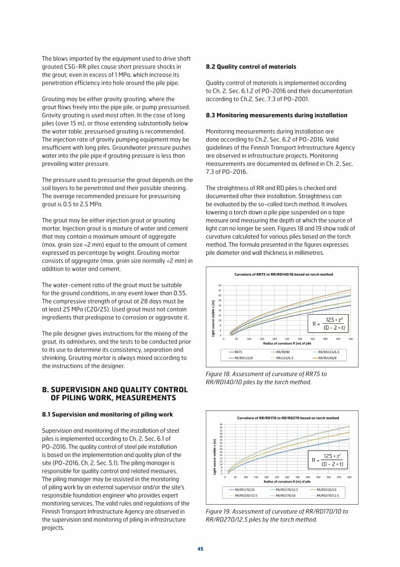
45
468
1012141618202224262830323436
0 50 100 150 200 250 300 350 400 450 500 550 600
Ligh
tsou
rce
visi
ble
z[m
]
Radius of curvature R [m] of pile
RR/RD170/10 RR/RD170/12.5 RR/RD220/10
RR/RD220/12.5 RR/RD270/10 RR/RD270/12.5
=125
)
The blows imparted by the equipment used to drive shaft grouted CSG-RR piles cause short pressure shocks in the grout, even in excess of 1 MPa, which increase its penetration efficiency into hole around the pile pipe.
Grouting may be either gravity grouting, where the grout flows freely into the pipe pile, or pump pressurised. Gravity grouting is used most often. In the case of long piles (over 15 m), or those extending substantially below the water table, pressurised grouting is recommended. The injection rate of gravity pumping equipment may be insufficient with long piles. Groundwater pressure pushes water into the pile pipe if grouting pressure is less than prevailing water pressure.
The pressure used to pressurise the grout depends on the soil layers to be penetrated and their possible shearing. The average recommended pressure for pressurising grout is 0.5 to 2.5 MPa.
The grout may be either injection grout or grouting mortar. Injection grout is a mixture of water and cement that may contain a maximum amount of aggregate (max. grain size <2 mm) equal to the amount of cement expressed as percentage by weight. Grouting mortar consists of aggregate (max. grain size normally <2 mm) in addition to water and cement.
The water-cement ratio of the grout must be suitable for the ground conditions, in any event lower than 0.55. The compressive strength of grout at 28 days must be at least 25 MPa (C20/25). Used grout must not contain ingredients that predispose to corrosion or aggravate it.
The pile designer gives instructions for the mixing of the grout, its admixtures, and the tests to be conducted prior to its use to determine its consistency, separation and shrinking. Grouting mortar is always mixed according to the instructions of the designer.
8. SUPERVISION AND QUALITY CONTROL OF PILING WORK, MEASUREMENTS
8.1 Supervision and monitoring of piling work
Supervision and monitoring of the installation of steel piles is implemented according to Ch. 2, Sec. 6.1 of PO-2016. The quality control of steel pile installation is based on the implementation and quality plan of the site (PO-2016, Ch. 2, Sec. 5.1). The piling manager is responsible for quality control and related measures. The piling manager may be assisted in the monitoring of piling work by an external supervisor and/or the site’s responsible foundation engineer who provides expert monitoring services. The valid rules and regulations of the Finnish Transport Infrastructure Agency are observed in the supervision and monitoring of piling in infrastructure projects.
Figure 19. Assessment of curvature of RR/RD170/10 to RR/RD270/12.5 piles by the torch method.
Figure 18. Assessment of curvature of RR75 to RR/RD140/10 piles by the torch method.
8.2 Quality control of materials
Quality control of materials is implemented according to Ch. 2, Sec. 6.1.2 of PO-2016 and their documentation according to Ch.2, Sec. 7.3 of PO-2001.
8.3 Monitoring measurements during installation
Monitoring measurements during installation are done according to Ch.2, Sec. 6.2 of PO-2016. Valid guidelines of the Finnish Transport Infrastructure Agency are observed in infrastructure projects. Monitoring measurements are documented as defined in Ch. 2, Sec. 7.3 of PO-2016.
The straightness of RR and RD piles is checked and documented after their installation. Straightness can be evaluated by the so-called torch method. It involves lowering a torch down a pile pipe suspended on a tape measure and measuring the depth at which the source of light can no longer be seen. Figures 18 and 19 show radii of curvature calculated for various piles based on the torch method. The formula presented in the figures expresses pile diameter and wall thickness in millimetres.
Curvature of RR/RD170 to RR/RD270 based on torch method
Curvature of RR75 to RR/RD140/10 based on torch method
4
6
8
10
12
14
16
18
20
22
24
0 50 100 150 200 250 300 350 400 450 500
Ligh
tsou
rce
visi
ble
z[m
]
Radius of curvature R [m] of pile
RR75 RR/RD90 RR/RD115/6.3
RR/RD115/8 RRs125/6.3 RR/RD140/8
=125
)
125 * z2
(D - 2 * t)R =

46
The torch method provides an estimate of the radius of curvature of the upper pile end to the depth at which the light source vanishes from sight. In the case of long piles, the radius of curvature below the vanishing point cannot be estimated by the method. When the light source is visible at the bottom of the pile, the minimum radius is as shown in Figures 18 or 19, but it is generally considerably larger, especially as pile size increases. With larger pile diameters the light source allows determining visually, for example, the existence of local more curved sections towards the bottom of the pile.
If necessary, the curvature of piles can be determined more accurately by an inclinometer. Inclinometer measurements are generally used with piles driven in thick cohesion soils primarily at foundation underpinning sites.
Piles that do not meet straightness requirements are reported to the responsible foundation engineer of the site who decides on further measures.
The radius of curvature estimated by the torch method or measured by an inclinometer is compared to the radius used in dimensioning. The comparison must consider the soil layers: the strength of the pile structure has generally been dimensioned for the weakest soil section. Pile curvature may be considerably smaller in coarse-grained than in cohesion soil layers thanks to the strong lateral support. If the radius of curvature is, or is estimated to be, smaller than in dimensioning, a dimensioning value is calculated for pile strength based on it, which is compared to the design value of the load taken by the pile.
8.4 Testing of piles
Implemented according to Ch.2, Sec. 6.3 of PO-2016. The test methods applicable to steel piles are indicated in Sec. 5.5. Tests are documented according to Ch. 2, Sec. 7.3 of PO-2016.
9. DOCUMENTATION OF PILING WORK
9.1 General
In building construction projects all piling documents are compiled into a construction inspection document according to Ch. 2, Sec. 7.1 of PO-2016. In infrastructure projects documentation is done according to the valid rules and regulations of the Finnish Transport Infrastructure Agency
9.2 Piling records
Documentation of piling is done according to standard EN 1997-1 and Ch. 2, Sec. 7.2 of PO-2016. Piling records applicable to SSAB's steel piles are presented in Appendix 4.
9.3 Outcome drawing and other piling documents
The piling outcome drawing is made after completion of piling works. The content and preparation of the outcome drawing are according to Ch. 2, Sec. 7.4 of PO-2016. Monitoring measurements are documented according to Ch. 2, Sec. 7.3 of PO-2016.
10. WORK SAFETY AND ENVIRONMENTAL PROTECTION
Work safety and environmental protection are according to Ch. 2, Sec. 8 of PO-2016.
Instructions on the safe handling of SSAB's steel piles are found in “Piles and pile accessories, recommendations for safe handling on site” which advise on safe handling of pile products and accessories before actual piling. Section 7 of these instructions is observed in piling. A special work safety aspect concerning steel pipe piling is the reliable closing of the ends of open pile pipes after installation.

47
11. END-OF-DRIVING TABLES
11.1 General
The end-of-driving tables and graphs have been prepared on the basis of analyses made using the GRLWEAP program built on the one-dimensional wave theory according to the main principles of Ch. 1, App. 2 of PO-2016.
The end-of-driving tables present five different ultimate geotechnical resistance values (Rc) for each pile size, pile length and driving equipment. In addition to the Rc, max values corresponding to piling classes PTL1 to PTL3, the tables also present the smaller than maximum values corresponding to PTL2 and PTL3. The reduced value of PTL2 is about 88 to 90 % of its maximum value, and the reduced value of PTL3 is the average of the maximum values of PTL2 and PTL3 corresponding to 80 % of the yield strength of steel. The reduced values are presented to facilitate setting appropriate end-of-driving criteria in situations where the goal is not to attain the maximum values of the piling class in question. End-of-driving curves have also been drawn for hydraulic rams and pneumatic hammers as function of geotechnical resistance and end-of-driving settlement. The end-of-driving tables and graphs are suitable for steel piles serving as end-bearing piles.
The end-of-driving tables present the design geotechnical resistance values (Rd) of piles. The Rd values apply in the case of so-called non-rigid structures. In PTL3, Rd values are calculated using a correlation coefficient ξ5 of 1.47.
End-of-driving criteria have been calculated for four pile lengths: 5, 10, 20 and 30 m.
11.2 Drop and hydraulic hammers
11.2.1 Basics of modelling
In connection with the building of the soil model, the number of final blows imparted with drop and hydraulic hammers was determined using a shaft resistance of 10% of the total ultimate geotechnical resistance of a pile and shaft resistance distributed evenly in the form of a downward expanding triangle. The used Smith damping factor (Js) is 0.23 s/m, which corresponds to the typical piling conditions for the above-mentioned shaft resistance distribution where about half of the pile lies in cohesion soil and the rest in friction soil. Otherwise, the dynamic soil parameters of App. 2 of PO-2016 are used in creating the soil model.
• elastic compression of soil under the tip before quake qt = d/120 [mm]
• elastic compression of soil around pile before quake qs = 2.5 mm
• Smith’s damping factor at pile tip, Jt = 0.5*(25/ σt) [s/m], (σt [MPa] = soil failure stress under pile tip)
Drop and hydraulic hammers up to 2000 kg have been analyzed using the SELF PJ hammer model created for GRLWEAP using typical moving part dimensions based on hammer weight. Drop and hydraulic hammers have been calculated with the same driving equipment model using 80 % as the efficiency of the drop hammer and 90 % for the hydraulic hammer.
In the modelling of 3000 to 9000 kg drop and hydraulic hammers, the Junttan HHK hammer models have been used as follows:• the efficiency assigned to drop hammers was 80 %• the efficiency assigned to hydraulic hammers was 95 %
Pile cushion values of Junttan have been used in modeling 3000 and 4000 kg hammers up to pile size RR170/12.5. With other driving equipment/pile combinations calculations have been made ignoring pile cushions.
11.2.2 Instructions for use of end-of-driving tables
The end-of-driving settlement of piles driven by hammers is always 10 mm/10 blows in PTL1 and PTL2, while in PLT3 it is 7 mm/10 blows.
The tables present with an accuracy of 0.05 m the required drop height for the combination of hammer weight, pile size and length, and intended geotechnical ultimate resistance and design value of resistance of each pile. The maximum allowed drop height used is the highest value suggested for each combination. When a value is given in parentheses in connection with maximum drop height, it refers to the fact that when maximum drop height is used, the maximum stress on the pile is 90% according to modelling, and that using the drop height in calculation will produce the ultimate geotechnical resistance indicated in parentheses. Drop heights can be interpolated on the basis of pile length.
The drop heights of the end-of-driving tables of piling class PTL3 are tentative. Mobilising geotechnical resistance and stresses on the pile during driving must be determined on the basis of PDA measurements.
In case the driving equipment includes an impact energy tester found reliable, the required impact energy can be determined as follows: required impact energy [kNm] = hammer weight of table [kg] x drop height [m] x efficiency given in table [-] x 0.00981. If the efficiency of the driving equipment is known from measurements to be something other than the 80 % or 95 % of the tables, drop height can be changed to correspond to actual efficiency.

48
Example 1:
Pile RR170/10, length 20 m, driving equipment: 4 t hydraulic hammer, design value of geotechnical resistance is the maximum value for PTL2 (Rd = 893kN).
According to the end-of-driving table drop height is 0.65 m, end-of driving settlement ≤10 mm/10 blows.
Example 2:
Pile RR170/10, length 17 m, driving equipment: 4 t accelerated hydraulic hammer (measured efficiency 100%), Rd = 893kN.
Drop height is interpolated based on 10 and 20 m pile lengths -> 0.6 m, efficiency of driving equipment is considered, drop height is 95 %/100 % * 0.6 m = 0.57 m, rounded to 0,55 m, end-of-driving settlement ≤10 mm/10 blows.
11.3 Hydraulic rams and pneumatic hammers
11.3.1 Principles of modelling
The magnitude of the shaft resistance of a pile used in creating the soil model was 1 % of the total ultimate resistance of the pile, and shaft resistance was distributed evenly in the form of a downward expanding triangle. Otherwise, the dynamic soil parameters presented in App. 2 of PO-2016 were used.
The hammers for the program were modelled based on data and properties provided by importers or manufacturers. The efficiencies of the ram and hammer, again, were based on opinions or measurements. Used hammer efficiency was 80 %. With certain hammer/pile combinations lower efficiency was used. In those cases, efficiency has been indicated in connection with the end-of-driving graph and table for the combination in question.
11.3.2 Instructions for use of end-of-driving graphs and tables
The end-of-driving settlement (mm/30 s) corresponding to the ultimate geotechnical resistance (Rc) and the design value (Rd) of geotechnical resistance is presented in the end-of-driving tables for each hammer, pile size and pile length. In case calculated end-of-driving settlement exceeds 100 mm/30 s, the magnitude of end-of-driving settlement is limited to 100 mm/30 s in the table. An end-of-driving settlement exceeding 100 mm/30 s can be used case-specifically, but then it must be taken into account that the actual number of hammer blows may decrease as settlement increases. If simulation indicates that a hammer is unable to mobilise the required geotechnical resistance, the table shows the mobilised geotechnical ultimate resistance when settlement <2 mm/30 s.
End-of-driving graphs show the calculated geotechnical ultimate resistance (Rc) with respect to end-of-driving settlement. If the targeted design value (Rd) of geotechnical resistance in piling classes PTL1 and PTL2 deviates from tabulated values, it can be interpolated based on the values of the table or determined from the end-of-driving graphs as follows: design value of geotechnical resistance (Rd) is multiplied by the factor 1.764 (1.47 x 1.2) to arrive at the corresponding geotechnical resistance (Rc), which allows reading the end-of-driving settlement from the graph.
In case the hammer cannot mobilise sufficient geotechnical resistance based on simulation, geotechnical resistance is to be ensured, for instance, by a separate test loading hammer and dynamic bearing capacity measurement or alternately by elasticity measurement and a dynamic bearing capacity formula.
In piling class PTL3 the geotechnical ultimate resistance must be determined on the basis of dynamic bearing capacity measurements.
If the end-of-driving graphs indicate an efficiency below 80%, the instructions of Sections 7.3.3 and 7.3.7 of the manual are to be followed in pile installation.

49
Example: Furukawa F19 hydraulic hammer, pile RRs115/8, piling class PTL2, pile length 10 m. Piles have two Rd values: 535 kN and 560 kN.
The end-of-driving settlement corresponding to Rd value 535 kN given in the table is 32 mm/30 s.
The Rd value 560 kN is converted to a geotechnical ultimate resistance (Rc) as follows: 1.764 * 560 kN = 988 kN. Based on the end-of-driving graph, the end-of-driving settlement is about 16 mm/30 s.
10PTL1
10020 9530 7710
PTL232
20 1730 510
PTL2<2 (1045)*
20 <2 (990)*30 <2 (955)*10
PTL3<2 (1045)*
20 <2 (990)*30 <2 (955)*10
PTL3<2 (1045)*
20 <2 (990)*30 <2 (955)*
793 450
955 535
1058 860
1190 661
1322 749
Hammer efficiency 80%Pile length
[m]Piling class
<2 (xxx)* = mobilised geotechnical resistance xxx kN when settlement <2mm/30s
SettlementRc [kN]R Rd [kN]
Pile length L = 10m Pile length L = 20m Pile length L = 30m
Settlement
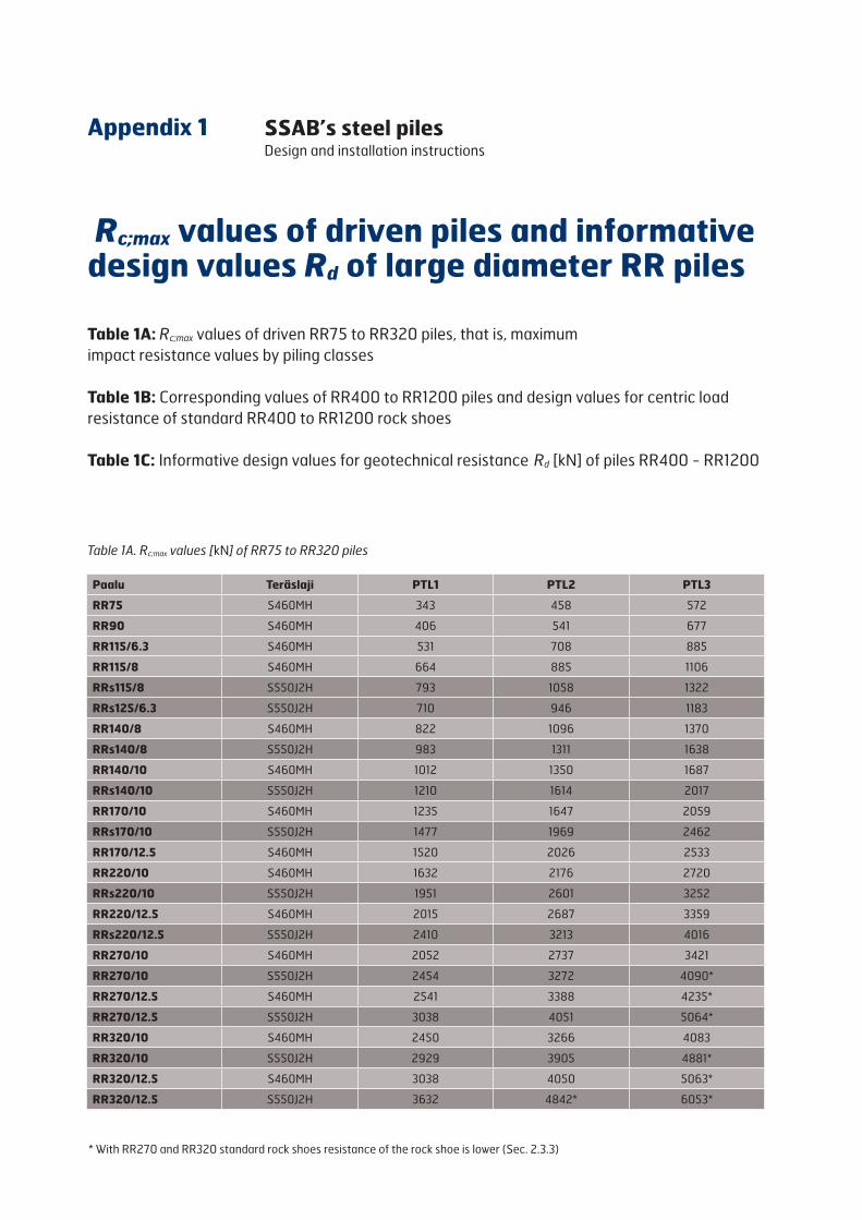
Rc;max values of driven piles and informative design values Rd of large diameter RR piles
Table 1A: Rc;max values of driven RR75 to RR320 piles, that is, maximum impact resistance values by piling classes
Table 1B: Corresponding values of RR400 to RR1200 piles and design values for centric load resistance of standard RR400 to RR1200 rock shoes
Table 1C: Informative design values for geotechnical resistance Rd [kN] of piles RR400 - RR1200
Appendix 1 SSAB’s steel piles Design and installation instructions
* With RR270 and RR320 standard rock shoes resistance of the rock shoe is lower (Sec. 2.3.3)
Table 1A. Rc;max values [kN] of RR75 to RR320 piles
Paalu Teräslaji PTL1 PTL2 PTL3
RR75 S460MH 343 458 572
RR90 S460MH 406 541 677
RR115/6.3 S460MH 531 708 885
RR115/8 S460MH 664 885 1106
RRs115/8 S550J2H 793 1058 1322
RRs125/6.3 S550J2H 710 946 1183
RR140/8 S460MH 822 1096 1370
RRs140/8 S550J2H 983 1311 1638
RR140/10 S460MH 1012 1350 1687
RRs140/10 S550J2H 1210 1614 2017
RR170/10 S460MH 1235 1647 2059
RRs170/10 S550J2H 1477 1969 2462
RR170/12.5 S460MH 1520 2026 2533
RR220/10 S460MH 1632 2176 2720
RRs220/10 S550J2H 1951 2601 3252
RR220/12.5 S460MH 2015 2687 3359
RRs220/12.5 S550J2H 2410 3213 4016
RR270/10 S460MH 2052 2737 3421
RR270/10 S550J2H 2454 3272 4090*
RR270/12.5 S460MH 2541 3388 4235*
RR270/12.5 S550J2H 3038 4051 5064*
RR320/10 S460MH 2450 3266 4083
RR320/10 S550J2H 2929 3905 4881*
RR320/12.5 S460MH 3038 4050 5063*
RR320/12.5 S550J2H 3632 4842* 6053*
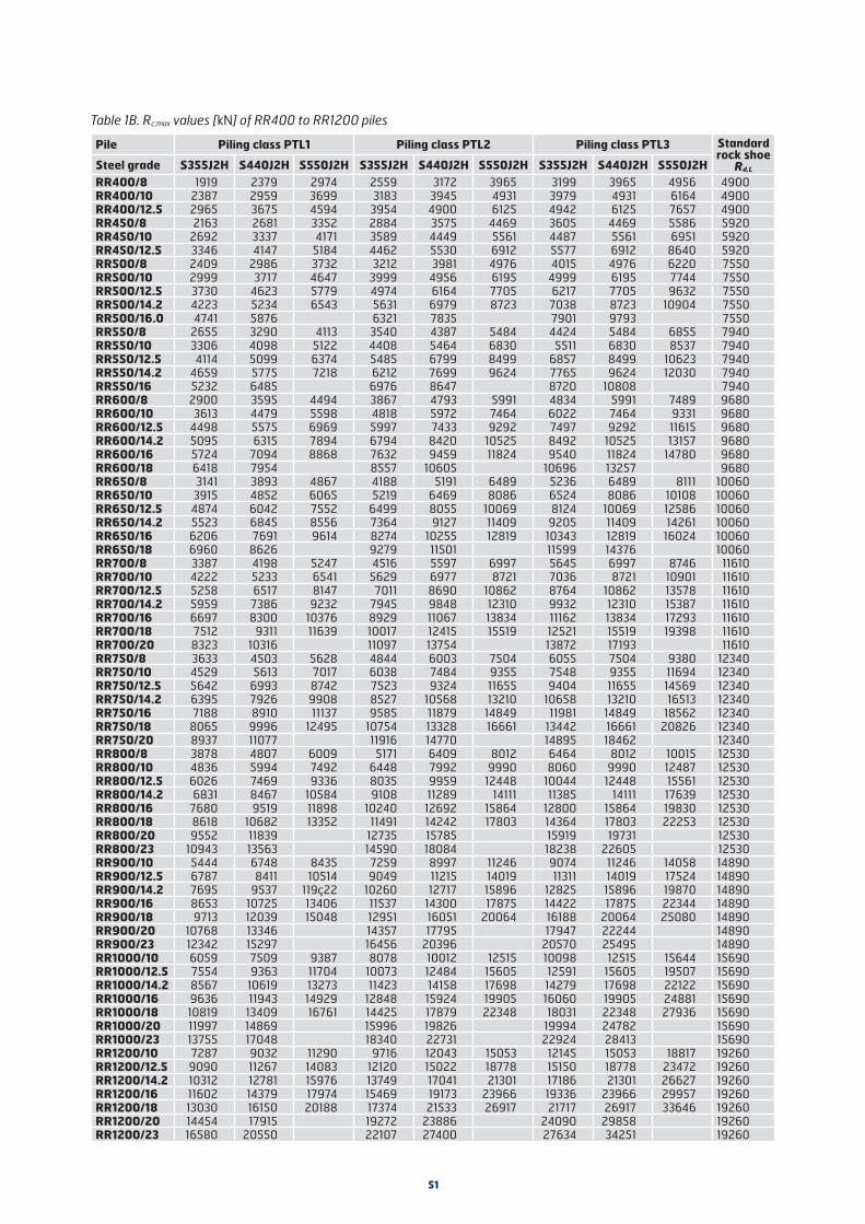
51
Table 1B. Rc;max values [kN] of RR400 to RR1200 piles
Pile Piling class PTL1 Piling class PTL2 Piling class PTL3 Standard rock shoe
Rd,L Steel grade S355J2H S440J2H S550J2H S355J2H S440J2H S550J2H S355J2H S440J2H S550J2HRR400/8 1919 2379 2974 2559 3172 3965 3199 3965 4956 4900RR400/10 2387 2959 3699 3183 3945 4931 3979 4931 6164 4900RR400/12.5 2965 3675 4594 3954 4900 6125 4942 6125 7657 4900RR450/8 2163 2681 3352 2884 3575 4469 3605 4469 5586 5920RR450/10 2692 3337 4171 3589 4449 5561 4487 5561 6951 5920RR450/12.5 3346 4147 5184 4462 5530 6912 5577 6912 8640 5920RR500/8 2409 2986 3732 3212 3981 4976 4015 4976 6220 7550RR500/10 2999 3717 4647 3999 4956 6195 4999 6195 7744 7550RR500/12.5 3730 4623 5779 4974 6164 7705 6217 7705 9632 7550RR500/14.2 4223 5234 6543 5631 6979 8723 7038 8723 10904 7550RR500/16.0 4741 5876 6321 7835 7901 9793 7550RR550/8 2655 3290 4113 3540 4387 5484 4424 5484 6855 7940RR550/10 3306 4098 5122 4408 5464 6830 5511 6830 8537 7940RR550/12.5 4114 5099 6374 5485 6799 8499 6857 8499 10623 7940RR550/14.2 4659 5775 7218 6212 7699 9624 7765 9624 12030 7940RR550/16 5232 6485 6976 8647 8720 10808 7940RR600/8 2900 3595 4494 3867 4793 5991 4834 5991 7489 9680RR600/10 3613 4479 5598 4818 5972 7464 6022 7464 9331 9680RR600/12.5 4498 5575 6969 5997 7433 9292 7497 9292 11615 9680RR600/14.2 5095 6315 7894 6794 8420 10525 8492 10525 13157 9680RR600/16 5724 7094 8868 7632 9459 11824 9540 11824 14780 9680RR600/18 6418 7954 8557 10605 10696 13257 9680RR650/8 3141 3893 4867 4188 5191 6489 5236 6489 8111 10060RR650/10 3915 4852 6065 5219 6469 8086 6524 8086 10108 10060RR650/12.5 4874 6042 7552 6499 8055 10069 8124 10069 12586 10060RR650/14.2 5523 6845 8556 7364 9127 11409 9205 11409 14261 10060RR650/16 6206 7691 9614 8274 10255 12819 10343 12819 16024 10060RR650/18 6960 8626 9279 11501 11599 14376 10060RR700/8 3387 4198 5247 4516 5597 6997 5645 6997 8746 11610RR700/10 4222 5233 6541 5629 6977 8721 7036 8721 10901 11610RR700/12.5 5258 6517 8147 7011 8690 10862 8764 10862 13578 11610RR700/14.2 5959 7386 9232 7945 9848 12310 9932 12310 15387 11610RR700/16 6697 8300 10376 8929 11067 13834 11162 13834 17293 11610RR700/18 7512 9311 11639 10017 12415 15519 12521 15519 19398 11610RR700/20 8323 10316 11097 13754 13872 17193 11610RR750/8 3633 4503 5628 4844 6003 7504 6055 7504 9380 12340RR750/10 4529 5613 7017 6038 7484 9355 7548 9355 11694 12340RR750/12.5 5642 6993 8742 7523 9324 11655 9404 11655 14569 12340RR750/14.2 6395 7926 9908 8527 10568 13210 10658 13210 16513 12340RR750/16 7188 8910 11137 9585 11879 14849 11981 14849 18562 12340RR750/18 8065 9996 12495 10754 13328 16661 13442 16661 20826 12340RR750/20 8937 11077 11916 14770 14895 18462 12340RR800/8 3878 4807 6009 5171 6409 8012 6464 8012 10015 12530RR800/10 4836 5994 7492 6448 7992 9990 8060 9990 12487 12530RR800/12.5 6026 7469 9336 8035 9959 12448 10044 12448 15561 12530RR800/14.2 6831 8467 10584 9108 11289 14111 11385 14111 17639 12530RR800/16 7680 9519 11898 10240 12692 15864 12800 15864 19830 12530RR800/18 8618 10682 13352 11491 14242 17803 14364 17803 22253 12530RR800/20 9552 11839 12735 15785 15919 19731 12530RR800/23 10943 13563 14590 18084 18238 22605 12530RR900/10 5444 6748 8435 7259 8997 11246 9074 11246 14058 14890RR900/12.5 6787 8411 10514 9049 11215 14019 11311 14019 17524 14890RR900/14.2 7695 9537 119ç22 10260 12717 15896 12825 15896 19870 14890RR900/16 8653 10725 13406 11537 14300 17875 14422 17875 22344 14890RR900/18 9713 12039 15048 12951 16051 20064 16188 20064 25080 14890RR900/20 10768 13346 14357 17795 17947 22244 14890RR900/23 12342 15297 16456 20396 20570 25495 14890RR1000/10 6059 7509 9387 8078 10012 12515 10098 12515 15644 15690RR1000/12.5 7554 9363 11704 10073 12484 15605 12591 15605 19507 15690RR1000/14.2 8567 10619 13273 11423 14158 17698 14279 17698 22122 15690RR1000/16 9636 11943 14929 12848 15924 19905 16060 19905 24881 15690RR1000/18 10819 13409 16761 14425 17879 22348 18031 22348 27936 15690RR1000/20 11997 14869 15996 19826 19994 24782 15690RR1000/23 13755 17048 18340 22731 22924 28413 15690RR1200/10 7287 9032 11290 9716 12043 15053 12145 15053 18817 19260RR1200/12.5 9090 11267 14083 12120 15022 18778 15150 18778 23472 19260RR1200/14.2 10312 12781 15976 13749 17041 21301 17186 21301 26627 19260RR1200/16 11602 14379 17974 15469 19173 23966 19336 23966 29957 19260RR1200/18 13030 16150 20188 17374 21533 26917 21717 26917 33646 19260RR1200/20 14454 17915 19272 23886 24090 29858 19260RR1200/23 16580 20550 22107 27400 27634 34251 19260

52
Pile Piling class PTL1 Piling class PTL2 Piling class PTL3 Standard rock shoe
Rd,L Steel grade S355J2H S440J2H S550J2H S355J2H S440J2H S550J2H S355J2H S440J2H S550J2H
RR400/8 1088 1349 1686 1451 1798 2248 1814 2248 2810 4900
RR400/10 1353 1677 2097 1804 2237 2796 2256 2796 3495 4900
RR400/12.5 1681 2084 2604 2241 2778 3473 2802 3473 4341 4900
RR450/8 1226 1520 1900 1635 2027 2533 2044 2533 3167 5920
RR450/10 1526 1891 2364 2035 2522 3152 2543 3152 3941 5920
RR450/12.5 1897 2351 2939 2529 3135 3919 3162 3919 4898 5920
RR500/8 1366 1693 2116 1821 2257 2821 2276 2821 3526 7550
RR500/10 1700 2107 2634 2267 2810 3512 2834 3512 4390 7550
RR500/12.5 2115 2621 3276 2819 3495 4368 3524 4368 5460 7550
RR500/14.2 2394 2967 3709 3192 3956 4945 3990 4945 6182 7550
RR500/16.0 2688 * 3331 * 3583 * 4441 * 4479 * 5552 * 7550
RR550/8 1505 1865 2332 2007 2487 3109 2508 3109 3886 7940
RR550/10 1874 2323 2904 2499 3097 3872 3124 3872 4840 7940
RR550/12.5 2332 2891 3613 3110 3854 4818 3887 4818 6022 7940
RR550/14.2 2641 3274 4092 3522 4365 5456 4402 5456 6820 7940
RR550/16 2966 * 3676 * 3955 * 4902 * 4944 * 6127 * 7940
RR600/8 1644 2038 2547 2192 2717 3397 2740 3397 4246 9680
RR600/10 2048 2539 3174 2731 3385 4232 3414 4232 5289 9680
RR600/12.5 2550 3160 3951 3400 4214 5267 4250 5267 6584 9680
RR600/14.2 2888 3580 4475 3851 4773 5967 4814 5967 7458 9680
RR600/16 3245 4022 5027 4326 5362 6703 5408 6703 8378 9680
RR600/18 3638 4509 4851 6012 6063 7515 9680
RR650/8 1781 2207 2759 2374 2943 3679 2968 3679 4598 10060
RR650/10 2219 2750 3438 2959 3667 4584 3699 4584 5730 10060
RR650/12.5 2763 3425 4281 3684 4567 5708 4605 5708 7135 10060
RR650/14.2 3131 3880 4851 4174 5174 6467 5218 6467 8084 10060
RR650/16 3518 4360 5450 4690 5814 7267 5863 7267 9084 10060
RR650/18 3945 4890 5260 6520 6576 8150 10060
RR700/8 1920 2380 2975 2560 3173 3966 3200 3966 4958 11610
RR700/10 2393 2966 3708 3191 3955 4944 3989 4944 6180 11610
RR700/12.5 2981 3695 4618 3975 4926 6158 4968 6158 7697 11610
RR700/14.2 3378 4187 5234 4504 5583 6978 5630 6978 8723 11610
RR700/16 3796 4705 5882 5062 6274 7842 6327 7842 9803 11610
RR700/18 4259 5278 6598 5678 7038 8797 7098 8797 10997 11610
RR700/20 4718 5848 6291 7797 7864 9747 11610
Table 1C. Informative design values for geotechnical resistance Rd [kN] of piles RR400 - RR1200Values in table 1C are calculated from table 1B Rc;max values by using the correlation coefficient ξ5 = 1.47 and the partial factor γt =1.20. The correlation coefficient used with large diameter piles is usually defined according to number/percentage of PDA measurement done. Due to this, the Rd values vary somewhat compared to the values presented in table.
*) pile size not in normal production, check availability from SSAB sales

Pile Piling class PTL1 Piling class PTL2 Piling class PTL3 Standard rock shoe
Rd,L Steel grade S355J2H S440J2H S550J2H S355J2H S440J2H S550J2H S355J2H S440J2H S550J2H
RR750/8 2059 2552 3191 2746 3403 4254 3432 4254 5318 12340
RR750/10 2567 3182 3978 3423 4243 5304 4279 5304 6629 12340
RR750/12.5 3199 3964 4956 4265 5286 6607 5331 6607 8259 12340
RR750/14.2 3625 4493 5617 4834 5991 7489 6042 7489 9361 12340
RR750/16 4075 5051 6313 5433 6734 8418 6792 8418 10522 12340
RR750/18 4572 5667 7084 6096 7556 9445 7620 9445 11806 12340
RR750/20 5066 6280 6755 8373 8444 10466 12340
RR800/8 2199 2725 3406 2932 3633 4542 3664 4542 5677 12530
RR800/10 2742 3398 4247 3655 4531 5663 4569 5663 7079 12530
RR800/12.5 3416 4234 5293 4555 5646 7057 5694 7057 8821 12530
RR800/14.2 3873 4800 6000 5163 6400 8000 6454 8000 10000 12530
RR800/16 4354 5396 6745 5805 7195 8993 7256 8993 11242 12530
RR800/18 4886 6055 7569 6514 8074 10092 8143 10092 12615 12530
RR800/20 5415 6711 7220 8948 9025 11185 12530
RR800/23 6203 * 7689 * 8271 * 10252 * 10339 * 12814 * 12530
RR900/10 3086 3825 4782 4115 5100 6376 5144 6376 7969 14890
RR900/12.5 3847 4768 5961 5130 6358 7947 6412 7947 9934 14890
RR900/14.2 4362 5407 6758 5816 7209 9011 7270 9011 11264 14890
RR900/16 4905 6080 7600 6540 8106 10133 8176 10133 12666 14890
RR900/18 5506 6825 8531 7342 9099 11374 9177 11374 14218 14890
RR900/20 6104 7566 8139 10088 10174 12610 14890
RR900/23 6996 * 8672 * 9329 * 11562 * 11661 * 14453 * 14890
RR1000/10 3435 4257 5321 4579 5676 7095 5724 7095 8869 15690
RR1000/12.5 4283 5308 6635 5710 7077 8847 7138 8847 11058 15690
RR1000/14.2 4857 6020 7524 6476 8026 10033 8095 10033 12541 15690
RR1000/16 5463 6770 8463 7283 9027 11284 9104 11284 14105 15690
RR1000/18 6133 7602 9502 8177 10135 12669 10222 12669 15837 15690
RR1000/20 6801 8429 9068 11239 11335 14049 15690
RR1000/23 7797 * 9664 * 10397 * 12886 * 12996 * 16107 * 15690
RR1200/10 4131 5120 6400 5508 6827 8534 6885 8534 10667 19260
RR1200/12.5 5153 6387 7984 6871 8516 10645 8589 10645 13306 19260
RR1200/14.2 5846 7245 9057 7794 9661 12076 9743 12076 15095 19260
RR1200/16 6577 8152 10190 8769 10869 13586 10961 13586 16983 19260
RR1200/18 7387 9155 11444 9849 12207 15259 12311 15259 19074 19260
RR1200/20 8194 10156 10925 13541 13656 16926 19260
RR1200/23 9399 * 11650 * 12532 * 15533 * 15665 * 19416 * 19260
*) pile size not in normal production, check availability from SSAB sales


SSAB is a Nordic and US-based steel company. SSAB offers value added products and services developed in close cooperation with its customers to create a stron-ger, lighter and more sustainable world. SSAB has employees in over 50 countries. SSAB has production facilities in Sweden, Finland and the US. SSAB is listed on the NASDAQ OMX Nordic Exchange in Stockholm and has a secondary listing on the NASDAQ OMX in Helsinki. www.ssab.com
The accuracy of this instruction sheet has been inspected with utmost care. However, we do not assume responsibility for any mistakes or direct or indirect damages due to incorrect application of the information. The right to make changes is reserved.
Copyright © 2019 SSAB. All rights reserved. SSAB and SSAB brand names are registered trademarks of SSAB.
SSABHarvialantie 420FI-13300 Hämeenlinna, Finland
Tel. +358 20 5911
www.ssab.com/infra
80
2-en-RR
and RD
piles design and installation manual-v9
-20
20
-Precis