Cyclic Axial Loading Analysis of Piles in Sand
17
CYCLIC AXIAL LOADING ANALYSIS OF PILES IN SAND By Harry G. Poulos, 1 Fellow, ASCE ABSTRACT: This paper develops an analysis for the behavior of a single pile or symmetrical pile group in sand under cyclic axial loading. The analysis allows consideration of the effects of degradation of skin friction, base resistance and soil modulus, the influence of loading rate, and the accumulation of permanent dis- placements. Laboratory data for skin friction degradation are presented and it is shown that the amount of degradation due to cyclic loading depends on the cyclic displacement, the number of cycles, the soil type, and the type of pile. Theoretical solutions for a hypothetical pile and a recent field test emphasize the importance of determining whether the degradation of skin friction depends on the absolute cyclic displacement or the cyclic displacement relative to the pile diameter. INTRODUCTION The design of offshore piles requires consideration of the effects of cyclic loading on the axial load capacity and the cyclic and permanent deformations of the pile head. Available methods of analyzing the cyclic axial response of piles can be broadly divided into three categories: 1. Axial load transfer (t-z) analyses, modified for the effects of cyclic deg- radation; e.g., Matlock and Foo (1979), Randolph (1985). 2. Boundary element analyses modified for cyclic degradation and loading rate effects (Poulos 1979, 1981, 1982, 1983). 3. Finite element methods, involving a simplified description of the effects of cyclic loading (Boulon et al. 1980). The limited information available on the effects of cyclic axial loading on piles in sand indicates that remarkable reductions in load capacity and pile- soil system stiffness can occur (Chan and Hanna 1980; Gudehus and Hettler 1981; Van Weele 1979). In some of these cases, failure is characterized by a continued accumulation of permanent displacement, resulting in move- ments of the order of one pile diameter after many cycles. Van Weele (1979) attributes this to the continuous rearrangement of particles (and the possible crushing of highly stressed particles) and argues that deformation may con- tinue to increase with increasing cycles without reaching a final and constant value. It appears that at least two mechanisms may contribute to the failure of piles under cyclic axial loading: 1. Cyclic degradation of skin friction and base resistance; this may be ex- pected to dominate under essentially two-way cyclic loading. 2. Accumulation of permanent displacement with increasing load cycles; this 'Prof, of Civ. Engrg., Univ. of Sydney, Sydney, N.S.W., Australia 2006. Note. Discussion open until November 1, 1989. To extend the closing date one month, a written request must be filed with the ASCE Manager of Journals. The manuscript for this paper was submitted for review and possible publication on June 23, 1986. This paper is part of the Journal of Geotechnical Engineering, Vol. 115, No. 6, June, 1989. ©ASCE, ISSN 0733-9410/89/0006-0836/$!.00 + $.15 per page. Paper No. 23566. 836 J. Geotech. Engrg. 1989.115:836-852. Downloaded from ascelibrary.org by Coffey Geotechnics P/L on 07/14/15. Copyright ASCE. For personal use only; all rights reserved.
-
Upload
independent -
Category
Documents
-
view
0 -
download
0
Transcript of Cyclic Axial Loading Analysis of Piles in Sand

CYCLIC AXIAL LOADING ANALYSIS
OF PILES IN SAND
By Harry G. Poulos,1 Fellow, ASCE
ABSTRACT: This paper develops an analysis for the behavior of a single pile or symmetrical pile group in sand under cyclic axial loading. The analysis allows consideration of the effects of degradation of skin friction, base resistance and soil modulus, the influence of loading rate, and the accumulation of permanent displacements. Laboratory data for skin friction degradation are presented and it is shown that the amount of degradation due to cyclic loading depends on the cyclic displacement, the number of cycles, the soil type, and the type of pile. Theoretical solutions for a hypothetical pile and a recent field test emphasize the importance of determining whether the degradation of skin friction depends on the absolute cyclic displacement or the cyclic displacement relative to the pile diameter.
INTRODUCTION
The design of offshore piles requires consideration of the effects of cyclic loading on the axial load capacity and the cyclic and permanent deformations of the pile head. Available methods of analyzing the cyclic axial response of piles can be broadly divided into three categories:
1. Axial load transfer (t-z) analyses, modified for the effects of cyclic degradation; e.g., Matlock and Foo (1979), Randolph (1985).
2. Boundary element analyses modified for cyclic degradation and loading rate effects (Poulos 1979, 1981, 1982, 1983).
3. Finite element methods, involving a simplified description of the effects of cyclic loading (Boulon et al. 1980).
The limited information available on the effects of cyclic axial loading on piles in sand indicates that remarkable reductions in load capacity and pile-soil system stiffness can occur (Chan and Hanna 1980; Gudehus and Hettler 1981; Van Weele 1979). In some of these cases, failure is characterized by a continued accumulation of permanent displacement, resulting in movements of the order of one pile diameter after many cycles. Van Weele (1979) attributes this to the continuous rearrangement of particles (and the possible crushing of highly stressed particles) and argues that deformation may continue to increase with increasing cycles without reaching a final and constant value.
It appears that at least two mechanisms may contribute to the failure of piles under cyclic axial loading:
1. Cyclic degradation of skin friction and base resistance; this may be expected to dominate under essentially two-way cyclic loading.
2. Accumulation of permanent displacement with increasing load cycles; this
'Prof, of Civ. Engrg., Univ. of Sydney, Sydney, N.S.W., Australia 2006. Note. Discussion open until November 1, 1989. To extend the closing date one
month, a written request must be filed with the ASCE Manager of Journals. The manuscript for this paper was submitted for review and possible publication on June 23, 1986. This paper is part of the Journal of Geotechnical Engineering, Vol. 115, No. 6, June, 1989. ©ASCE, ISSN 0733-9410/89/0006-0836/$!.00 + $.15 per page. Paper No. 23566.
836
J. Geotech. Engrg. 1989.115:836-852.
Dow
nloa
ded
from
asc
elib
rary
.org
by
Cof
fey
Geo
tech
nics
P/L
on
07/1
4/15
. Cop
yrig
ht A
SCE
. For
per
sona
l use
onl
y; a
ll ri
ghts
res
erve
d.
may be expected to dominate under essentially one-way cyclic loading, particularly if "strain-softening" behavior can occur at the pile-soil interface.
The present paper summarizes an approach developed from the boundary element method of analysis which provides a framework for estimation of the behavior of piles in sand under cyclic axial loading. This approach extends that described in earlier papers (Poulos 1981, 1982, 1983, 1984), both in regard to the capabilities of the numerical model used and in the modeling of the effects of cyclic loading, including permanent displacement accumulation. Laboratory data for the degradation of skin friction in both silica and calcareous sands are then reviewed and some of these data are used to obtain theoretical solutions for the cyclic behavior of a hypothetical offshore pile. Finally, a comparison is presented between the theoretical and observed behavior of a grouted pile in a recently published field test.
OUTLINE OF ANALYSIS
Static Loading The basic framework for the analysis has been described previously by
the writer (Poulos 1981) and is a development of a boundary element analysis used for the analysis of pile response to static axial loading (Poulos 1977). A brief review of this analysis will be given below, with details of recent modifications and extensions of the analysis.
Fig. 1 illustrates the geometry of a pile and the soil mass, and the division the pile and soil into elements. In general, there will be three types of elements to model the pile-soil boundary:
1. Cylindrical elements along the shaft. 2. Annular elements at the base. 3. Annular elements at discontinuities in shaft diameter.
AP
tlJQ (TTr I j f Apj
I I t | I I
7777777777 Incremental Interaction Incremental Interaction Stresses Acting on Pile Stresses Acting on Soil
FIG. 1. Computational Model of Axially Loaded Pile (Interaction Stresses Shown Only at a Few Elements; Each Dot Represents an Element Collocation Point)
m Ap,
TT
837
J. Geotech. Engrg. 1989.115:836-852.
Dow
nloa
ded
from
asc
elib
rary
.org
by
Cof
fey
Geo
tech
nics
P/L
on
07/1
4/15
. Cop
yrig
ht A
SCE
. For
per
sona
l use
onl
y; a
ll ri
ghts
res
erve
d.

On each element, a uniform vertical interaction shear stress is assumed to act. While conditions at the pile-soil interface remain elastic, the expressions for the incremental pile-soil displacement compatibility may be equated and solved, with the equilibrium equation, for the unknown stresses and displacements at each pile element. The pile head settlement can thus be computed.
Allowance can be made for pile-soil slip of the shaft elements or soil yield at the annular elements by specifying an upper limit to the interaction stress at each element, and carrying out an iterative analysis.
To allow for nonhomogeneity of the soil, the modification suggested by Poulos (1979) can be used in which the incremental soil displacement at one element, due to another loaded element, is computed from Mindlin's equation using a soil Young's modulus equal to the mean of the values at the influenced and influencing elements. As previously pointed out, it is essential to have a convenient and economical means of considering soil non-homogeneity because, under cyclic loading, differing rates of degradation along the pile shaft will lead to a nonuniform distribution of soil modulus.
Two useful extensions may be also incorporated into the analysis:
1. Pile group behavior can readily be considered if the piles are symmetrically arranged around the circumference of a circle, so that all piles behave identically. The incremental soil displacements at each element then include components due to the surrounding piles, in addition the subject pile itself. These components can be evaluated from Mindlin's equations, as described in Poulos (1977). Solution of the resulting displacement compatibility equations is then carried out as for a single pile.
2. Strain-softening (or more accurately displacement-softening) behavior of the pile-soil interface can be incorporated. The simplest form is that in which, once the peak resistance has been reached, the resistance decreases, linearly with total displacement, to an ultimate or residual value. The limiting value of interaction stress at an element is then the peak value (for elements which have not yet failed), or the value corresponding to the maximum previous total displacement at that element (for elements which have previously failed).
Cyclic Loading The analysis of cyclic axial pile response requires consideration of a num
ber of effects, including:
1. Possible degradation of limiting skin friction, limiting base resistance, and soil modulus, due to soil particle crushing, volume changes due to shearing, and particle reorientation,
2. Loading rate effects. 3. Accumulation of permanent displacements due to cyclic loading about non
zero mean stresses.
To quantify the effects of soil degradation due to cyclic loading, it is convenient to introduce the concept of degradation factors, the degradation factor being defined as
_ property after cyclic loading
property for static loading
838
J. Geotech. Engrg. 1989.115:836-852.
Dow
nloa
ded
from
asc
elib
rary
.org
by
Cof
fey
Geo
tech
nics
P/L
on
07/1
4/15
. Cop
yrig
ht A
SCE
. For
per
sona
l use
onl
y; a
ll ri
ghts
res
erve
d.

The degradation factors for limiting skin friction, limiting base resistance, and soil modulus are denoted as DT, Db, and DE respectively.
Both pile resistance and pile head stiffness tend to increase linearly with the logarithm of loading rate (Ben et al. 1980). Thus, if the rate of cyclic loading is relatively high, the rate effects will tend to counteract the degradation due to cycling (Kraft et al. 1981).
Incorporation of permanent displacements into the analysis requires modification of the expression for incremental soil displacements. The incremental displacement of the soil adjacent to each pile element can be considered as the sum of two components:
1. One due to the incremental pile-soil stresses on the soil elements. 2. One due to the accumulation of permanent displacement under nonzero
mean shear stress on the element.
Thus, a vector {ASP} of incremental permanent soil displacements due to cyclic loading can be added to the equation for the incremental soil displacement due to the pile-soil interaction stresses.
After incorporating both degradation and loading rate effects, the limiting peak skin friction 7ac after cyclic loading can be expressed as
iac = DKDTfa (2)
where ia = peak static, skin friction DT degradation factor for skin friction; and DR = loading rate factor. Similar expressions hold for the limiting base resistance, Pbc, and the soil Young's modulus, Ec. The corresponding degradation factors are denoted as Db and DE. For sands, the values of peak static skin friction, T„, peak static base resistance, pb, and static soil Young's modulus, E„, would normaly be those relevant to drained loading conditions.
Using this analytical framework, the response of a pile after N cycles of uniform loading (maximum value Pmax) minimum value Pmia) can be analyzed by simulating each cycle as follows:
1. Starting with the static values of Es, and pb, modified by the rate factor, DR, the pile is analyzed for an incremental load of Pmax.
2. The load is then decreased to Pmin and the analysis repeated. Finally the load is returned to the mean load, thus completing the first cycle of loading.
3. For the degradation model specified, the degradation factors, DT, Db, and DE are determined.
4. The increment in permanent displacement is determined for each element, as will be discussed later. This will generally depend on the number of cycles and the mean stress level (relative to failure) on the element.
5. The values of Young's modulus Ec, limiting skin friction iac, and base resistance pbc for the next cycle are determined by multiplying the static values by the appropriate degradation factor and the rate factor DR.
6. Steps 1 and 2 are again performed to determine the incremental response over the next cycle, using the updated values Ec, tac, pbc.
7. The procedure is repeated until the required number N of cycles has been simulated.
If another sequence of cyclic loading with different loads is to be considered, the same procedure can be used, except that the starting values of soil
839
J. Geotech. Engrg. 1989.115:836-852.
Dow
nloa
ded
from
asc
elib
rary
.org
by
Cof
fey
Geo
tech
nics
P/L
on
07/1
4/15
. Cop
yrig
ht A
SCE
. For
per
sona
l use
onl
y; a
ll ri
ghts
res
erve
d.
modulus, skin friction, and base resistance in step 1 are the values existing at the end of the previous sequence of loading. In this way, a complete "storm loading" sequence can be considered. A computer program, TAPCYC9, has been developed to carry out the numerical analysis.
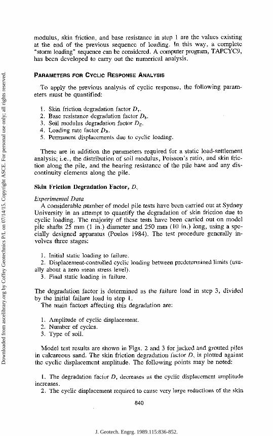
PARAMETERS FOR CYCLIC RESPONSE ANALYSIS
To apply the previous analysis of cyclic response, the following parameters must be quantified:
1. Skin friction degradation factor £>T. 2. Base resistance degradation factor Db. 3. Soil modulus degradation factor DE. 4. Loading rate factor DR. 5. Permanent displacements due to cyclic loading.
These are in addition the parameters required for a static load-settlement analysis; i.e., the distribution of soil modulus, Poisson's ratio, and skin friction along the pile, and the bearing resistance of the pile base and any discontinuity elements along the pile.
Skin Friction Degradation Factor, DT
Experimental Data A considerable number of model pile tests have been carried out at Sydney
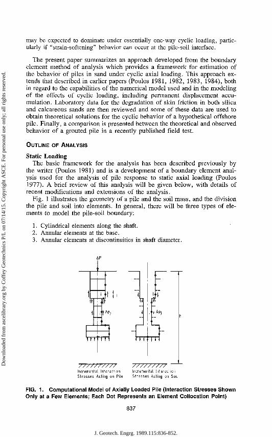
University in an attempt to quantify the degradation of skin friction due to cyclic loading. The majority of these tests have been carried out on model pile shafts 25 mm (1 in.) diameter and 250 mm (10 in.) long, using a specially designed apparatus (Poulos 1984). The test procedure generally involves three stages:
1. Initial static loading to failure. 2. Displacement-controlled cyclic loading between predetermined limits (usu
ally about a zero mean stress level). 3. Final static loading in failure.
The degradation factor is determined as the failure load in step 3, divided by the initial failure load in step 1.
The main factors affecting this degradation are:
1. Amplitude of cyclic displacement. 2. Number of cycles. 3. Type of soil.
Model test results are shown in Figs. 2 and 3 for jacked and grouted piles in calcareous sand. The skin friction degradation factor DT is plotted against the cyclic displacement amplitude. The following points may be noted:
1. The degradation factor Dr decreases as the cyclic displacement amplitude increases.
2. The cyclic displacement required to cause very large reductions of the skin
840
J. Geotech. Engrg. 1989.115:836-852.
Dow
nloa
ded
from
asc
elib
rary
.org
by
Cof
fey
Geo
tech
nics
P/L
on
07/1
4/15
. Cop
yrig
ht A
SCE
. For
per
sona
l use
onl
y; a
ll ri
ghts
res
erve
d.

^ ) h ^ P f s = 0 '021"™
0.8
0.6
0.4
0.2
l
a
' ! A
1 X?a
» n \
05
1 1 N = 100 cycles
-
-
A V _
>-t-1.0 1.5 3 I I
±pc mm
0 0.025 0.05 0.075 0.10
ip c /d
FIG. 2. Skin Friction Degradation Factors: Model Jacked Piles in Calcareous Sand from Bass Strait
u^pfs=0.15mm
I f
" \
- \ V
— c V
_ 0-5,
I
I I
-
N = 100 cycles
X
\ t -\ ^ o + • _
1.0 1.5» * — I I
0-8
DT 0.6
04
0.2
" 2.0 ±9C mm
0 0.025 0.05 0.075 0.10
±qc/d
FIG. 3. Skin Friction Degradation Factors: Model Grouted Piles in Calcareous Sand from Bass Strait
friction of the model piles is small, of the order of ±0.5 mm. 3. Significant degradation does not occur until the cyclic displacement am
plitude exceeds the displacement required to develop the limiting skin friction under static loading, pfs.
4. The degradation of skin friction for grouted piles is more severe than for jacked piles.
Other points which have emerged from the model tests are:
1. The majority of degradation appears to take place within the first 10 cycles; there is little additional degradation up to 100 cycles. For example, for a typical test on a grouted pile shaft in medium-dense calcareous sand, the degradation factor at JV = 2, 5, 10, 50, and 100 was 0.66, 0.28, 0.17, 0.08, and 0.06, respectively.
841
J. Geotech. Engrg. 1989.115:836-852.
Dow
nloa
ded
from
asc
elib
rary
.org
by
Cof
fey
Geo
tech
nics
P/L
on
07/1
4/15
. Cop
yrig
ht A
SCE
. For
per
sona
l use
onl
y; a
ll ri
ghts
res
erve
d.

2. The effective overburden pressure and the overconsolidation ratio of the soil do not significantly affect skin friction degradation.
3. Skin friction degradation in calcareous sands is more severe than in silica sands, at least over the first 100 cycles. This presumably arises because of the greater compressibility of the calcareous sand, which results in a greater reduction in soil volume near the pile shaft due to cyclic loading. This volume reduction leads to a reduction in normal stress, and consequently to a reduction or "degradation" of the skin friction.
4. The extent of degradation in calcareous sands may vary considerably with the soil characteristics.
Models of Skin Friction Degradation A number of different hypotheses are possible when trying to construct a
model for skin friction degradation on the basis of small-scale model pile tests, including the following:
1. The skin friction degradation factors are related to the absolute magnitude of cyclic displacement. In this hypothesis, the degradation curves in Figs. 2 and 3 would be applied directly to piles of all sizes.
2. The skin friction degradation factors are related to the relative magnitude of cyclic displacement; e.g., the cyclic displacement divided by the diameter. In this case, the horizontal scale in Figs. 2 and 3 would be multiplied by the ratio of the diameters of the prototype pile and the model pile, so that substantially larger cyclic displacements would be needed to cause degradation along the prototype pile than the model pile.
3. The skin friction degradation factors are related to the cyclic slip displacement, pcs, where
Pes = Pc - P/s (3)
in which pc = cyclic displacement amplitude; and pfs = displacement required to develop peak skin friction under cyclic loading.
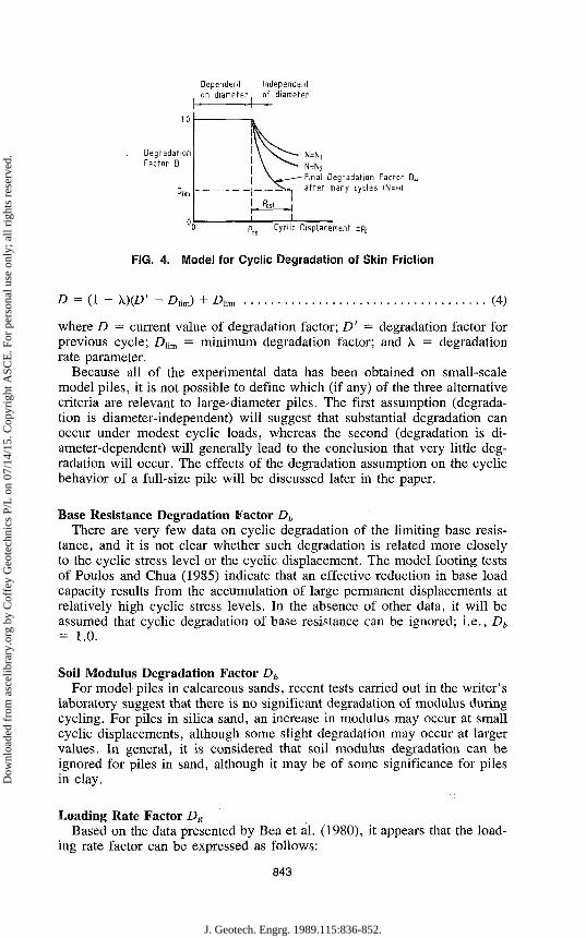
The latter model is illustrated in Fig. 4, where degredation depends on cyclic slip displacement p„ = pc - pfi (where pfl = displacement required to cause static slip); cyclic slip displacement required to cause maximum possible degradation = pcs, (independent of pile diameter). No degradation occurs until pc reaches pfs, which can be evaluated from an elastic analyses and is dependent on pile diameter. When pc exceeds pfs, degradation occurs and is dependent on the cyclic slip displacement p„ and the number of cycles N. The cyclic slip displacement to cause a particular amount of degradation is independent of pile diameter and dependent primarily on the soil and pile type. The minimum degradation factor (representing the maximum extent of degradation possible) is Dhm, and will occur after many cycles of cyclic slip displacement greater than some value, pcst. The data in Figs. 2 and 3 suggest that pcs, may be only of the order of 2 to 3 mm.
It is interesting to note that the well-known degradation model developed by Matlock and Foo (1979) is a special case of the cyclic slip displacement model, in which p„, is zero. Their model assumes that, provided reverse slip occurs at a point on the pile a sufficient number of times, the degradation factor will reach the limiting value Dlim. The Matlock and Foo model can be expressed as follows:
842
J. Geotech. Engrg. 1989.115:836-852.
Dow
nloa
ded
from
asc
elib
rary
.org
by
Cof
fey
Geo
tech
nics
P/L
on
07/1
4/15
. Cop
yrig
ht A
SCE
. For
per
sona
l use
onl
y; a
ll ri
ghts
res
erve
d.
Dependent Independent on diameter of diameter
1.0
Degradation Factor D
Dllm
"0 pfs Cyclic Displacement ±PC
FIG. 4. Model for Cyclic Degradation of Skin Friction
D = (1 - \)(D' - Aim) + Aim (4)
where D — current value of degradation factor; D' — degradation factor for previous cycle; D[im = minimum degradation factor; and X = degradation rate parameter.
Because all of the experimental data has been obtained on small-scale model piles, it is not possible to define which (if any) of the three alternative criteria are relevant to large-diameter piles. The first assumption (degradation is diameter-independent) will suggest that substantial degradation can occur under modest cyclic loads, whereas the second (degradation is diameter-dependent) will generally lead to the conclusion that very little degradation will occur. The effects of the degradation assumption on the cyclic behavior of a full-size pile will be discussed later in the paper.
Base Resistance Degradation Factor Db
There are very few data on cyclic degradation of the limiting base resistance, and it is not clear whether such degradation is related more closely to the cyclic stress level or the cyclic displacement. The model footing tests of Poulos and Chua (1985) indicate that an effective reduction in base load capacity results from the accumulation of large permanent displacements at relatively high cyclic stress levels. In the absence of other data, it will be assumed that cyclic degradation of base resistance can be ignored; i.e., Db = 1.0.
Soil Modulus Degradation Factor DE For model piles in calcareous sands, recent tests carried out in the writer's
laboratory suggest that there is no significant degradation of modulus during cycling. For piles in silica sand, an increase in modulus may occur at small cyclic displacements, although some slight degradation may occur at larger values. In general, it is considered that soil modulus degradation can be ignored for piles in sand, although it may be of some significance for piles in clay.
Loading Rate Factor DR Based on the data presented by Bea et al. (1980), it appears that the load
ing rate factor can be expressed as follows:
N=N2
Final Degradation Factor D„ after many cycles |N=~)
843
J. Geotech. Engrg. 1989.115:836-852.
Dow
nloa
ded
from
asc
elib
rary
.org
by
Cof
fey
Geo
tech
nics
P/L
on
07/1
4/15
. Cop
yrig
ht A
SCE
. For
per
sona
l use
onl
y; a
ll ri
ghts
res
erve
d.

DR = 1 + F? • log,0 '- (5) Rr
where Fp = rate coefficient; R = actual loading rate; and Rr = reference loading rate (e.g., for static loading). Bea et al. (1980) suggest that the ratio R/Rr for typical wave loading may be of the order of 10,000. Available field and model data suggest values of F9 of between 0.1 and 0.25 for piles in clay; hence, DR could be as high as 2.0. However, recent model tests show considerably smaller values of Fp (zero to 0.04) for piles in calcareous sand and almost zero for piles in silica sand. Thus, loading rate effects may not be significant for piles in sand deposits, and should not be relied upon for design purposes.
Permanent Displacements Reliable theories have yet to be developed for predicting the permanent
displacement of piles. However, for the pile base, an empirical approach developed by Chua (1983), based on the work of Diyaljee and Raymond (1982), may be applicable. From model footing tests on both silica and calcareous sand, it was found that the increment in permanent settlement ASP could be expressed as follows:
/ AAA ASP = SPN I nAX + m — I (6)
where ASP = increment in permanent displacement between cycles N and N + AN; AX = change in mean stress level between cycles N and N + AN; SPN = permanent displacement at cycle N; and m, n = experimentally determined dimensionless parameters.
For the shaft elements of the pile, preliminary model tests suggest that Eq. 5 may also apply, although different values of the parameters m and n may be relevant.
From Chua's footing tests on calcareous sand with a relative density of 45%, the values of m and n were found to be 0.12 and 5.9, while the silica sand (relative density 67%), m and n were 0.25 and 7.6, respectively. It is presumed that these values can be applied to the pile base.
THEORETICAL SOLUTIONS
Theoretical solutions were obtained for the cyclic response of a hypothetical driven steel tube pile 100 m long, of 1.0 m diameter with a 37.5-mm wall, in a deep uniform marine calcareous sand deposit. This case was also analyzed previously by the writer (Poulos 1984), and as before, ten shaft elements were used to represent the pile. The computations were carried out on an APRICOT microcomputer using the program TAPCYC9. Fig. 5 illustrates the problem and the static soil parameters assumed. No interface strain-softening along the shaft or at the base was allowed. Degradation of skin friction was generally assumed to follow the relationship shown in Fig. 3 for the Bass Strait calcareous sand, but neither base resistance nor soil modulus were assumed to degrade with cyclic loading. For permanent displacements, the parameters m and n adopted for the base were 0.12 and 5.9,
844
J. Geotech. Engrg. 1989.115:836-852.
Dow
nloa
ded
from
asc
elib
rary
.org
by
Cof
fey
Geo
tech
nics
P/L
on
07/1
4/15
. Cop
yrig
ht A
SCE
. For
per
sona
l use
onl
y; a
ll ri
ghts
res
erve
d.

t Cyclic iP
Load
c
1 Mean Load P„
Steel Tube Pile
Uniform Calcareous Sand
d = 1.0m —
L = 100"
\
20kPa
Od
I , Oistribuhon ' of Ultimate
Static Skin Friction
/ / / / / / / / / / / / / / / / / / y Static Soil Modulus' Distribution
= 0.75z MPa
7
FIG. 5. Problem Studied
respetively. Zero permanent displacement accumulation for shaft elements was assumed.
The following aspects of behavior were studied:
1. The effect of the assumptions made regarding skin friction degradation on the post-cyclic axial load capacity of the pile.
2. The cyclic and mean load combinations to cause failure during cycling. 3. The accumulation of permanent displacements.
Effect of Assumptions Made Regarding Skin Friction Degradation Calculations were carried out for four alternative assumptions regarding
skin friction degradation factor DT:
1. Dr is dependent on the normalized displacement; i.e., the ratio of the cyclic displacement to the pile diameter.
2. D7 depends on the actual value of the cyclic displacement, as in Fig. 3. 3. Z)T depends on the cyclic slip displacement, with the minimum degradation
factor Dllm being 0.25 and the cyclic slip displacement to cause p„( = 2.0 mm. 4. £>T is given by the Matlock and Foo (1979) criterion (Eq. 9) with Diim =
0.25 and \ = 0.6.
Fig. 6 plots the post-cyclic shaft load capacity as a function of the cyclic load amplitude Pc, for N = 10 cycles. The assumptions made regarding DT clearly make a dramatic difference to the computed shaft load capacity. The assumption that degradation depends on the' actual cyclic displacement, and is independent of pile diameter, gives the most severe reduction in load capacity, with a 57% reduction in shaft load capacity for a cyclic load of only ±1 MN. The alternative assumptions (1 ,3 , and 4) give reductions of shaft
845
J. Geotech. Engrg. 1989.115:836-852.
Dow
nloa
ded
from
asc
elib
rary
.org
by
Cof
fey
Geo
tech
nics
P/L
on
07/1
4/15
. Cop
yrig
ht A
SCE
. For
per
sona
l use
onl
y; a
ll ri
ghts
res
erve
d.

,p~>-4. i—'—i—'—rr^ r~
N = 10 cycles
I I I I I I I I I I I 0 1 2 3 4 5 6
Cyclic Load Amplitude ±PC 'MN
Degradation dependent on normalised cyclic displacement pc/d
Degradation dependent on actual cyclic displacement Pc
Matlock and Foo degradation model
/ / — Degradation dependent on cyclic slip displacement
FIG. 6. Effect of Degradation Assumptions on Post-Cyclic Shaft Load Capacity
load capacity of less than 1% at the same cyclic load level. Indeed, the curves for the cyclic slip displacement model and the Matlock and Foo model show virtually no degradation up to cyclic loads of about ±4.5 MN and 4 MN, respectively. Beyond these values, a very sudden drop in load capacity occurs with only small further increases in cyclic load. Thus, these models indicate a very "brittle" behavior with a narrow metastable range of cyclic load beyond which a sudden reduction in load capacity occurs: The other two models of degradation indicate considerably greater metastable cyclic load ranges.
It is obvious that the dependence or independence of skin friction degradation on the pile diameter is a key question to be resolved if reliable estimates of pile response under cyclic loading are to be obtained.
Fig. 7 shows the mean and cyclic load combinations to cause failure in 10 cycles. The importance of the assumption made regarding skin friction degradation is again clearly demonstrated.
Fig. 8 plots the maximum axial displacement during one-way compression cycling (from zero to PmaK) against the number of cycles N. The skin friction degradation is assumed to be independent of the diameter. For low maximum load levels, the behavior is almost elastic and little or no accumulation of permanent displacement occurs. As the load level increases, there is a progressively greater increase in permanent displacement with increasing N, and when the maximum load is only 36% of the static ultimate compressive load capacity P„s, failure occurs after 4 cycles. For a less severe skin friction degradation criterion, the maximum load level which may be sustained without failure will increase. Qualitatively, there are similarities between the be-
-z. 2Z
>* •*-s CL rt>
1_J
- o
S _! «-IV - C U l
,t!
— LJ
>, v "£ £ CL
5
4
3
2
1
846
J. Geotech. Engrg. 1989.115:836-852.
Dow
nloa
ded
from
asc
elib
rary
.org
by
Cof
fey
Geo
tech
nics
P/L
on
07/1
4/15
. Cop
yrig
ht A
SCE
. For
per
sona
l use
onl
y; a
ll ri
ghts
res
erve
d.

Legend Curve 1-No degradation Curve 2-Degradation dependent on pc/d Curve 3-Degradation dependent on cyclic slip displacement Curve 4-Matlock & Foo degradation model Curve 5-Degradation 2?Z~Z rFJrlE: dependent on pc
10
2 - .
u£ - l - T
Cyclic Load iPc MN
N = 10 cycles
Failure in compression Failure in tension
- 2 0 2 4 Mean Load P. MN
_L_J
FIG. 7. Load Combinations for Cyclic Failure—Effect of Skin Friction Degradation Assumption
% 10
No. of Cycles N
2 5 10 20 50 100 1
1
1 1
0.36
1 1
1 10.12 0.24
____y£ Values of Pm>.
~~~~ -—^_JL33
I I
FIG. 8. Increase in Maximum Displacement versus Number of Cycles; One-Way Loading in Compression
havior shown in Fig. 8 and that observed in the model tests of Chan and Hanna (1980).
ANALYSIS OF FIELD TEST
A controlled field test on a drilled and grouted pile in calcareous sand has been described recently by Nauroy et al. (1985). Fig. 9 shows the geotech-nical data for the site. Various sequencies of static and cyclic tensile loading were applied to the pile and pile movement and the loads along the pile were measured. An analysis of this case was carried out using the program TAPCYC9. The required input parameters were determined as follows:
1. The limiting static skin friction was determined from the static tension test to failure, assuming a constant value along the shaft; a value of 157 kPa was found.
2. The static soil modulus was assumed to be constant with depth and was determined from the static load-deflection performance; a value of 72.5 MPa was found.
847
J. Geotech. Engrg. 1989.115:836-852.
Dow
nloa
ded
from
asc
elib
rary
.org
by
Cof
fey
Geo
tech
nics
P/L
on
07/1
4/15
. Cop
yrig
ht A
SCE
. For
per
sona
l use
onl
y; a
ll ri
ghts
res
erve
d.

FIG. 9. Results of the Soil Investigation at Plouasne (Nauroy et al. 1985)
3. The degradation of skin friction was assumed to be given by the relationship in Fig. 3 for grouted model piles.
4. No degradation of soil modulus or base resistance was assumed. 5. For the shaft, the permanent displacement parameters were taken to be m
= 0.065, n = 0.
Calculations were carried out for two alternative assumptions regarding skin friction degradation:
1. Degradation is dependent on the actual cyclic displacement. 2. Degradation is given by the Matlock and Foo criterion, with D]im = 0.1
and X = 0.6.
Fig. 10 compares the calculated combinations of mean and cyclic load for failure, and those combinations which in the field tests showed either failure or no failure. Failure was only observed in one sequence of cyclic loading
Theoretical relationship for failure at N=1000: Matlock and Foo model Theoretical relationship for failure at N=1000: degradation dependent on absolute cyclic displacement Relationship for no degradation
o No failure observed
@ Failure during cycling
1500
s \
\ = — \
O O | * \
p
500 1000 Mean Load P. kN
FIG. 10. Comparison between Theoretical and Observed Behavior; Test of Nauroy et al. (1985)
848
J. Geotech. Engrg. 1989.115:836-852.
Dow
nloa
ded
from
asc
elib
rary
.org
by
Cof
fey
Geo
tech
nics
P/L
on
07/1
4/15
. Cop
yrig
ht A
SCE
. For
per
sona
l use
onl
y; a
ll ri
ghts
res
erve
d.
Load Range kN
0 100 200 300 ^OO 500 600
N 'Cm 4f t
n-1000 = 0.45 = 0.46
N =
AP» Aft
1000 = 0.95 = 0.48
N
' f t . *ft
= 1000 = 0.63 = 0.78
N = 138 4pn = 7.9 A9t = - (Failure)
N =
' 9» 4 f t
500 = 0.52 = 0.69
Apm = measured increase in perm, displ. mm
Apc = calculated increase in perm, displ mm
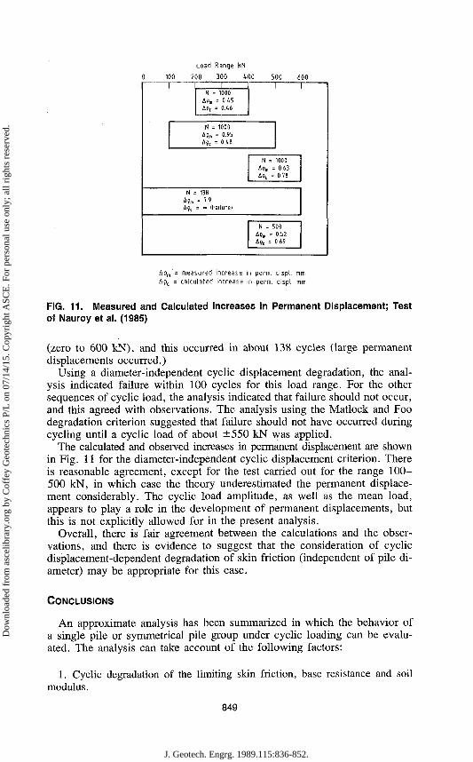
FIG. 11. Measured and Calculated Increases in Permanent Displacement; Test of Nauroy et al. (1985)
(zero to 600 kN), and this occurred in about 138 cycles (large permanent displacements occurred.)
Using a diameter-independent cyclic displacement degradation, the analysis indicated failure within 100 cycles for this load range. For the other sequences of cyclic load, the analysis indicated that failure should not occur, and this agreed with observations. The analysis using the Matlock and Foo degradation criterion suggested that failure should not have occurred during cycling until a cyclic load of about ±550 kN was applied.
The calculated and observed increases in permanent displacement are shown in Fig. 11 for the diameter-independent cyclic displacement criterion. There is reasonable agreement, except for the test carried out for the range 100-500 kN, in which case the theory underestimated the permanent displacement considerably. The cyclic load amplitude, as well as the mean load, appears to play a role in the development of permanent displacements, but this is not explicitly allowed for in the present analysis.
Overall, there is fair agreement between the calculations and the observations, and there is evidence to suggest that the consideration of cyclic displacement-dependent degradation of skin friction (independent of pile diameter) may be appropriate for this case.
CONCLUSIONS
An approximate analysis has been summarized in which the behavior of a single pile or symmetrical pile group under cyclic loading can be evaluated. The analysis can take account of the following factors:
1. Cyclic degradation of the limiting skin friction, base resistance and soil modulus.
849
J. Geotech. Engrg. 1989.115:836-852.
Dow
nloa
ded
from
asc
elib
rary
.org
by
Cof
fey
Geo
tech
nics
P/L
on
07/1
4/15
. Cop
yrig
ht A
SCE
. For
per
sona
l use
onl
y; a
ll ri
ghts
res
erve
d.

2. The rate of loading. 3. The accumulation of permanent displacements.
This analysis is an extension of an earlier analysis, but allows incorporation of group effects, strain-softening interface behavior, and permanent displacement accumulation.
Laboratory data for degradation of skin friction are reviewed, and it is demonstrated that the amount of degradation due to cyclic axial loading depends on the cyclic displacement, the number of cycles, the soil type, and the type of pile.
Previous modeling of cyclic degradation (Poulos 1981) was based on the assumption that the degradation was dependent on the ratio of the cyclic displacement to pile diameter. However, there is now some doubt on the validity of this assumption, and the solutions for a hypothetical pile demonstrate that the assumed degradation criterion has a major influence on the post-cyclic ultimate load capacity. If the absolute cyclic displacement governs degradation, the allowable cyclic loads on a large diameter pile may be relatively small.
It is not clear whether the absolute cyclic displacement, the normalized cyclic displacement (e.g., relative to diameter), or the cyclic slip displacement is the governing factor. An analysis of a field test suggests that the first may govern, but clearly more research is needed on this vital question. Other factors which require further investigation are the possible effect of excess pore pressure generation due to cyclic loading and the development of permanent displacement due to cyclic loading on the shaft and on the base of the pile.
It should be emphasized that this paper has focused attention on the failure of piles arising from cyclic degradation of skin friction. Under two-way cyclic loading, this mode of failure would be expected to predominate. However, under one-way cyclic loading, it is probable that failure would occur by accumulation of excessive displacements, particularly if the interface is "strain-softening." The conditions under which each of these mechanisms of failure prevail will be examined in a future paper.
ACKNOWLEDGMENTS
The work described in this paper forms part of a research project on the behavior of offshore foundations, which is supported by a grant from the Australian Research Grants Committee. Some of the experimental results were obtained during the course of an investigation for ESSO Australia, Ltd. The North West Shelf soil was provided by Woodside Offshore Petroleum, Ltd.
The writer gratefully acknowledges the contribution of the following persons in obtaining laboratory data: G. S. Young, E. W. Chua, T. S. Hull, C. Y. Lee and K. Chan. The comments of J. P. Carter are also gratefully acknowledged.
APPENDIX I. REFERENCES
Bea, R. G., Audibert, J. M. E., and Dover, A. R. (1980). "Dynamic response of laterally and axially loaded piles." Proc, 12th OTC Conf. Paper OTC 3749, 129-139.
850
J. Geotech. Engrg. 1989.115:836-852.
Dow
nloa
ded
from
asc
elib
rary
.org
by
Cof
fey
Geo
tech
nics
P/L
on
07/1
4/15
. Cop
yrig
ht A
SCE
. For
per
sona
l use
onl
y; a
ll ri
ghts
res
erve
d.

Boulon, M., et al. (1980). "Numerical model for foundation under cyclic loading, application to piles." Int. Symp. on Soils Under Cyc. and Trans. Loading, A. A. Balkema, Rotterdam, The Netherlands, 681-694.
Chan, S. F., and Hanna, T. H. (1980). "Repeated loading on single piles in sand." / . Geotech. Engrg., ASCE, 106(2), 171-188.
Chua, E. W. (1983). "Bearing capacity of foundations in calcareous sand." thesis, presented to the University of Sydney, at Sydney, Australia, in partial fulfillment of the requirements for the degree of Master of Engineering Science.
Diyaljee, V. A., and Raymond, G. P. (1982). "Repetitive load deformation of cohe-sionless soil." J. Geotech. Engrg., ASCE, 108(10), 1215-1229.
Gudehus, G., and Hettler, A. (1981). "Cyclic and monotonous model tests in sand." Proc, lOthlCSMFE, 2, 211-214.
Kraft, L. M., Cox, W. R., and Verner, E. A. (1981). "Pile load tests: Cyclic loads and varying load rates." / . Geotech. Engrg., ASCE, 107(1), 1-19.
Ladd, C. C , et al. (1977). "Stress-deformation and strength characteristics." State-of-the-art report, Proc, 9th ICSMFE, 2, 421-494.
Matlock, H., and Foo, S. C. (1979). "Axial analysis of pile using a hysteretic and degrading soil model." Proc, Conf. Num. Methods in Offshore Piling, I.C.E. London, U.K., 165-185.
Nauroy, J. F., Brucy, F., and Le Tirant, P. (1985). "Static and cyclic load tests on a drilled and grouted pile in calcareous sand." BOSS 85, Delft, The Netherlands.
Poulos, H. G. (1977). "Settlement of pile foundations." Ch.10 of Numerical Methods in Geotechnical Engineering, C. S. Desai and J. T. Christian, eds., McGraw-Hill, New York, N.Y.
Poulos, H. G. (1979). "Development of an analysis for cyclic axial loading of piles." Proc, 3rd Int. Conf. Num. Meth. Geomechs., 4, 1513-1530.
Poulos, H. G. (1981). "Cyclic axial response of single pile." J. Geotech. Engrg., ASCE, 107(1), 41-58.
Poulos, H. G. (1982). "Influence of cyclic loading on axial pile response." Proc, 2nd Conf. Num. Meth. in Offshore Piling, 419-440.
Poulos, H. G. (1983). "Cyclic axial pile response—Alternative analyses." ASCE Spec. Conf. on Geotech. Practice in Offshore Engrg., 403-421.
Poulos, H. G. (1984). "Cyclic degradation of pile performance in calcareous soils." Anal, and Design of Pile Foundations, ASCE, 99-118.
Poulos, H. G., and Chua, E. W. (1985). "Bearing capacity of foundations on calcareous sand." Proc, 11th ICSMFE, 3, 1619-1622.
Randolph, M. F. (1983). "Design considerations for offshore piles." ASCE Spec. Conf. on Geotech. Practice in Offshore Engrg., 422-439.
Randolph, M. F. (1985). "RATZ-load transfer analysis of axially loaded piles." Users' Manual, Engrg. Dept., Cambridge Univ., Cambridge, U.K.
Van Weele, A. F. (1979). "Pile bearing capacity under cyclic loading compared with that under static loading." Proc, 2nd Int. Conf. Beh. Off. Struct., London, U.K. 475-488.
APPENDIX II. NOTATION
The following symbols are used in this paper:
D = degradation factor; D' = value of D at previous cycle; Db = degradation factor for base resistance; DE = degradation factor for soil modulus; DR = loading rate factor;
Dlira = minimum degradation factor; DT = degradation factor for skin friction; Ec = soil Young's modulus after cyclic loading; E„ = soil Young's modulus for static loading;
851
J. Geotech. Engrg. 1989.115:836-852.
Dow
nloa
ded
from
asc
elib
rary
.org
by
Cof
fey
Geo
tech
nics
P/L
on
07/1
4/15
. Cop
yrig
ht A
SCE
. For
per
sona
l use
onl
y; a
ll ri
ghts
res
erve
d.
FP m n N
p -* max P -*• m m
pb Pbc
R K
SPN
AN AX ASP
\ 9c
Pes
Pfs fa
Tac
= = = = = = = = = = = = = = = = = = = =
rate coefficient; permanent displacement parameter; permanent displacement parameter; number of cycles; maximum applied load; minimum applied load; pile base resistance for static loading; pile base resistance after cyclic loading; loading rate; reference loading rate; permanent displacement at cycle iV; increment in number of cycles; increment in element stress level; increment in permanent displacement of element; degradation rate parameter; cyclic displacement amplitude; cyclic slip displacement; displacement for peak skin friction under static loading; pile skin friction under static loading; and pile skin friction after cyclic loading.
852
J. Geotech. Engrg. 1989.115:836-852.
Dow
nloa
ded
from
asc
elib
rary
.org
by
Cof
fey
Geo
tech
nics
P/L
on
07/1
4/15
. Cop
yrig
ht A
SCE
. For
per
sona
l use
onl
y; a
ll ri
ghts
res
erve
d.