Broms method for analysis of single piles under lateral loading
Upload
khangminh22Category
view
1download
0
Lehigh UniversityLehigh Preserve
Theses and Dissertations
2014
Pervious Concrete Piles: Development andInvestigation of an Innovative GroundImprovement SystemLusu NiLehigh University
Follow this and additional works at: http://preserve.lehigh.edu/etd
Part of the Civil and Environmental Engineering Commons
This Dissertation is brought to you for free and open access by Lehigh Preserve. It has been accepted for inclusion in Theses and Dissertations by anauthorized administrator of Lehigh Preserve. For more information, please contact [email protected].
Recommended CitationNi, Lusu, "Pervious Concrete Piles: Development and Investigation of an Innovative Ground Improvement System" (2014). Theses andDissertations. Paper 1572.
PERVIOUS CONCRETE PILES: DEVELOPMENT AND INVESTIGATION OF
AN INNOVATIVE GROUND IMPROVEMENT SYSTEM
By
Lusu Ni
A Dissertation
Presented to the Graduate and Research Committee
Of Lehigh University
In Candidacy for the Degree of
Doctor of Philosophy
In
Civil Engineering
Lehigh University
September, 2014

ii
© 2014 Copyright
Lusu Ni

iii
Lusu Ni
PERVIOUS CONCRETE PILES: DEVELOPMENT AND INVESTIGATION OF
AN INNOVATIVE GROUND IMPROVEMENT SYSTEM
Approved and recommended for acceptance as a dissertation in partial
fulfillment of the requirements for the degree of Doctor of Philosophy.
_________________________
Defense Date
_________________________
Accepted Date
________________________
Muhannad T. Suleiman
Committee Members:
________________________
Sibel Pamukcu
________________________
Clay J. Naito
________________________
Anne M. Raich
________________________
Mesut Pervizpour

iv
ACKNOWLEDGEMENT
First of all, I would like to express my thanks to my advisor, Dr. Muhannad
Suleiman, for his guidance, support and generosity. It was my great fortune to work
with such a diligent, high self-demand, passionate researcher.
My thanks go to all other members of my committee members for their
insightful and valuable advices and encouragement: Dr. Sibel Pamukcu, Dr. Clay
Naito, Dr. Mesut Pervizpour, Dr. Anne Raich.
I would like to appreciate all members in our research group at Lehigh
University for their assistance in laboratory testing and discussions: Hai Lin, Suguang
Xiao, Ehsan Ghazanfari, Pierre Bick and Caleb Davis; and also the undergraduate
students from Lafayette College: Matthew D O'Loughlin, Martin Anderson. I would
never forget the days and nights we spent together to study and figure out the
problems.
I also would like to acknowledge the Lehigh University and National Science
Foundation for supporting this research.
Last, but by no means least, I would like to thank my family for their
unconditional love and encouragement, which are always my inspiration and courage
during my study.
v
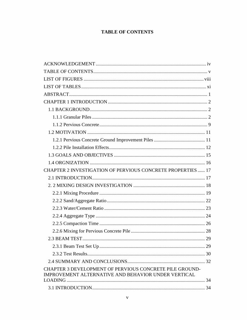
TABLE OF CONTENTS
ACKNOWLEDGEMENT ........................................................................................... iv
TABLE OF CONTENTS .............................................................................................. v
LIST OF FIGURES ................................................................................................... viii
LIST OF TABLES ....................................................................................................... xi
ABSTRACT .................................................................................................................. 1
CHAPTER 1 INTRODUCTION .................................................................................. 2
1.1 BACKGROUND ................................................................................................. 2
1.1.1 Granular Piles ............................................................................................... 2
1.1.2 Pervious Concrete ......................................................................................... 9
1.2 MOTIVATION ................................................................................................. 11
1.2.1 Pervious Concrete Ground Improvement Piles .......................................... 11
1.2.2 Pile Installation Effects ............................................................................... 12
1.3 GOALS AND OBJECTIVES ........................................................................... 15
1.4 ORGNIZATION ............................................................................................... 16
CHAPTER 2 INVESTIGATION OF PERVIOUS CONCRETE PROPERTIES ...... 17
2.1 INTRODUCTION ............................................................................................. 17
2. 2 MIXING DESIGN INVESTIGATION ........................................................... 18
2.2.1 Mixing Procedure ....................................................................................... 19
2.2.2 Sand/Aggregate Ratio ................................................................................. 22
2.2.3 Water/Cement Ratio ................................................................................... 23
2.2.4 Aggregate Type .......................................................................................... 24
2.2.5 Compaction Time ....................................................................................... 26
2.2.6 Mixing for Pervious Concrete Pile ............................................................. 28
2.3 BEAM TEST ..................................................................................................... 29
2.3.1 Beam Test Set Up ....................................................................................... 29
2.3.2 Test Results................................................................................................. 30
2.4 SUMMARY AND CONCLUSIONS................................................................ 32
CHAPTER 3 DEVELOPMENT OF PERVIOUS CONCRETE PILE GROUND-
IMPROVEMENT ALTERNATIVE AND BEHAVIOR UNDER VERTICAL
LOADING .................................................................................................................. 34
3.1 INTRODUCTION ............................................................................................. 34
vi
3.2 BACK GROUND .............................................................................................. 35
3.2.1 Permeable granular piles ............................................................................ 35
3.2.2 Pervious Concrete Material ........................................................................ 38
3.3 MATERIAL PROPERTIES .............................................................................. 39
3.3.1 Pervious Concrete Properties...................................................................... 39
3.3.2 Sand and Aggregate Properties................................................................... 42
3.4 TESTING FACILITY ....................................................................................... 46
3.5 TEST UNITS AND INSTRUMENTATION .................................................... 48
3.5.1 Installation of Test Units ............................................................................ 48
3.5.2 Description of Test Units ............................................................................ 50
3.5.3 Instrumentation of Test Units and Surrounding Soil .................................. 51
3.6 LOADING SEQUENCE ................................................................................... 54
3.7 TEST RESULTS ............................................................................................... 55
3.7.1 Experimental Pile Load-Displacement Response ....................................... 55
3.7.2 Load Transfer along Pile Length ................................................................ 57
3.7.3 Variation of Soil Stresses and Movement during Pile Installation ............. 59
3.8 SUMARY AND CONCLUSIONS ................................................................... 65
CHAPTER 4 BEHAVIOR AND SOIL-STRUCTURE INTERACTION OF
PERVIOUS CONCRETE GROUND IMPROVEMENT PILES UNDER LATERAL
LOADING .................................................................................................................. 68
4.1 INTRODUCTION ............................................................................................. 68
4.2 MATERIAL PROPERTIES .............................................................................. 71
4.2.1 Soil Properties............................................................................................. 71
4.2.2 Pervious Concrete Properties...................................................................... 73
4.3 TESTING FACILITY ....................................................................................... 74
4.4 TEST UNITS AND INSTRUMENTATION .................................................... 76
4.4.1 Test Units and Installation .......................................................................... 76
4.4.2 Instrumentation of Test Units and Surrounding Soil .................................. 78
4.5 LOADING SEQUENCE ................................................................................... 80
4.6 TEST RESULTS ............................................................................................... 81
4.6.1 Lateral Load-Displacement at Pile Head .................................................... 81
4.6.2 Strain along the Pile .................................................................................... 82
4.6.3 Soil-Pile Interaction .................................................................................... 84
4.6.4 Shear Wave Velocity Change during Pile Installation ............................... 90
4.7 SUMMARY AND CONCLUSIONS................................................................ 91

vii
CHAPTER 5 NUMERICAL SIMULATION OF PERVIOUS CONCRETE PILE
TESTS ......................................................................................................................... 95
5.1 INTRODUCTION ............................................................................................. 95
5.2 BACKGROUND ............................................................................................... 96
5.3 EXPERIMENTAL PROGRAM ....................................................................... 99
5.3.1Soil Properties.............................................................................................. 99
5.3.2 Vertical Load Tests ................................................................................... 100
5.4 MATERIAL CONSTITUTIVE MODELS ..................................................... 102
5.5 FINITE ELEMENT MODEL ......................................................................... 105
5.6 MODELING PROCEDURE ........................................................................... 108
5.7 RESULTS ANALYSES .................................................................................. 114
5.8 SUMMARY AND CONCLUSIONS.............................................................. 125
CHAPTER 6 SUMMARY AND CONCLUSIONS ................................................ 127
6.1 SUMMARY AND CONCLUSIONS.............................................................. 127
6.2 FUTURE RESEARCH ................................................................................... 128
REFERENCE ............................................................................................................ 130
VITA ......................................................................................................................... 145
viii
LIST OF FIGURES
Figure 1.1 Constructions of granular piles by Vibro-compaction Method ................... 4
Figure 1.2 Constructions of granular piles by Vibro-replacement Method (Top
feeding method) ............................................................................................................ 5
Figure 1.3 Constructions of granular piles by Vibro-displacement Method (Bottom
feeding method) ............................................................................................................ 5
Figure 1.4 Constructions of rammed aggregate piers ................................................... 6
Figure 1.5 Constructions of sand compaction pile (Kitazume, 2005) .......................... 7
Figure 2.1 Falling head permeameter used for the permeability testing ..................... 18
Figure 2.2 Pervious concrete properties for mixtures prepared using different mixing
procedures ................................................................................................................... 21
Figure 2.3 Pervious concrete properties for mixtures ................................................. 21
Figure 2.4 Failure surface of samples prepared using the two mixing procedure ...... 22
Figure 2.5 Pervious concrete compressive strength and permeability for mixtures
prepared using different sand/aggregate ratios ........................................................... 23
Figure 2.6 Pervious concrete compressive strength and permeability for mixtures
prepared using different water/cement ratios .............................................................. 24
Figure 2.7 The gradation of aggregates used for pervious concrete mixing ............... 26
Figure 2.8 Pervious concrete compressive strength and permeability for mixtures
prepared using different aggregate.............................................................................. 26
Figure 2.9 pervious concrete mixtures with different compacting times .................... 28
Figure 2.10 pervious concrete compressive strength and permeability versus the
porosity ....................................................................................................................... 29
Figure 2.11 Beam test setting up of pervious concrete pile ........................................ 30
Figure 2.12 The deformation of pervious concrete pile in beam test ......................... 31
Figure 2.13. The moment curvature relationship of pervious concrete pile ............... 31
Figure 3.1 Material properties..................................................................................... 45
Figure 3.2 SSI facility and reaction frame system for vertical load tests ................... 48
ix
Figure 3.3 Summary of the developed pile installation method ................................. 50
Figure 3.4 Set up of vertical load tests ........................................................................ 53
Figure 3.5 Instrumentation for Test unit 4. ................................................................. 54
Figure 3.6 Vertical load versus displacement for all test units ................................... 56
Figure 3.7 Test units after performing the vertical load test ....................................... 57
Figure 3.8 Comparison of the force transferred along the length of Test units 3 and 4
for different loading stages ......................................................................................... 59
Figure 3.9 Shear stress versus displacement curves (t-z curves) for the soil-pile
interface calculated using the strain gauge measurements for test units 3 and 4 ........ 60
Figure 3.10 Soil lateral displacement at 51 mm (average) and at 152 mm from the
surface of the pile measured using SAAs for Test unit 4 ........................................... 62
Figure 3.11 Effect of installation on the change of soil pressure................................ 65
Figure 4.1 Material Properties .................................................................................... 73
Figure 4.2 Laboratory Soil-Structure Interaction (SSI) testing facility with lateral
loading set up and a 3D system sketch (bottom left). ................................................. 76
Figure 4.3 Lateral loading tests set up. ....................................................................... 79
Figure 4.4 Instrumentation for lateral loading tests. ................................................... 80
Figure 4.5 Lateral load vs. displacement at the loading point. ................................... 82
Figure 4.6 Strain profile along the pile during lateral load tests. ................................ 84
Figure 4.7 Test units after lateral load tests. ............................................................... 84
Figure 4.8 The pile and soil lateral displacement under lateral loading of 3225 N .... 86
Figure 4.9 Precast pile displacements under lateral loading ....................................... 87
Figure 4.10 Soil reactions (soil-pile interaction force per unit length) along the pile
for the precast pile test unit ......................................................................................... 88
Figure 4.11 Soil-pile interaction force-displacement relationships ............................ 90
Figure 4.12 Change of shear wave velocity during pile installation at depth 550 mm91
Figure 5.1 The measured and calculated triaxial deviator stress vs. strain curves under
different confining pressure ...................................................................................... 104

x
Figure 5.2 The geometry of finite element model. ................................................... 107
Figure 5.3 The mesh of finite element model. .......................................................... 108
Figure 5.4 The prescribed displacement on soil boundary to simulate the cavity
expansion in pile installation .................................................................................... 111
Figure 5.5 The soil stiffness change after pile installation ....................................... 113
Figure 5.6 Comparison of vertical load versus displacement ................................... 115
Figure 5.7 The comparison of calculated and measured soil lateral movements at 51
mm from surface of installed pile ............................................................................. 116
Figure 5.8 The comparison of calculated and measured soil vertical pressure 76 mm
below the pile tip during the vertical load test .......................................................... 117
Figure 5.9 distribution of displacement under vertical load ..................................... 119
Figure 5.10 Distribution of soil stress under vertical load ........................................ 120
Figure 5.11 Influence on the interface ...................................................................... 123
Figure 5.12 Influence of soil stiffness for vertical load of installed pile .................. 124
Figure 5.13 Soil movements during pile installation ................................................ 125

xi
LIST OF TABLES
Table 1.1 Ultimate capacity for different failure mechanisms of granular piles .......... 8
Table 1.2 Summaries of the properties of granular piles .............................................. 9
Table 1.3 Summary of the properties of pervious concrete material .......................... 10
Table 2.1 Mixing procedure ........................................................................................ 20
Table 2.2 Properties of aggregates used for the pervious concrete mixing ................ 25
Table 3.1 Properties of three types of granular piers .................................................. 38
Table 5.1 The constitutive model parameters for sand used in vertical load tests.... 103
Table 5.2 The load-displacement properties of model with/without interface ......... 122

1
ABSTRACT
Permeable granular piles are used to increase the time rate of consolidation,
reduce liquefaction potential, improve bearing capacity, and reduce settlement.
However, the behavior of granular piles depends on the confinement provided by
surrounding soil, which limits their use in very soft clays and silts, and organic and
peat soils. This research effort aims to develop a new ground-improvement method
using pervious concrete piles. Pervious concrete piles provide higher stiffness and
strength which are independent of surrounding soil confinement, while offering
permeability comparable to granular piles. This proposed ground-improvement
method can improve the performance of different structures supported on poor soils.
To achieve the goal of the research project, a series of pervious concrete
sample mixing has been conducted to investigate the pervious concrete material
properties. Four vertical load tests were performed on one granular pile and three
pervious concrete piles. The vertical load responses of pervious concrete and
aggregate piles are compared and the variation of soil stresses and displacement
during pile installation are discussed. Two lateral load tests were conducted on a
precast pervious concrete pile and on a cast-in-place pile. The behavior of pervious
concrete piles and the effects of installation on their response under lateral loading
were investigated. In addition, a finite element model simulation account for the
installation effect has been used to further investigate the behavior of the pervious
concrete pile and surrounding soil under vertical load condition.
2
CHAPTER 1
INTRODUCTION
1.1 BACKGROUND
Ground improvement methods are widely used to enhance soil strength, allow
for drainage path, mitigate total and differential settlements, and to reduce
construction time. Based on different conditions, various ground improvement
methods are available (i.e., prefabricated vertical drains, vacuum consolidation, deep
soil mixing, grouting, and vibro-compaction). As one of the most commonly used
ground improvement methods, granular piles have been used extensively in several
geotechnical engineering applications (Mitchell 1981; Barksdale and Bachus 1983;
Aboshi and Suematsu 1985; Bergado et al. 1994; Baez 1995; Terashi and Juran 2000;
Okamura et al. 2006). The sections below will discuss different types of granular
piles and their installation, properties and failure mechanisms. In addition, this
chapter presents the properties of pervious concrete. Furthermore, the motivation and
goals of research are presented in this chapter.
1.1.1 Granular Piles
The term ‘granular piles’ refers to columns composed of compacted sand or
gravel. The three common granular piles are sand compaction piles, stone columns,
and rammed aggregate piers (Geopiers®
). Granular piles provide higher stiffness and
strength than surrounding soil. In addition, the piles provide high permeability
allowing for soil drainage and consolidation.

3
The construction of granular piles will change the soil stresses and accelerate
pore water pressure dissipation, resulting in consolidation, which leads to the
improvement of surrounding soil. Granular piles have been used to increase the time
rate of consolidation, increase the bearing capacity, reduce liquefaction potential, and
reduce settlement (Mitchell 1981; Barksdale and Bachus 1983; Aboshi and Suematsu
1985; Bergado et al. 1994; Baez 1995; Terashi and Juran 2000; Okamura et al. 2006).
Construction Techniques
Depending on soil types, water level, equipment availability, local practice
and construction company ownership, various technical methods have been
developed to install different types of granular piles. (Mitchell 1981; Barksdale and
Bachus 1983; Bergado 1994; Lin and Wong 1999; Terashi and Juran 2000; Elias et al.
2006). These main installation methods are briefly described as below:
1. Vibro-compaction Method
In this method, a vibroflot with water jetting and vibration penetrate into soil
to predetermined depth, and then the vibroflot is withdrawn gradually with granular
backfill inserted near the ground surface by top feeding method. This specific method
is usually used in the cohesionless granular soils (Figure 1.1).
4
(a) Step 1 (b) Step 2 (c) Step 3
Figure 1.1 Constructions of granular piles by Vibro-compaction Method: (1) Step 1; (2) Step 2;
(3) Step 3. (www.HaywardBaker.com)
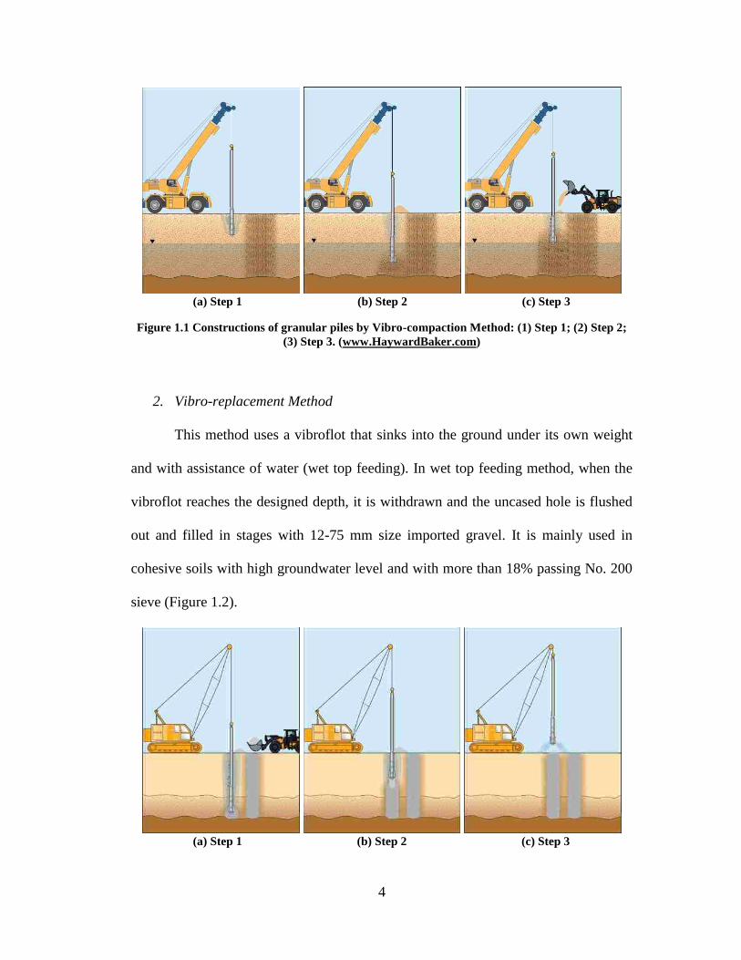
2. Vibro-replacement Method
This method uses a vibroflot that sinks into the ground under its own weight
and with assistance of water (wet top feeding). In wet top feeding method, when the
vibroflot reaches the designed depth, it is withdrawn and the uncased hole is flushed
out and filled in stages with 12-75 mm size imported gravel. It is mainly used in
cohesive soils with high groundwater level and with more than 18% passing No. 200
sieve (Figure 1.2).
(a) Step 1 (b) Step 2 (c) Step 3

5
Figure 1.2 Constructions of granular piles by Vibro-replacement Method (Top feeding method):
(1) Step 1; (2) Step 2; (3) Step 3. (www.HaywardBaker.com)
3. Vibro-displacement Method
This method is similar to the vibro-replacement method, however, the
difference is that the soil is penetrated without water jetting and can be either top
feeding method (short piles) or bottom feeding (deep piles). In the bottom feeding,
the aggregate is fed gradually through a feeding pipe attached to the vibrator as
showed in Figure 1.3. Because of the dry process without water jetting, this method is
suitable for soft clay with undrained shear strength more than 40 kN/m2 and low
groundwater level.
(a) Step 1 (b) Step 2 (c) Step 3
Figure 1.3 Constructions of granular piles by Vibro-displacement Method (Bottom feeding
method): (1) Step 1; (2) Step 2; (3) Step 3. (www.HaywardBaker.com)
4. Aggregate Ramming Method
Rammed aggregate piers is a method using a beveled tamper to compact the
loose aggregate into the prebored hole in stages. The compaction process results in a
high density and stiffness aggregate pier (Figure 1.4). With the beveled tamper, the
surrounding soil is densified and horizontal stresses are increased to further support

6
the piers. Rammed aggregate piers can be used in soft clay and silt, loose sand and
soils below the groundwater level.
. (a) Step 1 (b) Step 2 (c) Step 3
Figure 1.4 Constructions of rammed aggregate piers: (1) Step 1; (2) Step 2; (3) Step 3.
(www.HaywardBaker.com)
5. Vibro-compozer Method
This method is mainly used to install sand compaction piles (Bergado et al.
1988, 1994; Aboshi et al. 1974, 1985). As shown in Figure 1.5, a casing pipe is driven
into the soil with a vertical vibratory hammer. The casing pipe with an open end cone
will be used to transport sands down to the bottom and the casing is then repeatedly
extracted and partially re-driven to compact the sand below. When the pipe is driven
in, the cone at the tip of the casing pipe is kept close. As the pipe is extracted, the
cone will open under the weight of feeding sand. This method is suitable to be used in
soft clay with high groundwater level.

7
Figure 1.5 Constructions of sand compaction pile (Kitazume, 2005)
Failure Mechanism
As shown in Figure 1.6, regardless of the used construction method, single
isolated granular piles under vertical load fail in bulging, shear, or punching
(Barksdale and Bachus 1983). For typical granular pile length-to-diameter (L/D)
ratios, the most common failure mechanism is bulging, which is usually observed
over a distance of 2 to 3 pile diameters (2 to 3D) below the soil surface (Barksdale
and Bachus 1983; Bergado et al. 1994). In this failure mechanism, the granular pile
bulges into the surrounding soil (Figure 1.6a). Therefore, the ultimate vertical
resistance of the column depends upon the lateral confining stress provided by the
surrounding soil. Shear failure is possible to occur in short piles bearing on a firm
support layer. This is similar to the general shear bearing capacity failure occurring in
shallow foundations. Punching failure occurs in a short pile (less than 3 D in length)
with a floating end installed in soft soils. The ultimate capacities of the first two
failure mechanisms are summarized in Table 1.1. Note that the third failure

8
mechanism is similar to that experienced by rigid deep foundations subjected to
vertical loading.
When subjected to lateral load, such as in slope stabilization, the granular
piles fail in direct shear along the failure surface. The shear strength is calculated as
the average shear strength of the soil/granular piles composite materials along the
failure surface (Mitchell 1981; Barksdale and Bachus 1983; Bergado et al. 1994).
(a) Bulging Failure (b) Shear Failure (c) Punching Failure
Figure 1.6 Failure mechanisms of single granular piles
Table 1.1 Ultimate capacity for different failure mechanisms of granular piles
Mode of
failure Derived formula References
Bulging
Where, : the total radial confining stress; : undrained shear
strength of soil; :the friction angle of aggregate material; :
undrained modulus of soil; : Poisson’s ratio of soil
Barksdale and
Bachus 1983
Shear
;
Where, : saturated or wet unit weight of the cohesive soil; :
foundation (including surrounding soil) width; : failure surface
inclination; : the area replacement ratio; the stress concentration
factor for granular piles; : undrained shear strength within the
unreinforced cohesive soil;
Barksdale &
Bachus 1983

9
Properties of Granular Piles
The properties of granular piles (i.e. sand compaction piles, stone columns,
rammed aggregate piers) are summarized in Table 1.2. As shown in the table, the
modulus of granular piles ranges from 25 to 190 MPa and the permeability ranges
from 0.05 to 2.0 cm/sec.
Table 1.2 Summaries of the properties of granular piles
Granular
pile
Friction
Angle (°)
Modulus
(MPa)
Stress
Concentration
ratio
Permeability
(cm/sec) Reference
Sand
Compaction
Piles
30-36 25-40 1.5-6.0 0.05-0.65 Aboshi et al. 1979; Bergado
et al. 1988, 1994
Stone
Columns 35-45 30-70 2.0-8.5 0.09-2.0
Mitchell 1981; Barksdale
and Bachus 1983; Baez
1995
Rammed
Aggregate
Piers
47-52 60-190 2.0-10 1.90
Hoevelkamp 2002; White
and Suleiman 2004;
Suleiman et al. 2014a
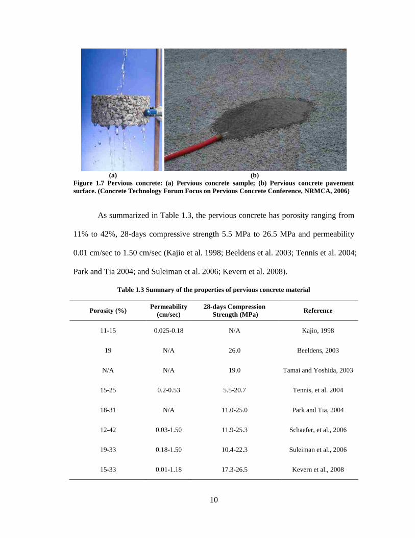
1.1.2 Pervious Concrete
Pervious concrete is a special concrete made primarily of single-size
aggregate (Figure 1.7). Pervious concrete has been used in pavements to reduce the
quantity of storm water runoff and perform initial treatment of water quality by
allowing water to penetrate through the porous surface. The pervious concrete is
mainly used in pavement application, including sidewalks, parking lots, tennis courts,
and low traffic density areas (Tennis et al. 2004; and Suleiman et al. 2011).
10
(a) (b)
Figure 1.7 Pervious concrete: (a) Pervious concrete sample; (b) Pervious concrete pavement
surface. (Concrete Technology Forum Focus on Pervious Concrete Conference, NRMCA, 2006)
As summarized in Table 1.3, the pervious concrete has porosity ranging from
11% to 42%, 28-days compressive strength 5.5 MPa to 26.5 MPa and permeability
0.01 cm/sec to 1.50 cm/sec (Kajio et al. 1998; Beeldens et al. 2003; Tennis et al. 2004;
Park and Tia 2004; and Suleiman et al. 2006; Kevern et al. 2008).
Table 1.3 Summary of the properties of pervious concrete material
Porosity (%) Permeability
(cm/sec)
28-days Compression
Strength (MPa) Reference
11-15 0.025-0.18 N/A Kajio, 1998
19 N/A 26.0 Beeldens, 2003
N/A N/A 19.0 Tamai and Yoshida, 2003
15-25 0.2-0.53 5.5-20.7 Tennis, et al. 2004
18-31 N/A 11.0-25.0 Park and Tia, 2004
12-42 0.03-1.50 11.9-25.3 Schaefer, et al., 2006
19-33 0.18-1.50 10.4-22.3 Suleiman et al., 2006
15-33 0.01-1.18 17.3-26.5 Kevern et al., 2008

11
1.2 MOTIVATION
1.2.1 Pervious Concrete Ground Improvement Piles
The various installation methods and improvement benefits allow granular
piles to be used to improve a wide range of poor soils. However, when compared with
other pile types (e.g., steel and concrete piles), the strength and stiffness of granular
piles are lower and depend on the properties of the surrounding soil. For conditions
where the surrounding soil cannot provide the confining pressure around granular
piles to ensure developing the required stiffness and strength, the use of granular piles
is limited (Venema 1991). For example, Barksdale and Bachus (1983) reported that
when a stratum of poor soil (very soft clays and silts, peat and other organic materials)
with a thickness greater than 1 column diameter, granular piles is not suitable to
improve the soil. Therefore, granular piles have limited use in very soft clays and silts,
and organic and peat soils.
Comparing the properties of granular piles (Table 1.2) with those of the
pervious concrete material (Table 1.3), pervious concrete can develop a much higher
unconfined compressive strength and maintain a relatively similar permeability of
granular piles. According to the studies of other ground improvement techniques
(Suleiman et al. 2003; Han and Gabr 2002), the stress concentration ratio of pervious
concrete piles is expected to be 3 to 4 times that of granular piles in embankment
applications. Higher stress concentration ratio indicates that the stresses carried by
soils and the area replacement ratio in the field will be reduced. Meanwhile, the
relative high permeability ensures accelerated consolidation and dissipation of pore
water pressure. Furthermore, the stiffness of pervious concrete pile is not depending

12
on surrounding soil. These advantages are expected to result in an enhanced ground
improvement system that can be used in a wider range of soil types.
1.2.2 Pile Installation Effects
During pile installation or constructions, the soil surrounding the pile
experience significant change of displacement and stress and its properties also be
changed correspondingly. The changes due to the pile installation influence the
subsequent load-displacement response of the pile. Therefore, the effects of pile
installation have been investigated by several researchers (Yu 1990 and 2000;
Shublaq 1992; Klotz and Coop 2001; Hunt et al. 2002; Lee et al. 2004; White and
Bolton 2004; Dijkstra et al. 2006 and 2008; Suleiman and White 2006; Pham and
White 2007; Salgado and Prezzi 2007; Chen et al. 2009; Said et al. 2009; Basu et al.
2010; Castro and Karstunen 2010; Thompson and Suleiman 2010; Yi et al. 2010;
Dijkstra et al. 2011; Pucker and Grabe 2012; and Lundberg et al. 2013).
Different approaches have been used by these researchers to investigate the
effects of pile installation on surrounding soils, including cavity expansion analysis,
numerical modeling methods, experimental methods with pressure measurement at
soil-pile interface, soil density measurement, shear wave velocity measurement and
movement around the pile.
Shublaq (1992) and Dijkstra et al. (2008) used thermal probe density
measurement to investigate the installation effect of driven pile in sand and showed
that sand was compacted with 0.6 to 28.6% density increase in a zone of 7D
(diameter) around the pile tip. Klotz and Coop (2001) conducted a series of model

13
pile tests in a centrifuge and investigated the effects of changing soil density and
stresses on pile capacity. They concluded that the shaft friction increase by
approximately 12% due to the increase of horizontal stresses. Hunt et al. (2002)
measured the shear wave velocity change and investigated the changes of soil
properties surrounding piles driven in soft clay through a comprehensive testing
program. The testing results show that the soil zone affected by pile installation
extends to 3.5D (3.5 x pile diameter) from pile center and that the soil stiffness of the
soil adjacent to pile increased by10 to 15% due to pile installation. Lee et al. (2004),
who performed centrifuge tests, reported that the soil horizontal stresses and pore
water pressure changes by 30 to 100% within 6D surrounding the pile during the
installation of sand compaction piles in soft clay. Yi et al. (2010) investigated the
effects of installation of sand compaction piles on soil shear strength using the same
centrifuge test setting-up as Lee et al. (2004). The results showed that the increase of
the shear strength of the soil at 1.5D from pile center ranged from 25% to 200% along
the pile length. White and Bolton (2004) investigated the penetration mechanism of a
displacement pile using an image-cased deformation measurement technique, and the
results demonstrate that the soil displacement extended to 15D, which were amplified
by the testing boundary. Yu (1990 and 2000) and Salgado and Prezzi (2007) used the
cavity expansion theory and cone penetration tests to investigate the stress
development in pile installation. However, the cavity expansion theory assumed an
large effected zone (70 to 100 times of cavity diameter) for available calculation.
Lundberg et al. (2013) observed the displacement of soil during pile installation
through the Plexiglas wall of test container and the results showed the displacement

14
occurs within 2D from pile centers due to pile installation. However, none of these
approaches, directly and simultaneously measured the variation of soil stresses and
soil movement during pile installation. Therefore, Lundberg et al. (2013) reported that
there is a lack of direct combined measurements of soil stresses and movement
surrounding piles in general.
Numerical simulation methods have been also utilized to investigate the
effects of pile installation on soil properties, displacement and stress (Dijkstra et al.
2006; Ambily and Ganhdi 2007; Pham and White 2007; Chen et al. 2009; Said et al.
2009; Basu et al. 2010; Castro and Karstunen 2010; Thompson and Suleiman 2010;
Dijkstra et al. 2011; Pucker and Grabe 2012). However, due to the complexity of the
pile installation effects and lack of direct measurements on soil and pile, the
modelling results are difficult to be validated (Dijkstra 2011; Pucker and Grabe 2012).
In addition, very few researches have investigated the change of soil properties due to
pile installation (Wehnert and Vermeer 2004a and 2004b; Said et al. 2009) in
numerical simulation. Therefore, the numerical simulation needs to be improved and
validate calculation results with the experimental measurement. In addition, very few
researchers have been investigating the installation effects on the behavior of laterally
loaded piles (Lunberg et al. 2013). The installation effects on laterally loaded pile and
soil require further investigation.
In this research, the installation effects on pile and soil behavior will be
investigated utilizing both experimental method and numerical modeling method.

15
1.3 GOALS AND OBJECTIVES
The goal of this research is to develop an innovative ground improvement
alternative that uses pervious concrete piles and investigate the pile installation effect.
The pervious concrete piles should be able to provide higher stiffness and strength
that are independent of the surrounding soil properties while offering permeability
comparable to granular piles, to support structures and highway facilities constructed
on a wide range of poor soil conditions, including very soft clays and silts, and peat
and organic soils. In addition, the effect of pile installation on soil properties,
displacement and stress was directly measured in tests. The installation effects are
analyzed by experimental and numerical approaches.
The objectives of this research are:
1. Investigating the pervious concrete material properties and developing
suitable mixing procedures and mixing proportions for pervious concrete pile
casting;
2. Developing installation technique for pervious concrete pile and investigating
the effects of pile installation effects on soil and pervious concrete pile
properties, soil-pile interactions, and on pile behavior;
3. Evaluating the response of pervious concrete piles when subjected to different
loading conditions;
4. Developing appropriate analytical methods to simulate the pervious pile
behavior, soil-pile interaction and installation effects.

16
1.4 ORGNIZATION
The Dissertation begins with Chapter 1, in which the back ground information,
the motivation and research goal has been introduced.
Chapter 2 discusses the investigation of pervious concrete material properties,
and provides an optimized mixing procedure and mixing proportion design for
casting pervious concrete piles.
Chapter 3 describes the soil-pile interaction and behavior of pervious concrete
piles subjected to vertical loading and the effects of pile installation on the sepsonse
under vertical loading.
Chapter 4 presents the soil-pile interaction and behavior of pervious concrete
piles under lateral loads, including the pile behavior with respect to lateral capacity,
pile and soil displacements, soil-pile interactions and the effects of installation.
Chapter 5 focuses on numerical modeling of pervious concrete piles under
vertical load including the effects of installation.
Chapter 6 summarizes the general conclusions and provides recommendations
for further studies.

17
CHAPTER 2
INVESTIGATION OF PERVIOUS CONCRETE PROPERTIES
2.1 INTRODUCTION
In Chapter 1, the use of pervious concrete in pavement and sidewalk
applications were introduced and the properties of pervious concrete from literatures
were summarized in Table 1.3, which shows a wide range of strength and
permeability. For ground improvement applications, a pervious concrete material
need to be improved with high stiffness and strength, and permeability comparable to
granular piles (ranged from 0.05 to 2.0 cm/s).
To develop a mixture suitable for ground improvement application, a series of
pervious concrete mixtures was prepared to obtain an adequate compressive strength
and permeability. Pervious concrete cylinder samples were tested to measure the
porosity, permeability, compressive strength, elastic modulus, and split tensile
strength. The porosity was measured using ASTM C1688 (ASTM 2009e), the
compressive strength was determined using ASTM C39 (ASTM 2009b), the elastic
modulus was measured using ASTM C469 (ASTM 2009j), and the split tensile
strength was measured using ASTM C496 (ASTM 2009i). In addition, the
permeability was measured using an in house designed falling-head as shown in
Figure 2.1. The permeameter has a transparent tube with scale for recording the water
level. The tube has an inside diameter of 76 mm and height of 914 mm. The sample
was installed at the bottom of the tube. Duct Seal (DS-130, Gardner Bender) was used
to seal the both sides of the sample to prevent water leakage along the sides of the

18
sample. The falling-head test was performed for several times to obtain an average
value of permeability.
Pervious concrete properties are significantly affected by the mixing
procedure, aggregate type, compaction (vibrating) times, water/cement ratio, and
sand/aggregate ratio (Schaefer et al. 2006; Suleiman 2006; Kevern 2008). The effects
of these variables on pervious concrete strength and permeability were investigated
and will be discussed next.
Figure 2.1 Falling head permeameter used for the permeability testing
2. 2 MIXING DESIGN INVESTIGATION
The materials used for pervious concrete mixing include aggregate, cement
(Portland cement type II from Lafarge North America Inc.), sand (fine play sand
available in home improvement store), water, air enhancement admixture (AEA,
Daravair 1000) and high range water reducer (HRWR, V-MAR VSC 500). The
investigation focuses on mixing procedure, aggregate type, compaction time,
water/cement ratio, and sand/aggregate ratio. Mixtures were prepared using

19
water/cement ratios ranging from 0.21 – 0.28 and sand/aggregate ratios ranging from
0.05 – 0.17 using two mixing procedures, four different types of aggregate and four
different compaction times.
2.2.1 Mixing Procedure
The main procedure of pervious concrete mixing follows the normal concrete
mixing procedure in the ASTM C192 (2009a). Two procedures have been used for
pervious concrete mixing as summarized in Table 2.1. The main difference between
two mixing procedures is in the Step 2 and Step 4 as show in table. Two mixtures
were prepared using the two mixing procedures. The first mixture has the following
mixing design: sand/aggregate ratio of 0.07, water/cement ratio of 0.26, 343 kg/m3
cement, 1,510 kg/m3 coarse aggregate, 0.49 kg/m
3 AEA, and 0.96 kg/m
3 HRWR. The
sec.ond mixing design is 0.11 sand/aggregate ratio, 0.21 water/cement ratio, 343
kg/m3 cement, 1,440 kg/m
3 coarse aggregate, 2.47 kg/ m
3 AEA, and 4.94 kg/m
3
HRWR. Both mixtures used Nazareth gravel, which was locally available in Lehigh
Valley. The aggregate was sieved and the portion passing the 9.5 mm sieve (3/8 in.
sieve) and retained on the 4.75 mm sieve (No.4 sieve) was used (Schaefer et al. 2006).
For both mixtures, a compaction time of 10 sec. was used.
The compressive strength and permeability comparison of mixture using these
two mixing procedures are summarized in the Figure 2.1. The results shows that the
compressive strength of mixtures prepared by procedure 1 (13.8 MPa as average) is
higher than that of mixtures prepared by procedure 2 (9.6 MPa as average). The
permeability of samples prepared suing procedure 2 (2.1 cm/sec.) is higher than that

20
in procedure 1 (1.7 cm/sec.). Further investigation on mixing proportion adjustment
shows that the compressive strength can be improved by optimization of mixing
proportion, while the permeability is more difficult to be improved by changing the
mixing proportion if the aggregate size is kept the same. It is worth noting that the
mixing of cement in step 4 of procedure 1 may cause cement clumps as shown in
Figure 2.2, which may affect the pervious concrete properties. As shown in Figure 2.4,
the failure surface of samples prepared by procedure 2 passes through the aggregate,
while the failure surface of samples prepared by procedure 1 mainly passes through
cement or the interface between the cement and aggregate. This phenomenon
indicates that the sample prepared by procedure 2 may achieve a higher strength with
better quality aggregate material. Based on the above observations and analysis, the
mixing procedure 2 was selected for further mixing.
Table 2.1 Mixing procedure
Procedure 1:
Step 1 Mix water, AEA, and HRWR together
Step 2 Add sand, aggregate, and 2/3 of water mixture to mixer
Step 3 Mix together for 1 minute
Step 4 Add cement and last 1/3 of water mixture to mixer
Step 5 Mix thoroughly for 3 minutes
Step 6 Allow to rest for 3 minutes
Step 7 Mix for an additional 2 minutes
Procedure 2:
Step 1 Mix water, AEA, and HRWR together
Step 2 Add Aggregate and 5 – 10% cement
Step 3 Mix together for 1 minute
Step 4 Add sand, water mixture, and rest of cement to mixer
Step 5 Mix thoroughly for 3 minutes
Step 6 Allow to rest for 3 minutes
Step 7 Mix for an additional 2 minutes

21
(a)
(b)
Figure 2.2 Pervious concrete properties for mixtures prepared using different mixing procedures:
(a) 28-day compressive strength; (b) permeability
Figure 2.3 Pervious concrete properties for mixtures
Porosity
0.05 0.10 0.15 0.20
28
-day
Co
mp
ress
ive
Str
ength
(M
Pa)
0
2
4
6
8
10
12
14
16
Mixing procedure 1
Mixing procedure 2
Porosity
0.05 0.10 0.15 0.20
Per
mea
bil
ity (
cm/s
ec)
0.0
0.5
1.0
1.5
2.0
2.5
Mixing procedure 1
Mixing procedure 2

22
(a) (b)
Figure 2.4 Failure surface of samples prepared using the two mixing procedure: (a) Mix
procedure 1; (b) Mix procedure 2
2.2.2 Sand/Aggregate Ratio
Four different sand/aggregate ratios (0.05, 0.08, 0.11 and 0.17) have been
used. The samples were mixed using the mixing procedure 2, sieved Nazareth
aggregate, and 10 sec. compaction time. The material proportion for mixing is
water/cement ratio of 0.21, 343 kg/m3 cement, 1,523 kg/m
3 coarse aggregate for ratio
0.05 (1,477 kg/m3 for ratio 0.08, 1,440 kg/m
3 for ratio 0.11, and 1,329 kg/m
3 for
ratio 0.17), 0.49 kg/m3 AEA, and 0.96 kg/m
3 HRWR.
The results in Figure 2.5 show that the mixing with sand/aggregate ratio with
0.11 can provide the highest compressive strength of 13.6 MPa. The permeability of
the mixtures with different sand/aggregate ratio is higher than 1.6 cm/s which is
comparable to granular piles (up to 2.0 cm/sec.). Therefore, the sand/aggregate ratio
of 0.11 was selected for further investigation.
Other mixtures were prepared using the sieved Pea gravel with sand/aggregate
ratios of 0.07 and 0.11. The mixtures have water/cement ratio of 0.21, 343 kg/m3

23
cement, 1,440 kg/m3 coarse aggregate, 0.74 kg/m
3 AEA, and 4.06 kg/m
3 HRWR. The
compressive strengths of mixtures with 0.07 and 0.11 sand/aggregate ratios were 22.2
and 29.0 MPa, respectively. The permeability was 1.68 cm/sec. of mixture with 0.07
sand/aggregate ratio and 1.45 cm/sec. of mixture with 0.11 sand/aggregate ratio.
Therefore, the sand/aggregate ratio of 0.11 was selected for further mixing
investigation.
Figure 2.5 Pervious concrete compressive strength and permeability for mixtures prepared using
different sand/aggregate ratios
2.2.3 Water/Cement Ratio
Four different water/cement ratios (0.21, 0.23, 0.27 and 0.28) were used for
pervious concrete mixtures. The samples were mixed using mixing procedure 2 and
with sand/aggregate ratio of 0.11, water/cement ratio of 0.21, 377 kg/m3 cement,
1,440 kg/m3 coarse aggregate, 2.47 kg/m
3 AEA, and 4.94 kg/m
3 HRWR. The
aggregate used for these mixtures was sieved Nazareth gravel. The compaction time
of 10 sec. was used for these samples.
Sand/aggregate ratio
0.05 0.10 0.15 0.20
28
-day
Co
mp
ress
ive
Str
ength
(M
Pa)
0
2
4
6
8
10
12
14
16
Per
mea
bil
ity (
cm/s
ec)
0.0
0.5
1.0
1.5
2.0
2.5
28-day compressive strength
Permeability
24
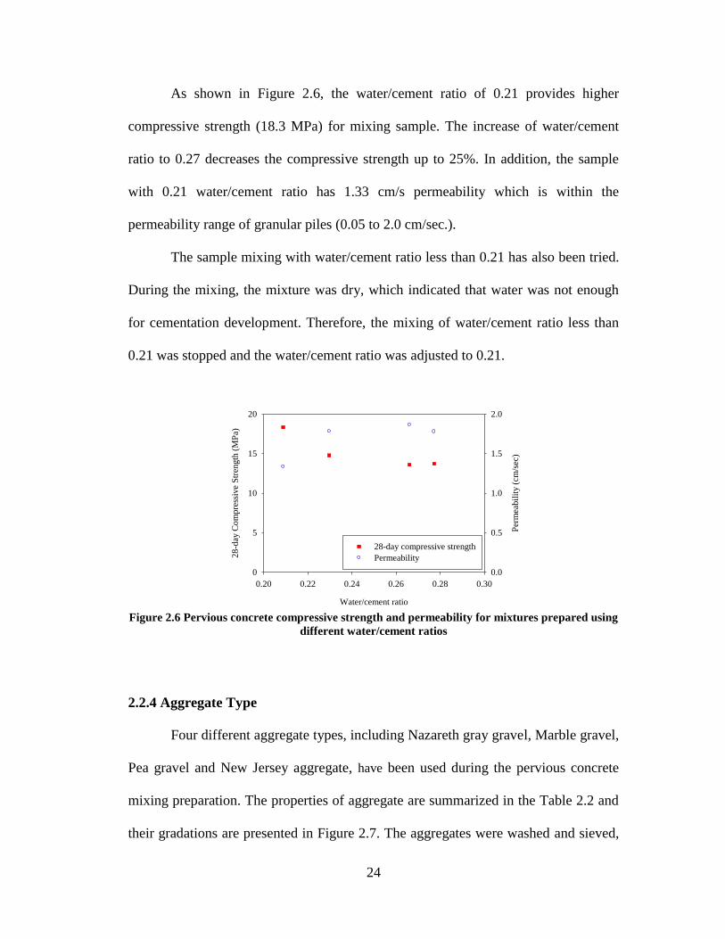
As shown in Figure 2.6, the water/cement ratio of 0.21 provides higher
compressive strength (18.3 MPa) for mixing sample. The increase of water/cement
ratio to 0.27 decreases the compressive strength up to 25%. In addition, the sample
with 0.21 water/cement ratio has 1.33 cm/s permeability which is within the
permeability range of granular piles (0.05 to 2.0 cm/sec.).
The sample mixing with water/cement ratio less than 0.21 has also been tried.
During the mixing, the mixture was dry, which indicated that water was not enough
for cementation development. Therefore, the mixing of water/cement ratio less than
0.21 was stopped and the water/cement ratio was adjusted to 0.21.
Figure 2.6 Pervious concrete compressive strength and permeability for mixtures prepared using
different water/cement ratios
2.2.4 Aggregate Type
Four different aggregate types, including Nazareth gray gravel, Marble gravel,
Pea gravel and New Jersey aggregate, have been used during the pervious concrete
mixing preparation. The properties of aggregate are summarized in the Table 2.2 and
their gradations are presented in Figure 2.7. The aggregates were washed and sieved,
Water/cement ratio
0.20 0.22 0.24 0.26 0.28 0.30
28
-day
Co
mp
ress
ive
Str
ength
(M
Pa)
0
5
10
15
20
Per
mea
bil
ity (
cm/s
ec)
0.0
0.5
1.0
1.5
2.0
28-day compressive strength
Permeability

25
and the portion passing the 9.5 mm sieve (3/8 in. sieve) and retained on the 4.75 mm
sieve (No.4 sieve) was used for all mixtures. The samples were mixed using mixing
procedure 2, compaction time of 10 sec., and sand/aggregate ratio of 0.11,
water/cement ratio of 0.21, 377 kg/m3 cement, 1,440 kg/m
3 coarse aggregate, 2.47
kg/m3 AEA, and 4.94 kg/m
3 HRWR.
The compressive strength and permeability versus porosity are presented in
the Figure 2.8. The testing results show that aggregate type has great effect on the
pervious concrete mixture properties. The mixture using New Jersey aggregate
provides the highest compressive strength and permeability. However, this type
material can only be obtained from one manufacture in New Jersey. The quantity
obtained by research team is not enough for further mixing. Among the mixtures of
the other three aggregates, the samples mixed with Pea gravel have higher strength
(20.8 MPa) and permeability (1.75 cm/sec.) comparable to granular piles (up to 2.0
cm/sec.). In addition, the pea gravel is available from home improvement stores.
Therefore, the Pea gravel was chosen for further investigation.
Table 2.2 Properties of aggregates used for the pervious concrete mixing
Aggregate Type Nazareth Gray
Gravel
Marble
Gravel
Pea
Gravel
New Jersey
Aggregate
Unit Weight (kN/m3) 14.9 16.2 16.1 16.1
Voids (%) 40 35 33 43
Specific Gravity 2.62 2.62 2.48 2.90
Absorption (%) 1.8 1.6 0.7 0.9
Abrasion Mass Loss (%) 12.1 - 14.1 10.9

26
Figure 2.7 The gradation of aggregates used for pervious concrete mixing
Figure 2.8 Pervious concrete compressive strength and permeability for mixtures prepared using
different aggregate
2.2.5 Compaction Time
The pervious concrete samples were compacted using a vibrating table
(HUMBOLDT, 60 Hz with amplitude 0.86 mm). The samples were mixed using
sieved Pea gravel and mixing procedure 2 with 0.11 sand/aggregate ratio, 0.21
water/cement ratio, 377 kg/m3 cement, 1,440 kg/m
3 coarse aggregate, 2.47 kg/m
3
AEA and 4.94 kg/m3 HRWR. Four different compaction times (5 sec., 10 sec., 30 sec.
Particle Size (mm)
0.1 1 10
% P
assin
g
0
10
20
30
40
50
60
70
80
90
100
Marble gravel
pea gravel
Nazareth gray gravel
New Jersey aggregate
Porosity
0.10 0.15 0.20 0.25 0.30
28
-day
Co
mp
ress
ive
Str
ength
(M
Pa)
0
5
10
15
20
25
30
Per
mea
bil
ity (
cm/s
ec)
0.0
0.5
1.0
1.5
2.0
2.5
3.0
28-day compressive strength
Permeability
New Jersey aggregate
Pea gravel
Marbel gravel
Nazareth aggregate

27
and 60 sec.) have been used to investigate the compaction time effect on pervious
concrete properties.
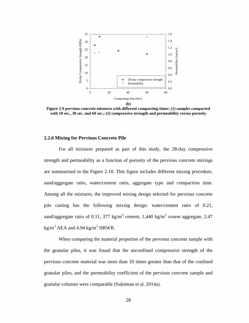
As shown in Figure 2.9a, the samples with compaction time of 10 sec. have
uniform distribution of materials, while samples with 30 and 60 sec.. compaction time
have segregation at the bottom. This segregation may affect the permeability of the
pervious concrete sample and the pile as well as the strength. The 28-day compressive
strength and permeability presented in Figure 2.9b, the sample compacted by 10 sec..
has highest strength (33.3 MPa) and a comparable permeability (1.1 cm/sec.) to
granular piles. Therefore, compaction time with 10 sec. was selected for further
investigation. It should be noted that the permeability increase of samples with 30 and
60 sec. compaction times shown in Figure 2.9b was determined after cutting the
segregation part at the bottom of the samples.
(a)
28
(b)
Figure 2.9 pervious concrete mixtures with different compacting times: (1) samples compacted
with 10 sec., 30 sec. and 60 sec.; (2) compressive strength and permeability versus porosity
2.2.6 Mixing for Pervious Concrete Pile
For all mixtures prepared as part of this study, the 28-day compressive
strength and permeability as a function of porosity of the pervious concrete mixings
are summarized in the Figure 2.10. This figure includes different mixing procedure,
sand/aggregate ratio, water/cement ratio, aggregate type and compaction time.
Among all the mixtures, the improved mixing design selected for pervious concrete
pile casting has the following mixing design: water/cement ratio of 0.21,
sand/aggregate ratio of 0.11, 377 kg/m3 cement, 1,440 kg/m
3 coarse aggregate, 2.47
kg/m3 AEA and 4.94 kg/m
3 HRWR.
When comparing the material properties of the pervious concrete sample with
the granular piles, it was found that the unconfined compressive strength of the
pervious concrete material was more than 10 times greater than that of the confined
granular piles; and the permeability coefficient of the pervious concrete sample and
granular columns were comparable (Suleiman et al. 2014a).
Compacting time (Sec)
0 20 40 60 80
28
-day
Co
mp
ress
ive
Str
ength
(M
Pa)
0
5
10
15
20
25
30
35
Per
mea
bil
ity (
cm/s
ec)
0.0
0.2
0.4
0.6
0.8
1.0
1.2
1.4
1.6
28-day compressive strength
Permeability

29
Figure 2.10 pervious concrete compressive strength and permeability versus the porosity
2.3 BEAM TEST
2.3.1 Beam Test Set Up
The purpose of the beam test is to obtain the moment-curvature relationship of
the pervious concrete pile cross section. The test follows the procedure of ASTM C78
(2009f). A load increment of 89 N was used and each load was hold for 1 minute. The
test was stopped when the pile displacement increased continuously under a constant
load.
The pervious concrete pile shown in Figure 2.11 was cast using the mixing
design mentioned at the end of the previous section. The pervious concrete mixing
has a porosity of 0.11, permeability of 1.21 cm/s, 28-day compressive strength of 24.8
MPa, split tensile strength of 2,260 kPa and elastic modulus of 16.3 GPa. The pile has
101 mm diameter and 1,524 mm length. The pile had one No.4 rebar installed at pile
center and one groove along the pile was made for Shape Acceleration Arrays (SAA)
installation (Figure 2.11b).
Porosity
0.05 0.10 0.15 0.20
28
-day
Co
mp
ress
ive
Str
ength
(M
Pa)
0
5
10
15
20
25
30
35
Per
mea
bil
ity (
cm/s
ec)
0.0
0.5
1.0
1.5
2.0
2.5
28-day compressive strength
Permeability

30
As shown in Figure 2.11, the beam was loaded at two symmetric points,
which was located at 1/3 and 2/3 length of pile. The moment at the section between
these two loading points is keep constant. The pile was instrumented with Shape
Acceleration Arrays (SAA) at middle along the pile to measure the pile deformation
during the test. Four dial gauges had been set to verify the SAA measurements.
Figure 2.11 Beam test setting up of pervious concrete pile: (a) pervious concrete pile setting up;
(b) SAA and dial gauge setting up; (c) hydraulic load on beam
2.3.2 Test Results
The ultimate load of the beam test was 5,204N with maximum displacement
of 18.7 mm at the middle of the pile. Figure 2.12 shows the pile deformation during
the test. Based on the measurement values of the load and the displacement along the
pile, the moment curvature relationship was calculated and presented in Figure 2.13.
The maximum moment is 1,322N·m with curvature of 0.0019. Theoretical method
results based on SAP2000 was compared with the moment-curvature response
calculated using the measured displacement of the pile, which shows very good
(a)
(b) (c)

31
agreement. The slope of the moment-curvature curve shows that EI (elastic modulus
multiplied by inertia) value of pile section decreased from 130 kN·m2 to 18 kN·m
2.
This moment-curvature relationship will be used to model the behavior of the
pervious concrete pile cross section.
Figure 2.12 The deformation of pervious concrete pile in beam test
Figure 2.13. The moment curvature relationship of pervious concrete pile
Location (mm)
0 200 400 600 800 1000 1200 1400 1600 1800
Dis
pla
cem
ent
(mm
)0
5
10
15
20
578
1023
1468
1913
2357
2802
3247
3692
4137
4581
5026
5204
Load (N)
Curvature (1/m)
0.00 0.02 0.04 0.06 0.08 0.10 0.12 0.14 0.16
Mo
men
t (N
*m
)
0
200
400
600
800
1000
1200
1400
1600
1800
Measured
Modeled (Sap 2000)
32
2.4 SUMMARY AND CONCLUSIONS
In this chapter, the pervious concrete properties have been investigated. A
mixing design targeted higher strength and comparable permeability of granular pile
The moment-curvature properties have been investigated using the beam tests. Based
on the discussion of the experimental results presented in this chapter, the conclusions
on pervious concrete properties are made as follow:
1. The mixing initial step of the additional 1 min. mixing of aggregate
and 5-10% cement improved the coating of aggregate w and improved
the mixing quality.
2. Sand/aggregate ratio of 0.11 provides higher compressive strength in
the range of 0.05 to 0.17, and comparable permeability to granular
piles.
3. Water/cement ratio of 0.21 provides highest compressive strength
(18.3 MPa) comparing to other water/cement ratio and permeability of
1.33 cm/sec.
4. Aggregate type has great effect on concrete strength and permeability.
Pea gravel, which provides high strength (20.8 MPa) and comparable
permeability (1.75 cm/sec.), was chosen for pervious concrete pile
mixing.
5. The 10 second compaction time c prevent segregation of cement at
bottom and provide adequate strength and permeability. The sample
has compressive strength of 33.3 MPa and a comparable permeability
of 1.1 cm/sec.

33
6. The moment-curvature curve of pervious concrete pile has been
developed using beam test and proved that the calculation procedure
for normal concrete to develop moment-curvature can be used for
pervious concrete section.

34
CHAPTER 3
DEVELOPMENT OF PERVIOUS CONCRETE PILE GROUND-
IMPROVEMENT ALTERNATIVE AND BEHAVIOR UNDER VERTICAL
LOADING
3.1 INTRODUCTION
Numerous structures and highway facilities, including embankments and
bridges, are often constructed on poor soils (i.e., soft or loose soils as well as
organic/peat soils). In order to facilitate construction, achieve allowable settlements,
and avoid failures, poor soils are often improved using ground improvement
technologies. A common ground improvement technique involves using permeable
granular piles (aggregate piers), which include sand compaction piles, stone columns
and rammed aggregate piers, to improve soil strength and provide a drainage path.
The use of permeable granular piles increases the time rate of consolidation, reduces
liquefaction potential, improves bearing capacity and reduces settlement (Barksdale
and Bachus, 1983; Mitchell, 1981; Aboshi and Suematsu, 1985; Bergado, 1994; Baez,
1995; Terashi and Juran, 2000; and Okamure et al., 2006). However, when compared
to other pile types (i.e., steel and concrete piles), the strength and stiffness of granular
piles are lower and depend on the properties of the surrounding soil. Therefore,
granular piles have limited use in very soft clays and silts, and organic and peat soils.
This research effort proposes the use of pervious concrete piles that can provide
higher stiffness and strength, which are independent of the surrounding soil properties,
while offering permeability comparable to granular piles, to support structures and
highway facilities constructed on poor soils.

35
The goal of this research is to develop an innovative ground improvement
alternative that uses pervious concrete piles. This chapter focuses on: (1) presenting
the material properties of pervious concrete and describing the developed installation
method for pervious concrete piles; (2) comparing the response of pervious concrete
and aggregate piles when subjected to vertical loading; (3) comparing the vertical
loading response of precast pervious concrete pile with that of cast-in-place pervious
pile constructed using the developed installation method; and (4) briefly discussing
the variation of soil stresses and displacement (or movement) during installation.
3.2 BACK GROUND
3.2.1 Permeable granular piles
Permeable granular piles are often used as a ground improvement technique to
support structures, embankments and highway facilities constructed on poor soils.
The term “permeable granular column” describes any columnar foundation element
made of sand or gravel, including sand compaction piles, stone columns, and rammed
aggregate piers. The effective use of permeable granular piles in supporting structures
and highway facilities subjected to static and seismic loading is well documented (e.g.,
Mitchell, 1981; Barksdale and Bachus, 1983; Welsh, 1987; Bergado et al., 1994;
Baez, 1995; Mitchell et al., 1995; Yasuda et al., 1996; Schaefer et al., 1997; Lawton,
1999; Lawton, 2000; Terashi and Juran, 2000; Ashford et al., 2000; Okamura et al.,
2003; White and Suleiman, 2004; Ohtsuka et al., 2004; Krishna et al., 2006; and
Suleiman and White, 2006). The benefits of permeable granular piles include
36
increasing the time rate of consolidation, reducing liquefaction potential, improving
bearing capacity, and reducing settlement.
Many construction methods, including vibro-composer, vibro-compaction,
vibro-replacement, impact, and ramming compaction, are used to install permeable
granular piles (Aboshi et al., 1979; Mitchell, 1981; Barksdale and Bachus, 1983;
Bergado et al., 1994; Moseley and Kirsch, 2004; White and Suleiman, 2004; and
Geopier Foundation Company, 2012). These construction methods change the soil
stresses resulting in horizontal consolidation, which leads to the improvement of
surrounding soil (Handy, 2001; Basu et al., 2011; and Lundberg et al., 2013). The
effects of granular piles construction on soil stresses and displacement have been
investigated by several researchers (Shublaq, 1992; Hunt, et al., 2002; Lee, et al.,
2004; Suleiman and White, 2006; Ambily and Ganhdi, 2007; Guetif et al., 2007;
Elshazly et al., 2008; Chen et al., 2009; Yi et al., 2010; Dijkstra, et al., 2011;
Thompson and Suleiman, 2010; and Frikha et al., 2013). Different approaches have
been used to evaluate the effects of granular column installation on surrounding soils,
including cavity expansion analysis, numerical modeling methods, cone penetration
tests before and after installation, and shear wave velocity measurements. None of
these approaches, however, directly and simultaneously measured the variation of soil
stresses and soil movement during pile installation. Lundberg et al. (2013) reported
that there is a lack of direct combined measurements of soil stresses and movement
surrounding displacement piles in general; a knowledge gap that is partially addressed
as part of this chapter for the installation method used to construct pervious concrete
piles. Further experimental tests measuring the variation of soil stresses and lateral

37
movement during installation along with analytical modeling are being performed by
the research team.
The method used to install granular piles affects their properties. Table 3.1
provides a comparison of published properties of sand compaction piles, stone
columns and rammed aggregate piers. For the range of design loads, the friction angle
of sand compaction piles, stone columns and rammed aggregate piers ranges from
30–36°, 35–45° and 48–52°, respectively. White and Suleiman (2004) conducted
triaxial tests on different types of compacted aggregates used in constructing granular
piles and reported an average friction angle of 48.5° and a cohesion of 30 kPa. Table
3.1 also shows that the initial elastic modulus of granular piles ranges from 25 to 120
MPa and the measured stress concentration ratios range from 1.5 to 10, while the
permeability measured using laboratory and field tests ranges from 0.05 cm/sec. to
2.0 cm/sec.
Regardless of the used construction method, single isolated granular piles fail
in bulging, shear, or punching (Barksdale and Bachus, 1983). For typical granular
column length to diameter (L/D) ratios, the most common failure mechanism is
bulging, which is usually observed over a distance of 2 to 3 pier diameters below the
soil surface (Barksdale and Bachus, 1983; Bergado et al., 1994). The ultimate vertical
load capacity for a bulging failure mechanism of granular piles depends on the
confinement provided by the surrounding soil (Hughes and Withers, 1974). For this
reason, the use of granular piles is limited in very poor soils, where minimum
confinement is provided by the surrounding soil (Barksdale and Bachus, 1983; and
Bergado et al., 1994). This research effort proposes an innovative ground
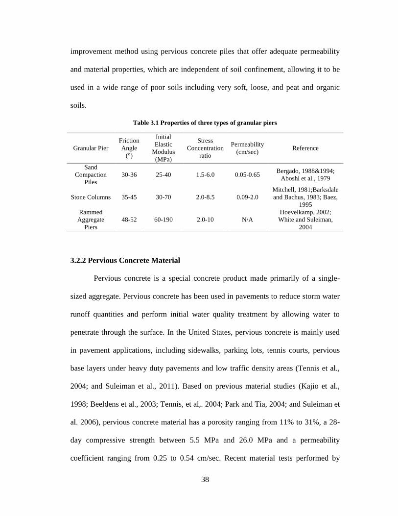
38
improvement method using pervious concrete piles that offer adequate permeability
and material properties, which are independent of soil confinement, allowing it to be
used in a wide range of poor soils including very soft, loose, and peat and organic
soils.
Table 3.1 Properties of three types of granular piers
Granular Pier
Friction
Angle
(°)
Initial
Elastic
Modulus
(MPa)
Stress
Concentration
ratio
Permeability
(cm/sec) Reference
Sand
Compaction
Piles
30-36 25-40 1.5-6.0 0.05-0.65 Bergado, 1988&1994;
Aboshi et al., 1979
Stone Columns 35-45 30-70 2.0-8.5 0.09-2.0
Mitchell, 1981;Barksdale
and Bachus, 1983; Baez,
1995
Rammed
Aggregate
Piers
48-52 60-190 2.0-10 N/A
Hoevelkamp, 2002;
White and Suleiman,
2004
3.2.2 Pervious Concrete Material
Pervious concrete is a special concrete product made primarily of a single-
sized aggregate. Pervious concrete has been used in pavements to reduce storm water
runoff quantities and perform initial water quality treatment by allowing water to
penetrate through the surface. In the United States, pervious concrete is mainly used
in pavement applications, including sidewalks, parking lots, tennis courts, pervious
base layers under heavy duty pavements and low traffic density areas (Tennis et al.,
2004; and Suleiman et al., 2011). Based on previous material studies (Kajio et al.,
1998; Beeldens et al., 2003; Tennis, et al,. 2004; Park and Tia, 2004; and Suleiman et
al. 2006), pervious concrete material has a porosity ranging from 11% to 31%, a 28-
day compressive strength between 5.5 MPa and 26.0 MPa and a permeability
coefficient ranging from 0.25 to 0.54 cm/sec. Recent material tests performed by
39
Kevern et al. (2008) indicated that the 28-day compressive strength of pervious
concrete ranged from 17.0 MPa to 26.5 MPa and the permeability coefficient ranged
from 0.02 to 1.03 cm/sec.
To investigate the benefits of the proposed pervious concrete pile ground
improvement method, four vertical load tests were conducted in a Soil-Structure
Interaction (SSI) facility. The Test units included one granular column (Test unit 1)
and three pervious concrete piles (Test units 2, 3, and 4). All the Test units were
installed in loose well-graded sand. Test units 1 and 2 were used to compare the
behavior of a granular column to a pervious concrete pile. Test units 3 (precast) and 4
(cast-in-place or installed) were used to evaluate the effects of the installation method
on the behavior of pervious concrete piles subjected to vertical loading. The
following sections of this chapter focus on presenting the pervious concrete material
properties; describing the installation method for pervious concrete piles; comparing
the vertical loading response of pervious concrete and aggregate piles; comparing the
vertical loading response of precast and installed pervious concrete piles; and briefly
discussing the variation of soil stresses and movement during installation.
3.3 MATERIAL PROPERTIES
3.3.1 Pervious Concrete Properties
A series of pervious concrete mixtures were prepared in order to obtain an
adequate compressive strength and permeability. Pervious concrete cylinder samples
were tested to measure the porosity, permeability, compressive strength, elastic
modulus, and split tensile strength. The compressive strength was determined using

40
ASTM C39 (2009a), the permeability was measured using an in-house designed
falling head permeameter, the porosity was measured using ASTM C1688 (2009b),
the elastic modulus was measured using ASTM C469 (2009c) and the split tensile
strength was measured using ASTM C496 (2009d). Several aggregate types, sizes
and compaction (vibration) times were investigated. Mixtures were prepared using
water/cement ratios (w/c) ranging from 0.21 to 0.27 and sand/aggregate ratios ranging
from 5% to 11% using two mixing procedures and three different compaction times.
Figure 3.1a summarizes the 28-day compressive strength and permeability
coefficient results for pervious concrete mixtures that were prepared using a 10
second compaction time for different water/cement and sand/aggregate ratios, as a
function of porosity. The results presented in Figure 3.1a indicate that the porosity
ranged from 6% to 23% with the 28-day compressive strength ranging from 10.0 to
34.0 MPa and the permeability coefficient ranging from 1.0 to 2.4 cm/sec. Based on
these results, two pervious concrete mixes with high compressive strength and
adequate permeability (comparable to granular piles) were selected to cast the piles
for the vertical load tests. Both mixtures used a 0.21 water/cement ratio, an 11%
sand/aggregate ratio, 377 kg/m3 cement and 1440 kg/m
3 coarse aggregate. Test units
1 and 2 used crushed Nazareth aggregate, which is locally available in eastern
Pennsylvania. However, it was observed that the quality of this aggregate varies from
one delivery to the other. To ensure more consistent results, pea river gravel
(commercially available at home improvement stores) was used to conduct further
material testing and to construct Test units 3 and 4. Both aggregates were washed and
sieved, and the portion passing through a 9.5 mm sieve and retained on a No.4 (4.75

41
mm) sieve was used (see Figure 3.1b). The pervious concrete mixture used in
preparing Test unit 2 had an average porosity of 20%, a permeability of 1.33 cm/sec.,
a 28-day compressive strength of 18.3 MPa, a split tensile strength of 2344 kPa, and
an elastic modulus of 16.2 GPa. The pervious concrete mixture used in preparing Test
units 3 and 4 had an average porosity of 12.5%, a permeability of 1.21 cm/sec., a 28-
day compressive strength of 22.2 MPa, a split tensile strength of 2337 kPa, and an
elastic modulus of 15.4 GPa.
Pervious concrete samples cut from Test units 3 and 4 were used to measure
the porosity and permeability of these piles. The average porosity and permeability
of the precast pile (Test unit 3) were 13.6% and 1.35 cm/sec., respectively. For the
installed pile (Test unit 4), the average porosity and permeability were 11.2% and
1.06 cm/sec., respectively. Strength tests were not performed on the samples cut from
the test piles because the cutting process affects the strength of pervious concrete as
concluded by Suleiman et al. (2006).
Mixtures that used a compaction (vibration) time of 10 seconds per layer
during sample preparation resulted in an adequate compressive strength and
permeability with no or minimal segregation of cement and aggregate. By comparing
the material properties of granular piles and the pervious concrete piles, the following
observations can be made: (1) the unconfined compressive strength of the pervious
concrete material is more than 10 times greater than that of the confined granular
piles; and (2) the permeability coefficient of the pervious concrete piles and granular
piles are comparable. Furthermore, according to the analytical work of Han and Gabr
(2002) and Suleiman et al. (2003) for embankments supported on several ground

42
reinforcement techniques representing a wide range of modulus ratios (i.e., elastic
modulus of pile/elastic modulus of soil), using a pile with a modulus similar to
pervious concrete piles will increase the stress concentration ratio by approximately 3
times the ratio for granular piles. This will reduce the stress carried by poor
foundation soils and reduce the area replacement ratio. Given that several researchers
documented the successful use of granular piles in mitigating liquefaction, which is
attributed to higher stiffness and permeability when compared to the surrounding soil
(e.g., (Adalier et al., 2003; Adalier and Elgamal, 2004; Shenthan et al., 2004; and
Shao et al. 2013), it is expected that pervious concrete piles will provide the same
advantages under similar loading conditions.
3.3.2 Sand and Aggregate Properties
Due to the large soil quantity needed in the large-scale experiments and
because it is easier to rain sandy soils and to achieve uniform soil properties in the
soil box, the testing program focuses on pervious concrete piles installed in loose
sand. However, pervious concrete piles can be used in different soil types including
very soft clays, and peat and organic soils. The soil used in all vertical load tests was
classified as well-graded sand (SW) according to the United Soil Classification
System (Figure 3.1b). The minimum and maximum relative density vibrating table
tests [ASTM D4254 (2009h), and ASTM D4253 (2009g)] were performed at oven
dry conditions and the minimum and maximum unit weight of the sand were 15.1
kN/m3 and 20.8 kN/m
3, respectively (i.e., maximum void ratio of 0.720 and minimum
void ratio of 0.250). For each vertical load test, the soil was placed in the large soil
box using soil storage and moving system. The dry unit weight and moisture content

43
of the sand placed in the soil box were measured using a nuclear density gauge. The
placed soil had an average relative density of 32%, unit weight of 16.5 kN/m3, and
water content of 2%. The standard deviation of the unit weight measurements was
0.377 kN/m3, which confirmed the uniformity of the placed soil. (Note: soil
placement is described later in the chapter). To characterize the soil properties,
consolidated drained (CD) triaxial tests were performed. The samples were prepared
to achieve a relative density similar to that of the soil in the large soil box (i.e., 32%
relative density or unit weight of 16.5 kN/m3). The 70-mm diameter samples were
tested at confining stresses of 15, 25, 35, 100 and 160 kPa. The measured deviator
stress-axial strain and volume change during the CD triaxial tests are presented in
Figure 3.1c. The initial modulus of the soil (Ei) as a function of confining pressure
(σ3) was evaluated using the power function suggested by Janbu (1963) [i.e., Ei = k
Pa (σ3/Pa)n, where Pa is the atmospheric pressure, k is the modulus number and n is
the modulus exponent] and the calculated values of k and n were 82.3 and 0.95,
respectively, as shown in Figure 3.1c. The Kf line presented in Figure 3.1d indicates
that the peak friction angle of the soil equals to 38°. The peak and critical friction
angles of the used loose sand have the same value, which is consistent with the results
presented by Mitchell and Soga (2005) for loose sands. The friction angle and
permeability of Nazareth aggregate, which was used to construct Test unit 1 (granular
column), was measured using CD triaxial tests and failing head permeability tests.
The friction angle of the aggregate was 47° and the permeability was 1.90 cm/sec.

44
(a)
(b)
Porosity
0.04 0.08 0.12 0.16 0.20 0.24
28
-da
ys C
om
pre
ssiv
e S
tre
ng
th (
MP
a)
0
5
10
15
20
25
30
35
40
Pe
rme
ab
ility
(cm
/se
c)
0.0
0.5
1.0
1.5
2.0
2.5
Compressive strength
Permeability
Particle Size (mm)
0.01 0.1 1 10
% P
assin
g
0
10
20
30
40
50
60
70
80
90
100
soil
pea gravel
Nazareth gray gravel

45
(c)
(d)
Figure 3.1 Material properties: (a) pervious concrete compressive strength and permeability for
mixtures prepared using different aggregates with compaction time of 10 seconds, (b) gradation
of the aggregate used for casting the test piles and for the soil used in the large soil box, (c) CD
triaxial tests on sand samples with the same relative density used in the soil box, and (d) p’f-q’f
diagram for the peak stresses of soil samples
Axial Strain (%)
0 2 4 6 8 10 12 14 16 18D
evia
tor
Str
ess (
kP
a)
0
100
200
300
400
500
600
15
25
35
100
160
Confining pressure (kPa)
n
a
aiP
kPE )( 3
k = 82.3
n = 0.95
Axial Strain (%)
0 2 4 6 8 10 12 14 16 18
Vo
lum
etr
ic S
tra
in (
%)
-1
0
1
2
3
4
5
15
25
35
100
160
Confining pressure (kPa)Contraction
Dilation
p'f '
'
0 100 200 300 400 500
q' f
'
'
0
100
200
300
400
500
q'f = 0.62 p'f
tan-1
K f Line
sintan
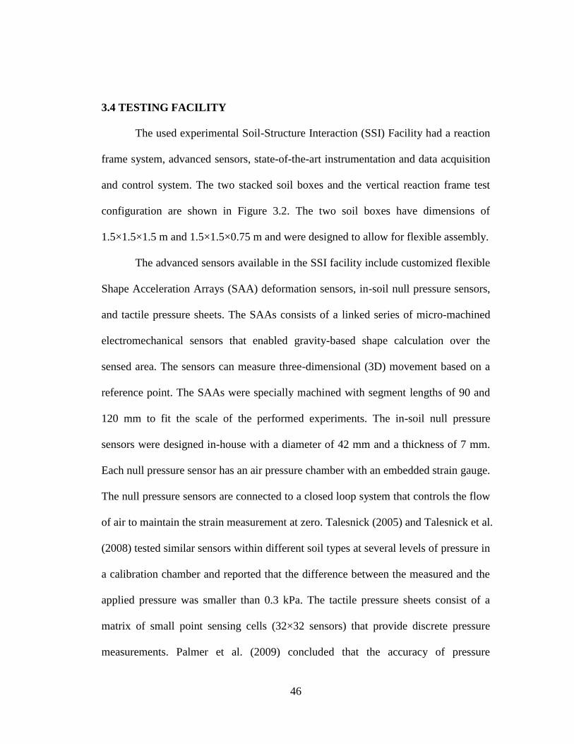
46
3.4 TESTING FACILITY
The used experimental Soil-Structure Interaction (SSI) Facility had a reaction
frame system, advanced sensors, state-of-the-art instrumentation and data acquisition
and control system. The two stacked soil boxes and the vertical reaction frame test
configuration are shown in Figure 3.2. The two soil boxes have dimensions of
1.5×1.5×1.5 m and 1.5×1.5×0.75 m and were designed to allow for flexible assembly.
The advanced sensors available in the SSI facility include customized flexible
Shape Acceleration Arrays (SAA) deformation sensors, in-soil null pressure sensors,
and tactile pressure sheets. The SAAs consists of a linked series of micro-machined
electromechanical sensors that enabled gravity-based shape calculation over the
sensed area. The sensors can measure three-dimensional (3D) movement based on a
reference point. The SAAs were specially machined with segment lengths of 90 and
120 mm to fit the scale of the performed experiments. The in-soil null pressure
sensors were designed in-house with a diameter of 42 mm and a thickness of 7 mm.
Each null pressure sensor has an air pressure chamber with an embedded strain gauge.
The null pressure sensors are connected to a closed loop system that controls the flow
of air to maintain the strain measurement at zero. Talesnick (2005) and Talesnick et al.
(2008) tested similar sensors within different soil types at several levels of pressure in
a calibration chamber and reported that the difference between the measured and the
applied pressure was smaller than 0.3 kPa. The tactile pressure sheets consist of a
matrix of small point sensing cells (32×32 sensors) that provide discrete pressure
measurements. Palmer et al. (2009) concluded that the accuracy of pressure

47
measurements using the tactile pressure sheets was higher than 90%. Suleiman et al.
(2014b) studied the accuracy of the pressure measurements obtained in a lateral load
test by comparing the applied load to the soil reaction obtained from measured
pressures, which resulted in a difference smaller than 8%. The data acquisition and
control system combines testing control and sensor monitoring. The system monitors
several types of sensors, including load cells, strain gauges, null pressure sensors, tilt
meters and displacement transducers. The SSI facility also has a soil storage and
moving system, vibrating table to characterize granular material compaction
properties, nuclear density gauge, and web broadcasting capability.
(a)
Actuator
Soil
Top soil box
Bottom soil box
Reaction frame
48
(b)
Figure 3.2 SSI facility and reaction frame system for vertical load tests: (a) schematic of the SSI
facility, and (b) top soil box and reaction system of the SSI facility
3.5 TEST UNITS AND INSTRUMENTATION
3.5.1 Installation of Test Units
A laboratory installation method was developed by the research team to
simulate a field construction method. Details of several stages of the laboratory
installation method are shown in Figure 3.3. The developed installation system
consists of a hollow steel mandrel with a specially designed cone at the tip. The
mandrel can be vibrated into soil using an attached concrete vibrator (Figure 3.3a) or
a Rhino pile driver placed on top of the mandrel. A bracing system was designed to
ensure the verticality of the mandrel driving (Figure 3.3b and c). During mandrel
advancement (mandrel penetration stage), the cone tip stays closed. Once the desired
depth is reached, the pervious concrete or aggregate is placed inside the mandrel from
the top (Figure 3.3d). Then, the mandrel is lifted upward (mandrel retrieval stage) at a
Reaction frame
Top soil box
Actuator
49
slow rate. During the mandrel retrieval stage, the cone tip opens and the pervious
concrete or aggregate fills the created space (Figure 3.3e). This installation method is
similar to the one used for sand piles described by Magnan (1983), which
demonstrate that pervious concrete piles can be installed using available construction
techniques.
Initially, a mandrel with 76 mm outside diameters was designed and
fabricated. Test units 1 and 2 (one aggregate pier and one pervious concrete pile)
were installed using the 76 mm mandrel utilizing the installation method described
above. These two test units were tested under vertical loading and only the load and
the displacement at the pile head were measured. To investigate the load transfer
along the pile length, a steel rebar with mounted strain gauges is needed. With the 76
mm diameter mandrel, the installation of the steel rebar without damaging the strain
gauges (or their wires) was difficult. So, a newer cone/mandrel setup was designed
and fabricated with a diameter of 102 mm that allowed for easier installation of strain
gauges. The 102 mm mandrel was used to install Test unit 4. Test unit 3 was a precast
pervious concrete pile that has the same dimensions as Test unit 4.

50
Figure 3.3 Summary of the developed pile installation method: (a) cone with vibrator, (b)
bracing (guiding) system, (c) driving the mandrel, (d) casting the pile, (e) open cone during
casting
3.5.2 Description of Test Units
Test units 1 and 2 were cast using the 76-mm diameter mandrel with an
embedded length of 864 mm. Test unit 1 was a granular column and Test unit 2 was a
pervious concrete pile; both used the same aggregate (Nazareth crushed aggregate)
and were installed using the developed laboratory installation method described
above. Test units 3 and 4 were pervious concrete piles, which were prepared using
pea river gravel, with an embedded length of 1219 mm. Test unit 3 was a precast pile
with a 102 mm diameter, which was placed vertically into the soil box and the soil
was rained around it. Test unit 4 was installed using the 102-mm diameter mandrel.
(d)
(a)Cone tip
Mandrel
Vibrator
(b)
Soil surface
Bracing
system
Top soil box
(c)
Bracing
system
Vibrator
Mandrel
(e)
Mandrel
Open
cone tip
Pervious
concrete

51
Since the cone did not completely open during the installation of Test unit 4, the
installed pile has a slightly tapered tip with a cross-sectional area of 4825 mm2 and an
average cross-sectional area along the pile length of 5935 mm2.
3.5.3 Instrumentation of Test Units and Surrounding Soil
As mentioned previously, two soil boxes were stacked on top of the other,
which provided a total height of 2.25 m, and a reaction frame was assembled for the
vertical load tests (Figure 3.2a and Figure 3.4a). To produce a uniform soil, a soil
storage and movement system was designed. This system consists of a bottom dump
soil container with an attached sieve to rain the soil into the soil box. As shown in
Figure 3.4b, the soil was placed in the soil boxes by raining the soil from a height of
approximately 1.5 m.
Due to the large soil quantity needed in the large-scale experiments and
because it is easier to rain sandy soils and to achieve uniform soil properties in the
soil box, the testing program focuses on piles installed in sand. However, pervious
concrete piles can be used in different soil types including very soft clays, and peat
and organic soils.
Test unit 1 (granular column) and Test unit 2 (pervious concrete pile) were
installed to assess the performance of the developed installation method and to
compare the response of the granular column to that of the pervious concrete pile
when subjected to vertical loading. These two Test units and the surrounding soil
were not reinforced or instrumented and only the vertical applied load and
displacement of the pile head were monitored during the load tests.

52
Test unit 3 (precast pervious concrete pile) and Test unit 4 (pervious concrete
pile installed using the developed installation method or simply referred to as
installed pervious concrete pile) were used to evaluate the effects of the installation
method on the pile response when subjected to vertical loading. Test unit 3 was
reinforced with a No. 4 (12.7 mm diameter) rebar instrumented with strain gauges
and placed at the center of pile cross-section, as shown in Figure 3.5a. To evaluate the
effects of the soil box boundaries on the installation and response of the pile, one
tactile pressure sheet was mounted on the bottom of the soil box and another sheet on
the side of the soil box (Figure 3.5a and b).
Test unit 4 was installed using the developed installation method. Similar to
Test unit 3, Test unit 4 was reinforced with a No. 4 rebar with mounted strain gauges
along the length of the pile. The surrounding soil was instrumented with three SAAs
and six null pressure sensors as shown in Figures 3.4c, d and Figure 3.5. Two of the
SAAs were installed at a distance of one pile diameter (1D or 102 mm) from the
center of the pile and one SAA was installed at a distance of 2D from the center of the
pile (203 mm). As shown in Figure 3.5, null pressure sensors 1, 2 and 3 were installed
at 76, 178, and 279 mm (i.e., 0.75D, 1.75D, and 2.75D) below the tip of the pile. Null
pressure sensors 4, 5 and 6 were installed at a horizontal distance of 1D from the
center of the pile at either a depth of 914 mm or 1270 mm below the soil surface. Null
pressure sensors 4 and 5 were installed at the same depth with a similar distance from
the center of the pile to check the repeatability of the measured stress changes.
Furthermore, one pressure sheet was mounted at the bottom of the soil box and one
on the side wall of the soil box (Figure 3.5a and b) to assess the effect of the soil box
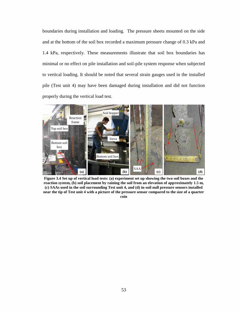
53
boundaries during installation and loading. The pressure sheets mounted on the side
and at the bottom of the soil box recorded a maximum pressure change of 0.3 kPa and
1.4 kPa, respectively. These measurements illustrate that soil box boundaries has
minimal or no effect on pile installation and soil-pile system response when subjected
to vertical loading. It should be noted that several strain gauges used in the installed
pile (Test unit 4) may have been damaged during installation and did not function
properly during the vertical load test.
Figure 3.4 Set up of vertical load tests: (a) experiment set up showing the two soil boxes and the
reaction system, (b) soil placement by raining the soil from an elevation of approximately 1.5 m,
(c) SAAs used in the soil surrounding Test unit 4, and (d) in-soil null pressure sensors installed
near the tip of Test unit 4 with a picture of the pressure sensor compared to the size of a quarter
coin
Soil hopper
Bottom soil box
Sieve
(b)
Reaction
frame
Top soil box
Bottom soil
box
(a)SAA
(c) (d)

54
(a) (b)
Figure 3.5 Instrumentation for Test unit 4: (a) side view, and (b) top view.
3.6 LOADING SEQUENCE
The four vertical load tests were conducted in general accordance with the fast
procedure outlined in the ASTM D1143 (2009d). Each load level was held constant
for at least 4 minutes or until the pile head displacement stabilized. The test was
stopped when the pile displacement continued increasing without an increase in the
applied load. During testing of Test units 1 and 2, a load increment of 222.4 N was
used. For Test units 3 and 4, load increments of 222.4 N and 889.6 N were used.
Bottom box
Top box
1524 mm
762 mm
Soil surface
#1
#2
#3
#4#5
#6
305 mm
1240 mm
51 mm
76 mm
102 mm
102 mm
1219 mm
914 mm
Vertical loading
787 mm
SAAs
178 mmSAA
Strain gauge
In-soil null pressure sensor
Pressure sheet
152 mm 102 mm
51 mm51 mm
Pressure
sheets

55
3.7 TEST RESULTS
3.7.1 Experimental Pile Load-Displacement Response
Effect of Pile Type on Response
Figure 3.6a presents the measured vertical load-displacement responses for
Test unit 1 (granular column) and Test unit 2 (pervious concrete pile). Both test units
were made using the same aggregate and installed using the same installation method.
The ultimate load of Test unit 1 was 2.2 kN and the ultimate load of Test unit 2 was
9.8 kN. Therefore, the ratio of the ultimate load of the pervious concrete pile to the
ultimate load of the granular column was 4.4. After the ultimate load was reached
during testing, the soil surrounding each pile was removed to expose the Test units.
Figure 3.7a illustrates that Test unit 1 (granular column) failed by bulging into the
surrounding soil due to the low confining pressure provided by the surrounding soil.
The depth of the bulged zone was approximately 2.5D below the soil surface. For
Test unit 2 (pervious concrete pile), the pile failed by punching vertically into the soil
(Figure 3.7b). The observed failure types indicate that unlike granular piles, pervious
concrete piles do not experience bulging into the surrounding soil allowing them to be
used in different poor soil conditions including very soft, loose, and peat and organic
soils.

56
(a)
(b)
Figure 3.6 Vertical load versus displacement for all test units: (a) Test units 1 and 2 with a 76
mm diameter piles installed using the developed installation method, and (b) Test units 3 and 4
with a 102 mm diameter piles
Effect of Pile Installation Method on Response
Figure 3.6b presents the measured vertical load-displacement responses for
Test unit 3 (precast pervious concrete pile) and Test unit 4 (installed pervious
concrete pile). These tests were conducted to compare the load-displacement response
Vertical Load (N)
0 2000 4000 6000 8000 10000 12000
Ve
rtic
al D
isp
lace
me
nt
(mm
)
0
25
50
75
100
125
Test unit 1: Aggregate pier
Test unit 2: Pervious pile9,786 N
2,225 N
Vertical Load (N)
0 5000 10000 15000 20000 25000 30000 35000
Ve
rtic
al D
isp
lace
me
nt
(mm
)
0
25
50
75
100
125
150
175
200
Test unit 3: Precast pervious pile
Test unit 4: Installed pervious pile
31,200 N
12,200 N

57
of two similar pervious concrete piles that were installed using different methods. The
ultimate load of Test unit 3 was 12.20 kN and the ultimate load of Test unit 4 was
31.20 kN. Therefore, the ratio of the ultimate load of the installed pervious concrete
pile to the ultimate load of the precast pile was 2.6. The difference between the
ultimate loads of the two pervious concrete piles occurs because of the installation
method, which has significant effects on the surrounding soil properties that will be
briefly discussed later in this chapter. Similar to the failure experienced by Test unit 2,
Test units 3 and 4 also experienced vertical punching failures as shown in Figure 3.7c
and d.
Figure 3.7 Test units after performing the vertical load test: (a) Test unit 1 with bulging failure,
(b) Test unit 2, (c) Test unit 3, and (d) Test unit 4
3.7.2 Load Transfer along Pile Length
Using the strain gauge measurements along the pile length and the calculated
initial elastic modulus of the pervious concrete composite section, including the steel
reinforcing bar, the load transfer along the pile length for Test units 3 and 4 was
calculated and compared at loading stages of 1.78 kN, 4.89 kN and 11.12 kN (Figure
58
3.8). These loading stages were selected for comparison because they represent the
initial (linear) stage, transition stage and near the ultimate load for Test unit 3. The
rate of load transfer shown in Figure 3.8 indicates that at the applied load of 11.12 kN,
the maximum unit friction, which is the slope of the curve between depths of 381 mm
and 965 mm, was 9.0 N/mm for Test unit 3 (precast pile) and 10.6 N/mm for Test unit
4 (installed pile). These unit friction values illustrate that the pile installed using the
developed installation method had a 17.8% higher load transfer rate to the
surrounding soil through shaft resistance than the precast pile at this loading step.
Extending the load transfer curves in Figure 3.8 to the depth of the pile tip for the
11.12 kN loading stage results in tip resistances of 1.10 kN and 3.28 kN for Test units
3 and 4, respectively. At the ultimate load of Test unit 4 (31.20 kN), the tip resistance
was approximately 35% of the applied load (i.e., shaft friction resisted 65% of the
applied load). The difference in the ultimate load and load transfer between Test unit
3 and 4 is mainly attributed to the used installation method, which for the installed
pile changes the soil density and soil stresses, as well as results in a rougher pile
surface as shown in Figure 3.7 c and d.
Using the load transfer along the pile length and displacements back
calculated using the strain measurements along the pile, the frictional soil-pile
interface stress (interface shear stress)-displacement relationships at the soil-pile
interface (i.e., t-z curves) were developed and are presented in Figure 3.9. The results
illustrate that Test unit 4 (installed pile) had a higher maximum interface frictional
stress transfer than that of Test unit 3 (precast pile). The ratio of maximum frictional
stress at the soil-pile interface for Test unit 4 relative to that of Test unit 3 was 2.5 at

59
an average depth of 191 mm below the soil surface and 5.3 at an average depth of 635
mm. These ratios are consistent with those reported in the literature when comparing
displacement and non-displacement piles (e.g., Colombi et al., 2006). The differences
in ultimate load and load transfer clearly illustrate the significant effect that the
installation method had on the soil-pile interaction for vertically loaded pervious
concrete piles.
Figure 3.8 Comparison of the force transferred along the length of Test units 3 and 4 for
different loading stages
3.7.3 Variation of Soil Stresses and Movement during Pile Installation
As the mandrel penetrates the soil, it pushes the soil downward and laterally
(cavity expansion) resulting in a significant increase of vertical stress and a smaller
increase of horizontal stress (Basu et al., 2011). For a soil element at a specific depth,
the cavity expands until the mandrel, which has a constant diameter, starts to
penetrate the location of the soil element. Vertical shearing is then applied to the soil
element as the mandrel penetrates deeper. As discussed before, the effects of pile
Force (N)
0 2000 4000 6000 8000 10000 12000 14000
De
pth
(m
m)
-200
0
200
400
600
800
1000
1200
1400
Test unit 3 (Precast pile)
Test unit 4 (Installed pile)
1,779 N 4,893 N 11,121 N
Soil surface
Pile
Pile tip

60
installation on soil lateral displacement (movement) and stresses were monitored
using SAAs and null pressure sensors for Test unit 4. The in-soil null pressure sensors
were zeroed before starting the experiment which did not allow us to record the initial
horizontal stresses (i.e., allowing the measurement of the change of stresses during
installation and load testing). Null pressure sensor 2 did not function properly due to
air leakage during installation.
(a)
(b)
Figure 3.9 Shear stress versus displacement curves (t-z curves) for the soil-pile interface
calculated using the strain gauge measurements for test units 3 and 4: (a) for average depth
below soil surface of 191 mm, and (b) for average depth below soil surface of 635 mm
Vertical Displacement, z (mm)
0 2 4 6 8 10 12 14 16
Sh
ea
r S
tre
ss, t (k
Pa
)
0
2
4
6
8
10
12
14
16
18
20
Test unit 3 (Precast pile)
Test unit 4 (Installed pile)
Vertical Displacement, z (mm)
0 2 4 6 8 10 12 14 16
Sh
ea
r S
tre
ss, t (k
Pa
)
0
10
20
30
40
50
60
70
80
Test unit 3 (Precast pile)
Test unit 4 (Installed pile)

61
Lateral Soil Movement
The lateral soil movement due to pile installation measured using the SAAs
are summarized in Figure 3.10. The SAAs measurements at 1D (102 mm) from the
center of the pile, which was 51 mm from the surface of the pile, illustrate that the
steel mandrel penetration resulted in a non-uniform lateral soil movement along the
depth of the mandrel. The lateral movement near the soil surface was 17.6 mm, while
the lateral movement near the pile tip was 8.2 mm. Therefore, the soil movement at
the pile tip is only 50% of the soil movement near the soil surface. These non-uniform
displacements along the depth of the pile are commonly modeled by researchers as
uniform displacements that produce similar vertical load-displacement pile response
(e.g., Chen et al., 2009; and Dijkstra et al. 2011). However, non-uniform
displacement can also be simulated using the volumetric strain approach suggested by
Thompson and Suleiman (2010); an approach that is currently being investigated
further by the authors. During vertical loading, the soil at 1D experienced 1.7 to 5.8
mm additional lateral movement. At a distance of 2D (152.4 mm from the surface of
the pile), the lateral soil movement was 4.1 mm at the soil surface with no lateral soil
movement occurring below a depth of 500 mm (~5D).

62
Figure 3.10 Soil lateral displacement at 51 mm (average) and at 152 mm from the surface of the
pile measured using SAAs for Test unit 4
Horizontal Soil Stresses
The changes of horizontal soil stresses due to pervious concrete pile
installation and during vertical loading, which were measured using null pressure
sensors 4, 5 and 6, are summarized in Figure 3.11a. The following observations can
be made regarding the changes occurring in the horizontal stresses: (1) due to
mandrel advancement, the change of horizontal stresses measured by sensor 6 was
147 kPa at 914 mm below the soil surface; (2) the horizontal stress increased by 99
kPa at 1240 mm below the soil surface (i.e., near the tip of the pile); (3) sensors 4 and
5, located at the same depth and distance from the pile, showed similar horizontal
stress increases during mandrel advancement, which confirms the repeatability of the
stress measurements for the sensors.; (4) during the vertical load test, the horizontal
stresses measured by sensor 6 increased, which is similar to the trend reported by
Lehane et al. (1993); and (5) during the vertical load test, Test unit 4 with a slightly
tapered tip (see Figure 3.5) penetrated the soil below the pile tip resulting in cavity
Lateral Soil Movement (mm)
0 5 10 15 20 25
Depth
Belo
w S
oil
Surf
ace (
mm
)
0
500
1000
1500
2000
2500
Pile tip
152 mm from pile
51 mm from pileSoil surface
After pile installation
After vertical loading
63
expansion at the location of sensors 4 and 5 approaching a condition similar to that at
the location of sensor 6. Therefore, it was expected that at this stage the change of soil
horizontal stress measured using sensors 4 and 5 would be similar to that of sensor 6,
which is observed in Figure 3.11a. This measurement is another confirmation of the
repeatability of the measured stresses.
The measured changes of soil horizontal stresses were compared with the
elastic and elastic-plastic cavity expansion solutions presented by Yu (2000). Using
the elastic and elastic-plastic solutions, the calculated changes of horizontal stress at
the location of sensor 6 (914 mm below soil surface) were 182.9 kPa and 170.3 kPa,
respectively, which are approximately 26% and 17% smaller than the measured
change in soil horizontal stress at the same location (145 kPa). At the location of
sensors 4 and 5 (depth of 1240 mm), the calculated changes in soil horizontal stress
were 172.3 kPa and 177.5 kPa using the elastic and elastic-plastic cavity expansion
analyses, respectively, which are approximately 12% and 10% smaller than the
average measured pressure using sensors 4 and 5 (195.7 kPa).
Vertical Soil Stresses
For changes in vertical stresses, which were measured using sensors 1 and 3,
the vertical stress increased by 180 kPa at 76 mm below the tip of the cone due to
mandrel advancement. The increase of vertical stress is approximately 1.9 times the
increase in horizontal stress measured using sensors 4 and 5 (located near sensor 3).
The result of having the vertical stress significantly higher than horizontal stress
during cone advancement was also reported by Salgado et al. (1997) and Salgado and

64
Prezzi (2007). Sensor 1 showed an increase of vertical stress of 57 kPa at the end of
mandrel advancement. At the end of the load test, sensor 3, which was approximately
55 mm below the pile tip at this stage, recorded an increase of vertical stress of 638
kPa and sensor 1, which was approximately 60 mm below the pile tip at this stage,
recorded an increase of 135 kPa (Figure 3.11a and b).
Figure 3.11b summarizes the development of measured pressures from sensor
6 during different installation stages focusing on the mandrel advancement stage.
During mandrel advancement, the variation of horizontal stress measured using
sensor 6 increased until the mandrel passed the location of the sensor. The horizontal
stress measured by sensor 6 then decreased as the mandrel advanced deeper. This
stress changing trend caused by the cavity expansion and shearing along soil-pile
interface is consistent with the one-dimensional (1-D) finite element analytical results
reported by Basu et al. (2011) for jacked piles.
(a)
Step0 10 20 30 40 50 60 70 80 90 100 110 120
Ch
an
ge
of
Pre
ssu
re (
KP
a)
0
100
200
300
400
500
600
700
Sensor 1
Sensor 3
Sensor 4
Sensor 5
Sensor 6
Vert
ica
l Load T
est
Waiting Period Before
Mandrel Retrieval and
Casting
Befo
re S
tart
ing L
oad T
est
Mandre
l A
dvance
ment
Mandre
l R
etr
ieval
#1
#2
#3#4#5
#6

65
(b)
Figure 3.11 Effect of installation on the change of soil pressure: (a) summary of pressure changes
developed at the end of installation and during load testing, and (b) details of changes of
horizontal pressure measured using sensor 6 and changes of vertical pressure measured using
sensor 3 focusing on the changes during installation (Note: the x axis represent different stages
(steps) including mandrel advancement, waiting period, casting and mandrel retrieval and
vertical load testing)
3.8 SUMARY AND CONCLUSIONS
A new ground improvement method has been developed using pervious
concrete piles. This chapter summarizes the material properties of the pervious
concrete and the response of four different vertical load tests performed using the SSI
Facility. Initially, Test unit 1 (granular column) and Test unit 2 (pervious concrete
pile) were installed to investigate the effectiveness of the designed laboratory
installation method and to compare the vertical load-displacement response of the
granular column to that of the pervious concrete pile. Then two instrumented vertical
load tests were performed on a precast pervious concrete pile (Test unit 3) and an
installed pervious concrete pile (Test unit 4) to evaluate the effects of the installation
Step
0 5 10 40 50 60 70 80 90 100 110 120
Chan
ge o
f P
ressure
(kP
a)
0
100
200
300
400
500
600
700
Sensor 3 at 1295 mm
Sensor 6 at 914 mm
Mandrel Advancement
Pa
ssin
g s
en
so
r 6
Ma
nd
rel R
etr
ieva
l a
nd
Ca
stin
g
Vertical Load Testing
#3
#6

66
method on the soil-pile interaction. Although the testing program focuses on piles
installed in loose sand, pervious concrete piles can be used in different soil types
including very soft clays, and peat and organic soils. Based on the experimental
results obtained from the four vertical load tests and the discussion of the results
presented in this chapter, the following conclusions were made:
1. Pervious concrete piles have a compressive strength that is more than
10 times that of granular piles, while providing similar permeability to
granular piles.
2. The pervious concrete pile (Test unit 2), which had the same
dimensions, aggregate type, and installation method, as the granular
column (Test unit 1), had an ultimate load that was 4.4 times greater
than the ultimate load of the granular column. Furthermore, the
pervious concrete pile failed by vertically punching into the soil at the
pile tip, while the granular column failed by bulging outward into the
surrounding soil.
3. The installation method had significant effects on the response of the
pervious concrete piles. When comparing the response of the two
pervious concrete piles installed using different methods [precast pile
(Test unit 3) and installed pile (Test unit 4)], the ultimate load of the
installed pile was 2.6 times greater than the ultimate load of the precast
pile.
4. Installation of the pervious concrete pile resulted in an increase of the
maximum frictional stress transferred at the soil-pile interface. The

67
ratio of the maximum frictional stress calculated using the strain
gauges for the installed pile compared to the precast pile ranged from
2.5 to 5.3.
5. The lateral soil displacements measured at a distance of 1D from the
pile center during installation were not uniform along the length of the
pile. The installation of the pile also resulted in significant increases of
the soil vertical stress and a smaller increase of the soil horizontal
stress. The measured change of the vertical and horizontal soil stresses
showed trends similar to those reported in the literature.

68
CHAPTER 4
BEHAVIOR AND SOIL-STRUCTURE INTERACTION OF PERVIOUS
CONCRETE GROUND IMPROVEMENT PILES UNDER LATERAL
LOADING
4.1 INTRODUCTION
Granular columns are commonly used to resist vertical and lateral loads and to
improve soft and loose soils. Granular columns include stone columns, sand
compaction piles, and rammed aggregate piers. With higher stiffness, strength, and
higher permeability than surrounding soils, granular columns have been used to
improve soil strength, increase consolidation rate, reduce liquefaction potential,
improve bearing capacity, reduce settlement, improve embankment stability, and
stabilize slopes (Barksdale and Bachus 1983; Mitchell 1981; Aboshi and Suematsu
1985; Bergado et al. 1994; Baez 1995; Terashi and Juran 2000; Okamure et al. 2006;
Elgamal et al. 2009; and Stuedlein and Holtz 2013). For typical granular column
length to diameter (L/D) ratios, the most common failure mechanism when subjected
to vertical loading is bulging, which is usually observed over a distance of 2 to 3
diameters below the soil surface (Barksdale and Bachus 1983; Bergado et al. 1994;
Suleiman et al. 2014a). When subjected to lateral loading, such as to stabilize slopes,
granular columns fail in direct shear at the location of loading or along the slope
failure surface (i.e., do not transfer loads to deeper stable soils as in the case of
concrete or steel piles used to stabilize slopes) (Barksdale and Bachus, 1983; Mitchell
1981; Bergado et al. 1994; White and Suleiman 2005; Suleiman et al. 2014b).

69
Compared to other pile types (concrete and steel piles), granular columns have
lower strength and stiffness, which depend on the properties of the surrounding soil.
Therefore, granular columns have limited use in very soft clays and silts, and organic
and peat soils. The research team has recently developed a new ground improvement
pile made of pervious concrete material. In addition to providing adequate
permeability comparable to granular columns, pervious concrete ground improvement
piles have higher stiffness and strength, which are independent of the surrounding soil
properties.
The behavior of vertically loaded pervious concrete piles compared to
granular columns has been studied using a series of fully-instrumented tests. The
results and analysis of pervious concrete piles subjected to vertical loading were
presented by Suleiman et al. (2014a). The vertical load tests included one granular
column test and three pervious concrete pile tests installed using two different
methods. Comparison of the behavior of the granular column and the pervious
concrete pile that had the same dimensions and installation method showed that the
ultimate load of the pervious concrete pile was 4.4 times that of the granular column.
In addition, the pervious concrete pile failed by punching into the soil at the pile tip,
while the granular column failed by bulging into the surrounding soil.
To further characterize the behavior of the pervious concrete ground
improvement piles, this chapter focuses on experimentally investigating the behavior
of pervious concrete piles and the effects of pile installation on the soil-structure
interaction when subjected to lateral loading. It is worth noting that there is a lack of
knowledge related to the effects of pile installation on the soil-structure interaction of

70
laterally loaded piles in general (Fan and Long, 2005; Kim and Jeong, 2011); a
knowledge gap that is partially addressed in this chapter. To achieve the goal of the
chapter, two fully-instrumented lateral load tests were performed using the soil-
structure interaction (SSI) testing facility at Lehigh University. One of the test piles
was a precast pervious concrete pile with sand rained around it, while the other was a
cast-in-place pile installed using the method developed by the research team to
simulate field installation. To investigate the soil-structure interaction of laterally
loaded pervious concrete piles, the piles and surrounding soil were instrumented with
advanced sensors. In addition to comparing the lateral load responses of the precast
and installed piles, the soil-structure interaction pressure and displacement in the
surrounding soil were analyzed. Furthermore, the effects of the pile installation
methods on measured responses were briefly discussed. This chapter presents: (1) the
material properties of the pervious concrete and the installation methods used for
pervious concrete piles; (2) the lateral load behavior of pervious concrete piles,
including pile response, soil-pile interaction and surrounding soil displacements; and
(3) the effects of the installation methods on the response of pervious concrete piles
and on surrounding soil. The research team is currently conducting a detailed
analytical study to evaluate the effects of installation on the response of pervious
concrete piles subjected to vertical and lateral loading; the results of which will be
presented in a separate future paper.

71
4.2 MATERIAL PROPERTIES
4.2.1 Soil Properties
The soil used in the two lateral load tests was classified as poorly graded sand
(SP) using the Unified Soil Classification System (Figure 4.4.1a). The minimum and
maximum unit weights of sand at oven dry condition obtained from minimum and
maximum relative density tests (ASTM D4253, 2009g and ASTM D4254, 2009h)
were 14.54 kN/m3 and 16.75 kN/m
3, respectively (maximum void ratio of 0.79 and a
minimum of 0.55). In order to provide homogeneous soil conditions, the sand was
rained from a height of approximately 1.5 m through a bottom-dump container fitted
with a sieve. The soil placed in the box had an average unit weight of 15.24 N/m3 and
water content of 0.4%, which were measured by a nuclear density gauge (Humboldt
HS-5001EZ). A series of consolidated drained (CD) triaxial tests with different
confining pressures (15 kPa, 25 kPa, 50 kPa and 100 kPa) targeting the same relative
density (35%) as the soil in the box were conducted. The results showed that the
average peak friction angle of soil was 39° with a critical state friction angle of 36°.
The initial soil modulus (Ei) was evaluated as a function of confining pressure (σ3) as
Ei=kPa(σ3/Pa)n (Janbu, 1963), where Pa is the atmospheric pressure of 101 kPa and k
and n are calculated as 506.7 and 0.445, respectively (Figure 4.1b).
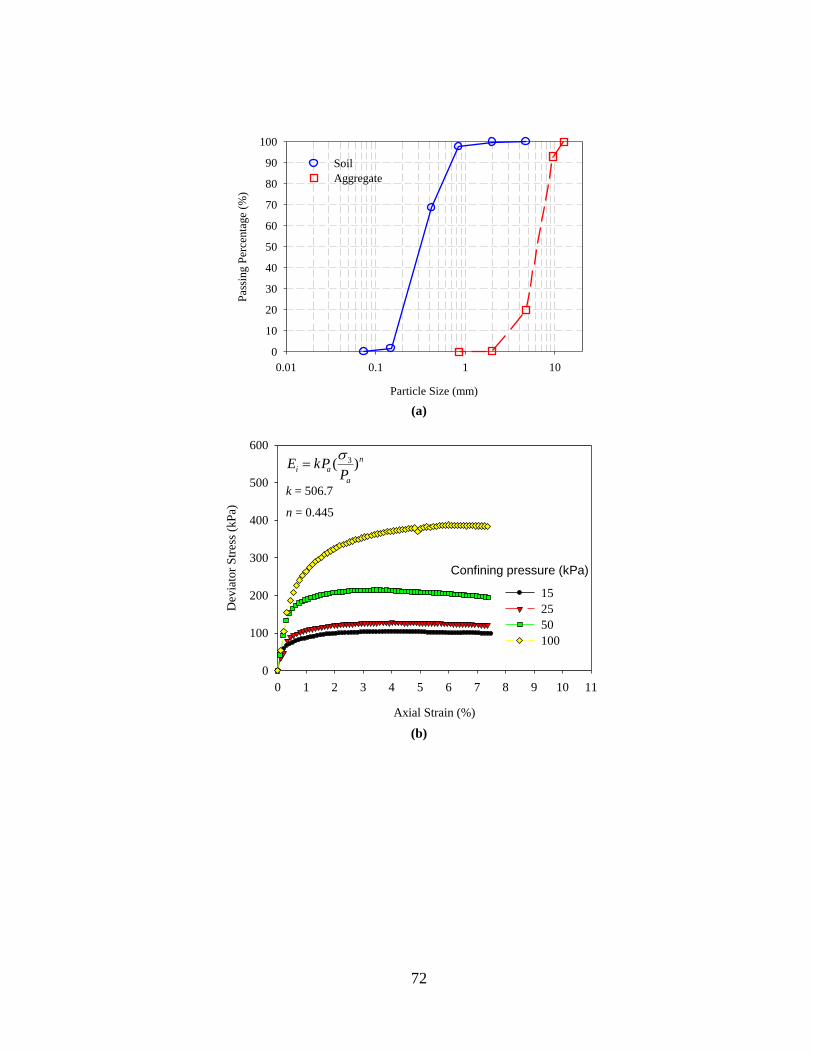
72
(a)
(b)
Particle Size (mm)
0.01 0.1 1 10
Pas
sing P
erce
nta
ge
(%)
0
10
20
30
40
50
60
70
80
90
100
Soil
Aggregate
Axial Strain (%)
0 1 2 3 4 5 6 7 8 9 10 11
Dev
iato
r S
tres
s (k
Pa)
0
100
200
300
400
500
600
15
25
50
100
Confining pressure (kPa)
n
a
aiP
kPE )( 3
k = 506.7
n = 0.445

73
(c)
Figure 4.1 Material Properties: (a) Gradation of soil and aggregate used in lateral loading tests,
(b) CD triaxial tests on sand with same relative density measured in the lateral load tests, (c)
pervious concrete compressive strength and permeability vs. the porosity
4.2.2 Pervious Concrete Properties
To achieve adequate compressive strength and permeability, a series of
pervious concrete mixtures were prepared. Pervious concrete cylindrical samples
were tested to measure the pervious concrete properties including the compressive
strength (ASTM C39, 2009b), permeability, porosity, spilt tensile strength (ASTM
C496, 2009i), and elastic modulus (ASTM C469, 2009j). The effects of aggregate
type, size and compaction time were investigated to optimize the pervious concrete
mix. The 28-day compressive strength, porosity and permeability of tested mixtures
are summarized in Figure 4.1c. Based on the results presented in Figure 4.1c, the
mixture with 0.21 water/cement ratio, 0.11 sand/aggregate ratio, 377 kg/m3 cement
and 1440 kg/m3 coarse aggregate (pea gravel, available at home improvement stores)
was used for casting the test piles. The pea gravel for pile casting was washed and
Porosity
0.04 0.06 0.08 0.10 0.12 0.14 0.16 0.18 0.20
28-d
ays
Com
pre
ssiv
e S
trength
(M
Pa)
5
10
15
20
25
30
35
Perm
eabili
ty (
cm
/sec)
0.8
1.0
1.2
1.4
1.6
1.8
2.0
2.2
2.4
Compressive stength
Permeability

74
sieved, and the portion passing the 9.5 mm sieve (3/8 in. sieve) and retained on the
4.75 mm sieve (No.4 sieve) was used. The pervious concrete mixture used in
preparing the test piles had average porosity of 10.7%, permeability of 1.44 cm/sec.,
28-day compressive strength of 22.8 MPa, split tensile strength of 2702 kPa, and
elastic modulus of 15.1 GPa. Samples cut from the test piles were used to measure the
porosity and permeability of the two piles. The permeability and porosity for the
precast pile were 1.33 cm/sec. and 10.4%, respectively. For the installed pile, the
permeability and porosity were 1.51 cm/sec. and 11.3%, respectively. By comparing
the material properties of the pervious concrete piles with the granular columns, it
was found that the unconfined compressive strength of the pervious concrete material
was more than 10 times greater than that of the confined granular columns; and the
permeability coefficient of the pervious concrete piles and granular columns were
comparable (Suleiman et al. 2014a).
4.3 TESTING FACILITY
The Soil-Structure Interaction (SSI) testing facility at Lehigh University,
which includes soil boxes, a reaction frame system, advanced sensors, state-of-the-art
instrumentation and data acquisition and control systems, has been used for the
pervious concrete lateral load tests. As shown in the Figure 4.2, a soil box with
dimensions of 1.8 × 1.8 × 1.8 m (width × length × height) and a reaction frame were
assembled for the two lateral load tests.
The advanced sensors available at the SSI facility included customized
flexible Shape Acceleration Arrays (SAAs) deformation sensors and tactile pressure

75
sheets. The SAAs consist of a series of micro-machined electromechanical sensors
capable of measuring three-dimensional (3D) movement based on a reference point.
These SAAs were specially designed with segment lengths of 90 and 120 mm to fit
the scale of the performed laboratory experiments. The tactile pressure sheets (0.7
mm thickness) consist of a matrix of small point sensing cells that provide discrete
pressure measurements. The accuracy of pressures measured by the tactile pressure
sheets was discussed by Palmer et al. (2009) who concluded that the error was
smaller than 10%. In addition to using these sensors, bender elements were fabricated
in-house using two-parallel-layer piezoelectric transducer to measure the soil shear
wave velocity in the soil box (Lee and Santamarina, 2005; Brandenberg et al., 2008).
The SSI facility also uses data acquisition and control systems that combine testing
control and sensor monitoring of several types of sensors, including load cells, strain
gauges, tiltmeters and displacement transducers. In addition, the SSI facility includes
a soil storage and moving system, pile driving system, nuclear density gauge to
measure the soil properties, and web broadcasting system.

76
Figure 4.2 Laboratory Soil-Structure Interaction (SSI) testing facility with lateral loading set up
and a 3D system sketch (bottom left).
4.4 TEST UNITS AND INSTRUMENTATION
4.4.1 Test Units and Installation
The two test piles were prepared using the designed pervious concrete mix
with a diameter of 102 mm and a length of 1321 mm below the soil surface. The
precast pile (Test unit 1) was cast using a 102 mm-inside diameter PVC pipe. The pile
was then placed vertically in the soil box and soil was rained around it. To produce
soil with uniform properties, a soil storage and movement system was used. The
system (shown in Figure 4.3a) consisted of a bottom-dump soil container with an
attached sieve to rain the soil into the soil box from a height of 1.5 m. Due to the
needed large soil quantity and because it is easier to rain sandy soils to achieve
uniform soil properties, the testing program focused on piles installed in sand.

77
However, pervious concrete piles can be used in different soil types, including very
soft clays, and organic and peat soils.
The installed pile (Test unit 2) was constructed using a laboratory installation
system after filling the soil box. The laboratory installation system was developed to
simulate field installation methods. As shown in Figure 4.3b, the laboratory
installation system consists of a hollow steel mandrel (102 mm inside diameter) with
a specially designed cone at the tip and an air-operated driver (Rhino PD-200) placed
on top of the mandrel. A bracing system was designed to ensure accurate pile position
and the verticality of the pile installation. Through the hollow cylinder of the bracing
system (Figure 4.3b), the mandrel was driven into the soil. Once the designed depth
was reached, the pervious concrete was placed inside the mandrel from the top. As
the mandrel was lifted upward at slow rate, the cone was separated from the mandrel
and the pervious concrete filled the cavity created by the mandrel retrieval. This
installation method is similar to the one described by Magnan (1983) for installing
sand compaction piles, which demonstrates that pervious concrete piles can be
installed using currently available construction techniques. It is worth noting that
similar to displacement piles, the used installation method results in lateral
compression and densification of the surrounding sand as well as increase lateral soil
stresses (e.g., Lundberg et al. 2013; Dijkstra et al. 2011). These changes are expected
to affect the soil-structure interaction and response of laterally loaded pervious
concrete piles.

78
4.4.2 Instrumentation of Test Units and Surrounding Soil
As discussed previously, one soil box with height of 1.8 m and a reaction
frame were assembled for the lateral load tests. As shown in Figure 4.3c and 3d, the
lateral loads were applied to the pile by a hydraulic jack, which was attached to the
pile head by a free rotation plate to create a free head loading condition. The load cell
and displacement transducers were attached to the pile head with the loading point
located at 235 mm above the soil surface.
The advanced sensors described previously were used to instrument the pile
and surrounding soil as shown in Figure 4.4. In the precast pile test (Test unit 1), one
steel rebar with 11 strain gauges was installed on the tension side of the pile at 25.4
mm from the pile center. Three SAAs were installed in the pile and within the passive
wedge (on the front side as shown in Figure 4.4) to measure the pile and soil
movement. SAA1 and SAA2 were installed at 51 mm and 153 mm (0.5 D and 1.5 D)
from pile surface. SAA3 was installed in the pile to measure the lateral displacement
along the pile length at one side of the central line. Three tactile pressure sheets were
wrapped along the pile length between the soil surface and a depth of 1111 mm to
measure the soil-pile interface pressure. One additional pressure sheet was mounted
on the inside surface of soil box to independently monitor the boundary effects of the
soil box during the lateral load test.
For the installed pile test (Test unit 2), one steel rebar, with strain gauges
installed at the same locations as the precast pile, was used. Due to the installation
method, it was not possible to install the pressure sheets around the pile or the SAA in
the pile. Therefore, three SAAs (SAA1, SAA2 and SAA3) were placed on the front
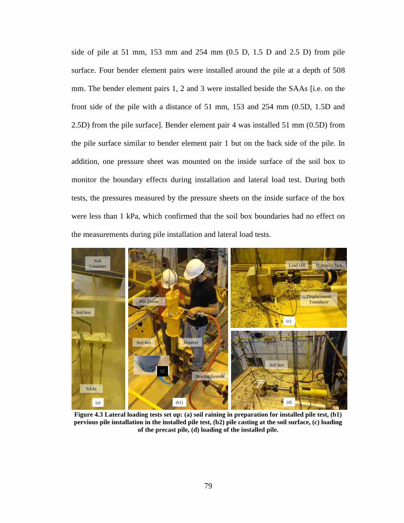
79
side of pile at 51 mm, 153 mm and 254 mm (0.5 D, 1.5 D and 2.5 D) from pile
surface. Four bender element pairs were installed around the pile at a depth of 508
mm. The bender element pairs 1, 2 and 3 were installed beside the SAAs [i.e. on the
front side of the pile with a distance of 51 mm, 153 and 254 mm (0.5D, 1.5D and
2.5D) from the pile surface]. Bender element pair 4 was installed 51 mm (0.5D) from
the pile surface similar to bender element pair 1 but on the back side of the pile. In
addition, one pressure sheet was mounted on the inside surface of the soil box to
monitor the boundary effects during installation and lateral load test. During both
tests, the pressures measured by the pressure sheets on the inside surface of the box
were less than 1 kPa, which confirmed that the soil box boundaries had no effect on
the measurements during pile installation and lateral load tests.
Figure 4.3 Lateral loading tests set up: (a) soil raining in preparation for installed pile test, (b1)
pervious pile installation in the installed pile test, (b2) pile casting at the soil surface, (c) loading
of the precast pile, (d) loading of the installed pile.
(d)
Soil box
(c)
Load cell Hydraulic Jack
Displacement
Transducer
(b1)
(b2)
Pile Driver
Bracing System
MandrelSoil box
SAAs
Soil
Container
Soil box
(a)

80
(a) (b)
Figure 4.4 Instrumentation for lateral loading tests: (a) Side View, (b) Top view (Notes: the
strain gauge with rebar was installed on the tension side of pile at 25 mm from pile center; SAA3
was installed in the precast pile and was installed in the soil at 254 mm from pile for the installed
pile test).
4.5 LOADING SEQUENCE
The two lateral load tests were conducted in general accordance with the
procedure outlined in ASTM D3966 (2009i). The loading procedure, however,
included two stages; a loading-control stage and a displacement-control stage. During
the loading-control stage, loading was held constant for at least 5 minutes or until the
pile head displacement stabilized. When the pile reached ultimate load (observed by a
large increase of lateral displacement under constant load), the control was shifted to
displacement-control by applying a constant lateral displacement at the pile head. The
tests were stopped when the displacement at the pile head reached approximately 125
mm. For the precast pile test, a load increment of 111 N was used for loads smaller
than 1780 N and a load increment of 222 N was used for larger loads. When the
Sensor
No.
Distance to Pile
Surface (mm)
1 51
2 153
3 254
4 51
: bender element
: SAA
: Strain gauge
4123
1829 mm
914 mm
Loading
Back sideFront Side
51 mm
153 mm
Loading
Soil Surface
508 mm
1321 mm
508 mm
SAA 1
Pressure
Sheet in
Test 1
4123Pressure
Sheet
SAA 2
SAA 3
in Test 1
SAA 3
in Test 2
254 mm
Back SideFront Side
Bender Element
in Test 2

81
ultimate load was reached at a displacement of 72.3 mm, the procedure shifted to
displacement-control with an increment of 10 mm and 2 minute holding time. For the
installed pile test, load-control with an increment of 222 N was used, and
displacement-control with 10 mm increment and 2 minute holding time was applied
after reaching the ultimate load at a displacement of 39.7 mm.
4.6 TEST RESULTS
4.6.1 Lateral Load-Displacement at Pile Head
Figure 4.5 illustrates the lateral load-displacement response of the precast and
installed pervious concrete piles. The results show that the ultimate loads of the
precast and installed pervious concrete piles were 3225 N and 3440 N, respectively,
indicating that the installation method had small effect on the ultimate (maximum)
load for laterally loaded piles, which is consistent with the results reported by
Lundberg, et al. (2013). This result could be attributed to the fact that the ultimate
lateral load is controlled by the structural resistance of the pile as concluded by
Suleiman et al. (2014b). However, ultimate loads were reached at a pile head
displacement of 39.7 mm for the installed pile, which is 55% of the displacement of
the precast pile (72.3 mm) at ultimate load. In addition, the stiffness of the soil-pile
system (i.e. the slope of the initial part of the load-displacement curve) for the precast
pile was 75.2 N/mm, which is 32% of the stiffness of the installed pile (233.2 N/mm).
These differences between the pile head displacement at ultimate load and stiffness of
the soil-pile system are mainly attributed to the effect of pile installation method,
which alters soil stresses and properties as will be discussed later.

82
Figure 4.5 Lateral load vs. displacement at the loading point.
4.6.2 Strain along the Pile
The strain measurements along the pile length from the two tests are
summarized in Figure 4.6. The strains are presented at four loading stages that
represent the beginning of the test, the linear part of the load-displacement response,
the nonlinear part of the load-displacement response, and the ultimate condition.
Figure 4.6 shows that the strains along the pile increased with lateral load. In both
pervious concrete piles, the strain increased along the depth and reached a peak value
at depth of 444 mm (4.4 D) below the soil surface; then the strain started to decrease
reaching zero at the pile tip. At ultimate load, the maximum strain occurred at the
depth of 444 mm, which indicates that the maximum moment was at this depth. After
the tests, the piles were retrieved and inspected (Figure 4.7). The precast and installed
piles cracked on the tension side at depths ranging from 460 mm (4.5 D) to 470 mm
(4.6 D) below the soil surface and the concrete was crushed on the compression side
at similar depth locations. These results are consistent with measurements of strain
gauges in the piles. The strain profiles and inspection of the piles after the tests
Lateral Displacement (mm)
0 20 40 60 80 100 120 140 160
Lat
eral
Lo
ad (
N)
0
1000
2000
3000
4000
Precast Pervious Concrete Pile
Installed Pervious Concrete Pile
Load = 3440 NDisplacement =39.4 mm
Load = 3225 NDisplacement =72.3 mm
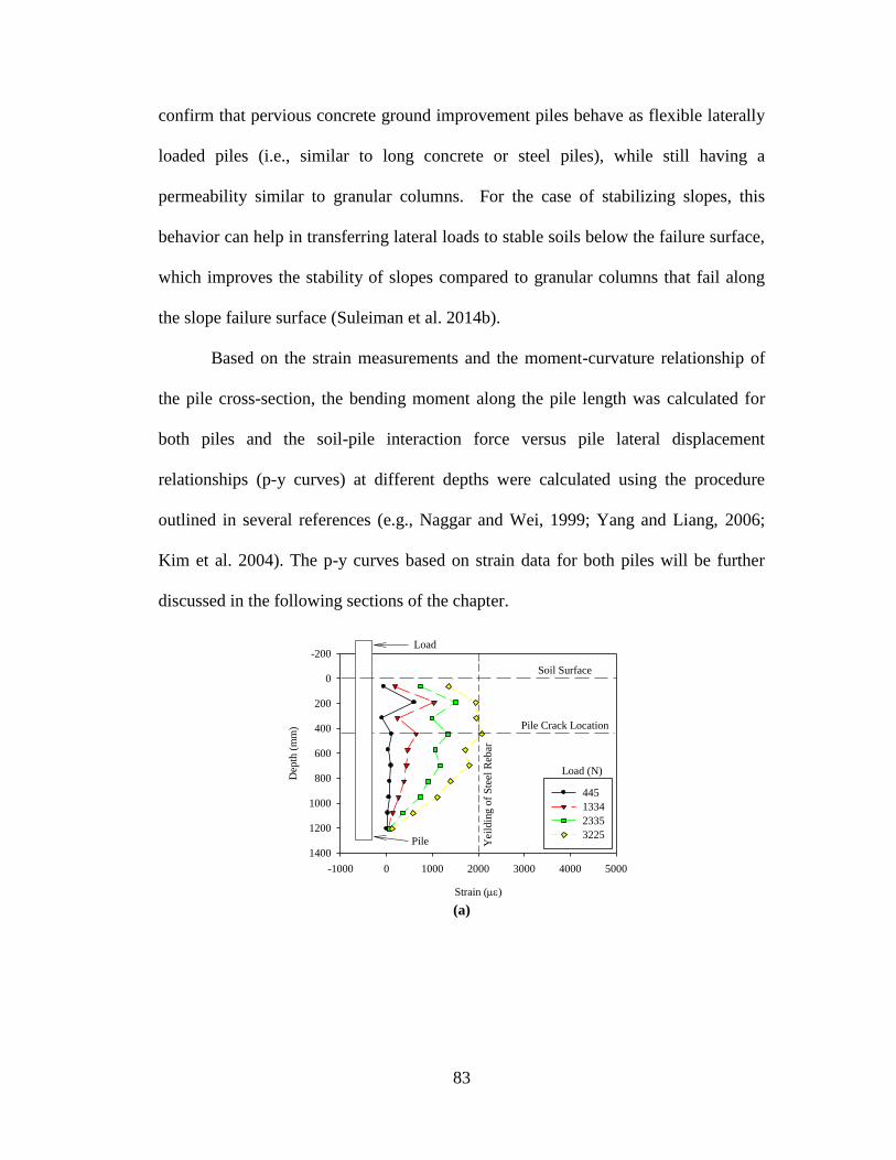
83
confirm that pervious concrete ground improvement piles behave as flexible laterally
loaded piles (i.e., similar to long concrete or steel piles), while still having a
permeability similar to granular columns. For the case of stabilizing slopes, this
behavior can help in transferring lateral loads to stable soils below the failure surface,
which improves the stability of slopes compared to granular columns that fail along
the slope failure surface (Suleiman et al. 2014b).
Based on the strain measurements and the moment-curvature relationship of
the pile cross-section, the bending moment along the pile length was calculated for
both piles and the soil-pile interaction force versus pile lateral displacement
relationships (p-y curves) at different depths were calculated using the procedure
outlined in several references (e.g., Naggar and Wei, 1999; Yang and Liang, 2006;
Kim et al. 2004). The p-y curves based on strain data for both piles will be further
discussed in the following sections of the chapter.
(a)
Strain ()
-1000 0 1000 2000 3000 4000 5000
Dep
th (
mm
)
-200
0
200
400
600
800
1000
1200
1400
445
1334
2335
3225
Pile Crack Location
Soil Surface
Yei
ldin
g o
f S
teel
Reb
ar
Load (N)
Load
Pile

84
(b)
Figure 4.6 Strain profile along the pile during lateral load tests: (a) precast pervious concrete pile,
and (b) installed pervious concrete pile.
(a) (b)
Figure 4.7 Test units after lateral load tests: (a) precast pervious concrete pile (the tape
measurement from the bottom of pile head, the depth of crack is at 470 mm below the soil
surface), and (b) Installed pervious concrete pile (the tape measurement from the top of pile head,
the depth of crack is 460 mm below the soil surface).
4.6.3 Soil-Pile Interaction
Pile and Soil Lateral Displacement
The pile and soil lateral displacements measured by the SAAs and
displacement transducers at an applied lateral load of 3225 N, which is the ultimate
Strain ()
-1000 0 1000 2000 3000 4000 5000
Dep
th (
mm
)
-200
0
200
400
600
800
1000
1200
1400
445
1334
2335
3225
3440
Pile Crack Location
Soil Surface
Yei
ldin
g o
f S
teel
Reb
ar
Load (N)
Load
Pile
85
load of the precast pile, are presented in Figure 4.8. As shown in the Figure 4.4 for
the precast pile, the SAAs were installed in the pile, at 51 mm and at 152 mm (0.5D
and 1.5D) from pile, while the SAAs were placed at 51 mm, 152 mm and 254 mm
(0.5D, 1.5D and 2.5D) from pile surface for the installed pile test. Based on the SAA
measurements at the applied load of 3225 N, the following observation can be made:
(1) the precast pile had a displacement of 61.8 mm at the soil surface while the
displacement of the installed pile was 27.7 mm; (2) at a distance of 51 mm (0.5D)
from the pile surface, the soil in precast pile test had a displacement of 24.4 mm at a
depth of 115 mm and decreased to 0 mm at a depth of 900 mm, while the soil had a
lateral displacement of 20.0 mm at a depth of 115 mm and decreased to 0 mm at a
depth of 640 mm for the installed pile test; (3) at 152 mm (1.5 D) from the pile
surface, the soil lateral displacement was small in both tests (less than 6 mm); and (4)
for the installed pile test, the soil at a distance of 254 mm (2.5D) on the front side of
the pile showed minimal lateral displacement during the test. These results indicate
that the soil lateral displacements on the front side of the installed pile were smaller
than those measured during the precast pile test, which reflects the effects of soil
densification and lateral compression during pile installation on the surrounding soil
and soil-pile interaction.
Figure 4.9 summarizes the lateral displacement of the precast pile along its
length. Figure 4.9 shows that the pile lateral displacement increased as the load
increased. The pile experienced no or minimal movement at the pile tip indicating a
long, flexible pile behavior when subjected to lateral loading. The displacement

86
profile indicates that a plastic hinge forms at a depth of approximately 440 mm,
which is consistent with the strain measurements (Figure 4.6).
(a)
(b)
Figure 4.8 The pile and soil lateral displacement under lateral loading of 3225 N: (a) precast
pervious concrete pile, and (b) installed pervious concrete pile
Lateral Displacement (mm)
-10 0 10 20 30 40 50 60 70
Dep
th (
mm
)
-200
0
200
400
600
800
1000
1200
1400
Pile Displacement
Soil Movement 51 mm from Pile
Soil Movement 152 mm from Pile
Soil Surface
Lateral Displacement (mm)
-10 0 10 20 30 40 50 60 70
Dep
th (
mm
)
-200
0
200
400
600
800
1000
1200
1400
Pile Head Displacement
Soil Movement 51 mm from Pile
Soil Movement 152 mm from Pile
Soil Movement 254 mm from Pile
Soil Surface

87
Figure 4.9 Precast pile displacements under lateral loading
Soil-Pile Interaction Pressure along the Precast Pile
During the precast pile test, the interaction pressures between the pile and
surrounding soil were measured using tactile pressure sheets. As mentioned in the
instrumentation section, three pressure sheets were wrapped around the pile from the
soil surface to the depth of 1111 mm (the bottom pressure sheet didn’t function
properly during the test due to a wire connection problem). The soil reaction (i.e. the
soil-pile interaction force per unit length, p in N/mm) along the pile is shown in
Figure 4.10 at the four loading stages previously defined. The soil reaction was
calculated using the measured soil-pile interaction pressures utilizing the following
two steps: (1) integrate the soil-pile interaction measured pressures to produce a force
(in N); and (2) divide the calculated force by the integrated length to produce the soil-
pile interaction force (p in N/mm). As shown in Figure 4.10, as the lateral loading
increased, the soil reaction (p) along the pile increased and the maximum value of soil
reaction reached 2.5 N/mm between depths of 388 mm and 453 mm (3.8 D and 4.5 D)
at ultimate load in the precast pile test.
Lateral Movement (mm)
-10 0 10 20 30 40 50 60 70
Dep
th (
mm
)
-200
0
200
400
600
800
1000
1200
1400
445
1334
2335
3225
Soil Surface
Load (N)
Load
SAA 3
Pile

88
Figure 4.10 Soil reactions (soil-pile interaction force per unit length) along the pile for the
precast pile test unit
Soil-Pile Interaction Force-Displacement Relationships (P-Y Curves)
Based on the measured pressures (Figure 4.10) and pile displacements (Figure
4.9), the p-y curves based on direct measurement at several depths along the precast
pile were generated (Figure 4.11a). The curves show that the initial slope (or stiffness)
and ultimate soil reaction (pu) increased as the depth increased.
The directly-measured p-y curves for the precast pile were compared with the
p-y curves calculated using the strain measurements and those developed using the
procedures suggested by Reese et al. (1974). For the precast pile, the p-y curves
calculated using the measured strains show higher initial stiffness (i.e. the slope of the
initial part of the curve) and ultimate soil reaction than the directly-measured curves.
An example of the compared p-y curves is presented in Figure 4.11b for a depth of
364 mm and comparisons at other depths show similar trends. Along the length of the
precast pile, the differences in the p-y curve initial stiffness and ultimate soil reaction
between the directly-measured curves and those calculated using measured strains
ranged from 20% to 53% and 31% to 73%, respectively. The p-y curves error was
Soil Reaction, p (N/mm)
0.0 0.5 1.0 1.5 2.0 2.5 3.0
Dep
th (
mm
)
-200
0
200
400
600
800
1000
1200
1400
445
1334
2335
3225
Soil Surface
Load (N)

89
calculated using the procedure suggested by Yang and Liang (2006). The error is
defined as the summation of the ratios of the difference between the measured and the
calculated p divided by the measured p at deflections of 0.25ym, 0.5 ym, 0.75 ym and
ym (ym is the maximum measured y). For different p-y curves along the pile length,
the calculated errors ranged from 3 to 8, which are similar or smaller than that those
reported by Yang and Liang (2006) who mainly attributed these errors to the
inaccurate determination of moment profiles from strain gauges. When compared to
the procedures suggested by Reese et al. (1974), the initial stiffness and ultimate soil
reaction of the directly measured p-y curves show differences up to 95% and 82%,
respectively.
The p-y curve of the installed pile at a depth of 364 mm has an initial stiffness
that is 95% of the value calculated using the method suggested by Reese et al. (1974).
The ultimate soil reaction is 98% of that calculated using Reese et al. (1974) method.
Along the pile length, the difference between values of initial stiffness and ultimate
soil reaction ranges from 1% to 58% and 0% to 17%, respectively. The better match
of the method suggested by Reese et al. (1974) to the installed pile results was
expected since the Reese method was developed for driven piles, which is an
installation method similar to the method used in the installed pile.
It is noteworthy that when comparing the p-y curves of the precast and
installed piles (i.e., effect of installation) using the strain measurements at the same
depth, the p-y curves of the installed pile shows a higher stiffness and ultimate soil
reaction. Along the pile, the ratio of the ultimate soil reaction of the installed pile to
the precast pile ranges from 1.4 to 5.9 at different depths. For smaller diameter piles
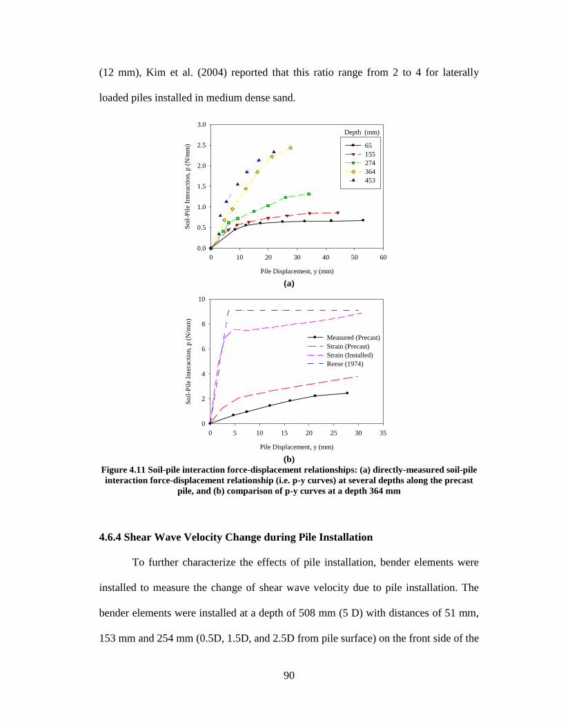
90
(12 mm), Kim et al. (2004) reported that this ratio range from 2 to 4 for laterally
loaded piles installed in medium dense sand.
(a)
(b)
Figure 4.11 Soil-pile interaction force-displacement relationships: (a) directly-measured soil-pile
interaction force-displacement relationship (i.e. p-y curves) at several depths along the precast
pile, and (b) comparison of p-y curves at a depth 364 mm
4.6.4 Shear Wave Velocity Change during Pile Installation
To further characterize the effects of pile installation, bender elements were
installed to measure the change of shear wave velocity due to pile installation. The
bender elements were installed at a depth of 508 mm (5 D) with distances of 51 mm,
153 mm and 254 mm (0.5D, 1.5D, and 2.5D from pile surface) on the front side of the
Pile Displacement, y (mm)
0 10 20 30 40 50 60
Soil
-Pil
e In
tera
ctio
n, p (
N/m
m)
0.0
0.5
1.0
1.5
2.0
2.5
3.0
65
155
274
364
453
Depth (mm)
Pile Displacement, y (mm)
0 5 10 15 20 25 30 35
Soil
-Pil
e In
tera
ctio
n, p
(N
/mm
)
0
2
4
6
8
10
Measured (Precast)
Strain (Precast)
Strain (Installed)
Reese (1974)
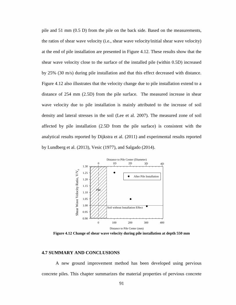
91
pile and 51 mm (0.5 D) from the pile on the back side. Based on the measurements,
the ratios of shear wave velocity (i.e., shear wave velocity/initial shear wave velocity)
at the end of pile installation are presented in Figure 4.12. These results show that the
shear wave velocity close to the surface of the installed pile (within 0.5D) increased
by 25% (30 m/s) during pile installation and that this effect decreased with distance.
Figure 4.12 also illustrates that the velocity change due to pile installation extend to a
distance of 254 mm (2.5D) from the pile surface. The measured increase in shear
wave velocity due to pile installation is mainly attributed to the increase of soil
density and lateral stresses in the soil (Lee et al. 2007). The measured zone of soil
affected by pile installation (2.5D from the pile surface) is consistent with the
analytical results reported by Dijkstra et al. (2011) and experimental results reported
by Lundberg et al. (2013), Vesic (1977), and Salgado (2014).
Figure 4.12 Change of shear wave velocity during pile installation at depth 550 mm
4.7 SUMMARY AND CONCLUSIONS
A new ground improvement method has been developed using pervious
concrete piles. This chapter summarizes the material properties of pervious concrete
Distance to Pile Center (mm)
0 100 200 300 400
Shea
r W
ave
Vel
oci
ty R
atio
, V
/V0
0.90
0.95
1.00
1.05
1.10
1.15
1.20
1.25
1.30
Distance to Pile Center (Diameter)
After Pile Installation
Pile
2D1D 3D 4D
Soil without Installation Effect
0

92
and the pile and soil responses obtained from two lateral load tests performed using
the SSI facility at Lehigh University. Fully-instrumented lateral load tests were
performed on a precast pervious concrete pile and an installed pervious concrete pile
to investigate the pile and soil behavior, to study the soil-pile interaction, and to
evaluate the effects of installation methods on pile behavior under lateral loading.
Based on the experimental results obtained from the two lateral load tests and the
discussion of the results presented in this chapter, the following conclusions are
drawn:
1. A pervious concrete mixture prepared using proportions of 0.21 water/cement
ratio, 0.11 sand/aggregate ratio, 377 kg/m3 cement and 1440 kg/m
3 coarse
aggregate provided an average compressive strength of 22.8 MPa, modulus of
15.1 GPa, and permeability of 1.44 cm/sec. at an average porosity of 10.7%.
These properties show that pervious concrete piles have a compressive
strength that is more than 10 times that of granular columns, while having
permeability similar to granular columns.
2. The used installation method results in lateral compression and densification
of surrounding sand as well as lateral stress increase. These changes
significantly affect the pile and soil responses and the soil-structure interaction
of pervious concrete ground improvement piles when subjected to laterally
loading.
3. The ultimate lateral loads for the precast and installed pervious concrete piles
were similar but the lateral displacements at ultimate load were significantly
different. The displacement of the installed pile was 55% of the precast pile.
93
4. For both the precast and installed piles, the maximum strain and moment
occurred at a similar depth of 444 mm below the soil surface, which is
consistent with the locations of major tensile cracks (460 to 470 mm).
Regardless of the installation method, pervious concrete ground improvement
piles behave similar to long concrete or steel piles (i.e., long, flexible piles)
when subjected to lateral loading, while providing permeability similar to that
of granular columns. Unlike granular columns, this behavior helps in
transferring lateral loads to stable deeper soils below the failure surface when
used to stabilize slopes, which improve the response of stabilized slopes.
5. The installation of pervious concrete piles affects the surrounding soil
response. A comparison of the soil displacements illustrates that the lateral
displacements around the installed pile are smaller than the displacements
around the precast pile.
6. The soil-pile interaction was directly measured for the precast pile using
tactile pressure sheets and SAAs, which provided the information needed to
develop directly measured p-y curves. The p-y curves obtained based on direct
measurements show that the initial slope and ultimate soil reaction increased
as the depth increased.
7. The p-y curves developed using the strain measurements of the installed pile
more closely matched the curves produced using the Reese et al. (1974)
method than the curves developed for the precast pile.

94
8. The installation method significantly affects the p-y curves for laterally loaded
piles. Along the pile, the ratio of the ultimate soil reaction of the installed pile
to the precast pile ranged from 1.4 to 5.9.
9. Shear wave velocity changes measured in the soil surrounding the installed
pervious concrete pile during installation demonstrate that the zone of soil
affected by installation extended to 2.5D from the pile surface.
95
CHAPTER 5
NUMERICAL SIMULATION OF PERVIOUS CONCRETE PILE TESTS
5.1 INTRODUCTION
Pervious concrete piles have recently been developed as an innovative ground
improvement method (Suleiman et al. 2014; Ni et al. 2014). The behaviors of
pervious concrete piles when subjected to vertical loading have been investigated
using state-of-art Soil-Structure Interaction (SSI) facility. As part of this research, the
piles and surrounding soil were instrumented and the effects of pile installation on
soil-pile interaction and pile responses have been evaluated using the experimental
tests. To improve the understanding of the installation effects on soil-pile interaction,
2D finite element modeling has been used. This study focuses on validating the finite
element analytical models that can be used to simulate the installation effects of pile
and the behaviors of pervious concrete piles under vertical loading.
However, developing a proper numerical model to accurately simulate the pile
installation and behavior under vertical loading is a challenging task. In finite element
method modeling, the large deformations, which occur during pile installation and at
the soil-pile interface during loading, lead to severe mesh distortion in the finite
element analysis. In addition, pile installation may change the soil properties and
stresses, which significantly affect the behavior of piles when subjected to vertical
loading.
Researchers have used different modeling approaches to simulate the effects
of installation methods and effect on vertical load behavior, including 1D, 2D and 3D

96
finite element methods(Dijkstra et al. 2006; Pham and White 2007; Gennaro et al.
2008; Chen et al. 2009; Said et al. 2009; Basu et al. 2010; Dijkstra et al. 2011; Pucker
and Grabe 2012). These approaches utilized defining soil-pile interaction properties
by interface model and using special calculation steps to modeling the pile installation
effects, the pile and soil behavior under vertical loading.
In this chapter, numerical analysis method has been developed to investigate
the behavior of the pervious concrete piles subjected to vertical loading. The vertical
load tests of pervious concrete piles are simulated using 2D axisymmetric finite
element model with Plaxis 2D. An approach used to take into account the installation
effects are proposed and discussed. The comparison between calculation results from
the numerical simulations and measured results from experimental testing were
conducted to validate the numerical simulations.
5.2 BACKGROUND
During the process of pile installation, the soil experience large displacement
and its properties and stress will change. These installation effects influence the load-
displacement response of the pile. Several laboratory and field tests have been
conducted to investigate the installation effects of different types of pile.
Measurements included the change of soil density, soil deformation along the pile and
at the tip of the pile, cone penetration tests before and after installation, and shear
wave velocity (Shublaq 1992; Klotz and Coop 2001; Hunt et al. 2002; Lee et al. 2004;
White and Bolton 2004; Suleiman and White 2006; Ambily and Ganhdi 2007; Yi et al.
2010; Frikha et al. 2013; and Lundberg et al. 2013).

97
Numerical simulations of pile installation have been developed by several
researchers (Wehnert and Vermeer 2004a, 2004b; Dijkstra et al 2006; Ambily and
Gandhi 2007; Guetif et al. 2007; Pham and White 2007; Gennaro et al 2008; Chen et
al. 2009; Said et al. 2009; Basu et al. 2010; Castro and Karstunen 2010; Thompson
and Suleiman 2010; Dijkstra et al. 2011; and Pucker and Grabe 2012). These
approaches include 1D (one dimension), 2D and 3D finite element modeling of
different pile types (i.e. stone column, rammed aggregate pier, displacement pile, and
bored pile).
To consider the installation effects of bored piles, Wehnert and Vermeer
(2004a and 2004b) concluded that the soil stiffness (i.e. soil Young’s modulus)
needed to be increased 25% within 1D at the tip of pile.
In the numerical analysis of stone columns, Ambily and Gandhi (2007) didn’t
consider the installation effect, Guetif, et al. (2007) used an elastic-perfectly plastic
soil model and the improvement of the soil Young’s modulus was considered due to
column installation. Castro and Karstunen (2010) improved the simulation by using a
hardening-soil model and modeling the pile installation as the expansion of a cavity.
The behavior of rammed aggregate piers installed in a prebored hole was
simulated by Pham and White (2007), Chen, et al. (2009), and Thompson and
Suleiman (2010). In the study of Pham and White (2007), the pier installation process
was modeled by applying 5 to 10% of the nominal diameter of cavity outward
displacement along the shaft and downward uniform displacement at the bottom of
the cavity based on measurement (Pham 2005). Chen et al. (2009) used same concept
of cavity expansion to develop a 3D (diameter) model and investigate the effect of

98
different installation method of aggregate pier. Thompson and Suleiman (2010) used
prescribed cavity volumetric strain expansion to simulate stress-dependent stiffness
behavior of the aggregate, instead of using the prescribed displacement method
proposed by Pham and White. In addition, the interface elements with hardening soil
model were used to improve the modeling.
The displacement pile (normal concrete pile compared with granular pile) has
been investigated using numerical method by several researchers. Dijkstra et al (2006)
studied the effects of soil model on the behavior of pile, recommended the interface
element with reduction factor as 0.75 for modeling and proposed the cavity expansion
method with 3.75% of the pile diameter horizontally expansion and 3.75D (diameter)
vertical expansion to simulate the displacement pile installation effects. Gennaro, et al.
(2008) and Said et al. (2009) simulated the soil pile interaction by special interface
constitutive model and proposed an approach to account for the pile installation
effects due to jacking and driving in a 2D finite element model. In this approach,
empirical correlations based on field data have been used to reproduce the soil stress,
shaft friction and base resistance due to pile installation. The numerical models
mentioned above only take into the installation effects without simulating the
installation process. Few researchers have simulated the installation process to
improve the understanding of changes during the installation process. Basu et al.
(2011) used 1D finite element model to investigate the shaft capacity development for
a displacement pile installed in sand. A small initial radius (<10% of pile diameter)
has been selected for cavity expansion to simulate the pile installation. Dijkstra, et al.
(2011) used a 2D finite element model capable of large displacement to simulate the
99
pile installation phase. The simulation results showed a soil zone with 2D around pile
and 4D × 2D at the pile tip in axisymmetric model was effected by pile installation
and the soil property (density) had been changed in the pile installation process.
Pucker, et al. (2012) develop a 3D finite element model to simulate the pile
installation process. The pile installation effects on the soil stress state and the soil
density was investigated. However, because of the complexity of installation process
simulation, the further validation of these models is still needed.
Based on the previous research work, a proper numerical model to simulate
the pile installation and behavior under vertical loading should include:
1. Proper soil constitutive model to simulate the soil behavior
2. Interface element to consider the soil pile interaction
3. A Cavity expansion procedure to simulate the soil stress development due
to pile installation
4. Changes of soil properties caused by the pile installation
These requirements were used in the numerical simulations presented in this
chapter. The next sections provide the details of the numerical models and the
experimental measurements used for validation.
5.3 EXPERIMENTAL PROGRAM
5.3.1 Soil Properties
The soil used in vertical load test was classified as well-graded sand (SW)
according to the Unified Soil Classification System. The sand was rained into the soil
box to produce a homogeneous soil profile along the total depth of the pile. The

100
minimum and maximum unit weights of the sand were 15.1 and 20.8 kN/m3,
respectively (i.e., maximum void ratio of 0.720 and minimum void ratio of 0.250).
The rained sand had average relative density of 32%, unit weight of 16.5 kN/m3, and
water content of 2%.
To characterize the soil properties, consolidated drained (CD) triaxial tests
were performed. The soil samples were prepared with similar properties for vertical
load tests, (i.e., relative density of 32% and unit weight of 16.5 kN/m3). The samples
were tested under confining pressures of 15, 25, 100 and 160 kPa. The Kf line
indicates that the peak friction angle of the soil is 38°. The critical friction angle is the
same as the peak friction angle, which is consistent with the results presented by
Mitchell and Soga (2005) for loose sand. Based on the triaxial data, the sand at low
confining pressure has the friction angle as 42° which is higher than the friction angle
calculated using all confining pressure. Low confining pressure presents the stress
range within the soil box; therefore, it is more suitable to use the friction angle at low
confining pressure to represent the initial condition.
5.3.2 Vertical Load Tests
The pervious concrete pile tests used to validate the numerical analysis are
two instrumented vertical load tests. Both piles were prepared using pea river gravel,
with diameter of 102 mm and embedded length of 1,219 mm. The first test unit was a
precast pile, which was installed vertically into soil box with soil raining afterward.
The second test unit (installed pile) was a cast-in-place pile installed using a 102-mm-
diameter mandrel as shown in Figure 3.3. A bracing system was designed to ensure
101
accurate pile position and the verticality of the pile installation. Through the hollow
cylinder of the bracing system, the mandrel was driven into the soil. Once the targeted
depth was reached, the pervious concrete was placed into the mandrel from the top.
As the mandrel was lifted upward at a slow rate, the cone would open to fill the
created cavity with pervious concrete during retrieval. It is worth noting that similar
to displacement piles, the used installation method results in lateral compression and
densification of the surrounding sand as well as increase lateral soil stresses (Dijkstra
et al. 2011; Lundberg et al. 2013).
The vertical load tests generally followed the fast procedure outlined in the
ASTM D1143 (ASTM 2009d). In tests, the loads were applied by successive
increments of 222.4 N for precast pile test and 889.6 N for installed pile test. Each
load was held constant for 4 min or until the pile head displacement stabilized. The
tests were stopped when the pile displacement continued increasing without an
increase in the applied load. The load-displacement responses were shown in the
Fgiure 3.6b.
In the vertical load test of installed pile, the surrounding soil was instrumented
with three SAAs and six null pressure sensors, as shown in Figure 3.5. Two SAAs
were installed at 102 (1D) from the center of pile, and one SAAs was installed at 203
mm from the center of pile (2D). The null pressure sensor 1, 2 and 3 were installed at
76, 178 and 279 mm (i.e., 0.75 D, 1.75 D, and 2.75 D) below the tip of the pile to
measure the vertical soil pressure. The null pressure sensor 4, 5 and 6 were installed
at the same horizontal distance of 102 mm (1D) from the pile center with different
depth of 1,270, 1,270 and 914 mm below the soil surface, respectively. The soil

102
movement during the pile installation and vertical test are shown in Figure 3.10 and
the soil pressure changes are summarized at Figure 3.11.
5.4 MATERIAL CONSTITUTIVE MODELS
5.4.1 Hardening-Soil Model
The hardening-soil (HS) constitutive model is used to describe the behavior of
sand used in the tests. This HS model has been recommended by Wehnert and
Vermeer (2004a) and Dijkstra et al. (2006) to simulate sand behaviors. The
parameters for the model are derived from triaxial consolidated drained (CD) tests
which are summarized in Table 5.1. In this constitutive model, the soil initial stiffness
is determined by , which is the confining stress dependent modulus given by
the equation (1):
(1)
The parameters are defined in Table 5.1 and are calculated based on
Brinkgreve et al. (2014). The dilatant behavior of sand needs to be considered in the
modelling for its influence on the shaft resistance (Wehnert and Vermeer 2004a;
Dijkstra et al. 2006; Gennaro et al. 2008). A dilatation angle of 12° was selected for
modeling. This value was determined based on the difference of 30° between the
friction angle and the dilatation angle as recommended by Gennaro et al. (2008) and
Brinkgreve et al. (2014). The stress dependency value m is 0.725 in the range given
by Von Soos (1990) and the unloading-reloading modulus
is set as three times
of
based on the recommendation by Schanz et al. (1999).

103
Table 5.1 The constitutive model parameters for sand used in vertical load tests
Name Symbol HS model Unit
Unsaturated unit weight 16.5 kN/m3
Saturated unit weight 19.8 kN/m3
Initial void ratio 0.606 -
Reference stiffness
4878 kN/m2
Oedometer reference modulus
4878 kN/m2
Unloading/reloading stiffness
14634 kN/m2
Power for stress-level dependency of stiffness m 0.725 -
Cohesion 0 kN/m
2
Friction angle 42 (degree)
Dilatation angle 42 (degree)
Poisson ratio 0.2 -
Reference stress for stiffness 100 kN/m2
Interface strength reduction factor 0.75 (0.8) -
To validate the soil parameters used in the hardening soil model, the triaxial
tests was modeled in Plaxis. The measured from consolidated drained (CD) triaxial
test and calculated (from Plaxis) stress-strain responses for sand are presented in the
Figure 5.1. The similarity between measured and calculated soil behavior indicates
that the soil behavior is well simulated by HS constitutive model.

104
Figure 5.1 The measured and calculated triaxial deviator stress vs. strain curves under different
confining pressure
5.4.2 Interface Soil Element Model
The soil-pile interaction is included in the model by utilizing the interface
element between the pile and surrounding soil. The interface element is modelled
using the Mohr-Coulomb friction failure criterion. The displacement is allowed to
occur within the interface element to simulate the relative movement between the pile
and soil, where the small displacements are controlled by elastic behavior and large
displacement are described by plastic behavior. In Plaxis, the interface properties are
functions of the adjacent soil strength properties associated with strength reduction
factor ( ). The value of is set as 0.75 for precast pile interface as
recommended by Dijkstra et al. (2006) and set as 0.8 for installed pile interface with
rough pile surface based on the match between the calculated and measured results.
Axial Strain (%)
0 2 4 6 8 10 12 14 16 18
Dev
iato
r S
tres
s (k
Pa)
0
100
200
300
400
500
600
15 (Calculated)
25 (Calculated)
100 (Calculated)
160 (Calculated)
15 (Measured)
25 (Measured)
100 (Measured)
160 (Measured)
Confining pressure (kPa)

105
5.4.3 Pile Element Model
The pile is simulated by linear elastic model (Wehner and Vermeer 2004;
Dijktra et al. 2006) with Young’s elastic modulus of 15.4×10⁶ kN/m
3, and Poisson
ratio of 0.3, which are obtained from experimental results of pervious concrete
sample.
5.5 FINITE ELEMENT MODEL
The model dimension is set the same as the soil box that was used for vertical
load tests with height of 2286 mm and half width of 762 mm as shown in Figure 5.2.
The pile and soil are modeled by 15-noded triangular elements in axisymmetric
model. The interface between pile and soil has been set along the pile length using
values mentioned before.
In vertical load tests, the pervious concrete piles have radius of 51 mm and
embedded length of 1219 mm. The precast pile is directly modeled with this
dimension. For the installed pile, the model accounted for the installation effects,
which will be discussed in further details in the next section. The previous analysis by
Wehnert and Vermeer (2004a) and Dijkstra et al. (2006) pointed out that, in order to
avoid the effect of element size on calculation results, the pile needed to be meshed
with at least 16 elements along the pile and at least 2 elements over the radius of the
pile tip. Therefore, the local element size factor of pile was reset to 0.1 instead of 1.0.
And the local element size factor of soil near the pile was reset to 0.25. The smaller
size of element is able to provide better prediction of the soil behavior. The mesh of
two models with the refined zone near the pile is shown in the Figure 5.3.

106
As shown in Figure 5.2a and 5.3a, three soil zones were used around the
precast pile for near the pile are set for mesh refinement. According to the
investigation of Dijkstra et al. (2008), Said et al. (2009), Dijkstra et al. (2011) and
Lundberg et al. (2013), the soil within 2D around the pile and 4D below the pile tip
was effected by the vertical loading. Therefore, Zone 1 is adjacent to the pile along its
length (1219 mm) and has a width of 203 mm (2D). Zone 2 is below the pile with
height of 406 mm (4D) and width of 51 mm (0.5 D). Zone 3 is below the soil adjacent
to the pile with height of 406 mm (4D) and width of 203 mm (2D). Zone 4 represents
the soil away from pile, which is less affected by the vertical load, with boundary of
soil box. The model includes 2119 elements totally.
For the installed pile model shown Figure 5.2b and 5.3b, the soil area
surrounding the installed pile was divided into additional six zones to take account for
the installation effects on surrounding soil. Research on the installation effects of
displacement pile demonstrated that the area affected by pile installation at the tip is
approximately 4D × 2D (height × width) (Shublaq 1992; Dijkstra et al. 2008; Said et
al. 2009; Dijkstra et al. 2011; and Lundberg et al. 2013). This affected zone is
confirmed by the measured vertical stress below the pile tip presented in Chapter 3. In
addition, the measured soil movements around the pile show that the zone affected by
pile installation extended to 2D along the pile (Lundberg et al. 2013). Therefore, the
soil area affected by installation is set in a horizontal distance of 2D along the pile
and a vertical distance of 4D below the pile tip. As shown in Figure 5.2b and 5.3b,
two zones beside the pile have been set, which are zone 1 of 1019 mm × 147 mm
(height × width) and zone 2 of 1019 mm × 102 mm (height × width). In addition, two

107
bottom zones, which are zone 3 of 403 mm × 152 mm (height × width) and zone 4 of
606 mm × 254 mm (height × width, and expect zone 3), have been used. The Zone 5
is set with dimension of 203 mm (2D) below the zone 4 and 203 mm (2D) beside the
zone 1 and 4. Zone 5 is set for the further study the effected zone of pile installation.
Zone 6 represents the dimension of the soil box in vertical load test. The total number
of the meshed element is 1784. The effects of installation on soil properties will be
discussed in the next section.
(a) (b)
Figure 5.2 The geometry of finite element model: (a) Precast pile; (b) Installed pile.
Zone 1
Pile
Interface
Zone 3
Zone 2
Vertical load
1219 mm
2286 mm
762 mm
Zone 4
Zone 1
Initial cavity
Interface
Zone 4
Zone 3
Vertical load
1019 mm
2286 mm
762 mm
Zone 2
Zone 5
Prescribed displacement
Zone 6

108
(a) (b)
Figure 5.3 The mesh of finite element model: (a) Precast pile; (b) Installed pile.
5.6 MODELING PROCEDURE
For the precast pile, the modeling procedure includes the initial phase to
generate initial stress and a series of loading phases. In order to consider the
installation effects on the vertical load test of the installed pile, installation phases
were included between pr the initial phase and the loading phases. The section below
provides the details of different modeling phases.
5.6.1 Initial Phase
The initial stress condition is established to generate the initial vertical and
horizontal soil stresses. The vertical stresses are calculated using the unit weight of
Zone 1
Zone 3Zone 2
Zone 4

109
the soil. Initial horizontal stresses are generated using the K0 procedure, in which the
in-situ horizontal effective stresses are calculated using the vertical effective stress
and the predefined K0 value (based on the soil friction angle).
5.6.2 Installation Phase
For the installed pile, the zone representing the pile with the initial size which
is 10% of the pile diameter (5.1 mm width) is deactivated initially. The 10% size of
the initial cavity was recommended by Basu et al. (2011). In pile installation, the
cavity is mainly expanded vertically with the pile driving into deeper depth. However,
the simulation of only vertical cavity expansion in finite element model will cause
mesh distortion at the tip of pile. Therefore, the numerical approach focuses on
simulating the final installation effects rather than the installation procedure itself.
The installation effects are considered by applying prescribed displacements
at the pile-soil boundary of initial cavity. The prescribed displacement method was
recommened by Broere and Van Tol (2006) and Said et al. (2009). The total cavity
expansion includes horizontal prescribed displacement of 45.7 mm and vertical
prescribed displacement of 200 mm (2D) as shown in Figure 5.4. The implementation
of cavity expansion is divided into four expansion steps. Each step has 25%
increment of horizontal displacement (11.4 mm) and vertical displacement (50 mm).
For each expansion step, the mesh is updated (i.e. to consider large displacement) to
avoid mesh distortion. This expansion procedure of cavity in model is different from
the actual cavity creation process during pile penetration.

110
During the experimental test, the horizontal displacement of the soil (cavity
expansion) starts from zero lateral soil displacement (i.e., no initial cavity). However,
the cavity expansion from a zero radius in finite element model may cause numerical
instability and errors. Therefore, researches investigating pile installation effects
using cavity expansion (e.g., Salgado and Prezzi 2007; Basu et al. 2011)
recommended that instead of creating a cavity from zero radius, the cavity expansion
from a sufficient small initial cavity radius (~10% of the final radius) lead to a
reasonable results. Therefore, the initial horizontal expansion in this model is set as
5.1 mm, which is 10% of final pile radius.
For the vertical direction, the cavity was expanded by a displacement that
results in vertical stress change similar to the measured value during the test. Several
trials were performed for the vertical expansion to match measured stress. It was
found that the vertical expansion of 200 mm (i.e., after expansion the length of cavity
is the same as the pile length of 1219 mm) produce similar soil stress at the tip of the
pile as the measured pressure at the same location in the experimental test.

111
Figure 5.4 The prescribed displacement on soil boundary to simulate the cavity expansion in pile
installation
5.6.3 Activation Phase
Before applying the vertical load on the installed pile, the pile elements were
reactivated in the expanded cavity and the prescribed displacement was deactivated.
For the installed pile, the pile installation will not only densify the soil and
increase the soil stress, but also will improve the soil stiffness. Wehnert and Vermeer
(2004a, and 2004b) recommended improving the soil stiffness by 25% in the effected
zone below the pile tip of 1D. Gennaro (1999) presented an equation to quantify the
increase of the soil modulus after pile installation, which is confirmed by Said, et al.
(2009). The equation of the modified soil modulus as a function of confining pressure
is presented as:
(2)
H: 45.7 mm
V:200 mm

112
where the m value is calculated as 1.16 from the initial value of under reference
confining pressure (100 kPa) from measurements of CD triaxial test. The modified
value of at pile tip is calculated as 21.96 MPa using Equation (2) and the
measured radial stress close to the pile tip as 210 kPa (i.e. the stress measured by
sensor 4 and 5), which is about 50% increase compared to initial soil modulus.
Therefore, the soil modulus in the installation effected zone (2D around the pile, 4D
below the pile tip) should increasing 25 to 50% compared to initial modulus.
According to the previous studies (Suleiman et al. 2014) on soil stiffness
change during pile installation and the experimental analysis of soil stress and
movement during vertical load tests in Chapter 3, the soil modulus (including the
parameter of ,
, and ) are reactivated with increased value due to pile
installation is shown in the Figure 5.5. Zone 1 (within 1D to pile) and zone 3 (within
2D to pile tip) has modulus 1.5 times of the initial value. Zone 2 (1D to 2D beside the
pile) and zone 4 (2D to 4D below the tip of pile) has modulus 1.25 times of the initial
value.

113
Figure 5.5 The soil stiffness change after pile installation
5.6.4 Loading Phase
The vertical loading procedure was modeled by applying a sequence of
vertical loads on the pile head. The vertical loads on the top of the pile were
simulated by point loads at the axis of symmetry. The input value of loads was the
force acted on the angle of one radian (i.e., the point load should be multiplied by 2π
to give load on physical pile). Mesh updating was also used for each load step to
minimize any numerical instability that could be caused by large displacement, and to
obtain more accurate results.
1.5 Modulus
1.0 Modulus
1.25 Modulus

114
5.7 RESULTS ANALYSES
5.7.1 Model Validation
The model validation focuses on the comparison between the calculated and
measured values, including the load-displacement relationship, soil movement and
stress development near the pile tip.
The calculated and measured vertical load-displacement relationships were
shown in Figure 5.6. For the precast pile, the calculated initial slope of load
displacement curve is 149 N/mm and the displacement at ultimate load is 113 mm,
which are similar with the measured initial slope of 155 N/mm and displacement of
119 mm (i.e., the calculated slope and displacement under ultimate load is 96% and
95% of the measured value, respectively). For the installed pile, the calculated initial
slope of load displacement curve is 2,427 N/mm and displacement at ultimate load is
37 mm, which is 84% of the measured initial slope (2,883 N/mm) and 109% of the
measured displacement (34 mm), respectively. The very good match between the
model prediction and test results indicates that procedure used to model the response
of pervious concrete piles and the effects of installation is reasonable and the soil
parameter selection is appropriate.
The major difference between precast pile model and installed pile model is
the additional of two calculation phases to consider the pile installation effects. The
increases of load capacity and slope of the load-displacement curve attributed to the
pile installation effects have been well simulated by the proposed approach, which
confirmed that this modeling approach of pile installation effects is reasonable.
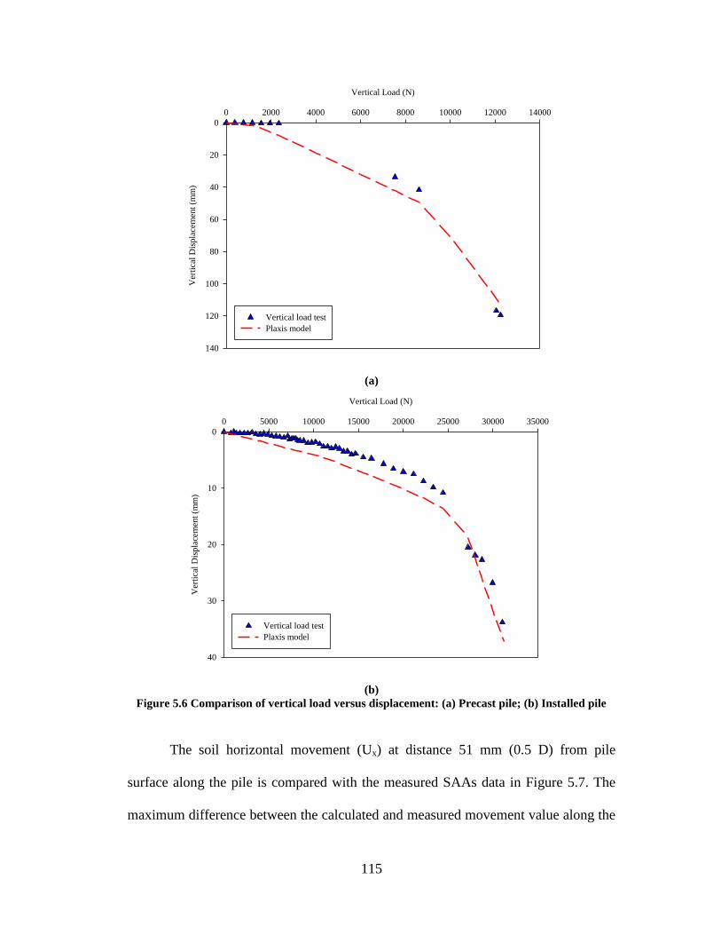
115
(a)
(b)
Figure 5.6 Comparison of vertical load versus displacement: (a) Precast pile; (b) Installed pile
The soil horizontal movement (Ux) at distance 51 mm (0.5 D) from pile
surface along the pile is compared with the measured SAAs data in Figure 5.7. The
maximum difference between the calculated and measured movement value along the
Vertical Load (N)
0 2000 4000 6000 8000 10000 12000 14000
Ver
tica
l D
isp
lace
men
t (m
m)
0
20
40
60
80
100
120
140
Vertical load test
Plaxis model
Vertical Load (N)
0 5000 10000 15000 20000 25000 30000 35000
Ver
tica
l D
isp
lace
men
t (m
m)
0
10
20
30
40
Vertical load test
Plaxis model

116
pile is 3.7 mm (34%), which further validates that the initial set of prescribed
displacement with 45.7 mm on a small diameter (5.1 mm) cavity.
Figure 5.7 The comparison of calculated and measured soil lateral movements at 51 mm from
surface of installed pile
During the vertical loading stage, the soil stress development at 76 mm (0.75D)
below the pile tip is plotted and compared with the measured soil stress at this point
(i.e., the pressure sensor 3 measurement in Figure 3.11a). As shown in Figure 5.8,
after pile installation, the calculated pressure (the 1st point) is 214 kPa, which is very
close to the measured pressure of 215 kPa after installation. This confirms that the
prescribed displacement of 200 mm (2D) in the vertical direction is appropriate.
When comparing the measured final pressure of 644 kPa under ultimate vertical load,
the calculated pressure (the last point) of was 512 kPa has difference to the measured
pressure value less than 20%.
Soil movement (mm)
-2 0 2 4 6 8 10 12 14 16 18 20
Dep
th (
mm
)0
500
1000
1500
2000
2500
Measured
Model
Pile depth
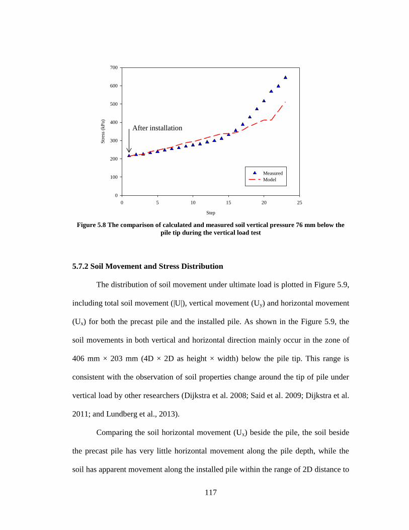
117
Figure 5.8 The comparison of calculated and measured soil vertical pressure 76 mm below the
pile tip during the vertical load test
5.7.2 Soil Movement and Stress Distribution
The distribution of soil movement under ultimate load is plotted in Figure 5.9,
including total soil movement (|U|), vertical movement (Uy) and horizontal movement
(Ux) for both the precast pile and the installed pile. As shown in the Figure 5.9, the
soil movements in both vertical and horizontal direction mainly occur in the zone of
406 mm × 203 mm (4D × 2D as height × width) below the pile tip. This range is
consistent with the observation of soil properties change around the tip of pile under
vertical load by other researchers (Dijkstra et al. 2008; Said et al. 2009; Dijkstra et al.
2011; and Lundberg et al., 2013).
Comparing the soil horizontal movement (Ux) beside the pile, the soil beside
the precast pile has very little horizontal movement along the pile depth, while the
soil has apparent movement along the installed pile within the range of 2D distance to
Step
0 5 10 15 20 25
Str
ess
(kP
a)
0
100
200
300
400
500
600
700
Measured
Model
After installation
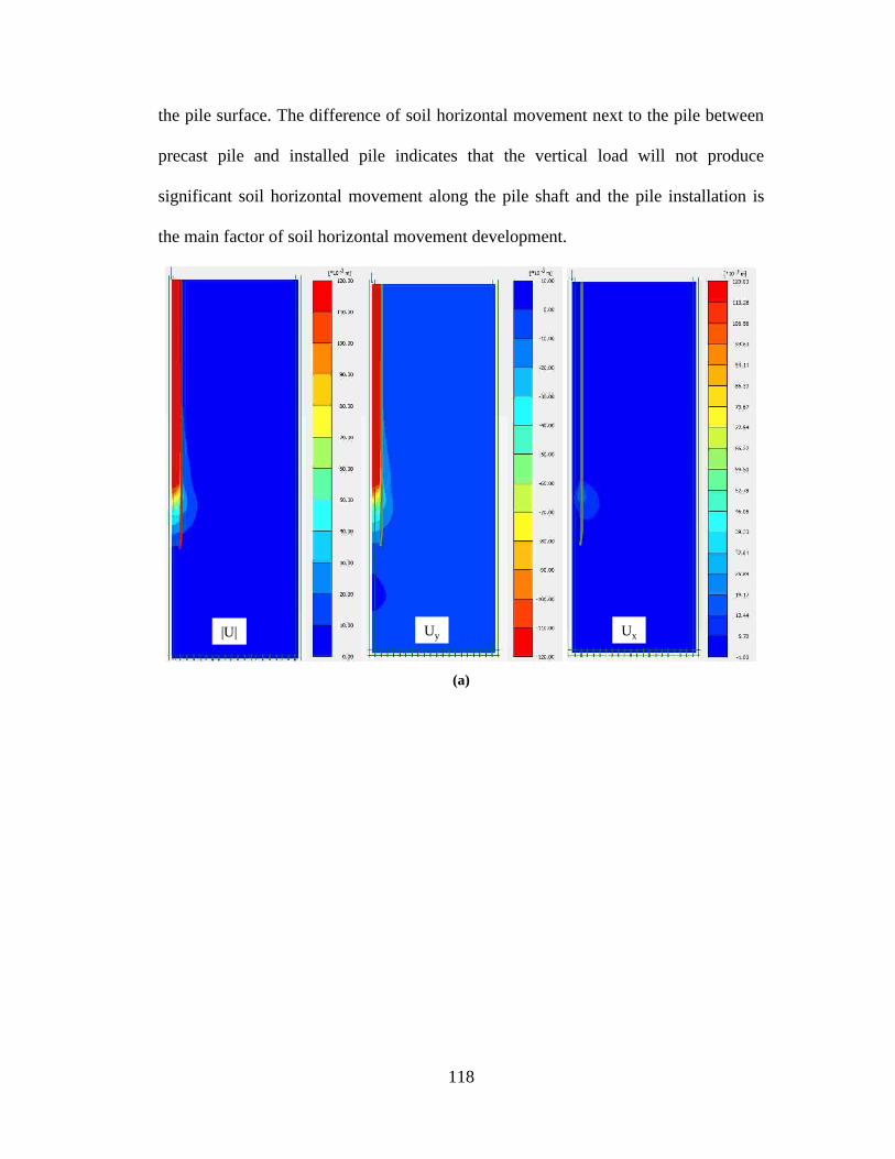
118
the pile surface. The difference of soil horizontal movement next to the pile between
precast pile and installed pile indicates that the vertical load will not produce
significant soil horizontal movement along the pile shaft and the pile installation is
the main factor of soil horizontal movement development.
(a)
|U| UxUy

119
(b)
Figure 5.9 distribution of displacement under vertical load: (a) Precast pile; (b) Installed pile
The soil stress distributions in vertical and horizontal direction at the final
loading step of 31,200 N are shown in Figure 5.10. The stress contours show that the
zone of main stress change is below the pile tip that extend is 4.5 D × 3D for installed
pile model and 4 D × 2D for the precast pile model. This effected soil area is
consistent with the area of soil properties changes observed by other researchers (Said
et al. 2009; Dijkstra et al. 2011) and confirms the geometry setting of soil zone in
both model.
|U| UxUy

120
(a)
(b)
Figure 5.10 Distribution of soil stress under vertical load: (a) Precast pile; (b) Installed pile
σyy σxx
σyy σxx
121
5.7.3 Influence of the Interface Model
The influence of the interface model on the simulation results of the vertical
load tests is investigated by two calculation cases. In the first calculation case, the
soil-pile interface behavior is modeled using interface element created between soil
and pile. For the second case, the soil and pile were perfectly attached to each other
(i.e., no interface element).
The calculation results of load-displacement relationship are compared in the
Figure 5.11. And the properties of load-displacement curve are summarized in the
Table 5.2. For the precast pile, the model without interface element has initial slope
of 295 N/mm and failed at a small displacement of 30 mm under an ultimate load of
10,000 N. Compared to the measured response, the model without interface element
has much higher (around 2 times as high as the measured one) initial load-
displacement slope with an underestimated the displacement and ultimate load at
failure. Moreover, when large vertical displacement occurs at large vertical load, the
model needs extended interface to simulate the large soil movement below the tip of
pile. As showed in Figure 5.10a, when the displacement is larger than 51 mm (0.5D),
the model without extended interfaces cannot well estimate the vertical load behavior,
while the model with original interface along the pile and extended interface can
accurately simulate the pile under vertical load.
For the installed pile, without using interface element does not have
significant influence at the stage with small displacement increment as show in Table
5.2. However, when the large displacements occur (>17 mm), the soil in model
without interface collapsed under lower vertical load.

122
In both vertical load tests, the finite element model without interface failed at
small displacement. This phenomenon is expected because that the finite element
model doesn’t allow large displacement to occur.
Table 5.2 The load-displacement properties of model with/without interface
Type Initial slope
(N/mm)
Ultimate load
(N)
Displacement
(mm)
Precast pile
Test 155 12, 200 119
Model with two
interfaces 149 12, 200 113
Model without
extended interface 149 12, 200 88
Model without
interface 295 10, 000 30
Installed pile
Test 2883 31, 222 34
Model with
interface 2427 31, 222 37
Model without
interface 2600 28, 770 17
(a)
Vertical load (N)
0 2000 4000 6000 8000 10000 12000 14000
Dis
pla
cem
ent
(mm
)
0
20
40
60
80
100
120
140
Measured
Model with two interfaces
Model without extended interface
Model without interface

123
(b)
Figure 5.11 Influence on the interface: (a) Precast pile; (b) Installed pile
5.7.4 The Influence of Soil Stiffness
As mentioned in background, the soil stiffness has been improved by the pile
installation, which will affect the load-displacement response of pile. To evaluate the
effects of soil stiffness change, the results of two models, one without changes of soil
stiffness and one with changes, were compared. As shown in the Figure 5.12, the
initial slope of the model without considering the changes of soil stiffness around the
pile is 2067 N/mm, which is 72% of the slope of the measured response; and the
displacement under ultimate load (44 mm) is 29% larger than the measure value.
Therefore, the results of the model with initial soil stiffness overestimate the
displacement of pile under vertical load around 30% compared to the test results. In
addition, the effect of soil stiffness 1D beside the pile and 2D below the pile tip was
investigated by increasing 30%, 40% and 60% after pile installation. The results show
that the displacements under ultimate load with 30%, 40% and 60% soil stiffness
Vertical load (N)
0 5000 10000 15000 20000 25000 30000 35000
Dis
pla
cem
ent
(mm
)
0
10
20
30
40
50
Measured
Model with improved soil stiffness
Model with initial soil stiffness

124
increase are 5.5% bigger, 2.1% bigger and 2.5% smaller than the one with 50% soil
stiffness increase, which indicate that the soil stiffness increase indeed effect the pile
load-displacement behavior.
Figure 5.12 Influence of soil stiffness for vertical load of installed pile
5.7.5 Soil Movement during Installation
In the installed pile model, the pile installation is taken into account using
installation and activation phases. In the installation phase, the cavity expansion due
to the pile installation is applied using a prescribed displacement on soil. During the
prescribed displacement process, the soil is pushed to create the cavity. The
corresponding soil movement caused by pile installation is presented in Figure 5.13.
The range of the soil movement is mainly in the zone of 406 mm (4D) below the tip
of the pile and 203 mm (2D) beside the pile. The affected soil zone is consistent with
the soil movement zone measured by Lundberg et al. (2013) and the SAAs
measurements in the tests presented in chapter 3.
Vertical load (N)
0 5000 10000 15000 20000 25000 30000 35000
Dis
pla
cem
ent
(mm
)
0
10
20
30
40
50
Measured
Model with improved soil stiffness
Model without initial soil stiffness

125
Figure 5.13 Soil movements during pile installation
5.8 SUMMARY AND CONCLUSIONS
In this chapter, the behaviors of pervious concrete piles and surrounding soil
were investigated using Plaxis 2D. The pile installation effects have been taken into
account. The analysis results confirm that the installation effects significant influence
the pile and soil behaviors.
Two finite element models have been created to simulate the installation
effects and behavior of pervious concrete piles subjected to vertical loading. The pile
responses in modeling have been compared with the measured response. The major
findings of the numerical study include:
1. A finite element simulation approach is proposed to account for the effects of
pile installation. The approach includes two additional calculation phases:
installation phases with prescribed displacement (2D in vertical direction and
|U| UxUy
2D
4D

126
0.45 D in horizontal direction); and activation phase with soil stiffness
increased.
2. The modeling results of both precast and installed pile show good agreement
with the measurement results. The difference of the initial load-displacement
slope and the displacement under ultimate load is less than 16%, the
difference of the displacement under ultimate load is less than 9%.
3. The pile installation effect on soil movement (1D from pile center) has
difference less than 34% between the modeling results and measurements.
After pile installation, the soil stress development at pile tip in model has less
than 20% difference to the measured pressure value.
4. The soil properties improvement is taken into consideration of modeling the
pile installation effect. The analytical results show that within the range of 2D
horizontal distance to pile and 4D vertical distance to tip of pile, the soil
stiffness based on the needs to be increased by 25%~50% as consequence of
pile installation.
127
CHAPTER 6
SUMMARY AND CONCLUSIONS
6.1 SUMMARY AND CONCLUSIONS
An innovative ground improvement method using pervious concrete piles has
been created and studied in this research. In addition, the installation effects are
investigated by various advanced experimental and numerical methods. The
important conclusions from this research are summarized as follow:
1. Pervious concrete piles have a compressive strength that is more than 10 times
that of granular piles, while providing similar permeability to granular piles.
2. The pervious concrete pile, which had the same dimensions, aggregate type,
and installation method as the granular pile, had an ultimate load that was 4.4
times greater than the ultimate load of the granular piles.
3. The installation method had significant effects on the response of the pervious
concrete piles and surrounding soil.
4. The ultimate vertical load of the installed pile was 2.6 times greater than that
of the precast pile.
5. Installation of the pervious concrete pile resulted in an increase of the
maximum frictional stress transferred at the soil-pile interface.
6. The lateral soil displacements measured at a distance of 1D from the pile
center during installation were not uniform along the length of the pile.
7. The ultimate lateral loads for the precast and installed pervious concrete piles
were similar but the lateral displacement at ultimate load of the installed pile
was 55% of the precast pile.

128
8. The installation method significantly affects the p-y curves for laterally loaded
piles. Along the pile, the ratio of the ultimate soil reaction of the installed pile
to the precast pile ranged from 1.4 to 5.9.
9. Shear wave velocity changes measured in the soil surrounding the installed
pervious concrete pile during installation demonstrate that the zone of soil
affected by installation extended to 2.5D from the pile surface.
10. A new finite element simulation approach is proposed to account for the
effects of pile installation. The approach includes two additional calculation
phases: installation phases with prescribed displacement and activation phase
with soil stiffness increased.
11. 2D axisymmetric finite element simulations that account for the effects of
installation show good agreement with the measured response of test piles.
12. The zone of soil affected by the pile installation and loading is 2D × 4D
(Width × height) below the tip of the pile and 2D along the pile length.
6.2 FUTURE RESEARCH
The author suggests that the following of pervious concrete ground
improvement pile needs further study:
1. Parametric study on pervious concrete pile in different soils using finite
element models proposed by author.
2. The pervious concrete pile has high permeability comparing to surrounding
soil. The pore water pressure dissipation is worth to investigate to further
understand the ground improve process by using pervious concrete piles.
129
3. Instead of single pile, the further investigation should include the pile and soil
behavior of group piles. And the 3D model will be more benefit for
investigation the soil-pile interaction and group piles behavior.
4. The field tests on pervious concrete pile will be helpful for investigate the
pervious concrete piles behavior and industrial application.

130
REFERENCE
Aboshi, H., Ichimoto, E., Harada, K., and Emoki, M. (1979). The Compozer: A
Method to Improve Characteristics of Soft Clays by Inclusion of Large
Diameter Sand Columns. International Conference on Soil Reinforcement,
Reinforced Earth and Other Techniques, Vol.1, Paris, pp 211−216.
Aboshi, H., and Suematsu, N. (1985). Sand Compaction Pile Method: State-of-art
Paper. 3rd International Seminar on Soil Improvement Methods, Singapore,
pp. 1−12.
Adalier, K., Elgamal, A., Meneses, J. and Baez, J. I. (2003). Stone Columns as
Liquefaction Countermeasure in Non-plastic Silty Soils, Soil Dynamics and
Earthquake Engineering. Vol.23, No. 7, pp. 571−584.
Adalier, K. and Elgamal, A. (2004). Mitigation of Liquefaction and Associated
Ground Deformations by Stone Columns. Engineering Geology, Vol.72, No.
3-4, pp. 275−291.
Ambily, A. P. and Gandhi, S. R. (2007). Behavior of Stone Columns Based on
Experimental and FEM Analysis, Journal of Geotechnical and
Geoenvironmental Engineering, Vol. 133, No. 4, pp. 405−415.
ASTM. (2009a). Standard Practice for Making and Curing Concrete Test Specimens
in the Laboratory. C192, West Conshohocken, PA.
ASTM. (2009b). Standard Test Method for Compressive Strength of Cylindrical
Concrete Specimens. C39, West Conshohocken, PA.
ASTM. (2009c). Standard Test Methods for Deep Foundations under Lateral Load.
D3966, West Conshohocken, PA.

131
ASTM. (2009d). Standard Test Methods for Deep Foundations under Static Axial
Compressive Load. D1143, West Conshohocken, PA.
ASTM. (2009e). Standard Test Method for Density and Void Content of Freshly
Mixed Pervious Concrete. C1688, West Conshohocken, PA.
ASTM. (2009f). Standard Test Method for Flexual Strength of Concrete (Using
Simple Beam with Third-Point Loading). C78, West Conshohocken, PA.
ASTM. (2009g). Standard Test Methods for Maximum Index Density and Unit
Weight of Soils Using a Vibratory Table. D4253, West Conshohocken, PA.
ASTM. (2009h). Standard Test Methods for Minimum Index Density and Unit
Weight of Soils and Calculation of Relative Density. D4254, West
Conshohocken, PA.
ASTM. (2009i). Standard Test Methods for Splitting Tensile Strength of Cylindrical
Concrete Specimens. C496, West Conshohocken, PA.
ASTM. (2009j). Standard Test Methods for Static Modulus of Elasticity and
Poisson’s Ratio of Concrete in Compression. C469, West Conshohocken, PA.
Ashford, S. A., Rollins, K. M., Bradford V, S. C., Weaver, T. J., and Baez, J. I.
(2000). Liquefaction Mitigation Using Stone Columns Around Deep
Foundations: Full Scale Test Results. Transportation Research Record 1736,
pp 110-118.
Baez, J. I. (1995). A Design Model for the Reduction of Soil Liquefaction by Vibro-
stone Columns. Ph.D. Dissertation, University of Southern California, Los
Angeles, CA.
132
Barksdale, R. D., and Bachus, R. C. (1983). Design and Construction of Stone
Columns. Federal Highway Administration, FHWA/RD 83/026, Vol. 1,
Report No.1.
Basu, P., Loukidis, D., Prezzi, M. and Salgado, R. (2011). Analysis of Shaft
Resistance of Jacked Piles in Sands. International Journal for Numerical and
Analytical Methods in Geomechanics, Vol. 35, pp. 1605−1635.
Beeldens, A., Gemert, D. V. and Caestecker, C. (2003). Porous Concrete: Laboratory
Versus Field Experience. 9th
International Symposium on Concrete Roads,
Istanbul, Turkey.
Bergado, D. T., Miura, N., Panichayatum, B. and Sampaco, C. L. (1988).
Reinforcement of Soft Bangkok Clay using Granular Piles. Proceedings of the
International Geotechnical Symposium on Theory and Practice of Earth
Reinforcement, pp. 179 – 184.
Bergado, D. T., Chai, J. C., Alfaro, M. C., and Balasubramaniam, A. S. (1994).
Improvement Techniques of Soft Ground in Subsiding and Lowland
Environment, A.A. Balkema, Rotterdam/Brookfield VT USA.
Brandenberg, S. J., Kutter, B. L. and Wilson, D. W. (2008). Fast Stacking and Phase
Corrections of Shear Wave Signals in a Noisy Environment. Journal of
Geotechnical and Geoenvironmental Engineering, Vol. 134, No. 8, pp. 1154 –
1165.
Brinkgreve, R. B. J., Broere, W. and Waterman, D. (Edited). PLAXIS 2014, PLAXIS,
Delft, Netherlands.
133
Castro, J. and Karstunen, M. (2010). Numerical Simulation of Stone Column
Installation. Canadian Geotechnical Journal, Vol. 47, pp. 1127 – 1138.
Chen, J. F., Jan, J., Oztoprak, S., and Yang, X. M. (2009). Behavior of Single
Rammed Aggregate Piers Considering Installation Effects. Computers and
Geotechnics, Vol. 36, pp. 1191−1199.
Colombi, A., Fioravante, V., and Jamiolkowski, M. (2006). Displacement vs. Non-
displacement Axially Loaded Pile Behaviour in Sand from Centrifuge Tests.
Proceedings of the 6th International Conference on Physical Modeling in
Geotechnics, Hong Kong, pp. 815 – 820.
Dijkstra, J., Broere, W. and Heeres, O. M. (2011). Numerical Simulation of Pile
Installation. Computer and Geotechnics, Vol. 38, pp. 612 – 622.
Dijkstra, J., Broere, W. and Tol A. F. V. (2006). Numerical Investigation into Stress
and Strain Development around A Displacement Pile in Sand. 6th
European
Conference on Numerical Methods in Geotechnical Engineering, Graz,
Austria, pp. 595 – 600.
Dijkstra, J., Broere, W. and Tol, A. F. V. (2008). Density Changes Near An
Advancing Displacement Pile in Sand. Proceeding of 2nd
International
Conference on Foundations, pp. 545 – 554.
Elgamal, A., Lu, J. and Forcellini, D. (2009). Mitigation of Liquefaction-Induced
Lateral Deformation in a Sloping Stratum: Three-dimensional Numerical
Simulation. Journal of Geotechnical and Geoenvironmental Engineering, Vol.
135, No. 11, pp. 1672 – 1682.

134
Elias, V., Welsh, J., Warren, J., Lukas, R., Collin, J. G. and Berg, R. R. (2006).
Ground Improvement Methods I & II. National Highway Institute, Federal
Highway Administration, U.S. Department of Transportation, FHWA NHI-
06-019.
Elshazly, H. A., Hafez, D. H., and Mossaad, M. E. (2008). Reliability of
Conventional Settlement Evaluation for Circular Foundations on Stone
Columns. Geotechnical and Geological Engineering, Vol. 26, No. 3, pp.
323−334.
Fan, C. C., and Long, J. H. (2005). Assessment of Existing Methods for Predicting
Soil Response of Laterally Loaded Piles in Sand. Computers and Geotechnics,
Vol. 32, No. 4, pp. 274 – 289.
Frikha, W., Bouassida, M. and Canou, J. (2013). Observed Behaviour of Laterally
Expanded Stone Column in Soft Soil, Geotechnical and Geological
Engineering, Vol. 31, No. 2, pp. 739−752.
Gennaro, V. D., Frank, R. and Said, I. (2008). Finite element analysis of model piles
axially loaded in sands, Italian Geotechnical Journal, Vol. 2, pp. 44 – 62.
Geopier Foundations Company. (2014). Rammed Aggregate Pier System.
http://www.geopier.com/Geopier-Systems
Guetif Z., Bouassida M. and Debats J. M. (2007). Improved Soft Clay Characteristics
Due to Stone Column Installation. Computers and Geotechnics, Vol. 34, No. 2,
pp. 104 − 111.
135
Han, J. and Gabr, M. (2002). Numerical Analysis of Geosynthetic-Reinforced and
Pile-Supported Earth Platforms over Soft Soil. Journal of Geotechnical and
Geoenvironmental Engineering, Vol. 128, No. 1, pp. 44 − 53.
Handy, R. L. (2001). Does Lateral Stress Really Influence Settlement. Geotechnical
and Geoenvironmental Engineering, Vol. 127, No. 7, pp. 623 − 626.
Hoevelkamp, K. K. (2002). Rammed Aggregate Pier Soil Reinforcement: Group
Load Tests and Settlement Monitoring of Large Box Culvert. M.S. Thesis,
Iowa State University, Ames, Iowa.
Hughes, J. M. O. and Withers, N. J. (1974). Reinforcing of Soft Cohesive Soils with
Stone Column. Ground Engineering, Vol.7, No. 7. pp. 42 − 49.
Hunt, C. E., Pestana, J. M., Bray, J. D. and Riemer, M. F. (2002). Effect of Pile
Installation on Static and Dynamic properties of Soft Clay. Journal of
Geotechnical Engineering, Vol. 128, No. 1, pp. 199 − 212.
Janbu, N. (1963). Soil Compressibility as Determined by Oedometer and Triaxial
Tests. European Conference on Soil Mechanics and Foundation Engineering,
Wiesbaden, Germany, Vol. 1, pp. 19 − 25.
Kajio, S., Tanaka, S., Tomita, R., Noda, E. and Hashimoto, S. (1998). Properties of
Porous Concrete with High Strength. 8th
International Symposium on Concrete
Roads, pp. 171 − 177.
Kevern, J. T., Schaefer, V. R., Wang, K., and Suleiman, M. T. (2008). Pervious
Concrete Mixture Proportions for Improved Freeze-Thaw Durability. Journal of
ASTM International, Vol. 5, No. 2.

136
Kim, B. T., Kim, N. K., Lee, W. J. and Kim, Y. S. (2004). Experimental Load-
Transfer Curves of Laterally Loaded Piles in Nak-Dong River Sand. Journal of
Geotechnical and Geoenvironmental Engineering, Vol. 130, No. 4, pp. 416 –
425.
Kim, Y., and Jeong, S. (2011). Analysis of Soil Resistance on Laterally Loaded Piles
Based on 3D Soil-pile Interaction. Computers and Geotechnics, Vol. 38, No. 2,
pp. 248 – 257.
Klotz, E. U. and Coop, M. R. (2001). An Investigation of the Effect of Soil State on
the Capacity of Driven Piles in Sands. Geotechnique, Vol. 51, No. 9, pp. 733 –
751.
Krishna, A. M., Madhav, M. R., and Latha, G .M. (2006). Liquefaction Mitigation of
Ground Treated with Granular Piles: Densification Effect. Journal of
Earthquake Technology, Vol. 43, No. 4, pp. 105 – 120.
Lawton, E. C. (1999). Performance of Geopier Foundation during Simulated Seismic
Tests at South Temple Bridge on Interstate 15, Salt Lake city, Utah, Interim
Report, No. UUCVEEN 99-06, University of Utah, Salt Lake City, Utah.
Lawton, E. C. (2000). Performance of Geopier Foundations During Simulated
Seismic Tests on I-15 Bridge Bents. Transportation Research Record 1736,
No. 00-1307, pp. 3 – 11.
Lee, F. H., Juneja, A., and Tan, T. S. (2004). Stress and Pore Pressure Changes Due
to Sand Compaction Pile Installation in Soft Clay. Geotechnique, Vol. 54,
No.1, pp. 1 − 16.
137
Lee, J. S. and Santamarina, J. C. (2005). Bender Elements: Performance and Signal
Interpretation. Journal of Geotechnical and Geoenvironmental Engineering,
Vol. 131, No. 9, pp. 1063 – 1070.
Lee, J. S., Guimaraes, M., and Santamarina, J. C. (2007). Micaceous Sands
Microscale Mechanics and Macroscale Response. Journal of Geotechnical
and Geoenvironmental Engineering, Vol. 133, No. 9, pp. 1136 – 1143.
Lehane, B. M., Jardine, R. J, Bond, A. J., and Frank, R. (1993). Mechanisms of Shaft
Friction in Sand from Instrumented Pile Tests. Journal of Geotechnical
Engineering, ASCE, Vol.119, No. 1, pp. 19 – 35.
Lehane, B. M. and White, D. J. (2005). Lateral Stress Changes and Shaft Friction for
Model Displacement Piles in Sand. Canadian Geotechnical Journal, Vol. 42,
No. 4, pp. 1039 – 1052.
Lin, K. Q., and Wong I. H. (1999). Use of Deep Cement Mixing to Reduce
Settlement Bridge Approaches. Journal of Geotechnical and
Geoenvironmental Engineering, Vol. 125, No. 4, pp. 309 – 320.
Lundberg, A. B., Dijkstra, J., and Tol, A. F. V. (2013). Displacement Pile Installation
Effects in Sand. Installation Effects in Geotechnical Engineering, Hicks
Editor, Taylor and Francis Group, London, UK.
Magnan J. P. (1983). Théorie et pratique des drains verticaux. Edition Technique et
Documentation-Lavoisier. Paris.
Magnan J. P. (1983). Théorie et pratique des drains verticaux. Edition Technique et
Documentation-Lavoisier. Paris.

138
Mitchell J.K. (1981). State-of-the-art Report, Session 12. 10th
International
Conference on Soil Mechanics and Foundation Engineering, Stockholm,
Sweden, pp. 506 − 565.
Mitchell, J. K., Baxter, C. D. P., and Munson, T. C., (1995). Performance of
Improved Ground During Earthquakes. Proceedings of Soil Improvement for
Earthquake Hazard Mitigation, ASCE Geotechnical Publication No.49, pp. 1
– 36.
Mitchell, J. K., and Soga, K. (2005). Fundamentals of Soil Behavior, Third Edition,
Wiley, Hoboken, NJ.
Moseley, M. P., and Kirsch, K. (2004). Ground Improvement. Spon Press, Taylor and
Francis Group, New York, NY.
Ni, L., Suleiman, M. T. and Raich, A. (2013). Pervious Concrete Pile: An Innovative
Ground Improvement Alternative. Geo-Congress 2013, pp. 2051 – 2058.
Naggar, M. H. EI and Wei, J. Q. (1999) Response of Tapered Piles subjected to
Lateral Loading. Canadian Geotechnical Journal, Vol. 36, No. 1, pp. 52 – 71.
Ohtsuka, T., Aramaki, G., and Koga, K. (2004). Soil Improvement of Soft Ground
around Pile Foundation in Earthquake-Resistant Design. Lowland Technology
International, Vol. 6, No. 1, pp. 42 – 54.
Okamura, M., Ishihara, M., and Ohshita, T. (2003) Liquefaction Resistance of Sand
Deposit Improved with Sand Compaction Piles. Soils and Foundations, Vol.
43, No.5, pp.175 – 187.
Okamura, M., Ishihara, M., and Tamura, K. (2006). Degree of Saturation and
Liquefaction Resistances of Sand Improved with Sand Compaction Pile.

139
Journal of Geotechnical and Geoenvironmental Engineering, Vol. 132, No. 2,
pp. 258 – 264.
Palmer, M. C., O'Rourke, T. D., Olson, N. A., Abdoun, T., Ha, D. and O'Rourke, M. J.
(2009). Tactile Pressure Sensors for Soil-Structure Interaction Assessment.
Journal of Geotechnical and Geoenvironmental Engineering, Vol. 135, No.11,
pp. 1638 – 1645.
Park, S. and Tia, M. (2004). An Experimental Study on the Water-purification
Properties of Porous Concrete. Cement and Concrete Research, Vol. 34, No. 2,
pp. 177 – 184.
Pham, H. T. V. (2005). Support mechanism for rammed aggregate piers. Ph.D
Dissertation, Iowa State University, Ames, Iowa.
Pham, H. T. V. and White, D. J. (2007). Support Mechanisms of Rammed Aggregate
Piers. II: Numercial Analyses. Journal of Geotechnical and Geoenvironmental
Engineering, ASCE, Vol. 133 No. 12, pp. 1512 – 1521.
Pucker, T., Grabe, J. (2012). Numerical Simulation of the Installation Process of Full
Displacement Piles. Computers and Geotechnics, Vol. 45, pp. 93 – 106.
Reese, L. C., Cox, W. R., and Koop, F. D. (1974). Analysis of Laterally Loaded Pile
in Sand. In Proceedings of the Six Annual Offshore Technology Conference.
Houston, TX, No. 2080, pp. 671 – 690.
Said, I., Gennaro, V. D. and Frank, R. (2009). Axisymmetric Finite Element Analysis
of Pile Loading Tests, Computer and Geotechnics, Vol. 36, PP. 6 – 19.
140
Salgado, R., Mitchell, J. K., and Jamiolkowski, M. (1997). Cavity Expansion and
Penetration Resistance in Sand. Journal of Geotechnical and
Geoenvironmental Engineering, ASCE, Vol. 123 No. 4, pp. 344 – 354.
Salgado, R. and Prezzi, M. (2007), Computation of Cavity Expansion Pressure and
Penetration Resistance in Sands. International Journal of Geomechanics,
ASCE, Vol. 7 No. 4, pp. 251 – 265.
Salgado, R. (2014). Experimental Research on Cone Penetration Resistance. Keynote
Lecture. GeoCongress 2014, Atlanta, GA, Feb 23 – 26.
Schaefer, V. R., Abramson, L. W., Drumheller, J. C., Hussin, J. D., and Sharp, K. D.
(1997). Ground Improvement, Ground Reinforcement, Ground Treatment:
Development 1987−1997. Geotechnical special publication No. 69, ASCE,
Logan, Utah.
Schaefer V. R., Wang K. J., Suleiman M. T., and Kevern J. T. (2006). Mix Design
Development for Pervious Concrete in Cold Weather Climates. National
Concrete Pavement Technology Center, Iowa State University, Ames, Iowa.
Schanz, T., Vermeer, P. A., Bonnier, P. G. (1999). The Hardening-Soil Model:
Formulation and Verification. Beyond 2000 in Computational Geotechnics
(Brinkgreve, R. B. J. edited), Balkema, Rotterdam, pp. 281 – 290.
Shao, L., Taylor, D., Koelling, M. (2013). Stone Columns and Earthquake Drain
Liquefaction Mitigation for Federal Center South in Seattle, Washington. Geo-
Congress 2013, San Diego, CA, pp. 864 – 878.
Shenthan, T., Nashed, R., Thevanayagam, S. and Martin, G. R. (2004). Liquefaction
Mitigation in Silty Soils Using Composite Stone Columns and Dynamic

141
Compaction. Earthquake Engineering and Engineering Vibration, Vol.3, No. 1,
pp. 39 – 50.
Shublaq, E. W. (1992). Soil Disturbance due to Installation of Model piles and Pile
Groups. Soils and Foundations, Vol. 32, No. 4, pp. 17 – 26.
Stuedlein, A. W. and Holtz, R. D. (2013). Bearing Capacity of Spread Footings on
Aggregate Pier Reinforced Clay. Journal of Geotechnical and
Geoenvironmental Engineering, Vol. 139, No. 1, pp. 49 – 58.
Suleiman, M. T., Pham, H., and White, D. J. (2003). Numerical Analyses of
Geosynthetic-Reinforced Rammed Aggregate Pier-Supported Embankments.
Report No. ISU-ERI-03598, Iowa State University, Ames, Iowa.
Suleiman, M. T. and White, D. (2006). Load Transfer in Rammed Aggregate Piers.
International Journal of Geomechanics, Vol. 6, No. 6, pp. 389 – 398.
Suleiman, M. T., Kevern, J., Schaefer, V. R., and Wang, K. (2006). Effect of
compaction energy on pervious concrete properties. Concrete Technology
Forum–Focus on Pervious Concrete, National Ready Mix Concrete
Association, Nashville, TN.
Suleiman, M. T., Gopalakrisnan, K., and Kevern, J. (2011). Structural Behavior of
Pervious Pavement Systems. Journal of Transportation Engineering, Vol. 137,
No. 12, pp. 907 – 917.
Suleiman, M. T. Ni, L. and Raich, A. (2014a). Development of Pervious Concrete
Pile Ground Improvement Alternative and Behavior under Vertical Loading.
Journal of Geotechnical and Geoenvironmental Engineering, under review.
142
Suleiman, M. T. Ni, L., Helm, J. D. and Raich, A. (2014b). Soil-Pile Interaction for
Small Diameter Pile Embedded in Granular Soil Subjected to Passive Loading.
Journal of Geotechnical and Geoenvironmental Engineering, Accepted.
Suleiman, M. T., Ni, L., Raich, A. M., and Ghazanfari, E., (2013). Measured Soil-
Structure Interaction for Piles Subjected to Lateral Loading. Journal of
Geotechnical and Geoenvironmental Engineering, Under Review.
Talesnick, M. (2005). Measuring Soil Contact Pressure on a Solid Boundary and
Quantifying Soil Arching. Geotechnical Testing Journal, Vol.28, No. 2, pp. 171
– 179.
Talesnick, M., Horany, H., Dancygier, A. N. and Karinski, Y. S. (2008). Measuring
soil pressure on a buried model structure for the validation of quantitative
frameworks. Journal of Geotechnical and Geoenvironmental Engineering, Vol.
134, No. 6, pp. 855 – 865.
Tamai, M., and Yoshida, M. (2003). Durability of Porous Concrete. Proceeding in 6th
International Conference on Durability of Concrete, American Concrete
Institute, Detroit, MI.
Tennis P. D., Leming, M. L. and Akers, D. J. (2004). Pervious Concrete Pavements.
EB302, Portland Cement Association, Skokie, IL, and National Ready Mixed
Concrete Association, Silver Spring, MD.
Terashi, M., and Juran, I. (2000). Ground Improvement - State-of-the-art.
International Conference on Geotechnical and Geological Engineering.
Melbourne, Australia.

143
Thompson, M. J. and Suleiman, M. T. (2010). Numerical Modeling of Rammed
Aggregate Pier Construction. GeoFlorida 2010: Advances in Analysis,
Modeling & Design, pp 1460-1469.
Vesic, A. S. (1977). Design of Pile Foundations. Transportation Research Board
National Cooperative Highway Research Program, National Research
Council, ed., Washington, D.C.
Von Soos, P. (1990). Porperties of Soil and Rock (in German). In
Grundbautaschenbuch Part 4, Edition 4, Ernst & Sohn, Berlin.
Wehnert, M. and Vermeer, P. A. (2004a). Numerical Analyses of Load Tests on
Bored Piles. Proceeding of 9th
numerical models in Geomechanics, Ottawa,
Canada, pp. 505 – 511.
Wehnert, M. and Vermeer, P. A. (2004b). Numerische Simulation von
Probebelastungen an Grobbohrpfahlen (in German). Proceeding of the 4th
Kolloqium Bauen in Boden und Fels, Ostfildern, pp. 555 – 565.
Welsh, J. P., (1987). Soil Improvement -A Ten Year Update, ASCE Geotechnical
Publication No.12.
White, D. J. and Bolton, M. D. (2004). Displacement and Strain Paths During Plane-
Strain Model pile installation in sand. Geotechnique, Vol. 54, No. 6, pp. 375 –
397.
White, D. J. and Suleiman, M. T. (2004). Design of Short Aggregate Piers to Support
Highway Embankments. Journal of the Transportation Research Board. No.
1868, Transportation Research Board, National Research Council,
Washington D. C., pp. 103 – 112.
144
White, D. J., and Suleiman, M. T. (2005) “Full Scale Direct Shear Tests for Rammed
Aggregate Piers.” Report No. ISU-ERI-05416, Iowa State University, Ames,
Iowa.
Yang, K. and Liang, R. (2006). Methods for Deriving p-y Curves from Instrumented
Lateral Load Tests. Geotechnical Testing Journal, Vol. 30, No. 1, pp. 49 – 58.
Yasuda, S., Ishihara, K., Harada, K., and Shinkawa, N. (1996). Effectiveness of the
Ground Improvement on the Susceptibility of Liquefaction Observed During
the 1995 Hyogo-ken Nambu (Kobe) Earthquake. World Conference on
Earthquake Engineering, Mexico.
Yi, J. T., Goh, S. H. and Lee, F. H. (2010). Centrifuge Study on the “Set-up” Effect
Induced by Sand Compaction Pile Installation, Physical Modeling in
Geotechnics – Springman, Laue &Seward (eds), pp. 1383 – 1388.
Yu, H. S. (1990). Cavity Expansion Theory and its Application to the Analysis of
Pressuremeters, Dissertation, University of Oxford, British.
Yu, H. S. (2000). Cavity Expansion Methods in Geomechanics. Kluwer Academic
Publishers, Dordrecht, Netherlands.

145
VITA
Lusu Ni was born on August 12, 1985 at Yushan, Jiangxi Province of China.
He received his Bachelor Degree of Civil Engineering in 2007 and Master Degree of
Underground Engineering in 2010 at Beijing Jiaotong University, Beijing, China. He
started research on this doctoral dissertation at Lehigh University in August 2010.
Copyright © 2022 FDOKUMEN