SESOC / NZGS SPECIFICATION Bored and Driven Piles - AWS
66
SESOC / NZGS SPECIFICATION Bored and Driven Piles Revision 1 – Final Draft December 2020 A collaborative industry reference document that has been compiled and published by Structural Engineering Society New Zealand and the New Zealand Geotechnical Society Inc
-
Upload
khangminh22 -
Category
Documents
-
view
1 -
download
0
Transcript of SESOC / NZGS SPECIFICATION Bored and Driven Piles - AWS

SESOC / NZGS SPECIFICATION
Bored and Driven Piles
Revision 1 – Final Draft
December 2020
A collaborative industry reference document that has been compiled and published by
Structural Engineering Society New Zealand and the New Zealand Geotechnical Society Inc

SESOC/NZGS PILING SPECIFICATION PAGE i
REV H 16 DEC 2020
1 GENERAL 1
1.1 SCOPE AND INTERPRETATION 1
1.2 DEFINITIONS AND NOTATIONS 1
DEFINITIONS 1
NOTATION 1
1.3 PROJECT SPECIFIC REQUIREMENTS 2
1.4 HEALTH AND SAFETY 2
1.5 METHOD STATEMENT 3
1.6 PILING PROGRAMME 3
1.7 PILE DESIGN 3
1.8 PILE LENGTHS 3
1.9 PILE CONSTRUCTION 3
1.10 HANDLING, STORAGE AND MARKING OF PILES 3
1.11 NATURE OF GROUND AND SUBSURFACE CONDITIONS 4
1.12 PROVING BORE REQUIREMENTS 4
1.13 SETTING OUT AND AS-BUILT LOCATIONS 4
1.14 TOLERANCES 4
1.15 SUPERVISION 5
1.16 OBSERVATION 5
1.17 PILE SUPPORT DURING CONSTRUCTION 6
1.18 PROTECTION OF EXISTING STRUCTURES AND PROPERTY 6
1.19 EXISTING SERVICES 6
1.20 COMPLETION 6
2 MATERIALS AND WORKMANSHIP 7
2.1 CONCRETE 7
PROJECT SPECIFIC REQUIREMENTS 7
REFERENCED DOCUMENTS 7
MATERIAL 7
CONCRETING OF PILES 7
PLACING CONCRETE UNDER WATER 9
PRECAST CONCRETE PILES 11
2.2 STRUCTURAL STEEL 12
PROJECT SPECIFIC REQUIREMENTS 12
REFERENCED DOCUMENTS 12
STEEL H PILES 12
STEEL PIPE PILE AND STEEL CASING MANUFACTURING PROCESS 12
WELDING 13
SITE SPLICES 14
DRIVING SHOES 14
PREPARATION OF PILE HEADS 14

SESOC/NZGS PILING SPECIFICATION PAGE ii
REV H 16 DEC 2020
STEEL SHEET PILES 14
2.3 TIMBER 15
PROJECT SPECIFIC REQUIREMENTS 15
REFERENCED DOCUMENTS 15
MATERIAL 15
TIMBER TREATMENT 16
MARKING, HANDLING AND STORAGE OF TIMBER PILES 16
SPLICING OF TIMBER PILES 16
PREPARATION OF PILE HEADS 17
3 BORED PILES 18
3.1 SCOPE 18
3.2 PROJECT SPECIFIC REQUIREMENTS 18
3.3 REFERENCED DOCUMENTS 18
3.4 STEEL CASINGS 18
PERMANENT STEEL CASINGS 18
TEMPORARY STEEL CASINGS 19
3.5 BELLING OR UNDER REAMING 19
3.6 PILE GROOVING 19
3.7 EXCAVATION FOR PILES 19
3.8 CONSTRUCTION OBSERVATIONS 20
3.9 PILE CONSTRUCTION RECORD CARD 20
3.10 ADDITIONAL REQUIREMENTS FOR PRECAST CONCRETE, STEEL OR TIMBER PILES
PLACED IN BORED SOCKETS 21
PILE LENGTHS 21
EXCAVATION OF PILES 21
PILE CONSTRUCTION RECORD CARD 22
4 DRIVEN PILES 23
4.1 SCOPE AND INTERPRETATION 23
4.2 PROJECT SPECIFIC REQUIREMENTS 23
4.3 REFERENCED DOCUMENTS 23
4.4 PILE LOADS 23
4.5 SET AND RESISTANCE 23
4.6 PILE DRIVING 24
4.7 RISEN PILES 25
4.8 REDRIVING OF PILES 25
4.9 PREBORING AND JETTING OF PILES 26
4.10 PILE CONSTRUCTION RECORD CARD 26
4.11 ADDITIONAL REQUIREMENTS FOR DRIVEN PRECAST CONCRETE PILES 27
ADDITIONAL REINFORCEMENT 27
PILE CONSTRUCTION RECORD CARD 27

SESOC/NZGS PILING SPECIFICATION PAGE iii
REV H 16 DEC 2020
4.12 ADDITIONAL REQUIREMENTS FOR CLOSED ENDED STEEL PIPE PILES (BOTTOM
DRIVEN) 27
DRIVING PLUG 27
PILE CONSTRUCTION RECORD CARD 28
4.13 ADDITIONAL REQUIREMENTS FOR OPEN ENDED STEEL PIPE PILES (TOP DRIVEN) 28
PILE CONSTRUCTION RECORD CARD 28
4.14 ADDITIONAL REQUIREMENTS FOR DRIVEN TIMBER PILES 28
PILE HEADS 28
DRIVING SHOES 29
4.15 ADDITIONAL REQUIREMENTS FOR STEEL SHEET PILES 29
STORAGE 29
PILE DRIVING 29
5 INTEGRITY TESTING, PHYSICAL LOAD TESTING AND USE OF PILE
DRIVING ANALYSERS (PDA) 30
5.1 INTEGRITY TESTING 30
PROJECT SPECIFIC REQUIREMENTS 30
REFERENCED DOCUMENTS 30
METHOD 30
INDEPENDENT OBSERVER 30
INTERPRETATION OF RESULTS AND REPORTING 31
ANOMALOUS RESULTS 31
5.2 PHYSICAL LOAD TESTING 31
PROJECT SPECIFIC REQUIREMENTS 31
REFERENCED DOCUMENTS 31
COMPRESSIVE LOAD TESTS 32
5.3 PILE DRIVING ANALYSER 32
PROJECT SPECIFIC REQUIREMENTS 32
REFERENCED DOCUMENTS 32
GENERAL 32
EXTENT OF TESTING 32
PRE-TESTING ANALYSIS 32
REPORTING 33
6 REFERENCES 34
APPENDIX A : SAMPLE PROJECT SPECIFIC REQUIREMENTS 35
APPENDIX B : SAMPLE PILE CONSTRUCTION RECORD CARDS 43
APPENDIX C : PILE DRIVING FORMULA 50
APPENDIX D : BASE TESTING WEIGHT EXAMPLES 60

SESOC/NZGS PILING SPECIFICATION PAGE iv
REV H 16 DEC 2020
Acknowledgements
2020 Panel of Experts:
Tony Fairclough – Panel Chair: Tonkin & Taylor
Andy Dodds – Lead Author: ARUP
Tessa Beetham: Aurecon
Paul Berriman: Brian Perry
Ryan Clarke: Dunning Thornton
Lian Ching Oh: Ground
Anchorages
James Harrison: Fulton Hogan
Gil Johnson: Fulton Hogan
Andrew Langbein Tonkin & Taylor
Martin Larisch: Jacobs
Malcolm McWhannell: Heron Construction
Rob Presland: Holmes Consulting
Nicola Ridgley: BECA
Michael Robinson: BECA
Nick Warmby: March
Construction
2002 Panel of Experts:
Dean Coleman: Hauraki Piling
Glyn East: OPUS
Andrew Langbein: Tonkin & Taylor
Chris MacKenzie: Holmes Consulting
Dick Salter: Downer
Albert Smith: Smithbridge
Malcolm Stapleton: Babbage
Paul Swinburne: Brian Perry
Stuart Tucker: BECA
John Young: Gilbert Hadfield
Document Status:
Revision Number: 1 (Final Draft for Public Comment)
Issue Date: December 2020
Document Owners:
Structural Engineering Society New Zealand (SECOC)
PO Box 3839
Christchurch 8140
New Zealand Geotechnical Society Inc (NZGS)
c/ Institution of Professional Engineers New Zealand
PO Box 12–241
Wellington 6013
Disclaimer
This document is published in collaboration by the
Structural Engineering Society New Zealand (SESOC) and
the New Zealand Geotechnical Society Inc (NZGS). Both
of these organisations are not-for-profit Technical
Societies of Engineering New Zealand (ENZ).
This document supersedes the Auckland Structural
Group publication “Piling Specification” (Rev G, 2002).
Every reasonable effort has been made during the
preparation of this document to ensure that the
statements made and opinions expressed within
represent a robust specification for the construction of
bored or driven piles in New Zealand. However, no
liability or responsibility associated with the application
of this document shall be directed to or accepted by the
authors, SESOC, NZGS and/or ENZ. The use of this
document implies full acceptance of this condition.
All users of this specification are fully and solely
responsible for ensuring, on a case-by-case basis, that
the contents and recommendations which are contained
within this document are appropriate for the particular
circumstances and conditions that are associated with its
proposed application.
Any reference or recommendation that is contained in
this document does not relieve any user of their
obligation to consider all matters to which the
information contained herein relates to the particular
circumstances of its proposed application.
All users of this document should consider taking
appropriate professional advice prior to entering into a
construction contract which incorporates all or parts of
this document.
Important Notice
The contents of this document are subject to periodic
review, updates, changes, additions, and/or deletions.
The latest version of this document is published on the
SECOC and NZGS websites:
- http://www.sesoc.org.nz
- http://www.nzgs.org.nz
It is the responsibility of all users to ensure that they are
at all times using the latest and current version of this
document.
Comments and feedback on this specification from
appropriately qualified and experienced engineering
design and/or construction specialists is encouraged.
Such comments and feedback should be submitted to
the SESOC and NZGS National Management Committees
via the following email addresses:
- SESOC Executive Officer:
Email: [email protected]
- NZGS Secretary:
Email: [email protected]
© Copyright
The owners authorise reproduction of this document, in
whole or in part, so long as no charge is made for the
supply of copies, and the integrity and attribution of the
contributors and publishers of the document is not
interfered with in any way.
This document may be reproduced and distributed in
whole, in any medium physical or electronic, provided
that the terms of this license are adhered to, and that
this license is displayed in the reproduction.
Any whole publication in standard (paper) book form
shall require the citation of the original publishers and
authors. The publishers and author's names shall appear
on all outer surfaces of the book. On all outer surfaces of
the book the original publisher's name shall be as large
as the title of the work and cited as possessive with
respect to the title

SESOC/NZGS PILING SPECIFICATION PAGE 1
REV H 16 DEC 2020
1 GENERAL
1.1 SCOPE AND INTERPRETATION
This Specification sets out requirements for the construction of a number of pile types.
It is intended that this document be read in conjunction with the Project Specific
Requirements, which shall be prepared by the Engineer for each project.
In the event of a conflict between the requirements of this Specification and the Project
Specific Requirements, the requirements of the Project Specific Requirements shall
take precedence.
In this Specification, the word ‘shall’ indicates a requirement that is to be adopted in
order to comply with the Specification, while the word ‘should’ indicates a
recommended practice.
Reference to any standard in this Specification shall be taken to mean the current
published revision at the time of publication of this Specification.
1.2 DEFINITIONS AND NOTATIONS
Definitions
The following terms are used within this specification:
Project Specific Requirements: A list of requirements supplemental to the
requirements of this Specification that pertain to an individual project. These are
prepared by the specifier and are usually included in the project Specifications.
Specifier: The author of the overall project Specification (including the Project
Specific Requirements). Usually a consulting or local authority engineer.
Ultimate Driving Resistance: The load capable of being supported by the soil or
rock. To be greater than the ultimate limit state load (with appropriate strength
reduction factor) or working load (with appropriate factors of safety).
Engineer: The person or her or his duly authorised representative responsible for
understanding, interpreting and enforcing the pile design, construction and
verification requirements of this Specification.
Contractor: The organisation responsible for construction of the physical pile works
as specified.
Notation
DVL Design Verification Load kN
��′ Concrete compressive strength MPa
��� Prestress within prestressed piles MPa
�� Steel yield strength MPa

SESOC/NZGS PILING SPECIFICATION PAGE 2
REV H 16 DEC 2020
G Permanent Action kN
NSF Negative Skin Friction kN
Q Imposed Action kN
�� Allowable stress of timber piles MPa
∅ Strength reduction factor -
1.3 PROJECT SPECIFIC REQUIREMENTS
The following items, where appropriate, are detailed in the project specification:
• location and description of the Site
• nature and extent of the work
• site datum and grid references
• nature of the ground and subsurface conditions
• requirement for proving bores
• requirements for tolerances
• requirements for quality management
• requirements for Producer Statements
• technical requirements for consideration of alternative pile designs
• requirements for pile testing
1.4 HEALTH AND SAFETY
The requirements for health and safety are detailed in the Project Specific
Requirements. Where not specified, the piling works shall comply with the
requirements of the following documents as a minimum precaution:
• Health and Safety at Work Act 2015
• Good Practice Guidelines for Excavation Safety (WorkSafe, Good Practice
Guidelines for Excavation Safety, 2016)
• Approved Code of Practice for Load-Lifting Rigging (MBIE, Approved
Code of Practice for Load-lifting Rigging, 2012)
• Approved Code of Practice for Cranes (WorkSafe, Approved Code of
Practice for Cranes, 2009)
• Best Practice Guidelines for Working at Height in New Zealand (MBIE,
Best practice guidelines for working at height in New Zealand, 2019)
• Good Practice Guideline for Temporary Works (TWfNZ, GPG01, 2019)
• Working (Piling) Platform Information Poster (TWfNZ, Working
Platforms, 2018)
SESOC/NZGS PILING SPECIFICATION PAGE 3
REV H 16 DEC 2020
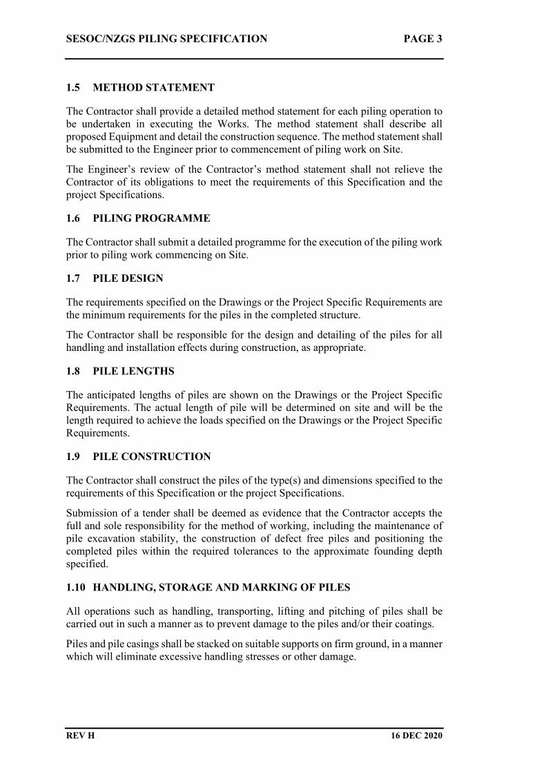
1.5 METHOD STATEMENT
The Contractor shall provide a detailed method statement for each piling operation to
be undertaken in executing the Works. The method statement shall describe all
proposed Equipment and detail the construction sequence. The method statement shall
be submitted to the Engineer prior to commencement of piling work on Site.
The Engineer’s review of the Contractor’s method statement shall not relieve the
Contractor of its obligations to meet the requirements of this Specification and the
project Specifications.
1.6 PILING PROGRAMME
The Contractor shall submit a detailed programme for the execution of the piling work
prior to piling work commencing on Site.
1.7 PILE DESIGN
The requirements specified on the Drawings or the Project Specific Requirements are
the minimum requirements for the piles in the completed structure.
The Contractor shall be responsible for the design and detailing of the piles for all
handling and installation effects during construction, as appropriate.
1.8 PILE LENGTHS
The anticipated lengths of piles are shown on the Drawings or the Project Specific
Requirements. The actual length of pile will be determined on site and will be the
length required to achieve the loads specified on the Drawings or the Project Specific
Requirements.
1.9 PILE CONSTRUCTION
The Contractor shall construct the piles of the type(s) and dimensions specified to the
requirements of this Specification or the project Specifications.
Submission of a tender shall be deemed as evidence that the Contractor accepts the
full and sole responsibility for the method of working, including the maintenance of
pile excavation stability, the construction of defect free piles and positioning the
completed piles within the required tolerances to the approximate founding depth
specified.
1.10 HANDLING, STORAGE AND MARKING OF PILES
All operations such as handling, transporting, lifting and pitching of piles shall be
carried out in such a manner as to prevent damage to the piles and/or their coatings.
Piles and pile casings shall be stacked on suitable supports on firm ground, in a manner
which will eliminate excessive handling stresses or other damage.

SESOC/NZGS PILING SPECIFICATION PAGE 4
REV H 16 DEC 2020
Piles to be driven shall be clearly marked with paint prior to installation with the pile
number, overall length and at regular intervals, the cumulative length measured from
the pile tip.
1.11 NATURE OF GROUND AND SUBSURFACE CONDITIONS
It is deemed that the Contractor has inspected the Site and considered the nature of the
ground through which piles are to be constructed.
The Contractor shall inform the Engineer of any circumstances which indicates, in the
Contractor’s opinion, that ground conditions differ from those reported or which could
have been inferred from ground investigation reports or preliminary pile results.
Should the Contractor consider that such a change in the ground conditions could not
have been reasonably foreseen by an experienced contractor when tendering and will,
in the Contractor’s opinion, change the construction methodology or substantially
increase the Contractor’s costs, then redress may be sought in accordance with the
unforeseen physical conditions of the project Conditions of Contract.
No warranty is expressed or implied that any information, opinions or conclusions,
given in any factual or interpretative ground investigation report, supplied in good
faith by the Engineer, will present a complete or accurate picture of the whole of the
Site.
1.12 PROVING BORE REQUIREMENTS
The requirements for proving bores are detailed in the Project Specific Requirements.
Proving bores shall be drilled before piling commences. Proof-boring shall be carried
out in the presence of the Engineer, who will require at least one Working Day's notice
of when proving will take place. Proving bores shall be drilled at each location
specified on the Drawings, to enable the Engineer to carry out further inspection of
the founding material.
1.13 SETTING OUT AND AS-BUILT LOCATIONS
The position of all piles shall be accurately set out by the Contractor. The pile positions
shall be checked by the Contractor immediately prior to installation.
After construction, actual pile locations shall be surveyed by an appropriately qualified
and suitably experienced surveyor employed by the Contractor for this purpose. The
Contractor shall submit an as-built pile plan to the Engineer within five Working Days
of completion of the last pile. Partial as-built information may be submitted throughout
construction of the piles as required.
1.14 TOLERANCES
Pile tolerances are specified in the Project Specific Requirements.
The Contractor shall make all necessary provisions to the pile construction procedure,
initial spotting and inclination of piles in order to achieve installation of piles to the
specified tolerances. Standard tolerances are as follows:

SESOC/NZGS PILING SPECIFICATION PAGE 5
REV H 16 DEC 2020
Positional (at pile commencement level): Within 75mm of location indicated.
Verticality:
Construction Method Verticality
Tolerance
All Bearing Piles - minimum 1 : 75
Bored Piles – standard equipment 1 : 100
CFA Piles 1 : 100
CFA Piles – extra heavy duty augers 1 : 125
Bored Piles – full depth heavy wall casing 1 : 200
If records or measurements show that piles have been installed outside the specified
tolerances the Contractor shall provide the Engineer with details of measures to be
adopted to enable the piles to comply with the Specification. Forcible correction of
laterally displaced piles shall not be made unless the Contractor can demonstrate that
the strength, integrity and durability performance of the pile will not be adversely
affected.
Should the Contractor fail to meet the above requirements, the Engineer reserves the
right to order such extra work as may be required to overcome the resultant structural
problems. No additional cost to the Principal shall arise from any such extra work.
Any additional engineering design work required because of piles placed outside the
specified tolerances (for example, the strengthening of existing piles or design of
additional piles) shall be carried out by the Engineer and paid for by the Contractor.
The Contractor shall not carry out any remedial work on any pile, without the written
approval of the Engineer.
1.15 SUPERVISION
The Contractor shall nominate a suitably experienced person as the “Piling
Supervisor”. The Contractor shall submit a curriculum vitae for the proposed Piling
Supervisor prior to commencement of pile construction.
The Piling Supervisor shall be responsible for ensuring that all piling operations
comply with the requirements of this Specification. The Piling Supervisor shall also
ensure that all monitoring and pile records are maintained up to date and are available
for inspection by the Engineer.
The Piling Supervisor shall not be removed from the Works without the Engineer
being notified one week in advance. The Contractor shall nominate a suitable
replacement before the Piling Supervisor is removed from the Works.
1.16 OBSERVATION
The Engineer requires to have the opportunity of observing all phases of the piling
operations and of inspecting particular items such as (but not limited to) set and
rebound, the bottom of bored piles, jointing of casings, concreting, fabrication of
reinforcing cages, etc. The Contractor shall therefore keep the Engineer informed daily
as to the work anticipated to be carried out on the next working day.
SESOC/NZGS PILING SPECIFICATION PAGE 6
REV H 16 DEC 2020
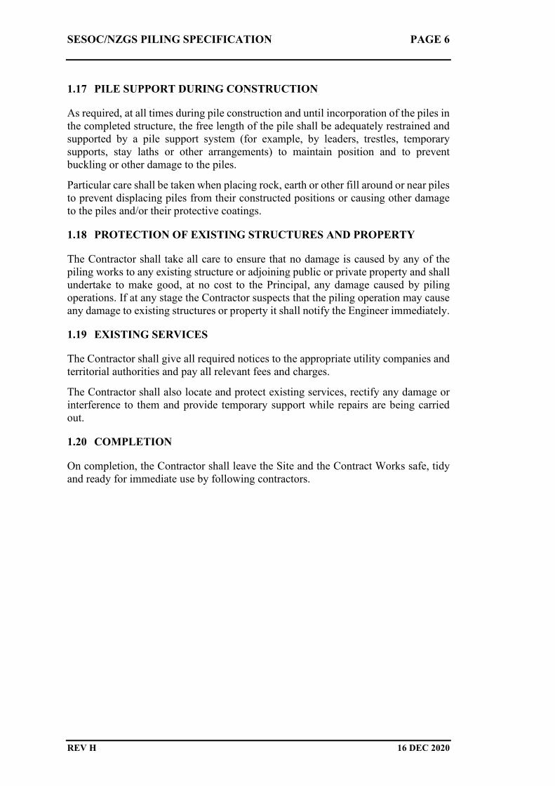
1.17 PILE SUPPORT DURING CONSTRUCTION
As required, at all times during pile construction and until incorporation of the piles in
the completed structure, the free length of the pile shall be adequately restrained and
supported by a pile support system (for example, by leaders, trestles, temporary
supports, stay laths or other arrangements) to maintain position and to prevent
buckling or other damage to the piles.
Particular care shall be taken when placing rock, earth or other fill around or near piles
to prevent displacing piles from their constructed positions or causing other damage
to the piles and/or their protective coatings.
1.18 PROTECTION OF EXISTING STRUCTURES AND PROPERTY
The Contractor shall take all care to ensure that no damage is caused by any of the
piling works to any existing structure or adjoining public or private property and shall
undertake to make good, at no cost to the Principal, any damage caused by piling
operations. If at any stage the Contractor suspects that the piling operation may cause
any damage to existing structures or property it shall notify the Engineer immediately.
1.19 EXISTING SERVICES
The Contractor shall give all required notices to the appropriate utility companies and
territorial authorities and pay all relevant fees and charges.
The Contractor shall also locate and protect existing services, rectify any damage or
interference to them and provide temporary support while repairs are being carried
out.
1.20 COMPLETION
On completion, the Contractor shall leave the Site and the Contract Works safe, tidy
and ready for immediate use by following contractors.

SESOC/NZGS PILING SPECIFICATION PAGE 7
REV H 16 DEC 2020
2 MATERIALS AND WORKMANSHIP
2.1 CONCRETE
Project Specific Requirements
The following items, where appropriate, are detailed in the project Specification:
• details of concrete strength and mix proportions
• requirements for alkali-aggregate reaction
• variations to NZS3109 (where specified)
Referenced Documents
This Specification shall be read in conjunction with the following standards,
guidelines, and other documents, which are deemed to form part of this Specification.
In the event of this Specification being at variance with any provision of these
referenced documents, the requirements of this Specification shall take precedence.
All materials and workmanship shall comply with these documents unless expressly
noted otherwise. All documents referenced below shall be the latest revision, complete
with current amendments, as at the commencement of the Contract Works.
NZS3109 Concrete Construction
EFFC/DFI Guide to Tremie Concrete for Deep Foundations (EFFC/DFI, 2018)
CIA Recommended Practice Tremie Concrete for Deep Foundations (CIA,
2012)
Material
All concrete, reinforcing steel and prestressing steel shall comply with the
requirements of NZS3109 and related standards.
Concreting of Piles
Concreting of piles shall be generally in accordance with NZS3109, noting the
following.
The Contractor shall include its proposals for placing and compacting concrete in the
method statement submitted in accordance with section 1.5. Concrete mix design,
placement and compaction techniques proposed should be in accordance with current
industry best practice and guidelines as appropriate.
No concreting shall begin until the Engineer has approved the founding of the pile in
question.
The time period between completion of pile excavation and completion of concreting
shall not exceed 24 hours for piles which are less than 20 m long and/or 1000 mm in
diameter. For all piles of a greater length or diameter the time period shall be mutually
agreed by the Engineer and Contractor prior to the commencement of construction.

SESOC/NZGS PILING SPECIFICATION PAGE 8
REV H 16 DEC 2020
No loose or disturbed material shall lie at the bottom of the excavation when
concreting is started, nor be permitted to fall into the concrete as concreting proceeds.
The concreting technique shall be approved in advance by the Engineer, who will
require to be satisfied that the method of placing and the concrete mix design will
result in concrete fully compacted in place, possessing the specified strength and
having the necessary density, integrity and durability. No concrete shall be placed in
wet conditions or under water without the Engineer's approval (where the Engineer’s
approval is given verbally, this shall be followed up in writing as soon as practicable).
Wet conditions are defined when more than 75 mm of water is present at the base of
the pile immediately prior to the concrete being discharged to the pile bore and/or
inflow of water into the excavation during the pile pour process exceeds 200 mm of
bore depth per hour. Measures shall be taken to ensure that the structural strength of
the concrete is not impaired through grout loss, segregation or bleeding.
Concreting of piles shall be carried out continuously so that no segregation occurs,
thorough compaction is effected in all parts of the pile and previously placed concrete
does not achieve a stiffness which could prevent proper amalgamation of subsequent
concrete batches.
Unless approved otherwise by the Engineer, in a dry pile bore, concrete shall be placed
using a chute, hopper and discharge pipe or pump line. The concrete may fall freely
below the discharge point up to 10 m as long as concrete placement can be controlled
and there is no segregation of the concrete (such as may be caused by concrete hitting
the pile reinforcement during placement).
The reinforcing steel shall always be adequately supported to prevent displacement
during or after placement of the concrete.
Where only a short section of reinforced concrete is to be placed at the top of the pile
(for example, to make connection with a reinforced concrete superstructure), the
Contractor shall ensure that adequate support is provided to the concrete to prevent
any settlement of the newly placed or plastic concrete.
Concrete shall be placed such that the specified construction joint can be prepared at
the top of the pile. Where not specified, construction joints shall be type B in
accordance with NZS3109.
No concrete shall be placed when there is any danger of adverse weather causing
damage to plastic or partially set concrete due to movement of pile liners.
Where temporary casing is used to effect a dry pile bore, there must be a sufficient
head of concrete inside the casing when extracted to fill the annulus left by the casing
as well as resist any outside groundwater infiltrating into the fresh concrete.
Recording actual versus theoretical concrete volume shall be undertaken during
concreting of the pile and any interruption to the continuous concreting procedure
(truck exchange, breaking of the tremie or any other unforeseen circumstance) also
recorded.

SESOC/NZGS PILING SPECIFICATION PAGE 9
REV H 16 DEC 2020
Placing Concrete Under Water
The preferred method of placing concrete in piles shall be in a dry excavation.
However, should either;
• The depth of water at the base of the pile at the commencement of concrete
placement exceed 75 mm,
• the inflow of water exceeds 200 mm of bore depth per hour, or
• the use of drilling fluid prove necessary to maintain excavation stability,
then concrete shall be placed using the tremie or another appropriate underwater
concreting technique approved by the Engineer.
Workplan
The Contractor shall submit a detailed written workplan for underwater concreting to
the Engineer as part of the method statement submitted in accordance with section 1.5.
This workplan shall be provided five Working Days prior to underwater concreting
commencing on Site. The workplan shall explain in detail the proposed method of
placement of concrete, including the sequence of operations in the event that either a
blockage occurs or the concrete charge is lost during concreting.
Tremie
Where used, the bore of the tremie shall be smooth to allow the free flow of concrete
and have a uniform internal diameter of at least:
• Six times the maximum size of aggregate, or
• 100 mm
whichever is the greater.
The external shape and dimension of the tremie, including its joints, shall allow its
free movement within the reinforcement cage. The maximum outside diameter of the
tube, including its joints, should be not more than:
• 0.35 times the pile diameter, or the inner diameter of a casing
• 0.45 times the inner diameter of the reinforcing cage for circular piles,
unless agreed otherwise with the Engineer
The tremie shall be equipped with a hopper at its upper end to receive fresh concrete
and to prevent spillage of concrete that could otherwise fall into the pile. The hopper
shall hold a minimum capacity of concrete to fill not less than 1.5 m of bore depth and
should have a means of holding this concrete until ready for the initial discharge.
The tremie and hopper shall be clean with all pipes and joints watertight. All
previously hardened concrete shall be removed from the tremie prior to insertion of
the tremie in the pile. A bung, hinged flap or sacrificial closure plate (closed tremie)
or travelling plug of suitable material (open tremie) shall be employed prior to
commencement of concrete placement to ensure that fresh concrete can be placed
without it coming into contact with water or drilling fluid.

SESOC/NZGS PILING SPECIFICATION PAGE 10
REV H 16 DEC 2020
Concrete Mix
The following shall apply to concrete to be placed underwater:
• minimum cementitious materials of not less than 400 kg/m³
• maximum total water content of 170 kg/m³
• maximum aggregate size 20 mm
• target concrete slump shall be 230 mm, ±25 mm
• minimum slump retention of 2hrs (extended further as required)
Method
The method adopted by the Contractor shall ensure that;
• There is sufficient delivery capacity to discharge the concrete, e.g. a 200
mm (8-inch) diameter tremie pipe requires 2 x 125 mm (5-inch) boom
pumps;
• with a closed tremie (utilising a bung, hinged flap or sacrificial closure
plate), the discharge pipe must be fully charged with concrete before it is
lifted off the base of the bore to commence concrete placement;
• with an open tremie (utilising a travelling plug) that is held close to but not
on the base of the bore, the discharge pipe must be fully charged with
concrete before concrete placement;
• the initial concrete flow is sufficient to achieve embedment of the tremie
and the concrete can be placed continuously so that no segregation occurs
and thorough compaction results in all parts of the pile;
• the discharge pipe shall at all times penetrate the concrete which has
previously been placed with a minimum embedment of 1.5 metres and
maximum embedment of 9.0 metres;
• surging of the tremie pipe is not permitted.
Towards the completion of the pour when the head of concrete in the tremie is
becoming low, do not plunge the tremie pipes up and down to release the last of the
concrete. Instead, calculate the required amount of concrete to fill the pile shaft and
fill the hopper with the correct amount (plus some) then lift the tremie out slowly
releasing the last of the concrete to the hole.
Loss of Immersion of Tremie Pipe
When the immersion of the tremie pipe is lost during concreting (for example, to repair
breakages or to remove a blockage), further placement of concrete shall not proceed
unless:
• The concrete into which fresh concrete is to be placed has maintained its
workability, and
• The tremie pipe is re-immersed sufficiently deep into the previously placed
concrete (as noted above – refer to section 2.1.5.4), and

SESOC/NZGS PILING SPECIFICATION PAGE 11
REV H 16 DEC 2020
• No water or other contaminant is introduced into concrete which will
remain below the final pile cut-off level, and
• The base of the tremie pipe is fully sealed and watertight and can withstand
the pressures that will be applied to it at re-immersion depth. This seal can
be released when the re-immersed tremie pipe is embedded 1.5m into the
existing workable concrete.
If these conditions cannot be met, concrete placement shall be suspended, the tremie
pipe shall be removed and alternative measures shall be agreed with the Engineer to
form a sound pile.
In cases where immersion of the tremie pipe is lost and inflow of contaminant (water,
air or other material) into the freshly placed concrete is likely to have occurred, the
placement of concrete shall be suspended.
The pile may be completely replaced or reformed in its original position if the
reinforcement cage can be extracted and the previously placed concrete removed.
Piles may be recovered by the formation of a construction joint (in accordance with
NZS3109) after all concrete of insufficient quality has been removed and sound
concrete over the full section of the pile has been exposed, forming a faultless
interface. Where the preparation of a construction joint is not possible, the pile shall
be abandoned and the empty bore above the placed concrete backfilled with an
appropriate material approved by the Engineer.
Integrity tests shall be carried out to document the quality of any pile where loss of
immersion of the tremie pipe has occurred, or where a construction joint has been
formed in the pile. Refer to section 5.1 for requirements for integrity testing.
Precast Concrete Piles
Precast concrete piles shall be cast in one continuous operation and shall be properly
cured.
Units shall be handled, transported and erected so that no damage is caused to them at
any stage. Units shall only be lifted using properly designed and installed lifting
devices. The Contractor shall be responsible for the design, provision and subsequent
removal of lifting devices as required.
Splicing of Precast Piles
Details of the design, manufacture and tests of the jointing system shall be submitted
to the Engineer prior to the commencement of precast pile manufacture.
A spliced pile shall be capable of withstanding the same driving stresses as a single
unjointed pile of the same cross sectional dimensions, length and materials.
The welding of a joint to main reinforcement in lieu of a lapped connection with
projecting bars shall not be permitted without the prior approval of the Engineer.
Each pile splice shall be square to the axis of the pile. The alignment of the spliced
pile sections shall not vary by more than ±5 mm from a 1000 mm long straight edge.
The centroid of the splice shall lie within ±5 mm of the centroid of the adjacent pile
sections.

SESOC/NZGS PILING SPECIFICATION PAGE 12
REV H 16 DEC 2020
Cutting off and Preparing of Pile Heads
When the pile has been installed in accordance with the requirements of this
specification, the concrete at the head of the pile shall be cut off to the levels specified
on the Drawings.
Care shall be taken to avoid shattering or otherwise damaging the remaining section
of the pile. Any cracked or defective concrete or reinforcement shall be cut away and
the pile repaired to provide a full and sound section at the pile cut off level.
2.2 STRUCTURAL STEEL
Project Specific Requirements
The following items, where appropriate, are detailed in the project specification:
• Weld category for welds in accordance with NZS3404 (GP or SP)
• corrosion protection for steel piles
• grade and category of steel
• material testing requirements
• weld inspection requirements
Referenced Documents
This Specification shall be read in conjunction with the following standards,
guidelines, and other documents, which are deemed to form part of this Specification.
In the event of this Specification being at variance with any provision of these
referenced documents, the requirements of this Specification shall take precedence.
All materials and workmanship shall comply with these documents unless expressly
noted otherwise. All documents referenced below shall be the latest revision, complete
with current amendments, as at the commencement of the Contract Works.
AS/NZS1554.1 Welding of Steel Structures
BS3100 Specification for Steel Castings for General Engineering
Purposes
NZS3404 Steel Structures Standard
Steel H Piles
Steel H piles shall comply with the requirements of NZS3404.
Steel Pipe Pile and Steel Casing Manufacturing Process
All piles shall be of the type and minimum cross section dimensions as specified on
the Drawings or Project Specific Requirements.
Steel casings shall be approved longitudinally or spirally welded mild steel, or an
approved substitute, capable of withstanding the forces induced by driving without

SESOC/NZGS PILING SPECIFICATION PAGE 13
REV H 16 DEC 2020
deformation. The casings shall also be capable of being dewatered if required by the
Engineer.
The rolling or manufacturing tolerances for steel tubular piles shall be such that the
actual weight of section does not differ from the theoretical weight by more than ±5%.
The external diameter at any section, measured using a steel tape on the circumference,
shall not differ from the theoretical diameter by more than ±1%. The deviation from
straightness on any longitudinal face shall not exceed 1/600 of the length of the pile,
nor 5 mm in any 3000 mm length.
The Contractor shall submit details of the manufacturing and welding processes to the
Engineer, before commencement of pile manufacture. The Contractor shall provide
the Engineer with works test certificates, analyses, and mill certificates, together with
the tube manufacturer’s certificate showing details of the pile number, cast number of
the steel and a record of all tests and inspections carried out. The Contractor shall give
the Engineer adequate notice of the start of each stage of the manufacturing process
and any production tests, and shall make facilities available to the Engineer for
inspection. The Contractor shall provide the Engineer with samples when required.
Welding
Where not specified in the Project Specific Requirements, all welds shall be weld
category SP in accordance with NZS3404.
All welding procedures shall be in accordance with AS/NZS1554. The Contractor
shall submit full details of the proposed welding procedures and electrodes, with
drawings and schedules as required. Only welders qualified to AS/NZS1554 or who
have attained a similar standard shall be employed on the Works. Proof of welders
proficiency and qualification shall be made available to the Engineer on request.
Splices between adjacent lengths of pile shall be made with full penetration butt welds,
complete with backing plates (where required).
The standard for interpretation of non-destructive testing shall be AS/NZS1554.1. The
extent of non-destructive examination (NDE) is set out in Table 2.2.5.
Table 2.2.5 : Extent of Non Destructive Examination
Extent of Non-Destructive Examination (%)
Weld
Category
Visual Means Other Means
Visual
Scanning (1)
Visual
Examination
(2)
Magnetic
Particle or
Liquid
Penetrant
Radiography
or Ultrasonics
GP 100% 25% Nil Nil
SP 100% 100% (3) 10% 10%
Notes:

SESOC/NZGS PILING SPECIFICATION PAGE 14
REV H 16 DEC 2020
(1) Visual scanning shall determine that no welds called for in the Drawings or
Specification are omitted. Visual scanning shall also detect gross welding defects.
(2) Visual examination shall determine whether the required weld quality (in
accordance with Table 6.2 of AS/NZS1554.1) has been achieved.
(3) Per Appendix D, NZS3404
Where the proportion of NDE called for above is less than 100%, the Contractor shall
agree a programme of testing with the Engineer prior to commencement of any
welding. The programme shall involve full testing of the first 5% of welds, in order to
pick up and correct the cause of any major defect at the commencement of welding.
The frequency of testing may then be progressively reduced on the basis of continuing
compliance with this Specification. In the event of a non-compliant test result, a return
to full testing of the next 5% of welds will be required.
Results of weld testing shall be submitted to the Engineer within ten days of
completion of the tests. If the tests of any weld do not conform to the specified
requirements, two additional specimens from the same length of pile shall be tested.
In the case of failure of one or both of these additional tests, the length of pile covered
by the tests shall be rejected.
Site Splices
Splices between adjacent lengths of pile shall be made with full penetration butt welds.
Site splices shall meet all of the requirements of section 2.2.5.
All work associated with welding shall be protected from the weather so that the
quality of work meets the requirements of the Specification.
Driving Shoes
Cast steel shoes shall be of steel to BS3100 Grade A1. Flat plate and welded fabricated
steel shoes shall be mild steel complying with NZS3404. Fabricated pile shoes, or the
strengthening to the toe of a pile in lieu of a shoe, or the strengthening of the head of
a pile for driving, shall be made using material of the same grade as the pile.
Preparation of Pile Heads
If a steel structure is to be welded to the piles, the piles shall be cut square and to
within 5 mm of the level specified.
If the pile heads are to be encased in concrete, they shall be cut to within 20 mm of the
levels specified, and protective coatings (where specified) removed from the surfaces
of the pile heads down to a level 100 mm above the soffit of the concrete.
Steel Sheet Piles
Manufacture
Steel sheet piles shall be mild steel complying with NZS3404 or a recognised
international standard. Only new sheet piles shall be used for permanent works (used

SESOC/NZGS PILING SPECIFICATION PAGE 15
REV H 16 DEC 2020
sheet piles may be used in place of new sheet piles but only with the prior written
approval of the Engineer).
All fabricated pile components, such as corners, junctions, box piles, and high
modulus piles, shall be fabricated and supplied in accordance with the sheet pile
manufacturer’s written instructions.
All piles and production facilities shall be made available for inspection at any time.
All sheet piles shall be carefully examined at the time of delivery to the Site, and
damaged piles shall be repaired or replaced. The Contractor shall ensure that all
interlocks are clean and free from distortion.
Welding
Welding of sheet piles shall comply with section 2.2.5. Welded site splices shall
comply with section 2.2.6.
Where sheet piles are to be spliced by butt welding, the interlocks shall not be
welded unless a seal weld is required.
2.3 TIMBER
Project Specific Requirements
The following items, where appropriate, are detailed in the project specification:
• size and shape of timber piles
• timber species
• timber hazard class
Referenced Documents
This Specification shall be read in conjunction with the following standards,
guidelines, and other documents, which are deemed to form part of this Specification.
In the event of this Specification being at variance with any provision of these
referenced documents, the requirements of this Specification shall take precedence.
All Materials and workmanship shall comply with these documents unless expressly
noted otherwise. All documents referenced below shall be the latest revision, complete
with current amendments, as at the commencement of the Contract Works.
NZS3605 Timber Piles and Poles for use in Buildings
NZS3640 Chemical Preservation for Round and Sawn Timber
Material
The requirements for timber species are detailed in the Project Specific Requirements.
Timber poles and piles shall meet the requirements of NZS3605.
The timber shall be new and free from defects, decay, large loose or dead knots, undue
shake, excessive sap, rot, pests, fungal or pest attack which may affect the strength or
durability of piles. The grain shall be straight and parallel to the axis of the pile.

SESOC/NZGS PILING SPECIFICATION PAGE 16
REV H 16 DEC 2020
The minimum requirements for pile sizes are shown on the Drawings or Project
Specific Requirements.
Timber Treatment
Unless specified otherwise in the Project Specific Requirements timber piles shall be
treated to TPC Brand H6 (refer to NZS3640).
Cutting and boring or timber shall be done as far as practicable before preservative
treatment, but where this is impracticable, any piles that are cut or notched after
pressure treatment shall be well dried and brush treated with a suitable preservative,
in accordance with NZS3605.
Certificates of treatment shall be submitted to the Engineer for all treated timber.
Marking, Handling and Storage of Timber Piles
The Contractor shall notify the Engineer of the delivery of the timber piles to the Site,
and provide all labour and equipment to enable the Engineer to inspect each piece of
timber on all faces, and to measure it, all at the time of delivery and prior to driving.
Each timber pile shall be clearly marked prior to installation, with its number and
overall length.
Timber piles shall be stacked in lengths clear of the ground with an air space around
them. The piles shall be separated vertically by suitable blocks or spacers placed
vertically one above the other, and positioned at centres which are close enough to
prevent sagging. Timber piles shall be protected from the sun and rain by means of
tarpaulins or other appropriate covers which allows free circulation of air.
All operations such as handling, transporting and pitching of piles shall be carried out
in such a manner as to prevent damage to piles.
Splicing of Timber Piles
Piles shall be provided in one piece unless specified otherwise.
If the piles are to be spliced, the splice shall be capable of resisting any stresses which
may develop during lifting, pitching, driving or under the action of the design loads in
the completed structure. The position and details of the splice shall be reviewed by the
Engineer prior to driving of piles.
Splices shall be made using two timbers of the same cross sectional dimensions, each
cut at right angles to its axis, to make contact over the whole of the cross section when
the two pile sections are aligned. A jointing compound shall be applied to the contact
surfaces. Round timbers shall be joined by a section of steel tube. Rectangular piles
shall be joined by a prefabricated steel box section fitting the timber closely, or by
steel splice plates. The steel connectors shall be bolted, screwed, or spiked to the
timbers to ensure that the ends of the timbers are kept in close contact. The axial
alignment of the two timber sections shall not vary by than 10 mm from a 1000 mm
straightedge. The requirements for corrosion protection of steel joining elements are
detailed in the Project Specific Requirements.

SESOC/NZGS PILING SPECIFICATION PAGE 17
REV H 16 DEC 2020
Preparation of Pile Heads
No timber pile head shall be cut off without the approval of the Engineer.
Unless noted otherwise in the project specification, all portions of cut off pile heads
shall become the property of the Contractor and shall be removed from the Site.
When timber piles are installed by driving, the heads shall be cut off square to sound
timber, to within ± 20 mm of the levels specified on the Drawings. The cut surfaces
shall be well dried and brush treated with a suitable preservative, in accordance with
NZS3605.

SESOC/NZGS PILING SPECIFICATION PAGE 18
REV H 16 DEC 2020
3 BORED PILES
3.1 SCOPE
This section covers the construction of bored piles with or without the use of
permanent or temporary steel casings to maintain bore stability. Piles will be excavated
to the required depths necessary to achieve the specified loads, and then backfilled
with reinforced concrete. This section also covers the use of timber, steel or precast
concrete piles placed in predrilled sockets.
3.2 PROJECT SPECIFIC REQUIREMENTS
The following items, where appropriate, are detailed in the particular specification:
• disposal of excavated material
• requirement for support fluid
• pressure grouting
• trial piles
3.3 REFERENCED DOCUMENTS
This Specification shall be read in conjunction with the following standards,
guidelines, and other documents, which are deemed to form part of this Specification.
In the event of this Specification being at variance with any provision of these
referenced documents, the requirements of this Specification shall take precedence.
All Materials and workmanship shall comply with these documents unless expressly
noted otherwise. All documents referenced below shall be the latest revision, complete
with current amendments, as at the commencement of the Contract Works.
NZS3404 Steel Structures Standard
AS2159 Piling Design and Installation
3.4 STEEL CASINGS
Permanent Steel Casings
Permanent steel casings shall be mild steel complying with NZS3404. The
requirements of section 2.2 shall also apply.
Casings shall be of the thickness specified on the Drawings, or other such greater
thickness as is necessitated by the conditions met and the Contractor’s method of
working. The choice of the casing thickness is the sole responsibility of the Contractor
provided the above requirements are met.
Surplus lengths of casings shall be cut off when construction of the superstructure
begins. Unless noted otherwise in the project specification, all such lengths shall
remain the property of the Contractor and shall be removed from the Site on
completion of the Works.

SESOC/NZGS PILING SPECIFICATION PAGE 19
REV H 16 DEC 2020
Temporary Steel Casings
The Contractor shall determine requirements for temporary casings.
A short length of temporary casing shall be provided for all piles to maintain an
upstand of at least 0.9 m above existing ground level to prevent contamination of the
pile bore and provide a safe barrier prior to and during concreting. Contamination from
flood waters shall be considered if applicable at the site. Alternative methods to
prevent contamination and provide a safe barrier may be submitted to the Engineer for
review.
The use of vibration to install and remove temporary casings shall be subject to the
requirements of section 1.18.
When the temporary casing is being extracted, a sufficient quantity of concrete shall
be maintained within it to ensure that the pressure from external water, support fluid
or soil is exceeded and that the pile concrete is not reduced in section or contaminated.
3.5 BELLING OR UNDER REAMING
Where specified on the Drawings, each pile bore shall be constructed with a
mechanically enlarged base which shall be no smaller than the size specified and shall
be concentric with the pile shaft to within 10% of the shaft diameter. Where not
specified on the Drawings the sloping surface of the bell shall make an angle to the
axis of the pile of not more than 35º. At the specified diameter of the under-ream at
the perimeter of the base, there shall be a minimum height of 150 mm.
3.6 PILE GROOVING
If sidewall grooving is specified on the Drawings but details are not provided, each
pile bore shall be spirally grooved with a 50 x 50 mm finger withdrawn to achieve a
pitch of 300 mm, over the entire length of minimum embedment shown on the
Drawings. If a temporary or permanent casing is used, the minimum length of
embedment, as specified on the Drawings, shall be measured from below the bottom
of the casing.
A grooving trial shall be carried out on the first production pile. The Contractor shall
allow for inspection of the grooved pile by the Engineer.
3.7 EXCAVATION FOR PILES
Each pile shall be in intimate contact with the ground over its full length so that it is
able to effectively transmit horizontal loads. Any space between the permanent casing
and surrounding ground shall be completely filled with compacted sand or other
approved material.
The use of explosives is forbidden without the written approval of the Engineer. If
approved, explosives shall be used strictly in accordance with the requirements of
WorkSafe and the relevant Authorities.
On completion of excavation, loose, disturbed or softened soil shall be removed from
the pile bore using an appropriate method. Base cleanliness should then be checked

SESOC/NZGS PILING SPECIFICATION PAGE 20
REV H 16 DEC 2020
using a weighted tape or similar instrument, sounding over at least 3 locations on the
pile base. Examples of base testing weights are provided in Appendix D.
Pumping from pile bores shall not be permitted unless groundwater inflow is limited
to an inflow of water not exceeding 200 mm of bore depth per hour and written
approval of the Engineer obtained. Due care shall be taken to ensure that the pile bore
(sidewall and base) remains stable at all times until the completion of construction.
3.8 CONSTRUCTION OBSERVATIONS
The Engineer shall be given the opportunity to observe geotechnical conditions
encountered, confirm key design assumptions, and all aspects of pile construction
before concrete is poured in accordance with the approved Inspection and Testing Plan
or otherwise agreed between the Engineer and Contractor.. The Contractor shall
inform the Engineer at least one Working Day in advance when such observations will
be required. This section shall be read in conjunction with section 3.7.
For dry bores, bore cleanliness assessments, when specified by the Engineer, are to be
undertaken remotely using video equipment lowered progressively down the pile
excavation. Such equipment shall be capable of taking clear, focussed, high quality
video images which should be referenced with pile number depth and orientation. The
images shall be retained by the Contractor as part of the permanent pile as-builts
records. Alternatively, as agreed with the Engineer, where visibility permits, visual
inspection of shaft cleanliness may be undertaken from the surface using spotlights,
mirrors of similar.
For wet bores, cleanliness assessments, when specified by the Engineer, should at least
require a base cleanliness check using a weighted tape or similar instrument per section
3.7.
The Contractor shall remain responsible for the safety of all personnel undertaking
construction observations and shall provide all necessary facilities to enable the
Engineer to observe any pile, including facilities to check the depth, verticality and
position. The full requirements of Good Practice Guidelines for Excavation Safety
(WorkSafe, Good Practice Guidelines for Excavation Safety, 2016) shall be followed
as a minimum, and observations shall be undertaken using the safest possible method.
3.9 PILE CONSTRUCTION RECORD CARD
The Contractor shall complete a Pile Construction Record Card for every pile
constructed on the Site. A copy of the proposed Pile Construction Record Card shall
be submitted to the Engineer on week prior to commencing pile construction. The Pile
Construction Record Card shall contain the following information as a minimum;
• contract and structure name
• pile number, location, pile type, and pile dimensions.
• the drillers record, showing date and time of drilling, the type of materials
encountered, and the depths at which the materials were encountered.
• the expected and actual constructed founding levels.

SESOC/NZGS PILING SPECIFICATION PAGE 21
REV H 16 DEC 2020
• casing finished levels (top and bottom) and total length.
• water levels inside the pile.
• confirmation of cleaning of pile base, including the recorded depth of the
shaft at the end of drilling and immediately prior to placing concrete.
• weather conditions (including tide and wave height if applicable) at the
time of concreting.
• concreting records, including the total volume of concrete placed, the
volume supplied with each truck, slump measurements and number of cube
or cylinder samples taken, time of batching, and concrete placing start and
completion times.
• the time and date of casing extraction (if applicable).
• the design and actual constructed elevation of the top of the pile.
• cross reference proving bores (if appropriate).
• pile load test records (if applicable).
• the Contractors signature verifying that all work has been completed
satisfactorily.
Pile construction records shall be submitted to the Engineer within 24 hours of the
completion of concrete placement of each pile. An example bored pile construction
record card indicating typical information required is provided in Appendix B. It is
noted that all items shown on this example may not be relevant to all projects.
3.10 ADDITIONAL REQUIREMENTS FOR PRECAST CONCRETE,
STEEL OR TIMBER PILES PLACED IN BORED SOCKETS
Pile Lengths
The length of the pile shall be selected to ensure that the pile by itself satisfies the
minimum penetration into the substrata as defined on the Drawings. Any additional
length to satisfy the construction methodology for placing the pile into the drilled
socket shall be the responsibility of the Contractor.
A schedule of pile lengths shall be prepared by the Contractor and reviewed by the
Engineer before pile manufacture begins.
Excavation of Piles
The requirements of section 3.7 shall apply.
Each pile shall be in intimate contact with the ground over its concreted length so that
it is able to effectively transmit horizontal loads. Any space, above the concreted layer,
between the pile and the surrounding ground shall be completely filled with clean sand
or other approved material.

SESOC/NZGS PILING SPECIFICATION PAGE 22
REV H 16 DEC 2020
Pile Construction Record Card
The requirements of section 3.9 shall apply. Reference should be made to Appendix
B for an example pile construction card. Additional information shall be recorded on
the Pile Construction Record card as follows:
• The production number of the precast pile (this shall be the number stated
on the precaster’s concrete pour card).
• the level of the top of the pile before and after placing concrete.
• Steel grade, cross referencing to NDE, position of splices, welder’s
information, time of weld, end plate details.
SESOC/NZGS PILING SPECIFICATION PAGE 23
REV H 16 DEC 2020
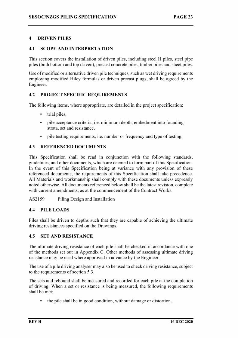
4 DRIVEN PILES
4.1 SCOPE AND INTERPRETATION
This section covers the installation of driven piles, including steel H piles, steel pipe
piles (both bottom and top driven), precast concrete piles, timber piles and sheet piles.
Use of modified or alternative driven pile techniques, such as wet driving requirements
employing modified Hiley formulas or driven precast plugs, shall be agreed by the
Engineer.
4.2 PROJECT SPECIFIC REQUIREMENTS
The following items, where appropriate, are detailed in the project specification:
• trial piles,
• pile acceptance criteria, i.e. minimum depth, embedment into founding
strata, set and resistance,
• pile testing requirements, i.e. number or frequency and type of testing.
4.3 REFERENCED DOCUMENTS
This Specification shall be read in conjunction with the following standards,
guidelines, and other documents, which are deemed to form part of this Specification.
In the event of this Specification being at variance with any provision of these
referenced documents, the requirements of this Specification shall take precedence.
All Materials and workmanship shall comply with these documents unless expressly
noted otherwise. All documents referenced below shall be the latest revision, complete
with current amendments, as at the commencement of the Contract Works.
AS2159 Piling Design and Installation
4.4 PILE LOADS
Piles shall be driven to depths such that they are capable of achieving the ultimate
driving resistances specified on the Drawings.
4.5 SET AND RESISTANCE
The ultimate driving resistance of each pile shall be checked in accordance with one
of the methods set out in Appendix C. Other methods of assessing ultimate driving
resistance may be used where approved in advance by the Engineer.
The use of a pile driving analyser may also be used to check driving resistance, subject
to the requirements of section 5.3.
The sets and rebound shall be measured and recorded for each pile at the completion
of driving. When a set or resistance is being measured, the following requirements
shall be met;
• the pile shall be in good condition, without damage or distortion.

SESOC/NZGS PILING SPECIFICATION PAGE 24
REV H 16 DEC 2020
• the hammer blow shall be in line with the axis of the pile, and the impact
surfaces shall be flat and perpendicular to the hammer axis.
• the hammer shall be in good condition, delivering the required energy per
blow as specified in section 4.7 and operating correctly.
• the rebound shall be measured and recorded.
The set shall be recorded as the penetration in millimetres per blow averaged over ten
blows.
For piles that exhibit hydraulicing, characterised by no set with high rebound, driving
shall be temporarily suspended to allow pore pressures to dissipate and then attempt
to drive again, repeating as necessary until hydraulicing is no longer observed or the
set at re-drive is achieved to the satisfaction of the Engineer.
4.6 PILE DRIVING
The Contractor shall carry the sole responsibility for providing all necessary
equipment for the pitching, positioning and driving of piles. The driving procedure
shall avoid damage to the piles.
The Contractor shall provide the Engineer with information on the efficiency and
energy of the driving equipment, including when mandrels or followers are used.
Where a drop hammer is used no drop shall exceed 2500 mm for a bottom driven pile
or 2000 mm for a top driven pile unless agreed by the Engineer. The Contractor shall
include in its method statement details of the proposed pile driving equipment,
including hammer weight and an example set of Hiley calculations that show that the
required ultimate driving resistance specified on the Drawings can be achieved.
An appropriate hammer and packer shall be used to minimise damage to the pile
during driving. The helmet shall be entirely suited to the profile of the top of the pile,
upon which it shall fit snugly. A packer shall be fitted between this helmet and the pile
top of all concrete piles and comprise replaceable material that deforms more readily
than the pile or helmet.
The driving equipment shall be capable of redriving piles after the suspension of
driving.
The minimum weight of driving hammer shall provide an efficiency of hammer blow
not less than or equal to 0.45. Hammer blow efficiency shall be calculated in
accordance with Appendix C.
The Engineer shall be given 24 hours notice of the commencement of pile driving.
The Contractor shall give the Engineer adequate notice and provide all necessary
facilities to enable the Engineer to check driving resistances, sets, and rebounds. The
driving of each pile shall be continuous until the depth and/or resistance or set, as
required by the design, has been achieved. In the event of an unavoidable interruption
to driving, a pile may be redriven provided it can be driven to the specified depth
and/or resistance or set without damage.
Where top driving of piles employs a mandrel or follower, the set shall be revised to
take into account the reduction in the effectiveness of the hammer blow.
SESOC/NZGS PILING SPECIFICATION PAGE 25
REV H 16 DEC 2020
The Contractor shall inform the Engineer without delay if an unexpected change in
driving characteristics is encountered.
Care shall be taken when using drop hammers on floating craft to avoid instability of
the craft and to prevent damage to the pile.
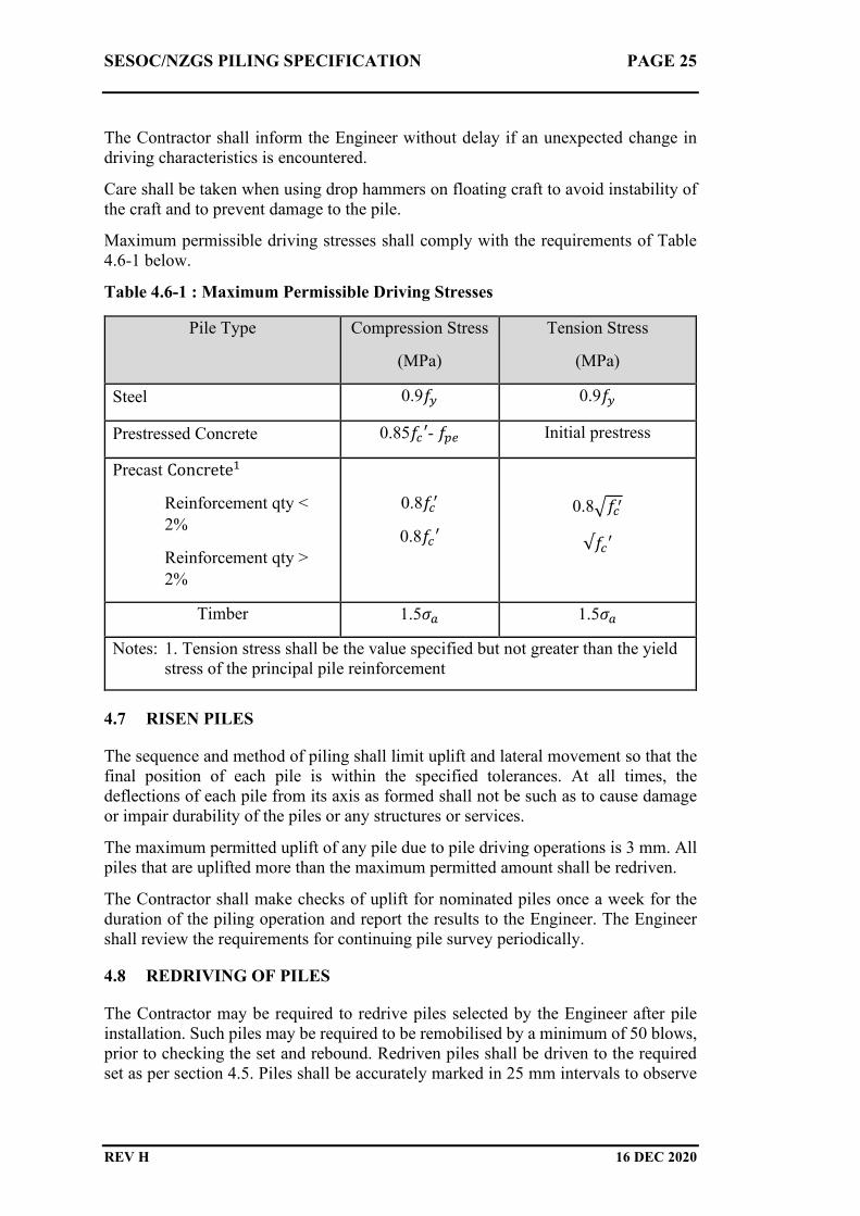
Maximum permissible driving stresses shall comply with the requirements of Table
4.6-1 below.
Table 4.6-1 : Maximum Permissible Driving Stresses
Pile Type Compression Stress
(MPa)
Tension Stress
(MPa)
Steel 0.9�� 0.9��
Prestressed Concrete 0.85��′- ��� Initial prestress
Precast Concrete�
Reinforcement qty <
2%
Reinforcement qty >
2%
0.8���
0.8��′
0.8����
√��′
Timber 1.5�� 1.5��
Notes: 1. Tension stress shall be the value specified but not greater than the yield
stress of the principal pile reinforcement
4.7 RISEN PILES
The sequence and method of piling shall limit uplift and lateral movement so that the
final position of each pile is within the specified tolerances. At all times, the
deflections of each pile from its axis as formed shall not be such as to cause damage
or impair durability of the piles or any structures or services.
The maximum permitted uplift of any pile due to pile driving operations is 3 mm. All
piles that are uplifted more than the maximum permitted amount shall be redriven.
The Contractor shall make checks of uplift for nominated piles once a week for the
duration of the piling operation and report the results to the Engineer. The Engineer
shall review the requirements for continuing pile survey periodically.
4.8 REDRIVING OF PILES
The Contractor may be required to redrive piles selected by the Engineer after pile
installation. Such piles may be required to be remobilised by a minimum of 50 blows,
prior to checking the set and rebound. Redriven piles shall be driven to the required
set as per section 4.5. Piles shall be accurately marked in 25 mm intervals to observe

SESOC/NZGS PILING SPECIFICATION PAGE 26
REV H 16 DEC 2020
penetration. Piles selected for redriving shall not be cut off until redriving is completed
and approved by the Engineer.
The Contractor shall provide an updated legible set card for each pile at the completion
of redriving.
4.9 PREBORING AND JETTING OF PILES
Piles shall not be prebored without the written approval of the Engineer. Preboring of
piles may be allowed by the Engineer as long as the piles remain in intimate contact
with surrounding soil and the completed piles comply with the requirements of the
Specification. If boring is oversize, any gap between tube and ground shall be filled
with compacted sand prior to driving to the Engineer's approval.
Piles shall not be jetted without the written approval of the Engineer. Prior to jetting
any pile, the Contractor shall submit to the Engineer details of the equipment to be
used and the proposed method to be adopted.
4.10 PILE CONSTRUCTION RECORD CARD
The Contractor shall complete a Pile Construction Record Card for every pile
constructed on the Site. A copy of the proposed Pile Construction Record Card shall
be submitted to the Engineer on week prior to commencing pile construction. The Pile
Construction Record Card shall contain the following information as a minimum;
• contract and structure name
• pile number, location, type, steel grade, pile dimensions, preformed length,
end plate details, locations of splices and cross referencing to NDE.
• date and time of driving, redriving, jetting or preboring, including
stoppages and delays, from start to finish.
• type, weight, drop and mechanical condition of the hammer, and equivalent
information for other equipment.
• the height of the working platform on which the piling machine operates.
• final drop height, etc, and the set and rebound, recorded as the average
penetration in millimetres recorded over ten blows, including a legible
copy of the set card and the calculated ultimate driving resistance.
• any information regarding obstructions, delays and other interruptions to
the sequence of work.
• the expected and actual constructed founding levels.
• weather conditions (including tide and wave height if applicable).
• the design and actual constructed elevation of the top of the pile, including
compliance with tolerances.
• cross referencing to proving bores (if applicable).
• cross referencing to pile load test results (if applicable).
• updated set cards for piles that been redriven.

SESOC/NZGS PILING SPECIFICATION PAGE 27
REV H 16 DEC 2020
• the Contractors signature verifying that all work has been completed
satisfactorily.
Pile construction records shall be submitted to the Engineer within 24 hours of the
completion of each pile. An example driven pile construction record card indicating
typical information required is provided in Appendix B. It is noted that all items shown
on this example may not be relevant to all projects.
4.11 ADDITIONAL REQUIREMENTS FOR DRIVEN PRECAST
CONCRETE PILES
Additional Reinforcement
The Contractor shall ensure that pile heads and toes are adequately reinforced or
banded to prevent bursting of the pile during driving.
Pile Construction Record Card
The requirements of section 4.11 shall apply. Additional information shall be recorded
on the Pile Construction Record card as follows:
• Concreting records for the precast pile, including pre-pour cards and
material certificates.
4.12 ADDITIONAL REQUIREMENTS FOR CLOSED ENDED STEEL PIPE
PILES (BOTTOM DRIVEN)
Driving Plug
Where used, a bottom driving plug shall consist of hard, durable screened and washed
aggregate conforming to Table 4.12-1, with cement content in the initial plug not
exceeding 60 kg. The length of the driving plug shall not be less than 1.5 casing
diameters. The length of the driving plug shall not be greater than 4 m without the
prior approval of the Engineer. Driving plug material should be recharged at maximum
intervals of 40 minutes during continuous driving or when the plug becomes powdered
resulting in a soft response indicating a loss of driving efficiency. The recharge plug
length shall be between 450 mm and 600 mm long. A recharge plug shall have at least
20 blows and no more than 75 blows applied to it prior to measuring the set. Recharge
of the driving plug does not require cement to be added.
Table 4.12-1: Aggregate properties for driving plug
Gradation
Sieve Size Percent Passing
19 mm 100
13.2 mm 0 - 5
Crushing Resistance 230 kN per NZS4407 Test 3.10
Solid Density At least 2.60 per NZS4407 Test 3.7.1

SESOC/NZGS PILING SPECIFICATION PAGE 28
REV H 16 DEC 2020
The use of alternative driving plugs shall be agreed with the Engineer prior to
commencement of pile driving.
Pile Construction Record Card
The requirements of section 4.10 shall apply. Additional information shall be recorded
on the Pile Construction Record card as follows:
• the amount of material used to form the driving plug, and the length of the
plug
• reinforcement checklist
• the level of the top of the reinforcement cage before and after pouring
• concreting records, including the total volume of concrete placed, the
volume supplied with each truck, slump measurements and number of cube
or cylinder samples taken, time of batching, and concrete placing start and
completion times
• depth to top of concrete for each truck placed and depth of tremie tube (if
appropriate).
• The number of blows for each driving plug (or part).
4.13 ADDITIONAL REQUIREMENTS FOR OPEN ENDED STEEL PIPE
PILES (TOP DRIVEN)
Pile Construction Record Card
The requirements of section 4.11 shall apply. Additional information shall be recorded
on the Pile Construction Record card as follows:
• reinforcement and other pre-pour checks (if applicable)
• the level of the top of the reinforcement cage before and after pouring (if
applicable)
• concreting records, including the total volume of concrete placed, the
volume supplied with each truck, slump measurements and number of cube
or cylinder samples taken, time of batching, and concrete placing start and
completion times (if applicable)
• depth to top of concrete for each truck placed and depth of tremie tube (if
appropriate).
4.14 ADDITIONAL REQUIREMENTS FOR DRIVEN TIMBER PILES
Pile Heads
The requirements of section 2.3.7 shall apply.
The pile head shall be flat and perpendicular to the axis of the pile.
Unless specified otherwise, the head of the pile shall be trimmed to a circular cross
section and fitted with a tight steel ring. The ring shall be not less than a 50x12 mm

SESOC/NZGS PILING SPECIFICATION PAGE 29
REV H 16 DEC 2020
mild steel flat, and the join shall be butt welded over the full section. The top of the
ring shall be positioned between 10 mm and 20 mm below the top of the pile. If the
ring is displaced during driving, it shall be refitted. If the ring is broken, a new ring
shall be fitted.
As an alternative to a ring, a metal helmet may be used. The top of the pile must be
trimmed to fit closely into the recess in the underside of the helmet. A 25 mm thick
plywood packer shall be used between the helmet and the hammer.
Driving Shoes
Where used, pile shoes shall be attached to the pile by steel straps fixed, spiked or
bolted to the timber. The shoes shall be coaxial with the pile and firmly bedded into
it.
4.15 ADDITIONAL REQUIREMENTS FOR STEEL SHEET PILES
Storage
If sheet piles of different grades are stored on Site, each pile shall be clearly marked
showing its grade, with piles of different grades stored separately.
Pile Driving
The piles shall be guided and held in position by temporary gates, with each pile
properly interlocked with its neighbour. Piles shall not bypass one another in place of
interlocking unless agreed by the Engineer. At all stages during driving, the free length
of the sheet pile shall be adequately supported and restrained if required.
The Contractor shall ensure that sheet piles are driven without significant damage or
declutching.
Pile driving hammers shall be correctly positioned on the sheet pile so that the hammer
is aligned as near to the sheet pile axis as is practically possible. Freely suspended pile
hammers shall be equipped with correctly adjusted leg guides and inserts. Where a
hammer is mounted in a rigid leader, the leader shall be stable. The anvil block or
driving plate shall be of a sufficient size to cover as much as possible of the cross
section of the pile.

SESOC/NZGS PILING SPECIFICATION PAGE 30
REV H 16 DEC 2020
5 INTEGRITY TESTING, PHYSICAL LOAD TESTING AND USE OF
PILE DRIVING ANALYSERS (PDA)
5.1 INTEGRITY TESTING
Project Specific Requirements
The following items, where appropriate, are detailed in the project specification:
• the number, type and location of the piles to be tested
• the stages in the programme when integrity testing will be required
Referenced Documents
This Specification shall be read in conjunction with the following standards,
guidelines, and other documents, which are deemed to form part of this Specification.
In the event of this Specification being at variance with any provision of these
referenced documents, the requirements of this Specification shall take precedence.
All Materials and workmanship shall comply with these documents unless expressly
noted otherwise. All documents referenced below shall be the latest revision, complete
with current amendments, as at the commencement of the Contract Works.
ASTM D5882 Low Strain Impact Integrity Testing of Deep Foundations
ASTM D6760 Integrity Testing of Concrete Deep Foundations by Ultrasonic
Crosshole Testing
Method
Where integrity testing is required by the Project Specific Requirements, the method
to be adopted shall be either:
• full depth coring of the pile, or
• sonic echo/impulse method, or
• crosshole sonic logging method.
Other methods, such as thermal integrity profiling, may be considered by the Engineer
subject to satisfactory evidence of performance.
The Engineer may order additional integrity testing of any pile when the Engineer has
reasonable cause to doubt the integrity of the pile.
Independent Observer
All integrity testing shall be carried out by a suitably qualified and experienced
independent specialist in strict accordance with the methodologies outlined in ASTM
D5882 (sonic echo) and/or ASTM D6760 (crosshole sonic logging). The Contractor
shall submit for approval by the Engineer the name of such specialist, their
professional qualifications, relevant experience, a description of the test equipment
and any associated calibration certificates, a test method statement and a programme

SESOC/NZGS PILING SPECIFICATION PAGE 31
REV H 16 DEC 2020
for executing the work, prior to integrity testing commencing on Site. Upon request, a
copy of the unprocessed test data shall be provided to the Engineer within 48 hours.
Interpretation of Results and Reporting
The interpretation of test results shall be carried out by suitably experienced and
competent persons. Preliminary results of each test shall be submitted to the Engineer
within 24 hours of completion of the test. The final test results and findings shall be
submitted to the Engineer within ten Working Days of completion of the test.
The report shall contain a summary of the method used in conducting the test, a
summary of the method of interpretation, including all assumptions, calibrations, and
corrections used in the analysis. The units and scales shall be clearly marked on all
diagrams. Current calibration certificates shall be provided for all impulse equipment.
Anomalous Results
In the event that the tests indicate that an anomaly is found in the pile, the Contractor
shall demonstrate to the Engineer that the pile is fit for its intended purpose or shall
carry out remedial work to make it so. The Contractor shall provide the Engineer with
details of measures to be adopted to enable the defective pile to comply with the
Specification. The Contractor shall not carry out any remedial work on any pile,
without the written approval of the Engineer.
Should the Contractor fail to meet the above requirements, the Engineer reserves the
right to order such extra work as may be required to overcome the resultant structural
problems. No additional cost to the Principal shall arise from any such extra work.
5.2 PHYSICAL LOAD TESTING
Project Specific Requirements
The following items, where appropriate, are detailed in the project specification:
• the number, type and location of the piles to be tested
• the stages in the programme when load testing will be required
• the test load
Referenced Documents
This Specification shall be read in conjunction with the following standards,
guidelines, and other documents, which are deemed to form part of this Specification.
In the event of this Specification being at variance with any provision of these
referenced documents, the requirements of this Specification shall take precedence.
All Materials and workmanship shall comply with these documents unless expressly
noted otherwise. All documents referenced below shall be the latest revision, complete
with current amendments, as at the commencement of the Contract Works.
AS2159 Piling Design and Installation

SESOC/NZGS PILING SPECIFICATION PAGE 32
REV H 16 DEC 2020
Compressive Load Tests
Where required by the Project Specific Requirements, physical load testing of piles
shall be carried out using the incremental sustained load test procedure specified in
AS2159 “Piling Design and Installation”.
5.3 PILE DRIVING ANALYSER
Project Specific Requirements
The following items, where appropriate, are detailed in the Project Specific
Requirements:
• proportion of piles to be dynamically tested
• proportion of dynamically tested piles which will be subject to wave signal
matching (CAPWAP analyses)
• if any pile must be dynamically tested (and wave signal matched), a list of
these piles
Referenced Documents
This Specification shall be read in conjunction with the following standards,
guidelines, and other documents, which are deemed to form part of this Specification.
In the event of this Specification being at variance with any provision of these
referenced documents, the requirements of this Specification shall take precedence.
All Materials and workmanship shall comply with these documents unless expressly
noted otherwise. All documents referenced below shall be the latest revision, complete
with current amendments, as at the commencement of the Contract Works.
AS2159 Piling Design and Installation
ASTM D4945 High-Strain Dynamic Testing of Deep Foundations
General
Dynamic pile testing shall be carried out in accordance with the requirements of
AS2159 and ASTM D4945.
Extent of Testing
The actual piles to be tested and the programme of dynamic tests shall be agreed with
the Engineer prior to piling works commencing on Site.
Pre-testing Analysis
Two days prior to driving the piles, the Contractor shall submit to the Engineer a wave
equation analysis (e.g. GRLWEAP) indicating the pile is able to be driven to achieve

SESOC/NZGS PILING SPECIFICATION PAGE 33
REV H 16 DEC 2020
the required test load without overstressing the pile. Guidelines on permissible driving
stresses are presented in Table 4.6-1.
Reporting
Field results providing indicative pile capacities shall be made available to the
Engineer as testing is undertaken. A detailed report on the piles tested for the project
shall be forwarded to the Engineer within 10 working days of the completion of the
test piling. The report shall include all items listed in Clause 7 of ASTM D4945. Upon
request, an electronic copy of the unprocessed data shall be provided to the Engineer
with 48 hours in a database format such as W01 extension files.

SESOC/NZGS PILING SPECIFICATION PAGE 34
REV H 16 DEC 2020
6 REFERENCES
CIA. (2012). Recommended Practice Tremie Concrete for Deep Foundations.
Sydney: Concrete Institute of Australia.
EFFC/DFI. (2018). Guide to Tremie Concrete for Deep Foundations,. Deep
Foundation Institute, European Federation of Foundation Constractors.
Retrieved from http://www.dfi.org/publications.asp
MBIE. (2012). Approved Code of Practice for Load-lifting Rigging. Wellington:
Ministry of Business, Innovation and Employment. Retrieved from Approved
Code of Practice for Load-lifting Rigging: https://worksafe.govt.nz/topic-
and-industry/load-lifting-and-rigging/
MBIE. (2019). Best practice guidelines for working at height in New Zealand.
Ministry of Business, Innovation & Employment. Retrieved from
https://worksafe.govt.nz/topic-and-industry/working-at-height/working-at-
height-in-nz/
TWfNZ. (2018). Working Platforms. Temporary Works forum (NZ). Retrieved from
https://www.sesoc.org.nz/membership/special-committees/temporary-works-
forum-nz/
TWfNZ. (2019). Temporary Works Procedural Control. Temporary Works forum
(NZ). Retrieved from https://www.sesoc.org.nz/membership/special-
committees/temporary-works-forum-nz/
WorkSafe. (2009). Approved Code of Practice for Cranes. Wellington: Deparatment
of Labour. Retrieved from Approved Code of Practice for Cranes:
https://worksafe.govt.nz/topic-and-industry/cranes/
WorkSafe. (2016). Good Practice Guidelines for Excavation Safety. Wellington:
Worksafe New Zealand. Retrieved from Good Practice Guidelines for
Excavation Safety: https://worksafe.govt.nz/topic-and-
industry/excavation/excavation-safety-gpg/

SESOC/NZGS PILING SPECIFICATION PAGE 35
REV H 16 DEC 2020
APPENDIX A: SAMPLE PROJECT SPECIFIC REQUIREMENTS
A1: SUMMARY OF PROJECT SPECIFIC RQUIREMENTS
A2: SAMPLE CAST IN PLACE BOARD PILE PROJECT SPECIFIC
REQUIREMENTS
A3: SAMPLE DRIVEN STEEL H PILE PROJECT SPECIFIC
REQUIREMENTS

SESOC/NZGS PILING SPECIFICATION PAGE 36
REV H 16 DEC 2020
A1: SUMMARY OF PROJECT SPECIFIC REQUIREMENTS
The following items, where appropriate, are detailed in the Project Specific
Requirements.
GENERAL
• location and description of the Site
• nature and extent of the work
• site datum and grid references
• nature of the ground and subsurface conditions
• requirement for proving bores
• requirements for tolerances
• requirements for quality management
• requirements for Producer Statements
• technical requirements for consideration of alternative pile designs
• requirements for pile testing
MATERIALS
• details of concrete strength and mix proportions
• requirements for alkali-aggregate reaction
• weld category for welds in accordance with NZS3404 (GP or SP)
• corrosion protection for steel piles
• grade and category of steel
• size and shape of timber piles
• timber species
• timber hazard class
BORED PILES
• requirement for support fluid
• pressure grouting

SESOC/NZGS PILING SPECIFICATION PAGE 37
REV H 16 DEC 2020
• trial piles
• disposal of excavated material
• reinforcement checklist.
• the level of the top of the reinforcement cage before and after pouring.
DRIVEN PILES
• trial piles
INTEGRITY TESTING, PHYSICAL LOAD TESTING AND USE OF
PILE DRIVING ANALYSERS (PDA)
• the number, type and location of the piles to be tested
• the stages in the programme when integrity or load testing will be required
• proportion of piles to be dynamically tested
• proportion of dynamically tested piles which will be subject to wave signal
matching (CAPWAP analyses)
• if any pile must be dynamically tested (and wave signal matched), a list of
these piles

SESOC/NZGS PILING SPECIFICATION PAGE 38
REV H 16 DEC 2020
A2: PROJECT SPECIFIC REQUIREMENTS : SAMPLE CAST IN PLACE
BORED PILE
GENERAL
A2.1.1 Location And Description Of The Site
The site is located approximately 30 kilometres south east of Whangarei adjacent to
the Samuel Marsden Canning facilities at Marsden Point and may be accessed from
Marsden Point Road.
The extent of the site is generally as shown on the Drawings.
A2.1.2 Nature And Extent Of The Work
The extent of work is shown on the Drawings and generally comprises construction
of 24 – 1200 mm diameter permanently cased reinforced concrete piles in dense
sand.
A2.1.3 Site Datum And Grid References
All levels shown on the drawings and referred to in the specifications are in terms of
chart datum. Grid references are specified in terms of the Mount Eden co-ordinate
system.
A2.1.4 Nature Of The Ground And Subsurface Conditions
A factual geotechnical report has been prepared for this project and may be inspected
at the offices of Sardine & Glass Limited at 131 Victory Street, Auckland.
The site is located in Marsden Bay on the southwestern side of the entrance to
Whangarei harbour. The seabed level at the existing wharf is approximately 8 to 9
metres below chart datum. Much of the seabed in the dredge area is mantled with
algae covered shell. Zones of active sediment transport occur along the northeastern
margin and southwestern corner of the dredge area. Blacksmiths Creek extends
inland generally southwest from the western end of the development.
The oldest rocks in the area are greywacke and argillite of the Waipapa Group.
These rocks outcrop north, south and southwest of the harbour and constitute the
basement to younger coastal and estuarine sediments at the site. Basement rocks are
discontinuous and are not encountered in the Marsden Point area.
A2.1.5 Requirement For Proving Bores
Proving bores shall be drilled at each location shown on the Drawings.
Each proving bore shall be wash drilled from existing ground surface level down
to five metres above the anticipated founding level specified on the Drawings.
Below this level, the bore shall be cored using triple tube sampling equipment
with SPT tests undertaken at 1.5 metre centres to a depth of twelve pile

SESOC/NZGS PILING SPECIFICATION PAGE 39
REV H 16 DEC 2020
diameters below the anticipated founding level specified on the Drawings. The
retrieved cores shall be fully labelled, sealed in plastic and securely stored in
fully labelled core boxes on Site by the Contractor for the duration of the
contract. Cores shall be made available for inspection by the Engineer as
required.
A2.1.6 Requirements For Tolerances
Piles shall be constructed in accordance with the following tolerances:
• Tops of piles shall not vary more than 75 mm horizontally and 25 mm
vertically from their true position as specified on the Drawings.
• The maximum permitted deviation of piles from the vertical at any level shall
be not more than 1:75.
A2.1.7 Requirements For Quality Management
Refer to the Preliminary and General section for requirements for Quality
Management.
A2.1.8 Requirements For Producer Statements
Producer Statements are not required.
MATERIALS
A2.2.1 Details Of Concrete Strength And Mix Proportions
Concrete strengths are shown on the Drawings.
A2.2.2 Requirements For Alkali-Aggregate Reaction
All concrete for use in piles shall meet the requirements of NZS3109. The Contractor
shall supply the Engineer with the concrete mix design five Working Days prior to
placing concrete on Site.
The total free water content shall not exceed 170 kg/m³. The maximum aggregate
size shall not exceed 19 mm. No calcium chloride accelerator or other chloride
containing admixtures shall be added to the mix.
A2.2.3 Weld Category For Welds In Accordance With NNZ3404
All welds shall be category SP.
BORED PILES
A2.3.1 Requirement For Support Fluid
Support fluid shall not be used without the written approval of the Engineer.

SESOC/NZGS PILING SPECIFICATION PAGE 40
REV H 16 DEC 2020
A2.3.2 Trial Piles
Trial piles are not required.
A2.3.3 Disposal Of Excavated Material
Excavated material may be disposed of on site at locations to be agreed with the
Engineer.

SESOC/NZGS PILING SPECIFICATION PAGE 41
REV H 16 DEC 2020
A3: PROJECT SPECIFIC REQUIREMENTS : SAMPLE DRIVEN STEEL H
PILE
GENERAL
A3.1.1 Location And Description Of The Site
The site is located approximately 30 kilometres south east of Whangarei adjacent to
the Samuel Marsden Canning Company facilities at Marsden Point and may be
accessed from Marsden Point Road.
The extent of the site is generally as shown on the Drawings.
A3.1.2 Nature And Extent Of The Work
The extent of work is shown on the Drawings and generally comprises installation of
24 – 360 mm universal bearing piles in dense sand.
A3.1.3 Site Datum And Grid References
All levels shown on the drawings and referred to in the specifications are in terms of
chart datum. Grid references are specified in terms of the Mount Eden co-ordinate
system.
A3.1.4 Nature Of The Ground And Subsurface Conditions
A factual geotechnical report has been prepared for this project and may be inspected
at the offices of Sardine & Glass Limited at 131 Victory Street, Auckland.
The site is located in Marsden Bay on the southwestern side of the entrance to
Whangarei harbour. The seabed level at the existing wharf is approximately 8 to 9
metres below chart datum. Much of the seabed in the dredge area is mantled with
algae covered shell. Zones of active sediment transport occur along the northeastern
margin and southwestern corner of the dredge area. Blacksmiths Creek extends
inland generally southwest from the western end of the development.
The oldest rocks in the area are greywacke and argillite of the Waipapa Group.
These rocks outcrop north, south and southwest of the harbour and constitute the
basement to younger coastal and estuarine sediments at the site. Basement rocks are
discontinuous and are not encountered in the Marsden Point area.
A3.1.5 Requirement For Proving Bores
Proving bores shall be drilled at each location shown on the Drawings.
Each proving bore shall be wash drilled from existing ground surface level down to
five metres above the anticipated founding level specified on the Drawings. Below
this level, the bore shall be cored using triple tube sampling equipment with SPT
tests undertaken at 1.5 metre centres to a depth of twelve pile diameters below the
anticipated founding level specified on the Drawings. The retrieved cores shall be
SESOC/NZGS PILING SPECIFICATION PAGE 42
REV H 16 DEC 2020
fully labelled, sealed in plastic and securely stored in fully labelled core boxes on
Site by the Contractor for the duration of the contract. Cores shall be made available
for inspection by the Engineer as required.
A3.1.6 Requirements For Tolerances
Piles shall be constructed in accordance with the following tolerances:
• Tops of piles shall not vary more than 75 mm horizontally and 25 mm
vertically from their true position as specified on the Drawings.
• The maximum permitted deviation of piles from the vertical at any level shall
be not more than 1:75.
A3.1.7 Requirements For Quality Management
Refer to the Preliminary and General section for requirements for Quality
Management.
A3.1.8 Requirements For Producer Statements
Producer Statements are not required.
MATERIALS
A3.2.1 Corrosion Protection For Steel Piles
Corrosion protection is not required for the steel H piles.
A3.2.2 Weld Category For Welds In Accordance With NNZ3404
All welds shall be category SP.
A3.4 DRIVEN PILES
A3.4.1 Trial Piles
Trial piles are not required.
INTEGRITY TESTING, PHYSICAL LOAD TESTING AND USE OF
PILE DRIVING ANALYSERS (PDA)
A3.5.1 Number, Type And Location Of The Piles To Be Tested
The capacity of not less than 10% of piles shall be calculated using a dynamic pile
driving analyser. The location and timing of pile tests shall be agreed with the
Engineer as production piling proceeds.
The test load shall be not less than the ultimate driving resistance specified on the
Drawings.

SESOC/NZGS PILING SPECIFICATION PAGE 43
REV H 16 DEC 2020
APPENDIX B: SAMPLE PILE CONSTRUCTION RECORD CARDS
BORED PILE RECORD
DRIVEN PILE RECORD

CONTRACT: JOB NO:
PILE NO: AREA:
Date Initial
Final
Vert: mm/m
Initial
Final
Vert: mm/m
Depth Date Time
Actual Toe Level:
Check by: Date:
Check by: Date:
Check by: Date:
BASE TEST
m
Special Notes
m m
Date: m
Date:
m3
Helical:
m
Design Slump:
Design Top of Conc: RL
RL
Actual Volume:
Actual Top of Conc:
Casing Withdrawn OK:
m
Casing Withdrawn:
Piling Rig Type:
Approval
Design Representative:
Time
Contractors Representative:
Drilling Log
Finish Concrete:
Finish Drilling:
Casing Install:
Start Drilling:
Start Concrete:
Piling Details
Platform Level:
Drilling Details
RL
m3
Theoretical Volume:
RL
Water or Bentonite Level:
Base Test Rating:
mm
Actual Top of Steel
t
RL
%
Concrete Mix Code:
Bentonite Density:
Concrete Length:
g/ml
Concrete Details
mm
m
Location & Offset Sketch
Casing Diameter: mm
Bentonite Sand Content:
Offsets
Casing Length:
sec
Pile Diameter: mm
Bentonite Viscosity:
Splice Length:
Total Cage Length:
Cage Mass:
Design Top of Steel RL
Main Bars:
Reinforcing Details
Design Toe Level:
RL
Offsets
Temp or Perm:
BORED PILE RECORD

CONTRACT: JOB NO:
PILE NO: AREA:
TOC Top of Casing Level: RL
Piling Platform Level: RL
TOS Top of Steel Level: RL
Design Steel Level: RL
Length of Cage: m
TOConc. Top of Concrete Level: RL
Design Concrete Level: RL
Toe of Casing Level: RL
Length of Casing: m
Reinforcing Details Initials Date
Bar Size / Number:
Spiral Size / Spacing:
Spiral Lap Welds:
Ubolts Installed:
Cover Spacers:
Splice Lengths:
Grout Tube Details Initials Date
TaMs checked
Tube unbolts checked
Couplers checked
Tubes coloured
Drill Details Initials Date
Toe Level checked:
Bentonite tested clean?
Base tested clean?
BPC Representative:
Design Representative:
Toe Actual Toe Level: RL
Design Toe Level: RL
PREPOUR INSPECTION
BORED PILE RECORD

CONTRACT: JOB NO:
PILE NO: AREA:
Notes / Sketch:
Check by: Date:
Depth Tremie Embedment Truck Batch Pour Truck Total Conc Samples
Top Conc Length Docket Time Time Vol Vol Slump Taken
m m m m3 m3 mm
Special Notes
Weather Conditions Wind Wave Height
Date:
Date:
Tremie POUR DETAILS
Prepour Checks
Tremie Pipe Length:
Pile Length:
Grout Mix?
Joints Properly Sealed?
Pipes Clean?
Tremie POUR RECORD
Design Representative:
Contractors Representative:
Approval
Vermiculite Plug?
Tremies to Bottom?
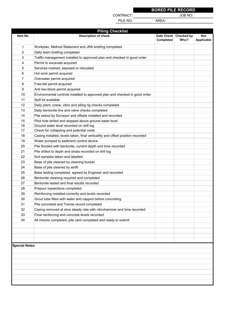
CONTRACT: JOB NO:
PILE NO: AREA:
1
2 Daily team briefing completed
3 Traffic management installed to approved plan and checked in good order
4 Permit to excavate acquired
5 Services marked, exposed or relocated
6 Hot work permit acquired
7 Overwater permit acquired
8 Free-fall permit acquired
9 Anti two-block permit acquired
10 Environmental controls installed to approved plan and checked in good order
11 Spill kit available
12 Daily plant, crane, vibro and piling rig checks completed
13 Daily bentonite line and valve checks completed
14 Pile setout by Surveyor and offsets installed and recorded
15 Pilot hole drilled and stopped above ground water level
16 Ground water level recorded on drill log
17 Check for collapsing and potential voids
18 Casing installed, levels taken, final verticallity and offset position recorded
19 Water pumped to sediment control device
20 Pile flooded with bentonite, current depth and time recorded
21 Pile drilled to depth and strata recorded on drill log
22 Soil samples taken and labelled
23 Base of pile cleaned by cleaning bucket
24 Base of pile cleaned by airlift
25 Base testing completed, agreed by Engineer and recorded
26 Bentonite cleaning required and completed
27 Bentonite tested and final results recorded
28 Prepour inpsections completed
29 Reinforcing installed correctly and levels recorded
30 Grout tube filled with water and capped before concreting
31 Pile concreted and Tremie record completed
32 Casing removed at slow steady rate with vibrohammer and time recorded
33 Final reinforcing and concrete levels recorded
34 All checks completed, pile card completed and ready to submit
Special Notes
Checked by
Who?
Not
Applicable
Description of check
BORED PILE RECORD
Workplan, Method Statement and JRA briefing completed
Piling ChecklistItem No Date Check
Completed

CONTRACT: CEP NO:
PILE NO: AREA:
Initial
Final
Vert: mm/m
Hammer Type:
Initial
Depth Date Time Final
Vert: mm/m
Check by: Date:
Actual Top Level:
Actual Toe Level:
Check by: Date:
Check by: Date:
Special Notes
Date:
Date:
mm
Approval
Design Representative:
Contractors Representative:
Actual Load (Ru): kN
Actual Drop: mm
Actual Set (S): mm
Actual Compression (C):
Target Drop: mm
Target Set (S): mm
Target Compression (C): mm
Hammer Weight: t
Helmet Weight: t
Target Load (Ru): kN
Design Rock Level: RL
Actual Rock Level: RL
Driving Details
Design Top Level: RL
RL
Design Toe Level: RL
RL
Check Safe to Lift by:
Temp or Perm:
Level Details
Steel Grade: MPa
Pile Length: m
Pile Weight: kg
Section Type:
Dimensions: mm
Thickness: mm
Welder:Offsets
Pile Details
Notes
DRIVEN PILE RECORD
Piling Details Date Time Location & Offset Sketch
Start Driving: Platform Level: RL
Start Splicing:Offsets
Finish Splicing:
Finish Driving:
Crane Type:

CONTRACT: CEP NO:
PILE NO: AREA:
Notes / Sketch:
Special Notes
Weather Conditions Wind
Date:
Date:
SET RECORD
Approval
Design Representative:
Contractors Representative:

SESOC/NZGS PILING SPECIFICATION PAGE 50
REV H 16 DEC 2020
APPENDIX C: PILE DRIVING FORMULA
C1: FORMULA AND SYMBOLS
C2: TEMPORARY COMPRESSION
C3: BLOW EFFICIENCY
C4: ALTERNATIVE FORMULA FOR HARD DRIVING
C5: PILE STRESSES AND HARDNESS OF DRIVING
C6: BEARING CAPACITY
C7: FIELD MEASUREMENTS

SESOC/NZGS PILING SPECIFICATION PAGE 51
REV H 16 DEC 2020
FORMULA AND SYMBOLS
C1.1 The Hiley dynamic pile-driving formula estimates the ultimate axial compressive
pile capacity for a driven pile. The estimate is referred to as the ultimate driving
resistance to driven piles and is expressed as:
R = W h n
S + C/2
where:
R = ultimate driving resistance (kN)
W = weight of hammer (kN)
S = final set or penetration per blow (mean of final ten blows) (mm)
C = sum of temporary compressions of pile dolly, packings and ground (mm)
n = efficiency of blow (dimensionless)
h = free-fall height of hammer (mm)
The free fall height shall be calculated as:
For trigger operated drop hammers - the full fall
For normally-proportioned winch operated hammers-80% of the fall.
For single-acting hammers-90% of the stroke
For hydraulic hammer-the equivalent drop specified by the manufacturer
TEMPORARY COMPRESSION
C2.1 Total temporary compression C is derived from:
C = Cc + Cp + Cq
where:
Cc = elastic compression of pile head or dolly. Cp = elastic compression of the pile
itself.
Cq = quake of the ground beneath the pile.
C2.2 Wherever possible Cp and Cq should be determined by field measurements (see
Paragraph C7), especially in soft or peaty soils, or where soft ground exists below
the pile
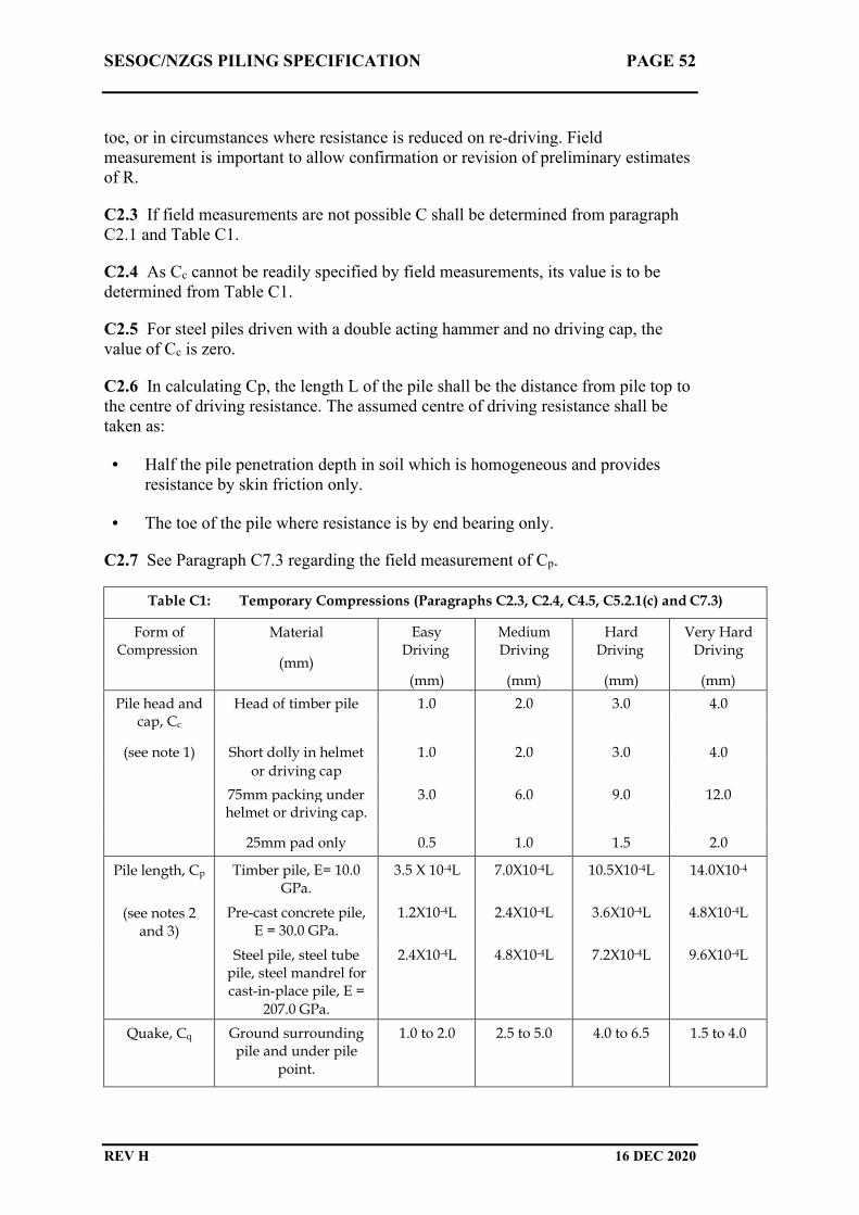
SESOC/NZGS PILING SPECIFICATION PAGE 52
REV H 16 DEC 2020
toe, or in circumstances where resistance is reduced on re-driving. Field
measurement is important to allow confirmation or revision of preliminary estimates
of R.
C2.3 If field measurements are not possible C shall be determined from paragraph
C2.1 and Table C1.
C2.4 As Cc cannot be readily specified by field measurements, its value is to be
determined from Table C1.
C2.5 For steel piles driven with a double acting hammer and no driving cap, the
value of Cc is zero.
C2.6 In calculating Cp, the length L of the pile shall be the distance from pile top to
the centre of driving resistance. The assumed centre of driving resistance shall be
taken as:
• Half the pile penetration depth in soil which is homogeneous and provides
resistance by skin friction only.
• The toe of the pile where resistance is by end bearing only.
C2.7 See Paragraph C7.3 regarding the field measurement of Cp.
Table C1: Temporary Compressions (Paragraphs C2.3, C2.4, C4.5, C5.2.1(c) and C7.3)
Form of Compression
Material
(mm)
Easy Driving
(mm)
Medium Driving
(mm)
Hard Driving
(mm)
Very Hard Driving
(mm)
Pile head and Head of timber pile 1.0 2.0 3.0 4.0 cap, Cc
(see note 1) Short dolly in helmet 1.0 2.0 3.0 4.0
or driving cap
75mm packing under 3.0 6.0 9.0 12.0 helmet or driving cap.
25mm pad only 0.5 1.0 1.5 2.0
Pile length, Cp Timber pile, E= 10.0 GPa.
3.5 X 10⁻⁴L 7.0X10⁻⁴L 10.5X10⁻⁴L 14.0X10⁻⁴
(see notes 2 and 3)
Pre-cast concrete pile, E = 30.0 GPa.
1.2X10⁻⁴L 2.4X10⁻⁴L 3.6X10⁻⁴L 4.8X10⁻⁴L
Steel pile, steel tube pile, steel mandrel for cast-in-place pile, E =
207.0 GPa.
2.4X10⁻⁴L 4.8X10⁻⁴L 7.2X10⁻⁴L 9.6X10⁻⁴L
Quake, Cq Ground surrounding pile and under pile
point.
1.0 to 2.0 2.5 to 5.0 4.0 to 6.5 1.5 to 4.0
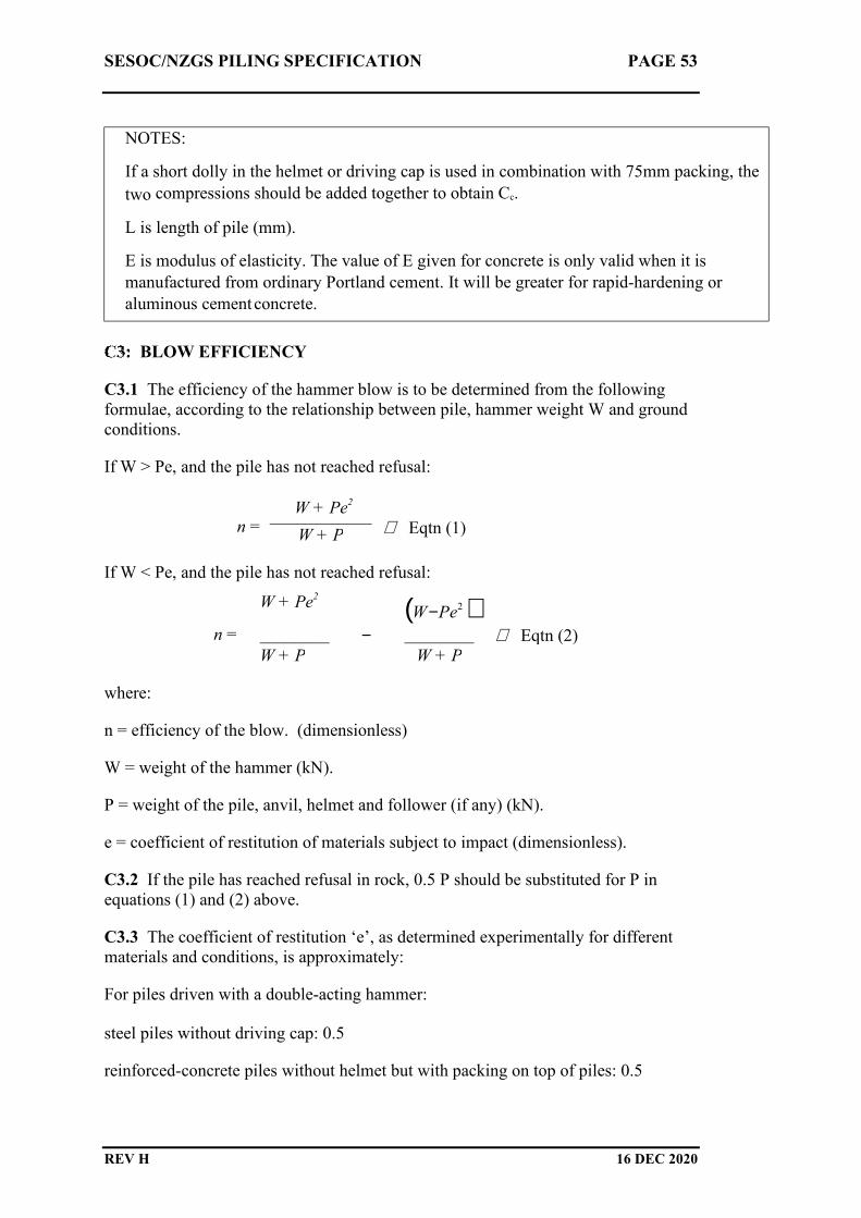
SESOC/NZGS PILING SPECIFICATION PAGE 53
REV H 16 DEC 2020
BLOW EFFICIENCY
C3.1 The efficiency of the hammer blow is to be determined from the following
formulae, according to the relationship between pile, hammer weight W and ground
conditions.
If W > Pe, and the pile has not reached refusal:
n = W + Pe
2
Eqtn (1)
W + P
If W < Pe, and the pile has not reached refusal:
W + Pe2 (W − Pe
2 )
n = ________ − ________ Eqtn (2)
W + P W + P
where:
n = efficiency of the blow. (dimensionless)
W = weight of the hammer (kN).
P = weight of the pile, anvil, helmet and follower (if any) (kN).
e = coefficient of restitution of materials subject to impact (dimensionless).
C3.2 If the pile has reached refusal in rock, 0.5 P should be substituted for P in
equations (1) and (2) above.
C3.3 The coefficient of restitution ‘e’, as determined experimentally for different
materials and conditions, is approximately:
For piles driven with a double-acting hammer:
steel piles without driving cap: 0.5
reinforced-concrete piles without helmet but with packing on top of piles: 0.5
NOTES:
If a short dolly in the helmet or driving cap is used in combination with 75mm packing, the
two compressions should be added together to obtain Cc.
L is length of pile (mm).
E is modulus of elasticity. The value of E given for concrete is only valid when it is
manufactured from ordinary Portland cement. It will be greater for rapid-hardening or
aluminous cement concrete.

SESOC/NZGS PILING SPECIFICATION PAGE 54
REV H 16 DEC 2020
reinforced concrete piles with short dolly, helmet and packing: 0.4
timber piles: 0.4
For piles driven with single-acting or drop hammer:
reinforced concrete piles without helmet but with packing on top of piles: 0.4
steel or steel tube piles with driving cap and short dolly covered with steel plate: 0.32
reinforced concrete piles with helmet ,packing and dolly in good condition: 0.25
timber piles in good condition: 0.25
timber piles in poor condition: 0.0
C3.4 For piles in penetrable (not rock) ground only, and provided W > Pe, the blow
efficiency n may be obtained from Table C2 for different combinations of P/W and
e. For situations where the pile point is on rock, the formulae in paragraph C3.1 as
modified by Paragraph C3.2 must be used.
ALTERNATIVE FORMULA FOR HARD DRIVING
C4.1 Where the set S in the Hiley formula (see Paragraph C1.1) is small or zero, R
is approximately proportional to C. Thus:
R = mC
where:
m = a constant for any particular pile (kN/mm)
C4.2 Substituting R/m for C, the Hiley formula becomes:
R
W h n
= _______
S + (R / 2m)
or
R = (2 W h n m + (mS)2 )0.5 - m S
C4.3 If the pile is driven to refusal, S becomes zero and the equation simplifies to:
R = (2 W h n m)0.5
C4.4 The value of m is determined from:
m = R1/C
where R1 is either the anticipated ultimate axial compressive load assessed by
another method (not the Hiley formula),based on the soil and rock information
available, or the value or R1 obtained from clause C4.5.

SESOC/NZGS PILING SPECIFICATION PAGE 55
REV H 16 DEC 2020
C4.5 R1 may be calculated using the Hiley formula:
R1 = W h n
S + C/2
taking the value of S = 0, and of C from the appropriate figures for very hard driving
in Table C1. Where possible Cp and Cq should be determined from observation, and
only Cc from Table C1.
Table C2: Efficiency of Blow (Paragraph C3.4)
Ratio P/W e = 0.5 e=0.4 e=0.32 e = 0.25 e = 0.0
0.5 0.75 0.72 0.70 0.69 0.67
1.0 0.63 0.58 0.55 0.53 0.50
1.5 0.55 0.50 0.46 0.44 0.40
2.0 0.50 0.44 0.40 0.37 0.33
2.5 - 0.40 0.36 0.33 0.28
3.0 - - 0.33 0.30 0.25
4.0 - - - 0.25 0.20
5.0 - - - - 0.16
6.0 - - - - 0.14
PILE STRESSES AND HARDNESS OF DRIVING:
C5.1 Hardness of driving
The comparative hardness of driving is expressed in terms of the
compressive stress in the pile or shoe. This is related directly to the pile cross
sectional area and indicative values are given in Table C3.
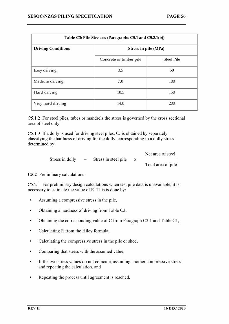
SESOC/NZGS PILING SPECIFICATION PAGE 56
REV H 16 DEC 2020
Table C3: Pile Stresses (Paragraphs C5.1 and C5.2.1(b))
Driving Conditions Stress in pile (MPa)
Concrete or timber pile Steel Pile
Easy driving 3.5 50
Medium driving 7.0 100
Hard driving 10.5 150
Very hard driving 14.0 200
For steel piles, tubes or mandrels the stress is governed by the cross sectional
area of steel only.
If a dolly is used for driving steel piles, Cc is obtained by separately
classifying the hardness of driving for the dolly, corresponding to a dolly stress
determined by:
Net area of steel
Stress in dolly = Stress in steel pile x
Total area of pile
C5.2 Preliminary calculations
For preliminary design calculations when test pile data is unavailable, it is
necessary to estimate the value of R. This is done by:
• Assuming a compressive stress in the pile,
• Obtaining a hardness of driving from Table C3,
• Obtaining the corresponding value of C from Paragraph C2.1 and Table C1,
• Calculating R from the Hiley formula,
• Calculating the compressive stress in the pile or shoe,
• Comparing that stress with the assumed value,
• If the two stress values do not coincide, assuming another compressive stress
and repeating the calculation, and
• Repeating the process until agreement is reached.

SESOC/NZGS PILING SPECIFICATION PAGE 57
REV H 16 DEC 2020
C5.3 Use of published data
Where available, tables, graphs and other information from relevant literature on use
of the Hiley formula, may be used to obtain data for calculating resistance for
various piles and driving conditions.
BEARING CAPACITY
C6.1 Test loadings
The Hiley formula, being an empirical design tool, has its accuracy improved
when adjusted with site-specific data. The ultimate axial compressive pile capacity
should be obtained whenever possible from test loadings. If a sufficient proportion of
piles are tested, the data obtained may be used for refining variables in the formula,
which can then be readily applied to the control of the remaining piles.
If load tests are not used, the ultimate driving resistance determined from the
formula should be used with a greater factor of safety than would be required for
accurate test results. The factor of safety should be further increased if re-driving
tests show a reduction in resistance.
C6.2 Factors of safety
The ultimate axial compressive pile capacity, determined either by test
loadings or as the ultimate driving resistance derived from the Hiley formula, shall
be divided by a factor of safety appropriate to the circumstances prevailing,
particularly the reliability of the available data and the consequences of failure of the
structure being considered.
Table C4 is a guide to suitable factors of safety for average conditions. These
should be increased where necessary to accommodate:
• a) Requirements for limiting total or differential settlement (e.g. in buildings
having fragile finishings or machinery that must be accurately aligned).
• Large impact loads.
• The expected reduced bearing capacity of a pile in a pile group where test
loads have been applied only to single piles.
• Any likely deterioration of soil or rock properties over time.
• The degree of confidence in the available data.
• A loading situation on friction piles where the live load is long term and a
major part of the total loads.

SESOC/NZGS PILING SPECIFICATION PAGE 58
REV H 16 DEC 2020
Factors of safety Table C4 may be reduced for temporary work and where
large settlements are permissible.
Table C4: Factors of safety for average conditions (Paragraphs C6.2.2 and
C6.2.3)
Factors of safety applied when
ultimate resistance determined
from:
Type of ground Test
loading
Formula only,
resistance not
reduced on re-
driving
Rock - 2.0
Non-cohesive soil 2.0 3.0
Hard cohesive soil 2.0 3.0
Soft cohesive soil 2.0 Not applicable
C6.3 Raked Piles
Where piles are driven with single-acting drop hammers in leader guides
inclined on an angle, the ultimate driving resistance calculated from the Hiley
formula should be reduced. Table C5 provides recommended percentages by which
calculated values for vertical piles, should be reduced to suit different rake angles.
Table C5: Reduction of calculated value of R for raked piles (see note 1)
(Paragraph C6.3.1)
Rake Percent to be
deducted
1 in 12 1.0
1 in 10 1.5
1 in 8 2.0
1 in 6 3.0
1 in 5 4.0
1 in 4 5.5
1 in 3 8.5
1 in 2 14.0
NOTE:
1. R is the ultimate driving resistance from the formula in Paragraph C1.1

SESOC/NZGS PILING SPECIFICATION PAGE 59
REV H 16 DEC 2020
FIELD MEASUREMENTS
C7.1 The recording of set (S), and temporary compressions of pile (Cp) and of the
ground (Cq) on site, can be done by:
a) Erecting a horizontal straight-edge close to the face of the pile.
b) Ensuring the straight edge supports are outside the zone of ground movement,
and no less than 1.2m from the pile under test.
c) Attaching a sheet of cardboard or heavy paper to the straightedge.
d) Holding a pencil horizontally on top of the straight-edge, and drawing it slowly
across the card while the pile is being driven.
Alternatively electronic set measurement equipment (e.g. Pile Driving Monitor) may
be used.
C7.2 The resulting graphical record will be as shown in Figure C1.
C7.3 If the record card is attached some distance below the pile top, the elastic
compression in the upper part of the pile (part of Cp) will not be shown on the graph.
That compression should be calculated from Table C1 and added to the sum of the
temporary compressions used to derive C, i.e. C = Cc + Cp + Cq + upper pile
compression.
S
Cp +Cq
Figure C1: Field measurement of temporary compression and set.

SESOC/NZGS PILING SPECIFICATION PAGE 60
REV H 16 DEC 2020
APPENDIX D: BASE TESTING WEIGHT EXAMPLES

Date
Drawn By
Date
Drawn By
Project: Drawing No.
Job No.
Description:Extra Heavy
Base Testing Weight
Project:
Description:
Std Base Testing Weight
Drawing No.
Job No.
HD20 Rebar 200mm Long
120dia 16mm thick base plate
16
200
Hook installed to fix tape
Loop installed to guide tape to centre
BASE TESTING WEIGHT = APPROX 1.5kg
HD25 Rebar 250mm Long
150dia 20mm thick base plate20
250
Hook installed to fix tape
Loop installed to guide tape to centre
BASE TESTING WEIGHT = APPROX 2.5kg
FOR USE ON DEEP, LARGE DIAMETER BENTONITE PILES.
andy.dodds
Text Box
BORED PILE
andy.dodds
Text Box
BORED PILE