Ground Treated with Granular Piles and its Response Under ...
60
Ground Treated with Granular Piles and its Response Under Load* by Gopal Ranjan** INTRODUCTION Practically all civil engineering construction is carried out on, in or with soil. The decreasing availability of good construction sites is building up pressure on the engineers to utilize even the poorest of sites either by providing special type of foundations or by improving the ground. Cost effective techniques to utilize the poor and marginal sites effectively have therefore become a subject of profound interest to geotechnical engineers. The weak subsoil deposits pose the problems of low bearing capacity and excessive settlements over long periods of time. The recently developed methods of ground improverment can be effectively utilized to force the soil to behave according to the project requirements rather than having to change the project to meet the limitations due to weak ground. The basic concepts of ground improvement, namely drainage, densification, cementation, reinforce- ment, drying and heating are age old and are valid even today. However, the advent of more effective and fast operating machines and decades of accumulated experience have combined to trigger rapid advancement in ground improvementtechniques. Better understanding of the response of improved ground has been the natural consequence. The scope of the theme is very wide and any attempt to cover it fully in the scope of a single lecture would diffuse the effort. The paper, therefore focusses attention on deep ground treatment methods, particularly in the context of developing countries. The various techniques of ground improvement have been briefly reviewed with emphasis laid primarily on the granular piles. Describing the simple labour oriented technique for installing granular piles, the response of treated ground under load is evaluated by reviewing critically the available approaches for estimating ultimate bearing capacity and settlement of composite (treated) ground. Design steps for granular piles for direct use by practicing engineers are highlighted. Futher, presenting the innovative concept of skirting, the utility of skirted granular piles for foundations under seismic loading condition has been demonstrated. The utility of the concept has been supported by a number of case records. GROUND IMPROVEMENT TECHNIQUES A variety of methods of ground improvement have been successfully applied in several cases. With the advent of new machines there have been significant changes in quality and productivity. Some of the techniques are well established being based on well developed theories whereas others continue to be empirical or semi- empirical in nature. Well documented state-of-the-art reports are available on currently used methods (Broms 1979, Mitchell1981) and also practices followed in different Asian and South-east Asian countries (Datye and Nagaraju 1985, Miki 1985, Qian 1985, Tan et al. 1985). The various techniques for deep ground treatment are : (i) Dynamic compaction (ii) Blasting (iii) Heating and Freezing (iv) Consolidation by preloading and or vertical drains (v) Electro-osmosis (vi) Lime piles (vii) Jet Grouting (viii) Granular piles/stone columns *Eleventh IGS Annual Lecture delivered on the occasion of 30th Annual General Session held at Allahabad. **Professor of Civil Engineering, University of Roorkee, Roorkee-247667, INDIA. 345
-
Upload
khangminh22 -
Category
Documents
-
view
0 -
download
0
Transcript of Ground Treated with Granular Piles and its Response Under ...

Ground Treated with Granular Piles and its Response Under Load*
by
Gopal Ranjan**
INTRODUCTION
Practically all civil engineering construction is carried out on, in or with soil. The decreasing availability of good construction sites is building up pressure on the engineers to utilize even the poorest of sites either by providing special type of foundations or by improving the ground. Cost effective techniques to utilize the poor and marginal sites effectively have therefore become a subject of profound interest to geotechnical engineers.
The weak subsoil deposits pose the problems of low bearing capacity and excessive settlements over long periods of time. The recently developed methods of ground improverment can be effectively utilized to force the soil to behave according to the project requirements rather than having to change the project to meet the limitations due to weak ground.
The basic concepts of ground improvement, namely drainage, densification, cementation, reinforcement, drying and heating are age old and are valid even today. However, the advent of more effective and fast operating machines and decades of accumulated experience have combined to trigger rapid advancement in ground improvementtechniques. Better understanding of the response of improved ground has been the natural consequence.
The scope of the theme is very wide and any attempt to cover it fully in the scope of a single lecture would diffuse the effort. The paper, therefore focusses attention on deep ground treatment methods, particularly in the context of developing countries. The various techniques of ground improvement have been briefly reviewed with emphasis laid primarily on the granular piles. Describing the simple labour oriented technique for installing granular piles, the response of treated ground under load is evaluated by reviewing critically the available approaches for estimating ultimate bearing capacity and settlement of composite (treated) ground. Design steps for granular piles for direct use by practicing engineers are highlighted. Futher, presenting the innovative concept of skirting, the utility of skirted granular piles for foundations under seismic loading condition has been demonstrated. The utility of the concept has been supported by a number of case records.
GROUND IMPROVEMENT TECHNIQUES
A variety of methods of ground improvement have been successfully applied in several cases. With the advent of new machines there have been significant changes in quality and productivity. Some of the techniques are well established being based on well developed theories whereas others continue to be empirical or semiempirical in nature. Well documented state-of-the-art reports are available on currently used methods (Broms 1979, Mitchell1981) and also practices followed in different Asian and South-east Asian countries (Datye and Nagaraju 1985, Miki 1985, Qian 1985, Tan et al. 1985).
The various techniques for deep ground treatment are :
(i) Dynamic compaction
(ii) Blasting
(iii) Heating and Freezing
(iv) Consolidation by preloading and or vertical drains
(v) Electro-osmosis
(vi) Lime piles
(vii) Jet Grouting
(viii) Granular piles/stone columns
*Eleventh IGS Annual Lecture delivered on the occasion of 30th Annual General Session held at Allahabad.
**Professor of Civil Engineering, University of Roorkee, Roorkee-247667, INDIA.
345

DYNAMIC COMPACTION
The methcrd, basically requires repeated dropping of a heavy weight on to the surface of the soil to compact and consolidate the weaker upper layers. Methods very from site to site according to soil strength profile within the required depth of treatment and to some extent on the nature of deposit.
The weights usually consist of toughened steel plates bolted tightly together. Before starting, a surface blanket of unsaturated granular material about 1 m thick or more is spread over the area to be tamped if this does not occur naturally. Its most important function is to act as a 'dolly' to lessen local impulsive shear stress and resulting surface failure to allow effective compaction, and in so doing it retains stability for tracked plant and lessen risk of flying stones or mud displaced by the energy of the weight (Greenwood and Kirsch, 1983).
The method has been used to stabilise soft clays, silts and organic soils when the organic' soil consolidates (Menard 1959, 1972, West and Solocombe 1976, Ramaswamy et al. 1980, Qian 1985). Several cases of applications both in cohesive and. noncohesive soils where heavy tamping has been successfully are reported by Menard and Braise (1975), Hansbo et. al. (1973). One of the major limitations of the method is that it is uneconmical when the area for treatment is less than 1500 sq.m. and further it calls for improving the bearing capacity of the area in order to support the heavy tamping machine (600-2000 kN) before stabilistion could begin. The effectiveness of the method in improving the load carrying capacity of soil at various sites have also been examined by Charles et al. (1981).
Versatility of this method lies in dropping of large weight from great heightto achieve a much deeper zone of influence to effectively meet the requirement of modern building foundations. Prior to 1970, heavy crawler cranes for use on construction sites were not generally capable of withstanding.continuously repeated stresses required to lift 150kN to 200 kN upto 20m-the typical ranges to achieve any useful results up to depths of about 1Om (Greenwood & Kirsch, 1983).
COMPACTION BY BLASTING
The philosophy of compaction of cohesion less deposits by blasting is that due to detonation of explosives, shock waves are generted in the medium resulting in the development ofthestate of liquefaction, followed by pore water escape and rearrangeme,.,t of grains in a denser packing. Mitchell (1981) reported that the success of the method depends on the ability ot the shock wave generated by blast to break down the initial structure and create a liquefaction condition for a sufficent period to enable particles to rearrange themselves in a denser packing. It is therefore, logical that the stronger the sand initially, the larger are the charges that will be required for effective densification. Thus, greater the depth to which densification is needed and higher the initial equivalent relative density, the greater the explosive energy that is required.
The blasting technique can be successful in cases where the soil consists of loose, water saturated sands (Hansbo, 1983). However, stabilisation of soft clays by blasting with the use of explosives has been used by Long and George (1967) and has been successfully tried in USSR (Mueller, 1971 ).
HEATING AND FREEZING
Heating and freezing of soils has also been used as a method of soil improvement (Litvinov, 1960). Heating of fine-grained soils to temperatures higher than 1 ooo C can cause drying and strength increase if subsequent wetting is prevented. Mitchell (1981) reported that heating of fine grained soils to temperatures in the range of 600° C to 1000° C can produce significant permanent property improvements, including decrease in water sensitivity, swelling and compressibility and increase in strength. Treatment at still higher temperatures may result in fusion of soil particles.
The soil is treated in-situ by burning gas or liquied under pressure in boreholes (Litvinov, 1960). The method has been used in USSR mainly in loess to reduce settlements and to increase the bearing capacity of buildings constructed on spread footings and rafts to prevent landslides and for the underpinning of existing structures.
Beles and Stanculescu (1954) observed that the liquid limit of a soil decreases drastically when the temperature approaches 400° C. Thermal stabilisation has been used in Rumania to stabilise embankments, deep cuts and slopes and to increase the bearing capacity of existing structures.
Artificial ground freezing can be effectively used for temporary ground support particularly in soft ground conditions and for excavations deeper than 7 to 8m and below the ground water table. Shuster (1972) presented
346

a practical overview of the method and specifies that the most critical aspects that must be considered to ensure safety and success in ground freezing are (a) accurate positioning of the freezing elements (b) ground water flow and quality (c) potential ground movements and pressures accompanying freezing and (d) long term strength and stress-strain properties of the frozen ground.
PRELOADING
Preloading of soft saturated clays, compressible silts, organic clays and peats is a simple age old and widely used method of soil improvement. The principle is simple. A fill is placed over the area to be improved with the weight of the fill corresponding to at least the weight of the future structure. The fill is removed when the consolidation is complete. Long time may be required for the consolidation, particularly if the thickness of the compressible soil is large. A surcharge load in combination with vertical drains can be used to reduce the time (Fig. 1). Details of treatment on methods of preloading, time required etc. are presented by Broms (1979), Mitchell (1981).
DRAINS
Fill
Berm ~----
..-' ~" /
- -- ----Vertical drains -. - - - - -.- .... ----- - ---
d -\. ·"·· ... v." ,·. "oC, ': •c:. • 0 0 . • . • • : • • • • • • • •• • •
-··· -•t 'Ill "• J',. ,• e ~·.v f - "- .... • 0 \I U .i - '"' ~ • (" ·~ ,J .Jj ' • 0 • •.., •
FIGURE 1 Vertical Drains with Preloading
Development of sand drain and using it as a method of stabilisation (Moran, 1926) was the first step towards improving the strength deformation behaviour of soft soils. The application of sand drains to live problems followed with a combination of preload has been highlighted by several investigators (Proctor 1936, Moran et al.1958, Casagrande and Poulos 1969, Nonveiller 1976, Chalmers and Harris 1981 ). Sand wicks (Dastidar et al. 1969) rope drains (Mohan et al., 1977) have also been used with preloadings, as these are not smeared easily as sand drains. Developments on the new types of drains such as card board drains (Fig. 2a) geo-drains (Fig. 2b), ali-drains and Colbond etc. and their application to live problems have also been identified (borns, 1979, Burke and Smucha, 1981 ). The geodrains and ali-drains both have a plastic core which is surrounded by a pervious paper which serves as a filter and prevents clogging of grooves or channels in the plastic cores. The width of the drains is 1 00 mm which is the same as those of card board wicks developed by Kjelmann (1948). These drains are used to reduce the consolidation time of soft clays. The main advantage associated with these drains is that the disturbance caused by installation is small as compared to the sand drains due to the small size of the drains and efficiency of the drain is not affected by large settfements. However, it is found that the effectiveness of 1 OOmm geodrain somewhat le~s than that of 1 60 mm sand drains (Errikson and Ekstrom, 1975). The main disadvantage with these drains is the durability of filter paper around the plastic core which mainly depends upon the bacteriological activity in the subsoil stratum and ground water level. The maximum life of the filter paper is from one to one and a half years under normal conditions (Hansbo and Thorstensson, 1977).
LIME PILES
In this method (Broms,1985) lime or cement columns with 0.5 m diameter and 15m maximum length are
347

Cross-section of mandrel
. . . .· .. .... . . . . . ... . .. . .. . . : . . . . . . . . .. . . . • ... - . . '
. . . . . . .. . . . . . . .. . . . . . . . . .
" . . . . . : : . .. . . .: . . . • • .,' • • •• • • ' ' • • • • •·•• I E . • E :: ~ • : • • • : ., • • • •' • • • , • • • • .. 3mm ......._ • E . .• ~
• • ~-...;":.._~------------ I I T""·- :.L .. · •. ·.:· c:r e1 c c c c c c c W c I -.-
• _.., • I •
: • • • 1'.·1!:::..==::;====~:-:-~1~0~0m~m~~~==::=:=~~=::~~!J .. · ... I,~ , • I 1 I I • I 11 I f 1 .. I I • I I " • • 11
I I :
I. • I • I '9 I I f t I I It I I I I It. I • e • I .. ·I I ..
I I ' '·I I I II I I ••• I •••• II I I I I - ••• . . . ·:· . .. · .. ··:··::, .. ' .. ·· .. -... _ ..... . . . .. ' . . . . . . ' . . . . . . . . . : ··." •' .......... ··. . • • .. • .. •• ,. • .. • • • • ••• f •
• • 4 • • • •• • • • • • • • • • • • • • . . . . . . ' . '. . . - .- . . ·: . . . FIGURE 2 (a) Cross-Section o Cardboard Drain and Insertion Mandrel
100mm
Cross-section of mandrel
FIGURE 2(b) Cross-Section of Plastic Geodrain and Insertion Mandrel
used which are manufactured in-situ by mixing the soft clay with quick lime (CaO) or with cement using a special tool.
Broms (1985) reported that the shear stregth of soft clay is increased when it is mixed with quick lime or cement. The strength increases in general with increasing lime content upto about 1 0 percent to 12 percent with respect to dry weight of soil. 12 percent is considered as the upper limit beyond which no increase in shear strength of clay or the bearing capacity of column is noted. With cement there is no such upper limit. In soft clays relative irJcrease of the order of 10-15 times the initial strength have been reported. Further, the relative increase decays in general with increasing liquid limit of clay. Lime is preferred when the plasticity index of clay is high while it is advantageous to use cement when the soil is sandy or silty and has a low plasticity index.
Lime columns have been used for stabilisation of bridge abutments, trenches (Broms, 1985), light structures (Helmet et al. 1981) for harbour construction (Fukuoka, 1977) and ground improvement for buildings, road project (Qian, 1985).
348

FIGURE 3 Vibroflot
349
Lifting pulley
Manifold section
Hydraulic hoses
Follower sections
Top jets
Vibration isolator
Vibrator section
Hydraulic motor
Water passage to nose cone
Eccentric
Fins to prevent twist
Nose cone

JET GROUTING
Use of jet grouting to augment the stability of deep excavations and tunnels in very soft clay deposits is becoming common, despite higher costs, because of higher degree of reliability. The method is,however mainly used to tackle special problems like underpinning of structures or when other less expensive ground improve.ment methods cannot be used. Also, in some cases, the disposal of the displaced soft material can cause problem (Broms,. 1987).
1 n this rnethod, jetting is accomplished through a pipe which is rotated in the bore hole as the pipe is slowly withdrawn. The high pressure jE.t (20 MPa) cuts an approximately 1.5 m to 2m diameter hole in the soft clay, which is eventually filled with cement slurry. The columns of cement mortar or soil-cement after the jet grouting can be used as foundation for str~cti.Jres, or as lateral support in deep excavation.
GRANULAR PILES/STONE COLUMNS
Granular piles also called stone columns, are becoming popular as technique of deep ground improvement not only in soft cohesive soils but also in loose cohesion less deposits (Rao and Bhandari, 1979). Most stone column installations ar.e made using the vibration technique through a vibroflot.wherein a cylindrical vertical hole is made by the vibroflot penetrating by jetting and under its own weight. In some cases a dry process without water jets is used. Gravel backfill is placed into the hole in increments and compacted by the probe which simultaneously displaces the material radially. Simpler techniques using the conventional boring equipment have also been developed (Ranjan and Rao, 1983). The details of installation techniques and perfomance of these granular piles are discussed in the following sections.
TRENDS IN INSTALLATION TECHNIQUES
Various techniques have been used the world over to install the granular piles. Some of these techniques have proved their applicability whereas others have yet to confirm so. Vibroflotation (Greenwood and Kirsch, 1984), rammed stone columns (Datye and Nagaraju, 1981) and simple boring technique (Ranjan and Rao, 1983) are some of these common techniques which have been briefly reviewed in the following section.
VIBROFLOTATION
Vibroflotation or vibrocompaction conceived in Germany in mid 1930's has been extensively used for major structures. The system is most versatiiP. with respect to range of soils to which it has been applied, through soft to firm clays, silts, sands and gravels to brick rubble and essentially inorganic rubbish (Greenwood and Kirsch; 1984).
VIBROFLOT
The basic tool used in the system is the poker vibrator or vibroflot with diameter ranging from 300 to 400 mm and about 2.0 to 3.0m long (Fig. 3) The vibroflot contains an eccentric weight mounted at the bottom on a vertical shaft directly linked to a motor in the body of the machine. The vibratory motion is thus horizontal with the body cycling around a vertical axis. Vibratory energy is applied directly to the ground through the tubular casing of the machine and output remains constant whatever be the depth of pentration.
The machine is suspended through a flexible vibration damping cennector to a follower tube about 300 mm diameter which provides extension pieces to allow deep penetration into the ground. This tube carries power lines and water pipes from the surface for jets in the nose cone and sides of the vibrator.
Vibration frequencies usually have been fixed arbitrarily at either 30 Hz or 50 Hz to suit electric power cycles. When hanging free amplitudes are generally between 5 to 10 mm (half total displacement range), but when the machine is working hard and restrained by the ground these are much less.
VIBRO-COMPACTION PROCESS
In the case of non-cohesive subsoil stratum vibroflot sinks in the ground under its own weight with the assistance of water and vibration. The length of the extension tube together with the vibrator and the lifting height of the crane is required to correspond with the total depth of penetration. After reaching the predetermined depth, the vibrator is then gradually withdrawn from the ground causing compaction. Three basic steps are involved in
350

Extension ubes
Choesionless soil
(a) Vibrator is lowered into the ground
(b) Vibrator is kept at desired depth for compaction
Supply of granular soil material
.... /Compacted ~ ... = .... ,r.:O~ zone :·-~·""'·· .:.: ··~~ ·~·· .• :··;.8, !~ .. =~· :. =.o: :b: i ....... l!~: .-:o_!
(c) Vibrator is withdrawn in stages and backtill material is added
FIGURE 4 The Vibro-Compaction Process (After Bauma.1 and Bauer, 1974) the construction (Fig. 4) (Engelhardt and Kirsch, 1977). The effectiveness of the compaction is dependent on the characteristics of the vibrator in terms of energy input, amplitude, frequency and its shape. In well graded sand even the most powerful vibrators available to-data require centre spacing of 3.0 to 3.5 min equilateral triangular grids to produce 65 to 70 per cent of relative density at the centroid between the three compaction points. But spacing close of 1.5m can produce a relative density of 90 per cent and more (D' Appolonia, 1953).
Sand Gravel Silt Clay
Q) c
60 c Q)
~ Q)
a..
20
4 10 20 40 60 100 140 200 (US Standard sieve size) particle size
FIGURE 5 Range of Soil Suitable for Treatment (After Baumann and Bauer, 1974)
351

During vibration the intergranular forces between the particles are nullified and particles are rearanged unconstrained, unstressed by gravitational forces to the densest possible state and the compressibility and void ratio decrease significantly (Thorburn and McVicar, 1968).
These tests suggest that for typical unit loads of 100-400 kN/m2 compaction spacing of 1.8m to 2.5m is appropriate. All these results are applicable to American/British type of vibroflot. The system of compacting loose sand by vibroflot is already known for its application and vibro replacement method (Watt. et al. 1967).
As a standard rule sand has to be clean for successful densification by vibration (Engelhardt and Krisch, 1977) .More than 20 per cent silt and/or clay in sand increases the binding forces between the particles to an extent where rearrangement of individual particles to a greater state of density is not any longer achievable by vibrocompaction. Range· of soils suitable for stabilisation by vibro-compaction method is shown in Fig.S.
VIBRO-REPLACEMENT PROCESS
While vibro compaction is a method to improve the density of cohesionless granular soils, vibroreplacement is used to improve cohesive soils with deep vibratory methods. The equipment used for this method is the same as that for vibro-compaction (Engelhardt and Kirsch 1977, Thorburn and McVicar 1 968). The vibroflot sinks rapidly under its own weight and assisted by water or air as a flushing medium into the ground until it reaches the predetermined depth. Without the jetting fluid the soil immediately around the vibroflot is disturbed or remoulded. It is, therefore, always preferable to use jetting fluid (water or compressed air) to remove softened material (Watt et al. 1967). Generally water is used in a fully saturated soil and air is used in a partially saturated soil (Engelhardt and Kirsch, 1977). In the case of natural or artificial cohesive soils, the stratum is completely unaffected by the induced vibration because the rearrangement of the partricles is prevented by cohesion between the particles (Thorburn and McVicar, 1968). When the vibroflot is withdrawn it leaves a borehole of greater diameter than the vibrator (Fig. 6). This borehole is filled partially with imported gravel usually well graded 12mm-75mm size. Also furnace slag has been used (Thorburn and McVicar, 1968). The vibroflot then repenetrates and displaces the back fill into the sides of the borehole in native soil and at the same time compacting underneath its tip. During the back filling the vibroflot is raised and lowered by 300mm. Thus each batch of granular material placed in the borehole is influenced by the weight of the machine and by a centrifugal force created by an eccentric vibration (Watt et al., 1967). Repetition of this procedure forms a cylindrical granular pile. Conical or straight sided dowel 300-500-mm diameter with lengths of 2 to Sm is vibrated and hole is made in soft cohesive soils (Broms, 1979), remaining procedure is same as discussed earlier.
Supply of "-==-~ granular ...
material
Cohesive or organic soil
(a) Bore hoi~ 1s termed by sinking vibrator into the ground
(b) Back fill material is placed into the bore hole in stages and compacted
Compacted column pile
(c) Alternate back filling and compaction forms continuous granular pile
FIGURE 6 The Vibro-replacement Process (After Baumann and Bauer, 1974)
352

The diameter of the granular pile usually depends on the strength of the native soil and sometimes on the equipment available. In very soft cohesive soil the back fill material is pushed laterally and forms a granular pile of a larger diameter (1.1 m) whereas in stiff cohesive soil a slightly smaller (600mm) pile results. Thus to a considerable extent the system is self compensating. Softer the soil, larger the pile diameter (Waston and Thorburn 1966, Engelhardt and Krisch 1977, Brems 1979). Thus the improvement in the strength of the cohesive soil is dependent on the formation of very dense granular pile of coarse fill material together with the improvement in the rate of dissipation of excess pore water pressure and radial drainage conditions (Thorburn and McVicar, 1968).
INFLUENCE ZONE
As the diameter of the vibroflot is generally between 300 and 500 mm, the granular piles constructed with eithervibroflotation process in non-cohesive soil orvibro-replacement method in clays, have diameters between 600 mm and 1100 mm depending upon the compressibility of the subsoil stratum.A large number of Dutch cone penetration tests on three sites in clayey, silty and wind-blown dune sand at various distances from the centre of the compaction points, were conducted (Webb, 1968) to measure influence zone. The maximum radius of influence ranged from 1300 mm for clayey sand to 1800 mm for dune sand. The respective cone resistances near the centre of the compaction point were of the order of 8.6 MN/m2 and 16.5 MN/m2 in comparison to 3.5 MN/m2
and 6.9 MN/m2 for untreated soil.
VIBRO-COMPOZER METHOD
Aboshi and Suematsu (1985) reported that the sand compaction pile method W·. s first announced by Murayama in 1957. The installation procedure followed in the compozer system is shown ~·"·hematically in Fig.7. A casing pipe is driven to the desired depth by a vibrator at the top. A sand charge is then introduced into the casing pipe which is withdrawn partway while compresed air is blown down inside the casing to hold the sand in place. The pipe is vibrated down to compact the sand pile and enlarge its diameter. The process is repeated till the pipe reaches the ground surface. Usually 600 mm to 800 mm diameter piles can be conveniently constructed. However, the actual diameter of the pile can be calculated from the depth of the pile and the actual volume of sand discharged into the ground.
Vibro
Hopper
Casing --pipe
Setting
.. .. .. ·.·.:.
Penetation
: ·. :. .. ., .. : . . · r
.. . ·. ..
·: ~
Forming the pile and compaction
·': .: ::: .•, . . . .
; .... • ..
. ... . .. . .•
FIGURE 7 Vibro-compozer Method (After Aboshi and Suematsu, 1985)
353

SOIL VIBRATORY STABILIZING METHOD
The method termed both the SVS method and the Toyomenka method combines both the vertical vibrations of vibratory driving hammer and the horizontal vibrations of a Vilot depth compactor. The Vilot is a special probe of about the same size as a vibroflot. Sand backfill is used but water is not used either during sinking or during compaction.
RAMMED STONE COLUMN
Datye and Nagaraju (1975) proposed a method for installing stone columns. The method primarily uses a hammer weighing 15 to 20 KN falling throuhg a height of 1 .0 to 1 .5 m. The stone aggregate placed in prebored holes is rammed by the hammer. This is claimed to be a low cost substitute for vibrator compaction. Later, Datye and Nagaraju (1981), classifying the boring method into non-displacement type and displacement type presented the method of advancing bore hole, placing of stone and sand ramming techniques along with their merits and limitations.
The method requires a heavy rammer with a large drop and as such requires suitable system to provide tamping, such as pile driver.
Nayak (1987) also described the method of installing stone columns by using normal piling rig with winch, bailer and casing. It has been suggested that in case, the length of stone column is less than 6 m, a single piece of casing is used for speedy construction. To accelerate the process of construction the use of preassembled cages, made out of bamboo, are also recommended for placement of granular pile. However, Nayak (1987) does not recommend the preassembled stone column in view of contamination of bentonit· slurry and granular fill and the limitation of granular pile diameter.
SIMPLE AUGER BORING METHOD
Most of the methods described above call for partial or full mechanisation requiring special equipment, trained personnel and are also time consuming. A simple method, particularly useful in developing countries, which is technically viable and uses indigenously developed equipment has been developed (Rao 1982, Ranjan and Rao 1983). A spiral auger is used to make the borehole utilising manual labour. After reaching the desired depth, the borehole is thoroughly cleaned manually by using specially made tools (Rao, 1982) having a thin plate welded to a mild steel rod. The plate is bent at 90° in the middle to enable collection of loose soil from the borehole bottom.
GL
(a) Making of bore hole
(b) Pouring of store aggragate and sand
(c) Compaction • (d) Pouring of of first layer material for
second layer
GL
diameter after installation
(e) Compaction of second layer
(f) Installed granular pile
FIGURE 8 Granular Pile Installation Method using Indigenous Knowhow (After Rao, 1982)
354

Following the completion of the borehole, granular piles are cast using 20-30 mm stone aggregates and 20-25 per cent of locally available sand with a uniformity coefficient of 2. The stone aggregate is placed in the borehole in layers of 300-500 mm followed by sand layer of 50-100 mm. A cast iron hammer weighing 125 kg and diameter less than the diameter of the borehole, operated by a power winch having a fall of 750 mm is used to compact the sand/stone aggregate layer. During the course of compaction (impact) by the hammer the sand fills the voids of the stone aggregates followed by the lateral and downward displacement of the charged material till full compaction is achieved. Thus the lateral displacement of the material helps in compaction of the surrounding soils. Various stages of installation proecedure of the granular pile are shown in Fig. 8. To ensure uniform compaction throughout the pile length, check tests by set measurements are carried out at different stages.
Munshi and Bhandari (1988) expressed the view that the pile installation technique is applicable to small building foundations only. Rao and Ranjan (1988) have indicated that partially penetrating granular piles (600 mm diameter, 15m deep) have been successfully installed using the technique for a 79 m diamter 13.5 high MCO tank on a soft clay deposit. The performance of the structure has been reported to be satisfactory.
RESPONSE OF TREATED GROUND UNDER LOAD
The satisfactory performance of any foundation is generally assessed by the two basic criteria namely, safety against the shear failure of the subsoil and settlement (both total and differential) which should be within limits. Accordingly, the response of the treated ground under load can best be assessed in terms of its bearing capacity and settlement (both total and differential). Further, if the improved ground behaves satisfactorily under dynamic loads it is an added advantage.
To provide a workable solution for a problem in geotechnical engineering recourse is always taken to analytical and or experimental techniques. Many a time,efforts are also made to provide semi-empirical approaches to provide a solution. The problem of treated ground is no exception. Efforts have been made by various investigators to assess the performance of treated ground through analytical and or experimental studies.
In the following sections, while presenting the efforts of various investigators to estimate the ultimate bearing capacity and settelment of treated ground, a comprehensive simplified procedure for estimating ultimate bearing capacity (Rao 1982; Ranjan and Rao, 1986) and settlement ( Rao 1982; Rao and Ranjan 1985) of composite ground reinforced with granular piles has been presented. '
PARAMETERS INFLUENCING PERFORMANCE
FAILURE MODE
The first and the foremost task in developing an expression for the bearing capacity of the treated ground is the postulation of the failure mode of the granular piles under the applied load when it attains its ultimate value. Current state-of-the-art reveals different modes of failures for a single granular pile contained in a weak subsoil deposit. These can be classed in four different categories (Table 1 ).
Unlike a R.C.C. pile which is rigid and consequently undergoes practically no lateral displacement, a
Mode of failure
No lateral strain
Significant lateral strain Bulging failure mode
General shear failure modeplane strain condition
Sliding failure mode
TABLE.1
MODES OF FAILURE
Examples
Concrete piles
Weak soil reinforced with granular piles
References
Madhav and Vitkar (1978)
Hughes and Withers(1974),Rao and Bhandari (1979), Datye and Nagaraju (1981), Rao (1982), Ranjan and Rao (1983, 1986,1987, 1988)
Strip footing resting on granular trench Greenwood (1970), Madhav or "two dimensional plastic failure case and Vitkar (1987)
Embankment resting on composite ground
355
Aboshi (1970).
G.L.
/·.; • ~., .. 1. I A.·.· ..... A, I ~',:·:::
1
~ ~~-~· :~ : :. ,
-······.' •· .. ····· ... •t. ' ' . · t':. •'· ·6 .. A· · ~ , ... . , .• -... ,.'. • , ~. ' • I . • ....... I : ... ~ I.. • • • ,
.···.~ :·· .... , ·"-···'·" • • • •I . •. • 4, I ·r ~ '
-I • • • 'f . . . . • ".... .... . . I "I • •••• • • • I .~ • A · ; I ,;•: _.' Cnt1ca p1 e ... • " • .. • 41 · · · : . : · 'A 1 " · • length (L ) . • : .· · .. ,. 4 .. ~. c ,,•:• AI •. "'•A .•• ·••• ., ........ .
orl~; .:: ~,' :. t A!:·.~.:.;. ~~·.a._ 1 ·~:· :·::·: ...... ~.: __ ....,, • ~ t;-. · ·• _ ;, ·. I _ ··:. ~ .·· • • • .. • • • I . •A . . •• L •
. ••• • .-..· o.,:: ..... -·.·.t .·:···_<."Jf .. ,.-.' ·~ ·•· ··4· 1 · .. ~ ·. ·.·• .• ·., : '. •'• I, .. ·· ... ··."· ! 4 ., .· ~ ~ · . ,. , • : I ··A::· ', · · I ·.·. · ': ·: :', ·: .
• • •.• • ,. • .. A . .. ... ·- • • •. ·' • ' .. ' . • •.... •4 ·. · .. • ... · ... · ..... \''. . . . . . . :. 4 . .·... . . ~ _.;;y....-
...... # ••••• • : • ·:
Weak clay •• • : ,f : . Weak clay A· . .. .• ·.: ·.· ~· ·:-.t •· ... :.·::.·~ ..
"'' •'•' •' .. , • • • A A.. .• • • . f~ ': "· •• •. : '· • .. .. . ,·· .·: • ~. • ..... • ·;, .: ....... · .. .c.:' . . ·14 4 ..... -,.,:.,t.·.:·.:.·. '• • •• • '' • . A ... • •• • •. .
·.::·:----. .:.~"!'~· ...... ••• •• ~ . . . . ........ . 4 . . .. . .... .,. · .. :·. t •••• . ,·· .••..... ! . : .. .. • . . .. :. ... J ••• ·' '.
•• • : '.• : .. • ,4 • • . • _ .,··.I::~ ":.f ', ; .• • ...... • .• · .. .. . 4 . . .,~·.. ... : ·= ·. ~· .. ·· :' .. ,.··~: ~·· .• ..... ~4!? . .... .. .. · ... ' .. ;- '-I\ _1 •: :• : 6 •. •
' '• ,.' t ""•' , I .,. • • : •
.. : ............. d ... :. . . ... ; ·.. . . .. : . Granular • :·· ·4: .".: · ~ pile of .:. •... • :. ·: ~ ~ .:-,..
. d • , • .,. 4 .. · .. ""'=' d1a . •••• • .• 0 ...
:·.::: :···~: •... ,. 4' ·.:·-~ .:-:.-.: ·•.:· . .~ ~ ... ::~ .. •. ··.. . .. c~· · ... . .. . \ ·t··· ..... ~
.:-;.. ·:.9
- -. • •• f ; t t , :;..-;;. ... -:· ..... '··" , .... (;'t' ·'· ... .., . __ ,. ~ .,,, ...... --'~·:; ·~··.z· .. -:. .- ·••• .... -.-- ....
FIGURE 9 Single Granular Pile-Bulging Failure Mode (After Rao, 1982)
'
granular pile is not rigid and accordingly such a behaviour cannot be anticipated. Bulging failure mode (Fig. 9) i~ observed in granular piles in soft clays. On the basis of the observed deformed shape of the granular pile (Fig. 1 0) in model test (Hughes and Withers. 1974) and also .in case of an insitu pile excavated after test (Fig.11 ), Hughes et al. (1975) suggest that the failure shape in the upper part is like a bucket resting on a cylindrical stem through lower level. The deformed shape of the piles in the laboratory and field were found to be geometrically similar. Thus, when a single granular pile is subjected to sustained vertical load on pile top, it fails by bulging. The length of the bulge is limited to 4-5 pile diameters (fermed critical pile length).
In the case of a footing on granular trench, which may be considered as a two dimensional version of a granular pile, Madhav and Vitkar {1978) considered a general shear failure mechanism (Fig.12) and presented solutions for ultimate bearingcapacity. Thus it may be considered as a special case.
Further, in the calculation of failure of embankment of granular pile treated ground (Fig. 13) ,Aboshi (1979) assumed a sliding mode. At the shearing phase at a depth Z, both the granular pile and the surrounding clay are assumed to exhibit their strength against the vertical load. This type of failure mode can be considered to be applicable in the case of embankments (Fig.13) ,for granular piles in soft clays under vertical load, bulging failure mode is more realistic. Such a failure has also been confirmed by laboratory studies (Hughes and Withers 197 4, Mokashi et al. 1976) and in-situ test on full scale piles (Hughes and Withers 1974; Rao 1982; Ranjan and Rao 1986).
356

0
0
0
0
0
0
0
limit of one percent strain in clay Movement of
lead shot markers \
FIOiURE 10 Deformed Shape of a Laboratory Model Pile (After Hughes and Withers, 1974)
0 uornm 0 50()m_m
Ol----.......
0.5 Estimated initial dia
E .r:. a Q)
0 W.T.
1.0
1.5
FIGURE 11 Deformed Shape of an lnsitu Pile After Excavation (After Hughes, Withers and Greenwood, 1975)
CRITICAL PILE LENGTH
F<;>r piles in cohesive soils (Hughes and Withers, 1974) developed a relation between vertical stress o. and length to diameter ratio, (LID) of the pile. At bulging failure, the vertical stress ov atthe top decreases with dept~ and reaches a zero value at some depth. Further, beyond a certain depth (l/0=4.1) ,there is no increase in the pile capacity. Hughes and Withers (1974) reported that if the depth is reduced, the pile will aetas an end bearing
357

GL
··~·· ·~·· :;;, · ... ·~.: · ....... . · .•... :·. ••' ,A. •:r. .. ·.:.··A·: • &•. , ..... .. ·.·.· .. . . .. . .... ... . . a•.:• :, .. o:. . .. . ...... .. · ...
···: ··:: ·. •.·
G.L.
Granular pile
FIGURE 12 General Shear Failure Mode (After Madhav and Vitkar, 1978)
0
oz~ z
FIGURE 13 Circular Sliding Surface Method including Granular Piles (After Aboshi, 1979)'
pile. If the length is so short that the stresses at the base exceed the bearing capacity of the clay,Gcu the end bearing failure will occur.
Hughes (1975) proposed a simple method to estimate the critical length of pile under bulging mode of failure by assuming that the vertical shear stress developed along the pile surface-clay interface is equal to average shear strength of clay when end bearing failure is likely to occure. Thus critical pile length can be evaluated by equating the ultimate pile load to the sum of the shaft resistance and bearing forces.
Williams(1969) reported that the pile under a typical loading condition shall be weakest at a depth equal • to 1 .9 to 2.33 times the diameter in weak clay deposit under triaxial stresses with equal all round stress.
358

Spacing of granular pile, m
pry method clay strength 40 KN/m2 (0.4kg/cm2
)
Clay strength
40 KN m2 (0.2 kg/cm2l
20 KN m2 (0.2 kg/cm2)
Curves neglect immediate settlement and shear displacement
Piles assumed resting on firm clay sand or harder ground
FIGURE 14 Spacing of Granular Pile and Settlement of Treated Ground in
Uniform Soft Clay (After Greenwood, 1970)
T s
l f s j_
+-- s
1/2
[ (1+ei) ]
S= ~ei-e d
(a) Square arrangement (b) Regular triangular arrangement
FIGURE 15 Spacing between Granular Piles
In the model study, Mokashi et al.(1976) observed 2.85 times the pile diameter as the critical pile length. Beyond this depth the pile was not found to be stressed. In the case of 250 mm diameter granular piles installed in silty sand deposit Rao (1982) observed a critical pile length of 1020 mm and thus reported that the depth of bulging extends to about 4-5 times the pile diameter.
PILE DIAMETER
Installation of granular piles using vibroflot either by vibroflotationtechnique in cohesion less soils or vibroreplacement method in cohesive soils (Greenwood, 1970) is an established method of granular pile construction (Boer and Greenwood, 1967). The variation in pile diameter installed by vibroflot (diameter 300 to 500mm) varies between 0.6 m (stiff clays) and 1.1 m (very soft cohesive soils) .With the same diameter of the vibroflot.
359

. ®
I I
I ~
de
I I
ek. w de= 1.055
s
.
•I ® ,
:::....
s
I "'<
~ Granular pile
~
FIGURE 16 Triangular Pattern of Granular Piles used for Finite Element Analysis (After Balsam et al. 1977)
Floss(1979) has reported pile diameter from 750 tq 1050 mm. Thus if the soil layer is softer, the diameter of the installed pile is larger (Watson and Thorburn 1966; Engelhardt and Kirsch 1977).
Datye and Nagaraju (1981) have reported construction of stone columns ranging from 400 to 750 mm using rammed process. They have not given any range of pile diameters that could be constructed by the technique. However, they have recommended that the cross-sectional area of the stone column for the purpose of analysis and interpretation is derived from the compacted volume of the stone.
Using the simple boring equipment and the light hammer, (Rao 1982; Ranjan and Rao 1986) reported granular pile constructon in various types of soils ranging from loose silty sand to clay of low compressibility with diameters ranging from 250 mm to 600 mm. Rao(1982) reported that using the technique the installed granular pile diameter was about 20-25 percent more than the initial diameter of the borehole. Further,it is recommended that to have a uniform compaction all through the length of the pile, check tests by set measurements be carried out during different stages of construction.
PILE SPACING
Piles installed through vibroflotation process, vary in diameter from 0.6 to 1.1 m dependeing upon the relative density of a cohesionless soil deposit and consistency of cohesive deposit. These piles have been used in the past at a spacing of 1.65 to 2. 73 times the pile diameter(Watt, Boer and Greenwood 1976; Engelhardt and Kirsch, 1979). The spacing of granular piles is generally determined by settlement tolerahces for the loads to be applied and to provide overlapping zones to cover a wide area of ground (Greenwood, 1970). Pile spacing is also dependent on the degree of improvement required for providing a satisfactory foundation under the applied design load (Engelhardt and Kirsch, 1977). The settlement ratio of the reinforced ground and unreinforced ground is a function of pile spacing (Fig.14) and method of pile installation. Mitchell (1981) reported that if it is desired to increase the average density of loose sand from an initial void ratio e; to a void ratio e, and if it is assumed that the installation of a sard pile causes compaction only in a lateral direction, the pile spacings may be determined using ·
1
S = [ ;r (~ + ei) ]2 d ei - e
. (1)
360

for sand piles in a square pattern (Fig. 15 a) and
1
s = 1. 08 [ JT ~~ + eei) r d ... (2)
for piles in a triangular pattern(Fig.15b), in which dis the diameter of the sand pile (diameter up to 800 mm). Salaam et al. (1977), considering the triangular pattern of granular piles (Fig.16) have indicated on the basis of finite element anafysis that significant reduction in settlement occurs only when the granular piles are closedly spaced (S s 5d), and piles are installed to the full depth of the consolidating layer. It has further been indicated that too close a spacing (S/d s 2) may not be feasible from construction point of view and if the pile spacing is kept at S/d more than 4, the overall desired reduction in settlement may not be possible. Thus a pile spacing (S/ d) between 2.5 and 4 may be adopted with reasonable accuracy. Also it has been recognised in practice that closer spacings are preferred under isolated footings than beneath large rafts (Greenwood, 1970).
SKIRTING OF GRANULAR PILES
As indicated earlier (section 4.1.1 ), the depth of bulging in a granular pile subjected to sustained vertical load on pile top is limited to five times the pile diameters. When granular piles are used in a group under a raft or an embankment the peripheral piles will have reduced load bearing capacity due to abrupt disappearance of design load surchage and absence of neighbourhood piles (Greenwood, 1970). To check the bulging of the piles, replacing the bulged portion of the pile by concrete piles or injection of cement grout in the upper portion is considered a suitable solution (Engelhardt and Kirsch 1977; Floss 1979). These prepositions may be useful in preventing the bulging of piles but are uneconomical and difficult to execute.
To increase the passive restraint on the peripheral piles in a granular pile group and consequently the load bearing capacity, provision of all round surcharge has also been suggested. Model studies on these aspect do confirm the increase in bearing capacity and reduction in settlement (Mokashi et al. 1976). The efficacy of counter-weighing in resisting the settlement due to lateral flow of the soft cohesive subsoil is demonstrated in the settlement pattern obtained during tank loading (Penman, 1977). However, the solution is likely to affect the functional requirer:nents of the structure besides being uneconomical. The above problem could be conveniently and economically handled by providing a collective rigid skirting around the pile group (Rao 1982, Ranjan and Rao, 1986).
Skirted granular pile foundation consists of a cast in-situ concrete footing placed on a soil plug. The soil plug in turn is reinforced by granular piles which is subsequently confined by a rigid wall called 'skirt' (Fig.17). The footing edge and the concrete skirt interface is provided with a clear gap of 12-25 mm to enable the footing to settle under load independently inside the skirt.
G.L.
Skirt
. ,: . " .·· . . ·•. . BDETN. lJN-g-' • :· J ... ~ ..
FIGURE 17 Skirted Granular Pile Foundation (After Ranjan and Rao, 1986)
361

1968 70 72 74 76 78 80 82 84 86 1988 I I I I I I I I I I I
•Greenwood
Analytical
• Datye & Nagaraju • Hughes & Withers •Rao
• Salaam & Poulos • Madha& Vitkar
• Datye & Nagaraju
•Priebe • Goughnour et al
• Ranjan & Rao
Thaarburn & McVicar • Smoltzyk • Tharburn
Empirical • . • Mari Hughes & Wither
• Greenwood • Hughes, Withers & Greenwood
• Mokashi et al
Experiment
• Rao & Bhandari • Goughnour & Bayok
• Datye & Nagaraju •Greenwood
• Rao • Ranjan & Rao
FIGURE 18 Main studies on Ultimate Bearing Capacity of GranuLar Piles/Stone Columns.
ULTIMATE BEARING CAPACITY
A realistic assessment of the ultimate bearing capacity of the supporting soil is of paramount importance for safe and economic design of the foundation. During the last three decades or more, efforts have been made by investigators all over the world to provide a solution to the problem of ultimate bearing capacity through experimental and analytical techniques (Fig.18). The various approaches available could be grouped into the following categories :
(a) Passive pressure or plastic failure approach
(b) General shear failure approach
(c) Lateral limit-stress approach or
pressuremeter theory
(d) Unit-cell approach
(e) Cavity expansion approach
(f) Empirical approaches
(g) Experimental approaches
Greenwood(1970)
Madhav and Vitkar(1978)
Gibson and Anderson ( 1 961 ) , Hughes and Withers
(1974), Hughes et a1.(1975), Mori(1979),Aboshi(1979)
Priebe (1976) ,Datye and Nagaraju (1975), Goughnour and Bayuku (1979)
Rao (1982), Ranjan and Rao(1983, 1986, 1987) ,Datye
and Nagaraju (1981)
Thorburn and McVicar (1968), Greenwood (1970),
Thorburn (1975), Smoltzyk (1979)
Hughes et al. (1975), Rao and Bhandari (1979)
These approaches have briefly been discussed in the following sections.
PASSIVE PRESSURE APPROACH
In the passive pressure approach, the load applied through a strip footing (Fig.19) on a granular pile top tends to concentrate on the granular pile which is the stronger material of the composite foundation soil. The pile material dilates and exerts lateral stresses on the surrounding clay which are resisted by the passive earth pressure (Greenwood, 1970). Conventional theory of passive pressures implies an increase of pressure with depth. There will be a zone of no significant deformation within the pile (Fig.19) under the rigid concrete footirig. It was the belief that the ultimate bearing capacity of~ single granular pile is equal to the ultimate lateral strength of the soil surrounding the pile (Hughes and Withers, 197 4). Thus, the ultimate bearing capacity of a g~anular pile is given by equation 3 (Greenwood, 1970), as a two dimensional plastic failure case
quh = PP =- Y Z KP + 2cu ..JK; .... (3)
362

Soft clay
w
t
Not subjected to significant --t=::et~~ deformation !
FIGURE 19 Granular Pile under Strip Footing
(After Greenwood, 1970).
Firm clay
Earth fill
~ F";;-d7ai-;;Tng blanket
A I· ·I· ·I
FIGURE 20 Granular Piles under Wide-Spread Load (After Greenwood, 1970)
G.L.
G.L.
E
(a) Failure mechanism for A/B/<1
(b) Failure mechanism A/8>1
G.L.
FIGURE 21 Failure Mechanism (After Madhav and Vitkar, 1978)
363

Where qutt is the ultimate load bearing capacity of the granular pile, y the bulk density of clay, Z the total depth of the limit of bulge of the pile and K is the coefficient of passive earth pressure.
p -
The total depth of bulge Z is equal to the depth of the footing ffom the ground _level plus the deptn uf the bulge of the pile which is the cr~ical pile length (Fig.19). In case of a day of essentially uniform strength, the passive restraint just below the dotted line (Fig.19), the granular pile will be the weakest where the lateral support is the least which is about 1. 75 m to 2 m below ground level (Greenwood, 1970). This critical length is found to be equal to 2 times the pile diameter (Williams, 1969) as reported by Greenwood (19iO). However, in the case of bulging failure mode in clay, the critical length is found to be 4 times the pile diameter (Hughes and Withers, 1 ~7 4). equation 3 as proposed by Greenwood (1970) gives the all round passive pressure which is taken as equal to ultimate bearing capacity of the pile. This· is a conservative estimate of the granular pile capacity. The lateral passive restraint on the pile away from the edge of loaded area under the wide spread footing is much larger due to the equal all rouod pressure influence due to surcharge load. Generally the effect of surcharge load, q, to the restraining pressure is much larger than the strength of the surrounding soil and its density. Thus the total carrying capacity of the granular pile increases until the local shear failure in clay(due to contact stresses with the individual pite material back fill particles) or the end bearing failure of the pile whichever occurs earlier. It is determined by the strength of the surrounding soil, Fig. 19 (Greenwood, 1970). The ultimate bearing capacity of the pile, qu1,
depends on its diameter and is giveQ by equation 4
quH = qy Z KP + 2cu ..JK; + qKP ..... (4)
Thus the total pile capacity,QP is given by equation 5
Qp = quit' Ap • .... (5)
Where A is the cross-sectional area of granular pile and q the surcharge load per unit area. p
It has also been demonstrated that the pile near the edge of the loaded area (indicated by dotted lines in Fig. 20) will not have the same bearing capacity as those under the centre. This is not critical under the embankment loading where gradual decrease of loading occurs; however, it becomes critical when the load terminates abruptly. Granular piles near the edge, therefore, must be spaced closely than in the centre and should not carry more loads than those for isolated footings.
GENERAL SHEAR FAILURE APPROACH
Madhav and Vitkar (1979) stipulated the plane strain version of a granular pile as a granular trench and postulated the failure mechanism (Fig.21). Utilising the limit analysis approach, an analytical solution has been developed.
Using the Lipper bound theorem, the work equation is formed by equating the external rate of work done due to (a) external applied load (b) soil weight and (c) soil surcharge, to the internal energy dissipated in the plastically determined region, for which Coulomb's yield criterion _is valid. The approach for the analysis follows closely Chen's (1975) theory.
The general shear failure mechanism is postulated for two cases (a) A/8 s 1 and (b) A/8 2: 1 (Fig.21 ), where A is the trench width and 8 is the width of the strip footing resting on soil trench system with the found at ion at a depth Dt,. The mechanism under consideration is 'Prandtl Mechanism' for homogeneous soils consisting of different zories such as Fig.21 a. The different zones are:
(a) an active Rankine zone AGCwith weqge angles and
(b) a mixed transition zone GCDwith central angle 8, bounded by log spiral based on frictional angle, ct>, of the trench material.
(c) a transition zone GDEwith a central angle 82
bounded by log spiral based on friction angle q>2
of the weak clay.
(d) a passive Rankine Zone GEFwith wedge angle 11
The wedge AGC of active Rankine zone moves vertically down as a rigid body with the same initial velocity V F of the footing. The downward movement of the footing and wedge AGC is accomodated by the lateral movement of the adjacent soil. The central angles 8, and 8
2 of the transition zone depend upon the wedge angles
s and YJ, the ratio A/8 and the angle of internal friction ct>, of the trench material. The properties of the granular trenc~material considered are cohesion, c,, angle of internal friction oftrench material, <1>, and density of trenching
364

46r-r-~~~~,-~~ 40
20
28
0.4 0.8 1.2 1.6 2.0
10 ~~§:::~!=:~ s.__....._"--"---'--...&.--'-;;;;.;;..-'--'-..J
0 0.4 0.8 1.2 1.6 2.0
16
AlB AlB
(a) (b)
N,
A/8 AlB
- ~ ~ FIGURE 22 Bearing Capacity Factors :(a) and (b) Nc, (c) N, and (d) Nq
(After Madhav and Vitkar, 1978) materal,y,. Cohesion c, of the trench material could be zero. However, the theory is developed for the most general case of c- q, -y soil. The properties of natural soil are cohesion c
2, angle of internal friction cp
2 and density
y2.
From the geometry of the failure surfaces, the lengths and velocities at various discontinuities are found.
The rate at which the work is done by soil weight is found by multiplying the area of each rigid body by y times the vertical component of the velocity of the rigid body. The velocity component of the zones AGC, GCD, GDE and GEF are considered to act in the same direction at that of the force V F' while that of surcharge in the opposite direction. This convention is based on whether the work is done against V ~or in the same direction as that of V F"
The work equation is formulated by equating total rate at which the work is done by (a) eXternal load on the foundation (b) soil weight in motion and (c) the surcharge to total rate of energy dissipation along the lines of discontinuiti~s. Equating work done by the external load quit' to the energies dissipated by cohesion arid work done on account of soil weight and surcharge, equation (6) is obtained
quH = c2NC + (y2 B I 2) NY + y2 D, Nq ... (6)
where Nc = [ ~: l Nc1 + Nc2 .. (6a)
and NY l ~: l Ny1 + Ny2 .. (6b)
=
365

qP q- applied load
~q. -- ·-- .·· .....
- f- _: =-: .":-:.:. ; = ....... . -- ... -- :. --:-o, .:... -- ~~- -:_ :- ::· ~ ::::_
.· - 0 - •• --.. .
. -- ·. - - -~ - - ·. -- .. - - ·. - - 1: - - • -- .. - .. - ·. - ."·""-._--. -~ - :: - _ .:. -'!:·~ :::::- Granular pile
~ Softsoil
unit cell A
Granular pile (rigid plastic
ncompressible) 0 0 0
. 0 0 0 0 0 0 Soft soil
(elastic)
(a)
o' r
(b)
FIGURE 23(a) Stress Concentration Ratio n, and Replacement Factor, (b) Effective Stress Path in a Unit Cell Assumed by Goughnour et al (1978)
q p
5
' E /E =10 E. rn l~gs3) ---£. .!--- ---
f.E eala~ --"'- ------------ '
-
.........._ Pribe (1976, --- ~ -
Goughnour
values of a in practice
Prebe (1976)
FIGURE 24 Unit Cell Concept-Comparision between Different Modes and Finite Element Analysis (After Schlolsser and Juran, (1983)
366

Nc1
, Nc2
, N11
, N12
and Nq are dimensionless factors, depending upon the preperties of trench, soil material and ratio of {AlB).
To obtain the minimum value of the ultimate bearing capacity of the strip footing the factors are minimized. The bearing capacity factors, Nc, N , and N have been evaluated for a wide range and are given in the form of curves{Fig.22) for convenience in u~e. Whe~ c
1 = c
2 and<j>
1 = cp
2, the soil-trench system reduces to a homogeneous
medium and the values of the bearing capacity factors are similar to those of Chen (1975). For an axisymmetric case, that is a grariL;~Iar pile in soft soil, equations are modified by incorporating shape factors for the three bearing capacity factors as suggested by Vesic (1975). Nc values vary significantly with the ratio (AlB), cp
1 and the ratio
{c/c2). When {AlB= 0), the problem reduces to the homogeneous case with soft soil having <j>2 = 0, and Nc value is 5.14 {same as the Prandtl value). The rate of increase in Nc values is higher for (AlB) ratio in the range of 0-1 than in the range of 1-2. This rate depends upon the ratio of (cJcJ For (A!B)-oc,Nc value should coincide with Prandtl values corresponding to cp
1• As in the homogeneous case, Nc values increase with increase in <1>, values.
For intermediate ratio of (cJc2), the Nc values can be interpolated. The values of NY also increase with (AlB) and
cjl1
values {Fig.22). The increases are significant because more and more trench material will be contributing to the work done by the soil weight as the ratio (AlB) increases. However, it may be noted that N values increase by only 10 percent as (Y/Y) increases from 1.0 to 1.5. The trend in variation of NY is similar to th~se of Nc and Nq.
LATERAL LIMIT STRESS (PRESSUREMETER) APPROACH
I nth is approach, the granular pile is considered as a single incompressible. rigid plastic column contained in a semi-infinite, rigid plastic soft soil (Schlosser and Juran, 1983).
The available lateral limit stress, u, is found from triaxial compression test (equation 7a) or from a pressuremeter test (equation 7b)
o = 2c + o ... (7a) y u s
or uY = p1 .. (7b)
Where u. is the normal stress and p, is the lateral limit stress in a pressuremeter. Schlosser and Juran (1983) have further pointed out that the lateral limit stress approach does not consider the effect of pile group, which clearly indicates that contribution of the soil surrounding the pile is not visualised. The lateral limit stress P, (= o,L) has been estimated by various investigators by different techniques. These are briefly presented below.
(A) PRESSUREMETER THEORY
(i) For c-q, soils The fictitious case of expansion of the cavity from a zero initial radius was first demonstrated by Bishop.
Hill and Mott (1945). But Ladanyi (1961) was responsible for developing it to its full potential. Baguelin, Jezequel and Shield (1978) proposed the relationship between limit pressure o,L and shear strength parameters c and c11
based on elasto-palstic models (equation 8a & 8b)
+ ccot<jl) {1 - sin<jl) (-1-) {
1 - Ka }
2aF) 2 c cot~ ... (Sa)
and for purely cohesive soils
= + + Ln -1-)
2 aF. ..(8b)
Where o,L is the theoretical limit pressure at finite expansion of the cavity, oha is the total initial ground stress and n.F is the ALMANSI STRAIN at failure.
The ALMANSI strain is directly proportional to the change in volume, t..v such that
a = ..!_ [ V - V0 ] = ..!_ fl. V F 2 V 2 V .... (9)
Where V0
=initial volume and V =volume in deformed state so that f..v is the change in volume.
(ii) For freely draining soils There is no theoretical approach at presentto relate limit pressure t l,L and effective angle of internal friction
367

<j>' in case of free draining soils: However, empirical relationship between limit pressure oTand <j>' for sands have been proposed.
= 2.5 X (2) ... (1 0)
Where o,L is expressed in kN/m2. The relationship expressed by equation (1 0) is quoted by Muller (1970)
as:
Where b = 1.8 for homogeneous wet soils
= 3.5 for dry heterogenous soils
= 2.5 (average)
... (11)
The results of 13 pressuremeter tests in free draining soils reveal that the values of laterallimit'stress, o,L computed from equation (1 0) are closer to the independently measured values (Winter and Rodriguez 1975, according to Vesic 1972).
(iii) For cohesive soils The method of using the limit pressure n,L for estimating undrained shear strength cu from pressureme
ter has received much attention in recent· past. The popular theoretical relationships with different volume change properties available are:
Bishop, Hill and Matt (1945)
u = cu [1 + Ln { Es }] rl 2{1 + ,11} Cu
.. (12)
Gibson and Anderson (1961), after incorporating the effect of total initial lateral stress, nho in an elasto plastic material, based on insitu measurement of limit pressure, o,L from pressure meter modified the Bishop Hill and Matt (1945) equation in the form
= [ l E )] + cu 1 + Ln s 2 cu { 1 + ~l}
or = uho + kcu
Hill (1966)
o,, = c" [ 1 + l c" { 5 E: 4 ~·} ) l Salencon (1966)
ll rl = C [ 1 + Ln J Es ) ] u l 4 cu { 1 - ~l 2 }
.. (13)
... (14)
.. (15)
... (16)
Where o L =limit pressure in a pressuremeter, E =the elastic soil modulus, c =undrained shear strength r s u
of the clay deposit and 1-.1. = Poisson's ratio
If 1-.1. =0.5, all the above equations reduce to
u,L = Cu lr 1 ln{S_}] 3cu
Equation 17 is rewritten as
Where k = 1 + Ln Js_} 13cu
368
... (17)
.. (18)
.... (19)

Typical values of the ratios (EJc) range between 5.2 and 7.5. The theoretical values of k would be increased by {1 /3) if the pressuremeter tube is too short and a spherical cavity is expanded in the ground instead of cylindrical cavity (Bishop et al. 1945). Also higher values sof E. will lead to much higher values of k. It has been concluded that none of the three variables (o,L'k and c) that make up equation 18 and 19 can be estimated precisely (Baguelin, Jezequel and Shields, 1978). However Cassan (1972) has recommended k equal to 5.5 for low values for u,L and also according to Amar and Jezequel (1972) the limit pressure o,L less than 3kg/cm2 (300 K Pa).For the intermediate range of u,L (Limit pressure) the value of k is proposed as 8 and for high limit pressure this value is increased to 15(Cassan, 1972).
Amar and Jezequel (1972) suggest instead an equation relating limit pressure u,L and undrained shear strength cu:
c = { 0
rL l (kN/m2) u t-O J .. (20)
Where cu and o,L are in kN/m2
Based on the results of quick pressuremeter test Hughes and Withers (1974) demonstrated that the limit pressure o,L may be approximated to an acceptable solution replacing rigorous analytical solution by following equation:
CJL = oh +kc +U r o u o .... (21)
Where U0
is the initial excess hydrostatic pore water pressure and other terms are as defined earlier.
Based on the field records and the fact that the granular piles, as in the case of triaxial tests where the cell pressure in limited, the limit stress o,L is approximated by equation 21. If a loaded granular pile behaves as a pressuremeter, (Hughes et al. 1975) and the granular material constituting the granular pile approaches shear failure with an angle of internal friction <j>' and the bulging occurs near the top of the pile, the ultimate bearing capacity quit of the granular pile is given by equation 22 (taking Uo as zero by allowing full drainge in the granular pile) ·
= K o p rL
.... (22a)
.... (22b)
Where oho is the initial total lateral stress at a depth z, cu is the undrained shear strength of clay and k is a coefficient defined earlier and is equal to 4 in accordance with findings of Hughes and Withers (1974). The coefficient of passive earth pressure K is defined as :
p
K = tan2 {45 + V2 q,'} p
.. (23)
Where tp' is the angle of internal friction of the granular pile material (stone aggregate). The values of KP depend on tp' Values of tp' from 36° to 45° have been used (Broms, 1979).
At tp' = 45°, value of K = 5.89. p
If the initial total lateral stress, l\o due to overburden at depth Z is neglected, then
quit= Kp. k Cu .. (24)
The allowable load qancw when a factor of safety F with respect to ultimate bearing capacity is used, will be equal to
qanow = (Kp . k. c)/F ... (25)
at KP = 5, k = 5 and F =3 (Broms, 1979)
q II = 8.3 c a OW U
.. (26)
According to Hughes and Withers (1974), at
uho = 54 kN/m2, <ll :..: 35o
K = 3.69, k ;, 4 and F = 3 p
q II = 25.22Cj3 = 8.4 C a ow u ... (27)
The ultimate axial load qu1, was found as 482 kN/m2 when co = 19.1 kN/m2 which agreed well with the
oebserved values.
369
Mori (1979) on the basis of field experience modified Hughes and'Wither's (197 4} equation for the ultimate bearing capacity of granular pile (equation 28).
quit= kp (0.5 y' h + 5 c) .. (28)
The only difference with Hughes and Withers' (1974} equaton lies is selecting the value of total initial lateral stress uho and k values which are taken as (0.5 y' h) and 5, where y'h is the overburden pressure. Taking ljl' = 38° and cu = 20 kN/m2, y' = 7.0 kN/m3 and h = 5m, Mori (1979) found the value of quit as 500 kN/m2 which agree well with Hughes and Withers (1974}. Taking q>' = 38° and cu = 20 KN/m2
, y' = 7.0 kN/m2 and h = 5m, Mori (1979} found the value of quit as 500 kN/m2 which agrees well with Hughes and Withers (1974}.
Neglecting the effect of initial total lateral stress, uho' equation 22, is rewritten as :
qjcu = KP. k .... (29}
While considering the effect of oho, Hughes and Withers (1974) found the value of qjcu = 25.2. This value reduced to 14.7 when oho is negected (Mokashi et al. 1976) though th~r actual tests gave a value of qjcu = 22 or (k . k) = 22. The values of cp' as reported by Mokashi et al. (1976) range between 45° to 55°. Thus the value of (K. k) ranges from 25 to 30. The details of soil paremters and values of k and·K. k are shown in Table 2. p p
UNIT-CELL APPROACH
Priebe (1976), Goughnour and Bayuk (1979) considered the behaviour of a single granular pile and its surrounding tributary soil as a unit cell (Fig. 23a}. The main assumption in this analysis is that the unit cell is confined by a rigid frictionless wall and,the vertical strains at any horizontal level are uniform (Schlosser and Juran, 1983). The model is similar to an oedometerwith a central pile. It provides a more rational basis for design.
The main assumption in the analysis (Priebe, 1976) was that the granular pile contained in the unit cell is rigid plastic and incompressible while the soft soil is considered as elastic. Further it is also assumed that the state of stresses in the soft soil is isotropic (K
0=1) hence o, = qs. It is shown that under these conditions the stress
concentration ratio, n = (qjqs), decreases with (1/n) (Fig. 24) where n is replacement factor that is the ratio of area of pile A to area of unit cell A.
p
Goughnour et al. (1 979) assumed that the granular pile is linearly elastic, perfectly at failure and incompressible in the plastic state. The soil confined within the unit cell is assumed to have a nonlinear elastic behaviour following.an effective stress path which depends on the vertical and the radial strain Ev and E, and on the geometry of the problem. When the replacement ratio n approaches 1 the ratio of the radial to the vertical effective stresses K(=Mr'/~dJ approaches(1/KJ During the loading the effective stress path is assumed to be bilinear as shown in Fig. 23b and the K coefficient varies between K and (1/K ).
0 0
Depending on the state of deformation the column can be either in an elastic state or in a state of a constrained plastic equilibrium. In the latter case n is function of the replacement factor r( and of the assumed value of K. The theoreticval variations of n with (1 /r () for different values of K =K
0; 1; and (1 /K) are shown in Fig.
24 assuming Ko = 0.6.
It is interesting to note that in the range of interest for practical considerations 4 :S (1 /r () :S 9 the two models provide similar results considering K= 1, which agrees fairly well with experimental observations (n = 3 to 5) (Schlosser, 1 983).
Salaam and Poulos(1983) have performed a finite element analysis of the behaviour of granular pile. They have considered that both the pile and the clay are elastic, perfectly plastic materials obeying a MohrCoulomb's failure criterion and a law of plastic flow which is characterized by a dilatancy angle. The soil-column
TABLE 2
UNDRAINED SHEAR STRENGTH AND ULTIMATE PILE CAPACITY
cu Meterial Value of k Ratio Reference kN/m2 quit cu or (KP. k)
194 Clay 4.0 25.2 Hughes and Withers (1974)
19.0 Clay 3.0 15.8-18.8 Mokashi et al. (1976)
88.0 Wax 3.8 do
20.0 Soft Clay 5.0 20.0 Mori (1979)
Clay 5.0 25.0 Broms (1979)
370

interface is simulated using contact elements which allow for pure adhesion, pure friction and adhesio·n-friction taking dilatancy into account. The 'unit cell' concept has been considered for the investigation of the reinforced foundation soil under b.oth rigid and flexible foundation rafts uniformly loaded. Salaam and Poulos have shown that for the geometry of stone columns generally used the solutions for uniformly loaded flexibie foundations are nearly equal to the analytical elastic solutions obtained by Salaam and Booker (1981) for uniformly loaded rigids foundations. They have calculated the variation of the ratio (qjq.) with the replacementfactor u for different values of the ratio of the elasticity modulus (EjEP). From thase results the value of n is approximately constant with (1 /a) and varies from about 6 to 30 when the modular ratio (EjE.) varies from 1 0 to 40 (Fig. 24).
CAVITY EXPANSION APPROACH
The problem of expansion of a cylindrical cavity in a homogeneous, infinite, isotropic soil mass expanded by a uniformly distributed internal pressure·is considered analogous to the bulging of a single granular pile in a soil medium when it is subjected to a sustained vertical load E>nly on its top. Because of the internal pressure, the initial radius of the cavity increases resulting in an increase in the plastic zone around the cavity. Beyond this plastic zone, the soil remains in an elastic state of equilibrium. To arrive atthe lateral limit stress, the soil in the plastic zone behaves as compressible plastic solid defined by Coulomb-Mohr shear strength parameters c and <j>, and average volumetric strain, d. Beyond the plastic zone the soil is assumed to behave as a linearly deformable isotropic solid defined by modulus of deformation E •. and the Poisson's ratio 1-l· It is further assumed that prior to the load application the entire soil mass has anisotropic effective stress am and that the body forces within the plastic zone are negligible when considered with existing and newly applied stresses. Based on the above assumptions the lateral limit stress is computed as proposed by Vesic (1972).
D atye and N agaraju ( 1977) used the cavity expansion approach proposed by Vesic ( 1972) and computed the limit lateral stress of a granular pile in soft saturated clay, having 750 mm nominal diameter. The soft saturated clay had cohesion c as 1 0 kN/m2
, submerged unit weight of 9kN/m2 and the area of the installed piie was 0. 7082 sq.m. Computations were made for the two extreme cases of soft saturated clay (rigidity index I, = 1 0) and stiff clay (1, = 300). The main assumptions made in computing the ultimate bearing capacity of the granular pile are (a) the depth of the cylindrical cavity is taken arbitrarily as 4m below the ground level, (b) the stability of-the reinforced clay is based on assumed load sharing ratio between the pile and the surrounding soil based on strain compatibility phenomenon and (c) the ultimate vertical stress is taken as six times the limit lateral stress computed from cavity expansion approach. No rational justification for these assumptions has, however, been given. Also the comparison between the observed and computed pile capacity has not been made as the piles were subjected to preloading before load testing through the comparison in an earlier case is claimed to be satisfactory (Datye and Nagaraju, 1975).
Similarly in the case of noncohesive soil (c= 0), Datye and Nagaraju (1981) have computed the ultimate bearing capacity of the granular piles for a range of compressibilities (loose sand to dense sand deposits) using different values of rigidity index and have indicated the adequacy of such an analysis even if the ratio of the ultimate pile capacity to the limit lateral stress is reduced due to dilation of the pile under vertical loading associated with the enlargement of the pile diameter.
EMPIRICAL APPROACHES
The load bearing capacity of a single granular pile is a complex problem involving interaction of the granular pile material constituting the pile and the soil surrounding the pile. As such, no exact mathematical solution is available to estimate the ultimate bearing capacity.
Granular piles cannot be considered as completely rigid elements although they can perhaps be thought of as piles with a low factor of stiffness. Further, these are not capable of transferring high stresses to the deeper load bearing stratum. Under the actual loading conditions, the applied load is distr:buted between the granular pile and the ambient soil. For this reason, the experimental studies and model tests, where vertical loads are directly applied to the granular pile while the insitu soil remains in its original state of stress, do not correspond wlth the actual conditions. In these circumstances a different state of stress exists between the granular pile and the surrounding soil. The existing construction practices utilise vibroreplacement method for the construction of granl!lar piles in soft clays. On the basis of actual load tests, t_he following empirical approaches have been suggested.
(a) Thorburn and McVicar Chart (1968) Based on the experience and results of the actual load tests on granular piles, Thorburn and McVicar
371

(1968) proposed an empirical relationship (Fig.25) between allowable load on a granular pile and the undrained shear strength, cu of the cohesive soil mass surrounding the pile. It was, however, recommended that the allowable load thus obtained should invariably be verified by insitu load tests. Also the consolid?tion settlement of the cohesive soil reinforced with granular piles should also be calculated and compared with s-:-ructural requirements. Though method tg, compute settlement in such a case has, however, not been suggestec 'Nhile
125 c:·
..11::
~ i5..
§ "C 100 C1l ..Q Q)
:0 C1l ~
..Q ;.;:
75
50
Un-drained shear stress, KN/m2
- Allowable load v/s Cu
........ Footing width v/s Cu
25
50
75
100
~ -"C '§ Ol c: ''5 0 u.
FIGURE 25 Relation between Undrained Shear Stress and allowable Load on Pile (After Thorburn and McVicar, 1968)
150 06
/ /
/ E
125 Hughes & Withers (1974) 07
~ Based on Rankine / ·c.. passive pressure / ~ c: / ..11:: :::J
.9i / c: C1l
·c.. / 0, c: /
08 -0 100 0 .....
"C / 2 C1l ..Q / Q)
E .J!
/( C1l
.c 15 ~ Ol
/ c: ..Q 75 09 ·n ;.;: Allowable Load ~ w
Effective diameter
50 10
10 20 30 40 50 60
Undraind shear strength of cohesive soil cu, kn
FIGURE 26 Relation between Undrained Shear Strength of Cohesive Soil at Point of Max1mum Radial Resistance and Allowable Working Load on Granular
Pile(After Thorburn, 1975)
372

arriving at the empirical design chart, it is assumed that the total design load is supported directly by granular piles ~nd based on this assumption the total number of piles should be calculated. Further, it i!:; claimed that such a design approach is likely to have an adequate factor of safety, both initially under rapid loading conditions and finally when the excess pore water pressure is fully dissipated. This will ensure safety against bearing capacity failure and provide the ground with a considerable stiffness.
Further, it has been suggested that in case of a strip footing resting on a cohesive soil reinforced with granular piles, its width should be such that it covers the granular piles. The recommended width in relation to undrained shear strength of the cohesive soil is also shown in Fig.25.(Thorburn and McVicar, 1988). Also, ·itis pointed out that cohesive soils having shear strength less than 19.2 kN/m2 cannot be satisfactorily reinforced with granular piles due to their low passive resistance and difficulties of forming sound piles. The relation between undrained shear strength cu (kN/m2
) and the working pile load as proposed by Thorburn (1975) is shown in Table 3.
(b) Charts proposed by Hughes and Withers (1974) and Th.orburn (1975)
Within the normal range of undrained shear strength of cohesive soils which can be reinforced with granular piles for preliminary design purposes, Thorburn (1975) proposed an empirical relationship between the allowable working load and the undrained shear strength, cu (Fig.26). The allowable working load of agranular pile was arrived at by using passive earth pressure approach and the effective diameter was obtained from field measurements, as marked on Fig.26. A similar relationship between allowable working load and cu as proposed by Hughes and Withers (197 4) is marked on Fig. 26 by dotted lines. The field measurement of effective diameters of granular piles concern piles formed by powerful cementation and Keller Vibroflots which were used for the construction of granular piles. It is seen from Fig.27 that the nonlinear relationship between allowable working load and undrained shear strength cu proposed by Thorburn (1975) shows a good corresponsdence with those suggested by Hughes and Withers (197 4). Similar comparison is also shown in Fig. 28 besides empirical relations suggested by Hughes and Withers (1974) and Mokashi eta/. (1976) are marked. These also compare well with each other.
(c) Charts proposed by Smoltzyk (1979)
A modified design chart based on undrained shear strength and settlement (Fig.29) has been proposed by Smoltzyk (1979) .It is observed thatthe lateral earth resistance is not sufficient for granular pile when undrained shear strength cu is less than 15 kN/m2
• However, an economical limit for the method is given in cases of stiff cohesive soils, with c values> 50 KN/m2
• u
EXPERIMENTAL APPROACHES
A series of model tests were carried out at Cambridge University using radiographic technique to determine the actual behaviour of single granular piles in normally consolidated clay (Hughes and Withers, 197 4).
The undrained shear strength of clay used in the test was 19.1 kN/m2• The angle of internal friction of the granular pile material was 35°. The initial lateral stress in the clay was 54 kN/m2 which is 2.84 times the value of undrained shear strength of clay. The test results indicated that the ratio of the applied stress to the undrained shear strength of the footing on granular pile was more than 23, while this ratio was far less for the footing on clay
TABLE 3
RELATION BETWEEN UNDRAINED SHEAR STRENGTH, cu AND WORKING PILE LOAD
(After Thorburn, 1975)
cu (KN/m2} . Working pile toad (kN)
19.2 88.5
24.0 100.83
28.8 110.67
33.6 1'18.00
38.4 125.43
43.2 127.89
48.8 132.81
373

400
.. Allable stress on granular pile according to Thorburn and McVicar (1968)
1 wn . I
I I
I I
I
I I
I I
I I
I I
I I
fJ \ Allowable stress on granular pile accoriding L
to Hughes and • Withers (1974)
0~--------~--------~--------~ 0 25 50 75
Undrained shear·strength, cu kg/cm2
FIGURE 27 Relation between Undrained'Shear Strength of Cohesive Deposit and Alloable Vertical Strees on Graular Pile (After Thorburn, 1975).
without granular pit e. It was further observed that the extent of vertical movement in the granular pile was limited to 4 times the diameter ofthe pile. It was also indicated that the granular pile failed in end bearing before the bulging would take place if the length of the pile was less than 4 times pile diameter. The limiting load was predicted by results of plasticity theory.
Hughes, Withers and Greenwood (1975) presenteE~ interesting data on the behaviour of a single granular pile subjected to vertical load up to its ultimate capacity. The granular test pile 660 mm in diameter and 10m deep was constructed in soft clay, having an undrained shear strength of 22 kN/m2
, angle of internal friction for the pile material cp' of 38° and the limit pressure a,L of 120 kN/m2. The piies were formed by vibro jetting a vibroflot in to the ground and compacting an imported gravel in to ~e resulting hole. The ultimate pile capacity was predicted by Hughes and Withers (1974) using equation as given below:
qu~ = KP (atoo + 4c) Where
Clu,t' ono and cu are all expressed in kN/m2•
.. (30)
The total axial stress quit was found to be 500 kN/m2 (50t/m2). This was equivalent to a total load of 171
kN for a 660 mm diameter granular pile. The back fill material was uni1ormly graded 20 mm-40mm gravel. However, from the excavation of the piles at Convey site (out of 1000 piles), the average diameter of the constructed piles was 730 mm i.e. an incresse of about 10 ~er cent over the original pile diameter.
374

300
Observed
200 without t radial
100
0.4 0.6
Undrained Shear Strength, Cu, kg/cm2
Calculated with radial stress Observed with radial stress Calculated without radial stress
Observed without radial stress Observed without radial stress but with pre - compressed layers
J Hughes and withers ( 1974)
J Makashi et al (1976)
FIGURE 28 Relation between Undrained Shear Strength and
Allowable Pile Stress (After Mokashi 1976)
c ~
..91 200 ·a. (ij ... (.)
t1l .E :; 0 c 1cm c ~ 8 01 w Q;
100 C:
0. :J "0 t1l 0
_J
Settlement
Shear Strength of undrained soil, Cu, kn/m2
FIGURE 29 Design Charts for Bearing Capacity of Granular Piles (After Smoltzyk, 1979)
375

0.05
0.10 shear settlement
0.15 Predicated ultimate E loads E' 0.20 A Cambridge pressuremeter Q)
E B Menard pressuremeter {346 KN) Q)
0.25 E Q) C By calculation from 8.1.
(/) using radial clay strain
0.30 22BKN D By calculation from 8.1.
0.35 using plane clay strain
(Cementation approach) I I 0.40 A C
FIGURE 30 Predicated Load-Settlement Characterstics for 730 mm Diameter Columns Compared with Observed Results (After Huges, Withers and Greenwood, 1975)
TABLE 4
COMPUTED AND OBSERVED GRANULAR PILE CAPACITY (AFTER HUGHUES ET. AL.,1975)
Investigation method
Cambridge Pressuremeter
Menard Pressuremeter
Calcuiation from Site Investigation
Cementation Approach
Computed ultimate pileload(kN)
209
346
228
123
Observed pile load (kN)
Tending to 220
Taking average pile diameter as 730 mm, cu = 22 kN/m2 <1>' = 38°, the ultimate granular pile capacity has been predicted and compared with the observed pile capacity (Table 4 and Fig. 30).
The shear along pile-soil interface may be found by substracting total shear on the boundary from the applied load above the horizon. The consideration of shear along the pile-soil interface is recommended. A comparison of the load deformation curves after making allowance for the shear and without is shown in Fig.30. However, Goughnour and Bayuk(1979), Rao(1982) and Greenwood and Kirsch (1984) have shown thatthe shear stresses generated at the soil granular pile interface are very small as there is no relative movement of the pile with respect to soil due to bulging of the pile and hence, it does not practically affect the state of stress in the soil.
SUMMARY AND COMMENTS
Though the technique of reinforcing weak subsoil stratum by granular piles was known to the French Engineers in 1830s, the process drew the attention of research workers only during the last decade and a half.
The expression for ultimate bearing capacity has been arrived at by utilising passive pressure of the soft clay deposit surrounding the pile (Greenwood 1970; Hughes and Withers 197 4). This approach leads to conservative estimates. The approach considers a two dimensional plastic failure case while the actual problem is a three dimensional case.
The analysis proposed by Madhav and Vitkar (1978) is based on shear failure modes for the computation of the bearing capacity of strip footing placed on a granular trench in cohesive soft soils. The study is limited to strip footings in cohesive soils only. Thus its utility is limited, though the benefit of using the granular trench is clearly demonstrated.
376

Energy concept is another approach (Datye and Nagaraju, 1977) which has been adopted for the computation of bearing capacity besides cavity expansion approach (Datye and Nagaraju, 1981 ), which uses the limit pressure required for the expansion of a cylindrical cavity in an infinite soil mass subjected to a uniform all round pressure on the wall of the cylinder. The ultimate bearing capacity has been compared for the two extreme consistencies of the clay (soft and stiff clays) for both drained and undrained conditions. The analysis considers the granular pile basically as a shear pin. The analyses for both the drained and undrained cases have been presented. It is left to the designer to guess the actual load bearing capacity of the pile after the maximum capacity for the soft to stiff and loose to dense cases have been computed.
The unit cell approach (Priebe, 1976) provides simple solutions and can be related to simple tests like the pressuremetertest. However, the assumption of complete plasticity of the soft soil between the columns does not correspond to the actual state of the confined soft soil in the reinforced foundation. Moreover, the predicted value of stiffness factor, m, under undrained conditions depends on the level of loading. Thus theoretical results do n0t agree with field and laboratory observations (Aboshi eta/. 1 979). Therefore, Schlossar and Juran (1983) reported that the development of models based on the 'unit cell' concept as suggested by Wallays eta/. (1983) are necessary in order to obtain more approprate design methods.
Computation of bearing capacity based on empirical approaches attempts to relate the pile capacity to the undrained shear strength of the clay deposit cu (Thorburn and McVicar, 1968; Thorburn, 1975) and are reported to compare well with the allowable load predicted by Hughes and Withers (1974). In developing these empirical charts, it is assumed that the total desiging load is carried by pile alone and based on this, the total number of piles are calculated. Though this assumption gives an adequate factor of saftey towards bearing capacity and provides adequate stiffness no attempt is however, made to predict settlements. Such .an assumption might be true for a strip footing resting on granular piles but may not be applicable to a raft or an embankment which transmit the load to a large area.
Though this fact was realised by Thorburn (1975), it was attributed to the nonavailability and complexity of the theoretical solution. However, the modified chart proposed by Smoltzyk (1979) relating undrained shear strength to allowable load per pile and settlement is definitely a step forward in this direction and deserves attention.
Semi-empirical design approach based on pressuremeter theory (Bishop et a/. 1945, Gibson and Anderson 1961) for the prediction of ultimate bearing capacity of granular piles in clay sub-soil, has been proposed by Hughes and Withers (1974), Hughes eta/. (1975). The perdicted pile capacity has been reported to compare well with actual load test results (Hughes et a/. 1975) provided shear along soil pile interface is recognised.
It is of interest to note (Rao, 1982) that the semi-empirical design methodology uses Hughes and Withers (1974) equation for the prediction of ultimate pile capacity and is given by equation 34 as already explained .
.... (31)
Where
K = 1 + Ln ( Es ) = 1 + Ln {lr} 2cu {1 + p}
... (32)
and the rigidity index (Vesic, 1972)1, for cohesive soils is given by
lr = ( 2cu {~s + p}) I = 1 0 of soft clays and 300 for stiff clays with these values of I E, the value of k will have a value between r r
3.33 to 6.7.
Therefore
.. (22a)
377

The fact which should be borne in mind is that the equation is developed on the basis of the assumption that the design load is exclusively sustained by the pile only and is contrary to actual practice. Moreover, it is also indicated that the reliability of the above equation is interdependent on the values of (a) coefficient of passive pressure, KP (b) total insitu lateral initial ground stress, oho and (c) coefficient, k.
Coefficient of Passive Pressure, (K)
The value of Kp is dependent on <j>'(for granular material) and varies from 3.69, 4 to 5.89 depending on <jl'values from 35°,38° to 45° as found from actual tests on granular piles (Hughes and Withers 1974, Engelhardt and Golding 1975,-Broms, 1979) respectively.
Totallnsitu Lateral Initial Ground Stress, oha'
This may be found either from undrained shear strength cu and taken as equal to 2cu or from the limit pressure strain relationship obtained from in situ pressure meter tests (Hughes eta/. 1975). The latter procedure, is, however preferred. Besides this, Mori (1979) has used average effective overburden pressure (0.5 y'h) for finding the value of aho,. Here, h is taken as 5 m below ground level and is equivalent to effective overburden pressure at a depth of 2.5 m which is nearly 4 times the pile diameter.
Cofficient, k
It is seen that the value of k varies from 3 to 5 (Table 2) as proposed by various investigators (Mokashi eta/. 1976, Hughes and Withers 1974 and Broms 1979) for soft clays. However, the value of k determines the compressibility of the clay surrounding the pile and is dependent on the rigidity index I,(Vesic, 1972). The value of lr varies from about 10 for soft clays to about 300 for stiff clays. The corresponding values of k are between 3.33 to 6.7. In view of these observations, a value of k equal to 4 as proposed by Hughes and Withers (1974) appears to be on the conservative side but at the same time it may be argued that k cannot have a value of 6. 7 which is for stiff clays. Thus k value of 5 appears to be a reasonable approximation as proposed by Broms (1979) and Mori (1979).
It is, therefore, observed that the empirical or semiempirical design methodology available for granular piles in clay needs improvement in view of the divergent opinions by different investigators for the values of the various parameters used in the method. Besides the method does not account for noncohesive soils and the share of the design load by the soil surrour.ding the pile is also ignored.
Experimental investigations in the laboratory have been very few e.g. Hughes and Withers (197 4), Mokashi eta/. (1976) and Madhav (1981 ). Radiographic technique has also been used (Hughes and Withers, 1974) to study the problem. Though the model studies have incorporated the effect of surcharge, depth of pile penetration and rate of loading in soft clay deposit, the influence of design load shared by the surrounding clay soil on the ultimate capacity of the piles has not been studied so far. Large scale field investigations have been reported by Hughes et a/.(1975) Sheng Ghongwen (1979), Engelhardt and Golding (1975), Greenwood (1970), Datye and N agaraju (1 981). It is noted that all the model or field tests are limited to investigation on single granular pile-reinforced soft clay deposit. The effect of pile groups has not been considered.
MODIFIED CAVITY EXPANSION APPROACH WITH LOAD SHARING
The analogy of expansion of cylindrical cavity (Vesic, 1972) and the bulging failure phenomenon of granular pile in a homogeneous, isotropic and infinite soil mass has been used to estimate the ultimate bearing capacity of a single granular pile (Rao 1982, Ranjan and Rao 1986) .The analysis has been extended to pile groups also. The analysis is based on 'i:he assumption that (a) the granular pile fails in bulging (Fig.31 & 32) at the instant when the lateral induced stress a, in the pile body due to applied stress qat the pile top attain their ultimate values o,L and qurt respectively (b) the critical pile length Lc or the depth of bulging failure mode is analogous to the expansion of cylindrica~ cavity of diameter d and height L (d) the applied load q is shared between the granular
c . pile (qJ and the surrounding soil (q.) in proportion to their relative stiffness (Ep/E.) in the elastic range and (e) the cylindrical zone around the bulged pile will pass into the plastic state of equilibrium and beyond this, the soil is assumed to remain in the elastic state of equilibrium.
Thus the ultimate bearing capacity of a single granular pile installed in a week subs.oil deposit (Rao 1982, Ranjan and Rao 1986) is given by equation 34 :
... (34)
378

For cohesionless soil (c = 0)
and q ' = Ko 'F ' ult m q
where om = 1/3 (1 + 2 K) ov
and om = 1/3 (1 + 2K)qs
.. (35)
.... (36)
.. (37)
... (38)
Here om is the effective mean normal stress, om' is the inreased effective mean normal stress and Kis aconstant which is assigned a value equ~ to 6. Further F is Vesic's dimensionless cylindrical cavity expansion factor (Vesic, 1972) which is found to very with rigidity index, I, as given by equation :
I, = E's
= G
s ... (39)
Where J.l is the Poisson's ratio, <jl the angle of internal friction andEs the measured elastic modulus of the soil which increases with increase in confining stresc:;. The corrected soil modulus E,' for equation 39 is found from equation 40 (Rao, 1982).
Es' = Es (ojo,) o.s .. .. (40)
Also the stress concentration ration is equal to relative stiffness r&tio or modular ratio,m.
q n - ___£_ -- - ... {41)
qs
Where E andEs are the modulii of the pile material and the surrounding soil respectively, om is1he mean normal stress at~ depth, Z, equal to critical pile length, Lc and o, is the normal stress taken as 100 kN/m2 for the purpose of making the multiplying factor in equation 40 nondimensional.
Rao (1982), Ranjan and Rao (1986) have used equation 41 to compute the load shared between the pile (q) and the surrounding soil qs given by equation 42 and 43:
( EP \ qp = q l a EP + {1- a} Es ) = q{Es / Eaq}
qs = ( Es )\ - q{E I E } \ a EP + {1- a} E
5, -
5 eq
... (42)
... (43)
Where a is the relative pile area or replacement factor defined as (A/A) and q is the applied stress.
For cohesive soils : (<I> = 0, J.l = 0.5, K0 = 1)
F'=1, o =a· q m v
Hence equation 39 becomes
I, = (E;'/3 cJ (oJo,) 0·5
.... (44)
and F' = 1 + Ln I .... (45) c r
The average value of (1 + L" 1,) is taken as 5 (Rao, 1982; Mori, 1979; Rao and Ranjan, 1986). Using equations 44 and 45 and values of F ', F ' in equation 35 and 36, it is found that :
q e
qu~ 1 = K (0.5 Ysub Lc + 5 cJ .... (46)
and qull = K (q, + 5 cJ .... (47)
379

Hence equation 34 in case of cohesive soils becomes :
quft = K (1 0 Cu + q• + 0.5 Ysub L) ... (48)
If dis the installed pile diameter, and Lc = 5d
quft = K (1 0 Cu + q1 + 2.5 Ysub d) ... (49)
Where Ysub is the submerged unit weight of the soil surrounding the pile.
The significant features of the analysis proposed by Ranjan and Rao (1986) for estimating the ultimate capacity of granular piles installed in weak subsoil deposits are (a) it accounts for the load shared by the ambient soil (b) it involves the estimation of modular ratio, w}lich can be easily estimated from field/laboratory tests (Goughnour, 1988). The stress concentration ratio, n being taken equal to the stiffness factor, (EjE.) (Rao & Ranjan, 19.88) which within the elastic range is the modular ratio and (c) the cavity expansion factor is dependent on the rigidity index which varies with the angle of internal friction. Also the analysis considers the group effect. The validity of the analysis is demonstrated by comparing results with insitu full scale tests (Table 5) (Ranjan and Rao,1988).
SETTLEMENT OF FOUNDATIONS ON COMPOSITE GROUND
Approaches for Settlement Analysis Different methods for predicting the settlements of weak subsoil deposits reinforced with granular piles
have been proposed during. the last two decades. A review of the present state-of-the-art reveals that these approaches can easily be grouped under three categories namely-(a) Analytical approaches (b) Empirical methods and (c) Experimental methods. These methods have been summarised in Table 6.
A glance of Table 6 clearly demonstrates that no attempt has been made in the recent past to develop a rational analysis for estimating the settlement of a weak subsoil deposit reinforced with granular piles, except assigning some arbitrary values for the settlement such as 5 to 30 mm for the reinforced ground or overall reduction in settlement due to r~inforcementfrom 80 to 90 per cent. The method based on finite element and finite difference requires assumption of material properties that may not be justified fully. The method based on radial strains measured from insitu pressuremeter tests show promise. However, the necessity of specialized equipment for routine use and the skilled personnel for operating the pressure meter has to be assessed (Rao and Ranjan, 1985). Further, it is noted that the sophisticated methods based on unit cell concept (Priebe 1976, Aboshi 1979; Goushnour and Bayuk 1979) consider stress concentration ratio (qjq.) =nand replacement factor, a= (A/A). The method proposed by Baumann and Bauer (1974) is complicated to apply (Greenwood and Kirsh, 1984).
A theoretical study by Goughnour and Bayuk (1979) for fully penetrating columns treats the stress/strain behaviour ofthe composite soil as an elastic and then plastic relationship as strain increases(Fig. 33). They show how the stress path starts always on the K
0 line and is assumed to be bilinear as stresses increase and
consolidation progresses. The stress path is confined between the Ko and (1/K) lines (Fig. 34). The solution of simultaneous equations for plastic and elastic states allows the choice of the maximum value of vertical strain for a given stress increment on the clay. Thus the composite stress strain behaviour can be constructed and depth of plastic zone in the column determined, together with the ratio of column and soil stresses to carry the total load at any stage of loading and consolidation. The method is complex but is sufficiently versatile to allow introduction of lateral stress ratios K reflecting preconsolidiation of the soil naturally or by the action of the construction . process. Many soil parameters are required which need to be accurately measures. Time or consolidation assisted by drainge through the columns is calculated as for sand drains using the Biot equations.
Salaam eta/. (1977) used finite elements to study elastic deformations of flexible loaded areas on columns both partially and totally penetrating the elastic half space. The analysis was extended to account for a plastic state occurring especially near the top of the column but they concluded interestingly that by neglecting this, discrepancy in settlements was limited to 6 per cent a resuslt which needs further checking by alternative
380

TABLE 5 COMPARISON OF OBSERVED AND COMPUTED ULTIMATE LOADS
(AFTER RANJAN AND RAO, 1986)
Test No. lnsitu Ultimate Ultimate Ratio Remarls tests loads loads (Observed)
observed computed (Computed) {KN) (KN)
Site-1 1. Single pile 140.0 155.4 0.90 Plain granular piles fr'om
test no.1 to 7
2. Group of 2 280.0 310.6 0.90 J•
Site-Ill
3. Group of 2 370.0 348.8 1.06
Site-1 4. Single pile 85.0 80.0 0.94 5. Group of 2 190.0 160.0 us 6. Group of 3 265.0 240.0 uo 7. Group of 4 350.0 320.0 1.09 8. Single pile 200.0 220.0 0.90 Collectively skirted granular piles
from test no. 8 to 12
9. Group of 2 420.0 427.2 0.90 10. Group of 3 680.0 646.4 1.05 11. Group of 4 830.0 875.0 0.94 12. Group of 5 390.0 516.0 0.755 13. Skirted footing 175.0 164.9 1.06 Using timber pile skirting without piles. 14. Group of 4 380.0 370.8 1.02 15. Skirted footing 137.7 134.4 1.02 Prefab pile unit skirting without piles. 16. Group of 4 380.0 336.6 0.98 -do-with piles
Site-Ill
17. Group of 4 700.0* 980.0 Collectively skirted using R.C.C. skirt loaded up to 700 kN for 16 mm settlement. No further load was <;lVailable
Site-1
18. Single pile 120.0 117.0 1.02 Individually skirted piles using
m.s. pipes as skirting
19. Group of 2 240.0 234.0 1.02
20. Group of 3 380.0 351.0 1.08
21. Group of 4 480.0 468.0 1.02
Site- IV
22. Single 330.0 360.0 0.91 Plain granular pile
23. Group of 2 665.0 720.0 0.92 60 em dia., 9m deep
*The pile group could not be loaded beyond700 KN due to shortage of kentledge.
approaches. Results are presented in a series of diagrams whose usefulness would increase by the inclusion of lower stiffeness ratios more appropriate for granul~r piles in relation to soil. Salaam (1978) revised the analysis for smooth rigid rafts, pointing out the stiffening effect of raft on columns and resulting increased efficiency of columns. Practically, however, with modular ratios of column and soil.in the range 5 to 10, the difference are not significant in this context. The presentations are on the basis of Poison's ratio of 0.3. against0.33 cho~en by Priebe: the difference is insignificant. Results are presented in the form of a settlement improvement ratio based on drained modular ratio. The analysis is extended using Biot's (1941) method for rate of pore pressure dissipation to the columns.
It has been indicated (Greenwood and Kirsch, 1984) that the replacement factor a is very sensitive to the pile diameter. Thus it is important to note that much greater accuracy in installed pile diameter is warranted.
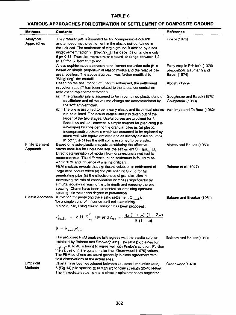
TABLE 6
VARIOUS APPROACHES FOR ESTIMATION OF SETTLEMENT OF COMPOSITE GROUND
Methods
Analytical Approaches
Finit9 Element Approach
Contents
The granular pi~ is assumed as an incompressible column and an oedo metric-settlement in the elastic soil contained in the unit-cell. The settlement of virgin ground is divided by a soil improvement factor n =[(1-JA.)/2k.J. This depends on angle q, only if J.l= 0.33. Thus the improvement is found to range between 1.2 to 1.9 for q, from 35° to 45° A less sophisticated approach to settlement reduction ratio~· is based on simple proportion of elastic moduli and the relative pile area position. The above approach was further modified by 'Weighting' the modulii. Based on the assumption of uniform settlement, the settlement reduction ratio 13* has been related to the stress concentration ratio n and replacement factor a (a) The granular pile is assumed to be in contained plastic state of
equilibrium and all the volume change are accommodated by the soft ambient clay.
(b) The pile is assumed to be linearly elastic and its vertical strains are calculated. The actual vertical strain is taken out of the larger of the two stages. Useful curves are provided for f3. Based on unit cell concept, a simple method for predicting f3 is developed by considering the granular piles as (a) plastic, incompressible cotumns which are assumed to be replaced by stone wall with equivalent area and as linearly elastic columns. In both the cases the soft soil is assumed to be elastic.
Based on e'lasto-plastic analysis, considering the effective stress-modulus for undrained soil, the settlement S = (PIE.) LIP Direct determination of modulii from drained/undrained test is recommended. The difference in the settlement is found to be within 1 0% and influence of J.l is insignificant. FEM analysis reveais that significant reduction in settlement of large area occurs when (a) the pile spacing S s 5d for full penetrating piles (b) the effectiveness of granular piles in increasing the rate of consolidation increases significantly by simultaneously increasing the pile depth and reducing the pile spacing. Charts have been presented for obtaining optimum spacing, diameter and degree of penetration
Elastic Approach A method for predicting the elastic settlement (b elast;d•
'for a single zone of influence (unit cell) containing a single, pile, using elastic solution has been proposed :
2 qst (1 + p) (1 - 2p) 4.1asr.c = q. H. S q. I M and (~oil = . -='--'--=--:'--'--~---'-""" e E (1 - ,11)
Reference
Priebe(1976)
Early step in Priebe's (1976) preposition. Baumann and Bauer (1974)
Aboshi (1979)
Goughnour and Bayuk (1979). Goughnour (1983)
Van lmpe and DeBeer (1983)
Mattes and Poulos (1969)
Salaam et a1.(1977)
Salaam and Brooker (1981)
The proposed FEM analysis fully agrees with the elastic solution Salaam and Poulos(1983)
Empirical Methods
obtained by Salaam and Brooker(1981l. The ratio~ obtained for E,!E.=10 to 40 is found to agree well with Priebe's solution. Further
the values of f3 are quite smaller than Greenwood (1970) va!ues. The FEM solutions are found generally in close agreement with field observations at the actual sites. Charts have been developed between settlement reduction ratio, Greenwood(1970) (3 (Fig.14) pile spacing (2 to 3.25 m) for clay strength 20-40 kN/m2. The immediate settlement and shear displacement are neglected.
382

Methods
Experimental method
·contents
The tota! settlement of composite ground may closely be approximated i:>y vertical strain at the top of granular pile plus the compression of the soil layer below pile tip. The settlement reduction ratio 1~ wa.s found to be 0.25 for 200 mm diameter and 2 m deep granular piles. Also under a raft subjected to a stress of 5 kN/m2
, ~ was found to be 0.1 0. A design chart (Fig. 24) has been proposed between nand a for various cj>'. Value of~ from 0.2 to 0.25 have also been reported. A relation has been, developed between clay strength load per granular piles for different settlements. Based on the measurements of radial strains from the pressuremeter tests, the vertical strain within the granular pile is taken as twice the radial strain, provided there is no volume change in the pile. The radial strains are found from pressuremeter tests and settlements can be found by dividing the pile in to layers of different thicknesses Vertical displacement of top of pile (5 to 30 mm) is added to the settlement of soil strata below pile tip.
Reference
Thorburn (1 975)
Hughes and Withers(1974)
Priebe(1 976) Broms(1 979) Somltzyk(1 972)
Hughes et a/.(1 975)
Floss (1 979)
P = total load on pile L = length of pile
seq= equivalent spacinQ ratio E, u, G, are elastic constants
IP =factor based on pile geometry and EjE. ratio
d = pile dia, A. - [ (1 +
seq = d/dp
*Settlement Reduction Ratio, f3 = t\L = Settlement of the treated so.ll
t\L' = Settlement of the virgin soil
n = improvement factor, q,' = angle of internal friction of pile material.
Further, though the Goughnour and Bayuk (1979) approach appears promising and worthy of further investigation, is very cumbersome and calls for a high grade data on soil properties not easily available at tender stage of a project to justify its application. This limits its value except for research purposes (Greenwood and Kirsch, 1984).
The finite element solutions are generally claimed to provide good agreement with observations on actual sites and therefore provide a rational basis for settlement prediction (Schlosser eta/., 1983). However, their utility depends upon the accuracy of input parameters and calls for more performance observations (Rao and Ranjan, 1985).
It is therefore useful to develop a method for computing the settlement of a subsoil stratum reinforced with granular pile. The method should incorporate the pile material properties and also those of the surrounding soil, the size, spacing, and depth of the granular pile, and the area of the footing/raft supported by the soil/pile system. Rao and Ranjan (1985) presented a rational method for predicting the settlement of a ground, reinforced with granular piles in weak subsoils. The proposed method is particularly useful because it can acomodate changing subsoil conditions of the composite ground reinforced with granular piles. The method uses a concept of equivalent coefficient of volume compressibility of the composite mass of the soil-pile system. It is based on the data easily acquired from field laboratory tests, besides accommodating changing soil properties with depth. (Goughnour, 1988).
Sharing of Load Between Pile and Soil In actual practice the applied load, q is shared between the granular pile and the ambient soil. For this
purpose, the experimental structures and model test in which only the pile top is loaded and the surrounding soils
383

is maintained in a vertical stress state do not correspond to the actual cases where surrounding soil is also loaded. Under such circumstances, a different state of shear between the pile and the surrounding in situ soil exists (Floss, 1979). Some efforts appear to have been made in this direction (Baumann and Bauer 1974, Broms 1979, Datye and Nagaraju 1981 ), through without much success. These have been examined in detail elsewhere (Rao, 1982). The present state of the art reveals that no attempt has been made to study the improvement in the granular pile capacity due to sharing of the load by the ambient soil and subsequently, to predict the ultimate load capacity of the pile. The mathematical model proposed by Baumann and Bauer (197 4) for the distribuiton of the applied load between pile and the soil for predicting the sttlement resulted in a conservative estimate of the consolidation settlement, (Rao, 1982).
In the analysis (Rao and Ranjan, 1985), the total applied load, Q, is assumed to be shared by the granular pile, QP, having total cross-sectional area, AP (after the installation) and the surrounding soil, o. 'under the footing having an area, A. If A is the total area of the footing base, the applied load Q on the area A may be expressed as
0=0 +0 p s
..... (50)
The unit stress qP, shared by the pile and q., shared by the soil are assumed to be proportional to their respective moduli, EP'and E."and is expressed by equation 41.
Where E and E are the measured modulii of the pile material and the surrounding soil respectively, p s
om= the collective mean normal stress at a depth, Z, equal to critical pile length, Le; n, =the effective normal stress taken as 1 00 kN/m2 for the purpose of making the multiplying factor in equations 52 and 53 nondimensional.
The denominator in equations 42 and 43 on the right hand side represents the equivalent modulus, Eeq of the composite mass consisting of soil reinforced with granular piles. Based on this, the equivaleht modulus, Eeq of the composite mass may be expressed by equation 51.
E = n E + (1 - n) E eq q s
.. .. (51)
The coefficient of equivalent volume compressibility, mveq of the composite mass is represented by equation 52.
m~, = [a E, + (~ - a) E, ] ... (52)
Modulii and Replacement Factor
Equations 42 and 43 involve determination of modulus of deformation of surrounding soil, E.' and installed pile material, E and the relative pile area, n, in terms of A and A where A =the total pile area and A= the area
p r • p of the footing/raft. The modulus of deformation for the soi can be estimated from the standard penetration tests or static or dynamic cone penetration tests (Bowles 1982, Peck et a/. 1874, Schmertmann, 1970). The determination of modulus of installed pile material E , from field penetrometer tests is not practical. Further, the
p
stress strain behaviour of installed pile material (20-70 mm) stone aggregates with 20-30 per cent of sand can not be easily assessed (Rao and Ranjan, 1985). Laboratory tests have little relevance owing to sample disturbances and difficulty of particle orientation. In view of this, in situ load tests on single and group of granular piles are likely to yield fruitful results, Based on large number of full scale field tests, Rao (1 982) observed that elastic modulus of deformation of the pile material, E is dependent on the method of pile installation. It was found
p
the EP values for the granular pile installed by internal operating hammer may vary from 24,000-50,000 kN/m2
for hammers of 1 ,250-5,000 N force. These values agree well with the E values of 6 X 1 04 kN/m2 for vibrofloted stone columns as rep0rted by Engelhardt and Kirsch (1977) and found to lie within the range of values mentioned by Mitchell (1981 ).
SETTLEMENT OF GROUND REINFORCED WITH GRANULAR PILES
The total settlementS of the improved ground reinforced with partially penetrating granular piles under the footing/raft can be estimated from equation 53.
S = A L + A H .... (53)
384

G.L.
. I •" • • • 4 • •
.·:·, ···----a,l --... ~·. :~ •, - Lc
Ti ... ·· .. .' .. • .. : i J : l . . --1-- -I I R ... .: I
K ~. '7· Elastic zone Tl I "~J .. r~r
Elastic ~ ,·. :. Plastic zone
zone Plastic ·• · · · . . . , zone ·• · ·• . ". "" ,.
I •: It .r: •..
~·· .. :.~.
q
G.L .
. .. ~ . . ......
o.
.. ·· .. . ___....... ... .. -• 0 .....
__ u,L :. . ·. ("l __.. ··• ...... .
rl ...
(a) Plain granular pile (b) Individually skirte.d pile
FIGURE 31 Failure Mode in Plain and Individually skirted Granular Pile (After Ranjan and Rao, 1986)
G.L.
f.=Coefficient of friction inside skirt
f0=Coefficient of frication
outside skirt q=O/BL= Applied stress qb=Ob = Stress at the \81\ base of skirt *,L = limit stress
G.L.
~
r= unit weigh of the so11 S= Granular pile spacing W=Width of the footing L
1= length of the footing
D0=Depth of the footing
05=0epth of the skirt
d= pile diameter
FIGURE 32 State of Stress at Ultimate Load in Skirted Granular Pile Group (After Ranjan and Rao, 1986)
385

I
--I
I
I
Strain
FIGURE 33 Elastro-Piastic Idealised Stress-Strain Relationship (After Goughnour and Bayuk, 1979)
(/) (/)
~ rn m u "€ (!)
>
u . ~=max1mum /Ute
.P= (cpL)
Plastic state
Generally in range1.5-4 for gravels
(a) Longitudinal strain
k PC
0
ovc =maximum •c
k = l+sin .pm pc 1-sincpm
cjlm
according to strain anticipated
(b) Direct stresses
Assumed effective stress path during consolidation
C-Final conditions
Effective vertical stress
(c) (d)
FIGURE 34 Idealised Stress Changes in Column (a,b,c) and Soil (d) (After Goughnourand Bayuk, 1979).
386

Where A L =the settlement of the reinforced layer having the thickness as L(FGRI<) (Fig. 35); the applied stress is distributed by the 2:1 method; and the thickness Lis divided into n layers. Thus, -the settlement in the reinforced layer is given by equation 54.
n
dL = L q, mveqi hi I= 1
... (54)
and the settlement in the unreinforced layer KROZ (Fig. 35) is given by equation 55.
n
dH = _2: q'1 mvi Hi i = 1 ... (55)
When the granular piles are allowed to penetrate hard stratum the value of His taken as zero.
The settlement of reinforced ground Lis given by equation 54 and that of the unreinforced virgin ground L' by equation 56.
n
dL' = L q'1 mvi Hi I= 1
.... (56)
where mvi is the coefficient of volume compressibility of the unreinforced soil. The settlement reduction ratio, f~ is defined as the ratio of the settlement of reinforced ground to that of the virgin ground and is given by equaltion 57.
Layer n
z
-\ _ d L I - t\ L'
G.L.
Layer I
f· 8 ---·~1 q=0/82 Applied load
-L..l -•- .L ...J_-
__ Li -L.!.. ...1.. __
__ L ~ _L..l --L __
T Reinforced sub-soil (L)
FIGURE 35 Settement of a Subsoil Stratum Reinforced with Partially Pencetrating Plain Granular Piles (After Rao and Ranjan, 1985)
3~7

40
50
Plain Tooting (900mm*900mm)
Intensity of pressure,KN/m2
t---1 900mm
/ Prefabncated pipe unit skirting
C I 900 mm 25mm d;a
~ 3.5mdeep
900 mm granular piles
Retrievable type of skirting
using prefabricated pipe units
FIGURE 36 Pressure Settlement Behaviour of Plain Footing, Skirted Footing and Skirted Granular Pile Group at Site-1 (After Ranjan and Rao, 1983).
Stiffness of composite ground
The stiffness of the composite ground, whether reinforced with four or six granular piles for prototype in situ "':esting or with large· number of piles under flexible raft foundations in live structures, will remain the same provided the pile spacing in the two cases is the same (Rae and Ranjan, 1988).
The stress concentration ration= (q /q.); the relative pile area or replacement factor u= (A/A) and the stiffness ratio or effective modular ratio m =(EjE.) are the main design parameters which govern the response of composite ground under load. Rao (1982) and Rao and Ranjan (1988) indicate that within the elastic yield point E (Fig. 36), the stiffness ratio or effective modular raM m is related to stress concentration ratio, n by equation 41 (Rao and Ranjan, 1985). Utilising equation 41 and 52 for mv and mveq Rao and Ranjan (1988) have shown that
~ = .[ a E, + ~; - a) E,] = [ 1 + (m1
- 1) a] ... (58)
which is the same equation as proposed by Meyerhof (1984). The equivalent coefficient of volume compressibility,mveq• of the composite ground is given by equation 59 (Rao, 1982, Schlosser and Juran, 1979). Thus the equivalent coefficient of volume compressibility is related to the stiffness ratio and replacement factor by equation 59.
m . = 1 + (m - 1) a .... (59) veq1
388

TABLE7
OBSERVED AND PREDICTED SETTLEMENTS OF PLAIN AND SKIRTED GRANULAR PILES (AFTER RAO AND RANJAN, 1985)
Site Test Single/ Equivalent, Coefficient Computed Ovserved Ratio of Remarks number group E,.- (kN/m2
) of volume settlement settlement computed/ decrease for 200 for 200 observed
m x 1o-~ kN/m2 kN/m2 settlement "(m!kN) pressure (mm)
(mm)
1. Single 10,944.5 9.1370 17.0 16.25 1.04 Plain granular piles (Test No. 1-7)
2. Group of 2 10,530.5 9.4962 26.0 19.5 1.33
II 3. Group of 2 10,450.0 9.5693 5.56• 5.75" 0.96
4. Single 12,596.6 7.9386 4.4 4.8 0.91 Plain granular piles
5. Group of 2 11,061.5 9.0403 7.4 8.0 0.92
6. Group of 3 9,866.7 10.1351 5.3 16.0 0.96
7. Group of 4 10,941.4 9.9570 15.85 17.5 0.90 Collectively skirted granular piles
8. Single 10,944.5 9.1370 7.0 7.75 0.90 (Test no.8-11)350 mm diameter 8m deeo piles
9. Group of 2 10,498.5 9.5251 9.3 10.8 0.86
10. Group of 3 10,164.5 9.8381 20.0 19.25 1.03
11. Group of 4 10,564.0 9.4661 15.5 15.0 1.03
12. Group of 5 11,675.0 8.5653 9.0 6.7 1.34 Collective skirting using brick panels
13. Skirted footing 8,000.0 12.5b 9.0" 11.8•· 0.726 Using timber pile skirting without granular piles
14. Group of 4 10,940.0 9.1407 10.6 8.45 1.25 Collectively skirted granular piles using timber pile skirting
15. Skirted footing 8,000.0 12.5b 1o.o• 11.8 0.847 Using prefabricated pipe unit skirting
16. Group of4 11,628.5 8.6 9.3 9.0 1.03 Collectively skirted granular piles using pre-fabricated pipe unit skirting
II 17 Group no 4 9,797.5 10.2061 16.6 15.0 1.10 Collectively skirted granular pile using r.c.c. skirt
18. Single 12,593.0 7.9409 2.72 3.0 0.9 Individually skirted granular
19. Group of 2 11,061.5 9.0403 4.25 5.3 0.8 piles using 300 mm diameter
20. Group of 3 9,888.7 10.1391 12.0 11.6 1.04 m.s. pipe (Test no. 18-21)
21. Group of4 10,041.4 9.95 10.78 10.0 1.07
Ill 22. Single pile 18,716.0 5.34 5.4 6.0 0.9 Single plain granular pile
23. Group of 2 11,598.2 8.62 13.4 11.25 1.19 Collectively skirted
IV 24. Group of 2 13,376.0 7.47 13.75 10.0 1.37 Plain granular piles
• Settlement for an intensity of stress equal to 1 00 kN/m2
b Coefficient of volume decrease and settlement for virgin soil without piles. Note : The computed settlement for test no. 1 and 2 is doubled due to submergence.
Equation 59 shows that the term mveqi is the same as settlement improvement ratio, R proposed by Priebe (1976) and discussed by Greenwood and Kirsch (1984). It is therefore clear that the equivalent coefficient of volume compressibility of the composite ground is dependent on effective modular ratio m and the .replacement factor a( equation 59). The prediction of the settlement from the proposed analysis and the full scale in situ testing have been found reliable (Rao 1982, Rao and Ranjan 1985) (Table 7). However, some details of actual structures founded on skirted granular piles in India are provided in Table 8 and heavy storage tanks founded on skirted foundations in ltaliana, to counteract excessive settlement and low bearing capacity have been discussed elsewhere (Rao and Bhandari 1980, Rao and Ranjan 1988).
389

TABLE 8
STRUCTURES FOUNDED ON SKIRTED GRANULAR PILES (AFTER RAO AND RANJAN, 1985)
Foundation size Granular pile Depth Number Remarks ot of piles
Site Soil Dia- Height Dla- Depth skirt installed type meter (m) meter (m)
(m) (m)
II SM-SP 24.0 6.75 0.35 3.5 1.8 ~35 Several molasses tank foundations "on II a ML 24.0 6.75 0.35 4.0 2.0 235 granular piles installed in loose medium
dense sand and saturated silt and clays have been founded since 1979 with success.
Ill CL-ML 13.5 7.5 0.55 10.0 4.0 300 The R.C.C. raft supporting oil drilling rig was placed on 120 em diameter and 4m deep pHes held rigidly at the pile head by a R.C.C beam.
IVa CH 79.0 13.5 0.60 15.0 2.5 4,000 MCP tank founded on skirted granular piles in 1983 have been hydrotested and commissioned successfully.
IVb Cl 42.0 9.6 0.55 11.0 3.75 3,000 The furnace oil tank three numbers have been hydrotested and commissioned successfuily. Seven more tanks of the same size and design are under construction.
Recently two storeeyed residential houses have been founded on granular piles installed in saturated cohesionless soli With water table at 0.10 m depth below ground level.
The main design parameters ctre the stress concentration- ratio, n and replacement factor a, (Schlosser et a/.1983). Based on the assumption of uniform settlement, Aboshi eta/. (1979) related these parameters with settlement reduction ratio, I):
13 = (n -
... (60)
Greenwood and Kirsch (1984) pointed out that the less sophisticated approaches to settlement improvement ratio, R can be expressed by equation 61 (Priebe, 1976)
R = 1 + --1 -{ EP l { AP} Settlement improvement ratio, Es J A .... (61)
where R is the inverse of settlement reduction ratio, lias proposed by Aboshi eta/. (1979), Rao and Ranjan (1988) and Bhandari (1987).
Further, Rao and Ranjan (1985, 1988) use stiffness ratio or modular ratio 'm' in place of stress concentration ratio, n in equation 59. It may further be emphasised here that accurate determination of the stress concentration ration is not easy and also it does not have a unique value since under constant loading it is found to have a diminishing trend (Vautrain, 1977).1tistherefore, rational to use a stiffness factor, min equation60which can be easily assessed. It has also been experienced that relative pile area or replacement factor, c tis the prime determinant of the curves and stress on the soil whilst stiffness ratio, m controls the magnitude of the settlement (Greenwood and Krisch, 1984). Further, the stress concentration ration appears to reflect relative stiffness ratio, m of the granular pile and the ambient clay. Thus the validity of assumption by Rao (1982), Rao and Ranjan (1985) that within the elastic limits, both n and m are equal is justified. The correctness of this equation is also furthe~ substantiated by full scale field tests in different soil conditions.
LATERAL DISPLACEMENT
Large foundations such as rafts supporting heavy storage tanks, soils, and embankments when built on composite ground not only provide stability but is suitable from the considerations of settlements and lateral displacements (Rao and Bhandari 1980, Meyerhof 1984). The lateral displacement particularly at the extremities of such large foundations can be as large as the vertical settlement, though in the central part of the loaded are the soil displacement is essentially vertical (Schlosser and Juran, 1979; Schlosser eta/. 1983). Also the peripheral granular piles installed under these foundations are found to have a reduced load bearing capacity due to abrupt
390

discontinuity of the design load and significant lateral shift of the peripheral piles (Greenwood, 1970). Analysis of the observations (Castelli eta/. 1984, Munfah eta/. 1984) for a large wharf on soft ground treated with stone columns (pre-loaded by surcharge) revealed the ratio of maximum horizontal and vertical displacements of about two (Meyerhof, 1984).
Thus (a) significant lateral displacement of the soft ground reinforced with granular piles at the periphery of large raft and (b) a reduced pile capacity in the peripheral rows emerge as important considerations for an efficient and cost effective foundation. Various solutions to overcome these eventualities have been discussed elsewhere (Rao, 1982). Suggestions to replace the bulged portion of the granular piles/stone columns or injection of cement in the bulged portion (Engelhardt and Kirsch 1977; Floss 1970) have not found favour due to the fact that conventional piling system is considered to be more appropriate if improved stiffness is required (Greenwood and Kirsch, 1984) as it is difficult to ensure that the injected cement remains at the top of the column unless the whole length is injected. Extra concentration of seven rows of peripheral stone columns, three rows within and four rows outside the tank periphery, at the refinery site at Madras, India, under a 79 m diameter, 14m high crude oil storage tank (Bhandari, 1983) amounted to 52 per cent of the number of stone columns required within the tank base. Whether such a ring of seven rows of stone columns that were provided (Bhandari, 1983) from settlement considerations with a view to withstand lateral stresses and lateral displacements due to design load is doubtful, particularly in soft saturated clayey deposits (Rao and Ranjan, 1988). Further if such a proposal would be economically viable in the light of large additional quantities of granular material required, a detailed study of cost effectiveness and technical merit in terms of total and differential settlements of such a proposal over the new concept of rigid skirt with a ring beam is warranted (Rao and Ranjan, 1988). For mechanised construction a boring and skirting machine (Kaushik and Rao, 1983) has also been developed.
The minimum depth of individual or collective skirting is limited to the critical pile length which is four to five times the installed pile diameter (Rao, 1982, Ranjan and Rao, 1983; Rao and Ranjan, 1985). However, in the case of column footing without granular piles, the depth of skirt is limited to half the footing width (Narahari and Rao, 1979).
The primary benefit in increased foundation capacity and significant reduction in settlement comes from both the granular piles and the skirt (Fig. 36).
While appreciating (Goughnour, 1988) the analytical model proposed by Rao (1982), Rao and Ranjan (1985) for computing settlement of foundations over weak subsoil deposits reinforced with granular piles and its usefulness because of its versatility to accommodate changing subsoil conditions with depth and based on the soil parameters which can be easily estimated. However, Goughnour (1988) has expressed doubt about its effectiveness in soft cot1esive subsoil deposits where the pile material and the insitu soil are assumed to behave as a linearly elastic material.
TIME DEPENDENT SETTLEMENT
Soft compressible soils when treated with granular piles or stone columns by replacing 15-23 per cent of soft material with 20-70 mm of stone aggregates and 15-20 per cent of clean sand will behave elastically up to the elasto-plastic stage (Rao, 1982). The elastic behaviour of the composite ground has also been advocated by Goughnour (1984). Further, when such a composite ground is subjected to design load the rate of settlement will be much taster in comparison to the untreated virgin soft compressible soils, primarily due to the rapid drainage of water (dissipation of pore water pressure) which occurs due to presence of porous granular piles acting as drains, and the total settlement is also reduced. It may be noted that in some of the studies the reduction in total settlement of a soft compressible soil reinforced with granular piles stone columns is reported as 70 per cent with respect to untreated soil. The consolidation of the composite ground was completed within five months (Castelli eta/. 1984). Also, Munfakh eta/. (1984) have reported that consolidation of soil strata underlying a test embankment was accelerated by the presence of stone columns. They further observed that the time for 1 00 percent primary consolidation of the area reinforced by the stone columns was found equivalent to that of 25 percent consolidation of the homogeneous clay strata outside the treated area. In view of the foregoing discussions and with personal experience Rao and Ranjan (1988) have indicated that the total settlement even in soft compressible soils reinforced with partially penetrating granular piles supporting large oil tanks or embankments, the settlement predicted by Rao (1982), Rao and Ranjan(1985) approach be increased by about 20 per cent till such time, as more refinement in analytical approach can be introduced by accurate mathehmatical models incorporating the realistic behaviour of composite ground under full design loads including time dependency (Rao and Ranjan, 1988)
391

Goughnour (1988) has expressed his views that in case of the granular piles installed in less compressible material such as silty sand, the bulging phenomenon is insignificant. Granular piles do bulge in loose to medium dense cohesionless soils also. It has been confirmed through full scale in situ testing on granular piles, followed by the inspection of exhumed piles by excavating beyond the critical pile length (Rao and Sharma, 1980). The depth of bulge (critical pile length) found four to five times installed pile diameter (Rao 1982; Ranjan and Rao 1983).
RESPONSE UNDER DYNAMIC LOADS
PROBLEMS ASSOCIATED WITH DYNAMIC LOADS
Earthquakes are one of the most destructive agencies that nature unleashes on earth. Since, earthquakes, till todate are unpreventable and unpredictable, it is necessary that civil engineering structures are built so as to minimize the loss to property and life. The earthquake causes vibratory motion to the earth mass through which the energy waves pass and this motion is transmitted to the foundations/structure standing on the earth's surface. The foundation/structure thus gets impulsive jolts in both horizontal direction and also to some extent in the vertical direction. The vertical motion is prominent in the epicentral region, but it decreases significantly with increasing distance from epicentres. The vibratory jolts cause additional shears and moments in the structures and in turn additional forces on foundation. Machines are another source which cau::;e vibrations (vertical or horizontal depending upon the nature of unbalanced force of machine) in the soils. Therefore, these additional forces, if riot recognised in the design/analysis of the structure/foundation, may lead to disaster.
A saturated granular material, subjected to cyclic loading involving the reversal of shear stresses, tends to compact and if it is unable to drain, the tendency to decrease in volume will lead to an increase in pore water pressure. Ultimately, if the cyclic loading is maintained, it will reach a condition of zero effective stress and depending upon its relative density, wnl suffer essentilly a complete loss of strength (liquefaction) or undergo some degree of strain with little or no resistance to deformation (initial liquefaction with limited strain potential) '(Seed and Booker, 1977).
The consequence of dynamic forces either due to earthquake or due to vibrations from machines must be duly recognised. These are :
* increased forces on foundations resulting in a reduced factor of safety and excessive settlements
* increased pore pressures with the possibility of partial/complete liquefaction.
INCREASED GROUND CAPACITY AND REDUCED SETTLEMENT
Though the analyses of the previous earthquake records have established the superiority of pile foundations over shallow foundations (Thornley and Albini 1957; Kishida, 1966) merely their adoption alone does not lead to a seismic design offoundations. Rao and Sharma, (1980) have indicated that the vertical and horizontal displacements of fi>otings during earthquakes may be considerably reduced by (a) increasing the effective depth of footing and {b) preventing the lateral movement of the soil through suitable system. Both these requirements are fulfilled by providing a rigid skirt around a shallow foundation.
Kotada (1987).reported that the foundations constructed by the stilling method that is by laying arrow plates around shallow base so as to restrict the lateral displacement of soil from below the foundation and in turn to control its sinking, have been used in Japan since long. The effectiveness of arrow plates was demonstrated during the Niigata earthquake of 1964 when the foundations of the two buildings of Niigata City Administration and Nagai Electrical Building constructed in 1957 and 1960 respectively were strengthened by binding the loose sandy base by leaving the arrowplates used in pit excavation as such, remained undamaged.
Kotada (1987) has further compared the behaviour of plain footing with that of skirted foundation (Narahari and Rao 1979; Rao and Bhandari 1980) through model tests on horizontal shake table. The analysis of test results (Fig. 37) indicates that the absolute value of settlement is quite small in the case of skirted foundations as compared to that for a plain footing.
Rao (1982), Ranjan and Rao (1983) based onfullscale insitutests on granular piles both plain and skirted have reported significant increase in load carrying capacity. It has been reported that the ultitmate load capacity for the virgin ground reinforced with single and groups of 2, 3 and 4 piles in a cohesionless subsoil deposit increases from 164 percent to 427 percent. over the ultimate load of virgin subsoil without any pile reinforcement. A further increase (290 per cent to 566 percent) is obtained when the piles are skirted.
392

Number of Cycles
200 400 600 800 1000
E 10 E c 0 -~ "0 20 c :l .£ -0
'E 30 QJ
E QJ
E QJ
(/) 40
Relative density Dr >90% Frequency. f = 7. 7 Hz
Diameter of toundation = 1 00 mm
Embedded length of skirt, Ls = 25,50,100 m
100
Ls 50
Ls 25
FIGURE 37 Settlement of Foundation under Vibration (After Kotada, 1987) For a clayey silt depositthe increase is noted to be 209 per cent over the bearing capacity computed from
undrained shear strength of the deposit. However, in the case of soft clay deposits, the improvement is reported to be 363 percent (Rao, 1982). These observations clearly indicate that there is significant improvement in the ultimate capacity of weak subsoil deposits when reinforced with plain/skirted granular piles.
Rao and Ranjan (1985) listed (Table 8) several typical structures founded on ground treated with granular piles and also provided with a skirt. Furhter, they have reported significant reduction in the settlement corresponding to ultimate loads for various plain footing and ground reinforced with plain/skirted granular piles (Table 9). The reduction in settlement is reported to be (Ranjan and Rao, 1983) 76 percent for a group of 3 or 4 piles and it increases to 86 percent when the piles are skirted. This improvement is attributed partially to the
TABLE 9
SETTLEMENT REDUCTION DUE TO PLAIN AND SKIRTED GRANULAR PILE INSTALATION (AFTER RAO AND RANJAN, 1985)
Site Type of granular pile lnsitu tests
Individually
skirted
collectively
skirted
Group of 3
Group of 4
Goup of 3
Group of 4
Group of 5
Group of 4 timber piles
Group of4 with prefabricated pipe unit
• Settlement of skirted footing without piles.
Settlement at ultimate load of virgin soil (mm)
PF PGP SGP
25
25
25
25
32
24
30
6
6
8"
8"
4
3.5
4
2
4
3.0
3.75
b Reduction in sttlement due to skirted granular pile over skirted footing without pile.
Note: PF = plain footing; PGF = plain granular pile'; SGP =skirted granular pile.
393
Reduction In setUement percent
PGP SGP SGP over over over PF PGP PF
76.0 33.3 84.0
76.0 41.6 86.0
84.0
92.0
87.5
62.5b 87.5
53.12b 87.5

confinement provided by the rigid skirt to the granular piles which results in a significant resistance against bulging of the granular piles (Fig. 35)
Attempts have been made to evaluate performance of the composite ground reinforced with stone columns/granular piles in seismic areas (Engelhardt and Golding, 1975). The performance has been evaluated in terms of factor of safety against base shear failure for a particular horizontal ground acceleration.
Rao and Sharma (1980), adopting a horizontal ground acceleration of 0.25g as design criterion, have worked out the factor of safety against base shear failure for plain footing and for skirted footing or skirted granular pile foundation. The results are tabulated in Table. 10.
The analysis (Table 1 0) indicates that the factor of safety against base shear failure of a plain footing is double when the footing and the soil plug are skirted with a rigid skirt having a depth equal to half the width of the footing. However, if the soil plug is reinforced with granular piles, the factor of safety appears to be three times larger than for a plain footing. The factor of safety of a plain footing on a soil reinforced with granular pile is about 30 percent more than for a plain footing founded on virgin soil.
The observations noted above go to show that confining the soil below a footing may be beneficial ir.1 terms of (a) increasing the effective depth of plain footing (b) developing skin friction between soil plug and interface of skirt (c) augmenting resistance to lateral flow of soil beneath the footing (d) effecting reduction in dead load of the foundation and (e) increasing load carrying capacity and reducing settlements. The added advantage of constructing a skirt around a footing is in terms of resistance to lateral displacement due to passive resistance offered by the soil around the skirt (Rao and Sharma, 1980).
SUSCEPTIBILITY TO LIQUEFACTION
Loose medium, saturated sand or very fine silty sand (with N-value<5) may be transformed to a state of instantaneous liquefaction followed by subsidence of foundation when subjected to any form of shock loading (Tomlinson, 1976). During the earthquakes, a number of buildings are reported to have sunk into the ground, embankments have subsided or disappeared, bridges tilted or sank. Sinking ofthe abutment of bridges is reported to be more common than the sinking of the central portion of the bridge (supported on screw piles) testifying to the fact that pile foundations are superior to shallow foundations under earthquake condition. These observations have been substantiated by analyses of damages to buildings during the Mexico earthquake of 1 957 and Niigata earthquake of 1964.
If the site lies in a seismic area, it is necessary for the designer to make an inital assessment of the liquefection potential of the pile. If the site is susceptible to liquefaction the alternative for the designer are either to reject the site or to compact the soil strata to increase the relative density of sand layers. In some cases, pile foundations may be used. However, the use of piles or otherwise will have to be decided on the basis of cost viability.
A possible method of stabilizing a soil deposit susceptible to liquefaction is to install a system of granular piles (also called rock drains) so that the pore water pressures generated by cyclic loading could be dissipated almost as fast as they are generated. Seed and Booker (1977) developed design principles for stone columns.
TABLE10
FACTOR OF SAFETY IN DIFFERENT TYPES OF FOUNDATIONS (AFTER RAO AND SHARMA, 1980)
Foundation Type Base shear Stress due to Normal stress Factor of safety stress passive resistance on (kN/m2
)
= on tanq> (kN/m2) = qKp (kN/m2
)
Plain footing 57.7 100.0 2.3
Skirted footing 63.2 57.6 109.6 44
Plain granular pile 75.0 100.0 3.0
Skirted granular pile 85.3 105.6 113.2 6.75
Note: Design !oad assumed to be equal to 100 kN/m2 . normal load. o where as for sktrted footi4g o,::: design load+ surface load. Natural density y for soilts taken as 16 kN/rrr and for the granular material constituting the piie ts taken as 22 kN m3 The width of the footing is assumed as 1.2 m and depth of skirt equal to 0 6 m
394

(a) Equation for generation and dissipation of pore water pressure
Assuming Darcy's law to be valid, the continuity of flow equation in the sand layer may be written as
... (62)
Where kh and k. are the coefficients of permeability of sand in the horizontal and vertical direction respectively u the excess pore water pressure, Yw the unit weight of water and E the volumetric strain' with volumetric reduction being positive.
During a time interval dt, the pore water pressure in a soil element changes by du. However, if a cyclic shear stress is applied on a soil element there is an increase of pore water. In a time dt, there are dN number of cyclic shear stresses; the corresponding increase of pore water pressure is (buJbN) dN, where u
9 is the excess
pore water pressure generated by cyclic shear stress. The net change in pore water pressure in time dt, thus is
b E = mvs [du - (b U/b N) dN]
where m.s is the coefficient of volume compressib!lity
or b E
b t - m -(
ou - vs b t
Combining equiations 62 and 64
+ ( Kh b u) +
by ·rw by
b
O·Z
dN) bt
( Kh ~) Yw b Z
= ( b u m --
vs \ b t bu
bt
.. (63)
.. (64)
.. (65)
If the coefficient of permeability and m.s are constant and radial symmetry exists, then equation 65 can be written in cylindrical coordinates as
For the condition of purely radial flow, equation 66 takes the form
()Ug ()'N
(JN ()t
() u
()t
(5U9 (5N
(fN (H .(66)
In order to solve equation 67 it is necessary to evaluate the terms kh, m.s , bN/bt, and bujbN. The value of kh can be easily determined from field pumping tests. The coefficient of volume compressibility can be determined frOm cyclic triaxial tests (Lee and Albaisia, 197 4). The term 6N/bt can thus be expressed as
(b N/bt) = (NJt) ... (68)
Where N. is the significant number of uniform stress cycles due to an earthquake and td is the duration of an earthquake.
For many soils the relationship between u and Ncan be expressed for practical purposes in terms ofthe number of cycles N, required to cause initialliqu~faction under the given stress conditions in the form (Seed et a/. 1975).
...(69)
395
FIGURE 38 Relation Between Greatest Pore Pressure Railo and Drain System Parameters for{a) N,./N,=1; (b) N.IN,=2; (c) N.JN,=3; (d) N,./N,=4;
(After Seed and Booker, 1977)
E E
i Q)
E Q)
~ (f)
30r------------------------------,
25 -
20 r-
15 -i 0 f-
Initial relative density, Dri =50% Acceleration ,a = 0.30 g
Frequency of vibration, f = 1.833 cps No of cycles N
0 ~---·~L-1---~·------------------------------~ :2.!:l 3.5 5t
Granular material wall spacing in terms of thickness of wall
FIGURE 39 Settlement vs Granular Material Wall Spacing for Initial Relative Density of Deposit of 50% at
Acceleration of 0.30g (After Koul, 1987).
396
Where u is the excess pore water pressure developed due to N number of cyclic shear stress applications, ov is the init,al consolidation pressure, N
1 is then number of stress cycles needed for initial liquefaction, and< ( is a
constant= 0.7, thus
-1
t5 U9 _ 2 lTy [s· (Z a_ 1) ( 1 U9 ) C ( 1 U9 ) l -- - -- In -.ff- OS - .ff-t5N aJTN1 2 tTy 2 ~
... (70)
SOLUTIONS FOR GRAVEL OR ROCK DRAINS
Seed and Brooker (1977) solved equation 67 for the radial flow conditions. It has been shown that the ratio u/ov is function of the parameters:
a/b = radius of rock or gravel drains .. (71)
effective radius of the rock of gravel drains
k ... (72)
Using the above parameters, the solution to equation 67 is given in a nondimensional form in Fig. 38 for design of rock gravel drains. In Fig. 38, the term r is defined as
g
rq = greatest limiting value of u9
chosen for design
0 v ... (73)
In obtaining the solution given in Fig. 38, it was assumed that the coefficient of permeability of the material used in the gravel or rock drains is infinity. However, in a practical case, it would be sufficient to have a value of
Kh (rock or gravei)/K(sand) = 200
Koul (1987) studied the effectiveness of gravel drains through tests in horizontal shake table in reducing settlements of loose saturated sand deposits. Tests were carried out on loose saturated sand deposits with or without gravel drains under steady state horizontal vibrations at different accelerations ranging from 0.1 Og to 0.30. Settlements of the deposit at different cycles of motion ranging from 10 to 80 cycles have been computed by measuring the quantity of water collected on the surface (Fig. 39). The analysis of the data reveals that the introduction of the granular trench in the deposit brings down the settlement significantly. However, the magnitude of decrease in settlement of the reinforced desposit reinforced with granular drain compared to the unreinforced deposit depends upon the spacing of the granular drain. The closer the spacing of drain, the larger is the reduction in settlement, other parameters being the same.
Rao and Sharma (1980) reported that for a site having silty sand deposit possibility of liquefaction was indicated for an earthquake of magnitude M equal to 6.5-7 with corresponding horizontal ground acceleration of 0.25. However, considering a three granular pile group (consisting of 250 mm diameter piles, 3m long and three diameters spacing) the possibility of liquefaction is ruled out (Fig. 40).
FIELD RECORDS
Granular piles have been used (Engelhardt and Golding, 1975) for ground improvement for the construction of a 16 mgd sewerage treatment plant on a predominantly deep, soft cohesive soil in an area of highest seismic susceptibility. Large scale field tests and the analysis of data obtained therefrom confirmed that (a) in the process of stone column installation, sand lenses in the predominantly cohesive soils are sufficienty densified with respect to liquefaction potential (b) the combined mass of stone column and native intervening soil
397

0.6
0.5
0.4 0
·.o:; ~ (/) (/)
~ u; .!::1 0.3 0 >-()
• 0.2
0.1
M = Earthquacke
•
magnitude
~3pile group
Test Points
practice (1976)
•
•
10
• A·~
,._ Surface wirgin soil depth greater than 2.5 m
• Centre of pile grou~
+- Centre near the pile • Virgin soil • At center of 3pile group A Near the pile
N,, blows I tool (corrected to 10 t/m2 O.B.P.)
40
FIGURE 40 Comparison of (T/n) Corres'ponding to (N,) for Virgin Ground Reinforced byGranular Piles (After Rao and Sharma, 1980)
develops sufficient shear strength to resist safely the horizontal forces resulting from a gound acceleration of 0.25g and (c) the g@nular piles pattern which satisfied the shear and density requirements also provides an adequate load settlement relationship.
Bhandari (1977) reported the use of compaction piling and dynamic consolidation for densifying the subsoil of a refinery complex. The site consisted of 0.6 m of top silty loam followed by about 10 m of loose to moderately dense sand overlying dense to very dense grey sand mixed with gravels and cobbles upto 18.5 m depth. Compaction piles used at 4.3 times the pile diameter spacing, have been reported to be effective in densifying the soil upto 10 m depth. However, it has been reported that the subsoil containing more than 20 percent fines were not amenable to densification by compaction piles.
Analysing the foundations for a 70kN forge hammer, Prakash, Ranjan and Kumar (1983) observed that the soils at site have low bearing capacity and the amplitudes of vibration are excessive. Besides, the problem of build up of pore water pressures in the saturated silty soil under vibrations was also anticipated. Considering three alternatives namely (a) providing concrete piles under the foundation (b) lowering of the ground water table and (c) increasing the base area of foundation and providing granular piles with sand cushion to overcome the problem, on the basis of the feasibility of construction, effectiveness of the solution and cost considerations the provision of granular piles with sand cushion was adopted. Granular piles 300 mm diameter 6 m deep at 1 .2 m spacing were provided under the foundation. This has since been in operation and the foundation has performed satisfactorily.
398

FURTHER PROJECTIONS
The current state-of-the-art leaves several indentifiable gaps which are of paramount importance for better understanding of the behaviour of treated ground and its predictions towards response under load. Some of these are :
(a) The influence of granular pile installation technique on the behaviour of composite ground
(b) The modifications in the properties of soil in the zone of influence of the granular pile and their influence on pile capacity.
{c) The characteristics of granular pile material particularly the modulus of deformation and its changing value under varying magnitude of stress.
{d) A better estimation of load sharing between the granular pile and the ambient soil.
{e) Influence of parameters e.g. granular pile spacing, relative rigidity of surface loading on. the behaviour of composite gound.
{f) Defining limits for total and differential settlements of structures including lateral displacement.
(g) Instrumentation and field monitoring of Jive structures and comparison of predicted (theoretical) and observed behaviour. Some initiation in this direction has already been done by instrumenting a 79 m diameter and 13.5 m high (6500 cum) tank on soft clay deposit reinforced with granular piles (Bhandari , 1988).
ACKNOWLEDGEMENT
The work reported in the presentation is based on the author's involvement with the problem for over a decade. The data presented in the paper has been drawn heavily from the normal collaborative research programme between the University of, Roorkee and the Central Building Research Institute, Roorkee. I wish to express my gratitude to Prof. Dinesh Mohan, former Director, CBRI Roorkee for the guidance during the programme.
Thanks are also due to Dr. R.K.Bhandari, Director CBRI, Roorkee for encouragement during the entire programme.
A number of my friends and colleagues, particularlyDr.R.K.Bhandari, Director, CBRI, SriA.S.R. Rao and Dr. M.N. Viladkar; Readers in Civil Engineering Department, University of Roorkee, have gone through the manuscript and offered useful comments. The author is thankful to them.
Thanks are also due to Dr. G.C.Nayak, Professor and Head, Civil Engineering Department. University of Roorkee for permitting the use of the facilities of the department. Author thanks Sri. Jagdish Prasad for his patience in typing the manuscript, Sri S.S.Gupta for the drawings and the other staff of the CAD Centre, Civil Engineering Department, University of Roorkee for bringing the manuscript to thE! final shape.
The information presented in the paper has been freely drawn from the doctoral thesis of Dr. B. Geving Rao, Scientist, CBRI, Roorkee, guided by the author and the technical reports of the University of Roorkee. The author wishes to express his sincere thanks to his students for the use of the data.
REFERENCES
ABOSHI, H., (1979), 'The composer A method to improve characteristics of soft clay by inclusion of large diameter sand cohJmns", Colleque. Inter. Sur le Rein-torment de Sols E.N.P. C.'. Paris, France, pp. 211-216.
ABOSHI. H. and SNEMATSU, N.,(1985),"Sand compaction pile method, State-of-the-art-paper, 3rd International Geotechnical Seminar on Soil Improvement Methods, Nanyang Institute, Singapore, Nov. 1985.
AMAR, S., and JAZEQUEL, J.F., (1972), "Essias en place et en laboratorie sur sds coherents; comparaisions des oe sutlant," Bulletin de Liasson des laboratories, des ponts et chausses, No. 58, Mass, avril pp. 97-108.
BALAMM, N.P., et al. (1977),"Settlement analysis of soft clays reinforcement with granular piles", Proc 5th Asian Regional Conference, Vol. 1, Bangkok.
SALAAM, N.P. and BROOKER, J.R., (1983), "The effect of yield on the settlement of rigid foundations on clay stabilised with stone columns," Research report No. 461, University of Sydney, Australia.
BALAMM, N.P. and POULOUS, H.G., (1983),"The behaviour of foundations supported by clay stabilized by stone columns", Proc. Speciality session 5, VIII European Conference on Soil Mechanics and Foundation Engineering,
399

Helsinki, Vol. 2.
BAUMANN, V., and BAUER, G. E.A, (1974), "The performance of foundation on various soils stabilized by vibrocompaction method", Canadain Geotechnical Journal, Vol. ll,pp 509-530.
BELES, A. A., and STANCULESCU, 1.1., (1958), "Thermal treatment as a means of improving stability of earth masses", Geotechnique, London, Vol. 8 No. 4.
BHANDARI, R.K.M.,(1977),"Countering liquefaction by subsoil densificatior.t at a refinery complex in Assam, India", Proc 6th World Conference of Earthquake Engineering, New Delhi, India Vol. 6 pp 61-66.
BHANDARI ,R. K.M., (1983), "Behaviour of tank founded on soil reinforced with stone columns, "VIII Eurpean Cont. on Soil Mechanics and Foundation Engineering, Helsinki, Vol. 2,
BHANDARI, R.K., (1987),"Shallow and deep foundation", Theme Lecture. Proc. 8th Asian Regional Conference on Soil Mechanics and Foundation Engineering, Kyoto, Japan, Vol. 2 pp. 171-195.
BHANDARI R. K., (1988),"Personal discussions,"
BlOT, M.A., (1941), "General theory of three dimensional consolidation", Journal of Applied physics, Vol. 12, No.2, pp 155-164.
BISHOP,R.F., HILL, R. and MOTT,N.F., (1945), "The theory of identification and hardness test," Proc. of the physical Society, Vol. 57, pp 147-159.
BOWLES, J.F.,(1982),"Foundation analysis and design," 2nd edition, Me. Graw Hill, Kogakusha Ltd., Tokyo, Japan.
BAGUELIN, F., JAZBQUNEL, J.F., and SHIELDS, D.H.,(1978),"The pressuremeter and foundation engineering," Trans Tech publiscations, First edition.
BROMS, B.,(1979),"Problem and solution to construction on soft clay", Proc. 6th Asian Regional Conference on Soil Mechanics and Foundation Engineering, Vol. 2, Singapore, pp 3-40.
BROMS, B. B., (1985), "Stabilization of very soft clay in waste ponds at Tampines, Singapore," Pro c. Third International Seminar on Soil Improvement Methods, Nanyang Technological Institute, Singapore, pp 147-152.
BROMS, B. B., (1987), "Soil improvement mett:ods in Southeast Asia for soft soils", Guest Lecture, Proc. 8th Asian Regional Conference on Soil Mechanics and Foundation Engineering, Kyoto, Japan, July, Vol. 2, pp 29-64.
BURKE, H.H. and SMUCHA, S.S., (1981),"Geo drain installation in Lornese tailing", Proc. Tenth International Conference on soil Mechanics and Foundations Engineering, Stockholm, Vol. 3, pp. 599-602.
CARSAN, M., (1972),"Correlation entre essais insitu en mechanique des sols", Internal report, Fondasol, Avignon.
CASAGRANDE, L. and POULOS, S., (1968),"0n the effectiveness of sand drains", Canadian Geotechnical Journal, Vol. 6, No. 3, pp. 287-326.
CASTELLI, R.J., SARKAR, S.K., and MUNKFAH, G.A., (1984),"Ground treatment in design and construction of wharf structure". Proc. International Conference on Advances in Piling and Ground Treatment, Institution of Civil Engineers, Thomas Telford Ltd., London pp. 275-352.
CHALMERS, A. and HARRIS, A.B.,(1981),"Six storey building on soils improved by sand drain", Proc. Tenth International Conference on Soil Mechanics and Foundation Engineering, Stockholm, Vol. 3, pp. 611-616.
CHEN,W.F., (1975),"Limit analysis and soil plasticity",Eisevir Publishing Co., New York.
CHARLES, J. A., BUFORD, D. and WATTS, V.S., (1981),"Field effectiveness of dynamic consolidation' Proc. Tenth International Conference on Soil Mechanics and Foundation Engineering, Stockholm, Sweden, Vol. 3. pp. 617-22.
D' APPOLONIA, E., (1953), "Loose sands their compaction by vibrofiotation", Symposium on Dynamic Testing of Soils, American Society for Testing Materials, STP-156, PP. 138-154.
D' APPOLONIA D.J., POULOS, H.G. and LADD, C. C., (1971 ), ''Initial settlement of structures on clay", Journal of the Soil Mechanics and Foundations Division, ASCE, Vol. 97, No. S M 10. Oct, pp. 1359-1377.
DASTIDAR, A. G., GUPTA, S. and GHOSH, T.K.,(1969),"Applicationofsand wick in a housing project", Proc. Seventh International Conference on Soil Mechanics and Foundation Engineering, Mexico, Vol. 2, pp. 59-64.
DATYE, K.R., and NAGARAJU, S.S., (1975), "Installation and testing of rammed stone columns", Pro c. IGS Speciality session, 5th Asian Regional Conference of Soil Mechanics and Foundation Engineering, Bangalore, India.
DATYE,K.R., and NAGARAJU, S.S., (1977),"Design approach and field control for stone columns", Proc. Tenth International Conference of Soil Mechanics an~ Foundation Engineering, Stockholm, Sweden, Vol. 3, pp. 627-644.
DATYE, K.R., and NAGARAJU, S.S., (1985)," Ground Improvement" Commemorative Volume, Indian Geotechnical Society, New Delhi, India, August, 1985, pp. 121-125.
ENGELHARDT, K. and GOLDING, H. C., (1975), "Field testing to evaluate stone column performa nee in seismic area", Proc. Symposium on Ground Treatment by Deep Compaction, X:XV, Institution of Civil Eingineers, London, pp. 61.
ENGELHARDT, K. and Kl RSCH, K., (1977), "Soil improvement by deep vibratory technique", Proc. 5th South-East Asian Conference on Soil Engineering, Bangkok, Thailand, pp. 377-387.
400

ERIKSON, L., and EKSTROM, A.,(1975),"Er farenheter av vertikal dranering som joud for starkning smetod vid vagyggand (Experience with vertical drinage to increase the strength of soil at road construction), "Scandinavian Geotechnical Conference, Cophenhagen, May, 1985, pp. 215-226.
FLOSS, R., (1979),"Design parameters for artificially improved soils", Panel discussion, Design parameters in Geotechnical Engineering, Proc. 7th European Conference on Soil Mechanics and Foundation Engineering, Vol. 4, London, pp. 277.
FUKUOKA, M., (1977), "The state of geotechnical engineering in Japan", Proc. 9th International Conference on Soil Mechanics and Foundation Engineering, Tokyo, Vol. 3, pp. 213-220.
GIBSON, R.E. and ANDERSON, W.F., (1961),"1nsitu measurement of soil properties with the pressuremeter", Civil Engineering, London, Vol. 56, pp 615-620.
GREENWOOD, D.A., (1970),"Mechanical improvement of soils below ground surface", Proc. Ground Engineering Conference, lnst. of Civil Engineering, London.
GREENWOOD, D.A., and KIRSCH, K.,(1983),"Specialist ground treatment by vibratory and dynamic methods, State of art paper, Proc. International Conference on Advances in Pilling and Ground Treatment, Institution, of Civil Engineers, Thomas Telford Ltd., London, pp. 17-45.
GOUGHNOUR, R. R. and BAYUK, A. A., (1979),"Analysis of stone column soil matrix interaction under vertical loads, "C. R. Coli. Int. Reinforcement des sols, ENPC-ICPC paris, 271-273.
GOUGHNOUR, R. R., (1983), "Settlement of vertically loaded stone columns in soft ground", Proc, Speciality session-5th, VIII European Conference Soil Mechanics and Foundation Engineering, Vol. 2, Helsinki 1983.
GOUGHNOUR, R.R., (1984),"Discussionon paper 17-22'Case histories", Proc.lnternational Conference on Advances in piling and ground treatment, Institution of Civil Engineers, Thomas Telford Ltd., London, 283-291.
GOUGHNOUR, R.R., (1988),"Discussions on the paper Settlement analysis of skirted granular piles", Journal of Geotechnical Engineering Division, ASCE, Vol 114, No. 6, June, 1988, pp. 727-728.
HANSBO, S., PRAMANAG, B. ahd NORDIN, P.O., (1973),"The Vcinern terminal and illustrative example of dynamic consolidation of hydraulically placed fill of organic slit and sand", Sols and Soils, Paris, France No. 25, pp. 5-14.
HANSBO, S., PRAMANAG, B. and NORDIN, P.O., (1977),"Geodrain and other vertical drain behaviour", Proc. Ninth International Conference on Soil Mechanics and Foundation Engineering, Tokyo, Vol, 1, pp. 533-540.
HANSBO, S., (1983),"How to evalute the properties of prefabricated drains". Proc. VIII European Conference on Soil Mechanics and Foundation Engineering, Helsinki, Vol 1, pp. 612-626.
HILL, R., (1950), "The mathematical theory of plasticity", Oxford University Press, London, pp. 125-127.
HUGHES, J.M.O. and WITHERS, N.J. (1974),"Reinforcing of soft cohesive soils with stone columns", Ground Engineering, London, Vol. 17, No. 3, pp. 42-49.
HUGHES, J.M.O., WITHERS, N.J. and GREENWOOD, D.A. (1975),"A field trial of the reinforced effect of a stone column in soil", Geotechnique, London, Vol. 25, No. 1, pp. 31-44.
KJELLMANN, W., (1948),"Accelerating consolidation of fine grained soils by means of card-board wicks", Second International Conference Soil Mechanics and Foundation Engineering, Rotterdam Vol. 2, pp. 302-305.
KISHIDA, H., (1966), "Damage to reinforced concrete buildings in Niigata city with special reference to foundation engineering", Soil and Foundation Journal, JSCE, Tokyo, Vol. 6, No. 1, Jan. 1966, pp. 71-88.
KOTADA, K., (1987),"Skirted foundation and shell foundations", Proc. 8th Asian Regional Conference on So11 Mechanics and Foundation Engineering Vol. 3, Kyoto, Japan, pp. 341.
KOUL, K.K., (1987), "Settlement of sand deposits reinforced with granular material under vibrations", M.E. Thesis, Department of Civil Engineering, University of Roorkee, Roorkee.
LADANYI, B., (1961 ), "Etude theorique et experimentale de !expansion dans us sol pulveruelent dune cavite presentent une symetrie spherique on cylindrique", Annales des Travaux Publics de Belgigive, Vol. 62, pp. 104-48, 365-406.
LEE, S. L. eta/., (1984)," Improvement of peaty clay by dynamic replcement and mixing", Proc. International Seminar on Soil Improvement and Construction Techniques for Soft Ground, Singapore, pp. 208-214.
LITVINOV, I.M., (1960), "Stabilization of setting and weak clayey soils by thermal treatment", Highway Research Board. Special Report No. 60. pp 94-112.
LONG, E. and GEORGE, W., (1967),"Turnagein slide stabilization anchorage, Alaska". Journal of Soil Machan1cs and Foundation Engineering Division, ASCE, Vol. 93, SM4, pp. 611-627.
MADHAV, M.R. and VITKAR, P.P.,(1978),"Stnp footing on weak clay stabilised with granular trench,"Canad1an Geotechnical Journal, Vol. 15, No. 4.
MADHAV, M. R., (1981). "Annual report on gravel/sand pile reinforced soils", Research scheme Applied to River Valley Projects, (unpublished).
401

MENARD, L., {1957},"Measure insitu des characterastiques physiques des sols," Annales De Ponts et chaussees, MayJune.
MENARD, L., (1972},"A low cost method of consolidation fills dumped into sea", Sols and Soils, Paris, France No. 24.
MEULLER, 0., (1971},"Soil Compaction by blasting", Proc. Fourth Conf on Soil Mechanics, Budapest, pp. 463-468.
MEYERHOF, G.G.,(1984},"Soil compaction by blasting", Proc. International Conference on Advance in Piling and Ground Treatment, Institution of Civil E.ngineers, Thomas Telford Ltd. London, pp 293-297.
MIKI, G., (1985),"Soil improvement by jet grouting", Proceeding Third International Seminar on SoillmprovementonSoil Improvement Methods, Nanyang Technological Institute, Singapore pp. 45-54.
MITCHELL, ·J.K. et. a/., {1981),"Soillmprovement general report,"Tenth International Conference on Soil Mechanics and Foundation Engineering. Stockholm. Vol. 4.
MOHAN, D. eta/., (1977),"Consolidation of ground by vertical rope drains", Indian Geotechnical Journal, New Delhi,lndia Vol. 7, No. 2.
MOKASHI, S.L., PAUWAL, S.T.and BAPAYE, D.R., (1976),"Use of stone columns for strengthening soft foundation clay", Proc. Central Board of Irrigation and Power, 45th Annual Research Session, Vol. Ill-Soils and Concrete 8-11.June, pp. 61-68.
MORAN, D.E. et a/.,(1958),"Study of deep stabilization by vertical sand drains", Bureau of Yards and Docks, Department of the Navy, Washington, D.C.
MORAN, D.E., (1926},"Foundation and the like", US Patent 1, 593,300,5.
MORI, H., (1979), "Some case records of stability and settlement of embankment of the soft. ground", Proc. 6th Asian Regional Conference on Soil Mechani<;:s and Foundation Engineering, Singapore, Vol. 2, pp. 169-189.
MUNKFAH, G.A., SARKAR, S.K. and CASTELLI, R.J., (1984},"Performance of test embankment founded on stone columns", Proc. International Conference on Advances in Piling and Ground Treatment, Institution of Civil Engineers, Thomas Telford Ltd., London, 259-265.
MUNSHI, T.K.M. and BHANDART R.K.M., (1986),"Discussion on the paper settlement analysis of skirted granular piles", Journal of Geotechnical Engineering Division, ASCE, Vol. 114, No.6, June, 1988, pp. 727-728.
MURAYAMA, S., (1957}, "Soil improvement by sand compaction pile (compozer method}", Seminar report of Osaka Constructors Association, Japan, pp. 1-17.
NARAHARI, D.R. and RAO, B. G., (1979}, "Skirted soil plug foundation··, Proc. Sixth Asian Regional Conference on Soil Mechanicals and Foundation Engineering, Vol. 1, Singapore, pp. 319-322.
NAYAK, N.V., (1987}, "The recent advances in Indian practice of ground improvement by stone columns", Fifth National Geotechnical Seminar, Case Histories in Soft Clay, Nanyang Technological Institute, Singapore, Vol. .1, pp. 235-244.
NONVEILLER, E., (1976), "Consolidiation of a weak strata by drainage and pre loading", Anna las Trav, Publics de Belgique, No. 6, pp. 456-473.
PECK, A.B., HANSON, W.E., and THORBURN, T.H., (1974},"Foundation Engineering", 2nd Edition, John Wiley and Sons, New York, N.Y.
POTEUR, M., (1973},"lmprovementofthe bearing capacityofcohesivesoils by immersion vibration", Baumaschine and Bautechnik, No. 10, 1973.
PRAKASH, S., RANJAN, G. and KUMAR, K., (1983},"Dynamic analysis for foundation of a forging hammer at Dera Bassi", Consultancy report, Department of Civil Engineering, University of Roorkee, Roorkee.
PRIEBE, A., (1976}, "Abschalzung des Setzung sverha mens eines duren stopverditchtung verbesserten", Baugrundes Die Bauteichnik. H. 5. 1946.
PROCTOR, C.S., (1936}, "Foundation forthe palace of Soviets: Designing a rigid heavy foundation on compressible material through the use of soil mechanics' Proc. First International Conference Soil Mechanics and Foundation Engineering Cambridge, June, Vol. 1, pp. 276-278.
QIAN, Z., (1985}, :Several soil improvement methods in China", Proc. Third International Seminar on Soil Improvement Methods, Nanyang Technological! nstitute, Singapore, pp. 237-248.
RAMASWAMY, S.D., eta/., (1986),"Deep compaction of silty clay by high energy impact", Proc. 6th Southeast Asian Conference on Sc:: Engineering, Taipei, pp. 537-549.
RANJAN, G., and RAO, B. GOVIND (1983},"Skirted granular piles for ground improvement", Proc VIII European Conference on Soil Mechanics and Foundation Engineering, Halsinki.
RANJAN, G. and RAO, B. GOVIND, (1985}, "Earth strengthening by granular piles", Panel discussion session-58-Earth Strengthening, XI International Conference on Soil Mechanics and Foundation Engineering., San Francisco.
RANJAN, G., RAO, B. GOVIND and GUPTA, V.K., (1985},"Ground improvement and mobile foundation", Key Paper, Proc. Seminar on Recent Advances and Development in Construction Techniques and Management, Oil and Natural Gas Commiss1on, Dehra Dun, Vol. 1, pp-27.
402
RANJAN, G., (1986),"Ground improvement through granular piles". Invited Lecture, Asian .Regional Symposium on Geotechnical Problems and Practices in Foundation Engineering, National Buildings Organisation, Colombo, Sri Lanka, Feb., 1986.
RANJAN, G. and RAO B. GOVIND, (1986),'Granularpilesforground improvement", Proc.lnternational Conference on Deep Foundations, Beijing, China Vol. 1.
RANJAN, G. and RAO, B. GOVIND, (1987),"Soil improvement by granular piles", Journal of Indian Geotechnical Society, New Delhi, Vol. 17, No. 2.
RA.O, B.G., and SHARMA, A.K., (1980),"Skirted granular pile foundation for seismic and flood prone zones", International Conf. on Engineering Protection from Natural Disasters, Asian Institute of Technology, Bangkok, Jan, pp 709-728.
HAO, B. G. and BHANDARI, R. K., (1980), "Skirting-A new concept in design of heavy storage tank foundation", Proc. 6th Southeast Conference on Soil Engineering, Taipei, May, pp. 283-300.
RAO, B. GOVIND, (1982),"Behaviour of skirted granular piles", Doctoral Thesis, Civil Engineerign Department, University of Roorkee, Roorkee.
RAO, B. GOVIND and RANJAN, G., (1985),"Settlement analysis of skirted granular piles", Proc. Geotechnical Engineering Division, ASCE, Vol. 111, No.11, pp 1264.
RAO, B. GO VI NO and RANJAN, G., (1988), "Closure of the paper Settlement analysis of skirted granular piles", Journal Geotechnical, Engineering f:?ivision, ASCE, Vol. 114, No. 1, June 1988, pp. 729-736.
SELECON, F.J., (1966),"Expansion quasistatique dune cavite a symetrie spherique on cylindrique dans un milieu elasto-plastique", Annlas Pes Pants et Chaussees No.3, Mai, June, pp. 175-187.
SCHLOSSER, F. and JURAN, 1., (1979),"General Report-Design parameters for artificially improved soils", Proc. VII European Conference on Soil Mechanics and Foundation Engineering, Brighton, London.
SCHLOSSER, F., JACOBSEN, H.U. and JURAN. 1., (1983),"General Report Soil reinforcement", Speciality session 5, Proc. VIII European Conference on Soil Mechanics and Foundation Engineering, Vol. 3, Helsinki, 1159-1180.
SHUSTER, J.A., (1972),"Controlled freezing for temporary ground support", Proc. First North American Rapid Exavation and Tunneling Conference, Vol. 2, Chicago. pp. 863-894.
SCHMERTMANN, J. N., (1970), "Static cone to compute static settlement over sand", Journal of Soil Mechanics and Foundation Engineering Division, ASCE, Vol. 96, SM3, pp. 1011-43.
SEED, H.B., ARANGO, 1., CHEN, COK., (1975),"Evaluation of soil liquefaction potential during earthquakes", Report No. EERC-75-28, Earthquake Engineering Centre, Univ. of California, Berkeley.
SEED, H.B. and BOOKER, J.R., (1977),"Stabilization of potentially liquifiable sand deposits using gravel drains", Journal of Geotechnical Engineering Division, ASCE, Vol .. 103, GT7, pp. 757--768.
TOM, S. B. et al., (1985), "Soil improvement methods in Singapore", Proceedings on Third International Seminar on Soil Improvement Methods, Nanyang Technologicallnsitiute, Singapore, pp. 249-272.
TOMLINSON, M.J., (1976),"Foundation Design and Construction", Pitman Publishing Ltd. Lundon, 3rd Edition.
SHENG CHONGWCH, (1979),"Use of the stone columns to reinforce soft ground",Panel discussion- Design parameters in Geotechnical Engineering, VII European Conf. on Soil Mechanics and Foundation Engineering, Brighton, London, Vol. 4, pp. 301.
SMOL TEZYK, H. and HILMER, K. (1979), "Qurschnitlsberieht Baugrundrebesserung Schriftenreihe 'Ban-und wohnforschung Bunde minister fur Roumordhung Banursetl un sladte ban.
THORN BURN, S., (1975), "Building structures supported by stabilized ground", Geotechnique, London, Vol. 25, No. 1, pp. 83-94
THORBURN, S., and McVICAR, R.S.L., (1968),"Soil stabilisation employing surface and depth vibrations", Sturctureal Engineer, Vol. 10, pp. 117-120.
VAN IMPE, W., and DE BEER, E., (1983),"1mprovement of settlement behaviour of soft layers by means of stone columns", Proc. VIII European Conf. on Soil Mechanics and Foundation Engineering', Vol1, Helsinki, 309-312
VAUTRAIN, J., (1977),"Mur en terre arrnee sur colonnes ballastees", Proc. International Symposium on.Geotechnical Aspect of Soft Clays, Asian Institute of Technology, Bangkok, pp. 613-628.
VESIC, A.S., (1972), "Expansion of cavities in infinite soil mass", Journal Soil Mechanics and Foundation Engineering, Vnl 1 HP.I!':inki rm 313-317.
WA 1 ::iUN, li.H. and THORNBURN, S., (1966),"Building construction on soft alluvium", Civil Engineering and public works Reviews, Vol 61, No. 776, pp. 295-298.
WATT,A.J., DE BOER, B. B., and GREENWOOD, P.A., (1967),"Loading tests on structures founded on soft cohesive soils strengthend by compacted granular column", Proc. 3rd Asian Regional Conference on Soil Mechnics and Foundation Engineering, Vol. 1, pp. 248-251.
.403

WEST, J. M., and SOLOCOMBE, B. C., (1973), "Dynamic consolidation as an altemate foundation", Ground Engineering, London, Vol. 6, Nov. ~P· 52-54.
WEBB, D. L., (1968), "Foundation problems of the Nalal Coast Arcen", Natal convention South Africa, Institution of Civil Engineers.
WILLIAMS, J.D. G., (1969),"Small scale tests on granular piles in soft clay", B.Sc. Thesis, University of Wales.
WINTER, E., and RODRIGUEZ, A., (1975),"Evaluationof preconsolidation and friction angle in granular soils using the pressuremeter", Proc. 9th Speciality Conference on lnsitu Measurement of Soil Properties, ASCE, Releigh, North Carolina, Vol. 1, pp. 323-36.
404