Experimental Studies of the Process of Crushing Coal Charge ...

ARTICLE IN PRESS
Contents lists available at ScienceDirect
Journal of the Mechanics and Physics of Solids
Journal of the Mechanics and Physics of Solids 57 (2009) 1293–1313
0022-50
doi:10.1
� Cor
E-m
journal homepage: www.elsevier.com/locate/jmps
Crushing of particles in idealised granular assemblies
Adrian R. Russell a,�, David Muir Wood b, Mamoru Kikumoto c
a School of Civil and Environmental Engineering, University of New South Wales, Sydney, NSW 2052, Australiab Department of Civil Engineering, University of Bristol, Queen’s Building, University Walk, Bristol BS8 1TR, UKc Department of Civil Engineering, Nagoya Institute of Technology, Gokiso-cho, Showa-ku, Nagoya 466-8555, Japan
a r t i c l e i n f o
Article history:
Received 23 July 2008
Received in revised form
6 April 2009
Accepted 21 April 2009
Keywords:
Stress concentrations
Granular material
Stability
Brittle material
Particle crushing
96/$ - see front matter & 2009 Elsevier Ltd. A
016/j.jmps.2009.04.009
responding author. Tel.: +61 2 9385 5035; fax:
ail address: [email protected] (A.R. Russe
a b s t r a c t
Four idealised assemblies of equally sized spherical particles are subjected to a range of
macroscopic compressive principal stresses and the contact forces on individual
particles are determined. For each set of contact forces the stress fields within
individual particles are studied. A failure criterion for brittle materials is imposed and
indicates that crushing (or rupture) occurs when the maximum contact force reaches a
threshold particle strength value, irrespective of the presence and magnitude of other
lesser contact forces acting on the particle and the material properties of the particle.
Combining the crushing mechanism with an assembly instability mechanism enables
failure surfaces to be drawn in the three-dimensional stress space. A simple spatial
averaging technique has been applied to the failure surfaces to remove the effects of
assembly anisotropies. Sections of the failure surfaces on p planes have similarities to
those commonly used in sand modelling.
& 2009 Elsevier Ltd. All rights reserved.
1. Introduction
Particle crushing in granular media and its influence on macroscopic stress–strain behaviour are of great interest to thegeotechnical, mining and mineral engineering industries. Particle crushing alters the stiffness and strength of a soil andchanges the particle size distribution. It is associated with volumetric contraction if drainage is allowed and pore pressurebuild-up and increased tendency for liquefaction if drainage is prevented. Such phenomena are of particular significancein establishing the driving resistance, set-up time and bearing capacity of piled foundations, pull-out resistance ofanchors, interpreting the results of in-situ penetration tests, and assessing seepage through and stability of earth dams andtheir foundations.
There have been numerous theoretical studies on the behaviour of granular media when particle crushing occurs.Many constitutive models have been developed, which treat the granular medium as a continuum (for example Russell
and Khalili, 2002, 2004; Pestana and Whittle, 1999; Taiebat and Dafalias, 2008) and are able to reproduce key macroscopicfeatures of stress–strain behaviour such as a reduction in specific volume and loss of stiffness through the shape of a criticalstate line or limiting compression line. Key model ingredients including the failure (or yield) surfaces arephenomenological in origin.
Other studies focus on the crushing of individual particles of which the medium is composed. For example, Cheng et al.(2003, 2004) assume particles are made up of flawed agglomerates of bonded spheres. Using the agglomerates in a discreteelement analysis enables key macroscopic characteristics of crushable soils to be reproduced reasonably well. A different
ll rights reserved.
+61 2 9385 6139.
ll).
ARTICLE IN PRESS
A.R. Russell et al. / J. Mech. Phys. Solids 57 (2009) 1293–13131294
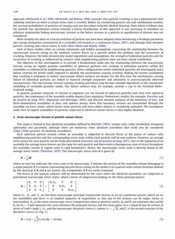
approach (McDowell et al., 1996; McDowell and Bolton, 1998) assumes that particle crushing is not a phenomenon thatsuddenly switches on when a certain stress state is reached. Rather, by considering particle size and coordination number,the survival probabilities of particles of varying sizes are described using the Weibull function, from which it follows thatthe particle size distribution evolves towards a fractal distribution. In this approach it was necessary to introduce anarbitrary relationship linking macroscopic stresses to the failure stresses in a particle as equilibrium of stresses was notconsidered.
More recently the ideas of a fractal evolution of particle size have been adopted when introducing a breakage parameterinto energy dissipation assumptions of a crushable soil treated as a continuum (Einav, 2007), and through links betweenparticle crushing and critical states in soils (Muir Wood and Maeda, 2008).
Each of these studies relies on certain statements and hidden assumptions concerning the relationship between themacroscopic stresses acting on the medium, contact forces on a particle within the medium, and the occurrence ofcrushing. However, the links between key model ingredients and assumptions, the strength of individual particles and theoccurrence of crushing as influenced by contacts with neighbouring particles have not been clearly established.
The objective of this investigation is to provide a fundamental study into the relationship between the macroscopicstresses acting on regular granular assemblies of spherical particles and crushing of individual particles within theassemblies as influenced by neighbouring particles. Stress configurations within individual particles are investigated and afailure criterion for brittle solids imposed to identify the mechanisms causing crushing. Making the further assumptionthat crushing is analogous to failure, macroscopic failure surfaces are drawn. For the first time the mechanisms causingfailure of individual particles are linked to material strength properties and ultimately to macroscopically observedcharacteristics. The macroscopic stresses causing crushing and failure may become valuable ingredients in the constitutivemodelling of crushable granular media. The failure surfaces may, for example, provide a cap to the frictional Mohr–Coulomb wedge.
In general, granular materials of interest to engineers are not formed of spherical particles and, even with sphericalparticles, the randomness of the assembly readily departs from regularity. Photoelastic studies (for example, Drescher andde Josselin de Jong, 1972; Majmudar and Behringer, 2005) and discrete element analyses of the behaviour of two- andthree-dimensional assemblies of discs and spheres always show that boundary stresses are transmitted through theassembly via force chains, which favour some particles and leave others almost or completely unloaded. The assumptionmade here of regular assemblies of particles subjected to identical contact forces is thus highly idealised.
2. From macroscopic stresses to particle contact forces
This study is limited to four idealised assemblies defined by Mitchell (1993): simple cubic, cubic tetrahedral, tetragonalsphenoidal and pyramidal, although there are numerous other idealised assemblies that could also be considered(Filep (1936) presents 29 idealised assemblies).
Each spherical particle located within an assembly is subjected to discrete forces at the points of contact withneighbouring particles and the corresponding stress state within each particle will be non-uniform. However, an averagestress tensor for each particle can be easily determined (Drescher and de Josselin de Jong, 1972). Due to the regularity of anassembly the average stress tensors are the same for each particle and there exists a homogenous state of stress throughoutthe assembly (except at regions next to rigid boundaries). Hence, the macroscopic stress state is directly linked to theaverage stress tensor (Thornton, 1979). The macroscopic stress state r is given by
r ¼1
VaF (1)
where an over-bar indicates the stress state to be macroscopic, V denotes the portion of the assembly volume belonging toa single particle, F is a matrix representing discrete forces acting on the surface S of a particle with contact locations definedby the matrix a. If r and a are known, the components of F are easily evaluated.
The forces at the particle contacts will be determined for the cases when the idealised assemblies are subjected togeneralised macroscopic stress states, which consist of compressive loading on the three principal planes:
r ¼sx 0 0
0 sy 0
0 0 sz
264
375 ¼
Kxsm 0 0
0 Kysm 0
0 0 Kzsm
264
375 (2)
where sx; sy and sz are the three macroscopic principal compressive stresses in an xyz coordinate system, which act onthe assemblies and there is no implied sequence of magnitudes so that any of the stresses can be major, minor orintermediate. sm is the mean macroscopic stress (compression taken as positive) and Kx, Ky and Kz are constants that satisfyKx+Ky+Kz ¼ 3 and represent the ratios between the principal stresses and the mean stress. In a p plane r may be written interms of Lode’s angle x, sm and the macroscopic deviatoric stress ss (where ss ¼
ffiffiffiffiffiffiffi3J2
qand J2 is the second invariant of the
deviatoric stress) as (Fig. 1):
r ¼ smIþ
ffiffiffi2
3
rssðcosxn1 þ sinxn2Þ (3)

ARTICLE IN PRESS
x
y z
32
�mI
σ
�s �
Fig. 1. Definition of r, x, sm and ss in the p plane.
y
yy
y
z
z z
z
Fig. 2. Idealised assemblies of equally sized spherical particles: (a) simple cubic, (b) cubic tetrahedral, (c) tetragonal sphenoidal and (d) pyramidal.
A.R. Russell et al. / J. Mech. Phys. Solids 57 (2009) 1293–1313 1295
in which I is the unit matrix and:
n1 ¼
ffiffiffi6p .
3 0 0
0 �ffiffiffi6p .
6 0
0 0 �ffiffiffi6p .
6
2666664
3777775 and n2 ¼
0 0 0
0ffiffiffi2p .
2 0
0 0 �ffiffiffi2p .
2
26664
37775 (4)
Eq. (1) can be easily solved for the four chosen idealised assemblies and the macroscopic stress of Eq. (2).To illustrate the use of this procedure consider the example of a simple cubic assembly in the xyz space. A section
through the assembly in the yz plane is illustrated in Fig. 2a, where the origin coincides with the centre of a particle. Eachparticle within the assembly has six contacts with neighbouring particles, and three pairs of diametrically opposite forcesp, q and r act normal to the surface through these contacts. Taking advantage of symmetry for the sake of brevity in themathematical expressions, only one force belonging to each pair of diametrically opposite forces is considered, and

ARTICLE IN PRESS
x
r
p
qz
x
z
x
z
x
q sr
q r
z
t
s
p
p
r
p q
t us
Fig. 3. Contact point locations for (a) simple cubic, (b) cubic tetrahedral, (c) tetragonal sphenoidal and (d) pyramidal assemblies. The particles are viewed
in the negative y direction, and the points labelled are on the top of the sphere, with y-coordinate zero or positive.
A.R. Russell et al. / J. Mech. Phys. Solids 57 (2009) 1293–13131296
therefore only three of the position vectors for the corresponding contacts need to be considered, with locations illustratedusing crosses in Fig. 3a. These position vectors can be presented in a single location matrix as:
a ¼
d=2 0 0
0 d=2 0
0 0 d=2
264
375 (5)
where d is the diameter of the spherical particle. The corresponding contact forces can also be represented in a single forcematrix:
F ¼
p 0 0
0 q 0
0 0 r
264
375 (6)
The volume of a single spherical particle is Vs ¼ pd3/6 and the specific volume of the simple cubic assembly is v ¼ 6/p sothat the portion of the assembly volume belonging to a single particle is V ¼ Vsv ¼ d3. These can be substituted into Eq. (1),and a multiplier of 2 introduced to account for the fact that only one force belonging to each pair of diametrically oppositeforces has been accounted for, to give:
r ¼2
d3
d=2 0 0
0 d=2 0
0 0 d=2
264
375
p 0 0
0 q 0
0 0 r
264
375 ¼
p.
d2 0 0
0 q.
d2 0
0 0 r.
d2
2666664
3777775 (7)
enabling p, q and r to be evaluated as:
p ¼ Kxsmd2 q ¼ Kysmd2 r ¼ Kzsmd2 (8)
The same procedure can be followed for the other three assemblies. Their configurations in sections through the xyz
space are shown in Fig. 2b, c and d, with contact forces and locations indicated in Fig. 3b, c and d, respectively. In theassemblies considered here each contact force is part of a diametrically opposite pair. The matrices of contact locations andforces as multiplied together with V to get r are summarised in Table 1, along with expressions for the contact forces interms of sm, d, Kx, Ky and Kz.
For each assembly there is an influence of orientation of principal stress axes xyz relative to the orientation of theassembly, even when symmetries exist within the assembly. Different expressions for the contact forces would result whenorientations different from those shown in Fig. 2 were assumed. Some orientations, including those used here, ensure that

Table 1Static equilibrium equations, contact forces and transition Lode angles for the four assemblies.
Simple cubic Cubic tetrahedral
Static equilibrium equation r ¼ 1V aF
r ¼2
d3
d=2 0 0
0 d=2 0
0 0 d=2
2664
3775
p 0 0
0 q 0
0 0 r
2664
3775
¼
p.
d2 0 0
0 q.
d2 0
0 0 r.
d2
26666664
37777775
r ¼4ffiffiffi3p
d3
d=2 0 0 0
0ffiffiffiffiffiffiffiffiffiffiffiffiffiffiffiffi2�
ffiffiffi3p
þp
d.
4ffiffiffiffiffiffiffiffiffiffiffiffiffiffiffiffi2þ
ffiffiffi3p
þp
d.
4ffiffiffi2þp
d.
4
0ffiffiffiffiffiffiffiffiffiffiffiffiffiffiffiffi2þ
ffiffiffi3p
�p
d.
4ffiffiffiffiffiffiffiffiffiffiffiffiffiffiffiffi2�
ffiffiffi3p
�p
d.
4ffiffiffi2þp
d.
4
266664
377775
p 0 0
0ffiffiffiffiffiffiffiffiffiffiffiffiffiffiffiffi2�
ffiffiffi3p
þp
q.
2ffiffiffiffiffiffiffiffiffiffiffiffiffiffiffiffi2þ
ffiffiffi3p
�p
q.
2
0ffiffiffiffiffiffiffiffiffiffiffiffiffiffiffiffi2þ
ffiffiffi3p
þp
r.
2ffiffiffiffiffiffiffiffiffiffiffiffiffiffiffiffi2�
ffiffiffi3p
�p
r.
2
0ffiffiffi2þp
s.
2ffiffiffi2þp
s.
2
26666666664
37777777775
¼
2ffiffiffi3p
p.
3d2 0 0
0ffiffiffi3pð2q�
ffiffiffi3p
qþ 2r þffiffiffi3p
r þ 2sÞ.
6d2�
ffiffiffi3pðqþ r � 2sÞ
.6d2
0 �ffiffiffi3pðqþ r � 2sÞ
.6d2 ffiffiffi
3pð2qþ
ffiffiffi3p
qþ 2r �ffiffiffi3p
r þ 2sÞ.
6d2
26666664
37777775
Contact forces p ¼ Kxsmd2
q ¼ Kysmd2
r ¼ Kzsmd2
p ¼ffiffiffi3p
Kxsmd2.
2
q ¼ ðffiffiffi3p
Ky þffiffiffi3p
Kz � 3Ky þ 3KzÞsmd2.
6
r ¼ ðffiffiffi3p
Ky þffiffiffi3p
Kz þ 3Ky � 3KzÞsmd2.
6
s ¼ffiffiffi3pðKy þ KzÞsmd2
.6
Lode angles marking transition between stability and crushing tanx1 ¼3sN � 1ffiffiffi3pð1� sN Þ
tanx2 ¼1ffiffiffi
3pð2sN � 1Þ
x1 ¼ arctan2ffiffiffi3p
3
sN
2�ffiffiffi3p
sN
� ��
1
3
" #
x2 ¼p2þ arctan½3� 2
ffiffiffi3p
sN �
x3 ¼p2þ arctan
3sN
2ffiffiffi3p� 3sN
� �
Tetragonal sphenoidal Pyramidal
Static
equilibrium
equation
r ¼ 1V aF
r ¼8
3d3
ffiffiffi3þp
d.
4 0 0 0ffiffiffi3�p
d.
4
ffiffiffi2þp
d.
8ffiffiffiffiffiffiffiffiffiffiffiffiffiffiffiffi2�
ffiffiffi3p
þp
d.
4ffiffiffiffiffiffiffiffiffiffiffiffiffiffiffiffi2þ
ffiffiffi3p
þp
d.
4ffiffiffi2þp
d.
4ffiffiffi2þp
d.
8
ffiffiffi2þp
d.
8ffiffiffiffiffiffiffiffiffiffiffiffiffiffiffiffi2þ
ffiffiffi3p
�p
d.
4ffiffiffiffiffiffiffiffiffiffiffiffiffiffiffiffi2�
ffiffiffi3p
�p
d.
4ffiffiffi2þp
d.
4ffiffiffi2þp
d.
8
26666664
37777775
ffiffiffi3þp
p.
2ffiffiffi2þp
p.
4ffiffiffi2þp
p.
4
0ffiffiffiffiffiffiffiffiffiffiffiffiffiffiffiffi2�
ffiffiffi3p
þp
q.
2ffiffiffiffiffiffiffiffiffiffiffiffiffiffiffiffi2þ
ffiffiffi3p
�p
q.
2
0ffiffiffiffiffiffiffiffiffiffiffiffiffiffiffiffi2þ
ffiffiffi3p
þp
r.
2ffiffiffiffiffiffiffiffiffiffiffiffiffiffiffiffi2�
ffiffiffi3p
�p
r.
2
0ffiffiffi2þp
s.
2ffiffiffi2þp
s.
2
ffiffiffi3�p
t.
2ffiffiffi2þp
t.
4ffiffiffi2þp
t.
4
2666666666666664
3777777777777775
¼
ðpþ tÞ.
d2 ffiffiffi6pðp� tÞ
.6d2 ffiffiffi
6pðp� tÞ
.6d2
ffiffiffi6pðp� tÞ
.6d2
ðpþ 4q� 2ffiffiffi3p
qþ 4r þ 2ffiffiffi3p
r þ 4sþ tÞ.
6d2ðp� 2q� 2r þ 4sþ tÞ
.6d2
ffiffiffi6pðp� tÞ
.6d2
ðp� 2q� 2r þ 4sþ tÞ.
6d2ðpþ 4qþ 2
ffiffiffi3p
qþ 4r � 2ffiffiffi3p
r þ 4sþ tÞ.
6d2
26666664
37777775
r ¼2ffiffiffi2p
d3
ffiffiffi2p
d.
4ffiffiffi2p
d.
4 0 0 �ffiffiffi2p
d.
4 �ffiffiffi2p
d.
4
d=4 d=4 d=2 0 d=4 d=4
�d=4 d=4 0 d=2 �d=4 d=4
26664
37775
ffiffiffi2p
p.
2 p=2 �p=2
ffiffiffi2p
q.
2 q=2 q=2
0 r 0
0 0 s
�ffiffiffi2p
t.
2 t=2 �t=2
�ffiffiffi2p
u.
2 u=2 u=2
26666666666666664
37777777777777775
¼
ffiffiffi2pðpþ qþ t þ uÞ
.2d2
ðpþ q� t � uÞ.
2d2ð�pþ qþ t � uÞ
.2d2
ðpþ q� t � uÞ.
2d2 ffiffiffi2pðpþ qþ 4r þ t þ uÞ
.4d2 ffiffiffi
2pð�pþ q� t þ uÞ
.4d2
ð�pþ qþ t � uÞ.
2d2 ffiffiffi2pð�pþ q� t þ uÞ
.4d2 ffiffiffi
2pðpþ qþ 4sþ t þ uÞ
.4d2
26666664
37777775

Table 1 (continued )
Tetragonal sphenoidal Pyramidal
Contact forces p ¼ Kxsmd2.
2
q ¼ ð�ffiffiffi3p
Ky þ Ky þffiffiffi3p
Kz þ KzÞsmd2.
4
r ¼ ðffiffiffi3p
Ky þ Ky �ffiffiffi3p
Kz þ KzÞsmd2.
4
s ¼ ð�Kx þ Ky þ KzÞsmd2.
4
t ¼ Kxsmd2.
2
p ¼ffiffiffi2p
Kxsmd2.
4
q ¼ffiffiffi2p
Kxsmd2.
4
r ¼ffiffiffi2pð�Kx þ 2KyÞsmd2
.4
s ¼ffiffiffi2pð�Kx þ 2KzÞsmd2
.4
t ¼ffiffiffi2p
Kxsmd2.
4
u ¼ffiffiffi2p
Kxsmd2.
4
Lode angles
marking
transition
between
stability and
crushing
x1 ¼ pþ arctan1
3� 3sN
� �
x2 ¼ pþ arctan 1�4
3sN
� � x1 ¼ arctan
ffiffiffi6pð3
ffiffiffi2p
sN � 8Þ
3ð4ffiffiffi2p� 2sN Þ
" #
x2 ¼ pþ arctan4ffiffiffi
6pðsN �
ffiffiffi2pÞ
" #
x3 ¼ pþ arctan
ffiffiffi3p
33�
2ffiffiffi2p
sN
!" #

ARTICLE IN PRESS
A.R. Russell et al. / J. Mech. Phys. Solids 57 (2009) 1293–1313 1299
simple expressions for normal contact forces can be obtained without introducing shear forces at the contacts or withoutintroducing shear stresses in r. In other words, for the assemblies and orientations used here in which some contacttangents are not aligned with the principal axes of applied stress, there is no difficulty with the assumption that thecontacts provide normal forces only. This will be discussed later in the paper.
3. From particle contact forces to internal stress fields
The stress field in a single spherical particle corresponding to the contact forces determined for each assembly (Table 1)will be investigated for a range of sm, Kx, Ky and Kz values. But first attention is given to the stresses belonging to just onepair of diametrically opposite forces.
Let B be a point on the sphere’s surface where a normal force b is applied (there is a corresponding force of equalmagnitude acting on the sphere at a point diametrically opposite to B). The location vector for the force b denoted as B isexpressed in the general form:
B ¼
xB
yB
zB
264
375 (9)
whereffiffiffiffiffiffiffiffiffiffiffiffiffiffiffiffiffiffiffiffiffiffiffiffiffiffix2
B þ y2B þ z2
B
q¼ d=2. Imagine a point C located on a plane containing the sphere’s centre and B and a vector from the
origin to C, where C has a projected point on the yz plane oriented at an angle f to the y-axis (Fig. 4a). C is located at adistance r from the origin, and a radius from the origin to C makes an angle o to the x-axis. The location vector for C is then:
C ¼
xC
yC
zC
264
375 ¼
rcosorsino cosfrsino sinf
264
375 (10)
Stresses at C due to the concentrated force at B (and its equal but diametrically opposite force) can be evaluated using theclosed form solutions of Hiramatsu and Oka (1966). In that analysis it is assumed that the material making up the sphere isisotropic and perfectly elastic. It is also assumed that the force at the surface acts normal to and uniformly across a smallarea defined by a, where a is half of an angle subtended from the centre of the sphere to the boundary of the area (Fig. 3 inRussell and Muir Wood, 2009, although in that paper a was denoted as y0). The solutions are a function of the anglesubtended between vectors B and C, denoted as y (Fig. 4a), and given by
y ¼ arccosB � Cffiffiffiffiffiffiffiffiffiffiffiffiffiffiffiffiffiffiffiffiffiffiffiffiffiffiffiffi
ðB � BÞðC � CÞp" #
(11)
where � symbolises the dot product of two vectors. The solutions depend on the variable r and the sphere diameter d. Thesolutions also depend on a.
Hiramatsu and Oka (1966) give expressions for the normal stress sr that acts along the same line as vector C. Also givenare expressions for the normal stress sy that acts along a line orthogonal to sr and on the plane containing vectors B and C,and the normal stress acting orthogonal to sr and sy and denoted by sc. The lines of action of sr, sy and sc are shown inFig. 4b. Also given is the expression for the shear stress, which acts perpendicular to the line of intersection of the planes onwhich sr and sy act, denoted by try. The other components of shear stress trc and tyc are, from symmetry, zero.
Theoretical values for the stresses at any location on the plane containing vectors B and C due to a single pair of contactforces at and diametrically opposite to B, for given values of f and a, can be obtained by adjusting r and y and substituting
y
z
x
B
C
x′
y′
z′
y
z
x
B Cr
force b
�
�
�
�
�� �r��
Fig. 4. (a) Force b acts normal to the surface of the sphere at point B with location vector B. Stresses at point C due to force b, when C is located on the
plane containing the origin and B and the vector of length r from the origin to C, are direct functions of r and h (b) stresses at C due to force b at B in the x0 ,
y0 and z0 coordinate system.

ARTICLE IN PRESS
A.R. Russell et al. / J. Mech. Phys. Solids 57 (2009) 1293–13131300
these into the expressions given in Hiramatsu and Oka (1966). However, the objective of this study is to investigate thecombined influence of multiple pairs of contact forces on the stress field within the sphere. In particular, stress fieldsbelonging to pairs of forces will be superimposed on each other. It is therefore necessary to convert the stresses belongingto one pair of forces to an equivalent set of stresses in a common reference coordinate system. The original xyz coordinatesystem will be used as this reference. The normal stresses sr, sy and sc at C due to the forces at and diametricallyopposite to B are orthogonal to the x0, y0 and z0 axes as shown in Fig. 4b. The stresses at C in this coordinate system denotedby s0C are:
r0C ¼
sr try 0
try sy 0
0 0 sc
264
375 ¼
sx0 tx0y0 0
tx0y0 sy0 0
0 0 sz0
264
375 (12)
where a0 is used to indicate an association with x0y0z0.The stress rC in the reference xyz coordinate system can then be found using the expression:
rC ¼
sx txy txz
txy sy tyz
txz tyz sz
264
375 ¼MTr0CM (13)
where the transformation matrix M is given by
M ¼
l m n
l0 m0 n0
l00 m00 n00
264
375 (14)
in which l, m and n are the direction cosines of the x0-axis, l0, m0 and n0 are the direction cosines of the y0-axis and l00, m00 andn00 are the direction cosines of the z0-axis, each being a function of o and f.
Stresses in the xyz coordinate system can now be determined at any point within the sphere due to a pair ofdiametrically opposite contact forces. Stresses due to multiple pairs of contact forces are obtained by simply addingtogether the stresses belonging to each pair of contact forces after they have been converted to the xyz coordinate system.The procedure was validated by reproducing the results for multiple pairs of contact forces as presented in Gundepudi et al.(1997).
4. Stresses fields and failure within individual particles
Failure of a brittle sphere subjected to a single pair of diametrically opposite contact forces has been studied by Russelland Muir Wood (2009). The simple two parameter multi-axial failure criterion for brittle materials proposed byChristensen (2000) was assumed to apply. The criterion states that a material is not at failure when:
wkffiffiffi3p I1 þ ð1þ wÞ2
I21
3� I2
!o
k2
1þ w orwkffiffiffi
3p I1 þ ð1þ wÞ2J2o
k2
1þ w (15)
where I1 and I2 are the first and second invariants of r and J2 ¼ I12/3�I2 is the second invariant of r� smI, with tensile
stresses being taken as positive. The parameter w is a dimensionless shape parameter and represents the ratio between thecharacteristic uniaxial compressive and tensile strengths, sc and st respectively, through:
w ¼ jscj
st� 1 (16)
and the parameter k is a scale parameter defined as
k ¼ 1þ wffiffiffi3p jscj (17)
The characteristic unconfined compressive and tensile strengths of the material are then:
sc ¼ �
ffiffiffi3p
k1þ w
and st ¼
ffiffiffi3p
kð1þ wÞ2
(18)
The criterion is a modified form of the von Mises criterion, the modification surrounding the inclusion of I1 in Eq. (15). Agraphical representation of the criterion is given in Fig. 5 of Russell and Muir Wood (2009).
Christensen (2000) referred to k as an intrinsic strength and w as a microstructure parameter, and surmised that k is ameasure of the strength of the material having no microstructural damage and must be related to atomic scale properties,and w represents the effects of microstructural deviations from the ideal. Reference should be made to Christensen (2000)and Russell and Muir Wood (2009) for a more detailed discussion of the criterion and the significance of the parameters wand k.

ARTICLE IN PRESS
Fig. 5. Mobilised k for w ¼ 99, diametrically opposite contact forces of f ¼ �165 N, applied to an area bounded by a ¼ p/36, d ¼ 1.4 mm, m ¼ 0.08 and
E ¼ 90 GPa. The bold line near the top of the sphere indicates the extent of the surface over which the contact force is uniformly applied.
A.R. Russell et al. / J. Mech. Phys. Solids 57 (2009) 1293–1313 1301
In the Russell and Muir Wood (2009) study it was found that, for wb1 (a characteristic of brittle materials), failureinitiates in the sphere where mobilised k (denoted as kmob) is a maximum, that is where the ratio (�J2/I1) is a maximumwithin that stress field, not where the tensile stress is a maximum. For small contact areas and a single pair of contactforces, the ratio (�J2/I1) was found to always be a maximum at a distance of tana�d/2 below the centre of the contact,irrespective of the elastic properties of the material making up the sphere. Russell and Muir Wood (2009) went on to back-calculate material strength characteristics of a quartz sand particle subjected to a point load test by Nakata et al. (1999).The contact force at failure for the particle, having an average diameter of d ¼ 1.4 mm, was f ¼ �165 N. This information,along with assumed elastic properties for quartz, Poisson’s ratio m ¼ 0.08 and Young’s modulus E ¼ 90 GPa (Grady, 1998),and an assumed contact area bound by a, enabled contour plots of kmob to be drawn for different values of w and a: the oneshown in Fig. 5 is for a ¼ p/36 and w ¼ 99. The maximum value of kmob, and therefore the intrinsic strength k for assumedvalues of w ¼ 99 and a ¼ p/36, was found to be k ¼ 520 GPa. The intrinsic strength k, and the characteristic tensile strengthst that may be subsequently obtained using Eq. (18), are very sensitive to the assumed values of m, a and w. However, aslong as wb1, the characteristic compressive strength sc is virtually insensitive to the assumed w, although a strongdependence on the assumed m and a is maintained. A reasonable estimate of m may be assumed or obtained from publishedtables if it cannot be measured experimentally. To establish a suitable value for a it is necessary to consider the geometry ofthe force contact. In this study, however, the failure surfaces are normalised with respect to a specially defined particlecharacteristic strength rather than sc, st or k, as explained in Section 5, to avoid using a and other material parameters inthe presentation of results.
Now a more elaborate stress field analysis will be conducted for multiple pairs of contact forces, again using the failurecriterion of Christensen (2000).
5. From micro-failure to macro-failure
As a starting point it is assumed that a particle within an arrangement will rupture when k ¼ 520 GPa. Inherentfeatures of this assumption are that all particles have the property w ¼ 99, a diameter of 1.4 mm, force contact areas boundby a ¼ p/36, elastic properties m ¼ 0.08 and E ¼ 90 GPa, and fail in a point load test when f ¼ �165 N. One could useHertzian theory for elastic spheres in contact to establish the size of the contact areas (and a) for each pair of contact forces.Forces of different magnitude would have different contact areas. However, such differences in contact areas have beenignored in the results that follow: this assumption is justified in subsequent discussion.
Another key assumption here is that if a single particle ruptures then the entire assembly has failed. As each particle inan assembly is subjected to contact forces of identical configurations, each particle will fail simultaneously. An alternativeview not employed here is that contact forces in granular media, even idealised assemblies of equally sized spheres, vary
ARTICLE IN PRESS
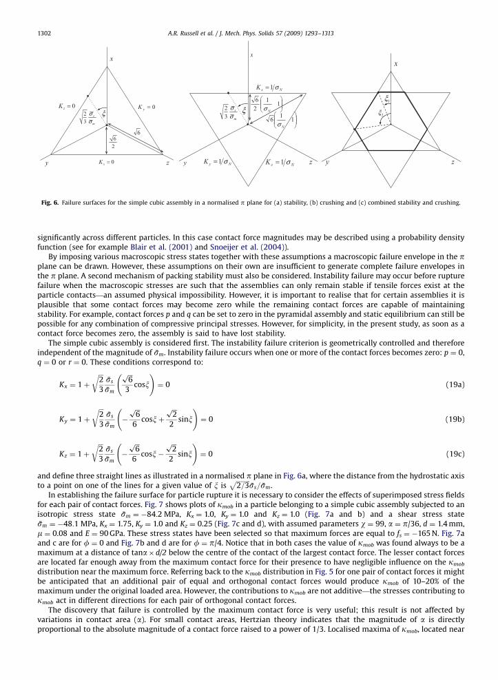
Fig. 6. Failure surfaces for the simple cubic assembly in a normalised p plane for (a) stability, (b) crushing and (c) combined stability and crushing.
A.R. Russell et al. / J. Mech. Phys. Solids 57 (2009) 1293–13131302
significantly across different particles. In this case contact force magnitudes may be described using a probability densityfunction (see for example Blair et al. (2001) and Snoeijer et al. (2004)).
By imposing various macroscopic stress states together with these assumptions a macroscopic failure envelope in the pplane can be drawn. However, these assumptions on their own are insufficient to generate complete failure envelopes inthe p plane. A second mechanism of packing stability must also be considered. Instability failure may occur before rupturefailure when the macroscopic stresses are such that the assemblies can only remain stable if tensile forces exist at theparticle contacts—an assumed physical impossibility. However, it is important to realise that for certain assemblies it isplausible that some contact forces may become zero while the remaining contact forces are capable of maintainingstability. For example, contact forces p and q can be set to zero in the pyramidal assembly and static equilibrium can still bepossible for any combination of compressive principal stresses. However, for simplicity, in the present study, as soon as acontact force becomes zero, the assembly is said to have lost stability.
The simple cubic assembly is considered first. The instability failure criterion is geometrically controlled and thereforeindependent of the magnitude of sm. Instability failure occurs when one or more of the contact forces becomes zero: p ¼ 0,q ¼ 0 or r ¼ 0. These conditions correspond to:
Kx ¼ 1þ
ffiffiffi2
3
rss
sm
ffiffiffi6p
3cosx
!¼ 0 (19a)
Ky ¼ 1þ
ffiffiffi2
3
rss
sm�
ffiffiffi6p
6cosxþ
ffiffiffi2p
2sinx
!¼ 0 (19b)
Kz ¼ 1þ
ffiffiffi2
3
rss
sm�
ffiffiffi6p
6cosx�
ffiffiffi2p
2sinx
!¼ 0 (19c)
and define three straight lines as illustrated in a normalised p plane in Fig. 6a, where the distance from the hydrostatic axisto a point on one of the lines for a given value of x is
ffiffiffiffiffiffiffiffiffi2=3
pss=sm.
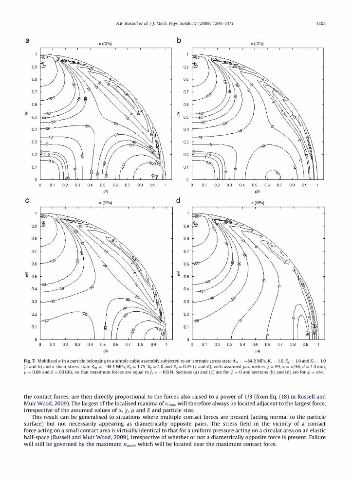
In establishing the failure surface for particle rupture it is necessary to consider the effects of superimposed stress fieldsfor each pair of contact forces. Fig. 7 shows plots of kmob in a particle belonging to a simple cubic assembly subjected to anisotropic stress state sm ¼ �84:2 MPa, Kx ¼ 1.0, Ky ¼ 1.0 and Kz ¼ 1.0 (Fig. 7a and b) and a shear stress statesm ¼ �48:1 MPa, Kx ¼ 1.75, Ky ¼ 1.0 and Kz ¼ 0.25 (Fig. 7c and d), with assumed parameters w ¼ 99, a ¼ p/36, d ¼ 1.4 mm,m ¼ 0.08 and E ¼ 90 GPa. These stress states have been selected so that maximum forces are equal to fs ¼ �165 N. Fig. 7aand c are for f ¼ 0 and Fig. 7b and d are for f ¼ p/4. Notice that in both cases the value of kmob was found always to be amaximum at a distance of tana�d/2 below the centre of the contact of the largest contact force. The lesser contact forcesare located far enough away from the maximum contact force for their presence to have negligible influence on the kmob
distribution near the maximum force. Referring back to the kmob distribution in Fig. 5 for one pair of contact forces it mightbe anticipated that an additional pair of equal and orthogonal contact forces would produce kmob of 10–20% of themaximum under the original loaded area. However, the contributions to kmob are not additive—the stresses contributing tokmob act in different directions for each pair of orthogonal contact forces.
The discovery that failure is controlled by the maximum contact force is very useful; this result is not affected byvariations in contact area (a). For small contact areas, Hertzian theory indicates that the magnitude of a is directlyproportional to the absolute magnitude of a contact force raised to a power of 1/3. Localised maxima of kmob, located near
ARTICLE IN PRESS
Fig. 7. Mobilised k in a particle belonging to a simple cubic assembly subjected to an isotropic stress state sm ¼ �84:2 MPa, Kx ¼ 1.0, Ky ¼ 1.0 and Kz ¼ 1.0
(a and b) and a shear stress state sm ¼ �48:1 MPa, Kx ¼ 1.75, Ky ¼ 1.0 and Kz ¼ 0.25 (c and d), with assumed parameters w ¼ 99, a ¼ p/36, d ¼ 1.4 mm,
m ¼ 0.08 and E ¼ 90 GPa, so that maximum forces are equal to fs ¼ �165 N. Sections (a) and (c) are for f ¼ 0 and sections (b) and (d) are for f ¼ p/4.
A.R. Russell et al. / J. Mech. Phys. Solids 57 (2009) 1293–1313 1303
the contact forces, are then directly proportional to the forces also raised to a power of 1/3 (from Eq. (18) in Russell andMuir Wood, 2009). The largest of the localised maxima of kmob will therefore always be located adjacent to the largest force,irrespective of the assumed values of a, w, m and E and particle size.
This result can be generalised to situations where multiple contact forces are present (acting normal to the particlesurface) but not necessarily appearing as diametrically opposite pairs. The stress field in the vicinity of a contactforce acting on a small contact area is virtually identical to that for a uniform pressure acting on a circular area on an elastichalf-space (Russell and Muir Wood, 2009), irrespective of whether or not a diametrically opposite force is present. Failurewill still be governed by the maximum kmob, which will be located near the maximum contact force.

ARTICLE IN PRESS
A.R. Russell et al. / J. Mech. Phys. Solids 57 (2009) 1293–13131304
We can now generalise our conclusion that the particle rupture failure criterion is reached when the maximum contactforce is equal to that required to cause rupture of a singly loaded sphere, denoted fs (and equal to the assumed �165 N asdescribed above)—in other words, when either p ¼ fs, q ¼ fs or r ¼ fs. These conditions correspond to:
Kx ¼ 1þ
ffiffiffi2
3
rss
sm
ffiffiffi6p
3cosx
!¼
f s
smd2¼
1
sN(20a)
Ky ¼ 1þ
ffiffiffi2
3
rss
sm�
ffiffiffi6p
6cosxþ
ffiffiffi2p
2sinx
!¼
f s
smd2¼
1
sN(20b)
Kz ¼ 1þ
ffiffiffi2
3
rss
sm�
ffiffiffi6p
6cosx�
ffiffiffi2p
2sinx
!¼
f s
smd2¼
1
sN(20c)
and also define three straight lines as illustrated in Fig. 6b, although these now have a dependence on sm when fs and d arematerial constants. Notice that the substitution sN ¼ sm
.ðf s=d2
Þ has been made, where the normalised stress sN
represents the mean macroscopic stress acting on the assembly divided by a particle characteristic strength taken to be fs/d2.
Again, the distance from the hydrostatic axis to a point on one of the lines for a given value of x isffiffiffiffiffiffiffiffiffi2=3
pss=sm.
It is important to point out that if a laboratory test is used to obtain fs/d2 for a single particle then the nature of the test
will influence its value. For example, a test where a particle is squashed between flat platens would have larger forcecontact areas and therefore produce a larger fs/d
2 than a test where a particle is loaded between sharp pointers. It isreasonable to use k as the particle characteristic strength instead of fs/d
2, although results normalised using k would bedependant on a for the largest contact force acting on a particle in an assembly and other material properties w, m and E. Ithas therefore been deemed preferable to use fs/d
2 in this study. Inherent in this approach is the assumption that the loadedarea at the largest contact force on a particle in an assembly is the same as the loaded area in the laboratory test used toobtain fs/d
2.The two sets of straight lines form equilateral triangles in the normalised p plane. Overlaying the two sets leads to the
combined failure surface as shown in Fig. 6c. The Lode angles marking the intersection points of the two sets, which aretransitions between rupture and stability modes of failure, are found by solving components of Eqs. (19) and (20)simultaneously. For the two angles indicated in Fig. 6c it can be shown that:
tanx1 ¼3sN � 1ffiffiffi3pð1� sNÞ
and tanx2 ¼1ffiffiffi
3pð2sN � 1Þ
(21)
The other Lode angles marking transition points can be found by reflection.
For sNo1/3, that is when �smo� f s
.3d2, the inverted triangle representing rupture failure lies completely outside the
triangle representing stability failure. Stability therefore always controls failure when �smo� f s
.3d2. For 14sN42/3,
that is when �f s
.d24� sm4� 2f s
.3d2, the inverted triangle representing rupture failure lies entirely inside that for
stability failure so rupture totally controls failure. A combination of crushing and stability control failure for 2/34sN41/3.For sN ¼ 1, the crushing envelope reduces to a point in the p plane so no amount of shear stress can be tolerated by theassembly. Three surfaces in p planes are shown in Fig. 8 for sm ¼ �30, �40 and �50 MPa. Consider now the surface forsm ¼ �50 MPa. For x ¼ 0, failure occurs when Kx ¼ 1.684, Ky ¼ 0.658 and Kz ¼ 0.658 (point A) and is controlled by ruptureas the maximum kmob is 520 MPa. For x ¼ 0.838, failure occurs when Kx ¼ 1.684, Ky ¼ 1.316 and Kz ¼ 0 (point B). At thislocation the maximum kmob is again 520 GPa. However, as Kz ¼ 0, this location on the failure surface marks the point wherethe rupture and instability failure criteria are satisfied simultaneously. Increasing Lode’s angle to p/3, failure is governed byinstability as the maximum kmob is less than 520 GPa and the extent of the failure surface is established by Kx ¼ 1.5,Ky ¼ 1.5, Kz ¼ 0 (point C). Increasing Lode’s angle to 1.256, failure is governed by both instability and rupture, as Kx ¼ 1.316,Ky ¼ 1.684, Kz ¼ 0 and the maximum kmob is 520 GPa (point D).
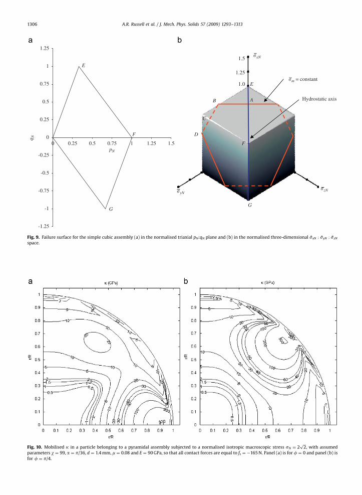
An orthogonal view of the failure surface is presented in Fig. 9a for axially symmetric conditions ðsy ¼ szÞ of triaxialcompression (x ¼ 0) and extension (x ¼ p), which can be achieved in routine laboratory equipment for testing granularmaterials. Notice that normalised triaxial stresses pN:qN have been used in place of the usual triaxial stresses p:q, wherep ¼ ðsx þ 2syÞ=3, pN ¼ p/(fs/d
2), q ¼ sx � sy and qN ¼ q/(fs/d2). p is analogous to sm and q is analogous to ss. The envelope
for triaxial compression, that is the part for qN40, is defined by a straight line that radiates from the origin with a slope of 3.Crushing commences when pN ¼ 1/3 and beyond this point it is defined by a different straight line of slope �3/2, whichintercepts the pN-axis at 1. The envelope for triaxial extension, that is the part for qNo0, is defined by a straight line thatradiates from the origin with a slope of �3/2. Crushing commences when pN ¼ 2/3 and beyond this point it is defined by adifferent straight line of slope 3, which also intercepts the pN-axis at 1. It is noted that failure mechanisms such as particlesliding and rotation (often referred to as frictional failure), which are not considered in this study, should be included inorder to form a more complete picture of failure in granular assemblies. The simple Mohr–Coulomb criterion capturesthese effects reasonably well. The failure surfaces shown thus far may extend into parts of the stress space, which arephysically unattainable as friction failure would have already occurred.

ARTICLE IN PRESS
25MPa
50
75
−�y
ABC
D
−�z
�m = −50 MPa
�m = −40
�m = −30
−�x
Fig. 8. Failure surfaces of a simple cubic assembly for w ¼ 99, k ¼ 520 GPa, a ¼ p/36, m ¼ 0.08 and E ¼ 90 GPa. Selected points on one of the surfaces are
labelled and also shown in Fig. 9.
A.R. Russell et al. / J. Mech. Phys. Solids 57 (2009) 1293–1313 1305
A three-dimensional image of the overall surface is shown in Fig. 9b in the sxN : syN : szN space, where the subscriptN indicates that stresses on the axes have been divided by fs/d
2. It has the shape of a cube with side length of 1, and withopposite corners located on the hydostatic axis. Selected points on the surface labelled in Figs. 8 and 9a are also labelled inFig. 9b. The hydrostatic axis is also labelled.
The same procedure was used to establish failure surfaces for the other three assemblies. In all cases it was observedthat the maximum kmob was located near the maximum contact force, irrespective of the magnitudes of the other contactforces as they are located far enough away for their presence to have negligible influence on the kmob distribution near themaximum, even for the pyramidal arrangement where 12 contact forces act on a particle (Fig. 10). Although Fig. 10 relatesto an isotropic imposed stress, the same conclusion applies to a strongly deviatoric stress state.
The failure surfaces for stability and rupture in each assembly were drawn by setting the contact forces (listed in Table 1in expanded form) to zero and fs, respectively.
For the cubic tetrahedral assembly each surface was defined by four straight lines as illustrated in Fig. 11a and b. Thelines in each surface corresponding to s ¼ 0 and fs are redundant, indicating that the other forces become zero or equal to fs
before s does. Overlaying the two sets leads to the combined failure surface as shown in Fig. 11c, where the lines for s havebeen omitted. The Lode angles marking the intersection points of the two sets (Fig. 11c), which are transitions between
rupture and stability modes of failure, are listed in Table 1. For sNo2=3ffiffiffi3p
, that is when �sm4� 2ffiffiffi3p
f s
.3d2, the triangle
representing rupture failure lies completely outside the triangle representing stability failure. Stability therefore always
controls failure when �smo� 2f s=3ffiffiffi3p
d2. For �sN4� 2ffiffiffi3p
=3, that is when �sm4� 2ffiffiffi3p
f s
.3d2, the triangle
representing rupture failure lies completely inside the triangle representing stability failure. Rupture therefore always
controls failure when �sm4� 2ffiffiffi3p
f s
.3d2. For sN ¼ 8
ffiffiffi3p
=9, the crushing envelope reduces to a point in the p plane
although it is located a distance offfiffiffi6p
=8 in the negative direction along the x-axis (Fig. 11b) rather than at the origin. Thispoint represents the maximum mean stress that the arrangement can withstand, although the arrangement can alsowithstand a small amount of shear stress. For �2
ffiffiffi3p
=34� sN4� 2=3ffiffiffi3p
, the crushing triangle cuts the corners of thestability triangle so failure is controlled by either crushing or stability, depending on x. The section through the p plane forx ¼ 0 and x ¼ p is shown in Fig. 12a, where the normalised stresses pN:qN have been used. Again a two-fold rotationalsymmetry exists with the point of rotation being the coordinate ð4
ffiffiffi3p
=9;�ffiffiffi3p
=6Þ. The point of rotation satisfiesffiffiffiffiffiffiffiffiffi2=3
pss=sm ¼
ffiffiffi6p
=8 and lies on the qN/pN ¼ �3/8 axis. A three-dimensional image of the overall surface is shown inFig. 12b in the sxN : syN : szN space. It has the shape of a parallelepiped, although opposite corners are not located on thehydrostatic axis. Selected points on the surface labelled in Fig. 12a are also labelled in Fig. 12b.
For the tetragonal sphenoidal assembly the failure surfaces for rupture and stability are defined by five straight lines,although those for p ¼ 0 and t ¼ 0 overlap, as do those for p ¼ fs and t ¼ fs, as illustrated in Fig. 13a and b. Overlaying thetwo surfaces leads to the combined failure surface as shown in Fig. 13c. The Lode angles marking the intersection points arelisted in Table 1. For sNo2/3, that is when �smo� 2f s
.3d2, the surface representing rupture failure lies completely
outside the surface representing stability failure. For sN44/3, that is when �sm4� 4f s
.3d2, the surface representing
rupture failure lies completely inside the surface representing stability failure. For 4/34sN42/3, the crushing surface cutsthe corners of the stability surface so failure is controlled by either crushing or stability, depending on x. For sN ¼ 2, the
ARTICLE IN PRESS
Fig. 10. Mobilised k in a particle belonging to a pyramidal assembly subjected to a normalised isotropic macroscopic stress sN ¼ 2ffiffiffi2p
, with assumed
parameters w ¼ 99, a ¼ p/36, d ¼ 1.4 mm, m ¼ 0.08 and E ¼ 90 GPa, so that all contact forces are equal to fs ¼ �165 N. Panel (a) is for f ¼ 0 and panel (b) is
for f ¼ p/4.
-1.25
-1
-0.75
-0.5
-0.25
0
0.25
0.5
0.75
1
1.25
0pN
E
F
F
E
B
C
D
A
GG
Hydrostatic axis
0.25 0.5 0.75 1 1.25 1.5
q N
�m = constant
�xN
�zN�yN
1.0
1.25
1.5
Fig. 9. Failure surface for the simple cubic assembly (a) in the normalised triaxial pN:qN plane and (b) in the normalised three-dimensional sxN : syN : szN
space.
A.R. Russell et al. / J. Mech. Phys. Solids 57 (2009) 1293–13131306

ARTICLE IN PRESS
− −
−
−
Fig. 11. Failure surfaces for the cubic tetrahedral assembly in a normalised p plane for (a) stability, (b) crushing and (c) combined stability and crushing.
-2
-1.75
-1.5
-1.25
-1
-0.75
-0.5
-0.25
0
0.25
0.5
0.75
1
1.25
1.5
1.75
2
0pN
E
F
G
E
H
F
G
H
0.25 0.5 0.75 1 1.51.25 1.75 2
q N
�xN
�zN
�yN
0.5
1.0
1.5
2.0
Fig. 12. Failure surface for the cubic tetrahedral assembly (a) in the normalised triaxial pN:qN plane and (b) in the normalised three-dimensional
sxN : syN : szN space.
A.R. Russell et al. / J. Mech. Phys. Solids 57 (2009) 1293–1313 1307
crushing envelope reduces to a point at the origin of the p plane. This point represents the maximum mean stress that thearrangement can withstand, and is in a state that cannot withstand any shear stress. The section through the p plane forx ¼ 0 and x ¼ p is shown in Fig. 14a. A symmetry does not exist. A three-dimensional image of the overall surface is shownin Fig. 14b in the sxN : syN : szN space.
For the pyramidal assembly the failure surfaces for rupture and stability are defined by six straight lines, although thosefor p ¼ 0, q ¼ 0, t ¼ 0 and u ¼ 0 overlap, as do those for p ¼ fs, q ¼ fs, t ¼ fs and u ¼ fs, as illustrated in Fig. 15a and b.

ARTICLE IN PRESS
Fig. 13. Failure surfaces for the tetragonal sphenoidal assembly in a normalised p plane for (a) stability, (b) crushing and (c) combined stability and
crushing.
-2.5
-2.25
-2
-1.75
-1.5
-1.25
-1
-0.75
-0.5
-0.25
0
0.25
0.5
0.75
1
1.25
1.5
1.75
2
2.25
2.5
0pN
q N
0.25 0.5 0.75 1 1.25 1.5 1.75 2 2.25 2.5
�xN
�zN
�yN
0.5
1.0
1.5
2.0
2.5
Fig. 14. Failure surface for the tetragonal sphenoidal assembly (a) in the normalised triaxial pN:qN plane and (b) in the normalised three-dimensional
sxN : syN : szN space.
A.R. Russell et al. / J. Mech. Phys. Solids 57 (2009) 1293–13131308
Overlaying the two surfaces leads to the combined failure surface and two possible shapes are shown in Fig. 15c. The Lode
angles marking the intersection points (Table 1), for which x2 is common to the two shapes shown, mark transitions
between rupture and stability modes of failure. For sNo2ffiffiffi2p
=3, that is when �smo� 2ffiffiffi2p
f s
.3d2, the surface representing

ARTICLE IN PRESS
Fig. 15. Failure surfaces for the pyramidal assembly in a normalised p plane for (a) stability, (b) crushing and (c) combined stability and crushing (two
possible surfaces).
-2.5
-2.25
-2
-1.75
-1.5
-1.25
-1
-0.75
-0.5
-0.25
0
0.25
0.5
0.75
1
1.25
1.5
1.75
2
2.25
2.5
0
2.5
2.0
1.5
1.0
0.5
�yN
�zN
�xN
q N
pN
0.25 0.5 0.75 1 1.25 1.5 1.75 2 2.25 2.5 2.75 3
Fig. 16. Failure surface for the pyramidal assembly (a) in the normalised triaxial pN:qN plane and (b) in the normalised three-dimensional sxN : syN : szN
space.
A.R. Russell et al. / J. Mech. Phys. Solids 57 (2009) 1293–1313 1309
rupture failure lies completely outside the surface representing stability failure. For sN44ffiffiffi2p
=3, that is when
�sm4� 4ffiffiffi2p
f s
.3d2, the surface representing rupture failure lies completely inside the surface representing stability
failure. For 4ffiffiffi2p
=34sN42ffiffiffi2p
=3, the crushing surface cuts the corners of the stability surface so failure is controlled by
either crushing or stability, depending on x. For sN ¼ 2ffiffiffi2p
, the crushing envelope reduces to a point at the origin of the pplane. This point represents the maximum mean stress that the arrangement can withstand, and is in a state that cannot
withstand any shear stress. The section through the p plane for x ¼ 0 and p is shown in Fig. 16a. A two-fold rotational
ARTICLE IN PRESS
A.R. Russell et al. / J. Mech. Phys. Solids 57 (2009) 1293–13131310
symmetry exists with the point of rotation being the coordinate ðffiffiffi2p
;0Þ. A three-dimensional image of the overall surface isshown in Fig. 16b in the sxN : syN : szN space. It has the shape of a parallelepiped, with opposite corners located on thehydrostatic axis.
6. Extension to account for asymmetries
The surfaces drawn are influenced by the orientation of principal stress axes xyz relative to the orientation of theassembly (Fig. 2). Supposing that only normal forces can exist at particle contacts, many possible orientations willnecessitate the introduction of off-diagonal components (shear stresses) in r to maintain a static equilibrium. When off-diagonal components exist in r, the diagonal components no longer represent principal stresses. Alternatively, if bothnormal and shear forces were able to exist at particle contacts, then it would be possible to form a static equilibrium for anyorientation even if r were written entirely in terms of principal stresses as in Eq. (2).
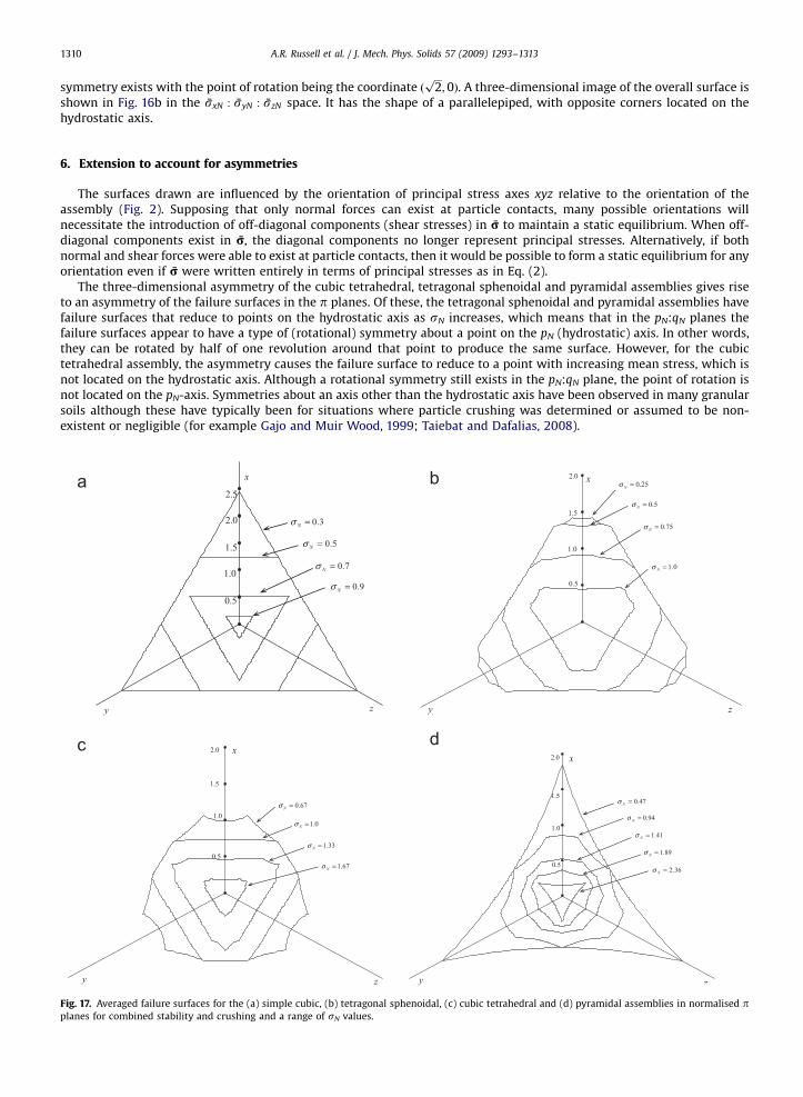
The three-dimensional asymmetry of the cubic tetrahedral, tetragonal sphenoidal and pyramidal assemblies gives riseto an asymmetry of the failure surfaces in the p planes. Of these, the tetragonal sphenoidal and pyramidal assemblies havefailure surfaces that reduce to points on the hydrostatic axis as sN increases, which means that in the pN:qN planes thefailure surfaces appear to have a type of (rotational) symmetry about a point on the pN (hydrostatic) axis. In other words,they can be rotated by half of one revolution around that point to produce the same surface. However, for the cubictetrahedral assembly, the asymmetry causes the failure surface to reduce to a point with increasing mean stress, which isnot located on the hydrostatic axis. Although a rotational symmetry still exists in the pN:qN plane, the point of rotation isnot located on the pN-axis. Symmetries about an axis other than the hydrostatic axis have been observed in many granularsoils although these have typically been for situations where particle crushing was determined or assumed to be non-existent or negligible (for example Gajo and Muir Wood, 1999; Taiebat and Dafalias, 2008).
Fig. 17. Averaged failure surfaces for the (a) simple cubic, (b) tetragonal sphenoidal, (c) cubic tetrahedral and (d) pyramidal assemblies in normalised pplanes for combined stability and crushing and a range of sN values.

ARTICLE IN PRESS
�xN
�zN
�yN
0.5
1.0
1.5
2.0
�xN
�zN
�yN
0.5
1.0
1.5
2.0
2.5
�xN
�zN
�yN
0.51.0
1.5
2.52.0
Fig. 19. Three-dimensional images of the averaged failure surface for the (a) cubic tetrahedral, (b) tetragonal sphenoidal and (c) pyramidal assemblies.
That for the simple cubic arrangement is not shown as it is the same as Fig. 9b.
-2
-1.75
-1.5
-1.25
-1
-0.75
-0.5
-0.25
0
0.25
0.5
0.75
1
1.25
1.5
1.75
2
0
-2
-1.75
-1.5
-1.25
-1
-0.75
-0.5
-0.25
0
0.25
0.5
0.75
1
1.25
1.5
1.75
2
-2.5
-2.25
-2
-1.75
-1.5
-1.25
-1
-0.75
-0.5
-0.25
0
0.25
0.5
0.75
1
1.25
1.5
1.75
2
2.25
2.5
q N
q N q N
pN pN pN
0.25 0.5 0.75 1 1.25 1.5 1.75 2 0 0.25 0.5 0.75 1 1.25 1.5 1.75 2 2.25 2.5 0 0.25 0.5 0.75 1 1.25 1.5 1.75 2 2.25 2.5 2.75 3
Fig. 18. Averaged failure surfaces for the (a) tetragonal sphenoidal (b) cubic tetrahedral and (c) pyramidal assemblies in normalised triaxial pN:qN planes.
That for the simple cubic arrangement is not shown as it is the same as Fig. 9a.
A.R. Russell et al. / J. Mech. Phys. Solids 57 (2009) 1293–1313 1311
A simple procedure will now be followed to remove the asymmetry implied by the assumed assemblies of Fig. 2. Foreach assembly consider an agglomerate of 8 spheres for which the centres join to form a parallelepiped. Now suppose thata granular material is made up of a very large number of these agglomerates, in which the parallelepiped for eachagglomerate has one of its three axes randomly aligned along one of the x, y or z directions. This enables us to obtain anaveraged and symmetric failure surface in the three-dimensional space. Inherent in this procedure is the simplifyingassumption that a perfect packing of randomly aligned agglomerates is possible—with the overall specific volume beingequal to that of each agglomerate. Also, no redistribution of contact forces across adjacent agglomerate surfaces that thepacking may generate is considered. This simple procedure can be represented mathematically by noting that the distancefrom the hydrostatic axis to the failure surface is a function of x, and for the averaged failure surface is given by
1
3
ffiffiffi2
3
rss
smxð Þ þ
ffiffiffi2
3
rss
smxþ
2p3
� �þ
ffiffiffi2
3
rss
smxþ
4p3
� � !(22)
ARTICLE IN PRESS
Lade-Duncan
Matsuoka-Nakai
Mohr-Coulomb
x
y z
0.5
1.0
1.5
2.0 cubicSimple
altetrahedrCubic
Pyramidal
I13/I3 = constant
I1I2/I3 = constant �N = 0.7
�N = 0.45
�N = 0.4
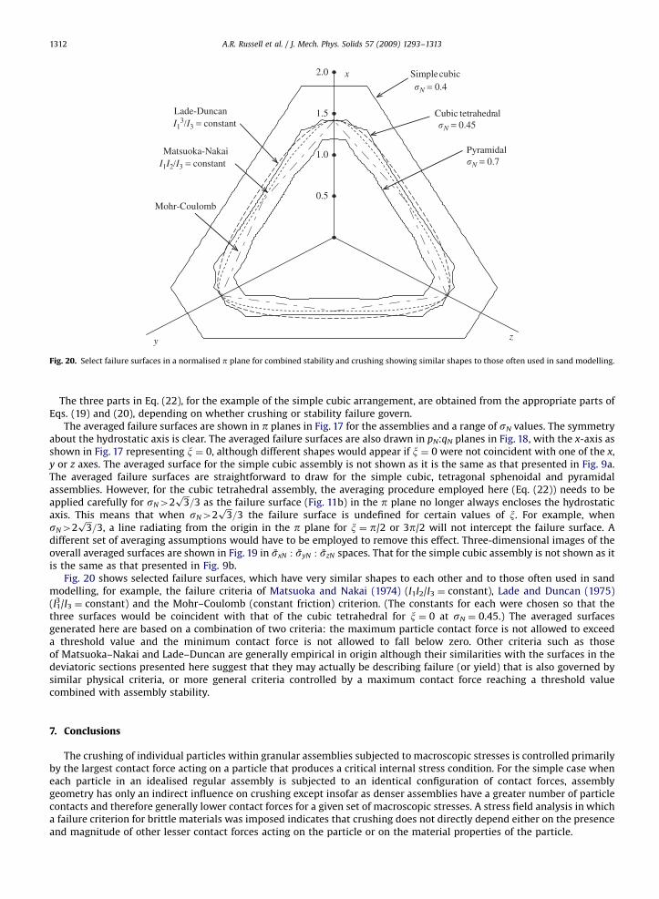
Fig. 20. Select failure surfaces in a normalised p plane for combined stability and crushing showing similar shapes to those often used in sand modelling.
A.R. Russell et al. / J. Mech. Phys. Solids 57 (2009) 1293–13131312
The three parts in Eq. (22), for the example of the simple cubic arrangement, are obtained from the appropriate parts ofEqs. (19) and (20), depending on whether crushing or stability failure govern.
The averaged failure surfaces are shown in p planes in Fig. 17 for the assemblies and a range of sN values. The symmetryabout the hydrostatic axis is clear. The averaged failure surfaces are also drawn in pN:qN planes in Fig. 18, with the x-axis asshown in Fig. 17 representing x ¼ 0, although different shapes would appear if x ¼ 0 were not coincident with one of the x,y or z axes. The averaged surface for the simple cubic assembly is not shown as it is the same as that presented in Fig. 9a.The averaged failure surfaces are straightforward to draw for the simple cubic, tetragonal sphenoidal and pyramidalassemblies. However, for the cubic tetrahedral assembly, the averaging procedure employed here (Eq. (22)) needs to beapplied carefully for sN42
ffiffiffi3p
=3 as the failure surface (Fig. 11b) in the p plane no longer always encloses the hydrostaticaxis. This means that when sN42
ffiffiffi3p
=3 the failure surface is undefined for certain values of x. For example, whensN42
ffiffiffi3p
=3, a line radiating from the origin in the p plane for x ¼ p/2 or 3p/2 will not intercept the failure surface. Adifferent set of averaging assumptions would have to be employed to remove this effect. Three-dimensional images of theoverall averaged surfaces are shown in Fig. 19 in sxN : syN : szN spaces. That for the simple cubic assembly is not shown as itis the same as that presented in Fig. 9b.
Fig. 20 shows selected failure surfaces, which have very similar shapes to each other and to those often used in sandmodelling, for example, the failure criteria of Matsuoka and Nakai (1974) (I1I2/I3 ¼ constant), Lade and Duncan (1975)(I1
3/I3 ¼ constant) and the Mohr–Coulomb (constant friction) criterion. (The constants for each were chosen so that thethree surfaces would be coincident with that of the cubic tetrahedral for x ¼ 0 at sN ¼ 0.45.) The averaged surfacesgenerated here are based on a combination of two criteria: the maximum particle contact force is not allowed to exceeda threshold value and the minimum contact force is not allowed to fall below zero. Other criteria such as thoseof Matsuoka–Nakai and Lade–Duncan are generally empirical in origin although their similarities with the surfaces in thedeviatoric sections presented here suggest that they may actually be describing failure (or yield) that is also governed bysimilar physical criteria, or more general criteria controlled by a maximum contact force reaching a threshold valuecombined with assembly stability.
7. Conclusions
The crushing of individual particles within granular assemblies subjected to macroscopic stresses is controlled primarilyby the largest contact force acting on a particle that produces a critical internal stress condition. For the simple case wheneach particle in an idealised regular assembly is subjected to an identical configuration of contact forces, assemblygeometry has only an indirect influence on crushing except insofar as denser assemblies have a greater number of particlecontacts and therefore generally lower contact forces for a given set of macroscopic stresses. A stress field analysis in whicha failure criterion for brittle materials was imposed indicates that crushing does not directly depend either on the presenceand magnitude of other lesser contact forces acting on the particle or on the material properties of the particle.

ARTICLE IN PRESS
A.R. Russell et al. / J. Mech. Phys. Solids 57 (2009) 1293–1313 1313
By taking crushing and assembly instability as each being analogous to separate mechanisms of failure a series ofmacroscopic failure surfaces has been drawn. The size and shape of the surfaces are heavily dependent on a particlecharacteristic strength. The surfaces are also dependent on the assumed orientation of the assembly with respect tothe macroscopic principal stresses, making the surfaces asymmetric about the hydrostatic axis for some assemblies. Forthese cases, a spatial averaging technique involving a number of simplifying assumptions may be applied to drawalternate composite failure surfaces that are symmetric about the hydrostatic axis. Sections of the averaged macroscopicfailure surfaces on p planes have similarities to those commonly used in sand modelling, under conditions whereparticle crushing has been assumed negligible or non-existent. The similarities suggest that any type of yield or failure in agranular assembly is governed by the two criteria: maximum contact force reaching a threshold value and assemblystability.
References
Blair, D.L., Mueggenburg, N.W., Marshall, A.H., Jaeger, H.M., Nagel, S.R., 2001. Force distributions in three-dimensional granular assemblies: effects ofpacking order and interparticle friction. Physical Review E 63, 041304.
Cheng, Y.P., Bolton, M.D., Nakata, Y., 2004. Crushing and plastic deformation of soils simulated using DEM. Geotechnique 54 (2), 131–141.Cheng, Y.P., Nakata, Y., Bolton, M.D., 2003. Distinct element simulation of crushable soil. Geotechnique 53 (7), 633–641.Christensen, R.M., 2000. Yield functions, damage states, and intrinsic strength. Mathematics and Mechanics of Solids 5, 285–300.Drescher, A., de Josselin de Jong, G., 1972. Photoelastic verification of a mechanical model for the flow of a granular material. Journal of the Mechanics and
Physics of Solids 20, 337–351.Einav, I., 2007. Breakage mechanics–Part I: theory. Journal of the Mechanics and Physics of Solids 55, 1274–1297.Filep, L., 1936. Egyenlo gombokbol allo halmazok. Vizugyi Kozlemenyek.Gajo, A., Muir Wood, D., 1999. Severn–Trent sand: a kinematic-hardening constitutive model: the q–p formulation. Geotechnique 49 (5), 595–614.Grady, D.E., 1998. Shock-wave compression of brittle solids. Mechanics of Materials, 181–203.Gundepudi, M.K., Sankar, B.V., Mecholsky, J.J., Clupper, D.C., 1997. Stress analysis of brittle spheres under multiaxial loading. Powder Technology 94,
153–161.Hiramatsu, Y., Oka, Y., 1966. Determination of the tensile strength of rock by a compression test of an irregular test piece. International Journal of Rock
Mechanics and Mining Sciences 3, 89–99.Lade, P.V., Duncan, J.M., 1975. Elasto-plastic stress–strain theory for cohesionless soil. Proceedings of ASCE, Journal of the Geotechnical Engineering
Division 101 (GT10), 1037–1053.Majmudar, T.S., Behringer, R.P., 2005. Contact force measurements and stress-induced anisotropy in granular materials. Nature 435, 1079–1082.Matsuoka, H., Nakai, T., 1974. Stress-deformation and strength characteristics of soil under three different principal stresses. Proceedings of Japan Society
of Civil Engineers 232, 59–70.Mitchell, J.K., 1993. Fundamentals of Soil Behaviour. Wiley, New York.McDowell, G.R., Bolton, M.D., Robertson, D., 1996. The fractal crushing of granular materials. Journal of the Mechanics and Physics of Solids 44 (12),
2079–2102.McDowell, G.R., Bolton, M.D., 1998. On the mechanics of crushable aggregates. Geotechnique 48, 667–679.Muir Wood, D., Maeda, K., 2008. Changing grading of soil: effect on critical states. Acta Geotechnica 3, 3–14.Nakata, Y., Hyde, A.F.L., Hyodo, M., Murata, H., 1999. A probabilistic approach to sand particle crushing in the triaxial test. Geotechnique 49 (5),
567–583.Pestana, J.M., Whittle, A.J., 1999. Formulation of a unified constitutive model for clays and sands. International Journal for Numerical and Analytical
Methods in Geomechanics 23, 1215–1243.Russell, A.R., Khalili, N., 2002. Drained cavity expansion in sands exhibiting particle crushing. International Journal of Numerical and Analytical Methods
in Geomechanics 26 (4), 323–340.Russell, A.R., Khalili, N., 2004. A bounding surface plasticity model for the behaviour of sands exhibiting particle crushing. Canadian Geotechnical Journal
41, 1179–1192.Russell, A.R., Muir Wood, D., 2009. Point load tests and strength measurements for brittle spheres. International Journal of Rock Mechanics and Mining
Sciences 46 (2), 272–280.Snoeijer, J.H., Vlugt, T.J.H., Ellenbroek, W.G., van Hecke, M., van Leeuwen, J.M.J., 2004. Ensemble theory for force networks in hyperstatic granular media.
Physical Review E 70, 061306.Taiebat, M., Dafalias, Y.F., 2008. SANISAND: simple anisotropic sand plasticity model. International Journal of Numerical and Analytical Methods in
Geomechanics 32, 915–948.Thornton, C., 1979. The conditions for failure of a face-centered cubic array of uniform rigid spheres. Geotechnique 29 (4), 441–459.
Copyright © 2022 FDOKUMEN