Corrosion Control on Underwater Piles
13
271 | Page Corrosion Control on Underwater Piles Ramlakhan Gupta 1 ,Adarsh Pathak 2 ,Manish Kumar 3 ABSTRACT Piles are structures used to transfer loads from superstructure to the soil (surface). When the subsurface layer is in water or if when we use with a hydraulic structure, the piles are to be driven into water and under water strata or layer. Piles used in underwater structures are often subjected to corrosion. There is no absolute way to eliminate all corrosion; but corrosion protection measures are employed to control the effect of corrosion. Corrosion are depend up on the environmental and other factors. Forms of corrosion protection include the use of inhibitors, coating surface treatments cathode protection and anode protection ,sealants. The control measures explained in this are Protective coatings, cathode treatment and application of Fibre Reinforced Polymer (FRP) Composites. Keywords: pile foundation, coating , fiber reinforced polymer ,corrosion. I.INTRODUCTION Corrosion is the deformation of metals and alloys by the chemical reaction with the environment. During corrosion the metals are converted to metallic compounds at the surface and these compounds varies in dry and wet condition, high temperature/high humidity can lead to rapid deterioration that necessitate costly repairs. The high concentration of chloride ion in seawater allows it to penetrate to the level of steel even in high-quality concrete. In a particular corrosion of metal structures, is a problem that must regularly be addressed in a wide variety of areas, for example, in the automotive industry, metal parts are often plated or coated to protect them from road salt and moisture in hopes of increasing their longevity. Corrosion repairs are only durable, the conditions responsible for the original deformation are removed. That means, all chloride-contaminated concrete including the concrete behind the steel must be removed. Since the boundaries of the chloride contaminated region are not known with any precision this is daunting task even under dry conditions. For half-submerged piles in salt water this is a near impossibility. Fiber reinforced polymers (FRP) offer the prospect of such a cost effective repair. Its lightweight, high strength and resistance to chemicals offer obvious cost advantages. In fabric form, it offers unprecedented flexibility in construction. Moreover, as fibers can be oriented as required they can provide strength in any desired direction many traditional metal parts are currently being used with polymeric components, which are not only lighter but also more cost effective to produce. But these are generally impervious to electrochemical corrosion often experienced by metals. Even with the proper selection of base metals and well-designed systems or structures, there is no absolute way to eliminate all corrosion. Therefore, corrosion protection methods are used to additionally mitigate and control the effects of corrosion. Corrosion protection can be in a number of different
-
Upload
khangminh22 -
Category
Documents
-
view
1 -
download
0
Transcript of Corrosion Control on Underwater Piles
271 | P a g e
Corrosion Control on Underwater Piles
Ramlakhan Gupta1,Adarsh Pathak
2,Manish Kumar
3
ABSTRACT
Piles are structures used to transfer loads from superstructure to the soil (surface). When the subsurface layer
is in water or if when we use with a hydraulic structure, the piles are to be driven into water and under water
strata or layer. Piles used in underwater structures are often subjected to corrosion. There is no absolute way
to eliminate all corrosion; but corrosion protection measures are employed to control the effect of corrosion.
Corrosion are depend up on the environmental and other factors. Forms of corrosion protection include the
use of inhibitors, coating surface treatments cathode protection and anode protection ,sealants. The control
measures explained in this are Protective coatings, cathode treatment and application of Fibre Reinforced
Polymer (FRP) Composites.
Keywords: pile foundation, coating , fiber reinforced polymer ,corrosion.
I.INTRODUCTION
Corrosion is the deformation of metals and alloys by the chemical reaction with the environment. During
corrosion the metals are converted to metallic compounds at the surface and these compounds varies in dry and
wet condition, high temperature/high humidity can lead to rapid deterioration that necessitate costly repairs.
The high concentration of chloride ion in seawater allows it to penetrate to the level of steel even in high-quality
concrete.
In a particular corrosion of metal structures, is a problem that must regularly be addressed in a wide variety of
areas, for example, in the automotive industry, metal parts are often plated or coated to protect them from road
salt and moisture in hopes of increasing their longevity.
Corrosion repairs are only durable, the conditions responsible for the original deformation are removed. That
means, all chloride-contaminated concrete including the concrete behind the steel must be removed. Since the
boundaries of the chloride contaminated region are not known with any precision this is daunting task even
under dry conditions. For half-submerged piles in salt water this is a near impossibility.
Fiber reinforced polymers (FRP) offer the prospect of such a cost effective repair. Its lightweight, high strength
and resistance to chemicals offer obvious cost advantages. In fabric form, it offers unprecedented flexibility in
construction. Moreover, as fibers can be oriented as required they can provide strength in any desired direction
many traditional metal parts are currently being used with polymeric components, which are not only lighter but
also more cost effective to produce. But these are generally impervious to electrochemical corrosion often
experienced by metals. Even with the proper selection of base metals and well-designed systems or structures,
there is no absolute way to eliminate all corrosion. Therefore, corrosion protection methods are used to
additionally mitigate and control the effects of corrosion. Corrosion protection can be in a number of different

272 | P a g e
forms/strategies with perhaps multiple methods applied in severe environments. Forms of corrosion protection
include the use of inhibitors, surface treatments, coatings and sealants, cathode protection and anodic protection.
II.CORROSION MECHANISM OF STEEL IN SEA WATER
On steel piling in seawater, the more chemically active surface areas (anodes) are metallically coupled through
the piling itself to the less chemically active surface areas (cathodes) resulting in a flow of electricity and
corrosion of the anodic areas. General surface roughening occurs when these local anodic and cathode areas
continually shift about randomly during the corrosion process. Sometimes these active local areas do not shift
position end, therefore, the metal suffers localized attack and pitting occurs. In general, the depth of pitting is
related to the ratio of the anodic sites to the area of cathode site in contact with the electrolyte (seawater). The
smaller the anode area relative to the cathode area, the deeper the pitting.
2.1 Zones of Corrosion of Steel Piles
Examination of corroded marine piles reveals several distinct areas of attack. It is convenient to divide these
areas into five zones, each having a characteristic corrosion rate as shown in Fig 2.1
Fig.2.1 Zone of corrosion of steel plates
2.2 Environments Conducive to Corrosion
There are many environments that are especially hostile and conducive to corrosion including fog and humidity,
saltwater and alkaline or acidic soils. Nations with a large land mass typically have a variety of these conditions.
The response of carbon steel to soil corrosion depends on the nature of the soil and
Other factors such as the availability to moisture and oxygen. Soils with high moisture content,
high electrical conductivity, high acidity and high dissolved salts will be most corrosive.

273 | P a g e
Corrosive conditions also know no national boundaries. Acid rain generated in one country pollutes the
environment and causes corrosion damage far beyond that country‘s borders – even beyond the borders of its
neighbours.
Acid rain is also a significant factor. Soil conditions vary widely from acidic to alkaline, And there are large
coastal areas where salt is found in the ground. Water properties range from saline to seawater and r
Freshwater
2.3 Corrosion Management
Before deciding on the methods for control of corrosion to be applied, conceptual and feasibility studies have
been carried out.
Typically, corrosion management can be divided into three major phases
Phase 1 of the program is the programmatic assessment of the project. This phase is the planning stage for a
corrosion management program to take place. It initiates the program to be implemented on structures that are
found to be under the threat of corrosion. For the planning stage, three main requirements are sought, namely
the strategy, budget and schedule needed to overcome the problem raised from corrosion of reinforcement. This
is seen as an important part for an effective management program as feasibility studies are normally conducted
to determine the serviceability of the structure after treatment
Phase 2 of the program involves physical assessment and actual remediation. Inspections for severity of
corrosion are conducted in this phase to determine what strategy or methods are most suitable to be applied
.Development of corrosion control strategy would present more option to the management program. Remedial
work would be carried out once the proper strategy has been recognize
Phase 3 of the program mainly deals with future monitoring of the repaired structure. Currently and historically,
most of the corrosion control programs are driven by response to incident or urgent need, rather than
systematically identifying and managing the existing resources. This can be overcome by implementing internal
or external monitoring system using current technology practiced in oil and gas industries is as shown in Fig.
2.2.

274 | P a g e
Fig.2.2 The overall flowchart for an effective corrosion management program
III.CORROSION PROTECTION METHODS:
3.1Protective Coating
In order to protect metals from corrosion, the contact between the metal and the corrosive environment is to be
cut off. This is done by coating the surface of metals with a continuous non-porous material inert to the
corrosive atmosphere.
Surface coatings are broadly classified into three
a). Metallic coatings
b). Inorganic Coatings
c). Organic Coatings
Individual coatings are formulated to perform specific functions and must be selected to become components of
a total system designed for optimum results considering the environment and service expectations.
The different types of coatings used for under water piles are:
3.1.1 Inorganic Zinc Silicates Primers:
Steel structures that are permanently immersed in sea water, such as jackets in the area below the Splash Zone,
are typically not coated for various reasons and protected solely by cathode protection systems consisting of
sacrificial anodes or impressed current arrays, which can be maintained as required by underwater contractors.
Various anticorrosive pigmented primers are available; some that passivity the steel but the most effective are
inorganic

275 | P a g e
zinc silicate primers which essentially become anodic to the steel in a corrosion cycle. The primary advantage
of this type of coating is that it will arrest rust creep, or undercutting of the coatings surrounding the damaged
area, and confine corrosion to the point of the damage. These coatings also provide a high degree of resistance
to heat and chemical spills.
3.1,2 High Build Epoxy Coatings:
Epoxies are generally more abrasion and chemical resistant than primers and topcoats and in this case protect
not only the substrate itself, but the zinc primer as well from all of these detrimental factors. However, one
drawback with epoxy coatings is very poor resistance to ultra violet from sunlight and most will chalk and fade
rapidly. This leads to an erosion of the coatings‘ film thickness, reducing the barrier protection of the system
3.1.3 Aliphatic Polyurethane Topcoats:
Polyurethane finish coats are generally acknowledged as providing optimum resistance to UV and high degrees
of flexibility and chemical resistance. They also help to maintain a very high level of cosmetic gloss and colour
retention and can be cleaned very easily, generally with low pH detergents and fresh water pressure washing.
Although polyurethane finishes offer no real anticorrosive or barrier protection to the substrate they do provide
a high level of protection to the integrity of the coatings system.
3.1.4Non-Skid Deck Coatings:
Coatings specifically designed with anti-slip properties normally incorporate very course aggregates for an
exaggerated profile. They are applied in very high film builds and normally without a zinc rich primer. When
primers are required they are usually epoxy types
3.2 Cathode Protection
The preferred technique for mitigating marine corrosion, based on historical performance and measurable
results, is cathode protection (CP) – the practice of using electrochemical reactions to prevent the corrosion of
steel structures. The reason for increased acceptance: cathode protection prevents corrosion on underwater
structures.
In theory and practice, the implementation of a CP system is quite simple. Assuming you already have
corroding steel in seawater, all you need is an anode, a power supply, and engineering talent. A protective
circuit is accomplished between the anode, steel (cathode), power supply and electrolyte (seawater).
3.3 A TYPICAL ANODE DELIVERY SYSTEM
3.3.1 Pile Mounted Anodes:
Pile mounted anodes are designed for efficient current distribution in and around pilings where the complex
geometry of the facility precludes remote placement of the anodes. These delivery systems are suitable for
direct attachment to pilings. The Flat Back Pile Mounted Anode
was designed specifically for H-Piles, and can also be configured for installation on sheet piling.
276 | P a g e
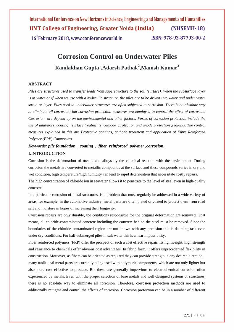
3.3.2 Disk Anode:
The disk anode was designed in conjunction with the U.S. Army Construction Engineering Research Lab for
use on navigational locks and dam gates. This anode system is also suitable for use on seawater intake
structures, vessel internals, and sheet piling when shore side access is possible.
.
. Fig.3.3.2 Pile mounted anode
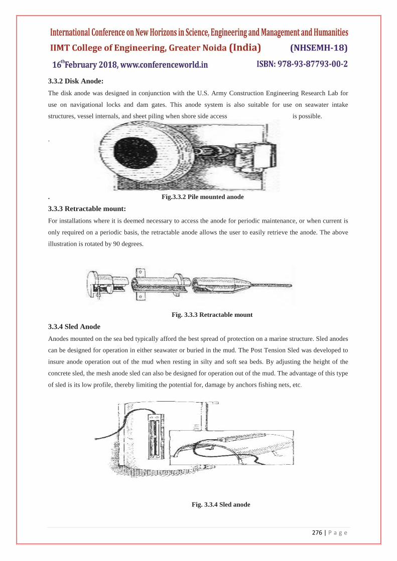
3.3.3 Retractable mount:
For installations where it is deemed necessary to access the anode for periodic maintenance, or when current is
only required on a periodic basis, the retractable anode allows the user to easily retrieve the anode. The above
illustration is rotated by 90 degrees.
Fig. 3.3.3 Retractable mount
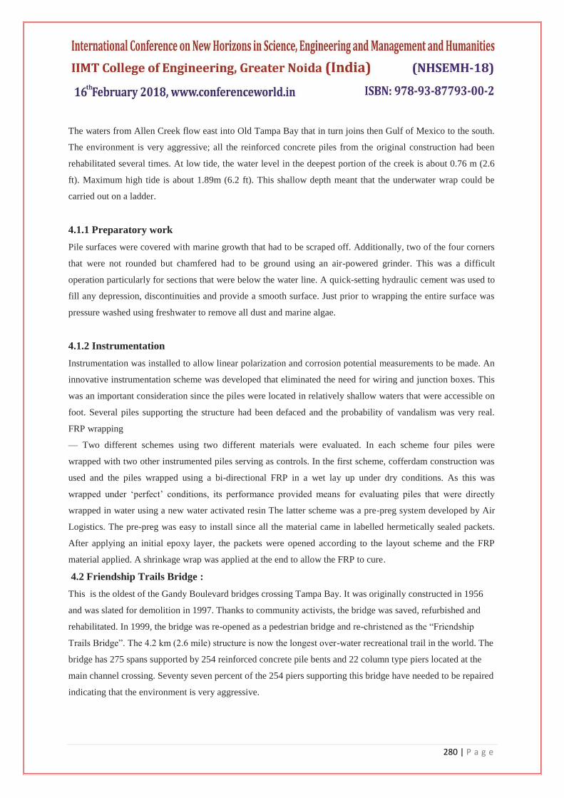
3.3.4 Sled Anode
Anodes mounted on the sea bed typically afford the best spread of protection on a marine structure. Sled anodes
can be designed for operation in either seawater or buried in the mud. The Post Tension Sled was developed to
insure anode operation out of the mud when resting in silty and soft sea beds. By adjusting the height of the
concrete sled, the mesh anode sled can also be designed for operation out of the mud. The advantage of this type
of sled is its low profile, thereby limiting the potential for, damage by anchors fishing nets, etc.
Fig. 3.3.4 Sled anode
277 | P a g e
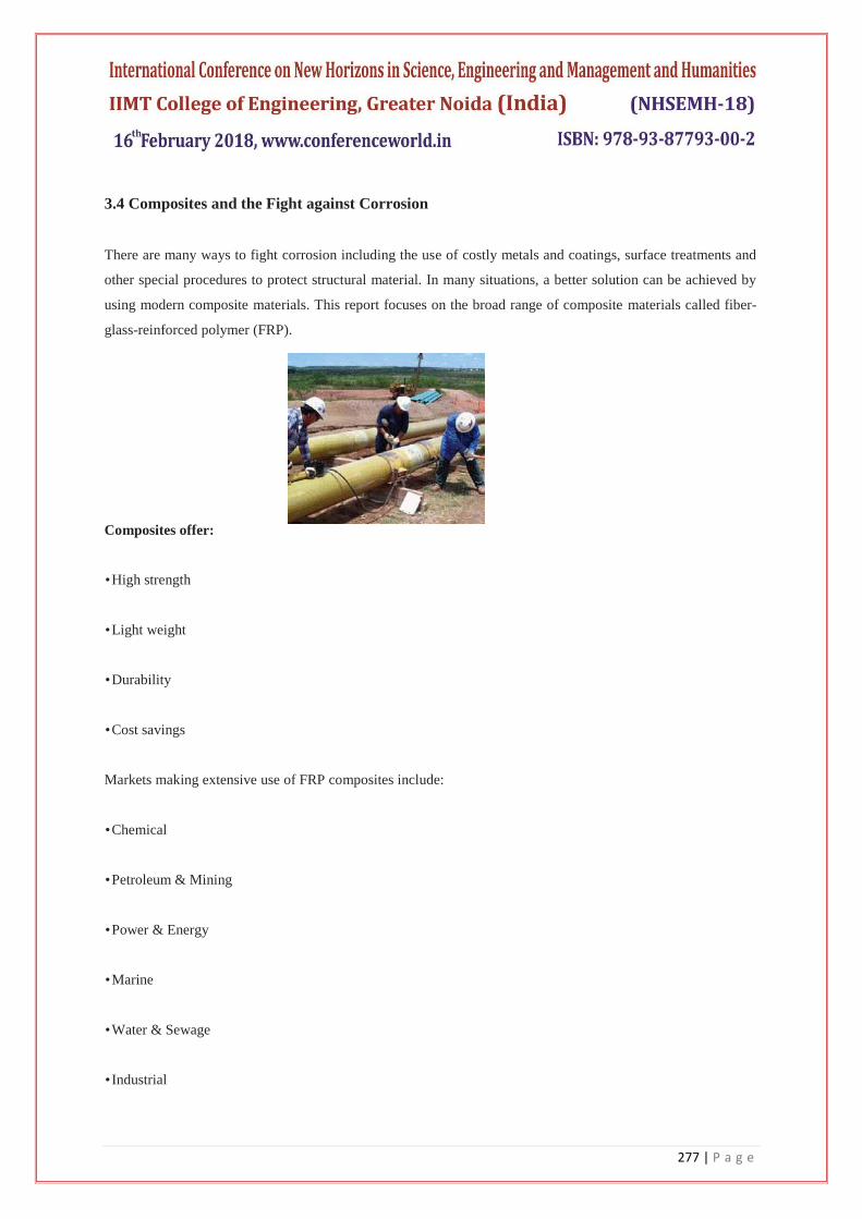
3.4 Composites and the Fight against Corrosion
There are many ways to fight corrosion including the use of costly metals and coatings, surface treatments and
other special procedures to protect structural material. In many situations, a better solution can be achieved by
using modern composite materials. This report focuses on the broad range of composite materials called fiber-
glass-reinforced polymer (FRP).
Composites offer:
• High strength
• Light weight
• Durability
• Cost savings
Markets making extensive use of FRP composites include:
• Chemical
• Petroleum & Mining
• Power & Energy
• Marine
• Water & Sewage
• Industrial

278 | P a g e
With more than 50 years of field experience, FRP is now proven technology. Tanks and pipe constructed with
corrosion-resistant composites have consistently provided extended service life over those made with metals.
And FRP is now regularly used to replace expensive stainless steel and high-nickel alloys.
FRP composites consist of engineered polymer resin and fiber reinforcement – about 95 percent of composites
are reinforced with glass fiber – and can be enhanced with additives and core materials. The combination can
produce some of the strongest materials for their weight ever developed.
3.5 Application of FRP Composites
Fibre reinforced polymers (FRP) have long been used for the repair and retrofit of concrete structural elements.
Their lightweight, high strength and resistance to chemicals offer obvious benefits. In fabric form, they provide
unparalleled flexibility. Moreover, as fibres can be oriented in any direction, their use can be optimized. This
makes FRP particularly suited for emergency repairs where damage can be multi-directional and speed of
strength restoration critically important
Fig 3.4 Repair and retrofit of concrete structural elements using FRP composites
The strength properties of FRPs collectively make up one of the primary reasons for which civil engineers
select them in the design of structures. A material‘s strength is governed by its ability to sustain a load without
excessive deformation or failure. When an FRP specimen is tested in axial tension, the applied force per unit
cross-sectional area (stress) is proportional to the ratio of change in a specimen‘s length to its original length
(strain).
When the applied load is removed, FRP returns to its original shape or length. In other words, FRP responds
linear-elastically to axial stress.
The response of FRP to axial compression is reliant on the relative proportion in volume of fibres, the properties
of the fibre and resin, and the interface bond strength. FRP composite compression failure occurs when the
fibres exhibit extreme (often sudden and dramatic) lateral or sides-way deflection called fiber buckling.
FRP‘s response to transverse tensile stress is very much dependent on the properties of the fiber and matrix, the
interaction between the fiber and matrix, and the strength of the fiber-matrix interface. Generally, however,

279 | P a g e
tensile strength in this direction is very poor. Shear stress is induced in the plane of an area when external loads
tend to cause two segments of a body to slide over one another. The shear strength of FRP is difficult to
quantify. Generally, failure will occur within the matrix material parallel to the fiber. Among FRP‘s high
strength properties, the most relevant features include excellent durability and corrosion resistance.
Furthermore, their high strength-to-weight ratio is of significant benefit; a member composed of FRP can
support larger live loads since its dead weight does not contribute significantly to the loads that it must bear.
Other features include ease of installation, versatility, anti=seismic behaviour, electromagnetic neutrality,
excellent fatigue behaviour, and fire resistance.
However, like most structural materials, FRP‘s have a few drawbacks that would create some hesitancy in civil
engineers to use it for all applications; high cost, brittle behaviour, susceptibility to deformation under long-
term loads, UV degradation, photo-degradation (from exposure to light), temperature and moisture effects, lack
of design codes, and most importantly, lack of awareness.
Fig.3.5 Impact damage that led to both cross-section loss and breakage of the spiral ties
The emergence of new adhesives that allow FRP to be bonded to wet concrete surfaces makes it possible to
economically conduct emergency repairs on sub-structure elements. Fig.3.6 shows impact damage that led to
both cross-section loss and breakage of the spiral ties. Conventional repairs will require the cross-section to be
enlarged to accommodate new ties. If instead, FRP were used it would only be necessary to re-form the cross-
section and apply bi-directional layers that could restore lost tensile capacity while providing equivalent lateral
support to the longitudinal steel. Moreover, the application of a protective UV (ultra-violet) coating on the wrap
of the right colour will render the repaired pile indistinguishable from other undamaged piles. The aesthetics of
FRP repair is one of its unheralded benefits.
IV.CASE STUDY FOR APPLICATION OF FRP COMPOSITES
4.1 Allen Creek Bridge
Allen Creek Bridge is located on the busy US 19 highway connecting Clearwater and St. Petersburg, FL. The
original bridge built in 1950 was supported on reinforced concrete piles driven into Allen Creek. In 1982, the
bridge was widened and this new section was supported on 35 cm (14 in.) square prestressed piles.
280 | P a g e
The waters from Allen Creek flow east into Old Tampa Bay that in turn joins then Gulf of Mexico to the south.
The environment is very aggressive; all the reinforced concrete piles from the original construction had been
rehabilitated several times. At low tide, the water level in the deepest portion of the creek is about 0.76 m (2.6
ft). Maximum high tide is about 1.89m (6.2 ft). This shallow depth meant that the underwater wrap could be
carried out on a ladder.
4.1.1 Preparatory work
Pile surfaces were covered with marine growth that had to be scraped off. Additionally, two of the four corners
that were not rounded but chamfered had to be ground using an air-powered grinder. This was a difficult
operation particularly for sections that were below the water line. A quick-setting hydraulic cement was used to
fill any depression, discontinuities and provide a smooth surface. Just prior to wrapping the entire surface was
pressure washed using freshwater to remove all dust and marine algae.
4.1.2 Instrumentation
Instrumentation was installed to allow linear polarization and corrosion potential measurements to be made. An
innovative instrumentation scheme was developed that eliminated the need for wiring and junction boxes. This
was an important consideration since the piles were located in relatively shallow waters that were accessible on
foot. Several piles supporting the structure had been defaced and the probability of vandalism was very real.
FRP wrapping
— Two different schemes using two different materials were evaluated. In each scheme four piles were
wrapped with two other instrumented piles serving as controls. In the first scheme, cofferdam construction was
used and the piles wrapped using a bi-directional FRP in a wet lay up under dry conditions. As this was
wrapped under ‗perfect‘ conditions, its performance provided means for evaluating piles that were directly
wrapped in water using a new water activated resin The latter scheme was a pre-preg system developed by Air
Logistics. The pre-preg was easy to install since all the material came in labelled hermetically sealed packets.
After applying an initial epoxy layer, the packets were opened according to the layout scheme and the FRP
material applied. A shrinkage wrap was applied at the end to allow the FRP to cure.
4.2 Friendship Trails Bridge :
This is the oldest of the Gandy Boulevard bridges crossing Tampa Bay. It was originally constructed in 1956
and was slated for demolition in 1997. Thanks to community activists, the bridge was saved, refurbished and
rehabilitated. In 1999, the bridge was re-opened as a pedestrian bridge and re-christened as the ―Friendship
Trails Bridge‖. The 4.2 km (2.6 mile) structure is now the longest over-water recreational trail in the world. The
bridge has 275 spans supported by 254 reinforced concrete pile bents and 22 column type piers located at the
main channel crossing. Seventy seven percent of the 254 piers supporting this bridge have needed to be repaired
indicating that the environment is very aggressive.

281 | P a g e
4.2.1 Preparatory work:
All piles wrapped were 50.8 cm x 50.6 m (20 in. x 20 in.) reinforced concrete piles and wrapped over a depth of
1.5 m that extended all the way to the underside of the pile cap. The waters are approximately 4.88 m (16 ft)
deep. This meant that ladders could no longer be used to apply the FRP in this situation. An innovative
scaffolding system was designed and fabricated. It was lightweight, modular yet sufficiently rigid when
assembled to support 4-6 people. The scaffolding was suspended from the pile cap and extended 2.74 m (9 ft)
below. Its mesh flooring provided a secure platform around the pile that allowed the wrap to be carried out
unimpeded in knee deep waters Fig. 4.1
4.2.2 Instrumentation:
Unlike the Allen Creek Bridge where vandalism was a real concern, the piles of the Friendship Trails Bridge are
located in deeper and more turbulent waters. Moreover, as the majority of the piles supporting this bridge had
been repaired and some were instrumented, the element of novelty was absent making vandalism less likely. In
view of this, an instrumentation system developed by the Florida Department of Transportation was selected.
This required both wiring and junction boxes. The scheme uses rebar probes Fig. 4.2 that are installed at
different elevations close to the reinforcing steel. Changes in the direction of the corrosion current between
these locations can indicate if the FRP is working as expected.
Fig. 4.2 Use of rebar probes in instrumentation
Reductions in the measured current compared to unwrapped controls were also expected to provide an index of
the efficacy of the FRP wrap. The drawback with this system is that it takes time for the equilibrium state
around the probe to be attained. Until this time, data may not be meaningful.
Fig 4.1 Mesh flooring around piles

282 | P a g e
4.2.3 FRP wrapping:
Two different FRP systems were used. One was the same pre-preg system with a water-activated resin used in
the Allen Creek Bridge. The other was Fyfe‘s system that used resins that cure in water. The pre-preg system
was used to wrap four piles – two using carbon and two using glass. The wet-layup system from Fyfe required
on-site saturation of the fibres. Two piles were wrapped with fibreglass using this system. Of the two, one was
an experimental FRP system that combined wrapping with a sacrificial cathodic protection system. Two other
unwrapped piles in a similar initial state of disrepair were used as controls to evaluate the performance of the
wrapped piles. Application was facilitated through the use of a scaffolding system mentioned earlier.
Fig. 4.2 Use of rebar probes in instrumental
The pre-preg system was applied as in the Allen Creek Bridge and posed no problems. The Fyfe system was
more challenging since the FRP material had to be saturated on-site. Access to foundations of an adjacent
bridge provided a convenient staging post for the on-site impregnation Fig. 4.4. On an average the operation
took 90 minutes to complete
Fig. 4.4 On-site saturation, Friendship Trails Bridge, Tampa
V.STANDARDS AND CODES
There are no Indian standards codes as such for the control of corrosion. The latest editions of the following
organizations‘ standards, codes, and guidelines shall be used for the design of corrosion control systems:
• NACE International (formerly The National Association of Corrosion Engineers)
• RP0169 – Control of External Corrosion on Underground or Submerged Metallic Piping Systems
• American Society for Testing and Materials (ASTM)

283 | P a g e
• ASTM D512 – Standard Test Methods for Chloride Ion in Water
• ASTM D516 – Standard Test Method for Sulfate Ion in Water
• ASTM G51 – Standard Test Method for measuring pH of Soil for Use in Corrosion Testing
• American Railway Engineering and Maintenance-of-Way Association (AREMA)
• Federal Highway Administration (FHWA)
• Publication FHWA-NHI-00-044 – Corrosion/Degradation of Soil Reinforcements for Mechanically Stabilized
Earth Walls and Reinforced Soil Slopes
VI.CONCLUSION
Though there is no absolute way to eliminate all corrosion on under water piles, there are some effective
measures to control them. The cathodic protection is found to be quite simple to employ and mostly used in
marine conditions. The protective coatings are used in vast and expensive structures. The FRP composites have
many advantages over conventional methods such that they are light weight, possess high strength and chemical
resistance and moreover have incomparable flexibility.
Of the various ways of wrapping of FRP composites, transverse wrapping is found to be the easiest as
otherwise, the longitudinal pieces are awkward to handle and difficult to position. Bi-directional material is the
best option. Scaffolding measures during the application of materials ensures safety and simplifies installation.
Out of the two system of FRP application, the pre-preg system is easier to use. On-site FRP saturation can be
problematic. High winds and high tides should be avoided during the process
REFERENCES
[1.] R. Sen, G. Mullins, K. Suh and D. Winters: ‗FRP application in underwater repair of corroded pipes‘,
FRPRCS-7 (the 7th International Symposium on Fiber Reinforced Polymer Reinforcement for Reinforced
Concrete Structures), November 7-10, 2005 New Orleans Marriott
[2.] http://www.quakewrap.com/frp%20papers/FRPApplicationinUnderwaterRepairofCorrodedPiles.pdf
[3.] Underwater steel structures: inspection, repair and maintenance
[4.] http://www.corrdefense.org/Technical%20Papers/UNDERWATER%20STEEL%20STRUCTURES%20IN
SPECTION%20REPAIR%20AND%20MAINTENANCE.pdf
[5.] Marine cathodic protection
[6.] http://www.farwestcorrosion.com/fwst/anodimpr/elg04.htm
[7.] L. Van Damme, W. Vreulst: ‗Low Water Corrosion Of Steel Pilings‘, Pianc Bulletin No.101,1999.