cathodic corrosion protection
601
-
Upload
ensmmannaba -
Category
Documents
-
view
0 -
download
0
Transcript of cathodic corrosion protection

Handbook of
CATHODICCORROSIONPROTECTION

This page intentionally left blank
With contributions from:W. von Baeckmann, H. Bohnes, G. Franke, D. Funk, C. Gey, H. Grafen,G. Heim, V. Heinzelmann, K. Horras, B. Isecke, H. Kampermann, B. Leutner,H. -U. Paul, F. Paulekat, W. Prinz, B. Richter, G. Rieger, H. G. Schoneich, W. Schwenk
J_ Gulf Professional PublishingH an imprint of Elsevier Science
Gulf Professional Publishing is an imprint of Elsevier Science.
Copyright © 1997 by Elsevier Science (USA).
All rights reserved.
Originally published by Gulf Publishing Company, Houston, TX.
No part of this publication may be reproduced, stored in a retrieval system, ortransmitted in any form or by any means, electronic, mechanical,photocopying, recording, or otherwise, without the prior written permission ofthe publisher.
Permissions may be sought directly from Elsevier's Science & TechnologyRights Department in Oxford, UK: phone: (+44) 1865 843830, fax: (+44)1865 853333, e-mail: [email protected]. You may also completeyour request on-line via the Elsevier Science homepage(http://www.elsevier.com), by selecting 'Customer Support' and then'Obtaining Permissions'.
This book is printed on acid-free paper.
ISBN 0-88415-056-9
The publisher offers special discounts on bulk orders of this book.For information, please contact:Manager of Special SalesElsevier Science200 Wheeler RoadBurlington, MA 01803Tel: 781-313-4700Fax:781-313-4802
For information on all Gulf publications available, contact our World WideWeb homepage at http://www.bh.com/gulf
1 0 9 8 7 6 5 4 3
Printed in the United States of America.
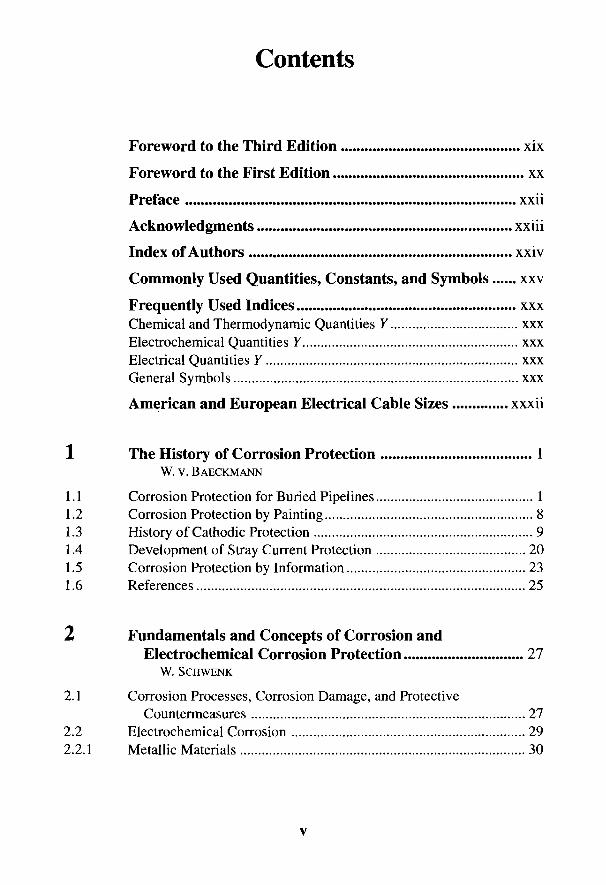
Contents
Foreword to the Third Edition xix
Foreword to the First Edition xx
Preface xxii
Acknowledgments xxiii
Index of Authors xxiv
Commonly Used Quantities, Constants, and Symbols xxv
Frequently Used Indices xxxChemical and Thermodynamic Quantities Y xxxElectrochemical Quantities Y xxxElectrical Quantities Y xxxGeneral Symbols xxx
American and European Electrical Cable Sizes xxxii
1 The History of Corrosion Protection 1W. v. BAECKMANN
1.1 Corrosion Protection for Buried Pipelines 11.2 Corrosion Protection by Painting 81.3 History of Cathodic Protection 91.4 Development of Stray Current Protection 201.5 Corrosion Protection by Information 231.6 References 25
2 Fundamentals and Concepts of Corrosion andElectrochemical Corrosion Protection 27
W. SCHWENK
2.1 Corrosion Processes, Corrosion Damage, and ProtectiveCountermeasures 27
2.2 Electrochemical Corrosion 292.2.1 Metallic Materials 30
v

2.2.2 Aqueous Electrolytes 342.2.3 Electrochemical Phase Boundary Reactions 362.2.3.1 Basic Thermodynamics 372.2.3.2 Electrochemical Kinetics 402.2.4 Mixed Electrodes 442.2.4.1 Homogeneous Mixed Electrodes 442.2.4.2 Heterogeneous Mixed Electrodes and Cell Formation 462.2.5 Observations of Current Distribution 502.3 Potential Dependence of Corrosion Extent 522.3.1 Almost Uniform Weight Loss Corrosion 532.3.1.1 Weight Loss Corrosion of Active Metals 532.3.1.2 Weight Loss Corrosion of Passive Metals 592.3.2 Pitting Corrosion 622.3.3 Stress Corrosion 632.3.4 Hydrogen-Induced Corrosion 662.3.5 Corrosion Fatigue 702.3.6 Limits of Applicability of Electrochemical Protection Processes 702.4 Critical Protection Potentials and Ranges 712.5 References 76
3 Fundamentals and Practice of Electrical Measurements ... 79W. v. BAECKMANN AND W. SCHWENK
3.1 The Electrical Parameters: Current, Voltage, and Resistance 793.2 Reference Electrodes 853.3 Potential Measurement 883.3.1 Bases of Potential Measurement of Electrodes with Flowing
Current 883.3.2 Application of Potential Measurement 963.3.2.1 Measuring Instruments and Their Properties 963.3.2.2 Potential Measurements on Pipelines and Storage Tanks 973.3.2.3 Potential Measurement under the Influence of Stray Currents 1003.3.2.4 Potential Measurement under the Influence of Alternating
Currents 1023.3.3 Application'of Protection Criteria 1033.3.3.1 Pragmatic Protection Criteria for Nonalloyed Ferrous Materials ... 1043.3.3.2 Potential Measurement with Potential Test Probes 1063.4 Current Measurement 1073.4.1 General Advice for Measurement of Current 1073.4.2 Pipe Current Measurement 108
vi

3.4.3 Measurement of Current Density and Coating Resistance 1103.5 Resistivity Measurement 1123.5.1 Resistivity Measuring Instruments 1133.5.2 Measurement of Specific Soil Resistivity 1143.5.3 Measurement of Grounding Resistance 1183.6 Location of Faults 1193.6.1 Measurement of Foreign Contacts 1203.6.1.1 Fault Location using dc 1203.6.1.2 Fault Location with ac 1223.6.2 Location of Heterogeneous Surface Areas by Measurements
of Field Strength 1233.6.2.1 Location of Local Anodes 1243.6.2.2 Location of Coating Defects 125
(a) Circular damage 127(b) Porous coating 129
3.7 Intensive Measurement Technique 1313.7.1 Quantities to be Measured and Objectives of Intensive
Measurement Technique 1323.7.2 Carrying Out an Intensive Measurement 135
(a) Determination of the pipe/soil potential 135(b) Determination of AU values 136
3.8 References 137
4 Corrosion in Aqueous Solutions and Soil 139G. HEIM AND W. SCHWENK
4.1 Action of Corrosion Products and Types of Corrosion 1394.2 Determining the Corrosion Likelihood of Uncoated Metals 1424.2.1 Corrosion in Soils 1444.2.2 Corrosion in Aqueous Media 1484.3 Enhancement of Anodic Corrosion by Cell Formation
or Stray Currents from dc Installations 1484.4 Corrosion Due to ac Interference 1504.5 References 152
5 Coatings for Corrosion Protection 153G. HEIM AND W. SCHWENK
5.1 Objectives and Types of Corrosion Protection by Coatings 1535.1.1 Organic Coatings 153
vii
5.1.2 Cement Mortar Coatings 1545.1.3 Enamel Coatings 1545.1.4 Metallic Coatings 1545.2 Properties of Organic Coatings 1555.2.1 Electrical and Electrochemical Properties 1555.2.1.1 Review of the Types of Reactions 1555.2.1.2 Coating Resistance and Protection Current Demand 1565.2.1.3 Effectiveness of Cathodes and Cell Formation 1625.2.1.4 Electrochemical Blistering 1635.2.1.5 Cathodic Disbonding 1665.2.2 Physicochemical Properties 1695.2.3 Mechanical Properties 1705.2.4 Corrosion of the Steel under the Coating 1715.3 Properties of Cement Mortar and Concrete 1735.3.1 Corrosion of Mortar 1735.3.2 Corrosion of Steel in Mortar 1745.4 Properties of Enamel Coatings 1755.5 Properties of Metallic Coatings 1765.6 References 177
6 Galvanic (Sacrificial) Anodes 179H. BOHNES AND G. FRANKE
6.1 General Information 1796.1.1 Current Capacity of Galvanic Anodes 1806.1.2 Current Discharge from Galvanic Anodes 1836.2 Anode Materials 1856.2.1 Iron 1856.2.2 Zinc 1856.2.3 Aluminum 1886.2.4 Magnesium 1916.3 Backfill Materials 1966.4 Supports 1986.5 Forms of Anodes 1996.5.1 Rod Anodes 2006.5.2 Plates and Compact Anodes 2006.5.3 Anodes for Tanks 2016.5.4 Offshore Anodes 2026.5.5 Special Forms 2026.6 Quality Control and Performance Testing 203
Vlll
6.7 Advantages and Disadvantages of Galvanic Anodes 2046.8 References 206
7 Impressed Current Anodes 207H. BOHNES AND D. FUNK
7.1 General Comments 2077.2 Anode Materials 2087.2.1 Solid Anodes 2087.2.2 Noble Metals and Valve Metals Coated with Noble Metals 2137.2.3 Metal Oxide-Coated Valve Metals 2167.2.4 Polymer Cable Anodes 2177.3 Insulating Materials 2177.4 Cables 2187.5 Forms of Anode 2197.5.1 Anodes Suitable for Soil 2197.5.2 Anodes Suitable for Water 2217.5.3 Anodes for Internal Application 2227.6 References 224
8 Impressed Current Equipment and Transformer-Rectifiers 225
W. v. BAECKMANN AND H. KAMPERMAN
8.1 Site and Electrical Protection Measures 2268.2 Design and Circuitry of Impressed Current 2288.3 Rectifier Circuit 2298.4 Adjustable Transformer-Rectifiers 2308.5 Rectifiers Resistant to High Voltage 2328.6 Control Rectifiers 2338.7 Transformer-Rectifiers without Mains Connections 2378.8 Equipment and Control of Transformer-Rectifiers 2378.9 References 242
9 Impressed Current Ground Beds and InterferenceProblems 243
W. VON BAECKMANN AND W. PRINZ
9.1 Impressed Current Ground Beds 2449.1.1 Continuous Horizontal Anode Beds 244
IX
9.1.2 Single Anode Installations 2489.1.3 Deep Anode Beds 2509.1.4 Design of Anodes 2549.2 Interference with Foreign Pipelines and Cables 2569.2.1 Interference from the Voltage Cone of Anodes 2579.2.2 Interference from the Cathodic Voltage Cone of the
Protected Object 2599.2.3 Avoidance of Interference 2619.3 References 264
10 Pipelines 265W. PRINZ
10.1 Electrical Properties of Steel Pipelines 26510.2 Preconditions for Pipeline Protection 26810.2.1 Measures for Achieving a Low Resistance Load 26810.2.2 Measures for Achieving a Low Leakage Load 26810.2.2.1 Pipeline Coating 26810.2.2.2 Insulating Joints 26910.2.2.3 Electrically Operated Valves and Regulators 27110.2.2.4 Casings 27210.2.2.5 Special Installations on the Pipeline 27410.2.2.6 Prevention of Electrical Contact with Foreign Objects 27410.3 Design of Cathodic Protection 27610.3.1 Design Documents 27610.3.2 Test Points 27610.3.3 Determination of Current Demand 27710.3.4 Choice of Protection Method 27810.3.4.1 Galvanic Anodes 27810.3.4.2 Impressed Current Anodes 27910.3.5 Pipelines for Electrolytically Conducting Liquids 28010.3.6 Distribution Networks 28310.4 Commissioning the Cathodic Protection Station 28510.5 Monitoring and Supervision 28710.6 References 289
11 Storage Tanks and Tank Farms 290K. HORRAS AND G. RlEGER
11.1 Special Problems Relating to the Protection of Tanks 29011.2 Preparatory Measures 290
x

11.3 Storage Tanks 29211.3.1 Determination of Current Demand, Evaluation, and Connections
of the Protection Equipment 29211.3.2 Choice of Protection Method 29511.3.3 Examples of the Design of Protective Installations 29611.3.3.1 Equipment Using Galvanic Anodes 29611.3.3.2 Impressed Current Station 29811.4 Tank Farms and Filling Stations 29911.5 Special Problems in Cathodic Protection Near Railways 30011.5.1 General Comments 30011.5.2 Equipotential Bonding and Insulating Joints 30111.5.3 Protective Grounding with Electrified Railways 30211.5.4 Lightning Protection 30211.5.5 Interference and Working in the Area of Railways 30311.6 Measures in the Case of Dissimilar Metal Installations 30411.7 Internal Protection of Fuel Tanks 30411.8 Consideration of Other Protection Measures 30611.9 Operation and Maintenance of Cathodic Protection Stations 30711.10 References 308
12 Local Cathodic Protection 309W. v. BAECKMANN AND W. PRINZ
12.1 Range of Applications 30912.2 Special Features of the Local Cathodic Protection 31012.3 Power Stations 31212.4 Oil Refineries 31512.5 Installations with Small Steel-Reinforced Concrete Foundations... 31712.6 Tank Farms 31812.7 References 322
13 Telephone Cables 323C. GEY
13.1 Laying Cables 32313.2 Passive Corrosion Protection 32413.3 Cathodic Protection 32613.3.1 Stray Current Protection 32713.3.2 Cathodic Protection with Impressed Current Anodes 32913.4 References 334
XI
14 Power Cables 335H.-U. PAUL AND W. PRINZ
14.1 Properties of Buried Power Cables 33514.2 Cathodic Protection of the Steel Conduits for Power Cables 33614.2.1 Requirements for dc Decoupling Devices (between Casing and
Ground) 33714.2.2 Types and Circuits of dc Decoupling Devices 33814.2.2.1 Low Ohmic Resistances 33814.2.2.2 Higher Ohmic Resistances 33914.2.2.3 dc Coupling Devices with Nickel-Cadmium Cell 34014.2.2.4 Polarization Cell 34014.2.2.5 dc Decoupling Devices with Silicon Diodes 34114.2.3 Installation of Cathodic Protection Station 34314.2.4 Control and Maintenance of Cathodic Protection 34314.3 Stray Current Protection 34414.4 References 346
15 Stray Current Interference and Stray CurrentProtection 347
W. v. BAECKMANN AND W. PRINZ
15.1 Causes of Stray Current Interference 34715.1.1 dc Equipment 34715.1.2 General Measures at dc Equipment 34815.2 Stray Currents from dc Railways 34815.2.1 Regulations for dc Railways 34815.2.2 Tunnels for dc Railways 35215.3 Stray Currents from High-Voltage dc Power Lines 35315.4 Stray Currents Due to Telluric Currents 35515.5 Protective Measures 35815.5.1 Stray Current Protection for Individual Pipelines 35815.5.2 Combined Stray Current Protective Measures in Urban Areas 36215.6 Stray Current Protection in Harbor Areas 36415.7 References 366
16 Marine Structures and Offshore Pipelines 367W. v. BAECKMANN AND B. RICHTER
16.1 Cathodic Protection Measures 36716.1.1 Design Criteria 368
xn
16.1.2 Protection with Galvanic Anodes 37216.1.3 Impressed Current Protection 37316.2 Platforms 37316.2.1 Steel Structures 37316.2.2 Concrete Structures 37616.3 Harbor Structures 37616.3.1 Impressed Current Equipment 37716.3.2 Protection with Galvanic Anodes 37916.4 Steel Sheet Piling 38016.5 Piling Foundations 38016.6 Offshore Pipelines 38316.7 Control and Maintenance of Cathodic Protection 38516.7.1 Production Platforms 38516.7.2 Harbor Structures 38716.7.3 Offshore Pipelines 38816.8 References 390
17 Cathodic Protection of Ships 391H. BOHNES AND B. RlCHTER
17.1 Water Parameters 39117.1.1 Dissolved Salts and Solid Particles 39117.1.2 Aeration and Oxygen Content 39317.1.3 Flow Rate in the Case of a Moving Ship 39417.1.4 Variations in Temperature and Concentration 39417.2 Effect of Materials and Coating Parameters 39517.3 Cathodic Protection Below the Waterline 39717.3.1 Calculations of the Protection Current Requirement 39817.3.2 Protection by Galvanic Anodes 39917.3.2.1 Size and Number of Anodes 39917.3.2.2 Arrangement of Anodes 40117.3.2.3 Control and Maintenance of Cathodic Protection 40217.3.3 Protection with Impressed Current 40317.3.3.1 Current Supply and Rectifiers 40417.3.3.2 Impressed Current Anodes and Reference Electrodes 40517.3.3.3 Arrangement of Anodes and Reference Electrodes 40817.4 Internal Cathodic Protection of Tanks and Containers 41017.5 Cathodic Protection of Heat Exchangers, Condensers
and Tubing 41217.6 Cathodic Protection of Bilges 412
xin

17.7 Cathodic Protection of Docks 41317.8 References 414
18 Cathodic Protection of Well Casings 415W. PRINZ AND B. LEUTNER
18.1 Description of the Object to be Protected 41518.2 Causes of Corrosion Danger 41518.2.1 Formation of Corrosion Cells 41518.2.2 Free Corrosion in Different Soil Layers 41718.2.3 Conditions for the Occurrence of Stress Corrosion 41718.2.4 Corrosion by Anodic Interference (Cell Formation,
Stray Currents) 41718.3 Measurements for Assessing Corrosion Protection of Well
Casings 41818.3.1 Investigations for Corrosion Damage 41818.3.2 Measurement of AU Profiles 41818.3.3 Measurement of the Tafel Potential 42118.4 Design and Construction of Cathodic Protection Stations 42218.5 Commissioning, Maintenance and Control 42518.6 References 426
19 Cathodic Protection of Reinforcing Steel inConcrete Structures 427
B. ISECKE
19.1 The Corrosion System Steel-Concrete 42719.2 Causes of Corrosion of Steel in Concrete 42819.3 Electrolytic Properties of Concrete 42819.4 Criteria for Cathodic Protection 42919.5 Application of Cathodic Protection to Reinforced Concrete
Structures 43119.5.1 Design and Installation 43119.5.2 Determination of the State of Corrosion of the Reinforcing
Steel 43219.5.3 Reinforcement Continuity 43319.5.4 Installation and Types of Anode System 43419.5.5 Concrete Replacement Systems for Cathodic Protection 43519.5.6 Commissioning, Maintenance and Control 436
xiv

19.6 Stray Current Effects and Protective Measures 43819.7 References 439
20 Internal Cathodic Protection of Water Tanksand Boilers 441
G. FRANKE AND U. HEINZELMANN
20.1 Description and Function of Objects to be Protected 44120.1.1 Materials for Objects to be Protected and Installation Components 44220.1.2 Types of Linings and Coatings 44320.1.3 Preconditions for Internal Cathodic Protection 44320.1.4 Measures to Prevent Anodic Interference 44420.1.5 Measures to Prevent Danger from Hydrogen Evolution 44620.2 Protection with Galvanic Anodes 44720.3 Protection with Impressed Current 44820.3.1 Equipment with Potential Control 44820.3.2 Equipment with Current Control Based on Water Consumption .... 45020.4 Description of Objects to be Protected 45020.4.1 Boilers with Enamel Linings 45020.4.2 Boilers with Electrolytically Treated Water 45620.4.3 Water Storage Tanks 45820.4.4 Filter Tanks 46120.5 Requirements for Drinking Water 46220.6 References 463
21 Internal Electrochemical Corrosion Protection ofProcessing Equipment, Vessels, and Tlibes 464
H. GRAFEN AND F. PAULEKAT
21.1 Special Features of Internal Protection 46421.2 Cathodic Protection with Galvanic Anodes 46621.3 Cathodic Protection with Impressed Current 46721.3.1 Internal Cathodic Protection of Wet Oil Tanks 46721.3.2 Internal Cathodic Protection of a Wet Gasometer 46821.3.3 Internal Cathodic Protection of a Power Plant Condenser
Cooled by Seawater 46921.3.4 Internal Cathodic Protection of a Water Turbine 46921.4 Anodic Protection of Chemical Plant 47421.4.1 Special Features of Anodic Protection 474
xv

21.4.2 Anodic Protection with Impressed Current 47621.4.2.1 Preparatory Investigations 47621.4.2.2 Protection Against Acids 47821.4.2.3 Protection Against Media of Different Composition 48021.4.2.4 Protection Against Alkaline Solutions 48021.4.2.5 Combined Protection by Impressed Current and Inhibitors 48321.4.3 Protective Effect of Local Cathodes due to Alloying 48321.4.4 Protective Action of Inhibitors 48421.5 Trends in the Application of Internal Electrochemical
Protection 48521.6 References 487
22 Safety and Economics 489W. v. BAECKMANN AND W. PRINZ
22.1 Safety 48922.1.1 Statistics of Pipeline Failures 48922.1.2 Measures for Control and Maintenance 49022.2 General Comments on Economics 49122.3 Costs of Cathodic Protection of Buried Pipelines 49222.3.1 Galvanic Anodes 49322.3.2 Impressed Current Anodes 49522.3.3 Prolonging the Life of Pipelines 49622.4 Corrosion Protection of Well Casings 49922.5 Corrosion Protection in Seawater 50022.6 Cost of Internal Protection 50122.6.1 Internal Cathodic Protection 50122.6.2 Internal Anodic Protection 50222.7 References 504
23 Interference Effects of High-Voltage TransmissionLines on Pipelines 505
H.-U. PAUL AND H. G. SCHONEICH
23.1 Capacitive Interference 50623.2 Ohmic Interference 50723.2.1 Contact with a Conductor under High Voltage 50723.2.2 Voltage Cone of a Pylon Grounding Electrode 50823.3 Inductive Interference 51023.3.1 Causes and Factors Involved 510
xvi

23.3.2 Calculation of Pipeline Potentials in the Case of Parallel Routingof a High-Voltage Transmission Line and a Pipeline 511
23.3.3 Obliquely Routed Sections of the Lines 51623.3.4 Simplified Calculation Methods 51723.3.4.1 Interference by Fault Currents and by Railway Operating
Currents 51723.3.4.2 Interference from a Three-Phase High-Voltage
Transmission Line in Normal Operation 51923.3.5 Representation of the Characteristics of a Pipeline 52123.4 Limiting Lengths and Limiting Distances 52423.4.1 Allowable Contact Voltages 52523.4.1.1 Short-Term Interference 52523.4.1.2 Long-Term Interference 52623.4.2 Determination of Pipeline Potentials 52623.5 Protection Measures against Unallowably High Pipeline
Potentials 52623.5.1 Short-Term Interference 52623.5.2 Long-Term Interference 52623.5.3 Protective Measures by Grounding 52723.5.4 Grounding Electrodes and Cathodic Protection 52823.5.4.1 Overvoltage Arresters for Short-Term Interference 52823.5.4.2 Voltage Arresters for Long-Term and Short-Term Interference 529
23.5.4.2.1 Polarization Cells 52923.5.4.2.2 Diodes 529
23.6 Measurement of Pipeline Potentials 53023.6.1 Measurement of Short-Term Interference 53123.6.1.1 Beat Method (by Superposition) 53123.6.1.2 Reverse Polarity Method 53123.6.2 Measurement of Long-Term Interference 53223.6.3 Results of Pipeline Potential Measurement 53323.7 References 534
24 Distribution of Current and Potential in a StationaryElectric Field 535
W. v. BAECKMANN AND W. SCHWENK
24.1 Grounding Resistance of Anodes and Grounds 53624.2 Interference Factor with Several Anodes 54424.3 Potential Distribution at Ground Level 54524.3.1 Soil Resistance Formulas 545
xvu

24.3.2 Anodic Voltage Cone 54624.3.3 Cathodic Voltage Cone in a Cylindrical Field 54724.3.4 Interference from the Cathodic Voltage Cone 54824.4 Calculation of Current and Potential Distribution 54924.4.1 General Relationships for a Two-Conductor Model 54924.4.2 Calculation of Ground Electrodes Having a Longitudinal
Resistance 55024.4.3 Range of Cathodic Protection and Current Requirement 55224.4.4 Potential Distribution in the Case of Overprotection 55524.4.5 Cathodic Protection in Narrow Gaps 55624.4.6 Distribution of Current and Potential Inside a Pipe
at Insulating Units 55724.5 General Comments on Current Distribution 55824.6 References 560
Index 561
xvin
Foreword to the Third Edition
The preparation of this third edition after about 10 years since publication ofthe second edition of this handbook has required a complete revision of the majorpart of the book. The reason is not only new developments in technology and ap-plication, but also the identification of vital factors in the protection system. Develop-ments in standards and regulations also had to be taken into account.
Electrochemical corrosion and electrochemical corrosion protection have thesame bases. These and the uniform terminology given in the DIN manual 219 formthe scientific basis for this handbook. Descriptions of new corrosion systems andincreased questions concerning the use of potential and current distribution as wellas the influence of high tension have improved our understanding and favor newapplications, even if less useful parts of the previous tests have had to be omitted.There are new developments in 7/?-free potential measurements, intensive measur-ing techniques, and computer-controlled evaluation data. Only interactions betweencorrosion and polarization are described in dealing with the properties of coatingsfor passive corrosion protection.
Considerable alterations have been made in the chapters concerned with tech-nical applications which are the result of advances in electrochemical corrosionprotection in general practice. Here also, abbreviation and omission of less rel-evant parts of the older editions have had to be made to create space for morerecent information. Recent applications in the chemical industry have necessitateda complete rewriting of the industrial chapter. A new chapter is included on thecathodic protection of steel reinforcement in concrete.
The editors thank all the collaborators in this handbook for their effort as wellas Ruhrgas AG and Mannesmannrohren-Werke AG for their generous support inediting the manuscript, and the publishers for their cooperation in shaping andpublishing this handbook.
W. VON BAECKMANNW. SCHWENK
and W. PRINZEssen and DuisbergSummer 1988
xix

Foreword to the First Edition
The discovery and use of metals at the end of the Stone Age was one of themost important steps in the development of modern technology. Most base metalsare, unfortunately, not stable. In unfavorable environments they can be destroyedat variable rates by corrosion. The study of such corrosion reactions and the meth-ods by which corrosion of metals can be fought is a task of great economic signifi-cance.
The processes of cathodic protection can be scientifically explained far moreconcisely than many other protective systems. Corrosion of metals in aqueous so-lutions or in the soil is principally an electrolytic process controlled by an electrictension, i.e., the potential of a metal in an electrolytic solution. According to thelaws of electrochemistry, the reaction tendency and the rate of reaction will de-crease with reducing potential. Although these relationships have been known formore than a century and although cathodic protection has been practiced in iso-lated cases for a long time, it required an extended period for its technical applica-tion on a wider scale. This may have been because cathodic protection used toappear curious and strange, and the electrical engineering requirements hinderedits practical application. The practice of cathodic protection is indeed more com-plex than its theoretical base.
There are extensive publications on many individual problems together withpractical instructions. However, it was difficult for the technologist in Germany tomaster the subject because no comprehensive up-to-date publication was availablein German. The Subcommittee for Corrosion of DVGW instigated the publicationof a handbook of cathodic protection, and a number of members offered their co-operation as authors of individual chapters.
This handbook deals mainly with the practice of cathodic protection, but thediscussion includes fundamentals and related fields as far as these are necessaryfor a complete review of the subject. We thought it appropriate to include a histori-cal introduction in order to explain the technological development of corrosionprotection. The second chapter explains the theoretical basis of metal corrosionand corrosion protection. We have deliberately given practical examples of combi-nations of various materials and media in order to exemplify the numerous fieldsof application of electrochemical protection.
At present cathodic protection is only generally applied for materials in con-tact with natural waters and soil, but future applications are envisaged for indus-trial plants and containers. For this reason we have included a chapter on anodic
xx
protection that has been applied in isolated cases during the past 10 years. Ca-thodic and anodic protection are basically very similar systems and justify thedescription electrochemical protection in the subtitle of this book.
Most applications combine cathodic protection with a surface coating. Thechapter on physical protection systems seemed appropriate because of the variousinteractions that must be taken into account. A chapter on general measuring tech-nology has also been added since the practice of cathodic protection has repeatedlyshown the importance of a careful study of measuring problems. It requires expe-rience to account for possible sources of error in calculations, and it is alwaysnecessary to check unusual measured results by independent monitoring. Impressedcurrent installations present particular measurement problems, keeping in mindthat an installation with reversed polarity generates intensive corrosion. This isworse than an inoperative system or no corrosion protection at all.
Further chapters cover in detail the characteristics and applications of galvanicanodes and of cathodic protection rectifiers, including specialized instruments forstray current protection and impressed current anodes. The fields of applicationdiscussed are buried pipelines; storage tanks; tank farms; telephone, power andgas-pressurized cables; ships; harbor installations; and the internal protection ofwater tanks and industrial plants. A separate chapter deals with the problems ofhigh-tension effects on pipelines and cables. A study of costs and economic factorsconcludes the discussion. The appendix contains those tables and mathematicalderivations which appeared appropriate for practical purposes and for rounding offthe subject.
The editors take the opportunity to thank all the contributors for their efforts;Ruhrgas AG and Mannesmann Research Institute GmbH for their kind assistance;and last but not least, the publishers Verlag Chemie for their generous help in pub-lishing and designing the handbook.
W. v. BAECKMANNand W. SCHWENKEssen and DuisburgSpring 1971
XXI
Preface
The editors of the German edition of the Handbook of Cathodic CorrosionProtection would like to express their cordial thanks to Gulf Publishing Companyfor their keen interest in the translation of this work. We are sure the English edi-tion will promote a better exchange of experience in the field of corrosion protec-tion, particularly with respect to problems of global safety and environment.
A serious problem in preparing this translation was that so many technicalbranches are involved with electrochemical corrosion and corrosion protection,and they often have their own "technical languages" and terms. A good translationrequired interdisciplinary teamwork. Consequently, the editors added to their teamA. Baltes and J. Venkateswarlu, who are experts in their fields. Dipl.-Ing. A. Baltes,with Pipeline Engineering GmbH, Essen, is the German delegate to the EuropeanCommittees for Standardisation in the field of pipeline protection and cathodicprotection. In this capacity he took care of the proper English translation of thetechnical terms in this field. J. Venkateswarlu, B. Tech. (Met.), is a metallurgistand corrosion engineer with Mannesmann Research Institute, Duisburg. He was agreat help in checking most of the metallurgical and technical terms as well ascritical phrases and idioms.
We would also like to thank many of the authors of the German edition, namely,G. Franke, U. Heinzelmann, H. Graf en, B. Isecke, B. Leutner, B. Richter, and H.G.Schoneich for their particular assistance. Thanks are due also to Pipeline Engi-neering GmbH, Essen, and Europipe Gmbh, Ratingen, for their keen interest in theEnglish edition and for having supported the work of our team.
We hope the reader of this English edition will not be troubled with some ofthe symbols that have "German" letters and indices. Changing all of these symbolswould have been an overwhelming task and would most likely have introducedunavoidable errors. To help our readers overcome this problem, a list of symbols isprovided. However, we must caution the reader that a translation cannot recognizethe local significance of both national standards and official regulations. In thisbook, one can only view these references as an example, keeping in mind thatscience and technology are international matters.
W. v. BAECKMANNW. SCHWENKEssen and DuisbergSpring 1997
xxn

Acknowledgments
The publishers wish to acknowledge the contribution of Dr. Robert W.Waterhouse, who provided the initial draft of the translation from the German. Thepublishers are grateful to the authors for their diligent help with subsequent draftsof the translation.
A special note of thanks to Dirk van Oostendorp, whose reading of the finalproofs was of great help rendering some of the most difficult aspects of the trans-lation. We also wish to recognize the fine efforts of Ruth B. Haas in overseeing theeditorial and production aspects of this project. We are also grateful for the contri-butions of Peter Dorn, who assisted Ms. Haas in rendering some of the most prob-lematic passages.
XXlll

Index of Authors
Dipl.-Phys. W. V. BAECKMANN Dipl.-Phys. H. KAMPERMANNUlmenstra(3e 12 Quante Fernmeldetechnik GmbH4300 Essen 1 Uellendahler Strape 353
5600 Wuppertal 1Dipl.-Chem. H. BOHNESGerrickstrape 23 Dipl.-Ing. B. LEUTNER4100 Duisburg 12 BEB Erdgas und Erdol GmbH
Postfach 51 0360G. FRANKE 30oo Hannover 1Norsk Hydro Magnesiumgesellschaft mbHScharnholzstrape 350 Dipl.-Ing H.-U. PAUL4250 Bottrop Rheinisch-Westfalische Elecktrizitatswerke AG
Postfachl031 65D- FuNK 4300 Essen 1Ruhrgas AGPostfach 10 32 52 Ing. F. PAULEKAT4300 Essen 1 Starkstrom-und Signalbaugesellschaft mbH
Postfach 10 37 32Ing. C. CEY 4300 Essen 1Fernmeldetechnisches ZentralamtPostfach 50 00 Ing. W. PRINZ6100 Darmstadt Ruhrgas AG
Postfach 10 32 52Prof. Dr. H. GRAFEN 4300 Essen 1Ursulastrape 95010 Bergheim 8 Dr. B. RlCHTER
Germanischer Lloyd AG, HamburgDr. G. HEIM Postfach 11 16 06Korrosionstechnik 2000 Hamburg 11Rubensweg 14010 Hilden Dipl.-Ing. G. RlEGER
Technischer Uberwachungsverein Rheinland e.V.Dipl.-Chem. U. HEINZELMANN Postfach 10 17 50Guldager Electrolyse GmbH ^000 Koln 91Postfach 1414660 Gelsenkirchen-Buer Dr. H. G. SCHONEICH
Ruhrgas AGDipl.-Ing. K. HORRAS Postfach 10 32 52Technische Akademie Wuppertal 4300 Essen 1Postfach 10 04 095600 Wuppertal 1 Prof. Dr. W. SCHWENK
Mannesmannrohren-Werke AGDr. B. ISECKE Mannesmann ForschungsinstitutBundensanstalt fur Materialpriifung (BAM) Postfach D 25 11 67Uter den Eichen 87 4 {00 Duisburg 251000 Berlin 45
XXIV
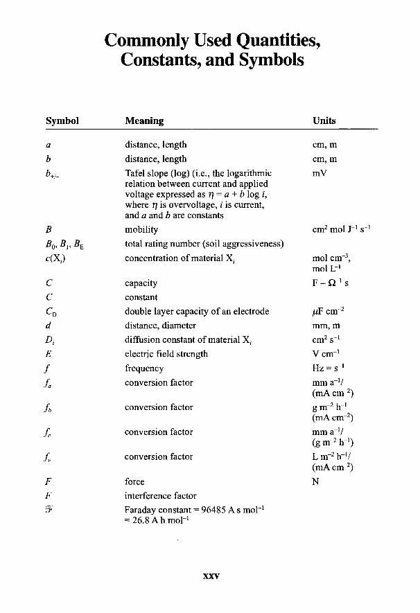
Commonly Used Quantities,Constants, and Symbols
Symbol Meaning Units
a distance, length cm, m
b distance, length cm, mb+/_ Tafel slope (log) (i.e., the logarithmic mV
relation between current and appliedvoltage expressed as 77 = a + b log i,where 77 is overvoltage, i is current,and a and b are constants
B mobility cm2 mol J"1 sBQ, 5]? BE total rating number (soil aggressiveness)
c(X(.) concentration of material X. mol cnr3,mol L-1
C capacity F = Q"1 sC constantCD double layer capacity of an electrode /iF cnr2
d distance, diameter mm, mD, diffusion constant of material X( cm2 s'1
E electric field strength V cm'1
/ frequency Hz = s"1
fa conversion factor mm a"1/(mA cnr2)
fb conversion factor g m~2 rr1
(mA cm~2)
fc conversion factor mm a"1/(g nr2 Ir1)
fv conversion factor L m~2 rr1/(mA cnr2)
F force NF interference factor8F Faraday constant = 96485 A s mol'1
= 26.8 Ah mor1
XXV
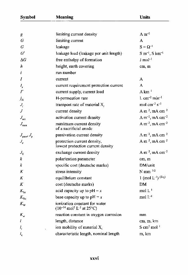
Symbol Meaning Units
g limiting current density A m~2
G limiting current AG leakage S = Or1
G' leakage load (leakage per unit length) S rrr1, S km"1
AG free enthalpy of formation J mol"1
h height, earth covering cm, m/ run number/ current A
Is current requirement protection current A/' current supply, current load A km"1
jH H-permeation rate L cm"2 min^1
Jj transport rate of material X, mol cm"2 s"1
J current density A m"2, mA cm"2
Jact activation current density A m"2, mA cm"2
Jmax maximum current density A m"2, mA cm"2
of a sacrificial anodeJpass, Jp passivation current density A m"2, mA cm"2
Js protection current density, A m"2, mA cm"2
lowest protection current density
J0 exchange current density A m"2, mA cnr2
k polarization parameter cm, mk specific cost (deutsche marks) DM/unitK stress intensity N mm"3/2
K equilibrium constant 1 (mol L"1) &"$
K cost (deutsche marks) DMKSx acid capacity up to pH = x mol L"1
KEx base capacity up to pH = x mol L"1
Kw ionization constant for water(10"14mol2l72at25°C)
Kw reaction constant in oxygen corrosion mm/ length, distance cm, m, km/. ion mobility of material X. S cm2 mol"1
4 characteristic length, nominal length m, km
XXVI
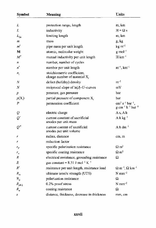
Symbol Meaning Units
L protection range, length m, km
L inductivity H - Q sIGr limiting length m, km
m mass g, kg
m' pipe mass per unit length kg m"1
M atomic, molecular weight g mol"1
M' mutual inductivity per unit length H km"1
n number, number of cyclesri number per unit length m"1, km"1
n. stoichiometric coefficient,charge number of material X,.
N defect (holiday) density m"2
N reciprocal slope of InjJj-L'-curves mVp pressure, gas pressure bar/?(X;) partial pressure of component X- barP permeation coefficient cm2 s"1 bar"1,
g cm"1 h"1 bar"1
Q electric charge A s, A hQ' current constant of sacrificial A h kg"1
anodes per unit mass
Q" current content of sacrificial A h dnr3
anodes per unit volumer radius, distance cm, mr reduction factorrp specific polarization resistance Q m2
ru specific coating resistance Q m2
R electrical resistance, grounding resistance QR gas constant = 8.31 J mol"1 K"1
R' resistance per unit length, resistance load Qnr^Qknr1
Rm ultimate tensile strength (UTS) N mm"2
Rp polarization resistance Q.Rp02 0.2% proof stress N mm"2
Ru coating resistance Q.
s distance, thickness, decrease in thickness mm, cm
XXVll
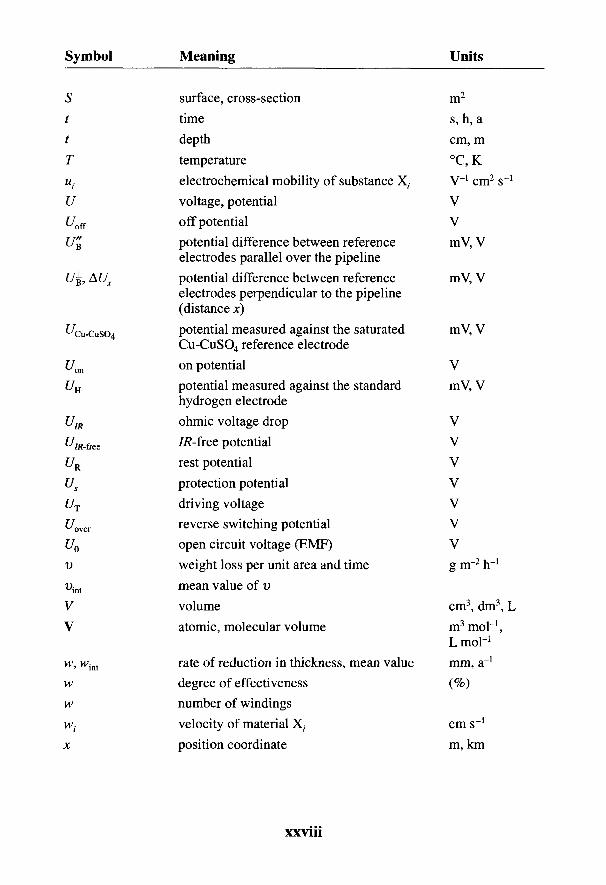
Symbol Meaning Units
S surface, cross-section m2
t time s, h, at depth cm, m
T temperature °C, K
u{ electrochemical mobility of substance X, V"1 cm2 s^1
U voltage, potential VUoff off potential Vt/B potential difference between reference mV, V
electrodes parallel over the pipelinet/B, AUX potential difference between reference mV, V
electrodes perpendicular to the pipeline(distance x]
^Cu-cuso4 potential measured against the saturated mV, VCu-CuSO4 reference electrode
Uon on potential VUH potential measured against the standard mV, V
hydrogen electrodeUIR ohmic voltage drop V
f///t.free //?-free potential Vf/R rest potential VUs protection potential VUT driving voltage VUOVM reverse switching potential VU0 open circuit voltage (EMF) Vv weight loss per unit area and time g rrr2 Ir1
Dint mean value of vV volume cm3, dm3, L
V atomic, molecular volume m3 moH,L mol-1
w, wint rate of reduction in thickness, mean value mm, a"1
w degree of effectiveness (%)w number of windingsw( velocity of material X, cm s-1
x position coordinate m, km
XXV11I

Symbol Meaning Units
Y' admittance per unit area (admittance load) S km"1
Ys yield point N mm"2
Zi charge number of material X(
Z impedance Q
Z characteristic resistance or impedance Q(of a line)
Z( rating number (soil aggressiveness)
Greek Symbols
a symmetry factora path constant (dc) km"1
j3+/_ Tafel slope (Napieran loop) mV7 transfer coefficient km"1
8 diffusion layer thickness cme, £r dielectric constant, relativee0 electric field constant = 8.85 x 10"14 F cm"1
7] overvoltage, polarization mV, V77^ ohmic voltage drop, resistance polarization mV, V
x specific conductance, conductivity S cm"1
fa electrochemical potential of material X( J mol"1
fjii partial molar free enthalpy of material X; J mol"1
H0 magnetic field constant = 1.26 x 10"8 H cm"1
Hr permeability numberv relative number of cyclesp specific resistance, resistivity Q cmpst specific resistance of steel (ca. 1.7 x 10"6 Q m)
ps density, specific weight g cm"3
a tensile strength N mm"2
T time constant s(p electrical potential V
<p phase angle
co cyclic frequency s"1
XXIX
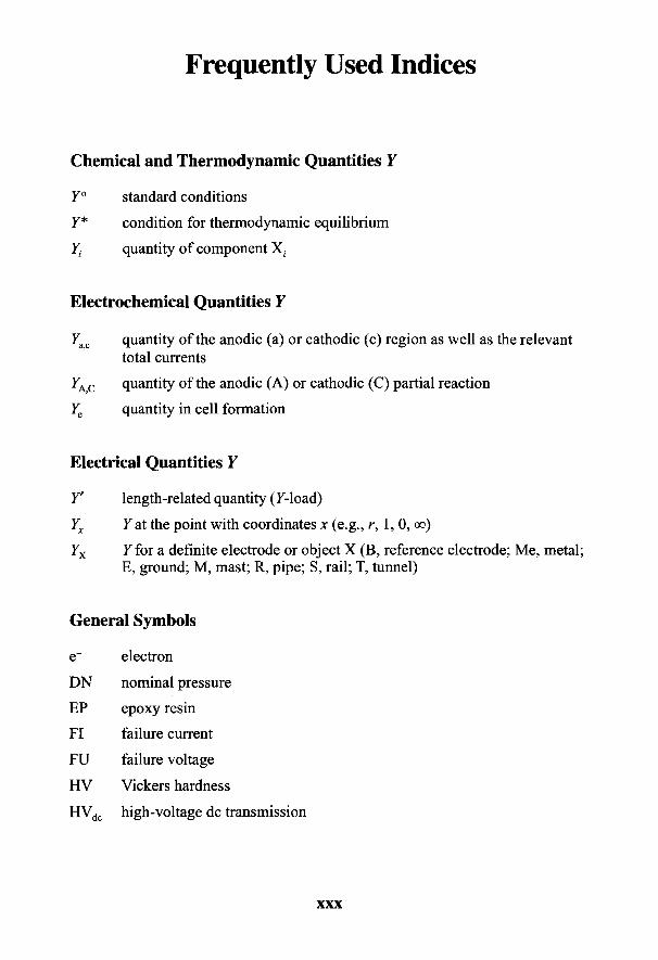
Frequently Used Indices
Chemical and Thermodynamic Quantities Y
Y° standard conditions
Y* condition for thermodynamic equilibrium
Yi quantity of component X.
Electrochemical Quantities Y
7ac quantity of the anodic (a) or cathodic (c) region as well as the relevanttotal currents
7AC quantity of the anodic (A) or cathodic (C) partial reaction
Ye quantity in cell formation
Electrical Quantities Y
7' length-related quantity (7-load)
Yx 7 at the point with coordinates x (e.g., r, 1,0, oo)
7X 7 for a definite electrode or object X (B, reference electrode; Me, metal;E, ground; M, mast; R, pipe; S, rail; T, tunnel)
General Symbols
e~ electron
DN nominal pressure
EP epoxy resin
FI failure current
FU failure voltage
HV Vickers hardness
HVdc high-voltage dc transmission
XXX
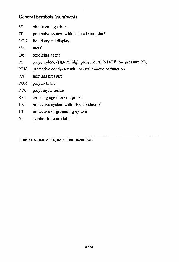
General Symbols (continued)
IR ohmic voltage drop
IT protective system with isolated starpoint*
LCD liquid crystal display
Me metal
Ox oxidizing agent
PE polyethylene (HD-PE high pressure PE, ND-PE low pressure PE)
PEN protective conductor with neutral conductor function
PN nominal pressure
PUR polyurethane
PVC polyvinylchloride
Red reducing agent or component
TN protective system with PEN conductor*
TT protective or grounding system
Xz. symbol for material i
* DIN VDE 0100, Pt 300, Beuth PubL, Berlin 1985
XXXI
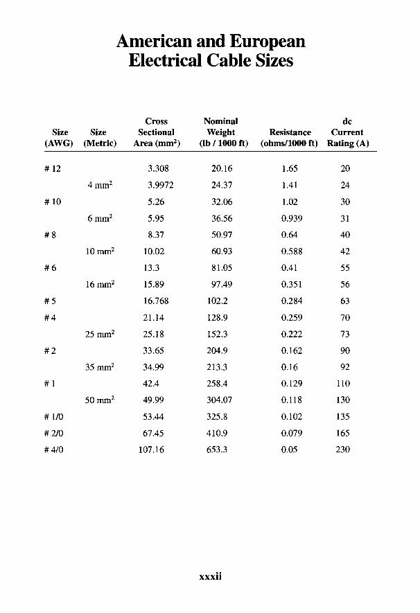
American and EuropeanElectrical Cable Sizes
Cross Nominal dcSize Size Sectional Weight Resistance Current
(AWG) (Metric) Area (mm2) (lb/1000 ft) (ohms/1000 ft) Rating (A)
#12 3.308 20.16 1.65 20
4mm2 3.9972 24.37 1.41 24
#10 5.26 32.06 1.02 30
6mm2 5.95 36.56 0.939 31
#8 8.37 50.97 0.64 40
10mm2 10.02 60.93 0.588 42
#6 13.3 81.05 0.41 55
16mm2 15.89 97.49 0.351 56
#5 16.768 102.2 0.284 63
#4 21.14 128.9 0.259 70
25mm2 25.18 152.3 0.222 73
#2 33.65 204.9 0.162 90
35mm2 34.99 213.3 0.16 92
#1 42.4 258.4 0.129 110
50mm2 49.99 304.07 0.118 130
#1/0 53.44 325.8 0.102 135
#2/0 67.45 410.9 0.079 165
#4/0 107.16 653.3 0.05 230
XXX11

The History of Corrosion ProtectionW. v. BAECKMANN
The works of Plato (427-347 B.C.) contained the first written description ofcorrosion. Plato defined rust as the earthy component separating out of the metal.Georgius Agricola held to the same opinion some 2000 years later in his great min-eralogical work De natura fossilium: "Iron rust (lat. ferrugo or rubigo) is, so tospeak, a secretion of metallic iron. Iron can be protected against this defect by vari-ous wrappings, such as red lead, white lead, gypsum, bitumen or tar." Gaius SecundusPliny also mentioned bitumen, pitch, white lead, and gypsum as protecting iron andbronze against corrosion. He reported that Alexander the Great had constructed apontoon bridge at Zeugmar on the Euphrates with the aid of an iron chain. Links thatwere inserted later suffered rust attacks, while the original ones remained immune.The opinion, sometimes expressed today, that modern iron is inferior and morecorrosion-prone than old iron, was thus current even in ancient times [1].
The concept of the corrosion process, derived from the Latin corrodere (to eataway, to destroy), first appeared in the Philosophical Transactions in 1667 [2]. Itwas discussed in a German translation from the French on the manufacture ofwhite lead in 1785 and was mentioned in 1836 in the translation of an Englishpaper by Davy on the cathodic protection of iron in seawater [3]. However, almostuntil the present day, the term was used indiscriminately for corrosion reaction,corrosion effects, and corrosion damage. Only in DIN* 50900, Part I, were theseterms distinguished and defined [4] (see Section 2.1).
1.1 Corrosion Protection for Buried Pipelines
The active and passive electrochemical processes on which present-day corro-sion protection is based were already known in the 19th century, but reliable pro-tection for pipelines only developed at the turn of the 20th century.
* All cable references contained in this text are based upon cable specifications in Germany asrequired by DIN (Deutsche Industrie Normen). We are aware that these specifications may or maynot be applicable to the reader's specific requirements, and we therefore recommend the readerconsult local standards and codes to ensure compliance with the necessary local codes. Some of thecables are defined in a list of American and European electrical cable sizes located in the front ofthis book.
1

2 Handbook of Cathodic Corrosion Protection
Corrosion protection using bitumen coatings reaches back into antiquity. Themost ancient occurrence of bitumen deposits was in Mesopotamia. Many writers ofantiquity, such as Dido, Strabo, and Vitruvius, mention that asphalt was obtained formany years near Babylon. About 5000 years ago, the streets of Ur, capital of theSumerians (north of present-day Kuwait), were lit at night with mineral oil. Naturalgas was reported to be used for lighting in the Middle East and China.
Bitumen was used in ancient times as an adhesive for sealing hydraulic struc-tures and as mortar for masonry [5]. The Bible mentions that Noah used pitch forcaulking the Ark. Not unlike the Tower of Babylon, the houses of one of the mostancient cities in the world, Mohenjo-Daro in the upper Indus valley, were con-structed with bricks of clay and bitumen mortar [6].
The earliest metal pipelines, made of copper, bronze, and lead, had no protec-tion against corrosion. The pipes were often surrounded by lime and gypsum mor-tar for sealing, cohesion, and protection. These early metal pipes are rarely foundtoday because the valuable metals were reused once the pipelines were abandoned.In 1907 the archaeologist Borchardt found the earliest metal pipe at a temple com-plex near the pyramid of King Sahu-re. It was part of a 250-m-long pipeline whichwas used to carry rain water from the temple courtyard. The 1-m-long sections,with a diameter of 47 mm, were made of 1.4-mm-thick beaten copper, curved, andthe overlapping longitudinal edges hammered together. The pipes were set into arock-hewn channel and covered with lime mortar. The only well-preserved pipe inits bedding is shown in Fig. 1-1. Its age can be taken as 4500 years since recordsindicate that King Sahu-re belonged to the fifth dynasty of Egyptian rulers [7].
The Phoenicians were building water ducts and pipelines of clay, stone, or bronzeabout 1000 B.C. and the construction of long-distance water pipelines flourished inimperial Roman times. The water supply lines of Rome had a total length of about450 km, and consisted mainly of open or covered water ducts. The Roman writerVitruvius gives a fairly accurate description of the manufacture of lead pipes [8].The pipes were above ground and were often laid beside the roadway or in ductsinside houses [9].
Fig. 1-1 The world's oldestmetal pipe from the temple ofKing Sahu-re (photo: Staat-liches Museum, Berlin).

The History of Corrosion Protection 3
Fig. 1-2 Drilling machine for wooden pipes,about 1500 (sketch by Leonardo da Vinci).
With the fall of the Roman Empire, the ancient water supplies petered out. Inearly medieval times, people were content to conduct local water in wooden pipesto public cisterns. The first wooden pipelines for water were laid at Liibeck about1293 and in 1365 at Nuremberg. In 1412 the Augsburg master builder LeopoldKarg first used wrought-iron pipes in conjunction with wooden pipes to supplywater. Because of their propensity to corrosion, they seem to have proved a failureand a few years later they were exchanged for wooden, lead, and cast-iron pipes.
The author of the first German natural history, puoch von der Natur, Chunradvon Megenberg, reported in 1349 that mainly larch and fir were used for watersupply [11]. The trunks were often steeped in lime water or brine before they werebored through on a drilling machine like the one sketched by Leonardo da Vinci(Fig. 1-2). Wooden pipes with one end tapered and the other socketed were wedgedinto each other. Pipes with abutting ends were held together by wrought-iron fer-rules (called "Tuchel" ferrules). Figure 1-3 shows wooden pipes with a cast-ironring ferrule (laid before 1760). The sleeves were sealed with hemp, tallow, pitch,wax or resin, which also acted as protection for the iron rings. It is recorded thatwooden pipes were painted with pitch or tar. Later on, wooden pipes with an inter-nal coating of liquid tar were used in London and New York for town and natural
Fig. 1-3 Oak water pipeover 200 years old laid aboveground in the WadgassenAbbey (Saarland) with castiron clamps (photo: Mannes-mann Archives).
JSk
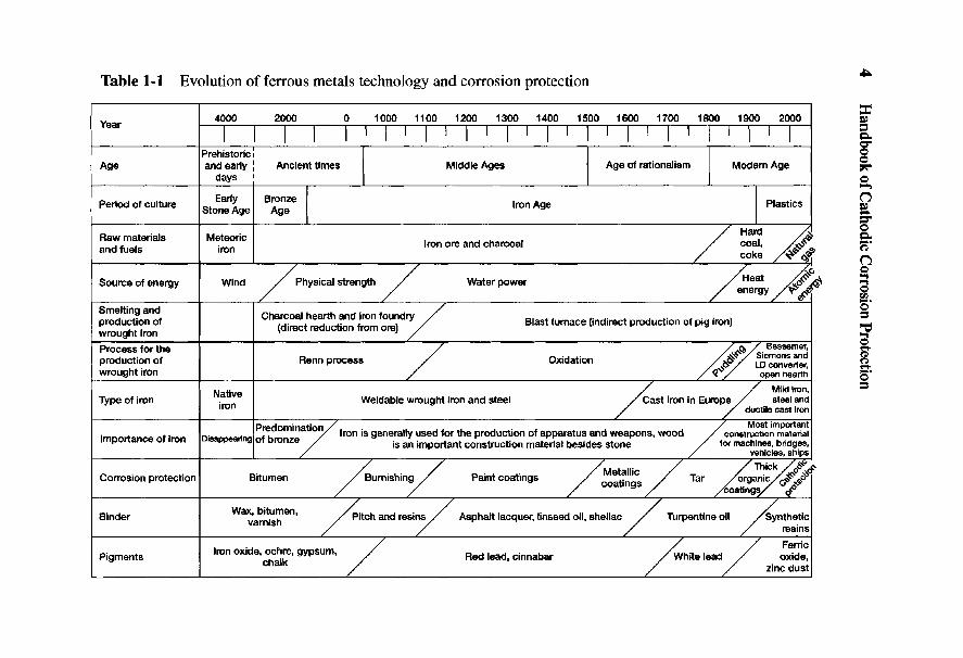
Table 1-1
Evolution of ferrous m
etals technology and corrosion protectionI
I Hg
Y
4000
2000
0
1000 1100 1200 1300 1400 1500
1600 1700
1800 1900 2000
So
_j^
I
I
| |
I
I
I
' I
' I
'
I
' I
'
I
' I
'
I
' I
' I
'
I
|
Prehistoric'
I I
I g
Age
and
early A
ncient times
Middle
Ages
Age
of rationalism
Modern
Age
p?
days O
I I
h^
Period
of culture
^^
B™
f Iron
Age
P
lastics £
|
|
|
I E3*
/
LJ
—IY
J
/I
O
„, /&
9;
coke /$f
*
~7 ~7
~7 /^
®
Source
of energy
Win
d
/
Physical strength
/
W
ater power
/
Heat
/vr <o}
3/
/
/
energy /V
^
g
SE
EK
S
I C^
S^
^«
>dV
/B
la
st
furnace (indirect p
roductio
n of pig
iron) |
wrought iron
' /
1-1
Process fo
r the
~7
/<&
/ Bessem
er; 2-
production o
f R
enn process /
O
xidation
/&
/
LDaom
wtor
&w
rought iron
^/_
/&
/
open hearth §•
Native
/
/
Mild
iron>
^T
ype of iron
.
Weldable
wro
ught iron
and
steel /
Cast iron
in E
urope /
steel andlro
n
/
/
ductile cast iron
Pre
dom
inatio
n /
/
Most im
portantim
^^Kto
^^« ~t -^
n-
~,o«r, * u
/
lron
is generally used fo
r the
pro
ductio
n o
f apparatus and
weapons, w
ood
/
construction material
Importance
of ,ron
D
,sappeanng o f bronze
/
js £
jmporta
nt c
onstru
ct io
n m
aterial besides stone
/
for machines, bridges,
/
/
vehicles, ships
/
"/
/M
eta
llic
~/
/T
hic
k /$
*.'&
Corrosion
pro
tectio
n
Bitum
en
/Burn
ishin
g/
Paint co
atin
gs
/
. /
T
ar
/org
anic
/1^
$*
s
/ /
CO
aTln
QS
/
/
.. _
/ v
JS-
/
/
/
a /
/to
atin
gs/
<j.°
Binder
ax, i um
en, / p
jtch
and
resin
s /
Asphalt lacquer, linseed
oil, shellac
/
Turpentine
oil
/Synth
etic
/
/
/
/
resins
/
/ s
Ferric
Red lead, cinnabar
/White
lead /
oxide,
^/_
/
zinc dust

The History of Corrosion Protection 5
gas. The protection of wooden pipes against rot may be regarded as the precursorof corrosion protection of wrought-iron pipelines.
The Bavarian Duke Maximilian I commissioned the master builder SimonReifenstuel in 1618 to lay the first pipeline for brine from Reichenhall to Traunstein.The 31-km-long line required 9000 wooden pipes. Two centuries later the King ofBavaria commissioned the extension of the pipeline from Reichenhall toBerchtesgaden. The noted Karlsruhe engineer, George Friedrich von Reichenbach,had iron pipes cast to his own specification for this first German high-pressurepipeline. The initially porous cast pipes had to be sealed with a mixture of linseedoil and finely ground quicklime to enable them to withstand a pressure of 43 atmos-pheres [12]. This treatment with linseed oil was apparently not intended to be aprotection against internal corrosion, which was known by the end of the 17thcentury. So-called "calcination" of pipelines was understood to include not onlythe formation of iron rust nodules with wastage of pipelines but also internal cor-rosive attack.
It cannot be ascertained with accuracy when molten iron was first obtained inthe European cultural sphere. The forge production of iron in Siegerland goesback to Roman times. Iron was made in the ancient world using charcoal-burningforges and only a small portion was converted into steel for weapons (see Table 1-1).Only in medieval times, when water wheels supplied the required air, were thetemperatures necessary for iron smelting reached. We can assume that the firstcast iron was obtained in Europe in about the year 1380 but a few decades elapsedbefore cast-iron pipes for water supply could be made, the impetus being given bythe casting of gun barrels. The Master Christian Slanterer cast 30 small breechloaders in Siegen in 1445. Twelve years later Count Johann IV required a watersupply for Dillenburg castle and the order for cast-iron pipes went to the samemaster. Figure 1-4 shows the socketed ends of a well-preserved pipe, l . lm longby 70 mm in diameter, with lead-sealed sleeves [13].
Forged and cast-iron pipes were painted with molten pitch or wood tar at theclose of medieval times. A work in 1827 states that pipes had been protected bycoal tar for a long time [14]. Before being buried, in 1847 cast-iron gas and waterpipes were treated with tar in Hanover. In Germany the tarring of wooden roofswas known before 1770. Coal tar had been produced in quantity during produc-tion of lighting gas between 1792 and 1802 in England. William Murdoch con-structed the first gas production plant in Soho and illuminated the factory of Boultonand Watt on the occasion of the peace of Amiens in 1802.
Cast-iron pipes were used for the mains in the early stages of town gas supply,their sockets being sealed with tarred rope, oakum, or lead. Originally the connec-tion pipes were lead and later of galvanized or coal-tarred forged iron. After thedefeat of Napoleon in 1815, there was a surplus of cheap musket barrels, and these

Handbook of Cathodic Corrosion Protection
Fig. 1-4 End socket of a cast-iron waterpipe sealed with lead laid in 1457 (photo:Rheinstahl, Gelsenkirchen).
were often used as house connections for town gas pipes. The term "barrel" is stillused in England to describe gas connection pipes [15].
The Dresden and Leipzig gasworks were founded in 1828 and the red leadputty socket seals were changed to seals of tarred rope when considerable losseswere experienced in the grid. An outer varnish coating was applied as corrosionprotection for pipes and connections. The Leipziger Regulator of 1863 stressesexternal protection against destruction by oxidation in its instruction for safe pipe-laying. In England between 1830 and 1850 we find directions on the use of coal tarand asphalt tar together with other materials for pipe protection. An English com-pany founded in 1884 for the manufacture of asphalt tar and mastic cladding wasthe first to use mineral filling materials.
After 1860 in the United States, water mains were only occasionally givencoatings of tar. About 1896 the activities of English undertakings were extended toAmerica, where chiefly bare metal pipelines had previously been laid. Water sup-ply pipes were coated internally with bitumen in America after 1912. Vicat (1837)in France and J. Bull (1843) in America introduced the widely known cement mor-tar as a protective material for water pipes [16].
The best-known English pipe protection material was invented by Angus Smith,and consisted of a mixture of coal tar and linseed oil. Occasionally pipes were laidin sand or pitch-filled wooden ducts to protect them against especially aggressivesoils. Bitumenized paper-wrapped pipes for gas lines that could withstand pres-sures of 20 atmospheres were first shown during the Paris Exhibition in 1867 thoughthey had come into use for water supply shortly before then (Fig. 1 -5). Zinc platingwas reported to be an effective protection for wrought-iron pipes in 1864. F. Fischermentioned cathodic protection for the first time in an exhaustive report. In 1875there was a report on the use of mineral wool as insulation and of tarred or asphalted
The History of Corrosion Protection
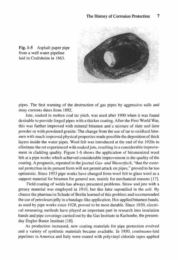
Fig. 1-5 Asphalt paper pipefrom a well water pipelinelaid in Crailsheim in 1863.
pipes. The first warning of the destruction of gas pipes by aggressive soils andstray currents dates from 1892.
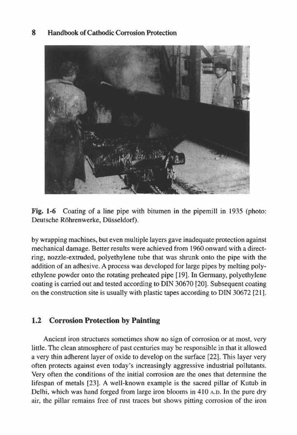
Jute, soaked in molten coal tar pitch, was used after 1900 when it was founddesirable to provide forged pipes with a thicker coating. After the First World War,this was further improved with mineral bitumen and a mixture of slate and limepowder or with powdered granite. The change from the use of tar to oxidized bitu-men with much improved physical properties made possible the deposition of thicklayers inside the water pipes. Wool felt was introduced at the end of the 1920s toeliminate the rot experienced with soaked jute, resulting in a considerable improve-ment in cladding quality. Figure 1 -6 shows the application of bitumenized woolfelt at a pipe works which achieved considerable improvement in the quality of thecoating. A prognosis, repeated in the journal Gas- und Wasserfach, "that the exter-nal protection in its present form will not permit attack on pipes," proved to be toooptimistic. Since 1953 pipe works have changed from wool felt to glass wool as asupport material for bitumen for general use, mainly for mechanical reasons [17].
Field coating of welds has always presented problems. Straw and jute with agreasy material was employed in 1910, but this later saponified in the soil. Bychance the pharmacist Schade of Berlin learned of this problem and recommendedthe use of petroleum jelly in a bandage-like application. Hot-applied bitumen bands,as used by pipe works since 1928, proved to be most durable. Since 1930, electri-cal measuring methods have played an important part in research into insulationbands and pipe coverings carried out by the Gas Institute in Karlsruhe, the present-day Engler-Bunte Institute [18].
As production increased, new coating materials for pipe protection evolvedand a variety of synthetic materials became available. In 1950, continuous-laidpipelines in America and Italy were coated with polyvinyl chloride tapes applied
8 Handbook of Cathodic Corrosion Protection
Fig. 1-6 Coating of a line pipe with bitumen in the pipemill in 1935 (photo:Deutsche Rb'hrenwerke, Dusseldorf).
by wrapping machines, but even multiple layers gave inadequate protection againstmechanical damage. Better results were achieved from 1960 onward with a direct-ring, nozzle-extruded, polyethylene tube that was shrunk onto the pipe with theaddition of an adhesive. A process was developed for large pipes by melting poly-ethylene powder onto the rotating preheated pipe [19]. In Germany, polyethylenecoating is carried out and tested according to DIN 30670 [20]. Subsequent coatingon the construction site is usually with plastic tapes according to DIN 30672 [21].
1.2 Corrosion Protection by Painting
Ancient iron structures sometimes show no sign of corrosion or at most, verylittle. The clean atmosphere of past centuries may be responsible in that it alloweda very thin adherent layer of oxide to develop on the surface [22], This layer veryoften protects against even today's increasingly aggressive industrial pollutants.Very often the conditions of the initial corrosion are the ones that determine thelifespan of metals [23]. A well-known example is the sacred pillar of Kutub inDelhi, which was hand forged from large iron blooms in 410 A.D. In the pure dryair, the pillar remains free of rust traces but shows pitting corrosion of the iron
The History of Corrosion Protection 9
buried in the soil. However, a sample of this 99.7% pure iron brought to Englandcorroded as fast as any other forged iron.
In Europe and India, iron blooms were made in small smelting furnaces usingcharcoal and air supplied by bellows; a single smelting yielded only 8 to 10 kilosof forged iron. The development of iron was different in China. The Chinese usedanthracite as early as 200 B.C., and this enabled them to make cast iron mainly forutility purposes, e.g., ploughshares, cauldrons, or large vases. The technique ofiron casting reached Europe only toward the end of the 14th century. Table 1-1reviews the development of iron manufacturing technology and of corrosion [24]protection [25]-[28].
The necessity to protect steel and iron against corrosion was generally recog-nized during the 18th century [14]. The first modern reports on rust-protectivepaints appeared in 1822 in Dinglers Polytechnischem Journal. They proposed touse varnish, resin or vegetable oils for painting steel surfaces. The basic essentialof good painting technique, the thorough cleaning of metallic surfaces before paint-ing, seems to have been recognized by 1847. Red lead as a primary coating wasrecommended in 1885 [14]. Paints and varnishes made from coal tar were used inAmerica after about 1860 to protect iron and steel in shipbuilding, but originallywere used only for coating the interior surfaces of iron ships. Coal tar paint wasfirst used in 1892 to paint a large floating dock. The locks, floodgates, and weirs ofthe Panama Canal were sprayed with tar paint in 1912.
A frequently cited example of protection from atmospheric corrosion is theEiffel Tower. The narrow and, for that age, thin sections required a good primingof red lead for protection against corrosion. The top coat was linseed oil with whitelead, and later coatings of ochre, iron oxide, and micaceous iron oxide were added.Since its construction the coating has been renewed several times [29]. Modernatmospheric corrosion protection uses quick-drying nitrocellulose, synthetic res-ins, and reaction resins (two-component mixes). The chemist Leo Baekeland dis-covered the synthetic material named after him, Bakelite, in 1907. Three yearslater the first synthetic resin (phenol formaldehyde) proved itself in a protectivepaint. A new materials era had dawned.
1.3 History of Cathodic Protection
In 1936, at Khuyut Rabuah near Baghdad, several clay jugs about 14 cm highwere found. Inside was a narrow, pitch-sealed copper cylinder, containing a cor-roded iron kernel. Similar jugs were found in the ruins of Seleucis on the oppositebank of the Tigris. The assumption is that these objects originate from imperialRoman times (27 B.C. to 395 A.D.) and Wilhelm Konig, a past director of the Baghdad
10 Handbook of Cathodic Corrosion Protection
antiquities administration, believes that these objects are battery cells used for gildingsmall pieces of jewelry by electrolytic processes. He writes: "All these finds mayprove that galvanic electricity was known a long time before Galvani (after whomit was named) experimented with frogs' legs (1789)" [30].
The attraction of rubbed amber and some other effects of electricity were knownin ancient times. We know from finding nails in an old wreck that the Romansknew about contact corrosion combined with electric current flow. A skin of leadas a protection against boring worms covered the wooden planks of the ship andwas nailed down with copper nails. Galvanic couples formed between the lead andthe copper nails and the less noble lead sheets around the nails corroded in theseawater and fell off. The shipbuilders discovered a simple solution and coveredthe heads of the copper nails with lead as well. Galvanic current flow between thetwo metals was eliminated and corrosion was prevented [26].
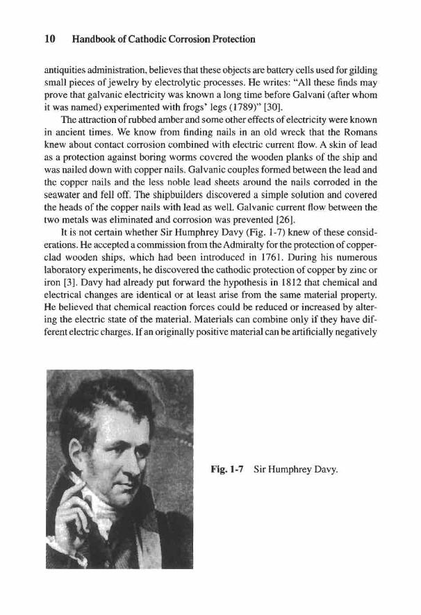
It is not certain whether Sir Humphrey Davy (Fig. 1-7) knew of these consid-erations. He accepted a commission from the Admiralty for the protection of copper-clad wooden ships, which had been introduced in 1761. During his numerouslaboratory experiments, he discovered the cathodic protection of copper by zinc oriron [3]. Davy had already put forward the hypothesis in 1812 that chemical andelectrical changes are identical or at least arise from the same material property.He believed that chemical reaction forces could be reduced or increased by alter-ing the electric state of the material. Materials can combine only if they have dif-ferent electric charges. If an originally positive material can be artificially negatively
Fig. 1-7 Sir Humphrey Davy.
The History of Corrosion Protection 11
charged, the binding forces are destroyed and can no longer participate in corro-sion reactions.
The beginnings of galvanic electricity and investigations on electrolytes werebased on Galvani's experiments with frogs' legs in 1789. The Italian physicistAlessandro Volta discovered in Pavia in 1797 the so-called voltaic pillar. For thefirst time current was produced from an electric cell. The reverse process, elec-trolysis, had been discovered by Alexander von Humboldt in 1795 in an electro-lytic cell with zinc and silver electrodes in an aqueous electrolyte. In 1798 Ritternoticed that the potential series of metals was identical with the ranking of metalsaccording to their oxidizability.
Although these discoveries can hardly be called electrochemical, the explana-tions given by Davy are remarkable. Davy had established that copper was a metalwhich acted weakly positive in a galvanic potential series. He deduced from that,that the corrosive action of seawater on copper could be prevented if it were weaklynegatively charged. If the copper surface became negative (i.e., a cathode) then allchemical reactions, including corrosion, would be prevented. To explain the pro-cess, Davy performed experiments in which polished copper coupons were im-mersed in weakly acidified seawater. A piece of tin was soldered onto one of thecopper coupons. After 3 days the copper coupons without tin showed considerablecorrosion whereas the specimen with the soldered tin bore no trace of any corro-sion. Davy came to the conclusion that other non-noble metals such as zinc or ironcould provide corrosion protection. Davy carried out further experiments with thehelp of his pupil Michael Faraday. From this work it became apparent that thelocation of the zinc was immaterial. On another copper coupon to which an ironcoupon was soldered, and which was then connected to a piece of zinc, not onlythe copper but also the iron was protected against corrosion.
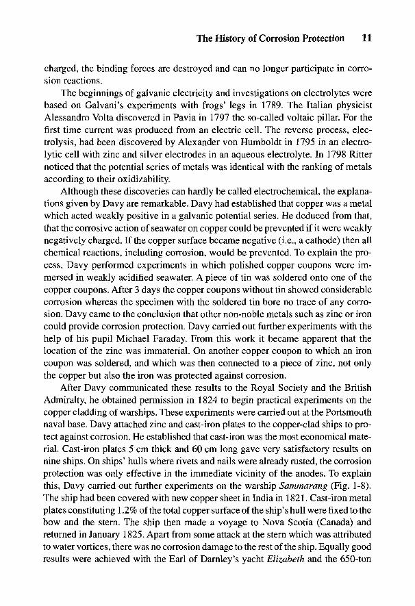
After Davy communicated these results to the Royal Society and the BritishAdmiralty, he obtained permission in 1824 to begin practical experiments on thecopper cladding of warships. These experiments were carried out at the Portsmouthnaval base. Davy attached zinc and cast-iron plates to the copper-clad ships to pro-tect against corrosion. He established that cast-iron was the most economical mate-rial. Cast-iron plates 5 cm thick and 60 cm long gave very satisfactory results onnine ships. On ships' hulls where rivets and nails were already rusted, the corrosionprotection was only effective in the immediate vicinity of the anodes. To explainthis, Davy carried out further experiments on the warship Sammarang (Fig. 1-8).The ship had been covered with new copper sheet in India in 1821. Cast-iron metalplates constituting 1.2% of the total copper surface of the ship's hull were fixed to thebow and the stern. The ship then made a voyage to Nova Scotia (Canada) andreturned in January 1825. Apart from some attack at the stern which was attributedto water vortices, there was no corrosion damage to the rest of the ship. Equally goodresults were achieved with the Earl of Darnley's yacht Elizabeth and the 650-ton

12 Handbook of Cathodic Corrosion Protection
Fig. 1-8 Constructional drawing of the Sammarang, which was the first ship tomake a sea voyage to Nova Scotia from March 1824 to January 1825 with cathodicprotection of the copper sheathing.
freighter Carnebra Castle. Each ship was equipped on the stern and bow with twozinc plates amounting to 1% of the copper surface. The copper cladding looked asgood as new after the freighter returned from Calcutta.
Some years after Davy's death, Faraday examined the corrosion of cast iron insea water and found that it corrodes faster near the water surface than deeper down.In 1834 he discovered the quantitative connection between corrosion weight lossand electric current. With this discovery he laid the scientific foundation of elec-trolysis and the principles of cathodic protection.
Apparently without knowledge of Davy's experiments, the inspector of tele-graphs in Germany, C. Frischen, reported to a meeting of the Architekten-undIngenieur-Verein at Hanover in 1856 the results of a wider experimental enquiry,over a long period, "with particular regard to the protection of the most importantand widely used metal, wrought iron, which constitutes the most important parts ofthe large structures, like bridges, locks, gates, etc." Frischen soldered or screwedpieces of zinc onto iron as a protection against seawater and concluded "that aneffective protection of iron is doubtless due to the influence of galvanic electric-ity." However, achieving a successful and practical protective technique wouldhave required many protracted, large-scale experiments [31] and [32].
It is little known that Thomas Alva Edison tried to achieve cathodic protection ofships with impressed current in 1890; however, the sources of current and anodicmaterials available to him were inadequate. In 1902, K. Cohen achieved practicalcathodic protection using impressed direct current. The manager of urban works at

Fig. 1-10 Internal cathodicprotection from the patent ofE.G. Cumberland of (DRPNo. 247544).
Fig. 1-9 Diagram of cathodic protection from the patent of H. Geppert of (DRPNo. 211612).
Karlsruhe, Herbert Geppert, constructed the first cathodic protection installation forpipelines in 1906. This was a direct current generator of 10 V 12 A capacity protect-ing 300 m of gas and water pipelines within the electrical field of a tramline [33].Figure 1-9 shows the principle for which H. Geppert obtained a German patent in1908 [34]. Protection using consumable anodes was termed "electrochemical pro-tection" at a Congress of the Institute of Metals in Geneva in the autumn of 1913.
To protect steam boilers and their tubes from corrosion, E. Cumberland usedcathodic impressed current in America in 1905. Figure 1-10 has been taken fromthe corresponding German patent [35]. In 1924 several locomotives of the Chi-cago Railroad Company were provided with cathodic protection to prevent boilercorrosion. Where previously the heating tubes of steam boilers had to be renewedevery 9 months, "the costs fell sharply after the introduction of the electrolytic
The History of Corrosion Protection 13
14 Handbook of Cathodic Corrosion Protection
process." Aluminum anodes with applied dc were used by A. Guldager in Den-mark for internal protection of hot water supply plants. Cathodic protection wasthereby provided to the interior of the warm water tank and the connecting pipesby formation of a secondary surface film.
At the beginning of the 20th century, with the development of stainless steels,the passivity of metals became technically important in corrosion protection. In apresentation at the international exhibition of chemical engineering (ACHEMA) inFrankfurt in 1958, it was asserted that it was thanks to metal passivity that progressfrom the Stone Age to the age of metal technology had been possible [36]. Investiga-tion of passivity phenomena in the 1930s and particularly after the Second WorldWar led to electrochemical investigations and the knowledge that potential was animportant variable in corrosion reactions. Great progress in measuring techniquesoccurred with the development of the potentiostat in the 1950s and systematic inves-tigation of the dependence of corrosion parameters on potential began worldwide.The scientific basis for general electrochemical protection was laid. By determiningthe limiting potentials for the occurrence of certain corrosion phenomena, in par-ticular local corrosion such as pitting and stress corrosion [37], this work led to theconcept of protection potentials.
The passivating stainless steels presented a possibility for developing anodicprotection. High-alloy steels, similar to carbon steels, are not capable of being ca-thodically protected in strong acids because hydrogen evolution prevents the neces-sary drop in potential. However, high-alloy steels can be passivated and maintainedin the passive state by anodic protection. C. Edeleanu was the first to demonstrate in1950 that anodic polarization of the pump housing and connecting pipework couldprotect a chromium-nickel steel pumping system against attack by concentratedsulfuric acid [38]. The unexpectedly wide range of anodic protection is due to thehigh polarization resistance of the passivated steel. Locke and Sudbury [39] investi-gated different metal/medium systems in which the application of anodic protectionwas relevant. Several anodically protected installations were in operation in theUnited States by 1960, e.g., storage tanks and reaction vessels for sulfonating andneutralization plants. Not only did the installations have a longer life but also agreater purity of the products was achieved. In 1961 anodic protection was firstapplied on a large scale to prevent stress corrosion cracking in a caustic soda electroly-sis plant in Aswan [40]. Anodic protection for caustic soda tanks has been used on alarge scale since the end of the 1960s and electrochemical corrosion protection meth-ods have become of permanent importance for industrial plants (see Chapter 21).
During the previous century, the success of cathodic protection was often amatter of chance. In 1906 at the instigation of the DVGW,1 F. Haber and L. Gold-
1 The Deutscher Verein des Gas- und Wasserfachs, the current name of an earlier association of gasand waterworks engineers.
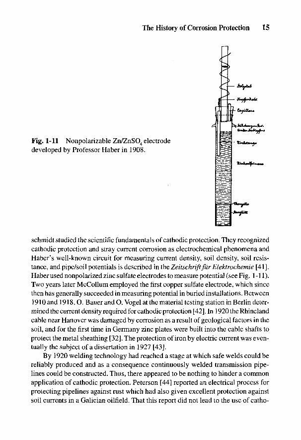
Fig. 1-11 Nonpolarizable Zn/ZnSO4 electrodedeveloped by Professor Haber in 1908.
schmidt studied the scientific fundamentals of cathodic protection. They recognizedcathodic protection and stray current corrosion as electrochemical phenomena andHaber's well-known circuit for measuring current density, soil density, soil resis-tance, and pipe/soil potentials is described in the Zeitschriftfiir Elektrochemie [41].Haber used nonpolarized zinc sulfate electrodes to measure potential (see Fig. 1-11).Two years later McCollum employed the first copper sulfate electrode, which sincethen has generally succeeded in measuring potential in buried installations. Between1910 and 1918,0. Bauer and O. Vogel at the material testing station in Berlin deter-mined the current density required for cathodic protection [42]. In 1920 the Rhinelandcable near Hanover was damaged by corrosion as a result of geological factors in thesoil, and for the first time in Germany zinc plates were built into the cable shafts toprotect the metal sheathing [32]. The protection of iron by electric current was even-tually the subject of a dissertation in 1927 [43].
By 1920 welding technology had reached a stage at which safe welds could bereliably produced and as a consequence continuously welded transmission pipe-lines could be constructed. Thus, there appeared to be nothing to hinder a commonapplication of cathodic protection. Peterson [44] reported an electrical process forprotecting pipelines against rust which had also given excellent protection againstsoil currents in a Galician oilfield. That this report did not lead to the use of catho-
The History of Corrosion Protection 15
16 Handbook of Cathodic Corrosion Protection
die protection was probably the fault of the engineering-oriented builders of pipenetworks, who regarded electrochemical protection as a black art. Even electricalengineers overestimated the costs of the process and the danger to other pipelinesfrom the applied currents. Instead, therefore, attempts were made to improve theresistance of pipe coating materials to aggressive soils and to reduce the danger ofstray current corrosion by insulating joints.
Cathodic protection of pipelines did not develop in Germany but it was appliedfrom 1928 onward in the United States. Figure 1-12 shows a medal with the head ofRobert J. Kuhn, called the "Father of Cathodic Protection" in America. He installedthe first cathodic protection rectifier in 1928 on a long-distance gas pipeline in NewOrleans, and thus inaugurated the first practical application of cathodic protection ofpipelines. As early as 1923, E.R. Shepard in New Orleans had diverted powerfultramline stray currents with an electrical drainage system. The protection range ofplain cast pipes with poorly conducting joints did not extend to the end of the pipe-line, so Kuhn put additional protective rectifiers in. He found by experiments that aprotective potential of-0.85 V against a saturated copper/copper-sulfate electrodeprovided sufficient protection against any form of corrosion. At the WashingtonConference for Corrosion Protection held by the National Bureau of Standards in1928, Kuhn reported on the significant value of his experiments, on which the entiremodern technology of cathodic protection is founded [45]. Considerable doubtexisted in the minds of American scientists at that time over the causes of corrosionof buried pipelines. Kuhn's presentation was the only one that dealt with corrosionresulting from galvanic cell formation. It contained the description of a process thatprevented corrosion by application of rectified dc, i.e., by cathodic protection. Kuhnwrote: "This method was not applied exclusively to prevent corrosion but to cut outelectrolytic corrosion of the pipeline arising from streetcar stray currents by electricdrainage." This application had shown that the pipes were not only protected against
Fig. 1-12 Gold medal with picture ofRobert J. Kuhn. The medal was estab-lished by the Technical Committee ofCathodic Protection and first awardedin 1970 by the DVGW in Wurzburg.

The History of Corrosion Protection 17
stray current electrolysis but also against galvanic cell currents and thus against soilcorrosion. The experiment showed that on average 10 to 20 mA nr2 protective cur-rent density was sufficient to depress the potential of the pipeline to a value wherepitting no longer occurred [46].
Some experts still regarded the experiments with skepticism. The AmericanPetroleum Institute in Los Angeles declared in 1935 that galvanic protective cur-rents from zinc anodes could no longer protect pipelines over the increasing dis-tances being used, and that protection against chemical attack, such as by acids,would be definitely impossible. Since pipelines in America were mostly laid withoutany insulating coverings until well into the present century, the cathodic protectionof such pipelines proved comparatively expensive and required considerable pro-tective currents. It is therefore not surprising that even in the early 1930s only about300 km of pipelines in America were protected by zinc anodes and 120 km by im-pressed current. Among them were pipelines in Houston, Texas, and Memphis, Ten-nessee, which had been cathodically protected by Kuhn from 1931 to 1934. In early1954, I. Denison was awarded the Whitney prize by the National Association ofCorrosion Engineers. Kuhn's discovery was given renewed publicity, for in his ac-ceptance speech, Denison explained: "In the first corrosion protection conference in1929 Kuhn described how the potential of a pipeline was depressed to -0.85 Vagainst a saturated copper/copper sulfate electrode using a D.C. rectifier. I need notremind you that this value is the accepted potential criterion for cathodic protectionused worldwide nowadays."
Smith reported in 1940 [47]:
"Cathodic protection applied in the United States has had mixed successand variable criticism. Failure is partly due to false evaluation of the activeregion and partly due to insufficient planning and operation of the plant to beprotected. It is partly the failure to recognize that the process against corro-sion due to high and widely ranging soil currents arising from stray currentsfrom D.C. installations with correspondingly higher potentials to give pro-tection against them, can only be successful if these currents are drained inaddition. The cathodic protection process is only relevant for oil, gas, andwater pipelines against soil attack in areas where there are no stray currents.Neither soil composition nor climate can impair the action of the protectivemedium if the anodic current is sufficient to reduce the potential of the pipe-line to be protected against that of the soil by about 0.3 V."
The first anode installation for the cathodic protection of gas pipelines in NewOrleans consisted of a 5-m-long horizontal cast-iron tube. Later old tramway lineswere used. Since in downtown New Orleans there was no suitable place to installimpressed current anodes and to avoid detrimental effects on other pipelines, Kuhnrecommended the use of deep anodes which were first installed in 1952 at a depth
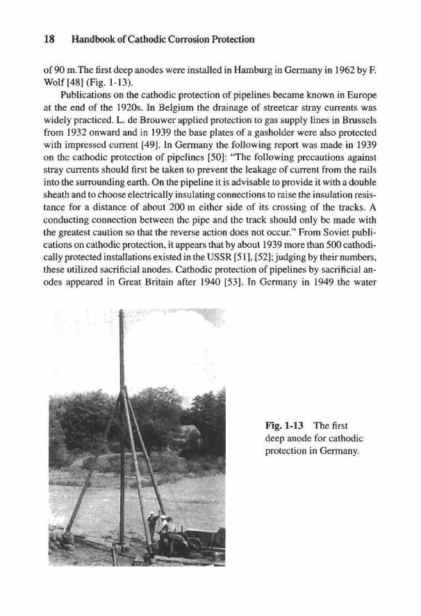
18 Handbook of Cathodic Corrosion Protection
of 90 m.The first deep anodes were installed in Hamburg in Germany in 1962 by F.Wolf [48] (Fig. 1-13).
Publications on the cathodic protection of pipelines became known in Europeat the end of the 1920s. In Belgium the drainage of streetcar stray currents waswidely practiced. L. de Brouwer applied protection to gas supply lines in Brusselsfrom 1932 onward and in 1939 the base plates of a gasholder were also protectedwith impressed current [49]. In Germany the following report was made in 1939on the cathodic protection of pipelines [50]: "The following precautions againststray currents should first be taken to prevent the leakage of current from the railsinto the surrounding earth. On the pipeline it is advisable to provide it with a doublesheath and to choose electrically insulating connections to raise the insulation resis-tance for a distance of about 200 m either side of its crossing of the tracks. Aconducting connection between the pipe and the track should only be made withthe greatest caution so that the reverse action does not occur." From Soviet publi-cations on cathodic protection, it appears that by about 1939 more than 500 cathodi-cally protected installations existed in the USSR [51], [52]; judging by their numbers,these utilized sacrificial anodes. Cathodic protection of pipelines by sacrificial an-odes appeared in Great Britain after 1940 [53]. In Germany in 1949 the water
Fig. 1-13 The firstdeep anode for cathodicprotection in Germany.
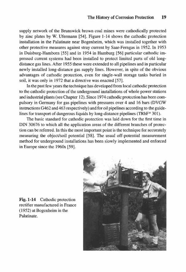
The History of Corrosion Protection 19
supply network of the Brunswick brown coal mines were cathodically protectedby zinc plates by W. Ufermann [54]. Figure 1-14 shows the cathodic protectioninstallation in the Palatinate near Bogenheim, which was installed together withother protective measures against stray current by Saar-Ferngas in 1952. In 1953in Duisburg-Hamborn [55] and in 1954 in Hamburg [56] particular cathodic im-pressed current systems had been installed to protect limited parts of old long-distance gas lines. After 1955 these were extended to all pipelines and in particularnewly installed long-distance gas supply lines. However, in spite of the obviousadvantages of cathodic protection, even for single-wall storage tanks buried insoil, it was only in 1972 that a directive was enacted [57].
In the past few years the technique has developed from local cathodic protectionto the cathodic protection of the underground installations of whole power stationsand industrial plants (see Chapter 12). Since 1974 cathodic protection has been com-pulsory in Germany for gas pipelines with pressures over 4 and 16 bars (DVGWinstructions G462 and 463 respectively) and for oil pipelines according to the guide-lines for transport of dangerous liquids by long-distance pipelines (TRbF* 301).
The basic standard for cathodic protection was laid down for the first time inDIN 30676 to which all the application areas of the different branches of protec-tion can be referred. In this the most important point is the technique for accuratelymeasuring the object/soil potential [58]. The usual off-potential measurementmethod for underground installations has been slowly implemented and enforcedin Europe since the 1960s [59].
Fig. 1-14 Cathodic protectionrectifier manufactured in France(1952) at Bogenheim in thePalatinate.

20 Handbook of Cathodic Corrosion Protection
1.4 Development of Stray Current Protection
The first news of the destructive influence of stray currents reached Europefrom America shortly before the turn of the century. Stray current electrolysis as anew corrosion hazard for buried pipes as a result of increasing domestic dc sup-plies and the construction of direct current railways also became evident in Ger-many. Werner von Siemens introduced at the 1879 Berlin Gewerbeausstellung(Trade Exhibition) the first direct current electric railway in the world. The firstelectric tram to Berlin-Lichterfelde ran 2 years later using a positive and a negativerail with an operating voltage of 140 V. In 1882 Siemens installed an experimentaltram service with overhead supply, running from Westend to Spandauer Bock. Asshown in Fig. 1-15, the line was initially equipped with two overhead wires so thatthe escape of stray currents into the soil was prevented [60]. Unfortunately, it wasnot possible to retain this system.
The first underground railway in the world was opened on January 10, 1863 inthe City of London, operating with steam locomotives. The first line with electrictraction and a three-rail system was built in 1890. The four-rail system, still in usetoday and consisting of two insulated conductor rails and two running rails, wasintroduced in 1903 in the course of electrification of the old steam tracks. TheMetropolitan Company, responsible for a part of the track, used ac, while the Dis-trict Railway preferred dc as a consequence of the connection with the Americanrailways. This dispute came before a British arbitration tribunal in 1900. The prob-lem of corrosion of public supply lines by the returning current from electric train
Fig. 1-15 Berlin streetcarin 1882 with double overheadconductor with rod contact.

The History of Corrosion Protection 21
locomotives was at that time already appreciated as a result of the considerabledifficulties encountered in America, and the advantage of the ac system was thatthese inconveniences were eliminated. The arbitrators solved the problem by rec-ommending the use of 600-V direct current and also the laying of a return-currentrail insulated from the running rails [61].
The first serious electrically induced corrosion damage in the field of tram railsappeared in 1887 at Brooklyn on forged iron pipes, and in the summer of 1891 atBoston on the lead sheaths of telephone cables [62]. The first commission to investi-gate the phenomenon of stray currents was set up in America.2 The commissionrecorded that considerable differences in potential exist between pipes and the trackof electric railways, and that the pipes are endangered in positions "where the chargeis positive and the current escapes into the electrolysis-prone surroundings." It wasfound experimentally by Flemming that iron surfaces buried in damp sand with apotential of +0.5 V and a current of 0.04 A corroded visibly after only a few days.The first direct stray current drainage was installed in 1895 by E. Thompson for theBrooklyn tramway in an attempt to move the stray current directly back to the railswithout harmful effects [63]. However, this occasionally caused such a powerfulincrease in the stray currents that they melted the lead seals of the joints.
Deliberate stray current drainage was installed at a subrectifier in Germany asearly as 1895 during the electrification of the Aachen tramway. The effective pro-tection extended over a relatively small field since the comparatively large resis-tance of the pipe joints did not permit a greater extension of protection.
The Berlin City electrical engineer M. Kallmann reported in 1899 on a systemfor controlling stray currents of electric railways [64]. As early as 1894, the Boardof Trade in London issued a safety regulation for the British electric railways whichspecified a potential differential of not more than 1.5 V where the pipeline waspositive to the rails, but 4.5 V with the rails positive. Extensive research was under-taken on reducing the risk of stray current in the soil by metallic connections frompipes to rails. However, as one writer noted, "a procedure on these lines shoulddefinitely be discouraged as it carries the seed of its own destruction" [64].
The Journal fur Gasbeleuchtung mentions electrolytic corrosion damage causedby direct current cables in Berlin in 1892, and a few years later damage by tram-way currents was reported in 14 German towns. As early as 1894 the electrolyticprocesses of stray current corrosion were explained in detail in this journal byG.Rasch [65].
In 1910, a joint commission of the associations of German electrotechniciansand gas and waterworks engineers issued regulations for the protection of gas and
2 Around 1890 about 100 tram lines were run by direct current in Germany and well over 500 inAmerica. In 1981 there were only 33 such local trams in the Federal Republic and 25 in the GermanDemocratic Republic.
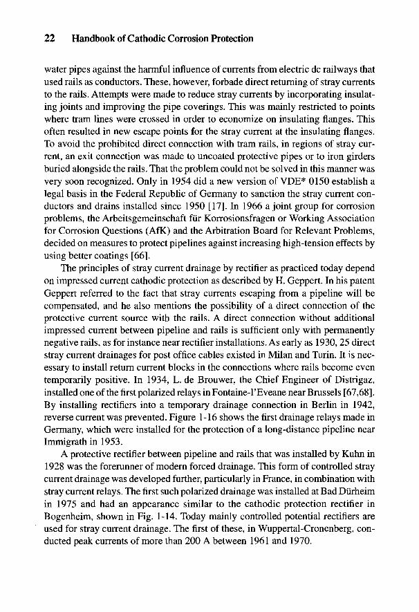
22 Handbook of Cathodic Corrosion Protection
water pipes against the harmful influence of currents from electric dc railways thatused rails as conductors. These, however, forbade direct returning of stray currentsto the rails. Attempts were made to reduce stray currents by incorporating insulat-ing joints and improving the pipe coverings. This was mainly restricted to pointswhere tram lines were crossed in order to economize on insulating flanges. Thisoften resulted in new escape points for the stray current at the insulating flanges.To avoid the prohibited direct connection with tram rails, in regions of stray cur-rent, an exit connection was made to uncoated protective pipes or to iron girdersburied alongside the rails. That the problem could not be solved in this manner wasvery soon recognized. Only in 1954 did a new version of VDE* 0150 establish alegal basis in the Federal Republic of Germany to sanction the stray current con-ductors and drains installed since 1950 [17]. In 1966 a joint group for corrosionproblems, the Arbeitsgemeinschaft fur Korrosionsfragen or Working Associationfor Corrosion Questions (AfK) and the Arbitration Board for Relevant Problems,decided on measures to protect pipelines against increasing high-tension effects byusing better coatings [66].
The principles of stray current drainage by rectifier as practiced today dependon impressed current cathodic protection as described by H. Geppert. In his patentGeppert referred to the fact that stray currents escaping from a pipeline will becompensated, and he also mentions the possibility of a direct connection of theprotective current source with the rails. A direct connection without additionalimpressed current between pipeline and rails is sufficient only with permanentlynegative rails, as for instance near rectifier installations. As early as 1930, 25 directstray current drainages for post office cables existed in Milan and Turin. It is nec-essary to install return current blocks in the connections where rails become eventemporarily positive. In 1934, L. de Brouwer, the Chief Engineer of Distrigaz,installed one of the first polarized relays in Fontaine-l'Eveane near Brussels [67,68].By installing rectifiers into a temporary drainage connection in Berlin in 1942,reverse current was prevented. Figure 1-16 shows the first drainage relays made inGermany, which were installed for the protection of a long-distance pipeline nearImmigrath in 1953.
A protective rectifier between pipeline and rails that was installed by Kuhn in1928 was the forerunner of modern forced drainage. This form of controlled straycurrent drainage was developed further, particularly in France, in combination withstray current relays. The first such polarized drainage was installed at Bad Diirheimin 1975 and had an appearance similar to the cathodic protection rectifier inBogenheim, shown in Fig. 1-14. Today mainly controlled potential rectifiers areused for stray current drainage. The first of these, in Wuppertal-Cronenberg, con-ducted peak currents of more than 200 A between 1961 and 1970.
The History of Corrosion Protection 23
Fig. 1-16 First polarized relay for straycurrent drainage in Germany at Immigrathin 1953.
1.5 Corrosion Protection by Information
The question of corrosion and corrosion protection has become even moreimportant with the increased use of metallic materials as industry has grown. Theconcern over the great number of avoidable failures compelled an investigation ofthe causes for which in most cases organizational problems had been indicated[69]. It also showed that the science of corrosion protection had spread into diversetechnical areas almost unsurveyed. The Arbeitsgemeinschaft Korrosion foundedin 1931 was reconstituted in 1981 as a registered association with a scientific advi-sory committee. In the new statute its purpose was designated as the coordinationof technical regulations as well as research and the exchange of experience. Theinformation given in this handbook is largely contained in the DIN standards whichwere formulated and mutually agreed upon by the standard committees NAGas 5.2and NMP 171. In this respect, the conceptual standards DIN 50900 and the basicstandards for electrochemical protection, DIN 30676 and DIN 50927, are particu-larly relevant.
To provide a better survey, the Arbeitsgemeinschaft Korrosion undertook thesifting of the regulations collected by the Deutsche Informationszentrum fiir Technikand published them in an industry-related compilation with an advisory commen-tary [70]. Updates continue to be published in the journal Werkstoffe und Korrosion.
24 Handbook of Cathodic Corrosion Protection
The state of the art in 1987 was published in "Survey of standards, technical rulesand regulations in the area of corrosion, corrosion testing and corrosion protec-tion," together with the most important DIN standards and some other regulationsin the DIN 219 [71]. A commentary on these standards has also appeared [72].
The History of Corrosion Protection 25
1.6 References
[I] L. Beck, Geschichte des Eisens, 5, Bd., Vierweg & Sohn, Braunschweig 1884-1903.[2] H. Leierzapf, Werkstoffe und Korrosion 36, 88 (1985).[3] H. Davy, Phil. Transact. 144, 151 (1824).[4] DIN 50900. Teil 1, Beuth Verlag, Berlin, 1975 und 1982; Werkstoffe und Korrosion
32, 33 (1981).[5] R.J.Forbes, Bitumen 4, 6 (1934).[6] Vergessene Sta'dte am Indus, Verlag Ph. v. Zabern, Mainz, 1987.[7] L. Borchardt, Das Grabdenkmal des Konigs Sahu-re, J.C. Hindrichs'sche
Buchhandlung, Leipzig 1910.[8] W. Schhrmann, Sanitar- u. Rohrenmarkt 7.21 (1952).[9] Mannesmann AG, Rohre gab es immerschon, Dhsseldorf 1965.[10] M. Kromer, Wasser in jedwedes Burgers Haus, Ullstein GmbH, Frankfurt u. Berlin
1962.[II] F. Feldhaus, Deutsche Industre B Deutsche Kultur 9, 1 (1913).[12] B. Gockel, gwf 108, 191 (1967).[13] A. Wittmoser, GieBerei 44, 557 (1957).[14] G. Seelmeyer, Werkstoffe u. Korrosion 4, 14 (1953).[15] J. Korting, Geschichte der deutschen Gasindustrie, Vulkan-Verlag, Essen 1963.[16] F. Fischer, Journal fur Gasbel. 19, 304 (1876).[17] W.v. Baeckmann, gwf 108, 702 (1967).[18] F. Eisenstecken, gwf 76, 78 (1933).[19] H. Klas, gwf 108, 208 (1967).[20] DIN 30670, Beuth Verlag, Berlin, 1980.[21] G. Heim u. W.v. Baeckmann, 3R intern. 26, 302 (1987).[22] F. Todt, Korrosion und Korrosionsschutz, Walter de Gruyter, Berlin 1961.[23] U.R. Evans, Einfiihrung in die Korrosion der Metalle. Historischer Uberblick, S. 251,
Verlag Chemie, Weinheim 1965.[24] R. Johannsen, Geschichte des Eisens, 2. Bd., Verlag-Stahleisen, Diisseldorf 1935.[25] G. Seelmeyer, Wichtige Daten aus der Geschichte der Korrosion bis 1900 in F. Todt
[16].[26] Geschichte des Lackes, Dtsch. Farben-Z. 10, 251 (1956).[27] P. Baur, Farbe u. Lack 69, 3 (1963).[28] G.A. Walter, Die geschichtliche Entwicklung der rheinischen Mineralfarbenindustrie.
G. Baedecker, Essen 1922.[29] K.A. van Oeteren-Panhauser, Werkstoffe u. Korrosion 10, 422 (1959).[30] W. Konig, Im verlorenen Paradies, R. Rohrer, Baden b. Wien 1940.[31] C. Frischen, Zeitschrift des Architechten- und Ingenieur-Vereins fhr das Konigreich
von Hannover, 3, 14 (1857).[32] H. Steinrath, Zur geschichtlichen Entwicklung des kathodischen Schutzverfahrens,
in Korrosion 11, Verlag Chemia, Weinheim 1959.[33] H. Geppert u. K. Liese, Journal fur Gasbel. 53, 953 (1910).[34] H. Geppert, Patenschrift Nr.211 612 v. 27. 3. 1908.
26 Handbook of Cathodic Corrosion Protection
[35] E.G. Cumberland, Patenschrift Nr. 247 544, 17 d, Gruppe 5 v. 28. 9. 1911.[36] H. Gerischer, Angew, Chemie 70, 285 (1958).[37] W. Schwenk, Werkstoffe u. Korrosion 19, 741 (1968).[38] W.v. Baeckmann, Chemiker Ztg. 87, 395 (1963).[39] J.P. Sudbury, W.P. Banks u. C.E. Locke, Mat. Protection 4, 81 (1965).[40] H. Grafen, E. Kahl, A. Rahmel, Korrosionum 1, Verlag Chemie, Weinheim (1974).[41] F. Haber u. F. Goldschmidt, Zeitschrift fur Elektrochemia 12, 49 (1908).[42] O. Vogel u. O. Bauer, gwf 63, 172 (1920); 68, 683 (1925).[43] W. van Wullen-Scholten, gwf 73, 403 (1930).[44] Perterson, gwf 71, 848 (1928).[45] R.J. Kuhn, Bureau of Standards 73B75 (1928).[46] R.J. Kuhn, Corr. Prev. Control 5, 46 (1958).[47] W.T. Smith, Gas Age 85, 49 (1940).[48] F. Wolfe, gwf 97, 104 (1956).[49] L. de Brouwer, gwf 84, 190 (1941).[50] H. Steinrath, Rohren u. Armaturen Ztg. 4, 180 (1939).[51] V.H. Pritula, Kathodischer Schutz fiir Rohrleitungen IWF, London 1953.[52] B.G. Volkov, N.I. Tesov, V.V. Suvanov, Korrosionsschutzhandbuch, Verlag Nedra,
Leningrad 1975.[53] J.H. Morgan, Cathodic Protection, Leonard Hill Books, London 1959.[54] w. Ufermann, gwf 95, 45 (1954).[55] G. Reuter u. G. Schurmann, gwf 97, 637 (1956).[56] F. Wolf, gwf 97, 100 (1956).[57] TRbf 408, Carl Heymanns Verlag, Koln, 1972.[58] DIN 30676, Beuth Verlag, Berlin 1984.[59] W. Schwenk, 3R internal. 25, 664 (1986).[60] H. Dominik, Geballte Kraft (W.v. Siemens), W. Limpert, Berlin 1941.[61] J.G. Bruce in T.H. Vogel, Jahrbuch des Eisenbahnwesens 17, 76 (1966), Hestra-
Verlag, Darmstadt.[62] C. Michalke, Journal fiir Gasbel. 49, 58 (1906).[63] J.J. Meany, Materials Performance 10, 22 (1974).[64] M. Kallmann, ETZ 20, 163 (1899).[65] G. Rasch, Journal fiir Gasbel. 37, 520 (1894); 38, 313 (1895); 41, 414 (1898).[66] R. Buckel, Elektr, Wirtschaft 72, 309 (1973).[67] F. Besig, Korrosion u. Metallschutz 5, 99 (1929); Journal fiir Gasbel. 77, 37 (1934).[68] A. Weiler, Werkstoffe und Korrosion 13, 133 (1962).[69] W. Schwenk, Werkstoffe u. Korrosion 37, 297 (1986).[70] Werkstoffe u. Korrosion 35, 337 (1984); 37, 211 (1986).[71 ] DIN Taschenbuch Nr. 219 "Korrosionsverhalten - Korrosionspriifung - Korrosions-
schutz," Beuth Verlag, Berlin 1987.[72] W. Fischer, Korrosionsschutz durch Information und Normung, Verlag I. Kuron,
Bonn 1988.
Fundamentals and Concepts ofCorrosion and Electrochemical
Corrosion ProtectionW. SCHWENK
2.1 Corrosion Processes, Corrosion Damage, and ProtectiveCountermeasures
The term corrosion is used to describe the reaction of a material with its sur-roundings that produces measurable changes and can lead to damage. With metal-lic materials and aqueous solutions, the reactions are in general of an electrochemicalnature. However, in addition, pure chemical reactions or entirely physical pro-cesses can also be occurring. Not every process necessarily leads to damage. Thisis a question of the extent of the reaction and the demands on the function ofmaterial or medium, which should always be considered together. Damage is saidto occur when this function is impaired. Corrosion protection is designed to pre-vent such detrimental action [1-4].
The schematic diagram in Fig. 2-1 shows the various reactions that can occursequentially and simultaneously in the corrosion process. Material transport andchemical reactions can supply or remove important reaction components. In addi-tion to adsorption or desorption, a phase boundary reaction occurs which mostlyinvolves electrochemical reactions and which can be affected by external currents.An example is formation of hydride on lead where the partner to the hydrogenreaction can arise from a cathodic process. Hydrogen can also penetrate the metalmicrostructure, where it can have a physical or chemical effect, causing a degrada-tion of the mechanical properties of the material. In this type of corrosion cracks canform during mechanical testing, leading to fracture without the loss of any metal.
Types of damage can be classified as uniform or localized metal removal, cor-rosion cracking or detrimental effects to the environment from the corrosion prod-ucts. Local attack can take the form of shallow pits, pitting, selective dissolution ofsmall microstructure regions of the material or cracking. Detrimental effects arecertainly not the case with buried pipelines, but have to be considered for environ-ments in vessels and containers. It is usual, where different results of reactions lead
27
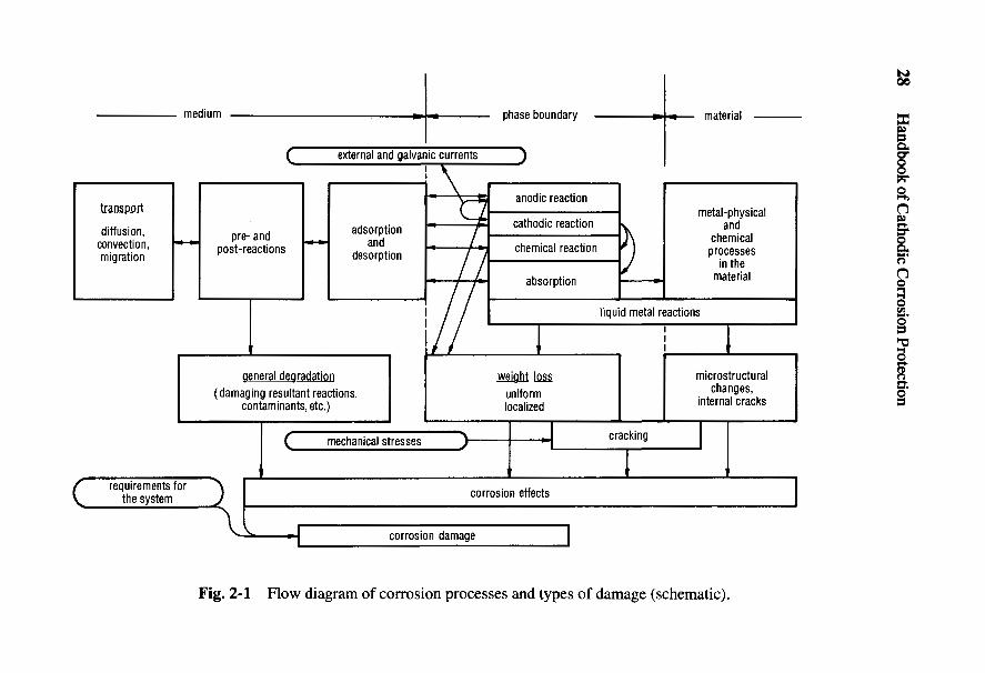
28 Handbook of Cathodic Corrosion Protection
^%—>cds£o(/2
<uSPspj
T3«4-lo(/)<uex>.
T3oJV3<ut/3(/I<uo2OH
_O
*S
gOo-Ho
tH002^oETH
<sei•P«ta
Fundamentals of Corrosion and Electrochemical Corrosion Protection 29
to definite forms of corrosion effects, to classify them as particular types of corro-sion. The most important are uniform corrosion, shallow pitting corrosion, pittingcorrosion, crevice corrosion, intergranular corrosion, and those with accompany-ing mechanical action—stress corrosion and corrosion fatigue. The two latter aremost to be feared. Most failures arise from pitting corrosion. Uniform corrosionalmost always occurs in practice but seldom leads to failure.
2.2 Electrochemical Corrosion
This handbook deals only with systems involving metallic materials and elec-trolytes. Both partners to the reaction are conductors. In corrosion reactions a partialelectrochemical step occurs that is influenced by electrical variables. These includethe electric current / flowing through the metal/electrolyte phase boundary, and thepotential difference A0 = 0^ - 0^ arising at the interface. 0^ and 0^ represent theelectric potentials of the partners to the reaction immediately at the interface. Thepotential difference A0 is not directly measurable. Therefore, instead the voltage Uof the cell MeVmetal/electrolyte/reference electrode/Me' is measured as the conven-tional electrode potential of the metal. The connection to the voltmeter is made of thesame conductor metal Me'. The potential difference 0 , - 0Me is negligibly small;then since A0g = 0g - 0E1:
0B is the potential of the reference electrode, without whose identification thepotential U is undefined. Potentials are conveniently calculated against a standardreference value. Section 3.2 contains further details on reference electrodes andconversion factors. Section 3.3 describes practical methods for measuring poten-tial in the case of flowing currents.
Electrochemical corrosion is understood to include all corrosion processes thatcan be influenced electrically. This is the case for all the types of corrosion describedin this handbook and means that data on corrosion velocities (e.g., removal rate,penetration rate in pitting corrosion, or rate of pit formation, time to failure of stressedspecimens in stress corrosion) are dependent on the potential U [5]. Potential can bealtered by chemical action (influence of a redox system) or by electrical factors(electric currents), thereby reducing or enhancing the corrosion. Thus exact knowl-edge of the dependence of corrosion on potential is the basic hypothesis for theconcept of electrochemical corrosion protection processes.
One must always bear in mind that potential dependence is not the same indifferent types of corrosion. Thus critical potential ranges for different kinds ofcorrosion can overlap or run counter to one another. This is particularly important
30 Handbook of Cathodic Corrosion Protection
to ascertain when dealing with electrochemical protection measures for unknownsystems. Electrolytic corrosion is a subsidiary branch of electrochemical corrosionand often involves the removal of metal by an anodic phase boundary reaction (seeFig. 2-1). Such corrosion is often increased by positive currents. There are alsosystems with opposite effects. In general, hydrogen-induced types of corrosion arefavored by negative currents.
Electrochemical corrosion protection has the objective of reducing corrosiondamage or removing it altogether. Three different processes are discussed in thiswork:
(a) Suppressing damage by direct currents from cells through electrical sepa-ration (protective measures against cell formation).
(b) Suppressing damage by direct currents by means of drainage (stray cur-rent protection).
(c) Protective measures using the controlled action of direct currents (protec-tion currents) to bring the object to be protected into a potential range(protection potential range) where corrosion damage cannot occur. Protec-tion currents can be imposed by rectifier installations or by cell formationby contact with sacrificial metals (e.g., sacrificial anodes in cathodic pro-tection) (see Chapters 6 to 8).
The measures in (a) are dealt with primarily in Chapter 10 but also in otherchapters relating to applications. Chapter 15 deals with the measures in (b). Infor-mation on the measures in (c) can be found in Chapters 10 to 21 and also in Sec-tions 2.3 and 2.4 of this chapter.
2.2.1 Metallic Materials
Metallic materials consist of one or more metallic phases, depending on theircomposition, and very small amounts of nonmetallic inclusions. In the metallicstate, atoms donate some of their outer electrons to the electron gas that permeatesthe entire volume of the metal and is responsible for good electrical conductivity(105 S cm"1). Pure elements do not react electrochemically as a single component.A mesomeric state can be approximately assumed
in which iron ions and electrons appear in the metal. Both components can reactwith electrolytes in which the dissolution of metal by the passage of Fe2+ results ina positive current 7A and metal loss of Am, while the passage of electrons corre-sponds to a negative current 7C without removal of metal. In the first case an anodicreaction occurs, and in the second a cathodic reaction. The relations are reversed in
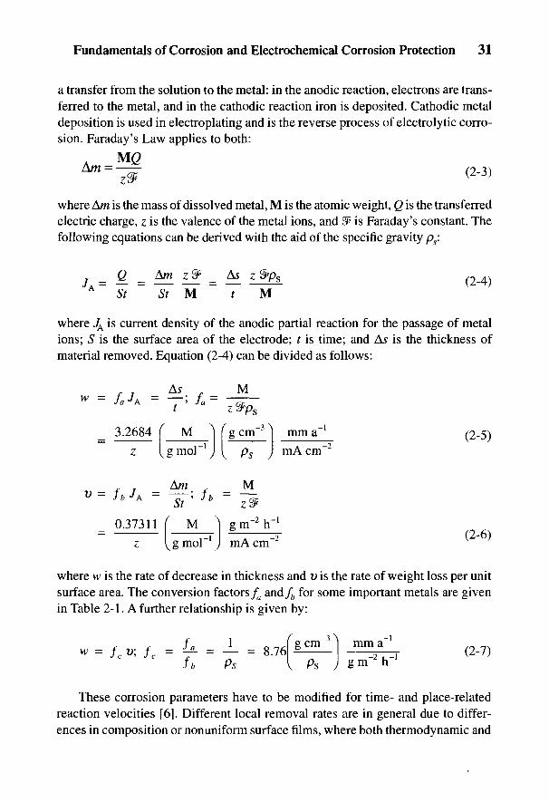
Fundamentals of Corrosion and Electrochemical Corrosion Protection 31
a transfer from the solution to the metal: in the anodic reaction, electrons are trans-ferred to the metal, and in the cathodic reaction iron is deposited. Cathodic metaldeposition is used in electroplating and is the reverse process of electrolytic corro-sion. Faraday's Law applies to both:
where Am is the mass of dissolved metal, M is the atomic weight, Q is the transferredelectric charge, z is the valence of the metal ions, and & is Faraday's constant. Thefollowing equations can be derived with the aid of the specific gravity ps:
where JA is current density of the anodic partial reaction for the passage of metalions; S is the surface area of the electrode; t is time; and As is the thickness ofmaterial removed. Equation (2-4) can be divided as follows:
where w is the rate of decrease in thickness and v is the rate of weight loss per unitsurface area. The conversion factors fa and/^ for some important metals are givenin Table 2-1. A further relationship is given by:
These corrosion parameters have to be modified for time- and place-relatedreaction velocities [6]. Different local removal rates are in general due to differ-ences in composition or nonuniform surface films, where both thermodynamic and
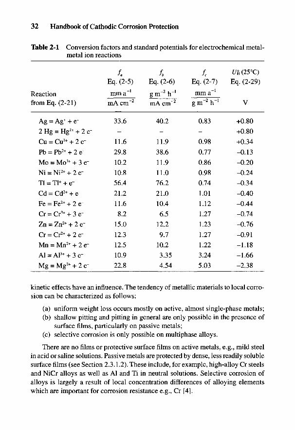
32 Handbook of Cathodic Corrosion Protection
Table 2-1 Conversion factors and standard potentials for electrochemical metal-metal ion reactions
Reactionfrom Eq. (2-21)
Ag = Ag+ + e-
2 Hg = Hg2+ + 2 e-
Cu = Cu2+ + 2 e-
Pb = Pb2+ + 2 e-
Mo = Mo3+ + 3 e-
Ni = Ni2+ + 2 e-
Tl = Tl+ + e-
Cd = Cd2+ + e-
Fe = Fe2+ + 2 e~
Cr = Cr3+ + 3 e~
Zn = Zn2+ + 2 e-
Cr = Cr2+ + 2 e-
Mn = Mn2+ + 2 e~
Al=Al3+ + 3e-
Mg = Mg2+ + 2 e-
/.Eq. (2-5)
mm a"1
mA cm~2
33.6
-
11.6
29.8
10.2
10.8
56.4
21.2
11.6
8.2
15.0
12.3
12.5
10.9
22.8
fbEq. (2-6)
gm-'h-1
mA cm"2
40.2-
11.938.6
11.911.076.2
21.010.46.5
12.29.7
10.23.354.54
fc
Eq. (2-7)
mm a"1
grn^h'1
0.83-
0.980.770.860.980.74
1.011.121.271.231.271.223.24
5.03
I/a (25°C)Eq. (2-29)
V
+0.80
+0.80
+0.34
-0.13
-0.20
-0.24
-0.34
-0.40
-0.44
-0.74
-0.76
-0.91
-1.18
-1.66
-2.38
kinetic effects have an influence. The tendency of metallic materials to local corro-sion can be characterized as follows:
(a) uniform weight loss occurs mostly on active, almost single-phase metals;(b) shallow pitting and pitting in general are only possible in the presence of
surface films, particularly on passive metals;(c) selective corrosion is only possible on multiphase alloys.
There are no films or protective surface films on active metals, e.g., mild steelin acid or saline solutions. Passive metals are protected by dense, less readily solublesurface films (see Section 2.3.1.2). These include, for example, high-alloy Cr steelsand NiCr alloys as well as Al and Ti in neutral solutions. Selective corrosion ofalloys is largely a result of local concentration differences of alloying elementswhich are important for corrosion resistance e.g., Cr [4].

Fundamentals of Corrosion and Electrochemical Corrosion Protection 33
The passage of electrons from the metal to the electrolyte is not directly relatedto metal removal, but has an indirect connection due to the electron neutrality law:
Electrons cannot be dissolved in aqueous solutions but react with oxidants in thefollowing way:
Ox and Red are general symbols for oxidation and reduction media respectively,and n and (n-z) indicate their numerical charge (see Section 2.2.2). Where there isno electrochemical redox reaction [Eq. (2-9)], the corrosion rate according toEq. (2-4) is zero because of Eq. (2-8). This is roughly the case with passive metalswhose surface films are electrical insulators (e.g., Al and Ti). Equation (2-8) doesnot take into account the possibility of electrons being diverted through a conduc-tor. In this case the equilibrium
is valid instead of Eq. (2-8).The current 7 is called the total current. In free corrosion, i.e., without the
contribution of external currents (see Fig. 2-1), it is always zero, as given by Eq. (2-8). 7A and 7C are known as the anodic and cathodic partial currents. According toEq. (2-10), generally in electrolytic corrosion anodic total currents and/or cathodicredox reactions are responsible.
All metallic materials can suffer electrolytic corrosion. Fractures caused bycathodic hydrogen only occur when the activity of the absorbed hydrogen and thelevel of the tensile stress, which can be external or internal, reach a critical value.In general, critical hydrogen absorption is achieved only in the presence of pro-moters. However, under very severe conditions such as at very low pH or verynegative potential, critical hydrogen absorption can occur. Steels with a hardnessgreater than HV 350 are particularly susceptible.
Materials consisting of elements of subgroups 4 and 5 of the periodic table areprone to the formation of internal hydrides, leading to severe embrittlement andfracture. Titanium and zirconium are important examples. Materials consisting ofelements in the main groups 4 to 6 of the periodic table suffer weight loss bycorrosion due to the formation of volatile hydrides [7]. A typical example is lead.Types of corrosion arising from cathodic hydrogen can limit the application ofcathodic protection and are dealt with in Refs. 8 and 9.
34 Handbook of Cathodic Corrosion Protection
2.2.2 Aqueous Electrolytes
Anions and cations exist in water. They migrate in an electric field and thuscarry a current. Ohm's Law is applicable:
where % is the specific conductivity and E is the electric field strength. In diluteelectrolytes, the conductivity is the sum of the ion mobilities /(:
The index i represents the type of ion and c is its concentration. In water, the ionshave velocity wF;, giving the relation:
The quotient u{ is called the electrochemical mobility and is tabulated along withion mobilities. It is important to pay attention to the units because of possibleconfusion. Values of /( are given in Table 2-2. Raising the temperature usually in-creases ion mobility, while increasing the concentration reduces the conductivitydue to interactions:
Electrical conductivity is of interest in corrosion processes in cell formation(see Section 2.2.4.2), in stray currents, and in electrochemical protection methods.Conductivity is increased by dissolved salts even though they do not take part inthe corrosion process. Similarly, the corrosion rate of carbon steels in brine, whichis influenced by oxygen content according to Eq. (2-9), is not affected by the saltconcentration [4]. Nevertheless, dissolved salts have a strong indirect influence onmany local corrosion processes. For instance, chloride ions that accumulate at lo-cal anodes can stimulate dissolution of iron and prevent the formation of a film.Alkali ions are usually regarded as completely harmless, but as counterions to OH~ions in cathodic regions, they result in very high pH values and aid formation offilms (see Section 2.2.4.2 and Chapter 4).
The pH value and thus the OH~ ion concentration is important in the formationof surface films, since OH~ ions generally form difficultly soluble compounds withmetal ions (see Section 2.2.3.1). pH is an important parameter of the medium. One
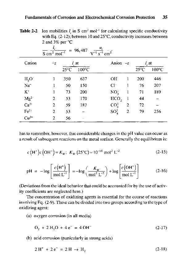
Fundamentals of Corrosion and Electrochemical Corrosion Protection 35
Table 2-2 Ion mobilities /. in S cm2 mol~' for calculating specific conductivitywith Eq. (2-12); between 10 and 25 °C, conductivity increases between2 and 3% per °C
£ r - 96,487 —J x-S cm2 mol"1 V-1 s'1 cm2
Cation +z / at Anion -z / at; i
25°C 100°C 25°C 100°C
H3O+ 1 350 637 OH 1 200 446
Na+ 1 50 150 Cl- 1 76 207K+ 1 73 200 NO' 1 71 189Mg2+ 2 53 170 HCO- 1 44Ca2+ 2 59 187 CO2" 2 72 -Fe2+ 2 53 S02~ 2 79 256
Cu2+ 2 56 -
has to remember, however, that considerable changes in the pH value can occur asa result of subsequent reactions on the metal surface. Generally the equilibrium is:
(Deviations from the ideal behavior that could be accounted for by the use of activ-ity coefficients are neglected here.)
The concentration of oxidizing agents is essential for the course of reactionsinvolving Eq. (2-9). These can be divided into two groups according to the type ofoxidizing agent:
(a) oxygen corrosion (in all media)
(b) acid corrosion (particularly in strong acids)
36 Handbook of Cathodic Corrosion Protection
The evolution of hydrogen from the acid molecule can also occur in slightlydissociated weak acids such as H2CO3 and H2S. In the case of only slightly dissoci-ated weak acids, such as H2CO3 and H2S, production of hydrogen can also occurfrom the acid molecules. In this case, the acid concentration rather than the pHvalue is a measure of the aggressiveness of the corrosion. In the same way, hydro-gen can be evolved from H2O:
This reaction occurs with overall cathodic currents, i.e., with cathodic polariza-tion. It can be practically ignored in the case of free corrosion of steel in a neutralsolution. Other oxidizing media are of interest only in special cases.
In some cases the amount of gas evolved or consumed according to Eqs. (2-17)to (2-19) can be asked for. Then Eq. (2-6) is applicable. To obtain the volume, thefollowing applies:
where jv is the rate of evolution or consumption of gas; Vis the volume of gas andV is the mol volume under standard conditions. For V = 22.4 L it follows that:
Some data are given in Table 2-3.
2.2.3 Electrochemical Phase Boundary Reactions
In electrolytic corrosion, an anodic partial reaction takes place according toEq. (2-3)
and a cathodic redox reaction according to Eq. (2-9) (see Fig. 2-1). The reactionrates can be expressed in general by using Eq. (2-6) with equivalent currents 7A and7C. They are a function of the partners to the reaction and the potential U. For everypartial reaction there is an equilibrium potential if in which the overall reaction iszero. The following section deals with the thermodynamic and kinetic fundamen-tals of these reactions.
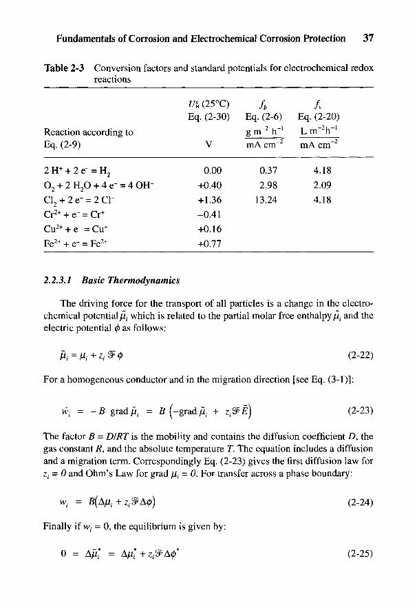
Fundamentals of Corrosion and Electrochemical Corrosion Protection 37
Table 2-3 Conversion factors and standard potentials for electrochemical redoxreactions
1/&(25°C) fb /„Eq. (2-30) Eq. (2-6) Eq. (2-20)
Reaction according to g m"2 h"' L m~ h~Eq. (2-9) V mAcnT2 mA cm"2
2H+ + 2e~ = H2 0.00 0.37 4.18
O2 + 2H2O + 4e- = 4OH- +0.40 2.98 2.09
Cl2 + 2e- = 2Cl- +1.36 13.24 4.18Cr2+ + e- = Cr+ -0.41
Cu2+ + e- = Cu+ +0.16
Fe2+ + e- = Fe2+ +0.77
2.2.3.1 Basic Thermodynamics
The driving force for the transport of all particles is a change in the electro-chemical potential/I( which is related to the partial molar free enthalpy/t, and theelectric potential 0 as follows:
For a homogeneous conductor and in the migration direction [see Eq. (3-1)]:
The factor B = DIRT is the mobility and contains the diffusion coefficient D, thegas constant R, and the absolute temperature T. The equation includes a diffusionand a migration term. Correspondingly Eq. (2-23) gives the first diffusion law forZi = 0 and Ohm's Law for grad fa = 0. For transfer across a phase boundary:
Finally if \vi = 0, the equilibrium is given by:
38 Handbook of Cathodic Corrosion Protection
Application of Eq. (2-25) to the reaction under consideration, i.e., Eq. (2-21),and to the potential-determining reaction of the reference electrode, Eq. (2-18),leads with Eq. (2-1) to the Nernst potential equation:
In this example, AG is the free reaction enthalpy of the chemical reaction
which corresponds to adding the electrochemical reactions in Eq. (2-18) and (2-21).The negative sign of If accounts for the fact that all A0 contain potential differencesin the reaction direction of Eq. (2-27) in the cell H2/electrolyte/metal and AG isappropriately defined [10]. From the concentration dependence of/I, it follows that
and for the standard state of the hydrogen electrode with a variable metal ionconcentration c(Mez+), the equilibrium potential against the standard hydrogen elec-trode is
and U£ is the standard potential which can be calculated from the free enthalpy offormation AG° Table 2-1 shows the more important values. The factor RT/ZP is26 mV at 25 °C. In the same way, a potential equilibrium can be derived for asimple redox reaction [Eq. (2-9)]:
Many redox reactions are more complicated than that given by Eq. (2-9). For ageneral redox reaction, with components Xt and their coefficients n{ written as
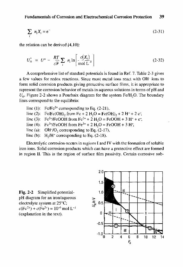
Fundamentals of Corrosion and Electrochemical Corrosion Protection 39
i
the relation can be derived [4,10]:
A comprehensive list of standard potentials is found in Ref. 7. Table 2-3 givesa few values for redox reactions. Since most metal ions react with OH" ions toform solid corrosion products giving protective surface films, it is appropriate torepresent the corrosion behavior of metals in aqueous solutions in terms of pH andUH. Figure 2-2 shows a Pourbaix diagram for the system Fe/H2O. The boundarylines correspond to the equilibria:
line (1): Fe/Fe2+ corresponding to Eq. (2-21),line (2): Fe/Fe(OH)2 from Fe + 2 H2O = Fe(OH)2 + 2 H+ + 2 e-line (3): Fe2+/FeOOH from Fe2+ + 2 H2O = FeOOH + 3 H+ + e~line (4): Fe3+/FeOOH from Fe3+ + 2 H2O - FeOOH + 3 H+,line (a): OH7O2 corresponding to Eq. (2-17),line (b): H2/H
+ corresponding to Eq. (2-18).
Electrolytic corrosion occurs in regions I and IV with the formation of solubleiron ions. Solid corrosion products which can have a protective effect are formedin region II. This is the region of surface film passivity. Certain corrosive sub-
Fig. 2-2 Simplified potential-pH diagram for an iron/aqueouselectrolyte system at 25°C;c(Fe2+) + c(Fe3+) = 1Q-6 mol L"1
(explanation in the text).
40 Handbook of Cathodic Corrosion Protection
stances in the medium (e.g., chloride ions) and mechanical effects can destroysurface films locally, leading to intensive local corrosion such as pitting and stresscorrosion. On the other hand, in certain passivating acids, such as HNO3, H2SO4,and H3PO4, there is an area in region I (shown hatched), Fig. 2-2, where the mate-rial is covered with an extremely thin nonequilibrium film. This chemical passivityis not technically different from surface film passivity. For both cases, corrosionrates are extremely small but not zero, as in region III where the metal is thermo-dynamically stable. In addition, there is the latent danger of local corrosion [4].
Such pH-£/H diagrams are available for all metals [7]. They give an overview ofcorrosion behavior and the electrochemical protection that is possible when thepotential is changed by means of impressed currents. Cathodic currents are requiredto reduce the potential in region III. Anodic currents are needed to raise the potentialin region II or the hatched area in region I. This is the basis of cathodic and anodicprotection. The region of H2O stability between the straight lines (a) and (b) must beconsidered before a preliminary judgment can be made. Outside these lines, thepossibility of changing the potential is limited by the electrolytic dissociation ofwater. From Fig. 2-2 it follows that cathodic protection in acid solutions is not prac-tically possible but on the other hand anodic protection probably is possible.
Regions for soluble hydroxy complexes of the type Fe(OH)+ are neglected inFig. 2-2 and in corresponding diagrams in Ref. 7; compare the amended diagrams inthe literature [11,12]. The regions in the pH-potential diagrams can be transposed tosome extent by complex formation. This must be taken into account when dealingwith unknown chemical solutions. In addition, when using the pH-potential diagramsin Ref. 7, care must be taken that, although regions of weight loss due to hydrideformation are represented, regions where internal hydride formation occurs in met-als of the 4 and 5 subgroups are not given.
2.2.3.2 Electrochemical Kinetics
The potential dependence of the velocity of an electrochemical phase bound-ary reaction is represented by a current-potential curve /(£/)• It is convenient torelate such curves to the geometric electrode surface area S, i.e., to present them ascurrent-density-potential curves J(U). The determination of such curves is repre-sented schematically in Fig. 2-3. A current is conducted to the counterelectrode E3
in the electrolyte by means of an external circuit (voltage source U0, ammeter,resistances R' and R"} and via the electrode E} to be measured, back to the externalcircuit. In the diagram, the current indicated (®) is positive. The potential of E} ismeasured with a high-resistance voltmeter as the voltage difference of electrodesEj and E2. To accomplish this, the reference electrode, E2, must be equipped with aHaber-Luggin capillary whose probe end must be brought as close as possible to
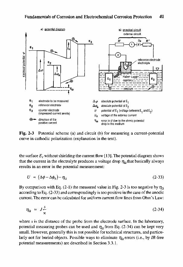
Fundamentals of Corrosion and Electrochemical Corrosion Protection 41
Fig. 2-3 Potential scheme (a) and circuit (b) for measuring a current-potentialcurve in cathodic polarization (explanation in the text).
the surface Ej without shielding the current flow [13]. The potential diagram showsthat the current in the electrolyte produces a voltage drop rfo that basically alwaysresults in an error in the potential measurement:
By comparison with Eq. (2-1) the measured value in Fig. 2-3 is too negative by 7]n
according to Eq. (2-33) and correspondingly is too positive in the case of the anodiccurrent. The error can be calculated for uniform current flow lines from Ohm's Law:
where s is the distance of the probe from the electrode surface. In the laboratory,potential measuring probes can be used and 7]Q from Eq. (2-34) can be kept verysmall. However, generally this is not possible for technical structures, and particu-larly not for buried objects. Possible ways to eliminate Tfa errors (i.e., by 7/?-freepotential measurements) are described in Section 3.3.1.

42 Handbook of Cathodic Corrosion Protection
A simplifying assumption is made that only one electrochemical reactionoccurs at Ej. Then the equilibrium potential If is present at I = 0. Positive (ornegative) currents can only flow with positive (or negative) deviations of if. Thedifference (U - if) = T] is termed the overvoltage. The function J(rj) gives infor-mation on kinetics of the reaction and on the rate-determining step. If transportthrough the phase boundary itself is rate determining, then /(?]) is an exponentialfunction (activation polarization). For this reason J(U) curves are mostly plottedon a semilogarithmic scale. On the other hand, if a chemical reaction or diffusionin the medium is rate determining, then/is independent of potential, i.e., the curve7(?7) ends parallel to the potential axis (concentration overvoltage). A similar casecan arise if less readily soluble surface films are formed which in the stationarystate have a solubility rate equivalent to /. This is the case with passive metals (seeSection 2.3.1.2). With poorly conducting surface films or in high-resistance media,the ohmic resistance controls the current so that 7(77) follows Ohm's Law. In thiscase 77 is not a genuine overvoltage, but corresponds to rj^'m Eq. (2-34) and is thusin principle a measurement error, given that the potential is defined for the inter-face between the metal and film.
The literature [14] on electrochemical kinetics is extensive and specialized.Figure 2-4 shows a/(r]) curve of a redox reaction according to Eq. (2-9) with acti-vation and diffusion polarization. It follows from theory [4, 10] for this example:
where J0 is exchange current density, and corresponds to the magnitude of theequally fast forward and reverse reactions in the equilibrium; GA and Gc are thelimiting diffusion current densities and are proportional to the concentration of thereactants concerned and increase according to the first law of diffusion with theflow velocity; and 6+ and 8_ are the anodic and cathodic Tafel slopes (see definitionin list of symbols) and are given by:
The term a is a symmetry factor for the energy threshold for the passage of elec-trons and is approximately equal to 0.5. In Fig. 2-4, the value of a was chosen as 2/3for better distinction; integer exponents are chosen for 70, GA and Gc for clarity,
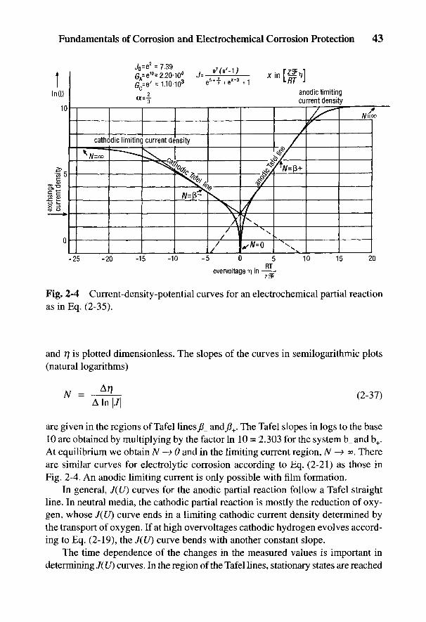
Fundamentals of Corrosion and Electrochemical Corrosion Protection 43
Fig. 2-4 Current-density-potential curves for an electrochemical partial reactionas in Eq. (2-35).
and T] is plotted dimensionless. The slopes of the curves in semilogarithmic plots(natural logarithms)
are given in the regions of Tafel lines^_ andfl+. The Tafel slopes in logs to the base10 are obtained by multiplying by the factor In 10 = 2.303 for the system b_ and b+.At equilibrium we obtain N —> 0 and in the limiting current region, N —> <». Thereare similar curves for electrolytic corrosion according to Eq. (2-21) as those inFig. 2-4. An anodic limiting current is only possible with film formation.
In general, J(U) curves for the anodic partial reaction follow a Tafel straightline. In neutral media, the cathodic partial reaction is mostly the reduction of oxy-gen, whose J(U) curve ends in a limiting cathodic current density determined bythe transport of oxygen. If at high overvoltages cathodic hydrogen evolves accord-ing to Eq. (2-19), the J(U) curve bends with another constant slope.
The time dependence of the changes in the measured values is important indetermining J(U) curves. In the region of the Tafel lines, stationary states are reached
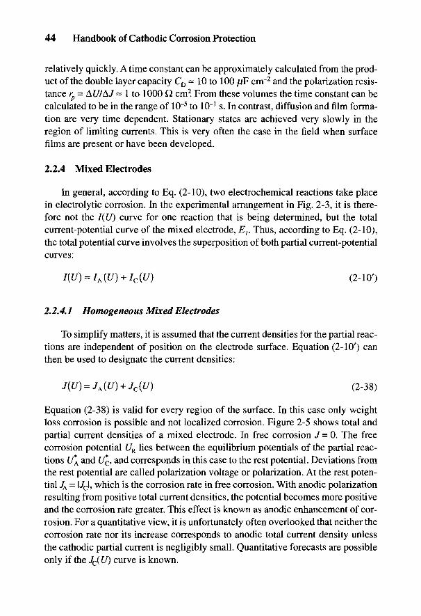
44 Handbook of Cathodic Corrosion Protection
relatively quickly. A time constant can be approximately calculated from the prod-uct of the double layer capacity CD~ 10 to 100 F cnr2 and the polarization resis-tance rp - AU/AJ = 1 to 1000 Q cm2. From these volumes the time constant can becalculated to be in the range of 10~5 to 10"1 s. In contrast, diffusion and film forma-tion are very time dependent. Stationary states are achieved very slowly in theregion of limiting currents. This is very often the case in the field when surfacefilms are present or have been developed.
2.2.4 Mixed Electrodes
In general, according to Eq. (2-10), two electrochemical reactions take placein electrolytic corrosion. In the experimental arrangement in Fig. 2-3, it is there-fore not the I(U) curve for one reaction that is being determined, but the totalcurrent-potential curve of the mixed electrode, E}. Thus, according to Eq. (2-10),the total potential curve involves the superposition of both partial current-potentialcurves:
2.2.4.1 Homogeneous Mixed Electrodes
To simplify matters, it is assumed that the current densities for the partial reac-tions are independent of position on the electrode surface. Equation (2-10') canthen be used to designate the current densities:
Equation (2-38) is valid for every region of the surface. In this case only weightloss corrosion is possible and not localized corrosion. Figure 2-5 shows total andpartial current densities of a mixed electrode. In free corrosion / = 0. The freecorrosion potential UR lies between the equilibrium potentials of the partial reac-tions U*A and U*c, and corresponds in this case to the rest potential. Deviations fromthe rest potential are called polarization voltage or polarization. At the rest poten-tial JA = l/cl, which is the corrosion rate in free corrosion. With anodic polarizationresulting from positive total current densities, the potential becomes more positiveand the corrosion rate greater. This effect is known as anodic enhancement of cor-rosion. For a quantitative view, it is unfortunately often overlooked that neither thecorrosion rate nor its increase corresponds to anodic total current density unlessthe cathodic partial current is negligibly small. Quantitative forecasts are possibleonly if the JC(U) curve is known.
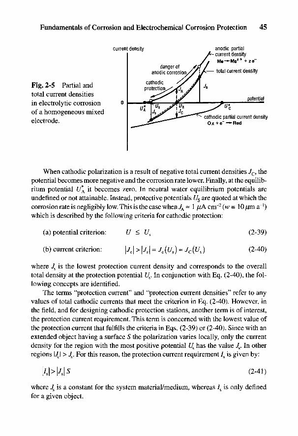
Fundamentals of Corrosion and Electrochemical Corrosion Protection 45
Fig. 2-5 Partial andtotal current densitiesin electrolytic corrosionof a homogeneous mixedelectrode.
When cathodic polarization is a result of negative total current densities Jc, thepotential becomes more negative and the corrosion rate lower. Finally, at the equilib-rium potential U*A it becomes zero. In neutral water equilibrium potentials areundefined or not attainable. Instead, protective potentials Us are quoted at which thecorrosion rate is negligibly low. This is the case when JA ~ 1 jJ,A cm"2 (w = 10 pm a"1)which is described by the following criteria for cathodic protection:
where 7S is the lowest protection current density and corresponds to the overalltotal density at the protection potential Us. In conjunction with Eq. (2-40), the fol-lowing concepts are identified.
The terms "protection current" and "protection current densities" refer to anyvalues of total cathodic currents that meet the criterion in Eq. (2-40). However, inthe field, and for designing cathodic protection stations, another term is of interest,the protection current requirement. This term is concerned with the lowest value ofthe protection current that fulfills the criteria in Eqs. (2-39) or (2-40). Since with anextended object having a surface S the polarization varies locally, only the currentdensity for the region with the most positive potential Us has the value Js. In otherregions \JC\ > Js. For this reason, the protection current requirement 7S is given by:
where J& is a constant for the system material/medium, whereas 7S is only definedfor a given object.
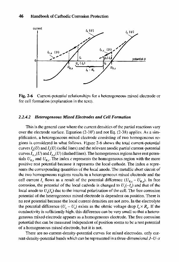
46 Handbook of Cathodic Corrosion Protection
Fig. 2-6 Current-potential relationships for a heterogeneous mixed electrode orfor cell formation (explanation in the text).
2.2.4.2 Heterogeneous Mixed Electrodes and Cell Formation
This is the general case where the current densities of the partial reactions varyover the electrode surface. Equation (2-10') and not Eq. (2-38) applies. As a sim-plification, a heterogeneous mixed electrode consisting of two homogeneous re-gions is considered in what follows. Figure 2-6 shows the total current-potentialcurves Ia(U) and IC(U) (solid lines) and the relevant anodic partial current-potentialcurves IA a(U) and /A)C(t/) (dashed lines). The homogeneous regions have rest poten-tials UR a and UR c. The index c represents the homogeneous region with the morepositive rest potential because it represents the local cathode. The index a repre-sents the corresponding quantities of the local anode. The metallic short circuit ofthe two homogeneous regions results in a heterogeneous mixed electrode and thecell current 7e flows as a result of the potential difference (UR c - UR a). In freecorrosion, the potential of the local cathode is changed to £/c(-/e) and that of thelocal anode to t/a(/e) due to the internal polarization of the cell. The free corrosionpotential of the heterogeneous mixed electrode is dependent on position. There isno rest potential because the local current densities are not zero. In the electrolytethe potential difference (Uc - £/a) exists as the ohmic voltage drop 7e x 7?e. If theconductivity is sufficiently high, this difference can be very small so that a hetero-geneous mixed electrode appears as a homogeneous electrode. The free corrosionpotential that can be measured independent of position seems to be a rest potentialof a homogeneous mixed electrode, but it is not.
There are no current-density-potential curves for mixed electrodes, only cur-rent-density-potential bands which can be represented in a three-dimensional J-U-x
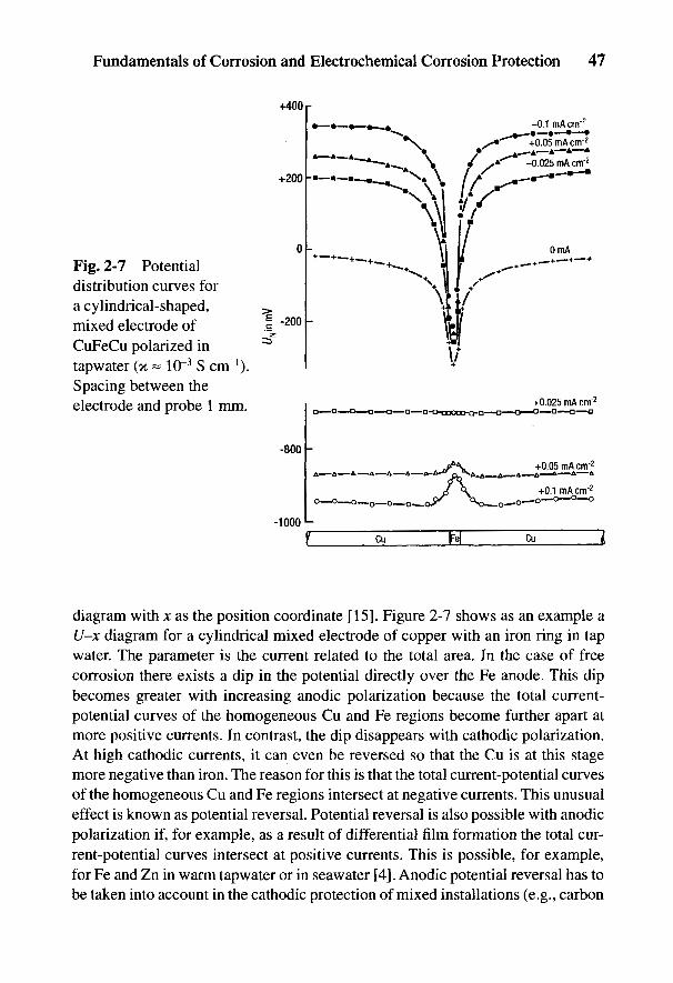
diagram with x as the position coordinate [15]. Figure 2-7 shows as an example aU-x diagram for a cylindrical mixed electrode of copper with an iron ring in tapwater. The parameter is the current related to the total area. In the case of freecorrosion there exists a dip in the potential directly over the Fe anode. This dipbecomes greater with increasing anodic polarization because the total current-potential curves of the homogeneous Cu and Fe regions become further apart atmore positive currents. In contrast, the dip disappears with cathodic polarization.At high cathodic currents, it can even be reversed so that the Cu is at this stagemore negative than iron. The reason for this is that the total current-potential curvesof the homogeneous Cu and Fe regions intersect at negative currents. This unusualeffect is known as potential reversal. Potential reversal is also possible with anodicpolarization if, for example, as a result of differential film formation the total cur-rent-potential curves intersect at positive currents. This is possible, for example,for Fe and Zn in warm tap water or in seawater [4]. Anodic potential reversal has tobe taken into account in the cathodic protection of mixed installations (e.g., carbon
Fundamentals of Corrosion and Electrochemical Corrosion Protection 47
Fig. 2-7 Potentialdistribution curves fora cylindrical-shaped,mixed electrode ofCuFeCu polarized intapwater (K ~ 10~3 S cm"1).Spacing between theelectrode and probe 1 mm.
48 Handbook of Cathodic Corrosion Protection
steel and stainless steel) and sacrificial anodes should be used in order not to dam-age the less noble component of the object being protected.
Local corrosion is generally the result of the formation of heterogeneous mixedelectrodes where the change in the local partial current-density-potential curvescan result from the material or the medium. Where this is caused by the contact ofdifferent metals, it is known as a galvanic cell (see Fig. 2-7) [16,17]. Local differ-ences in the composition of the medium result in concentration cells. These in-clude the differential aeration cell which is characterized by subsequent chemicalreactions that stabilize differences in pH values; chloride and alkali ions are im-portant here [4]. Such corrosion cells can have very different sizes. In selectivecorrosion of multiphase alloys, anodes and cathodes can be separated by fractionsof a millimeter. With objects having a large surface area (e.g., pipelines) the re-gions can cover several kilometers. It is immaterial whether the cathodic region isstill part of the pipeline or an external component of the installation that is electri-cally connected to the pipeline. In the latter case this is referred to as a cathodicforeign structure. Examples of this are electrical grounds and reinforcing steel inconcrete (see Section 4.3).
The ratio of the areas of cathodes to anodes is decisive for the potential dam-age resulting from cell formation [16,17]. Using the integral (mean) polarizationresistances
The difference in rest potentials (see the practical potential series in Table 2-4)determines mostly the direction of the current and less of the level; for these theresistances are significant. In particular Re can be neglected in the external corro-sion of extended objects. In addition, the Ia(U) curve is usually steeper than theIC(U) curve (i.e., Ra < 7?c). By introducing the surface areas of anode and cathode5a and 5C, it follows from Eq. (2-43) that:
where rc = Rcx Sc is the specific cathodic polarization resistance. At high cell cur-rents, the cathodic partial current at the anode can be neglected, so that 7A a ~ /a in
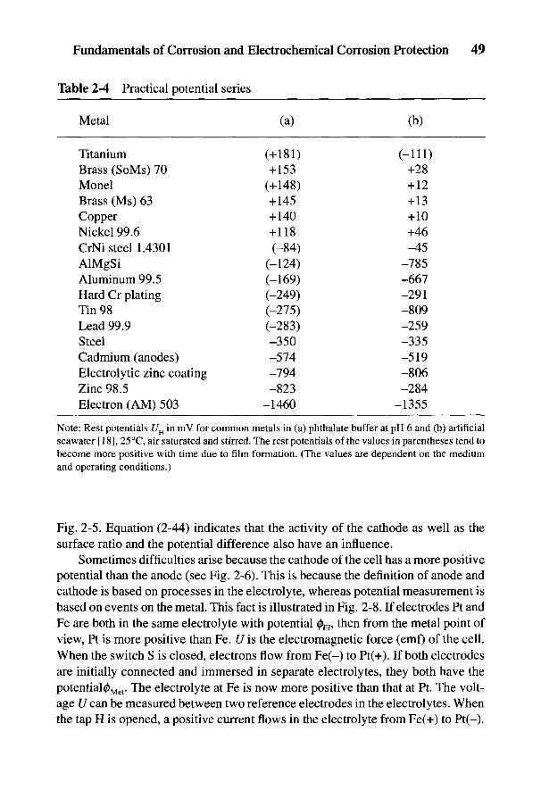
Fundamentals of Corrosion and Electrochemical Corrosion Protection 49
Table 2-4 Practical potential series
Metal (a) (b)
Titanium (+181) (-111)Brass (SoMs) 70 +153 +28Monel (+148) +12Brass (Ms) 63 +145 +13Copper +140 +10Nickel 99.6 +118 +46CrNi steel 1.4301 (-84) -45AlMgSi (-124) -785Aluminum 99.5 (-169) -667Hard Cr plating (-249) -291Tin 98 (-275) -809Lead 99.9 (-283) -259Steel -350 -335Cadmium (anodes) -574 -519Electrolytic zinc coating -794 -806Zinc 98.5 -823 -284Electron (AM) 503 -1460 -1355
Note: Rest potentials UH in mV for common metals in (a) phthalate buffer at pH 6 and (b) artificialseawater [18], 25°C, air saturated and stirred. The rest potentials of the values in parentheses tend tobecome more positive with time due to film formation. (The values are dependent on the mediumand operating conditions.)
Fig. 2-5. Equation (2-44) indicates that the activity of the cathode as well as thesurface ratio and the potential difference also have an influence.
Sometimes difficulties arise because the cathode of the cell has a more positivepotential than the anode (see Fig. 2-6). This is because the definition of anode andcathode is based on processes in the electrolyte, whereas potential measurement isbased on events on the metal. This fact is illustrated in Fig. 2-8. If electrodes Pt andFe are both in the same electrolyte with potential 0 , then from the metal point ofview, Pt is more positive than Fe. U is the electromagnetic force (emf) of the cell.When the switch S is closed, electrons flow from Fe(-) to Pt(+). If both electrodesare initially connected and immersed in separate electrolytes, they both have thepotentia!0Met. The electrolyte at Fe is now more positive than that at Pt. The volt-age U can be measured between two reference electrodes in the electrolytes. Whenthe tap H is opened, a positive current flows in the electrolyte from Fe(+) to Pt(-).

This last process is the basis for the definition of anode and cathode. When currentis flowing, the anode (Fe) is more negative on the metal side, but in the electrolyteit is more positive than the cathode (Pt).
2.2.5 Observations of Current Distribution
The distribution of current is of considerable interest in corrosion processes onheterogeneous mixed electrodes, particularly in the internal corrosion of tanks andcomplex shapes as well as generally in the application of electrochemical protec-tion. A primary current distribution can be obtained from the laws of electrostaticsby integration of the Laplace equation (div grad 0 = 0) [10,19]. Polarization resis-tances at the electrodes are neglected in this treatment. Current distribution is exclu-sively related to the geometry. When polarization resistance is taken into account,secondary and tertiary current distributions can be distinguished in which activationpolarization alone, or together with concentration polarization, has an effect [20].This is relevant in, for example, electroplating where uniform metal deposition isrequired. Current distribution is more uniform as a result of polarization resistancethan in primary current distribution [4,10,19,20]. A polarization parameter
is introduced for comparability in which the ratio of polarization resistance to elec-trolyte resistance is taken into account. It corresponds to the thickness of a layer ofelectrolyte, whose ohmic resistance is equal to the polarization resistance. If in theprimary current distribution this thickness is accounted for in the geometry, a bet-
Fig. 2-8Principleand potentialdiagram of agalvanic cell(explanationin the text).
50 Handbook of Cathodic Corrosion Protection
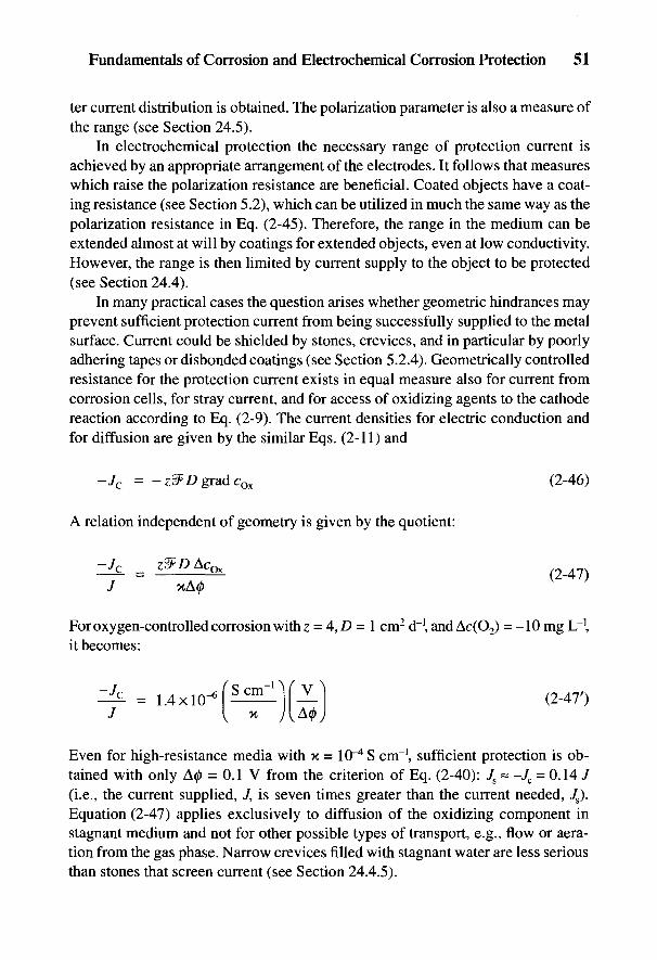
Fundamentals of Corrosion and Electrochemical Corrosion Protection 51
ter current distribution is obtained. The polarization parameter is also a measure ofthe range (see Section 24.5).
In electrochemical protection the necessary range of protection current isachieved by an appropriate arrangement of the electrodes. It follows that measureswhich raise the polarization resistance are beneficial. Coated objects have a coat-ing resistance (see Section 5.2), which can be utilized in much the same way as thepolarization resistance in Eq. (2-45). Therefore, the range in the medium can beextended almost at will by coatings for extended objects, even at low conductivity.However, the range is then limited by current supply to the object to be protected(see Section 24.4).
In many practical cases the question arises whether geometric hindrances mayprevent sufficient protection current from being successfully supplied to the metalsurface. Current could be shielded by stones, crevices, and in particular by poorlyadhering tapes or disbonded coatings (see Section 5.2.4). Geometrically controlledresistance for the protection current exists in equal measure also for current fromcorrosion cells, for stray current, and for access of oxidizing agents to the cathodereaction according to Eq. (2-9). The current densities for electric conduction andfor diffusion are given by the similar Eqs. (2-11) and
A relation independent of geometry is given by the quotient:
For oxygen-controlled corrosion with z = 4,D = 1 cm2 d \ and Ac(O2) = -10 mg L \it becomes:
Even for high-resistance media with K= 10~^ S cnr1, sufficient protection is ob-tained with only A0 = 0.1 V from the criterion of Eq. (2-40): Js « -Jc = 0.14 /(i.e., the current supplied, 7, is seven times greater than the current needed, /s).Equation (2-47) applies exclusively to diffusion of the oxidizing component instagnant medium and not for other possible types of transport, e.g., flow or aera-tion from the gas phase. Narrow crevices filled with stagnant water are less seriousthan stones that screen current (see Section 24.4.5).
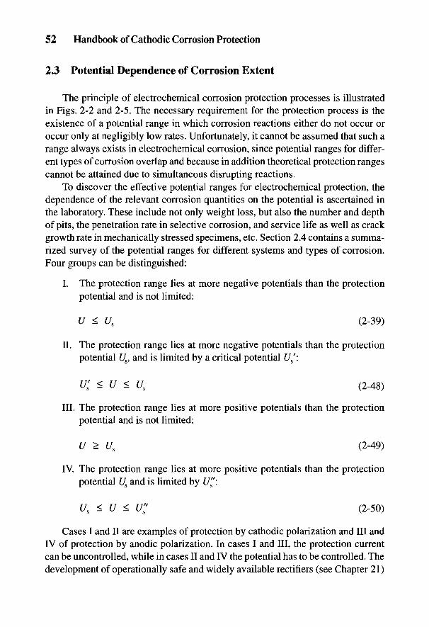
52 Handbook of Cathodic Corrosion Protection
2.3 Potential Dependence of Corrosion Extent
The principle of electrochemical corrosion protection processes is illustratedin Figs. 2-2 and 2-5. The necessary requirement for the protection process is theexistence of a potential range in which corrosion reactions either do not occur oroccur only at negligibly low rates. Unfortunately, it cannot be assumed that such arange always exists in electrochemical corrosion, since potential ranges for differ-ent types of corrosion overlap and because in addition theoretical protection rangescannot be attained due to simultaneous disrupting reactions.
To discover the effective potential ranges for electrochemical protection, thedependence of the relevant corrosion quantities on the potential is ascertained inthe laboratory. These include not only weight loss, but also the number and depthof pits, the penetration rate in selective corrosion, and service life as well as crackgrowth rate in mechanically stressed specimens, etc. Section 2.4 contains a summa-rized survey of the potential ranges for different systems and types of corrosion.Four groups can be distinguished:
I. The protection range lies at more negative potentials than the protectionpotential and is not limited:
a ^. s
II. The protection range lies at more negative potentials than the protectionpotential U&, and is limited by a critical potential £//:
j o \ /
III. The protection range lies at more positive potentials than the protectionpotential and is not limited:
IV. The protection range lies at more positive potentials than the protectionpotential t/s and is limited by U":
Cases I and II are examples of protection by cathodic polarization and III andIV of protection by anodic polarization. In cases I and III, the protection currentcan be uncontrolled, while in cases II and IV the potential has to be controlled. Thedevelopment of operationally safe and widely available rectifiers (see Chapter 21)
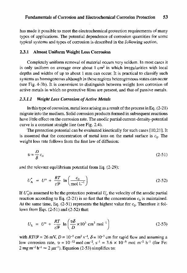
Fundamentals of Corrosion and Electrochemical Corrosion Protection 53
has made it possible to meet the electrochemical protection requirements of manytypes of applications. The potential dependence of corrosion quantities for sometypical systems and types of corrosion is described in the following section.
2.3.1 Almost Uniform Weight Loss Corrosion
Completely uniform removal of material occurs very seldom. In most cases itis only uniform on average over about 1 cm2 in which irregularities with localdepths and widths of up to about 1 mm can occur. It is practical to classify suchsystems as homogeneous although in these regions heterogeneous states can occur(see Fig. 4-3b). It is convenient to distinguish between weight loss corrosion ofactive metals in which no protective films are present, and that of passive metals.
2.3.1.1 Weight Loss Corrosion of Active Metals
In this type of corrosion, metal ions arising as a result of the process in Eq. (2-21)migrate into the medium. Solid corrosion products formed in subsequent reactionshave little effect on the corrosion rate. The anodic partial current-density-potentialcurve is a constant straight line (see Fig. 2.4).
The protection potential can be evaluated kinetically for such cases [10,21]. Itis assumed that the concentration of metal ions on the metal surface is c0. Theweight loss rate follows from the first law of diffusion:
and the relevant equilibrium potential from Eq. (2-29):
If f/^is assumed to be the protection potential f/s, the velocity of the anodic partialreaction according to Eq. (2-21) is so fast that the concentration c0 is maintained.At the same time, Eq. (2-51) represents the highest value for c0. Therefore it fol-lows from Eqs. (2-51) and (2-52) that:
with RT/2F= 26 mV, D = 10~5 cm2 s~!, 5= 10~3 cm for rapid flow and assuming alow corrosion rate, v = 10~12 mol cnr2, s~! = 3.6 x 10~5 mol rrr2 hr1 (for Fe:2 mg nr2 hr1 — 2 //a"1). Equation (2-53) simplifies to:
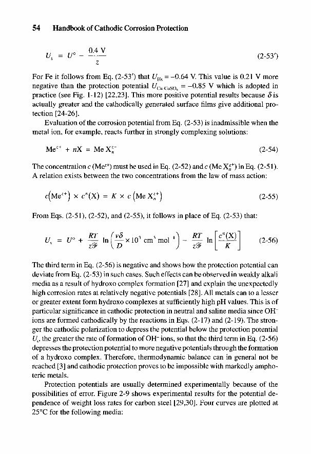
54 Handbook of Cathodic Corrosion Protection
For Fe it follows from Eq. (2-53') that UHs = -0.64 V. This value is 0.21 V morenegative than the protection potential f/Cu-cuso4
= -0-85 V which is adopted inpractice (see Fig. 1-12) [22,23]. This more positive potential results because 8isactually greater and the cathodically generated surface films give additional pro-tection [24-26].
Evaluation of the corrosion potential from Eq. (2-53) is inadmissible when themetal ion, for example, reacts further in strongly complexing solutions:
The concentration c (Mez+) must be used in Eq. (2-52) and c (Me X*+) in Eq. (2-51).A relation exists between the two concentrations from the law of mass action:
From Eqs. (2-51), (2-52), and (2-55), it follows in place of Eq. (2-53) that:
The third term in Eq. (2-56) is negative and shows how the protection potential candeviate from Eq. (2-53) in such cases. Such effects can be observed in weakly alkalimedia as a result of hydroxo complex formation [27] and explain the unexpectedlyhigh corrosion rates at relatively negative potentials [28]. All metals can to a lesseror greater extent form hydroxo complexes at sufficiently high pH values. This is ofparticular significance in cathodic protection in neutral and saline media since OH"ions are formed cathodically by the reactions in Eqs. (2-17) and (2-19). The stron-ger the cathodic polarization to depress the potential below the protection potentialt/s, the greater the rate of formation of OH~ ions, so that the third term in Eq. (2-56)depresses the protection potential to more negative potentials through the formationof a hydroxo complex. Therefore, thermodynamic balance can in general not bereached [3] and cathodic protection proves to be impossible with markedly ampho-teric metals.
Protection potentials are usually determined experimentally because of thepossibilities of error. Figure 2-9 shows experimental results for the potential de-pendence of weight loss rates for carbon steel [29,30]. Four curves are plotted at25 °C for the following media:
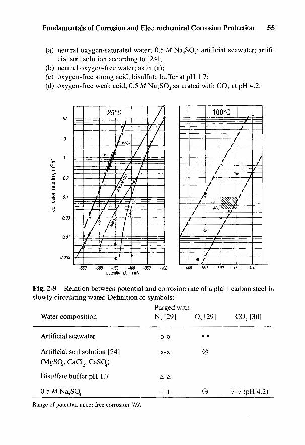
Fundamentals of Corrosion and Electrochemical Corrosion Protection 55
(a) neutral oxygen-saturated water; 0.5 M Na3SO4; artificial seawater; artifi-cial soil solution according to [24];
(b) neutral oxygen-free water; as in (a);(c) oxygen-free strong acid; bisulfate buffer at pH 1.7;(d) oxygen-free weak acid; 0.5 M Na2SO4 saturated with CO2 at pH 4.2.
Fig. 2-9 Relation between potential and corrosion rate of a plain carbon steel inslowly circulating water. Definition of symbols:
Purged with:
Water composition N2 [29] O2 [29] CO2 [30]
Artificial seawater o-o •-•
Artificial soil solution [24] x-x <8>
(MgSO4, CaCl2, CaSO4)
Bisulfate buffer pH 1.7 A-A
0.5MNa2S04 +-+ 0 v-v (pH 4.2)
Range of potential under free corrosion: \\\\\
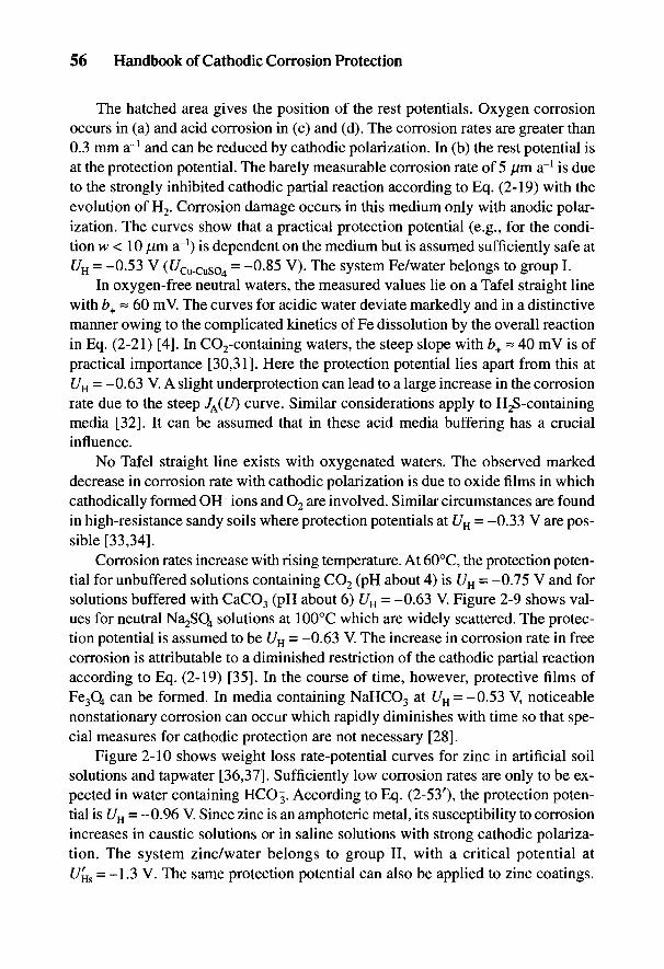
56 Handbook of Cathodic Corrosion Protection
The hatched area gives the position of the rest potentials. Oxygen corrosionoccurs in (a) and acid corrosion in (c) and (d). The corrosion rates are greater than0.3 mm a"1 and can be reduced by cathodic polarization. In (b) the rest potential isat the protection potential. The barely measurable corrosion rate of 5 pn a"1 is dueto the strongly inhibited cathodic partial reaction according to Eq. (2-19) with theevolution of H2. Corrosion damage occurs in this medium only with anodic polar-ization. The curves show that a practical protection potential (e.g., for the condi-tion w < 10 fjm a"1) is dependent on the medium but is assumed sufficiently safe atUH = -0.53 V (t/cu-cuso4
= -0-85 V). The system Fe/water belongs to group I.In oxygen-free neutral waters, the measured values lie on a Tafel straight line
with b+ ~ 60 mV. The curves for acidic water deviate markedly and in a distinctivemanner owing to the complicated kinetics of Fe dissolution by the overall reactionin Eq. (2-21) [4]. In CO2-containing waters, the steep slope with b+ ~ 40 mV is ofpractical importance [30,31]. Here the protection potential lies apart from this atUH = -0.63 V. A slight underprotection can lead to a large increase in the corrosionrate due to the steep JA(U) curve. Similar considerations apply to H2S-containingmedia [32]. It can be assumed that in these acid media buffering has a crucialinfluence.
No Tafel straight line exists with oxygenated waters. The observed markeddecrease in corrosion rate with cathodic polarization is due to oxide films in whichcathodically formed OH~ ions and O2 are involved. Similar circumstances are foundin high-resistance sandy soils where protection potentials at UH = -0.33 V are pos-sible [33,34].
Corrosion rates increase with rising temperature. At 60°C, the protection poten-tial for unbuffered solutions containing CO2 (pH about 4) is UH = -0.75 V and forsolutions buffered with CaCO3 (pH about 6) UH = -0.63 V. Figure 2-9 shows val-ues for neutral Na2SO4 solutions at 100°C which are widely scattered. The protec-tion potential is assumed to be UH - -0.63 V. The increase in corrosion rate in freecorrosion is attributable to a diminished restriction of the cathodic partial reactionaccording to Eq. (2-19) [35]. In the course of time, however, protective films ofFe3O4 can be formed. In media containing NaHCO3 at f/H = -0.53 V, noticeablenonstationary corrosion can occur which rapidly diminishes with time so that spe-cial measures for cathodic protection are not necessary [28].
Figure 2-10 shows weight loss rate-potential curves for zinc in artificial soilsolutions and tapwater [36,37]. Sufficiently low corrosion rates are only to be ex-pected in water containing HCO 3. According to Eq. (2-53'), the protection poten-tial is UH = -0.96 V. Since zinc is an amphoteric metal, its susceptibility to corrosionincreases in caustic solutions or in saline solutions with strong cathodic polariza-tion. The system zinc/water belongs to group II, with a critical potential att/HS = -1-3 V. The same protection potential can also be applied to zinc coatings.
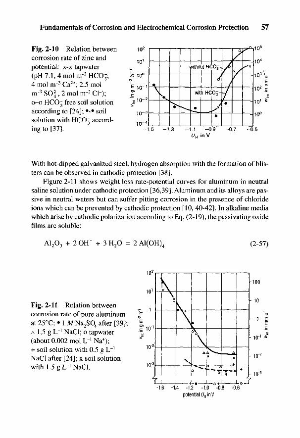
Fundamentals of Corrosion and Electrochemical Corrosion Protection 57
Fig. 2-10 Relation betweencorrosion rate of zinc andpotential: x-x tap water(pH7.1,4molnr3HCO-;4 mol nr3 Ca2+; 2.5 molnr3 SOJ- 2 mol nr3 Cl~);o-o HCO~ free soil solutionaccording to [24]; •-• soilsolution with HCO~ accord-ing to [37].
With hot-dipped galvanized steel, hydrogen absorption with the formation of blis-ters can be observed in cathodic protection [38].
Figure 2-11 shows weight loss rate-potential curves for aluminum in neutralsaline solution under cathodic protection [36,39]. Aluminum and its alloys are pas-sive in neutral waters but can suffer pitting corrosion in the presence of chlorideions which can be prevented by cathodic protection [10, 40-42]. In alkaline mediawhich arise by cathodic polarization according to Eq. (2-19), the passivating oxidefilms are soluble:
Fig. 2-11 Relation betweencorrosion rate of pure aluminumat 25°C; • 1 MNa2SO4 after [39];A 1.5 g L~l NaCl; o tapwater(about 0.002 mol L"1 Na+);+ soil solution with 0.5 g L"1
NaCl after [24]; x soil solutionwith 1.5 gL-1 NaCl.
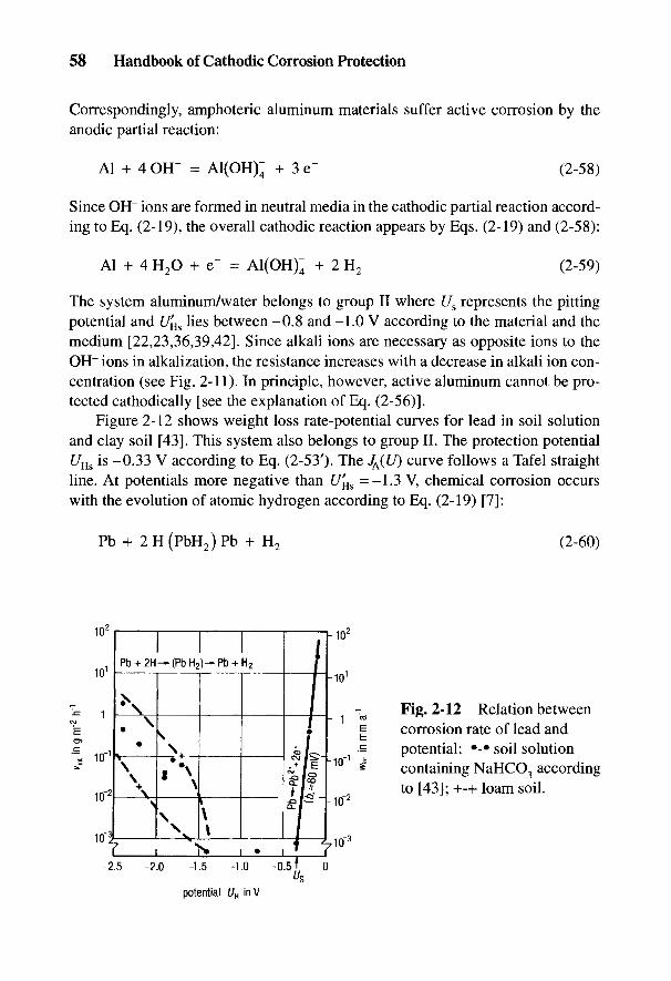
58 Handbook of Cathodic Corrosion Protection
Correspondingly, amphoteric aluminum materials suffer active corrosion by theanodic partial reaction:
Since OH~ ions are formed in neutral media in the cathodic partial reaction accord-ing to Eq. (2-19), the overall cathodic reaction appears by Eqs. (2-19) and (2-58):
The system aluminum/water belongs to group II where Us represents the pittingpotential and U'Hs lies between -0.8 and -1.0 V according to the material and themedium [22,23,36,39,42]. Since alkali ions are necessary as opposite ions to theOH" ions in alkalization, the resistance increases with a decrease in alkali ion con-centration (see Fig. 2-11). In principle, however, active aluminum cannot be pro-tected cathodically [see the explanation of Eq. (2-56)].
Figure 2-12 shows weight loss rate-potential curves for lead in soil solutionand clay soil [43]. This system also belongs to group II. The protection potentialUHs is -0.33 V according to Eq. (2-53'). The J^(U) curve follows a Tafel straightline. At potentials more negative than Uf
Es =-1.3 V, chemical corrosion occurswith the evolution of atomic hydrogen according to Eq. (2-19) [7]:
Fig. 2-12 Relation betweencorrosion rate of lead andpotential: •-• soil solutioncontaining NaHCO3 accordingto [43]; +-+ loam soil.
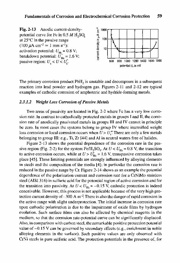
Fundamentals of Corrosion and Electrochemical Corrosion Protection 59
Fig. 2-13 Anodic current-density-potential curve for Fe in 0.5 M H2SO4
at 25°C in the passive range(lOOjUAcnr2^ imma-1):activation potential: UHs = 0.8 V;breakdown potential: U'H& = 1.6 V;passive region: U < U < If.
The primary corrosion product PbH2 is unstable and decomposes in a subsequentreaction into lead powder and hydrogen gas. Figures 2-11 and 2-12 are typicalexamples of cathodic corrosion of amphoteric and hydride-forming metals.
2.3.1.2 Weight Loss Corrosion of Passive Metals
Two areas of passivity are located in Fig. 2-2 where Fe has a very low corro-sion rate. In contrast to cathodically protected metals in groups I and II, the corro-sion rate of anodically passivated metals in groups III and IV cannot in principlebe zero. In most cases the systems belong to group IV where intensified weightloss corrosion or local corrosion occurs when U> U". There are only a few metalsbelonging to group III: e.g., Ti, Zr [44] and Al in neutral waters free of halides.
Figure 2-13 shows the potential dependence of the corrosion rate in the pas-sive region (Fig. 2-2) for the system Fe/H2SO4. At U < UHs = 0.8 V, the transitionto active corrosion occurs, while at U > U'Us = 1.6 V, transpassive corrosion takesplace [45]. These limiting potentials are strongly influenced by alloying elementsin steels and the composition of the media [4]; in particular the corrosion rate isreduced in the passive range by Cr. Figure 2-14 shows as an example the potentialdependence of the polarization current and corrosion rate for a CrNiMo stainlesssteel (AISI 316) in sulfuric acid for the potential region of active corrosion and forthe transition into passivity. At U < UH& = -0.15 V, cathodic protection is indeedconceivable. However, this process is not applicable because of the very high pro-tection current density of-300 A nr2. There is also the danger of rapid corrosion inthe active range with slight underprotection. The initial increase in corrosion rateupon cathodic polarization is due to the impairment of oxide films by hydrogenevolution. Such surface films can also be affected by chemical reagents in themedium, so that the corrosion rate-potential curve can be significantly displaced.Also, in comparison with carbon steel, the remarkable positive protection potentialvalue of-0.15 V can be governed by secondary effects (e.g., enrichment in noblealloying elements in the surface). Such positive values are only observed withCrNi steels in pure sulfuric acid. The protection potentials in the presence of, for

example, SO2 or H2S [46] or for Cr steels [47], lie at such negative values that theyare not capable of being achieved. Cathodic protection is therefore not possible forstainless steels in strong acids. On the other hand, anodic protection works verywell on account of their ease of passivation. To achieve passivity Uv > UHs =+0.15 V, the passivating current density ^,as must exceed about 0.3 A nr2. Only afew mA nr2 are sufficient to maintain the passive state. Since all the passivatingsteels belong to group IV, transpassive corrosion at U > [/"has to be heeded. ForCr and CrNi stainless steels in 1 M H2SO4, U^s is 1.1 V at 25°C [48] and 0.8 V at100°C [49].
The /(£/) curves for passivating metals have in general an N shape with severalrest potentials. Figure 2-15 shows three characteristic cases, which are given bysuperimposing a constant value anodic partial current-potential curve on the equi-librium potential U^ and three cathodic partial current-potential curves with con-stant equilibrium potential [/£ but with different slopes. In case I after passivatingwith 7a > 7pas, passivity can only be maintained by means of a constantly flowingprotection current. If the protection current is absent, the material rapidly assumesthe rest potential in the active corrosion range. The system is unstable-passive. Incase II, after passivation the material remains at the rest potential within the pas-
Fig. 2-14 Effect of potentialon corrosion rate (A) and ontotal current density (•), for No.1.4401 CrNiMo steel (AISI 316)in 1 M H2SO4 at 60°C (purgedwith N2).
60 Handbook of Cathodic Corrosion Protection
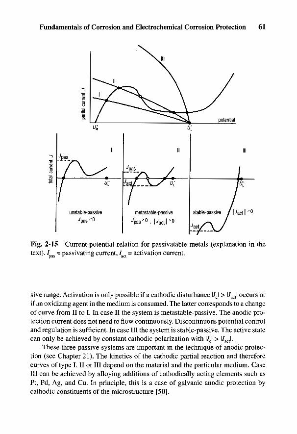
Fundamentals of Corrosion and Electrochemical Corrosion Protection 61
/
Fig. 2-15 Current-potential relation for passivatable metals (explanation in thetext). / as = passivating current, /act = activation current.
sive range. Activation is only possible if a cathodic disturbance l/cl > l/actl occurs orif an oxidizing agent in the medium is consumed. The latter corresponds to a changeof curve from II to I. In case II the system is metastable-passive. The anodic pro-tection current does not need to flow continuously. Discontinuous potential controland regulation is sufficient. In case III the system is stable-passive. The active statecan only be achieved by constant cathodic polarization with l/cl > l/actl.
These three passive systems are important in the technique of anodic protec-tion (see Chapter 21). The kinetics of the cathodic partial reaction and thereforecurves of type I, II or III depend on the material and the particular medium. CaseIII can be achieved by alloying additions of cathodically acting elements such asPt, Pd, Ag, and Cu. In principle, this is a case of galvanic anodic protection bycathodic constituents of the microstructure [50].
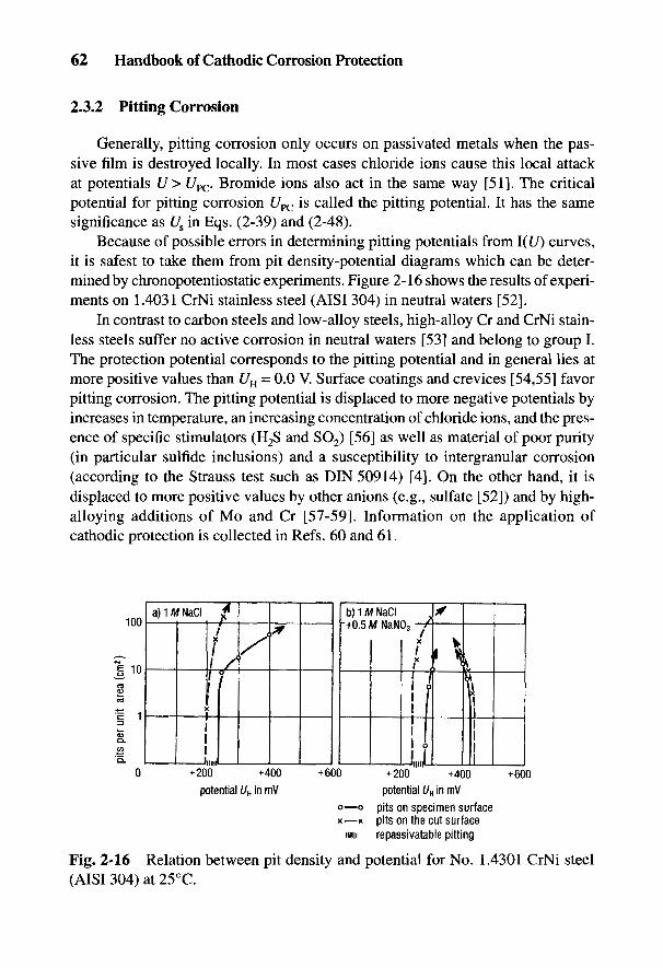
62 Handbook of Cathodic Corrosion Protection
2.3.2 Pitting Corrosion
Generally, pitting corrosion only occurs on passivated metals when the pas-sive film is destroyed locally. In most cases chloride ions cause this local attackat potentials U> t/PC. Bromide ions also act in the same way [51]. The criticalpotential for pitting corrosion UPC is called the pitting potential. It has the samesignificance as Us in Eqs. (2-39) and (2-48).
Because of possible errors in determining pitting potentials from l(U) curves,it is safest to take them from pit density-potential diagrams which can be deter-mined by chronopotentiostatic experiments. Figure 2-16 shows the results of experi-ments on 1.4031 CrNi stainless steel (AISI 304) in neutral waters [52].
In contrast to carbon steels and low-alloy steels, high-alloy Cr and CrNi stain-less steels suffer no active corrosion in neutral waters [53] and belong to group I.The protection potential corresponds to the pitting potential and in general lies atmore positive values than UH = 0.0 V. Surface coatings and crevices [54,55] favorpitting corrosion. The pitting potential is displaced to more negative potentials byincreases in temperature, an increasing concentration of chloride ions, and the pres-ence of specific stimulators (H2S and SO2) [56] as well as material of poor purity(in particular sulfide inclusions) and a susceptibility to intergranular corrosion(according to the Strauss test such as DIN 50914) [4]. On the other hand, it isdisplaced to more positive values by other anions (e.g., sulfate [52]) and by high-alloying additions of Mo and Cr [57-59]. Information on the application ofcathodic protection is collected in Refs. 60 and 61.
Fig. 2-16 Relation between pit density and potential for No. 1.4301 CrNi steel(AISI 304) at 25°C.
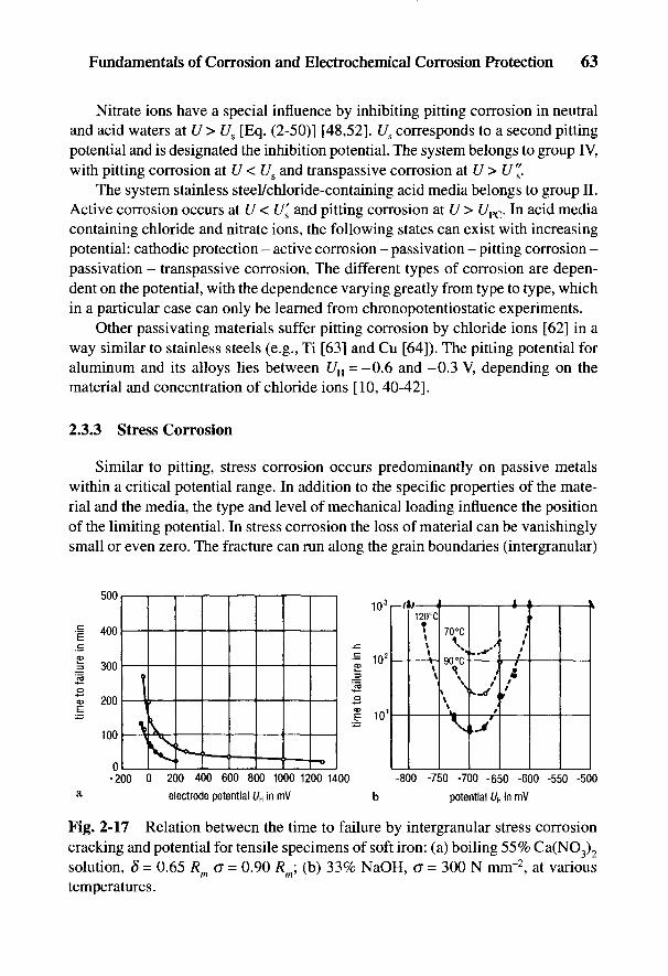
Fig. 2-17 Relation between the time to failure by intergranular stress corrosioncracking and potential for tensile specimens of soft iron: (a) boiling 55% Ca(NO3)2
solution, § = 0.65 Rm o = 0.90 Rm; (b) 33% NaOH, a = 300 N mnr2, at varioustemperatures.
Fundamentals of Corrosion and Electrochemical Corrosion Protection 63
Nitrate ions have a special influence by inhibiting pitting corrosion in neutraland acid waters at U > Us [Eq. (2-50)] [48,52]. Us corresponds to a second pittingpotential and is designated the inhibition potential. The system belongs to group IV,with pitting corrosion at U < U& and transpassive corrosion at U > U".
The system stainless steel/chloride-containing acid media belongs to group II.Active corrosion occurs at U < U'& and pitting corrosion at U > Upc. In acid mediacontaining chloride and nitrate ions, the following states can exist with increasingpotential: cathodic protection - active corrosion - passivation - pitting corrosion -passivation - transpassive corrosion. The different types of corrosion are depen-dent on the potential, with the dependence varying greatly from type to type, whichin a particular case can only be learned from chronopotentiostatic experiments.
Other passivating materials suffer pitting corrosion by chloride ions [62] in away similar to stainless steels (e.g., Ti [63] and Cu [64]). The pitting potential foraluminum and its alloys lies between UH = -0.6 and -0.3 V, depending on thematerial and concentration of chloride ions [10, 40-42].
2.3.3 Stress Corrosion
Similar to pitting, stress corrosion occurs predominantly on passive metalswithin a critical potential range. In addition to the specific properties of the mate-rial and the media, the type and level of mechanical loading influence the positionof the limiting potential. In stress corrosion the loss of material can be vanishinglysmall or even zero. The fracture can run along the grain boundaries (intergranular)
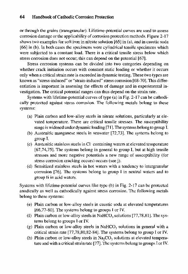
64 Handbook of Cathodic Corrosion Protection
or through the grains (transgranular). Lifetime-potential curves are used to assesscorrosion damage or the applicability of corrosion protection methods. Figure 2-17shows two examples for soft iron in nitrate solution [65] in (a), and in caustic soda[66] in (b). In both cases the specimens were cylindrical tensile specimens whichwere subjected to a constant load. There is a critical tensile stress below whichstress corrosion does not occur; this can depend on the potential [67],
Stress corrosion systems can be divided into two categories depending onwhether crack initiation occurs with constant static loading or whether it occursonly when a critical strain rate is exceeded in dynamic testing. These two types areknown as "stress-induced" or "strain-induced" stress corrosion [68-70]. This differ-entiation is important in assessing the effects of damage and in experimental in-vestigation. The critical potential ranges can thus depend on the strain rate.
Systems with lifetime-potential curves of type (a) in Fig. 2-17 can be cathodi-cally protected against stress corrosion. The following metals belong to thesesystems:
(a) Plain carbon and low-alloy steels in nitrate solutions, particularly at ele-vated temperature. There are critical tensile stresses. The susceptibilityrange is widened under dynamic loading [71]. The systems belong to group I.
(b) Austenitic manganese steels in seawater [72,73]. The systems belong togroup I.
(c) Austenitic stainless steels in Cl~ containing waters at elevated temperature[67,74,75]. The systems belong in general to group I, but at high tensilestresses and more negative potentials a new range of susceptibility (forstress corrosion cracking occurs) occurs (see j).
(d) Sensitized stainless steels in hot waters with a tendency to intergranularcorrosion [76]. The systems belong to group I in neutral waters and togroup li in acid waters.
Systems with lifetime-potential curves like type (b) in Fig. 2-17 can be protectedanodically as well as cathodically against stress corrosion. The following metalsbelong to these systems:
(e) Plain carbon or low-alloy steels in caustic soda at elevated temperatures[66,77-80]. The systems belong to groups I or IV.
(f) Plain carbon or low-alloy steels in NaHCO3 solutions [77,78,81]. The sys-tems belong to groups I or IV.
(g) Plain carbon or low-alloy steels in NaHCO3 solutions in general with acritical strain rate [77,78,80,82-84]. The systems belong to group I or IV.
(h) Plain carbon or low-alloy steels in Na2CO3 solutions at elevated tempera-ture and with a critical strain rate [77]. The systems belong to groups I or IV.
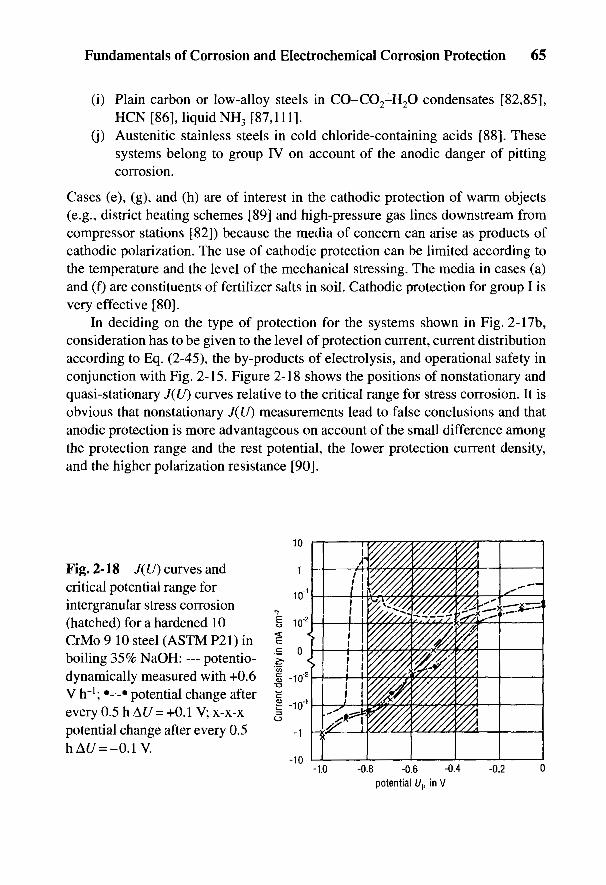
Fig. 2-18 J(U) curves andcritical potential range forintergranular stress corrosion(hatched) for a hardened 10CrMo 9 10 steel (ASTM P21) inboiling 35% NaOH: — potentio-dynamically measured with +0.6V rr1; •-•-• potential change afterevery 0.5 h AU = +0.1 V; x-x-xpotential change after every 0.5hAt/ = -0.1V.
Fundamentals of Corrosion and Electrochemical Corrosion Protection 65
(i) Plain carbon or low-alloy steels in CO-CO2-H2O condensates [82,85],HCN [86], liquid NH3 [87,111].
(j) Austenitic stainless steels in cold chloride-containing acids [88]. Thesesystems belong to group IV on account of the anodic danger of pittingcorrosion.
Cases (e), (g), and (h) are of interest in the cathodic protection of warm objects(e.g., district heating schemes [89] and high-pressure gas lines downstream fromcompressor stations [82]) because the media of concern can arise as products ofcathodic polarization. The use of cathodic protection can be limited according tothe temperature and the level of the mechanical stressing. The media in cases (a)and (f) are constituents of fertilizer salts in soil. Cathodic protection for group I isvery effective [80].
In deciding on the type of protection for the systems shown in Fig. 2-17b,consideration has to be given to the level of protection current, current distributionaccording to Eq. (2-45), the by-products of electrolysis, and operational safety inconjunction with Fig. 2-15. Figure 2-18 shows the positions of nonstationary andquasi-stationary J(U) curves relative to the critical range for stress corrosion. It isobvious that nonstationary J(U) measurements lead to false conclusions and thatanodic protection is more advantageous on account of the small difference amongthe protection range and the rest potential, the lower protection current density,and the higher polarization resistance [90].

2.3.4 Hydrogen-Induced Corrosion
Adsorbed atomic hydrogen, which is formed in the cathodic partial reactionaccording to Eqs. (2-18) or (2-19), can be absorbed in the presence of promoters(e.g., H2S), in acid media at pH < 3, or by strong cathodic polarization at UH < -0.8 Vas well as under high loading within the plastic region at a critical strain rate. As aconsequence, blisters and internal cracks can be formed below the surface as wellas fractures caused by stress corrosion under high loading [8,9,91,92]. Since thesusceptibility to H-induced cracking increases at negative potentials, but on theother hand positive potentials favor anodic corrosion, electrochemical protectionmeasures in these systems in general are not applicable. Protection measures thatmust be considered are choice of material, inhibition of the medium, and construc-tive measures to reduce stress. In general, with cathodic protection measures, itmust be ascertained whether the conditions encourage H absorption.
If the technical regulations are adhered to for constructional steels in neutralwaters, there are no conditions for H-induced corrosion. On the other hand, hard-ened and high-strength materials with hardnesses above HV 350 are very suscep-tible [60,82,92], since anodic polarization encourages crack formation in salinemedia and anodic pitting occurs with acid products of hydrolysis [93].
Figure 2-19 shows failure time-potential curves for a pipeline steel in weakacid buffer solution containing H2S [94]. At potentials within the protection rangefor general corrosion, stress corrosion can occur with high-tensile stresses. Att/H = -1.0 V, the resistance increases because the promoter becomes inactive dueto cathodic wall alkalinity according to Eq. (2-19). This effect does not occur instronger acid solutions. The failure times become shorter at negative potentials
Fig. 2-19 Time to failure vs. potentialfor X70 pipeline steel in pH 5.5 buffersolution containing 150 mg L~] sulfideions at various loads, 15°C: Us = -0.53 V(cathodic protection potential);J/n = -0.32 V (hydrogen equilibriumpotential at 1 bar).
66 Handbook of Cathodic Corrosion Protection

Fig. 2-20 Influence of potential on hydrogen permeation; 1 -mm-thick steel sheet/aerated seawater.
[95]. Stress corrosion only occurs in high-strength steels with Rm > 1200 N mm"2
in the absence of promoters under static loading. Systems belonging to group II,such as stainless high-strength Cr steels, can experience H-induced stress corro-sion cracking at U < f/s, and pitting or crevice corrosion at U > Us [96].
The activity of absorbed hydrogen is a measure of the damage for a givenmaterial. H absorption can be easily investigated in H-permeation experiments [9].Figure 2-20 shows experimental results for steel/aerated seawater. Significant Habsorption occurs only in the range of cathodic overprotection (UH < -0.8 V).
Susceptibility is generally very high in the case of dynamic deformation in theplastic range where strain-induced stress corrosion occurs. The parameters thatinfluence this type of corrosion can be investigated in a slow strain rate test atstrain rates around 10~6 s"1 [91,92,97]. Figure 2-21 shows results for steel in sea-water [92]. Included are the total current-density-potential curves and the reduc-tion in area of the cracked specimens plotted as a function of potential. In addition,it is noted whether internal cracks are observed on longitudinal microsections. Inaerated seawater, there is a transition at UH = -0.85 V between the limiting currentdensity for oxygen reduction according to Eq. (2-17) and the Tafel straight line for
Fundamentals of Corrosion and Electrochemical Corrosion Protection 67
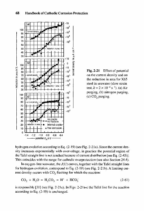
hydrogen evolution according to Eq. (2-19) (see Fig. 2-21a). Since the current den-sity increases exponentially with overvoltage, in practice the potential region ofthe Tafel straight line is not reached because of current distribution [see Eq. (2-45)].This coincides with the range for cathodic overprotection (see also Section 24.4).
In oxygen-free seawater, the J(lf) curves, together with the Tafel straight linesfor hydrogen evolution, correspond to Eq. (2-19) (see Fig. 2-21b). A limiting cur-rent density occurs with CO2 flushing for which the reaction:
is responsible [31] (see Fig. 2-21c). In Figs. 2-21a-c the Tafel line for the reactionaccording to Eq. (2-19) is unchanged.
Fig. 2-21 Effect of potentialon the current density and onthe reduction in area for X65steel in seawater (slow straintest, E - 2 x 10~6 s-1). (a) Airpurging, (b) nitrogen purging,(c) CO2 purging.
68 Handbook of Cathodic Corrosion Protection
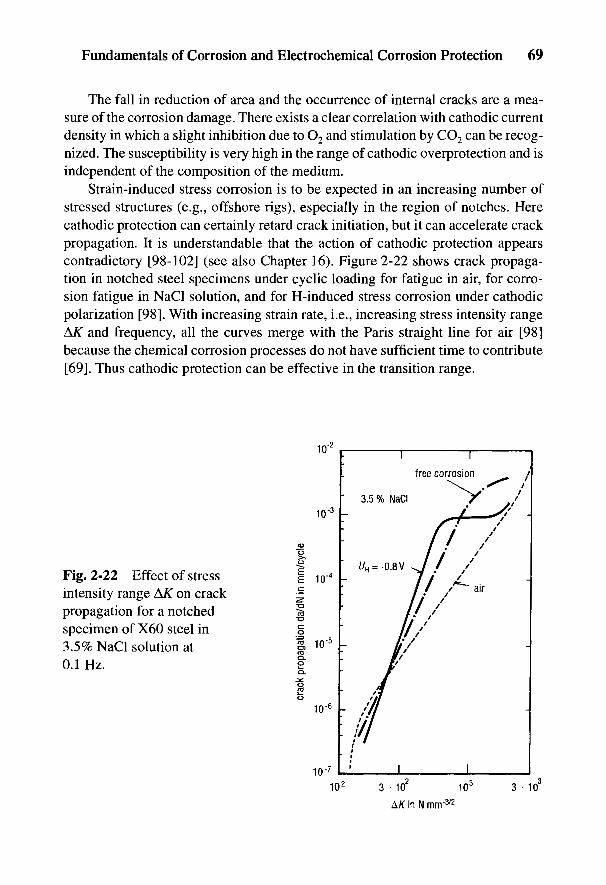
Fig. 2-22 Effect of stressintensity range AK on crackpropagation for a notchedspecimen of X60 steel in3.5% NaCl solution at0.1 Hz.
Fundamentals of Corrosion and Electrochemical Corrosion Protection 69
The fall in reduction of area and the occurrence of internal cracks are a mea-sure of the corrosion damage. There exists a clear correlation with cathodic currentdensity in which a slight inhibition due to O2 and stimulation by CO2 can be recog-nized. The susceptibility is very high in the range of cathodic overprotection and isindependent of the composition of the medium.
Strain-induced stress corrosion is to be expected in an increasing number ofstressed structures (e.g., offshore rigs), especially in the region of notches. Herecathodic protection can certainly retard crack initiation, but it can accelerate crackpropagation. It is understandable that the action of cathodic protection appearscontradictory [98-102] (see also Chapter 16). Figure 2-22 shows crack propaga-tion in notched steel specimens under cyclic loading for fatigue in air, for corro-sion fatigue in NaCl solution, and for H-induced stress corrosion under cathodicpolarization [98]. With increasing strain rate, i.e., increasing stress intensity range&K and frequency, all the curves merge with the Paris straight line for air [98]because the chemical corrosion processes do not have sufficient time to contribute[69]. Thus cathodic protection can be effective in the transition range.

2.3.5 Corrosion Fatigue
Under cyclic stressing, all metallic materials suffer crack formation well be-low their ultimate tensile strength (UTS). This process is called fatigue. There is arelationship between the stress amplitude and the number of cycles to failure whichis represented by the Wohler (S-N) curve. Figure 2-23 shows such a curve for aplain carbon steel with a fatigue limit in alternating bending of 210 N mnr2. Atthis stress level, the curve becomes horizontal, i.e., at lower stress levels failuredoes not occur at any further number of cycles. In corrosion fatigue there is nofatigue limit. The S-N curve at the rest potential UR falls steeply. Passivation byanodic protection at UH - +0.85 V produces an insignificant increase in the fatiguelife. On the other hand, cathodic protection at a much lower potential is very suc-cessful. At UH = -0.95 V, the value reached is the same as that reached in air [103].This favorable action of cathodic polarization relates to crack initiation in un-notchedspecimens and therefore does not contradict the opposite findings on crack propa-gation in Fig. 2-22. The boundary lines in the pH-potential diagram in Fig. 2-2 arenot changed under static loading. With cyclic loading on the other hand, the pas-sive regions disappear. In addition, line (1) is shifted with falling pH to more nega-tive potentials and at pH = 4 bends downward.
Fatigue life can be slightly lengthened by anodic protection or by passivation.In acids even passive stainless CrNi steels suffer corrosion fatigue [104]. Resis-tance can occur if the passive film itself has a fatigue strength (e.g., in neutralwaters [105]).
2.3.6 Limits of Applicability of Electrochemical Protection Processes
If the products of electrolysis favor other types of corrosion, electrochemicalprotection processes should not be applied or should be used only in a limitedform. Hydrogen and OH" ions are produced in cathodic protection according toEq. (2-19). The following possible corrosion danger must be heeded:
Fig. 2-23 S—N curves for plain carbonsteel in 0.05 M potassium hydrogenbenzoate (pH 4) at 30°C at variouspotentials UH (UR = rest potential).
70 Handbook of Cathodic Corrosion Protection
Fundamentals of Corrosion and Electrochemical Corrosion Protection 71
H-induced corrosion (see Section 2.2.1).
• Corrosion by hydride formation [e.g., Pb (Fig. 2-12)];• Embrittlement by internal hydride formation (e.g., Ti, Zr, Nb, Ta) [These
metals are important as valve metals for impressed current anodes(Section 7.1) and as materials in chemical plants (Section 21.4.3).]
• Stress corrosion (see Section 2.3.4), in particular accelerated crack propa-gation in fatigue (see Section 2.3.5).
OH~-induced corrosion
• Weight loss corrosion of amphoteric metals [e.g., Al (Fig. 2-11)];• Weight loss corrosion of passive metals (e.g., CrNi stainless steels in ac-
ids) (cathodic protection in acids is not practicable; see Fig. 2-14);• Stress corrosion of steels at elevated temperatures by NaOH.
There are limits to the use of anodic protection in the following cases:
• Too high a corrosion rate in the passive state;• No possibility of protection in the case of current shielding (e.g., crevices
under coatings or deposits);• Too high fatigue stressing.
In general, in the case of coated materials, interaction with protection currents mustbe taken into account [106,107] (see Section 5.2.1). In internal protection, the ef-fects of products of electrolysis must be checked [108] (see Chapters 20 and 21).
2.4 Critical Protection Potentials and Ranges
In this section a survey is given of the critical protection potentials as well asthe critical potential ranges for a possible application of electrochemical protec-tion. The compilation is divided into four groups for both cathodic and anodicprotection with and without a limitation of the protection range to more negativeor more positive potentials respectively.

72 Handbook of Cathodic Corrosion Protection
OH G
1> *> «T r* T3 .2
* I l§ I § I, ° s e S ^ ^ c bs S1 •- 3) g § .g | ' 3&o °? -v G § & -S 2 £
. * S S 1 1 I f? 11 I s 1 is s i? s § & iI if I l'| 11? 5 6 5 '!§ § = £ ~ S i S c ^ l ^ i c
1 1IM 1.8 |^^ III IsI l l l l s I I III S-ll l£
o ^•j i s ^ ^ i c g ^ ^ ^ § 2 ^ ?l,,n f i t ! ? ? r|| IG -2 D *J <*
II s-s* S 5 8 o
^ S ° <^ m c o c o ^ 2 - ^ 0C - 2 a » n ^ o ^ q - t ^ r 4 p o | ^ V
I ! a ? ? ? ? 1 ^ ^ &a« |^> ^N >rH ^>CA 0, ^ <•4^
S3
g aa, § "2 G s - S.1 Jo i S ^ t '5 1 .2 1£ | S 1| s 1 | 1 ji in i ^ i l i i ^ 9f | *1 I 1| 1 1 1 rl 1i I 1! l i l | IP I !! I-^ S . C ^ S J ^ ^ S P S « T ) 'S «J I ig c ^ z g n ^ § 3 z S « ^C3 D
•4—>
Oa ^ "g§ :§ §
• in «J ,«£
O 4 -So g oa(U o -5 en B >-, ccn - , - 2 ^ "*. M ^ 1 3§ . S ' S ^ S ^ £ ^ ^ 1 3 ^1:11 S § 2 ^3 hn " _ - M
* I §1 ^ 11 e^ |1§ Ibs 1 ^ 1I I = 1 1*5 . ? . • § «C S. '3 f c b b v o c / 3 2 V Z§ ^ E ^ S A < U U UDH
O ^'S s ^"dS 2 v ^g O HH ^ W
PH
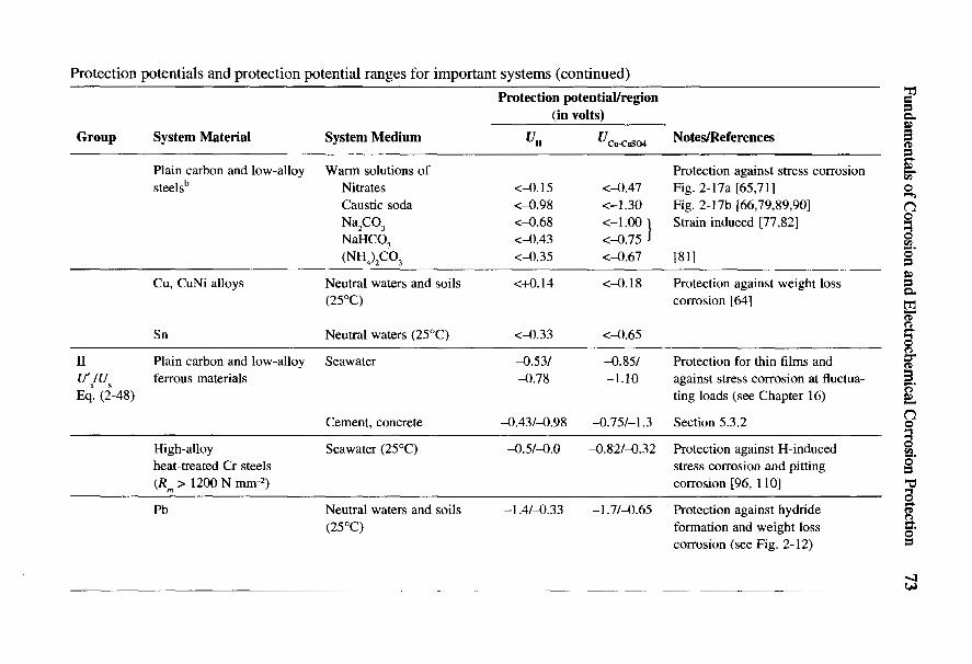
Fundamentals of Corrosion and Electrochemical Corrosion Protection 73
I IH & __ 3 T3g o -g <e ^ g M
2 _ £ ! ^ S I -I ^ 1 Rg ° CN '3 — |& '7 U *5 « ~
8 8 5 * * 8 8- K • § „ £ • § «8 a " ON f: S -2 id !« s § 2 t* 'S .spS s- ^ t^ L^ c -S R u S c ^ S ^ f c
g S m ' ^ O - O cd^n »H « <S o _" rt T) U
g s ? £ £ 8 ^S ^ i ^ ^ « ' i ^ « l ^1 I 5 £ 1 IS I ! 1 -S I I S 1111 S ^ ^ •§ 8'1 I S ° - B ^ S ' O B | OI 2 . s p . s ? 2 £ s g s l ^ B a a y s l gZ, ixpnt i - ioo 2 2 , 0 , 0 d . « - ^ o r 5 C L , ^ o C u < S o
I x — ^ 8 £_ § ? 1 J* ^ 8 !P ? S ! S ^ 2 79 d
1| ji i^'ti 1 ? ^ § S ?'§ I ^0 ® ^O ft C 00 ro^^ c O ON o C5v i o m o o o o c ^ i D 1 ^ - m ^ - . _ : _ : °iP ' - S a ^ - O N V O T t c n - H ^ c o o o 9 9 o
I ! a Wtt 1 1 if 3 § 1>• >- o I i^ ON I•i-j
cdtsoa ^ ^£ '° r7 °.J3 <a vj &oUi 'tJ T3 in "OO e O C eN <u c3* § <2 « r t C i ^ Q r tc/5 3 C TJ c / j c / 3 t H ; ; ^ co
S, ? -S 1 «om S S | s ^
1 ^ 1 1 -I 8 S % 0 S fc 5 t *•S | g 11 3 g* i a i | || la1 I |zu"~ |a | I II laoOH_H ^ >>g o oO S a
•^J fS si
% i * £ tr-o « - 2 3 8 ha. .3 "3 ^ "2 -^ ^ SC S >^ S « s i - c
' g ^ c £ S 'B uz
« 3 ^ ^ ^1 ^"^8^ a 53 % % 6 = 2 ^cd £ o r , 3 o e e c « c• ! alls U f i§ ^ V A§ 5, 3 S =f c ^ S - ^ S t v 5 ^^ C f l O H - S U o r i ( X ^ f f i ^ ^ C uOH
§ 00•Z3 a tO S1 ^"CN<u g o ^
I « H S" a1

74 Handbook of Cathodic Corrosion Protection
•5 -2o 2 J ' l e g 1'S ° 1 g? % ~ 3 „•e £ | I 2 s 2 g r-,§ .2? s a c .2? I -I g „^ £> fan i u < L > W £ O I- CNg ^ * C C g * « fc g 00
& * * — * > • < - > ' & O 5 *•> 4_, O ~ t~~9i 1C .En c/3 *-< |-1 o ^ I~P c« U ON (^a S -s -S u § + .s 3 ^ .s «« ^ ^g • £ g r t _ 1 ^ S cs S > r^ 3 g ^ > -oS S a «1 -r s z S>2 ^ ^^ |
«S P e 1 — ' < N C & O C *= e £ x > 5^ 2 | |gq ™|.| | g f ||S 3«S r S ^ O c ^ O N i j L U ^ o ^ ?~{ < - > > ^ N I e« ^ ^ P ^ ^ ^ S B S u ^ ^ ^ -S"o ^ ' ^ S s ^ w - ^ ^ S S 8 P " 9 M o 2 ^Z £ ^ £ 8 E 2 e ^ - § £ 8 $ £ § E £ 35 22,
O - CN CN CN _ .
^ I Ms !!T s 3 2 S ; s g1 |S-5 " 777 A ^?^'5 - ®G o >8 a e^ e ^ (r5l / '}[~~: S ^ ^ / ^«3 .2 ^ ^ o o o Q r - ! S o o ^ - £ r - ^ ig S S C ^ O N -i 3 2 § O « + + ^ ^ J QI JS ^ 7 ? S q S A a w -^ g g ^ o ^« p 7 7 7 ^g -g c p c p T , ?^ *< O S d,
C^ 73
? §8. a §g o . 2
•S 1 ! s S 1 'i t =S3 I I 8 § .a z o = I
I i l l I , , I I I !i^8"| I I P * 111 i § I g A i § 1 * la 5 Illl II lsEsll•4—1
oa >»*2e o c.2 -3 .§•*-* I K
S ^ «^ O J2
P ra ^ -s-sV-i 55 T3 ^-
°- *c S S"S S x s « 8§ I I ^ I4 I \^ 6 ^ -* ^ S 5Scd M I-H — u c•Z3 S < K = l £ C ^ O
I I- ^ <- 5 p litag ^ o| | ^e ^d| I s £ S t^S
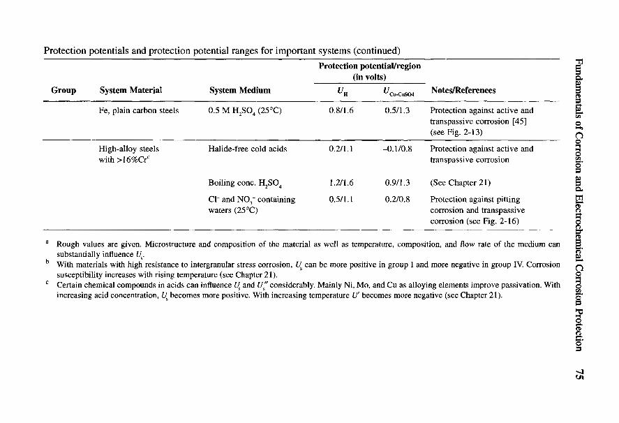
Fundamentals of Corrosion and Electrochemical Corrosion Protection
C C 43«l O .tS0 -35 >p o ^I g g
"S ~ « "S 3 Ic3 vT rt u e ^ >
>^ >B |1? Illrt'S ^ '33 & «5 . 'S 8 < u ^ r
ill i § s a iff | ? |s! a s s 1s * !i s ? s s I£ e« 0) , rt <U < U c 3 g M <$. X ' "S§ § -i«. g i & § c ^ ^ a i e
8 ? ' ^ ^ ^ - a S - C - ^ O O ~ <U ( U U
I If-s 11 ^ 111 1 I I*I IIS II sill § i »l'•O -3 .S rt•g g >, oo
I I "J 2 ^ S I §• 1 I^ ^ 2 - v ^ ^ c 5 S § a c* O 2 a 3 «^ ^ O N r 5 , g = 3 G^ . 2 _ ^ U d ^ d o 1 « ^ 15 e - 1 -s ^ |'§11 i > :•§8 & S e -^ | *^ C O « o ^ r~j
§ * ^ S 5 S 3 5 s 2 £§ 4 > ^ o o r5 c s i n « o ji> 3« 1 ° d - d 1 | -I |M &. „; -C 2 C
0 - § jj.55 1 a- If1 - -f ! g 116 ^ T3 ^ c - 2 e ut = ^ S S I s l = 8 - s•2 l a i * I = § ^ = , " 1I I g SS l §i I III*§ 7 f f i
N 43 ° 2 c i g ^ u ^-5- I s ^ c " B 2 | ^ 8 g Sc^3 * S ^ i .2 a ^ S c a ^ g o ,'•g ^ > n 13 ' o ^ r t o i u ^ a§ ^ d f f i C Q U ^ •« |B « |O a « g -S S°- » S £ § 2
I ! 31| I'-3 M 3 <U *"" -2 0)
8 1 S 1 G 8 *.
| 3 1 I ! : § '2d^ a 5 Bu^ S 8 5 - g . Sc « J3 ^ u d ^"-Sk ^ o S
S ss c ^8 ll^jll•g I s •? A ^ l ^ i s g
•§ I * -a^ ^ l ^ H s lB c^ £ iS^ si-i^l?2 S a" 'c S S MCX ^5 15 « js ooe > -c ea a ° So ^ js S S H, .5 S'§ s ^|-S 8 ^ §« o 9 •§ ':> 3 $ §^ »- o s S ^ S u . SS c?
CL, « * o
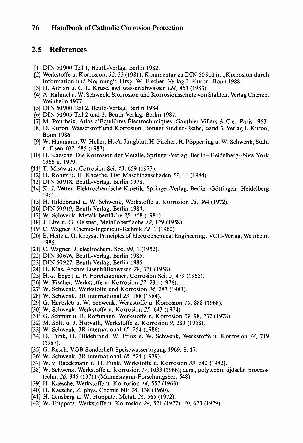
76 Handbook of Cathodic Corrosion Protection
2.5 References
[1] DIN 50900 Teil 1, Beuth-Verlag, Berlin 1982.[2] Werkstoffe u. Korrosion, 32, 33 (1981); Kommentar zu DIN 50900 in ,,Korrosion durch
Information und Normung", Hrsg. W. Fischer, Verlag I. Kuron, Bonn 1988.[3] H. Adrian u. C.L. Kruse, gwf wasser/abwasser 124, 453 (1983).[4] A. Rahmel u. W. Schwenk, Korrosion und Korrosionsschutz von Stahlen, Verlag Chemie,
Weinheim 1977.[5] DIN 50900 Teil 2, Beuth-Verlag, Berlin 1984.[6] DIN 50905 Teil 2 und 3, Beuth-Verlag, Berlin 1987.[7] M. Pourbaix, Atlas d'Equilibres Electrochimiques, Gauthier-Villars & Cie., Paris 1963.[8] D. Kuron, Wasserstoff und Korrosion, Bonner Studien-Reihe, Band 3, Verlag I. Kuron,
Bonn 1986.[9] W. Haumann, W. Heller, H.-A. Jungblut, H. Pircher, R. Popperling u. W. Schwenk, Stahl
u. Eisen 107, 585 (1987).[10] H. Kaesche, Die Korrosion der Metalle, Springer-Verlag, Berlin-Heidelberg-New York
1966u. 1979.[11] T. Misawata, Corrosion Sci. 13, 659 (1973).[12] U. Rohlfs u. H. Kaesche, Der Maschinenschaden 57, 11 (1984).[13] DIN 50918, Beuth-Verlag, Berlin 1978.[14] K.-J. Vetter, Elektrochemische Kinetik, Springer-Verlag, Berlin-Gottingen-Heidelberg
1961.[15] H. Hildebrand u. W. Schwenk, Werkstoffe u. Korrosion 23, 364 (1972).[16] DIN 50919, Beuth-Verlag, Berlin 1984.[17] W. Schwenk, Metalloberflache 55, 158 (1981).[18] J. Elze u. G. Oelsner, Metalloberflache 12, 129 (1958).[19] C. Wagner, Chemie-Ingenieur-Technik 32, \ (1960).[20] E. Heitz u. G. Kreysa, Principles of Electrochemical Engineering, VCH-Verlag, Weinheim
1986.[21] C. Wagner, J. electrochem. Soc. 99, 1 (1952).[22] DIN 30676, Beuth-Verlag, Berlin 1985.[23] DIN 50927, Beuth-Verlag, Berlin 1985.[24] H. Klas, Archiv Eisenhuttenwesen 29, 321 (1958).[25] H.-J. Engell u. P. Forchhammer, Corrosion Sci. 5, 479 (1965).[26] W. Fischer, Werkstoffe u. Korrosion 27, 231 (1976).[27] W. Schwenk, Werkstoffe und Korrosion 34, 287 (1983).[28] W. Schwenk, 3R international 23, 188 (1984).[29] G. Herbsleb u. W. Schwenk, Werkstoffe u. Korrosion 19, 888 (1968).[30] W. Schwenk, Werkstoffe u. Korrosion 25, 643 (1974).[31] G. Schmitt u. B. Rothmann, Werkstoffe u. Korrosion 29, 98, 237 (1978).[32] M. Solti u. J. Horvath, Werkstoffe u. Korrosion 9, 283 (1958).[33] W. Schwenk, 3R international 15, 254 (1986).[34] D. Funk, H. Hildebrand, W. Prinz u. W. Schwenk, Werkstoffe u. Korrosion 38, 719
(1987).[35] G. Resch, VGB-Sonderheft Speisewassertagung 1969, S. 17.[36] W. Schwenk, 3R international 18, 524 (1979).[37] W. v. Baeckmann u. D. Funk, Werkstoffe u. Korrosion 33, 542 (1982).[38] W. Schwenk, Werkstoffe u. Korrosion 17,1033 (1966); ders., polytechn. tijdschr. process-
techn. 26, 345 (1971) (Mannesmann-Forschungsber. 548).[39] H. Kaesche, Werkstoffe u. Korrosion 14, 557 (1963).[40] H. Kaesche, Z. phys. Chemie NF 26, 138 (1960).[41] H. Ginsberg u. W. Huppatz, Metall 26, 565 (1972).[42] W. Huppatz, Werkstoffe u. Korrosion 28, 521 (1977); 30, 673 (1979).
Fundamentals of Corrosion and Electrochemical Corrosion Protection 77
[43] W. von Baeckmann, Werkstoffe u. Korrosion 20, 578 (1969).[44] O. Riidiger u. W. R. Fischer, Z. Elektrochemie 62, 803 (1958).[45] G. Herbsleb u. H.-J. Engell, Z. Elektrochemie 65, 881 (1961).[46] G. Herbsleb u. W. Schwenk, Werkstoffe u. Korrosion 17, 745 (1966); 18, 521 (1967).[47] G. Herbsleb, Werkstoffe u. Korrosion 20, 762 (1969).[48] E. Brauns u. W. Schwenk, Arch. Eisenhiittenwes. 32, 387 (1961).[49] P. Schwaab u. W. Schwenk, Z. Metallkde. 55, 321 (1964).[50] H. Grafen, Z. Werkstofftechnik 2, 406 (1971).[51] G. Herbsleb, H. Hildebrand u. W. Schwenk, Werkstoffe u. Korrosion 27, 618 (1976).[52] G. Herbsleb, Werkstoffe u. Korrosion 16, 929 (1965).[53] G. Herbsleb u. W. Schwenk, gwf wasser/abwasser 119, 79 (1978).[54] A. Kugler, K. Bohnenkamp, G. Lennartz u. K. Schafer, Stahl u. Eisen 92, 1026 (1972).[55] A. Kugler, G. Lennartz u. H.-E. Bock, Stahl u. Eisen 96, 21 (1976).[56] G. Herbsleb, Werkstoffe u. Korrosion 33, 334 (1982).[57] G. Herbsleb u. W. Schwenk, Werkstoffe u. Korrosion 26, 5 (1975).[58] H. Kiesheyer, G. Lennartz u. H. Brandis, Werkstoffe u. Korrosion 27, 416 (1976).[59] E.-M. Horn, D. Kuron u. H. Grafen, Z. Werkstofftechnik 8, 37 (1977).[60] DIN 50929 Teil 2, Beuth-Verlag, Berlin 1985.[61] VG 81 249 Teil 2 (Vornorm), Beuth-Verlag, Berlin 1983.[62] G. Herbsleb, VDI-Bericht Nr. 243, S. 103 (1975).[63] W.R. Fischer, Techn. Mitt. Krupp Forsch.-Ber. 22, 65 u. 125 (1964).[64] K. D. Efird u. E. D. Verink, Corrosion 33, 328 (1977).[65] A. Baumel u. H.-J. Engell, Arch. Eisenhiittenwes. 32, 379 (1961).[66] K. Bohnenkamp, Arch. Eisenhiittenwes. 39, 361 (1968).[67] G. Herbsleb u. W. Schwenk, Werkstoffe u. Korrosion 21, 1 (1970).[68] DIN 50922, Beuth-Verlag 1985.[69] G. Herbsleb u. W. Schwenk, Corrosion 41, 431 (1985).[70] Werkstoffe u. Korrosion 37, 45 (1986).[71] W. Friehe, R. Popperling u. W. Schwenk, Stahl u. Eisen 95, 789 (1975).[72] W. Prause u. H.-J. Engell, Werkstoffe u. Korrosion 22, 421 (1971).[73] A. Baumel, Werkstoffe u. Korrosion 20, 389 (1969).[74] E. Brauns u. H. Ternes, Werkstoffe u. Korrosion 19, 1 (1968).[75] G. Herbsleb u. H. Ternes, Werkstoffe u. Korrosion 20, 379 (1969).[76] G. Herbsleb, VGB-Kraftwerkstechnik 55, 608 (1975).[77] G. Herbsleb, B. Pfeiffer, R. Popperling u. W. Schwenk, Z. Werkstofftechnik 9, 1 (1978).[78] H. Diekmann, P. Drodten, D. Kuron, G. Herbsleb, B. Pfeiffer u. E. Wendler-Kalsch,
Stahl u. Eisen 103, 895 (1983).[79] H. Grafen u. D. Kuron, Arch. Eisenhiittenwes. 36, 285 (1965).[80] W. Schwenk gwf gas/erdgas 123, 157 (1982).[81] K. J. Kessler u. E. Wendler-Kalsch, Werkstoffe u. Korrosion 28, 78 (1977).[82] Proc. 5th a. 6th Congr. Amer. Gas Assoc., Houston 1974, 1979.[83] J.M. Sutcliffe, R. R. Fessler, W. K. Boyd u. R.N. Parkins, Corrosion 28, 313 (1972).[84] G. Herbsleb, R. Popperling u. W. Schwenk, 3R international 20, 193 (1981).[85] A. Brown, J.T. Harrison u. R. Wilkins, Corrosion Sci. 10, 547 (1970).[86] H. Buchholtz u. R. Pusch, Stahl u. Eisen 62, 21 (1942).[87] D. A. Jones u. B. E. Wilde, Corrosion 33, 46 (1977).[88] G. Herbsleb, B. Pfeiffer u. H. Ternes, Werkstoffe u. Korrosion 30, 322 (1979).[89] B. Poulson, L. C. Henrikson u. H. Arup, Brit. Corrosion J. 9, 91 (1974).[90] H. Grafen, G. Herbsleb, F. Paulekat u. W. Schwenk, Werkstoffe u. Korrosion 22, 16
(1971).[91] H. Pircher u. R. GroBterlinden, Werkstoffe u. Korrosion 38, 57 (1987).[92] R. Popperling, W. Schwenk u. J. Venkateswarlu, Werkstoffe u. Korrosion 36, 389 (1985).[93] B.E. Wilde, Corrosion 27, 326 (1971).
78 Handbook of Cathodic Corrosion Protection
[94] G. Herbsleb, R. Popperling u. W. Schwenk, Werkstoffe u. Korrosion 31, 97 (1980).[95] F.K. Naumann u. W. Carius, Arch. Eisenhiittenwes. 30, 283 (1959).[96] G. Lennartz, Werkstoffe u. Korrosion 35, 301 (1984).[97] B. R.W. Hinton u. R. P. M. Procter, Corrosion Science 23, 101 (1983).[98] O. Vosikowski, Closed Loop 6, 3 (1976).[99] R. Popperling, W. Schwenk u. G. Vogt, Werkstoffe u. Korrosion 29, 445 (1978).[100] F. Schmelzer u. F.J. Schmitt, GKSS-Forschungszentrum Geesthacht, Bericht GKSS
85/E/29, Geesthacht 1985.[101] R. Helms, H. Henke, G. Oelrich u. T. Saito, Bundesanstalt fur Materialpriifung, For-
schungsbericht Nr. 113, Berlin 1985.[102] K. Nishiota, K. Hirakawa u. I. Kitaura, Sumitomo Search 16, 40 (1976).[103] K. Endo, K. Komai u. S. Oka, J. Soc. Mater. Sci. Japan, 19, 36 (1970).[104] H. Spahn, Z. phys. Chem. (Leipzig) 234, 1 (1967).[105] H. Tauscher u. H. Buchholz, Neue Hiitte 18, 484 (1973).[106] DIN 50928, Beuth-Verlag, Berlin 1985.[107] W. Schwenk, farbe + lack 90, 350 (1985).[108] DIN 50927, Beuth-Verlag, Berlin 1984.[109] G. Herbsleb u. W. Schwenk, Werkstoffe u. Korrosion 26, 93 (1975).[110] D.L. Dull u. L. Raymond, Corrosion 29, 205 (1973).[Ill] H. Grafen, H.Hennecken, E.-M. Horn, H. D. Kamphusmann u. D. Kuron, Werkstoffe
u. Korrosion 36, 203 (1985).
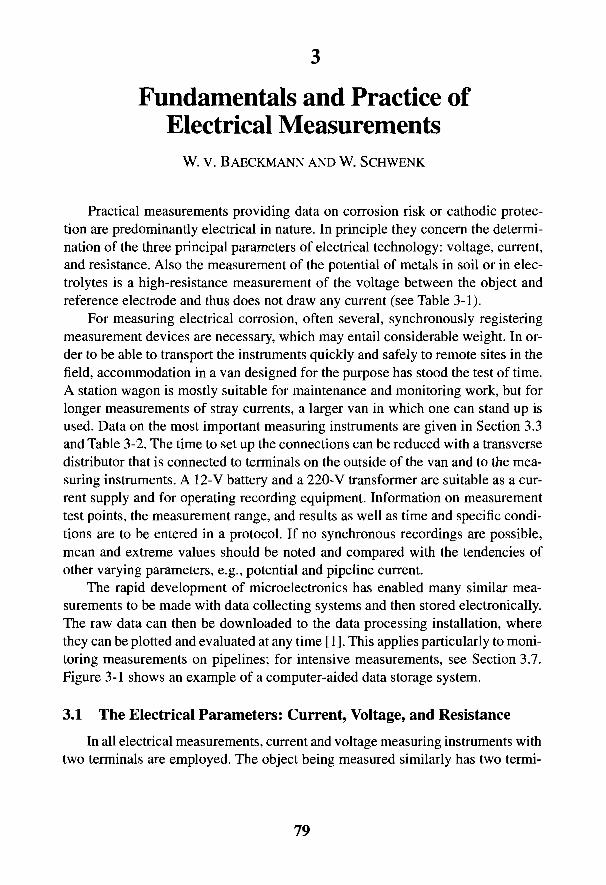
3
Fundamentals and Practice ofElectrical Measurements
W. v. BAECKMANN AND W. SCHWENK
Practical measurements providing data on corrosion risk or camodic protec-tion are predominantly electrical in nature. In principle they concern the determi-nation of the three principal parameters of electrical technology: voltage, current,and resistance. Also the measurement of the potential of metals in soil or in elec-trolytes is a high-resistance measurement of the voltage between the object andreference electrode and thus does not draw any current (see Table 3-1).
For measuring electrical corrosion, often several, synchronously registeringmeasurement devices are necessary, which may entail considerable weight. In or-der to be able to transport the instruments quickly and safely to remote sites in thefield, accommodation in a van designed for the purpose has stood the test of time.A station wagon is mostly suitable for maintenance and monitoring work, but forlonger measurements of stray currents, a larger van in which one can stand up isused. Data on the most important measuring instruments are given in Section 3.3and Table 3-2. The time to set up the connections can be reduced with a transversedistributor that is connected to terminals on the outside of the van and to the mea-suring instruments. A 12-V battery and a 220-V transformer are suitable as a cur-rent supply and for operating recording equipment. Information on measurementtest points, the measurement range, and results as well as time and specific condi-tions are to be entered in a protocol. If no synchronous recordings are possible,mean and extreme values should be noted and compared with the tendencies ofother varying parameters, e.g., potential and pipeline current.
The rapid development of microelectronics has enabled many similar mea-surements to be made with data collecting systems and then stored electronically.The raw data can then be downloaded to the data processing installation, wherethey can be plotted and evaluated at any time [1]. This applies particularly to moni-toring measurements on pipelines; for intensive measurements, see Section 3.7.Figure 3-1 shows an example of a computer-aided data storage system.
3.1 The Electrical Parameters: Current, Voltage, and Resistance
In all electrical measurements, current and voltage measuring instruments withtwo terminals are employed. The object being measured similarly has two termi-
79
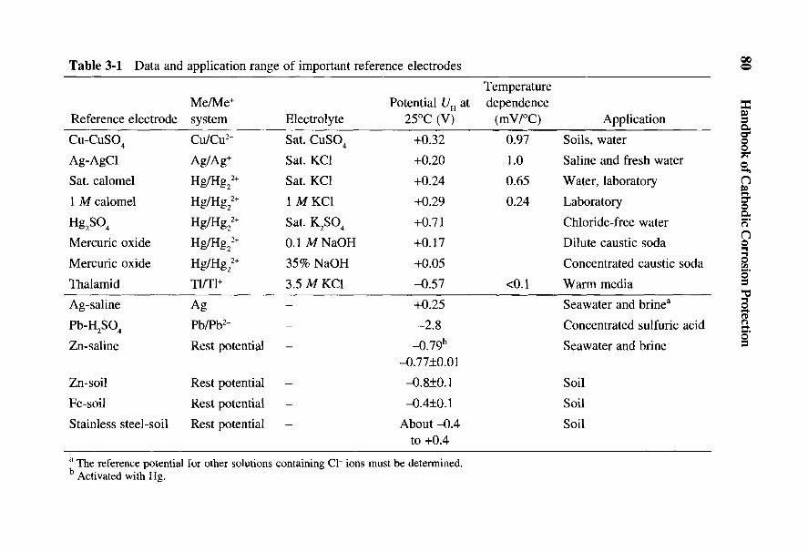
80 Handbook of Cathodic Corrosion Protection
a T3-o 'ag *£ o .a
c 5 fe «» ~ *« £ oo ^ ^ S "« a S S S
•O r- C «* O § 'C 3 'Crt "3 o £ <" S . 0 5 . 0^ £ 2 w . y ^ c s - d ^ - aa i S ^ ^ ^ l l ' - g a s a^ g a ^ i ^ s g s s a i
4 2 « S o ' g § | g | | g'o *a ^ "S 3 ^ § ^ g § g 'o 'S 'SE O o o i > H - l U Q U t > o r ! U o o c/3 on co
2^ «3 0 ^ ^•3 c rj2 J^ o r- v~> ^t- '—i53 ^ ^ cr\ p vq <N ^^ S ' C d ^ d d VS a, cD <U ^-^
H ^
S X^-s " ^t "S
1 ^ S 8 S R ! = E 8 K a « ^ | i i l | l8 s o ^ o o ° ° ? o ° 7 ° ^ ^ f ; § 5 | J a< u w ^ ' o i T ; 3 ~ ^D O I ^ «
^ ^ £I 3
Ǥ 6
D CX3
" ffi §1 £0* o ^ 9 g u 5o - s ^ u u y ^ ^ ^ ^ ^& 2 3 ^ ^ ^ ^ ^ ^ ^ f.§ ^ ^ ^ ^ ^ ^ ^ ^ ^ 1(._ r S S c a c d c s ^ c d ^ m 1 ^ 5^ W o o o o o r s ^ - i o o o m m i i i I I I g<u ^W) c«
03 ^ 13 13 13 .2*—i ' _, *^3 ' '.3 'tiS- C3 G C C ^o + + + + + D < u m < u o.;i + + ( N ( N < N < N < N •*-» ^ _ > ^ _ ^ ^ _ > yj•u «•> _ rJi + ts r< tM cs M + O O O Ooa ^ g r p t « w ) & a £ > o b x } 6 J ) + x> & O , O H D H S3 ^ ^ U ^ S f f i S K ^ C ^ ^ -(-. *j ^_> -S'Sn J S ^ ' B o a G o o j Q & o & o G a S ^ S c u S c S c S °g S ^ U < f f i E E E E E - H < £ ^ f t i^^ ,§
§ I , 1 •i § „ . '? i*Q Ji 3 S 13 ««
S x- 1 I ° ° . S 8*5 8 1 Si I o*1 111 SI •- - 3 11i iis^aliiiPi in iH « U < o o - H f f i 2 2 H < C L H N N f c o o = 3 x >
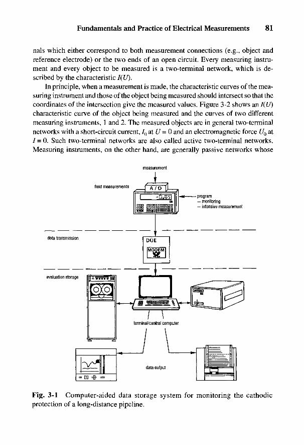
Fundamentals and Practice of Electrical Measurements 81
nals which either correspond to both measurement connections (e.g., object andreference electrode) or the two ends of an open circuit. Every measuring instru-ment and every object to be measured is a two-terminal network, which is de-scribed by the characteristic I(U).
In principle, when a measurement is made, the characteristic curves of the mea-suring instrument and those of the object being measured should intersect so that thecoordinates of the intersection give the measured values. Figure 3-2 shows an I(U)characteristic curve of the object being measured and the curves of two differentmeasuring instruments, 1 and 2. The measured objects are in general two-terminalnetworks with a short-circuit current, 70 at U = 0 and an electromagnetic force U0 at7 = 0. Such two-terminal networks are also called active two-terminal networks.Measuring instruments, on the other hand, are generally passive networks whose
Fig. 3-1 Computer-aided data storage system for monitoring the cathodicprotection of a long-distance pipeline.
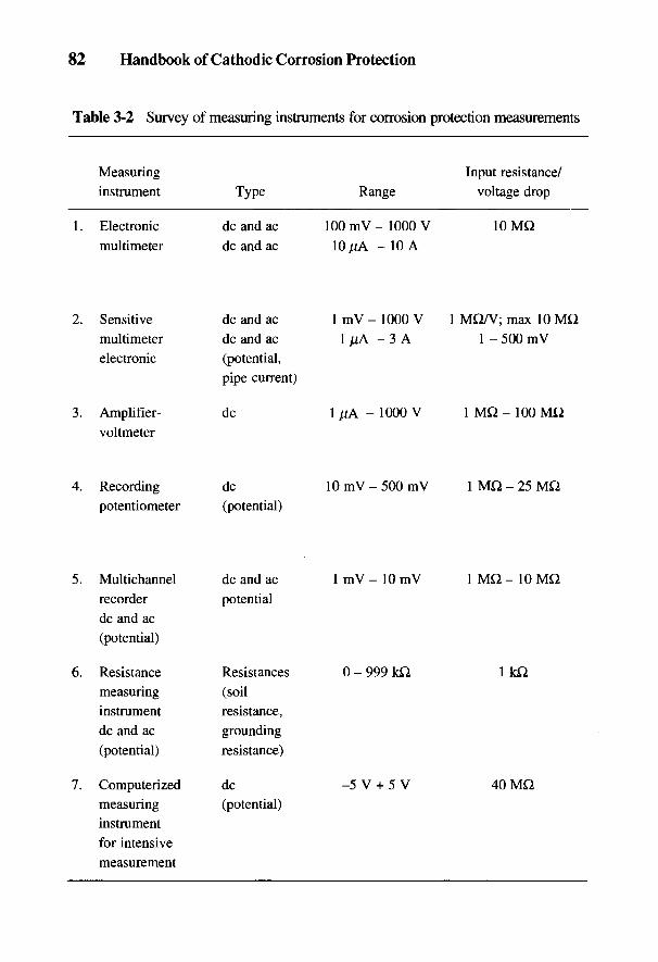
82 Handbook of Cathodic Corrosion Protection
Table 3-2 Survey of measuring instruments for corrosion protection measurements
Measuring Input resistance/instrument Type Range voltage drop
1. Electronic dc and ac 100 mV - 1000 V 10 MQmultimeter dc and ac 10 /fA - 10 A
2. Sensitive dc and ac 1 mV - 1000 V 1 MQ/V; max 10 MQmultimeter dc and ac 1 /xA - 3 A 1 - 500 mVelectronic (potential,
pipe current)
3. Amplifier- dc 1 /iA - 1000 V 1 MQ - 100 MQvoltmeter
4. Recording dc 10 mV - 500 mV 1 MQ - 25 MQpotentiometer (potential)
5. Multichannel dc and ac 1 mV - 10 mV 1 MQ - 10 MQrecorder potentialdc and ac(potential)
6. Resistance Resistances 0 - 999 kQ 1 kQmeasuring (soilinstrument resistance,dc and ac grounding(potential) resistance)
7. Computerized dc -5 V + 5 V 40 MQmeasuring (potential)instrumentfor intensivemeasurement
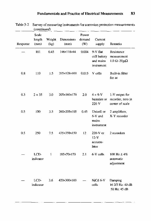
Fundamentals and Practice of Electrical Measurements 83
Table 3-2 Survey of measuring instruments for corrosion protection measurements(continued)
Scale Powerlength Weight Dimensions demand Current
Response (mm) (kg) (mm) (W) supply Remarks
— 101 0.45 146x118x44 0.004 9-V flat Resistancecell battery measurementand mains l.OQ-20^instrument
0.8 110 1.5 205x128x100 0.015 V cells Built-in filterfor ac
0.3 2x35 3.0 205x160x170 2.0 4 x 9-V 1-V output forbatteries or recorder, zero in220 V center of scale
0.5 100 3.5 260x205x105 0.45 Unicell or 2 amplifiers,6-V and X-Y recordermainsinstrument
0.5 250 7.5 435x350x150 12 220-V or 2 recorders12-Vaccumu-lator
— LCD- 1 185x70x170 2.1 6-V cells 108 Hz ± 4%indicator automatic
adjustment
— LCD- 3.6 420x300x100 — NiCd 6-V Dampingindicator cells 16 2/3 Hz: 40 dB
50 Hz: 45 dB
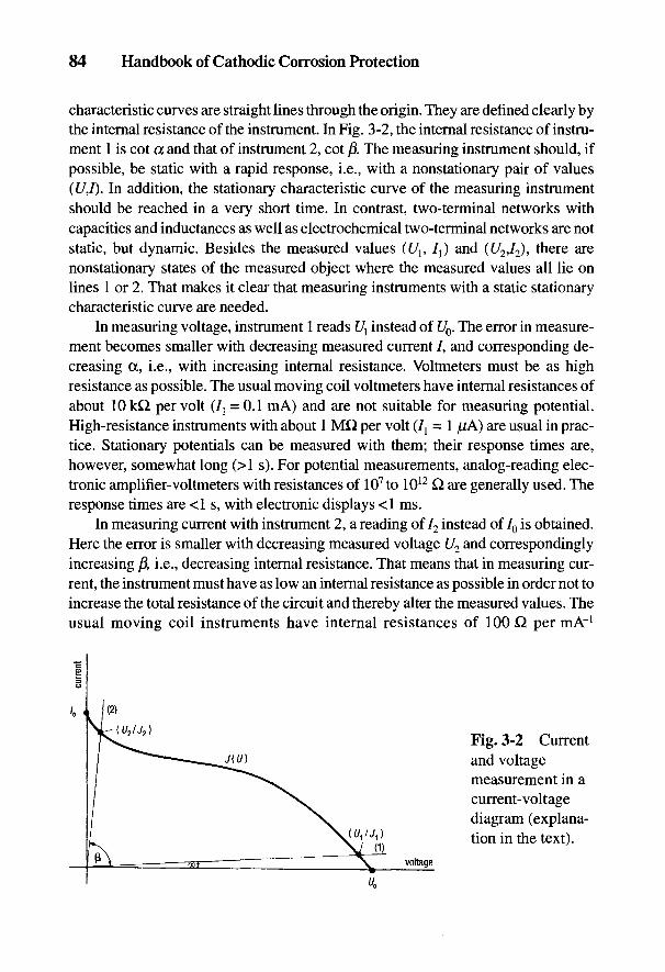
84 Handbook of Cathodic Corrosion Protection
characteristic curves are straight lines through the origin. They are defined clearly bythe internal resistance of the instrument. In Fig. 3-2, the internal resistance of instru-ment 1 is cot a and that of instrument 2, cot ft. The measuring instrument should, ifpossible, be static with a rapid response, i.e., with a nonstationary pair of values(£/,/). In addition, the stationary characteristic curve of the measuring instrumentshould be reached in a very short time. In contrast, two-terminal networks withcapacities and inductances as well as electrochemical two-terminal networks are notstatic, but dynamic. Besides the measured values ([/1? 7j) and (t/2,/2), there arenonstationary states of the measured object where the measured values all lie onlines 1 or 2. That makes it clear that measuring instruments with a static stationarycharacteristic curve are needed.
In measuring voltage, instrument 1 reads U{ instead of U0. The error in measure-ment becomes smaller with decreasing measured current /, and corresponding de-creasing a, i.e., with increasing internal resistance. Voltmeters must be as highresistance as possible. The usual moving coil voltmeters have internal resistances ofabout 10 kQ per volt (^ =0.1 mA) and are not suitable for measuring potential.High-resistance instruments with about 1 MQ per volt (I{ = 1 /lA) are usual in prac-tice. Stationary potentials can be measured with them; their response times are,however, somewhat long (>1 s). For potential measurements, analog-reading elec-tronic amplifier-voltmeters with resistances of 107to 1012 Q are generally used. Theresponse times are <1 s, with electronic displays <1 ms.
In measuring current with instrument 2, a reading of 72 instead of 70 is obtained.Here the error is smaller with decreasing measured voltage U2 and correspondinglyincreasing ft, i.e., decreasing internal resistance. That means that in measuring cur-rent, the instrument must have as low an internal resistance as possible in order not toincrease the total resistance of the circuit and thereby alter the measured values. Theusual moving coil instruments have internal resistances of 100 Q per mA"1
Fig. 3-2 Currentand voltagemeasurement in acurrent-voltagediagram (explana-tion in the text).

Fundamentals and Practice of Electrical Measurements 85
(U2 = 0.1 V) and are suitable for current measurement. For smaller currents, sensi-tive instruments with 5 kQ per /xAr1 (U2 = 5 rnV) are used. Small currents are usu-ally measured by the voltage drop across a fixed resistance (calibrated shunt) usingan electronic amplifier-voltmeter. This method has the advantage that the circuitdoes not have to be interrupted to measure the current.
Resistance is measured either indirectly by separate current and voltage mea-surements or directly by comparison in a bridge. In both cases it involves two mea-surements. The instruments for measuring the current and voltage U2 have to bechosen so as to make the deviation from U and /in Fig. 3-2 as small as possible.
In contrast to simple current and potential measurements, polarization measure-ments (i.e., current-potential curves) demand active systems with active externalcircuits with variable characteristic curves (see Fig. 2-3). These external circuitsshould be as static as possible so that all nonstationary values lie on the known curve,which is known as the resistance straight line of the external circuit. External circuitsfor electrochemical protection have steep straight lines in the /(£/) diagram (i.e., lowinternal resistance) because the potential can be well controlled independent of thecurrent. The usual dc sources with high internal resistance are less suitable becausechanges in current requirements cause correspondingly large changes in voltage.For certain systems (e.g., groups II and IV in Section 2.4) only low-resistance pro-tective rectifiers can be used (see Chapter 21).
3.2 Reference Electrodes
Reference electrodes are used in the measurement of potential [see the explana-tion to Eq. (2-1)]. A reference electrode is usually a metal/metal ion electrode. Theelectrolyte surrounding it is in electrolytically conducting contact via a diaphragmwith the medium in which the object to be measured is situated. In most casesconcentrated or saturated salt solutions are present in reference electrodes so thations diffuse through the diaphragm into the medium. As a consequence, a diffusionpotential arises at the diaphragm that is not taken into account in Eq. (2-1) andrepresents an error in the potential measurement. It is important that diffusion poten-tials be as small as possible or the same in the comparison of potential values.Table 3-1 provides information on reference electrodes.
Equations (2-13), (2-23), and (2-28) can be combined to give the followingequation for the migration of ions:
_ U; I RT 1 , 1 /a 1 \w{ = - —T grad ct + zt grad 0 O-U
z,\ (€& )
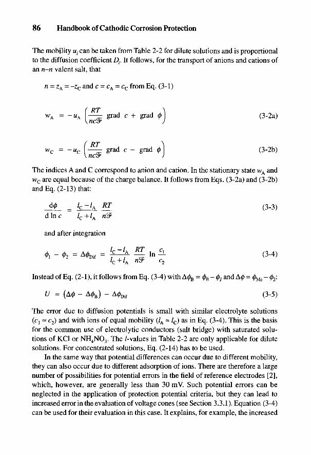
86 Handbook of Cathodic Corrosion Protection
The mobility u • can be taken from Table 2-2 for dilute solutions and is proportionalto the diffusion coefficient D;. It follows, for the transport of anions and cations ofan n-n valent salt, that
n = ZA = -zc and c = CA = cc from Eq. (3-1)
The indices A and C correspond to anion and cation. In the stationary state WA andwc are equal because of the charge balance. It follows from Eqs. (3-2a) and (3-2b)and Eq. (2-13) that:
Instead of Eq. (2-1), it follows from Eq. (3-4) with A^ = (^ - 0, and A0 = 0^ - 02:
The error due to diffusion potentials is small with similar electrolyte solutions(cl ~ c2) and with ions of equal mobility (/A = /c) as in Eq. (3-4). This is the basisfor the common use of electrolytic conductors (salt bridge) with saturated solu-tions of KC1 or NH4NO3. The /-values in Table 2-2 are only applicable for dilutesolutions. For concentrated solutions, Eq. (2-14) has to be used.
In the same way that potential differences can occur due to different mobility,they can also occur due to different adsorption of ions. There are therefore a largenumber of possibilities for potential errors in the field of reference electrodes [2],which, however, are generally less than 30 mV. Such potential errors can beneglected in the application of protection potential criteria, but they can lead toincreased error in the evaluation of voltage cones (see Section 3.3.1). Equation (3-4)can be used for their evaluation in this case. It explains, for example, the increased
Fundamentals and Practice of Electrical Measurements 87
potential difference that can occur between two reference electrodes when the ref-erence electrode is immersed in strong acid. In general the errors are small in saltsolutions and only to be expected in salt-free and cohesive soils [2].
Greater deviations which are occasionally observed between two referenceelectrodes in a medium are mostly due to stray electric fields or colloid chemicaldielectric polarization effects of solid constituents of the medium (e.g., sand [3])(see Section 3.3.1). Major changes in composition (e.g., in soils) do not lead tonoticeable differences of diffusion potentials with reference electrodes in concen-trated salt solutions. On the other hand, with simple metal electrodes which aresometimes used as probes for potential controlled rectifiers, certain changes are tobe expected through the medium. In these cases the concern is not with referenceelectrodes, in principle, but metals that have a rest potential which is as constant aspossible in the medium concerned. This is usually more constant the more activethe metal is, which is the case, for example, for zinc but not stainless steel.
In addition, the temperature dependence of the diffusion potentials and thetemperature dependence of the reference electrode potential itself must be consid-ered. Also, the temperature dependence of the solubility of metal salts is importantin Eq. (2-29). For these reasons reference electrodes with constant salt concentra-tion are sometimes preferred to those with saturated solutions. For practical rea-sons, reference electrodes are often situated outside the system under investigationat room temperature and connected with the medium via a salt bridge in whichpressure and temperature differences can be neglected. This is the case for all dataon potentials given in this handbook unless otherwise stated.
In practice, different reference electrodes are used, depending on the mediumand function. In particular, the following should be observed:
(a) stability of the reference electrode potential with time;(b) grounding resistance and current loading ability;(c) resistance against constituents of the medium and environmental influences
as well as compatibility with the system being measured.
Point (a) only concerns simple metal electrodes and needs to be tested for eachcase. Point (b) is important for the measuring instrument being used. In this respect,polarization of the reference electrode leads to less error than an ohmic voltagedrop at the diaphragm. Point (c) has to be tested for every system and can result inthe exclusion of certain electrode systems for certain media and require specialmeasures to be taken.
Cu-CuSO4 electrodes with saturated CuSO4 solution are recommended for poten-tial measurements in soil. Their potential constancy is about 5 mV. Larger errorscan be traced to chemical changes in the CuSO4 solution. These electrodes havebeen developed for long-life applications in potential-controlled rectifiers and built-

88 Handbook of Cathodic Corrosion Protection
in potential measuring instruments on account of their robustness [4]. Their ground-ing resistance in the built-in arrangement in soil with p = <100 Q, m lies generallybelow 1000 Q.
On the other hand, Cu-CuSO4 should not be used as built-in electrodes forpotential test probes (see Section 3.3.3.2) because there is a danger of copper pre-cipitating on the steel electrode. Calomel electrodes with saturated KC1 solutionare preferred in this case and present no problems.
3.3 Potential Measurement
3.3.1 Bases of Potential Measurement of Electrodes with Flowing Current
According to the explanation of Fig. 2-3 and Eq. (2-33), there is always anohmic voltage drop Tfo in the potential measurement of polarized electrodes whichis measured as an error. This can be kept small by using capillary probes on thereference electrode. This is used in laboratory experiments but in practice it isusually not feasible (e.g., with measurements in soils). Here one tries to separateelectrochemical polarization from 7]Q by other methods. This is accomplished bymaking use of the different time dependencies [5]. It is assumed that the electricalproperties of the phase boundary surface and of the medium can be approximatelyrepresented by a parallel circuit of resistance and capacity. These RC members areconnected in series in an equivalent circuit with a voltage source UR for the restpotential. With the specific parameters rp and CD for the phase boundary surfaceand rM and CM for the medium, the following expression can be derived for agalvanostatic switching experiment [6] from J{ to J2:
where U(J2) = UR + (rp + rM) J2 is the stationary potential. For the time constants:
The possible values for TP lie between 10 5 and 10 l s according to the data in Sec-tion 2.2.3.2, but with a concentration polarization this can be much greater. In Eq. (3-8)
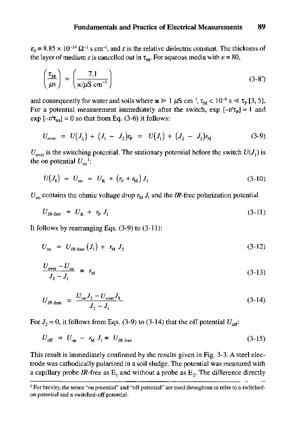
Fundamentals and Practice of Electrical Measurements 89
EQ = 8.85 x 10~14 Or1 s cm"1, and £ is the relative dielectric constant. The thickness ofthe layer of medium s is cancelled out in TM. For aqueous media with e = 80,
and consequently for water and soils where x ^> 1 /iS cm \ 1M < 10 6 s <^ Tp [3,5].For a potential measurement immediately after the switch, exp [-t/ip] ~ 1 andexp [-t/lM] = 0 so that from Eq. (3-6) it follows:
t/over is the switching potential. The stationary potential before the switch U(J^ isthe on potential Uon
l:
Uon contains the ohmic voltage drop rM J\ and the 7/?-free polarization potential
It follows by rearranging Eqs. (3-9) to (3-11):
For J2 - 0, it follows from Eqs. (3-9) to (3-14) that the off potential Uof{:
This result is immediately confirmed by the results given in Fig. 3-3. A steel elec-trode was cathodically polarized in a soil sludge. The potential was measured witha capillary probe 7/?-free as Ej and without a probe as E2. The difference directly
1 For brevity, the terms "on potential" and "off potential" are used throughout to refer to a switched-on potential and a switched-off potential.
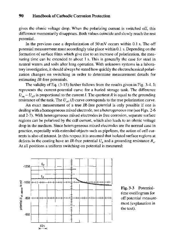
90 Handbook of Cathodic Corrosion Protection
gives the ohmic voltage drop. When the polarizing current is switched off, thisdifference momentarily disappears. Both values coincide and slowly reach the restpotential.
In the previous case a depolarization of 50 mV occurs within 0.1 s. The offpotential measurement must accordingly take place within 0.1 s. Depending on theformation of surface films which give rise to an increase of polarization, the mea-suring time can be extended to about 1 s. This is generally the case for steel inneutral waters and soils after long operation. With unknown systems in a labora-tory investigation, it should always be stated how quickly the electrochemical polari-zation changes on switching in order to determine measurement details forestimating 7/?-free potentials.
The validity of Eq. (3-15) further follows from the results given in Fig. 3-4. Itrepresents the current-potential curve for a buried storage tank. The differenceUon - Uoff is proportional to the current /. The quotient R is equal to the groundingresistance of the tank. The Uofi (/) curve corresponds to the true polarization curve.
An exact measurement of a true 7/?-free potential is only possible if one isdealing with a homogeneous mixed electrode, not a heterogeneous one (see Figs. 2-6and 2-7). With heterogeneous mixed electrodes in free corrosion, separate surfaceregions can be polarized by the cell current, which also leads to an ohmic voltagedrop in the medium. Since heterogeneous mixed electrodes are the normal case inpractice, especially with extended objects such as pipelines, the action of cell cur-rents is also of interest. In this respect it is assumed that isolated surface regions atdefects in the coating have an 7/?-free potential Un and a grounding resistance Rn.At all positions a uniform switching-on potential is measured:
Fig. 3-3 Potential-time oscillogram foroff potential measure-ment (explanation inthe text).

Fundamentals and Practice of Electrical Measurements 91
where In is the polarization current for an individual isolated region. The currentfor the entire object is given by:
Correspondingly, for a switching experiment from I{ to 72:
Using Eqs. (3-13) and (3-15) and designating the currents by
it follows from these expressions and Eqs. (3-17) and (3-18):
The 7/?-free potential is thus always the average of the single potentials Un. Themethod of determination (i.e., the contribution of 72) theoretically has no influence.In practice, however, with a small difference 72 - Ilt a related inexact potential
Fig. 3-4 Current-potentialmeasurements on a buried steelstorage tank with bitumencoating (surface area 4 m2 withfour defects 5 cm x 20 cm; soilresistivity p ~ 30 Q m).
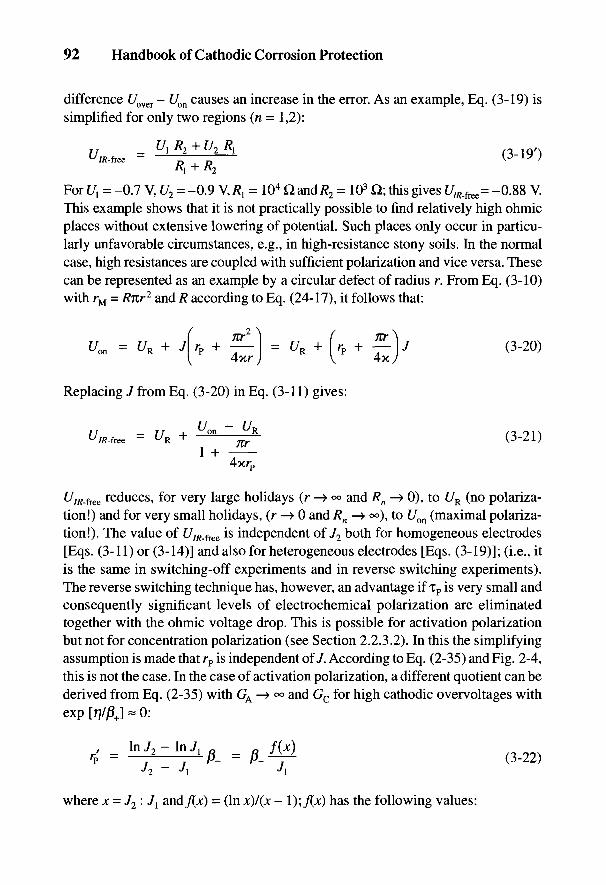
92 Handbook of Cathodic Corrosion Protection
difference f/over - Uon causes an increase in the error. As an example, Eq. (3-19) issimplified for only two regions (n = 1,2):
For C/j = -0.7 V, U2 = -0.9 V, R{ = 104 H and/?2 = 103 Q; this gives UlR.fKe= -0.88 V.This example shows that it is not practically possible to find relatively high ohmicplaces without extensive lowering of potential. Such places only occur in particu-larly unfavorable circumstances, e.g., in high-resistance stony soils. In the normalcase, high resistances are coupled with sufficient polarization and vice versa. Thesecan be represented as an example by a circular defect of radius r. From Eq. (3-10)with rM = Rnr2 and R according to Eq. (24-17), it follows that:
Replacing J from Eq. (3-20) in Eq. (3-11) gives:
^Wree reduces, for very large holidays (r —> °° and Rn -> 0), to UR (no polariza-tion!) and for very small holidays, (r —> 0 and Rn —> °°), to Uon (maximal polariza-tion!). The value of Um.iK& is independent of J2 both for homogeneous electrodes[Eqs. (3-11) or (3-14)] and also for heterogeneous electrodes [Eqs. (3-19)]; (i.e., itis the same in switching-off experiments and in reverse switching experiments).The reverse switching technique has, however, an advantage if TP is very small andconsequently significant levels of electrochemical polarization are eliminatedtogether with the ohmic voltage drop. This is possible for activation polarizationbut not for concentration polarization (see Section 2.2.3.2). In this the simplifyingassumption is made that rp is independent of J. According to Eq. (2-35) and Fig. 2-4,this is not the case. In the case of activation polarization, a different quotient can bederived from Eq. (2-35) with GA -> °° and Gc for high cathodic overvoltages withexp [rj/flj « 0:
where x = J2:J{ andflx) = (In x)/(x - 1 );/(*) has the following values:
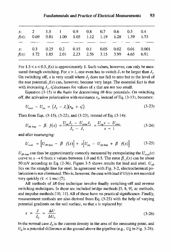
Fundamentals and Practice of Electrical Measurements 93
x: 2 1.5 1 0.9 0.8 0.7 0.6 0.5 0.4/(*): 0.69 0.81 1.00 1.05 1.12 1.19 1.28 1.39 1.53
x: 0.3 0.25 0.2 0.15 0.1 0.05 0.02 0.01 0.001/(jc): 1.72 1.85 2.01 2.23 2.56 3.15 3.99 4.65 6.91
For 1.5 < Jt < 0.5,/(jc) is approximately 1. Such values, however, can only be mea-sured through switching. For x > 1, one even has to switch J2 to be larger than J{.On switching off, x is very small where J2 does not fall to zero but to the level ofthe rest potential. f(x) can, however, become very large. The essential fact is thatwith increasing 7l5 r/decreases for values of jc that are not too small.
Equation (3-15) is the basis for determining IR-free potentials. On switchingoff, the activation polarization with resistance rp, instead of Eq. (3-13), becomes:
Then from Eqs. (3-15), (3-22), and (3-23), instead of Eq. (3-14):
and after rearranging:
UIR_fKe can thus be approximately correctly measured by extrapolating the Uover(x)curve to x —» 0 from x values between 1.0 and 0.5. The error (3_f(x) can be about50 mV according to Eq. (2-36). Figure 3-5 shows results for lead and steel. t/off
lies on the straight line for steel. In agreement with Fig. 3-2, electrochemical po-larization is not eliminated. This is, however, the case with lead if U(f) is not recordedvery quickly (i < 1 ms) [7].
All methods of 7/?-free technique involve finally switching-off and reverseswitching techniques. In these are included bridge methods [5, 8, 9], ac methods,and impulse methods [10, 11]. All of these have no practical significance. Finally,measurement methods are also derived from Eq. (3-25) with the help of varyingpotential gradients on the soil surface, so that x is replaced by:
In the normal case J0 is the current density in the area of the measuring point, andU0 is a potential difference at the ground above the pipeline (e.g., U# in Fig. 3-24).
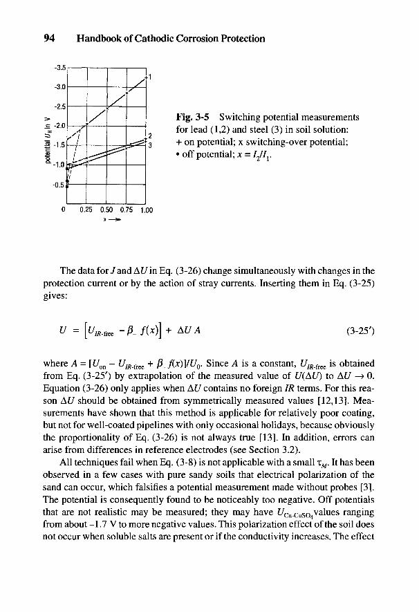
94 Handbook of Cathodic Corrosion Protection
Fig. 3-5 Switching potential measurementsfor lead (1,2) and steel (3) in soil solution:+ on potential; x switching-over potential;• off potential; jc = /2//r
The data for / and At/ in Eq. (3-26) change simultaneously with changes in theprotection current or by the action of stray currents. Inserting them in Eq. (3-25)gives:
where A = [Uon - t//J?_free + f3_f(x)]/U0. Since A is a constant, t///?_free is obtainedfrom Eq. (3-25') by extrapolation of the measured value of (/(At/) to At/ —> 0.Equation (3-26) only applies when At/ contains no foreign IR terms. For this rea-son At/ should be obtained from symmetrically measured values [12,13]. Mea-surements have shown that this method is applicable for relatively poor coating,but not for well-coated pipelines with only occasional holidays, because obviouslythe proportionality of Eq. (3-26) is not always true [13]. In addition, errors canarise from differences in reference electrodes (see Section 3.2).
All techniques fail when Eq. (3-8) is not applicable with a small 1M. It has beenobserved in a few cases with pure sandy soils that electrical polarization of thesand can occur, which falsifies a potential measurement made without probes [3].The potential is consequently found to be noticeably too negative. Off potentialsthat are not realistic may be measured; they may have t/Cu.CuS04values rangingfrom about -1.7 V to more negative values. This polarization effect of the soil doesnot occur when soluble salts are present or if the conductivity increases. The effect
Fundamentals and Practice of Electrical Measurements 95
then only occurs when neither galvanic nor stray current corrosion due to highresistances can take place, or when the soil is not corrosive due to the absence ofions (see Chapter 4). Consequently an erroneous measurement limited by theseeffects does not lead to damage on account of an incorrect potential.
Ohmic voltage drops of the protection current were exclusively involved inthe processes for IR-free potential measurements described above. Besides this,other foreign currents can cause potential drops and falsify the potential measure-ment (e.g., cell currents, equalizing currents and stray currents).
Cell currents and equalizing currents, which occur as a consequence of a localvery nonuniform polarization of the object being protected when the protectioncurrent is switched off can be recognized by potential gradients on the soil surfacewith switching off of the protection current. The following paragraph shows a methodof calculating 7/?-free potentials with the help of these potential gradients [2,13].
Application of this method or Eq. (3-250 in the presence of stray currents isconceivable but would be very prone to error. It is particularly valid for good coat-ing. Potential measurement is then only significant if stray currents are absent for aperiod, e.g., when the source of the stray current is not operating. In other casesonly local direct measurements with the help of probes or test measurements atcritical points can be considered. The potential test probes described in Sec-tion 3.3.3.2 have proved true in this respect.
For 7/?-free potential measurement with cell or equalizing currents it is assumed,analogous to Eq. (3-26), that current densities and potentials are proportional:
The first term in Eq. (3-27) represents the voltage drop between the reference elec-trode over the pipeline and the pipe surface. The second term represents the poten-tial difference At/measured at the soil surface (ground level) perpendicular (directlyabove) to the pipeline. Average values of the U# values measured to the left andright of the pipeline are to be used (see Fig. 3-24) [2]. In this way stray IR compo-nents can be eliminated. The third term comprises the current densities where, inthe switched-off state of the protection installation, there is a cell current Je. In thenormal case Je = 0 and also correspondingly At/off = 0 as well as U1R,free = Uoff. Onrearranging Eq. (3-27)
96 Handbook of Cathodic Corrosion Protection
If Af/on and Af/off have the same sign, UIR_fKe is more positive than Uoff. Thisarises when the measuring point has a more positive potential than the surround-ings. This means that regions with a relatively positive pipe/soil potential have astill more positive potential than the measured Uoff value! If AC/off and At/on havedifferent signs, then UIR_flse is more negative than Uoff. This occurs, for example,with local cathodic protection when there are foreign cathodic structures (seeChapter 12).
The second term of Eq. (3-28) is very prone to errors because the factor AC/off
includes electrode errors (see Section 3.2). For small values of At/off, Eq. (3-28) isnot applicable in practice [2]. Applications are described in Section 3.7 along withintensive measurement.
3.3.2 Application of Potential Measurement
3.3.2.1 Measuring Instruments and Their Properties
As explained in Sections 3.1 and 3.2, potentials are measured withhigh-impedance electronically amplified voltmeters. The amplified voltmeters havehigh input resistances between 1 and 100 MQ. The measured voltage is transformedelectronically into an alternating voltage, amplified in two stages, rectified by amodulator, and fed via a direct voltage amplifier acting as integrator to a movingcoil measuring instrument or digital display. Superimposed alternating voltagesare attenuated with preconnected RC filters of 60 to 90 dB (which corresponds to aratio of 1000 to 30,000:1) (see Section 3.3.2.4). For measurements in soil, analogmeasuring instruments are generally used. Digital display instruments are onlysuitable for relatively steady potential readings. The power rating of amplifiers isonly a few tenths of a watt. They are usually supplied from nickel-cadmium cells.Their life is about 60 h.
Amplifying voltmeters generally have an output that can be connected to arecording and measuring instrument. Thus, recorders with low input impedancecan also be used for recording results with high source resistance. High-impedancemultimeter instruments used in electrotechnology for measuring voltage, currentand resistance can also be employed in potential measurement. Multimeter instru-ments are mostly moving coils with tension-wire adjustment. They are robust, insen-sitive to temperature changes and have a linear scale. For response times of <1 s,which is necessary for potential measurement, these instruments have a maximuminternal resistance of 100 kQ per volt. Since the source resistance of referenceelectrodes with a large area is below 1 kQ, sufficiently accurate potential measure-ments are possible with such instruments. With potential measurements in high-
Fundamentals and Practice of Electrical Measurements 97
resistance sandy soils or in paved streets (small diaphragm), the source resistanceof the reference electrode can, however, considerably exceed 1 kQ. Table 3-2 in-cludes data from potential measuring instruments, recorders as well as dc and acmultimeter instruments, which are frequently used in corrosion protectionmeasurements.
The decay time of electrochemical depolarization depends not only on theprepolarization but also on the quality of the coating (see Fig. 3-6). With newlyinstalled pipelines and storage tanks, it is generally only necessary to carry out adrainage test for a few hours. Figure 3-7 shows the potential decay of a polarizedsteel surface, which was recorded after switching off the protection current using afast recorder with a response time of 2 ms for 10 cm at different chart speeds. Theoff potential at a chart speed of 1 cm/s corresponds to the value measured with anamplified voltmeter. It can be seen in Fig. 3-7 that the error arising from measuringinstruments with response times of 1 s amounts to about 50 mV, because a smallpart of the polarization is measured as a part of the ohmic drop [ 10]. It is necessaryin measuring off potentials that the measuring instrument have a response time of<1 s and aperiodic damping. The response time of multimeter instruments dependson the input resistance of the instrument and on the source resistance of the objectto be measured, and in amplifying voltmeters on the amplifier circuit. The responsetime can be determined with the circuit shown in Fig. 3-8 [14]. The internal resis-tance of the current and voltage source which is being measured is demonstratedby a resistance Rp connected in parallel with the measurement instrument. Rv andRp are suitable reverse switching decade resistances (20 to 50 kQ). The potentiometerRT (about 50 kQ) serves as the input of the instrument to be tested on the full range.With aperiodic damped instruments, the response time of the indicator is stoppedon reaching 1% of the end or the beginning of the scale. In instruments that over-shoot, the time of the indicator movement, including the overshoot, is recordedand simultaneously the magnitude of the overshoot is determined as a percentageof the scale reading. Table 3-2 contains response times of some common instru-ments used in corrosion protection measurements (for recording instruments, seeSection 3.3.2.3).
3.3.2.2 Potential Measurements on Pipelines and Storage Tanks
Errors can occur in potential measurements on pipelines and storage tanks insoil if foreign voltages such as, for example, ohmic voltage drops in soil, are nottaken into account [15]. Figure 3-9 shows the potential curves for a single defect(spherical field) or for several statistically distributed defects (cylindrical field) inthe pipeline coating. In general the on potential of the installation to be protected(e.g., a pipeline) is measured, with flowing protection current, against a reference
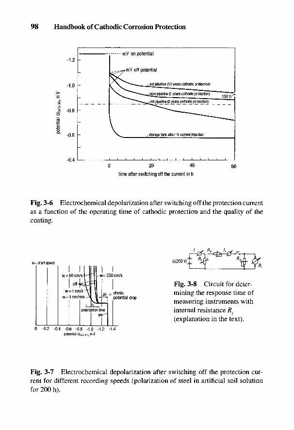
98 Handbook of Cathodic Corrosion Protection
Fig. 3-6 Electrochemical depolarization after switching off the protection currentas a function of the operating time of cathodic protection and the quality of thecoating.
Fig. 3-8 Circuit for deter-mining the response time ofmeasuring instruments withinternal resistance R.(explanation in the text).
Fig. 3-7 Electrochemical depolarization after switching off the protection cur-rent for different recording speeds (polarization of steel in artificial soil solutionfor 200 h).
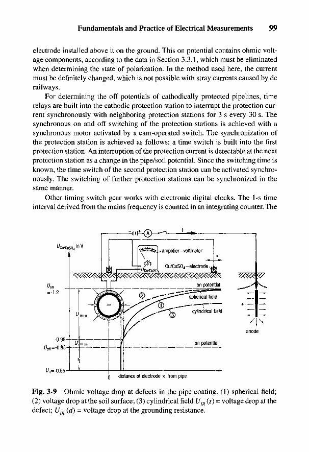
Fundamentals and Practice of Electrical Measurements 99
electrode installed above it on the ground. This on potential contains ohmic volt-age components, according to the data in Section 3.3.1, which must be eliminatedwhen determining the state of polarization. In the method used here, the currentmust be definitely changed, which is not possible with stray currents caused by dcrailways.
For determining the off potentials of cathodically protected pipelines, timerelays are built into the cathodic protection station to interrupt the protection cur-rent synchronously with neighboring protection stations for 3 s every 30 s. Thesynchronous on and off switching of the protection stations is achieved with asynchronous motor activated by a cam-operated switch. The synchronization ofthe protection station is achieved as follows: a time switch is built into the firstprotection station. An interruption of the protection current is detectable at the nextprotection station as a change in the pipe/soil potential. Since the switching time isknown, the time switch of the second protection station can be activated synchro-nously. The switching of further protection stations can be synchronized in thesame manner.
Other timing switch gear works with electronic digital clocks. The 1-s timeinterval derived from the mains frequency is counted in an integrating counter. The
Fig. 3-9 Ohmic voltage drop at defects in the pipe coating. (1) spherical field;(2) voltage drop at the soil surface; (3) cylindrical field UIR (s) = voltage drop at thedefect; UIR (d) = voltage drop at the grounding resistance.
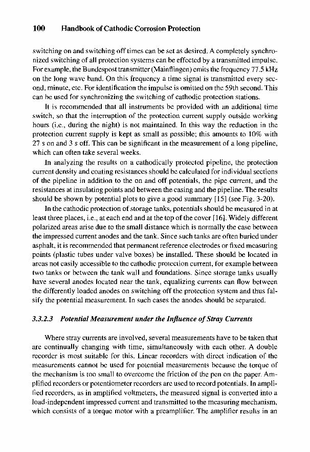
100 Handbook of Cathodic Corrosion Protection
switching on and switching off times can be set as desired. A completely synchro-nized switching of all protection systems can be effected by a transmitted impulse.For example, the Bundespost transmitter (Mainflingen) emits the frequency 77.5 kHzon the long wave band. On this frequency a time signal is transmitted every sec-ond, minute, etc. For identification the impulse is omitted on the 59th second. Thiscan be used for synchronizing the switching of cathodic protection stations.
It is recommended that all instruments be provided with an additional timeswitch, so that the interruption of the protection current supply outside workinghours (i.e., during the night) is not maintained. In this way the reduction in theprotection current supply is kept as small as possible; this amounts to 10% with27 s on and 3 s off. This can be significant in the measurement of a long pipeline,which can often take several weeks.
In analyzing the results on a cathodically protected pipeline, the protectioncurrent density and coating resistances should be calculated for individual sectionsof the pipeline in addition to the on and off potentials, the pipe current, and theresistances at insulating points and between the casing and the pipeline. The resultsshould be shown by potential plots to give a good summary [15] (see Fig. 3-20).
In the cathodic protection of storage tanks, potentials should be measured in atleast three places, i.e., at each end and at the top of the cover [16]. Widely differentpolarized areas arise due to the small distance which is normally the case betweenthe impressed current anodes and the tank. Since such tanks are often buried underasphalt, it is recommended that permanent reference electrodes or fixed measuringpoints (plastic tubes under valve boxes) be installed. These should be located inareas not easily accessible to the cathodic protection current, for example betweentwo tanks or between the tank wall and foundations. Since storage tanks usuallyhave several anodes located near the tank, equalizing currents can flow betweenthe differently loaded anodes on switching off the protection system and thus fal-sify the potential measurement. In such cases the anodes should be separated.
3.3.2.3 Potential Measurement under the Influence of Stray Currents
Where stray currents are involved, several measurements have to be taken thatare continually changing with time, simultaneously with each other. A doublerecorder is most suitable for this. Linear recorders with direct indication of themeasurements cannot be used for potential measurements because the torque ofthe mechanism is too small to overcome the friction of the pen on the paper. Am-plified recorders or potentiometer recorders are used to record potentials. In ampli-fied recorders, as in amplified voltmeters, the measured signal is converted into aload-independent impressed current and transmitted to the measuring mechanism,which consists of a torque motor with a preamplifier. The amplifier results in an

Fundamentals and Practice of Electrical Measurements 101
increased torque in order to achieve a response time of 0.5 s with the necessaryoperating pressure of the recording pen. The energy requirement for amplified re-corders is about 3 W. Technical data on recorders are given in Table 3-2.
As shown in Fig. 3-10, in potentiometer recorders with a servomotor, the aux-iliary current Ik is supplied by a measuring bridge. The voltage to be measured Ux iscompared with the compensation voltage Uk. The voltage difference is convertedto an alternating voltage, amplified 106-fold and fed to the control winding of aservomotor. This moves the slider s of the measuring bridge to the left until thevoltage difference Ux - Uk is zero. The position of the slider indicates the value ofthe voltage to be measured, which is compensated and indicated by the recorder.Potentiometer recorders have a relatively short response time—up to 0.1 s—and ahigh accuracy of 2.5% of the maximum scale reading.
The chart movement of the recorder is driven by a synchronous motor with arating of 2 to 5 W. With rapidly varying readings, a chart speed of 600 mm rr1 isneeded, but for stray current fluctuations, usually 300 mm tr1 is sufficient. Forrecording over several hours, chart speeds of 120 or 100 mm tr1 are advantageous.Optical evaluation of recorder traces is sufficient to obtain average values as wellas extreme values important for corrosion protection measurements. In general,recordings at a test point are not made for more than 0.5 to 1 h. Occasional extremevalues or potentials at night are not usually recorded. The frequency and length oftime that the protection potential is below the required level can be determinedwith a limiting value counter.
Fig. 3-10 Principle of acompensation circuit forrecording potentials(explanation in the text).
Where there are stray currents, the switching method described in Section 3.3.1cannot be used. Stray current protection stations are usually installed where thepipeline has the most positive pipe/soil potential. When the stray current drainageis cut off, a too-positive stray current exit potential that is not 7/?-free is quicklyestablished. In distant areas a too-negative stray current entry potential that is notIR-free will be measured. The determination of the 7/?-free pipe/soil potential isonly possible in stray current areas when the origin of the stray current is not oper-
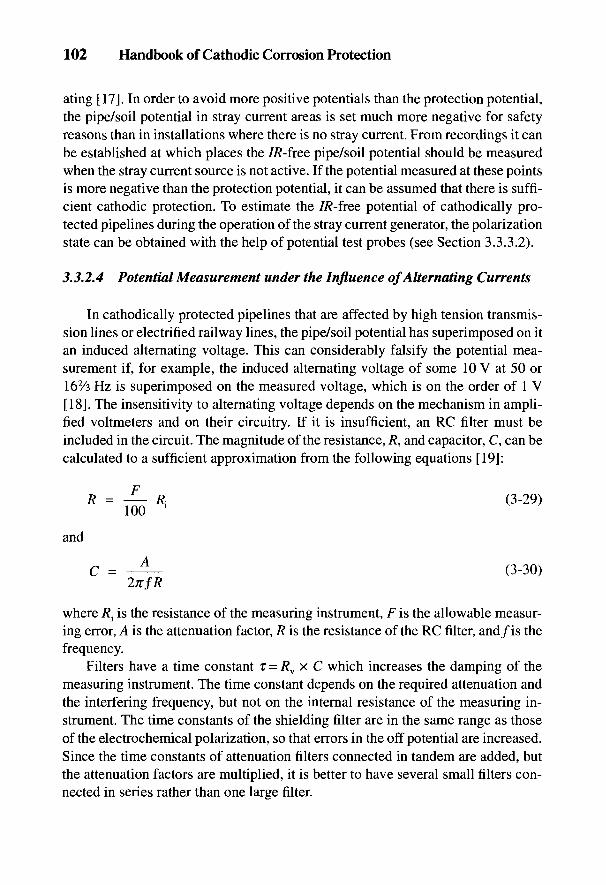
102 Handbook of Cathodic Corrosion Protection
ating [17]. In order to avoid more positive potentials than the protection potential,the pipe/soil potential in stray current areas is set much more negative for safetyreasons than in installations where there is no stray current. From recordings it canbe established at which places the 7/?-free pipe/soil potential should be measuredwhen the stray current source is not active. If the potential measured at these pointsis more negative than the protection potential, it can be assumed that there is suffi-cient cathodic protection. To estimate the 7/?-free potential of cathodically pro-tected pipelines during the operation of the stray current generator, the polarizationstate can be obtained with the help of potential test probes (see Section 3.3.3.2).
3.3.2.4 Potential Measurement under the Influence of Alternating Currents
In cathodically protected pipelines that are affected by high tension transmis-sion lines or electrified railway lines, the pipe/soil potential has superimposed on itan induced alternating voltage. This can considerably falsify the potential mea-surement if, for example, the induced alternating voltage of some 10 V at 50 or162/3 Hz is superimposed on the measured voltage, which is on the order of 1 V[18]. The insensitivity to alternating voltage depends on the mechanism in ampli-fied voltmeters and on their circuitry. If it is insufficient, an RC filter must beincluded in the circuit. The magnitude of the resistance, /?, and capacitor, C, can becalculated to a sufficient approximation from the following equations [19]:
and
where R{ is the resistance of the measuring instrument, F is the allowable measur-ing error, A is the attenuation factor, R is the resistance of the RC filter, and/is thefrequency.
Filters have a time constant i = Rv x C which increases the damping of themeasuring instrument. The time constant depends on the required attenuation andthe interfering frequency, but not on the internal resistance of the measuring in-strument. The time constants of the shielding filter are in the same range as thoseof the electrochemical polarization, so that errors in the off potential are increased.Since the time constants of attenuation filters connected in tandem are added, butthe attenuation factors are multiplied, it is better to have several small filters con-nected in series rather than one large filter.

Fundamentals and Practice of Electrical Measurements 103
In contrast to direct voltage, alternating voltage can be measured using a ground-ing rod as reference electrode. The grounding resistance of the rod is considerablylower than that of the reference electrodes in Table 3-1 but can still be too high formeasurements with soft iron, moving iron or electrodynamic measuring instru-ments. It is therefore also recommended that amplified voltmeters or amplifiedrecorders be used which have high internal resistances, great accuracy and a linearscale. Attention to frequency and shape of curve is important in the technique of acmeasurements. In general, measuring instruments are gauged for effective valuesfor 50 Hz and sine curves. They can therefore give false readings for diverse fre-quencies and waveforms (phase control). Measurement errors due to different wave-forms can be recognized by the fact that they give different results in differentmeasurement regions.
3.3.3 Application of Protection Criteria
According to the statements in Section 2-3, electrochemical protection existswhen the 7/?-free potential corresponds to the criteria in Eqs. (2-39), (2-48) to (2-50).For buried installations of ferrous materials, the potential must be more negativethan f/cu/cuso = -0.85 V. The details are to be found in Section 2-4. This criterionhas been known for a long time [20], with the 7/?-free potential being measuredbest by the switching-off technique [see Section 3.3.1 and Eq. (3-15)1 [21]. In prac-tice, the preconditions for applying the switching-off technique and related meth-ods are sometimes not given: the effect of stray current or galvanic currents frominstallations that are not isolated (e.g., old rusted pipelines) as well as steel founda-tions or ground electrodes, or pipelines affected by high voltage (see Chapter 15).In these cases other criteria can be drawn on for information. These are detailed inTable 3-3 for nonalloyed ferrous materials together with their fields of application.Criterion 1 corresponds to Eqs. (2-39), (3-15), and (3-28). This criterion is widelyknown (see Chapter 1); however, in contrast to Ref. 22, it is not stated in foreignstandards how the ohmic voltage drop is to be eliminated (see, for example, Ref. 23).Criterion 7 has the same basis as criterion 1 [24, 25].
Criteria 2 to 6 are pragmatic criteria which are only applicable to qualitativeexplanations. These criteria only give qualitative information which is dealt withfurther below (Section 3.3.3.1). Criterion 7 gives better information with potentialtest probes (see Section 3.3.3.2). In all the criteria it must be remembered that onlymixed potentials can be measured for extended objects to be protected [see theexplanation to Eqs. (3-19) and (3-28)]. Criteria 5 and 6 are particularly to beobserved for objects [22]. A comparison of the different criteria in field experimentshas shown that, besides Criterion 1, good results are obtained with Criterion 3 [26].
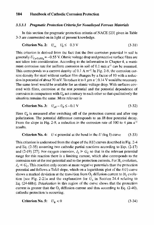
104 Handbook of Cathodic Corrosion Protection
3.3.3.1 Pragmatic Protection Criteria for Nonalloyed Ferrous Materials
In this section the pragmatic protection criteria of NACE [23] given in Table3-3 are commented on in light of present knowledge.
Criterion No. 2: Uon-UR<-0.3V (3-31)
This criterion is derived from the fact that the free corrosion potential in soil isgenerally f/Cu-cuso4
= -0-55 V. Ohmic voltage drop and protective surface films arenot taken into consideration. According to the information in Chapter 4, a maxi-mum corrosion rate for uniform corrosion in soil of 0.1 mm a"1 can be assumed.This corresponds to a current density of 0.1 A nr2. In Fig. 2-9, the corrosion cur-rent density for steel without surface film changes by a factor of 10 with a reduc-tion in potential of about 70 mV. To reduce it to 1 /um ar\ 0.14 V would be necessary.The same level would be available for an ohmic voltage drop. With surfaces cov-ered with films, corrosion at the rest potential and the potential dependence ofcorrosion in comparison with UR act contrary to each other so that qualitatively thesituation remains the same. More relevant is
Criterion No. 3: UoS- UR < -0.1 V (3-32)
Here UR is measured after switching off of the protection current and after steppolarization. The potential difference corresponds to an 7/?-free potential decay.From the slope in Fig. 2-9, a reduction in the corrosion rate of 100 to 4 fj.m a"1
results.
Criterion No. 4: U < potential at the bend in the U (log I) curve (3-33)
This criterion is understood from the shape of the I(U) curves described in Fig. 2-4and Eq. (2-35) assuming two cathodic partial reactions according to Eqs. (2-17)and (2-19) [27]. For oxygen corrosion, J0 > Gc so that in the relevant potentialrange for this reaction there is a limiting current, which also corresponds to thecorrosion rate at the rest potential and to the protection currents. For H2 evolution,J0< Gc. This reaction only occurs at more negative potentials than the protectionpotential and follows a Tafel slope, which on a logarithmic plot of the I(U) curveshows a marked deviation at the transition from O2 diffusion current to H2 evolu-tion [see Fig. 2-2la and the explanation for Uh in Section 24.4 relating toEq. (24-68b)]. Polarization in this region of the curve shows that the protectioncurrent is greater than the O2 diffusion current and thus according to Eq. (2-40),cathodic protection is occurring.
Criterion No. 5: U£<0 (3-34)

Fundamentals and Practice of Electrical Measurements 105
Table 3-3 Practical criteria for cathodic protection of plain carbon and low-alloy steels in soil
No. Basis Explanation Application
1 U < Us IR voltage drop "should Generalbe considered"
2 At/ > 300 mV 300-mV negative change Pipeline withoutfrom rest potential on connections to foreignswitching on protection cathodic structurescurrent
3 Af />100mV Measurement of Uncoated pipelinesdepolarization onswitching off protectioncurrent
4 U = /(log /) The protection current is Well casingsdetermined from the bendin the current density vs.potential curve by adrainage test
5 A U < 0 at All voltage drops Pipelines with groundsthe pipe perpendicular to the
pipeline must be negativeto the pipeline
6 U < U - 0.3 V Cancelling the cell Mixed installationon i- °(near foreign voltage with foreign cathodiccathode) structures (steel-
reinforced concretestructures)
7 UM < Us The potential test probe If the off potential(provided with a near measurement is notreference electrode) is possible, contact withconnnected to the foreign cathodicpipeline, and the structures (steel-connection is interrupted reinforced concretefor measurement structures)

106 Handbook of Cathodic Corrosion Protection
This criterion indicates that cathodic current is entering the pipeline and that thereis no more cell activity present (see Figs. 3-24 and 3-25 as well as the explanationof Fig. 2-7). The criterion for cathodic protection of pipelines with connected gal-vanized grounds against high-voltage interference is also comparable with thiscriterion [22]. In the connection between ground and pipeline, the current mustflow to the pipeline.
In DIN 30676 [22] there is a further criterion (No. 6: Uon <US- 0.3 V) forprotection of intermeshed objects with foreign cathodic structures. The on poten-tial should be measured in the vicinity of the foreign cathodic structure. Here it isassumed that in spite of a high IR term, the potential of the foreign cathodic struc-ture is so negative that cell formation is not expected to occur and the object alsoexperiences cathodic protection. Verification is only possible with Criterion No. 7,i.e., with potential test probes.
3.3.3.2 Potential Measurement with Potential Test Probes
This measuring technique is applied when there are relatively high IR valuesdue to cell currents with intermeshed objects or contact with steel-concrete struc-tures, as well as the influence of stray currents, which cannot be switched off. Theprinciple corresponds to the information in Fig. 2-3 on the use of measuring probes.
Test coupons of steel of a specified size are buried near the pipeline and con-nected by cable at the test point with the cathodically protected pipeline. Theysimulate artificial defects in the coating. The protection current taken from the testcoupon can be measured via the cable connection and the true potential deter-mined from a reference electrode in front of the test coupon by momentarily inter-rupting the cable connection [28]. Ohmic potential drops between the referenceelectrode and the test coupon are obtained from a measuring test probe that has abuilt-in reference electrode on the back of it to measure the 7/?-free potentialdirectly [see Eq. (2-34) with s —» 0] without having to switch off the protectioncurrent or interrupt the cable connection to the pipeline (see Fig. 3-11). The pipe/soil potential at the plate is measured by means of a permanent reference electrodethat is installed in a plastic tube behind the plate filled with electrolyte. Contact ismade via a diaphragm in the plate [24]. The steel plate and the diaphragm that isled through the steel plate must be carefully insulated since otherwise the potentialof the test coupon unaffected by the protection current inside the plastic tube willbe measured instead of that of the external steel probe. A comparison of valuesfrom the potential test probe with the external reference electrode, test probes withbuilt-in reference electrodes and the off potentials of the pipeline shows discrepan-cies of less than 20 mV. Since the potential becomes more negative with defects ofdecreasing size [see Eq. (3-21)], all coating defects in areas of similar resistivitythat are smaller than the test probe must show more negative potentials (Crite-
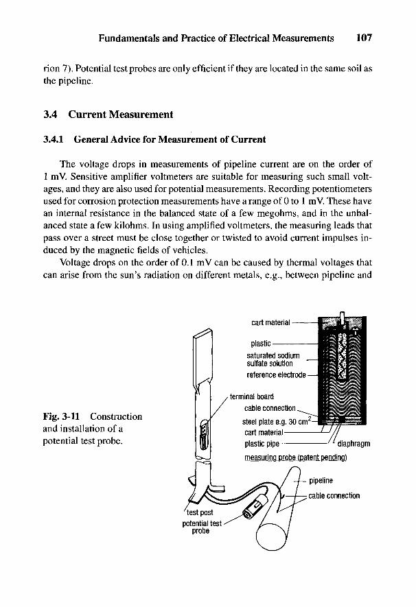
Fundamentals and Practice of Electrical Measurements 107
rion 7). Potential test probes are only efficient if they are located in the same soil asthe pipeline.
3.4 Current Measurement
3.4.1 General Advice for Measurement of Current
The voltage drops in measurements of pipeline current are on the order of1 mV. Sensitive amplifier voltmeters are suitable for measuring such small volt-ages, and they are also used for potential measurements. Recording potentiometersused for corrosion protection measurements have a range of 0 to 1 mV. These havean internal resistance in the balanced state of a few megohms, and in the unbal-anced state a few kilohms. In using amplified voltmeters, the measuring leads thatpass over a street must be close together or twisted to avoid current impulses in-duced by the magnetic fields of vehicles.
Voltage drops on the order of 0.1 mV can be caused by thermal voltages thatcan arise from the sun's radiation on different metals, e.g., between pipeline and
Fig. 3-11 Constructionand installation of apotential test probe.
108 Handbook of Cathodic Corrosion Protection
measuring rods. In damp conditions, a cell voltage acting in parallel can falsify themeasured value if there is no clean, low-resistance contact. The resistances of mea-sured stretches of the pipeline that are not part of a permanent measurement setupshould therefore be checked before every measurement. Today it is usual to installsolid measuring connections by cable and pole clamps at test points so that a per-fect contact can be quickly achieved (see Section 10.3.2). In excavated pipelinesor fittings, good contacts can be made with metal rods, and in the case of small-diameter pipes, with battery or metal clamps. A safer contact can be made aboveground with the help of magnets [29].
3.4.2 Pipe Current Measurement
Besides potential measurement, the measurement of currents in the pipeline isof considerable importance, not only for investigating the causes of corrosion, butalso for detecting failures in cathodic protection. The current flowing in the pipe-line cannot be measured directly because of its low resistance (1 km of pipelineDN* 700, 8-mm wall thickness -10 mQ) even if, for example, a measuring instru-ment can be switched into the electrically interrupted pipeline at insulating socketsor by disconnecting the pipeline. The internal resistance of a low-resistance 60-mVshunt would amount to between 1 and 10 mQ and therefore would be on the samescale as the resistance of the circuit to be measured. Cable sheathing and pipelinecurrents are therefore determined indirectly by Ohm's Law from the voltage dropover a standard resistance.
S
The resistance per unit length can be calculated from the resistance formula of thelinear conductor if the outer diameter da, the wall thickness s, and wall cross-section S = ns (da - s) are known:
A further measurement of current can be obtained from the pipe mass per meter,given in the standards, m = mil = S ps
where ps is the specific gravity of steel.With ps = 1.7 x 10~5 Q cm and ps = 7.85 g cnr3 for steel, it follows from
Eqs. (3-37) and (3-38):
Fundamentals and Practice of Electrical Measurements 109
The specific electrical resistances usually depend on the material and the tempera-ture [31]. For the most important pipe materials these are (in 10~5 Q cm):
Steel St 34: 1.7; gray cast iron [32]: 8 to 10,Steel St 60: 1.8; ductile cast iron: 7.
The values calculated using Eqs. (3-36) and (3-37) are only true for welded pipe-lines. Extension joints, fittings, and screwed or caulked joints can raise the longitu-dinal resistance of a pipeline considerably and therefore must be bridged over forcathodic protection.
The usual geometric length for measurements on pipes of 30 m has for DN 700a resistance of about 0.3 m£2. This allows, with an easily measurable voltage of 0.1mV, a current of > 0.3 A to be determined with sufficient accuracy. For a measureddistance of pipe current over DN 700, 50 m is sufficient. Since with unwelded steeltubes the wall thickness can vary by 10%, and with welded pipes by 5%, and oftenthe specific conductivity of the steel is not definitely known, it is recommendedthat long pipelines have built-in calibration stretches. The current measuring sec-tions for the pipe current described in Section 11.2 can be somewhat varied. Sepa-rate leads for injecting current and measuring voltage are necessary for accuratecalibration of the measuring sections for pipe current. On roads where measure-ment connections can easily be made above ground, two measuring points with1 m between measuring connections should be provided for each calibration mea-surement section on longer distances (about 100 m).
Figure 3-12 shows the current flow and potential distribution on a DN 80 pipeof wall thickness 3.5 mm with a current input of 68 A. Since the pipe was relativelyshort, no pipe current could flow to the right. At a distance of 15 cm to the left,practically no deviation from the linearly decreasing voltage drop in the pipelinecould be noted. Two pipe diameters were therefore a satisfactory distance for sepa-rating measuring cables for current and voltage measurements. With short excava-tions, an improvement can be achieved by alternating the connections at 45° to theright and to the left [33].
110 Handbook of Cathodic Corrosion Protection
3.4.3 Measurement of Current Density and Coating Resistance
The protective cathodic current demand can only be ascertained under stableconditions, that is, on objects that have been cathodically protected over long peri-ods. If two cathodic protection stations are acting on the section to be measured, bothstations must be switched off from time to time by using current interrupters. Be-sides the protection current density, the ohmic voltage drop in the soil at holidaysmust also be determined. From this the apparent coating resistance of the pipelinecan be determined. This corresponds to the sum of the parallel grounding resistancesof the holidays (see Section 5.2.1.2). By plotting the pipe current along its length,contacts with foreign lines can often be recognized (see Section 3.6 and Fig. 3-20).
The procedure for determining the protection current density and the averagecoating resistance is explained in Fig. 3-13. At the current drainage point, the cur-rent 2 70 is fed into the anode of the cathodic protection stations or an auxiliaryground electrode and periodically interrupted. With a symmetrical current distri-bution, the current 70 flows back from each side of the pipeline. On account of theminimal length resistance of welded pipelines with a good coating, the pipe/soilpotential decreases very slowly. Mean values can be linearly approximated ac-cording to recommendations by NACE [33,34]. This applies especially if the testpoint spacings, /t, /2 and /3 are small in comparison with the length of the protectedrange, L. The current 7j, 72,73 ..., In flowing in the pipeline is measured at measur-ing stations with a spacing A / = 1 to 2 km, and the current that enters each sectionbetween test points is:
This entering current causes ohmic voltage drops in the soil at holidays in the pipecoating, which are specified as Af/j, A£/2, A£/3..., AUn from which the averagevalue
is given for every measured length /. From this follows the specific coating resis-tance that corresponds to an average defect resistance according to Section 5.2.1.2:
where S is the surface area of the pipeline in the measured section. The sheathingresistance is not only determined by the size and number of holidays in the coating,but also by the specific soil resistivity.
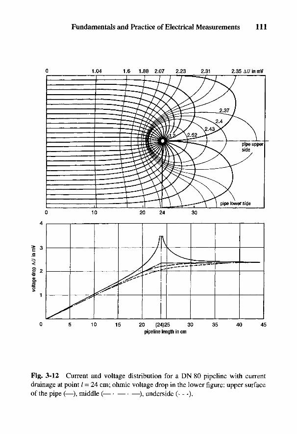
Fig. 3-12 Current and voltage distribution for a DN 80 pipeline with currentdrainage at point / = 24 cm; ohmic voltage drop in the lower figure: upper surfaceof the pipe (—), middle ( —), underside (—).
Fundamentals and Practice of Electrical Measurements 111
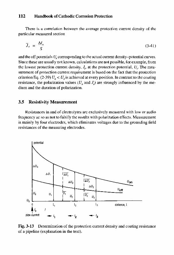
Fig. 3-13 Determination of the protection current density and coating resistanceof a pipeline (explanation in the text).
3.5 Resistivity Measurement
Resistances in and of electrolytes are exclusively measured with low or audiofrequency ac so as not to falsify the results with polarization effects. Measurementis mainly by four electrodes, which eliminates voltages due to the grounding fieldresistances of the measuring electrodes.
112 Handbook of Cathodic Corrosion Protection
There is a correlation between the average protection current density of theparticular measured section
and the off potentials Un corresponding to the actual current density-potential curves.Since these are usually not known, calculations are not possible, for example, fromthe lowest protection current density, Js, at the protection potential, Us. The mea-surement of protection current requirement is based on the fact that the protectioncriterion Eq. (2-39) Un < Us is achieved at every position. In contrast to the coatingresistance, the polarization values (Un and Js) are strongly influenced by the me-dium and the duration of polarization.
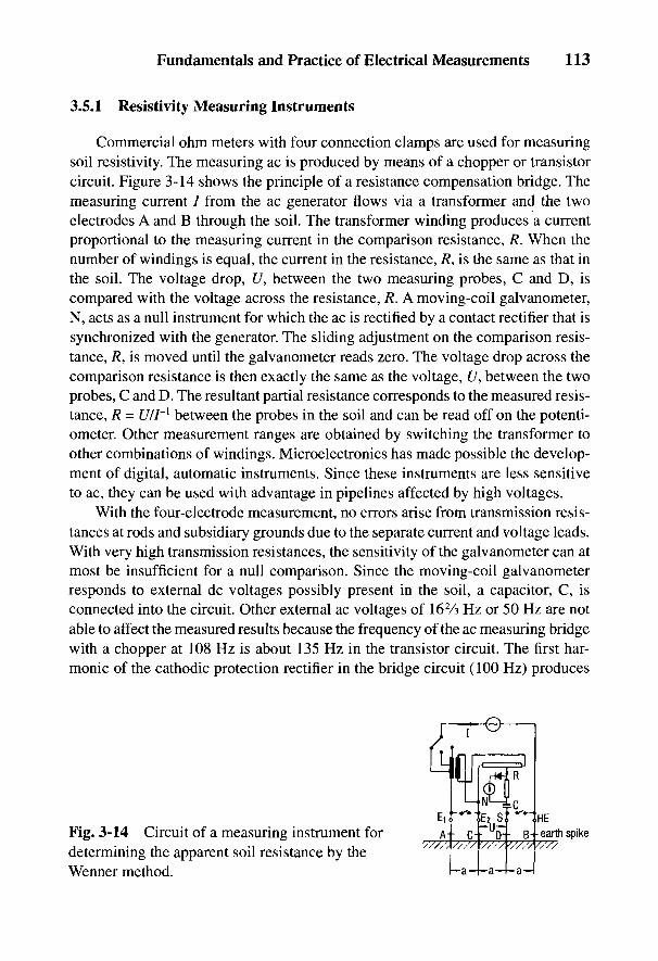
Fig. 3-14 Circuit of a measuring instrument fordetermining the apparent soil resistance by theWenner method.
Fundamentals and Practice of Electrical Measurements 113
3.5.1 Resistivity Measuring Instruments
Commercial ohm meters with four connection clamps are used for measuringsoil resistivity. The measuring ac is produced by means of a chopper or transistorcircuit. Figure 3-14 shows the principle of a resistance compensation bridge. Themeasuring current / from the ac generator flows via a transformer and the twoelectrodes A and B through the soil. The transformer winding produces a currentproportional to the measuring current in the comparison resistance, R. When thenumber of windings is equal, the current in the resistance, R, is the same as that inthe soil. The voltage drop, U, between the two measuring probes, C and D, iscompared with the voltage across the resistance, R. A moving-coil galvanometer,N, acts as a null instrument for which the ac is rectified by a contact rectifier that issynchronized with the generator. The sliding adjustment on the comparison resis-tance, R, is moved until the galvanometer reads zero. The voltage drop across thecomparison resistance is then exactly the same as the voltage, U, between the twoprobes, C and D. The resultant partial resistance corresponds to the measured resis-tance, R = U/I~[ between the probes in the soil and can be read off on the potenti-ometer. Other measurement ranges are obtained by switching the transformer toother combinations of windings. Microelectronics has made possible the develop-ment of digital, automatic instruments. Since these instruments are less sensitiveto ac, they can be used with advantage in pipelines affected by high voltages.
With the four-electrode measurement, no errors arise from transmission resis-tances at rods and subsidiary grounds due to the separate current and voltage leads.With very high transmission resistances, the sensitivity of the galvanometer can atmost be insufficient for a null comparison. Since the moving-coil galvanometerresponds to external dc voltages possibly present in the soil, a capacitor, C, isconnected into the circuit. Other external ac voltages of 162A Hz or 50 Hz are notable to affect the measured results because the frequency of the ac measuring bridgewith a chopper at 108 Hz is about 135 Hz in the transistor circuit. The first har-monic of the cathodic protection rectifier in the bridge circuit (100 Hz) produces
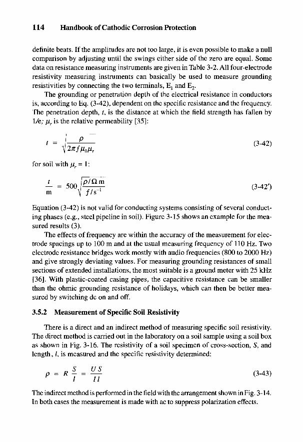
The indirect method is performed in the field with the arrangement shown in Fig. 3-14.In both cases the measurement is made with ac to suppress polarization effects.
3.5.2 Measurement of Specific Soil Resistivity
There is a direct and an indirect method of measuring specific soil resistivity.The direct method is carried out in the laboratory on a soil sample using a soil boxas shown in Fig. 3-16. The resistivity of a soil specimen of cross-section, S1, andlength, /, is measured and the specific resistivity determined:
Equation (3-42) is not valid for conducting systems consisting of several conduct-ing phases (e.g., steel pipeline in soil). Figure 3-15 shows an example for the mea-sured results (3).
The effects of frequency are within the accuracy of the measurement for elec-trode spacings up to 100 m and at the usual measuring frequency of 110 Hz. Twoelectrode resistance bridges work mostly with audio frequencies (800 to 2000 Hz)and give strongly deviating values. For measuring grounding resistances of smallsections of extended installations, the most suitable is a ground meter with 25 kHz[36]. With plastic-coated casing pipes, the capacitive resistance can be smallerthan the ohmic grounding resistance of holidays, which can then be better mea-sured by switching dc on and off.
for soil with fj.r = 1:
114 Handbook of Cathodic Corrosion Protection
definite beats. If the amplitudes are not too large, it is even possible to make a nullcomparison by adjusting until the swings either side of the zero are equal. Somedata on resistance measuring instruments are given in Table 3-2. All four-electroderesistivity measuring instruments can basically be used to measure groundingresistivities by connecting the two terminals, El and E2.
The grounding or penetration depth of the electrical resistance in conductorsis, according to Eq. (3-42), dependent on the specific resistance and the frequency.The penetration depth, ?, is the distance at which the field strength has fallen by1/e; (Jir is the relative permeability [35]:
Fig. 3-15 Penetration depth, t, by ac as a function of the frequency,/. (1) Copper,(2) steel; t in millimeters; (3) pipeline of DN 200 steel; (4) and (5) in soil: t inkilometers.
tivity of less cohesive soils can be determined with approximate accuracy if theinterfacial resistivity of the end surfaces is eliminated by using the four-electrodeprocess. Current and voltage leads are separated according to the Wenner method[37]. With uniform current distribution, Eq. (3-43) also applies if / stands for thespacing of the inner electrodes [38].
The most commonly applied indirect method of measuring soil resistivityusing the four-electrode arrangement of Fig. 3-14 is described further in Section24.3.1. The measured quantities are the injected current, /, between the electrodesA and B, and the voltage, U, between the electrodes C and D. The specific soilresistivity follows from Eq. (24-41). For the usual measuring arrangement withequally spaced electrodes a - b, it follows from Eq. (24-41):
If the specific soil resistivity varies vertically with depth, t, an apparent specificresistivity can be obtained from a combination of the resistivity of the upper and
Fundamentals and Practice of Electrical Measurements 115
When making measurements in the soil box, it has to be remembered that soilsamples can change from their original condition and this will have an effect onthe resistivity. Soil resistivity measurements in the soil box only give accurateresults with cohesive soils. However, the order of magnitude of the specific resis-
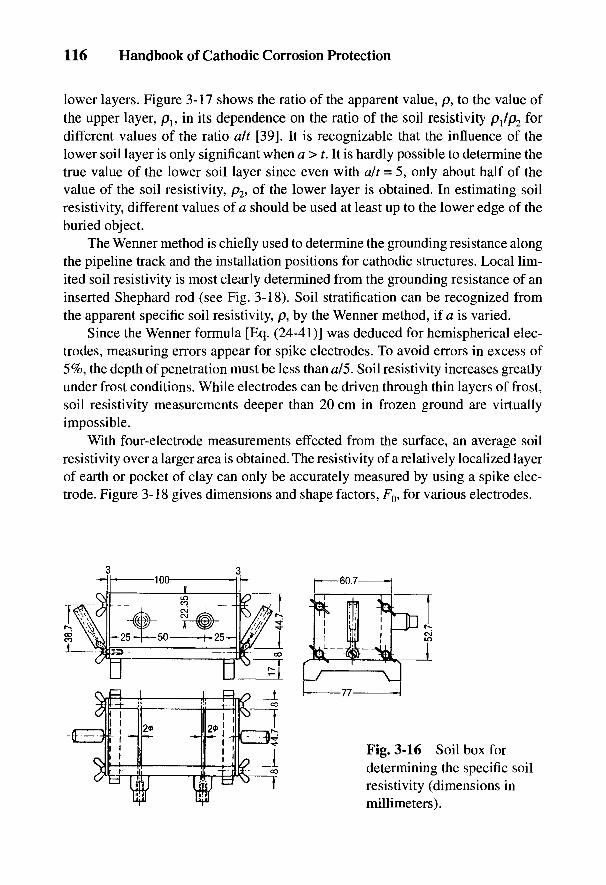
Fig. 3-16 Soil box fordetermining the specific soilresistivity (dimensions inmillimeters).
116 Handbook of Cathodic Corrosion Protection
lower layers. Figure 3-17 shows the ratio of the apparent value, p, to the value ofthe upper layer, p}, in its dependence on the ratio of the soil resistivity p^/p2 fordifferent values of the ratio alt [39]. It is recognizable that the influence of thelower soil layer is only significant when a > t. It is hardly possible to determine thetrue value of the lower soil layer since even with a/t = 5, only about half of thevalue of the soil resistivity, p2, °f me lower layer is obtained. In estimating soilresistivity, different values of a should be used at least up to the lower edge of theburied object.
The Wenner method is chiefly used to determine the grounding resistance alongthe pipeline track and the installation positions for cathodic structures. Local lim-ited soil resistivity is most clearly determined from the grounding resistance of aninserted Shephard rod (see Fig. 3-18). Soil stratification can be recognized fromthe apparent specific soil resistivity, p, by the Wenner method, if a is varied.
Since the Wenner formula [Eq. (24-41)] was deduced for hemispherical elec-trodes, measuring errors appear for spike electrodes. To avoid errors in excess of5%, the depth of penetration must be less than a/5. Soil resistivity increases greatlyunder frost conditions. While electrodes can be driven through thin layers of frost,soil resistivity measurements deeper than 20 cm in frozen ground are virtuallyimpossible.
With four-electrode measurements effected from the surface, an average soilresistivity over a larger area is obtained. The resistivity of a relatively localized layerof earth or pocket of clay can only be accurately measured by using a spike elec-trode. Figure 3-18 gives dimensions and shape factors, F0, for various electrodes.
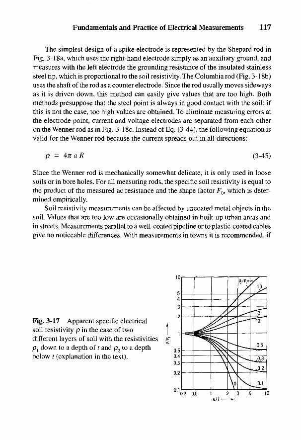
Fig. 3-17 Apparent specific electricalsoil resistivity p in the case of twodifferent layers of soil with the resistivitiesp1 down to a depth of t and p2 to a depthbelow t (explanation in the text).
Since the Wenner rod is mechanically somewhat delicate, it is only used in loosesoils or in bore holes. For all measuring rods, the specific soil resistivity is equal tothe product of the measured ac resistance and the shape factor F0, which is deter-mined empirically.
Soil resistivity measurements can be affected by uncoated metal objects in thesoil. Values that are too low are occasionally obtained in built-up urban areas andin streets. Measurements parallel to a well-coated pipeline or to plastic-coated cablesgive no noticeable differences. With measurements in towns it is recommended, if
Fundamentals and Practice of Electrical Measurements 117
The simplest design of a spike electrode is represented by the Shepard rod inFig. 3-18a, which uses the right-hand electrode simply as an auxiliary ground, andmeasures with the left electrode the grounding resistance of the insulated stainlesssteel tip, which is proportional to the soil resistivity. The Columbia rod (Fig. 3-18b)uses the shaft of the rod as a counter electrode. Since the rod usually moves sidewaysas it is driven down, this method can easily give values that are too high. Bothmethods presuppose that the steel point is always in good contact with the soil; ifthis is not the case, too high values are obtained. To eliminate measuring errors atthe electrode point, current and voltage electrodes are separated from each otheron the Wenner rod as in Fig. 3-18c. Instead of Eq. (3-44), the following equation isvalid for the Wenner rod because the current spreads out in all directions:
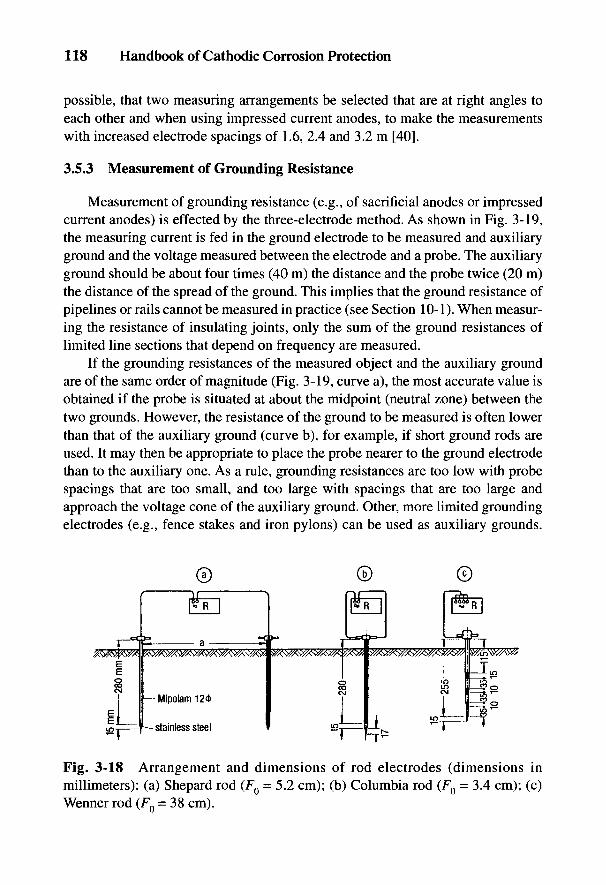
Fig. 3-18 Arrangement and dimensions of rod electrodes (dimensions inmillimeters): (a) Shepard rod (FQ = 5.2 cm); (b) Columbia rod (FQ = 3.4 cm); (c)Wenner rod (FQ = 38 cm).
118 Handbook of Cathodic Corrosion Protection
possible, that two measuring arrangements be selected that are at right angles toeach other and when using impressed current anodes, to make the measurementswith increased electrode spacings of 1.6, 2.4 and 3.2 m [40].
3.5.3 Measurement of Grounding Resistance
Measurement of grounding resistance (e.g., of sacrificial anodes or impressedcurrent anodes) is effected by the three-electrode method. As shown in Fig. 3-19,the measuring current is fed in the ground electrode to be measured and auxiliaryground and the voltage measured between the electrode and a probe. The auxiliaryground should be about four times (40 m) the distance and the probe twice (20 m)the distance of the spread of the ground. This implies that the ground resistance ofpipelines or rails cannot be measured in practice (see Section 10-1). When measur-ing the resistance of insulating joints, only the sum of the ground resistances oflimited line sections that depend on frequency are measured.
If the grounding resistances of the measured object and the auxiliary groundare of the same order of magnitude (Fig. 3-19, curve a), the most accurate value isobtained if the probe is situated at about the midpoint (neutral zone) between thetwo grounds. However, the resistance of the ground to be measured is often lowerthan that of the auxiliary ground (curve b), for example, if short ground rods areused. It may then be appropriate to place the probe nearer to the ground electrodethan to the auxiliary one. As a rule, grounding resistances are too low with probespacings that are too small, and too large with spacings that are too large andapproach the voltage cone of the auxiliary ground. Other, more limited groundingelectrodes (e.g., fence stakes and iron pylons) can be used as auxiliary grounds.
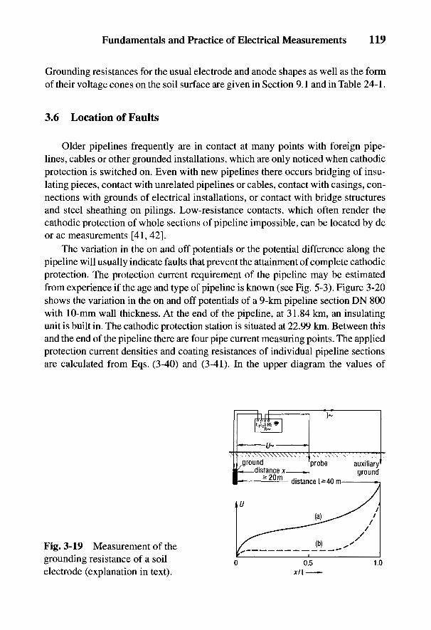
Fig. 3-19 Measurement of thegrounding resistance of a soilelectrode (explanation in text).
Fundamentals and Practice of Electrical Measurements 119
Grounding resistances for the usual electrode and anode shapes as well as the formof their voltage cones on the soil surface are given in Section 9.1 and in Table 24-1.
3.6 Location of Faults
Older pipelines frequently are in contact at many points with foreign pipe-lines, cables or other grounded installations, which are only noticed when cathodicprotection is switched on. Even with new pipelines there occurs bridging of insu-lating pieces, contact with unrelated pipelines or cables, contact with casings, con-nections with grounds of electrical installations, or contact with bridge structuresand steel sheathing on pilings. Low-resistance contacts, which often render thecathodic protection of whole sections of pipeline impossible, can be located by dcor ac measurements [41, 42].
The variation in the on and off potentials or the potential difference along thepipeline will usually indicate faults that prevent the attainment of complete cathodicprotection. The protection current requirement of the pipeline may be estimatedfrom experience if the age and type of pipeline is known (see Fig. 5-3). Figure 3-20shows the variation in the on and off potentials of a 9-km pipeline section DN 800with 10-mm wall thickness. At the end of the pipeline, at 31.84 km, an insulatingunit is built in. The cathodic protection station is situated at 22.99 km. Between thisand the end of the pipeline there are four pipe current measuring points. The appliedprotection current densities and coating resistances of individual pipeline sectionsare calculated from Eqs. (3-40) and (3-41). In the upper diagram the values of
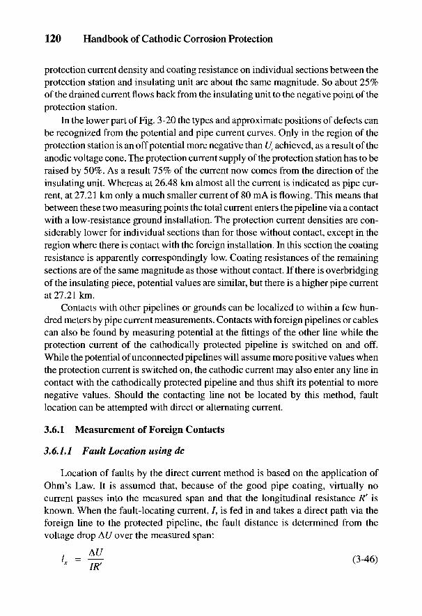
120 Handbook of Cathodic Corrosion Protection
protection current density and coating resistance on individual sections between theprotection station and insulating unit are about the same magnitude. So about 25%of the drained current flows back from the insulating unit to the negative point of theprotection station.
In the lower part of Fig. 3-20 the types and approximate positions of defects canbe recognized from the potential and pipe current curves. Only in the region of theprotection station is an off potential more negative than Us achieved, as a result of theanodic voltage cone. The protection current supply of the protection station has to beraised by 50%. As a result 75% of the current now comes from the direction of theinsulating unit. Whereas at 26.48 km almost all the current is indicated as pipe cur-rent, at 27.21 km only a much smaller current of 80 mA is flowing. This means thatbetween these two measuring points the total current enters the pipeline via a contactwith a low-resistance ground installation. The protection current densities are con-siderably lower for individual sections than for those without contact, except in theregion where there is contact with the foreign installation. In this section the coatingresistance is apparently correspondingly low. Coating resistances of the remainingsections are of the same magnitude as those without contact. If there is overbridgingof the insulating piece, potential values are similar, but there is a higher pipe currentat 27.21km.
Contacts with other pipelines or grounds can be localized to within a few hun-dred meters by pipe current measurements. Contacts with foreign pipelines or cablescan also be found by measuring potential at the fittings of the other line while theprotection current of the cathodically protected pipeline is switched on and off.While the potential of unconnected pipelines will assume more positive values whenthe protection current is switched on, the cathodic current may also enter any line incontact with the cathodically protected pipeline and thus shift its potential to morenegative values. Should the contacting line not be located by this method, faultlocation can be attempted with direct or alternating current.
3.6.1 Measurement of Foreign Contacts
3.6.1.1 Fault Location using dc
Location of faults by the direct current method is based on the application ofOhm's Law. It is assumed that, because of the good pipe coating, virtually nocurrent passes into the measured span and that the longitudinal resistance /?' isknown. When the fault-locating current, /, is fed in and takes a direct path via theforeign line to the protected pipeline, the fault distance is determined from thevoltage drop AC/ over the measured span:
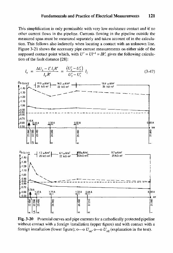
Fig. 3-20 Potential curves and pipe currents for a cathodically protected pipelinewithout contact with a foreign installation (upper figure) and with contact with aforeign installation (lower figure); o—o UQn, o—o Uo{{ (explanation in the text).
Fundamentals and Practice of Electrical Measurements 121
This simplification is only permissible with very low-resistance contact and if noother current flows in the pipeline. Currents flowing in the pipeline outside themeasured span must be measured separately and taken account of in the calcula-tion. This follows also indirectly when locating a contact with an unknown line.Figure 3-21 shows the necessary pipe current measurements on either side of thesupposed contact point which, with U' = Ul~l = IR\ gives the following calcula-tion of the fault distance [28]:
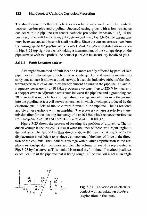
122 Handbook of Cathodic Corrosion Protection
The direct current method of defect location has also proved useful for contactsbetween casing pipe and pipeline. Uncoated casing pipes with a low-resistancecontact with the pipeline can render cathodic protection impossible [43]. If theposition of the fault has been roughly determined using Eq. (3-46), the casing pipemust be excavated at this spot if at all possible. Since the current crosses over fromthe casing pipe to the pipeline at the contact point, the potential distribution shownin Fig. 3-22 top right results. By taking a measurement of the voltage drop on thepipe surface with two probes, the contact point can be accurately localized [441.
3.6.1.2 Fault Location with ac
Although this method of fault location is more readily affected by parallel-laidpipelines or high-voltage effects, it is as a rule quicker and more convenient tocarry out; at least it allows a quick survey. It uses the inductive effect of the elec-tromagnetic field of an audio-frequency current flowing in the pipeline. An audio-frequency generator (1 to 10 kHz) produces a voltage of up to 220 V by means ofa chopper over an adjustable resistance between the pipeline and a grounding rod20 m away, through which a corresponding locating current flows over the groundinto the pipeline. A test coil serves as receiver in which a voltage is induced by theelectromagnetic field of the ac current flowing in the pipeline. This is renderedaudible in an earphone with an amplifier. The receiver contains a selective trans-mission filter for the locating frequency of 1 to 10 kHz, which reduces interferencefrom frequencies of 50 and 162/3 Hz by a ratio of 1 : 1000 [45].
Figure 3-23 shows the process of locating the position of a pipeline. The in-duced voltage in the test coil is lowest when the lines of force are at right angles tothe coil axis. The test coil is then directly above the pipeline. A slight sidewaysdisplacement is sufficient to produce a component of the lines offeree in the direc-tion of the coil axis. This induces a voltage which, after amplification in the ear-phone or loudspeaker, becomes audible. The volume of sound is represented inFig. 3-23 by the curve, a. This method is termed the "minimum" method. It allowsexact location of the pipeline that is being sought. If the test coil is set at an angle
Fig. 3-21 Location of an electricalcontact with an unknown pipeline(explanation in the text).
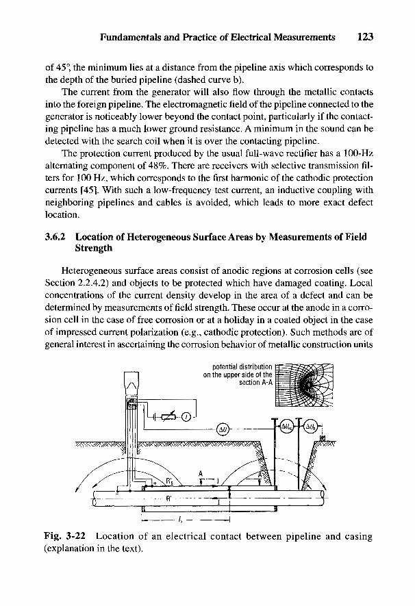
Fig. 3-22 Location of an electrical contact between pipeline and casing(explanation in the text).
Fundamentals and Practice of Electrical Measurements 123
of 45°, the minimum lies at a distance from the pipeline axis which corresponds tothe depth of the buried pipeline (dashed curve b).
The current from the generator will also flow through the metallic contactsinto the foreign pipeline. The electromagnetic field of the pipeline connected to thegenerator is noticeably lower beyond the contact point, particularly if the contact-ing pipeline has a much lower ground resistance. A minimum in the sound can bedetected with the search coil when it is over the contacting pipeline.
The protection current produced by the usual full-wave rectifier has a 100-Hzalternating component of 48%. There are receivers with selective transmission fil-ters for 100 Hz, which corresponds to the first harmonic of the cathodic protectioncurrents [45]. With such a low-frequency test current, an inductive coupling withneighboring pipelines and cables is avoided, which leads to more exact defectlocation.
3.6.2 Location of Heterogeneous Surface Areas by Measurements of FieldStrength
Heterogeneous surface areas consist of anodic regions at corrosion cells (seeSection 2.2.4.2) and objects to be protected which have damaged coating. Localconcentrations of the current density develop in the area of a defect and can bedetermined by measurements of field strength. These occur at the anode in a corro-sion cell in the case of free corrosion or at a holiday in a coated object in the caseof impressed current polarization (e.g., cathodic protection). Such methods are ofgeneral interest in ascertaining the corrosion behavior of metallic construction units
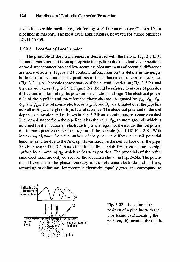
124 Handbook of Cathodic Corrosion Protection
inside inaccessible media, e.g., reinforcing steel in concrete (see Chapter 19) orpipelines in masonry. The most usual application is, however, for buried pipelines[24,44,46-49].
3.6.2.1 Location of Local Anodes
The principle of the measurement is described with the help of Fig. 2-7 [50].Potential measurement is not appropriate in pipelines due to defective connectionsor too distant connections and low accuracy. Measurements of potential differenceare more effective. Figure 3-24 contains information on the details in the neigh-borhood of a local anode: the positions of the cathodes and reference electrodes(Fig. 3-24a), a schematic representation of the potential variation (Fig. 3-24b), andthe derived values (Fig. 3-24c). Figure 2-8 should be referred to in case of possibledifficulties in interpreting the potential distribution and sign. The electrical poten-tials of the pipeline and the reference electrodes are designated by 0^, 0Bc, 0 ,03^ and 0 . The reference electrodes BM, B^ and Bx, are situated over the pipelineas well as B^ at a height of B^ in lateral distance. The electrical potential of the soildepends on location and is shown in Fig. 3-24b as a continuous, or a coarse dashedline. At a distance from the pipeline it has the value 0^ (remote ground) which isassumed for the location of electrode B^. In the region of the anode, the soil poten-tial is more positive than in the region of the cathode (see RHS Fig. 2-8). Withincreasing distance from the surface of the pipe, the difference in soil potentialbecomes smaller due to the IR drop. Its variation on the soil surface over the pipe-line is shown in Fig. 3-24b as a fine dashed line, and differs from that on the pipesurface by an amount % which varies with position. The potentials of the refer-ence electrodes are only correct for the locations shown in Fig. 3-24a. The poten-tial differences at the phase boundary of the reference electrode and soil are,according to definition, for reference electrodes equally great and correspond to
Fig. 3-23 Location of theposition of a pipeline with thepipe locator: (a) Locating theposition, (b) locating the depth.
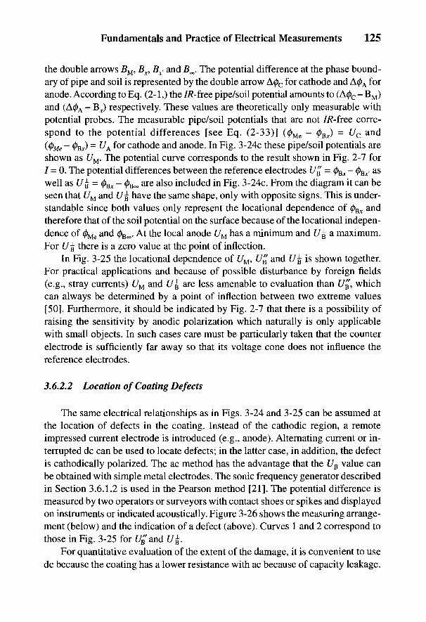
Fundamentals and Practice of Electrical Measurements 125
the double arrows BM, Bx, Bx> and B^. The potential difference at the phase bound-ary of pipe and soil is represented by the double arrow A0C for cathode and A0A foranode. According to Eq. (2-1,) the 7/?-free pipe/soil potential amounts to (A0C - BM)and (A0A - B^) respectively. These values are theoretically only measurable withpotential probes. The measurable pipe/soil potentials that are not 7R-free corre-spond to the potential differences [see Eq. (2-33)] (0Me - (j)Ex) = Uc and(<j)Me - 0gJ = UA for cathode and anode. In Fig. 3-24c these pipe/soil potentials areshown as t/M. The potential curve corresponds to the result shown in Fig. 2-7 for7 = 0. The potential differences between the reference electrodes UE = (j)Ex - (f)E^ aswell as t/g = 0^ - </>goo are also included in Fig. 3-24c. From the diagram it can beseen that UM and UE have the same shape, only with opposite signs. This is under-standable since both values only represent the locational dependence of 0Bjr andtherefore that of the soil potential on the surface because of the locational indepen-dence of 0^ and 0Boo. At the local anode UM has a minimum and UE a maximum.For U% there is a zero value at the point of inflection.
In Fig. 3-25 the locational dependence of UM, UE and U% is shown together.For practical applications and because of possible disturbance by foreign fields(e.g., stray currents) UM and UE are less amenable to evaluation than t/B, whichcan always be determined by a point of inflection between two extreme values[50]. Furthermore, it should be indicated by Fig. 2-7 that there is a possibility ofraising the sensitivity by anodic polarization which naturally is only applicablewith small objects. In such cases care must be particularly taken that the counterelectrode is sufficiently far away so that its voltage cone does not influence thereference electrodes.
3.6.2.2 Location of Coating Defects
The same electrical relationships as in Figs. 3-24 and 3-25 can be assumed atthe location of defects in the coating. Instead of the cathodic region, a remoteimpressed current electrode is introduced (e.g., anode). Alternating current or in-terrupted dc can be used to locate defects; in the latter case, in addition, the defectis cathodically polarized. The ac method has the advantage that the UE value canbe obtained with simple metal electrodes. The sonic frequency generator describedin Section 3.6.1.2 is used in the Pearson method [21]. The potential difference ismeasured by two operators or surveyors with contact shoes or spikes and displayedon instruments or indicated acoustically. Figure 3-26 shows the measuring arrange-ment (below) and the indication of a defect (above). Curves 1 and 2 correspond tothose in Fig. 3-25 for £7^ and t/£.
For quantitative evaluation of the extent of the damage, it is convenient to usedc because the coating has a lower resistance with ac because of capacity leakage.
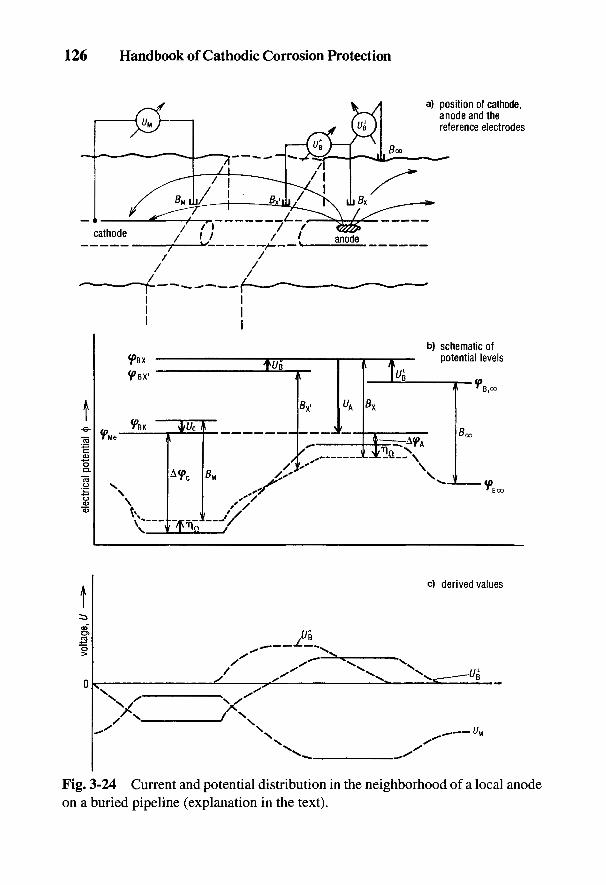
Fig. 3-24 Current and potential distribution in the neighborhood of a local anodeon a buried pipeline (explanation in the text).
126 Handbook of Cathodic Corrosion Protection
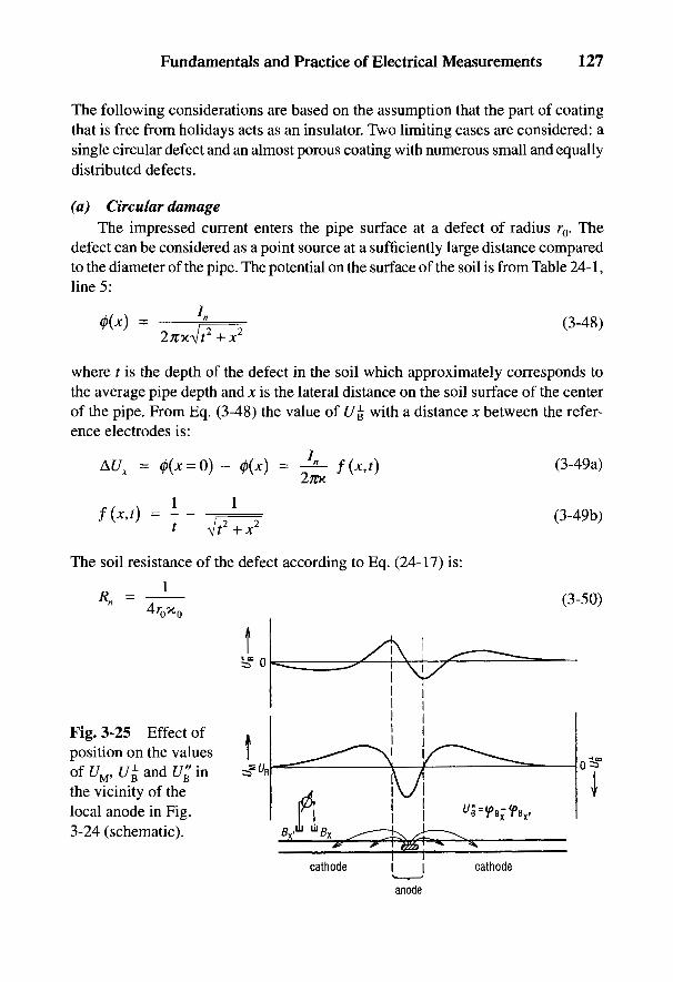
Fig. 3-25 Effect ofposition on the valuesof C/M, £/£ and U£ inthe vicinity of thelocal anode in Fig.3-24 (schematic).
The soil resistance of the defect according to Eq. (24-17) is:i
where t is the depth of the defect in the soil which approximately corresponds tothe average pipe depth and x is the lateral distance on the soil surface of the centerof the pipe. From Eq. (3-48) the value of 17£ with a distance x between the refer-ence electrodes is:
Fundamentals and Practice of Electrical Measurements 127
The following considerations are based on the assumption that the part of coatingthat is free from holidays acts as an insulator. Two limiting cases are considered: asingle circular defect and an almost porous coating with numerous small and equallydistributed defects.
(a) Circular damageThe impressed current enters the pipe surface at a defect of radius r0. The
defect can be considered as a point source at a sufficiently large distance comparedto the diameter of the pipe. The potential on the surface of the soil is from Table 24-1,line 5:
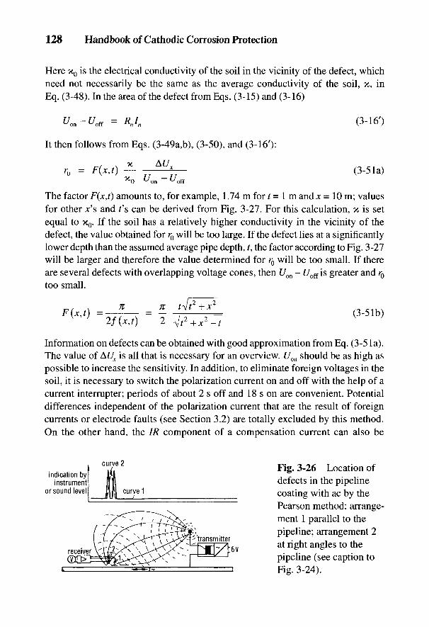
Fig. 3-26 Location ofdefects in the pipelinecoating with ac by thePearson method: arrange-ment 1 parallel to thepipeline; arrangement 2at right angles to thepipeline (see caption toFig. 3-24).
Information on defects can be obtained with good approximation from Eq. (3-5 la).The value of AUX is all that is necessary for an overview. Uon should be as high aspossible to increase the sensitivity. In addition, to eliminate foreign voltages in thesoil, it is necessary to switch the polarization current on and off with the help of acurrent interrupter; periods of about 2 s off and 18 s on are convenient. Potentialdifferences independent of the polarization current that are the result of foreigncurrents or electrode faults (see Section 3.2) are totally excluded by this method.On the other hand, the IR component of a compensation current can also be
*0 '-'on ~ ^off
The factor F(x,f) amounts to, for example, 1.74 m for t= 1 m and x = 10 m; valuesfor other jc's and f s can be derived from Fig. 3-27. For this calculation, x is setequal to x0. If the soil has a relatively higher conductivity in the vicinity of thedefect, the value obtained for r0 will be too large. If the defect lies at a significantlylower depth than the assumed average pipe depth, ?, the factor according to Fig. 3-27will be larger and therefore the value determined for r0 will be too small. If thereare several defects with overlapping voltage cones, then Uon - Uoff is greater and r0
too small.
It then follows from Eqs. (3-49a,b), (3-50), and (3-16'):
128 Handbook of Cathodic Corrosion Protection
Here x0 is the electrical conductivity of the soil in the vicinity of the defect, whichneed not necessarily be the same as the average conductivity of the soil, x, inEq. (3-48). In the area of the defect from Eqs. (3-15) and (3-16)

Fundamentals and Practice of Electrical Measurements 129
determined from the AUX (off) (see Section 3.3.1). Since these quantities are smallerthan AUX (on) [2, 47] the resultant error can be ignored.
Figure 3-28 shows, as an example, results obtained from an intensive mea-surement of a short section of pipe which could be very strongly polarized to in-crease the sensitivity of defect location. From Eq. (3-51 a) r0 = 4 mm at &UX = 0.1 V.In the results in Fig. 3-29, r0 = 9 cm at AUX = 0.1 V. These results are clear indica-tions of water traps resulting from a poor coating [46]. Further examples are shownin Section 3.7.
(b) Porous coatingFor a cylinder diameter, d, the following equations derived from Fig. 24-4
together with Eq. (24-46) to (24-48) are relevant:
In contrast to signal spread, according to Eq. (3-48) for a coating with few defects,in this case a locally almost constant conductivity is assumed. For the extreme caseof an uncoated pipe and neglecting the ohmic polarization resistances, there is adistance x = a where both voltage drops of Eqs. (3-52) and (3-53) are equal
From Eqs. (3-52) and (3-53) and a soil cover h-t- d/2, it follows:
AUa can be determined from a U% measurement using this value of a. The truepotential then follows from Eq. (3-54) with Eq. (3-15): UIR_fKe = Uon - AUa. Thisrelation is, however, no longer true when ohmic voltage drops are occurring insurface films or in a porous coating on the pipe surface. Instead of Eq. (3-54), thefollowing relation is applicable:
where At/w is the voltage drop in the pores of the coating while the subtractedquantity Uu0 takes account of the limiting case of no coating. Af/w0 corresponds to
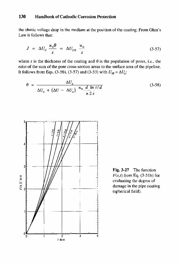
130 Handbook of Cathodic Corrosion Protection
the ohmic voltage drop in the medium at the position of the coating. From Ohm'sLaw it follows that:
where s is the thickness of the coating and 0 is the population of pores, i.e., theratio of the sum of the pore cross-section areas to the surface area of the pipeline.It follows from Eqs. (3-56), (3-57) and (3-53) with UIR = &Ua:
Fig. 3-27 The functionF(jt,0 from Eq. (3-5 Ib) forevaluating the degree ofdamage in the pipe coating(spherical field).
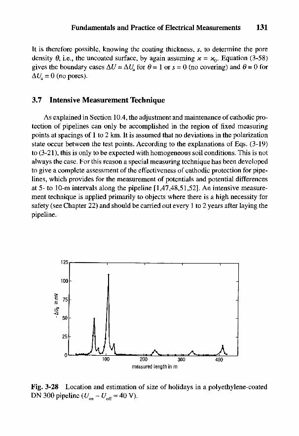
Fundamentals and Practice of Electrical Measurements 131
It is therefore possible, knowing the coating thickness, s, to determine the poredensity 6, i.e., the uncoated surface, by again assuming x = XQ. Equation (3-58)gives the boundary cases AJ7 = A££ for 6 = I or s = 0 (no covering) and 6 = 0 forAUa = 0 (no pores).
3.7 Intensive Measurement Technique
As explained in Section 10.4, the adjustment and maintenance of cathodic pro-tection of pipelines can only be accomplished in the region of fixed measuringpoints at spacings of 1 to 2 km. It is assumed that no deviations in the polarizationstate occur between the test points. According to the explanations of Eqs. (3-19)to (3-21), this is only to be expected with homogeneous soil conditions. This is notalways the case. For this reason a special measuring technique has been developedto give a complete assessment of the effectiveness of cathodic protection for pipe-lines, which provides for the measurement of potentials and potential differencesat 5- to 10-m intervals along the pipeline [1,47,48,51,52]. An intensive measure-ment technique is applied primarily to objects where there is a high necessity forsafety (see Chapter 22) and should be carried out every 1 to 2 years after laying thepipeline.
Fig. 3-28 Location and estimation of size of holidays in a polyethylene-coatedDN 300 pipeline (Uon - Uoff « 40 V).
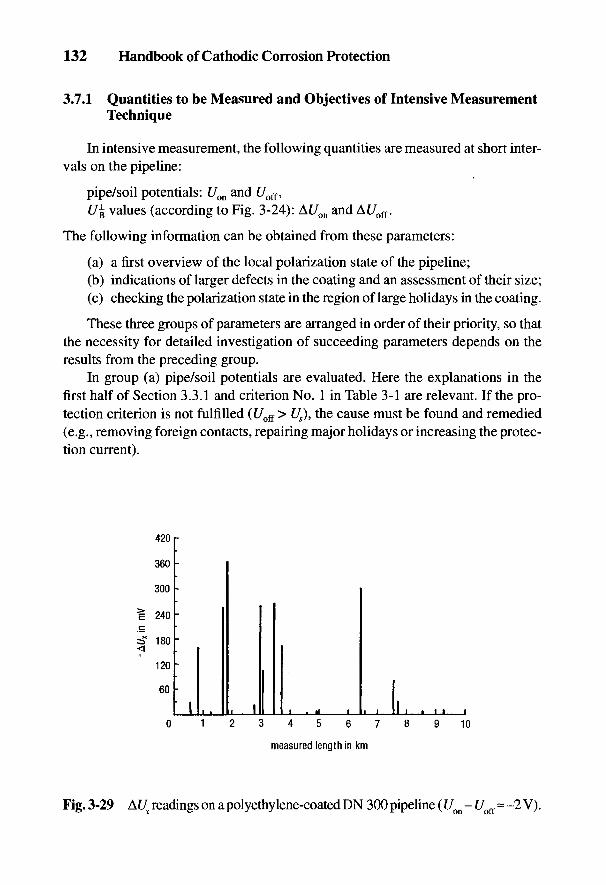
132 Handbook of Cathodic Corrosion Protection
3.7.1 Quantities to be Measured and Objectives of Intensive MeasurementTechnique
In intensive measurement, the following quantities are measured at short inter-vals on the pipeline:
pipe/soil potentials: Uon and Uoff,£/B values (according to Fig. 3-24): At/on and At/off.
The following information can be obtained from these parameters:
(a) a first overview of the local polarization state of the pipeline;(b) indications of larger defects in the coating and an assessment of their size;(c) checking the polarization state in the region of large holidays in the coating.
These three groups of parameters are arranged in order of their priority, so thatthe necessity for detailed investigation of succeeding parameters depends on theresults from the preceding group.
In group (a) pipe/soil potentials are evaluated. Here the explanations in thefirst half of Section 3.3.1 and criterion No. 1 in Table 3-1 are relevant. If the pro-tection criterion is not fulfilled (Uoff > Us), the cause must be found and remedied(e.g., removing foreign contacts, repairing major holidays or increasing the protec-tion current).
Fig. 3-29 A£7 readings on a polyethylene-coated DN 300 pipeline (Um - Uoff ~ -2 V).
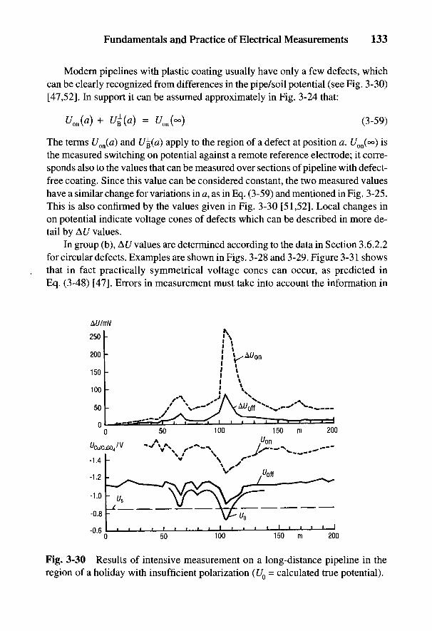
Fig. 3-30 Results of intensive measurement on a long-distance pipeline in theregion of a holiday with insufficient polarization (U0 = calculated true potential).
Fundamentals and Practice of Electrical Measurements 133
Modern pipelines with plastic coating usually have only a few defects, whichcan be clearly recognized from differences in the pipe/soil potential (see Fig. 3-30)[47,52]. In support it can be assumed approximately in Fig. 3-24 that:
Um(a) + U$(a) = £U~) (3-59)
The terms Uon(a) and U%(a) apply to the region of a defect at position a. £/on(°°) isthe measured switching on potential against a remote reference electrode; it corre-sponds also to the values that can be measured over sections of pipeline with defect-free coating. Since this value can be considered constant, the two measured valueshave a similar change for variations in a, as in Eq. (3-59) and mentioned in Fig. 3-25.This is also confirmed by the values given in Fig. 3-30 [51,52]. Local changes inon potential indicate voltage cones of defects which can be described in more de-tail by AU values.
In group (b), AC/ values are determined according to the data in Section 3.6.2.2for circular defects. Examples are shown in Figs. 3-28 and 3-29. Figure 3-31 showsthat in fact practically symmetrical voltage cones can occur, as predicted inEq. (3-48) [47]. Errors in measurement must take into account the information in

Fig. 3-31 Equipotential lines on the soil surface above a defect in the pipe coating(DN 700, thickness of soil covering 1.5 m).
134 Handbook of Cathodic Corrosion Protection
Eq. (3-5 Ib) and Fig. 3-27 because of the unknown depth, t, of the damage, but notthe length, x, in the measurement of U^. The difference for t = 1 m at x - 10 mcompared with x = °° only amounts to 10%. Further sources of error which must beheeded are electrode faults and foreign fields. These can be best eliminated bysubstituting the difference (At/on - At/off) for AUX in Eq. (3-5la).
The evaluation of AU values together with off potentials are aids in decidingwhether coating damage should be repaired. In addition, by comparison with pre-vious results, intensive measurements indicate whether new coating defects havearisen. These could be the result of external foreign forces on the pipeline.
A further objective is the evaluation in group (c) of the local polarization stateby taking account of IR errors due to direct currents. Here Eq. (3-28) and the fur-ther explanations in the second half of Section 3.3.1 are relevant. In practical ap-plication, the error effect of A(/off must be estimated [2]. When foreign fields arepresent, it is necessary to substitute for the At/ value the average of the measure-ments made on both sides of the pipeline [2,52]. Figure 3-30 gives an example of
where
Fundamentals and Practice of Electrical Measurements 135
measured values which show quite clearly that at the position a = 105 m the calcu-lated potential U0 does not fulfill the protection criterion.
3.7.2 Carrying Out an Intensive Measurement
The precondition of an intensive measurement is the exact location of the courseof the pipeline. Methods described in Section 3.6.1.2 using the pipe locator areapplicable. The harmonics of the protection current can be used. The protectioncurrent is interrupted to obtain the pipe/soil potentials and AU value for both switch-ing phases. Although the AU value can be determined independently of the mea-suring point, measuring the pipe/soil potentials requires a measuring cable about1 km in length as the connection to the pipeline. On practical grounds, simplifica-tions can be introduced which certainly in most cases are applicable and low inerror [1]. These concern AU values for both on and off switching phases as well asthe pipe/soil potential.
(a) Determination of the pipe/soil potentialThe pipe/soil potential is conventionally measured at a test point with a refer-
ence electrode BQ:
The reference electrode B} is set up at a distance, a, over the pipeline. The voltagebetween the two reference electrodes
gives the pipe/soil potential at this point:
The determination of U} only requires the measured value U0 and no cable connec-tion to the pipeline. This technique can be repeated at equal intervals Aa = av - av_{:

136 Handbook of Cathodic Corrosion Protection
A further possibility of error is the addition of electrode errors. For this reasonexamination of the Un value according to Eq. (3-62) at the next measuring point isnecessary.
(b) Determination of AU valuesAccording to Fig. 3-24 the reference electrode B^ is remotely positioned, out-
side the voltage cones of the pipeline holidays. Thus it may also be positionedabove a section of the pipeline where there are no defects in the coating, which canbe tested by a conventional U% measurement. If now the electrode B0 lies on sucha section (0g0 = 0^), but electrode Bj already lies in the voltage cone of a defect inthe pipe coating, Eq. (3-61) applies for the position, a}:
and for the general position an from Eq. (3-64):
It is recommended that further evaluation be carried out by direct measurementaccording to the data in Section 3.7.1 because of possible errors caused by foreignsources in the case of large readings.
The determination of At/ values as well as the potential is effected by simplemeasurements of the difference in potential between two reference electrodes overthe pipeline. To reduce possible electrode errors, partial sums can also be mea-sured for a larger span, e.g., (ak - at) ~ 300 m:
Here the voltage Um is measured directly between reference electrodes at the posi-tions ak and at.
The use of microelectronics for obtaining measurements and evaluating themis rational for intensive measurements with about 1000 values per kilometer [53].The additions according to Eqs. (3-63) and (3-66) are performed with a pocketcalculator using the correct sign, and read off by the engineer.
Equipment has been developed that records measured values in steps of 2.5mV through a digital converter connected to it, analyzes them and transmits themto a hard disk. The measured values can be fed to a central computer and furtheranalyzed and plotted. This system can be used for intensive measurements andalso for monitoring measurements, and offers the following possibilities: listing
Fundamentals and Practice of Electrical Measurements 137
measured data, preparing potential plots, tracking trends over a timespan of sev-eral years, searching for larger coating defects, correcting potential values as wellas listing information and data on defects in a protection installation database. Atpresent there are no suggestions for a general need to repeat intensive measure-ments. It is, however, recommended that in particular local situations (e.g., theconstruction of parallel lines), repeat intensive measurements be made [54].
3.8 References
[I] W.v. Baeckmann u. W. Prinz, gwf gas/erdgas 726, 618 (1985).[2] H. Hildebrand, W. Fischer, W. Prinz u. W. Schwenk, Werkstoffe u. Korrosion 39, 19
(1988).[3] W.v. Baeckmann, D. Funk, H. Hildebrand u. W. Schwenk, Werkstoffe und Korrosion
28,757(1977).[4] W.v. Baeckmann u. J. Meier, Ges. Forschungs-Berichte Ruhrgas 75, 33 (1967).[5] W. Schwenk, Werkstoffe und Korrosion 13, 212 (1962); 14, 944 (1963).[6] DIN 50918, Beuth-Verlag, Berlin 1978; W. Schwenk, Electrochemica Acta 5, 301
(1961)[7] W.v. Baeckmann, Werkstoffe und Korrosion 20, 578 (1969).[8] J.M. Pearson, Trans. Electrochem. Soc. 81,485 (1942).[9] H.D. Holler, J. Electrochem. Soc. 97, 271 (1950).[10] W.v. Baeckmann, Forschungsberichtiiber IR-freie Potentialmessung vom 10.5.1977,
Ruhrgas AG, Essen.[II] W.v. Baeckmann, D. Funk, W. Fischer u. R. LiinenschloB. 3R international 27, 375
(1982).[12] T.J. Barlo u. R.R. Fessler, Proceedings AGA Distribution Conf., Anaheim (Calif.) 18.
5.81.[13] W.v. Baeckmann, H. Hildebrand, W. Prinz u. W. Schwenk, Werkstoffe u. Korrosion
34,230(1983).[14] J. Pohl, Bestimmung der Einstellzeit von MeBgeraten, DVGW-Arbeitsbericht vom
25. 2. 1965.[15] W.v. Baeckmann, Werkstoffe und Korrosion 75, 201 (1964).[16] TRbF 408, Richtlinie fur den kathodischen Korrosionsschutz von Tanks und Betriebs-
rohrleitungen aus Stahl, Carl Heymanns Verlag, Koln 1972.[17] W.v. Baeckmann u. W. Prinz, 3R international 25, 266 (1986).[18] J. Pohl, Europ. Symposium Kathod. Korrosionsschutz, s. 325, Deutsche Gesellschaft
fur Metallkunde Koln, 1960.[19] W.v. Baeckmann, Taschenbuch fur kathod. Korrosionsschutz, S. 134, n. Angaben von
Herrn Kampermann, Vulkan Verlag, Essen 1985, und Technische Rundschau 17 v. 22.4. 1975.
[20] R.J. Kuhn, Bureau of Standards 73 (1928), u. Corr. Prev. Control 5, 46 (1958).[21] M. Parker, Rohrleitungskorrosion und kathodischer Schutz, Vulkan-Verlag, Essen
1963.
138 Handbook of Cathodic Corrosion Protection
[22] DIN 30676, Beuth Verlag, Berlin 1985.[23] NACE Standard RP-01-69, Recommended practices: Control of external corrosion
on underground or submerged metallic piping systems.[24] W.G.v. Baeckmann, Rohre, Rohrleitungsbau, Rohrleitungstranrport 12,217 (1973).[25] J. Polak, 3R intern. 77,472 (1978).[26] T.J. Barlo u. W.E. Berry, Materials performance, 23, H9, 9 (1984).[27] H. Kaesche, Korrosion 11, Verlag Chemie, Weinheim 1959.[28] W.v. Baeckmann u. W. Prinz, gwf 109,665 (1968).[29] A. Baltes, Energie und Technik 20, 83 (1968).[30] Stahlrohrhandbuch, 9. Aufg., Vulkan-Verlag, Essen 1982.[31] F. Richter, Physikalische Eigenschaften von Stahlen und ihre Temperaturbhangigkeit,
Stahleisen-Sonderberichte, Heft 10, Dusseldorf 1983.[32] GieBereikalender 1962, Schiele & Schon GmbH, Berlin.[33] W.v. Baeckmann, gwf 104, 1237 (1963).[34] W.v. Baeckmann, Werkstoffe und Korrosion 75, 201 (1964).[35] W.v. Baeckmann, gwf, 103,489 (1962).[36] J. Ufermann and K. Jahn, BBC-Nachrichten 49, 132 (1967).[37] F. Wenner, U.S. Bulletin of Bureau of Standards 72, Washington 1919 und Graf, ATM,
65,4 (1935).[38] W.v. Baeckmann, gwf 707, 1265 (1960).[39] H. Thiele, Die WassererschlieBung, Vulkan-Verlag, Essen 1952.[40] P. Pickelmann, gwf 772,140 (1971).[41 ] W.v. Baeckmann und A. Vitt, gwf 702, 861 (1961).[42] L. Mense, Rohre, Rohrleitungsbau, Rohrleitungstransport 8, 11 (1969).[43] K. Thalhofer, ETZ A 85, 35 (1964).[44] W.v. Baeckmann, Technische Uberwachung 6, 78 (1965).[45] F. Schwarzbauer, 3R international 16, 301 (1977).[46] W. Schwenk und H. Ternes, gwf gas/erdgas 108, 749 (1967).[47] W. Prinz, 3R international 20,498 (1981).[48] W.v. Baeckmann, gwf gas/erdgas 723, 530 (1982).[49] W.v. Baeckmann und G. Heim, Werkstoffe und Korrosion 24,477 (1973).[50] H. Hildebrand und W. Schwenk, Werkstoffe und Korrosion 23, 364 (1972).[51] W. Prinz u. N. Schillo, NACE-Conference CORROSION 1987, Paper 313.[52] W. Schwenk, 3R international 26, 305 (1987); Werkstoffe und Korrosion 39, 406
(1988).[53] H. Lyss, gwf gas/erdgas 726,623 (1985).[54] W. Prinz, gwf/gas/erdgas 729,508 (1988).
Corrosion in AqueousSolutions and Soil
G. HEIM AND W. SCHWENK
Corrosion of metals in aqueous solutions and soils is essentially oxygen corro-sion with a cathodic partial reaction according to Eq. (2-17). Hydrogen evolutionfrom H2O according to Eq. (2-19) is severely restricted on very alkaline metalssuch as Mg, Al and Zn; according to Eq. (2-18) it is possible in acids (e.g., H2CO3)or in organic acids in the soil. The aggressive corrosive action of acids is less aparticipation in the cathodic partial reaction than the result of damage to protectivesurface films arising from corrosion products. The course of the partial reactions inEqs. (2-17) and (2-21) is less restricted due to this. An understanding of the prop-erties of surface films is basic to an understanding of corrosion in soils and aque-ous media [1-3].
4.1 Action of Corrosion Products and Types of Corrosion
Surface films are formed by corrosion on practically all commercial metalsand consist of solid corrosion products (see area II in Fig. 2-2). It is essential forthe protective action of these surface films that they be sufficiently thick and homo-geneous to sustain the transport of the reaction products between metal and medium.With ferrous materials and many other metals, the surface films have a consider-ably higher conductivity for electrons than for ions. Thus the cathodic redox reac-tion according to Eq. (2-9) is considerably less restricted than it is by the transportof metal ions. The location of the cathodic partial reaction is not only the interfacebetween the metal and the medium but also the interface between the film andmedium, in which the reaction product OH" is formed on the surface film andraises the pH. With most metals this reduces the solubility of the surface film (i.e.,the passive state is stabilized).
Both partial reactions are stimulated on uncovered areas of the metal surface.Coverage of such a region is determined by whether the corrosion product is formedactually on the metal surface or whether it arises initially as solid oxide at some
139
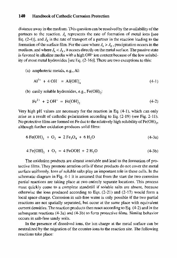
140 Handbook of Cathodic Corrosion Protection
distance away in the medium. This question can be resolved by the availability of thepartners to the reaction. JA represents the rate of formation of metal ions [seeEq. (2-4)], and Jx is the rate of transport of a partner in the reaction leading to theformation of the surface film. For the case where JA > Jx, precipitation occurs in themedium, and where JA < Jx, it occurs directly on the metal surface. The passive stateis favored in alkaline media with a high OH" ion content because of the low solubil-ity of most metal hydroxides [see Eq. (2-16)]. There are two exceptions to this:
(a) amphoteric metals, e.g., Al:
(b) easily soluble hydroxides, e.g., Fe(OH)2:
Very high pH values are necessary for the reaction in Eq. (4-1), which can onlyarise as a result of cathodic polarization according to Eq. (2-19) (see Fig. 2-11).No protective films are formed on Fe due to the relatively high solubility of Fe(OH)2,although further oxidation produces solid films:
The oxidation products are almost insoluble and lead to the formation of pro-tective films. They promote aeration cells if these products do not cover the metalsurface uniformly. Ions of soluble salts play an important role in these cells. In theschematic diagram in Fig. 4-1 it is assumed that from the start the two corrosionpartial reactions are taking place at two entirely separate locations. This processmust quickly come to a complete standstill if soluble salts are absent, becauseotherwise the ions produced according to Eqs. (2-21) and (2-17) would form alocal space charge. Corrosion in salt-free water is only possible if the two partialreactions are not spatially separated, but occur at the same place with equivalentcurrent densities. The reaction products then react according to Eq. (4-2) and in thesubsequent reactions (4-3a) and (4-3b) to form protective films. Similar behavioroccurs in salt-free sandy soils.
In the presence of dissolved ions, the ion charge at the metal surface can beneutralized by the migration of the counter-ions to the reaction site. The followingreactions take place:
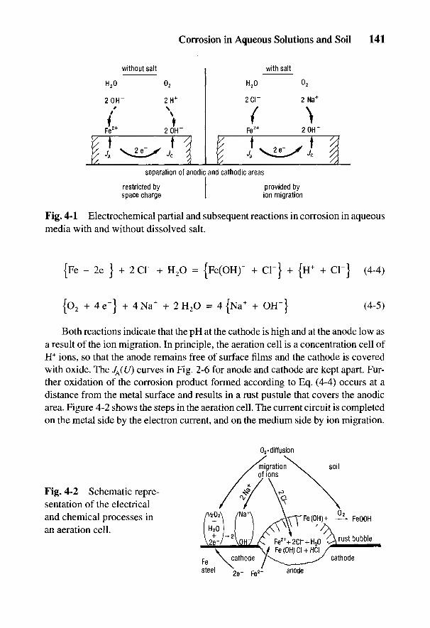
Corrosion in Aqueous Solutions and Soil 141
Fig. 4-1 Electrochemical partial and subsequent reactions in corrosion in aqueousmedia with and without dissolved salt.
Both reactions indicate that the pH at the cathode is high and at the anode low asa result of the ion migration. In principle, the aeration cell is a concentration cell ofH+ ions, so that the anode remains free of surface films and the cathode is coveredwith oxide. The JA(U) curves in Fig. 2-6 for anode and cathode are kept apart. Fur-ther oxidation of the corrosion product formed according to Eq. (4-4) occurs at adistance from the metal surface and results in a rust pustule that covers the anodicarea. Figure 4-2 shows the steps in the aeration cell. The current circuit is completedon the metal side by the electron current, and on the medium side by ion migration.
Fig. 4-2 Schematic repre-sentation of the electricaland chemical processes inan aeration cell.

142 Handbook of Cathodic Corrosion Protection
It is a consequence of the action of different pH values in the aeration cell thatthese cells do not arise in well-buffered media [4] and in fast-flowing waters [5-7].The enforced uniform corrosion leads to the formation of homogeneous surfacefilms in solutions containing O2 [7-9]. This process is encouraged by film-forminginhibitors (HCOg, phosphate, silicate, Ca2+ and A13+) and disrupted by peptizinganions (Cl~, SC>4~) [10]. In pure salt water, no protective films are formed. In thiscase the corrosion rate is determined by oxygen diffusion [6,7,10]
where Kw is the diffusion path in the medium and represents a porous film of cor-rosion product. Kw is about 0.2 mm in fast-flowing solutions and about 1.5 mm infree convection [10]. Such diffusion rates correspond to protection current densi-ties Js of O.I to 1 A rrr2, which have also been measured on moving ships (seeSection 17.1.3).
In soils the constituents restrict diffusion so that Kw in general rises to over5 mm. The removal rate is mostly below 30 /am a"1 [11-13]. The danger of corro-sion in soil is generally local corrosion through cell formation or by anodic influ-ence (see Fig. 2-5) and can lead to removal rates of from a few tenths of a millimeterto several millimeters/year.
4.2 Determining the Corrosion Likelihood of Uncoated Metals
Corrosion likelihood describes the expected corrosion rates or the expectedextent of corrosion effects over a planned useful life [14]. Accurate predictions ofcorrosion rates are not possible, due to the incomplete knowledge of the param-eters of the system and, most of all, to the stochastic nature of local corrosion.Figure 4-3 gives schematic information on the different states of corrosion ofextended objects (e.g., buried pipelines) according to the concepts in Ref. 15. Thearrows represent the current densities of the anode and cathode partial reactions ata particular instant. It must be assumed that two narrowly separated arrows inter-change with each other periodically in such a way that they exist at both fracturelocations for the same amount of time. The result is a continuous corrosion attackalong the surface.
Figure 4-3a indicates the ideal case of a mixed electrode in free corrosion.Such situations do not arise in soils or aqueous media. Usually the attack is locallynonuniform (see Fig. 4-3b) in which the current balance is not equalized at smallregions along the surface. This is a case of free corrosion without extended corro-
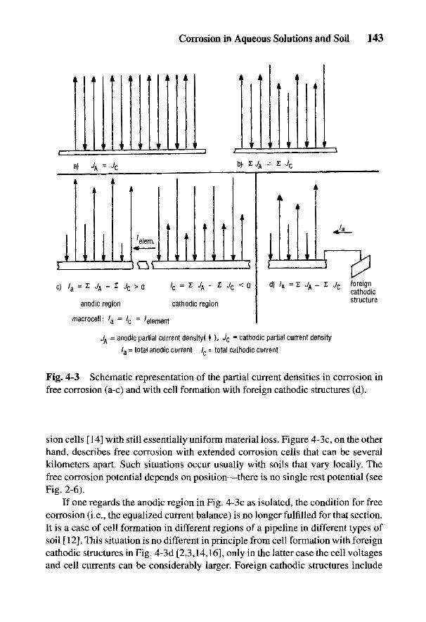
Fig. 4-3 Schematic representation of the partial current densities in corrosion infree corrosion (a-c) and with cell formation with foreign cathodic structures (d).
sion cells [14] with still essentially uniform material loss. Figure 4-3c, on the otherhand, describes free corrosion with extended corrosion cells that can be severalkilometers apart. Such situations occur usually with soils that vary locally. Thefree corrosion potential depends on position—there is no single rest potential (seeFig. 2-6).
If one regards the anodic region in Fig. 4-3c as isolated, the condition for freecorrosion (i.e., the equalized current balance) is no longer fulfilled for that section.It is a case of cell formation in different regions of a pipeline in different types ofsoil [12]. This situation is no different in principle from cell formation with foreigncathodic structures in Fig. 4-3d [2,3,14,16], only in the latter case the cell voltagesand cell currents can be considerably larger. Foreign cathodic structures include
Corrosion in Aqueous Solutions and Soil 143
144 Handbook of Cathodic Corrosion Protection
grounding installations and steel in concrete [17,18]. Mostly pitting and nonuni-form corrosion are associated with cell formation.
4.2.1 Corrosion in Soils
Estimation of corrosion likelihood results from consideration of the character-istics of the soils and of the installed object, which are tabulated in Table 4-1 fornonalloyed and low-alloy steel products. Rating numbers, Z, are given accordingto the data on individual characteristics from which a further judgment can bemade using the sum of the rating numbers.
The sum^Q reflects the corrosion likelihood of objects without extended cells as inFig. 4-3b. This value also characterizes the class of soil, depending on which typeof pipeline coating is selected [16]. The sum Bl shows the corrosion likelihood ofobjects with extended cells as in Fig. 4-3c. This indicates that, in the case of ex-tended objects, the class of soil is by itself not sufficiently informative.
Objects with extended concentration cells can be individual lengths of pipe-line and storage tanks if the makeup of the soil over the surface changes. Thedistance between anodic and cathodic areas can lie between a few centimeters anda few kilometers.
The sum BE can only be obtained with buried objects and provides informationon anodic damage through cell formation as in Fig. 4-3d. More detailed consider-ations can provide information on whether preferential anodic or cathodic regionsare formed and how active they are [3,14].
From Table 4-1 it can be seen that a very high corrosion rate can be recognized(Ib and Ic) from a few characteristics alone, and also that the action of coke can beseen as a well-aerated foreign cathode. Furthermore, it can clearly be seen thatanodic damage can be much reduced (e.g., by laying a pipeline in high-resistancesandy soils, and homogeneous embedding).
A relatively high degree of corrosion arises from microbial reduction of sul-fates in anaerobic soils [20]. Here an anodic partial reaction is stimulated and theformation of electrically conductive iron sulfide deposits also favors the cathodicpartial reaction.
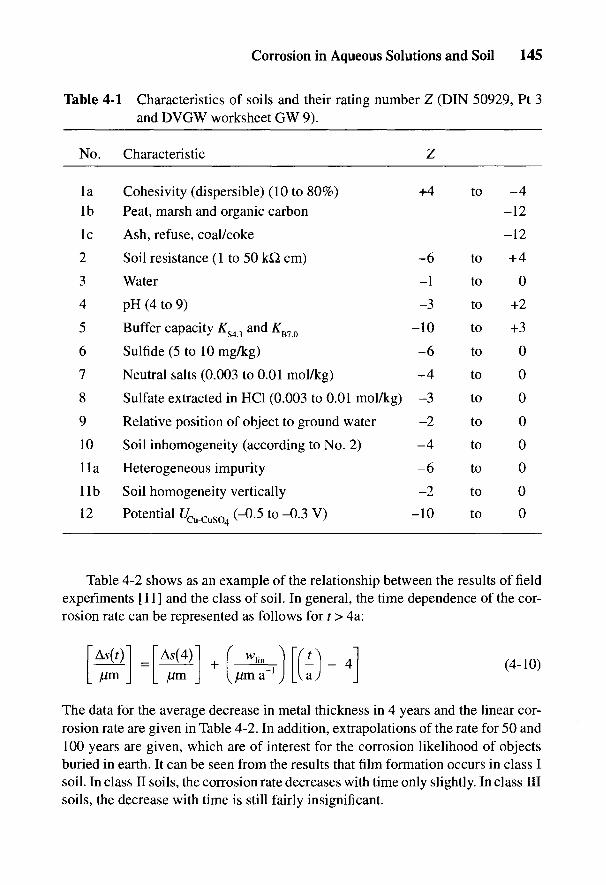
Corrosion in Aqueous Solutions and Soil 145
Table 4-1 Characteristics of soils and their rating number Z (DIN 50929, Pt 3and DVGW worksheet GW 9).
No. Characteristic Z
la Cohesivity (dispersible) (10 to 80%) +4 to -4Ib Peat, marsh and organic carbon -12
Ic Ash, refuse, coal/coke -12
2 Soil resistance (1 to 50 kQ cm) -6 to +4
3 Water -1 to 0
4 pH(4to9) -3 to +2
5 Buffer capacity KS4^ and KB1Q -10 to +3
6 Sulfide (5 to 10 mg/kg) -6 to 0
7 Neutral salts (0.003 to 0.01 mol/kg) -4 to 0
8 Sulfate extracted in HC1 (0.003 to 0.01 mol/kg) -3 to 0
9 Relative position of object to ground water -2 to 0
10 Soil inhomogeneity (according to No. 2) -4 to 0
lla Heterogeneous impurity -6 to 0
lib Soil homogeneity vertically -2 to 0
12 Potential t/Cu_CuS04 (-0.5 to-0.3 V) -10 to 0
Table 4-2 shows as an example of the relationship between the results of fieldexperiments [11] and the class of soil. In general, the time dependence of the cor-rosion rate can be represented as follows for t > 4a:
The data for the average decrease in metal thickness in 4 years and the linear cor-rosion rate are given in Table 4-2. In addition, extrapolations of the rate for 50 and100 years are given, which are of interest for the corrosion likelihood of objectsburied in earth. It can be seen from the results that film formation occurs in class Isoil. In class II soils, the corrosion rate decreases with time only slightly. In class IIIsoils, the decrease with time is still fairly insignificant.

Table 4-2
Evaluation of field tests [11] by class of soil (average ± standard deviation).
£ON
Soil class [14,19] I
II III
Num
ber of soils investigated 21
30 27
Decrease in thickness A
S 94±
37 22 soils:
137±52 12 soils:
268±141
ofor 4 years in Aim
8 soils:
64±36
15 soils: 220±
152 o*""
OL
inear removal rate
6±3.3
16±9.0
55±38
£w
hn after years in jam sr }
8.o
A5
50 in ^m extrapolated
370±189
22 soils: 873±466
12 soils: 2798±1889
g?decrease in m
etal thickness 8 soils:
800±450
15 soils: 2750±1750
ofor 50 years
§2?A
5100 in jjim
extrapolated 670±
354 22
soils: 1673±916
12
soils: 5548±3789
|decrease in m
etal thickness 8 soils:
1536±864 15 soils:
5500±3800 §;
for 100 years P

Corrosion in Aqueous Solutions and Soil 147
Table 4-3 Data on local corrosion from field experiments (after 12 years [11]and 6 years [12]).
Maximum penetration ratevv> in am a~l
t,max ~
Type of soil/reference Class of soil Average Scatter
Free corrosion [11] I 30 15 to 120II 80 20 to 140III 180 80 to 400
Free corrosion [12] I 133II 250III 300
Cell formation [12] 400(sandy soil/clay soil)
S.:S.= 10
The extrapolated values of decrease in thickness for 50 and 100 years inTable 4-2 are relevant in predicting the life of structural components (e.g., buriedfoundations of roads and steel retaining walls). These structural items lose theirfunctional efficiency if their strength is impaired by too great a loss of thickness.
The size of test specimens in field experiments [11] is only a few square deci-meters. In these specimens only micro cells can develop according to Fig. 4-3b.However, the maximum penetration rates in Table 4-3 were greater than expectedfrom the average rate of decrease in thickness. Similar results were obtained fromcell experiments with sand and clay soils [12]. Cell action only takes place if thesurface ratio Sc/Sa is greater than 10 [13, 18]. In sandy soils, the salt content, andtherefore the electrical conductivity, plays a relatively important role [21]. Themaximum penetration rates in Table 4-3 are applicable when estimating the life ofpipelines and storage tanks. These items lose their functional efficiency if theydevelop leaks due to shallow pitting or pitting corrosion.
The data in Table 4-1 show the considerable influence of the electrical resistiv-ity of soil. This is particularly so in categories 2, 7, and 10. From a profile of thesoil resistance along the course of a pipeline with welded connections or with elec-trically conducting thrust couplings, one can readily recognize anodic areas, and
148 Handbook of Cathodic Corrosion Protection
therefore the locations of areas of increased corrosion. They mostly coincide withminima in the resistance between larger regions of higher resistance [22].
The assessment for nonalloyed ferrous materials (e.g., mild steel, cast iron)can also be applied generally to hot-dipped galvanized steel. Surface films of cor-rosion products act favorably in limiting corrosion of the zinc. This stronglyretards the development of anodic areas. Surface film formation can also be as-sessed from the sum of rating numbers [3, 14].
Stainless steels in soil can only be attacked by pitting corrosion if the pittingpotential is exceeded (see Fig. 2-16). Contact with nonalloyed steel affords con-siderable cathodic protection at UH < 0.2 V. Copper materials are also very resis-tant and only suffer corrosion in very acid or polluted soils. Details of the behaviorof these materials can be found in Refs. 3 and 14.
4.2.2 Corrosion in Aqueous Media
Corrosion susceptibility in aqueous media is assessed on the basis of the ratingnumbers [3, 14], which are different from those of soils. An increased likelihood ofcorrosion is in general found only in the splash zone. Particularly severe local corro-sion can occur in tidal regions, due to the intensive cathodic action of rust compo-nents [23, 24]. Since cathodic protection cannot be effective in such areas, the onlypossibility for corrosion protection measures in the splash zone is increased thicknessof protective coatings (see Chapter 16). In contrast to their behavior in soils, hori-zontal cells have practically no significance.
4.3 Enhancement of Anodic Corrosion by Cell Formationor Stray Currents from dc Installations
Anodic enhancement gives rise to high corrosion susceptibility according toFig. 2-5. It is immaterial whether this is the result of cell formation or stray cur-rents. The danger due to contact with foreign cathodic structures must be treatedjust as seriously as the danger from emerging stray currents. Stainless steels, brassand bronze, and reinforcing steel in concrete act as foreign cathodic structures formild and low-alloy steels. The intensity of cell action depends on the aeration ofthe foreign cathodic structures [25-27] and on the surface ratio (i.e., the ratio ofcathodic to anodic surface areas) [18].
Differences in rest potential can be about 0.5 V for cell formation with foreigncathodic structures. The danger increases on coated construction components withcoating defects of decreasing size on account of the surface rule [Eq. (2-44)], andis limited, for a given soil resistivity p = 1/x, not by the grounding resistance of thedefect /?!, but rather by the pore resistance R2 and the polarization resistance of Rp.
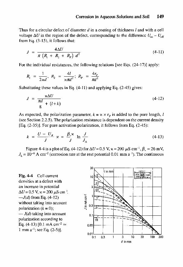
Corrosion in Aqueous Solutions and Soil 149
Thus for a circular defect of diameter d in a coating of thickness / and with a cellvoltage At/ in the region of the defect, corresponding to the difference Uon - Uofi
from Eq. (3-15), it follows that:
For the individual resistances, the following relations [see Eqs. (24-17)] apply:
Substituting these values in Eq. (4-11) and applying Eq. (2-45) gives:
As expected, the polarization parameter, k - K x rp is added to the pore length, /(see Section 2.2.5). The polarization resistance is dependent on the current density[Eq. (2-35)1. For pure activation polarization, it follows from Eq. (2-45):
Figure 4-4 is a plot of Eq. (4-12) for At/= 0.5 V,x = 200 //S cnr1,0+ = 26 mV,J^ = 10~6 A cm"2 (corrosion rate at the rest potential 0.01 mm a"1). The continuous
Fig. 4-4 Cell currentdensities at a defect withan increase in potentialAt/ = 0.5V,x = 200/iScnr1.—J(d) from Eq. (4-12)without taking into accountpolarization (k = 0);— J(d) taking into accountpolarization according toEq. (4-13) [O.lmA cm-2-1 mm a"1; see Eq. (2-5)].
150 Handbook of Cathodic Corrosion Protection
curves are for k = 0 and the dashed curves for k from Eq. (4-13). Constant k valueswhere there is film formation according to Eq. (2-44) can be taken care of by add-ing in the parameter /. In general, the current density increases with cell voltage,conductivity and decreasing defect size. The corrosion rate lies above 1 mm a"1.Cell formation with foreign installations of more positive potential represents agreat corrosion danger, which cannot be countered by passive protective measures.Possible protective measures are galvanic separation [14,16,28] and local cathodicprotection (see Chapter 12).
Stray currents from foreign sources are to be regarded in the same way asgalvanic currents. The explanations for Eq. (4-11) are relevant. Protective mea-sures life 4escribed in Chapters 9 and 15.
A particular type of anodic danger arises in the interiors of pipes and storagetanks that are filled with an electrolyte and consist of similar or different metals,which, however, are electrically separated by insulating units. Potential differencesare produced from external cathodic protection and are active in the interior [29,30].These processes are dealt with in more detail in Sections 10.3.5,20.1.4, and 24.4.6.
A further possibility of anodic danger is attributed to solutions containing O2
acting on coatings with too low a coating resistance. Bitumen coatings and manythin coatings are, or become in the course of time, electrolytically conducting (seeSection 5.2.1.3). A pore-free coated surface of 104 m2 (e.g., a 10-km-long conduct-ing pipeline DN 300) with specific coating resistances ^ 105 Q. m2, has a coatingresistance Ru ^ 10 Q. The cathodic partial reaction can take place on these coatedsurfaces, whereas the anodic reaction is inhibited and only occurs in the region ofdefects. The coated surfaces act as cathodes and can lead to intense pitting corrosion,which has also been observed in saline waters [31-33]. To avoid such danger, thecoating resistances must be sufficiently thick, as, for example, with polyethylenecoatings (see Section 5.2.1) or the cell voltage must be raised by cathodic protection.
4.4 Corrosion Due to ac Interference
The effects of alternating currents are much less of a corrosion danger thanthose of direct currents. Experiments on steel have shown that during the positivehalf wave [34-37] only about 1 % contributes to the dissolution of iron according toEq. (2-21). The remaining 99% is involved in the discharge of capacitances, ofredox systems (e.g., Fe2+/Fe3+ in surface films) or in the evolution of O2 by
From the data in Table 2-1 this results in a corrosion rate for Fe of 0.1 mm a"1 foran effective ac current density of 20 A m"2. Thus only ac current densities above
Corrosion in Aqueous Solutions and Soil 151
50 A m~2 are serious. Frequency has an effect which, however, in the region 162/3 to60 Hz is small. Generally the danger increases with falling frequency [34].
Even with the superposition of the ac with a cathodic protection current, alarge part of the anodic half wave persists for anodic corrosion. This process can-not be detected by the normal method (Section 3.3.2.1) of measuring the pipe/soilpotential. The 7/?-free measurable voltage between an external probe and the refer-ence electrode can be used as evidence of more positive potentials than the protec-tion potential during the anodic phase. Investigations have shown, however, thatthe corrosion danger is considerably reduced, since only about 0.1 to 0.2% con-tributes to corrosion.
The action of effects in the environment and cathodic current densities on accorrosion requires even more careful investigation. It is important to recognizethat ac current densities above 50 A nr2 can lead to damage even when the dcpotential is formally fulfilling the protection criterion [40].
Low-frequency potential deviations have to be taken into account with increasedcorrosion rate if the protection criterion according to Eq. (2-39) occasionally lapses.It is insufficient if only the average value of the potential over time remains morenegative than the protection potential [38].
With metals other than Fe, the percent of the ac current leading to corrosioncan be considerably different. Cu and Pb behave similarly to Fe [36], whereas Al[36] and Mg [39] corrode much more severely. This has to be watched with sacri-ficial anodes of these materials if they are subjected to ac.

152 Handbook of Cathodic Corrosion Protection
4.5 References
[1] W. Schwenk, 3R international 18, 524 (1979).[2] W. Schwenk, gwf gas/erdgas 123, 158 (1982).[3] W. Schwenk, gwf gas/erdgas 127, 304 (1986).[4] V. V. Skorchelletti u. N. K. Golubeva, Corrosion Sci. 5, 203 (1965).[5] H. Kaesche, Werkstoffe u. Korrosion 26, 175 (1975).[6] W. Schwenk, Werkstoffe u. Korrosion 30, 34 (1979).[7] A. Rahmel u. W. Schwenk, Korrosion und Korrosionsschutz von Stahlen, Verlag Chemie,
Weinheim-New York 1977.[8] K. Bohnenkamp, Arch. Eisenhiittenwes. 47, 253, 751 (1976).[9] DIN 50930 Teil 2, Beuth-Verlag, Berlin 1980.
[10] H. Kaesche, Die Korrosion der Metalle, Springer-Verlag, Berlin-Heidelberg-New York1966, 1979.
[11] M. Romanoff, Underground Corrosion, Nat. Bur. of Stand., Circ. 579, 1957, US Dep.Comm.
[12] H. Hildebrand u. W. Schwenk, Werkstoffe u. Korrosion 29, 92 (1978).[13] H. Hildebrand, C.-L. Kruse u. W. Schwenk, Werkstoffe u. Korrosion 38, 696 (1987).[14] DIN 50929 Teile 1 bis 3, Beuth-Verlag, Berlin 1985; Kommentar zu DIN 50929 in ,,Kor-
rosionsschutz durch Information und Normung", Hrsg. W. Fischer, Verlag I. Kuron,Bonn 1988.
[15] DIN 50900 Teil 2, Beuth-Verlag, Berlin 1984.[16] DIN 30675 Teil 1, Beuth-Verlag, Berlin 1985.[17] W. Schwenk, gwf gas/erdgas 103, -546 (1972).[18] G. Heim, Elektrizitatswirtschaft 81, 875 (1982).[19] DVGW Arbeitsblatt GW 9, ZfGW-Verlag, Frankfurt 1986.[20] H. Klas u. H. Steinrath, Die Korrosion des Eisens und ihre Verhiitung, Verlag Stahleisen,
2. Auflage, Dusseldorf 1974, S. 206.[21] D. Funk, H. Hildebrand, W. Prinz u. W. Schwenk, Werkstoffe u. Korrosion 38, 719
(1987).[22] H. Klas u. G. Heim, gwf 98, 1104, 1149 (1957).[23] M. Stratmann, K. Bohnenkamp u. H.-J. Engell, Werkstoffe u. Korrosion 34, 605 (1983).[24] W. Schwenk, Stahl u. Eisen 104, 1237 (1984).[25] H. Arup, Mat. Perform. 18, H. 4, 41 (1979).[26] H. J. Abel und C.-L. Kruse, Werkstoffe u. Korrosion 33, 89 (1982).[27] H. Hildebrand u. W. Schwenk, Werkstoffe u. Korrosion 37, 163 (1986).[28] DVGW Arbeitsblatt G 600 (TRGI), ZfGW-Verlag, Frankfurt 1986.
[29] FKK, 3R international 24, 82 (1985).[30] DIN 50927, Beuth-Verlag, Berlin 1985.[31] H. Hildebrand u. W. Schwenk, Werkstoffe u. Korrosion 30, 542 (1979).[32] DIN 50928, Beuth-Verlag, Berlin 1985.[33] W. Schwenk, farbe + lack 90, 350 (1985).[34] W. Fuchs, H. Steinrath u. H. Ternes, gwf gas/erdgas 99, 78 (1958).[35] F. A. Waters, Mat. Perform. /, H. 3, 26 (1962).[36] J. F. Williams, Mat. Perform. 5, H. 2, 52 (1966).[37] S. R. Pookote u. D. T. Chin, Mat. Perform. 17, H. 3, 9 (1978).[38] G. Heim, 3R international 21, 386 (1982).[39] G. Kraft u. D. Funk, Werkstoffe u. Korrosion 29, 265 (1978).[40] G. Heim u. G. Peez, 3R international 27, 345 (1988).

Coatings for Corrosion ProtectionG. HEIM AND W. SCHWENK
5.1 Objectives and Types of Corrosion Protection by Coatings
Corrosion protection measures are divided into active and passive processes.Electrochemical corrosion protection plays an active part in the corrosion processby changing the potential. Coatings on the object to be protected keep the aggres-sive medium at a distance. Both protection measures are theoretically applicableon their own. However, a combination of both is requisite and beneficial for thefollowing reasons:
• Coatings free of defects cannot be reliably produced, installed and main-tained perfectly in operation. Without electrochemical corrosion protec-tion, there is increased danger of corrosion if the coating is damaged (seeSection 4.3). To test for damage or defects under operating conditions, avoltage is applied and the current flow measured (drainage test). This is thesame electrical circuit that is used in cathodic protection. Thus, a combina-tion of both processes is indicated.
• Without a coating, electrochemical corrosion protection is used if the pro-tection criteria can be fulfilled with sufficiently good current distribution.Usually this can be achieved with extended objects only if the polarizationparameter can be considerably increased by a coating (see Eq. 2-45). Inaddition, the current supply needed can be drastically reduced by a coat-ing, which leads to a considerable reduction in the costs of installation andoperation. A decisive advantage of smaller protection currents is a reduc-tion in the interference of foreign installations for which the protectioncurrent is to be regarded as a stray current (see Chapters 9 and 15).
Coatings applied for corrosion protection are divided into organic coatings,cement mortar, and enamel and metallic coatings.
5.1.1 Organic Coatings
Organic coatings applied primarily to protect pipelines and storage tanksinclude paints, plastics and bituminous materials. According to Ref. 1 these can be
153
5

154 Handbook of Cathodic Corrosion Protection
further divided into thin and thick coatings. The latter are those with a thicknessover 1 mm.
Thin coatings consist of paints and varnishes, which are applied as liquids orpowdered resin with a thickness of about 0.5 mm [e.g., epoxy resin (EP) [2]]. Typicalthick coatings are bituminous materials [3] and polyolefins [e.g., polyethylene (PE)[4]], thick coating resin combinations [e.g., EP tar and polyurethane (PUR) tar [2]]as well as heat-shrinkable sleeves and tape systems [5].
Thin coatings contain in general many polar groups that promote adhesion.Low polar or nonpolar thick coatings (e.g., PE) are usually combined with polaradhesives to achieve the necessary bond strength against peeling.
All organic coatings show varying degrees of solubility and permeability forcomponents of the corrosive medium, which can be described as permeation andionic conductivity (see Sections 5.2.1 and 5.2.2). An absolute separation of pro-tected object and medium is not possible because of these properties. Certainrequirements have to be met for corrosion protection, which must also takeaccount of electrochemical factors [1] (see Section 5.2).
5.1.2 Cement Mortar Coatings
Cement coatings are usually applied as linings for water pipes and water tanks,but occasionally also for external protection of pipelines [7]. Cement is not imper-vious to water, so electrochemical reactions can take place on the surface of theobject to be protected. Because of the similar processes occurring at the interfaceof cement and object and reinforcing steel and concrete, data on the system iron/cement mortar are dealt with in this chapter taking into account the action of elec-trolytes with and without electrochemical polarization. To ensure corrosion pro-tection, certain requirements must be met (see Section 5.3 and Chapter 19).
5.1.3 Enamel Coatings
Enamel coatings are applied for internal protection of storage tanks (see Sec-tion 20.4.1). Enamel is impervious to water, i.e., it separates the protected objectand corrosive medium. Corrosion protection can fail only at defects in the enamelcoating and through corrosion of the enamel (see Section 5.4).
5.1.4 Metallic Coatings
Metal coatings are applied in special cases where the protective action has tobe ensured by the coating metal or its corrosion products. Additional electrochemi-

Coatings for Corrosion Protection 155
cal protection can be significant if the coating metal also has the advantage ofproviding electrochemical protection (see Section 5.5).
5.2 Properties of Organic Coatings
The following requirements must be met for long-term corrosion protection:
(a) high mechanical resistance and adhesion, especially during transport andinstallation;
(b) chemical stability under service conditions (aging);(c) sufficiently low permeability for corrosive components under service
conditions;(d) sufficient stability under electrochemical influences, especially with elec-
trochemical protection measures.
The requirements (a) to (c) are obligatory for all types of coating and all objects tobe protected; for example, they are well known in the protection of steel structures.The objects discussed in this handbook are continuously in contact with electro-lytes. For this reason in addition, requirement (d) is of great importance and isdiscussed in detail below.
5.2.1 Electrical and Electrochemical Properties
5.2.1.1 Review of the Types of Reactions
Figure 5-1 shows schematically the processes that can take place on coated metalsin electrolytes. The following properties are important:
Fig. 5-1 Over-view of reactionson coated steel.
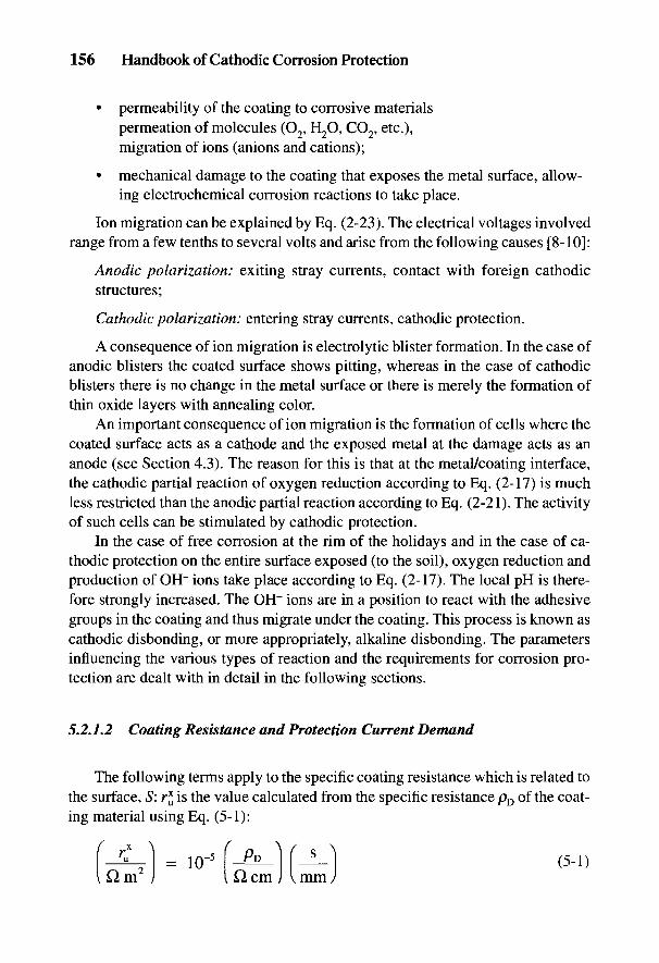
156 Handbook of Cathodic Corrosion Protection
• permeability of the coating to corrosive materialspermeation of molecules (O2, H2O, CO2, etc.),migration of ions (anions and cations);
• mechanical damage to the coating that exposes the metal surface, allow-ing electrochemical corrosion reactions to take place.
Ion migration can be explained by Eq. (2-23). The electrical voltages involvedrange from a few tenths to several volts and arise from the following causes [8-10]:
Anodic polarization: exiting stray currents, contact with foreign cathodicstructures;
Cathodic polarization: entering stray currents, cathodic protection.
A consequence of ion migration is electrolytic blister formation. In the case ofanodic blisters the coated surface shows pitting, whereas in the case of cathodicblisters there is no change in the metal surface or there is merely the formation ofthin oxide layers with annealing color.
An important consequence of ion migration is the formation of cells where thecoated surface acts as a cathode and the exposed metal at the damage acts as ananode (see Section 4.3). The reason for this is that at the metal/coating interface,the cathodic partial reaction of oxygen reduction according to Eq. (2-17) is muchless restricted than the anodic partial reaction according to Eq. (2-21). The activityof such cells can be stimulated by cathodic protection.
In the case of free corrosion at the rim of the holidays and in the case of ca-thodic protection on the entire surface exposed (to the soil), oxygen reduction andproduction of OH~ ions take place according to Eq. (2-17). The local pH is there-fore strongly increased. The OH" ions are in a position to react with the adhesivegroups in the coating and thus migrate under the coating. This process is known ascathodic disbonding, or more appropriately, alkaline disbonding. The parametersinfluencing the various types of reaction and the requirements for corrosion pro-tection are dealt with in detail in the following sections.
5.2.1.2 Coating Resistance and Protection Current Demand
The following terms apply to the specific coating resistance which is related tothe surface, S: r* is the value calculated from the specific resistance pD of the coat-ing material using Eq. (5-1):
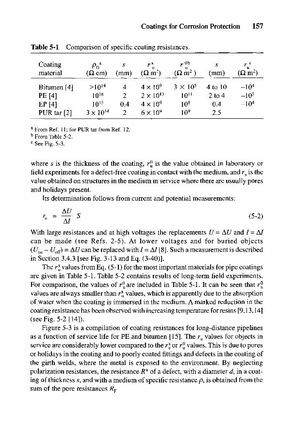
Coatings for Corrosion Protection 157
Table 5-1 Comparison of specific coating resistances.
Coating p* s rx r°b s rcG ' D u u u
material (Q, cm) (mm) (Q m2) (Q m2) (mm) (Q m2)
Bitumen [4] >1014 4 4x l0 9 3 X 10⁵ 4 to 10 -104
PE[4] 1018 2 2x l0 1 3 1011 2 to 4 -105
EP[4] 1015 0.4 4 x l 0 9 108 0.4 -104
PUR tar [2] 3 x 10¹⁴ 2 6x l0 9 109 2.5
a From Ref. 11; for PUR tar from Ref. 12.b From Table 5-2.c See Fig. 5-3.
where s is the thickness of the coating, r° is the value obtained in laboratory orfield experiments for a defect-free coating in contact with the medium, and ru is thevalue obtained on structures in the medium in service where there are usually poresand holidays present.
Its determination follows from current and potential measurements:
With large resistances and at high voltages the replacements U = At/ and / = A/can be made (see Refs. 2-5). At lower voltages and for buried objects(Uon - t/off) = At/ can be replaced with / = A/ [8]. Such a measurement is describedin Section 3.4.3 [see Fig. 3-13 and Eq. (3-40)].
The r* values from Eq. (5-1) for the most important materials for pipe coatingsare given in Table 5-1. Table 5-2 contains results of long-term field experiments.For comparison, the values of r^are included in Table 5-1. It can be seen that r°values are always smaller than r* values, which is apparently due to the absorptionof water when the coating is immersed in the medium. A marked reduction in thecoating resistance has been observed with increasing temperature for resins [9,13,14](see Fig. 5-2 [14]).
Figure 5-3 is a compilation of coating resistances for long-distance pipelinesas a function of service life for PE and bitumen [15]. The ru values for objects inservice are considerably lower compared to the T* or r° values. This is due to poresor holidays in the coating and to poorly coated fittings and defects in the coating ofthe girth welds, where the metal is exposed to the environment. By neglectingpolarization resistances, the resistance 7?x of a defect, with a diameter d, in a coat-ing of thickness s, and with a medium of specific resistance p, is obtained from thesum of the pore resistances RF
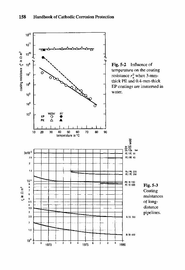
158 Handbook of Cathodic Corrosion Protection
Fig. 5-2 Influence oftemperature on the coatingresistance r^ when 3-mm-thick PE and 0.4-mm-thickEP coatings are immersed inwater.
Fig. 5-3Coatingresistancesof long-distancepipelines.
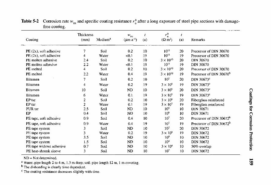
Table 5-2 Corrosion rate wint and specific coating resistance r: after a long exposure of steel pipe sections with damage- free coating.
Coating
PE (2x), soft adhesive PE (2x), soft adhesive PE molten adhesive PE molten adhesive PE melted PE melted Bitumen Bitumen Bitumen Bitumen EP tar EP tar PUR tar EP PE tape, soft adhesive PE tape, soft adhesive PE tape system PE tape system PE tape system PE tape system PE tape without adhesive PE heat-shrunk sleeve
7 4 2.4 2.2 4 2.2 7 4
10 6 2 2 2.5 0.4 0.9 0.9 3 3 3.5 1.5 0.7 3
Soil Water Soil
Water Soil
Water Soil
Water Soil
Water Soil
Water Soil Soil Soil
Water Soil
Water Soil Soil Soil Soil
0.2 10 <o. 1 19
0.2 10 <o. 1 19
0.2 10 0.4 19 0.2 10 0.2 19 ND 10 0.1 19 0.2 10 0.1 19 ND 10 ND 10 0.4 10 0.4 19 ND 10 0.2 19 ND 10 ND 10 ND 10 ND 10
10" 10"
3 x 10'0 10"
3 x 10'0 3 x 10'0
105 3 x 10⁵ 3 x 10⁵ 3 x 10⁵
3 x 10⁷ 109
107 107 107
3 x 10⁹ 109
3~ 104
107
3 x 10⁶
108
108
20 19 20 19 20 19 20 19 20 19 20 19 10 10 20 19 20 19 10 10 10 10
Precursor of DIN 30670 Precursor of DIN 30670 DIN 30670 DIN 30670 Precursor of DIN 30670 Precursor of DIN 30670b DIN 30673' DIN 30673' DIN 30673' DIN 30673' Fiberglass reinforced Fiberglass reinforced DIN 3067 1 DIN 30671 Precursor of DIN 30672b Precursor of DIN 30672b DIN 30672 DIN 30672 DIN 30672 DIN 30672 50% overlap DIN 30672
ND = Not determined.
The disbonding is clearly time dependent. The coating resistance decreases slightly with time.
a Water: pipe length 2 to 4 m, 1.3 m deep; soil: pipe length 12 m, 1 m covering.
Thickness t r : t (mm) Mediuma ( P a-'1 (a) (SZ m2) (a) Remarks
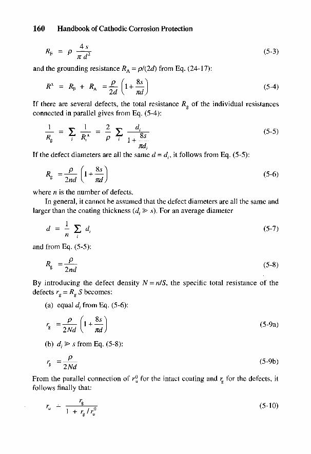
160 Handbook of Cathodic Corrosion Protection
and the grounding resistance RA - p/(2d) from Eq. (24-17):
z,c-t \ /it* /
If there are several defects, the total resistance Rg of the individual resistancesconnected in parallel gives from Eq. (5-4):
/CC* .•
If the defect diameters are all the same d - d(, it follows from Eq. (5-5):
where n is the number of defects.In general, it cannot be assumed that the defect diameters are all the same and
larger than the coating thickness (dt > s). For an average diameter
and from Eq. (5-5):
By introducing the defect density N = n/S, the specific total resistance of thedefects rg = Rg S becomes:
(a) equal d{ from Eq. (5-6):
From the parallel connection of r° for the intact coating and r for the defects, itfollows finally that:
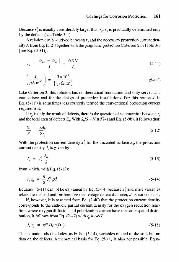
Coatings for Corrosion Protection 161
Because r° is usually considerably larger than rg, ru is practically determined onlyby the defects (see Table 5-1).
A relation can be derived between ru and the necessary protection current den-sity Js from Eq. (5-2) together with the pragmatic protection Criterion 2 in Table 3-3[see Eq. (3-31)]:
Like Criterion 2, this relation has no theoretical foundation and only serves as acomparison and for the design of protection installations. For this reason Js inEq. (5-11') is sometimes less correctly termed the conventional protection currentrequirement.
If rg is only the result of defects, there is the question of a connection between rg
and the total area of defects 50. With SJS = N(nd2/4) and Eq. (5-9b), it follows that:
With the protection current density J°s for the uncoated surface S0, the protectioncurrent density Js is given by
o
from which, with Eq. (5-12):
Equation (5-11) cannot be explained by Eq. (5-14) because J°s and p are variablesrelated to the soil and furthermore the average defect diameter, d, is not constant.
If, however, it is assumed from Eq. (2-40) that the protection current densitycorresponds to the cathodic partial current density for the oxygen reduction reac-tion, where oxygen diffusion and polarization current have the same spatial distri-bution, it follows from Eq. (2-47) with rg = A0/7:
This equation also includes, as in Eq. (5-14), variables related to the soil, but nodata on the defects. A theoretical basis for Eq. (5-11) is also not possible. Equa-
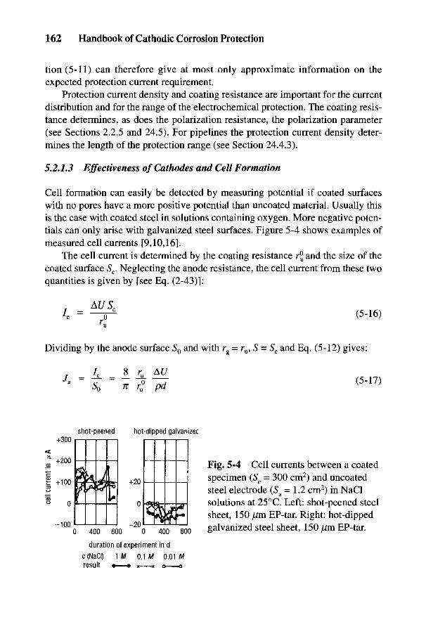
162 Handbook of Cathodic Corrosion Protection
tion (5-11) can therefore give at most only approximate information on theexpected protection current requirement.
Protection current density and coating resistance are important for the currentdistribution and for the range of the electrochemical protection. The coating resis-tance determines, as does the polarization resistance, the polarization parameter(see Sections 2.2.5 and 24.5). For pipelines the protection current density deter-mines the length of the protection range (see Section 24.4.3).
5.2.1.3 Effectiveness of Cathodes and Cell Formation
Cell formation can easily be detected by measuring potential if coated surfaceswith no pores have a more positive potential than uncoated material. Usually thisis the case with coated steel in solutions containing oxygen. More negative poten-tials can only arise with galvanized steel surfaces. Figure 5-4 shows examples ofmeasured cell currents [9,10,16].
The cell current is determined by the coating resistance rjj and the size of thecoated surface Sc. Neglecting the anode resistance, the cell current from these twoquantities is given by [see Eq. (2-43)]:
Dividing by the anode surface 50 and with rg = ru, S = 5C and Eq. (5-12) gives:
Fig. 5-4 Cell currents between a coatedspecimen (Sc = 300 cm2) and uncoatedsteel electrode (5a = 1.2 cm2) in NaClsolutions at 25°C. Left: shot-peened steelsheet, 150 /mi EP-tar. Right: hot-dippedgalvanized steel sheet, 150 /im EP-tar.
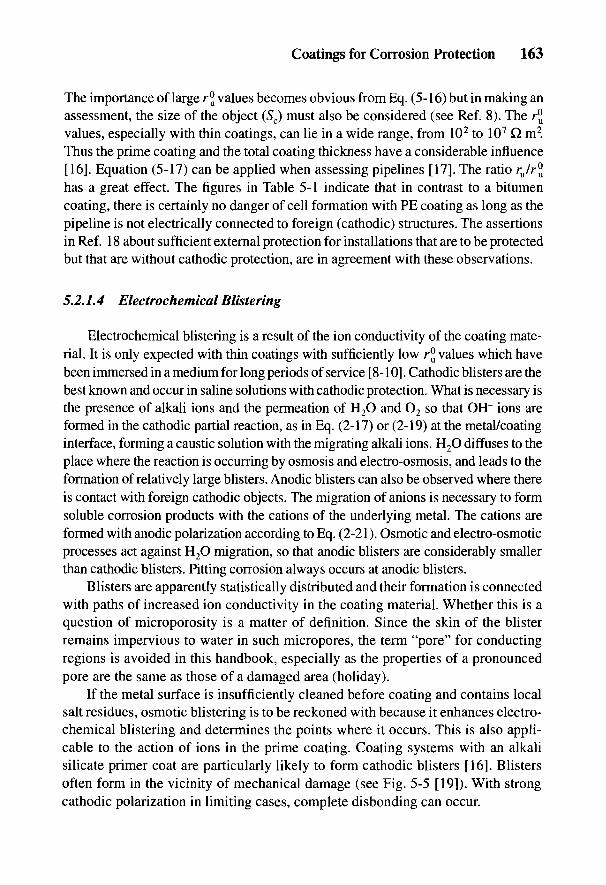
Coatings for Corrosion Protection 163
The importance of large r° values becomes obvious from Eq. (5-16) but in making anassessment, the size of the object (Sc) must also be considered (see Ref. 8). The r^values, especially with thin coatings, can lie in a wide range, from 102 to 107 Q. m2.Thus the prime coating and the total coating thickness have a considerable influence[16]. Equation (5-17) can be applied when assessing pipelines [17]. The ratio ru/r°has a great effect. The figures in Table 5-1 indicate that in contrast to a bitumencoating, there is certainly no danger of cell formation with PE coating as long as thepipeline is not electrically connected to foreign (cathodic) structures. The assertionsin Ref. 18 about sufficient external protection for installations that are to be protectedbut that are without cathodic protection, are in agreement with these observations.
5.2.1.4 Electrochemical Blistering
Electrochemical blistering is a result of the ion conductivity of the coating mate-rial. It is only expected with thin coatings with sufficiently low r® values which havebeen immersed in a medium for long periods of service [8-10]. Cathodic blisters are thebest known and occur in saline solutions with cathodic protection. What is necessary isthe presence of alkali ions and the permeation of H2O and O2 so that OH" ions areformed in the cathodic partial reaction, as in Eq. (2-17) or (2-19) at the metal/coatinginterface, forming a caustic solution with the migrating alkali ions. H2O diffuses to theplace where the reaction is occurring by osmosis and electro-osmosis, and leads to theformation of relatively large blisters. Anodic blisters can also be observed where thereis contact with foreign cathodic objects. The migration of anions is necessary to formsoluble corrosion products with the cations of the underlying metal. The cations areformed with anodic polarization according to Eq. (2-21). Osmotic and electro-osmoticprocesses act against H2O migration, so that anodic blisters are considerably smallerthan cathodic blisters. Pitting corrosion always occurs at anodic blisters.
Blisters are apparently statistically distributed and their formation is connectedwith paths of increased ion conductivity in the coating material. Whether this is aquestion of microporosity is a matter of definition. Since the skin of the blisterremains impervious to water in such micropores, the term "pore" for conductingregions is avoided in this handbook, especially as the properties of a pronouncedpore are the same as those of a damaged area (holiday).
If the metal surface is insufficiently cleaned before coating and contains localsalt residues, osmotic blistering is to be reckoned with because it enhances electro-chemical blistering and determines the points where it occurs. This is also appli-cable to the action of ions in the prime coating. Coating systems with an alkalisilicate primer coat are particularly likely to form cathodic blisters [16]. Blistersoften form in the vicinity of mechanical damage (see Fig. 5-5 [19]). With strongcathodic polarization in limiting cases, complete disbonding can occur.

164 Handbook of Cathodic Corrosion Protection
Fig. 5-5 Cathodic blisters in thevicinity of a scratched cross; steel pipewith 70 ]Jm Zn-epoxy resin +300 ]nmEP-tar, seawater; f/Cu.CuS04 = -1.1 to -1.2V, 220 days, 20°C.
There are numerous publications [9,10,16,19-24] and test specifications [8,25]on the formation of cathodic blisters. They are particularly relevant to ships,marine structures and the internal protection of storage tanks. Blister attack in-creases with rising cathodic polarization. Figures 5-6 and 5-7 show the potentialdependence of blister density and the NaOH concentration of blister fluid, where itis assumed that c(Na+) and c(NaOH) are equal due to the low value of c(Cl~) [23].
The blister population-potential curves can intersect one another. Thus short-term experiments at very negative potentials, in the region of cathodic overprotec-tion, give no information on the behavior at potentials in the normal protectionrange. The susceptibility generally increases strongly with overprotection(f/H<-0.83V).
Compared with cathodic blisters, which can be recognized by their alkali con-tent, anodic blisters can be easily overlooked. Intact blisters can be recognized bythe slightly lower pH value of the hydrolyzed corrosion product. The pitted surfaceat a damaged blister cannot be distinguished from that formed at pores.
In general the population of cathodic blisters increases with cathodic polariza-tion and the population of anodic blisters with anodic polarization. Both types of
Fig. 5-6 Relation between the density ofcathodic blisters and potential; shot-peenedsteel sheet without primer (•) and with about40 /mi primer coat (Zn ethyl silicate + poly-vinyl butyral) (•); top coat: 500 /am EP-tar;0.5 M NaCl, 770 days at 25°C.
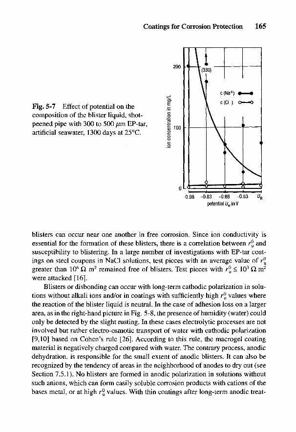
Coatings for Corrosion Protection 165
Fig. 5-7 Effect of potential on thecomposition of the blister liquid, shot-peened pipe with 300 to 500 jUm EP-tar,artificial seawater, 1300 days at 25°C.
blisters can occur near one another in free corrosion. Since ion conductivity isessential for the formation of these blisters, there is a correlation between r°u andsusceptibility to blistering. In a large number of investigations with EP-tar coat-ings on steel coupons in NaCl solutions, test pieces with an average value of rJJgreater than 106 Q m2 remained free of blisters. Test pieces with r°u < 103 Q m2
were attacked [16].Blisters or disbonding can occur with long-term cathodic polarization in solu-
tions without alkali ions and/or in coatings with sufficiently high rJ values wherethe reaction of the blister liquid is neutral. In the case of adhesion loss on a largerarea, as in the right-hand picture in Fig. 5-8, the presence of humidity (water) couldonly be detected by the slight rusting. In these cases electrolytic processes are notinvolved but rather electro-osmotic transport of water with cathodic polarization[9,10] based on Cohen's rule [26]. According to this rule, the macrogel coatingmaterial is negatively charged compared with water. The contrary process, anodicdehydration, is responsible for the small extent of anodic blisters. It can also berecognized by the tendency of areas in the neighborhood of anodes to dry out (seeSection 7.5.1). No blisters are formed in anodic polarization in solutions withoutsuch anions, which can form easily soluble corrosion products with cations of thebases metal, or at high rj values. With thin coatings after long-term anodic treat-
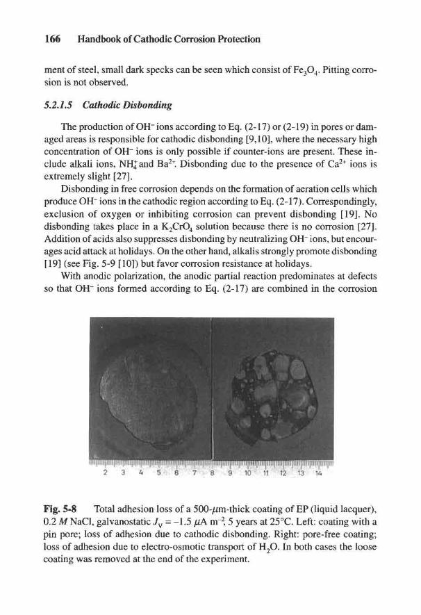
166 Handbook of Cathodic Corrosion Protection
ment of steel, small dark specks can be seen which consist of Fe3O4. Pitting corro-sion is not observed.
5.2.7.5 Cathodic Disbanding
The production of OH~ ions according to Eq. (2-17) or (2-19) in pores or dam-aged areas is responsible for cathodic disbonding [9,10], where the necessary highconcentration of OH" ions is only possible if counter-ions are present. These in-clude alkali ions, NHJ and Ba2+. Disbonding due to the presence of Ca2+ ions isextremely slight [27].
Disbonding in free corrosion depends on the formation of aeration cells whichproduce OH~ ions in the cathodic region according to Eq. (2-17). Correspondingly,exclusion of oxygen or inhibiting corrosion can prevent disbonding [19]. Nodisbonding takes place in a K2CrO4 solution because there is no corrosion [27].Addition of acids also suppresses disbonding by neutralizing OH" ions, but encour-ages acid attack at holidays. On the other hand, alkalis strongly promote disbonding[19] (see Fig. 5-9 [10]) but favor corrosion resistance at holidays.
With anodic polarization, the anodic partial reaction predominates at defectsso that OH~ ions formed according to Eq. (2-17) are combined in the corrosion
Fig. 5-8 Total adhesion loss of a 500-/im-thick coating of EP (liquid lacquer),0.2 M NaCl, galvanostatic Jv = -1.5 ^A m~2, 5 years at 25°C. Left: coating with apin pore; loss of adhesion due to cathodic disbonding. Right: pore-free coating;loss of adhesion due to electro-osmotic transport of H2O. In both cases the loosecoating was removed at the end of the experiment.
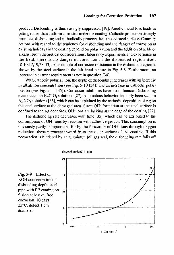
Coatings for Corrosion Protection 167
product. Disbonding is thus strongly suppressed [19]. Anodic metal loss leads topitting rather than uniform corrosion under the coating. Cathodic protection stronglypromotes disbonding and cathodically protects the exposed steel surface. Contraryactions with regard to the tendency for disbonding and the danger of corrosion atexisting holidays in the coating depend on polarization and the addition of acids oralkalis. From theoretical considerations, laboratory experiments and experience inthe field, there is no danger of corrosion in the disbonded region itself[8-10,17,19,28-33]. An example of corrosion resistance in the disbonded region isshown by the steel surface in the left-hand picture in Fig. 5-8. Furthermore, anincrease in current requirement is not in question [34].
With cathodic polarization, the depth of disbonding increases with an increasein alkali ion concentration (see Fig. 5-10 [34]) and an increase in cathodic polar-ization (see Fig. 5-11 [35]). Corrosion inhibitors have no influence. Disbondingeven occurs in K2CrO4 solutions [27]. Anomalous behavior has only been seen inAgNO3 solutions [36], which can be explained by the cathodic deposition of Ag onthe steel surface at the damaged area. Since OH" formation at the steel surface isconfined to the Ag dendrites, OH" ions are lacking at the edge of the coating [27].
The disbonding rate decreases with time [35], which can be attributed to theconsumption of OH" ions by reaction with adhesive groups. This consumption isobviously partly compensated for by the formation of OH" ions through oxygenreduction; these permeate inward from the outer surface of the coating. If thispermeation is hindered by an aluminum foil gas seal, the disbonding rate falls off
Fig. 5-9 Effect ofKOH concentration ondisbonding depth; steelpipe with PE coating onfusion adhesive, freecorrosion, 10 days,25°C, defect 1 cmdiameter.
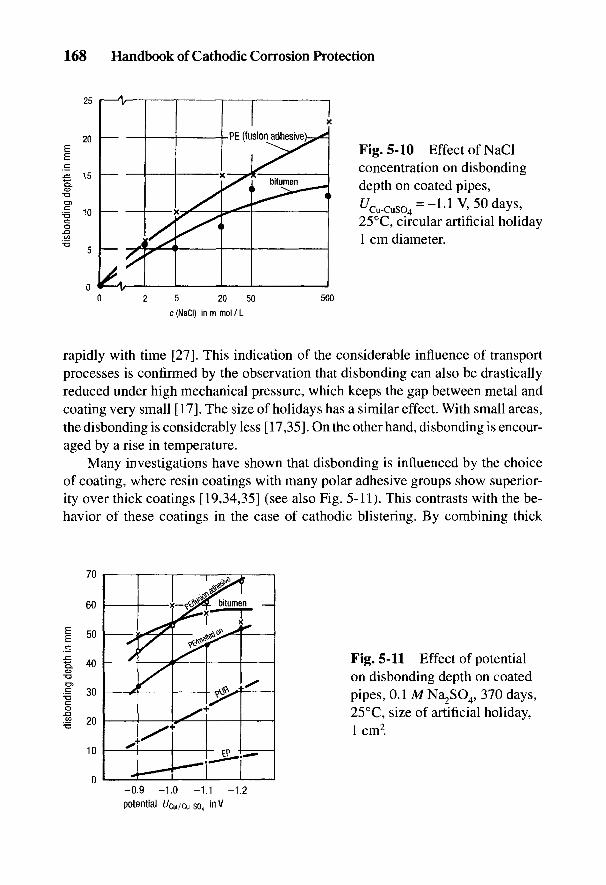
168 Handbook of Cathodic Corrosion Protection
Fig. 5-10 Effect of NaClconcentration on disbondingdepth on coated pipes,£Wso4 = -l-lV,50days,25°C, circular artificial holiday1 cm diameter.
rapidly with time [27]. This indication of the considerable influence of transportprocesses is confirmed by the observation that disbonding can also be drasticallyreduced under high mechanical pressure, which keeps the gap between metal andcoating very small [17]. The size of holidays has a similar effect. With small areas,the disbonding is considerably less [17,35]. On the other hand, disbonding is encour-aged by a rise in temperature.
Many investigations have shown that disbonding is influenced by the choiceof coating, where resin coatings with many polar adhesive groups show superior-ity over thick coatings [19,34,35] (see also Fig. 5-11). This contrasts with the be-havior of these coatings in the case of cathodic blistering. By combining thick
Fig. 5-11 Effect of potentialon disbonding depth on coatedpipes, 0.1 M Na2SO4, 370 days,25°C, size of artificial holiday,1 cm2.

Coatings for Corrosion Protection 169
coatings with polar adhesives, the difference between thin EP coatings and thickPE coatings in resistance to disbonding can be eliminated [14].
5.2.2 Physicochemical Properties
The properties of coatings must remain constant under service conditions forlong-term corrosion protection. The coating materials must be absolutely stableagainst the corrosive environment. Material standards [2-5] provide the necessaryrequirements for chemical and aging stability against heat and UV irradiation [37].With the relatively thin corrosion-protection coatings used for construction steel,the protective action is derived from pigments in the prime coat that inhibit corro-sion. In the course of time, this action can be lost due to reaction with corrosivecomponents. Coatings dealt with in this chapter that are constantly exposed toelectrolytes have a different protection principle which is based on greater thick-ness and as low a permeation rate of corrosive agents as possible. Thus, even whenthe metal under the coating is no longer inhibited or passive, protection is stillmaintained if the corrosion rate stays sufficiently low in areas of low adhesion.
All organic coatings can dissolve O2 and H2O and allow them to penetrate. Thefollowing corrosion reaction can take place on an active steel surface under a coating:
which on aging of the FeOOH allows the separation of H2O, so that finally thecontinuation of the corrosion is solely determined by the permeation of O2. Thisneglects corrosion by H2O with the action of H2 according to Eq. (2-19). Theequation for O2 permeation is:
where P = permeation coefficient (see Table 5-3); A/? = difference in oxygenpressure, which is equal to the partial pressure in the ambient air of 0.2 bar; ands = thickness of the coating. From Eqs. (2-5) and (2-20) it follows that
and including the data in Tables 2-1 and 2-3 in Eq. (5-19) gives:

170 Handbook of Cathodic Corrosion Protection
Table 5-3 Permeation coefficients and rate of oxygen corrosion according toEq. (5-21).
Permeation coefficients (cm2 s"1 bar"1) „ ,..t^ ,. v ' A wCoatingmaterial H2O CO2 O2 (mm) ( j j m a ~ l )
ND PE 2 x 10⁻⁷ - 10-8 3 0.9HD PE 6 x 10~7 7 x 10⁻⁸ 2 x lO'8 3 1.8PUR tar 4X10⁻⁶ - 5 x 10~9 1 1.3EP (1 to 2) x 10-6 3 x 10⁻⁸ (0.5 to 2) x 10"9 0.5 0.3 to 1
The permeation coefficients of the most important coating materials are given inTable 5-3 [17,38]. In addition, the corrosion rates according to Eq. (5-21) for theusual coating thicknesses are calculated. From this it can be seen that in all casesthe maximum possible corrosion rates can be completely disregarded. This agreeswith the results of long-term experiments in Table 5-2 and with experience in thefield [30,39,40]. It should be mentioned here that there is no connection betweencorrosion rates and coating resistances.
Questions about criteria for judging the effectiveness of protective action canarise with new coating materials where there is no practical experience, and inextreme service conditions, particularly with regard to temperature or electricalvoltage. Here the effect of temperature on the /•„ value must be considered (seeFig. 5-2) because it can lead to increased blistering. In addition, it must be remem-bered that alkali is formed in the case of cathodic polarization, which can attackcoating materials. Stability with aging and resistance to alkali have to be testedwhen there are questions of behavior at elevated temperatures. The action of highelectrical voltages is not damaging for high r° values. A PE coating with littledamage and subjected to -2 A cnr2 (-100 V) was completely unattacked after100 days, whereas an EP coating was etched after 1 week due to a temperature risefrom ohmic heating [17].
5.2.3 Mechanical Properties
Since damage to protective coatings arising in transport, backfilling and instal-lation, as well as in service cannot be excluded, cathodic protection cannot bedispensed with except for short, well-insulated pipelines [18]. The highest pos-sible ru values and the lowest possible protection current requirements are desir-able for the reasons given in Section 5.2.1.2. Therefore, the coatings must besufficiently resistant to mechanical influences. This demands good adhesion in terms
Coatings for Corrosion Protection 171
of high peeling and shear strength, high resistance to impact and low penetrationunder pressure. These requirements have pushed the replacement of bituminouscoatings with plastic coatings due to increased pipe dimensions, installation re-quirements and unfavorable conditions in backfilling.
A series of testing methods relating to products [37] for determining peelingstrength, penetration and impact resistance are given in the material standards [2-5].The results in all these tests serve for comparisons and the establishment of confor-mity with standards. They do not, however, provide directly applicable informa-tion for service use. Since the service loading cannot be completely described,only a statement about the order of magnitude of the defects will be possible. How-ever, as long as even a single defect cannot be safely excluded, electrochemicalprotection measures should be applied. This applies particularly to objects that arein danger of contact with foreign cathodic structures (e.g., distribution networks intowns with a large number of foreign cathodic structures from concrete founda-tions) [41]. One must also remember that the evidence from damage-measuringtechniques requires the same assumptions as electrochemical protection. Insofaras good mechanical properties are necessary to achieve the highest possible valueof ru, there is a practical limit of about 106 Q m2 above which there is no advantageto be expected since ru = r°, i.e., freedom from damage cannot be attained withcertainty.
In order to choose the type of coating and determine the necessary coatingthickness, many practice-oriented tests would have to be carried out in which theevaluation of damage areas and choice of service conditions are not always com-parable [42-44]. However, information on the various thickness ranges of the PEcoating in Ref. 4 was deduced from such experiments.
Among the different coating materials, bituminous substances have the lowestmechanical strength. In the case of plastics, coating thickness and adhesion areimportant. Thus, thick coatings with PE are superior to thin coatings of EP [14]. Afurther increase is possible with an additional cement mortar coating in Ref. 7, butit is used with advantage only in special cases, e.g., stony surroundings or rocks. Insuch cases rock shields are also usually installed. According to Ref. 43 these areinferior to coatings of increased thickness. Chemical fleeces provide better protec-tion than plastic nets. However, the fleece must have sufficient electrolytic con-ductivity so that the access of the protection current is not impaired.
5.2.4 Corrosion of the Steel under the Coating
A steel surface can be wetted and corroded by permeation of corrosive agents(see Section 5.2.2) and by cathodic disbonding (see Section 5.2.1.5). In all casesthe corrosion rates are negligibly small (see Table 5-2). In the case of cathodic
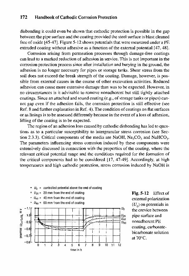
172 Handbook of Cathodic Corrosion Protection
disbonding it could even be shown that cathodic protection is possible in the gapbetween the pipe surface and the coating provided the steel surface is blast cleanedfree of oxide [45-47]. Figure 5-12 shows potentials that were measured under a PEextruded coating without adhesive as a function of the external potential [47, 48].
Corrosion arising from permeation processes through damage-free coatingscan lead to a marked reduction of adhesion in service. This is not important in thecorrosion protection process since after installation and burying in the ground, theadhesion is no longer necessary for pipes or storage tanks. Shear stress from thesoil does not exceed the break strength of the coating. Damage, however, is pos-sible from external causes in the course of other excavation activities. Reducedadhesion can cause more extensive damage than was to be expected. However, inno circumstances is it advisable to remove nonadherent but still tightly attachedcoatings. Since an attached and sound coating (e.g., of storage tanks or pipes) can-not gap even if the adhesion fails, the corrosion protection is still effective (seeRef. 8 and further explanation in Ref. 4). The condition of coatings on flat surfacesor as linings is to be assessed differently because in the event of a loss of adhesion,lifting of the coating is to be expected.
The region of an adhesion loss caused by cathodic disbonding has led to ques-tions as to a particular susceptibility to intergranular stress corrosion (see Sec-tion 2.3.3). Critical components of the media are NaOH, Na2CO3 and NaHCO3.The parameters influencing stress corrosion induced by these components wereextensively discussed in connection with the properties of the coating, where therelevant critical potential range and the conditions required for the formation ofthe critical components had to be considered [17, 47-49]. Accordingly, at hightemperatures and high cathodic protection, stress corrosion induced by NaOH is
Fig. 5-12 Effect ofexternal polarization(£/0) on potentials inthe crevice betweenpipe surface andnonadherent PEcoating, carbonate-bicarbonate solutionat70°C.
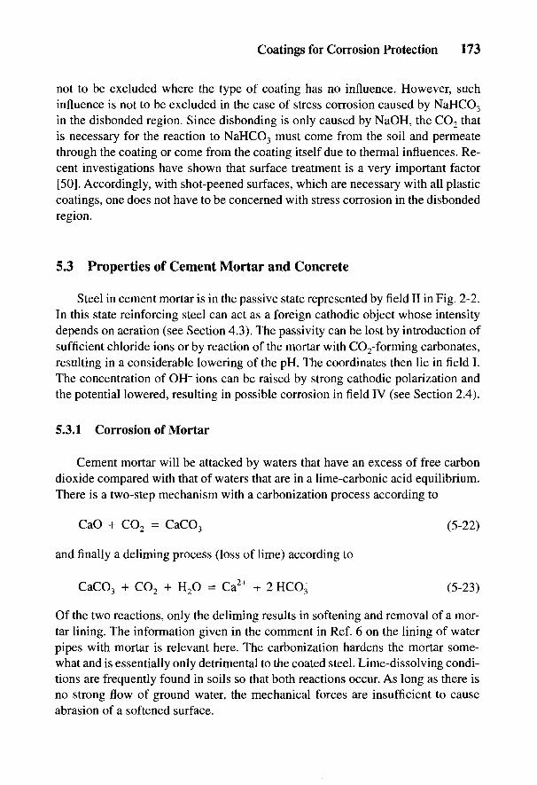
Coatings for Corrosion Protection 173
not to be excluded where the type of coating has no influence. However, suchinfluence is not to be excluded in the case of stress corrosion caused by NaHCO3
in the disbonded region. Since disbonding is only caused by NaOH, the CO2 thatis necessary for the reaction to NaHCO3 must come from the soil and permeatethrough the coating or come from the coating itself due to thermal influences. Re-cent investigations have shown that surface treatment is a very important factor[50]. Accordingly, with shot-peened surfaces, which are necessary with all plasticcoatings, one does not have to be concerned with stress corrosion in the disbondedregion.
5.3 Properties of Cement Mortar and Concrete
Steel in cement mortar is in the passive state represented by field II in Fig. 2-2.In this state reinforcing steel can act as a foreign cathodic object whose intensitydepends on aeration (see Section 4.3). The passivity can be lost by introduction ofsufficient chloride ions or by reaction of the mortar with CO2-forming carbonates,resulting in a considerable lowering of the pH. The coordinates then lie in field I.The concentration of OH" ions can be raised by strong cathodic polarization andthe potential lowered, resulting in possible corrosion in field IV (see Section 2.4).
5.3.1 Corrosion of Mortar
Cement mortar will be attacked by waters that have an excess of free carbondioxide compared with that of waters that are in a lime-carbonic acid equilibrium.There is a two-step mechanism with a carbonization process according to
and finally a deliming process (loss of lime) according to
Of the two reactions, only the deliming results in softening and removal of a mor-tar lining. The information given in the comment in Ref. 6 on the lining of waterpipes with mortar is relevant here. The carbonization hardens the mortar some-what and is essentially only detrimental to the coated steel. Lime-dissolving condi-tions are frequently found in soils so that both reactions occur. As long as there isno strong flow of ground water, the mechanical forces are insufficient to causeabrasion of a softened surface.
174 Handbook of Cathodic Corrosion Protection
5.3.2 Corrosion of Steel in Mortar
Due to both carbonization and penetration of chloride ions, steel will passfrom a passive to an active condition and (consequently) may corrode. If the mor-tar is completely surrounded by water, oxygen diffusion in wet mortar is extremelylow so that the situation is corrosion resistant because the cathodic partial reactionaccording to Eq. (2-17) scarcely occurs. For this reason the mortar lining of wastepipes remains protective against corrosion even if it is completely carbonated or ifit is penetrated by chloride ions.
A danger exists with anodic polarization (e.g., by neighboring aerated passiveregions or by the presence of oxygen), which is possible in the gas phase throughunwetted pores. It should be understood that just above the water/air zone, severecorrosion occurs in which the growing corrosion products can break off the mortarcoating. Galvanizing has a beneficial influence on this process because internalcell formation is increased by the galvanic anode [52]. This protective action islimited in time by the thickness of the zinc coating. Permanent corrosion protec-tion of steel in mortar can therefore only be given by an insulating organic coating.
The cathodic effectiveness of the passive steel in cement mortar can be seen inFig. 5-13. The cell current is measured between a mortar-coated DN 100 pipe sec-tion and an uncoated steel ring 16 mm broad as anode. It can be clearly seen that thecell current immediately falls and after 100 days goes toward zero. The same resultis obtained by removing the specimens and aerating the mortar coating and repeat-ing the experiment with the same components [51].
Cathodic protection can be used to protect steel in concrete (see Chapter 19).There is no fear of damage by H2 evolution due to porosity of the mortar. Localcorrosion attack can be observed under extreme conditions due to porosity (water/cement ratio =1) and polarization (Uu = -0.98 V) with portland cement but notwith blast furnace cement, corresponding to field IV in Fig. 2-2 [53]. However,such conditions do not occur in practice.
Anodic polarization can occur in the presence of stray currents. Oxygen isevolved on the passive steel according to:
The anodically produced acid is neutralized by the alkaline mortar (CaO).Corrosion is then possible only if the supply of alkali at the steel surface is con-sumed and the steel becomes active. This process is possible only under certaincircumstances after a very long incubation period. Apparently in steel-concretefoundations the possible current densities are so small that this case never arises.The possibility of danger has to be verified with thin outer coatings where deliminghas been noticed on the steel surface.
Coatings for Corrosion Protection 175
UUICLUVJII Ul t-A|Jtl II Mtilll III U
Fig. 5-13 Cell current in a pipe with cement-mortar lining; anode is an uncoatedring, tapwater at 15°C.
5.4 Properties of Enamel Coatings
Enamel coatings are completely electrochemically inert, but in general are notfree of pores. Pores are mostly difficult to recognize. Electrical pore testing revealsplaces covered with conducting oxide covering the metal. In free corrosion, poresare mostly blocked up with corrosion products so that corrosion comes to a stand-still. This process is not so definite with larger areas of damage in the enamel.
Enamel coatings are used for the internal protection of storage tanks that inmost cases have built-in components (e.g., fittings with exits, probes, temperaturedetectors) that usually exhibit cathodic effectivity. These constitute a considerabledanger of pitting corrosion at small pores in the enamel. Corrosion protection isachieved by additional cathodic protection which neutralizes the effectiveness ofthe cathodic objects.
Enamel coatings usually consist of several layers in which the prime coating isapplied for adhesion but does not have the chemical stability of the outer layers.With cathodic polarization at holidays, attack on the exposed prime coating is pos-sible as the cathodically produced alkali causes the defects to increase in size. Thisparticularly cannot be excluded in salt-rich media.
Enamels have very varied properties where their chemical stability is con-cerned. Relevant stability testing must be carried out for the different areas ofapplication. Enamel coatings for hot water heaters, their requirements and combi-nation with cathodic protection are described in Section 20.4.1.
It must be remembered that the interface of steel and enamel reacts very sensi-tively to hydrogen recombination, which causes cracks (fish scales) and spalling.

176 Handbook of Cathodic Corrosion Protection
The hydrogen can originate from the enamel itself, or can be produced duringservice. The rear surfaces should not be treated with acid as far as possible.Cathodic protection of these surfaces can lead to weak H absorption (see Fig. 2-20),which leads to long-term fish-scaling and spalling. With reference to this effect,there is an electrolytic test method for determining the susceptibility to fish-scaling [54].
5.5 Properties of Metallic Coatings
Coatings of more noble metals than the substrate metal (e.g., Cu on Fe) areonly protective when there are no pores. In other cases severe local corrosionoccurs due to cell formation (bimetallic corrosion). Cathodic protection is theo-retically possible. This protection combination is not very efficient since the coat-ing usually consumes more protection current than the uncoated steel.
Coatings of less noble metals than the substrate metal (e.g., Zn on Fe) are onlyprotective if the corrosion product of the metal coating restricts the corrosion process.At the same time, the formation of aeration cells is hindered by the metal coating. Nocorrosion occurs at defects. Additional cathodic protection to reduce the corrosionof the metal coating can be advantageous. Favorable polarization properties and lowprotection current requirements are possible but need to be tested in individual cases.The possibility of damage due to blistering and cathodic corrosion must be heeded.
Blistering of the zinc coating has been observed with cathodic protection of hot-dipped galvanized steel in warm water. The cause was absorption and recombina-tion of hydrogen. The blisters arise in the Fe-Zn alloy phases [55]. With Zn andespecially with Al, the protection potential region must be limited at the negativeend because corrosion-forming zincates and aluminates are possible (see Figs. 2-10and 2-11).
Coatings for Corrosion Protection 177
5.6 References
[I] DIN 50927, Beuth-Verlag, Berlin 1985.[2] DIN 30671, Beuth-Verlag, Berlin 1987.[3] DIN 30673, Beuth-Verlag, Berlin 1987.[4] DIN 30670, Beuth-Verlag, Berlin 1980.[5] DIN 30672, Beuth-Verlag, Berlin 1979.[6] DIN 2614, Beuth-Verlag, Berlin 1989.[7] DIN 30674 (Vornorm) Teil 2, Beuth-Verlag, Berlin 1984.[8] DIN 50928, Beuth-Verlag, Berlin 1985.[9] W. Schwenk, Metalloberflache 34, 153 (1980); NACE Conf. "Corrosion Control by
Organic Coatings," Houston 1981, s. 103B110.[10] W. Schwenk, farbe+lack 90, 350 (1984).[II] J. D'Ans u. E. Lax, Taschenbuch f. Chemiker u. Physiker, Springer, Berlin 1949, S.
772, 773 und 1477.[12] W. Klahr, Fa. Th. Goldschmidt, personl. Mitteilung 1978.[13] H. Landgraf, 3R international 20, 283 (1981).[14] R.E. Sharpe u. RJ. Dick, J. Coating Techn. 57, 25 (1985).[15] W.v. Baeckmann, 3R international 20, 470 (1981).[16] H. Hildebrand u. W. Schwenk, Werkstoffe u. Korrosion 30, 542 (1979).[17] W. Schwenk, 3R international 19, 586 (1980).[ 18] TRbF 131, C. Heymanns-Verlag KG, Koln 1981.[19] W. Schwenk, 3R international 75, 389 (1976).[20] H. Determann, E. Hargarter, H. Sass u. H. Haagen, Schiff & Hafen 28, 729 (1974).[21] H. Determan, E. Hargarter u. H. Sass, Schiff & Hafen 28, 729 (1976); 32, H. 2, 89
(1980).[22] W. Bahlmann, E. Hargarter, H. Sass u. D. Schwarz, Schiff & Hafen 33, H. 7, 50
(1981); W. Bahlmann u. E. Hargarter, Schiff & Hafen, Sonderheft Meerwasser-Korrosion, Febr. 1983. S. 98.
[23] H. Hildebrand u. w. Schwenk, Werkstoffe u. Korrosion 33, 653 (1982).[24] W. Fischer, EUROCORR '87, DECHEMA, Frankfurt 1987, S. 719B724; W. Fischer
U. Hermann u. M. Schroder, Werkstoffe u. Korrosion 42, 620 1991.[25] Schiffbautechnische Gesellschaft, STG-Richtilinien Nr. 2220, Hamburg 1988.[26] J. Eggert, Lehrbuch der physikalischen Chemie, Leipzig 1948, S. 559B570.[27] W. Schwenk, gwf gas/erdgas 118,1 (1977).[28] W. Schwenk, Rohre - Rohrleitungsbau - Rohrleitungstransport 12, 15 (1973).[29] W. Takens, J. van helden u. A. Schrik, Gas 93, 174 (1973).[30] P. Pickelmann u. H. Hildebrand, gwf gas/erdgas 722, 54 (1981).[31] W. Schwenk, 3R international 23, 188 (1984).[32] W.v. Baeckmann, D. Funk u. G. Heim, 3R international 24, 421 (1985).[33] J.M. Holbrook, Unveroffentl. Untersuchung, Battelle, Columbus, 1982/84.[34] W. Schwenk, 3R international 18, 565 (1979).[35] G. Heim, W.v. Baeckmann u. D. Funk, 3R international 14, 111 (1975).[36] H.C. Woodruff, J. Paint Techn. 47, 57 (1975).[37] G. Heim u. W.v. Baeckmann, 3R international 26, 302 (1987).

178 Handbook of Cathodic Corrosion Protection
[38] N. Schmitz-Pranghe u. W.v. Baeckmann, Mat. Perf. 17, H. 8, 22 (1978).[39] H. Fisher, gwf gas/erdgas 113, 283 (1972).[40] P. Pickelmann, gwf gas/erdgas 116, 119 (1975).[41] F. Schwarzbauer, 3R international 25, 272 (1986); gwf gas/erdgas 128, 98 (1987).[42] N. Schmitz-Pranghe, W. Meyer u. W. Schwenk, DVGW Schriftenreihe Gas/Wasser
1, ZfGW Verlag, Frankfurt 1976, S. 7B19.[43] H. Landgraf u. W. Quitmann, 3R international 22, 524 u. 595 (1983).[44] A. Kottmann u. H. Zimmermann, gwf gas/erdgas 126, 219 (1985).[45] R.R. Fessler, A.J. Markoworth u. R.N. Parkins, Corrosion 39, 20 (1983).[46] A.C. Toncre, Mat. Perform. 23, H. 8, 22 (1984).[47] W. Schwenk, 3R international 26, 305 (1987).[48] W. Schwenk, gwf gas/erdgas 123, 158 (1982).[49] G. Herbsleb, R. Popperling u. W. Schwenk, 3R international 20, 193 (1981).[50] W. Delbeck, A. Engel, D. Mhller, R. Sporl u. W. Schwenk, Werkstoffe u. Korrosion
37, 176 (1986).[51] H. Hildebrand u. M. Schulze, 3R international 25, 242 (1986).[52] H. Hildebrand u. W. Schwenk, Werkstoffe u. Korrosion 37, 163 (1986).[53] H. Hildebrand, M. Schulze u. W. Schwenk, Werkstoffe u. Korrosion 34, 281 (1983).[54] H. Hildebrand u. W. Schwenk, Mitt. VDEfa 79, 13 (1971).[55] S. Schwenk, Werkstoffe u. Korrosion 17, 1033 (1966).
6
Galvanic (Sacrificial) AnodesH. BOHNES AND G. FRANKE
6.1 General Information
In contrast to impressed current anodes, the possibility of using galvanicanodes is limited by their electrochemical properties. The rest potential of theanode material must be sufficiently more negative than the protection potential ofthe object to be protected so that an adequate driving voltage can be maintained.Rest potentials (see Table 2-4) and protection potentials (see Section 2-4) can often beapproximately related to the standard potentials (see Table 2-1). This relation isfrequently given by Eq. (2-53") for the protection potential as long as there is nocomplex formation [see Eq. (2-56)]. On the other hand, there is no clear relationshipfor rest potentials according to the explanation for Fig. 2-5, where there is a definiteinfluence of the environment according to Table 2-4. Furthermore, temperature canhave an influence. The potential of zinc in aqueous media becomes increasinglymore positive with a rise in temperature, due to film formation, which is attributedto a retardation of the anodic partial reaction (passivation) according to Fig. 2-5.The passivatability of galvanic anodes should be as low as possible. The anodemetals form numerous less easily soluble compounds from which, under normalcircumstances, hydroxides, hydrated oxides and oxides, carbonates, phosphates andseveral basic salts can arise. With the use of galvanic anodes for the internal protec-tion of a chemical plant (see Chapter 21), still further compounds that are less easilysoluble can be formed. In general the insoluble compounds do not precipitate on theworking anode because the pH is lowered there by hydrolysis [1]. If the anode is notheavily loaded or the concentration of the film-forming ions is too high, the lesseasily soluble compounds can cover the anode surface (see also Section 4.1). Manysurface films are soft, porous and permeable and do not interfere with the function-ing of the anode. However, some films can become as hard as enamel, completelyblocking the anode, but on drying out alter their structure and become brittle andporous. They can then be removed by brushing.
Galvanic anodes should exhibit as low a polarizability as possible. The extent oftheir polarization is important in practice for their current output. A further anode
179
180 Handbook of Cathodic Corrosion Protection
property is the factor Q for the equivalence between charge and mass according toEq. (2-3). This factor is termed current content. It is larger the smaller the atomicweight and the higher the valence of the anode metal [see Eq. (2-6)]. The theoreticalcurrent content is not sufficient to determine the practical application because fromthe data in Fig. 2-5 the total anode current density Ja from Eq. (2-38) is smaller by anamount Jc than the anodic partial current JA. Here JA corresponds to the theoreticaland 7a to the usable current content. Jc corresponds to the self-corrosion of the anode,which is derived from the cathodic partial reaction in which intermediate cations ofanomalous valence can be involved (see Section 6.1.1).
For application in flowing media (e.g., for ships) it is also necessary that theusable current content be as large as possible not only per unit of mass but also perunit of volume, so that the volume of the installed anodes becomes as small aspossible.
The cathodic protection of plain carbon and low-alloy steels can be achievedwith galvanic anodes of zinc, aluminum or magnesium. For materials withrelatively more positive protection potentials (e.g., stainless steels, copper, nickelor tin alloys), galvanic anodes of iron or of activated lead can be used.
The anodes are generally not of pure metals but of alloys. Certain alloyingelements serve to give a fine-grained structure, leading to a relatively uniform metalloss from the surface. Others serve to reduce the self-corrosion and raise thecurrent yield. Finally, alloying elements can prevent or reduce the tendency tosurface film formation or passivation. Such activating additions are necessary withaluminum.
6.1.1 Current Capacity of Galvanic Anodes
The theoretical current content Q' per unit mass, from Eqs. (2-3) and (2-6) isgiven by:
/b values are given in Table 2-1. In practical units:
Correspondingly, the theoretical current content Q" related to volume is given byEqs. (2-3) to (2-7):
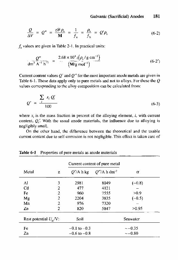
Galvanic (Sacrificial) Anodes 181
/a values are given in Table 2-1. In practical units:
Current content values Q' and Q" for the most important anode metals are given inTable 6-1. These data apply only to pure metals and not to alloys. For these the Qvalues corresponding to the alloy composition can be calculated from:
where xt is the mass fraction in percent of the alloying element, /, with currentcontent, <2/. With the usual anode materials, the influence due to alloying isnegligibly small.
On the other hand, the difference between the theoretical and the usablecurrent content due to self-corrosion is not negligible. This effect is taken care of
Table 6-1 Properties of pure metals as anode materials
Current content of pure metal
Metal z £>'/Ahkg g'YAhdnr3 a
Al 3 2981 8049 (-0.8)Cd 2 477 4121Fe 2 960 7555 >0.9Mg 2 2204 3835 (-0.5)Mn 2 976 7320Zn 2 820 5847 >0.95
Rest potential UH/V: Soil Seawater
Fe -0.1 to-0.3 —0.35Zn -0.6 to-0.8 —0.80
182 Handbook of Cathodic Corrosion Protection
by a correction factor a which, according to data in Fig. 2-5 and Eq. (2-10), isdefined as follows:
The sum of all the cathodic partial reactions is included in 7C, e.g., oxygenreduction according to Eq. (2-17) and hydrogen evolution according to Eq. (2-19).The intermediate formation of anode metal ions of anomalous valence is alsopossible:
with subsequent reaction in the medium,
can be treated in the overall reaction as if one of the reactions according toEq. (6-5b) had occurred as an equivalent cathodic partial reaction at the anode.
The factor a varies considerably with individual alloys and is also dependenton the application conditions. It varies between wide limits from about 0.98 forzinc to below 0.5 for magnesium anodes. The a values given in Tables 6-1 to 6-4apply to cold seawater. Deviations in application (i.e., cooling water) temperatureand loading can lead to considerable changes.
The influence of loading on a is due to the dependence of 7C on potential orcurrent or is due to self-corrosion. Whereas oxygen corrosion should beindependent of material and potential, hydrogen evolution decreases with increasedloading. Furthermore, it is strongly dependent on the material, where the morenoble alloying elements promote self-corrosion. Since in both cases 7C is notproportional to the current output, /, there can be no value for a independent of /according to Eq. (6-4) or for the self-corrosion. In contrast, the anodic reactionaccording to Eq. (6-5a) and the equally fast reaction according to Eq. (6-5b)increase with potential and loading. Then / and 7C are proportional to each otherand a becomes independent of loading. This is roughly the case with magnesiumanodes where a = 0.5 given by z = 2 and n = 1 [2]. Another explanation of thisa value refers to an active region on the anode surface being proportional tothe current 7 [3,4]. As to the consequence of hydrolysis analogous to Eq. (4-4),in this region acid corrosion with hydrogen evolution occurs. In this casevalues deviating from or smaller than a = 0.5 are understandable. The two
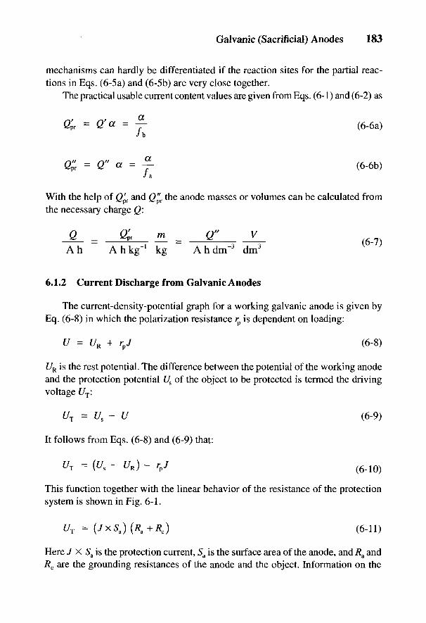
Galvanic (Sacrificial) Anodes 183
mechanisms can hardly be differentiated if the reaction sites for the partial reac-tions in Eqs. (6-5a) and (6-5b) are very close together.
The practical usable current content values are given from Eqs. (6-1) and (6-2) as
With the help of Q^T and Q'^T the anode masses or volumes can be calculated fromthe necessary charge Q:
6.1.2 Current Discharge from Galvanic Anodes
The current-density-potential graph for a working galvanic anode is given byEq. (6-8) in which the polarization resistance r is dependent on loading:
UR is the rest potential. The difference between the potential of the working anodeand the protection potential Us of the object to be protected is termed the drivingvoltage f/T:
It follows from Eqs. (6-8) and (6-9) that:
\" /
This function together with the linear behavior of the resistance of the protectionsystem is shown in Fig. 6-1.
Here J X 5a is the protection current, 5a is the surface area of the anode, and Ra andRc are the grounding resistances of the anode and the object. Information on the

184 Handbook of Cathodic Corrosion Protection
Fig. 6-1 Characteristic /(£/T) andresistance straight lines of a galvanicanode. Slope of the resistance lines:tan a = [l/S(R +/?)]. Slope of the
a a C -1
resistance line at maximum currentoutput: tan aQ = (l/SaRa).
measurement and calculation of grounding resistances is given in Sections 3.5.3and 24.1 (see also Table 24-1). The grounding resistance of the cathode Rc can beneglected compared with 7?a on account of the large cathode area. With well-coatedand not too large objects, Rc can, however, be significantly large. According toEq. (6-11), an increase in the current discharge is to be expected if Rc decreases inthe course of time. The anode has therefore a current reserve.
The intersection of the graphs of Eq. (6-10) and (6-11) gives the working pointfor the protection system. The driving voltage decreases with increasing /. Withanodes that are less polarizable, it remains more or less constant over a wide rangeof current density. The anode graph of Eq. (6-10) indicates the efficiency of theanode. It depends on the composition of the anode and the electrolyte. Theworking point of the system should lie in the unpolarizable part of the J(UT) curve,so that it can be assumed that rp = 0. The maximum current discharge at Rc = 0 isgiven from Eqs. (6-10) and (6-11) as:
If the working point does not lie in the unpolarizable region (e.g., on account of theaction of surface films) then instead of Eq. (6-12),
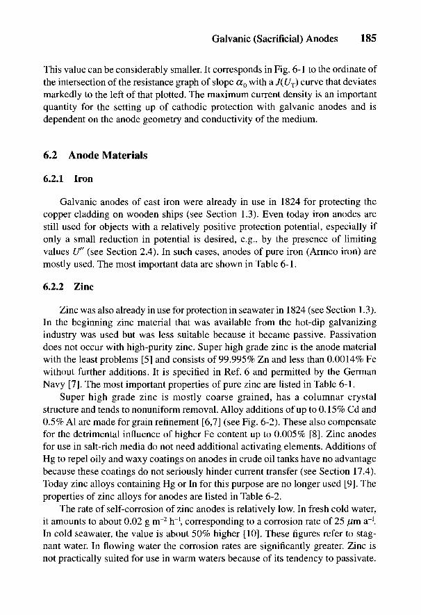
Galvanic (Sacrificial) Anodes 185
This value can be considerably smaller. It corresponds in Fig. 6-1 to the ordinate ofthe intersection of the resistance graph of slope cc0 with a J(UT) curve that deviatesmarkedly to the left of that plotted. The maximum current density is an importantquantity for the setting up of cathodic protection with galvanic anodes and isdependent on the anode geometry and conductivity of the medium.
6.2 Anode Materials
6.2.1 Iron
Galvanic anodes of cast iron were already in use in 1824 for protecting thecopper cladding on wooden ships (see Section 1.3). Even today iron anodes arestill used for objects with a relatively positive protection potential, especially ifonly a small reduction in potential is desired, e.g., by the presence of limitingvalues U" (see Section 2.4). In such cases, anodes of pure iron (Armco iron) aremostly used. The most important data are shown in Table 6-1.
6.2.2 Zinc
Zinc was also already in use for protection in seawater in 1824 (see Section 1.3).In the beginning zinc material that was available from the hot-dip galvanizingindustry was used but was less suitable because it became passive. Passivationdoes not occur with high-purity zinc. Super high grade zinc is the anode materialwith the least problems [5] and consists of 99.995% Zn and less than 0.0014% Fewithout further additions. It is specified in Ref. 6 and permitted by the GermanNavy [7]. The most important properties of pure zinc are listed in Table 6-1.
Super high grade zinc is mostly coarse grained, has a columnar crystalstructure and tends to nonuniform removal. Alloy additions of up to 0.15% Cd and0.5% Al are made for grain refinement [6,7] (see Fig. 6-2). These also compensatefor the detrimental influence of higher Fe content up to 0.005% [8]. Zinc anodesfor use in salt-rich media do not need additional activating elements. Additions ofHg to repel oily and waxy coatings on anodes in crude oil tanks have no advantagebecause these coatings do not seriously hinder current transfer (see Section 17.4).Today zinc alloys containing Hg or In for this purpose are no longer used [9]. Theproperties of zinc alloys for anodes are listed in Table 6-2.
The rate of self-corrosion of zinc anodes is relatively low. In fresh cold water,it amounts to about 0.02 g m~2 hr1, corresponding to a corrosion rate of 25 /mi a"1.In cold seawater, the value is about 50% higher [10]. These figures refer to stag-nant water. In flowing water the corrosion rates are significantly greater. Zinc isnot practically suited for use in warm waters because of its tendency to passivate.
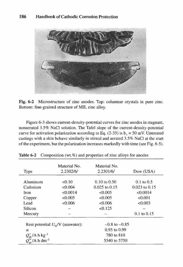
186 Handbook of Cathodic Corrosion Protection
Fig. 6-2 Microstructure of zinc anodes. Top: columnar crystals in pure zinc.Bottom: fine-grained structure of MIL zinc alloy.
Figure 6-3 shows current-density-potential curves for zinc anodes in stagnant,nonaerated 3.5% NaCl solution. The Tafel slope of the current-density-potentialcurve for activation polarization according to Eq. (2-35) is b+ = 50 mV. Untreatedcastings with a skin behave similarly in stirred and aerated 3.5% NaCl at the startof the experiment, but the polarization increases markedly with time (see Fig. 6-5).
Table 6-2 Composition (wt.%) and properties of zinc alloys for anodes
Material No. Material No.Type 2.2302/6/ 2.2301/6/ Dow (USA)
Aluminum <0.10 0.10 to 0.50 0.1 to 0.5Cadmium <0.004 0.025 to 0.15 0.023 to 0.15Iron <0.0014 <0.005 <0.0014Copper <0.005 <0.005 <0.001Lead <0.006 <0.006 <0.003Silicon - <0.125Mercury - - 0.1 to 0.15
Rest potential £/H/V (seawater): -0.8 to -0.85a 0.95 to 0.99gpVAhkg-1 780 to 810(T/Ahdnr3 5540 to 5750
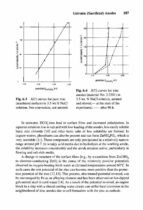
Fig. 6-3 J(U) curves for pure zinc(machined surface) in 3.5 wt.% NaClsolution, free convection, not aerated.
Fig. 6-4 J(U) curves for zincanodes (material No. 2.2301) in3.5 wt. % NaCl solution, aeratedand stirred;— at the start of theexperiment; after 90 h.
Galvanic (Sacrificial) Anodes 187
In seawater, HCO3 ions lead to surface films and increased polarization. Inaqueous solutions low in salt and with low loading of the anodes, less easily solublebasic zinc chloride [10] and other basic salts of low solubility are formed. Inimpure waters, phosphates can also be present and can form ZnNH4PO4, which isvery insoluble [11]. These compounds are only precipitated in a relatively narrowrange around pH 7. In weakly acid media due to hydrolysis at the working anode,the solubility increases considerably and the anode remains active, particularly inflowing and salt-rich media.
A change in structure of the surface films [e.g., by a transition from Zn(OH)2
to electron-conducting ZnO] is the cause of the relatively positive potentialsobserved in oxygen-bearing fresh water at elevated temperatures around 60°C. Insuch cases the rest potential of the zinc can become more positive than the protec-tion potential of the iron [12,13]. This process, also termed potential reversal, canbe encouraged by Fe as an alloying element and has been observed on hot-dippedgalvanized steel in cold water [14]. As a result of the potential reversal, an engineblock in a ship with a closed cooling water circuit can suffer local corrosion in theneighborhood of zinc anodes due to cell formation with the zinc as cathode.
188 Handbook of Cathodic Corrosion Protection
In spite of a low driving voltage of about 0.2 V, about 90% of all galvanicanodes for the external protection of seagoing ships are zinc anodes (see Section17.3.2). Zinc alloys are the only anode materials permitted without restrictions forthe internal protection of exchange tanks on tankers [16] (see Section 17.4).
For the external protection of pipelines in seawater (see Section 16.6), zincanodes in the form of bracelets are installed; in the length direction these are weldedon to clips attached to the pipe or in the form of half-shells. In brackish or stronglysaline water, such as that found in oil drilling or in mining, zinc anodes can beinstalled for the internal protection of storage tanks. The use of zinc anodes infresh water is very limited because of their tendency to passivate. This also appliesto installing them in soil. Apart from occasional installation of rod or band anodesas ground electrodes, zinc anodes are only used for soil resistivities below 10 m.In order to reduce passivation and lower the grounding resistance, the anodes haveto be surrounded with special bedding materials as backfill (see Section 6.2.5).
6.2.3 Aluminum
Pure aluminum cannot be used as an anode material on account of its easypassivatability. For galvanic anodes, aluminum alloys are employed that containactivating alloying elements that hinder or prevent the formation of surface films.These are usually up to 8% Zn and/or 5% Mg. In addition, metals such as Cd, Ga,In, Hg and Tl are added; as so-called lattice expanders, these maintain the long-term activity of the anode. Activation naturally also encourages self-corrosion ofthe anode. In order to optimize the current yield, so-called lattice contractors areadded that include Mn, Si and Ti.
The various aluminum alloys behave very differently as anodes. The poten-tials lie between about UH = -0.75 V and -1.3 V; the a value is 0.95 for alloyscontaining Hg and lies between 0.7 and 0.8 for alloys with Cd, In and Sn. Threetypes of alloy are particularly important for aluminum anodes. All of them containa few percent of Zn. In, Hg, Sn and Cd are present as activators. Anodes containingHg can give a high current yield but they are seldom used because of the toxicity ofHg salts. For this reason, aluminum anodes with Zn and In as activators areacquiring increased importance. In spite of an a value of about 0.8 and a restpotential of only UH = -0.8 V, their low polarizability is a special advantage. Theyare therefore employed preferentially in offshore applications. Aluminum anodeswith Zn and Sn as activators occupy a middle position with regard to a value.Their rest potentials are similar to those of alloys containing In or are somewhatmore positive. Their polarizability is, however, considerably greater. Heattreatment is necessary according to the alloy composition. Table 6-3 gives the
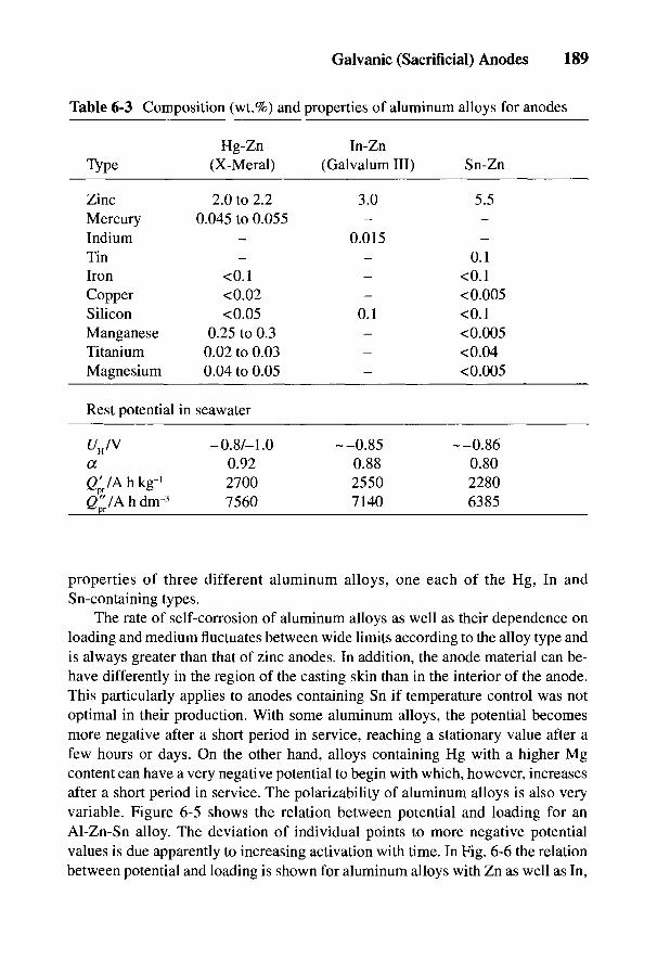
properties of three different aluminum alloys, one each of the Hg, In andSn-containing types.
The rate of self-corrosion of aluminum alloys as well as their dependence onloading and medium fluctuates between wide limits according to the alloy type andis always greater than that of zinc anodes. In addition, the anode material can be-have differently in the region of the casting skin than in the interior of the anode.This particularly applies to anodes containing Sn if temperature control was notoptimal in their production. With some aluminum alloys, the potential becomesmore negative after a short period in service, reaching a stationary value after afew hours or days. On the other hand, alloys containing Hg with a higher Mgcontent can have a very negative potential to begin with which, however, increasesafter a short period in service. The polarizability of aluminum alloys is also veryvariable. Figure 6-5 shows the relation between potential and loading for anAl-Zn-Sn alloy. The deviation of individual points to more negative potentialvalues is due apparently to increasing activation with time. In Fig. 6-6 the relationbetween potential and loading is shown for aluminum alloys with Zn as well as In,
Galvanic (Sacrificial) Anodes 189
Table 6-3 Composition (wt.%) and properties of aluminum alloys for anodes
Hg-Zn In-ZnType (X-Meral) (Galvalumlll) Sn-Zn
Zinc 2.0 to 2.2 3.0 5.5Mercury 0.045 to 0.055Indium - 0.015Tin - - 0.1Iron <0.1 - <0.1Copper <0.02 - <0.005Silicon <0.05 0.1 <0.1Manganese 0.25 to 0.3 - <0.005Titanium 0.02 to 0.03 - <0.04Magnesium 0.04 to 0.05 - <0.005
Rest potential in seawater
t/H/V -0.8/-1.0 --0.85 --0.86a 0.92 0.88 0.80gVArikg-1 2700 2550 2280(/pVAhdnr3 7560 7140 6385

190 Handbook of Cathodic Corrosion Protection
Fig. 6-5 /(U) curves for an aluminum alloy with 2% Zn and 0.1 % Sn in 3.5 wt. %NaCl solution, free convection, not aerated.
Fig. 6-6 J(U) curves for aluminum alloys in 3.5 wt. % NaCl solution, aerated andstirred; — at the start of the experiment, after 1 week; A Al-In-Zn,X Al-In-Zn, Q Al-In-Zn.
Galvanic (Sacrificial) Anodes 191
Hg and Sn at the beginning of the experiment and after 1 week. Alloys containingIn are the least polarizable, and those containing Sn the most polarizable.
Oxide, hydroxide and basic salts of aluminum are less soluble at pH values ofabout 7 than those of zinc [17], which explains the easy passivatability. Galvanicanodes of aluminum alloys are primarily employed in the area of offshoretechnology. The anodes work in relatively pure seawater flowing with a highvelocity so that by using suitable alloys, passivation phenomena are rare. Theirlow weight is particularly favorable in view of a service time of 20 to 30 years.
Their polarizability increases in saline muds and their current efficiency mark-edly decreases e.g., for the alloy galvalum III in Table 6-3, from 2550 A h kg"1 to1650 Ah kg-1.
6.2.4 Magnesium
Magnesium is considerably less passivatable than zinc and aluminum and hasthe highest driving voltage. On account of these properties and its high currentcontent, magnesium is particularly suitable for galvanic anodes. Magnesium,however, is prone to self-corrosion of considerable extent, which increases withincreasing salt content of the medium [18]. The available current content of puremagnesium is therefore much less than the theoretical current content. It isinfluenced by the impurity content of the anode metal, by the type of materialremoval (uniform or pitting), and by the current density as well as the electrolyte.
Even in good alloys and under favorable conditions, the a value does not lieabove about 0.6. In enamelled storage tanks where the current requirement is low,the a value can fall to as low as about 0.1. The cause of the high proportion of self-corrosion is hydrogen evolution, which occurs as a parallel cathodic reactionaccording to Eq. (6-5b) or by free corrosion of material separated from the anodeon the severely craggy surface [2-4, 19-21].
Magnesium anodes usually consist of alloys with additions of Al, Zn and Mn.The content of Ni, Fe and Cu must be kept very low because they favor self-corrosion. Ni contents of >0.001% impair properties and should not be exceeded.The influence of Cu is not clear. Cu certainly increases self-corrosion but amountsup to 0.05% are not detrimental if the Mn content is over 0.3%. Amounts of Fe upto about 0.01% do not influence self-corrosion if the Mn content is above 0.3%.With additions of Mn, Fe is precipitated from the melt which on solidification isrendered harmless by the formation of Fe crystals with a coating of manganese.The addition of zinc renders the corrosive attack uniform. In addition, thesensitivity to other impurities is depressed. The most important magnesium alloyfor galvanic anodes is AZ63, which corresponds to the claims in Ref. 22. AlloysAZ31 and M2 are still used. The most important properties of these alloys are
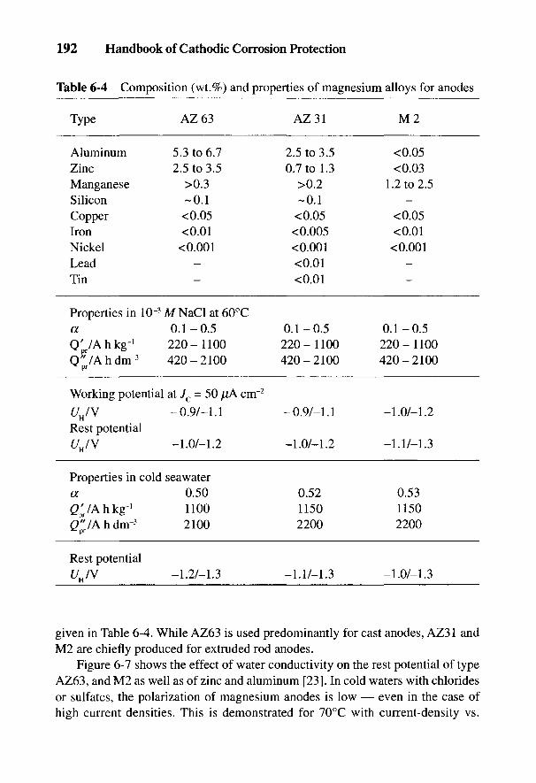
192 Handbook of Cathodic Corrosion Protection
Table 6-4 Composition (wt.%) and properties of magnesium alloys for anodes
Type AZ63 AZ31 M 2
Aluminum 5.3 to 6.7 2.5 to 3.5 <0.05Zinc 2.5 to 3.5 0.7 to 1.3 <0.03Manganese >0.3 >0.2 1.2 to 2.5Silicon -0.1 -0.1Copper <0.05 <0.05 <0.05Iron <0.01 <0.005 <0.01Nickel <0.001 <0.001 <0.001Lead - <0.01Tin - <0.01
Properties in 10~3 M NaCl at 60°Ca 0.1-0.5 0.1-0.5 0.1-0.5Q'pr/A h kg-1 220 - 1100 220 - 1100 220 - 1100Q"/Ahdnr3 420-2100 420-2100 420-2100^pr
Working potential at Jc = 50 //A cnr2
UJV -0.9/-1.1 -0.9/-1.1 -1.0/-1.2ri
Rest potentialUJV -1.0/-1.2 -1.0/-1.2 -1.1/-1.3
H
Properties in cold seawatera 0.50 0.52 0.53<2p'r/Ahkg-' 1100 1150 11500"/Ahdm-3 2100 2200 2200^pr
Rest potentialUn/V -1.2/-1.3 -1.1/-1.3 -1.0/-1.3
H
given in Table 6-4. While AZ63 is used predominantly for cast anodes, AZ31 andM2 are chiefly produced for extruded rod anodes.
Figure 6-7 shows the effect of water conductivity on the rest potential of typeAZ63, and M2 as well as of zinc and aluminum [23]. In cold waters with chloridesor sulfates, the polarization of magnesium anodes is low — even in the case ofhigh current densities. This is demonstrated for 70°C with current-density vs.
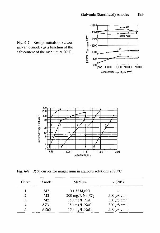
Fig. 6-8 J(U) curves for magnesium in aqueous solutions at 70°C.
Curve Anode Medium x (20°)
1 M2 0.1MMgSO4
2 M2 200 mg/L Na2SO4 300/iScm-'3 M2 150 mg/L NaCl 300 ^S crrr1
4 AZ31 150 mg/L NaCl 300 juS cm'1
5 AZ63 150 mg/L NaCl 300 S cnr1
Fig. 6-7 Rest potentials of variousgalvanic anodes as a function of thesalt content of the medium at 20°C.
Galvanic (Sacrificial) Anodes 193
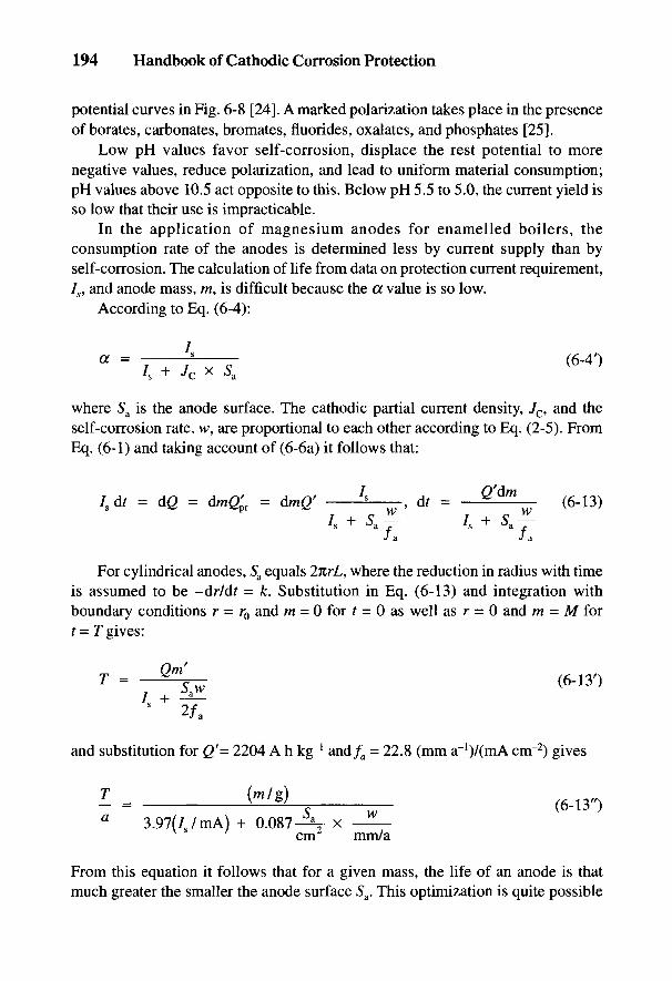
194 Handbook of Cathodic Corrosion Protection
potential curves in Fig. 6-8 [24]. A marked polarization takes place in the presenceof borates, carbonates, bromates, fluorides, oxalates, and phosphates [25].
Low pH values favor self-corrosion, displace the rest potential to morenegative values, reduce polarization, and lead to uniform material consumption;pH values above 10.5 act opposite to this. Below pH 5.5 to 5.0, the current yield isso low that their use is impracticable.
In the application of magnesium anodes for enamelled boilers, theconsumption rate of the anodes is determined less by current supply than byself-corrosion. The calculation of life from data on protection current requirement,Is, and anode mass, ra, is difficult because the a value is so low.
According to Eq. (6-4):
where Sa is the anode surface. The cathodic partial current density, Jc, and theself-corrosion rate, w, are proportional to each other according to Eq. (2-5). FromEq. (6-1) and taking account of (6-6a) it follows that:
For cylindrical anodes, 5a equals 2nrL, where the reduction in radius with timeis assumed to be -dr/dt = k. Substitution in Eq. (6-13) and integration withboundary conditions r = r0 and m = 0 for t = 0 as well as r = 0 and m = M fort- r gives:
and substitution for Q'= 2204 A h kg"1 and/a = 22.8 (mm a~l)/(mA cm"2) gives
From this equation it follows that for a given mass, the life of an anode is thatmuch greater the smaller the anode surface Sa. This optimization is quite possible
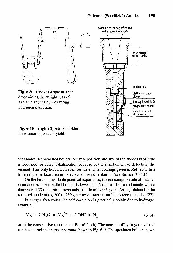
Galvanic (Sacrificial) Anodes 195
Fig. 6-9 (above) Apparatus fordetermining the weight loss ofgalvanic anodes by measuringhydrogen evolution.
Fig. 6-10 (right) Specimen holderfor measuring current yield.
for anodes in enamelled boilers, because position and size of the anodes is of littleimportance for current distribution because of the small extent of defects in theenamel. This only holds, however, for the enamel coatings given in Ref. 26 with alimit on the surface area of defects and their distribution (see Section 20.4.1).
On the basis of available practical experience, the consumption rate of magne-sium anodes in enamelled boilers is lower than 3 mm a~l For a rod anode with adiameter of 33 mm, this corresponds to a life of over 5 years. As a guideline for therequired anode mass, 200 to 250 g per m2 of internal surface is recommended [27].
In oxygen-free water, the self-corrosion is practically solely due to hydrogenevolution
or to the consecutive reactions of Eq. (6-5 a,b). The amount of hydrogen evolvedcan be determined in the apparatus shown in Fig. 6-9. The specimen holder shown
196 Handbook of Cathodic Corrosion Protection
in Fig. 6-10 is suitable for measurements at given anode currents, 7a. Suchmeasurements serve to determine the current yield a and test the quality of theanode (see Section 6.6). In addition, determining the potential vs. current supplyallows the tendency to passivation of the magnesium to be recognized [27], which,for example, exists for pure magnesium in low-salt water and which should betested generally for the formation of less easily soluble compounds.
The low-solubility compounds that form on magnesium anodes under normalloading include hydroxides, carbonates and phosphates. However, the solubility ofthe hydroxides and carbonates is relatively high. Only magnesium phosphate has alow solubility. The driving voltage with magnesium anodes for steel with not toolow conductivity x > 500 fj,S cm"1 with 0.65 V is almost three times as great as thatfor zinc and aluminum. Magnesium alloys are used if the driving voltage of zinc andaluminum anodes is not sufficient or where there is a danger of passivation.
Magnesium anodes are used in the case of higher specific resistivity of theelectrolyte and higher protection current densities. Objects to be protected includesteel-water structures in fresh water, ballast tanks for fresh water, boilers and drink-ing water tanks. The physiological assurance concerning corrosion products isimportant in containers for drinking water (see Section 20.5). The total weightcontent of Sb, As, Pb, Cr and Ni must not exceed 0.1%, and that of Cd, Hg and Semust not exceed <0.01% [27]. In the soil, smaller objects can be protected withmagnesium electrodes for resistivities up to 250 Q m and large tanks and pipelinesfor resistivities up to 100 Q m if the current requirement is not too high.
Hydrogen is involved in cathodic protection with magnesium anodes onaccount of the high contribution of self-corrosion. This must be considered in its usein closed containers, e.g., boilers. In enamelled boilers there is no danger from defla-gration of the oxy-hydrogen gas under normal service conditions [2]; however safetyrequirements must be observed [28,29], particularly with routine maintenance work.
6.3 Backfill Materials
According to Table 24-1 there is a relationship between the groundingresistance of anodes and the specific soil resistivity, which is subjected to annualvariations. To avoid these variations and to reduce the grounding resistance,anodes in soil are surrounded by bedding materials, so-called backfill. Suchmaterials, besides restricting the formation of surface films and preventing electro-osmotic dehydration, act to provide uniform current delivery and uniform materialconsumption. The latter is primarily due to the presence of gypsum in the backfill,while bentonite and kieselguhr retain moisture. The addition of sodium sulfatereduces the specific resistivity of the backfill. By changing the amounts of theindividual constituents, particularly sodium sulfate, leaching can be controlled and
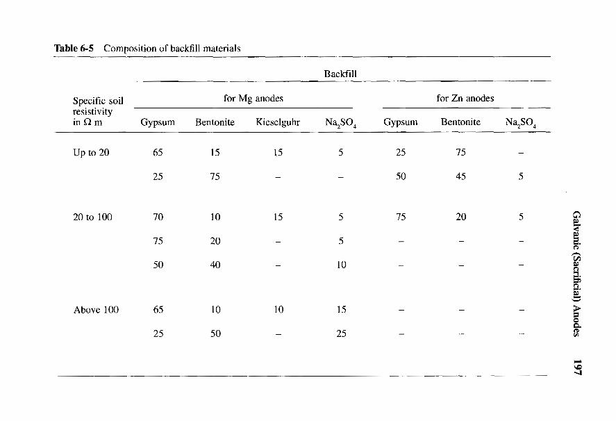
Galvanic (Sacrificial) Anodes 197
O^ I m m i l I I
S.(ft<u-oO 0}
03 'S_, o m m O i l i i= £ t> Tf <S ' I " I
8 ffl<4-H
II 8 8 £ i i i i^>O
l~~| Tt
ifl O• o o ^ - s i i ^ i ^ o «n ino , J N ^ 1 m in ^ ^ i ^ca ^3
W ^
VHX!
i f - 1 £ ' i 2 io <u§ 3OJO
Cfl ^
!§ £ 3S3 ^ 'S-*- o m in o o o o oS - S ^ r ^ <—i CN Tt i—i ms gS CQ«o«J-° S<+H fa
° t / 3 i n » n o » n o in inc D H V O C N t ^ r ^ i n ^ D f N0 >>
'•§ ^'t/ioD- ^1 'S O3 o & o g 2
^ • ^ 0 * 2 2 a>x? o t^r. 2 o >^ 21 s? ^ o 5^ c^ £ .S £ ^ <£t
E2
198 Handbook of Cathodic Corrosion Protection
thus the specific soil resistivity in the neighborhood of the anodes reduced. Thecomposition of various backfill materials is given in Table 6-5.
Backfill containing a large proportion of bentonite has a tendency to change itsvolume with variations in water content of the surrounding soil. This can lead toformation of hollow cavities in the backfill with a considerable decrease in the cur-rent delivery. A standard backfill consists of a mixture of 75% gypsum, 20% ben-tonite and 5% sodium sulfate. The specific resistivity of this backfill is initially 0.5 to0.6 £1 m and can rise with increased leaching to 1.5 £1 m.
The backfill is either poured into the borehole, or the anodes are enclosed insacks of permeable material filled with backfill. Such anodes are sunk into the bore-hole and backfilled with water and fine soil. Anodes installed in this way deliver theirmaximum current after only a few days.
Galvanic anodes must not be backfilled with coke as with impressed currentanodes. A strong corrosion cell would arise from the potential difference betweenthe anode and the coke, which would lead to rapid destruction of the anode. Inaddition, the driving voltage would immediately collapse and finally the protectedobject would be seriously damaged by corrosion through the formation of a cellbetween it and the coke.
6.4 Supports
Usually all cast galvanic anodes have specially shaped feeder appendages asanode supports by which the anodes are fixed by screws, brazing or welding. Thisguarantees a very low resistance for current flowing from the anode to the object tobe protected. Anode supports usually consist of mild steel. Supports ofnonmagnetic steels or bronze are used on warships. Wire anodes of zinc can havean aluminum core. Sheet iron supports 20 to 40 mm in breadth and 3 to 6 mm thickare used for plate anodes, and cast iron rods 8 to 15 mm in diameter for rod anodes.For larger anodes such as those used, for example, in the offshore field (see Chap-ter 16), heavier supports are necessary. Here pipes of suitable diameter are used asappendages and section steel as core material.
With correctly constructed and prepared anodes, nearly all the available anodematerial is consumed. In other circumstances a more or less greater part of theanode material can fall off during service and thereby be lost for cathodic protection.For this reason a strong bond between anode alloy and the core is necessary, whichshould extend over at least 30% of the contacting surfaces [6]. With good anodesthis percentage is widely exceeded because an intermediate layer between anodeand support is formed by alloying. In order to encourage this, the support must bewell cleaned by degreasing and pickling. After washing and drying, the support
Galvanic (Sacrificial) Anodes 199
must have the anode metal cast onto it. The support can also be shot blastedaccording to standard purity grade Sa 2V2 [30] and then must immediately have themetal cast onto it.
If the supports are provided in a state ready for casting, they must be giventemporary corrosion protection. For this purpose coatings are provided by, forexample, aluminizing, cadmium plating, galvanizing and phosphating. The twolast-named processes are mostly used. A minimum thickness of 13 jUm is prescribedfor zinc coatings [31]. Phosphate coatings must be very thin because they canimpair the bond between anode alloy and support. Correctly prepared anodes havea contact resistance between anode alloy and support of less than 1 mQ. Largercontact resistances must be avoided as they reduce the current delivery. This alsoapplies to the mounting to the object to be protected.
In most cases galvanic anodes are fixed to the object to be protected bywelding or brazing, less often by bolting to the supports. If for technical reasons oron the grounds of safety (e.g., internal protection) they have to be bolted, care mustbe taken to provide a sufficiently low resistance and reliable joint. Particularly inthe internal protection of tankers, where vibration and shaking is to be expected,the bolts must be secured against gradual loosening.
In soil, anodes are connected by cables to the object to be protected. The cablemust be low resistance in order not to reduce the current delivery. Therefore withlong lines, the cable cross-section must be proportionately large. A cable with NYMsheathing with 2.5 mm2 Cu is mostly sufficient. Occasionally stronger cables andspecial insulation are required, e.g., NYY* 4 mm2 Cu.1 Power supply cable buriedin soil should have a noticeably light color. For use in seawater, occasionallytemperature, oil and seawater-resistant cable is demanded, e.g., HO7RN.2
6.5 Forms of Anodes
The number of different anode shapes has decreased considerably with thepassage of time. Magnesium anodes for rapid prepolarization, so-called boosteranodes, are no longer used today. Guidelines are laid down for the form of gal-vanic anodes in various standards [6,22,31,32]. These guarantee good exchange-ability of anodes, particularly for the external protection of ships.
1 In the United States high molecular weight polyethylene is used, and in the United Kingdom,cross-linked polyethylene with polyvinylchloride is used.2 In the United States and the United Kingdom, KYNAR or CATHORAD cable is used.
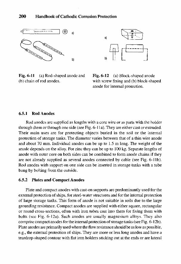
6.5.1 Rod Anodes
Rod anodes are supplied as lengths with a core wire or as parts with the holderthrough them or through one side (see Fig. 6-1 la). They are either cast or extruded.Their main uses are for protecting objects buried in the soil or the internalprotection of storage tanks. The diameter varies between that of a thin wire anodeand about 70 mm. Individual anodes can be up to 1.5 m long. The weight of theanode depends on the alloy. For zinc they can be up to 100 kg. Separate lengths ofanode with outer core on both sides can be combined to form anode chains if theyare not already supplied as several anodes connected by cable (see Fig. 6-1 Ib).Rod anodes with support on one side can be inserted in storage tanks with a tubebung by bolting from the outside.
6.5.2 Plates and Compact Anodes
Plate and compact anodes with cast-on supports are predominantly used for theexternal protection of ships, for steel-water structures and for the internal protectionof large storage tanks. This form of anode is not suitable in soils due to the largegrounding resistance. Compact anodes are supplied with either square, rectangularor round cross-sections, often with iron tubes cast into them for fixing them withbolts (see Fig. 6-12a). Such anodes are usually magnesium alloys. They alsocomprise compact anodes for the internal protection of storage tanks (see Fig. 6-12b).Plate anodes are primarily used where the flow resistance should be as low as possible,e.g., the external protection of ships. They are more or less long anodes and have ateardrop-shaped contour with flat iron holders sticking out at the ends or are lateral
Fig. 6-11 (a) Rod-shaped anode and Fig. 6-12 (a) Block-shaped anode(b) chain of rod anodes. with screw fixing and (b) block-shaped
anode for internal protection.
200 Handbook of Cathodic Corrosion Protection

Galvanic (Sacrificial) Anodes 201
Fig. 6-13 (left) Anode shapes for theexternal protection of ships. (a,b) Individualanodes and (c) groups of anodes.
Fig. 6-14 (above) Anode shapes for theinternal protection of tanks, (a) Semi-circular cross-section, (b) rectangularcross-section, (c) trapezoid cross-section.
shackles welded on. The edges are bevelled as long as the individual anodes are notcombined in larger groups (see Fig. 6-13). In addition, there are plate anodes that canbe bolted on [6,22].
The individual weights range from less than 1 kg to several 100 kg; the latter isparticularly used in steel-water structures. Anodes for the external protection ofships are heavier than 40 kg only in exceptional cases. According to need, anodes arecombined into groups whose total weight amounts to several hundred kilograms.
Finally there are large plate anodes up to 1 m square with cable connections ashangers. Such anodes serve to drain stray currents in ships in fitting out or repairs(see Section 15.6).
6.5.3 Anodes for Tanks
Tank anodes are elongated, with a round iron core running through them. Forproduction reasons the cross-sections are half round, almost rectangular ortrapezoidal and also occasionally triangular (see Fig. 6-14). The iron cores arewelded onto fasteners or crimped onto them. The shackles or the crimped coreserve for welding to the object to be protected. The weight extends from a fewkilograms for magnesium alloys to about 80 kg for zinc. The lengths, excludingsupports, are mostly between 1.0 and 1.2 m.
The anodes for internal protection of containers and tanks are frequently fixedby screws; because of the danger of explosion, welding or brazing is not allowed.
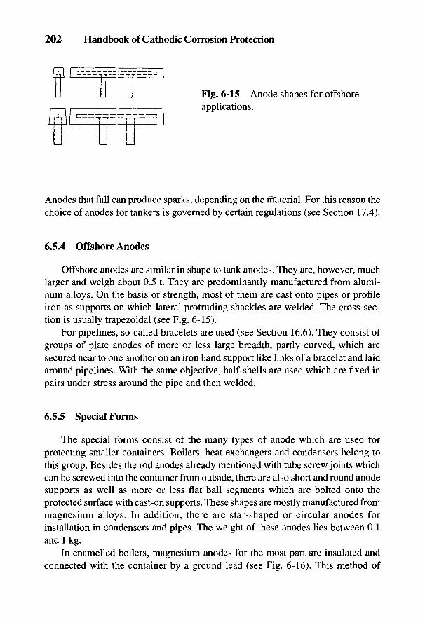
202 Handbook of Cathodic Corrosion Protection
n £—IT rr
Fig. 6-15 Anode shapes for offshoreapplications.
Anodes that fall can produce sparks, depending on the material. For this reason thechoice of anodes for tankers is governed by certain regulations (see Section 17.4).
6.5.4 Offshore Anodes
Offshore anodes are similar in shape to tank anodes. They are, however, muchlarger and weigh about 0.5 t. They are predominantly manufactured from alumi-num alloys. On the basis of strength, most of them are cast onto pipes or profileiron as supports on which lateral protruding shackles are welded. The cross-sec-tion is usually trapezoidal (see Fig. 6-15).
For pipelines, so-called bracelets are used (see Section 16.6). They consist ofgroups of plate anodes of more or less large breadth, partly curved, which aresecured near to one another on an iron band support like links of a bracelet and laidaround pipelines. With the same objective, half-shells are used which are fixed inpairs under stress around the pipe and then welded.
6.5.5 Special Forms
The special forms consist of the many types of anode which are used forprotecting smaller containers. Boilers, heat exchangers and condensers belong tothis group. Besides the rod anodes already mentioned with tube screw joints whichcan be screwed into the container from outside, there are also short and round anodesupports as well as more or less flat ball segments which are bolted onto theprotected surface with cast-on supports. These shapes are mostly manufactured frommagnesium alloys. In addition, there are star-shaped or circular anodes forinstallation in condensers and pipes. The weight of these anodes lies between 0.1and 1 kg.
In enamelled boilers, magnesium anodes for the most part are insulated andconnected with the container by a ground lead (see Fig. 6-16). This method of
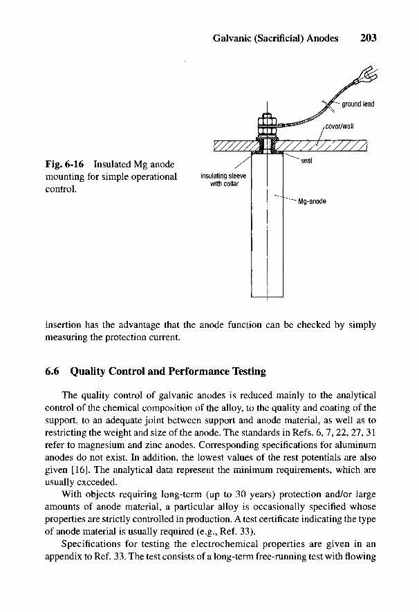
insertion has the advantage that the anode function can be checked by simplymeasuring the protection current.
6.6 Quality Control and Performance Testing
The quality control of galvanic anodes is reduced mainly to the analyticalcontrol of the chemical composition of the alloy, to the quality and coating of thesupport, to an adequate joint between support and anode material, as well as torestricting the weight and size of the anode. The standards in Refs. 6, 7, 22, 27, 31refer to magnesium and zinc anodes. Corresponding specifications for aluminumanodes do not exist. In addition, the lowest values of the rest potentials are alsogiven [16]. The analytical data represent the minimum requirements, which areusually exceeded.
With objects requiring long-term (up to 30 years) protection and/or largeamounts of anode material, a particular alloy is occasionally specified whoseproperties are strictly controlled in production. A test certificate indicating the typeof anode material is usually required (e.g., Ref. 33).
Specifications for testing the electrochemical properties are given in anappendix to Ref. 33. The test consists of a long-term free-running test with flowing
Fig. 6-16 Insulated Mg anodemounting for simple operationalcontrol.
Galvanic (Sacrificial) Anodes 203
204 Handbook of Cathodic Corrosion Protection
natural seawater. For production control, an additional short-term galvanostatictest [34] is prescribed on account of the long experimental duration of the free-running test. In addition, there are further specifications (e.g., for large-scale appli-cations) which prescribe special experimental conditions relating to practice. Theresults obtained in such tests, however, only represent comparative values; theycannot be applied to the available data in a practical application in an individ-ual case.
To estimate the current yield of magnesium alloys, the weight loss is deter-mined indirectly over the volumetric measurement of the evolved hydrogen in theapparatus in Fig. 6-9 in Section 6.2.4. The mass balance for oxygen-free mediafollows from Eqs. (6-1) and (6-5a,b) or (6-14):
Here Q is the charge delivered by the anode, V(H2) is the measured hydrogen vol-ume and V(H2) its molecular volume under the same test conditions.
From Eq. (6-15) it follows analogously with Eq. (6-14) and Eq. (6-1):
Anodes for boilers can be tested by such methods. Good-quality magnesiumanodes have a mass loss rate per unit area < 30 g m~2 d"1, corresponding to a cur-rent yield of >18% under galvanostatic anode loading of 50 /lA cm"2 in 10~2 MNaCl at 60°C. In 10~3 M NaCl at 60°C, the potential should not be more positivethan f/H = -0.9 V for the same polarization conditions [27].
6.7 Advantages and Disadvantages of Galvanic Anodes
Cathodic protection with galvanic anodes requires generally no great technicalexpenditure. Once the protection system has been installed, it operates almost with-out maintenance and only needs occasional checking of potential or protectioncurrent. Galvanic protection systems need no ac electric supply and cause no dam-aging interference on neighboring objects because of the low driving voltage. There
Galvanic (Sacrificial) Anodes 205
are also no safety problems on account of the low voltages. Galvanic systems cantherefore be installed in areas where there is a danger of explosions.
For corrosion protection in soils, the anodes can be brought close to the objectto be protected in the same construction pit so that practically no further excava-tions are needed. By connecting anodes to locally endangered objects (e.g., in thecase of interference by foreign cathodic voltage cones) the interference can beovercome (see Section 9.2.3).
In poorly conducting media or soils, however, the low driving voltage canlimit the use of galvanic anodes. Raising the current delivery, which becomes nec-essary in service, is only practically possible with the help of an additional externalvoltage. In special cases this is used if an installed galvanic system is overstretchedor if the reaction products take over additional functions (see Section 7.1).
206 Handbook of Cathodic Corrosion Protection
6.8 References
[1] E. Eberius u. H. Bohnes, Metall 14, 785 (1960).[2] W. Schwenk, Techn. Uberwachung //, 54 (1970).[3] L. Robinson und P. F. King, J. electrochem. Soc. 108, 36 (1961).[4] P. F. King, J. electrochem. Soc. 113, 536 (1966).[5] N. N., Cathodic protection of pipelines with zinc anodes, Pipe & Pipelines International,
S. 23, August 1975.[6] MIL-A-18001, USA Deptmt. of Defense, Washington DC 1968.[7] Normenstelle Marine, VG-Norm 81 255, Zink fur Anoden, Beuth Verlag, Koln 1983.[8] K. I. Vassilew, M. D. Petrov u. V. Z. Krasteva. Werkstoff und Korrosion 25, 587 (1974).[9] E. de Bie, DOS 2411608, 1974.
[10] W. Wiederholt, Das Korrosionsverhalten von Zink, Band 2: Verhalten von Zink inWassern, S. 33, Metallverlag, Berlin 1965.
[11] Gmelins Handbuch der anorganischen Chemie, Band Zink, System-Nr. 32 (1924).[12] G. Schikorr, Metallwirtschaft 18, 1036 (1939).[13] C. L. Kruse, Werkstoffe und Korrosion 27, 841 (1976).[14] W. Friehe u. W. Schwenk, Werkstoffe und Korrosion 26, 342 (1975).[15] F. Jensen, Cathodic protection of ships, Proc. 7th Scand. Corr. Congr., Trondheim, 1975.[16] Lloyds Register of Shipping, Guidance Notes on Application of Cathodic Protection,
London 1966.[17] Gmelins Handbuch der anorganischen Chemie, 8. Aufl., Band Aluminium, System-
Nr. 35, Teil B, 1934.[18] H. H. Uhlig, Corrosion Handbook, J. Wiley & Sons Inc., New York 1948, S. 224.[19] R. L. Petty, A. W. Davidson u. J. Kleinberg, J. Amer. Chem. Soc. 76, 363 (1954).[20] D. V. Kokulina u. B. N. Kabanov, Doklady Akad. Nauk. SSSR 112, 692 (1957).[21] R. Tunold et al., Corr. Science 17, 353 (1977).[22] MIL-A-21412 A, USA Deptmt. of Defense, Washington DC 1958.[23] E. Herre, aus Kap. XV, dieses Handbuch 1. Aufl.[24] W. Schwenk, aus Kap. XV, dieses Handbuch 1. Aufl.[25] W. Rausch, Kathodischer Schutz - Grundlagen und Anwendung, Metallgesellschaft,
Frankfurt 1954.[26] DIN 4753 Teil 3, Beuth-Verlag, Berlin 1987.[27] DIN 4753 Teil 6, Beuth-Verlag, Berlin 1987.[28] DIN 50927, Beuth-Verlag, Berlin 1985.[29] Unfallverhiitungsvorschriften der Berufsgenossenschaft der chemischen Industrie vom
01.04.1965, Abschn. 16, Druckbehalter § 2.4 in Verbindung mit AD-Merkblatt A3.[30] DIN 55928 Teil 4, Beuth-Verlag, Berlin 1978.[31] British Standards Institution, Code of Practice for Cathodic Protection, London 1973.[32] VG 81 257 Teil 1, Beuth-Verlag, Koln 1982.[33] Det Norske Veritas, No. IOD-90-TA1, File No. 291.20, Oslo 1982.[34] Det Norske Veritas, Technical Notes TNA 702, Abschn. 2.7, Oslo 1981.
7
Impressed Current AnodesH. BOHNES AND D. FUNK
7.1 General Comments
Galvanic anodes should have, besides a sufficiently negative potential, as higha current efficiency as possible and be as little polarizable as possible. Impressedcurrent anodes, on the other hand, can deliver a much higher current supply, as isto be expected from Eq. (2-4) and Table 2-1, when anodic redox reactions run inparallel. Impressed current anodes, which are connected to the protected objectfrom a dc source, in operation usually have a more positive potential than theprotected object. Materials for impressed current anodes should not only be of aslow solubility as possible, but should also not be damaged by impact, abrasion orvibration. Finally, they should have high conductivity and be capable of heavyloads. Anodic loading with only little material loss or none according to Eq. (2-4)is possible if an anodic redox reaction occurs according to Eq. (2-9) and Table 2-3[e.g., oxygen evolution according to Eq. (2-17)]. This usually results in a reduc-tion of the pH in the vicinity of the anode:
2H2O-4e- = O2 + 4H+ (7-1)
2 Cl- - 2 e- = C12 (7-2a)
C12 + H2O = HC1 + HOC1 (7-2b)
There are two types of impressed current anodes: either they consist ofanodically stable noble metals (e.g., platinum) or anodically passivatable materialsthat form conducting oxide films on their surfaces. In both cases, the anodic redoxreaction occurs at much lower potentials than those of theoretically possibleanodic corrosion.
This general statement does not of course mean that materials withstoichiometric weight are completely unsuited as impressed current anodes.
207
208 Handbook of Cathodic Corrosion Protection
Sometimes scrap iron is used as a material for anode installations; moreover,aluminum anodes are used in electrolytic water treatment (see Section 20.4.2). Zincalloys are used in electrolytic derusting in order to avoid the formation of explosivechlorine gas. Magnesium anodes are sometimes supplied with impressed current inthe internal protection of storage tanks containing poorly conducting water to raisethe current delivery. In the so-called Cathelco process, copper anodes aredeliberately used in addition to aluminum anodes to prevent algal growths, as wellas to provide corrosion protection by incorporation of toxic copper compounds intothe surface films. All these cases, however, involve special applications. In practice,the number of materials suitable for impressed current anodes is relatively limited.The main materials are graphite, magnetite, high-silicon iron with various additions,and lead-silver alloys as well as coated anodes of so-called valve metals. These aremetals that at very positive potentials have stable passive films, which are notelectron conducting, e.g., titanium, niobium, tantalum and tungsten. The best knownin this group are the platinized titanium anodes.
The anodes developed mainly for electrochemical processes, with electron-conducting surfaces of platinum metal oxides on valve metals, have becomeimportant in cathodic protection. In contrast, anodes of valve metals with coatingsof electron-conducting ceramic material provide considerably better anodeproperties. There are a large number of such ceramic oxides (spinel ferrite) whichare suitable as coating materials; one of them—magnetite—has been used for along time as an anode material. Magnetite anodes produced by sintering are ofcourse brittle, restricted in shape and size and cannot be machined. Applying ferritesto valve metals, leads on the other hand, to anodes that are durable and can beproduced in any shape. They exhibit low consumption rates, they are impermeableto oxygen, have a relatively low electrical resistance, do not passivate in service andare mechanically strong. Titanium anodes coated with lithium ferrite are used incorrosion protection.
Anodes similar to cables are used which consist of a copper conductor coveredwith conducting plastic. This creates an electrolytically active anode surface and atthe same time protects the copper conductor from anodic dissolution.
7.2 Anode Materials
Data on impressed current anodes are assembled in Tables 7-1 to 7-3.
7.2.1 Solid Anodes
Scrap iron is seldom used as anode material today. When applied, it includes oldsteel girders, pipes, tram lines or railway lines (30 to 50 kg nr1) which are welded
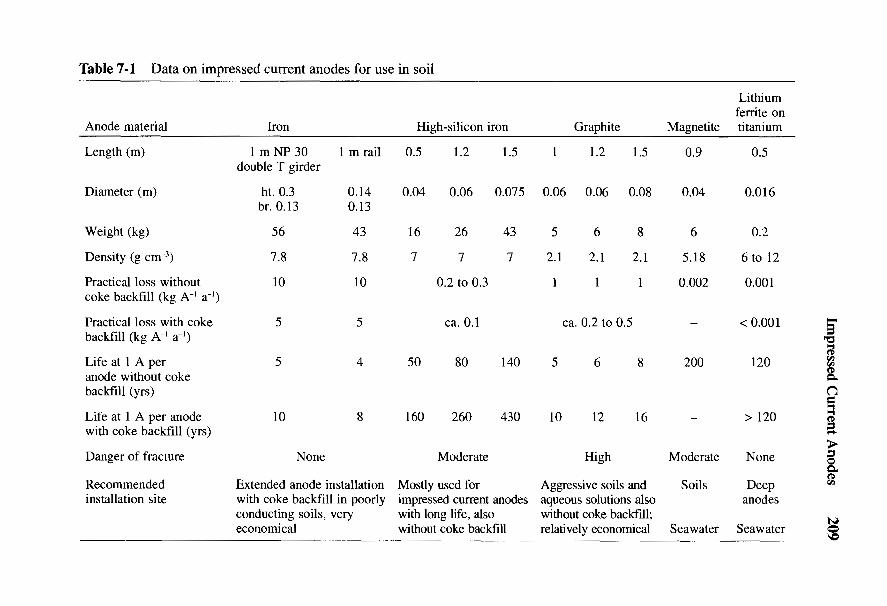
Impressed Current Anodes 209
l!l « * N - 3 8 o 8 § & • § !Sf| " § « J § « a A 2 *8 1
a % 531 g 3 ^ 22 | , g , | | 1g> O o -r> g <N | ^ gs s «»
2 1 - 3 - « * |1|1O ,/-> a g g
s ? il*l- S ^ o ^ ^ ^ 2 ^ «s •§> S 3 ^ gg- - § ^ ^ - ^ g ^ - a .g s - g «O oo c/a ._, <—<
• &o 3 tt 4)^ 4) n S >
- § « 3 - " - 2 |||1«3
• ,—. r-s 4>
a 2 ^ 3 r- f I 1 =2 ° S oS
cn B S — oi = § » - n 8 - I ni lr-H M >, M O "3
's « ^ 3 ^ ^ o s l^SI.s ° d s .§ '^ 'i(U
3 -H C
S | ^ ^ 5 o o 0 v n T t ^ | §
5 a dd - - - !-&T3 _C j-H >
§ ^ c 5 S ^S« °-8 I 113'Ig r"5im2 §-°M-3
I M p s — - - s IIeP , ^ ^£ 7 4) ^vtn gi ^ i/i
C 37 3 ^5° ^< ^r ja §r e^2 ^ - v . - S b o . t i ^ O c d ^ a
Q 1 a 1 II T^ &|« ^ 1 H1 a S S , °S J^ <l£ <^ ^ 1§
i it j fflillpiiiiHr2 < J O ^ Q P H O C L , X 5 h J c 3 X ) H j ^ Q P ! i . 5C"
210 Handbook of Cathodic Corrosion Protection
together. A suitable cable is brazed onto them (e.g., NYY-O 2 H 2.5 mm2 Cu for usein soil or NSHou of different diameters in water). The anode in the vicinity of thecable connection must be well insulated with bitumen (in soils) or cast resin (inwater) so that the exposed copper cable cannot be anodically attacked at defects inthe insulation.
Since the anodic dissolution of iron takes place with almost 100% currentefficiency through the formation of Fe(II) compounds, 1 kg of iron gives about960 A h. This high weight loss requires the use of a large amount of scrap iron [1].For a protection system that requires 10 A, at least 2 tons of scrap iron are necessaryfor 20 years of service life. Iron anodes in the ground are always embedded in coke.Low cost and good stability during transport make up for the high materialconsumption.
Magnetite, Fe3O4, conducts electrons because of its defect structure. Theresistivity of pure magnetite lies between 5.2 x 10~3 Q cm [2] and as high as10 X 10~3 Q cm. Magnetite occurs as the mineral (kirunavara and gellivare) innorthern Sweden and is mined in large amounts as iron ore. The melting point canbe lowered by adding small amounts of other minerals. Cast magnetite is glass hardand free of pores. Formerly only cylindrical compact anodes were producedbecause of the difficulty of casting this material. According to production data [3],the anode consumption is 1.5 g A4 a"1 calculated from an anode current density of 90to 100 A nr2. Consumption increases with increasing anode current density but it isstill very low even at 160 A nr2 giving 2.5 g A"1 a~l Magnetite anodes can be used insoils and aqueous environments, including seawater. They endure high voltages andare insensitive to residual ripple. Their disadvantage is their brittleness, thedifficulty in casting, and the relatively high electrical resistance of the material.
Graphite has an electron conductivity of about 200 to 700 Q.~l cm"1, is rela-tively cheap, and forms gaseous anodic reaction products. The material is,however, mechanically weak and can only be loaded by low current densities foreconomical material consumption. Material consumption for graphite anodesinitially decreases with increased loading [4, 5] and in soil amounts to about 1 to1.5 kg A"1 a"1 at current densities of 20 A nr2 (see Fig. 7-1). The consumption ofgraphite is less in seawater than in fresh water or brackish water because in thiscase the graphite carbon does not react with oxygen as in Eq. (7-1),
but with HOC1 corresponding to Eq. (7-2b) to give

Impressed Current Anodes 211
Fig. 7-1 Material consumption fromimpressed current anodes.• graphite anodewithout coke backfill, O graphite anode withcoke backfill, A FeSi anode without cokebackfill, A FeSi anode with coke backfill.
Because a considerable part of the anodically evolved chlorine is carried away bythe flowing water, the amount of hypochlorous acid is small and therefore the re-moval of graphite is less than in fresh water or soil, where direct oxidationaccording to Eq. (7-3) predominates.
Under medium loading of from 10 to 50 A irr2 in seawater, the consumption isbetween 300 and 1000 g A"1 a"1. The density of the material is between 1.6 and2.1 g cm"3. The material loss of impregnated graphite anodes is much less atcomparable current densities.
High-silicon iron is an iron alloy with 14% Si and 1% C. Its density is between7.0 and 7.2 g cm"3. Surface films containing silicic acid are formed on the passageof anodic current and restrict the anodic dissolution of iron in favor of oxygenevolution according to Eq. (7-1). The formation of surface films is insufficient inseawater and brackish water. Alloys with about 5% Cr, 1% Mn and/or 1 to 3% Mohave greater stability for use in salt water. High-silicon iron anodes behave worsethan graphite in chloride-rich water because chloride ions destroy the passive filmon the alloy. The main areas of their use are therefore soil and brackish and freshwater. Average loading is between 10 and 50 A nr2 so that the consumption rate,depending on service conditions, is below 0.25 kg A"1 a"1. High-silicon ironanodes are frequently buried directly in the soil because of their low loss rate [6];however, an outlet for the evolved gases must be provided to prevent an increase inanode resistance [7].
Lead-silver is primarily used in seawater and strong chloride-containingelectrolytes. PbAg anodes are particularly suitable for use on ships and in steel-water constructions, especially as they are relatively insensitive to mechanicalstresses. The original alloy developed by Morgan [8,9] consists of 1% Ag and 6%Sb, with the remainder Pb. It is represented as alloy 1 in Table 7-2. A similar alloydeveloped by Applegate [10] has 2% Ag and the remainder Pb. Another alloy
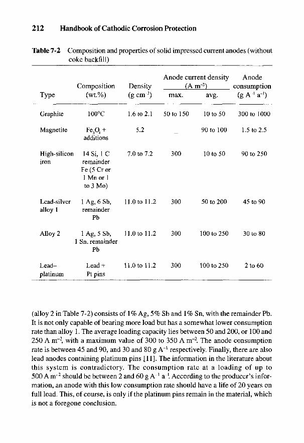
212 Handbook of Cathodic Corrosion Protection
Table 7-2 Composition and properties of solid impressed current anodes (withoutcoke backfill)
Anode current density AnodeComposition Density (A m~2) consumption
Type (wt.%) (g cnr3) max. avg. (g A~! a~!)
Graphite 100°C 1.6 to 2.1 50 to 150 10 to 50 300 to 1000
Magnetite Fe3O4 + 5.2 90 to 100 1.5 to 2.5additions
High-silicon 14 Si, 1 C 7.0 to 7.2 300 10 to 50 90 to 250iron remainder
Fe (5 Cr or1 Mn or 1to 3 Mo)
Lead-silver 1 Ag, 6 Sb, 11.0 to 11.2 300 50 to 200 45 to 90alloy 1 remainder
Pb
Alloy 2 lAg, 5Sb, 11.0 to 11.2 300 100 to 250 30 to 801 Sn, remainder
Pb
Lead- Lead+ 11.0 to 11.2 300 100 to 250 2 to 60platinum Pt pins
(alloy 2 in Table 7-2) consists of 1% Ag, 5% Sb and 1% Sn, with the remainder Pb.It is not only capable of bearing more load but has a somewhat lower consumptionrate than alloy 1. The average loading capacity lies between 50 and 200, or 100 and250 A nr2, with a maximum value of 300 to 350 A m~2. The anode consumptionrate is between 45 and 90, and 30 and 80 g A"1 respectively. Finally, there are alsolead anodes containing platinum pins [11]. The information in the literature aboutthis system is contradictory. The consumption rate at a loading of up to500 A nr2 should be between 2 and 60 g A"1 a~\ According to the producer's infor-mation, an anode with this low consumption rate should have a life of 20 years onfull load. This, of course, is only if the platinum pins remain in the material, whichis not a foregone conclusion.
Impressed Current Anodes 213
While antimony improves the mechanical properties of the soft lead, additionsof silver and tin as well as platinum pins, act to form a thick and good conductinglayer of PbO2 that actually constitutes the current leakage surface in operation. If thealloying elements or the Pt pins are absent, the PbO2 remains full of cracks, is porousand adheres badly, so that in electrolytes containing chloride, a reaction occurs onthe metallic lead under the film, forming PbCl^ ions so that the anode is consumedtoo quickly. Even with the presence of the additions or pins, the formation of theblack-brown, strongly adherent, uniformly growing film occurs over the PbCl2 andis also bonded in the presence of chloride ions. If a tolerable anode consumption is tobe ensured, then healing of damage to the PbO2 film which cannot be avoided inoperation must be sufficiently certain. Anodes based on lead, such as silver alloy orplatinum pins, can only be used in chloride-rich electrolytes [12]. The advantage oflead anodes is their easy formability. Disadvantages—besides their limitation instrong chloride electrolytes—are the high density of 11 to 11.2 g cirr3 and, for theexterior of ships, their relatively low anode current densities.
Finally it must be remembered with these anodes that PbO2 film, which acts toprovide the current leakage, can be detached even when no current is flowing.With renewed anodic loading, the film has to be reformed, which leads to acorresponding consumption of anode material. The anodes should therefore beoperated as continuously as possible with a basic load. An exhaustive treatment ofthe composition and behavior of lead alloy anodes can be found in Ref. 13.
7.2.2 Noble Metals and Valve Metals Coated with Noble Metals
Impressed current anodes of the previously described substrate materials al-ways have a much higher consumption rate, even at moderately low anode cur-rent densities. If long life at high anode current densities is to be achieved, onemust resort to anodes whose surfaces consist of anodically stable noble metals,mostly platinum, more seldom iridium or metal oxide films (see Table 7-3).
Cotton proposed solid platinum [14] as a material for impressed current anodes.Such anodes are capable of delivering current densities of 104 A nr2 under suit-able conditions. The driving voltage is practically unlimited, and the consumptionrate, assuming optimum conditions, is very low—in the region of less than a fewmilligrams A"1 a"1. This applies chiefly at relatively low current densities inseawater where there is good dispersion of the hypochlorous acid that is formed.When noble materials have to be used to achieve high anode current densities inpoorly conducting electrolytes, the anodic consumption of platinum increases dueto the formation of chlorocomplexes and is then directly dependent on thecurrent density [15-17]. In addition, in solutions containing little chlorine, the moresoluble PtO2 instead of PtO is preferentially formed due to the dominance ofoxygen evolution at the anode surface, so that the consumption of platinum also
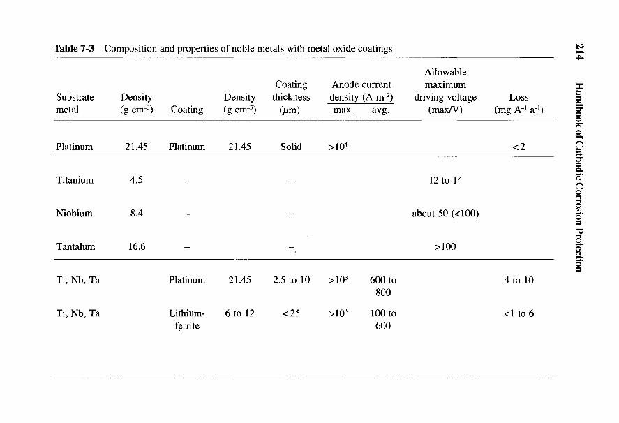
214 Handbook of Cathodic Corrosion Protection
<3 o 1O1/1 — '—I ^«5 I CS O
9 < v 2 ~I ^ v
«D o"
-S S §I I o > - ^ o£ .§ > a 2 o 2o * 2P § ^ ^ 713 KJ C H <N . , /x
< a > - - j•" •§
I ffef ll si| | <j * voO o O-
^ <u >,^ 'o -a *'>< C C g O 0 0
° <^ S A A A03
1S w> £ 2•S C OJ ^ T3 ^ ^
'S S I I ^ ' ' '" ^ VM o .a 3 oo «o v13 u -S <N
•4—>
0>
a<U >^ m^ fN
1 !i 3 2 o£ Q M <^ ^ voO s '(/i
I S- I I 6 ao '-S c i i i c -3 'HC c« -£5 I I I \3 S Ccx o c3 ^ -a .oj-•g u cu OH jCHcdC /-v
I fl= ^ ^ ^ *>5 g S -' ^ od S6 Q s59CHoU
cd cd*? £ S E g S ^ H^ 2 3 .2 I -^ ^ xT-2 ^ ^ - S S ^ § Z ^i -§ « 3 £ -2 §£j c ^ S S H ^ H H H
Impressed Current Anodes 215
rises. However, the loss is small so that solid platinum is actually an ideal anodematerial. Such anodes are very heavy because of the high density of platinum(21.45 g cnr3) and are uneconomical because of the very high purchase price ofplatinum. For this reason anodes of another metal are used whose effectivesurfaces are coated with platinum.
Platinum on titanium is the best-known anode of this type. The use of platinumon the so-called valve metals was first mentioned in 1913 [18]. Titanium is a lightmetal (density 4.5 g cm"3) that is capable of anodic passivation. The passive film ispractically insulating at driving voltages of less than 12V. According to Ref. 16,the current in an NaCl solution is very small up to a potential of UH = +6 V, butrises steeply above this value. The oxide film on titanium, which initially consistsof the orthorhombic brookite, is replaced by tetragonal anatase as the thickness ofthe film increases [19]. If the oxide film, however, is damaged with increasingpotential, then it is only regenerated at potentials of UH < 1.7 V. This critical self-healing potential is thus less positive than the above-mentioned critical breakdownpotential of +6 V.
If titanium is coated with platinum, the oxide film must first of all be removedby careful etching of the surface. Then the platinum must be applied by electro-chemical or thermal means, or mechanically by cladding. The film thickness inelectrochemical or thermal platinizing is from 2.5 to 10 jum. Clad platinumcoatings are usually thicker. They are also, in contrast to the former, free of poresand therefore more efficient from the point of view of resistance, but of course theyare considerably more expensive. The platinum surface behaves practically likesolid platinum and can be subjected to higher driving voltages as long as the un-clad titanium surface is isolated from the medium. The thinner porous platinumcoatings, on the other hand, possess the limitations of titanium if with lowerconductivity and higher driving voltages the TiO2 film in the pores can bedestroyed and the platinum film can be disbonded and removed [20-22].
Whereas with impressed current anodes of passivatable materials no specialdemands are imposed on the quality of the direct current that is fed in, this is quitedifferent with platinized anodes. Investigations [23-25] showed that the loss ofplatinum with residual ripple of the direct current increased over 5%. Basically thedemand on the residual ripple of the direct current increases with increasingdriving voltage and anode current density and is dependent on the removal of theelectrolysis products and therefore on the electrolytic flow at the anode. It can beassumed as certain that increased consumption occurs for low-frequency residualripple <50 Hz. Above 100 Hz, the influence of the residual ripple is small. Theresidual ripple lies in this frequency range for bridge rectifiers operated with50-Hz alternating voltage; with three-phase rectifiers the frequency is much higher(300 Hz), and the residual ripple is controlled by the circuit at 4%. Experience has
216 Handbook of Cathodic Corrosion Protection
shown that the influence of residual ripple is small under optimum conditions atthe anode.
Platinum on other valve metals is used where the low critical breakdownpotential of titanium presents intolerable limitations. There are several reasons forthis in cathodic protection. With good conducting electrolytes, the high anodecurrent densities of on average between 600 and 800 A irr2, and even up to 103 A m~2
and above, can be made good use of without further problems. With poorlyconducting electrolytes (e.g., fresh water) the allowable driving voltage for aneconomic layout with platinized titanium anodes is not sufficient. In addition, athigher temperatures above about 50°C, the critical breakdown potential decreasesstill further; at 90°C it is about UH = 2.4 V. Finally, the chemical composition of theelectrolyte can influence the breakdown potential. This is for instance the case foracid electrolyte containing hydrogen halites. In such cases materials are chosen asthe substrate metal that have properties similar to titanium but are considerablymore stable, particularly niobium and tantalum. The breakdown potentials underthe limiting conditions described are considerably higher. Driving voltages up to100 V in chloride solutions are permissible with niobium and tantalum.Platinized niobium and tantalum anodes can be used almost without any limita-tions. They only break down in electrolytes containing fluoride or boron fluoride,as does titanium, because all three substrate materials cannot form passive films insuch media. Niobium has a density of 8.4 g cnr3 and tantalum 16.6 g cm"3. Afurther superiority of these valve metals is their high electrical conductivity, whichis almost three times that of titanium at 2.4 X 10^ Q"1 cm"1.
Iridium on valve metals is suitable if the consumption rate of platinum is toohigh at elevated temperatures or critical composition of the medium.Mostly platinum-iridium alloys are used with about 30% Ir, because coating valvemetals with pure iridium is somewhat complicated. For the same reason, othernoble metals such as rhodium cannot be used [21]. At present there is little pricedifference between platinum and iridium.
7.2.3 Metal Oxide-Coated Valve Metals
Good results are obtained with oxide-coated valve metals as anode materials.These electrically conducting ceramic coatings of p-conducting spinel-ferrite (e.g.,cobalt, nickel and lithium ferrites) have very low consumption rates. Lithiumferrite has proved particularly effective because it possesses excellent adhesion ontitanium and niobium [26]. In addition, doping the perovskite structure withmonovalent lithium ions provides good electrical conductivity for anodic reactions.Anodes produced in this way are distributed under the trade name Lida [27]. Theconsumption rate in seawater is given as 10~3 g A"1 a"1 and in fresh water is

Impressed Current Anodes 217
about 6 x 10~3 g A"1 a"1. With bedding in calcium petroleum coke, the consumptionrate is less than 10~3 g A"1 a"1. The anodes are very abrasion resistant and have ahardness of 6 on the Mohs scale; they are thus much more abrasion resistant thanplatinized titanium anodes. There are no limitations in forming these anodes as isalso the case with platinized titanium anodes. The polarization resistance of theseanodes is very low. Therefore, voltage variations at the anode surface resultingfrom alternating voltage components in the supplying rectifier are very small.The current loading in soil with coke backfill is 100 A irr2 of active surface, inseawater 600 A nr2 and in fresh water 100 A nr2. They offer great advantages overhigh-silicon iron anodes as deep well anodes because of their low weight.
7.2.4 Polymer Cable Anodes
Polymer cable anodes are made of a conducting, stabilized and modifiedplastic in which graphite is incorporated as the conducting material. A copper cablecore serves as the means of current lead. The anode formed by the cable is flexible,mechanically resistant and chemically stable. The cable anodes have an externaldiameter of 12.7 mm. The cross-section of the internal copper cable is 11.4 mm2
and its resistance per unit length R' is consequently 2 mQ nr1. The maximumcurrent delivery per meter of cable is about 20 mA for a service life of 10 years.This corresponds to a current density of about 0.7 A mr2. Using petroleum coke asa backfill material allows a higher current density of up to a factor of four.
Without coke backfill, the anode reactions proceed according to Eqs. (7-1) and(7-2) with the subsequent reactions (7-3) and (7-4) exclusively at the cable anode.As a result, the graphite is consumed in the course of time and the cable anoderesistance becomes high at these points. The process is dependent on the localcurrent density and therefore on the soil resistivity. The life of the cable anode isdetermined, not by its mechanical stability, but by its electrical effectiveness.
7.3 Insulating Materials
Impressed current anodes must be insulated from the surface that is beingprotected. Also, the current connections must be well insulated to prevent the freeends of the cable from being attacked and destroyed.
The demands on insulating materials in soil and fresh water are relatively low.Anodically evolved oxygen makes the use of aging-resistant insulating materialsnecessary. These consist of special types of rubber (neoprene) and stabilizedplastics of polyethylene, and polyvinylchloride, as well as cast resins such asaery late, epoxy, polyester resin and many others.
218 Handbook of Cathodic Corrosion Protection
Much greater demands are made on insulating materials for seawater and otherelectrolytes containing halides because anodic chlorine is evolved, depending onthe chloride content and the current density, which is particularly aggressive anddestructive to many insulating materials. HC1 and HOC1 formed according toEq. (7-2b) attack the materials forming the anode supports. Chloride-resistantinsulating materials are polypropylene, neoprene, chloroprene, and special typesof polyvinylchloride (e.g., Trovidur HT) as well as special variations of epoxy andunsaturated polyesters. A particular requirement is a reliable bond between anodematerial and insulating material. Even with scrupulous cleanliness, it is oftendifficult to produce a strong and lasting bond that will be exposed (e.g., in cathodicprotection in and on ships) to considerable mechanical stresses from streaming,vibration, impact, etc. Where gluing or casting with cast resin is not possible,elastic sealing materials such as silicone cement are used. Disbonding of theinsulating material, especially in the area of the current leads, can result inbreakdown of the anode in a short time.
Especially resistant insulating materials have to be provided for the followingsevere service conditions: aggressive environments, high temperatures and highpressure. Organic insulating materials that can withstand severe chemicalconditions are fluorinated plastics, e.g., polytetrafluoroethylene (Teflon). Athigher temperatures and pressures, ceramic insulating materials are used (e.g., por-celain insulators, or glass inserts for high-pressure-resistant, screwed-in anodes).The brittleness and different coefficients of thermal expansion have to beconsidered with ceramic materials.
7.4 Cables
A single or multicored plastic-coated cable of the type NYY* or NYY-O isused as the connecting cable between a protected object and an anode in soils andfresh water, and particularly in seawater, medium heavy or heavy rubber-sheathedconnections of an NSHou or NSSHou* type are used. Heavy welded connectionsof type NSLFSou* are used for severe mechanical loading. In addition to these, forships, marine cable of type MGCG* or watertight cables must be considered.
Ohmic voltage drops resulting in losses cannot be ignored in the connectingcables with long anode cables and high protection currents [28]. Cable costs andlosses must be optimized for economic reasons. The most economic calculatedcable dimension depends primarily on the lowest cross-section from the thermalpoint of view. For various reasons the permitted voltage drop usually lies between1 and 2 V, from which the cross-section of the cable to be installed can becalculated from Eq. (3-36).
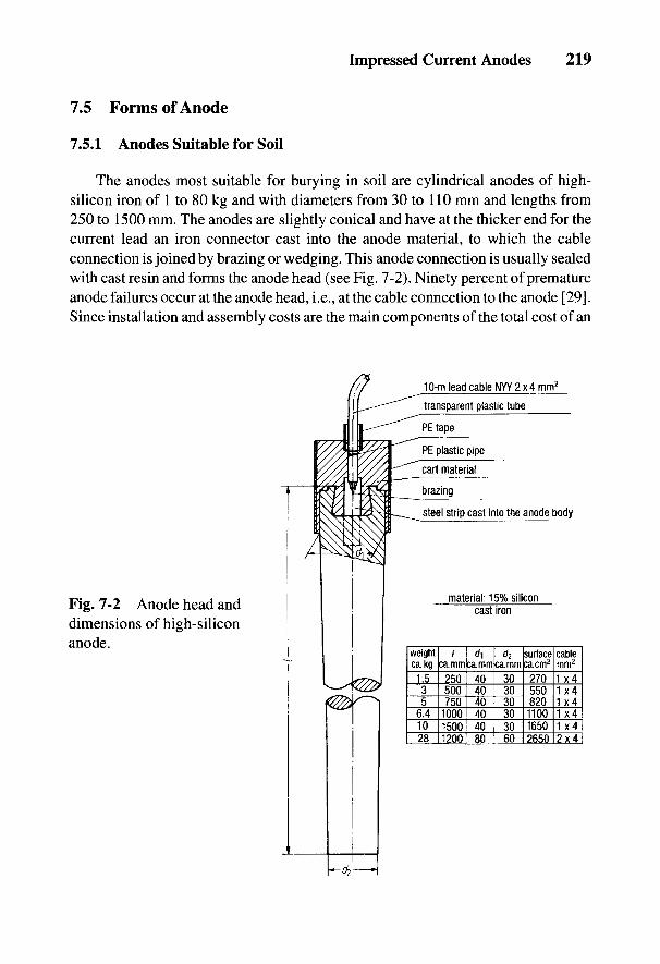
Impressed Current Anodes 219
7.5 Forms of Anode
7.5.1 Anodes Suitable for Soil
The anodes most suitable for burying in soil are cylindrical anodes of high-silicon iron of 1 to 80 kg and with diameters from 30 to 110 mm and lengths from250 to 1500 mm. The anodes are slightly conical and have at the thicker end for thecurrent lead an iron connector cast into the anode material, to which the cableconnection is joined by brazing or wedging. This anode connection is usually sealedwith cast resin and forms the anode head (see Fig. 7-2). Ninety percent of prematureanode failures occur at the anode head, i.e., at the cable connection to the anode [29].Since installation and assembly costs are the main components of the total cost of an
Fig. 7-2 Anode head anddimensions of high-siliconanode.
220 Handbook of Cathodic Corrosion Protection
anode system, very careful attention should be given to the construction of a reliableand durable anode head. With heavier anodes, support for the cable is necessary(e.g., attachment to a carrying rope) and a device is needed at the exit point from theanode head to prevent kinking and damage during installation.
Impressed current anodes in soil are usually bedded in coke. Blast furnacecoke No. 4 that is 80 to 90% C, has a resistivity p = 0.2 to 0.5 Q. m and a particlesize between 2 and 15 mm is particularly suitable as backfill. Anodically evolvedgases (O2, CO2 and C12, e.g., in soils with high chloride content) can escape so thatno increase in anode resistance arises from a gas lock. In addition, by bedding incoke, the actual dimensions of the anode can be increased and the groundingresistance considerably reduced (see Chapter 9). The grounding resistance ofanodes bedded in coke remains constant over many years, whereas for anodes notbedded in coke, it can double in a few years due to electro-osmotic dehydrationand surface film formation. Anodes with a low current loading can also be beddedin clay mud (see Section 6.3). Coke as backfill must be lightly compacted to givegood electrical connection with the anode. As a result, loss from the anode is mostlytransferred to the outer surface of the coke backfill. To avoid the formation oflarger amounts of acid at the anode according to Eqs. (7-1) and (7-2b), slaked limecan be added to the coke backfill. The consumption rate of the coke backfill isabout 2 kg A"1 a~l Practical consumption rates for scrap iron, graphite, and high-silicon iron anodes with and without coke backfill are given in Table 7-1. Thereduction in consumption rate by coke backfill is particularly important with scrapiron anodes because material consumption can be reduced by ca. 50%.
In addition to anodes with a simple connecting head, there are cylindrical doubleanodes that have cable connectors cast on at both ends and that can be used in theconstruction of horizontal or vertical anode chains. Anodes of graphite or magnetiteare more compact than anodes of high-silicon iron because of the danger of fracture.
Cylindrical anodes are preferred for the oxide-coated titanium anodes, with di-ameters of 16 and 25 mm and lengths between 250 and 1000 mm [31]. The anodesare supplied as single anodes or as finished anode chains with a connecting cable.The carrier material consists of a titanium tube through which a special cable (EPR/CSPE1) is threaded. This cable is insulated in the middle of the titanium tube and isequipped with a copper outer covering. Electrical contact with the anode is achievedby crimping the tube at the ends and sealing it to the cable in the middle. To protectthe metal oxide coating, copper shoes are fixed at the contact points. These anodesare particularly suitable for the construction of deep well anode installations becauseof their low weight as well as the simple production of anode chains. The anodes
'A trade name of CEAT CAVI Ind., Turin, Italy. It is ethylene propylene rubber/chlorosulfonatedpolyethylene.
Impressed Current Anodes 221
have to be inserted into a backfill of calcined petroleum coke to give a low groundresistance and increased life. This coke has a bulk weight of 0.8 tons m~3 and aparticle size of 1 to 5 mm. The resistivity is between 0.1 and 5 Q cm, depending onthe compressive loading. Detergents are added to the coke to give a rapid compac-tion time.
With deep anodes, a tube that allows gases to escape must be included to avoida build-up of gas (see Section 9.1.3). The anode chains are supplied with cable, acentering device and a gas escape tube.
Cable anodes of conducting polymers have an advantage when there are siteproblems with the installation of other anodes. They are extensively used for thecathodic protection of reinforcing steel in concrete (see Section 19.5.4).
7.5.2 Anodes Suitable for Water
Cylindrical anodes with a construction similar to those in Section 7.5.1 arealso suitable for use in water to protect steel-water constructions and offshoreinstallations, and for the inner protection of tanks. In addition to graphite,magnetite and high-silicon iron, anodes of lead-silver alloys are used as well astitanium, niobium or tantalum coated with platinum or lithium ferrite. Theseanodes are not usually solid, but are produced in tube form. In the case of lead-silver anodes, the reason is their heavy weight and relatively low anode currentdensity; with coated valve metals, only the coating suffers any loss. Finally, thetubular shape gives larger surfaces and therefore higher anode currents. The sametypes of connection apply to lead-silver anodes as those given in Section 7.5.1.The cable can be directly soft soldered onto the anode if a reduction in the tensileload is required. This is not possible with titanium. Such anodes are therefore pro-vided with a screw connection welded on where appropriate, which is also of tita-nium. The complete connection is finally coated with cast resin or the whole tubeis filled with a suitable sealing compound. Because of the poor electrical conduc-tivity of titanium, with long and highly loaded anodes it is advisable to providecurrent connections at both ends.
Disc and ingot-shaped anodes are also used in water besides the cylindrical orconical shapes. Several parallel-connected rod anodes as well as hurdle-shapedracks are sometimes used for the protection of larger objects such as sheet steellinings and loading bridges if sufficient space is available and there is no likelihood ofthe anodes being damaged, e.g., by anchors. These are situated on the ground andcontain several anodes, mostly rod anodes, next to one another in insulated fixtures.In calculating the ground resistance of such groups of anodes, the influence ofneighboring anodes must be taken into account (see Section 24.2). Floating anodesare used for offshore installations in which the current outflow surface is attached
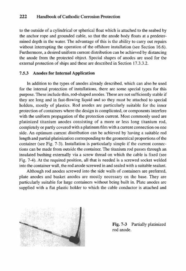
222 Handbook of Cathodic Corrosion Protection
to the outside of a cylindrical or spherical float which is attached to the seabed bythe anchor rope and grounded cable, so that the anode body floats at a predeter-mined depth in the water. The advantage of this is the ability to carry out repairswithout interrupting the operation of the offshore installation (see Section 16.6).Furthermore, a desired uniform current distribution can be achieved by distancingthe anode from the protected object. Special shapes of anodes are used for theexternal protection of ships and these are described in Section 17.3.3.2.
7.5.3 Anodes for Internal Application
In addition to the types of anodes already described, which can also be usedfor the internal protection of installations, there are some special types for thispurpose. These include thin, rod-shaped anodes. These are not sufficiently stable ifthey are long and in fast-flowing liquid and so they must be attached to specialholders, mostly of plastics. Rod anodes are particularly suitable for the innerprotection of containers where the design is complicated, or components interferewith the uniform propagation of the protection current. Most commonly used areplatinized titanium anodes consisting of a more or less long titanium rod,completely or partly covered with a platinum film with a current connection on oneside. An optimum current distribution can be achieved by having a suitable rodlength and partial platinization corresponding to the geometrical proportions of thecontainer (see Fig. 7-3). Installation is particularly simple if the current connec-tions can be made from outside the container. The titanium rod passes through aninsulated bushing externally via a screw thread on which the cable is fixed (seeFig. 7-4). At the required position, all that is needed is a screwed socket weldedinto the container wall, the rod anode screwed in and sealed with a suitable sealant.
Although rod anodes screwed into the side walls of containers are preferred,plate anodes and basket anodes are mostly necessary on the base. They areparticularly suitable for large containers without being built in. Plate anodes aresupplied with a flat plastic holder to which the cable conductor is attached and
Fig. 7-3 Partially platinizedrod anode.

Fig. 7-4 Standardrod anodes forinternal protection ofcontainers and pipes(dimensions inmillimeters).
Impressed Current Anodes 223
insulated. Large plate anodes are seldom used because the current distribution atanode current densities from 600 to 800 A m~2 becomes too inhomogeneous andcan lead to premature breakdown of the anode due to preferential removal of plati-num at the edges.
In such cases basket anodes are frequently used. These have a relatively largesurface and work at a low driving voltage due to their special construction. A cyl-inder of platinized titanium-expanded metal serves as the basket to which a tita-nium rod is welded. This serves as the current lead and carrier, and ends in a plasticfoot that contains the cable lead and at the same time serves as the mounting plate.The expanded metal anode exhibits a very uniform anode current density distribu-tion, even at large dimensions, in contrast to the plate anode. The reason is themany corners and edges of the metal that make the point effect only evident at theouter edges of the anode.
In internal protection, attention must be paid to the fact that mixed gases thatcontain hydrogen and oxygen are evolved by the protection current. Noble metalsand noble metal coatings can catalyze an explosion. The safety measures requiredin this case are presented in DIN 50927 [32] (see also Section 20.1.5).
224 Handbook of Cathodic Corrosion Protection
7.6 References
[1] M. Parker, Rohrkorrosion und kathodischer Schutz, Vulkan-Verlag, Essen 1963.[2] H. Backstrom, Ojvers. Akad. Stockholm 45, 544 (1888).[3] Bergs0e, Anticorrosion AS, Firmenschrift ,,BERA Magnetite Anodes".[4] W. v. Baeckmann, gwf 107, 633 (1966).[5] S. Tudor, Corrosion 14, 957 (1958).[6] NACE, Publ. 66-3, Corrosion 16, 65 t (1960).[7] W.T. Bryan, Mat. Perf. 9, H. 9, 25 (1970).[8] J.H. Morgan, Corrosion 13, 128 (1957).[9] J. H. Morgan, Cathodic Protection, Leonhard Hill Ltd, London 1959.
[10] L. M. Applegate, Cathodic Protection, 90, Me Graw-Hill Book Co, New York 1960.[11] R. L. Benedict, Mat. Protection 4, H. 12, 36 (1965).[12] G.W. Moore u. J.H. Morgan, Roy. Inst. Nav. Arch. Trans. 110, 101 (1968).[13] J. A. v. Frauenhofer, Anti-Corrosion 15, 4 (1968), 16, 17 (1969).[14] J. B. Cotton, Platinum Metals Rev. 2, 45 (1958).[15] R. Baboian, International Congress of Marine Corrosion and Fouling, Juni 1976.[16] R. Baboian, Mat. Perf. 16, H. 3, 20 (1977).[17] C. Marshall u. J.P. Millington, J. Appl. Chem. 19, 298 (1969).[18] R.H. Stevens, USP 665427 (1913).[19] J. B. Cotton, Werkstoffe und Korrosion //, 152 (1960).[20] E.W. Dreyman, Mat. Perf. 11, H. 9, 17 (1972).[21] v. Stutternheim, Metachem, Oberursel, pers. Mitteilung Marz 1978.[22] M. A. Warne u. P.C.S. Hayfield, Mat. Perf. 15, H. 3, 39 (1976).[23] R. Juchniewicz, Platinum Metals Rev. 6, 100 (1962).[24] R. Juchniewicz, Corrosion Science 6, 69 (1966).[25] R. Juchniewicz und Bogdanowicz, Zash. Metal 5, 259 (1969).[26] A. Kumar, E.G. Segan u. J. Bukowski, Mat. Perf. 23, H. 6, 24 (1984).[27] D. H. Kroon u. C. F. Schrieber, NACE-Confer. Corrosion 1984, Paper Nr. 44.[28] H.G. Fischer u. W. A. Riordam, Corrosion 13, 19 (1956).[29] F. Paulekat, Kath. Innenschutz, HDT-Veroffentlichung 402, Vulkan-Verlag, Essen 1978.[30] G. Heim u. H. Klas, ETZ A 77, 153 (1958).[31] C.G. Schrieber u. G.L. Mussinelli, Mat. Perf. 26, H. 7, 45 (1987).[32] DIN 50927, Beuth Verlag, Berlin 1985.
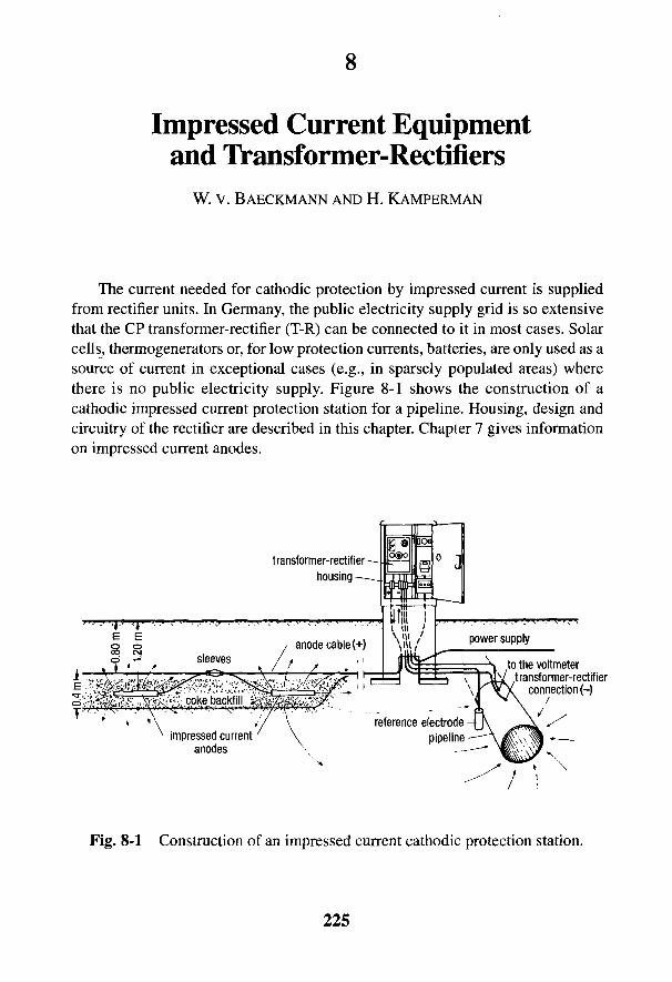
8
Impressed Current Equipmentand Transformer-Rectifiers
W. v. BAECKMANN AND H. KAMPERMAN
The current needed for cathodic protection by impressed current is suppliedfrom rectifier units. In Germany, the public electricity supply grid is so extensivethat the CP transformer-rectifier (T-R) can be connected to it in most cases. Solarcells, thermogenerators or, for low protection currents, batteries, are only used as asource of current in exceptional cases (e.g., in sparsely populated areas) wherethere is no public electricity supply. Figure 8-1 shows the construction of acathodic impressed current protection station for a pipeline. Housing, design andcircuitry of the rectifier are described in this chapter. Chapter 7 gives informationon impressed current anodes.
Fig. 8-1 Construction of an impressed current cathodic protection station.
225

226 Handbook of Cathodic Corrosion Protection
8.1 Site and Electrical Protection Measures
Impressed current stations for buried tanks are connected to the electricity sup-ply of the site on which the tank stands. The location of a protection installation forlocal distribution and for transmission lines, on the other hand, is determined princi-pally by the availability of connection to a public electricity supply grid becauseconsiderable costs are involved in connecting a very long voltage supply to the grid.With a very large current requirement, it is of only secondary importance that theanodes be installed in a region of low soil resistivity. In choosing the location, thefollowing considerations are relevant and are given in their order of importance:
• availability of a grid connection,
• as low an electrical soil resistivity as possible in the area of the anode bed,
• sufficient distance from buried foreign installations to reduce their inter-ference (see Chapter 9),
• as little disturbance of the site owner's property as possible,
• good access for vehicles,
• with stray current installations, a location that has as large a leakage area aspossible for the stray current of the pipe network.
With impressed current stations on privately owned sites, it is advisable toconclude contracts with the property owner in order to guarantee access to theinstallation at all times, to prevent damage to the cables and to exclude construc-tion or modifications in the area of the anode beds.
In choosing a site for protection installations for steel-water structures,decisive factors are the location in the harbor area and the need to keep the lengthsof cable to the protected object and anode as short as possible where very highprotection currents are involved.
The units and ancillary equipment must be protected from mechanical damageand the effects of weather to ensure the reliable operation of an impressed currentstation. This is achieved by installing it in a weatherproof plastic housing(see Fig. 8-2). Sufficient ventilation must be provided to disperse heat. The venti-lation holes should be protected with brass gauze to keep out animals. Transformer-rectifier units must be connected to a circuit that is continuously energized, especiallyif they are in a building where the current is turned off at night, e.g., gas stationsthat are not open for 24 h.
In work places, T-R units should be installed where there is no danger ofexplosion, since explosion-proof measures are very costly and units in suchinstallations are difficult to service and maintain. It is more convenient to bear the
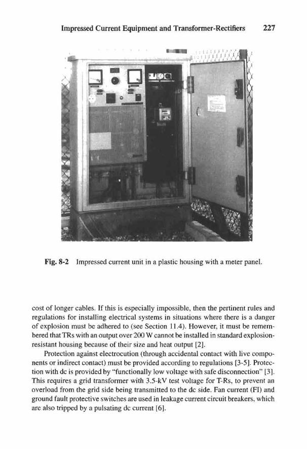
Impressed Current Equipment and Transformer-Rectifiers 227
Fig. 8-2 Impressed current unit in a plastic housing with a meter panel.
cost of longer cables. If this is especially impossible, then the pertinent rules andregulations for installing electrical systems in situations where there is a dangerof explosion must be adhered to (see Section 11.4). However, it must be remem-bered that TRs with an output over 200 W cannot be installed in standard explosion-resistant housing because of their size and heat output [2].
Protection against electrocution (through accidental contact with live compo-nents or indirect contact) must be provided according to regulations [3-5]. Protec-tion with dc is provided by "functionally low voltage with safe disconnection" [3].This requires a grid transformer with 3.5-kV test voltage for T-Rs, to prevent anoverload from the grid side being transmitted to the dc side. Fan current (FI) andground fault protective switches are used in leakage current circuit breakers, whichare also tripped by a pulsating dc current [6].

228 Handbook of Cathodic Corrosion Protection
8.2 Design and Circuitry of Impressed Current
Transformer-rectifiers are produced for use in corrosion protection stationswith a rated dc output of about 10 W for storage tanks and short pipelines as well asup to a few kilowatts for large steel-water constructions. In general, T-Rs forpipelines have an output of 100 to 600 W. It is recommended that the rated currentof the T-R be twice that of the required current so that sufficient reserve is availableto cope with potential future enlargement of the installation, a possible decrease inthe coating resistance, increase in stray currents or other changes. The necessaryrated output voltage results from the required protection current and the resistanceof the anode/soil/protected object circuit, which can be estimated or measuredafter installation of the final anode bed. Sufficient reserve should also be providedfor the output voltages.
In rail installations, a drainage test of sufficient duration during the mostsevere service conditions (such as commuter traffic) must always be carried outwhere there is stray current interference. This should be carried out as far aspossible from the previously installed anode bed and only in exceptional circum-stances with provisional anodes, or in the case of planned stray current forceddrainage, by a connection to the rails (see Section 15.5.1). A portable self-regulatingT-R serves for the drainage test. During the test, protection current and outputvoltage as well as the potential at the test site and at other significant points in thepipe network are recorded. It is particularly recommended that attention be paid tothe output data of the T-R and that there is sufficient reserve.
In stray current forced drainage against rails, current peaks up to 100 A canoccur, particularly in the protection of old pipe networks with poor coating,although the necessary output voltage remains quite low. This current depends onthe voltage between rail and pipe as well as on the resistance of the circuit. Withrails laid in the street and thus earthbound tracks, this is mostly between 5 and10 V. The dc supply for such installations is therefore considerably less than fornormal impressed current anode stations.
The behavior is quite different with modern tramways, which run on their owntrack bed with wooden ties and clean ballast. Here the grounding resistance of thetrack would have to be very high to produce even a small stray current interfer-ence. Due to this and the high operating current of the heavy locomotives, thevoltage between rail and soil is very high and can reach 40 to 50 V in short pulses.Therefore, the above-mentioned advantage of the necessary low output voltage ofthe T-R is lost with forced stray current drainage. It is then more beneficial to useimpressed anode beds, especially when protecting well-coated pipelines with lowprotection current requirements. It has also been shown that connecting severalprotection installations to a stretch of track with a high ground resistance has a
Impressed Current Equipment and Transformer-Rectifiers 229
mutually unfavorable influence, so that for this reason also the use of impressedanode beds is preferable.
8.3 Rectifier Circuit
In single-phase bridge circuits for ac connections and for very low ac outputvoltages below 5 V, single-phase center tap circuits are used as rectifier circuits forCP transformer-rectifiers. They have an efficiency of 60 to 75% and a residualripple of 48% with a frequency of 100 Hz. A three-phase bridge circuit for three-phase alternating current is more economical for outputs of about 2 kW. It has anefficiency of about 80 to 90% and a residual ripple of 4% with a frequency of300 Hz. The residual ripple is not significant in the electrochemical effect of theprotection current so that both circuits are equally valid.
The following factors can impose limits on the residual ripple:
• A current with ripples can lead to a high consumption rate for platinizedtitanium anodes and their premature failure. The residual ripple should belimited to 5% (see Section 7.2.2) [7],
• In the cathodic protection of asymmetrically connected communicationcables, distortions are coupled into the transmission lines coming from theripple of the sheath current. In this case also, limiting the residual ripple to5% is usually sufficient.
• In cathodically protected water pipelines, inductive flow meters areaffected by the ripple on the pipe current. The producers of these instru-ments mostly say that a ripple of 5% is permissible.
Reducing the residual ripple from single-phase rectifiers for currents up toabout 20 A and voltages of up to about 20 V can be achieved by filter circuits ofchoke coils and condensers. For greater output and constant residual ripple inde-pendent of load, the only possibility is the three-phase bridge circuit. It is alwaysmore satisfactory than a filter circuit.
The rating of a transformer-rectifier unit refers to an external temperature of35°C. Higher temperatures require the special design of some components and thisshould be discussed with the manufacturer. Usually T-Rs are outfitted with self-cooling by natural ventilation. Forced ventilation with a fan leads to considerablecontamination and is not used for this reason. In particularly difficult climaticconditions (e.g., for steel-water constructions in the tropics), oil cooling is neces-sary for larger units. This provides good protection for the rectifier cells andtransformers, removes heat, and provides protection against atmospheric effectsfor variable ratio transformers with current collectors.
230 Handbook of Cathodic Corrosion Protection
Selenium columns or silicon stacks are an important component in the rectifierunit. Selenium rectifiers are insensitive to overcurrent, short circuit and overvoltage,and can be inertly fused. They have an outstanding operational safety and arepreferred for all normal applications of CP transformer-rectifiers. Several plates ofselenium are connected in series for output voltages over 20 V due to their lowbarrier voltage of 25 to 30 V. This results in rapid increases in losses and volume,which are much greater than with silicon, where one cell per section in the bridge issufficient even for high-output voltages. This is the basis of the widely known advan-tage of silicon in rectifier design, but it is not effective in CP transformer-rectifierswith low output voltages. Silicon cells are very sensitive to overcurrent and overvolt-age, and require protection by quick-response safety devices and voltage limiters.They have indeed a very high barrier voltage, but are not able to suppress short, low-energy voltage peaks as do selenium rectifiers, owing to their extremely smallbarrier current, and they blow out when this occurs. On the other hand, blowoutswith selenium rectifiers are self-healing. Silicon is preferred under severe climaticconditions since the cells can be hermetically sealed and made insensitive to atmo-spheric effects. Furthermore, the permitted operating temperature is somewhat higherthan for selenium. Silicon cells are used exclusively for high-voltage T-Rs.
Rectifiers cannot be completely protected against overvoltage by gas dischargearresters even if the barrier voltage is considerably above the response voltage ofthe arrester. The reason for this is the relatively long response time of the arrester(a few microseconds), whereas semiconductors blow out much quicker, in theregion of a few nanoseconds. Voltage limiters based on selenium and condensershave proved themselves in protecting silicon cells against overvoltage.
8.4 Adjustable Transformer-Rectifiers
Transformer-rectifiers with fixed output voltages are used in all cathodicprotection stations in which the current circuit resistance and the currentrequirement remain constant. For low output and low currents, this is achieved bytaps and terminals on the secondary of the transformer. For greater output and fora simple setting, it is convenient to provide an isolating transformer with a fixedsecondary voltage for the maximum output dc voltage of the device and to includea control transformer in the circuit of the primary that serves as an autotransformer.It can be installed as a toroidal core or pile control transformer, variable or withtaps, combined with a multiple contact switch. It is recommended that the contactsof control transformers and switches be cleaned thoroughly during maintenanceand occasionally activated to keep them clean.
Usually the annual variations in the specific resistance of the soil lead only tosmall changes in the current circuit resistance so that adjustment of the protection
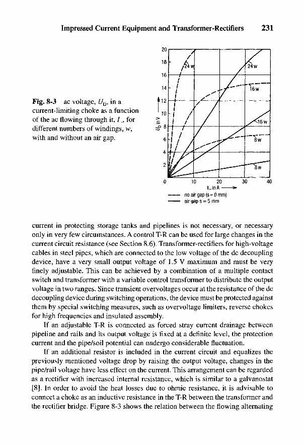
Impressed Current Equipment and Transformer-Rectifiers 231
Fig. 8-3 ac voltage, t/D, in acurrent-limiting choke as a functionof the ac flowing through it, /_, fordifferent numbers of windings, w,with and without an air gap.
current in protecting storage tanks and pipelines is not necessary, or necessaryonly in very few circumstances. A control T-R can be used for large changes in thecurrent circuit resistance (see Section 8.6). Transformer-rectifiers for high-voltagecables in steel pipes, which are connected to the low voltage of the dc decouplingdevice, have a very small output voltage of 1.5 V maximum and must be veryfinely adjustable. This can be achieved by a combination of a multiple contactswitch and transformer with a variable control transformer to distribute the outputvoltage in two ranges. Since transient overvoltages occur at the resistance of the dcdecoupling device during switching operations, the device must be protected againstthem by special switching measures, such as overvoltage limiters, reverse chokesfor high frequencies and insulated assembly.
If an adjustable T-R is connected as forced stray current drainage betweenpipeline and rails and its output voltage is fixed at a definite level, the protectioncurrent and the pipe/soil potential can undergo considerable fluctuation.
If an additional resistor is included in the current circuit and equalizes thepreviously mentioned voltage drop by raising the output voltage, changes in thepipe/rail voltage have less effect on the current. This arrangement can be regardedas a rectifier with increased internal resistance, which is similar to a galvanostat[8]. In order to avoid the heat losses due to ohmic resistance, it is advisable toconnect a choke as an inductive resistance in the T-R between the transformer andthe rectifier bridge. Figure 8-3 shows the relation between the flowing alternating
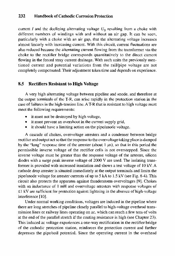
232 Handbook of Cathodic Corrosion Protection
current / and the declining alternating voltage UD resulting from a choke withdifferent numbers of windings with and without an air gap. It can be seen,particularly with a choke with an air gap, that the alternating voltage increasesalmost linearly with increasing current. With this circuit, current fluctuations arealso reduced because the alternating current flowing from the transformer via thechoke to the rectifier bridge corresponds quantitatively to the direct currentflowing in the forced stray current drainage. With such units the previously men-tioned current and potential variations from the rail/pipe voltage are notcompletely compensated. Their adjustment takes time and depends on experience.
8.5 Rectifiers Resistant to High Voltage
A very high alternating voltage between pipeline and anode, and therefore atthe output terminals of the T-R, can arise rapidly in the protection station in thecase of failures in the high-tension line. A T-R that is resistant to high voltage mustmeet the following requirements:
• it must not be destroyed by high voltage,• it must prevent an overshoot in the current supply grid,• it should have a limiting action on the pipe/anode voltage.
A cascade of chokes, overvoltage arresters and a condenser between bridgerectifier and output act so that the response to the overvoltage taking place is dampedby the "long" response time of the arrester (about 1 jUs), so that in this period thepermissible inverse voltage of the rectifier cells is not overstepped. Since theinverse voltage must be greater than the response voltage of the arrester, silicondiodes with a surge peak inverse voltage of 2000 V are used. The isolating trans-former is provided with increased insulation and shows a test voltage of 10 kV. Acathode drop arrester is situated immediately at the output terminals and limits thepipe/anode voltage for arrester currents of up to 5 kA to 1.5 kV (see Fig. 8-4). Thiscircuit also protects the apparatus against thunderstorm overvoltages [9]. Chokeswith an inductance of 1 mH and overvoltage arresters with response voltages of<1 kV are sufficient for protection against lightning in the absence of high-voltageinterference [10].
Under normal working conditions, voltages are induced in the pipeline wherethere are long stretches of pipeline closely parallel to high-voltage overhead trans-mission lines or railway lines operating on ac, which can reach a few tens of voltsat the end of the parallel stretch if the coating resistance is high (see Chapter 23).This induced ac voltage experiences a one-way rectification in the rectifier bridgeof the cathodic protection station, reinforces the protection current and furtherdepresses the pipe/soil potential. Since the operating current in the overhead
Impressed Current Equipment and Transformer-Rectifiers 233
Fig. 8-4 Circuit diagram of a transformer-rectifier with overvoltage protection (pro-tected against high voltage).
transmission line or the railway changes with time, the induced voltage and there-fore also the rectified alternating current varies synchronously so that thepipe/soil potential is continuously fluctuating. Optimal adjustment of thecathodic protection station becomes extremely difficult. High-voltage-resistantrectifiers here have the advantage that their chokes severely reduce the rectifiedalternating current.
In the case of an accident, steel pipes containing high-voltage cables can take ona high voltage against the ground (see Chapter 14). Therefore high-voltage T-Rs areused in the cathodic protection of these pipes whenever they are used outside of theswitchplants [11].
8.6 Control Rectifiers
Cathodic protection stations frequently operate under conditions that arecontinually changing. These include:
• stray current interference,
• frequent and large changes in the grounding resistance of an impressedcurrent station due to the varying specific electrical resistance of the medium,e.g., in steel-water constructions,
• fluctuation in the current requirement with changes in the aqueouscondition and oxygen access (flowing velocity), e.g., in the internalprotection of storage tanks,
• protection potential ranges with two limiting potentials (see Section 2.4).
234 Handbook of Cathodic Corrosion Protection
In such conditions, it is recommended that the T-R be equipped with anelectrical control circuit, which primarily keeps the potential constant, and, inexceptional circumstances, also the protection current. These pieces of equipmentare potentiostats (for controlling potential) and galvanostats (for controllingcurrent) [8].
The inclusion of control units in a protection station has the considerableadvantage that the station is always working under optimal conditions. As anexample, with potential control, sufficient protection current is always availablefor forced stray current drainage and for stray current peaks resulting from largenegative rail/soil potential during periods when the railway is not operating; withmore positive rail/soil potentials, only the necessary current flows to attain theprotection potential. This ensures that the interference of foreign installations is,on average, small. Furthermore, a reference point in the course of the potentialalong the pipeline is held constant, namely the potential at the protection stations.Also, limiting values of other fluctuating potentials at the remaining measuringpoints can be covered.
The adjustment of a protection station or of a complete protection system wherethere is stray current interference is made much easier by potential control. Poten-tial control can be indispensable for electrochemical protection if the protectionpotential range is very small (see Sections 2.4 and 21.4). This saves anode materialand reduces running costs.
Current control can be more advantageous where rail/soil potentials arepredominantly positive. Current control is also preferred in the cathodic protectionof steel-water construction if the anode resistance fluctuates due to changes inelectrical conductivity.
Figure 8-5 shows the main circuit diagram of a potential control rectifierprovided with magnetic amplifiers (transducers). The chosen potential is set at thenominal value with a potentiometer. The actual potential is compared with thisvalue, which corresponds to the voltage between a reference electrode and theprotected object.
The difference between the nominal and the actual voltage controls a presteppedmagnetic amplifier that sets the primary alternating voltage for the rectifiertransformer via a final-step magnetic amplifier. The output voltage and, with it, theprotection current of the rectifier, is raised or lowered by this means whenever thepotential of the protected object deviates from the nominal value in either direction.The response time is between 0.1 and 0.3 s. The control current amounts to about50 //A. At this loading, the reference electrode must have sufficiently low resis-tance and low polarizability.
Potential control rectifiers can also be constructed using thyristors. However,these produce strong high-frequency harmonic waves that can be transmitted to
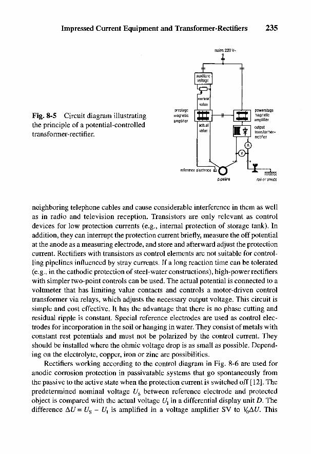
Impressed Current Equipment and Transformer-Rectifiers 235
Fig. 8-5 Circuit diagram illustratingthe principle of a potential-controlledtransformer-rectifier.
neighboring telephone cables and cause considerable interference in them as wellas in radio and television reception. Transistors are only relevant as controldevices for low protection currents (e.g., internal protection of storage tank). Inaddition, they can interrupt the protection current briefly, measure the off potentialat the anode as a measuring electrode, and store and afterward adjust the protectioncurrent. Rectifiers with transistors as control elements are not suitable for control-ling pipelines influenced by stray currents. If a long reaction time can be tolerated(e.g., in the cathodic protection of steel-water constructions), high-power rectifierswith simpler two-point controls can be used. The actual potential is connected to avoltmeter that has limiting value contacts and controls a motor-driven controltransformer via relays, which adjusts the necessary output voltage. This circuit issimple and cost effective. It has the advantage that there is no phase cutting andresidual ripple is constant. Special reference electrodes are used as control elec-trodes for incorporation in the soil or hanging in water. They consist of metals withconstant rest potentials and must not be polarized by the control current. Theyshould be installed where the ohmic voltage drop is as small as possible. Depend-ing on the electrolyte, copper, iron or zinc are possibilities.
Rectifiers working according to the control diagram in Fig. 8-6 are used foranodic corrosion protection in passivatable systems that go spontaneously fromthe passive to the active state when the protection current is switched off [12]. Thepredetermined nominal voltage Us between reference electrode and protectedobject is compared with the actual voltage t/j in a differential display unit D. Thedifference At/ = Us - t/j is amplified in a voltage amplifier SV to V0AU. This
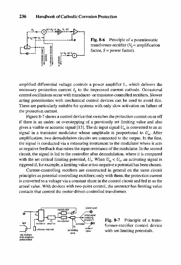
236 Handbook of Cathodic Corrosion Protection
Fig. 8-6 Principle of a potentiostatictransformer-rectifier (V0= amplificationfactor, S = power factor).
amplified differential voltage controls a power amplifier L, which delivers thenecessary protection current 7S to the impressed current cathode. Occasionalcontrol oscillations occur with transducer- or transistor-controlled rectifiers. Sloweracting potentiostats with mechanical control devices can be used to avoid this.These are particularly suitable for systems with only slow activation on failure ofthe protection current.
Figure 8-7 shows a control device that switches the protection current on or offif there is an under- or overstepping of a previously set limiting value and alsogives a visible or acoustic signal [13]. The dc input signal Um is converted to an acsignal in a transistor modulator whose amplitude is proportional to Um. Afteramplification, two demodulation circuits are connected to the output. In the first,the signal is conducted via a measuring instrument to the modulator where it actsas negative feedback that raises the input resistance of the modulator. In the secondcircuit, the signal is led to the controller after demodulation, where it is comparedwith the set critical limiting potential, Us. When Um< Us, an activating signal isriggered if, for example, a limiting value at too-negative a potential has been chosen.
Current-controlling rectifiers are constructed in general on the same circuitprinciples as potential-controlling rectifiers; only with them, the protection currentis converted to a voltage via a constant shunt in the control circuit and fed in as theactual value. With devices with two-point control, the ammeter has limiting valuecontacts that control the motor-driven controlled transformer.
Fig. 8-7 Principle of a trans-former-rectifier control devicewith set-limiting potentials.
Impressed Current Equipment and Transformer-Rectifiers 237
8.7 Transformer-Rectifiers without Mains Connections
In inaccessible regions where an impressed current installation is not suffi-ciently close to a low voltage supply, the protection current can be supplied frombatteries, thermogenerators, and if there is sufficient radiation from the sun, solarcells. Wind generators and diesel units, on the other hand, are less suitable becauseof the maintenance necessary for continuous operation.
The limit for the application of an accumulator battery is a protection currentof about 20 mA. This is calculated to be supplied by a 100-A h capacity batteryover a period of about 7 months. It is sufficient to change the discharged battery fora fully charged one every 6 months.
In a thermogenerator, heat energy is transformed into electrical energy bythermocouples. A dc voltage is produced by the temperature difference betweenthe junctions of two different metals (thermocouples), its magnitude depending onthe temperature difference. Essential parts of a thermogenerator are thecombustion chamber, the thermopile with the thermocouples, which consist ofsemiconductors, as well as the cold junction. The efficiency is about 3%. Propane,butane or natural gas can be used as the fuel. The last can be obtained, for example,from the long-distance gas pipeline that is being cathodically protected. Itsoperating pressure must first be reduced and controlled at about 2 bars. Thecontroller belonging to the thermogenerator reduces this pressure to 0.5 bar. Onegenerator that was tried out in practice had a maximum electrical capacity of 130 W.The protection installation driven by it supplied a protection current of 9 A at anoutput voltage of 12 V and has been working for about 15 years without anyproblems.
Solar cells can also be used to produce current for protection installations oflow capacity [14]. Such an installation consists of a panel of solar cells mountedon a mast, an accumulator battery to bridge the periods when the sun is not shining,a charge regulator connected between the solar cells and the battery, as well as anoutput controller between the battery and the protection current circuit. It caneither be current controlled or potential controlled. These construction elementsare designed according to the local sun radiation and the electrical supplynecessary for the protection installation. Computer programs are available for thispurpose. Solar generators are mainly used for the cathodic protection of pipelinesin desert regions. An experimental unit is also operating in Germany [15].
8.8 Equipment and Control of Transformer-Rectifiers
Transformer-rectifiers should have an ammeter to indicate the current and ahigh-resistance voltmeter to indicate the potential at the protection station.
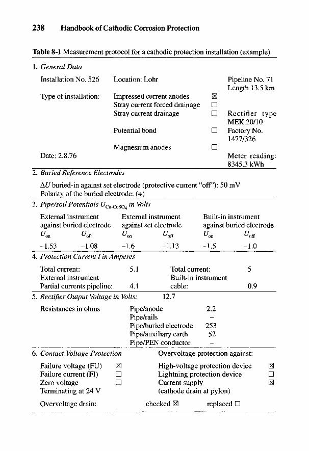
238 Handbook of Cathodic Corrosion Protection
Table 8-1 Measurement protocol for a cathodic protection installation (example)
1. General Data
Installation No. 526 Location: Lohr Pipeline No. 71Length 13.5 km
Type of installation: Impressed current anodes 1*3Stray current forced drainage DStray current drainage D Rectifier type
MEK 20/10Potential bond D Factory No.
1477/326Magnesium anodes D
Date: 2.8.76 Meter reading:8345.3 kWh
2. Buried Reference Electrodes
At/buried-in against set electrode (protective current "off'): 50 mVPolarity of the buried electrode: (+)
3. Pipe/soil Potentials £/Cu-CuSO4 in Volts
External instrument External instrument Built-in instrumentagainst buried electrode against set electrode against buried electrodetf« tfoff ^on Z/oiF ^on ^off
-1.53 -1.08 -1.6 -1.13 -1.5 -1.04. Protection Current I in Amperes
Total current: 5.1 Total current: 5External instrument Built-in instrumentPartial currents pipeline: 4.1 cable: 0.9
5. Rectifier Output Voltage in Volts: 12.7
Resistances in ohms Pipe/anode 2.2Pipe/rails -Pipe/buried electrode 253Pipe/auxiliary earth 52Pipe/PEN conductor -
6. Contact Voltage Protection Overvoltage protection against:
Failure voltage (FU) S High-voltage protection device SFailure current (FI) D Lightning protection device DZero voltage D Current supply [x]Terminating at 24 V (cathode drain at pylon)
Overvoltage drain: checked IS) replaced D
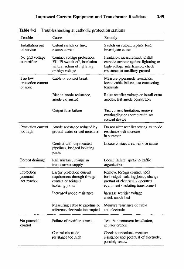
Impressed Current Equipment and Transformer-Rectifiers 239
Table 8-2 Troubleshooting at cathodic protection stations
Trouble Cause Remedy
Installation out Cutout switch or fuse, Switch on cutout, replace fuse,of service excess current investigate cause
No grid voltage Contact voltage protection, Insulation measurement, installat rectifier FU, FI switch off, insulation cathode arrester against lightning or
failure, action of lightning high-voltage interference, checkor high voltage resistance at auxiliary ground
Too low Cable or contact break Measure pipe/anode resistance,protection current locate cable failure, test connectingor none terminals
Rise in anode resistance, Raise rectifier voltage or install extraanode exhausted anodes, test anode connection
Output fuse failure Test current limitation, removeoverloading or short circuit, setcontrol device
Protection current Anode resistance reduced by Do not alter rectifier setting as anodetoo high ground water or soil moisture resistance will increase
in summer
Contact with unprotected Locate contact area, remove causepipelines, bridged isolatingjoints
Forced drainage Rail fracture, change in Locate failure, speak to traffictram current supply organization
Protection Larger protection current Remove foreign contact, lookpotential requirement through foreign for bridged isolating joints, changenot reached contact or bridged ground of electrically operated
isolating joints equipment (isolating transformer)
Increased anode resistance Increase rectifier voltage,check anode bed
Measuring cable to pipeline or Measure resistance of cablereference electrode interrupted and electrode
No potential Failure of rectifier control Test the instrument installation,control ac interference
Control electrode Check connections, measureresistance too high resistance and potential of electrode,
possibly renew
240 Handbook of Cathodic Corrosion Protection
Measuring terminals parallel to the instruments facilitate their control and the con-nection to voltage and current recorders.
With single-phase transformers, large surges can occur when they are switchedon if this is done when the ac voltage supply is in an unfavorable phase. This can tripfuses or automatic cutouts in switching on fixed-value rectifiers of about 600 Wcapacity. This leads to, for example, unnoticed breakdown of the protection stationwhen the current is switched on again after an interruption. It is recommended that astarting attenuator be installed so the rectifier is connected to the mains through aresistor. This is then bridged after a short time by a contactor. Rectifiers with acontrol current generally do not experience current surges when switched on.
In rectifiers with fuses as protection against overloading and short circuits, onlythose of the type recommended by the supplier must be used. This is particularly thecase with silicon rectifiers. Potential-controlling rectifiers can be protected againstoverloading and short circuits by limiting current in the control circuit.
Stray currents can flow from pipe to rails where a rectifier is used for forcedstray current drainage when there is a small secondary voltage in the transformer andthe negative voltage between rails and pipe is greater than the open circuit voltage ofthe transformer. This state of affairs can be recognized when the voltmeter of therectifier reads in the opposite direction, so that a very high current can flow. Over-loading of the rectifier can then be prevented by an automatic circuit. An overcurrentrelay provides protection that separates the output current circuit pipe/rectifier/railsand in this case produces a direct connection between pipe and rails. The protectionis switched on again by an adjustable time switch. By this means the installation ismaintained in operation. A counter mechanism records the number of shutdowns.Frequent shutdowns give information about interferences in the operation of therailway.
Switching of protection installations to measure the off potential shouldalways be on the dc side, particularly if there are ac voltage effects between anodeand pipeline that are rectified in the rectifier and provide a protection current, orwhen it is a matter of forced drainage where the drainage current flows from thepipeline via the rectifier to the rails. If the rectifiers control potential, the controlcircuit must also be switched off; otherwise current surges will occur when it isswitched on.
Impressed current stations must be inspected regularly [16,17]. This should takeplace generally every month because:
• considerable anodic corrosion can occur on failure of the stray current pro-tection system,
• installation can be overloaded by possible disturbances in railway operation,• changes in the operation of tramways or the section supply can create other
stray current behavior.

Impressed Current Equipment and Transformer-Rectifiers 241
On inspection, the built-in measurements and the counter readings should beread off and recorded. Any breakdown should be reported to the authorizedheadquarters of the cathodic protection organization. Table 8-1 illustrates a formfor use in the supervision of cathodic protection stations. Causes of trouble andremedial measures are given in Table 8-2.
With impressed current installations supervised by technical telecom-munications, it is sufficient to carry out operational control annually [17]. With gaspipeline grids, it is advisable to build in inspection instruments in the controlinstallations or connecting stations since connection with the telecommunicationsystem is possible.
242 Handbook of Cathodic Corrosion Protection
8.9 References
[1] DVGW-Arbeitsblatt GW 12, ZfGW-Verlag, Frankfurt 1984.[2] AfK-Empfehlung Nr. 5, ZfGW-Verlag, Frankfurt 1986.[3] DIN VDE 0100 Teil 410, Beuth-Verlag, Berlin 1983.[4] AfK-Empfehlung Nr. 6, ZfGW-Verlag, Frankfurt 1985.[5] VBG 4, Elektrische Anlagen und Betriebsmittel, Heymanns-Verlag, Koln 1979.[6] DIN VDE 0664 Teil 1, Beuth-Verlag, Berlin 1983.[7] V. Ashworth u. C. J. L. Booker, Cathodic Protection, Theory and Practice, E. Horwood
Ltd., Chichester/GB 1986, S. 116, 265.[8] DIN 50918, Beuth-Verlag, Berlin 1978.[9] H. Kampermann, ETZ-A 96, 340 (1975).
[10] W. v. Baeckmann, N. Wilhelm u. W. Prinz, gwf gas/erdgas 107, 1213 (1966).[11] AfK-Empfehlung Nr. 8, ZfGW-Verlag, Frankfurt 1983.[12] H. Grafen u. a., Die Praxis des Korrosionsschutzes, expert-Verlag, Grafenau 1981, S. 304.[13] J. Prusek, K. Mojzis u. M. Machacek, Werkstoffe u. Korrosion 20, 27 (1969).[14] G. Gouriou, 3R internal. 26, 315 (1987).[15] R. Wielpiitz. Neue Deliwa-Z. 38, 16 (1987).[16] DIN 30676, Beuth Verlag, Berlin 1985.[17] DVGW-Arbeitsblatt GW 10, ZfGW-Verlag, Frankfurt 1984.
9
Impressed Current Ground Bedsand Interference Problems
W. VON BAECKMANN AND W. PRINZ
Cathodic protection of long pipelines, distribution networks, pipelines in indus-trial plants and other buried installations with a high protection current require-ment is achieved mostly by means of impressed current anodes. With a highprotection current requirement, the grounding resistance of the anodes, as the highestresistance in the protection current circuit, determines the necessary rectifiervoltage and also the power of the protection station. The lowest grounding resis-tance practically possible should be designed for in order to keep down the electricpower and therefore the operating costs (see Section 9.1.4). According to Table 24-1,the grounding resistance, /?, is directly proportional to the specific soil resistivity, p.Anode beds with protection current output >1 A are installed wherever possible inareas of low specific soil resistivity [1]. Today the anode bed is generally arrangedin continuous coke backfill in horizontal or vertical positions [2].
The protection current is transmitted to the soil via the impressed currentanode bed. Therefore the current density and the field strength, the voltage dropper meter, are greatest in the vicinity of the anode bed; they decrease with increas-ing distance from it. At a distance from the anode bed where no appreciable fieldstrength due to the protection current is detectable, the soil potential (^^ = 0(see Fig. 3-24). This potential is termed that of the remote ground. The voltagebetween the remote ground and the anodes is the anode voltage. Because of thecone-shaped &U(x) curve of the voltage distribution on the soil surface (see Fig. 9-1),this is called the voltage cone of the anode bed. The height of the voltage conedepends on the anode voltage and its shape depends on the arrangement of theanodes. This is important for possible effects on buried foreign installations.
Voltage cones also occur where the protection current enters through defectsin the pipe coating (see Sections 3.6.2 and 24.3.4). Figure 9-1 showsschematically the variation of the voltage cone of an anode bed and a cathodicallyprotected pipeline that results from the raising and lowering of potential.
243
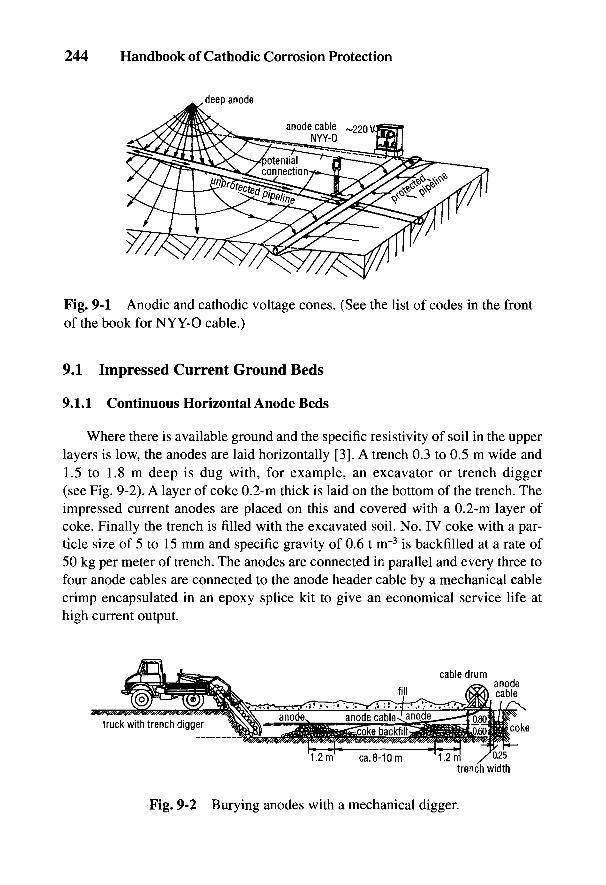
244 Handbook of Cathodic Corrosion Protection
Fig. 9-1 Anodic and cathodic voltage cones. (See the list of codes in the frontof the book for NYY-O cable.)
9.1 Impressed Current Ground Beds
9.1.1 Continuous Horizontal Anode Beds
Where there is available ground and the specific resistivity of soil in the upperlayers is low, the anodes are laid horizontally [3]. A trench 0.3 to 0.5 m wide and1.5 to 1.8 m deep is dug with, for example, an excavator or trench digger(see Fig. 9-2). A layer of coke 0.2-m thick is laid on the bottom of the trench. Theimpressed current anodes are placed on this and covered with a 0.2-m layer ofcoke. Finally the trench is filled with the excavated soil. No. IV coke with a par-ticle size of 5 to 15 mm and specific gravity of 0.6 t m"3 is backfilled at a rate of50 kg per meter of trench. The anodes are connected in parallel and every three tofour anode cables are connected to the anode header cable by a mechanical cablecrimp encapsulated in an epoxy splice kit to give an economical service life athigh current output.
Fig. 9-2 Burying anodes with a mechanical digger.
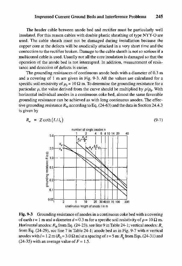
Impressed Current Ground Beds and Interference Problems 245
The header cable between anode bed and rectifier must be particularly wellinsulated. For this reason cables with double plastic sheathing of type NYY-O areused. The cable sheath must not be damaged during installation because thecopper core at the defects will be anodically attacked in a very short time and theconnection to the rectifier broken. Damage to the cable sheath is not so serious if amulticored cable is used. Usually not all the core insulation is damaged so that theoperation of the anode bed is not interrupted. In addition, measurement of resis-tance and detection of defects is easier.
The grounding resistances of continuous anode beds with a diameter of 0.3 mand a covering of 1 m are given in Fig. 9-3. All the values are calculated for aspecific soil resistivity of p0 = 10 Q m. To determine the grounding resistance for aparticular p, the value derived from the curve should be multiplied by p/p0. Withhorizontal individual anodes in a continuous coke bed, almost the same favorablegrounding resistance can be achieved as with long continuous anodes. The effec-tive grounding resistance /?w according to Eq. (24-63) and the data in Section 24.4.3is given by
Fig. 9-3 Grounding resistance of anodes in a continuous coke bed with a coveringof earth / = 1 m and a diameter d = 0.3 m for a specific soil resistivity of p = 10 Q m.Horizontal anodes: RH from Eq. (24-23), see line 9 in Table 24-1; vertical anodes: Rv
from Eq. (24-29), see line 7 in Table 24-1; anode bed as in Fig. 9-7 with n verticalanodes with / = 1.2 m (RQ = 3.0 Q m) at a spacing of s = 5 m: R^ from Eqs. (24-31) and(24-35) with an average value of F= 1.5.
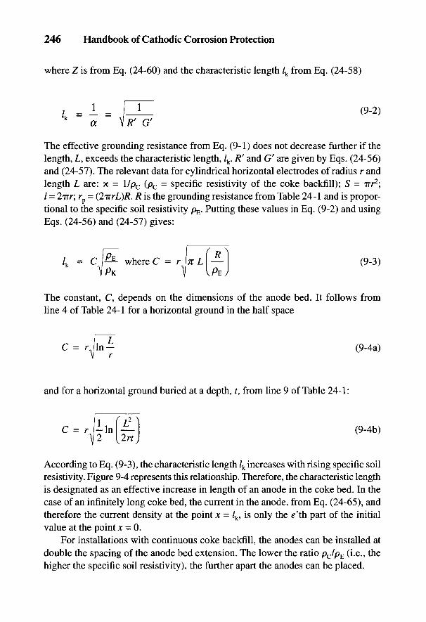
246 Handbook of Cathodic Corrosion Protection
where Z is from Eq. (24-60) and the characteristic length /k from Eq. (24-58)
The effective grounding resistance from Eq. (9-1) does not decrease further if thelength, L, exceeds the characteristic length, /k. R
f and G' are given by Eqs. (24-56)and (24-57). The relevant data for cylindrical horizontal electrodes of radius r andlength L are: K = \/pc (pc = specific resistivity of the coke backfill); S - irr2;/ = 2TT/-; rp = (2irrL)/?. R is the grounding resistance from Table 24-1 and is propor-tional to the specific soil resistivity pE. Putting these values in Eq. (9-2) and usingEqs. (24-56) and (24-57) gives:
The constant, C, depends on the dimensions of the anode bed. It follows fromline 4 of Table 24-1 for a horizontal ground in the half space
and for a horizontal ground buried at a depth, t, from line 9 of Table 24-1:
According to Eq. (9-3), the characteristic length /k increases with rising specific soilresistivity. Figure 9-4 represents this relationship. Therefore, the characteristic lengthis designated as an effective increase in length of an anode in the coke bed. In thecase of an infinitely long coke bed, the current in the anode, from Eq. (24-65), andtherefore the current density at the point jc = /k, is only the e'th part of the initialvalue at the point x = 0.
For installations with continuous coke backfill, the anodes can be installed atdouble the spacing of the anode bed extension. The lower the ratio pc/pE (i.e., thehigher the specific soil resistivity), the further apart the anodes can be placed.
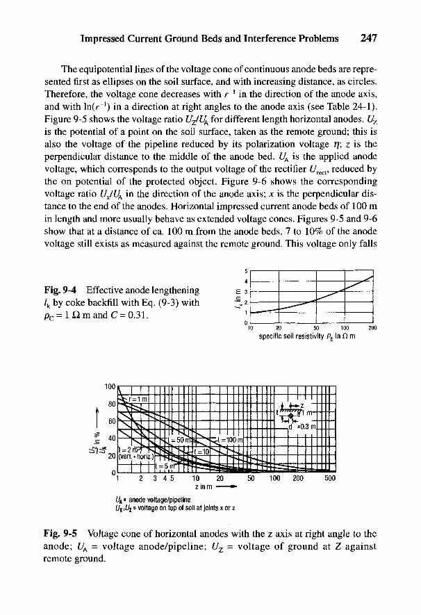
Impressed Current Ground Beds and Interference Problems 247
The equipotential lines of the voltage cone of continuous anode beds are repre-sented first as ellipses on the soil surface, and with increasing distance, as circles.Therefore, the voltage cone decreases with r"1 in the direction of the anode axis,and with \n(r~l) in a direction at right angles to the anode axis (see Table 24-1).Figure 9-5 shows the voltage ratio UZ/UA for different length horizontal anodes. Uz
is the potential of a point on the soil surface, taken as the remote ground; this isalso the voltage of the pipeline reduced by its polarization voltage 77; i is theperpendicular distance to the middle of the anode bed. UA is the applied anodevoltage, which corresponds to the output voltage of the rectifier f/rect, reduced bythe on potential of the protected object. Figure 9-6 shows the correspondingvoltage ratio UJU^ in the direction of the anode axis; x is the perpendicular dis-tance to the end of the anodes. Horizontal impressed current anode beds of 100 min length and more usually behave as extended voltage cones. Figures 9-5 and 9-6show that at a distance of ca. 100 m from the anode beds, 7 to 10% of the anodevoltage still exists as measured against the remote ground. This voltage only falls
Fig. 9-4 Effective anode lengthening/k by coke backfill with Eq. (9-3) withpc= 1 Hm and C = 0.31.
Fig. 9-5 Voltage cone of horizontal anodes with the z axis at right angle to theanode; UA = voltage anode/pipeline; Uz = voltage of ground at Z againstremote ground.

248 Handbook of Cathodic Corrosion Protection
Fig. 9-6 Voltage cone of a horizontal anode in the direction of the anode axis, x;UA = voltage anode/pipeline; Ux = voltage of ground at X against remote ground.
to 1 % at a distance of 1 km. The size of the voltage cone is of great importance inits interference with foreign lines.
9.1.2 Single Anode Installations
Installations of single anodes today are generally used only for small protec-tion currents or where a continuous anode bed is not possible, e.g., in woods orswampy ground. Vertical anodes generally 1.2 m in length are centrally mountedin boreholes 2 m deep and 0.3 m in diameter. The holes for vertical anodes areeither dug by hand or by motor-driven drilling machines. The bottom of the hole iscovered with a 0.2-m thick layer of coke on which the impressed current anode isplaced. The surrounding space is filled with ca. 75 kg of No. IV coke to a depth of0.2 m above the anode (see Fig. 9-7). Single anodes can also be installed inhorizontally excavated pits 0.5 x 1.5 x 2 m in dimension. About 200 kg of coke arerequired as backfill for horizontal single anodes.
The grounding resistance, Rg, of an anode bed of n single anodes with a spac-ing, s, is only a little greater than that of a continuous anode bed of length, / = sn.Since the single anodes with finite spacing, s, have mutual interference up to about10m, the total grounding resistance, Rg, of an anode installation of n single anodesis, however, noticeably greater than the resistance of anodes connected in parallelwith a spacing s —> °o. The influence factor, F, which the grounding resistancemagnifies, is shown in Fig. 9-8 as a function of the spacing, s, of single verticalanodes [see Eq. (24-35)]. The dimensions of the single anode beds are / = 1.5 mand d — 0.3 m. The interference factor also applies with good accuracy to shorthorizontal anodes with a covering of 1 m. For an anode installation of n single
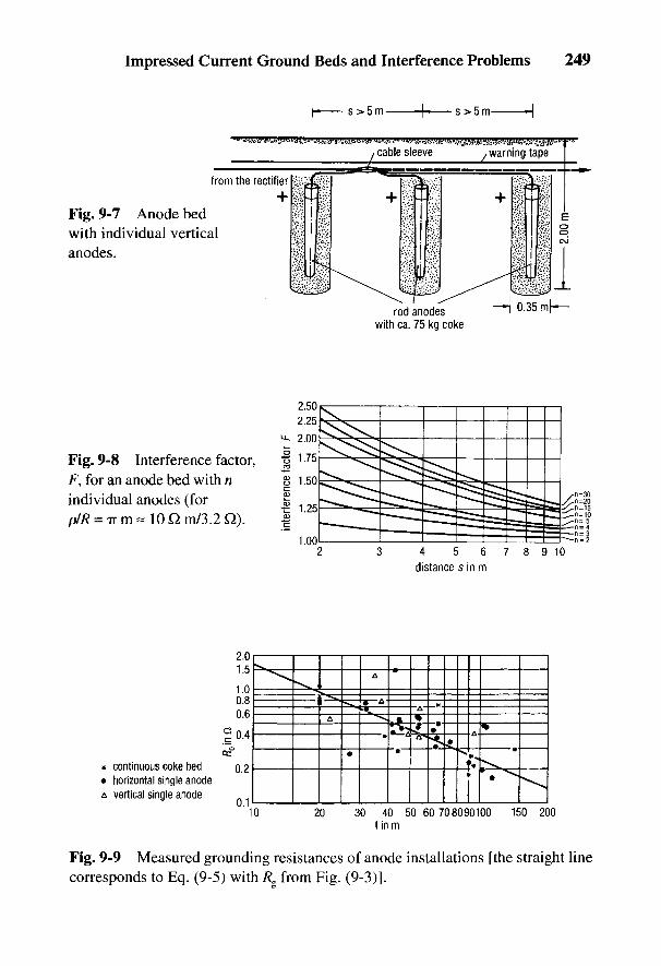
Impressed Current Ground Beds and Interference Problems 249
Fig. 9-7 Anode bedwith individual verticalanodes.
Fig. 9-8 Interference factor,F, for an anode bed with nindividual anodes (forpIR = TT m « 10 £1 m/3.2 Q).
Fig. 9-9 Measured grounding resistances of anode installations [the straight linecorresponds to Eq. (9-5) with Rg from Fig. (9-3)].
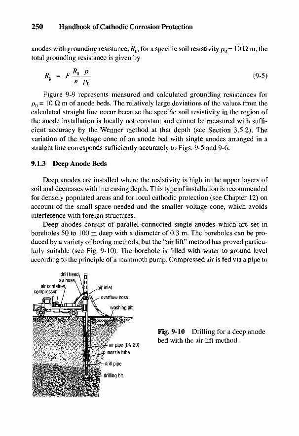
250 Handbook of Cathodic Corrosion Protection
anodes with grounding resistance, R0, for a specific soil resistivity p0 = 10 Q m, thetotal grounding resistance is given by
Figure 9-9 represents measured and calculated grounding resistances forp0= 10 Q m of anode beds. The relatively large deviations of the values from thecalculated straight line occur because the specific soil resistivity in the region ofthe anode installation is locally not constant and cannot be measured with suffi-cient accuracy by the Wenner method at that depth (see Section 3.5.2). Thevariation of the voltage cone of an anode bed with single anodes arranged in astraight line corresponds sufficiently accurately to Figs. 9-5 and 9-6.
9.1.3 Deep Anode Beds
Deep anodes are installed where the resistivity is high in the upper layers ofsoil and decreases with increasing depth. This type of installation is recommendedfor densely populated areas and for local cathodic protection (see Chapter 12) onaccount of the small space needed and the smaller voltage cone, which avoidsinterference with foreign structures.
Deep anodes consist of parallel-connected single anodes which are set inboreholes 50 to 100 m deep with a diameter of 0.3 m. The boreholes can be pro-duced by a variety of boring methods, but the "air lift" method has proved particu-larly suitable (see Fig. 9-10). The borehole is filled with water to ground levelaccording to the principle of a mammoth pump. Compressed air is fed via a pipe to
Fig. 9-10 Drilling for a deep anodebed with the air lift method.
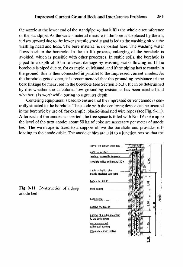
Impressed Current Ground Beds and Interference Problems 251
the nozzle at the lower end of the standpipe so that it fills the whole circumferenceof the standpipe. As the water-material mixture in the bore is displaced by the air,it rises upward due to the lower specific gravity and is led to the washing pit via thewashing head and hose. The bore material is deposited here. The washing waterflows back to the borehole. In the air lift process, enlarging of the borehole isavoided, which is possible with other processes. In stable soils, the borehole ispiped to a depth of 10 m to avoid damage by washing water flowing in. If theborehole is piped due to, for example, quicksand, and if the piping has to remain inthe ground, this is then connected in parallel to the impressed current anodes. Asthe borehole gets deeper, it is recommended that the grounding resistance of thebore linkage be measured in the borehole (see Section 3.5.3). It can be determinedby this whether the calculated low grounding resistance has been reached andwhether it is worthwhile boring to a greater depth.
Centering equipment is used to ensure that the impressed current anode is cen-trally situated in the borehole. The anode with the centering device can be insertedin the borehole by use of, for example, plastic-insulated wire ropes (see Fig. 9-11).After each of the anodes is inserted, the free space is filled with No. IV coke up tothe level of the next anode; about 50 kg of coke are necessary per meter of anodebed. The wire rope is fixed to a support above the borehole and provides off-loading to the anode cable. The anode cables are laid to a junction box so that the
Fig. 9-11 Construction of a deepanode bed.
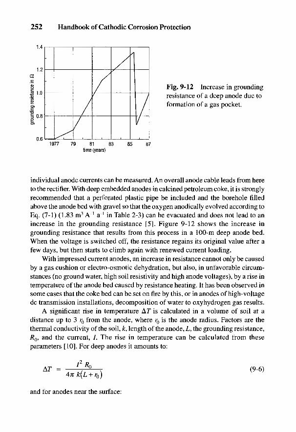
252 Handbook of Cathodic Corrosion Protection
Fig. 9-12 Increase in groundingresistance of a deep anode due toformation of a gas pocket.
individual anode currents can be measured. An overall anode cable leads from hereto the rectifier. With deep embedded anodes in calcined petroleum coke, it is stronglyrecommended that a perforated plastic pipe be included and the borehole filledabove the anode bed with gravel so that the oxygen anodically evolved according toEq. (7-1) (1.83 m3 A"1 a"1 in Table 2-3) can be evacuated and does not lead to anincrease in the grounding resistance [5]. Figure 9-12 shows the increase ingrounding resistance that results from this process in a 100-m deep anode bed.When the voltage is switched off, the resistance regains its original value after afew days, but then starts to climb again with renewed current loading.
With impressed current anodes, an increase in resistance cannot only be causedby a gas cushion or electro-osmotic dehydration, but also, in unfavorable circum-stances (no ground water, high soil resistivity and high anode voltages), by a rise intemperature of the anode bed caused by resistance heating. It has been observed insome cases that the coke bed can be set on fire by this, or in anodes of high-voltagedc transmission installations, decomposition of water to oxyhydrogen gas results.
A significant rise in temperature A!T is calculated in a volume of soil at adistance up to 3 r0 from the anode, where r0 is the anode radius. Factors are thethermal conductivity of the soil, k, length of the anode, L, the grounding resistance,R0, and the current, /. The rise in temperature can be calculated from theseparameters [10]. For deep anodes it amounts to:
and for anodes near the surface:

Impressed Current Ground Beds and Interference Problems 253
It follows approximately from Eqs. (9-6) and (24-24):
The permissible anode voltage can be calculated from Eq. (9-8). For unfavorableconditions, with A7 = 20 K, for dry soil with k = 0.2 W nr1, p = 50 Q m andL/r0 = 500, Eq. (9-8) gives U = 50 V.
The grounding resistance of deep anodes can be read off from Fig. 9-3 in whichthe length of the coke bed is to be inserted. The covering has practically no effecton the grounding resistance. From Eq. (24-29) the grounding resistance of a30-m-long anode in homogeneous soil covered with 10 m of soil is reduced only10% compared with a covering of 1 m. The interference factor for deep anodes canbe calculated from Eq. (24-37). The value is smaller than the value in Fig. 9-8.Therefore it is safer to use the values in Fig. 9-8 in practice.
In contrast to the grounding resistance, a reduction of the voltage cone on thesoil surface can be achieved in an area up to 20 m from the anode axis byincreasing the covering, which is important where foreign installations are con-cerned. Figure 9-13 represents the voltage cone for 30-m-long deep anodes fordifferent levels of covering.
Fig. 9-13 Voltage coneof 30-m-long deep anodeswith various depths ofearth coverings t.
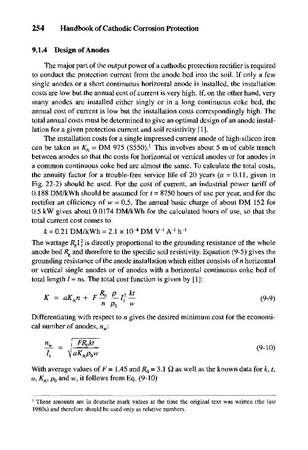
254 Handbook of Cathodic Corrosion Protection
9.1.4 Design of Anodes
The major part of the output power of a cathodic protection rectifier is requiredto conduct the protection current from the anode bed into the soil. If only a fewsingle anodes or a short continuous horizontal anode is installed, the installationcosts are low but the annual cost of current is very high. If, on the other hand, verymany anodes are installed either singly or in a long continuous coke bed, theannual cost of current is low but the installation costs correspondingly high. Thetotal annual costs must be determined to give an optimal design of an anode instal-lation for a given protection current and soil resistivity [1].
The installation costs for a single impressed current anode of high-silicon ironcan be taken as ^A = DM 975 ($550).l This involves about 5 m of cable trenchbetween anodes so that the costs for horizontal or vertical anodes or for anodes ina common continuous coke bed are almost the same. To calculate the total costs,the annuity factor for a trouble-free service life of 20 years (a = 0.11, given inFig. 22-2) should be used. For the cost of current, an industrial power tariff of0.188 DM/kWh should be assumed for t = 8750 hours of use per year, and for therectifier an efficiency of w = 0.5. The annual basic charge of about DM 152 for0.5 kW gives about 0.0174 DM/kWh for the calculated hours of use, so that thetotal current cost comes to
The wattage Rgl 2
S is directly proportional to the grounding resistance of the wholeanode bed Rg and therefore to the specific soil resistivity. Equation (9-5) gives thegrounding resistance of the anode installation which either consists of n horizontalor vertical single anodes or of anodes with a horizontal continuous coke bed oftotal length / = ns. The total cost function is given by [1]:
Differentiating with respect to n gives the desired minimum cost for the economi-cal number of anodes, nw:
With average values of F = 1.45 and RQ = 3.1 Q. as well as the known data for k, t,a, KA, p0 and w, it follows from Eq. (9-10)
1 These amounts are in deutsche mark values at the time the original text was written (the late1980s) and therefore should be used only as relative numbers.
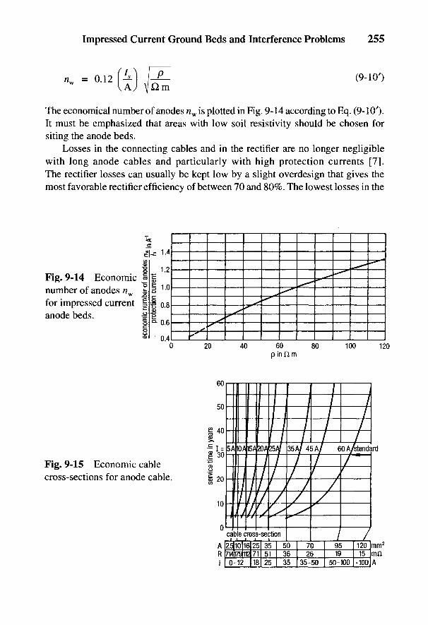
Impressed Current Ground Beds and Interference Problems 255
The economical number of anodes «w is plotted in Fig. 9-14 according to Eq. (9-10').It must be emphasized that areas with low soil resistivity should be chosen forsiting the anode beds.
Losses in the connecting cables and in the rectifier are no longer negligiblewith long anode cables and particularly with high protection currents [7].The rectifier losses can usually be kept low by a slight overdesign that gives themost favorable rectifier efficiency of between 70 and 80%. The lowest losses in the
Fig. 9-14 Economicnumber of anodes «w
for impressed currentanode beds.
Fig. 9-15 Economic cablecross-sections for anode cable.

256 Handbook of Cathodic Corrosion Protection
anode cable can be calculated from considerations of economy similar to those forimpressed current anodes [8]. The design of the cables from such considerationsdepends essentially on the lowest thermally permissible cross-section. It is shownin Fig. 9-15 for various operating lives of a cathodic protection station.
The current requirement of the protected object basically determines thedesign of the anode bed. For example, for a pipeline requiring 10 A with horizontalanodes laid in soil with p = 45 H m, according to Fig. 9-14, eight anodes are nec-essary. The grounding resistance of one anode amounts to R0 = 14 Q.From Fig. 9-8, the grounding resistance of the anode bed with an interferencefactor F = 1.34 for 8 anodes spaced at 5 m comes to Rg = 2.34 £1.
9.2 Interference with Foreign Pipelines and Cables
Under normal operating conditions, cathodic corrosion protection stations leadto the passage of a direct current through soil, which is introduced at the anodesand conducted to the protected object. According to DIN VDE 0150, there aredirect current installations from which stray currents emerge which can bring aboutcorrosion damage on foreign buried metallic installations, e.g., pipelines and cables[9]. The protection current causes an anodic voltage cone in the area of the anodes.This results in the potential of the soil being raised above the potential of theremote ground. The protection current produces cathodic voltage cones at defectsin the pipe coating. Here the soil potential is lowered with respect to the potentialof the remote ground. Buried foreign metal installations take up current in the areaof the anodes and give it up at a distance from the anodes, i.e., they are cathodi-cally polarized in the neighborhood of the anodes and anodically polarized at adistance from the anodes. Anodic corrosion occurs where the stray current emerges.
Such interference can be measured by switching the protection stations on andoff and observing the changes in potential of the foreign installation and thevoltage cone in the soil (see Section 3.6.2.1). Anodic damage to neighboringinstallations is to be reckoned with in such areas if the voltage between theinfluenced installation and a reference electrode placed directly above it on the soilsurface changes with the flow of protection current by an average of more than0.1 V in a positive direction [9], particularly
• with installations that are not cathodically protected against the potentialwhen the protection current is switched off.
• with installations cathodically protected against the protection potential, C/s.
The measured potential contains, besides the true object/soil potential, an ohmicvoltage drop that is proportional to the specific soil resistivity and the current density.

Impressed Current Ground Beds and Interference Problems 257
The 7/?-free anodic potential change actually caused by the emergence of the straycurrent is in practice not usually measurable if external measuring probes are notused (see Section 3.3.3.2). Furthermore, there is also no direct information on thedanger of corrosion, because the shape of the anodic partial current-potential curveis unknown. According to Fig. 2-9, an increase in the 7/?-free potential of 100 mV or20 mV leads to an increase in corrosion rate by a factor of 30 or 2, respectively, ifthere are no surface films. In the presence of surface films, the increase isconsiderably lower. This effect and the ever-present IR portion explain why the0.1-V criterion derived from experience is sufficient for soils that do not haveparticularly low resistance. In England and Switzerland, on the other hand, only analmost 7/?-free potential change at the phase boundary of 20 mV is allowed [10,11];in this case, however, the accuracy of the measurement is unclear. Some other Euro-pean countries allow a potential change with an IR contribution of 50 mV [12].
9.2.1 Interference from the Voltage Cone of Anodes
The greatest effect on the potential of foreign pipelines and cables is usually theresult of the voltage cone of impressed current anodes, where a high current densityand a large potential drop are present in the soil. Since there is only a negative shift inpotential near the anodes, there is no danger of anodic corrosion. With corrosionsystems of group II in Section 2.4 (e.g., aluminum and lead in soil), of coursecathodic corrosion can occur. The magnitude of the current uptake depends on the
Fig. 9-16 Interference of a short(a) and a long (b) pipeline by theanode voltage cone; ///// region ofcathodic polarization; \\\\\ regionof anodic polarization.
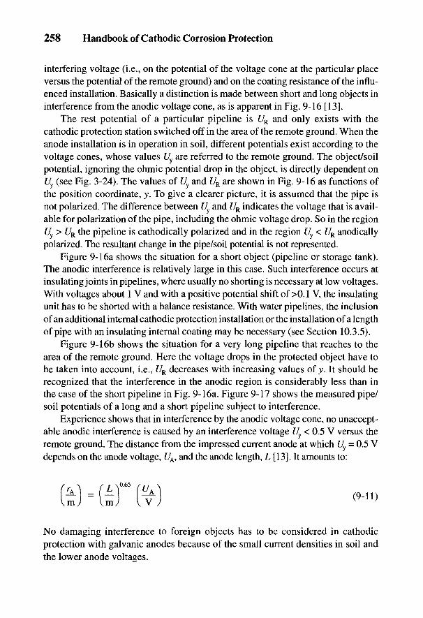
258 Handbook of Cathodic Corrosion Protection
interfering voltage (i.e., on the potential of the voltage cone at the particular placeversus the potential of the remote ground) and on the coating resistance of the influ-enced installation. Basically a distinction is made between short and long objects ininterference from the anodic voltage cone, as is apparent in Fig. 9-16 [13].
The rest potential of a particular pipeline is UR and only exists with thecathodic protection station switched off in the area of the remote ground. When theanode installation is in operation in soil, different potentials exist according to thevoltage cones, whose values Uy are referred to the remote ground. The object/soilpotential, ignoring the ohmic potential drop in the object, is directly dependent onU (see Fig. 3-24). The values of Uy and UR are shown in Fig. 9-16 as functions ofthe position coordinate, y. To give a clearer picture, it is assumed that the pipe isnot polarized. The difference between Uy and UR indicates the voltage that is avail-able for polarization of the pipe, including the ohmic voltage drop. So in the regionUy > UR the pipeline is cathodically polarized and in the region Uy < UR anodicallypolarized. The resultant change in the pipe/soil potential is not represented.
Figure 9-16a shows the situation for a short object (pipeline or storage tank).The anodic interference is relatively large in this case. Such interference occurs atinsulating joints in pipelines, where usually no shorting is necessary at low voltages.With voltages about 1 V and with a positive potential shift of >0.1 V, the insulatingunit has to be shorted with a balance resistance. With water pipelines, the inclusionof an additional internal cathodic protection installation or the installation of a lengthof pipe with an insulating internal coating may be necessary (see Section 10.3.5).
Figure 9-16b shows the situation for a very long pipeline that reaches to thearea of the remote ground. Here the voltage drops in the protected object have tobe taken into account, i.e., UR decreases with increasing values of y. It should berecognized that the interference in the anodic region is considerably less than inthe case of the short pipeline in Fig. 9-16a. Figure 9-17 shows the measured pipe/soil potentials of a long and a short pipeline subject to interference.
Experience shows that in interference by the anodic voltage cone, no unaccept-able anodic interference is caused by an interference voltage Uy < 0.5 V versus theremote ground. The distance from the impressed current anode at which Uy = 0.5 Vdepends on the anode voltage, UA, and the anode length, L [13]. It amounts to:
No damaging interference to foreign objects has to be considered in cathodicprotection with galvanic anodes because of the small current densities in soil andthe lower anode voltages.

Fig. 9-17 Interference of a long (by shorting insulating joints) and a short pipelineby an anode voltage cone 1 km in length; P = potential measuring point; /= insulatingjoint; "on" protection current, long pipeline; "on" protection current,short pipeline; ---. "off protection current, both pipelines.
9.2.2 Interference from the Cathodic Voltage Cone of the Protected Object
The current entering at defects in the coating of cathodically protectedpipelines causes a cathodic voltage cone in the soil (see Section 3.6.2).With pipelines that have coatings of high mechanical strength (e.g., PE coating),usually only a few widely spaced defects occur. In the vicinity of these defects theshape of the potential is similar to a grounded circular disc; at a greater distance itcan be approximated from the potential of a buried spherical ground [see case (a)in Section 3.6.2.2]. The size of small defects can be assessed by measuring thevoltage cone &UX and the difference between the on and off potential with the helpof Eq. (3-5la). If the pipe coating has very many defects close together, the indi-vidual voltage cones coalesce into a cylindrical voltage field around the pipeline[14] [see case (b) in Section 3.6.2.2]. Apotential distribution according to Eq. (3-52)is likely, especially with old pipelines with coatings of jute- or wool felt-bitumenfor average protection current densities of a few mA irr2. The high protection cur-rent requirement of older pipelines is often caused by uncoated fittings, badly insu-lated welds and conducting contacts with foreign pipelines or uncoated casing tubes.Since protection current densities of up to 500 mA irr2 are necessary to cathodi-cally protect bare iron surfaces in soil, particularly with good aeration, voltagecones of a few hundred millivolts occur.
Impressed Current Ground Beds and Interference Problems 259
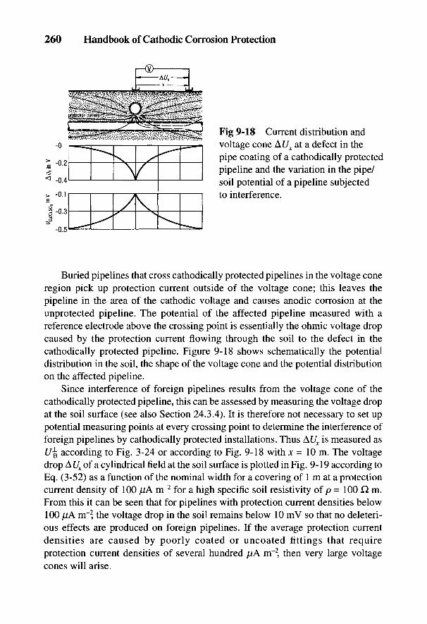
Buried pipelines that cross cathodically protected pipelines in the voltage coneregion pick up protection current outside of the voltage cone; this leaves thepipeline in the area of the cathodic voltage and causes anodic corrosion at theunprotected pipeline. The potential of the affected pipeline measured with areference electrode above the crossing point is essentially the ohmic voltage dropcaused by the protection current flowing through the soil to the defect in thecathodically protected pipeline. Figure 9-18 shows schematically the potentialdistribution in the soil, the shape of the voltage cone and the potential distributionon the affected pipeline.
Since interference of foreign pipelines results from the voltage cone of thecathodically protected pipeline, this can be assessed by measuring the voltage dropat the soil surface (see also Section 24.3.4). It is therefore not necessary to set uppotential measuring points at every crossing point to determine the interference offoreign pipelines by cathodically protected installations. Thus AUX is measured ast/B according to Fig. 3-24 or according to Fig. 9-18 with x = 10 m. The voltagedrop A Ux of a cylindrical field at the soil surface is plotted in Fig. 9-19 according toEq. (3-52) as a function of the nominal width for a covering of 1 m at a protectioncurrent density of 100 [lA m"2 for a high specific soil resistivity of p = 100 Q m.From this it can be seen that for pipelines with protection current densities below100 //A m"2, the voltage drop in the soil remains below 10 mV so that no deleteri-ous effects are produced on foreign pipelines. If the average protection currentdensities are caused by poorly coated or uncoated fittings that requireprotection current densities of several hundred jtiA m"2 then very large voltagecones will arise.
Fig 9-18 Current distribution andvoltage cone At/,, at a defect in thepipe coating of a cathodically protectedpipeline and the variation in the pipe/soil potential of a pipeline subjectedto interference.
260 Handbook of Cathodic Corrosion Protection

Fig 9-19 Protection current density as a function of the nominal diameter causinga voltage drop of &UX = 100 mV (x = 10 m) for p = 100 Q m.
9.2.3 Avoidance of Interference
Interference with foreign structures due to anodic and cathodic voltage conescan in every case be prevented by a continuity bond with the cathodically protectedinstallation. Figure 9-1 shows a potential connection at the crossing point of acathodically protected and an unprotected pipeline. The current entering theunprotected pipeline from the voltage cone of the anode bed no longer flows throughthe soil as a corrosion current at the crossing point, but via the continuity bond to thecathodically protected pipeline. By this means an unallowable positive potential shiftat the crossing point is converted to a reduction in potential. Usually a balancingresistance of about 0.2 to 2 Q is connected into the potential connection in order tolimit the balance current and the potential reduction in the affected pipeline. Thebalancing resistance is connected so that on switching on a small potential shift in anegative direction, only a few millivolts are produced. The cathodic protection canbe impaired by a continuity bond if too much protection current has to be taken up bythe affected installation. In addition, checking the cathodic protection by measure-ment of 7/?-free potentials by the switching technique can be faulty due to the consid-erable equalizing currents. So a connection with the affected pipeline should only beresorted to if there is no other possible economical means available to reduce theinterference to a tolerable level. Figures 9-5, 9-6, and 9-13 show that interferencefrom the anodic voltage cone can be avoided by remaining a sufficiently large dis-tance from foreign installations or low anode voltages. The site of the anode bed istherefore not only chosen for a convenient current supply and low specific soil
Impressed Current Ground Beds and Interference Problems 261

262 Handbook of Cathodic Corrosion Protection
resistivity, but also with consideration of the distance from foreign pipelines. Lowanode voltages can be achieved by having several protection stations with lowercurrent output, by lengthening the anode bed to reduce the grounding resistance anddepressing the required anode voltage, or by deep anodes. Deep anodes with a cov-ering of 20 m as in Fig. 9-13 are therefore particularly suitable for the cathodicprotection of pipelines in urban areas, thus essentially reducing the distance fromforeign installations.
The uptake of current by foreign installations should be avoided as far aspossible in the region of anodic voltage cones. Foreign pipelines in an anodic volt-age cone should have a coating of high resistance, no uncovered fittings and noelectrical contacts to steel-reinforced concrete pits, foundations, or electricallygrounded structures. Foreign pipelines that are laid near existing anode beds musthave a coating of the best possible insulation, e.g., polyethylene, to keep the up-take of current as small as possible. Figure 9-20 shows the pipe/soil potentials ofa pipeline that is situated 5 m parallel to an anode installation and that is providedwith a particularly good coating of polyethylene in the region of the anodic
Fig. 9-20 Pipe/soil potential of a pipeline with defect-free PE coating (up to 200 m)and with bitumen coating (200 to 600 m) in the region of an anodic voltage coneon switching the protection current on ( ) and off (---); the &UX values showthat no current enters in the region of the voltage cone.

Impressed Current Ground Beds and Interference Problems 263
potential cone. By this means interference can be avoided. With cables withplastic insulation laid near anode beds, there also is no danger of interference.
The exit current density, 7a, at coating defects of the affected pipeline can becalculated from Eqs. (24-51) or (24-51'), where ^ is the radius of a defect causingthe cathodic voltage cone. Since the quantities in these equations are generallyunknown, no quantitative assessment of possible corrosion danger can be made,but only a qualitative assessment of tendencies, e.g., measures to reduce interference.The most important measure is to remove the cause of the interference by improv-ing the coating of the affected pipeline in the crossing region. This measure is,however, economical only if the voltage cone is the result of a single defect and notof very many defects (cylindrical field).
In addition to a continuity bond, the following further measures can be takento reduce the interference:
• apparent increase of the defect area by connection of galvanic anodes; inaddition, the anodes will reduce the effect of interference with the aid oftheir own protection current output,
• increasing the distance between both defects, e.g., by using a plastic casing,
• electrical separation at the crossing point or of the parallel course by insu-lating joints.
With increasing improvement in pipe coatings, the interference problem isbecoming less severe. Interference by foreign objects is excluded in pipelines withpolyethylene coating. Interference by foreign objects can only occur with badlycoated fittings and uncoated welds. However, with old pipelines with average pro-tection current densities of 0.5 to 1 mA rrr2, interference can occur only as theresult of the cathodic potential cone of large defects, or electrical contacts withuncoated casing pipes or insufficiently coated fittings and uncoated girth welds. Inthese cases it is necessary for the safety of the cathodic protection to removeelectrical contacts or to repair defects in the coating.

264 Handbook of Cathodic Corrosion Protection
9.3 References
[1] W. v. Baeckmann, gwf/gas 99, 153 (1958).[2] F. Wolf, gwf/gas 103, 2 (1962).[3] J. Backes u. A. Baltes, gwf/gas 117, 153 (1976).[4] W. Prinz, 3R internal. 17, 466 (1978).[5] W. T. Brian, Mat. Perf. 9, H. 4, 25 (1970).[6] W. H. Burkhardt, Corrosion 36, 161 (1980).[7] R. G. Fischer u. M. A. Riordam, Corrosion 13, 519 (1956).[8] R. Reuter u. G. Schiirmann, gwf/gas 97, 637 (1956).[9] DIN VDE 0150, Beuth-Verlag, Berlin 1983.
[10] J. H. Gosden, 19. Tagung der CIGRE in Paris, Archiv fur Energiewirtschaft 1962, Bericht207.
[11] Schweizerische Korrosionskommission, Richtlinien fur Projekte, Ausfiihrung und Betriebdes kathodischen Korrosionsschutzes von Rohrleitungen 1987.
[12] Technisches Komitee fur Fragen der Streustrombeeinflussung (TKS): Technische Emp-fehlung Nr. 3, VEO-Verlag, Wien 1975.
[13] AfK-Empfehlung Nr. 2, ZfGW-Verlag, Frankfurt 1985.[14] W. v. Baeckmann, Techn. Uberwachung 6, 170 (1965).
10
Pipelines
W. PRINZ
Buried steel pipelines for the transport of gases (at pressures >4 bars) and ofcrude oil, brine and chemical products must be cathodically protected againstcorrosion according to technical regulations [1-4]. The cathodic protection processis also used to improve the operational safety and economics of gas distributionnetworks and in long-distance steel pipelines for water and heat distribution.Special measures are necessary in the region of insulated connections in pipelinesthat transport electrolytically conducting media.
10.1 Electrical Properties of Steel Pipelines
The electrical characteristic of a buried pipeline corresponds to that of anextended ground with a longitudinal resistance (see Section 24.4.2). Thelongitudinal resistance, Rf, related to the length / is described by Eq. (24-70) and istermed the resistance per unit length (resistance load), R'.
Here pst = \IAst, the electrical resistance of the pipeline material; d is pipediameter and s is the pipe wall thickness. In contrast to grounds, anode installations,storage tanks and other spatially limited objects, pipelines have no definablegrounding resistance. For a limited length of pipe, /, the grounding resistance, RE,follows from a drainage test from Eq. (3-10) with rM = ru [see Eq. (5-10)]:
265
The voltages At/ and r]L are defined by Eqs. (24-69) and (24-68a) and have a con-stant value of about 0.3 V. It is shown in Section 24.4.4 that with overprotection(i.e., by polarization into the range of hydrogen evolution) the cathodically pro-tected range cannot be markedly lengthened. Therefore Eq. (10 -5) is basic for thecathodic protection of pipelines.
Protection ranges from Eq. (24-75) are represented in Fig. 10-1 as a functionof current density 7S. Here AC/is taken as 0.3 V, which is the difference between thepipe/soil potentials at the end of the protected range (C/cu-cuso4 = -0-85 V) and thecurrent drainage point (C/Cu.CuS04 = -1.15 V) (see Eq. 24-69). Figure 10-2 showsthe protection current requirement of pipelines of protected length, 2 L, as afunction of the protection current density according to Eq. (24-76).
In Section 24.4.3, the cathodic protection length (2 L) of a pipeline from a currentdrainage point is derived for locally constant values of/?' and G' [see Eq. (24-75)]:
Equation (10-2) is true only for pipelines of relatively short lengths since other-wise the longitudinal resistance will be noticeable at longer distances. Thus in Eq.(10-2) RE will approach Z, not zero, for a long length. Here Z denotes the charac-teristic resistance defined in Eq. (24-66). Z is therefore the minimumgrounding resistance for the case where current is fed at one end of the pipeline.This quantity is reduced by half for current fed in at a central point on the pipe. Itfollows from Eq. (24-66)
For coated pipelines, rp <^ ru, which modifies Eq. (10-3):
266 Handbook of Cathodic Corrosion Protection
The reciprocal grounding resistance is the leakage, G. The leakage related tothe length, /, is the leakage per unit length (leakage load), G' [see Eq. (24-71)]:

Pipelines 267
Fig. 10-1 Length of the protected range 2 L as a function of pipe wall thickness andprotection current density J& from Eq. (10-5); the pipeline (pst = 0.18 X 10~6 Q m, s = 8mm; DN 600) with insulated sockets is bridged by 0.5-m NYY cable of 16 mm2 copper.
Fig. 10-2 Protection current requirement 7S for protected length 2 L and various pipedimensions (DN/s) as a function of protection current density Js (pst = 0.18 x 10~6 Q m).

268 Handbook of Cathodic Corrosion Protection
10.2 Preconditions for Pipeline Protection
Conclusions can be drawn from Eq. (10-5) to achieve the greatest possible pro-tected length. The resistance and leakage loads, R' and G', must be as low as possible:
(a) The pipeline must not have any additions that would raise the longitudinalresistance (e.g., couplings, expansion joints, flanged valves) or they mustbe bridged with metal conductors.
(b) The pipeline must have a good insulating coating with as few defects aspossible. It should have no contact with grounded installations that wouldraise the leakage load, e.g., grounding installations, pipelines, casings, valvesupports, or interconnections.
(c) Insulating connections should be fitted at the grounded end points of shortpipelines and at the end of the protected range (where / = 0) of longpipelines, or by parallel-connected additional cathodic protection stationsto limit the protected range electrically [see the details of Eqs. (24-77)to 24-80)].
10.2.1 Measures for Achieving a Low Resistance Load
Pipelines with welded connections always have a low resistance load, R'. Thisis, however, considerably higher with higher resistance pipe connections such asflanges, couplings with insulating spacers (e.g., rubber screw sockets) or expan-sion joints. They must be bypassed using insulated copper cable as short as pos-sible with a cross-section of at least 16 mm2 and with a bridging resistance <1 m£2.The cable should be connected to the pipeline by a suitable method such as Cadweld,stud welding or pin brazing [5-7] in order to guarantee a low-resistance bridge.The connection points must be covered with perfect coating [8]. Earlier, commonpipeline connections with lead as the sealing material were usually sufficientlyconducting, but reduced the protection range.
10.2.2 Measures for Achieving a Low Leakage Load
10.2.2.1 Pipeline Coating
In order to achieve a low leakage load, the direct ground contact (i.e., the effect ofthe ground connection of the pipeline) must be reduced. This is done by coatingthe pipeline and avoiding or preventing conducting connections with installationswith low grounding resistances.
To achieve a low leakage load for a pipeline, it is necessary first of all to havea coating with a sufficiently high resistance (see Section 5.2.1.2). The leakage load
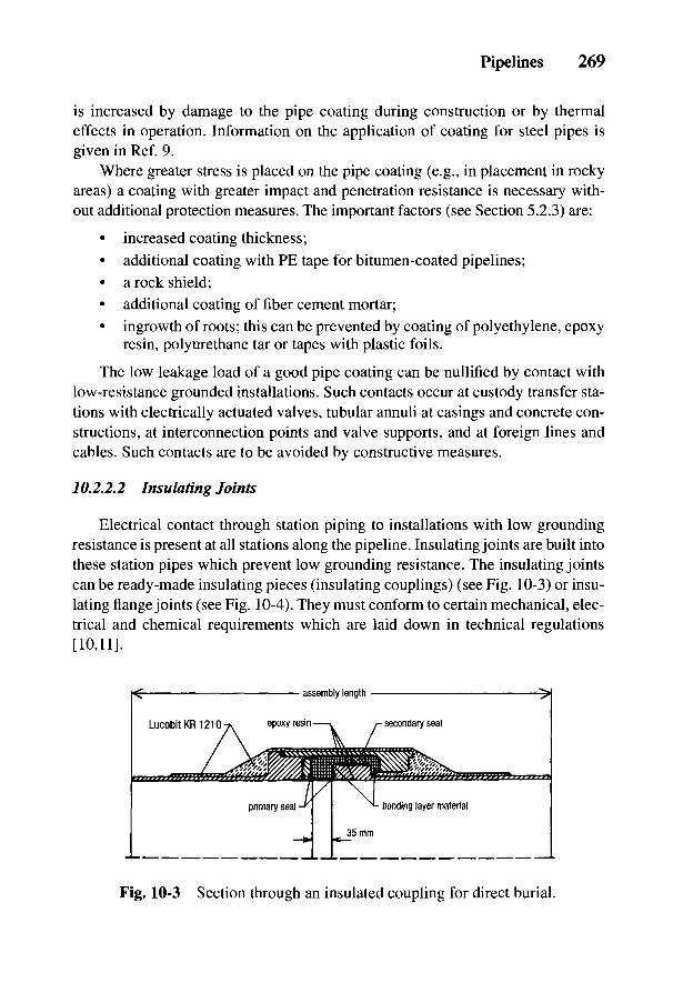
Pipelines 269
is increased by damage to the pipe coating during construction or by thermaleffects in operation. Information on the application of coating for steel pipes isgiven in Ref. 9.
Where greater stress is placed on the pipe coating (e.g., in placement in rockyareas) a coating with greater impact and penetration resistance is necessary with-out additional protection measures. The important factors (see Section 5.2.3) are:
• increased coating thickness;• additional coating with PE tape for bitumen-coated pipelines;• a rock shield;• additional coating of fiber cement mortar;• ingrowth of roots; this can be prevented by coating of polyethylene, epoxy
resin, polyurethane tar or tapes with plastic foils.
The low leakage load of a good pipe coating can be nullified by contact withlow-resistance grounded installations. Such contacts occur at custody transfer sta-tions with electrically actuated valves, tubular annuli at casings and concrete con-structions, at interconnection points and valve supports, and at foreign lines andcables. Such contacts are to be avoided by constructive measures.
10.2.2.2 Insulating Joints
Electrical contact through station piping to installations with low groundingresistance is present at all stations along the pipeline. Insulating joints are built intothese station pipes which prevent low grounding resistance. The insulating jointscan be ready-made insulating pieces (insulating couplings) (see Fig. 10-3) or insu-lating flange joints (see Fig. 10-4). They must conform to certain mechanical, elec-trical and chemical requirements which are laid down in technical regulations[10,11].
Fig. 10-3 Section through an insulated coupling for direct burial.
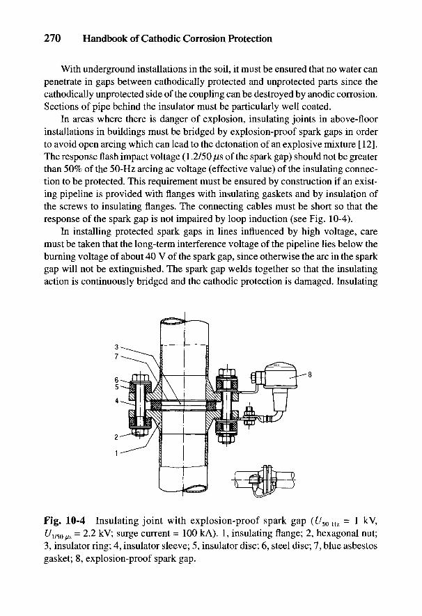
270 Handbook of Cathodic Corrosion Protection
With underground installations in the soil, it must be ensured that no water canpenetrate in gaps between cathodically protected and unprotected parts since thecathodically unprotected side of the coupling can be destroyed by anodic corrosion.Sections of pipe behind the insulator must be particularly well coated.
In areas where there is danger of explosion, insulating joints in above-floorinstallations in buildings must be bridged by explosion-proof spark gaps in orderto avoid open arcing which can lead to the detonation of an explosive mixture [12].The response flash impact voltage (1.2/50 fj,s of the spark gap) should not be greaterthan 50% of the 50-Hz arcing ac voltage (effective value) of the insulating connec-tion to be protected. This requirement must be ensured by construction if an exist-ing pipeline is provided with flanges with insulating gaskets and by insulation ofthe screws to insulating flanges. The connecting cables must be short so that theresponse of the spark gap is not impaired by loop induction (see Fig. 10-4).
In installing protected spark gaps in lines influenced by high voltage, caremust be taken that the long-term interference voltage of the pipeline lies below theburning voltage of about 40 V of the spark gap, since otherwise the arc in the sparkgap will not be extinguished. The spark gap welds together so that the insulatingaction is continuously bridged and the cathodic protection is damaged. Insulating
Fig. 10-4 Insulating joint with explosion-proof spark gap (£/50Hz = 1 kV,t/1/50/ls = 2.2 kV; surge current = 100 kA). 1, insulating flange; 2, hexagonal nut;3, insulator ring; 4, insulator sleeve; 5, insulator disc; 6, steel disc; 7, blue asbestosgasket; 8, explosion-proof spark gap.
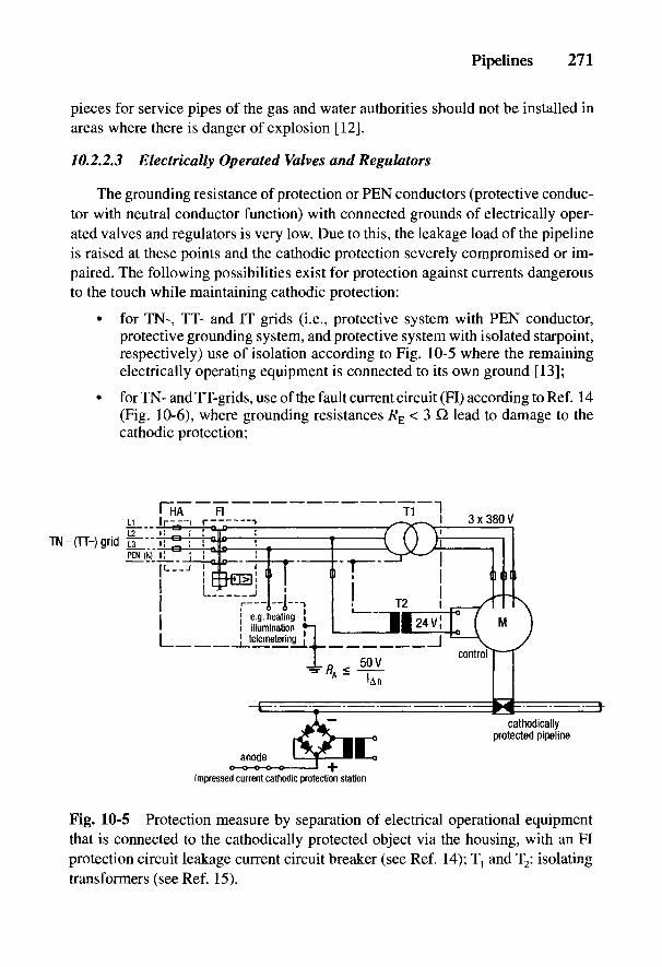
Pipelines 271
pieces for service pipes of the gas and water authorities should not be installed inareas where there is danger of explosion [12].
10.2.2.3 Electrically Operated Valves and Regulators
The grounding resistance of protection or PEN conductors (protective conduc-tor with neutral conductor function) with connected grounds of electrically oper-ated valves and regulators is very low. Due to this, the leakage load of the pipelineis raised at these points and the cathodic protection severely compromised or im-paired. The following possibilities exist for protection against currents dangerousto the touch while maintaining cathodic protection:
• for TN-, TT- and IT grids (i.e., protective system with PEN conductor,protective grounding system, and protective system with isolated starpoint,respectively) use of isolation according to Fig. 10-5 where the remainingelectrically operating equipment is connected to its own ground [13];
• for TN- and TT-grids, use of the fault current circuit (FI) according to Ref. 14(Fig. 10-6), where grounding resistances RE < 3 Q lead to damage to thecathodic protection;
Fig. 10-5 Protection measure by separation of electrical operational equipmentthat is connected to the cathodically protected object via the housing, with an FIprotection circuit leakage current circuit breaker (see Ref. 14); Tt and T2: isolatingtransformers (see Ref. 15).
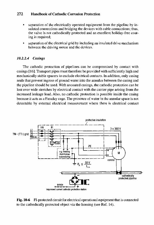
272 Handbook of Cathodic Corrosion Protection
• separation of the electrically operated equipment from the pipeline by in-sulated connections and bridging the devices with cable connections; thus,the valve is not cathodically protected and an excellent holiday-free coat-ing is required;
• separation of the electrical grid by including an insulated drive mechanismbetween the driving motor and the devices.
10.2.2.4 Casings
The cathodic protection of pipelines can be compromised by contact withcasings [16]. Transport pipes must therefore be provided with sufficiently high andmechanically stable spacers to exclude electrical contacts. In addition, only casingseals that prevent ingress of ground water into the annulus between the casing andthe pipeline should be used. With uncoated casings, the cathodic protection can belost over wide stretches by electrical contact with the carrier pipe arising from theincreased leakage load. Also, no cathodic protection is possible inside the casingbecause it acts as a Faraday cage. The presence of water in the annular space is notdetectable by external electrical measurement where there is electrical contact
Fig. 10-6 Fl-protected circuit for electrical operational equipment that is connectedto the cathodically protected object via the housing (see Ref. 14).

Pipelines 273
between carrier pipe and casing. Corrosive water in the annular space can causecorrosion damage. In this case one must consider the possibility of cell formationwhere the rusted inner surface of the casing acts as a cathode.
If well-coated casings are used, local impairment of cathodic protection throughelectrical contact is small due to the low drainage load. Cathodic protection is notpossible for the carrier pipe inside the annular space. Even without electrical con-tacts with casings whose coating has fewer defects than the carrier pipe, cathodicprotection cannot be achieved in the annular space. Measures for dealing withcontacts between casings and the pipeline are given in Table 10-1. Casings should
Table 10-1 Measures for casings
Measures
Type of failure Uncoated casing Coated casing
Electrical contact between pipe and casing*
No electrolyte in annulus Locate and eliminate Locate and eliminatecontact or provide local contact. If not possiblecathodic protection. for structural reasons—Take note of interfering depending on theforeign installations individual case—take
other protectionElectrolyte in annulus Locate and eliminate measures, e.g. insert
contact or insert hydraulic sealinghydraulic sealing medium or organicmaterial or organic materials into thematerials into the annulus.annulus. If necessary,install local cathodicprotection
Nonelectrical contact between pipe and casing
No electrolyte in annulus No measures necessary, Usually no measuressince cathodic protection necessaryof pipe acting
Electrolyte in annulus Usually no measures necessarya With electrical contact of pipe and casing, the absence of electrolyte within the annulus is notdetectable from the outside by electrical measurements.
274 Handbook of Cathodic Corrosion Protection
only be provided on cathodically protected pipelines where the latter cannot belaid at crossing points without risk of damage, and where the use of reinforcedconcrete casings is not possible.
In installing carrier pipes by thrust boring, a drainage test should be conductedbefore tie-in of the pipe to see whether, on imposition of cathodic protection, thepipe can be sufficiently negatively polarized according to Section 10.4. Table 10-2shows a data sheet for such a drainage test. If the coating resistance of the pipelineis so high that no polarization can be achieved, it is recommended that an uncoatedsteel rod be driven into the soil and directly connected electrically to the pipe. Ifthe drainage current increases and the off potential is more negative than theprotection potential, then there are no defects present in the coating and the carrierpipe can be included in the cathodic protection of the pipeline.
10.2.2.5 Special Installations on the Pipeline
To ensure water tightness in concrete foundations, pipelines are usuallyembedded in a concrete ring. The danger here is of an electrical contact with thereinforcement of the concrete, which not only damages the cathodic protection butalso endangers the pipeline by cell formation with the large steel-concreteinterface (see Section 10.3.6). The supporting ring has to be insulated with apressure-resistant plastic (e.g., epoxy resin) so that contacts can be prevented. Withrestraint points, valve supports, river crossings, and bridge constructions,connection with the ground must be prevented by an intermediate layer of amechanically strong insulating material. Gas and water crossing regulations haveto be taken into account in the area of overhead conductors of railway systems[17]. Pipelines may only be connected over spark gaps with flashover protectionequipment [18]. Grounds of pipelines influenced by high voltage must beconnected to the pipeline via dc coupling devices (see Section 23.5.4).
10.2.2.6 Prevention of Electrical Contact with Foreign Objects
Metallic contact with pipelines and cables that are not cathodically protectedmust be avoided on account of the high leakage load. Where pipelines and cablesare running parallel, a spacing of at least 0.4 m must be observed for safety reasons.A distance of not less than 0.2 m must be adhered to in narrow passages andcrossings. If such a distance is not possible, electrical contact must be preventedby interposing insulating shells or plates. Such materials can be PVC or PE.The dimensions of these plates should not be less than the diameter of the largerpipeline [19].

Pipelines 275
Table 10-2 Form for recording measurements on an extruded pipe
Measurement Data DateMeasurements on coated pipes installed by thrust boring
Pipeline: casing/pipeDesignation of pipeline:Location of thrust boring:Type of coating: Type of girth weld coating:Diameter; DNWall thickness: mm Total length of pipe: mLength in earth: m Surface area of pipe: m2
Appearance of pipe coating in the receiving pit after thrust boring:
Type of soil:
ReadingsRest potential, launching pit t/Cu-cuso4
: VRest potential, receiving pit f/Cu.CuSO : VGrounding resistance R: Q; Specific soil resistivity p: £1 m/: 135; 105 Hz
Time t/Cu-cuso4 "°n" f/Cu.Cuso4 "off M/ 7S ^ Js J~min V V V /lA Q ^A/m2 Qm2
3 -1.56 -1.59 -1.5
12 -1.515 -1.530 -2.060 -2.0
Switch-off time: <5 s
A = surface area of pipe (m2); Cathodic protection possible: yes/no
Measurements carried out by:
276 Handbook of Cathodic Corrosion Protection
10.3 Design of Cathodic Protection
10.3.1 Design Documents
The following documents are necessary for planning cathodic protection [20]:
• a general map showing the position of lines and details of valves, regu-lating stations, casings, river crossings, insulating joints, expansion joints,and lines in bridges; flowing media, operating conditions (temperature andpressure);
• length, diameter, wall thickness and material of the pipe, type of pipe con-nections, with buried pipelines, year of burial;
• type of mill-applied as well as field coating, coating of fittings and valves;
• routing of dc railway lines, location of transformer substations and nega-tive feeder points, encroachments, parallel trajectories and crossings withoverhead power lines of > 100 kV as well as ac railway lines.
If the projected pipeline is situated in an area with dc railway lines, rail/soilpotential measurements should be carried out at crossing points and where thelines run parallel a short distance apart, particularly in the neighborhood of sub-stations, in order to ascertain the influence of stray currents. Potential differencesat the soil surface can give information on the magnitude of stray current effects inthe vicinity of dc railway lines. It is recommended that with existing pipelines themeasurements be recorded synchronously (see Section 15.5) and taken intoaccount during design.
10.3.2 Test Points
Test points are necessary for measuring pipe/soil potentials, and pipe currentsas well as resistances of insulating connections and casings. Potential test pointsshould have a maximum spacing of 1 to 2 km, and every fifth test point should bedesigned as a pipe-current test point. In built-up areas, the spacing of test pointsshould be reduced to about 0.5 km. At the initial point of long, branched pipelines,it is recommended that pipe-current test points be installed so that the currentconsumption of this pipeline can be controlled. The installation of pipe-current testpoints before insulating is advisable in order to determine internal electrolyticbridging, which can lead to the destruction of insulating connections.
In general NYY-O cable is used with a minimum copper cross-section of2 x 2.5 mm. The cable is connected to the pipeline by a suitable process [5-7], andthe connections carefully coated. The cable is usually connected to abovegroundtest points and covered with hoods, tiles or a cable ribbon.
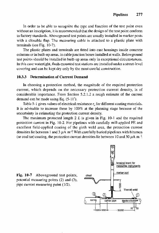
Pipelines 277
In order to be able to recognize the type and function of the test point evenwithout an inscription, it is recommended that the design of the test point conformto factory standards. Aboveground test points are usually installed in marker postswith a closable flap. The measuring cable is attached to a plastic plate withterminals (see Fig. 10-7).
The plastic plates and terminals are fitted into cast housings inside concretecolumns or in built-up areas, in cable junction boxes installed at walls. Belowgroundtest points should be installed in built-up areas only in exceptional circumstances.In this case watertight, flush-mounted test stations are installed under a street-levelcovering and can be kept dry only by the most careful construction.
10.3.3 Determination of Current Demand
In choosing a protection method, the magnitude of the required protectioncurrent, which depends on the necessary protection current density, is ofconsiderable importance. From Section 5.2.1.2 a rough estimate of the currentdemand can be made using Eq. (5-IT).
Table 5-1 gives values of electrical resistance ru for different coating materials.It is advisable to increase these by 100% at the planning stage because of theuncertainty in estimating the protection current density.
The maximum protected length 2 L is given in Fig. 10-1 and the requiredprotection current in Fig. 10-2. For pipelines with carefully mill-applied PE andexcellent field-applied coating of the girth weld area, the protection currentdensities lie between 1 and 3 jtiA m~2. With carefully buried pipelines with bitumen(or coal tar) coating, the protection current densities lie between 10 and 30 ,uA nr2.
Fig. 10-7 Aboveground test points,potential measuring points (2) and (3),pipe current measuring point (1/2).
278 Handbook of Cathodic Corrosion Protection
In the case of older pipelines and offshore pipelines, protection current densitiescan amount to several mA m~2. For older onshore pipelines, the protection currentdensities are determined by a drainage test according to Section 3.4.3.
The drainage test should be carried out if possible in the area in which theplanned protection installation is to be provided. The connection for the drainagetest can be provided via already installed test points or at fittings that have low-resistance connections with the pipeline. Provisional grounding rods can be drivenin to act as anodes. Since the resistance of these grounds is different from that ofthe final anode installation, the output voltages of the drainage test and of the finaldc current supply units are also different. However, this is not important indesigning an anode installation. The drainage current is periodically switched onand off and the on and off potentials at all possible measuring points on thepipeline (e.g., standpipes, valve spindles and hydrants) are measured. Because ofthe short polarization period, pipelines with high drainage load will mainly haveUon > Us at most of the measuring points. From experience, it can be assumed thatat all measuring points where Uon < Us, after a sufficient polarization period of afew weeks Uoff < U& will be attained. The drainage test, in which all the measuringpoints Uon < Us, gives the conventional current demand of the pipeline. In order tobe able to increase the protection current output of the anode installation and toprovide, for example, additional connecting pipelines with cathodic protection, itis recommended that the projected protection current demand be increased by afactor of 1.5. Pipe/soil potentials and pipe currents in a drainage test are shown inFig. 10-8, together with those after 1 year of operation.
10.3.4 Choice of Protection Method
The current output of galvanic anodes depends on the specific soil resistivityin the installation area and can only be used in low-resistivity soils for pipelineswith a low protection current requirement because of the low driving voltage.Impressed current anode installations can be used in soils with higher specific soilresistivities and where large protection currents are needed because of theirvariable output voltage.
10.3.4.1 Galvanic Anodes
Cathodic protection with magnesium anodes can be just as economical asimpressed current anode assemblies for pipelines only a few kilometers in lengthand with protection current densities below 10 pA nr2 e.g., in isolated stretches ofnew pipeline in old networks and steel distribution or service pipes. In this case,several anodes would be connected to the pipeline in a group at test points. Thedistance from the pipeline is about 1 to 3 m. The measurement of the off potential
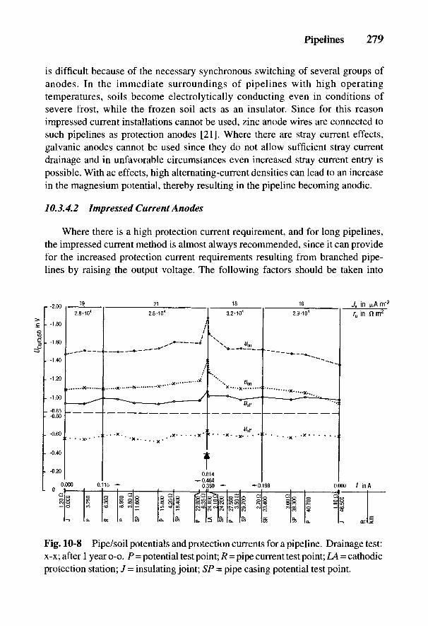
Pipelines 279
is difficult because of the necessary synchronous switching of several groups ofanodes. In the immediate surroundings of pipelines with high operatingtemperatures, soils become electrolytically conducting even in conditions ofsevere frost, while the frozen soil acts as an insulator. Since for this reasonimpressed current installations cannot be used, zinc anode wires are connected tosuch pipelines as protection anodes [21]. Where there are stray current effects,galvanic anodes cannot be used since they do not allow sufficient stray currentdrainage and in unfavorable circumstances even increased stray current entry ispossible. With ac effects, high alternating-current densities can lead to an increasein the magnesium potential, thereby resulting in the pipeline becoming anodic.
10.3.4.2 Impressed Current Anodes
Where there is a high protection current requirement, and for long pipelines,the impressed current method is almost always recommended, since it can providefor the increased protection current requirements resulting from branched pipe-lines by raising the output voltage. The following factors should be taken into
Fig. 10-8 Pipe/soil potentials and protection currents for a pipeline. Drainage test:x-x; after 1 year o-o. P = potential test point; R = pipe current test point; LA = cathodicprotection station; J = insulating joint; SP = pipe casing potential test point.
280 Handbook of Cathodic Corrosion Protection
account when choosing the location of an impressed current cathodic protectionstation:
• presence of a low voltage supply;
• as low as possible specific electrical soil resistivity in the area of the anodeground bed;
• the maximum protection length as shown in Fig. 10-1 and in Eq. (10-5);
• sufficient distance between the anode ground bed and foreign lines as inEq. (9-11) to keep interference low;
• good access to the protection installation.
The housing of the transformer-rectifier unit should be erected in an area witha right-of-way for the pipeline.
The information in Section 9-1 covers the anode installation. Housing, layoutand circuitry of the transformer-rectifier unit are described in Chapter 8, and typeand possible choices of anode materials in Chapter 7.
The results of the design should be assembled in a report which should includethe following documents:
• a general map of the location of the proposed impressed current cathodicprotection station and test points as well as the position of insulatingconnectors and casings;
• site plan of the proposed protection station;• circuit diagram of the protection station and test points;• calculations of the protected range and protection current densities;• rating of the anode ground bed and transformer-rectifier unit.
It is appropriate to assemble the results in a data sheet as shown in Table 10-3for planning and documentation.
10.3.5 Pipelines for Electrolytically Conducting Liquids
Practically no electric currents occur inside pipes for electrolyticallyconducting media such as potable water, district heating or brine [22]. On the otherhand, the situation at insulating connections or joints is completely different (seeSection 24.4.6). In cathodic protection there is a difference in the pipe/soilpotentials of the protected and unprotected parts of the pipeline, leading to avoltage of between 0.5 and 1 V. This leads to the danger of anodic corrosion on theinner surface of the part of the pipeline that is not cathodically protected, whichwith good conducting media (e.g., salt solution) rapidly leads to damage. Thedanger of internal corrosion increases with the size of the pipe diameter and theconductivity of the transported medium. It decreases with the length of the
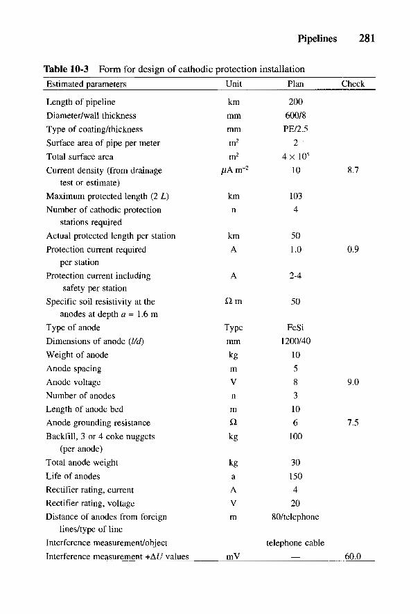
Pipelines 281
Table 10-3 Form for design of cathodic protection installation
Estimated parameters Unit Plan Check
Length of pipeline km 200
Diameter/wall thickness mm 600/8
Type of coating/thickness mm PE/2.5
Surface area of pipe per meter m2 2
Total surface area m2 4 x 10⁵
Current density (from drainage [j.Am~2 10 8.7test or estimate)
Maximum protected length (2 L) km 103
Number of cathodic protection n 4stations required
Actual protected length per station km 50
Protection current required A 1.0 0.9per station
Protection current including A 2-4safety per station
Specific soil resistivity at the Q m 50anodes at depth a = 1.6 m
Type of anode Type FeSi
Dimensions of anode (l/d) mm 1200/40
Weight of anode kg 10
Anode spacing m 5
Anode voltage V 8 9.0
Number of anodes n 3
Length of anode bed m 10
Anode grounding resistance £2 6 7.5
Backfill, 3 or 4 coke nuggets kg 100(per anode)
Total anode weight kg 30
Life of anodes a 150
Rectifier rating, current A 4
Rectifier rating, voltage V 20
Distance of anodes from foreign m 80/telephonelines/type of line
Interference measurement/object telephone cable
Interference measurement +AJ7 values mV = 60.0
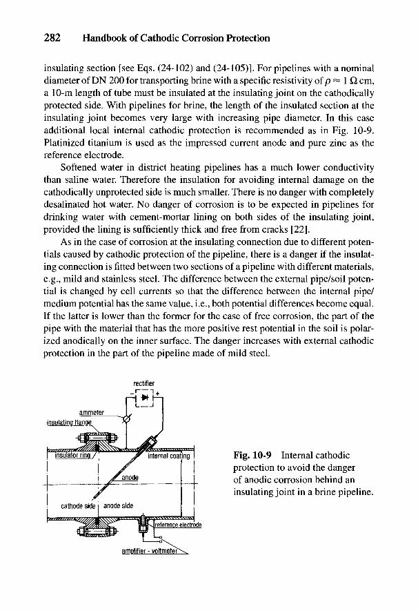
282 Handbook of Cathodic Corrosion Protection
insulating section [see Eqs. (24-102) and (24-105)]. For pipelines with a nominaldiameter of DN 200 for transporting brine with a specific resistivity of p ~ IQ. cm,a 10-m length of tube must be insulated at the insulating joint on the cathodicallyprotected side. With pipelines for brine, the length of the insulated section at theinsulating joint becomes very large with increasing pipe diameter. In this caseadditional local internal cathodic protection is recommended as in Fig. 10-9.Platinized titanium is used as the impressed current anode and pure zinc as thereference electrode.
Softened water in district heating pipelines has a much lower conductivitythan saline water. Therefore the insulation for avoiding internal damage on thecathodically unprotected side is much smaller. There is no danger with completelydesalinated hot water. No danger of corrosion is to be expected in pipelines fordrinking water with cement-mortar lining on both sides of the insulating joint,provided the lining is sufficiently thick and free from cracks [22].
As in the case of corrosion at the insulating connection due to different poten-tials caused by cathodic protection of the pipeline, there is a danger if the insulat-ing connection is fitted between two sections of a pipeline with different materials,e.g., mild and stainless steel. The difference between the external pipe/soil poten-tial is changed by cell currents so that the difference between the internal pipe/medium potential has the same value, i.e., both potential differences become equal.If the latter is lower than the former for the case of free corrosion, the part of thepipe with the material that has the more positive rest potential in the soil is polar-ized anodically on the inner surface. The danger increases with external cathodicprotection in the part of the pipeline made of mild steel.
Fig. 10-9 Internal cathodicprotection to avoid the dangerof anodic corrosion behind aninsulating joint in a brine pipeline.
Pipelines 283
In the previous case, it was a question of a type of bimetallic corrosion withoutelectrical contact between the metals involved. The process initially is difficult tounderstand; it is, however, easy to understand if one considers it as a battery withan external short circuit caused by an electrolyte behaving in the same way. Theresults of measurements on a model and the action of cathodic protection aredescribed in Ref. 23.
10.3.6 Distribution Networks
Distribution networks in towns have been built over periods of decades withvarious phases of pipeline technology. Networks can consist of welded steel pipes,steel pipes with lead sockets, different types of cast iron and plastic pipes.
Steel pipelines in urban networks are at greater risk of corrosion than thoseoutside built-up areas. This is chiefly due to the different types of cell formationcaused by many electrical connections to low-resistance grounded installationsand the numerous possibilities of damage to the pipe coating caused by relativelyfrequent excavation in the vicinity of pipelines. In addition, the presence of stronglyaggressive soils due to pollution by slag, domestic builders' rubble, and sewage, orby infill and mixtures of soils [24] is important in urban districts. There is a greatdanger of corrosion damage to supply lines in the area of influence of stray cur-rents, mostly caused by dc railways (see Chapter 15).
A similar danger of corrosion lies in cell formation in steel-concrete founda-tions (see Section 4.3). Such steel-concrete cells are today the most frequent causeof the increasing amount of premature damage at defects in the coating of newsteel pipelines. The incidence of this type of cell formation is increased by theconnection of potential-equalizing conductors in internal gas pipelines and domes-tic water pipelines [25], as well as by the increased use of reinforcing steel inconcrete foundations for grounding electrical installations [26].
Figure 10-10 shows the voltage cones for four different steel-concrete founda-tions [27]. Pipelines in the vicinity of such foundations are affected by these volt-age cones (see Section 9.2), which can quickly lead to corrosion damage, particularlyin pipelines that have some defects in their coatings.
The requirements derived in Eq. (10-5) are relevant in the cathodic protectionof distribution networks for low and as uniform as possible values of resistanceand leakage loading. The second requirement is often not fulfilled with old pipe-line networks on account of their different ages and the type of pipe coating. Whensetting up cathodic protection, a distinction must be made between old and newsteel distribution networks.
Insulating connections or joints are used in new distribution networks for gasservice pipes. Their installation in these pipes has been compulsory in Germanysince 1972 [28]. Therefore, use of cathodic protection here is no problem and is

284 Handbook of Cathodic Corrosion Protection
economically possible. The cost of installing cathodic protection can of course beconsiderable if there are numerous pipeline connections between new and old sup-ply lines. Networks installed after 1972 must be separated from older networks byadditional insulating connections. Furthermore, test points must be installed forsupervision of the cathodic protection (see Section 10.5). With new networks withpipeline lengths greater than 5 km, it is recommended that additional insulatingconnections be built in to provide electrical separation of certain measuringregions for supervision and location of defects. Since the protection current re-quirement of such new networks is generally very small, the networks can usuallybe connected to the cathodic protection of the high-pressure gas supply line. In thispotential connection, a fuse must be included so that if the low-pressure grid fails,the fuse blows and breaks the connection to the high-pressure gas line so that thelatter's cathodic protection is not damaged [29].
In distribution networks installed before 1972, all service pipes must be pro-vided with insulating connections. The following documents are useful in additionto those given in Section 10.3.1:
• lists of insulating connections in the service pipes;• plans of the cathodically protected superimposed high-pressure gas lines
by impressed current cathodic protection stations and stray current protec-tion systems;
• renovation measures planned for the pipe network.
Fig. 10-10 Voltage cone of reinforced concrete structures.
Pipelines 285
The protection current density is usually considerably higher than that for anew network and can amount to several mA mr2. The protection current require-ment of the pipe network is determined from drainage tests. Contacts with foreignpipelines lead to a high protection current demand. After foreign contacts are loca-ted and eliminated, the current, which is now too high, can be used to extend theprotection range. Interference measurements are of special importance because ofthe high current densities (see Section 9.2).
Factors that are important for the limitation of protected areas are the pipenetwork structure, degree of mesh, number of service pipes, type of pipe connections,quality of the pipe coating and availability of protection current as well as straycurrent effects. A protected area in a distribution network is shown in Fig. 10-11with separate parts of the network (NT I to NT IV). Previous experience has shownthat protected areas of 1 to 2 km2 with lengths of pipeline from 10 to 20 km areadvantageous [30].
If the distribution network consists of pipes with screwed rubber sockets andonly the service pipes are of steel, these can be protected with zinc or magnesiumanodes. This requires an insulating service clip near the insulating connection. It isusually sufficient just to insulate the stirrup of the service clip since the rubber sealof the service pipe acts as an insulator. In the United Kingdom, the protection ofnumerous service pipes has been proved with magnesium anodes [31].
In urban districts, installation of impressed current anodes near the surface isusually very difficult because of the interference of nearby installations. Here theinstallation of deep anodes in suitable soils is recommended; these also have theadvantage of being able to be installed in the track of the supply line (see Sec-tion 9.1.3).
10.4 Commissioning the Cathodic Protection Station
After verifying the effectiveness of the protective measures against contactvoltage of an impressed current cathodic protection station, before the current isswitched on, the ground resistance of the anode ground bed, the resistancebetween the pipeline and the anode ground bed, the ac voltage between pipelineand anode ground bed in the presence of high-voltage interference, as well as thepipe/soil potential should be measured. Where there are stray current effects, mea-surement of pipe/soil potentials at all test points is recommended. The protectioncurrent should be adjusted so that Uon at the cathodic protection station falls to^Cu-cuso4 - ~l-5 V. If the necessary protection current is somewhat higher than theestimated value, the cause should be clarified by further measurements.
If the avoidance of anodic interference with other pipelines (see Section 9.2) isinvolved in the cathodic protection of the main pipeline, all lines must be con-
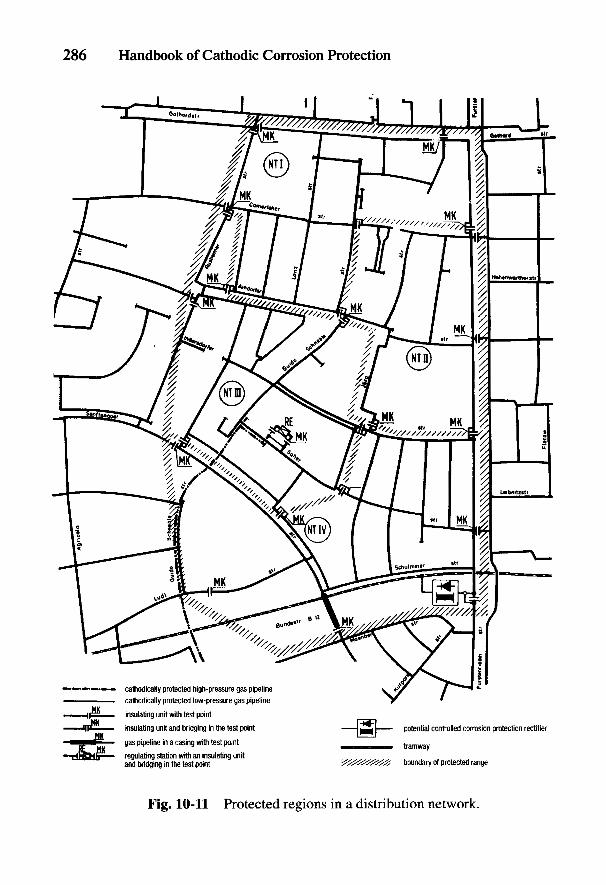
286 Handbook of Cathodic Corrosion Protection
Fig. 10-11 Protected regions in a distribution network.

Pipelines 287
nected via diodes and variable resistors to the cathodic protection station to avoidequalizing currents. After the final adjustment of the protection current where theprotection criterion is achieved at the ends of the protection range, the output volt-age, the meter reading and the on potential in the vicinity of the cathodic protectionstation outside the voltage cone of the anode ground bed as well as at the endpoints of the protection range must be measured and recorded. A few weeks aftercommissioning and setting up the cathodic protection, if the final polarization isattained, a final check is made. In this all the necessary and important data of thecathodic protection station, the protection current output, pipe/soil potential, recti-fier output voltage, grounding resistance of the anode ground bed, meter reading,and the state of the current supply must be measured and recorded in a register (seeTable 8-1). The pipe/soil potentials are checked at all test points to ensure that theprotection criterion Uoff < Us [Eq. (2-39)] is fulfilled at all measuring points. Inaddition, the resistance of the insulating joints and the resistances between casingand the pipeline as well as pipe currents are measured and recorded [32]. It isrecommended that for further evaluation and clear representation, the values bepresented in potential plots (see Fig. 3-30). These potential plots can today be con-veniently computerized to show the protection current densities and coating resis-tances of individual sections of the pipeline (see Fig. 10-8).
This check provides a good survey of the polarization state of the pipeline,assuming that the protection current distribution is approximately independent oflocation. Uniform protection current distribution does not, however, exist in areasof serious damage to the coating. For evidence that the protection criterion is ful-filled at such locations, intensive measurements are carried out on new pipelinesafter reaching complete contact with the surrounding soil, about 1 year after beinglaid (see Section 3.7). With pipelines where cathodic protection has subsequentlybeen applied, intensive measurements can be carried out after attaining the neces-sary polarization.
Deviations from the protection criterion determined by the detailed measure-ments must be rectified either by digging up the pipe and repairing the coating orby resetting the cathodic protection station or constructing an additional station.The detailed measurements should then be repeated and recorded.
10.5 Monitoring and Supervision
According to Ref. 32, the functioning of impressed current cathodic protectionstations should be monitored every 2 months, and the stray current protection sta-tion every 1 month. If protection installations are provided with measuring instru-ments for current and potential, this supervision can be carried out by operatingstaff, so that the readings are recorded and sent to the technical department for
288 Handbook of Cathodic Corrosion Protection
examination. Deviations of the actual values from the nominal values can revealfaults that must be located and dealt with by the operating staff. By noting thereadings, the type of damage or the deficiency in the protection installation and itscauses can be identified and measures taken to achieve the safe operationof the protection system. Causes of damage and remedial measures are describedin Table 8-2.
A check on the cathodic protection of the pipeline should be carried out annu-ally according to Section 10.4, where, of course, only the on potential should bemeasured. This value should also be compared with the values of the measure-ments in Section 10.4. If there are no changes in the on potentials and the protec-tion current densities for the individual sections of the pipeline, it can be concludedthat the off potential has not changed. The values can easily be compared usingcomputers and represented in plots. If the protection current and potential distribu-tion have changed, or in any case every 3 years, the off potentials as well as the onpotentials should be measured.
Remote monitoring of the pipe/soil potential is worthwhile for extended net-works of cathodically protected pipelines where test points show noticeable changesin a positive direction of the pipe/soil potential due to deficiencies in neighboringcathodic protection installations, the shorting of insulating connectors or contactwith foreign pipelines. The limit should be determined by investigation at thoselocations from which a fault in the cathodic protection system can be detected.This limit is to be supervised and announced, if exceeded, at a control room. Moni-toring of the limit every 24 h is sufficient [33]. Daily inspection is particularlysuitable for the hours of the night between 1 and 4 A.M. since fluctuations in thepipe/soil potentials caused by dc railways do not occur because they are not oper-ating. Failures recorded in the monitoring unit due to telluric currents can be recog-nized by long-term recording of the pipe/soil potential at a location not affected bystray currents and transmitting the readings to the control room. Also, periodiclarge changes due to switching off the protection station to determine off potentialsshould not be recorded as failures.
The cathodic protection of pipelines is best monitored by an intensive mea-surement technique according to Section 3.7, by an off potential survey every 3 yearsand by remote monitoring of pipe/soil potentials. After installation of parallel pipe-lines, it can be ascertained by intensive measurements whether new damage of thepipe coating has occurred. These measurements provide evidence of possible exter-nal actions that can cause mechanical damage.
Pipelines 289
10.6 References
[1] TRbF 301, Carl Heymanns Verlag, Koln 1981.[2] TRGL 141, Carl Heymanns Verlag, Koln 1977.[3] DVGW Arbeitsblatt G 463, ZfGW-Verlag, Frankfurt 1983.[4] DVGW Arbeitsblatt G 462/2, ZfGW-Verlag, Frankfurt 1985.[5] F. Giesen, J. Heseding und D. Miiller, 3R intern. 9, 317 (1970).[6] H. J. Arnholt, SchweiBen + Schneiden 32, 496 (1980).[7] Firmenschrift, Bergsoe Anti Corrosion, Landskrona (Schweden) 1987.[8] DVGW Arbeitsblatt GW14, ZfGW-Verlag, Frankfurt 1989.[9] DIN 30675 Teil 1, Beuth Verlag, Berlin 1985.
[10] DIN 2470 Teil 1, Beuth Verlag, Berlin 1987.[11] DIN 3389, Beuth Verlag, Berlin 1984.[12] AfK-Empfehlung Nr. 5, ZfGW-Verlag, Frankfurt 1986.[13] AfK-Empfehlung Nr. 6, ZfGW-Verlag, Frankfurt 1985.[14] DIN VDE 0664, Teil 1, Beuth Verlag, Berlin 1985.[15] DIN VDE 0551, Beuth Verlag, Berlin 1980.[16] AfK-Empfehlung Nr. 1, ZfGW-Verlag, Frankfurt 1985.[17] Gas- und Wasserkreuzungsrichtlinien der Deutschen Bundesbahn (DS 180).[18] DIN VDE 0185 Teil 2, Beuth Verlag, Berlin 1982.[19] DIN VDE 0101, Beuth Verlag, Berlin 1988.[20] DVGW Arbeitsblatt GW12, ZfGW-Verlag, Frankfurt 1984.[21] A. W. Peabody, Materials Perform. 18, H. 5, 27 (1979).[22] H. Hildebrand u. W. Schwenk, 3R intern. 21, 387 (1982).[23] Fachverband Kathodischer Korrosionsschutz, 3R intern. 24, 82 (1985).[24] A. Winkler, gwf/gas 120, 335 (1979).[25] DIN VDE 0190, Beuth Verlag, Berlin 1986.[26] DIN VDE 0100 Teil 540, Abschn. 4, Beuth Verlag, Berlin 1986.[27] F. Schwarzbauer, pers. Mitteilung 1988.[28] DVGW Arbeitsblatt G600 (TRGI), ZfGW-Verlag, Frankfurt 1972 u. 1987.[29] DVGW Arbeitsblatt GW412, ZfGW-Verlag, Frankfurt 1988.[30] F. Schwarzbauer, gwf/gas 121, 419 (1980).[31] W. v. Baeckmann, ndz. 22, 42 (1971).[32] DVGW Arbeitsblatt GW10, ZfGW-Verlag, Frankfurt 1984.[33] H. Lyss u. W. Prinz, 3R intern. 24, 472 (1985).
11
Storage Tanks and Tank FarmsK. HORRAS AND G. RlEGER
11.1 Special Problems Relating to the Protection of Tanks
The external cathodic protection of underground storage tanks [1], particularlyolder tank installations, presents difficulties compared with buried pipelines forthe following reasons: the tanks are often close to buildings or grouped closetogether. In many cases, buried storage tanks are mounted on large concrete foun-dations as a protection against buoyancy. With older tank installations, thecontainers are mostly situated in secondary containments that formerly wereprovided as collecting facilities for single-wall containers and therefore may showsigns of leaking. Depending on the method of construction, such arrangements canaffect the distribution of the protection current when there are larger areas ofdamage in the coating in which the protection current is restrained, but to whichcorrosive constituents of the soil have uninhibited access. In this case theconditions for Eq. (2-47) do not apply. By careful planning and construction ofnew installations, factors interfering with the cathodic protection of the tank canbe safely avoided.
11.2 Preparatory Measures
The preparatory work for tank installations with single-wall containers beginswith checking whether cathodic protection is prescribed or is appropriate on thegrounds of economy [2]. The information in Chapter 4 is relevant in judging therisk of corrosion. Corrosion risk in storage tanks consists of the formation of cellswith foreign cathodic structures via connecting lines, e.g., pipelines of copper orstainless steel or rusted steel pipes embedded in concrete as well as steel-reinforced concrete structures.
For economical and complete cathodic protection against external corrosionwithout harmful effects on nearby installations, the storage tank to be protectedmust have good coating and therefore require a low protection current density. Inaddition, it must have no electrical contacts with other buried installations, such as
290

Storage Tanks and Tank Farms 291
pipelines and cables. In this case the interconnected installations take up muchmore current than the object to be protected because of their generally lowergrounding resistance so that the higher protection current required has damagingeffects on neighboring installations (see Section 9.2). If the interconnected instal-lations are very close to the tank to be protected, they can have a shielding effect sothat the latter does not receive sufficient protection.
In new installations the coating of the tank should be tested and repaired ifnecessary before backfilling. Also, all metallic components that are electricallyconnected to the storage tank which have to be included within the cathodicprotection must be well coated. These components are filling and emptying pipeworkand aeration pipes, as well as possible steel domes and the lifting points on thetank. Tanks and their connected pipework have to be embedded in soft soil. Goodcoating must comply with the data in Section 5.1 for the safe application ofcathodic protection. Guidelines and regulations for the installation of storage tanksmust be adhered to [3,4].
The tank and auxiliary pipework that is to be cathodically protected must beelectrically isolated from all other metallic installations. This is achieved byarranging insulating couplings so that all the steel and coated copper connectionpipes of the storage tank which are underground can be covered by the cathodicprotection. The insulating couplings should be inside the building where thepipework enters and at the base of the pumps in service stations. To protect againstcorrosion by cell formation with the above-named parts of the installation,electrical separation of the service area and the building through use of insulatingjoints that can be examined is emphatically recommended [2,5].
Recently in some types of refuelling stations, corrosion-resistant materials havebeen used between the filter-water separator and the outlet pipeline and valves,usually stainless steel, rarely aluminum. If these are buried, they must have goodinsulating coating and be electrically separated from other tank installations byinsulating couplings.
At the point where pipes enter buildings or pits, accidental electrical contactbetween the pipes and the ducting must be strenuously avoided. Accidentalaboveground contact of aeration pipes and grounded metal components, whichfrequently occurs, can be prevented simply by ensuring that all the fixings andsupports are mounted on the aeration pipes with a mechanically strong insulatinginsert. If underground crossing between the protected pipeline and otherinstallations (e.g., cables, lightning conductors) is unavoidable, care should be takenthat no contact can occur if compaction or later subsidence of the soil takes place.All additional equipment in contact with the tank installation (e.g., leak preventionequipment and filling gauges) must be installed so that no electrical connectionsthat would damage the cathodic protection arise in the protection leads of the
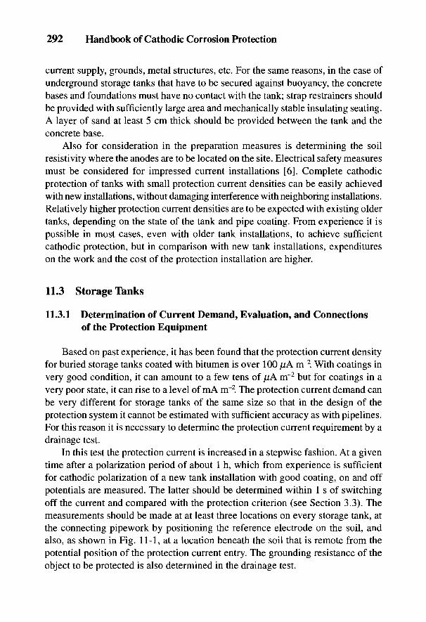
292 Handbook of Cathodic Corrosion Protection
current supply, grounds, metal structures, etc. For the same reasons, in the case ofunderground storage tanks that have to be secured against buoyancy, the concretebases and foundations must have no contact with the tank; strap restrainers shouldbe provided with sufficiently large area and mechanically stable insulating seating.A layer of sand at least 5 cm thick should be provided between the tank and theconcrete base.
Also for consideration in the preparation measures is determining the soilresistivity where the anodes are to be located on the site. Electrical safety measuresmust be considered for impressed current installations [6]. Complete cathodicprotection of tanks with small protection current densities can be easily achievedwith new installations, without damaging interference with neighboring installations.Relatively higher protection current densities are to be expected with existing oldertanks, depending on the state of the tank and pipe coating. From experience it ispossible in most cases, even with older tank installations, to achieve sufficientcathodic protection, but in comparison with new tank installations, expenditureson the work and the cost of the protection installation are higher.
11.3 Storage Tanks
11.3.1 Determination of Current Demand, Evaluation, and Connectionsof the Protection Equipment
Based on past experience, it has been found that the protection current densityfor buried storage tanks coated with bitumen is over 100 p,A m~2. With coatings invery good condition, it can amount to a few tens of /lA m~2 but for coatings in avery poor state, it can rise to a level of mA nr2. The protection current demand canbe very different for storage tanks of the same size so that in the design of theprotection system it cannot be estimated with sufficient accuracy as with pipelines.For this reason it is necessary to determine the protection current requirement by adrainage test.
In this test the protection current is increased in a stepwise fashion. At a giventime after a polarization period of about 1 h, which from experience is sufficientfor cathodic polarization of a new tank installation with good coating, on and offpotentials are measured. The latter should be determined within 1 s of switchingoff the current and compared with the protection criterion (see Section 3.3). Themeasurements should be made at at least three locations on every storage tank, atthe connecting pipework by positioning the reference electrode on the soil, andalso, as shown in Fig. 11-1, at a location beneath the soil that is remote from thepotential position of the protection current entry. The grounding resistance of theobject to be protected is also determined in the drainage test.
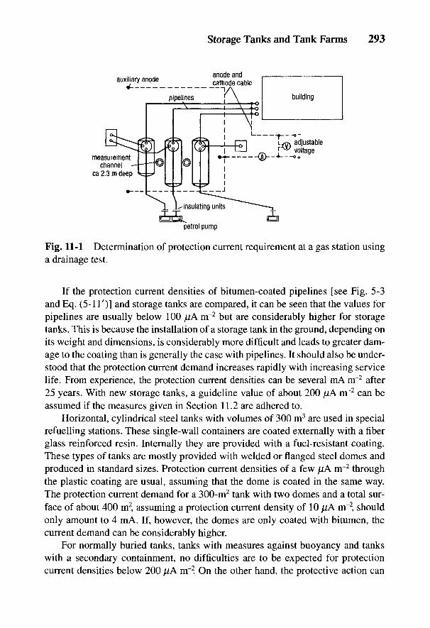
Storage Tanks and Tank Farms 293
Fig. 11-1 Determination of protection current requirement at a gas station usinga drainage test.
If the protection current densities of bitumen-coated pipelines [see Fig. 5-3and Eq. (5-IT)] and storage tanks are compared, it can be seen that the values forpipelines are usually below 100 [lA m~2 but are considerably higher for storagetanks. This is because the installation of a storage tank in the ground, depending onits weight and dimensions, is considerably more difficult and leads to greater dam-age to the coating than is generally the case with pipelines. It should also be under-stood that the protection current demand increases rapidly with increasing servicelife. From experience, the protection current densities can be several mA irr2 after25 years. With new storage tanks, a guideline value of about 200 [lA nr2 can beassumed if the measures given in Section 11.2 are adhered to.
Horizontal, cylindrical steel tanks with volumes of 300 m3 are used in specialrefuelling stations. These single-wall containers are coated externally with a fiberglass reinforced resin. Internally they are provided with a fuel-resistant coating.These types of tanks are mostly provided with welded or flanged steel domes andproduced in standard sizes. Protection current densities of a few /lA m"2 throughthe plastic coating are usual, assuming that the dome is coated in the same way.The protection current demand for a 300-m2 tank with two domes and a total sur-face of about 400 m2 assuming a protection current density of 10 /nA nr2, shouldonly amount to 4 mA. If, however, the domes are only coated with bitumen, thecurrent demand can be considerably higher.
For normally buried tanks, tanks with measures against buoyancy and tankswith a secondary containment, no difficulties are to be expected for protectioncurrent densities below 200 (JiA nr2. On the other hand, the protective action can

294 Handbook of Cathodic Corrosion Protection
be impaired by much higher protection current demand and serious obstaclesto access to the protection current (e.g., plastic-coated secondary containments).The following advice for judging protective action and the possible interferencewith neighboring installations is derived from a number of case studies:
1. If the protection current density for underground tank installations is not muchover 200 jjA nr2 and the protection current is no more than a few 10 mA,complete cathodic protection can usually be achieved even in unfavorable siteconditions, e.g., if the anodes can only be arranged on one side of the object tobe protected. Influence on foreign installations is not to be expected as long asthese are not situated in the voltage cone of the anodes.
2. For installations with several storage tanks and a protection current of sev-eral tens of an mA, uniform protection current distribution should be thegoal, so that the current injection occurs via a number of anodes distrib-uted over the site or via a more distant anode bed. Dividing up the protec-tion current over several anodes avoids large local anodic voltage conesand therefore effects on neighboring installations.
3. Protection currents of a few amperes are needed for the cathodic protec-tion of assemblies of storage tanks or refuelling stations. In this case, elec-trical contact with grounded installations is the main problem. For cathodicprotection, these contacts must be located and electrically separated. Ifthis is not possible, then local cathodic protection should be installed (seeChapter 12).
In the case of higher protection current densities and protection currents, inter-ference can occur on nearby installations not covered by the protection. The dan-ger of anodic interference must be investigated by making measurements andprevented by taking appropriate measures [7] (see Section 9.2). For the same reasons,anode systems should not be installed near steel-reinforced concrete foundations.
A cathode cable is adequate for the return path of the protection currentfor individual storage tanks. In pumping stations with several storage tanks, each tankmust be provided with a cable connection. If the tanks are connected to each other byelectrical connections, then two cathode cable connections must be provided [2].
Suitable cable for cathode and anode cables to be laid in earth is NYY-0 (in theUnited States, HMWPE on Kynar). The cable must be protected in the earth andconnected (by straps to the dome supports of tanks; see Ref. 3) to structural partsof the object to be protected, which must not become detached in operation.
The lowest cross-section of 4 mm2 Cu (equivalent to No. 12 AWG) is for cableto the object to be protected, and 2.5 mm2 Cu (equivalent to No. 14 AWG) to theanodes [2]. It is recommended that two-core cathode connecting cable, 2 X 4 mm2,
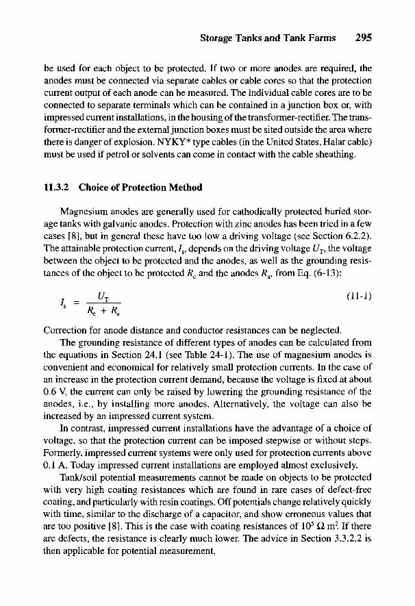
Storage Tanks and Tank Farms 295
be used for each object to be protected. If two or more anodes are required, theanodes must be connected via separate cables or cable cores so that the protectioncurrent output of each anode can be measured. The individual cable cores are to beconnected to separate terminals which can be contained in a junction box or, withimpressed current installations, in the housing of the transformer-rectifier. The trans-former-rectifier and the external junction boxes must be sited outside the area wherethere is danger of explosion. NYKY* type cables (in the United States, Halar cable)must be used if petrol or solvents can come in contact with the cable sheathing.
11.3.2 Choice of Protection Method
Magnesium anodes are generally used for cathodically protected buried stor-age tanks with galvanic anodes. Protection with zinc anodes has been tried in a fewcases [8], but in general these have too low a driving voltage (see Section 6.2.2).The attainable protection current, 7S, depends on the driving voltage UT, the voltagebetween the object to be protected and the anodes, as well as the grounding resis-tances of the object to be protected Rc and the anodes Ra, from Eq. (6-13):
Correction for anode distance and conductor resistances can be neglected.The grounding resistance of different types of anodes can be calculated from
the equations in Section 24.1 (see Table 24-1). The use of magnesium anodes isconvenient and economical for relatively small protection currents. In the case ofan increase in the protection current demand, because the voltage is fixed at about0.6 V, the current can only be raised by lowering the grounding resistance of theanodes, i.e., by installing more anodes. Alternatively, the voltage can also beincreased by an impressed current system.
In contrast, impressed current installations have the advantage of a choice ofvoltage, so that the protection current can be imposed stepwise or without steps.Formerly, impressed current systems were only used for protection currents above0.1 A. Today impressed current installations are employed almost exclusively.
Tank/soil potential measurements cannot be made on objects to be protectedwith very high coating resistances which are found in rare cases of defect-freecoating, and particularly with resin coatings. Off potentials change relatively quicklywith time, similar to the discharge of a capacitor, and show erroneous values thatare too positive [8]. This is the case with coating resistances of 105 Q m2. If thereare defects, the resistance is clearly much lower. The advice in Section 3.3.2.2 isthen applicable for potential measurement.

296 Handbook of Cathodic Corrosion Protection
11.3.3 Examples of the Design of Protective Installations
11.3.3.1 Equipment Using Galvanic Anodes
As can be seen in Fig. 11-2, the fuel oil tank to be protected is close to abuilding and is buried. On the side of the tank facing away from the building, theboundary of the premises is a few meters from the tank. The steel pipelines con-nected to the tank and included in the cathodic protection are coated. The neces-sary insulating couplings for electrical separation of the fuel oil tank are situated inthe building. The overall data necessary for the design of the cathodic protectioninstallation, determined by a drainage test, are included in the following list:
• storage tank 20 m3, tank and pipework surface area: 50 m2;• grounding resistance of the fuel oil tank installation: 30 Q;• resistance at the insulating coupling: 28 Q;• soil resistivity at the anode sites measured with probe at distances of 1.6
and 3.2 m, average value of 8 measurements: 35 Q m;• protection current at an off potential £/cu-cuso4
= -0.88 V: 10 mA;• current density: 200 ]LiA m~2.
Magnesium anodes were chosen as the source of the protection current in thisold example, because on one hand a sufficient current, including current reserve,could be achieved due to the relatively low soil resistivity, and on the other hand,use of an impressed current protection system would have required much greaterexpenditure.
Since to achieve the necessary protection current, including a current reserve(in total about 15 mA), the total resistance of the protection current circuit at avoltage of 0.6 V between steel and magnesium anodes [Eq. (11-1)1 must notexceed 40 Q, two 5-kg magnesium block anodes were provided whose groundingresistance RA for each anode amounted to about 20 iQ. The grounding resistance ofthe two anodes connected in parallel, taking into account an interference effectfactor, F = 1.1 with n = 2in Eq. (24-35), comes to about 11 £1
Basically the maximum anode currents given by Eq. (6-14) indicate that the ground-ing resistance of the cathode is considerably smaller than that of the anode. Since this isnot necessarily the case, particularly with storage tanks with good coating, the currentoutput of the anodes is considerably lower [see Eqs. (6-13) and (11-1)].
Although an anode arrangement on both sides of this tank had been planned toensure uniform protection current distribution, the two anodes had to be installed inthe strips of land between the storage tank and the boundary of the site, taking intoaccount the grounding resistance and the required life of 25 years [2], because therewere several foreign installations between the building and the storage tank (waterpipes, electric cables and telephone cables). The anodes were installed at a distance

Storage Tanks and Tank Farms 297
Fig. 11-2 Cathodic protection of a fuel tank with magnesium anodes.
of 11 m and about 2.8m deep in the ground. Burying the anodes at a shallower depth,1.5 to 2.0 m, is only practicable if the soil in the area remains damp in long dryperiods. If the anodes are situated at an even shallower depth, the grounding resis-tance and also the resistance of the protection current circuit rises so sharply due todrying out of the surface of the soil that the current necessary to protect the tanksurfaces at a greater depth can no longer be supplied by galvanic anodes.
At the relatively low protection current density of 200 ^uA m"2 and with theanode positioned on one side, it is to be expected that with this storage tank suffi-cient reduction in potential would be achieved on the other side of the tank fromthe anode. The off potential was measured using a measurement point at a depth ofabout 2 m as UCu _CuSO4 = -0.88 V at the tank. At the other side of the tank as wellas above it, off potentials of-0.90 to -0.94 V were found. These potentials weremeasured with a protection current of 10 mA (anode 1: 6 mA, anode 2: 4 mA) withan additional resistance of 8 Q. in the protection current circuit (see Fig. 11-2).With a direct connection between the tank and the group of magnesium anodes, theinitial current was about 16 mA, which after 1 h of polarization decreased to about14 mA. The reserve current, based on a long-term current of 10 mA, amounted toca. 40% in the operation of the cathodic protection installation.
The life of the magnesium anodes with a current content of about 1.2 A a for 10mA according to Table 6-4 was calculated from Eq. (6-9) as 120 years. Thisassumes that the protection current is equally distributed over both anodes. Thecalculated life would certainly not be reached because uniform anode current dis-tribution cannot be achieved over a long period of time. It would, however, besubstantially longer than the minimum required life of 25 years. For this length
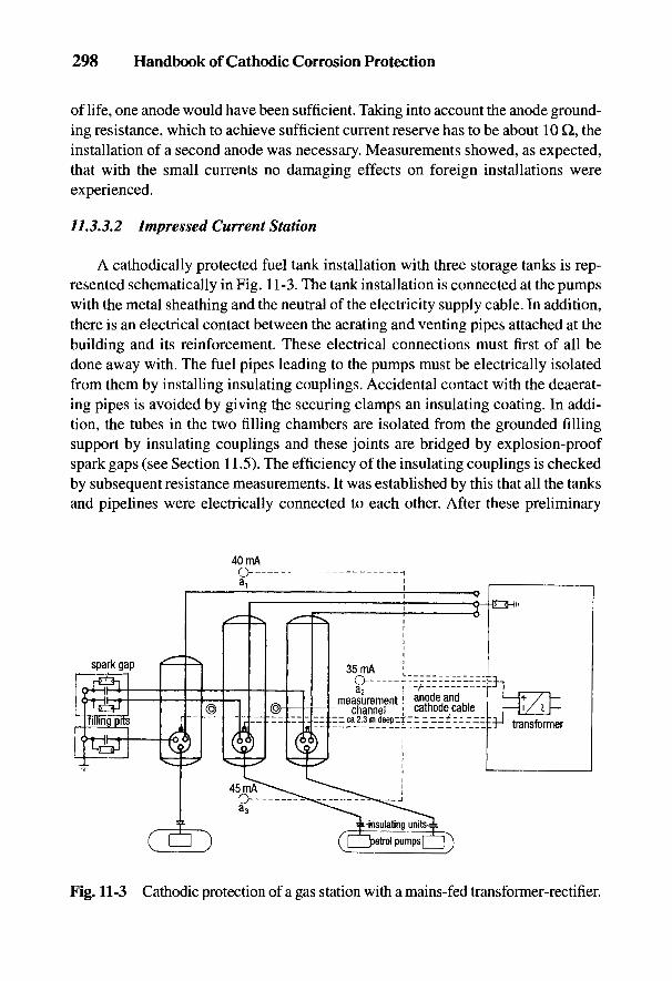
298 Handbook of Cathodic Corrosion Protection
of life, one anode would have been sufficient. Taking into account the anode ground-ing resistance, which to achieve sufficient current reserve has to be about 10 Q, theinstallation of a second anode was necessary. Measurements showed, as expected,that with the small currents no damaging effects on foreign installations wereexperienced.
11.3.3.2 Impressed Current Station
A cathodically protected fuel tank installation with three storage tanks is rep-resented schematically in Fig. 11-3. The tank installation is connected at the pumpswith the metal sheathing and the neutral of the electricity supply cable. In addition,there is an electrical contact between the aerating and venting pipes attached at thebuilding and its reinforcement. These electrical connections must first of all bedone away with. The fuel pipes leading to the pumps must be electrically isolatedfrom them by installing insulating couplings. Accidental contact with the deaerat-ing pipes is avoided by giving the securing clamps an insulating coating. In addi-tion, the tubes in the two filling chambers are isolated from the grounded fillingsupport by insulating couplings and these joints are bridged by explosion-proofspark gaps (see Section 11.5). The efficiency of the insulating couplings is checkedby subsequent resistance measurements. It was established by this that all the tanksand pipelines were electrically connected to each other. After these preliminary
Fig. 11-3 Cathodic protection of a gas station with a mains-fed transformer-rectifier.
Storage Tanks and Tank Farms 299
measures, a drainage test was carried out. The following data are relevant in thedesign of the protection installation:
• total surface area of the tanks and pipelines: about 190 m2;• resistance of the built-in insulators: 11 Q;• resistance between the aeration pipes and the connecting clamps after
insulating: 13 £7;• average soil resistivity of the site of the tank installation: 70 to 80 Q m;• current requirement of the installation: 120 mA;• protection current density: about 630 //A nrr2.
In this case, impressed current protection with several anodes was chosen on theone hand to achieve uniform current distribution with the relatively high protec-tion current density, and on the other hand to avoid large anode voltage cones.A transformer-rectifier with a capacity of 10 V/l A was chosen.
In total, three high-silicon iron anodes of 3 kg each were installed at points a1?
a2 and a3 as shown in Fig. 11-3. The anodes were bedded vertically in fine-grainedcoke in boreholes about 2.3 m deep and d = 0.2 m so that the length of the cokebackfill was about 1 m. Each anode was connected by a separate cable to the anodebus bar of the transformer-rectifier to allow the current of individual anodes to bemonitored. Three cathode cables 2 x 4 mm2 were installed for the return path ofthe protection current and attached on the tank end to the connecting clamps of thedome support.
The grounding resistance of the three anodes with the stated dimensions of thecoke backfill, a soil resistivity of 75 Q m and an interference factor, F = 1.2, wascalculated from Eq. (24-35) as about 14 Q. After the anode installation was inoperation, measurements of the grounding resistance gave a value of about 12 Q.
During commissioning, the cathodic protection system gave a protection cur-rent of 120 mA with a voltage of about 4 V. The adequate off potential oft/cu-cuso4 = -0.88 to -0.95 V was found at all the potential test points and alsobetween the tanks where the potential was measured by means of a measurementpoint at a depth of 2.3 m at places where the spacing between the tanks was closest.The anode currents are given in Fig. 11-3. The voltage cones of the anodes werekept small by the anode arrangement chosen and the current distribution so thatforeign installations at the pumping station were not affected.
11.4 Tank Farms and Filling Stations
Efforts are made in the construction of new, large tank farms to achieveelectrical isolation of buried and cathodically protected fuel installations from all
300 Handbook of Cathodic Corrosion Protection
grounded installations, and to provide at the planning stage a correspondingnumber of insulating couplings. If there is an extended pipe network, it isrecommended that the pipe system be electrically separated from the tanks byinsulating couplings. The eventual trouble-shooting of faults is made much easier.Also, the current uptake of the tanks and pipework can be determined separately.In such cases, cathodic protection usually presents no difficulties.
When installing insulating joints, a measuring lead should be provided to ensurethat the joints can be monitored. Insulating units in areas of explosion danger mustbe bridged with explosion-proof spark gaps (see Section 11.5). Bridging with sparkgaps of low response voltage (£/aw < 1 kV) is particularly important with pipelinesthat normally carry explosive mixtures of air and vapor (ventilation pipes, empty-running waste pipes, etc.). It is important to ensure that the breakdown voltage ofthe insulating joints as well as the wall entrances of the pipes into the building andsimilar arrangements are at least twice the response voltage of the spark gaps.Since an electrical voltage arises at insulating joints in cathodic protection, it isparticularly important to provide sufficient isolation in explosion-hazardousregions so that the insulating joints in the pipe cannot be electrically bridged.
Only local cathodic protection can be used for large installations and oldinstallations with electrical contact to components with low grounding resistancesthat cannot be isolated (see Section 12.6). The measures necessary for tank instal-lations are described in Ref. 10.
As an example, a tank farm that is to be cathodically protected by this methodis shown schematically in Fig. 11-4. As can be seen in the figure, injection of theprotection current occurs with two current circuits of a total of about 9 A, via 16vertically installed high-silicon iron anodes embedded in coke. These are distrib-uted over several locations in the tank farm to achieve an approximately uniformpotential drop. The details of the transformer-rectifier as well as the individualanode currents are included in Fig. 11-4. Anodes 4, 5 and 6 have been placed atareas where corrosion damage previously occurred. Since off potentials for IR-freepotential measurements cannot be used, external measuring probes should beinstalled for accurate assessment (see Section 3.3.3.2 and Chapter 12).
11.5 Special Problems in Cathodic Protection Near Railways
11.5.1 General Comments
Tank installations below ground in the neighborhood of railway lines are oftenin aggressive soil that is contaminated with slag. Cathodic protection is thereforeparticularly important. Because of the particularities of railway operations,company standards must be followed in addition to the generally required direc-
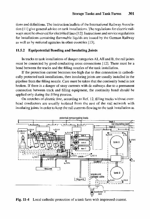
Storage Tanks and Tank Farms 301
tions and definitions. The instruction leaflets of the International Railway Associa-tion [11] give general advice on tank installations. The regulations for electric rail-ways must be observed for electrified lines [12]. Instructions and service regulationsfor installations containing flammable liquids are issued by the German Railwayas well as by national agencies in other countries [13].
11.5.2 Equipotential Bonding and Insulating Joints
In tracks to tank installations of danger categories AI, All and B, the rail jointsmust be connected by good conducting cross connections [12]. There must be abond between the tracks and the filling nozzles of the tank installation.
If the protection current becomes too high due to this connection in cathodi-cally protected tank installations, then insulating joints are usually installed in thepipeline from the filling nozzle. Care must be taken that the continuity bond is notbroken. If there is a danger of stray currents with dc railways due to a permanentconnection between track and filling equipment, the continuity bond should beapplied only during the filling process.
On stretches of electric line, according to Ref. 12, filling tracks without over-head conductors are usually isolated from the rest of the rail network withinsulating joints in order to keep the rail currents flowing to the tank installation as
Fig. 11-4 Local cathodic protection of a tank farm with impressed current.
302 Handbook of Cathodic Corrosion Protection
low as possible. The insulating joints are installed outside the danger zone, inparticular at the beginning of a dead-end line, and on both sides of the danger zonefor lines that are connected to other lines on both sides. Installing insulating unitsin the pipeline to the filling nozzle is then not necessary if the protection currentfor the tank installations is not noticeably raised by connecting the fillingequipment to these lines. Insulating joints in the filling tracks can be dispensedwith if there are no voltages above 50 V between the rail network and the tankinstallation, so long as they are not connected by a conductor and the return currentof the railway will not endanger the tank installation (see Section 11.5.3).
Insulating joints must not be built into filling tracks with overhead conductors.The overhead conductors must be switched off during filling and can be connectedto the railway ground. In these cases, insulating couplings must always be builtinto the pipeline to the filling nozzle in order to enable cathodic protection of thetank installation.
11.5.3 Protective Grounding with Electrified Railways
The railway lines (tracks) of electrified railways serve as the railway ground.Metallic parts of filling equipment that are aboveground should be grounded torails directly or via breakdown fuses (voltage fuses) if these parts are situated inthe overhead conductor area of electric railways with nominal voltages of morethan 1 kV for ac or 1.5 kV for dc. As can be seen in Fig. 11-5, directly groundedparts must be electrically separated from the cathodically protected installation.Where grounding is via breakdown fuses, the parts and also the cathodically pro-tected installation are not connected to the railway ground under normal operatingconditions.
Monitoring of the breakdown fuses is necessary. Tracks of electrified railwaysconduct return currents and will have a voltage against the remote ground; thisvoltage is also termed rail potential. The transformer-rectifier must be providedaccording to Ref. 14.
11.5.4 Lightning Protection
Grounded installations, including buried metallic pipelines, that are within 2 mof a lightning conductor should be connected directly to it or via a spark gap [15].If pipelines connected to a lightning conductor are provided with insulating coup-lings, the latter must be bridged by spark gaps. Tracks of electrified railways andtracks of all railways up to 20 m distant from the connection of a lightning conduc-tor to the track must be dealt with in the same way as lightning conductors.
With AI, All and B-classified installations on electrified railways, spark gapsin the danger zone must be explosion proof [12]. Insulating couplings and spark
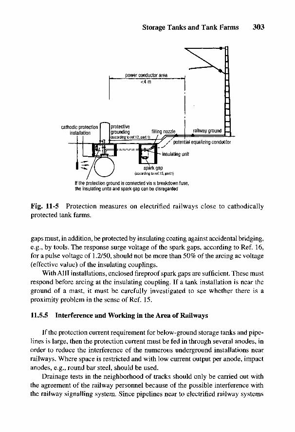
Fig. 11-5 Protection measures on electrified railways close to cathodicallyprotected tank farms.
gaps must, in addition, be protected by insulating coating against accidental bridging,e.g., by tools. The response surge voltage of the spark gaps, according to Ref. 16,for a pulse voltage of 1.2/50, should not be more than 50% of the arcing ac voltage(effective value) of the insulating couplings.
With AIII installations, enclosed fireproof spark gaps are sufficient. These mustrespond before arcing at the insulating coupling. If a tank installation is near theground of a mast, it must be carefully investigated to see whether there is aproximity problem in the sense of Ref. 15.
11.5.5 Interference and Working in the Area of Railways
If the protection current requirement for below-ground storage tanks and pipe-lines is large, then the protection current must be fed in through several anodes, inorder to reduce the interference of the numerous underground installations nearrailways. Where space is restricted and with low current output per anode, impactanodes, e.g., round bar steel, should be used.
Drainage tests in the neighborhood of tracks should only be carried out withthe agreement of the railway personnel because of the possible interference withthe railway signalling system. Since pipelines near to electrified railway systems
Storage Tanks and Tank Farms 303
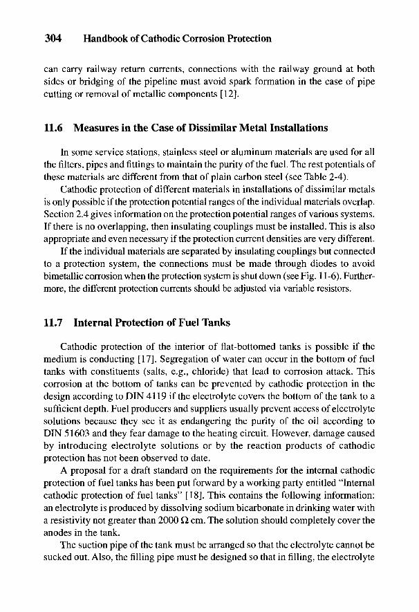
304 Handbook of Cathodic Corrosion Protection
can carry railway return currents, connections with the railway ground at bothsides or bridging of the pipeline must avoid spark formation in the case of pipecutting or removal of metallic components [12].
11.6 Measures in the Case of Dissimilar Metal Installations
In some service stations, stainless steel or aluminum materials are used for allthe filters, pipes and fittings to maintain the purity of the fuel. The rest potentials ofthese materials are different from that of plain carbon steel (see Table 2-4).
Cathodic protection of different materials in installations of dissimilar metalsis only possible if the protection potential ranges of the individual materials overlap.Section 2.4 gives information on the protection potential ranges of various systems.If there is no overlapping, then insulating couplings must be installed. This is alsoappropriate and even necessary if the protection current densities are very different.
If the individual materials are separated by insulating couplings but connectedto a protection system, the connections must be made through diodes to avoidbimetallic corrosion when the protection system is shut down (see Fig. 11-6). Further-more, the different protection currents should be adjusted via variable resistors.
11.7 Internal Protection of Fuel Tanks
Cathodic protection of the interior of flat-bottomed tanks is possible if themedium is conducting [17]. Segregation of water can occur in the bottom of fueltanks with constituents (salts, e.g., chloride) that lead to corrosion attack. Thiscorrosion at the bottom of tanks can be prevented by cathodic protection in thedesign according to DIN 4119 if the electrolyte covers the bottom of the tank to asufficient depth. Fuel producers and suppliers usually prevent access of electrolytesolutions because they see it as endangering the purity of the oil according toDIN 51603 and they fear damage to the heating circuit. However, damage causedby introducing electrolyte solutions or by the reaction products of cathodicprotection has not been observed to date.
A proposal for a draft standard on the requirements for the internal cathodicprotection of fuel tanks has been put forward by a working party entitled "Internalcathodic protection of fuel tanks" [18]. This contains the following information:an electrolyte is produced by dissolving sodium bicarbonate in drinking water witha resistivity not greater than 2000 Q cm. The solution should completely cover theanodes in the tank.
The suction pipe of the tank must be arranged so that the electrolyte cannot besucked out. Also, the filling pipe must be designed so that in filling, the electrolyte
Storage Tanks and Tank Farms 305
Fig. 11-6 Diode circuit for the cathodicprotection of various materials.
is disturbed as little as possible. Undesirable turbulence can be prevented if thevelocity of the fuel as it enters the tank does not exceed 0.3 m s~! The end of thesuction pipe must not be lower than 5 cm above the level of the electrolyte. Mag-nesium anodes such as type AZ63 (see Section 6.2.4) are used as galvanic anodes.They have a current capacity of about 1100 A h kg"1 and a weight of 0.8 kg for alength of 35 cm per m2 of tank surface to be protected. They are electricallyseparated at a distance of 3 to 5 mm from the bottom of the tank and arranged inuniform distribution. The anodes are connected electrically with each other and tothe dome of the tank with an insulated cable. Galvanic anodes produce relativelylarge amounts of corrosion product, which leads to the formation of sludge andimpurities. These disadvantages do not arise with inert impressed current anodes.These are usually metal oxide-coated titanium anodes (see Section 7.2.3). Plati-num and anodes coated with platinum may not be used because of the danger ofexplosion [17]. Impressed current anodes are installed in the same way as galvanicanodes. The length of anode per 2 m2 of surface to be protected is 10 cm.
Anodes are connected to the object to be protected or to the transformer-rectifierby insulated conductors that are resistant to mineral oil (e.g., Teflon-coated cable)with a cross-section of 2.5 mm2 of Cu. The transformer-rectifier must meet thedemands according to Ref. 6 and have the capability for monitoring and controllingits operation. The life of the anodes is in every case designed to be at least 15 years.
Cathodic protection installations must be tested when commissioned and at leastannually. The potentials should be measured at several points on the bottom of thetank with special probes under the oil, and the height of the electrolyte solutionshould be checked. The off potential and the protection potential as in Section 2.4 arethe means for checking the protection criterion according to Eq. (2-39).
306 Handbook of Cathodic Corrosion Protection
11.8 Consideration of Other Protection Measures
Other protection measures (e.g., lightning protection, protection againstelectrical contact voltage) must not be affected by the use of cathodic protection.Therefore, all the necessary protection measures must be coordinated beforesetting up cathodic protection installations. With a lightning protection installation,if the cathodically protected tank installation or its pipework is situated near light-ning conductor grounds [15], the relevant tank installation should be connected tothe lightning conductor grounding system with spark gaps and, in areas wherethere is danger of explosion, with explosion-proof spark gaps. These should beinstalled so that the connections are as short as possible [19]. The information inSection 8.1 should be noted in the installation of ground fault circuit breakers forprotection against contact.
Tanks that use the connected pipelines as grounding systems are not permitted[20]. It has been shown that magnesium anodes connected to the tanks as groundsare effective in reducing the cathode grounding resistance, avoiding the need forhigher protection currents. The grounding resistance of the anodes should be 50V/Ifailure. The protection current should be so arranged that a small entry current(a few mA) into the magnesium anodes is detectable to avoid their corrosion. Thecircuit can be tripped by failure of a circuit breaker if the auxiliary ground is in thevoltage cone of the anodes, although there is no failure voltage. In such cases, thecorresponding measures could be avoided in the construction of the cathodicprotection station, but a remedy can be obtained by connecting a properly sizedcapacitor to the auxiliary ground's conductor.
The relevant instructions and regulations, among others, are to be observed inregions where there is danger of explosion [21-23]. When carrying out work on thedome of cathodically protected tanks, the cathodic protection station should beswitched off and the tank itself grounded to achieve potential equalization. In suchcases, fitting so-called cover grounding switches is worthwhile. These break thecathode connection to the tank when the cover dome is opened and connect thetank to the grounding system of the installation. The method can be used where allthe tanks have separate cathode connections and when the pipelines from the tanksare electrically separated with insulating couplings.
Figure 11-7 shows the basic circuit diagram for a tank with two domes. The protec-tion current flows via the two interconnected openers of the cover grounding switch tothe cathode connection. If one of the covers is opened, the protection current circuit isbroken and the tank grounded via the closing contact. The unconnected cable connec-tion of the tank is without current and can be used for measuring potential. By thismethod, only one tank at a time is separated from the protection system while the otherparts of the installations are still supplied with protection current.

Storage Tanks and Tank Farms 307
Fig. 11-7 Grounding acathodically protected tankwith a switch for groundingthe cover.
11.9 Operation and Maintenance of Cathodic Protection Stations
For commissioning and monitoring of cathodic protection stations, the advicein Refs. 1 and 2 is relevant. For potential measurement, the explanations in Section3.3 are valid.
After adjustment, the tank and pipe/soil potentials have to be checked annuallyand recorded. The results of the measurements are the basis of the maintenanceprocess. If the check measurements differ from the values established by the con-trol, the cause must be determined and the defect remedied.
A direct current flows in the installations during operation of cathodic protec-tion stations; therefore, the transformer-rectifier must be switched off when pipesare out or other work on the fuel installation is carried out, and the separated areasmust be bridged with large cross-section cables before the work is started in orderto avoid sparking that could come from the current network.
308 Handbook of Cathodic Corrosion Protection
11.10 References
[1] DIN 30676, Beuth-Verlag, Berlin 1986.[2] TRbF 521, Carl Heymanns Verlag, Koln 1984; C.-H. Degener u. G. Krause, Kommentar
zu VbF/TRbF ,,Lagerung und Abfullung brennbarer Fliissigkeiten", Abschn. 6.2,,Kommentar zu TRbF 521", Carl Heymanns Verlag, Koln 1986.
[3] DIN 6608, Beuth-Verlag, Berlin 1981.[4] Verordnung iiber Anlagen zur Lagerung, Abfullung und Beforderung brennbarer Fliissig-
keiten zu Lande (VbF), Carl Heymanns Verlag, Koln 1980.[5] DIN 50928 Teil 3, Beuth-Verlag, Berlin 1985.[6] DIN VDE 0100 Teil 410, Beuth-Verlag, Berlin 1983.[7] DIN VDE 0150, Beuth-Verlag, Berlin 1983.[8] G. Burgmann u. H. Hildebrand, Werkst. Korros. 22, 1012 (1971).[9] AfK-Empflg. Nr. 9, ZfGW-Verlag, Frankfurt 1979.
[10] TRbF 522, Carl Heymanns Verlag, Koln 1988.[11] Merkblatter des internationalen Eisenbahnverbandes UIC, Internationaler Eisenbahn-
verband, 14 rue Jean Rey, F 75015 Paris, Juli 1987.[12] DIN VDE 0115 Teile 1 bis 3, Beuth-Verlag, Berlin 1982.[13] Dienstvorschriften der Deutschen Bundesbahn, 901 c, 954/2 und 954/6, Drucksachenzen-
trale DB, Karlsruhe, 1970/72/73.[14] DIN VDE 0551 Teil 1, Beuth-Verlag, Berlin 1975.[15] DIN VDE 0185 Teile 1 und 2, Beuth-Verlag, Berlin 1982.[16] DIN VDE 0433 Teil 3, Beuth-Verlag, Berlin 1966.[17] DIN 50927, Beuth-Verlag, Berlin 1985.[18] Normvorlage Nr. 941-978024.2 TUV Rheinland e.V., Koln 12/1987.[19] AfK-Empfehlung Nr. 5, ZfGW-Verlag, Frankfurt 1986.[20] TRbF 100, Carl Heymanns Verlag, Koln 1984.[21] Verordnung uber elektrische Anlagen in explosionsgefahrdeten Raumen (Elex V), Bun-
desgesetzblatt I, S. 214, v. Juni 1980.[22] DIN VDE 0165, Beuth-Verlag, Berlin 1983.[23] Richtlinie fur die Vermeidung der Gefahren durch explosionsfahige Atmosphare mit
Beispielsammlung (Ex-RL), ZH1/10, Carl Heymanns Verlag, Koln 1986.
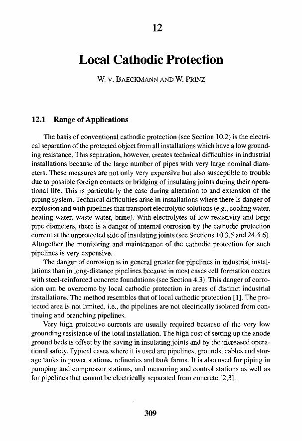
12
Local Cathodic ProtectionW. v. BAECKMANN AND W. PRINZ
12.1 Range of Applications
The basis of conventional cathodic protection (see Section 10.2) is the electri-cal separation of the protected object from all installations which have a low ground-ing resistance. This separation, however, creates technical difficulties in industrialinstallations because of the large number of pipes with very large nominal diam-eters. These measures are not only very expensive but also susceptible to troubledue to possible foreign contacts or bridging of insulating joints during their opera-tional life. This is particularly the case during alteration to and extension of thepiping system. Technical difficulties arise in installations where there is danger ofexplosion and with pipelines that transport electrolytic solutions (e.g., cooling water,heating water, waste water, brine). With electrolytes of low resistivity and largepipe diameters, there is a danger of internal corrosion by the cathodic protectioncurrent at the unprotected side of insulating joints (see Sections 10.3.5 and 24.4.6).Altogether the monitoring and maintenance of the cathodic protection for suchpipelines is very expensive.
The danger of corrosion is in general greater for pipelines in industrial instal-lations than in long-distance pipelines because in most cases cell formation occurswith steel-reinforced concrete foundations (see Section 4.3). This danger of corro-sion can be overcome by local cathodic protection in areas of distinct industrialinstallations. The method resembles that of local cathodic protection [1]. The pro-tected area is not limited, i.e., the pipelines are not electrically isolated from con-tinuing and branching pipelines.
Very high protective currents are usually required because of the very lowgrounding resistance of the total installation. The high cost of setting up the anodeground beds is offset by the saving in insulating joints and by the increased opera-tional safety. Typical cases where it is used are pipelines, grounds, cables and stor-age tanks in power stations, refineries and tank farms. It is also used for piping inpumping and compressor stations, and measuring and control stations as well asfor pipelines that cannot be electrically separated from concrete [2,3].
309
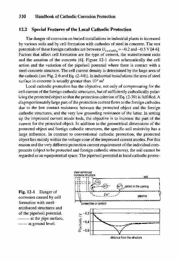
310 Handbook of Cathodic Corrosion Protection
12.2 Special Features of the Local Cathodic Protection
The danger of corrosion on buried installations in industrial plants is increasedby various soils and by cell formation with cathodes of steel in concrete. The restpotentials of these foreign cathodes are between £/Cu-cuso4 - ~0.2 and -0.5 V [4-6].Factors that affect cell formation are the type of cement, the water/cement ratioand the aeration of the concrete [6]. Figure 12-1 shows schematically the cellaction and the variation of the pipe/soil potential where there is contact with asteel-concrete structure. The cell current density is determined by the large area ofthe cathode [see Fig. 2-6 and Eq. (2-44)]. In industrial installations the area of steelsurface in concrete is usually greater than 104 m2.
Local cathodic protection has the objective, not only of compensating for thecell current of the foreign cathodic structures, but of sufficiently cathodically polar-izing the protected object so that the protection criterion of Eq. (2-39) is fulfilled. Adisproportionately large part of the protection current flows to the foreign cathodesdue to the low contact resistance between the protected object and the foreigncathodic structures, and the very low grounding resistance of the latter. In settingup the impressed current anode beds, the objective is to increase the part of thecurrent for the protected object. In addition to the geometrical dimensions of theprotected object and foreign cathodic structures, the specific soil resistivity has alarge influence. In contrast to conventional cathodic protection, the protectedobject lies mainly within the voltage cone of the impressed current anodes. For thisreason and the very different protection current requirement of the individual com-ponents (object to be protected and foreign cathodic structures), the soil cannot beregarded as an equipotential space. The pipe/soil potential in local cathodic protec-
Fig. 12-1 Danger ofcorrosion caused by cellformation with steel-reinforced structures andof the pipe/soil potential.
at the pipe surface,at ground level.

Local Cathodic Protection 311
tion changes only in relation to a nearby reference electrode and less in relation tothe potential of a remote ground. This involves considerable measurement prob-lems since the off potential for interpretation cannot be directly measured. Thepragmatic criterion No. 6 in Table 3-3 and monitoring with a measuring probe(No. 7 in Table 3-3) must be considered.
In the case of very strong polarization of steel in concrete, it was feared thatcorrosion field IV in Fig. 2-2 could be reached [7]. Tests have shown, however,that there is no danger of corrosion of the steel in concrete and any evolved hydro-gen would be dispersed through the porous concrete (see Section 5.3.2).
In order to achieve complete cathodic protection for all pipes, the foreign catho-dic structures (foundations, grounds) must be polarized to the protection potential,i.e., Uon in the neighborhood of the foreign cathodic structures must be definitelymore negative than f/s (see No. 6 in Table 3-3). In order to polarize the reinforce-ment to the protection potential, an average protection current density of 5 to10 mA m~2 is necessary, which decreases with time to 3 mA m~2. To evaluate theprotection current requirement with a reinforcement factor of 1, the total area ofconcrete exposed to the soil must be used. In comparison with this, the protectioncurrent requirement of the object to be protected is negligibly small. The protec-tion current requirement in industrial installations is generally over 100 A.
Deep anodes are mainly used for injecting such high protection currents (seeSection 9.1). The advice given in Section 9.1 on resistances and potential distribu-tion relates to anodes in homogeneous soils. Large deviations are to be expected insoil used as backfill and in the neighborhood of structures [2]. This is generally thecase with local cathodic ("hot-spot") protection.
Additional individual anodes must be installed at points on the protectedobject where a sufficiently negative pipe/soil potential cannot be achieved. Sinceusually only the voltage cone is of interest, the place of installation does notdepend on the specific soil resistivity. Coke backfill is not necessary, and the placeof installation is determined by the local circumstances. Individual horizontal an-odes are conveniently installed parallel to the pipeline at the depth of the pipe axis.The voltage, length and distance of the anodes from the protected object arechosen according to Section 9.1 so that criterion No. 6 or No. 7 in Table 3-3 isfulfilled.
With local cathodic protection, the off potential measurement cannot be useddirectly to check the protective action because, due to the mixed type of installa-tion of the protected object and foreign cathodic structures in the soil, there is aconsiderable flow of cell currents and equalizing currents. The notes to Eq. (3-28)in Section 3.3 are relevant here, where the 7/?-free potentials must be substantiallymore negative than the off potential of the protected object. If Uoff is found to bemore positive than U&, this does not confirm or conclusively indicate insufficient

312 Handbook of Cathodic Corrosion Protection
polarization since in every case the IR-frze potential, depending on the intensity ofthe equalizing currents, must be more negative. For this reason, the £7off value canonly be used as a comparison and not for direct estimate. The results of measure-ments given below are to be used in the same way (see Figs. 12-2,12-5, and 12-7).
Therefore, for controlling local cathodic protection, Uon values are generallymeasured with the reference electrode arranged as close as possible to the pro-tected object. The measured values should be substantially more negative thant/cu-cuso4 = -1.2 V. It can, however, be that with a value of Uon = -0.85 V, thedamaging cell formation with steel in concrete is avoided [21. The least negativepotentials occur where the protected object is in the wall entrance or near the steel-reinforced concrete foundation. It is recommended therefore that potential test pointsbe installed at these locations as well as external measuring probes.
For efficient current distribution, steel-reinforced concrete walls should be pro-vided at the wall entrance of pipes and at least 1 m around them and up to the soilsurface with at least 2 mm thick electrically insulating layers of plastic or bitumen.This is also recommended if the pipelines are laid in soil parallel to steel-reinforced concrete foundations and the closest spacing is smaller than twice thepipe diameter or smaller than 0.5 m [2].
12.3 Power Stations
Cooling water pipes are essential for the operation of power stations and mustnot cease to function. Pipelines for fire fighting are also important for safety reasons.Such steel pipelines are usually well coated. At areas of unavoidable damage to thepipe coating, there is an increased danger due to cell formation between steel andconcrete where local corrosion rates of >1 mm a"1 are to be expected [4]. Damageto pipelines for fire fighting has frequently been observed after only a few years inservice.
Figure 12-2 shows as an example the arrangement of the anode installation forthe local cathodic protection of pipelines in a power station. The cooling water pipe-lines have a nominal diameter of DN 2000 and 2500 and a covering of earth up to6 m. The fire-fighting pipelines have a nominal diameter of DN 100 and a covering of1 m. All the pipelines have a bitumen coating.
Since it relates to an existing power station, the points at which the pipelineenters the steel-reinforced concrete foundation have no electrically insulating coat-ing. The soil has a high specific resistivity of 150 to 350 Q m. To polarize the steel-reinforced concrete foundation, the required protection current of about 120 A isinjected via eight deep anode installations according to Fig. 9-11 with six high-silicon iron anodes, each in well-conducting soil layers 20 to 50 m deep. Table 12-1contains the information on the installations taking up the current and the loading
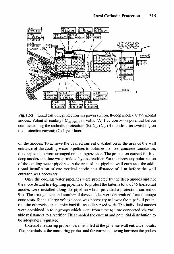
Fig. 12-2 Local cathodic protection in a power station. • deep anodes; O horizontalanodes; Potential readings UCu_CuS04 in volts: (A) free corrosion potential beforecommissioning the cathodic protection; (B) Uoa (£/off) 4 months after switching onthe protection current; (C) 1 year later.
on the anodes. To achieve the desired current distribution in the area of the wallentrance of the cooling water pipelines to polarize the steel-concrete foundation,the deep anodes were arranged on the ingress side. The protection current for fourdeep anodes at a time was provided by one rectifier. For the necessary polarizationof the cooling water pipelines in the area of the pipeline wall entrance, the addi-tional installation of one vertical anode at a distance of 1 m before the wallentrance was necessary.
Only the cooling water pipelines were protected by the deep anodes and notthe more distant fire-fighting pipelines. To protect the latter, a total of 45 horizontalanodes were installed along the pipeline which provided a protection current of9 A. The arrangement and number of these anodes were determined from drainagecone tests. Since a large voltage cone was necessary to lower the pipe/soil poten-tial, the otherwise usual coke backfill was dispensed with. The individual anodeswere combined in four groups which were from time to time connected via vari-able resistances to a rectifier. This enabled the current and potential distribution tobe adequately regulated.
External measuring probes were installed at the pipeline wall entrance points.The potentials of the measuring probes and the currents flowing between the probes
Local Cathodic Protection 313
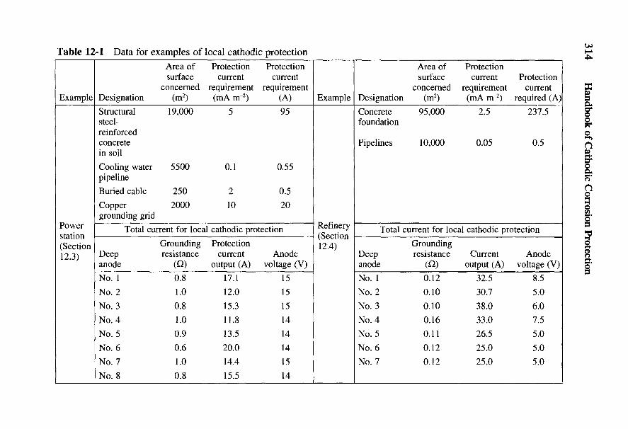
314 Handbook of Cathodic Corrosion Protection
c < :>"O •!-> '*-' <U O
'«1 "S S "•> B ' O & ^ P P ^ P P P£ 5 .b r*"> o S e j j o o i n v o t ^ i n i n i no R 3 (N --H <£ ±i£ * t> ^^ £ 5 >
SS C x-S ^ O
.2 s c "I* .a c So § £ S >o JQ T3 S ^ i o r - . q q i n q q<U b 2- ^« rxi • 2 C 3 c N O o 6 m v O » n v io 3 '=3 73 O -S 3 C X c o c n < n c n ( N < N r J2 3 g, e £ u Sfc O — ^ Ocj
OT3 ^ W) u
^ < " S o o ^ .S yy E ^ Q o , o i o S ^ N « s o o ^ o ^ H t s r < i
« ig S3 C O O ^ C ^ r ^ ^ H ^ H ^ H ^ - , , - , ^ ^ ,
2 g 3 in o ^ g . g ^ d d d d d d d< S § ^ ^ § § S
O t O *-!
« Io c 13« n_) O c« *Jca *s - 3 Hi OC <U C8 C HbO Jj "O ^3 CL^ >- (N en -rf «n ^O t^
'33 c S J2 W oa j o 3 & m 2 o o o o o o oQ U S I I Q § 2 £ ^ Z Z Z Z
- >? c& g .2H G -i—• ^~^
§ « ^^
w x&'S
11 € 1 - SS ^ g S < ^ ^ 2 3 - 1 ^ ^ ^ ^ 3 ^ S ! 2 22 2 S'g,^ ° | <|a fc g^ s go *-^ - 2O C S -^ CU G O
- G O ^ ; ^ ^ O 0 ^ ^o s t s S g e , - 0 ^ ' ^ l ^ ^ q n ^ ^ q ^ . ^^ o f c ^ ^ 1 0 rS ^ii o « f c 3 r ~ - ( N > n - H f n o T i - m- ^ O ^ ' S ' S ^ ^ • g : 3 a ( - H ^ H T - H ^ - H - H ( N ' - l - H?? 2 o g, g *g S o -gO QH (u ^^ O (X O
% ^ 8 ^P «° ^ < D g 0 ^ -S g^ e t f ^ J n ^ T S O S o g " 2 c g ^ O O O O O O O N ^ O O O O&|1|SS- ^ ^ 3 «g ||Sc5 ^ o « o d ^ o1 < M 8 - g £ SX Cw <- "2 3I l_ ,B u ll° I lil|i II1 HH n d d 6: d d d dTH o ^ ^ ^ S . s u ' a f f l U b b Q § ^ 2 ; z z z z z z2 « c« | S3 § •B _S I £ '5 8 « r^ P 5 (W <Nt^ M-J Q-i «! -.—' i—i

Local Cathodic Protection 315
and the pipeline give good information on the danger of corrosion and theprotective action after setting up the local cathodic protection [9]. As an example,Fig. 12-3 shows the time dependence of current and potential for two measuringprobes after cathodic protection was set up. One probe indicated that the currentuptake and sufficient lowering of the potential could only be achieved by installa-tion of an additional anode.
To ensure long durability, electrical grounding equipment in power stations isconstructed of corrosion-resistant materials that have a very positive rest potential(e.g., copper with t/Cu-Cuso4
= ~0.1 to ~0-2 V). These grounds, like steel in con-crete, lead to cell formation. Since copper can be polarized less easily than steel inconcrete, local cathodic protection is difficult under these circumstances. Copperbehaves more favorably with lead sheathing or hot-dipped galvanized steel, whereaccording to Fig. 2-10 the zinc is cathodically protected at UCu_CuSO = -1.2 V. Thusconsiderably lower current densities are necessary than for the polarization of othergrounding materials.
12.4 Oil Refineries
In contrast to power stations with small and large pipes, in refineries there aremany small pipelines for fire-fighting water, waste water, products, etc. Furthermore,refineries have a large area. Conventional cathodic protection can possibly be usedfor the small pipelines, but it is actually susceptible to trouble because of pos-sible electrical bridging of the numerous insulating joints required.
The protection current required for polarization of the steel-reinforced con-crete foundation can be determined by a drainage experiment. In new installationsthis is relatively simple with individual electrically separated foundations [11]. Inthe foregoing case the results showed various current densities between 1.5 and
Fig. 12-3 Change in potential ( ) and current ( ) with time at externalmeasuring probes for local cathodic protection. • probe 1; O probe 2.
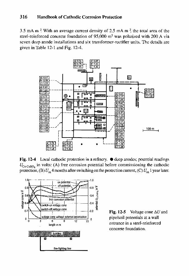
316 Handbook of Cathodic Corrosion Protection
3.5 mA nr2. With an average current density of 2.5 mA nr2, the total area of thesteel-reinforced concrete foundation of 95,000 m2 was polarized with 200 A viaseven deep anode installations and six transformer-rectifier units. The details aregiven in Table 12-1 and Fig. 12-4.
Fig. 12-4 Local cathodic protection in a refinery. • deep anodes; potential readings^tu-cuso *n v°lts: (A) free corrosion potential before commissioning the cathodicprotection, (B) Uoa 4 months after switching on the protection current, (C) Uon 1 year later.
Fig. 12-5 Voltage cone At/ andpipe/soil potentials at a wallentrance in a steel-reinforcedconcrete foundation.
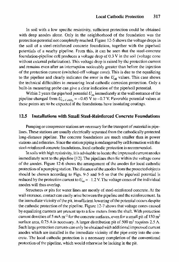
Local Cathodic Protection 317
In soil with a low specific resistivity, sufficient protection could be obtainedwith deep anodes alone. Only in the neighborhood of the foundation was theprotection potential not completely reached. Figure 12-5 shows the voltage drops inthe soil of a steel-reinforced concrete foundation, together with the pipe/soilpotentials of a nearby pipeline. From this, it can be seen that the steel-concretefoundation-pipeline cell produces a voltage drop of 0.3 V in the soil (voltage conewithout external polarization). This voltage drop is raised by the protection currentand remains even after an interruption noticeably greater than before the injectionof the protection current (switched-off voltage cone). This is due to the equalizingto the pipeline and clearly indicates the error in the Uoff values. This case showsthe technical difficulties in measuring local cathodic corrosion protection. Only abuilt-in measuring probe can give a clear indication of the pipe/soil potential.
Within 2 years the pipe/soil potential Uon immediately at the wall entrance of thepipeline changed from £/Cu-cuso4
= -0-45 V to -0.7 V. Favorable potential values atthese points are to be expected if the foundations have insulating coatings.
12.5 Installations with Small Steel-Reinforced Concrete Foundations
Pumping or compressor stations are necessary for the transport of material in pipe-lines. These stations are usually electrically separated from the cathodically protectedlong-distance pipeline. The concrete foundations are much smaller than in powerstations and refineries. Since the station piping is endangered by cell formation with thesteel-reinforced concrete foundations, local cathodic protection is recommended.
In soils with high resistivity, it is advisable to locate the impressed current anodesimmediately next to the pipeline [12]. The pipelines then lie within the voltage coneof the anodes. Figure 12-6 shows the arrangement of the anodes for local cathodicprotection of a pumping station. The distance of the anodes from the protected objectsshould be chosen according to Figs. 9-5 and 9-6 so that the pipe/soil potential isreduced by the protection current to Uon = -1.2 V. The voltage cones of the individualanodes will thus overlap.
Structures or pits for water lines are mostly of steel-reinforced concrete. At thewall entrance, contact can easily arise between the pipeline and the reinforcement. Inthe immediate vicinity of the pit, insufficient lowering of the potential occurs despitethe cathodic protection of the pipeline. Figure 12-7 shows that voltage cones causedby equalizing currents are present up to a few meters from the shaft. With protectioncurrent densities of 5 mA rrr2 for the concrete surfaces, even for a small pit of 150 m2
surface area, 0.75 A is necessary. A larger distribution pit of 500 m2 requires 2.5 A.Such large protection currents can only be obtained with additional impressed currentanodes which are installed in the immediate vicinity of the pipe entry into the con-crete. The local cathodic protection is a necessary completion of the conventionalprotection of the pipeline, which would otherwise be lacking in the pit.
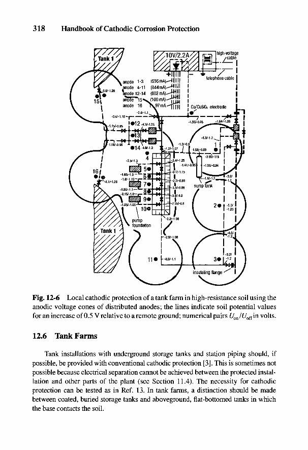
318 Handbook of Cathodic Corrosion Protection
Fig. 12-6 Local cathodic protection of a tank farm in high-resistance soil using theanodic voltage cones of distributed anodes; the lines indicate soil potential valuesfor an increase of 0.5 V relative to a remote ground; numerical pairs Uon/Uoffm volts.
12.6 Tank Farms
Tank installations with underground storage tanks and station piping should, ifpossible, be provided with conventional cathodic protection [3]. This is sometimes notpossible because electrical separation cannot be achieved between the protected instal-lation and other parts of the plant (see Section 11.4). The necessity for cathodicprotection can be tested as in Ref. 13. In tank farms, a distinction should be madebetween coated, buried storage tanks and aboveground, flat-bottomed tanks in whichthe base contacts the soil.
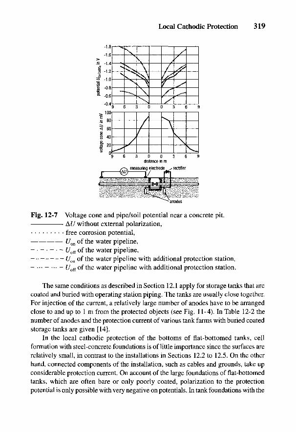
Local Cathodic Protection 319
Fig. 12-7 Voltage cone and pipe/soil potential near a concrete pit.At/ without external polarization,free corrosion potential,t/on of the water pipeline,
- - - - - - - t/off of the water pipeline,[7on of the water pipeline with additional protection station,
- ... - ... - £/off of the water pipeline with additional protection station.
The same conditions as described in Section 12.1 apply for storage tanks that arecoated and buried with operating station piping. The tanks are usually close together.For injection of the current, a relatively large number of anodes have to be arrangedclose to and up to 1 m from the protected objects (see Fig. 11-4). In Table 12-2 thenumber of anodes and the protection current of various tank farms with buried coatedstorage tanks are given [14].
In the local cathodic protection of the bottoms of flat-bottomed tanks, cellformation with steel-concrete foundations is of little importance since the surfaces arerelatively small, in contrast to the installations in Sections 12.2 to 12.5. On the otherhand, connected components of the installation, such as cables and grounds, take upconsiderable protection current. On account of the large foundations of flat-bottomedtanks, which are often bare or only poorly coated, polarization to the protectionpotential is only possible with very negative on potentials. In tank foundations with the
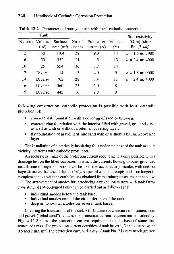
320 Handbook of Cathodic Corrosion Protection
Table 12-2 Parameters of storage tanks with local cathodic protection
Tank Soil resistivityNumber Volume Surface No. of Protection Voltage (Q m) [after
(m3) area (m2) anodes current (A) (V) Eq. (3-44)]
~ ~ 1 2 5 0 1104 39 93 1 4 a = 1 .6 m: 7000
6 50 552 21 4.5 13 a = 2.4 m: 4000
10 25 554 36 7.7 14
7 Diverse 114 13 4.0 9 a = 1.6 m: 9000
14 Diverse 762 28 7.4 11 a = 2.4 m: 4000
16 Diverse 360 25 6.0 8
6 Diverse 445 16 2.8 9
following construction, cathodic protection is possible with local cathodicprotection [3]:
• concrete slab foundation with a covering of sand or bitumen;• concrete ring foundation with the interior filled with gravel, grit, and sand,
as well as with or without a bitumen covering layer;• flat foundation of gravel, grit, and sand with or without a bitumen covering
layer.
The installation of electrically insulating foils under the base of the tank or in itsvicinity interferes with cathodic protection.
An accurate estimate of the protection current requirement is only possible with adrainage test on the filled container, in which the currents flowing to other groundedinstallations through connections can be taken into account. In particular, with tanks oflarge diameter, the base of the tank bulges upward when it is empty and is no longer incomplete contact with the earth. Values obtained from drainage tests are then too low.
The arrangement of anodes for introducing a protection current with tank farmsconsisting of flat-bottomed tanks can be carried out as follows [15]:
• individual anodes below the tank base;• individual anodes around the circumference of the tank;• deep or horizontal anodes for several tank bases.
Covering the foundations of the tank with bitumen or a mixture of bitumen, sandand gravel ("oiled-sand") reduces the protection current requirement considerably.Figure 12-8 shows the protection current requirement of the base of some flat-bottomed tanks. The protection current densities of tank bases 1, 3 and 4 lie between0.5 and 2 mA m"2. The protection current density of tank No. 2 is very much greater.
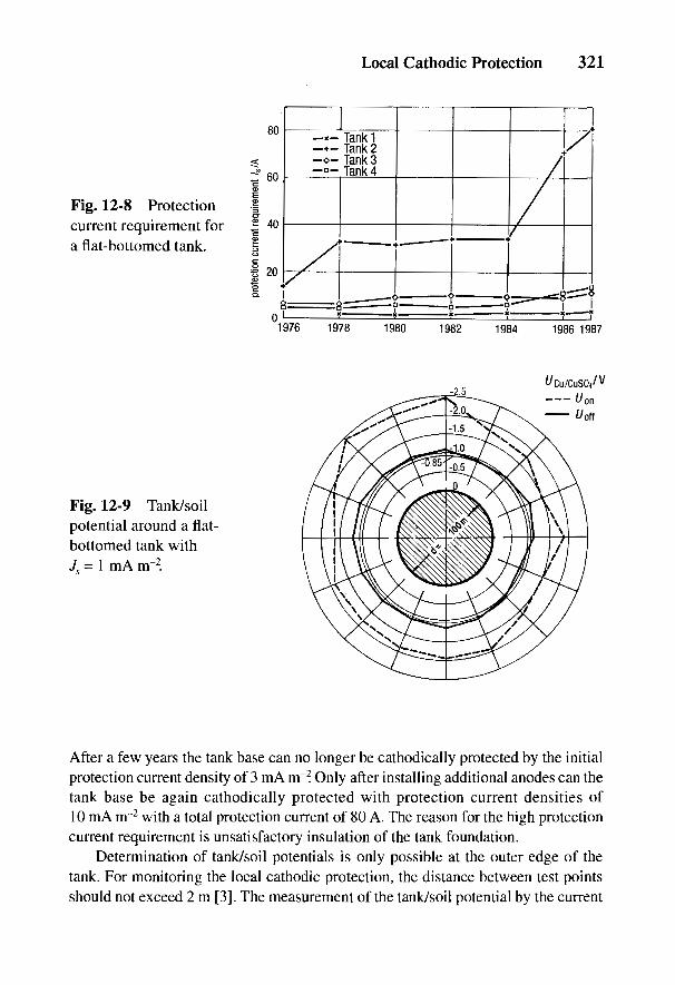
Local Cathodic Protection 321
Fig. 12-8 Protectioncurrent requirement fora flat-bottomed tank.
Fig. 12-9 Tank/soilpotential around a flat-bottomed tank withJs = 1 mA m~2.
After a few years the tank base can no longer be cathodically protected by the initialprotection current density of 3 mA m~2. Only after installing additional anodes can thetank base be again cathodically protected with protection current densities of10 mA nr2 with a total protection current of 80 A. The reason for the high protectioncurrent requirement is unsatisfactory insulation of the tank foundation.
Determination of tank/soil potentials is only possible at the outer edge of thetank. For monitoring the local cathodic protection, the distance between test pointsshould not exceed 2 m [3]. The measurement of the tank/soil potential by the current
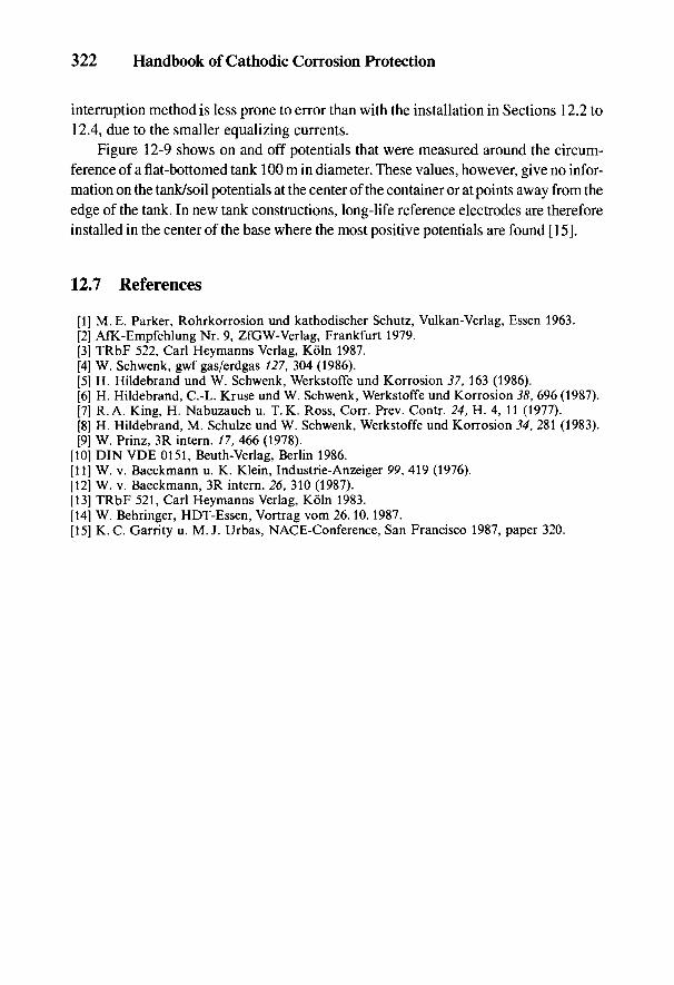
322 Handbook of Cathodic Corrosion Protection
interruption method is less prone to error than with the installation in Sections 12.2 to12.4, due to the smaller equalizing currents.
Figure 12-9 shows on and off potentials that were measured around the circum-ference of a flat-bottomed tank 100 m in diameter. These values, however, give no infor-mation on the tank/soil potentials at the center of the container or at points away from theedge of the tank. In new tank constructions, long-life reference electrodes are thereforeinstalled in the center of the base where the most positive potentials are found [15].
12.7 References
[1] M. E. Parker, Rohrkorrosion und kathodischer Schutz, Vulkan-Verlag, Essen 1963.[2] AfK-Empfehlung Nr. 9, ZfGW-Verlag, Frankfurt 1979.[3] TRbF 522, Carl Heymanns Verlag, Koln 1987.[4] W. Schwenk, gwf gas/erdgas 127, 304 (1986).[5] H. Hildebrand und W. Schwenk, Werkstoffe und Korrosion 37, 163 (1986).[6] H. Hildebrand, C.-L. Kruse und W. Schwenk, Werkstoffe und Korrosion 38, 696 (1987).[7] R. A. King, H. Nabuzaueh u. T.K. Ross, Corr. Prev. Contr. 24, H. 4, 11 (1977).[8] H. Hildebrand, M. Schulze und W. Schwenk, Werkstoffe und Korrosion 34, 281 (1983).[9] W. Prinz, 3R intern. 17, 466 (1978).
[10] DIN VDE 0151, Beuth-Verlag, Berlin 1986.[11] W. v. Baeckmann u. K. Klein, Industrie-Anzeiger 99, 419 (1976).[12] W. v. Baeckmann, 3R intern. 26, 310 (1987).[13] TRbF 521, Carl Heymanns Verlag, Koln 1983.[14] W. Behringer, HDT-Essen, Vortrag vom 26.10.1987.[15] K.C. Garrity u. M. J. Urbas, NACE-Conference, San Francisco 1987, paper 320.
13
Telephone CablesC. GEY
Telephone cables need different corrosion protection measures than pipelinesbecause of their particular construction and operating conditions. All telephonecables have either a completely solid metal sheathing around the core or in the caseof completely plastic cables, a metal band as an electric shield [1-3]. With cablesthat have a protective wrapping of jute and a viscous material around the cablesheathing, the leakage load G' is much higher than in cables with a protectivesheathing of plastic. The cable sheathing or the shield is connected with the opera-tional ground in the transmission or booster stations in order to improve theshielding action of the sheathing or shield. Glass fiber cables are the exception inwhich the shield is not grounded.
Formerly, cables with a metal sheathing were predominantly used. These cablesshould be cathodically protected in the case of corrosion risk (see Chapter 4). Moderncables (such as multiple sheathing or glass fiber cables) have a protective wrap-ping of plastic. Generally cathodic protection is not necessary in this case. Inexceptional cases multiply sheathed cables may need cathodic protection if groundedmetallic sleeves are used at splicing points. With the increased use of cables withplastic protective wrapping, corrosion problems only arise in groundinginstallations of these cables, entry structures into buildings, and cable attachments(booster and sleeves), as well as lightning protection systems.
13.1 Laying Cables
Telephone cables are either laid directly in the ground or drawn through ducts.Formerly, cable duct-shaped blocks (1000 mm long) were used for these ducts.Usually several of the cable duct blocks were laid connected to each other and thejunctions between them cemented. Such ducts gave no electrical insulation againstthe soil. The junctions were not watertight so that constituents of the soil got intothe duct with penetrating water. In the past, lead cables without coatings and cableswith a sheathing material other than lead were laid in these ducts. Today cableswith a plastic coating (or sheath) are generally used.
323
324 Handbook of Cathodic Corrosion Protection
For several years now, cable ducts have been manufactured from plastic pipes,which are watertight and form a continuous run of piping. In laying the ducts, lowpoints can occur in which condensed water or water penetrating from the ends cancollect. In many cases this water has led to corrosion damage in lead-sheathedcables. Lead-sheathed cables must therefore only be used in such ducts with anadditional PE sheath of type A-PM2Y. Cathodic protection of these cables is notpossible because of their complete insulation by the plastic pipe.
13.2 Passive Corrosion Protection
Passive corrosion protection can be achieved by coating the metallic cablesheathing (see Chapter 5). In the past, lead was mainly used for the cable sheath-ing. Today steel, copper, and aluminum are being increasingly used as the sheath-ing material or shield. It can be seen from Table 2-1 that for the same anodic currentdensity, the corrosion rate is 2.5 times higher for lead than for iron. It should beremembered that telephone cables have a much thinner wall than pipelines so thatlead-sheathed cables are much more prone to damage than pipelines. Lead-sheathedcables without additional coating are therefore no longer used.
For direct burial, the lead sheathing is protected against corrosion byalternating layers of impregnated paper and viscous bitumen. Cables of smalldiameter are mechanically protected with closely wound round wires, and those oflarger diameter with flat tape reinforcement. A layer of impregnated jute is appliedover the reinforcement, which gives some corrosion protection but does not insu-late the cable sheathing from the soil. In contrast, PE sheathing, free of junctionsand pores, 1.6 mm to 4.0 mm thick, is also used. Cathodic protection is thus mainlyapplied to jute-covered, lead-sheathed cables and plastic-sheathed cables that haveexternal reinforcement (e.g., lightning protection cable). Cables with other metal-lic sheathing can be included in cathodic protection, but special arrangements haveto be made [4].
With corrugated steel-sheathed cables, the cable tube is enclosed with a bandof carbon steel welded longitudinally without overlap. The sheathing core pro-duced in this way is corrugated to make it easier to bend. The undulations are filledwith a viscous material that adheres to metal and plastic and is wrapped aroundwith a plastic tape. Then a plastic casing of PE is extruded above this layer. Thisplastic sheathing is virtually free of pores and therefore gives good corrosion pro-tection. Only sleeves and mechanically damaged areas are exposed to the soil.
Cables with a copper sheathing are used only seldom. The protective cover isthe same as with a corrugated steel-sheathed cable. If a cable with copper sheath-ing is connected to a lead-sheathed cable (A-PMbc) (see Table 13-1), the coppersheathing acts as a cathode in a galvanic cell and is therefore cathodically protected.
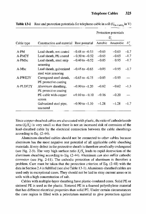
Telephone Cables 325
Table 13-1 Rest and protection potentials for telephone cable in soil (t/Cu-cuso4 m V)
Protection potentials
Us
Cable type Construction and material Rest potential Aerobic Anaerobic U[
A-PM Lead sheath, not coated -0.48 to-0.53 -0.65 -0.65 -1.7A-PM2Y Lead sheath, PE coated -0.50 to-0.52 -0.65 -0.65 -1.7A-PMbc Lead sheath, steel strip -0.40 to-0.52 -0.85 -0.95 -1.7
armoringA-Mbc Lead sheath, galvanized -0.45 to-0.65 -0.85 -0.95 -1.7
steel wire armoringA-PWE2Y Corrugated steel sheath, -0.65 to-0.75 -0.85 -0.95 —
PE protective coatingA-PLDE2Y Aluminum sheathing, -0.90 to-1.20 -0.62 -0.62 -1.3
PE protective coatingPE-cable with copper +0.10 to-0.10 -0.16 -0.20 —screenGalvanized steel pipe, -0.90 to-1.10 -1.28 -1.28 -1.7uncoated
Since copper-sheathed cables are also coated with plastic, the ratio of cathode/anodearea (Sc/Sa) is very small so that there is not an increased risk of corrosion of thelead-sheathed cable by the electrical connection between the cable sheathingsaccording to Eq. (2-44).
Aluminum-sheathed cables should not be connected to other cables becausealuminum has the most negative rest potential of all applicable cable sheathingmaterials. Every defect in the protective sheath is therefore anodically endangered(see Fig. 2-5). The very high surface ratio Sc/Sa leads to rapid destruction of thealuminum sheathing according to Eq. (2-44). Aluminum can also suffer cathodiccorrosion (see Fig. 2-11). The cathodic protection of aluminum is therefore aproblem. Care must be taken that the protection criterion of Eq. (2-48) with thedata in Section 2.4 is fulfilled (see also Table 13-1). Aluminum-sheathed cables areused only in exceptional cases. They should not be laid in stray current areas or insoils with a high concentration of salt.
Cables with multiple-layer sheathing have plastic-insulated cores. Solid PE orsintered PE is used as the plastic. Sintered PE is a foamed polyethylene materialthat has different electrical properties than solid PE. Under certain circumstancesthe core region is filled with a petrolatum material to give protection against
326 Handbook of Cathodic Corrosion Protection
condensation and to make it longitudinally watertight. Plastic tape and a metalband as a shield are wound around it. The metal band consists of aluminum orcopper and is coated with plastic. In addition, a plastic coating of PE is extrudedover the metal band. Public telephone and telegraph cables with a plastic coatingare stamped with a prominent symbol that is only allowed on PE and not on PVC,since deep stamping can lead to internal stresses and the material can sufferstress corrosion.
13.3 Cathodic Protection
Telephone cables and their lightning protection systems can be protected againstcorrosion in the same way as pipelines. According to the type of cable and cableconstruction, different protected lengths are achieved. The range of cathodicprotection is considerably greater with well-coated cables than with bitumen-jutecoatings. Equation (24-75) applies in calculating the length of the protected range,which is that much greater
• the better the protected object is coated (small 7S),• the lower the resistance load (/?') is.
In contrast to pipelines, cables and their lightning protection have only poorsheathing or none and therefore a greater leakage as well as a considerably higherresistance load, so that the length of the protected range in cathodic protection issmall. This necessarily means that limits are imposed on corrosion protection.Despite these disadvantages, cathodic protection of telephone cables can beapplied economically by accurate calculation and careful planning.
Whereas cathodic protection—apart from a few exceptions—can be relativelyeasily applied outside built-up areas, in urban areas difficulties arise due to thenumerous metallic installations below ground. Interference with nearby installa-tions has to be considered, on account of the relatively high protection currents(see Section 9.2).
The switching-off method for 7/?-free potential measurement is, according tothe data in Fig. 3-5, subject to error with lead-sheathed cables. For a rough survey,measurements of potential can be used to set up and control the cathodic protection.This means that no information can be gathered on the complete corrosionprotection, but only on the protection current entry and the elimination of cellactivity from contacts with foreign cathodic structures. The reverse switchingmethod in Section 3.3.1 can be used to obtain an accurate potential measurement.Rest and protection potentials for buried cables are listed in Table 13-1 as anappendix to Section 2.4. The protection potential region lies within U's < U < Us.
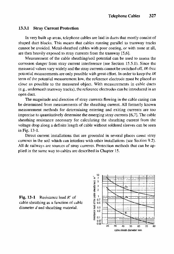
Telephone Cables 327
13.3.1 Stray Current Protection
In very built up areas, telephone cables are laid in ducts that mostly consist ofshaped duct blocks. This means that cables running parallel to tramway trackscannot be avoided. Metal-sheathed cables with poor coating, or with none at all,are then heavily exposed to stray currents from the tramway [5,6].
Measurement of the cable sheathing/soil potential can be used to assess thecorrosion danger from stray current interference (see Section 15.5.1). Since themeasured values vary widely and the stray currents cannot be switched off, 77?-freepotential measurements are only possible with great effort. In order to keep the IRterm of the potential measurement low, the reference electrode must be placed asclose as possible to the measured object. With measurements in cable ducts(e.g., underneath tramway tracks), the reference electrodes can be introduced in anopen duct.
The magnitude and direction of stray currents flowing in the cable casing canbe determined from measurements of the sheathing current. All formerly knownmeasurement methods for determining entering and exiting currents are tooimprecise to quantitatively determine the emerging stray currents [6,7]. The cablesheathing resistance necessary for calculating the sheathing current from thevoltage drop along a definite length of cable without soldered sleeves can be seenin Fig. 13-1.
Direct current installations that are grounded in several places cause straycurrents in the soil which can interfere with other installations (see Section 9.2).All dc railways are sources of stray currents. Protection methods that can be ap-plied in the same way to cables are described in Chapter 15.
Fig. 13-1 Resistance load R' ofcable sheathing as a function of cablediameter d and sheathing material.

328 Handbook of Cathodic Corrosion Protection
Fig. 13-2 Potential variation at a telephone cable in an area affected by straycurrents in a large town with two stray current drainages.
In stray current drainage (see Fig. 15-5) in urban areas, 10 to 15% of thesupply current of a tramway transformer substation is often drained. Sometimes upto 300 A can flow from cable sheathing via stray current drainage back to thesource of the stray current. The lowering of potential by stray current drainageoften acts for a few hundred meters with unsheathed lead cables due to their highleakage load and the proportionately high cable sheathing resistance load [8].
The active length of the protection system can be increased by installing forcedstray current drainage (see Fig. 15-7). These protection measures are used whenthe dc installation at the point of connection to the stray current drainage is notsufficiently negative or if a much greater voltage drop arises due to the resistanceof the stray current return conductor, so that the required protection potential canno longer be attained.
Potential-regulating instruments are predominantly used for forced straycurrent drainage (see Chapter 8). Potential control lowers current consumptionand reduces the interference of foreign installations, because by it the potential ofthe protected object is lowered only enough for the required protection of theinstallation. Several smaller protection current devices are advantageous in theprotection of wider cable areas since this gives uniform potential lowering at theprotected object and there is less interference with foreign installations.Figure 13-2 shows the potential distribution for a cable with stray current drainage.The total current drained amounts to about 70 A.
All protection measures must be checked and monitored at regular intervals toguarantee their effectiveness. To keep the labor cost as low as possible, the timeinterval between inspections should be as long as possible. This requires that thecomponents of the installation, such as transformer-rectifiers, which can often fail
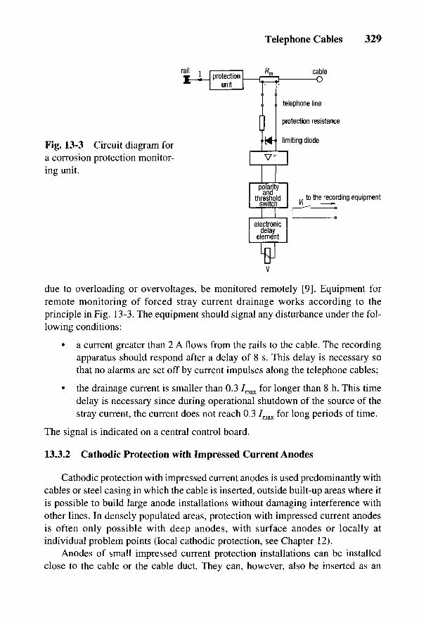
Telephone Cables 329
Fig. 13-3 Circuit diagram fora corrosion protection monitor-ing unit.
due to overloading or overvoltages, be monitored remotely [9]. Equipment forremote monitoring of forced stray current drainage works according to theprinciple in Fig. 13-3. The equipment should signal any disturbance under the fol-lowing conditions:
• a current greater than 2 A flows from the rails to the cable. The recordingapparatus should respond after a delay of 8 s. This delay is necessary sothat no alarms are set off by current impulses along the telephone cables;
• the drainage current is smaller than 0.3 7max for longer than 8 h. This timedelay is necessary since during operational shutdown of the source of thestray current, the current does not reach 0.3 7max for long periods of time.
The signal is indicated on a central control board.
13.3.2 Cathodic Protection with Impressed Current Anodes
Cathodic protection with impressed current anodes is used predominantly withcables or steel casing in which the cable is inserted, outside built-up areas where itis possible to build large anode installations without damaging interference withother lines. In densely populated areas, protection with impressed current anodesis often only possible with deep anodes, with surface anodes or locally atindividual problem points (local cathodic protection, see Chapter 12).
Anodes of small impressed current protection installations can be installedclose to the cable or the cable duct. They can, however, also be inserted as an

330 Handbook of Cathodic Corrosion Protection
Fig. 13-4 Potential variation of telephone cables in a damp cable duct constructedof cable channel-shaped stone (without stray currents).
anode string in an open channel of a cable duct of duct-shaped blocks. Thisreduces interference with other lines. Figure 13-4 shows the potential distributionfor three telephone cables protected with an anode string. Long-distance cableswith metal sheathings should always be cathodically protected since extended cor-rosion cells are formed from factors arising from the soil (see Section 4.2.1).
Lead-sheathed cable near cathodically protected pipelines must be connectedto the cathodic protection of the pipeline since they will otherwise suffer interfer-ence from the protection current (see Section 9.2). Figure 13-5 shows the currentrequirement for a 10-m length of cable and the potential distribution of such cables.
The same applies to crossings with cathodically protected pipelines to combatinterference (see Section 9.2). An untenable interference by the protection currentof the pipeline can nearly always be avoided if:
• the cable is coated with PE in the region of the voltage cone of the anodeinstallations (about 100 m radius around the anode installation),
• the cable is coated with PE free of defects for at least 3 m on either side ofthe crossing point with the pipeline [4].
Telephone cables that lead to telephone towers are very prone to lightningdamage. To avoid lightning damage, these cables should either be enclosed in gal-
Fig. 13-5 Potentialvariation at a telephonecable adjacent to acathodically protectedpipeline.
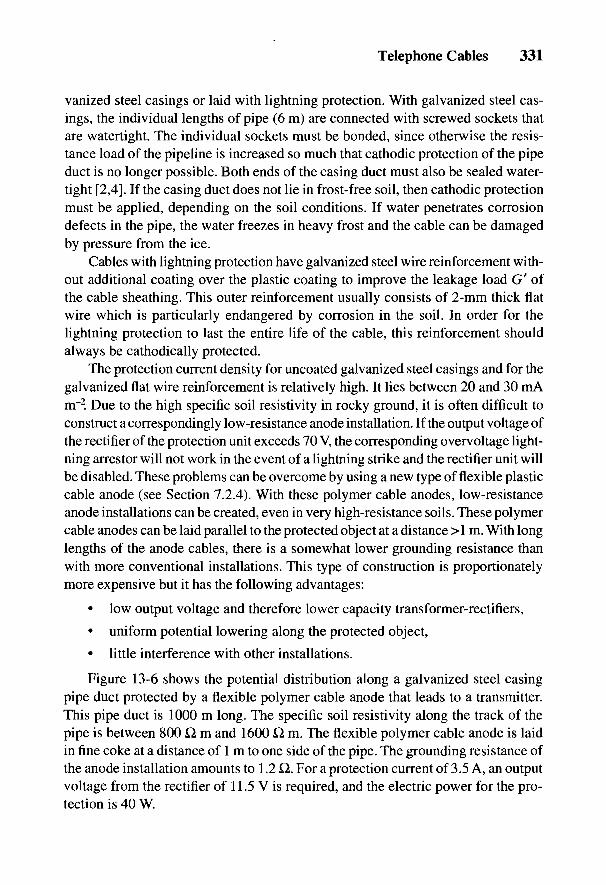
Telephone Cables 331
vanized steel casings or laid with lightning protection. With galvanized steel cas-ings, the individual lengths of pipe (6 m) are connected with screwed sockets thatare watertight. The individual sockets must be bonded, since otherwise the resis-tance load of the pipeline is increased so much that cathodic protection of the pipeduct is no longer possible. Both ends of the casing duct must also be sealed water-tight [2,4]. If the casing duct does not lie in frost-free soil, then cathodic protectionmust be applied, depending on the soil conditions. If water penetrates corrosiondefects in the pipe, the water freezes in heavy frost and the cable can be damagedby pressure from the ice.
Cables with lightning protection have galvanized steel wire reinforcement with-out additional coating over the plastic coating to improve the leakage load G' ofthe cable sheathing. This outer reinforcement usually consists of 2-mm thick flatwire which is particularly endangered by corrosion in the soil. In order for thelightning protection to last the entire life of the cable, this reinforcement shouldalways be cathodically protected.
The protection current density for uncoated galvanized steel casings and for thegalvanized flat wire reinforcement is relatively high. It lies between 20 and 30 mAm"2. Due to the high specific soil resistivity in rocky ground, it is often difficult toconstruct a correspondingly low-resistance anode installation. If the output voltage ofthe rectifier of the protection unit exceeds 70 V, the corresponding overvoltage light-ning arrestor will not work in the event of a lightning strike and the rectifier unit willbe disabled. These problems can be overcome by using a new type of flexible plasticcable anode (see Section 7.2.4). With these polymer cable anodes, low-resistanceanode installations can be created, even in very high-resistance soils. These polymercable anodes can be laid parallel to the protected object at a distance >1 m. With longlengths of the anode cables, there is a somewhat lower grounding resistance thanwith more conventional installations. This type of construction is proportionatelymore expensive but it has the following advantages:
• low output voltage and therefore lower capacity transformer-rectifiers,
• uniform potential lowering along the protected object,
• little interference with other installations.
Figure 13-6 shows the potential distribution along a galvanized steel casingpipe duct protected by a flexible polymer cable anode that leads to a transmitter.This pipe duct is 1000 m long. The specific soil resistivity along the track of thepipe is between 800 Q, m and 1600 Q m. The flexible polymer cable anode is laidin fine coke at a distance of 1 m to one side of the pipe. The grounding resistance ofthe anode installation amounts to 1.2 £2. For a protection current of 3.5 A, an outputvoltage from the rectifier of 11.5 V is required, and the electric power for the pro-tection is 40 W.
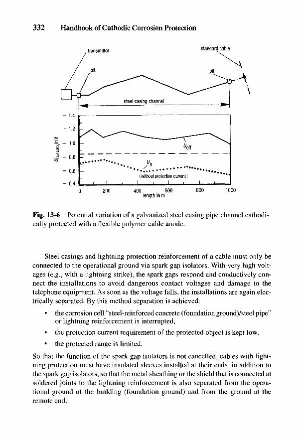
332 Handbook of Cathodic Corrosion Protection
Fig. 13-6 Potential variation of a galvanized steel casing pipe channel cathodi-cally protected with a flexible polymer cable anode.
Steel casings and lightning protection reinforcement of a cable must only beconnected to the operational ground via spark gap isolators. With very high volt-ages (e.g., with a lightning strike), the spark gaps respond and conductively con-nect the installations to avoid dangerous contact voltages and damage to thetelephone equipment. As soon as the voltage falls, the installations are again elec-trically separated. By this method separation is achieved:
• the corrosion cell "steel-reinforced concrete (foundation ground)/steel pipe"or lightning reinforcement is interrupted,
• the protection current requirement of the protected object is kept low,
• the protected range is limited.
So that the function of the spark gap isolators is not cancelled, cables with light-ning protection must have insulated sleeves installed at their ends, in addition tothe spark gap isolators, so that the metal sheathing or the shield that is connected atsoldered joints to the lightning reinforcement is also separated from the opera-tional ground of the building (foundation ground) and from the ground at theremote end.

Telephone Cables 333
Fig. 13-7 Potential of acathodically protectedspecial cable with galva-nized steel armoring (zinccoating already corroded).
If insulated sleeves and spark gap isolators lie directly in soil, they constitutedanger spots. Currents can exit and then reenter. This danger is reduced if they areinstalled in a dry pit and the first meter of the cable on either side is insulated.
Figure 13-7 shows the potential plan for the cathodic protection of aspecial cable (cable with lightning protection) that leads to an antenna installationand has unsheathed galvanized steel armoring. A low-resistance site for the anodeinstallation could only be found at a distance of 1.6 km due to the rocky ground.The transformer-rectifier unit is protected against lightning strikes with overvol-tage arresters. The operation of the protection station is remotely monitored by acable lead and shut down by remote control when there is warning of a thunder-storm.

334 Handbook of Cathodic Corrosion Protection
13.4 References
[1] DIN VDE 0816, Beuth Verlag, Berlin 1979.[2] Fernmeldebauordnung der Deutschen Bundespost, Teil 10 A, Bundesminister fur das Post-
und Fernmeldewesen, Bonn 1983.[3] Fernmeldebauordnung der Deutschen Bundespost, Teil 12 A, Bundesminister fur das Post-
und Fernmeldewesen, Bonn 1973.[4] Fernmeldebauordnung der Deutschen Bundespost, Teil 16 B, Bundesminister fur das Post-
und Fernmeldewesen, Bonn 1987.[5] FernmeldemeBordnung der Deutschen Bundespost, Teil IV B, Bundesminister fur das Post-
und Fernmeldewesen, Bonn 1988.[6] A. Reinhard, VDI-Forschungsheft 482, Ausgabe B, S. 26, Diisseldorf 1960.[7] Chr. Gey, Unterrichtsblatter der Deutschen Bundespost, Ausgabe B, S. 20, 40. Jahrgang,
Nr. 1, 10.1.1987, Oberpostdirektion Hamburg.[8] W. v. Baeckmann, in: Handbuch des Fernmeldewesens, Springer-Verlag, Berlin 1969,
S. 360.[9] Chr. Gey, Unterrichtsblatter der .Deutschen Bundespost, Ausgabe B, S. 371, 40. Jahrgang,
Nr. 10, 10.10.1987, Oberpostdirektion Hamburg.

14
Power CablesH. U. PAUL AND W. PRINZ
14.1 Properties of Buried Power Cables
Cables for domestic and industrial electricity for low-voltage (220-380 V)medium-voltage (1-30 kV) and high-voltage supplies (chiefly 110 kV) are com-monly buried. For low- and medium-voltage grids, plastic cable is used (e.g., forlow-voltage types NYY and NAYY, which require no corrosion protection). Cableswith copper shielding and plastic sheathing (e.g., types NYCY and NYCWY) aresufficiently corrosion resistant. Danger of corrosion exists in cables with lead sheath-ing and steel armoring, which are only coated with a layer of jute impregnated withbitumen, and also in cables sheathed with aluminum and corrugated steel with aplastic coating if the coating is damaged. This also applies to 110-kV cable, whichis usually buried in steel pipes with bitumen or plastic coating.
To prevent unacceptably high contact voltages [1,2], metal sheathing of powercables in transformer and switching stations and in the distribution network isconnected to grounded installations, which have a low grounding resistance. Thisincreases the danger of corrosion and makes corrosion protection more difficult if:
(a) there is danger of corrosion due to cell formation with foreign cathodicstructures (e.g., steel-reinforced concrete foundations or grounding instal-lations) [3];
(b) there is danger of corrosion from stray currents (e.g., from installations fordc railways);
(c) stray currents can be picked up by grounds;(d) there is an inability to apply the normal cathodic protection since the
grounding is in conflict with the assumption (b) in Section 10.2.
The corrosion danger in (a) and (b) cannot be avoided by providing animproved coating as recommended in Section 4.3, if absolute freedom fromdefects cannot be guaranteed. From experience, areas of damage to the coating ofsteel conduits carrying high-voltage cables cannot be avoided even with carefulconstruction practices. Avoidance of the corrosion danger is only possible in this
335
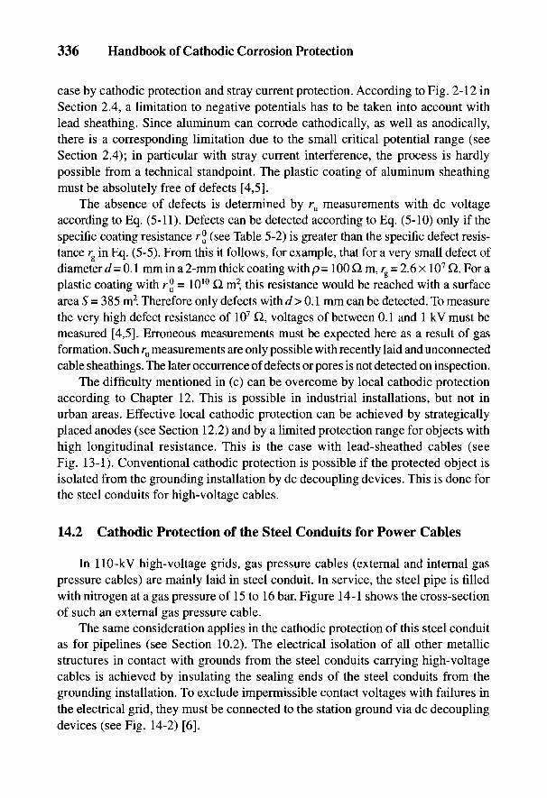
336 Handbook of Cathodic Corrosion Protection
case by cathodic protection and stray current protection. According to Fig. 2-12 inSection 2.4, a limitation to negative potentials has to be taken into account withlead sheathing. Since aluminum can corrode cathodically, as well as anodically,there is a corresponding limitation due to the small critical potential range (seeSection 2.4); in particular with stray current interference, the process is hardlypossible from a technical standpoint. The plastic coating of aluminum sheathingmust be absolutely free of defects [4,5].
The absence of defects is determined by ru measurements with dc voltageaccording to Eq. (5-11). Defects can be detected according to Eq. (5-10) only if thespecific coating resistance r® (see Table 5-2) is greater than the specific defect resis-tance rg in Eq. (5-5). From this it follows, for example, that for a very small defect ofdiameter d = 0.1 mm in a 2-mm thick coating with p= 100 £1 m, rg = 2.6 x 10⁷ Q. For aplastic coating with r® = 1010 Q m2, this resistance would be reached with a surfacearea S = 385 m2. Therefore only defects with d > 0.1 mm can be detected. To measurethe very high defect resistance of 107 Q, voltages of between 0.1 and 1 kV must bemeasured [4,5]. Erroneous measurements must be expected here as a result of gasformation. Such ru measurements are only possible with recently laid and unconnectedcable sheathings. The later occurrence of defects or pores is not detected on inspection.
The difficulty mentioned in (c) can be overcome by local cathodic protectionaccording to Chapter 12. This is possible in industrial installations, but not inurban areas. Effective local cathodic protection can be achieved by strategicallyplaced anodes (see Section 12.2) and by a limited protection range for objects withhigh longitudinal resistance. This is the case with lead-sheathed cables (seeFig. 13-1). Conventional cathodic protection is possible if the protected object isisolated from the grounding installation by dc decoupling devices. This is done forthe steel conduits for high-voltage cables.
14.2 Cathodic Protection of the Steel Conduits for Power Cables
In 110-kV high-voltage grids, gas pressure cables (external and internal gaspressure cables) are mainly laid in steel conduit. In service, the steel pipe is filledwith nitrogen at a gas pressure of 15 to 16 bar. Figure 14-1 shows the cross-sectionof such an external gas pressure cable.
The same consideration applies in the cathodic protection of this steel conduitas for pipelines (see Section 10.2). The electrical isolation of all other metallicstructures in contact with grounds from the steel conduits carrying high-voltagecables is achieved by insulating the sealing ends of the steel conduits from thegrounding installation. To exclude impermissible contact voltages with failures inthe electrical grid, they must be connected to the station ground via dc decouplingdevices (see Fig. 14-2) [6].
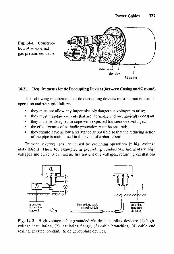
Power Cables 337
Fig. 14-1 Construc-tion of an externalgas-pressurized cable.
14.2.1 Requirements for dc Decoupling Devices (between Casing and Ground)
The following requirements of dc decoupling devices must be met in normaloperation and with grid failures:
• they must not allow any impermissibly dangerous voltages to arise;• they must maintain currents that are thermally and mechanically constant;• they must be designed to cope with expected transient overvoltages;• the effectiveness of cathodic protection must be ensured;• they should have as low a resistance as possible so that the reducing action
of the pipe is maintained in the event of a short circuit.
Transient overvoltages are caused by switching operations in high-voltageinstallations. Thus, for example, in grounding conductors, momentary highvoltages and currents can occur. In transient overvoltages, returning oscillations
Fig. 14-2 High-voltage cable grounded via dc decoupling devices: (1) high-voltage installation, (2) insulating flange, (3) cable branching, (4) cable endsealing, (5) steel conduit, (6) dc decoupling devices.
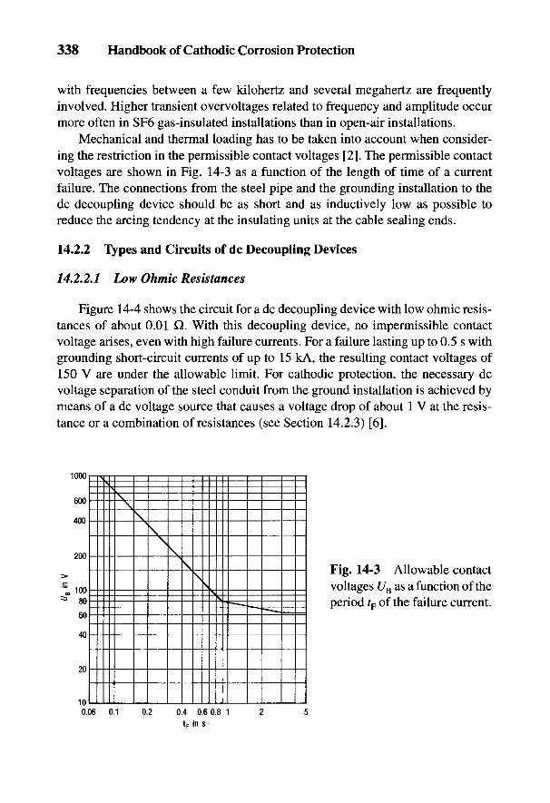
338 Handbook of Cathodic Corrosion Protection
with frequencies between a few kilohertz and several megahertz are frequentlyinvolved. Higher transient overvoltages related to frequency and amplitude occurmore often in SF6 gas-insulated installations than in open-air installations.
Mechanical and thermal loading has to be taken into account when consider-ing the restriction in the permissible contact voltages [2]. The permissible contactvoltages are shown in Fig. 14-3 as a function of the length of time of a currentfailure. The connections from the steel pipe and the grounding installation to thedc decoupling device should be as short and as inductively low as possible toreduce the arcing tendency at the insulating units at the cable sealing ends.
14.2.2 Types and Circuits of dc Decoupling Devices
14.2.2.1 Low Ohmic Resistances
Figure 14-4 shows the circuit for a dc decoupling device with low ohmic resis-tances of about 0.01 Q. With this decoupling device, no impermissible contactvoltage arises, even with high failure currents. For a failure lasting up to 0.5 s withgrounding short-circuit currents of up to 15 kA, the resulting contact voltages of150 V are under the allowable limit. For cathodic protection, the necessary dcvoltage separation of the steel conduit from the ground installation is achieved bymeans of a dc voltage source that causes a voltage drop of about 1 V at the resis-tance or a combination of resistances (see Section 14.2.3) [6].
Fig. 14-3 Allowable contactvoltages UB as a function of theperiod tF of the failure current.
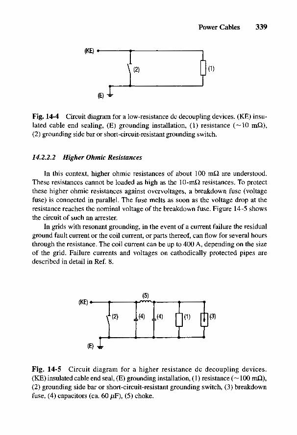
Power Cables 339
Fig. 14-4 Circuit diagram for a low-resistance dc decoupling devices. (KE) insu-lated cable end sealing, (E) grounding installation, (1) resistance (~10 mQ),(2) grounding side bar or short-circuit-resistant grounding switch.
14.2.2.2 Higher Ohmic Resistances
In this context, higher ohmic resistances of about 100 mQ are understood.These resistances cannot be loaded as high as the 10-mQ resistances. To protectthese higher ohmic resistances against overvoltages, a breakdown fuse (voltagefuse) is connected in parallel. The fuse melts as soon as the voltage drop at theresistance reaches the nominal voltage of the breakdown fuse. Figure 14-5 showsthe circuit of such an arrester.
In grids with resonant grounding, in the event of a current failure the residualground fault current or the coil current, or parts thereof, can flow for several hoursthrough the resistance. The coil current can be up to 400 A, depending on the sizeof the grid. Failure currents and voltages on cathodically protected pipes aredescribed in detail in Ref. 8.
Fig. 14-5 Circuit diagram for a higher resistance dc decoupling devices.(ICE) insulated cable end seal, (E) grounding installation, (1) resistance (~ 100 m£2),(2) grounding side bar or short-circuit-resistant grounding switch, (3) breakdownfuse, (4) capacitors (ca. 60 juF), (5) choke.

340 Handbook of Cathodic Corrosion Protection
Unnecessary loading of the breakdown fuse through transient overvoltages canbe avoided by connection to a n element which consists of a length choke andtransverse capacitors. So-called iron core chokes are most conveniently used forseries chokes, which are usual in power electronics. A damping element with a67-/JF capacitor is advised at the input and output of the n element.
14.2.2.3 dc Coupling Devices with Nickel-Cadmium Cell
Nickel-cadmium cells have a very low ac resistance of 1 mQ. The charge stateof the cells is of secondary importance. Nickel-cadmium cells must have sufficientcurrent capacity and have current stability. They can be used directly as a dcdecoupling device (Fig. 14-6) [6].
For normal operation, the breakdown fuse is not connected because if it iscalled upon to act, the cell would be short circuited, which could lead to itsdestruction. When there is work being done on the cable and the cathodicprotection station is switched off, the fuse is connected by closing the switch. Thecell (2) can be isolated by removing the connection (4). Finally, by closing theconnection (1), direct grounding is established. In installing the cell, the process iscarried out in the reverse direction.
The charge state of the cell must be maintained in operation to have a cellvoltage of 0.9 to 1.2 V [6]. Overcharging the cell is to be avoided due toelectrolytic decomposition of water and evolution of gas. The cell voltage shouldtherefore not exceed 1.4 V. Cathodic protection stations should be operated so thatthe cell voltage lies in the desired range.
14.2.2.4 Polarization Cell
The polarization cell is an electrochemical component in which nickel orstainless steel electrodes are immersed in 50% KOH solution [9]. With ac, the
Fig. 14-6 Circuit diagram for a dc decoupling device with nickel-cadmium cell.(KE) insulated cable end sealing, (E) grounding installation, (1) grounding sidebar; (2) NiCd cell, 1.2 V; (3) breakdown fuse; (4,5) isolating links.
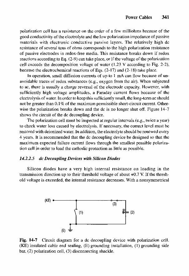
Power Cables 341
polarization cell has a resistance on the order of a few milliohms because of thegood conductivity of the electrolyte and the low polarization impedance of passivematerials with electronic conductive passive layers. The relatively high dcresistance of several tens of ohms corresponds to the high polarization resistanceof passive electrodes in redox-free media. This resistance breaks down if redoxreactions according to Eq. (2-9) can take place, or if the voltage of the polarizationcell exceeds the decomposition voltage of water (1.23 V according to Fig. 2-2),because the electrochemical reactions of Eqs. (2-17) and (2-18) take place.
In operation, small diffusion currents of up to 1 mA can flow because of un-avoidable traces of redox substances (e.g., oxygen from the air). When subjectedto ac, there is usually a charge reversal of the electrode capacity. However, withsufficiently high voltage amplitudes, a Faraday current flows because of theelectrolysis of water. In order to keep this sufficiently small, the long-term ac shouldnot be greater than 0.1% of the maximum permissible short-circuit current. Other-wise the polarization breaks down and the dc is no longer shut off. Figure 14-7shows the circuit of the dc decoupling device.
The polarization cell must be inspected at regular intervals (e.g., twice a year)to check water loss caused by electrolysis. If necessary, the correct level must berestored with deionized water. In addition, the electrolyte should be renewed every4 years. It is recommended that the dc decoupling device be designed so that themaximum expected failure current flows through the smallest possible polariza-tion cell in order to load the cathodic protection as little as possible.
14.2.2.5 dc Decoupling Devices with Silicon Diodes
Silicon diodes have a very high internal resistance on loading in thetransmission direction up to their threshold voltage of about +0.7 V. If the thresh-old voltage is exceeded, the internal resistance decreases. With a nonsymmetrical
Fig. 14-7 Circuit diagram for a dc decoupling device with polarization cell.(KE) insulated cable end sealing, (E) grounding installation, (1) grounding sidebar, (2) polarization cell, (3) disconnecting shackle.
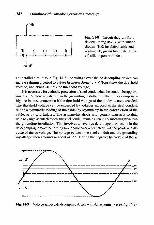
342 Handbook of Cathodic Corrosion Protection
Fig. 14-8 Circuit diagram for adc decoupling device with silicondiodes. (KE) insulated cable endsealing, (E) grounding installation,(1) silicon power diodes.
antiparallel circuit as in Fig. 14-8, the voltage over the dc decoupling device canincrease during a period to values between about -2.8 V (four times the thresholdvoltage) and about +0.7 V (the threshold voltage).
It is necessary for cathodic protection of steel conduit that the conduit be approx-imately 1 V more negative than the grounding installation. The diodes comprise ahigh-resistance connection if the threshold voltage of the diodes is not exceeded.The threshold voltage can be exceeded by voltages induced in the steel conduit,due to a symmetric loading of the cable, by asymmetry in the construction of thecable, or by grid failures. The asymmetric diode arrangement then acts so that,with any high ac interference, the steel conduit remains about 1 V more negative thanthe grounding installation. This involves an average dc voltage that results in thedc decoupling device becoming low ohmic over a branch during the positive half-cycle of the ac voltage. The voltage between the steel conduit and the groundinginstallation then amounts to about +0.7 V. During the negative half-cycle of the ac
Fig. 14-9 Voltage across a dc decoupling device with 4:1 asymmetry (see Fig. 14-8).

Power Cables 343
voltage, the voltage is about -2.8 V. The arithmetic mean is therefore -1.05 V (seeFig. 14-9) [10]. To achieve other values of the voltage, the branch with only onediode remains unchanged while the number of diodes in the other branch can becorrespondingly varied [see Eq. (23-45)].
A dc decoupling device with a symmetric antiparallel circuit is not logicalbecause a 50-Hz ac voltage usually exists between the steel conduit and the ground-ing installation. With a symmetric diode circuit, so many diodes must be connectedin series in each branch that the ac voltage between the steel conduit and ground-ing installation remains below the sum of the threshold voltage of the diodes con-nected in series because otherwise the average voltage would be zero. Cathodicprotection of the steel conduit would then no longer be possible.
14.2.3 Installation of Cathodic Protection Station
If the cathodic protection of the steel conduit requires only a small protectioncurrent, up to 10 mA, the positive pole of the transformer-rectifier can be con-nected to the station ground if there is no danger of any marked anodic damage tothe ground or installations connected to it. This is the case when the potential ofthe grounding installation does not change by more than 10 mV in the positivedirection on switching on the protection station [6]. With greater current require-ments, additional rectifiers can be provided in the stations so that the anodic load-ing of the station grounds is eliminated. The impressed current anodes are mostconveniently installed as deep anodes (see Sections 9.1.3 and 12.3).
The current required with low-resistance dc decoupling devices is always large.For direct injection via the resistance in the station, a rectifier with low output volt-age and high current is necessary. With low-resistance dc decoupling devices withNi-Cd cells or with silicon diodes, the corrosion protection stations can be arrangedalong the route of the cable. With dc decoupling devices with Ni-Cd cells, also witha low protection current requirement, rectifiers are installed to maintain the cellvoltage; in the case of dc decoupling devices with polarization cells or silicon diodes,galvanic anodes are also involved in the cathodic protection.
For adjustment and for monitoring the cathodic protection, test points arenecessary along the cable (see Section 10.3.2). It is convenient to install these testpoints at the cable sleeves. This gives distances between test points of about 0.5 km.The installation of test points to measure conduit current is also convenient forlocating accidental contacts.
14.2.4 Control and Maintenance of Cathodic Protection
Off potentials cannot be used to control cathodic protection. Such a measure-ment is only correct if the dc decoupling devices are isolated from the grounding
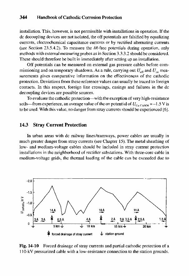
344 Handbook of Cathodic Corrosion Protection
installation. This, however, is not permissible with installations in operation. If thedc decoupling devices are not isolated, the off potentials are falsified by equalizingcurrents, electrochemical capacitance currents or by rectified alternating currents(see Section 23.5.4.2). To measure the //?-free potentials during operation, onlymethods with external measuring probes as in Section 3.3.3.2 should be considered.These should therefore be built in immediately after setting up an installation.
Off potentials can be measured on external gas pressure cables before com-missioning and on temporary shutdown. As a rule, carrying out Uoff and Uon mea-surements gives comparative information on the effectiveness of the cathodicprotection. Deviations from these reference values can usually be traced to foreigncontacts. In this respect, foreign line crossings, casings and failures in the dcdecoupling devices are possible sources.
To evaluate the cathodic protection—with the exception of very high-resistancesoils—from experience, an average value of the on potential of C/Cu-CuS04 = -1 -5 V isto be used. With this value, no danger from stray currents should be experienced [6].
14.3 Stray Current Protection
In urban areas with dc railway lines/tram ways, power cables are usually inmuch greater danger from stray currents (see Chapter 15). The metal sheathing oflow- and medium-voltage cables should be included in stray current protectioninstallations in the neighborhood of rectifier substations. With three-core cable inmedium-voltage grids, the thermal loading of the cable can be exceeded due to
Fig. 14-10 Forced drainage of stray currents and partial cathodic protection of a110-kV pressurized cable with a low-resistance connection to the station grounds.

Power Cables 345
additional stray currents. These can necessitate limiting the stray current drainagewith resistances. Stray current protection measures are similar to those for pipe-lines and are described in Section 15.5. In spite of the low-resistance grounding ofthe cable sheathing, cathodic protection can be achieved over wide areas of thelength of the cable by forced stray-current drainage (see Fig. 14-10). When layingpower cables in steel conduit and connections to low-resistance grounding instal-lations, the stray current behavior can be considerably altered, which makes thechecking of foreign protection systems absolutely necessary.

346 Handbook of Cathodic Corrosion Protection
14.4 References
[1] DIN VDE 0100, Beuth-Verlag, Berlin 1973.[2] DIN VDE 0141, Beuth-Verlag, Berlin 1976.[3] DIN VDE 0151, Beuth-Verlag, Berlin 1986.[4] H. Sondermann u. J. Baur, OZE 31, 161 (1978).[5] E. Jackie ETZ-A 99, 356 (1978).[6] AfK-Empfehlung Nr. 8, ZfGW-Verlag, Frankfurt 1983.[7] W. v. Baeckmann u. J. Matuszczak, ETZ-A 96, 335 (1975).[8] A. Kohlmeyer, ETZ-A 96, 328 (1975).[9] J. B. Prime, jr., Materials Perform. 16, H. 9, 33 (1977).
[10] J. Pestka, 3R intern. 22, 228 (1983).
15
Stray Current Interference andStray Current Protection
W. V. BAECKMANN AND W. PRINZ
15.1 Causes of Stray Current Interference
Stray current is a current flowing in an electrolyte (soil, water) that arises frommetal conductors in these media and is produced by electrical installations [1]. Itcan be the result of dc or ac, predominantly with a frequency of 50 Hz (publicelectricity supply)1 or \62/3 Hz (traction power supply). In its course through thesoil, the stray current can also flow in metallic conductors (e.g., pipelines and cablecasings). Direct current causes anodic corrosion at exit points on these conductorsinto the surrounding electrolyte (see Section 4.3). In a similar manner, ac producesanodic corrosion in the anodic phase. On account of the very high capacity of thesteel/electrolyte interface, anodic corrosion is very frequency-dependent and at\62/3 Hz or 50 Hz only occurs with high current densities (see Section 4.4). Usuallythe ratio of corrosion current to ac is also dependent on the electrolyte and the typeof metal, so that steel, lead and aluminum all behave differently. In this chapteronly stray current corrosion resulting from dc is dealt with, along with interferencefrom telluric currents.
15.1.1 dc Equipment
An electrical installation can only produce stray current if a conductor in theoperating current circuit or part of the installation is grounded in more than oneplace. Such installations are:
(a) de-operated railways where the rails are used for conducting the current;(b) overhead tram installations in which more than one conducting connec-
tion consists of a pole from the current supply with a ground or a returnconductor of the railway line;
(c) high-voltage dc transmission;(d) electrolysis installations;(e) dc operations in outer and inner harbors, dc welding equipment, particu-
larly in shipyards;1 In the United States this is 60 Hz.
347
348 Handbook of Cathodic Corrosion Protection
(f) dc telephone network and traffic light equipment [2];(g) cathodic protection installations (impressed current equipment, stray
current drainage and forced drainage).
Installations with only one operating ground (e.g., welding equipment,electrolysis grounds and dc cranes) can also produce stray currents if additionalgrounding at another place (e.g., a ground fault) is present. Stray currents can onlyoccur with grounded equipment if two ground faults are present in different placesat the same time.
15.1.2 General Measures at dc Equipment
Measures for avoiding or reducing stray currents are given in Ref. 1. The groundin operation should not be used to carry current. An exception is made with small,intermittently flowing currents from telephone equipment, currents from dc rail-ways, high-voltage dc transmission lines, and cathodic protection equipment.Special requirements are set out for these installations. All current-carryingconductors and parts of the installation belonging to the operating current circuitmust be insulated. Ground fault monitoring is recommended for extended andungrounded dc installations with high operating currents. By this means a groundfault can immediately be recognized and failure avoided before a second groundoccurs. Several simultaneous grounding connections must be reliably reduced overa short period of time. If grounding of a conductor or part of the equipmentbelonging to the operational current circuit is necessary for operational reasons orfor prevention of too high contact voltages, the installation must only be groundedat one point. Direct current grids with PEN conductors as protective measures arenot allowed [3]. Welding equipment, crane rails and other dc equipment with highoperating currents should have connecting leads as short as possible. Groundedmetal components such as industrial railway lines, crane rails, pipe bridges, andpipelines should not be used to carry current. Rectifiers with large output for sup-plying several users should be avoided. An ac supply should be aimed for, with theproduction of dc with small rectifiers at the actual point of use (e.g., for welding inshipyards).
15.2 Stray Currents from dc Railways
15.2.1 Regulations for dc Railways
Nearly all dc railways use the rails to return the operating current. The rails aremounted on wood or concrete sleepers (ties) and have a reasonably good contactwith the soil in surface railway installations. The electrolytically conducting soil is
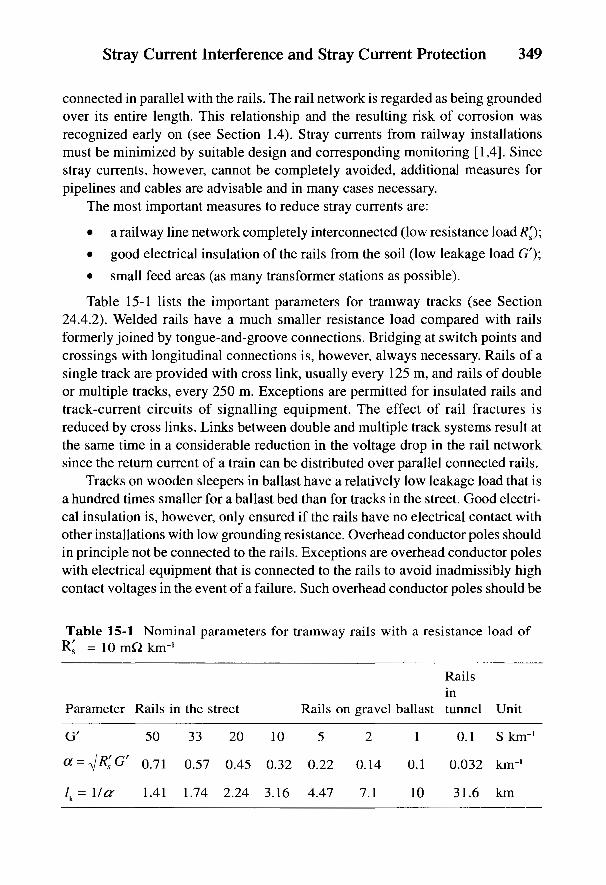
Stray Current Interference and Stray Current Protection 349
connected in parallel with the rails. The rail network is regarded as being groundedover its entire length. This relationship and the resulting risk of corrosion wasrecognized early on (see Section 1.4). Stray currents from railway installationsmust be minimized by suitable design and corresponding monitoring [1,4]. Sincestray currents, however, cannot be completely avoided, additional measures forpipelines and cables are advisable and in many cases necessary.
The most important measures to reduce stray currents are:
• a railway line network completely interconnected (low resistance load R'&);
• good electrical insulation of the rails from the soil (low leakage load G');
• small feed areas (as many transformer stations as possible).
Table 15-1 lists the important parameters for tramway tracks (see Section24.4.2). Welded rails have a much smaller resistance load compared with railsformerly joined by tongue-and-groove connections. Bridging at switch points andcrossings with longitudinal connections is, however, always necessary. Rails of asingle track are provided with cross link, usually every 125 m, and rails of doubleor multiple tracks, every 250 m. Exceptions are permitted for insulated rails andtrack-current circuits of signalling equipment. The effect of rail fractures isreduced by cross links. Links between double and multiple track systems result atthe same time in a considerable reduction in the voltage drop in the rail networksince the return current of a train can be distributed over parallel connected rails.
Tracks on wooden sleepers in ballast have a relatively low leakage load that isa hundred times smaller for a ballast bed than for tracks in the street. Good electri-cal insulation is, however, only ensured if the rails have no electrical contact withother installations with low grounding resistance. Overhead conductor poles shouldin principle not be connected to the rails. Exceptions are overhead conductor poleswith electrical equipment that is connected to the rails to avoid inadmissibly highcontact voltages in the event of a failure. Such overhead conductor poles should be
Table 15-1 Nominal parameters for tramway rails with a resistance load ofRS = 10 mQ. km-1
Railsin
Parameter Rails in the street Rails on gravel ballast tunnel Unit
G' 50 33 20 10 5 2 1 0.1 S kirr1
a = R's G' 0.71 0.57 0.45 0.32 0.22 0.14 0.1 0.032 km-1
/ k = l / ^ 1.41 1.74 2.24 3.16 4.47 7.1 10 31.6 km

350 Handbook of Cathodic Corrosion Protection
given a sufficiently high grounding resistance by electrically insulating thefoundations [4].
The railway lines on bridges are often electrically connected with steel or rein-forced steel structures which usually have a very low grounding resistance. In newinstallations, an electrical separation of the rails from the bridge structure isrequired according to the grounding resistance of the structure and the type of railbed. Independent of this, pipelines and metal sheathing of cables are always elec-trically separated from the structure in order to exclude direct transmission of straycurrent from the rails in these conductors.
Bus bars of a transformer substation must not be directly grounded. They mustbe connected with rails by at least two insulated cables. Metal sheathing of feederand return current cables must only then be connected with the rails or bus bar if anincrease in anodic corrosion on other buried installations is absolutely excluded.The insulation of all return cables must therefore be monitored regularly.
To reduce stray currents, voltage drops in the rail network should not exceed acertain limiting value over an average time (see Table 1 in Ref. 1). A distinctionshould be made here between the average voltage drop in the core of the networkand the voltage drop in outlying stretches of the network.
The core of the network is the region of the rail network in which the branchline of two transformer substations or of any other branch line is less than 2 kmdistant in a direct line. All branch lines outside the core of the network are termedoutlying lines. In a branched rail network, not only the stretches of line within acircle with a radius of 2 km from the most negative return current point of a trans-former substation belong to the core of the network, but also connecting branchlines that are less than 2 km from each other [1]. The area of a network core can besimply determined on a track plan with the help of a circular template as in Fig. 15-1.
External lines are generally found only in outlying districts and between dif-ferent cities. Of considerable importance in reducing stray currents and keeping
Fig. 15-1 Schematic diagram ofa network core in a branched railnetwork.

Stray Current Interference and Stray Current Protection 351
within the limiting value in a total network core is the requirement that the voltagebetween the return conductor points and various transformer substations be as lowas possible over an average time period. This can be achieved by favorable con-necting points for the return conductor cable, variable resistors and suitable choiceof feeder areas. In the case of parallel operation of several substations, a smallchange in the feeding voltage of individual substations is often sufficient.
The permitted limiting value applies both in the planning as well as for themeasured values in operation. In calculating the voltage drop at the rails, theparallel current passing through the soil is neglected. The resistance of the track isconsidered to be the highest permitted level. Uniform current loading is assumedwithin each section of the track. When checking during operation, the timedaverage value of the voltage drop should be measured over a period of at least3 h [1]. A measurement during operation alone does not give sufficient informationon the state of the rail network. It could even lead to false conclusions if lowvoltage drops are ascribed to a high leakage load value of the rail network whichthen allows particularly high stray currents. Assessment of the rail network is onlypossible by comparing the calculated values with the measured values.
In the Verband Deutscher Elektrotechniker (VDE) regulations [1,4], nodemands are made on the accuracy of the measured or calculated voltage drops ina rail network. An inaccuracy of ±10% and, in difficult cases, up to ±20%, shouldbe permitted. A calculation of the annual mean values is required. If the necessaryequipment is not available, a calculation is permitted over a shorter period (e.g., anaverage day). Voltage drops in the rail network only indicate the trend of the inter-ference of buried installations. Assessment of the risk of corrosion of an installa-tion can only be made by measuring the object/soil potential. A change in potentialof 0.1 V can be taken as an indication of an inadmissible corrosion risk [5].
In almost all dc railways in Germany, the positive pole of the rectifier is con-nected to the tram wire of the current rail and the negative pole with the runningrails. A connection of the positive pole with the running rails is technically pos-sible and was previously convenient when mercury vapor rectifiers were in use forcontact protection; however, this resulted in difficulties with corrosion protectionmeasures which involved stray current drainage or forced drainage. For this reason,connection of the negative pole with running rails is strongly recommended [4].
The resistance of a section of line with n rails of cross-section S per rail isgiven from the rail resistance load R's and for length, /, by:
Here K = 1 for welded rail joints or K = 1.15 for butted junctions, whichincrease the resistance and pst = 13 to 25 //Q cm, the specific resistivity of the steel,
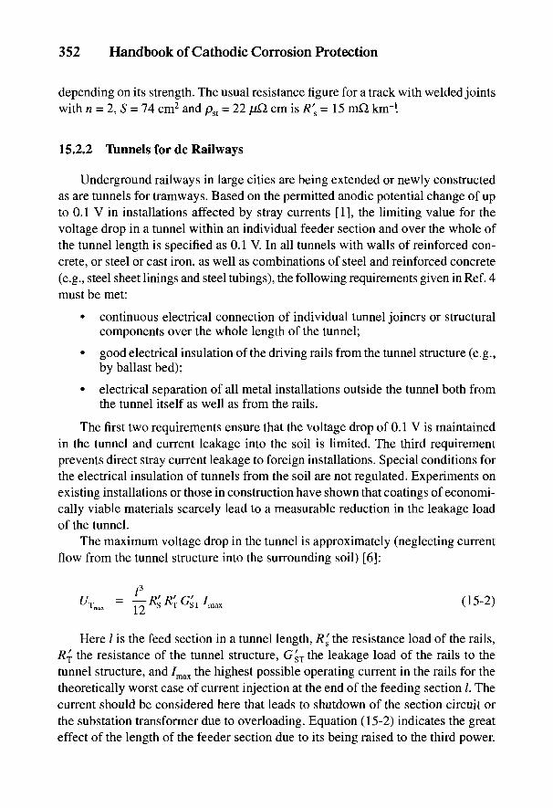
352 Handbook of Cathodic Corrosion Protection
depending on its strength. The usual resistance figure for a track with welded jointswith n = 2, S = 74 cm2 and pst = 22 p£l cm is R's = 15 mQ km-1.
15.2.2 Tunnels for dc Railways
Underground railways in large cities are being extended or newly constructedas are tunnels for tramways. Based on the permitted anodic potential change of upto 0.1 V in installations affected by stray currents [1], the limiting value for thevoltage drop in a tunnel within an individual feeder section and over the whole ofthe tunnel length is specified as 0.1 V. In all tunnels with walls of reinforced con-crete, or steel or cast iron, as well as combinations of steel and reinforced concrete(e.g., steel sheet linings and steel tubings), the following requirements given in Ref. 4must be met:
• continuous electrical connection of individual tunnel joiners or structuralcomponents over the whole length of the tunnel;
• good electrical insulation of the driving rails from the tunnel structure (e.g.,by ballast bed);
• electrical separation of all metal installations outside the tunnel both fromthe tunnel itself as well as from the rails.
The first two requirements ensure that the voltage drop of 0.1 V is maintainedin the tunnel and current leakage into the soil is limited. The third requirementprevents direct stray current leakage to foreign installations. Special conditions forthe electrical insulation of tunnels from the soil are not regulated. Experiments onexisting installations or those in construction have shown that coatings of economi-cally viable materials scarcely lead to a measurable reduction in the leakage loadof the tunnel.
The maximum voltage drop in the tunnel is approximately (neglecting currentflow from the tunnel structure into the surrounding soil) [6]:
Here / is the feed section in a tunnel length, R's the resistance load of the rails,Rj the resistance of the tunnel structure, GsTthe leakage load of the rails to thetunnel structure, and 7max the highest possible operating current in the rails for thetheoretically worst case of current injection at the end of the feeding section /. Thecurrent should be considered here that leads to shutdown of the section circuit orthe substation transformer due to overloading. Equation (15-2) indicates the greateffect of the length of the feeder section due to its being raised to the third power.
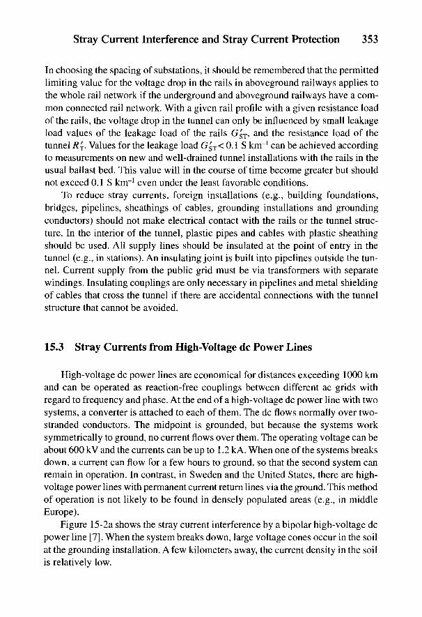
Stray Current Interference and Stray Current Protection 353
In choosing the spacing of substations, it should be remembered that the permittedlimiting value for the voltage drop in the rails in aboveground railways applies tothe whole rail network if the underground and aboveground railways have a com-mon connected rail network. With a given rail profile with a given resistance loadof the rails, the voltage drop in the tunnel can only be influenced by small leakageload values of the leakage load of the rails G§T, and the resistance load of thetunnel R^. Values for the leakage load G^T< 0.1 S km"1 can be achieved accordingto measurements on new and well-drained tunnel installations with the rails in theusual ballast bed. This value will in the course of time become greater but shouldnot exceed 0.1 S km"1 even under the least favorable conditions.
To reduce stray currents, foreign installations (e.g., building foundations,bridges, pipelines, sheathings of cables, grounding installations and groundingconductors) should not make electrical contact with the rails or the tunnel struc-ture. In the interior of the tunnel, plastic pipes and cables with plastic sheathingshould be used. All supply lines should be insulated at the point of entry in thetunnel (e.g., in stations). An insulating joint is built into pipelines outside the tun-nel. Current supply from the public grid must be via transformers with separatewindings. Insulating couplings are only necessary in pipelines and metal shieldingof cables that cross the tunnel if there are accidental connections with the tunnelstructure that cannot be avoided.
15.3 Stray Currents from High-Voltage dc Power Lines
High-voltage dc power lines are economical for distances exceeding 1000 kmand can be operated as reaction-free couplings between different ac grids withregard to frequency and phase. At the end of a high-voltage dc power line with twosystems, a converter is attached to each of them. The dc flows normally over two-stranded conductors. The midpoint is grounded, but because the systems worksymmetrically to ground, no current flows over them. The operating voltage can beabout 600 kV and the currents can be up to 1.2 kA. When one of the systems breaksdown, a current can flow for a few hours to ground, so that the second system canremain in operation. In contrast, in Sweden and the United States, there are high-voltage power lines with permanent current return lines via the ground. This methodof operation is not likely to be found in densely populated areas (e.g., in middleEurope).
Figure 15-2a shows the stray current interference by a bipolar high-voltage dcpower line [7]. When the system breaks down, large voltage cones occur in the soilat the grounding installation. A few kilometers away, the current density in the soilis relatively low.

354 Handbook of Cathodic Corrosion Protection
The principal circuit diagram for a bipolar system is shown in Fig. 15-2a andthe current distribution in the case of breakdown of a monopolar system inFig. 15-2b. I and II are the respective ac systems.
The current density, 7, in the soil in the middle region between the two ground-ing installations 2L can be derived as follows from Eq. (24-39) with r = L + x andR = L~x
Fig. 15-2 Stray current interference from high-voltage dc transmission installa-tions: (a) bipolar system, (b) monopolar system.
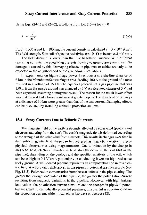
Stray Current Interference and Stray Current Protection 355
Using Eqs. (24-1) and (24-2), it follows from Eq. (15-4) for x = 0
For 7 = 1000 A and L = 100 km, the current density is calculated / = 3 x 10~8 A irr2.The field strength, E, in soil of specific resistivity, p - 100 Q m becomes 3 mV km"1.
The field strength is lower than that due to telluric currents. With differentoperating currents, the equalizing currents flowing to ground are even lower. Nodamage is caused by this. Damaging effects on pipelines or cables are only to beexpected in the neighborhood of the grounding installations.
In experiments on high-voltage power lines over a straight-line distance of6 km in the Mannheim/Schwetzingen area, feeding 100 A to the ground of a mastresulted in a voltage of 150 V. The pipe/soil potential of a gas pipeline that was150 m from the mast's ground was changed by 1 V. A calculated change of 5 V hadbeen expected, assuming homogeneous soil. The reason for the much lower effectwas that the soil had a lower resistance at greater depths. The effects of dc railwaysat a distance of 10 km were greater than that of the test current. Damaging effectscan be alleviated by installing cathodic protection stations.
15.4 Stray Currents Due to Telluric Currents
The magnetic field of the earth is strongly affected by solar wind (protons andelectrons radiating from the sun). The earth's magnetic field is deformed accordingto the strength of the solar wind from sunspots. This results in changes over time inthe earth's magnetic field; these can be measured as magnetic variation by geo-physical observatories using magnetometers. Due to induction by the change inmagnetic field, electrical changes in field strength occur in the soil (not in thepipeline), depending on the geology and the specific resistivity of the soil, whichcan be as high as 0.1 V km"1, particularly in conducting layers on high-resistancerocky ground. A well-coated pipeline represents an equipotential line in this elec-tric field at whose ends differences in the pipe/soil potential are measurable (seeFig. 15-3). Polarization currents arise from these at defects in the pipe coating. Thegreater the leakage load value of the pipeline, the greater the polarization currentresulting from magnetic variations in the pipeline. However, with high leakageload values, the polarization current densities and the changes in pipe/soil poten-tial are small. In cathodically protected pipelines, this current is superimposed onthe protection current, which it can either increase or decrease [8].
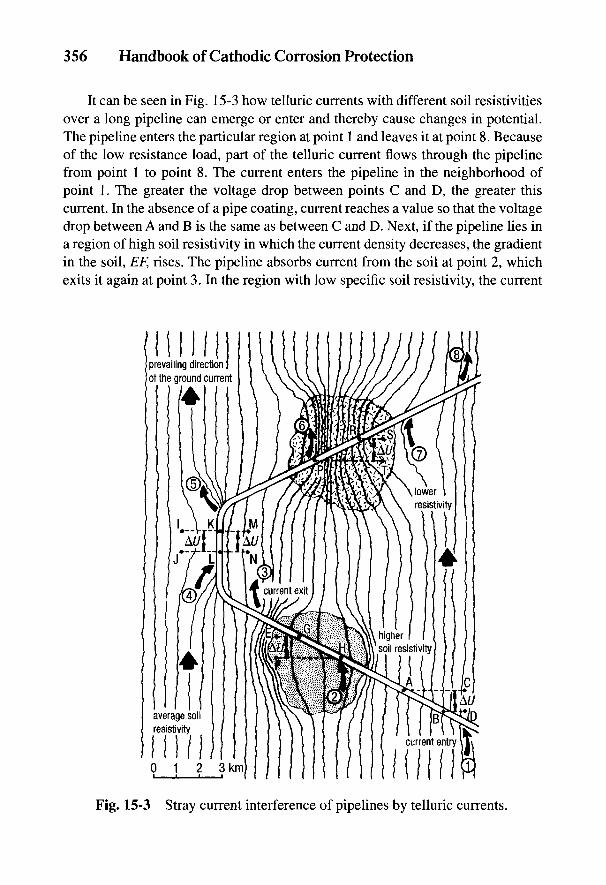
356 Handbook of Cathodic Corrosion Protection
It can be seen in Fig. 15-3 how telluric currents with different soil resistivitiesover a long pipeline can emerge or enter and thereby cause changes in potential.The pipeline enters the particular region at point 1 and leaves it at point 8. Becauseof the low resistance load, part of the telluric current flows through the pipelinefrom point 1 to point 8. The current enters the pipeline in the neighborhood ofpoint 1. The greater the voltage drop between points C and D, the greater thiscurrent. In the absence of a pipe coating, current reaches a value so that the voltagedrop between A and B is the same as between C and D. Next, if the pipeline lies ina region of high soil resistivity in which the current density decreases, the gradientin the soil, EF, rises. The pipeline absorbs current from the soil at point 2, whichexits it again at point 3. In the region with low specific soil resistivity, the current
Fig. 15-3 Stray current interference of pipelines by telluric currents.

Stray Current Interference and Stray Current Protection 357
density in the soil is higher. In order for the voltage drop, PR, to equal the voltagedrop, TS, in the soil, telluric current has to leave the pipeline at point 6 and reenterin the area of point 7. Because the telluric currents vary slowly and can evenreverse direction from the preferred direction of the ground current, continualchanges in potential occur at defects in the pipe coating.
The risk of anodic corrosion on a pipeline due to magnetic variations can beaccessed with the help of the planetary earth magnetic index, Kp. These indicesgive the degree of the maximum change in field strength for a time period of 3 h,each derived from observations at geophysical observatories. The K indices arepublished monthly in tables and diagrams.
The relation between the change in the earth's magnetic field and the variationin pipe/soil potential, t/Cu-cuso4'
can be seen in Fig-15'4- H, D and Z are the changesof the earth's magnetic field components, north-south, east-west and vertical.
Extensive investigations show [9,10] that in 1981 the pipe/soil potential wasmore positive than the protection potential for only 20 h. Therefore, no danger ofcorrosion should be expected from magnetic variation. Because it cannot be fore-seen when the earth's magnetic field might change with different intensity, leadingto changes in pipe/soil potential, considerable difficulties arise in monitoringcathodic protection with regard to /fl-free measurements of pipe/soil potentials.7/?-free potentials using a switching-off technique can only be made in periodswhen there is no magnetic variation. In principle, the only possible way of
Fig. 15-4 Pipe/soil potentialsfor a pipeline (a) with and (b)without interference due tomagnetic variation.
358 Handbook of Cathodic Corrosion Protection
measuring 7/?-free potentials is with fixed, installed test measuring probes (seeSection 3.3).
15.5 Protective Measures
15.5.1 Stray Current Protection for Individual Pipelines
Frequently, measures for dc installations are not sufficient to limit stray currents.This applies particularly to dc railways. In many cases, additional protectivemeasures for the affected installations are advisable [1] or even necessary [11].
Protective measures restrict the outflow of stray current from the particularinstallations into the surrounding soil. This can be done in the simplest case by aconnecting cable between the installation to be protected and the railway lineswith a sufficiently negative potential (see Fig. 15-5). The stray current thatformerly flowed through the soil can then flow back via the cable connection to therails with no risk. Protection against stray current corrosion is achieved if thepotential of the installation to be protected-with the exception of momentary peakvalues-is equal to or more negative than the free corrosion potential. Lowering thepotential gives partial cathodic protection.
The same conditions as for cathodic protection apply for reliable stray currentdrainage or forced drainage for rails of dc railways (see Section 10.2). The objectsto be protected must be electrically connected. Individual insulating sockets(e.g., lead-caulked or rubber screw sockets) must be bridged. The installations tobe protected must have no electrical contact to the rails as these can possibly be atbridges. Even in cases where stray current protective measures are applied, bridgesare a source of danger due to carrying over of stray current. Figure 15-5 shows theeffect of a pipeline laid parallel to tramway rails with and without stray currentdrainage.
The figure shows the current and potential distribution for a single tram whichfeeds a current, /, into the rails at the end of the parallel stretch. In the vicinity ofthe tram, stray current flows from the driving rails through the soil to the pipeline;in the absence of stray current drainage in the region of the transformer substation,the current flows back again from the pipeline through the soil to the rails and herecauses anodic corrosion of the pipeline. In the area of the positive rails, from 1/2 to/, there is cathodic polarization of the pipeline and in the area of the negative railsfrom 0 to 1/2 anodic polarization. The pipeline assumes the potential of the rails asa result of the low-resistance stray current drainage to the rails before the trans-former substation.
The pipe/soil potential can therefore become very negative. The pipe currentsbecome very large with poorly coated pipelines. The pipe current can be limited by
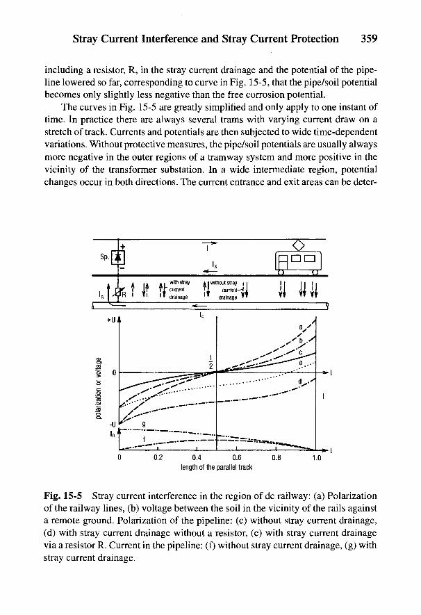
Stray Current Interference and Stray Current Protection 359
including a resistor, R, in the stray current drainage and the potential of the pipe-line lowered so far, corresponding to curve in Fig. 15-5, that the pipe/soil potentialbecomes only slightly less negative than the free corrosion potential.
The curves in Fig. 15-5 are greatly simplified and only apply to one instant oftime. In practice there are always several trams with varying current draw on astretch of track. Currents and potentials are then subjected to wide time-dependentvariations. Without protective measures, the pipe/soil potentials are usually alwaysmore negative in the outer regions of a tramway system and more positive in thevicinity of the transformer substation. In a wide intermediate region, potentialchanges occur in both directions. The current entrance and exit areas can be deter-
Fig. 15-5 Stray current interference in the region of dc railway: (a) Polarizationof the railway lines, (b) voltage between the soil in the vicinity of the rails againsta remote ground. Polarization of the pipeline: (c) without stray current drainage,(d) with stray current drainage without a resistor, (e) with stray current drainagevia a resistor R. Current in the pipeline: (f) without stray current drainage, (g) withstray current drainage.
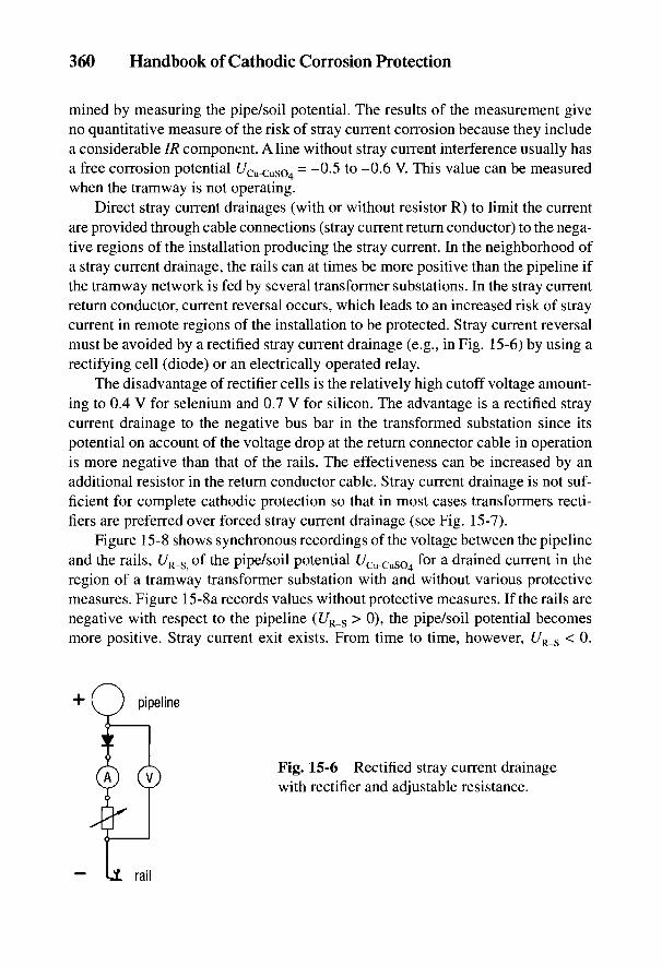
360 Handbook of Cathodic Corrosion Protection
mined by measuring the pipe/soil potential. The results of the measurement giveno quantitative measure of the risk of stray current corrosion because they includea considerable IR component. A line without stray current interference usually hasa free corrosion potential t/Cu-CuSO4
= ~~0.5 to ~0.6 V. This value can be measuredwhen the tramway is not operating.
Direct stray current drainages (with or without resistor R) to limit the currentare provided through cable connections (stray current return conductor) to the nega-tive regions of the installation producing the stray current. In the neighborhood ofa stray current drainage, the rails can at times be more positive than the pipeline ifthe tramway network is fed by several transformer substations. In the stray currentreturn conductor, current reversal occurs, which leads to an increased risk of straycurrent in remote regions of the installation to be protected. Stray current reversalmust be avoided by a rectified stray current drainage (e.g., in Fig. 15-6) by using arectifying cell (diode) or an electrically operated relay.
The disadvantage of rectifier cells is the relatively high cutoff voltage amount-ing to 0.4 V for selenium and 0.7 V for silicon. The advantage is a rectified straycurrent drainage to the negative bus bar in the transformed substation since itspotential on account of the voltage drop at the return connector cable in operationis more negative than that of the rails. The effectiveness can be increased by anadditional resistor in the return conductor cable. Stray current drainage is not suf-ficient for complete cathodic protection so that in most cases transformers recti-fiers are preferred over forced stray current drainage (see Fig. 15-7).
Figure 15-8 shows synchronous recordings of the voltage between the pipelineand the rails, [7R_S of the pipe/soil potential £/Cu-cuso4 for a drained current in theregion of a tramway transformer substation with and without various protectivemeasures. Figure 15-8a records values without protective measures. If the rails arenegative with respect to the pipeline (£/R_s > 0), the pipe/soil potential becomesmore positive. Stray current exit exists. From time to time, however, UR_S < 0.
Fig. 15-6 Rectified stray current drainagewith rectifier and adjustable resistance.

Stray Current Interference and Stray Current Protection 361
Then stray current enters the pipeline and the pipe/soil potential becomes morenegative. The recording in Fig. 15-8b shows the behavior with a direct stray cur-rent drainage to the rails. With UR_S > 0, a current flows off the pipeline via thestray current return conductor back to the rails so that there is no anodic polariza-tion of the pipeline. With UR_S < 0, a current flows over the connection in thepipeline and anodically polarizes it. Direct stray current drainage is therefore notpossible in this case. Figure 15-8c shows the result of a rectified stray currentdrainage to the rails. Now the pipeline is always cathodically polarized. Cathodicprotection is, however, also not fully attained.
With forced stray current drainage, the current is returned from the pipeline tothe rails by means of a grid-fed rectifier. The transformer-rectifier is connected intothe stray current return conductor, the negative pole is connected with the installa-tion to be protected and the positive pole is connected to the rails or the negativeside of the bus bar in the transformer substation.
Various arrangements for the protection rectifier and its possible applicationsare described in Chapter 8. Large fluctuations of the protection current can bereduced by a current-reducing resistor, R (see Fig. 15-7). This means that the pipe/soil potential in the middle becomes less negative. A current smoothing action canbe achieved with rectifiers connected to the network or by reducing losses by aninductive resistance between the transformer and bridge rectifier (see Section 8.4).
Stray current drainage and forced drainage with uncontrolled protection cur-rent devices often require expensive drainage tests in setting up the protectiondrainage test station. The use of controlled protection current devices can reducethis expense (see Section 8.6). Also, with controlled protection current devices,potential fluctuations occur in the adjoining sections of the pipeline which are gov-erned by voltage drops caused by stray currents in the soil.
Fig. 15-7 Forced current drainage withresistor and/or choke to limit current.
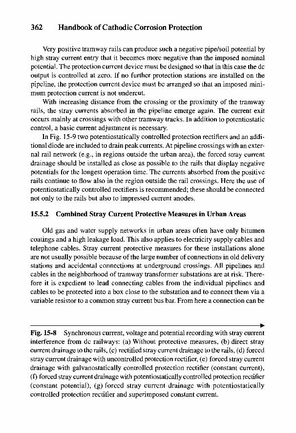
362 Handbook of Cathodic Corrosion Protection
Very positive tramway rails can produce such a negative pipe/soil potential byhigh stray current entry that it becomes more negative than the imposed nominalpotential. The protection current device must be designed so that in this case the dcoutput is controlled at zero. If no further protection stations are installed on thepipeline, the protection current device must be arranged so that an imposed mini-mum protection current is not undercut.
With increasing distance from the crossing or the proximity of the tramwayrails, the stray currents absorbed in the pipeline emerge again. The current exitoccurs mainly at crossings with other tramway tracks. In addition to potentiostaticcontrol, a basic current adjustment is necessary.
In Fig. 15-9 two potentiostatically controlled protection rectifiers and an addi-tional diode are included to drain peak currents. At pipeline crossings with an exter-nal rail network (e.g., in regions outside the urban area), the forced stray currentdrainage should be installed as close as possible to the rails that display negativepotentials for the longest operation time. The currents absorbed from the positiverails continue to flow also in the region outside the rail crossings. Here the use ofpotentiostatically controlled rectifiers is recommended; these should be connectednot only to the rails but also to impressed current anodes.
15.5.2 Combined Stray Current Protective Measures in Urban Areas
Old gas and water supply networks in urban areas often have only bitumencoatings and a high leakage load. This also applies to electricity supply cables andtelephone cables. Stray current protective measures for these installations aloneare not usually possible because of the large number of connections in old deliverystations and accidental connections at underground crossings. All pipelines andcables in the neighborhood of tramway transformer substations are at risk. There-fore it is expedient to lead connecting cables from the individual pipelines andcables to be protected into a box close to the substation and to connect them via avariable resistor to a common stray current bus bar. From here a connection can be
^Fig. 15-8 Synchronous current, voltage and potential recording with stray currentinterference from dc railways: (a) Without protective measures, (b) direct straycurrent drainage to the rails, (c) rectified stray current drainage to the rails, (d) forcedstray current drainage with uncontrolled protection rectifier, (e) forced stray currentdrainage with galvanostatically controlled protection rectifier (constant current),(f) forced stray current drainage with potentiostatically controlled protection rectifier(constant potential), (g) forced stray current drainage with potentiostaticallycontrolled protection rectifier and superimposed constant current.
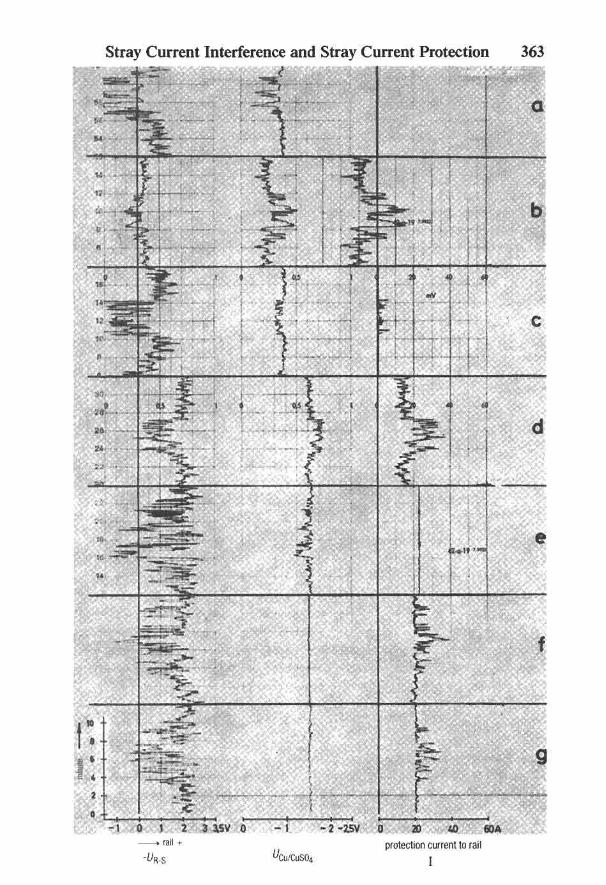
Stray Current Interference and Stray Current Protection 363
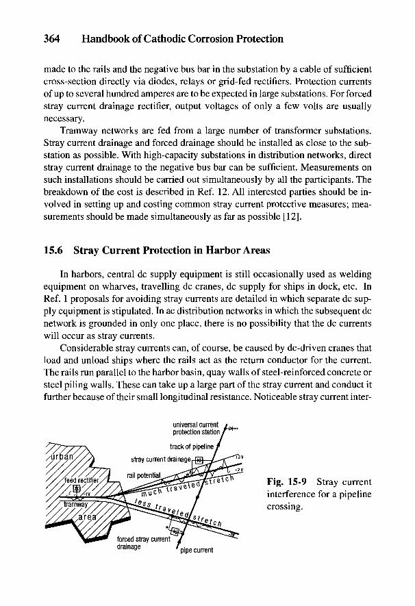
364 Handbook of Cathodic Corrosion Protection
made to the rails and the negative bus bar in the substation by a cable of sufficientcross-section directly via diodes, relays or grid-fed rectifiers. Protection currentsof up to several hundred amperes are to be expected in large substations. For forcedstray current drainage rectifier, output voltages of only a few volts are usuallynecessary.
Tramway networks are fed from a large number of transformer substations.Stray current drainage and forced drainage should be installed as close to the sub-station as possible. With high-capacity substations in distribution networks, directstray current drainage to the negative bus bar can be sufficient. Measurements onsuch installations should be carried out simultaneously by all the participants. Thebreakdown of the cost is described in Ref. 12. All interested parties should be in-volved in setting up and costing common stray current protective measures; mea-surements should be made simultaneously as far as possible [12].
15.6 Stray Current Protection in Harbor Areas
In harbors, central dc supply equipment is still occasionally used as weldingequipment on wharves, travelling dc cranes, dc supply for ships in dock, etc. InRef. 1 proposals for avoiding stray currents are detailed in which separate dc sup-ply equipment is stipulated. In ac distribution networks in which the subsequent dcnetwork is grounded in only one place, there is no possibility that the dc currentswill occur as stray currents.
Considerable stray currents can, of course, be caused by de-driven cranes thatload and unload ships where the rails act as the return conductor for the current.The rails run parallel to the harbor basin, quay walls of steel-reinforced concrete orsteel piling walls. These can take up a large part of the stray current and conduct itfurther because of their small longitudinal resistance. Noticeable stray current inter-
Fig. 15-9 Stray currentinterference for a pipelinecrossing.
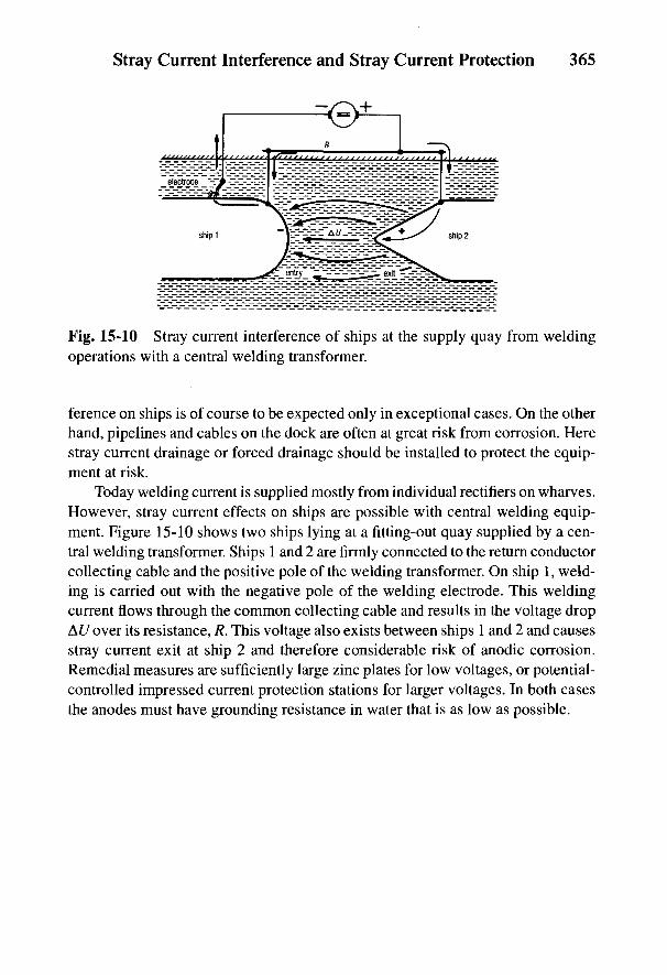
Stray Current Interference and Stray Current Protection 365
Fig. 15-10 Stray current interference of ships at the supply quay from weldingoperations with a central welding transformer.
ference on ships is of course to be expected only in exceptional cases. On the otherhand, pipelines and cables on the dock are often at great risk from corrosion. Herestray current drainage or forced drainage should be installed to protect the equip-ment at risk.
Today welding current is supplied mostly from individual rectifiers on wharves.However, stray current effects on ships are possible with central welding equip-ment. Figure 15-10 shows two ships lying at a fitting-out quay supplied by a cen-tral welding transformer. Ships 1 and 2 are firmly connected to the return conductorcollecting cable and the positive pole of the welding transformer. On ship 1, weld-ing is carried out with the negative pole of the welding electrode. This weldingcurrent flows through the common collecting cable and results in the voltage dropAU over its resistance, R. This voltage also exists between ships 1 and 2 and causesstray current exit at ship 2 and therefore considerable risk of anodic corrosion.Remedial measures are sufficiently large zinc plates for low voltages, or potential-controlled impressed current protection stations for larger voltages. In both casesthe anodes must have grounding resistance in water that is as low as possible.
366 Handbook of Cathodic Corrosion Protection
15.7 References
[1] DIN VDE 0180, Beuth-Verlag, Berlin 1983.[2] AfK-Empfehlung Nr. 7, ZfGW-Verlag, Frankfurt 1974.[3] DIN VDE 0100 Teil 410, Beuth-Verlag, Berlin 1983.[4] DIN VDE 0115 Teil 3, Beuth-Verlag, Berlin 1982.[5] vorgesehene Anderung von [1].[6] VOV-Empfehlung 04.740.5, Verband offentlicher Verkehrsbetriebe, Koln 1975.[7] W. J. Mitchel, NACE-Konferenz, paper No. 31, Toronto 1981.[8] A. L. Smart, IEEE Transactions on Industry Applications, Vol. IA-18, Nr. 5, 557 (1982).[9] W. v. Baeckmann, gwf gas/erdgas 123, 530 (1982).
[10] H. Brasse u. A. Junge, gwf gas/erdgas 125, 194 (1984).[11] W. v! Baeckmann u. W. Heim, gwf gas/erdgas 110, 393 (1969).[12] AfK-Empfehlung Nr. 4, ZfGW-Verlag, Frankfurt 1970.

16
Marine Structuresand Offshore Pipelines
W. v. BAECKMANN AND B. RICHTER
The cathodic protection of marine structures (i.e., drilling and oil productionplatforms, steel piling walls, locks and other harbor installations) is increasinglyused today and is always prescribed for subsea pipelines. Thin coatings(see Section 5.1.1) have only a limited life under water; in general, the thin coat-ings listed above cannot be repaired. Therefore, such coatings are rarely used andalmost never in offshore applications. Regulations based on comprehensive inves-tigations govern the setting up of cathodic protection [1-3].
In the tidal zone and the spray zone (known as the splash zone), cathodic protec-tion is generally not very effective. Here thick coatings or sheathing with corrosion-resistance materials (e.g., based on NiCu) are necessary to prevent corrosion attack[4]. The coatings are severely mechanically stressed and must be so formed thatrepair is possible even under spray conditions. Their stability against cathodicpolarization (see Section 17.2), marine growths, UV rays and seawater must beensured [4,5].
In contrast to pipelines and harbor installations, platforms are dynamicallyloaded. Therefore in the choice of steels, in addition to strength and typesof machinability, the risk of corrosion fatigue and strain-induced stress corrosionmust be taken into account in combination with cathodic protection (seeSections 2.3.3 to 2.3.5).
16.1 Cathodic Protection Measures
Protection with impressed current, with galvanic anodes, and a combination ofboth processes is used for marine structures and offshore pipelines. Their properties,as well as their advantages and disadvantages, are given in Table 16-1. The protec-tive measures must be optimized for every structure. In the impressed current pro-tection of offshore platforms, for example, the difficulties of maintenance and repairwill be of major importance, whereas in harbor installations these problems can be
367
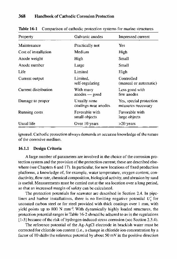
368 Handbook of Cathodic Corrosion Protection
Table 16-1 Comparison of cathodic protection systems for marine structures
Property Galvanic anodes Impressed current
Maintenance Practically not Yes
Cost of installation Medium High
Anode weight High Small
Anode number Large Small
Life Limited High
Current output Limited, Controlledself-regulating (manual or automatic)
Current distribution With many Less good withanodes — good few anodes
Damage to proper Usually none Yes, special protectioncoatings near anodes measures necessary
Running costs Favorable with Favorable withsmall objects large objects
Usual life Over 10 years >20 years
ignored. Cathodic protection always demands an accurate knowledge of the natureof the corrosive medium.
16.1.1 Design Criteria
A large number of parameters are involved in the choice of the corrosion pro-tection system and the provision of the protection current; these are described else-where (see Chapters 6 and 17). In particular, for new locations of fixed productionplatforms, a knowledge of, for example, water temperature, oxygen content, con-ductivity, flow rate, chemical composition, biological activity, and abrasion by sandis useful. Measurements must be carried out at the sea location over a long period,so that an increased margin of safety can be calculated.
The protection potentials for seawater are described in Section 2.4. In pipe-lines and harbor installations, there is no limiting negative potential U[ foruncoated carbon steel or for steel provided with thick coatings over 1 mm, withyield points up to 800 N mm"2. With dynamically highly loaded structures, theprotection potential ranges in Table 16-2 should be adhered to as in the regulations[1-3] because of the risk of hydrogen-induced stress corrosion (see Section 2.3.4).
The reference potential of the Ag-AgCl electrode in brackish water must becorrected for chloride ion content (i.e., a change in chloride ion concentration by afactor of 10 shifts the reference potential by about 50 mV in the positive direction
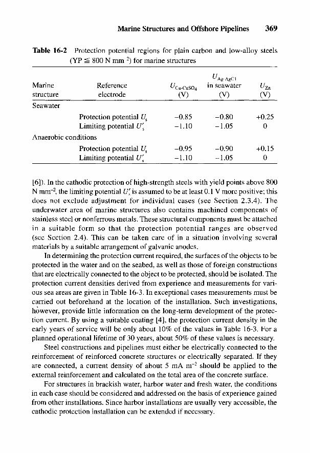
Marine Structures and Offshore Pipelines 369
Table 16-2 Protection potential regions for plain carbon and low-alloy steels(YP 800 N mm"2) for marine structures
^Ag-AgCl
Marine Reference ^Cu-cuso4 in seawater f/Zn
structure electrode (V) (V) (V)
Seawater
Protection potential Us -0.85 -0.80 +0.25Limiting potential U's -1.10 -1.05 0
Anaerobic conditions
Protection potential Us -0.95 -0.90 +0.15Limiting potential U's -1.10 -1.05 0
[6]). In the cathodic protection of high-strength steels with yield points above 800N mnr2, the limiting potential U[ is assumed to be at least 0.1 V more positive; thisdoes not exclude adjustment for individual cases (see Section 2.3.4). Theunderwater area of marine structures also contains machined components ofstainless steel or nonferrous metals. These structural components must be attachedin a suitable form so that the protection potential ranges are observed(see Section 2.4). This can be taken care of in a situation involving severalmaterials by a suitable arrangement of galvanic anodes.
In determining the protection current required, the surfaces of the objects to beprotected in the water and on the seabed, as well as those of foreign constructionsthat are electrically connected to the object to be protected, should be isolated. Theprotection current densities derived from experience and measurements for vari-ous sea areas are given in Table 16-3. In exceptional cases measurements must becarried out beforehand at the location of the installation. Such investigations,however, provide little information on the long-term development of the protec-tion current. By using a suitable coating [4], the protection current density in theearly years of service will be only about 10% of the values in Table 16-3. For aplanned operational lifetime of 30 years, about 50% of these values is necessary.
Steel constructions and pipelines must either be electrically connected to thereinforcement of reinforced concrete structures or electrically separated. If theyare connected, a current density of about 5 mA m~2 should be applied to theexternal reinforcement and calculated on the total area of the concrete surface.
For structures in brackish water, harbor water and fresh water, the conditionsin each case should be considered and addressed on the basis of experience gainedfrom other installations. Since harbor installations are usually very accessible, thecathodic protection installation can be extended if necessary.
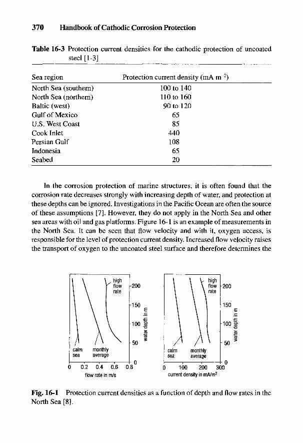
370 Handbook of Cathodic Corrosion Protection
Table 16-3 Protection current densities for the cathodic protection of uncoatedsteel [1-3]
Sea region Protection current density (mA nr2)
North Sea (southern) 100 to 140North Sea (northern) 110 to 160Baltic (west) 90 to 120Gulf of Mexico 65U.S. West Coast 85Cook Inlet 440Persian Gulf 108Indonesia 65Seabed 20
In the corrosion protection of marine structures, it is often found that thecorrosion rate decreases strongly with increasing depth of water, and protection atthese depths can be ignored. Investigations in the Pacific Ocean are often the sourceof these assumptions [7]. However, they do not apply in the North Sea and othersea areas with oil and gas platforms. Figure 16-1 is an example of measurements inthe North Sea. It can be seen that flow velocity and with it, oxygen access, isresponsible for the level of protection current density. Increased flow velocity raisesthe transport of oxygen to the uncoated steel surface and therefore determines the
Fig. 16-1 Protection current densities as a function of depth and flow rates in theNorth Sea [8].
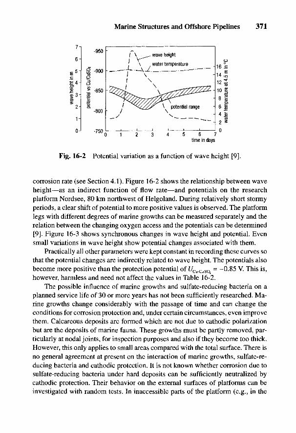
Marine Structures and Offshore Pipelines 371
Fig. 16-2 Potential variation as a function of wave height [9].
corrosion rate (see Section 4.1). Figure 16-2 shows the relationship between waveheight—as an indirect function of flow rate—and potentials on the researchplatform Nordsee, 80 km northwest of Helgoland. During relatively short stormyperiods, a clear shift of potential to more positive values is observed. The platformlegs with different degrees of marine growths can be measured separately and therelation between the changing oxygen access and the potentials can be determined[9]. Figure 16-3 shows synchronous changes in wave height and potential. Evensmall variations in wave height show potential changes associated with them.
Practically all other parameters were kept constant in recording these curves sothat the potential changes are indirectly related to wave height. The potentials alsobecome more positive than the protection potential of t/Cu_CuSO = -0.85 V. This is,however, harmless and need not affect the values in Table 16-2.
The possible influence of marine growths and sulfate-reducing bacteria on aplanned service life of 30 or more years has not been sufficiently researched. Ma-rine growths change considerably with the passage of time and can change theconditions for corrosion protection and, under certain circumstances, even improvethem. Calcareous deposits are formed which are not due to cathodic polarizationbut are the deposits of marine fauna. These growths must be partly removed, par-ticularly at nodal joints, for inspection purposes and also if they become too thick.However, this only applies to small areas compared with the total surface. There isno general agreement at present on the interaction of marine growths, sulfate-re-ducing bacteria and cathodic protection. It is not known whether corrosion due tosulfate-reducing bacteria under hard deposits can be sufficiently neutralized bycathodic protection. Their behavior on the external surfaces of platforms can beinvestigated with random tests. In inaccessible parts of the platform (e.g., in the

372 Handbook of Cathodic Corrosion Protection
Fig. 16-3 Synchronousvariation in wave heightand off potentials [9].
interior of the platform legs containing standing water or between piles and legs),inspection is hardly possible. Corrosion protection by coatings is necessary in suchendangered areas.
16.1.2 Protection with Galvanic Anodes
The composition and driving voltage of galvanic anodes as well as their mate-rial, size and application are dealt with in Chapter 6 and are also laid down in theregulations for offshore structures [1-3]. Galvanic anodes are always welded bythe protruding iron core or for pipelines, connected via a cable. Screw connectionsare not allowed even for repairs. Magnesium anodes are not used on account oftheir high self-corrosion in seawater, but aluminum anodes are installed on plat-forms and zinc anodes on ships, harbor installations and tanks.
Chemical analyses should be provided for all anodes used in the offshore andharbor area, together with results for current content in A h kg"1 and current outputin amperes [2,3]. The geometric shape and the number of anodes required is deter-mined by these parameters. Expensive calculations for design based on groundingresistances are made only in exceptional cases because in practice there are toomany uncertainties and the number and mass of the anodes have to be quoted witha corresponding safety factor.
Marine Structures and Offshore Pipelines 373
16.1.3 Impressed Current Protection
Materials for impressed current anodes and their consumption and service lifeare described in Chapter 7. Chapter 17 contains information on protection currentequipment for ships that would also apply to platforms. The use of impressed cur-rent systems for these structures requires very great care at the planning stagesince later repairs can be carried out only at a disproportionately high cost. Inparticular, cable mountings under water must be designed so that mechanical dam-age by wave and ice movement and shipping traffic is absolutely prevented. Theprotection current equipment should be installed as close as possible to the anodes;however, this is not always possible. For this reason the protection of platformswith impressed current has not yet been successfully achieved.
16.2 Platforms
Production platforms for extraction of oil and gas are planned to have servicelives of several decades. These structures—there are about 6000 of them world-wide—can only be inspected and monitored in situ by divers or diving equipment.On the other hand, semisubmersible floating platforms and drilling rigs—there areabout 500 in operation worldwide—are treated in the same way as ships (see Chap-ter 17) since they are movable and can be maintained and repaired in dock. Thedocking interval of these installations is normally 5 years, which must be takenaccount of in the design. Aluminum anodes are almost exclusively used as gal-vanic anodes because of weight considerations. Titanium and niobium coated withplatinum are used as impressed current anodes (see Section 7.2.2). The negativelimiting critical potential t/s of the steel is particularly important at the designstage, since support legs and floats are increasingly fabricated from high-strengthsteels with yield points of over 800 MPa (see Section 16.1.1).
16.2.1 Steel Structures
Production platforms are coated only in exceptional cases or for the purposesof investigation because the life of the structure is greater than the life of the coat-ing. Therefore in the design of the cathodic protection, only the protection poten-tial Us of the steel need be considered. Steels with an ultimate tensile strength of upto 350 N mnr2 are used for these structures, which are weldable even in thicksections, and the hardness of the welded material can be kept to 350 HV(see Section 2.3.4 [2,10]). Aluminum anodes with the same protection effect andlife as zinc anodes have much less weight. This is a very important advantage for

374 Handbook of Cathodic Corrosion Protection
the uncoated surface that is to be protected. Several thousands of tons aluminumanodes are used on platforms at greater depths, which must be taken into accountof construction and transport to the installation site.
The anode mountings are welded to lap joints in the yard, and the anodes areinstalled at a minimum distance of 30 cm from the structure to achieve the mostuniform current distribution [1-3]. Nonuniform potential distribution occurs evenwith this distance.
Nodal points of the platform require special attention for corrosion protection.Therefore the anodes have to be installed in the vicinity of these points, as indi-cated in Fig. 16-4. The spacing must be sufficiently large that the welded joints ofthe nodes do not lie in the area of the lap joints. The effort for calculating theoptimal distribution with the lowest weight of anodes is considerable and has ledto computer programs by which the anode distribution can be estimated [11].
The production platforms are equipped with a large number of production tubesand risers, which are connected to the flow lines. The corrosion protection of theseinstallations must be carried out particularly reliably since any damage can resultin the escape of gas or oil and cause great danger to personnel and the environ-ment. These pipes are usually provided with heavy-duty thick coatings; in the splashzone the thickness is over 10 mm. These coatings must be resistant againstcathodic polarization (see Sections 5.2.1 and 17.3). In choosing galvanic anodes,the temperature of the material to be conveyed must be taken into account. In someareas and according to national regulations, the risers must be electrically sepa-rated (from the platform) if different corrosion protection systems are used,e.g., platforms with impressed current protection and risers with galvanic anodes.To date, impressed current protection for fixed platforms has only been installed
Fig. 16-4Arrangement ofgalvanic anodeson platforms.
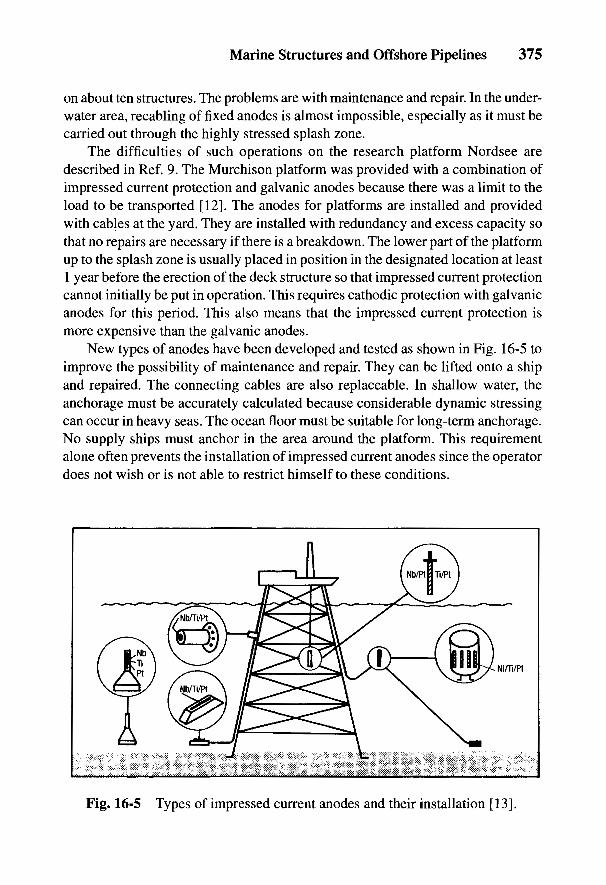
Marine Structures and Offshore Pipelines 375
on about ten structures. The problems are with maintenance and repair. In the under-water area, recabling of fixed anodes is almost impossible, especially as it must becarried out through the highly stressed splash zone.
The difficulties of such operations on the research platform Nordsee aredescribed in Ref. 9. The Murchison platform was provided with a combination ofimpressed current protection and galvanic anodes because there was a limit to theload to be transported [12]. The anodes for platforms are installed and providedwith cables at the yard. They are installed with redundancy and excess capacity sothat no repairs are necessary if there is a breakdown. The lower part of the platformup to the splash zone is usually placed in position in the designated location at least1 year before the erection of the deck structure so that impressed current protectioncannot initially be put in operation. This requires cathodic protection with galvanicanodes for this period. This also means that the impressed current protection ismore expensive than the galvanic anodes.
New types of anodes have been developed and tested as shown in Fig. 16-5 toimprove the possibility of maintenance and repair. They can be lifted onto a shipand repaired. The connecting cables are also replaceable. In shallow water, theanchorage must be accurately calculated because considerable dynamic stressingcan occur in heavy seas. The ocean floor must be suitable for long-term anchorage.No supply ships must anchor in the area around the platform. This requirementalone often prevents the installation of impressed current anodes since the operatordoes not wish or is not able to restrict himself to these conditions.
Fig. 16-5 Types of impressed current anodes and their installation [13].
376 Handbook of Cathodic Corrosion Protection
The distance between the structure and fixed impressed current anodes is animportant factor. The number of anodes has to be small so the anodes need to berelatively large, which will result in too negative a potential if the distance is notsufficiently great. A minimum distance of 1.5 m is prescribed [1-3], but thisinvolves considerable construction effort due to the effects of heavy seas. Besidesthe so-called restriction on impressed current installations, there is the requirementthat the corrosion protection be switched off when diving work is beingcarried out [14] .This regulation is not justifiable. Work on the underwater region ofproduction platforms takes place continuously, as far as the weather allows; if theprotection must be switched off each time, the impressed current protectionbecomes very limited.
The protection current equipment must be installed on the deck, so great lengthsof cable with a corresponding cross-section are required. Only potential-control-ling protection current equipment, as in the case of ships, should be employedsince the necessary current densities are continually changing due to the changingheavy seas (Figs. 16-2 and 16-3).
16.2.2 Concrete Structures
A series of platforms of reinforced concrete have been installed in the NorthSea and the Baltic. The concrete covering in the underwater region of 60 mm forweak reinforcement and 75 mm for prestressed concrete as well as 75 mm and 100mm in the splash zone should prevent corrosion of the reinforcing steel [15]. Alarge number of steel components either built in or attached are always present onthese structures. The passive reinforcing steel acts as a foreign cathodic structureto these attachments; therefore, they must be cathodically protected. In designingprotection with galvanic anodes, current densities according to Table 16-3 must beallowed for, together with the surface area of nearby electrically conducted rein-forcement, at about 5 mA m"2 of concrete surface. The connection fittings for pipe-lines protected with galvanic anodes can be seen in Fig. 16-6. The large verticallyattached anodes serve to protect the steel casing wall, which is driven into theseabed. The anode is connected to the wall by flat iron.
16.3 Harbor Structures
In planning cathodic protection, the specific resistivity of the water, the size ofthe surfaces to be protected and the required protection current densities have to bedetermined. The protection current density depends on the type and quality of thecoating. Thermosetting resins (e.g., tar-epoxy resin coatings) are particularlyeffective and are mostly used today on coastal structures. They are chemically

Marine Structures and Offshore Pipelines 377
Fig. 16-6Galvanic anodeson concretestructures.
resistant in various types of water and are not destroyed even by marine growths.Thicknesses of 0.4 to 0.6 mm have a high electrical resistance, high resistance tocathodic disbondment and very good wear resistance (see Section 5.2.1.4).
The protection current densities for structures near the sea can amount to 60 to100 mA m~2 for uncoated surfaces in the area in contact with water and 20% of thatfor parts driven into the soil. The land sides of retaining walls take so little currentthat they do not have to be taken into account in the calculation. With coated ob-jects, the protection current density lies between 5 and 20 mA nr2, depending onthe quality of the coating. About half this value must be expected for the part in thesoil because either the coating is absent or is damaged by the driving.
16.3.1 Impressed Current Equipment
Impressed current installations should always be designed with a large excesscapacity [16]. The cost of the extra expenditure is insignificant in relation to thetotal objective, especially if the life of the anodes is lengthened by calling on theexcess capacity. A larger protection installation provides the possibility of carryingout prepolarization on uncoated components. Damage or degradation of theprotective coating in the case of coated surfaces can be compensated for. Impressedcurrent anode materials are detailed in Chapter 7.
The anodes can either be laid on the bottom, hung between the pillars orattached to the object to be protected. In every case they should be mounted sothey can be easily exchanged. Anodes laid on the seabed are installed on concretesleds or concrete slabs (see Fig. 16-7) so that they do not sink into the mud orbecome covered with sand. The current output in sand is considerably reduced due

378 Handbook of Cathodic Corrosion Protection
Fig. 16-7 Fixture for PtTi anodes for laying on the sea bed.
to the high specific resistivity. Anodes cannot be laid on the seabed in harborsbecause they can cause interference with ships lying there or can be damaged bydredging operations. A proper design for fixing the impressed current anodes di-rectly onto retaining walls, dolphins, lock gates, etc., is necessary. There is a lim-ited range (5 to 8 m) and considerable overprotection in the vicinity of the anodes,which frequently cannot be avoided in harbors.
Anode supports, cable insulators and the coating on the object to be protectedcan be destroyed by anodic evolution of chlorine (see Section 7.1). Only chorine-resistant materials should be used. Anodes on retaining walls or between pile foun-dations can be installed in perforated or fabricated plastic tubes (half-shells) (seeFig. 16-8). They must naturally be provided with very many holes to avoid unevenremoval of anode material. Filter tubes of a chlorine-resistant special material or
Fig. 16-8 Impressed currentanodes for protecting tubesupports of a loading bridge.
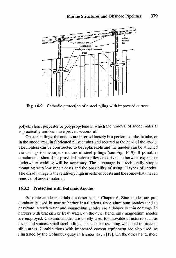
Marine Structures and Offshore Pipelines 379
Fig. 16-9 Cathodic protection of a steel piling with impressed current.
polyethylene, polyester or polypropylene in which the removal of anode materialis practically uniform have proved successful.
On steel pilings, the anodes are inserted loosely in a perforated plastic tube, orin the anode area, in fabricated plastic tubes and secured at the head of the anode.The holders can be constructed to be replaceable and the anodes can be attachedvia casings to the superstructure of steel pilings (see Fig. 16-9). If possible,attachments should be provided before piles are driven, otherwise expensiveunderwater welding will be necessary. The advantage is a technically simplemounting with low repair costs and the possibility of using all types of anodes.The disadvantage is the relatively high investment costs and the somewhat unevenremoval of anode material.
16.3.2 Protection with Galvanic Anodes
Galvanic anode materials are described in Chapter 6. Zinc anodes are pre-dominantly used in marine harbor installations since aluminum anodes tend topassivate in such water and magnesium anodes are a danger to thin coatings. Inharbors with brackish or fresh water, on the other hand, only magnesium anodesare employed. Galvanic anodes are chiefly used for movable structures such aslocks and sluices, small steel pilings, coated steel retaining walls and in inacces-sible areas. Combinations with impressed current equipment are also used, asillustrated by the Columbus quay in Bremerhaven [17]. On the other hand, there

380 Handbook of Cathodic Corrosion Protection
are harbors or quays where the laying of cables and the installation of impressedcurrent protection equipment appears impractical.
16.4 Steel Sheet Piling
With steel sheet pilings, every joint must be electrically bridged with a weld orwith a welded cover plate to avoid an ohmic voltage drop in the return conductionof the protection current since joints, even with apparently excellent clamping,cannot be assumed to have a low-resistance connection. Testing of many sheetsteel piling joints has given values of over 0.1 mQ. Subsequent connection of thepanels is very uneconomical since the tops of the panels are mostly covered withconcrete or with a concrete apron reaching down to the water. The electrical bond-ing of the steel sheet must be carried out well before its final installation [18].Table 16-4 contains the data on cathodic protection systems for marine structures.
Very often steel sheet pilings exist in conjunction with steel-reinforced con-crete structures in harbors or locks. If cathodic protection is not necessary for thereinforced concrete structure, there is no hindrance to the ingress of the protectioncurrent due to the connection with the steel surfaces to be protected. The concretesurface has to be partly considered at the design stage. An example is the base ofthe ferry harbor at Puttgarden, which consists of reinforced concrete and is electri-cally connected to the uncoated steel sheet piling.
16.5 Piling Foundations
Loading bridges and piers are generally built on piles with reinforced concretesuperstructures. They consist of an access bridge with an extended pier for mooringseveral ships. Zinc anodes operate without maintenance and independent of currentsupply as well as operational requirements, as for example, in the ore loading pier inMonrovia, Libya. Between the piles there are 186 slab-shaped zinc anodes, each of100 kg, which are joined by 82 chains. The chains are connected to the steel rein-forcement and via this to the piles and the cross-beams by a copper cable about 1 mmlong and with a 16 mm2 cross-section; this can be used to measure the current outputof the anodes. The potential of the bridge piles is UCu_CuSO = -1.0 V; the averageprotection current density was initially 25 mA m~2; after 2 years it was 11 mA m~2
and after 15 years, 6.5 mA irr2. The relatively low current densities are due to theseinstallations being coated in the underwater areas. The current per anode fluctuatesinitially between 0.9 and 1.2 A and decreases at the rate of 0.2 A per year. Accordingto more recent measurements, the life expectancy of the anodes is 25 years for 85%consumption. Table 16-4 contains further data on loading piers [19].
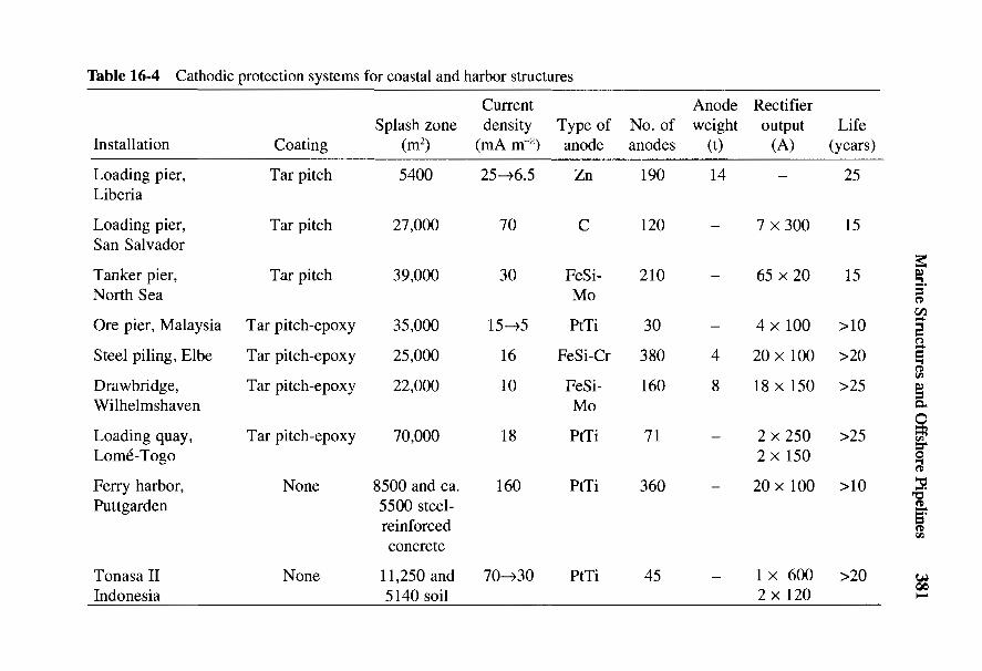
Marine Structures and Offshore Pipelines 381
uH ^ 10 10 10 O O 10 <D O O^ ^ J C i ^2 ^2 ^ <N (N (N -H (NJ ^ ^ A A A A A A
£ ^ o o o § £ o o g o oI &o , 8 S 2 2 12 as 2 §28 3 ~ x * x > < x x x x x& ° <- 8 ^ 8 2 < N N 8 _ ^
•S £g - ^ S ^ I I I Tf oo I I IC 1> —< ^
<+* V)
° - a O O O 0 0 0 ^ O ^_ r g a \ <N ^H ^ O O V O ^ ^D 1J
^ g ^ H T-H (N ^ C O r ^ ^ CO ^
^-t cd
=4-H VH
« "§ q M c« 5 H .J^ t» 5 H H Hg £! N £ S £ g -S £ £ £
*_I
- I - ^ ' S ^ o o t vo o oo g t
1 all j " n » - - - s Jra """'
X3
l iti i 1 in I lisiii3 s& * R R ^ « S R g 8 .§ § «. 2g ^ § ^ 2 " - ^
'-4—
c > > > . > » > - ,» x x x x" _ _ _ o o o o1/3 b O - S -f? ^ C i i C X C L , CX^ c B ^ ^ v v v v s a 2ae "S 'a 'a 'a -g -S -g -g § §O Q ! _ i l _ i S _ i 4 3 - i - J . i - - > - t _ > ^ 7 ^7
'•S r i ^ ^ ^ ' r ^ ' S ' S °oo U H H H ex & a, ex<U fcn VH Vj Ui^ rt c^ ca TO8 H H H Hex
_o*S Cj
_§ 'S «"i ^ - Gu c -3 w > ^^^ *—i t — i r Z * TO »• »* rrt S—i
§ 1 11 I - S ^ |,| 11 |g* 1 f.g .f| S1* 11 li .f| ^i 11I 1 II 11 1| e l If ll gf l|£J ^ J J J c ^ H ^ O c ^ Q ^ H - l K - l t J H a , HnS

382 Handbook of Cathodic Corrosion Protection
Fig. 16-10Cathodic protectionof an ore loadingbridge.
Today loading piers are mostly cathodically protected with impressed current.At moorings for tankers, cathodic protection rectifiers are installed on extinguisherbridges as far as possible from the hazardous area. Otherwise, they must be of anexplosion-proof type.
Figure 16-10 shows a plan of a bridge structure for supplying the Krakatau steelworks in Indonesia [20]. The tubular piles are between 25 and 30 m in length. Indesigning the cathodic protection, a surface area of 4 x 10 4 m2 was calculated. The piles
Fig. 16-11 Variation incathodic polarizationwith time.

Marine Structures and Offshore Pipelines 383
are coated with 300-yimi-thick tar-epoxy resin, giving a protection current density of 10mAnr2. To take account of expected damage, the equipment was designed for 1200 A,which is provided by four rectifiers each with an output of 10 V/300 A. The equipmentis regulated by stepless transformers and the rectifiers are oil cooled. A three-phasegrid supply with full-wave rectification was chosen on account of the high capacityand the residual ripple of 5% required for the anodes. Thirty-two PtTi anodes 2.7 mlong and 10 mm thick were installed (see Fig. 16-7). The anodes were inserted inholes in the concrete support, grouted in with epoxy resin, and lowered onto theseabed. The current loading for individual anodes was between 10 and 15 A for arectifier output voltage of 6 V.
The free corrosion potential of £/Cu-cuso4 = -0.7 V was lowered to -0.9 V witha protection current totalling 600 A. Figure 16-11 shows that after a polarizationperiod of 4 months, an average of-1.0 V was reached. The protection current wasthen reduced to 210 A. This corresponds to an average protection current densityof 5.3 mA m"2. Long-life zinc reference electrodes were installed for potentialcontrol whose measurements over a constant voltage source were converted to theCu-CuSO4 scale. In the summer of 1978, the pier on the other side was lengthenedto 300 m so that two more cathodic protection installations were set up, with a totalcurrent output of 200 A. The average protection current density amounted to only3 mA m"2 as the result of a thicker coating. Installing, equipping and checking thecathodic protection took about 3 months.
16.6 Offshore Pipelines
Every year several thousand kilometers of pipeline are laid in the sea in theoffshore regions of the world. The total at present is about 35,000 km. Whereas theearly offshore pipelines were limited to shallow water and short pipelines of smalldiameter, today pipelines of several hundred kilometers and up to DN 1000 arelaid. With short pipelines, impressed current cathodic protection is also possible,but is seldom used [21], e.g., for the 10-km-long pipeline of the German platformsSchwedeneck in the Baltic and Emshorn Z1A in the North Sea. According toEq. (24-75), the possible protection range for a pipeline DN 300 with s = 16 mmand good insulating coating can amount to 100 km. For offshore applications, thecoating resistances ru will not be as good for onshore pipelines (see Section 5.2.1.2).For this reason, the protection current densities 7S are sharply increased[see Eq. (5-11')] and the length of the protected region is relatively short[see Eq. (24-75)]. It is inefficient to increase the protected length by raising theanode voltage. Therefore, the valid area of Eq. (24-75) has to be abandoned.According to the information in Section 24.4.4, only hydrogen evolution in thevicinity of the anodes has to be taken into account with cathodic overprotection so
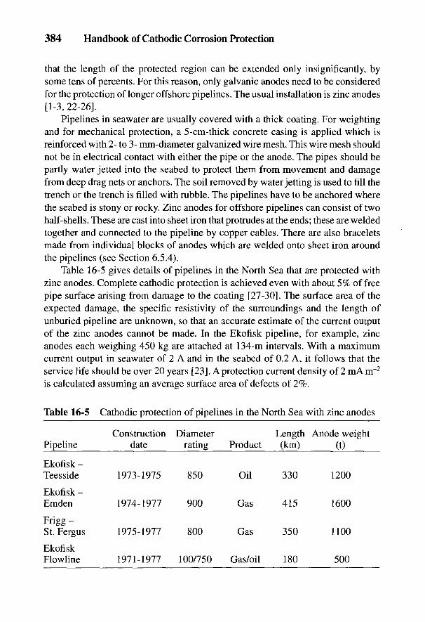
384 Handbook of Cathodic Corrosion Protection
that the length of the protected region can be extended only insignificantly, bysome tens of percents. For this reason, only galvanic anodes need to be consideredfor the protection of longer offshore pipelines. The usual installation is zinc anodes[1-3, 22-26].
Pipelines in seawater are usually covered with a thick coating. For weightingand for mechanical protection, a 5-cm-thick concrete casing is applied which isreinforced with 2- to 3- mm-diameter galvanized wire mesh. This wire mesh shouldnot be in electrical contact with either the pipe or the anode. The pipes should bepartly water jetted into the seabed to protect them from movement and damagefrom deep drag nets or anchors. The soil removed by water jetting is used to fill thetrench or the trench is filled with rubble. The pipelines have to be anchored wherethe seabed is stony or rocky. Zinc anodes for offshore pipelines can consist of twohalf-shells. These are cast into sheet iron that protrudes at the ends; these are weldedtogether and connected to the pipeline by copper cables. There are also braceletsmade from individual blocks of anodes which are welded onto sheet iron aroundthe pipelines (see Section 6.5.4).
Table 16-5 gives details of pipelines in the North Sea that are protected withzinc anodes. Complete cathodic protection is achieved even with about 5% of freepipe surface arising from damage to the coating [27-30]. The surface area of theexpected damage, the specific resistivity of the surroundings and the length ofunburied pipeline are unknown, so that an accurate estimate of the current outputof the zinc anodes cannot be made. In the Ekofisk pipeline, for example, zincanodes each weighing 450 kg are attached at 134-m intervals. With a maximumcurrent output in seawater of 2 A and in the seabed of 0.2 A, it follows that theservice life should be over 20 years [23]. A protection current density of 2 mA m~2
is calculated assuming an average surface area of defects of 2%.
Table 16-5 Cathodic protection of pipelines in the North Sea with zinc anodes
Construction Diameter Length Anode weightPipeline date rating Product (km) (t)
Ekofisk -Teesside 1973-1975 850 Oil 330 1200
Ekofisk -Emden 1974-1977 900 Gas 415 1600
Frigg -St. Fergus 1975-1977 800 Gas 350 1100
EkofiskFlowline 1971-1977 100/750 Gas/oil 180 500
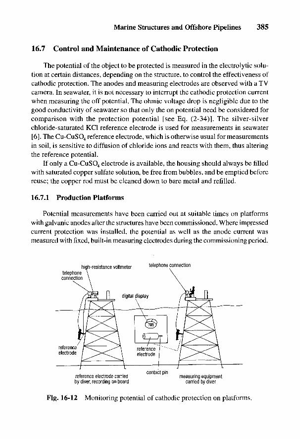
Marine Structures and Offshore Pipelines 385
16.7 Control and Maintenance of Cathodic Protection
The potential of the object to be protected is measured in the electrolytic solu-tion at certain distances, depending on the structure, to control the effectiveness ofcathodic protection. The anodes and measuring electrodes are observed with a TVcamera. In seawater, it is not necessary to interrupt the cathodic protection currentwhen measuring the off potential. The ohmic voltage drop is negligible due to thegood conductivity of seawater so that only the on potential need be considered forcomparison with the protection potential [see Eq. (2-34)]. The silver-silverchloride-saturated KC1 reference electrode is used for measurements in seawater[6]. The Cu-CuSO4 reference electrode, which is otherwise usual for measurementsin soil, is sensitive to diffusion of chloride ions and reacts with them, thus alteringthe reference potential.
If only a Cu-CuSO4 electrode is available, the housing should always be filledwith saturated copper sulfate solution, be free from bubbles, and be emptied beforereuse; the copper rod must be cleaned down to bare metal and refilled.
16.7.1 Production Platforms
Potential measurements have been carried out at suitable times on platformswith galvanic anodes after the structures have been commissioned. Where impressedcurrent protection was installed, the potential as well as the anode current wasmeasured with fixed, built-in measuring electrodes during the commissioning period.
Fig. 16-12 Monitoring potential of cathodic protection on platforms.
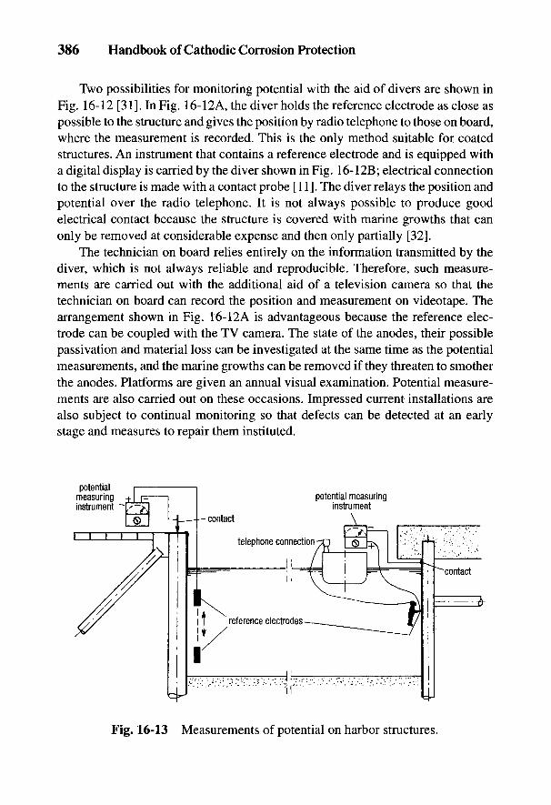
386 Handbook of Cathodic Corrosion Protection
Two possibilities for monitoring potential with the aid of divers are shown inFig. 16-12 [31]. In Fig. 16-12A, the diver holds the reference electrode as close aspossible to the structure and gives the position by radio telephone to those on board,where the measurement is recorded. This is the only method suitable for coatedstructures. An instrument that contains a reference electrode and is equipped witha digital display is carried by the diver shown in Fig. 16-12B; electrical connectionto the structure is made with a contact probe [11]. The diver relays the position andpotential over the radio telephone. It is not always possible to produce goodelectrical contact because the structure is covered with marine growths that canonly be removed at considerable expense and then only partially [32].
The technician on board relies entirely on the information transmitted by thediver, which is not always reliable and reproducible. Therefore, such measure-ments are carried out with the additional aid of a television camera so that thetechnician on board can record the position and measurement on videotape. Thearrangement shown in Fig. 16-12A is advantageous because the reference elec-trode can be coupled with the TV camera. The state of the anodes, their possiblepassivation and material loss can be investigated at the same time as the potentialmeasurements, and the marine growths can be removed if they threaten to smotherthe anodes. Platforms are given an annual visual examination. Potential measure-ments are also carried out on these occasions. Impressed current installations arealso subject to continual monitoring so that defects can be detected at an earlystage and measures to repair them instituted.
Fig. 16-13 Measurements of potential on harbor structures.

Marine Structures and Offshore Pipelines 387
16.7.2 Harbor Structures
Harbor structures are very accessible and can be investigated without theeffects of wave motion. Grounding of steel pilings presents no problems and thework can be carried out from the quay (see the left-hand side of Fig. 16-13). Withsteel-reinforced concrete structures, measurements have to be made from a boat ifno reliable contact has been provided in their construction (see the right-hand sideof Fig. 16-13).
In protection with impressed current installations, it depends on theconductivity of the harbor water whether off potentials can be measured and alsowhether the IR component can be taken into account. Only very few inland harborsrequire such expenditure; usually the conductivity is sufficiently high.
Fig. 16-14 Monitoringcathodic protection ofoffshore pipelines.
388 Handbook of Cathodic Corrosion Protection
16.7.3 Offshore Pipelines
It is very expensive to check cathodic protection on long pipelines since pro-tection is afforded by galvanic anodes. The few short pipelines with impressedcurrent protection are not considered here since built-in measuring electrodes areprovided and therefore no problems are expected in monitoring.
For offshore pipelines, there are four possibilities for monitoring the efficiencyof the cathodic protection [11,31,33-36]. These methods are represented schemati-cally in Fig. 16-14.
(a) Cable connection ship-pipelineThe ship is connected by cable to the platform and the reference electrodeis steered by a remote-operated vehicle (ROV) or—in shallow waters—directly from the ship over the pipeline. In the case of long pipelines ofmore than 20 km, there can be considerable difficulty in running the cables.
(b) Potential difference measurements between reference electrodesIn this process, a reference electrode is attached to the supply cable of theROV. There are two further electrodes on the ROV. As it travels along thepipeline, the potential differences between the electrodes provide infor-mation on the effectiveness of the galvanic anodes, on the location andcurrent uptake at defect areas and on the potentials. Section 3.6.2 providesinformation on the evaluation of the potential differences. From the knownpotential at the initial point on the platform, the potentials given for themethod described in Section 3.7.2 can be determined if ohmic voltage dropsin the pipeline do not have to be considered.
All measurement data are recorded on tape—with a plausibility check dur-ing the measurements—and later evaluated with the computer. This methodhas been tested in practice and is sufficiently accurate.
(c) Magnetic inductive methodA probe is passed over the pipeline, which enables the flowing protectioncurrent to be determined by magnetic inductive methods, the efficiency ofthe actual anodes to be measured and areas of defects to be detected. Anincreased current flow is recorded at the defect areas as well as at the an-odes installed at definite distances. This method is now frequently used,particularly in combination with method (b).
(d) Electrodes with data teletransmissionPotential probes have been developed that are anchored near the pipelinewith buoyancy floats and electrically connected to the pipeline. These probesare switched on by coded signals from the ship; they read the potential and
Marine Structures and Offshore Pipelines 389
send the information back to the ship acoustically. The batteries of theprobes have to be renewed at definite intervals. A very large number ofprobes is required, and these can be at risk of mechanical damage bydrag nets.
Methods (a) to (c) are principally only applicable to pipelines that are not buried;otherwise, the probes cannot be accurately located over the pipeline. With buriedpipelines, in addition to the methods described, it is necessary to register theirposition according to depth and distance from the ROV.
390 Handbook of Cathodic Corrosion Protection
16.8 References
[1] NACE, Standard RP-01-76 (Rev. 83), Houston Texas 1976.[2] Germanischer Lloyd, Vorschriften fur meerestechnische Einrichtungen, Hamburg 1985.[3] Det Norske Veritas, Technical Note TNA 701-703, 1981.[4] Schiffbautechnische Gesellschaft, Richtlinien Nr. 2215 u. Nr. 2220, Hamburg 1987.[5] B. Richter, Schiff u. Hafen 33, H. 8, 78 (1981).[6] VG 81259 Teile 1-3, Kathodischer Korrosionsschutz von Schiffen, Beuth Verlag, Koln
1986.[7] F. J. Kievits und H. Hebos, Werkstoffe u. Korrosion 23, 1975 (1972).[8] Fischer, Hue, Battes, und Steensland, OTC Houston 1980, Paper No. 3889.[9] B. Richter, Schiff u. Hafen 32, H. 10, 102 u. H 11, 81 (1980).
[10] DIN 50929 Teil 3, Beuth Verlag, Berlin 1985.[11] V. Ashworth u. C. J. L. Booker, Cathodic Protection, Ellis Horwood LTD, Chichester
1986, S. 36.[12] R. Vennelt, R. Saeger u. M. Warne, Materials Performance 22, H. 2, 22 (1983).[13] B. Richter, Schiff u. Hafen, Sonderheft Meerwasserkorrosion, Februar 1983, S. 88.[14] Hauptverband der gewerblichen Berufsgenossenschaften, Taucherarbeiten, VBG 39,
Koln 1984.[15] Recommendations for the design and construction of concrete sea structures. Federation
Internationale de la Precontrainte, Paris.[16] Hafenbautechnische Gesellschaft, Kathodischer Korrosionsschutz im Wasserbau, Ham-
burg 1981.[17] H.-P. Karger, Korrosion und Korrosionsschutz im Stahlwasserbau, T.A. Wuppertal
1978.[18] H. Determann u. E. Hargarter, Schiff u. Hafen 20, 533 (1968).[19] G. Hoppmann, 3 R-intern. 16, 306 (1977).[20] K. Klein, 3 R-intern. 16, 421 (1977).[21] K. Klein, 3 R-intern. 15, 716 (1976).[22] NACE Standard, RP-06-75, Houston, Texas, 1975.[23] W. v. Baeckmann, Erdol/Erdgas 93, 34 (1977).[24] B. S. Wyatt, Anti-Corrosion H. 6, 4 u. H. 7, 8 u. H. 8, 7 (1985).[25] H. Hinrichsen u. H. G. Payer, Hansa 119, 661 (1982).[26] C. Schmidt, Erdol - Erdgas 100, 404 (1984).[27] M. Reuter u. J. KnieB, 3 R-intern. 15, 674 (1976).[28] T. Michinshita u.a., 2nd Int. Conf. Int. Ext. Prot. Pipes, Paper C2, Canterbury 1977.[29] F.Q. Jensen, A. Rigg u. O. Saetre, NACE Int. Corr. Forum Pap. 217, Houston (Texas)
1978.[30] A. Cozens, Offshore Technology Conf., Houston 1977.[31] B. Richter, Schiff u. Hafen 34, H. 3, 24 (1982).[32] B. Richter, Meerestechnik 14, 105 (1982).[33] T. Sydberger, Material Performance 22, H. 5, 56 (1983).[34] C. Weldon, A. Schultz u. M. Ling, Material Performance 22, H. 8, 43 (1983).[35] G. H. Backhouse, NACE Corrosion, Paper 108, Toronto 1981.[36] R. Str0mmen u. A. R0dland, NACE Corrosion, Paper 111, Toronto 1981.
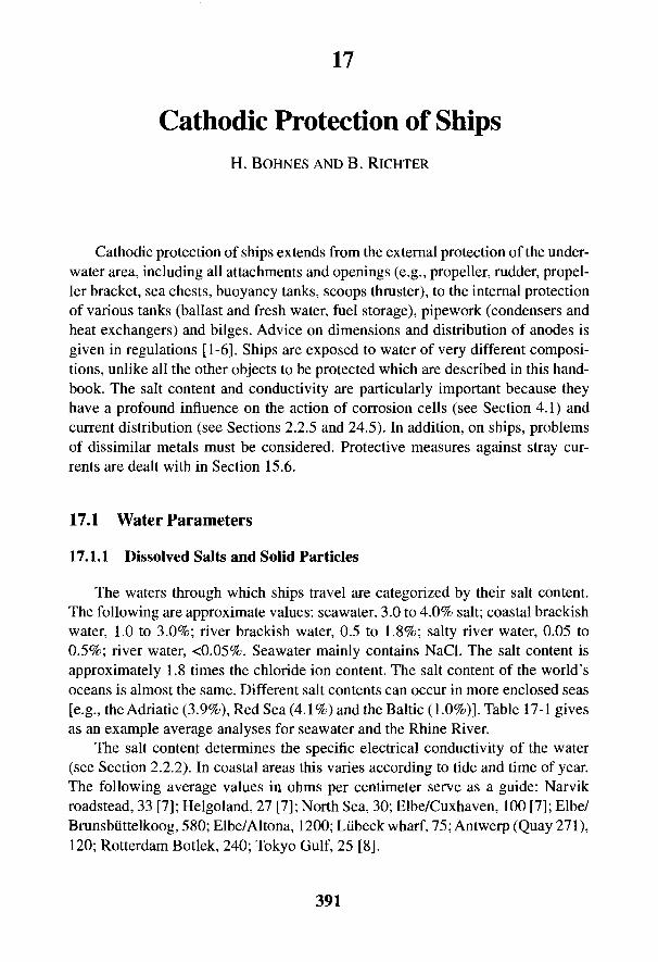
17
Cathodic Protection of ShipsH. BOHNES AND B. RlCHTER
Cathodic protection of ships extends from the external protection of the under-water area, including all attachments and openings (e.g., propeller, rudder, propel-ler bracket, sea chests, buoyancy tanks, scoops thruster), to the internal protectionof various tanks (ballast and fresh water, fuel storage), pipework (condensers andheat exchangers) and bilges. Advice on dimensions and distribution of anodes isgiven in regulations [1-6]. Ships are exposed to water of very different composi-tions, unlike all the other objects to be protected which are described in this hand-book. The salt content and conductivity are particularly important because theyhave a profound influence on the action of corrosion cells (see Section 4.1) andcurrent distribution (see Sections 2.2.5 and 24.5). In addition, on ships, problemsof dissimilar metals must be considered. Protective measures against stray cur-rents are dealt with in Section 15.6.
17.1 Water Parameters
17.1.1 Dissolved Salts and Solid Particles
The waters through which ships travel are categorized by their salt content.The following are approximate values: seawater, 3.0 to 4.0% salt; coastal brackishwater, 1.0 to 3.0%; river brackish water, 0.5 to 1.8%; salty river water, 0.05 to0.5%; river water, <0.05%. Seawater mainly contains NaCl. The salt content isapproximately 1.8 times the chloride ion content. The salt content of the world'soceans is almost the same. Different salt contents can occur in more enclosed seas[e.g., the Adriatic (3.9%), Red Sea (4.1%) and the Baltic (1.0%)]. Table 17-1 givesas an example average analyses for seawater and the Rhine River.
The salt content determines the specific electrical conductivity of the water(see Section 2.2.2). In coastal areas this varies according to tide and time of year.The following average values in ohms per centimeter serve as a guide: Narvikroadstead, 33 [7]; Helgoland, 27 [7]; North Sea, 30; Elbe/Cuxhaven, 100 [7]; Elbe/Brunsbuttelkoog, 580; Elbe/Altona, 1200; Lubeck wharf, 75; Antwerp (Quay 271),120; Rotterdam Botlek, 240; Tokyo Gulf, 25 [8].
391
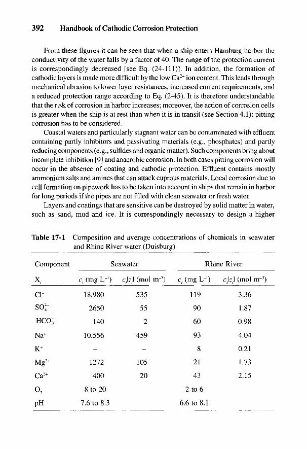
392 Handbook of Cathodic Corrosion Protection
From these figures it can be seen that when a ship enters Hamburg harbor theconductivity of the water falls by a factor of 40. The range of the protection currentis correspondingly decreased [see Eq. (24-111)]. In addition, the formation ofcathodic layers is made more difficult by the low Ca2+ ion content. This leads throughmechanical abrasion to lower layer resistances, increased current requirements, anda reduced protection range according to Eq. (2-45). It is therefore understandablethat the risk of corrosion in harbor increases; moreover, the action of corrosion cellsis greater when the ship is at rest than when it is in transit (see Section 4.1); pittingcorrosion has to be considered.
Coastal waters and particularly stagnant water can be contaminated with effluentcontaining partly inhibitors and passivating materials (e.g., phosphates) and partlyreducing components (e.g., sulfides and organic matter). Such components bring aboutincomplete inhibition [9] and anaerobic corrosion. In both cases pitting corrosion willoccur in the absence of coating and cathodic protection. Effluent contains mostlyammonium salts and amines that can attack cuprous materials. Local corrosion due tocell formation on pipework has to be taken into account in ships that remain in harborfor long periods if the pipes are not filled with clean seawater or fresh water.
Layers and coatings that are sensitive can be destroyed by solid matter in water,such as sand, mud and ice. It is correspondingly necessary to design a higher
Table 17-1 Composition and average concentrations of chemicals in seawaterand Rhine River water (Duisburg)
Component Seawater Rhine River
X. c (mg L"1) c\z\ (mol m~3) c. (mg L~') c\z\ (mol m~3)i ; v p '_ ; i v '_ ; v ° '_ i ; v '
Cl- 18,980 535 119 3.36
SO2; 2650 55 90 1.87
HCQ- 140 2 60 0.98
Na+ 10,556 459 93 4.04
K+ - - 8 0.21
Mg2+ 1272 105 21 1.73
Ca2+ 400 20 43 2.15
O2 8 to 20 2 to 6
pH 7.6 to 8.3 6.6 to 8.1

Cathodic Protection of Ships 393
protection current output for ships that are subject to such conditions. On the otherhand, marine growths have both positive and negative importance for corrosionand cathodic protection. On one hand they raise the diffusion resistance foroxygen access and on the other they can destroy coatings that do not meet theregulations [10,11].
17.1.2 Aeration and Oxygen Content
The solubility of oxygen in water with a salt content up to 1 mol L"1 is onlydependent on the temperature. The oxygen concentrations in equilibrium with airamount to (in mg L'1): 0°C, 14; 10°C, 11; 20°C, 9; and 30°C, 7. The depth of waterhas no effect in the case of ships. In Hamburg harbor in summer, 7.3 mg L"1 aremeasured in depths up to 7 m. The value can be much lower in polluted harbors andeven fall to zero [8]. In the open sea, constant values are found at depths of up to20 m. With increasing depth, the O2 content in oceans with low flow rates decreas-es [12] but hardly changes at all with depth in the North Sea [13].
Oxygen is essential as a component in the cathodic partial reaction. In the caseof differential aeration, heterogeneous film formation occurs together with localcorrosion (see Section 4.1). Just as with steel pilings, local corrosion is observedon ships in the splash zone [9] due to differential aeration, particularly at weldedjoints [14]. On uncoated steel, the corrosion usually leads to shallow pitting. Theoxygen supply depends on flow rate according to Eq. (4-6). The quantity Kw
depends on the flow rate. In the course of some years Kw can increase due to filmformation. According to Eq. (2-40), equivalence can be assumed between the mini-mum protection current density 7S and the corrosion rate. The observed corrosionrate of 0.1 to 1.0 mm a"1 corresponds to protection current densities of 0.1 to 1A m"2.The protection current density decreases markedly with time due to cathodic filmformation (see Fig. 17-1), so that an almost constant protection current density of50 mA m~2 can be assumed in still seawater. In ballast water tanks, corrosion rates
Fig. 17-1 Protection current vs. timefor uncoated steel in a calm sea.

394 Handbook of Cathodic Corrosion Protection
of 3 mm a"1 are observed on horizontal surfaces, particularly on the base; theserequire corresponding provision of a cathodic protection current density of 3 Anr2.
Oxygen solubility decreases almost linearly with increasing temperature butthe diffusion rate increases exponentially. This leads to a slight increase in corro-sion rate with increasing temperature although in Eq. (4-6) the factor is assumed tobe greater. For this reason an increase in corrosion rate of about 1.5 times is con-sidered in tropical waters compared with the North Atlantic.
17.1.3 Flow Rate in the Case of a Moving Ship
Flow rate not only raises the rate of oxygen transport by lowering the Kw value inEq. (2-6), but also adversely affects surface film formation. Figure 17-2 shows therelation between protection current density and steaming velocity. Factor Fj relatesto undisturbed film formation. The influence of flow is not very great in this case.Factor F2 represents the real case where surface films are damaged by abrasion [15].The protection current density can rise to about 0.4 A nr2 at uncoated areas.
17.1.4 Variations in Temperature and Concentration
Differences in temperature and concentration can in principle lead to corro-sion cell formation, but have little effect below the water line. On the other hand,they have to be taken into account in the interior corrosion of containers and tanksin relation to their service operation (see Section 2.2.4.2). Generally the action ofcorrosion cells can be reduced or eliminated by cathodic protection.
In strong sunlight, water can evaporate at defects in coatings and surface films,and lead to concentration and crystallization of salts (e.g., in the upper decks of theship). This can damage surface films, giving rise to local anodes. This is the casewhen a ship slowly rises in the water on unloading and is later reimmersed onloading.
Fig. 17-2 Protection currentdensities of uncoated steel as afunction of flow rate in flowingseawater, Ft with undisturbedfilm formation; F2 with disturbedfilm formation due to erosion.
Cathodic Protection of Ships 395
17.2 Effect of Materials and Coating Parameters
Almost all common metals and structural steels are liable to corrode in sea-water. Regulations have to be followed in the proper choice of materials [16]. Inaddition, there is a greater risk of corrosion in mixed constructions consisting ofdifferent metals on account of the good conductivity of seawater. The electrochemi-cal series in seawater (see Table 2-4), the surface area rule [Eq. (2-44)] and thegeometrical arrangement of the structural components serve to assess the possibil-ity of bimetallic corrosion (see Section 2.2.4.2 and Ref. 17). Moreover the polar-ization resistances have considerable influence [see Eq. (2-43)]. The standards onbimetallic corrosion provide a survey [16,17].
Different microstructural regions in a material which has an almost uniformcomposition can also lead to the formation of corrosion cells (e.g., in the vicinityof welds). Basically, corrosion cells can be successfully overcome by cathodicprotection. However, in practice, care has to be taken to avoid electrical shieldingby large current-consuming cathode surfaces by keeping the area as small as pos-sible. In general, with mixed installations of different metals, it must be remem-bered that the protection potentials and the protection range depend on the materials(Section 2.4). This can restrict the use of cathodic protection or make special po-tential control necessary.
The protection of aluminum ships demands particular attention since electricalcontact with steel and copper materials can seldom be avoided and a whole rangeof aluminum alloys are unsuitable for cathodic protection (see Section 2.4 andFig. 2-11). Later protective measures must therefore be observed during the con-struction stage since even good coatings in combination with cathodic protectionare frequently not adequate to protect gaps or openings.
Coatings assume the function of passive protection on ships and are indispens-able as carriers for antifouling substances. By combining them with cathodic pro-tection, the aim is to substantially reduce the protection current requirement andincrease the protection range by raising the polarization parameter (see Section 5.1).Besides chemical and mechanical durability, electrical coating resistivity as wellas porosity and degree of damage determine the quality of the coating. With goodresin coatings, the coating resistivity on pore-free specimens can be over 105 Q m2.After soaking in water, the resistivity can fall by several tens of percents and evenfall as low as 30 Q. m2 [18,19]. This corresponds from Eq. (5-11) to a protectioncurrent density of Js = 10 mA m"2 The factors that affect the coating resistivity arethickness, type of coating and quality of the substrate preparation. For a practicalprotection current requirement, the current uptake at uncoated surfaces and defectsalso has to be considered (see Section 5.2.1.2).
In contrast to thick coatings, thin coatings combined with cathodic protectionpresent certain risks on ships. Blisters filled with highly alkaline liquids resulting
396 Handbook of Cathodic Corrosion Protection
from electro-osmotic processes, ion migration, and (depending on the alkali ionconcentration) potential, temperature and the properties of the coating system haveto be considered (see Section 5.2.1.4). To avoid blistering, the cathodic protectionshould be limited to negative potentials (e.g., U^& = -0.65 V). Even closed blistersare undesirable on ships because they increase the resistance to motion. One of theobjects of cathodic protection is to reduce the resistance to motion by preventingthe formation of rust pustules. In general, this resistance is due 70% to friction and30% to shape and wave resistance. The latter is constant for a given ship but thefrictional resistance can be raised up to 20% by corrosion. It is considerablyreduced by having hull surfaces as smooth as possible, which are not damaged bylocal corrosion products. A further factor increasing resistance to motion is marinegrowths, which can be countered by antifouling coatings. The loss in efficiencycaused by roughness can correspond to an increase of 12% in fuel consumption.The loss due to marine growths can be three times greater.
Coatings for application to the hull below the waterline and for tanks must besuitable for combining with cathodic protection. The type of protection—impressedcurrent or galvanic anodes—is not important since the potential alone is the gov-erning factor. The requirements in DIN 50928 [20] (see Section 5.2.1) must beobserved in the case of continual action of an electrolyte and electrochemicalpolarization. In this respect, the Ship Building Technical Society (Schiff-bautechnische Gesellschaff, STG) has developed a standard [11] in which thetesting and evaluation of coatings for application under water are laid down.£/H = -0.73 V is prescribed as the test potential in an experiment lasting at least9 months in operating conditions or a similar period in which marine growths takeplace in natural experiments. Blister formation, efflorescence, and adhesion areassessed on damaged as well as undamaged surfaces. The regulation is based oncomprehensive investigations and has been internationally endorsed [19,21].
The economic use of ships requires lengthening the intervals between drydockings and the associated maintenance costs. For this reason, newly developedhigh-grade coating materials are used that require greater expense in their applica-tion. The STG has enacted a standard [10] governing coating materials for use onships and offshore structures. The standards include their application and mainte-nance, which is related to DIN 55928 Part 5 [22]. These high-grade coating mate-rials today demand better surface preparation; the standard value for the degree ofpurity for the outer surface is Sa 2!/2 [10], while for special coatings in tanks SA3is demanded. The use of other preparation methods (e.g., flame cleaning) hasdecreased and vapor cleaning does not give the desired surface quality.
Welds represent particularly weak points. The sheet itself is mechanically shotblasted in the factory or in the shipyard and given a shop primer. The installation

Cathodic Protection of Ships 397
welds can usually only be derusted mechanically and coatings combined withcathodic protection are particularly prone to blistering and loss of adhesion.
In addition to careful surface preparation, these high-grade coatings requirespecific climatic conditions, such as humidity and temperature, as well as specificrepainting intervals and control of the film thickness. In open docks even in climati-cally favorable zones, such as central Europe, these conditions can be observed onlyat considerable expense. Damage arising from unfavorable application conditionsis often attributed to the cathodic protection although it is not responsible if thecorrect coating material has been chosen.
Blistering is influenced by the total film thickness as well as by the applicationconditions and the coating material. A minimum dry film thickness of over 250 /^mis required, and this does not take account of the antifouling component [10].
17.3 Cathodic Protection Below the Waterline
Cathodic protection of an uncoated ship is practically not possible or is uneco-nomic due to the protection current requirement and current distribution. In addi-tion, there must be an electrically insulating layer between the steel wall and theantifouling coating in order to stifle the electrochemical reduction of toxic metalcompounds. Products of cathodic electrolysis cannot prevent marine growths. Onthe contrary, in free corrosion, growths on inert copper can occur if cathodic pro-tection is applied [23].
A distinction is made between complete and partial protection of the under-water area, depending on the extent of the protected region. In partial protection,only the stern is protected; it is particularly endangered because of the high flowrate and aeration as well as the formation of cells on attachments, such as thepropeller and rudder. Partial protection can also be extended to the bow, which alsoexperiences high rates of flow. The complete protection of the ship with galvanicanodes or impressed current is becoming increasingly important since defects inthe coating due to mechanical damage are more frequent at the bow and amid-ships. Installation of galvanic anodes on the bilge keel presents no problems. Theextent to which attachments such as propellers and rudders can be covered by theprotection or be given individual cathodic protection depends on the design of theship and the method of protection.
In all cases partial or total hulls of aluminum or stainless steel must be pro-vided with cathodic protection. This also applies to high-alloy steels with over20% chromium and 3% molybdenum since they are prone to crevice corrosionunderneath the coatings. The design of cathodic protection must involve the parti-cular conditions and is not gone into further here.

398 Handbook of Cathodic Corrosion Protection
17.3.1 Calculations of the Protection Current Requirement
If the surface area cannot be obtained from structural drawings, the under-water surface area can be calculated from the following relation [1]:
where LCWL is the length of the construction waterline, #CWL is the breadth of thewaterline at moulding edge (machined at 0.5 LCWL), 7"CWL is the depth of construc-tion on 0.5 LCWL (calculated as basis), and 8is the block coefficient.
In addition, the surface area of all attachments and openings must be sepa-rately determined from construction drawings. The sum gives the total area, S.Attachments include rudders and propellers as well as propeller brackets and shaftbosses as in multiscrew ships. Further, special driving gear (Kort nozzles and Voith-Schneider perpendicular propellers) must be paid particular attention. Openingsinclude sea chests, which sometimes have an uncoated bronze grid, as well asscoop openings and bow thrusters [1]. The attachments and openings require con-siderably larger current densities so that the current requirement cannot be deter-mined merely from the sum of the surface areas. From the protection current density,7si, of the individual surfaces, S{, the total protection current requirement, 7S, iscalculated as:
The protection current density for steel ships. Jsi, depends on the quality ofcoating, the flow behavior and the type of components to be protected (see Sec-tions 17.1 and 17.2). For example, a propeller that is assembled with a slip ringrequires protection current densities of up to 0.5 A nrr2. Experience has to be reliedon for the service behavior of coated surfaces (e.g., possible damage from ice orsand abrasion). Protection current densities are usually a few mA nr2 for typicalships' coatings. They increase somewhat with time. After a year, average values ofbetween 15 and 20 mA irr2 can be assumed. It is usual in designing with galvanicanodes for 15 mA nr2 to include a mass reserve of 20%. For steel merchant ships,impressed current equipment giving 30 mA nr2 is designed so that it can eventu-ally deliver more current to cope with damage to the coating. This value has to beincreased for ice breakers and ice-going ships according to the area and time oftravel (e.g., in the Antarctic at least 60 mA m~2 is required). The additional expen-diture is negligible with this system compared with galvanic anodes.
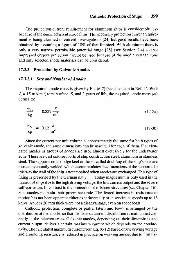
Cathodic Protection of Ships 399
The protection current requirement for aluminum ships is considerably lessbecause of the dense adherent oxide films. The necessary protection current require-ment is being clarified in current investigations [24] but good results have beenobtained by assuming a figure of 10% of that for steel. With aluminum there isonly a very narrow permissible potential range [25] (see Section 2.4) so thatimpressed current protection cannot be used because of the anodic voltage coneand only selected anode materials can be considered.
17.3.2 Protection by Galvanic Anodes
/ 7.3.2.1 Size and Number of Anodes
The required anode mass is given by Eq. (6-7) (see also data in Ref. 1). With7S = 15 mA m~2, total surface, 5", and 2 years of life, the required anode mass (tri)comes to:
Since the current per unit volume is approximately the same for both types ofgalvanic anode, the same dimensions can be assumed for each of them. Flat elon-gated anodes or groups of anodes are used almost exclusively for the underwaterzone. These are cast onto supports of ship construction steel, aluminum or stainlesssteel. The supports on the bilge keel or the so-called doubling of the ship's side aremost conveniently welded, which accommodates the dimensions of the supports. Inthis way the wall of the ship is not impaired when anodes are exchanged. This type offixing is prescribed by the German navy [1]. Today magnesium is only used in theinterior of ships due to the high driving voltage, the low current output and the severeself-corrosion. In contrast to the protection of offshore structures (see Chapter 16),zinc anodes maintain their preeminent role. The feared increase in resistance tomotion has not been apparent either experimentally or in service at speeds up to 18knots. Anodes 20 mm thick were not a disadvantage, even on speedboats.
Cathodic protection, complete or partial (stern and bow), is arranged by thedistribution of the anodes so that the desired current distribution is maintained cor-rectly in the relevant areas. Galvanic anodes, depending on their dimensions andcurrent output, deliver a certain maximum current which depends on the conduc-tivity. The calculated maximum current from Eq. (6-12) based on the driving voltageand grounding resistance is reduced in practice on working anodes due to film for-

400 Handbook of Cathodic Corrosion Protection
mation and polarization resistances which depend on the anode material, the electro-lyte and the time (i.e., the operating conditions). It is understandable therefore thatthe maximum currents given by manufacturers for a particular anode material can beupset in practice by such changes. In the design it is important to consider not onlythe total current but also to see that the necessary current densities and protectionranges are achieved. Initially the coatings have a high resistance and a low degree ofdamage. The range according to Eq. (24-111) is then large and the protection currentrequirement is low. In service, the coating resistance decreases so that the currentrequirement not only increases but the protected range decreases. In particular, atten-tion has to be paid to the fact that a reduction in conductivity (e.g., in harbor) alsorestricts the range as in Eq. (2-45). If the protection potential range is temporarily notreached at the total surface to be protected, there is nevertheless not a great danger ofcorrosion since the cathodic protection usually encourages the action of corrosioncells. Figure 2-9 shows the relation between corrosion rates and potential.
The required number,«, of anodes can be calculated using Eq. (17-2) from thecurrent requirement, together with the maximum current output 7max of the anodes.The arrangement of the anodes is dealt with in Section 17.3.2.2. Galvanic protec-tion systems are usually designed to give protection for 2-4 years. After this per-iod, a maximum of up to 80% of the anodes should be consumed.
Here, ni is the number of anodes for the ith surface area region.The equipping of a steel ship with a below-waterline area of 4500 m2 is given
as an example. With 7S = 15 mA m"2, the current requirement is 67.5 A; accordingto Eq. (17-3a), this would require 1517 kg of zinc for a life of 2 years. This wouldrequire 96 anodes each of 15.7 kg of zinc (16.8 kg gross). Such anodes have acurrent output of 0.92 A.
The total current therefore amounts to 88 A. This covers the required protec-tion current density. On the other hand, by choosing a larger anode size of 25.9 kgof zinc and with a current output of 1.2 A, 58 anodes would provide the necessaryprotection current. For a service life of 4 years, the amount of zinc is doubled to3033 kg. Here the possibility for groups of anodes could be, for example, 82 two-anode groups, each anode weighing 18 kg. With a current output per group of1.3 A, this gives a total current output of 107 A. This level of current supply couldalso be given, if practical considerations demanded it, by 54 three-anode groups.
Equipping a ship with aluminum anodes to last 2 years would require, accord-ing to Eq. (17-3b), 540 kg. Ninety-six anodes of the same size as those of zinc,each weighing 6.2 kg of aluminum (7.3 kg gross) give a total of 595 kg and
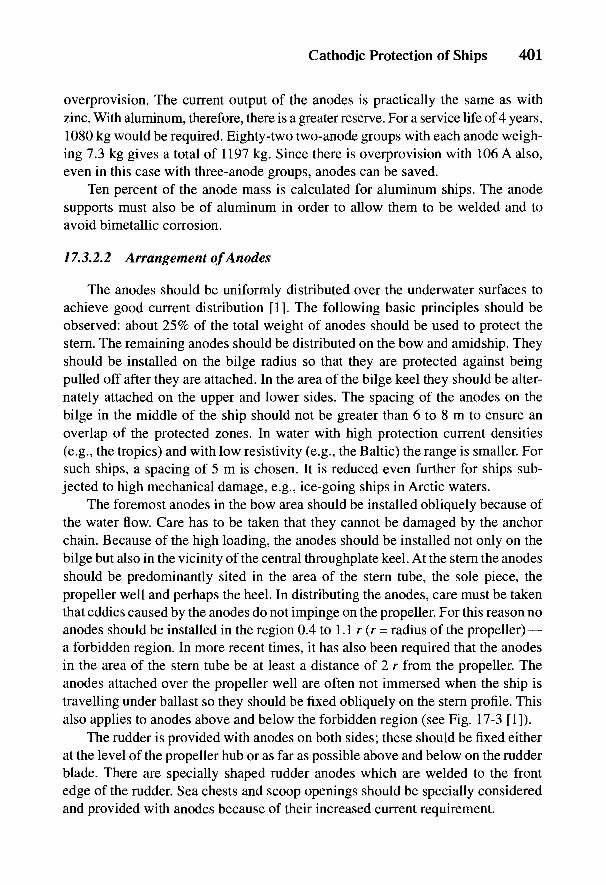
Cathodic Protection of Ships 401
overprovision. The current output of the anodes is practically the same as withzinc. With aluminum, therefore, there is a greater reserve. For a service life of 4 years,1080 kg would be required. Eighty-two two-anode groups with each anode weigh-ing 7.3 kg gives a total of 1197 kg. Since there is overprovision with 106 A also,even in this case with three-anode groups, anodes can be saved.
Ten percent of the anode mass is calculated for aluminum ships. The anodesupports must also be of aluminum in order to allow them to be welded and toavoid bimetallic corrosion.
17.3.2.2 Arrangement of Anodes
The anodes should be uniformly distributed over the underwater surfaces toachieve good current distribution [1]. The following basic principles should beobserved: about 25% of the total weight of anodes should be used to protect thestern. The remaining anodes should be distributed on the bow and amidship. Theyshould be installed on the bilge radius so that they are protected against beingpulled off after they are attached. In the area of the bilge keel they should be alter-nately attached on the upper and lower sides. The spacing of the anodes on thebilge in the middle of the ship should not be greater than 6 to 8 m to ensure anoverlap of the protected zones. In water with high protection current densities(e.g., the tropics) and with low resistivity (e.g., the Baltic) the range is smaller. Forsuch ships, a spacing of 5 m is chosen. It is reduced even further for ships sub-jected to high mechanical damage, e.g., ice-going ships in Arctic waters.
The foremost anodes in the bow area should be installed obliquely because ofthe water flow. Care has to be taken that they cannot be damaged by the anchorchain. Because of the high loading, the anodes should be installed not only on thebilge but also in the vicinity of the central throughplate keel. At the stern the anodesshould be predominantly sited in the area of the stern tube, the sole piece, thepropeller well and perhaps the heel. In distributing the anodes, care must be takenthat eddies caused by the anodes do not impinge on the propeller. For this reason noanodes should be installed in the region 0.4 to 1.1 r (r = radius of the propeller) —a forbidden region. In more recent times, it has also been required that the anodesin the area of the stern tube be at least a distance of 2 r from the propeller. Theanodes attached over the propeller well are often not immersed when the ship istravelling under ballast so they should be fixed obliquely on the stern profile. Thisalso applies to anodes above and below the forbidden region (see Fig. 17-3 [1]).
The rudder is provided with anodes on both sides; these should be fixed eitherat the level of the propeller hub or as far as possible above and below on the rudderblade. There are specially shaped rudder anodes which are welded to the frontedge of the rudder. Sea chests and scoop openings should be specially consideredand provided with anodes because of their increased current requirement.
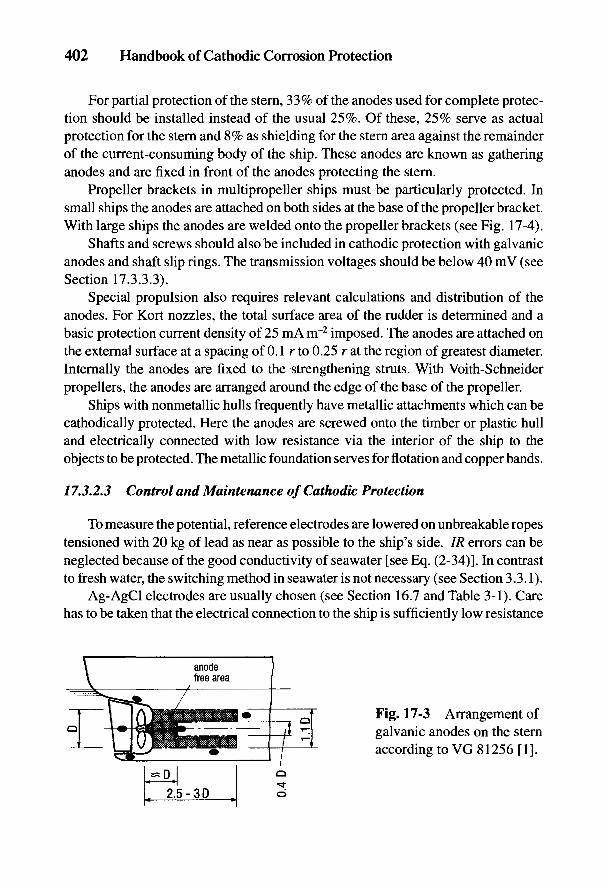
402 Handbook of Cathodic Corrosion Protection
For partial protection of the stern, 33% of the anodes used for complete protec-tion should be installed instead of the usual 25%. Of these, 25% serve as actualprotection for the stern and 8% as shielding for the stern area against the remainderof the current-consuming body of the ship. These anodes are known as gatheringanodes and are fixed in front of the anodes protecting the stem.
Propeller brackets in multipropeller ships must be particularly protected. Insmall ships the anodes are attached on both sides at the base of the propeller bracket.With large ships the anodes are welded onto the propeller brackets (see Fig. 17-4).
Shafts and screws should also be included in cathodic protection with galvanicanodes and shaft slip rings. The transmission voltages should be below 40 mV (seeSection 17.3.3.3).
Special propulsion also requires relevant calculations and distribution of theanodes. For Kort nozzles, the total surface area of the rudder is determined and abasic protection current density of 25 mA irr2 imposed. The anodes are attached onthe external surface at a spacing of 0.1 r to 0.25 r at the region of greatest diameter.Internally the anodes are fixed to the strengthening struts. With Voith-Schneiderpropellers, the anodes are arranged around the edge of the base of the propeller.
Ships with nonmetallic hulls frequently have metallic attachments which can becathodically protected. Here the anodes are screwed onto the timber or plastic hulland electrically connected with low resistance via the interior of the ship to theobjects to be protected. The metallic foundation serves for flotation and copper bands.
/ 7.3.2.3 Control and Maintenance of Cathodic Protection
To measure the potential, reference electrodes are lowered on unbreakable ropestensioned with 20 kg of lead as near as possible to the ship's side. IR errors can beneglected because of the good conductivity of seawater [see Eq. (2-34)]. In contrastto fresh water, the switching method in seawater is not necessary (see Section 3.3.1).
Ag-AgCl electrodes are usually chosen (see Section 16.7 and Table 3-1). Carehas to be taken that the electrical connection to the ship is sufficiently low resistance
Fig. 17-3 Arrangement ofgalvanic anodes on the sternaccording to VG 81256 [1].

Cathodic Protection of Ships 403
and dry. Clamps on the drams are usually used. The information on protection poten-tials is given in Section 2.4.
17.3.3 Protection with Impressed Current
The number of galvanic anodes is approximately proportional to the area of thesurfaces to be protected due to their limited current output and range. With largenumbers of anodes, galvanic protection is economically inferior to impressed cur-rent because costs of material and mountings are proportional to the number ofgalvanic anodes whereas the cost of impressed current protection increases lessthan proportionally with the surface area. The boundary lies with ships of about 100m in length. Additional advantages of impressed current protection are the control-
Fig. 17-4 Distribution of galvanic anodes for different shapes of stern, (a) Steamerstern: one propeller, one balance rudder, (b) Steamer stern: one propeller, asuspension rudder, (c) Tugboat stern: two propellers, a Kort nozzle rudder, (d) Tran-som stern: two propellers, a suspension rudder, (e) Transom stern: two propellers,two suspension rudders.
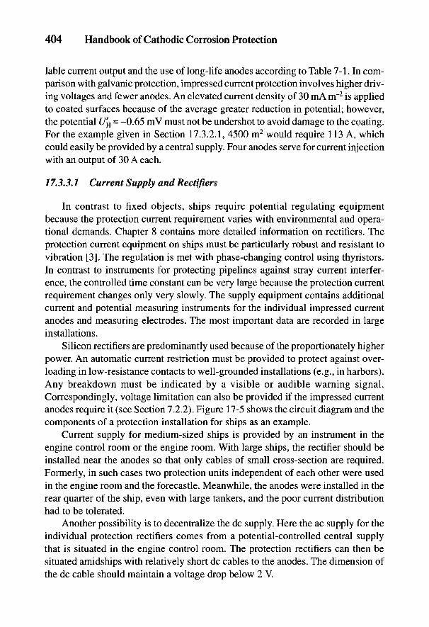
404 Handbook of Cathodic Corrosion Protection
lable current output and the use of long-life anodes according to Table 7-1. In com-parison with galvanic protection, impressed current protection involves higher driv-ing voltages and fewer anodes. An elevated current density of 30 mA nr2 is appliedto coated surfaces because of the average greater reduction in potential; however,the potential U'H = -0.65 mV must not be undershot to avoid damage to the coating.For the example given in Section 17.3.2.1, 4500 m2 would require 113 A, whichcould easily be provided by a central supply. Four anodes serve for current injectionwith an output of 30 A each.
17.3.3.1 Current Supply and Rectifiers
In contrast to fixed objects, ships require potential regulating equipmentbecause the protection current requirement varies with environmental and opera-tional demands. Chapter 8 contains more detailed information on rectifiers. Theprotection current equipment on ships must be particularly robust and resistant tovibration [3]. The regulation is met with phase-changing control using thyristors.In contrast to instruments for protecting pipelines against stray current interfer-ence, the controlled time constant can be very large because the protection currentrequirement changes only very slowly. The supply equipment contains additionalcurrent and potential measuring instruments for the individual impressed currentanodes and measuring electrodes. The most important data are recorded in largeinstallations.
Silicon rectifiers are predominantly used because of the proportionately higherpower. An automatic current restriction must be provided to protect against over-loading in low-resistance contacts to well-grounded installations (e.g., in harbors).Any breakdown must be indicated by a visible or audible warning signal.Correspondingly, voltage limitation can also be provided if the impressed currentanodes require it (see Section 7.2.2). Figure 17-5 shows the circuit diagram and thecomponents of a protection installation for ships as an example.
Current supply for medium-sized ships is provided by an instrument in theengine control room or the engine room. With large ships, the rectifier should beinstalled near the anodes so that only cables of small cross-section are required.Formerly, in such cases two protection units independent of each other were usedin the engine room and the forecastle. Meanwhile, the anodes were installed in therear quarter of the ship, even with large tankers, and the poor current distributionhad to be tolerated.
Another possibility is to decentralize the dc supply. Here the ac supply for theindividual protection rectifiers comes from a potential-controlled central supplythat is situated in the engine control room. The protection rectifiers can then besituated amidships with relatively short dc cables to the anodes. The dimension ofthe dc cable should maintain a voltage drop below 2 V.

Cathodic Protection of Ships 405
Fig. 17-5 Circuit diagram for an impressed current protection installation.
17.3.3.2 Impressed Current Anodes and Reference Electrodes
Two types of impressed current anodes are mainly used on ships: attached andrecessed anodes, which are fixed flush with the ship's side. Several years ago, tow-ing anodes of aluminum or platinized silver were also used. These anodes were notused later on because of insufficient protection of the bow region. With attachedanodes [27,281 as in Fig. 17-6, which mainly applies to lead-silver anodes, theholder consists of a long trapezoid-shaped plastic (usually fiberglass-reinforcedpolyester) anode body into whose sides the active anode surfaces are set. The plas-tic body is screwed to staybolts welded to the ship's side and containing femaleinserts. The plastic body is provided with a protective shield as a support whichguards the ship's side in the immediate vicinity of the anode surfaces and protectsthe coating against the cathodic effects of very negative potentials. This protectionshield is fixed to the hull of the ship by welded support brackets. The current isconnected inside the plastic body to a cap at the end of the body. From there thecables are either led directly through the ship's side or they emerge at the end of theanode body and are installed on the hull under a protective cover.
Attached anodes provide the particular advantage of proportionately low ground-ing resistance for the protection current because the actual anode body is set intoboth sloping sides of the plastic body as long narrow strips. The disadvantage is thatthe body is exposed on the ship's side and can easily be damaged mechanically.
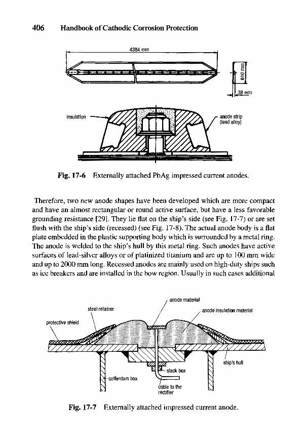
406 Handbook of Cathodic Corrosion Protection
Fig. 17-6 Externally attached PbAg impressed current anodes.
Therefore, two new anode shapes have been developed which are more compactand have an almost rectangular or round active surface, but have a less favorablegrounding resistance [29]. They lie flat on the ship's side (see Fig. 17-7) or are setflush with the ship's side (recessed) (see Fig. 17-8). The actual anode body is a flatplate embedded in the plastic supporting body which is surrounded by a metal ring.The anode is welded to the ship's hull by this metal ring. Such anodes have activesurfaces of lead-silver alloys or of platinized titanium and are up to 100 mm wideand up to 2000 mm long. Recessed anodes are mainly used on high-duty ships suchas ice breakers and are installed in the bow region. Usually in such cases additional
Fig. 17-7 Externally attached impressed current anode.
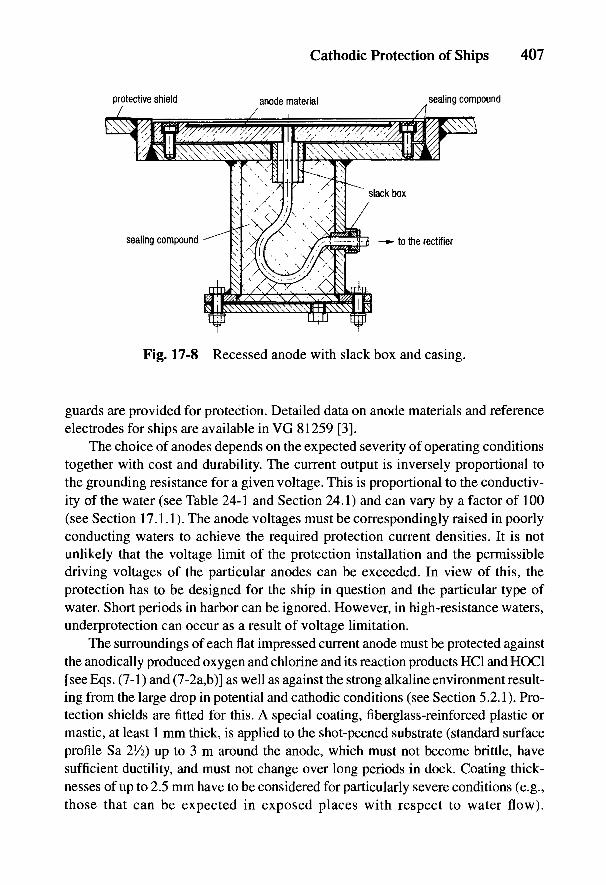
Cathodic Protection of Ships 407
Fig. 17-8 Recessed anode with slack box and casing.
guards are provided for protection. Detailed data on anode materials and referenceelectrodes for ships are available in VG 81259 [3].
The choice of anodes depends on the expected severity of operating conditionstogether with cost and durability. The current output is inversely proportional tothe grounding resistance for a given voltage. This is proportional to the conductiv-ity of the water (see Table 24-1 and Section 24.1) and can vary by a factor of 100(see Section 17.1.1). The anode voltages must be correspondingly raised in poorlyconducting waters to achieve the required protection current densities. It is notunlikely that the voltage limit of the protection installation and the permissibledriving voltages of the particular anodes can be exceeded. In view of this, theprotection has to be designed for the ship in question and the particular type ofwater. Short periods in harbor can be ignored. However, in high-resistance waters,underprotection can occur as a result of voltage limitation.
The surroundings of each flat impressed current anode must be protected againstthe anodically produced oxygen and chlorine and its reaction products HC1 and HOC1[see Eqs. (7-1) and (7-2a,b)] as well as against the strong alkaline environment result-ing from the large drop in potential and cathodic conditions (see Section 5.2.1). Pro-tection shields are fitted for this. A special coating, fiberglass-reinforced plastic ormastic, at least 1 mm thick, is applied to the shot-peened substrate (standard surfaceprofile Sa 2Vi) up to 3 m around the anode, which must not become brittle, havesufficient ductility, and must not change over long periods in dock. Coating thick-nesses of up to 2.5 mm have to be considered for particularly severe conditions (e.g.,those that can be expected in exposed places with respect to water flow).
408 Handbook of Cathodic Corrosion Protection
The size of the protection shield depends on the protection current, the voltage andthe shape of the anode [3].
Measuring electrodes for impressed current protection are robust referenceelectrodes (see Section 3.2 and Table 3-1) which are permanently exposed to sea-water and remain unpolarized when a small control current is taken. The otherwiseusual silver-silver chloride and calomel reference electrodes are used only for check-ing (see Section 16.7). All reference electrodes with electrolytes and diaphragmsare unsuitable as long-term electrodes for potential-controlled rectifiers. Only metal-medium electrodes which have a sufficiently constant potential can be consideredas measuring electrodes. The silver-silver chloride electrode has a potential thatdepends on the chloride content of the water [see Eq. (2-29)]. This potential devia-tion can usually be tolerated [3]. The most reliable electrodes are those of pure zinc[3]. They have a constant rest potential, are slightly polarizable and in case of filmformation can be regenerated by an anodic current pulse. They last at least 5 years.
Cables for anodes and measuring electrodes are laid in pipes or cable banks.The anode cables must be sufficiently low resistance (see Section 7.4). Occasion-ally axial watertight quality is demanded for anode cables. Previously the currentconnection was made with a short cable and a socket bolt under the anode, rarelywith a lateral lead. Today the cable socket to the anodes below the waterline isconnected via a cofferdam box (see Fig. 17-8) and an iron bushing [5]. The wallthickness of these boxes must correspond to that of the wall of the ship [4-6]. Theanode cable leads through the cofferdam box to the current supply if the connec-tion with the current supply cable in the cofferdam box is not made with a connect-ing bolt. Anode cables and connecting bolts are led in through a watertight bulkheadslack box. The supply cable to the rectifier is led through two slack boxes. Thecofferdam boxes can be also packed with viscous insulating material (Fig. 17-8).
17.3.3.3 Arrangement of Anodes and Reference Electrodes
The same observations as those for galvanic anodes apply to impressed cur-rent anodes concerning forbidden areas and their arrangement to guard againstmechanical damage (see Section 17.3.2.2). The essential differences are the smallernumber of anodes required and difficulties arising from their connections. In tank-ers even current leads in armored tubes are forbidden in the area of the loadingtank. The current lead must only be exposed with a suitable cover. The absence ofanodes in this area will impair current distribution. Figure 17-9 shows the idealarrangement of anodes and reference electrodes allowed for in the ship's construc-tion [3]. The ideal arrangement is that in which current distribution is the decidingfactor in the design. This is the case with ice breakers and ice-going ships wherelarge surface areas in the bow region can occur where there is no coating. Their
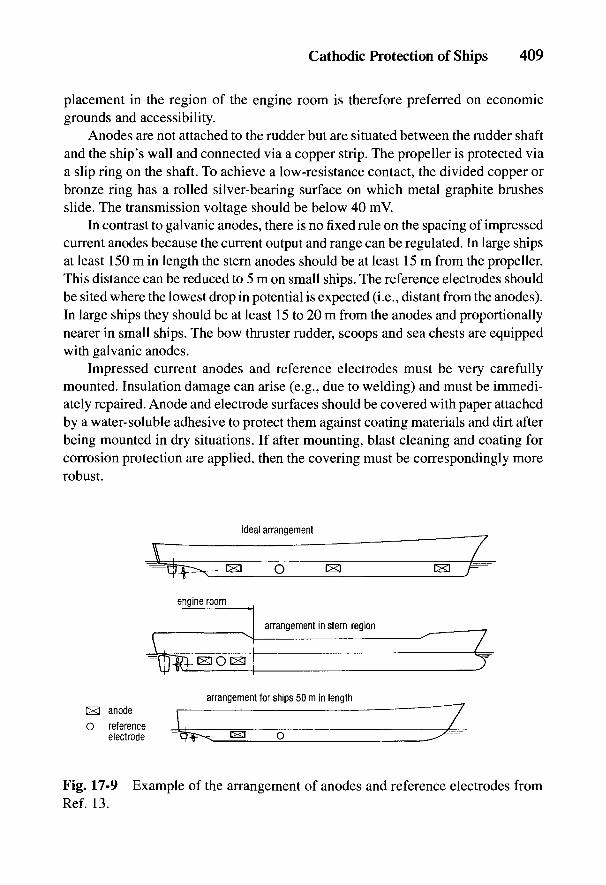
Cathodic Protection of Ships 409
placement in the region of the engine room is therefore preferred on economicgrounds and accessibility.
Anodes are not attached to the rudder but are situated between the rudder shaftand the ship's wall and connected via a copper strip. The propeller is protected viaa slip ring on the shaft. To achieve a low-resistance contact, the divided copper orbronze ring has a rolled silver-bearing surface on which metal graphite brushesslide. The transmission voltage should be below 40 mV.
In contrast to galvanic anodes, there is no fixed rule on the spacing of impressedcurrent anodes because the current output and range can be regulated. In large shipsat least 150 m in length the stern anodes should be at least 15 m from the propeller.This distance can be reduced to 5 m on small ships. The reference electrodes shouldbe sited where the lowest drop in potential is expected (i.e., distant from the anodes).In large ships they should be at least 15 to 20 m from the anodes and proportionallynearer in small ships. The bow thruster rudder, scoops and sea chests are equippedwith galvanic anodes.
Impressed current anodes and reference electrodes must be very carefullymounted. Insulation damage can arise (e.g., due to welding) and must be immedi-ately repaired. Anode and electrode surfaces should be covered with paper attachedby a water-soluble adhesive to protect them against coating materials and dirt afterbeing mounted in dry situations. If after mounting, blast cleaning and coating forcorrosion protection are applied, then the covering must be correspondingly morerobust.
Fig. 17-9 Example of the arrangement of anodes and reference electrodes fromRef. 13.
410 Handbook of Cathodic Corrosion Protection
17.4 Internal Cathodic Protection of Tanks and Containers
The general advice given in DIN 50927 applies to internal cathodic protection[30]. The interior of tanks is protected by galvanic anodes. Impressed current pro-tection is not allowed due to the danger of ignition by sparking and short circuits.Objects to be protected include ballast tanks, loading tanks and water tanks (seealso Chapters 20 and 21). In some types of ships (e.g., deep-sea tugs and navyunits) fuel consumed is replaced by seawater in the tanks for reasons of stability. Insuch cases the fuel tanks also have to be included in the cathodic protection sys-tem. The regulations in Ref. 5 cover the design of the protection system and thechoice of anodes, which include possibilities in new ship building to reduce thethickness of materials covered by the class designation KORR. The extent of cor-rosion protection can be seen in Table 17-2. The following criteria are distinguished:
(a) ballast tanks that travel either empty or containing water;(b) tanks for dirty material.
Magnesium anodes must not be used in tanks. Aluminum anodes may be in-stalled in all tanks according to the agreements of the International Association ofClassification Societies, which are included in the individual regulations [5,6], butin tanks (b) in the event of the anode falling off, the kinetic energy must not exceed275 J, i.e., a 10 kg anode must not be fixed more than 2.8 m above the bottom of thetank. There are no restrictions on the use of zinc anodes. The restrictions on the useof aluminum anodes are due to the possible danger of sparks if the anode falls off.
Anodes are designed to last 4 years so that ballast times for (a) are 40% of theservice time and for (b) 25%, which corresponds to 146 and 91 days per year,respectively. The shortest filling time should amount to 5 days per ballast journey.Protection current densities are given in Table 17-3.
The surfaces to be protected should be the total surface, including inserts, sparsand pipes. The upper 1.5 m of the side walls and the covers should be providedwith a coating of recognized quality [10] to protect against corrosion.
The horizontal surfaces should be coated because there is residual water in theballast and there are water-oil mixtures in the crude oil tanks when ships travelempty and these can cause severe corrosion attack. In the lower part of the tank, upto about 1.5m from the base, a combination of coating and cathodic protectionwith special anodes is chosen. Basically the anodes could take over the exclusiveprotection in this area, but with empty ballast tanks containing residual water orempty crude oil tanks with aggressive oil-water mixtures containing sulfur com-pounds, they do not prevent corrosion.
Suitable anode shapes have been developed for different types and construc-tions of tanks. For example, there are long flat anodes which when installed on the
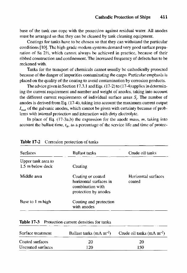
Cathodic Protection of Ships 411
base of the tank can cope with the protection against residual water. All anodesmust be arranged so that they can be cleaned by tank cleaning equipment.
Coatings for tanks have to be chosen so that they can withstand the particularconditions [10]. The high-grade modern systems demand very good surface prepa-ration of Sa 25/2, which cannot always be achieved in practice, because of theirribbed construction and confinement. The increased frequency of defects has to bereckoned with.
Tanks for the transport of chemicals cannot usually be cathodically protectedbecause of the danger of impurities contaminating the cargo. Particular emphasis isplaced on the quality of the coating to avoid contamination by corrosion products.
The advice given in Section 17.3.1 and Eqs. (17-2) to (17-4) applies in determin-ing the current requirement and number and weight of anodes, taking into accountthe different current requirements of individual surface areas S{. The number ofanodes is derived from Eq. (17-4), taking into account the maximum current output7max of the galvanic anodes, which cannot be given with certainty because of prob-lems with internal protection and interaction with dirty electrolyte.
In place of Eq. (17-3a,b) the expression for the anode mass, m, taking intoaccount the ballast time, tE, as a percentage of the service life and time of protec-
Table 17-2 Corrosion protection of tanks
Surfaces Ballast tanks Crude oil tanks
Upper tank area to1.5m below deck Coating
Middle area Coating or coated Horizontal surfaceshorizontal surfaces in coatedcombination withprotection by anodes
Base to 1 m high Coating and protectionwith anodes
Table 17-3 Protection current densities for tanks
Surface treatment Ballast tanks (mA nr2) Crude oil tanks (mA m"2)
Coated surfaces 20 20Uncoated surfaces 120 150

412 Handbook of Cathodic Corrosion Protection
tion, rs; and the current content Q'^ [see Eq. (6-9)] is given by:
Practical values for Q'pr are 780 for zinc anodes and 2250 to 2800 for alumi-num anodes, depending on the particular alloy. The weight of the anodes isincreased by 20% so that at the end of the proposed life the remains of the anodeare still active. The number of anodes given by Eq. (17-4) and their weight calcu-lated from Eq. (17-5) for individual anodes must agree with the actual anodes sothat for the object in question the special data concerning geometrically endan-gered areas and cell formation (e.g., in mixed material installations) are taken intoaccount.
In contrast to external protection, the anodes in internal protection are usuallymore heavily covered with corrosion products and oil residues because the electro-lyte is stagnant and contaminated. The impression can be given that the anodes areno longer functional. Usually the surface films are porous and spongy and can beremoved easily. This is achieved by spraying during tank cleaning. In their unal-tered state they have in practice little effect on the current output in ballast sea-water. In water low in salt, the anodes can passivate and are then inactive.
17.5 Cathodic Protection of Heat Exchangers, Condensers and TVibing
Galvanic or impressed current anodes are used to protect these components.The anode material is determined by the electrolyte: zinc and aluminum for seawa-ter, magnesium for freshwater circuits. Platinized titanium is used for the anodematerial in impressed current protection. Potential-regulating systems working inde-pendently of each other should be used for the inlet and outlet feeds of heat ex-changers on account of the different temperature behavior. The protection currentdensities depend on the material and the medium.
The internal cathodic protection of pipes is only economic for pipes with anominal width greater than DIN 400 due to the limit on range. Internal protectioncan be achieved in individual cases by inserting local platinized titanium wireanodes (see Section 7.2.2).
17.6 Cathodic Protection of Bilges
The layer of dirty water standing in bilges is usually so small that protectionwith anodes of the usual dimensions is not possible. Experiments with very flat
Cathodic Protection of Ships 413
anodes attached to polished surfaces with conducting adhesive have shown thatthe method is not sufficiently effective. Better results have been achieved withanode wires of aluminum or zinc alloys with steel cores. Such wire anodes havediameters of 6 to 10 mm and are laid directly on the deck in long loops that passover standing structural items and are soldered. The wire loops can be laid inbunches, depending on the corrosion intensity. Additional protection can also begiven by scattered zinc powder with activating additions. The zinc particles (10 to100 /mi) sink into corrosion craters and pits and give good local protection. Thisaddition must, of course, be repeated frequently (e.g., every 3 to 6 months). Anodewires last about 2 years.
17.7 Cathodic Protection of Docks
Floating docks are protected with galvanic and impressed current anodes, thatis, on the outside, the gates and the base. Since docks are stationary, types ofanodes and arrangements that would otherwise be in danger of mechanical damagecan be chosen, as for marine structures. In the past, graphite, magnetite and silicon-iron anodes (see Chapter 16) in the form of round rods or plates were hung on theoutside sufficiently far into the water so that uniform current distribution was en-sured. Chambers can also be provided in which the anodes are drawn up when thedocks are flooded. In every case care has to be taken for traction relief of the anodecable. Finally, the anodes can be fixed to racks and anchored to the ground. Oftenthe cathodic protection of docks is managed in the same way as the cathodic pro-tection of ships so that every dockside has a potential-controlled protection instal-lation or one protection rectifier with a transfer cable (to the other side).
Since docks are usually situated in brackish water, the anodes must have largesurface areas to keep the grounding resistance and the driving voltage low.Cathodic protection of the interior is not necessary because the dock is only floodedfor a short time and can be otherwise maintained.
414 Handbook of Cathodic Corrosion Protection
17.8 References
[1] VG 81 255, Beuth Verlag, Koln 1983.VG 81 256 Teile 1 bis 3, Beuth Verlag, Koln 1979 und 1980.VG 81 257 Teile 1 und 3, Beuth Verlag, Koln 1982.
[2] VG 81 258, Beuth Verlag, Koln 1984.[3] VG 81 259 Teile 1 bis 3, Beuth Verlag, Koln 1985 und 1986.[4] Brit. Stand. Inst., Code of Practice for Cathodic Protection, London 1973.[5] Germanischer Lloyd, Vorschriften fur Konstruktion und Bau von stahlernen Seeschiffen,
Hamburg.[6] Det Noske Veritas, Rules for Classification of Steel Ships, Oslo.[7] H. Determann u. E. Hargarter, Schiff u. Hafen 20, 533 (1968).[8] R. Tanaka, Sumitomo Light Met. Techn. Rep. 3, 225 (1962).[9] P. Drodten, G. Lennartz u. W. Schwenk, Schiff u. Hafen 30, 643 (1978).
[10] STG-Richtlinie Nr. 2215, Hamburg 1987.[11] STG-Richtlinie Nr. 2220, Hamburg 1988.[12] H. Kubota u.a., Nippon Kokan techn. Rep. Overs. 10, 27 (1970).[13] Fischer, Bue, Brattes, Steensland, OTC, Houston 1980, Paper No. 388.[14] B. Richter, Schiff u. Hafen, Sonderheft Meerwasser-Korrosion, Februar 1983, S. 88.[15] A. Baumel, Werkstoffe u. Korrosion 20, 391 (1969).[16] VG 81 249 Teile 1 und 2, Beuth Verlag, Koln 1977 u. 1983.
VG 81 250, Beuth Verlag, Koln 1988.[17] DIN 50919, Beuth Verlag, Berlin 1984.[18] K. Meyer u. W. Schwenk, Schiff u. Hafen 26, 1062 (1974).[19] H. Hildebrand u. W. Schwenk, Werkstoffe u. Korrosion 30, 542 (1979) und 33, 653 (1982).[20] DIN 50928, Beuth Verlag, Berlin 1985.[21] H. Determann, E. Hargarter, H. Sass, Schiff u. Hafen 32, 89 (1980);
H. Determann, E. Hargarter, H. Sass, Schiff u. Hafen 28, 729 (1976);W. Bahlmann, E. Hargarter, H. Sass, D. Schwarz, Schiff u. Hafen 33, H.7, 50 (1981);W. Bahlmann, E. Hargarter, Schiff «.-Hafen, Sonderheft Meerwasser-Korrosion, Februar1983, S. 98.
[22] DIN 55928 Teil 5, Beuth-Verlag, Berlin 1980.[23] H. Pircher, B. Ruhland u. G. Sussek, Thyssen Technische Berichte 18, H. 1, 69 (1986).[24] J.H. Gobrecht, E. Hargarter, W. Huppatz u. F. J. Reker, Schiff u. Hafen, Sonderheft
Meerwasser-Korrosion, Februar 1983, S. 24.[25] V. Brucken, H. Dahmen u.a., Int. Leichtmetalltagung, Leoben-Wien, 22-26.6.1987.[26] U. Neumann, Techn. Rundschau 16. H.4, 65 (1971).[27] J.H. Morgan, Corrosion 13, 198 (1975).[28] J.H. Morgan, Cathodic Protection, Leonhard Hill Ltd, London 1959.[29] H. Bohnes, Kathodischer Korrosionsschutz mit galvanischen Anoden und Fremdstrom,
Grille-Ampak, Duisburg 1979.[30] DIN 50927, Beuth Verlag, Berlin 1985.

18
Cathodic Protection of Well CasingsW. PRINZ AND B. LEUTNER
18.1 Description of the Object to be Protected
In oil and natural gas fields and reservoirs, the boreholes are cased to stabilizethe wells. Depending on the depth and the operating conditions, several pipes maybe fitted inside each other in the area near the surface (telescope casing)(see Fig. 18-1).
The annular space between the outer pipe and the surrounding rock is filledwith cement over the whole depth up to the ground in new wells. The purpose ofthis is to seal the deposits at the top and to keep the fresh water and salt water zonesseparate. In addition, it serves as a protection against pressure from the rock and ascorrosion protection which, however, is only effective so long as there is no cur-rent exit caused by extended corrosion of cells or due to foreign anodic influences.The cement filling of the borehole casing is usually not uniformly spread over thepipe surface. It has to be remembered that there can be sections which are eithernot covered or are only thinly covered with cement.
With old borehole casings, it is often only the oil- or gas-producing depths of thedeposit and the upper regions that are cemented. The noncemented depths containresidue from drilling mud and various-sized particles of rock. The circulation duringdrilling is carried out with a suspension of BaSO4 and water with a high density,which usually contains salt. This promotes the effectiveness of corrosion cells.
18.2 Causes of Corrosion Danger
18.2.1 Formation of Corrosion Cells
The usual practice in old wells of only partially cementing the outer pipe canlead to cell formation (steel in the cement-steel in the soil) in the transition regions tothe uncoated sections (see Sections 4.2 and 4.3). In contrast to the well-known cath-ode "steel-soil" in the vicinity of the ground surface, the cathodic activity of the
415
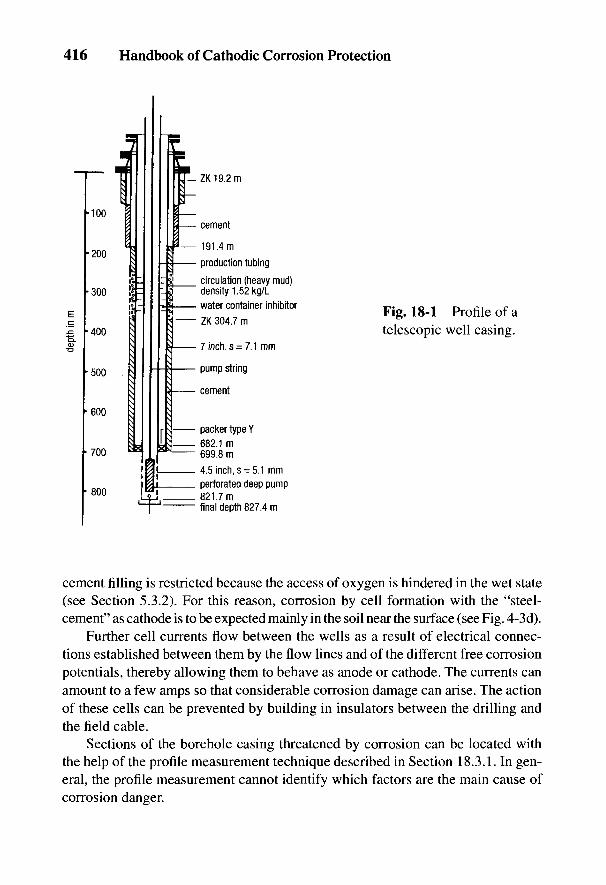
416 Handbook of Cathodic Corrosion Protection
Fig. 18-1 Profile of atelescopic well casing.
cement filling is restricted because the access of oxygen is hindered in the wet state(see Section 5.3.2). For this reason, corrosion by cell formation with the "steel-cement" as cathode is to be expected mainly in the soil near the surface (see Fig. 4-3d).
Further cell currents flow between the wells as a result of electrical connec-tions established between them by the flow lines and of the different free corrosionpotentials, thereby allowing them to behave as anode or cathode. The currents canamount to a few amps so that considerable corrosion damage can arise. The actionof these cells can be prevented by building in insulators between the drilling andthe field cable.
Sections of the borehole casing threatened by corrosion can be located withthe help of the profile measurement technique described in Section 18.3.1. In gen-eral, the profile measurement cannot identify which factors are the main cause ofcorrosion danger.
Cathodic Protection of Well Casings 417
18.2.2 Free Corrosion in Different Soil Layers
Throughout its depth the borehole casing passes through several geologicalregions which can range from layers with saline water to inert bedrock. In addi-tion, corrosive gases (CO2, H2S) and temperature differences up to 50°C may occur,depending on the type of deposit. These factors lead to an increased corrosivity indeeper layers of soil where film formation is restricted by salt and concentrationcells may be formed (see Figs. 4-3b to 4-3c).
18.2.3 Conditions for the Occurrence of Stress Corrosion
Since borehole casings are subjected to increased temperatures at increasingdepths and since additional tensile stresses are acting, there is the possible dangerof stress corrosion. From the data in Section 2.3.3, there exists a danger, in the caseof cathodically protected casings, of intergranular stress corrosion arising fromconditions e, g and h where NaOH is generated according to Eqs. (2-17) and (2-19)and the remaining components are generated by the reaction of NaOH with CO2
from the soil. The critical potential and protection potential ranges are given inSection 2.4. Under the prevailing service conditions it can be assumed that stresscorrosion by NaHCO3 does not occur because of adequate cathodic polarization,nor does stress corrosion by Na2CO3 and NaOH due to their low concentration.Furthermore, the high-carbon, high- strength casing steels have increased resis-tance to this type of stress corrosion [1], especially as the necessary critical stresslevel is not likely to be reached. From previous experience, no damage by stresscorrosion has been observed in cathodically protected casings.
18.2.4 Corrosion by Anodic Interference (Cell Formation, Stray Currents)
In oilfields with high paraffin content, the production tubing has to be cleanedby heating every week to remove paraffin deposits. The heating of the pipe takesplace while a dc of about 1.2 kA is fed into the production tubing from the wellhead. The current is fed back via the casing to the dc installation by contacts be-tween the production tubing and the casing in the lower part of the borehole. Partof the return current in the casing is shunted through the rock to the well head. Thishas the consequence that during the heating period the lower part of the casing isanodically polarized. This can interfere with wells within a radius of 1000 m.
Since in oilfields or reservoirs borehole casings are frequently sited close toone another, they can be affected by the voltage cone of the anode bed and thecathodic voltage cone of other casings. Thus, in the case of large oilfields andreservoirs, it is appropriate to protect all wells cathodically.
418 Handbook of Cathodic Corrosion Protection
18.3 Measurements for Assessing Corrosion Protection of Well Casings
With buried pipelines, the degree of corrosion danger from cell formation andthe effectiveness of cathodic protection can be determined by pipe/soil potentialmeasurements along the pipeline (see Sections 3.6.2 and 3.7). This is not possiblewith well casings since the only point available for a measuring point is at the wellhead. Therefore, other methods are required to identify any corrosion risk or theeffectiveness of corrosion protection.
18.3.1 Investigations for Corrosion Damage
Various electromagnetic and mechanical measuring methods are used to inves-tigate the old well casings to determine whether there is external or internal corro-sion.
The individual methods provide information on:
(a) exact depth of the screw socket connections;
(b) reduction from the average wall thickness irrespective of whether thereduction in wall thickness is on the inside or outside of the pipe;
(c) reduction in wall thickness or penetration with the distinction as to whetherthe areas of attack are due to external or internal corrosion;
(d) attack by internal corrosion and penetration.
Methods for (a) to (c) are electromagnetic or use eddy currents. The methodfor (d) is a mechanical system similar to the caliper pig, in which the probe runsover the inner wall of the pipe over pits, shallow pits and penetration holes.
18.3.2 Measurement of At/ Profiles
When measuring At/ profiles, the voltage drop is measured along the interiorof the casing [2]. The voltage drop is caused by cell currents as in Section 18.2.1 orby cathodic protection currents. The anodic and cathodic sections of the casing andalso the effect of the cathodic protection can be determined from the At/ profiles.
A At/ profile measurement is carried out with a measuring probe which isintroduced into the borehole. Two measuring contacts arranged one above the otheract as the measuring probe (see Fig. 18-2); they are pressed against the wall of thecasing under great pressure. The contacts, which are about 8 m apart, must be verywell insulated from each other. To avoid measuring errors, the internal wall of thecasing must be practically free of contamination (e.g., cement residues, paraffin,oil deposits and corrosion products). Cleaning with a scraper may be necessary. Inaddition, the casing must be filled with a nonconducting or poorly conducting
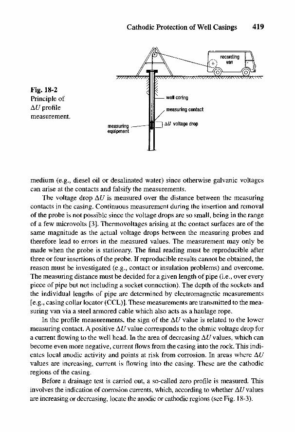
Cathodic Protection of Well Casings 419
Fig. 18-2Principle ofAt/ profilemeasurement.
medium (e.g., diesel oil or desalinated water) since otherwise galvanic voltagescan arise at the contacts and falsify the measurements.
The voltage drop AC/ is measured over the distance between the measuringcontacts in the casing. Continuous measurement during the insertion and removalof the probe is not possible since the voltage drops are so small, being in the rangeof a few microvolts [31. Thermovoltages arising at the contact surfaces are of thesame magnitude as the actual voltage drops between the measuring probes andtherefore lead to errors in the measured values. The measurement may only bemade when the probe is stationary. The final reading must be reproducible afterthree or four insertions of the probe. If reproducible results cannot be obtained, thereason must be investigated (e.g., contact or insulation problems) and overcome.The measuring distance must be decided for a given length of pipe (i.e., over everypiece of pipe but not including a socket connection). The depth of the sockets andthe individual lengths of pipe are determined by electromagnetic measurements[e.g., casing collar locator (CCL)]. These measurements are transmitted to the mea-suring van via a steel armored cable which also acts as a haulage rope.
In the profile measurements, the sign of the At/ value is related to the lowermeasuring contact. A positive At/ value corresponds to the ohmic voltage drop fora current flowing to the well head. In the area of decreasing At/ values, which canbecome even more negative, current flows from the casing into the rock. This indi-cates local anodic activity and points at risk from corrosion. In areas where At/values are increasing, current is flowing into the casing. These are the cathodicregions of the casing.
Before a drainage test is carried out, a so-called zero profile is measured. Thisinvolves the indication of corrosion currents, which, according to whether At/ valuesare increasing or decreasing, locate the anodic or cathodic regions (see Fig. 18-3).
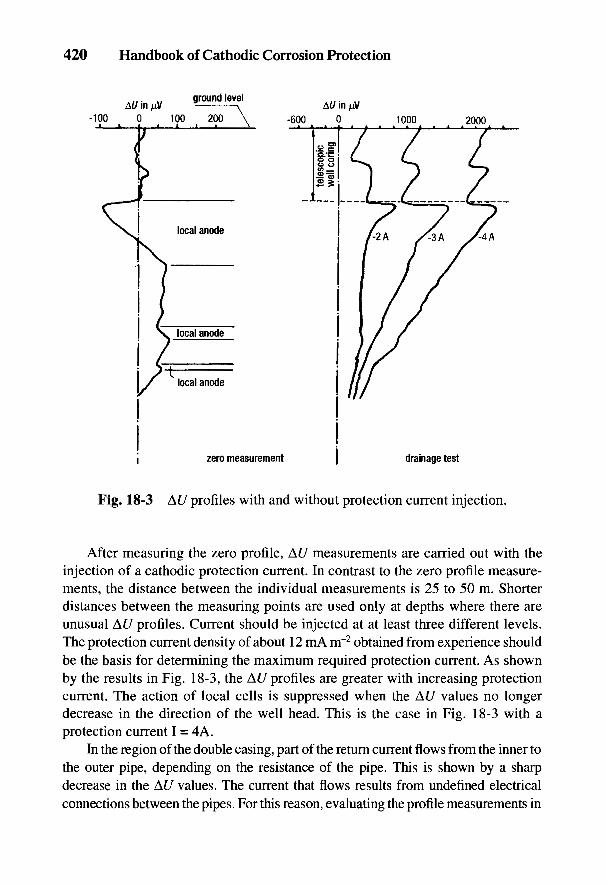
420 Handbook of Cathodic Corrosion Protection
Fig. 18-3 At/ profiles with and without protection current injection.
After measuring the zero profile, At/ measurements are carried out with theinjection of a cathodic protection current. In contrast to the zero profile measure-ments, the distance between the individual measurements is 25 to 50 m. Shorterdistances between the measuring points are used only at depths where there areunusual At/ profiles. Current should be injected at at least three different levels.The protection current density of about 12 mA nr2 obtained from experience shouldbe the basis for determining the maximum required protection current. As shownby the results in Fig. 18-3, the At/ profiles are greater with increasing protectioncurrent. The action of local cells is suppressed when the At/ values no longerdecrease in the direction of the well head. This is the case in Fig. 18-3 with aprotection current I = 4A.
In the region of the double casing, part of the return current flows from the inner tothe outer pipe, depending on the resistance of the pipe. This is shown by a sharpdecrease in the At/ values. The current that flows results from undefined electricalconnections between the pipes. For this reason, evaluating the profile measurements in

Cathodic Protection of Well Casings 421
Fig. 18-4 Uotf (log /) curves for determining the Tafel potential.
the area of double or multiple casing is pointless. Electrolytic corrosion does not occurin the annular region because of the current flow through electrical connections.
18.3.3 Measurement of the Tafel Potential
The Tafel potential is given by a bend in the £/off (log /) curve.1 According tocriterion No. 4 in Table 3-3, under the conditions given in Section 3.3.3.1, it corre-sponds to the protection potential.
The average protection current requirement can be conveniently determinedfor individual wells in an oilfield by measuring the Tafel potential. In contrast toprofile measurements, internal measurements on the casing are not necessary. Thesemeasurements cannot be used to predict polarization behavior at greater depths.
To determine the Tafel potential, the casing is cathodically polarized over afixed time period of about 10 minutes with increasing levels of current. The resultsin Fig. 18-4 show how the Tafel potential can be determined from the intersectionof two straight lines plotted on a logarithmic scale [4]. Casing potentials can alsobe calculated from the electrostatic fields and the ohmic voltage drop in the casing[5]. This assumes homogeneous conductivity and polarization.
1 In the United States, these are E log / tests.

422 Handbook of Cathodic Corrosion Protection
18.4 Design and Construction of Cathodic Protection Stations
The most important parameters in the cathodic protection of a well casing arethe depth of penetration of the protection current and its magnitude. These dependon the geological formations and the specific electrical resistance of the individuallayers. Insulating layers are a disadvantage because they limit the extent of theprotected region. Borehole profiles are not adequate to make an assessment [6].Depending on the type of field or reservoir, it is recommended that measurementsbe carried out on the casing as detailed in Section 18.3.2. The results can be appliedto other wells [7]. With well casings for oil and gas deposits in salt domes, previ-ous experience has shown that information from measurement of Tafel potentialsis sufficient for planning the cathodic protection of casings. The protection currentrequirement of the flow lines is determined by a drainage test or from experience(see Section 10.3.3).
In planning the cathodic protection of oil and gas fields or reservoirs,depending on the subsoil of the pipelines, the required technical data on the casinginclude diameter, wall thickness, depth, cement filling and the geological situationin its vicinity. Other factors that have to be considered are operational data such astemperature of the deposits, well head temperature, electrical heating of oil inoilfields and the conductivity of the transported media. While the pipelines for gasand oil reservoirs do not carry electrolytic media, media in pipelines of oilfields—governed by the high saline content of the extracted oil—are extremely electrolyti-cally conductive. In this case, an anodic corrosion danger behind the insulatingunit has to be considered (see Sections 10.3.5 and 24.4.6).
It follows from this that the casing and the flow lines in oilfield installationsshould not be separated from one another by insulting units. The cathodic cable isalways connected to the well to be protected. The flow lines are all equipped withpipe current measuring points in order to calculate the current uptake of the indi-vidual well casing. The current flowing from the electrical drive of the oil well pumpto the grounding system is not important for the current balance of the casing and,from experience, can in most cases be neglected. Protective measures against inter-nal corrosion have to be taken at the connecting point with the flow lines (see Section10.3.5). Setting up local cathodic protection as described in Chapter 12 can also beadvantageous in oilfields because here there is no interference from buried installa-tions due to the voltage cone of the anodic system or the voltage cone of the casing.Measurement of 7/?-free potentials by the switching method is not possible becauseof the very different polarization of the casings and the flow lines. The comparativemeasurement and control of polarization potentials of long-distance pipelines can beperformed with measuring probes as in Section 3.3.3.2.
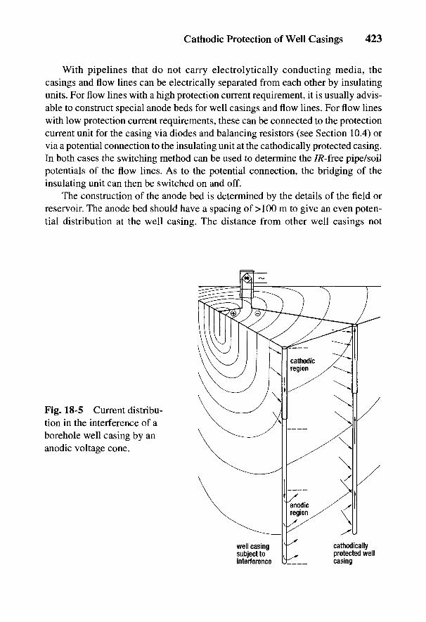
Cathodic Protection of Well Casings 423
With pipelines that do not carry electrolytically conducting media, thecasings and flow lines can be electrically separated from each other by insulatingunits. For flow lines with a high protection current requirement, it is usually advis-able to construct special anode beds for well casings and flow lines. For flow lineswith low protection current requirements, these can be connected to the protectioncurrent unit for the casing via diodes and balancing resistors (see Section 10.4) orvia a potential connection to the insulating unit at the cathodically protected casing.In both cases the switching method can be used to determine the 7/?-free pipe/soilpotentials of the flow lines. As to the potential connection, the bridging of theinsulating unit can then be switched on and off.
The construction of the anode bed is determined by the details of the field orreservoir. The anode bed should have a spacing of > 100 m to give an even poten-tial distribution at the well casing. The distance from other well casings not
Fig. 18-5 Current distribu-tion in the interference of aborehole well casing by ananodic voltage cone.
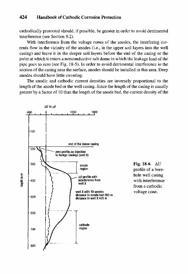
424 Handbook of Cathodic Corrosion Protection
cathodically protected should, if possible, be greater in order to avoid detrimentalinterference (see Section 9.2).
With interference from the voltage cones of the anodes, the interfering cur-rents flow in the vicinity of the anodes (i.e., in the upper soil layers into the wellcasing) and leave it in the deeper soil layers before the end of the casing or thepoint at which it enters a nonconductive salt dome in which the leakage load of thepipe goes to zero (see Fig. 18-5). In order to avoid detrimental interference in thesection of the casing near the surface, anodes should be installed in this area. Deepanodes should have little covering.
The anodic and cathodic current densities are inversely proportional to thelength of the anode bed or the well casing. Since the length of the casing is usuallygreater by a factor of 10 than the length of the anode bed, the current density of the
Fig. 18-6 At/profile of a bore-hole well casingwith interferencefrom a cathodicvoltage cone.
Cathodic Protection of Well Casings 425
well casings is smaller by this factor. But even here interference with cathodicallyunprotected well casings is possible. This is the case when an unprotected casing issunk in the immediate vicinity of a cathodically protected casing. If the electricfield of the cathodic voltage cone is stronger than that of the anodic voltage cone atthe place of interference, current could enter the lower region of the cathodicallyunprotected casing and leave it for the cathodically protected casing, causinganodic corrosion of this upper part of the unprotected casing (see Fig. 18-6).
18.5 Commissioning, Maintenance and Control
When commissioning the cathodic protection station for the well casing, aprotection current about 10% higher than that determined in the measurements asin Section 18.3 is supplied. In the case of a separate protection current supply forthe flow lines, the pipe/soil potential should be set at a Uon value of t/Cu.CuSo4 ~ ~1 -^ V.After a sufficient polarization period, which for the well casing is about a year, forflow lines with a high protection current requirement about half a year, and forflow lines with good coating about a month, the cathodic protection for the flowlines can be verified as in Section 10.4. If the cathodic protection is set up as localcathodic protection, checking is only necessary after a year.
It is very important to measure interference. The measurements can be madeas described in Section 9.2. In general, raising of the potential cannot be measuredexcept in the case of interference from the cathodic voltage cone of a well casing

426 Handbook of Cathodic Corrosion Protection
since it occurs at a distance from the surface. With anodic interference, the 0.5-Vlimit must be observed (see Section 9.2.1). Damaging interference can only besuppressed by an equal potential bond to the cathodically protected object.
The protection station must be carefully maintained (see Section 10.5). Thefunction of the rectifier should be monitored at monthly intervals. The pipe/soilpotentials of the pipelines should be measured at least once a year. The IR-freepotentials should be determined as far as possible by the switching method,especially when new pipework is installed and connected to the protection system.
18.6 References
[1] G. Herbsleb, R. Popperling und W. Schwenk, 3R internal. 13, 259 (1974).[2] H. Kampermann u. W. Harms, Erdol Erdgas 101, H. 2, S. 45 (1985).[3] R. Graf u. B. Leutner, 3R internal. 13, 247 (1971).[4] E. W. Haycock, 13. NACE-Jahreslagung, April 1957, S. 769t.[5] F. W. Schremp u. L. E. Newlon, NACE-Jahreslagung, Marz 1979, Paper 63.[6] W. F. Gasl, Oil and Gas Journal 23.4.1973, S. 79.[7] E. P. Doremus u. F. B. Thorn, Oil and Gas Journal 4.8.1969, S. 127.

19
Cathodic Protection of ReinforcingSteel in Concrete Structures
B. ISECKE
19.1 The Corrosion System Steel-Concrete
The corrosion protection of reinforcing steel in steel-reinforced concrete andprestressed concrete structures acts through the alkalinity of the porous concretewater content, since the steel passivates under these conditions [1-5] (see alsoSection 5.3). This corrosion protection is long term if the construction work has beencarried out according to the state of the art [6,7] and if no changes likely to impair thepassivity occur in use. Deficiencies in the construction process in the thickness anddensity of the concrete covering as well as the action of chloride-containing electro-lytes (deicing salts, seawater, PVC combustion, waste incinerators) can lead todepassivation [8-12], requiring additional corrosion protection measures. Thesemeasures must either give the concrete greater resistance to the corrosive environ-ments or, if depassivation has already set in after severe attack on the concrete, theymust involve additional direct protective action. Coating of the concrete to preventpenetration of chloride ions [10], coating the reinforcing steel with epoxy resin[13-18], or hot dip galvanizing [18-20] are used for this purpose.
Cathodic protection of reinforcing steel with impressed current is a relativelynew protection method. It was used experimentally at the end of the 1950s [21,22]for renovating steel-reinforced concrete structures damaged by corrosion, but notpursued further because of a lack of suitable anode materials so that driving voltagesof 15 to 200 V had to be applied. Also, from previous experience [23-26], loss ofadhesion between the steel and concrete due to cathodic alkalinity [see Eqs. (2-17)and (2-19)] was feared, which discouraged further technical development.
Cathodic protection as a restoration measure was revived in 1974 [27] as a result ofthe increasing damage to roadwork structures from Cl~-induced corrosion of the rein-forcing steel, which resulted in high repair costs in the United States [18]. This devel-opment was promoted by considerable negative experience with other methods. Todayimpressed current is used to protect reinforcing steel on road bridges, retaining walls,marine structures, multistory car parks, salt tanks and waste incinerator plants [28-37].
427
428 Handbook of Cathodic Corrosion Protection
Cathodic protection cannot work with prestressed concrete structures that haveelectrically insulated, coated pipes. There is positive experience in the case of adirect connection without coated pipes; this is protection of buried prestressedconcrete pipelines by zinc anodes [38]. Stability against H-induced stress corrosionin high-strength steels with impressed current has to be tested (see Section 2.3.4).
19.2 Causes of Corrosion of Steel in Concrete
The passivating action of an aqueous solution within porous concrete can bechanged by various factors (see Section 5.3.2). The passive film can be destroyedby penetration of chloride ions to the reinforcing steel if a critical concentration ofions is reached. In damp concrete, local corrosion can occur even in the presenceof the alkaline water absorbed in the porous concrete (see Section 2.3.2). The Cl~content is limited to 0.4% of the cement mass in steel-concrete structures [6] and to0.2% in prestressed concrete structures [7].
A further cause of depassivation is a reduction in the alkalinity of the concrete asin Fig. 2-2 (i.e., a reduction in the pH of the absorbed water). This occurs withcarbonizing of the concrete by reaction with CO2 in the atmosphere. In structureswith a sufficiently thick concrete covering over the steel inserts, especially withdense, low-porosity concrete of good quality, carbonization is unimportant. Withpoorer quality concrete and/or with too little concrete covering, carbonization pene-trates to the steel reinforcement, which then loses its passivity. With depassivationdue to chloride ions or carbonization, there is a danger of corrosion in damp concreteonly if there is access to oxygen. If the concrete is thoroughly soaked on all sides,access is severely restricted, so that the cathodic partial reaction according toEq. (2-17) cannot take place at any point on the reinforcing steel (see Section 5.3.2).Then, however, the anodic reaction according to Eq. (2-8) also cannot occur, i.e., thedepassivated steel will not corrode.
However, if part of the reinforcing steel is aerated, a cell is formed as inSection 2.2.4.2. With a high surface area ratio Sc/Sa and with well-aerated cathodes,very high corrosion rates can occur at anodic regions.
19.3 Electrolytic Properties of Concrete
The specific electrical resistance of concrete can be measured by the methoddescribed in Section 3.5. Its value depends on the water/cement value, the type ofcement (blast furnace, portland cement), the cement content, additives (flue ash),additional materials (polymers), the moisture content, salt content (chloride), thetemperature and the age of the concrete. Comparisons are only meaningful for the
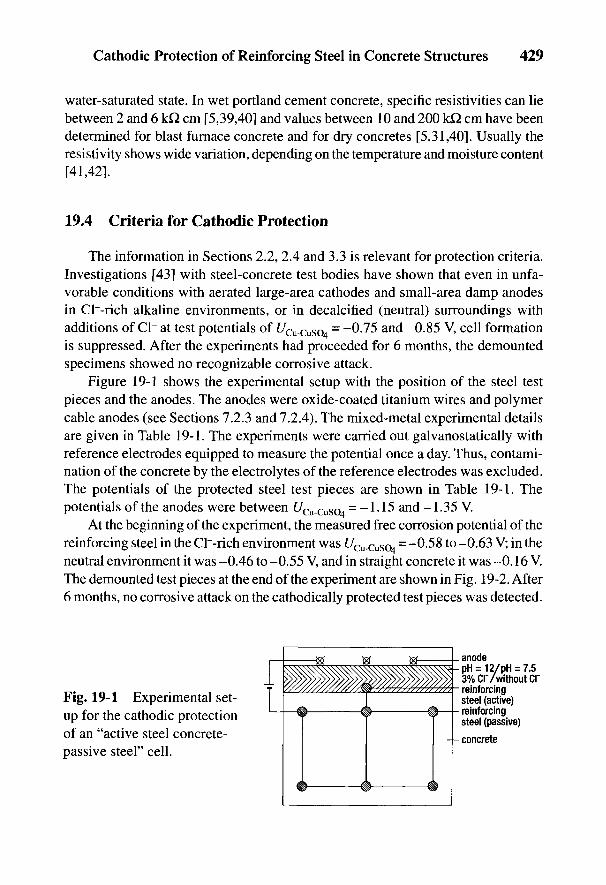
Cathodic Protection of Reinforcing Steel in Concrete Structures 429
water-saturated state. In wet portland cement concrete, specific resistivities can liebetween 2 and 6 k£l cm [5,39,40] and values between 10 and 200 kQ cm have beendetermined for blast furnace concrete and for dry concretes [5,31,40]. Usually theresistivity shows wide variation, depending on the temperature and moisture content[41,42].
19.4 Criteria for Cathodic Protection
The information in Sections 2.2, 2.4 and 3.3 is relevant for protection criteria.Investigations [43] with steel-concrete test bodies have shown that even in unfa-vorable conditions with aerated large-area cathodes and small-area damp anodesin Cl~-rich alkaline environments, or in decalcified (neutral) surroundings withadditions of Cl~ at test potentials of UCu_CuSO = -0.75 and -0.85 V, cell formationis suppressed. After the experiments had proceeded for 6 months, the demountedspecimens showed no recognizable corrosive attack.
Figure 19-1 shows the experimental setup with the position of the steel testpieces and the anodes. The anodes were oxide-coated titanium wires and polymercable anodes (see Sections 7.2.3 and 7.2.4). The mixed-metal experimental detailsare given in Table 19-1. The experiments were carried out galvanostatically withreference electrodes equipped to measure the potential once a day. Thus, contami-nation of the concrete by the electrolytes of the reference electrodes was excluded.The potentials of the protected steel test pieces are shown in Table 19-1. Thepotentials of the anodes were between UCu_CuS04 = -1.15 and -1.35 V.
At the beginning of the experiment, the measured free corrosion potential of thereinforcing steel in the CI~-rich environment was t/Cu-cuso4
= -0-58 to -0.63 V; in theneutral environment it was -0.46 to -0.55 V, and in straight concrete it was -0.16 V.The demounted test pieces at the end of the experiment are shown in Fig. 19-2. After6 months, no corrosive attack on the cathodically protected test pieces was detected.
Fig. 19-1 Experimental set-up for the cathodic protectionof an "active steel concrete-passive steel" cell.
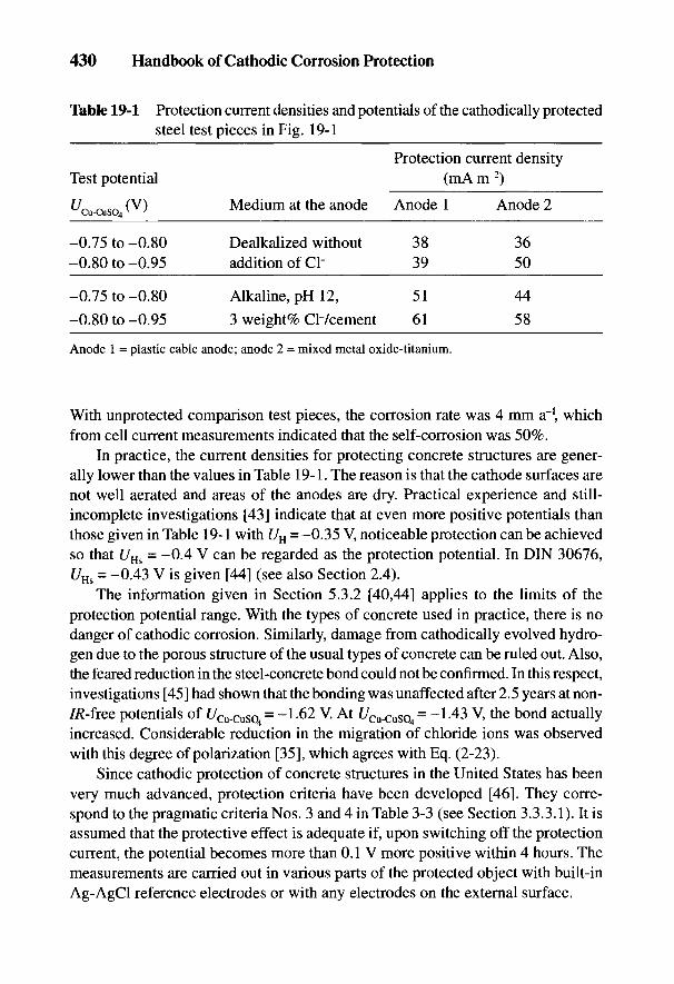
430 Handbook of Cathodic Corrosion Protection
Table 19-1 Protection current densities and potentials of the cathodically protectedsteel test pieces in Fig. 19-1
Protection current densityTest potential (mA m~2)
UCu CuSO (V) Medium at the anode Anode 1 Anode 2
-0.75 to-0.80 Dealkalized without 38 36-0.80 to-0.95 addition of Q- 39 50
-0.75 to -0.80 Alkaline, pH 12, 51 44
-0.80 to-0.95 3 weight% Ch/cement 61 58
Anode 1 = plastic cable anode; anode 2 = mixed metal oxide-titanium.
With unprotected comparison test pieces, the corrosion rate was 4 mm a"1, whichfrom cell current measurements indicated that the self-corrosion was 50%.
In practice, the current densities for protecting concrete structures are gener-ally lower than the values in Table 19-1. The reason is that the cathode surfaces arenot well aerated and areas of the anodes are dry. Practical experience and still-incomplete investigations [43] indicate that at even more positive potentials thanthose given in Table 19-1 with UH = -0.35 V, noticeable protection can be achievedso that i/Hs = -0.4 V can be regarded as the protection potential. In DIN 30676,UHs = -0.43 V is given [44] (see also Section 2.4).
The information given in Section 5.3.2 [40,44] applies to the limits of theprotection potential range. With the types of concrete used in practice, there is nodanger of camodic corrosion. Similarly, damage from cathodically evolved hydro-gen due to the porous structure of the usual types of concrete can be ruled out. Also,the feared reduction in the steel-concrete bond could not be confirmed. In this respect,investigations [45] had shown that the bonding was unaffected after 2.5 years at non-7/Wree potentials of f/Cu-cuso4
= -1-62 V. At £/Cu-Cuso4= -1-43 V, the bond actually
increased. Considerable reduction in the migration of chloride ions was observedwith this degree of polarization [35], which agrees with Eq. (2-23).
Since cathodic protection of concrete structures in the United States has beenvery much advanced, protection criteria have been developed [46]. They corre-spond to the pragmatic criteria Nos. 3 and 4 in Table 3-3 (see Section 3.3.3.1). It isassumed that the protective effect is adequate if, upon switching off the protectioncurrent, the potential becomes more than 0.1 V more positive within 4 hours. Themeasurements are carried out in various parts of the protected object with built-inAg-AgCl reference electrodes or with any electrodes on the external surface.
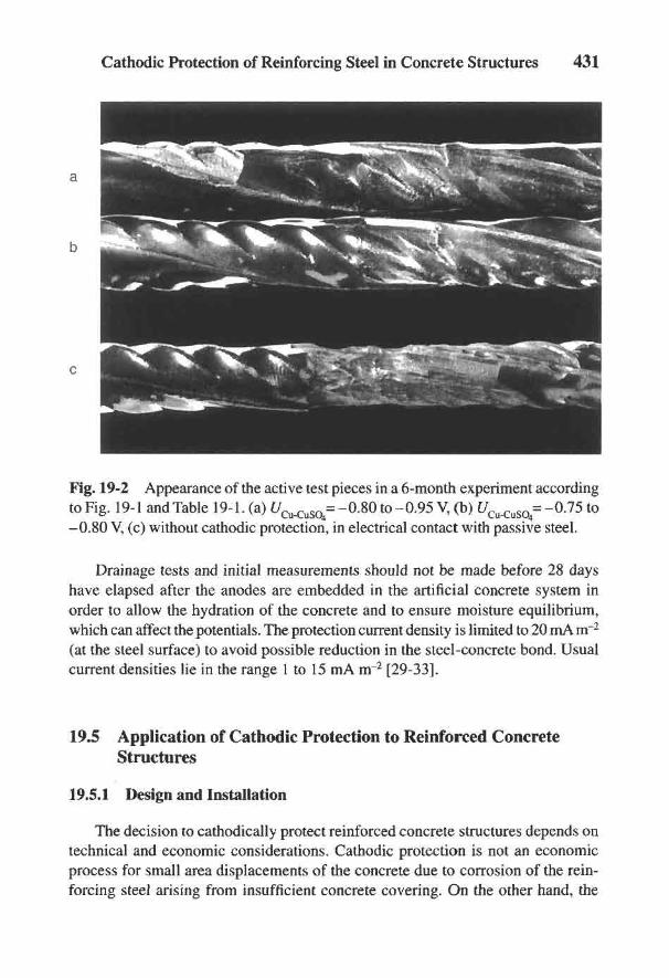
Cathodic Protection of Reinforcing Steel in Concrete Structures 431
Fig. 19-2 Appearance of the active test pieces in a 6-month experiment accordingto Fig. 19-1 and Table 19-1. (a) £7^=-0 .80 to-0.95 V, (b) UCu_CuSO = -0.15 to
-0.80 V, (c) without cathodic protection, in electrical contact with passive steel.
Drainage tests and initial measurements should not be made before 28 dayshave elapsed after the anodes are embedded in the artificial concrete system inorder to allow the hydration of the concrete and to ensure moisture equilibrium,which can affect the potentials. The protection current density is limited to 20 mA irr2
(at the steel surface) to avoid possible reduction in the steel-concrete bond. Usualcurrent densities lie in the range 1 to 15 mA m~2 [29-33].
19.5 Application of Cathodic Protection to Reinforced ConcreteStructures
19.5.1 Design and Installation
The decision to cathodically protect reinforced concrete structures depends ontechnical and economic considerations. Cathodic protection is not an economicprocess for small area displacements of the concrete due to corrosion of the rein-forcing steel arising from insufficient concrete covering. On the other hand, the
432 Handbook of Cathodic Corrosion Protection
main areas of application of such reinforced concrete structures must be looked at,particularly where there are high chloride ion concentrations at considerable depthin the concrete. To repair this, the Cl~-contaminated old concrete can only beremoved down to the uppermost layer of reinforcing steel for technical reasons. Ifa high Cl~ content remains in the concrete at greater depths, then corrosion willcontinue there. Since the repaired upper layer represents a new cathode surface,cell action is increased and corrosion in the deeper layer is promoted. Negativeexperience with repairs of this kind is unfortunately very widespread [47].
19.5.2 Determination of the State of Corrosion of the Reinforcing Steel
A diagnosis of possible damage should be made before beginning repairs withother construction measures [48,49]. There should be a checklist [48] of the impor-tant corrosion parameters and the types of corrosion effects to be expected. Ofspecial importance are investigations of the quality of the concrete (strength, typeof cement, water/cement ratio, cement content), the depth of carbonization, con-centration profile of chloride ions, moisture distribution, and the situation regard-ing cracks and displacements. The extent of corrosion attack is determined visually.Later the likelihood of corrosion can be assessed using the above data.
The extent of the corrosion shows itself by, for example, cracks and displace-ments arising from growing solid corrosion products (rust). A little-used method tofind these is to tap the concrete surface with a hammer; this allows hollow regionsand cracks to be clearly distinguished acoustically from undamaged regions. Thesesimple methods cannot, however, answer the question of whether the reinforcingsteel is already depassivated. Corrosion damage in concrete is attributed to solidcorrosion products arising from Fe2+ ions from the anode according to Eq. (2-21)and subsequent reaction with oxygen. Since the porous structure of the concretecan absorb Fe2+ ions, the site of this oxidation is not necessarily the surface of theanode. The reaction site is determined mainly by the diffusion currents of the part-ners to the reaction—Fe2+ ions and O2 in the concrete (see the explanation inSection 4.1). When oxidation occurs at some distance from the anode the corrod-ing anode can remain uncovered. At a later stage, rust stains can appear on theconcrete surface. If the oxidation takes place in the vicinity of the anode, where thehighest concentration of corrosion products is to be found, internal stresses arisedue to the growing solid corrosion products of hydrated ferric oxide (rust) withcracks, voids and displacement as a consequence.
Two-dimensional potential measurements on the concrete surface serve todetermine the corrosion state of the reinforcing steel. This method has been provedfor one-dimensional systems (pipelines), according to the explanation forFig. 3-24 in Section 3.6.2.1 on the detection of anodic areas.
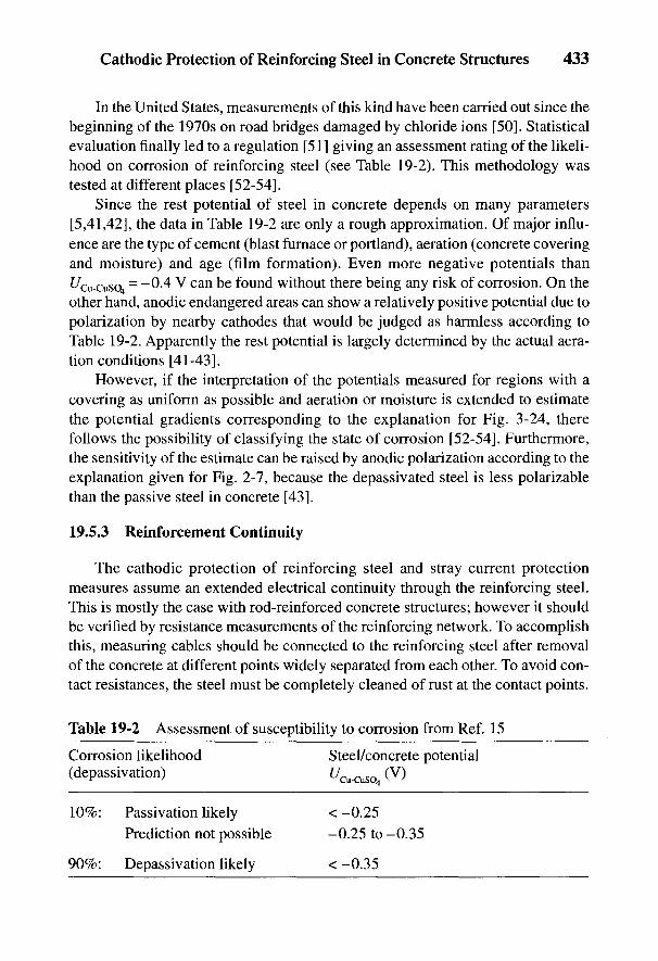
Cathodic Protection of Reinforcing Steel in Concrete Structures 433
In the United States, measurements of this kind have been carried out since thebeginning of the 1970s on road bridges damaged by chloride ions [50]. Statisticalevaluation finally led to a regulation [51] giving an assessment rating of the likeli-hood on corrosion of reinforcing steel (see Table 19-2). This methodology wastested at different places [52-54].
Since the rest potential of steel in concrete depends on many parameters[5,41,42], the data in Table 19-2 are only a rough approximation. Of major influ-ence are the type of cement (blast furnace or portland), aeration (concrete coveringand moisture) and age (film formation). Even more negative potentials than^Cu-cuso4
= ~0-4 V can be found without there being any risk of corrosion. On theother hand, anodic endangered areas can show a relatively positive potential due topolarization by nearby cathodes that would be judged as harmless according toTable 19-2. Apparently the rest potential is largely determined by the actual aera-tion conditions [41-43].
However, if the interpretation of the potentials measured for regions with acovering as uniform as possible and aeration or moisture is extended to estimatethe potential gradients corresponding to the explanation for Fig. 3-24, therefollows the possibility of classifying the state of corrosion [52-54]. Furthermore,the sensitivity of the estimate can be raised by anodic polarization according to theexplanation given for Fig. 2-7, because the depassivated steel is less polarizablethan the passive steel in concrete [43].
19.5.3 Reinforcement Continuity
The cathodic protection of reinforcing steel and stray current protectionmeasures assume an extended electrical continuity through the reinforcing steel.This is mostly the case with rod-reinforced concrete structures; however it shouldbe verified by resistance measurements of the reinforcing network. To accomplishthis, measuring cables should be connected to the reinforcing steel after removalof the concrete at different points widely separated from each other. To avoid con-tact resistances, the steel must be completely cleaned of rust at the contact points.
Table 19-2 Assessment of susceptibility to corrosion from Ref. 15
Corrosion likelihood Steel/concrete potential(depassivation) t/cu-cuso4 (
v)
10%: Passivation likely <-0.25Prediction not possible -0.25 to -0.35
90%: Depassivation likely < -0.35
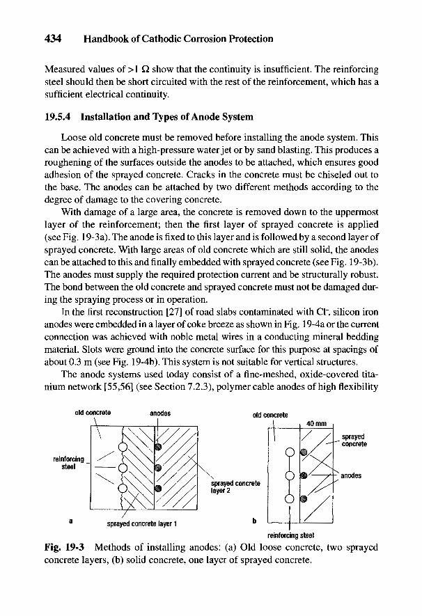
434 Handbook of Cathodic Corrosion Protection
Measured values of >1 Q show that the continuity is insufficient. The reinforcingsteel should then be short circuited with the rest of the reinforcement, which has asufficient electrical continuity.
19.5.4 Installation and "types of Anode System
Loose old concrete must be removed before installing the anode system. Thiscan be achieved with a high-pressure water jet or by sand blasting. This produces aroughening of the surfaces outside the anodes to be attached, which ensures goodadhesion of the sprayed concrete. Cracks in the concrete must be chiseled out tothe base. The anodes can be attached by two different methods according to thedegree of damage to the covering concrete.
With damage of a large area, the concrete is removed down to the uppermostlayer of the reinforcement; then the first layer of sprayed concrete is applied(see Fig. 19-3a). The anode is fixed to this layer and is followed by a second layer ofsprayed concrete. With large areas of old concrete which are still solid, the anodescan be attached to this and finally embedded with sprayed concrete (see Fig. 19-3b).The anodes must supply the required protection current and be structurally robust.The bond between the old concrete and sprayed concrete must not be damaged dur-ing the spraying process or in operation.
In the first reconstruction [27] of road slabs contaminated with Cl~, silicon ironanodes were embedded in a layer of coke breeze as shown in Fig. 19-4a or the currentconnection was achieved with noble metal wires in a conducting mineral beddingmaterial. Slots were ground into the concrete surface for this purpose at spacings ofabout 0.3 m (see Fig. 19-4b). This system is not suitable for vertical structures.
The anode systems used today consist of a fine-meshed, oxide-covered tita-nium network [55,56] (see Section 7.2.3), polymer cable anodes of high flexibility
Fig. 19-3 Methods of installing anodes: (a) Old loose concrete, two sprayedconcrete layers, (b) solid concrete, one layer of sprayed concrete.
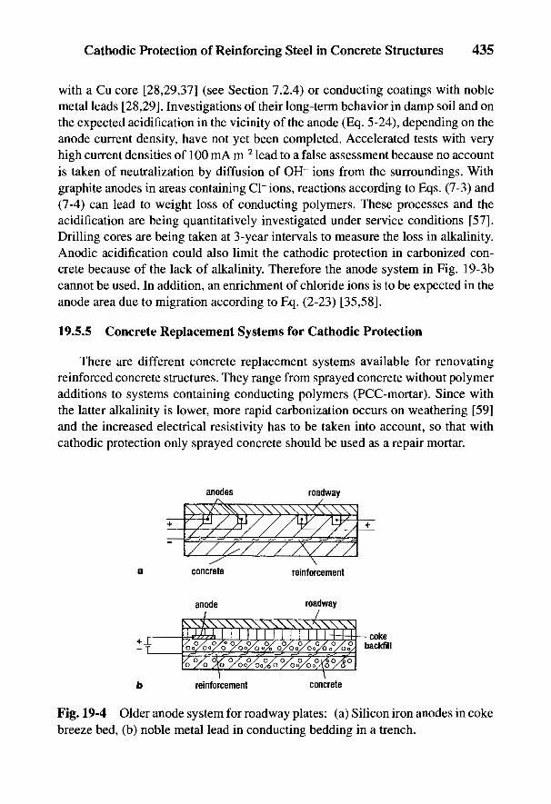
Cathodic Protection of Reinforcing Steel in Concrete Structures 435
with a Cu core [28,29,37] (see Section 7.2.4) or conducting coatings with noblemetal leads [28,29]. Investigations of their long-term behavior in damp soil and onthe expected acidification in the vicinity of the anode (Eq. 5-24), depending on theanode current density, have not yet been completed. Accelerated tests with veryhigh current densities of 100 mA m~2 lead to a false assessment because no accountis taken of neutralization by diffusion of OH~ ions from the surroundings. Withgraphite anodes in areas containing Cl~ ions, reactions according to Eqs. (7-3) and(7-4) can lead to weight loss of conducting polymers. These processes and theacidification are being quantitatively investigated under service conditions [57].Drilling cores are being taken at 3-year intervals to measure the loss in alkalinity.Anodic acidification could also limit the cathodic protection in carbonized con-crete because of the lack of alkalinity. Therefore the anode system in Fig. 19-3bcannot be used. In addition, an enrichment of chloride ions is to be expected in theanode area due to migration according to Eq. (2-23) [35,58].
19.5.5 Concrete Replacement Systems for Cathodic Protection
There are different concrete replacement systems available for renovatingreinforced concrete structures. They range from sprayed concrete without polymeradditions to systems containing conducting polymers (PCC-mortar). Since withthe latter alkalinity is lower, more rapid carbonization occurs on weathering [59]and the increased electrical resistivity has to be taken into account, so that withcathodic protection only sprayed concrete should be used as a repair mortar.
Fig. 19-4 Older anode system for roadway plates: (a) Silicon iron anodes in cokebreeze bed, (b) noble metal lead in conducting bedding in a trench.

436 Handbook of Cathodic Corrosion Protection
19.5.6 Commissioning, Maintenance and Control
In designing cathodic protection for concrete structures, it is convenient todivide the surfaces to be protected into separate areas that take account of the localsteel area per volume of concrete as well as the distribution of moisture. Figure19-5 shows schematically the division of a reinforced concrete support wall whichis to be protected in four areas. The object to be protected had a concrete surfacearea of 200 m2, and the component areas ranged from 20 to 90 m2. The reinforcingindex (steel surface/concrete surface) was 1 and had to be known in each case inorder to determine the protection current density. Plastic cable anodes were usedfor the anode system. These were loop shaped and dowelled into the concrete sur-face in areas of low reinforcing index in straight lines. Ag-AgCl reference elec-trodes were used for the control system. These were built in at a distance of 2 cmfrom the reinforcing steel and had to be protected against mechanical influences.In the object considered in Fig. 19-5, eight reference electrodes were used withseparate anode connections to each component area.
Control of the cathodic protection was carried out by potential measurementswith the built-in reference electrodes and with mobile electrodes on the surface. Inspite of there being little information on the long-term stability of built-in refer-ence electrodes, they should not be abandoned for this reason, because the IR erroraccording to Eq. (2-34) is small due to the small distance from the reinforcingsteel. Special reference electrodes are being developed [59]. Mobile reference elec-trodes have the advantage that potential control can be carried out at any desiredlocation. IR errors have to be considered, particularly near the anodes, due to thelarge distance from the reinforcing steel.
Fig. 19-5 Renovation of a retaining wall with cathodic protection, division intosections.
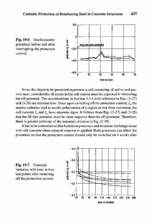
Cathodic Protection of Reinforcing Steel in Concrete Structures 437
Fig. 19-6 Steel/concretepotentials before and afterinterrupting the protectioncurrent.
Since the object to be protected represents a cell consisting of active and pas-sive steel, considerable IR errors in the cell current must be expected in measuringthe off potential. The considerations in Section 3.3.1 with reference to Eqs. (3-27)and (3-28) are relevant here. Since upon switching off the protection current, 7S, thenearby cathodes lead to anodic polarization of a region at risk from corrosion, thecell currents 7e and 7S, have opposite signs. It follows from Eqs. (3-27) and (3-28)that the 7/?-free potential must be more negative than the off potential. Therefore,there is greater certainty of the potential criterion in Eq. (2-39).
It has to be remembered that hydration processes and moisture exchange occurwith old concrete when sprayed concrete is applied. Both processes can affect thepotentials so that the protection current should only be switched on 4 weeks after
Fig. 19-7 Potentialvariation with time at fivetest points after switchingoff the protection current.
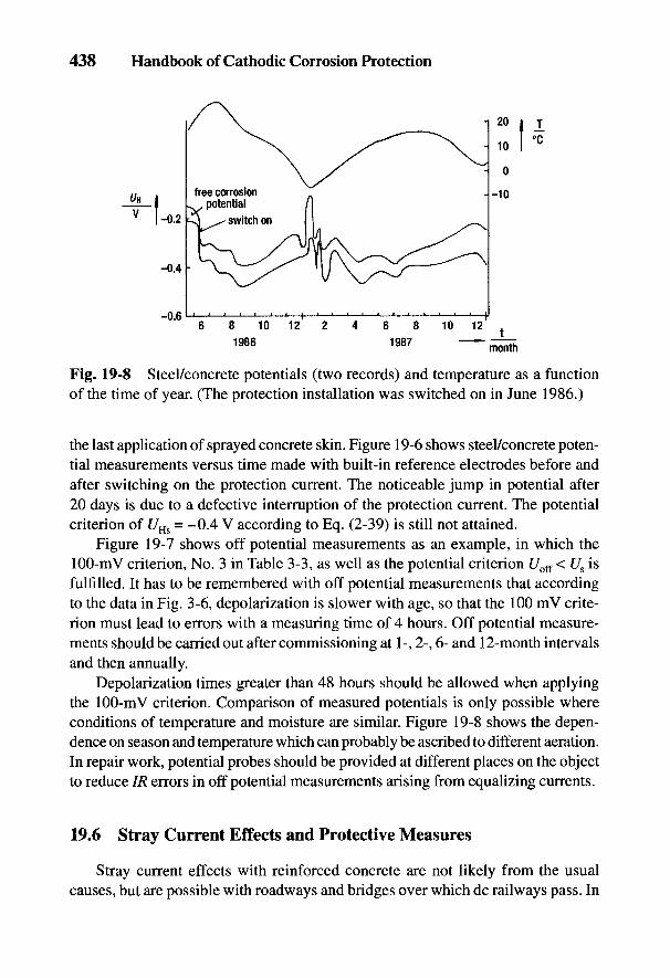
438 Handbook of Cathodic Corrosion Protection
Fig. 19-8 Steel/concrete potentials (two records) and temperature as a functionof the time of year. (The protection installation was switched on in June 1986.)
the last application of sprayed concrete skin. Figure 19-6 shows steel/concrete poten-tial measurements versus time made with built-in reference electrodes before andafter switching on the protection current. The noticeable jump in potential after20 days is due to a defective interruption of the protection current. The potentialcriterion of C/Hs = -0.4 V according to Eq. (2-39) is still not attained.
Figure 19-7 shows off potential measurements as an example, in which the100-mV criterion, No. 3 in Table 3-3, as well as the potential criterion C/off < Us isfulfilled. It has to be remembered with off potential measurements that accordingto the data in Fig. 3-6, depolarization is slower with age, so that the 100 mV crite-rion must lead to errors with a measuring time of 4 hours. Off potential measure-ments should be carried out after commissioning at 1-, 2-, 6- and 12-month intervalsand then annually.
Depolarization times greater than 48 hours should be allowed when applyingthe 100-mV criterion. Comparison of measured potentials is only possible whereconditions of temperature and moisture are similar. Figure 19-8 shows the depen-dence on season and temperature which can probably be ascribed to different aeration.In repair work, potential probes should be provided at different places on the objectto reduce IR errors in off potential measurements arising from equalizing currents.
19.6 Stray Current Effects and Protective Measures
Stray current effects with reinforced concrete are not likely from the usualcauses, but are possible with roadways and bridges over which dc railways pass. In
Cathodic Protection of Reinforcing Steel in Concrete Structures 439
the Federal Republic of Germany, the railways are mainly ac. Usually, the rails arenot grounded and are well insulated with high-resistance ballast. If, however, straycurrents escape, the protective measures in Chapter 15 are applicable so that allother lines that run parallel to the reinforcing steel and the rails must be included inthe protection system.
19.7 References
[I] A. Baumel, Zement, Kalk, Gips 12, 284 (1959).[2] H. Kaesche, Zement, Kalk, Gips 72, 289 (1959).[3] A. Baumel u. HJ. Engell, Arch. Eisenhuttenwes. 30, 417 (1959).[4] H. Kaesche, Arch. Eisenhuttenwes. 36, 911 (1965).[5] W. Schwenk, Betonwerk + Fertigteil-Technik, 51, 216 (1985).[6] DIN 1045, Beuth-Verlag, Berlin (1988).[7] DIN 4277, Beuth-Verlag, Berlin (1988).[8] B. Isecke, Werkst, Korros. 37, 322 (1986).[9] G. Ruffert, Schaden an Betonbauwerken, Verlagsgesellschaft Rudolf Miiller, Koln-
Braunsfeld 1982.[10] D. Jungwirth, E. Beyer, P. Griibel, Dauerhafte Betonbauwerke, Beton-Verlag,
Dusseldorf, 1986.[II] HJ. Lasse u. W. Stichel, Die Bautechnik 60, 124 (1983).[12] D. Weber, Amts- und Mitteilungsblat BAM 72, 107 (1982).[13] P. SchieBl, Bautenschutz u. Bausanierung 10, 62 (1987).[14] B.D. Mayer, Bautenschutz u. Bausanierung 70, 66 (1987).[15] B. Isecke, Bautenschutz u. Bausanierung 10, 72 (1987).[16] G. Rehm u. E. Fielker, Bautenschutz und Bausanierung 10, 79 (1987).[17] G. Thielen, Bautenschutz und Bausanierung 10, 87 (1987).[18] I.E. Slater, Corrosion Metals in Association with Concrete, ASTM STP 818,
Philadephia 1983.[19] U. Niirnberger, Werkst. Korros. 37, 302 (1986).[20] D.E. Tonini u. S.W. Dean (ed.), Chloride Corrosion of Steel in Concrete, ASTM STP
629, Philadelphia 1977.[21] R.F. Stratfull, Corrosion 13, 174t (1957).[22] R.F. Stratfull, Corrosion 75, 331t (1959).[23] A.E. Archambault, Corrosion 3, 57 (1947).[24] E.B. Rasa, B. McCollom, O.S. Peters, Electrolysis in Concrete, U.S. Bureau of Stan-
dards, Technological Paper No. 18, Washington 1913.[25] O.L. Eltingle, Engineering News 63, 327 (1910).[26] G. Mole, Engineering 766, H. 11, 5 (1948).[27] R.F. Stratfull, Materials Performance 13, H 4, 24 (1974).[28] Proc. "Corrosion in Concrete B Practical Aspects of Control by Cathodic Protec-
tion," Seminar London, published by Global Corrosion Consultants, Telford,England, 1987.
440 Handbook of Cathodic Corrosion Protection
[29] Proc. 2nd International Conference on the deterioration and repair of reinforced con-crete in the Arabian Gulf, Bahrain 1987.
[30] Cathodic Protection of Reinforced Concrete Decks, NACE, 20 papers, 1985.[31] D. Whiting u. D. Stark, Cathodic Protection for Reinforced Concrete Bridge Decks
B Field Evaluation, Final Report, Construction Technology Laboratories, PortlandCement Association, Skokie, Illinois, NCHRP 12-13A(1981).
[32] Proc. NACA Corrosion 87, San Francisco, papers 122 bis 147, 1987.[33] B. Heuze, Materials Performance, 79, H. 5, 24 (1980).[34] O. Saetre u. F. Jensen, Materials Performance, 27, H. 5, 30 (1982).[35] O.E. Gjorv u. 0. Vennesland, Materials Performance, 79, H. 5, 49 (1980).[36] B. Isecke, Beton, 37, 211 (1987).[37] K.B. Pithouse, Corrosion Prevention and Control, 75, H. 10, 113 (1986).[38] J.T. Gourley u. F.E. Moresco, NACE Corrosion 87, paper 318, San Francisco 1987.[39] B.P. Hughes, A.K.O. Soleit, R.W. Brierly, Magazine of Concrete Research 37, 243
(1985).[40] H. Hildebrand, M. Schulze u. W. Schwenk, Werkst, Korros. 34, 281 (1983).[41] H. Hildebrand u. W. Schwenk, Werkst. Korros. 37, 163 (1986).[42] H. Hildebrand, C.-L. Kruse u. W. Schwenk, Werkst. Korros. 38, 696 (1987).[43] J. Fischer, B. Isecke, B. Jonas, Werkst. Korros., demnachst.[44] DIN 30676, Beuth-Verlag, Berlin 1985.[45] J.A. Shaw, Civil Engineering (ASCE), H. 6, 39 (1965).[46] Cathodic Protection of Reinforcing Steel in Concrete Structures, Proposed NACE-
Standard, Committee T-3K-2 NACE, Houston 1985.[47] P. Vassie, Corrosion Prevention and Control, 32, H. 6, 43 (1985).[48] H.U. Aeschlimann, Schweizer Ingenieur und Architekt, 75, 867 (1985).[49] V. Herrmann, Beton- und Stahlbetonbau, 82, 334 (1987).[50] J.R. van Daveer, ACI Journal 72, 697 (1975).[51] ASTM C 876, Philadelphia 1980.[52] J. Tritthardt u. H. Geymayer, Beton, 31, 237 (1981).[53] B. Elsener u. H. Bohni, Schweizer Ingenieur und Architekt 14, 264 (1984).[54] R. Miiller, Proc, "Werkstoffwissenschaften und Bausanierung," TA Esslingen, 689
(1987).[55] J.E. Bennett, Beitrag in [28] und [29].[56] S. Kotowski, B. Busse u. R. Bedel, METALL42, 133 (1988).[57] Forschungsprojekt 102D der EG im BRITE-Forschungsprogramm "Electrochemi-
cally Based Techniques for Assessing and Preventing Corrosion of Steel in Con-crete," Bericht erhaltlich 1990.
[58] G. Mussinelli, M. Tettamanti u. P. Pedeferri in [29], S. 99.[59] R. Kwasny, A. Roosen u. M. Maultzsch, Betonwerk u. Fertigteil-Technik 52, 797
(1986).

20
Internal Cathodic Protectionof Water Tanks and Boilers
G. FRANKS AND U. HEINZELMANN
Internal cathodic protection of water tanks and boilers is most economical if itis taken care of at the design stage. It can, however, be installed at a later stage asa rehabilitation measure to halt the progress of corrosion. Tanks and boilers inships were described in Section 17.4. Further applications of internal protectionare dealt with in Chapter 21.
20.1 Description and Function of Objects to be Protected
Water tanks are used for storing hot and cold drinking water, service water,cooling water, condensate and sewage. Filter tanks are used for purifying water,and reaction vessels are used for physical and chemical reactions (e.g., removal ofozone). The tanks may be open, with variable water levels, filled as pressure ves-sels, or partly filled as compression tanks; they may also be vacuum tanks. Theycan be equipped with inserts such as heating or cooling surfaces, separating parti-tions, probes, connected tubes or distribution tubing.
All these components can be included in the cathodic protection if certain fea-tures are considered in the design [e.g., bundles of heating tubes in a square array(see Fig. 20-1)], and the electrodes are arranged so that all the surfaces receivesufficient protection current i.e., so that the criterion in Eq. (2-39) is fulfilled.
In enamelled tanks with protection electrodes of low current output, fittings[e.g., heating surfaces (cathodic components)] must be electrically isolated fromthe tank and the ground. Figure 20-2 shows such a bushing. Smaller cathodic compo-nents which take up only negligible protection current (e.g., temperature probes)do not need to be insulated.
In uncoated cathodically protected tanks, inserts must have an electrical con-nection to the tank to avoid damage due to anodic interference in the cathodicvoltage cone of the surfaces of the object to be protected. These processes are also
441

442 Handbook of Cathodic Corrosion Protection
Fig. 20-1 Heating element tubebundle on a rectangular pattern.
Fig. 20-2 Insulated installation of heating pipes in enamelled containers withelectrical separation of container and ground.
well known in the case of buried pipelines and are described in Section 24.3.4.This anodic danger in the internal protection of tanks is known as "current exitcorrosion" and is discussed further in Section 20.1.4.
20.1.1 Materials for Objects to be Protected and Installation Components
Materials for metal tanks and installations include plain carbon steel, hot-dippedgalvanized steel, stainless steel [e.g., steel No. 1.4571 (AISI 316Ti)], copper and itsalloys. The corrosion resistance of these materials in water is very variable and can
Internal Cathodic Protection of Water Tanks and Boilers 443
be assessed with the aid of Ref. 1. Furthermore, the rest potentials are very different(see Table 2-4) as are the protection potentials (see Section 2.4). Plain carbon steelthat is uncoated is not corrosion resistant. Stainless steel can suffer chloride-inducedlocalized corrosion. The rest of the materials are corrosion resistant due to the for-mation of protective films but can be attacked if the films have defects locally. In allthese cases, cathodic protection is applicable.
20.1.2 Types of Linings and Coatings
Different linings and coatings are used to provide corrosion protection for thetank which, according to Section 5.1, often makes economical cathodic protectionpossible. The properties of these materials are extensively described in Chapter 5.
Organic coatings include phenol formaldehyde, epoxy, polyacryl and polyacrylacid resins, polyamide, polyolefin, bitumen and rubber. The required properties oflining materials in combination with cathodic protection are given in Section 5.2.1.In addition, adequate resistance to water vapor diffusion is required (see Sec-tion 5.2.2). These properties are discussed in the basic standard for internal cathodicprotection [2], which also reports how these properties can be assured by testingwith the aid of Ref. 3. It is convenient to limit the protection potential region to£/HS = -0.8 V in the presence of resin coatings, which makes potential-controlledprotection current equipment necessary.
Cathodic blistering is not expected with high-resistance polyolefins and rub-berized coatings; however, where there are defects, local reduction in adhesion(cathodic disbonding) is apparent. Enamel linings have the best resistance againstcathodic influence (see Section 5.4).
20.1.3 Preconditions for Internal Cathodic Protection
The preconditions for internal cathodic protection are assembled in Ref. 2 anddiscussed in Section 21.1. The following directions are applicable to water tanks:
A protection potential range must exist for the materials of the internal sur-faces (tank and components) (see Section 2.4). The electrolytic conductivity ofwater in uncoated tanks should be > 100 //S cm"1. For lower conductivities, a coat-ing must be applied to maintain adequate current distribution that has a sufficientlyhigh coating resistance ru as in Eq. (5-2), in order to raise the polarization param-eter k in Eq. (2-45). For this the specific polarization resistance rp and the specificcoating resistance ru are considered equal. Usually adequate current distributionhas to be ensured by structural design (see Fig. 20-1) as well as by the arrangementand number of anodes.
With water of pH < 5, the data for Eq. (6-4) should be used to check whetherthe galvanic anodes have a self-corrosion that is too high (see Section 6.1.1). The

444 Handbook of Cathodic Corrosion Protection
data and test information in Section 6.2.4 should be used for magnesium anodes.Impressed current protection can lead to too high hydrogen evolution (see the protec-tion measures in Section 20.1.5).
20.1.4 Measures to Prevent Anodic Interference
Current exit corrosion arising from anodic interference of the surfaces of theobject to be protected in the cathodic voltage cone and at insulating units can beseen in Fig. 20-3. The object to be protected is an internally coated boiler with anuncoated heating element (e.g., copper pipe) that is electrically insulated from theobject to be protected according to Fig. 20-2. To avoid electrical shorting throughthe ground, an additional insulating unit must be built into the pipe outside thetank. Defects are present in the tank coating near the insulator, which produces acathodic voltage cone. The arrows show the path of the protection current; thehatched region represents the location of current exit corrosion.
The anodic danger in the interior of the heating element is dealt with theoreti-cally in Section 24.4.6. Assuming high polarization resistances in the system pipematerial-heating water, a current density distribution is set up in the interior of thepipe according to Eq. (24-91) with constants according to Eqs. (24-101) and(24-102). Out of these, the maximum current density J0 according to Eq. (24-102)is of particular interest. Quantitative application of this relationship is not possible
Fig. 20-3 Heating pipe (HE) in a boiler with a high-resistance coating with elec-trical separation from the boiler and from the ground by insulating units and abalancing resistor.

Internal Cathodic Protection of Water Tanks and Boilers 445
because of the idealized assumption and the unknown parameters involved. How-ever, it gives an indication of the trend of reduced danger of corrosion. This decreaseswith the length of the insulator, L, and with the square root of the polarizationparameter, ^pTI; it increases, however, with the square root of the pipe diam-eter, 4d.
A circular defect in the coating of diameter d is assumed to indicate the anodicdanger in the region of the cathodic voltage cone. With current density 7S, andgrounding resistance according to Eq. (24-17), the cathode voltage UQ is given by
The electric field is given by the equations in Table 24-1, column 2. UT and Ut givethe voltage distribution in the radial and depth directions respectively, where 2r0 = d.For small arguments of the arc sin and arc tan functions (i.e., for r0 « r and r0 « f),it follows that at a distance x = r or x = t from the defect:
Finally, it follows from Eqs. (20-1) and (20-2):
If the object interfered with (heating element) lies in the region between xl and x2,then the interfering voltage due to the voltage cone from Eq. (20-3) is given by:
The size of the defects in the coating has an important influence.It should be clearly pointed out that with anodic interference according to the
data in Fig. 2-6 in Section 2.2.4.1, the corrosivity of the electrolyte for the particu-lar material has no influence on the current exit corrosion. On the other hand, theconductivity of the electrolyte has an effect according to Eqs. (24-102) and (20-4).Chemical parameters have a further influence that determines the formation ofsurface films and the polarization resistance.
To avoid the described corrosion risk from current exit corrosion, heating ele-ments should be electrically connected to the object to be protected via a balancingresistor. Figure 20-3 shows a correctly placed balancing resistor R (dashed line).
The heat exchanger is brought into the cathodic protection circuit with a cor-rectly rated balancing resistor, thus eliminating the anodic danger according to
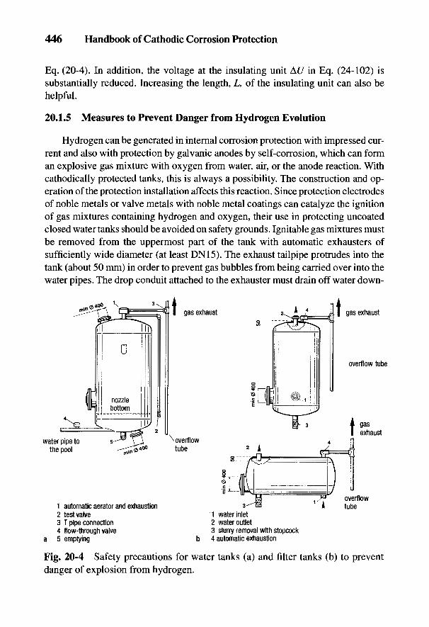
446 Handbook of Cathodic Corrosion Protection
Eq. (20-4). In addition, the voltage at the insulating unit At/ in Eq. (24-102) issubstantially reduced. Increasing the length, L, of the insulating unit can also behelpful.
20.1.5 Measures to Prevent Danger from Hydrogen Evolution
Hydrogen can be generated in internal corrosion protection with impressed cur-rent and also with protection by galvanic anodes by self-corrosion, which can forman explosive gas mixture with oxygen from water, air, or the anode reaction. Withcathodically protected tanks, this is always a possibility. The construction and op-eration of the protection installation affects this reaction. Since protection electrodesof noble metals or valve metals with noble metal coatings can catalyze the ignitionof gas mixtures containing hydrogen and oxygen, their use in protecting uncoatedclosed water tanks should be avoided on safety grounds. Ignitable gas mixtures mustbe removed from the uppermost part of the tank with automatic exhausters ofsufficiently wide diameter (at least DN15). The exhaust tailpipe protrudes into thetank (about 50 mm) in order to prevent gas bubbles from being carried over into thewater pipes. The drop conduit attached to the exhauster must drain off water down-
Fig. 20-4 Safety precautions for water tanks (a) and filter tanks (b) to preventdanger of explosion from hydrogen.
Internal Cathodic Protection of Water Tanks and Boilers 447
ward and gas upward via a T piece (see Fig. 20-4a). The exhaust tailpipe must be ledat a constant slope into the open if the water tank is in an insufficiently ventilatedroom. Before a cathodically protected uncoated tank is emptied, the protection equip-ment must be switched off and the tank completely filled with water.
In filter tanks, a pipe (at least DN15) with a test valve must be placed beneaththe exhausters leading to the floor level through which water must be taken to theopen air every day until the water is free from gas bubbles (see Fig. 20-4b). Thepartly filled cathodically protected pressure booster tank cannot be provided withautomatic gas exhaustors. Therefore, nozzles (at least DN15) with manually oper-ated valves must be provided at the highest point of the tank. Before emptying, theprotection system must be switched off and the tank filled with water through themanual valve.
Tanks that are enamelled or that have other high-resistance coatings with vol-umes below 4 m3 do not require automatic exhausts if they are equipped withgalvanic anodes in which the surface area does not exceed 5 dm2 per square meterof surface to be protected, or with controlled impressed current anodes with a lowcurrent output of 150mA.
20.2 Protection with Galvanic Anodes
Only magnesium anodes are practical for the cathodic protection of water tanksbecause their driving voltage is sufficiently high (see Section 6.2.4). Zinc and alu-minum anodes are not suitable for fresh water because their driving voltages aretoo low and they passivate too easily. Aluminum anodes containing Hg, whichhave a sufficiently negative rest potential and low polarizability, cannot be usedfor drinking water (see Section 20.5).
The range of applications for magnesium anodes includes the internalprotection of boilers, feedwater tanks, filter tanks, coolers, pipe heat exchangers andcondensers. They are mainly used in conjunction with coatings and whereimpressed current equipment is too expensive or cannot be installed.
Anode consumption is high with uncoated objects. Care therefore has to betaken that the Mg(OH)2 slurry does not interfere with the function of the system.Regular deslurrying has to be undertaken.
Magnesium anodes are frequently used as an additional protection measure ata later stage for stainless steel tanks. In this case the anodes are connected througha 5- to 10-£2 resistor to the tank to avoid an unnecessarily high current for thecathodic protection of the tank and simultaneous high consumption of the anodes.
Magnesium anodes are widely used in conjunction with enamel coatings. Thistype of corrosion protection is particularly economical and convenient in small-and medium-sized boilers. The anode only has to ensure protection of small de-
448 Handbook of Cathodic Corrosion Protection
fects in the enamel, which are unavoidable when enamelling in mass production,and are detailed in Ref. 4. The life of magnesium anodes designed with 0.2 kg m~2
of enamelled surface is at least 2 years and, on average, over 5 years.
20.3 Protection with Impressed Current
The impressed current protection method is used mainly for the internal pro-tection of large objects and particularly where high initial current densities have tobe achieved (e.g., in activated charcoal filter tanks and in uncoated steel tanks).There are basically two types of equipment: those with potential control, and thosewith current control.
20.3.1 Equipment with Potential Control
Protection current devices with potential control are described in Section 8.6(see Figs. 8.5 and 8.6); information on potentiostatic internal protection is given inSection 21.4.2.1. In these installations the reference electrode is sited in the mostunfavorable location in the protected object. If the protection criterion accordingto Eq. (2-39) is reached there, it can be assumed that the remainder of the surfaceof the object to be protected is cathodically protected.
Since usually the reference electrode is not equipped with a capillary probe(see Fig. 2-3), there is an error T|Q in the potential measurement given by Eq. (2-34);in this connection see the data in Section 3.3.1 on 7/?-free potential measurement.The switching method described there can also be applied in a modified form topotential-controlled protection current devices. Interrupter potentiostats are usedthat periodically switch off the protection current for short intervals [51. The switch-off phase is for a few tens of microseconds and the switch-on phase lasts severalhundred microseconds.
During the switching-off phase, the 7/?-free potential measured by the protec-tion current equipment is the actual potential and is compared with the nominalpotential. The protection current delivered by the device is adjusted so that the IR-free potential meets the nominal value. As a simplification, the impressed currentanode can also be used in the switching-off phase as the reference electrode in theevent one of them indicates a constant potential in this phase. This applies to noblemetal coatings on valve metals (e.g., TiPt) since O2 is evolved in the switching-onphase according to Eq. (7-1) and a definite redox system is established. Figure 20-5shows potential-time curves for switching-on and switching-off phases of a TiPtelectrode in tapwater. Immediately after switching off and switching on, there is anohmic voltage drop corresponding to Eq. (2-34) and represented by a dashed linein the figure. During the first 50 /is after switching off, a noticeable depolarization
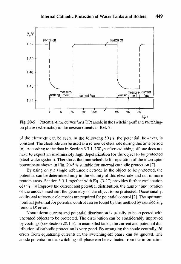
Internal Cathodic Protection of Water Tanks and Boilers 449
T/fJLS
Fig. 20-5 Potential-time curves for a TiPt anode in the switching-off and switching-on phase (schematic) in the measurements in Ref. 7.
of the electrode can be seen. In the following 50 /us, the potential, however, isconstant. The electrode can be used as a reference electrode during this time period[6]. According to the data in Section 3.3.1, 100 |is after switching off one does nothave to expect an inadmissibly high depolarization for the object to be protected(steel-water system). Therefore, the time schedule for operation of the interrupterpotentiostat shown in Fig. 20-5 is suitable for internal cathodic protection [7].
By using only a single reference electrode in the object to be protected, thepotential can be determined only in the vicinity of this electrode and not in moreremote areas. Section 3.3.1 together with Eq. (3-27) provides further explanationof this. To improve the current and potential distribution, the number and locationof the anodes must suit the geometry of the object to be protected. Occasionally,additional reference electrodes are required for potential control [2]. The optimumnominal potential for potential control can be found by this method by consideringremote IR errors.
Nonuniform current and potential distribution is usually to be expected withuncoated objects to be protected. The distribution can be considerably improvedby coatings (see Section 20.1.3). In enamelled tanks, the current and potential dis-tribution of cathodic protection is very good. By arranging the anode centrally, IRerrors from equalizing currents in the switching-off phase can be ignored. Theanode potential in the switching-off phase can be evaluated from the information
450 Handbook of Cathodic Corrosion Protection
in Fig. 20-5 for potential control so that the whole surface of the protected objectcan be adequately protected. A suitable arrangement of several anodes is necessaryonly for larger tanks of over 2 m3 in volume.
In general, potential control according to this technique allows the most accu-rate and stable maintenance generally possible of the potential of the object to beprotected. Changes in the protection current requirement (e.g., through formationof surface films or enlargement of defects in coatings) can be readjusted. Thereforethe overprotection associated with increased hydrogen evolution according toEq. (2-19) is not possible. This is particularly important in internal protection (seeSection 20.1.5).
20.3.2 Equipment with Current Control Based on Water Consumption
In some cases it is convenient to control the protection current according to thewater consumption. This mainly concerns tanks that supply fresh water in smallamounts at irregular intervals (e.g., storage tanks for fire-fighting installations).Hydrogen evolution occurs with otherwise constant protection current in a stagna-tion period after cathodic oxygen reduction as in Eq. (2-19). In this case, currentcontrol with a contact water meter acting as a pulse generator to limit hydrogenevolution is advisable (see Section 20.4.2).
20.4 Description of Objects to be Protected
20.4.1 Boilers with Enamel Linings
Cathodic protection of enamelled tanks with Mg anodes has long been the stateof the art, with potential-controlled equipment being used with increasing frequencyin recent years. A high-resistance coating with limited defects according to Ref. 4enables uniform current distribution to be maintained over the whole tank.
A danger of corrosion exists at defects in the enamel due to cell formation withcathodic components (i.e., inserts with a more positive free corrosion potential).These are mainly heating elements with a somewhat larger surface area than theenamel defects. With uninsulated inserts, they consume protection current so thatdefects lying in the voltage cone of the inserts not only receive no protectioncurrent but, under certain circumstances, can become anodic. For this reason, heat-ing elements must be electrically isolated from the boiler (see Figs. 20-2 and 20-3).The inserts must not be grounded in order to prevent a short circuit of the heatingelement with the object to be protected. In this case, safety regulations [8] must beobserved. These assume that the steel tank has a protective lead connection and
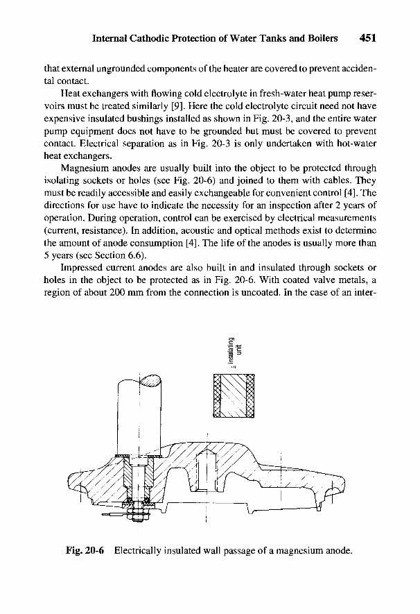
Internal Cathodic Protection of Water Tanks and Boilers 451
that external ungrounded components of the heater are covered to prevent acciden-tal contact.
Heat exchangers with flowing cold electrolyte in fresh-water heat pump reser-voirs must be treated similarly [9]. Here the cold electrolyte circuit need not haveexpensive insulated bushings installed as shown in Fig. 20-3, and the entire waterpump equipment does not have to be grounded but must be covered to preventcontact. Electrical separation as in Fig. 20-3 is only undertaken with hot-waterheat exchangers.
Magnesium anodes are usually built into the object to be protected throughisolating sockets or holes (see Fig. 20-6) and joined to them with cables. Theymust be readily accessible and easily exchangeable for convenient control [4]. Thedirections for use have to indicate the necessity for an inspection after 2 years ofoperation. During operation, control can be exercised by electrical measurements(current, resistance). In addition, acoustic and optical methods exist to determinethe amount of anode consumption [4]. The life of the anodes is usually more than5 years (see Section 6.6).
Impressed current anodes are also built in and insulated through sockets orholes in the object to be protected as in Fig. 20-6. With coated valve metals, aregion of about 200 mm from the connection is uncoated. In the case of an inter-
Fig. 20-6 Electrically insulated wall passage of a magnesium anode.
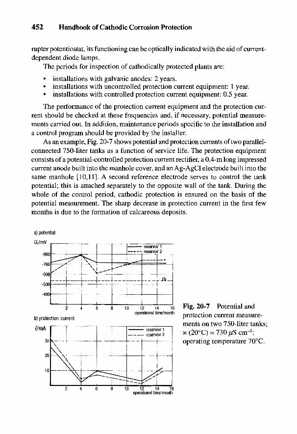
452 Handbook of Cathodic Corrosion Protection
rupter potentiostat, its functioning can be optically indicated with the aid of current-dependent diode lamps.
The periods for inspection of cathodically protected plants are:
• installations with galvanic anodes: 2 years.• installations with uncontrolled protection current equipment: 1 year.• installations with controlled protection current equipment: 0.5 year.
The performance of the protection current equipment and the protection cur-rent should be checked at these frequencies and, if necessary, potential measure-ments carried out. In addition, maintenance periods specific to the installation anda control program should be provided by the installer.
As an example, Fig. 20-7 shows potential and protection currents of two parallel-connected 750-liter tanks as a function of service life. The protection equipmentconsists of a potential-controlled protection current rectifier, a 0.4-m long impressedcurrent anode built into the manhole cover, and an Ag-AgCl electrode built into thesame manhole [10,11]. A second reference electrode serves to control the tankpotential; this is attached separately to the opposite wall of the tank. During thewhole of the control period, cathodic protection is ensured on the basis of thepotential measurement. The sharp decrease in protection current in the first fewmonths is due to the formation of calcareous deposits.
Fig. 20-7 Potential andprotection current measure-ments on two 750-liter tanks;x(20°C) = 730j/S cm-1;operating temperature 70°C.
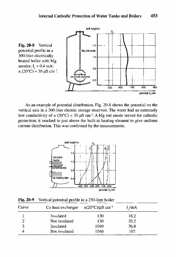
Internal Cathodic Protection of Water Tanks and Boilers 453
Fig. 20-8 Verticalpotential profile in a300-liter electricallyheated boiler with Mganodes; Is = 0.4 mA;x (20°C) = 30 juS cm-1.
As an example of potential distribution, Fig. 20-8 shows the potential on thevertical axis in a 300-liter electric storage reservoir. The water had an extremelylow conductivity of x (20°C) = 30 /iS cm"1. A Mg rod anode served for cathodicprotection; it reached to just above the built-in heating element to give uniformcurrent distribution. This was confirmed by the measurements.
Fig. 20-9 Vertical potential profile in a 250-liter boiler
Curve Cu heat exchanger x(20°C)/jiiS cnr1 ^/mA
1 Insulated 130 16.22 Not insulated 130 30.23 Insulated 1040 36.84 Not insulated 1040 107
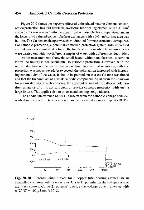
454 Handbook of Cathodic Corrosion Protection
Figure 20-9 shows the negative effect of uninsulated heating elements on cor-rosion protection. In a 250-liter tank, an electric tube heating element with a 0.05-m2
surface area was screwed into the upper third without electrical separation, and inthe lower third a tinned copper tube heat exchanger with a 0.61-m2 surface area wasbuilt in. The Cu heat exchanger was short-circuited for measurements, as required.For cathodic protection, a potential-controlled protection system with impressedcurrent anodes was installed between the two heating elements. The measurementswere carried out with two different samples of water with different conductivities.
As the measurements show, the small heater without an electrical separation(from the boiler) is not detrimental to cathodic protection. However, with theuninsulated built-in Cu heat exchanger without an electrical separation, cathodicprotection was not achieved. As expected, the polarization increased with increas-ing conductivity of the water. It should be pointed out that the Cu tube was tinnedand that the tin could act as a weak cathodic component. Apart from the unknownlong-term stability of such a coating, the apparent raising of the cathodic polariza-tion resistance of tin is not sufficient to provide cathodic protection with such alarge fixture. This applies also to other metal coatings (e.g., nickel).
The anodic interference of built-in inserts from the cathodic voltage cone de-scribed in Section 20.1.4 is clearly seen in the measured values in Fig. 20-10. The
Fig. 20-10 Potential-time curves for a copper tube heating element in anenamelled container with brass screws. Curve 1: potential in the voltage cone ofthe brass screws. Curve 2: potential outside the voltage cone. Tapwater withx (20°C) = 100 n$ cm-1; 50°C.
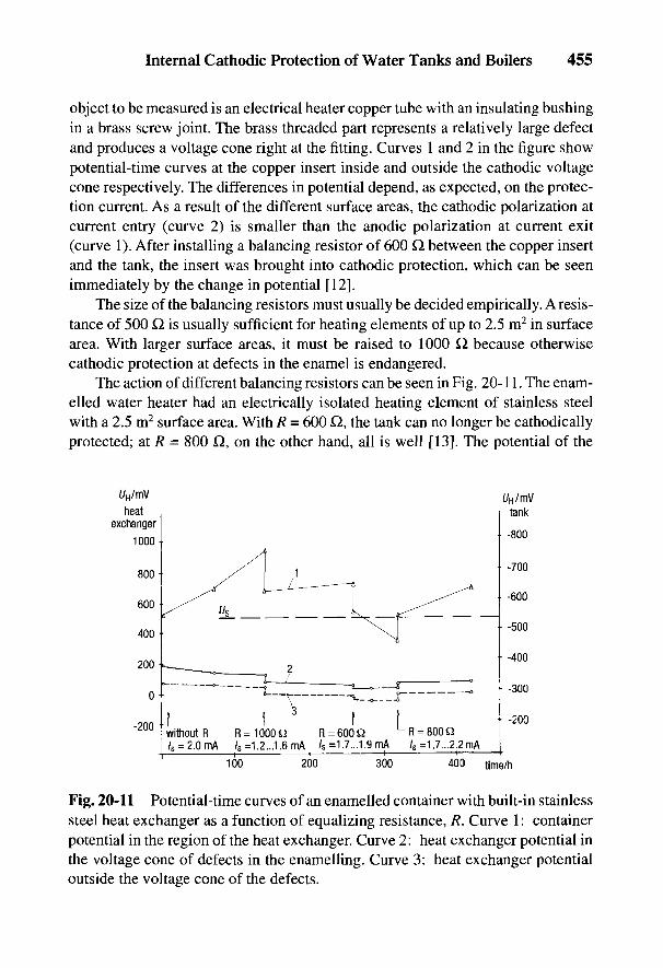
Internal Cathodic Protection of Water Tanks and Boilers 455
object to be measured is an electrical heater copper tube with an insulating bushingin a brass screw joint. The brass threaded part represents a relatively large defectand produces a voltage cone right at the fitting. Curves 1 and 2 in the figure showpotential-time curves at the copper insert inside and outside the cathodic voltagecone respectively. The differences in potential depend, as expected, on the protec-tion current. As a result of the different surface areas, the cathodic polarization atcurrent entry (curve 2) is smaller than the anodic polarization at current exit(curve 1). After installing a balancing resistor of 600 Q between the copper insertand the tank, the insert was brought into cathodic protection, which can be seenimmediately by the change in potential [121.
The size of the balancing resistors must usually be decided empirically. A resis-tance of 500 Q. is usually sufficient for heating elements of up to 2.5 m2 in surfacearea. With larger surface areas, it must be raised to 1000 Q. because otherwisecathodic protection at defects in the enamel is endangered.
The action of different balancing resistors can be seen in Fig. 20-11. The enam-elled water heater had an electrically isolated heating element of stainless steelwith a 2.5 m2 surface area. With R = 600 Q, the tank can no longer be cathodicallyprotected; at R = 800 Q, on the other hand, all is well [13]. The potential of the
Fig. 20-11 Potential-time curves of an enamelled container with built-in stainlesssteel heat exchanger as a function of equalizing resistance, R. Curve 1: containerpotential in the region of the heat exchanger. Curve 2: heat exchanger potential inthe voltage cone of defects in the enamelling. Curve 3: heat exchanger potentialoutside the voltage cone of the defects.

456 Handbook of Cathodic Corrosion Protection
stainless steel [material no. 1.4435 (AISI 316)] is clearly more negative than theexpected pitting potential of this material [14].
20.4.2 Boilers with Electrolytically Treated Water
The electrolysis protection process using impressed current aluminum anodesallows uncoated and hot-dipped galvanized ferrous materials in domestic installa-tions to be protected from corrosion. If impressed current aluminum anodes areinstalled in water tanks, the pipework is protected by the formation of a film with-out affecting the potability of the water. With domestic galvanized steel pipes, amarked retardation of the cathodic partial reaction occurs [15]. Electrolytic treat-ment alters the electrolytic characteristics of the water, as well as internal cathodicprotection of the tank and its inserts (e.g., heating elements). The pipe protectionrelies on colloidal chemical processes and is applied only to new installations andnot to old ones already attacked by corrosion.
In applying electrolytic protection, galvanized tubes can be installed down-stream from copper components in water boilers without danger of Cu2+-inducedpitting corrosion. The protection process extends the application range for galvanizedtubes with respect to water parameters, temperature and material quality beyondthat in the technical regulations [16, 17].
Fig. 20-12 Boiler protected by electrolysis protection process (schematic).

Internal Cathodic Protection of Water Tanks and Boilers 457
Figure 20-12 shows schematically the arrangement of aluminum anodes invertical and horizontal boilers with heating tubes. More than 33% of the aluminumanodes must be sited in the upper third of the tank for the formation of protectivefilms in the tubing [18]. Cathodic currents needed to protect the tubing may bethree times as high as the current requirement for cathodic protection [19].
The treated water contains sufficient concentration of surface film-formingagents if cold water spends about 12 min and warm water at least 20 min in thetank [19]. Sudden temperature variations over 10°C must be prevented because theactive form of A1(OH)3 is sensitive to them [20]. If mixing with cold water orsubsequent warming cannot be avoided, a short-term electrolytic aftertreatmentmust be provided in a small reaction tank. The development of undisturbed protec-tive films in the tubing assumes continuous water flow with forced circulation bypumps [20].
The main part of the anode slurry, which can contain CaCO3, depending on thehardness of the water, is chemically inert from the corrosion point of view, andsettles to the bottom of the tank. The slurry must be removed once or twice a weekthrough a stub with a stopcock; this takes place in short bursts of opening andclosing of the tap at full water pressure. The deslurrying outlet is at the end oppo-site to the water inlet in a horizontal tank.
A higher content of A12O3 and SiO2 is critical for the composition of the pro-tective films in the tubing, assuming the water contains silicates or silicic acid. Theprotective films have a maximum thickness of 1.5 mm and cannot grow further.The corrosion process can be stopped even in copper pipe networks with type Ipitting [21] by providing a reaction tank with impressed current aluminum anodes.
Some construction points for tanks when using the electrolysis protectionmethod should be noted:
(a) automatic exhausters must be provided to remove reaction gases (hydro-gen) [2,22] (see Section 20.1.5).
(b) the water outlet must be inserted about 50 mm into the tank to promoteeffective exhaustion.
(c) stubs with stopcocks must be provided in the bottom of the tank fordeslurrying.
(d) heating pipe bundles must be arranged on a square pattern with consider-ation of values for a minimum spacing of the pipe (see Section 20.1).
(e) the sealing materials for the current lead sockets and anode fixtures mustbe suitable for use with drinking water.
The current yield of aluminum depends on the composition of the water andthe operating conditions; it usually lies between oc = 0.8 and 0.9 (see Section 6.2.3).Self-corrosion occurs, as with Mg, with hydrogen evolution.

458 Handbook of Cathodic Corrosion Protection
Pure aluminum is used in the electrolysis protection process, which does notpassivate in the presence of chloride and sulfate ions. In water very low in salt witha conductivity of x < 40 ^S cm"1, the polarization can increase greatly, so that thenecessary protection current density can no longer be reached. Further limits to itsapplication exist at pH values < 6.0 and > 8.5 because there the solubility of A1(OH)3
becomes too high and its film-forming action is lost [19]. The aluminum anodesare designed for a life of 2 to 3 years. After that they must be renewed. The protec-tion currents are indicated by means of an ammeter and/or a current-operated lightdiode. In addition to the normal monitoring by service personnel, a qualified firmshould inspect the rectifier equipment annually.
In water containing sulfate, the use of the electrolysis protection process withlow water consumption can sometimes result in the formation of small amounts ofH2S, which is detectable by the smell. Sulfate reduction occurs through the actionof bacteria in anaerobic areas (e.g., in the slurry zone of the tank).
There are heat-resistant sulfate-reducing bacteria with high activity at 70°C[23]. On the other hand, electrochemical sulfate reduction has not been confirmed[24]. To avoid microbial sulfate reduction and the formation of excessive alumi-num compounds, it is advisable to adjust the electrolysis currents to the waterconsumption. Flow rate or differential pressure switches in the inlet tube allow thecurrent to be controlled according to the water consumption. The electrolysis cur-rents can also be regulated for alternating water consumption by installing a con-tact counter in the inlet tube. The contact water counter governs the protectioncurrent equipment electronically and smoothly controls the current strength.Regularly varying water consumption can be catered for with a time switch. Theactivity of anaerobic bacteria can be avoided by installing metal oxide-coveredtitanium anodes in the slurry area, on which anodic oxygen is evolved [25].
20.4.3 Water Storage Tanks
The protection current requirement of a water storage tank depends mainly on thepresence and quality of an internal coating. The requirement increases with risingtemperature, increasing salt content and lowering pH of the water. It isrecommended that an experimental estimate of the protection current requirement bemade in such cases. A drainage test may also be necessary with organic coat-ings sincethe extent of defects or mechanical damage is unknown. Such testing is not necessarywith inorganic coatings (enamelling) because of the limited number and size of de-fects, according to Ref. 4, as well as the higher degree of stability of these coatings.
To achieve satisfactory current distribution and to avoid cathodic damage tothe lining (see Section 5.2.1), the distance between the anodes and the object to beprotected should not be too close and the driving voltage should not be too high. In
Internal Cathodic Protection of Water Tanks and Boilers 459
the vicinity of the anodes, the potential should be limited to UH = -0.8 to -0.9 V. Alarge number of anodes have to be installed in uncoated steel tanks to give satisfac-tory protection current distribution!. The specific conductivity determines the mini-mum distance of the anodes from the object to be protected [26].
A tank with a fixed cover of plain carbon steel for storing 60°C warm, softenedboiler feed water that had a tar-pitch epoxy resin coating showed pits up to 2.5 mmdeep after 10 years of service without cathodic protection. Two separate protectionsystems were built into the tank because the water level varied as a result of serviceconditions. A ring anode attached to plastic supports was installed near the bottomof the tank and was connected to a potential-controlled protection rectifier. Theside walls were protected by three vertical anodes with fixed adjustable protectioncurrent equipment.
Partially platinized titanium impressed current anodes were chosen becausecontamination of the feed water by anodic decomposition products had to beavoided. Four pure zinc reference electrodes were installed in the tank to controland regulate the potential. The supports for the anodes were of polypropylene,which can operate for short periods up to 100°C, in contrast to the usual PVCsupports used in cold water.
The measured grounding resistances of the anodes were 6.5 Q for the 24-m-long ring anode and 8 Q, for the three 7-m-long vertical anodes and were within therange of the calculated design values. By gradual adjustment of t/off values, theprotection potential of the initial protection current density amounted to about450 M nr2.
Potential control with zinc reference electrodes presented a problem becausedeposits of corrosion products are formed on zinc in hot water. This caused changesin the potential of the electrode which could not be tolerated. Other reference elec-trodes (e.g., calomel and Ag-AgCl reference electrodes) were not yet available forthis application. Since then, Ag-AgCl electrodes have been developed which suc-cessfully operate at temperatures up to 100°C. The solution in the previous casewas the imposition of a fixed current level after reaching stationary operating con-ditions [27].
After 10 years of service, a crown-shaped drinking water tank of 1500 m3
capacity showed pitting 3 mm deep at defects in the chlorinated rubber coating.After a thorough overhaul and a new coating with a two-component zinc dust primerand two top coats of chlorinated rubber, impressed current protection was installed[27]. Taking into account a protection current requirement of 150 mA m~2 for un-coated steel at pores covering 1% of the surface, protection current equipmentdelivering 4 A was installed. Two protection current circuits were provided to copewith the calculated varying protection current requirement resulting from the wa-ter level. One serves the bottom anode and is permanently fixed. The other serves
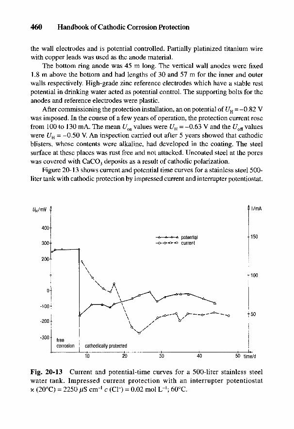
460 Handbook of Cathodic Corrosion Protection
the wall electrodes and is potential controlled. Partially platinized titanium wirewith copper leads was used as the anode material.
The bottom ring anode was 45 m long. The vertical wall anodes were fixed1.8 m above the bottom and had lengths of 30 and 57 m for the inner and outerwalls respectively. High-grade zinc reference electrodes which have a stable restpotential in drinking water acted as potential control. The supporting bolts for theanodes and reference electrodes were plastic.
After commissioning the protection installation, an on potential of UH = -0.82 Vwas imposed. In the course of a few years of operation, the protection current rosefrom 100 to 130 mA. The mean Uon values were UH = -0.63 V and the C7off valueswere UH = -0.50 V. An inspection carried out after 5 years showed that cathodicblisters, whose contents were alkaline, had developed in the coating. The steelsurface at these places was rust free and not attacked. Uncoated steel at the poreswas covered with CaCO3 deposits as a result of cathodic polarization.
Figure 20-13 shows current and potential time curves for a stainless steel 500-liter tank with cathodic protection by impressed current and interrupter potentiostat.
Fig. 20-13 Current and potential-time curves for a 500-liter stainless steelwater tank. Impressed current protection with an interrupter potentiostatx (20°C) = 2250 ,uS cnr1 c (C1-) = 0.02 mol L~J; 60°C.

Internal Cathodic Protection of Water Tanks and Boilers 461
Fig. 20-14 Internalcathodic protection ofpressure filter boiler withimpressed current.
On switching on the protection current, there was an immediate shift of the poten-tial into the protection region U < UHs = 0.0 V [2] (see group I in Section 2.4). Theinitial high current requirement of about 120 mA fell in the course of operation tobelow 50 mA. If protection is effected potentiostatically, there is no danger fromhydrogen evolution because the negative potentials necessary for electrolysis willnot be reached [28].
20.4.4 Filter Tanks
The arrangement and distribution of anodes in gravel and activated charcoalfilters is different. Cathodic protection of activated charcoal filters is basically fea-sible but requires a large number of electrodes and high protection current densi-ties that are twice those for gravel bed filters, so that an electrically insulating layercan be deposited on the steel wall.
Figure 20-14 shows the protection of a gravel filter in the treatment of rawwater. The 200-m2 internal surface was coated with 300 jUm of tar-pitch epoxyresin. Long-term experiments indicated that at UH = -0.83 V, no cathodic blisterswere formed, but were formed at more negative potentials (see Section 5.2.1.4).TiPt anodes 400 and 1100 mm in length, 12 mm in diameter, and with an activesurface of 0.11 m2 were installed [29].
After several years of operation, protection current densities between 50 and450 jtiA rrr2 were measured on several vessels. The filter tanks and pure watertanks were provided with protection current by separate current circuits. This wasnecessary because the nozzle bottom out of the filter tank made it impossible tosupply the pure water tank with sufficient protection current.

462 Handbook of Cathodic Corrosion Protection
Monitoring the cathodic protection of filter tanks extends to the control ofprotection current levels with the use of ammeters and/or current-operated lightdiodes. The internal condition of tanks should be inspected visually every 2 years.
20.5 Requirements for Drinking Water
Only those anodes can be used in the internal protection of drinking watertanks whose reaction products in water are beyond suspicion from the health pointof view regarding type and concentration. This excludes galvanic anodes contain-ing toxic elements (e.g., Hg-activated aluminum anodes or PbAg anodes). Onlymagnesium and impressed current aluminum can be considered for galvanicanodes in drinking water because their reaction products are absolutely harmlessto health. Noble metal anodes, titanium anodes coated with noble metals or oxides,or magnetite anodes can also be used without hesitation in drinking water sincethey do not release reaction products into the water. The reaction products result-ing from corrosion protection with aluminum anodes in drinking water tanks usedfor heating or storage are "additives" and cannot be avoided technically [30]. Theycan be used if the products are not detrimental to the customer and are unobjec-tionable concerning health, taste, and smell, which applies to A1(OH)3 [31].
Cathodic protection with impressed current, aluminum or magnesium anodesdoes not lead to any promotion of germs in the water. There is also no multiplica-tion of bacteria and fungi in the anode slime [32,33]. Unhygienic contamination ofthe water only arises if anaerobic conditions develop in the slurry deposits, givingrise to bacterial reduction of sulfate. If this is the case, H2S can be detected bysmell in amounts which cannot be detected analytically or by taste. Remedial mea-sures are dealt with in Section 20.4.2.

Internal Cathodic Protection of Water Tanks and Boilers 463
20.6 References
[1] DIN 50930 Teile 2 bis 5, Beuth-Verlag, Berlin 1980.[2] DIN 50927, Beuth-Verlag, Berlin 1985.[3] DIN 50928, Beuth-Verlag, Berlin 1985.[4] DIN 4753 Teile 3 und 6, Beuth-Verlag, Berlin 1987 u. 1986.[5] Patentschrift DE 2928998, 1982.[6] Patentschrift DE 3707791, 1988.[7] H. Rickert, G. Holzapfel u. Ch. Fianda, Werkstoffe u. Korrosion 38, 691 (1987).[8] DIN VDE 0720 Teil 2Eb, Beuth-Verlag, Berlin 1978.[9] G. Hitzblech, Heizungsjournal, 2. Themenheft NT-Heizung, 1981.
[10] G. Franke, Der Elektromeister und Deutsches Elektrohandwerk 13, 942 (1980).[11] C.L. Kruse u. G. Hitzblech, IKZ 10, 42 (1980).[12] G. Franke, in: "Korrosion in Kalt- u. Warmwasser-Systemen der Hausinstallation",
S. 127-144, Deutsche Gesellsch. Metallkd., Oberursel 1984.[13] G. Franke, SHT 3, 205 (1987).[14] G. Herbsleb u. W. Schwenk, Werkstoffe u. Korrosion 18, 685 (1967); 24. 763 (1973).[15] C.-L. Kruse, Werkstoffe u. Korrosion 34, 539 (1983).[16] Teil3aus[l] .[17] Merkblatt 405 der Stahlberatungsstelle "Das Stahlrohr in der Hausinstallation - Vermei-
dung von Korrosionsschaden", Diisseldorf 1981.[18] Deutsches Bundespatent 2144514.[19] U. Heinzelmann, in: "Korrosion in Kalt- und Warmwassersystemen der Hausinstalla-
tion", S. 46-55, Deutsche Ges. Metallkd., Oberursel 1974.[20] G. Burgmann, W. Friehe u. K. Welbers, Heizung-Luftung-Haustechn. 23, Nr. 3, 85
(1972).[21] Teil5aus[l] .[22] DIN 4753 Teil 10 (Entwurf), Beuth-Verlag, Berlin 1988.[23] Hygiene-Inst. d. Ruhrgebietes, Gelsenkirchen, Tgb. Nr. 5984/72 v. 5. 10. 1972, unverofftl.
Untersuchung.[24] W. Schwenk, unveroffentl. Untersuchungen 1972-1975.[25] Deutsches Bundespatent 2445903.[26] Deutsches Bundespatent 2946901.[27] A. Baltes, HdT Vortragsveroffentlichungen 402, 15 (1978).[28] P. Forchhammer u. H.-J. Engell, Werkstoffe u. Korrosion 20, 1 (1969).[29] F. Paulekat, HdT Veroffentlichungen 402, 8 (1978).[30] Lebensmittel- u. Bedarfsgegenstandegesetz v. 15. 8. 1974, Bundesgesetzbl. I, S. 1945-
1966.[31] K. Redeker, Bonn, unverofftl. Rechtsgutachten v. 8. 11. 1978.[32] R. Schweisfurth u. U. Heinzelmann, Forum Stadte-Hygiene 36, 162 (1988).[33] R. Schweisfurth, Homburg/Saar, unveroffl. Gutachten 1987.
21
Internal Electrochemical CorrosionProtection of Processing Equipment,
Vessels, and TiibesH. GRAFEN AND F. PAULEKAT
Measures a and c in Section 2.2 are directly relevant for internal electrochem-ical protection. In the previous chapter examples of the application of not onlycathodic protection but also anodic protection were dealt with; in this connectionsee the basic explanation in Sections 2.2 and 2.3 and particularly in Section 2.3.1.2.
Besides the use of anodic polarization with impressed current to achieve passiva-tion, raising the cathodic partial current density by special alloying elements and theuse of oxidizing inhibitors (and/or passivators) to assist the formation of passive filmscan be included in the anodic protection method [1-3].
Electrochemical corrosion protection of the internal surfaces of reaction vessels,tanks, pipes and conveyor equipment in the chemical, power and petroleum industries isusually carried out in the presence of strongly corrosive media. The range stretches fromdrinking water through more or less contaminated river, brackish and seawater frequentlyused for cooling, to reactive solutions such as caustic soda, acids and salt solutions.
21.1 Special Features of Internal Protection
In comparison with the external cathodic protection of pipelines, tanks, etc., inter-nal protection has limitations [4] which have already been indicated in Section 20.1 butare fully listed here:
(a) The free corrosion potentials and protection ranges must be determinedfor every protection system and for all the operational phases, because ofthe multiplicity of materials and media. Section 2.4 gives a summary ofimportant protection potentials or potential ranges.
(b) The ratio of the volume of the electrolyte to the surface area of the object tobe protected is considerably lower than with external protection. For thisreason the current distribution, especially on uncoated surfaces, is limited.
464

Corrosion Protection of Processing Equipment, Vessels, and Tubes 465
Particular difficulties can arise with complicated objects with inserts (stir-rers, heaters, etc.) Uniform current distribution thus can only be achieved byan increased number and proper location of several protective electrodes.
(c) The electrochemical reactions and consecutive reactions at the object to beprotected and at the impressed current electrodes must be considered in inter-nal protection. The type of electrochemical protection and the material of theimpressed current anodes must be chosen with regard to the electrolyte and therequirements for its purity. It must be ascertained which electrolytic reactionsare occurring and to what extent these reactions can lead to detrimental effects(e.g., contamination of the medium by reaction products from the electrodematerial or electrochemical reactions with constituents of the medium).
(d) With internal coatings, either applied or planned, it must be determinedwhether they have the necessary stability against electrochemical effectsof the protection current (see Section 5.2.1) [5].
(e) Hydrogen can evolve from the effects of the protection current or self-corrosion of galvanic anodes, and can form explosive gas mixtures. In thiscase the protective measures described in Section 20.1.5 must be applied [4].Catalytically active noble metal anodes and anodes coated with noble metalscannot be used if they penetrate the gas space. The use of catalyticallyactive noble metals should be avoided for safety reasons and the protec-tion potential region limited to U'Hs = -0.9 V.
(f) With inserts electrically insulated from the object to be protected and notincluded in the electrochemical protection, it should be determined whetherthe protection current could lead to damaging interference and which protec-tive measures are to be adopted [4] (see Section 20.1.4).
(g) It should be determined whether special measures have to be instituted whenthe operation is nonsteady (e.g., with erratic or interrupted throughput) andwhen changes in the temperature and concentration of the electrolyte occur.
(h) Test points must be provided for measuring the object and medium poten-tial, depending on the requirements of the protective system. This involvesfinding the sites where the protective effect is expected to be at its lowestbecause of the protection current distribution.
Reference electrodes at the test points may only be needed part of the time,depending on the mode of operation of the protective systems (e.g., for monitoringor for permanent control of potential-controlled protection current equipment).Potentiostatic control is always preferred to galvanostatic systems where opera-tional parameters are changing.
466 Handbook of Cathodic Corrosion Protection
Half-cells and simple metal electrodes with nearly constant rest potential serveas reference electrodes (see Tables 3-1 and 3-2 in Ref. 4). They have to be tested tosee whether their potential is sufficiently constant and their stability adequateunder the operating conditions (temperature and measuring circuit loading).
The following information is required for planning internal protective systems:
• Construction plans with accurate information on the materials to be used andadditional welding materials.
• Chemical composition of the electrolyte with information on possible varia-tions.
• Information on the operating conditions, such as height of filling, temperature,pressure, and flow velocity, as well as range of variations of these parameters.
From this it is apparent that the choice of protection method and protectioncriteria should always be properly tailored. Coatings are usually applied to reducethe protection current requirement as well as to improve the protection currentdistribution in cathodic internal protection systems, because they raise the polar-ization parameter (see Sections 2.2.5 and 5.1). If the polarization parameter lies inthe same range as the protected object, the current distribution is sufficiently good.
21.2 Cathodic Protection with Galvanic Anodes
Galvanic anodes (see Chapter 6) are used for smaller objects to be protected(e.g., water heaters [see Chapter 20], feedwater tanks, coolers and pipe heatexchangers). Large objects (power station condensers, inlet structures, ducts, sluices,water turbines and large pumps) are mainly protected with impressed current oneconomic grounds. Galvanic anodes are, however, also installed if account has tobe taken of protection against explosion and safety regulations regarding productsof electrolysis. Areas of application include tanks for ballast, loading, petrol, water,and exchange tanks of ships (see Section 17.4) as well as crude oil tanks.
Aluminum anodes are used for the internal cathodic protection of large crudeoil tanks which are susceptible to damage from corrosive salt-rich deposits. In anearlier example [6] 71 anodes were equally spaced in the base area. The baseregion up to 1 m in height in the region of the water/oil interface had, includingthe inserts, an area of 2120 m2 and was protected with 17 A. The protection cur-rent density was 8 mA irr2. With a total anode weight of 1370 kg and with<2'pr = 2600 A h kg~!, the service life was calculated to be 24 years.
The type of anode used consisted of two parts, each 1 m long, which werewelded to specially prepared plates. Potential measurements were carried out forcontrolling the protection. This was achieved with floating reference electrodes inthe water sump.
Corrosion Protection of Processing Equipment, Vessels, and Tubes 467
Today for this kind of object, the aluminum anodes are usually insulated andconnected via cables outside the tank. By this means it is possible to purify andactivate the anodes by applying anodic current pulses from an external voltagesource. This is necessary during the course of operation since the anode surfacescan be easily passivated by oil films [7].
21.3 Cathodic Protection with Impressed Current
Cathodic protection by means of impressed current is very adaptable and eco-nomic because of the long durability of anodes and the large number of anodematerials and shapes. Some examples are described here. Internal cathodic protec-tion of fuel oil tanks has already been dealt with in Section 11.7. The internalprotection of water tanks is described in detail in Chapter 20.
21.3.1 Internal Cathodic Protection of Wet Oil Tanks
The output from oil fields, after secondary and tertiary processing [7], is con-sidered "wet oil." It consists of oil field brine, crude oil and natural gases contain-ing a high CO2 content and in certain circumstances it may also contain smallamounts of H2S. Wet oil can also contain solid particles from the bedrock.
Wet oil is collected and treated in large steel tanks (knockout tanks) between102 and 104 m3 in size, depending on the application. The aqueous phase is drainedoff in the process. The corrosivity of the aqueous phase is determined by the highsalt content (1 mol L"1), high CO2 content (corresponding to a partial pressure of1 bar), and after buffering with CaCO3, a pH of 6; as well as small amounts of H2Sand traces of O2 [7]. Investigations have shown that a protection potential of^Cu-cuso4
= -0-95 V must be applied under these conditions and for operating tem-peratures up to 70°C. In unbuffered media, the pH is 4; in this case the protectionpotential must be reduced by an additional 0.1 V. The steep total current density-potential curve means that one has to contend with a correspondingly high protec-tion current requirement. The lowest current densities are up to 10 A m"2. Theycan, however, be much smaller if scales are formed [7].
Corrosion protection by coatings alone demands freedom from pores anddefects during the entire service time. Since this is difficult to guarantee and thereis the danger of cell formation (see Section 5.1), a combination with cathodic pro-tection is advisable. The coatings involved must be compatible with the cathodicprotection and the operating conditions (see Section 5.2.1.4). Reference 5 givesthe basis for such decisions. By neglecting the danger of cathodic damage to coat-ings, considerable damage occurred to the coatings in the past, which caused amarked increase in protection current densities. Internal cathodic protection with-
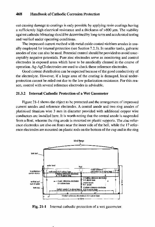
468 Handbook of Cathodic Corrosion Protection
out causing damage to coatings is only possible by applying resin coatings havinga sufficiently high electrical resistance and a thickness of >800 nm. The stabilityagainst cathodic blistering should be determined by long-term and accelerated testingand verified under operating conditions.
The impressed current method with metal oxide-coated niobium anodes is usu-ally employed for internal protection (see Section 7.2.3). In smaller tanks, galvanicanodes of zinc can also be used. Potential control should be provided to avoid unac-ceptably negative potentials. Pure zinc electrodes serve as monitoring and controlelectrodes in exposed areas which have to be anodically cleaned in the course ofoperation. Ag-AgCl electrodes are used to check these reference electrodes.
Good current distribution can be expected because of the good conductivity ofthe electrolyte. However, if a large area of the coating is damaged, local under-protection cannot be ruled out due to the low polarization resistance. For this rea-son, control with several reference electrodes is advisable.
21.3.2 Internal Cathodic Protection of a Wet Gasometer
Figure 21-1 shows the object to be protected and the arrangement of impressedcurrent anodes and reference electrodes. A central anode and two ring anodes ofplatinized titanium wire 3 mm in diameter provided with additional copper wireconductors are installed here. It is worth noting that the central anode is suspendedfrom a float, whereas the ring anode is mounted on plastic supports. The zinc refer-ence electrodes are also on floats near the inner side of the bell, while the 17 refer-ence electrodes are mounted on plastic rods on the bottom of the cup and in the ring
Fig. 21-1 Internal cathodic protection of a wet gasometer
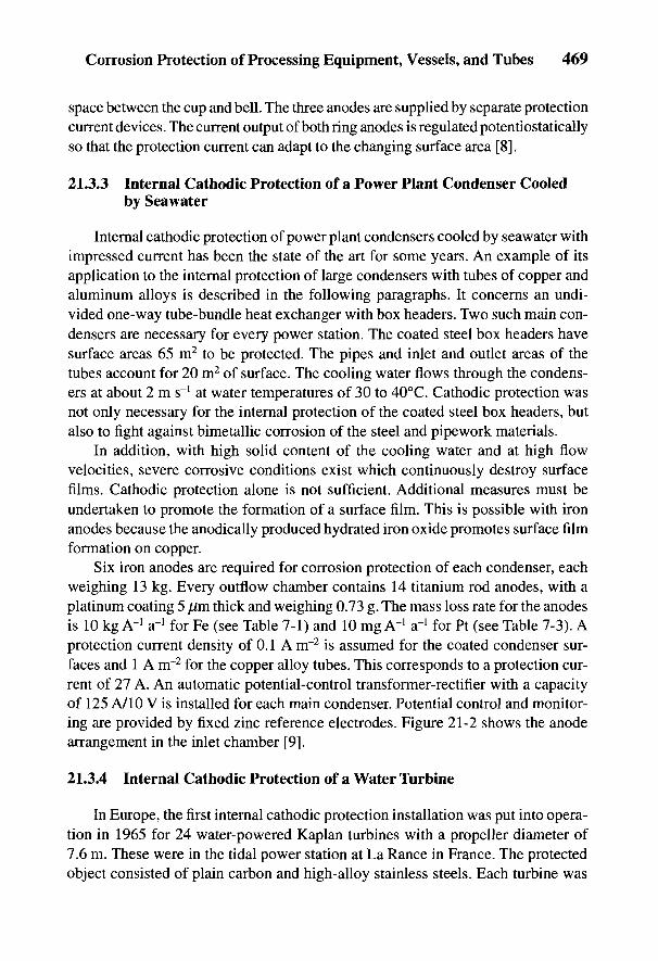
Corrosion Protection of Processing Equipment, Vessels, and Tubes 469
space between the cup and bell. The three anodes are supplied by separate protectioncurrent devices. The current output of both ring anodes is regulated potentiostaticallyso that the protection current can adapt to the changing surface area [8].
21.3.3 Internal Cathodic Protection of a Power Plant Condenser Cooledby Seawater
Internal cathodic protection of power plant condensers cooled by seawater withimpressed current has been the state of the art for some years. An example of itsapplication to the internal protection of large condensers with tubes of copper andaluminum alloys is described in the following paragraphs. It concerns an undi-vided one-way tube-bundle heat exchanger with box headers. Two such main con-densers are necessary for every power station. The coated steel box headers havesurface areas 65 m2 to be protected. The pipes and inlet and outlet areas of thetubes account for 20 m2 of surface. The cooling water flows through the condens-ers at about 2 m s"1 at water temperatures of 30 to 40°C. Cathodic protection wasnot only necessary for the internal protection of the coated steel box headers, butalso to fight against bimetallic corrosion of the steel and pipework materials.
In addition, with high solid content of the cooling water and at high flowvelocities, severe corrosive conditions exist which continuously destroy surfacefilms. Cathodic protection alone is not sufficient. Additional measures must beundertaken to promote the formation of a surface film. This is possible with ironanodes because the anodically produced hydrated iron oxide promotes surface filmformation on copper.
Six iron anodes are required for corrosion protection of each condenser, eachweighing 13 kg. Every outflow chamber contains 14 titanium rod anodes, with aplatinum coating 5 jam thick and weighing 0.73 g. The mass loss rate for the anodesis 10 kg A-1 a-1 for Fe (see Table 7-1) and 10 mg A'1 a'1 for Pt (see Table 7-3). Aprotection current density of 0.1 A m~2 is assumed for the coated condenser sur-faces and 1 A nr2 for the copper alloy tubes. This corresponds to a protection cur-rent of 27 A. An automatic potential-control transformer-rectifier with a capacityof 125 A/10 V is installed for each main condenser. Potential control and monitor-ing are provided by fixed zinc reference electrodes. Figure 21-2 shows the anodearrangement in the inlet chamber [9].
21.3.4 Internal Cathodic Protection of a Water l\irbine
In Europe, the first internal cathodic protection installation was put into opera-tion in 1965 for 24 water-powered Kaplan turbines with a propeller diameter of7.6 m. These were in the tidal power station at La Ranee in France. The protectedobject consisted of plain carbon and high-alloy stainless steels. Each turbine was
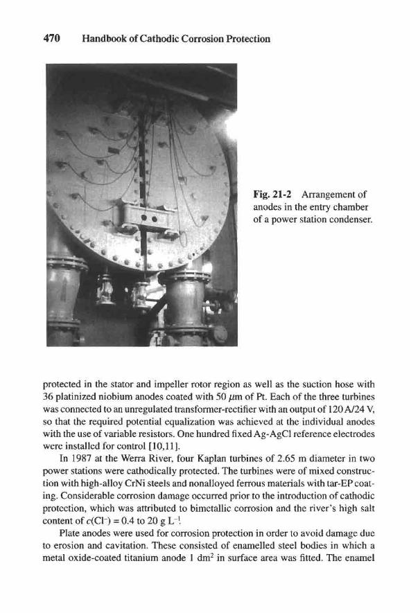
470 Handbook of Cathodic Corrosion Protection
Fig. 21-2 Arrangement ofanodes in the entry chamberof a power station condenser.
protected in the stator and impeller rotor region as well as the suction hose with36 platinized niobium anodes coated with 50 pm of Pt. Each of the three turbineswas connected to an unregulated transformer-rectifier with an output of 120 A/24 V,so that the required potential equalization was achieved at the individual anodeswith the use of variable resistors. One hundred fixed Ag-AgCl reference electrodeswere installed for control [10,11].
In 1987 at the Werra River, four Kaplan turbines of 2.65 m diameter in twopower stations were cathodically protected. The turbines were of mixed construc-tion with high-alloy CrNi steels and nonalloyed ferrous materials with tar-EP coat-ing. Considerable corrosion damage occurred prior to the introduction of cathodicprotection, which was attributed to bimetallic corrosion and the river's high saltcontent of c(Cl-) = 0.4 to 20 g L I
Plate anodes were used for corrosion protection in order to avoid damage dueto erosion and cavitation. These consisted of enamelled steel bodies in which ametal oxide-coated titanium anode 1 dm2 in surface area was fitted. The enamel
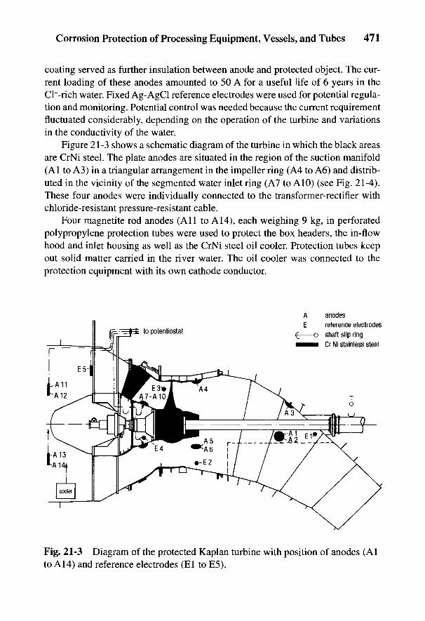
Corrosion Protection of Processing Equipment, Vessels, and Tubes 471
coating served as further insulation between anode and protected object. The cur-rent loading of these anodes amounted to 50 A for a useful life of 6 years in theCl~-rich water. Fixed Ag-AgCl reference electrodes were used for potential regula-tion and monitoring. Potential control was needed because the current requirementfluctuated considerably, depending on the operation of the turbine and variationsin the conductivity of the water.
Figure 21-3 shows a schematic diagram of the turbine in which the black areasare CrNi steel. The plate anodes are situated in the region of the suction manifold(Al to A3) in a triangular arrangement in the impeller ring (A4 to A6) and distrib-uted in the vicinity of the segmented water inlet ring (A7 to A10) (see Fig. 21-4).These four anodes were individually connected to the transformer-rectifier withchloride-resistant pressure-resistant cable.
Four magnetite rod anodes (All to A14), each weighing 9 kg, in perforatedpolypropylene protection tubes were used to protect the box headers, the in-flowhood and inlet housing as well as the CrNi steel oil cooler. Protection tubes keepout solid matter carried in the river water. The oil cooler was connected to theprotection equipment with its own cathode conductor.
Fig. 21-3 Diagram of the protected Kaplan turbine with position of anodes (Alto A14) and reference electrodes (El to E5).
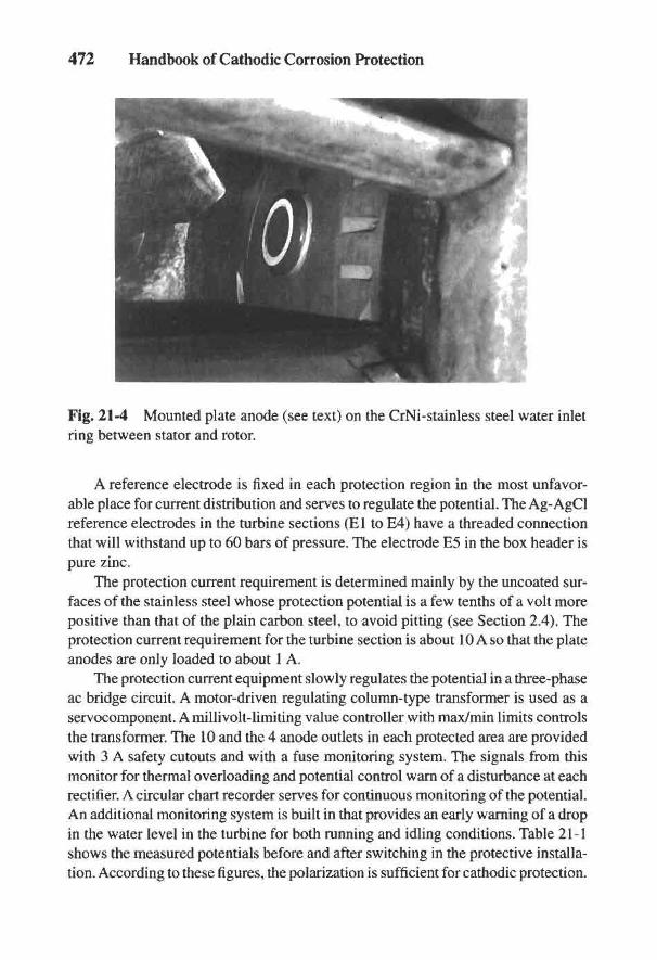
472 Handbook of Cathodic Corrosion Protection
Fig. 21-4 Mounted plate anode (see text) on the CrNi-stainless steel water inletring between stator and rotor.
A reference electrode is fixed in each protection region in the most unfavor-able place for current distribution and serves to regulate the potential. The Ag-AgClreference electrodes in the turbine sections (El to E4) have a threaded connectionthat will withstand up to 60 bars of pressure. The electrode E5 in the box header ispure zinc.
The protection current requirement is determined mainly by the uncoated sur-faces of the stainless steel whose protection potential is a few tenths of a volt morepositive than that of the plain carbon steel, to avoid pitting (see Section 2.4). Theprotection current requirement for the turbine section is about 10 A so that the plateanodes are only loaded to about 1 A.
The protection current equipment slowly regulates the potential in a three-phaseac bridge circuit. A motor-driven regulating column-type transformer is used as aservocomponent. A millivolt-limiting value controller with max/min limits controlsthe transformer. The 10 and the 4 anode outlets in each protected area are providedwith 3 A safety cutouts and with a fuse monitoring system. The signals from thismonitor for thermal overloading and potential control warn of a disturbance at eachrectifier. A circular chart recorder serves for continuous monitoring of the potential.An additional monitoring system is built in that provides an early warning of a dropin the water level in the turbine for both running and idling conditions. Table 21-1shows the measured potentials before and after switching in the protective installa-tion. According to these figures, the polarization is sufficient for cathodic protection.
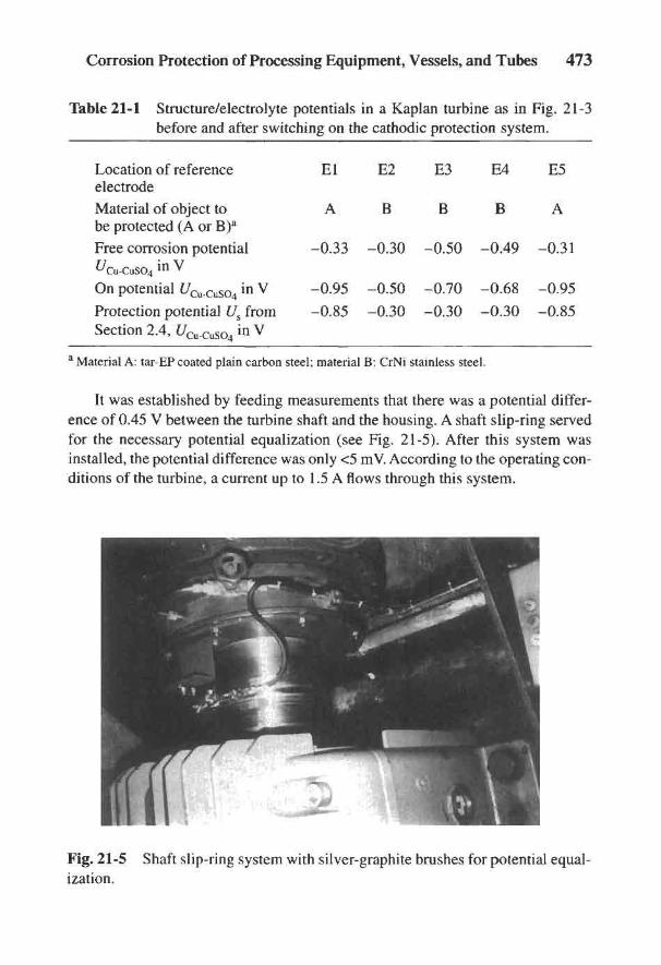
Corrosion Protection of Processing Equipment, Vessels, and Tubes 473
Table 21-1 Structure/electrolyte potentials in a Kaplan turbine as in Fig. 21-3before and after switching on the cathodic protection system.
Location of reference El E2 E3 E4 E5electrodeMaterial of object to A B B B Abe protected (A or B)a
Free corrosion potential -0.33 -0.30 -0.50 -0.49 -0.31^cu-cuso4
in v
On potential £/Cu-cuso4 in V -0.95 -0.50 -0.70 -0.68 -0.95
Protection potential Us from -0.85 -0.30 -0.30 -0.30 -0.85Section 2.4, t/Cu-cuso4 in V
a Material A: tar-EP coated plain carbon steel; material B: CrNi stainless steel.
It was established by feeding measurements that there was a potential differ-ence of 0.45 V between the turbine shaft and the housing. A shaft slip-ring servedfor the necessary potential equalization (see Fig. 21-5). After this system wasinstalled, the potential difference was only <5 mV. According to the operating con-ditions of the turbine, a current up to 1.5 A flows through this system.
Fig. 21-5 Shaft slip-ring system with silver-graphite brushes for potential equal-ization.
474 Handbook of Cathodic Corrosion Protection
Cathodic protection of water power turbines is characterized by wide varia-tions in protection current requirements. This is due to the operating conditions(flow velocity, water level) and in the case of the Werra River, the salt content. Forthis reason potential-controlled rectifiers must be used. This is also necessary toavoid overprotection and thereby damage to the coating (see Sections 5.2.1.4 and5.2.1.5 as well as Refs. 4 and 5). Safety measures must be addressed for the rea-sons stated in Section 20.1.5. Notices were fixed to the turbine and the externalaccess to the box headers which warned of the danger of explosion from hydrogenand included the regulations for the avoidance of accidents (see Ref. 4).
21.4 Anodic Protection of Chemical Plant
21.4.1 Special Features of Anodic Protection
The fundamentals of this method of protection are dealt with in Section 2.3and illustrated in Fig. 2-15. Corrosion protection for the stable-passive state isunnecessary because the material is sufficiently corrosion resistant for free corro-sion conditions. If activation occurs due to a temporary disturbance, the materialimmediately returns to the stable passive state. This does not apply to the meta-stable passive state. In this case anodic protection is necessary to impose the returnto the passive state. Anodic protection is also effective in the unstable passive stateof the material but it must be permanently switched on, in contrast to the metast-able passive state.
The protection potential ranges are commonly limited with anodic protection:group IV in Sections 2.3 and 2.4. For this reason potential-regulating protectioncurrent devices must be used. The protection potential range can be severely lim-ited by certain corrosion processes (e.g., chloride-induced pitting corrosion in stain-less steels). Often anodic corrosion protection is no longer applicable under thesecircumstances. In such cases, partial cathodic protection (to prevent pitting corro-sion) was investigated by lowering the potential slightly below that of the pittingpotential. Local corrosion susceptibility caused by the material's condition canalso render anodic protection ineffective. This includes, for example, the suscepti-bility to intergranular corrosion of high chromium-bearing stainless steels andnickel-based alloys.
Three types of anodic protection can be distinguished: (1) impressed current,(2) formation of local cathodes on the material surface and (3) application of pas-sivating inhibitors. For impressed current methods, the protection potential rangesmust be determined by experiment (see information in Section 2.3). Anodic pro-tection with impressed current has many applications. It fails if there is restrictedcurrent access (e.g., in wet gas spaces) with a lack of electrolyte and/or in the
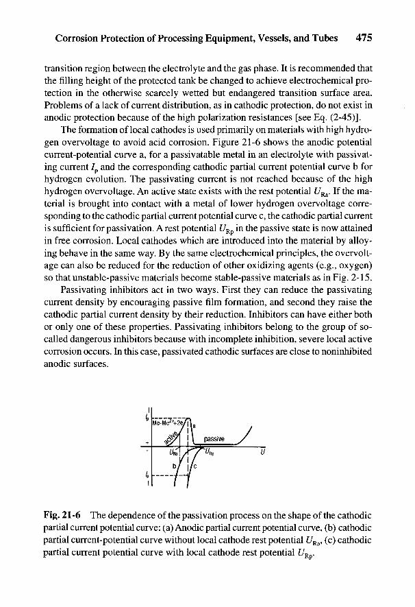
Corrosion Protection of Processing Equipment, Vessels, and Tubes 475
transition region between the electrolyte and the gas phase. It is recommended thatthe filling height of the protected tank be changed to achieve electrochemical pro-tection in the otherwise scarcely wetted but endangered transition surface area.Problems of a lack of current distribution, as in cathodic protection, do not exist inanodic protection because of the high polarization resistances [see Eq. (2-45)].
The formation of local cathodes is used primarily on materials with high hydro-gen overvoltage to avoid acid corrosion. Figure 21-6 shows the anodic potentialcurrent-potential curve a, for a passivatable metal in an electrolyte with passivat-ing current 7p and the corresponding cathodic partial current potential curve b forhydrogen evolution. The passivating current is not reached because of the highhydrogen overvoltage. An active state exists with the rest potential f/Ra. If the ma-terial is brought into contact with a metal of lower hydrogen overvoltage corre-sponding to the cathodic partial current potential curve c, the cathodic partial currentis sufficient for passivation. A rest potential URp in the passive state is now attainedin free corrosion. Local cathodes which are introduced into the material by alloy-ing behave in the same way. By the same electrochemical principles, the overvolt-age can also be reduced for the reduction of other oxidizing agents (e.g., oxygen)so that unstable-passive materials become stable-passive materials as in Fig. 2-15.
Passivating inhibitors act in two ways. First they can reduce the passivatingcurrent density by encouraging passive film formation, and second they raise thecathodic partial current density by their reduction. Inhibitors can have either bothor only one of these properties. Passivating inhibitors belong to the group of so-called dangerous inhibitors because with incomplete inhibition, severe local activecorrosion occurs. In this case, passivated cathodic surfaces are close to noninhibitedanodic surfaces.
Fig. 21-6 The dependence of the passivation process on the shape of the cathodicpartial current potential curve: (a) Anodic partial current potential curve, (b) cathodicpartial current-potential curve without local cathode rest potential £/Ra, (c) cathodicpartial current potential curve with local cathode rest potential UR .
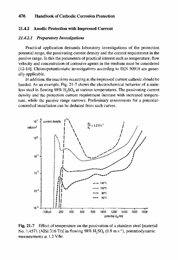
476 Handbook of Cathodic Corrosion Protection
21.4.2 Anodic Protection with Impressed Current
21.4.2.1 Preparatory Investigations
Practical application demands laboratory investigations of the protectionpotential range, the passivating current density and the current requirement in thepassive range. In this the parameters of practical interest such as temperature, flowvelocity and concentration of corrosive agents in the medium must be considered[12-14]. Chronopotentiostatic investigations according to DIN 50918 are gener-ally applicable.
In addition, the reactions occurring at the impressed current cathode should beheeded. As an example, Fig. 21-7 shows the electrochemical behavior of a stain-less steel in flowing 98% H2SO4 at various temperatures. The passivating currentdensity and the protection current requirement increase with increased tempera-ture, while the passive range narrows. Preliminary assessments for a potential-controlled installation can be deduced from such curves.
Fig. 21-7 Effect of temperature on the passivation of a stainless steel [materialNo. 1.4571 (AISI 316 Tr)] in flowing 98% H2SO4 (0.8 m s"1), potentiodynamicmeasurements at 1.2 V/hr.
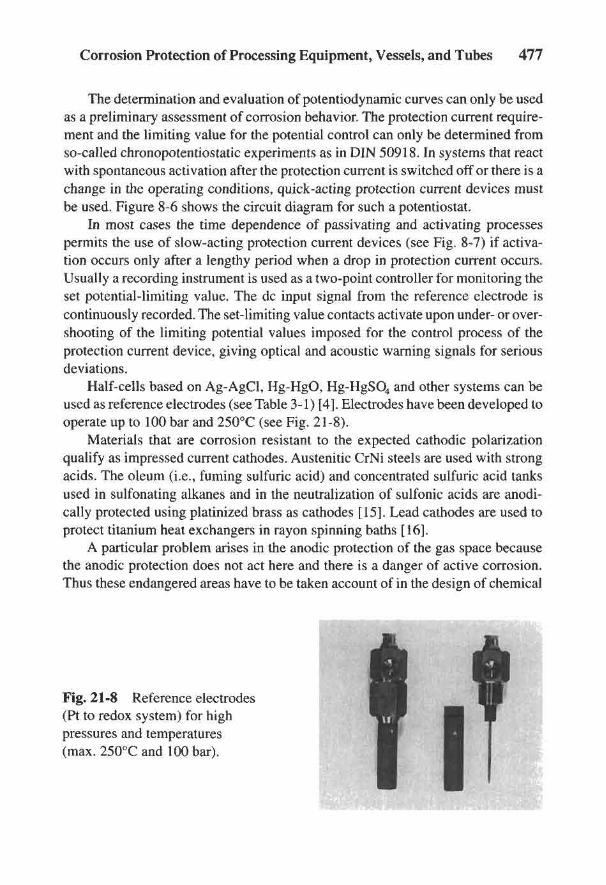
Corrosion Protection of Processing Equipment, Vessels, and Tubes 477
The determination and evaluation of potentiodynamic curves can only be usedas a preliminary assessment of corrosion behavior. The protection current require-ment and the limiting value for the potential control can only be determined fromso-called chronopotentiostatic experiments as in DIN 50918. In systems that reactwith spontaneous activation after the protection current is switched off or there is achange in the operating conditions, quick-acting protection current devices mustbe used. Figure 8-6 shows the circuit diagram for such a potentiostat.
In most cases the time dependence of passivating and activating processespermits the use of slow-acting protection current devices (see Fig. 8-7) if activa-tion occurs only after a lengthy period when a drop in protection current occurs.Usually a recording instrument is used as a two-point controller for monitoring theset potential-limiting value. The dc input signal from the reference electrode iscontinuously recorded. The set-limiting value contacts activate upon under- or over-shooting of the limiting potential values imposed for the control process of theprotection current device, giving optical and acoustic warning signals for seriousdeviations.
Half-cells based on Ag-AgCl, Hg-HgO, Hg-HgSO4 and other systems can beused as reference electrodes (see Table 3-1) [4]. Electrodes have been developed tooperate up to 100 bar and 250°C (see Fig. 21-8).
Materials that are corrosion resistant to the expected cathodic polarizationqualify as impressed current cathodes. Austenitic CrNi steels are used with strongacids. The oleum (i.e., fuming sulfuric acid) and concentrated sulfuric acid tanksused in sulfonating alkanes and in the neutralization of sulfonic acids are anodi-cally protected using platinized brass as cathodes [15]. Lead cathodes are used toprotect titanium heat exchangers in rayon spinning baths [16].
A particular problem arises in the anodic protection of the gas space becausethe anodic protection does not act here and there is a danger of active corrosion.Thus these endangered areas have to be taken account of in the design of chemical
Fig. 21-8 Reference electrodes(Pt to redox system) for highpressures and temperatures(max. 250°C and 100 bar).
478 Handbook of Cathodic Corrosion Protection
installations. If gas spaces cannot be avoided in the construction, they must be cladwith corrosion-resistant materials. Tanks and storage containers should be keptcompletely full wherever possible and the time between emptying and filling shouldbe kept as short as possible so that activation does not occur spontaneously.
21.4.2.2 Protection Against Acids
Anodic protection against acids has been used in a number of processes in thechemical industry, as well as during storage and transport. It is also successful ingeometrically complicated containers and tubings [12]. Carbon steel can be pro-tected from nitric and sulfuric acids. In the latter case, temperature and concentra-tion set application limits [17]. At temperatures of up to 120°C, efficient protectioncan only be achieved with concentrations over 90% [18]. At concentrations between67 and 90%, anodic protection can be used at up to 140°C with CrNi steels [19].
In sulfuric acid production involving heat recovery and recovery of waste sul-furic acid, acids of various concentrations at high temperatures can be dealt with.Corrosion damage has been observed, for example, in sulfuric acid coolers, whichseriously impairs the availability of such installations. The use of anodic protec-tion can prevent such damage.
It is known that the common austenitic stainless steels have sufficient corro-sion resistance in sulfuric acid of lower concentrations (<20%) and higher concen-trations (>70%) below a critical temperature. If with higher concentrations of sulfuricacid (>90%) a temperature of 70°C is exceeded, depending on their composition,austenitic stainless steels can exhibit more or less pronounced corrosion phenom-ena in which the steels can fluctuate between the active and passive state [19].
Anodic protection allows the use of materials under unfavorable conditions ifthey are also passivatable in sulfuric acid. CrNi steels [material Nos. 1.4541 (AISI321) and 1.4571 (AISI 316 Ti)] can be used in handling sulfuric acid of 93 to 99%at temperatures up to 160°C. This enables a temperature of 120 to 160°C to bereached, which is very suitable for heat recovery.
Anodic protection today allows safe and efficient protection of air coolers andbanks of tubes in sulfuric acid plants. In 1966 the air cooler in a sulfuric acid plantin Germany was anodically protected. Since then more than 10,000 m2 of coolingsurfaces in air- and water-cooled sulfuric acid plants worldwide have been pro-tected. The dc output supply of the potentiostats amounts to >25 kW, correspond-ing to an energy requirement of 2.5 W per m2 of protected surface. As an example,Fig. 21-9 shows two parallel-connected sulfuric acid smooth tube exchangers in aproduction plant in Spain.
Two heat exchangers, each 1.2 m in diameter and 9 m in length, with 1500 heatexchanger tubes of stainless CrNiMo steel [material No. 1.4571 (AISI 316 Ti)]were subjected to 98 to 99% sulfuric acid. The flow rate around the tubes was
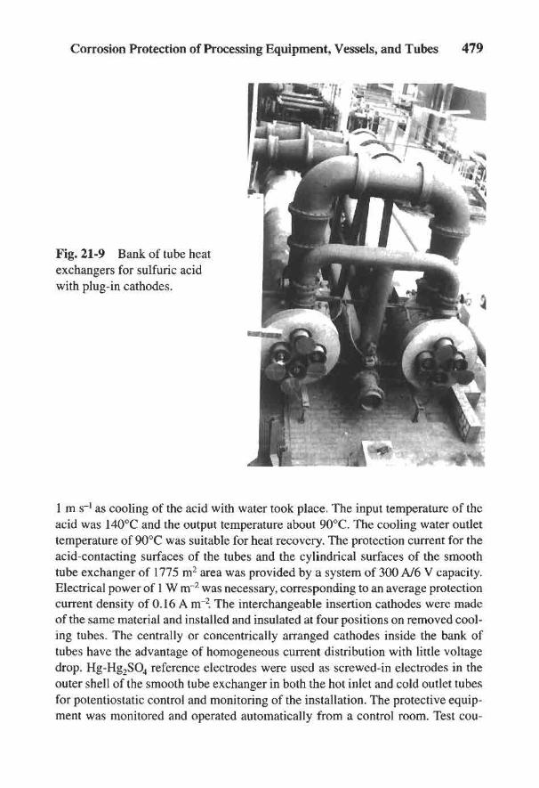
Corrosion Protection of Processing Equipment, Vessels, and Tubes 479
Fig. 21-9 Bank of tube heatexchangers for sulfuric acidwith plug-in cathodes.
1 m s-1 as cooling of the acid with water took place. The input temperature of theacid was 140°C and the output temperature about 90°C. The cooling water outlettemperature of 90°C was suitable for heat recovery. The protection current for theacid-contacting surfaces of the tubes and the cylindrical surfaces of the smoothtube exchanger of 1775 m2 area was provided by a system of 300 A/6 V capacity.Electrical power of 1 W nr2 was necessary, corresponding to an average protectioncurrent density of 0.16 A m"2. The interchangeable insertion cathodes were madeof the same material and installed and insulated at four positions on removed cool-ing tubes. The centrally or concentrically arranged cathodes inside the bank oftubes have the advantage of homogeneous current distribution with little voltagedrop. Hg-Hg2SO4 reference electrodes were used as screwed-in electrodes in theouter shell of the smooth tube exchanger in both the hot inlet and cold outlet tubesfor potentiostatic control and monitoring of the installation. The protective equip-ment was monitored and operated automatically from a control room. Test cou-
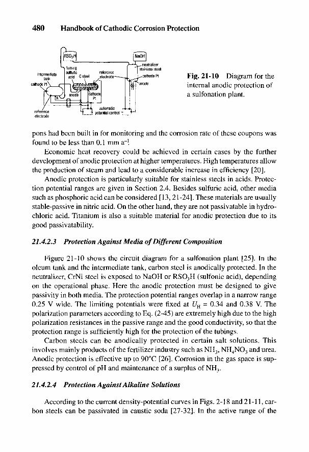
480 Handbook of Cathodic Corrosion Protection
Fig. 21-10 Diagram for theinternal anodic protection ofa sulfonation plant.
pons had been built in for monitoring and the corrosion rate of these coupons wasfound to be less than 0.1 mm a~l
Economic heat recovery could be achieved in certain cases by the furtherdevelopment of anodic protection at higher temperatures. High temperatures allowthe production of steam and lead to a considerable increase in efficiency [20].
Anodic protection is particularly suitable for stainless steels in acids. Protec-tion potential ranges are given in Section 2.4. Besides sulfuric acid, other mediasuch as phosphoric acid can be considered [13,21-24]. These materials are usuallystable-passive in nitric acid. On the other hand, they are not passivatable in hydro-chloric acid. Titanium is also a suitable material for anodic protection due to itsgood passivatability.
21.4.2.3 Protection Against Media of Different Composition
Figure 21-10 shows the circuit diagram for a sulfonation plant [25]. In theoleum tank and the intermediate tank, carbon steel is anodically protected. In theneutralizer, CrNi steel is exposed to NaOH or RSO3H (sulfonic acid), dependingon the operational phase. Here the anodic protection must be designed to givepassivity in both media. The protection potential ranges overlap in a narrow range0.25 V wide. The limiting potentials were fixed at UH = 0.34 and 0.38 V. Thepolarization parameters according to Eq. (2-45) are extremely high due to the highpolarization resistances in the passive range and the good conductivity, so that theprotection range is sufficiently high for the protection of the tubings.
Carbon steels can be anodically protected in certain salt solutions. Thisinvolves mainly products of the fertilizer industry such as NH3, NH4NO3 and urea.Anodic protection is effective up to 90°C [26]. Corrosion in the gas space is sup-pressed by control of pH and maintenance of a surplus of NH3.
21.4.2.4 Protection Against Alkaline Solutions
According to the current density-potential curves in Figs. 2-18 and 21-11, car-bon steels can be passivated in caustic soda [27-32]. In the active range of the

Corrosion Protection of Processing Equipment, Vessels, and Tubes 481
Fig. 21-11 Current density-potential curves for plain carbon steel in hot causticsoda from Refs. 28-31.
curves, corrosion occurs with the formation of FeO^~ ions (see field IV in Fig. 2-2).The steel can be stable or metastable passive, depending on the temperature, theNaOH concentration, and the presence of oxidizing agents (e.g., O2). A well-knownexample is the protection of some cellulose digesters in Canada, which are oper-ated with alkali digesting solutions [32]. The passivatability must be checked withNaOH concentrations of over 50% at high temperatures.
In spite of the possibility of cathodic corrosion discussed in relation to Eq. (2-56),practical experience has shown that carbon steel is a suitable material for impressedcurrent cathodes. Stress corrosion of the cathode material does not have to be con-sidered because of the strong cathodic polarization as shown in Fig. 2-18.
Stress corrosion can arise in plain carbon and low-alloy steels if critical condi-tions of temperature, concentration and potential in hot alkali solutions are present(see Section 2.3.3). The critical potential range for stress corrosion is shown inFig. 2-18. This potential range corresponds to the active/passive transition. Theo-retically, anodic protection as well as cathodic protection would be possible (seeSection 2.4); however, in the active condition, noticeable negligible dissolution ofthe steel occurs due to the formation of FeO|~ ions. Therefore, the anodic protec-tion method was chosen for protecting a water electrolysis plant operating withcaustic potash solution against stress corrosion [30]. The protection current wasprovided by the electrolytic cells of the plant.
Six caustic soda evaporators were anodically protected against stress corro-sion in the aluminum industry in Germany in 1965 [27]. Each evaporator had aninternal surface area of 2400 m2. The transformer-rectifier had a capacity of 300 A/5 V and was operated intermittently for many years. Automatic switching on of theprotection current only took place in case of need when the drop in potential reached
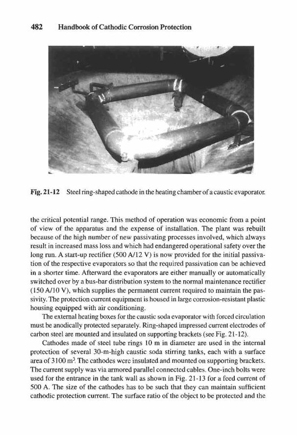
482 Handbook of Cathodic Corrosion Protection
Fig. 21-12 Steel ring-shaped cathode in the heating chamber of a caustic evaporator.
the critical potential range. This method of operation was economic from a pointof view of the apparatus and the expense of installation. The plant was rebuiltbecause of the high number of new passivating processes involved, which alwaysresult in increased mass loss and which had endangered operational safety over thelong run. A start-up rectifier (500 A/12 V) is now provided for the initial passiva-tion of the respective evaporators so that the required passivation can be achievedin a shorter time. Afterward the evaporators are either manually or automaticallyswitched over by a bus-bar distribution system to the normal maintenance rectifier(150A/10V), which supplies the permanent current required to maintain the pas-sivity. The protection current equipment is housed in large corrosion-resistant plastichousing equipped with air conditioning.
The external heating boxes for the caustic soda evaporator with forced circulationmust be anodically protected separately. Ring-shaped impressed current electrodes ofcarbon steel are mounted and insulated on supporting brackets (see Fig. 21-12).
Cathodes made of steel tube rings 10 m in diameter are used in the internalprotection of several 30-m-high caustic soda stirring tanks, each with a surfacearea of 3100 m3. The cathodes were insulated and mounted on supporting brackets.The current supply was via armored parallel connected cables. One-inch bolts wereused for the entrance in the tank wall as shown in Fig. 21-13 for a feed current of500 A. The size of the cathodes has to be such that they can maintain sufficientcathodic protection current. The surface ratio of the object to be protected and the
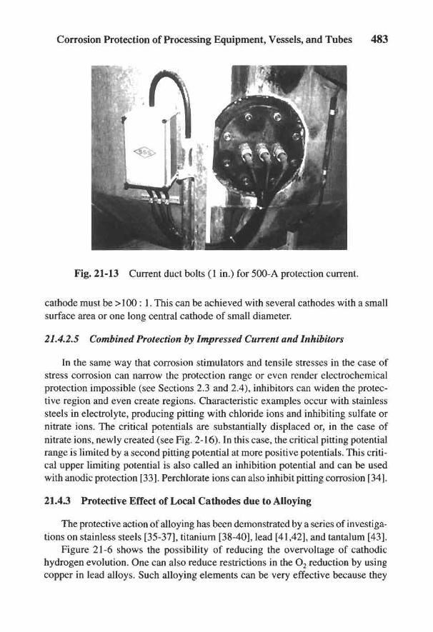
Corrosion Protection of Processing Equipment, Vessels, and Tubes 483
Fig. 21-13 Current duct bolts (1 in.) for 500-A protection current.
cathode must be >100 : 1. This can be achieved with several cathodes with a smallsurface area or one long central cathode of small diameter.
21.4.2.5 Combined Protection by Impressed Current and Inhibitors
In the same way that corrosion stimulators and tensile stresses in the case ofstress corrosion can narrow the protection range or even render electrochemicalprotection impossible (see Sections 2.3 and 2.4), inhibitors can widen the protec-tive region and even create regions. Characteristic examples occur with stainlesssteels in electrolyte, producing pitting with chloride ions and inhibiting sulfate ornitrate ions. The critical potentials are substantially displaced or, in the case ofnitrate ions, newly created (see Fig. 2-16). In this case, the critical pitting potentialrange is limited by a second pitting potential at more positive potentials. This criti-cal upper limiting potential is also called an inhibition potential and can be usedwith anodic protection [33]. Perchlorate ions can also inhibit pitting corrosion [34].
21.4.3 Protective Effect of Local Cathodes due to Alloying
The protective action of alloying has been demonstrated by a series of investiga-tions on stainless steels [35-37], titanium [38-40], lead [41,42], and tantalum [43].
Figure 21-6 shows the possibility of reducing the overvoltage of cathodichydrogen evolution. One can also reduce restrictions in the O2 reduction by usingcopper in lead alloys. Such alloying elements can be very effective because they

484 Handbook of Cathodic Corrosion Protection
result in more positive potentials. For example, Pt acts in this manner, Pd is some-what less effective, and Au, on the other hand, is practically ineffective [36].
In the construction of plants, titanium with 0.2% Pd is mainly used. It canbe employed with advantage in nonoxidizing acid media and also has increasedresistance to pitting and crevice corrosion because of its more favorable pittingpotential [40].
The addition of cathodically active elements to pure lead was the main objec-tive of investigations to improve its corrosion resistance to H2SO4 [42,44]. Bestknown is copper-lead with 0.04 to 0.08% Cu. By adding combinations of alloyingelements, it was possible to produce lead alloys that not only had much bettercorrosion resistance, but also had greater high-temperature strength. Lead alloywith 0.1% Sn, 0.1% Cu and 0.1% Pd is an example [45].
An interesting field of application is the protection of tantalum against hydro-gen embrittlement by electrical connection to platinum metals. The reduction inhydrogen overvoltage and the shift of the free corrosion potential to more positivevalues apparently leads to a reduced coverage by adsorbed hydrogen and therebylower absorption [43] (see Sections 2.1 and 2.3.4).
21.4.4 Protective Action of Inhibitors
Inhibitors are materials that reduce either one or both of the partial corrosionreactions as in Fig. 2-5. Anodic or cathodic inhibitors inhibit the anodic orcathodic reaction respectively so that the rest potential becomes either more posi-tive or more negative. Most inhibitors, however, inhibit the anodic partial reaction.This is because the transfer of metal ions can be more easily restricted than that ofelectrons.
Anodically acting inhibitors facilitate passivation in passivatable systems andalso reduce the passivating current density by covering the surface well. With non-passivating systems, corrosion protection only occurs with complete coverage of thesurface. If the coverage is incomplete or damaged, there is a danger of local attack.
The inhibitive effect can be detected by a high increase in polarization resis-tance. It can be determined from current density potential curves which are usedsuccessfully to check it [46,47]. Raising the cathodic partial current density is alsofavorable for passivation as well as the reduction of the passivating current den-sity. For this reason oxidizing agents are also termed passivators with the anodi-cally acting inhibitors. For example, nickel passivates in 0.5 M H2SO4 with theaddition of Fe2(SO4)3, H2O2, KMnO4, Ce(SO4)2 and K2Cr2O7 [48].
Alkalizing and film-forming inhibitors are used to prevent corrosion in watercontaining O2 or salt. These include Na2CO3, NaOH, Na3PO4, Na2SiO3, NaNO2
and Na2CrO4. The number of organic compounds that effectively inhibit metal

Corrosion Protection of Processing Equipment, Vessels, and Tubes 485
corrosion in various media is small. Typical materials that act as inhibitors areorganic sulfur and nitrogen compounds, higher alcohols and fatty acids. Thesematerials are described in the comprehensive references [49-51] on their type andeffect.
21.5 Trends in the Application of Internal Electrochemical Protection
The use of electrochemical protection in the chemical industry started about20 years ago, which is somewhat recent, compared with its use for buried pipelines40 years ago. Adoption was slow because the internal protection has to be tailoredto the individual plant, which is not the case with the external protection of buriedobjects. Interest in internal protection came from the increasing need for greatersafety for operating plants, increased demands for corrosion resistance, and largerplant components. While questions of its economy cannot generally be answered(see Section 22.6), the costs of electrochemical protection are generally less thanthe cost of equivalent and reliable coatings or corrosion-resistant materials.
The safety, availability and capacity of production plants are predetermined bythe quality of the materials and the corrosion protection measures in the essentialareas; both are major considerations in the initial planning. Even today, damage toequipment and tanks is often assumed to be unavoidable and the damaged compon-ents are routinely replaced. By carrying out damage analysis, which points the wayto knowledge of prevention of damage, the availability and life of plants can beincreased considerably. This particularly applies to the use of anodic protection.
It was demonstrated that the anodic protection of chemical plants constructedof plain carbon or low-alloy steels in contact with caustic solutions is technicallypossible and can be used without disrupting the operation of the plant. Anodicprotection reduces mass loss from corrosion and prevents stress corrosion. Theprotective system can be interrupted without spontaneous activation of the pro-tected surfaces. The range of the protection is increased through the homogeneouslyformed passive film and the consequent increase in the polarization resistance. Itshould be specially mentioned that the formation of sodium aluminum silicate inaluminate solutions from kaolinite and the difficult removal of these encrustations,particularly on heating elements, are reduced as a result of the smooth anodicallyprotected surface. In this respect it should be mentioned that safe operation wasmade possible by anodic protection, because annealing adequate to relieve stressin apparatuses susceptible to stress corrosion, particularly large tanks, is practi-cally impossible and constructional or operational stresses are unavoidable. Thedesired and, from a cost point of view, expected operational safety achieved byusing very high-cost corrosion-resistant materials cannot be reliably achieved inmany cases. This is particularly so in chemical installations.
486 Handbook of Cathodic Corrosion Protection
In recent years, a number of protective installations have come into operation,especially where new installations must be maintained, or where older and alreadydamaged installations have to be saved and operating costs have to be lowered.Worldwide, equipment, tanks and evaporators in the aluminum industry andindustries using caustic alkalis with a capacity of 60,000 m3 and a surface area of47,000 m2 are being anodically protected. Equipment for electrochemical protec-tion has been installed with a total rating of 125 kW and 12 kA.
In spite of considerable advances in recent years, only 20% of the endangeredplants and tanks in German industry urgently requiring protection are anodicallyprotected against pitting and stress corrosion; worldwide, aluminum oxide produc-ers have protected only 1.5% of their plants against corrosion. Over the past20 years, experience has shown that 40 to 50% of surfaces wetted with causticsolutions exhibit corrosion attack and that in almost all installations the electro-chemical and mechanical conditions are those causing the most severe damage. Ofthe worldwide annual production of 23,500 t of alumina, only about 20% is pro-duced in anodically protected installations. It is therefore to be expected that internalelectrochemical protection is going to show a continuing increase in use. DIN 50927[4], published in 1985, should be an important factor in this development.
Corrosion Protection of Processing Equipment, Vessels, and Tubes 487
21.6 References
[1] H. Grafen, Z. Werkstofftechnik 2, 406 (1971).[2] H. Grafen, G. Herbsleb, P. Paulekat u. W. Schwenk, Werkst. Korros. 22, 16 (1971).[3] M. J. Pryor u. M. Cohen, J. Electrochem. Soc. 100, 203 (1953).
[4] DIN 50927, Beuth-Verlag, Berlin 1985.[5] DIN 50928, Beuth-Verlag, Berlin 1985.[6] F. Paulekat, HdT Vortragsveroffentlichung 402, 8 (1978).[7] B. Leutner, BEB Erdgas u. Erdol GmbH, personliche Mitteilung 1987.[8] W. v. Baeckmann, A. Baltes u. G. Loken, Blech Rohr Profile 22, 409 (1975).[9] F. Paulekat, Werkst. Korros. 38, 439 (1987).
[10] M. Faral, La Houille Blanche, Nr. 2/3, S. 247-250 (1973).[11] J. Weber, 23rd Ann. Conf. Metallurg., Quebec 19.-22. 8. 1984, Advance in Met. Techn.
S. 1-30.[12] J.D. Sudbury, O. L. Riggs jr. u. D. A. Shock, Corrosion 16, 471 (1960).[13] D. A. Shock, O. L. Riggs u. J.D. Sudbury, Corrosion 16, 551 (1960).[14] W. A. Mueller, Corrosion 18, 359t (1962).[15] C. E. Locke, M. Hutchinson u. N.L. Conger, Chem. Engng. Progr. 56, 50 (1960).[16] B. H. Hanson, Titanium Progress Nr. 8, Hrsg. Imperial Metal Industries (Kynoch) Ltd.,
Birmingham 1969.[17] W.P. Banks u. J.D. Sudbury, Corrosion 19, 300t (1963).[18] J.E. Stammen, Mat. Protection 7, H. 12, 33 (1968).[19] D. Kuron, F. Paulekat, H. Grafen, E.-M. Horn, Werkst. Korros. 36, 489 (1985).[20] H. Grafen, in: DECHEMA-Monografie Bd. 93 "Elektrochemie der Metalle, Gewinnung,
Verarbeitung und Korrosion", S. 253-265, VCH-Verlag, Weinheim 1983.[21] O.L. Riggs, M. Hutchinson u. N.L. Conger, Corrosion 16, 581 (1960).[22] C.E. Locke, Mat. Protection 4, H.3, 59 (1965).[23] Z. A. Foroulis, Ind. Engng. Chem. Process Design. 4, H. 12, 23 (1965).[24] W. P. Banks u. E. C. French, Mat. Protection 6, H.6, 48 (1967).[25] W.P. Banks u. M. Hutchinson, Mat. Protection 8, H.2, 31 (1969).[26] J.D. Sudbury, W.P. Banks u. C.E. Locke, Mat. Protection 4, H.6, 81 (1965).[27] H. Grafen, G. Herbsleb, F. Paulekat u. W. Schwenk, Werkst. Korros. 22, 16 (1971).[28] K. Bohnenkamp, Arch. Eisenhiittenwes. 39, 361 (1968).[29] M.H. Humphries u. R. N. Parkins, Corr. Science 7, 747 (1967).[30] H. Grafen u. D. Kuron, Arch. Eisenhiittenwes. 36, 285 (1965).[31] W. Schwarz u. W. Simons, Ber. Bunsenges. Phys. Chem. 67, 108 (1963).[32] T. R. B. Watson, Pulp Paper Mag. Canada 63, T-247 (1962).[33] G. Herbsleb, Werkst. u. Korrosion 16, 929 (1965).[34] I.G. Trabanelli u. F. Zucchi, Corrosion Anticorrosion 14, 255 (1966).[35] N. D. u. G.P. Tschernowa, Verl. d. Akad. d. Wiss. UdSSR, 135 (1956).[36] G. Bianchi, A. Barosi u. S. Trasatti, Electrochem. Acta 10, 83 (1965).[37] N.D. Tomaschow, Corr. Science 3, 315 (1963).[38] H. Nishimura u. T. Hiramatsu, Nippon Konzeku Gakkai-Si 21, 465 (1957).[39] M. Stern u. H. Wissenberg, J. elektrochem. Soc. 106, 759 (1959).[40] W. R. Fischer, Techn. Mitt. Krupp 27, 19 (1969).
488 Handbook of Cathodic Corrosion Protection
[41] M. Werner, Z. Metallkunde 24, 85 (1932).[42] E. Pelzel, Metall 20, 846 (1966); 21, 23 (1967).[43] C.R. Bishop u. M. Stern, Corrosion 17, 379t (1961).[44] H. WeiBbach, Werkst. u. Korrosion 15, 555 (1964).[45] H. Grafen u. D. Kuron, Werkst. u. Korrosion 20, 749 (1969).[46] K. Risch, Werkst. u. Korrosion 18, 1023 (1967).[47] F. Hovemann u. H. Grafen, Werkst. u. Korrosion 20, 221 (1969).[48] J.M. Kolotyrkin, 1st Intern. Congr. on Met. Cor. Butterworths, London 1962, S. 10.[49] J. I. Bregman, Corrosion Inhibitors, The Macmillan Comp., N.Y. Collier - Macimillan
Limit., London 1963.[50] C.C. Nathan, Corrosion Inhibitors, NACE, Houston 1973.[51] H. Fischer, Werkstoffe u. Korrosion 23, 445 u. 453 (1973); 25, 706 (1974).
22
Safety and EconomicsW. v. BAECKMANN AND W. PRINZ
Corrosion protection not only maintains the value of industrial plants and struc-tures but also ensures safe operational conditions and the reliability of these struc-tures; it prevents damage that can endanger people and the environment. For thisreason corrosion protection of such installations forms the most important meansof protecting the environment.
The use of corrosion-resistant materials and the application of corrosion pro-tection measures are in many cases the reason that industrial plants and structurescan be built at all. This is particularly so in pipeline technology. Without cathodicprotection and without suitable coating as a precondition for the efficiency of catho-dic protection, long-distance transport of oil and gas under high pressures wouldnot be possible. Furthermore, anodic protection was the only protective measure tomake possible the safe operation of alkali solution evaporators (see Section 21.5).
In all these applications it should be realized that the safety provided by corro-sion protection depends on its efficacy. The system must not only be correctlyinstalled at the commissioning stage but must also be monitored continually, or atregular intervals during operation [1]. In this respect the methods of measurementused in monitoring cannot be too highly emphasized.
22.1 Safety
The greatest possible safety against corrosion damage is achieved by passiveprotection with coatings in combination with cathodic protection. Therefore coat-ing and cathodic protection of pipelines that have strong safety requirements arecompulsory in order to protect both people and the environment [2-5].
22.1.1 Statistics of Pipeline Failures
According to Ref. 6, 70 incidents of corrosion damage for 1000 km of buriedsteel pipeline transporting gas were reported on average each year in Germany. For1000 km of pipeline on lines operating at pressures up to 4 bar, 100 incidents of
489
490 Handbook of Cathodic Corrosion Protection
corrosion damage were recorded; there were 150 instances of damage to servicepipes and 75 instances of damage to supply pipelines. In high-pressure gas pipe-lines operating at pressures of 4 to 16 bar, there were 20 incidents of corrosiondamage, and in high-pressure gas pipelines over 16 bar there were 1.4 incidentsper 1000 km. The highest corrosion rate occurred in gas pipelines operating below4 bar, where cathodic protection is not compulsory. In this case service pipes areparticularly endangered by corrosion.
Cathodic protection has been compulsory since 1976 for high-pressure gaspipelines operating at pressures between 4 and 16 bar. Not all such pipelines oper-ating in this pressure range which were installed before 1976 have been subse-quently provided with cathodic protection. The total number of new corrosion casesper 1000 km per year has been reduced to 20 by cathodic protection. In high-pressure gas pipelines operating at pressures greater than 16 bar, the number ofcorrosion failures is only 1.4 (i.e., two orders of magnitude less than for pipelineswithout cathodic protection). These figures clearly show the effect of cathodic pro-tection in raising the safety level.
In the United States, all steel pipelines for gas transport and distribution mustbe cathodically protected. The damage statistics for pipeline safety for 1983 showthat the likelihood of damage for all steel pipelines is about 1 per 1000 km ofpipeline per year [7]. The number of corrosion failures in gas pipelines in the UnitedStates is an order of magnitude less than in Germany. The trend of damage statis-tics compared with the American statistics shows that the safety of gas pipelinescan be considerably improved by cathodic protection. German damage statisticsclearly show, moreover, a considerably higher risk of corrosion in pipelines in thedistribution network (see Section 10.3.6). Reference 8 details how cathodic pro-tection of gas distribution networks is carried out.
22.1.2 Measures for Control and Maintenance
At present, Ref. 9 is the best source of information on checking and monitoringcathodic protection and fulfilling the protection criterion of Eq. (2-39) at the poten-tial measuring points along the pipeline by using the switching-off method (seeSection 3.3.1). Since, however, there are IR errors in these potential measurements,arising from equalizing currents and foreign currents, monitoring according to Ref. 9can result in insufficient cathodic protection, which can remain unknown and over-looked [1]. This occurs with unfavorable soil conditions (e.g., with locally widelyvarying values of the soil resistivity, p) and also, more important, through largedefects in the coating between the test posts (see Section 10.4). Considerableimprovement in maintenance can be achieved by reducing errors in potential mea-
Safety and Economics 491
surement by applying Eq. (3-28) with the help of more intensive types of surveys(Section 3.7) and also by the use of external measuring probes (Section 3.3.3.2) [1].
On about 2500 km of pipeline laid since 1970, overline surveys showed 84places totalling 5 km in length where the protection criterion had not been reached.In 21 exploratory excavations, 7 cases of pitting corrosion with penetration depths/max > 1 mm were found. At three places the pipe had to be replaced or repaired withsplit sleeves. Seven hundred sixty-five places with a total length of 95 km in 2500km of pipeline laid between 1928 and 1970 were found to have failed to reach theprotection criterion. Thirty-two examples of pitting corrosion with /max > 1 mm werediscovered in 118 excavations. In eight cases the pipe had to be replaced or madesafe with a split sleeve [10]. It can be clearly seen from these examples that weakpoints in the cathodic protection system can be detected with overline surveys andcorrected, thus increasing the reliability of corrosion protection of pipelines.
22.2 General Comments on Economics
The cost and economics of cathodic protection depend on a variety of param-eters so that general statements on costs are not really possible. In particular, theprotection current requirement and the specific electrical resistance of the electro-lyte in the surroundings of the object to be protected and the anodes can varyconsiderably and thus affect the costs. Usually electrochemical protection is par-ticularly economical if the structure can be ensured a long service life, maintainedin continuous operation, and if repair costs are very high. As a rough estimate, theinstallation costs of cathodic protection of uncoated metal structures are about 1 to2% of the construction costs of the structure, and are 0.1 to 0.2% for coated sur-faces.
In some cases, electrochemical protection allows older structures to be keptfunctional that otherwise would have to be replaced due to local corrosion damage(nonuniform corrosion attack, pitting, corrosion cracks, etc.). In certain cases theoperation has been technically possible only by using economical materials pro-tected electrochemically. The advantages of electrochemical protection are gener-ally recognized today. Its application is constantly being extended into new areasand applications [11]. It is particularly advantageous in the following:
1. Nonuniform corrosion or pitting corrosion frequently occurs on steel struc-tures in seawater and in soil. Nonuniform and pitting corrosion easily leadto damage in tanks, pipelines, water heaters, ships, buoys and pontoons,because these structures lose their functional efficiency when their wallsare perforated (see Chapter 4).

492 Handbook of Cathodic Corrosion Protection
2. Frequently wall thicknesses are increased to meet the planned service life,resulting in a considerable increase in the materials used. This not onlyraises installation and transport costs but also the weight, which makesconstruction more difficult.
3. Many tanks could be constructed with low-alloy, high-strength steels ifthey could be given adequate corrosion resistance. In the absence of electro-chemical protection, corrosion-resistant high-alloy steels or alloys have tobe used which often have less favorable mechanical properties and aremuch more expensive. Areas of application are heat exchangers, coolingwater piping for seawater turbines, reaction vessels, and storage tanks forchemicals (see Chapter 21).
4. Cathodic protection can be used as a renovation measure for steel-reinforced concrete structures (see Chapter 19). Although material costsof from 100 DM nr2 (particularly with preparation, erection, and spraycoating costs) up to 300 DM nr2 are quite high, they do not compare withthe costs of demolition or partial replacement.1
22.3 Costs of Cathodic Protection of Buried Pipelines
Cathodic protection of uncoated objects in the soil is technically possible; how-ever, the high current requirement, as well as measures for the necessary uniformcurrent distribution and for 7/?-free potential measurement, result in high costs. Indetermining the costs of cathodic protection of pipelines, it has to be rememberedthat costs will increase with increases in the following factors:
• necessary current requirement,• electrical soil resistivity at the location for installation of the anodes,• distance of the nearest power supply for impressed current anodes.
The current requirement depends on the leakage load [Eq. (24-71)] and the dimen-sions of the protected surface [12]. Measures to reduce the leakage load are describedin Section 10.2.2. The level of current output from galvanic anodes or the groundingresistance of impressed current anodes—and with it the necessary rectifier output volt-age for supplying the protection current—depend mainly on the soil resistivity.
The higher the costs of connecting the current of an impressed current installa-tion, the more economical galvanic anodes become. Usually the choice of one or theother protection method is made not only from an economic point of view, but alsofrom technical considerations. Only the economic point of view is dealt with here.
1 The costs here and in the table are based on deutsche mark values at the time the original text waswritten (the late 1980s) and therefore should be used only as relative numbers.

kjaiciy mm u/v^uiiuiiiics t ^>
Table 22-1 Installation costs of a cathodic protection station with three magnesiumanodes for 7total =100 mA, r = 30 W m and service life of 36 years.
1 Setup and installation of test post, including DM 1200material used and operational testing
2 Provision and installation of three 10-kg anodes DM 4500
3 Laying and burying cable, including cable DM 600and earthworks (58 DM nr1)
4 Connection of sleeves DM 200
5 Connection of cable pipes by Thermit welding, DM 700field coating, including material and earthworks
6 Commissioning DM 300
7 Total cost with earthworks DM 7500
22.3.1 Galvanic Anodes
Galvanic anodes (Chapter 6) for buried installations are predominantly of mag-nesium. With specific soil resistivities of p < 20 Q m, zinc anodes can also beeconomical because of their longer life. Table 22-1 gives the costs of cathodicprotection with magnesium anodes with a total current output of 100 mA. The barematerial costs of magnesium anodes with backfill amount to about 40 DM kg"1. Ifthe galvanic protection method is to be compared with the impressed current method,test points separating the anodes for off potential measurements, which are usualwith long-distance pipelines, have to be taken into account, so that the costs,including those of the test points, come to about KA = 2500 DM/anode.
On the other hand, the costs for an average cathodic protection station for 6 Acome to Klc = 40,000 DM according to Table 22-2. For very small installations as,for example, the external cathodic protection of a tank, the costs of an impressedcurrent system where a current supply is already available without cost, with lowercurrent output, can be reduced to about 4000 DM. With larger tanks and greatersoil resistivity, the following considerations point to the increased suitability of animpressed current system.
The following economic considerations apply particularly to the cathodic pro-tection of pipelines. The total cost of protection with galvanic anodes K^A shouldbe less than the costs of an impressed current installation Klc:
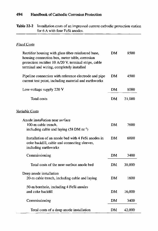
494 Handbook of Cathodic Corrosion Protection
Table 22-2 Installation costs of an impressed current cathodic protection stationfor 6 A with four FeSi anodes.
Fixed Costs
Rectifier housing with glass fiber-reinforced base, DM 8500housing connection box, meter table, corrosionprotection rectifier 10 A/20 V, terminal strips, cableterminal and wiring, completely installed
Pipeline connection with reference electrode and pipe DM 4500current test point, including material and earthworks
Low-voltage supply 220 V DM 8000
Total costs DM 21,000
Variable Costs
Anode installation near surface100-m cable trench, DM 7600including cable and laying (58 DM nr1)
Installation of an anode bed with 4 FeSi anodes in DM 6000coke backfill, cable and connecting sleeves,including earthworks
Commissioning DM 3400
Total costs of the near-surface anode bed DM 38,000
Deep anode installation20-m cable trench, including cable and laying DM 1600
50-m borehole, including 4 FeSi anodesand coke backfill DM 16,000
Commissioning DM 3400
Total costs of a deep anode installation DM 42,000
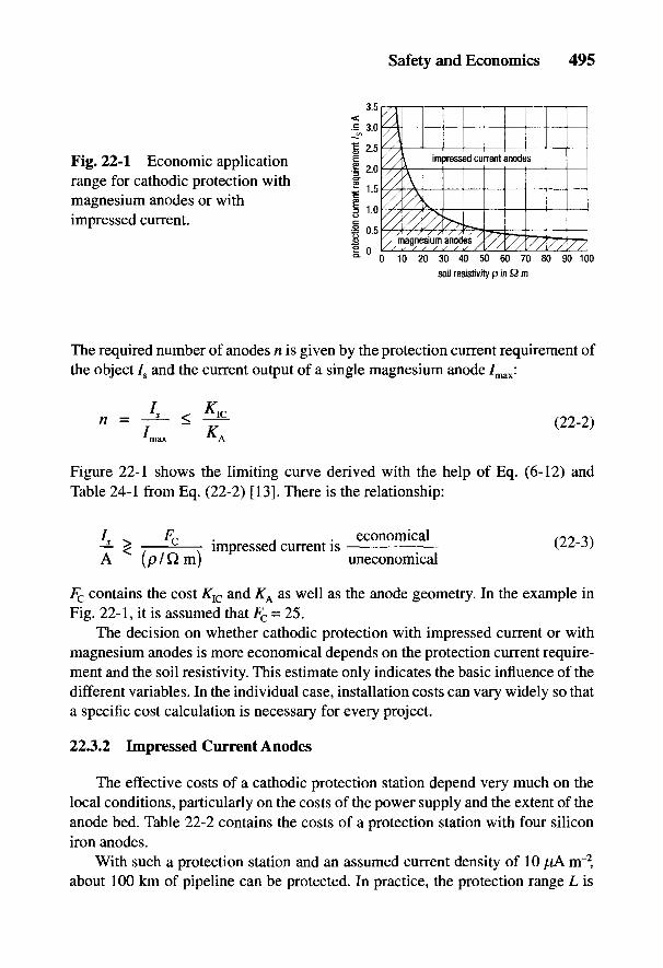
Safety and Economics 495
Fig. 22-1 Economic applicationrange for cathodic protection withmagnesium anodes or withimpressed current.
The required number of anodes n is given by the protection current requirement ofthe object 7S and the current output of a single magnesium anode 7max:
Figure 22-1 shows the limiting curve derived with the help of Eq. (6-12) andTable 24-1 from Eq. (22-2) [13]. There is the relationship:
Fc contains the cost Klc and K^ as well as the anode geometry. In the example inFig. 22-1, it is assumed that Fc - 25.
The decision on whether cathodic protection with impressed current or withmagnesium anodes is more economical depends on the protection current require-ment and the soil resistivity. This estimate only indicates the basic influence of thedifferent variables. In the individual case, installation costs can vary widely so thata specific cost calculation is necessary for every project.
22.3.2 Impressed Current Anodes
The effective costs of a cathodic protection station depend very much on thelocal conditions, particularly on the costs of the power supply and the extent of theanode bed. Table 22-2 contains the costs of a protection station with four siliconiron anodes.
With such a protection station and an assumed current density of 10 [lA m~2,about 100 km of pipeline can be protected. In practice, the protection range L is
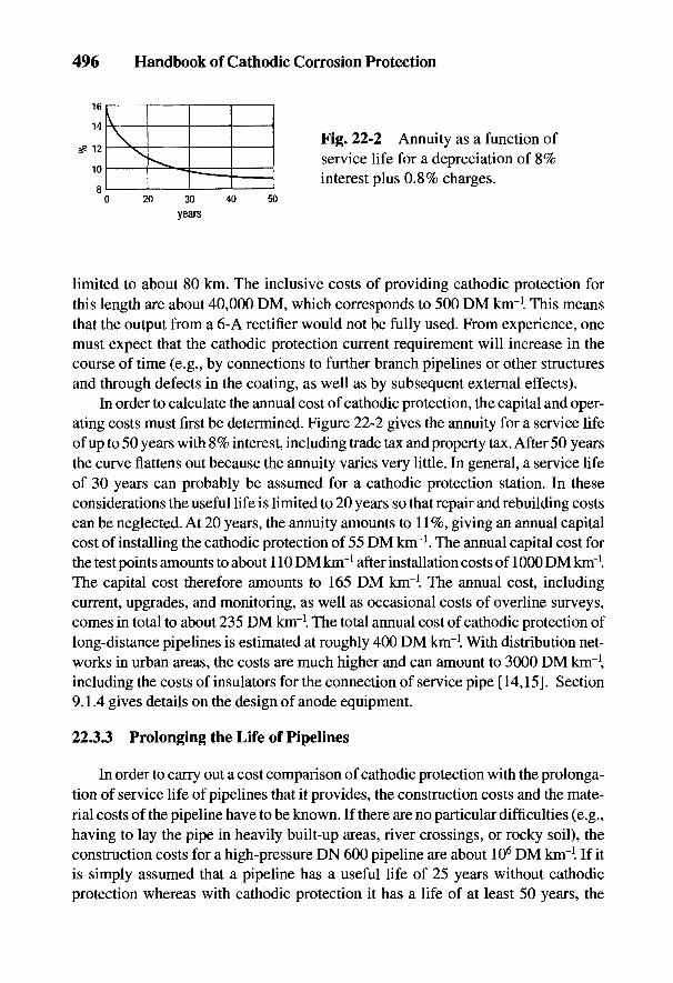
496 Handbook of Cathodic Corrosion Protection
Fig. 22-2 Annuity as a function ofservice life for a depreciation of 8%interest plus 0.8% charges.
limited to about 80 km. The inclusive costs of providing cathodic protection forthis length are about 40,000 DM, which corresponds to 500 DM kirrl This meansthat the output from a 6-A rectifier would not be fully used. From experience, onemust expect that the cathodic protection current requirement will increase in thecourse of time (e.g., by connections to further branch pipelines or other structuresand through defects in the coating, as well as by subsequent external effects).
In order to calculate the annual cost of cathodic protection, the capital and oper-ating costs must first be determined. Figure 22-2 gives the annuity for a service lifeof up to 50 years with 8% interest, including trade tax and property tax. After 50 yearsthe curve flattens out because the annuity varies very little. In general, a service lifeof 30 years can probably be assumed for a cathodic protection station. In theseconsiderations the useful life is limited to 20 years so that repair and rebuilding costscan be neglected. At 20 years, the annuity amounts to 11 %, giving an annual capitalcost of installing the cathodic protection of 55 DM kirr1. The annual capital cost forthe test points amounts to about 110 DM knr1 after installation costs of 1000 DM km'1.The capital cost therefore amounts to 165 DM km"1. The annual cost, includingcurrent, upgrades, and monitoring, as well as occasional costs of overline surveys,comes in total to about 235 DM km'1. The total annual cost of cathodic protection oflong-distance pipelines is estimated at roughly 400 DM km"1. With distribution net-works in urban areas, the costs are much higher and can amount to 3000 DM km"1,including the costs of insulators for the connection of service pipe [14,15]. Section9.1.4 gives details on the design of anode equipment.
22.3.3 Prolonging the Life of Pipelines
In order to carry out a cost comparison of cathodic protection with the prolonga-tion of service life of pipelines that it provides, the construction costs and the mate-rial costs of the pipeline have to be known. If there are no particular difficulties (e.g.,having to lay the pipe in heavily built-up areas, river crossings, or rocky soil), theconstruction costs for a high-pressure DN 600 pipeline are about 106 DM knr1. If itis simply assumed that a pipeline has a useful life of 25 years without cathodicprotection whereas with cathodic protection it has a life of at least 50 years, the
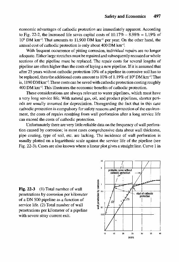
Safety and Economics 497
economic advantages of cathodic protection are immediately apparent. Accordingto Fig. 22-2, the increased life saves capital costs of 10.17% - 8.98% = 1.19% of106 DM km-1. That amounts to 11,900 DM knr1 per year. On the other hand, theannual cost of cathodic protection is only about 400 DM knr I
With frequent occurrence of pitting corrosion, individual repairs are no longeradequate. Either large stretches must be repaired and subsequently recoated or wholesections of the pipeline must be replaced. The repair costs for several lengths ofpipeline are often higher than the costs of laying a new pipeline. If it is assumed thatafter 25 years without cathodic protection 10% of a pipeline in corrosive soil has tobe replaced, then the additional costs amount to 10% of 1.19% of 106 DM km-1. Thatis, 1190 DM km"1. These costs can be saved with cathodic protection costing roughly400 DM km"1. This illustrates the economic benefits of cathodic protection.
These considerations are always relevant to water pipelines, which must havea very long service life. With natural gas, oil, and product pipelines, shorter peri-ods are usually assumed for depreciation. Disregarding the fact that in this casecathodic protection is compulsory for safety reasons and protection of the environ-ment, the costs of repairs resulting from wall perforation after a long service lifecan exceed the costs of cathodic protection.
Unfortunately there are very little reliable data on the frequency of wall perfora-tion caused by corrosion; in most cases comprehensive data about wall thickness,pipe coating, type of soil, etc. are lacking. The incidence of wall perforation isusually plotted on a logarithmic scale against the service life of the pipeline (seeFig. 22-3). Cases are also known where a linear plot gives a straight line. Curve 1 in
Fig. 22-3 (1) Total number of wallpenetrations by corrosion per kilometerof a DN 500 pipeline as a function ofservice life. (2) Total number of wallpenetrations per kilometer of a pipelinewith severe stray current exit.
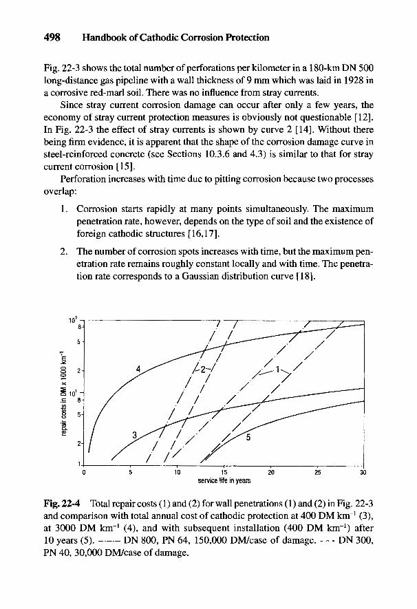
498 Handbook of Cathodic Corrosion Protection
Fig. 22-3 shows the total number of perforations per kilometer in a 180-km DN 500long-distance gas pipeline with a wall thickness of 9 mm which was laid in 1928 ina corrosive red-marl soil. There was no influence from stray currents.
Since stray current corrosion damage can occur after only a few years, theeconomy of stray current protection measures is obviously not questionable [12].In Fig. 22-3 the effect of stray currents is shown by curve 2 [14]. Without therebeing firm evidence, it is apparent that the shape of the corrosion damage curve insteel-reinforced concrete (see Sections 10.3.6 and 4.3) is similar to that for straycurrent corrosion [15].
Perforation increases with time due to pitting corrosion because two processesoverlap:
1. Corrosion starts rapidly at many points simultaneously. The maximumpenetration rate, however, depends on the type of soil and the existence offoreign cathodic structures [16,17].
2. The number of corrosion spots increases with time, but the maximum pen-etration rate remains roughly constant locally and with time. The penetra-tion rate corresponds to a Gaussian distribution curve [18].
Fig. 22-4 Total repair costs (1) and (2) for wall penetrations (1) and (2) in Fig. 22-3and comparison with total annual cost of cathodic protection at 400 DM km"1 (3),at 3000 DM knr1 (4), and with subsequent installation (400 DM km-1) after10 years (5). DN 800, PN 64, 150,000 DM/case of damage. - - - DN 300,PN 40, 30,000 DM/case of damage.

Safety and Economics 499
Both cases can be understood as being an increasing growth of coating defectswith time, leading to the exponential curve shown in Fig. 22-3. The assumptionsthat with time the coating permits more oxygen to diffuse through it and that thecoated surface acts as a cathode, lead to the same dependence on time (see Section5.2.1.3). If after the cathodic protection is commissioned, further wall penetrationsoccur that correspond to the curve in Fig. 22-3, this is usually due to the difficultyof fulfilling the protection criterion on old corroded spots. According to the infor-mation in Eq. (3-21), this is to be expected when too little cathodic polarization iscombined with too great a resistance of the local anodes [19].
The costs for repairing one area of corrosion damage in a high-pressure gaspipeline are approximately 150,000 DM for large-diameter and 50,000 DM forsmall-diameter pipes. According to Fig. 22-4, the total curves 1 and 2 of the annualcost of repairing wall perforations increase exponentially with service life. This isbased on the curves for the frequency of wall perforation in Fig. 22-3. The risingcosts of cathodic protection related to service life are shown by curves 3 and 4 inFig. 22-4. The cost advantage of cathodic protection occurs relatively late, as shownby the intersection of the two curves with the straight lines 1 and 2. With old pipe-lines, cathodic protection was only applied after commissioning (curve 5).
22.4 Corrosion Protection of Well Casings
The danger of corrosion in well casings is described in Section 18.2. The costof repairing corrosion damage in well casings is very high. On average it is around
Fig. 22-5 Total number of wall penetrations in well casings in an oil field.
500 Handbook of Cathodic Corrosion Protection
300,000 DM [20]. Figure 22-5 shows the number of wall perforations in an oilfield in which the first corrosion damage appeared after 8 years. The number ofcorrosion incidents rose considerably in the course of subsequent years, as curve ain Fig. 22-5 indicates. The well casings were cathodically protected. Inhibitorswere used to protect against internal corrosion. The number of fresh corrosionincidents clearly decreased, as shown by curve b. In the 12 years after the cathodicprotection was commissioned, only 16 examples of corrosion occurred, whereasfrom curve a about 350 would have been expected. The savings in repair costs ofabout 63 x 106 DM are set against the annual capital costs of the cathodic protec-tion of 231,000 DM and operational costs of 150,000 DM, amounting to a total ofabout 4.6 x 10⁶ DM for the period of 12 years. This clearly shows the economicbenefits of cathodic protection for well casings.
22.5 Corrosion Protection in Seawater
Shipping is the oldest area of application of cathodic protection (see Section 1.3).While galvanic anodes are predominantly used in ship construction and offshorestructures, the high current requirement for harbor installations and loading bridgesdemands the use of impressed current anodes. Characteristic corrosion problems inoffshore structures became apparent in the Gulf of Mexico in the middle 1950s. Inaddition to nonuniform and pitting corrosion, problems of corrosion fatigue becamemore prominent [21]. In contrast to dolphins and ships, no coatings were applied inmost offshore installations. Corrosion protection was achieved with cathodic pro-tection. The current output ratios of galvanic anodes of aluminum, magnesium andzinc are shown in Tables 6-2 to 6-4 as 3.3:1.4:1. On the other hand, the ratio of thecosts of anodes in DM kg"1 is 1.8:3.2:1, so that the specific costs in DM A"1 hr"1 are1:4.2:1.8 (i.e., very favorable for aluminum anodes). Long-term observations on thethree types of anode in the Gulf of Mexico gave the cost ratio as 1:3.5:2 [21]. Mag-nesium anodes are therefore uneconomic in the offshore field and are also not suit-able (see Section 16.1.2). Protection with zinc anodes is more costly than withaluminum anodes.
A particular advantage of impressed current systems is the ability to control theoutput voltage of the rectifier. Also, there are the comparatively low installation costsand relatively uniform current distribution. The costs of impressed current protec-tion compared with aluminum anodes are 0.8:1. With ships this ratio depends on thelength of the ship; with larger ships it is 1:2.5 since the calculation is made in com-parison with zinc and aluminum anodes. The order of magnitude of the annual costsdepends on the structure and the investment costs.

Safety and Economics 501
Table 22-3 Cost survey for cathodic protection of various installations.
Cost of cathodicStructure to Protective measures protectionbe protected carried out (DM m~2 a"1)
5000-m3 saline Cathodic protection, 2.65water tank coating
Pipeline PE coating 0.2ys=10jUAm-2,cathodic protection
Pipeline Bitumen coating, 0.44Js = 1 mA m~2,cathodic protection
Well casing Cathodic protection 1.2
Well casing and Cathodic protection 1.35pipelines in oilfield Bitumen coating
The structural costs of impressed current protection of harbor and coastal struc-tures are about 1.5 to 2.5% of the total cost of the object to be protected. As anexample, for the installation of a cathodic protection station in a tanker dischargejetty, the construction costs amounted to 2.2% of the total costs. The annual cost ofcurrent, maintenance, testing, and repairs amounted to 5% of the construction costsof the cathodic protection [22].
22.6 Cost of Internal Protection
Information on the costs of cathodic and anodic internal protection of tanksvaries very widely since the costs depend not only on the material costs but also onthe special installation costs and these in turn depend on the internal geometriclayout of the tank and its pipework.
22.6.1 Internal Cathodic Protection
The economic aspects of internal cathodic protection are naturally most im-portant where there is a danger of pitting or nonuniform corrosion. Usually no
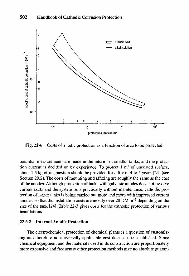
502 Handbook of Cathodic Corrosion Protection
Fig. 22-6 Costs of anodic protection as a function of area to be protected.
potential measurements are made in the interior of smaller tanks, and the protec-tion current is decided on by experience. To protect 1 m2 of uncoated surface,about 1.5 kg of magnesium should be provided for a life of 4 to 5 years [23] (seeSection 20.2). The costs of mounting and affixing are roughly the same as the costof the anodes. Although protection of tanks with galvanic anodes does not involvecurrent costs and the system runs practically without maintenance, cathodic pro-tection of larger tanks is being carried out more and more with impressed currentanodes, so that the installation costs are mostly over 20 DM m"2, depending on thesize of the tank [24]. Table 22-3 gives costs for the cathodic protection of variousinstallations.
22.6.2 Internal Anodic Protection
The electrochemical protection of chemical plants is a question of customiz-ing and therefore no universally applicable cost data can be established. Sincechemical equipment and the materials used in its construction are proportionatelymore expensive and frequently other protection methods give no absolute guaran-

Safety and Economics 503
tee of operational safety, developments for protection in this area are rapidly mov-ing forward (see Section 21.5).
In spite of lower anodic current densities for uncoated steel surfaces, the tech-nical applications of anodic protection are generally greater than those of cathodicprotection. Naturally the costs of the plant and reaction vessels are also consider-able, so that the costs of anodic protection can be estimated at about 3% of theinstallation costs of the object to be protected. The installation costs calculated forthe surface area of anodic protection against stress corrosion by caustic soda in alarge chemical plant are in the region of 60 DM rrr2. Stable coatings cannot beapplied for this price nor can the tank be constructed of stress corrosion-resistantmaterials. There are many cases where, after 1 to 2 years, 20% of the tank repaircosts were for repairing stress corrosion. Figure 22-6 shows the cost of anodicprotection for two very different installations as a function of the surface area to beprotected [25]. Current costs for anodic protection are, in general, negligible as inthe case of cathodic protection.
504 Handbook of Cathodic Corrosion Protection
22.7 References
[1] W. Schwenk, 3R intern. 26, 305 (1988); Werkst. Korros. 39, 406 (1988).[2] TRbF 301, Carl Heymanns Verlag, Koln 1981.[3] TRGL 141, Carl Heymanns Verlag, Koln 1977.[4] DVGW Arbeitsblatt GW 463, ZfGW-Verlag, Frankfurt 1983.[5] DVGW Arbeitsblatt GW 462 Teil 2, ZfGW-Verlag, Frankfurt 1985.[6] DVGW Schaden- und Unfallstatistik, Frankfurt 1984.[7] Pipeline & Gas Journal, Dallas/Texas, August 1985.[8] DVGW Arbeitsblatt GW412, ZfGW-Verlag, Frankfurt 1988.[9] DVGW Arbeitsblatt GW10, ZfGW-Verlag, Frankfurt 1984.
[10] W. Prinz, gwf gas/erdgas 129, 508 (1988).[11] H. J. Fromm, Mat. Perform. 16, H. 11, 21 (1977).[12] W. v. Baeckmann u. D. Funk, 3R intern. 17, 443 (1978).[13] C. Zimmermann, Diplomarbeit, TU Berlin 1962.[14] W. Pickelmann, gwf gas/erdgas 114, 254 (1973).[15] W. Schwarzbauer, gwf gas/erdgas 121, 419 (1980).[16] K. F. Mewes, Stahl und Eisen 59, 1383 (1939).[17] S. A. Bradford, Mat. Perform. 9, H.7, 13 (1970).[18] M. Arpaia, CEOCOR, interner Bericht, Kom. 1, 1978.[19] W. v. Baeckmann u. D. Funk, Rohre, Rohrleitungsbau, Rohrleitungstransport 10, 11
(1971).[20] B. Leutner, pers. Mitteilung 1988.[21] D. E. Boening, OTC Proc. Pap. 2702 (1976).[22] G. Hoppmann, 3R intern. 16, 306 (1977).[23] K. Sautner, Sanitare Technik 26, 306 (1977).[24] W. v. Baeckmann, A. Baltes u. G. Loken, Blech 10, 409 (1975).[25] F. Paulekat, pers. Mitteilung 1988.

23
Interference Effects of High-VoltageTransmission Lines on Pipelines
H.-U. PAUL AND H.G. SCHONEICH
Areas of dense building, a lack of corridors for erecting overhead transmissionlines, and conditions imposed by regulatory authorities have made it necessary touse common "energy rights-of-way" more and more frequently. This results in fre-quent crossings and contiguity, and in stretches of lines running parallel for severalkilometers, which can lead to ac interference. This results not only in danger to thepipeline maintenance personnel, but also in damage to the cathodic protection.
By ac interference is understood the action of a high-voltage power plant on apipeline by capacitive, ohmic and inductive coupling. In contrast to the other chap-ters in this handbook, in this chapter only ac and its relevant parameters are dealtwith. The theoretical bases correspond closely to the information in Section 24.4;however, analogous parameters are designated differently and must be representedas complex. The concept potential as used in this chapter (e.g., the pipeline poten-tial) is the ac voltage between the pipeline and the reference ground (remote ground).The important pipe/soil potential used in corrosion protection, which is a super-imposed dc component, is not considered here.
Various kinds of interference can be defined:
• Capacitive interference: the production of electrical potentials in conduc-tors due to the influence of alternating electrical fields (e.g., by high-voltagetransmission lines under power).
• Ohmic interference: the production of electrical potentials in conductorsby electrical contact, by arcing or by a local voltage cone, caused by faultcurrents or stray currents in the soil (see Chapter 15).
• Inductive interference: the production of electrical potentials in conduc-tors due to the induction from alternating magnetic fields arising from short-circuit currents or operational currents in high-voltage power lines.
Depending on the length of time the interference processes are active, a dis-tinction is made between short-term and long-term interference. Short-term inter-ference is a rare occurrence resulting from a failure in a high-voltage installation
505
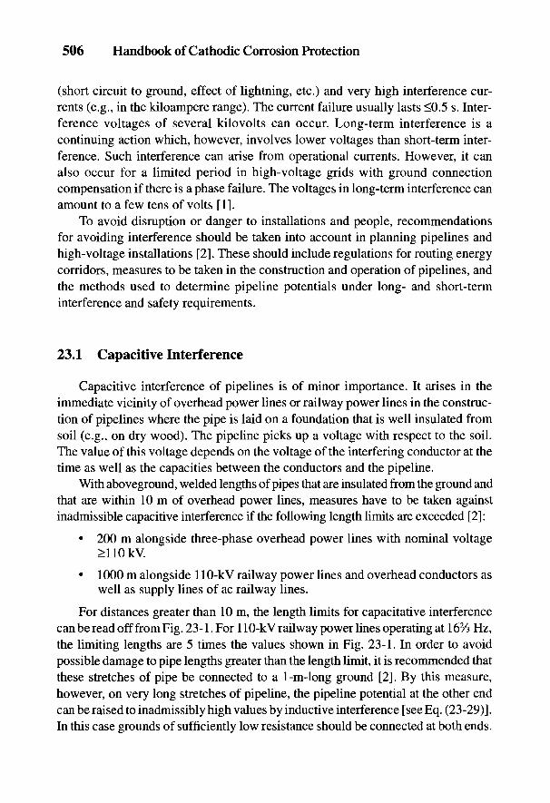
506 Handbook of Cathodic Corrosion Protection
(short circuit to ground, effect of lightning, etc.) and very high interference cur-rents (e.g., in the kiloampere range). The current failure usually lasts <0.5 s. Inter-ference voltages of several kilovolts can occur. Long-term interference is acontinuing action which, however, involves lower voltages than short-term inter-ference. Such interference can arise from operational currents. However, it canalso occur for a limited period in high-voltage grids with ground connectioncompensation if there is a phase failure. The voltages in long-term interference canamount to a few tens of volts [1].
To avoid disruption or danger to installations and people, recommendationsfor avoiding interference should be taken into account in planning pipelines andhigh-voltage installations [2]. These should include regulations for routing energycorridors, measures to be taken in the construction and operation of pipelines, andthe methods used to determine pipeline potentials under long- and short-terminterference and safety requirements.
23.1 Capacitive Interference
Capacitive interference of pipelines is of minor importance. It arises in theimmediate vicinity of overhead power lines or railway power lines in the construc-tion of pipelines where the pipe is laid on a foundation that is well insulated fromsoil (e.g., on dry wood). The pipeline picks up a voltage with respect to the soil.The value of this voltage depends on the voltage of the interfering conductor at thetime as well as the capacities between the conductors and the pipeline.
With aboveground, welded lengths of pipes that are insulated from the ground andthat are within 10 m of overhead power lines, measures have to be taken againstinadmissible capacitive interference if the following length limits are exceeded [2]:
• 200 m alongside three-phase overhead power lines with nominal voltage>110kV.
• 1000 m alongside 110-kV railway power lines and overhead conductors aswell as supply lines of ac railway lines.
For distances greater than 10m, the length limits for capacitative interferencecan be read off from Fig. 23-1. For 110-kV railway power lines operating at 162/3 Hz,the limiting lengths are 5 times the values shown in Fig. 23-1. In order to avoidpossible damage to pipe lengths greater than the length limit, it is recommended thatthese stretches of pipe be connected to a 1-in-long ground [2]. By this measure,however, on very long stretches of pipeline, the pipeline potential at the other endcan be raised to inadmissibly high values by inductive interference [see Eq. (23-29)].In this case grounds of sufficiently low resistance should be connected at both ends.

Interference Effects of High-Voltage Transmission Lines on Pipelines 507
Fig. 23-1 Limiting length Ljim of aparallel insulated stretch of pipe withcapacitive interference by a 50-Hz, three-phase overhead power line witha nominal voltage >110 kV [2].
23.2 Ohmic Interference
23.2.1 Contact with a Conductor under High Voltage
During construction in the vicinity of overhead power lines, there is a great dan-ger that construction equipment (e.g., cranes) may inadvertently come too close to thevoltage-carrying conductor, causing arcing or even direct contact with the conductorcable. In both cases, dangerous contact voltages occur at the construction equipmentitself and its surroundings. Great care should be taken in the construction and repair ofpipelines to observe sufficiently wide distances for safety (see Fig. 23-2) [2-4].
This can be achieved by limiting the height and reach of equipment working inthe vicinity of high-voltage overhead power lines and by careful supervision ofconstruction [2]. It is recommended that equipment remain at least 5 m away fromhigh-voltage power lines with a nominal voltage of >110 kV, and 3 m away fromthose of <110 kV, including overhead conductors and supply lines.
To avoid immediate current discharge from a pylon to a pipeline due to a high-voltage failure, the distance between the pipeline and the corner legs of the pylonor the pylon ground should be greater than 2 m if possible. Reducing the distanceby not less than 0.5 m is permitted only with an agreement by the parties con-cerned. It has been proved that, with a distance of 0.5 m between a ground and aPE-coated pipeline, even under unfavorable conditions no arcing occurs when thereis a failure of the high-voltage grid [5]. If the tracks of ac railways cross under-

508 Handbook of Cathodic Corrosion Protection
Fig. 23-2 Safe distances from high-voltage overhead power lines.
ground, a distance of 1.5 m must be maintained between the pipeline and the upperedge of the ties.
Where pipelines and high-voltage cables cross, a distance of at least 0.2 mmust be observed to prevent contact between cable and pipeline (this can be achievedby interposing insulating shells or plates). Such intermediate materials can be PVCor PE. Their disposition and shape must be determined by mutual agreement [2,6].
Where pipelines and high-voltage cables run parallel to each other, spacing ofat least 0.4 m should be observed to ensure adequate working space. In bottle-necks, the spacing should not be less than 0.2 m [2].
23.2.2 Voltage Cone of a Pylon Grounding Electrode
Figure 23-3 shows in principle the change in the potential at the soil surface inthe vicinity of an overhead power line pylon as a function of distance. If there is aground connection at a high-voltage pylon grid, part 7G of the ground leakage current7F flows via the grounding impedance ZG of the pylon into the ground. The pylonreaches the voltage UG = IG x ZG against the reference ground. A pipeline withbitumen or plastic coating has the potential of the reference ground. If it is within thevoltage cone of a pylon, a person touching the pipeline (e.g., when carrying outrepair work) could receive a shock from the potential between the surrounding soiland the pipeline.
Interference Effects of High-Voltage Transmission Lines on Pipelines 509
Fig. 23-3 Variation of the potential at ground level in the vicinity of a powerline pylon.
If the contact voltage exceeds 65 V for long-term interference or 1000 V forshort-term interference, protective measures are necessary for people working onthe pipeline (e.g., rubber boots, insulated gloves, or insulated protective padding)[21. On no account can there be an electrical connection between a pipeline and anoverhead power line pylon or its ground. In the normal operation of a three-phaseoverhead power line, pylon grounding voltages arise from a main conductorexchange at a transposition of pylon lines [7].
The potentials from larger grounding installations on the soil surface are essen-tially flatter but more extended than those from overhead power line pylons (e.g.,power stations, transformers and switchboard plants). The maximum expectedgrounding voltage in case of failure and its variation at the soil surface can beobtained from the facility's management.
The lines of an ac railway produce changes in the potential of the soil surface atright angles to the surface of the soil [8]. Since the potential differences on the soilsurface are, however, much lower than the voltage between the rails and the refer-ence ground, which, for contact protection, must not exceed 65 V, the potentialchanges are negligibly small.
Special conditions arise if a pipeline is laid in the region of the groundinginstallation of a power station or a transformer installation. If a lasting or a transi-tory connection with the grounding installation results during a grounding fault,
510 Handbook of Cathodic Corrosion Protection
the grounding voltage will be transferred to the pipeline and then appear outsidethe voltage cone as a contact voltage. Depending on the characteristics of thepipeline, the contact voltage decreases more or less quickly at greater distances.The variation is identical to the contact voltage UB outside close proximity in thecase of inductive interference (see Section 23.3). The grounding voltage is substitut-ed for by f/Bmax. The pipeline is usually cathodically protected and electricallyisolated from the grounding installation by an insulating unit at the works bound-ary or in the vicinity of its entry into the buildings. In the first case, the pipeline canbe connected to the grounding installation in the works area. It is not possible toconduct the voltage to the outside because of the insulating unit. In the secondcase, additional measures may be necessary to prevent accidental connections withthe grounding installation or with grounded parts of the plant, and to avoid highcontact voltages inside the works area.
Contact voltages at pipelines must not exceed the limiting values in Fig. 14-3 [9]inside high-voltage plants. With long-term interference (i.e., acting for >3 s) thecontact voltage must be U<65 V; with short-term interference, the limiting value ofthe contact voltage depends on the duration of the failure current t¥ (e.g., UE <370 Vfor fp = 0.2 s and UE <740 V for fF = 0.1 s).
If these values cannot be conformed to, additional measures are necessary (e.g.,wearing insulating footwear and using insulating padding) [2]. There is increaseddanger if there is a possibility of simultaneous contact with the pipeline and a groundor grounded part of the installation. At distances closer than 2 m, the ground orgrounded parts of the installation should be covered with insulating cloths or plateswhen work is being carried out on the pipeline.
23.3 Inductive Interference
23.3.1 Causes and Factors Involved
Inductive interference on pipelines is usually only to be expected with extendedand close or parallel routing with three-phase, high-voltage overhead power lines, aswell as with conductors and supply lines of ac railways.
The likelihood of interference increases with rising operational and short-circuitcurrents in the high-voltage installation and with increasing coating resistance of thepipeline. Voltages are induced in nearby metallic conductors by magnetic couplingwith the high-voltage lines, which results in currents flowing in a conducting pipe-line and the existence of voltages between it and the surrounding soil. Operationalcurrents of high-voltage overhead power lines play an increasing role in interfer-
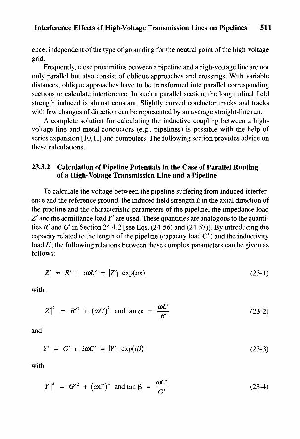
Interference Effects of High-Voltage Transmission Lines on Pipelines 511
ence, independent of the type of grounding for the neutral point of the high-voltagegrid.
Frequently, close proximities between a pipeline and a high-voltage line are notonly parallel but also consist of oblique approaches and crossings. With variabledistances, oblique approaches have to be transformed into parallel correspondingsections to calculate interference. In such a parallel section, the longitudinal fieldstrength induced is almost constant. Slightly curved conductor tracks and trackswith few changes of direction can be represented by an average straight-line run.
A complete solution for calculating the inductive coupling between a high-voltage line and metal conductors (e.g., pipelines) is possible with the help ofseries expansion [10,11] and computers. The following section provides advice onthese calculations.
23.3.2 Calculation of Pipeline Potentials in the Case of Parallel Routingof a High-Voltage Transmission Line and a Pipeline
To calculate the voltage between the pipeline suffering from induced interfer-ence and the reference ground, the induced field strength E in the axial direction ofthe pipeline and the characteristic parameters of the pipeline, the impedance loadZ' and the admittance load Y' are used. These quantities are analogous to the quanti-ties R' and G' in Section 24.4.2 [see Eqs. (24-56) and (24-57)]. By introducing thecapacity related to the length of the pipeline (capacity load C") and the inductivityload L', the following relations between these complex parameters can be given asfollows:
with
and
with

512 Handbook of Cathodic Corrosion Protection
II Edx ' i ,
I 'I—1 1 (SH Z > d X J 1 ' I 1 17' 11 yl T3 • 1 *I , ^ ' ' i I , Fig. 23-4 Equivalentj-^-i i—'—i | ! r~\ circuit diagram for aN u
y-J- J| {u+*u] Z2 pipeline subjected to
*-r , —i— ! | interference.1 1 1 "
—I ||_J 1 i—u 10 u x (x + dx) i i L
where CO = 2/T/",/is the frequency and i = V-l. The following approximations aremade in the calculation using transmission theory [12]:
• The pipeline runs parallel to the interfering power line between points x = 0and jc = L (see Fig. 23-4). The field strength is constant over this length.
• The pipeline has constant parameters (/?', G', Z', Y') and therefore also thesame r values in the close proximity region.
• The specific electrical soil resistivity is constant in the region under con-sideration. With short-term interference, the ground short circuit occursoutside the region under consideration.
The equivalent circuit diagram in Fig. 23-4 shows a differential fundamental sec-tion and the closed-circuit impedance at the end of the close proximity region.
It follows from the equivalent circuit diagram for a loop pipe/soil of the differ-ential fundamental section:
Here / is induced current, U is pipeline potential, and x is the position coordinate.With the locally constant field strength, E, it follows from Eqs. (23-5) and (23-6):
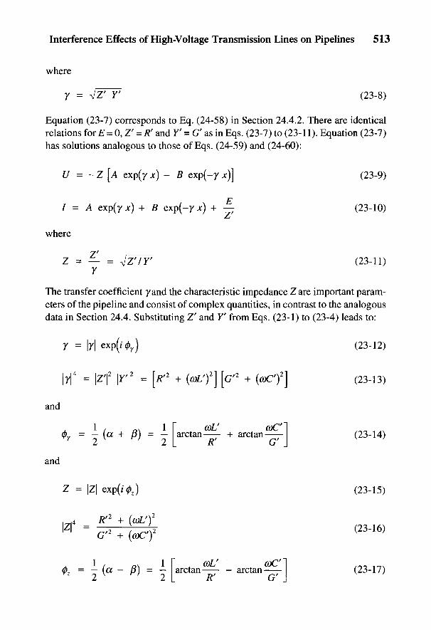
Interference Effects of High-Voltage Transmission Lines on Pipelines 513
where
Equation (23-7) corresponds to Eq. (24-58) in Section 24.4.2. There are identicalrelations for E = Q,Z' = R' and F' = G' as in Eqs. (23-7) to (23-11). Equation (23-7)has solutions analogous to those of Eqs. (24-59) and (24-60):
where
The transfer coefficient /and the characteristic impedance Z are important param-eters of the pipeline and consist of complex quantities, in contrast to the analogousdata in Section 24.4. Substituting Z' and Y' from Eqs. (23-1) to (23-4) leads to:
and
and
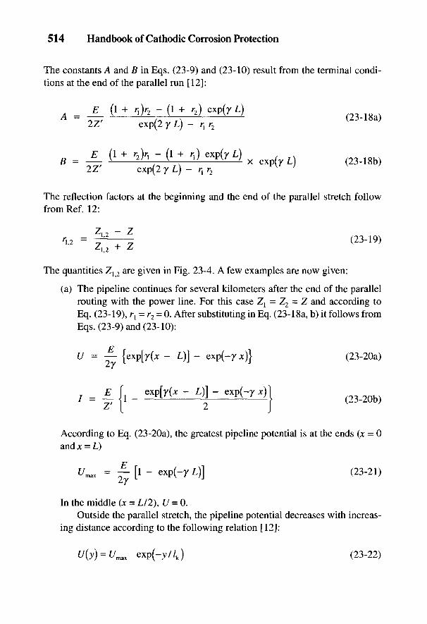
514 Handbook of Cathodic Corrosion Protection
The constants A and B in Eqs. (23-9) and (23-10) result from the terminal condi-tions at the end of the parallel run [12]:
The reflection factors at the beginning and the end of the parallel stretch followfrom Ref. 12:
The quantities Z{ 2 are given in Fig. 23-4. A few examples are now given:
(a) The pipeline continues for several kilometers after the end of the parallelrouting with the power line. For this case Z{ = Z2 = Z and according toEq. (23-19), r{ = r2 = 0. After substituting in Eq. (23-18a, b) it follows fromEqs. (23-9) and (23-10):
According to Eq. (23-20a), the greatest pipeline potential is at the ends (x = 0and x = L)
In the middle (x = L/2), £7 = 0.Outside the parallel stretch, the pipeline potential decreases with increas-
ing distance according to the following relation [12]:
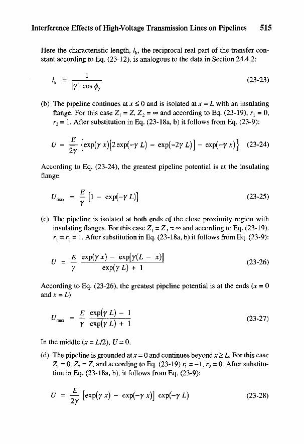
Interference Effects of High-Voltage Transmission Lines on Pipelines 515
Here the characteristic length, /k, the reciprocal real part of the transfer con-stant according to Eq. (23-12), is analogous to the data in Section 24.4.2:
(b) The pipeline continues at x < 0 and is isolated at x = L with an insulatingflange. For this case Z{ = Z, Z2 = °° and according to Eq. (23-19), rl = 0,r2 = 1. After substitution in Eq. (23-18a, b) it follows from Eq. (23-9):
According to Eq. (23-24), the greatest pipeline potential is at the insulatingflange:
(c) The pipeline is isolated at both ends of the close proximity region withinsulating flanges. For this case Z{ = Z2 - <*> and according to Eq. (23-19),rl = r2 = 1. After substitution in Eq. (23-18a, b) it follows from Eq. (23-9):
According to Eq. (23-26), the greatest pipeline potential is at the ends (jc = 0andjc = L):
In the middle (x = L/2), U = 0.
(d) The pipeline is grounded at x = 0 and continues beyond x > L. For this caseZj = 0, Z2 = Z, and according to Eq. (23-19) rt = -1, r2 = 0. After substitu-tion in Eq. (23-18a, b), it follows from Eq. (23-9):
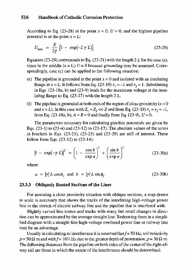
516 Handbook of Cathodic Corrosion Protection
According to Eq. (23-28) at the point x = 0, (7 = 0, and the highest pipelinepotential is at the point x = L:
Equation (23-29) corresponds to Eq. (23-21) with the length 2 L for the case (a),since in the middle (x = L) U = 0 because grounding may be assumed. Corre-spondingly, case (c) can be applied to the following situation:
(e) The pipeline is grounded at the point x = 0 and isolated with an insulatingflange at x = L. It follows from Eq. (23-19) r{ - -1 and r2 = 1. Substitutingin Eqs. (23-18a, b) and (23-9) leads for the maximum voltage at the insu-lating flange to Eq. (23-27) with the length 2 L.
(f) The pipeline is grounded at both ends of the region of close proximity (x = 0and x = L). In this case with Zj ~ Z2« Z and from Eq. (23-19) r{ ~ r2 ~ -1,from Eq. (23-18a, b), A « B « 0 and finally from Eq. (23-9), U~ 0.
The parameters necessary for calculating pipeline potentials are given byEqs. (23-1) to (23-4) and (23-12) to (23-17). The absolute values of the termsin brackets in Eqs. (23-21), (23-25) and (23-29) are still of interest. Thesefollow from Eqs. (23-12) to (23-14):
where
23.3.3 Obliquely Routed Sections of the Lines
For assessing a close proximity situation with oblique sections, a map drawnto scale is necessary that shows the tracks of the interfering high-voltage powerline or the stretch of electric railway line and the pipeline that is interfered with.
Slightly curved line routes and tracks with many but small changes in direc-tion can be approximated by the average straight line. Redrawing them in a simpli-fied diagram with a straight-line high-voltage overhead power line or railway linemay be an advantage.
Usually in calculating ac interference it is assumed that/= 50 Hz, soil resistivityp = 50 Q m and with/= 162/s Hz due to the greater depth of penetration, p = 30 Q m.The following distances from the pipeline on both sides of the center of the right-of-way rail are those in which the extent of the interference should be determined:
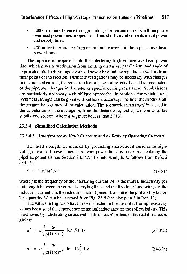
Interference Effects of High-Voltage Transmission Lines on Pipelines 517
• 1000 m for interference from grounding short-circuit currents in three-phaseoverhead power lines or operational and short-circuit currents in rail powerand supply lines,
• 400 m for interference from operational currents in three-phase overheadpower lines.
The pipeline is projected onto the interfering high-voltage overhead powerline, which gives a subdivision from limiting distances, parallelism, and angle ofapproach of the high-voltage overhead power line and the pipeline, as well as fromtheir points of intersection. Further investigations may be necessary with changesin the induced current, the reduction factors, the soil resistivity and the parametersof the pipeline (changes in diameter or specific coating resistance). Subdivisionsare particularly necessary with oblique approaches in sections, for which a uni-form field strength can be given with sufficient accuracy. The finer the subdivision,the greater the accuracy of the calculation. The geometric mean (a1a2)
1/2 is used inthe calculation for the average, a, from the distances al and a2 at the ends of thesubdivided section, where alla2 must be less than 3 [13].
23.3.4 Simplified Calculation Methods
23.3.4.1 Interference by Fault Currents and by Railway Operating Currents
The field strength, E, induced by grounding short-circuit currents in high-voltage overhead power lines or railway power lines, is basic in calculating thepipeline potentials (see Section 23.3.2). The field strength, E, follows from Refs. 2and 13:
where/is the frequency of the interfering current, M' is the mutual inductivity perunit length between the current-carrying lines and the line interfered with, / is theinduction current, r is the reduction factor (general), and ft) is the probability factor.The quantity M' can be assumed from Fig. 23-5 (see also plan 3 in Ref. 13).
The values in Fig. 23-5 have to be corrected in the case of differing resistivityvalues because of the dependence of mutual inductance on the soil resistivity. Thisis achieved by substituting an equivalent distance, a\ instead of the real distance, a,giving:
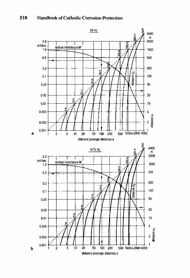
518 Handbook of Cathodic Corrosion Protection
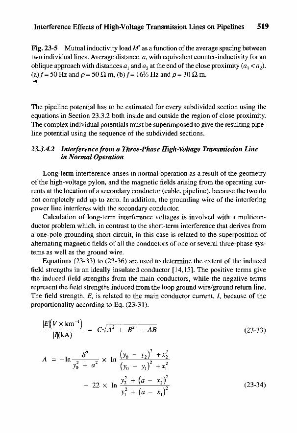
Interference Effects of High-Voltage Transmission Lines on Pipelines 519
Fig. 23-5 Mutual inductivity load M' as a function of the average spacing betweentwo individual lines. Average distance, a, with equivalent counter-inductivity for anoblique approach with distances a{ and a2 at the end of the close proximity (av < a2).(a)/= 50 Hz and p = 50 Q m, (b)/= 16% Hz and p = 30 Q m.-^
The pipeline potential has to be estimated for every subdivided section using theequations in Section 23.3.2 both inside and outside the region of close proximity.The complex individual potentials must be superimposed to give the resulting pipe-line potential using the sequence of the subdivided sections.
23.3.4.2 Interference from a Three-Phase High-Voltage Transmission Linein Normal Operation
Long-term interference arises in normal operation as a result of the geometryof the high-voltage pylon, and the magnetic fields arising from the operating cur-rents at the location of a secondary conductor (cable, pipeline), because the two donot completely add up to zero. In addition, the grounding wire of the interferingpower line interferes with the secondary conductor.
Calculation of long-term interference voltages is involved with a multicon-ductor problem which, in contrast to the short-term interference that derives froma one-pole grounding short circuit, in this case is related to the superposition ofalternating magnetic fields of all the conductors of one or several three-phase sys-tems as well as the ground wire.
Equations (23-33) to (23-36) are used to determine the extent of the inducedfield strengths in an ideally insulated conductor [14,151. The positive terms givethe induced field strengths from the main conductors, while the negative termsrepresent the field strengths induced from the loop ground wire/ground return line.The field strength, E, is related to the main conductor current, 7, because of theproportionality according to Eq. (23-31).
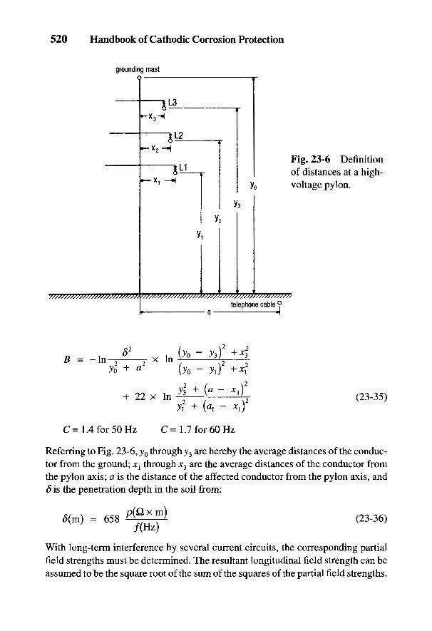
520 Handbook of Cathodic Corrosion Protection
Fig. 23-6 Definitionof distances at a high-voltage pylon.
Referring to Fig. 23-6, y0 through y3 are hereby the average distances of the conduc-tor from the ground; x{ through x3 are the average distances of the conductor fromthe pylon axis; a is the distance of the affected conductor from the pylon axis, and6 is the penetration depth in the soil from:
With long-term interference by several current circuits, the corresponding partialfield strengths must be determined. The resultant longitudinal field strength can beassumed to be the square root of the sum of the squares of the partial field strengths.

Interference Effects of High-Voltage Transmission Lines on Pipelines 521
If, however, long-term interference results from current circuits that are con-nected in parallel (e.g., double conductors) or from current circuits that generallyexhibit the same load flow direction (e.g., power station connection conductors),then the partial field strengths have to be added.
To determine the pipeline potentials, the resultant induced field strengths haveto be included in the equations in Section 23.3.2. Such calculations can be carriedout with computers that allow detailed subdivision of the sections subject to inter-ference. A high degree of accuracy is thus achieved because in the calculation withcomplex numbers, the phase angle will be exactly allowed for. Such calculationsusually lead to lower field strengths than simplified calculations. Computer pro-grams for these calculations are to be found in Ref. 16.
23.3.5 Representation of the Characteristics of a Pipeline
Important parameters of a pipeline for calculating pipeline potentials are dealtwith in Section 23.3.2. These quantities depend on the frequency,/, of the interfer-ing current and on the material data of the pipeline. These are as follows:
The following data are the basis of the diagrams in Figs. 23-7 through 23-11:
(a) Variables: d = pipe diameter and ru = specific coating resistance [whoserelation with the protection current density Js follows from Eq. (5-11)];
(b) Constants: p = 100 Q m for the soil; pst = 1.6 x 10~5 Q m and r = 200 forsteel; er = 5 and the thickness of the coating s = 3 mm.
Some of the data assumed to be constant (pst, ^ur, £r) can deviate more or lessbut this affects the results only slightly. The parameters provided in the following
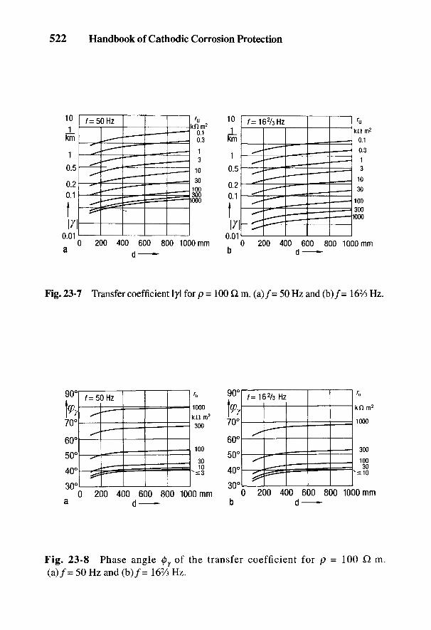
522 Handbook of Cathodic Corrosion Protection
Fig. 23-7 Transfer coefficient lyl for p = 100 Q. m. (a)/= 50 Hz and (b)/= 16% Hz.
Fig. 23-8 Phase angle 0y of the transfer coefficient for p = 100 Q. m.(a)/= 50 Hz and (b)/= 16% Hz.
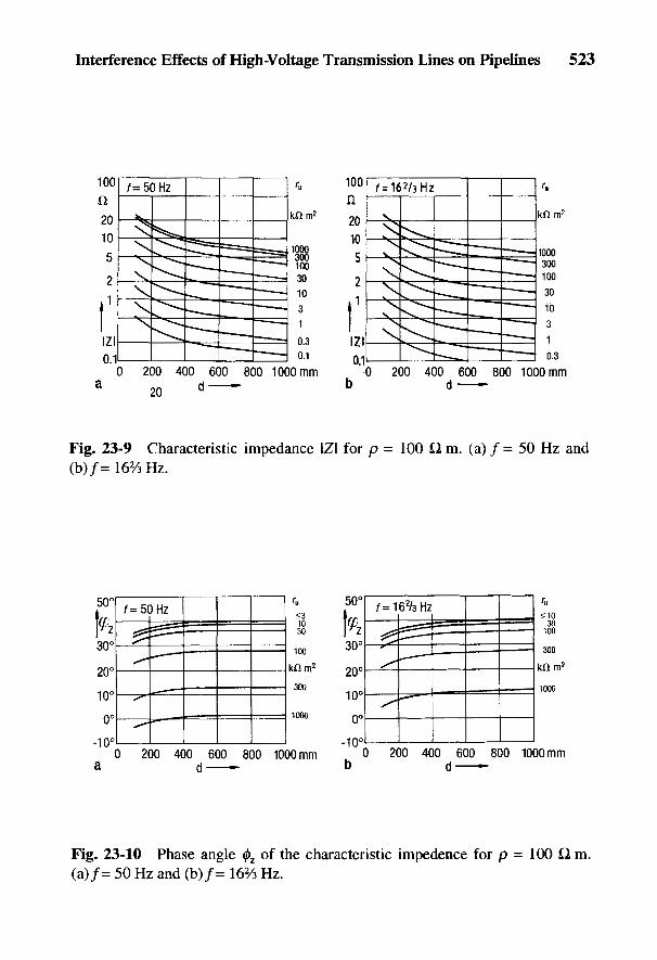
Interference Effects of High-Voltage Transmission Lines on Pipelines 523
Fig. 23-9 Characteristic impedance IZI for p = 100 Q m. (a) / = 50 Hz and(b)/= 162/3 Hz.
Fig. 23-10 Phase angle 0Z of the characteristic impedence for p = 100 Q m.(a)/= 50 Hz and (b)/= 162/3 Hz.
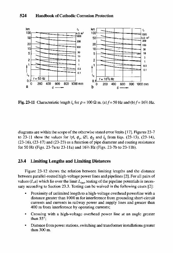
524 Handbook of Cathodic Corrosion Protection
Fig. 23-11 Characteristic length /k for p = 100 Q m. (a)/= 50 Hz and (b)/= 16% Hz.
diagrams are within the scope of the otherwise stated error limits [17]. Figures 23-7to 23-11 show the values for I/I, 0y, IZI, 0Z and /k from Eqs. (23-13), (23-14),(23-16), (23-17) and (23-23) as a function of pipe diameter and coating resistancefor 50 Hz (Figs. 23-7a to 23-lla) and 162/s Hz (Figs. 23-7b to 23-llb).
23.4 Limiting Lengths and Limiting Distances
Figure 23-12 shows the relation between limiting lengths and the distancebetween parallel-routed high-voltage power lines and pipelines [2]. For all pairs ofvalues (L,d) which lie over the limit Ljim, testing of the pipeline potentials is neces-sary according to Section 23.3. Testing can be waived in the following cases [2]:
• Proximity of unlimited length to a high-voltage overhead powerline with adistance greater than 1000 m for interference from grounding short-circuitcurrents and currents in railway power and supply lines and greater than400 m from interference by operating currents;
• Crossing with a high-voltage overhead power line at an angle greaterthan 55°;
• Distance from power stations, switching and transformer installations greaterthan 300 m.
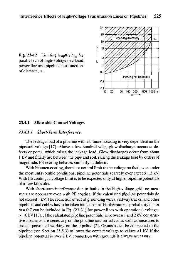
Interference Effects of High-Voltage Transmission Lines on Pipelines 525
Fig. 23-12 Limiting lengths Llim forparallel run of high-voltage overheadpower line and pipeline as a functionof distance, a.
23.4.1 Allowable Contact Voltages
23.4.1.1 Short-Term Interference
The leakage load of a pipeline with a bitumen coating is very dependent on thepipe/soil voltage [17]. Above a few hundred volts, glow discharge occurs at de-fects or pores, which raises the leakage load. Glow discharges occur from about1 kV and finally arc between the pipe and soil, raising the leakage load by orders ofmagnitude. PE coating behaves similarly at defects.
With bitumen coating, there is a natural limit to the voltage so that, even underthe most unfavorable conditions, pipeline potentials scarcely ever exceed 1.5 kV.With PE coating, a voltage limit is to be expected only at higher pipeline potentialsof a few kilo volts.
With short-term interference due to faults in the high-voltage grid, no mea-sures are necessary even with PE coating, if the calculated pipeline potentials donot exceed 1 kV. The reduction effect of grounding wires, railway tracks, and otherpipelines and cables has to be taken into account. Furthermore, a probability factorco = 0.7 can be included in Eq. (23-31) for power lines with operational voltages>110 kV [13]. If the calculated pipeline potentials lie between 1 and 2 kV, construc-tive measures are necessary on the pipeline and on valves as well as measures toprotect personnel working on the pipeline [2]. Grounds can be connected to thepipeline (see Section 25.5.3) to lower the contact voltage to values <1 kV. If thepipeline potential is over 2 kV, connection with grounds is always necessary.
526 Handbook of Cathodic Corrosion Protection
23.4.1.2 Long-Term Interference
With long-term interference from operational currents of high-voltage powerlines or railway power and supply lines, the contact voltage must not exceed 65 V[9]. The relevant operational current has to be stated by the operator responsiblefor the basic calculation. If the calculated pipeline potentials are above 65 V, con-nection with grounds is always necessary.
23.4.2 Determination of Pipeline Potentials
If pipeline potentials have to be calculated according to Fig. 23-12, then all thenecessary data must be requested from the energy supply companies or the railwaycompanies (e.g., the Bundesbahn Central Office in Munich). This includes, amongother items, route plans, short-circuit diagrams, operational currents (thermal lim-iting currents), pylon diagrams, and grounding wire information (see also the datain Section 23.3.4 in this connection). The following information is required on thepipeline that is interfered with: route plans, position of insulating units, location ofobjects acting as grounds and cathodic protection stations, and parallel-routed pipe-lines and cables (see also the data in Section 23.3.5 in this connection). The methodof calculation is given in Section 23.3.
23.5 Protection Measures against Unallowably High PipelinePotentials
23.5.1 Short-Term Interference
For working at the pipeline, standing surface insulation or equipotential ground-ing mats at valves [2] must be provided for voltages of 1 to 2 kV. Rubber boots andwater-repelling protective clothing have to be used in wet pits. According toDIN 4843 part 1, high rubber boots are sufficient. In addition, commercial insulat-ing padding of 2.5 mm minimum thickness (e.g., safety mats for welding or insu-lating rubber or plastic mats) must be used in the case of working in a lying orsitting position. Generally, the pipeline potentials can be reduced by decreasingthe leakage load through grounding.
23.5.2 Long-Term Interference
Installation of grounds, standing surface insulation, or equipotential ground-ing mats are necessary in the case of pipeline potentials higher than 65 V [21. In thecase of long sections of parallelism for an overhead power line and a pipeline,continuous grounding with respect to the distances and the resistances of the grounds

Interference Effects of High-Voltage Transmission Lines on Pipelines 527
are favored to obtain an allowable voltage distribution within the close proximityfor a short circuit to ground.
23.5.3 Protective Measures by Grounding
The leakage load, G' as well as the transfer coefficient in Eq. (23-13) is raisedand the pipeline potential according to Eq. (23-20a) is lowered by grounding. Ithas to be deduced, for a given interference, what the minimum value of G'm iswhich must be achieved to keep the pipeline potential sufficiently low. For a givenvalue of G' the leakage G for a section of the pipeline of length, L, with n groundsand with grounding resistance, /?G, is given by:
With n = nIL (number of grounds per unit length), it follows from Eq. (23-41):
The minimum value of G'm corresponds to the highest value of ru m of the coatingresistance according to Eq. (23-39):
Hot-dipped galvanized steel with a coating of at least 550 g nr2 (about 70 /mi) ofzinc is usually employed for grounds. The usual material for horizontal groundsthat can be laid in the pipeline trench is a galvanized steel strip with a cross sectionof 30 x 3.5 mm. Deep grounds mostly consist of assembled galvanized rods with adiameter of at least 20 mm. Grounds with these cross sections always have dimen-sions more than sufficient for their current loading if they are distributed along thetrajectory subject to interference.
Protective measures using grounds can, according to Eq. (23-42), be achieved bychoosing values of n and RG suitable from an economic point of view. It is oftenconvenient to lay strip grounds in the pipe trench at the time of construction. Deepgrounds are advisable if the soil resistivity decreases with depth. They have the addi-tional advantage of not taking up much space and are particularly suitable forpostconstruction installation. With deep grounds, a derived grounding resistance canbe achieved by twisting together corresponding lengths of the grounding material. Inthis case, particularly with inhomogeneous soils, it is advisable to measure the ground-ing resistance when installing the ground (e.g., after each additional rod length).
528 Handbook of Cathodic Corrosion Protection
The connection of grounds to a pipeline must not only be within the close prox-imity of length /R, but also on both sides of the close proximity region over a length/k, on account of the cutoff of the pipeline by the characteristic impedance, Z (seeFig. 23-4). The length /k is obtained from Eq. (23-23) or Fig. 23-11, at which, afterconnection of the grounds, valid values of G'm (i.e., the values of ru m calculated fromEq. (23-39') have to be applied). The number of grounds required is given by:
If the pipeline ends within a close proximity region or if the pipeline is electricallycut off by an insulating unit, a ground must be connected at this point, whosegrounding resistance corresponds roughly to the characteristic impedance, Z, accord-ing to Eq. (23-16) or with rum in Fig. 23-9.
Instead of installing a large number of grounding rods distributed along thepipeline, each with the characteristic length of /0, a concentrated ground rod maybe connected at each end of the area of close proximity. The resistance to the groundof these concentrated rods must be selected to provide a termination with the char-acteristic impedance Z. In addition, the details outlined in Section 23.5.4 must betaken into account. The different resistances to ground of various grounding rodsare given in Table 24-1.
23.5.4 Grounding Electrodes and Cathodic Protection
The protection current for cathodic protection of a pipeline is raised by groundsthat are directly connected to the pipeline. The additional current requirement of theground is small, however, due to the relatively negative potential of galvanized steel.The usual grounds, with a circumference of about 70 mm, have a current require-ment of about 0.5 to 1 mA per meter. If, however, concentrated grounds are con-nected at the ends of the close proximity region or if station grounds, concretefoundations or sheet piling walls are required as protective measures against highinterference, the grounding for the ac must be de-decoupled from the cathodicallyprotected object (i.e., in the range of the pipe/soil potentials of the cathodic protec-tion there must be sufficiently large Y' values and sufficiently low G' values). Over-voltage arresters described in Sections 14.2.2.1 to 14.2.2.4 have this property. Thereare various types of construction and methods available for its implementation.
23.5.4.1 Overvoltage Arresters for Short-Term Interference
This section deals with overvoltage spark gaps (gas discharge spark gaps) whichproduce a connection between pipeline and ground only when a trigger voltage
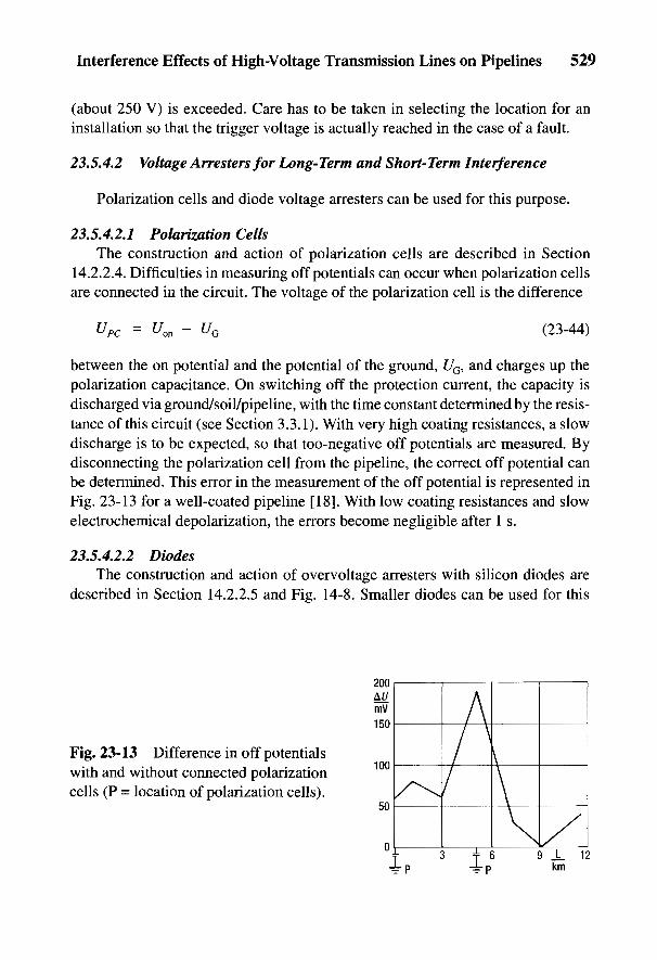
Interference Effects of High-Voltage Transmission Lines on Pipelines 529
(about 250 V) is exceeded. Care has to be taken in selecting the location for aninstallation so that the trigger voltage is actually reached in the case of a fault.
23.5.4.2 Voltage Arresters for Long-Term and Short-Term Interference
Polarization cells and diode voltage arresters can be used for this purpose.
23.5.4.2.1 Polarization CellsThe construction and action of polarization cells are described in Section
14.2.2.4. Difficulties in measuring off potentials can occur when polarization cellsare connected in the circuit. The voltage of the polarization cell is the difference
between the on potential and the potential of the ground, UG, and charges up thepolarization capacitance. On switching off the protection current, the capacity isdischarged via ground/soil/pipeline, with the time constant determined by the resis-tance of this circuit (see Section 3.3.1). With very high coating resistances, a slowdischarge is to be expected, so that too-negative off potentials are measured. Bydisconnecting the polarization cell from the pipeline, the correct off potential canbe determined. This error in the measurement of the off potential is represented inFig. 23-13 for a well-coated pipeline [18]. With low coating resistances and slowelectrochemical depolarization, the errors become negligible after 1 s.
23.5.4.2.2 DiodesThe construction and action of overvoltage arresters with silicon diodes are
described in Section 14.2.2.5 and Fig. 14-8. Smaller diodes can be used for this
Fig. 23-13 Difference in off potentialswith and without connected polarizationcells (P = location of polarization cells).

530 Handbook of Cathodic Corrosion Protection
application than for power cables. The diodes must be sufficiently stable againstthe ac in normal operation and during short-term interference. In addition, theymust have sufficient surge current resistance so that possible lightning currents donot destroy them.
As described in Section 14.2.2.5, a nonsymmetric diode overvoltage arrestercreates a dc voltage in operation
which determines the on potential of the pipeline corresponding to Eq. (23-44):
where n is the number of diodes in the right-hand branch in Fig. 14-8 (n = 4), and[/TV = 0.7 V is the threshold voltage.
According to the details of Eq. (23-44), off potentials cannot be measured ifthe diode overvoltage arrester cannot be switched off from the power line momen-tarily (e.g., by using a time switch).
For measuring off potentials, thyristors can also be connected between pipe-line and overvoltage arrester; these operate only if inadmissibly high pipelinepotentials arise by making the connection to the arrester. During the rest of thetime (low load time), no grounding occurs and therefore there is no problem inmaking /tf-free measurements by the switching method [19]. The number of diodesfollows approximately from Eq. (23-46) since UG must not become too positivedue to the anodic danger.
23.6 Measurement of Pipeline Potentials
Pipeline potentials should be measured to control interference calculations andfor the determination of environmental reduction factors and ohmic interference(see Section 23.2). With inductive interference, a ground rod is used as a referenceelectrode in the region of the remote ground (i.e., outside the voltage cone of thepipeline or of other grounds). This is usually the case at a distance of 20 m from thepipeline. The measuring conductor must be perpendicular to the interfering high-voltage line to avoid induced voltages in the measuring conductor. The referenceelectrode is brought over the pipeline in the region of the voltage cone of high-voltage installations to measure the contact voltages due to ohmic interference.According to the type of interference, corresponding preparations should be madeby the operator of the high-voltage installation and/or recordings carried out.
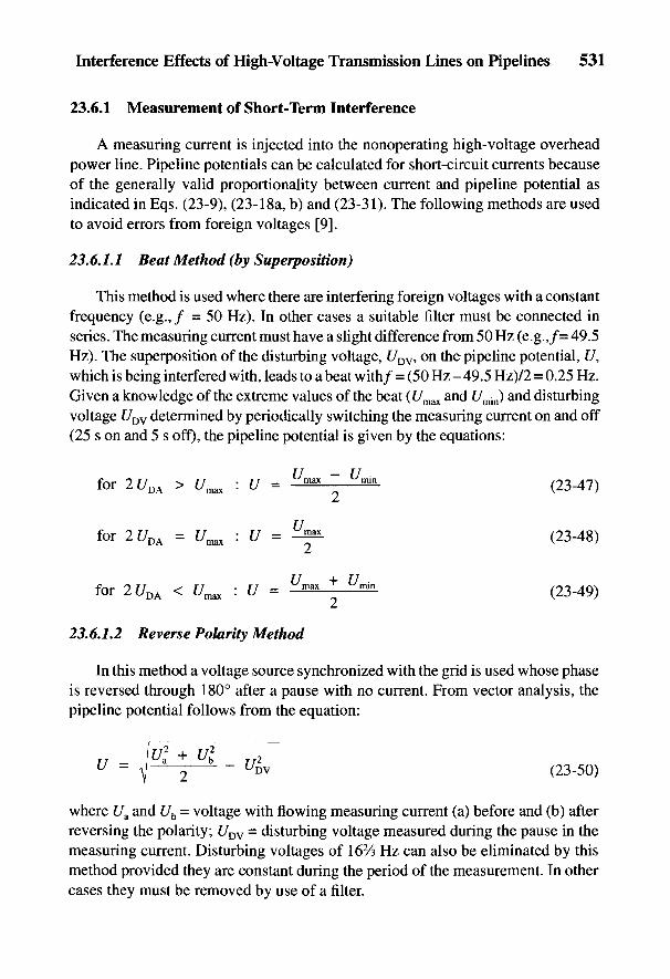
Interference Effects of High-Voltage Transmission Lines on Pipelines 531
23.6.1 Measurement of Short-Term Interference
A measuring current is injected into the nonoperating high-voltage overheadpower line. Pipeline potentials can be calculated for short-circuit currents becauseof the generally valid proportionality between current and pipeline potential asindicated in Eqs. (23-9), (23-18a, b) and (23-31). The following methods are usedto avoid errors from foreign voltages [9].
23.6.1.1 Beat Method (by Superposition)
This method is used where there are interfering foreign voltages with a constantfrequency (e.g.,/ = 50 Hz). In other cases a suitable filter must be connected inseries. The measuring current must have a slight difference from 50 Hz (e.g.,/= 49.5Hz). The superposition of the disturbing voltage, UDV, on the pipeline potential, U,which is being interfered with, leads to a beat with/ = (50 Hz - 49.5 Hz)/2 = 0.25 Hz.Given a knowledge of the extreme values of the beat (f/max and f/min) and disturbingvoltage UDV determined by periodically switching the measuring current on and off(25 s on and 5 s off), the pipeline potential is given by the equations:
23.6.1.2 Reverse Polarity Method
In this method a voltage source synchronized with the grid is used whose phaseis reversed through 180° after a pause with no current. From vector analysis, thepipeline potential follows from the equation:
where Ua and Ub = voltage with flowing measuring current (a) before and (b) afterreversing the polarity; UDV = disturbing voltage measured during the pause in themeasuring current. Disturbing voltages of 162/s Hz can also be eliminated by thismethod provided they are constant during the period of the measurement. In othercases they must be removed by use of a filter.
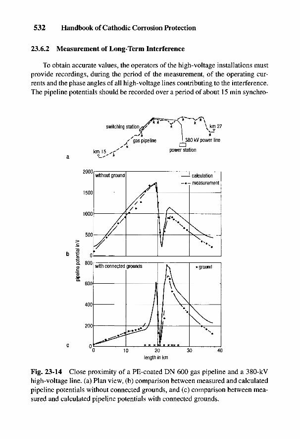
532 Handbook of Cathodic Corrosion Protection
23.6.2 Measurement of Long-Term Interference
To obtain accurate values, the operators of the high-voltage installations mustprovide recordings, during the period of the measurement, of the operating cur-rents and the phase angles of all high-voltage lines contributing to the interference.The pipeline potentials should be recorded over a period of about 15 min synchro-
Fig. 23-14 Close proximity of a PE-coated DN 600 gas pipeline and a 380-kVhigh-voltage line, (a) Plan view, (b) comparison between measured and calculatedpipeline potentials without connected grounds, and (c) comparison between mea-sured and calculated pipeline potentials with connected grounds.
Interference Effects of High-Voltage Transmission Lines on Pipelines 533
nized to the interfering operational current at every measuring point. Only by thismeans can correlations be obtained between the pipeline potentials and the data ofthe interfering high-voltage lines.
Where there is no pipeline measuring point in a section of the line (e.g., in thevicinity of a transposition of pylon lines), the pipeline can be simulated by a spe-cially designed measuring line [20]. The measuring line is electrically connectedto the nearest measuring points on either side of the pylon. The pipeline potentialscan then be measured along the pipeline by connecting grounding rods to the mea-suring line.
23.6.3 Results of Pipeline Potential Measurement
Figure 23-14a shows a sketch of a region of close proximity between a PE-coated DN 600 gas pipeline and a 380-kV high-voltage overhead power line. Fig-ure 23-14b shows the measured and calculated pipeline potentials before theconnection of grounds. The pipeline is electrically connected to two other pipe-lines at 38 km and grounded at 0 with 1 H. The measuring current amounted to256 A and the represented measured values relate to a given short circuit current of12.2 kA. Figure 23-14c shows the comparison between calculated and measuredpipeline potentials after connection to the grounds shown in Fig. 23-14a withRG = 1 to 2 Q.
534 Handbook of Cathodic Corrosion Protection
23.7 References
[1] H.-U. Paul, Elektrizitatswirtschaft 85, 98 (1986).[2] AfK-Empfehlung Nr. 3, ZfGW-Verlag, Frankfurt 1982; Techn. Empflg. Nr.7, VWEW-
Verlag, Frankfurt 19.[3] H.-U. Paul, Elektrizitatswirtschaft 86, 389 (1987).[4] DIN VDE0210, Beuth-Verlag, Berlin 1985.[5] H.-J. Sowade, Elektrizitatswirtschaft 75, 603 (1976).[6] AfK-Empfehlung Nr. 2, ZfGW-Verlag, Frankfurt 1985.[7] H. Spickmann, ETZ-A //, 261 (1969).[8] DIN VDE0115, Beuth-Verlag, Berlin 1982.[9] DIN VDE0141, Beuth-Verlag, Berlin 1976.
[10] J. R. Carsson, Bell System Techn. J. S. 539 (1926).[11] F. Pollaczek, E.N.T. 3, 339 (1926).[12] G. Rohrl, Elektrische Bahnen 38;\9 u. 38 (1967).[13] Techn. Empflg. Nr. 1, VWEW-Verlag, Frankfurt 1987.[14] W. v. Baeckmann, H.-U. Paul u. K.-H. Feist, CIGRE-Bericht Nr. 36-02, Paris 1982.[15] DIN VDE 0228 Teil 1, Beuth-Verlag, Berlin 1987.[16] J. Pestka u. B. Knoche, Elektrizitatswirtschaft 81, 518 (1982).[17] J. Pohl, CIGRE-Konf., Bericht Nr. 326, Paris 1966.[18] W. v. Baeckmann u. D. WeBling, 3R intern. 23, 343 (1984).[19] H. Rosenberg, Balslev Cons Eng. (DK), pers. Mitteilung 1987.[20] H.-U. Paul, OZE 35, 245 (1982).

24
Distribution of Current and Potentialin a Stationary Electric Field
W. v. BAECKMANN AND W. SCHWENK
In this chapter some important equations for corrosion protection are derivedwhich are relevant to the stationary electric fields present in electrolytically con-ducting media such as soil or aqueous solutions. Detailed mathematical deriva-tions can be found in the technical literature on problems of grounding [1-5]. Theequations are also applicable to low frequencies in limited areas, provided no no-ticeable current displacement is caused by the electromagnetic field.
The stationary electric field is described by the following equations:
1. The vector Ohm's Law
from which because
the potential 0 in polar coordinates is given by
2. The field outside a local current lead is source free. This means that thesurface integral is equal to a current introduced by a ground:
Equations (24-3) and (24-4) correspond to Kirchhoff's laws for electrical net-works. Figure (24-2) gives the voltage distribution for every point in space for agiven field strength.
535
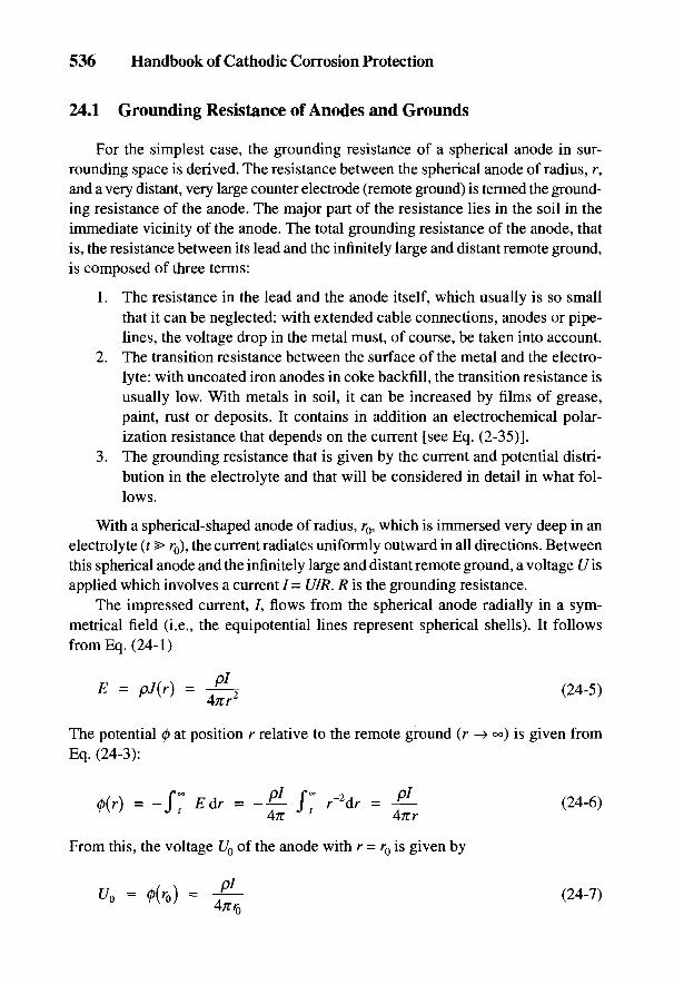
536 Handbook of Cathodic Corrosion Protection
24.1 Grounding Resistance of Anodes and Grounds
For the simplest case, the grounding resistance of a spherical anode in sur-rounding space is derived. The resistance between the spherical anode of radius, r,and a very distant, very large counter electrode (remote ground) is termed the ground-ing resistance of the anode. The major part of the resistance lies in the soil in theimmediate vicinity of the anode. The total grounding resistance of the anode, thatis, the resistance between its lead and the infinitely large and distant remote ground,is composed of three terms:
1. The resistance in the lead and the anode itself, which usually is so smallthat it can be neglected: with extended cable connections, anodes or pipe-lines, the voltage drop in the metal must, of course, be taken into account.
2. The transition resistance between the surface of the metal and the electro-lyte: with uncoated iron anodes in coke backfill, the transition resistance isusually low. With metals in soil, it can be increased by films of grease,paint, rust or deposits. It contains in addition an electrochemical polar-ization resistance that depends on the current [see Eq. (2-35)].
3. The grounding resistance that is given by the current and potential distri-bution in the electrolyte and that will be considered in detail in what fol-lows.
With a spherical-shaped anode of radius, r0, which is immersed very deep in anelectrolyte (t > r0), the current radiates uniformly outward in all directions. Betweenthis spherical anode and the infinitely large and distant remote ground, a voltage t/isapplied which involves a current / = U/R. R is the grounding resistance.
The impressed current, /, flows from the spherical anode radially in a sym-metrical field (i.e., the equipotential lines represent spherical shells). It followsfrom Eq. (24-1)
The potential 0 at position r relative to the remote ground (r —» °°) is given fromEq. (24-3):
From this, the voltage U0 of the anode with r = rQ is given by
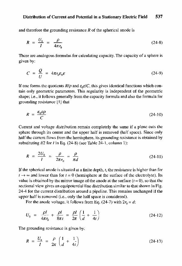
Distribution of Current and Potential in a Stationary Electric Field 537
and therefore the grounding resistance R of the spherical anode is
There are analogous formulas for calculating capacity. The capacity of a sphere isgiven by:
If one forms the quotients Rip and £0£/C, this gives identical functions which con-tain only geometric parameters. This regularity is independent of the geometricshape; i.e., it follows generally from the capacity formula and also the formula forgrounding resistance [1] that
^^
Current and voltage distribution remain completely the same if a plane cuts thesphere through its center and the upper half is removed (half space). Since onlyhalf the current flows from the hemisphere, its grounding resistance is obtained bysubstituting 1/2 for / in Eq. (24-8) (see Table 24-1, column 1):
If the spherical anode is situated at a finite depth, f, the resistance is higher than fort -> oo and lower than for t = 0 (hemisphere at the surface of the electrolyte). Itsvalue is obtained by the mirror image of the anode at the surface (t = 0), so that thesectional view gives an equipotential line distribution similar to that shown in Fig.24-4 for the current distribution around a pipeline. This remains unchanged if theupper half is removed (i.e., only the half space is considered).
For the anode voltage, it follows from Eq. (24-7) with 2r0 = d:
The grounding resistance is given by:
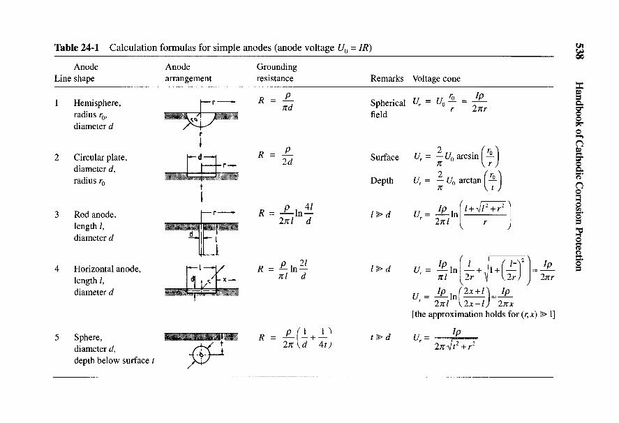
538 Handbook of Cathodic Corrosion Protection
Q- fc ~^ <^ A» -g
- x ^ ex g£^ ^ ' h J" *N 1/3
>. ^ > *- i <N T3
>o| v. >?! - + Lr ^J-^ 23* vT + " ^ni -Vi § -v --^^i a,+§ ^°i ^ b° ^° ^ - •?-1 ^ I ^ r * \ X « \ * $8 $* 3\* | ^
S II N II II II II J II
£ ^ ^ ^ ^ ^ ^ £ ^S 13r^ _0 <U
| 'S ^3 «ti "o, "^ " "°<u H T5 s ^ A A A
^ ^ O ^ o n q s c n Q - ^ — *^sstl^°<u ., N£P ^^5 ^K'o — i _ +
S 'i «!•« c!31 |§ ^'g <^S 4g afs ^^
Ca JH 53 tN I K
^ § .| » "I II II "
- S o S ^ ^ ^ ^ °=
•3. i u i v I if; i6 S? «- : «. S X $ -•*-—(
^ g I_"JL_ IL.|^_ L.J.X.J. I X i jj o I 5\ i .* l-J i *Hr |N^\0 " cd ^ ^ [ 1 ^
*
I 8
S 4J «§1 *rt v-iO - O S^ <L) C ^r1^ u rt „ ^ , £^ s ^ - a ^ ^ " ^ 1 3 ^ -^^o
•el >£ fc Jg S3 ° g - S c -^ S3 ? & .o
4 l | l = I 111 ^tl ItS Hf< S C = 2 S T 3 r t . ^ r t T 3 O C ^ O C & D - ^ u« < - S £ 2 ^ 5 U '-3 2 f t i^^ f f i^^ c^^-a3 gr« .SH J ^ (N m TJ- >n
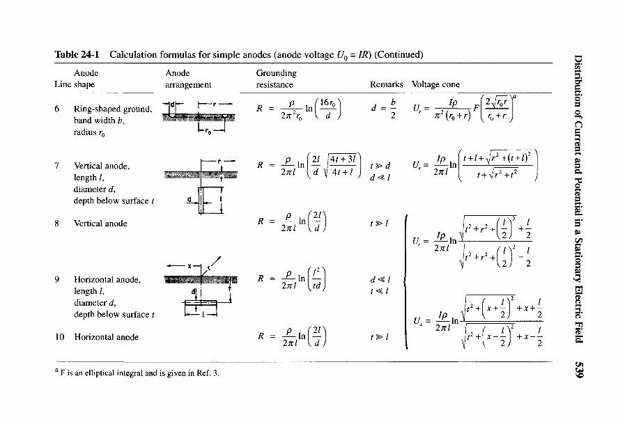
Distribution of Current and Potential in a Stationary Electric Field 539
— | <N -— | (N
c^ ^|^ ^|cs, + ^
+ + ' + +
I hJ £ ^ M+ 5^5 c~^3 ^s ^^^^ ^ ^^ +« i
^sr i i $ + ^ r"I CJ O*
I ^^ "~^~" ^ ^0 ^~" Q. "3 CL fe 3- fc^ ^ ^(N ^ <N ^ ^
3 n II II II
I £ tf ^ ^r ^H
_c «, 'C ^ -0|<N ^ ^
§ 1 " A ^ I ^ v AC ^ ^ 3 * -~Q -^ ^3 ^ *-
g ^ ^II ^T?
^° — i iU »? _ L±j>0 V^Q ^3 -pa-
•g ^—-" cll1^ r5|"« 'i-l'S r3|^
« ^ o e ,£ c e(U fc? '—^ -—< —< '—i"O ^ ^ s O l ^ *~^ ~~* l~~* l~»o . c g ^ f e c x f e : Q. ^ ah=J Q f cC ^ c f N CN <N I<N <N3< c 8^ § .2 i i i i n " "
fli fci </3
- O O 2 = < ^ <*! ^ ^
Cc3aj ^^
'S •- | I I I S ^x § ft] f ^
^2 a L..|i_i •*—g—•I—r-4 "r^B'ziii-jr ^«2 « l« S i ' I t S6"^' c^ -O ^ I 1 T I W—*- GI s i 4-1 I i >b < § T—i P * P ««
rj"] T P®* ' " J2
S ** "c.2 "Q <t> <U rt• S f i o y —J3 3 cS <o" <5 o 23 2 ^ "« fa ^ M
^ I- I M I | § i° II . S - s ^ S 1 - 6 ^ 1 13 -s « 1| s 131£ 1 s S § S § I3 If -si | Ifl & | | fl 8- | S« < -a o i ^ 2 > ^ - 3 - a > S ^ - 5 - o f f i §3 « -2^ .S o &M i — I VO C~- OO ON ^ H C S
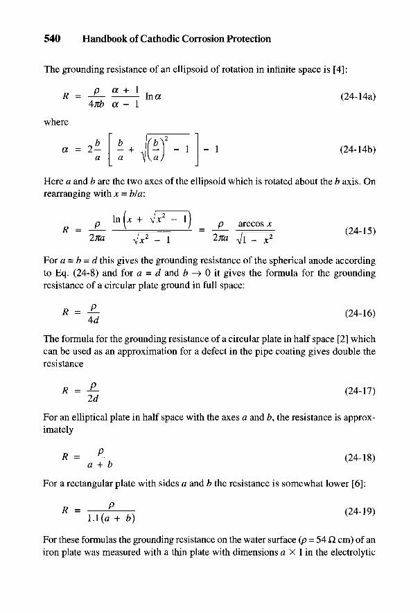
540 Handbook of Cathodic Corrosion Protection
The grounding resistance of an ellipsoid of rotation in infinite space is [4]:
where
Here a and b are the two axes of the ellipsoid which is rotated about the b axis. Onrearranging with x = b/a:
For a = b = d this gives the grounding resistance of the spherical anode accordingto Eq. (24-8) and for a = d and b —> 0 it gives the formula for the groundingresistance of a circular plate ground in full space:
The formula for the grounding resistance of a circular plate in half space [2] whichcan be used as an approximation for a defect in the pipe coating gives double theresistance
For an elliptical plate in half space with the axes a and b, the resistance is approx-imately
For a rectangular plate with sides a and b the resistance is somewhat lower [6]:
For these formulas the grounding resistance on the water surface (p = 54 Q cm) of aniron plate was measured with a thin plate with dimensions a X 1 in the electrolytic
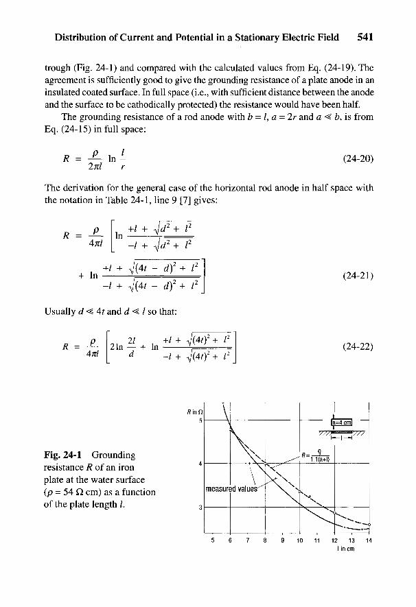
Distribution of Current and Potential in a Stationary Electric Field 541
trough (Fig. 24-1) and compared with the calculated values from Eq. (24-19). Theagreement is sufficiently good to give the grounding resistance of a plate anode in aninsulated coated surface. In full space (i.e., with sufficient distance between the anodeand the surface to be cathodically protected) the resistance would have been half.
The grounding resistance of a rod anode with b = /, a - 2r and a < b, is fromEq. (24-15) in full space:
The derivation for the general case of the horizontal rod anode in half space withthe notation in Table 24-1, line 9 [7] gives:
Usually d < 4t and d ^ I so that:
Fig. 24-1 Groundingresistance R of an ironplate at the water surface(p = 54 Q cm) as a functionof the plate length /.

542 Handbook of Cathodic Corrosion Protection
For extended anodes or strip grounds, 4t <^ / so that the formula in line 9 in Table24-1 becomes:
For t —> °o, Eq. (24-22) for full space becomes:
A formula frequently seen in western literature which is derived by integrating thepotential along the rod anode is:
which approximately agrees with Eq. (24-24) for a long, thin anode. Inserting1 = In 2.72 in Eq. (24-25) gives:
For a strip ground it follows from Eq. (24-21) with t - 0 and d < I in half space:
The grounding resistances of short rod anodes are also used to determine anodegrounding resistances in seawater. Care has to be taken here that the anodes aresufficiently deep below the water surface and at least a few anode lengths awayfrom uncoated or coated steel surfaces. Figure 24-2 shows the effect of distance xon the grounding resistance R of a rod anode with t = 0 near to a metal plate (curve 1)and to a plastic plate (curve 2). Furthermore, in the absence of the plate, the effectof immersion depth t on the grounding resistance of the rod is given by curve 3.Curve 3 shows that the resistance at a depth corresponding to the length of theanode is equal to the grounding resistance in full space. The measured value is,however, greater than half the value for the immersion depth at t = 0.
For a vertical rod anode, the general formula comparable with Eq. (24-21) isgiven by:
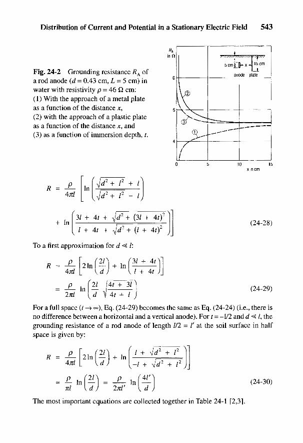
Distribution of Current and Potential in a Stationary Electric Field 543
Fig. 24-2 Grounding resistance RA ofa rod anode (d - 0.43 cm, L - 5 cm) inwater with resistivity p = 46 Q cm:(1) With the approach of a metal plateas a function of the distance x,(2) with the approach of a plastic plateas a function of the distance x, and(3) as a function of immersion depth, t.
To a first approximation for d < I:
For a full space (t -> °°), Eq. (24-29) becomes the same as Eq. (24-24) (i.e., there isno difference between a horizontal and a vertical anode). For t = -1/2 and d <§ /, thegrounding resistance of a rod anode of length 1/2 = I' at the soil surface in halfspace is given by:
The most important equations are collected together in Table 24-1 [2,3].
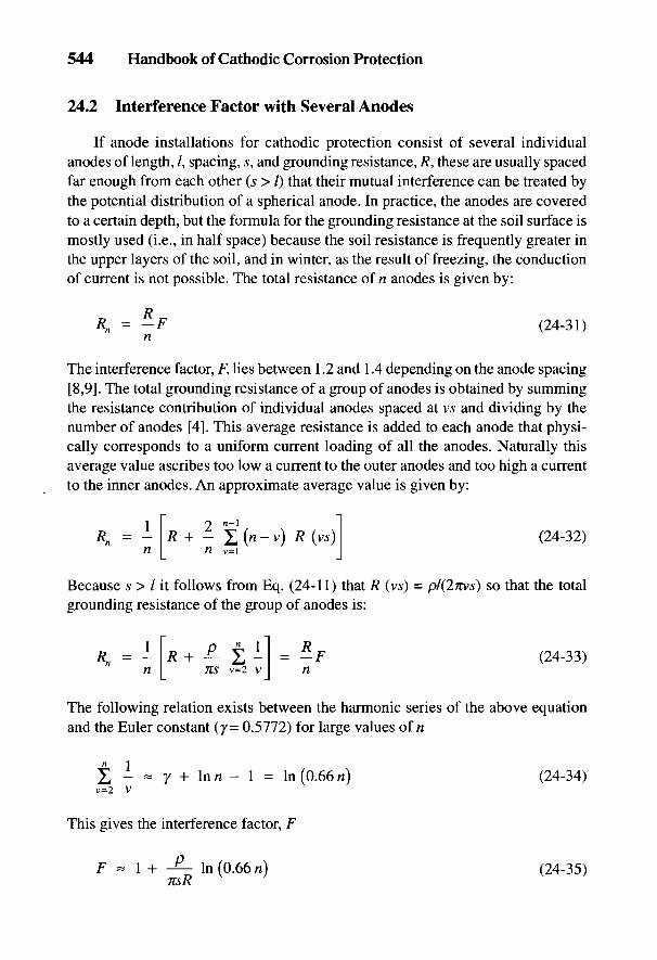
544 Handbook of Cathodic Corrosion Protection
24.2 Interference Factor with Several Anodes
If anode installations for cathodic protection consist of several individualanodes of length, /, spacing, s, and grounding resistance, R, these are usually spacedfar enough from each other (s > I) that their mutual interference can be treated bythe potential distribution of a spherical anode. In practice, the anodes are coveredto a certain depth, but the formula for the grounding resistance at the soil surface ismostly used (i.e., in half space) because the soil resistance is frequently greater inthe upper layers of the soil, and in winter, as the result of freezing, the conductionof current is not possible. The total resistance of n anodes is given by:
The interference factor, F, lies between 1.2 and 1.4 depending on the anode spacing[8,9]. The total grounding resistance of a group of anodes is obtained by summingthe resistance contribution of individual anodes spaced at vs and dividing by thenumber of anodes [4]. This average resistance is added to each anode that physi-cally corresponds to a uniform current loading of all the anodes. Naturally thisaverage value ascribes too low a current to the outer anodes and too high a currentto the inner anodes. An approximate average value is given by:
Because s > I it follows from Eq. (24-11) that R (vs) = pl(2TCvs) so that the totalgrounding resistance of the group of anodes is:
The following relation exists between the harmonic series of the above equationand the Euler constant (y= 0.5772) for large values of n
This gives the interference factor, F
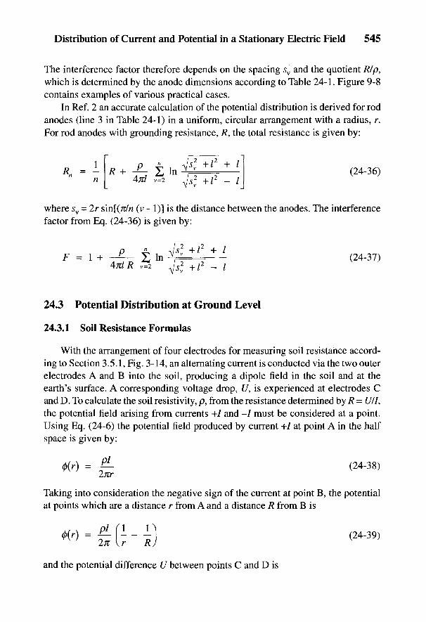
Distribution of Current and Potential in a Stationary Electric Field 545
The interference factor therefore depends on the spacing sv and the quotient Rip,which is determined by the anode dimensions according to Table 24-1. Figure 9-8contains examples of various practical cases.
In Ref. 2 an accurate calculation of the potential distribution is derived for rodanodes (line 3 in Table 24-1) in a uniform, circular arrangement with a radius, r.For rod anodes with grounding resistance, /?, the total resistance is given by:
where sv = 2r sin[(7i/n (v - 1)] is the distance between the anodes. The interferencefactor from Eq. (24-36) is given by:
24.3 Potential Distribution at Ground Level
24.3.1 Soil Resistance Formulas
With the arrangement of four electrodes for measuring soil resistance accord-ing to Section 3.5.1, Fig. 3-14, an alternating current is conducted via the two outerelectrodes A and B into the soil, producing a dipole field in the soil and at theearth's surface. A corresponding voltage drop, U, is experienced at electrodes Cand D. To calculate the soil resistivity, p, from the resistance determined by R = U/I,the potential field arising from currents +/ and -/ must be considered at a point.Using Eq. (24-6) the potential field produced by current +/ at point A in the halfspace is given by:
Taking into consideration the negative sign of the current at point B, the potentialat points which are a distance r from A and a distance R from B is
and the potential difference U between points C and D is
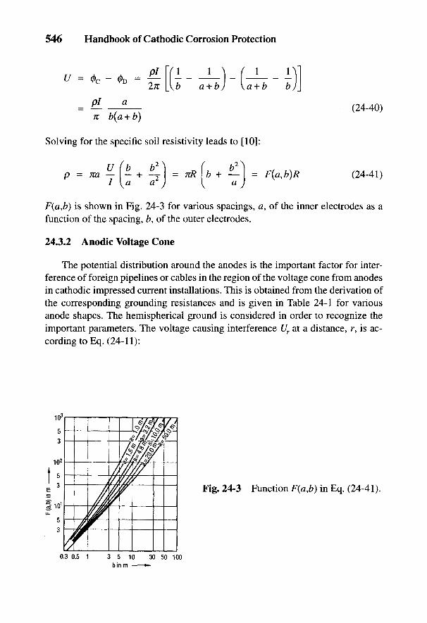
546 Handbook of Cathodic Corrosion Protection
Solving for the specific soil resistivity leads to [10]:
F(a,b) is shown in Fig. 24-3 for various spacings, a, of the inner electrodes as afunction of the spacing, b, of the outer electrodes.
24.3.2 Anodic Voltage Cone
The potential distribution around the anodes is the important factor for inter-ference of foreign pipelines or cables in the region of the voltage cone from anodesin cathodic impressed current installations. This is obtained from the derivation ofthe corresponding grounding resistances and is given in Table 24-1 for variousanode shapes. The hemispherical ground is considered in order to recognize theimportant parameters. The voltage causing interference Ur at a distance, r, is ac-cording to Eq. (24-11):
Fig. 24-3 Function F(a,b) in Eq. (24-41).

Distribution of Current and Potential in a Stationary Electric Field 547
The voltage Ur increases linearly with increasing anode voltage (i.e., with increas-ing soil resistivity, p) for a given current, /. If these interfering voltages are, forexample, below 0.5 V, they follow the observed spacings, r. Other voltage conesare described in Chapter 9. Figures 9-5 and 9-6 show the relative anode voltagesUZ/UA = Ur/U0 or UX/UA for various distances and shapes of anode.
24.3.3 Cathodic Voltage Cone in a Cylindrical Field
With an uncoated pipe or one with very poor coating and many defects closetogether, uniform current distribution for the pipeline can be assumed in the soileven at quite short distances from it (see Section 3.6.2.2, case b).
Without taking into consideration the soil surface, the current density J(f) at adistance r from the pipe axis for a pipeline (pipe diameter, d) with a protectioncurrent density J expressed in the terminology of Fig. 24-4 and corresponding toEq. (24-4), is given by:
Fig. 24-4 Cylindrical fieldaround an uncoated pipelinein soil.
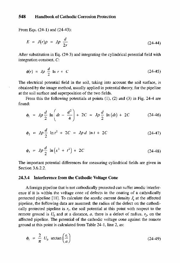
548 Handbook of Cathodic Corrosion Protection
From Eqs. (24-1) and (24-43):
After substitution in Eq. (24-3) and integrating the cylindrical potential field withintegration constant, C:
L
The electrical potential field in the soil, taking into account the soil surface, isobtained by the image method, usually applied in potential theory, for the pipelineat the soil surface and superposition of the two fields.
From this the following potentials at points (1), (2) and (3) in Fig. 24-4 arefound:
The important potential differences for measuring cylindrical fields are given inSection 3.6.2.2.
24.3.4 Interference from the Cathodic Voltage Cone
A foreign pipeline that is not cathodically protected can suffer anodic interfer-ence if it is within the voltage cone of defects in the coating of a cathodicallyprotected pipeline [11]. To calculate the anodic current density Ja at the affectedpipeline, the following data are assumed: the radius of the defect on the cathodi-cally protected pipeline is rt, the soil potential at this point with respect to theremote ground is U0 and at a distance, a, there is a defect of radius, r2, on theaffected pipeline. The potential of the cathodic voltage cone against the remoteground at this point is calculated from Table 24-1, line 2, as:
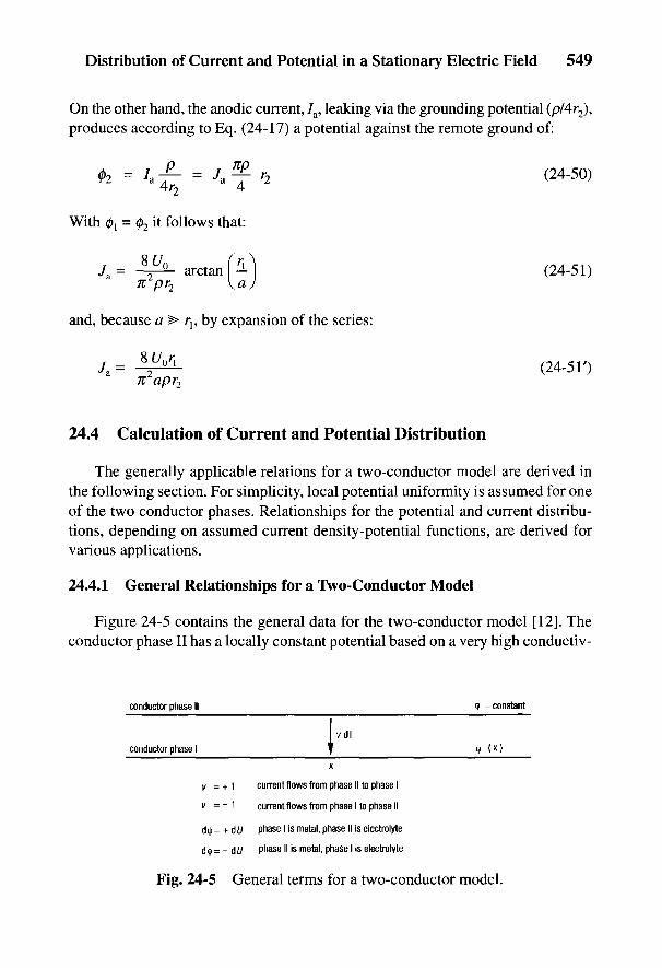
Distribution of Current and Potential in a Stationary Electric Field 549
On the other hand, the anodic current, 7a, leaking via the grounding potential (p/4r2),produces according to Eq. (24-17) a potential against the remote ground of:
With 0! = 02 it follows that:
and, because a > rp by expansion of the series:
24.4 Calculation of Current and Potential Distribution
The generally applicable relations for a two-conductor model are derived inthe following section. For simplicity, local potential uniformity is assumed for oneof the two conductor phases. Relationships for the potential and current distribu-tions, depending on assumed current density-potential functions, are derived forvarious applications.
24.4.1 General Relationships for a Two-Conductor Model
Figure 24-5 contains the general data for the two-conductor model [12]. Theconductor phase II has a locally constant potential based on a very high conductiv-
Fig. 24-5 General terms for a two-conductor model.

550 Handbook of Cathodic Corrosion Protection
ity. At point* a current exchange, vd/, occurs between the two conductors in whichthe factor v indicates the sign. Inside phase I, there is a potential 0(;c) dependent onposition. Since this phase can be a metal or an electrolyte, there are different rela-tionships between d0 and dU. U is the metal/electrolyte potential.
The current in phase I is given by Ohm's Law:
The relationship for the current interchange at x is:
where S = cross-sectional area of conductor phase I, x = electrical conductivity ofconductor phase I, / = contact line between the two conductor phases in a cross-sectional plane where the current, vd/, transfers, and J - current density betweenthe two conductor phases at point x.
The Laplace equation follows from Eqs. (24-52) and (24-53):
24.4.2 Calculation of Ground Electrodes Having a LongitudinalResistance
A ground with locally constant values of S and / in full space is regarded asconductor phase II. Therefore d0 = dU. A linear current density-potential functionis assumed for the current transfer:
where rp is the polarization resistance. According to Fig. 24-5, v = -1 for anodicpolarization, and v = +1 for cathodic polarization. The resistance load R' and theleakage load of the ground for the parameters S and / are given by:
and
Distribution of Current and Potential in a Stationary Electric Field 551
Substitution of Eqs. (24-55) into (24-57) in Eq. (24-54) gives:
and after integration:
Finally from Eqs. (24-52), (24-56) and (24-59) it follows that:
The constants A and B are determined by the boundary conditions.The boundary conditions for a ground of length, L, are: U = U0 and / = 70 for
x = 0 as well as / = 0 for x = L. It follows from Eqs. (24-59) and (24-60): A = U0 = Z/0coth (aL) and B = -70Z and after substituting:
The effective grounding resistance, Rw, is given by:
For a better overview, the hyperbolic functions are shown in Fig. 24-6.For an infinitely long ground, it follows from Eqs. (24-61) to (24-63) for L —> <=o;

552 Handbook of Cathodic Corrosion Protection
Fig. 24-6 Graphs ofhyperbolic and exponentialfunctions: 2 sinh x = ex - e~?2 cosh x = QX + e~*.
The characteristic resistance Z is therefore the lowest value of the grounding resis-tance. The path constant I/a = lA/ft'G' = /k is the characteristic length of theinfinite ground.
24.4.3 Range of Cathodic Protection and Current Requirement
A linear function corresponding to Eq. (24-55) is assumed for cathodic polar-ization [12-14]:
where 77 = -(£/- £/R), the cathodic overvoltage. The following are taken as thelimits for the protected region:
Equation (24-68a) means that the protection potential, C/s, must be reached at the endof the pipeline (x - L), and that at the drainage point (;c = 0), the potential must notfall below Uh because due to hydrogen evolution, according to Eq. (2-19), Eq. (24-67)is no longer valid. From experience, the following approximate values apply:
For the lowest current density, Js, it follows from Eq. (24-67)
Distribution of Current and Potential in a Stationary Electric Field 553
It follows from Eqs. (24-56), (24-57) and (24-67') for a pipeline of radius, r, andwall thickness, s:
Substituting in Eqs. (24-58) to (24-61) with UQ = T]0 leads to:
The approximation after expansion of the series is permissible because ofEq. (24-69). The protected length, 2L, is given by Eq. (24-74) with drainage at themidpoint of the pipeline:
The protection current requirement /s = 2/0 follows from Eq. (24-63) withEq. (24-69):
The protected length 2 L* for an infinitely long pipeline corresponding toEq. (24-68a) can be derived with the aid of Eqs. (24-64) to (24-66) for U0 = %
In contrast to the limited pipe length, the pipe current at the point x = L* is,however, not zero. From Eqs. (24-64), (24-68a) and (24-68b):
554 Handbook of Cathodic Corrosion Protection
Comparison with Eq. (24-74) and taking account of Eq. (24-69) gives:
The protection current requirement 7* = 2 70 follows from Eqs. (24-66) and (24-73):
Comparison with Eq. (24-76), taking into account Eq. (24-69), gives:
With an infinitely long pipeline, the current requirement is raised by 16% and theprotected length is reduced by 51% as a consequence of omitting the insulatingunit at the point x = L.
In Eq. (24-67) it is assumed that rp is constant in the potential range Uh<U< UR.This could be true for resistance polarization at defects in the coating. In this case,however, a change in the 77?-free potential is only possible if electrochemical polar-ization is also occurring. Linear polarization is, however, very unlikely in the givenpotential range.
On the other hand, it can be assumed for the oxygen corrosion of steel in aque-ous solutions and soils that there is a constant minimum protection current density,Js, in the protective range, Uh < U < Us, which corresponds to the limiting currentdensity for oxygen reduction according to Eq. (4-5) (see Section 2.2.3.2). Then itfollows, with v = +1, / = 2;rr, S = 2ms and d0 = dU from Eq. (24-54), instead ofEq. (24-58) [12-14]:
Integration with the limits U=US and d U/dx=0 f or x - 0 as well as U - Uh at x = L leadsto Eq. (24-75), which can therefore be regarded as correct without the approximationaccording to Eq. (24-74), where Js applies for every point and not only for x = L.Correspondingly, the protection current requirement, 7S, of the pipeline surface area(2flr)(2L) is, instead of Eq. (24-76), given by 4n/f2At/xs /s)
1/2. Equation (24-81) andits solutions are also valid if there is an ohmic leakage load. With the constant currentdensity 7S, this leads to a constant voltage drop at the pipeline surface, which need notbe taken into account if only 77?-free potentials are used in Eq. (24-81).

Distribution of Current and Potential in a Stationary Electric Field 555
24AA Potential Distribution in the Case of Overprotection
There is a constant protection current density in the protection regionUh < U < Us. At potentials U < Uh, overprotection occurs so that hydrogen evolu-tion takes place according to Eq. (2-19). The current density is clearly dependenton the potential, so that usually activation polarization is assumed to occur (seeSection 2.2.3.2). Approximately from Eq. (2-35):
Substitution in Eq. (24-54) leads to, instead of Eq. (24-81) [12,13]:
Integrating with the boundary condition z = 0 and (dz/dx) = 2ALVL/3 gives for* = L:
where q = /3/(At/ - ft). L corresponds to Eq. (24-75) and (x - L) is the extension ofthe protected length due to overprotection. For unlimited overprotection (z —> <*>),Eq. (24-84) gives a limiting value:
Using practical numbers shows that the extension of the protected length can onlybe about 10%.
With very high overvoltages, Eq. (24-82) is no longer applicable because ofresistance polarization. It is assumed approximately that:
and b/J& corresponds to the ohmic polarization resistance in the range of overpro-tection. Substitution in Eq. (24-54) leads in place of Eq. (24-81) to [12,13]:
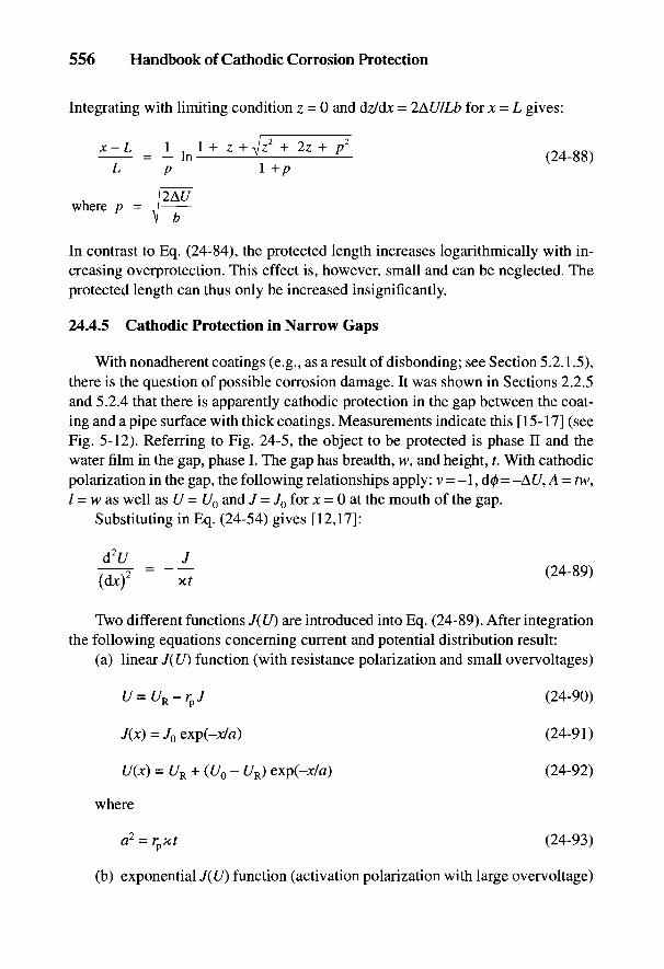
556 Handbook of Cathodic Corrosion Protection
Integrating with limiting condition z = 0 and dz/dx = 2AU/Lb for x = L gives:
In contrast to Eq. (24-84), the protected length increases logarithmically with in-creasing overprotection. This effect is, however, small and can be neglected. Theprotected length can thus only be increased insignificantly.
24.4.5 Cathodic Protection in Narrow Gaps
With nonadherent coatings (e.g., as a result of disbonding; see Section 5.2.1.5),there is the question of possible corrosion damage. It was shown in Sections 2.2.5and 5.2.4 that there is apparently cathodic protection in the gap between the coat-ing and a pipe surface with thick coatings. Measurements indicate this [15-17] (seeFig. 5-12). Referring to Fig. 24-5, the object to be protected is phase II and thewater film in the gap, phase I. The gap has breadth, w, and height, t. With cathodicpolarization in the gap, the following relationships apply: v = -1, d0 = -AC/, A = tw,I = w as well as U = U0 and J = J0 for x = 0 at the mouth of the gap.
Substituting in Eq. (24-54) gives [12,17]:
Two different functions J(U) are introduced into Eq. (24-89). After integrationthe following equations concerning current and potential distribution result:
(a) linear J(U) function (with resistance polarization and small overvoltages)
where
(b) exponential J(U) function (activation polarization with large overvoltage)
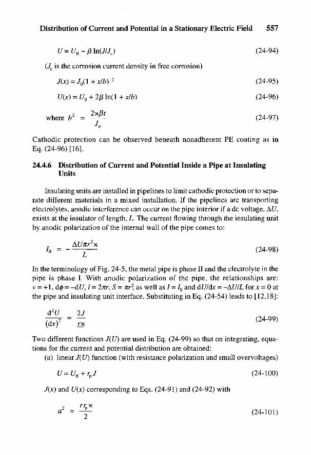
Distribution of Current and Potential in a Stationary Electric Field 557
(Jc is the corrosion current density in free corrosion)
Cathodic protection can be observed beneath nonadherent PE coating as inEq. (24-96) [16].
24.4.6 Distribution of Current and Potential Inside a Pipe at InsulatingUnits
Insulating units are installed in pipelines to limit cathodic protection or to sepa-rate different materials in a mixed installation. If the pipelines are transportingelectrolytes, anodic interference can occur on the pipe interior if a dc voltage, At/,exists at the insulator of length, L. The current flowing through the insulating unitby anodic polarization of the internal wall of the pipe comes to:
In the terminology of Fig. 24-5, the metal pipe is phase II and the electrolyte in thepipe is phase I. With anodic polarization of the pipe, the relationships are:v = +1, d0 = -df/, / = 27zr, S = Ttr2, as well as / = 70 and dU/dx = -AU/L for x = 0 atthe pipe and insulating unit interface. Substituting in Eq. (24-54) leads to [12,18]:
Two different functions J(U) are used in Eq. (24-99) so that on integrating, equa-tions for the current and potential distribution are obtained:
(a) linear J(Lf) function (with resistance polarization and small overvoltages)
7(jt) and U(x) corresponding to Eqs. (24-91) and (24-92) with
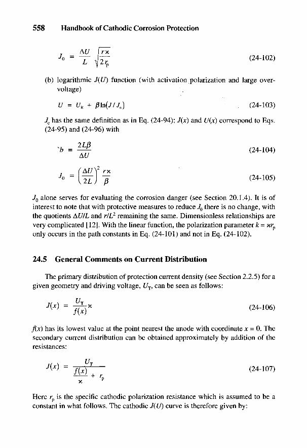
558 Handbook of Cathodic Corrosion Protection
(b) logarithmic J(U) function (with activation polarization and large over-voltage)
Jc has the same definition as in Eq. (24-94); J(x) and U(x) correspond to Eqs.(24-95) and (24-96) with
J0 alone serves for evaluating the corrosion danger (see Section 20.1.4). It is ofinterest to note that with protective measures to reduce JQ there is no change, withthe quotients AU/L and rIL2 remaining the same. Dimensionless relationships arevery complicated [12]. With the linear function, the polarization parameter k = xrp
only occurs in the path constants in Eq. (24-101) and not in Eq. (24-102).
24.5 General Comments on Current Distribution
The primary distribution of protection current density (see Section 2.2.5) for agiven geometry and driving voltage, C/T, can be seen as follows:
f(x) has its lowest value at the point nearest the anode with coordinate x = 0. Thesecondary current distribution can be obtained approximately by addition of theresistances:
Here rp is the specific cathodic polarization resistance which is assumed to be aconstant in what follows. The cathodic J(U) curve is therefore given by:
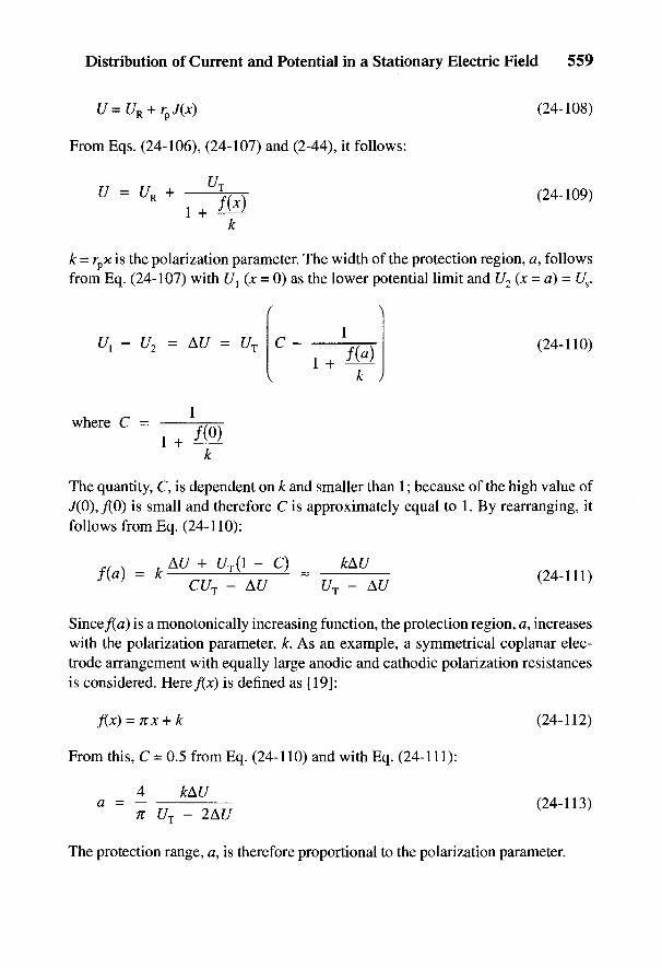
Distribution of Current and Potential in a Stationary Electric Field 559
From Eqs. (24-106), (24-107) and (2-44), it follows:
k = rpx is the polarization parameter. The width of the protection region, a, followsfrom Eq. (24-107) with Ul (;c = 0) as the lower potential limit and U2 (x = a} = Us.
AC
The quantity, C, is dependent on k and smaller than 1; because of the high value of7(0), /(O) is small and therefore C is approximately equal to 1. By rearranging, itfollows from Eq. (24-110):
Since/(a) is a monotonically increasing function, the protection region, a, increaseswith the polarization parameter, k. As an example, a symmetrical coplanar elec-trode arrangement with equally large anodic and cathodic polarization resistancesis considered. Here/(jt) is defined as [19]:
From this, C = 0.5 from Eq. (24-110) and with Eq. (24-111):
The protection range, a, is therefore proportional to the polarization parameter.
560 Handbook of Cathodic Corrosion Protection
24.6 References
[1] K. Kupfmuller, Einfuhrung in die theoretische Elektronik, Springer-Verlag, Berlin 1955.[2] W. Koch, Erdungen in Wechselstromanlagen iiber 1 kV, 4. Auflage, Springer-Verlag 1968.[3] F. Ollendorf, Erdstrome, 2. Auflage, Birkhauser-Verlag, Basel 1971.[4] E. D. Sunde, Earth Conduction Effects in Transmission Systems, D. van Nostrand Com-
pany, New York 1949.[5] AfK-Empfehlung Nr. 9, ZfGW-Verlag, Frankfurt 1979.[6] E. R. Sheppard u. H. J. Gresser, Corrosion 6, 362 (1950).[7] J. Pohl, in: Europaisches Symposium, Kathodischer Korrosionsschutz, Deutsche Gesell-
schaft fur Metallkunde, Koln 1960, S. 325.[8] J. H. Morgan, Cathodic Protection, Leonard-Hill-Books, London 1959, S. 66.[9] L. M. Applegate, Cathodic Protection, McGraw-Hill-Book, New York 1960, S. 129.
[10] W. v. Baeckmann u. G. Heim, gwf 101, 942 u. 986 (1960).[11] F. Schwarzbauer, B. Thiem u. E. Sachsenroder, gwf gas/erdgas 120, 384 (1979).[12] W. Schwenk, Corrosion Sci. 23, 871 (1983).[13] W. Schwenk, 3R international 20, 466 (1981).[14] W. v. Baeckmann, gwf/gas 104, 1237 (1963).[15] W. Schwenk, gwf gas/erdgas 123, 158 (1958).[16] W. Schwenk, 3R international 26, 305 (1987).[17] R. R. Fessler, A. J. Markworth u. R. N. Parkins, Corrosion 39, 20 (1983).[18] H. Hildebrand u. W. Schwenk, 3R international 21, 367 (1982).[19] H. Kaesche, Korrosion der Metalle, 1. Auflage, Springer-Verlag Heidelberg, New York
1966, S. 231 f.

Index
Anode bed. See Impressed current ground docks, 413beds economics, 500
Anodes. See Specific type of anode Edison, Thomas, 12Anodes and grounds, grounding resistance effect of materials and coating
of, 536-44 parameters, 395-97Anodic protection heat exchangers, condensers and
basis, 40 tubing, 412history, 14 tanks and containers, 410-12
Attached anodes, 405-6 water parameters, 391-94Cathodic protection of water tanks and
Basket anodes, 222-23 boilers, internalBlistering, electrochemical, 163-66, 169, 170 boilers with electrolytically treatedBoilers. See Cathodic protection of water water, 456-58
tanks and boilers, internal boilers with enamel linings, 450-55description and function of objects to
Cable anodes be protected, 441-47advantage, 221 drinking water requirements, 462reinforcing steel in concrete structures, filter tanks, 461
434-35, 436 galvanic anodes, 447-48telephone cables, 331-32 hydrogen evolution, danger preven-
Cables. See Power cables; Telephone cables tion, 446^7Cathodic disbonding, 156, 166-69, 172-73, impressed current, 448-50
443 interference prevention, 444-46,Cathodic protection 454-55
ac interference, 150-51 preconditions, 443-44basis, 40 water storage tanks, 458-61cathodic hydrogen and, 33 Cathodic protection of well casingscriteria, 45 causes of corrosion danger, 415-17history, 9-20 commissioning, maintenance andmetallic coatings, 176 control, 425
Cathodic protection of reinforcing steel in description, 415concrete structures design and construction, 421-24
application, 431-38 economics, 499-500, 501corrosion, causes of, 428 measurements, 418-21criteria, 429-31 Cathodic protection stationelectrolytic properties of concrete, measurement protocol, 238
428-29 troubleshooting, 239steel-concrete corrosion system, Chemical plant, anodic protection of, 474—85
427-28 Coating defects, location of, 125, 127-31stray current effects and protective Coating resistance
measures, 438-39 comparison of specific, 157Cathodic protection of ships corrosion rate and specific, 159
below the waterline, 397-409 influence of temperature on, 158bilges, 412-13
561

562 Handbook of Cathodic Corrosion Protection
Coating resistance (continued) Crevice corrosion, 29of long-distance pipelines, 158 Current density measurement, 110, 112measurement, 110, 112 Current distribution in a stationary electricprotection current demand and, field, 535-59
156-62 calculation of, 549-58Coatings general comments, 558-59
cement mortar, 154, 173-75 interference factor with severalcorrosion of steel under, 172-73 anodes, 544-45enamel, 154, 175-76 Current measurementfor galvanic anode supports, 199 general advice, 107-8and linings for water tanks and boilers, in pipe, 108-9
443 Cylindrical anodes, 219-22metallic, 154-55 Cylindrical double anodes, 220objectives and types, 153-55organic, 153-73 Deep anodes
See also Organic coatings first use, 17-18Cohen's rule, 165 local cathodic protection, 311, 312-16,Columbia rod, 117, 118 320Compact anodes, 200-201 pipeline protection, 285Corrosion power cables, 343
aqueous electrolytes, 34-36 See also Impressed current groundin aqueous media, 148 beds, deep anode bedsin aqueous solutions and soil, 139-52 DIN numbers, explanation of DIN 50900,basic thermodynamics, 37-40 Part I, 1defined, 27 DIN standards, development of, 23-24determining likelihood in uncoated Diodes, silicon
metals, 142-48 construction and action of, 342-43due to ac interference, 150-51 as voltage arresters for pipelines,due to cell formation, 148-50 529-30due to stray currents, 148-50 Disc-shaped anodes, 221electrical conductivity and, 34-36electrochemical, defined, 29 Economicsfield tests in soils, 146, 147 buried pipelines, cathodic protectionflow diagram of processes, 28 of, 492-99, 501fundamentals and concepts, 27-78 general comments, 491-92hydrogen-induced, 65-69, 70-71, 73 internal protection, 501-3metallic materials, 30-33 seawater, corrosion protection in,mixed electrodes, 44-51 500-501phase boundary reactions, 36-44 well casings, corrosion protection of,types, 27-30 499-500, 501
See also Specific type of corrosion Edison, Thomas, 12Corrosion fatigue, 29, 69-71 Electrochemical kinetics, 40-44Corrosion protection Electrodes
fundamentals and concepts, 27-78 cell formation and heterogeneousimportance of potential, 52-75 mixed, 46-50overview, 30 Columbia rod, 117, 118
See also History of corrosion homogeneous mixed, 44-46protection Shephard rod, 116-17, 118
Costs. See Economics Wenner rod, 117, 118

Index 563
Electrolytic corrosion, 30-51 Horizontal anodesFault location, 119-31 grounding resistance, 538-39, 541,Floating anodes, 221-22 543Four-electrode process, 113-16 local cathodic protection, 311, 313
Hydrogen induced corrosion, 65-71Galvanic anodes
advantages and disadvantages, 204-5 Impressed current anode beds. See Impressedaluminum, 188-91 current ground bedsapparatus for determining weight loss, Impressed current anodes
195 cables for, 218backfill materials, 196-98 data for use in soil, 209current capacity, 180-83 general comments, 207-8current discharge from, 183-85 insulating materials for, 217-18in drinking water, 462 for internal application, 222-23forms, 199-203 materials, 208-17general information, 179-80 pipeline protection, 279-80, 285iron, 185 polymer cable, 217magnesium, 191-96 processing equipment, vessels, andoffshore, 202 tubes, 467-83, 485-86pipeline protection, 278-79 solid, composition and properties of,power cables, 343 212processing equipment, vessels, and storage tanks, 295
tubes, 466-67 suitable for soil, 219-21pure metals as, 181 suitable for water, 221-22quality control and performance for telephone cables, 329-33
testing, 203-4 water tanks and boilers, 444, 446-62rest potentials of various, 193 See also Impressed currentspecial forms, 202-3 equipment; Impressed currentstorage tanks, 295-98 ground beds; Local cathodicsupports, 198-99 protectionsurface films, 179-80, 187 Impressed current equipmentfor tanks, 201-2 control rectifiers, 233-36water tanks and boilers, 443-44, design and circuitry, 228-29
446^18, 450-53 protection measures, site andzinc, 185-88 electrical, 226-27
Galvanostat, 234-36 rectifier circuit, 229-30Gas production platforms. See Marine rectifiers resistant to high voltage,
structures, platforms 232-33Gathering anodes, 402 transformer-rectifiers, adjustable,
230-32History of corrosion protection transformer-rectifiers, equipment and
for buried pipelines, 1-8 control of, 237, 240^-1cathodic protection, 9-20 transformer-rectifiers, without mainsdevelopment of DIN standards, 23-24 connections, 237evolution of ferrous metals Impressed current ground beds
technology, 4 anode beds, continuous horizontal,by painting, 8-9 244-48stray current protection, 20-23 anode beds, deep, 250-53
design and cost considerations, 254-56

564 Handbook of Cathodic Corrosion Protection
Impressed current ground beds (continued) processing equipment, vessels, andgeneral information, 243 tubes, 474interference with foreign pipelines and Location
cables, 256-63 of coating defects, 125, 127-31single anode installations, 248-50 of faults using alternating current,
Ingot-shaped anodes, 221 122-23Intensive measurement technique, 131-37 of faults using direct current, 120-22Interference effects of high-voltage transmis- of heterogeneous surface areas,
sion lines on pipelines 123-24capacitive interference, 505, 506-7 of local anodes, 124-25defined, 505-6 of pipeline with pipe locator, 122-23,inductive interference, 505, 510-24 124limiting lengths and distances, 524-26measurement of pipeline potentials, Marine structures
530-33 cathodic protection measures, 367-73ohmic interference, 505, 507-10 economics of protection, 500-501protection measures against unallow- harbor structures, 376-80, 387
ably high pipeline potentials, offshore pipelines, 383-84, 388-89526-30 piling foundations, 380-83
Interference problems piling, steel sheet, 380impressed current ground beds, platforms, 373-76, 385-86
256-63 Measurementstorage tank protection, 294 coating resistance, 110, 112telephone cables, 326, 330 current density, 110, 112water tanks and boilers, 444-46, electrical, fundamentals and practice,
454-55 79-138well casings, 417, 423-24, 425 grounding resistance, 118-19
See also Stray current interference intensive measurement technique forIntergranular corrosion, 29 pipelines, 131-37
of pipeline potentials, 530-33Kinetics, electrochemical, 40—44 resistivity, 112-19
specific soil resistivity, 114-18Local anodes, location of, 124-25 survey of instruments for corrosionLocal cathodic protection protection, 82-83
applications, range of, 309 See also Potential measurementdata for examples of, 314 Metalsinstallations with small steel- for anode supports, 198-99
reinforced concrete foundations, as coatings, 154-55, 176317 corrosion in aqueous solutions and
oil refineries, 314, 315-17 soil, 148-51power cables, 336 as galvanic anodes, 180-83, 185-96power stations, 312-15 noble, 176, 207, 213-16, 223, 448,special features, 310-12 465tank farms, 317-21 safety and, 446, 462, 465well casings, 422, 425 substrate, 176
Local corrosion valve, 208, 213-17, 221, 448, 451data from field experiments, 147described, 48-50 Oil production platforms. See Marinemetallic coatings, 176 structures, platforms

Index 565
Organic coatings Platforms. See Marine structures, platformsblistering, electrochemical, 163-66, Polarization cells
169, 170 construction and action of, 341cathodic disbonding, 156, 166-69, as voltage arresters for pipelines, 529
172-73,443 Potentialcell formation, effectiveness of conversion factors, 37
cathodes and, 162-63 diffusion, 85-88properties, electrical and electrochemi- electric, 37-38
cal, 155-69 electrochemical, 37-38properties, mechanical, 170-71 pitting, 62-63properties, physicochemical, 169-70 ranges, determining, for effectivestress corrosion, 172-73 protection, 52-78for water tanks and boilers, 443 ranges, survey of critical, 71-75
rest, 49Pearson method, 125, 128 standard, 39Phase boundary reactions, 36-44 Potential distribution in a stationary electricPipelines field, 535-59
cathodic protection, costs of, 492-99 calculation of, 549-58cathodic protection, design of, 276-85 at ground level, 545-49cathodic protection, monitoring and Potential measurement
supervision of, 287-88 alternating currents, influence of,commissioning the cathodic protection 102-3
station, 285-87 of difference in pipelines, 124-25, 126historical protection, 15-23 electrodes with flowing current, 88-96historical use, 1-8 instruments, measuring, and theirinterference, capacitive, 505, 506-7 properties, 96-97interference, inductive, 505, 510-24 pipelines, to control interferenceinterference, ohmic, 505, 507-10 calculations, 530-33measurement of potential difference, pipelines and storage tanks, 97-100
124-25, 126 potential test probes, 106-7measurement of potentials to control reference electrodes, 85-88
interference, 530-33 stray currents, influence of, 100-102preconditions for protection, 268-75 Potential reversal, of zinc galvanic anodes,steel, electrical properties of, 265-67 187
See also Interference effects of Potentiostathigh-voltage transmission lines described, 234-36on pipelines; Marine structures, processing equipment, vessels, andoffshore pipelines tubes, 477-80
Pitting corrosion Power cablesdescribed, 29 buried, properties of, 335-36economics of protection, 498-99 cathodic protection of the steelpassivated metals, 61-63 conduits, 336^5
Plate anodes dc decoupling devices, 337-43docks and, 413 stray current protection, 345grounding resistance, 538, 540-41 Power plant condenser, cooled by seawater,for internal application, 222-23 internal cathodic protection of, 469supports for, 198 Processing equipment, vessels, and tubes,uses, 200-201 internal protection ofwater turbines, 470-72 chemical plant, 474-85

566 Handbook of Cathodic Corrosion Protection
Processing equipment, vessels, and tubes, grounding resistance, 538, 541-43,internal protection of (continued) 545
galvanic anodes, 466-67 for internal application, 222-23impressed current, 467-74 power plant condensers, 469power plant condenser cooled by supports for, 198
seawater, 469 uses, 200special features, 464-66 in water, 221trends, 485-86 water turbines, 471water turbine, 469-74 Rudder anodes, 401wet gasometer, 468-69wet oil tanks, 467-68 Sacrificial anodes
Protection criteria first use, 18-19application of, 103-7 See also Galvanic anodesfor nonalloyed ferrous materials, Safety
104, 106 measures for control and maintenance,for steels, plain carbon and low-alloy, 490-91
in soil, 105 pipeline failure statistics, 489-90Shepardrod, 116-17, 118
Recessed anodes, 405, 406-7 Ships. See Cathodic protection of shipsRectifiers. See Impressed current equipment SoilsReference electrodes characteristics, 145
data and application range of corrosion likelihood in various,important, 80 144-48
grounding rods as, 103 Spherical anodes, grounding resistance of,potential measurement, 85-88 536-38, 540processing equipment, vessels, and Storage tanks
tubes, 465-66, 468-73, 477-80 coordinating protection measures, 306ships, 408-9 current demand, evaluation, andwater tanks and boilers, 448^9, connections, 292-95
459-60 galvanic anodes, 295-98, 305, 306Reinforcing steel. See Cathodic protection of impressed current installations, 295,
reinforcing steel in concrete structures 298-99Resistance internal protection, 304-5
coating, 51 measures for dissimilar metalmeasurement of grounding, 118-19 installations, 304polarization, 48-51 operation and maintenance of cathodicthree-electrode method of measuring protection stations, 307
grounding, 118-19 preparatory measures, 290-92Resistance of anodes and grounds, protection methods, choice of, 295
grounding, 536-43 special problems, 290Resistivity special problems near railways,
four-electrode process of measuring, 300-304113-16 tank farms and filling stations,
measurement of, 112-19 299-300measurement of specific soil, 114-18 Stray current interference
Rod anodes causes, 347^4-8alloys for, 191 from dc railways, 348-53docks, 413 due to telluric currents, 355-58

Index 567
from high-voltage dc power lines, Thermodynamics, basic, 37-40353-55 Three-electrode method, 118, 119
protective measures, 358-65 Towing anodes, 405reinforcing steel in concrete structures Transformer-rectifiers. See Impressed current
and, 438-39 equipmentStray current protection Tubes. See Processing equipment, vessels,
development, 20-23 and tubes, internal protection ofeconomics, 497-98for power cables, 345 Uniform corrosion, 29for telephone cables, 327-29
Stray currents, 34 Vessels. See Processing equipment, vessels,historical reference, 7, 18-23 and tubes, internal protection ofpotential measurement, influence on,
100-102 Water tanks. See Cathodic protection ofStress corrosion water tanks and boilers, internal
organic coatings, 172-73 Water turbine, internal cathodic protection of,passive metals, 63-65 469-74processing equipment, vessels, and Weight loss corrosion
tubes, 481-82, 485 of active metals, 53-59well casings, 417 of passive metals, 59-61
Surface films Well casings. See Cathodic protection of welldescribed, 139-42 casingspH value, 34-36 Wenner method, 113, 115-17power plant condensers, 469 Wenner rod, 117, 118zinc galvanic anodes, 187 Wet gasometer, internal cathodic protection
of, 468-69Tanks. See Storage tanks Wet oil tanks, internal cathodic protection of,Telephone cables 467-68
impressed current anodes for, 329-33 Wire anodeslaying cables, 323-24 ships and, 412-13protection, cathodic, 326-33 supports for, 198protection, from passive corrosion,
324-26protection, from stray currents, 327-29rest and protection potentials in soil,
325