Three-dimensional particle cracking damage development in an Al–Mg-base wrought alloy
16
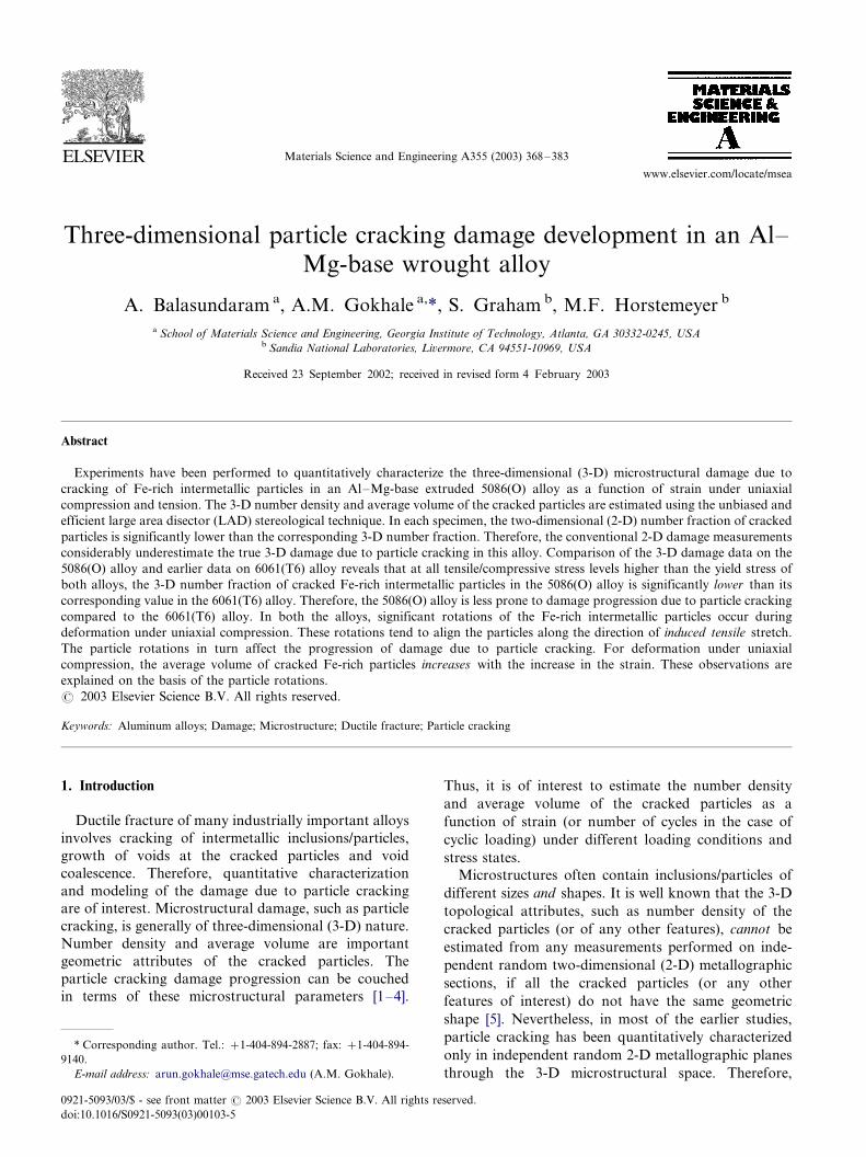
Three-dimensional particle cracking damage development in an Al / Mg-base wrought alloy A. Balasundaram a , A.M. Gokhale a, *, S. Graham b , M.F. Horstemeyer b a School of Materials Science and Engineering, Georgia Institute of Technology, Atlanta, GA 30332-0245, USA b Sandia National Laboratories, Livermore, CA 94551-10969, USA Received 23 September 2002; received in revised form 4 February 2003 Abstract Experiments have been performed to quantitatively characterize the three-dimensional (3-D) microstructural damage due to cracking of Fe-rich intermetallic particles in an Al /Mg-base extruded 5086(O) alloy as a function of strain under uniaxial compression and tension. The 3-D number density and average volume of the cracked particles are estimated using the unbiased and efficient large area disector (LAD) stereological technique. In each specimen, the two-dimensional (2-D) number fraction of cracked particles is significantly lower than the corresponding 3-D number fraction. Therefore, the conventional 2-D damage measurements considerably underestimate the true 3-D damage due to particle cracking in this alloy. Comparison of the 3-D damage data on the 5086(O) alloy and earlier data on 6061(T6) alloy reveals that at all tensile/compressive stress levels higher than the yield stress of both alloys, the 3-D number fraction of cracked Fe-rich intermetallic particles in the 5086(O) alloy is significantly lower than its corresponding value in the 6061(T6) alloy. Therefore, the 5086(O) alloy is less prone to damage progression due to particle cracking compared to the 6061(T6) alloy. In both the alloys, significant rotations of the Fe-rich intermetallic particles occur during deformation under uniaxial compression. These rotations tend to align the particles along the direction of induced tensile stretch. The particle rotations in turn affect the progression of damage due to particle cracking. For deformation under uniaxial compression, the average volume of cracked Fe-rich particles increases with the increase in the strain. These observations are explained on the basis of the particle rotations. # 2003 Elsevier Science B.V. All rights reserved. Keywords: Aluminum alloys; Damage; Microstructure; Ductile fracture; Particle cracking 1. Introduction Ductile fracture of many industrially important alloys involves cracking of intermetallic inclusions/particles, growth of voids at the cracked particles and void coalescence. Therefore, quantitative characterization and modeling of the damage due to particle cracking are of interest. Microstructural damage, such as particle cracking, is generally of three-dimensional (3-D) nature. Number density and average volume are important geometric attributes of the cracked particles. The particle cracking damage progression can be couched in terms of these microstructural parameters [1 /4]. Thus, it is of interest to estimate the number density and average volume of the cracked particles as a function of strain (or number of cycles in the case of cyclic loading) under different loading conditions and stress states. Microstructures often contain inclusions/particles of different sizes and shapes. It is well known that the 3-D topological attributes, such as number density of the cracked particles (or of any other features), cannot be estimated from any measurements performed on inde- pendent random two-dimensional (2-D) metallographic sections, if all the cracked particles (or any other features of interest) do not have the same geometric shape [5]. Nevertheless, in most of the earlier studies, particle cracking has been quantitatively characterized only in independent random 2-D metallographic planes through the 3-D microstructural space. Therefore, * Corresponding author. Tel.: /1-404-894-2887; fax: /1-404-894- 9140. E-mail address: [email protected] (A.M. Gokhale). Materials Science and Engineering A355 (2003) 368 /383 www.elsevier.com/locate/msea 0921-5093/03/$ - see front matter # 2003 Elsevier Science B.V. All rights reserved. doi:10.1016/S0921-5093(03)00103-5
-
Upload
independent -
Category
Documents
-
view
5 -
download
0
Transcript of Three-dimensional particle cracking damage development in an Al–Mg-base wrought alloy
Three-dimensional particle cracking damage development in an Al�/
Mg-base wrought alloy
A. Balasundaram a, A.M. Gokhale a,*, S. Graham b, M.F. Horstemeyer b
a School of Materials Science and Engineering, Georgia Institute of Technology, Atlanta, GA 30332-0245, USAb Sandia National Laboratories, Livermore, CA 94551-10969, USA
Received 23 September 2002; received in revised form 4 February 2003
Abstract
Experiments have been performed to quantitatively characterize the three-dimensional (3-D) microstructural damage due to
cracking of Fe-rich intermetallic particles in an Al�/Mg-base extruded 5086(O) alloy as a function of strain under uniaxial
compression and tension. The 3-D number density and average volume of the cracked particles are estimated using the unbiased and
efficient large area disector (LAD) stereological technique. In each specimen, the two-dimensional (2-D) number fraction of cracked
particles is significantly lower than the corresponding 3-D number fraction. Therefore, the conventional 2-D damage measurements
considerably underestimate the true 3-D damage due to particle cracking in this alloy. Comparison of the 3-D damage data on the
5086(O) alloy and earlier data on 6061(T6) alloy reveals that at all tensile/compressive stress levels higher than the yield stress of
both alloys, the 3-D number fraction of cracked Fe-rich intermetallic particles in the 5086(O) alloy is significantly lower than its
corresponding value in the 6061(T6) alloy. Therefore, the 5086(O) alloy is less prone to damage progression due to particle cracking
compared to the 6061(T6) alloy. In both the alloys, significant rotations of the Fe-rich intermetallic particles occur during
deformation under uniaxial compression. These rotations tend to align the particles along the direction of induced tensile stretch.
The particle rotations in turn affect the progression of damage due to particle cracking. For deformation under uniaxial
compression, the average volume of cracked Fe-rich particles increases with the increase in the strain. These observations are
explained on the basis of the particle rotations.
# 2003 Elsevier Science B.V. All rights reserved.
Keywords: Aluminum alloys; Damage; Microstructure; Ductile fracture; Particle cracking
1. Introduction
Ductile fracture of many industrially important alloys
involves cracking of intermetallic inclusions/particles,
growth of voids at the cracked particles and void
coalescence. Therefore, quantitative characterization
and modeling of the damage due to particle cracking
are of interest. Microstructural damage, such as particle
cracking, is generally of three-dimensional (3-D) nature.
Number density and average volume are important
geometric attributes of the cracked particles. The
particle cracking damage progression can be couched
in terms of these microstructural parameters [1�/4].
Thus, it is of interest to estimate the number density
and average volume of the cracked particles as a
function of strain (or number of cycles in the case of
cyclic loading) under different loading conditions and
stress states.
Microstructures often contain inclusions/particles of
different sizes and shapes. It is well known that the 3-D
topological attributes, such as number density of the
cracked particles (or of any other features), cannot be
estimated from any measurements performed on inde-
pendent random two-dimensional (2-D) metallographic
sections, if all the cracked particles (or any other
features of interest) do not have the same geometric
shape [5]. Nevertheless, in most of the earlier studies,
particle cracking has been quantitatively characterized
only in independent random 2-D metallographic planes
through the 3-D microstructural space. Therefore,
* Corresponding author. Tel.: �/1-404-894-2887; fax: �/1-404-894-
9140.
E-mail address: [email protected] (A.M. Gokhale).
Materials Science and Engineering A355 (2003) 368�/383
www.elsevier.com/locate/msea
0921-5093/03/$ - see front matter # 2003 Elsevier Science B.V. All rights reserved.
doi:10.1016/S0921-5093(03)00103-5
development and applications of general quantitative
metallographic techniques for an unbiased and efficient
estimation of 3-D microstructural damage are of inter-
est.
Most of the earlier investigations focus on the particle
cracking damage evolution under a uniaxial applied
tensile stress [6�/9]; damage evolution under other test
conditions, such as compression and torsion, has
received very little attention. Recently, cracking of Fe-
rich intermetallic particles has been quantitatively
characterized in the 3-D microstructure of an extruded
Al�/Mg�/Si-base precipitation hardened 6061(T6) alloy,
which is a typical alloy of 6XXX series. In this alloy,
significant differences have been observed in the damage
evolution under tension and compression [10,11]. It is of
interest to determine if such differences in the path of
damage progression exist in other categories of wrought
aluminum alloys as well.
5XXX series Al�/Mg-base wrought alloys are widely
used for structural applications. The ductile fracture of
these alloys is also associated with cracking of Fe-rich
intermetallic particles. It is the objective of this con-
tribution to quantitatively characterize evolution of 3-D
particle cracking damage in an extruded 5086(O)
aluminum alloy (which is a typical alloy of 5XXX
series) under uniaxial tension and compression and to
compare these data with those for 6061(T6) alloy. Note
that 5086(O) is a solid solution strengthened alloy that
exhibits pronounced dynamic strain aging (DSA),
whereas 6061(T6) is a precipitation hardened alloy
that does not undergo DSA. It is of interest to study
how such differences in the microstructure and deforma-
tion characteristics affect the particle cracking damage
progression.
In the present study, evolution of the particle cracking
damage in an extruded 5086(O) alloy is quantitatively
characterized via estimation of 3-D number fraction,
volume fraction and average volume of the cracked Fe-
rich particles as a function of strain under uniaxial
compression and tension using two- and three-dimen-
sional stereological probes and digital image analysis
techniques. Comparison of these data with earlier data
on particle cracking in 6061(T6) alloy reveals that
5086(O) alloy is significantly less prone to the particle
cracking damage compared to 6061(T6) alloy. Thedifferences in the particle cracking damage progression
in the two alloys are explained on the basis of the
differences in their microstructure and deformation
characteristics.
2. Experimental
2.1. Materials and mechanical tests
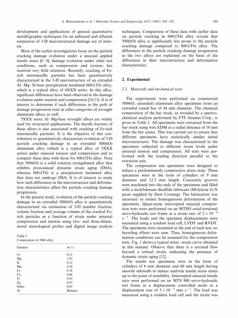
The experiments were performed on commercial
5086(O, annealed) aluminum alloy specimens from an
extruded round bar of 44 mm diameter. The chemical
composition of the bar stock, as revealed by a spectro-
chemical analysis performed by FTI Anamet Corp., is
given in Table 1. All specimens were extracted from the
bar stock using wire EDM at a radial distance of 10 mmfrom the bar center. This was carried out to ensure that
different specimens have statistically similar initial
microstructures. The damage was characterized in the
specimens subjected to different strain levels under
uniaxial tension and compression. All tests were per-
formed with the loading direction parallel to the
extrusion axis.
The compression test specimens were designed toinduce a predominantly compressive stress state. These
specimens were in the form of cylinders of 9 mm
diameter and 12.5 mm length. Concentric grooves
were machined into the ends of the specimens and filled
with a molybdenum disulfide lubricant (Molykote G-N
paste supplied by Dow Corning). The lubrication was
necessary to ensure homogeneous deformation of the
specimens. Quasi-static interrupted uniaxial compres-sion tests were performed on an MTS81-axial-torsional
servo-hydraulic test frame at a strain rate of 2�/10�4
s�1. The loads and the specimen displacements were
measured using a resident load cell, LVDT and RVDT.
The specimens were examined at the end of each test; no
barreling effects were seen. Thus, homogeneous defor-
mation conditions can be assumed for the compression
tests. Fig. 1 shows a typical stress�/strain curve obtainedin this manner. Observe that there is a serrated flow
beyond a critical strain, indicating the presence of
dynamic strain aging [12].
The tensile test specimens were in the form of
cylinders of 6 mm diameter and 60 mm length having
smooth sidewalls to induce uniform tensile stress states
up to the point of instability. Interrupted uniaxial tensile
tests were performed on an MTS 880 servo-hydraulictest frame in a displacement controlled mode at a
displacement rate of 5�/10�3 mm s�1. The load was
measured using a resident load cell and the strain was
Table 1
Composition of 5086 alloy
Element wt.%
Cr 0.11
Mg 3.95
Si 0.12
Mn 0.56
Fe 0.18
Cu 0.06
Ti 0.03
Zn 0.07
Other 0.05
Al Balance
A. Balasundaram et al. / Materials Science and Engineering A355 (2003) 368�/383 369
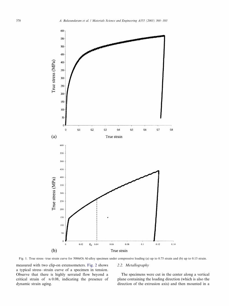
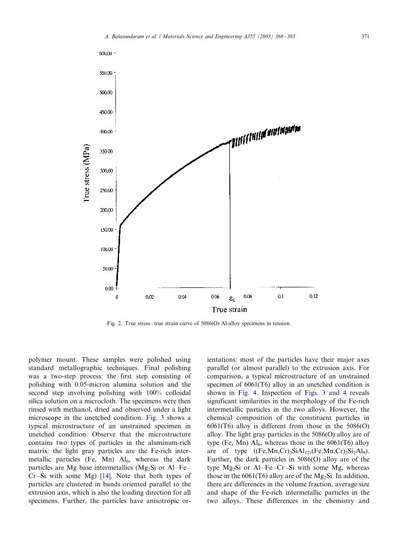
measured with two clip-on extensometers. Fig. 2 shows
a typical stress�/strain curve of a specimen in tension.
Observe that there is highly serrated flow beyond a
critical strain of :/0.08, indicating the presence of
dynamic strain aging.
2.2. Metallography
The specimens were cut in the center along a vertical
plane containing the loading direction (which is also the
direction of the extrusion axis) and then mounted in a
Fig. 1. True stress�/true strain curve for 5086(O) Al-alloy specimen under compressive loading (a) up to 0.75 strain and (b) up to 0.13 strain.
A. Balasundaram et al. / Materials Science and Engineering A355 (2003) 368�/383370
polymer mount. These samples were polished using
standard metallographic techniques. Final polishing
was a two-step process: the first step consisting of
polishing with 0.05-micron alumina solution and the
second step involving polishing with 100% colloidal
silica solution on a microcloth. The specimens were then
rinsed with methanol, dried and observed under a light
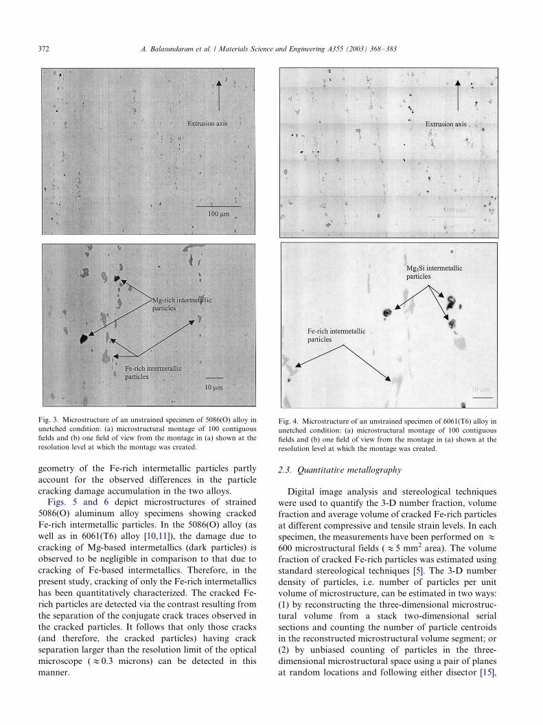
microscope in the unetched condition. Fig. 3 shows a
typical microstructure of an unstrained specimen in
unetched condition. Observe that the microstructure
contains two types of particles in the aluminum-rich
matrix: the light gray particles are the Fe-rich inter-
metallic particles (Fe, Mn) Al6, whereas the dark
particles are Mg base intermetallics (Mg2Si or Al�/Fe�/
Cr�/Si with some Mg) [14]. Note that both types of
particles are clustered in bands oriented parallel to the
extrusion axis, which is also the loading direction for all
specimens. Further, the particles have anisotropic or-
ientations: most of the particles have their major axes
parallel (or almost parallel) to the extrusion axis. For
comparison, a typical microstructure of an unstrained
specimen of 6061(T6) alloy in an unetched condition is
shown in Fig. 4. Inspection of Figs. 3 and 4 reveals
significant similarities in the morphology of the Fe-rich
intermetallic particles in the two alloys. However, the
chemical composition of the constituent particles in
6061(T6) alloy is different from those in the 5086(O)
alloy. The light gray particles in the 5086(O) alloy are of
type (Fe, Mn) Al6, whereas those in the 6061(T6) alloy
are of type ((Fe,Mn,Cr)3SiAl12,(Fe,Mn,Cr)2Si2Al9).
Further, the dark particles in 5086(O) alloy are of the
type Mg2Si or Al�/Fe�/Cr�/Si with some Mg, whereas
those in the 6061(T6) alloy are of the Mg2Si. In addition,
there are differences in the volume fraction, average size
and shape of the Fe-rich intermetallic particles in the
two alloys. These differences in the chemistry and
Fig. 2. True stress�/true strain curve of 5086(O) Al-alloy specimens in tension.
A. Balasundaram et al. / Materials Science and Engineering A355 (2003) 368�/383 371
geometry of the Fe-rich intermetallic particles partly
account for the observed differences in the particle
cracking damage accumulation in the two alloys.
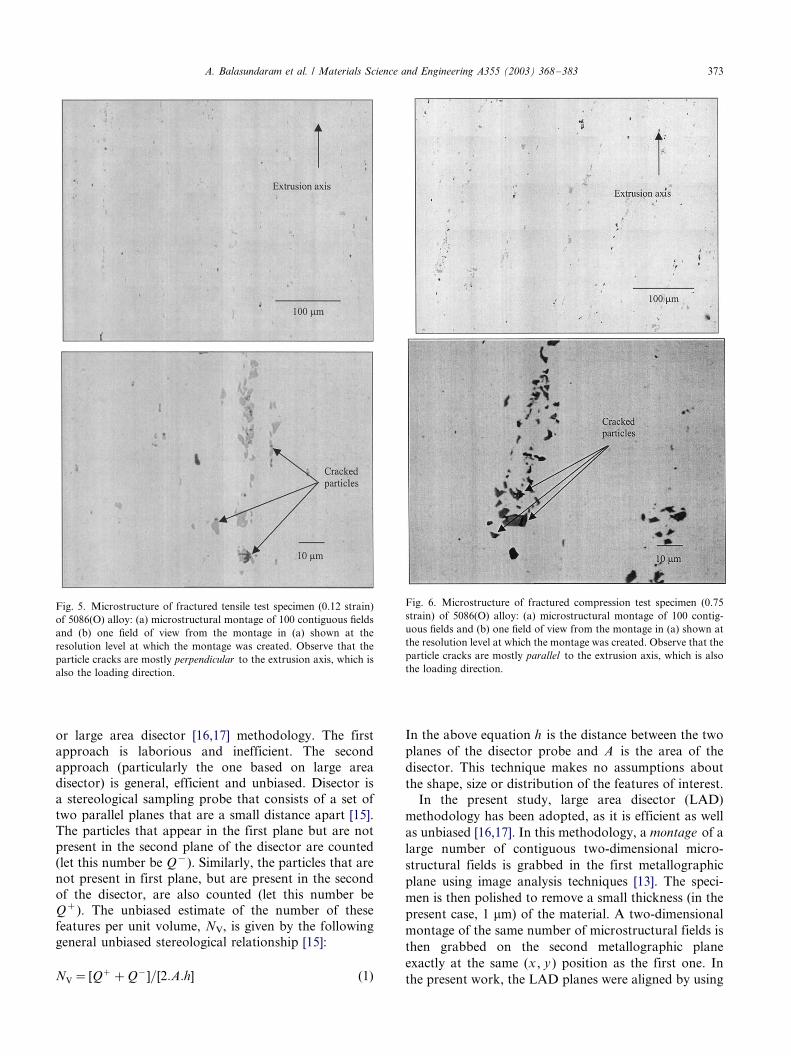
Figs. 5 and 6 depict microstructures of strained
5086(O) aluminum alloy specimens showing cracked
Fe-rich intermetallic particles. In the 5086(O) alloy (as
well as in 6061(T6) alloy [10,11]), the damage due to
cracking of Mg-based intermetallics (dark particles) is
observed to be negligible in comparison to that due to
cracking of Fe-based intermetallics. Therefore, in the
present study, cracking of only the Fe-rich intermetallics
has been quantitatively characterized. The cracked Fe-
rich particles are detected via the contrast resulting from
the separation of the conjugate crack traces observed in
the cracked particles. It follows that only those cracks
(and therefore, the cracked particles) having crack
separation larger than the resolution limit of the optical
microscope (:/0.3 microns) can be detected in this
manner.
2.3. Quantitative metallography
Digital image analysis and stereological techniques
were used to quantify the 3-D number fraction, volume
fraction and average volume of cracked Fe-rich particles
at different compressive and tensile strain levels. In each
specimen, the measurements have been performed on :/
600 microstructural fields (:/5 mm2 area). The volume
fraction of cracked Fe-rich particles was estimated using
standard stereological techniques [5]. The 3-D number
density of particles, i.e. number of particles per unit
volume of microstructure, can be estimated in two ways:
(1) by reconstructing the three-dimensional microstruc-
tural volume from a stack two-dimensional serial
sections and counting the number of particle centroids
in the reconstructed microstructural volume segment; or
(2) by unbiased counting of particles in the three-
dimensional microstructural space using a pair of planes
at random locations and following either disector [15],
Fig. 3. Microstructure of an unstrained specimen of 5086(O) alloy in
unetched condition: (a) microstructural montage of 100 contiguous
fields and (b) one field of view from the montage in (a) shown at the
resolution level at which the montage was created.
Fig. 4. Microstructure of an unstrained specimen of 6061(T6) alloy in
unetched condition: (a) microstructural montage of 100 contiguous
fields and (b) one field of view from the montage in (a) shown at the
resolution level at which the montage was created.
A. Balasundaram et al. / Materials Science and Engineering A355 (2003) 368�/383372
or large area disector [16,17] methodology. The first
approach is laborious and inefficient. The second
approach (particularly the one based on large areadisector) is general, efficient and unbiased. Disector is
a stereological sampling probe that consists of a set of
two parallel planes that are a small distance apart [15].
The particles that appear in the first plane but are not
present in the second plane of the disector are counted
(let this number be Q�). Similarly, the particles that are
not present in first plane, but are present in the second
of the disector, are also counted (let this number beQ�). The unbiased estimate of the number of these
features per unit volume, NV, is given by the following
general unbiased stereological relationship [15]:
NV� [Q��Q�]=[2:A:h] (1)
In the above equation h is the distance between the two
planes of the disector probe and A is the area of the
disector. This technique makes no assumptions about
the shape, size or distribution of the features of interest.In the present study, large area disector (LAD)
methodology has been adopted, as it is efficient as well
as unbiased [16,17]. In this methodology, a montage of a
large number of contiguous two-dimensional micro-
structural fields is grabbed in the first metallographic
plane using image analysis techniques [13]. The speci-
men is then polished to remove a small thickness (in the
present case, 1 mm) of the material. A two-dimensional
montage of the same number of microstructural fields is
then grabbed on the second metallographic plane
exactly at the same (x , y ) position as the first one. In
the present work, the LAD planes were aligned by using
Fig. 5. Microstructure of fractured tensile test specimen (0.12 strain)
of 5086(O) alloy: (a) microstructural montage of 100 contiguous fields
and (b) one field of view from the montage in (a) shown at the
resolution level at which the montage was created. Observe that the
particle cracks are mostly perpendicular to the extrusion axis, which is
also the loading direction.
Fig. 6. Microstructure of fractured compression test specimen (0.75
strain) of 5086(O) alloy: (a) microstructural montage of 100 contig-
uous fields and (b) one field of view from the montage in (a) shown at
the resolution level at which the montage was created. Observe that the
particle cracks are mostly parallel to the extrusion axis, which is also
the loading direction.
A. Balasundaram et al. / Materials Science and Engineering A355 (2003) 368�/383 373

the locations of micro-hardness indents for reference.
The thickness of material removed (i.e. distance between
the LAD planes, h ) was calculated by measuring the
difference in the diagonal length of the diamond indentsin the two LAD planes, which is related to the material
thickness removed h through the geometry of the micro-
hardness indentor. From the experimental measure-
ments of Q�, Q� and h , the number of particles per
unit volume can be estimated using Eq. (1). For
representative statistical sampling, in the present study,
three sets of LADs were analyzed to estimate the
average 3-D number density of the cracked Fe-richintermetallic particles in each specimen. A similar
procedure was also used to estimate the number density
of overall population of the Fe-rich intermetallic parti-
cles (cracked as well as undamaged). From these
experimental data, the 3-D number fraction of the
cracked Fe-rich particles, F, was estimated in each
specimen. For comparison, the 2-D number fraction of
cracked Fe-rich particles in metallographic planes, f ,was also measured in each specimen. Further, from the
experimental data on the number density of the cracked
particles, NV and their volume fraction, VV, the average
volume of cracked and bulk Fe-rich intermetallic
particles was calculated by using the following relation-
ship:
V��
VV
NV
(2)
3. Results and discussion
3.1. Mechanical behavior of 5086 Al-alloy
Fig. 1 shows the true stress�/true strain curve of the
5086(O) alloy under uniaxial compression. Observe that
there is a serrated plastic flow beyond a critical strain,
indicating the presence of dynamic strain aging (DSA).
The critical strain for onset of DSA is :/0.04 for
deformation under uniaxial compression. Fig. 2 showsthe true stress�/true strain curve of the 5086(O) Al-alloy
under uniaxial tension. Notice again, that there is a
highly serrated flow after a critical strain of :/0.08,
indicating the presence of dynamic strain aging under
tensile loading as well. For comparison, the true stress�/
true strain curves for 6061(T6) alloy in tension and
compression [1011] are shown in Figs. 7 and 8,
respectively. Inspection of these stress�/strain curvesreveals the following:
1) Dynamic strain aging is observed in the 5086(O)
alloy in both tension and compression, whereas it is
not observed in the 6061(T6) alloy.
2) The 5086(O) alloy has lower yield stress and a
higher strain-hardening coefficient than the
6061(T6) alloy.
As mentioned earlier, 5086(O) is a solid solution
strengthened alloy, whereas 6061(T6) is a precipitation-
hardened alloy. Although both alloys contain Mg,5086(O) alloy has a significantly higher amount of Mg
(3.5�/4.5)% than 6061(T6) alloy (0.8�/1.2)%. The Si
content is, however, higher in the 6061(T6) alloy (0.4�/
0.8)% compared to the 5086(O) alloy (0.4% max).
Therefore, in the 6061(T6) alloy, most of the Mg is
locked up in Mg2Si precipitates and Mg-rich constituent
particles and, consequently, sufficient Mg atoms are not
available to form the solute atmospheres around thedislocations that can lead to DSA [18�/22]. Due to this
reason, DSA is not observed in the 6061(T6) alloy. On
the other hand, in the 5086(O) alloy, due to the lower
amount of Si, an insufficient amount of Mg2Si pre-
cipitates is formed and, therefore, there is no precipita-
tion hardening, but as most of the Mg is in solid
solution, pronounced DSA is observed. The higher yield
stress of 6061(T6) alloy is primarily due to precipitationhardening, whereas the higher strain-hardening coeffi-
cient of 5086(O) alloy is essentially due to the presence
of DSA [23]. These differences in the deformation
characteristics are partly responsible for the observed
differences in the particle cracking damage progression
in these alloys.
3.2. Bulk microstructure of 5086(O) and 6061(T6)
alloys
The quantitative microstructural data for the un-
strained 5086(O) Al-alloy specimens are given in Table
2. For comparison, the corresponding data on un-
strained 6061(T6) alloy obtained in the earlier study[10] are also given in Table 2. The volume fraction,
number density, aspect ratio and average volume of Fe-
rich intermetallic particles are higher in the 6061(T6)
alloy compared to those in the 5086(O) alloy. It is well
known that the larger and elongated particles (high
aspect ratio) crack at lower stresses. Therefore, higher
particle cracking damage observed in the 6061(T6) alloy
compared to that in the 5086(O) alloy is partly due tothe differences in the amount, size, shape and number
density of the Fe-rich particles in the two alloys.
3.3. Qualitative microstructural observations on particle
cracking
Figs. 5 and 6 depict unetched microstructures of thespecimens deformed in tension and compression, re-
spectively. Inspection of the microstructures of these
and other specimens lead to the following observations.
A. Balasundaram et al. / Materials Science and Engineering A355 (2003) 368�/383374
1) In the tensile test specimens, the cracks in the
damaged particles are mostly perpendicular to the
loading direction, whereas those in the compression
test specimens are mostly parallel to the loading
direction. Therefore, the anisotropy of the crack
orientations strongly depends on the loading con-
dition and stress state.
2) The cracks are mostly perpendicular to the direction
of the major axis of the corresponding Fe-rich
intermetallic particles in both tensile and compres-
sion test specimens. Therefore, particle cracking is
strongly influenced by the local maximum principal
stretch.
3) There are no debonded particles in both tensile and
compression test specimens. Therefore, particle
cracking is the dominant damage nucleation mode
in tension as well as compression.
The above observations are essentially the same as
those on the cracked Fe-rich intermetallic particles in
the 6061(T6) Al-alloy [10,11]. Therefore, qualitatively,
the Fe-rich particle cracking damage in the 5086(O) Al-
alloy is similar to that observed in the 6061(T6) alloy.
However, as shown in the subsequent sections, there are
significant differences in the quantitative data on
the particle cracking damage evolution in the two
alloys.
3.4. Particle cracking under uniaxial compression
Fig. 9 shows variation of the average cracked particle
volume with compressive strain in the 5086(O) and
6061(T6) alloys. Observe that, in both alloys, the
average volume of the cracked particles increases withincrease in compressive strain in a monotonic manner.
In the 5086(O) alloy, the average volume of cracked
particles at the highest compressive strain level studied
(0.75 strain) is larger than that at the lowest strain
studied (0.125) by almost a factor of three. A similar
trend has been observed for the strain dependence of
average volume of cracked particles in the 6061(T6)
alloy as well, and a similar explanation [10,11] can alsobe given for the present experimental data. An increase
in average cracked particle volume with strain implies
that more and more larger particles crack at progres-
sively higher compressive strain/stress levels. Gurland
and Plateau [9] have given following equation for critical
tensile stress s to develop a crack in a particle of size D.
s� [Eg=(Dq2)]1=2 (3)
In Eq. (3), q is the stress concentration factor at the
particle, E is weighted average of the elastic moduli ofthe particle and matrix and g is the interfacial energy of
the crack. Thus, the stress s required to crack a particle
is inversely proportional to the square root of the
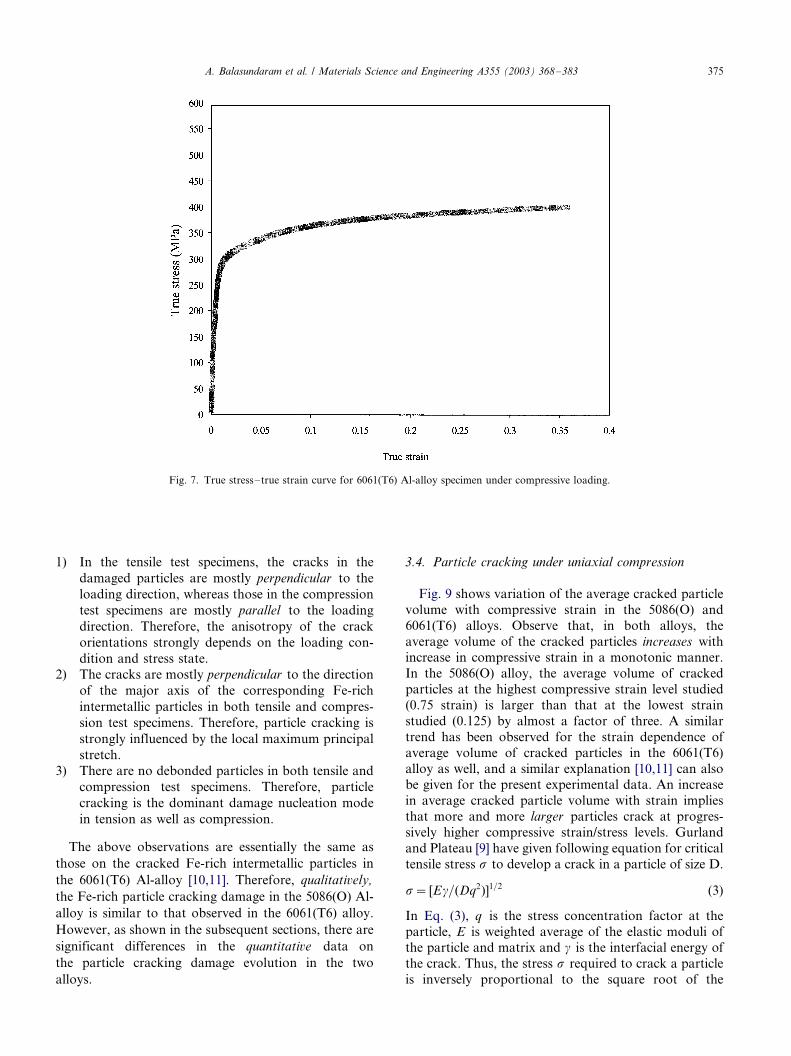
Fig. 7. True stress�/true strain curve for 6061(T6) Al-alloy specimen under compressive loading.
A. Balasundaram et al. / Materials Science and Engineering A355 (2003) 368�/383 375
particle size and, accordingly, larger particles crack at
lower stresses. Therefore, as damage accumulates, the
largest particles are expected to fracture at the lowest
stress levels and progressively smaller particles may
crack at higher and higher stress levels. As a result of
such damage progression, the average volume of
cracked particles is expected to decrease with increase
in strain, which is opposite to what is observed
experimentally in the present investigation. Therefore,
the observed increase in average cracked particle volume
with compressive stress (or strain) cannot be explained
on the basis of existing particle-cracking theories.
However, it must be recognized that all particle-cracking
theories implicitly assume that the brittle inclusions/
particles remain stationary as the ductile matrix under-
goes plastic deformation. However, if the brittle Fe-rich
particles rotate as the ductile aluminum-rich matrix
deforms, then the particle rotations can bring new Fe-
rich particles into morphological orientations that may
facilitate particle cracking, which can then affect the
damage progression. Thus, it is of interest to determine
if significant rotations of Fe-rich intermetallic particles
occur during the deformation of 5086(O) alloy when a
compressive stress is applied parallel to the extrusion
axis.
The orientation of a particle can be specified by the
angle u between the major axis of the particle and the
loading direction (which is the extrusion axis). The
orientation angles of the Fe-rich particles can be
measured in the metallographic plane using image
analysis and the morphological orientation distribution
can be computed from such data. Significant changes in
the morphological orientation distribution function with
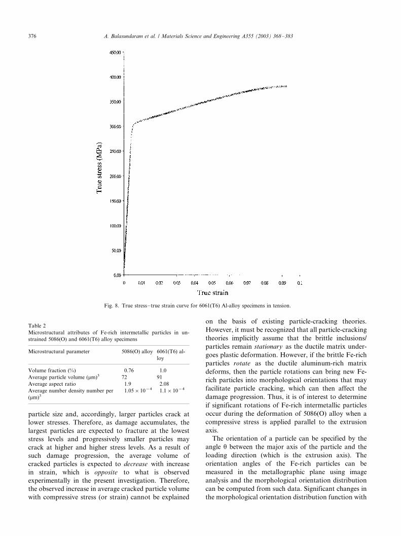
Fig. 8. True stress�/true strain curve for 6061(T6) Al-alloy specimens in tension.
Table 2
Microstructural attributes of Fe-rich intermetallic particles in un-
strained 5086(O) and 6061(T6) alloy specimens
Microstructural parameter 5086(O) alloy 6061(T6) al-
loy
Volume fraction (%) 0.76 1.0
Average particle volume (mm)3 72 91
Average aspect ratio 1.9 2.08
Average number density number per
(mm)3
1.05�/10�4 1.1�/10�4
A. Balasundaram et al. / Materials Science and Engineering A355 (2003) 368�/383376
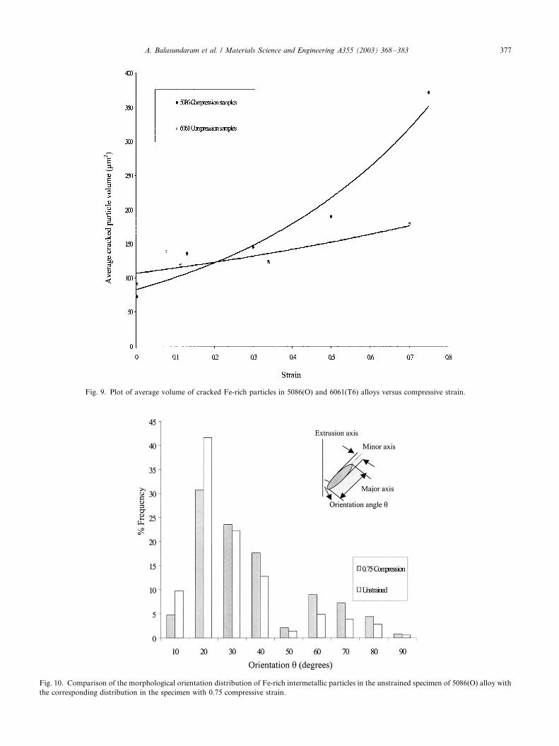
Fig. 9. Plot of average volume of cracked Fe-rich particles in 5086(O) and 6061(T6) alloys versus compressive strain.
Fig. 10. Comparison of the morphological orientation distribution of Fe-rich intermetallic particles in the unstrained specimen of 5086(O) alloy with
the corresponding distribution in the specimen with 0.75 compressive strain.
A. Balasundaram et al. / Materials Science and Engineering A355 (2003) 368�/383 377
the strain are then indicative of the particle rotations.
Fig. 10 compares the experimentally measured morpho-
logical orientation distribution of the Fe-rich interme-
tallic particles in the unstrained specimen of the alloywith that in the specimen strained to 0.75 strain in
compression. These data include both undamaged and
damaged particles. In the unstrained specimen, :/70%
of the particles have orientations in the range of 0�/308and :/10% are oriented in the range of 60�/908. There-
fore, most of the particles tend to align themselves along
the extrusion axis, which is quite expected in the
microstructure of an extruded alloy. In the 0.75 com-pressive strained specimen, :/60% of the particles have
orientations in the range of 0�/308, whereas :/20% of
the particles have orientations in the range of 60�/908.Therefore, 0.75 deformation under uniaxial compression
parallel to the extrusion axis leads to an increase in the
percentage of particles in the orientation range of 60�/
908 from 10 to 20% (i.e. % is doubled) and it decreases
the percentage of particles in the orientation range of 0�/
308 from 70 to 60%. Clearly, under uniaxial compression
along the extrusion axis, the Fe-rich particles rotate and
tend to align themselves along the direction perpendi-
cular to the loading direction, which is the direction of
induced tensile stress . It is well known that the particles
aligned parallel (or almost parallel) to the induced (or
applied) tensile stress have a higher probability of
cracking compared to the particles of the same sizeand shape oriented perpendicular to the induced (or
applied) tensile stress. Therefore, the particle rotations
bring new large particles in the orientations almost
parallel to the induced tensile stress, which facilitates the
cracking of additional large particles. Such damage
progression should lead to an increase in the average
volume of cracked particles with an increase in com-
pressive strain, as observed experimentally. Thus, thepresent data clearly demonstrate that there is a strong
link between the particle rotations and particle cracking
damage evolution in 5086(O) alloy. Extensive experi-
mental data on particle rotations in the 5086(O) alloy
are presented elsewhere [23,24].
Significant rotations of Fe-rich intermetallic particles
also occur in the extruded 6061(T6) alloy, when a
compressive load is applied parallel to the extrusionaxis [10,22]: a plastic deformation of 0.70 strain leads to
an increase in the percentage of particles in the orienta-
tion range of 60�/908 from 7% (in the initial micro-
structure) to 30% (i.e. increase of a factor of four) and it
decreases the percentage of particles in the orientation
range of 0�/308 from 77 to 43%. On the other hand, in
the 5086(O) alloy, a comparable deformation under
compression (0.75 strain) leads to an increase in thepercentage of particles in the orientation range of 60�/
908 from 10 to 20% (i.e. % is doubled) and it decreases
the percentage of particles in the orientation range of 0�/
308 from 70 to 60%. Therefore, although the particle
rotation occurs in both the alloys, the extent of particle
rotation is significantly less in the 5086(O) alloy
compared to that in the 6061(T6) alloy under a
compressive loading applied parallel to the extrusionaxis. The lower tendency of particle rotation in the
5086(O) alloy partly accounts for the observed lower
particle cracking damage in this alloy compared to the
6061(T6) alloy.
Fig. 9 compares the variation of average cracked
particle volume of Fe-rich particles with compressive
strain in the 5086(O) and 6061(T6) microstructures.
Observe that, in the 6061(T6) alloy, at the highestcompressive strain level studied (70%), the average
cracked particle volume is lower by almost a factor of
two than that at the comparable strain level (75%) in the
5086(O) alloy. Further, the rate of increase of average
cracked particle volume is also significantly higher in the
5086(O) alloy compared to that in 6061(T6) Al-alloy
under compression. Therefore, with an increase in the
applied compressive stress, more larger particles crackin the 5086(O) alloy compared to those in the 6061(T6)
alloy.
Fig. 11 depicts strain dependence of 2-D and 3-D
number fraction of cracked Fe-rich intermetallic parti-
cles in the bulk microstructure of 5086(O) Al-alloy
under a uniaxial compression. As expected, the number
fraction of cracked particles (in both 2-D and 3-D)
monotonically increases with an increase in the com-pressive strain. However, at any given strain, the 3-D
number fraction of cracked particles is higher than the
corresponding 2-D number fraction in the plane con-
taining the extrusion axis (which is also the loading
direction). A similar trend has been also observed in the
6061(T6) alloy [10]. Therefore, for deformation in
compression, the 2-D number fraction of cracked
particles significantly underestimates the 3-D numberfraction of the cracked particles in the microstructural
volume, which is the true damage parameter.
Fig. 12 compares the variation of 3-D number
fraction of cracked Fe-rich intermetallic particles with
applied true compressive stress in 5086 and 6061 Al-
alloys, respectively. Recall that the yield stress of
5086(O) alloy is lower than that of 6061(T6) alloy. The
extrapolated curve reveals that at stresses lower than theyield stress of 6061(T6) alloy, the damage is higher in
5086(O) alloy. This is consistent with the earlier
observations [6] that plastic deformation of matrix is
essential for particle cracking to occur. At any applied
stress higher than the yields stress of both the alloys, the
3-D number fraction of cracked particles in 6061(T6)
alloy is higher than its corresponding value for the
5086(O) alloy. Therefore, the 5086(O) alloy is less proneto the damage due to particle cracking compared to the
6061(O) alloy under a compressive load applied parallel
to the extrusion axis. This may be due to lower volume
fraction and lower average volume (and therefore, size)
A. Balasundaram et al. / Materials Science and Engineering A355 (2003) 368�/383378

of the Fe-rich particles in the unstrained microstructure
of the 5086(O) alloy (Table 2), differences in the
chemical composition of the Fe-rich particles in the
two alloys and the differences in the particle rotation
tendencies in the two alloys. The higher extent of
particle rotations in 6061(T6) alloy brings more particlesin the orientations that facilitate particles cracking,
thereby leading to a higher damage. These observations
further demonstrate that the particle rotations and
damage nucleation by particle cracking are inter-related.
However, it must be pointed out that the additional
factors, such as dynamic strain aging, may also affect
the particle cracking damage evolution in the two alloys.
3.5. Particle cracking under uniaxial tension
Fig. 13 shows the variation of average cracked
particle volume as a function of tensile strain in the5086(O) and 6061(T6) alloys. Interestingly, unlike the
variation observed in compression specimens (Fig. 9),
the average volume of cracked Fe-rich particles in the
5086(O) alloy does not change significantly with tensile
strain. The differences in the variation of averaged
cracked particle volume with strain under compression
and tension in the 5086(O) alloy are essentially due to
the differences in the particle rotation tendency under
these two loading conditions, when the load is applied
parallel to the extrusion axis of the specimens. Signifi-
cant rotations of Fe-rich particles do not occur, when a
tensile load is applied parallel to the extrusion axis [24].
These observations are consistent with the hypothesis
that the Fe-rich particles rotate and tend to align
themselves along the direction of applied/induced tensile
stress. In the unstrained specimens, most of the Fe-rich
particles are aligned along the extrusion axis. Therefore,
no significant particle rotations occur when the applied
tensile stress direction is parallel to the extrusion axis.
Under the tensile loading condition, the large particles
that are almost parallel to the tensile loading direction
are the first to crack. In the absence of significant
particle rotations, as the tensile stress increases, addi-
tional particle cracking may occur due to cracking of
Fig. 11. Plot of number fraction of cracked Fe-rich particles in 2-D and 3-D versus compressive strain in 5086(O) alloy.
A. Balasundaram et al. / Materials Science and Engineering A355 (2003) 368�/383 379

Fig. 12. Comparison of variation of 3-D number fraction of cracked Fe-rich particles with compressive strain in 6061(T6) and 5086(O) alloys.
Fig. 13. Variation of average cracked particle volume as a function of tensile strain in the 5086(O) and 6061(T6) alloys.
A. Balasundaram et al. / Materials Science and Engineering A355 (2003) 368�/383380
smaller favorably oriented particles, or cracking of large
particles that are not favorably oriented, or both. If
additional particle cracking is predominantly due to
cracking of progressively smaller favorably oriented
particles with the increase in the tensile stress, then
average cracked particle volume should decrease with an
increase in the strain/stress, which is the trend observed
in the 6061(T6) alloy [10,11]. On the other hand, if the
additional particle cracking is predominantly due to
cracking of large unfavorably oriented particles (having
the sizes in the same regime as those cracked at lower
strains), then the average cracked particle volume is not
expected to change significantly with the tensile strain,
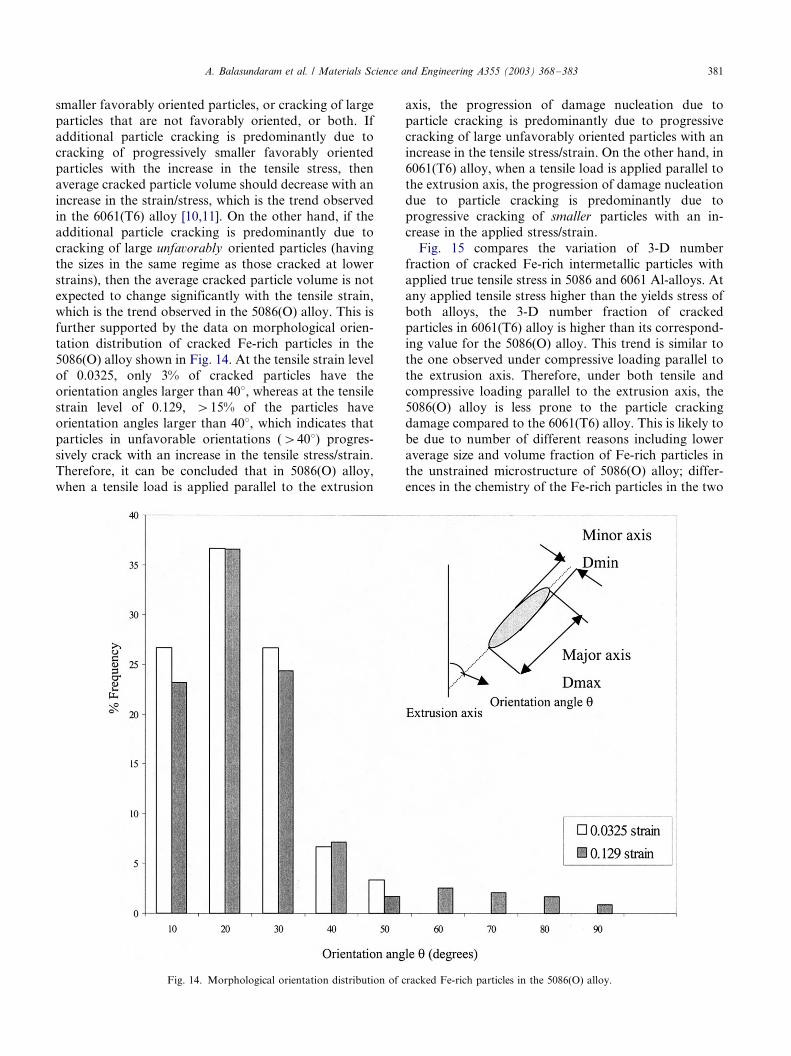
which is the trend observed in the 5086(O) alloy. This is
further supported by the data on morphological orien-
tation distribution of cracked Fe-rich particles in the
5086(O) alloy shown in Fig. 14. At the tensile strain level
of 0.0325, only 3% of cracked particles have the
orientation angles larger than 408, whereas at the tensile
strain level of 0.129, �/15% of the particles have
orientation angles larger than 408, which indicates that
particles in unfavorable orientations (�/408) progres-
sively crack with an increase in the tensile stress/strain.
Therefore, it can be concluded that in 5086(O) alloy,
when a tensile load is applied parallel to the extrusion
axis, the progression of damage nucleation due to
particle cracking is predominantly due to progressive
cracking of large unfavorably oriented particles with an
increase in the tensile stress/strain. On the other hand, in
6061(T6) alloy, when a tensile load is applied parallel to
the extrusion axis, the progression of damage nucleation
due to particle cracking is predominantly due to
progressive cracking of smaller particles with an in-
crease in the applied stress/strain.
Fig. 15 compares the variation of 3-D number
fraction of cracked Fe-rich intermetallic particles with
applied true tensile stress in 5086 and 6061 Al-alloys. At
any applied tensile stress higher than the yields stress of
both alloys, the 3-D number fraction of cracked
particles in 6061(T6) alloy is higher than its correspond-
ing value for the 5086(O) alloy. This trend is similar to
the one observed under compressive loading parallel to
the extrusion axis. Therefore, under both tensile and
compressive loading parallel to the extrusion axis, the
5086(O) alloy is less prone to the particle cracking
damage compared to the 6061(T6) alloy. This is likely to
be due to number of different reasons including lower
average size and volume fraction of Fe-rich particles in
the unstrained microstructure of 5086(O) alloy; differ-
ences in the chemistry of the Fe-rich particles in the two
Fig. 14. Morphological orientation distribution of cracked Fe-rich particles in the 5086(O) alloy.
A. Balasundaram et al. / Materials Science and Engineering A355 (2003) 368�/383 381
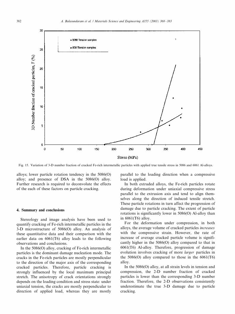
alloys; lower particle rotation tendency in the 5086(O)
alloy; and presence of DSA in the 5086(O) alloy.
Further research is required to deconvolute the effects
of the each of these factors on particle cracking.
4. Summary and conclusions
Stereology and image analysis have been used to
quantify cracking of Fe-rich intermetallic particles in the
3-D microstructure of 5086(O) alloy. An analysis of
these quantitative data and their comparison with the
earlier data on 6061(T6) alloy leads to the following
observations and conclusions.
In the 5086(O) alloy, cracking of Fe-rich intermetallic
particles is the dominant damage nucleation mode. The
cracks in the Fe-rich particles are mostly perpendicular
to the direction of the major axis of the corresponding
cracked particles. Therefore, particle cracking is
strongly influenced by the local maximum principal
stretch. The anisotropy of crack orientations strongly
depends on the loading condition and stress state: under
uniaxial tension, the cracks are mostly perpendicular to
direction of applied load, whereas they are mostly
parallel to the loading direction when a compressive
load is applied.
In both extruded alloys, the Fe-rich particles rotate
during deformation under uniaxial compressive stress
parallel to the extrusion axis and tend to align them-
selves along the direction of induced tensile stretch.
These particle rotations in turn affect the progression of
damage due to particle cracking. The extent of particle
rotations is significantly lower in 5086(O) Al-alloy than
in 6061(T6) alloy.
For the deformation under compression, in both
alloys, the average volume of cracked particles increases
with the compressive strain. However, the rate of
increase of average cracked particle volume is signifi-
cantly higher in the 5086(O) alloy compared to that in
6061(T6) Al-alloy. Therefore, progression of damage
evolution involves cracking of more larger particles in
the 5086(O) alloy compared to those in the 6061(T6)
alloy.In the 5086(O) alloy, at all strain levels in tension and
compression, the 2-D number fraction of cracked
particles is lower than the corresponding 3-D number
fraction. Therefore, the 2-D observations consistently
underestimate the true 3-D damage due to particle
cracking.
Fig. 15. Variation of 3-D number fraction of cracked Fe-rich intermetallic particles with applied true tensile stress in 5086 and 6061 Al-alloys.
A. Balasundaram et al. / Materials Science and Engineering A355 (2003) 368�/383382
At all tensile/compressive stress levels higher than the
yield stress of both alloys, the 3-D number fraction of
cracked particles in 5086(O) alloy is significantly lower
than the corresponding value in the 6061(T6) alloy.Therefore, 5086(O) alloy is less prone to particle
cracking damage than the 6061(T6) alloy.
Acknowledgements
This research was supported through grants fromSandia National Laboratories, Livermore CA and US
National Science Foundation (Grant No. DMR-
9816618). The financial support is gratefully acknowl-
edged. SG and MFH acknowledge financial support
from the US Department of Energy, Sandia National
Laboratories under contract DE-AC04-94AL85000.
References
[1] M.F. Horstemeyer, A.M. Gokhale, Int. J. Sol. Struct. 36 (1999)
5029.
[2] M.F. Horstemeyer, J. Lathrop, A.M. Gokhale, M. Dighe, Theor.
Appl. Fract. Mech. 33 (2000) 31.
[3] A.F. McClintock, ASME J. Appl. Mech. 35 (1968) 363.
[4] A.L. Gurson, in: D.M.R. Taplin (Ed.), Proceedings of the
International Conference on Fracture, vol. 2A, 1977, p. 357.
[5] E.E. Underwood, Quantitative Stereology, Addison-Wesley,
Reading, MA, 1970.
[6] J.-W. Yeh, W.-P. Liu, Metall. Trans. 27A (1996) 3558.
[7] R. Doglione, J.L. Douziech, C. Berdin, D. Francois, Mater. Sci.
For. (1996) 130.
[8] E.N. Pan, C.S. Lin, C.R. Loper, Am. Foundrym. Soc. Trans. 98
(1990) 735.
[9] J. Gurland, J. Plateau, Trans. ASM 56 (1963) 442.
[10] H. Agarwal, M.S. Thesis Dissertation, Georgia Institute of
Technology, 2001.
[11] H. Agarwal, A.M. Gokhale, S. Graham, M.F. Horstemeyer,
Metall. Mater. Trans. 33A (2002) 2599�/2606.
[12] M. Wagenhofer, M. Erickson, R.W. Armstrong, F.J. Zerilli, Scr.
Mater. 41 (1999) 1177.
[13] P. Louis, A.M. Gokhale, Metall. Mater. Trans. 26A (1995) 1449.
[14] H.B. Mcshane, C.P. Lee, T. Sheppard, Mater. Sci. Technol. 6
(1990) 428.
[15] D.C. Sterio, J. Microsc. 134 (1984) 127.
[16] A. Tewari, A.M. Gokhale, J. Microsc. 200 (2000) 227.
[17] A. Tewari, A.M. Gokhale, R.M. German, Acta Mater. 47 (1999)
3721.
[18] J. Polmear, Light Alloys: Metallurgy of Light Alloys, Halsted
Press, New York, 1996, p. 67.
[19] J.M. Robinson, M.P. Shaw, Internat. Mater. Rev. 39 (1994) 113.
[20] G.E. Dieter, Mechanical Metallurgy, McGraw-Hill, New York,
1988, p. 197.
[21] K.L. Murthy, C.S. Seok, J. Metal. 53 (2001) 23.
[22] H. Agarwal, A.M. Gokhale, S. Graham, M.F. Horstemeyer,
Mater. Sci. Eng. A328 (2002) 310.
[23] H. Agarwal, A.M. Gokhale, S. Graham, M.F. Horstemeyer, D.J.
Bamann, Mater. Sci. Eng. A328 (2002) 310�/316.
[24] A. Balasundaram, M.S. Dissertation, Georgia Institute of Tech-
nology, 2002.
A. Balasundaram et al. / Materials Science and Engineering A355 (2003) 368�/383 383