Environmental Stress Corrosion Cracking Resistance of High ...
59
University of Calgary PRISM: University of Calgary's Digital Repository Graduate Studies The Vault: Electronic Theses and Dissertations 2012-10-05 Environmental Stress Corrosion Cracking Resistance of High Density Polyethylene Pipes in Alkali Surfactant Polymer Floods Dooley, Colin Dooley, C. (2012). Environmental Stress Corrosion Cracking Resistance of High Density Polyethylene Pipes in Alkali Surfactant Polymer Floods (Unpublished master's thesis). University of Calgary, Calgary, AB. doi:10.11575/PRISM/25921 http://hdl.handle.net/11023/305 master thesis University of Calgary graduate students retain copyright ownership and moral rights for their thesis. You may use this material in any way that is permitted by the Copyright Act or through licensing that has been assigned to the document. For uses that are not allowable under copyright legislation or licensing, you are required to seek permission. Downloaded from PRISM: https://prism.ucalgary.ca
-
Upload
khangminh22 -
Category
Documents
-
view
1 -
download
0
Transcript of Environmental Stress Corrosion Cracking Resistance of High ...
University of Calgary
PRISM: University of Calgary's Digital Repository
Graduate Studies The Vault: Electronic Theses and Dissertations
2012-10-05
Environmental Stress Corrosion Cracking Resistance
of High Density Polyethylene Pipes in Alkali
Surfactant Polymer Floods
Dooley, Colin
Dooley, C. (2012). Environmental Stress Corrosion Cracking Resistance of High Density
Polyethylene Pipes in Alkali Surfactant Polymer Floods (Unpublished master's thesis). University
of Calgary, Calgary, AB. doi:10.11575/PRISM/25921
http://hdl.handle.net/11023/305
master thesis
University of Calgary graduate students retain copyright ownership and moral rights for their
thesis. You may use this material in any way that is permitted by the Copyright Act or through
licensing that has been assigned to the document. For uses that are not allowable under
copyright legislation or licensing, you are required to seek permission.
Downloaded from PRISM: https://prism.ucalgary.ca

UNIVERSITY OF CALGARY
Environmental Stress Corrosion Cracking Resistance of
High Density Polyethylene Pipes in Alkali Surfactant Polymer Floods
By
Colin Dooley, P.Eng
A THESIS
SUBMITTED TO THE FACULTY OF GRADUATE STUDIES
IN PARTIAL FULFILLMENT OF THE REQUIREENTS FOR THE
DEGREE OF MASTER OF ENGINEERING
Department of Mechanical and Manufacturing Engineering
CALGARY, ALBERTA
September 17, 2012
© Colin Dooley 2012

UNIVERSITY OF CALGARY
FACULTY OF GRADUATE STUDIES
The undersigned certify that they have read, and recommend to the Faculty of
Graduate Studies for Acceptance, a thesis entitled “Determination of Stress
Corrosion Cracking Resistance of High Density Polyethylene Pipes in Alkali
Surfactant Polymer Floods” submitted by Colin Dooley in partial fulfillment of the
requirements of the degree of Master of Engineering.
Supervisor, Yufeng (Frank) Cheng,
Department of Mechanical and Manufacturing Engineering
Dr. Raafat El-Hacha
Department of Civil Engineering (Internal External)
Dr. Leping Li
Department of Mechanical and Manufacturing Engineering
Dr. Simon Park
Department of Mechanical and Manufacturing Engineering
Date

i
ABSTRACT
Enhanced oil recovery (EOR) techniques such as alkali surfactant polymer (ASP)
flooding will be required to meet future energy requirements. Large pipeline
networks are required for the transportation of ASP fluids. To ensure the safe
and reliable operation of these pipelines, high density polyethylene (HDPE)
materials are frequently used due to its corrosion resistance from oil-field fluids.
Surfactant chemicals and other wetting agents are known to cause
environmental stress corrosion cracking (SCC) of polyethylene plastics. This
thesis studies the resistance of HDPE pipeline materials to environmental stress
corrosion cracking due to the exposure to ASP chemicals.
This research taken an industrial focus, as a result, test methods were selected
that closely represented actual pipeline conditions. Full scale HDPE pipe
samples were pressurized with a solution of alkali and surfactant chemicals
commonly used for ASP floods. Following conditioning, test specimens were
prepared from the pipe samples and subjected to tensile testing to investigate for
evidence of stress corrosion cracking. The results showed that conditioned
specimens had no significant degradation of the mechanical properties compared
to unconditioned samples.
Based on the test results, it is concluded that there is no evidence of
environmental SCC of the HDPE pipe materials due to pressurized exposure to
ASP fluids. Additional testing utilizing more severe accelerated test methods are
recommended to confirm the long-term resistance of HDPE materials in ASP
floods. Nevertheless, this work supports the empirical industry experience that
current HDPE pipeline materials are resistance to ASP chemicals. These
research results can be incorporated into current pipeline design and operating
procedures to ensure the safe and reliable operation of ASP systems.

ii
ACKNOLEDGEMENTS
It is a pleasure to thank those who made this thesis possible. I would like to
show my gratitude to my supervisor, Dr. Y.F. Cheng for his guidance throughout
the project. I would also like to express my gratitude towards my fellow graduate
student Zhong Li, without her continual effort and ingenuity in the laboratory this
thesis would not have been possible.
I am grateful to Husky Energy for supporting my Master’s Degree and providing
time and resources for this research project.
I am indebted to the National Science and Engineering Research Council of
Canada for their financial support of this project.
I would like to thank Flexpipe Systems for providing their support and results for
prior testing performed on HDPE in ASP service.
I would like to thank Flint Global Poly, Polytubes and WL Plastics for their
donation of HDPE pipe samples.

iii
TABLE OF CONTENTS
Approval Page ...................................................................................................... ii
Abstract ................................................................................................................ iii
Acknowledgments ................................................................................................ iv
Table of Contents ................................................................................................. v
List of Tables ........................................................................................................ vi
List of Figures ....................................................................................................... vi
1.0 Background Information ............................................................................... 1
1.1 Alkali Surfactant Polymer Flooding ...................................................... 1
1.2 Use of HDPE in Oil and Gas Pipelines ................................................ 1
1.3 HDPE Cracking in ASP Service .......................................................... 2
1.4 Objectives ............................................................................................ 3
1.5 Content of Thesis ................................................................................ 4
2.0 Literature Review ......................................................................................... 5
2.1 Polyethylene ........................................................................................ 5
2.2 Polyethylene and Pipelines ............................................................... 12
2.3 Chemicals Used in ASP Floods ......................................................... 16
2.4 Stress Corrosion Cracking (SCC) ...................................................... 19
2.5 Pipeline Performance in Alberta ........................................................ 20
3.0 Operator Qualification of HDPE in ASP Service ........................................ 25
3.1 Industry Testing of HDPE in ASP Fluid ............................................. 25
3.2 Analysis of Pipe Sample in ASP Service ........................................... 27
4.0 Experimental .............................................................................................. 29
4.1 Overview of Research Experiment .................................................... 29
4.2 Materials ............................................................................................ 30
4.3 Test Conditions ................................................................................. 31
4.4 Experimental Procedure .................................................................... 31
4.5 Tensile Testing .................................................................................. 33

iv
5.0 Results ....................................................................................................... 34
5.1 Stress Strain Curves ......................................................................... 34
5.2 Ultimate Tensile Strength .................................................................. 38
5.3 Elongation at Break ........................................................................... 39
6.0 Conclusions ............................................................................................... 42
7.0 Future Work ............................................................................................... 44
7.1 Testing Proposal ............................................................................... 44
7.2 Bent Strip Test (ASTM D1693) .......................................................... 45
7.3 Full-Notch Creep Test (ISO 16770) ................................................... 46
7.4 Future Testing of Other ASP Surfactants .......................................... 46
8.0 References ................................................................................................. 48

v
LIST OF TABLES
Table 2-1: Density Classifications for Polyethylene .............................................. 7
Table 2-2: Effects of Changes in Density and Molecular Weight Distribution ....... 9
Table 2-3: Material Physical Properties for Common HDPE Grades .................. 13
Table 2-4: PE 100+ Requirements Compared to European Standards .............. 14
Table 2-5: HDS and MRS for HDPE Pipe at 20oC .............................................. 14
Table 2-6: HDPE Pipe Environment Factor, fE.................................................... 15
Table 3-1: HDPE Tensile Properties from Pipeline Cut-Out ............................... 28
Table 4-1: HDPE Pipe Grades in Experiment ..................................................... 30
Table 4-2: Chemical Type and Concentrations in Experiment ............................ 30
Table 4-3: Test Pressure Based on HDPE Pipe Pressure Rating ...................... 31
Table 4-4: Summary of Failed 75oC Test Samples ............................................. 32
Table 5-1: Tensile Strength Comparison of Samples Conditioned at 25oC ........ 38
Table 5-2: Tensile Strength Comparison of Samples Conditioned at 75oC ........ 38
Table 5-3: Elongation at Break Comparison of Samples Conditioned at 25oC ... 40
Table 5-4: Elongation at Break Comparison of Samples Conditioned at 75oC ... 40

vi
LIST OF FIGURES
Figure 1-1: Free-Standing HDPE, Tight-Fit Liner and Composite Pipe ................ 1
Figure 1-2: Brittle Cracks on HDPE Liner (Magnification X100) ........................... 2
Figure 2-1: Diagram of Polymerization of Ethylene to Polyethylene ..................... 5
Figure 2-2: Chain Branching Structure of Polyethylene [PPI 2007]. ..................... 6
Figure 2-3: Polyethylene Molecular Weight Distributions [PI 2007] ...................... 8
Figure 2-4: Example Stress vs. Strain Curves for Polyethylene ......................... 10
Figure 2-5: pH Comparison of Common Alkaline Chemicals [Mayer 83] ............ 17
Figure 2-6: Molecular Structure of Sodium Dodecyl Sulfate Surfactant .............. 18
Figure 2-7: Three Conditions Required for SCC ................................................. 19
Figure 2-8: Pipeline Failures by Cause in Alberta from 1990-2005 [ERCB 05] .. 20
Figure 2-9: Average Frequency of Alberta Pipelines, 1990– 2005 [ERCB 05] ... 21
Figure 2-10: Pipeline Failure Frequency for Alberta, 2007 [CAPP 07] ................ 22
Figure 2-11: Reinforced Composite Failures by Cause [CAPP 07] .................... 23
Figure 3-1: Weight Change over Time for HDPE at 60oC in ASP Fluid [Ref]...... 26
Figure 3-2: Mechanical Properties of HDPE Samples Tested at 60oC [Ref] ....... 27
Figure 4-1: Pressurized HDPE Pipe Samples .................................................... 32
Figure 4-2: Test Specimen Dimensions .............................................................. 33
Figure 5-1: Stress-Strain Curve for Un-Soaked 3608 ......................................... 34
Figure 5-2:Stress-Strain Curve for Un-Soaked 4710 .......................................... 35
Figure 5-3: Stress-Strain Curve for Un-Soaked PE100+ .................................... 35
Figure 5-4: Stress-Strain Curve for 3608 Conditioned in ASP at 25oC ............... 36
Figure 5-5: Stress-Strain Curve for 4710 Conditioned in ASP at 25oC ............... 36

vii
Figure 5-6: Stress-Strain Curve for PE100+ Conditioned in ASP at 25oC .......... 37
Figure 5-7: Stress-Strain Curve for 3608 Conditioned in ASP at 75oC ............... 37
Figure 7-1: Bent Strip Test Sample, Holder and Test Assembly......................... 45

viii
LIST OF SYMBOLS, ABBREVIATIONS AND NOMENCLATURE
ABBREVIATON DEFINITION ASP Alkali surfactant polymer ASTM ASTM International EOR Enhanced oil recovery IFT Inter facial tension HDPE High density polyethylene HDS Hydrostatic design stress LDPE Low density polyethylene MOP Maximum Operating Pressure KOH Potassium hydroxide MRS Minimum required strength NaOH Sodium hydroxide NPS Nominal Pipe Size PE Polyethylene SCC Stress corrosion cracking SDR Standard dimension ratio SMYS Specified minimum yield strength %wt Weight percentage YS Yield Strength

1
1.0 BACKGROUND INFORMATION
1.1 Alkali Surfactant Polymer Flooding
Alkali surfactant polymer (ASP) flooding is an enhanced oil recovery (EOR)
process that is used to increase the amount of crude oil that can be extracted
from conventional oil reservoirs. Depending upon the reservoir characteristics
and applicable EOR process, an additional 10% - 30% of the in-situ oil can be
recovered compared to primary or secondary recovery methods [EPRI, 1999].
In the ASP process, low concentrations of an alkali chemical (e.g. NaOH, KOH)
and surfactant are injected into the reservoir. The surfactant is used to achieve
ultra-low interfacial tension between the trapped oil and the formation water. The
ultra-low interfacial tension allows the alkali in the injection fluid to deeply
penetrate the formation and react with the acidic components in the crude oil to
form additional in-situ surfactants. Polymer is sometimes added to increase the
viscosity of the injection fluid to minimize channeling and provide mobility control.
1.2 Use of HDPE in Oil and Gas Pipelines
Due to its corrosion resistance, high density polyethylene (HDPE) is commonly
used in upstream pipelines (Figure 1-1). HDPE is used in in three forms:
• Free standing HDPE pipelines
• Steel pipelines fitted with tight-fit HDPE liners
• Spoolable composite pipelines with internal HDPE liner
Figure 1-1: Free-Standing HDPE, Tight-Fit Liner and Composite Pipe

2
1.3 HDPE Cracking in ASP Service
Due to unrelated issues, a tight-fit HDPE liner was removed by an operator from
a steel ASP injection pipeline. Samples were sent to an independent third party
consultant for analysis. Microscopic examination from one of the samples
revealed the presence of a number of very tight cracks along the internal liner
surface, as seen in Figure 1-2. The consultant could not ascertain the cause of
the cracking.
Figure 1-2 Cracks on HDPE Liner (Magnification X100)
Historically, the pipeline operator had not observed this type of cracking in
pipelines that transported fluids other than ASP. If the observed cracking in the
HDPE was due to ASP fluids, it would lead to premature failure of the pipelines.
Cracking in a free-standing HDPE pipeline would concentrate the circumferential
hoop stress at the crack tip leading to failure once the crack grew to critical size.
Through-wall cracking of internal liners in tight-fit steel pipelines and spoolable
composite would lead to premature pipeline failures by allowing the ASP fluid to
contact the pressure containing steel pipe or reinforcing fibreglass layers.

3
For pipelines with tight-fit HDPE liners, the carrier pipes are constructed from low
alloy carbon steel. ASP injection fluid is typically transported at 20oC – 60oC with
a pH of from 12.5 - 14. Under these operating conditions, the steel carrier pipe
would be susceptible to caustic corrosion (API RP579, 2011), which would lead
to premature failure of the pipeline.
Spoolable composite pipelines are constructed with reinforcing layers of varying
materials from fibreglass to steel. Through-wall cracking of HDPE liners in
composites with steel reinforcing layers would lead to caustic corrosion of the
steel reinforcing layer. Through-wall cracking of HDPE liners in composites with
fibre reinforcing layers may result in the saturation of fibres. The strength of
some spoolable composite pipe systems is severely diminished if the fibreglass
layers are exposed to moisture.
The small number of ASP systems in North America and limited experience with
HDPE materials in ASP service suggests that a single finding of HDPE cracking
should be examined closely to better understand potential SCC mechanisms. If
the presence of ASP fluids induces cracking in HDPE materials it will result in
premature pipeline failures. Safe and reliable pipeline networks are critical to the
effective use of EOR methods such as ASP flooding. A better understanding of
HDPE compatibility with ASP fluids is required by industry for the successful
design, operation, and integrity management of pipeline systems.
1.4 Objectives
The primary objective of this research was to determine the environmental stress
corrosion cracking resistance of HDPE pipe in ASP service. Due to the industrial
application of the research, the test methods had to closely resemble actual
pipeline operating conditions and render results that were directly relatable to
current operating pipeline systems.
4
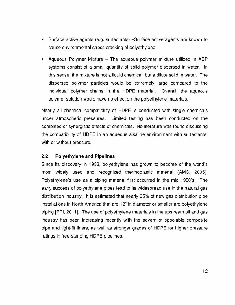
1.5 Content of Thesis
The thesis contains the following main sections:
• Literature Review
• Operator Qualification of HDPE in ASP Service
• Experimental
• Results
• Conclusions
• Future Work
The literature review examines the current state of knowledge regarding the use
of and potential damage mechanisms of HDPE materials in a combined
environment of alkali and surfactant. The literature review showed that
surfactant chemicals are known to cause environmental stress corrosion cracking
in HDPE. However, no research was found that tested the cracking resistance of
HDPE pipe in ASP Service.
The next section presents non-public testing results completed by a pipe
manufacturer for a Western Canadian oil and gas company that was constructing
as ASP system. The test results showed no degradation of the HDPE material in
ASP fluids. However, the test specimens were not subject to any tensile stress
during testing. As a result, the testing performed did not adequately test the
resistance of the material to environmental stress corrosion cracking.
The experimental section presents the test methods, materials, conditions and
equipment utilized to evaluate the stress corrosion cracking resistance of HDPE
in ASP service. Testing was conducted utilizing full scale pipe samples under
conditions that were representative of actual pipeline operating conditions.
Following conditioning, the samples were subjected to mechanical testing
utilizing a tensile tester to investigate for the presence of SCC.
Finally, the results, conclusions and recommendations for future work are
outlined in the remaining sections.

5
2.0 LITERATURE REVIEW
2.1 Polyethylene
Polymers are large molecule formed by the polymerization (i.e. the chemical
linking) or repeating of small molecular units. Polyethylene is generally formed
by the polymerization of ethylene (Figure 2-1). Ethylene can also be
copolymerized with small amount of other monomers such as butane, propylene,
hexane, and octane, which result in small modifications in chemical structure
which are reflected in differences in material properties such as density, ductility,
hardness, etc.
Figure 2-1: Diagram of Polymerization of Ethylene to Polyethylene
2.1.1 Branching
The amount of side branching determines the density of the polyethylene
molecule. The more side branches, the lower the density. Controlled branching
results in improved performance where certain types of stresses are involved.
Figure 2-2 depicts the various molecular structures associated with the four main
classifications of polyethylene:
• PE homopolymer
• PE copolymer
• High Pressure LDPE
• Linear LDPE

6
Figure 2-2: Chain Branching Structure of Polyethylene [PPI 2007].
2.1.2 Crystalline Structure
The relationship between branching and density can be explained in terms of
crystalline versus non-crystalline or amorphous regions. Portions of the polymer
chain in certain regions align themselves in closely packed and very well ordered
arrangements of polyhedral-shaped, microscopic crystals called spherulites.
Other portions of the polymer chain lie in amorphous regions that have no
definite molecular arrangement. Since polyethylene contains both crystalline and
amorphous regions, it is called a semi-crystalline material. High density
polyethylene grades can contain up to 90% crystalline regions compared to 40%
for low density polyethylene.

7
2.1.3 Density
Polyethylene pipe in North America is generally classified by its density in
accordance with ASTM D3350 (Table 2-1). In Europe, polyethylene pipe is
generally classified by performance, generally tensile strength. This classification
is beginning to emerge in North America; however, classification by density is still
the most common.
Table 2-1: Density Classifications for Polyethylene
Type Density Class
I 0.910 – 0.925 Low
II 0.926 – 0.940 Medium
III 0.941 – 0.959 High
IV ≥ 0.960 High or Homopolymer
High density polyethylene is chemically the closet in structure to pure
polyethylene. It consists primarily of unbranched molecules with very few flaws
to impair its linearity. With a low level of flaws to hinder organization, the resins
achieve a high degree of crystallinity resulting in a high density relative to other
types of polyethylene.
Low density polyethylene contains substantial concentrations of branches that
hinder the crystallization process, resulting in relatively low densities. The
branches primarily consist of ethyl and butyl group with some long chain
branches. Medium density polyethylene contains a level of crystallization and
branching between high density and low density polyethylene.

8
2.1.4 Molecular Weight Distribution
The size of a polymer molecule is represented by is molecular weight. Molecular
weights exert a great influence on the processability and the final physical and
mechanical properties of the polymer. During the production of polyethylene, not
all molecules grow to the same length. As a result, the molecular weight is a
distribution and often expressed as an average value.
The distribution of different sized molecules in a polyethylene polymer typically
follows the bell shaped normal distribution curve described by the Gaussian
probability theory. Polymers can also have bimodal shaped distribution curves
which depict a blend of two different polymer populations, each with its particular
average and distribution. Resins having a bimodal molecular weight distribution
contain both very short and very long molecules, resulting in excellent resin
physical properties while maintaining good processability. Figure 2-3 shows the
difference in thee distributions.
Figure 2-3: Polyethylene Molecular Weight Distributions [PI 2007]

9
The latest generation of North American HDPE pipe materials (e.g. PE4710) are
typically produced from bimodal resins. These materials are characterized by
improved resistance to slow crack growth, higher pressure ratings and improved
chemical resistance.
Molecular weight distribution (MWD) is dependent upon the type of process used
to manufacture the particular polyethylene resin. The effects of density and
molecular weight distribution on physical properties are summarized in Table 2-2.
Table 2-2: Effects of Changes in Density and Molecular Weight Distribution
Property As Density Increases
As MWD Broadens
Yield Strength Increases Varies
Stiffness Increases Decreases
Impact Strength Decreases Decreases
Low Temperature Brittleness Increases Decreases
Hardness Increases Varies
Stress Crack Resistance Decreases Increases
Chemical Resistance Increases Varies
Shrinkage Decreases Increases
2.1.5 Tensile Strength
A traditional means for determining the strength of materials has been the tensile
test, by which the stress / strain behaviour of the material of interest is evaluated
under a constant strain rate. Because of its viscoelastic nature, polyethylene
does exhibit a true elastic region. As illustrated in Figure 2-4, polyethylene
exhibits a yield point in the tensile test. Increasing the strain further results in
irreversible yielding of the material until failure is achieved at the ultimate
strength of the material. Also, as is illustrated by Figure 2-4 the stress strain
curve is significantly affected by the rate of straining.

10
Figure 2-4: Example Stress vs. Strain Curves for Polyethylene [PI 2007]

11
2.1.6 Chemical Resistance
The chemical resistance of solid materials is often defined as the ability of the
material to resist damage or degradation by chemical reactivity or solvent action.
Generally, polyethylene is widely recognized for its unique chemical resistance to
a wide variety of chemicals.
A comprehensive chemical resistance chart for polyethylene has been published
by the Plastics Pipe Institute (PPI) in the Handbook of Polyethylene Pipe (PPI
2009). It is important to note that these chemical resistance tables are only a
guideline. Chemical resistance data, including those provided in the handbook,
are generally developed on the basis of laboratory tests involving the evaluation
of tensile coupons in the presence of a single chemical at atmospheric pressure.
As such, they do not assess the effect produced by exposure to various
combinations of chemicals listed. Additionally, these chemical resistance tables
do not take into consideration the effect of stress loading, magnitude or duration.
A preliminary measure of the potential effects of chemicals on the properties of
polyethylene is by means of a “soak” or “chemical immersion” test in which the
polyethylene is not subjected to any stresses. In this type of laboratory test, strips
of PE material are soaked for different periods of time – generally, not longer
than a month – in the medium of interest, which is maintained at a specified
temperature. After certain soaking periods, changes are noted in appearance,
dimensions, weight gain or loss, and in strength properties – generally, tensile
strength at yield or elongation at break.
The chemical resistance of HDPE to ASP fluids is generally understood to be:
• Aqueous solutions of salts, acids, bases – Because polyethylene is virtually
immune to electrolytic attack these solutions have no adverse effect. Nearly
all manufacturers list the chemical resistance of HDPE to strong salts, acids,
and bases such as sodium hydroxide as excellent.
12
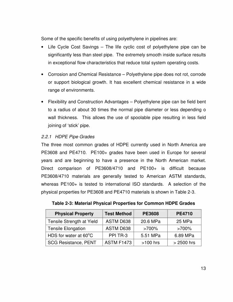
• Surface active agents (e.g. surfactants) –Surface active agents are known to
cause environmental stress cracking of polyethylene.
• Aqueous Polymer Mixture – The aqueous polymer mixture utilized in ASP
systems consist of a small quantity of solid polymer dispersed in water. In
this sense, the mixture is not a liquid chemical, but a dilute solid in water. The
dispersed polymer particles would be extremely large compared to the
individual polymer chains in the HDPE material. Overall, the aqueous
polymer solution would have no effect on the polyethylene materials.
Nearly all chemical compatibility of HDPE is conducted with single chemicals
under atmospheric pressures. Limited testing has been conducted on the
combined or synergistic effects of chemicals. No literature was found discussing
the compatibility of HDPE in an aqueous alkaline environment with surfactants,
with or without pressure.
2.2 Polyethylene and Pipelines
Since its discovery in 1933, polyethylene has grown to become of the world’s
most widely used and recognized thermoplastic material (AMC, 2005).
Polyethylene’s use as a piping material first occurred in the mid 1950’s. The
early success of polyethylene pipes lead to its widespread use in the natural gas
distribution industry. It is estimated that nearly 95% of new gas distribution pipe
installations in North America that are 12” in diameter or smaller are polyethylene
piping [PPI, 2011]. The use of polyethylene materials in the upstream oil and gas
industry has been increasing recently with the advent of spoolable composite
pipe and tight-fit liners, as well as stronger grades of HDPE for higher pressure
ratings in free-standing HDPE pipelines.
13
Some of the specific benefits of using polyethylene in pipelines are:
• Life Cycle Cost Savings – The life cyclic cost of polyethylene pipe can be
significantly less than steel pipe. The extremely smooth inside surface results
in exceptional flow characteristics that reduce total system operating costs.
• Corrosion and Chemical Resistance – Polyethylene pipe does not rot, corrode
or support biological growth. It has excellent chemical resistance in a wide
range of environments.
• Flexibility and Construction Advantages – Polyethylene pipe can be field bent
to a radius of about 30 times the normal pipe diameter or less depending o
wall thickness. This allows the use of spoolable pipe resulting in less field
joining of ‘stick’ pipe.
2.2.1 HDPE Pipe Grades
The three most common grades of HDPE currently used in North America are
PE3608 and PE4710. PE100+ grades have been used in Europe for several
years and are beginning to have a presence in the North American market.
Direct comparison of PE3608/4710 and PE100+ is difficult because
PE3608/4710 materials are generally tested to American ASTM standards,
whereas PE100+ is tested to international ISO standards. A selection of the
physical properties for PE3608 and PE4710 materials is shown in Table 2-3.
Table 2-3: Material Physical Properties for Common HDPE Grades
Physical Property Test Method PE3608 PE4710
Tensile Strength at Yield ASTM D638 20.6 MPa 25 MPa
Tensile Elongation ASTM D638 >700% >700%
HDS for water at 60oC PPI TR-3 5.51 MPa 6.89 MPa
SCG Resistance, PENT ASTM F1473 >100 hrs > 2500 hrs

14
The primary difference between PE100+ grades and traditional HDPE grades is
the creep rupture strength, stress crack resistance and resistance to rapid crack
propagation (PE100+ Association, 2012). North American ASTM standards for
HDPE are at a lower level compared to European or ISO HDPE standards. The
PE100+ testing requirements are shown in Table 2-4.
Table 2-4: PE 100+ Requirements Compared to European Standards
Physical Property Test Method CEN/ISO
Requirement PE100+
Requirement
Creep Rupture Strength
Pressure test at 20oC and 12.4 MPa
≥ 100 hrs ≥ 200 hrs
Stress Crack Resistance
Pipe notch test at 80oC and 0.92 MPa
≥ 165 hrs ≥ 500 hrs
Resistance to Rapid Crack Propagation
S4 Test a 0oC 18
13
4.2−≥
MOPPC ≥ 1.0 MPa
2.2.2 Pressure Rating of HDPE Pipe
Polyethylene is different than other common pipeline materials because its
strength under load depends on the magnitude and the duration of the load. In
North America, Hydrostatic Design Stress (HDS) ratings for long-term internal
pressure service are determined in accordance with ASTM D1598 and PPI TR-3
standards. Outside of North America and for PE100+ grades, the Minimum
Required Strength (MRS) is determined in accordance with ISO 12162.
Table 2-5: HDS and MRS for HDPE Pipe at 20oC
HDPE Grade HDS
(MPa) MRS (MPa)
PE3608 5.8 ---
PE4710 7.1 ---
PE100+ --- 10

15
Industrial pressure rating for HDPE pipe is calculated based on a combination of
PE grade, diameter, wall thickness, temperature and internal fluid. The following
equation is used to determine the long-term internal pressure rating:
( )1
2
−
⋅⋅⋅=
SDR
ffHDSPR TE
Where:
PR Pressure Rating
HDS Hydrostatic design stress (MRS may be substituted)
fE Environment Design Factor
fT Operating Temperature Multiplier
SDR Standard Dimension Ratio
For a pressurized fluid inside the pipe or for a chemically significant environment
outside the pipe, an environmental factor (fE) is applied to reduce the pressure
rating of the HDPE Pipe (Table 2-6).
Table 2-6: HDPE Pipe Environment Factor, fE
fE Fluid and Environmental Comments
1.00
Internal liquids, gases and external soils or liquids that are chemically benign to polyethylene such as water, sewage, brine solutions, glycol, alcohols, dry natural gas, landfill gas, nitrogen, air, oxygen, carbon dioxide, and hydrogen sulfide
0.80 Buried distribution, transmission or gathering systems for Canadian Federal and Provincial regulated fuel gases such as natural gas, LP gas, propane, butane, landfill gas
0.64 Buried distribution, gathering or transmission systems for US Federal and State regulated dry fuel gases such as natural gas, LP gas, propane, butane, and landfill gas
0.50 Multi-phase fluids, wet natural gas, and liquids containing >2% permeating or solvating liquids in the pipe or surrounding soil such as hydrocarbons (gasoline, fuel oil, kerosene, crude oil, diesel fuel)

16
For distribution and transmission of liquids such as water or water-born slurries,
surge pressure allowances are applied above the pipe pressure rating.
Occasional pressure surges typically result from instantaneous liquid velocity
changes from component failure. Recurring pressure surges typically result from
cyclical events such as pump or system control operation or regularly occurring
system draws. Pressure surge allowance is provided for occasional or recurring
pressure surges using the following equations:
PRP
PRP
RS
OS
×=
×=
50.0
00.1
Where:
POS = Surge pressure allowance for occasional surge
PRS = Surge pressure allowance for recurring surge
2.3 Chemicals Used in ASP Floods
2.3.1 Alkali
Several different alkaline agents have been used in ASP flooding including
sodium hydroxide, sodium orthosilicate, sodium carbonate, ammonium hydroxide
and ammonium carbonate (Gogarty, W.B., 1983). The first three have been the
most widely considered because of their widespread availability, relatively low
cost and effective performance in ASP laboratory studies.
Addition of alkali chemicals results in an increase in pH because of the
dissociation in the aqueous phase. For example, sodium hydroxide (NaOH)
disassociates to yield [OH-] as follows:
−++→ OHNaNaOH
Equilibrium dissociation of water is given by:
][
]][[
2OH
HOHK
+−
=

17
Where brackets indicate molar concentration and an increase in [OH-] causes a
decrease in [H+]. Since the concentration of water is essentially constant pH is
defined as:
][log10
+−= HpH
Therefore, if the concentration of [OH-] increases, the [H+] decreases and the pH
increases resulting in a more basic environment.
Sodium carbonate disassociates into carbonate as:
−++→
2
332 2 CONaCONa
Followed by the hydrolysis reaction:
−−−+→+ OHHCOOHCO 32
2
3
The dissociation of sodium silicate compounds is complete, involving formation of
oligomeric species. Consequently, cannot be represented by a single chemical
equation. Figure 2-5 compares several commonly used alkaline materials
(Mayer. et al, 1983).
Figure 2-5: pH Comparison of Common Alkaline Chemicals [Mayer 83]

18
2.3.2 Surfactants
Surface active agents, or surfactants, are chemical substances that adsorb on or
concentrate at a surface or fluid/fluid interface when present at low
concentrations in a system [Rosen, 1978]. They alter the interfacial properties
significantly; in particular, they decrease the interfacial surface tension, or IFT.
Surfactants usually consist of a hydrocarbon portion (nonpolar) and a polar or
ionic portion.
The nonpolar or tail end of a surfactant is hydrophobic. Conversely, the polar or
head end interacts strongly with water molecules, undergoing solvation. This
part of the surfactant is hydrophilic. Basically, it is the balance between the
hydrophilic and hydrophobic parts of a surfactant that gives it the characteristics
associated with a surface active agent.
Surfactants may be classified according to the ionic nature of the head group as
anion, cationic, non-ionic and zwitterionic [Ottewill, 1984]. Anionic surfactants
have been the most widely used in EOR processes because they have good
surfactant properties, are relatively stable, exhibit relatively low adsorption on
reservoir rock, and can be manufactured economically. The most common
surfactants used in ASP flooding are sulfonated hydrocarbons. The molecular
structure of a common anionic sulfonated surfactant used in ASP systems is
shown in Figure 2-6.
Figure 2-6: Molecular Structure of Sodium Dodecyl Sulfate Surfactant

19
2.3.3 Polymers
Low concentrations of polymers are sometimes added to the injection water to
reduce channelling and improve sweep efficiencies in ASP flood. Under
formation or process conditions the injected polymer is inert and is used solely as
a viscosity thickening agent. The polymer is chemically inert and does not react
chemically with the formation fluids, injected alkali, surfactant, or HDPE in the
pipeline gathering system.
2.4 Stress Corrosion Cracking (SCC)
Stress corrosion cracking is the cracking of a material produced by the combined
action of corrosion and tensile stress (residual or applied). Three conditions
must be present simultaneously to produce SCC; critical environment,
susceptible material and tensile stress (Figure 2-7).
Figure 2-7: Three Conditions Required for SCC
The critical environment is often specific to the material and may not have an
effect on other material types. For example, hot aqueous chloride solutions
readily crack stainless steels, but do not have the same effect on carbon steels,
Critical Environment
Tensile Stress
Susceptible Material

20
aluminum, or other nonferrous alloys. For polyethylene materials, surface active
agents such as surfactants have been known to induce stress corrosion cracking.
It is important to note that cracking of polyethylene under the effect of wetting
agents starts under stresses far below the allowable proof stress of the material.
2.5 Pipeline Performance in Alberta
At the end of 2005 there were over 377,000 kilometres of energy related
pipelines in Alberta (ERCB, 2007). During the period from 1990 to 2005, there
were 12,191 pipeline failures in Alberta. Internal corrosion is the prevalent cause
of pipeline failures during this period representing 57.7% of all releases (Figure
2-8).
Figure 2-8: Pipeline Failures by Cause in Alberta from 1990-2005 [ERCB 05]

21
2.5.1 Pipeline Failure Frequency
The average frequency of pipeline incidents in Alberta declined steadily from
1990 through 2005 (see Figure 2-9). The ERCB is continuing to look for ways to
improve pipeline performance with emphasis on new corrosion-resistant
composite and polymeric pipelines. The vast majority of these new pipeline
materials utilized HDPE as an internal liner or bladder. The ERCB expects
growth in the installation of non-metallic pipelines in the future (ERCB, 2007).
Figure 2-9: Average Frequency of Alberta Pipelines, 1990– 2005 [ERCB 05]
Nu
mb
er
of In
cid
en
ts p
er
10
00
km
of P
ipelin
e
1990 1992 1994 1996 1998 2000 2002 2004

22
2.5.2 Performance of Non-Metallic Pipelines in Alberta
In 2007, an analysis of pipeline failure statistics was performed and presented at
a pipeline symposium held in Banff, Alberta [CAPP, 2009]. The analysis showed
a relatively high incident rate with reinforced composite pipelines, with fibreglass
pipelines having particular high failure rate (Figure 2-10).
Figure 2-10: Pipeline Failure Frequency for Alberta, 2007 [CAPP 07]
Figure 2-11 provides a summary of reinforced composite pipeline failures in
Alberta by cause from 2002 to 2007. The data indicates that the most common
and reoccurring causes of failures include:
• Damage from construction or installation
• Corrosion of associated steel pipe risers and fittings
• Damage by others (third party damage)
• Mechanical failures of valves or fittings

23
Figure 2-11: Reinforced Composite Failures by Cause [CAPP 07]
2.5.3 Factors in Non-Metallic Pipeline Failures
Based on experience in the pipeline industry in Western Canada, it can be
inferred that the high failure rate associated with reinforced composite pipelines
and other non-metallic pipe systems can be largely attributed to the lack of
industry experience in North America in designing, constructing and operating
pipelines that are not constructed from steel.
Steel pipelines have been constructed since the late 1800’s and early 1900’s.
As a result, there is a large depth of knowledge and experience related to the
design, construction and operation of steel pipelines. The codes and regulations
governing steel pipelines are mature representing the collection of knowledge
gained from more than a century of operating hundreds of thousands of
kilometers of steel pipelines.

24
In contrast, non-metallic pipelines containing HDPE materials (e.g. liners,
spoolable composites) have only been used by the oil and gas industry for the
past 10 – 15 years1. Many of the failures associated with non-metallic pipelines
are believed to be related to “growing pains” often associated with the adoption
of a new materials or technologies. The lessons learned by industry from these
failures will be incorporated into the next generation of non-metallic pipeline
codes and regulations to prevent similar occurrences. As the industry matures, it
is expected that the failure rate associated with non-metallic pipelines will
decrease over time.
However, the high failure rate associated with non-metallic pipelines coupled with
the relative lack of industry experience and knowledge (compared to the steel
pipeline industry), highlights the need to increase the collective knowledge and
understanding of the complete life cycle of non-metallic pipelines. Moreover, with
the increased utilization of new enhanced oil recovery methods, non-metallic
pipelines systems will be required to operate in unfamiliar conditions with new
operating parameters and production fluids that must also be understood.
1 Free-standing HDPE pipelines have been used by the low pressure natural gas distribution
industry since the 1970’s. However, due to their very low operating pressures, the low pressure
systems do not face the same challenges as seen in the upstream oil and gas industry. Many of
the non-metallic pipeline failures experienced by upstream oil and gas pipelines do not occur in
the natural gas distribution industry due to their low operating pressures and small pipe
diameters.

25
3.0 OPERATOR QUALIFICATION OF HDPE IN ASP SERVICE
To qualify the suitability of HDPE for use in ASP pipelines, the pipeline operator
requested that the pipe manufacturer conduct testing of the HDPE pipe material
in ASP chemicals (Section 3.1). Following operation of the ASP pipeline system,
a section of a reinforced composite pipeline was removed and analyzed to
determine if it had degraded as a result of the ASP service (Section 3.2).
3.1 Industry Testing of HDPE in ASP Fluid
Six (6) dumbbell specimens of HDPE were immersed in a glass bottle containing
ASP Fluid supplied by the Company. The bottle was sealed to avoid any
evaporation and kept in a controlled environment at 60oC for three months.
All samples were weighed once a week for the first month using a high-accuracy
balance with an accuracy of 0.01 grams. After weighing, all samples were
immediately immersed back into the fluid. No significant weight gain or loss was
observed during the three month exposure period (see Figure 3-1). In the first
week approximately 1%wt loss was noticed. The reason for this weight loss is
unknown. In the three (3) month period, all specimens gains around 0.4%wt.
This amount of weight gain is considered minimal in comparison to weight gain
from other fluids common to the oil and gas industry such as crude oil or
aromatics.

26
Figure 3-1: Weight Change over Time for HDPE at 60oC in ASP Fluid [Ref]
The mechanical properties of the immersed specimens were tested at 60oC and
compared with the properties of the unexposed material. Mechanical properties
decreased slightly following exposure (see Figure 3-2). The decrease in
mechanical properties is consistent with immersion tests conducted with water at
60oC and is not attributed to the presence of ASP fluid.

27
Figure 3-2: Mechanical Properties of HDPE Samples Tested at 60oC [Ref]
3.2 Analysis of Pipe Sample in ASP Service
A section of pipe transporting oil effluent and diluted ASP fluid was cut-out and
analyzed. The pipeline was operating at 1.0 MPa, 10oC and a pH of 11.7.
Undiluted ASP fluid typically has a pH ranging from 12 – 14. The pipeline had
been in service for approximately four years.
Tensile testing on HDPE specimens removed from the pipeline was conducted in
accordance with ASTM D638. The yield strength and elongation at break for
these specimens were marginally lower than typical values reported on the resin
manufacturer data sheets for this material (see Table 3-1). However, these pipe
samples are manufactured from an extrusion process. Polyethylene
manufactured from extrusion processes are known to have slightly lower physical
properties than resin samples made from compression molded processes, as
used by resin manufactures for the purpose of publishing data sheets.

28
Moreover, the results are comparable to other pipe cut-outs previously conducted
in non-ASP service conditions. Hence, hence it is believed that the decrease in
tensile strength is caused by a combination of aqueous immersion and
manufacturing method, not from the presence of ASP chemicals.
Table 3-1: HDPE Tensile Properties from Pipeline Cut-Out
Description Yield
Stress (MPa)
Elongation at Break
(%)
Elastic Modulus
(MPa)
Average Specimen Values 20.2 797 572
Resin Manufacturer Datasheet 22.4 850 760 - 860
The decrease in tensile elastic modulus was greater compared to the drop in
yield strength and elongation at break (see Table 3-1). However, this result
compares favourably with the drop in tensile modulus that is considered
acceptable in other service conditions such as those with high aromatic
hydrocarbon contents. Thus, the HDPE is considered to be in good condition
and well able to perform a non-structural role of fluid bladder.

29
4.0 EXPERIMENTAL
A review of the chemical resistance of HDPE shows that surface active agents
such as surfactants have been known to cause environmentally stress corrosion
cracking (SCC) of polyethylene. However, the qualification testing performed by
the pipe manufacturer did not apply any tensile stress to the test specimens.
Without the application of tensile stress, one of the three necessary conditions for
stress corrosion cracking was not present. Hence, the qualification tests did not
evaluate the stress corrosion cracking resistance of the HDPE to the ASP
chemicals. The aim of this research is to test the HDPE materials in an overall
environment that susceptible to stress corrosion cracking. Therefore, the HDPE
will be tested in ASP chemicals while applying a tensile stress.
4.1 Overview of Research Experiment
The purpose of these experiments is to determine the resistance of common
pipeline HDPE grades to environmental stress corrosion cracking in an aqueous
alkaline environment containing surfactant commonly used in ASP floods.
Different HDPE pipe samples were filled with an alkali and surfactant mixture
representative of ASP flood conditions. To apply a circumferential tensile stress,
the samples were pressurized to the maximum pressure rating of the respective
pipe and set in a controlled temperature environment. After the pressurized
immersion testing the mechanical properties of the HDPE were evaluated using a
tensile tester. The testing results were compared to native HDPE pipe samples
to determine the effect of the ASP chemicals in a stressed state.

30
4.2 Materials
4.2.1 HDPE Pipe Samples
Tests were conducted on three HDPE pipe grades (see Table 4-1). All pipe
materials used in this experiment were donated and subject to availability from
the pipe manufacturers.
Table 4-1: HDPE Pipe Grades in Experiment
Grade Diameter SDR
PE3608 NPS 4 17
PE4710 NPS 4 17
PE100+ NPS 3 11
4.2.2 Chemicals
Tests were conducted in distilled water with the addition of an alkali and
surfactant commonly used in Western Canadian ASP floods (see Table 4-2).
Petrostep S-1 is the trade name for an anionic surfactant with the chemical
description C16-17 – 7PO – SO4. Note, the structure does not indicate the degree
to which the surfactant branches.
Table 4-2: Chemical Type and Concentrations in Experiment
Description Chemical Concentration
Alkali Sodium hydroxide (NaOH) 1.5%
Surfactant Stepan Petrostep S-1 0.5%
The polymer component the ASP flood was not added to the test mixture for a
combination of reasons. First and foremost, as polymer is an inert solid material
that is dispersed in the solution, it should have no chemical effect on the HDPE.
Second the polymer solution is difficult to produce, requiring several grinding and
blending steps. Based on the production difficulties and lack of mechanism that
could damage the HDPE it was not included.

31
4.3 Test Conditions
4.3.1 Temperature
The maximum operating temperature of most HDPE pipe is 60oC, with most ASP
flood systems operating between 15oC – 40oC. In this experiment, HDPE pipe
samples were testing at 25oC (room temperature) and 75oC, with the 75oC test
being more severe than actual ASP system conditions.
4.3.2 Pressure
The experiment was conducted at the applicable pressure rating for the HDPE
pipe sample with no de-rating for environment or surging (i.e. fE = 1, PR = PRS).
Due to the discrepancy between standards for the PE3608/4710 and PE100+
grades, the hydrostatic design stress (HDS) of PE4710 was utilized for PE100+
because of safety considerations. Although this likely resulted in a lower stress
in the PE100+ pipe sample, the stress is still higher then would be allowed in
ASP service due to environmental de-rating factor (fE) as required by Canadian
pipeline regulations and codes. Test Pressures for the applicable pipe samples
are shown in Table 4-3.
Table 4-3: Test Pressure Based on HDPE Pipe Pressure Rating
HDPE Grade
Pressure (kPa)
25oC 75oC
PE3608 670 240
PE4710 845 420
PE100+ 1340 675
4.4 Experimental Procedure
The HDPE pipe samples were filled with the ASP solution, mounted in a pressure
containing aluminum jig assembly and pressurized to the respective test
pressure (see Figure 4-1). The 75oC samples were placed in a controlled
temperature oven (25oC were left at room temperature). All the samples were

32
left pressurized for a period of three months. The samples were routinely
checked to ensure the samples remaining pressurized.
Figure 4-1: Pressurized HDPE Pipe Samples
During immersion testing, the pressure retraining seals failed on two of the three
HDPE pipe samples that were being tested at 75oC (Table 4-4). As a result,
these samples had to be discarded. Additional attempts to improve the seal at
75oC were unsuccessful.
Table 4-4: Summary of Failed 75oC Test Samples
HDPE Result Comments
PE3608 Good Test Test sample remained pressurized for 3 months
PE4710 Seal Failure Seal failed resulting in loss of pressure
PE100+ Seal Failure Seal failed resulting in loss of pressure

33
4.5 Tensile Testing
Tensile testing of the HDPE pipe samples was completed using a BOSE 10 Kip
SmartTest Servopneumatic Fatigue Test System in accordance with ASTM
D638-03 “Standard Test Method for Tensile Properties of Plastics”.
Test specimens were cut-out of the HDPE pipe samples and prepared with the
dimensions shown in Figure 4-2. In accordance with ASTM D638-03, speed of
testing was 500 mm/min +/- 10%. Tests were conducted at room temperature
(approximately 25oC).
Figure 4-2: Test Specimen Dimensions

34
5.0 RESULTS
5.1 Stress Strain Curves
The stress-strain curves measured for un-soaked HDPE pipe samples are shown
in Figure 5-1 through Figure 5-3. Stress-strain curves for HDPE pipe samples
soaked in ASP solution are shown in Figure 5-4 through Figure 5-7. Note, tensile
testing results for the 4710 and PE100+ samples that were immersed at 75oC are
not available due to seal failures.
5.1.1 Un-Soaked HDPE Pipe Samples
Figure 5-1: Stress-Strain Curve for Un-Soaked 3608
0
5
10
15
20
25
30
-10% 0% 10% 20% 30% 40% 50% 60% 70% 80% 90%
Str
ess
(M
Pa
)
Strain (%)
Sample 1 Sample 2 Sample 3
Properties (Avg)
σT = 24.7 MPa
El = 0.65

35
Figure 5-2:Stress-Strain Curve for Un-Soaked 4710
Figure 5-3: Stress-Strain Curve for Un-Soaked PE100+
0
5
10
15
20
25
30
-10% 0% 10% 20% 30% 40% 50% 60% 70% 80% 90%
Str
ess
(M
Pa
)
Strain (%)
Sample 1 Sample 2
0
5
10
15
20
25
30
-10% 10% 30% 50% 70% 90%
Str
ess
(M
Pa
)
Strain (%)
Sample 1 Sample 2 Sample 3
Properties (Avg) σ
T = 25.1 MPa
El = 0.47
Properties (Avg) σ
T = 26.6 MPa
El = 0.57

36
5.1.2 ASP Conditioned Samples
Figure 5-4: Stress-Strain Curve for 3608 Conditioned in ASP at 25oC
Figure 5-5: Stress-Strain Curve for 4710 Conditioned in ASP at 25oC
0
5
10
15
20
25
30
-10% 0% 10% 20% 30% 40% 50% 60% 70% 80% 90%
Str
ess
(M
Pa
)
Strain (%)
Sample 1 Sample 2 Sample 3 Sample 4 Sample 5
0
5
10
15
20
25
30
-10% 0% 10% 20% 30% 40% 50% 60% 70% 80% 90%
Str
ess
(M
Pa
)
Strain (%)
Sample 1 Sample 2 Sample 3 Sample 4 Sample 5 Sample 6
Properties (Avg) σ
T = 24.6 MPa
El = 0.57
Properties (Avg) σ
T = 25.7 MPa
El = 0.51

37
Figure 5-6: Stress-Strain Curve for PE100+ Conditioned in ASP at 25oC
Figure 5-7: Stress-Strain Curve for 3608 Conditioned in ASP at 75oC
0
5
10
15
20
25
30
-10% 0% 10% 20% 30% 40% 50% 60% 70% 80% 90%
Str
ess
(M
Pa
)
Strain (%)
Sample 1 Sample 2 Sample 3 Sample 4
0
5
10
15
20
25
30
-10% 0% 10% 20% 30% 40% 50% 60% 70% 80% 90%
Str
ess
(M
Pa
)
Strain (%)
Sample 1 Sample 2 Sample 3 Sample 4 Sample 5
Properties (Avg) σ
T = 25.7 MPa
El = 0.48
Properties (Avg) σ
T = 26.1 MPa
El = 0.45

38
5.2 Ultimate Tensile Strength
5.2.1 Results
The ultimate tensile strength for each combination of pipe grade and test
condition was calculated by taking the average value from the samples tested
(see Table 5-1 and Table 5-2).
Table 5-1: Tensile Strength Comparison of Samples Conditioned at 25oC
HDPE Grade
Tensile Stress (MPa) Difference
Un-Soaked Cond. 25oC
PE3608 24.7 24.6 -0.4%
PE4710 25.1 25.7 +2.3%
PE100+ 26.6 25.7 -3.3%
Table 5-2: Tensile Strength Comparison of Samples Conditioned at 75oC
HDPE Grade
Tensile Stress (MPa) Difference
Un-Soaked Cond. 75oC
PE3608 24.7 26.1 +5.7%
PE4710 25.1 n/a1 ------
PE100+ 26.6 n/a1 ------
Notes
(1) Conditioning of PE4710 and PE100+ samples at 75oC was unsuccessful due
to failure of end seals.
5.2.2 Analysis and Discussion
Although the small sample sizes do not permit statistical analysis of the data,
meaningful conclusions can be obtained from a qualitative analysis of the data.
If cracking was experienced on the conditioned samples, a significant decrease
in the tensile strength would be expected. The magnitude of the decrease would
depend on the crack dimensions (i.e. length and depth) and level of crack
interaction (i.e. spacing between cracks). With no cracking present, the tensile

39
strengths of the conditioned samples should be similar, but may decrease slightly
(<1 – 2%) due to absorption and/or creep from being pressurized.
Review of the tensile measurements showed that the PE4710 conditioned at
25oC and the PE3608 conditioned at 75oC showed an increase in tensile strength
of +2.3% and +5.7% respectively. The increase in the measured tensile strength
is attributed to the variability of the test measurements and is not significant.
Tensile measurements of a given pipe grade and test condition routinely varied
by 1.5 MPa (approximately +/- 3% of the yield strengths). It is believed that the
variability is caused by a combination of sample preparation, clamping in tensile
tester and inherent tensile variability in pipe material introduced during the
extrusion process (the wall thickness at the bottom of the pipe during the
extrusion process may be marginally thicker due to gravitational influences).
The PE3608 and PE100+ conditioned at 25oC showed a slight decrease in
tensile strength of -0.3% and -3.3% respectively. Given the similar magnitude of
change, the slight decrease in tensile strength is attributed to variability of the
test measurements and not the presence of cracking. A substantial decrease in
tensile strength would be expected if cracking was experienced on the
conditioned samples. As a result, it is concluded that the tensile measurements
present no evidence of environmental stress corrosion cracking (SCC) from
immersion in the ASP fluid.
5.3 Elongation at Break
5.3.1 Results
The elongation at break for each combination of pipe grade and test condition
was calculated by taking the average value from the samples tested (see
Table 5-3 and Table 5-4).

40
Table 5-3: Elongation at Break Comparison of Samples Conditioned at 25oC
HDPE Grade
Elongation at Break (%) Difference
Un-Soaked Cond. 25oC
PE3608 65% 57% -8.0%
PE4710 47% 51% +4.0%
PE100+ 57% 48% -9.0%
Table 5-4: Elongation at Break Comparison of Samples Conditioned at 75oC
HDPE Grade
Elongation at Break (%) Difference
Un-Soaked Cond. 75oC
PE3608 65% 45% -20%
PE4710 47% n/a1 ------
PE100+ 57% n/a1 ------
Notes
(2) Conditioning of PE4710 and PE100+ samples at 75oC was unsuccessful due
to failure of end seals.
5.3.2 Analysis and Discussion
The immersion of HDPE normally causes a discernible decrease in the
elongation due to the absorption of the fluid. The elongation decreases with
increasing temperature and increasing hydrocarbon solvency of the liquid
(e.g. aromatic solvents such as benzene or toluene). Under normal operating
conditions, the decrease in elongation does not affect the integrity of the
pipelines in the oil and gas industry as HDPE is very flexible compared to other
non-metallic pipe materials.
Environmental stress corrosion cracking (SCC) of HDPE causes the material to
become brittle resulting in very large decreases in elongation. Testing of HDPE
coating with stress corrosion cracking (SCC) shows that the elongation at break
decreased by nearly an order of magnitude.

41
Review of the samples conditioned at 25oC showed that the elongation at break
decreased on the order of 5% – 10% for PE100+ and PE3608.The decrease is
consistent with the author’s experience from industry and the immersion testing
in Section 3. As expected, the PE3608 conditioned at 75oC showed a larger
decrease in elongation due to the higher immersion temperature. The elongation
at break of PE4710 conditioned at 25oC increased by 4%. This is attributed to
experimental error resulting from the variability of the testing methods and
material. Overall, the decreases in elongation at break are considered normal for
the immersion conditions. It is concluded that the elongation at break
measurements show no evidence of environmental stress corrosion cracking of
the HDPE material from the ASP fluid.

42
6.0 CONCLUSIONS
The aim of this project was to study to environmental stress corrosion cracking
(SCC) resistance of high density polyethylene in alkali surfactant polymer (ASP)
service conditions. Due to the industrial nature of this project, the experimental
test methods closely represented pipeline operating conditions such that the
experimental results would be directly applicable to industry. The mechanical
testing showed no evidence of environmental stress corrosion cracking of the
HDPE pipe materials from the ASP fluid. As a result of this research, oil and gas
operators will be able to maximize the corrosion resistance benefits associated
with HDPE pipe materials to improve the reliability and performance of the large
pipeline networks required for ASP flood systems.
Pressurized immersion testing of full scale HDPE pipe samples was conducted in
ASP solution representative of actual pipeline operating conditions. Due to the
accelerated nature of the testing (3 month soak periods), the specific test
parameters were selected to be more severe than actual operating conditions.
The concentration of the surfactant utilized in this experiment is two to three
times more concentrated than ASP systems in Western Canada. Similarly, the
test pressures were 1.25 – 1.50 times higher than those allowed by North
American pipeline regulations.
Tensile testing was performed on the conditioned and unconditioned HDPE pipe
samples to investigate for the presence of stress corrosion cracking. The
mechanical properties of the respective samples were compared to determine
the presence of any cracking.
Measurement of the yield strength showed no significant difference between the
unconditioned and conditioned samples. Any variability in the test results was
attributed to experimental error. The conditioned samples showed a decrease in
elongation at break compared to the unconditioned samples. The elongation of

43
samples conditioned at 25oC decreased by 5% – 10%, while the elongation of
the sample conditioned at 75oC decreased by 20%.
These decreases in elongation at break are considered normal for immersion
testing and are attributed to absorption of the fluid, not SCC cracking of the
HDPE material. Environmental stress corrosion cracking of the HDPE should
cause it to become significantly more brittle resulting in much larger decreases in
elongation at break than which were observed.
Overall, the experimental results showed no evidence of environmental stress
corrosion cracking of the HDPE pipe materials resulting from pressurized
immersion in ASP fluids. These results are directly applicable to the oil and gas
industry and the information can be incorporated into the design and operation of
safe and reliable pipeline systems for ASP flood systems.

44
7.0 FUTURE WORK
Due to the industrial nature of this research, the experimental results had to be
directly applicable to industry. As a result, testing was performed on full scale
pipe samples that closely resembled actual pipeline operating conditions.
However, full scale pipe sample testing is expensive and time consuming and not
practical for testing small changes to ASP chemicals or process conditions.
As a result, it is recommended that HDPE pipe materials be tested utilizing
accelerated standard test methods modified to incorporate ASP fluids. These
test methods utilize artificial conditions to increase the severity of the test
environment. These styles of test methods can generally be performed quicker
and with less resources then full scale test methods. The main disadvantage to
these styles of test methods is they are generally not directly relatable to real
world conditions. However, with the full scale pipe sample testing already
completed the results from the accelerated standardized testing could be cross
referenced to the full scale testing make the results more directly applicable.
7.1 Testing Proposal
It is proposed that testing of two (2) standard test methods modified to
incorporate ASP fluids be conducted to help evaluate the environmental stress
corrosion cracking resistance of HDPE materials. The test methods are:
• Bent Strip Test (ASTM D1693)
• Full Notch Creep Test (ISO 16770)
The duration of the Bent Strip Test (ASTM D1693) can be impractically long for
newer HDPE grades with higher cracking resistance such as PE100+. Despite
this limitation, it is still the most common method for evaluating the environmental
stress corrosion resistance of HDPE pipe materials in North America.
To ensure adequate evaluation of the newer HDPE pipe grades, it is proposed
that ISO 166770 Full-Notch Creep Test (FNCT) be conducted concurrently with

45
the ASTM D1693 Bent Strip Testing. The North American pipeline industry is
more familiar and comfortable with the Bent Strip Test (despite it’s limitations).
Conducting the tests concurrently will help industry understand and adopt the
results more effectively. Combining the results from this research with
accelerated standard testing in more severe environments should provide the oil
and gas industry with sufficient information to feel comfortable with the resistance
of HDPE pipe materials to environmental stress corrosion cracking from ASP
flood systems.
7.2 Bent Strip Test (ASTM D1693)
This test was the dominant QA/QC test for polyethylene materials in the 1960s
and 1970s and is still commonly used in evaluating North American HDPE resin
grades. The test involves cutting 10 rectangular samples notched longitudinally
on the surface. The specimens are then bent into an 180o arc and placed in a
metal specimen holder. The entire assembly is immersed in a specified solution
(see Figure 7-1).
Figure 7-1: Bent Strip Test Sample, Holder and Test Assembly

46
The specimens are examined after certain periods of time and the percentage of
the failed specimens is recorded. The test duration varies from 24 hours to 1000
hours depending on the HDPE material. The bent strip test is simple and easy to
perform. However, significant stress relaxation occurs during the test, and rate of
stress relaxation is difficult to quantify. Although the test is still commonly used, it
has been found to be insufficient to distinguish the SCR property of current
HDPE materials.
7.3 Full-Notch Creep Test (ISO 16770)
The full-notch creep test (FNCT) was developed by Nishio et al. (1982), and is
the preferred test method in Europe due to its shorter failure time compared to
the PENT test. The FNCT specimen is a square section of 10x10mm bar with
four coplanar notches 1.5mm, made by a razor. The test is performed in a liquid
environment at 80oC under a single stress level. The test is suitable to evaluate
the latest pipe resins, such as PE100+, because it takes a few hundred hours to
fail the specimens, compared to a few thousand hours for traditional test
methods.
7.4 Future Testing of Other ASP Surfactants
Although the results show no evidence of environmental stress corrosion
cracking from the ASP fluids, one series of immersion testing is insufficient to
fully understand the environmental stress corrosion cracking resistance of HDPE
pipe in ASP service. As ASP systems change and evolve, it will be important to
understand the cracking resistance of HDPE under more severe and diverse
process conditions.

47
If the prior accelerated standardized testing is performed under similar conditions
to the full scale pipe testing the results will be more relatable to the actual
performance of the material in ASP flood systems. With the ability to relate
accelerated testing to actual performance, the chemicals and conditions can be
readily varied to test any combination of conditions that may result as ASP flood
systems become more common in North America.
48
8.0 REFERENCES
[1] Enhanced Oil Recovery Scoping Study, EPRI, 1999. TR-113836
[2] API Recommended Practice 579 - Damage Mechanisms Affecting Fixed
Equipment in the Refining Industry, API, April 2011
[3] Handbook of Polyethylene Pipe, 2nd Edition, Plastics Pipe Institute, 2007
[4] Pipeline Performance in Alberta, 1990-2005, Alberta Energy Conservation
Resources Board (ERCB), April 2007
[5] The History of Plastics, American Plastics Council (AMC), May 2005
[6] Gogarty, W.B.: Enhanced Oil Recovery Through the Use of Chemicals –
Part I, JPT, Sept. 1983, 1581-90
[7] Mayer, E.H. et al.: Alkaline Injection for Enhanced Oil Recovery – A Status
report, JPT, Jan. 1983, 209-21
[8] Rosen, M.J.: Surfactants and Interfacial Phenomena, John Wiley& Sons
Inc., New York City (1978)
[9] Ottewill, R.H.: Introduction, Surfactants, T.F. Tadros (ed.), Academic
Press, San Francisco (1984), 1-18
[10] Green, D.W. et al.: Enhanced Oil Recovery, SPE Textbook Series Vol.8,
1998
[11] Kocks-fuchs, H.J.: Stress Corrosion Cracking of Polyethylene: Practical
Examples of Steel Pipe Coatings, Unitracc E-Journal, October 05, 2007.
[12] Canadian Association of Petroleum Producers (CAPP), Best Management
Practice, Use of Reinforced Composite Pipe (Non-Metallic Pipelines),
November 2009