Resistance to Corrosion of Zirconia Coatings Deposited by Spray Pyrolysis in Nitrided Steel
41
For Review Only ! ! " #$ #% ! &! ’&() *$ + , &! *#- ./ 0 " *$#- 123 1!- / 0 *34- 56$ 23 7%- !/ 0 " *$#- 26 3 *,- ./ 0 *34- 56$ 23 1- ./ 0 *34- 56$ 23 & , 89:;% < &- 2 < &- 4 < =>- % ! < - 2! < - , !2 < ASM International Journal of Thermal Spray Technology
-
Upload
independent -
Category
Documents
-
view
3 -
download
0
Transcript of Resistance to Corrosion of Zirconia Coatings Deposited by Spray Pyrolysis in Nitrided Steel

For R
eview O
nly
������������������������������ ���
��������������
�������� ������������� �������������������
������ ������ �������������������
���������������� ��� �����������������!��� ���� � �� ��
���!� ����"����
�������#$ ��� �#%��!��&��!��� �'�&����(�)�
*�$������+ ����,�&��!���� *�# ����-�.��� �/�0� ���� � �"�� ����� ��*���$# �-�1�2��3�1��!�������-������/�0� ���� � � ��*3 4-�5�6$ �������23� ���7��%�-��!��/�0� ���� � �"�� ����� ��*���$# �-���2�� ��6����3� ���* ,�� �-�.������/�0� ���� � � ��*3 4-�5�6$ �������23� ���1�����-�. ����/�0� ���� � � ��*3 4-�5�6$ �������23� ���
&�����,�89���� ��:;�%��� �������� ���������� ���<�&��� ��� ���-�������� ������� �2��<�&��� ��� ���-�4 ���� ��<�=�� ����>-���%����� ����!����<� �������������-����2!�����<�������� ��-����,����!�� �� �2��<�������� ���
ASM International
Journal of Thermal Spray Technology

For R
eview O
nly
�
����� ���� ���� ���� ���� ��� ��� ����
����
���
���
���
���
��
����������� ����
�������������������
�
�����������������
�������������
������������
���������� �� ��!"#���
Page 1 of 40
ASM International
Journal of Thermal Spray Technology
For R
eview O
nly
RESISTANCE TO CORROSION OF ZIRCONIA COATINGS IN NITRIDED
STEEL
G. I. Cubillos1*, J. J. Olaya
2, M. Bethencourt
3, G. Cifredo
4 and G. Blanco
4
1. Chemistry Department. College of Science. National University of Colombia. Bogotá-
Colombia. [email protected].
2. Department of Mechanical Engineering and Mechatronics. College of Engineering. National
University of Colombia. Bogotá-Colombia. [email protected]
3. Materials Science and Metallurgical Engineering Department, and Inorganic Chemistry
Department. University of Cadiz. Marine Science and Technology Center of Andalucía.
International Campus of Excellence of the Sea (CEI·MAR). Avda. República de Saharaui.
Puerto real, E-11510. Spain. [email protected].
4. Materials Science and Metallurgical Engineering Department, and Inorganic Chemistry
Department. College of Sciences. University of Cadiz. Avda. República de Saharaui. Puerto
real, E-11510. Spain. [email protected], [email protected].
*Corresponding author: [email protected]
ABSTRACT
Coatings of zirconium oxide were deposited onto three types of stainless steel: AISI
316L, 2205 and tool steel AISI D2, using the ultrasonic spray pyrolysis method. The
effect of the flux ratio on the process and its influence on the structure and morphology
of the coatings were investigated. Coatings obtained 600 nm thick was characterized
using X-ray diffraction, scanning electron microscopy, confocal microscopy, and atomic
force microscopy. The resistance to corrosion of the coatings deposited over steel (not
nitrided) and stainless steel nitrided (for 2 h at 600°C in an ammonia atmosphere was
evaluated). The zirconia coating enhances the stainless steel’s resistance to corrosion,
with the greatest increase in corrosion resistance being observed for tool steel. When the
deposition is performed on previously nitrided stainless steel, the morphology of the
surface improves, and the coating is more homogeneous, which leads to an improved
corrosion resistance.
Key words:
Spray pyrolysis, corrosion, nitriding, polarization, zirconium oxide.
1. Introduction
Research in the field of materials science and technology is being driven by the necessity to
improve and obtain materials that meet the demands of constant technological advances. The
combination of two or more of materials into so-called composite materials has emerged as an
option in the search for systems with properties that exceed those of each individual material
[1, 2]. For example, metal/ceramic materials manufactured via diffusion at high pressures
followed by sinterization at temperatures in excess of 1300°C, which guarantees the uptake of
Page 2 of 40
ASM International
Journal of Thermal Spray Technology

For R
eview O
nly
the ceramic into the metal, maximally decreases the chance of fracture because of the
extensive difference in ductility between the two types of materials [3]. This
diffusion/sintering process makes these materials potential candidates for applications that
involve conditions of extreme temperature and corrosive environments [4, 5].
Zirconia deposited onto metals constitutes one such example. This composite material
exhibits low thermal expansion and conductivity and shows high resistance to thermal shock;
these properties make this material suitable for applications at high temperature [6]. However,
the concentration of tensions as a result of the poor wettability in intermediate layers between
the metal and the ceramic manifest itself in problems such as delamination, fracture, and
detachment of the ceramic, thus reducing their applicability as a thermal barrier [7]. In
addition, the development of micro-cracks during the process compromises the resistance to
corrosion because these micro-cracks provide pathways leading the corrosive agent towards
the substrate, on occasion turning the composite less resistant to corrosion than the substrate
itself [8]. One alternative to address this problem is offered by methods to deposit thin layers,
which decreases the tensions responsible for delamination and fractures [9].
Thin coatings can be deposited through a variety of methods that range from exclusively
physical to chemical processes. The first type constitutes a clean and simple methodology in
the procurement of coatings with desirable properties, with sputtering being the best-known
method. Sputtering is based on an intense bombardment of a metallic target (the material for
the coating), with the ions produced in an electrical discharge in the plasma state at pressures
on the order of 10-4
o 10-6
mbar [10, 11]. However, sputtering is an expensive process and
requires vast facilities for its implementation. For these reasons, the study and use of
techniques that allow for the coating of extensive surfaces at a low cost has become a focus of
attention during the last several years.
Page 3 of 40
ASM International
Journal of Thermal Spray Technology

For R
eview O
nly
Spray pyrolysis, for instance, is a chemical process in which a liquid solution is sprayed over
a heated substrate, and the solution precursors react chemically to form a layer [12]. It allows
for the deposition of a wide variety of organometallic compounds that decompose at low
temperatures, which makes the technique even more versatile. Spray pyrolysis is a technique
with industrial scalability, it is easy to operate, and the costs are relatively low with respect to
facility installation and coating synthesis [13-16]. If the spraying is implemented through an
ultrasonic nebulizer, ultrasonic pyrolysis spray (UPS) is used, and this adaptation of the
technique allows for more homogenous coatings of a smaller particle size to be obtained.
Zirconium oxide, in contrast, is a promising candidate as a functional material. Its crystalline
structure gives it desirable properties, such as good mechanical resistance, good refractory
capacity, and high chemical stability; these advantages make zirconium oxide a material with
numerous applications, including both structural and functional ones. It is employed in the
bearing and cutting-tools industries because of its high resistance to abrasion [17]. It is of
special interest in the manufacture of oxygen sensors, cell batteries, and piezoelectric systems,
where oxygen vacancies are produced within the crystalline structure because of the
interchange of Zr4+
ions by cations of a lower valence [18]. This substitution increases the
diffusion coefficient of the oxide anion, which increasing the ionic conductivity and this is
one of the reasons why zirconia has even been considered as a substitute for silicon in
microelectronics [19-21].
The aim of the current study is the production of tetragonal zirconia coatings that are partially
stabilized with yttria on two types of steel: stainless steel and tool steel, and silicon using the
UPS technique. The standard deposition conditions have been previously reported [15].
Resistance to corrosion of the deposited coating on bare steel and nitrided steel was assessed
using potentiodynamic polarization plots in a 3.5% sodium chloride solution, and is related to
the observed structural and microstructural properties of the coating using confocal
Page 4 of 40
ASM International
Journal of Thermal Spray Technology

For R
eview O
nly
microscopy, scanning electron microscopy, and atomic force microscopy. The results
obtained offer a potential solution to the problem of surface cracking for this type of coating.
2. Experimental Procedure
2.1 Substrate preparation
Silicon wafers (100), stainless steel plates 3 mm thick and a 2.0 × 2.0 cm2 area of AISI 2205
and AISI 316 and of tool steel AISI D2 were used; their chemical compositions are presented
in Table I. The steel was polished with SiC prior to the coating step in the following order:
80, 120, 240, 400, 600, 1500, and 2500 grit. Organic impurities were removed with an
ultrasonic wash performed for 3 min for both silicon and steel using three organic solvents of
different polarity: dichloroethane, acetone, and isopropanol.
Table I. Composition of stainless steel AISI 2205, 316L, and steel D2. (% by mass)
% C % Si % Mn % Cr % Ni % Mo % Cu % Co % Ti % Fe % N
X10-1
X10-1
X10-1
X10-0
X10-0
X10-1
X10-1
X10-1
X10-2
X10 X10-1
2205 0.24 4.45 13.7 23.02 5.7 31,00 0.36 0.36 1.4 6.59 1.36
316L 0.18 4.29 17.4 17.33 10.97 25.7 2.74 1.17 2.5 6.62 0.41
D2 14.5 3.16 3.73 10.62 0.153 6.7 0.65 1.7 8.52
AISI
The layer was obtained through the thermochemical conversion of a zirconium
acetylacetonate solution, and the transport was produced with the aerosol generated by an
ultrasonic nebulizer operated at 256 MHz.
2.2 Conditions for spray pyrolysis coating
Conditions previously standardized by G.I. Cubillos et al. were employed for zirconia
deposition [15]. The spray pyrolysis solution consisted of 0.025 M zirconium (IV)
acetylacetonate (Zr(C5H7O2)4) and 7.0×10⁻⁴
M yttrium (III) nitrate (Y(NO3)3·6H2O) dissolved
in 99.9% anhydrous methanol; the reagents were purchased from Sigma-Aldrich. The doping
level of yttrium in zirconia is 2.2%. A carrier flux Φc of 2.5 to 4.0 L/min and a director flux
Φd of 0.60 to 0.9 L/min were used. The carrier flux is the speed of the air current that
transports the zirconium acetylacetonate precursor solution from where the precursor is
Page 5 of 40
ASM International
Journal of Thermal Spray Technology

For R
eview O
nly
nebulized to the nozzle, where a second air current directs it to strike at a higher speed over
the heated substrate. A diagram of the experimental setup is shown in Fig. 1.
Fig. 1 Diagram of the experimental setup used in the spray pyrolysis process.
Some of the test samples were subjected to a 2 h nitriding process in an anhydrous ammonia
environment in a continuous flux at atmospheric pressure and at a temperature of 823 K. The
anhydrous ammonia flux was 30 L/min and the cooling was performed in an ammonia
environment. ZrO2 was subsequently deposited by spray pyrolysis with the aim of evaluating
the resistance to corrosion of the coating on bare steel and nitriding steel.
2.3 Conditions for steel nitriding
The steel samples were nitrided in anhydrous ammonia, at an atmosphere pressure, for two
hours at 823K, at a continuous flow. The ammonia flux was maintained during the cooling
until the samples, reach ambient temperature, to avoid possible oxidations. Later, on these
nitrided steel samples were deposited ZrO2, using the same technique described in 2.2.
2.4 Characterization of the coatings
X-Ray diffraction patterns were recorded using a Panalytical X-pert Pro X-ray diffractometer
with Bragg–Brentano geometry using Kα radiation. Scans were performed from 10º to 100º
using a 0.02° scan step. The surface morphology was characterized by imaging the secondary
electrons using a Quanta 2000 scanning electron microscope operating at 15 kV and 10 mA
and confocal laser scanning microscopy (CLSM) using a LSM 700 equipped with a solid-
state laser with wavelengths of 455 nm and 550 nm and a maximum power of 2 mW, a
horizontal resolution of 667 nm, and vertical resolution of 290 nm, for use in the study of
materials. Confocal laser scanning microscopy, have been used to examine the surface
morphology of stainless steel and the coatings (inclusions, pits, grain boundaries, etc.) before
and after corrosion [22]. Roughness and particle size were determined using atomic force
Page 6 of 40
ASM International
Journal of Thermal Spray Technology

For R
eview O
nly
microscopy (AFM) with a Park Scientific Autoprobe cp microscope using a study area of 25
μm2 and a frequency of 10 Hz.
The composition of the zirconia films was investigated with EDX, and their stoichiometry
was determined using XPS. Chemical analysis of the surface was performed by ray
photoelectron spectroscopy X (XPS) on a Leybold-Heraeus spectrometer LHS-10. The
spectra were recorded under a vacuum of less than 1.10-8
mbar, using Mg Ka radiation (hv =
1253.6 eV) and a constant pass energy (PE, Pass Energy) of 50 eV. The binding energy scale
was calibrated with reference to the C 1s peak at 284.6 eV layer adventitious contaminations.
The error in the determination of the binding energy is +/- 0.2 eV. The relative atomic
concentrations were calculated using tabulated atomic sensitivity factors [23]. Phase
identification was performed using the EVA program from Sacabim, which retrieved phase
information from the ICDD-PDF-2 database. When discrimination among the different
identification options was required, the full XRD spectra were simulated using the
FULLPROF Rietveld program (reference: http://www.ill.eu/sites/fullprof/index.html ).
The resistance to corrosion of the coatings deposited on steel was assessed with a GAMRY
Instruments Reference 600 potentiostat/galvanostat according to standards ASTM 2010 G3
and G5. A saturated calomel electrode (SCE) was employed as the reference electrode, and
high-purity graphite was used as the counter electrode. The process was performed at ambient
temperature after 60 min of immersion in the electrolyte. The exposed surface was 1.0 cm2,
and a scan from -1.0 V to 2.5 V with respect to the rest potential was performed at a speed of
30 mV/min. A 3.5% (P/V) NaCl solution was used as the electrolyte.
Page 7 of 40
ASM International
Journal of Thermal Spray Technology
For R
eview O
nly
3. Results and Discussion
The coatings of polycrystalline tetragonal zirconia ZrO2 (t), partially stabilized with ytria, was
deposited, initially onto silicon wafers (100), to obtain a well differentiated signal of
diffraction emitted by the coating, avoiding the interference from signals emitted by the
stainless steel itself. After this, under the same conditions used with silicon, the coating was
deposited over stainless steels AISI 2205 and 316L and tool steel AISI D2.
Deposition conditions, such as substrate temperature, precursor concentration, and deposition
time, were standardized and reported in a previous work [15]. Under these conditions coatings
of 600 nm thick are obtained. Here, the role of the ratio of the carrier and direction of fluxes
on the crystalline structure of the coating on Si (100) and stainless steel 316L were
investigated while a constant temperature of 733 K was maintained for a deposition time of 30
min.
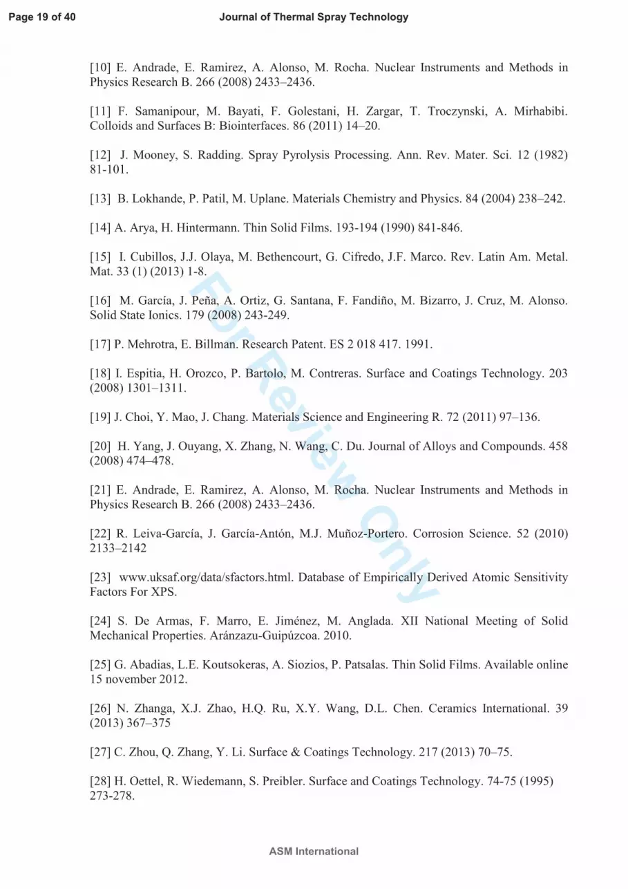
Fig. 2 Role of the ratio of drag/director fluxes (Φc/Φd) in the formation of crystalline ZrO2: (a) on Si
(100) wafers and (b) on stainless steel AISI 316L. Temperature: 733 K; deposition time: 30 min. ZrO2
(t) = tetragonal zirconia, ZrO2 (m) = monoclinic zirconia.
The role of the variation of the flux ratio on the deposited coating over the two types of
substrate, Si (100) and stainless steel is shown in the XRD patterns shown in Fig. 2. Among
the observations in this study, maintaining Φc in the range of 2.5 to 4.0 L/min and the director
flux Φd in the range of 0.60 to 0.90 L/min resulted in polycrystalline-phase ZrO2 (t). Director
fluxes less than 0.50 or greater than 0.90 L/min deposit amorphous zirconia with a low
adherence to the substrate. The production of polycrystalline tetragonal zirconia with good
adherence to the substrate is favored when a difference between the carrier and director
fluxes, Φc – Φd, is maintained at approximately 2.0; however, a poor deposition is formed if
Φc – Φd is less than 2.0, and neither the formation of crystalline zirconia nor adherence to the
substrate occurs at values greater than 3.0.
Page 8 of 40
ASM International
Journal of Thermal Spray Technology

For R
eview O
nly
The deposits on the two types of substrates consist primarily of ZrO2 (t). However,
monoclinic zirconia ZrO2 (m) is also present in the coatings deposited with a carrier flux of
3.0 L/min and director fluxes of 0.7 to 0.9 L/min, as evident in Fig. 2a. A more crystalline
coating is deposited over the stainless steel 316L, and ZrO2 (m) is virtually nonexistent. The
best crystallization of tetragonal zirconia on the two types of substrate is obtained with a flux
difference Φc – Φd = 2.2, which corresponds to Φc = 3.0 L/min and Φd = 0.8 L/min. The
preferential orientation is in the direction (101) for the two types of substrate. Notably,
crystalline ZrO2 (t) grows on stainless steel at the flux ratio Φc/Φd of 3.0/0.8, whereas, on
silicon, incipient crystallization occurs. The crystallization on stainless steel may be related to
the presence of magnetite where the principal planes of diffraction occur at the same angles as
those of tetragonal zirconia.
Two types of stainless steel were selected with different contents of alloy elements, such as
Cr, Ni, and Mo; tool steel AISI D2 which possesses a high carbon content and low content of
alloy elements, was also selected. The goal was to assess whether the formation of oxides on
the steel surface plays a role in the development of the coating’s crystalline structure. As
evident from the XRD spectra in Fig. 3, polycrystalline tetragonal zirconia grows on each of
the substrates under the standardized deposition conditions, and preferential orientations occur
in either of the (101) or (110) plane. Growth is preferential on the (101) plane over stainless
steel AISI 316L and tool steel D2, whereas growth is preferential on the (110) plane over
silicon and stainless steel AISI 2205. Thus, the chemical composition of the substrate bears no
influence on the crystalline structure of the coating. However, the coatings with the most
crystalline structure are deposited onto AISI 316L.
Fig. 3 Reproducibility in the crystalline structure of ZrO2 (t) deposited on different substrates: silicon
wafers (100), stainless steel 2205 and 316L, and tool steel AISI D2. Temperature: 733 K; time: 30
min; Φc/Φd = 3.0/0.80.
Page 9 of 40
ASM International
Journal of Thermal Spray Technology

For R
eview O
nly
The resistance to corrosion of the ZrO2 (t) coatings deposited over stainless steel was
assessed with the potentiodynamic polarization plots obtained for the three types of stainless
steel object of this study. The general results are summarized in Table II. For AISI D2, the
PL plots are shown in Fig. 4, and the naming convention followed is: AISI D2 for bare steel,
AISI D2-ZrO2 for steel coated with ZrO2, AISI D2-N for the steel nitride for 2 h in anhydrous
ammonia at 823 K, and AISI D2-N ZrO2 for steel coated with ZrO2 after nitriding under the
same described conditions. A duplicate of PL for the system AISI D2-ZrO2 and a triplicate
for the system AISI D2-N ZrO2 are shown. In Table II are shown one of every of these
samples, for comparison effects.
Fig. 4 Linear polarization plots for ZrO2 coatings deposited with spray pyrolysis on AISI D2.
Temperature: 733 K; Φc/Φd = 3.0/0.8; time: 30 min; corrosive solution: 3.5% NaCl.
A comparison between the bare steel and ZrO2-coated steel revealed that the ZrO2 coating
enhances, slightly, the resistance to substrate corrosion, as evidenced by the displacement of
the potentiodynamic polarization plot, towards lower corrosion current densities, and by a
corrosion potential value that is higher than, the one of the steel AISI D2 without any coating.
A similar behavior is observed for the nitrided steel, and a much higher resistance to corrosion
is observed when zirconia is deposited, over, previously nitride steel. The values of the
resistance to polarization Rp, shown in Table II, confirm the results. If ZrO2 is deposited over
nitrided stainless steel, the Rp is two orders of magnitude higher than that of bare stainless
steel, but, when is deposited over non nitrided stainless steel, the value of Rp is only four
times bigger. In other words, AISI D2N-ZrO2 is a more capacitive coating, compared with the
AISI D2-ZrO2 system.
Table II. Electrochemical parameters obtained from polarization plots acquired in 3.5% NaCl solution
on steels and ZrO2 films deposited onto steels.
Page 10 of 40
ASM International
Journal of Thermal Spray Technology

For R
eview O
nly
Muestra Icorr A/cm2
Ecorr (V) Rp Ω.cm2
D2 4,23E-07 -7,50E-01 1,97E+05
D2-ZrO2 2,34E-08 -3,78E-01 7,82E+05
D2-N 2,65E-06 -4,69E-01 4,32E+04
D2-N ZrO2 9,89E-09 -1,31E-03 5,72E+07
2205 5,73E-08 -4,99E-02 1,59E+07
2205 ZrO2 9,53E-09 -1,43E-01 6,31E+07
2205N 1,20E-08 -4,62E-01 1,46E+07
2205N ZrO2 8,28E-09 7,88E-02 1,27E+08
316L 1,99E-08 -9,66E-02 1,31E+06
316L ZrO2 4,16E-07 -2,05E-01 6,27E+04
316LN 2,09E-09 -1,00E-01 1,25E+07
316LN ZrO2 6,85E-09 3,32E-01 6,32E+06
The results for AISI 316L shown in Fig. 5a reveal that the stainless steel coated with zirconia
shows deterioration in the corrosion resistance, compared with that of bare stainless steel. A
displacement of the corrosion current density towards values higher than those of stainless
steel is within two orders of magnitude, an inferior corrosion potential, and a complete loss of
the passivity region are observed. For nitrided stainless steel, the corrosion resistance is
improved compared to that of bare stainless steel, as can be seen in the displacement of the PL
plot towards smaller corrosion current densities. However, the corrosion potential is smaller,
and the resistance to crack nucleation is lower by approximately 0.3 V. However, when
zirconia is deposited over previously nitrided stainless steel, the PL plot shows a clear
increase in the corrosion resistance of the substrate: the corrosion current density decreases by
one order of magnitude, the corrosion potential increases by approximately 0.3 V, and the
crack nucleation potential is 0.6 V above that of bare stainless steel (crack nucleation potential
0.52V in AISI 316L, 1.12 in AISI 316LN-ZrO2).
Fig. 5 Linear polarization plots for ZrO2 coatings deposited with spray pyrolysis on stainless steel
316L and 2205. Temperature: 733 K; Φc/Φd = 3.0/0.8; time: 30 min; corrosive solution: 3.5% NaCl.
The decrease in the corrosion resistance of 316L stainless steel coated with zirconia may be
related to two different factors:
Page 11 of 40
ASM International
Journal of Thermal Spray Technology

For R
eview O
nly
1) Difference in the coefficient of thermal expansion (CTE) between the substrate and the
coating. The CTE for stainless steel is 16X10-4
K-1
, and for Zirconium is 10X10-4
K-1
, 1.6
times lower, so it means that while the coated stainless steel is cooling, the contraction speed
of the coating is lower than the one of the stainless steel. This situation is responsible of the
appearance of micro cracks on the coating. The presence of micro cracks in the coating may
generate a high current density in a small exposed area, decrease the resistance to
polarization, and create corrosion at a local level [24].
The coating microstructure depends on the concentration of residual stress present. Thin
films residual stress may be generated during the cooling process after being deposited (s c)
or, they can result from the growth of the film itself, and they are known as intrinsic stress (s
g) [25-26]. Total residual stress, s is determined by the relationship:
s = sc+sg
Cooling efforts are attributable to the difference between the thermal expansion coefficient of
the coating and the substrate. The thermal expansion mismatch stress, using a balanced biaxial
stress state approximation, is performed according to the following equation:
mas
-DD=D
1..
ET
T
Where, ΔT is the difference between the temperature after cooling and the experimental
temperature, Δα is the difference between thermal expansion coefficient of ceramic coating
and metallic substrate, E is the Young's modulus of ceramic coating, μ is the Poisson's rate of
ceramic coating. Such high stresses can induce the formation of cracks in coating, the thermal
expansion distortion of substrate and ceramic is another reason of crack formation [27-29].
2) The precipitation of carbides on grain boundaries may weaken the austenitic phase because
of lixiviation of chromium and nickel, which are the alloy elements that stabilize such phases.
In the image in Fig. 6 (a), a cross-section of zirconia coated stainless steel 316L is shown,
with the arrow in the image pointing to the carbide precipitation region in the grain boundary
due to stainless steel sensitization. However, Fig. 6 (b) shows a sample of the same stainless
steel without zirconia that was subjected to the same experimental conditions, but with no
precipitation observed.
Fig. 6 Optical microscopy of a cross-section of (a) ZrO2 deposited with spray pyrolysis on 316L
stainless steel and (b) 316L stainless steel subjected to the same conditions but in the absence of
ZrO2. Villela´s reactive developments 100X.
Page 12 of 40
ASM International
Journal of Thermal Spray Technology

For R
eview O
nly
XRD confirmed that the sensitization process is followed by the emergence of magnetite,
which indicates a loss in the stainless character of the steel. By comparing the results obtained
for stainless steel 316L coated with zirconia and the stainless steel with no coating, we
conclude that zirconia promotes steel sensitization at 733 K and the oxidation of iron to
magnetite.
The sensitization of 316L was not expected at such low temperatures, especially with such a
short heating time (30 min). This type of stainless steel sensitizes at temperatures greater than
873 K when subjected to a heating process for long periods [30]. However, a similar process
has been reported for liquid nitriding processes in nitrate baths: the precipitation of Cr23C6,
which is concurrent with the emergence of ferrite Fe2O3 in a temperature range of between
723 and 923 K and from 0.5 to 2 h [31].
The AISI 2205 stainless steel was thus studied with the goal of evaluating the resistance to
corrosion for the case of a sensitization-resistant stainless steel. AISI 2205 stainless steel is
endowed with titanium and is resistant to sensitization that occurs through heating for
prolonged periods. A comparison of the corrosion resistance of 2205 with the 316L coated
with zirconia reveals that the damage in AISI 316L is not present in AISI 2205. In contrast to
316L, 2205-ZrO2 is more resistant to corrosion than bare stainless steel. The Rp for AISI
2205 is 1.59×10⁷, whereas the Rp for 2205-ZrO2 is 6.31×10
7. However, the presence of micro
crack the coating is also evident, as can be seen in Fig. 7a.
For AISI 2205 (Fig. 7b), the stainless steel coated with zirconia, the one nitrided, and the one
coated after nitriding all show a corrosion current density of the same order and lower than
that of bare stainless steel . However, the corrosion potential for the nitrided stainless steel is
Page 13 of 40
ASM International
Journal of Thermal Spray Technology

For R
eview O
nly
0.4 V less than that of bare stainless steel, which indicates deterioration in the corrosion
resistance. The PL plot for the zirconia deposited on the nitrided stainless steel shows a
displacement towards lower corrosion current densities and higher corrosion potentials than
those of non-coated stainless steel. The displacement of the passivity region towards lower
corrosion current densities is notable.
Therefore, we conclude that the decrease in the observed resistance to corrosion observed for
ZrO2 deposited on stainless steel AISI 316L is directly related to the presence of micro cracks
in the coating, which leaves the sensitized substrate exposed to the aggressive solution.
Zirconia that is directly deposited on stainless steel AISI 316L with UPS cannot act as a
barrier against substrate corrosion [8, 32].
A comparison of the results for corrosion resistance shown in Table II reveals that the
corrosion current density decreases from one to two orders of magnitude for the stainless steel
2205 and the tool stainless steel when the zirconia is deposited onto the previously nitrided
stainless steel. The resistance to polarization shown by the material increases by two orders of
magnitude in the D2 case and by one order of magnitude in the 2205 case.
Fig. 7 ZrO2 deposited on stainless steel AISI 2205: (a) SEM image and (b) confocal image. ZrO2
deposited on previously nitrided stainless steel. Conditions of deposition: Φc/Φd = 3.0/0.8 for 30 min
at 733 K, 5000X.
Elastic deformation develops if the zirconia films are deposited directly onto stainless steel,
which leads to a fracture in the ZrO2 coating because of the inferior ductility of the composite
material coating with respect to that of stainless steel. When the temperature is increased, the
metal expansion rate is significantly higher than that of the ceramic, which causes the
emergence of micro cracks that are directly related to a decrease in the material’s corrosion
resistance. The cracking of the zirconia surface is not a problem limited to the spray pyrolysis
Page 14 of 40
ASM International
Journal of Thermal Spray Technology

For R
eview O
nly
method [33]. The problem is also present when the coating is electrodeposited [34] or
deposited using the sol-gel method [35].
However, if ZrO2 is deposited over previously nitrided stainless steel, the hardness of
stainless steel is increased [36], and the difference in the ductility between the two materials
decreases [37]. These changes result in the disappearance of micro cracks and the resistance
of the material increases when it is polarized. In addition, the positive effect of nitrogen on
stainless steel through passivation is well known to increase its resistance to corrosion
depending on the nitrogen content [38-41]. The confocal and SEM images in Figs. 7 a-b
reveal that the coating shows micro cracks when zirconia is deposited onto AISI 2205;
however ZrO2 deposited onto previously nitrided stainless steel leads to a highly
homogeneous coating with no micro cracks (see Figs. 7 c-d).
The deposition of zirconia on previously nitrided stainless steel not only improves the surface
morphology of the coating but also increases the roughness of the substrate, which, in turn,
enhances the adherence of ZrO2. Table III shows that the nitriding of D2 increases the
roughness of the stainless steel 11-fold compared to stainless steel with no treatment; the
roughness of the coating on nitrided stainless steel is three times higher. This change is not as
pronounced for stainless steel; nevertheless, an increase in roughness is also observed: the
roughness of the stainless steel is six times higher in the case of nitrided stainless steel, and
the roughness of the coating increases by a factor of 3.0 for coatings deposited on steel D2
previously nitrided, to 1.7 when ZrO2 is deposited onto nitrided stainless steel 2205 and 1.3
on 316L.
Page 15 of 40
ASM International
Journal of Thermal Spray Technology

For R
eview O
nly
Table III Roughness of steel: bare, nitrided, and ZrO2 deposited with spray pyrolysis.
Stainless stainless steel
Roughness Rms (A°)
SS SS- ZrO2 SS-N SS-N ZrO2
AISI D2 57.0 126 609 418
AISI 2205 80.2 284 586 495
AISI 316L 85.7 309 525 417
To showcase this process, the differences in the surface roughness and the produced particle
size depending on the treatment is evident in AFM images in Fig. 8. The roughness is low,
and the particle size is large when ZrO2 is directly deposited onto stainless steel. However, the
roughness of the stainless steel increases 11-fold when ZrO2 is deposited onto previously
nitrided stainless steel, which leads to an increase in the roughness of the coating.
Fig. 8 AFM images: (a) AISI D2, (b) AISI D2-ZrO2, (c) AISI D2N, and (d) AISI D2N-ZrO2.
Fig. 9 XRD patterns of (a) AISI 316L, (b) AISI 316L-N, and (c) ZrO2 deposited on AISI 316L-N
The increased adherence of the coating on nitrided stainless steel can also be complemented
with the observed epitaxy between the zirconia and the magnetite produced during the
nitriding process. Figure 9 show a comparison of the XRD patterns of bare AISI 316L, AISI
316L nitride for 2 h in an ammonia environment, and nitrided AISI 316L with a ZrO2 coating.
The nitriding process induces magnetite growth on the surface of the stainless steel and ZrO2
epitaxial growth on Fe3O4 at 30 and 35 °2θ is present, with planes of diffraction that grow
along the principal angles of tetragonal zirconia. The main planes of diffraction for the
magnetite have been indexed starting from those reported for the standard JPDS 00-001-1111
magnetite, Fe3O4.
Regarding the chemical composition of the coating, shows the general XPS spectrum for a
zirconia sample deposited onto 316L stainless steel. The comparison between the initial
spectrum and the one obtained after several cleaning steps with sputtering (in situ Ar+ for 15,
Page 16 of 40
ASM International
Journal of Thermal Spray Technology

For R
eview O
nly
50, or 70 min analysis with a depth of 3 to 15 nm) reveals the chemical homogeneity of the
sample along the path towards the substrate.
Figure 10 shows an analysis of the high-resolution Zr3d signal on the stainless steel AISI 316L
substrate. A spin doublet can be observed with two spin–orbital components at 3d3/2 181.7 eV
and 3d3/2 184.1 eV, separated by 2.4 eV and with an 3d5/2/3d3/2 intensity ratio of 10:7, which
corresponds to the Zr(IV) species. However, a binding energy (BE) smaller by 0.3 eV with
respect to pure zirconia may be directly related to the existing interactions between the
coating and the substrate, which indicates that the Zr4+
BE of the zirconia coating is lower
than that of the pure oxide because of effects of the electronic cloud on the metallic substrate
[42]. Pure zirconia is characterized with a BE of 182 eV. The signal for the O1S at 531.0 eV is
associated with the Zr-O bond.
Fig. 10 XPS spectra for the O1S and Zr3d signal in ZrO2 (t) obtained by spray pyrolysis on AISI 316L.
4. Conclusion
Polycrystalline zirconia (t) stabilized in part with yttria was synthesized on three types of
steel and Si (100) wafers. For the deposition conditions optimized in the current study,
polycrystalline tetragonal zirconia grows on the metallic and ceramic substrates.
A systematic study was performed to assess the effect of the carrier and flow direction ratio
on the polycrystalline structure and the surface morphology of the zirconia coating on steel
and silicon. The obtained results show that the flux ratio of has no effect on the preferential
orientation of the coating.
When ZrO2 is deposited on previously nitrided steel, the increased roughness of the steel
enhances the adherence of the coating and increases its roughness. The previous nitriding
process also controls the emergence of micro cracks. For ZrO2 deposited onto nitrided steel,
Page 17 of 40
ASM International
Journal of Thermal Spray Technology

For R
eview O
nly
the resistance to corrosion can increase by up to two orders of magnitude because of an
improvement in the surface homogeneity.
XPS results confirmed that the composition of the film is ZrO2, and a depth profile indicates
that the composition is conserved from the surface to the substrate. The OH- groups are
present only on the surface.
Acknowledgements
The authors acknowledge the Foundation for the Promotion of Research and Technology –
Bank of the Republic of Colombia, for funding this research, the LABYP Corrosion and
Protection Laboratory of the University of Cádiz for allowing the realization of corrosion
experiments, and the Rocasolano Institute of Physical Chemistry for allowing the realization
of the XPS analysis.
References
[1] K. Hembram, G. Duttab, U. Waghmareb, M. Rao. Physica B. 399 (2007) 21–26.
[2] F. Legorreta, V. Gonzaga, E. De Grave, A. Peigney, A. Barnabe, C. Laurent. Materials
Research Bulletin. 44 (2009) 1301–1311.
[3] R. Polanco. Processes of union and study of interfaces in Si3N4 and ZrO2. Doctoral Thesis.
Department of Inorganic Chemistry, College of Science.
Universidad Autómona de Madrid. (2007) 6-11.
[4] I. Kosackia,T. Rouleaub, P. Bechera, J. Bentleya, D. Lowndesb. Solid State Ionics. 176
(2005) 1319–1326.
[5] R. Ugas-Carrión, F. Sittner, M. Yekehtaz, S. Flege, J. Brötz, W. Ensinger. Surface and
Coatings Technology. 204 (2010) 2064–2067.
[6] G. Freiman, P. Barboux, J. Perrière, K. Giannakopoulos. Thin Solid Films. 517 (2009)
2670–2674.
[7] T. Yeh, Y. Chien, B. Wang, B. Horng. Corrosion Science. 50 (2008) 2327–2337.
[8] F. Samiee, K. Raeissi. M.A. Golozar. Corrosion Science. 53 (2011) 1969–1975.
[9] K. Koski, J. Ho, P. Juliet. Surface and Coatings Technology. 120–121 (1999) 303–312.
Page 18 of 40
ASM International
Journal of Thermal Spray Technology
For R
eview O
nly
[10] E. Andrade, E. Ramirez, A. Alonso, M. Rocha. Nuclear Instruments and Methods in
Physics Research B. 266 (2008) 2433–2436.
[11] F. Samanipour, M. Bayati, F. Golestani, H. Zargar, T. Troczynski, A. Mirhabibi.
Colloids and Surfaces B: Biointerfaces. 86 (2011) 14–20.
[12] J. Mooney, S. Radding. Spray Pyrolysis Processing. Ann. Rev. Mater. Sci. 12 (1982)
81-101.
[13] B. Lokhande, P. Patil, M. Uplane. Materials Chemistry and Physics. 84 (2004) 238–242.
[14] A. Arya, H. Hintermann. Thin Solid Films. 193-194 (1990) 841-846.
[15] I. Cubillos, J.J. Olaya, M. Bethencourt, G. Cifredo, J.F. Marco. Rev. Latin Am. Metal.
Mat. 33 (1) (2013) 1-8.
[16] M. García, J. Peña, A. Ortiz, G. Santana, F. Fandiño, M. Bizarro, J. Cruz, M. Alonso.
Solid State Ionics. 179 (2008) 243-249.
[17] P. Mehrotra, E. Billman. Research Patent. ES 2 018 417. 1991.
[18] I. Espitia, H. Orozco, P. Bartolo, M. Contreras. Surface and Coatings Technology. 203
(2008) 1301–1311.
[19] J. Choi, Y. Mao, J. Chang. Materials Science and Engineering R. 72 (2011) 97–136.
[20] H. Yang, J. Ouyang, X. Zhang, N. Wang, C. Du. Journal of Alloys and Compounds. 458
(2008) 474–478.
[21] E. Andrade, E. Ramirez, A. Alonso, M. Rocha. Nuclear Instruments and Methods in
Physics Research B. 266 (2008) 2433–2436.
[22] R. Leiva-García, J. García-Antón, M.J. Muñoz-Portero. Corrosion Science. 52 (2010)
2133–2142
[23] www.uksaf.org/data/sfactors.html. Database of Empirically Derived Atomic Sensitivity
Factors For XPS.
[24] S. De Armas, F. Marro, E. Jiménez, M. Anglada. XII National Meeting of Solid
Mechanical Properties. Aránzazu-Guipúzcoa. 2010.
[25] G. Abadias, L.E. Koutsokeras, A. Siozios, P. Patsalas. Thin Solid Films. Available online
15 november 2012.
[26] N. Zhanga, X.J. Zhao, H.Q. Ru, X.Y. Wang, D.L. Chen. Ceramics International. 39
(2013) 367–375
[27] C. Zhou, Q. Zhang, Y. Li. Surface & Coatings Technology. 217 (2013) 70–75.
[28] H. Oettel, R. Wiedemann, S. Preibler. Surface and Coatings Technology. 74-75 (1995)
273-278.
Page 19 of 40
ASM International
Journal of Thermal Spray Technology

For R
eview O
nly
[29] M. R. Begley and H. Wadley. Acta Materialia. 60 (2012) 2497–2508.
[30] M. Terada, D.M. Escriba, I. Costa, E. Materna-Morris, A.F. Padilha. Materials
Characterization. 59 (2008) 663 – 668.
[31] T. Shih, Y. Sen Huang, Ch. Chen. Applied Surface Science. 258. (2011) 81– 88.
[32] M.R. Saghi, Sh. Khameneh, S. Norouzi. Surface & Coatings Technology. 205 (2010)
2605–2610.
[33] R. López Ibáñez, F. Martín, J.R. Ramos-Barrado, D. Leinen. Surface & Coatings
Technology. 200 (2006) 6368–6372.
[34] E. Setare, K. Raeissi, M.A. Golozar, M.H. Fathi. Corrosion Science. 51 (2009) 1802–
1808.
[35] R. Di Maggio, S. Rossi, L. Fedrizzi, P. Scardi. Surface & Coatings Technology. 89
(1997) 292-298.
[36] S. Liscano, L. Gil, O. León, M. Cruz, M. Staia. Surface & Coatings Technology. 201
(2006) 4419–4423.
[37] J. Valle, A. Mestra, M. Anglada. Journal of the European Ceramic Society. 31 (2011)
1015–1025
[38] F. M. Bayoumi, W. A. Ghanem. Materials Letters. 59 (2005) 3311 – 3314.
[39] M. Katsura. Journal of Alloys and Compounds. 182 (1992) 91-102
[40] H. Dong, Y. Sun, T. Bell. Surface and Coatings Technology. 90 (1997) 91-101.
[41] L.C. Gontijo, R. Machado, S.E. Kuri, L.C. Casteletti, P. Nascente. Thin Solid Films. 515
(2006) 1093–1096.
[42] M. Signore, A. Rizzo, L. Mirenghi, M. Tagliente, A. Cappello. Thin Solid Films. 515
(2007) 6798–6804.
Page 20 of 40
ASM International
Journal of Thermal Spray Technology

For R
eview O
nly
Figure 1. Diagram of the experimental setup used in the spray pyrolysis process.
Page 21 of 40
ASM International
Journal of Thermal Spray Technology

For R
eview O
nly
20 30 40 50 60
(a)
fa/fd (L/min)
Si
Si
Si
Si
ZrO
2(t)
(2 1
1)
ZrO
2(t)
(1 1
2)
ZrO
2(t)
(1 1
0)
ZrO
2(002)
ZrO
2(m)
ZrO
2(t)
(1 0
1)
3,0/0,9
3,0/0,6
4,0/0,6
Si
3,0/0,8
3,0/0,7
Inte
nsit
y (
ua)
2q Angle (deg)
20 30 40 50 60 70 80 90
(b)
fa/f
d (L/min)
3,00/0,90
FeC
r 0.29
Ni 0.
16C
0.06
(3
1 1)
FeC
r 0.29
Ni 0.
16C
0.06
(2
2 0)
ZrO
2(t)
(2
1 1)
FeC
r 0.29
Ni 0.
16C
0.06
(2
0 0)
ZrO
2(t)
(1
1 2)
FeC
r 0.29
Ni 0.
16C
0.06
(1
1 1)
ZrO
2(t)
(1
1 0)
ZrO
2(t)
(1
0 1)
ZrO
2(m)
4,00/0,60
3,00/0,60
3,00/0,70
3,00/0,80
Inte
nsity
(ua)
2q Angle (deg)
Φc L/min 3.0 4.0 3.0 3.0 3.0
Φd L/min 0.60 0.60 0.70 0.80 0.90
Φc-Φd 2.4 3.4 2.3 2.2 2.1
Figure 2. Role of the ratio of carrier fluxes/flow direction (Φc/Φd) in the structure crystalline ZrO2:
(a) on Si (100) wafers and (b) on AISI 316L. Temperature: 733 K; deposition time: 30 min. Tetragonal
zirconia= ZrO2 (t), monoclinic zirconia = ZrO2 (m).
Page 22 of 40
ASM International
Journal of Thermal Spray Technology

For R
eview O
nly
20 40 60 80
FeC (2
00)
FeC
r 0.29
Ni 0.
16C
0.06
(311
)
NiC
rFe
(211
)
FeC
r 0.29
Ni 0.
16C
0.06
(220
)
ZrO
2(t) (
211)
FeC
r 0.29
Ni 0.
16C
0.06
(2 0
0)
ZrO
2(t) (
112)
NiC
rFe
(110
)
FeC
r 0.29
Ni 0.
16C
0.06
(111
)
ZrO
2(t) (
110)
ZrO
2(t) (
101)
ZrO2.AISI 2205
ZrO2.AISI D2
ZrO2-Si
ZrO2- 316L
Inte
nsity
(ua)
2q Angle (deg)
Figure 3. Reproducibility in the crystalline structure of ZrO2 (t) deposited on different substrates:
silicon wafers (100), stainless stainless steel s 2205 and 316L, and tool steel AISI D2. Temperature:
733 K; time: 30 min; Φc/Φd = 3.0/0.80.
Page 23 of 40
ASM International
Journal of Thermal Spray Technology

For R
eview O
nly
1E-121E-111E-10 1E-9 1E-8 1E-7 1E-6 1E-5 1E-4 1E-3 0,01-1,5
-1,0
-0,5
0,0
0,5
1,0
1,5
2,0
(4b)
(3c)
(3a)
(4a)
(3b)
(2)
(1)
---- AISI D2N ZrO2 3a
---- AISI D2N ZrO2 3b
---- AISI D2N ZrO2 3c
Po
ten
tial (V
vs S
CE
)
Current density (I A/cm-2)
---- AISI D2 (1)
---- AISI D2N (2)
---- AISI D2 ZrO2 4a
---- AISI D2 ZrO2 4b
Figure 4. Linear polarization plots for ZrO2 coatings deposited with spray pyrolysis on AISI D2.
Temperature: 733 K; Φc/Φd = 3.0/0.8; time: 30 min; corrosive solution: 3.5% NaCl.
Page 24 of 40
ASM International
Journal of Thermal Spray Technology

For R
eview O
nly
1E-11 1E-10 1E-9 1E-8 1E-7 1E-6 1E-5 1E-4 1E-3
-0,3
0,0
0,3
0,6
0,9
1,2
(3)
(2)
(4)
(1)
(a)
Po
ten
tial (V
vs S
CE
)
___ AISI 316L-N ZrO2(3)
___ AISI 316L-ZrO2(4)
---- AISI 316L N (2)
---- AISI 316L (1)
Current density (I A/cm-2)
1E-10 1E-9 1E-8 1E-7 1E-6
-0,8
-0,6
-0,4
-0,2
0,0
0,2
0,4
0,6
0,8
1,0
1,2
1,4
(4)
(2)
(3)
(1) (b)
Current density (I A/cm-2)
Po
ten
tial (V
vs S
CE
)
... AISI 2205 (1)
---AISI 2205-N (2)
---AISI 2205-N-ZrO2(3)
---AISI 2205-ZrO2(4)
Figure 5. Linear polarization plots for ZrO2 coatings deposited with spray pyrolysis on stainless steel
316L and 2205. Temperature: 733 K; Φc/Φd = 3.0/0.8; time: 30 min; corrosive solution: 3.5% NaCl.
Page 25 of 40
ASM International
Journal of Thermal Spray Technology

For R
eview O
nly
Figure 6. Optical microscopy of a cross-section of (a) ZrO2 deposited with spray pyrolysis on 316L
stainless steel and (b) 316L stainless steel subjected to the same conditions but in the absence of
ZrO2. Villela´s reactive developments 100X.
Page 26 of 40
ASM International
Journal of Thermal Spray Technology

For R
eview O
nly
Figure 7. (a) SEM image AISI 2205- ZrO2, (b) confocal image 2205- ZrO2 (c) SEM image AISI
2205N- ZrO2 and (d) confocal image AISI 2205N- ZrO2. Conditions of deposition: Φc/Φd = 3.0/0.8 for
30 min at 733 K, 5000X.
Page 27 of 40
ASM International
Journal of Thermal Spray Technology

For R
eview O
nly
Figure 8. AFM images: (a) AISI D2, (b) AISI D2-ZrO2, (c) AISI D2N, and (d) AISI D2N-ZrO2.
Page 28 of 40
ASM International
Journal of Thermal Spray Technology

For R
eview O
nly
10 20 30 40 50 60 70 80 90 100
Fe
3O4 (4
40)
Fe
3O4 (3
11)
Fe
3O4 (2
22)
Fe
3O4 (2
20)
Fe
3O4 (1
11)
ZrO
2 t
(211)
ZrO
2 t
(112)
ZrO
2 t
(110)
(c)
(b)
(a)
Fe
2O3 (3
10)
Fe
3O4 (1
11)
FeC
r 0.2
9N
i 0.1
6C
0.0
6 (
222)
FeC
r 0.2
9N
i 0.1
6C
0.0
6 (
3 1
1)
FeC
r 0.2
9N
i 0.1
6C
0.0
6 (
2 2
0)
FeC
r 0.2
9N
i 0.1
6C
0.0
6 (
1 1
1)
FeC
r 0.2
9N
i 0.1
6C
0.0
6 (
2 0
0)Z
rO2 t
(101)
Inte
nsit
y u
a
2q Angle (deg)
Figure 9. XRD patterns of (a) AISI 316L, (b) AISI 316L-N, and (c) ZrO2 deposited on AISI 316LN
Page 29 of 40
ASM International
Journal of Thermal Spray Technology

For R
eview O
nly
Figure 10. XPS spectra for the O1S and Zr3d signals in ZrO2 (t) obtained by spray pyrolysis
on AISI 316L.
Page 30 of 40
ASM International
Journal of Thermal Spray Technology

For R
eview O
nly
�
����������������������� ����������������������������������������������������
Page 31 of 40
ASM International
Journal of Thermal Spray Technology

For R
eview O
nly
��
�
���������� ���� ���� ���� ���� ����
��������� ����� ����� ����� ����� ����
���� ��� ���� ��� �� ���
�
��� ������������������������������� ����������������������������������� �� �������������������� ��� ��� ������ ����� ��� ���� ��� !�!� "�#$%� &�'(�� ��� )""� *+� ��(�������� ��'��� "�� '��%�
&��,����-�����.��������/�'����������-������.������'�%�
� �� �� �� ��
���
�����������������
�
�
�
�
� �
�������������
� �
�������������
� �
�������������
� �
�������
� �
�����
� �
�������������
�������
�������
�������
�
�������
�������
�����������
������� !����� �
� �� �� �� �� �� �� �
�"�
�����������������
��������� ��� ���� �����������������
��� ���� ���������������
��������������
��� ���� ����������������
��������������
��� ���� �����������������
���������������
���������������
�������
���������
���������
���������
���������
�����������
������� !����� �
Page 32 of 40
ASM International
Journal of Thermal Spray Technology

For R
eview O
nly
�
������������������� ���� ������ ������� �� ������������� ������� ������������� ����� �� ����
�������������������� �������� �������� ����������������� !������ ����� ����"#$#�%�&�'�(���� �����
)���*+� (������(�+�,-,��.��&�-�&/�&��
�� �� �� ��
�������
���� � ���� � ���� ������
����������
���� � ���� � ���� ������
����������
���� � ���� � ���� ������
����������
����������
���� � ���� � ���� ������
����������
����������
������������
�����������
���� ��
���� ����
������������
�����������
Page 33 of 40
ASM International
Journal of Thermal Spray Technology

For R
eview O
nly
�
�
�
���������������������������� � �������� ������ ���� ���������� ��������� � ������������
����������� �!""�#$�%�&%��'�"�(&(�)$����� �"(����$���� �*�� ���� �"�+,�-�.���
��������������� ���� ���� ���� ��� ��� ���� ���� � ��
�� �
��
� �
�
� �
�
�
�����������������
�����������������
������������������
��
���
�������
�����
��
�
������������������ �!���
������������
��������������
����������������
����������������
��������������� ���� ���� ���� ��� ��� ���� ���� � ����
�� �
��
� �
�
� �
�
� �
�" �
�#��
�#��
�"��
�# �
���
�$�
�
�����������������#�
�����������������#
�����������������#�
��
���
�������
�����
��
�
������������������ �!���
��������������$�
������������������
����������������"�
����������������"
Page 34 of 40
ASM International
Journal of Thermal Spray Technology

For R
eview O
nly
Figure 5 Linear polarization plots for ZrO2 coatings deposited with spray pyrolysis on stainless
steels 316L and 2205. Temperature: 733 K; �a/�d = 3.0/0.8; time: 30 min; corrosive solution: 3.5%
NaCl.
Figure 5. Linear polarization plots for ZrO2 coatings deposited with spray pyrolysis on stainless
steel 316L and 2205. Temperature: 733 K; �c/�d = 3.0/0.8; time: 30 min; corrosive solution: 3.5%
NaCl.
1E-10 1E-9 1E-8 1E-7 1E-6 1E-5 1E-4 1E-3
-0,3
0,0
0,3
0,6
0,9
1,2
Po
ten
tia
l (V
vs
SC
E)
(a)---- AISI 316L-N ZrO
2
---- AISI 316L-ZrO2
---- AISI 316L N
---- AISI 316L
Current density (I A/cm-2)
1E-10 1E-9 1E-8 1E-7 1E-6
-0,8
-0,6
-0,4
-0,2
0,0
0,2
0,4
0,6
0,8
1,0
1,2
1,4 (b)
Current density (I A/cm-2)
Po
ten
tia
l (V
vs
SC
E)
---AISI 2205
---AISI 2205-ZrO2
---AISI 2205-N
---AISI 2205-N-ZrO2
1E-11 1E-10 1E-9 1E-8 1E-7 1E-6 1E-5 1E-4 1E-3
-0,3
0,0
0,3
0,6
0,9
1,2
(3)
(2)
(4)
(1)
(a)
Po
ten
tia
l (V
vs
SC
E)
___ AISI 316L-N ZrO2(3)
___ AISI 316L-ZrO2(4)
---- AISI 316L N (2)
---- AISI 316L (1)
Current density (I A/cm-2)
1E-10 1E-9 1E-8 1E-7 1E-6
-0,8
-0,6
-0,4
-0,2
0,0
0,2
0,4
0,6
0,8
1,0
1,2
1,4
(4)
(2)
(3)
(1) (b)
Current density (I A/cm-2)
Po
ten
tia
l (V
vs
SC
E)
... AISI 2205 (1)
---AISI 2205-N (2)
---AISI 2205-N-ZrO2(3)
---AISI 2205-ZrO2(4)
Page 35 of 40
ASM International
Journal of Thermal Spray Technology

For R
eview O
nly
�
�
���� �
������������������������ ������������������������������������������������ �� �� ������������
�����������������������������������������������������������������������������������������������������
��� ��������!�������"����"����������##$ ��
Page 36 of 40
ASM International
Journal of Thermal Spray Technology

For R
eview O
nly
�
�
�
���� �
����� �
���������� ������������ ���������������� ������������� ��������������� ������������ ����
��������������������������������� ��������������������� ��!������"�! ��#�$�%$��&�'��%��(�
����'����� �)''�*������+���
Page 37 of 40
ASM International
Journal of Thermal Spray Technology

For R
eview O
nly
��� ����� ���� ����������������������� ������������ ����������������� ����������������� ����������������
Page 38 of 40
ASM International
Journal of Thermal Spray Technology

For R
eview O
nly
Figure 10 XPS spectra for the O1S and Zr3d signals in ZrO2 (t) obtained by spray pyrolysis
on AISI 316L.
526 528 530 532
531,0
529,0
Inte
ns
ity
(u
a)
Binding energy (eV)
180 182 184 186 188
18
1,7
49
18
4,1
5
Inte
ns
ity
(u
a)
Binding energy (eV)
Page 39 of 40
ASM International
Journal of Thermal Spray Technology

For R
eview O
nly
�
�
������� �� � ���� ������� � � ���� ����� ������ ���� ����� �������� ��� ���� � ���� ����� ���� �� �����
�������
�� �� �� �� �� �� �� � � ���
����������
��������
����
������
����������
�������
� �
������
� �
������
� �
������
��
��
��
���������
�������
�� � ����� ���� ����������
�� � ����� ���� ������������
�� � ����� ���� ������������
�� � ����� ���� ������������
�� � ����� ���� ������������� �
������
������������
�����������������
Page 40 of 40
ASM International
Journal of Thermal Spray Technology