Hydrogen and Carbon Nanotubes from Pyrolysis-Catalysis of ...
28
Vol.:(0123456789) 1 3 Waste and Biomass Valorization https://doi.org/10.1007/s12649-020-01054-w REVIEW Hydrogen and Carbon Nanotubes from Pyrolysis‑Catalysis of Waste Plastics: A Review Paul T. Williams 1 Received: 24 October 2019 / Accepted: 30 March 2020 © The Author(s) 2020 Abstract More than 27 million tonnes of waste plastics are generated in Europe each year representing a considerable potential resource. There has been extensive research into the production of liquid fuels and aromatic chemicals from pyrolysis-catal- ysis of waste plastics. However, there is less work on the production of hydrogen from waste plastics via pyrolysis coupled with catalytic steam reforming. In this paper, the different reactor designs used for hydrogen production from waste plastics are considered and the influence of different catalysts and process parameters on the yield of hydrogen from different types of waste plastics are reviewed. Waste plastics have also been investigated as a source of hydrocarbons for the generation of carbon nanotubes via the chemical vapour deposition route. The influences on the yield and quality of carbon nanotubes derived from waste plastics are reviewed in relation to the reactor designs used for production, catalyst type used for carbon nanotube growth and the influence of operational parameters. Graphic Abstract Keywords Plastics · Pyrolysis · Catalyst · Hydrogen · Carbon nanotubes Statement of Novelty Waste plastics are of current environmental concern. Pro- duction of hydrogen and carbon nanotubes represents a novel route to thermal recycling of waste plastics to produce higher value products. Introduction Worldwide production of plastics is more than 330 million tonnes/year, with 60 million tonnes/year produced in Europe [1]. The different applications and range of various plastic types means that their industrial, commercial and domes- tic service life can range from less than one year to more than 50 years. Inevitably, much of the plastic will end up in the waste stream and in Europe approximately 27 mil- lion tonnes of waste plastics are generated each year [1]. The current process routes for plastic waste management in the EU are ~ 42% used for energy recovery (mainly through energy from waste incineration) ~ 27% disposed to landfill * Paul T. Williams [email protected] 1 School of Chemical & Process Engineering, University of Leeds, Leeds LS2 9JT, UK
-
Upload
khangminh22 -
Category
Documents
-
view
0 -
download
0
Transcript of Hydrogen and Carbon Nanotubes from Pyrolysis-Catalysis of ...

Vol.:(0123456789)1 3
Waste and Biomass Valorization https://doi.org/10.1007/s12649-020-01054-w
REVIEW
Hydrogen and Carbon Nanotubes from Pyrolysis‑Catalysis of Waste Plastics: A Review
Paul T. Williams1
Received: 24 October 2019 / Accepted: 30 March 2020 © The Author(s) 2020
AbstractMore than 27 million tonnes of waste plastics are generated in Europe each year representing a considerable potential resource. There has been extensive research into the production of liquid fuels and aromatic chemicals from pyrolysis-catal-ysis of waste plastics. However, there is less work on the production of hydrogen from waste plastics via pyrolysis coupled with catalytic steam reforming. In this paper, the different reactor designs used for hydrogen production from waste plastics are considered and the influence of different catalysts and process parameters on the yield of hydrogen from different types of waste plastics are reviewed. Waste plastics have also been investigated as a source of hydrocarbons for the generation of carbon nanotubes via the chemical vapour deposition route. The influences on the yield and quality of carbon nanotubes derived from waste plastics are reviewed in relation to the reactor designs used for production, catalyst type used for carbon nanotube growth and the influence of operational parameters.
Graphic Abstract
Keywords Plastics · Pyrolysis · Catalyst · Hydrogen · Carbon nanotubes
Statement of Novelty
Waste plastics are of current environmental concern. Pro-duction of hydrogen and carbon nanotubes represents a novel route to thermal recycling of waste plastics to produce higher value products.
Introduction
Worldwide production of plastics is more than 330 million tonnes/year, with 60 million tonnes/year produced in Europe [1]. The different applications and range of various plastic types means that their industrial, commercial and domes-tic service life can range from less than one year to more than 50 years. Inevitably, much of the plastic will end up in the waste stream and in Europe approximately 27 mil-lion tonnes of waste plastics are generated each year [1]. The current process routes for plastic waste management in the EU are ~ 42% used for energy recovery (mainly through energy from waste incineration) ~ 27% disposed to landfill
* Paul T. Williams [email protected]
1 School of Chemical & Process Engineering, University of Leeds, Leeds LS2 9JT, UK
Waste and Biomass Valorization
1 3
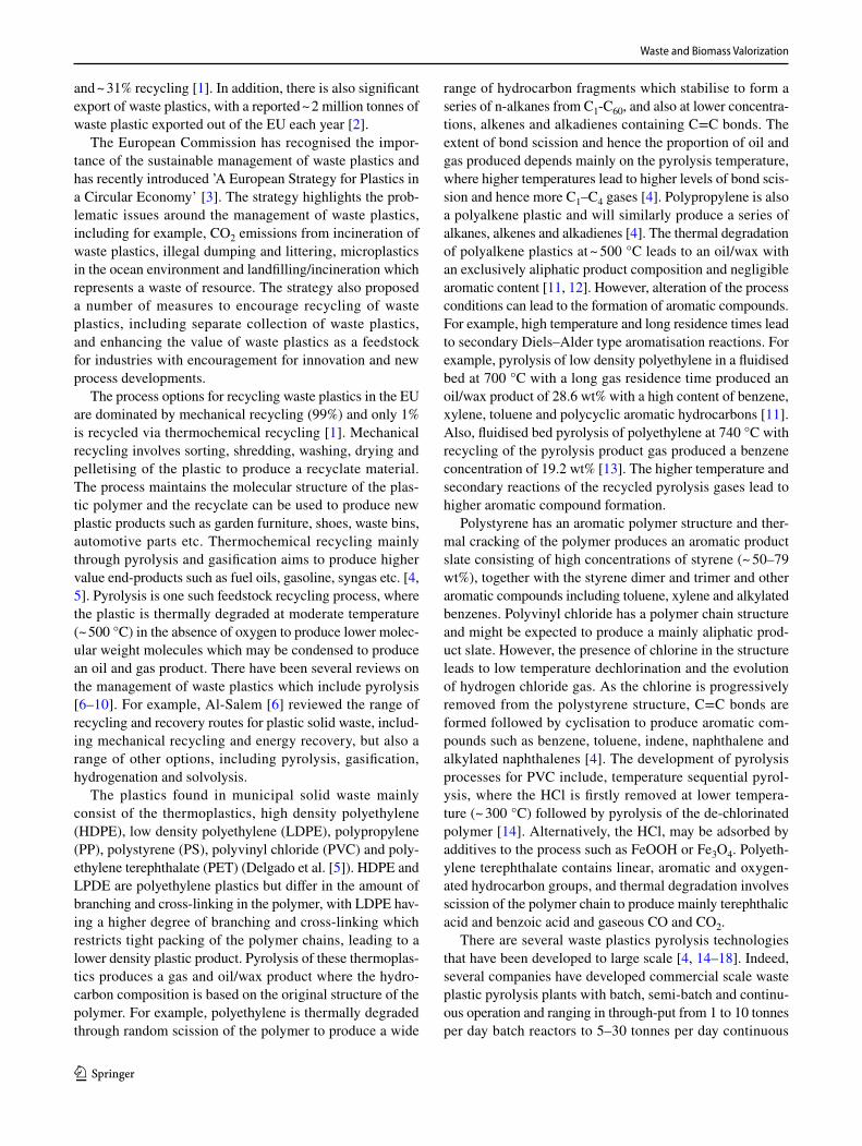
and ~ 31% recycling [1]. In addition, there is also significant export of waste plastics, with a reported ~ 2 million tonnes of waste plastic exported out of the EU each year [2].
The European Commission has recognised the impor-tance of the sustainable management of waste plastics and has recently introduced ’A European Strategy for Plastics in a Circular Economy’ [3]. The strategy highlights the prob-lematic issues around the management of waste plastics, including for example, CO2 emissions from incineration of waste plastics, illegal dumping and littering, microplastics in the ocean environment and landfilling/incineration which represents a waste of resource. The strategy also proposed a number of measures to encourage recycling of waste plastics, including separate collection of waste plastics, and enhancing the value of waste plastics as a feedstock for industries with encouragement for innovation and new process developments.
The process options for recycling waste plastics in the EU are dominated by mechanical recycling (99%) and only 1% is recycled via thermochemical recycling [1]. Mechanical recycling involves sorting, shredding, washing, drying and pelletising of the plastic to produce a recyclate material. The process maintains the molecular structure of the plas-tic polymer and the recyclate can be used to produce new plastic products such as garden furniture, shoes, waste bins, automotive parts etc. Thermochemical recycling mainly through pyrolysis and gasification aims to produce higher value end-products such as fuel oils, gasoline, syngas etc. [4, 5]. Pyrolysis is one such feedstock recycling process, where the plastic is thermally degraded at moderate temperature (~ 500 °C) in the absence of oxygen to produce lower molec-ular weight molecules which may be condensed to produce an oil and gas product. There have been several reviews on the management of waste plastics which include pyrolysis [6–10]. For example, Al-Salem [6] reviewed the range of recycling and recovery routes for plastic solid waste, includ-ing mechanical recycling and energy recovery, but also a range of other options, including pyrolysis, gasification, hydrogenation and solvolysis.
The plastics found in municipal solid waste mainly consist of the thermoplastics, high density polyethylene (HDPE), low density polyethylene (LDPE), polypropylene (PP), polystyrene (PS), polyvinyl chloride (PVC) and poly-ethylene terephthalate (PET) (Delgado et al. [5]). HDPE and LPDE are polyethylene plastics but differ in the amount of branching and cross-linking in the polymer, with LDPE hav-ing a higher degree of branching and cross-linking which restricts tight packing of the polymer chains, leading to a lower density plastic product. Pyrolysis of these thermoplas-tics produces a gas and oil/wax product where the hydro-carbon composition is based on the original structure of the polymer. For example, polyethylene is thermally degraded through random scission of the polymer to produce a wide
range of hydrocarbon fragments which stabilise to form a series of n-alkanes from C1-C60, and also at lower concentra-tions, alkenes and alkadienes containing C=C bonds. The extent of bond scission and hence the proportion of oil and gas produced depends mainly on the pyrolysis temperature, where higher temperatures lead to higher levels of bond scis-sion and hence more C1–C4 gases [4]. Polypropylene is also a polyalkene plastic and will similarly produce a series of alkanes, alkenes and alkadienes [4]. The thermal degradation of polyalkene plastics at ~ 500 °C leads to an oil/wax with an exclusively aliphatic product composition and negligible aromatic content [11, 12]. However, alteration of the process conditions can lead to the formation of aromatic compounds. For example, high temperature and long residence times lead to secondary Diels–Alder type aromatisation reactions. For example, pyrolysis of low density polyethylene in a fluidised bed at 700 °C with a long gas residence time produced an oil/wax product of 28.6 wt% with a high content of benzene, xylene, toluene and polycyclic aromatic hydrocarbons [11]. Also, fluidised bed pyrolysis of polyethylene at 740 °C with recycling of the pyrolysis product gas produced a benzene concentration of 19.2 wt% [13]. The higher temperature and secondary reactions of the recycled pyrolysis gases lead to higher aromatic compound formation.
Polystyrene has an aromatic polymer structure and ther-mal cracking of the polymer produces an aromatic product slate consisting of high concentrations of styrene (~ 50–79 wt%), together with the styrene dimer and trimer and other aromatic compounds including toluene, xylene and alkylated benzenes. Polyvinyl chloride has a polymer chain structure and might be expected to produce a mainly aliphatic prod-uct slate. However, the presence of chlorine in the structure leads to low temperature dechlorination and the evolution of hydrogen chloride gas. As the chlorine is progressively removed from the polystyrene structure, C=C bonds are formed followed by cyclisation to produce aromatic com-pounds such as benzene, toluene, indene, naphthalene and alkylated naphthalenes [4]. The development of pyrolysis processes for PVC include, temperature sequential pyrol-ysis, where the HCl is firstly removed at lower tempera-ture (~ 300 °C) followed by pyrolysis of the de-chlorinated polymer [14]. Alternatively, the HCl, may be adsorbed by additives to the process such as FeOOH or Fe3O4. Polyeth-ylene terephthalate contains linear, aromatic and oxygen-ated hydrocarbon groups, and thermal degradation involves scission of the polymer chain to produce mainly terephthalic acid and benzoic acid and gaseous CO and CO2.
There are several waste plastics pyrolysis technologies that have been developed to large scale [4, 14–18]. Indeed, several companies have developed commercial scale waste plastic pyrolysis plants with batch, semi-batch and continu-ous operation and ranging in through-put from 1 to 10 tonnes per day batch reactors to 5–30 tonnes per day continuous

Waste and Biomass Valorization
1 3
reactors [19–23]. However, there is growing interest in producing significantly higher value products from waste plastics involving the use of catalysts [24–26]. Catalysts can play a critical role in the thermochemical processing of waste plastics in terms of promoting targeted reactions, reducing reaction temperature and improving process system efficiency. Sharuddin et al. [25] reviewed the pyrolysis of different types of common waste plastics in terms of mainly the product oil and included work on catalytic-pyrolysis. The influence of temperature, reactor type, residence time, pressure, catalysts, type of carrier gas and gas flow rate on the product oil composition and fuel properties was reported. Miandad et al. [26] reviewed work on the catalytic pyroly-sis of plastic waste in relation to the production of liquid fuels and by-product gases and char. The influence of several different catalysts and operational parameters on the yield, composition and fuel properties of the product oil were reviewed. Al-Salem et al. [24] also reviewed the thermal and catalytic pyrolysis of waste plastics including different technologies used for pyrolysis and pyrolysis-catalysis, and the influence of process parameters on product yields and composition.
The catalyst involved in the process may be mixed with the waste plastic and thermally processed together, or alter-natively, the catalyst may be placed downstream of the thermal pyrolysis step. The two-step approach to catalytic pyrolysis of waste plastics has been recommended as a pre-ferred option [27–29] since advantages include;
• Interaction of the pyrolysis gases and catalyst improves the contact between pyrolysis products and the catalyst in the subsequent catalytic stage and minimises mass and heat transfer problems.
• The process is more controllable e.g. the temperature of each stage can be easily and independently controlled.
• Catalysts enable a lower reforming temperature, thereby reducing sintering effects.
• It is particularly suited to mixed plastic wastes, where any residues and dirt associated with the plastics remains in the pyrolysis unit.
• Two-stage reaction systems enable the reacted catalysts to be recovered, recycled and reused.
Using a two-stage reactor system, the wide range of hydrocarbon products derived from the pyrolysis of the waste plastics pass directly to the second stage and interact with the catalyst. For example, the hydrocarbon pyrolysis products derived from the waste plastics can be catalyti-cally steam reformed in the second stage catalytic reactor with nickel based catalysts at typical catalyst temperatures of ~ 800 °C to produce a hydrogen rich syngas. There has also been recent interest in developing a pyrolysis-catalytic
process to treat waste plastics to produce carbon nanotubes as the main targeted product. There is also the potential to produce both hydrogen and carbon nanotubes in the same two-stage process.
In this paper, the two-stage pyrolysis-catalysis of waste plastics is discussed in relation to the different configu-ration of reactors used and also the influence of process parameters and the use and development of different types of catalyst to produce hydrogen and/or carbon nanotubes.
Hydrogen Production from Waste Plastics
Hydrogen is a valuable commodity with extensive use in petroleum refining, production of ammonia for fertiliser, and production of cyclohexane and methanol as feedstock for the plastics and pharmaceuticals industries. In addition, with concerns related to climate change there is increas-ing interest in producing higher quantities of hydrogen for use as a non-polluting fuel in transport engines and fuel cells to support the projected future hydrogen economy [30]. Hydrogen is currently produced mostly from fossil fuels (96%), the largest source being natural gas (meth-ane). The process involves steam reforming of methane in the presence of nickel-based catalysts at high temperature (700–1000 °C) and pressure (0.3–2.5 MPa) to produce hydrogen and carbon monoxide. Further reaction of the carbon monoxide with steam via the water gas shift reac-tion produces enhanced hydrogen yields, but also carbon dioxide [31]. The water gas shift reaction involves two suc-cessive processes at high temperature (310–450 °C) with iron-based catalysts and low temperature (200–250 °C) with copper-based catalysts. The by-product carbon diox-ide is removed by scrubbing or pressure swing adsorption to purify the hydrogen end product. Producing hydrogen from waste plastics rather than from fossil fuels such as natural gas would offer an alternative feedstock and would also solve a major waste treatment problem.
There are several research groups who have mimicked the commercial natural gas catalytic steam reforming pro-cess but using pyrolysis of waste plastics to produce hydro-carbons which are then steam reformed in the presence of a nickel catalyst to produce hydrogen. This involves a two-stage reactor system. The first stage involves pyrolysis of the waste plastics at temperatures of ~ 500 °C which gen-erate a complex suite of hydrocarbon gases and vapours from the thermal degradation of the waste plastics. The evolved pyrolysis gases are then passed to a second stage catalytic reactor typically heated to ~ 800 °C and in the presence of steam for catalytic steam reforming to produce hydrogen.

Waste and Biomass Valorization
1 3
Reactor Design for Hydrogen Production from Waste Plastics
Several different types of reactor have been developed and investigated for the two-stage pyrolysis–catalytic steam reforming of waste plastics for hydrogen production. The two stages of pyrolysis and catalytic steam reforming have included several different configurations. For example, experimental systems incorporating; fixed bed pyrolysis-fixed bed reforming batch reactor system, screw kiln pyrol-ysis-fixed bed reforming, fluidised bed pyrolysis-fluidised bed reforming continuous reactor, spouted bed pyrolysis-fluidised bed reforming etc. The different reactor designs have been used to investigate the influence of process parameters on the yield of hydrogen, and semi-continu-ous and continuous reactors have been developed with the potential for eventual deployment and commercialisation of the technology for higher plastic waste throughputs.
A two-stage fixed bed batch reactor system incorporat-ing, pyrolysis followed by catalytic steam reforming for
the production of hydrogen has been used in several stud-ies to investigate the influence of various catalyst types and many process parameters (Fig. 1) [32–37]. The two stages process batch samples of the waste plastics and the catalytic reactor contains a batch of catalyst in a fixed bed. The first stage involves pyrolysis of the waste plastics at a fixed heating rate to a final pyrolysis temperature (typi-cally 500–700 °C). The pyrolysis gases and vapours are passed to a second stage catalytic steam reforming reactor to produce a hydrogen-rich gas. Product gases are cooled in a condenser system to remove condensable hydrocar-bons from the product gases. For example, the two-stage pyrolysis catalytic steam reforming system was used to produce hydrogen from polypropylene, polystyrene and high density polyethylene, together with a mixture of the three plastics and a real-world sample of polyalkene plas-tics with a Ni–Mg–Al catalyst at 800 °C catalyst tempera-ture [36].
Development towards a continuous pyrolysis-catalytic steam reforming process has been investigated by Park et al. [38] and Namioka et al. [39] who used a continuous
Fig. 1 Two-stage fixed bed polypropylene pyrolysis-catalytic steam reforming reactor. Reprinted from [37] via Creative Commons Attribution License (CC BY)

Waste and Biomass Valorization
1 3
feed of plastic into a two-stage reactor system with a first stage hot pyrolysis unit followed by a steam reformer unit with a packed bed of catalyst (Fig. 2). The plastic material was fed continuously via a screw feeder into the stainless steel heated pyrolysis reactor maintained at temperatures ranging from 380 to 550 °C. Fast pyrolysis of the plastics produces volatiles which pass through to the second stage, separately heated section of the reactor containing a Ru/γ-Al2O3 catalyst and with the introduction of steam for cata-lytic steam reforming. The product gases passed through a condenser and scrubber system to clean the product gases. They investigated catalyst temperatures which ranged from 580 to 680 °C [38]. Using this reactor system they investi-gated catalytic steam reforming of polypropylene [38] and polystyrene [39] using the Ru/γ-Al2O3 catalyst. Park et al. [38] reported much higher carbon conversions and high hydrogen yields were obtained with a Ru content of 5.0 wt% compared to a Ru content of 0.5 wt%, typically 3.3–4.5 g H2 per 100 g plastic at the lower Ru content, rising signifi-cantly to 33.1–36.3 g H2 per 100 g plastic at the higher Ru content. In a later paper, Namioka et al. [39] investigated
the pyrolysis-catalytic steam reforming of polystyrene using the same Ru/γ-Al2O3 catalyst and reactor system. It was also suggested that the Ru/γ-Al2O3 catalyst was much more effec-tive than Ni-based catalysts for producing hydrogen, as the reforming temperature was ~ 200 °C lower than tempera-tures used for hydrocarbon reforming using nickel catalysts [38, 39]. He et al. [40] used a similar reactor configuration to that used by Namioka et al. [39]. They used a process where the plastic (polyethylene) was continuously fed via a screw feeder into a heated first stage section of the reactor for fast pyrolysis. The resultant pyrolysis gases with steam were passed over a fixed catalyst bed of NiO/γ-Al2O3 cata-lyst supported on a porous ceramic plate for catalytic steam reforming. The product gases passed through a cyclone, con-denser system, filter and dryer to clean the product gases. The production of hydrogen was investigated in terms of the pyrolysis-catalytic reforming temperature between 700 and 900 °C.
Using a continuous feed of plastic with continuous pyrolysis through a screw kiln reactor followed by a fixed bed catalytic steam reforming reactor has been developed
Fig. 2 Two-stage pyrolysis-catalytic steam reforming of waste plastics. Reprinted from reference [39]. Copyright (2011) with permission from Elsevier

Waste and Biomass Valorization
1 3
for the production of hydrogen from polypropylene [41]. A Ni–Mg–Al catalyst was used and the influence of catalyst temperature was investigated. The plastic was fed continu-ously into a pre-heated zone and then fed via an auger screw through the pyrolysis reactor at 500 °C. Any solid char resi-due exited from the pyrolysis reactor, carried by the screw to be deposited in a char hopper. The products of pyroly-sis were passed to a fixed bed, separately heated, catalytic reactor with steam addition for catalytic steam reforming of the pyrolysis gases. The product gases were cooled in a condenser system and filtered to clean the gases. A com-mercial Ni/SiO2/Al2O3 catalyst and a prepared Ni–Mg–Al catalyst were used. The results showed that as the catalyst temperature was increased an increase of hydrogen yield from 4.8 g H2 per 100 g plastic at 600 °C rising to 17.9 g H2 per 100 g plastic at 900 °C was found [41]. The hydrogen yield was 11.3% of the maximum theoretical hydrogen yield at 600 °C rising to 41.6% at 900 °C. The continuous reactor produced lower yield than experiments in a fixed bed reac-tor with a similar Ni–Mg–Al catalyst [32] due possibly to a longer residence time in the screw kiln reactor and increased secondary charring reactions.
Fully continuous reactors, should ideally include a con-tinuous feed of waste plastic feedstock into a continuous pyrolysis reactor such as a fluidised bed or screw-kiln reac-tor followed by a continuous catalytic bed enabling efficient
catalyst reaction and the option of catalyst regeneration. A continuous process was developed by Czernik and French, [42] who were the first to investigate the pyrolysis-steam reforming process, using plastics (polypropylene) as the hydrocarbon feedstock for hydrogen production, rather than natural gas methane. They used a fluidised bed pyrolysis unit maintained at a pyrolysis temperature of 650 °C. The derived pyrolysis gases passed through a cyclone to remove any par-ticulate matter and were fed into a second stage fluidised bed catalytic steam reforming reactor using a commercial Ni cat-alyst (C11-NK) and maintained at a temperature of 850 °C (Fig. 3). The product hydrogen-rich gases are passed through a cyclone, hot solids filter, condensation system and coa-lescence filter to clean the gases. Czernik and French [42] reported a yield of 34 g H2 per 100 g polypropylene which represented ~ 80% of the maximum theoretical amount of hydrogen (42.9 g H2 per 100 g polypropylene) which could be produced if all of the polypropylene was completely con-verted to CO2 and H2. The product volumetric gas composi-tion consisted of ~ 70 vol% H2, ~ 16 vol% CO2, ~ 11 vol% CO and lower concentrations of hydrocarbons.
Dou et al. [43] used a variation of the pyrolysis-catalytic steam reforming process by using steam gasification rather than pyrolysis to produce the hydrocarbons for subsequent reforming. They used fluidised bed steam gasification of the waste plastics followed by catalytic steam reforming in a
Fig. 3 Fluidised bed pyrolysis-catalytic steam reforming of plastics. (Reprinted with permission from reference [42]. Copyright (2006) Ameri-can Chemical Society)

Waste and Biomass Valorization
1 3
fluidised bed gasification reactor coupled with a catalysis-sorption enhanced reactor (Fig. 4). The gasification of the waste plastic used steam as the oxidant and the gasification took place at temperatures between 810 and 880 °C. The product gases from gasification consisted of CO, H2, CH4 and other hydrocarbons and a small quantity of HCl. The gases were passed to a second moving bed reactor contain-ing a NiO/NiAl2O4 catalyst with steam input for catalytic steam reforming and also CaO for CO2 and HCl adsorption to produce a hydrogen-rich gas. Off-take from the catalysis-adsorption reactor enabled catalyst and adsorbent regen-eration at 900 °C using another moving bed reactor. The regenerated catalyst/sorbent was passed via a riser back to the catalyst/sorbent feed hopper. The optimum process con-ditions produced a gas composed of 88.4 vol% hydrogen obtained at a fluidised bed pyrolysis temperature of 818 °C and a catalyst/sorbent temperature of > 583 °C.
Barbarais et al. [29, 44, 45] have developed a novel two-stage continuous reactor system consisting of a spouted bed pyrolysis reactor and a fluidised bed catalytic reforming reactor to produce hydrogen from waste plastics (Fig. 5). The reactor system consists of a vibrating piston feeder to deliver the waste plastic to a conical spouted bed reactor heated to a typical temperature of 500 °C where flash pyrolysis of the plastics takes place in the presence of steam. The derived pyrolysis gases are then passed to a fluidised bed reactor where catalytic steam reforming takes place at a typical temperature of 700 °C to produce hydro-gen. The conical spouted reactor system contains sand of a particular size range and the physical process of the spouted bed produces a rapid cyclic movement of the sand resulting in high heat transfer rates and intimate contact of hot gas and solid plastic. The product gases from the process were passed through a filter, condenser system and coalescence filter to clean the gases. Barbarias et al. [44] investigated the production of hydrogen from high density polyethylene in the reactor system with a commercial Ni-based catalyst. They reported that almost complete conver-sion of the plastic occurred at a catalytic steam reforming temperature of 700 °C. An optimised maximum hydrogen yield of 38.1 g H2 per 100 g plastic was reported. A later paper by the same group [29] investigated a range of dif-ferent plastics and a plastic mixture. They showed that the yield of hydrogen was influenced by plastic type with low hydrogen yields reported for polyethylene terephthalate (18.2 g H2 per 100 g plastic) and with an associated higher catalyst coke formation.
All of the reactors discussed here, using the two-stage, waste plastic pyrolysis followed by catalytic steam reforming have been at the laboratory scale involving gram quantities of plastics processed in each experiment. Many studies have been performed in a fixed bed pyrolysis and fixed bed cata-lytic steam reforming system with typically 1.0 g quantities of plastic used [e.g. 33, 40]. While fixed bed reactors have a simple design, are easy to operate and are of low cost, they have disadvantages of poor heat transfer rates and low gas–solid contact [46], which is particularly problematic at larger scale. They are also difficult to scale-up because of the higher manpower required for operation in relation to the tonnages of plastic waste throughput of the plant, resulting in higher operational costs and lower cost effectiveness [24].
A key aspect of the development of the process is there-fore to move to continuous operation. Laboratory scale semi-continuous reactors have been developed. For example, a screw auger pyrolysis reactor fed continuously with waste plastics followed by a fixed bed reactor for catalytic steam reforming, where hydrogen yields of 18 g H2 per 100 g plastic were reported [41]. A continuous two-stage reac-tor system with a first stage pyrolysis unit followed by a steam reformer unit with a packed bed of catalyst has been
Fig. 4 Fluidised bed gasification of waste plastics coupled with cata-lytic steam reforming with sorption enhancement. Reprinted from ref-erence [43]. Copyright (2016) with permission from Elsevier

Waste and Biomass Valorization
1 3
developed with reported hydrogen yields of ~ 36 g H2 per 100 g plastic [38].
Fully continuous reactors have been developed and with noticeably high yields of hydrogen reported. For example, Czernik and French [42] used a fluidised bed pyrolysis reac-tor fed continuously with plastic waste via a screw feeder followed by catalytic steam reforming in a fluidised bed reactor and reported hydrogen yields of ~ 37 g H2 per 100 g of plastic. A fully continuous spouted bed pyrolysis-fluidised bed catalytic steam reforming reactor system with through-puts of plastic up to 5 g h−1 produced ~ 37 g H2 per 100 g of plastic [29, 44, 45]. A further advantage of this reactor configuration was the significantly lower formation of cata-lyst coke in the catalytic steam reforming reactor compared to using a fixed bed of catalyst [44]. The technology has been scaled-up to 25 kg h−1 throughput but for processing biomass rather than waste plastics [47].
Influence of Process Conditions on Hydrogen Production from Waste Plastics
The influence of process conditions for the pyrolysis-cat-alytic steam reforming of plastics has been researched in relation to a range of process conditions, including different types of catalyst, different types of plastic, catalysts tem-perature, steam input, catalyst:plastic ratio etc. In addition,
operational parameters to maximise hydrogen production should also consider catalyst deactivation by carbonaceous coke deposits or catalyst sintering.
Influence of Plastic Type on Hydrogen Yield
The influence of plastic type in terms of hydrogen produc-tion is significant between the linear and branched hydro-carbon plastics, that is, polyethylene and polypropylene compared to the more complex hydrocarbon plastics, poly-styrene, polyvinyl chloride and polyethylene terephthalate. As discussed earlier, the pyrolysis of the main plastic types found in municipal solid waste yields different decomposi-tion products. Pyrolysis of polyethylene and polypropylene will yield linear and branched long and short chain alkanes and alkenes, polystyrene yields largely styrene and styrene oligomers, polyvinyl chloride yields HCl and aromatic compounds and polyethylene terephthalate yields benzoic acid and other oxygenated compounds CO and CO2 and a significant solid residue. Therefore, these different volatile compositions will lead to a different product slate during the catalytic steam reforming process and consequently greatly influence the product hydrogen yield. For example, Barbarias et al. [29] investigated hydrogen production from the pyrolysis-catalytic steam reforming of various plastics and reported a hydrogen yield in terms of plastic feedstock of 37.3 g H2 per 100 g for polyethylene, 34.8 g H2 per 100 g
Fig. 5 Continuous two-stage spouted bed pyrolysis reactor with fluidised bed catalytic reforming reactor. Reprinted from reference [44]. Copyright (2016) with permission from Elsevier

Waste and Biomass Valorization
1 3
for polypropylene, 29.1 g H2 per 100 g for polystyrene and 18.2 g H2 per 100 g for polyethylene terephthalate. Also reflecting hydrogen yield from different types of plastic, hydrogen yields of 26.6 and 26.0 g H2 per 100 g plastic were obtained for polypropylene and high density polyeth-ylene, but for polystyrene plastic, H2 yield was only 18.5 g H2 per 100 g plastic [36]. However, Namioka et al. [39] reported little difference in gas and hydrogen production for polystyrene compared to polypropylene for a catalyst steam reforming temperature of 630 °C. Hydrogen yields were 26.2 g H2 per 100 g polystyrene plastic at 580 °C catalyst reforming temperature, rising to 33.3 g H2 per 100 g plastic at 630 °C catalyst temperature, a similar range of hydrogen yields compared to that of polypropylene. They suggested that the particular Ru/γ-Al2O3 catalyst used at the reforming temperature of 630 °C was highly active and was enough to minimise any differences in the rates of catalytic steam reforming of the pyrolysis gases produced from polypropyl-ene and polystyrene.
The two-stage pyrolysis-catalytic steam reforming pro-cess has been investigated for several types of plastic and the polyolefin plastics, polyethylene and polypropylene have been shown to produce the highest hydrogen yields since they readily thermally degrade to produce alkane and alkene gases which are easily reformed in the second stage reactor. Other plastics such as polystyrene and polyvinyl chloride thermally degrade to produce aromatic compounds, which are less easy to reform and polyethylene terephthalate which forms significant quantities of CO and CO2, resulting overall in lower yields of hydrogen for these plastics.
In addition, a key issue for the development of the pyrolysis-catalytic steam reforming process for hydrogen production is the heterogeneous nature of the waste plastic feedstock. Here, the two stage process has advantages since any dirt, glass, metals or other contaminants in the waste plastics are retained in the pyrolysis step as the char/ash residue. However, contamination of the waste plastics by minor plastics can have major influence on the process. For example, polyamides and polyurethanes can generate HCN from pyrolysis. However, Kumagai et al. [48, 49] have used a two-stage, fixed bed pyrolysis–catalytic reactor system with Ni/Mg/Al catalysts to produce a hydrogen-rich product gas from polyamide and polyurethane, but also the catalyst was reported to remove hydrogen cyanide from the syngas. Polyvinyl chloride generates hydrogen chloride gas but may be effectively removed using calcium oxide absorption [43]. Dou [43] used a two-stage, fluidised bed gasification reactor coupled with a catalysis-sorption enhanced reactor with CaO to produce a hydrogen-rich gas with minimised HCl content. Also some plastic products may also contain fire-retardant brominated compounds which may release hydrogen bromide and brominated hydrocarbons during the pyrolysis process. A water/alkali dual scrubber system has
been investigated for the removal of HBr from the fluidised bed pyrolysis-catalysis of brominated waste plastics [50]. Such gas-phase components may influence the catalyst activ-ity or process integrity. For example, the presence of HCl from polyvinyl chloride pyrolysis has been shown to reduce catalyst activity for catalytic steam reforming and thereby reduced hydrogen yield [51].
Using plastics as the feedstock for catalytic steam reform-ing has implications for the formation of carbonaceous coke on the catalyst and deactivating the catalyst by block-ing access of the reactant gases to the active metal sites of the catalyst. The high volatile content of plastics produces light alkene hydrocarbons during pyrolysis which readily polymerise to produce aromatic hydrocarbons, polycyclic aromatic hydrocarbons leading to the formation of carbon which deposits on the catalyst. Pyrolysis of aromatic based plastics such as polystyrene will generate aromatic and poly-cyclic aromatic hydrocarbons, again producing catalyst coke.
Influence of Catalyst Type on Hydrogen Production
For the commercial production of hydrogen from the cata-lytic steam reforming of natural gas, the most common cata-lysts used are nickel-based. Therefore, nickel-based catalysts have been the most extensively investigated for hydrogen production from waste plastics via the pyrolysis-catalytic steam reforming process. However, there has been research into other types of transition metal-based catalysts and for the addition of metal promoters to the nickel to enhance hydrogen yield. For example, ruthenium catalysts have been reported to show higher catalytic activity towards catalytic steam reforming of methane compared to nickel-based cata-lysts [52] and they have been investigated for the production of hydrogen from waste plastics [38, 39].
Addition of Mg to nickel-based catalysts has been reported to replace the Ni in the catalyst structure result-ing in improved physical strength of the catalyst [32, 53, 54]. However, addition of Mg showed no major increase in hydrogen production although lower carbon deposition on the catalyst was reported. Addition of Cu to nickel cata-lysts has been reported to enhance catalytic activity for the catalytic steam reforming of methane [55, 56], but addition of Cu to a Ni–Al catalyst produced reduced hydrogen for-mation suggesting that Cu is not a suitable metal promoter for waste plastic feedstocks. Investigation of the prepara-tion conditions of the catalyst also influenced the catalytic activity of the catalyst, with high calcination tempera-ture (850 °C) resulting in lower catalyst surface area and reduced H2 yield. The introduction of cerium into nickel based catalysts has been suggested as a means to reduce the formation of carbonaceous coke on the catalyst [57]. However, for the pyrolysis-catalytic steam reforming of polypropylene, although hydrogen yield was increased, no

Waste and Biomass Valorization
1 3
significant improvement in coke deposition on the catalyst was reported for a Ni-Ce-ZSM-5 catalyst [34].
The support material of the catalyst may also affect hydrogen yield, influencing the distribution of the metal catalyst particles throughout the surface and pores of the support and also the metal-support interactions which influence coke formation on the catalyst, all factors which will influence hydrogen yield. A range of different nickel based catalysts with different metal promoters (Mg, Ce) and different catalyst support materials (Al2O3, MgO, CeO2, ZSM-5) was investigated for the pyrolysis-catalytic steam reforming of polypropylene [35]. The type of sup-port material for the nickel catalyst had a major influence on the theoretical H2 production, varying from 8 to ~ 50% of the theoretical maximum hydrogen yield from polypro-pylene (42.9 g H2 per 100 g polypropylene) with Ni–MgO producing the lowest theoretical hydrogen production and Ni–Al the highest.
Yao et al. [37] investigated the influence of support mate-rial for Ni-based catalyst for hydrogen production from pol-yethylene with different types of zeolite support (ZSM-5, β-type and Y-type) using a two-stage, pyrolysis-catalytic steam reforming fixed bed reactor system. The zeolites had different structures, Si:Al ratios, and different surface areas and porosity characteristics. Zeolites are crystalline, alu-mina-silicates with an open structure consisting of AlO4 and SiO4 tetrahedral crystal structure with a defined microporous structure and surface acidity related to the ratio of Si:Al. The substitution of aluminium in the zeolite structure lowers the Si:Al ratio, increases the relative surface aluminium concen-tration, alters the surface chemistry and thereby increases surface acidity [58]. Introduction of nickel to zeolites was suggested to enhance catalytic activity for hydrogen produc-tion via the development of well dispersed nickel particles in the micro-pores of the zeolite. The pore size of zeolite cata-lysts controls the molecular size of the hydrocarbon products from pyrolysis of the waste plastics from entering the pore structure for catalytic cracking and reformation reactions to take place. The larger molecular weight pyrolysis products produced from waste plastics pyrolysis would need to first decompose to lighter, smaller hydrocarbon products on the surface of the catalyst before they could enter the small pore size of the zeolite catalyst. Yao et al. [37] reported that the ZSM-5 catalyst produced the highest hydrogen yield but the narrower pores of the Y-type zeolite produced less hydrogen and were more susceptible to catalyst coking and thereby catalyst deactivation. The influence of Si:Al ratio showed that lower Si:Al ratio reflecting higher surface acidity which promotes catalytic cracking of hydrocarbons and produced increased yield of hydrogen. They also reported that higher Ni/ZSM-5 catalyst temperature (850 °C) and higher steam inputs produced higher hydrogen yields, with the maximum at 13.3 g H2 per 100 g plastic.
The production of hydrogen from waste plastics via the two-stage, pyrolysis-catalytic steam reforming process requires careful selection of the catalyst to produce enhanced hydrogen yields. Consideration should also be given to the lifetime of the catalysts, rate of deactivation of the catalyst and catalyst regeneration. Therefore, strategies for regenerat-ing the catalyst by coke removal should be part of the reactor design process.
Influence of Catalyst Temperature on Hydrogen Production
The influence of catalyst temperature on the production of hydrogen from waste plastics has been investigated by sev-eral researchers [33, 59]. Increasing the catalyst temperature from 600 to 900 °C resulted in a marked increase in the theoretical maximum hydrogen potential for the pyrolysis-reforming of polypropylene with a Ni–CeO2–Al2O3 catalyst [59]. The hydrogen production was increased from 5.7 g H2 per 100 g plastic at 600 °C to 22.3 g H2 per 100 g plastic at 900 °C, producing a product gas with a composition of 66 vol% H2, 28 vol% CO, 5 vol% CO2 and lower concentrations of hydrocarbon gases. At the lower catalyst temperatures, there was incomplete reforming of the pyrolysis gases result-ing in a low gas yield of only ~ 50 wt% at 600 °C. Using a different catalyst (Ni-CeO2-ZSM-5), Wu and Williams [33] also investigated the influence of catalyst temperature for the pyrolysis-catalytic steam reforming of polypropylene at catalyst temperatures of 600 to 900 °C. Again, at the lower temperatures, incomplete hydrocarbon reforming occurred resulting in low gas yields. Additionally, the hydrogen yield from polypropylene was 11.6 g H2 per 100 g plastic at a cata-lyst temperature of 600 °C, but increased markedly to 26.2 g H2 per 100 g plastic at a catalyst temperature of 900 °C. The influence of catalyst temperature for the two-stage, fixed bed pyrolysis-catalytic steam reforming of real-world plas-tic waste derived from municipal solid waste was reported over a catalyst temperature range of 600 to 900 °C using a Ni–Mg–Al catalyst [60]. Total product gas yield was more than doubled as the temperature of the catalyst was raised from 600 to 900 °C and coke formation on the catalyst was reduced. Hydrogen yield increase from 12.0 g H2 per 100 g plastic at 600 °C to 25.5 g H2 per 100 g plastic at 900 °C.
Barbarias et al. [44] investigated catalytic steam reform-ing temperature for the two-stage, pyrolysis- catalytic steam reforming of high density polyethylene. The pyrolysis step was at 500 °C and took place in a spouted bed reactor and the catalytic steam reforming was investigated at tempera-tures of 600, 650 and 700 °C and took place in a fluidised bed reactor. They reported an increase in plastic conver-sion with increasing catalyst reforming temperature due to favourable reforming reaction kinetics with almost com-plete conversion of the plastic (98%) at 700 °C producing a

Waste and Biomass Valorization
1 3
maximum hydrogen yield of 37.3 g H2 per 100 g of plastic at 700 °C. They also reported an increase in CO yield with increasing catalytic reforming temperature. He et al. [40] also reported a marked increase in gas yield with increasing reforming temperature with a significant increase in syngas (H2 and CO) and hydrogen yield. For example, carbon con-version was 86.54 wt% at 900 °C, producing a gas composed of mainly H2 and CO with lower concentrations of CO2, CH4 and C2 hydrocarbons. The influence of steam was in promoting the water gas shift reaction and steam reforming of hydrocarbon reactions, thereby increasing H2 and CO2 content and decreasing CO, CH4 and C2 hydrocarbons. The influence of temperature promoting char-steam reactions and tar decomposition producing increased total gas yield. Park et al. [38] investigated the pyrolysis-catalytic steam reform-ing of polypropylene in relation to the process parameters of pyrolysis temperature from 380 to 550 °C and catalyst steam reforming temperature from 580 to 680 °C. They reported that higher temperatures led to higher carbon conversion, but increased carbonaceous coke deposits on the catalyst. Using a Ni/ZSM-5 catalyst in a two stage, fixed bed pyroly-sis catalytic steam reforming reactor system Yao et al. [37] investigated hydrogen production from waste polyethylene at catalyst temperatures between 650 and 850 °C. Hydrogen yield was found to increase from 8.8 g H2 per 100 g plastic at a catalyst temperature of 650 °C to 13.3 g H2 per 100 g plastic at a catalyst temperature of 850 °C.
Other Factors Influencing Hydrogen Production from Waste Plastics
Increasing the catalyst:plastic ratio has shown a rise in the conversion of plastic to hydrogen, with an increase in catalyst:plastic ratio from 0.25 to 2.0 producing an increase in hydrogen yield from 19.3 to 26.2 g H2 per 100 g plastic for the catalytic reforming of polypropylene with a Ni-CeO2-Al2O3 catalyst [59]. However, with an Ni–Mg–Al catalyst the influence of catalyst:plastic ratio for the pyrolysis-cata-lytic steam reforming of municipal solid waste derived plas-tic showed little influence of catalyst:plastic ratio [60]. It was reported that as the catalyst:plastic ratio was increased from 0.5 to 2.0 the production of H2 was maintained at ~ 25 g H2 per 100 g plastic.
The input of steam (water input flow rate) has also been shown to influence hydrogen production due to the promo-tion of the steam reforming reaction [33]. Pyrolysis-catalytic steam reforming of polypropylene with a Ni-ZSM-5 catalyst increased the yield of gas and also increased the theoreti-cal maximum H2 yield from 34 to 59% with an increase in steam input rate. At high steam inputs, the yield of hydrogen decreased. An optimum steam:carbon ratio is required to maximise hydrogen yield, such that at higher steam inputs, the yield of hydrogen decreases due to saturation of the
catalyst [61]. The influence of water (steam) input rate for the pyrolysis-catalytic steam reforming of municipal solid waste derived plastic with an Ni–Mg–Al catalyst showed an increase from 19.0 to 33.4 g H2 per 100 g plastic [60].
Catalyst Deactivation
Catalyst deactivation can be caused by carbonaceous coke formation on the catalyst thereby preventing access of the pyrolysis gases to the active metal sites. Deactivation may also be caused by poisoning of the catalyst by trace compo-nents such as sulphur which chemisorb into the active metal producing a non-active layer. Sintering of the catalyst metal particles may also occur which produces agglomeration of the metals to larger particles and lowering the availability of the active metal sites to interact with the pyrolysis gases. Argyle and Bartholomew [62] have undertaken a compre-hensive review of the literature related to deactivation of heterogeneous catalysts. A key issue with catalytic steam reforming of a range of hydrocarbons is the formation of coke on the catalyst which leads to deactivation [63, 64]. There have been a number of studies attempting to develop catalysts which avoid coke formation with the aim to main-tain catalyst activity [65–67]. During the catalytic steam reforming process two types of carbon have been recognised, amorphous encapsulating carbons and filamentous type car-bons [67–70]. The amorphous encapsulating carbons cover the active nickel particles leading to catalyst deactivation [71]. However, the amorphous nature of such carbons leads to easier oxidisation than the less reactive graphitic filamen-tous carbons [67, 68, 70]. Filamentous carbons may cause parts of the catalyst to fragment [68, 72].
Thermogravimetric analysis with temperature pro-grammed oxidation of used catalysts from catalytic steam reforming have shown two peaks of mass loss which is linked to the different types of carbon deposited on the catalyst. Mass loss at low temperature (~ 400–550 °C) is attributed to oxidation of the amorphous carbons and higher temperature (550–700 °C) mass loss is due to oxidation of the filamentous carbons [68]. The amount and type of carbon formed on the catalyst has also been reported to link with the type of feedstock used in the process to produce hydrogen. Sehested, [69] has reported that feedstocks for the catalytic steam reforming of heavy hydrocarbons with a high con-tent of aromatic compounds produce encapsulating carbons which deactivate the catalyst. Also Yung et al. [72], showed that aromatic compounds produce most carbons, followed by alkenes and alkanes.
Coke formation on the catalyst and the type of carbon deposited is reported to be influenced by the type of plastic since the pyrolysis products involved in the catalytic steam reforming reactions will vary depending on the type of

Waste and Biomass Valorization
1 3
plastic [68]. For a Ni–Mg–Al catalyst it was reported that polystyrene generated amorphous type carbons which encap-sulated the nickel particles which resulted in deactivation of the catalyst and consequently lower H2 yields. Whereas high density polyethylene and polypropylene produced a filamen-tous, more graphitic type of carbon which grows away from the catalyst surface and therefore has less of a deactivation effect on the catalytic metal particles. The pyrolysis of poly-styrene produces a product slate which is mainly aromatic which enters the catalytic steam reforming unit and gener-ates a more amorphous type carbon on the catalyst surface during reaction. However, the linear and branched alkene polymers, polypropylene and polyethylene produce an ali-phatic product slate which generates mainly filamentous type carbons during catalytic steam reforming. Barbarias et al. [29], for the two-stage pyrolysis catalytic steam reforming of various plastics, also reported a significantly higher catalyst coke deposition for polystyrene (~ 20 wt% on the catalyst) compared to polyethylene and polypropylene (6.2 wt% and 6.7 wt% on the catalyst respectively). Polyethylene tereph-thalate gave a slighter higher catalyst coke deposition (8.3 wt%).
The type of catalyst support also influences the tendency for a catalyst to form coke, since different supports may have different surface areas, porosities and metal-support inter-action. A range of nickel catalysts prepared with different supports have been investigated for the two-stage pyroly-sis-catalytic steam reforming of polypropylene [35]. The Ni–MgO, Ni–Al2O3 and Ni–CeO2 catalysts showed the larg-est amounts of carbon deposition. However, the Ni/Al2O3 and Ni/CeO2 catalysts activities remained high in terms of hydrogen production, since the carbons were the filamentous type which showed less catalyst deactivation.
The mechanism of coke formation on the catalyst during the pyrolysis-catalytic steam reforming of polypropylene with a Ni–Mg–Al2O3 catalyst has been proposed based on identification of amorphous and filamentous carbons using temperature programmed oxidation and electron micros-copy [68]. Initially decomposition/reforming reactions of the hydrocarbons produced from pyrolysis occurs on the sur-face and inside the catalyst which may result in cracking of the catalyst particles and surface break-up. Further reaction between the pyrolysis hydrocarbons and the nickel catalyst results in the formation of non-stoichiometric metal carbides and/or reactive amorphous type carbons which act as a tran-sition layer for filamentous carbon formation. As hydrocar-bon reforming progresses the carbons may further dissolve and diffuse into the nickel particles which is a precursor to the growth of filamentous carbons [71]. Subsequently, the less reactive filamentous carbons develop on top of the amorphous carbons.
Sintering of the catalyst where the metal particles of the catalyst agglomerate and increase in size, and thereby can
influence catalytic activity and coke formation on the cata-lyst [69]. Sintering of the catalyst particles can occur due to, particle migration where the metal atoms diffuse from one side of the particle to the other and the metal particle migrates across the support then coalesce to form larger par-ticles. Sintering may also occur via Otswald ripening where metal species are emitted from the particle into the support or gas phase followed by sorption onto another metal parti-cle causing metal particle growth.
The review of process parameters for the pyrolysis-cat-alytic steam reforming of waste plastics clearly influence hydrogen yield. For example, higher pyrolysis temperature results in higher thermal degradation of the plastic poly-mer producing high hydrocarbon gas yields for increased catalytic steam reforming. Higher catalytic reforming tem-peratures favour increased yields of hydrogen, although at high temperatures (e.g. 900 °C) catalyst metal particle sin-tering may occur reducing catalyst activity and consequently reducing hydrogen yield. Similarly, increased steam input to the catalytic reforming step increases hydrogen yield, but at higher inputs, the hydrogen yield drops due to catalyst satu-ration. Therefore, an optimum steam:carbon ratio is required to maximise hydrogen yield.
In addition to the two-stage pyrolysis-catalytic steam reforming of waste plastics for the production of hydrogen, other thermal processes have been investigated for plastics conversion to hydrogen. In particular, the steam gasifica-tion of waste plastics has been investigated and shown to produce hydrogen yields of between 3 and 18 g H2 per 100 g of plastic [28]. The presence of steam in the gasi-fication environment promoting steam reforming reactions and water gas shift to produce a hydrogen-rich, H2/CO syn-gas. For example, Wilk and Hofbauer [73] investigated the steam gasification of polyethylene and polypropylene and mixtures with other plastics in a dual fluidised bed reactor steam. Erkiaga et al. [74] used a spouted bed steam gasifica-tion process for the production of hydrogen-rich gas from the steam gasification of high density polyethylene. High temperatures (850–900 °C) of steam gasification favouring higher hydrogen yields. However, a major disadvantage of the steam gasification of plastics process is the significantly higher formation of tar [28]. Tar is a complex mixture of condensable hydrocarbons with a wide range of molecu-lar weights. The formation of tar in the product gas causes major in-process and syngas end-use problems, including tar blockages in process pipelines, plugging and corrosion in downstream fuel lines, filters, engine nozzles and turbines. Tar formation is particularly prevalent for steam gasifica-tion of waste plastics due to the highly volatile character-istics of plastics. Lighter hydrocarbons produced from the pyrolysis of polyethylene and polypropylene and aromatic volatiles produced from polystyrene, polyvinyl chloride and polyethylene terephthalate are directly linked to primary

Waste and Biomass Valorization
1 3
and secondary tar formation mechanisms [28]. On the other hand, the hydrogen-rich product gas produced from two-stage, pyrolysis-catalytic steam reforming of waste plastics produces a product gas that contains no tar. The tars being reformed in the catalytic steam reforming reactor at tempera-tures of ~ 800 °C to produced enhanced yields of hydrogen and carbon monoxide. In addition, the yields of hydrogen from the two-stage, pyrolysis-catalytic steam reforming of waste plastics are markedly higher compared with yields produced from steam gasification. For example Park et al. [38], 36.5 g H2 per 100 g plastic, Barbarias et al. [44] 37.3 g H2 per 100 g plastic and Czernik and French [42] 37 g H2 per 100 g plastic have been reported.
Carbon Nanotubes from Waste Plastics
Carbon nanotubes (CNTs) have attracted a great deal of interest due to their unique characteristics and their sug-gested potential use in a wide variety of applications [75]. Carbon nanotubes are cylindrical hollow tubes composed of carbon with nano-sized diameters (0.1–100 nm) and long length (> 100 µm). The nanotubes may be single-walled or multi-walled. Carbon nanotubes are physically and chemi-cally stable, with high electrical conductivity and tensile strength more than 100 times that of stainless steel [76]. The applications of carbon nanotubes are extensive and include their use in; composite plastic materials as electrically con-ductive fillers or for increasing composite strength; conduc-tive paints and coatings; use in transistors for microelectron-ics and for semiconductors; energy storage; environmental applications; and for biosensors and medical devices [75, 77–83].
Carbon nanotubes are mainly produced through the pro-cess of chemical vapour deposition (CVD), but arc discharge production and laser ablation have also been used [84]. Arc discharge involves electrical arc discharge between two car-bon electrodes generates carbon nanotubes on the negative electrode. Introduction of a catalyst to the electrode encour-ages growth of single walled nanotubes. Laser ablation involves high temperatures (1200 °C) and carbon vaporisa-tion. Chemical vapour deposition involves carbon rich gases which interact with catalysts at between 600 and 1200 °C and form carbon nanotubes on the catalyst surface [85].
Kumar [86] has reviewed the formation mechanism of carbon nanotubes on the catalyst via chemical vapour deposition. The hydrocarbon precursor decomposes on the metal nanoparticles to liberate hydrogen and carbon which dissolves into the metal then diffuses through the particle. Where there is weak interaction between metal and the cata-lyst support, the carbon in the form of carbon nanotubes pre-cipitate out and lift the metal from the surface. The carbon nanotubes grow and lift the metal on the tip of the carbon
nanotube, and the process is known as tip growth mecha-nism. However, if there is strong metal particle-support interaction, the precipitate of carbon cannot lift the particle and instead precipitation takes place on the upper metal par-ticle surface. Growth of the carbon nanotube, is then away from the metal particle on the surface and is known as base growth mechanism.
A range of different carbon sources for the production of CNTs has been investigated, including methane [87, 88], coal [89] and aromatic hydrocarbons including benzene, toluene and xylene [90–92] and biomass such as coconut oil [93] and animal fat [94]. Typical catalysts include the use of nano-particle sized transition metals such as nickel, iron and cobalt and organo-metallic catalysts such as ferrocene [86, 90, 95, 96].
The interest in producing carbon nanotubes form alterna-tive hydrocarbon sources has stimulated research into the use of waste plastics as the feedstock, since pyrolysis of waste plastics produces a hydrocarbon rich suite of compounds which could be used as the carbon precursor for the carbon nanotube production. The production of carbon nanotubes from waste plastics will be more complicated than that using pure hydrocarbons. The pyrolysis of waste plastics will pro-duce a wide range of aliphatic and aromatic hydrocarbon gases, polymer fragments and large molecular weight spe-cies, particularly when mixed plastics are used as the feed-stock. The formation mechanism for carbon nanotube growth with mixed plastics will also be difficult to determine. The use of waste plastics for the production of carbon nano-tubes has been investigated by numerous research groups [97–100]. Barzagan and McKay [76] have reviewed the production of carbon nanotubes from waste plastics, high-lighting a range of different catalytic and thermal processes.
Reactor Design for Carbon Nanotube Production from Waste Plastics
Investigations into the production of carbon nanotubes pro-duced from waste plastics based on the two-stage pyrolysis-catalyst reactor design have developed from single-stage reactors where the plastics pyrolysis and catalysis are com-bined in one reactor to the use of two separate steps of pyrol-ysis and catalysis, but in the same heated reactor. However, further development to two independently heated and con-trolled pyrolysis and catalyst reactors enables better control of both the pyrolysis stage and chemical vapour deposition catalyst stage. More advanced systems have an intermedi-ate step between the pyrolysis and catalysis stages where product pyrolysis oils are condensed, thereby producing a simpler hydrocarbon stream for chemical vapour deposition. Further advancements are towards continuous processes for the production of higher quantities of carbon nanotubes.

Waste and Biomass Valorization
1 3
Single stage reactors have been used to produce carbon nanotubes from waste plastics. For example, Kong and Zhang [101] used an autoclave reactor to pyrolyse polyeth-ylene with organometallic ferrocene in polypropylene to aid dispersion of the iron. The autoclave was heated up to a temperature of 700 °C with a dwell time of 12 h at 700 °C. The product carbon consisted of > 80% carbon nanotubes with diameters between 20 and 60 nm. They reported that carbon nanotubes with diameters of 20–60 nm produced with a yield of more than 80%, and also produced were ~ 5% helically shaped carbon nanotubes. Later research with poly-propylene as the plastic feedstock and nickel as the catalyst found that the carbon nanotubes produced had much larger diameters at 160 nm with thick multiwalls [102]. In the absence of the nickel catalyst, carbon spheres were formed instead of carbon nanotubes, suggesting the key requirement is the need for a catalyst in carbon nanotube production. Arena et al. [99] used a bubbling fluidised bed pyrolysis reactor and polypropylene to investigate the production of carbon nanotubes with pyrolysis temperatures between 450 and 850 °C and a bed material of quartz or alumina. The plastic was fed continuously to the fluidised bed pyrolysis reactor with nitrogen as the fluidising gas, and held at tem-peratures between 450 and 50 °C. The solid phase consisting of the quartz sand and carbon nanotubes was continuously withdrawn from the bed. The product carbon nanotubes were multi-walled with diameters of 15–40 nm. However, such single stage reactors do not have the precise process control that is found with the two-stage, independently heated and controlled process conditions that are found with the two-stage reactor systems, whether batch or continuous.
In early work, Kukovitskii et al. [97] investigated the use of polyethylene as a feedstock for the production of car-bon nanotubes using a two-step pyrolysis process followed by nickel plate catalysts placed in a quartz tube reactor at 420–450 °C. The product carbon nanotubes were 10–20 nm in diameter and were of poor quality containing defects and carbon nano-fibres. Later research at higher nickel catalyst temperatures of 700–800 °C improved the quantity and qual-ity of the carbon nanotubes [103, 104]. A combined, fixed bed, batch pyrolysis-catalytic reactor system was used by Mishra et al. [100] who used waste polypropylene with a nickel catalyst in a pyrolysis reactor heated to between 600 and 800 °C. The polypropylene and catalyst were placed in series in separate quartz boats in the reactor and the inlet gas was a mixture of hydrogen and argon. The tempera-tures investigated were 600, 700 and 800 °C. Multi-walled carbon nanotubes were produced with diameters between 10 and 25 nm and lengths up to 100 µm. The increase in pyrolysis temperature was found to improve the quality of the product carbon nanotubes, reducing the extent of metal impurities and irregularity of the carbon nanotubes. A batch combined reactor system was also used by Yen et al. [105]
to form carbon nanotubes, but the pyrolysis and catalyst sec-tions were fluidised. The plastic waste in the form of either polycarbosilane or polyethylene was heated and fluidised at temperatures between 800 and 950 °C followed by a sepa-rately heated fluidised section containing a Fe–MgO catalyst heated to 700 or 800 °C. The plastic and catalyst beds were fluidised by H2 in argon, with higher input of H2 produc-ing more graphitic carbons. The product carbon nanotubes produced from both plastics were 15–90 nm diameter and greater than 1 µm in length. The carbon nanotubes from polycarbosilane as the carbon feedstock were of lower qual-ity with a lower degree of graphitisation and a wider range of diameters compared to those produced from polyethylene.
A two-stage, fixed bed, batch reactor system was used by Acomb et al. [106], but the two stages were separate reac-tors, independently heated and controlled. Such a system enables better control of the process conditions in both the pyrolysis reactor and the catalytic reactor, including tem-perature control, pyrolysis gas flow rate, catalytic tempera-ture control and input gas control such as steam addition. Acomb et al. [106] used a two-stage pyrolysis-catalytic steam reforming reactor system to investigate the influence of catalyst temperature on the yield of carbon nanotubes from low density polyethylene with an Fe–Al2O3 catalyst. Increasing the catalyst temperature from 700 to 900 °C resulted in a higher yield of carbon nanotubes, which was attributed to a faster rate of carbon diffusion in the metal particles [107]. At 700 °C catalyst temperature, a higher pro-portion of amorphous carbons were produced and at 900 °C less uniformly structured carbon nanotubes were produced.
The desire to enable larger quantities of carbon nanotubes to be produced and subsequent commercialisation of the pro-cess, has stimulated research to advance from batch reactors to continuous reactor systems. A continuously fed fluidised bed–fixed catalytic bed reactor system was used to produce carbon nanotubes from waste plastics by Yang et al. [108]. They used a mixture of polyethylene and polypropylene as feedstock for production of carbon nanotubes, together with hydrogen. The waste plastic was continuously fed to the fluidised bed gasifier reactor with sub-stoichiometric air and the product gases were filtered and passed to a fixed bed, catalyst reactor containing Ni–Al2O3 catalysts where the carbon nanotubes were formed (Fig. 6). The catalysts were prepared by different processes either calcined in air, N2 or H2/He. The Al2O3 catalysts prepared in a H2 calcina-tion atmosphere produced nano-sized nickel particles which produced the optimal production yield and quality of carbon nanotubes. They investigated the influence of catalyst tem-perature on carbon yield and found that the carbon nanotube yield at 600 °C was 20.0%, 24.3% at 680 °C and 30.5% at 750 °C. However, the highest quality carbon nanotubes were produced at 680 °C with a higher degree of graphitisation. In a later paper Yang et al. [109] reported on the production

Waste and Biomass Valorization
1 3
of carbon nanotubes and hydrogen in relation to gasifica-tion temperature (500–700 °C) using the same fluidised bed gasification reactor system. They showed that high fluid-ised bed gasification temperature resulted in higher thermal cracking of the plastic waste producing increased production of carbon nanotubes and hydrogen. In addition, the carbon nanotubes produced were of higher quality with uniform diameters and less defects.
The volatile gases arising from the pyrolysis of waste plastics are complex with a wide range of molecular weight species produced. In addition, where mixed plastics are used as the feedstock, the range and complexity of the hydrocar-bon species produced from pyrolysis will be even greater. Such complex mixtures of hydrocarbons are in marked con-trast to the commercial production of carbon nanotubes, where typically only a single hydrocarbon is used. To over-come this problem, several researchers have introduced an intermediate condensation stage between the pyrolysis reactor and the catalyst reactor where higher molecular weight oils and waxes are condensed. Therefore, the gases then entering the catalytic reactor are a simple mixture of lower molecular weight hydrocarbons. The process of car-bon nanotube production is consequently more controllable. For example, Veksha et al. [110] investigated the pyrolysis-catalysis of low density polyethylene, polypropylene, poly-styrene and polyethylene terephthalate and a plastic mixture
in a two-stage, horizontal quartz pyrolysis reactor and verti-cal quartz catalyst reactor system. There was an intermediate condenser between the two reactors to remove condensable oils. Pyrolysis was at 600 °C (heated from ambient tempera-ture at 10 °C min−1), the catalyst temperature was fixed at either 500 or 800 °C and the catalyst was Ni–CaCO3. At the catalyst temperature of 800 °C, the yield of carbon on the catalyst was 31% for polypropylene, 33% for low density polyethylene and 22% for the mixed plastic, the lower yield for the plastic mixture yield was attributed to the presence of polyethylene terephthalate. The product carbon consisted of a mixture of carbon nanocages and multi-walled carbon nanotubes in addition to amorphous and encapsulating car-bons. Aboul-Enein et al. [87] also reported on the pyroly-sis of plastic waste (HDPE, LDPE, PP, PET and PS) in a two-stage, batch, fixed bed quartz reactor system but with an intermediate oil condensation system to minimise the complexity of the gases used as the carbon source used to produce multi-walled carbon nanotubes. Pyrolysis of the plastics was at a temperature of 700 °C and the fixed bed of catalyst was at 650 °C where CNTs were produced on a Ni–Mo/Al2O3 catalyst. The condenser serves to remove the higher molecular weight hydrocarbons in the form of pyroly-sis oil and the non-condensed lighter hydrocarbons pass to the second stage for CNT growth. The total yield of gases passing to the catalytic CNT reactor was different depending
Fig. 6 Fluidised bed-catalytic gasification of waste plastics for car-bon nanotube production. Legend: (1) computer, (2) TIC, (3) blower, (4) flow meter, (5) feeder, (6) thermocouple, (7) sand bed, (8) elec-tric resistance, (9) U manometer, (10) cyclone, (11) column filter,
(12) trapping tube, (13) cooler, (14) gas-washing bottles, (15) backup absorber, (16) GC/TCD, (17) GC/FID, (18) sampling place, and (19) catalysis reactor. Reprinted with permission from reference [108]. Copyright (2015) American Chemical Society

Waste and Biomass Valorization
1 3
on the type of plastic as, LDPE > PP > HDPE > PET > PS. The highest yield of multi-walled CNTs was produced with LDPE and PP which was linked to their higher yield of hydrocarbon gases. PET and PS produced a low total yield of gas and a consequent small yield of CNTs which were of poor quality, showing structural defects. In a later paper, Aboul-Enein and Awadallah [111] investigated a different support material with the catalyst metals, Co–Mo/MgO, with polypropylene feedstock. Pyrolysis of the polypropyl-ene took place at 500 °C in a vertical pyrolysis reactor with intermediate condensation of higher hydrocarbons followed by the catalyst at temperatures of 700–850 °C. The influence of carrier gas flow rate was also reported. They reported that at higher catalyst temperatures, agglomeration of metal particles took place resulting in increased carbon nanotube diameters. Carrier gas flow rate was also shown to influence the yield and quality of the product carbon nanotubes. Fur-ther work [112] used the same pyrolysis-condensation-catal-ysis reactor system (Fig. 7) with a series of MgO supported bimetallic Fe–Mo catalysts for carbon nanotube production from polyethylene. They reported that the ratio of Fe:Mo in the bimetallic catalysts greatly influenced the growth of carbon nanotubes as well as their morphology.
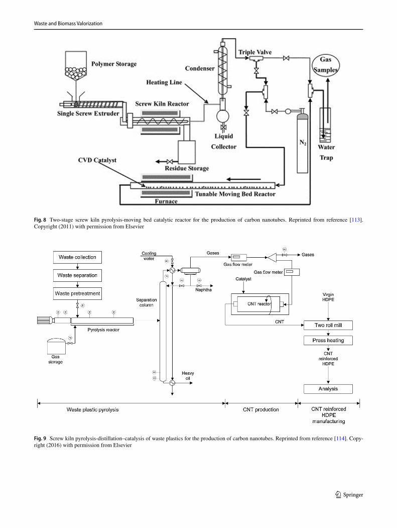
A fully continuous two stage pyrolysis-catalytic reactor system including an intermediate oil condensation system was developed by Liu et al. [113] for the production of car-bon nanotubes from polypropylene. The waste plastic poly-propylene was fed continuously via a screw feeder into a first stage pyrolysis reactor in the presence of a zeolite cata-lyst. The pyrolysis liquid oil products were condensed and
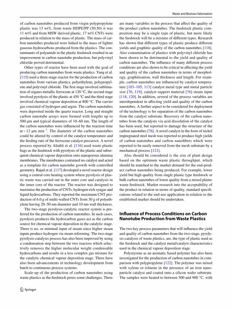
the gases passed to the second stage consisting of a moving bed reactor containing a NiO catalyst (Fig. 8). The product filamentous carbons were mostly multi-walled carbon nano-tubes. The influence of varying the pyrolysis temperature (550 °C to 750 °C) showed higher polymer decomposition at higher temperature leading to higher pyrolysis gas yield and consequent higher carbon nanotube yield. Increasing the catalyst temperature (500 °C to 800 °C) led to an improve-ment in the quality of the product hydrocarbons in terms of graphitisation of the carbon nanotube walls. In addition, the effect of higher catalyst temperature was to narrow the outer diameter range of the carbon nanotubes from 10 to 50 nm at 500 °C to 15–25 nm at 800 °C. The yield of carbon nano-tubes was optimised at a pyrolysis temperature of 650 °C and a catalyst temperature of 700 °C at 37 wt% of carbon nanotubes from the polypropylene. Borsodi et al. [114] have also developed a continuous two-stage pyrolysis-catalysis system with an intermediate condensation/distillation col-umn for the production of carbon nanotubes (Fig. 9) A wide range of plastics was investigated, including virgin plastics and waste polypropylene, polyethylene and mixed waste plastic derived from municipal solid waste. The waste plas-tics contained significant contamination. The reactor system consisted of a heated extruder which fed the plastic materi-als to a screw kiln pyrolysis reactor (560–570 °C) with a downstream packed bed, water cooled distillation column for separation of heavy oil, light oil and gases. The lighter gaseous fraction was passed to a semi-continuous rotating catalysis reactor (700 °C) containing Fe or Co based SiO2/Al2O3 catalyst for carbon nanotube production. The amount
Fig. 7 Pyrolysis-catalysis of polyethylene with intermediate condensation of higher hydrocarbons for the production of carbon nanotubes. Reprinted from reference [112]. Copyright (2018) with permission from Elsevier
Waste and Biomass Valorization
1 3
Fig. 8 Two-stage screw kiln pyrolysis-moving bed catalytic reactor for the production of carbon nanotubes. Reprinted from reference [113]. Copyright (2011) with permission from Elsevier
Fig. 9 Screw kiln pyrolysis-distillation–catalysis of waste plastics for the production of carbon nanotubes. Reprinted from reference [114]. Copy-right (2016) with permission from Elsevier
Waste and Biomass Valorization
1 3
of carbon nanotubes produced from virgin polypropylene plastic was 13 wt%, from waste HDPE/PP (50:50) it was 11 wt% and from MSW derived plastic, 17 wt% CNTs were produced in relation to the mass of plastic. The mass of car-bon nanotubes produced were linked to the mass of lighter gaseous hydrocarbons produced from the plastics. The con-taminants of polyamide in the plastic feedstock resulted in an improvement in carbon nanotube production, but polyvinyl chloride proved detrimental.
Other types of reactor have been used with the goal of producing carbon nanotubes from waste plastics. Yang et al. [115] used a three-stage reactor for the production of carbon nanotubes from various plastics, polyethylene, polypropyl-ene and polyvinyl chloride. The first stage involved sublima-tion of organo-metallic ferrocene at 120 °C, the second stage involved pyrolysis of the plastic at 450 °C and the third stage involved chemical vapour deposition at 800 °C. The carrier gas consisted of hydrogen and argon. The carbon nanotubes were deposited inside the quartz reactor. Long and straight carbon nanotube arrays were formed with lengths up to 500 µm and typical diameters of 10–60 nm. The length of the carbon nanotubes were influenced by the reaction time at ~ 12 µm min 1. The diameter of the carbon nanotubes could be altered by control of the catalyst temperature and the feeding rate of the ferrocene catalyst precursor. A novel process reported by Altahli et al. [116] used waste plastic bags as the feedstock with pyrolysis of the plastic and subse-quent chemical vapour deposition onto nanoporous alumina membranes. The membranes contained no catalyst and acted as a template for carbon nanotube growth with controlled geometry. Bajad et al. [117] developed a novel reactor design using a central core heating system where pyrolysis of plas-tic waste was carried out in the outer core and catalysis in the inner core of the reactor. The reactor was designed to maximise the production of CNTs, hydrogen-rich syngas and liquid hydrocarbons. They reported the maximum CNT pro-duction of 6.0 g of multi-walled CNTs from 30 g of polyeth-ylene having 20–50 nm diameter and 10 nm wall thickness.
The two-stage pyrolysis-catalytic reactor system is pre-ferred for the production of carbon nanotubes. In such cases, pyrolysis produces the hydrocarbon gases act as the carbon source for chemical vapour deposition in the catalytic stage. There is no, or minimal input of steam since higher steam inputs produce hydrogen via steam reforming. The two-stage pyrolysis-catalysis process has also been improved by using a condensation step between the two reactors which selec-tively removes the higher molecular weight condensable hydrocarbons and results in a less complex gas mixture for the catalytic chemical vapour deposition stage. There have also been advancements in technology development from batch to continuous process systems.
Scale-up of the production of carbon nanotubes using waste plastics as the feedstock poses some challenges. There
are many variables in the process that affect the quality of the product carbon nanotubes. The feedstock plastic com-position may be a single type of plastic, but more likely the feedstock will be a mixture of different types. Research has shown that different types of plastic produce different yields and graphitic quality of the carbon nanotubes [118]. Also contamination of plastics with polyvinyl chloride has been shown to be detrimental to the yield and quality of carbon nanotubes. The influence of many different process conditions are also shown to be critical in affecting the yield and quality of the carbon nanotubes in terms of morphol-ogy, graphitisation, wall thickness and length. For exam-ple, carbon nanotubes are influenced by catalyst tempera-ture [103–105, 113] catalyst metal type and metal particle size [76, 119], catalyst support material [76] steam input [118, 120]. In addition, several of the process variables are interdependent in affecting yield and quality of the carbon nanotubes. A further aspect to be considered for deployment of the technology is for separation of the carbon nanotubes from the catalyst substrate. Recovery of the carbon nano-tubes from the catalysts via acid dissolution of the catalyst has been used, but reported to damage the structure of the carbon nanotubes [76]. A novel catalyst in the form of nickel impregnated steel mesh was reported to produce high yields of carbon nanotubes and carbon nanofibers which were reported to be easily removed from the mesh substrate by a mechanical process [121].
Also should be considered is the size of plant design based on the optimum waste plastic throughput, which should be matched to the market demand for the end-prod-uct carbon nanotubes being produced. For example, lower yield but high quality from single plastic type feedstock or bulk carbon nanotubes of lower quality from a mixed plastic waste feedstock. Market research into the acceptability of the product in relation in terms of quality, standard specifi-cations related to the end-use application in relation to the established market should be undertaken.
Influence of Process Conditions on Carbon Nanotube Production from Waste Plastics
The two key process parameters that will influence the yield and quality of carbon nanotubes from the two-stage, pyroly-sis-catalysis of waste plastics, are, the type of plastic used as the feedstock and the catalyst metal/catalyst characteristics used in the chemical vapour deposition stage.
Polystyrene as an aromatic based polymer has also been investigated for the production of carbon nanotubes in com-parison with polypropylene [122]. The polymer was mixed with xylene or toluene in the presence of an iron nano-particle catalyst and coated onto a silicon wafer substrate. The samples were heated to between 500 and 900 °C, with

Waste and Biomass Valorization
1 3
700 °C producing the most suitable carbon nanotubes. The product carbon nanotubes from polystyrene were between 7.5 and 25 nm but had thick walls compared to those pro-duced with polypropylene which was attributed to second-ary pyrolytic deposition of carbon with the polystyrene precursor. Polyvinyl chloride (and other plastics, including polypropylene and polyethylene) has been investigated as a feedstock for the production of carbon nanotubes [115]. The process involved a quartz tube reactor with sublimation of organo-metallic ferrocene to produce an iron catalyst. Poly-vinyl chloride was pyrolysed at 450 °C and then heating of the quartz tube to 800 °C produced vapour-catalyst interac-tion and the formation of carbon nanotubes. However, it was found that the graphitic walls of the carbon nanotubes were more disordered and contained more defects compared with those produced with polyethylene. The defects were attrib-uted to the presence of chlorine within the polyvinyl chloride influencing the dissolution of carbon into the metal catalyst.
There are fewer reports on the use of real-world waste plastic feedstocks for the production of carbon nanotubes. The presence of impurities potentially influencing the yield and quality of the carbon nanotubes. Wu et al. [123] reported on the pyrolysis-catalysis of several different waste plastics, including plastics from a motor oil container (MOC), waste commercial high density polyethylene (HDPE) and regran-ulated HDPE waste containing polyvinyl chloride (PVC). The plastics were pyrolysed and the product gases passed to a catalytic steam reforming reactor using a Ni–Mn–Al catalyst, where the carbon was deposited on the catalyst. All of the plastics produced carbon deposits which consisted of amorphous and filamentous carbons which were shown to be mostly multi-walled carbon nanotubes. The carbon nanotubes had average diameters of 30 nm with 10 nm thick walls and up to 10 µm in length. The HDPE containing PVC produced less carbon nanotubes which was attributed to the chlorine which poisoned the catalyst.
The type of metal catalyst, presence of metal promo-tors and catalyst support material will influence the yield and quality of the product carbon nanotubers. Acomb et al. [124], investigated the influence of different catalyst metals supported on alumina for the production of carbon nano-tubes using a fixed bed, batch pyrolysis-catalytic, two-stage reactor. The metal-alumina catalysts investigated were Ni–Al2O3, Fe–Al2O3, Co–Al2O3 and Cu–Al2O3. Pyrolysis of the polyethylene was at a temperature of 600 °C (plas-tic heated to 600 °C at 50 °C min−1) and the catalyst was heated to 800 °C in the second stage. Carbon nanotubes were produced with the Ni-, Fe- and Co-alumina catalysts but only low yields were reported for the Cu-alumina catalyst. The yield of carbon nanotubes was linked to the strength of interaction between the metal and support. Iron having a strong interaction between metal and support and also a high carbon solubility producing the highest yield of carbon
nanotubes, whereas copper had only a weak interaction with the alumina support, producing virtually no carbon nano-tubes. Gong et al. [125] also investigated the influence of different catalyst metals on the production of carbon nano-tubes using polypropylene as the plastic feedstock. They pyrolysed polypropylene at temperatures between 720 and 920 °C with metal catalysts together with activated carbon. The metal catalysts consisted of Ni2O3, Fe2O3 and Co2O3 and were mixed with the activated carbon and polypropyl-ene and heated in a quartz tube reactor. The carbon residue left in the quartz tube after reaction contained the carbon nanotubes. It was suggested that the addition of activated carbon produced an increase in the cracking of the polypro-pylene and also the formation of aromatic and/or polycyclic aromatic compounds from the light hydrocarbon pyrolysis products. Also, the activated carbon promoted hydrogena-tion and aromatisation reactions which led to an increase in carbon nanotube production.
Nahil et al. [119] used a two-stage reaction system to investigate the influence of a range of metal catalyst promo-tors (Zn, Mg, Ca, Ce or Mn) incorporated into a nickel based catalyst based on ternary mixed oxide types Ni-Metal-Al for the two-stage pyrolysis-catalysis of polypropylene. Only the Ni–Mn–Al catalyst produced significant amounts of carbon nanotubes, with the others producing amorphous or filamen-tous carbons. Liu et al. [126] reported that the most effective catalyst metals for carbon nanotube production using the chemical vapour deposition synthesis process are nanopar-ticles of the transition metals nickel, iron and cobalt due to their high carbon solubility and high diffusion rate of car-bon. Other metals investigated include, copper, ruthenium, manganese and chromium. Liu et al. [126] used a two-stage pyrolysis-catalyst reactor to produce carbon nanotubes from waste plastics using a Ni/ceramic (Al2O3) membrane cata-lyst. The micro-channels of the ceramic membrane struc-ture control the active catalyst metal deposition inside the ceramic membrane and thereby control the diameters of the product carbon nanotubes. The plastic used was high density polyethylene pyrolysed at 500 °C and the pyrolysis gases passed to the catalyst stage maintained at either, 600, 700 or 800 °C. In addition, different nickel metal loadings on the ceramic membrane support were investigated. The results showed that the optimum temperature for CNT growth was 700 °C, it was suggested that increased catalyst temperature promoted the diffusion rate of carbon atoms in the metal particles and thereby carbon nanotubes are produced with less defects. But at higher temperatures, sintering of metal particles increases particle size and deactivates the catalyst. Increased metal loading resulted in increased metal particle size from ~ 12.0 to 34.5 nm and consequent increase in the diameters of the product carbon nanotubes, from ~ 15.5 to 25.0 nm. In a later paper [120] using the same reactor sys-tem and same Ni/ceramic membrane catalyst, the influence

Waste and Biomass Valorization
1 3
of steam injection on the production and quality of product carbon nanotubes was investigated. The results showed that the injection of steam reduced the carbon nanotube diameter range. It was also suggested that steam was responsible for the mild oxidation of amorphous carbon, thereby reducing catalyst deactivation via carbon encapsulation of the metal particle and consequently influencing carbon nanotube growth.
The addition of steam to the second stage catalytic reac-tor has been found to influence the amount and quality of carbon nanotubes, with high steam input markedly reducing carbon nanotube formation [119]. The injection of steam and rate of steam input has also been shown to influence the yield and quality of carbon nanotubes by others [118, 127, 128]. Hata et al. [127] reported that the steam acts as a mild oxidising agent for the oxidation of the amorphous carbons which reduces catalyst deactivation, thereby, ena-bling longer and purer carbon nanotubes to form. Ago et al. [128] investigated the rate of steam input and showed that increased steam addition increased carbon nanotube yield, but excessive steam input deactivated the catalyst and restricted the deposition of methane for carbon nanotube production. Acomb et al. [118] investigated the influence of steam input rate for polypropylene, low density polyethylene and polystyrene on the formation of carbon nanotubes using a two-stage pyrolysis-catalytic steam reforming reactor. The yield and quality of the product carbons was influenced by steam input rate, but the optimum rate was different for the different plastics.
The main catalyst used for carbon nanotube production from waste plastics reflect those used in commercial produc-tion, such as iron, cobalt and nickel based catalysts. Cata-lysts with strong interaction between metal and support and finely dispersed metal catalyst particles have been shown to result in higher yields of carbon nanotubes. The influ-ence of process conditions suggests that higher pyrolysis temperature produces a less complex gas mixture for car-bon nanotubes growth. Higher catalyst temperatures favour carbon nanotube production but at temperatures of 900 °C, carbon nanotubes are reduced in quality due to sintering of the catalyst metal. Higher steam inputs to the catalyst result in higher rates of hydrocarbon reforming and consequently much lower yields of CNTs. At low steam inputs, mild oxi-dation of amorphous hydrocarbons improves the quality of the carbon nanotubes.
One of the issues of producing carbon nanotubes from waste plastics using the catalytic chemical vapour deposition process is the extraction of the product carbon nanotubes away from the catalyst used for their growth. The carbon nanotubes can become encapsulated and intermingled with the catalyst particles, making recovery of the carbon nano-tubes difficult. Zhang et al. [121] used a two-stage pyrolysis-catalytic reactor with a novel nickel impregnated stainless
steel mesh in the catalyst stage to produce carbon nanotubes. The plastic used was high density polyethylene. Higher tem-peratures of the nickel-stainless steel mesh catalyst increased CNT yield and higher plastic-to-catalyst ratio resulted in a reduction in catalyst carbon deposition at 900 °C. It was also found that the use of the mesh catalyst enabled easy collection of the product CNTs. The production of carbon nanotubes produced from waste plastics by pyrolysis and chemical vapour deposition catalysis are often accompa-nied by the production of carbon nanofibers, that is, solid filaments rather than hollow tubes [76, 121, 129]. Indeed, Zhang et al. [121] estimated that the proportion of carbon nanofibers compared to carbon nanotubes was up to 40% for filamentous type carbons produced from waste plastics using their nickel-stainless steel mesh catalyst. Chatterjee and Deopura [130] have discussed the mechanism of formation for carbon nanofibers compared to carbon nanotubes. They suggest that the initial formation of the carbon nanofibers is similar to that of carbon nanotubes, involving a carbon con-taining precursor feedstock and a process of carbon deposi-tion, absorption and precipitation of carbon onto the catalyst metal particle surface. Further carbon vapour precipitation forms a highly graphitic strand that lengthens and thickens to produce a nanofiber. Carbon nanofibers, similarly to carbon nanotubes, have a commercial value and with applications in battery technology, composite materials and in medical and environmental applications.
Co‑production of Hydrogen and Carbon Nanotubes from Waste Plastics
The two-stage pyrolysis-catalysis of waste plastics has been shown to produce carbon nanotubes. In addition, the addi-tion of steam may be beneficial for improving the quality of the product carbon nanotubes through the mild oxida-tion of reactive amorphous carbon. The addition of steam to the waste plastics pyrolysis gases in a chemical vapour deposition catalytic reactor will also generate steam through reforming of the pyrolysis hydrocarbons. As a consequence, there has been interest in developing a two-stage pyrolysis-catalysis system for the co-production of both hydrogen and carbon nanotubes. For example, Liu et al. [131] investigated iron and nickel based SiO2 catalysts for the co-production of hydrogen and carbon nanotubes from waste polypropyl-ene. A two-stage reactor was used with pyrolysis at a final temperature of 500 °C and catalyst temperature at 800 °C and the influence of catalyst metal particle size investigated. The results showed that the Fe–SiO2 catalyst had the largest metal particles compared with the smaller metal particles for Ni–SiO2. The larger iron particles resulted in the high-est hydrogen production and highest yield of carbon, which was suggested to be due to the high carbon solubility of iron. There was a strong link between the metal particle size

Waste and Biomass Valorization
1 3
and the diameters of the product carbon nanotubes. Also, Yao et al. [129] reported on the influence of different types of catalyst with different support materials and also the influence of operational parameters on CNT and hydrogen production in a two-stage, quartz pyrolysis-catalyst reactor. The catalysts investigated were Ni, Fe and Ni–Fe metals on γ-Al2O3, or α-Al2O3 support material and the operational parameters investigated included catalyst temperature and steam-input. The bimetallic Ni–Fe catalyst showed strong interaction between metal and support and finely dispersed catalyst particles resulting a higher yield of carbon nano-tubes. Higher catalyst temperature favoured CNT production and also hydrogen, but at the highest temperature investi-gated at 900 °C, the carbon nanotubes were of lower qual-ity due to sintering of the metal. Higher steam inputs to the catalyst reactor resulted in higher rates of hydrocarbon reforming and consequently higher yields of hydrogen, but much lower yields of CNTs.
Wu et al. [132] used a two-stage reaction system to pyro-lyse polypropylene followed by steam reforming of the prod-uct pyrolysis gases using Ni/Ca–Al and Ni/Zn–Al catalysts. In addition to the generation of hydrogen, significant for-mation of multi-walled carbon nanotubes on the catalyst was reported. The carbon nanotubes deposited on the Ni/Ca–Al catalyst were 50 nm in diameter and several µm in length and characterisation by Raman spectrometry revealed that they were highly graphitic in nature. From temperature
programmed oxidation of the used Ni/Ca–Al catalyst, it was estimated that 20 wt% of the mass of catalyst consisted of carbon nanotubes, representing ~ 0.16 g g−1polypropylene. The Ni/Zn–Al catalyst produced more hydrogen and less carbon nanotubes than the Ni/Ca-Al catalyst.
Properties of Plastic Derived Carbon Nanotubes
Carbon nanotubes may be characterised by a range of dif-ferent analytical techniques, including scanning electron microscopy (SEM) and transmission electron microscopy (TEM) and Raman spectral analysis [124]. Typical SEM, TEM and Raman spectral analyses of carbon nanotubes derived from waste plastic are shown in Fig. 10. The carbon nanotubes were produced from the pyrolysis-catalysis of waste low density polyethylene in the presence of a nickel-alumina catalyst. The deposition on the nickel-alumina cata-lyst in the SEM image in Fig. 11a shows the presence of filamentous carbons on the catalyst surface. TEM images shown in Fig. 11c confirmed that the filaments observed were multi-walled carbon nanotubes. The carbon nanotubes had diameters between 15 and 30 nm and lengths of up to several microns.
Also shown in Fig. 10 is the Raman spectral analysis of the carbon nanotubes collected on the nickel-alumina cata-lyst. Raman spectrometry characterises the purity, crystal defects and tube alignment of the carbon nanotubes. The
Fig. 10 Analysis of carbon nanotubes produced from waste plastic (low density polyeth-ylene) on a nickel-alumina catalyst a SEM, b Raman spec-troscopy and c TEM. Reprinted from reference [124]. Copyright (2016) with permission from Elsevier

Waste and Biomass Valorization
1 3
analysis gives an indication of the quality of the carbon nanotubes. The Raman spectrum of the sp3-hybridised carbon–carbon bond (D band) shows a single sharp peak between 1290 cm−1 and 1360 cm−1. Carbon atoms in hex-agonal arrangement such as graphite, graphene and multi-walled carbon nanotubes (MWCNT) with sp3-hybridised carbon–carbon bond, shifts the Raman peak to a higher frequency at 1582 cm−1, designated as the G-band. The G’ band gives a peak at 2700 cm−1. For MWCNT the inten-sity of the D band increases compared to the G band with increasing number of walls in the MWCNT. Figure 10 shows the presence of both G and D peaks for the carbon nanotubes produced from plastic waste, with the peaks being of a simi-lar height. The ratio between these peaks, G:D ratio, is often used as a tool to determine the quality of CNTs produced with a higher value representing higher quality or purity CNTs. Figure 10 shows a G:D ratio of 1.10, indicating less purity in terms of CNTs. The spectra produced show peaks at 1589 and 1348 cm−1 corresponding to the G peak, asso-ciated with graphitic carbon structures within the sample, and the D peak associated with defects within the graphic lattice or amorphous carbons, respectively. The G’ peak is also observed at 2709 cm−1 associated with the two photon elastic scattering process, and can be used as an indicator of the purity of carbon nanotubes.
Carbon nanotubes produced from different waste plastics via pyrolysis-catalysis have also been characterised by trans-mission electron microscopy and Raman spectroscopy to determine the influence of plastic type on the carbon nano-tubes produced [118]. Figure 11 shows the carbon deposits formed from polyethylene, polypropylene and polystyrene. Multi walled carbon nanotubes were confirmed for all of the plastics and were similar in morphology and were between 10 and 20 nm in diameter and lengths of several hundred nm. However, the yield of CNTs for each plastic were dif-ferent, where polyethylene produced 19 wt% of carbon nanotubes, much larger than either polypropylene, 9 wt%, or
polystyrene, 10 wt%. Raman spectroscopy was also under-taken to characterise the carbon deposits produced with the different waste plastics (Fig. 12). The results showed that polyethylene had a much higher purity of CNTs with a G:D ratio of 1.7, compared with 1.2 for polypropylene and 1.1 for polystyrene.
The European Commission Joint Research Centre [133] have characterised, in detail, several representative multi-walled carbon nanotubes. The carbon nanotubes produced were multi-walled types produced by chemical vapour depo-sition of hydrocarbons at 600–1200 °C. The characteristic morphology of entangled carbon nanotubes as determined by transmission electron microscopy, and the lengths and diameters of the commercial carbon nanotubes are similar to those produced from waste plastics. In addition, Raman spectral analysis of the commercial carbon nanotubes [133] compared to those produced from waste plastics [118, 124] showed a similar graphitic nature and purity.
Application of Carbon Nanotubes Produced from Waste Plastics
The product carbon nanotubes from the pyrolysis-catalysis of waste plastics have been tested in a limited number of applications. For example, carbon nanotubes produced from the pyrolysis-catalysis of waste polypropylene were incor-porated as strengthening reinforcement in the fabrication of a low density polyethylene composite material [134]. It was reported that the tensile strength and flexural strength of the CNT reinforced composite material were significantly improved to a maximum of 15% and 19% respectively, with the addition of the recovered CNTs. Moo et al. [135] pro-duced carbon nanotubes from various different plastics using a two-stage quartz pyrolysis-catalysis reactor. They evalu-ated the product CNTs as electrode materials in electroca-talysis, such applications include their use as fuel cell elec-trode material for oxygen reduction reaction. They reported
Fig. 11 Transmission electron micrographs of carbon nanotubes produced with different waste plastics. Reprinted from reference [118]. Copy-right (2014) with permission from Elsevier

Waste and Biomass Valorization
1 3
improved electrocatalytic activity for CNTs produced at higher catalyst temperature, but there was little difference in performance for the CNTs produced from different types of waste plastic. Cai et al. [136] have reported on a novel
route to produce nitrogen and iron carbon nanotubes with an application as electro-catalysts for the oxygen reduction reaction in fuel cells or metal air batteries. Fe-CNTs were produced from the pyrolysis-catalysis of polypropylene with a Fe-Al2O3 catalyst, followed by co-pyrolysis of the Fe-CNTs with melamine. The product Fe–N-CNT’s showed remarkable electro-catalytic activity, outperforming a Pt on carbon electro-catalyst in oxygen reduction reaction tests and in Zn-air battery tests. Deokar et al. [137] produced carbon nanotubes from waste polyethylene as the source of carbon with a Ni/Mo/MgO catalyst in a single step process using a quartz crucible. The product carbon nanotubes were tested for the removal of a herbicide (diuron) from a representative wastewater. Diuron is a phenyl herbicide used for control of grassy weeds, mosses and algae. It was reported that the plastic derived carbon nanotubes were an effective adsorbent for diuron removal from aqueous solution and therefore a suitable adsorbent for the treatment of wastewater.
Conclusions and Discussion
The environmentally sustainable management of waste plas-tics is of current concern. Hydrogen has a wide number of industrial applications and is regarded as a clean fuel and centrally placed in future energy scenarios. Carbon nano-tubes have been shown to have unique and advantageous properties in a number of applications and are regarded as high value products. Consequently, using waste plastics as a feedstock for the production of hydrogen and carbon nano-tubes provides an appealing treatment option. Literature reports have shown a range of different reactor configura-tions used to produce hydrogen and carbon nanotubes from waste plastics. This review has concentrated on the two-stage reactor system, with pyrolysis of the waste plastics under controlled conditions in a first stage process, the evolved pyrolysis gases are then passed to a second controlled cata-lytic reactor where hydrogen and/or carbon nanotubes can be produced. In particular, this review has covered the produc-tion of hydrogen and carbon nanotubes from waste plastics concentrating on the various reactor designs investigated, influence of process parameters, catalyst types used etc. The development of reactor systems for both hydrogen and carbon nanotubes production is a move from batch to con-tinuous systems which enable larger throughputs of waste plastics and increased yields of product. Some continuous system have been developed, but the reactors are at labora-tory scale. Consequently, larger pilot-scale reactor systems should be developed.
In regard to the influence of process parameters on hydro-gen yield and quality and yield of carbon nanotubes, the type of plastic under investigation, the temperature of pyrol-ysis and catalyst temperature are shown to be key factors
Fig. 12 Raman spectra of carbon nanotubes produced from differ-ent waste plastics (polyethylene, polypropylene and polystyrene). Reprinted from reference [118]. Copyright (2014) with permission from Elsevier

Waste and Biomass Valorization
1 3
in determine hydrogen and carbon nanotube yield. In some processes, both hydrogen and carbon nanotubes have been produced in a co-processing system. In such cases, the steam input is optimised for either hydrogen, carbon nanotubes or both products. There is a trade-off between introduction of steam which improves hydrogen yield, and also improve carbon nanotubes quality by oxidising more reactive amor-phous carbons. However, at higher steam inputs, the carbon nanotubes themselves are oxidised.
A further consideration for the devlopment of waste plas-tics management via the two-stage process is the need for a whole-systems approach to consider the collection and potentially the sorting of the post-consumer plastic waste and the market demand for the end-products. The collection of household waste plastics is common in Europe, whether as a separate plastic waste or commingled with other house-hold recylable waste streams. The collection process involv-ing potentially hundreds of thousands of homes represents a considerable part of the costs of the process system. Cen-tralised sorting may be required to produce a suitable plastic feedstock for the pyrolysis-catalysis process plant. Sorting of plastics involves removal of any commingled waste mate-rials and also to produce a plastic waste stream of known plastic composition. In particular, it may be necessary for the removal/reduction of contaminants from the plastic where there presence in the plastic may inhibit the plant efficien-cieny. For example, the presence of chlorinated plastics (polyvinyl chloride), plastics wcontaining brominated fire retardants and inorganic contaminants mixed with the plas-tics such as volatile heavy metals. In addition, transport costs of the plastic waste to the sorting plant and/or the plastics pyrolysis-catalysis plant should also be considered. While hydrogen and carbon nanotubes are known to be higher value products, the penetration of alternative sources of these commodities into the market place may not be straight forward. For example, low production tonnages of hydrogen may not be attractive to a market that is well established with known composition/quality standards to maintain. Similarly, there are many different types of carbon nanotubes that are in market demand and again, quality of the produced carbon nanotubes and the requirement to meet standard specifica-tions should be considered. Therefore, it is essential to match the characteristics of the produced carbon nanotubes and thereby, the process conditions to the requirements of the stabndard specifications of the particular application of the carbon nanotubes in the market place.
Open Access This article is licensed under a Creative Commons Attri-bution 4.0 International License, which permits use, sharing, adapta-tion, distribution and reproduction in any medium or format, as long as you give appropriate credit to the original author(s) and the source, provide a link to the Creative Commons licence, and indicate if changes were made. The images or other third party material in this article are included in the article’s Creative Commons licence, unless indicated
otherwise in a credit line to the material. If material is not included in the article’s Creative Commons licence and your intended use is not permitted by statutory regulation or exceeds the permitted use, you will need to obtain permission directly from the copyright holder. To view a copy of this licence, visit http://creativecommons.org/licenses/by/4.0/.
References
1. PlasticsEurope. Plastics the facts 2017. PlasticsEurope, Brussels (2017)
2. EUWID: EU waste plastics exports down a quarter in 2018, EUWID Recycling & bWaste Management, Gernsbach, Ger-many (2019)
3. European Commission: A stretegy for plastics in a circular economy, COM(2018) 28 Final. 16.1.2018. European Com-mission, Brussels (2018)
4. Scheirs, J., Kaminsky, W.: Feedstock Recycling and Pyrolysis of Waste Plastics: Converting Waste Plastics into Diesel and Other Fuels. Wiley, London (2006)
5. Delgado, C., Barruetabeña, L., Salas, O., Wolf, O.: Assessment of the Environmental Advantages and Drawbacks of Existing and Emerging Polymers Recovery Processes. European Com-mission JRC, EUR 22939, Luxembourg (2007)
6. Al-Salem, S.M., Lettieri, P., Baeyens, J.: Recycling and recovery routes of plastic solid waste (PSW): a review. Waste Manag. 29, 2625–2643 (2019)
7. Al-Salem, S.M., Lettieri, P., Baeyens, J.: The valorization of plastic solid waste (PSW) by primary to quarernary routes: from re-use to energy and chemicals. Prog. Energy Combust. Sci. 36, 103–129 (2010)
8. Sannita, E., Aliakbarian, B., Casazza, A.A., Perego, P., Busca, G.: Medium temperature conversion of biomass and wastes into liquid products, a review. Renew. Sustain. Energy Rev. 16, 6455–6475 (2012)
9. Brems, A., Baeyens, J., Dewil, R.: Recycling and recovery of post-consumer plastic solid waste in a European Context. Therm. Sci. 16, 669–685 (2012)
10. Panda, A., Singh, R.K., Mishra, D.K.: Thermolysis of waste plastics to liquid fuel; A suitable method for plastic waste man-agement and manufacture of value added products: a world prospective. Renew. Sustain. Energy Rev. 14, 233–248 (2010)
11. Williams, P.T., Williams, E.A.: Fluidised bed pyrolysis of low density polyethylene to produce petrochemical feedstock. J. Anal. Appl. Pyrol. 51, 107–126 (1999)
12. Williams, P.T., Williams, E.A.: Interaction of plastics in mixed plastics pyrolysis. Energy Fuels 13, 188–196 (1999)
13. Kaminsky, W., Predel, M., Sadiki, A.: Feedstock recycling of polymers by pyrolysis in a fluidised bed. Polym. Degrad. Stab. 85, 1045–1050 (2004)
14. Kunwar, B., Cheng, H.N., Chanrashekaran, S.R., Sharma, B.J.: Plastics to fuel: a review. Renew. Sustain. Energy Rev. 54, 421–428 (2016)
15. Wu, C., Williams, P.T.: Chapter 1: advanced thermal treat-ment of wastes for fuels, chemicals and materials recovery. In: Hester, R.E., Harrison, R.M. (eds.) Waste as a Resource. Royal Society of Chemistry, London (2013)
16. UNEP, United Nations Environmental Programme: Converting Waste Plastics into a Resources, International Environmental Technology Centre, Osaka, Japan (2009)
17. Miskolczi, N., Angyal, A., Bartha, L., Valkai, I.: Fuel by pyrol-ysis of wasteplastics from agricultural and packaging sectors

Waste and Biomass Valorization
1 3
in a pilot scale reactor. Fuel Process. Technol. 90, 1032–1040 (2009)
18. Elordi, G., Arabiourrutia, M., Bilbao, J., Olazar, M.: Energetic viability of a polyolefin pyrolysis plant. Energy Fuels 32(3), 3751 (2018)
19. Beston (Henan) Machinery Co., Ltd., Zhengzhou, China. https ://tyrep yroly sispl ants.net/
20. Splainex Ecosystems Ltd. Rijswijk, Netherlands. https ://splai nex.com/
21. HUYAIN GROUP, Xinxiang City, China. https ://huayi nrecy cling .com/
22. PLASTIC ENERGY Ltd., London. https ://plast icene rgy.com/ 23. UNEP, Converting waste plastics into a resource, Compendium
of Technologies, United Nations Environment Programme (UNEP), Division of Technology, Industry and Economics Inter-national Environmental Technology Centre, Osaka/Shiga, Japan (2009)
24. Al-Salem, S.M., Antelava, A., Constantinou, A., Manos, G., Dutta, A.: A review on thermal and catalytic pyrolysis of plastic solid waste (PSW). J. Environ. Manag. 197, 177–198 (2017)
25. Sharuddin, S.D.A., Abnisa, F., Daud, W.M.A.W., Aroua, M.K.: A review on pyrolysis of plastic wastes. Energy Convers. Manag. 115, 308–326 (2016)
26. Miandad, R., Barakat, M.A., Aburiazaiza, A.S., Rehan, M., Nizami, A.S.: Catalytic pyrolysis of plastic waste: a review. Pro-cess Saf. Environ. Prot. 102, 822–838 (2016)
27. Serrano, D.P., Aguado, J., Escola, J.M.: Developing advanced catalysts for the conversion of polyolefinic waste plastics into fuels and chemicals. ACS Catal. 2, 1924–1941 (2012)
28. Lopez, G., Artetxe, M., Amutio, M., Alvarez, J., Bilbao, J., Ola-zar, M.: Recent advances in the gasification of waste plastics: a critical overview. Renew. Sustain. Energy Rev. 82, 576–596 (2018)
29. Barbarias, I., Lopez, G., Alvarez, J., Artetxe, M., Arregi, A., Bilbao, J., Olazar, M.: Valorisation of different waste plastics by pyrolysis and in-line catalytic steam reforming for hydrogen production. Energy Convers. Manag. 156, 575–584 (2018)
30. IEA, The Future of Hydrogen: Siezing todays opportunities. Report prepared by the IEA for the G20, Japan. International Energy Agency, Paris, France (2019)
31. Spath, P.L., Mann, M.K.: Life cycle assessment of hydrogen pro-duction via natural gas steam reforming. National Renewable Energy Laboratory, Golden Colorado (2001)
32. Wu, C., Williams, P.T.: Investigation of Ni-Al, Ni-Mg-Al and Ni-Cu-Al catalyst for hydrogen production from pyrolysis-gasi-fication of polypropylene. Appl. Catal. B 90, 147–156 (2009)
33. Wu, C., Williams, P.T.: Hydrogen production from the pyrolysis-gasification of polypropylene: Influence of steam flow rate, car-rier gas flow rate and gasification temperature. Energy Fuels 23, 5055–5061 (2009)
34. Wu, C., Williams, P.T.: Ni/CeO2/ZSM-5 catalysts for the produc-tion of hydrogen from the pyroilysis-gasification of polypropyl-ene. Int. J. Hydrogen Energy 34, 6242–6252 (2009)
35. Wu, C., Williams, P.T.: Hydrogen production by steam gasifica-tion of polypropylene with various nickel catalyst. Appl. Catal. B 87, 152–161 (2009)
36. Wu, C., Williams, P.T.: Pyrolysis-gasification of plastics, mixed plastics and real-world plastic waste with and without Ni-Mg-Al catalyst. Fuel 89, 3022–3032 (2018)
37. Yao, D., Yang, H., Chen, H., Williams, P.T.: Investigation of nickel-impregnated zeolite catalysts for hydrogen/syngasproduc-tion from the catalytic reforming of waste polyethylene. Appl. Catal. B 227, 477–487 (2018)
38. Park, Y., Namioka, T., Sakamoto, S., Min, T., Roh, S., Yoshi-kawa, K.: Optimum operating conditions for a two-stage gasifi-cation process fueled by polyproylene by means of continuous
reactor over ruthenium catalyst. Fuel Process. Technol. 91, 951–957 (2010)
39. Namioka, T., Saito, A., Inoue, Y., Park, Y., Min, T.J., Roh, S.A., Yoshikawa, K.: Hydrogen-rich gas production from waste plas-tics by pyrolysis and low-temperature steam reforming over a ruthenium catalyst. Appl. Energy 88, 2019–2026 (2011)
40. He, M., Xiao, B., Hu, Z., Liu, S., Guo, X., Luo, S.: Syngas pro-duction from catalytic gasification of waste polyethylene: Influ-ence of temperature on gas yield and composition. Int. J. Hydro-gen Energy 34, 1342–1348 (2009)
41. Wu, C., Williams, P.T.: Hydrogen from waste plastics by way of pyrolysis-gasification. Waste Resour. Manag. 167, 35–46 (2014)
42. Czernik, S., French, R.J.: Production of hydrogen from plastics by pyrolysis and catalytic steam reform. Energy Fuels 20, 754–758 (2006)
43. Dou, B., Wang, K., Jiang, B., Song, Y., Zhang, C., Chen, H., Xu, Y.: Fluidized-bed gasification combined continuous sorp-tion-enhanced steam reforming system to continuous hydrogen production from waste plastic. Int. J. Hydrogen Energy 41, 3803–3810 (2016)
44. Barbarias, I., Lopez, G., Alvarez, J., Artetxe, M., Arregi, A., Bilbao, J., Olazar, M.: A sequential process for hydrogen pro-duction based on continuous HDPE fast pyrolysis and in-line steam reforming. Chem. Eng. J. 296, 191–198 (2016)
45. Barbarias, I., Lopez, G., Alvarez, J., Artetxe, M., Arregi, A., Santamaria, L., Bilbao, J., Olazar, M.: Pyrolysis and in-line catalytic steam reforming of polystyrene througha two-step reaction system. J. Anal. Appl. Pyrol. 122, 502–510 (2016)
46. Sharma, S.S., Batra, V.S.: Production of hydrogen and carbon nanotubes via catalytic thermo-chemical conversion of plastic waste: review. J. Technol. Biotechnol. 95, 11–19 (2019)
47. Makibar, J., Fernandez-Akarregi, A.R., Amutio, M., Lopez, G., Olazar, M.: Performance of a conical spouted bed pilot plant for bio-oil production by poplar flash pyrolysis. Fuel Process. Technol. 137, 283–289 (2015)
48. Kumagai, S., Hosaka, T., Kameda, T., Yoshioka, T.: Removal of toxic HCN and recovery of H2-rich syngas via catalytic reforming of product gas from gasification of polyimide over Ni/Mg/Al catalysts. J. Anal. Appl. Pyrol. 123, 330–339 (2017)
49. Kumagai, S., Yabuki, R., Kameda, T., Saito, Y., Yoshioka, T.: Simultaeous recovery of H2-rich syngas and removal of HCN during pyrolytic recycling of polyurethane by Ni/Mg/Al cata-lysts. Chem. Eng. J. 361, 408–415 (2019)
50. Hall, W.J., Williams, P.T.: Fast pyrolysis of halogenated plas-tics recovered from waste computers. Enewrgy & Fuels 20, 1536–1549 (2006)
51. Veksha, A., Giannis, A., Oh, W.D., Chang, V.W., Lisak, G., Lim, T.T.: Catalytic activities and resistance to HCl poisoning of Ni-based catalysts during steam reforming of naphthalene. Appl. Catal. A 557, 25–38 (2018)
52. Kikuchi, E., Tanaka, S., Yamazaki, Y., Morita, Y.: Steam reforming of hydrocarbons on noble metal catalyst (Part1): the catalytic activity in methane-steam reaction. Bull. Jpn. Petrol. Inst. 16, 95–98 (1974)
53. Ovsyannikova, I.A., Goldsdenberry, G.I., Koryabkina, N.A., Shkrabina, R.A., Ismailov, Z.R.: Study of structural and mechanical properties of granulated alumina supports using X-ray microprobes. Appl. Catal. 55, 75–80 (1989)
54. Koryabkina, N.A., Ismagilov, Z.R., Shkabina, R.A., Moroz, E.M., Ushakov, V.A.: Influence of the method of alumina modification on formation of low-temperature solid solutions in magnesia-alumina systems. Appl. Catal. 72, 63–69 (1991)
55. Li, Y., Chen, J., Qin, Y., Chang, L.: Simultaneous production of hydrogen and nanocarbon from decomposition of methane on a nickel-based catalyst. Energy Fuels 14, 1188–1194 (2000)

Waste and Biomass Valorization
1 3
56. Chen, J., Li, X., Li, Y., Qin, Y.: Production of hydrogen and nanocarbon from direct decomposition of undiluted methane on high-nickeled Ni–Cu–alumina catalysts. Chem. Lett. 32, 424–435 (2003)
57. Miyazawa, T., Kimura, T., Nishikawa, J., Kao, S., Kunimori, K., Tomishige, K.: Catalytic performance of supported Ni cata-lysts in partial oxidation and steam reforming of tar derived from the pyrolysis of wood biomass. Catal. Today 115, 254–262 (2006)
58. Venuto, P.B., Habib, T.E.: Fluid Catalytic Cracking with Zeo-lite Catalysts. Marcel Dekker, New York (1979)
59. Wu, C., Williams, P.T.: Effects of gasification temperature and catalyst ratio on hydrogen production from catalytic steam pyrolysis-gasification of polypropylene. Energy Fuels 22, 4125–4132 (2008)
60. Wu, C., Williams, P.T.: Pyrolysis-gasification of post consumer municipla solid plastic waste for hydrogen production. Int. J. Hydrogen Energy 35, 949–957 (2010)
61. Simell, P.A., Hirvensalo, E.K., Smolander, V.T.: Steam reform-ing of gasification gas tar over dolomite with benzene as a model compound. Ind. Eng. Chem. Res. 38, 1250–1257 (1999)
62. Argyle, M.D., Bartholomew, C.H.: Heterogeneous catalyst deac-tivation and regeneration: a review. Catalysts 5, 145–269 (2015)
63. Cai, X., Dong, X., Lin, W.: Effect of CeO2 on the catalytic perfor-mance of Ni/Al2O3 for autothermal reforming of methane. Nat. Gas Chem. 17, 98–104 (2008)
64. Buffoni, I.N., Pompero, F., Santori, G.F., Nichio, N.N.: Nickel catalysts applied in steam reforming of glycerol for hydrogen production. Catal. Commun. 10, 1656–1660 (2009)
65. Sato, K., Fujimoto, K.: Development of new nickel based cata-lyst for tar reforming with superior resistance to sulfur poison-ing and coking in biomass gasification. Catal. Commun. 8(11), 1697–1701 (2007)
66. Srinakruang, J., Sato, K., Vitidsant, T., Fujimoto, K.: A highly efficient catalyst for tar gasification with steam. Catal. Commun. 6(6), 437–440 (2005)
67. Trimm, D.L.: Catalysts for the control of coking during steam reforming. Catal. Today 49, 3–10 (1999)
68. Wu, C., Williams, P.T.: Investigation of coke formation on Ni-Mg-Al catalyst for hydrogen production from the catalytic steam pyrolysis-gasification of polypropylene. Appl. Catal. B 96, 198–207 (2010)
69. Sehested, J.: Four challenges for nickel steam-reforming cata-lysts. Catal. Today 111, 103–110 (2006)
70. Kroll, V.C.H., Swaan, H.M., Mirodatos, C.: Methane reforming reaction with carbon dioxide over Ni/SiO2 catalyst: I. Deactiva-tion studies. J. Catal. 161, 409–422 (1996)
71. Rostrup-Neilsen, J.R., Trimm, D.L.: Mechanisms of carbon for-mation on nickel-containing catalysts. J. Catal. 48, 155 (1977)
72. Yung, M.M., Jablonski, W.S., Magrini-Bair, K.A.: Review of catalytic conditioning of biomass-derived syngas. Energy Fuels 23, 1874–1887 (2009)
73. Wilk, V., Hofbauer, H.: Conversion of mixed plastic wastes in a dual fluidized bed steam gasifier. Fuel 107, 787–799 (2013)
74. Erkiaga, A., Lopez, G., Amutio, M., Bilbao, J., Olazar, M.: Syn-gas from steam gasification of polyethylene in a conical spouted bed reactor. Fuel 109, 461–469 (2013)
75. De-Volder, M.F., Tawfick, S.H., Baughman, R.H., Hart, A.J.: Carbon Nanotubes: present and future commercial applications. Science 339, 535–539 (2013)
76. Bazargan, A., McKay, G.: A review- synthesis of carbon nano-tubes from plastic wastes. Chem. Eng. J. 195–196, 377–391 (2012)
77. Coleman, J.N., Khan, U., Blau, W.J., Gunko, Y.K.: Small but strong: a review of the mechanical properties of carbon nano-tube-polymer composites. Carbon 44, 1624–1652 (2006)
78. Dai, L., Chang, D.W., Baek, J.B., Lu, W.: Carbon nanomaterials for advanced energy conversion and storage. Small 8, 1130–1166 (2012)
79. Yang, W., Ratinac, K.R., Ringer, S.P., Thordarson, P., Goodfing, J.J., Braet, F.: Carbon nanomaterials in biosensors: should you use nanotubes or graphene. Angew. Chem. Int. Ed. 49, 2114–2138 (2010)
80. Rather, S.U.: Preparation, characterization and hydrogen storage studies of carbon nanotubes and their composites: a review. Int. J. Hydrogen Energy 45, 4653–4672 (2019)
81. Bassyouni, M., Mansi, A.E., Elgabry, A., Ibrahim, B.A., Kassem, O.A., Alhebeshy, R.: Utilization of carbon nanotubes in removal of heavy metals from wastewater: a review of the CNTs’ potential and current challenges. Appl. Phys. A 126, 38 (2020)
82. Kumar, A., Sharma, K., Dixit, A.R.: Carbon nanotube- and gra-phene-reinforced multiphase polymeric composites: review on their properties and applications. J. Mater. Sci. 55, 2682–2724 (2020)
83. Yang, Z.F., Tian, J.R., Yin, Z.F., Cui, C.J., Qian, W.Z., Wei, F.: Carbon nanotube- and graphene-based nanomaterials and appli-cations in high-voltage supercapacitor: a review. Carbon 141, 467–480 (2019)
84. Dai, H.: Carbon nanotubes: opportunities and challenges. Surf. Sci. 500, 218–241 (2002)
85. Joselevich, E., Dai, H., Liu, J., Hata, K., Windle, A.H.: Carbon nanotube synthesis and organization. In: Jorio, A., Dresselhaus, M., Dresselhaus, G. (eds.) Carbon Nanotubes: Advanced Topics in the Synthesis Structure Properties and Applications. Springer, New York (2008)
86. Kumar, M.: Carbon nanotubes- Synthesis and growth mecha-nism. In: Yellampalli, S. (ed.) Nanotechnology and Nanomate-rials; Carbon Nanotubes- Synthesis, Characterisation, Applica-tions. Intech, Vienna (2011)
87. Aboul-Enein, A.A., Awadallah, A.E., Abdel-Rahman, A.H., Haggar, A.M.: Synthesis of multi-walled carbon nanotubes via pyrolysis of plastic waste using a two-stage process. Fullerenes Nanotubes Carbon Nanostruct. 26(2), 443–450 (2018)
88. Awadallah, A.E., Aboul-Enein, A.A., Yonis, M.M., Aboul-Gheit, A.K.: Effect of structural promoters on the catalytic performance of cobalt-based catalysts during natural gas decomposition to hydrogen and carbon nanotubes. Fullerenes Nanotubes Carbon Nanostruct. 24, 181–189 (2016)
89. Moothi, K., Iyuke, S.E., Meyyappan, M., Falcon, R.: Coal as a carbon source for carbon nanotube synthesis. Carbon 50, 2679–2690 (2012)
90. Kong, J., Cassell, A.M., Dai, H.: Chemical vapor deposition of methane for single-walled carbon nanotubes. Chem. Phys. Lett. 292, 567–574 (1998)
91. Wei, Y.Y., Eres, G., Merkulov, V.I., Lowndes, D.H.: Effect of catalyst film thickness on carbon nanotube growth by selective area chemical vapor deposition. Appl. Phys. Lett. 78(10), 1394–1396 (2001)
92. Das, N., Dalai, A., Mohammadzadeh, J.S.S., Adjaye, J.: The effect of feedstock and process conditions on the synthesis of high purity CNTs from aromatic hydrocarbons. Carbon 44(11), 2236–2245 (2006)
93. Paul, S., Samdarshi, S.K.: A green precursor for carbon nanotube synthesis. New Carbon Mater. 26(2), 85–88 (2011)
94. Suriani, A.B., Dalila, A.R., Mohamed, A., Mamat, M.H., Salina, M., Rosmi, M.S., Rosly, J., Nor, R.M., Rusop, M.: Vertically aligned carbon nanotubes synthesis from waste chicken fat. Mater. Lett. 101, 61–64 (2013)

Waste and Biomass Valorization
1 3
95. Chai, S.-P., Zein, S.H.S., Mohamed, A.R.: Synthesizing carbon nanotubes and carbon nanofibers over supported-nickel oxide catalysts via catalytic decomposition of methane. Diam. Relat. Mater. 16(8), 1656–1664 (2007)
96. Jung, M.J., Eun, K.Y., Baik, Y.J., Lee, K.R., Shin, J.K., Kim, S.T.: Effect of NH3 environmental gas on the growth of aligned carbon nanotube in catalystically pyrolizing C2H2. Thin Solid Films 398, 150–155 (2001)
97. Kukovitskii, E.F., Chernozatonskii, L.A., Lvov, S.G., Melnik, N.N.: Carbon nanotubes of polyethylene. Chem. Phys. Lett. 266, 323–328 (1997)
98. Pol, V.G., Thiyagarajan, P.: Remediating plastic waste into car-bon nanotubes. J. Environ. Monit. 12(2), 455–459 (2010)
99. Arena, U., Mastellone, M.L., Camino, G., Boccaleri, E.: An innovative process for mass production of multi-wall carbon nanotubes by means of low-cost pyrolysis of polyolefins. Polym. Degrad. Stab. 91(4), 763–768 (2006)
100. Mishra, N., Das, G., Ansaldo, A., Genovese, A., Malerba, M., Povia, M., Ricci, D., Fabrizio, E.D., Zitti, E.D., Sharon, M., Sharon, M.: Pyrolysis of waste polypropylene for the synthesis of carbon nanotubes. J. Anal. Appl. Pyrol. 94, 91–98 (2012)
101. Kong, Q.H., Zhang, J.: Synthesis of straight and helical car-bon nanotubes from catalytic pyrolysis of polyethylene. Polym. Degrad. Stab. 92(11), 2005–2010 (2007)
102. Zhang, J., Li, J., Cao, J., Qian, Y.: Synthesis and characterisa-tion of larger diameter carbon nanotubes from catalytic pyroly-sis of polypropylene. Mater. Lett. 62, 1839–1842 (2008)
103. Kukovitskii, E.F., Lvov, S.G., Sainov, N.A., Shustov, V.A., Chernozatonskii, L.A.: Correlation between metal catalyst particle size and carbon nanotube growth. Chem. Phys. Lett. 355(5–6), 497–503 (2002)
104. Kukovitskii, E.F., Lvov, S.G., Sainov, N.A., Shustov, V.A.: CVD growth of carbon nanotube films on nickel substrates. Appl. Surf. Sci. 215(1–4), 201–208 (2003)
105. Yen, Y.W., Huang, M.D., Lin, F.J.: Synthesize carbon nano-tubes by a novel method using chemical vapor deposition-fluidized bed reactor from solid-stated polymers. Diam. Relat. Mater. 17(4–5), 567–570 (2008)
106. Acomb, J., Wu, C., Williams, P.T.: Effect of growth tempera-ture and feedstock:catalyst ratio on the production of carbon nanotubes and hydrogen from the pyrolysis of waste plastics. J. Anal. Appl. Pyrol. 113, 231–238 (2015)
107. Lee, C.J., Park, J., Huh, Y., Lee, J.Y.: Temperature effect on the growth of carbon nanotubes using thermal chemical vapor deposition. Chem. Phys. Lett. 343, 33–38 (2001)
108. Yang, R.X., Chuang, K.H., Wey, M.Y.: Effects of nickel spe-cies on Ni/Al2O3 catalysts in carbon nanotube and hydrogen production by waste plastic gasification: bench and pilot-scale tests. Energy Fuels 29, 8178–8187 (2015)
109. Yang, R.X., Chuang, K.H., Wey, M.Y.: Effects of temperature and equivalence ratio on carbon nanotubesand hydrogen pro-duction from waste plastic gasification influidized bed. Energy Fuels 32, 5462–5470 (2018)
110. Veksha, A., Giannis, A., Chang, V.W.C.: Conversion of non-condensable pyrolysis gases from plastics into carbon nano-materials: effects of feedstock and temperature. J. Anal. Appl. Pyrol. 124, 16–24 (2017)
111. Aboul-Enein, A.A., Awadallah, A.E.: A novel design for mass production of multi-walled carbon nanotubes using Co-Mo/MgO catalyst via pyrolysis of polypropylene waste: effect of operating conditions. Fullerenes Nanotubes Carbon Nano-struct. 26(9), 591–605 (2018)
112. Aboul-Enein, A.A., Awadallah, A.E.: Production of nanostruc-tured carbon materials using Fe–Mo/MgO catalysts via mild catalytic pyrolysis of polyethylene waste. Chem. Eng. J. 354, 802–816 (2018)
113. Liu, J., Jiang, Z., Yu, H., Tang, T.: Catalytic pyrolysis of polypropylene to synthesize carbon nanotubes and hydrogen through a two-stage process. Polym. Degrad. Stab. 96(10), 1711–1719 (2011)
114. Borsodi, N., Szentes, A., Miskolczi, N., Wu, C., Liu, X.: Car-bon nanotubes synthetized from gaseous products of waste polymer pyrolysis and their application. J. Anal. Appl. Pyrol. 120, 304–313 (2016)
115. Yang, Z., Zhang, Q., Luo, G., Huang, J.Q., Zhao, M.Q., Wei, F.: Coupled process of plastics pyrolysis and chemical vapor deposition for controllable synthesis of vertically aligned car-bon nanotube arrays. Appl. Phys. A 100(2), 533–540 (2010)
116. Altalhi, T., Kumeria, T., Santos, A., Losic, D.: Synthesis of well carbon nanotube membranes from non-degradable plastic bags with tuneable molecular transport: towards nanotechno-logical recycling. Carbon 63, 423–433 (2013)
117. Bajad, G.S., Vijayakumar, R.P., Gupta, A.G., Jagtap, V., Singh, Y.: Production of liquid hydrocarbons, carbon nanotubes and hydrogen rich gases from waste plastic in a multi-core reactor. J. Anal. Appl. Pyrol. 125, 83–90 (2017)
118. Acomb, J.C., Wu, C., Williams, P.T.: Control of steam input to the pyrolysis-gasification of waste plastics for improved pro-duction of hydrogen or carbon nanotubes. Appl. Catal. B 147, 571–584 (2014)
119. Nahil, M.A., Wu, C., Williams, P.T.: Influence of metal addition to Ni-based catalysts for the co-production of carbon nanotubes and hydrogen from the thermal processing of waste polypropyl-ene. Fuel Process. Technol. 130, 46–53 (2015)
120. Liu, X., Sun, H., Wu, C., Patel, D., Huang, J.: Thermal chemi-cal conversion of high-density polyethylene for the production of valuable carbon nanotubes using ni/aao membrane catalyst. Energy Fuels 32(4), 4511–4520 (2018)
121. Zhang, Y., Nahil, M.A., Wu, C., Williams, P.T.: Pyrolysis-catal-ysis of waste plastic using a nickel-steel mesh catalyst for high value carbon products. Environ. Technol. 38(22), 2889–2897 (2017)
122. Chung, Y.-H., Jou, S.: Carbon nanotubes from catalytic pyrolysis of polypropylene. Mater. Chem. Phys. 92(1), 256–259 (2005)
123. Wu, C., Nahil, M.A., Miskolczi, N., Huang, J., Williams, P.T.: Processing real-world waste plastics by pyrolysis reforming for hydrogen and high value carbon nanotubes. Environ. Sci. Tech-nol. 48, 819–826 (2014)
124. Acomb, J., Wu, C., Williams, P.T.: The use of different metal catalysts for the simultaneous production of carbon nanotubes and hydrogen from pyrolysis of waste plastic feedstocks. Appl. Catal. B 180, 497–510 (2016)
125. Gong, J., Liu, J., Wan, D., Chen, X., Wen, X., Mijowska, E., Jiang, Z., Wang, Y., Tang, T.: Catalytic carbonization of polypro-pylene by the combined catalysis of activated carbon with Ni2O3 into carbon nanotubes and its mechanism. Appl. Catal. A 449, 112–120 (2012)
126. Liu, X., Shen, B., Wu, Z., Parlett, C.M.A., Han, Z., George, A., Yuan, P., Patel, D., Wu, C.: Producing carbon nanotubes from thermochemical conversion of wasteplastics using Ni/ceramic based catalyst. Chem. Eng. Sci. 192, 882–891 (2018)
127. Hata, K., Futaba, D.N., Mizuno, K., Namai, T., Yumura, M., Iijima, S.: Water-assisted highly efficient synthesis of impurity-free single-walled carbon nanotubes. Science 306, 1362–1364 (2004)
128. Ago, H., Uehara, N., Yoshihara, N., Tsuji, M., Yumura, M., Tomonaga, N., Setoguchi, T.: Gas analysis of the CVD process for high yield growth of carbon nanotubes over metal-supported catalysts. Carbon 44, 2912–2918 (2006)
129. Yao, D., Zhang, Y., Williams, P.T., Yang, H., Chen, H.: Co-production of hydrogen and carbon nanotubes from real-world

Waste and Biomass Valorization
1 3
waste plastics: Influence of catalyst composition and operational parameters. Appl. Catal. B 221, 584–597 (2018)
130. Chartterjee, A., Deopura, B.L.: Carbon naotubes and nanofibre: an overview. Fibers Polym. 3(4), 134–139 (2002)
131. Liu, X., Zhang, Y., Nahil, M.A., Williams, P.T., Wu, C.: Develop-ment of Ni- and Fe- based catalysts with different metal particle sizes for the production of carbon nanotubes and hydrogen from thermochemical conversion of waste plastics. J. Anal. Appl. Pyrol. 125, 32–39 (2017)
132. Wu, C., Wang, Z., Wang, L., Williams, P.T., Huang, J.: Sustain-able processing of waste plastics to produce high yield hydrogen rich synthesis gas and high quality carbon nanotubes. RSC Adv. 2, 4045–4047 (2012)
133. JRC: Multi-walled carbon nanotubes, NM-400, NM401, NM402, NM403: Characterisation and Physico-chemical properties. JRC Science and Policy Report, Eu, Luxembourg Publications Offivce of the EU (2014)
134. Wu, C., Nahil, M.A., Miskolczi, N., Huang, J., Williams, P.T.: Production and application of carbon nanotubes, as a co-product of hydrogen from the pyrolysis-catalytic reforming of waste plas-tic. Process Saf. Environ. Prot. 103, 107–114 (2016)
135. Moo, J.G.S., Veksha, A., Oh, W.D., Giannis, A., Udayanga, W.D.C., Lin, S.X., Ge, L., Lisak, G.: Plastic derived carbon nano-tubes for electrocatalytic oxygen reduction reaction: Effects of plastic feedstock and synthesis temperature. Electrochem. Com-mun. 101, 11–18 (2019)
136. Cai, N., Xia, S.W., Zhang, X., Meng, Z.H., Bartocci, P., Fan-tozzi, F., Chen, Y.Q., Chen, H.P., Williams, P.T., Yang, H.P.: Preparation of iron- and nitrogen- co-doped carbon nanotubes from waste plastics pyrolysis for the oxygen reduction reaction. Chemsuschem (2020). https ://doi.org/10.1002/cssc.20190 3293
137. Deokar, S.K., Bajad, G.S., Bhonde, P., Vijayakumar, R.P., Man-davgane, S.A.: Adsorptive removal of diuron herbicide on carbon nanotubes synthesised from plastic waste. J. Polym. Environ. 25, 165–175 (2017)
Publisher’s Note Springer Nature remains neutral with regard to jurisdictional claims in published maps and institutional affiliations.