A density function theory study on the NO reduction on nitrogen doped graphene

RSC Advances
PAPER
Publ
ishe
d on
24
Nov
embe
r 20
14. D
ownl
oade
d by
Uni
vers
ity o
f K
waz
ulu-
Nat
al o
n 08
/12/
2014
20:
08:5
0.
View Article OnlineView Journal | View Issue
Pyrrolic nitrogen
School of Chemistry and Physics, Universi
Private Bag X54001, Durban, 4000, South A
+27 31 260 3091; Tel: +27 31 260 8256
† Electronic supplementary informa10.1039/c4ra12523a
Cite this: RSC Adv., 2015, 5, 109
Received 16th October 2014Accepted 24th November 2014
DOI: 10.1039/c4ra12523a
www.rsc.org/advances
This journal is © The Royal Society of C
-doped carbon nanotubes:physicochemical properties, interactions with Pdand their role in the selective hydrogenation ofnitrobenzophenone†
Lucy M. Ombaka, Patrick G. Ndungu and Vincent O. Nyamori*
Nitrogen-doped carbon nanotubes (N-CNTs) containing 63%, 73% and 80% pyrrolic-N were synthesized
and used to evaluate the influence of pyrrolic nitrogen on the physicochemical properties and catalytic
activity of Pd supported on N-CNTs (Pd/N-CNTs). Micrographs of Pd/N-CNTs showed that Pd was
located along the defect sites of N-CNTs indicating strong Pd-support interactions. X-ray photoelectron
spectroscopy revealed that the abundance of Pd0 decreased while that of Pd2+ increased as the quantity
of pyrrolic nitrogen increased. The Pd2+ species were formed as Pd–N coordination complexes, which
stabilized Pd2+ nanoparticles. Selective hydrogenation of nitrobenzophenone to aminobenzophenone or
p-benzylaniline was used to evaluate the catalytic performance of catalysts. Pd/N-CNTs exhibited a
higher selectivity towards aminobenzophenone than Pd on carbon nanotubes and Pd on activated
carbon. The enhanced selectivity towards nitro-reduction alone, observed with Pd/N-CNTs was
attributed to the promoting effect of pyrrolic-N. Hence, Pd/N-CNTs are promising catalysts for the
selective reduction of nitro arenes.
1. Introduction
Graphene and carbon nanotubes (CNTs) are carbonaceousmaterials exhibiting unique properties, which make themattractive materials for use as metal catalyst supports.1,2 Theseproperties include, high mechanical strength,3,4 good chemicalstability,3,5 high surface area,6,7 notable electronic interactionswith metal catalysts such as Pt and Ru8,9 and a mesoporousstructure10 which facilitates favourable reactant-product masstransport.11 Due to these unique properties, CNTs and grapheneare classied together with other smart carbonaceous supportssuch as graphene oxides and graphyne, which show novelproperties as catalyst supports.12–14
When used as metal catalyst supports, CNTs show goodmechanical and chemical stability,3 metal dispersion,15 highersubstrate conversion, and an improved regio- and stereo-selectivity16 compared with traditional supports. This in turnhas economic benets since yields are generally increased andby-products or waste is reduced thus upholding green chemistryprinciples. Nonetheless, activated carbon (AC) is still a commoncarbonaceous material used as a catalyst support in thesynthesis of industrial chemicals owing to its high surface area.
ty of KwaZulu-Natal, Westville Campus,
frica. E-mail: [email protected]; Fax:
tion (ESI) available. See DOI:
hemistry 2015
However, AC suffers drawbacks such as faster deactivationrates,17 poor metal-support electronic interactions, lowerthermal and mechanical stability, metal catalyst agglomerationand leaching.18 Thus, CNTs, which exhibit better supportproperties, are potentially the next generation of preferredcarbonaceous supports.
Recent reports indicate that CNTs exhibit superior catalyticactivity in industrial applications such as hydrogenation19 anddehydrogenation2 reactions. To improve the activity of CNTs,heteroatom-containing functional groups can be introducedonto the surface of CNTs. Heteroatoms such as nitrogen, oxygen,phosphorous, sulphur and boron can be used to modify thesurface chemistry of CNTs.2 Incorporation of nitrogen func-tionalities into the graphene layers of CNTs to form nitrogen-doped CNTs (N-CNTs) improves their utility in catalytic reac-tions.20 For example, the presence of basic functional groupssuch as pyrrolic and pyridinic nitrogen in N-CNTs can enhancethe chemical2 and electronic properties of N-CNTs.21 Theimproved chemical and electrical properties of N-CNTs result inactivation of the metal catalyst22 and enhancement of thebinding energy between N-CNTs andmetal catalysts.23 Doping ofCNTs with nitrogen also improves the physical properties ofCNTs by introducing surface defects into the graphene structureof N-CNTs. Such surface defects promote N-CNTs surfacewetting resulting in increased catalytic activity.24
Depending on the procedure used to synthesize N-CNTs,various nitrogen species such as pyridine-like, pyridine–N-
RSC Adv., 2015, 5, 109–122 | 109

RSC Advances Paper
Publ
ishe
d on
24
Nov
embe
r 20
14. D
ownl
oade
d by
Uni
vers
ity o
f K
waz
ulu-
Nat
al o
n 08
/12/
2014
20:
08:5
0.
View Article Online
oxide, pyrrole-like, carbonitrile, graphitic/quaternary nitrogenand lactams can be present in N-CNTs (Fig. 1). The differentnitrogen species inuence the catalytic activity of N-CNTs indiverse ways. For instance, pyridinic nitrogens were reported toenhance the catalytic activity of Pd supported on N-CNTs.25
However, the selective doping of N-CNTs with a single nitrogenspecies to facilitate structure–activity relationship studiesremains under-researched.
Oxygen functional groups can be added to the surface ofN-CNTs via in situ or ex situ treatment of N-CNTs with oxygencontaining organic or inorganic compounds.2 Oxygen functionalgroups such as carboxyl, carbonyl, lactone and quinone (Fig. 1)enhance the wettability of N-CNTs, further improving the cata-lytic performance of N-CNTs. The oxygen functional groups alsoact as anchoring sites for well dispersed metal nanoparticlessupported on N-CNTs. Thus, compared with CNTs, oxygen-functionalized N-CNTs exhibit enhanced metal nanoparticleproperties such as better stability, smaller particle size, betterdispersion and activation, which results in higher catalyticactivity and selectivity.2 As a result, oxygen-functionalisedN-CNTs are potentially smart materials for application as cata-lysts or as metal catalyst supports used in catalytic reactions.
The catalytic activity of CNTs in hydrogenation reactions hasbeen considerably studied.19 However, limited studies reportthe catalytic activity of N-CNTs in general, and more specicallypyrrolic containing N-CNTs in the selective hydrogenation ofnitro-arenes. Selective hydrogenation of nitro-arenes to amino-arenes is of immense industrial importance as amino-arenes
Fig. 1 Graphical representation of possible nitrogen and oxygen functio
110 | RSC Adv., 2015, 5, 109–122
are used in pharmaceuticals and in the production of nechemicals. Aminobenzophenone is an example of an amino-arene which is industrially important as it is used as an inter-mediate in the synthesis of Schiff bases,26 and in nonlinearoptical materials generating blue lasers.27,28 p-Benzylaniline isanother amino-arene that has the potential to be used as anintermediate for the synthesis of other Schiff bases. In thisstudy, the selective hydrogenation of nitrobenzophenone (NBP)to aminobenzophenone was chosen as a model reaction. This isbecause NBP contains two reducible functional groups (NO2
and CO), which allows for the evaluation of catalysts' selectivitytowards reduction of the nitro group alone.
Ferrocene is commonly used as a catalyst in the CVDsynthesis of N-CNTs.29 To modulate the level of nitrogen-dopingand the nitrogen species incorporated into N-CNTs, nitrogen-containing ferrocenyl derivatives can be used as catalystsinstead of ferrocene.30 In this study, the effect of using3-ferrocenyl-2-(4-cyanophenyl)acrylonitrile as a catalyst for theintroduction of nitrogen species into N-CNTs was evaluated. Wereport the selective synthesis of pyrrolic N-CNTs and theirphysicochemical properties. The inuence of pyrrolic nitrogenon the chemical properties of Pd nanoparticles supported onthe pyrrolic N-CNTs is also reported. Additionally, we investi-gated the role of pyrrole-like nitrogen in the selective hydroge-nation of nitrobenzophenone to aminobenzophenone over Pdsupported on N-CNTs. For comparison purposes, the catalyticactivity of Pd supported on CNTs and also on AC was evaluatedunder similar reactions.
nal groups present in N-CNTs.
This journal is © The Royal Society of Chemistry 2015

Paper RSC Advances
Publ
ishe
d on
24
Nov
embe
r 20
14. D
ownl
oade
d by
Uni
vers
ity o
f K
waz
ulu-
Nat
al o
n 08
/12/
2014
20:
08:5
0.
View Article Online
2. Experimental2.1. Materials and instrumentation
The reagents 4-nitrobenzophenone (99%), 4-aminobenzo-phenone (97%) and diethyl ether (99.8%) were purchased fromSigma Aldrich, Germany. Palladium acetylacetonate {Pd(acac)2}(synthesis grade) was purchased from Merck, Germany. Pd onactivated carbon (5 wt%) was purchased from Sigma-Aldrich,Germany. Toluene (99.4%) was purchased from LiChroSolv,Germany. All reagents and solvents were of analytical grade andused as received from the suppliers. Pd was loaded onto N-CNTsand CNTs in a cylindrical stainless steel reaction chamber(140 mm � 10 mm) sealed at one end with a Swagelok® ttingnut. To monitor the partial pressure used during synthesis of thecatalyst, a Thyracont VD84/1 Pirani vacuum gauge was used.Hydrogenation of 4-nitrobenzophenone was conducted in aParr® Instrument Co. 4848 reactor. The catalyst was separatedfrom the reactants by rst ltering the mixture through What-man ashless, no. 42 lter paper purchased from Sigma-AldrichGermany, followed by ltration through a PVDF 0.45 mm (GVS)membrane syringe lters purchased from Lasec, SA.
2.2. Synthesis of N-CNTs and CNTs
N-CNTs were synthesized by use of a chemical vapour deposi-tion (CVD) method similar to that reported by Oosthuizenet al.31 and Koch et al.32 Briey, the compound 3-ferrocenyl-2-(4-cyanophenyl)-acrylonitrile that we previously synthesized andcharacterized (ESI S1†), was used as a catalyst, and it wassynthesized following the protocol outlined by Imrie et al.33 andOmbaka et al.34 Acetonitrile was used as a carbon and nitrogensource, while ethylbenzoate was used as a source of oxygen. Thesolution used to synthesize N-CNTs was prepared by dissolving0.25 g of the catalyst in 9.75 g of acetonitrile to make a total of10 g of solution (i.e. 2.5 wt% of catalyst). To introduce 1 wt% and2 wt% of oxygen into the synthesis precursors, 0.5 and 1.0 g ofethylbenzoate was added to 0.25 g of the catalyst respectively.Each solution was then prepared to a total mass of 10 g withacetonitrile. The solution of precursors was injected into aquartz tube (placed inside a tube furnace) at a ow rate of 0.8mL min�1 with a syringe pump. The injected precursors werecarried through the quartz tube by a carrier gas made-up of 10%hydrogen in argon (v/v) which was pumped through the systemat a rate of 100 mL min�1 and a pressure of 80 kPa. The furnacewas set to a reaction temperature of 850 �C for 30 minutes.
CNTs were also synthesized by a CVD method as previouslydetailed by Oosthuizen et al.31 For synthesis of CNTs, ferrocenewas used as the catalyst while toluene was used as the carbonsource. The solution used to synthesize CNTs was made bydissolving 0.25 g of ferrocene in 9.75 g of toluene to make 10 g ofsolution. The CNTs were synthesized at a temperature of 850 �Cfor 30 minutes by use of similar synthesis conditions as thoseoutlined for N-CNTs.
The N-CNTs and CNTs were collected from the hot zone of thequartz tube upon completion of the reaction. All products werepuried by rst calcining the samples at 300 �C for 3 hours,followed by ultrasonication of the samples in 6 M nitric acid for
This journal is © The Royal Society of Chemistry 2015
40minutes at room temperature. The sonicatedmixture was thenreuxed at 100 �C for 24 hours at a constant stirring rate of 300rpm. Aer reuxing, the acid was neutralized with 3MNaOH andthe mixture sonicated for 40 minutes. Aerwards, the N-CNTs orCNTs were separated from the mixture via ltration and washedwith deionized water until a neutral pH was obtained.
2.3. Synthesis of catalysts
Synthesis of the catalysts was achieved by loading Pd onto acidtreated N-CNTs and CNTs to yield Pd/N-CNTs and Pd/CNTsrespectively. Loading of 5 wt% Pd onto each support was ach-ieved via a metal organic-CVD (MOCVD) method as outlined bySuttisawat et al.35 In detail, 0.072 g of Pd(acac)2 was mixed with0.475 g of acid treated N-CNTs or CNTs and ground thoroughlyby using a pestle and mortar. The resulting mixture was placedinside a stainless steel MOCVD reactor and the reactor compo-nents sealed. The sealed MOCVD reactor was connected to avacuum pump maintained at a partial pressure of 2.2 � 10�2
mbar for 45minutes. Aer evacuating theMOCVD reactor for 45minutes, it was placed in the middle of a muffle furnace oper-ated at 120 �C for 30 minutes. This was followed by increasingthe temperature to 300 �C at a rate of 2 �C min�1 and thereaermaintaining it at 300 �C for 45 minutes. The system was thenallowed to cool to ambient temperature while still undervacuum. Upon completion of the reaction, the formed catalystswere removed from the reactor by scraping with a spatula, andthen characterized as outlined in Section 2.5.
2.4. Catalytic tests
Hydrogenation of nitrobenzophenone to aminobenzophenonewas conducted in a closed vessel reactor by using a mole ratio of1 : 66 (Pd : nitrobenzophenone). For all catalytic tests, 180.0mg ofthe catalyst was put into a Parr reactor stainless steel vessel andmixed with 1250 mg of 4-nitrobenzophenone and 100 mL of drytoluene. The reactor vessel and its contents was sealed and thenstirred continuously under hydrogen gas at the desired reactionconditions. A control experiment without any catalyst was per-formed under similar conditions. To monitor the reaction prog-ress, aliquots of 1 mL of the reactant mixture were collected fromthe reaction vessel at intervals of 2 hours, quenched with 4 mL oftoluene, ltered as described in Section 2.1 and then analysed off-line by GC-FID or GC-MS. Upon completion of the reaction, thesolution in the reaction vessel was cooled to ambient temperature,ltered as described in Section 2.1 and the ltrate kept in a sealedcontainer for further analysis. The used catalyst was obtained as altration residue, washed with 100 mL of diethylether, dried at100 �C overnight in an oven, and then kept in a sealed containerfor X-ray diffraction analysis. The conversion of 4-nitro-benzophenone (NBP) and selectivity to 4-aminobenzophenone(ABP) was calculated by using eqn (A) and (B), respectively.
Conversion of NBP ¼ Initial ½NBP� �Measured ½NBP�Initial ½NBP� (A)
Selectivity to ABP ¼ Measured ½ABP�Initial ½NBP� �Measured ½NBP� (B)
RSC Adv., 2015, 5, 109–122 | 111

RSC Advances Paper
Publ
ishe
d on
24
Nov
embe
r 20
14. D
ownl
oade
d by
Uni
vers
ity o
f K
waz
ulu-
Nat
al o
n 08
/12/
2014
20:
08:5
0.
View Article Online
where, initial [NBP] is the initial concentration of NBP beforestarting the reaction, measured [NBP] and [ABP] are theconcentrations of NBP and ABP at various time intervals asobtained from GC analysis.
2.5. Characterization
Images of N-CNTs, CNTs and all catalysts were taken by using atransmission electron microscope (TEM) (JEOL JEM 1010) and ascanning electron microscope (SEM) (JEOL JSM 6100). A highresolution-TEM (JEOL 2100) was used to take highermagnicationimages. The thermalstability of N-CNTs and CNTs was determinedby using a Q Series™ Thermal Analyzer DSC/TGA (Q600). X-rayphotoelectron spectroscopy (XPS) analysis was performed with aKRATOS AXIS Ultra DLD equipped with Al Ka (1486 eV) X-rays, anX-ray Power of 20 W and a beam diameter of 100 mm. Fouriertransform infrared spectra (FTIR) of supports and catalystsembedded into KBr pellets were recorded on a Perkin Elmerspectrum RX1 FTIR spectrometer. Temperature programmedreduction (TPR) analysis was conducted in 5% H2 in argon byusing aMicromeritics Autochem II Chemisorption Analyzer (2920).The graphitic nature of N-CNTs and CNTs was determined by useof a Raman spectrometer (DeltaNu Advantage 532™). XRD spectrawere obtained from a Bruker D8 Advance X-ray diffractometerequipped with a graphite monochromatized high-intensity Cu Ka
radiation (l ¼ 0.15406 nm). The Pd-loading content was deter-mined by inductively coupled plasma-optical emission spectros-copy (ICP-OES) (Perkin Elmer Optima 5300 DV). Details for ICP-OES analysis are provided in the ESI S1.† The surface area andnitrogen adsorption–desorption isotherms of the catalysts weredetermined by using a Micromeritics Tristar II surface area andporosity analyser. The hydrogenation products were characterizedby using GC-FID (Shimadzu 2010 gas chromatograph) and GC-MS(Shimadzu GCMS-QP2010 SE gas chromatograph-mass spectrom-eter). The conditions under which the GC-FID and GC-MS analysiswere performed are provided in ESI S1.†
Fig. 3 Outer diameter and inner diameter of N-CNTs and CNTs; foreach sample at least 80 tubes were measured.
3. Results and discussion3.1. Characterization of N-CNTs and CNTs
3.1.1. Morphology of N-CNTs and CNTs. The N-CNTssynthesized by using 0, 1 and 2 wt% oxygen in acetonitrilewere coded as N-CNTs-0, N-CNTs-1 and N-CNTs-2 respectively(Fig. 2). The images of N-CNTs (Fig. 2B and C) showed the
Fig. 2 TEM images of (A) CNTs, (B) N-CNTs-0 and (C) N-CNTs-2.
112 | RSC Adv., 2015, 5, 109–122
presence of bamboo compartments associated with nitrogen-doping of CNTs.36 Similar bamboo compartments were absentin the image of CNTs synthesized from ferrocene and toluene(Fig. 2A). From the TEM images, pristine CNTs exhibited astraight morphology (Fig. 2A), while N-CNTs exhibited a kinkedmorphology consisting of curved and bent N-CNTs (Fig. 2B andC). The observed kinked morphology is caused by introductionof pentagonal and heptagonal structures into the graphenelayers of N-CNTs.37 Such pentagonal and heptagonal structurescan be induced by pyrrolic and pyridinic nitrogen-doping of N-CNTs. Images of N-CNTs synthesized using oxygen showed anincreased density of kinked N-CNTs, which is indicative of anincrease in pyrrolic–N incorporation into N-CNTs as discussedlater in Section 3.2.
All N-CNTs exhibited a reduced outer diameters (OD)compared with those of CNTs (Fig. 3). The reduced OD can beexplained by the fact that, nitrogen species dominate tube edgesimpeding further formation of graphitic layers and resulting inclosure of the tube.36 The OD of N-CNTs-1 and N-CNTs-2 wereobserved to be smaller than that of N-CNTs-0. Since N-CNTs-1and N-CNTs-2 were synthesized using 1 and 2 wt% oxygen,the further reduction of their OD can be ascribed to the etchingeffect of oxygen resulting in thinner tube walls and smaller OD.
All N-CNTs exhibited larger inner diameters (ID) comparedwith those of CNTs (Fig. 3). This can be attributed to theformation of larger iron catalyst nanoparticles (NPs) in N-CNTs
This journal is © The Royal Society of Chemistry 2015

Paper RSC Advances
Publ
ishe
d on
24
Nov
embe
r 20
14. D
ownl
oade
d by
Uni
vers
ity o
f K
waz
ulu-
Nat
al o
n 08
/12/
2014
20:
08:5
0.
View Article Online
compared to those formed in CNTs during synthesis. It ispossible that, the heteroatom-containing ferrocenyl derivativeused to synthesize N-CNTs predominantly forms larger ironcatalyst NPs compared to those formed by ferrocene which wasused to synthesize CNTs.38 Another possible explanation is thatthe presence of nitrogen and oxygen heteroatoms duringsynthesis facilities formation of larger iron catalyst NPs.39 Thepresence of bigger catalyst NPs in N-CNTs can be related to theincrease in residual iron content (CNTs < N-CNTs-0 < N-CNTs-1< N-CNTs-2) evidenced from the (thermalgravimetric analysis)TGA thermograms of as-synthesized samples (Fig. 4A). Thebigger catalyst particles could have favoured formation of largerinner diameters.
3.1.2. Thermalstability of N-CNTs and CNTs. The thermalstability and purity of N-CNTs and CNTs were determined by theuse of TGA. Fig. 4 represents the thermograms and derivativethermograms (DTG) of as-synthesized and puried N-CNTs andCNTs. From the thermograms and DTG, both the as-synthesized and puried CNTs were more thermally stable
Fig. 4 Thermograms of (A) as-synthesized and (B) purified CNTs andN-CNTs; derivative thermograms of (C) as-synthesized and (D) purifiedCNTs and N-CNTs. The symbols hash (#) and asterisk (*) denote theas-synthesized and purified samples respectively.
Fig. 5 (A) N 1s XPS spectra of N-CNTs synthesized by using 0–2 wt% oxyN-CNTs synthesized by using 0–2 wt% oxygen.
This journal is © The Royal Society of Chemistry 2015
than N-CNTs. The decreased thermostability of N-CNTs can becredited to the presence of defects induced by nitrogen-doping,which reduces the crystallinity of N-CNTs. Likewise, Ramananalysis revealed that the crystallinity of N-CNTs was lower thanthat of CNTs (ESI S1†). The decreased crystallinity observed withN-CNTs was associated with an increase in defect sites inducedby nitrogen-doping. Such defects perpetuate decomposition atlower temperatures resulting in a lower thermal stability of thewhole sample.40
All puried N-CNTs were less thermally stable than CNTsimplying that the purication procedure did not severelyremove the nitrogen present in N-CNTs. The thermal stability ofpuried N-CNTs decreased in the order N-CNTs-2 > N-CNTs-1 >N-CNTs-0. This decrease in thermal stability was attributed toan increase in pyrrole-like nitrogen. Purication of N-CNTs andCNTs reduced the iron content in all samples to similar quan-tities (Fig. 4B). A signicant reduction of the peak associatedwith amorphous carbons at ca. 400 �C, marked by a dotted circlewas achieved aer sample purication (cf. Fig. 4C and D).
3.2. Characterization of catalysts
3.2.1. Surface chemistry. The surface chemistry of Pd/N-CNTs and Pd/CNTs was analysed by the use of XPS and FTIRspectroscopy. From the XPS analysis, the atomic nitrogenpercentage of N-CNTs-0, N-CNTs-1 and N-CNTs-2 was 4.4%,3.5% and 2.5% respectively. The decrease of nitrogenpercentage in N-CNTs synthesized by using 1 and 2 wt% ofoxygen was due to the reduction in the quantity of nitrogen inthe precursors used to synthesize these samples (ESI S2†). Asimilar observation has been reported wherein the nitrogenpercentage in N-CNTs reduced as the amount of nitrogen in thesynthesis precursor reduced.41
The N 1s spectra of all N-CNTs showed a broad peak between399–405 eV resulting from an overlap of different peaks(Fig. 5A). Deconvolution of the broad N 1s peak gave three peaksat 398.5–398.4, 400.3–400.6 and 404.1–404.7 eV (ESI S3†). Thepeak at 398.4–398.5 eV was attributed to pyridinic and carbon-itrile nitrogen species and it was coded N1.42,43 The peak at400.3–400.6 eV was accredited to pyrrole nitrogen species and itwas coded N2.43–45 While the peak at 404.1–404.7 eV was
gen in acetonitrile, and (B) variations in the nitrogen species present in
RSC Adv., 2015, 5, 109–122 | 113

Scheme 1 Plausible synthetic route for pyrrole formation.
RSC Advances Paper
Publ
ishe
d on
24
Nov
embe
r 20
14. D
ownl
oade
d by
Uni
vers
ity o
f K
waz
ulu-
Nat
al o
n 08
/12/
2014
20:
08:5
0.
View Article Online
attributed to nitrogen molecules adsorbed or encapsulatedwithin the N-CNTs, it was coded N3.46
Increasing the amount of oxygen from 0–2 wt% during thesynthesis of N-CNTs, resulted in an increase in the amount ofN2 and a decrease in the amount of N1 and N3 (Fig. 5B). Thiscould imply that the presence of oxygen favoured formation ofN2 at the expense of N1 and N3. The decrease in N3 can be dueto formation of NOx molecules via the reaction between oxygenand nitrogen molecules. The NOx molecules exit the reactionchamber as exhaust gases. On the other hand, the decrease inN1 was accredited to an additional reaction induced by thepresence of oxygen that favoured formation of N2. The possi-bility of an additional reaction initiated by oxygen was deducedfrom evaluating the C 1s and O 1s spectra of N-CNTs and CNTs.
Deconvolution of the C 1s spectra of N-CNTs and CNTs gavetwo common carbon species (C1 and C2) in all N-CNTs andCNTs. A third carbon species (C3) was only present in N-CNTs-1and N-CNTs-2, while the fourth carbon species (C4) was onlypresent in CNTs and N-CNTs-0 (Table 1 and ESI S3†). The lowestenergy peak obtained was at 284.4–284.7 eV (C1); this wasassigned to graphitic carbons.42,47 A second peak was obtainedat 285.5–285.9 eV (C2); this peak was assigned to C–N and C–Ospecies.48,49 The third peak was obtained at 287.3–287.7 eV (C3);this was attributed to carbonyls in quinone, lactones andcarboxyl groups.49,50 The fourth peak was obtained at 288.2–288.8 eV (C4); this was ascribed to carbonyls in carboxylgroups.49,50 Resonance shake-up satellite peaks caused byp–p transitions in the aromatic rings were observed at 291.1–291.6 eV.50
All N-CNTs exhibited lower quantities of C1 (graphiticcarbon) compared with CNTs implying that, nitrogen-dopingreduced the graphitic nature of CNTs. Additionally, theamount of graphitic carbon in N-CNTs further reduced as thepercentage of pyrrolic groups increased (cf. Table 1 and Fig. 5B).Since the quantity of graphitic carbon in N-CNTs did not show apositive correlation with the total nitrogen percentage, thedecrease in graphitic carbon was ascribed to formation of morepyrrole groups. An increase in pyrrolic groups enhanced thedisorder in the N-CNTs, accounting for the reduced thermalstability of N-CNTs-1 and N-CNTs-2 observed from the ther-mograms and DTG of these samples. Similarly, the decrease ingraphitic carbon resulted in decreased crystallinity of the N-CNTs as observed from Raman analysis51 (ESI S1†).
Based on the C 1s and O 1s spectra of N-CNTs, we proposethat during the synthesis of N-CNTs-1 andN-CNTs-2 lactones areformed52 as explained in the ESI S4.† The formed lactones react
Table 1 Summary of C 1s XPS spectra of Pd/N-CNTs and Pd/CNTs
Sample
C at.% O at.%
C1 C2 C3 C4 O Total
Pd/N-CNTs-0 52.7 33.8 — 8.9 10.4Pd/N-CNTs-1 45.9 28.6 21.7 — 8.3Pd/N-CNTs-2 42.4 27.3 23.5 — 13.5Pd/CNTs 57.4 25.1 — 10.0 6.6
114 | RSC Adv., 2015, 5, 109–122
with ammonia obtained from the reaction of hydrogen andacetonitrile53 to form lactams. The lactams are then converted topyrrole groups by the removal of a –CO group (Scheme 1).44 Asmore oxygen is added into the synthesis precursor, morelactones are formed resulting in an increased formation ofpyrrole groups at the expense of pyridinic and carbonitrilegroups. Hence, lactones provided an additional route to thatalready present in N-CNTs-0, by which pyrrole groups areformed, thus, increasing selectivity towards pyrrole formation.
Further identication of the functional groups present in Pd/N-CNTs and Pd/CNTs was accomplished by the use of FTIR.From the FTIR spectra of all samples, a clear distinction wasobserved between the functional groups present in N-CNTs andCNTs (Fig. 6). At z2373 cm�1 a peak caused by an overlapbetween carbonitriles and C–O stretching vibrations wasobserved.54,55 The intensity of this peak was strong in Pd/N-CNTs but very weak in Pd/CNTs. Hence, in Pd/N-CNTs thepeak at z2373 cm�1 was majorly from carbonitrile groups,further supporting the presence of carbonitriles in N-CNTs asobserved from XPS analysis. Since the peak atz2373 cm�1 wasweak in Pd/CNTs, it is possible that in Pd/CNTs this peakoriginated only from C–O stretching vibrations.
Another important peak was that at 1466 cm�1 assigned toC]N in pyridinic groups.55,56 The intensity of this peak was
Fig. 6 FTIR spectra of Pd/CNTs and Pd/N-CNTs.
This journal is © The Royal Society of Chemistry 2015

Fig. 7 Representative N2 adsorption–desorption isotherms of Pd/CNTs and Pd/N-CNTs.
Paper RSC Advances
Publ
ishe
d on
24
Nov
embe
r 20
14. D
ownl
oade
d by
Uni
vers
ity o
f K
waz
ulu-
Nat
al o
n 08
/12/
2014
20:
08:5
0.
View Article Online
quite weak in all Pd/N-CNTs but completely absent in Pd/CNTs.The transmittance peak of C]C in the graphene layers of CNTswas observed at 1653 cm�1,57,58 while the peak assigned to C–Ngroups was observed atz1570 cm�1.55,59 In Pd/CNTs, the peaksattributed to C–N and carbonitrile groups were absent but theywere clearly visible in Pd/N-CNTs. The absence of these peaksindicated that no nitrogen-doping was present in Pd/CNTs asalso observed from XPS analysis (ESI S3†). It was interesting tonote that for N-CNTs-0 the C]C and C–N peaks exhibitedalmost the same intensity while in N-CNTs-1 and N-CNTs-2 theintensity of the C]C peak was signicantly lower than that ofC–N. This was related to the presence of more pyrrole groups inN-CNTs-1 and N-CNTs-2 compared with N-CNTs-0.
The peak at 3420 cm�1, attributed to hydrogen bonded –OHgroups,60,61 was present in all samples. Peaks at 1393 and1258 cm�1 allotted to stretching of the C–O and C]C in thetubes61 were stronger in Pd/CNTs than in Pd/N-CNTs. While thepeaks at 1089 and 790 cm�1, assigned to C–O vibrations andstretching modes,57,58 were only present in Pd/CNTs. Thecarbonyl peak appearing at 1706 cm�1 was very weak inPd/CNTs but slightly stronger in Pd/N-CNTs.57,58 This couldimply that the hydrogen bonded –OH groups in Pd/CNTs weremainly from phenol groups and adsorbed water, while the –OHgroups in Pd/N-CNTs are mainly due to carboxylic groups andadsorbed water. The peak at 2937 cm�1, assigned to CH2
groups, was present in all samples.55,57
3.2.2. Textural properties. The surface area and pore size ofCNTs and all N-CNTs increased aer acid treatment (ESI S4†).This implied that the acid treatment effectively di-bundled thetubes and opened their closed ends. The textural properties ofPd/N-CNTs and Pd/CNTs are presented in Table 2. Doping ofCNTs with 4.4 at.% nitrogen containing 63% pyrrolic groupsincreased the surface area of Pd/CNTs from 52 to 55 m2 g�1. Thesurface area of Pd/N-CNTs further increased to 89 m2 g�1 as thenitrogen-content dropped to 3.5 at.% and the percentage ofpyrrolic groups increased to 73%. A further drop in the nitrogencontent to 2.5 at.% accompanied by an increase in the pyrrolecontent to 80% decreased the surface area of Pd/N-CNTs from89 to 38 m2 g�1. Thus, no clear relationship was observedbetween surface area and the nitrogen-doping levels as Pd/CNTshad a higher surface area than Pd/N-CNTs-2. Hence, the causeof surface area variation remained unclear.
All supports were classied as type IV mesoporous materials,exhibiting a hysteresis loop between 0.5–1.0 P/P0 (Fig. 7, ESIS4†).62 Pd/CNTs and Pd/N-CNTs-0 showed a hysteresis loopbetween 0.7–1.0 P/P0 which appeared very similar to a H1 typehysteresis loop.63 Such a hysteresis loop is intrinsic of inde-pendent regular cylindrical and spherical shaped pores.64 In
Table 2 Textural properties of Pd/CNTs and Pd/N-CNTs
Catalyst At.% N Pyrrole composition (%)
Pd/CNTs 0 0Pd/N-CNTs-0 4.4 63Pd/N-CNTs-1 3.5 73Pd/N-CNTs-2 2.5 80
This journal is © The Royal Society of Chemistry 2015
addition, Pd/N-CNTs-0 showed a more open hysteresis loopthan Pd/CNTs (ESI S4†), indicating that the pore size of CNTsincreased upon doping with nitrogen (Table 2). The increase inpore size observed with Pd/N-CNTs-0 was associated with theincrease of ID observed from TEM analysis (Fig. 3).
Pd/N-CNTs-1 and Pd/N-CNTs-2 showed an almost horizontalhysteresis loop between 0.5–0.9 P/P0 with a cavitation at ca. 0.5P/P0 that is associated with a H3 type hysteresis loop.63 The H3
type hysteresis loop could be due to disordered pores formingthe network of a porous matrix,65 or large pores betweenentangled nanotubes. The disordered pores could be due toextensive structural disorders dominated with pyrrole groups,which are ve membered rings that distort the graphenestructure of CNTs. Alternatively, the disordered pores couldresult from oxygen etching some of the formed regular shapedpores, making them irregularly shaped.
3.2.3. Interactions of pyrrole N-CNTs with Pd nano-particles. The inuence of pyrrolic nitrogen on the interactionsbetween N-CNTs and Pd NPs was inferred from XPS, FTIR, TPR,TEM and XRD analysis. The Pd 3d XPS spectra of Pd/N-CNTsand Pd/CNTs exhibited four overlapping peaks (Fig. 8). Decon-volution of these peaks (ESI S3†) revealed the presence of Pd0
and Pd2+ species as summarized in Table 3.As shown in Table 3 the binding energies at ca. 335.6 and
340.8 eV were assigned to Pd0 species47 while, those at ca. 337.7and 342.8 eV were assigned to Pd2+ species.66–69 The Pd2+ speciesin Pd/CNTs could be PdO formed via an oxidation reactionbetween Pd0 and the surface oxygen groups in CNTs. However,the Pd2+ species in N-CNTs were not entirely from PdO as nolinear correlation was observed between the oxygen percentageand the percentage of Pd2+ (cf. Tables 1 and 3). It was noted thatas the amount of pyrrolic nitrogen increased from 0 (in CNTs) to80% (in N-CNTs-2), the quantity of Pd0 reduced while that ofPd2+ increased (Table 3 and Fig. 8). This indicated that as thepercentage of pyrrolic nitrogen increased, Pd0 species derived
Surface area of catalyst (m2 g�1) Pore size distribution (nm)
52 4.155 4.589 4.138 4.1
RSC Adv., 2015, 5, 109–122 | 115

Fig. 8 Pd 3d XPS spectra of Pd/CNTs and Pd/N-CNTs synthesized byusing 0–2% oxygen in acetonitrile.
Scheme 2 Possible interactions between pyrrolic nitrogens and Pdnanoparticles.
Fig. 9 (A) FTIR spectra of N-CNTs-2 and Pd/N-CNTs-2, and (B) TPRprofiles of Pd/CNTs and Pd/N-CNTs.
RSC Advances Paper
Publ
ishe
d on
24
Nov
embe
r 20
14. D
ownl
oade
d by
Uni
vers
ity o
f K
waz
ulu-
Nat
al o
n 08
/12/
2014
20:
08:5
0.
View Article Online
from Pd(acac)2 were progressively being bonded to the pyrrolicnitrogen to form Pd–N complexes. This interaction could occurduring synthesis of the catalyst following the reaction depictedin Scheme 2. Such a reaction could be due to the interaction ofPd0 with neighbouring pyrrolic cations.66,70 The covalentlybonded Pd2+ could be stable, preventing further reduction ofPd2+ to Pd0 during synthesis.
To probe further, the existence of an interaction between PdNPs and N-CNTs, the FTIR spectrum of N-CNTs-2 was comparedwith that of Pd/N-CNTs-2 (Fig. 9A). InN-CNTs-2 the peak assignedto C–N groups appeared at ca. 1567 cm�1, while in Pd/N-CNTs-2this peak appears at around 1552 cm�1.59 The shi of the C–Npeak to lower wavenumbers in the presence of Pd NPs is indic-ative of interactions between pyrrolic nitrogen and Pd NPs.70,71
The interaction between Pd NPs and the surface of differentsupports was also studied by using TPR and the prolesobtained are presented in Fig. 9B. From the TPR proles, a
Table 3 Pd species and atomic % of Pd in N-CNTs and CNTs
Pd 3d5/2
Sample
Pd0 Pd2+
BE (eV) At.% BE (eV)
Pd/N-CNTs-0 335.6 36.5 337.7Pd/N-CNTs-1 335.4 20.0 337.3Pd/NCNTs-2 335.2 8.16 337.0Pd/CNTs 335.6 44.11 337.5
116 | RSC Adv., 2015, 5, 109–122
broad peak was observed between 60–150 �C; this peak wasassociated with reduction of Pd2+ species, possibly in PdO.72 ThePd2+ reduction peak was observed to gradually broaden towardshigher temperatures as the quantity of pyrrolic groupsincreased in N-CNTs-0 and N-CNTs-2. This shi towards highertemperatures is indicative of formation of stronger metal-support interactions as the number of pyrrolic nitrogengroups increased. However, the Pd2+ reduction peak of Pd/N-CNTs-1 occurred at a lower temperature than expected.
TPR proles showed that the intensity of the Pd2+ reductionpeak did not increase in a manner similar to that observed fromthe Pd 3d XPS spectra (Fig. 8). This implied that the increasedquantity of Pd2+ observed from the Pd 3d XPS spectra was notentirely due to the formation of more PdO. This observationfurther supported our hypothesis that the increase in Pd2+
species in Pd/N-CNTs was due to interactions between Pd NPsand pyrrolic nitrogen groups. A weak desorption peak wasobserved at ca. 50 �C in the TPR prole of Pd/CNTs alone. Thispeak was ascribed to decomposition of Pd-b-hydride73 and its
Pd 3d3/2
Pd0 Pd2+
At.% BE (eV) At.% BE (eV) At.%
20.5 340.8 24.8 342.8 18.134.1 340.8 23.1 342.8 22.745.2 340.3 11.3 342.4 29.311.5 340.9 44.11 342.9 10.62
This journal is © The Royal Society of Chemistry 2015

Fig. 11 TEM images of (A) Pd/CNTs-0 and (B) Pd/N-CNTs-2.
Paper RSC Advances
Publ
ishe
d on
24
Nov
embe
r 20
14. D
ownl
oade
d by
Uni
vers
ity o
f K
waz
ulu-
Nat
al o
n 08
/12/
2014
20:
08:5
0.
View Article Online
absence in all the other proles implied that no Pd-b-hydridewas formed when Pd NPs were supported on N-CNTs.
The TEM images of Pd/CNTs and Pd/N-CNTs are presentedin Fig. 10. Pd NPs supported on N-CNTs-0, N-CNTs-1 and N-CNTs-2 exhibited a more even particle dispersion comparedwith Pd NPs supported on CNTs (cf. Fig. 10A–D). Pd NPs wererandomly distributed on CNTs, while on N-CNTs-1 and N-CNTs-2 Pd NPs were typically located along the defect sites. Thesedefect sites consist of pentagons and heptagons induced bynitrogen-doping.36 This indicated that electronic charges arelocalized on the pentagons and heptagons, which enhanceelectronic interactions between Pd NPs and defect sites, leadingto well dispersed Pd NPs.74,75 Interestingly, hexagonal Pd NPswere only observed in Pd/N-CNTs-2 as shown in Fig. 10E whichis a higher magnication of Fig. 10D. This could imply that thehigh composition of pyrrolic nitrogen (80%) provided a suffi-cient quantity of molecules that acted as surface cappingagents, also facilitated formation of hexagonal Pd NPs.
Representative images of supported Pd NPs analysed by HR-TEM are shown in Fig. 11. From the HR-TEM images, Pd NPssupported on N-CNTs-0 (Fig. 11A) appeared spherical while PdNPs supported on N-CNTs-2 (Fig. 11B) appeared hexagonal. Thehexagonal Pd NPs similar to those observed in the lowermagnication images of Pd/N-CNTs-2 (Fig. 10E).
High magnication images of Pd/N-CNTs-0 showed thepresence of tiny Pd NPs forming nanoclusters and larger Pd NPs(Fig. 11A). Such tiny particles were mainly present in Pd/N-CNTs-0 containing the highest level of nitrogen-doping.Consequently, formation of nanoclusters was ascribed togreater nitrogen-doping levels and the presence of morepyridinic/carbonitrile groups. Generally, higher nitrogen-doping levels favoured the formation of tiny Pd NPs, while
Fig. 10 TEM images of (A) Pd/CNTs, (B) Pd/N-CNTs-0, (C) Pd/N-CPd/N-CNTs-2. Inset histograms in images a, b, c and d are the correspo
This journal is © The Royal Society of Chemistry 2015
higher levels of pyrrolic nitrogen favoured formation of hexag-onal Pd NPs.
The XRD diffractograms of various catalysts are presented inFig. 12 where Pd/AC was used as an external standard. The peakat 26.4� was indexed as the C(002) reection of the hexagonalgraphite in CNTs and N-CNTs. The peaks at 40� and 45� present
NTs-1, (D) Pd/N-CNTs-2 and (E) a higher magnification image ofnding Pd NPs size distributions.
Fig. 12 XRD diffractograms of Pd/CNTs, Pd/N-CNTs and Pd/AC.
RSC Adv., 2015, 5, 109–122 | 117

Fig. 13 (A) Conversion of NBP over Pd/N-CNTs, Pd/CNTs, Pd/AC and(B) conversion of NBP over Pd/N-CNTs-2 and N-CNTs-2.
RSC Advances Paper
Publ
ishe
d on
24
Nov
embe
r 20
14. D
ownl
oade
d by
Uni
vers
ity o
f K
waz
ulu-
Nat
al o
n 08
/12/
2014
20:
08:5
0.
View Article Online
in Pd/AC, Pd/CNTs and all Pd/N-CNTs were indexed as the Pd(111) and Pd (200) reections of Pd0.76 Pd/CNTs showed an extrapeak at 67� that was indexed as the Pd (220) reection. Allcatalysts had similar Pd loading levels as obtained from ICP-OES analysis (Table 4). Therefore, the absence of the Pd (220)reection in Pd/N-CNTs was related to differences in Pd NPsizes. A further evaluation of the Pd NP sizes was performed byusing the Pd (111) diffraction peak and TEM image analysis.
The Pd NP sizes were estimated from the Pd (111) diffractionpeak, by applying the Debye-Scherrer equation given by:
D ¼ 0:89l
b cos q
where D is the crystal size of Pd NPs, l ¼ 0.154 nm which is thewavelength of the X-rays, q is the diffraction angle of the Pd(111) reection and b is the full width at half maximum of thePd (111) reection.
In addition, the particle size of supported Pd NPs wasdetermined by measuring the size of at least 200 Pd NPs fromthe TEM images (Fig. 10). Both the TEM and XRD analyses of PdNP sizes showed a comparable trend in the particle size varia-tion (Table 4). Based on the XRD analysis, Pd NPs supported onCNTs exhibited larger particle sizes than Pd NPs supported onN-CNTs. Pd NPs supported on N-CNTs-0 showed the smallestparticle size. The Pd NP sizes decreased as the total percentagenitrogen in N-CNTs increased. This indicated that increasingnitrogen-doping levels in N-CNTs introduced more functionalgroups which adequately anchored the Pd NPs. The well-anchored Pd NPs were less prone to NP sintering and agglom-eration during the cooling stages of catalyst synthesis resultingin smaller particle sizes.2
3.3. Catalytic activity tests
The catalytic activity of Pd/N-CNTs, Pd/CNTs, N-CNTs-2 and Pd/AC was evaluated with the aim of determining the inuence ofpyrrolic nitrogen on the selective nitro-reduction of NBP. SinceNBP has three reducible groups vis. NO2, CHO and C]C,selectivity towards ABP was more vital than the conversion ofNBP because this selectivity is an indication of the catalysts'efficiency in the formation of substituted anilines. Fig. 13 andTable 5 presents the catalytic activity of these catalysts. All Pd/N-CNTs showed a greater conversion of NBP than Pd/CNTs aer24 hours of the reaction. This indicated that doping of CNTswith nitrogen enhanced the activity of Pd NPs (Fig. 13A).
Table 4 Summary of Pd wt%, Pd NP size and X-ray structural paramete
CatalystPd loading wt%(ICP-OES)
Ave. Pd NP size(nm) TEM
Ave. Pd N(nm) XRD
Pd/CNTs 4.9 8 4.5Pd/N-CNTs-0 4.5 5 3.8Pd/N-CNTs-1 5.0 7 4.0Pd/N-CNTs-2 4.9 5 4.1Pd/AC 5.0b 12 10.7
a NP: nanoparticle. b As determined by the manufacturer, Ave: average, FW
118 | RSC Adv., 2015, 5, 109–122
Pd/N-CNTs-1 and Pd/N-CNTs-2 with a smaller at.% N contentwere more active than Pd/N-CNTs-0 which had the highest at.%N. Since Pd/N-CNTs-1 and Pd/N-CNTs-2 had a higher pyrrolic Ncontent than Pd/N-CNTs-0, it is plausible that pyrrolic nitrogenenhances activity. The pyrrolic nitrogen groups could havepromoted Pd-support interactions by forming Pd–N coordina-tion complexes.77 Such complexes can alter the electronic andstructural properties of Pd NPs as explained in Section 3.2.3resulting in improved activities.76 The improved activity of Pd/N-CNTs could also be due to the stronger metal-support interac-tions as observed from TPR analysis. Such strong metal-supportinteractions can enhance Pd NP dispersion, reduce Pd NPagglomeration and sintering during reactions, resulting in ahigher activity.25
Pd/N-CNTs-2 with the highest percentage of pyrrolicnitrogen and the lowest surface area showed an activity higherthan that of Pd/N-CNT-0 and Pd/CNTs, but slightly lower thanthat of Pd/N-CNTs-1. To further probe the cause of theenhanced activity over Pd/N-CNTs-2, the activity of puried N-CNTs-2 was evaluated. N-CNTs-2 exhibited a higher activitythan Pd/N-CNTs-2 (Fig. 13A). A possible explanation for thelower activity observed with Pd/N-CNTs-2 is that some of thepyrrolic groups were bound to Pd NPs, thus reducing thequantity of pyrrolic groups available for NBP conversion. Thisimplied that the pyrrolic groups in N-CNTs-2 largely promotedthe catalytic activity of Pd/N-CNTs-2. Thus, the enhancedactivity of Pd/N-CNTs-2 despite having a low surface area, couldbe due to the promotin effect of pyrrolic groups. The availabilityof more pyrrolic groups also resulted in more disorders in Pd/N-CNTs-2 compared with other catalysts as evidenced form theXPS and TGA analysis. Such a high content of disordered sitesare related to nitrogen-induced defects which can lower thework function of materials resulting in increased catalyst
rs of catalystsa
P diameter 2q ofPd(111) peak (�)
FWHM ofPd(111) peak (�)
Inter layerspacing (A)
39.429 1.867 2.2834739.938 2.254 2.2555439.924 2.11 2.2563139.892 2.085 2.2580740.278 0.793 2.23728
HM: full width at half maximum.
This journal is © The Royal Society of Chemistry 2015
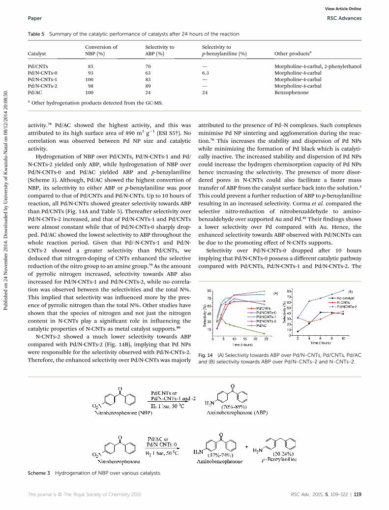
Table 5 Summary of the catalytic performance of catalysts after 24 hours of the reaction
CatalystConversion ofNBP (%)
Selectivity toABP (%)
Selectivity top-benzylaniline (%) Other productsa
Pd/CNTs 85 70 — Morpholine-4-carbal, 2-phenylethanolPd/N-CNTs-0 93 63 6.3 Morpholine-4-carbalPd/N-CNTs-1 100 83 — Morpholine-4-carbalPd/N-CNTs-2 98 89 — Morpholine-4-carbalPd/AC 100 24 24 Benzophenone
a Other hydrogenation products detected from the GC-MS.
Fig. 14 (A) Selectivity towards ABP over Pd/N-CNTs, Pd/CNTs, Pd/ACand (B) selectivity towards ABP over Pd/N-CNTs-2 and N-CNTs-2.
Paper RSC Advances
Publ
ishe
d on
24
Nov
embe
r 20
14. D
ownl
oade
d by
Uni
vers
ity o
f K
waz
ulu-
Nat
al o
n 08
/12/
2014
20:
08:5
0.
View Article Online
activity.78 Pd/AC showed the highest activity, and this wasattributed to its high surface area of 890 m2 g�1 (ESI S5†). Nocorrelation was observed between Pd NP size and catalyticactivity.
Hydrogenation of NBP over Pd/CNTs, Pd/N-CNTs-1 and Pd/N-CNTs-2 yielded only ABP, while hydrogenation of NBP overPd/N-CNTs-0 and Pd/AC yielded ABP and p-benzylaniline(Scheme 3). Although, Pd/AC showed the highest convertion ofNBP, its selectivity to either ABP or p-benzylaniline was poorcompared to that of Pd/CNTs and Pd/N-CNTs. Up to 10 hours ofreaction, all Pd/N-CNTs showed greater selectivity towards ABPthan Pd/CNTs (Fig. 14A and Table 5). Thereaer selectivity overPd/N-CNTs-2 increased, and that of Pd/N-CNTs-1 and Pd/CNTswere almost constant while that of Pd/N-CNTs-0 sharply drop-ped. Pd/AC showed the lowest selectivity to ABP throughout thewhole reaction period. Given that Pd/-N-CNTs-1 and Pd/N-CNTs-2 showed a greater selectivity than Pd/CNTs, wededuced that nitrogen-doping of CNTs enhanced the selectivereduction of the nitro group to an amine group.79 As the amountof pyrrolic nitrogen increased, selectivity towards ABP alsoincreased for Pd/N-CNTs-1 and Pd/N-CNTs-2, while no correla-tion was observed between the selectivities and the total N%.This implied that selectivity was inuenced more by the pres-ence of pyrrolic nitrogen than the total N%. Other studies haveshown that the species of nitrogen and not just the nitrogencontent in N-CNTs play a signicant role in inuencing thecatalytic properties of N-CNTs as metal catalyst supports.80
N-CNTs-2 showed a much lower selectivity towards ABPcompared with Pd/N-CNTs-2 (Fig. 14B), implying that Pd NPswere responsible for the selectivity observed with Pd/N-CNTs-2.Therefore, the enhanced selectivity over Pd/N-CNTs was majorly
Scheme 3 Hydrogenation of NBP over various catalysts.
This journal is © The Royal Society of Chemistry 2015
attributed to the presence of Pd–N complexes. Such complexesminimise Pd NP sintering and agglomeration during the reac-tion.76 This increases the stability and dispersion of Pd NPswhile minimizing the formation of Pd black which is catalyti-cally inactive. The increased stability and dispersion of Pd NPscould increase the hydrogen chemisorption capacity of Pd NPshence increasing the selectivity. The presence of more disor-dered pores in N-CNTs could also facilitate a faster masstransfer of ABP from the catalyst surface back into the solution.2
This could prevent a further reduction of ABP to p-benzylanilineresulting in an increased selectivity. Corma et al. compared theselective nitro-reduction of nitrobenzaldehyde to amino-benzaldehyde over supported Au and Pd.81 Their ndings showsa lower selectivity over Pd compared with Au. Hence, theenhanced selectivity towards ABP observed with Pd/NCNTs canbe due to the promoting effect of N-CNTs supports.
Selectivity over Pd/N-CNTs-0 dropped aer 10 hoursimplying that Pd/N-CNTs-0 possess a different catalytic pathwaycompared with Pd/CNTs, Pd/N-CNTs-1 and Pd/N-CNTs-2. The
RSC Adv., 2015, 5, 109–122 | 119

RSC Advances Paper
Publ
ishe
d on
24
Nov
embe
r 20
14. D
ownl
oade
d by
Uni
vers
ity o
f K
waz
ulu-
Nat
al o
n 08
/12/
2014
20:
08:5
0.
View Article Online
different catalytic pathway in Pd/N-CNTs-0 was accredited to theexistence of tiny Pd NPs forming nanoclusters. A similar drop inselectivity was observed over Pd/AC which also had tiny Pd NPsin the form of clusters (ESI S6†). Such Pd nanoclusters maypossess a different reaction mechanism from the larger PdNPs.82 This different reaction mechanism could have favouredthe further reduction of ABP to p-benzylaniline accounting forthe drop in selectivity (ESI S6† and Table 5).
Since all catalysts had a similar quantity of residual ironcatalyst (Fig. 4B) the possibility of the residual iron catalystinuencing the observed catalytic trend was ruled out. From theTEM analysis no iron particles were observed on the surface ofthe supports. This implied that the residual iron was encapsu-lated inside the CNTs and N-CNTs and hence not available forsurface catalysis.
Pd/N-CNTs-2, which showed the highest selectivity aer 24hours, was used to evaluate the effect of pressure on the cata-lytic activity and selectivity. It was observed that as the pressureincreases the catalytic activity and selectivity over Pd/N-CNTs-2reduced (ESI S7†). Thus, the optimum pressure for the hydro-genation of NBP was 1 bar.
3.4. Stability of Pd NPs aer hydrogenation reactions
The stability of Pd NPs on N-CNTs-0, N-CNTs-1 and N-CNTs-2aer use was analysed by XRD. From the XRD diffractograms,the Pd NP size of used catalysts was determined in a similarmanner to that outlined in Section 3.2.3. Used Pd/CNTs was notanalysed because it strongly adhered to the lter paper resultingin a low catalyst recovery, which was insufficient for XRDanalysis. Table 6 shows the average diameters of the Pd NPsbefore and aer reaction. The size of the Pd NPs in N-CNTs-0 and N-CNTs-1 increased aer the reaction while in N-CNTs-2 the size of the Pd NPs did not change. This implied that Pdsintering and agglomeration may have occurred only in Pd/N-CNTs-0 and Pd/N-CNTs-1. Thus, the Pd NPs in N-CNTs-2 wereconsidered very stable; owing to the formation of more Pd–Ncomplexes in Pd/N-CNTs-2 than in Pd/N-CNTs-0 and Pd/N-CNTs-1. In a similar manner, Chen et al. showed that pyr-idinic nitrogen can complex with Ru3+ as a ligand to form stableRu3+ particles, which were resilient to metal sintering andagglomeration.20
The diffractograms of the used catalysts showed an increasein the intensity of the Pd (111) reection compared with those ofthe fresh catalyst (ESI S8†). This increase in the Pd (111)
Table 6 Average Pd NP sizes of various catalysts before and after asingle reactiona
CatalystAve. Pd NPdiameterb (nm)
Ave. Pd NPdiameterc (nm)
Pd/N-CNTs-0 3.8 5.0Pd/N-CNTs-1 4.0 5.8Pd/N-CNTs-2 4.1 4.1
a Ave: average, NP: nanoparticle. b Before hydrogenation reaction.c Aer hydrogenation reaction.
120 | RSC Adv., 2015, 5, 109–122
reection indicated that more Pd0 were formed via thehydrogen reduction of Pd2+ during the reaction.
4. Conclusions
Pyrrolic N-CNTs containing 2.5–4.4 at.% of nitrogen weresuccessfully synthesized by means of CVD method. Selectivitytowards formation of pyrrolic nitrogen was promoted by theincorporation of oxygen derived from ethylbenzoate duringsynthesis of the N-CNTs. Increasing the amounts of pyrrolicgroups in N-CNTs signicantly altered the physicochemicalproperties of N-CNTs such as thermal stability, textural prop-erties and surface wetness. Also, an increase in the pyrrolicpercentage improved the interactions between Pd and N-CNTsresulting in better dispersion and more stable Pd NPs. Theimproved dispersion and stability of Pd NPs was associated witha strong interaction between the pyrrolic nitrogen and Pd NPs.The catalytic activity and selectivity of Pd/N-CNTs in thehydrogenation of NBP was dependent on the percentage ofpyrrolic nitrogen and not on the total nitrogen content. Pd/N-CNTs showed an enhanced selectivity compared with Pd/CNTsand Pd/AC. Thus, Pd supported on pyrrolic N-CNTs is a prom-ising catalyst for the selective reduction of NBP and otherindustrially important nitro arenes such as nitrobenzenederivatives.
Acknowledgements
The authors wish to thank the University of KwaZulu-Natal andthe National Research Foundation (NRF) for nancial support.We are grateful to Professor Bice Martincigh and Dr R. S.Mwakubambanya for their insightful suggestions during themanuscript development and their assistance with proof-reading.
References
1 Y. Tang, Z. Yang, X. Dai, D. Ma and Z. Fu, J. Phys. Chem. C,2013, 117, 5258–5268.
2 L. M. Ombaka, P. Ndungu and V. O. Nyamori, Catal. Today,2013, 217, 65–75.
3 H. Dai, Nanotube growth and characterization, in CarbonNanotubes Synthesis, Structure, Properties and Applications,ed. M. S. Dresselhaus and G. Dresselhaus, Springler-Verlag,Heidelberg, 2001, pp. 29–51.
4 A. Politano, A. R. Marino, D. Campi, D. Farıas, R. Mirandaand G. Chiarello, Carbon, 2012, 50, 4903–4910.
5 J. S. Qi, J. Y. Huang, J. Feng, D. N. Shi and J. Li, ACS Nano,2011, 5, 3475–3482.
6 A. Loiseau, X. Blase, J.-C. Charlier, P. Gadelle, C. Journet,C. Laurent and A. Peigney, Synthesis methods and growthmechanism, in Understanding Carbon Nanotubes, ed. A.Loiseau, P. Launois, P. Petit, S. Roche and J.-P. Salvetat,Springer-Heidelberg, Springer, 2006, pp. 49–122.
7 C. Wang, L. Zhang, Z. Guo, J. Xu, H. Wang, K. Zhai andX. Zhuo, Microchim. Acta, 2010, 169, 1–6.
This journal is © The Royal Society of Chemistry 2015

Paper RSC Advances
Publ
ishe
d on
24
Nov
embe
r 20
14. D
ownl
oade
d by
Uni
vers
ity o
f K
waz
ulu-
Nat
al o
n 08
/12/
2014
20:
08:5
0.
View Article Online
8 J. Wang, G. Yin, Y. Shao, Z. Wang and Y. Gao, J. Phys. Chem.,2008, 112, 5784–5789.
9 A. Politano and G. Chiarello, Nanoscale, 2013, 5, 8215–8220.10 J.-S. Lee, S.-I. Kim, J.-C. Yoon and J.-H. Jang, ACS Nano, 2013,
7, 6047–6055.11 J. J. Niu, J. N. Wang, Y. Jiang, L. F. Su and J. Ma, Microporous
Mesoporous Mater., 2007, 100, 1–5.12 K. S. Novoselov, A. K. Geim, S. V. Morozov, D. Jiang,
Y. Zhang, S. V. Dubonos, I. V. Grigorieva and A. A. Firsov,Science, 2004, 306, 666–669.
13 K. P. Loh, Q. Bao, G. Eda and M. Chhowalla, Nat. Chem.,2010, 2, 1015–1024.
14 D. Malko, C. Neiss, F. Vines and A. Gorling, Phys. Rev. Lett.,2012, 108, 086804–086807.
15 Y. Wang, N. Shah, F. E. Huggins and G. P. Huffman, EnergyFuels, 2006, 20, 2612–2615.
16 J.-H. Olivier, F. Camerel, R. Ziessel, P. Retailleau, J. Amadouand C. Pham-Huu, New J. Chem., 2008, 32, 920–924.
17 M. P. Lazaro, E. Garcıa-Bordeje, D. Sebastian, M. J. Lazaroand R. Moliner, Catal. Today, 2008, 138, 203–209.
18 S. Domınguez-Domınguez, A. Berenguer-Murcia,B. K. Pradhan, A. Linares-Solano and D. Cazorla-Amoros, J.Phys. Chem. C, 2008, 112, 3827–3834.
19 R. S. Oosthuizen and V. O. Nyamori, Platinum Met. Rev.,2011, 55, 154–169.
20 J. J. L. Chen, Z. H. Zhu, S. B. Wang, Q. Ma, V. Rudolph andG. Q. Lu, Chem. Eng. J., 2010, 156, 404–410.
21 E. M. M. Ibrahim, O. K. Vyacheslav, A. Leonhardt, S. Hampel,S. Oswald, M. H. Rummeli and B. Buchner, Diamond Relat.Mater., 2010, 19, 1199–1206.
22 F. R. Garcıa-Garcıa, J. Alvarez-Rodrıguez, I. Rodrıguez-Ramosand A. Guerrero-Ruiz, Carbon, 2010, 48, 267–276.
23 W. An and C. H. Turner, J. Phys. Chem. C, 2009, 113, 7069–7078.
24 C. Yonghai, Y. Hao, T. Jun, P. Feng, W. Hongjuan, L. Jing,Z. Wenxu and W. Ning-Bew, Carbon, 2013, 57, 433–442.
25 K. Chizari, I. Janowska, M. Houlle, I. Florea, O. Ersen,T. Romero, P. Bernhardt, M. J. Ledoux and C. Pham-Huu,Appl. Catal., A, 2010, 380, 72–80.
26 A. S. Saghiyan, L. A. Stepanyan, L. L. Manasyan,A. V. Geolchanyan, S. M. Djamgaryan, H. R. Ajvazyan,H. A. Panosyan, V. I. Maleev and T. F. Saveleva,Tetrahedron Lett., 2010, 21, 2638–2645.
27 A. K. Bhowmik, S. Tan, A. C. Ahyi, J. A. Dharmadhikari,A. K. Dharmadhikari and D. Mathur, Opt. Commun., 2007,280, 472–476.
28 Z. Li, B. Wu, G. Su and G. Huang, Appl. Phys. Lett., 1997, 70,562–564.
29 E. N. Nxumalo and N. J. Coville, Materials, 2010, 3, 2141–2171.
30 E. N. Nxumalo, V. O. Nyamori and N. J. Coville, J. Organomet.Chem., 2008, 693, 2942–2948.
31 R. S. Oosthuizen and V. O. Nyamori, Appl. Organomet. Chem.,2012, 26, 536–545.
32 R. J. Koch, M. Weser, W. Zhao, F. Vines, K. Gotterbarm,S. M. Kozlov, O. Hofert, M. Ostler, C. Papp, J. Gebhardt,
This journal is © The Royal Society of Chemistry 2015
H. P. Steinruck, A. Gorling and T. Seyller, Phys. Rev. B:Condens. Matter Mater. Phys., 2012, 86, 075401–075406.
33 C. Imrie, P. Kleyi, V. O. Nyamori, T. I. A. Gerber,D. C. Levendis and J. Look, J. Organomet. Chem., 2007, 692,3443–3453.
34 L. M. Ombaka, P. G. Ndungu, B. Omondi and V. O. Nyamori,J. Coord. Chem., 2014, 67, 1905–1922.
35 Y. Suttisawat, P. Rangsunvigit, B. Kitiyanan, M. Williams,P. Ndungu, M. V. Lototskyy, A. Nechaev, V. Linkov andS. Kulprathipanja, Int. J. Hydrogen Energy, 2009, 34, 6669–6675.
36 B. G. Sumpter, V. Meunier, J. M. Romo-Herrera, E. Cruz-Silva, D. A. Cullen, H. Terrones, D. J. Smith andM. Terrones, ACS Nano, 2007, 1, 369–375.
37 L. Lizhao, L. Feng and Z. Jijun, Nano Res., 2014, 7, 626–657.38 K. Chizari and U. Sundararaj, Mater. Lett., 2014, 116, 289–
292.39 S. Liu, Y. Zhang, Y. Lin, Z. Zhao and Q. Li, Carbon, 2014, 69,
247–254.40 K. Chizari, A. Vena, L. Laurentius and U. Sundararaj, Carbon,
2014, 68, 369–379.41 A. A. Koos, M. Dowling, K. Jurkschat, A. Crossley and
N. Grobert, Carbon, 2009, 47, 30–37.42 Z. Luo, S. Lim, Z. Tian, J. Shang, L. Lai, B. MacDonald, C. Fu,
Z. Shen, T. Yu and J. Lin, J. Mater. Chem., 2011, 21, 8038–8044.
43 E. T. Kang, K. G. Neoh, S. H. Khor, K. L. Tan and B. T. G. Tan,Polymer, 1990, 31, 202–207.
44 S. Kundu, W. Xia, W. Busser, M. Becker, D. A. Schmidt,M. Havenith and M. Muhler, Phys. Chem. Chem. Phys.,2010, 12, 4351–4359.
45 S. Wang, F. Wang and X. Ge, Synth. Met., 1986, 16, 99–104.46 Y. Cao, H. Yu, J. Tan, F. Peng, H. Wang, J. Li, W. Zheng and
N.-B. Wong, Carbon, 2013, 57, 433–442.47 C. J. Powell, J. Electron Spectrosc. Relat. Phenom., 2012, 185,
1–3.48 S. C. Ray, A. Saha, N. R. Jana and R. Sarkar, J. Phys. Chem. C,
2009, 113, 18546–18551.49 D. Briggs and G. Beamson, Anal. Chem., 1992, 64, 1729–1736.50 S. Kundu, Y. Wang, W. Xia and M. Muhler, J. Phys. Chem. C,
2008, 112, 16869–16878.51 S. Z. Mortazavi, P. Parvin, A. Reyhani, R. Malekfar and
M. Soghra, RSC Adv., 2013, 3, 1397–1409.52 G. Beamson, D. T. Clark, N. W. Hayes and D. S.-L. Law, Surf.
Sci. Spectra, 1994, 3, 357–365.53 H. Li, Y. Wu, H. Luo, M. Wang and Y. Xu, J. Catal., 2003, 214,
15–25.54 A. Misra, P. K. Tyagi, M. K. Singh and D. S. Misra, Diamond
Relat. Mater., 2006, 15, 385–388.55 G. Lazar and I. Lazar, J. Non-Cryst. Solids, 2003, 331, 70–78.56 T. Barzetti, E. Selli, D. Moscotti and L. Forni, J. Chem. Soc.,
Faraday Trans., 1996, 92, 1401–1407.57 L. Vanyoreka, R. Meszarosa and S. Barany, Colloids Surf., A,
2014, 448, 140–146.58 P. E. Fanning and M. A. Vannice, Carbon, 1993, 31, 721–730.59 T. J. Bandosz, Carbon materials fo catalysis, John Wiley &
Sons, Inc., United States of America, 2009, pp. 63–66.
RSC Adv., 2015, 5, 109–122 | 121
RSC Advances Paper
Publ
ishe
d on
24
Nov
embe
r 20
14. D
ownl
oade
d by
Uni
vers
ity o
f K
waz
ulu-
Nat
al o
n 08
/12/
2014
20:
08:5
0.
View Article Online
60 U.-J. Kim, C. A. Furtado, X. Liu, G. Chen and P. C. Eklund, J.Am. Chem. Soc., 2005, 127, 15437–15445.
61 M. Aydin, Vib. Spectrosc., 2013, 65, 84–93.62 Z. Lei, D. Bai and X. S. Zhao,Microporous Mesoporous Mater.,
2012, 147, 86–93.63 K. S. W. Sing, D. H. Everett, R. A. W. Haul, L. Moscou,
R. A. Pierotti, J. Rouquerol and T. Siemieniewska, PureAppl. Chem., 1985, 57, 603–619.
64 C. J. Rasmussen, A. Vishnyakov, M. Thommes,B. M. Smarsly, F. Kleitz and A. V. Neimark, Langmuir, 2010,26, 10147–10157.
65 H.-J. Woo and P. A. Monson, Phys. Rev. E: Stat., Nonlinear,So Matter Phys., 2003, 67, 041207–041224.
66 J. Y. Kim, K. Park, S. Y. Bae, G. C. Kim, S. Lee and H. C. Choi,J. Mater. Chem., 2011, 21, 5999–6005.
67 X.-F. Guo, D.-Y. Jang, H.-G. Jang and G.-J. Kim, Catal. Today,2012, 186, 109–114.
68 S. Santra, P. Ranjan, P. Bera, P. Ghosh and S. K. Mandal, RSCAdv., 2012, 2, 7523–7533.
69 T. H. Fleisch and G. J. Mains, J. Phys. Chem., 1986, 90, 5317–5320.
70 I. Rivas, J. Badano, C. Lederhos, D. Liprandi, E. Cagnola andC. V. M. Quiroga, Quim. Nova, 2011, 34, 87–90.
71 M. Baghayeri, H. Veisi, H. Veisi, B. Maleki, H. Karimi-Malehdand H. Beitollahi, RSC Adv., 2014, 4, 49595–49604.
122 | RSC Adv., 2015, 5, 109–122
72 O. S. G. P. Soares, J. J. M. Orfao and M. F. R. Pereira, Ind. Eng.Chem. Res., 2010, 49, 7183–7192.
73 M. Gurratha, T. Kuretzky, H. P. Boehm, L. B. Okhlopkova,A. S. Lisitsyn and V. A. Likholobov, Carbon, 2000, 38, 1241–1255.
74 A. Staykov, Y. Ooishi and T. Ishihara, J. Phys. Chem. C, 2014,118, 8907–8916.
75 L. Bardotti, F. Tournus, R. Delagrange, J. M. Benoit,O. Pierre-Louis and V. Dupuis, Appl. Surf. Sci., 2014, 301,564–567.
76 P. Chen, L. M. Chew, A. Kostka, M. Muhlera and W. Xia,Catal. Sci. Technol., 2013, 3, 1964–1971.
77 D. He, C. Zeng, C. Xu, N. Cheng, H. Li, S. Mu and M. Pan,Langmuir, 2011, 27, 5582–5588.
78 Q. B. Wen, L. Qiao, W. T. Zheng, Y. Zeng, C. Q. Qu, S. S. Yuand Q. Jiang, Phys. E, 2008, 40, 890–893.
79 P. Chen, F. Yang, A. Kostka and W. Xia, ACS Catal., 2014, 4,1478–1486.
80 W. Ouyang, D. Zeng, X. Yu, F. Xie, W. Zhang, J. Chen, J. Yan,F. Xie, L. Wange, H. Meng and D. Yuan, Int. J. HydrogenEnergy, 2014, 39, 15996–16005.
81 A. Corma and P. Serna, Science, 2006, 313, 332–334.82 C. Torres, C. Campos, J. L. G. Fierro, M. Oportus and
P. Reyes, Catal. Lett., 2013, 143, 763–771.
This journal is © The Royal Society of Chemistry 2015
Copyright © 2022 FDOKUMEN