Carbon Nanotubes from Unconventional Resources: Part A: Entangled Multi-Walled Carbon Nanotubes and...
18
Chapter 11 Carbon Nanotubes from Unconventional Resources: Part A: Entangled Multi-Walled Carbon Nanotubes and Part B: Vertically-Aligned Carbon Nanotubes S. Karthikeyan and P. Mahalingam Additional information is available at the end of the chapter http://dx.doi.org/10.5772/51073 1. Part A: Entangled Multi-walled carbon nanotubes 1.1. Introduction Nanotechnology is a topic attracting scientists, industrialists, journalists, governments and even a common people alike. Carbon nanotubes (CNTs) and other carbon nanostructures are supposed to be a key component of this nanotechnology. Having realized its tremen‐ dous application potential in nanotechnology, a huge amount of efforts and energy is invest‐ ed in CNT projects worldwide. Till date, the art of CNT synthesis lies in the optimization of parameters for selected group materials on a particular experimental set-up. As viewed from the perspective of green chemistry, sustaining the environment implies sustaining the human civilization. The long-term key of a sustainable society lies in stable economy that uses energy and resources efficiently. Therefore, it is high time to evaluate the existing CNT techniques on these parameters. Let us examine three popular methods of CNT synthesis viz Arc discharge, Laser-vaporiza‐ tion and CVD method. Arc-discharge method, in which the first CNT was discovered [1], employs evaporation of graphite electrodes in electric arcs that involve very high tempera‐ tures around 4000º C. Although arc-grown CNTs are well crystallized, they are highly im‐ pure. Laser-vaporization technique employs evaporation of high-purity graphite target by high-power lasers in conjunction with high-temperature furnaces [2]. Although laser-grown CNTs are of high purity, their production yield is very low. Thus it is obvious that these two methods score too low on account of efficient use of energy and resources. Chemical vapor deposition (CVD), incorporating catalyst-assisted thermal decomposition of hydrocarbons, is the most popular method of producing CNTs, and it is truly a low-cost and scalable tech‐ © 2013 Karthikeyan and Mahalingam; licensee InTech. This is an open access article distributed under the terms of the Creative Commons Attribution License (http://creativecommons.org/licenses/by/3.0), which permits unrestricted use, distribution, and reproduction in any medium, provided the original work is properly cited.
Transcript of Carbon Nanotubes from Unconventional Resources: Part A: Entangled Multi-Walled Carbon Nanotubes and...
Chapter 11
Carbon Nanotubes from Unconventional Resources:Part A: Entangled Multi-Walled Carbon Nanotubes andPart B: Vertically-Aligned Carbon Nanotubes
S. Karthikeyan and P. Mahalingam
Additional information is available at the end of the chapter
http://dx.doi.org/10.5772/51073
1. Part A: Entangled Multi-walled carbon nanotubes
1.1. Introduction
Nanotechnology is a topic attracting scientists, industrialists, journalists, governments andeven a common people alike. Carbon nanotubes (CNTs) and other carbon nanostructuresare supposed to be a key component of this nanotechnology. Having realized its tremen‐dous application potential in nanotechnology, a huge amount of efforts and energy is invest‐ed in CNT projects worldwide. Till date, the art of CNT synthesis lies in the optimization ofparameters for selected group materials on a particular experimental set-up. As viewedfrom the perspective of green chemistry, sustaining the environment implies sustaining thehuman civilization. The long-term key of a sustainable society lies in stable economy thatuses energy and resources efficiently. Therefore, it is high time to evaluate the existing CNTtechniques on these parameters.
Let us examine three popular methods of CNT synthesis viz Arc discharge, Laser-vaporiza‐tion and CVD method. Arc-discharge method, in which the first CNT was discovered [1],employs evaporation of graphite electrodes in electric arcs that involve very high tempera‐tures around 4000º C. Although arc-grown CNTs are well crystallized, they are highly im‐pure. Laser-vaporization technique employs evaporation of high-purity graphite target byhigh-power lasers in conjunction with high-temperature furnaces [2]. Although laser-grownCNTs are of high purity, their production yield is very low. Thus it is obvious that these twomethods score too low on account of efficient use of energy and resources. Chemical vapordeposition (CVD), incorporating catalyst-assisted thermal decomposition of hydrocarbons,is the most popular method of producing CNTs, and it is truly a low-cost and scalable tech‐
© 2013 Karthikeyan and Mahalingam; licensee InTech. This is an open access article distributed under theterms of the Creative Commons Attribution License (http://creativecommons.org/licenses/by/3.0), whichpermits unrestricted use, distribution, and reproduction in any medium, provided the original work isproperly cited.

nique for mass production of CNTs [3]. Unfortunately, however, till date only purified pe‐troleum products such as methane, ethylene, acetylene, benzene, xylene are in practice, asprecursor, for synthesizing CNTs. Apart from petroleum based hydrocarbons, carbon nano‐tubes have been synthesized from polymers, metallocenes and domestic fuels such as kero‐sene and liquefied petroleum gas [4-7].
According to the principle of green chemistry, the feed stock of any industrial process mustbe renewable, rather than depleting a natural resource. Moreover, the process must be de‐signed to achieve maximum incorporation of the constituent atoms (of the feed stock) intothe final product. Hence, it is the time’s prime demand to explore regenerative materials forCNT synthesis with high efficiency. This well-valued material of biotechnology researchwas successfully brought to nanotechnology research with the first report of CNTs from nat‐ural precursors in 2001. Since then, investigators involved with this environment-friendlysource of CNTs and established the conditions for growing multiwalled nanotubes(MWNTs), single-wall nanotubes (SWNTs) and vertically aligned MWNTs on the suitablecatalytic support by a simple and inexpensive CVD technique. Researchers prepared goodquality of Multi-walled carbon nanotubes (MWNTs) and vertically aligned ones by thermaldecomposition of turpentine oil and Camphor [8,9]. Andrews et al. synthesized pure Single-walled carbon nanotubes (SWNTs) by catalytic decomposition of camphor and its anologes[10]. Ghosh et al. prepared single-walled carbon nanotubes from turpentine oil and eucat‐lyptus oil [11]. We have succeeded in growing of CNTs from pine oil [12] and methyl esterof Jatropha curcas oil [13], a botanical hydrocarbon extracted from plant source, having boil‐ing point around 200 - 280º C. Being a green-plant product, these oils are eco-friendly sourceand can be easily cultivated in as much quantity as required. Unlike any fossil/petroleumproduct, there is no fear of its ultimate shortage as it is a regenerative source. These sourcesare readily available, cheap and also user-friendly for chemical vapor deposition due to itsvolatile and non-toxic nature.
United states Environmental Protection Agency has developed 12 principles of green chem‐istry [14] that explain what the green chemistry means in practice. Using those definitions asa protocol, we can evaluate the CNT precursor materials such as Pine oil, Methyl ester ofJatropha curcas oil and Methyl ester of Pongamia pinnata oil, as follows.
Prevention : With the highest CNT-production efficiency, plant based precursor complieswith waste-prevention rule significantly.
Atom Economy : Botanical hydrocarbons gets maximum incorporation of its constituentatoms into the final product, CNTs.
Less Hazardous Chemical Synthesis : All the substances involved in this technique (car‐bon source, catalyst and support material) possess little or no toxicity to human healthand the environment.
Designing Safer Chemicals: Our final product is common-grade CNTs that are apparentlysafe.Safer Solvents and Auxiliaries : The only auxiliary used in our method is the metal cata‐lyst that are apparently safe.
Syntheses and Applications of Carbon Nanotubes and Their Composites240

Design for Energy Efficiency : By virtue of a low-temperature atmospheric pressure CVDprocess, the energy requirements of our technique are significantly low.
Use of Renewable Feedstock : The raw material is purely a regenerative material; so there isno danger of depleting a natural resource.
Reduce Derivatives: No derivative is formed in this technique; solely catalyst-assisted in-situdecomposition of plant based precursor leads to CNTs.
Catalysis: It is a purely catalytic process, no stoichiometric reagents are involved.
Design for Degradation: CNTs as such are non-biodegradable; however, their intentionaldegradation can be achieved by introducing certain functional groups.
Real-time analysis for pollution Prevention: This technique as such should be fully compati‐ble with real-time analysis for pollution prevention, if executed at an industrial laboratory.
Inherently Safer Chemistry for Accident Prevention : Substances and their form used in ourprocess are chosen so as to minimize the potential for chemical accidents, including releases,explosions and fires.
In this chapter the authors discuss the morphology of the carbon nanostructures producedusing Pine oil, Methyl ester of Jatropha curcas oil and Methyl ester of Pongamia pinnata oil asnatural carbon precursors by spray pyrolysis method, a modified chemical vapor depositionmethod. It is similar to chemical vapor deposition method, the only difference is the vapori‐zation and pyrolysis of carbon source occurs simultaneously in spray pyrolysis whereas inCVD it is a two step process. Since these precursors evaporate at relatively higher tempera‐tures, spray pyrolysis method was adopted for synthesis of CNTs. The results show that themorphology closely correlates with precursor concentration and the authors propose thatthe effect is related to the competition between rate of decomposition of precursor and thediffusion of carbon species through the catalyst particle.
1.2. Experimental Methods
A catalytic supporting material Fe, Co and Mo with silica (Fe:Co:Mo:SiO2 = 1:0.5:0.1:4) was pre‐pared by wet impregnation method [15]. Appropriate quantities of metal salts (Merk) i.e.Fe(NO3)3 .6H2O, Co(NO3)3 .3H2O and (NH4)6Mo7O24 .4H2O were dissolved in methanol andmixed thoroughly with methanol suspension of silica (Merk). The solvent was then evaporat‐ed and the resultant cake heated to 90-100 °C for 3 h, removed from the furnace and ground tofine power. The fine powders were then calcined for 1 h at 450 °C and then re-ground beforeloading into the reactor. The prepared catalyst was directly placed in a quartz boat and kept atthe centre of a quartz tube which was placed inside a tubular furnace. The carrier gas nitrogenwas introduced at the rate of 100 mL per minute into the quartz tube to remove the presence ofany oxygen inside the quartz tube. The temperature was raised from room temperature to thedesired growing temperature. Subsequently, the carbon precursor was introduced into thequartz tube through spray nozzle and the flow was maintained at the rate of 0.1 - 0.5 ml/min.Spray pyrolysis was carried out for 45 minutes and thereafter furnace was cooled to room tem‐perature. Nitrogen atmosphere was maintained throughout the experiment. The morphology
Carbon Nanotubes from Unconventional Resources: Part A: Entangled Multi-Walled Carbon Nanotubeshttp://dx.doi.org/10.5772/51073
241

and degree of graphitization of the as-grown nanostructures were characterized by high reso‐lution transmission electron microscopy (JEOL-3010), Raman spectroscopy (JASCONRS-1500W) green laser with excitation wavelength 532 nm) and thermo gravimetric analysis(TGA). The as-grown products were subjected to purification process as follows [16]. The sam‐ple material was added to 20 ml 1N HCl to form an acidic slurry. This slurry was heated to 60°C and stirred at 600 rpm. To this heated acidic slurry 20 ml H2O2 was added to form oxidativeslurry and stirred for 30 minutes. The sample was filtered and washed with 1N HCl and distil‐led water. The collected sample was calcined at 400 °C in nitrogen atmosphere for 2 hours. Theexperiment at optimum reaction conditions were repeated several times to ensure the repro‐ducibility of formation of carbon nanostructures.
1.3. Result and Discussion
Pine oil, Methyl ester of Jatropha curcas oil and Methyl ester of Pongamia pinnata oil wereused for synthesis of carbon nano structures by spray pyrolysis method. These oils were in‐dividually sprayed at different rate (10 mL, 20 mL and 30 mL per hour) over silica support‐ed Fe, Co and Mo catalyst at different reaction temperatures (550 °C, 650 °C and 750 °C) tosynthesis carbon nanostructures. The as-grown nanostructures were characterized by SEM,TEM, TGA and Raman spectroscopy techniques.
The result shows low yield of carbon nano structures with three types of precursors, Pineoil, Methyl ester of Jatropha curcas oil and Methyl ester of Pongamia pinnata oil, when sprayedindividually at the precursor flow rate of 10mL per hour over silica supported Fe, Co andMo catalyst at 550 °C. An improved carbon nanostructure formation at 650 °C for the pre‐cursor flow rate of 20 mL per hour was observed invariably for the three precursor materi‐als. When the experimental condition was either 750 °C or precursor flow rate of 30 mL perhour, decrease in carbon nanotube yield observed.
Figure 1 illustrates the SEM image of the CNTs samples grown at different temperatures us‐ing pine oil as precursor at a flow rate of 20 mL per hour. At 550 °C few CNTs were found togrow because this temperature is not sufficient to pyrolyse the carbon source (Fig. 1a). Onthe other hand, at 650 °C (Fig. 1b) the formation of CNTs is high because at this temperaturethe carbon source decomposes effectively. At 750 °C, the quantity of CNTs has decreasedand thick nanotubes have been formed (Fig. 1c). Experiments with methyl ester of JatrophaCurcas oil as a carbon precursor at different temperatures were conducted and the SEM im‐ages of the sample were recorded. The SEM images of sample synthesized at 650 °C re‐vealed the formation of homogeneous and dense distribution of CNTs in a web-like network(Fig. 1e), while very few nanotubes formation at 550 °C (Fig. 1g).
At higher temperature (750 °C) an increase in diameter of the CNTs was observed (Fig. 1f). Themorphology of carbon nanotube synthesized at different temperatures using methyl ester ofPongamia pinnata oil are recorded using SEM. Few carbon nanostructures were observed at alower deposition temperature of 550 °C (Fig. 1g). When the temperature was increased to 650°C chain like carbon nanostructure was dominant (Fig. 1h). At 750 °C, a more uniform distribu‐tion of MWNTs was observed with a diameter of around 150 nm (Fig. 1i).
Syntheses and Applications of Carbon Nanotubes and Their Composites242
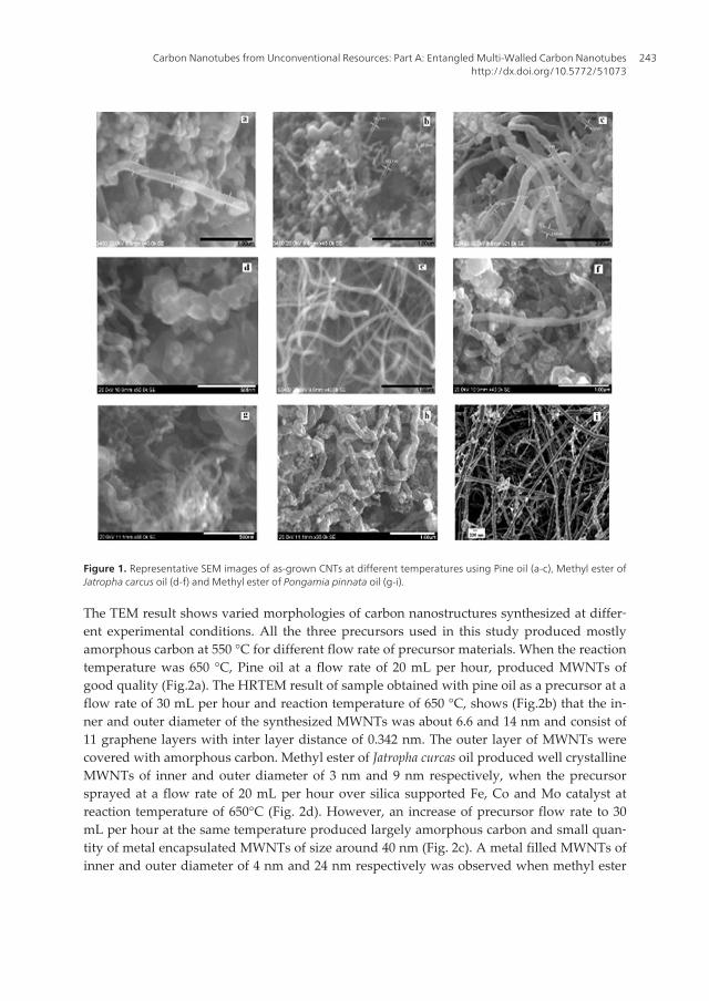
Figure 1. Representative SEM images of as-grown CNTs at different temperatures using Pine oil (a-c), Methyl ester ofJatropha carcus oil (d-f) and Methyl ester of Pongamia pinnata oil (g-i).
The TEM result shows varied morphologies of carbon nanostructures synthesized at differ‐ent experimental conditions. All the three precursors used in this study produced mostlyamorphous carbon at 550 °C for different flow rate of precursor materials. When the reactiontemperature was 650 °C, Pine oil at a flow rate of 20 mL per hour, produced MWNTs ofgood quality (Fig.2a). The HRTEM result of sample obtained with pine oil as a precursor at aflow rate of 30 mL per hour and reaction temperature of 650 °C, shows (Fig.2b) that the in‐ner and outer diameter of the synthesized MWNTs was about 6.6 and 14 nm and consist of11 graphene layers with inter layer distance of 0.342 nm. The outer layer of MWNTs werecovered with amorphous carbon. Methyl ester of Jatropha curcas oil produced well crystallineMWNTs of inner and outer diameter of 3 nm and 9 nm respectively, when the precursorsprayed at a flow rate of 20 mL per hour over silica supported Fe, Co and Mo catalyst atreaction temperature of 650°C (Fig. 2d). However, an increase of precursor flow rate to 30mL per hour at the same temperature produced largely amorphous carbon and small quan‐tity of metal encapsulated MWNTs of size around 40 nm (Fig. 2c). A metal filled MWNTs ofinner and outer diameter of 4 nm and 24 nm respectively was observed when methyl ester
Carbon Nanotubes from Unconventional Resources: Part A: Entangled Multi-Walled Carbon Nanotubeshttp://dx.doi.org/10.5772/51073
243

of Pongamia Pinnata oil, at a flow rate of 20 mL per hour, was spray pyrolysed at 650 °C oversilica supported Fe, Co and Mo catalyst. When flow rate was increased to 30 mL per hour, ashort growth of metal encapsulated carbon nanostructures was observed (Fig. 2e). The TEMand TGA studies revel that the carbon nanostructures are not well graphitized.
Figure 2. Representative TEM images of as-grown CNTs under constant reaction temperature of 650 °C for flow rateof precursor: Pine oil (a) 20 mL per hour (b) 30 mL per hour; Methyl ester of Jatropha carcus oil (c) 30 mL per hour (d)20 mL per hour and Methyl ester of Pongamia pinnata oil (e) 30 mL per hour (f) 20 mL per hour.
The Fig. 2a shows TEM images of sample prepared using Pine oil as carbon source at a flowrate of 20 mL per hour over silica supported Fe, Co and Mo catalyst at a reaction temperature of650°C. The TEM images indicate that the inner and outer diameter was uniform over entirelength of the tube. It is also evident that carbon nanotubes do not contain encapsulated catalystbut amorphous carbon at the outer wall of the tube. The well crystallization of the graphenelayer was confirmed from the IG/ID ratio of 2.5 (Fig.3a). The IG/ID ratio increases with increase ofprecursor flow rate from 10mL per hour to 20 mL per hour, but further increase of precursorflow rate to 30mL per hour results in decrease of IG/ID ratio to 0.5 (Fig.3b). The improved quali‐ty can be attributed to increase of precursor concentration in the tube. The higher flow rate ofprecursor (20 mL per hour) increases precursor concentration in the tube which leads to in‐crease in decomposition of precursor over catalyst. Thus quality carbon nanotubes wereformed at a reaction temperature of 650 °C. However, too high a concentration of precursor (30mL per hour) or a reaction temperature of 750 °C leads to the formation of amorphous product
Syntheses and Applications of Carbon Nanotubes and Their Composites244

as vapor phase decomposition of precursor is promoted than the decomposition over catalyst.The results are in good accordance with the reports by Afre et al. [17]. They have synthesizedMWNTs using turpentine oil as a precursor by spray pyrolysis method in the temperaturerange of 600 to 800 °C. While Ghosh and co workers [18] reported synthesis of single walledcarbon nanotube at a reaction temperature of 850 °C and abundant amount of MWCNTs atlower temperatures using turpentine oil as precursor by CVD method. No lower frequencyRBM peaks in Raman spectra of our samples shows the absence of SWNTs.
Figure 3. Typical Raman spectrum (green laser with excitation wavelength 532 nm) of as-grown MWNTs at differentflow rate of precursors: Pine oil (a) 20 mL per hour (b) 30 mL per hour; Methyl ester of Jatropha carcus oil (c) 20 mL perhour (d) 30 mL per hour and Methyl ester of Pongamia pinnata oil (e) 20 mL per hour (f) 30 mL per hour.
Thermogravimetric analysis was performed to characterize the thermal behavior of the car‐bon nanotube synthesized using Pine oil as precursor. The Thermogravimetric graph showsthe wt% vs. temperature. Upto a certain period of time there is no weight loss. The oxidationof carbon deposit starts after this point which is indicated by a dip in curve. With increase intemperature the weight loss increases till all the carbon get burnt. The residue is the catalystand support. The TGA curves gives the temperature corresponds to the maximum mass de‐crease, which is considered to be a measure of the level of crystallinity of carbon nanotube.The TGA results (Fig.4a,b,c) shows the variation in decomposition temperature for the prod‐ucts synthesized at 650 °C for different flow rate of Pine oil precursor. It was found that thedecomposition temperature varied between 568 and 591 °C. The relatively high decomposi‐tion temperature of 591 °C for the product synthesized at a reaction temperature of 650 °Cfor precursor flow rate of 20 mL per hour indicates well crystalline structure formation.
A HRTEM images (Fig. 2d) of sample prepared using Methyl ester of Jatropha curcas oil ascarbon precursor at a flow rate of 20 mL per hour over silica supported Fe, Co and Mocatalyst at a reaction temperature of 650°C clearly shows well graphitized layers of a typi‐cal MWNTs with uniform inner and outer diameter. The TEM image also revels that en‐capsulated catalyst or amorphous carbon is rarely seen in the sample. The image indicatesthat the MWNTs are composed of around 26 walls and layers grow perpendicular to thegrowth axis of the tube. An increase of precursor flow rate to 30 mL per hour at the reac‐tion temperature of 650 °C produced largely amorphous carbon and small quantity ofmetal incorporated MWNTs of size around 40 nm is evident from the TEM images (Fig.2c). An additional confirmation for high degree graphitization and formation of metal fil‐
Carbon Nanotubes from Unconventional Resources: Part A: Entangled Multi-Walled Carbon Nanotubeshttp://dx.doi.org/10.5772/51073
245

led MWNTs for sample prepared using the precursor flow rate of 20 mL per hour and 30mL per hour respectively is shown by Raman spectra (Fig. 3c,d). The G band at 1571 cm-1
was attributed to well crystallized carbon structure, while the D band at 1359 cm-1 was at‐tributed to defects in the structure [19]. The decrease in relative intensity of the G bandand D band (IG/ID ratio) for sample prepared with precursor flow rate of 30 mL per hourindicates more defects in as-grown sample (Fig. 3d). The defects in MWNTs can be attrib‐uted to increase of precursor concentration in the tube and encapsulation of catalyst parti‐cles. An increase of precursor concentration in the tube leads to increase in decompositionof precursor over catalyst. Above the critical concentration of precursor, rate of decompo‐sition of precursor exceeds rate of diffusion of carbon into the catalyst particle and thusencapsulation of metal particle occurs. The TGA results of MWNTs sample grown usingmethyl ester of Jatropha curcas oil are shown in (Fig.4d,e,f). Higher decomposition temper‐ature and 37% residue observed in the TGA studies for the product synthesized at a reac‐tion temperature of 650 °C for precursor flow rate of 20 mL per hour shows the samplecontain around 60% MWNTs with well crystallized structure. A decrease in decomposi‐tion temperature and high residue shows defects in structure and metal encapsulation forthe sample prepared at 650 °C for the precursor flow rate of 30 mL per hour.
Figure 4. TGA curves of as-grown CNTs samples at different flow rate of precursors: Pine oil (a) 10 mL per hour (b) 20mL per hour (c) 30 mL per hour, Methyl ester of Jatropha carcus oil (d) 10 mL per hour (e) 20 mL per hour (f) 30 mL perhour, Methyl ester of Pongamia pinnata oil, as-grown, (g) 10 mL per hour (h) 20 mL per hour (i) 30 mL per hour andpurified (j) 10 mL per hour (k) 20 mL per hour (l) 30 mL per hour.
The TEM images of sample synthesized for 20 mL per hour flow rate of methyl ester of pon‐gamia pinnata oil over silica supported Fe, Co and Mo catalyst at a reaction temperature of650 °C was shown in Fig. 2f. The average outer diameter of the tube synthesized varied ran‐domly as the reaction temperature was changed. At 550 °C, the diameter of the arborization-like nanostructures were around 65 nm, whilst at 650 °C, the formed MWNTs has inner andouter diameter in the range of 7nm & 33nm. The HRTEM image of the sample synthesizedat 650 °C (Fig.2f) indicates the metal particles, seen as a dark spot on the image, were tightlycovered by carbon layers with a thickness of a few nanometers. When precursor flow ratewas reduced from 30 to 20 mL per hour, due to effective decomposition of precursor and thefluid nature of catalyst particle, the morphology of the product changed from arborization-like nanostructure to magnetic nanopartical encapsulated in multi-walled carbon nanotubes.
Syntheses and Applications of Carbon Nanotubes and Their Composites246

A similar observation was reported by Kang et al. [20]. Also, morphology change from mag‐netic nanopartical encapsulated in multi-walled carbon nanotubes to multi-walled carbonnanotubes structure was attributed to the high fluid nature of catalyst at 750 °C. The innerdiameter of the carbon structure formed is same as that observed for products synthesizedat 650 °C indicates the prevention of agglomeration of catalyst particles by Mo [21].
Amorphous carbon formation in large quantity, at 750 °C or at precursor flow rate of 30mL perhour, may be due to increased thermal decomposition of precursor material. The TGA resultsare shown in Fig.4g,h,i. It is evident that the weight loss continues to increase rapidly with tem‐perature until reaches a constant value. Residue of the as-grown sample for precursor flow rateof 10 mL, 20 mL and 30 mL per hour at 650 °C was found to be 63.2, 60.9 and 50.5% respectivelyby weight (Fig.4g,h,i). The TGA results of same samples after purification shows (Fig. 4j,k,l)weight of residue as 3.5, 22.5 and 2.5% mass fraction. The more decline in mass fraction wascaused by the acid leaching of catalyst particles that was not encapsulated by carbon. The lowresidue observed for products synthesized at 550 °C and 750 °C are attributed to low catalyticactivity and high thermal decomposition of precursors respectively, which leads to formationof high amorphous carbon and low encapsulated products. The products synthesized at 650 °Cshows minimum mass loss in TGA studies, even after purification, is due to better encapsula‐tion of metal particles by carbon layers. The IG/ID value of 0.9 (Fig.3e) for samples prepared at650 °C with flow rate of 20 mL per hour indicates that magnetic nanoparticals encapsulated incarbon nanotubes structure had defects and moderate crystallization of graphene planes[22,23]. This supports the HRTEM results. The increased IG/ID value of 1.87 (Fig. 3f) for the samesample, after purification indicates the removal of amorphous carbon and defective structuresduring purification. The removal of amorphous carbon and defective structures were furthersupported by higher ignition temperature 610 °C in TGA studies. According to TGA curves,weight of residue for the purified sample decreased to about 13 to 31% mass fraction compar‐ing to unpurified sample due to leaching of metal particle and amorphous carbon removalduring purification process. This shows that carbon layers covering the metal particles preventtheir dissolution during purification process.
The mechanism of CNT nucleation and growth is one of the challenging and complex topicsin current scientific research. Presently, various growth models based on experimental andquantitative studies have been proposed. It is well established, that during CNT nucleationand growth the following consecutive steps were taken place [24].
1. Carbon species formation by decomposition of precursor over the catalyst
2. Diffusion of carbon species through the catalyst particle
3. Precipitation of the carbon in the form of CNTs
The first step involves formation of carbon species by catalytic vapor decomposition of va‐pors of the precursor material over the catalyst. In the second step the diffusion of carbonspecies through the catalyst particle takes place. The catalyst surface may exert a diffusionbarrier. It is still unclear whether carbon species diffuse on the particle surface [25], on theparticle bulk [24] or whether surface and diffusion compete. The most accepted growth
Carbon Nanotubes from Unconventional Resources: Part A: Entangled Multi-Walled Carbon Nanotubeshttp://dx.doi.org/10.5772/51073
247

model suggests bulk diffusion of carbon species into the metal particles [26]. The third stepis the precipitation of the carbon in the form of CNTs from the saturated catalyst particle.
Figure 5. TEM images of as-grown CNTs sample synthesized under constant reaction temperature of 650 °C usingrMethyl ester of Pongamia pinnata oil at a flow rate of 20 mL per hour. (a) indicates the reshaping of catalyst particle(b) metal particle at the tip of tube.
Based on experimental results, a possible growth mechanism of MWNTs was proposed. It isknown from the fact that Catalytic centers on catalyst particle act as nucleation site for thegrowth of MWNTs [22]. The precursor vapor decomposed on surface of the catalyst particleproduces carbon. As the reactivity between the catalyst and the carbon exceeds the thresh‐old value, carbon atoms loose their mobility in the solid solution, forming metal carbides[23]. These meta stable Fe and Co carbides decomposed and produce carbon which dissolvein these metal particles. The dissolved carbon diffuses through the metal particle and getsprecipitated in the form of crystalline graphene layer. This carburized surface acts as a barri‐er for further carbon transfer from the gas phase to the bulk of the catalyst since carbon dif‐fusion is slower through metal carbides [27]. The saturated metal carbide have lowermelting point and they are fluid like during the growth process [28].
If the rate of precursor decomposition and the rate of diffusion of carbon are equal, then themetal raise through a capillary action and tube growth occurs. The fact that long carbonnanotubes observed have their catalyst particles partially exposed indicates that the directcontact of catalyst surface with carbon precursor is essential for continuous CNT growth(Fig. 5a). This is consistent with the growth mechanism proposed by Rodriguez [29]. In casethe decomposition rate exceeds the diffusion rate, more of carbon produced forms a thickcarbide layer over the surface of metal which acts as a barrier for further carbon transferfrom the gas phase to the bulk of the catalyst. However, the thick carbide layer crystallizesout as graphene layer which encapsulate the metal particle. When a catalyst particle is fullyencapsulated by layers of graphene sheets, the carbon supply route is cut and CNT growthstops resulting in short MWCNTs. The catalyst particle undergoes several mechanical re‐shaping during the tip growth of multi-walled nanotubes [30, 31]. This gives the impressionthat the catalyst is in liquid state during reaction. The catalyst particle seen inside and at the
Syntheses and Applications of Carbon Nanotubes and Their Composites248
tip of tube could be the solidified form of the liquid phase metal particle. Thus the growthprocess is by the vapor–liquid–solid (VLS) mechanism [32].
The CNTs grow with either a tip growth mode or a base growth mode. Base growth mode issuggested when the catalyst particle remain attached to the support, while tip growth hap‐pens when the catalyst particle lifts off the support material. These growth modes dependson the contact forces or adhesion forces between the catalyst particle and support [33], whilea weak contact favors tip-growth mechanism, a strong interaction promotes base growth[34]. Catalyst particle seen at tip of CNTs (Fig. 5b) indicate tip growth mode. These catalystparticles have lifted off the support and elongated due to the flow nature and stress inducedby the carbon surrounding the catalyst.
2. Part B: Vertically-aligned carbon nanotubes
2.1. Introduction
Aligned carbon nanotubes were first reported by Thess et al.[2]. In the same year the Chi‐nese academy of science reported that a 50 µm thick film of highly aligned nanotubes hadsuccessfully grown by chemical vapor deposition (CVD) [35]. Vertically aligned CNTs arequasi-dimensional carbon cylinders that align perpendicular to a substrate [36]. Verticallyaligned with high aspect ratios [37] and uniform tube length made it easy spinning intomacroscopic fibres [38] Aligned CNTs are widely used in nano electronics, composite mate‐rials as reinforcing agents and self-cleaning applications [39-41]. Aligned CNTs are idealelectrode material for biosensors over entangled CNTs, may be due to its high electrical con‐ductive property [42]. Large CNT arrays have successfully been grown on different sub‐strates, such as mesoporous silica [43] planar silicon substrate [44] and quartz glass plate[45]. Substrate provides a solid foundation for growing aligned CNTs. The substrate mustable to inhibit the mobility of the catalyst particles in order to prevent agglomeration. Themost commonly used active catalyst for growing CNTs are magnetic elements such as Fe,Co or Ni. Gunjishima et al. [46] used Fe-V bimetallic catalyst for synthesize of alignedDWCNTs. Recently, there have been appreciable attempt of using ferrocence as a catalystfor synthesis of aligned carbon nanotubes[47]. Here we report fabrication of aligned CNTsby spray pyrolysis on silicon wafer using mixture of Pine oil, Methyl ester of Jatropha curcasoil and Methyl ester of Pongamia pinnata oil with ferrocence.
2.2. Experimental Methods
The syntheses of aligned CNTs were carried out using the spray pyrolysis method. In thisspray pyrolysis method, pyrolysis of the carbon precursor with a catalyst take place followedby deposition of aligned CNTs occur on silicon substrate. Pine oil, Methyl ester of Jatropha cur‐cas oil and Methyl ester of Pongamia pinnata oil were used as carbon source and ferrocene [Fe(C5H5)2] (Sigma Aldrich, high purity 98 %) was used as a source of Fe which acts as a catalyst forthe growth of CNTs. n type silicon wafer (100) of size (1x1cm 2) was used as a substrate andkept inside the quartz tube. In a typical experiment, the quartz tube was first flushed with ar‐
Carbon Nanotubes from Unconventional Resources: Part A: Entangled Multi-Walled Carbon Nanotubeshttp://dx.doi.org/10.5772/51073
249
gon (Ar) gas in order to eliminate air from the quartz tube and then heated to a reaction temper‐ature. The precursor mixture was sprayed into the quartz tube, using Ar gas. Theconcentration of ferrocene in carbon precursor was ~25 mg/ml. The flow rate of Ar was 200sccm/min. The experiments were conducted at 650 ºC with reaction time of 45 min was main‐tained for each deposition. After deposition, the furnace was switched off and allowed to cooldown to room temperature under Ar gas flow. A uniform black deposition on the silicon sub‐strate was observed. Finely, the substrate containing aligned CNTs was removed from thequartz tube for characterization. The experiments were repeated several times to ensure the re‐producibility of the formation of vertically aligned carbon nanotubes.
2.3. Result and Discussion
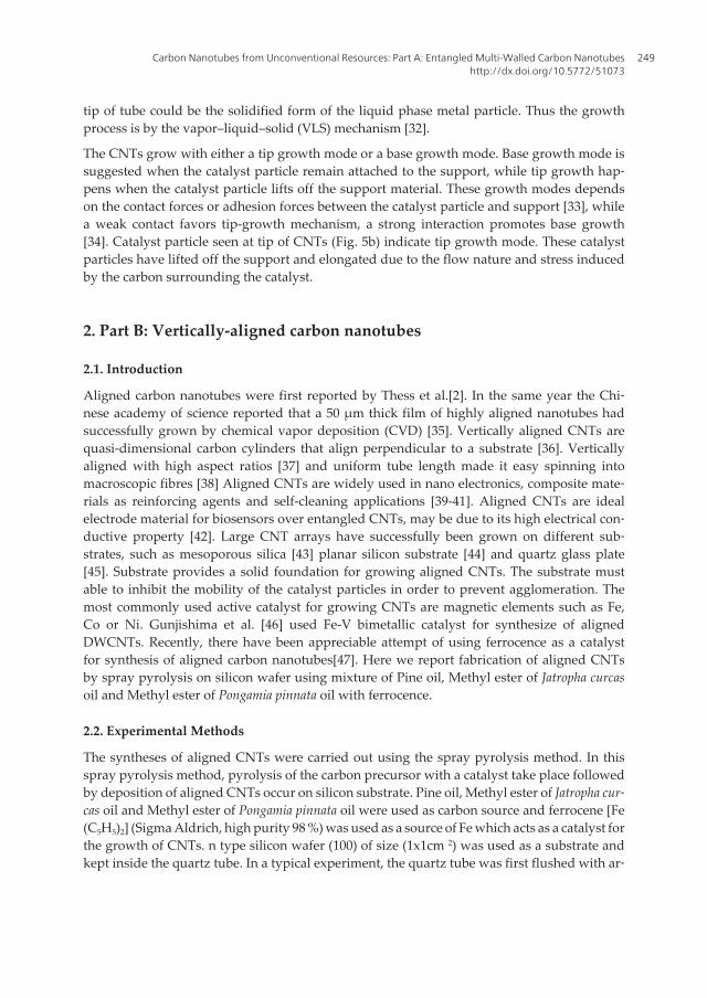
The morphology of carbon sample grown on silicon substrate using a mixture of Pine oil andferrocene at 650 °C can be observed in Figure 6a. The image revel the formation of high abun‐dance of carbon nanotubes which are forest like and vertically-aligned to the substrate surface.The growth of carbon nanotubes seems to be uniform and reaches up to a length of 10µm. Fig‐ure 6b shows the SEM image of carbon sample grown on silicon substrate using a mixture ofMethyl ester of Jatropha curcas oil and ferrocene at 650 °C. The dense, aligned but non-uniformgrowth of carbon nanotubes was observed. The length of carbon nanotubes grown was foundto be varied from 12.5 to 7.5µm. Figure 6c illustrates the SEM image of the carbon naotubesgrown at 650 °C using Methyl ester of Pongamia pinnata oil. A thick carbon nanotube with poorstructure and alignment was observed.
Figure 6. Representative SEM images of as-grown vertically-aligned carbon nanotubes at 650 °C using Pine oil (a),Methyl ester of Jatropha carcus oil (b) and Methyl ester of Pongamia pinnata oil (c).
From the experimental results we suggest that the synthesis of aligned CNTs is very sensitive tothe carbon precursors used. Ferrocene on thermal decomposition at high temperature forms Fenano particles on the silicon substrate surface. During the chemical vapor deposition process,the carbon precursor is catalytically decomposed and the carbon fragments formed diffuse intothe Fe catalyst. The Fe particles may thus easily become saturated or supersaturated with car‐bon atoms, and the precipitation of the carbon from the surface of the Fe particle leads to the for‐mation of dense carbon nanotubes [48]. The high surface density of the growing nanotubesserves as an additional advantage for the constituent nanotubes to be “uncoiled”. The Vanderwaals forces between the tube keep them aligned. Thus, the Fe catalysts can effectively catalyzethe growth of highly dense vertically aligned carbon nanotubes on silicon substrate. Further in‐
Syntheses and Applications of Carbon Nanotubes and Their Composites250

vestigation is going on in our laboratory for a better understanding of the actual growth mecha‐nism of vertically aligned carbon nanotubes.
3. Conclusions, challenges and future prospects
In view of the perspective of green chemistry, we attempt to explore regenerative materials forCNT synthesis with high efficiency. In this research work a well graphitized MWNTs were syn‐thesized from Pine oil and Methyl ester of Jatropha curcas oil using silica supported Fe, Co andMo catalyst by spray pyrolysis method. The optimum reaction conditions for synthesis ofMWNTs were 650 °C and precursor flow rate of 20 mL per hour. Spray pyrolysis of Methyl esterof Pongamia pinnata oil over silica supported Fe, Co and Mo catalyst results in formation ofMWNTs filled with magnetic nanoparticles, which find potential applications in magnetic re‐cording, biomedical and environmental protection. Vertically aligned carbon nanotubes wereobtained by spray pyrolysis of Pine oil and Methyl ester of Jatropha curcas oil and ferrocene mix‐ture, at 650 ºC on silicon substrate under Ar atmosphere. The use of natural precursors givessensible yield and makes the process natural world friendly as well. A thick carbon nanotubewith poor structure and alignment was observed with mixture of Methyl ester of Pongamia pin‐nata oil and ferrocene.
The studies in this work demonstrate that the carbon materials are potential precursor for CNTsproduction under suitable experimental conditions and comply with green chemistry princi‐ples. It is clear that specific carbon nanostructures can be synthesized by suitably altering theexperimental parameters. However, it is a challenge to consistently reproduce CNT of samequality and quantity form the precursor of inconsistent composition. Designing of catalyst ma‐terial and optimization of reaction parameters which is suitable for synthesis of specific mor‐phological CNTs from a renewable natural precursor of inconsistent chemical composition isone of the future prospects in this area of research.
Acknowledgements
The authors acknowledge the UGC New Delhi for financial support, the Institute for Environ‐mental and Nanotechnology for technical support and IITM for access to Electron microscopes.
Author details
S. Karthikeyan1* and P. Mahalingam2
*Address all correspondence to: [email protected]
1 Chikkanna Government Arts College, TN, India
2 Arignar Anna Government Arts College, TN, India
Carbon Nanotubes from Unconventional Resources: Part A: Entangled Multi-Walled Carbon Nanotubeshttp://dx.doi.org/10.5772/51073
251
References
[1] Iijima, S. (1991). Helical microtubules of graphitic carbon. Nature, 354, 56-58.
[2] Thess, A., Lee, R., Nikolaev, P., Dai, H., Petit, P., Robert, J., Xu, C., Smalley, R., et al.(1996). Crystalline ropes of metallic carbon nanotubes. Science, 273, 483-487.
[3] Karthikeyan, S., Mahalingam, P., & Karthik, M. (2008). Large scale synthesis of car‐bon nanotubes. E-Journal of Chemistry, 6, 1-12.
[4] Parathasarathy, R. V., Phani, K. L. N., & Martin, C. R. (1995). Template synthesis ofgraphitic nanotubules. Advanced Materials, 7, 896-897.
[5] Sen, R., Govindaraj, A., & Rao, C. N. R. (1997). Carbon nanotubes by the MetalloceneRoute. Chemical Physics Letters, 267, 276-280.
[6] Pradhan, D., & Sharon, M. (2002). Carbon nanotubes, Nanofilaments and Nanobeadsby thermal Chemical Vapor Deposition Process. Material Science and Engineering: B,96, 24-28.
[7] Qian, W., Yu, H., Wei, F., Zhang, Q., & Wang, Z. (2002). Synthesis of carbon nano‐tubes from liquefied petroleum gas containing sulfur. Carbon, 40, 2968-2970.
[8] Aswasthi, K., Kumar, R., Tiwari, R. S., & Srivastava, O. N. (2010). Large scale synthe‐sis of bundles of aligned carbon nanotubes using a natural precursor: Turpentine oil.Journal of Experimental Nanoscience, 5(6), 498-508.
[9] Ghosh, P., Soga, T., Tanemura, M., Zamri, M., Jimbo, T., Katoh, R., & Sumiyama, K.(2009). Vertically aligned carbon nanotubes from natural precursors by spray pyroly‐sis method and their field electron emission properties. Applied Physics A: MaterialsScience & Processing, 94, 151-156.
[10] Andrews, R. J., Smith, C. F., & Alexander, A. J. (2006). Mechanism of carbon nano‐tube growth from camphor and camphor analogs by chemical vapor deposition. Car‐bon, 44(2), 341-347.
[11] Ghosh, P., Afre, R. A., Soga, T., & Jimbo, T. (2007). A simple method of producingsingle-walled carbon nanotubes from a natural precursor: Eucalyptus oil. MaterialsLetters, 61(17), 3768-3770.
[12] Karthikeyan, S., & Mahalingam, P. (2010). Studies of yield and nature of multi-wal‐led carbon nanotubes synthesized by spray pyrolysis of pine Oil at different temper‐atures. International Journal of Nanotechnology and Applications, 4, 189-197.
[13] Karthikeyan, S., & Mahalingam, P. (2010). Synthesis and characterization of multi-walled carbon nanotubes from biodiesel oil: green nanotechnology route. Internation‐al Journal of Green Nanotechnology: Physics and Chemistry, 2(2), 39-46.
[14] Anastas, P., & Warner, J. C. (1998). Green Chemistry: Theory and Practice, Oxford Uni‐versity Press, Oxford, 30.
Syntheses and Applications of Carbon Nanotubes and Their Composites252
[15] Sabelo, D. M., Kartick, C. M., Robin, C., Michael, J. W., & Neil, J. C. (2009). The effectof synthesis parameters on the catalytic synthesis of multiwalled carbon nanotubesusing Fe-Co / CaCO3 catalysts. South African Journal of Chemistry, 62, 67-76.
[16] Smalley, R. E., Marek, I. M., Wang, Y., & Hange, R. H. (2007). Purification of carbonnanotubes based on the chemistry of fenton’s reagent. USPTO Patent Application No.20070065975.
[17] Afre, R. A., Soga, T., Jimbp, T., Mukul, Kumar., Anto, Y., Sharon, M., Prakash, R., So‐mani, , & Umeno, M. (2006). Carbon nanotubes by spray pyrolysis of turpentine oil atdifferent temperatures and their studies. Microporous and Mesoporous Materials, 96,184-190.
[18] Ghosh, P., Soga, T., Afre, R. A., & Jimbo, T. (2008). Simplified synthesis of single-wal‐led carbon nanotubes from a botanical hydrocarbon: Turpentine Oil. Journal of alloysand Compounds, 462-92008.
[19] Dresselhausa, M. S., Dresselhausc, G., Joriob, A., Souza Filhob, A. G., & Saito, R.(2002). Raman spectroscopy on isolated single wall carbon nanotubes. Carbon, 40,2043-2061.
[20] Kang, J. L., Li, J. J., Du, X. W., Shi, C. S., Zhao, N. Q., Cui, L., & Nash, P. (2008). Syn‐thesis and growth mechanism of metal filled carbon nanostructures by CVD usingNi/Y catalyst supported on copper. Journal of Alloys and Compounds, 456(1-2), 290-296.
[21] Abello, M. C., Gomez, M. F., & Ferretti, O. (2001). Mo/γ-Al2O3 catalysts for the oxi‐dative dehydrogenation of propane: Effect of Mo loading. Applied Catalysis A,207(1-2), 421-431.
[22] Lee, M. H., & Park, D. G. (2003). Preparation of MgO with High Surface Area, andModification of Its Pore Characteristics. Korean Chemical Society, 24(10), 1437-1443.
[23] Sinclair, R., Itoh, T., & Chin, R. (2002). In situ TEM studies of metal-carbon reactions.Microscopy and Microanalysis, 8(4), 288-304.
[24] Brukh, R., & Mitra, S. (2006). Mechanism of carbon nanotube growth by CVD. Chemi‐cal Physics Letters, 424, 126-32.
[25] Hofmann, S., Csanji, G., Ferrari, A. C., Payne, M. C., & Robertson, J. (2005). Surfacediffusion: The low activation energy path for nanotube growth. Physical Review let‐ters, 95, 036101-036104.
[26] Ducati, C., Alexandrou, I., Chhowalla, M., Robertson, J., & Amaratunga, G. A. J.(2004). The role of the catalytic particle in the growth of carbon nanotubes by plasmaenhanced chemical vapor deposition. Journal of Applied Physics, 95(11), 6387-6391.
[27] Ozturk, B., Fearing, Vl., Ruth, J. A., & Simkovich, G. (1982). Self-Diffusion Coeffi‐cients of Carbon in Fe3C at 723 K via the Kinetics of Formation of This Compound.Metallurgical and Materials Transactions A, 13(10), 1871-1873.
Carbon Nanotubes from Unconventional Resources: Part A: Entangled Multi-Walled Carbon Nanotubeshttp://dx.doi.org/10.5772/51073
253
[28] Chakraborty, A. K., Jacobs, J., Anderson, C., Roberts, C. J., & Hunt, M. R. C. (2005).Chemical vapor deposition growth of carbon nanotubes on Si substrates using Fe cat‐alyst: What happens at the nanotube/Fe/Si interface. Journal of Applied Physics, 100(8),084321.
[29] Rodriguez, N. M. (1993). A review of catalytically grown carbon nanofibers. Journal ofMaterials Research, 8, 3233-3250.
[30] Hofmann, S., Sharma, K., Ducati, C., Du, G., Mattevi, Cepek C., Cantoro, M., Pisana,S., Parvez, A., Cervantes-sodi, F., Ferrari, A. C., & Dunin-Borkowski, R. E. (2007). Insitu Observations of Catalyst Dynamics during Surface-Bound Carbon NanotubeNucleation. Nano Letters, 7(3), 602-608.
[31] Helveg, S., Lopez-Cartes, C., Sehested, J., Hensen, P. L., Clausen-Nielsen, Rostrup.,Abild-Pederson, J. R., , F., & Norskov, J. K. (2004). Atomic-scale imaging of carbonnanofibre growth. Nature, 427, 426-429.
[32] Kukovitsky, E. F., L’vov, S. G., & Sainov, N. A. (2000). VLS-growth of carbon nano‐tubes from the vapor. Chemical Physics Letters, 317, 65-70.
[33] Leonhardt, A., Hampel, S., Büchner, B., et al. (2006). Synthesis, properties and appli‐cations of ferromagnetic filled carbon. Chemical Vapor Deposition, 12(6), 380-387.
[34] Bower, C., Otto, Z., Wei, Z., Werder, D. J., & Jin, S. (2000). Nucleation and growth ofcarbon nanotubes by microwave plasma chemical vapor deposition. Applied PhysicsLetters, 77(17), 2767-2768.
[35] Li, W. Z., Xie, S. S., Qian, L. X., Chang, B. H., Zou, B. S., Zhou, W. Y., Zhao, R. A., &Wang, G. (1996). Large-scale synthesis of aligned carbon nanotubes. Science,274(5293), 1701-1703.
[36] Feng, W., Bai, X. D., Lian, Y. Q., Liang, J., Wang, X. G., & Yoshino, K. (2003). Wellaligned polyaniline/carbon-nanotube composite films grown by in-situ aniline poly‐merization. Carbon, 41(8), 1551-1557.
[37] Zhang, Q., Zhao, M. Q., Huang, J. Q., Liu, Y., Wang, Y., Qian, W. Z., & Wei, F. (2009).Vertically aligned carbon nanotube arrays grown on a lamellar catalyst by fluidizedbed catalytic chemical vapor deposition. Carbon, 47(11), 2600-2610.
[38] Zhang, Q., Zhou, W. P., Qian, W. Z., Xiang, R., Huang, J. Q., Wang, D. Z., & Wei, F.(2007). Synchronous growth of vertically aligned carbon nanotubes with pristinestress in the heterogeneous catalysis process. Journal of Physical Chemistry, 111(40),14638-14643.
[39] Afre, R. A., Soga, T., Jimbo, T., Kumar, M., Ando, A., & Sharon, M. (2005). Growth ofvertically aligned carbon nanotubes on silicon and quartz substrate by spray pyroly‐sis of a natural precursor: Turpentine oil. Chemical Physics Letters, 414(1-3), 6-10.
Syntheses and Applications of Carbon Nanotubes and Their Composites254

[40] Teo, K. B. K., Singh, C., Chhowalla, M., & Milne, W. I. (2003). Catalytic synthesis ofcarbon nanotubes and nanofiber. In: Nalwa H S, eds. Encyclopedia of nanoscience andnanotechnology, American Scientific Publishers, 1-22.
[41] Bu, I. Y. Y., & Oei, S. P. (2010). Hydrophobic vertically aligned carbon nanotubes onCorning glass for self cleaning applications. Applied surface science, 256(22), 6699-6704.
[42] Yang, L., Xu, Y., Wang, X., Zhu, J., Zhang, R., He, P., & Fang, Y. (2011). The applica‐tion of b-cyclodextrin derivative functionalized aligned carbon nanotubes for electro‐chemically DNA sensing via host-guest recognition. Analytica Chimica Acta, 689(1),39-46.
[43] Pan, Z. W., Zhu, H. G., Zhang, Z. T., Im, H. J., Dai, S., Beach, D. B., & Lowndes, D. H.(2003). Patterned growth of vertically aligned carbon nanotubes on pre-patternediron/silica substrates prepared by sol-gel and shadow masking. Journal of physicalchemistry B, 107(6), 1338-1344.
[44] Jung, Y. J., Wei, B. Q., Vajtai, R., & Ajayan, P. M. (2003). Mechanism of selectivegrowth of carbon nanotubes on SiO2/Si patterns. Nano Letters, 3(4), 561-564.
[45] Gong, Q. M., Li, Z., Li, D., Bai, X. D., & Liang, J. (2004). Fabrication and structure: astudy of aligned carbon nanotube/carbon nanocomposites. Solid State Communica‐tions, 131(6), 399-404.
[46] Gunjishima, I., Inoue, T., Yamamuro, S., Sumiyama, K., & Okamoto, A. (2007). Syn‐thesis of vertically aligned, double-walled carbon nanotubes from highly active Fe-V-O nanoparticles. Carbon ., 45(6), 1193-1199.
[47] Kumar, M., & Ando, Y. (2003). A simple method of producing aligned carbon nano‐tubes from an unconventional precursor- Camphor. Chemical Physics Letters, 374(5-6),521-526.
[48] Liu, Y., Yang, X. C., Pu, Y., & Yi, B. (2010). Synthesis of aligned carbon nanotube withstraight-chained alkanes by nebulization method. Transaction of Nonferrous Metals So‐ciety of China, 20(6), 1012-1016.
Carbon Nanotubes from Unconventional Resources: Part A: Entangled Multi-Walled Carbon Nanotubeshttp://dx.doi.org/10.5772/51073
255