
Carbon nanotubes as liquid crystals
14
Liquid crystals DOI: 10.1002/smll.200700082 Carbon Nanotubes as Liquid Crystals Shanju Zhang and Satish Kumar* reviews S. Zhang and S. Kumar Atomic force microscopy image of oriented bundles of single-walled carbon nanotubes. From the Contents 1. Introduction.... 1271 2. Liquid-crystal Theory of Carbon Nanotubes .... 1272 3. Fabrication of Liquid-Crystalline Phases ....... 1273 4. Solution Properties in Liquid-Crystalline Phases ....... 1277 5. Liquid-Crystal Processing of Macroscopic Assemblies .... 1279 6. Summary and Outlook....... 1280 Keywords: alignment carbon nanotubes liquid crystals phase behavior self-assembly 1270 ß 2008 Wiley-VCH Verlag GmbH & Co. KGaA, Weinheim small 2008, 4, No. 9, 1270–1283
Transcript of Carbon nanotubes as liquid crystals

reviews S. Zhang and S. Kumar
1270
Liquid crystals
DOI: 10.1002/smll.200700082
Carbon Nanotubes as Liquid CrystalsShanju Zhang and Satish Kumar*
Atomic force microscopy image of oriented bundles of single-walled carbon nanotubes.
From the Contents
1. Introduction. . . .1271
2. Liquid-crystal
Theory of Carbon
Nanotubes . . . .1272
3. Fabrication of
Liquid-Crystalline
Phases . . . . . . .1273
4. Solution Properties in
Liquid-Crystalline
Phases . . . . . . .1277
5. Liquid-Crystal Processing
of Macroscopic
Assemblies . . . .1279
6. Summary and
Outlook. . . . . . .1280
Keywords:� alignment
� carbon nanotubes
� liquid crystals
� phase behavior
� self-assembly
� 2008 Wiley-VCH Verlag GmbH & Co. KGaA, Weinheim small 2008, 4, No. 9, 1270–1283

Nanotube Liquid Crystals
Carbon nanotubes are the best of known materials with a combination of
excellent mechanical, electronic, and thermal properties. To fully exploit
individual nanotube properties for various applications, the grand challenge
is to fabricate macroscopic ordered nanotube assemblies. Liquid-crystalline
behavior of the nanotubes provides a unique opportunity toward reaching
this challenge. In this Review, the recent developments in this area are
critically reviewed by discussing the strategies for fabricating liquid-
crystalline phases, addressing the solution properties of liquid-crystalline
suspensions, and exploiting the practical techniques of liquid-crystal routes
to prepare macroscopic nanotube fibers and films.
[�] Dr. S. Zhang, Prof. S. Kumar
School of Polymer, Textile and Fiber Engineering
Georgia Institute of Technology
Atlanata, GA 30332-0295 (USA)
E-mail: [email protected]
1. Introduction
Liquid crystal can be considered a fourth state of matter
following solid, liquid, and gas. Liquid-crystal phases, as their
name implies, exist between the conventional crystal phase
and the liquid phase. Usually, liquid-crystal molecules possess
rodlike or disclike anisotropic structures. The unique
characteristic of liquid crystals is the tendency of themolecules
to align themselves with long-range order. In general, rod-like
liquid crystals exhibit nematic or smectic phases depending on
the degree of the positional order (Figure 1). In the simplest
form of nematic phase the molecules have only orientational
but no positional order. The molecules are free to move but
like to point along one particular direction, which is described
by the director vector n. The smectic phases are characterized
by additional degrees of positional order and generally have
separate layers within which there is a loss of positional order.
The disclike liquid crystals normally form ordered columnar
phases, which are characterized by stacked columns of
molecules to form two-dimensional (2D) crystalline arrays
(Figure 1).
In general, liquid crystals are most stable when all
molecules are aligned along a single director. However,
liquid-crystal molecules are highly sensitive to the external
forces and thus, in most cases, liquid crystals contain defects,
which are called topological disclinations.[1,2] The detailed
molecular trajectories of a disclination are distinguished by
strength s (the number of rotations in multiples of 2p of the
director over a path encircling the disclination) and a value of
constant parameter c in the simplest case, f(u)¼ suþ c, in
which f and u are the director orientation angle and polar
angle, respectively. According to Frank continuum theory,[3]
one negative pattern and one positive pattern for s ¼ � 12, and
one negative pattern and three positive patterns for s¼�1 can
be expected in a 2D ordered liquid crystal (Figure 2). Knowing
the disclination microstructure can shed light on defect
mobility, which, in turn, affects the liquid-crystal properties,
such as the alignment quality or rheological behavior.[4,5]
It has been suggested that carbon nanotubes (CNTs) are
simply exceptionally stiff examples of rigid-rodlike macro-
molecules,[6] which due to their shape and size can act as liquid
crystals. Liquid-crystal phases have been identified in the
suspensions (or dispersions) of both multi-walled carbon
small 2008, 4, No. 9, 1270–1283 � 2008 Wiley-VCH Verlag
nanotubes (MWNTs) and single-walled carbon nanotubes
(SWNTs).[7–18] The ability of CNTs to form a liquid-crystal
phase, its mesogenicity, depends predominately on its
straightness and its aspect ratio. Liquid-crystal structures in
the CNT suspension can be maintained in the solid film when
the solvent is completely evaporated. The individual CNT
orientation around the disclination and the central core can be
directly visualized under high-resolution scanning electron
microscopy (HRSEM)[7,8] or atomic forcing microscopy
(AFM)[13]. Therefore, the liquid-crystal system of CNTs
serves as a model for studying physical issues of considerable
interest in liquid-crystal science.
Kevlar, a rigid-rod polymer of poly(p-phenylene terephthal-
amide) (PPTA), is an example of commercially successful
liquid-crystalline polymers. Kevlar exhibits so-called lyotropic
liquid crystallinity in solution as a function of polymer
concentration.[19] Carbon nanotubes, analogous to Kevlar,
also exhibit lyotropic liquid crystallinity in a suspension under
certain conditions.[7–18] This analogy is applicable to fabri-
catingmacroscopic films and fibers of CNTs by using the liquid-
crystal phase to achieve high alignments within the films and
fibers.[20–22] The SWNT fibers spun from a liquid-crystalline
phase in a super acid had a misalignment of �15.58 and a
Young’s modulus of about 120� 10GPa,[20] while MWNT
fibers spun from a liquid-crystal phase in ethylene glycol had a
misalignment of only �7.88 and a Young’s modulus of
142� 70GPa.[21] These modulus values of CNT fibers are
comparable to those of Kevlar fiber. However, a large amount
of further work will have to be done before commercialization
of CNT fibers by liquid-crystal spinning.
In this Review, we give a critical overview of literature
reports of CNTs exhibiting liquid crystallinity and their
applications. We briefly discuss rigid-rod liquid-crystalline
theories of CNT systems in Section 2 and strategies for
fabricating liquid-crystalline phases of CNTs are discussed in
Section 3. In Section 4, we present solution properties of CNTs
in liquid-crystalline phases. Next, we address technical
GmbH & Co. KGaA, Weinheim www.small-journal.com 1271

reviews S. Zhang and S. Kumar
Shanju Zhang received his B.Sc. in
chemistry from Jilin University (P.R.
China) in 1993 and his Ph.D. in
polymer chemistry and physics from
the same university in 1998. From
1998 to 2000 he was an assistant
professor at Changchun Institute of
Applied Chemistry at the Chinese
Academy of Sciences. In 2000, he
moved to the Johannes Gutenberg
University of Mainz (Germany) and
later worked at the Technical University of Berlin (Germany) as a
postdoctoral fellow. He received an Alexander von Humboldt
fellowship in Berlin in 2000. From 2002 to 2006 he worked in the
Cavendish laboratory and Materials Science department at the
University of Cambridge (England) as a research associate. Since
2006, he has been a research scientist in the school of Polymer,
Textile and Fiber Engineering at Georgia Institute of Technology
(U.S.A.). His research interest is in the area of soft matter,
including liquid crystals, polymers, carbon nanotubes, and bio-
materials.
Satish Kumar received his Ph.D.
degree in 1979 from the Textile
Technology Department at the Indian
Institute of Technology, New Delhi,
India in the area of polymer and fiber
science. He obtained his postdoctoral
experience in the Polymer Science and
Engineering department at the
University of Massachusetts (1979–
82). During 1982–83, he was a visiting
scientist at the Atomic Energy
Commission of France, C.E.N.G., Gre-
noble, France. During 1984–89 he was associated with the
Polymer Branch, Air Force Materials Laboratory, Wright Patterson
Air Force Base, Dayton, OH on contract through Universal Energy
Systems and the University of Dayton Research Institute. He
joined the faculty of the School of Polymer, Textile and Fiber
Engineering at Georgia Tech in 1989, where he is currently serving
as a Professor. Dr. Kumar has published extensively in the areas of
structure, processing, and properties of polymers and fibers. His
current research is focused on polymer–carbon-nanotube com-
posites.
1272
developments using liquid-crystal routes for CNT fiber and
film formation. Finally, we give a summary and outlook.
2. Liquid-Crystal Theory of Carbon Nanotubes
The liquid-crystal nature of CNTs can be understood using
the steric theory of rigid-rodlike liquid crystals.[23,24] Based on
the simple steric model, no two molecules occupy the same
space and the molecular configurations are dominated by
steric repulsive interactions. The model describes the
equilibrium phase diagram depending on the concentration.
Both translational and rotational degrees of freedom con-
tribute to the entropy of the system at a given concentration. In
a dilute solution, the translational entropy dominates over the
rotational entropy because of the large free volume. There-
fore, the parallel configuration of molecules is not favored and
the phase is isotropic. While in a concentrate solution,
reducing the free volume increases parallel configurations to
optimize the packing efficiency. The rotational entropy is
thereafter predominant, leading to the liquid-crystalline
phase. In reality, many factors such as particle–particle
interaction, particle–solvent interaction as well as the
tortuosity and polydispersity of the particles play a role in
controlling the phase transition.[25]
CNTs are a very complex system. From a theoretical
viewpoint, CNTs can be considered as model straight, long,
rigid-rodlike particles. The steric theory for the electrostatic
repulsion of long rigid rods has been used to investigate the
SWNT phase behavior in their suspension.[26] Calculations
have shown that SWNTs in a good solvent is analogous to the
classic rigid-rod system if the van der Waals force between
CNTs is overcome by strong repulsive intertube potentials.
The nematic phase starts to form at a volume fraction of about
3.3 d/l and fully develops at about 4.5 d/l, where d and l are tube
diameter and tube length, respectively.[26] When the solvent is
not good for SWNTs, the van derWaals attractive interactions
between the nanotubes are still strong. As a result, only
extremely dilute solutions of SWNTs are thermodynamically
stable and no liquid-crystal phases form at room temperature.
Considering the effect of temperature on the phase
behavior, the liquid crystallinity of finite-size capped CNTs
with and without full van der Waals interactions has been
analyzed by using continuum-based density-functional
theory.[27] The resultant phase diagram is complex, which
describes temperature (T) versus concentration (h) for CNTs
with different aspect ratios (Figure 3). In the presence of full
van der Waals interactions, the nematic phase as well as
columnar phase occur in a wide range of very high
temperatures. The existence of the columnar phase is very
interesting, as the ordered columnar phase normally occurs in
the disclike liquid crystals.[28] The columnar phase predicted
by theory is assumed to be analogous to the hexagonal
ordering of SWNTs in the rope, which is commonly observed
in high-temperature-synthesized SWNTs.[29] Although such
an analogy remains questionable, the predominant columnar
phase at high temperature predicted by theory can explain the
stability of the SWNT ropes during their growth at high
temperature in extreme conditions. In the absence of van der
www.small-journal.com � 2008 Wiley-VCH Verlag Gm
Waals interactions, the system is dominated by steric repulsive
interactions only. With an increase of concentration, the
system undergoes an isotropic-to-nematic phase transition via
a biphasic region, the so-called Flory chimney in the liquid-
crystalline polymers.[25] The longer the CNTs, the lower the
concentration needed. The ordered smectic phase is predicted
at higher concentration over h� 0.36. This calculation is
consistent with that of simple rodlike liquid crystals.
The above theoretical calculations have shown that to form
liquid-crystal phases at room temperature, strong van der
Waals attractions between CNTs must be screened out. This
requires a good solvent with an ability to disperse CNTs down
bH & Co. KGaA, Weinheim small 2008, 4, No. 9, 1270–1283

Nanotube Liquid Crystals
Figure 1. Schematic image of liquid-crystal structures in nematic, smectic, and columnar phases.
to the level of individual tubes. Experimentally, several
strategies have been successfully developed to increase
repulsive interactions between CNTs or to concentrate them
by gradually evaporating the solvent or to form aligned phases
by flowing the CNTs. These include negative or positive
charging of CNT surfaces,[7–10] polymer wrapping,[15,16] drop
drying,[12–14] and shear flow.[17] In the following section, we
will discuss in detail how each approach works to create liquid-
crystal phases in CNTs.
3. Fabrication of Liquid-Crystalline Phases
3.1. Acid Oxidation
Acid oxidation is an efficient approach to modify the CNT
surface by introducing functional groups.[30] Typically, CNTs
are treated by using a mixture of concentrated sulfuric acid
and concentrated nitric acid (H2SO4/HNO3) at a 3:1 ratio in
volume under ultrasonication. After treatment, the CNTs are
not only cut into short tubes but also functionalized by
carboxylic, carbonyl, and hydroxyl groups. The presence of
oxygenated groups on CNTs negatively charges the CNT
surface and thereafter enhances the dispersibility and stability
of the CNTs in a polar solvent without any additives. In this
case, the intertube van derWaals interactions are overcome by
Figure 3. Theoretically ca
tubes with different aspe
fractionh: a) 70, b) 140, c
region denotes the isotro
dashed line the nematic–
isotropic–nematic coexis
force. Reprinted with perm
American Physical Societ
Figure 2. Molecular trajectories in a 2D ordered liquid crystal associ-
ated with disclinations of s ¼ � 12 and �1.
small 2008, 4, No. 9, 1270–1283 � 2008 Wiley-VCH Verlag GmbH & Co. KGaA, Weinheim
electrostatic repulsion and CNTs are
thus analogous to charged rigid-rodlike
particles. The reported concentration
value of acid-oxidized CNTs in water is
up to 8wt%.[8]
While much effort has beenmade to
address CNT dispersibility and surface
chemical functionalization via acid
oxidation,[31–33] little attention has been
paid to the phase behavior of acid-
oxidized CNTs. In 2003,Windle’s group
first reported the liquid-crystalline
behavior of an aqueous suspension of
acid-oxidized MWNTs[7] and analyzed the phase diagram using
the simple rigid-rod steric theory.[8] The liquid-crystalline
behavior of CNTs has now been reported in several systems.[9–18]
In a dilute aqueous solution, the acid-oxidized CNTs
behave as Browian particles, forming an isotropic phase.[7,8]
With an increase in concentration above the percolation
threshold, the nematic nuclei due to steric effects grow and
coagulate into large nematic domains. The liquid-crystalline
domains coexist with isotropic regions, which remain dark
irrespective of the rotation setting of the crossed polars. This
shows a biphasic suspension in equilibrium, which is analogous
to the Flory chimney in the rigid-rodlike liquid crystals.[25]
Further increasing the concentration leads to a single liquid-
crystal phase. The whole phase transition for aqueous
suspension of MWNTs under polarized optical microscope
is shown in Figure 4. The observed Schlieren texture is a
lculated phase diagrams for carbon nano-
ct ratio as a function of temperature T and
) 280, d) 37, e) 74, and f) 148. The shaded gray
pic–nematic coexistence region and the
columnar spinodal. The thick line marks the
tence region in the absence of van der Waals
ission from Reference [27]. Copyright 2001,
y.
www.small-journal.com 1273

reviews S. Zhang and S. Kumar
1274
typical optical effect of nematic liquid crystals. This phase
behavior of MWNTs is consistent with the theoretical
predictions in the simple rigid-rod particles[23,24] as well as
in the CNT systems.[26,27]
The critical concentrations for starting the nematic phase
(c1�) and ending the isotropic phase (c2�) depend on the
solvent quality and aspect ratio of the CNTs.[8] In the case of
MWNTs with an aspect ratio of 30, the reported critical
concentrations c1� and c2� are 1.0 vol % and 4.0 vol %,
respectively,[8] while the simple rigid-rod theory predicts that a
biphase for monodisperse liquid crystals is typically at a
�1–2 vol % concentration range depending on the aspect
ratio.[25] The comparatively large range of the Flory chimney is
assumed to associate with polydispersity in terms of length,
diameter, and straightness of the CNTs. The widening effect of
the Flory chimney due to size polydispersity has been
recognized in polymeric liquid crystals before.[34,35] Reducing
polydispersity of polymer chains significantly narrows the
Flory chimney toward reaching the theoretical prediction.
Recently, the liquid-crystal phase diagram of aqueous
suspension of monodisperse MWNTs has been investi-
gated.[36] Acid-oxidized CNTs can be fractionalized and
purified in the biphasic regions by centrifugation.[36] Long
nanotubes enter the liquid-crystalline phase, which can be
removed and refractionized by adding more solvent. With an
Figure 4. Optical images of MWNT aqueous suspensions with crossed pol
phase transition from isotropic to the liquid-crystal phase with increasin
Reprinted with permission from Reference [8]. Copyright 2005, American
www.small-journal.com � 2008 Wiley-VCH Verlag Gm
increase of centrifugation cycles, the CNT length range
becomes smaller and the Flory chimney becomes narrower.
This method is very efficient to size fractionize nanotubes
based on their liquid crystallinity and therefore allows the
polydispersity to be greatly decreased. The values of c1� and
c2� for monodisperse MWNTs with a length of 900 nm and a
diameter of 30 nm are reported to be about 1.6wt% and
4.5wt%, respectively.[36] The ratio of c2�/c1� is about 2.8,
which is in agreement with the theoretical value of �2–3 for a
system of rigid rods with the most probable distribution.
The liquid-crystalline structures including the singularities
of the Schlieren texture can be preserved as a thin film after
the solvent is completely evaporated from the suspen-
sion.[7,8,36] This preservation provides further opportunity to
study disclination supramolecular microstructures using SEM
or AFM at a resolution sufficient to view individual CNTs. In
particular, it is possible to visualize the individual CNT
contribution to distortions of the director field and central
core of the disclination. For a polydisperse system of liquid-
crystalline polymers, it has long been speculated that short
polymer chains have a tendency to aggregate in the disclination
cores, where they reduce the high elastic-distortion ener-
gies.[37,38] CNT liquid crystals have the ability to directly
visualize such segregation in the polydisperse system,[36]
in which short tubes and impurities are in the central core
arizers showing the
g concentration.
Chemistry Society.
bH & Co. KGaA, Weinhei
(Figure 5). After CNT size fractionation,
the disclination cores decrease and no
segregation of short tubes or impurities
appears in the core (Figure 5).
3.2. Acid Protonation
It has been suggested that CNTs can
behave as a weak base and be protonated
by superacids.[9,10] As a result, the delo-
calization of positive charge over the
entire CNT occurs. Such protonation
yields the formation of ordered acid layers
on the CNT surfaces and thus the dissolu-
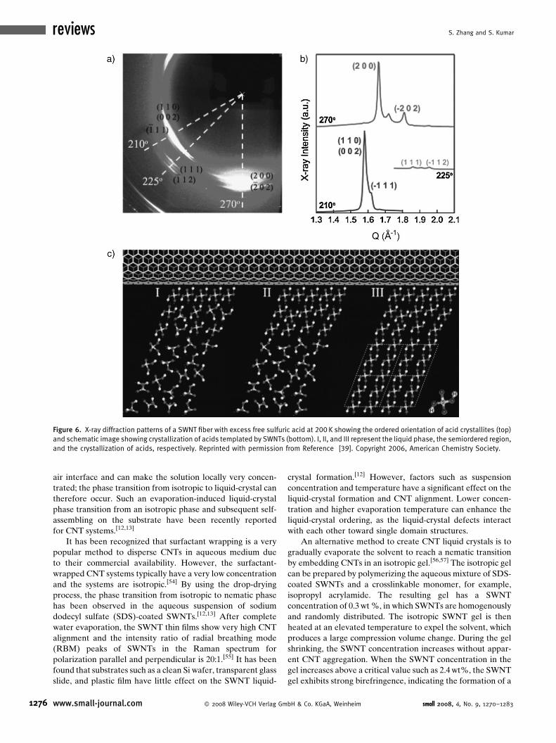
tion of CNTs.[39,40] Based on X-ray
data,[39,40] a three-layer model has been
suggested (Figure 6). The acids in the
innermost layer have positional and
orientational molecular order, showing
strong association between CNTs and
superacids. In the middle layer, acid
molecules interact with the innermost
layer via hydrogen bonding, forming
semiordered regions. In the outermost
layer, acid molecules behave as bulk
disordered regions.
The ordered acid layers around CNTs
produce intertube electrostatic repulsions,
which are strong enough to overcome the
intertube van de Waals attractions. It has
been reported that the SWNTs can be
dispersed in superacids, such as 100%
sulfuric acid, oleum (20% free SO3),
m small 2008, 4, No. 9, 1270–1283

Nanotube Liquid Crystals
Figure 5. SEM images of a � 12 disclination in the nematic phase of MWNTs: a) unpurified
materials and b) purified materials. Reprinted with permission from Reference [36]. Copyright
2006, American Chemistry Society.
trifluromethanesulfonic acid (triflic acid), methanesulfonic
acid, and chlorosulfonic acid, with a concentration of up to
8wt%.[41] Again, the protonated SWNTs in the superacid
behave as rigid-rodlike liquid crystals and exhibit an isotropic-
to-nematic phase transition with an increase in concentration
over a critical value.[9,10] The phase diagram of SWNTs in
superacids is reminiscent of those in the lyotropic rigid-rod
polymers and particles.
As in the rigid-rodlike liquid crystals, solvent quality
greatly affects the SWNT–solvent interaction and thereafter
the phase diagram of the system investigated. It has been
reported that the critical concentration of the isotropic-to-
nematic transition for SWNTs in superacids shifts towards a
higher value with an increase of acid strength.[10] Thus, the
isotropic phase of SWNTs in superacids becomes more stable
when the acid strength is high. Stronger acids have greater
protonating power, resulting in increased charge stabilization
and the overall number of SWNTs in the isotropic phase.
These findings further confirm the protonation mechanism of
CNTs in superacids. From a viewpoint of the stabilization of
CNT suspension, this system also opens a new route to
improve the dispersibility of CNT suspension.
Acid oxidation and acid protonation are very efficient
methods to introduce negative or positive charges on the CNT
surface to create electrostatic repulsions. This intertube
electrostatic interaction can overcome the intertube van der
Waals attraction. The resultant CNTs are exfoliated and they
behave as rigid-rodlike liquid crystals.
3.3. Polymer Wrapping
Polymer-wrapped CNTs can be effectively dispersed in a
solvent without damaging CNTs. Polymers used to increase
CNT dispersibility include conjugated polymers,[42] amphi-
philic block copolymers,[43] polyelectrolytes,[44] and biopoly-
mers.[45] Depending on the polymer structures and polymer–
CNT interactions, the polymer-wrapped CNTs can be
dispersed and stabilized in a solvent with a considerable
concentration. With an increase of suspension concentration,
the suspensions of polymer-wrapped CNTs undergo an
small 2008, 4, No. 9, 1270–1283 � 2008 Wiley-VCH Verlag GmbH & Co. KGaA, Weinheim
isotropic-to-nematic phase transition
under certain conditions.[15,16,46]
In an aqueous medium of a water-
soluble polymer, the hydrophobic CNT
surface can be eliminated by polymer
wrapping around the CNTs. Biopoly-
mers such as DNA and polysaccharides
have been used to wrap SWNTs and to
increase tube dispersibility in
water.[15,45] DNA is a charged amphi-
philic polymer that can be strongly
adsorbed on the CNTs. The electro-
static repulsions between DNA mole-
cules can overcome the intertube van
der Waals attractions and therefore
DNA can effectively disperse CNTs in
water. As in the case of acid-treated
CNTs, the phase diagram of DNA-
wrapped SWNTs is similar to those of lyotropic rigid-rod
polymers.[15,16] There is a biphasic region (2–4wt%) before
the system enters a single-liquid-crystal phase (Figure 7). The
liquid-crystalline behavior of SWNTs with such biological
molecules is particularly interesting. Liquid-crystal phases
have been frequently observed for biologically important
molecules including lipids, nucleic acids, carbohydrates, and
proteins in vivo as well as in vitro under well-controlled
conditions.[47] Moreover, liquid-crystal ordering may be
relevant to the biological function and self-assembly processes
associated with each biological molecule. Recent work on
liquid-crystal materials used in the biosensors and medicines
has shown promise for the new revolution of liquid crystals in
biological systems.[48,49]
Polymer wrapping provides a direct way to create
intertube repulsive interactions to overcome van der Waals
attractions. As a result, the concentration of the CNT
dispersion, in some special conditions such as strong binding
interactions between CNTs and polymers, is high enough to
allow the system to enter a nematic liquid-crystal phase.
However, the CNT–polymer interactions in most cases are not
strong enough to stabilize the suspension at a significant
concentration by such physical wrapping. Approaches to
create a spontaneous phase transition from the isotropic to the
liquid-crystal phase in CNT systems are highly desired.
3.4. Gradual Evaporation
Drop drying has been widely used for fabricating 2D
ordered structures of nanoparticles.[50] Drops of the solvent
are put on the solid substrate surface and are allowed to
evaporate by controlling the drying rate. As the solvent
evaporates,theliquidlevelsweepsoverthesubstrate,depositing
the solute behind as an ordered assembly when the solvent is
completely gone. This gradual evaporation process starting
from the dilute solution has been used for organic rigid-
chain polymers,[51] inorganic nanorods,[52] and DNA[53] to
create liquid-crystalline assemblies on the substrate. The
convective flow due to the solvent evaporation carries
the rodlike objects from the bulk solution to the liquid–solid–
www.small-journal.com 1275
reviews S. Zhang and S. Kumar
Figure 6. X-ray diffraction patterns of a SWNT fiber with excess free sulfuric acid at 200 K showing the ordered orientation of acid crystallites (top)
and schematic image showing crystallization of acids templated by SWNTs (bottom). I, II, and III represent the liquid phase, the semiordered region,
and the crystallization of acids, respectively. Reprinted with permission from Reference [39]. Copyright 2006, American Chemistry Society.
1276
air interface and can make the solution locally very concen-
trated; the phase transition from isotropic to liquid-crystal can
therefore occur. Such an evaporation-induced liquid-crystal
phase transition from an isotropic phase and subsequent self-
assembling on the substrate have been recently reported
for CNT systems.[12,13]
It has been recognized that surfactant wrapping is a very
popular method to disperse CNTs in aqueous medium due
to their commercial availability. However, the surfactant-
wrapped CNT systems typically have a very low concentration
and the systems are isotropic.[54] By using the drop-drying
process, the phase transition from isotropic to nematic phase
has been observed in the aqueous suspension of sodium
dodecyl sulfate (SDS)-coated SWNTs.[12,13] After complete
water evaporation, the SWNT thin films show very high CNT
alignment and the intensity ratio of radial breathing mode
(RBM) peaks of SWNTs in the Raman spectrum for
polarization parallel and perpendicular is 20:1.[55] It has been
found that substrates such as a clean Si wafer, transparent glass
slide, and plastic film have little effect on the SWNT liquid-
www.small-journal.com � 2008 Wiley-VCH Verlag Gm
crystal formation.[12] However, factors such as suspension
concentration and temperature have a significant effect on the
liquid-crystal formation and CNT alignment. Lower concen-
tration and higher evaporation temperature can enhance the
liquid-crystal ordering, as the liquid-crystal defects interact
with each other toward single domain structures.
An alternative method to create CNT liquid crystals is to
gradually evaporate the solvent to reach a nematic transition
by embedding CNTs in an isotropic gel.[56,57] The isotropic gel
can be prepared by polymerizing the aqueous mixture of SDS-
coated SWNTs and a crosslinkable monomer, for example,
isopropyl acrylamide. The resulting gel has a SWNT
concentration of 0.3wt%, in which SWNTs are homogenously
and randomly distributed. The isotropic SWNT gel is then
heated at an elevated temperature to expel the solvent, which
produces a large compression volume change. During the gel
shrinking, the SWNT concentration increases without appar-
ent CNT aggregation. When the SWNT concentration in the
gel increases above a critical value such as 2.4wt%, the SWNT
gel exhibits strong birefringence, indicating the formation of a
bH & Co. KGaA, Weinheim small 2008, 4, No. 9, 1270–1283

Nanotube Liquid Crystals
Figure 7. Phase diagram of DNA-wrapped SWNTs in water. The dashed
line shows the limit above which SWNTs are homogeneously dispersed
after sonication (white circles); below the line, aggregations are still
observed (black circles). Insets: optical images with cross polarizers in
biphasic and nematic phases. Adapted from Reference [15].
Figure 8. Phase diagram of long CNTs suspended in a polymer liquid
under shear flow. The concentration increases from top to bottom.
Dashed lines mark the stability limit. Open circles are nematics, closed
circles are isolated aggregates, open squares are vorticity bands,
and closed squares are cavitated networks. N and I present nematic
and isotropic phases, respectively. Reprinted with permission from
Reference [17]. Copyright 2006, American Physical Society.
nematic phase. It is interesting to note that the critical
concentration from isotropic to nematic phase in the gel is
close to those in other systems described above. This result
indicates that the isotropic-to-nematic phase transition of
SWNTs in the gel is still dominated by the rotational entropy
as those of unconstrained Brownian particles in the solution.
3.5. Shear Flow
While the above-discussed short CNTs (typically less than
1mm) are extremely stiff and exhibit liquid-crystalline
behavior with increasing concentration over a critical value
in the suspension, the long CNTs are soft and typically due to
entanglements form disordered networks in equilibrium.[58,59]
Considering the real values for application of the long CNTs,
creating liquid-crystal phases in the long-CNT suspension is
more meaningful.
It is well known that shear flow can induce liquid-crystal
ordering of the long-chain macromolecules in their suspen-
sion.[60,61] The shear forces could induce the polymer flow and
orient along the shear direction, resulting in an isotropic-to-
nematic phase transition. Following the similar physical
principle, shear-induced nematic phases of long-CNT suspen-
sion have been reported.[17,63] It is found that a critical mixing
time t� is needed to achieve a homogeneous dispersion, which
is dependent on the long-CNT concentration and on the shear
stress.[62] With an increase in concentration, shear stress and
aspect ratio, the nematic ordering of long CNTs significantly
increases. A universal liquid-crystal phase diagram of long
CNTs with an aspect ratio of 200 has been developed,[17,63]
which describes a first-order phase transition from isotropic
disordered networks to (para)nematic liquid crystals under the
shear field (Figure 8). While the long CNTs are strongly non-
Brownian, their phase behavior under the shear field is found
to be similar to those of rigid-rodlike particles. Better
understanding of phase transitions of the long-CNT suspen-
small 2008, 4, No. 9, 1270–1283 � 2008 Wiley-VCH Verlag
sion under the shear field is required in order to control their
alignment during processing.
The fact that shear induces the nematic phase in longCNTs
is very valuable from a practical viewpoint. It provides a way to
control CNT alignment during processing, while maintaining
their unique electronic and mechanical properties.
4. Solution Properties in Liquid-Crystalline Phases
4.1. Rheology
The rheology of CNT liquid-crystal suspensions is similar
to those of rigid-rodlike liquid-crystalline polymers. Figure 9
shows the rheological behavior of SWNTs in superacids.[9] The
viscosity-versus-concentration curve is not monotonic, where
the viscosity first reaches a maximum value with an increase in
concentration and then falls to a minimum value in a single
nematic phase. Increasing the shear rate results in lower
viscosity, indicating a shear-thinning effect. The first normal
stress difference N1 due to the orientation of CNTs by flow is
the first-order elastic effect, showing negative values. The
negative N1 indicates compression along the streamlines and
tension in the cross-stream direction.
It is well recognized that the polymer solution or melt
swells due to the positive N1 when it is extruded from the
die.[64] This die swell results in an irregular extruded shape and
affects the physical properties of the resulting products. The
negative N1 in the CNT liquid-crystal dispersions is very
meaningful for practical technique developments, as it could
be exploited to eliminate the die swell.[65] Further work to
investigate the origin of the negative N1 and to develop
industrial techniques for the exploitation of the negative N1
effect for improving the CNT-based materials properties are
desirable.
GmbH & Co. KGaA, Weinheim www.small-journal.com 1277

reviews S. Zhang and S. Kumar
Figure 9. a) Viscosity versus concentration for SWNTs in superacids at
a shear rate of 0.1 s�1 and b) viscosity versus shear rate for 4.5 vol%
SWNTs in superacids. N1 is the thrust on the plate divided by the plate
area. Reprinted with permission from Reference [9]. Copyright 2004,
American Chemistry Society.
Figure 10. Plots showing a) volume fraction of MWNTs in each of the
phases coexisting in the Flory chimney as a function of overall concen-
tration after centrifuging the sample, b) the volume fraction of the
nematic phase over the same range of total concentration, and SEM
images of c) isotropic and d) nematic phases. Reprintedwith permission
from Reference [36]. Copyright 2006, American Chemistry Society.
1278
4.2. Phase Separation
One of the unique characteristics in lyotropic rigid-rod
polymers is the biphasic region in equilibrium where the
isotropic and liquid-crystalline phases coexist.[25] In the
polydisperse system, liquid-crystal forming ability (mesogeni-
city) of polymer chains is dependent on their length and
straightness. The polymeric molecules with lengths below their
persistence length diffuse preferentially to the disordered
isotropic phase. As a result, the macroscopic phase separation
with size fractionation occurs within the Flory chimney in
equilibrium. Such phase separations have been well recog-
nized in the solutions of classical rigid-rod liquid-crystalline
polymers.[66,67]
Similar to the lyotropic rigid-rod polymers, the CNT
liquid-crystal suspension also exhibits a biphasic region and
can phase separate into nematic domains in equilibrium with
an isotropic phase over time.[8–10,36] The time required for
phase separation to occur is dependent on the CNT length and
concentration. Macroscopic phase separation in the Flory
chimney can be obtained on centrifuging the biphasic
suspension or allowing it to stand.[36] After phase separation
by centrifugation, two layers are identified in the centrifuga-
tion tube with an isotropic phase in the top layer and a nematic
phase in the bottom layer. Long and straight CNTs with higher
mesogenicity segregate preferentially to the nematic phase in
the bottom layer, whereas shorter CNTs and impurities with
lower mesogenicity segregate preferentially to the isotropic
phase in the top layer (Figure 10a and b). This is confirmed by
SEM imaging (Figure 10c and d). Furthermore, such
interphase fractionation can be repeated as a purification
method by an iterative process. As a result, the Flory chimney
decreases in width with each successive cycle of centrifugation,
www.small-journal.com � 2008 Wiley-VCH Verlag Gm
indicating narrower CNT length distribution. The process
provides a promising route to a way of sorting CNTs by their
length upon separation of the nematic and isotropic phases.
This method would be very useful for the analysis and
purification of CNTs to produce monodisperse samples, which
would be of significant scientific and technological value.
Phase separation can also occur in long-CNT suspensions
under shear flow.[68] With increasing shear rate, longer flow-
aligned CNTsmove into the bulk, whereas shorter CNTsmove
onto the shearing surfaces. In addition to the mesogenicity of
CNTs, the geometrical confinement may play an important
role in such length-fractionation phenomenon.
4.3. Optical Anisotropy
The optical anisotropy of liquid crystals yields a birefrin-
gence. Typical Schlieren textures of a nematic phase have been
bH & Co. KGaA, Weinheim small 2008, 4, No. 9, 1270–1283

Nanotube Liquid Crystals
reported in liquid-crystal phases of the CNT suspensions.[7–18]
The anisotropy of optical absorption can be obtained by
measuring the transmission intensities of plane-polarized light
through birefringent domains with polarization parallel and
perpendicular to the CNT alignment axis. Birefringence of the
CNT suspension at a critical value of concentration abruptly
increases with a change of order parameter, S, from 0.3 to 0.8,
indicating a first-order transition of isotropic-to-nematic
phases.[56] Under the shearing field, the optical anisotropy
of CNT suspensions strongly depends on the shear rate and
CNT concentration.[68] Increasing shear rate and CNT
concentration results in increased birefringence, similar to
those of liquid-crystalline polymers.
5. Liquid-Crystal Processing of MacroscopicAssemblies
The demonstration of liquid crystallinity in the CNT
suspensions has opened up a rich field of study, not only as a
new system of interest to liquid-crystalline science but also as a
basis for a range of technological developments in the
processing of CNTs into useful material forms such as fibers
and thin films.Well-alignedmacroscopic assemblies represent a
practical development in the exploitation of liquid crystallinity
in CNT technology using routes analogous to those developed
for commercial rigid-rodlike liquid-crystalline polymers.
5.1. CNT Fibers
A number of approaches to spin neat CNT fibers without
the use of polymers have been reported. These include gas-
phase spinning from a chemical vapor deposition (CVD)
reactor,[69–72] solid-state spinning from vertically aligned CNT
arrays,[73–77] and coagulation wet-spinning from the liquid-
Figure 11. Solution-spinning process for SWNT fibers from liquid-crystallin
of SWNT dispersion being extruded from the capillary spinneret, and c)
Reference [20]. Copyright 2008, AAAS.
small 2008, 4, No. 9, 1270–1283 � 2008 Wiley-VCH Verlag
crystalline phase.[20–22] Liquid-crystal spinning is promising as
this process has the potential to produce very high CNT
orientation, which is crucial for obtaining high-modulus fibers.
In liquid-crystal spinning, the CNT liquid-crystal suspen-
sion is extruded through a capillary spinneret into a
coagulation bath that contains a second liquid in which the
CNT solvent is soluble but the CNTs themselves are not. The
CNTs therefore phase separate and condense to form a fiber.
As the shear forces orient liquid-crystal domains of CNT
suspension during the extrusion process, the resulting CNT
fibers are highly oriented.
SWNTfibers have been successfully spun from their liquid-
crystalline phase in sulfuric acid[20] using the wet-spinning
technique similar to those of liquid-crystalline polymer fibers
(Figure 11). The G-band Raman ratio for polarization parallel
and perpendicular to the SWNT fiber axis is 20:1 and the
SWNT misalignment is �15.58. This alignment was obtained
without any post-drawing process, indicating that the liquid-
crystalline nature of the SWNT suspension is mainly
responsible for this orientation. The reported Young’s
modulus of the SWNT fibers is 120� 10GPa, similar to that
of the Kevlar-49 fiber. The internal microstructures of SWNT
fibers show a substructure of superropes of �200–500 nm in
diameter throughout the fibers.[20] These superropes in SWNT
fibers are analogous to the elemental microfibrils commonly
observed in rodlike liquid-crystalline polymer fibers.[25]
MWNT fibers have also been fabricated from their liquid-
crystalline phase in ethylene glycol.[21] The CNTmisalignment
in the MWNT fibers varied from �7.88 to �10.18 dependingon the CNT straightness. With an increase in CNT alignment,
the modulus of the MWNT fibers increased and the best
value is reported to be about 142� 70GPa. These results fit
into known polymer-fiber theory, where mechanical proper-
ties of the fiber increase with the polymer orientation.[78] The
1-mm-long MWNTs have been spun into the fibers using this
e phase in sulfuric acids: a) apparatus used for extruding fibers, b) a jet
a 30-m-long example of SWNT fibers. Reprinted with permission from
GmbH & Co. KGaA, Weinheim www.small-journal.com 1279

reviews S. Zhang and S. Kumar
1280
method.[22] Longer nanotubes are expected to increase the
intertube contact area and hence the tensile strength of the
resulting fibers.
As in liquid-crystal spinning of polymeric fibers, the
microstructure and physical properties of the CNT fibers are
largely dependent on the spinning conditions, coagulation, and
postprocessing. Ithasbeenshownthat theelongationflowplays
an important role in CNT alignment.[21,79] The shear and
capillary forces involvedcantransformthepolydomainnematic
solution into a single-domain, highly oriented fiber. The fiber
canbe driedwhen the solvent evaporates away. TheCNTfibers
spunwith diethyl ether exhibit a collapsed structurewith lots of
voids, while CNT fibers spun with water or ethanol show a
uniform circular cross section. These results show that
decreasing evaporation of the solvent allows sufficient time
to anneal the fiber structure with fewer internal voids.
The importance of the liquid-crystalline spinning tech-
nique of CNT fibers is parallel to that of the polymers, such as
Kevlar andZylon. However, the technique development is still
in its infancy. Further optimization of the dispersion, spinning
conditions, coagulation conditions, and post treatment are
expected to improve the physical properties of the fibers. For
example, annealing the CNT fibers at 1400K in argon for 24 h
resulted in an order of magnitude increase in electrical
conductivity as compared to the tubes annealed at 300K.[76]
The tensile strength and Young’s modulus of the CNT fibers
after heat treatment at 2000K could be enhanced six times and
twice, respectively, due to the welding effect at the nanotube
joints.[73,75] The hot drawing during the post processing has
been reported to significantly improve the CNT alignment and
therefore enhance the tensile strength and Young’s mod-
ulus.[80,81] For polymeric fibers and pitch-based carbon fibers
with ultrahigh orientation, Young’s modulus values close to
70% and 90% of the theoretical modulus have been achieved,
respectively.[19,82] Therefore, future work on efficiently
controlling nanotube alignment in the CNT fibers is very
necessary. In addition, CNTs with monodisperse diameter
and absence of catalyst particles are desirable to achieve
high-tensile-strength fibers.[83]
Higher-molecular-weight polymers result in higher-ten-
sile-strength fibers.[84,85] Similarly, longer CNTs increase
intertube contact length, which is crucial to enhance tube-
to-tube load transfer. A recent report on the CNT fibers from
millimeter-long nanotubes has given a tensile strength as high
as 8.8GPa.[72] Developments of strategies on synthesizing
ultralong CNTs have been reported. For example, half-
centimeter-long CNT arrays have been synthesized by adding
a small amount of water into the standard CVD environ-
ment.[86,87] Another factor that affects the mechanical
properties of CNT fibers is the CNT diameter of inner and
outer parts. The large ratio tends to induce CNTs to collapse.
Collapsed CNTs maximize the contact area and enhance tube-
to-tube load transfer, resulting in improved tensile strength of
the CNT fibers. A recent report on the CNT fibers made from
dog-bone-shaped nanotubes has shown such an improve-
ment.[71,72] Centimeter-long collapsed nanotubes without
the presence of catalyst particles are expected to yield the
CNT fiber tensile strength that approaches the theoretical
value.
www.small-journal.com � 2008 Wiley-VCH Verlag Gm
5.2. Thin Films
CNTs have been proposed for high-performance thin-film
electronic applications because of their potentially high
charge-carrier mobilities and large current-carrying capacities.
Semiconducting CNTs work as transistors while metallic
CNTs act as electrical conductors. The film surface density and
the CNT alignment are considered as critical elements for
fabricating high-performance CNT-based thin-film electronic
devices.
Liquid-crystalline processing has been recognized as a
promising route to fabricate highly dense, highly aligned CNT
thin films for electronic devices.[13] Among various strategies
to make liquid-crystal phases of CNTs, drop drying is a simple
and straightforward method. Millimeter-scale monolayer
CNT thin films have been reported via drop drying.[13] The
resulting oriented CNT thin films can be used to fabricate
CNT-based thin-film transistors (TFTs; Figure 12). The
reported oriented CNT-based TFT performance is even
better than that of the orientated silicon-based TFT.[13]
It should be noted that the device performance and
electrical characteristics of aligned CNT-based TFTs pro-
cessed via the liquid-crystalline phase are very high compared
to those reported for rather complicated CNT-based TFTs.
The simple and easy fabrication of liquid-crystalline proces-
sing of CNTs is very promising towards the practical
application of low-cost, large-scale, high-performance CNT-
based electronic devices. If the effective separation of metallic
and semiconducting CNTs could be developed, unique
electrical properties of individual CNTs would be fully utilized
in thin-film microdevices using liquid-crystalline processing.
6. Summary and Outlook
We have described recent developments of CNTs as
liquid crystals, covering rigid-rod steric theory, liquid-crystal
fabrication, solution properties, and processing techniques.
With the remarkable progress in research on CNTs over past
seventeen years, nanotubes as liquid-crystal materials become
more and more important. Control of nanotube alignment has
been recognized to play a crucial role in developing the
practical techniques in the exploitation of individual nanotube
properties in the macroscopic assemblies. The intrinsic self-
assembling nature in the liquid-crystalline phase is promising
in achieving such macroscopic nanotube alignment. As the
liquid crystals are highly sensitive to the external forces, the
applied fields, such as mechanical shear flow, electric or
magnetic stimuli, as well as surface tension, could significantly
improve the nanotube alignment in the liquid-crystalline
phase.
Understanding dynamic interactions between the disclina-
tions in the CNT system is very important to control the
nanotube alignment. In liquid-crystal science, the pairwise
interaction of disclinations is analogous to the electrostatic
interaction between the line charges.[1,2] Disclinations of
opposite sign attract and annihilate each other, while
disclinations of the same sign repel each other. This interaction
results in the annihilation of defects and therefore a decrease
in their number density. However, the details of these
bH & Co. KGaA, Weinheim small 2008, 4, No. 9, 1270–1283

Nanotube Liquid Crystals
Figure 12. a) Schematic image of liquid-crystalline fabrication of a SWNT thin film, b) AFM height image of SWNT films showing uniaxially oriented,
densely packed SWNT bundles, c) AFM height image of a SWNT-TFT device of backgated-oriented SWNTs with Au source/drain electrodes, and d)
output characteristics of device shown in (c) when the gate voltage is swept from �40 to 40V. Adapted from Reference [13]. Copyright 2006,
American Chemistry Society.
processes are still far from being understood due to both the
complexity of potential many-body disclination interactions
and the lack of suitable, high-resolution, experimental
methods. Nanotube liquid crystals will be a model system to
study such physical issues. Based on the nanotube orientation,
the director fields can be directly mapped. Thus, disclination
interactions at the nanosclae can be investigated.
Nanotubes have been considered to be an excellent
reinforcing agent for polymer nanocomposites.[88,89] CNTs act
as an orientation template and nucleating agent for polymer
crystallization.[22,90–92] However, the critical challenge in
nanotube-reinforced polymer composites lies in uniform
dispersion, nanotube alignment, strong nanotube-matrix
adhesion, nanotube length, and nanotube loading. [93,94] To
achieve high nanotube loading with good orientation in a
polymer matrix has been a challenge.[88,89,93,94] A possible
solution to this difficulty is to use oriented nanotube fiber or
film in which the nanotubes are already well aligned.[95] In this
well-aligned fiber or film, the monomer can be infiltrated
followed by in situ polymerization. Another method is to
infiltrate the polymer solution into the nanotube fibers with
subsequent crystallization if the polymer is semicrystalline.
Resulting nanotube-fiber-based polymer nanocomposites will
small 2008, 4, No. 9, 1270–1283 � 2008 Wiley-VCH Verlag
have potential applications in high-performance structural
materials,[88,89] muscle-like actuators,[96] and energy-harvest-
ing devices.[97]
As liquid-crystal materials are starting to be used in
biomedical applications such as biosensors, biology imaging,
artificial muscles, gene delivery, and so on;[48,49] CNT liquid
crystals may also have potential applications in biological
systems. Recent studies have shown that functionalized
nanotubes and nitrogen-doped nanotubes can be more
biocompatible and less toxic than pristine nanotubes.[98,99]
Onepossible application is that nanotube liquid crystalsmaybe
useful as novel responsive fluids. For example, study of the
nanotube liquid-crystal orientation depending on the interac-
tion with analyte solutions containing specific biomolecules
could be very interesting, as it offers possibilities for use in
biosensorapplications.[100]Duetoexcellentmechanicalproper-
ties, nanotubes are suitable as bone-scaffold material. It has
beenreportedthatosteoblasts, thebone-formingcells, cangrow
on the nanotube aggregates and the cultured bone cells can
further produce mineralized hydroxyapatite (HA) nanocrys-
tals.[101] Nanotube fibers through the liquid-crystal route will
provide anisotropic scaffolds for bone regeneration as well as
permanent mechanical support of the damaged bone tissue.
GmbH & Co. KGaA, Weinheim www.small-journal.com 1281

reviews S. Zhang and S. Kumar
1282
Acknowledgements
We thank Professors M. Pasquali and A. Griffin for critical
comments. Financial support from Air Force Office of Scientific
Research is acknowledged.
[1] P. G. de Gennes, P. Prost, The Physics of Liquid Crystals, Clar-
endon Press, Oxford, UK 1993.[2] M. Kleman, Points, Lines and Walls: in Liquid Crystals, Magnetic
Systems, and Various Ordered Media, Wiley, Chichester, UK 1983.[3] F. C. Frank, Discuss. Faraday Soc. 1958, 25, 19.[4] a) S. J. Zhang, E. M. Terentjev, A. M. Donald, Macromolecules
2004, 37, 390; b) S. J. Zhang, E. M. Terentjev, A. M. Donald,
Langmuir 2005, 21, 3539; c) S. J. Zhang, E. M. Terentjev, A. M.
Donald, J. Phys. Chem. B 2005, 109, 13195; d) S. J. Zhang, E. M.
Terentjev, A. M. Donald, Macromol. Rapid Commun. 2005, 26,911; e) S. J. Zhang, E. M. Terentjev, A. M. Donald, Eur. Phy. J. E
2003, 11, 367.[5] P. E. Cladis, W. Van Saarloos, P. L. Finn, A. R. Kortan, Phys. Rev.
Lett. 1987, 58, 222.[6] M. S. P. Shaffer, A. H. Windle, Macromolecules 1999, 32, 6864.[7] W. H. Song, I. A. Kinloch, A. H. Windle, Science 2003, 302, 1363.[8] W. H. Song, A. H. Windle, Macromolecules 2005, 38, 6181.[9] V. A. Davis, L. E. Ericson, A. Nicholas, G. Parra-Vasquez, H. Fan, Y.
Wang, V. Prieto, J. A. Longoria, S. Ramesh, R. K. Saini, C. Kittrell,
W. E. Billups, W. W. Adams, R. H. Hauge, R. E. Smalley, M.
Pasquali, Macromolecules 2004, 37, 154.[10] P. K. Rai, R. A. Pinnick, A. Nicholas, G. Parra-Vasquez, V. A. Davis,
H. K. Schmidt, R. H. Hauge, R. E. Smalley, M. Pasquali, J. Am.
Chem. Soc. 2006, 128, 591.[11] S. D. Bergin, V. Nicolosi, S. Giordani, A. de Gromard, L. Carpenter,
W. J. Blau, J. N. Coleman, Nanotechnology, 2007, 18, 455705.[12] Q. W. Li, Y. T. Zhu, I. A. Kinloch, A. H. Windle, J. Phys. Chem. B
2006, 110, 13962.[13] K. Ko, V. V. Tsukruk, Nano Lett. 2006, 6, 1443.[14] R. Duggal, F. Hussain, M. Pasquali, Adv. Mater. 2006, 18, 29.[15] S. Badaire, C. Zakri, M. Maugey, A. Derre, J. N. Barisci, G. Wallace,
P. Poulin, Adv. Mater. 2005, 17, 1673.[16] a) C. Zakri, P. Poulin, J. Mater. Chem. 2006, 16, 4095; b) S. E.
Moulton, M. Maugey, P. Poulin, G. G. Wallace, J. Am. Chem. Soc.
2007, 129, 9452.[17] E. K. Hobbie, D. J. Fry, Phys. Rev. Lett. 2006, 97, 036101.[18] C. Zakri, Liq. Cryst. Today 2007, 16, 1.[19] H. G. Chae, S. Kumar, J. Appl. Poly. Sci. 2006, 100, 791.[20] L. M. Ericson, H. Fan, H. Peng, V. A. Davis, W. Zhou, J. Sulpizio, Y.
Wang, R. Booker, J. Vavro, C. Guthy, A. N. G. Para-Vasquez, M. J.
Kim, S. Ramesh, R. K. Saini, C. Kittrell, G. Lavin, H. Schmidt, W. W.
Adams, W. E. Billups, M. Pasquali, W. F. Hwang, R. H. Hauge, J. E.
Fischer, R. E. Smalley, Science 2004, 305, 1447.[21] S. J. Zhang, K. K. K. Koziol, I. A. Kinloch, A. H. Windle, Small 2008,
4, 217.
[22] S. J. Zhang, M. L. Minus, L. B. Zhu, C. P. Wong, S. Kumar, Polymer
2008, 49, 1356.[23] L. Onsager, Ann. N. Y. Acad. Sci. 1949, 56, 627.[24] P. J. Flory, Proc. R. Soc. London Ser. A 1956, 234, 73.[25] A. M. Donald, A. H. Windle, Liquid-Crystalline Polymers,
Cambridge University Press, Cambridge, UK 1992.[26] Y. Sabba, E. L. Thomas, Macromolecules 2004, 37, 4815.[27] A. M. Somoza, C. Sagui, C. Roland, Phys. Rev. B 2001, 63,
081403.
[28] R. J. Bushby, O. R. Lozman, Curr. Opin Colloid Interface Sci. 2002,7, 343.
[29] Y. K. Kwon, D. Tomanek, Phys. Rev. Lett. 2000, 84, 1483.
www.small-journal.com � 2008 Wiley-VCH Verlag Gm
[30] a) J. Liu, A. G. Rinzler, H. Dai, J. H. Hafner, R. K. Bradley, P. J. Boul,
A. Lu, T. Iverson, K. Shelimov, C. B. Huffman, F. Rodriguez-Macias,
Y. S. Shon, T. R. Lee, D. T. Collert, R. E. Smalley, Science 1998,280, 1253; b) A. Kuznetsova, D. B. Mawhinney, V. Naumenko, J. T.
Yates, Jr, J. Liu, R. E. Smalley, H. H. Hwu, J. G. Chen, J. Am. Chem.
Soc. 2001, 123, 10699; c) J. Zhang, H. Zou, Q. Qing, Y. Yang, Q. Li,Z. Liu, X. Guo, Z. Du, J. Phys. Chem. B 2003, 107, 3712; d) Q. W. Li,
H. Yan, Y. C. Ye, J. Zhang, Z. F. Liu, J. Phys. Chem. B 2002, 106,11085.
[31] S. Niyogi, M. A. Hamon, H. Hu, B. Zhao, P. Bhowmik, R. Sen, M. E.
Itkis, R. C. Haddon, Acc. Chem. Res. 2002, 35, 1105.[32] K. Esumi, A. Ishigami, A. Nakajima, K. Sawada, H. Honda, Carbon
1996, 34, 279.[33] M. S. P. Shaffer, K. Koziol, Chem. Commun. 2002, 2074.[34] S. L. Kwolek, P. W. Morgan, J. R. Schaefgen, L. W. Gulrich,
Macromolecules, 1977, 10, 1390.[35] R. Bair, P. W. Morgan, J. L. Killian, Macromolecules, 1977, 10,
1396.
[36] S. J. Zhang, I. A. Kinloch, A. H. Windle, Nano Lett. 2006, 6, 568.[37] S. J. Zhang, E. M. Terentjev, A. M. Donald, Liq. Cryst. 2005, 32, 69.[38] S. D. Hudson, J. W. Fleming, E. Gholz, E. L. Thomas, Macromol-
ecules, 1993, 26, 1270.[39] W. Zhou, P. A. Heiney, H. Fan, R. E. Smalley, J. E. Fishcer, J. Am.
Chem. Soc. 2005, 127, 1640.[40] W. Zhou, J. E. Fischer, P. A. Heiney, H. Fan, V. A. Davis, M.
Pasquali, R. E. Smalley, Phys. Rev. B 2005, 72, 045440.[41] S. Ramesh, L. M. Ericson, V. A. Davis, R. K. Sain, C. Kittrell, M.
Pasquali, W. E. Billups, W. W. Adam, R. H. Hauge, R. E. Smalley, J.
Phys. Chem. B 2004, 108, 8794.[42] A. B. Dalton, C. Stephan, J. N. Coleman, B. McCarthy, P. M. Ajayan,
S. Lefrant, P. Bernier, W. J. Blau, H. J. Byrne, J. Phys. Chem. B 2000,104, 10012.
[43] R. Shvartzman-Cohen, Y. Levi-Kalisman, E. Nativ-Roth, R.
Yerushalmi-Rozen, Langmuir 2004, 20, 6085.[44] V. A. Sinani, M. K. Gheith, A. A. Yaroslavov, A. A. Rakhnyanskays,
K. Sun, A. A. Mamedov, J. P. Wicksted, N. A. Kotov, J. Am. Chem.
Soc. 2005, 127, 3463.[45] T. Takahashi, K. Tsunoda, H. yajima, T. Ishii, Jpn. J. Appl. Phys.
2004, 43, 3636.[46] M. J. O’Connell, P. Boul, L. M. Ericson, C. Huffman, Y. Wang, E.
Haroz, C. Kuper, J. Tour, K. D. Ausman, R. E. Smalley, Chem. Phys.
Lett. 2001, 342, 265.[47] G. T. Stewart, Liq. Cryst. 2004, 31, 443.[48] S. J. Woltman, G. D. Jay, G. P. Crawford, Nat. Mater. 2007, 6,
929.
[49] P. Palffy-Muhoray, Phys. Today 2007, 60, 54.[50] R. D. Deegan, O. Bakajin, T. F. Dupont, G. Huber, S. R. Nagel, T. A.
Witten, Nature 1997, 389, 827.[51] W. Wang, G. Lieser, G. Wegner, Liq. Cryst. 1993, 15, 1.[52] L. S. Li, A. P. Alivisatos, Adv. Mater. 2003, 15, 408.[53] I. I. Smalyukh, O. Zribi, J. Butler, O. D. Lavrentovich, G. C. L. Wong,
Phys. Rev. Lett. 2006, 96, 177801.[54] V. C. Moore, M. S. Strano, E. H. Haroz, R. H. Hauge, R. E. Smalley,
Nano Lett. 2003, 3, 1379.[55] L. Huang, X. Cui, G. Dukovic, S. P. O’Brien, Nanotechology 2004,
15, 1450.
[56] M. F. Islam, A. M. Alsayed, Z. Dogic, J. Zhang, T. C. Lubensky, A. G.
Yodh, Phys. Rev. Lett. 2004, 92, 0883031.[57] M. F. Islam, M. Nobili, F. Ye, T. C. Lubensky, A. G. Yodh, Phys. Rev.
Lett. 2005, 95, 1483011.[58] S. S. Rahatekar, K. K. K. Koziol, S. A. Butler, J. A. Elliott, M. S. P.
Shaffer, M. R. Mackley, A. H. Windle, J. Rheogoly 2006, 50, 599.[59] I. A. Kinloch, S. A. Roberts, A. H. Windle, Polymer 2002, 43, 7483.[60] M. Doi, S. F. Edwards, The Theory of Polymer Dynamics, Oxford
University Press, New York 1986.[61] G. G. Fuller, Optical Rheometry of Complex Fluids, Oxford
University Press, New York 1995.
bH & Co. KGaA, Weinheim small 2008, 4, No. 9, 1270–1283

Nanotube Liquid Crystals
[62] Y. Y. Huang, S. V. Ahir, E. M. Terentjev, Phys. Rev. B 2006, 73,125422.
[63] E. K. Hobbie, Phys. Rev. E 2007, 75, 012501.[64] M. M. Denn, Annu. Rev. Fluid Mech. 2001, 33, 265.[65] a) S. B. Kharchenko, J. F. Douglas, J. Obrzut, E. A. Grulke, K. B.
Migler, Nat. Mater. 2004, 3, 564; b) M. Pasquali, Nat. Mater.
2004, 3, 509.[66] G. Conio, E. Bianchi, A. Ciferri, W. R. Krigbaum, Macromolecules
1984, 17, 856.[67] S. M. Aharoni, E. K. Walsh, Macromolecules 1979, 12, 271.[68] D. Fry, B. Langhorst, H. Kim, E. Grulke, H. Wang, E. K. Kobbie,
Phys. Rev. Lett. 2005, 95, 0383041.[69] Y. L. Li, I. A. Kinloch, A. H. Windle, Science 2004, 304, 276.[70] M. Motta, Y. L. Li, I. A. Kinloch, A. H. Windle, Nano Lett. 2005, 5,
1529.
[71] M. Motta, A. Moisala, I. A. Kinloch, A. H. Windle, Adv. Mater. 2007,19, 3721.
[72] K. Koziol, J. Vilatela, A. Moisala, M. Motta, P. Cunniff, M. Sennett,
A. Windle, Science 2007, 318, 1892.[73] K. L. Jiang, Q. Q. Li, S. S. Fan, Nature 2002, 419, 801.[74] M. Zhang, K. R. Atkinson, R. H. Baughman, Science 2004, 306,
1358.
[75] X. B. Zhang, K. L. Feng, P. Liu, L. Zhang, J. Kong, T. H. Zhang, Q. Q.
Li, S. S. Fan, Adv. Mater. 2006, 18, 1505.[76] X. F. Zhang, Q. W. Li, Y. Tu, Y. Li, Y. Coulter, L. Zheng, Y. Zhao, Q.
Jia, D. E. Peterson, Y. T. Zhu, Small, 2007, 3, 244.[77] S. J. Zhang, L. B. Zhu, M. L. Minus, H. G. Chae, S. Jagannathan,
C. P. Wong, J. Kowalik, L. B. Roberson, S. Kumar, J. Mater. Sci.
2008, 43, 4356.[78] T. Liu, S. Kumar, Nano Lett. 2003, 3, 647.[79] W. Zhou, J. Vavro, C. Guthy, K. I. Winey, J. E. Fischer, L. M. Ericson,
S. Ramesh, R. Saini, V. A. Davis, C. Kittrell, M. Pasquali, R. H.
Hauge, R. E. Smalley, J. Appl. Phys. 2004, 95, 649.[80] B. Vigolo, P. Poulin, M. Lucas, P. Launois, P. Bernier, Appl. Phys.
Lett. 2002, 81, 1210.[81] P. Miaudet, S. Badaire, M. Maugey, A. Derre, V. Pichot, P. Launois,
P. Poulin, C. Zakri, Nano Lett. 2005, 5, 2212.[82] M. L. Minus, S. Kumar, JOM, 2005, 57, 52.[83] H. G. Chae, S. Kumar, Science 2008, 319, 908.[84] I. M. Ward, P. D. Coates, M. M. Dumoulin, Solid Phase Processing
of Polymers, Hanser Gerdner, Germany 2000.[85] L. M. Nicholson, K. S. Whitley, T. S. Gates, J. A. Hinkley, J. Mater.
Sci. 2000, 35, 6111.[86] Q. W. Li, X. F. Zhang, R. F. DePaula, L. X. Zheng, Y. H. Zhao, L. Stan,
T. G. Holesinger, P. N. Arendt, D. E. Peterson, Y. T. Zhu, Adv. Mater.
2006, 18, 3160.[87] Y. Yun, V. Shanov, Y. Tu, S. Subramaniam, M. J. Schulz, J. Phys.
Chem. B 2006, 110, 23920.[88] R. H. Baughman, A. A. Zakhidov, W. A. de Heer, Science 2002,
297, 787.
small 2008, 4, No. 9, 1270–1283 � 2008 Wiley-VCH Verlag
[89] H. G. Chae, M. L. Minus, A. Rasheed, S. Kumar, Polymer 2007, 48,3781.
[90] a) M. L. Minus, H. G. Hae, S. Kumar, Polymer 2006, 47, 3705;b) H. G. Chae, M. L. Minus, S. Kumar, Polymer 2006, 47, 3494.
[91] L. Li, C. Y. Li, C. Ni, J. Am. Chem. Soc. 2006, 128, 1692.[92] S. J. Zhang, S. Kumar,Macromol. Rapid Commun. 2008, 29, 557.[93] J. N. Coleman, U. Khan, Y. K. Gun’ko, Adv. Mater. 2006, 18, 689.[94] R. Andrews, D. Jacques, D. L. Qian, T. Rantell, Acc. Chem. Res.
2002, 35, 1008.[95] H. S. Peng, J. Am. Chem. Soc. 2008, 130, 42.[96] a) S. V. Ahir, A. M. Squires, A. R. Tajbakhsh, E. M. Terentjev, Phys.
Rev. B 2006, 73, 085420; b) S. Courty, J. Mine, A. R. Tajbakhsh,
E. M. Terentjev, Europhys. Lett. 2003, 64, 654; c) S. V. Ahir, E. M.
Terentjev, Nat. Mater. 2005, 4, 491; d) S. Lu, S. V. Ahir, E. M.
Terentjev, B. Panchapakesan, Appl. Phys. Lett. 2007, 91, 103106;e) V. H. Ebron, Z. Yang, D. J. Seyer, M. E. Kozlov, J. Oh, H. Xie, J.
Razal, L. J. Hall, J. P. Ferraris, A. G. MacDiamid, R. H. Baughman,
Science 2006, 311, 1580; f) T. Mirfakhrai, J. D. W. Madden, R. H.
Baughman, Mater. Today 2007, 10, 30; g) R. H. Baughman, C. X.
Cui, A. A. Zakhidov, Z. Iqbal, J. N. Barisci, G. M. Spinks, G. G.
Wallace, A. Mazzoldi, D. D. Rossi, A. G. Rinzler, O. Jaschinski, S.
Roth, M. Kertesz, Science 1999, 284, 1340.[97] a) V. Sgobba, D. M. Guldi, J. Mater. Chem. 2008, 18, 153; b) R.
Ulbricht, S. B. Lee, X. Jiang, K. Inoue, M. Zhang, S. Fang, R. H.
Baughman, Sol. Energy Mater. Sol. Cells 2007, 91, 416; c) J. D. W.
Madden, J. N. Barisci, P. A. Anquetil, G. M. Spinks, G. G. Wallace,
R. H. Baughman, I. W. Hunter, Adv. Mater. 2006, 18, 870.[98] J. C. Carrero-Sanchez, A. L. Elias, R. Mancilla, G. Arrellin,
H. Terrones, J. P. Laclette, M. Terrones, Nano Lett. 2006, 6,
1609.
[99] a) Z. Liu, X. M. Sun, N. Nakayama-Ratchford, H. J. Dai, ACS Nano
2007, 1, 50; b) N. W. S. Kam, M. O’Connell, J. A. Wisdom, H. J. Dai,
PNAS 2005, 102, 11600.[100] a) S. L. Helfinstine, O. D. lavrentovich, C. J. Woolverton, Lett. Appl.
Microbio. 2006, 43, 27; b) Y. A. Nastishin, H. Liu, T. Schneider, V.Nazarenko, R. Vasyuta, S. V. Shiyanovskii, O. D. Lavrentovich,
Phys. Rev. E 2005, 72, 041711; c) S. V. Shiyanovskii, O. D.
Lavrentovich, T. Schneider, T. Ishikawa, I. I. Smalyukh, C. J.
Woolverton, G. D. Niehaus, K. J. Doane, Mol. Cryst. Liq. Cryst.
2005, 434, 587.[101] a) L. P. Zanello, B. Zhao, H. Hu, R. C. Haddon, Nano Lett. 2006, 6,
562; b) Y. Usui, K. Aoki, N. Narita, N. Murakami, I. Nakamura, K.
Nakamura, N. Ishigaki, H. Yamazaki, H. Horiuchi, H. Kato, S.
Taruta, Y. A. Kim, M. Endo, N. Saito, Small 2008, 4, 240.
GmbH & Co. KGaA, Weinheim
Received: February 1, 2007Revised: February 12, 2008
www.small-journal.com 1283


![Extraordinary properties of nematic phases of bent-core liquid crystals (Invited Paper)[6911-05]](https://static.fdokumen.com/doc/165x107/6333b2707a687b71aa08555a/extraordinary-properties-of-nematic-phases-of-bent-core-liquid-crystals-invited.jpg)


![A 2 [MX 4 ] Copper(II) Pyridinium Salts. From Ionic Liquids to Layered Solids to Liquid Crystals](https://static.fdokumen.com/doc/165x107/6320086afdf36d7df603834c/a-2-mx-4-copperii-pyridinium-salts-from-ionic-liquids-to-layered-solids-to.jpg)


