
Optimization of human Th17 cell differentiation in vitro : evaluating different polarizing factors
Upload
independentCategory
view
0download
0
Nanoscale
COMMUNICATION
Cite this: Nanoscale, 2015, 7, 1616
Received 11th October 2014,Accepted 7th December 2014
DOI: 10.1039/c4nr06008c
www.rsc.org/nanoscale
Graphene oxide liquid crystals for reflectivedisplays without polarizing optics†
Liqun He,a Jian Ye,b Min Shuai,c Zhuan Zhu,d Xufeng Zhou,e Yanan Wang,d Yang Li,d
Zhihua Su,d Haiyan Zhang,b Ying Chen,b Zhaoping Liu,e Zhengdong Cheng*c andJiming Bao*d
The recent emergence of liquid crystals of atomically thin two-
dimensional (2D) materials not only has allowed us to explore
novel phenomena of macroscopically aligned 2D nanomaterials
but also has provided a route toward their controlled assembly
into three-dimensional functional macrostructures. Using flow-
induced mechanical alignment, we prepared flakes of graphene
oxide (GO) in different orientational orders and demonstrated that
GO liquid crystals (LC) can be used as rewritable media for reflec-
tive displays without polarizing optics. With a wire or stick as a
pen, we can make the surface of GO LC reflective and bright, and
we can then manually draw lines, curves, and any patterns with
dark appearance. The contrast between bright and dark features is
due to anisotropic optical responses of ordered GO flakes. Since
optical anisotropy is an intrinsic property of 2D structures, our
observations and demonstration represent one of many potential
applications of macroscopically aligned 2D nanomaterials.
A variety of atomically thin two-dimensional (2D) materialshave been synthesized or fabricated since the preparation ofsingle-layer graphene by dry mechanical exfoliation.1–5 Besidetheir great potential in basic and applied research, theiroptical properties and photonic applications have attractedconsiderable attention.6 Two-dimensional nanomaterials havefound applications in diverse areas such as transparent con-tacts, high-speed broadband photodetectors, high-efficiencylight-emitting diodes and flexible solar cells.6–8 With thedevelopment of wet exfoliation,9 a large quantity of discrete
layers of 2D materials can be routinely obtained and sus-pended in solvents, and the recent emergence of liquid crystals(LCs) of 2D nanomaterials—a 3D self-assembly of suspended2D flakes, has created a new opportunity for their novel appli-cations.10 Liquid crystals of 2D materials not only allow peopleto study the basic interaction among flakes and their 3Dmacroscopic order, but also provide a means to assembleflakes in 3D, creating new structures with desired functional-ities. Liquid crystals of graphene oxide (GO) are the firstreported and studied among 2D nanomaterials.10–12 In thiscommunication, we systematically investigated the optical pro-perties of GO liquid crystals, and we discovered that meso-scopic order of GO liquid crystals can be revealed by scatteringor transmission of unpolarized light. By using a simple stylusas a writing and alignment tool, we demonstrated reflectivedisplays as new photonic applications of GO LCs: arbitrarypatterns can be created, preserved, erased, and viewed withoutany polarizing optics.13,14
Ink writing on a white paper and chalk writing on a black-board are excellent examples of reflective displays, and theyrepresent some of the oldest information recording and com-munication technologies. The modern electronic version of areflective display is widely used in portable devices such asKindle and Boogie Board.13–15 Compared with back-illumi-nated LC displays, it has the advantages of being low cost andconsuming little or no energy because it makes use of ambientlight and does not require polarizing optics. Kindle andBoogie Board represent two mature reflective display tech-niques. Kindle utilizes the difference in electrophoresisbetween black and white pigment particles embedded inmicrocapsules,15 while Boogie Board makes use of the struc-tural transition between planar and focal conic textures ofcholesteric LCs.13,14 The Bragg periodicity of cholesteric mole-cules in the planar structure is responsible for the strongreflection, and the reflective display demonstrated here isbased on the anisotropic optical response of GO flakes.Because optical anisotropy is an inherent property arisingfrom the shape anisotropy,16,17 orientation-dependent lightscattering and the related application in reflective displays can
†Electronic supplementary information (ESI) available. See DOI: 10.1039/c4nr06008c
aDepartment of Thermal Science & Energy Engineering, University of Science and
Technology of China, Hefei, Anhui 230027, ChinabGuangdong Provincial Key Laboratory on Functional Soft Condensed Matter, School
of Materials and Energy, Guangdong University of Technology, Guangzhou,
Guangdong 510006, ChinacArtie McFerrin Department of Chemical Engineering, Texas A&M University, College
Station, Texas 77843, USA. E-mail: [email protected] of Electrical and Computer Engineering, University of Houston,
Houston, TX 77204, USA. E-mail: [email protected] Institute of Materials Technology & Engineering, Chinese Academy of
Sciences, Ningbo, Zhejiang 315201, China
1616 | Nanoscale, 2015, 7, 1616–1622 This journal is © The Royal Society of Chemistry 2015
Publ
ishe
d on
08
Dec
embe
r 20
14. D
ownl
oade
d by
Uni
vers
ity o
f C
olor
ado
at B
ould
er o
n 17
/04/
2015
02:
37:5
9.
View Article OnlineView Journal | View Issue

be observed and realized using other 2D materials. The recentdemonstration of the manipulation of the orientation of GOflakes under an electrical field further paves the way for thecontrolled assembly of 2D nanomaterials and their new appli-cations in many fields of science and technology.18
Graphene oxide flakes are synthesized in two separate lab-oratories using slightly different procedures, but both pro-cedures use a similar chemical exfoliation based on Hummers’method.19–21 GO liquid crystals are prepared by dispersingflakes in de-ionized water. Fig. 1a–d show that arbitrary andhigh-contrast surface textures can be created on a GO LCsurface. These textures can be conveniently captured using areflective imaging setup as shown in Fig. 1e and f. As can beseen, there are two ways these surface textures can be createdand imaged: reflective bright textures on a dark backgroundsurface or dark features on a reflective bright surface. Unlessstated otherwise, no polarizers are used to create these images.
Fig. 2 and its four insets show additional examples ofsurface textures and symbols. Like most things that requireexternal light illumination, the visual rendition of such manu-ally created surface textures is strongly dependent on the light-ing and imaging conditions. In this case, the photos weretaken under natural sunlight with a commercial Canoncamera (EOS60D). The size of the GO flakes might also be afactor that causes the difference in brightness and contrastbetween Fig. 1 and 2. The average size of the GO flakes inFig. 2 is 8 µm,19 while the average size of the flakes in all ofthe other figures is 15 µm.20
These surface textures and letters are drawn manually usinga thin stick or wire in exactly the same way as writing with apen or stylus. Fig. 3 shows how a GO LC is prepared for writingand how writing will affect the orientation of the GO flakes.Fig. 3a and b represent two types of featureless surfaces withweak light scattering. In Fig. 3a, the GO flakes are randomlyoriented in three directions, resulting in an optically isotropicGO solution, and in Fig. 3b the GO flakes are vertically
oriented, but their directors are freely oriented in the X–Yplane. The GO LC in Fig. 1a is an excellent example of a flakesuspension depicted in Fig. 3b. In order to create a large-area,bright reflective surface, we can simply sweep the surface witha stick parallel to the surface, which will turn flakes and makethem aligned nearly parallel to the surface (GO flake directorsin the Z direction). Fig. 3c illustrates the effect of this surfacesweeping on initially randomly oriented GO flakes, and itshould be noted that this creation of bright surfaces worksregardless of the initial orientations of GO flakes. Fig. 1b is agood example of a bright surface created from a dark one. Tocreate a dark line on the bright reflective surface, we can holdthe stick vertically in the GO LC and then slide it in any direc-tion, as shown in Fig. 3d. This movement aligns flakes verti-cally along the path of sliding, and this is the way in which thedark line and curve in bright regions in Fig. 1c and d arecreated. In contrast, the bright line and curve in Fig. 1c and d
Fig. 2 More examples of surface features: vortex-like structure andfour letters. A vortex was created on a dark GO LC surface by makingthe liquid turn clockwise in a petri dish. The letters “G,” “D,” “U”and “T”were created on bright GO LC surfaces.
Fig. 1 Two ways to create and display arbitrary features on the surface of graphene oxide (GO) liquid crystals (LCs). (a) A clear, dark surface withweak light back scattering. (b) A bright surface region created from the dark surface. (c) Straight and (d) curved lines created in both dark and brightregions. (e, f ) Photo and schematic of the experimental setup showing how the GO LCs are illuminated and imaged.
Nanoscale Communication
This journal is © The Royal Society of Chemistry 2015 Nanoscale, 2015, 7, 1616–1622 | 1617
Publ
ishe
d on
08
Dec
embe
r 20
14. D
ownl
oade
d by
Uni
vers
ity o
f C
olor
ado
at B
ould
er o
n 17
/04/
2015
02:
37:5
9.
View Article Online
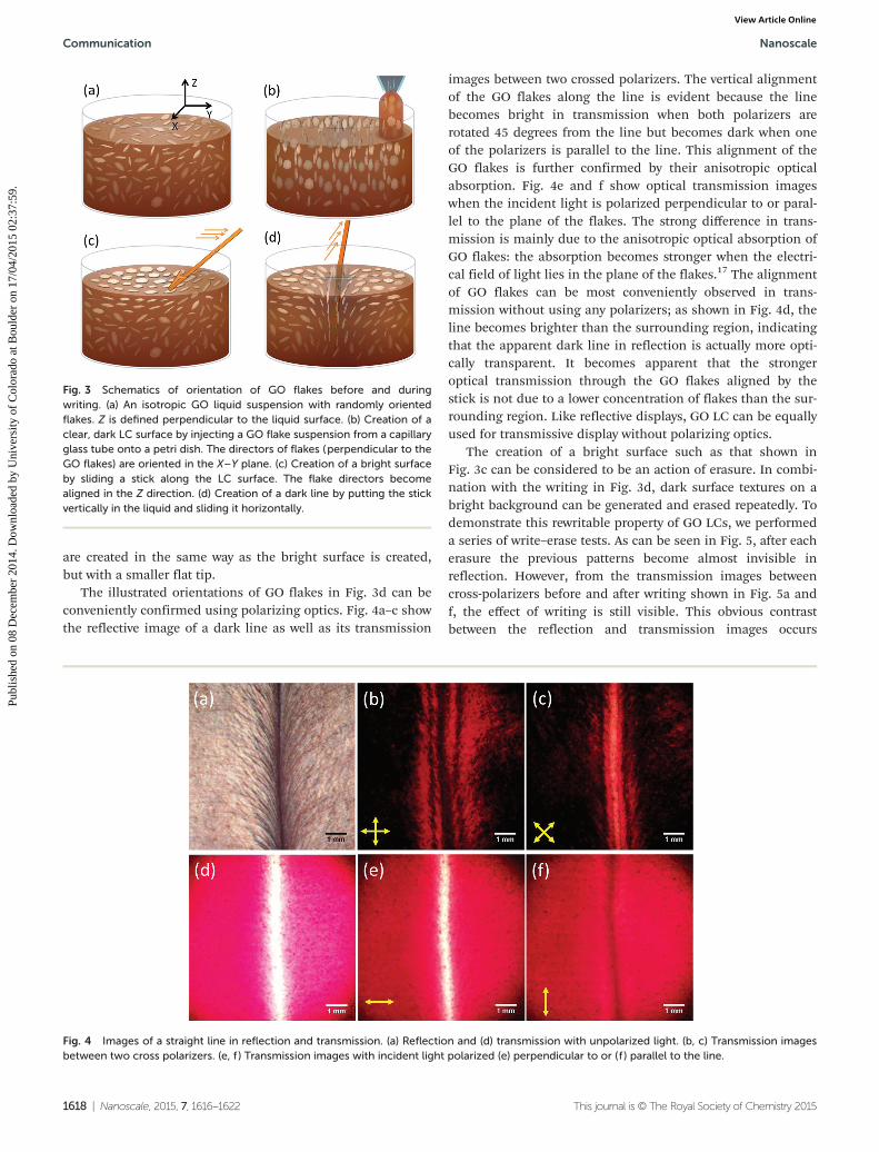
are created in the same way as the bright surface is created,but with a smaller flat tip.
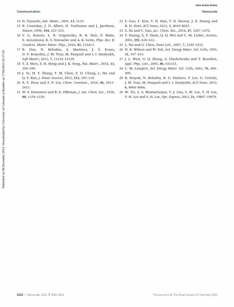
The illustrated orientations of GO flakes in Fig. 3d can beconveniently confirmed using polarizing optics. Fig. 4a–c showthe reflective image of a dark line as well as its transmission
images between two crossed polarizers. The vertical alignmentof the GO flakes along the line is evident because the linebecomes bright in transmission when both polarizers arerotated 45 degrees from the line but becomes dark when oneof the polarizers is parallel to the line. This alignment of theGO flakes is further confirmed by their anisotropic opticalabsorption. Fig. 4e and f show optical transmission imageswhen the incident light is polarized perpendicular to or paral-lel to the plane of the flakes. The strong difference in trans-mission is mainly due to the anisotropic optical absorption ofGO flakes: the absorption becomes stronger when the electri-cal field of light lies in the plane of the flakes.17 The alignmentof GO flakes can be most conveniently observed in trans-mission without using any polarizers; as shown in Fig. 4d, theline becomes brighter than the surrounding region, indicatingthat the apparent dark line in reflection is actually more opti-cally transparent. It becomes apparent that the strongeroptical transmission through the GO flakes aligned by thestick is not due to a lower concentration of flakes than the sur-rounding region. Like reflective displays, GO LC can be equallyused for transmissive display without polarizing optics.
The creation of a bright surface such as that shown inFig. 3c can be considered to be an action of erasure. In combi-nation with the writing in Fig. 3d, dark surface textures on abright background can be generated and erased repeatedly. Todemonstrate this rewritable property of GO LCs, we performeda series of write–erase tests. As can be seen in Fig. 5, after eacherasure the previous patterns become almost invisible inreflection. However, from the transmission images betweencross-polarizers before and after writing shown in Fig. 5a andf, the effect of writing is still visible. This obvious contrastbetween the reflection and transmission images occurs
Fig. 3 Schematics of orientation of GO flakes before and duringwriting. (a) An isotropic GO liquid suspension with randomly orientedflakes. Z is defined perpendicular to the liquid surface. (b) Creation of aclear, dark LC surface by injecting a GO flake suspension from a capillaryglass tube onto a petri dish. The directors of flakes (perpendicular to theGO flakes) are oriented in the X–Y plane. (c) Creation of a bright surfaceby sliding a stick along the LC surface. The flake directors becomealigned in the Z direction. (d) Creation of a dark line by putting the stickvertically in the liquid and sliding it horizontally.
Fig. 4 Images of a straight line in reflection and transmission. (a) Reflection and (d) transmission with unpolarized light. (b, c) Transmission imagesbetween two cross polarizers. (e, f ) Transmission images with incident light polarized (e) perpendicular to or (f ) parallel to the line.
Communication Nanoscale
1618 | Nanoscale, 2015, 7, 1616–1622 This journal is © The Royal Society of Chemistry 2015
Publ
ishe
d on
08
Dec
embe
r 20
14. D
ownl
oade
d by
Uni
vers
ity o
f C
olor
ado
at B
ould
er o
n 17
/04/
2015
02:
37:5
9.
View Article Online

because the action of erasure only aligns the GO flakes nearthe surface, and the reflective images are only sensitive tosurface GO flakes, while the writing aligns the GO flakes bothnear and below the surface. Local erasure of small features canbe achieved using a pen with a smaller tip.
The alignment of GO flakes is induced by shear flowcreated by relative motion between the stick and the liquid.Such alignment has been demonstrated with GO LCs andnanowires.17,22–24 Although the active moving object in ourcase is the stick rather than the LC, the effect is the same. Asreported by Guo et al.,22 the GO flakes will form a concentriclayer driven by homeotropic anchoring on the surface of thestick and become aligned in the wake of flow behind the stick.This picture of alignment is also valid when the path of thestick is curved, as shown in Fig. S1.† The flow alignment of theGO flakes is also used to create vertically oriented GO flakes,and as shown in Fig. 3b these flakes are aligned along a glasscapillary tube when the GO solution is injected into a petridish. Their orientations remain the same when the liquidspreads over the dish, however the flakes are not verticallyaligned as well as those by the stick alignment, as is evidentfrom some white background in Fig. 1a. The imperfect align-ment by flow can also be seen from a low order parameter of∼0.4 as compared to ∼0.8 or larger in typical liquid crystals.17
In contrast, the aligned GO flakes such as those shown inFig. 4 exhibit an order parameter as high as 0.7.
As mentioned above, the flakes aligned perpendicular tothe LC surface appear dark in reflection, while those parallelwith the LC surface show stronger reflection and appearbright. Note that this relatively strong reflection is due to thereflection from multiple GO flakes, which can form domains,
so the flake schematics in Fig. 3 do not necessarily representindividual flakes. Such mesoscopic ordering of GO flakes is aresult of their mutual interactions, and it is a basic andunique property of all LCs. Because the lateral size of the GOflakes is on the order of 10 µm, which is much larger than thewavelength of visible light, such a stack of GO flakes or flakedomains can be treated as a reflective mirror. The only differ-ence is that unlike spectral reflection from a flat mirror, thescattering from GO flakes is very diffusive: the brightness andcontrast of surface features do not strongly depend on the illu-mination and imaging directions. We believe that thisdiffusive reflection is mainly caused by two things: (1) GOflakes are not perfectly flat—they may have wrinkles or foldingstructures, and (2) the flakes have different orientations andare not perfectly aligned parallel to the surface, although theiraverage directors are in the Z direction.
The dark appearance of GO flakes perpendicular to thesurface indicates weak back scattering of light, which is due toa combined effect of shape anisotropy, dielectric anisotropy,and the macroscopic order of the GO flakes. First, the backscattering is weak because the effective light scattering cross-section is small when light is incident on the edges of the GOflakes. This mechanism is similar to the reason that surfaceswith vertically grown wire or wire-like nanostructures arestrongly absorptive and appear black.25 Second, because theout-of-plane dielectric constant or refractive index is smallerthan the in-plane value, light with out-of-plane polarizationwill have less back scattering, which will reduce the total backscattering of light. Finally, it is well known that strong lightscattering is caused by a medium’s density and structural orindex fluctuation. Aligned domains of GO flakes will become
Fig. 5 Rewritable and erasable characters of GO LC. (a) Transmission image of nearly isotropic LCs between two cross polarizers before linedrawing. (b–e) Reflective images of the same GO LC surface after the sequence of write–erase–write–erase. (f ) Transmission image of GO LCsin (e).
Nanoscale Communication
This journal is © The Royal Society of Chemistry 2015 Nanoscale, 2015, 7, 1616–1622 | 1619
Publ
ishe
d on
08
Dec
embe
r 20
14. D
ownl
oade
d by
Uni
vers
ity o
f C
olor
ado
at B
ould
er o
n 17
/04/
2015
02:
37:5
9.
View Article Online

more transparent and exhibit less light scattering comparedwith randomly oriented flakes, as shown in Fig. 3a. This prop-erty has been frequently observed in LCs,26,27 and has beensuccessfully used in smart windows: the window is transparentand clear when the domains of LCs are aligned by an electricalfield, but it becomes diffusive and milky when domains arerandomly oriented.28
High optical anisotropy is a unique property of atomicallythin 2D materials, in which the in-plane dielectric constant istypically larger than the out-of-plane constant. This property isnot shared by many other nanomaterials, such as nanowires.25
Graphene is an excellent example;16 its out-of-plane refractiveindex is close to one, but the in-plane index has a larger realcomponent as well as a large imaginary part, and this polariz-ation-sensitive absorption has been used to make broadbandpolarizers. Graphene oxide flakes have inherited graphene’soptical anisotropy, although the precise index of individual GOflakes has not been reported,17,29 and it may depend upon thesynthesis method, among other factors. The bright and darkappearance of the line pattern shown in Fig. 4e and f providesdirect evidence of anisotropic optical absorption of GO flakes.The strong transmission with unpolarized light in Fig. 4d ismainly due to the reduced optical absorption in Fig. 4e,although another factor is the reduced scattering of the inci-dent light through this more-ordered region of GO flakes.
To summarize the above discussion, the contrast betweenbright and dark features in reflective displays of GO LCs is aresult of multiple contributions from scattering, absorption,and transmission, and Fig. 6a and b provide another excellentexample of such an effect. First, as anticipated from any reflec-
tive display, the vertically aligned GO flakes appear darkregardless of the polarization of incident light, but a closerlook reveals that the line is darker and thicker when the polar-ization is parallel to the line. Based on the difference betweenthe in-plane and out-of-plane optical constants, the backscat-tered light should be stronger when the incident light is paral-lel to the line or planes of the GO flakes, which should create arelatively brighter color for the line in Fig. 6a than in Fig. 6b.We believe that multiple scattering from flakes below the LCsurface is responsible for this discrepancy. Incident light thatis perpendicular to the line will penetrate deeper below thesurface, and some of the light will be back scattered fromflakes or the bottom of the petri dish below the surface, even-tually contributing to the total back-scattered light andmaking the line lighter.
Such a combined effect can be used to understand the evolu-tion of contrast as a function of GO weight concentration.Fig. 6c–h show the images of a similar line in GO liquids withlow to high concentrations. As can be seen, the contrastbecomes more visible only when the concentration reaches0.05 wt%, and the contrast becomes diminished at concen-trations lower than 0.05 wt% or higher than 0.4 wt%. The con-trast is low for the low-concentration GO suspension becauseboth reflection and absorption are weak due to lower numbersof aligned GO flakes. At the concentration of 0.05 wt%, the linedoes not appear dark because of low optical absorption, as wellas the considerable back-scattered light from below the surface,as discussed above. For very high concentrations, the viscosityof the GO solution increases so significantly that it becomesdifficult to change and align the orientations of the GO flakes.
Fig. 6 Reflective images of a straight line in GO solution under polarized light or with different weight concentrations. (a, b) Under incident lightwith polarization parallel to (a) and perpendicular to (b) the line. Concentration: 0.2 wt%. (c–h) GO solutions with increasing concentrations from0.01 to 0.4 wt%.
Communication Nanoscale
1620 | Nanoscale, 2015, 7, 1616–1622 This journal is © The Royal Society of Chemistry 2015
Publ
ishe
d on
08
Dec
embe
r 20
14. D
ownl
oade
d by
Uni
vers
ity o
f C
olor
ado
at B
ould
er o
n 17
/04/
2015
02:
37:5
9.
View Article Online

Previous studies have shown that a GO flake solution with aweight concentration <0.05 wt% is isotropic and that solutionswith higher concentrations begin to exhibit a higher fractionof the nematic phase.17,18,22 Such concentration-dependentphase transitions can be conveniently observed by monitoringthe dynamics of aligned GO flakes, as shown in Fig. S2–4.† Ascan be seen, the initially bright line becomes dimmer and dis-appears in about 90 s for a solution with 0.01 wt%, but thealignment persists longer for solutions with higher concen-trations, and no obvious decay is observed when the concen-tration reaches 0.05 wt%. Such a concentration-dependentretention time allows us to choose the right concentration ofGO flakes for the right application.
The above observations show that ordered structures of GOflakes can be temporarily created in otherwise isotropic solu-tions. Conversely, an isotropic phase can be generated in anematic LC phase. Such isotropic phases are actually fre-quently created when we prepare 0.2 wt% GO LCs for manyexperiments in this work. To do that, we manually shake thesolution randomly using the petri dish. Except for GO flakesnear the surface that have been partially aligned parallel to thesurface, flakes inside the solution are believed to have randomorientation as shown in Fig. 3a. Such an isotropic phase showsa relatively strong scattering of light but exhibits no birefrin-gence, as indicated in Fig. 4 and 5. If we shake the dish by thehand and make the liquid spin slowly in one direction, avortex-like pattern as shown in Fig. 2 will be generated, pro-vided that the concentration is higher than 0.4 wt%. Note thatthe liquid near the wall of the petri dish shows weak back scat-tering because it does not move as the rest of the solution.
We demonstrate repeated manual writing of dark featureson a bright background in Fig. 5, and a similar demonstrationof bright features on a dark background, as shown in Fig. 1,can also be accomplished, with the exception that the erasureor preparation of a dark surface requires the extraction andinjection of GO solution through a capillary tube. The recentdemonstration of alignment of GO flakes using an electricalfield has solved this erasure problem.18,30 Using a similar tech-nique that has been employed in Boogie Board and other LCdisplays, GO flakes can be aligned vertically between two trans-parent electrodes by applying a voltage, and thus a devicesimilar to Boogie Board or an electronic blackboard can bedemonstrated. It should be noted that the electrical fieldcannot fix the directors of GO flakes, it can only align them ina pattern shown in Fig. 3b if an electrical field is appliedbetween the top and bottom surfaces of the LC.
Conclusions
In conclusion, we created GO flakes with different macroscopicordering of orientation using mechanical flow alignment. Wesystematically studied their optical responses, including backscattering, absorption, and transmission under different polar-izations of light. A relationship between scattering and orien-tation of GO flakes was established and explained, and a
reflective display using GO LC as a rewritable medium wasdemonstrated. Because shape and optical anisotropy are thebasic properties of 2D materials, the observed phenomena anddemonstrated applications are applicable to any 2D nanoma-terials. The creation of macroscopically ordered structuresfrom individual flakes enables new opportunities for basicresearch and device applications of 2D nanomaterials.
Acknowledgements
J.B. acknowledges support from the National Science Foun-dation (Career Award ECCS-1240510 monitored by AnupamaKaul) and the Robert A Welch Foundation (E-1728). Z.C., L.H.,H.Z. and Y.C. acknowledge support from NSF (DMR-1006870),NASA (NASA-NNX13AQ60G) and the Natural Science Foun-dation of China (no. 51376050 and 50876100).
Notes and references
1 K. S. Novoselov, A. K. Geim, S. V. Morozov, D. Jiang,Y. Zhang, S. V. Dubonos, I. V. Grigorieva and A. A. Firsov,Science, 2004, 306, 666–669.
2 M. Osada and T. Sasaki, Adv. Mater., 2012, 24, 210–228.3 X. Huang, Z. Y. Zeng and H. Zhang, Chem. Soc. Rev., 2013,
42, 1934–1946.4 X. Huang, C. L. Tan, Z. Y. Yin and H. Zhang, Adv. Mater.,
2014, 26, 2185–2204.5 C. N. R. Rao, H. Matte and U. Maitra, Angew. Chem., Int.
Ed., 2013, 52, 13162–13185.6 F. Bonaccorso, Z. Sun, T. Hasan and A. C. Ferrari, Nat.
Photonics, 2010, 4, 611–622.7 D. Jariwala, V. K. Sangwan, L. J. Lauhon, T. J. Marks and
M. C. Hersam, ACS Nano, 2014, 8, 1102–1120.8 A. Pospischil, M. M. Furchi and T. Mueller, Nat. Nanotech-
nol., 2014, 9, 257–261.9 J. N. Coleman, M. Lotya, A. O’Neill, S. D. Bergin, P. J. King,
U. Khan, K. Young, A. Gaucher, S. De, R. J. Smith,I. V. Shvets, S. K. Arora, G. Stanton, H. Y. Kim, K. Lee,G. T. Kim, G. S. Duesberg, T. Hallam, J. J. Boland,J. J. Wang, J. F. Donegan, J. C. Grunlan, G. Moriarty,A. Shmeliov, R. J. Nicholls, J. M. Perkins, E. M. Grieveson,K. Theuwissen, D. W. McComb, P. D. Nellist andV. Nicolosi, Science, 2011, 331, 568–571.
10 N. Behabtu, J. R. Lomeda, M. J. Green, A. L. Higginbotham,A. Sinitskii, D. V. Kosynkin, D. Tsentalovich, A. N. G. Parra-Vasquez, J. Schmidt, E. Kesselman, Y. Cohen, Y. Talmon,J. M. Tour and M. Pasquali, Nat. Nanotechnol., 2010, 5,406–411.
11 J. E. Kim, T. H. Han, S. H. Lee, J. Y. Kim, C. W. Ahn,J. M. Yun and S. O. Kim, Angew. Chem., Int. Ed., 2011, 50,3043–3047.
12 Z. Xu and C. Gao, ACS Nano, 2011, 5, 2908–2915.13 D. K. Yang, J. W. Doane, Z. Yaniv and J. Glasser, Appl. Phys.
Lett., 1994, 64, 1905–1907.
Nanoscale Communication
This journal is © The Royal Society of Chemistry 2015 Nanoscale, 2015, 7, 1616–1622 | 1621
Publ
ishe
d on
08
Dec
embe
r 20
14. D
ownl
oade
d by
Uni
vers
ity o
f C
olor
ado
at B
ould
er o
n 17
/04/
2015
02:
37:5
9.
View Article Online
14 N. Tamaoki, Adv. Mater., 2001, 13, 1135.15 B. Comiskey, J. D. Albert, H. Yoshizawa and J. Jacobson,
Nature, 1998, 394, 253–255.16 V. G. Kravets, A. N. Grigorenko, R. R. Nair, P. Blake,
S. Anissimova, K. S. Novoselov and A. K. Geim, Phys. Rev. B:Condens. Matter Mater. Phys., 2010, 81, 155413.
17 B. Dan, N. Behabtu, A. Martinez, J. S. Evans,D. V. Kosynkin, J. M. Tour, M. Pasquali and I. I. Smalyukh,Soft Matter, 2011, 7, 11154–11159.
18 T. Z. Shen, S. H. Hong and J. K. Song, Nat. Mater., 2014, 13,394–399.
19 J. Ye, H. Y. Zhang, Y. M. Chen, Z. D. Cheng, L. Hu andQ. Y. Ran, J. Power Sources, 2012, 212, 105–110.
20 X. F. Zhou and Z. P. Liu, Chem. Commun., 2010, 46, 2611–2613.
21 W. S. Hummers and R. E. Offeman, J. Am. Chem. Soc., 1958,80, 1339–1339.
22 F. Guo, F. Kim, T. H. Han, V. B. Shenoy, J. X. Huang andR. H. Hurt, ACS Nano, 2011, 5, 8019–8025.
23 Z. Xu and C. Gao, Acc. Chem. Res., 2014, 47, 1267–1276.24 Y. Huang, X. F. Duan, Q. Q. Wei and C. M. Lieber, Science,
2001, 291, 630–633.25 L. Hu and G. Chen, Nano Lett., 2007, 7, 3249–3252.26 H. R. Wilson and W. Eck, Sol. Energy Mater. Sol. Cells, 1993,
31, 197–214.27 J. L. West, G. Q. Zhang, A. Glushchenko and Y. Reznikov,
Appl. Phys. Lett., 2005, 86, 031111.28 C. M. Lampert, Sol. Energy Mater. Sol. Cells, 2003, 76, 489–
499.29 B. Senyuk, N. Behabtu, B. G. Pacheco, T. Lee, G. Ceriotti,
J. M. Tour, M. Pasquali and I. I. Smalyukh, ACS Nano, 2012,6, 8060–8066.
30 W. Tie, S. S. Bhattacharyya, Y. J. Lim, S. W. Lee, T. H. Lee,Y. H. Lee and S. H. Lee, Opt. Express, 2013, 21, 19867–19879.
Communication Nanoscale
1622 | Nanoscale, 2015, 7, 1616–1622 This journal is © The Royal Society of Chemistry 2015
Publ
ishe
d on
08
Dec
embe
r 20
14. D
ownl
oade
d by
Uni
vers
ity o
f C
olor
ado
at B
ould
er o
n 17
/04/
2015
02:
37:5
9.
View Article Online
Copyright © 2022 FDOKUMEN