3D Displays - eScholarship.org
42
UC Berkeley UC Berkeley Previously Published Works Title 3D Displays. Permalink https://escholarship.org/uc/item/1fc83454 Authors Banks, Martin S Hoffman, David M Kim, Joohwan et al. Publication Date 2016-10-01 DOI 10.1146/annurev-vision-082114-035800 Peer reviewed eScholarship.org Powered by the California Digital Library University of California
-
Upload
khangminh22 -
Category
Documents
-
view
3 -
download
0
Transcript of 3D Displays - eScholarship.org

UC BerkeleyUC Berkeley Previously Published Works
Title3D Displays.
Permalinkhttps://escholarship.org/uc/item/1fc83454
AuthorsBanks, Martin SHoffman, David MKim, Joohwanet al.
Publication Date2016-10-01
DOI10.1146/annurev-vision-082114-035800 Peer reviewed
eScholarship.org Powered by the California Digital LibraryUniversity of California

VS02CH18-Banks ARI 8 September 2016 20:35
3D DisplaysMartin S. Banks,1 David M. Hoffman,2 Joohwan Kim,3
and Gordon Wetzstein4
1University of California, Berkeley, California 94720; email: [email protected], San Jose, California 951343Nvidia, Santa Clara, California 950514Stanford University, Stanford, California 94305
Annu. Rev. Vis. Sci. 2016. 2:397–435
First published online as a Review in Advance onAugust 15, 2016
The Annual Review of Vision Science is online atvision.annualreviews.org
This article’s doi:10.1146/annurev-vision-082114-035800
Copyright c© 2016 by Annual Reviews.All rights reserved
Keywords
display, stereo vision, visual acuity, visual resolution, depth perception,motion perception, eye movements, accommodation, light field
Abstract
Creating realistic three-dimensional (3D) experiences has been a very activearea of research and development, and this article describes progress andwhat remains to be solved. A very active area of technical development hasbeen to build displays that create the correct relationship between viewingparameters and triangulation depth cues: stereo, motion, and focus. Severaldisciplines are involved in the design, construction, evaluation, and use of 3Ddisplays, but an understanding of human vision is crucial to this enterprisebecause in the end, the goal is to provide the desired perceptual experience forthe viewer. In this article, we review research and development concerningdisplays that create 3D experiences. And we highlight areas in which furtherresearch and development is needed.
397
Click here to view this article'sonline features:
• Download figures as PPT slides• Navigate linked references• Download citations• Explore related articles• Search keywords
ANNUAL REVIEWS Further
Ann
u. R
ev. V
is. S
ci. 2
016.
2:39
7-43
5. D
ownl
oade
d fr
om w
ww
.ann
ualr
evie
ws.
org
Acc
ess
prov
ided
by
Uni
vers
ity o
f C
alif
orni
a -
Ber
kele
y on
03/
27/1
7. F
or p
erso
nal u
se o
nly.

VS02CH18-Banks ARI 8 September 2016 20:35
1. INTRODUCTION
Imagine a Turing test for displays. A person views input that comes either from a direct view of thereal world or from a simulated view of that world presented on a display. He or she has to decide:real or display? Today’s displays would fail the test miserably because everyone would be able tocorrectly make the distinction. Many current displays would fail because of limitations in spatialand temporal resolution. More would fail because of limitations in color reproduction and therange of displayable intensities. We focus on another critical property in which current displaysfall well short: How realistic a three-dimensional (3D) experience do so-called 3D displays create?Creating realistic 3D experiences has been a very active area of research and development, andthis article describes progress and what remains to be solved.
The problem of how we see in three dimensions is interesting in its own right because onedimension is lost in the projection of the natural world onto the retina. Vision scientists conceiveof the 3D experience as a construction based on a variety of so-called depth cues, properties ofthe retinal images that signify variations in the depth dimension (Palmer 1999). We can categorizedepth cues according to their cause: (a) depth cues based on triangulation, (b) cues based onperspective projection, and (c) cues based on light transport and reflection. The second categoryincludes linear perspective, the texture gradient, relative size, and such. The third category includesshading, occlusion, atmospheric effects, and so forth. These cues have been well studied, andmethods for presenting them are now quite advanced in computer graphics and display technology.Thus, we do not devote much attention to those two categories.
The first category of triangulation is based on viewing the world from different vantage points.Binocular disparity is the spatial differences in the images seen by the two eyes. Motion parallax isdifferences in images seen over time when the eye translates. Blur is defocus in images caused bylight rays passing through different parts of the pupil (Held et al. 2010, 2012). Disparity, motionparallax, and blur are measureable in the retinal images, but they are also associated with specificextraretinal signals. The extraretinal component for disparity is vergence, the degree to which thelines of sight are converged. For motion parallax, the extraretinal signals include proprioceptorsassociated with head and body movements, kinesthesia, and vestibular signals. The extraretinalcomponent for blur is accommodation, the change in focal power of the eye’s crystalline lens. Tomake clear that retinal and extraretinal signals are involved, we refer to disparity and vergencecollectively as stereo cues, to motion parallax and sensing self-motion as parallax cues, and to blurand accommodation as focus cues. A very active area of technical development has been to builddisplays that create the correct relationship between viewing parameters and these triangulationcues. The head tracking and image updating required to create high-fidelity parallax has improvedgreatly, but we concentrate on stereo and focus cues because our understanding of how theyaffect viewer experience has grown substantially in the past decade and because a number of newtechnologies are emerging that support those cues better than ever before.
Several disciplines are involved in the design, construction, evaluation, and use of 3D displaysincluding materials science, electrical engineering, computer graphics, and human-factors engi-neering. But an understanding of human vision is also crucial to this enterprise because in the end,the goal is to provide the desired perceptual experience for the viewer.
Before categorizing different types of 3D displays, we need to get something straight. All mod-ern displays—even conventional televisions—are 3D displays because they all employ numerousdepth cues to create an impression of three dimensionality. Display types are more usefully cat-egorized by the kind of depth cues they support. Thus, 3D displays can be broadly categorizedas nonstereoscopic displays when they support only perspective-based and light-transport-basedcues; as stereoscopic displays when they also support stereo cues; and as advanced displays when
398 Banks et al.
Ann
u. R
ev. V
is. S
ci. 2
016.
2:39
7-43
5. D
ownl
oade
d fr
om w
ww
.ann
ualr
evie
ws.
org
Acc
ess
prov
ided
by
Uni
vers
ity o
f C
alif
orni
a -
Ber
kele
y on
03/
27/1
7. F
or p
erso
nal u
se o
nly.

VS02CH18-Banks ARI 8 September 2016 20:35
they also support focus cues and in some cases parallax cues. Most of the recent work has been onstereoscopic displays, so we start there.
2. STEREOSCOPIC DISPLAYS
Stereoscopic displays are becoming increasingly important for many applications including op-eration of remote devices, scientific visualization, virtual prototyping, entertainment, medicalimaging, surgical training, and more. A review of these applications is beyond the scope of thisarticle, but we mention briefly some findings in medicine (Held & Hui 2011, McIntire et al. 2014a,van Beurden et al. 2012). The added depth of information afforded by stereoscopic displays hasbeen shown to aid the detection of diagnostically relevant shapes, orientations, and positionsof anatomical features, especially when monocular cues are absent or unreliable. For example,stereoscopic viewing of medical imagery significantly improves tumor detection in breast imagingand the visualization of internal structures in ultrasound. Stereoscopic displays also help surgeonsorient themselves in the surgical landscape to better perform complicated tasks. In minimally in-vasive surgery, for instance, stereoscopic imagery decreases surgery time and increases procedureaccuracy.
2.1. Techniques for Image Separation
There are two general types of stereoscopic display: those with nonoverlapping optical paths tothe two eyes and those with overlapping paths (Figure 1).
The nonoverlapping solutions use two separate displays or two different regions on one dis-play to present distinct images to the two eyes. Examples are head-mounted, near-eye displays(Cakmakci & Rolland 2006) and mirror haploscopes (Wheatstone 1838) (Figure 1a). Because theyhave nonoverlapping paths, these displays guarantee complete separation of the images deliveredto the two eyes. But to achieve a large enough binocular field, the displays or mirrors must beclose to the eyes. The nonoverlapping solution is viable for virtual-reality and augmented-realityapplications (Cakmakci & Rolland 2006) and for scientific apparatus (Backus et al. 1999), but it isnot a suitable replacement for a conventional display because the solution works only for one userand requires a fixed relationship between the display and the viewer’s head, which can be quitecumbersome.
The overlapping-path solution is much more common but requires a means to encode photonsleaving the display so that some are visible to only the left eye and some to only the right eye.An old approach is the color-anaglyph method (Borel & Doyen 2013, Woods & Harris 2010)(subpanel i in Figure 1b). In this method, different wavelength bands are used to encode light forthe left and right eyes. The left and right images are presented on the screen in red for one eye andblue-green for the other using the display primaries. The viewer wears a red analyzer over one eyeand a cyan analyzer over the other, and hence, the two eyes receive their intended images. Thereare numerous problems with the color-anaglyph approach. First and most important, the colorsof the two delivered images are generally very different from the color of the original content, socolor appearance is significantly altered. Second, by presenting different colors to the two eyes,binocular rivalry can occur, often creating a lustrous percept (Formankiewicz & Mollon 2009).Third, the spectral bandwidth of the display primaries and the acceptance band of the analyzersare generally broad, so crosstalk (incomplete image separation) often occurs (Woods et al. 2007).
Another anaglyph approach uses two sets of narrowband primaries [red, green, and blue (RGB)]and two matched notch-filter analyzers. The three bands (primaries and analyzers) are shifted inwavelength for one eye relative to the other ( Jorke et al. 2009, Simon & Jorke 2011). With this
www.annualreviews.org • 3D Displays 399
Ann
u. R
ev. V
is. S
ci. 2
016.
2:39
7-43
5. D
ownl
oade
d fr
om w
ww
.ann
ualr
evie
ws.
org
Acc
ess
prov
ided
by
Uni
vers
ity o
f C
alif
orni
a -
Ber
kele
y on
03/
27/1
7. F
or p
erso
nal u
se o
nly.

VS02CH18-Banks ARI 8 September 2016 20:35
Mirror haploscope
Virtualfixationpoint
Overlapping stereoscopic displays
Nonoverlapping stereoscopic displaysa
Mirrors
biii Temporally alternating
Red-cyan filters
i Color anaglyph ii Polarization
Polarizing filters
Time 1 Time 2
Shutter glasses
Figure 1Techniques for image separation in stereoscopic displays. (a) Nonoverlapping displays have two separateoptical paths, one for the left eye and one for the right. The depicted display is a mirror haploscope. The lefteye sees the image on the left display screen once reflected off a mirror. The right eye sees the image on theright screen reflected off another mirror. Points illuminated in the middle of the left and right screens createa virtual point indicated by the intersection of the dashed lines. (b, i ) An overlapping display in which theoptical paths for the left and right eyes come from one display screen. Light rays of all three color primariesapproach the left eye, but a red-transmitting filter should deliver only red rays to that eye. Likewise, acyan-transmitting filter delivers green and blue rays to the right eye. (b, ii ) An overlapping display in whichimage separation is created by polarization. The left eye’s image is produced with one orientation ofpolarization and the right eye’s with the orthogonal orientation. Polarized filters in front of the eyes, oneorientation in front of the left eye and the orthogonal one in front of the right, deliver the desired images tothe intended eyes. (b, iii ) An overlapping display in which image separation is created by temporalmultiplexing. Shutter glasses in front of the eyes switch between transmitting to the left eye and not the rightand then transmitting to the right eye and not the left. Images intended for the left and right eyes alternateon the screen, synchronized to the switching of the glasses.
approach, both eyes see a full color image, and crosstalk is minimal. Apparent color differencescan occur, but they are generally small and do not produce binocular rivalry. The disadvantagesare the cost associated with making three-band notch filters, the light loss due to narrowbandtransmission, and the fact that color percepts across individual viewers tend to vary more withnarrowband than with broadband primaries (Fairchild & Wyble 2007).
Another approach for encoding the left and right imagery uses polarization (Borel & Doyen2013) (subpanel ii in Figure 1b). The light from the display is orthogonally polarized for the leftand right eyes, and the viewer wears analyzers such that one polarization is delivered to one eye andthe orthogonal polarization to the other. Two types of polarization are used: linear and circular.
400 Banks et al.
Ann
u. R
ev. V
is. S
ci. 2
016.
2:39
7-43
5. D
ownl
oade
d fr
om w
ww
.ann
ualr
evie
ws.
org
Acc
ess
prov
ided
by
Uni
vers
ity o
f C
alif
orni
a -
Ber
kele
y on
03/
27/1
7. F
or p
erso
nal u
se o
nly.
VS02CH18-Banks ARI 8 September 2016 20:35
Linear polarization has the advantage that image separation is excellent, and the impact on coloris minimal. It has the disadvantage that image separation depends critically on the orientationof the analyzers relative to the polarization filters at the display. If the viewer’s head tilts to theside, significant crosstalk can ensue, which of course reduces image quality (Seuntiens et al. 2005).Circular polarization eliminates this problem because orthogonality is unaffected by head tilt. Butcircular polarization has poorer image separation than properly aligned linear polarization andalso has more effect on color.
Another approach for differentiating photons from the display involves controlling the angleat which they exit the display. Such displays are called autostereoscopic displays because they donot require glasses (Dodgson 2006). The exit angle can be manipulated by using lenticular sheetsplaced on the display surface or by using parallax barriers in front of or behind the display surface(Son et al. 2003). The most common complaints with autostereoscopic displays are that theyhave degraded resolution, have a limited sweet spot (the region in which the left and right eyessee the appropriate views), and are usable by only one viewer. But autostereoscopic displays canbe constructed to support additional viewers by creating more than two viewing zones. They canalso be constructed with larger sweet spots at the expense of spatial resolution. An alternativeapproach for expanding the sweet spot is to use a camera to track viewer head position and adjustthe images on the display to move the sweet spot with the viewer (Kim et al. 2015). To minimizeresolution loss, some implementations use liquid-crystal barriers that allow switching to nativepanel resolution for nonstereoscopic imagery (Lee & Park 2010).
2.2. Temporal- and Spatial-Interlacing Displays
Nearly all conventional stereoscopic 3D displays use temporal or spatial interlacing to presentdifferent images to the left and right eyes. Temporal interlacing delivers the left- and right-eyeviews alternately in time (subpanel iii in Figure 1b). This is often accomplished either by switchingviews with an active element at the viewer’s eye (e.g., liquid-crystal shutter glasses; Turner &Hellbaum 1986, Edwards 2009) or by switching views at the source (e.g., switching polarizationat the output of a projector; Cowan 2008). The alternation must of course be synchronized withthe display to ensure that images intended for the left eye are indeed seen by that eye and likewisefor the right eye. Thus, in temporal-interlacing displays, only one eye receives light at a giventime, but it receives all the pixels. Spatial interlacing delivers one set of pixels to the left eye andanother to the right eye simultaneously. In most implementations, even pixel rows go to one eyeand odd rows to the other (Dawson 2012). This is typically done using a film-patterned retarderon the display that polarizes the emitted light in opposite directions row by row. The viewer wearspassive eyewear that transmits alternate rows to the two eyes. In this way, both eyes receive lightat any given moment, but each receives only half the pixels.
Temporal interlacing and spatial interlacing have different shortcomings from a perceptualstandpoint. Temporal interlacing is prone to temporal artifacts such as flicker, unsmooth motionappearance, and distortions in the perceived depth of moving objects. Spatial interlacing resultsin lower spatial resolution and some distortions of perceived depth.
2.3. Crosstalk and Ghosting
Crosstalk is the incomplete segregation of the two eyes’ images. It is defined quantitatively as theproportion of the light delivered to the intended eye that leaks into the unintended eye. Nearly allcommercial stereoscopic display systems have some crosstalk (Blonde et al. 2011, Woods 2012).
www.annualreviews.org • 3D Displays 401
Ann
u. R
ev. V
is. S
ci. 2
016.
2:39
7-43
5. D
ownl
oade
d fr
om w
ww
.ann
ualr
evie
ws.
org
Acc
ess
prov
ided
by
Uni
vers
ity o
f C
alif
orni
a -
Ber
kele
y on
03/
27/1
7. F
or p
erso
nal u
se o
nly.

VS02CH18-Banks ARI 8 September 2016 20:35
Ghosting is perceived crosstalk. It can occur when as little as 1% of the light leaks into theunintended eye (Nojiri et al. 2004, Pastoor 1993).
The contents of the image clearly affect ghosting: It becomes more apparent with highercontrast, sharper edges, and larger disparities. Ghosting affects perceived image quality: Reportedquality decreases in rough proportion to the amount of crosstalk (Seuntiens et al. 2005, Wilcox& Stewart 2003). Crosstalk also affects depth percepts: The amount of perceived depth decreasesmonotonically with increasing crosstalk (Tsirlin et al. 2011).
2.4. Capture-Display-Viewing Pipeline
For the viewer of a stereoscopic display to accurately perceive the geometry of the 3D scenefrom the binocular images, the pipeline from the generation of the binocular images (capturedvia cameras or created via computer graphics) to the viewing of the displayed images must beappropriate; in other words, the capture, display, and viewing parameters must be compatible.Errors in the pipeline generally lead to distortions of perceived depth relative to the original sceneand to reduced visual quality.
The simplest approach for producing 3D imagery is to capture a scene with a stereo camera(a camera system with two positions corresponding to the two eye positions) and then display theimages from the left and right cameras to the viewer’s left and right eyes respectively on one or twodisplays (Figure 1). We ignore the camera distortions by assuming pinhole apertures (althoughwe explore the importance of camera bokeh in Section 3.1). Camera and display pipelines includeseveral other factors that influence image quality, but we ignore these for now because they havelittle unique bearing on 3D displays. For more information on such issues, see Brainard et al.(2002) and Wandell & Silverstein (2003).
In any application based on perspective projection (e.g., photographs, cinematography, com-puter graphics, realistic paintings), all light rays from a captured or generated image pass throughthe center of projection (COP) (Kubovy 1986). Correct stereoscopic imagery has two COPs, onefor the left eye and one for the right. If care is taken in the camera configuration, the display setup,and the viewer’s position, the viewer’s eyes will be located at the respective COPs and have thecorrect alignment so he or she will receive the same retinal images and eye-position signals thatwould have been received from the original scene. If these constraints are obeyed, the perceptsshould be quite similar. In practice, creating the appropriate pipeline to reproduce veridical binoc-ular retinal images and eye-position signals is challenging. When the pipeline is altered, there maynot be consistent COPs for the left- and right-eye images; there may be consistent COPs but theviewer’s eyes are not located at those points; and/or the horizontal vergence required to fixatepoints in the scene may be inappropriate. In each case, predictable distortions in perceived depthensue, some more important than others.
All angular relationships captured by the camera system should be faithfully reproduced bythe display system. Camera adjustments such as zooming and cropping that are acceptable in2D imagery can be very disruptive in 3D imagery if not done in a consistent manner. The twomain parameters of a camera are focal length and dimensions of the sensor plane. The size ofthe image in the sensor plane is determined by focal length, and the field of view is determinedby the tangent of focal length/sensor dimension, which can be changed with cropping. In thedisplay, there are two analogous parameters of viewing distance and screen size. A veridical perceptrequires matching the focal length/sensor size to the viewing distance/display size. Additionally,one must ensure that the optical axes of the cameras are appropriate for the manner in whichthe images are displayed. For example, parallel camera axes (coplanar sensors) are appropriatefor overlapping stereoscopic displays (subpanels i–iii in Figure 1b), whereas converging axes are
402 Banks et al.
Ann
u. R
ev. V
is. S
ci. 2
016.
2:39
7-43
5. D
ownl
oade
d fr
om w
ww
.ann
ualr
evie
ws.
org
Acc
ess
prov
ided
by
Uni
vers
ity o
f C
alif
orni
a -
Ber
kele
y on
03/
27/1
7. F
or p
erso
nal u
se o
nly.

VS02CH18-Banks ARI 8 September 2016 20:35
appropriate for nonoverlapping stereoscopic displays arranged as in Figure 1a. When the camera-display parameters are inappropriate (e.g., converging axes with an overlapping display), geometricperspective correction is required to guarantee that correct disparities are presented to the viewer’seyes (Held & Banks 2008).
When there are multiple viewers, a veridical pipeline is not possible with conventional tech-nology (although with some high–frame-rate displays, time multiplexing for multiple viewers ispossible; Hoffman et al. 2014). When there are incompatibilities in the pipeline, a ray-intersectionmodel is typically used to determine the perceptual distortions that are likely to occur. In the model,two rays propagate from the eyes through corresponding points in the stereoscopic display andbeyond. The rays intersect at a location in space that should correspond with the location of theobject that created the two disparate image points. When the rays do not intersect (because ofviolations of epipolar geometry), the model finds the point of closest passage and predicts per-ceived depth based on the 3D location of such points. With this model, one can calculate theretinal disparities for a wide range of capture, display, and viewing parameters (Held & Banks2008, Pollock et al. 2012, Woods et al. 1993). When the disparities are not the same as those thatwould be generated by the original scene, the perceptual experience is usually a distortion of the3D structure of that scene because viewers are generally unable to compensate for an incorrectviewing position when viewing stereoscopic imagery (Banks et al. 2009, Bereby-Meyer et al. 1999,Hands et al. 2015). This contrasts with the viewing of nonstereoscopic imagery whereby viewersare able to compensate impressively for incorrect viewing position (Bereby-Meyer et al. 1999,Hands et al. 2015, Vishwanath et al. 2005).
Figure 2 summarizes some of the distortions that occur when stereo imagery is viewed fromvarious positions. In panel c, the capture-display-viewing parameters are all appropriate, so theoriginal scene (an open-book hinge) should be perceived veridically. In panels b and d, the vieweris too far to the left and too far to the right, respectively, and the scene is perceived as skewedrespectively to the left and right. In panels a and e, the viewer is too close and too far, respectively,and the scene is seen respectively as compressed and expanded in depth. Other errors in the pipeline(converged or so-called toed-in cameras, larger or smaller separation between the cameras, etc.)also lead to predictable distortions of perceived depth, such as unintended curvature and changesin apparent size (Held & Banks 2008, Woods et al. 1993).
An additional problem in the capture-display-viewing pipeline is optical distortion in the stereocameras. With simple lenses, the focal distance for axial rays can be different than for obliquerays. This leads to barrel distortion (center of image swells) or pincushion distortion (cornersare stretched from image center). These distortions often affect corresponding parts of the left-and right-camera images differently, so they can create unintended disparities, and thereforeunintended distortions in the perceived 3D scene (Woods et al. 1993). Distortions also occur inthe lenses used in near-eye displays. This problem can be serious because such displays require awide field of view. The optical distortions can, however, be corrected in software provided thatthe lens properties and positions of the eyes relative to the screens are known with sufficientaccuracy.
2.5. Head Roll
In properly constructed stereoscopic media for presentation on one screen, all disparities arehorizontal on the screen. To generate the same retinal images as would be received when viewingthe original scene, the viewer’s eyes must be placed at the respective COPs, separated by theinterocular distance. When the eyes are so positioned, the horizontal and vertical disparities atthe retinas are identical to those that would be created by looking at the original 3D scene. But
www.annualreviews.org • 3D Displays 403
Ann
u. R
ev. V
is. S
ci. 2
016.
2:39
7-43
5. D
ownl
oade
d fr
om w
ww
.ann
ualr
evie
ws.
org
Acc
ess
prov
ided
by
Uni
vers
ity o
f C
alif
orni
a -
Ber
kele
y on
03/
27/1
7. F
or p
erso
nal u
se o
nly.

VS02CH18-Banks ARI 8 September 2016 20:35
CamerasViewer
Displayscreen
Perceivedstimulus
10 cm
Originalstimulus
a
e
b c d
Figure 2Predicted 3D percepts for different capture-display-viewing situations. Each panel shows an overhead viewof the viewer (dark gray), stereo cameras (blue), display screen ( yellow), original stimulus (light gray), andpredicted percept (light blue). The parameters are the following. Capture: parallel orientation of optical axes,intercamera separation of 6.2 cm, focal length of 6.5 mm. Display: one display screen, picture magnificationof 69×. Viewing: viewing distance of 45 cm, interocular distance of 6.2 cm, viewer positioned such thatmidpoint of interocular axis is on central surface normal of display screen, viewer oriented with face parallelto display surface. The stimulus is a vertical hinge with a hinge angle of 90◦. (c) With display and viewingparameters set correctly for the capture parameters, the original and predicted perceived stimuli areidentical. (a) Viewer is too close to the display. Predicted perceived hinge angle is greater than 90◦.(e) Viewer is too far from the display. Perceived angle is now less than 90◦. (b) Viewer is translated to left ofdisplay. Predicted hinge rotates toward viewer, and predicted angle is less than 90◦. (d ) Viewer is translatedto right of display. Predicted hinge rotates toward viewer, and predicted angle is less than 90◦. Figureadapted from Held & Banks (2008).
404 Banks et al.
Ann
u. R
ev. V
is. S
ci. 2
016.
2:39
7-43
5. D
ownl
oade
d fr
om w
ww
.ann
ualr
evie
ws.
org
Acc
ess
prov
ided
by
Uni
vers
ity o
f C
alif
orni
a -
Ber
kele
y on
03/
27/1
7. F
or p
erso
nal u
se o
nly.

VS02CH18-Banks ARI 8 September 2016 20:35
when the viewer’s head is tilted to the side, the strictly horizontal on-screen disparities becomepartly vertical at the viewer’s eyes.
Consider a stereoscopic image with on-screen horizontal disparity Hd that varies sinusoidallyover time and has a mean of zero in the equation
Hd = A sin(t), (1)
where A is disparity amplitude. The on-screen vertical disparity is zero. Assuming that the on-screen horizontal disparity does not vary with position in the stimulus, the temporal change indisparity specifies an approaching and receding frontoparallel plane. Now consider rolling thehead by angle ϕ while viewing the same stereoscopic image. The interocular axis is no longerhorizontal, so the orientation of the disparities at the eyes changes. In particular, horizontal on-screen disparities are now horizontal and vertical disparities relative to the head. Ignoring thesmall torsional eye movements made with head roll relative to gravity (Collewijn et al. 1985), theretinal disparities are
H d = Hd (t) cos(−ϕ),V d = Hd (t) sin(−ϕ).
(2)
There are two likely consequences.
1. The amount of perceived depth is reduced because we know that perceived depth variation isdetermined almost entirely by variations in horizontal, not vertical, disparity. Indeed, if theviewer’s head were rolled 90◦, no depth variation should be seen because horizontal disparitywould be effectively zero. Kane et al. (2012) measured reductions in perceived depth withhead roll that are well predicted by Equation 2.
2. When a portion of horizontal disparity is converted into vertical disparity, the viewer mustmake both horizontal vergence eye movements (one eye leftward and the other rightward)and vertical vergence movements (upward and downward) to fuse the stimulus. Verticalvergence occurs naturally, but it is quite small and slow relative to horizontal vergence(Howard et al. 1997, Krishnan et al. 1973). Figure 3 shows that amount of required verticalvergence as a function of head roll and on-screen horizontal disparity. The need to makevertical vergence movements leads to two undesirable effects: Binocular fusion becomesmore difficult and visual discomfort ensues (Kane et al. 2012).
As we noted earlier, circular polarization is much better than linear polarization is at retainingseparation of the two eyes’ images when the head is rolled. Ironically, this apparent advantage ofcircular polarization might in the end be a disadvantage because viewers might be more likely tokeep their heads upright with linear polarization, thereby avoiding the perceptual and discomforteffects that occur with a tilted head.
2.6. Perceptual Artifacts with Temporal- and Spatial-Interlacing Displays
We next consider spatiotemporal artifacts and distortions of perceived depth that occur withdifferent types of stereoscopic displays.
2.6.1. Spatiotemporal artifacts. It is generally desirable for visual displays to create faithful im-pressions of the real world, but of course they provide only spatiotemporal approximations. Forexample, a smoothly moving object is represented by a sequence of static views, which may or maynot create the impression of smooth motion. Likewise, a complex image with fine detail is repre-sented by the pattern of illumination from discrete points on the screen—pixels—and the densityof pixels may or may not be sufficient to yield a convincing impression of the detail. Here, we first
www.annualreviews.org • 3D Displays 405
Ann
u. R
ev. V
is. S
ci. 2
016.
2:39
7-43
5. D
ownl
oade
d fr
om w
ww
.ann
ualr
evie
ws.
org
Acc
ess
prov
ided
by
Uni
vers
ity o
f C
alif
orni
a -
Ber
kele
y on
03/
27/1
7. F
or p
erso
nal u
se o
nly.

VS02CH18-Banks ARI 8 September 2016 20:35
Head roll (degrees)Re
quir
ed v
erge
nce
mov
emen
ts (d
egre
es)
HorizontalVertical3.8
2.0
1.4
3.8
2.0
1.4
4
3
2
1
0–90 –60 –30 0 30 60 90
Figure 3Horizontal and vertical vergence eye movements required to track and fuse a stereoscopic image when thehead is tilted to the side. The on-screen horizontal disparity of the stimulus oscillates by 1.4◦, 2◦, or 3.8◦from peak to trough. The required horizontal and vertical vergence movements are indicated by the solidand dashed curves, respectively. Figure adapted from Kane et al. (2012).
discuss how to evaluate the temporal properties of stereoscopic displays and summarize researchon the perception of those properties. We then discuss how to evaluate the spatial properties ofstereoscopic displays and summarize research on perceiving those properties.
Nonstereoscopic digital displays have been widely adopted, so the requirements for creatingacceptable motion and spatial resolution have been well researched and described (Sugawara et al.2008, Watson 2013, Watson et al. 1986). But the introduction of stereoscopic displays requiresa reevaluation because the prevailing techniques for creating separate images to the two eyesintroduce noticeable temporal and spatial artifacts that are not observed with nonstereoscopicdisplays. We take advantage of previous work with nonstereoscopic displays to better understandproblems that arise with stereoscopic displays.
The impressions created by digital displays can be understood by relating the display’s spatialand temporal characteristics to the spatiotemporal properties of the visual system. The analysiscan be done in space and time or spatial and temporal frequency, but one gains more insight fromanalysis in the frequency domain, so we focus there. We initially consider the images producedfor one eye because many of the perceptual artifacts that occur with stereoscopic displays are bestunderstood by considering monocular inputs.
The display of video content involves three dimensions (two in space, one in time), but weshow the analysis for two dimensions (one in space, one in time) for ease of visualization. Thepipeline from image data to presentation to the eye is schematized in Figure 4a. The stimulus inthis example is a horizontal line moving vertically across the screen at constant speed. Typically,image data i( y,t) are antialiased before being sent to the display, which we do by convolving withan interpolation function, a( y,t). We then calculate how intensity varies over space and time whenthe image data are presented on the display. To do so, we sample the antialiased image datawith a comb function representing the display’s spatiotemporal sampling, where the samples areseparated spatially by y0 (pixel spacing) and temporally by t0 (frame time). The encoding methodcan affect the periodicity of the sampling function. Temporally interlacing displays double thetemporal separation, whereas spatially interlaced displays double the spatial separation.
406 Banks et al.
Ann
u. R
ev. V
is. S
ci. 2
016.
2:39
7-43
5. D
ownl
oade
d fr
om w
ww
.ann
ualr
evie
ws.
org
Acc
ess
prov
ided
by
Uni
vers
ity o
f C
alif
orni
a -
Ber
kele
y on
03/
27/1
7. F
or p
erso
nal u
se o
nly.

VS02CH18-Banks ARI 8 September 2016 20:35
a
b c
Time (s)
i(y,t) a(y,t) p (y,t)
s(y,t)
Posi
tion
(arc
min
)
=**
Input image and antialiasing
Samplingfunctions
=
=×
× Pixelation**
**
=
=
Sampledoutputs
Space-timeoutputs
Spectrum fortemporal interlacing
Spectrum forspatial interlacing�
�
Temporal frequency (Hz)
Spat
ial f
requ
ency
(cpd
)
Spatial interlacing
600
60
0
–60–60 600–60
–60–60
–30
–30
0
00
30
30
60
60
Temporal frequency (Hz)
Spat
ial f
requ
ency
(cpd
)
100
200
Sensitivity
Temporal interlacing
Figure 4Pipeline of image generation, display, and viewing. (a) The pipeline proceeds from left to right. Where there are two rows, the upperone represents the pipeline for temporal interlacing, and the lower one represents the pipeline for spatial interlacing. The image datai( y,t) represent an object moving vertically at a constant speed of 1 degree/s. The image data are antialiased by convolution with acubic-interpolation function a( y,t). Then the antialiased data are sampled with spatiotemporal comb function s( y,t) with samplesseparated by y0 and t0 (1 arcmin and 16.7 ms). Different encoding methods for stereoscopic displays result in different periodicities ofthe sampling function (upper and lower show temporally and spatially interlaced displays, respectively). The displayed intensities havefinite spatial and temporal extent (pixelization) represented by spatiotemporal aperture function p( y,t). The resultant is a space-timeplot of the sampled and pixelated imagery being presented on the screen: upper one for temporal interlacing and lower for spatialinterlacing. Those space-time plots are then subjected to Fourier transformation, represented by F. (b) Human spatiotemporalcontrast-sensitivity function. Sensitivity (reciprocal of contrast required for detection) is plotted as a function of temporal and spatialfrequency. Panel based on data from Kelly (1979). (c) Amplitude spectra for temporally and spatially interlacing displays. The amplitudespectra were derived from the pipeline in panel a. Amplitude is plotted as a function of temporal and spatial frequency. A diagonal linethrough the center of each panel (not shown) would be the spectrum of the smoothly moving stimulus (the signal). The diagonalthrough the center that is shown is a filtered version of the signal. The other lines are aliases created by sampling. Red diamondsrepresent the spatiotemporal contrast sensitivity function in panel b. Components within the diamonds will be visible, whereascomponents outside the diamonds will not be. Abbreviation: cpd, cycles per degree.
The displayed intensities have finite spatial and temporal extent, which we represent withspatiotemporal aperture function p( y,t). The aperture function is set such that pixel width is equalto pixel spacing (i.e., fill factor is 1), and duration of illumination in each frame is equal to frameperiod (i.e., duty cycle is 1). In real displays, the fill factor would be a bit less than 1 and duty cyclecould be much less than 1 depending on the technology being used, illustrated in the equations
[[i (y, t) ∗∗a(y, t)]s (y, t)] ∗∗p(y, t) (3)
www.annualreviews.org • 3D Displays 407
Ann
u. R
ev. V
is. S
ci. 2
016.
2:39
7-43
5. D
ownl
oade
d fr
om w
ww
.ann
ualr
evie
ws.
org
Acc
ess
prov
ided
by
Uni
vers
ity o
f C
alif
orni
a -
Ber
kele
y on
03/
27/1
7. F
or p
erso
nal u
se o
nly.

VS02CH18-Banks ARI 8 September 2016 20:35
and [[i ( y, t) ∗∗a( y, t)] comb
(yy0
,tt0
)]∗∗rect
(yy0
,tt0
), (4)
where rect is a scaled rectangle function with widths y0 in space and t0 in time, and y0 and t0 alsorepresent the spatial and temporal separations of samples in the comb function. In the Fourierdomain, Equation 4 becomes
[[I ( fy , ft)A( fy , ft)] ∗∗comb(y0 fy , t0 ft)]sinc(y0 fy , t0 ft), (5)
where fy and ft are spatial and temporal frequency and the sinc functions have zeros at fy = 1/y0,2/y0, etc., and ft = 1/t0, 2/t0, etc.
The rightmost panels in Figure 4a are space-time intensity distributions created by temporallyand spatially interlacing stereoscopic displays. They have been calculated for one eye’s image forreasons we make clear later. The amplitude spectra associated with those distributions are shownin Figure 4c. An extended diagonal line through the center of each panel (not shown) would bethe spectrum of the original smoothly moving stimulus (the signal). The diagonal through thecenter that is shown is a filtered version of that signal. The other lines are aliases introduced bythe spatiotemporal sampling. The separation of the aliases along the temporal-frequency axis is1/t0 (the frame rate) and along the spatial-frequency axis is 1/y0 (pixel spacing).
The human visual system is not equally sensitive to contrast variation at all spatial frequencies:Variations above a particular frequency are invisible because they exceed the acuity limit. Likewise,humans are not equally sensitive to contrast modulations at all temporal frequencies: Variationsabove a specific frequency are invisible because they exceed the critical flicker frequency. Thevariation in sensitivity to different combinations of spatial and temporal frequency is not separable(i.e., cannot be represented by the product of a function in spatial frequency and a function intemporal frequency) (Kelly 1979). The sensitivity to different combinations is represented bythe spatiotemporal contrast sensitivity function (the window of visibility) (Figure 4b). To firstapproximation, spatiotemporal frequencies falling within the red diamonds in Figure 4c willbe visible and those falling outside the diamonds will be invisible. The amplitude spectra of asmoothly moving stimulus and the digital approximation to that stimulus differ primarily at higherspatiotemporal frequencies, so those differences may not be visible, in which case we predict thatthe digital stimulus will appear to move smoothly just like an object moving in the real world.
The viewer will see various artifacts when the aliases are low enough in frequency and highenough in amplitude to be visible. Two general spatiotemporal artifacts have been examined:flicker and motion artifacts. Visible flicker is defined as perceived fluctuation in the brightness of a(usually stationary) stimulus. Motion artifacts are defined as object motions that appear unsmoothor otherwise distorted.
2.6.1.1. Flicker. The relevant part of the amplitude spectrum for predicting flicker visibility isalong the temporal-frequency axis. When aliases on the axis fall within the window of visibility,we expect flicker to be visible. Visibility is influenced by several factors, including the temporalfrequency and amplitude of luminance modulation, overall luminance (Kelly 1972), stimulus area,and retinal eccentricity (Rovamo & Raninen 1988). Conditions producing the most noticeableflicker are large bright areas in peripheral vision with high-amplitude modulation at lower temporalfrequencies. The modulation amplitude differs greatly for temporally and spatially interlacingdisplays. In spatial displays, the duty cycle of illumination to an eye can be nearly 1, whereas intemporal displays, duty cycle can be no greater than 0.5 because the two eyes’ images are shown inalternation. The reduction in duty cycle makes flicker much more likely to be visible. For a spatial-or temporal-interlacing display alternating between luminances of Lmax and Lmin at a particular
408 Banks et al.
Ann
u. R
ev. V
is. S
ci. 2
016.
2:39
7-43
5. D
ownl
oade
d fr
om w
ww
.ann
ualr
evie
ws.
org
Acc
ess
prov
ided
by
Uni
vers
ity o
f C
alif
orni
a -
Ber
kele
y on
03/
27/1
7. F
or p
erso
nal u
se o
nly.

VS02CH18-Banks ARI 8 September 2016 20:35
temporal frequency, the contrast of the lowest frequency component is[
2 sin(πd )πd
] [d (Lmax − Lmin)
d (Lmax − Lmin) + Lmin
], (6)
and the average luminance is
d (Lmax − Lmin) + Lmin, (7)
where d is duty cycle (Campbell & Robson 1968). These equations show that shorter duty cyclesgenerally create greater amplitudes of the fundamental frequency and lower average luminances.Greater amplitudes would yield more visible flicker, whereas lower luminance would yield lessvisible flicker. The amplitude effect is generally much greater than the luminance effect, so shorten-ing the duty cycle typically makes flicker more visible. Thus temporal-interlacing displays shouldproduce more visible flicker than spatially interlacing displays.
Hoffman et al. (2011) measured flicker visibility with various presentation protocols. For eachprotocol, they found the highest frame rate at which flicker became visible. When the presenta-tions alternated between eyes (as in temporal interlacing), flicker was just visible at a presentationrate of ∼40 Hz. When the images were delivered simultaneously to the two eyes, flicker wasslightly more visible. This means that some cancellation of flicker occurs in combining the twoeyes’ images binocularly (Cavonius 1979), but the effect is small. Thus, the primary determinantof flicker visibility is the fundamental temporal frequency presented to one eye. To avoid visibleflicker, temporally interlacing stereoscopic displays require higher frame rates than nonstereo-scopic displays and spatially interlacing stereoscopic displays because of the need to alternateilluminated and nonilluminated frames, which by reducing duty cycle increases the amplitude ofthe fundamental frequency.
The content for film-based cinema was almost universally captured at 24 Hz. The duty cy-cle of presentation was much less than 1 to provide sufficient time for each film frame to ad-vance before being illuminated. A mechanical shutter ensured that the film was not illuminatedwhile it was being advanced and was illuminated while the film frame was stationary. When asequence of still images was projected at that rate, flicker was very noticeable, so film engineersdeveloped a technique for presenting each frame twice before advancing to the next frame (Elkins2013). This double-shuttering technique greatly reduced flicker visibility by presenting 24-Hz dataat 48 Hz.
Because of the need to insert dark frames in stereoscopic temporal-interlacing displays, doubleshuttering and even triple shuttering has been used to reduce flicker visibility (Cowan 2008).Hoffman et al. (2011) and Johnson et al. (2015a,b) verified that multi-shuttering does indeedreduce flicker visibility. Wilcox et al. (2015) reported that viewers of stereoscopic 3D displayshave a general preference for higher frame rates in part because they reduce flicker visibility.
2.6.1.2. Motion artifacts. Motion artifacts include judder (jerky or unsmooth motion appearance),motion blur (apparent smearing in the direction of stimulus motion), and banding (appearance ofmultiple edges in the direction of stimulus motion). We next describe the conditions that makethese artifacts visible in stereoscopic displays. The theoretical analysis was originally developedfor nonstereoscopic displays, but the same principles apply.
As with flicker, one can best understand the visibility of motion artifacts by analysis in thefrequency domain. In that domain, one finds that the spatiotemporal frequencies of the aliases areaffected only by capture rate and speed of object motion (Hoffman et al. 2011, Klompenhouwer2006, Watson 2013). Changes in duty cycle and single, double, or triple shuttering do not changethe alias frequencies, but they affect the magnitude of aliases at different temporal frequencies.
www.annualreviews.org • 3D Displays 409
Ann
u. R
ev. V
is. S
ci. 2
016.
2:39
7-43
5. D
ownl
oade
d fr
om w
ww
.ann
ualr
evie
ws.
org
Acc
ess
prov
ided
by
Uni
vers
ity o
f C
alif
orni
a -
Ber
kele
y on
03/
27/1
7. F
or p
erso
nal u
se o
nly.

VS02CH18-Banks ARI 8 September 2016 20:35
A smoothly moving real-world stimulus does not generate aliases, but a digitally presentedrendition does (Figure 4c). Thus, one predicts that smooth, artifact-free motion will be perceived ifno aliases fall within the window of visibility and if the amplitude of the central spectral componentdoes not deviate noticeably from the amplitude of that component for a smoothly moving stimulus.Increasing the speed of motion s and decreasing the capture rate τ c move the aliases toward thewindow of visibility, making them more likely to be seen. Thus, artifact visibility should be roughlyconstant when the ratio s/τ c is constant.
Viewers often track a real moving object with smooth-pursuit eye movements, thereby keepingthe object on the fovea. Assuming the pursuit movement is accurate, the stimulus becomes sta-tionary on the retina, so its retinal speed sretinal equals 0. When a viewer tracks a digitally displayedmoving object, different sorts of motion artifacts become visible (Watson 2010). With tracking,the artifacts tend to be motion blur and edge banding. Without tracking (i.e., stationary fixation),the artifacts tend to be judder. The cause of the change in the type of artifact seen is schematizedin Figure 5. The top row shows the retinal position of the stimulus over time for stroboscopic(duty cycle d ≈ 0) and sample-and-hold presentation (d > 0). Each image presentation of duration
ω(c
pd)
Ret
inal
pos
itio
n (d
egre
es)
Stroboscopic
tc
Triple shutter
tc tp
Slope = –s
Single shutter
tc tp
Spat
ial f
requ
ency
(cpd
)
Temporal frequency (Hz)
Time (s)
τc τ(Hz)τ(Hz)
2τc
s τc
s
Figure 5Motion artifacts with tracking eye movements. Columns depict stroboscopic, single-, and triple-shutterprotocols. In each case, the viewer makes a smooth eye movement so eye speed matches object speed on thescreen. The top row shows the retinal position of the stimulus as a function of time for different protocols.Frame time is tc. Presentation time is tp. Gray horizontal lines represent a smoothly moving stimulus. Greendots and line segments represent discrete stimuli moving at the same speed. Each sample of the discretestimulus shifts across the retina by �x = −stp. The bottom row shows amplitude spectra for each stimulus.The abscissa is temporal frequency (τ ), and the ordinate is spatial frequency in retinal coordinates (ω). Theorigin (τ = 0, ω = 0) is in the middle of each panel. Capture rate is τ c. Darker grays represent greateramplitude. Abbreviation: cpd, cycles per degree.
410 Banks et al.
Ann
u. R
ev. V
is. S
ci. 2
016.
2:39
7-43
5. D
ownl
oade
d fr
om w
ww
.ann
ualr
evie
ws.
org
Acc
ess
prov
ided
by
Uni
vers
ity o
f C
alif
orni
a -
Ber
kele
y on
03/
27/1
7. F
or p
erso
nal u
se o
nly.

VS02CH18-Banks ARI 8 September 2016 20:35
tp (where tp = d/τ for duty cycle d and frame rate τ ) displaces across the retina by �x = −stp
or �x = −sd/τ . Thus, significant displacement can occur with high stimulus speeds, low framerates, and long duty cycles, which blur the stimulus on the retina, yielding visible motion blur.Multi-shuttering (Figure 5, right column) should decrease the blur but increase edge bandingbecause of repeated presentation on slightly different parts of the retina. The amplitude spectrain retinal coordinates for the three presentation protocols are displayed in the bottom row ofFigure 5. The signal and aliases are sheared parallel to the temporal-frequency axis such thatthey have a slope of −1/sretinal; in other words, they become vertical. The zero crossings of thealiases are unchanged because eye movements do not affect the rate at which images are delivered.The envelope by which the signal and aliases are attenuated is sheared in the same fashion as thesignal and aliases. The amplitude spectra in the bottom row are the sheared signal and aliasesmultiplied by the sheared envelope. Imagine that the component along the spatial-frequency axisis the only visible component because of filtering by the window of visibility. The stroboscopicstimulus (d = 0) has a uniform spectrum along the spatial-frequency axis, so it should look like avertical line that is stationary on the retina and would therefore be perceived to move smoothlyas the eye rotates. The more realistic sample-and-hold stimuli in the middle and right columnshave duty cycles greater than 0, and this generates amplitude spectra that are attenuated along thespatial-frequency axis, more attenuation with greater speeds, larger duty cycles, and lower framerates. The attenuation along that axis produces motion blur.
From this analysis, one expects the following: (a) Combinations of speed and capture ratethat yield a constant ratio (s/τ c) should have equivalent motion artifacts. (b) Multi-shuttering tominimize flicker for a given capture rate (τ p = fτ c) should not reduce visibility of motion artifacts.(c) Edge banding should be determined by the number of repetitions in multi-shutter protocols:two bands being perceived with double shutter, three with triple shutter, etc. (d ) Sensitivity in thedisparity domain is restricted to a much smaller range of spatial and temporal frequencies than inthe luminance domain (Banks et al. 2004, Kane et al. 2014, Norcia & Tyler 1984, Tyler 1974).Thus, one predicts that motion artifacts will be no more visible with binocular, disparity-varyingstimuli than with monocular stimuli.
Hoffman et al. (2011) and Johnson et al. (2015a,b) measured the probability of observingmotion artifacts with stereoscopic displays for a variety of conditions and compared their findingsto the above predictions. Consistent with the first prediction, the ratio of object speed dividedby capture rate (s/τ c) was a good predictor of artifact visibility. Thus, to maintain the appearanceof smooth motion, an increase in object speed must be accompanied by an increase in capturerate. Consistent with the second prediction, the results were similar across different protocolsexcept that at a given capture rate, the multi-shutter protocols produced artifacts at slightly slowerspeeds than the corresponding single-shutter protocol did. Consistent with the fourth prediction,Hoffman et al. observed only a very small increase in the likelihood of observing motion artifactswith binocular as opposed to monocular viewing.
2.6.1.3. Spatial resolution. In spatial-interlacing displays, the left- and right-eye views are pre-sented simultaneously, but one eye receives the odd rows on the display while the other eye receivesthe even rows. Because each eye receives half the pixels, it seems likely that the effective spatialresolution will be lower than with temporal-interlacing displays. However, some researchers haveclaimed that the visual system can construct a full-resolution binocular view from the two monoc-ular views (Kelley 2011, Soneira 2012). The claim in effect is that the visual system composites thebright rows while rejecting the dark rows in forming the binocular image. This claim is implausi-ble, given what we know about binocular fusion. Binocular matching is made between monocularfeatures with similar properties—in other words, similar orientation (Mitchell & O’Hagan 1972),
www.annualreviews.org • 3D Displays 411
Ann
u. R
ev. V
is. S
ci. 2
016.
2:39
7-43
5. D
ownl
oade
d fr
om w
ww
.ann
ualr
evie
ws.
org
Acc
ess
prov
ided
by
Uni
vers
ity o
f C
alif
orni
a -
Ber
kele
y on
03/
27/1
7. F
or p
erso
nal u
se o
nly.

VS02CH18-Banks ARI 8 September 2016 20:35
motion (van Ee & Anderson 2001), color ( Jordan et al. 1990), and contrast polarity (Krol & vande Grind 1983). The seen and unseen rows in each eye form a pattern of bright and dark rows. Itis very unlikely that the viewer would match bright rows in one eye with dark ones in the other eyebecause such matches would violate the contrast-polarity constraint (Krol & van de Grind 1983).Instead, the viewer is likely to make small vertical vergence eye movements (one eye rotatingupward or downward relative to the other) to align the bright and dark rows in the retinas tomatch bright to bright and dark to dark (Hakala et al. 2015). As a consequence, there should be aloss in effective resolution in binocular viewing.
To examine this, Kim & Banks (2012) measured letter acuity in spatial- and temporal-interlacing stereo displays. At the industry-recommended viewing distance (where a pixel subtends1 arcmin), acuity was significantly worse with spatial than with temporal interlacing. At longerviewing distances (where pixel rows were too small to be visible), acuity became the same in the twotypes of displays. Thus, at the recommended distance, the effective resolution of spatial-interlacingdisplays is indeed lower than that of temporal-interlacing displays. Kim & Banks also measuredletter acuity in spatially and temporally interlacing displays with binocular and monocular view-ing. According to Kelley (2011) and Soneira (2012), effective resolution should be much lowerwith monocular viewing of spatial-interlacing displays because the second eye’s data would notbe available to fill in the missing data from every other row in the first eye’s data. Kim & Banksobserved only slightly lower resolution with monocular viewing, a reduction that is consistent withthe well-known improvement in binocular over monocular acuity (Blake & Fox 1973, Blake et al.1981, Campbell & Green 1965). Most significantly, the monocular-binocular difference was thesame for spatial and temporal interlacing displays. This is quite inconsistent with Kelley’s (2011)and Soneira’s (2012) claim because they have to predict a larger decrease with spatial interlacing,as the second eye’s data are not delivered with monocular viewing. Yun et al. (2013) also observedlower effective resolution with spatial- as opposed to temporal-interlaced stereo displays.
2.6.2. Distortions of perceived depth. We next consider the distortions of perceived depth thatoccur with temporal and spatial interlacing.
2.6.2.1. Depth distortions in temporal interlacing. When a continuous moving stimulus is pre-sented binocularly but the neural response to one eye’s image is delayed relative to the other’s byreducing the luminance in one eye, the Pulfrich effect occurs: Sinusoidal motion in the frontopar-allel plane appears elliptical in depth ( Julesz & White 1969, Pulfrich 1922, Ross & Hogben 1975).This alteration of perceived depth is readily explained. Suppose that the image being deliveredto the right eye is delayed by �i relative to those delivered to the left eye. An object movingrightward with speed s is at position x when it is first seen by the left eye. By the time this sameimage reaches the right eye, the left eye’s image is at a new position of x + s �i. At this instant, thetwo eyes’ images are at different positions, creating a spatial disparity of s �i, which leads naturallyto a change in perceived depth.
Similar distortions in the perceived depth of moving stimuli occur in temporally interlacingdisplays. Figure 6 illustrates the sequence of images delivered to the two eyes with a typicaltemporally interlacing display. The left panel is a space-time plot of a stimulus moving horizontallyat constant speed. It has a spatial disparity of zero, so it should be seen as moving in the planeof the display screen. But it often appears to be in front of or behind the screen, depending onthe direction of motion and order of eye stimulation. These distortions of perceived depth are aserious problem because they lead to situations in which one depth cue, binocular disparity, is inconflict with many others. Imagine, for example, a woman moving from left to right and that theerror in the disparity estimate causes her to appear closer. If she passes behind a stationary object,
412 Banks et al.
Ann
u. R
ev. V
is. S
ci. 2
016.
2:39
7-43
5. D
ownl
oade
d fr
om w
ww
.ann
ualr
evie
ws.
org
Acc
ess
prov
ided
by
Uni
vers
ity o
f C
alif
orni
a -
Ber
kele
y on
03/
27/1
7. F
or p
erso
nal u
se o
nly.

VS02CH18-Banks ARI 8 September 2016 20:35
Time
Posi
tion
a b
0 0
1
Weight
Time difference
Dis
pari
ty
Δx
–Δx
Δx
–Δx
Left-eye imagesRight-eye images
Figure 6Disparity computation with temporal interlacing. (a) Space-time plot of a stimulus moving horizontally atconstant speed on a temporally interlacing display. The stimulus has a spatial disparity of zero and a speed of�x/�t. Left- and right-eye presentations are represented by filled and unfilled symbols, respectively. In eachframe, right-eye images are delayed by �i relative to left-eye images. (b) Disparity estimation with weightedaveraging over time. The abscissa represents the arrival time of each candidate match from the right eyerelative to the reference image from the left eye. The left ordinate represents the disparity of each potentialmatch. The black squares represent the disparities and time differences for candidate matches. The rightordinate represents the weight given to each match. The estimated disparity is a weighted average of thedisparities of potential matches. In the example, the stimulus is moving rightward and the left image leadsthe right, so the erroneous disparity leads to the object being seen nearer than intended.
it can be startling to see a person, who initially appeared closer than the object, to suddenly beoccluded by that object.
To estimate spatial disparity with any sequence of images, the brain has to solve the binocular-matching problem: Which image feature in one eye should be matched with a given feature inthe other eye? With temporal-interlacing displays, no features are presented simultaneously, sothe neural mechanisms that perform the matching have to determine whether a given image in theleft eye should be matched with a later or earlier image in the right eye. Both right-eye images areoffset by the same interocular delay relative to the left-eye image, so there is presumably no wayto know which match to make. Several observations indicate that the brain uses a time-weightedaverage to solve the problem (Hoffman et al. 2011; Johnson et al. 2015a,b; Kuroki 2012; Read &Cumming 2005). The averaging process is depicted in Figure 6b. The weighting function givesthe highest weight to images that are delivered simultaneously and successively lower weights toimages that arrive at increasingly different times.
When the interocular delay is less than ∼50 ms, as it always is with practical temporal-interlacing displays, the behavior of the weighted-averaging model is very consistent with observeddepth distortions (Burr & Ross 1979; Hoffman et al. 2011; Johnson et al. 2015a,b; J. Kim et al.2014a; Morgan 1979; Read & Cumming 2005).
There are two obvious ways to minimize or eliminate the distortion of perceived depth.(a) Eliminate the interocular delay; in other words, set �i to 0. Johnson et al. (2015a,b) found,as predicted, that the distortion was eliminated. (b) Adjust the spatial disparity to be consistentwith the interocular delay; in other words, for a stimulus speed of �x/�t, shift the position of theright-eye image by �x/2. Hoffman et al. (2011) found that this did indeed eliminate the distortion.One can also reduce the magnitude of the depth distortion by increasing the capture rate (numberof unique video frames per unit time). In that case, �t is reduced, yielding a time-average disparityestimate closer to the intended value.
www.annualreviews.org • 3D Displays 413
Ann
u. R
ev. V
is. S
ci. 2
016.
2:39
7-43
5. D
ownl
oade
d fr
om w
ww
.ann
ualr
evie
ws.
org
Acc
ess
prov
ided
by
Uni
vers
ity o
f C
alif
orni
a -
Ber
kele
y on
03/
27/1
7. F
or p
erso
nal u
se o
nly.

VS02CH18-Banks ARI 8 September 2016 20:35
The visual system estimates disparity primarily from luminance information as opposed tochromatic information (Lu & Fender 1972). One can exploit this to reduce depth distortions intemporal-interlacing stereoscopic displays that use narrowband-wavelength filtering for imageseparation ( Jorke et al. 2009). Specifically, one can present the green primary to the left eye at thesame time as presenting the red and blue primaries to the right eye, and then present the greento the right eye at the same time as red and blue to the left eye ( J. Kim et al. 2014a; Simon &Jorke 2011). This color-interlacing technique greatly reduces the magnitude of perceived depthdistortions due to temporal interlacing provided that the stimulus is not highly saturated ( J. Kimet al. 2014a). When the stimulus is saturated (e.g., all green), color interlacing becomes equivalentto temporal interlacing and the expected depth distortions are seen. Most stimuli are, however,not highly saturated so temporal-interlacing displays can benefit from multiplexing primaries.
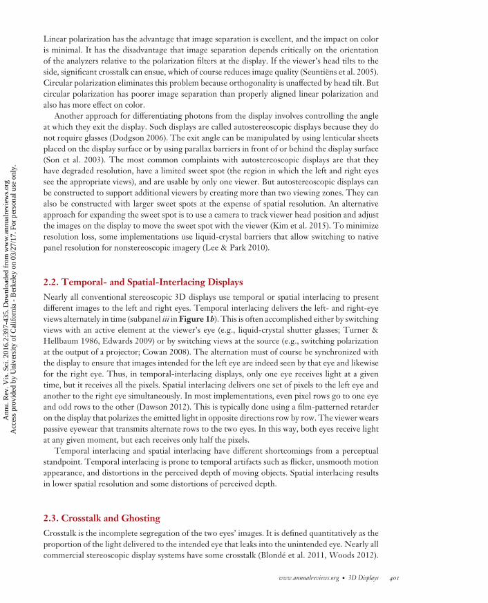
2.6.2.2. Depth distortions in spatial interlacing. The slight vertical misalignment between theleft- and right-eye images in row-by-row spatial interlacing presents an interesting problem forthe interpretation of depth. An illuminated row in the left eye’s image is at the same elevation asan unilluminated (i.e., dark) row in the right eye’s image. When the rows are visible, the visualsystem will match bright rows to bright rows and dark to dark (Krol & van de Grind 1983) bymaking a small vertical vergence eye movement. The vertical movement can change horizontaldisparity at the retina. When displayed contours are neither vertical nor horizontal, the alteration ofretinal horizontal disparity should affect the depth interpretation of the binocular image (Hakalaet al. 2015). Figure 7 illustrates this. Two intersecting diagonal lines are presented with zerohorizontal disparity on the display, so both limbs of the X should be seen in the screen plane.If one eye rotates vertically to align illuminated and unilluminated rows retinally, the binocularimage acquires unintended horizontal disparity. In Figure 7c, the right eye has rotated downwardrelative to the left, introducing uncrossed disparity for the limb sloping up and to the left andcrossed disparity for the other limb. Thus, in the fused image, the lines should appear at differentdepths and not to intersect. Hakala et al. (2015) presented such stimuli on a spatial-interlacingdisplay and measured the magnitude of the depth alteration. They found that perceived depth wasindeed consistent with the geometric analysis in Figure 7. This alteration of perceived depth canbe mitigated by spatially averaging the image data across two rows (Kelley 2011). Hakala et al.(2015) found that such vertical averaging does indeed eliminate the alteration of perceived depthbut that the averaging causes some loss of spatial detail.
2.7. Vergence-Accommodation Conflict
Binocular fixation involves two oculomotor functions: vergence and accommodation. The formeris the rotation of the eyes in opposite directions to obtain a single fused image of the fixated object.The latter is the adjustment of the power of the crystalline lens to obtain a sharp image. Thus,accurate vergence and accurate accommodation are both required to achieve a single, clear imageof a fixated object. The primary stimulus that drives vergence is, of course, binocular disparity(disparity-driven vergence), and the primary stimulus that drives accommodation is retinal-imageblur (blur-driven accommodation).
But vergence and accommodation are also coupled. Specifically, accommodative responsesevoke vergence responses (blur-driven vergence or accommodative vergence), and vergenceresponses evoke accommodative responses (disparity-driven accommodation or vergenceaccommodation) (Fincham & Walton 1957, Martens & Ogle 1959, Schor 1992). Vergence-accommodation coupling is helpful in the real world because vergence and focal distances are
414 Banks et al.
Ann
u. R
ev. V
is. S
ci. 2
016.
2:39
7-43
5. D
ownl
oade
d fr
om w
ww
.ann
ualr
evie
ws.
org
Acc
ess
prov
ided
by
Uni
vers
ity o
f C
alif
orni
a -
Ber
kele
y on
03/
27/1
7. F
or p
erso
nal u
se o
nly.
VS02CH18-Banks ARI 8 September 2016 20:35
Image dataa
Binocularly fused imagec
Left imageb Right image
Figure 7Disparity errors in spatial-interlacing displays. (a) The image data to be presented on the display. Eachsquare represents a pixel. The image has zero disparity and should be seen in the plane of the screen. (b) Thedata displayed to the left and right eyes. The dark rows represent unilluminated rows (even rows to the lefteye, odd rows to the right) and bright rows represent illuminated rows (odd rows to the left, even rows to theright). (c) The presumed binocularly fused image. In binocularly fusing the two eyes’ images, the visualsystem matches illuminated rows in the left eye with illuminated rows in the right and likewise for theunilluminated rows. To do this, the right eye rotates upward or downward by one pixel row relative to theleft eye. In the bottom panel, the right eye has rotated downward. This vertical vergence eye movementcreates horizontal disparity at the retina. Uncrossed disparity is created for edges that are tiltedcounterclockwise from vertical and crossed disparity for edges rotated clockwise.
almost always the same no matter where one looks. The coupling increases speed of response.Specifically, accommodation is faster with binocular viewing—where blur and disparity signalsspecify the same change in distance—than it is with monocular viewing where only blur providesa useful signal (Cumming & Judge 1986, Krishnan et al. 1977). Similarly, vergence is faster whendisparity and blur signals specify the same change in distance than when only disparity specifiesa change (Cumming & Judge 1986, Semmlow & Wetzel 1979).
When the distances to which the eyes must converge and accommodate differ, the vi-sual system must override the vergence-accommodation coupling. This produces the vergence-accommodation conflict. The conflict is commonplace in conventional stereoscopic 3D displaysand is frequently cited as a cause of visual discomfort (Howarth 2011, Kooi & Toet 2004, Lambooijet al. 2009, Sheedy et al. 2003, Urvoy et al. 2013).
We first discuss this conflict in the context of optically correcting a patient because several usefulconcepts have arisen from that situation. We then discuss the viewing of stereoscopic displays andwhether the optometric/ophthalmic concepts are useful to the design, assessment, and use of suchdisplays.
When the relationship between the accommodative stimulus and vergence stimulus is al-tered by a new optical correction, the patient may be unable to maintain clear and single vision
www.annualreviews.org • 3D Displays 415
Ann
u. R
ev. V
is. S
ci. 2
016.
2:39
7-43
5. D
ownl
oade
d fr
om w
ww
.ann
ualr
evie
ws.
org
Acc
ess
prov
ided
by
Uni
vers
ity o
f C
alif
orni
a -
Ber
kele
y on
03/
27/1
7. F
or p
erso
nal u
se o
nly.

VS02CH18-Banks ARI 8 September 2016 20:35
Zone of clear
single binocu
lar vi
sion
Zone of comfort
1
2
3
4
Vergence stimulus (D)
Acc
omm
odat
ive
stim
ulus
(D)
00 1 2 3 4
Figure 8Zone of clear single binocular vision (ZCSBV) and Percival’s zone of comfort. ZCSBV is represented by thewhole gray region. It represents the combinations of vergence and accommodative stimuli [here expressed indiopters (D)] for which a viewer can maintain sharp and fused binocular percepts by accommodating andconverging sufficiently accurately. Percival’s zone of comfort is represented by the light gray. It representsthe combinations of vergence and accommodative stimuli for which people do not experience discomfort.
simultaneously. The zone of clear single binocular vision (ZCSBV) summarizes the vergence-accommodation conflicts that allow maintenance of fused, sharp imagery (Fry 1939, Hofstetter1945) (Figure 8).
Optometrists and ophthalmologists found that patients often experience visual discomfort orasthenopia (Sheedy et al. 2003) when attempting to manage the vergence-accommodation conflictinduced by new optical correction. From clinical experience, Percival (1928) and Sheard (1930)proposed zones of comfort. Percival’s zone is the middle third of ZCSBV at each accommodativedistance (light gray in Figure 8). Sheard’s has the same width as Percival’s but is also determinedby the person’s phoria.
Vergence-accommodation conflicts also arise in viewing stereoscopic displays because the ver-gence stimulus can be at various distances relative to the display screen, whereas the accommodativestimulus remains fixed at the screen. The conflicts that arise are different than those that occurwith optical correction. Optical correction introduces a constant offset in diopters (D) relative tonatural viewing at all distances. Adding −1D (concave lens), for example, increases the accom-modative stimulus by 1D, displacing the diagonal line in Figure 8 upward. Stimuli presentedon stereoscopic displays enable variation in vergence stimuli, but the accommodative stimulusremains at the distance of the screen, which would be a horizontal line in the figure. Thus, theability to adapt to the vergence-accommodation conflicts induced by viewing stereoscopic displaysmight be quite different from the ability to adapt to a new optical correction.
Despite the widespread belief that vergence-accommodation conflict is a significant sourceof discomfort, there are few studies that actually tested the hypothesis directly. Many studiescompared symptoms after viewing content stereoscopically to symptoms after viewing similarcontent nonstereoscopically. Most found that viewers reported more severe symptoms afterstereoscopic viewing (Emoto et al. 2005; Hakkinen et al. 2006; Nojiri et al. 2003; Peli 1998;Wopking 1995; Yang & Sheedy 2011; Yano et al. 2002, 2004). These results have practicalimportance in assessing visual comfort for the two types of viewing experience, but they cannot
416 Banks et al.
Ann
u. R
ev. V
is. S
ci. 2
016.
2:39
7-43
5. D
ownl
oade
d fr
om w
ww
.ann
ualr
evie
ws.
org
Acc
ess
prov
ided
by
Uni
vers
ity o
f C
alif
orni
a -
Ber
kele
y on
03/
27/1
7. F
or p
erso
nal u
se o
nly.

VS02CH18-Banks ARI 8 September 2016 20:35
inform us about what the causes of discomfort are because they did not isolate candidate causes.That is, the source of discomfort could be the vergence-accommodation conflict, crosstalk (Kooi& Toet 2004), increased immersion, increased sense of self-motion (Palmisano 1996, 2002),decreased brightness, more salient motion artifacts (Hoffman et al. 2011), and many other thingsthat differ between stereoscopic and nonstereoscopic viewing experiences. Without knowing thecause(s) of discomfort, one cannot know how to minimize them.
To persuasively determine whether a particular property causes discomfort, one has to manip-ulate that property while holding other potential causes constant. Furthermore, natural viewingin which vergence and accommodation are consistent with one another is the most appropri-ate baseline for assessing discomfort when they are in conflict. The development of multi-planestereoscopic displays (Section 3.2) has made this possible. Such displays create digital approxi-mations to a 3D volume with nearly correct focus cues. They are stereoscopic, so they enableindependent manipulation of the stimulus to vergence and the stimulus to accommodation.
Recent studies used multi-plane displays or displays coupled with tunable lenses to directly testthe hypothesis that vergence-accommodation conflict is a source of visual discomfort (Hoffmanet al. 2008, Johnson et al. 2016, J. Kim et al. 2014b, Konrad et al. 2016, Shibata et al. 2011). Theypresented two main conditions: (a) natural viewing in which the distance of the vergence stimulusand the distance of the accommodative stimulus changed in unison as they do in the naturalenvironment; and (b) stereo viewing in which the distance of the vergence stimulus changed in thesame fashion as the natural-viewing condition whereas the distance of the accommodative stimulusremained constant. Hoffman et al. (2008) found that the vergence-accommodation inconsistenciesin stereoscopic viewing induced more discomfort than the consistent vergence and accommodationstimuli in natural viewing. This was direct evidence that vergence-accommodation conflict instereoscopic displays is a cause of visual discomfort.
Shibata et al. (2011) extended this to estimate the zone of comfort for viewing stereoscopicdisplays. They too observed that vergence-accommodation conflict causes visual discomfort. Theyalso found that subjects are more susceptible to conflict at long viewing distances and that posi-tive conflict induces greater discomfort at far viewing distance, whereas negative conflict inducesgreater discomfort at closer viewing distance. From their data, they made a rough estimate of thezone of comfort for young adult viewers of stereoscopic displays (Figure 9). Panel b shows that dis-comfort is less likely to occur at typical viewing distances for television and cinema. Consistent withthis, Read & Bohr’s (2014) study found minimal discomfort with viewing of stereoscopic television.
Although the accommodative stimulus of stereoscopic displays is fixed, accommodative re-sponses can still occur when the simulated distance of an object changes (Inoue & Ohzu 1997,Torii et al. 2008). The change in simulated distance is signaled by binocular disparity and otherancillary depth cues such as perspective and motion parallax, and they can drive accommoda-tion via the vergence-accommodation cross-coupling and the proximal component (Heath 1956).Simultaneously, the blur-driven component to accommodation remains fixed at the screen dis-tance. Therefore, the components that drive accommodation are in conflict: two attempting todrive accommodation according to the video content and one attempting to hold it fixed at thescreen. It is therefore not surprising that accommodative responses are more unstable when view-ing stereoscopic displays than in natural viewing (Fukushima et al. 2009, Torii et al. 2008).
Visual discomfort is a subjective phenomenon, so most assessments have relied on self-reportsof subjective experience. There have, however, been many recent attempts to develop objectiveindices in the hope that more reliable and rapid assessment can be achieved. These indices haveincluded measurements of performance in visually demanding tasks (Akeley et al. 2004, Hoffmanet al. 2008), electroencephalography (EEG) (Mun et al. 2012), functional magnetic resonanceimaging (fMRI) (D. Kim et al. 2014), and heart rate (Park et al. 2014). Our reading of this workis that none have proven to be an effective index.
www.annualreviews.org • 3D Displays 417
Ann
u. R
ev. V
is. S
ci. 2
016.
2:39
7-43
5. D
ownl
oade
d fr
om w
ww
.ann
ualr
evie
ws.
org
Acc
ess
prov
ided
by
Uni
vers
ity o
f C
alif
orni
a -
Ber
kele
y on
03/
27/1
7. F
or p
erso
nal u
se o
nly.

VS02CH18-Banks ARI 8 September 2016 20:35
View
ing
dist
ance
(m)
10
0.3
0.3 1 3 10 30
30
1
3
CinemaCinema
TelevisionTelevision
DesktopDesktopMobileMobile
Far
Nea
r
0 1 2 3 4 50
1
2
3
4
5
Vergence distance (D)
a b
Vergence distance (m)Vi
ewin
g di
stan
ce (D
)
MobileMobile
DesktopDesktop
TelevisionTelevision
Far
Near
CinemaCinema
Figure 9Zone of comfort for stereoscopic viewing. (a) Comfort zone plotted in diopters. The abscissa is the distanceof the vergence stimulus, and the ordinate is viewing distance, which corresponds to the focal stimulus. Theblack diagonal line represents natural viewing. The red and blue lines represent estimates from the data ofShibata and colleagues (2011). The dashed horizontal lines represent typical viewing distances for mobiledevices, desktop displays, television, and cinema. (b) Comfort zone plotted in meters. The abscissa andordinate are the distance of the vergence stimulus and viewing distance. The black diagonal line representsnatural viewing. Red and blue lines again represent the boundaries of the comfort zone. Dashed horizontallines represent viewing distances for the same devices as in the panel a. Abbreviation: D, diopter.
It has been frequently observed that some individuals are more susceptible than others to visualdiscomfort when viewing stereoscopic displays. It would be very useful to know what makes oneperson susceptible and another not. Recent research has investigated whether age and propertiesof binocular visual function are predictive.
The range of distances over which an individual can accommodate declines steadily with age(Glasser & Campbell 1998). For people in their forties, the restricted range becomes noticeable.By their fifties and sixties, the accommodative range is effectively nil. Restricted range of accom-modation is presbyopia. Presbyopes experience vergence-accommodation conflicts all the time innatural viewing because they can converge appropriately but cannot accommodate. This leads tothe expectation that vergence-accommodation conflicts associated with stereoscopic viewing willnot cause visual discomfort in presbyopes. Yang et al. (2012) reported data consistent with thisexpectation. They exposed subjects to prolonged viewing of similar content presented stereoscop-ically and nonstereoscopically. Young adults reported more severe symptoms after stereoscopicthan nonstereoscopic viewing. But subjects 46 years of age or older reported more symptomsafter nonstereoscopic viewing. This reversal of the usual outcome makes sense because stereo-scopic viewing allows consistency between disparity-driven vergence and proximal vergence inpresbyopes, whereas nonstereoscopic viewing puts the two in conflict.
Optometric aspects of binocular visual function have also been investigated as potential pre-dictors of susceptibility to discomfort. Results are inconclusive. Shibata et al. (2011) examinedwhether gains of the vergence-accommodation cross-links [i.e., the accommodative-convergence/accommodation (AC/A) ratio and convergence-accommodation/convergence (CA/C) ratio] arepredictive and observed only a weak relationship. They found that an individual’s phoria wasreasonably predictive of the conditions in which he/she would experience discomfort. That find-ing was confirmed by Shibata et al. (2013) but not by Hakkinen et al. (2006) and McIntire et al.(2014b). Others reported that the width of Panum’s fusion zone is predictive (narrower zones pre-dicting great susceptibility) (Chen et al. 2012). Lambooij et al. (2011) found that a combinationof optometric parameters yielded reasonable predictions for susceptibility.
418 Banks et al.
Ann
u. R
ev. V
is. S
ci. 2
016.
2:39
7-43
5. D
ownl
oade
d fr
om w
ww
.ann
ualr
evie
ws.
org
Acc
ess
prov
ided
by
Uni
vers
ity o
f C
alif
orni
a -
Ber
kele
y on
03/
27/1
7. F
or p
erso
nal u
se o
nly.

VS02CH18-Banks ARI 8 September 2016 20:35
Read et al. (2016) found no evidence in children or adults of long-term effects on balance,coordination, and vision following two months of watching stereoscopic 3D television every day.
3. ADVANCED DISPLAYS
3.1. Focus Cues
It has often been stated that focus cues (blur and accommodation) do not have noteworthy effectson seeing three dimensionally. For example, Mather (2006, p. 276) stated that blur provides only“coarse ordinal (depth) information,” and Mather & Smith (2000, p. 3504) stated that “blur isalways treated as a relatively weak depth cue by the visual system.” The claim is based on the factthat defocus blur is unsigned; the same blur can be observed when an object is nearer or fartherthan the distance to which the eye is focused. Because of this relatively common view, we spendsome time describing evidence to the contrary: specifically, evidence that focus cues affect both3D shape perception and the apparent scale of the scene.
Buckley & Frisby (1993) and Frisby et al. (1995) observed striking differences in 3D shapepercepts when stimuli were presented as real objects versus on a conventional stereoscopic display.Their stimuli were raised ridges. When presented on a display, the depths specified by disparityand perspective were manipulated independently in the conventional way. The real objects werepatterned cards wrapped onto wooden forms. They manipulated disparity by changing the shape ofthe form and perspective by warping the texture pattern on the card. When stimuli were presentedon a display, disparity and perspective both affected the amount of perceived depth, but disparitydominated when the perspective-specified depth was large and perspective dominated when theperspective-specified depth was small. The results differed dramatically when the stimuli werepresented as real objects. The disparity-specified depth now dominated the percept in all cases, andjudgments were more accurate. Buckley and Frisby reasoned that focus cues played a critical rolein generating the 3D percepts. When the stimuli were presented on a display, focus cues signaledflatness because the light all came from the same distance. With the real objects, focus and stereocues both signaled the true shape. To test whether focus cues were indeed the determining factor,they redid the experiment with pinholes in front of the two eyes. Interestingly, the display datawere unaffected by the pinholes, but the real-ridge data became similar to the display data. Thisresult can be explained only by assuming that focus cues played an important role in perceivingshape. Viewing through a pinhole increased depth of field substantially. Greater depth of field doesnot change the retinal images arising from stimuli on a flat display, so percepts were in that caseunderstandably not affected. Increased depth of focus does cause a change in the images from real3D objects: blur no longer varies across the object. And that is presumably why the perception ofreal objects changed when viewing through pinholes. Overall, Buckley and Frisby’s observationsprovide convincing evidence for a noteworthy effect of focus cues on 3D shape perception. Similarresults have been reported elsewhere (Hoffman et al. 2008, Pentland 1987, Watt et al. 2005).
The pattern of blur in an image can also strongly influence the perceived size of scenes. Forexample, cinematographers make miniature models look larger by using small camera apertures,which increase depth of field (Fielding 1985). The opposite effect is created in a photographicmanipulation called the tilt-shift effect: A full-size scene is made to look smaller by adding blur witheither a special lens or postprocessing software tools (Held et al. 2010, Laforet 2007, Vishwanath& Blaser 2010). Scenes can also be made to look smaller by increasing the size of the effectivecamera aperture as demonstrated in Figure 10. The left image has been rendered sharply with asmall aperture and looks like a life-size urban scene. The right image has been rendered with ablur pattern consistent with a much larger aperture, and it looks like a miniature model. We can
www.annualreviews.org • 3D Displays 419
Ann
u. R
ev. V
is. S
ci. 2
016.
2:39
7-43
5. D
ownl
oade
d fr
om w
ww
.ann
ualr
evie
ws.
org
Acc
ess
prov
ided
by
Uni
vers
ity o
f C
alif
orni
a -
Ber
kele
y on
03/
27/1
7. F
or p
erso
nal u
se o
nly.

VS02CH18-Banks ARI 8 September 2016 20:35
Figure 10Effect of depth-of-field blur on apparent scale. The left image was rendered with a pinhole camera creating along depth of field. The right image was rendered with a 60-m aperture creating a short depth of field. Thescene on the right looks much smaller than the one on the left. Figure reprinted from Held et al. (2010).
understand why aperture size has such a dramatic influence on perceived scale by examining thedeterminants of blur in images. Consider a camera (or eye) focused on an object at distance z0. Apoint at another distance z1 creates a blurred image. The diameter of the blurred image is:
b = As0
z0
∣∣∣∣1 − z0
z1
∣∣∣∣ , (8)
where A is the diameter of the aperture (or pupil) and s0 is a focal length (or eye length) term.Converting the blur circle to radians and simplifying results in
β ≈ A∣∣∣∣ 1z0
− 1z1
∣∣∣∣ = A |�D| , (9)
where β is blur-circle diameter in radians and �D is the difference between the focused distanceand object distance in diopters. The absolute value is used because defocus blur is unsigned.Thus, the amount of blur variation from a given scene is proportional to aperture size and to thedifference in object distances in diopters. With an aperture of normal size (∼4 mm in humans),large variations in blur can happen only if the objects are close to the eye. Recent experimentshave shown that depth-of-field blur can indeed strongly affect perceived scale (Held et al. 2010,Nefs 2012, Trentacoste et al. 2011, Zhang et al. 2014).
Binocular disparity has the same basic geometry as blur because both cues are based on viewingthe world from different vantage points (Held et al. 2010, Schechner & Kiryati 2000). Disparity iscreated by the differing vantage points of two cameras or eyes; blur is created by differing vantagepoints across the camera’s or eye’s aperture. The disparity in radians between the point on whichthe cameras (or eyes) are converged and another point is
δ ≈ I (�D) , (10)
where I is interocular separation. Thus, the magnitudes of blur and disparity caused by a point in a3D scene should be proportional to one another. In humans, pupil diameter is ∼1/12 the distancebetween the eyes, so blur-circle diameters are generally 1/12 the magnitudes of disparities. Because
420 Banks et al.
Ann
u. R
ev. V
is. S
ci. 2
016.
2:39
7-43
5. D
ownl
oade
d fr
om w
ww
.ann
ualr
evie
ws.
org
Acc
ess
prov
ided
by
Uni
vers
ity o
f C
alif
orni
a -
Ber
kele
y on
03/
27/1
7. F
or p
erso
nal u
se o
nly.

VS02CH18-Banks ARI 8 September 2016 20:35
the geometries underlying disparity and blur are similar, the basic relationship holds for the viewingof all real scenes. This natural disparity-blur relationship should be obeyed if one wants the sceneto appear natural in scale.
Visual performance can also suffer when focus cues are not presented correctly on a stereoscopicdisplay. For example, many viewers find it difficult to fuse a binocular stimulus when vergence andaccommodative distances differ substantially. Specifically, the time required to fuse a stimulus de-creases monotonically when the conflict between vergence and accommodative distances decreases(Akeley et al. 2004, Hoffman et al. 2008). The minimum time occurs with zero conflict. This effectis surely a consequence of the vergence-accommodation coupling. The coupling is beneficial whenthere is no conflict between vergence and accommodative distances because disparity-driven andblur-driven vergence are in agreement, so vergence responds rapidly and accurately. The cou-pling is not beneficial when there is a conflict because the disparity- and blur-driven componentsof vergence attempt to drive vergence to different distances. Other performance decrements dueto vergence-accommodation conflict have been reported (Lambooij et al. 2012).
One approach for minimizing the conflict is to remap the disparities of the stereoscopic contentso that they do not deviate greatly from zero at the screen in the region of interest (Didyk et al.2014, Lang et al. 2010). Doing this, however, is very likely to distort 3D percepts.
In summary, there is now substantial evidence that incorrect focus cues (blur and accommo-dation) can alter 3D shape and scene perception, limit visual performance, and cause discomfort.For these reasons, there has been considerable effort recently toward developing and evaluatingdisplays that support correct focus cues.
3.2. Volumetric and Multi-Plane Displays
Volumetric displays place light sources in a 3D volume by, for example, using rotating displayscreens (Favalora et al. 2002) or stacks of switchable diffusers (Sullivan 2004). These allow correctstereo, parallax, and focus cues, but the displayed scene is confined to the display volume. Fur-thermore, a very large number of addressable voxels is required, which places practical limits oneffective resolution at the viewer’s eye. Importantly, these displays cannot reproduce occlusionsand viewpoint-dependent effects such as reflections. Instead, they show a world of glowing, trans-parent voxels. Recent techniques (Cossairt et al. 2007, Jones et al. 2007) have used anisotropicdiffusers to overcome this limitation, but focus cues then become incorrect.
Multi-plane displays are a variant of volumetric displays in which the viewpoint is fixed. Suchdisplays are promising because they can in principle provide correct depth cues, including focuscues, with conventional display hardware. In multi-plane displays, images are drawn on presen-tation planes at different focal distances. Most multi-plane displays have separate optical pathsfor the two eyes, so stereo cues and focus cues are both enabled. These displays have been con-structed using a system of beam splitters (Akeley et al. 2004, MacKenzie et al. 2010) and by timemultiplexing with high-speed switchable lenses (Liu et al. 2008, Love et al. 2009) to superimposemultiple presentation planes additively on the viewer’s retina. Most current implementations sup-port high-resolution imagery by presenting the full resolution of a conventional monitor at eachfocal distance. A multi-plane head-mounted version has been described (Hu & Hua 2013, 2014).
With multi-plane displays, a simulated object at one of the presentation planes is displayed byilluminating the pixels on that plane. A rule is, however, required to determine how to illuminatepixels in the more likely case that the simulated object is not at the distance of a presentationplane. This is accomplished by distributing intensities on the pixels of adjacent planes by linearinterpolation (Akeley et al. 2004) or somewhat more complicated rules (Hu & Hua 2014, Liu &Hua 2010). This approach works well when the presentation planes are not too far apart (less
www.annualreviews.org • 3D Displays 421
Ann
u. R
ev. V
is. S
ci. 2
016.
2:39
7-43
5. D
ownl
oade
d fr
om w
ww
.ann
ualr
evie
ws.
org
Acc
ess
prov
ided
by
Uni
vers
ity o
f C
alif
orni
a -
Ber
kele
y on
03/
27/1
7. F
or p
erso
nal u
se o
nly.

VS02CH18-Banks ARI 8 September 2016 20:35
than ∼0.7 D), the simulated stimuli are diffuse surfaces, and depth varies slowly across the image(Ravikumar et al. 2011).
But the approach produces objectionable haloing artifacts around occlusions. Reflections, re-fractions, and other non-Lambertian phenomena also produce image features that cannot beassigned a consistent focal distance and therefore cannot be handled by these interpolation rules.A novel optimized blending algorithm was recently developed that creates much more realisticresults for occlusions and non-Lambertian effects (Narain et al. 2015). Using a model of imageformation in the typical human eye, the researchers obtained for each desired viewpoint the stackof retinal images that would be experienced by a viewer when accommodating to different dis-tances. They then optimized the assignment of light intensities to presentation planes so that theresultant retinal images were as close as possible to the retinal images that would be produced bythe original scene. The outcome looks much more similar to the real world.
The presentation of nearly correct focus cues using multi-plane displays has several benefits.First, multi-plane displays support accommodation. With monocular viewing, subjects accommo-date to simulated objects even when they are positioned between presentation planes. Accommo-dation is quite accurate when the planes are 0.67 D apart and reasonably accurate when the planesare 1 D apart (MacKenzie et al. 2010, 2012). Second, the time to fuse a binocular stimulus is re-duced in such displays when the vergence and accommodation distances are the same (Akeley et al.2004, Hoffman et al. 2008, Maiello et al. 2014). Third, reducing the vergence-accommodationconflict leads to a reduction in visual discomfort. Finally, the presentation of nearly correct fo-cus cues improves the accuracy of 3D percepts. An interesting case is the perception of depthordering at an occlusion boundary. In earlier studies using conventional displays, viewers werepresented two abutting surfaces, one with a blurred texture and one with a sharp one (Marshallet al. 1996, Mather & Smith 2002, Palmer & Brooks 2008). Viewers indicated which of the twosurfaces was nearer—in other words, which was the occluder and which was the background. Theblur of the boundary between the surfaces is a completely informative cue. When the boundaryis blurred, the blurrier surface is the occluder; when the boundary is sharp, the sharper surfaceis the occluder. Despite this informative cue, viewers were quite poor in making depth-orderjudgments. The stimuli in those experiments were rendered for and displayed on a single plane.Zannoli et al. (2016) repeated those studies with single- and multi-plane stimuli (Figure 11).Subjects viewed the stimuli monocularly. With single-plane stimuli, subjects performed barelyabove chance, consistent with the previous findings. When the same occlusion relationship wasdisplayed on the multi-plane display with optimized blending, performance improved markedly.Subjects generally perceived the physically nearer surface as nearer even though they viewed thestimuli monocularly with no motion parallax and at durations too brief for an accommodativechange to occur (Figure 11). Thus, multi-plane displaying with optimized rendering significantlyimproves the perception of depth order at occlusion boundaries.
3.3. Light-Field Displays
The natural environment contains light rays of diverse intensities and colors running in variousdirections. The light field is a function that describes the amount and color of light flowing inevery direction through every point in space (Gershun 1939). A binocular viewer moving throughthe light-field experiences the triangulation cues to which we referred earlier. Stereo cues arecreated because the two eyes receive different light rays. Motion parallax cues are created becausethe eyes receive different rays as the viewer’s head moves. And focus cues are created becausedifferent parts of the viewer’s pupil receive different light rays. Light-field displays are intended
422 Banks et al.
Ann
u. R
ev. V
is. S
ci. 2
016.
2:39
7-43
5. D
ownl
oade
d fr
om w
ww
.ann
ualr
evie
ws.
org
Acc
ess
prov
ided
by
Uni
vers
ity o
f C
alif
orni
a -
Ber
kele
y on
03/
27/1
7. F
or p
erso
nal u
se o
nly.

VS02CH18-Banks ARI 8 September 2016 20:35
0.20 0.4 0.6 0.80
0.2
0.4
0.6
0.8
1.0
Multi-planeSingle-plane
Proportion correct (blurred edge)
Prop
orti
on c
orre
ct (s
harp
edg
e)
Edge sharp
Edge blurred
1.0
Figure 11Judgments of depth order at an occlusion boundary. Two surfaces were shown, one with a blurred textureand one with a sharp texture. They were presented in two ways: single-plane display in which the blur wasrendered and multi-plane display in which the blur was created in the viewer’s eye. The single-plane resultsare represented by the open symbols and multi-plane results by the filled symbols. The lines connect theresults for each subject. The horizontal axis is the proportion of correct responses when the boundary wasblurred, and the vertical axis is the proportion correct when the boundary was sharp. The dashed diagonalline represents chance performance with different biases.
to recreate those cues with sufficient accuracy to enable a high-fidelity, comfortable 3D viewingexperience.
A light-field display emits a four-dimensional distribution of light rays, which varies overthe two dimensions of a display surface but also over the horizontal and vertical viewing angleof each pixel. The display primitives of conventional displays are 2D pixels (picture elements),those of volumetric or multi-plane displays are 3D voxels (volume elements), and those of 4Dlight-field displays are light rays, each carrying radiance at some location into a specific direction.Figure 12 illustrates the common two-plane parameterization of a light field: A plane x is locatedon the physical display screen, and another plane u coincides with the pupils of the viewer. Topass our Turing test for displays—that is, to create a sufficiently persuasive 3D experience—a 4Dlight-field display would have to provide appropriate stereo, motion parallax, and focus cues. Nosuch display exists today, but different tradeoffs can be made to create reasonable approximations.
Over a century ago, Ives (1903) conceived of parallax barriers. A barrier mask consisting ofan array of pinholes or slits would be mounted at a slight offset in front of a display such that aviewer would perceive only a subset of the display pixels from any given perspective. The displaywould render an image that contains the corresponding, interlaced perspectives of the light field.Soon after, Lippmann (1908) built the first integrated light-field camera and display using integralimaging. Instead of pinhole arrays, he mounted microlens arrays on photographic plates and
www.annualreviews.org • 3D Displays 423
Ann
u. R
ev. V
is. S
ci. 2
016.
2:39
7-43
5. D
ownl
oade
d fr
om w
ww
.ann
ualr
evie
ws.
org
Acc
ess
prov
ided
by
Uni
vers
ity o
f C
alif
orni
a -
Ber
kele
y on
03/
27/1
7. F
or p
erso
nal u
se o
nly.

VS02CH18-Banks ARI 8 September 2016 20:35
3D scene Top view Light field, left eye Light field, right eye
x
x
xu
d
Nat
ural
light
fiel
dSt
erer
odi
spla
y u
u
a b c
Figure 12(a) The light field of a natural scene (b) is a collection of rays parameterized by their coordinates of intersection with two planes x and u.(c) All rays on a horizontal scanline (cyan) observed in the centers of the viewer’s two pupils are shown on the lower right (stereo display)and all rays on the same scanline across the viewer’s pupils are shown on the upper right (natural light field). The two eyes observe thescene from different vantage points so the left- and right-eye rays differ. Conventional stereoscopic displays do not provide parallaxacross the pupils and therefore do not support focus cues. The natural light field does provide parallax across the pupils and therebyprovides focus cues.
exposed and developed these plates with the lens arrays in place, such that they could be viewedas a light-field or glasses-free 3D image after the fact. The main drawback of parallax barriersand integral imaging is the spatio-angular resolution tradeoff: Adding more light-field viewingzones comes at the cost of reduced spatial display resolution. Additionally, parallax barriers areusually dim because most of the emitted light is blocked. To overcome these limitations, manyalternative technologies have emerged over the last 100 years to deliver high-resolution, glasses-free 3D experiences, as discussed in the previous sections. Yet, none can deliver experiences thatcome close to satisfying our Turing test for displays.
With an ever-increasing demand on image resolution, one of the major bottlenecks in the light-field display pipeline is the computation. Consider the example of a high-quality, light-field displaywith 100 × 100 views, each having high-definition resolution, streamed at 60 Hz. More than onetrillion light rays have to be rendered per second requiring more than 100 terabytes of floatingpoint RGB ray data to be stored and processed. Furthermore, with conventional integral imagingor parallax barriers, a display panel that has a resolution 10,000 times higher than available panelswould be needed. To tackle the big data problem and relax requirements on display hardware,compressive light-field displays have recently been introduced. They rely on two insights: lightfields of natural imagery are highly redundant, high-dimensional visual signals; and the humanvisual system has limitations that can be exploited for visual signal compression.
Multiplexing methods (e.g., temporal, spatial, polarization) can be adopted to optimize thetradeoff between spatial and angular resolution, brightness, etc., dynamically in a content-adaptivemanner. For example, the refresh rate of modern displays often exceeds the flicker thresholdof human vision. A parallax-barrier display implemented with fast liquid-crystal display (LCD)would allow for the optimal layout of time-multiplexed pinholes to be determined for each targetlight field. Further relaxing the requirement that the barrier mask is constrained to showingonly pinholes leads to the concept of content-adaptive parallax barriers that optimize the time-multiplexed patterns for both display and barrier mask (Lanman et al. 2010). Such a content-adaptive optimization not only allows adaptive tradeoffs between spatial and angular resolution tobe made, but it also allows for display brightness to be optimized with respect to pinhole-basedbarriers. The light field generated by a time-multiplexed parallax barrier displays with two LCDs
424 Banks et al.
Ann
u. R
ev. V
is. S
ci. 2
016.
2:39
7-43
5. D
ownl
oade
d fr
om w
ww
.ann
ualr
evie
ws.
org
Acc
ess
prov
ided
by
Uni
vers
ity o
f C
alif
orni
a -
Ber
kele
y on
03/
27/1
7. F
or p
erso
nal u
se o
nly.

VS02CH18-Banks ARI 8 September 2016 20:35
Left view
LCD patterns at frame 1 LCD patterns at frame N
Right view
BacklightLCD1
LCD2
LCD3
Layer 1Layer 2
Layer 3
a b c
Figure 13Compressive light-field prototype. (a) The prototype uses three stacked layers of liquid-crystal displays(LCDs) that are rear-illuminated by one backlight. (b) Top-down view of prototype display showing theLCD layers and backlight. (c) A light-field factorization algorithm computes time-multiplexed patterns forall LCD layers. The bottom subpanels show the three layers for the left and right views. They are displayedat a speed exceeding the flicker threshold of the visual system. Perceptually, these patterns fuse into aconsistent, high-resolution light field that supports stereo cues and parallax without needing glasses.
is given by
l(x, u) = 1M
M∑m=1
f (1)m
(x + d1
d(u − x)
)f (2)m
(x + d2
d(u − x)
)f (1)m , (11)
where M is number of time-multiplexed images that the visual system perceptually averages andd1 and d2 are the distances between LCD layers 1 and 2 and the x-plane, respectively. Given atarget light field l(x, u), a least-squared error approximation of it can be physically reproducedwith the parallax-barrier display by computing the best set of time-multiplexed patterns f (1)
m andf (2)m and displaying them on the respective LCD panels. The corresponding inverse problem is
usually formulated as a numerical optimization problem,
min{
f (1)m , f (2)
m
} ∥∥l(x, u) − l(x, u)∥∥2
F , subject to 0 ≤ f (1)m , f (2)
m ≤ 1, (12)
which can be efficiently solved with nonnegative matrix factorization approaches (Lanman et al.2010).
Compressive light-field displays generalize the idea of content-adaptive parallax barriers to avariety of display architectures, including multiple stacked layers of LCDs (Figure 13), a thin“sandwich” of two LCDs enclosing a microlens array or, in general, any combination of stacked,programmable light modulators and refractive optical elements (Wetzstein et al. 2012). Similarto parallax barriers, cascading LCDs usually have a multiplicative effect on the incident lightthat can selectively attenuate light in some directions (Huang et al. 2015; Lanman et al. 2010;Maimone et al. 2013; Wetzstein et al. 2011, 2012). The light-field factorization outlined abovegeneralizes to all of these display architectures. Their nonlinear, multiplicative image formation isfundamentally different from the linear, additive image formation provided by multi-focal planedisplays, volumetric displays, and many other time-multiplexed displays. In general, a nonlinearimage formation has the potential to provide more degrees of freedom for the image generationalgorithm than an additive, linear image formation (Huang et al. 2015, Maimone et al. 2013,Wetzstein et al. 2012).
A useful approach for characterizing the degrees of freedom of light-field displays is a frequencyanalysis. For this, we make one simplifying assumption: Instead of using an absolute two-planeparameterization on the x-u planes, we use a relative two-plane parameterization x-v, such thatl(x, u) = l(x, x + dv).
www.annualreviews.org • 3D Displays 425
Ann
u. R
ev. V
is. S
ci. 2
016.
2:39
7-43
5. D
ownl
oade
d fr
om w
ww
.ann
ualr
evie
ws.
org
Acc
ess
prov
ided
by
Uni
vers
ity o
f C
alif
orni
a -
Ber
kele
y on
03/
27/1
7. F
or p
erso
nal u
se o
nly.

VS02CH18-Banks ARI 8 September 2016 20:35
Ang
ular
freq
uenc
y(c
ycle
s/cm
)
Spatial frequency (cycles/cm)
Additivetwo-layer display
20
20 30
1510
10
50
0
–5–10
–10
–15–20
20151050
–5–10–15–20
–20–30Spatial frequency (cycles/cm)
Multiplicativetwo-layer display
a b
20 30100–10–20–30
Figure 14Spatio-angular frequency support of (a) an additive two-layer display and (b) a corresponding multiplicativetwo-layer display. The specific display parameters, including layer spacing and panel resolution, are adoptedfrom Wetzstein et al. (2012). The spatio-angular frequency support of a conventional display is a slantedline; the frequency support of two additive displays is their combined support (a). If the same display layersinteract in a multiplicative manner, their frequency support is convolved and covers a significantly larger area(b). The support shown for the multiplicative display is a theoretical upper bound that is not easily achievedin practice.
Real-world light fields contain all spatio-angular frequencies. Conventional 2D displays are apoor approximation: From each pixel, light is emitted in all directions, so such displays do notprovide any angular variation. The Fourier transform of the light field emitted by a conventionaldisplay is therefore a line: fm(ωx, ωv) = δ
(ωv − d0
d ωx)
(Wetzstein et al. 2011, 2012), which falls wellshort of representing the span of spatio-angular frequencies in natural light fields. The frequencysupport of additive, multi-plane displays is the sum of the support provided by each plane. Thus,display layers at different distances support a larger range of frequencies than a conventionaldisplay. This is illustrated for two layers in Figure 14a. The frequency support for two layersis sparse but can be improved simply by adding more closely spaced layers. Adding more layersapproximates a volumetric display and can provide adequate coverage of the required span ofspatio-angular frequencies. Before the design specifications can be understood, however, we needbetter models of human sensitivity to angular resolution.
The spatio-angular frequencies created by the multiplication of two display layers are given bythe convolution of the Fourier transforms of the individual layers:
l(ωx, ωv) = 1M
M∑m=1
f (1)m (ωx)δ(ωv − d1
dωx) ∗
M∑m=1
f (2)m (ωx)δ(ωv − d2
dωx). (13)
Figure 14b shows the theoretical upper bounds on the spatio-angular frequencies that can becreated by a two-layer, multiplicative display. The multiplicative approach theoretically providesgreater frequency support than the additive approach does. The estimated frequency support formultiplicative displays is, however, a theoretical upper bound that may be difficult to achieve inpractice. One practical limitation is nonnegativity constraints on pixel states. Another is time-multiplexing constraints due to the noninfinite speed of display panels. Finally, the resolution ofmultiplicative displays is fundamentally limited by diffraction. Observing one display panel throughanother one that has small pixels makes the farther panel appear blurred due to diffraction. Thesmaller the pixels become, the more obvious this becomes. If pixel size approached the wavelengthof light, the blur due to diffraction would be quite problematic. Figure 15 illustrates the diffractionproblem for a range of panel resolutions and distances between the panels. Here, we modelmonochromatic light with a wavelength of 555 nm. We assume viewing zones that are at most as
426 Banks et al.
Ann
u. R
ev. V
is. S
ci. 2
016.
2:39
7-43
5. D
ownl
oade
d fr
om w
ww
.ann
ualr
evie
ws.
org
Acc
ess
prov
ided
by
Uni
vers
ity o
f C
alif
orni
a -
Ber
kele
y on
03/
27/1
7. F
or p
erso
nal u
se o
nly.

VS02CH18-Banks ARI 8 September 2016 20:35
100 200 300 400 500 600 700
0
1
2
3
4
5
6
7
8
9
10
Diffraction-limited viewing zone size
Display panel resolution (DPI)
Dis
tanc
e be
twee
n di
spla
y pa
nels
(mm
)
Minimum viewing zonesize for focus cues
Sufficient viewing zones for stereo cues
Diff
raction limit
Light-field displaywith two stacked display panels
Δd
d =
125
cm
Pupil= 0.4 cm
Viewingzonesize
IPD = 6.4 cm
100
90
80
70
60
50
40
30
20
10
0
Viewing zone size (m
m)
Figure 15Diffraction-limited viewing zone size for two stacked liquid-crystal display layers. (Left) We simulate a generalized parallax barrierdisplay setup with the front panel being 125 cm from the viewer. The distance between panels as well as their resolution is varied forthe simulation on the left. For an appropriate choice of screen resolution and screen distance, stereo cues are easily achieved when thesize of the viewing zone is larger than the interpupillary distance. When more than two views enter the same pupil (here, simulated witha diameter of 4 mm), accommodation is theoretically possible. However, the viewing zone size of parallax barriers and other multilayerdisplays is fundamentally limited by diffraction as shown in the right panel. Abbreviations: DPI, dots per inch; IPD, interpupillarydistance.
large as the interpupillary distance to support stereo cues. To support focus cues, several viewingzones must enter the same pupil, which in the simulation has a diameter of 4 mm. To providesufficiently dense viewing zones, either the parallax barriers can be spaced farther apart or panelswith higher pixel density can be employed. For a given observer distance, we can compute theviewing zone size with a geometric optics approximation. Diffraction effects can be accounted forby simulating the panel closest to the viewer as an array of apertures with feature size p given bydisplay pixel pitch. The diffraction-limited spot size on the rear panels can be approximated as thefirst minimum of the Airy disk resulting from diffraction shown in the equation
2�d tan(
sin−1(
1.22λ
p
)), (14)
where �d is the distance between the panels. We observe that the viewing zones designed tosupport stereo cues are usually not affected much by diffraction, but for those targeting focus cues,diffraction limits must be carefully considered.
The frequency support for additive displays is more readily expanded in practice. For exam-ple, higher panel resolution extends the frequency lines outward; adding more densely spacedlayers fills in the span, thereby covering more frequencies. The blurring effect due to diffractionis generally not observed with additive displays. In summary, the multiplicative approach cantheoretically support a larger set of spatio-angular frequencies than the additive approach. Butpractical considerations currently limit the performance of multiplicative displays.
Compressive light-field displays have proven quite promising. Their primary benefit is that thesame display hardware configuration allows content-adaptive dynamic tradeoffs between spatial
www.annualreviews.org • 3D Displays 427
Ann
u. R
ev. V
is. S
ci. 2
016.
2:39
7-43
5. D
ownl
oade
d fr
om w
ww
.ann
ualr
evie
ws.
org
Acc
ess
prov
ided
by
Uni
vers
ity o
f C
alif
orni
a -
Ber
kele
y on
03/
27/1
7. F
or p
erso
nal u
se o
nly.

VS02CH18-Banks ARI 8 September 2016 20:35
Light-fieldfactorization
Photographs or prototype
Driver electronicsLiquid crystal display
Liquid crystal display
HousingLenses
Front focus Mid focus Rear focus
Backlight
Spacer
Prototype dual-layer light field head-mounted display design
Front focus
Mid focus
Rear focus
a b
Figure 16Near-eye light-field display with support for focus cues. (a) The design is based on the stereoscope but uses two stacked liquid-crystaldisplays inside the device to generate a separate light field for each eye. (b) Light-field factorization is employed to generate patternsshown on the front and rear panels. (c) The light field provides sufficient angular resolution for focus cues to be supported, so the viewercan accommodate within the virtual scene.
and angular resolution as well as image brightness, sweet-spot location, and crosstalk. A mainchallenge for a compressive display, however, is the need for advanced computational processing(i.e., real-time light-field factorization), which adds to the system complexity.
With increasing understanding of the benefits and limitations of generalized parallax barriers,other display applications are being explored. For example, light-field projection systems support-ing parallax and stereo cues have emerged (Balogh 2006, Jones et al. 2014). These display systemsare most suitable for collaboration among viewers and provide impressive image quality over largedepths of field. Unfortunately, dozens of projectors have to be employed, making such displaysystems expensive, difficult to calibrate, power hungry, and bulky. The compressive light-fieldmethodology can also be applied to projection systems (Hirsch et al. 2014). In this case, the goalis to compress the number of required devices. Hirsch et al. demonstrated that this is possibleby generating a light field inside a single projection device, via content-adaptive parallax barriers,and then optically amplifying the limited field of view of the emitted light field using a screencomposed of an array of microscopic Keplerian telescopes, one in each screen pixel.
Supporting focus cues have recently attracted a lot of attention with the renewed interest innear-eye displays for virtual reality (VR) and augmented reality (AR). Most near-eye displaysprovide stereo cues because they have either two separate microdisplays, one for each eye, or asingle screen that is optically split with two lenses. Lanman & Luebke (2013) demonstrated anintegral-imaging-type near-eye display that allowed for a limited accommodation but reduceddisplay resolution. More recently, Huang et al. (2015) investigated high-resolution compressivelight-field synthesis via two stacked LCDs (Figure 16). The device design is inspired by con-ventional stereoscopes, but employs two LCD panels with 1-cm spacing. Using factorizationalgorithms similar to those employed by the content-adaptive parallax barriers described above, a4D light field is emitted independently to each eye, providing parallax over the eye box. Withouteye tracking, the pupil can freely move within the eye box and, as long as multiple different perspec-tives enter that pupil simultaneously, focus cues can be produced. The frequency and diffractionanalyses described above apply to near-eye displays.
428 Banks et al.
Ann
u. R
ev. V
is. S
ci. 2
016.
2:39
7-43
5. D
ownl
oade
d fr
om w
ww
.ann
ualr
evie
ws.
org
Acc
ess
prov
ided
by
Uni
vers
ity o
f C
alif
orni
a -
Ber
kele
y on
03/
27/1
7. F
or p
erso
nal u
se o
nly.
VS02CH18-Banks ARI 8 September 2016 20:35
Another application of light-field displays is correction of visual aberrations for a human ob-server (Huang et al. 2014). Instead of correcting vision with eyeglasses or contact lenses, thesame can potentially be done directly in the screen, allowing for myopia, hyperopia, astigmatism,and even higher-order aberrations to be corrected. For such an application, the light-field dis-play presents a distorted light field to the eyes of the viewer such that their aberrations opticallyundistort them, resulting in the desired image.
4. CONCLUSIONS
Significant advances have been made in developing displays that create a compelling experience ofthree dimensionality. We may be nearing the time when a display could pass a 3D version of theTuring test: Can you distinguish the 3D scene geometry you perceive from an advanced displayfrom the geometry you perceive when viewing the real world?
SUMMARY POINTS
1. Different types of displays use different depth cues to create 3D experiences.
2. Significant advances have been made in how to incorporate stereoscopic and motion-parallax information in such displays. But ergonomic and perceptual problems persist.
3. An understanding of the human visual system is crucial to designing future displays. Suchan understanding guides the appropriate generation of visual inputs that affect perceptionwhile not generating inputs that do not affect perception.
FUTURE ISSUES
The most significant issue that remains to be solved is how to generate appropriate focuscues (blur and accommodation) in practical 3D displays.
DISCLOSURE STATEMENT
The authors are not aware of any affiliations, memberships, funding, or financial holdings thatmight be perceived as affecting the objectivity of this review.
LITERATURE CITED
Akeley K, Watt SJ, Girshick AR, Banks MS. 2004. A stereo display prototype with multiple focal distances.ACM Trans. Graph. 23:I804–13
Backus BT, Banks MS, van Ee R, Crowell JA. 1999. Horizontal and vertical disparity, eye position, andstereoscopic slant perception. Vis. Res. 39:1143–70
Balogh T. 2006. The HoloVizio system. Proc. SPIE 6055:60550UBanks MS, Gepshtein S, Landy MS. 2004. Why is spatial stereoresolution so low? J. Neurosci. 24(9):2077–89Banks MS, Held RT, Girshick AR. 2009. Perception of 3-D layout in stereo displays. Inf. Disp. 25:12–16Bereby-Meyer Y, Leiser D, Meyer J. 1999. Perception of artificial stereoscopic stimuli from an incorrect
viewing point. Percept. Psychophys. 61:1555–63Blake R, Fox R. 1973. The psychophysical inquiry into binocular summation. Percept. Psychophys. 14:161–85Blake R, Sloane M, Fox R. 1981. Further developments in binocular summation. Percept. Psychophys. 30:266–76
www.annualreviews.org • 3D Displays 429
Ann
u. R
ev. V
is. S
ci. 2
016.
2:39
7-43
5. D
ownl
oade
d fr
om w
ww
.ann
ualr
evie
ws.
org
Acc
ess
prov
ided
by
Uni
vers
ity o
f C
alif
orni
a -
Ber
kele
y on
03/
27/1
7. F
or p
erso
nal u
se o
nly.

VS02CH18-Banks ARI 8 September 2016 20:35
Blonde L, Sacre J-J, Doyen D, Huynh-Thu Q, Thebault C. 2011. Diversity and coherenece of 3D crosstalkmeasurements. SID Symp. Digest Tech. Pap. 42:804–7
Borel T, Doyen D. 2013. 3D display technologies. In Emerging Technologies for 3D Video: Creation, Coding,Transmission, and Rendering, ed. F Dufaux, B Pesquet-Popescu, M Cagnazzo. New York: Wiley
Brainard DH, Pelli DG, Robson T. 2002. Display characterization. In Encylopedia of Imaging Science andTechnology, ed. J Hornak. New York: Wiley
Buckley D, Frisby JP. 1993. Interaction of stereo, texture and outline cues in the shape perception of three-dimensional ridges. Vis. Res. 33(7):919–33
Burr DC, Ross J. 1979. How does binocular delay give information about depth? Vis. Res. 19:523–32Cakmakci O, Rolland J. 2006. Head-worn displays: a review. J. Disp. Technol. 2:199–216Campbell FW, Green DG. 1965. Monocular versus binocular visual acuity. Nature 208:191–92Campbell FW, Robson JG. 1968. Application of Fourier analysis to the visibility of gratings. J. Physiol. 197:551–
66Cavonius CR. 1979. Binocular interaction in flicker. Q. J. Exp. Psychol. 31:273–80Chen Z, Shi J, Tai Y. 2012. An experimental study on the relationship between maximum disparity and comfort
disparity in stereoscopic video. Proc. SPIE 8556:855608Collewijn H, Van der Steen J, Ferman L, Jansen TC. 1985. Human ocular counterroll: assessment of static
and dynamic properties from electromagnetic scleral coil recordings. Exp. Brain Res. 59:185–96Cossairt OS, Napoli J, Hill SL, Dorval RK, Favalora GE. 2007. Occlusion-capable multiview volumetric
three-dimensional display. Appl. Opt. 46(8):1244–50Cowan M. 2008. Real D 3D theatrical system: a technical overview. European Digital Cinema Forum, April 24.
http://www.edcf.net/articles.htmlCumming BG, Judge SJ. 1986. Disparity-induced and blur-induced convergence eye movement and accom-
modation in the monkey. J. Neurophysiol. 55:896–914Dawson S. 2012. Passive 3D from the beginning. HiFi Writer Blog, June 3. http://hifi-writer.com/
wpblog/?p=3797Didyk P, Ritschel T, Eisemann E, Myszkowski K, Seidel H-P. 2014. A perceptual model for disparity. ACM
Trans. Graph. 30:96Dodgson NA. 2006. On the number of viewing zones required for head-tracked autostereoscopic display. Proc.
SPIE 6055:60550QEdwards L. 2009. Active shutter 3D technology for HDTV. Phys.org, Sept. 25. http://phys.org/news173082582.
htmlElkins DE. 2013. The Camera Assistant’s Manual, p. 21. Burlington, MA: Focal PressEmoto M, Niida T, Okano F. 2005. Repeated vergence adaptation causes the decline of visual functions in
watching stereoscopic television. J. Disp. Technol. 1(2):328–40Fairchild MD, Wyble DR. 2007. Mean observer metamerism and the selection of display primaries. Proc. Soc.
Imaging Sci. Technol., Albuquerque, NM, November, pp. 151–56Favalora GE, Napoli J, Hall DM, Dorval RK, Giovinco M, et al. 2002. 100-million-voxel volumetric display.
Proc. SPIE 4712:300Fielding R. 1985. Techniques of Special Effects Cinematography. Oxford, UK: Focal Press. 4th ed.Fincham EF, Walton J. 1957. The reciprocal actions of accommodation and convergence. J. Physiol. 137:488–
508Formankiewicz MA, Mollon JD. 2009. The psychophysics of detecting binocular discrepancies of luminance.
Vis. Res. 49(15):1929–38Frisby JP, Buckley D, Horsman JM. 1995. Integration of stereo, texture, and outline cues during pinhole
viewing of real ridge-shaped objects and stereograms of ridges. Perception 24:181–98Fry G. 1939. Further experiments on the accommodative convergence relationship. Am. J. Optom. 16:325–34Fukushima T, Torii M, Ukai K, Wolffsohn JS, Gilmartin B. 2009. The relationship between CA/C ratio and
individual differences in dynamic accommodative responses while viewing stereoscopic images. J. Vis.9(13):21
Gershun A. 1939. The Light Field, transl. P Moon, G Timoshenko. J. Math. Phys. 18:51–151Glasser A, Campbell MC. 1998. Presbyopia and the optical changes in the human crystalline lens with age.
Vis. Res. 38(2):209–29
430 Banks et al.
Ann
u. R
ev. V
is. S
ci. 2
016.
2:39
7-43
5. D
ownl
oade
d fr
om w
ww
.ann
ualr
evie
ws.
org
Acc
ess
prov
ided
by
Uni
vers
ity o
f C
alif
orni
a -
Ber
kele
y on
03/
27/1
7. F
or p
erso
nal u
se o
nly.

VS02CH18-Banks ARI 8 September 2016 20:35
Hakala JH, Oittinen P, Hakkinen JP. 2015. Depth artifacts caused by spatial interlacing in stereoscopic 3Ddisplays. ACM Trans. Appl. Percept. 12(1):3
Hakkinen J, Polonen M, Takatalo J, Nyman G. 2006. Simulator sickness in virtual display gaming: a comparisonof stereoscopic and non-stereoscopic situations. In Proc. 8th Conf. Hum.-Comp. Interact. Mob. Devices Serv.,pp. 227–30. New York: ACM
Hands P, Smulders TV, Read JCA. 2015. Stereoscopic 3-D content appears relatively veridical when viewedfrom an oblique angle. J. Vis. 15(5):6
Heath GG. 1956. Components of accommodation. Am. J. Optom. Arch. Am. Acad. Optom. 33(11):569–79Held RT, Banks MS. 2008. Misperceptions in stereo displays: a vision science perspective. Proc. 5th Symp.
Appl. Percept. Graph. Vis., pp. 23–32. New York: ACMHeld RT, Cooper EA, Banks MS. 2012. Blur and disparity are complementary cues to depth. Curr. Biol.
22:426–31Held RT, Cooper EA, O’Brien JF, Banks MS. 2010. Using blur to affect perceived distance and size. ACM
Trans. Graph. 29(2):19Held RT, Hui TT. 2011. A guide to stereoscopic 3D displays in medicine. Acad. Radiol. 18:1035–48Hirsch M, Wetzstein G, Raskar R. 2014. A compressive light field projection system. ACM Trans. Graph.
33:58Hoffman DM, Girshick AR, Akeley K, Banks MS. 2008. Vergence–accommodation conflicts hinder visual
performance and cause visual fatigue. J. Vis. 8(3):33Hoffman DM, Johnson PV, Kim J, Vargas AD, Banks MS. 2014. 240 Hz OLED technology properties that
can enable improved image quality. J. Soc. Inf. Disp. 22(7):346–56Hoffman DM, Karasev VI, Banks MS. 2011. Temporal presentation protocols in stereoscopic displays: flicker
visibility, perceived motion, and perceived depth. J. Soc. Inf. Disp. 19(3):271–97Hofstetter HW. 1945. The zone of clear single binocular vision. Am. J. Optom. Physiol. Opt. 22:361–84Howard IP, Allison RS, Zacher JE. 1997. The dynamics of vertical vergence. Exp. Brain Res. 116:153–59Howarth PA. 2011. Potential hazards of viewing 3-D stereoscopic television, cinema and computer games: a
review. Ophthalmic Physiol. Opt. 31:111–22Hu X, Hua H. 2013. An optical see-through multi-focal-plane stereoscopic display prototype enabling nearly
correct focus cues. Proc. SPIE 8648:86481AHu X, Hua H. 2014. Design and assessment of a depth-fused multi-focal-plane display prototype. J. Disp.
Technol. 10(4):308–16Huang F-C, Chen K, Wetzstein G. 2015. The light field stereoscope: immersive computer graphics via
factored near-eye light field displays with focus cues. ACM Trans. Graph. 34:60Huang F-C, Wetzstein G, Barsky BA, Raskar R. 2014. Eyeglasses-free display: towards correcting visual
aberrations with computational light field displays. ACM Trans. Graph. 33:59Inoue T, Ohzu H. 1997. Accommodative responses to stereoscopic three-dimensional display. Appl. Opt.
36(19):4509–515Ives FE. 1903. Parallax stereogram and process of making same. US Patent No. 725,567Johnson PV, Kim J, Banks MS. 2015b. Stereoscopic 3D display technique using spatiotemporal interlacing
has improved spatial and temporal properties. Opt. Expr. 23(7):9252–75Johnson PV, Kim J, Hoffman DM, Vargas AD, Banks MS. 2015a. Motion artifacts on 240-Hz OLED stereo-
scopic 3D displays. J. Soc. Inf. Disp. 22(8):393–403Johnson PV, Parnell JA, Kim J, Saunter CD, Love GD, Banks MS. 2016. Dynamic lens and monovision 3D
displays to improve viewer comfort. Opt. Expr. 24(11):11808–27Jones A, McDowall I, Yamada H, Bolas M, Debevec P. 2007. Rendering for an interactive 360◦ light field
display. ACM Trans. Graph. 26:40Jones A, Nagano K, Liu J, Busch J, Yu X, et al. 2014. Interpolating vertical parallax for an autostereoscopic
three-dimensional projector array. J. Electron. Imaging 23:011005Jordan JR, Geisler WS, Bovik AC. 1990. Color as a source of information in the stereo correspondence process.
Vis. Res. 30:1955–70Jorke H, Simon A, Fritz M. 2009. Advanced stereo projection using interference filters. J. Soc. Inf. Disp.
17(5):407–10
www.annualreviews.org • 3D Displays 431
Ann
u. R
ev. V
is. S
ci. 2
016.
2:39
7-43
5. D
ownl
oade
d fr
om w
ww
.ann
ualr
evie
ws.
org
Acc
ess
prov
ided
by
Uni
vers
ity o
f C
alif
orni
a -
Ber
kele
y on
03/
27/1
7. F
or p
erso
nal u
se o
nly.

VS02CH18-Banks ARI 8 September 2016 20:35
Julesz B, White B. 1969. Short term memory and the Pulfrich phenomenon. Nature 222:639–41Kane D, Guan P, Banks MS. 2014. The limits of human stereopsis in space and time. J. Neurosci. 34(4):1397–
408Kane D, Held RT, Banks MS. 2012. Visual discomfort with stereo 3D displays when the head is not upright.
Proc. SPIE 8288:828814Kelley EF. 2011. Resolving resolution. Inf. Displ. 27(9):18–21Kelly DH. 1972. Flicker. In Handbook of Sensory Physiology, pp. 273–302, ed. D Jameson, LM Hurvich. Berlin,
Ger.: Springer Berlin HeidelbergKelly DH. 1979. Motion and vision. II. Stabilized spatio-temporal threshold surface. J. Opt. Soc. Am. 69:1340–
49Kim D, Jung YJ, Han Y, Choi J, Kim E, et al. 2014. fMRI analysis of excessive binocular disparity on the
human brain. Int. J. Imaging Syst. Technol. 24(1):94–102Kim J, Johnson PV, Banks MS. 2014a. Stereoscopic 3D display with color interlacing improves perceived
depth. Opt. Expr. 22(26):31924–34Kim J, Kane D, Banks MS. 2014b. The rate of change of vergence-accommodation conflict affects visual
discomfort. Vis. Res. 105:159–65Kim JS, Banks MS. 2012. Effective spatial resolution of temporally and spatially interlaced stereo 3D televisions.
SID Symp. Digest Tech. Pap. 43(1):879–82Kim S-K, Yoon K-H, Yoon SK, Ju H. 2015. Parallax barrier engineering for image quality improvement in
an autostereoscopic 3D display. Opt. Expr. 23:13230–44Klompenhouwer MA. 2006. Flat panel display signal processing. PhD dissertation, Eindhoven University, Neth.Konrad R, Cooper EA, Wetzstein G. 2016. Novel optical configurations for virtual reality: evaluating user
preference and performance with focus-tunable and mono vision near-eye displays. In Proceedings of the2016 CHI Conference on Human Factors in Computing Systems, pp. 1211–20. New York: ACM
Kooi FL, Toet A. 2004. Visual comfort of binocular and 3D displays. Displays 25:99–108Krishnan VV, Phillips S, Stark L. 1973. Frequency analysis of accommodation, accommodative vergence and
disparity vergence. Vis. Res. 13:1545–54Krishnan VV, Shirachi D, Stark L. 1977. Dynamic measures of vergence accommodation. Am. J. Optom.
Physiol. Opt. 54:470–73Krol JD, van de Grind WA. 1983. Depth from dichoptic edges depends on vergence tuning. Perception 12:425–
38Kubovy M. 1986. The Psychology of Perspective and Renaissance Art. New York: Cambridge Univ. PressKuroki Y. 2012. Improvement of 3D visual image quality by using high frame rate. J. Soc. Inf. Disp. 20:566–74Laforet V. 2007. A really big show. New York Times, May 31Lambooij M, Fortuin MF, IJsselsteijn WA, Heynderickx I. 2012. Reading performance as screening tool for
visual complaints from stereoscopic content. Displays 33(2):84–90Lambooij M, Fortuin M, IJsselsteijn WA, Evans BJW, Heynderickx I. 2011. Susceptibility to visual discomfort
of 3-D displays by visual performance measures. IEEE Trans. Circuits Syst. Video Technol. 21(12):1913–23Lambooij M, IJsselsteijn W, Fortuin M, Heynderickx I. 2009. Visual discomfort and visual fatigue of stereo-
scopic displays: a review. J. Imaging Sci. Technol. 53:1–14Lang M, Hornung A, Wang O, Poulakos S, Smolic A, Gross M. 2010. Nonlinear disparity mapping for
stereoscopic 3D. ACM Trans. Graph. 29(4):75Lanman D, Hirsch M, Kim Y, Raskar R. 2010. Content-adaptive parallax barriers: optimizing dual-layer 3D
displays using low-rank light field factorization. ACM Trans. Graph. 29(6):163Lanman D, Luebke D. 2013. Near-eye light field displays. ACM Trans. Graph. 32(6):220Lee B, Park J-H. 2010. Overview of 3D/2D switchable liquid crystal display technologies. Proc. SPIE
7618:761806Lippmann G. 1908. La photographie integrale. Acad. Sci. 146:446–51Liu S, Cheng D, Hua H. 2008. An optical see-through head mounted display with addressable focal planes. In
7th IEEE International Symposium on Mixed and Augmented Reality, pp. 33–42. Piscataway, NJ: Inst. Electr.Electron. Eng.
Liu S, Hua H. 2010. A systematic method for designing depth-fused multi-focal plane three-dimensionaldisplays. Opt. Expr. 18(11):11562–73
432 Banks et al.
Ann
u. R
ev. V
is. S
ci. 2
016.
2:39
7-43
5. D
ownl
oade
d fr
om w
ww
.ann
ualr
evie
ws.
org
Acc
ess
prov
ided
by
Uni
vers
ity o
f C
alif
orni
a -
Ber
kele
y on
03/
27/1
7. F
or p
erso
nal u
se o
nly.

VS02CH18-Banks ARI 8 September 2016 20:35
Love GD, Hoffman DM, Hands PJW, Gao J, Kirby AK, Banks MS. 2009. High-speed switchable lens enablesthe development of a volumetric stereoscopic display. Opt. Expr. 17:15716–25
Lu C, Fender DH. 1972. The interaction of color and luminance in stereoscopic vision. Investig. Ophthalmol.Vis. Sci. 11:482–90
MacKenzie KJ, Dickson RA, Watt SJ. 2012. Vergence and accommodation to multiple-image-plane stereo-scopic displays: “real world” responses with practical image-plane separations? J. Electron. Imaging21(1):011002
MacKenzie KJ, Hoffman DM, Watt SJ. 2010. Accommodation to multiple-focal-plane displays: implicationsfor improving stereoscopic displays and for accommodation control. J. Vis. 10(8):22
Maiello G, Manuela C, Solari F, Bex PJ. 2014. Simulated disparity and peripheral blur interact during binocularfusion. J. Vis. 14(8):13
Maimone A, Wetzstein G, Hirsh M, Lanman D, Raskar R, Fuchs H. 2013. Focus 3D: compressive accom-modation display. ACM Trans. Graph. 32(5):153
Marshall J, Burbeck C, Ariely D, Rolland J, Martin K. 1996. Occlusion edge blur: a cue to relative visual depth.J. Opt. Soc. Am. A 13:681–88
Martens TG, Ogle KN. 1959. Observations on accommodative convergence; especially its nonlinear relation-ships. Am. J. Ophthalmol. 47:455–62
Mather G. 2006. Foundations of Perception. New York: Taylor & FrancisMather G, Smith DRR. 2000. Depth cue integration: stereopsis and image blur. Vis. Res. 40:3501–6Mather G, Smith DRR. 2002. Blur discrimination and its relation to blur-mediated depth perception. Perception
31:1211–19McIntire JP, Havig PR, Geiselman EE. 2014a. Stereoscopic 3D displays and human performance: a compre-
hensive review. Displays 35:18–26McIntire JP, Wright ST, Harrington LK, Havig PR, Watamaniuk SN, Heft EL. 2014b. Optometric mea-
surement predict performance but not comfort on a virtual object placement task with a stereoscopicthree-dimensional display. Opt. Eng. 53(6):061711
Mitchell DE, O’Hagan S. 1972. Accuracy of stereoscopic localization of small line segments that differ in sizeor orientation for the two eyes. Vis. Res. 12:437–54
Morgan MJ. 1979. Perception of continuity in stroboscopic motion: a temporal frequency analysis. Vis. Res.19:491–500
Mun S, Park M-C, Park S, Whang M. 2012. SSVEP and ERP measurement of cognitive fatigue caused bystereoscopic 3D. Neurosci. Lett. 525(2):89–94
Narain R, Albert RA, Bulbul A, Ward GJ, Banks MS, O’Brien JF. 2015. Optimal presentation of imagery withfocus cues on multi-plane displays. ACM Trans. Graph. 34(4):59
Nefs HT. 2012. Depth of field affects perceived depth-width ratios in photographs of natural scenes. SeeingPerceiving 25:577–95
Nojiri Y, Yamanoue H, Hanazato A, Emoto M, Okano F. 2004. Visual comfort/discomfort and visual fatiguecaused by stereoscopic HDTV viewing. Proc. SPIE 5291:303
Nojiri Y, Yamanoue H, Hanazato A, Okana F. 2003. Measurement of parallax distribution, and its applicationto the analysis of visual comfort for stereoscopic HDTV. Proc. SPIE 5006:195
Norcia AM, Tyler CW. 1984. Temporal frequency limits for stereoscopic apparent motion processes. Vis.Res. 24:395–401
Palmer SE. 1999. Vision Science: Photons to Phenomenology. Cambridge, MA: MIT pressPalmer SE, Brooks JL. 2008. Edge-region grouping in figure-ground organization and depth perception.
J. Exp. Psychol.: Hum. Percept. Perform. 34(6):1353–71Palmisano S. 1996. Perceiving self-motion in depth: the role of stereoscopic motion and changing-size cues.
Percept. Psychophys. 58(8):1168–76Palmisano S. 2002. Consistent stereoscopic information increases the perceived speed of vection in depth.
Perception 31:463–80Park S, Won MJ, Mun S, Lee EC, Whang M. 2014. Does visual fatigue from 3D displays affect autonomic
regulation and heart rhythm? Int. J. Psychophysiol. 92(1):42–48Pastoor S. 1993. Human factors of 3D displays in advanced image communications. Displays. 14:150–57
www.annualreviews.org • 3D Displays 433
Ann
u. R
ev. V
is. S
ci. 2
016.
2:39
7-43
5. D
ownl
oade
d fr
om w
ww
.ann
ualr
evie
ws.
org
Acc
ess
prov
ided
by
Uni
vers
ity o
f C
alif
orni
a -
Ber
kele
y on
03/
27/1
7. F
or p
erso
nal u
se o
nly.

VS02CH18-Banks ARI 8 September 2016 20:35
Peli E. 1998. The visual effects of head-mounted display (HMD) are not distinguishable from those of desk-topcomputer display. Vis. Res. 38:2053–66
Pentland AP. 1987. A new sense for depth of field. IEEE Trans. Pattern Anal. Mach. Intell. 9:523–31Percival AS. 1928. The Prescribing of Spectacles. Bristol, UK: J. Wright & SonsPollock B, Burton M, Kelly JW, Gilbert S, Winer E. 2012. The right view from the wrong location: depth
perception in stereoscopic multi-user virtual environments. IEEE Trans. Vis. Comput. Graph. 18:581–88Pulfrich C. 1922. Die Stereoskopie im Dienste der isochromen und heterochromen Photometrie. Die
Naturwissenschaften 10:751–61Ravikumar S, Akeley K, Banks MS. 2011. Creating effective focus cues in multi-plane 3D displays. Opt. Expr.
19(21):20940–52Read JCA, Bohr I. 2014. User experience while viewing stereoscopic 3D television. Ergonomics 57:1140–53Read JCA, Cumming BG. 2005. The stroboscopic Pulfrich effect is not evidence for the joint encoding of
motion and depth. J. Vis. 5(5):3Read JCA, Godfrey A, Bohr I, Simonotto J, Galna B, Smulders TV. 2016. Viewing 3D TV over two months
produces no discernible effects on balance, coordination or eyesight. Ergonomics. In pressRoss J, Hogben JH. 1975. The Pulfrich effect and short-term memory in stereopsis. Vis. Res. 15:1289–90Rovamo J, Raninen A. 1988. Critical flicker frequency as a function of stimulus area and luminance at various
eccentricities in human cone vision: a revision of Granit-Harper and Ferry-Porter laws. Vis. Res. 28(7):785–90
Schechner YY, Kiryati N. 2000. Depth from defocus versus stereo: How different really are they? Int. J.Comput. Vis. 29(2):141–62
Schor CM. 1992. A dynamic model of cross-coupling between accommodation and convergence: simulationsof step and frequency responses. Optom. Vis. Sci. 69(4):258–69
Semmlow J, Wetzel P. 1979. Dynamic contributions of the components of binocular vergence. J. Opt. Soc.Am. 69:639–45
Seuntiens PJ, Meesters LM, IJsselsteijn WA. 2005. Perceptual attributes of crosstalk in 3D images. Displays26(4–5):177–83
Sheard C. 1930. Zones of ocular comfort. Am. J. Optom. 7(1):9–25Sheedy JE, Hayes J, Engle J. 2003. Is all asthenopia the same? Optom. Vis. Sci. 80(11):732–39Shibata T, Kim J, Hoffman DM, Banks MS. 2011. The zone of comfort: predicting visual discomfort with
stereo displays. J. Vis. 11(8):11Shibata T, Muneyuki F, Oshima K, Yoshitake J, Kawai T. 2013. Comfortable stereo viewing on mobile devices.
Proc. SPIE 8648:86481DSimon A, Jorke H. 2011. Interference filter system for high-brightness and natural-color stereoscopic imaging.
SID Symp. Digest Tech. Pap. 42:317–19Son J-Y, Saveljev VV, Choi Y-J, Bahn J-E, Kim S-K, Choi H-H. 2003. Parameters for designing autostereo-
scopic imaging systems based on lenticular, parallax barrier, and integral photography plates. Opt. Eng.42(11):3326–33
Soneira RM. 2012. 3D TV display technology shoot-out. DisplayMate. http://www.displaymate.com/3D_TV_ShootOut_1.htm
Sugawara M, Masaoka K, Emoto M, Matsuo Y, Nojiri Y. 2008. Research on human factors in ultrahigh-definition television (UHDTV) to determine its specifications. SMPTE Mot. Imaging J. 117(3):23–29
Sullivan A. 2004. DepthCube solid-state 3D volumetric display. Proc. SPIE 5291:279Torii M, Okada Y, Ukai K, Wolffsohn JS, Gilmartin B. 2008. Dynamic measurement of accommodative
responses while viewing stereoscopic image. J. Mod. Opt. 55(4–5):557–67Trentacoste M, Mantiuk R, Heidrich W. 2011. Blur-aware image downsampling. Comput. Graph. Forum
30:573–82Tsirlin I, Wilcox LM, Allison RS. 2011. The effect of crosstalk on the perceived depth from disparity and
monocular occlusions. IEEE Trans. Broadcast. 57(2):445–53Turner TL, Hellbaum RF. 1986. LC shutter glasses provide 3-D display for simulated flight. Inf. Disp. 9(2):22–
24Tyler CW. 1974. Depth perception in disparity gratings. Nature 251:140–42
434 Banks et al.
Ann
u. R
ev. V
is. S
ci. 2
016.
2:39
7-43
5. D
ownl
oade
d fr
om w
ww
.ann
ualr
evie
ws.
org
Acc
ess
prov
ided
by
Uni
vers
ity o
f C
alif
orni
a -
Ber
kele
y on
03/
27/1
7. F
or p
erso
nal u
se o
nly.

VS02CH18-Banks ARI 8 September 2016 20:35
Urvoy M, Barkowsky M, Le Callet P. 2013. How visual fatigue and discomfort affect 3D-TV quality ofexperience: a comprehensive review of technological, psychophysical, and psychological factors. Ann.Telecommun. 68:641–55
van Beurden MHPH, IJsselsteijn WA, Juola JF. 2012. Effectiveness of stereoscopic displays in medicine: areview. 3D Res. 3:3
van Ee R, Anderson BL. 2001. Motion direction, speed and orientation in binocular matching. Nature 410:690–94
Vishwanath D, Blaser E. 2010. Retinal blur and the perception of egocentric distance. J. Vis. 10(10):26Vishwanath D, Girshick AR, Banks MS. 2005. Why pictures look right when viewed from the wrong place.
Nature Neurosci. 8(10):1401–10Wandell BA, Silverstein L. 2003. Digital color reproduction. In The Science of Color, ed. S Shevell. Oxford,
UK: ElsevierWatson AB. 2010. Display motion blur: comparison of measurement methods. J. Soc. Inf. Disp. 18(2):179–90Watson AB. 2013. High frame rates and human vision: a view through the window of visibility. SMPTE Mot.
Imaging J. 122:18–32Watson AB, Ahumada AJ, Farrell JE. 1986. Window of visibility: a psychophysical theory of fidelity in time-
sampled visual motion displays. J. Opt. Soc. Am. A 3:300–7Watt SJ, Akeley K, Ernst MO, Banks MS. 2005. Focus cues affect perceived depth. J. Vis. 5(10):7Wetzstein G, Lanman D, Heidrich W, Raskar R. 2011. Layered 3D: tomographic image synthesis for
attenuation-based light field and high dynamic range displays. ACM Trans. Graph. 30:95Wetzstein G, Lanman D, Hirsch M, Raskar R. 2012. Tensor displays: compressive fight field synthesis using
multilayer displays with directional backlighting. ACM Trans. Graph. 31:80Wheatstone C. 1838. Contributions to the physiology of vision. Part the first. On some remarkable, and
hitherto unobserved, phenomena of binocular vision. Philos. Trans. R. Soc. Lond. 128:371–94Wilcox LM, Allison RS, Helliker J, Dunk B, Anthony RC. 2015. Evidence that viewers prefer higher frame-rate
film. ACM Trans. Appl. Percept. 12:15Wilcox LM, Stewart JAD. 2003. Determinants of perceived image quality: ghosting vs. brightness. Proc. SPIE
5006:263Woods AJ. 2012. Crosstalk in stereoscopic displays: a review. J. Electron. Imaging 21(4):040902Woods AJ, Docherty T, Koch R. 1993. Image distortions in stereoscopic displays. Proc. SPIE 1915, Stereosc.
Disp. Appl. IV, San Jose, CA, p. 36Woods AJ, Harris CR. 2010. Comparing levels of crosstalk with red/cyan, blue/yellow, and green/magenta
anaglyph 3D glasses. Proc. SPIE 7254:75240QWoods AJ, Yuen KL, Karvinen KS. 2007. Characterizing crosstalk in anaglyphic stereoscopic images on LCD
monitors and plasma displays. J. Soc. Inf. Disp. 15(11):889–98Wopking M. 1995. Viewing comfort with stereoscopic pictures: an experimental study on the subjective effects
of disparity magnitude and depth of focus. J. Soc. Inf. Disp. 101–3Yang S, Schlieski T, Salmons B, Cooper SC, Doherty RA, et al. 2012. Stereoscopic viewing and reported
perceived immersion and symptoms. Optom. Vis. Sci. 89:1068–80Yang S, Sheedy JE. 2011. Effects of vergence and accommodative responses on viewer’s comfort in viewing
3D stimuli. Proc. SPIE 7863:78630QYano S, Emoto M, Mitsuhashi T. 2004. Two factors in visual fatigue caused by stereoscopic HDTV images.
Displays 25:141–50Yano S, Ide S, Mitsuhashi T, Thwaites H. 2002. A study of visual fatigue and visual comfort for 3D
HDTV/HDTV images. Displays 23:191–201Yun JD, Kwak Y, Yang S. 2013. Evaluation of perceptual resolution and crosstalk in stereoscopic displays.
J. Disp. Technol. 9:106–11Zannoli M, Love GD, Narain R, Banks MS. 2016. Blur and the perception of depth at occlusions. J. Vis.
16(6):17Zhang T, O’Hare L, Hibbard PB, Nefs HT, Heynderickx I. 2014. Depth of field affects perceived depth in
stereographs. ACM Trans. Appl. Percept. 11(4):18
www.annualreviews.org • 3D Displays 435
Ann
u. R
ev. V
is. S
ci. 2
016.
2:39
7-43
5. D
ownl
oade
d fr
om w
ww
.ann
ualr
evie
ws.
org
Acc
ess
prov
ided
by
Uni
vers
ity o
f C
alif
orni
a -
Ber
kele
y on
03/
27/1
7. F
or p
erso
nal u
se o
nly.

VS02-FrontMatter ARI 28 September 2016 19:14
Annual Review ofVision Science
Volume 2, 2016ContentsThe Road to Certainty and Back
Gerald Westheimer � � � � � � � � � � � � � � � � � � � � � � � � � � � � � � � � � � � � � � � � � � � � � � � � � � � � � � � � � � � � � � � � � � � � � � � � � � � � � 1
Experience-Dependent Structural Plasticity in the Visual SystemKalen P. Berry and Elly Nedivi � � � � � � � � � � � � � � � � � � � � � � � � � � � � � � � � � � � � � � � � � � � � � � � � � � � � � � � � � � � � � �17
Strabismus and the Oculomotor System: Insights from Macaque ModelsVallabh E. Das � � � � � � � � � � � � � � � � � � � � � � � � � � � � � � � � � � � � � � � � � � � � � � � � � � � � � � � � � � � � � � � � � � � � � � � � � � � � � � � �37
Corollary Discharge and Oculomotor Proprioception: CorticalMechanisms for Spatially Accurate VisionLinus D. Sun and Michael E. Goldberg � � � � � � � � � � � � � � � � � � � � � � � � � � � � � � � � � � � � � � � � � � � � � � � � � � � � �61
Mechanisms of Orientation Selectivity in the Primary Visual CortexNicholas J. Priebe � � � � � � � � � � � � � � � � � � � � � � � � � � � � � � � � � � � � � � � � � � � � � � � � � � � � � � � � � � � � � � � � � � � � � � � � � � � � �85
Perceptual Learning: Use-Dependent Cortical PlasticityWu Li � � � � � � � � � � � � � � � � � � � � � � � � � � � � � � � � � � � � � � � � � � � � � � � � � � � � � � � � � � � � � � � � � � � � � � � � � � � � � � � � � � � � � � � 109
Early Visual Cortex as a Multiscale Cognitive BlackboardPieter R. Roelfsema and Floris P. de Lange � � � � � � � � � � � � � � � � � � � � � � � � � � � � � � � � � � � � � � � � � � � � � � � 131
Ocular Photoreception for Circadian Rhythm Entrainment in MammalsRussell N. Van Gelder and Ethan D. Buhr � � � � � � � � � � � � � � � � � � � � � � � � � � � � � � � � � � � � � � � � � � � � � � � 153
Probing Human Visual Deficits with Functional Magnetic ResonanceImagingStelios M. Smirnakis � � � � � � � � � � � � � � � � � � � � � � � � � � � � � � � � � � � � � � � � � � � � � � � � � � � � � � � � � � � � � � � � � � � � � � � 171
Retinoids and Retinal DiseasesPhilip D. Kiser and Krzysztof Palczewski � � � � � � � � � � � � � � � � � � � � � � � � � � � � � � � � � � � � � � � � � � � � � � � � � 197
Understanding Glaucomatous Optic Neuropathy: The Synergy BetweenClinical Observation and InvestigationHarry A. Quigley � � � � � � � � � � � � � � � � � � � � � � � � � � � � � � � � � � � � � � � � � � � � � � � � � � � � � � � � � � � � � � � � � � � � � � � � � � � 235
Vision and AgingCynthia Owsley � � � � � � � � � � � � � � � � � � � � � � � � � � � � � � � � � � � � � � � � � � � � � � � � � � � � � � � � � � � � � � � � � � � � � � � � � � � � � 255
Electrical Stimulation of the Retina to Produce Artificial VisionJames D. Weiland, Steven T. Walston, and Mark S. Humayun � � � � � � � � � � � � � � � � � � � � � � � � 273
v
Ann
u. R
ev. V
is. S
ci. 2
016.
2:39
7-43
5. D
ownl
oade
d fr
om w
ww
.ann
ualr
evie
ws.
org
Acc
ess
prov
ided
by
Uni
vers
ity o
f C
alif
orni
a -
Ber
kele
y on
03/
27/1
7. F
or p
erso
nal u
se o
nly.

VS02-FrontMatter ARI 28 September 2016 19:14
Evolution of Concepts and Technologies in Ophthalmic Laser TherapyDaniel Palanker � � � � � � � � � � � � � � � � � � � � � � � � � � � � � � � � � � � � � � � � � � � � � � � � � � � � � � � � � � � � � � � � � � � � � � � � � � � � 295
Low Vision and Plasticity: Implications for RehabilitationGordon E. Legge and Susana T.L. Chung � � � � � � � � � � � � � � � � � � � � � � � � � � � � � � � � � � � � � � � � � � � � � � � � 321
The Human Brain in Depth: How We See in 3DAndrew E. Welchman � � � � � � � � � � � � � � � � � � � � � � � � � � � � � � � � � � � � � � � � � � � � � � � � � � � � � � � � � � � � � � � � � � � � � � 345
Visual Object Recognition: Do We (Finally) Know More Now Than WeDid?Isabel Gauthier and Michael J. Tarr � � � � � � � � � � � � � � � � � � � � � � � � � � � � � � � � � � � � � � � � � � � � � � � � � � � � � � 377
3D DisplaysMartin S. Banks, David M. Hoffman, Joohwan Kim, and Gordon Wetzstein � � � � � � � � � 397
Capabilities and Limitations of Peripheral VisionRuth Rosenholtz � � � � � � � � � � � � � � � � � � � � � � � � � � � � � � � � � � � � � � � � � � � � � � � � � � � � � � � � � � � � � � � � � � � � � � � � � � � � � 437
Visual ConfidencePascal Mamassian � � � � � � � � � � � � � � � � � � � � � � � � � � � � � � � � � � � � � � � � � � � � � � � � � � � � � � � � � � � � � � � � � � � � � � � � � � 459
Errata
An online log of corrections to Annual Review of Vision Science articles may be found athttp://www.annualreviews.org/errata/vision
vi Contents
Ann
u. R
ev. V
is. S
ci. 2
016.
2:39
7-43
5. D
ownl
oade
d fr
om w
ww
.ann
ualr
evie
ws.
org
Acc
ess
prov
ided
by
Uni
vers
ity o
f C
alif
orni
a -
Ber
kele
y on
03/
27/1
7. F
or p
erso
nal u
se o
nly.