Efficient disparity vector coding for multi-view 3D displays
15
Signal Processing: Image Communication 19 (2004) 539–553 Efficient disparity vector coding for multiview sequences Yongtae Kim a , Seungchul Choi a , Sukhee Cho b , Kwanghoon Sohn a, * a Department of Electrical & Electronic Engineering, Yonsei University, Seoul 120-749, South Korea b Broadcasting System Research Department, Radio and Broadcasting Lab, Electronics and Telecommunications Research Institute, South Korea Received 19 November 2003; received in revised form 17 April 2004; accepted 27 April 2004 Abstract A multiview sequence codec with view scalability was described in a previous paper. To enhance the performance of this codec, an efficient disparity vector coding method for multiview sequences is proposed herein. For higher coding efficiency, we encode the differential vectors acquired by subtracting the original vectors from the predicted ones. To enhance the performance of disparity vector coding, it is essential to predict the disparity vectors accurately. The prediction by this proposed method utilizes the correlation among the multiview images, while conventional methods exploit the correlation among the causal blocks. Experiments were performed for three different 5 view sequences. We were able to confirm that the proposed method predicts disparity vectors accurately by comparing the entropy and the mean absolute values for differential vectors with conventional methods. Its performance is superior to vector coding methods used in MPEG-4 which uses only a spatial correlation. The proposed method increases the coding efficiency by a factor of 30–45% while preserving image quality. r 2004 Elsevier B.V. All rights reserved. Keywords: Multiview sequence codec; Disparity estimation; Disparity vector coding 1. Introduction The human brain processes subtle differences between images that are presented to the left and right eyes to perceive a three-dimensional outside world. Using this ability, called stereo vision [16],a viewer can feel an artificial presence through a multiview imaging system. There are two methods—stereoscopic and auto- stereoscopic—for three-dimensional perception which present a slightly different view of the same scene to each eye. Autostereoscopy means that a user can feel natural three-dimensional feeling without glasses or additional equipment. Although the stereoscopic method is technically easy to implement, it is limited to narrow areas of applica- tion because of the discomfort associated with wearing special glasses. The autostereoscopic meth- od may overcome this problem, but if stereo images are applied, the viewing zone becomes too narrow to permit a natural presence to be felt. Therefore, muliview images are needed since a multiview imaging system provides a wide viewing zone. ARTICLE IN PRESS *Corresponding author. Tel.: +82-2-2123-2879. E-mail address: [email protected] (K. Sohn). 0923-5965/$ - see front matter r 2004 Elsevier B.V. All rights reserved. doi:10.1016/j.image.2004.04.004
Transcript of Efficient disparity vector coding for multi-view 3D displays
ARTICLE IN PRESS
Signal Processing: Image Communication 19 (2004) 539–553
*Correspondin
E-mail addre
0923-5965/$ - see
doi:10.1016/j.ima
Efficient disparity vector coding for multiview sequences
Yongtae Kima, Seungchul Choia, Sukhee Chob, Kwanghoon Sohna,*aDepartment of Electrical & Electronic Engineering, Yonsei University, Seoul 120-749, South Korea
bBroadcasting System Research Department, Radio and Broadcasting Lab, Electronics and Telecommunications Research Institute,
South Korea
Received 19 November 2003; received in revised form 17 April 2004; accepted 27 April 2004
Abstract
A multiview sequence codec with view scalability was described in a previous paper. To enhance the performance of
this codec, an efficient disparity vector coding method for multiview sequences is proposed herein. For higher coding
efficiency, we encode the differential vectors acquired by subtracting the original vectors from the predicted ones. To
enhance the performance of disparity vector coding, it is essential to predict the disparity vectors accurately. The
prediction by this proposed method utilizes the correlation among the multiview images, while conventional methods
exploit the correlation among the causal blocks. Experiments were performed for three different 5 view sequences. We
were able to confirm that the proposed method predicts disparity vectors accurately by comparing the entropy and the
mean absolute values for differential vectors with conventional methods. Its performance is superior to vector coding
methods used in MPEG-4 which uses only a spatial correlation. The proposed method increases the coding efficiency by
a factor of 30–45% while preserving image quality.
r 2004 Elsevier B.V. All rights reserved.
Keywords: Multiview sequence codec; Disparity estimation; Disparity vector coding
1. Introduction
The human brain processes subtle differencesbetween images that are presented to the left andright eyes to perceive a three-dimensional outsideworld. Using this ability, called stereo vision [16], aviewer can feel an artificial presence through amultiview imaging system.There are two methods—stereoscopic and auto-
stereoscopic—for three-dimensional perception
g author. Tel.: +82-2-2123-2879.
ss: [email protected] (K. Sohn).
front matter r 2004 Elsevier B.V. All rights reserve
ge.2004.04.004
which present a slightly different view of the samescene to each eye. Autostereoscopy means that auser can feel natural three-dimensional feelingwithout glasses or additional equipment. Althoughthe stereoscopic method is technically easy toimplement, it is limited to narrow areas of applica-tion because of the discomfort associated withwearing special glasses. The autostereoscopic meth-od may overcome this problem, but if stereo imagesare applied, the viewing zone becomes too narrow topermit a natural presence to be felt. Therefore,muliview images are needed since a multiviewimaging system provides a wide viewing zone.
d.

ARTICLE IN PRESS
Image 3Image 2Image 1
X (x1, y1) (x2, y2) (x3, y3)λ λ λB2
B2
Zw(X,Y) Plane of constant Z
Fig. 1. Parallel camera geometry.
Y. Kim et al. / Signal Processing: Image Communication 19 (2004) 539–553540
The multiview imaging system has manypotential applications in the fields of education,training, three-dimensional movie entertainment,medical surgery, videoconferencing, etc. [16].Although many applications of three-dimensionalmultiview images/sequences exist, there are severalchallenges yet to be overcome. The use ofmultiview images may incur a significant increasein visual information and computational com-plexity. Thus, it is essential to compressthis information more efficiently. To reducethe redundancy of multiview images, we exploitthe fact that multiview sequences are highlysimilar to each other when disparities are com-pensated well. We estimate disparity vectorsfrom multiview sequences and transmit onlydisparity vectors with reference images to savebandwidth [2,3,21]. Multiview images are thenreconstructed at the receiver for three-dimensionaldisplay.The requirement for the codec of a multiview
sequence is that enormous views must be encodedwithin a limited bandwidth. The human visualsystem requires at least nine views for a naturalthree-dimensional perception [15]. Most existingalgorithms are not able to support many views orthey generate numerous coding bits even thoughmany coding schemes have been proposed formultiview image sequences [5,11,13,22]. Moreover,view scalability and capability to decode thedesired views from a bitstream are essential in amultiview system. View scalability increases thetypes of applicable displays and reduces thecomplexity of the decoder. Thus, a multiviewsequence codec should satisfy the high codingefficiency and view scalability so as to be used inpractical applications. We developed multiviewsequence codec with view scalability in theprevious paper [10].This paper proposes a novel disparity vector
coding method to efficiently encode multiviewimages. Conventional methods utilize a spatialcorrelation to encode disparity vectors. MPEG-2and MPEG-4 encode the difference between avector of a current macroblock and a vector ofeach neighboring macroblock. However, the pro-posed algorithm utilizes a correlation betweendisparity vectors at the same position in respective
views. It is composed of the mode decision of amacroblock, the prediction of disparity vectorsand a refinement process. The decision of thedirectional mode is very important in enhancingthe reliability of the predicted vectors. In addition,a refinement process is needed, to increase codingefficiency.Simulation results show that the proposed
method functions better than the conventionaldisparity estimation methods and gives satisfac-tory results in comparison with conventionalvector coding methods.The organization of the paper is as follows;
Section 2 introduces a multiview imagingsystem and parallel camera geometry. Section 3explains global disparity estimation and Section 4shows the proposed coding method ofdisparity vectors. Computer simulation resultsare presented in Section 5 to confirm the qualityof the proposed method. Section 6 containsconclusions.
2. Preliminaries
We assume a parallel camera geometry as shownin Fig. 1 for several reasons [14,18]. First, itensures that a vertical component of a disparityvector is zero, and a displacement of matchingpoints is simply x2 � x1; as shown in Fig. 1.Secondly, the projections of a rectangular surfacelying in a plane parallel to a respective image planehave the same area and aspect ratio, and therelative displacement of this surface is purelytranslational. Finally, parallel camera geometry is
ARTICLE IN PRESS
Y. Kim et al. / Signal Processing: Image Communication 19 (2004) 539–553 541
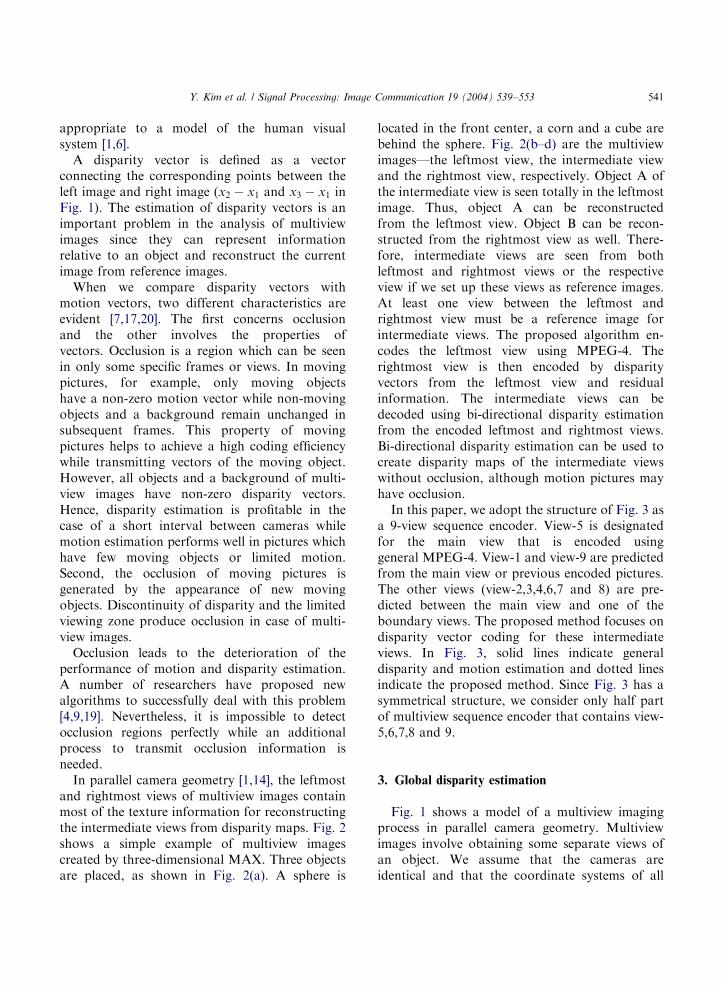
appropriate to a model of the human visualsystem [1,6].A disparity vector is defined as a vector
connecting the corresponding points between theleft image and right image (x2 � x1 and x3 � x1 inFig. 1). The estimation of disparity vectors is animportant problem in the analysis of multiviewimages since they can represent informationrelative to an object and reconstruct the currentimage from reference images.When we compare disparity vectors with
motion vectors, two different characteristics areevident [7,17,20]. The first concerns occlusionand the other involves the properties ofvectors. Occlusion is a region which can be seenin only some specific frames or views. In movingpictures, for example, only moving objectshave a non-zero motion vector while non-movingobjects and a background remain unchanged insubsequent frames. This property of movingpictures helps to achieve a high coding efficiencywhile transmitting vectors of the moving object.However, all objects and a background of multi-view images have non-zero disparity vectors.Hence, disparity estimation is profitable in thecase of a short interval between cameras whilemotion estimation performs well in pictures whichhave few moving objects or limited motion.Second, the occlusion of moving pictures isgenerated by the appearance of new movingobjects. Discontinuity of disparity and the limitedviewing zone produce occlusion in case of multi-view images.Occlusion leads to the deterioration of the
performance of motion and disparity estimation.A number of researchers have proposed newalgorithms to successfully deal with this problem[4,9,19]. Nevertheless, it is impossible to detectocclusion regions perfectly while an additionalprocess to transmit occlusion information isneeded.In parallel camera geometry [1,14], the leftmost
and rightmost views of multiview images containmost of the texture information for reconstructingthe intermediate views from disparity maps. Fig. 2shows a simple example of multiview imagescreated by three-dimensional MAX. Three objectsare placed, as shown in Fig. 2(a). A sphere is
located in the front center, a corn and a cube arebehind the sphere. Fig. 2(b–d) are the multiviewimages—the leftmost view, the intermediate viewand the rightmost view, respectively. Object A ofthe intermediate view is seen totally in the leftmostimage. Thus, object A can be reconstructedfrom the leftmost view. Object B can be recon-structed from the rightmost view as well. There-fore, intermediate views are seen from bothleftmost and rightmost views or the respectiveview if we set up these views as reference images.At least one view between the leftmost andrightmost view must be a reference image forintermediate views. The proposed algorithm en-codes the leftmost view using MPEG-4. Therightmost view is then encoded by disparityvectors from the leftmost view and residualinformation. The intermediate views can bedecoded using bi-directional disparity estimationfrom the encoded leftmost and rightmost views.Bi-directional disparity estimation can be used tocreate disparity maps of the intermediate viewswithout occlusion, although motion pictures mayhave occlusion.In this paper, we adopt the structure of Fig. 3 as
a 9-view sequence encoder. View-5 is designatedfor the main view that is encoded usinggeneral MPEG-4. View-1 and view-9 are predictedfrom the main view or previous encoded pictures.The other views (view-2,3,4,6,7 and 8) are pre-dicted between the main view and one of theboundary views. The proposed method focuses ondisparity vector coding for these intermediateviews. In Fig. 3, solid lines indicate generaldisparity and motion estimation and dotted linesindicate the proposed method. Since Fig. 3 has asymmetrical structure, we consider only half partof multiview sequence encoder that contains view-5,6,7,8 and 9.
3. Global disparity estimation
Fig. 1 shows a model of a multiview imagingprocess in parallel camera geometry. Multiviewimages involve obtaining some separate views ofan object. We assume that the cameras areidentical and that the coordinate systems of all

ARTICLE IN PRESS
Fig. 2. A simple example of multiview images produced by MAX (a) an image from top direction (b) the leftmost view (c) the
intermediate view (d) the rightmost view.
Y. Kim et al. / Signal Processing: Image Communication 19 (2004) 539–553542
cameras are perfectly aligned, differing only in thelocation of their origins.Because the axes of images are parallel, Eq. (1)
can be derived.
Y � l : B ¼ l : d; ð1Þ
where Y is the depth information in worldcoordinate systems and l is the focal length ofthe lens. B and d are the baseline distance betweenthe cameras and the disparity vector among themultiview images, respectively. The disparityvector is a relative displacement between the
matching points of an object. For example, d21 isx2 � x1 and d31 is x3 � x1: Eq. (2) can be obtainedfrom Eq. (1).
Y � ll
¼B
d: ð2Þ
The left side of Eq. (2) consists of constantparameters while B and d are variables for eachview. Therefore, the proportions of B and d areequal in the region with the same Y ; meaningdepth information. In this paper, a is defined as theproportions of B and d: Ideally, the values of a

ARTICLE IN PRESS
Fig. 3. GOP structure for 9-view sequence encoder.
Y. Kim et al. / Signal Processing: Image Communication 19 (2004) 539–553 543
calculated in all views are identical, so that theysatisfy Eq. (3).
a ¼B1
d21¼
B2
d31: ð3Þ
a is an another expression meaning depthinformation. An object with a large a is far fromthe camera and the object with a small a is close toan observer because a is inversely proportional tothe disparity vector. We use a to represent depthinformation since the a’s of macroblocks thatindicate the same position in the real world has thesame value for all views, unlike the disparityvectors.Unfortunately, B1 and B2 cannot be obtained
directly from multiview images. However, the ratioof B1 and B2 can be calculated from globaldisparity vectors. Global disparity vectors are theaverage of the disparity vectors for all macro-blocks except for the occlusion regions. We use a
bidirectional consistency check to detect theocclusion region. The global disparity vectors aresubstituted for B1 and B2 in Eq. (4). GD21 is globaldisparity vector between view-1 and view-2 andGD31 is that between view-1 and view-3.
a ¼GD21
d21¼GD31
d31¼ ?
¼GD21
GD21 þ d 021
¼GD31
GD31 þ d 031
¼ ? : ð4Þ
B is an absolute distance in the real world, theunit of which is in mm or cm. By substituting theglobal disparity vector a unit of which is a pixel forB; a denotes depth information without unitsbecause the units of d is in pixels as well. Ingeneral, a ranges from 0.5 to 5. Global disparityestimation can reduce the search range fordisparity estimation. In Fig. 4(a), conventionalmethods usually search disparity vectors from thesame relative position among multiview images

ARTICLE IN PRESS
Fig. 4. An example of global disparity estimation (a) conven-
tional method (b) disparity estimation based on global disparity
vector.
Fig. 5. Block diagram of the proposed algorithm.
Y. Kim et al. / Signal Processing: Image Communication 19 (2004) 539–553544
within a given search range. Conventional meth-ods are not efficient because they estimate thedisparity vector without any prior knowledge ofthe initial position. However, in this paper, asearch range for disparity estimation is restrictedto neighbors of the global disparity vector, asshown in Fig. 4(b). We substitute GD21 þ d 0
21 andGD31 þ d 0
31 for d21 and d31 to perform a globaldisparity estimation using Eq. (4). A global dis-parity vector can find the least mean absolutedifference (MAD) within a search range smallerthan that required conventional methods. Hence, asearch range can be reduced without losing imagequality. Because d 0
21 and d 031 have a smaller search
range than d21 and d31; it reduces the complexity ofdisparity estimation and it finds the disparityvector more correctly.
4. Disparity vector coding for multiview sequences
Fig. 5 shows a block diagram of the proposedalgorithm. The first step determines directionalmodes of the macroblocks. Three modes exist;forward, backward and bidirectional modes for
disparity compensation. After determining themodes, the value of a for each view is calculated.Theoretically, macroblocks should have the samevalue of a if they represent the same depth in real-world coordinates. However, macroblocks mayhave different a’s by occlusion or incorrectdisparity estimation. The most appropriate ashould be selected as a representative a amongthe different values to overcome this problem.Thus, it is necessary to obtain the differencebetween vectors predicted by the representative aand vectors that are directly estimated vectors. Alarge vector error increases the number of codingbits since the proposed algorithm encodes thedifference between the predicted and estimatedvectors. Thus, it includes the refinement process tofind new disparity vectors, which reduces thenumber of coding bits. If there are only a fewvector errors, the process skips the refinementprocess.
4.1. Directional mode decision
Prediction of disparity vectors considering allviews is not appropriate, because estimation in theocclusion region produces serious deterioration.Therefore, the prediction must be performed in amatched region and not in the occlusion region
ARTICLE IN PRESS
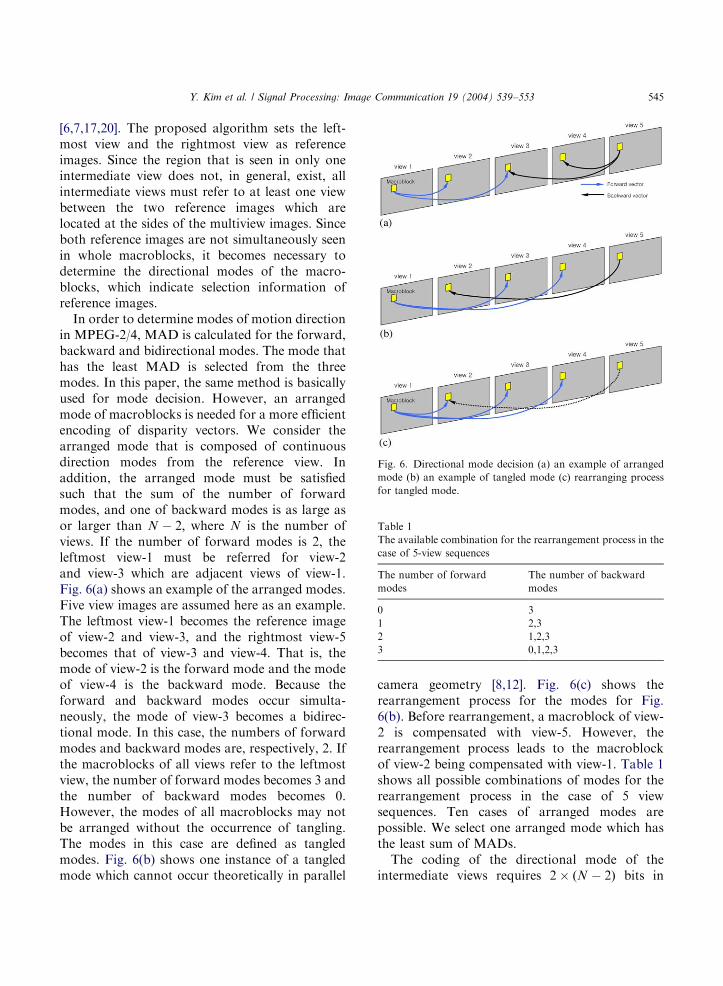
Fig. 6. Directional mode decision (a) an example of arranged
mode (b) an example of tangled mode (c) rearranging process
for tangled mode.
Table 1
The available combination for the rearrangement process in the
case of 5-view sequences
The number of forward
modes
The number of backward
modes
0 3
1 2,3
2 1,2,3
3 0,1,2,3
Y. Kim et al. / Signal Processing: Image Communication 19 (2004) 539–553 545
[6,7,17,20]. The proposed algorithm sets the left-most view and the rightmost view as referenceimages. Since the region that is seen in only oneintermediate view does not, in general, exist, allintermediate views must refer to at least one viewbetween the two reference images which arelocated at the sides of the multiview images. Sinceboth reference images are not simultaneously seenin whole macroblocks, it becomes necessary todetermine the directional modes of the macro-blocks, which indicate selection information ofreference images.In order to determine modes of motion direction
in MPEG-2/4, MAD is calculated for the forward,backward and bidirectional modes. The mode thathas the least MAD is selected from the threemodes. In this paper, the same method is basicallyused for mode decision. However, an arrangedmode of macroblocks is needed for a more efficientencoding of disparity vectors. We consider thearranged mode that is composed of continuousdirection modes from the reference view. Inaddition, the arranged mode must be satisfiedsuch that the sum of the number of forwardmodes, and one of backward modes is as large asor larger than N � 2; where N is the number ofviews. If the number of forward modes is 2, theleftmost view-1 must be referred for view-2and view-3 which are adjacent views of view-1.Fig. 6(a) shows an example of the arranged modes.Five view images are assumed here as an example.The leftmost view-1 becomes the reference imageof view-2 and view-3, and the rightmost view-5becomes that of view-3 and view-4. That is, themode of view-2 is the forward mode and the modeof view-4 is the backward mode. Because theforward and backward modes occur simulta-neously, the mode of view-3 becomes a bidirec-tional mode. In this case, the numbers of forwardmodes and backward modes are, respectively, 2. Ifthe macroblocks of all views refer to the leftmostview, the number of forward modes becomes 3 andthe number of backward modes becomes 0.However, the modes of all macroblocks may notbe arranged without the occurrence of tangling.The modes in this case are defined as tangledmodes. Fig. 6(b) shows one instance of a tangledmode which cannot occur theoretically in parallel
camera geometry [8,12]. Fig. 6(c) shows therearrangement process for the modes for Fig.6(b). Before rearrangement, a macroblock of view-2 is compensated with view-5. However, therearrangement process leads to the macroblockof view-2 being compensated with view-1. Table 1shows all possible combinations of modes for therearrangement process in the case of 5 viewsequences. Ten cases of arranged modes arepossible. We select one arranged mode which hasthe least sum of MADs.The coding of the directional mode of the
intermediate views requires 2� ðN � 2Þ bits in

ARTICLE IN PRESS
Y. Kim et al. / Signal Processing: Image Communication 19 (2004) 539–553546
conventional methods since each view requires 2bits to encode the mode. However, it is possible tointerpret the modes using the number of forwardmodes and one of the backward modes. Thus, only2� log2ðN � 1Þ bits are required in the proposedmethod. The advantage of this method is that thecoding bits are not proportional to N : Therefore,the larger the number of views, the higher thecoding efficiency can be obtained in encoding thedirectional modes.
4.2. Calculation of a
Directional modes which determine referenceimages have been determined previously. At thisstage, the candidate a’s are obtained for theforward and backward cases using fixed modeinformation.If the number of forward modes or one of the
backward modes is one
a ¼GDcorresponded view
dcorresponded view: ð5Þ
If the number of forward modes or one of thebackward modes is larger than one
a ¼ medianða1; a2;yÞ;
a1 ¼GD1
d1; a2 ¼
GD2
d2;y : ð6Þ
Disparity estimation uses MAD as a criterion todetermine the disparity vector with the least error.In many cases, the candidate vector with the leastMAD may be the correct vector indicating anactual world displacement. However, MAD couldbe an unreliable criterion in the occlusion regionsor local minima. If an incorrect disparity vector isobtained, the mean value for all a values isdeteriorated by an a of an incorrect vector. Toavoid this problem, median value of all a’s is set asthe candidate a:
4.3. Checking the vector errors from a
We calculate vector error using the value of acalculated in the previous stage.
Verror ¼X# of modes
i¼1
vec ½i �GDi
a
��������; ð7Þ
where, a vec ½i is an estimated disparity vector ofthe ith view. a in Eq. (7) is the candidate a which iscalculated at the second stage. GDi=a denotes theith predictive vector by Eq. (3). The number offorward modes or backward modes is obtainedfrom the process of directional mode decision.Verror is the summation of the absolute differencebetween vectors predicted by the candidate a andthe directly estimated vectors. Verror denotes theamount of coding bits since the proposed algo-rithm encodes the difference between estimatedvectors and predicted vectors. A reduction invector error results in an improvement in codingefficiency. It is important not only to find anadequate representative a but also to adjust vec½ibased on the candidate a in order to reduce theVerror:
4.4. Refinement process
The refinement process for disparity vectors isperformed if Verror is larger than the threshold(THvec err). In the case of a smaller Verror; thecandidate a is set as the representative a and theprocess skips the refinement process.The purpose of the refinement process is to
preserve errors in disparity compensation incomparison with the fullsearch algorithm and torefine disparity vectors for the small predictionerror of the vector. Finally, a new representative ais calculated from the refined vectors.Fig. 7 shows the spatial difference between
neighboring disparity vectors. In this figure, wecan see that a disparity vector has a value similarto those of neighboring vectors. In the real world,depth information of one object is usually uniformor changes smoothly except at the edges. Theproposed refinement process utilizes this correla-tion property of neighboring blocks. We userepresentative a’s of causal neighbor blocks ascandidate a’s for the current block because theseblocks have reliable a’s, since they were deter-mined by the previous refinement process. Theneighbor blocks are restricted to the 1st–4th causalblocks as shown in Fig. 8. The 0th block indicatesthe current block. The candidate a of the currentblock which is calculated in the second stage isrefined as other candidates.

ARTICLE IN PRESS
Fig. 7. Histogram of disparity vector spatial differentials.
Fig. 8. Blocks which offer candidate a’s to refinement process.
Y. Kim et al. / Signal Processing: Image Communication 19 (2004) 539–553 547
We find new disparity vectors from candidatea’s using Eq. (8). Eq. (8) shows the cost function ofthe proposed algorithm. Eq. (8a) shows the MADterm which represents similarities between currentand reference images. In Eq. (8b), the search rangeis determined in the range of SRrefine from thesevectors after the predicted disparity vectors arecalculated from candidate a for each view. Thecost function is as follows:
veck½i ¼ arg mindj
f ; ð8Þ
f ¼X
x;yAblock
jICðx; yÞ � IRðx þ d; yÞj ð8aÞ
djAGDi
ak
� SRrefine;y;GDi
ak
þSRrefine
� �;
k : 0; 1; 2; 3; 4ðblock indexÞ
i : 1; 2;y;# of modesðview indexÞ: ð8bÞ
In Eq. (8), k is the index of neighboring blocksand i is the index of the corresponding view.IC and IR indicate the current and referenceimages, respectively. By Eq. (3), GDi=ak denotesthe predicted disparity vector of the ith viewfrom the representative a of the kth neighboringblock. We select veck½i with the least MAD amongdjs which range from GDi=ak � SRrefine toGDi=ak þ SRrefine:SRrefine is a search range for refinement
process. If SRrefine increases, matching errorsof the disparity estimation decrease whilemore coding bits are needed. In the case wherethe multiview encoder generates more coding bitsthan buffer allocation, a reduction in SRrefinelessens buffer fullness using this relation. In anopposite case, an increase in SRrefine improvesimage quality by offering more candidate vectorsthat may have the least MAD. This control ofSRrefine protects against buffer overflow and bufferunderflow.In Eq. (8), new disparity vectors for candidate a
are obtained. Although the Verror for candidate a0
is smaller than the refinement process, a new a iscalculated from the new disparity vectors to giveless Verror: Eq. (9) shows a new vector errorobtained from a new a0k and the correspondingdisparity vectors.
Verror½k ¼Xcounti¼1
veck½i �GDk
ak
��������: ð9Þ
In Eq. (10), Total MADk represents a summa-tion of MADs for all corresponding views.
Total MADk ¼Xcounti¼1
Xx;yAblock
jICðx; yÞ:
� IRðx þ veck½i; yÞj: ð10Þ
For k whose Verror [k] is less than the threshold,Eq. (11) finds the least Total MADk. We then setthe candidate a0k which has the least Total MADk
to representative a: veck½is become disparity

ARTICLE IN PRESS
Fig. 9. Original ‘‘Bridge’’ 5-view sequence in the 1st frame (a) 1st view (b) 2nd view (c) 3rd view (d) 4th view (e) 5th view.
Y. Kim et al. / Signal Processing: Image Communication 19 (2004) 539–553548
vectors of the macroblocks.
ða; vec½iÞ ¼ arg minðak ;veck ½iÞ
Total MAD: ð11Þ
5. Experimental results
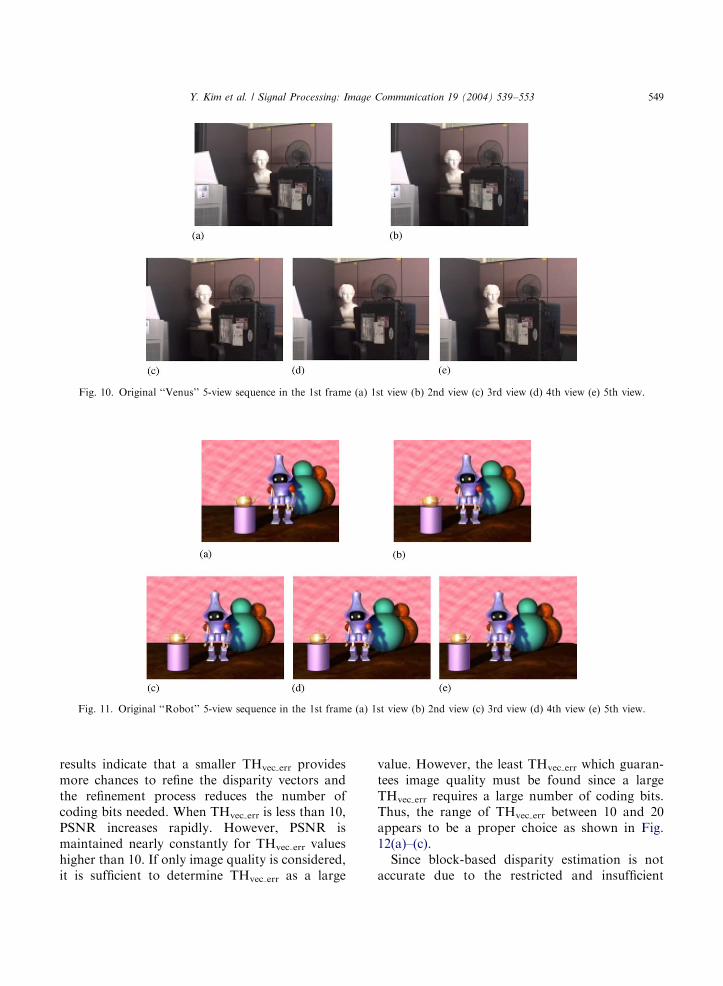
Simulations were performed with ‘‘Bridge’’ 5view sequences with a size of 352� 288 and‘‘Venus’’ 5 view sequences with a size of320� 240, as shown in Figs. 9 and 10. We alsoutilize ‘‘Robot’’ 5 view sequences with a size of320� 240, created by three-dimensional MAX asshown in Fig. 11. These three sets of multiviewsequences have 145 frames for each view. Theresults show average coding bits and PSNR perframe for 145 frames. An 8� 8 block size and�32B+32 search range were used for thedisparity estimation. We simulated the proposedalgorithm using various parameters. The proposedalgorithm was compared with a conventionaldisparity estimation and a disparity estimationusing a global vector with an MPEG-4vector coding method. The disparity vectors ofthree methods were encoded using the MPEG-4VLC table.
One value of GD is transmitted for each view.Moreover, we must transmit directional modeinformation for macroblocks which was containedin our experimental results. The values of a can becalculated from disparity vectors of the rightmostview (view-5). We can derive Eq. (12) from Eq. (4).
a ¼GD51
d51: ð12Þ
GD51 and d51 are global disparity vector anddisparity vector between view-1 and view-5,respectively. Therefore, there is no need totransmit additional information concerning a:Since d51 is encoded using the vector codingmethod of MPEG-4, coding bits of d51 are notincluded among the experimental results. Finally,we transmit refinement information. All wetransmit to decoder is GD, directional modeinformation and refinement information.Fig. 12 shows the rate-distortion for THvec err. A
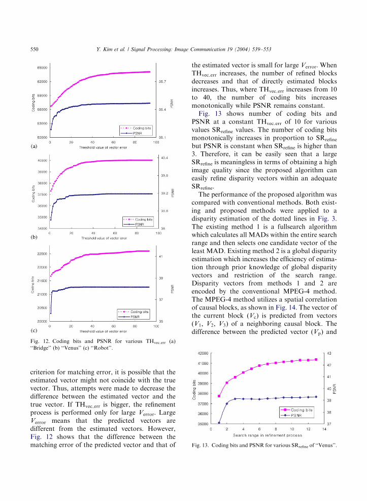
larger THvec err results in distortion lower andbitrate higher. Some distortion is allowed toobtain lower coding bits for the disparity vectorssince THvec err plays an important role in control-ling the refinement process of the disparity map.Coding bits increase monotonically for THvec errvalues of less than 40, as shown in Fig. 12. These
ARTICLE IN PRESS
Fig. 10. Original ‘‘Venus’’ 5-view sequence in the 1st frame (a) 1st view (b) 2nd view (c) 3rd view (d) 4th view (e) 5th view.
Fig. 11. Original ‘‘Robot’’ 5-view sequence in the 1st frame (a) 1st view (b) 2nd view (c) 3rd view (d) 4th view (e) 5th view.
Y. Kim et al. / Signal Processing: Image Communication 19 (2004) 539–553 549
results indicate that a smaller THvec err providesmore chances to refine the disparity vectors andthe refinement process reduces the number ofcoding bits needed. When THvec err is less than 10,PSNR increases rapidly. However, PSNR ismaintained nearly constantly for THvec err valueshigher than 10. If only image quality is considered,it is sufficient to determine THvec err as a large
value. However, the least THvec err which guaran-tees image quality must be found since a largeTHvec err requires a large number of coding bits.Thus, the range of THvec err between 10 and 20appears to be a proper choice as shown in Fig.12(a)–(c).Since block-based disparity estimation is not
accurate due to the restricted and insufficient
ARTICLE IN PRESS
Fig. 12. Coding bits and PSNR for various THvec err (a)
‘‘Bridge’’ (b) ‘‘Venus’’ (c) ‘‘Robot’’.
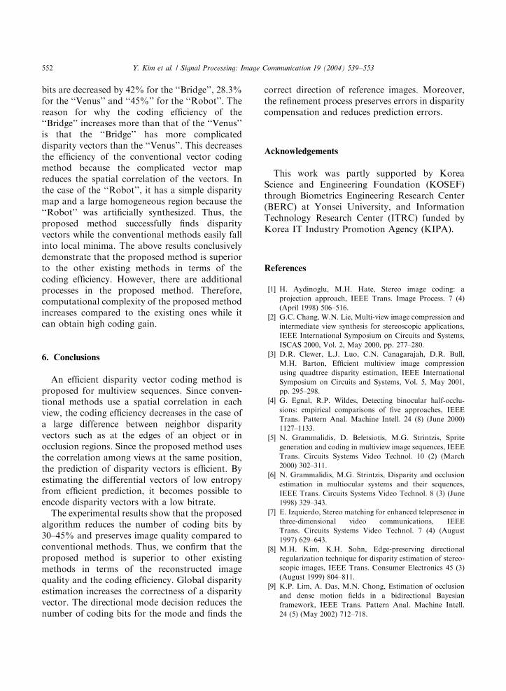
Fig. 13. Coding bits and PSNR for various SRrefine of ‘‘Venus’’.
Y. Kim et al. / Signal Processing: Image Communication 19 (2004) 539–553550
criterion for matching error, it is possible that theestimated vector might not coincide with the truevector. Thus, attempts were made to decrease thedifference between the estimated vector and thetrue vector. If THvec err is bigger, the refinementprocess is performed only for large Verror. LargeVerror means that the predicted vectors aredifferent from the estimated vectors. However,Fig. 12 shows that the difference between thematching error of the predicted vector and that of
the estimated vector is small for large Verror. WhenTHvec err increases, the number of refined blocksdecreases and that of directly estimated blocksincreases. Thus, where THvec err increases from 10to 40, the number of coding bits increasesmonotonically while PSNR remains constant.Fig. 13 shows number of coding bits and
PSNR at a constant THvec err of 10 for variousvalues SRrefine values. The number of coding bitsmonotonically increases in proportion to SRrefinebut PSNR is constant when SRrefine is higher than3. Therefore, it can be easily seen that a largeSRrefine is meaningless in terms of obtaining a highimage quality since the proposed algorithm caneasily refine disparity vectors within an adequateSRrefine.The performance of the proposed algorithm was
compared with conventional methods. Both exist-ing and proposed methods were applied to adisparity estimation of the dotted lines in Fig. 3.The existing method 1 is a fullsearch algorithmwhich calculates all MADs within the entire searchrange and then selects one candidate vector of theleast MAD. Existing method 2 is a global disparityestimation which increases the efficiency of estima-tion through prior knowledge of global disparityvectors and restriction of the search range.Disparity vectors from methods 1 and 2 areencoded by the conventional MPEG-4 method.The MPEG-4 method utilizes a spatial correlationof causal blocks, as shown in Fig. 14. The vector ofthe current block (Vc) is predicted from vectors(V1; V2; V3) of a neighboring causal block. Thedifference between the predicted vector (Vp) and

ARTICLE IN PRESS
Y. Kim et al. / Signal Processing: Image Communication 19 (2004) 539–553 551
the original vector (Vc) is transmitted to thedecoder.Table 2 shows the mean absolute value and
entropy of horizontal differential vectors. Themean absolute value indicates the accuracy ofprediction of the disparity vectors. The small meanabsolute value indicates that the predicted vector issimilar to the estimated vector. Moreover, entropydenotes the average amount of information persource symbol. Thus, the higher the entropy, thelarger number of coding bits that are needed, ingeneral. The proposed method has the lowestvalue for the mean absolute value and entropy
Table 2
Comparisons of mean absolute value and entropy for horizontal diff
Method Existing method 1
(SR:732)
Mean Bridge 6.080
absolute Venus 3.267
value Robot 1.632
Bridge 4.460
Entropy Venus 3.695
Robot 2.297
Table 3
Comparisons of performance with the existing methods
Method Existing method 1
(SR:732)
Bridge 4.45
RMSE Venus 2.808
Robot 3.083
Bridge 35.163
PSNR(db) Venus 39.162
Robot 38.351
Bpb Bridge 20.58
(bits/block) Venus 15.43
Robot 11.39
Fig. 14. Spatial prediction from causal blocks.
among the three methods. These results lead theproposed algorithm to achieve a high codingefficiency. Table 3 shows performance compari-sons of 3 different disparity estimation methods.The performances were compared by measuringthe PSNR and RMSE of the reconstructed images.We also evaluated the coding efficiency of thedisparity map by calculating the bitrate (bpb, bitsper block). The coded bitstream contains direc-tional mode information, forward vectors andbackward vectors. A search range of the existingmethod 1 is assigned as �32B+32. Moreover, theexisting method 2 has a search range of �16B+16based on a global disparity vector. The proposedalgorithm is performed with THvec err=10 andSRrefine=3. The simulation results show that theproposed method has fewer bpb than the conven-tional methods and preserves image quality,although small variations in parameters may leadto slightly different results. In more detail, coding
erential vectors
Existing method 2
(SR:GD716)Proposed method
(THvec err=10, SRrefine=3)
3.941 1.161
2.190 1.340
1.143 0.491
4.298 2.268
3.328 2.873
2.271 1.666
Existing method 2
(SR:GD716)Proposed method
(THvec err=10, SRrefine=3)
4.523 4.44
2.821 2.819
3.239 3.135
35.023 35.184
39.124 39.129
37.923 38.207
19.82 11.94
14.94 11.00
11.18 6.18
ARTICLE IN PRESS
Y. Kim et al. / Signal Processing: Image Communication 19 (2004) 539–553552
bits are decreased by 42% for the ‘‘Bridge’’, 28.3%for the ‘‘Venus’’ and ‘‘45%’’ for the ‘‘Robot’’. Thereason for why the coding efficiency of the‘‘Bridge’’ increases more than that of the ‘‘Venus’’is that the ‘‘Bridge’’ has more complicateddisparity vectors than the ‘‘Venus’’. This decreasesthe efficiency of the conventional vector codingmethod because the complicated vector mapreduces the spatial correlation of the vectors. Inthe case of the ‘‘Robot’’, it has a simple disparitymap and a large homogeneous region because the‘‘Robot’’ was artificially synthesized. Thus, theproposed method successfully finds disparityvectors while the conventional methods easily fallinto local minima. The above results conclusivelydemonstrate that the proposed method is superiorto the other existing methods in terms of thecoding efficiency. However, there are additionalprocesses in the proposed method. Therefore,computational complexity of the proposed methodincreases compared to the existing ones while itcan obtain high coding gain.
6. Conclusions
An efficient disparity vector coding method isproposed for multiview sequences. Since conven-tional methods use a spatial correlation in eachview, the coding efficiency decreases in the case ofa large difference between neighbor disparityvectors such as at the edges of an object or inocclusion regions. Since the proposed method usesthe correlation among views at the same position,the prediction of disparity vectors is efficient. Byestimating the differential vectors of low entropyfrom efficient prediction, it becomes possible toencode disparity vectors with a low bitrate.The experimental results show that the proposed
algorithm reduces the number of coding bits by30–45% and preserves image quality compared toconventional methods. Thus, we confirm that theproposed method is superior to other existingmethods in terms of the reconstructed imagequality and the coding efficiency. Global disparityestimation increases the correctness of a disparityvector. The directional mode decision reduces thenumber of coding bits for the mode and finds the
correct direction of reference images. Moreover,the refinement process preserves errors in disparitycompensation and reduces prediction errors.
Acknowledgements
This work was partly supported by KoreaScience and Engineering Foundation (KOSEF)through Biometrics Engineering Research Center(BERC) at Yonsei University, and InformationTechnology Research Center (ITRC) funded byKorea IT Industry Promotion Agency (KIPA).
References
[1] H. Aydinoglu, M.H. Hate, Stereo image coding: a
projection approach, IEEE Trans. Image Process. 7 (4)
(April 1998) 506–516.
[2] G.C. Chang, W.N. Lie, Multi-view image compression and
intermediate view synthesis for stereoscopic applications,
IEEE International Symposium on Circuits and Systems,
ISCAS 2000, Vol. 2, May 2000, pp. 277–280.
[3] D.R. Clewer, L.J. Luo, C.N. Canagarajah, D.R. Bull,
M.H. Barton, Efficient multiview image compression
using quadtree disparity estimation, IEEE International
Symposium on Circuits and Systems, Vol. 5, May 2001,
pp. 295–298.
[4] G. Egnal, R.P. Wildes, Detecting binocular half-occlu-
sions: empirical comparisons of five approaches, IEEE
Trans. Pattern Anal. Machine Intell. 24 (8) (June 2000)
1127–1133.
[5] N. Grammalidis, D. Beletsiotis, M.G. Strintzis, Sprite
generation and coding in multiview image sequences, IEEE
Trans. Circuits Systems Video Technol. 10 (2) (March
2000) 302–311.
[6] N. Grammalidis, M.G. Strintzis, Disparity and occlusion
estimation in multiocular systems and their sequences,
IEEE Trans. Circuits Systems Video Technol. 8 (3) (June
1998) 329–343.
[7] E. Izquierdo, Stereo matching for enhanced telepresence in
three-dimensional video communications, IEEE
Trans. Circuits Systems Video Technol. 7 (4) (August
1997) 629–643.
[8] M.H. Kim, K.H. Sohn, Edge-preserving directional
regularization technique for disparity estimation of stereo-
scopic images, IEEE Trans. Consumer Electronics 45 (3)
(August 1999) 804–811.
[9] K.P. Lim, A. Das, M.N. Chong, Estimation of occlusion
and dense motion fields in a bidirectional Bayesian
framework, IEEE Trans. Pattern Anal. Machine Intell.
24 (5) (May 2002) 712–718.

ARTICLE IN PRESS
Y. Kim et al. / Signal Processing: Image Communication 19 (2004) 539–553 553
[10] J. Lim, K. Ngan, W. Yang, K. Sohn, A multiview sequence
CODEC with view scalability, Signal Processing: Image
Communication 19 (3) (January 2004) 239–256.
[11] M. Mazri, A. Aggoun, Compression of 3D integral images
using wavelet decomposition, Proc. SPIE VCIP 5150
(2003) 1181–1192.
[12] J.R. Ohm, E. Izquierdo, K. Muller, System for disparity-
based multiple-view interpolation, Proceedings of the
IEEE International Symposium on Circuits and Systems,
ISCAS ’98, Vol. 5, June 1998, pp. 502–505.
[13] J.R. Ohm, K. Muller, Incomplete 3D-multiview represen-
tation of video objects, IEEE Trans. Circuits Systems
Video Technol. 9 (2) (March 1999) 389–400.
[14] L. Oisel, E. Memin, L. Morin, F. Galpin, One-dimensional
dense disparity estimation for three-dimensional recon-
struction, IEEE Trans. Image Process. 12 (9) (September
2003) 1107–1119.
[15] S. Pastoor, K. Schenke, Subjective assessments of the
resolution of viewing directions in a multi-viewpoint 3D
TV system, Proc. SID 3 (3) (1989) 217–222.
[16] A. Puri, R.V. Kollaritis, B.G. Haskell, Basic of stereo-
scopic video, new compression results with MPEG-2 and a
proposed for MPEG-4, Signal Processing, Image Commu-
nication 10 (1997) 201–234.
[17] K.H. Sohn, J.R. Ryou, J. Lim, Efficient stereoscopic video
coding using joint disparity-motion estimation, Circuits,
Systems Signal Process. 23 (1) (2003) 57–76.
[18] A. Tamtaou, C. Labit, Coherent disparity and motion
compensation in 3D TV image sequence coding schemes,
in: ICASSP, 1991, pp. 2845–2848.
[19] G.A. Triantafylldis, D. Tzovaras, M.G. Strintzis, Detec-
tion of occlusion and visible background and foreground
areas in stereo image pairs, Proceedings of the Ninth IEEE
International Conference on Electronics, Circuits and
Systems, Vol. 3, September 2002, pp. 1019–1022.
[20] D. Tzovaras, N. Grammalidis, M.G. Strintzis, Object-
based coding of stereo image sequences using joint 3-D
motion/disparity compensation, IEEE Trans. Circuits
Systems Video Technol. 7 (4) (April 1997) 312–327.
[21] Y. Zhang, G. Li, An efficient hierarchical disparity
estimation algorithm for stereoscopic video coding, IEEE
Asia-Pacific Conference on Circuits and Systems, Decem-
ber 2000, pp. 744–747.
[22] M. Ziegler, Digital stereoscopic imaging and application—
a way toward new dimensions: the RACE II project
DISTIMA, in: Institute of Electrical Engineering Collo-
quium, Stereoscopic Television, London, UK, October
1992.