Privacy and Security of Wearable Devices - | International ...
Upload
khangminh22Category
view
0download
0
WEARABLE TACTILE DISPLAYS
FOR MOTION FEEDBACK
A DISSERTATION
SUBMITTED TO THE DEPARTMENT OF MECHANICAL
ENGINEERING
AND THE COMMITTEE ON GRADUATE STUDIES
OF STANFORD UNIVERSITY
IN PARTIAL FULFILLMENT OF THE REQUIREMENTS
FOR THE DEGREE OF
DOCTOR OF PHILOSOPHY
Jason William Wheeler
August 2009

c© Copyright by Jason William Wheeler 2009
All Rights Reserved
ii

I certify that I have read this dissertation and that, in my opinion, it
is fully adequate in scope and quality as a dissertation for the degree
of Doctor of Philosophy.
(Mark Cutkosky) Principal Adviser
I certify that I have read this dissertation and that, in my opinion, it
is fully adequate in scope and quality as a dissertation for the degree
of Doctor of Philosophy.
(Scott Delp)
I certify that I have read this dissertation and that, in my opinion, it
is fully adequate in scope and quality as a dissertation for the degree
of Doctor of Philosophy.
(Thor Besier)
Approved for the University Committee on Graduate Studies.
iii

iv
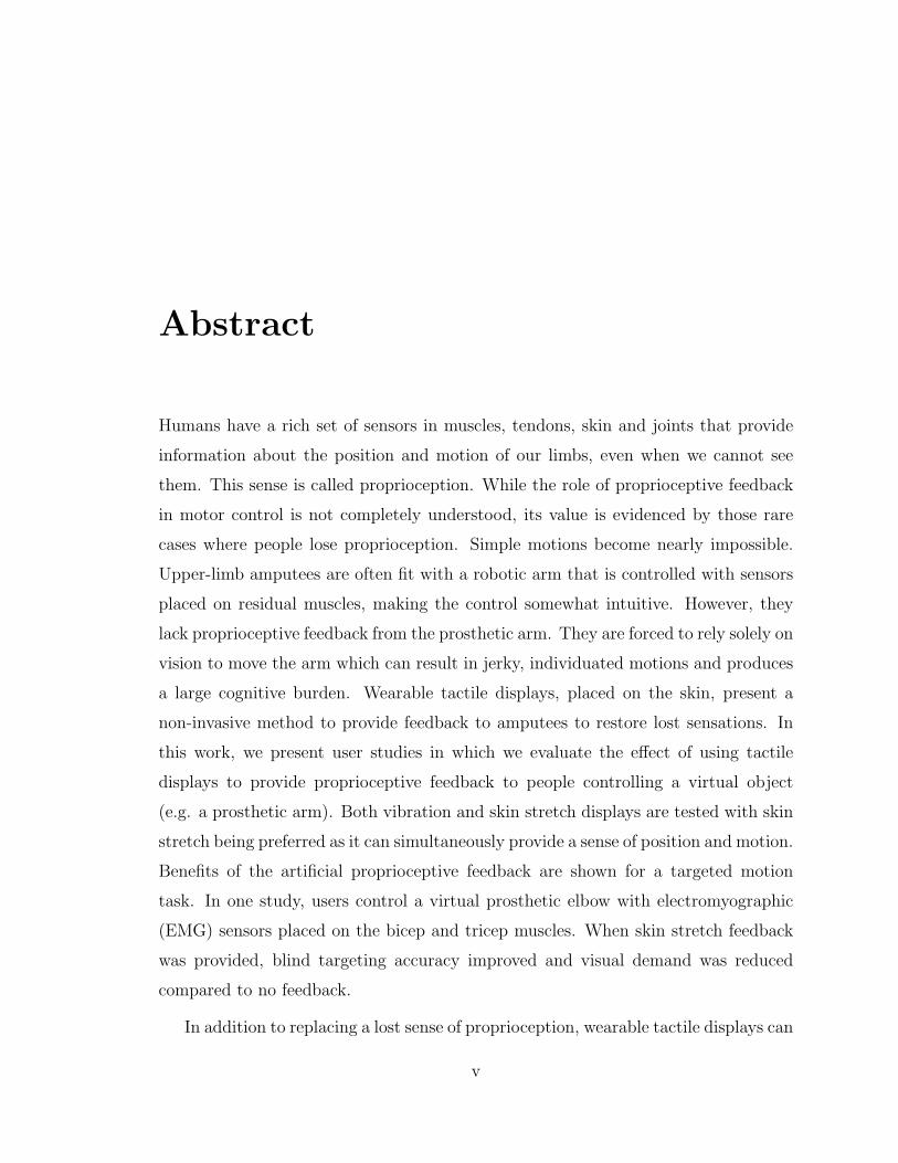
Abstract
Humans have a rich set of sensors in muscles, tendons, skin and joints that provide
information about the position and motion of our limbs, even when we cannot see
them. This sense is called proprioception. While the role of proprioceptive feedback
in motor control is not completely understood, its value is evidenced by those rare
cases where people lose proprioception. Simple motions become nearly impossible.
Upper-limb amputees are often fit with a robotic arm that is controlled with sensors
placed on residual muscles, making the control somewhat intuitive. However, they
lack proprioceptive feedback from the prosthetic arm. They are forced to rely solely on
vision to move the arm which can result in jerky, individuated motions and produces
a large cognitive burden. Wearable tactile displays, placed on the skin, present a
non-invasive method to provide feedback to amputees to restore lost sensations. In
this work, we present user studies in which we evaluate the effect of using tactile
displays to provide proprioceptive feedback to people controlling a virtual object
(e.g. a prosthetic arm). Both vibration and skin stretch displays are tested with skin
stretch being preferred as it can simultaneously provide a sense of position and motion.
Benefits of the artificial proprioceptive feedback are shown for a targeted motion
task. In one study, users control a virtual prosthetic elbow with electromyographic
(EMG) sensors placed on the bicep and tricep muscles. When skin stretch feedback
was provided, blind targeting accuracy improved and visual demand was reduced
compared to no feedback.
In addition to replacing a lost sense of proprioception, wearable tactile displays can
v

be placed on the limbs for motion training. We also present the results of a study in
which we provide real-time visual and vibration feedback to users about a potentially
damaging knee joint force as they walk on a treadmill. The feedback allows them
to adjust the way they walk to reduce the force much faster than with conventional
motion training methods, where verbal or visual feedback is given intermittently.
Based on the results of these studies, it is possible to formulate some general
guidelines about the use of wearable tactile displays. Due to the delays associated
with feedback (natural or artificial), it is most appropriately used for slow or repet-
itive motions. Haptic feedback is most useful when vision is devoted elsewhere or is
ambiguous. Skin stretch can be more effective than vibration when it is desirable to
convey a sense of motion and direction rather than event cues.
vi

Acknowledgments
I’ve always enjoyed reading colleagues’ acknowledgment sections in their theses. It
seems you can learn a bit about them beyond their technical work; what they value,
what they spent their few free hours doing during graduate school etc. That makes
writing my own section a bit terrifying for some reason. Nonetheless, I have a number
of people who I owe a great debt of gratitude and who have made this work possible
so here we go.
I have wanted to do a Ph.D. for many years. When I finished my Master’s degree
at MIT I was planning on staying for a few more years. However, funding in our lab
was at a temporary low point and we had just had our first child so we decided that
a real job might be best at that time. Fortunately, I was able to find a job that not
only allowed me to do the things I liked to do (research) but offered a program for
Ph.D. students which was better funded that most programs. Of course there was a
catch: a three-year time limit. With a little effort, I was able to find a few professors
that would agree to advise me with that constraint. I was torn between Stanford
(with Mark Cutkosky) and Johns Hopkins (with Allison Okamura). Both seemed like
great opportunities but I didn’t think I could have convinced Cecy to move to the
East Coast again so Stanford it was. We certainly did not regret that choice.
I’m indebted to Mark Cutkosky for having confidence in me to pull this off and
also for his incredible mentorship over the past three years. He was always willing
to let me do the things that I was interested in while providing insightful feedback
whenever needed. It’s a rare thing to have an advisor so talented yet so accessible
vii

and approachable. I consider him a mentor and a friend. In particular I remember
struggling with a study where users controlled a virtual object with a force sensor but
the task was too easy and the feedback we were giving was not useful. I was trying
to come up with a way to make the task harder but still realistic. Mark, (with only
a couple seconds thought) suggested giving the object position dependent dynamics
(like a real arm would have) and of course that was what we did and it worked well.
Scott Delp was also an inspirational teacher and mentor during my time at Stan-
ford. One of the reasons I wanted to come to Stanford was to learn about biomechanics
and my expectations in that regard were greatly exceeded. I was fortunate to be able
to do some research with Scott for class projects that do not appear in this work.
Thor Besier was also an incredibly great person to work with. He always had great
ideas and insights into our research and was more than helpful whenever I needed
something. He was an example to me of a solid researcher who also happened to be
an extremely nice person. Scott and Thor provided the original suggestions for the
study presented in Chapter 3 and Thor contributed all along the way. I also need to
thank the other faculty who assisted with my research and/or served on the defense
committee, many of them on short notice. Thanks to Professors Oussama Khatib,
Gunter Niemeyer, Bernie Roth and Ken Salisbury.
I owe a special thanks to two colleagues in the Biomimetics and Dexterous Ma-
nipulation Lab (BDML). Karlin Bark created the skin stretch feedback used in most
of the studies presented in this work. She is a brilliant designer and solid researcher.
I’m amazed that the device that she developed just as I arrived turned out to be ideal
for the applications I was interested in. I always enjoyed our discussions about every-
thing from piezoelectric motors to psychophysics. Pete Shull was a major contributor
to the work presented in Chapter 3. He was instrumental in getting the real-time
Vicon system set up and running the study. He’s already moving beyond that to new
and interesting things and I wish him all the best in that and look forward to working
together on papers in the future.
As my work was largely based on user studies, I’m indebted to everyone who
viii

volunteered to participate in my experiments. If I could name you I would. Your time
is greatly appreciated. Also, thanks to everyone (too numerous to name) in the BDML
for creating a collaborative and fun environment. I always enjoyed asking/answering
technical questions and sarcastically arguing over space with the biomimetics people.
I hope someone feeds the fish now that I’m gone. Who will take the throne of the
first one in each morning?
A few people from outside the university also contributed useful feedback. Prof.
Brent Gillespie was an extremely valuable resource and a great person to have longer
than expected discussions with. I lucked out that he happened to be on sabbatical here
when I arrived. He provided suggestions about the visual demand study in Chapter 5.
Prof. Neville Hogan provided typically brilliant insight into the motor control aspects
of the work. Also, though the work did not end up making it into the thesis, I wish to
thank Netta Gurari and Prof. Allison Okamura at Johns Hopkins University for the
opportunity to collaborate on a stiffness discrimination study. Thanks for hosting me
there for a week, I really enjoyed it. Also thanks to Curt Salisbury for always being
a good friend and excellent source of technical knowledge.
Of course, none of this would be possible without my beautiful and kind wife Cecy.
When she agreed to marry me, I don’t think she bargained for seven years consisting
of four moves across four states. I’m pretty sure she was a bit reluctant to leave our
house three years ago to move back to campus and a small apartment but I don’t
think she complained (unless sarcastically). I am eternally grateful for her patience
and support. I also need to thank our three small children, Anna, Adam and Haley
(who was not born when we started this but decided to come early the week before
quals). They have always made it fun to come home and I always looked forward to
seeing them. I wish I had better words to express how I truly feel about Cecy and
our children. Any other achievement or opportunity pales in comparison to the joy I
receive from our family.
My parents also deserve much of the credit for the things I have been able to do
in my life. Not only are they great examples and teachers but great friends that I
ix

respect as much as anyone I have interacted with. I appreciate their constant love
and support for my family and me. I hope to be able to live my life as a worthy
tribute to them.
Sandia National Laboratories, through the doctoral studies program, provided
the majority of the funding for this work. The program really is incredible and I’m
thankful that I was able to participate in it. With three kids in the bay area, I
don’t think we would have survived on a research stipend, in fact I know we would
not have. Tekes, a Finnish government organization and the King Abdullah Uni-
versity of Science and Technology provided supplementary funding for hardware and
experiments.
x

Contents
Abstract v
Acknowledgments vii
1 Introduction 1
2 Background 9
2.1 Wearable Haptics . . . . . . . . . . . . . . . . . . . . . . . . . . . . . 9
2.1.1 Vibration . . . . . . . . . . . . . . . . . . . . . . . . . . . . . 13
2.1.2 Skin Stretch . . . . . . . . . . . . . . . . . . . . . . . . . . . . 18
2.1.3 Choice of Feedback Modality . . . . . . . . . . . . . . . . . . . 27
2.2 Proprioception and Kinesthesia . . . . . . . . . . . . . . . . . . . . . 29
2.3 Models of Feedback in Motor Control . . . . . . . . . . . . . . . . . . 31
2.4 Feedback for Motion Guidance . . . . . . . . . . . . . . . . . . . . . . 33
3 Feedback for Motion Guidance 35
3.1 Background and Motivation . . . . . . . . . . . . . . . . . . . . . . . 35
3.2 Methods . . . . . . . . . . . . . . . . . . . . . . . . . . . . . . . . . . 37
3.2.1 Experimental Setup . . . . . . . . . . . . . . . . . . . . . . . . 37
3.2.2 Calibration . . . . . . . . . . . . . . . . . . . . . . . . . . . . 39
3.2.3 Experimental Trial . . . . . . . . . . . . . . . . . . . . . . . . 40
3.2.4 Participants . . . . . . . . . . . . . . . . . . . . . . . . . . . . 43
xi

3.2.5 Data Analysis . . . . . . . . . . . . . . . . . . . . . . . . . . . 44
3.3 Results . . . . . . . . . . . . . . . . . . . . . . . . . . . . . . . . . . . 45
3.4 Discussion . . . . . . . . . . . . . . . . . . . . . . . . . . . . . . . . . 49
4 Feedback for Targeted Movements 55
4.1 Methods . . . . . . . . . . . . . . . . . . . . . . . . . . . . . . . . . . 56
4.1.1 Cursor Dynamics . . . . . . . . . . . . . . . . . . . . . . . . . 58
4.1.2 Vibrotactile Feedback . . . . . . . . . . . . . . . . . . . . . . . 60
4.1.3 Skin Stretch Feedback . . . . . . . . . . . . . . . . . . . . . . 62
4.1.4 Perception Study . . . . . . . . . . . . . . . . . . . . . . . . . 63
4.2 Results . . . . . . . . . . . . . . . . . . . . . . . . . . . . . . . . . . . 66
4.2.1 Perception Study Results . . . . . . . . . . . . . . . . . . . . . 66
4.2.2 Targeting Study Results . . . . . . . . . . . . . . . . . . . . . 67
4.2.3 Cursor Position . . . . . . . . . . . . . . . . . . . . . . . . . . 69
4.2.4 Final Velocity . . . . . . . . . . . . . . . . . . . . . . . . . . . 73
4.3 Discussion . . . . . . . . . . . . . . . . . . . . . . . . . . . . . . . . . 77
5 Feedback for Myoelectric Prostheses 81
5.1 Introduction . . . . . . . . . . . . . . . . . . . . . . . . . . . . . . . . 81
5.2 Methods . . . . . . . . . . . . . . . . . . . . . . . . . . . . . . . . . . 84
5.2.1 Control System . . . . . . . . . . . . . . . . . . . . . . . . . . 84
5.2.2 Experimental Setup . . . . . . . . . . . . . . . . . . . . . . . . 87
5.2.3 Targeting Study . . . . . . . . . . . . . . . . . . . . . . . . . . 91
5.2.4 Visual Occlusion Study . . . . . . . . . . . . . . . . . . . . . . 91
5.3 Results . . . . . . . . . . . . . . . . . . . . . . . . . . . . . . . . . . . 96
5.3.1 Targeting Study . . . . . . . . . . . . . . . . . . . . . . . . . . 96
5.3.2 Visual Occlusion Study . . . . . . . . . . . . . . . . . . . . . . 97
5.4 Discussion . . . . . . . . . . . . . . . . . . . . . . . . . . . . . . . . . 99
xii

6 Conclusions 103
6.1 Summary of Results . . . . . . . . . . . . . . . . . . . . . . . . . . . 103
6.2 Open Questions and Future Work . . . . . . . . . . . . . . . . . . . . 105
Bibliography 109
xiii

xiv

List of Tables
2.1 Characteristics of mechanoreceptors found in human forearm skin. . . 11
2.2 Ultrasonic motor specifications . . . . . . . . . . . . . . . . . . . . . . 21
2.3 Wearable skin stretch device characteristics . . . . . . . . . . . . . . . 21
3.1 Results for all 16 subjects in the gait retraining study . . . . . . . . . 46
3.2 Average results for all subjects and grouped by feedback type. Mo-
ments are in units of percent of height times weight. . . . . . . . . . . 48
3.3 Gait modifications chosen by each subject. . . . . . . . . . . . . . . . 48
4.1 P-values for post hoc paired t-tests comparing absolute errors. . . . . 70
4.2 P-values for post hoc paired t-tests comparing relative errors. . . . . . 70
xv

xvi

List of Figures
1.1 Schematic representation of a person performing a movement task
based on a knowledge of the body’s dynamics and the various sensory
feedback elements present. . . . . . . . . . . . . . . . . . . . . . . . . 4
1.2 Schematic representation of a person performing a movement task with
an EMG-controlled prosthetic limb. Many of the normal feedback
paths are impaired or absent. Haptic feedback can be used to par-
tially replace the lost sensation. . . . . . . . . . . . . . . . . . . . . . 5
2.1 Mechanoreceptors found in hairy skin. . . . . . . . . . . . . . . . . . 11
2.2 Frequency response of fast adapting receptors. . . . . . . . . . . . . . 14
2.3 Vibrotactile difference thresholds as a function of frequency. . . . . . 15
2.4 C2 Tactor (EAI Inc). . . . . . . . . . . . . . . . . . . . . . . . . . . . 17
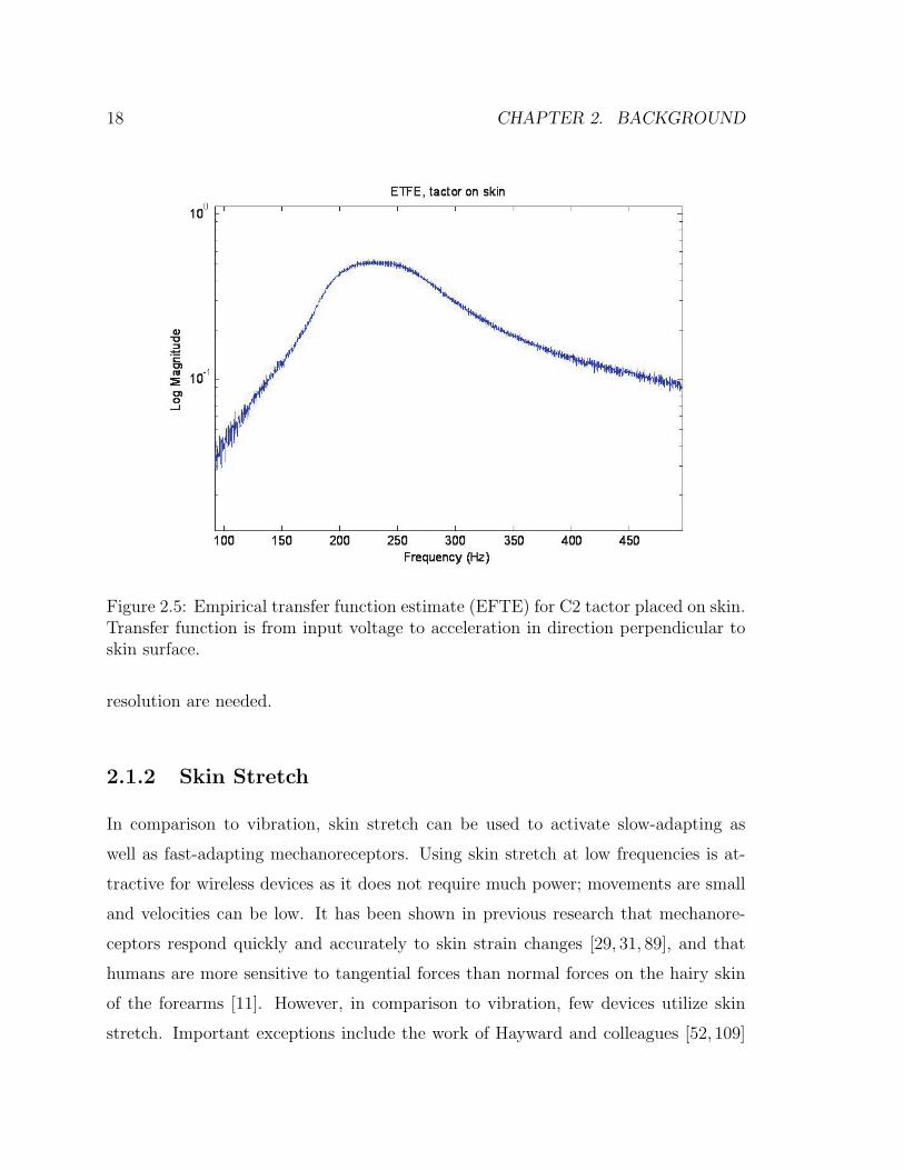
2.5 Empirical transfer function estimate (EFTE) for C2 tactor placed on
skin. Transfer function is from input voltage to acceleration in direction
perpendicular to skin surface. . . . . . . . . . . . . . . . . . . . . . . 18
2.6 Benchtop skin stretch device with degrees of freedom labeled. . . . . . 20
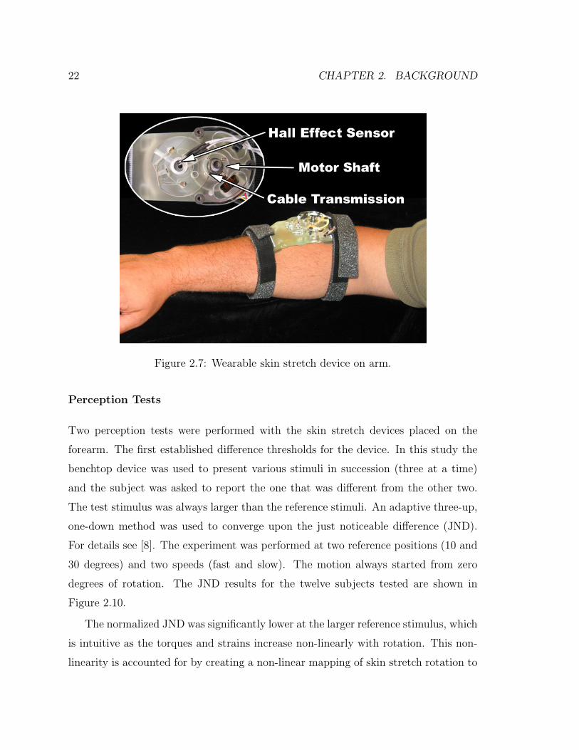
2.7 Wearable skin stretch device on arm. . . . . . . . . . . . . . . . . . . 22
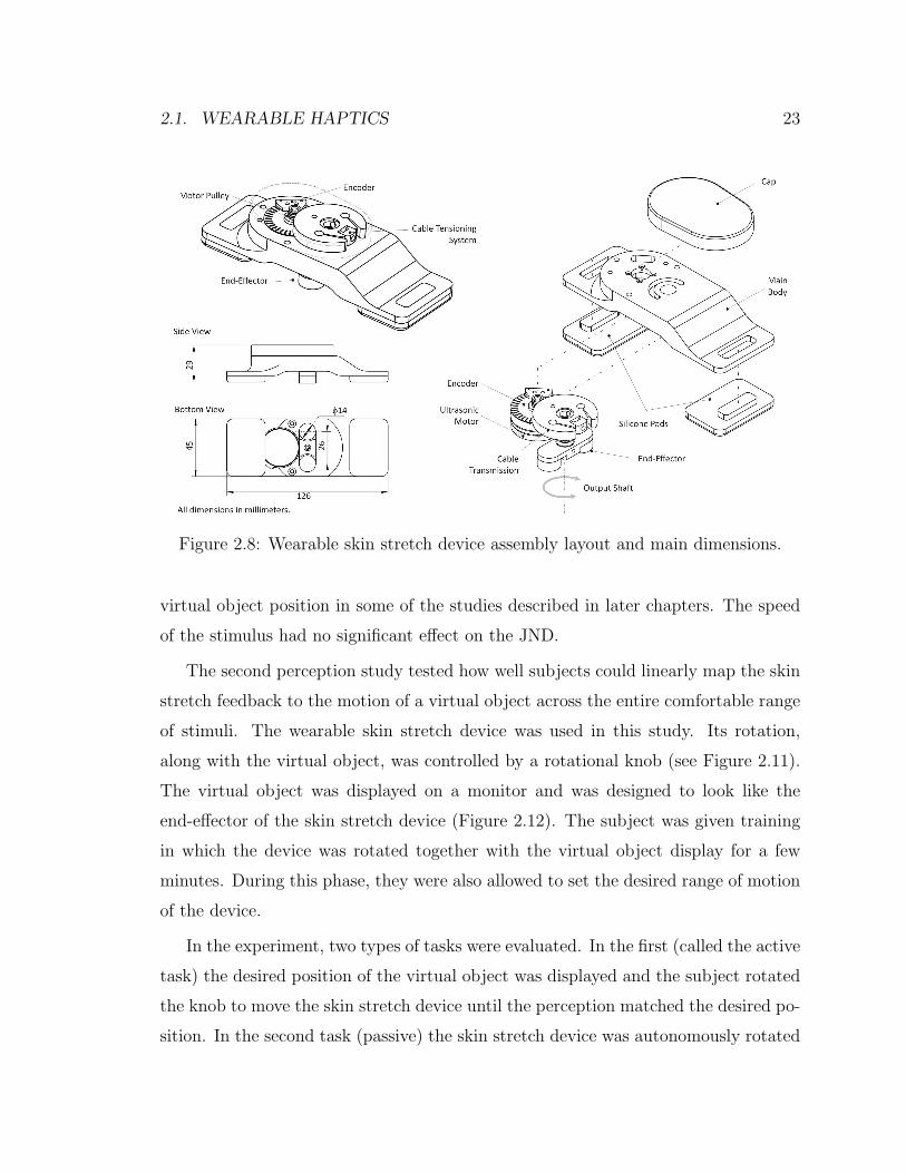
2.8 Wearable skin stretch device assembly layout and main dimensions. . 23
2.9 Most recent version of the wearable skin stretch device. . . . . . . . . 24
2.10 Results of difference threshold study for 12 subjects at slow (left) and
fast (right) speeds. The difference threshold was lower at the larger
reference position but speed had no significant effect. . . . . . . . . . 25
xvii

2.11 Setup for performance study with device and virtual object controlled
by a rotational knob. . . . . . . . . . . . . . . . . . . . . . . . . . . . 26
2.12 Display shown to subjects during trials. . . . . . . . . . . . . . . . . . 27
2.13 Data from all ten subjects in the active task. Two end-effectors (fixed
and free) were tested and minimal differences were found in perfor-
mance (From [8]). . . . . . . . . . . . . . . . . . . . . . . . . . . . . . 28
2.14 Data from all ten subjects in the passive study. Two end-effectors
(fixed and free) were tested and minimal differences were found in
performance (From [8]). . . . . . . . . . . . . . . . . . . . . . . . . . 29
2.15 One model of motor control with forward and inverse models to com-
pensate for feedback delays (Smith predictor [80]). . . . . . . . . . . . 33
3.1 Experimental setup for knee adduction moment study. Reflective mark-
ers capture motion data. Force plates in the treadmill gather force
data. Feedback is provided with a vibration device or a visual display. 38
3.2 General location of tibia segment and knee markers tracked in real-time. 40
3.3 Vectors used for knee adduction moment calculation. . . . . . . . . . 41
3.4 Sample of visual feedback display. The peak moment from the current
step and the previous nine were displayed to the subject. . . . . . . . 43
3.5 Mapping of peak knee adduction moment (KAM) to vibration ampli-
tude binned into three easily distinguishable levels. . . . . . . . . . . 44
3.6 Percent reduction in the knee adduction moment from baseline to final
trials along with the awkwardness rating for each subject. . . . . . . . 47
3.7 Average first peak of the KAM calculated in the lab frame in real-time
(left) and in the tibial coordinate frame after post-processing (right). 50
3.8 Second peak of the KAM in the tibial coordinate frame for baseline
and final trials. . . . . . . . . . . . . . . . . . . . . . . . . . . . . . . 51
4.1 Subject completing the task with right arm controlling force sensor and
left hand controlling button to end trial. . . . . . . . . . . . . . . . . 57
xviii

4.2 Screen shots of experiment task. . . . . . . . . . . . . . . . . . . . . . 58
4.3 Vibrotactor strapped to test subject, placed on forearm below the el-
bow joint as well as force sensor used for cursor control. . . . . . . . . 60
4.4 Skin stretch device attached to forearm below the elbow joint. . . . . 62
4.5 Skin stretch mapping relative to cursor position. . . . . . . . . . . . . 64
4.6 Perception curve for vibrotactile stimulation normalized over five sub-
jects. . . . . . . . . . . . . . . . . . . . . . . . . . . . . . . . . . . . . 68
4.7 Perception curve for skin stretch normalized over five subjects with
and without direction error correction. . . . . . . . . . . . . . . . . . 69
4.8 Average relative position errors for ten subjects. . . . . . . . . . . . . 71
4.9 Average absolute position errors for ten subjects. . . . . . . . . . . . 72
4.10 Average absolute position errors using vibration feedback and skin
stretch feedback for each of the ten subjects. . . . . . . . . . . . . . . 73
4.11 Average absolute position errors relative to step size. . . . . . . . . . 74
4.12 Average relative position errors by step size. . . . . . . . . . . . . . . 75
4.13 Average absolute position error versus desired target location. . . . . 76
4.14 Overall average ending velocities. . . . . . . . . . . . . . . . . . . . . 77
4.15 Average ending velocities with respect to desired ending cursor position. 78
5.1 Schematic representation of the primary control elements in the system. 85
5.2 Non-linear mapping of virtual arm angle to skin stretch rotation. Map-
ping is a fifth-order polynomial with a slope of one near the origin and
1/2 near the limits. . . . . . . . . . . . . . . . . . . . . . . . . . . . . 87
5.3 Experimental setup. Right pane shows schematic view of the primary
input and feedback elements. . . . . . . . . . . . . . . . . . . . . . . . 88
5.4 Schematic view of elbow manipulandum used to provide contralateral
proprioceptive feedback. . . . . . . . . . . . . . . . . . . . . . . . . . 89
xix

5.5 Visual display of virtual arm at beginning of a sample trial with starting
position equal to zero degrees. The thick diagonal line represents the
upper arm and does not move. . . . . . . . . . . . . . . . . . . . . . . 92
5.6 Visual display of virtual arm at beginning of visual occlusion trial.
Thick outer lines represent the desired range, thick horizontal line in
the center is the virtual arm which is only visible for one second after
a button press. . . . . . . . . . . . . . . . . . . . . . . . . . . . . . . 93
5.7 Virtual arm position and task position limits for 30 seconds of a sample
trial with skin stretch feedback. . . . . . . . . . . . . . . . . . . . . . 94
5.8 Visual demand calculations at each button press for a sample no feed-
back (NF) and skin stretch (SS) trial. . . . . . . . . . . . . . . . . . . 95
5.9 Box plot of average targeting errors for participants with no feedback
and skin stretch (SS) feedback (n=15) and contralateral proprioceptive
(CP) feedback (n=9) . . . . . . . . . . . . . . . . . . . . . . . . . . . 97
5.10 Sample of a movement profile for one subject with skin stretch feedback
(left) and no feedback (right). Three submovements are evident in the
case with feedback. The desired target was -60 degrees in both cases. 98
5.11 Box plot of average visual demand over three successful trials for all
15 participants with no feedback and skin stretch (SS) feedback. . . . 99
5.12 Average visual demand for each of the 15 subjects with no feedback
and skin stretch. . . . . . . . . . . . . . . . . . . . . . . . . . . . . . 100
6.1 Depiction of a system with motion capture, musculoskeletal simulation
and real-time feedback for motion guidance. . . . . . . . . . . . . . . 106
xx

Chapter 1
Introduction
Researchers in the field of haptics have sought to utilize the vast array of tactile
sensors in the human skin to improve communication between man and machine.
Haptic devices have the ability to convey a sense of interaction forces and textures
with a remote or virtual environment. Potential applications for haptics are myriad
and include remote robotic teleoperation and surgical simulation and training. While
these technologically-demanding applications could have a huge impact, to date the
most ubiquitous and successful applications of haptics involve some of the simplest
technologies.
Nearly every cell phone or pager is equipped with a vibration device to alert the
user that an event has occurred (e.g. an incoming call). Game controllers also utilize
simple vibration motors to create illusions of force or impact. This type of feedback
is portable in that it consumes little power and does not need to be grounded to
a large structure. It can also be more easily conveyed to a single person (without
the knowledge of those in proximity to them) than many audio or visual displays.
However, the bandwidth of the feedback is quite low. This is due to the relatively poor
ability to discriminate vibration parameters as well as a person’s ability to remember
what a particular vibration pattern means. This limits its use to simple “event-cue”
feedback rather than providing a rich sense of information, such as could be conveyed
1

2 CHAPTER 1. INTRODUCTION
with verbal comments or on a visual display. Tactile sensation is not typically used
for conveying symbolic information (though it can be done, for example Braille) but
it is inherently multi-modal and distributed. This allows relatively low bandwidth
information of various types (e.g. force, vibration, temperature) to be conveyed in a
localized manner. It can also be used in parallel with vision and audition to improve
the overall flow of information.
In this work, we will attempt to identify a few practical applications of wearable,
portable tactile displays that take advantage of the strengths of haptic feedback while
acknowledging its weaknesses. Of particular interest are applications where the feed-
back is related to the motion of a person’s body. The use of skin stretch feedback, in
addition to vibration, is a critical component of this work. Skin stretch has the ability
to convey an analog sense of position and motion in a way that is more intuitive than
vibration.
Two classes of motion-based feedback applications will be explored in this work.
In the first class of applications, haptic feedback is used to convey some new channel
of information to the user that they would not normally have. Within the constraints
of this research, the feedback is related to desired motions of the person’s body. This
feedback could be based on some biomechanical parameter that the person has no
natural sense of but is desirable to control (as in Chapter 3). Alternatively, the
feedback could be based on some external desired motions (e.g. in learning a skilled
movement).
The second broad class of applications we will explore in this work involves pro-
viding users a sense of feedback of their own movements or the movements of some
tightly coupled robotic device. The feedback of motion- and position-based informa-
tion we will refer to as proprioceptive or kinesthetic feedback, which can be either
natural or artificial (when provided with wearable haptic devices). These terms will
be defined more rigorously in Chapter 2. One of the clearest examples of an appli-
cation of artificial proprioceptive feedback, and the one we will explore in the most
depth, is the control of prosthetic limbs. Upper-limb amputees are often fit with
3
robotic limbs that can be controlled with electromyographic (EMG) sensors placed
on residual muscles, making the control somewhat intuitive. However, they lack any
proprioceptive feedback from the limb and are forced to use visual feedback or feed-
forward control strategies to move the limb. The addition of haptic feedback could
improve the ability of users to control the arm accurately and intuitively. This benefit
can be directly due to the addition of feedback or from improved learning of the arm
dynamics.
In both classes of applications described above, it is critical to understand the
role of feedback (natural or artificial) in motor control of various tasks. In order
to identify appropriate applications for the haptic devices, we must understand not
only how sensory information is used in motions, but how proprioceptive and visual
information are integrated. Unfortunately, there is much that is not understood on
this topic. However, we can say something about what the central nervous system
(CNS) seems to be doing. A more thorough discussion of some of these points can
be found in Chapter 2 but some high level points will be presented here to provide a
framework for the applications explored in later chapters.
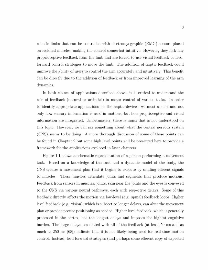
Figure 1.1 shows a schematic representation of a person performing a movement
task. Based on a knowledge of the task and a dynamic model of the body, the
CNS creates a movement plan that it begins to execute by sending efferent signals
to muscles. These muscles articulate joints and segments that produce motions.
Feedback from sensors in muscles, joints, skin near the joints and the eyes is conveyed
to the CNS via various neural pathways, each with respective delays. Some of this
feedback directly affects the motion via low-level (e.g. spinal) feedback loops. Higher
level feedback (e.g. vision), which is subject to longer delays, can alter the movement
plan or provide precise positioning as needed. Higher level feedback, which is generally
processed in the cortex, has the longest delays and imposes the highest cognitive
burden. The large delays associated with all of the feedback (at least 50 ms and as
much as 250 ms [68]) indicate that it is not likely being used for real-time motion
control. Instead, feed-forward strategies (and perhaps some efferent copy of expected

4 CHAPTER 1. INTRODUCTION
CNS
0 100Cognitive Load (%)
Task Model
Movement Plan
Sesn
sory
In
teg
rati
on
+
+Muscles
Vision
Sub-Cutaneous Receptors
Local JointCutaneousReceptors
Limbs/Joints
Feed-Forward
Efferent
Signals
Force MotionAfferent
Signals
Neural
Electrical
Mechanical
Lower Feedback Paths
C
TD1
TD2
TD3
Delays
Figure 1.1: Schematic representation of a person performing a movement task basedon a knowledge of the body’s dynamics and the various sensory feedback elementspresent.
sensory feedback) are used to perform many movements at preferred speeds. The
feedback may be used for slower corrections or adaptation of the dynamic models for
future tasks. More will be said about this in Chapter 2.
When a person has a limb amputated and is fitted with an EMG-controlled limb,
the efferent control path is somewhat intact but many of the feedback paths are elim-
inated or impaired (Figure 1.2). Electrical activity from residual muscles is detected
to actuate movement of the robotic arm. Visual feedback is the only remaining sense
of gross joint motion. However, we can place a haptic device on the skin near the
amputated joint or on some other area that conveys a sense of the limb’s motion to
partially replace the lost sense. As with physiological senses, this feedback channel
will have a delay associated with it, so its benefit will likely be for slower motions
or for developing dynamic models of the limbs and joints. In myoelectric prostheses,
motions are typically slower due to the lack of normal control mechanisms and the
difficulty in building dynamic models of the controller and joints [103]. The addition
of haptic proprioceptive feedback could reduce the visual demand associated with
moving the arm, allowing vision to be devoted to other tasks. It could also improve

5
Muscles
Vision
Sub-Cutaneous Receptors
Local JointCutaneousReceptors
Other CutaneousReceptors
Limbs/Joints
Efferent
Signals
Force Motion
Robotics
EMG
Processing
MappingHaptic Device
MyoelectricMyoelectric
MotionCutaneous Stimulus
Neural
Electrical
Mechanical
XX
CNS
0 100Cognitive Load (%)
Task Model
Movement Plan
Sesn
sory
In
teg
rati
on
+
+
Feed-ForwardAfferent
Signals
Lower Feedback Paths
C CC
TD1
TD2
TD3
TD4
Delays
Figure 1.2: Schematic representation of a person performing a movement task withan EMG-controlled prosthetic limb. Many of the normal feedback paths are impairedor absent. Haptic feedback can be used to partially replace the lost sensation.
motion accuracy in the absence of vision. These specific hypotheses are tested in
Chapter 5.
Based on this brief overview of the role of sensory feedback in movement, we
can begin to formulate some guidelines for when haptic feedback might be useful
for kinesthetic or proprioceptive feedback. First, when the feedback is related to
desired motions of an unimpaired person, the feedback is likely to be beneficial for
either slow movements, which may not be practically useful, or for learning a task in
a repetitive fashion. In the latter case – which we think is most practical and has
not been explored in depth to date – the feedback is not used in the current motion
but in building feed-forward strategies for future movements. This feedback can be
implicit (simply providing performance feedback to the person so they can iterate on

6 CHAPTER 1. INTRODUCTION
various strategies) or explicit (providing specific guidance on what motion corrections
to make). In Chapter 3, we provide an example of implicit feedback for lowering a
potentially harmful knee joint load during walking (a repetitive task).
The other application we will explore in this work involves the control of external
devices (e.g. prostheses). In this case, the feedback is directly related to the control
inputs from the users, which are limited to EMG or force in the studies we present.
With both of these inputs, the user does not have natural proprioceptive feedback
(at the joint level) as they would with a joystick or mouse. In the absence of pro-
prioceptive feedback, users can potentially control the device with visual feedback
or open-loop strategies based on models of the system’s dynamics. We do not claim
that the use of haptic feedback is superior to vision for most tasks, any more than
natural proprioception is. However, we will often compare to completely feed-forward
control strategies in the absence of vision for conditions when vision is not available.
In these cases, the feedback is more beneficial if the dynamics or control properties of
the system are not intuitive to learn. Additionally, we will evaluate if visual demand
can be reduced with artificial proprioceptive feedback.
To summarize, we hypothesize that providing haptic feedback of motion-based
information could be useful in at least the following situations:
• For motion guidance and correction of slow motions where visual feedback is
ambiguous.
• For implicit or explicit motion guidance for repetitive tasks (Chapter 3).
• For control of systems with non-intuitive dynamics when vision is not available
or is devoted to other tasks (Chapters 4 and 5).
Chapter 2 provides an overview of the major concepts of this research and presents
the relevant prior work. In Chapter 3 we describe an experiment about motion
training with visual and vibration feedback of a knee joint load that contributes to
osteoarthritis (OA). Chapters 4 and 5 describe studies that use skin stretch (and
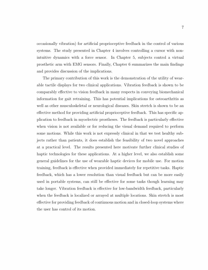
7
occasionally vibration) for artificial proprioceptive feedback in the control of various
systems. The study presented in Chapter 4 involves controlling a cursor with non-
intuitive dynamics with a force sensor. In Chapter 5, subjects control a virtual
prosthetic arm with EMG sensors. Finally, Chapter 6 summarizes the main findings
and provides discussion of the implications.
The primary contribution of this work is the demonstration of the utility of wear-
able tactile displays for two clinical applications. Vibration feedback is shown to be
comparably effective to vision feedback in many respects in conveying biomechanical
information for gait retraining. This has potential implications for osteoarthritis as
well as other musculoskeletal or neurological diseases. Skin stretch is shown to be an
effective method for providing artificial proprioceptive feedback. This has specific ap-
plication to feedback in myoelectric prostheses. The feedback is particularly effective
when vision is not available or for reducing the visual demand required to perform
some motions. While this work is not expressly clinical in that we test healthy sub-
jects rather than patients, it does establish the feasibility of two novel approaches
at a practical level. The results presented here motivate further clinical studies of
haptic technologies for these applications. At a higher level, we also establish some
general guidelines for the use of wearable haptic devices for mobile use. For motion
training, feedback is effective when provided immediately for repetitive tasks. Haptic
feedback, which has a lower resolution than visual feedback but can be more easily
used in portable systems, can still be effective for some tasks though learning may
take longer. Vibration feedback is effective for low-bandwidth feedback, particularly
when the feedback is localized or arrayed at multiple locations. Skin stretch is most
effective for providing feedback of continuous motion and in closed-loop systems where
the user has control of its motion.

8 CHAPTER 1. INTRODUCTION

Chapter 2
Background
This chapter provides a summary of prior work related to the topics of wearable
haptic feedback and motor control. As there are a number of diverse topics that
are relevant, some of the sections will provide only a cursory overview of the most
relevant works. Background on specific applications is provided at the beginning of
subsequent chapters as appropriate.
We first review the prior work in wearable haptic devices. The two primary
modalities of feedback, vibration and skin stretch, are then discussed independently.
We then discuss some of the relevant literature on proprioception and movement
science. Finally, we discuss the prior studies of biofeedback for motion guidance.
2.1 Wearable Haptics
Most early haptic devices were designed to convey a sense of force to a person’s hand.
To do this effectively, they were “grounded” to a benchtop, allowing forces to be
conveyed in the operational space of the endpoint. Wearable devices, which are not
grounded, cannot convey forces in this way. They can produce net torques around
joints however, and a number of such devices (exoskeletons) have been developed
(e.g. [50, 69]). Of course, force is only one of many types of haptic information
9

10 CHAPTER 2. BACKGROUND
that can be conveyed to a user. Mechanoreceptors in the skin can detect vibration,
temperature, normal and tangential skin strains and pressure. An understanding of
the types of receptors in the skin and their functional properties will help facilitate
later discussions of the types of feedback devices that have been developed.
The human skin is generally categorized into either glabrous or non-glabrous
(hairy) types. Glabrous skin is found primarily on the palms of the hands and bot-
toms of the feet. The vast majority of the skin surface area is non-glabrous. In this
work we are primarily interested in feedback to this non-glabrous skin as the proposed
applications involve placement of devices across the body segments. It is also bene-
ficial to keep the hands free for other tasks and in some cases (i.e., amputees), the
hand may be absent entirely. The following discussion will therefore focus primarily
on the hairy skin. We will refer occasionally to devices used on glabrous skin as these
seem to dominate the prior work.
Figure 2.1 shows the five main types of mechanoreceptors found in the human
hairy skin [107]. The receptors are often categorized by their relative depth under
the skin as well as the type of stimuli the respond to. Type I receptors are located
superficially in the skin and have relatively small receptive fields. Type II receptors are
found deeper in the skin and have large receptive fields. Slow adapting (SA) receptors
respond to slowly changing stimuli while fast adapting (FA) receptors respond to
more rapidly changing stimuli. As an example, the Pacinian corpuscle, which is
known to be sensitive to vibratory stimuli, is classified as a FAII receptor because it
responds to dynamic stimuli and is located deep in the skin. Table 2.1 summarizes
the classifications and functions of the primary mechanoreceptors.
Rather than creating a sense of force at a point in task space or about a joint, there
is clearly an opportunity to communicate information in a more compact package by
stimulating a small number of mechanoreceptors [64]. This type of communication
is not necessarily intuitive in the sense that it creates a realistic illusion of a tactile
interaction but the nervous system can certainly learn to interpret the information
with some training [113]. This idea of communicating information from external

2.1. WEARABLE HAPTICS 11
Figure 2.1: Mechanoreceptors found in hairy skin. Image taken from [72].
Table 2.1: Characteristics of mechanoreceptors found in human forearm skin [107].Sensed parameters suggested by Gilman 2002 [45].
sources (either to create a new sense or to partially replace a lost one) is often referred
to as sensory substitution [73]. An effective sensory substitution device should have
good information bandwidth and be as intuitive as possible.

12 CHAPTER 2. BACKGROUND
A number of devices have been developed that stimulate cutaneous receptors in
some way. The vast majority of them use either vibration (which is discussed in depth
below) or electrical stimulation. Most mechanoreceptors (or adjacent afferent nerve
fibers) can be artificially stimulated by injecting an electrical current into the skin.
Electrotactile stimulation devices are designed to communicate information with elec-
trodes that are placed on the skin. The current threshold required for a mechanore-
ceptor or nerve to respond (i.e., fire an action potential) depends on the depth under
the skin and the diameter of the nerve fiber. Superficial and large diameter nerves
have the lowest thresholds. In most embodiments, electrotactile displays stimulate a
large variety of sensory responses including pressure, vibration, temperature and pain,
creating a stimulus that is difficult to describe and is often uncomfortable [63, 64].
There have been some attempts to control the stimulus properties to selectively stim-
ulate certain receptors [65]. One problem with cutaneous electrical stimulation is
that the thresholds for stimulation change (due to skin conductivity changes) as the
moisture content of the skin changes (e.g. due to sweating). This makes it difficult
to control the stimulus for long periods. An electrotactile array called the Brainport
has been created for use on the tongue due to the high receptor density and relatively
constant moisture content [26]. While electrotactile displays have been effectively
used in some experiments for sensory substitution [106,113,114,116,117], We do not
consider them further here due to their subjective unpleasantness, relatively high
power consumption [64], and inconsistency on hairy skin due to sweating as most of
the expected applications will involve physical activity of the users. In the following
sections we will discuss vibration, which is the most common form of tactile display
for portable applications, and skin stretch which is a new alternative that has some
unique advantages.

2.1. WEARABLE HAPTICS 13
2.1.1 Vibration
A rapidly changing stimulus applied to the skin stimulates the fast adapting mechanore-
ceptors (Meisner and Pacinian corpuscles). Meisner corpuscles are sensitive to lower
frequency stimuli while Pacinian corpuscles respond to higher frequencies (see Fig-
ure 2.2). The Pacinian corpuscles are most sensitive to frequencies around 250 Hz
and are thought to be most important for detecting vibrotactile stimuli [64]. Unlike
other mechanoreceptors, for which the firing rate increases with stimulus amplitude,
Pacinian corpuscles fire at the frequency of stimulation [39, 95]. This implies that
amplitude perception must be coded by the number of receptors that are active or
with other receptors. Because the Pacinian corpuscles are type II receptors (deep),
they have large receptive fields. This makes localization of vibratory stimuli some-
what difficult (i.e., the stimuli must be relatively far apart, depending on the skin
area).
Extensive research has been completed to characterize vibration perception, study-
ing the effects of stimulus waveform, contact area size, frequency, amplitude, and
various other factors. Jones and Sarter provide a comprehensive summary of relevant
findings [62], covering the last 60 years of research on vibrotactile stimuli to aid in
designing tactile displays.
Vibrotactile stimuli are characterized in terms of the frequency and amplitude
of stimulation. Variations in results are evident and are attributed to differences
in experimental conditions and methods, choice of stimulus waveform, and size of
contact area [43, 59, 77]. In general humans are most sensitive to frequencies in the
150-300 Hz range, though it varies slightly depending on the region of the body where
the stimulus is applied [62]. For example, humans are most sensitive at the fingertips,
less sensitive on the forearms, and least sensitive in the abdominal and waist area.
This trend is even more pronounced in amplitude detection, where thresholds vary
considerably more. The amplitude for detecting vibration at any frequency varies
from 0.07 µm to 4 µm [111].

14 CHAPTER 2. BACKGROUND
Figure 2.2: Frequency response of fast adapting receptors. Image taken from [58].
Vibrotactile difference thresholds have been studied considerably less than detec-
tion thresholds due to the difficulties in modulating changes in frequency and ampli-
tude. As the amplitude of vibration increases, even though the frequency is constant,
there is a perceived increase in frequency [81]. In addition, perceived frequency varies
greatly across different regions of the body. Jones and Sarter produce a chart sum-
marizing the findings of several studies to determine vibrotactile difference thresholds
(see Figure 2.3). Here it can be noted that differences in measurement technique and
environment may cause variation in threshold results, as there is a large discrepancy
in difference thresholds at the finger. Frequency discrimination thresholds are typi-
cally presented as a normalized function of the reference frequency, (∆F )/Fref , where
(∆F ) is the frequency difference threshold in Hz, and Fref is the reference frequency.
Frequency difference thresholds for the forearm range from approximately 0.2 to

2.1. WEARABLE HAPTICS 15
Figure 2.3: Vibrotactile difference thresholds as a function of frequency for pulsesdelivered to the forearm (filled squares, Rothenberg [94] ; open squares Mahns [77]),the finger (filled circles, Franzen & Nordmark [34]; open circles, Goff [46]), and thehand (triangles, Mowbray & Gebhard [82]). Figure taken from Jones [62].
0.4, where the thresholds are higher at lower frequencies [77]. Changes in amplitude
can also be used to vary vibration intensity. Though there are variations in data,
in general, amplitude based difference thresholds decrease with increasing stimulus
intensity [59].
These perception studies typically used large actuators that have fast dynamics
such that the amplitude (either force or position) and frequency of stimulation can
be independently controlled. These actuators are obviously not practical for portable
applications. For wearable devices, two types of actuators are commonly used to
create vibrotactile stimuli. The most common type uses a simple DC rotational
motor with an unbalanced inertia on the output shaft. In this case the frequency
and amplitude of vibration are coupled (with amplitude approximately related to
the square of frequency) and are determined by the voltage sent to the motor. The
second class of motors used to create vibratory stimuli are simple linear actuators,
including voice-coil and piezoelectric types. With these actuators, the waveform sent
to the motor can be specified such that frequency and amplitude are theoretically
16 CHAPTER 2. BACKGROUND
independent. However, most actuators designed for wearable use, particularly on the
hairy skin, have mechanical dynamics that couple frequency and amplitude. In the
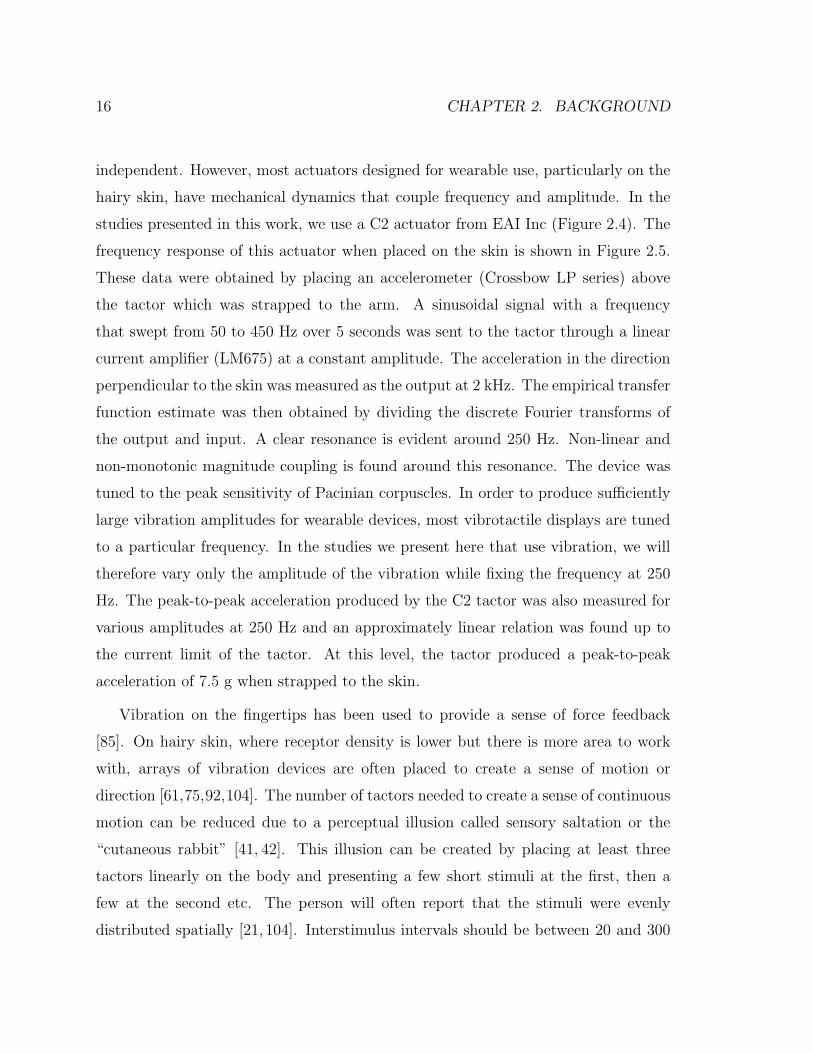
studies presented in this work, we use a C2 actuator from EAI Inc (Figure 2.4). The
frequency response of this actuator when placed on the skin is shown in Figure 2.5.
These data were obtained by placing an accelerometer (Crossbow LP series) above
the tactor which was strapped to the arm. A sinusoidal signal with a frequency
that swept from 50 to 450 Hz over 5 seconds was sent to the tactor through a linear
current amplifier (LM675) at a constant amplitude. The acceleration in the direction
perpendicular to the skin was measured as the output at 2 kHz. The empirical transfer
function estimate was then obtained by dividing the discrete Fourier transforms of
the output and input. A clear resonance is evident around 250 Hz. Non-linear and
non-monotonic magnitude coupling is found around this resonance. The device was
tuned to the peak sensitivity of Pacinian corpuscles. In order to produce sufficiently
large vibration amplitudes for wearable devices, most vibrotactile displays are tuned
to a particular frequency. In the studies we present here that use vibration, we will
therefore vary only the amplitude of the vibration while fixing the frequency at 250
Hz. The peak-to-peak acceleration produced by the C2 tactor was also measured for
various amplitudes at 250 Hz and an approximately linear relation was found up to
the current limit of the tactor. At this level, the tactor produced a peak-to-peak
acceleration of 7.5 g when strapped to the skin.
Vibration on the fingertips has been used to provide a sense of force feedback
[85]. On hairy skin, where receptor density is lower but there is more area to work
with, arrays of vibration devices are often placed to create a sense of motion or
direction [61,75,92,104]. The number of tactors needed to create a sense of continuous
motion can be reduced due to a perceptual illusion called sensory saltation or the
“cutaneous rabbit” [41, 42]. This illusion can be created by placing at least three
tactors linearly on the body and presenting a few short stimuli at the first, then a
few at the second etc. The person will often report that the stimuli were evenly
distributed spatially [21, 104]. Interstimulus intervals should be between 20 and 300

2.1. WEARABLE HAPTICS 17
Figure 2.4: C2 Tactor (EAI Inc).
ms (ideally about 50 ms). On the back, tactors should be located no more than 100
mm apart and three to six stimulus bursts per tactor are common [21]. Care must
be taken with vibrotactile stimulation to avoid desensitization with prolonged use as
fast adapting mechanoreceptors generally stop firing due to sensory adaptation after
a relatively short period of continuous stimulation [10,55,88].
In summary, vibrotactile stimulation is a common choice for wearable tactile feed-
back due to its small size and ease of implementation. However the resolution is
relatively low, particularly on hairy skin and is further limited by amplitude and fre-
quency coupling in most devices as well as how many stimulus levels a person can
remember. It is most commonly used to convey “event-cue” feedback (a single bit of
information) or for some sense of localized feedback. For instance, if it was desired
to instruct a subject to move their knee inward, a tactor on the outside of the knee
could be used to provide this cue intuitively. The ability to localize is limited by the
large receptive fields of the Pacinian corpuscles. Many users report is as annoying
with prolonged use and it can lead to relatively fast desensitization. Vibration is
most appropriately used when space is limited and/or many actuators with a low
18 CHAPTER 2. BACKGROUND
Figure 2.5: Empirical transfer function estimate (EFTE) for C2 tactor placed on skin.Transfer function is from input voltage to acceleration in direction perpendicular toskin surface.
resolution are needed.
2.1.2 Skin Stretch
In comparison to vibration, skin stretch can be used to activate slow-adapting as
well as fast-adapting mechanoreceptors. Using skin stretch at low frequencies is at-
tractive for wireless devices as it does not require much power; movements are small
and velocities can be low. It has been shown in previous research that mechanore-
ceptors respond quickly and accurately to skin strain changes [29, 31, 89], and that
humans are more sensitive to tangential forces than normal forces on the hairy skin
of the forearms [11]. However, in comparison to vibration, few devices utilize skin
stretch. Important exceptions include the work of Hayward and colleagues [52, 109]

2.1. WEARABLE HAPTICS 19
and [11,31,37,71,74,83,89] who have developed fingertip (i.e., glabrous) displays that
include skin stretch. Several investigators [31, 71, 74, 83] have also studied the mech-
anisms behind skin stretch. Makino [78] has developed a suction-based display that
produces illusions of pressure on the skin, at least in part by producing localized skin
stretch. However, non-glabrous skin stretch displays have been largely unexplored.
Skin stretch is known to contribute to motion sensations at various joints [25, 29, 30]
and elastic bandages placed on joints can enhance proprioception [90] due to increased
cutaneous sensations.
In this section we will provide an overview of the devices used in these studies as
well as some previous studies that established some of the perception and performance
qualities of the stimuli. The majority of the design and performance testing was
performed by Karlin Bark and much more detail can be found in her thesis [8].
Device Design
There are myriad ways of applying skin stretch. A single point can be moved linearly
in one or two directions and can also rotate. Multiple points can also be used that
move together or individually. A number of pilot studies were performed to determine
the type of stimulus that produced the greatest dynamic range and resolution of
feedback, with a desire to create a sense of motion as well as magnitude. It was
found that two circular contact points (d=13 mm) spaced about 25 mm apart, that
rotate about a central axis, produced a good sense of position and motion across a
range of about ±45 degrees [8]. A benchtop device was created that produced the
desired motions using a brushed DC motor with a capstan cable transmission (Figure
2.6). The device has a number of manually adjustable degrees of freedom to allow
accurate placement on the skin and also includes a six-axis force sensor which allows
monitoring of force and torque readings during motions. This device was used in the
study presented in Chapter 4.
While the benchtop device established the effectiveness of the stimulus, a wearable

20 CHAPTER 2. BACKGROUND
Figure 2.6: Benchtop skin stretch device with degrees of freedom labeled.
version was needed to meet the requirements of this work. In addition to being wear-
able, the device needed to be potentially portable, meaning that it should consume
minimal power and have no components that would not transfer to portable use. It
was also desired to create a motion that had very little vibration in the perceivable
range so as to not confound the skin stretch stimulus for perception studies. Conven-
tional DC motors were not ideal for this application as they needed to either be large
enough to produce torques in the 0.5 N-m range (based on data from the benchtop
device) or have a high transmission ratio. It was not desired to use a gearhead on
the motor as these produce significant vibrations. A capstan pulley of appropriate
size would have made the device prohibitively large. Finally, for portable use, a non-
backdriveable actuator is preferable as it does not require a current to hold a position
against an external torque.
A small piezoelectric rotational motor was identified that produces torques of up

2.1. WEARABLE HAPTICS 21
to 0.1 N-m in a small package and is not backdriveable (Shinsei Motors USR-30).
Additionally, it produces minimal perceivable vibration due to the high resonant
frequency of the piezo-crystals. The specifications of the actuator are presented in
Table 2.2.
Motor Specifications
Diameter 30 mmThickness 9 mm
Maximum Torque 0.1 NmHolding Torque 0.1 Nm
Weight 20 gMaximum Speed 150 rpm = 900 deg/sMinimum Speed 15 rpm = 90 deg/s
Driving Frequency 50 kHz
Table 2.2: Ultrasonic motor specifications
An additional transmission ratio of approximately 5:1 was required to achieve
the desired torque. This was accomplished with a capstan cable transmission. The
actuators and transmission were packaged with an encoder for position feedback into
the device shown in Figures 2.7 and 2.8. The specifications of the device are shown
in Table 2.3. A newer, smaller version of the same device has also been designed with
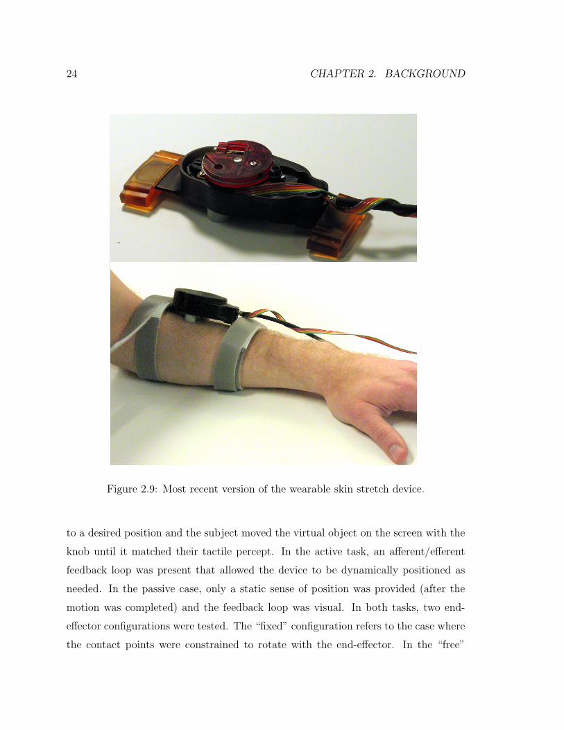
similar performance characteristics (Figure 2.9).
Design Requirements Device Specifications
Size small 29 x 45 x 126 mmMax Torque 0.2 Nm 0.6 NmSpeed Range ≤ 200 deg/s 15-150 deg/sWeight ≤ 200 g 115 gSensor 1 deg 1 deg (Hall Effect)Resolution 0.05 deg (Encoder)
Table 2.3: Wearable skin stretch device characteristics
22 CHAPTER 2. BACKGROUND
Figure 2.7: Wearable skin stretch device on arm.
Perception Tests
Two perception tests were performed with the skin stretch devices placed on the
forearm. The first established difference thresholds for the device. In this study the
benchtop device was used to present various stimuli in succession (three at a time)
and the subject was asked to report the one that was different from the other two.
The test stimulus was always larger than the reference stimuli. An adaptive three-up,
one-down method was used to converge upon the just noticeable difference (JND).
For details see [8]. The experiment was performed at two reference positions (10 and
30 degrees) and two speeds (fast and slow). The motion always started from zero
degrees of rotation. The JND results for the twelve subjects tested are shown in
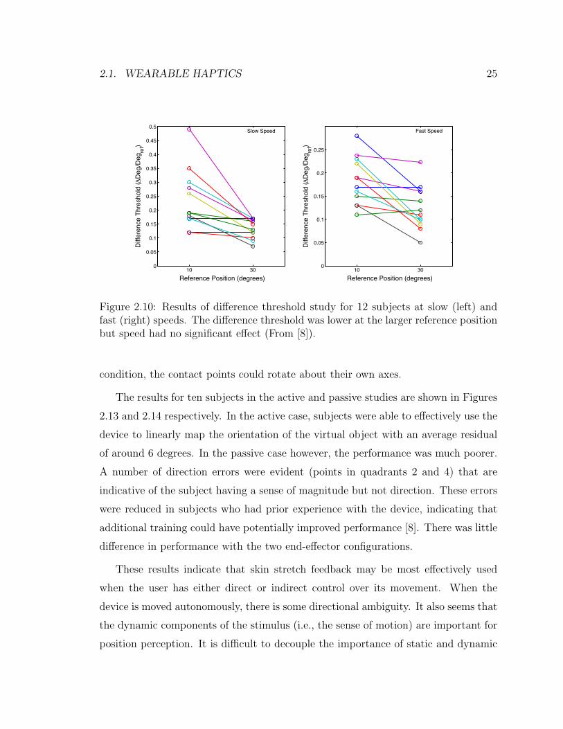
Figure 2.10.
The normalized JND was significantly lower at the larger reference stimulus, which
is intuitive as the torques and strains increase non-linearly with rotation. This non-
linearity is accounted for by creating a non-linear mapping of skin stretch rotation to
2.1. WEARABLE HAPTICS 23
Figure 2.8: Wearable skin stretch device assembly layout and main dimensions.
virtual object position in some of the studies described in later chapters. The speed
of the stimulus had no significant effect on the JND.
The second perception study tested how well subjects could linearly map the skin
stretch feedback to the motion of a virtual object across the entire comfortable range
of stimuli. The wearable skin stretch device was used in this study. Its rotation,
along with the virtual object, was controlled by a rotational knob (see Figure 2.11).
The virtual object was displayed on a monitor and was designed to look like the
end-effector of the skin stretch device (Figure 2.12). The subject was given training
in which the device was rotated together with the virtual object display for a few
minutes. During this phase, they were also allowed to set the desired range of motion
of the device.
In the experiment, two types of tasks were evaluated. In the first (called the active
task) the desired position of the virtual object was displayed and the subject rotated
the knob to move the skin stretch device until the perception matched the desired po-
sition. In the second task (passive) the skin stretch device was autonomously rotated
24 CHAPTER 2. BACKGROUND
Figure 2.9: Most recent version of the wearable skin stretch device.
to a desired position and the subject moved the virtual object on the screen with the
knob until it matched their tactile percept. In the active task, an afferent/efferent
feedback loop was present that allowed the device to be dynamically positioned as
needed. In the passive case, only a static sense of position was provided (after the
motion was completed) and the feedback loop was visual. In both tasks, two end-
effector configurations were tested. The “fixed” configuration refers to the case where
the contact points were constrained to rotate with the end-effector. In the “free”
2.1. WEARABLE HAPTICS 25
10 300
0.05
0.1
0.15
0.2
0.25
0.3
0.35
0.4
0.45
0.5
Reference Position (degrees)
Diff
eren
ce T
hres
hold
(ΔD
eg/D
egre
f)
10 300
0.05
0.1
0.15
0.2
0.25
Reference Position (degrees)
Diff
eren
ce T
hres
hold
(ΔD
eg/D
egre
f)
Slow Speed Fast Speed
Figure 2.10: Results of difference threshold study for 12 subjects at slow (left) andfast (right) speeds. The difference threshold was lower at the larger reference positionbut speed had no significant effect (From [8]).
condition, the contact points could rotate about their own axes.
The results for ten subjects in the active and passive studies are shown in Figures
2.13 and 2.14 respectively. In the active case, subjects were able to effectively use the
device to linearly map the orientation of the virtual object with an average residual
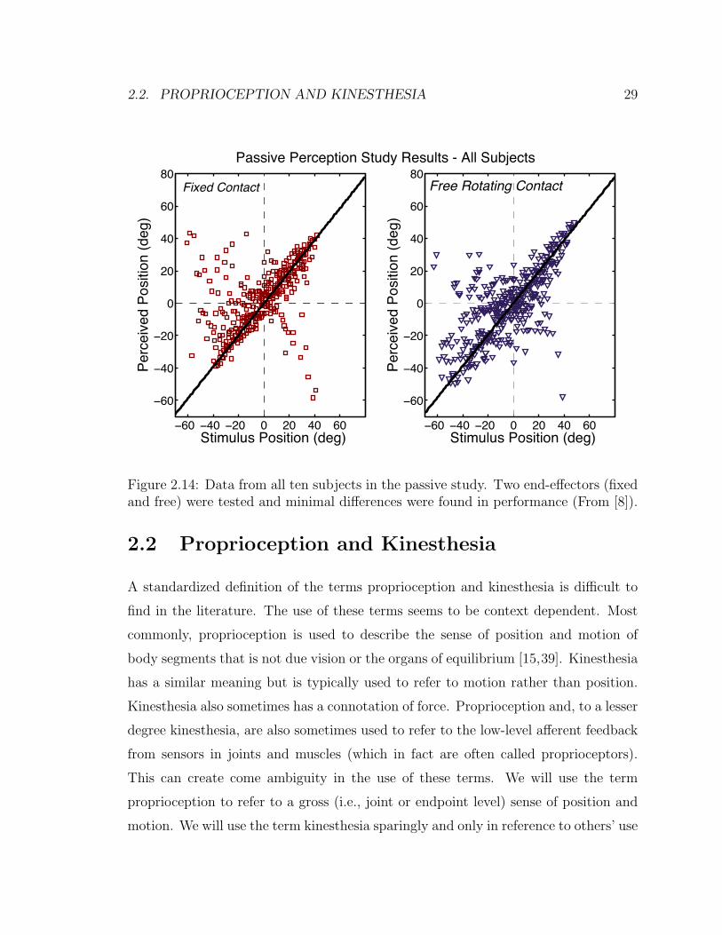
of around 6 degrees. In the passive case however, the performance was much poorer.
A number of direction errors were evident (points in quadrants 2 and 4) that are
indicative of the subject having a sense of magnitude but not direction. These errors
were reduced in subjects who had prior experience with the device, indicating that
additional training could have potentially improved performance [8]. There was little
difference in performance with the two end-effector configurations.
These results indicate that skin stretch feedback may be most effectively used
when the user has either direct or indirect control over its movement. When the
device is moved autonomously, there is some directional ambiguity. It also seems that
the dynamic components of the stimulus (i.e., the sense of motion) are important for
position perception. It is difficult to decouple the importance of static and dynamic

26 CHAPTER 2. BACKGROUND
skin stretchdevice rotational
knob
Figure 2.11: Setup for performance study with device and virtual object controlledby a rotational knob.
stimulus information from these results and it is similarly difficult to design a study
that decouples them as it is not possible to have a step input of position (there
is a dynamic and static component of the stimulus). However, we can infer from
the improved performance in the active case that the ability to move and control
the dynamic properties of the motion did improve performance. Subjects could use
various strategies to reach the desired position. For example, they could move to a
reliable point in the workspace (e.g. near the limits of the range) and the move back
to an area that is perhaps less sensitive. Even though the gain of the knob rotation to
device rotation was varied to avoid using finger proprioception to position the device,
the subjects could potentially remap the workspace (relying solely on tactile feedback)
by moving across the range in each trial if they desired. Additionally, direction errors
are eliminated as the subject rotated the knob in the desired direction and assumed

2.1. WEARABLE HAPTICS 27
Indicate PositionTrial 7 of 47
limits of rotation
+
-
Figure 2.12: Display shown to subjects during trials. The left is the screen displayedduring the training phase (showing the actual location) and on the right is the desiredlocation as shown in the experiment trial. Dashed lines indicate the limits of rotationspecified during the training phase.
that the device rotated in the correct direction.
2.1.3 Choice of Feedback Modality
Based on the discussion of vibration and skin stretch above, we can begin to make
some conjectures about which type of feedback might be most appropriate for a certain
application. Vibration is certainly simpler to implement and is effective for conveying
exogenous event-cues or perhaps a small number of levels of information. It can be
localized to some extent across body segments. Its prior use for vests and suits (e.g.
see [61]) seems appropriate. Skin stretch on the other hand, has the ability to convey
a sense of motion and position with a single device (which is larger than a typical
vibration actuator but has a smaller footprint than would be required to array multiple
actuators). It can also convey directional information, which vibration cannot do with
a single actuator, but ambiguity in direction is possible if the stimulus is exogenous.
Skin stretch can convey a fairly rich sense of motion in a small package but seems
best suited for applications where the user has at least some control of the motion.

28 CHAPTER 2. BACKGROUND
−60 −40 −20 0 20 40 60
−60
−40
−20
0
20
40
60
80R2 = 0.86164slope = 1.0294
Desired Position (deg)
Mea
sure
d Po
sitio
n (d
eg)
Fixed Contact
−60 −40 −20 0 20 40 60
−60
−40
−20
0
20
40
60
80R2 = 0.88451slope = 1.0274
Desired Position (deg)
Mea
sure
d Po
sitio
n (d
eg)
Positioning Study Results- All Subjects
Free Rotating Contact
Figure 2.13: Data from all ten subjects in the active task. Two end-effectors (fixedand free) were tested and minimal differences were found in performance (From [8]).
This reduces the risk of direction errors and allows for compensatory strategies for
positioning that reduce the insensitivity at small rotations. The perception results
indicate that subjects can learn to uniformly map a workspace with minimal training
with the device.
In the following chapters, we will use vibration for conveying coarse feedback of
performance (Chapter 3) and skin stretch for creating a sense of position and motion
of a virtual object. In Chapter 4, we will use both skin stretch and vibration to
compare performance for positioning a virtual object.
2.2. PROPRIOCEPTION AND KINESTHESIA 29
−60 −40 −20 0 20 40 60
−60
−40
−20
0
20
40
60
80
Stimulus Position (deg)
Perc
eive
d Po
sitio
n (d
eg)
−60 −40 −20 0 20 40 60
−60
−40
−20
0
20
40
60
80
Stimulus Position (deg)
Perc
eive
d Po
sitio
n (d
eg)
Passive Perception Study Results - All Subjects
Fixed Contact Free Rotating Contact
Figure 2.14: Data from all ten subjects in the passive study. Two end-effectors (fixedand free) were tested and minimal differences were found in performance (From [8]).
2.2 Proprioception and Kinesthesia
A standardized definition of the terms proprioception and kinesthesia is difficult to
find in the literature. The use of these terms seems to be context dependent. Most
commonly, proprioception is used to describe the sense of position and motion of
body segments that is not due vision or the organs of equilibrium [15,39]. Kinesthesia
has a similar meaning but is typically used to refer to motion rather than position.
Kinesthesia also sometimes has a connotation of force. Proprioception and, to a lesser
degree kinesthesia, are also sometimes used to refer to the low-level afferent feedback
from sensors in joints and muscles (which in fact are often called proprioceptors).
This can create come ambiguity in the use of these terms. We will use the term
proprioception to refer to a gross (i.e., joint or endpoint level) sense of position and
motion. We will use the term kinesthesia sparingly and only in reference to others’ use

30 CHAPTER 2. BACKGROUND
of the term in prior work. In all cases, it refers to a joint-level sense of motion. When
referring to low-level afferent feedback, we will avoid use of the terms proprioception
or kinesthesia to reduce ambiguity.
A number of sensory receptors contribute to the proprioceptive sense. The muscle
spindles and Golgi tendon organs are sensitive to position, movement and force in
muscles. Sensors in the joints give a sense of flexion and extension. Mechanoreceptors
in the skin, including Ruffini endings and Merkel cells, also contribute to the sense
of motion and position [39]. The brain integrates this afferent information to create
a percept of the body segments’ position and orientation.
The relative contribution of the various sensors and how the information is inte-
grated by the CNS is not well understood. It is difficult to study proprioception as
there are many contributors and they cannot easily be individually eliminated. Vi-
brotactile stimulation and skin stretch have been used to create illusory movements
at various joints. These phenomena are often used to evaluate how different sensors
contribute to kinesthesia [60]. Providing vibrotactile stimulation of about 75-100 Hz
can create an illusion of tendon lengthening [47]. These illusions are created by muscle
spindle activation and for many years it was thought that these dominated proprio-
ceptive feedback based on this observation. However recently, skin stretch near the
joints has also been found to create an illusory sense of motion [29, 30]. Collins et
al. [25] found that skin stretch contributed to illusory movements at the index finger,
elbow and knee and evaluated the relative magnitude of the perceived movements for
various combinations of tendon vibration and skin stretch. Gandevia et al. showed
that efferent signals contribute to proprioception [38].
Regardless of how the sense is created, the value of proprioception is unquestioned.
Even when vision is present, proprioceptive feedback can improve qualities of targeted
finger movements [70]. It has proven more effective than vision for stiffness discrimi-
nation [51]. The importance of proprioception is further evidenced by the tragic and
thankfully rare cases of people who suffer from neurological conditions that eliminate
this sense. Ian Waterman is one example of such a case [1]. He described his struggle
2.3. MODELS OF FEEDBACK IN MOTOR CONTROL 31
to do simple daily tasks using only visual feedback as a “daily marathon” [24].
Amputees who are fitted with robotic limbs no longer have proprioceptive feed-
back. They can use vision to position the limb, however. Many upper-limb jointed
prostheses have been designed that are controlled by moving other joints (e.g. the
shoulders). This allows amputees to have a sense of the position of the limb from re-
ceptors in the joints used to control the movement. The concept of creating a percept
of an external object based on body motions is referred to as Extended Physiological
Proprioception (EPP) [102]. Some more advanced upper-limb prostheses have been
developed that are controlled with EMG sensors on residual muscles. This allows
for less cumbersome and more intuitive control but no proprioceptive feedback is
provided. This topic is revisited in more detail in Chapter 5.
2.3 Models of Feedback in Motor Control
How humans control movements of their limbs (and external objects) is the subject
of much research and debate. A thorough review of this field is outside the scope of
this document. However, we will provide a summary of some of the major theories
while placing emphasis on the role of feedback (visual or proprioceptive) in motion
control. It should be noted that the actual neural circuits that govern the motions
are extremely complex and most of the work in movement science attempts to explain
the gross behavior of this circuitry with simplified models taken from control theory.
As stated in the introduction, human motor control cannot be explained by a
typical feedback control model due to the large delays associated with feedback. The
fastest spinal reflex loops have delays of about 50 ms and visual feedback delays for
arm movements can be as large as 250 ms [68]. The bandwidth of human motions is
such that delays of this magnitude would cause instability if the feedback gains were
not small. This has led researchers to propose other theories that explain how we
control our movements. One such theory, called equilibrium-point control [14,32,33],
theorizes that the brain simply sends a series of equilibrium points to the body to

32 CHAPTER 2. BACKGROUND
create a trajectory. This was based on the observation that peripheral and low-level
mechanisms such as reflex loops and the passive properties of the tissues tend to
stabilize the joints around a point. In this theory, low-level feedback from muscle
spindles etc. is used to maintain the actuators in certain regions where performance
is stable and sufficient force generating capacity is available to compensate for external
disturbances.
An alternative hypothesis that has gained prevalence in recent years theorizes
that the brain (specifically the cerebellum) contains internal dynamic models of the
body that allow efferent signals to be generated in a feed-forward fashion based on
a desired motion [68, 80]. Many of the proposed control structures contain both an
inverse model (for generating the motor command from a desired trajectory) and
a forward model that is sent an “efference copy” and generates expected sensory
feedback with a delay that is less than the actual feedback. The expected sensory
feedback can be compared to the actual feedback (after a delay) to update the motor
commands in a stable and robust way [80]. An example of the type of structure that
is often proposed is shown in Figure 2.15.
Given this background, we can begin to hypothesize about the role of feedback
in motor control. It seems that at a low level, there may be some degree of actuator
management. However at a high level, which is the focus of this work, feedback can
have a few roles. It almost certainly serves to update motor commands at slower
rates as it is compared to expected sensory feedback from the forward model. It is
also likely used to create the forward and inverse models so that future tasks can be
executed as desired. There is some debate over whether these models are generalized
to all tasks or are task specific [68].
Based on this discussion, the haptic feedback we provide should be focused on one
of a few cases, as introduced in the previous chapter. It is useful when the motions
are slow or the models are unreliable. It may also be useful for repetitive tasks or
generalized learning. We explore repetitive learning in Chapter 3 but do not address
generalized learning, though it could be an interesting study.

2.4. FEEDBACK FOR MOTION GUIDANCE 33
InverseModel
Desired State
-+
MotorCommand
EfferenceCopy
Motor System
Actual State
ForwardModel
Model Delay
FeedbackDelay
-+
-+
Figure 2.15: One model of motor control with forward and inverse models to com-pensate for feedback delays (Smith predictor [80]).
2.4 Feedback for Motion Guidance
We can finally look at the prior studies that have provided feedback to subjects to
guide their motions. The importance of feedback in motor learning of a task is well
established [12,13,17] with results suggesting the need for specificity and immediacy
of the feedback [3]. Feedback can be given visually or verbally from a teacher but this
introduces long delays and some information can be difficult to communicate with
these means. Virtual reality displays can show desired motions and errors between
actual and desired trajectories. However, 2D displays are not sufficient for displaying
full 3D motions. Tactile feedback presents an intuitive way to guide motions due
to the ability to localize feedback and minimize delays. This feedback can be given
manually by a teacher but a person can only apply feedback at a small number of
locations at a time. The use of tactile displays is a reasonable approach to provide
localized, real-time feedback. However, due to difficulties in tracking motions in real-
time, only two very recent papers have attempted this.

34 CHAPTER 2. BACKGROUND
Bloomfield and Badler [16] placed vibrotactile devices on the upper and lower
right arm and evaluated performance in a collision detection task compared to visual
feedback. A motion capture system was used to track arm motions. More relevant
to this work, they also tested the ability to train subjects to perform a new motion
(martial arts poses) with the tactile feedback. In fact the training was successful for
many motions (which were slow) but no comparisons were made to cases where no
tactile feedback was given. The authors state that these studies were expected to be
pilot studies but the results were included in the paper after examining the results.
Lieberman and Brazeal [75] also used motion capture and vibration on the arm.
They evaluated the accuracy of arm motions (5 degrees of freedom (DOF) with the
elbow on a table). Three of the DOF were hinge joints (elbow flexion/extension and
wrist flexion/extension and ad/abduction) and the other two were rotary motions
(upper and lower arm rotation). They found significantly lower errors and faster
training with the tactile feedback than with 2D vision alone. Results were best in the
hinge joints as the rotational vibration feedback may not have been easily interpreted.
Again, the motions in this study were slow. The authors claim potential applications
for a variety of situations but it is not clear how the training will translate based on
the discussion above about feedback delays.
The work presented in the following chapters seeks to improve upon prior studies
by using a new modality of feedback (skin stretch) to provide proprioceptive feedback
and by using feedback for motion training of a very practical, repetitive task (walking).
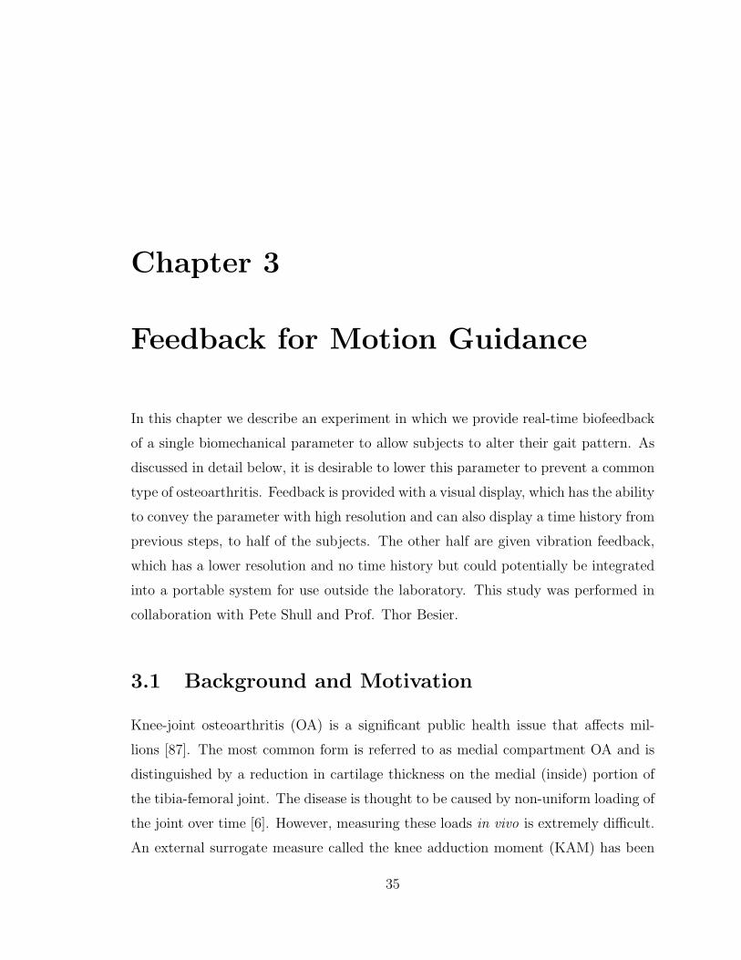
Chapter 3
Feedback for Motion Guidance
In this chapter we describe an experiment in which we provide real-time biofeedback
of a single biomechanical parameter to allow subjects to alter their gait pattern. As
discussed in detail below, it is desirable to lower this parameter to prevent a common
type of osteoarthritis. Feedback is provided with a visual display, which has the ability
to convey the parameter with high resolution and can also display a time history from
previous steps, to half of the subjects. The other half are given vibration feedback,
which has a lower resolution and no time history but could potentially be integrated
into a portable system for use outside the laboratory. This study was performed in
collaboration with Pete Shull and Prof. Thor Besier.
3.1 Background and Motivation
Knee-joint osteoarthritis (OA) is a significant public health issue that affects mil-
lions [87]. The most common form is referred to as medial compartment OA and is
distinguished by a reduction in cartilage thickness on the medial (inside) portion of
the tibia-femoral joint. The disease is thought to be caused by non-uniform loading of
the joint over time [6]. However, measuring these loads in vivo is extremely difficult.
An external surrogate measure called the knee adduction moment (KAM) has been
35

36 CHAPTER 3. FEEDBACK FOR MOTION GUIDANCE
identified that has been correlated to the onset, progression and severity of medial
compartment OA [6,97]. The KAM is the moment applied to the knee in the frontal
plane and can be calculated during gait with knowledge of the ground reaction force
(GRF) vector, the location of the center of pressure (COP) under the foot and the
location of the knee joint center. These values can be measured in a gait analysis
laboratory with force plates and a motion capture system. The KAM typically ex-
hibits two peaks during the stance phase of walking which correspond to the peaks
in the vertical GRF [56]. Of these, the first peak is the only one that has been shown
to be higher in OA patients [57, 84, 108]. It has been proposed that the first peak is
therefore the more important one to lower [36].
Severe cases of knee OA require total joint replacement which is a costly and inva-
sive procedure. Interventions can be performed in an attempt to slow the progression
of the disease before joint replacement becomes necessary. The success of these in-
terventions is often evaluated by comparing the KAM pre- and post-treatment. The
most common surgical intervention to lower the KAM is a high tibial osteotomy
(HTO) [108]. This procedure involves the addition or removal of a small piece of
bone on the proximal tibia in an attempt to redistribute the medial-lateral loading
on the joint. A good outcome of HTO is considered to be a 30-50% reduction in
the peak KAM. Two non-invasive interventions include orthoses, such as lateral heel
wedges or knee braces, and gait retraining. Lateral heel wedges shift the COP medi-
ally but have only been found to produce modest reductions (less than 10%) in the
peak KAM compared to HTO [66, 67]. Gait retraining strategies seek to alter the
patient’s gait such that the KAM is reduced. A few general strategies have been pro-
posed to reduce the moment. These include walking with the toes pointed outward,
increasing trunk sway, taking shorter strides, walking more slowly and what is called
a “medial-thrust gait”. Walking with the toes outward can reduce the second peak
but does not impact the first peak significantly [5, 6, 49, 108]. Increased trunk sway
can reduce both peaks but can be unnatural [27]. Walking more slowly may not be
acceptable to some patients and as with all generalized modifications, may not be

3.2. METHODS 37
effective for all patients. Therefore, an individualized gait modification is desirable.
Fregly et al. have used dynamic simulations to predict novel gaits that reduce the
first peak of the KAM and are subject specific [35,36]. While this has been effective for
a small number of subjects, it is very time consuming and potentially non-intuitive to
train novice patients to walk with the new gait. In the following sections, we describe
an experiment in which we calculate the knee adduction moment of the left leg while
patients walk on a treadmill. On each step, we give them real-time biofeedback of
the first peak of the KAM with visual or vibration feedback. The subjects then
iterate on gait modifications until a satisfactory gait is identified that produces a
lower peak KAM. This approach uses implicit feedback as we do not specifically
tell subjects how to modify their gait (though we do provide suggestions before the
trial). Subjects are simply given performance feedback. This approach has proven
effective for motor learning in other complex, repetitive tasks [76, 91, 112]. Due to
feedback delays, subjects do not necessarily use the feedback provided on the current
step. However, due to the repetitive nature of the task, they are able to use the
information provided on the current step in planning future motions. This study is
an example of providing a person a sense of a physiological variable that it is desirable
to change, but the person has no natural sense of.
3.2 Methods
3.2.1 Experimental Setup
The experiment was completed in the Human Performance Laboratory at Stanford
University. Motion capture information was collected with a Vicon 8-camera marker-
based system (OMG plc, Oxford, UK). Reflective markers were placed on various body
segments to allow reconstruction of kinematic information. Three marker clusters
were placed on each of the subjects’ feet and upper and lower legs. Four markers were
placed on both the pelvis and torso. Additional markers were placed on anatomical
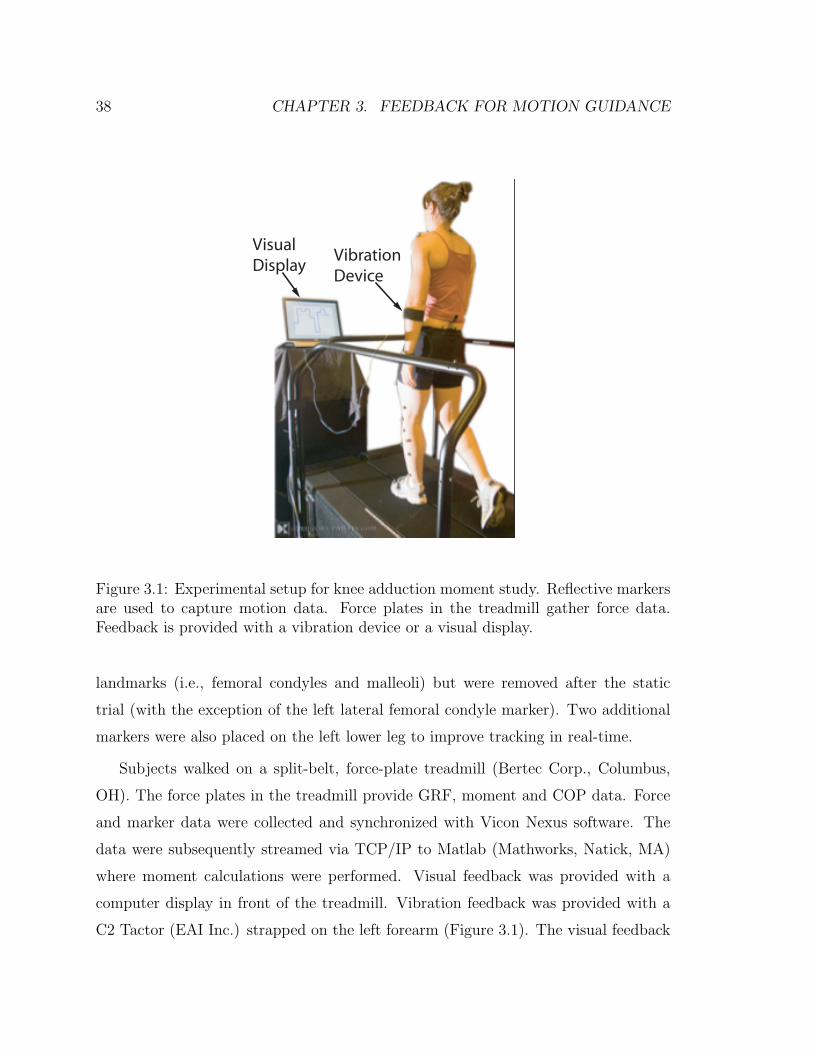
38 CHAPTER 3. FEEDBACK FOR MOTION GUIDANCE
Visual Display
VibrationDevice
Figure 3.1: Experimental setup for knee adduction moment study. Reflective markersare used to capture motion data. Force plates in the treadmill gather force data.Feedback is provided with a vibration device or a visual display.
landmarks (i.e., femoral condyles and malleoli) but were removed after the static
trial (with the exception of the left lateral femoral condyle marker). Two additional
markers were also placed on the left lower leg to improve tracking in real-time.
Subjects walked on a split-belt, force-plate treadmill (Bertec Corp., Columbus,
OH). The force plates in the treadmill provide GRF, moment and COP data. Force
and marker data were collected and synchronized with Vicon Nexus software. The
data were subsequently streamed via TCP/IP to Matlab (Mathworks, Natick, MA)
where moment calculations were performed. Visual feedback was provided with a
computer display in front of the treadmill. Vibration feedback was provided with a
C2 Tactor (EAI Inc.) strapped on the left forearm (Figure 3.1). The visual feedback

3.2. METHODS 39
was generated in Matlab and the vibration motor was controlled with the xPC real-
time operating system (Mathworks, Natick, MA).
3.2.2 Calibration
After the markers were placed on the subject, they stood on the treadmill and a
static trial was captured. Marker data from the static trial were used to build a
model of the left tibia segment (consisting of the 5 tibia markers and the left femoral
condyle marker as shown if Figure 3.2) so that it could be reliably tracked in real-
time. The static trial data were also used in post-processing to locate joint centers
and convert moments to the tibial coordinate frame. The left knee joint center was
defined as the location of the left femoral condyle marker plus an offset in the negative
y-direction (medial) in the lab coordinate frame that was equal to half of the knee
width. The subject also reported their height and weight to normalize the joint
moment (Nm/(ht ∗ wt)).
After the model of the tibia segment was created, the subject completed a baseline
walking trial. They were first asked to walk on the treadmill for 2-3 minutes at a
self-selected speed to become comfortable with the device. We then recorded 15 steps
of motion and force data and calculated the moment for each step. The moment
about the knee joint, Mk, was calculated as
Mk = rk/COP ×GRF (3.1)
where rk/COP is the position vector from the knee joint center to the center of
pressure and GRF is the ground reaction force vector (see Figure 3.3). The knee
adduction moment is the x-component of Mk. All moment calculations during the
experiment were performed in the lab coordinate frame, where the x-axis points to-
wards the front of the treadmill. After post-processing the data, we converted the
moment to the tibial coordinate frame to evaluate the adequacy of this approach.
The average first peak of the KAM over the 15 baseline steps was defined as the

40 CHAPTER 3. FEEDBACK FOR MOTION GUIDANCE
x
x
x
xx
x
Lateral Femoral Condyle Marker
Figure 3.2: General location of tibia segment and knee markers tracked in real-time.
baseline KAM and the feedback we provided in the experimental trial was relative to
this baseline. The first peak was defined by taking the maximum value of the KAM
over the first 40% of stance phase. The stance time was determined from pre-trial
walking data. Data from prior studies showed that the first peak always occurred
before this point (e.g. see [56]) and this was validated by examining the data after
the trial.
3.2.3 Experimental Trial
After the calibration and baseline trials, the details of the experiment were explained
to the subject. The subject would walk at the same self-selected speed on the tread-
mill. They were told that they would be given feedback on each step (of the left leg)
about a knee force that was desirable to minimize. Samples of the feedback (described

3.2. METHODS 41
COP
KJC
GRF
y
z
Figure 3.3: Vectors used for knee adduction moment (KAM) calculation. The KAMis the x-component of the cross product of the position vector from the knee jointcenter (KJC) to the center of pressure (COP) and the ground reaction force (GRF)vector.
below) were given prior to the experiment. The first peak of the KAM was calculated
after 40% of stance and the feedback was provided as soon as possible after that (based
on data collection and processing delays which were typically about 15% of the total
stance time). The feedback was always presented before the left foot left the ground.
Subjects were instructed to iterate on various gait modifications in an attempt to
identify a new gait that produced a lower force but was still symmetric, sustainable,
and acceptable. This meant that any modifications should be made on both legs, not
result in unreasonably large increases in energy expenditure and not produce a gait
that the subject would not consider using more permanently. We gave suggestions of
some modifications to try based on prior studies. These recommendations were:
• walking with toes pointed in or out,
• increased medial-lateral trunk sway,
42 CHAPTER 3. FEEDBACK FOR MOTION GUIDANCE
• taking longer or shorter strides (while adjusting stride frequency to maintain
the same speed),
• loading the lateral or medial side of the foot,
• varying the distance between the feet (step width).
The subject was instructed to try various combinations of these (and any other)
modifications until a satisfactory gait had been identified. We then allowed them to
practice this gait for 1-2 minutes before capturing 20 steps of post-trial data. The first
ten steps of this final trial were performed with the feedback device on, the final ten
with the feedback off. The total time required to identify the new gait was recorded.
The subject was also asked to report what strategies they chose for the final gait and
to rate the awkwardness of the new gait compared to their normal gait on a 0-10
scale (with 0 corresponding to no different and 10 being extremely awkward).
Visual Feedback
Visual feedback was displayed on a screen in front of the treadmill. A stair-step plot
of the current step’s peak KAM as well as the peaks from the previous nine steps was
shown. The baseline moment was displayed as a dotted line for reference. In addition
to providing a time history of data, the visual feedback allowed data to be conveyed
with high spatial resolution. These properties of the feedback allowed users to detect
trends in the KAM based on the modifications they made.
Vibration Feedback
As discussed in Chapter 2, vibration feedback has a limited perceptual resolution. In
pilot trials, subjects had difficulty distinguishing feedback amplitudes when a contin-
uous scale (linear or logarithmic) was used. We therefore binned the feedback into
three levels that were easily distinguishable (Figure 3.5). This put a fundamental
limitation on the resolution of the feedback but reduced ambiguity in remembering

3.2. METHODS 43
s
Current step
Figure 3.4: Sample of visual feedback display. The peak moment from the currentstep and the previous nine were displayed to the subject.
levels from previous steps. In all cases, a 0.5 second burst of vibration at 250 Hz was
provided as soon as possible after the first peak in KAM. If the peak KAM on the
current step was 80% of the baseline moment or larger, a large amplitude vibration
was presented. If the peak KAM was 60-80% of the baseline, a low-amplitude vibra-
tion was provided. If the peak KAM was below 60% of baseline, no vibration was
provided. The subjects’ goal therefore was to minimize the amplitude of the feedback.
3.2.4 Participants
Sixteen healthy subjects participated in the study (11 male, 5 female, mean age 29,
range 21-49). Eight of the subjects received vibration feedback and eight received
visual feedback. Approval was received from Stanford’s Institutional Review Board
and all subjects gave informed consent prior to their participation.

44 CHAPTER 3. FEEDBACK FOR MOTION GUIDANCE
0 60 80 100Off
Low
High
P eak K AM (%ht*wt)
Vib
ratio
n A
mp
litu
de
Figure 3.5: Mapping of peak knee adduction moment (KAM) to vibration amplitudebinned into three easily distinguishable levels.
3.2.5 Data Analysis
The primary measures of interest from the study were the average first peak in the
knee adduction moment (baseline and post-trial), the time required to complete the
trial, and the awkwardness rating of the new gait. As discussed above, the knee
adduction moment was calculated in the lab coordinate frame as this was a robust and
simple way to perform calculations in real-time. However, the choice of coordinate
frame for the knee moment can be important, particularly for non-standard gaits
[18, 96]. We therefore used the captured data to calculate the moment in the tibia
coordinate frame after the trial. We also used a more accurate method to determine
the location of the knee joint center. This provided a check on the appropriateness
of the approach used in real-time. Five of the sixteen subjects could not be post-
processed due to poor static or dynamic marker data. The remaining 11 subjects’

3.3. RESULTS 45
data (six vibration, five vision) were analyzed as follows.
Using data from the static trial, we created a transformation matrix that related
the coordinate frame created by the markers on the lower leg, to the coordinate frame
created by the markers on anatomical landmarks. This matrix allowed reconstruction
of the anatomical markers as “virtual markers” from the dynamic trial data. We also
created a virtual marker at the knee joint center which we defined to be the midpoint
of the line connecting the medial and lateral femoral condyle markers. As part of
this analysis, we also filtered the force plate data (2nd order low-pass Butterworth
with a cut-off of 30 Hz) and recalculated the COP. The knee joint moment was
then calculated in the lab coordinate frame as above with this new data and was
subsequently converted to the tibia frame with the coordinate transformation matrix
from the static trial. The x-component of this moment was then the KAM in the
tibia coordinate frame.
To evaluate statistical differences in the results of the experiment, various analyses
of variance (ANOVAs) were performed. When comparing results within subjects (i.e.,
from baseline to final trials or in the lab and tibia coordinate frame) repeated measures
ANOVAs were performed. When significant main effects were identified, paired t-test
were used to compare cases. When evaluating aggregate results and comparing the
two types of feedback a conventional ANOVA (between subjects) was performed with
no pairing.
3.3 Results
The results for each subject are summarized in Table 3.1. For each subject, the type
of feedback provided is given, along with the average first peak of the KAM for the
baseline and final trials. No significant differences were found in the post-trial cases
where the feedback was on and off so only the average of these 20 steps is presented for
conciseness. The percent reduction in the KAM from baseline to final is also shown
in Table 3.1 along with the time required to learn the new gait and the subjective

46 CHAPTER 3. FEEDBACK FOR MOTION GUIDANCE
awkwardness rating. These results are based on the real-time calculations performed
and are correlated to the feedback that was given to the subjects. All 16 subjects were
able to reduce their peak KAM compared to the baseline case, though the amount
of reduction varied from as little as 3% to more than 50%. Significant main effects
due to both subject and trial were identified. The averge first peak of the KAM was
significantly lower in the post-trial case (p < 0.001).
Sub # Feedback
Baseline KAM
(%h*w)
Post Trial 20 step ave
KAM
Trial Duration
(s) Percent
Reduction Awkwardness
Rating 1 Vision 5.80 4.15 292 28.45% 7 2 Vibro 2.95 1.53 867 48.14% 9 3 Vision 4.44 4.16 507 6.31% 4 4 Vibro 5.26 4.23 1139 19.58% 3 5 Vibro 3.02 2.92 968 3.31% 5 6 Vibro 4.84 3.89 538 19.63% 8 7 Vision 3.91 3.38 261 13.55% 7 8 Vision 4.38 4.14 598 5.48% 3 9 Vibro 3.80 3.67 505 3.42% 2
10 Vibro 3.57 3.26 431 8.68% 8 11 Vision 3.30 2.53 422 23.33% 8 12 Vision 3.66 3.31 381 9.56% 4 13 Vision 2.86 1.32 336 53.85% 3 14 Vision 4.21 3.31 350 21.38% 6 15 Vibro 4.84 3.27 384 32.44% 3 16 Vibro 2.88 1.91 455 33.68% 5
Table 3.1: Results for all 16 subjects. The Baseline KAM is the average first peak inthe baseline trial. The Post Trial 20 Step Ave. KAM is the average first peak withthe new gait. The percent reduction is a measure of the change in the average peakKAM from baseline to final. The trial duration is the time spent learning the newgait and the awkwardness rating is a subjective measure of the difference in the newgait compared to the subject’s normal gait.
The percent reduction in the KAM from the baseline to final trials, along with the
awkwardness ratings are presented in Figure 3.6. There is not a strong correlation

3.3. RESULTS 47
between the percent reduction and the awkwardness rating.
1 2 3 4 5 6 7 8 9 10 11 12 13 14 15 160
10
20
30
40
50
60
70
80
90
100
S ubject
Pe
rce
nt
Re
du
ctio
n in
KA
M
V is ionV ibration
0
2
4
6
8
10
Aw
kwa
rdn
ess
Ra
ting
Awkward.
Figure 3.6: Percent reduction in the knee adduction moment from baseline to finaltrials along with the awkwardness rating for each subject.
Average results for all subjects and results grouped by the type of feedback pro-
vided are presented in Table 3.2. The percent reduction and awkwardness ratings
for the visual and vibration feedback cases were not significantly different. However
the duration of the trial was significantly shorter with visual feedback compared to
vibration (p < 0.01).
The strategies that subjects reported using in their final chosen gait are shown
in Table 3.3. The most common modifications chosen were toeing in (14 subjects),
loading the medial side of the foot (6 subjects) and increasing the amount of trunk
sway (4 subjects). Other modifications varied by subject and included some that
were not included in the recommendations made before the trial.

48 CHAPTER 3. FEEDBACK FOR MOTION GUIDANCE
Baseline KAM Final KAM % Red. Duration (s) Awk. Rating
All Subs. 3.98 3.19 20.67% 527 5.31Visual 4.07 3.29 20.24% 393 5.25Vibration 3.90 3.09 21.11% 661 5.38
Table 3.2: Average results for all subjects and grouped by feedback type. Momentsare in units of percent of height times weight.
Sub #12345678910111213141516
Strategies
Toe-in, load lateral side of footToe-in, load medial side of foot, longer strides
Toe-in, medial knee thrust, longer stride, softer impactToe-in, feet closer togetherIncreased trunk sway, knee bent, medial heel strike, lateral push-off.Toe-in, feet closer together, no arm swing
Toe-in, wider stance, load medial side of foot
Toe-in, feet more apartToe-in, load medial side of footToe-in, load medial side of foot, slight hip thrust
Toe-in, leaning back, longer stride, less arm swing, knees flexed, widened stance, increased trunk swayToe-in, invert knees, increased trunk swayToe-in, load medial side of footLoad medial side of foot, increased trunk sway
Toe-in, shorter strideToe-in, invert knees, shorter stride
Table 3.3: Gait modifications chosen by each subject.
Data for 11 of the 16 subjects were post-processed to calculate the KAM in the
tibia coordinate frame. This analysis provided a check on the validity of performing
moment calculations in the lab coordinate frame in real-time. In general, the knee
adduction moments in the lab frame and the tibia frame were similar in the baseline
trial (after correcting for the more accurate knee joint center). However, for the
baseline trials where more abnormal motions were often present (particularly leg
rotations in the transverse plane), the choice of frame had a larger affect on the
moment calculation.
The average first peak of the knee adduction moment (for the baseline and final
trials) calculated in real-time with the less-accurate knee joint center in the lab frame

3.4. DISCUSSION 49
and the post-processed peak KAM with the corrected knee center in the tibia frame
are shown in Figure 3.7. While all subjects had a lower post-trial moment based on
the real-time calculation, this was not the case with the more accurate analysis. In
this case, two of the eleven subjects had a larger first peak with the new gait compared
to baseline and one had a nearly identical peak moment in both trials. Those subjects
whose average peak moment increased from baseline to final in the tibia frame were
those who had a modest reduction based on the real-time calculations. The other
eight subjects still had a smaller average peak moment in the final trial than the
baseline. In some cases, the percent reduction was greater in the tibia frame than
the lab frame. Overall, there was no statistically significant difference between the
percent reduction values for the two frames.
While the first peak was the one we were most interested in reducing in this study,
we were also interested in the effect of the new gait on the second peak of the knee
adduction moment. The average second peak was calculated in the tibia coordinate
frame for both trials for the 11 subjects with good marker data (Figure 3.8). The
trend was not consistent as five subjects had a higher second peak with the modified
gait and six had a lower second peak. The average peak was not significantly different
from baseline to final trials.
3.4 Discussion
The fact that all of the subjects were able to reduce the average first peak of the
KAM based on the feedback we provided was promising. This approach of providing
real-time feedback for a repetitive task has the potential to greatly improve the speed
of subject-specific gait retraining compared to prior studies [35, 36]. The fact that
vibration produced a similar percent reduction in the KAM and awkwardness ratings
was somewhat surprising. The resolution of the device is much lower than vision
and there is no time history other than the subject’s memory. This may have been
in part due to the fact that the subject only had coarse control over the KAM and

50 CHAPTER 3. FEEDBACK FOR MOTION GUIDANCE
R eal-time Lab B aseliine
R eal-time Lab F inal
P ost-P rocessed T ibia B aseline
P ost-P rocessed T ibia F inal
-1
0
1
2
3
4
5
6
Ave
rag
e F
irst
Pe
ak
of
KA
M (
%h
t*w
t)
Figure 3.7: Average first peak of the KAM calculated in the lab frame in real-time(left) and in the tibial coordinate frame after post-processing (right).
so a relatively coarse feedback channel was still effective. However, the amount of
time it took to converge on a new gait was much longer with vibration. In observing
the study, this was most likely due to the fact that the subject would only receive a
change in feedback from one step to the next if the peak KAM changed significantly
(at least 20%). This made it more difficult to identify which strategies were effective
and which were not. With visual feedback, trends of small changes could be detected
and this information could be used to give feedback about various modifications more
quickly. We feel that it may be most appropriate to first train subjects with visual
feedback and then vibration could be used for maintenance of the adopted gait in a
portable system. Of course, a portable system would also require sensors that could

3.4. DISCUSSION 51
B aseline F inal1
1.5
2
2.5
3
3.5
4
Se
con
d P
ea
k o
f K
AM
(%
ht*
wt)
Figure 3.8: Second peak of the KAM in the tibial coordinate frame for baseline andfinal trials.
provide a reasonable approximation of what the motion capture system and force
plates provided. The feasibility of this remains an open question.
There is some difficulty in assessing the aggregate results due to relatively large
subject-to-subject variations. While subjects were instructed to adopt a gait that was
sustainable and acceptable, there was significant subjectivity in how to interpret this.
Some subjects adopted a more awkward gait than others. Despite this, there was not
a strong correlation between the percent reduction in the moment and the subjective
awkwardness rating. Instead it seems that some subjects’ moment was very sensitive
to small gait changes while others’ was much less sensitive. This could be a function
of anatomy (e.g. varus/valgus alignment) or the nominal gait pattern of the person.
How this variability might affect future studies with OA patients is not yet clear.
In observing the gait modifications that subjects chose, there were some common
trends. Toeing in was by far the most universal strategy used. This is interesting

52 CHAPTER 3. FEEDBACK FOR MOTION GUIDANCE
as OA patients are often instructed to toe-out. This can reduce the second peak
but not necessarily the first [5, 6, 49, 108]. Another common strategy was to load
the medial side of the foot. To understand why these and other strategies might
be effective, an understanding of how the moment is generated is helpful. The knee
adduction moment has four contributing terms, all occurring in the frontal (yz) plane
of the chosen coordinate system [56]. These terms are the y (medial/lateral) and z
(vertical) components of the GRF and the y and z lever arms (see Figure 3.3). The
z force and lever arm are primarily determined by the weight of the person and the
length of the lower leg respectively and cannot be changed much with modest gait
modifications. The y force and lever arm, however are more sensitive. The y force
is small relative to the z-force but is multiplied by a larger lever arm. The y lever
arm is small compared to the z lever arm but is multiplied by the much larger z GRF
component. This makes the relative importance of these two terms similar (at least
the same order of magnitude). The y component of the GRF can be reduced by
increasing trunk sway such that the GRF vector points more laterally. Four subjects
adopted this strategy. In this approach, the timing of the trunk sway is important in
order to reduce the first peak. If the trunk sways at the wrong time it can increase
the y GRF component. Assuming the direction of the GRF is fixed, the lever arm in
the y direction can also be reduced by moving the knee joint center medially. Simply
inverting the knee (using hip and ankle motions to move the knee medially) can have
this effect. The knee can also move medially as a consequence of medially loading the
foot or toeing in. Toeing in actually causes the foot to be loaded medially towards the
beginning of stance and laterally toward the end of stance. This may account for the
reduction in first peak but not necessarily the second in this study and the inverse in
prior studies on toeing out. In this study we were interested in evaluating the efficacy
of the feedback and therefore only provided broad suggestions of gait modifications.
For clinical studies, faster and more effective training may be achieved with targeted
coaching of previously identified strategies that are likely to be advantageous.
The analysis of the post-processed data showed that the choice of reference frame

3.4. DISCUSSION 53
was important, particularly for the modified gait. However, those who had a sig-
nificant reduction in the KAM based on the real-time calculations generally had a
greater percent reduction in the tibia frame. Those with modest reductions based
on real-time data however, sometimes had a larger post-trial moment in the tibia
frame. In either case, the subjects were able to reduce the parameter they were given
feedback about, which seems to indicate that if the feedback was given in the tibia
frame, subjects would similarly be able to reduce it. Based on these findings, for
future studies, an attempt to convert to the tibia coordinate frame and produce a
more accurate estimate of the knee joint center in real-time should be made. This
is feasible but there are some potential issues. A larger number of markers must be
tracked in real-time in order to create the coordinate system. In the real-time analysis
in this study, only the left lateral femoral condyle marker needed to be detected at
all times. To convert to the anatomical frame, a minimum of three are needed. If less
than three are available at any time, the coordinate frame cannot be reconstructed.
Perhaps more problematic, the system will often mislabel a marker after it has not
been detected for a few frames. This causes all future calculations to be erroneous.
The software must be robust to marker ‘drop-out’ to prevent these problems. Some
additional computational burden will also result but this should not affect perfor-
mance of the system. The creation of the transformation matrix requires a matrix
inverse but this is only required once after the static trial. At each time step in the
dynamic trials, a simple matrix/vector multiplication and a few vector additions (for
the virtual markers) are all that are required.
This study showed the feasibility of providing real-time feedback for gait retrain-
ing. It also showed that simple haptic feedback could be effective, though learning
was slower than with visual feedback. In addition to the computational improvements
discussed above, future studies should test patients who have been diagnosed with
OA as well as the long term retention of the adopted gait pattern. This approach
provides significant benefits compared to other approaches as it is non-invasive, sub-
ject specific, and much faster than traditional gait retraining (a few minutes or hours

54 CHAPTER 3. FEEDBACK FOR MOTION GUIDANCE
instead of weeks or months).

Chapter 4
Artificial Proprioception for
Targeted Movements
In this chapter we describe an experiment in which we compared the ability of subjects
to perform blind cursor movements without haptic feedback (in open-loop fashion)
and with skin stretch feedback. To provide a comparison, simple vibration feedback
was also tested. The task is roughly analogous to asking a person to move her hand
specified distances, such as 10 or 20 cm to the left or right, without looking. In the
present case, subjects apply forces to a single-axis load-cell held between the fingers.
The force input controls a cursor that is attached to a virtual object that, like a
human or robotic arm, has position-dependent dynamics.
While there are a number of ways in which skin stretch and vibration could be
used to convey information, this study focused on evaluating the merits of using skin
stretch feedback in a generic blind positioning task. The feedback is proprioceptive in
that it is related to the position and motion of a virtual object. It is difficult to make
a fair comparison between vibration and skin stretch feedback as neither method was
optimized for this study. Instead, the general area of tactile stimulation was kept
comparable. Single actuators of comparable footprint on the skin (a few cm2) and
capable of being used continuously, varying the signal to represent position were used.
55

56 CHAPTER 4. FEEDBACK FOR TARGETED MOVEMENTS
More sophisticated approaches could be employed that utilize multiple actuators and
add discrete event cues. However, in order to make as fair a comparison as possible
between the modalities, we constrained the experiment to continuously varying signals
with a single actuator in each case. This work was performed collaboratively with
Karlin Bark.
4.1 Methods
In the following sections we describe two experiments used to assess the effectiveness
of skin stretch feedback for proprioception. We will first describe the methods for the
closed-loop targeting study. We will then describe a perception study that was used
to validate the choice of feedback mappings.
Subjects were asked to perform cursor movements using a single-axis load cell
with two strain gauges in a half-bridge configuration, held between the fingers and
thumb. The use of a force (versus position) input minimizes the use of the subject’s
own proprioceptive sense as the load cell replaces actual hand motion. The virtual
dynamics of the cursor are described in Section 4.1.1 below. A virtual workspace with
a range of motion from 0-10 units was displayed on a computer monitor (Figures 4.1,
4.2). For each task, the cursor appeared at a starting position that was randomly
chosen from (3, 5, 7) and the subject was instructed to move 2, 4 or 6 units to the
right or left. Movement commands were constrained so that the desired end location
was always in the range of 1-9. Subjects could not see the cursor during trials but
they were given post-trial visual feedback throughout the experiment (final cursor
position and desired position shown on the workspace). Subjects were instructed to
attempt to move the desired number of units, stop the cursor, and press a button
when they thought the virtual object was brought to a stop. Each of twelve possible
combinations of starting positions and movements was repeated three times, for a
total of 36 trials.
The experiment described above was performed under four feedback conditions

4.1. METHODS 57
Figure 4.1: Subject completing the task with right arm controlling force sensor andleft hand controlling button to end trial.
for each subject. First, subjects were tested with no haptic feedback. They were
then tested with vibrotactile and skin stretch feedback. Then they repeated the no-
feedback trial to evaluate training effects over the course of the experiment. Half of
the subjects did the vibrotactile feedback trial before the skin stretch and the others
did them in the opposite order. Before each trial, subjects were given training with
visual feedback (cursor and workspace visible) for about one minute and then given
ten practice trials with post-trial vision feedback, identical to the actual trials. For
the no-feedback case, this practice allowed subjects to learn the position dependent
cursor-dynamics and open-loop movement strategies. In the feedback cases, it allowed
them to learn the haptic mapping of the cursor position.
Ten subjects were tested (three female, seven male). Four had little or no ex-
perience with haptic devices; the other six had at least moderate experience. The

58 CHAPTER 4. FEEDBACK FOR TARGETED MOVEMENTS
Figure 4.2: Screen shots of experiment task. The left graph shows the screen presentedto the subject at the start of each trial. The right graph shows the screen presentedto the subject at the end of each trial, showing desired cursor position and actualposition to provide post-trial feedback.
experiment took about one hour to complete.
4.1.1 Cursor Dynamics
In pilot tests with four subjects we determined that if subjects were asked to move
repeatedly to a single target, or one of a small number of targets, they often used
feedback in a “pattern matching” mode. That is, they moved until the vibration
or skin stretch felt like it did previously when they were over the target, and then
they stopped. This way of using the feedback seemed closer to an event-cue (event
= target reached) than proprioception. Consequently, we revised the experiment to
utilize varied starting locations and amounts of movement in the left or right direction,
as described above.
We also discovered that the virtual object attached to the cursor should have
non-trivial dynamics. If the virtual object had a fixed mass and damping, subjects
quickly learned open-loop strategies such as pulsing the force applied to the sensor a

4.1. METHODS 59
certain number of times, or applying a steady force and counting “beats,” to move the
object a desired distance with accuracy. We hypothesized that analogous strategies
do not work with human or prosthetic arms in part because the arm dynamics, and
the mapping of muscle effort to movement, change continuously as a function of the
arm configuration. Accordingly, we gave the cursor an inertia that varies somewhat
like the endpoint inertia of a two-link robot arm whose end effector is constrained
to move along a single direction in space. The endpoint inertia will be a polynomial
involving sine and cosine functions of the position. A simplified approximation is a
sinusoid, so that the cursor dynamics become:
m(x)x+ bx = F (t) (4.1)
where b is the cursor damping, F(t) is the force applied to the force sensor which
produces cursor motion, x(t), and m(x) is the mass, which varies as
m(x) = 6 + 5sin(2π
10x) (4.2)
The period of the mass variation matched the length of the visible workspace
and the maximum and minimum mass were 11 and 1, respectively, with units such
that a force magnitude of F = 1 and a mass of m = 1 resulted in an acceleration
of 1 workspace unit/second2. The damping was set to a constant value of b = 10.
(The sinusoidal variation of the cursor mass can be seen superimposed on some of the
subjects’ data in Figure 4.15.)
A small deadband region was also added to reduce drift, such that the force applied
to the cursor was related to the force from the sensor, Fj, by
F (s) =
0 |Fj| < 0.2
Fj |Fj| ≥ 0.2(4.3)
Subjects removed their hands from the force sensor and the force was re-zeroed

60 CHAPTER 4. FEEDBACK FOR TARGETED MOVEMENTS
before each trial (which lasted approximately 15 seconds) to ensure that there was
no drift or bias force.
Subjects were told that the behavior of the cursor was position dependent but
they were not told the actual mapping. As described above, they were given time to
practice moving the cursor while it was visible before the experiment.
4.1.2 Vibrotactile Feedback
The vibrotactile feedback in this study was provided by a C2 Tactor, from EAI
Inc. The tactor was placed on the arm, just below the elbow joint using a Velcro
strap as shown in Figure 4.3. The actuator was controlled with a computer running
the Mathwork’s xPC Target real-time operating system through a current amplifier,
controlling the actuation force.
Figure 4.3: Vibrotactor strapped to test subject, placed on forearm below the elbowjoint. The force sensor used to control cursor position is also pictured. Forces greaterthan 200 mN were needed to move the cursor.
Several position mappings were evaluated in pilot trials, including linear and non-
linear mappings of frequency, amplitude or both. Sine waves were used in all cases.
Because of the dynamics of the actuator attached to the skin, varying the frequency
also results in magnitude variations, though not linearly or even monotonically. This
made a variable frequency mapping difficult to use. In addition, varying the frequency

4.1. METHODS 61
continuously results in Doppler effects when the cursor is moving rapidly, which cause
the instantaneous frequency to be higher or lower depending on the direction of mo-
tion.
A pager motor (DC motor with unbalanced inertia) was also used in pilot trials.
This motor exhibited an approximately linear relationship between input voltage
and magnitude and an approximately quadratic relationship between frequency and
voltage input. However, the ranges of frequencies (from about 50 Hz to 175 Hz) and
magnitudes that the motor was capable of producing were smaller than with the C2
Tactor.
Three subjects were tested with both the pager motor (input voltage varied as a
function of cursor position) and the C2 Tactor (forcing amplitude varied as a function
of cursor position at 250 Hz) and all three did better with the tactor. Based on
these studies, we determined that varying the amplitude of the sine wave sent to the
C2 Tactor at a constant frequency of 250 Hz provided the most effective position
mapping. Pilot trials also showed that a logarithmic amplitude mapping was more
effective than a linear one. This result is consistent with other findings in the literature
that amplitude perception follows a logarithmic pattern [85].
The final mapping chosen obeyed the following relation:
A(x) = 0.5× 100.06x (4.4)
where A(x) is the amplitude of the stimulus and x is the cursor position. This
results in a small but perceivable stimulus level at x = 0 and a stimulus near the
current limit of the actuator at x = 10 corresponding to A(x) = 2, which produces
a peak acceleration of approximately 7.5 G as measured by an accelerometer on
the tactor, in contact with skin. When the cursor moved outside the 0 ≤ x ≤ 10
units workspace, the stimulus saturated at the values for 0 and 10, respectively.
While more rigorous studies would be required to determine an optimal mapping of
vibrotactile stimulation, this was the vibration mapping that our pilot subjects found

62 CHAPTER 4. FEEDBACK FOR TARGETED MOVEMENTS
most intuitive and performed best with.
4.1.3 Skin Stretch Feedback
The benchtop skin stretch device was used in these studies for controlled application
of skin stretch. The skin stretch device was attached to the subject’s arm, just below
the elbow (Figure 4.4), in an area similar to where the vibration tactor was placed.
The contact points were placed such that the line connecting them was perpendicular
to the forearm.
Figure 4.4: Skin stretch device attached to forearm below the elbow joint. Twocontact points are attached using adhesive tape and rotate to apply skin stretch.Total contact area is approximately 2.5 cm2.
For these experiments, a range of ±45 degrees of rotation was mapped to the
cursor position. This range of stretch was determined to produce sufficiently large,
but comfortable, magnitudes of feedback in pilot studies.
One advantage of skin stretch feedback over vibration is the ability to convey
direction. For these experiments, the rotation was set to 0 degrees when the cursor was
in the middle of the workspace, at 5 units. The device subsequently rotated clockwise

4.1. METHODS 63
or counterclockwise according to the direction of the cursor movement. Because there
is relatively little information about perception of skin stretch applied to hairy skin,
determining the optimal mapping of the cursor to magnitude of stretch is an open-
ended problem. In pilot studies, a linear mapping of cursor position to degrees of skin
stretch was first evaluated. Pilot subjects noted that there appeared to be a region of
the cursor position surrounding x = 5 where it was difficult to detect rotation of the
device. This region of uncertainty was also found in the perception studies described
in Chapter 2. At higher levels of stretch, the skin stiffens nonlinearly [8] so that
linear increases in displacement produce more than linear increases in stress. Thus,
when skin stiffness is low, at low rotations, a greater change in rotation is required to
elicit sensations; at higher angles, near the saturation limits, smaller changes in angle
are detectable. To account for these effects we used a slightly nonlinear monotonic,
fifth order polynomial to map cursor position to rotation. A plot of the polynomial
mapping is shown in Figure 4.5. The slope of the polynomial is also shown, which
indicates the rate of change of skin stretch with respect to changes in cursor position.
The varying slope reflects the hypothesized variation in skin compliance at low and
high rotations, respectively.
Following the approach taken with vibration feedback, when the cursor left the
region 0 ≤ x ≤ 10 the skin stretch rotation was saturated at that the minimum or
maximum angles (±45 degrees). Although further testing is required to determine
optimal mappings of skin stretch stimulation, the subjects in pilot tests found the
slightly nonlinear mapping easy to interpret and they performed better with it than
with a linear mapping.
4.1.4 Perception Study
To evaluate the effectiveness of the mappings used in the present study, a perception
study of both vibration and skin stretch feedback was performed in which subjects
were presented stimuli corresponding to five cursor positions and they were asked to

64 CHAPTER 4. FEEDBACK FOR TARGETED MOVEMENTS
Figure 4.5: Skin stretch mapping relative to cursor position. Both the initial linearmapping as well as the non-linear method used are shown. Though the non-linearmapping is close to linear, at cursor locations near x=5 the increased change in stretchis great enough to overcome threshold limits to improve subject performance. Theslope of the nonlinear mapping is also shown, reflecting the hypothesized variation inskin compliance.
report their perception of the stimulus. The five cursor positions corresponded to
the final locations in the cursor workspace subjects were asked to move towards in
the targeting study. If the subjects could distinguish the different stimuli either by
perceived magnitude or position, the use of our mappings could be validated.
One of the unique features of the skin stretch feedback is that it is inherently
continuous and therefore, cannot be instantaneously changed in magnitude as vibra-
tion can be. Frequency and amplitude characteristics of a vibratory stimulus can
be changed in software, prior to presenting the stimulus to the user. In contrast,
skin stretch rotation must always ramp to the desired position. In order to apply
30 degrees of stretch, the rotation must pass through 10 and 20 degrees. Subjects
can use not only the static position of stretch, but also the dynamic motion as the
stretch applicator moves to distinguish between different stimuli. This makes a clas-
sical perception study like those typically used for vibration not practical. A more
intuitive method of reporting perceived skin stretch with directional components was

4.1. METHODS 65
to think in terms of rotational displacement rather than magnitude. Hence, subjects
were asked to report their perception of the orientation of the skin stretch device, not
simply the strength of the stimulus. For vibration, because it lacks a clear directional
component, subjects were simply asked to report a perceived magnitude.
We also observed that subjects could use information about the motion of the
device to detect the amount of static skin stretch by integrating the velocity sensation.
In our closed-loop task, as described in Section 4.1, the dynamics of the cursor were
position dependent which made it more difficult for subjects to use this open loop
strategy. To prevent subjects from simply timing the duration of the stimulus, we
presented stimuli (Skin Stretch and Vibration) that started at one of three easily
distinguishable levels corresponding to the extremes and middle of the workspace (0,
5 and 10 units) and ramped the stimulus at a constant speed to the desired stimulus
level (1,3,5,7 or 9 units). This followed the protocol outlined for the closed loop
experiments. In this method, subjects were able to use a sense of static or dynamic
information or both to estimate position. Vibration stimuli were applied in a similar
manner to keep the experiment protocol consistent between feedback methods.
Prior to the experiment, subjects were presented with the three possible starting
stimulus levels (min, max and zero) and they were asked to provide a numerical value
on an absolute scale including integers or fractions [118] of their choosing correspond-
ing to the minimum and maximum. For vibration, these numbers were constrained to
be positive numbers. For skin stretch, one was positive and the other negative (for the
opposite direction of rotation) but they did not need to be equal in value. Subjects
were not told that the rotations were in fact symmetric. The center point, where no
rotation was applied was constrained to be zero. After this initial calibration phase,
subjects were given the changing stimuli as described above and were asked to report
their perception on the scale that they had chosen by entering a numerical value
into a spreadsheet. For each subject, 75 stimuli were presented (15 at each stimulus
ending location) in random order. Five subjects were tested with each of the haptic
feedback methods. To prevent subjects from using audio cues to distinguish between

66 CHAPTER 4. FEEDBACK FOR TARGETED MOVEMENTS
stimuli, headphones were worn throughout the trials and subjects were instructed to
look away from the skin stretch device when in use. Subjects were not told that there
were only 5 different levels of stimuli and the stimuli were ramped to the desired
levels at constant rates of change for both vibration and skin stretch. Vibrotactile
trials were completed in 10 minutes while skin stretch trials lasted approximately 15
minutes.
4.2 Results
4.2.1 Perception Study Results
The results of the perception studies for vibration and skin stretch are shown in
Figures 4.6 and 4.7 respectively. For each case, the results were independently nor-
malized by dividing each of the subjects’ responses by the mean of all of their re-
sponses for each point and then multiplying by the mean of all subjects’ responses at
that point [85] to account for subject to subject variation. The resulting means and
standard deviations were then calculated and plotted.
For vibration, the perceived magnitudes were roughly linear on the average as a
function of workspace location (recall that the actual mapping was logarithmic as
given by Equation 1). The standard deviations were smaller at low stimulus ampli-
tudes. For data analysis, a one-way ANOVA comparison of means was conducted for
each of the points and each of the adjacent points were statistically distinguishable
(p < 1 · 10−5).
The skin stretch perception results were slightly less linear with more sensitivity
near the extremes of the workspace. This indicates that a slightly more non-linear
skin stretch mapping that the one chosen may have been more appropriate. Error
bars were also quite large with skin stretch feedback, however upon further inspection
of the data, we found that variances were generally low with the exception of a few
outliers. A total of eleven outliers out of 375 total data points were identified and

4.2. RESULTS 67
two subjects had no outliers. For example, in one trial when the starting position was
zero workspace units (about -45 degrees of skin stretch) and the stimulus ramped to
9 workspace units (about 40 degrees of skin stretch) the subject entered a negative
number of appropriate magnitude but opposite sign based on their chosen scale. This
could result from them making an error in detecting the direction of movement or
from them simply making a sign error. As this was an open loop perception study
similar to the passive study presented in Chapter 2, these errors were expected and
are not found in a closed-loop task. The red curve in Figure 4.7 shows the results if
these points are corrected (sign reversed). As expected, sensitivity is improved and
standard deviations reduced in this case. Even without correction all four sets of
adjacent points are statistically different (p < 0.001) and with corrections the largest
p-value was less than 1 · 10−8.
Overall, the perception results indicated that the mappings used were satisfactory
as users were able to statistically distinguish the various points from one another.
4.2.2 Targeting Study Results
The data collected from the experiments were analyzed to determine the effectiveness
of providing haptic feedback in blind movement tasks. The main parameters of inter-
est were the absolute and relative error (absolute error divided by desired movement
length) in final cursor position and the instantaneous velocity of the cursor at the
end of each trial. A repeated measures analysis of variance (ANOVA) comparison of
means was conducted to determine if the means in position error were significantly
different across the various feedback methods: no feedback (NF1), vibration (V), skin
stretch (SS), and the final no feedback case (NF2). The ANOVA method used was a
post hoc analysis conducted using the Bonferroni criterion [40]. The effects of varying
step sizes and the starting/ending positions of the cursor were also studied. The data
were grouped into several subcategories to identify patterns and trends.
Error bars on the plots below indicate standard errors. In general, standard

68 CHAPTER 4. FEEDBACK FOR TARGETED MOVEMENTS
0 1 2 3 4 5 6 7 8 9 100
1
2
3
4
5
6
7
8
9
10
Stimulus Magnitude (Workspace Location)
Perc
ieve
d M
agn
itu
de
Vibration Perception Study Results − 5 Subjects
Figure 4.6: Perception curve for vibrotactile stimulation normalized over five subjects.The x-axis represents the workspace location that the stimulus corresponded to. Theactual stimulus amplitude varied logarithmically with workspace location as given inequation 1. Error bars are plus and minus one standard deviation.
deviations were quite large relative to the means. This is largely due to the fact that
the difficulty of the task caused standard deviations within subjects to be similar
in magnitude to inter-subject standard deviations (such that normalization does not
significantly decrease standard deviations). The task was designed to be comparably
difficult to moving a real arm a specified distance without looking, which we expect
would also result in relatively large variances. Quantitative results across all subjects
as well as anecdotal observations of the most interesting cases are presented in the
following sections.

4.2. RESULTS 69
0 1 2 3 4 5 6 7 8 9 10−40
−30
−20
−10
0
10
20
30
40
50
Skin Stretch Magnitude (Workspace Units)
No
rmal
ized
Per
ciev
ed A
ng
le
Skin Stretch Perception Study Results − 5 Subjects
without error correctionwith error correction
Figure 4.7: Perception curve for skin stretch normalized over five subjects with andwithout direction error correction. The x-axis represents the workspace location thatthe stimulus corresponded to. The actual amount of rotation applied is shown inFigure 4.5. Error bars are plus and minus one standard deviation.
4.2.3 Cursor Position
Overall Error
Repeated measures ANOVA applied to the absolute errors revealed significant main
effects due to the feedback method, F(3, 10) = 7.848, p = 0.001. For relative errors,
main effects due to feedback method were also found, F(3,10) = 9.415, p = 0.0001.
Post hoc paired t-test analysis was then applied to the data using Least Squared
Differences, where Table 4.1 presents the p-values comparing the various feedback
methods.
As anticipated, the addition of skin stretch feedback improved movement accuracy.

70 CHAPTER 4. FEEDBACK FOR TARGETED MOVEMENTS
NF SS VL NF2NF x 0.002 0.035 0.214SS .002 x 0.057 0.014VL .035 .057 x 0.088
NF2 .214 .014 .088 xbold denotes significance at α = 0.10 level
Table 4.1: P-values for post hoc paired t-tests comparing absolute errors. Skin stretchand vibration feedback were significantly different than no feedback at the α = 0.10level. Skin stretch was also significantly different from vibration.
NF SS VL NF2NF x .0002 .027 .228SS .0002 x .052 .008VL .027 .052 x .103
NF2 .228 .008 .103 xbold denotes significance at α = 0.10 level
Table 4.2: P-values for post hoc paired t-tests comparing relative errors. Skin stretchand vibration feedback are significantly different than no feedback at the α = 0.10level. Skin stretch is also significantly different from vibration.
As seen in Figures 4.8 and 4.9, the relative and absolute position errors decreased
with vibration and skin stretch feedback. Overall, in both absolute and relative
error analysis, skin stretch produced statistically significant smaller error values (at
the α = 0.10 level) when compared to no feedback and vibrotactile feedback. The
standard deviation of the errors was also lower with skin stretch than the other
cases. Vibration feedback resulted in lower position errors as compared to receiving
no feedback (p < 0.10). Of the 10 subjects tested, 9 performed best with skin stretch
feedback (Figure 4.10).
Overall, subjects had significantly less error in the second no feedback case than
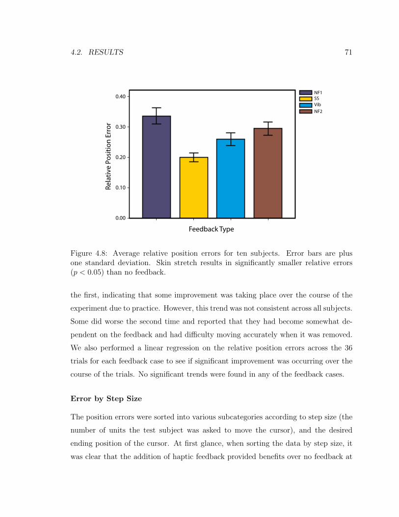
4.2. RESULTS 71
Rela
tive
Po
siti
on
Err
or
0.40
0.30
0.20
0.10
0.00
Feedback Type
NF1SSVib
NF2
Figure 4.8: Average relative position errors for ten subjects. Error bars are plusone standard deviation. Skin stretch results in significantly smaller relative errors(p < 0.05) than no feedback.
the first, indicating that some improvement was taking place over the course of the
experiment due to practice. However, this trend was not consistent across all subjects.
Some did worse the second time and reported that they had become somewhat de-
pendent on the feedback and had difficulty moving accurately when it was removed.
We also performed a linear regression on the relative position errors across the 36
trials for each feedback case to see if significant improvement was occurring over the
course of the trials. No significant trends were found in any of the feedback cases.
Error by Step Size
The position errors were sorted into various subcategories according to step size (the
number of units the test subject was asked to move the cursor), and the desired
ending position of the cursor. At first glance, when sorting the data by step size, it
was clear that the addition of haptic feedback provided benefits over no feedback at
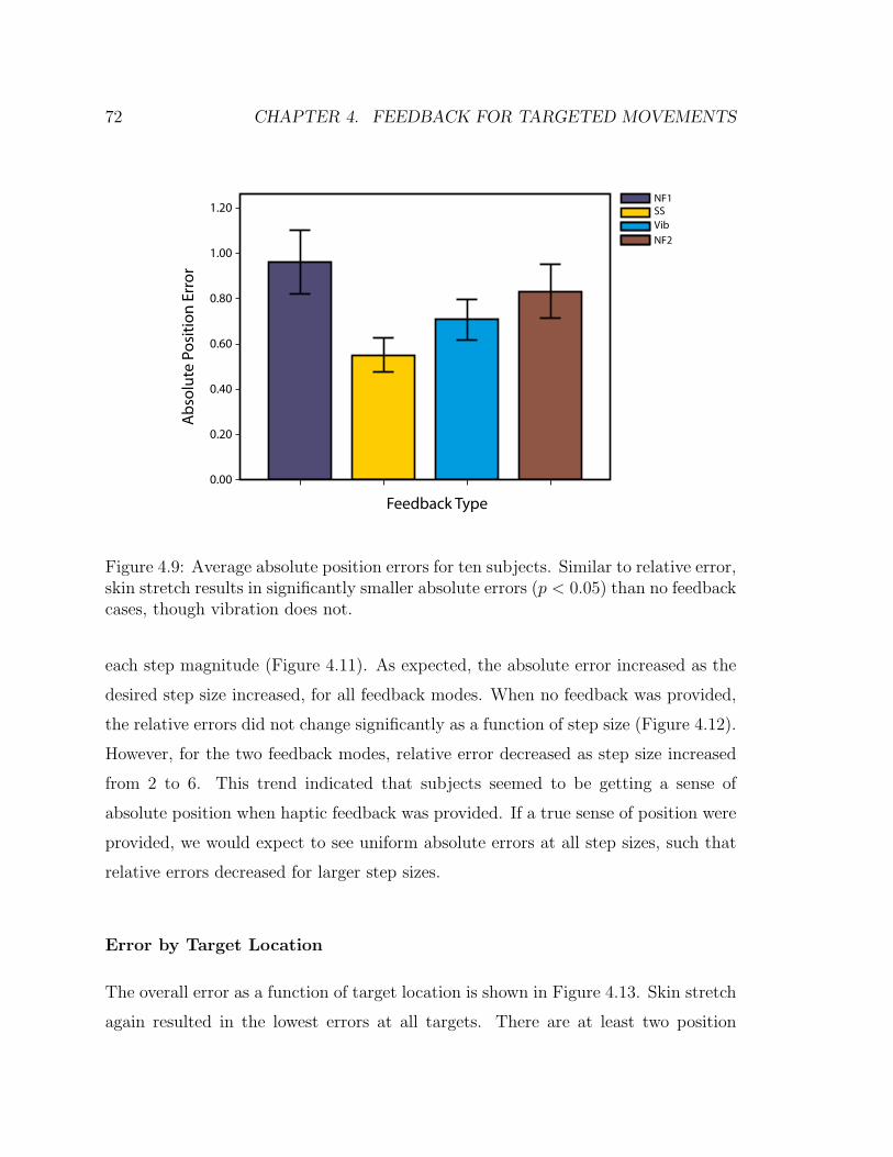
72 CHAPTER 4. FEEDBACK FOR TARGETED MOVEMENTS
Ab
solu
te P
osi
tio
n E
rro
r1.20
1.00
0.80
0.60
0.40
0.20
0.00
Feedback Type
NF1SSVib
NF2
Figure 4.9: Average absolute position errors for ten subjects. Similar to relative error,skin stretch results in significantly smaller absolute errors (p < 0.05) than no feedbackcases, though vibration does not.
each step magnitude (Figure 4.11). As expected, the absolute error increased as the
desired step size increased, for all feedback modes. When no feedback was provided,
the relative errors did not change significantly as a function of step size (Figure 4.12).
However, for the two feedback modes, relative error decreased as step size increased
from 2 to 6. This trend indicated that subjects seemed to be getting a sense of
absolute position when haptic feedback was provided. If a true sense of position were
provided, we would expect to see uniform absolute errors at all step sizes, such that
relative errors decreased for larger step sizes.
Error by Target Location
The overall error as a function of target location is shown in Figure 4.13. Skin stretch
again resulted in the lowest errors at all targets. There are at least two position

4.2. RESULTS 73
Figure 4.10: Average absolute position errors using vibration feedback and skinstretch feedback for each of the ten subjects. Each dot represents one subject. Dots inthe shaded region indicates subjects who performed better with skin stretch feedback(9 of 10).
dependent factors that could influence these results. One is position dependent per-
ception qualities of the haptic feedback, which are small (see perception study results
above). The more dominant effect seems to be the cursor inertia. Errors were gener-
ally lowest near target location 7, which corresponds to a lower cursor inertia. The
cursor was easier to stop in this location.
4.2.4 Final Velocity
Overall Velocity
The cursor velocity was calculated through differentiation (forward difference method)
of the recorded cursor position throughout the experiment. No additional data fil-
tering was needed since the cursor dynamics effectively act as a low-pass filter. The
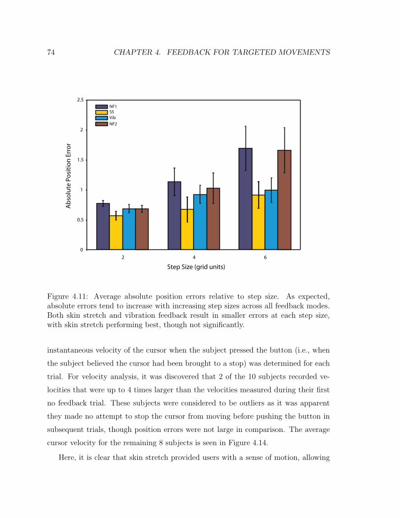
74 CHAPTER 4. FEEDBACK FOR TARGETED MOVEMENTS
0
0.5
1
1.5
2
2.5
2 4 6
Ab
solu
te P
osi
tio
n E
rro
r
Step Size (grid units)
NF1SSVib
NF2
Figure 4.11: Average absolute position errors relative to step size. As expected,absolute errors tend to increase with increasing step sizes across all feedback modes.Both skin stretch and vibration feedback result in smaller errors at each step size,with skin stretch performing best, though not significantly.
instantaneous velocity of the cursor when the subject pressed the button (i.e., when
the subject believed the cursor had been brought to a stop) was determined for each
trial. For velocity analysis, it was discovered that 2 of the 10 subjects recorded ve-
locities that were up to 4 times larger than the velocities measured during their first
no feedback trial. These subjects were considered to be outliers as it was apparent
they made no attempt to stop the cursor from moving before pushing the button in
subsequent trials, though position errors were not large in comparison. The average
cursor velocity for the remaining 8 subjects is seen in Figure 4.14.
Here, it is clear that skin stretch provided users with a sense of motion, allowing
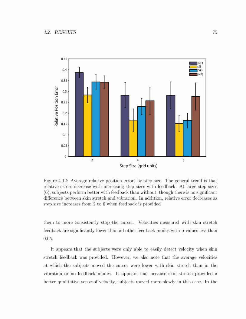
4.2. RESULTS 75
0
0.05
0.1
0.15
0.2
0.25
0.3
0.35
0.4
0.45
2 4 6
Rela
tive
Po
siti
on
Err
or
Step Size (grid units)
NF1SSVib
NF2
Figure 4.12: Average relative position errors by step size. The general trend is thatrelative errors decrease with increasing step sizes with feedback. At large step sizes(6), subjects perform better with feedback than without, though there is no significantdifference between skin stretch and vibration. In addition, relative error decreases asstep size increases from 2 to 6 when feedback is provided
them to more consistently stop the cursor. Velocities measured with skin stretch
feedback are significantly lower than all other feedback modes with p-values less than
0.05.
It appears that the subjects were only able to easily detect velocity when skin
stretch feedback was provided. However, we also note that the average velocities
at which the subjects moved the cursor were lower with skin stretch than in the
vibration or no feedback modes. It appears that because skin stretch provided a
better qualitative sense of velocity, subjects moved more slowly in this case. In the

76 CHAPTER 4. FEEDBACK FOR TARGETED MOVEMENTS
0
0.2
0.4
0.6
0.8
1
1.2
1.4
1 3 5 7 9
Ab
solu
te P
osi
tio
n E
rro
r
Ending Target Location
NF1SSVib
NF2
Figure 4.13: Average absolute position error versus desired target location. Skinstretch produced the lowest error at all targets. Lower errors are found where thecursor inertia is low (i.e. near point 7).
other cases, there was little sense of cursor velocity and no motivation or ability to
limit speed.
Velocity by Cursor End Position
A point of interest when examining the final velocities is the correlation with cursor
position and inertia. As the cursor inertia increases, while damping remains constant,
more effort is required to bring the cursor to a stop. In all feedback methods, the
average ending velocity of the cursor relative to the desired ending position closely
matches the pattern of the inertial changes (Figure 4.15). A cursor position of 7 cor-
responds to a low cursor inertia, and correspondingly, the measured ending velocities
of the cursor are lowest at that location. This suggests that subjects were indeed
experiencing the challenges of controlling the varying cursor dynamics. However, the

4.3. DISCUSSION 77
Cu
rso
r En
d V
elo
city
(gri
d u
nit
s/se
c)0.60
0.50
0.40
0.30
0.20
0.10
0.00
Feedback Type
NF1SSVib
NF2
Figure 4.14: Overall average ending velocities. Skin stretch is far superior to all otherfeedback modes in maintaining low end velocities (p < 0.05).
errors are consistently lower with skin stretch and the variation with cursor position
is generally lower than with other feedback modes.
4.3 Discussion
The results of the present study indicate that skin stretch may be an effective method
for providing proprioceptive feedback in wearable displays. Skin stretch is an impor-
tant part of the proprioceptive sense and provides a useful mapping for position
information. In particular, skin stretch gives a realistic sense of dynamic motion in
addition to static position using just a single stimulus, which could provide benefits
for many applications. As observed in previous studies, this feedback is effective for
closed loop control, providing a better sense of location and position when vision is

78 CHAPTER 4. FEEDBACK FOR TARGETED MOVEMENTS
Figure 4.15: Average ending velocities with respect to desired ending cursor position.Average ending velocities from each feedback mode follow the sinusoidal characteris-tics of the varying inertial properties of the cursor with respect to cursor position.
not present. Though subjects were able to position the cursor with smaller errors
using skin stretch feedback, the true value of skin stretch feedback lies in its ability
to convey a sense of motion. Subjects could easily detect whether the cursor was
moving or had stopped and in combination with the motor commands through the
force sensor input, users had a clear idea of the cursor direction. This perception of
motion becomes even more important when control channels or dynamics of a system
are complex. In this study, the dynamics of the system were complex to make it more
difficult for user to simply use open-loop strategies to position the cursor. In systems
where the dynamics are simple, skin stretch feedback may not provide a good cost
to benefit ratio. However, in systems such as a prosthetic arm, the dynamics can be
difficult to predict and the control channels can be noisy. Myoelectrically controlled
prostheses, which use electrical impulses produced from muscle contractions to control
high-impedance prosthetic joint actuators, may contain noisy signals. Coupled with
friction and the changing inertia and dynamics of the arm itself make it a difficult
4.3. DISCUSSION 79
system to control. It is this type of application in which skin stretch may provide to
be a very effective method of feedback. This is explored in the following chapter.
Although vibrotactile feedback was provided in these experiments and found to
be less effective in positioning accuracy than skin stretch, it must be noted that it
still remains an attractive choice for wearable haptic applications due to its size and
power characteristics. In the present study, the amplitude of the vibration was contin-
uously varied according to cursor position as this was found to be the most effective
continuous mapping. However, other strategies could be employed where discrete
changes in amplitude or frequency occur at specific intervals. This would require the
subject to “count” to some extent to perform movements and the inherent resolution
of the feedback channel would be limited. In any case, when vibration is used, it is
desirable only to turn on the stimulation when a movement is being made as many
subjects reported that continuous vibration was annoying. In addition, neural adap-
tation causes desensitization over time [10, 55]. Multiple vibration stimulators could
also convey a sense of motion if they are appropriately sequenced [104]. However
the stimulators must be spaced relatively far apart due to the large receptive fields
of the deep Pacinian corpuscles. Because skin stretch activates primarily superficial,
slow acting receptors, it is less susceptible to these issues.
Although these initial studies indicate there are unexplored benefits to using skin
stretch for tactile feedback, there are a few practical issues that must be addressed
when attempting to implement skin stretch. Particularly if the skin contact area is
relatively small, as with the device used in this study, care must be taken so that the
device does not slip on the skin. How well the device works is highly dependent on the
where it is placed on the skin and on the subject. The device tends to slip more if there
is a lot of hair on the skin or in areas where skin curvature is high. Though the Red-
E-Tape was found to adhere adequately to the skin, it is assumed that some amount
of slip occurred throughout the skin stretch trials. The varying stiffness of skin on
different parts of the body, as well as subject-to-subject variation of skin properties,
present significant design and control challenges. Some individual calibration may be

80 CHAPTER 4. FEEDBACK FOR TARGETED MOVEMENTS
required when the device is attached. Because skin stiffness properties also depend
on the configuration of the body or limbs, the perceived magnitude of stretch also
appears to change. In early pilot experiments, we attempted to place the skin stretch
applicator near the elbow joint to provide something closer to an illusory sense of
joint movement. However, we observed that as the trials progressed, subjects would
move and bend their elbows slightly to re-adjust their seating configuration. Using
the wearable device would be more comfortable for users and we can infer from these
results and previous studies that the results from a study such as this would be similar
with the wearable device.
The present study did not fully assess the effects of training on movement accuracy.
Because subjects were given post-trial vision feedback throughout the experiment,
some improvement over time was expected. In fact, most subjects had lower errors
in the second no feedback trial than the first but no significant improvement was
found across the 36 trials for a given feedback case. All subjects were given uniform
training in this study. To fully assess learning effects, a future study should be
performed where the training method is a controlled variable.
Overall, skin stretch feedback was found to provide effective feedback. It cannot
be used to replace vision, yet it can be used to reduce the dependence on vision by
providing a relative sense of position and motion. The following chapter builds on this
idea by applying this type of feedback to a more realistic application and assessing
the visual demand for another task with and without feedback.

Chapter 5
Artificial Proprioception for
Myoelectric Prostheses
5.1 Introduction
Recent advances in engineering and medicine have provided more sophisticated upper-
limb prostheses as well as improved means of controlling them. However, most upper-
limb prostheses lack direct sensory feedback. While still not approaching the richness
of human sensory systems, the current state of technology is such that prostheses
could be equipped with a variety of sensors to measure position and motion, forces,
temperature and vibration. A more challenging problem, however, is to relay this
information back to the amputee. Promising research is being done in the field of
neural prosthetics that may allow direct stimulation of neurons in the central or
peripheral nervous system (e.g. [28,86]). However, these approaches are invasive, and
more research and development will be needed before this becomes a viable option.
Wearable haptic displays can provide a non-invasive approach to communicating
information from sensors in a prosthetic limb to the amputee. As early as the 1960’s,
a number of researchers evaluated tactile displays to provide users a sense of grip
force in myoelectric hands. These included cutaneous [9,98,100] and implanted [4,23]
81

82 CHAPTER 5. FEEDBACK FOR MYOELECTRIC PROSTHESES
single electrode displays as well as vibrotactile displays [115]. Mann [79] implemented
a vibrotactile display of position proprioception in a myoelectric elbow joint. The pre-
vailing opinion at this time was that the feedback would be beneficial if not critical
for the advancement of myoelectric prostheses. While these studies found benefits
to the feedback, it was not widely adopted clinically. It is not clear why amputees
and clinicians did not respond to this concept, but there are a number of potential
contributing factors. First, the feedback modalities used can be subjectively unpleas-
ant [64, 99]. There may also have been some aversion to adding complexity in the
prosthesis without providing a more significant functional benefit. Most traditional
myoelectric prostheses have high-impedance actuators in the joints which, coupled
with the noise in the myoelectric signal (MES), may limit the user’s ability to con-
trol force even if they have some afferent feedback. Amputees also have some limited
sense of force in the prosthesis through vision (deformation) and reaction forces at the
socket interface. Recently, as more sophisticated arms and hands are being created,
haptic force feedback is again being evaluated, and may be better accepted clini-
cally as amputees adopt more technologically advanced prostheses. Cipriani et al.
implemented vibration feedback of grip force in an anthropomorphic hand that was
myoelectrically controlled and found qualitative benefits in unimpaired subjects [22].
Less work has focused on haptic proprioceptive feedback for prostheses. In the
absence of proprioception, amputees can rely on vision to position the arm. When
visual feedback is not available, users can potentially rely on internal models of the
arm and controller to perform some tasks with open-loop strategies. This has led
some to question the value of proprioceptive feedback in prostheses (e.g. see [54]). As
discussed in Chapters 1 and 2, the role of proprioceptive feedback in human motor
control is not completely understood. The substantial delays associated with the
feedback (50-250ms, depending on the modality [68]) indicate that it is likely not
being used for real-time control for most motions at preferred speeds. Many motions
seem to be performed in feed-forward fashion based on an internal model of the
body [68]. How this idea translates to myoelectric prostheses, where arm dynamics

5.1. INTRODUCTION 83
and control parameters are quite different (along with typical movement speeds) is
also not well understood. However, there is evidence suggesting that feedback would
be useful. Proprioceptive or visual feedback could be used to construct an internal
model of the system, which could improve long-term performance. Visual servoing
consumes a large portion of the user’s visual capacity that could be devoted to other
simultaneous tasks. High visual demand has been cited as a drawback of myoelectric
arms by amputees [7]. Additionally, some benefits of proprioception have been shown
even when vision is present [70]. The addition of proprioceptive feedback creates a
closed-loop system that may make the prosthesis a more intuitive extension of the
user. This is evidenced by the fact that body-controlled prostheses (including some
with external power, e.g. [2, 19, 20, 53, 110]) have proven popular in part due to the
fact that they take advantage of the principle of extended physiological proprioception
(EPP) as first described by Simpson [102]. Myoelectric prostheses can provide more
intuitive and less cumbersome control schemes but lack this element of feedback,
which some amputees have cited as a reason for rejection of the prosthesis [101].
In the present studies, we aim to show quantitative benefits of proprioceptive haptic
feedback in blind targeting accuracy and a reduction in visual demand for a continuous
movement task. The visual demand measurement is an attempt to quantify how often
a user must glance at the arm in order to complete the task.
In the study presented in the previous chapter, we found it necessary to give
the virtual object non-intuitive dynamics in order for the feedback to be beneficial
compared to feed-forward motions. For myoelectric prostheses, we hypothesize that
the inconsistent and noisy characteristics of the MES, coupled with the nonlinear
joint dynamics (due to static friction), will make open-loop strategies less effective
and the haptic display more beneficial.
In the following sections, we evaluate the wearable skin stretch device with unim-
paired subjects controlling a virtual prosthetic elbow joint with EMG electrodes on
the bicep and tricep muscles. The experimental setup approximates a transhumeral

84 CHAPTER 5. FEEDBACK FOR MYOELECTRIC PROSTHESES
amputation as the elbow joint is effectively fixed by having participants hold a sta-
tionary handle with their hand. We use a blind targeting task to compare their ac-
curacy with the haptic device to the cases where no feedback is provided (open-loop
movements) and where proprioception is provided on the contralateral arm. These
two comparison cases establish what we consider the worst (no feedback) and best
(contralateral proprioception) afferent cases for blind targeting while maintaining the
salient efferent characteristics of myoelectric control. In addition, we compare the
visual demand required to roughly position the virtual elbow continuously in a visual
occlusion study with skin stretch compared to no feedback.
5.2 Methods
In this section we describe the control of the virtual arm, including EMG data pro-
cessing steps as well as the control of the feedback devices. Finally, we describe the
calibration procedure and the experimental protocol for the two user studies. The
wearable skin stretch device was used for these studies.
5.2.1 Control System
We used a simple controller that captures the salient characteristics of many myo-
electric prostheses and was easy for the subjects to learn to use in the present work.
Figure 5.1 shows a schematic representation of the primary control elements of the ex-
perimental setup. The control elements can be divided into three sub-sections; EMG
data collection and processing, virtual prosthetic arm dynamics, and control of the
skin stretch device. Each of these is discussed in the following subsections. Matlab’s
xPC real-time target was used to perform the data collection and closed loop control
at 1 kHz.

5.2. METHODS 85
R aw B icep E MG
R aw T ricep E MG
Digital Low-P ass F ilter
Digital Low-P ass F ilter
K B
K T
+
- Deadband
Linear Arm Dynamics P (s )
Non-Linear S kin S tretch Mapping
Arm P os ition
E ncoder
+-
1 s
K I
K P
+
+
Motor S peed
EMG Processing Arm Dynamics Skin Stretch Device Control
Figure 5.1: Schematic representation of the primary control elements in the system.
EMG Data Processing
Differential EMG electrodes with pre-amplification (Delsys 2.1) were used to collect
the MES from the bicep and tricep muscles. A second stage handheld amplifier with
gain of 1000 (Delsys Bagnoli 2) was used for further signal amplification. Each EMG
channel was sampled at 1 kHz, the DC bias was subtracted (found during an initial
calibration procedure described below), and a low-pass Butterworth filter with a cut-
off frequency of 6 Hz was applied. Gains were then applied to each channel before
sending the signal to the virtual arm. These gains varied between subjects and were
determined as part of the calibration procedure.
Virtual Prosthetic Arm Dynamics
After the gains were applied to the filtered MES, the tricep signal was subtracted
from the bicep signal to create a virtual torque that was sent to the arm. This virtual
torque is analogous to the current sent to the motor in a prosthetic limb (multiplied
by the torque constant of the motor). A deadband was used to simulate static friction
in the arm which required a minimum torque of 0.5 units to be applied to the arm
for it to move. The torque was saturated at 5 units. Units are defined such that one
unit of torque produces an angular acceleration of one rad/sec2 when applied to one
unit of inertia (in the absence of friction).
After applying the non-linear elements, the torque was sent to the linear dynamics
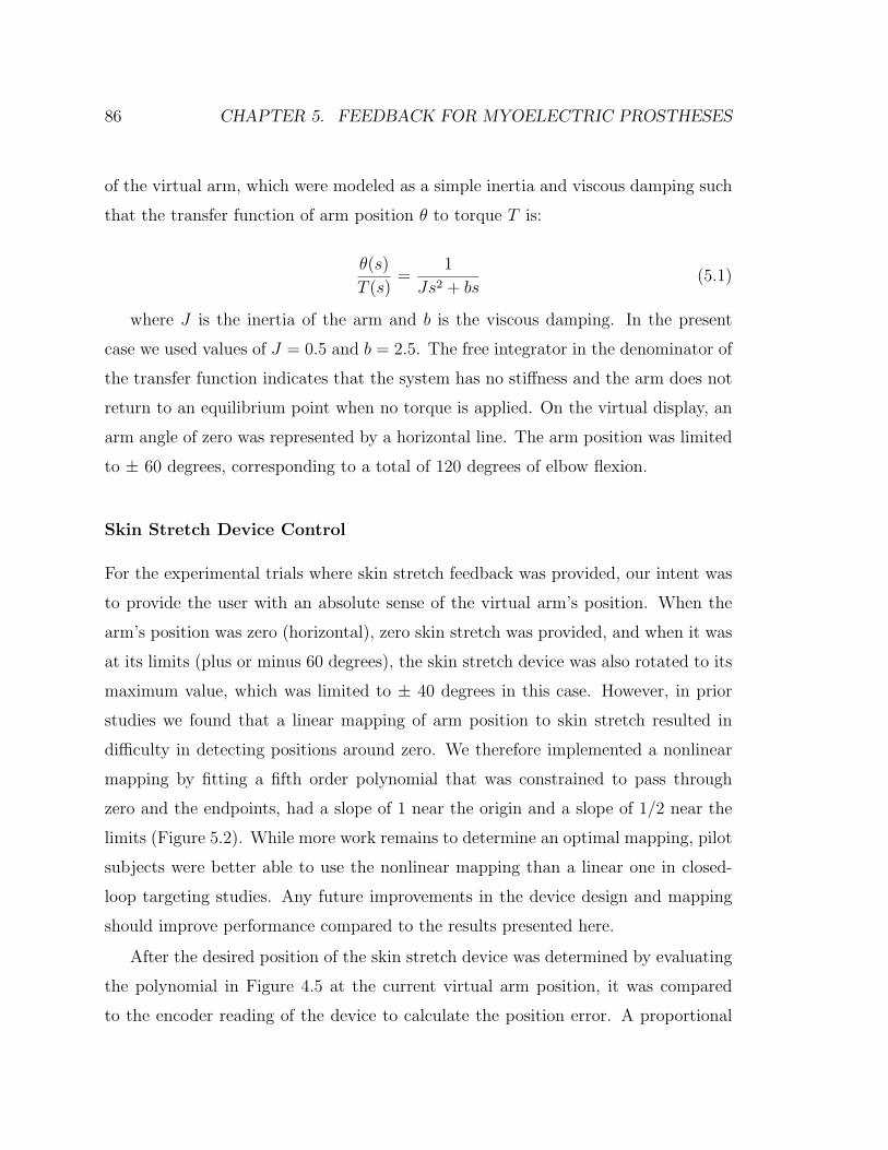
86 CHAPTER 5. FEEDBACK FOR MYOELECTRIC PROSTHESES
of the virtual arm, which were modeled as a simple inertia and viscous damping such
that the transfer function of arm position θ to torque T is:
θ(s)
T (s)=
1
Js2 + bs(5.1)
where J is the inertia of the arm and b is the viscous damping. In the present
case we used values of J = 0.5 and b = 2.5. The free integrator in the denominator of
the transfer function indicates that the system has no stiffness and the arm does not
return to an equilibrium point when no torque is applied. On the virtual display, an
arm angle of zero was represented by a horizontal line. The arm position was limited
to ± 60 degrees, corresponding to a total of 120 degrees of elbow flexion.
Skin Stretch Device Control
For the experimental trials where skin stretch feedback was provided, our intent was
to provide the user with an absolute sense of the virtual arm’s position. When the
arm’s position was zero (horizontal), zero skin stretch was provided, and when it was
at its limits (plus or minus 60 degrees), the skin stretch device was also rotated to its
maximum value, which was limited to ± 40 degrees in this case. However, in prior
studies we found that a linear mapping of arm position to skin stretch resulted in
difficulty in detecting positions around zero. We therefore implemented a nonlinear
mapping by fitting a fifth order polynomial that was constrained to pass through
zero and the endpoints, had a slope of 1 near the origin and a slope of 1/2 near the
limits (Figure 5.2). While more work remains to determine an optimal mapping, pilot
subjects were better able to use the nonlinear mapping than a linear one in closed-
loop targeting studies. Any future improvements in the device design and mapping
should improve performance compared to the results presented here.
After the desired position of the skin stretch device was determined by evaluating
the polynomial in Figure 4.5 at the current virtual arm position, it was compared
to the encoder reading of the device to calculate the position error. A proportional

5.2. METHODS 87
-60 -40 -20 20 40 60
-40
-30
-20
-10
0
10
20
30
40
Arm P os ition (Deg)
Ski
n S
tre
tch
An
gle
(D
eg
)
S lope = 1
S lope = 1/2
Figure 5.2: Non-linear mapping of virtual arm angle to skin stretch rotation. Mappingis a fifth-order polynomial with a slope of one near the origin and 1/2 near the limits.
plus integral (PI) controller was then used to set the speed of the motor based on
this position error. The proportional gain (Kp) was 0.75 and the integral gain (Ki)
was 0.1. A small driver board provided by the manufacturer (Shinsei Motors, D6030)
was used to control the motor. In addition to the analog speed channel, which was
specified as described above, two digital lines were used to control the direction of
rotation. Due to these direction changes and the fact that the motor has a minimum
speed at which it can rotate determined by the resonance of the piezo elements, some
chatter around the desired position was sometimes encountered when the arm moved
very slowly. We therefore implemented a deadband of 0.1 degrees on the position
error. The position error due to the controller was always less than 0.8 degrees.
5.2.2 Experimental Setup
Setup Overview
The experimental setup is shown in Figure 5.3. The participant was seated in front
of a computer display. EMG electrodes were placed on the right bicep and tricep

88 CHAPTER 5. FEEDBACK FOR MYOELECTRIC PROSTHESES
muscles near the center of the muscle body with the differential electrodes aligned
approximately with the fiber direction. A reference electrode was placed on the back
of the right hand. The wearable skin stretch device was placed on the back of the
right upper arm, proximal to the elbow, near the tricep electrode. The participant
gripped a handle with their right hand. A button was placed on the handle so it could
be easily pushed with the thumb. The setup was designed to simulate a transhumeral
amputation as the elbow joint was effectively fixed. Participants could produce the
MES by pulling up or pushing down on the handle. Pulling up approximates the
bicep acting in isolation, and pushing down approximates the tricep in isolation.
Virtual Arm/ Task Display
Tricep EMGElectrode
Bicep EMGElectrode
Push Button
Ground EMGElectrode
Skin StretchDevice
Figure 5.3: Experimental setup. Right pane shows schematic view of the primaryinput and feedback elements.
In the no feedback case, the skin stretch device was turned off. In trials where
contralateral proprioception was provided, the left arm of the participant was placed

5.2. METHODS 89
in a single degree of freedom manipulandum that could position the elbow joint at a
desired angle in the horizontal plane. The elbow angle was set to match the angle of
the virtual arm with zero degrees of elbow flexion corresponding to minus 60 degrees
of rotation of the virtual arm, and 120 degrees of elbow flexion corresponding to
60 degrees of rotation of the virtual arm (Figure 5.4). The elbow manipulandum
used a DC motor (Maxon RE025) with a 13.5:1 capstan cable drive transmission. A
PID current controller on the desired elbow angle was implemented that produced
dynamic tracking errors less than 2.0 degrees and static position errors of less than
0.21 degrees in all trials. A screen was placed above the manipulandum so the arm
motion was not visible to the subject.
0o
60o-60o
o
Manipulandum
Figure 5.4: Schematic view of elbow manipulandum used to provide contralateralproprioceptive feedback.

90 CHAPTER 5. FEEDBACK FOR MYOELECTRIC PROSTHESES
Calibration
Prior to the experiment, the participants underwent two phases of calibration. First,
they were asked to grip the handle but otherwise relax the arm. EMG activity from
both muscles was recorded for five seconds, and the mean of this resting data was
subtracted from each channel during later trials. Second, the participant was asked
to pull up and push down on the handle while EMG signals were recorded. They were
not instructed to use maximal force but a large force that would be comfortable to
apply during the experiment. The respective gains for the bicep and tricep muscles
were calculated by dividing the maximum filtered EMG signal recorded during the
calibration by a constant, in this case 5. The participants were then allowed to move
the virtual arm on the screen with visual feedback to determine if the calibration was
satisfactory. The calibration was considered satisfactory if the participant had some
control of the speed of the arm in both directions and approximately equal effort
was required to move the arm in both directions. The calibration was repeated as
necessary until the participant was satisfied with the controller. This took no longer
than four attempts. In a few cases during the experiment, some drift was encountered
due to a change in the DC bias. In such cases the calibration was repeated as needed.
Participants
Fifteen volunteers participated in the studies. Nine were male, six female, ages 19-
49, mean age 27.3. Nine of the fifteen participants (6 male, 3 female) completed the
targeting trial with contralateral proprioception. These trials were added to the study
after six participants had already completed the skin stretch and no feedback trials
in an attempt to provide a best-case baseline for performance. The studies took a
total of 45-120 minutes to complete, including setup and calibration. The study was
approved by Stanford’s Institutional Review Board.

5.2. METHODS 91
5.2.3 Targeting Study
The subjects first participated in a targeting accuracy study where no real-time vi-
sion feedback was provided. Prior to each set of trials a brief training period was
provided. Each participant was allowed to move the arm through the workspace with
visual feedback for two minutes and then was given 10 practice trials, identical to the
experimental trials. In the no feedback case, the training allowed them to learn open-
loop strategies, and in the haptic and contralateral proprioception feedback cases it
allowed them to learn the mapping of arm position to feedback sensations. In each
experimental trial, the starting position of the arm was displayed on the screen cho-
sen from [-60,0,60] degrees. An instruction to move ± 30, 60 or 90 degrees was also
displayed. Movements were constrained such the desired ending position was either
-30, 0 or 30 degrees. This resulted in a total of eight starting/ending combinations,
each of which was repeated four times in random order for a total of 32 trials per
participant. A sample starting screen is shown in Figure 5.5.
After this screen appeared, the participant moved the virtual arm without seeing
the motion of the arm on the screen. The participant was instructed to press the
button when they felt the target was reached. After the trial, the participant was
shown the actual and desired ending position of the arm. The targeting error was
recorded for each trial, i.e. the absolute value of the difference between the desired
and actual ending position. The 32 trials were performed with both skin stretch
feedback and no feedback. Seven participants did the no feedback trials first; eight
did the skin stretch trials first. The nine participants who completed the trials with
contralateral proprioception did these last.
5.2.4 Visual Occlusion Study
In the second study we assessed participants’ visual demand with and without the
skin stretch device using the visual occlusion method [48,105]. In this case, the task
was to keep the virtual arm in a desired range that moved in a quasi-random fashion.
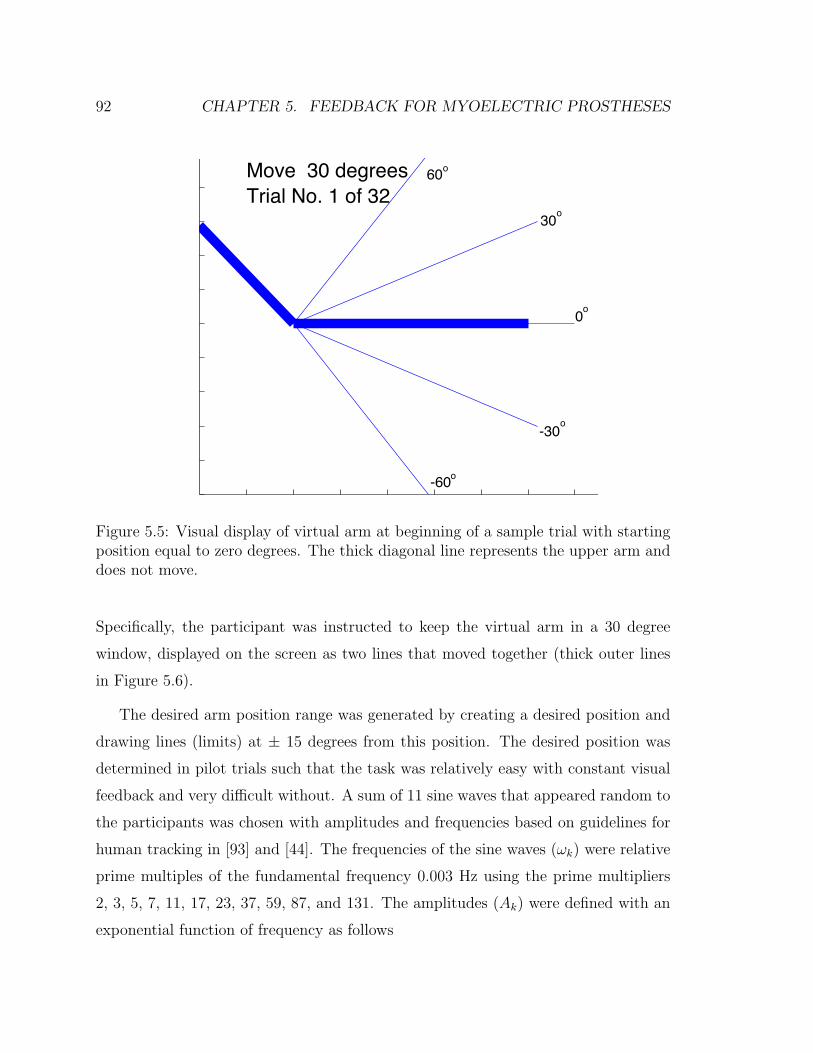
92 CHAPTER 5. FEEDBACK FOR MYOELECTRIC PROSTHESES
Move 30 degreesTrial No. 1 of 32
60o
30
0
-30
-60
o
o
o
o
Figure 5.5: Visual display of virtual arm at beginning of a sample trial with startingposition equal to zero degrees. The thick diagonal line represents the upper arm anddoes not move.
Specifically, the participant was instructed to keep the virtual arm in a 30 degree
window, displayed on the screen as two lines that moved together (thick outer lines
in Figure 5.6).
The desired arm position range was generated by creating a desired position and
drawing lines (limits) at ± 15 degrees from this position. The desired position was
determined in pilot trials such that the task was relatively easy with constant visual
feedback and very difficult without. A sum of 11 sine waves that appeared random to
the participants was chosen with amplitudes and frequencies based on guidelines for
human tracking in [93] and [44]. The frequencies of the sine waves (ωk) were relative
prime multiples of the fundamental frequency 0.003 Hz using the prime multipliers
2, 3, 5, 7, 11, 17, 23, 37, 59, 87, and 131. The amplitudes (Ak) were defined with an
exponential function of frequency as follows

5.2. METHODS 93
DesiredR ange
Arm P os ition
Figure 5.6: Visual display of virtual arm at beginning of visual occlusion trial. Thickouter lines represent the desired range, thick horizontal line in the center is the virtualarm which is only visible for one second after a button press.
Ak = 0.311∑
k=1
e−0.12(k−1) (5.2)
The scaling (0.3) and decay rate (0.12) values were determined such that sufficient
coverage of the workspace was generated while not exceeding the range. The phase
angles of the sine waves were randomized before each trial to prevent the participants
from memorizing the inputs. A sample of the desired range and the virtual arm’s
position for a successful trial are shown in Figure 5.7.
Visual feedback of the virtual arm’s position was provided for one second each
time the participant pressed the button on the handle. Participants were instructed
to press the button whenever they felt visual feedback was required to complete the
task. If the arm left the desired range, the trial ended and restarted. The trial was
successful if the participant kept the arm in the desired range for the duration of
the trial (40 seconds). Trials were repeated until the participant had three successful

94 CHAPTER 5. FEEDBACK FOR MYOELECTRIC PROSTHESES
0 5 10 15 20 25 30-60
-40
-20
0
20
40
60
Time (s)
Posi
tion
(Deg
)
LimitsArm Pos.
Figure 5.7: Virtual arm position and task position limits for 30 seconds of a sampletrial with skin stretch feedback.
trials for the no feedback and skin stretch cases. The order of the trials (no feedback
and skin stretch) was randomized. Prior to the experiment, participants were given
one full practice trial with constant vision feedback for each feedback case. Over
the course of the trials (including failures) participants were able to determine an
appropriate strategy of button press frequency that allowed them to complete the
task.
For each successful trial the average visual demand was calculated. The instan-
taneous visual demand (VisDem) can be calculated at each button press using the
following relation
V isDem =1.0
ti − ti−1
(5.3)
where the numerator is the duration of the feedback (1 sec.) and ti and ti−1 are
the times corresponding to the current and previous button presses. Visual demand

5.2. METHODS 95
calculations for a sample no feedback and skin stretch trial are shown in Figure 5.8.
The average visual demand is calculated by averaging these values over the trial or
equivalently by dividing the number of button presses by the duration of the trial.
The average visual demand is the fraction of time that visual demand was provided
over the course of the trial. It is a measure of how often the participant felt they
needed to glimpse at the arm to complete the task. In the data analysis, the average
over all three successful trials was used to compare the haptic and no feedback cases.
As a secondary measure, the number of task failures before completing the three trials
was also recorded.
0 5 10 15 20 25 30 35 40
0.2
0.25
0.3
0.35
0.4
0.45
0.5
0.55
0.6
0.65
T ime (s )
Vis
ua
l De
ma
nd
NFS S
Figure 5.8: Visual demand calculations at each button press for a sample no feedback(NF) and skin stretch (SS) trial.

96 CHAPTER 5. FEEDBACK FOR MYOELECTRIC PROSTHESES
5.3 Results
5.3.1 Targeting Study
In the targeting study, the primary measure of interest is the average targeting error
(across the 32 trials). A box plot of the average position errors for each of the
participants is shown in Figure 5.9. Repeated measure analysis of variance (ANOVA)
with pairwise comparisons was performed for this performance measure. For all 15
subjects a repeated measure ANOVA with two levels (no feedback and skin stretch)
was performed. Significant main effects were found due to both feedback condition,
F (1, 14) = 36, p = 3.3 · 10−5 and participant F (14, 14) = 544, p = 1.3 · 10−12.
Errors with skin stretch were significantly lower compared to errors with no feedback
with p = 3.3 · 10−5. For the nine subjects who participated in the contralateral
proprioception feedback case a separate repeated measure ANOVA with three levels
was performed. Significant main effects due to feedback condition, F (2, 8) = 29,
p = 6.6 ·10−4, and participant F (8, 8) = 57, p = 6.8 ·10−5 were again found. Post-hoc
pairwise comparisons with Bonferroni correction found significant differences between
all feedback cases with skin stretch lower than no feedback with p = 0.015 and
contralateral proprioception lower than skin stretch with p = 2.9 · 10−3.
While variations between participants were significant, trends were consistent
across participants as all 15 had lower average errors with skin stretch than no feed-
back, and all nine participants who completed the contralateral proprioception trial
had lowest errors in that case.
In order to get a sense of how the participants were utilizing the feedback that
was provided, we also examined the movement profiles. In the no feedback condition,
participants typically moved in a single motion, with a single burst of EMG data.
When feedback was provided (contralateral proprioception or skin stretch) we often
observed submovements with delays of 0.4-1.0 seconds between them. A sample
motion for each case is shown in Figure 5.10. In many cases, the submovements
were not all in the same direction. Given the delays associated with the feedback

5.3. RESULTS 97
No Feedback SS Feedback CP Feedback
4
6
8
10
12
14
16
18
20
22
Targ
etin
g Er
ror (
deg)
Figure 5.9: Box plot of average targeting errors for participants with no feedback andskin stretch (SS) feedback (n=15) and contralateral proprioceptive (CP) feedback(n=9) .
(probably around 100-200 ms) it seems that subjects would move and then wait to
get a sensation of the position before deciding whether to make another movement to
correct for error. The number of submovements was calculated by differentiating the
arm position and looking for peaks in this velocity profile (with a minimum temporal
separation of 0.3 seconds). With no feedback, participants had an average of 1.2
submovements per trial. With contralateral proprioceptive feedback, an average of
2.8 submovements was found. With skin stretch, the result was again between these
extremes with an average of 2.1 submovements per trial. These differences were
significant with p-values below 0.01.
5.3.2 Visual Occlusion Study
The primary measure in the visual demand study was the average visual demand
over the three successful trials for each feedback condition. A box plot of these

98 CHAPTER 5. FEEDBACK FOR MYOELECTRIC PROSTHESES
-60
-40
-20
0
20
40
60
Arm
Po
sitio
n (
De
g)
Movement with F eedback
0 0.5 1 1.5 2 2.5 3 3.5 4 4.5 5 5.5-0.2
-0.1
0
0.1
0.2
0.3
T ime (s )
Tri
cep
EM
G
-40
-20
0
20
40
60
Arm
Po
sitio
n (
de
g)
Movement without F eedback
0 0.5 1 1.5 2 2.5 3 3.5 4-0.4
-0.2
0
0.2
0.4
0.6
T ime (s )
Tri
cep
EM
G
Figure 5.10: Sample of a movement profile for one subject with skin stretch feedback(left) and no feedback (right). Three submovements are evident in the case withfeedback. The desired target was -60 degrees in both cases.
data is shown in Figure 5.11. While there was significant participant-to-participant
variation in the visual demand in both feedback cases, participants generally had
lower visual demand with the haptic device (Figure 5.12). With skin stretch feedback,
the average visual demand was reduced 23 percent (from 0.53 with no feedback, to
0.41). A repeated measure ANOVA was performed for average visual demand over
the three trials. Significant main effects were found due to both feedback condition,
F (1, 14) = 31, p = 7.2 · 10−5 and participant F (14, 14) = 184, p = 1.9 · 10−9. Visual
demand was significantly lower with skin stretch compared to the no feedback case
with p = 7.2 · 10−5.
Participants also had fewer failures before completing the three trials with skin
stretch feedback. The mean number of failures before completing the no feedback
trials was 12.2 (range 5-24), and with skin stretch the mean was 8.2 (range 2-21).
The difference in means was significant in a paired t-test with p < 1 · 10−6.

5.4. DISCUSSION 99
No Feedback SS Feedback0.2
0.3
0.4
0.5
0.6
0.7Av
erag
e Vi
sual
Dem
and
Figure 5.11: Box plot of average visual demand over three successful trials for all 15participants with no feedback and skin stretch (SS) feedback.
5.4 Discussion
Participants performed better in both user studies with the skin stretch device than
with no feedback. This indicates that the device may have value as a proprioceptive
feedback device in myoelectric prostheses. When no feedback was provided, partici-
pants were forced to rely on open-loop strategies for controlling the arm’s position.
Presumably due to the non-linearities in the virtual arm model and the noisy nature
of the EMG signal, this was difficult, making even a relatively coarse sense of posi-
tion feedback useful. Targeting errors with skin stretch were approaching, but still
significantly larger than errors with proprioceptive feedback from the contralateral
arm, which we consider to be the best case scenario for blind targeting as it relies on
intact physiological sensors while maintaining the other aspects of the experiment.

100 CHAPTER 5. FEEDBACK FOR MYOELECTRIC PROSTHESES
No F eedback S kin S tretch0.2
0.3
0.4
0.5
0.6
0.7
0.8A
vera
ge
Vis
ua
l De
ma
nd
Figure 5.12: Average visual demand for each of the 15 subjects with no feedback andskin stretch.
In addition to reducing targeting errors, skin stretch feedback reduced the visual de-
mand required to track a moving angular window. The lower visual demand indicates
that providing a rough sense of position could allow the arm to be used (if position
accuracy is not critical) while vision is devoted elsewhere, making the prosthetic arm
a more natural extension of the person. The addition of haptic feedback could ef-
fectively close the control loop and require only occasional glances from the user,
reducing the need for visual attention.
In both studies, only a short training period was provided. Additional training
may improve performance with no feedback and with the haptic device; however,
we expect minimal training benefit in the contralateral proprioception case. Though
we did not directly assess the effects of training as uniform training was provided

5.4. DISCUSSION 101
in all cases, a simple regression analysis was performed to determine if subjects’
performance improved over the time. In the targeting study, we fit a regression line
to the absolute value of the errors versus trial number across all participants and
found a significant negative slope for the skin stretch case (p = 0.034), providing
evidence that errors decreased as the trial progressed. However, when no feedback
is provided, the slope is not significantly different from zero. Individually, four of
fifteen participants had significant negative slopes with skin stretch while two had
significant slopes with no feedback. While future studies are needed to evaluate the
effects of training, this indicates that participants could improve with more training,
particularly with the haptic device.
While the device used in this study is wearable, it is not yet portable. We are
developing devices that are smaller and lighter, and that can be worn on more parts
of the body. We envision future devices that include on-board power, processing
and wireless communication for portable use. All of the primary components of the
device, including the motor, driving electronics, and sensors are amenable to portable
use. The device consumes power only while changing its position. For powered
prosthetic arms, it may be possible to integrate the device into the electronics of
the limb, minimally increasing the size, weight and power consumption. Placement
of the haptic device should be customizable depending on the wearer, as with most
prosthetic components. In some cases, it may even be possible to integrate the device
into the prosthetic socket directly, eliminating the need for straps. In the studies
described here, in which the user wore the device for no more than 2 hours, negligible
slipping between the device and the skin was observed. Future studies will evaluate
whether the current attachment method is adequate for longer term use (i.e. a full
day). Due to the relatively small amount of rotation applied in the study, subjects did
not complain of skin irritation or fatigue despite nearly continuous use for up to 30
minutes at a time. While increasing the range of rotation may improve performance,
it is unclear how this will affect comfort. We expect that each user will have a different
preferred range.

102 CHAPTER 5. FEEDBACK FOR MYOELECTRIC PROSTHESES
This paper has presented a proof of principle for rotational skin stretch as a
means of providing proprioceptive feedback in applications, such as prosthetic limbs,
where it is otherwise absent. The results of the experiments indicate that rotational
skin stretch can be used for closed-loop positioning in vision-impaired circumstances.
Looking ahead, we acknowledge some differences between the experiments described
in this paper and clinical applications, which may affect the performance of skin
stretch device. First, in amputees both the MES and feedback properties may differ
from unimpaired users. When the muscles on the residual limb are activated, more
significant conformal changes may result, which could affect the performance of the
skin stretch device in some cases. While subjects in this study did not have a gross
sense of joint motion, it is possible that they had some low-level afferent feedback
from tendons and other structures that amputees would lack. The effect of these fac-
tors is unclear and will be evaluated in future studies. Another difference between the
present case and the proposed application is the virtual arm and controller dynamics.
These were not specifically designed to match any specific prosthetic arm but were
intentionally simplified so that participants could learn to use the virtual arm with
minimal training. In reality, prosthetic arm dynamics would likely include more sig-
nificant non-linearities, control irregularities, and exogenous disturbances that would
make the arm more difficult to control in an open-loop fashion (which would increase
targeting errors in the absence of feedback). We conjecture that the addition of pro-
prioceptive feedback would be more useful when controlling an arm with more realistic
dynamics. The fact that it was beneficial even with these relatively simple dynamics
(while still maintaining the basic properties of the MES) is encouraging. There is also
the potential for improving the quality of the feedback. The device configuration and
mapping used in this study were effective but likely non-optimal. We are evaluating
potential improvements in these areas that may increase performance.
Chapter 6
Conclusions
The user studies presented in this thesis showed benefits of wearable tactile feedback
for a few applications. Those applications were carefully chosen based on an under-
standing of the inherent advantages and disadvantages of tactile feedback compared to
other modalities. We also relied on insights about the role of proprioceptive feedback
in motor control to guide appropriate use of the technology. Previous studies used for
motion feedback often tested users in tasks that were unrealistically slow compared to
the target applications [16, 75]. While the studies we presented showed feasibility of
the approaches, more work should be done in order to create clinically beneficial sys-
tems. This chapter summarizes the main findings of this work and presents guidelines
for future work.
6.1 Summary of Results
The primary contribution of this work is the evaluation of wearable tactile feedback
for specific clinical applications. Related to motion training, we successfully trained
subjects to modify their gait (a complex dynamic task) to reduce a potentially dam-
aging knee joint load with both visual and vibration feedback. Skin stretch was also
103

104 CHAPTER 6. CONCLUSIONS
evaluated for this task in pilot trials. However, as the feedback was largely discontin-
uous (updated on each step) and the information did not have a direction or motion
associated with it, the benefits of skin stretch were not exploited in this case. We
expect that performance would have been similar to vibration but there was not suffi-
cient justification for the added complexity of the device. It was somewhat surprising
that vibration had similar performance to visual feedback in many respects (with the
exception of the longer training time). It seems that the ability of the subjects to
control the knee force was limited enough that a high resolution feedback method was
not critical. The subjects could lower the load on the average but could not adjust it
with a high resolution. While vision is adequate for feedback in a laboratory setting,
vibration feedback could be used in a portable system if sensors could be developed
to calculate the knee joint loads. This would require a force (or perhaps pressure)
sensor under the foot to estimate the ground reaction force and center of pressure as
well as a method for estimating the relative location of the knee joint center. The
clinical problem addressed by this work is a significant public health problem and
could benefit greatly from non-invasive techniques such as this.
The other clinical issue addressed by this work involves feedback for prosthetic
limbs. While a number of researchers have attempted to implement force feedback
with tactile displays, very little work has focused on proprioceptive feedback. Argu-
ments were made that this type of feedback was not needed as vision was adequate
feedback or feed-forward strategies were effective (e.g. [54]). We tested both of these
hypotheses (Chapter 5) and found that feedback was indeed beneficial when vision
was not provided compared to feed-forward control for myoelectric systems. Ad-
ditionally, we showed that the visual demand required to perform movements with
coarse accuracy can be reduced with artificial proprioception. In Chapter 4, we
showed benefits of artificial proprioception when controlling an external object with
position-dependent dynamics.
In addition to these specific applications, we can also draw more general conclu-
sions about the use of wearable tactile feedback for motion applications. For motion

6.2. OPEN QUESTIONS AND FUTURE WORK 105
training, the feedback is most likely to be beneficial when the task is very slow (which
may be unrealistic) or when the task is repetitive. In repetitive tasks, feedback on each
repetition is used to build effective feed-forward strategies for future movements. The
use of tactile feedback should complement vision appropriately. It can be localized to
present an intuitive sense at a particular joint for instance. For many degrees of free-
dom, 2D vision can be ambiguous. Tactile feedback is also appropriate for portable
systems as it is not desirable to look at a display continuously. For replacement
of proprioceptive feedback, the feedback seems most appropriate when feed-forward
strategies are unreliable and vision is occupied elsewhere.
The use of skin stretch seems most appropriate when it is desired to create a
sense of motion as well as position or magnitude and the information is inherently
continuous. To reduce direction ambiguity, it seems most appropriate when used in
a closed-loop system in which the subject has control over its movement. Vibration
is attractive due to its small size and ease of application. They are easily arrayed to
create a sense of localized feedback. They have been used extensively in commercial
devices to convey exogenous event cues. In this work we also use them to provide
intrinsic feedback based on the users’ actions. For complex systems, a combination
of tactile feedback types along with vision and audition may be an effective way to
maximize communication bandwidth.
6.2 Open Questions and Future Work
The studies we presented here tested healthy subjects to show feasibility of the ap-
proaches. To establish clinical relevance, studies with patients should be carried out.
For osteoarthritis a similar study to the one presented in Chapter 3 could be per-
formed with patients. It should address retention of the new gait as well. Learning or
retention may be improved by using adaptive feedback as well as some explicit sugges-
tions (which could be conveyed with tactile displays as well). An immediate clinical
impact could potentially be made with minimal modifications from the present study.
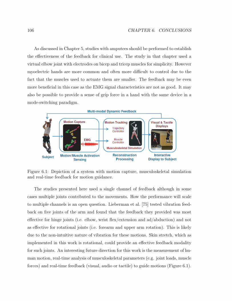
106 CHAPTER 6. CONCLUSIONS
As discussed in Chapter 5, studies with amputees should be performed to establish
the effectiveness of the feedback for clinical use. The study in that chapter used a
virtual elbow joint with electrodes on bicep and tricep muscles for simplicity. However
myoelectric hands are more common and often more difficult to control due to the
fact that the muscles used to actuate them are smaller. The feedback may be even
more beneficial in this case as the EMG signal characteristics are not as good. It may
also be possible to provide a sense of grip force in a hand with the same device in a
mode-switching paradigm.
Figure 6.1: Depiction of a system with motion capture, musculoskeletal simulationand real-time feedback for motion guidance.
The studies presented here used a single channel of feedback although in some
cases multiple joints contributed to the movements. How the performance will scale
to multiple channels is an open question. Lieberman et al. [75] tested vibration feed-
back on five joints of the arm and found that the feedback they provided was most
effective for hinge joints (i.e. elbow, wrist flex/extension and ad/abduction) and not
as effective for rotational joints (i.e. forearm and upper arm rotation). This is likely
due to the non-intuitive nature of vibration for these motions. Skin stretch, which as
implemented in this work is rotational, could provide an effective feedback modality
for such joints. An interesting future direction for this work is the measurement of hu-
man motion, real-time analysis of musculoskeletal parameters (e.g. joint loads, muscle
forces) and real-time feedback (visual, audio or tactile) to guide motions (Figure 6.1).

6.2. OPEN QUESTIONS AND FUTURE WORK 107
Because this may involve complex information over many joints being conveyed to the
user, studies should be performed to assess how to do this in a way that maximizes
the bandwidth and intuitiveness of the feedback.

108 CHAPTER 6. CONCLUSIONS

Bibliography
[1] A. Abbott. In search of the sixth sense. Nature, 442:125–127, 2006.
[2] H. M. Al-angari, R. ff. Weir, C. W. Heckathorne, and D. S. Childress. A
two degree-of-freedom microprocessor based extended physiological propriocep-
tion (EPP) controller for upper limb prostheses. Technology and Disability,
15(2):113–127, 2003.
[3] R. Ammons. Effects of knowledge of performance: A survey and tentative
theoretical formulation. The Journal of General Psychology, 54:279, 1956.
[4] A. B. Anani, K. Ikeda, and L. M. Korner. Human ability to discriminate various
parameters in afferent electrical nerve stimulation with particular reference to
prostheses sensory feedback. Medical and Biological Engineering and Compu-
tation, 15:363–373, 1977.
[5] M. Andrews, F. R. Noyes, T. E. Hewett, and T. P. Andriacchi. Lower limb
alignment and foot angle are related to stance phase knee adduction in normal
subjects: A critical analysis of the reliability of gait analysis data. Journal of
Orthopaedic Research, 14(2):289, 1996.
[6] T. P. Andriacchi. Dynamics of knee malalignment. The Orthopedic clinics of
North America, 25:395, 1994.
[7] D. Atkins. Epidemiologic overview of individuals with upper-limb loss and their
reported research priorities. Journal of prosthetics and orthotics, 8(1):2, 1996.
109

110 BIBLIOGRAPHY
[8] K. Bark. Rotational skin stretch feedback: A new approach to wearable haptic
display. PhD Dissertation, Stanford University, 2009.
[9] T. W. Beeker, J. During, and A. Den Hertog. Artificial touch in a hand pros-
thesis. Medical and Biological Engineering, 5:47–49, 1967.
[10] U. Berglund and B. Berglund. Adaptation and Recovery in Vibrotactile Per-
ception. Perceptual and Motor Skills, 30(3):843, 1970.
[11] J. Biggs and M. Srinivasan. Tangential versus normal displacements of skin:
Relative effectiveness for producing tactile sensations. In 10th International
Symposium on Haptic Interfaces for Virtual Environment and Teleoperator Sys-
tems,, pages 121–128. IEEE Computer Society, 2002.
[12] E. Bilodeau and I. Bilodeau. Some effects of introducing and withdrawing
knowledge of results early and late in practice. Journal of Experimental Psy-
chology, 58:142–144, 1959.
[13] E. Bilodeau and I. Bilodeau. Motor-skills learning. Annual Reviews in Psychol-
ogy, 12:243–280, 1961.
[14] E. Bizzi, N. Accornero, W. Chapple, and N. Hogan. Posture control and trajec-
tory formation during arm movement. The journal of neuroscience, 4(11):2738,
1984.
[15] M. Bjorklund. Effects of repetitive work on proprioception and of stretching on
sensory mechanisms. Medical Dissertation, UMEA University, 2004.
[16] Aaron Bloomfield and Norman I. Badler. Virtual training via vibrotactile ar-
rays. Presence: Teleoperators and Virtual Environments, 17(2):103–120, 04/01
2008.

BIBLIOGRAPHY 111
[17] J. Brown. A proposed program of research on psychological feedback (knowledge
of results) in the performance of psychomotor tasks. In Research Planning
Conferences on Perceptual and Motor Skills,, pages 81–87, 1949.
[18] A. Cappozzo, U. Della Croce, A. Leardini, and L. Chiari. Human movement
analysis using stereophotogrammetry: Part 1: theoretical background. Gait
and posture, 21(2):186–196, 2 2005.
[19] L. E. Carlson. Control of powered arm prosthesis with extended physiological
proprioception. In Proceedings of the 7th World Congress of the International
Society for Prosthetics and Orthotics, 1992.
[20] D. S. Childress, E. C. Grahn, R. F. ff Weir, C. W. Heckathorne, and J. E.
Uellendahl. Modification of a bock hand for E.P.P. control by exteriorized
tendons. In Proceedings of the 19th Annual Meeting of American Academy of
Orthotics and Prosthetics, page 13, 1993.
[21] R. Cholewiak and A. Collins. The generation of vibrotactile patterns on a linear
array: Influences of body site, time, and presentation mode. Perception and
psychophysics, 62(6):1220–1235, 2000.
[22] C. Cipriani, F. Zaccone, S. Micera, and M. C. Carrozza. On the shared control
of an EMG-controlled prosthetic hand: Analysis of user-prosthesis interaction.
IEEE Transactions on Robotics, 24(1):170–184, February 2008.
[23] R. W. Clippenger, R. Avery, and B. R. Titus. A sensory feedback system for an
upper-limb amputation prosthesis. Bulletin of Prosthetics Research, 10(22):247–
258, 1974.
[24] J. Cole. Pride and a Daily Marathon. MIT Press, 1995.
[25] D. F. Collins, K. M. Refshauge, G. Todd, and S. C. Gandevia. Cutaneous
receptors contribute to kinesthesia at the index finger, elbow, and knee. Journal
of Neurophysiology, 94:1699–1706, May 2005.

112 BIBLIOGRAPHY
[26] Y. Danilov and M. Tyler. Brainport: an alternative input to the brain. Journal
of integrative neuroscience, 4(4):537, 2005.
[27] J. L. DeMarre, L. Mundermann, T. P. Andriacchi, and A. Mundermann. A
mechanism to lower the knee adduction moment during walking: Gait retraining
as intervention for knee oa. 2006.
[28] G. S. Dhillon and K. W. Horch. Direct neural sensory feedback and control
of a prosthetic arm. IEEE Transactions on Neural Systems and Rehabilitation
Engineering, 13(4):468–472, December 2005.
[29] B. Edin and N. Johansson. Skin strain patterns provide kinaesthetic information
to the human central nervous system. Journal of Physiology, (487):243–251,
1995.
[30] B. B. Edin. Cutaneous afferents provide information about knee joint move-
ments in humans. The Journal of Physiology, (531.1):289–297, 2001.
[31] B. B. Edin. Quantitative analyses of dynamic strain sensitivity in human skin
mechanoreceptors. Journal of Neurophysiology, 92:3233–3243, 2004.
[32] A. Feldman. Functional tuning of the nervous system with control of movement
or maintenance of a steady posture. II. controllable parameters of the muscle.
Biophysics, 11(3):565, 1966.
[33] T. Flash. The control of hand equilibrium trajectories in multi-joint arm move-
ments. Biological cybernetics, 57(4-5):257, 1987.
[34] O Franzen and J Nordmark. Vibrotactile frequency discrimination. Perception
and Psychophysics, 17(5):480–484, Feb 1975.
[35] B. J. Fregly. Computational assessment of combinations of gait modifications for
knee osteoarthritis rehabilitation. Biomedical Engineering, IEEE Transactions
on, 55(8):2104–2106, 2008.

BIBLIOGRAPHY 113
[36] B. J. Fregly, J. A. Reinbolt, K. L. Rooney, K. H. Mitchell, and T. L.
Chmielewski. Design of patient-specific gait modifications for knee osteoarthritis
rehabilitation. IEEE Transactions on Biomedical Engineering, 54(9):1687–1695,
2007.
[37] M. Fritschi. Design of a tactile shear force prototype display. In
http://www.touch-hapsys.org, page Workpackage 6, 2003.
[38] S. C. Gandevia, J. L. Smith, M. Crawford, U. Proske, and J. L. Taylor. Motor
commands contribute to human position sense. The Journal of physiology,
571(3):703, 2005.
[39] E. Gardner, J. Martin, and T. Jessell. The Bodily Senses, chapter 22, pages
431–431–450. Principles Of Neural Science. McGraw Hill, fourth edition edition,
2000.
[40] GD Garson. Univariate glm, anova, and ancova from statnotes: Topics in
multivariabe analysis. Website, 2007. http://www2.chass.ncsu.edu/garson/
pa765/anova.htm.
[41] F. A. Geldard. Sensory saltation: Metastability in the perceptual world. Heldard
Press, 1975.
[42] Frank A. Geldard and Carl E. Sherrick. The cutaneous “rabbit”: A perceptual
illusion. Science, 178(4057):178–179, October 13 1972.
[43] G. Gescheider, S. Bolanowski, R. Verrillo, D. Arpajian, and T. Ryan. Vibro-
tactile intensity discrimination measured by three methods. Journal of the
Acoustical Society of America, 87(1):330–338, 1990.
[44] R. B. Gillespie and S. Sovenyi. Model-based cancellation of biodynamic
feedthrough using a force-reflecting joystick. Journal of Dynamic Systems, Mea-
surement, and Control, 128(1):94–103, 2006.

114 BIBLIOGRAPHY
[45] S Gilman. Joint position sense and vibration sense: anatomical organisation
and assessment. Journal of Neurology, Nerosurgery, and Psychiatry, 73:473–
477, Jan 2002.
[46] G Goff. Differential discrimination of frequency of cutaneous mechanical vibra-
tion. Journal of Experimental Psychology, 74(2):294–299, Jun 1967.
[47] G. M. Goodwin, D. I. McCloskey, and P. B. C. Matthews. The contribution of
muscle afferents to keslesthesia shown by vibration induced illusions of move-
ment and by the effects of paralysing joint afferents. Brain, 95(4):705–748,
1972.
[48] P. Griffiths and R. B. Gillespe. Sharing control between humans and automa-
tion using haptic interface: Primary and secondary task performance benefits.
Human Factors, 47(3):574, 2005.
[49] M. Guo, M. Axe, and K. Manal. The influence of foot progression angle on
the knee adduction moment during walking and stair climbing in pain free
individuals with knee osteoarthritis. Gait and posture, 26(3):436–441, 2007.
[50] A. Gupta and M. O’Malley. Design of a haptic arm exoskeleton for training and
rehabilitation. IEEE/ASME transactions on mechatronics, 11(3):280, 2006.
[51] N. Gurari, K. Kuchenbecker, and A. Okamura. Stiffness discrimination with
visual and proprioceptive cues. 2009.
[52] V. Hayward and M. Cruz-Hernandez. Tactile display device using distributed
lateral skin stretch. In Proceedings of the Haptic Interfaces for Virtual Envi-
ronment and Teleoperator Systems Symposium, pages 1309–1314.
[53] C. W. Heckathorne, D. S. Childress, E. C. Grahn, J. Strysik, and J. Uellendahl.
E.P.P. control of an electric hand by exteriorized forearm tendons. In Proceed-
ings of the 8th World Conference of the International Society of Prosthetics and
Orthotics, 1995.

BIBLIOGRAPHY 115
[54] N. Hogan. Mechanical impedance control in assistive devices and manipulators.
In Joint Automatic Control Conference,, volume 1, pages 361–371, 1980.
[55] M. Hollins, A.K. Goble, B.L. Whitsel, and M. Tommerdahl. Time Course
and Action Spectrum of Vibrotactile Adaptation. Somatosensory and Motor
Research, 7(2):205–221, 1990.
[56] M. A. Hunt, T. B. Birmingham, J. R. Giffin, and T. R. Jenkyn. Associations
among knee adduction moment, frontal plane ground reaction force, and lever
arm during walking in patients with knee osteoarthritis. Journal of Biomechan-
ics, 39(12):2213–2220, 2006.
[57] D. E. Hurwitz, A. B. Ryals, J. P. Case, J. A. Block, and T. P. Andriacchi. The
knee adduction moment during gait in subjects with knee osteoarthritis is more
closely correlated with static alignment than radiographic disease severity, toe
out angle and pain. Journal of Orthopaedic Research, 20(1):101, 2002.
[58] A. Iggo. Sensory receptors in the skin of mammals and their sensory functions.
Revue neurologique, 141(10):599, 1985.
[59] A Israr, H Tan, and C Reed. Frequency and amplitude discrimination along
the kinesthetic-cutaneous continuum in the presence of masking stimuli. The
Journal of the Acoustical Society of America, 120(5):2789–2800, Nov 2006.
[60] L. Jones. Motor illusions: What do they reveal about proprioception. Psycho-
logical Bulletin, 103(1):72–86, 1988.
[61] L. Jones, M. Nakamura, and B. Lockyer. Development of a tactile vest. In Pro-
ceedings of the 12th International Symposium on Haptic Interfaces for Virtual
Environment and Teleoperator Systems. IEEE, March 27-28, 2004.
[62] L Jones and N Sarter. Tactile displays: Guidance for their design and appli-
cation. Human Factors: The Journal of the Human Factors and Ergonomics
Society, 50(1):90–111, Feb 2008.

116 BIBLIOGRAPHY
[63] K. A. Kaczmarek, J. G. Webster, and R. G. Radwin. Maximal dynamic range
electrotactile stimulation waveforms. IEEE Transactions on Biomedical Engi-
neering, 39(7):701–715, 1992.
[64] K. A. Kaczmarek, J. G. Webster, P. Bach y Rita, and W. J. Tompkins. Electro-
tactile and vibrotactile displays for sensory substitution systems. IEEE Trans-
actions on Biomedical Engineering, 38(1):1–16, 1991.
[65] H. Kajimoto, N. Kawakami, S. Tachi, and M. Inami. Smarttouch: electric
skin to touch the untouchable. IEEE Computer Graphics and Applications,
24(1):36–43, 2004.
[66] W. Kakihana, M. Akai, K. Nakazawa, T. Takashima, K. Naito, and S. Torii.
Effects of laterally wedged insoles on knee and subtalar joint moments. Archives
of Physical Medicine and Rehabilitation, 86(7):1465–1471, 2005.
[67] W. Kakihana, M. Akai, N. Yamasaki, T. Takashima, and K. Nakazawa. Changes
in joint moments in the gait of normal subjects wearing laterally wedged insoles.
American journal of physical medicine rehabilitation, 83(4):273, 2004.
[68] M. Kawato. Internal models for motor control and trajectory planning. Current
opinion in neurobiology, 9(6):718–727, 1999.
[69] T. Koyama, I. Yamano, K. Takemura, and T. Maeno. Multi-fingered ex-
oskeleton haptic device using passive force feedback for dexterous teleoperation.
IEEE/RSJ International Conference on Intelligent Robots and System, 2002.,
3:2905–2910, 2002.
[70] K.J. Kuchenbecker, N. Gurari, and A.M. Okamura. Effects of visual and pro-
prioceptive motion feedback on human control of targeted movement. IEEE
10th International Conference on Rehabilitation Robotics, pages 513–524, June
2007.

BIBLIOGRAPHY 117
[71] R. H. LaMotte, M. A. Srinivasan, C. Lu, P. S. Khalsa, and R. M. Friedman.
Raised object on a planar surface stroked across the fingerpad: Responses of
cutaneous mechanoreceptors to shape and orientation. Journal of Neurophysi-
ology, 80:2446–2466, 1998.
[72] C Layne. Introduction to neuroscience. Website, 2009. http://grants.hhp.
coe.uh.edu/clayne/6397/Unit4a.htm.
[73] C. Lenay, O. Gapenne, S. Hanneton, C. Genoulle, and C. Marque. Sensory
Substitution, Limits and Perspectives, pages 275–292. Touching for Knowing.
2003.
[74] V. Levesque and V. Hayward. Experimental evidence of lateral skin strain
during tactile exploration. In Proc. Eurohaptics, July 2003.
[75] J. Lieberman and C. Breazeal. TIKL: Development of a wearable vibrotac-
tile feedback suit for improved human motor learning. IEEE Transactions on
Robotics, 23(5):919–926, October 2007.
[76] R. A. Magill. Knowledge is more than we can talk about:implicit learning in
motor skill acquisition. Research Quarterly for Exercise and Sport, 69:104–110,
1998.
[77] D. Mahns, N. Perkins, V. Sahai, L. Robinson, and M. Rowe. Vibrotactile
frequency discrimination in human hairy skin. Journal of Neurophysiology,
95:1442–1450, March 2006.
[78] Y. Makino and H. Shinoda. Selective stimulation to superficial mechanorecep-
tors by temporal control of suction pressure. In Haptic Interfaces for Virtual
Environment and Teleoperator Systems, World Haptics Conference, pages 229–
234, March 18-20, 2005.
118 BIBLIOGRAPHY
[79] R. W. Mann. Efferent and afferent control of an electromyographic proportional-
rate, force sensing artificial elbow with cutaneous display of joint angle. Pro-
ceedings of Institute of Mechanical Engineers, 183(3J):86–92, 1968.
[80] R. Miall and D. Wolpert. Forward models for physiological motor control.
Neural Networks, 9(8):1265–1279, 1996.
[81] J. Morley and M. Rowe. Perceived pitch of vibrotactile stimuli: effects of
vibration amplitude, and implications for vibration frequency coding. Journal
of Physiology, 431:403–416, May 1990.
[82] G. Mowbray and J. Gebhard. Sensitivity of the skin to changes in rate of
intermittent mechanical stimuli. Science, 125:1297–1298, Jun 1957.
[83] G. Moy and R. Fearing. Effects of shear stress in teletaction and human percep-
tion. In Proceedings of the 1998 ASME Dynamic Systems and Control Division,
ASME International Mechanical Engineering Congress and Exposition, volume
DSC-Vol. 64, pages 265–272, November 1998.
[84] A. Mundermann, C. O. Dyrby, and T. P. Andriacchi. Secondary gait changes in
patients with medial compartment knee osteoarthritis. Arthritis and rheuma-
tism, 52:2835, 2005.
[85] A. M. Murray, R. L. Klatzky, and P. K. Khosla. Psychophysical characterization
and testbed validation of a wearable vibrotactile glove for telemanipulation.
Presence, Vol.12(2):156–182, 2003.
[86] M. A. L. Nicolelis. Actions from thoughts. Nature, 409:403–407, 2001.
[87] American Academy of Orthopedic Surgeons. Knee arthritis statistics, 2008.
[88] S. O’Mara, M. Rowe, and R. Tarvin. Neural mechanisms in vibrotactile adap-
tation. Journal of Neurophysiology, 59(2):607–622, February 1988.

BIBLIOGRAPHY 119
[89] M. Pare, H. Carnahan, and A. Smith. Magnitude estimation of tangential force
applied to the fingerpad. Experimental Brain Research, 142:342–348, 2002.
[90] R. Perlau, C. Frank, and G. Fick. The effect of elastic bandages on human
knee proprioception in the uninjured population. American Journal of Sports
Medicine, 23(2):251, 1995.
[91] R. W. Pew. Levels of analysis in motor control. Brain Research, 71:393–400,
1974.
[92] E. Piateski and L. Jones. March 18-20 2005.
[93] D. W. Repperger, D. B. Rogers, J. W. Frazier, and K. E. Hudson. A task
difficulty - g stress experiment. Ergonomics, 27(2):161, 1984.
[94] M. Rothenberg, R. Verrillo, S. A. Zahorian, M. L. Brachman, and S. J.
Bolanowski. Vibrotactile frequency for encoding speech parameters. The Jour-
nal of the Acoustical Society of America, 62:1003–1012, Jun 1977.
[95] E. Salinas, A. Hernandez, A. Zainos, and R. Romo. Periodicity and firing rate
as candidate neural codes for the frequency of vibrotactile stimuli. The journal
of neuroscience, 20(14):5503, 2000.
[96] A. G. Schache, B. J. Fregly, K. M. Crossley, R. S. Hinman, and M. G. Pandy.
The effect of gait modification on the external knee adduction moment is ref-
erence frame dependent. Clinical Biomechanics, 23(5):601–608, 2008.
[97] O. D. Schipplein and T. P. Andriacchi. Interaction between active and passive
knee stabilizers during level walking. Journal of Orthopaedic Research, 9(1):113,
1991.
[98] R. N. Scott, R. H. Brittain, R. R. Caldwell, A. B. Cameron, and V. A. Dunfield.
Sensory feedback system compatible with myoelectric control. Medical and
Biological Engineering and Computing, 18:65–69, 1980.

120 BIBLIOGRAPHY
[99] G. F. Shannon. A comparison of alternative means of providing sensory feedback
on upper limb prostheses. Medical and Biological Engineering, 14(3):289–294,
1976.
[100] G. F. Shannon. A myoelectrically controlled prosthesis with sensory feedback.
Medical and Biological Engineering and Computing, 17:73–80, 1979.
[101] D. H. Silcox, M. D. Rooks, R. R. Vogel, and L. L. Fleming. Myoelectric pros-
theses. a long-term follow-up and a study of the use of alternate prostheses.
Journal of Joint and Bone Surgery, 75A(12):1781–1788, 1993.
[102] D. C. Simpson. The choice of control system for the multimovement prosthesis:
Extended physiological proprioception (E.P.P.). The Control of Upper Extrem-
ity Prostheses and Orthoses, 1974.
[103] R. B. Stein and M. Walley. Functional comparison of upper extremity amputees
using myoelectric and conventional prostheses. Archives of physical medicine
and rehabilitation, 64(6):243, 1983.
[104] H. Tan, R. Gray, J. J. Young, and R. Traylor. A haptic back display for
attentional and directional cueing. Haptics-e, 3(1):September 15, 2007, June
2003.
[105] O. Tsimhoni and P. A. Green. Visual demand of driving and the execution
of display-intensive in-vehicle tasks. pages 1589–1590. Human Factors and Er-
gonomics Society, 2001.
[106] M. E. Tyler, Y. Danilov, and P. Bach y Rita. Closing an open-loop control
system: vestibular substitution through the tongue. Journal of Integrative Neu-
roscience, (2):1–6, 2003.
[107] A. Vallbo, H. Olausson, J. Wessberg, and N. Kakuda. Receptive field character-
istics of tactile units with myelinated afferents in hairy skin of human subjects.
Journal of Physiology, 483(Pt 3):783, March 1995.
BIBLIOGRAPHY 121
[108] M. Wada, S. Imura, K. Nagatani, H. Baba, S. Shimada, and S. Sasaki. Rela-
tionship between gait and clinical results after high tibial osteotomy. Clinical
orthopaedics and related research, 354:180, 1998.
[109] Q. Wang, V. Hayward, and A. M. Smith. A new technique for the controlled
stimulation of the skin. In Proceedings of the Canadian Medical and Biological
Engineering Society Conference, CMBEC, September 9-11, 2004.
[110] R. ff. Weir, C. W. Heckathorne, and D. S. Childress. Cineplasty as a control
input for externally powered prosthetic components. Journal of Rehabilitation
Research and Development, 38(4):357–363, 2001.
[111] A Wilksa. On the vibrational sensitivity in different regions of the body surface.
Acta physiologica scandinavica, 31:284–289, Jul 1954.
[112] G. Wulf and R. A. Schmidt. Variability in practice and implicit motor learning.
Journal of Experimental Psychology:Learning, Memory, and Cognition, 23:987–
1006, 1997.
[113] P. Bach y Rita. Brain Mechanisms in Sensory Substitution. Academic Press,
New York, 1972.
[114] P. Bach y Rita. Tactile sensory substitution studies. Annals of the New York
Academy of Sciences, 1013:83, 2004.
[115] P. Bach y Rita and C. C. Collins. Sensory substitution and limb prostheses.
Advances in external control of human extremities, pages 9–21, 1970.
[116] P. Bach y Rita, C. C. Collins, F. Saunders, B. White, and L. Scadden. Vision
substitution by tactile image projection. Nature, 221:963–964, 1969.
[117] P. Bach y Rita, Y. Danilov, M. Tyler, and R. Grimm. Late human brain plastic-
ity: vestibular substitution with a tongue brainport human-machine interface.
Journal of Plasticity and Restorative Neurolgy, 4:31–34, 2005.

122 BIBLIOGRAPHY
[118] J. J. Zwislocki and D. A. Goodman. Absolute scaling of sensory magnitudes: a
validation. Perception and Psychophysics, 28(1):28–38, 1980.
Copyright © 2022 FDOKUMEN