
Affect expression in ECAs: Application to politeness displays
Upload
khangminh22Category
view
0download
0
DIRECT INTERACTION WITH LARGE DISPLAYS THROUGH MONOCULAR COMPUTER VISION
A thesis submitted in fulfilment of the requirements for the degree of Doctor of Philosophy in the School of Information Technologies at
The University of Sydney
Kelvin Cheng October 2008

© Copyright by Kelvin Cheng 2008
All Rights Reserved

ii
Abstract
Large displays are everywhere, and have been shown to provide higher productivity
gain and user satisfaction compared to traditional desktop monitors. The computer
mouse remains the most common input tool for users to interact with these larger
displays. Much effort has been made on making this interaction more natural and
more intuitive for the user. The use of computer vision for this purpose has been well
researched as it provides freedom and mobility to the user and allows them to
interact at a distance. Interaction that relies on monocular computer vision, however,
has not been well researched, particularly when used for depth information recovery.
This thesis aims to investigate the feasibility of using monocular computer
vision to allow bare-hand interaction with large display systems from a distance. By
taking into account the location of the user and the interaction area available, a
dynamic virtual touchscreen can be estimated between the display and the user. In
the process, theories and techniques that make interaction with computer display as
easy as pointing to real world objects is explored.
Studies were conducted to investigate the way human point at objects naturally
with their hand and to examine the inadequacy in existing pointing systems. Models
that underpin the pointing strategy used in many of the previous interactive systems
were formalized. A proof-of-concept prototype is built and evaluated from various
user studies.
Results from this thesis suggested that it is possible to allow natural user
interaction with large displays using low-cost monocular computer vision.
Furthermore, models developed and lessons learnt in this research can assist
designers to develop more accurate and natural interactive systems that make use of
human’s natural pointing behaviours.

iii
Acknowledgements
I would like to thank my supervisor Masahiro Takatsuka for his continuing support
and for being a fantastic supervisor throughout my degree.
I would also like to thank Peter Eades for his guidance and advice over the years, and
to David Vronay for his supervision and for making possible the internship at
Microsoft Research Asia.
I want to thank Frank Yu, Tony Huang, Adel Ahmed, Ben Yip, Calvin Cheung,
Nelson Yim and Daniel Rachmat for their advice and discussions at various times
during my PhD.
Thanks to Shea Goyette, Henry Molina, Abhaya Parthy, Howard Lau, Jacob
Munkberg, Zianlong Zhou, and Sheila Cheng for proof-reading my thesis as well as
the mathematics.
A big thank you to all the volunteers from my usability studies particularly the few
who have participated in all of my experiments.
Thank you to my family for their support and constant encouragement.
My thanks to fellow students at ViSLAB and the Infovis/HUM group for providing
laughter and entertainment, creating a relaxed and enjoyable working atmosphere.
Thanks to the various people at workshop, dp, the administrative and academic staff
at the School of IT for helping me throughout the years in various areas during my
time at SIT and especially for their help with my broken laptop. Thanks for the
weekly supply of milk, and in particular for providing a fantastic espresso machine to
keep me going during the day.

iv
Finally, thank you to The University of Sydney, Faculty of Science, Capital Markets
Cooperative Research Centre and Microsoft Research Asia for keeping me funded.

v
Table of Contents
Abstract ................................................................................................................................................. ii
Acknowledgements .............................................................................................................................. iii
Table of Contents .................................................................................................................................. v
List of Tables ......................................................................................................................................... x
List of Illustrations .............................................................................................................................. xi
Chapter 1 Introduction ........................................................................................................................ 1
1.1 Human-Computer Interaction ..................................................................................................... 1
1.2 Interaction with Large Displays .................................................................................................. 2
1.2.1 Entertainment Systems ........................................................................................................ 4
1.2.2 Presentation Systems ........................................................................................................... 5
1.3 Alternate input techniques ........................................................................................................... 6
1.4 Pointing Strategies ...................................................................................................................... 9
1.5 Aim of this Thesis ......................................................................................................................... 9
1.6 Contribution of this Thesis ......................................................................................................... 11
1.7 Research Methodology .............................................................................................................. 12
1.8 Thesis Structure ......................................................................................................................... 13
Chapter 2 Background and Previous Work ..................................................................................... 15
2.1 Manipulation and Interaction .................................................................................................... 15
2.2 Graphical User Interface .......................................................................................................... 16
2.3 Handheld Intrusive Devices....................................................................................................... 18
2.4 Non-intrusive Techniques .......................................................................................................... 24
2.4.1 Sensitive Surfaces .............................................................................................................. 24
2.4.2 Computer Vision ................................................................................................................ 25
2.5 Selection Strategies ................................................................................................................... 38

vi
2.5.1 Mouse click-less interfaces ................................................................................................ 38
2.5.2 Laser Pointer ...................................................................................................................... 39
2.5.3 Hand gesture ...................................................................................................................... 40
2.6 Summary .................................................................................................................................... 42
Chapter 3 Case Study – Current Interactive Methods ................................................................... 45
3.1 User Interface for the Media PC ............................................................................................... 45
3.2 Related Work ............................................................................................................................. 46
3.2.1 Input devices ...................................................................................................................... 46
3.2.2 User Interface and Interaction Design ............................................................................... 48
3.3 Hypotheses................................................................................................................................. 49
3.4 Usability Study .......................................................................................................................... 49
3.5 Apparatus .................................................................................................................................. 49
3.6 Participants ............................................................................................................................... 50
3.7 Procedure .................................................................................................................................. 51
3.8 Design ........................................................................................................................................ 51
3.9 Results ....................................................................................................................................... 52
3.10 Participants’ comments ........................................................................................................... 53
3.11 General Observations .............................................................................................................. 59
3.11.1 Questionnaires ................................................................................................................. 60
3.12 Discussion ............................................................................................................................... 62
3.13 Recommendations .................................................................................................................... 63
3.13.1 Unified Selection ............................................................................................................. 64
3.13.2 Keyboard/Remote Equivalence ....................................................................................... 64
3.13.3 Action Target / Remote Correspondence ......................................................................... 64
3.13.4 Software solutions ........................................................................................................... 65
3.13.5 User Experience ............................................................................................................... 65
3.13.6 Natural Interfaces ............................................................................................................. 66
3.14 Summary .................................................................................................................................. 66
Chapter 4 Pointing Strategies ........................................................................................................... 68
4.1 Background and Related Work .................................................................................................. 68
4.2 Experiment: Style of Pointing Gesture ...................................................................................... 72
4.2.1 Participants ........................................................................................................................ 72
4.2.2 Procedure ........................................................................................................................... 72
vii
4.2.3 Observations & Discussions .............................................................................................. 73
4.2.4 Limitations ......................................................................................................................... 77
4.2.5 Summary ............................................................................................................................ 77
4.3 Experiment: Pointing Accuracy ................................................................................................. 78
4.3.1 Participants ........................................................................................................................ 79
4.3.2 Apparatus ........................................................................................................................... 80
4.3.3 Design and Procedure ........................................................................................................ 81
4.3.4 Results and Discussion ...................................................................................................... 82
4.3.5 Summary ............................................................................................................................ 86
4.4 Models for Targeting ................................................................................................................. 86
4.4.1 Geometrical Configuration ................................................................................................ 86
4.4.2 The Point Model ................................................................................................................ 88
4.4.3 The Touch Model ............................................................................................................... 89
4.5 The dTouch (distant-Touch) Model ............................................................................................ 91
4.6 Indirect Interaction .................................................................................................................... 94
4.7 Summary .................................................................................................................................... 95
Chapter 5 Conceptual Design of Interaction Model ........................................................................ 98
5.1 Monocular Vision ...................................................................................................................... 98
5.2 Design Overview ....................................................................................................................... 99
5.2.1 The View Frustum ........................................................................................................... 100
5.2.2 Virtual Touchscreen ......................................................................................................... 102
5.2.3 Interaction Model ............................................................................................................. 104
5.2.4 Fingertip interaction ......................................................................................................... 105
5.2.5 Visual Feedback ............................................................................................................... 106
5.2.6 Limitations ....................................................................................................................... 106
5.2.7 Summary .......................................................................................................................... 106
Chapter 6 Monocular Positions Estimation ................................................................................... 108
6.1 Environment setup ................................................................................................................... 109
6.2 Geometric Constraints .............................................................................................................. 110
6.3 Step 1: Eye Location Estimation .............................................................................................. 110
6.3.1 Implementation ................................................................................................................. 115
6.3.2 Experiment ........................................................................................................................ 116
6.3.3 Results .............................................................................................................................. 117
6.3.4 Face position in 3D ........................................................................................................... 119
6.3.5 Summary .......................................................................................................................... 122

viii
6.4 Step 2: Fingertip Location Estimation .................................................................................... 122
6.4.1 Fingertip detection ........................................................................................................... 126
6.4.2 Imaginary Point ............................................................................................................... 127
6.4.3 Line Equation .................................................................................................................. 129
6.4.4 Intersection with sphere ................................................................................................... 129
6.4.5 Implementation ................................................................................................................ 131
6.4.6 Experiment ....................................................................................................................... 132
6.4.7 Results ............................................................................................................................. 134
6.4.8 Frontal Fingertip Detection .............................................................................................. 135
6.5 Step 3: Resultant position estimation ...................................................................................... 137
6.5.1 Simplified Model ............................................................................................................. 138
6.5.2 Parallel Plane Model ........................................................................................................ 141
6.6 Estimation error ...................................................................................................................... 146
6.7 Summary .................................................................................................................................. 153
Chapter 7 Experimental Evaluation ............................................................................................... 154
7.1 General Experimental Setup .................................................................................................... 155
7.1.1 The Task ........................................................................................................................... 157
7.1.2 Statistical Treatment ........................................................................................................ 159
7.2 Experiment 1: The effect of feedback on DTouch and EyeToy targeting system ...................... 159
7.2.1 2D Targeting System ........................................................................................................ 159
7.2.2 The Study ......................................................................................................................... 161
7.2.3 Experimental Design ....................................................................................................... 161
7.2.4 Participants ...................................................................................................................... 162
7.2.5 Procedure ......................................................................................................................... 163
7.2.6 Hypotheses ....................................................................................................................... 163
7.2.7 Results and Discussion .................................................................................................... 164
7.2.8 General Discussions ......................................................................................................... 175
7.2.9 Limitations ....................................................................................................................... 175
7.2.10 Summary ........................................................................................................................ 176
7.3 Experiment 2: Minimizing target size ...................................................................................... 177
7.3.1 Participants ...................................................................................................................... 177
7.3.2 Procedure and Design ...................................................................................................... 177
7.3.3 Results ............................................................................................................................. 178
7.4 Experiment 3: The Effect of Calibration ................................................................................. 181
7.4.1 Participants ...................................................................................................................... 182
7.4.2 Procedure ......................................................................................................................... 182
7.4.3 Design .............................................................................................................................. 183

ix
7.4.4 Results ............................................................................................................................. 183
7.5 Experiment 4: The Effect of User’s location ............................................................................ 185
7.5.1 Participants ...................................................................................................................... 186
7.5.2 Procedure and Design ...................................................................................................... 186
7.5.3 Results ............................................................................................................................. 188
7.5.4 Summary .......................................................................................................................... 191
7.6 Overall Summary ..................................................................................................................... 192
Chapter 8 Conclusion ....................................................................................................................... 193
8.1 Summary .................................................................................................................................. 193
8.2 Implications of this research .................................................................................................... 195
8.3 Application Domains ............................................................................................................... 196
8.4 Future Research Direction ...................................................................................................... 199
8.5 Final Remark ........................................................................................................................... 200
Bibliography ..................................................................................................................................... 202

x
List of Tables
Table 2.1: A summary of previous work (potentially problematic properties are highlighted in red) .. 44
Table 3.1: Device Assessment Questionnaire ....................................................................................... 61
Table 3.2: Device Comparison Questionnaire ...................................................................................... 62
Table 4.1: Number of subjects using each pointing style in each task ................................................. 74
Table 4.2 Table of p-values illustrating the significance of multiple pairwise means comparisons
within each pointing technique ............................................................................................................ 83
Table 4.3: Table of p-values illustrating the significance of multiple pairwise means comparisons
within each distance ............................................................................................................................. 84
Table 4.4: A summary of interaction methods under each targeting models proposed......................... 96
Table 6.1: Numerical results of the estimated distances at each distance, as well as the mean accuracy
that the system produced. .................................................................................................................... 117
Table 6.2: Numerical results showing face and eye detection rate at each distance. ........................... 118
Table 6.3: Estimated maximum head rotation on each axis before ..................................................... 119
Table 6.4: Table of average detected location and differences for each grid position. All values are
measured in centimetres. .................................................................................................................... 135
Table 7.1: A summary of p-values and significance of multiple pairwise means comparisons for
accuracy analysis ................................................................................................................................ 165
Table 7.2: A summary of p-values and significance of multiple pairwise means comparisons for task
time completion analysis .................................................................................................................... 168
Table 7.3: Table of p-values for each before and after t-tests. ............................................................ 172
Table 7.4 Target size and their corresponding effecting pointing accuracy required.......................... 177
Table 7.5: Table of p-values illustrating the significance of multiple pairwise means comparisons
between each condition. ..................................................................................................................... 184
Table 7.6: Paired t-test between the two conditions ........................................................................... 189
Table 7.7: Descriptive Statistics for the Distribution of Mean Depth Estimations ............................. 190

xi
List of Illustrations
Figure 1.1: Macintosh System 1 (January 1984)[6] ............................................................................... 1
Figure 1.2: The first ever computer mouse, invented by Douglas Engelbart in 1968[48]. ..................... 2
Figure 1.3: Steve Jobs’ 2008 WWDC Keynote[47] ............................................................................... 3
Figure 1.4: Mission Control Center, Houston[3] .................................................................................... 3
Figure 1.5: The Microsoft Home Living Room[90] ............................................................................... 5
Figure 1.6: An illustration of presenter’s mobility being restricted by the mouse and keyboard ........... 6
Figure 1.7: Gyration GyroMouse [59] ................................................................................................... 7
Figure 2.1: Project Looking Glass from Sun Microsystems [133] ....................................................... 16
Figure 2.2: BumpTop Prototype – using the concept of piling [2] ....................................................... 17
Figure 2.3: Drag-and-Pop – stretching potential targets closer [7] ....................................................... 18
Figure 2.4: Polhemus FasTrak[115] ..................................................................................................... 19
Figure 2.5: Logitech Spaceball[95] ...................................................................................................... 20
Figure 2.6: Soap - a Pointing Device that Works in Mid-Air [8] ......................................................... 21
Figure 2.7: The Hand-mouse System for Augmented Reality Environments. [76] .............................. 22
Figure 2.8: The MobiVR system [117] ................................................................................................ 23
Figure 2.9: SmartSkin [119] ................................................................................................................. 24
Figure 2.10: Low-Cost Multi-Touch Sensing through Fustrated Total Internal Reflection[60] ........... 25
Figure 2.11: Bare-hand interaction with a whiteboard [61]. ................................................................. 26
Figure 2.12: The Everywhere Displays Project [114]. ......................................................................... 27
Figure 2.13: Scanning Laser Rangefinder [130] .................................................................................. 27
Figure 2.14: Microsoft Surface [136] ................................................................................................... 28
Figure 2.17: A user playing the EyeToy game [12]. ............................................................................. 35
Figure 2.19: Virtual Keypad [146] ....................................................................................................... 36
Figure 2.20: 3DV ZCam [10] ............................................................................................................... 37
Figure 2.21: A monocular system used in [79] ..................................................................................... 37
Figure 2.22: Targets arranged in various angles from the camera in the Peek Thru implementation [79]
.............................................................................................................................................................. 38
Figure 2.23: GentleMouse [54] ............................................................................................................ 39
Figure 2.24: AirTap and ThumbTrigger [153] ...................................................................................... 41
Figure 3.1: A user using the mouse in our user study ........................................................................... 50
Figure 3.2: The effect of devices on task times for each task ............................................................... 52
Figure 3.3: Total task time for remote vs total task time for mouse ..................................................... 53

xii
Figure 3.4: Screenshot of task 2 - music UI ......................................................................................... 54
Figure 3.5: Screenshot of task 3 - photo browsing UI .......................................................................... 55
Figure 3.6: Screenshot of Task 4 - Scrolling. ....................................................................................... 56
Figure 3.7: Screenshot of Task 5 – Folders navigation ........................................................................ 57
Figure 3.8: A photo of the MC remote focusing on the navigational buttons as well as the “back”
button. .................................................................................................................................................. 57
Figure 3.9: Screenshot of Task 6 – UI widgets ..................................................................................... 58
Figure 3.10: Average ratings in the device assessment......................................................................... 61
Figure 3.11: Average rating in the device comparison questionnaire ................................................... 62
Figure 4.1: An example of using the head-hand line to deduce pointing direction [33]. ...................... 70
Figure 4.2: An example of an archer using the eye-fingertip method [18]. .......................................... 71
Figure 4.3: An example of forearm pointing, where the user only uses their forearm and fingertip to
point, while keeping their upper-arm as close to their body as possible. ............................................. 73
Figure 4.4: Pointing styles used for each task ...................................................................................... 74
Figure 4.5: Full arm pointing (1) – using the arm as a pointing instrument while keeping the arm as
straight as possible. .............................................................................................................................. 75
Figure 4.7: Mean Overall User Preference ........................................................................................... 76
Figure 4.6: Full arm pointing (2) – the fingertip is placed between the eye and the target .................. 76
Figure 4.8: The laser pointer was used to represent the arm’s direction .............................................. 79
Figure 4.9: A 5 x 5mm target at the center of a 30 x 30 cm square composed of 4 dots used for
calibration ............................................................................................................................................. 80
Figure 4.10: The red laser pointer used in this experiment. ................................................................. 80
Figure 4.11. The laser pointer used with the line-up method of pointing ............................................. 81
Figure 4.12. A typical webcam image capturing the red laser dot ........................................................ 82
Figure 4.13 Mean distance between target and the laser dot position. ................................................. 83
Figure 4.14: Perceived Accuracy and Overall Preference for each pointing technique. ...................... 85
Figure 4.15: The general configuration for targeting. .......................................................................... 87
Figure 4.16: Examples of visual markers (Pp). ..................................................................................... 87
Figure 4.17: The Point Model for targeting .......................................................................................... 88
Figure 4.18: Examples of techniques that use the Point model. (a) pointing with a straight arm,
forearm or fingertip. (b) pointing with an infrared laser pointer. ......................................................... 89
Figure 4.19: The Touch Model for targeting ........................................................................................ 90
Figure 4.20: Examples of techniques that use the Touch model. (a) targeting using the fingertip. (b)
pointing with a red laser pointer. .......................................................................................................... 91
Figure 4.21: The dTouch model for targeting ....................................................................................... 92
Figure 4.22: Examples of techniques that use the dTouch model. (a) targeting using the eye-fingertip
or head-hand line. (b) targeting with a head mounted display and fingertip. ....................................... 93
Figure 4.23: Examples of indirect techniques that use the Touch model. (a) computer mouse. (b)
EyeToy game with hand movements .................................................................................................... 95
Figure 5.1: Overview of our interactive system ................................................................................. 100

xiii
Figure 5.2: View frustum in computer graphics is the area within a rectangular pyramid between a
near plane (computer screen) and a far plane. Only object(s) within the view frustum are drawn on the
computer screen. ................................................................................................................................ 101
Figure 5.3: The view frustum is estimated by detecting the user’s head and eye, with the origin at the
eye. ..................................................................................................................................................... 102
Figure 5.4: (a) the way users used to point at a large display using their hand (b) users point at the
virtual touchscreen which is brought towards the users within arm’s reach ...................................... 103
Figure 5.5: A user is interacting with the large display using their fingertip through a virtual
touchscreen at an arm’s length. .......................................................................................................... 103
Figure 5.6: The virtual screen is readjusted as the user moves. .......................................................... 104
Figure 5.7: The dTouch model for targeting with the virtual touchscreen. ..................................... 105
Figure 6.1: Proposed interactive system overview ............................................................................. 108
Figure 6.2: Origin of world coordinates at the webcam’s center ........................................................ 109
Figure 6.3: An illustration of the webcam’s view (camera’s image plane) .......................................... 110
Figure 6.4: One end of the view frustum is determined to be the eye location of the user. By using the
size of the face, the distance between the user and the display can be calculated. .............................. 111
Figure 6.5: Checkerboard pattern for determining Rwd. Each square is measured 3cm by 3cm. ......... 113
Figure 6.6: Diagrammatical representation of the position of the checkerboard ................................. 113
Figure 6.7 Graph of Field-Of-View (both horizontal and vertical) vs Distance .................................. 114
Figure 6.8: Screenshot of our current implementation. ....................................................................... 116
Figure 6.9: Graph of distance estimated using face detection. The I bars indicate the lowest and
highest detected value. ........................................................................................................................ 118
Figure 6.10: Diagrams representing the pinhole camera model. Source:[62] .................................... 120
Figure 6.11: (a) An illustration of the webcam’s view (image plane) (b) a top view of the real world
coordinate representation ................................................................................................................... 121
Figure 6.12: A fully stretched arm is modelled by a sphere, with the right shoulder as the centre. ... 123
Figure 6.13: Depth deviation between shoulder and eye position ...................................................... 124
Figure 6.14: The depth deviation can be calculated based on plane normal of the display ................ 125
Figure 6.15: An illustration of the webcam’s view ............................................................................. 126
Figure 6.16: An illustration of the side on view. We can see clearly see the unknown we need to
determine: distance between fingertip and webcam. .......................................................................... 127
Figure 6.17: P indicates the location of the imaginary point; X indicates the actual displacement of P
from eye position E; Ez indicates distance from camera to eye. ......................................................... 127
Figure 6.18: (a) An illustration of the webcam’s view (image plane) (b) a top view of the real world
coordinate representation ................................................................................................................... 128
Figure 6.19: The sphere’s center is at the shoulder and its radius is the arm’s length ........................ 130
Figure 6.20: An illustration of the grid alignment process with the webcam. .................................... 133
Figure 6.21: An illustration of the grid alignment process with the webcam. .................................... 134
Figure 6.22: (a) webcam’s view showing fingertip detection discrepancy (b) user’s view showing the
pointing action .................................................................................................................................... 136

xiv
Figure 6.23: (a) side view of the lowered index finger (b) user’s view illustrating the new pointing
action .................................................................................................................................................. 137
Figure 6.24: Before and after skin colour detection ........................................................................... 137
Figure 6.25: Plane z = 0 shared between webcam and display ........................................................... 138
Figure 6.26: offset between z=0 plane and display ............................................................................ 141
Figure 6.27: checkerboard is used to define the plane that the display lies on ................................... 142
Figure 6.28: an example of checkerboard used to calibrate the display plane ................................... 142
Figure 6.29: Intersection of resultant vector and display plane .......................................................... 144
Figure 6.30: System’s estimated position with no filtering ................................................................ 147
Figure 6.31: Scatter plot of system’s estimated positions with no filtering. ....................................... 148
Figure 6.32: System’s estimated position with depth assumed accurate ............................................ 149
Figure 6.33: Scatter plot of system’s estimated positions .................................................................. 149
Figure 6.34: A webcam view showing the size and position of the virtual touchscreen. ................... 150
Figure 6.35: System’s estimated position with filtering for eye position. .......................................... 151
Figure 6.36: Scatter plot of system’s estimated positions with filtering for eye position. .................. 151
Figure 6.37: System’s estimated positions after resultant point filtering ........................................... 152
Figure 6.38: Scatter plot of system’s estimated positions after resultant point filtering ..................... 152
Figure 7.1: A diagrammatical illustration of our experimental setup ................................................. 155
Figure 7.2: Diagram of display used and the target position. ............................................................. 156
Figure 7.3: A photo of the experimental setup. .................................................................................. 157
Figure 7.4: A red circle is highlighted over the target when it is selected successfully. ..................... 158
Figure 7.5: An illustration of the EyeToy system. .............................................................................. 160
Figure 7.6: An illustration of the EyeToy system. .............................................................................. 160
Figure 7.7: Effect of feedback on accuracy ........................................................................................ 164
Figure 7.8: Effect of feedback on task completion time ..................................................................... 167
Figure 7.9: Error rate for each condition (over time limit) ................................................................. 169
Figure 7.10: Effect of before and after on Pointing Accuracy for dTouch ......................................... 171
Figure 7.11: Effect of before and after on Pointing Accuracy for EyeToy ......................................... 171
Figure 7.12: Error rate for dTouch ..................................................................................................... 173
Figure 7.13: Error rate for EyeToy ..................................................................................................... 173
Figure 7.14: User Preference (rank 1-6) ............................................................................................. 174
Figure 7.15: Percentage of successful and unsuccessful trials for each target ................................... 179
Figure 7.16: Mean Time Taken for Target Selection .......................................................................... 180
Figure 7.17: Accuracy of pointing to each target ............................................................................... 184
Figure 7.18: An illustration of the position of the four standing locations. ........................................ 186
Figure 7.19: An illustration of the difference between detected face width and the actual face width187
Figure 7.20: Accuracy of pointing from different locations ............................................................... 188
Figure 7.21: Mean estimated depth at various standing position ....................................................... 189
Figure 7.22: Distribution of Mean Depth Estimations for Front and Center Positions ...................... 190
Figure 8.1: 3D model of Manchester city in virtual reality cave[148] ............................................... 197

xv
Figure 8.2: First Person Shooter arcade game – Time Crisis 4[100] .................................................. 197
Figure 8.3: Ralph Lauren’s window shopping touch screen[149]. ..................................................... 198
Figure 8.4: The IshinDenshin System was designed to increase the sense of presence between remote
collaborators[81] ................................................................................................................................ 198

1
Chapter 1
Introduction
1.1 Human-Computer Interaction
One of the main themes in the field of Human-Computer Interaction (HCI) is
concerned with the interaction between computer systems and their users. Interaction
methods are designed to bridge the gap between these two entities by allowing
bidirectional communications [70]. Interaction methods usually involve both
hardware input devices and software graphical user interfaces (GUI). By providing
devices and user interfaces that are natural and easy to use, the gap between user and
system is reduced, which in turn gives users the ability to communicate with the
system effectively and efficiently [39]. To this end, researchers have attempted to
develop adequate interface and interaction techniques since the dawn of the computer
industry.
Since its mainstream introduction with the Apple Macintosh in 1984
(illustrated in Figure 1.1), the mouse-operated desktop GUI has become the interface
Figure 1.1: Macintosh System 1 (January 1984)[6]

2
of choice for personal computers (PCs). This interface was designed to support
tasks that were common to computers at that time: namely word processing,
spreadsheets, drawing, project planning, and other “productivity tasks.” These tasks
are typically performed with a user sitting in a chair at a desk. The desk provides a
surface for the operation of the mouse as well as placement of the monitor, typically
a high-resolution display less than a meter from the user.
The mouse has gone through numerous cycles in ergonomic improvement,
from the earliest brick-like units with mechanical rollers (Figure 1.2) to the sculpted
optical wireless mice prevalent today. Various studies have shown this to be a simple
to use and efficient input device [84, 91, 126].
In his 1996 survey, Robert Jacob, an HCI visionary, predicted that “it is likely
that computers smaller and larger than today’s workstation will appear, and the
workstation-size machines may disappear” [69]. Today, we see that both smaller and
larger computers (in terms of display size) have indeed appeared: small devices such
as PDA and smart phones, and large displays systems such as projected wall sized
display are now commonplace. As computer technologies become more advanced,
they can increasingly handle tasks beyond simple productivity applications and
towards the manipulation of rich media.
1.2 Interaction with Large Displays
Large displays have become less expensive in recent years, as have the performance
of graphics processors. Computer users can now afford and demand more screen real
estate. It has been shown that large displays provide a higher productivity gain as
Figure 1.2: The first ever computer mouse, invented by Douglas Engelbart in 1968[48].

3
well as user satisfaction compared to traditional monitor displays for the personal
computers [37, 139].
Large-scale display systems spanning an entire wall are widely used in many
modern information technology facilities, especially for interactive purposes such as
presentations (Figure 1.3), information visualizations (Figure 1.4), and 3D immersive
environments. The user interaction devices typically consist of the standard keyboard
and the computer mouse. However, there are a number of reasons why these devices,
especially the mouse, are less than optimal for such displays.
Figure 1.4: Mission Control Center, Houston[3]
Figure 1.3: Steve Jobs’ 2008 WWDC Keynote[47]
4
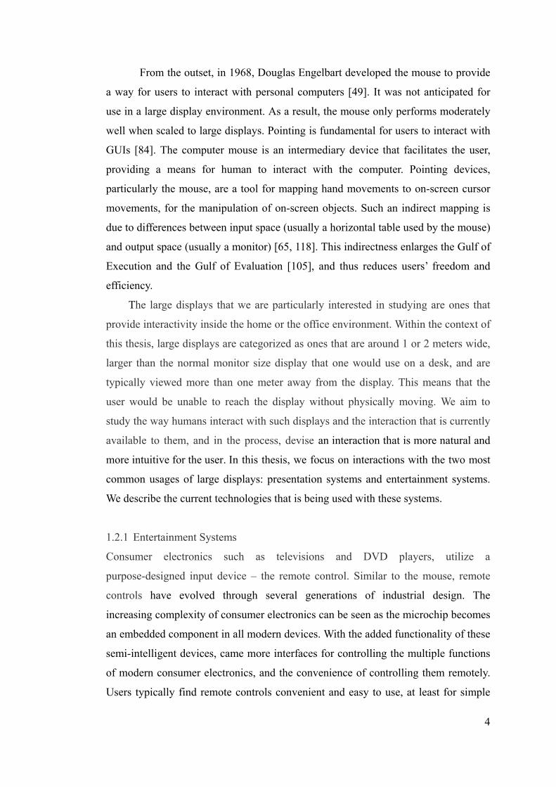
From the outset, in 1968, Douglas Engelbart developed the mouse to provide
a way for users to interact with personal computers [49]. It was not anticipated for
use in a large display environment. As a result, the mouse only performs moderately
well when scaled to large displays. Pointing is fundamental for users to interact with
GUIs [84]. The computer mouse is an intermediary device that facilitates the user,
providing a means for human to interact with the computer. Pointing devices,
particularly the mouse, are a tool for mapping hand movements to on-screen cursor
movements, for the manipulation of on-screen objects. Such an indirect mapping is
due to differences between input space (usually a horizontal table used by the mouse)
and output space (usually a monitor) [65, 118]. This indirectness enlarges the Gulf of
Execution and the Gulf of Evaluation [105], and thus reduces users’ freedom and
efficiency.
The large displays that we are particularly interested in studying are ones that
provide interactivity inside the home or the office environment. Within the context of
this thesis, large displays are categorized as ones that are around 1 or 2 meters wide,
larger than the normal monitor size display that one would use on a desk, and are
typically viewed more than one meter away from the display. This means that the
user would be unable to reach the display without physically moving. We aim to
study the way humans interact with such displays and the interaction that is currently
available to them, and in the process, devise an interaction that is more natural and
more intuitive for the user. In this thesis, we focus on interactions with the two most
common usages of large displays: presentation systems and entertainment systems.
We describe the current technologies that is being used with these systems.
1.2.1 Entertainment Systems
Consumer electronics such as televisions and DVD players, utilize a
purpose-designed input device – the remote control. Similar to the mouse, remote
controls have evolved through several generations of industrial design. The
increasing complexity of consumer electronics can be seen as the microchip becomes
an embedded component in all modern devices. With the added functionality of these
semi-intelligent devices, came more interfaces for controlling the multiple functions
of modern consumer electronics, and the convenience of controlling them remotely.
Users typically find remote controls convenient and easy to use, at least for simple

5
tasks such as changing channels on the television. In our modern world, it is common
to find consumers experienced with both remote control and the mouse interfaces.
As computer technology becomes more advanced, it can increasingly handle
tasks beyond simple productivity applications and towards the manipulation of rich
media. Computers that are capable of playing back music, showing digital photos,
and recording live television are now commonplace.
As their multimedia capabilities increase, we see an increasing number of
computers making their way from the desk in the home office to the living room. In
the living room environment, the user typically sits on a couch rather than at a desk –
a setting where more users are accustomed to using a remote control than a mouse.
The current desktop GUI loses effectiveness when viewed from a 10 foot distance. In
addition, the remote controller may require learning both the device itself and the
on-screen interface. This presents a problem when each remote requires a new set of
skills and only multiplies with additional functionalities to the ever advancing
technologies. It is also possible that these devices may be misplaced, disrupting the
user experience.
1.2.2 Presentation Systems
In presentation settings, a computer system - typically a laptop computer - is placed
on a desk and is connected to a projection display. When the presenter wishes to
navigate the content, s/he would have to return to the laptop to use the keyboard and
Figure 1.5: The Microsoft Home Living Room[90]

6
mouse. This greatly restricts the presenter’s mobility. Moreover, to make use of the
on-screen cursor, the presenter must be aware of the degree to which small
movements of the mouse correspond to larger movements on the display. This
distracts the presenter from the flow of presentation as s/he has to look at both the
mouse and the laptop display. To highlight key points on the slides, the presenter
might walk up to the projected display to point with their arm and hand.
Commercially available direct interaction system, such as the touch sensitive
Smartboard could be used[127]. However, to use such systems, the presenter is
required to directly touch the surface with their hand.
Alternatively, when the screen is beyond arm’s reach, a laser pointer could be
used. The laser dot produced on the display may be tracked by cameras. However,
the presenter’s hand tremor would be magnified. It has been reported that audience
may find this difficult to see and follow the laser dot [21]. Researches have found the
laser pointer to be the slowest at pointing from a distance [98] compared to both
traditional mouse pointing and directly touching the targets on the display.
1.3 Alternate input techniques
Various researches have attempted to optimize and improve the use of the computer
mouse on large displays by using software solutions such as Drag-and-Pop [7] where
Figure 1.6: An illustration of presenter’s mobility being restricted by the mouse and keyboard

7
a prediction algorithm is used to identify objects that are most likely required and are
then moved closer to the user for easy access. On the other hand, hardware solutions
have also been explored. Remote pointing devices are commonly used as alternatives
and are readily available and accessible commercially. They are designed specifically
to be used from a distance to complement or replace the use of a mouse. GyroMouse
[59] and RemotePoint [67] are two examples. GyroMouse is a handheld device that
allows a user to control the on-screen cursor position by detecting angular
movements of the hand using gyroscopes (Figure 1.7). While the RemotePoint
system allows the user to control on-screen cursor by providing a thumb operated
isometric joystick. These methods, however, still underperform compared to the
mouse in terms of throughput [84].
It can be seen that while research in the area of remote pointing devices for
large displays has become more prevalent in recent years, there is still no widely
accepted standard input device or techniques that can be used and readily available to
all.
Perhaps the most direct form of interaction is being able to point at something
without any restrictions. One common approach is to use our own hand as the input
method, throwing away the intermediary device that has restricted our mobility and
freedom. The pointing gesture may be used to indicate on-screen target directly,
without the need for any hardware devices.
Computer vision can be used to detect and track the user’s pointing gesture
and is an active area of research where vision is exploited as a mean of
communication from the user to the computer system. These computer vision based
Figure 1.7: Gyration GyroMouse [59]
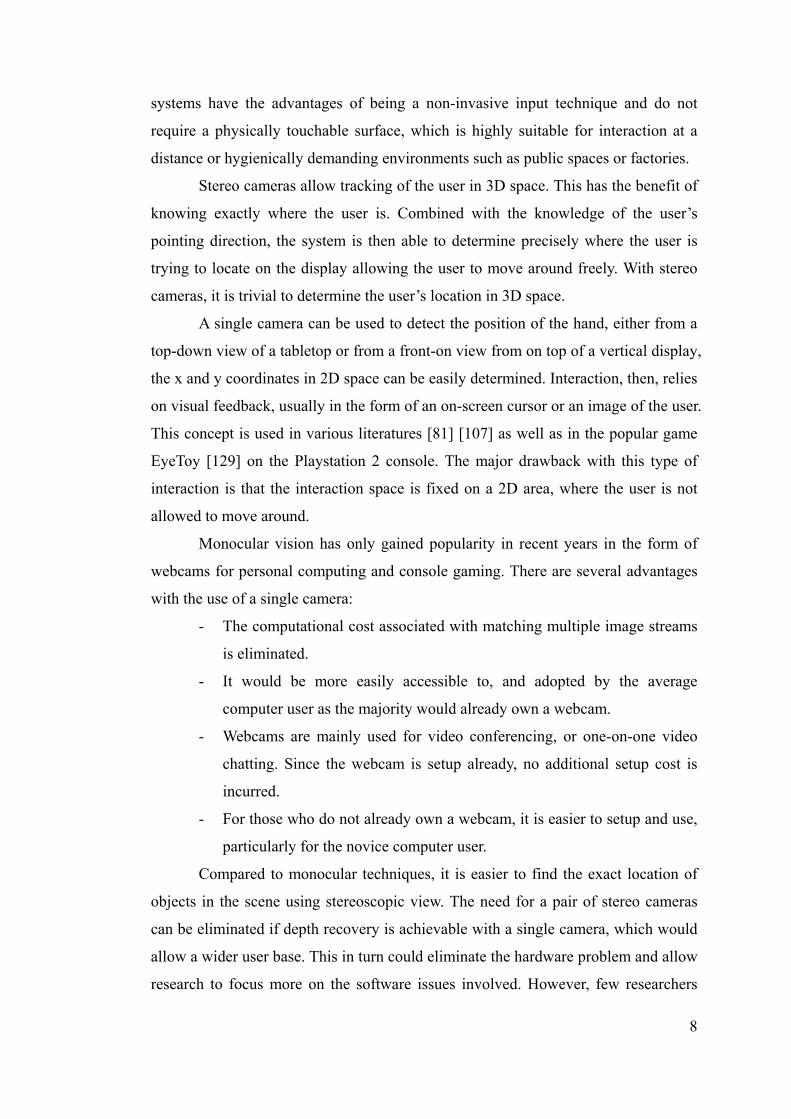
8
systems have the advantages of being a non-invasive input technique and do not
require a physically touchable surface, which is highly suitable for interaction at a
distance or hygienically demanding environments such as public spaces or factories.
Stereo cameras allow tracking of the user in 3D space. This has the benefit of
knowing exactly where the user is. Combined with the knowledge of the user’s
pointing direction, the system is then able to determine precisely where the user is
trying to locate on the display allowing the user to move around freely. With stereo
cameras, it is trivial to determine the user’s location in 3D space.
A single camera can be used to detect the position of the hand, either from a
top-down view of a tabletop or from a front-on view from on top of a vertical display,
the x and y coordinates in 2D space can be easily determined. Interaction, then, relies
on visual feedback, usually in the form of an on-screen cursor or an image of the user.
This concept is used in various literatures [81] [107] as well as in the popular game
EyeToy [129] on the Playstation 2 console. The major drawback with this type of
interaction is that the interaction space is fixed on a 2D area, where the user is not
allowed to move around.
Monocular vision has only gained popularity in recent years in the form of
webcams for personal computing and console gaming. There are several advantages
with the use of a single camera:
- The computational cost associated with matching multiple image streams
is eliminated.
- It would be more easily accessible to, and adopted by the average
computer user as the majority would already own a webcam.
- Webcams are mainly used for video conferencing, or one-on-one video
chatting. Since the webcam is setup already, no additional setup cost is
incurred.
- For those who do not already own a webcam, it is easier to setup and use,
particularly for the novice computer user.
Compared to monocular techniques, it is easier to find the exact location of
objects in the scene using stereoscopic view. The need for a pair of stereo cameras
can be eliminated if depth recovery is achievable with a single camera, which would
allow a wider user base. This in turn could eliminate the hardware problem and allow
research to focus more on the software issues involved. However, few researchers

9
have investigated interaction methods that rely on monocular computer vision, and
where depth information recovery is required.
1.4 Pointing Strategies
In most vision-based interactive systems, the accuracy of the estimated pointing
direction is an essential element to their success. The focus is usually on finding new
ways of improving the detection, estimation and tracking the pointing hand or finger,
and deduces the pointing direction [32, 33, 102]. However, these systems do not
account for inaccuracies made by the user and assumed implicitly that the user is
always pointing to the desired location.
The accuracy estimated by vision systems is only as good as the pointing
accuracy provided by the user, and in practice this can be even worse. To make any
system more reliable and accurate, one should begin by understanding the pointing
strategies adopted by users when pointing, and methods in which they can adopt to
point to the best of their ability. Only then should we focus on detecting the hand
accurately. We will also be addressing these issues.
1.5 Aim of this Thesis
The ultimate goal is to allow interaction of multiple large wall-sized displays directly
using nothing but one’s own hand. This research will build upon previous work and
take another step closer towards this aim.
This thesis aims to investigate the feasibility of using monocular computer
vision to allow bare-hand interaction with large display systems from a distance using
the pointing gesture.
It is important to note that the aim of computer vision based interaction
techniques is not to replace the mouse in general, but rather, to design input methods
that provide a viable alternative for users, particularly in tasks where the mouse is not
suitable for use.
Our goal is to design a new system that meets the following guidelines:
Natural – the interaction method should respond to the natural behaviour of
human so that users do not need to learn anything new in order to use the system.
They should also be comfortable throughout the entire interaction process.
10
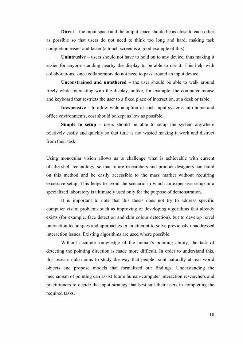
Direct – the input space and the output space should be as close to each other
as possible so that users do not need to think too long and hard, making task
completion easier and faster (a touch screen is a good example of this).
Unintrusive – users should not have to hold on to any device, thus making it
easier for anyone standing nearby the display to be able to use it. This help with
collaborations, since collaborators do not need to pass around an input device.
Unconstrained and untethered – the user should be able to walk around
freely while interacting with the display, unlike, for example, the computer mouse
and keyboard that restricts the user to a fixed place of interaction, at a desk or table.
Inexpensive – to allow wide adoption of such input systems into home and
office environments, cost should be kept as low as possible.
Simple to setup – users should be able to setup the system anywhere
relatively easily and quickly so that time is not wasted making it work and distract
from their task.
Using monocular vision allows us to challenge what is achievable with current
off-the-shelf technology, so that future researchers and product designers can build
on this method and be easily accessible to the mass market without requiring
excessive setup. This helps to avoid the scenario in which an expensive setup in a
specialized laboratory is ultimately used only for the purpose of demonstration.
It is important to note that this thesis does not try to address specific
computer vision problems such as improving or developing algorithms that already
exists (for example. face detection and skin colour detection), but to develop novel
interaction techniques and approaches in an attempt to solve previously unaddressed
interaction issues. Existing algorithms are used where possible.
Without accurate knowledge of the human’s pointing ability, the task of
detecting the pointing direction is made more difficult. In order to understand this,
this research also aims to study the way that people point naturally at real world
objects and propose models that formalized our findings. Understanding the
mechanism of pointing can assist future human-computer interaction researchers and
practitioners to decide the input strategy that best suit their users in completing the
required tasks.

11
1.6 Contribution of this Thesis
This thesis makes a number of research contributions to investigate and develop
theories, together with examples that attempt to push the limit in the area of HCI.
We investigate the use of current input devices (mouse and remote controller)
on a Media PC interface, resembling the use of technologies in an everyday
situation. We recommend that future interaction techniques should resemble
the way we interact with things in the real world, much like using our hand to
point at objects
We study the strategies which people use naturally to point at objects in the
real world at different distances. We observe in our experiment that the use of
full arm stretch is the most natural and the use of the line up strategy is the
most accurate.
From these analyses, we introduce and formalize three geometric models
(Point, Touch, dTouch) to systematically classify different pointing strategies
that underpin the methods used in previous and current interactive systems.
We introduce a depth recovery technique which makes use of human physical
attributes for use in monocular computer vision environments.
We present an interaction technique we call “virtual touchscreen” which
makes use of the user’s view frustum.
We design and show how it is possible to implement a novel interaction
system that uses monocular computer vision, geometric constraint of the
human body, and a virtual touchscreen to allow interaction with a vertical
display using a pointing gesture. (Proof-of-concept prototype)
We present an evaluation of our prototype in several usability studies to show
that it is possible to allow natural user interaction with large displays using
low-cost monocular computer vision:
o We compare the pointing performance with other similar pointing
systems using varying levels of feedback. We show that our system is
more accurate and is preferred by users overall.
o We study the minimum size required to attain reasonable accuracy
from our system, and we show that users can comfortably point at
10cm wide targets when interacting from a distance of 1.6 metres.
o We test the effect of system calibration required to use our prototype
12
and show that our system can be used by new users to obtain accurate
interaction after a two-step calibration process.
o We investigate the ability of our prototype to handle altering user’s
standing location. We show that this is possible with our system but is
hindered by detection issues.
Some of the theories and results presented in this thesis have been published in UIST
[31], OZCHI [27] and ACSC [26]. While a few more have been accepted for
publication in INTERACT [28], EICS [29] and IN-TECH [30].
1.7 Research Methodology
As with typical design process with HCI systems, our research follows both the
user-centered and iterative approach[9]. In user-centered design, users are involved
in all stages of the design process, from the initial gathering of user requirements to
performance testing and evaluation. Iterative design is an approach to the
development of user interfaces recognizing the notion that perfect user interfaces
cannot be designed on the first attempt, even by the best usability experts[103]. The
design is evaluated based on user testing, any problems that are revealed in the
process are fixed and the design refined. The design is then evaluated again, and thus
the refinement cycle continues. This thesis represents one iteration in the
user-centered interaction design process.
We begin by evaluating two common input methods (the mouse and the
remote controller) that are widely used for interaction with a display from a distance.
The result from this usability study reveals inadequacies in the current interaction
models and recommendations are provided for the improvements of current
techniques and for designing more natural interaction methods.
To design natural interaction methods, designers must understand how human
naturally point in the natural environment. However, there is a lack of literature that
systematically describes the strategies human adopt when pointing, and the accuracy
that these different strategies provide. We conduct experiments and formulate
geometric models to capture the essence of the different pointing strategies that is
observed. The model that provides the best accuracy is used to design a new
interactive system.

13
An interactive system is designed to:
- attempt to solve problems with previous interaction methods, and
- adopt the pointing model that provided the best accuracy, and
- satisfies the initial goals that was laid down.
Empirical evaluation is the main method used to evaluate our proposed
system. Estimation methods are designed and a proof-of-concept prototype
developed to demonstrate the viability of such approach. We then evaluate the
robustness of our system by testing the effect of varied amount of initial user
calibration. We also observe the effect of varied users standing location.
A series of experimental evaluation is then used to gauge the use of our
system from the user’s point of view. Test subjects are used to represent potential
users and we measure the performance of our system using both quantitative
measures (accuracy, task completion time and error rate) and qualitative means (user
preference and comfort). A usability experiment is conducted to compare our
prototype with another bare-hand interaction method. We also perform a short
experiment to see what size of target users can comfortably point at. With this
information, we can get an idea of the true resolution our pointing system can
provide. This aids in the future designs of interface for this type of interaction
method.
1.8 Thesis Structure
The thesis is organised so that most of the background material and related work are
presented in Chapters 1 and 2, followed by a presentation of a series of experimental
research. However, in order to preserve the flow of the whole thesis and to better
understand each experiment as a single unit, some related work specific to certain
topics is presented within the relevant chapters.
In the next chapter we investigate the significant research that have been done
both historically and recently, in the area of input methods in HCI, and then move
onto the more specific area relevant to this thesis. Specifically the solutions that have
been attempted to interact with large displays in the past and present, and the kind of
problems that these suffer.
In Chapter 3 we study the use of two common input methods that are used to

14
interact with displays from a distance based on user interface used in the real-world
environment and recommendations for designing a more natural interaction method.
Chapter 4 presents an investigation to the use of natural pointing gesture in
the real world, and formulate models to classify them. We then recommend a strategy
to help in designing more natural interaction method while preserving accuracy.
In Chapter 5 we propose and present our design for a novel interaction
method. We show the concepts within our design that addresses prior problems and
benefit that they bring.
In Chapter 6, an empirical evaluation is presented. Methodologies and
algorithms are described to show how it is possible to build such a system. In the
process, a proof-of-concept prototype is developed.
A series of experimental evaluation is conducted and reported in Chapter 7 to
evaluate the system performance. We also compare this with the use of a similar
pointing system.
Finally, in Chapter 8 we conclude and discuss the implications of this thesis
for the future of human computer interaction.

15
Chapter 2
Background and Previous Work
This chapter introduces important work historically and investigates significant
related research underlying this thesis. We will take a close look at the current trend
in immersive interaction, how it has been achieved, how pointing have evolved from
the earliest pointing devices (namely the computer mouse) to the state of the art
techniques that researchers around the world have proposed to improve interactions
with large surfaces.
2.1 Manipulation and Interaction
Manipulation is the adjustment or changes made to an object in some shape or form.
In terms of information technology, it goes as far back as the 1960s where Seymour
Papert at the Massachusetts Institute of Technology developed the LOGO computer
programming language. The concept of symbolic computation [35] was adopted to
give a visual representation to words and ideas. A graphical representation, a turtle, is
used to allow children to type simple commands and observe for the effects of the
turtle on screen. This is an example of indirect manipulation where instructions are
entered into the computer using the keyboard in order to manipulate the turtle.
Alternatively, a more direct approach is to control the turtle by interacting with its on
screen representation. This is the principle behind direct manipulation, a term coined
by Ben Shneiderman in 1983 [125]. MacDraw was the first commercially available
that uses this approach to allow users to manipulate lines and shapes on a drawing [5]
by providing users with a tool palette along the left side of the drawing. Users can
then select different tools using their mouse to manipulate the drawing as desired.
The manipulation is achieved by using the mouse to interact with the system.
Interaction, as distinct from manipulation, refers to the method which users
provide input to the system, and the system provides feedback to the user. The

16
interaction technique used in this thesis is pointing. The traditional keyboard is
sufficient for inputting characters or numbers, such as those used by children to enter
simple commands in LOGO. However, convenience and efficiency can be achieved
if one can point or aim directly at a location we are interested in. Such a system
would be more direct and easier to use. Indeed, children can use body postures and
gestures such as reaching and pointing by about 9 months [83]. The act of pointing
using the index finger to point at something is defined as the “deictic gesture”[154].
2.2 Graphical User Interface
The WIMP paradigm (Windows, Icon, Menu, Pointing) started since the birth of the
PC revolution with the Xerox Star in 1981. It provides a way for computer users to
interact with the computer using a mouse cursor rather than just typing characters.
Twenty-odd years on, this desktop metaphor is still the norm for interacting with
computers, even though processing speed and screen size has increased dramatically.
Figure 2.1: Project Looking Glass from Sun Microsystems [133]
There have been various attempts at improving this paradigm. Project Looking
Glass [135] from Sun Microsystems is an attempt at revolutionizing the current 2D
desktop by adding depth perception. The most novel concept is the ability to rotate
the windows and write or scribbles notes and comments at the back of the windows.
However, most of the features only provide a 3D representation of their 2D
counterpart.

17
Figure 2.2: BumpTop Prototype – using the concept of piling [2]
In a similar work, BumpTop [2] enhances the desktop metaphor by using
physical characteristics of lightweight objects and manipulate them in a more
physically realistic manner. By using the concept of piling rather than filing,
document management becomes more natural to the user. Using a stylus, users can
arrange a pile of documents by circling around them and organize them in a neat pile
or search through them in a heap one by one.
As the demand for large screen increases, so does the need for techniques that
facilitate their use. To address this, various approaches have been proposed to help
with large screen interactions.
Drag-and-Pop [7] attempts to reduce mouse movements required for dragging
screen objects (e.g. icons) across a large screen by animating and bringing potential
targets (e.g. folders or the recycle bin) closer to the object being dragged. To preserve
user’s spatial memory, a rubber band-like visualization is used to stretch the potential
targets closer to the original object rather than moving the targets themselves.
Compared to the “normal” condition where targets are not stretched, improvements
were observed when used on multiple screens where crossing the bezel is a problem.
However performance gained was not observed in a single screen.

18
Figure 2.3: Drag-and-Pop – stretching potential targets closer [7]
Object Pointing [58] attempts to reduce the gap between selectable objects by
“skipping empty spaces” making it much easier to move from objects to objects
especially with a large screen. A user study shows that movement time does not
follow Fitts’ Law (linear increase) but stayed constant when the distance between
two objects increased or their size decreased. As the authors pointed out, one
drawback of such solution is that no performance gain would result when selectable
regions are tilted together.
However, in all these cases, the same WIMP paradigm is still used. Users are
still required to use their mouse and click on buttons and menus.
Even with such software improvements, the fact remains that indirectness with
the mouse is still a factor inhibiting the naturalness of interacting with large screens.
Over the years, various novel input devices have been developed to address the
problem of indirectness with the mouse, with varying degrees of success – a
comprehensive overview is outlined in [69]. We now consider some devices and
techniques that provide a somewhat more direct approach than the mouse. We will
first examine intrusive techniques followed by a survey of non-intrusive techniques.
2.3 Handheld Intrusive Devices
Intrusive devices for HCI are ones that can be hand-held or placed on the body.
The lightpen is one of the first pointing devices produced [97]. It works by

19
pressing the pen against a CRT display which is operated by a switch on the pen and
allows it to capture light produced from the screen. However, this is not suitable for
prolonged use due to its poor ergonomics, and it was eventually replaced by the
mouse. As discussed in Chapter 1, the mouse provides an indirect method to interact
with the computer.
Light gun technology has been used extensively, especially in the computer
gaming industry. It also provides a direct approach to interacting with CRTs and
unlike light pens it can operate at a distance. Although the accuracy is maintained, its
major drawback is that it must be used with a CRT display. Thus, large-scale displays
cannot be used since images are provided by a data projector.
The Polhemus FasTrak and Logitech 3D Mouse belong to a category of industrial
strength tracking systems primarily designed for 3D motion tracking, as found in
applications such as CavePainting [73]. FasTrak is an electromagnetic tracking
system that computes the position and orientation of a tiny receiver as it moves
through space. The major problem however is its vulnerability to electromagnetic
interference and radiation particularly from the monitor. In addition, this system has
a limited range of 3 metres and a latency of 4 milliseconds. It is primarily designed
for 3D motion capturing in a Virtual Reality environment. The 3D Mouse is another
similar tracking system. It uses a stationary triangular transmitter which emits
ultrasonic signals to track the movement of a smaller triangular receiver. This
resolves the problem of interference from radiation but introduces interference by
other equipments that use ultrasonic signals. The system also has a limited range of 2
metres and a high latency of 30 milliseconds. These are typically used for CAD
Figure 2.4: Polhemus FasTrak[115]

20
object manipulation and Virtual Reality which are cumbersome and expensive,
costing up to US$6000.
Developed at MIT, the Put That There system is considered the first multimodal
system that incorporates both speech and gesture recognition [13]. A Polhemus
position-sensing cube is attached to a watchband which is worn on the wrist. The
user is able to indicate (using a pointing gesture) what should be moved by pointing
at an object on a large screen and uses voice commands to indicate what to do with
the object.
The Logitech Spaceball [95], Gyration GyroMouse [59], Interlink RemotePoint
[67], and SpaceCat [52, 134] represent another category of input devices designed
for personal use as a mouse replacement. The Spaceball is a device with a
ball-shaped controller mounted on top. It allows users to push, pull and twist the ball
in order to manipulate on-screen objects. It is designed for 3D model manipulation
and provides a more natural movement for the user. The Gyromouse is based on a
technology called GyroPoint that uses gyroscopes to detect angular movements of
the device. These rotations can be used to control a 3D object or mouse cursor. The
RemotePoint allow users to roll their thumb around a soft rubber pointing button
fitted onto a handheld device. SpaceCat is a softly elastic input device developed to
allow precise short-range movements and provide six degrees of freedom. The
advantages over the previous set include their wireless ability, affordability and easy
to handle, although the user still interacts through an intermediary device.
In a recent piece of research, a special casing is used to house a wireless mouse
which is then transformed into a soap-like device that can be used in mid-air [8]. The
hard outer casing of a normal computer mouse is replaced with a soft towel-like layer.
Figure 2.5: Logitech Spaceball[95]
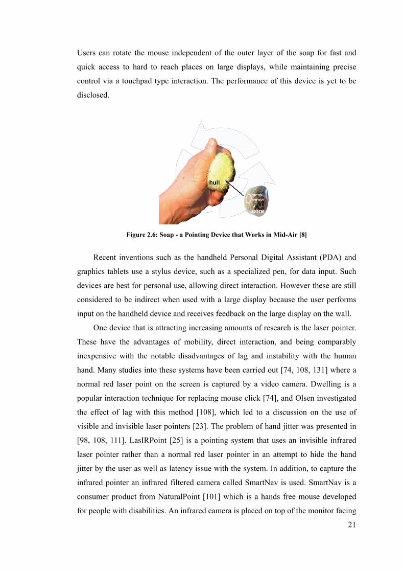
21
Users can rotate the mouse independent of the outer layer of the soap for fast and
quick access to hard to reach places on large displays, while maintaining precise
control via a touchpad type interaction. The performance of this device is yet to be
disclosed.
Figure 2.6: Soap - a Pointing Device that Works in Mid-Air [8]
Recent inventions such as the handheld Personal Digital Assistant (PDA) and
graphics tablets use a stylus device, such as a specialized pen, for data input. Such
devices are best for personal use, allowing direct interaction. However these are still
considered to be indirect when used with a large display because the user performs
input on the handheld device and receives feedback on the large display on the wall.
One device that is attracting increasing amounts of research is the laser pointer.
These have the advantages of mobility, direct interaction, and being comparably
inexpensive with the notable disadvantages of lag and instability with the human
hand. Many studies into these systems have been carried out [74, 108, 131] where a
normal red laser point on the screen is captured by a video camera. Dwelling is a
popular interaction technique for replacing mouse click [74], and Olsen investigated
the effect of lag with this method [108], which led to a discussion on the use of
visible and invisible laser pointers [23]. The problem of hand jitter was presented in
[98, 108, 111]. LasIRPoint [25] is a pointing system that uses an invisible infrared
laser pointer rather than a normal red laser pointer in an attempt to hide the hand
jitter by the user as well as latency issue with the system. In addition, to capture the
infrared pointer an infrared filtered camera called SmartNav is used. SmartNav is a
consumer product from NaturalPoint [101] which is a hands free mouse developed
for people with disabilities. An infrared camera is placed on top of the monitor facing

22
the user. Within the camera are 4 infrared LEDs which illuminate infrared light. A
small reflective dot is worn on the user’s forehead, cap, glasses or mic boom. When
the user moves their head, the camera detects the dot’s movement and translates that
motion into mouse cursor movement on screen.
Figure 2.7: The Hand-mouse System for Augmented Reality Environments. [76]
Computer vision is normally used in a non-intrusive environment and will be
discussed in the next section. However, there is a category of context-aware systems
based on computer vision techniques called Visual Wearables [77] and is used to
capture contextual information of the wearer environment to construct an augmented
environments. One typical example is the Hand Mouse developed by Kurata et al.
[76]. It is a wearable input device that uses computer vision based hand detection
using color and shape information. A camera is worn by the user hanging off their ear
and can capture the user’s pointing finger in front of them. Users also wear a
head-worn MicroOptical Clip-On display in the form of a pair of glasses. A GUI is
then presented to the users through the display and they use their finger to point at
particular items of interest. Because the device is wearable in natural, consideration
must be taken into account varying light and background conditions. User’s hand is
differentiated by approximating a color histogram with a Gaussian Mixture Model
(GMM) and the resultant classified hand pixels are then fitted to a simple model of
hand shapes.
Similar to the Hand-Mouse is the MobiVR system [117] which also captures
and detects a pointing finger behind a micro display. The main difference with

23
MobiVR is that it is a handheld device rather than head-mounted, which allows users
to use at will, rather than occluding the real world at all times (as with most other
wearable devices), making it more mobile. Their implementation uses a
non-see-through binocular near-eye microdisplay (taken from a Head Mounted
Display) and attached a reconfigured SmartNav infrared camera aiming forward. By
attaching an infrared reflector ring on the finger, the user can perform a pointing
gesture in front of the device to control a cursor.
Figure 2.8: The MobiVR system [117]
Fredriksson et al. used a consumer-grade webcam to capture user’s hand by requiring
the user to wear a colour coded glove to facilitate 3D hand tracking for interacting
with the computer [53].
Another popular device is the Wii remote controller (Wiimote) used with the
Wii game console [104]. The Wiimote is a handheld pointing device with an infrared
camera mounted at the front and captures two infrared LEDs placed on top of a
television display. By detecting the size and orientation of the LEDs in the camera’s
view, an approximation can be made about the position and orientation of the
Wiimote. This information can then be used to determine a position on the display
the user is pointing to. Interaction then relies heavily on visual feedback.
Even though intrusive devices have the advantage of providing accurate
estimation of user position and can support sophisticated interactions [33], they are
nevertheless intrusive and users might either have to adjust to the position of the
device or they have to wear or hold on to the device for however long necessary.

24
Some might even have to worry about dangling wires.
2.4 Non-intrusive Techniques
Non intrusive techniques for HCI are ones where users do not need to wear or hold
any special devices, nor will there be wires attached. Users only need to approach the
surface and use their bare hand. Most of these use some kind of sensors or computer
vision to detect the hand position.
2.4.1 Sensitive Surfaces
DiamondTouch [38] is a touch sensitive table from Mitsubishi Electric Research
Laboratories (MERL) that can detect and identify multiple and simultaneous users’
touches. Antennas are place under the surface of the table each with a different
electrical signal. When the user touches the table, a small electrical circuit is
completed, by going from a transmitter to the table surface to the user’s finger
touching the surface, through the user’s body and onto a receiver on the users’ chair.
Users must be seated to operate this device.
Figure 2.9: SmartSkin [119]
SmartSkin [119] is a similar technique proposed by Rekimoto. Instead of using
electricity, it relies on capacitive sensing by laying a mash of transmitter and receiver
electrodes on the surface. When a conductive object (such as the human hand) comes
near the surface, the signal at the crossing point is decreased. This also enables the
detection of the multiple hand positions. They are also able to detect the hand even
when it is not actually touching the surface.

25
More recently, multi-touch techniques have been widely researched. One
example is the use of frustrated total internal reflection (FTIR) to detect multiple
fingers on a tabletop display [60]. This technique makes use of the fact that when
light is travelling inside a medium (e.g. acrylic pane), while undergoing total internal
reflection, an external material (e.g. human finger) is encountered causing light to
escape from the medium. An external camera can capture exactly where the light
escapes, thereby detecting the position of the fingertip. Multiple fingertips can thus
be detected at the same time
Figure 2.10: Low-Cost Multi-Touch Sensing through Fustrated Total Internal Reflection[60]
All of these techniques require that the user to be at the location they want to
point at. It also requires large movements of the arm, as well as pacing across
surfaces. They do not work well when surfaces are hard to reach.
2.4.2 Computer Vision
Computer vision can also be used to track different parts of the human user.
Tracking hand above surfaces
Various researches have been dealing with tracking hand above surfaces. The most
notable is the implementation of DigitalDesk [157] by Wellner in 1993 who used a

26
projector and a camera pointing downwards from above a normal desk. It allows
users to use their finger, detected by using finger motion tracking, and a digitizing
pen. It supports computer based interaction with paper documents allowing such
tasks as copying numbers from paper to the digital calculator, copying part of a
sketch into digital form and moving digitals objects around the table.
In a similar research, rather than aiming a camera at a desk, the camera is
directed to a vertical whiteboard. Magic Board [36] used a steerable camera so that
screens can be larger than the field of view of the camera. Rather than using motion
detection, cross-correlation is used instead, which extracts small regions from an
image (e.g. image of a pointing finger) as template for searching in later images.
Figure 2.11: Bare-hand interaction with a whiteboard [61].
Hardenberg and Berard [61] also used a camera which captures hand activities
on a whiteboard. They developed an improved hand segmentation and fingertip
detection algorithm and demonstrated their implementation. They used bare hand
pointing on the whiteboard surface as a mouse replacement as well as using the
number of outstretched fingers to control the movement of presentation slides.
The SMART board [127] fixes 4 tiny cameras on four corners of its display
which can detect any objects that come into contact with the surface or when it
hovers above it.
The Everywhere Displays Project uses a “multi-surface interactive display
projector” so that it can make any surface in the room interactive [113]. It is done by

27
attaching a rotating mirror so that any surface in the room can be projected onto and
captured by the camera. Finger detection is performed on the same surface that is
being projected, generating a “click” event as if it is a computer mouse. In a similar
approach Molyneaux et al. [92] were able to display a projection image onto the
surfaces of 3D objects.
Figure 2.12: The Everywhere Displays Project [114].
In another research, Strickon and Paradiso built their own scanning laser range
finder and places it at one corner of a wall sized display to capture user’s hand up to
4 meters away [130]. However this method suffers from occlusion when one hand
gets in front of another.
Figure 2.13: Scanning Laser Rangefinder [130]

28
Infrared has been used to remove the need for color hand segmentation and
background subtraction due to fact that they sometimes fail when scene has a
complicated background and dynamic lighting [107]. Diffused illumination (DI) is
another common technique used in HoloWall [87] and Barehands [120], where
infrared LEDs are emitted from behind the wall as well as a back projected projector.
An infrared filtered camera is positioned behind as well to detect the presence of
hand or finger when it comes near the wall (within 30 cm) which reflects additional
infrared light.
The Microsoft Surface [89] is a tabletop display that also uses this technique,
but is designed to detect 52 touches at a time. Apart from detecting fingertips, the
camera can also recognize tagged physical objects placed on the surface.
Figure 2.14: Microsoft Surface [136]
EnhancedDesk [107] used hand and fingertip tracking on an augmented desk
interface (horizontal). An infrared camera is used to detect area lose to the human
body temperature from above the desk. Selection is based on where the fingertip is.
They also developed a fingertip detection algorithm that makes use of reduced search
window as well as simple assumptions. They are able to track multiple hands and
fingers, predict fingertip trajectories in real time, as well as recognize symbolic
gestures using Hidden Markov Model (HMM).

29
Figure 2.15: EnhanceDesk [107]
The Perceptive Workbench [80] uses infrared illuminated from the ceiling and a
camera under a table. When the user extends their arm over the desk, it casts a
shadow which can be picked up by the camera. A second camera fitted on the right
side of the table captures a side view of the hand. Combining together, the location
and the orientation of the user’s deictic (pointing) gesture can be computed. The
approach assumes that the user’s arm is not overly bent. It fails when shadow from
the user’s body is casted, as well as when two arm are extended at the same time.
Similar to the intrusive devices, these computer vision techniques require the
user to be at the location they want to point at. This also requires large movements of
the arm, as well as pacing across surfaces. They do not work well when surfaces are
hard to reach.
Head pose
Another category of input techniques using computer vision is to track the position of
the head of the user and moves the mouse cursor on the display accordingly. These
are primarily developed to provide full mouse control for people who cannot use
their hands but have good head control. Devices in this category consist of the
Synapse Head Tracking Device and Origin Instruments HeadMouse.
The Perceptual Window [36] uses head motions to control the scrolling of a
document both vertically and horizontally, effectively controlling the window view

30
point of the document. Skin color is detected by using a ratio of histograms of
normalized color with a table look-up.
Rather than detecting the face, Nouse [56] is a system that uses the nose to
control the on-screen cursor and uses doubleblink (both eyes blinking at the same
time) as a mouse click.
More examples of head pose estimation are given in conjunction with other
techniques in the next section.
Hand Gestures Recognition (3D)
Maggioni and Kammerer developed a computer system that is able to detect 3D
positions and orientation of the human hand together with the position of their head
under noisy and changing environment in real time. [85]. Two cameras are used, both
of which are placed on top of the computer, where one is looking down on the desk
capturing the hand and the other is facing the user capturing their head. A virtual 3D
model of the user’s hand is displayed on the screen thus movement of the real hand
will cause the virtual hand to move. They used two approaches for detecting the
position and gesture of the hand and head. In one approach, a marker is attached to a
glove that the user wears and a gray-level image is captured, this simplifies the image
processing required and decreases the time spent. The image is then binarised by
applying a global threshold. They also compared the images with the background
image so that not all pixels in the image are binarised unnecessarily. A contour
following algorithm is used in conjunction with moment calculation to detect objects
in the image. Using the marker, they can then calculate the x, y and z rotation of the
hand.
The second approach uses a fast colour classifier to segment the image to find
human skin colour. To detect the position of the head, they used the same contour
and moment calculation as well as using a color-based head detector. It finds the
largest elliptical area, uses a connected components algorithm to combine different
parts of the head, and uses a histogram approach to determine the center of the
forehead. In addition, they determine the distance between the head and the camera
from the width of the head. To detect the position of the hand in x,y and z, they used
the contour algorithm as well as a region shrinking algorithm and center of gravity to
determine the center of the hand. They then search for fingertips by locating local

31
maximum of distance from the center of the hand and finding a T-like structure. They
are then able to recognise six static hand gestures based on the number of visible
fingers and their orientation.
Their intended application is to allow the manipulation of 3D objects in a
non-immersive virtual world on a normal 2D monitor. Users can use the computer
mouse normally and when they raise their hand, the cameras will be activated. They
have also implemented a virtual holographic system where they used the head of the
user to control the viewpoint of the 3D virtual space. When users move their head
position, their line of sight also changes thereby change the view of the virtual object,
similar to walking around an object in real life. They have also introduced the virtual
touch screen application that they can also project the screen output on to the desk
space and using fingers to point, equivalent to the touchscreen but without physically
touching it.
A usability study was prepared to compare the use of head movements to
change the viewpoint of a 3D image, with the use of an ordinary mouse, as well as
using a set of GUI wheels to change the viewpoint. They found the time required for
problem solving in a 3D scene was much faster compared to the viewpoint that is
changed using head tracking.
To further Magonni’s work, Segen and Kumar [124] developed a vision based
system, GestureVR, which allows hand gesture interaction with a 3D scene. Two
cameras are used to track the thumb, the pointing finger, three simple gestures (point,
reach and click), as well as the hand’s 3D position (x, y and z) and its orientation
(roll, pitch, yaw) in real time (60Hz).
After the hand is captured in 2D using background subtraction, the boundary of
the hand is then determined. By measuring the curvature at each point on the
boundary, local extremes are detected and are classified as either Peaks or Valleys.
The number of Peaks or Valleys, together with a finite state classifier, is used to
classify the different gestures being produced. These then determine the orientation
of the pointing finger as well as the detection of clicks (quick bending of the pointing
finger). The results from the separate 2D image analysis are then combined to
calculate the 3D pose of the hand. When an informal trial was conducted where users
were asked to show one gesture at a time, the error rate was approximately 1/500.
One of the restrictions in this system is that they required a high contrast

32
uniform stationary background and stable ambient illumination intensity. Their
reasoning is that by doing so would give them an interaction system that is fast,
accurate and reliable and outweigh the small limitation.
The main problem with these solutions is that they are still indirect interaction
since they do not point to objects directly. Gestures are required to learn and
indirectly control the user interface and objects on screen. In addition, the interaction
is restricted to a small display area only. The user’s hand must be right under the
camera looking downwards. Users are not free to move around. They must also sit in
front of the computer restricting the user’s freedom.
Free Hand Pointing without Device
Perhaps the most direct form of interaction is being able to point at something with
your hand without any restrictions such as walking up to a particular surface. These
systems have the advantages of having no physically touchable surfaces thereby
highly suitable for hygienic demanding environment such as factories or public
spaces. Depending on the system setup, this usually allow users to interact with the
display wherever they are standing.
The Hand Pointing System [138] developed by Takenaka Corporation uses two
cameras attached to the ceiling to recognize the three-dimension position of user’s
finger. A mouse click is mimicked by using a forward and backward movement of
the finger.
The Free-Hand Pointing [66] is a similar system that also uses stereo camera to
track the user’s finger, by first detecting and segmenting the finger with a global
search. The fingertip and finger orientation is then determined in a local search.
Apart from the “finger-orientation mode” where the line from finger to display is
determined from the finger orientation, they have also introduced the
“Eye-to-Fingertip mode” where the line from finger to display is determined from
the eye (either left or right eye) to fingertip. They found that the latter approach is
more susceptible to noise because of the higher resolution given by the larger
distance between eye and fingertip. However, users need to raise their hand high
enough so that it is between the eye and the display.
The PointAt System [33] allows users to walk around freely in a room within a

33
museum while pointing to specific parts of a painting with their hand. Two cameras
are setup to detect the presence of a person by using modified background
subtraction algorithm as well as skin color detection. The tip of the pointing hand and
the head centroid is then extracted. By using visual geometry and stereo triangulation,
a pointing line is then deduced. This method can be applied to more than 2 cameras
as well, and do not require manual calibration. Dwell clicking is used in this
implementation.
Figure 2.16: The PointAt System [33]
Similar to the PointAt system, Nickel and Stiefelhagen [102] also used a set of
stereo cameras to track the user’s hand and head to estimate the pointing direction in
3D. The detection was done using a dense disparity map that provides 3D
coordinates for each pixel as well as a skin color classification. Pointing gesture is
recognised by using a three-phase model: Begin (hand moves from arbitrary position
towards pointing position), Hold (hand remains motionless while pointing) and End
(hand moves away from pointing position). The three-phases are detected by using a
Hidden Markov model trained with sample pointing gestures in different phases.
They observed that users tend to look at their target before they interact with them.
And so in a second experiment, they investigated whether head orientation can
improve their pointing gesture recognition by tracking the head using a magnetic
sensor. Results have shown that both detection and precision rates increased. In a
third experiment, they compared three different approaches for estimating the
direction of the pointing gesture: the line of sight between head and hand, the
orientation of the forearm, and the head orientation. Results show that, based on the
implementation, the hand-head line method was the most reliable in estimating the

34
pointing direction (90%). They concluded that the head orientation proved to be a
very useful feature in determining pointing direction. However, the conclusion drawn
from the third experiment is highly unreliable because of the inconsistent methods.
The first two methods were implemented using computer vision, while the head
orientation measurements were tracked by a magnetic sensor. It has yet to be seen
whether head orientation would be as accurate when detected using computer vision.
To compare the three methods equally, all methods should be tested using specialised
devices.
In most case studies above, the design choices for the interaction techniques, for
example, the different hand signal or hand gestures used, was not based on
observation from prior user study. These are frequently based solely on the authors’
intuition. These are inconsistent across different experiments.
There are a number of problems associated with using two cameras [137]. One
is the reduced acquisition speed as there is a need to process two images entirely to
locate the same point. With stereoscopic view, it is not difficult to find out the exact
location of a certain object in the scene and is the reason many gesture based
computer vision research has been based on stereo cameras. However, there are few
studies in literatures that use monocular vision to allow the use of remote hand
pointing gesture as well as being non-intrusive.
Monocular Systems
A single camera makes it much easier and simpler to allow real-time computation.
Nowadays, most computer users have one web-camera at home, but possessing two
or more is less likely.
In the computer vision community, various researchers have investigated the
use of monocular vision to estimate depth [123, 145]. It has even been suggested that
monocular vision is superior in detecting depth than stereo vision due to the fact that
“small errors in measuring the direction each camera is pointing have large effect on
the calculation [11]”. On the other hand, very few examples in the HCI literature
have been found using monocular vision to allow the use of remote hand pointing
gesture whilst being non-intrusive.
Compared with monocular vision techniques, it is easier to find the exact

35
location of a certain object in the scene using stereoscopic view. The need for a pair
of stereo cameras would be eliminated if depth recovery is achievable with a single
camera. This in turn transfers the problem from one that involves the hardware to one
of software. However, few researchers have investigated interaction methods that
rely on monocular computer vision, and where depth information recovery is
required.
A motion recognition camera, such as the EyeToy USB camera for
PlayStation2[129], is placed on top of a large display. A mirror image from the
camera is presented on the display, as well as additional game play information. A
selection is made when users place their hands at specific location so that it’s
on-screen image coincided spatially with on-screen targets. Note that the hand can
only be tracked in 2D and depth is not registered.
Figure 2.17: A user playing the EyeToy game [12].
This method is also used in [46] to compare the accuracy using two
computer-vision based selection techniques (motion sensing and object tracking).
They found that both techniques were 100% accurate while the object tracking
technique was significantly fewer errors and took less time.

36
Figure 2.18: Motion sensing (left) compared to object tracking (right) as selection technique [46]
A similar Virtual Keypad implementation detects the user’s fingertips
position in both the x and y directions for interacting with targets on-screen [146]. It
is used much closer to the camera.
Figure 2.19: Virtual Keypad [146]
The major drawback with this type of interaction is that the interaction space
is fixed on a 2D area, where the user is not allowed to move around.
More recently, 3DV Systems developed the “ZCam” [1] to detect depth
information based on the Time-Of-Flight principle. Infrared light are emitted into the
environment and a camera captures the depth by sensing the intensity of the reflected
infrared light reaching back to the camera. However, potential users are required to
purchase this special camera.

37
Figure 2.20: 3DV ZCam [10]
The above mentioned systems used monocular vision to detect the users hand only.
To provide a truly non-intrusive and natural pointing system, the system should also
take into account the user’s standing position, in addition to the hand location, such
as those system that uses stereo cameras (for example in [102]).
In another work, a single camera is used to detect the user’s pointing finger
and their eye position and is shown in an implementation “Peek Thru” [79]. However,
the detection of the fingertip was deemed too difficult to identify due to the observed
occlusion by the user’s torso. Users were asked to wear an easy to detect thimble on
their fingertip. We feel that this violates the notion of using nothing but our own hand
for interaction.
Figure 2.21: A monocular system used in [79]

38
An even if the fingertip position was detected using computer vision, this setup only
differential between different angels from the camera’s view, rather than exact x and
y coordinates.
Figure 2.22: Targets arranged in various angles from the camera in the Peek Thru implementation [79]
As can be seen, there is a gap in the literature where a single camera is used to detect
the direction of pointing from both the user’s standing location and their pointing
direction.
2.5 Selection Strategies
The current WIMP paradigm was initially designed for GUIs to be used exclusively
with the computer mouse, where the ability to select the intended target is by
“clicking” a button located on the mouse. This kind of UI provides pixel level
accuracy. A typical target is often around 20 pixels by 20 pixels. The “click”, that is
produced when the user presses a mouse button, provides tactile and acoustic
feedback to the user. When touch sensitive displays were developed, the same GUI
was also used with a stylus where the button is now located at the tip of the pen. In
addition, they provide the user the ability to write in the same way that they would
when using a pen, as well as providing freehand drawing functionality. The PDA
stylus that is currently being used adopted the same principle.
2.5.1 Mouse click-less interfaces
Cooliris [34] provides a novel way of interacting with internet browsers using
the mouse without clicking. Both applications are designed to be used as an add-on

39
to current internet browsers. When the mouse cursor hovers on a link, a small icon
(around 5px X 5px) appears beside the link and when the mouse cursors “hovers” on
the icon for a pre-determined time (e.g. 1 second) a special in-browser pop-up
appears, so the user can preview the linked-to page in a separate window, saving
user’s time when the linked-to page is not what the user wants. The hover time is
thus an alternative to mouse clicking. Dwell clicking is another name of the same
technique and is also used in a lot of other systems such as SmartNav.
Gentlemouse [54] is a similar mouse click replacement alternative. As the user
move over the object, instead of clicking on it, the user pauses for a predetermined
amount of time and a small trigger window will appear (see Figure 2.23). Meanwhile,
the current cursor location is saved (as shown in the figure as a red dot). The user
selects the desired action, such as a left click, by moving the mouse to the
corresponding trigger box. Once the user stops moving, the appropriate action (e.g. a
left click) is initiated. They have claimed that by reducing daily repetitive clicking,
their product “may significantly reduce the risk of Repetitive Strain Injury (RSI)
such as Carpal Tunnel Syndrome (CTS).”
The WIMP paradigm is often difficult to adapt, if not impossible, when
button-less pointing methods are used, there are no way of indicating a selection.
Dwell clicking provides a viable alternative for these systems.
2.5.2 Laser Pointer
It is also worth studying how interactive systems that use camera tracked laser
pointers provide input to the system. There are three ways of indicating selection:
- Laser dot on/off status – The laser pointer is initially off. When the laser
Figure 2.23: GentleMouse [54]
40
dot is first turned on and appears on the screen, the place where the laser
dot is indicated is regarded as the selection point [45]. Experiments have
found that the laser dot produced when it is first turned on is not a reliable
indicator for the user’s intended target [98]. Furthermore, it takes around
1 second to move it onto the intended target.
- Dwell – When the laser pointer is directed to the same location for a
certain amount of time, the target at that location is considered selected
[74]. Using this method, it was found that the unsteadiness of the human
hand causes wiggle in the laser beam. This causes a deviation of 8 pixels
and can be improved to around ± 2-4 pixels with filtering [98]. This
method is also commonly used in other button-less interaction methods
such as for gaze-selection [75].
- Physical button – Alternatively, a physical button can be added to the
laser pointer and the signal transmitted via wireless means [106]. With
desktop-based devices, a button-up event triggers a selection. However, as
the laser pointer is held in mid-air, a button press will cause a small
deviation, so it is best to use the button-down event to indicate selection.
Olsen investigated the effect of lag with using the laser pointer [108], which led to a
discussion on the use of visible and invisible laser pointers [23] for hiding the effect
of hand jitter.
2.5.3 Hand gesture
In order to explore interaction techniques that allow barehand interaction in the
future when marker free tracking becomes widely available, Vogel and Balakrishnan
introduced AirTap and ThumbTrigger [153].

41
Figure 2.24: AirTap and ThumbTrigger [153]
AirTap mimics the movement of the index finger when the mouse button is pushed.
However, as there is no physical object to constrain the downward movement of the
finger, kinesthetic feedback is lost. Visual and auditory feedbacks are used instead.
The velocity and acceleration of the finger motion is used to detect the finger. On the
other hand, ThumbTrigger uses a sideway thumb motion (moving in and out towards
the index finger). Kinesthetic is present in this case, in the form of the index finger.
However, it was reported that users found this method uncomfortable and tiring. It
should be noted that the authors were only able to achieve this with the use of motion
tracking system.
Grossman et al uses thumb trigger gesture [57]. The pointing gesture provides a
natural and intuitive to refer to distant objects in the environment. Many researches
have used this in their system to indicate a target on a distant display that the user
wants to interact with. The process of performing a pointing gesture can be broken
down into three steps [94, 102].
- The pointing hand is positioned towards the desired object from a
stationary resting position.
- When the hand is positioned correctly, it remains motionless for a period
of time. (dwell time)
- The hand is then moved away from the desired target.
The second step is most crucial for determining if an object is selected. For when the

42
dwell time is too short, unwanted selections could occur – “Midas Touch Problem”
[94]. When the dwell time is too long, users may grow impatient and may feel the
system to be unresponsive. A recent study has found that a delay time of between
350-600 ms gives users a natural and convenient experience [94].
Given our exploration into previous work that uses selection strategy that do
not require the need for buttons, dwelling is well regarded as the best choice for
interacting with natural hand pointing systems.
2.6 Summary
From software enhancements to monocular computer vision, we can observe
numerous attempts in the research area of HCI to improve on the current keyboard
and mouse interface for the large display.
Having reviewed the various literatures, the major previous work within each
category is summarized in Table 2.1. We also listed the problems and limitations
associated with them.
At this point in time, we are starting the transition from the mouse based UI
to that of surface based hand tracking era. They currently exist commercially in the
form of public directory touch screen and multi-touch interfaces such as iPhone and
Microsoft Surface. We believe that camera based hand pointing is the next frontier in
the future of HCI, as users do not even require to touch the displays, they are able to
interact from a distance. It is time for the computer system to finally adapt to humans,
rather than humans adapting to technologies. This research is invaluable for us to
develop more natural interaction methods that are easy to setup and use.
In the next chapter, we begin by evaluating two common input methods that
are widely used for interaction with large displays from a distance – the computer
mouse and remote controller. We observed that these devices have not been studied
in a real world environment such as the living room, and where the user interface
allows the use of both devices at the same time.

43
Aut
hor
Tech
niqu
e us
ed
Pro
pert
ies
N
atur
al &
Dir
ect
poin
ting
Inte
ract
ion
Dis
tanc
e
Non
-int
rus
ive
Com
pute
r V
isio
n
Tech
niqu
e C
ost
Oth
er li
mit
atio
ns &
erro
r ra
te
Intr
usiv
e de
vice
s
B
audi
sch
2003
[7]
V
isua
lisat
ion,
icon
mov
ing
clos
er to
mou
se
Mou
se, i
ndir
ect
Lon
g di
stan
ces
mou
se
- S
oftw
are
base
d,
Inex
pens
ive
Req
uire
s ta
ble
R
akko
lain
en 2
003
[117
]
Nea
r-ey
e m
icro
disp
lay
Fing
er p
oint
ing
Arm
’s le
ngth
,
virt
ual t
ouch
scre
en
Han
d-he
ld
devi
ce,
ring
Mon
ocul
ar,
mod
ifie
d
Sm
art-
nav
Sm
art-
nav
(inf
rare
d-ca
mer
a)
-
Can
tzle
r an
d H
oile
[20]
H
and
held
cam
era
Cam
era
poin
ting
40cm
– 3
m
Req
uire
s
hold
ing
the
cam
era
Mon
ocul
ar
US
B w
ebca
m
2-3
pixe
ls
Tra
ckin
g ha
nd a
bove
sur
face
s
D
ietz
and
Lei
gh
2001
[38
] E
lect
rica
l cir
cuit
To
uch
on ta
ble
Mus
t be
reac
habl
e
Touc
h
tabl
e lik
e -
Exp
ensi
ve ta
ble
Spe
cial
cha
ir
R
ekim
oto
2002
Sm
arts
kin
[119
] C
apac
itive
sen
sing
To
uch
on ta
ble
Mus
t be
reac
habl
e
Touc
h
tabl
e lik
e -
Exp
ensi
ve ta
ble
-
O
ka e
t al.
2002
[107
]
Infr
ared
cam
era
dete
ct
hand
(te
mp)
n f
inge
rtip
s
Han
d ge
stur
e an
d
poin
t on
tabl
e
Mus
t be
reac
habl
e
Touc
h
tabl
e lik
e
Infr
ared
cam
era
only
Exp
ensi
ve
infr
ared
cam
era
-

44
Tab
le 2
.1: A
su
mm
ary
of p
revi
ous
wor
k (
pot
enti
ally
pro
ble
mat
ic p
rop
erti
es a
re h
igh
ligh
ted
in r
ed)
Aut
hor
Tech
niqu
e us
ed
Pro
pert
ies
N
atur
al &
Dir
ect
poin
ting
Rem
ote
poin
ting
Non
-int
rus
ive
Com
pute
r V
isio
n C
ost
Oth
er li
mit
atio
ns &
erro
r ra
te
Ste
reo
Cam
era
S
ato
et a
l. 20
01 [
122]
3D
Pos
ition
, pos
e &
orie
ntat
ion
of h
and
Han
d G
estu
re, +
poin
ting
~2m
C
V
Ste
reo
2 C
CD
cam
era
at s
peci
fic
angl
es
-
C
olom
bo e
t al.
2003
[33]
H
and-
head
line
A
rm p
oint
ing
3 m
C
V
Ste
reo
Inex
pens
ive
US
B w
ebca
m
dwel
l 1.2
s,
max
err
or =
19.
5 cm
N
icke
l and
Stie
felh
agen
200
3
[102
]
Lin
e of
sig
ht b
etw
een
head
and
hand
, for
earm
A
rm p
oint
ing
~2m
C
V
Ste
reo
25
deg
rees
err
or, h
old
phas
e =
1.8
sec
Mon
ocul
ar C
amer
a &
Poi
ntin
g
S
ON
Y E
yeTo
y [1
29]
Indi
rect
han
d po
sitio
n
spac
e
Indi
rect
han
d
posi
tion
2 m
C
V
Mon
ocul
ar
US
B E
yeTo
y
cam
S
peci
aliz
ed h
ardw
are
3DV
[10
] In
dire
ct h
and
posi
tion
in
spac
e
Indi
rect
han
d
posi
tion
~2m
C
V
Sin
gle
cam
era
Not
ava
ilab
le
Spe
cial
ized
har
dwar
e
L
ee 2
001
Pee
k T
hru
[79]
Dir
ect h
and
poin
ting
to
targ
et
Dir
ect h
and
poin
ting
to ta
rget
3m
C
V
Mon
ocul
ar
web
cam
Det
ects
targ
et in
diff
eren
t ang
les
rath
er
than
2D
pos
ition
s
Our
App
roac
h
C
heng
200
8 E
ye-f
inge
rtip
, vir
tual
touc
h-sc
reen
A
rm p
oint
ing
1.5m
C
V
Mon
ocul
ar
US
B w
ebca
m
-

45
Chapter 3
Case Study – Current Interactive Methods
As computers become more powerful and increasingly capable of a variety of
multimedia tasks, they have naturally evolved from their original desktop
environment in the home office and into our living rooms where large screen
displays are typically used. Unfortunately, the desktop user interface is designed for a
user sitting close to the screen, using a mouse, which does not work well at typical
television distances, operated by a remote control.
In this chapter, we compare and investigate the use of a common Media PC user
interface operated by a mouse and a remote control in a living room environment.
This would help us in understanding and finding interaction methods that works well
with large displays, especially when the display is out-of-reach.
The results from this investigation are also used to formulate recommendations
for developing user interfaces that work to the advantages of both devices. In the
process, inadequacies in the current interaction method are revealed. The
recommendations can be served as guidelines that will help us in designing a more
natural interaction method for large displays.
3.1 User Interface for the Media PC
Various studies [84, 91, 116, 126] have shown that the computer mouse is a simple to
use and efficient input method for the desktop graphical user interface (GUI). On the
other hand, the remote controller is most commonly used with consumer electronic
devices that require simple input such as televisions. As computer technology
becomes more advanced and their multimedia capabilities increase, we see an
increasing number of computers making their way from the desk into the living room.
The current desktop GUI loses effectiveness when viewed from a distance of 3
metres.
46
Manufacturers have attempted to address this problem in two ways. The
dedicated device approach focused on making specialty devices specifically for
handling media. Despite having the full functionality of a desktop computer inside,
the manufacturer chooses to specialize the device for a small number of
media-related functions. For instance, the TiVo personal video recorder (PVR) [144]
is essentially a standard IBM-PC compatible computer running the Linux operating
system, but with a custom user interface designed for used at 3 meters via a remote
control.
The Media PC approach kept the desktop user interface for most tasks but add
specific software, with a dedicated user interface, to handle the media related tasks.
In addition, the computer is provided with a remote control which can operate both
media applications as well as standard productivity applications. For example,
Microsoft’s Windows XP Media Center Edition comes with a custom-designed
remote control together with a media software application.
Unlike dedicated devices, Media PCs can be used in both the traditional desktop
setting as well as the living room setting. This presents a unique challenge for the
interaction design team, as they must come up with a design that works in the
mouse-operated desktop setting and in the remote-operated 3 meter UI setting.
We informally observed that some tasks were better suited to the mouse, while others
were better suited to the remote control. We were also interested in seeing if previous
researchers have compared the two devices operating the same user interface and
design guidelines for which operations favored which device.
3.2 Related Work
3.2.1 Input devices
MacKenzie and Jusoh [84] compared the performances of standard traditional mouse
and two remote pointing devices (i.e. remote controllers that have an additional
mouse function which controls an on screen cursor, in the same way as the traditional
mouse). They argued that today’s remote controls are not sufficient for home
entertainment systems in the near future. Their study found that both remote pointing
devices, the GyroPoint [59] and RemotePoint [67] are slower, have lower throughput
than the traditional mouse as well as having lower subjective ratings from
participants. They concluded that these new remote pointing devices “need further

47
development to support facile interaction”. They have only focused on the same
pointing interaction technique (i.e. moving the mouse cursor) in different form factor
and different ergonomics (a mouse that sits on the table versus one where users can
hold in their hand) rather than comparing different interaction technique. Also, they
have only conducted the experiment in a controlled environment and not on an actual
production GUI.
Microsoft has recently performed a usability test internally, also comparing the
Gyration remote mouse [59] but with a traditional remote. They have found that the
traditional remote was significantly faster in task completion, as well as having
significant reduction in the number of errors produced.
Shneiderman [126] summarised that “pointing devices are faster than keyboard
controls such as cursor movement keys but this result depends on the task”. Card et
al. [22] reported that cursor keys were faster than the mouse for short distances but
slower for longer distances. However, the keyboard is also a device that must be
placed on a surface, restricting user handling. Preece [116] suggested that mouse
allows users to drag objects around, in addition to pointing, which is hard to achieve
with the cursor control.
Enns and MacKenzie [50] developed a novel remote control device with an
additional touchpad attached to the front allowing gestural input. Their solution was
to try and move the interface on to the TV and off the remote. The authors outlined
the advantages of this innovation including simplification of the device, flexible
interaction styles and reduced manufacturing costs. However, no user studies were
reported on how it compared to previous remote controls.
Other devices have also been studied. Douglas, Kirkpatrick and MacKenzie [42],
compared a finger-controlled isometric joystick and a touchpad both of which are
widely used in laptops. Results showed that the joystick provides significantly higher
throughput and significantly lower error rate. Qualitatively, they found no overall
difference in general except that the joystick required more force.
However, Douglas and Mithal [43] found that the mouse was faster than the
joystick and later found that the random variations in the movement microstructure
of isometric joystick made it hard to control [91].
Westerink and van den Reek [158] suggested that interaction techniques for
entertainment-oriented environments were adopted from task-oriented environments.
However subjective users’ appreciation for pointing devices has a higher importance
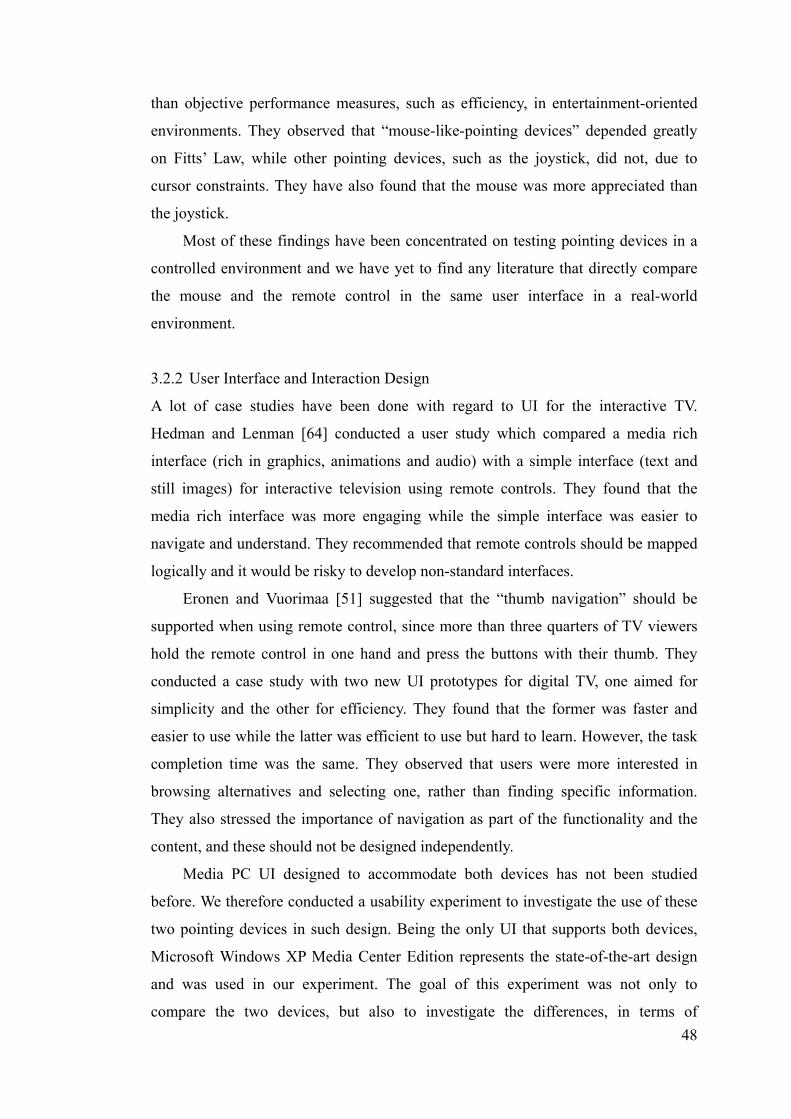
48
than objective performance measures, such as efficiency, in entertainment-oriented
environments. They observed that “mouse-like-pointing devices” depended greatly
on Fitts’ Law, while other pointing devices, such as the joystick, did not, due to
cursor constraints. They have also found that the mouse was more appreciated than
the joystick.
Most of these findings have been concentrated on testing pointing devices in a
controlled environment and we have yet to find any literature that directly compare
the mouse and the remote control in the same user interface in a real-world
environment.
3.2.2 User Interface and Interaction Design
A lot of case studies have been done with regard to UI for the interactive TV.
Hedman and Lenman [64] conducted a user study which compared a media rich
interface (rich in graphics, animations and audio) with a simple interface (text and
still images) for interactive television using remote controls. They found that the
media rich interface was more engaging while the simple interface was easier to
navigate and understand. They recommended that remote controls should be mapped
logically and it would be risky to develop non-standard interfaces.
Eronen and Vuorimaa [51] suggested that the “thumb navigation” should be
supported when using remote control, since more than three quarters of TV viewers
hold the remote control in one hand and press the buttons with their thumb. They
conducted a case study with two new UI prototypes for digital TV, one aimed for
simplicity and the other for efficiency. They found that the former was faster and
easier to use while the latter was efficient to use but hard to learn. However, the task
completion time was the same. They observed that users were more interested in
browsing alternatives and selecting one, rather than finding specific information.
They also stressed the importance of navigation as part of the functionality and the
content, and these should not be designed independently.
Media PC UI designed to accommodate both devices has not been studied
before. We therefore conducted a usability experiment to investigate the use of these
two pointing devices in such design. Being the only UI that supports both devices,
Microsoft Windows XP Media Center Edition represents the state-of-the-art design
and was used in our experiment. The goal of this experiment was not only to
compare the two devices, but also to investigate the differences, in terms of
49
interaction design.
3.3 Hypotheses
In general, remote controls are specialized input devices that are designed for the
operation of a single specific user interface. This fact alone should make them at
least potentially superior, in terms of efficiency and suitability, to a general purpose
input device.
Typically, remote controls do not require accurate pointing. The targets (e.g.
selectable items in a DVD menu) are fixed and the interaction path is constrained.
Users can only select different targets. They cannot, for example, choose an area
outside these targets. Users may not need to concentrate as hard to select a target
compared to the mouse. We also suspect that users should find the remote easier to
use overall (although their satisfaction might be limited due to the fact that they are
not familiar with the remote on first use).
The mouse, on the other hand, may be less accurate, but may be faster due to its
simple and direct operation, particularly in tasks with many targets. Users would
only need to move the mouse once compared to the multiple taps that remote users
would need to perform.
Fatigue should be a factor that affects the preference for users. The remote is
usually held in the hand in mid air while the mouse usually sits on a flat surface.
However, the mouse restricts the user to a certain position (i.e., near the table) while
remote users are free to move around. We are not certain which one users would
prefer.
With these hypotheses in mind, we conducted our study.
3.4 Usability Study
Our study tested the usability of the mouse and the remote control on a Media PC
focusing on photo browsing. It was set up so that subjects feel as though they were at
home in their living room, comfortably sitting on a couch in front of the Media PC.
Subjects were asked to perform a series of tasks as if they were at home - turning on
some music and browsing their photos.
3.5 Apparatus
The input devices used in this study were Microsoft Media Center remote control,

50
Microsoft Wireless Optical Mouse and Microsoft Wireless MultiMedia Keyboard.
They were connected to a Dell Optiplex GX260 Pentium 4, 2.8GHz PC running the
Chinese version of Microsoft Windows XP Media Center Edition 2004 (MC). The
display used was a 42” LG Plasma Display Panel (MT-42PZ12) running at a
resolution of 800x600. Subjects were approximately 2.5 meters (8.2 feet) away from
the display while sitting.
Every subject used the same photo collection, which consisted of over several
hundred photos. They were taken by a member of our team during a family vacation,
and were representative of the type of photo collection a user might have. The user
study was conducted in a living room setting with couches, tea table, rug, vast and an
entertainment system which includes a plasma TV, DVD player, Xbox, and a set of
5.1 speakers.
3.6 Participants
Eighteen volunteers (13 female, 5 male) were recruited for the study. Participants’
age ranged from 22 to 31 years old with an average of 25.67. In order to control for
possible bias or expertise effects, all participants were working or studying in a
non-technical field with average computer experience. None of the participants had
previously seen or used Microsoft Windows XP Media Center Edition or any other
Media PC UI before. All subjects were fluent with the Chinese language used in the
Windows XP Media Center. Some of the participants used the computer (and
therefore the keyboard and mouse) a few times a week, while most used it daily. All
of them have used some kind of remote before whether it is the TV remote or DVD
Figure 3.1: A user using the mouse in our user study

51
player remote. Experiences with using a remote control to navigate a DVD menu
structure ranged from few times a week to never. Participants were provided free soft
drinks and were given a small logo item as a gratuity. Participants were observed by
two observers in addition to the experimenter, and all sessions were video taped.
3.7 Procedure
Participants started off by filling out an initial questionnaire indicating their
experience with the remote and DVD menu operation. They were then given a
learning phase on using the remote and exploring parts of the Media PC interface by
themselves. Although many features of the Media PC were not used in the actual
experimentation, we hoped this would provide some comfort to the subject. A second
Media PC outside the experimental room was used for this phase of the experiment.
Participants were then asked to complete a list of simple tasks (collectively called
Task 1) that were similar to the tasks they would be asked to perform in the actual
user study. Help was available if needed, and the subject had no time constraints. The
purpose of Task 1 was to reduce learning effect of the remote control and the user
interface.
Participants were then told to complete task 2 to 7 with either the mouse or the
remote. The moderator read out each task in turn and they had to complete each task
before proceeding to the next. Finally, they were instructed to complete a device
assessment questionnaire.
After completing this sequence, subjects were asked to repeat the sequence
again with the other device. Two different sets of photos were used between the
trials.
At the end of the study, users were asked to complete a device comparison
questionnaire and were asked a series of questions in an interview.
3.8 Design
The study was a within-subject study so that each of the eighteen subjects had to
complete all tasks (2 to 7) for each device. The order of devices was
counter-balanced, with approximately half of the males and half of the females
starting with the mouse and the other half with the remote, to check for ordering
effect. The ordering of the tasks was not randomized. Any possible effect for not

52
doing so was assumed to be negligible since we are not comparing between the tasks
and each task required a different skill.
A five minutes deadline was imposed on each task. Those who failed to
complete were excluded from the results. Each session generally lasted for around an
hour and in some cases one and a half hours.
3.9 Results
Although we timed the tasks during the experiment, we had to use our video logs to
determine actual task time, as subjects would often ask questions or make comments
that were not part of the study. All times discussed here are from the video logs.
The average overall task time for the mouse (mean = 134 seconds) was faster than
for the remote (mean = 152 seconds) but it was not statistically significant at the 0.05
level, t(14) =1.84, p = 0.09 (Figure 3.2).
Figure 3.2: The effect of devices on task times for each task
In task 3 and 5, the differences between the devices were not significant but for task
4 and 6, they were significant. In task 4, the remote (mean = 24) was significantly
faster than the mouse (mean = 36), p = 0.02. In task 6, the mouse (mean = 21) was
significantly faster than the remote (mean = 52), p = 0.04.
In addition, we have tested statistically and found that gender effect (p= 0.77 for
remote, p = 0.99 for mouse), experienced with remote (p=0.85 for remote, p=0.31 for
mouse) and presentation order (p=0.20 for remote, p=0.57 for mouse) were not a
factor in our study.
152
134
65 65
52
2124
36
8 60
20
40
60
80
100
120
140
160
Remote MouseDevices
Ave
rage
Tas
k T
ime
(sec
onds
) Task 3 to 6
Task 5
Task 4
Task 6
Task 3
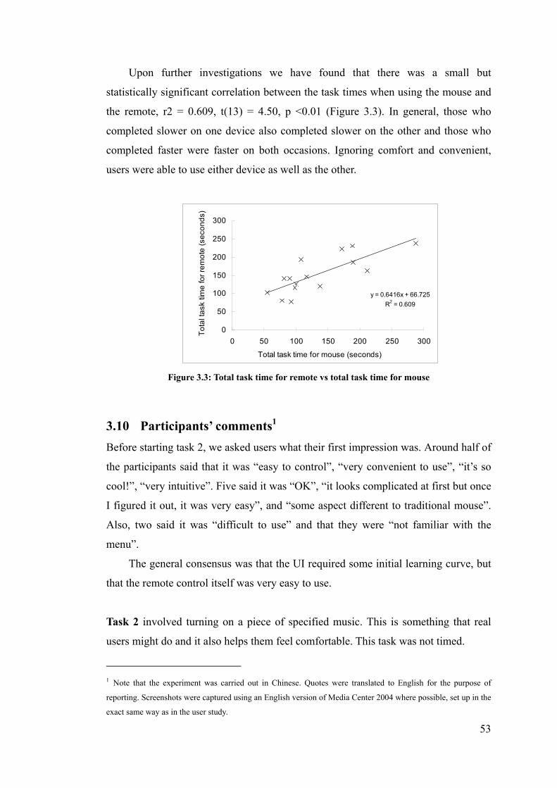
53
Upon further investigations we have found that there was a small but
statistically significant correlation between the task times when using the mouse and
the remote, r2 = 0.609, t(13) = 4.50, p <0.01 (Figure 3.3). In general, those who
completed slower on one device also completed slower on the other and those who
completed faster were faster on both occasions. Ignoring comfort and convenient,
users were able to use either device as well as the other.
Figure 3.3: Total task time for remote vs total task time for mouse
3.10 Participants’ comments1
Before starting task 2, we asked users what their first impression was. Around half of
the participants said that it was “easy to control”, “very convenient to use”, “it’s so
cool!”, “very intuitive”. Five said it was “OK”, “it looks complicated at first but once
I figured it out, it was very easy”, and “some aspect different to traditional mouse”.
Also, two said it was “difficult to use” and that they were “not familiar with the
menu”.
The general consensus was that the UI required some initial learning curve, but
that the remote control itself was very easy to use.
Task 2 involved turning on a piece of specified music. This is something that real
users might do and it also helps them feel comfortable. This task was not timed.
1 Note that the experiment was carried out in Chinese. Quotes were translated to English for the purpose of
reporting. Screenshots were captured using an English version of Media Center 2004 where possible, set up in the
exact same way as in the user study.
y = 0.6416x + 66.725
R2 = 0.609
0
50
100
150
200
250
300
0 50 100 150 200 250 300
Total task time for mouse (seconds)
To
tal t
ask
tim
e fo
r re
mo
te (
seco
nd
s)

54
When using the remote, a lot of them commented on the separation of the two “areas”
- the menu on the left and the list of music on the right (Figure 3.4).
They said that it was very “annoying” since they “couldn’t figure it out at first”.
Most initially tried to use the “down” button on the remote. They also mentioned that
“pressing one at a time is slow” since it requires “too many clicks” especially if there
were more music. They further commented that the remote is “not as good as the
mouse” since “the mouse is more direct”. But others insist that it was “better than the
mouse” and the remote was “fairly easy” to use. When using the mouse, a major
issue was that they didn’t know how to go back. On the remote, there is a dedicated
“back” button, but no such button exists on the mouse. The user interface actually
has a back button (a relatively small button near the top-left corner shown in figure
4), but for most users it was not discoverable without instruction.
A few users didn’t like the mouse either and said that there were “too many
steps involved”, “not as easy as pressing the play button like on a DVD player”.
Most said it was “easy” because they were used to using the mouse on their PC
already. One subject summed it up by saying “for computer users, the mouse is faster
but for family users, the remote is more convenient”.
Figure 3.4: Screenshot of task 2 - music UI

55
Task 3 is a simple task where users were asked to find a specified photo from a
folder of nine photos and enlarge it to full screen. We chose nine photos because it
was the maximum number that MC can display at any one time without scrolling
(Figure 3.5).
While using the remote, some found that it was “very simple” and “convenient”
with “no problem”, others commented that it was “troublesome”, “too much step
involved” and that they “can’t move to the photo directly”. When using the mouse,
they felt that it was “quite convenient” because it was “much faster and more direct”.
This initial reaction was supported by the statistics (mouse mean = 6 seconds, remote
mean = 8 seconds) although the difference was not significant.
Task 4 extended task 3 by adding more photos to the directory so that it was
necessary to scroll down before finding the target photo.
On the first iteration, no matter which device they were using, half of the
subjects didn’t know that there were more photos than those on display. The only
indicator in the UI was some text and scroll arrow buttons in the lower-right corner
(Figure 3.6). Some of the subjects discovered them eventually because they couldn’t
find a matching photo. They commented that there is a need for “more indication”
suggesting that the current indication is not obvious.
Figure 3.5: Screenshot of task 3 - photo browsing UI

56
Once the need to scroll was made apparent, users found the remote generally
“quite convenient”. Subjects mostly used the scroll wheel on the mouse to move
through the photos, although some used the up and down arrows at the bottom, and a
few used a combination of both. Some commented that they can “scroll faster with
the mouse” compared to the remote. This is attributed to the fact that the “down”
button on the remote allows only “discrete” push, while the scroll wheel allowed
“continuous” roll. Each push on the remote reveals one new row of photo, where one
roll of the mouse wheel uncovers multiple rows of unseen photos.
Overall, users found the mouse much “faster and more direct” and they felt “as
if they were using a computer”. Despite this impression, users performed the task
significantly faster with the remote. This difference in perception versus reality could
be explained by the fact that even though the remote only allowed one new row of
photos appearing at a time, subjects could tell exactly which photos were new and
which were not. This decreased the time to scan the display. Also, some users would
scroll too much and overshoot their target, thus requiring them to spend additional
time scrolling backwards to their original starting point.
Task 5 tested the efficiency of the interface for multiple directories. Ten folders were
presented to the user and their objective was to find a photo located in one of the
folders. They were told to search the folders sequentially. This task was designed to
require a large amount of repetitive movements – moving into and out of folders –
thereby uncovering problems and inconvenience with each device (Figure 3.7).
Figure 3.6: Screenshot of Task 4 - Scrolling.

57
Remote users generally found that the “buttons were too hard to click” and they
“have to click harder or click more than once to get it working”. One user mentioned
that “the default position for the thumb was at ‘OK’ but after reaching for the ‘back’
button, my finger was out of place, which made the next move difficult.” (Figure 3.8)
An interesting observation was that after scrolling to the target photo, subjects
would click ‘ok’ directly, without first selecting the photo. This suggests a disparity
between the eye movement and the hand – remote movement. The overall feeling
was that remote was “not easy” and “complex”. Mouse users complained about the
small “back” button provided which was “badly positioned”. Another user
commented that “remote is faster when doing things repeatedly and for short
distances while mouse is better at travelling longer distances”. This observation is in
general supported by the data. The mouse can move quickly, but is slow to aim. For
long distances, the faster travel time makes up for the slower aiming time at the end
of journey. While for short distances, the need to aim slows down the user. The
Figure 3.8: A photo of the MC remote focusing on the
navigational buttons as well as the “back” button.
Figure 3.7: Screenshot of Task 5 – Folders navigation

58
remote excels at short navigation tasks, where the user can just press the same button
sequence repeatedly. With longer navigation paths, the number and type of button
presses required is less predictable, resulting in slower performance.
The mean task time for this task was the same for both devices (65 seconds).
Task 6 required adjusting the slideshow timing in settings and playing the slide show.
This tested the interaction with standard UI widgets.
The major problem that surfaced was changing the time with the remote. All
users managed to navigate to the “slideshow timing” item with no problem, but none
knew immediately that they had to navigate to the “+” or “-” on the UI and press
“OK” on the remote. They tried pressing the “up” button on the remote instead of
“OK”. Most were very confused at first but discovered the usage without help in
the end. One subject tried to use the number keypad on the remote without success.
The general feeling was that “there were too many steps involved”, “slower than the
mouse”, “it was not convenient”, and one said “I wish I had a mouse”. A few mouse
users tried clicking on the actual number display and expecting that they can
manually input the desired number or that a drop down menu would appear. They
found the mouse “more comfortable, more direct, faster and easier than the remote”.
Indeed, our statistics shows that the mouse (mean = 21 seconds) is significantly
faster than the remote (mean = 52 seconds).
Task 7 was designed to test for fatigue and therefore not timed. Participants were
required to find a photo, by browsing sequential in full screen, using the “right”
Figure 3.9: Screenshot of Task 6 – UI widgets

59
navigational button on the remote or on the keyboard.
Our aim for this task was to test for fatigue in the extreme case. For both the
mouse and the remote, it was observed that almost all users pressed one at a time at
the initial phase. Only a few pressed continuously until the required photo was found.
“Because it was going so slow, it was only intuitive to click faster and harder, even
though the photos don’t show up faster” most users commented. Some reduced their
rate of click to align with the rate of transition thereby reducing unnecessary clicks.
They agreed that their eyes were tired after the task and their concentration decreased
towards the end. They also grew very impatient.
Keyboard users generally found that there was no fatigue and the buttons were
“easier to press than the remote”. Remote users agreed that it was “hard to push”.
Some subjects suggested it was because the remote was “not responsive enough”
which gave them the impression that they need to push harder. However, they found
that it was more “comfortable and relaxing” using the remote. One commented that
they didn’t feel tired since they are used to pressing buttons while typing text
messages on their mobile phones, where buttons are much smaller.
3.11 General Observations
Remote:
It was observed that more than half of the subjects looked at the remote
occasionally, especially when they were changing buttons. However, this
unfamiliarity is expected to diminish with practice.
Users like to hold the remote in mid-air while performing the tasks, but
retreat and rest on the lap when they have completed the tasks.
Around half of the subjects used both hands to hold the remote, usually one
for support, and one for clicking.
The remote requires much more button press than the mouse, but the mouse
requires physical translation of the object.
Mouse:
It was observed that users of mouse had to lean forward almost all the time,
but this was not the case for the remote.
Half of the users double clicked on folders, as if on a computer GUI, but only
one click was necessary.

60
Most users used the mouse as their eye. Their mouse action seems to follow
their eye. Some even used their scroll wheel to do the same. This behaviour
has been described in [24]. In addition their mouse movement was
unpredictable and quite erratic rather than a straight line of direct movement.
When users were clicking the “back” button, we have noticed that users
generally increased their speed at the initial phase of the journey and then
slow down as they approach the back button. Some overshot the target. This
is in accordance with expectation based on Fitts’ Law.
In many occasions, users felt the need to readjust their mouse position by
lifting the mouse or by moving the mouse pad.
User Interface Interaction:
It was interesting to observe that users always want to see if there were more
photos in that folder either by scrolling with the mouse wheel or pressing the
“down” button on the remote, even after being told that an indicator exists.
This suggests that most users have habituated to searching for more data that
are not immediately visible on the screen. This may also be attributed by the
unfamiliarity with the indicator.
There was a lack of indication which folder users came out from, after going
back up one level. Some users kept visiting folders that they have been to
before. This suggests that “folders” might not be a good metaphor for storing
photos
3.11.1 Questionnaires
The first questionnaire used in this study was a slightly modified version adopted
from [42] and is shown in Table 3.1. The results are presented in Figure 3.10.
After calculating the mean and statistical analysis, we have found that only
question 1 and 2 were statistically significant (p = 0.00 and p = 0.03 respectively).
This supports comments from users that excessive force was needed to push the
remote button. On the other hand, the mouse was found to be smoother during
operation. This again provides evidence along with the previous observations that the
mouse was more direct than the remote.

61
Figure 3.10: Average ratings in the device assessment questionnaire for remote and mouse
3.4
2.8
2.3
2.2
1.9
1.6
2.2
1.9
3.3
2.3
2.5
2.1
1.9
2.1
1.7
1.9
2.1
1.6
2.9
1.9
2.1
1.7
2.0
2.1
1.9
1.8
1 2 3 4 5
1
2
3
4
5
6
7
8
9
10
11
12
13
Que
stio
n N
umbe
r
Average Rating
Remote
Mouse
Device Assessment Questionnaire
1. The force required for pushing the buttons was:
Too low 1,2,3,4,5 Too high
2. Smoothness during operation was:
Very smooth 1,2,3,4,5 Very rough
3. The mental effort required for operation was:
Too low 1,2,3,4,5 Too high
4. The physical effort required for operation was:
Too low 1,2,3,4,5 Too high
5. Accurate pointing was:
Easy 1,2,3,4,5 Difficult
6. Operation speed was:
Too slow 1,2,3,4,5 Too fast
7. Finger fatigue:
None 1,2,3,4,5 Very high
8. Wrist fatigue:
None 1,2,3,4,5 Very h igh
9. Arm fatigue:
None 1,2,3,4,5 Very high
10. Shoulder fatigue:
None 1,2,3,4,5 Very high
11. Neck fatigue:
None 1,2,3,4,5 Very high
12. General comfort:
Very comfortable 1,2,3,4,5 Very uncomfortable
13. Overall, the input device was:
Very easy to use 1,2,3,4,5 Very difficult to use
Table 3.1: Device Assessment Questionnaire
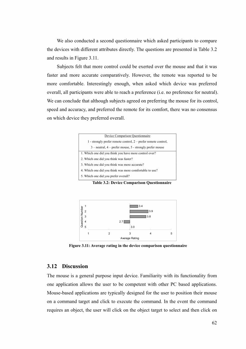
62
We also conducted a second questionnaire which asked participants to compare
the devices with different attributes directly. The questions are presented in Table 3.2
and results in Figure 3.11.
Subjects felt that more control could be exerted over the mouse and that it was
faster and more accurate comparatively. However, the remote was reported to be
more comfortable. Interestingly enough, when asked which device was preferred
overall, all participants were able to reach a preference (i.e. no preference for neutral).
We can conclude that although subjects agreed on preferring the mouse for its control,
speed and accuracy, and preferred the remote for its comfort, there was no consensus
on which device they preferred overall.
3.12 Discussion
The mouse is a general purpose input device. Familiarity with its functionality from
one application allows the user to be competent with other PC based applications.
Mouse-based applications are typically designed for the user to position their mouse
on a command target and click to execute the command. In the event the command
requires an object, the user will click on the object target to select and then click on
Figure 3.11: Average rating in the device comparison questionnaire
3.4
3.9
3.8
2.7
3.0
1 2 3 4 5
1
2
3
4
5Que
stio
n N
umbe
r
Average Rating
Device Comparison Questionnaire
1 - strongly prefer remote control, 2 – prefer remote control,
3 – neutral, 4 – prefer mouse, 5 - strongly prefer mouse
1. Which one did you think you have more control over?
2. Which one did you think was faster?
3. Which one did you think was more accurate?
4. Which one did you think was more comfortable to use?
5. Which one did you prefer overall?
Table 3.2: Device Comparison Questionnaire

63
the command target. When confronted with an unfamiliar application, the user will
move the mouse around the screen looking for potential targets that might match
their intended task.
The remote control, on the other hand, is typically designed for a single user
interface. Each action in the user interface has a dedicated button on the remote. For
commands which require an object, the user can navigate among targets using left,
right, up, and down buttons. Each press selects the next object. Once the proper
object is selected, the user can then press the appropriate action button on the remote.
The remote almost necessitates a trial and error approach with learning a new device
and how it interacts with that particular remote. Many design variables in remote
control interface design can be user friendly but can often result in frustration.
Whereas in mouse driven application only screen interface will determine usability.
With remotes, both screen and remote interfaces will need to be learned in some way
by new users.
One of the primary user confusions with switching between these devices is the
difference in selection paradigms. Specifically, remote control UI tends to always
have a selection, while mouse UI supports states with no selection.
Another source of confusion comes from the discoverability of possible user
interface actions. On a remote control, the user can quickly see all of the possible
actions, whereas the mouse UI must be explored by the user in order to discover
command targets. In order to save screen real estate, mouse UI typically reconfigures
itself to provide just the commands appropriate for the task at hand. This can make
the mouse UI more efficient, but results in confusion when users switch between the
input devices.
The question for interaction designers remains if they should design screen
interfaces to be used by both devices or to have dedicated screens optimized for each
particular control device. This study attempts to answer some of the difficulties in
having one screen interface for two control devices.
3.13 Recommendations
Based on these results and observations, we have come up with the following
recommendations for those designing UI for both mouse and remote control
operation.

64
3.13.1 Unified Selection
Many problems were the result of the differences in selection modality between the
two devices. Given the poor performance with trying to control a mouse cursor using
directional buttons [67, 84], we recommend making the mouse work more like a
remote. The user interface targets should be larger and adjacent to minimize targeting.
The user interface targets should have obvious highlighting to indicate that they are
targeted when the mouse is over them. This highlighting should be obviously distinct
from the selection indication.
3.13.2 Keyboard/Remote Equivalence
Users draw a natural correspondence between the buttons on the remote control and
the buttons on the keyboard. Therefore, it is crucial that those buttons that are
shared between these devices have the same effect in the user interface.
For example, most remote controls contain a numeric keypad, and yet we see
many instances where the user cannot input numbers by using the remote, even
though they can enter numbers using the keyboard. Another example is that the
arrow keys on the keyboard rarely have the same functionality as the equivalent
buttons on the remote. (In MC, the “more info” button on the remote does not have
any equivalence on either the keyboard or the mouse.)
3.13.3 Action Target / Remote Correspondence
Often users who are familiar with the user interface for one device have difficulty
transferring that knowledge to operate the other device. To facilitate this transfer, we
recommend making the action targets in the GUI and the action buttons on the
remote correspond as closely as possible, in both graphical appearance and relative
spatial layout. We also recommend that the action targets provide the same visual
feedback when the action is invoked, whether invoked from the click of a mouse or
the press of a remote button. (For example, the MC remote has a grey button labelled
‘back’, while the UI on screen has a green button, labelled with a white arrow
pointing to the left)
This will not only help the user learn the operation of one device when using the
other device, but can also help instruct the user of a remote which of the dedicated
remote buttons are appropriate at the given time.
65
3.13.4 Software solutions
Novel devices combining both mouse and remote have not proven to be more
efficient as mentioned earlier with the Gyration mouse. The touchpad-based remote
control was a combined software and hardware approach to solve the lack of
scalability problem with the remote [50]. It would therefore be appropriate to further
research on software approaches to reduce the interaction inconsistency between the
mouse and the remote (possibly in conjunction with other novel hardware
approaches). Initial research has been done on using personal digital assistant (PDA)
that operates together with interactive television [121]. Myers et al. have shown that
it is possible to capture the whole or parts of the screen and transfer it to a PDA. This
technique shows great potential for application to media PC [99].
Constrained movement technique used with the remote UI has showed
promising results. As observed by Jul [72], compared with unconstrained movement,
constrained movement in a 2D zooming environment showed improvements both
quantitatively (decreased task time) and qualitatively (decreased spatial
disorientation).
3.13.5 User Experience
Reported in questionnaires, despite the mouse as described by users as fast and direct,
the overall preference towards the mouse was not favoured. The restrictions
associated with the mouse were the main contributing factor. On the other hand, the
comfort and freedom provided by the remote was considered to outweigh the
complexity and proficient use of the remote. This suggests that users generally prefer
devices that are comfortable and at the same time provides an enjoyable experience.
A study has shown that users prefer a method that has a higher subjective satisfaction
with a lower quantitative performance [44]. As illustrated future user interface and
interaction design should aim to address users’ satisfaction with at least the same
priority as quantitative performance, if not higher priority. It is our recommendation
that designers should provide an enjoyable user experience as one of the primary
objectives.

66
3.13.6 Natural Interfaces
Users’ performance was affected by the degree of familiarity of the interface. We
observed that subjects required time to learn the interface with the mouse and to
learn the interface with the remote controller. In addition, if the behaviours or
placement of the learnt interface are changed, users will easily be confused and
disoriented. This was due to differences between the way people perform tasks in the
real world and the way they interact with these input devices. We recommend that
future interaction methods should be as natural to the user as possible, closer to
interacting with real world objects. This may be possible by studying the behaviour
of human in performing day-to-day tasks.
3.14 Summary
We have presented a user study comparing the performance of a remote control and a
mouse in operating a Media PC user interface that is intended to be operated by
either device, in front of a large display from a distance. We have observed that users
found the mouse to be more direct but restrictive, while the remote was more
comfortable and enjoyable but slow to learn. We have also observed a lot of
problems and inconsistencies with the mouse, remote and their interaction with the
Media PC UI. We have found no difference in the overall task time, as well as no
overall preference for the mouse and the remote control.
From specific user comments, we have observed that users preferred device that
closely matches their personal browsing and interaction style. We have seen, based
on the task, that one device may be better suited for accomplishing that task better.
However, the most surprising result is that users were able to use either control
device to accomplish the task in similar amount of time, with the mouse being
slightly faster. Although the results show that based on time and user feedback that
the mouse was faster and had better control, users still felt that the comfort and
convenience of the less precise device made it equal to using the mouse by
preference. Future research should take note of the tolerance level that users may
have in sacrificing comfort for effectiveness. Finding this exact threshold will be the
key in influencing users’ experience with new entertainment devices as more rich and
complex media applications migrate towards the living room.

67
We see from this study that it is possible to have one screen interface for both
mouse and remote that users can use based on their preferred control device.
Interface designers can design a screen interface usable by both control devices.
However, further research can be executed to determine if a screen interface
optimized for a particular control device will improve effectiveness or user
experience. Findings from this study may indicate that such minor gains may be
insufficient to warrant the time and resources to develop a specialized screen for each
control device.
In addition, we have presented recommendations for designing such
multi-device user interfaces. These can serve as guidelines to the design of future
interactive methods. Of particular importance to this thesis is the need to provide a
user experience that is natural for the user. In the next chapter, we will investigate the
natural strategy adopted by people to point at real world objects. We may then be
able to design an interactive system that is natural to the user and one that they will
enjoy using.
68
Chapter 4
Pointing Strategies
From the previous chapter, it was observed that future interaction should take into
account user preference as well as allowing a natural interaction. From this
observation, if we are to design any kind of interactive system, it is necessary to
study the natural means for its intended user. This chapter investigates the use of
natural pointing for interacting with the computer.
Much effort has been made on making interaction with the computer more
natural and more intuitive for the user. We will present various HCI literatures that
have adopted hand pointing as one of the main approaches to selection. Although
many interactive systems have focused on improving the detection of the users’
pointing direction, few have analyzed the kinds of pointing strategy that is natural to
the users and the accuracy of these strategies provided by the users themselves.
Pointing in the natural environment will be studied in an experiment to
determine the most common and natural strategies used. A second experiment will
study the accuracy that can be achieved from these strategies. In order to understand
the reason for this difference and to understand the mechanism of hand pointing with
respect to human-computer interaction, we introduce several models that underpin
the pointing strategies observed in our experiments, as well as those used in many of
the previous interactive systems. We recommend strategies that will help future
interaction designers make use of the natural pointing behaviors of humans while at
the same time allowing users to point accurately.
4.1 Background and Related Work
Perhaps the most direct form of selection at a distance is being able to point at
something with your hand without any restrictions. The current trend is to make
pointing as easy as pointing to real world objects. Taylor and McCloskey identified
that “to indicate accurately the position of an object that is beyond arm’s reach we

69
commonly point towards it with an extended arm and index finger” [142]. The
pointing gesture belongs to a class of gesture called “deictics” and is defined by
McNeill as “gestures pointing to something or somebody either concrete or abstract”
[88].
Studies have shown that the pointing gesture is often used to indicate a
direction as well as to identify nearby objects [88]. This is an interesting concept
because the pointing gesture is natural, intuitive, and easy to use and understand.
Indeed, children can use body postures and gestures such as reaching and pointing by
about nine months [83].
Here, we will review some of the literature, approaches to pointing and the
varied implementations where hand pointing was used for interactive systems.
The pointing finger has been used in many existing systems. Using active
contours, a pair of uncalibrated stereo cameras have been used to track and detect the
position and direction of the index finger for human-robot interaction within a 40cm
workspace [32]. In the Ishindenshin system [81] a small video camera is placed near
the center of a large vertical display directly in front of the user. The user is able to
keep eye-contact and use the pointing gesture to interact with another user in a video
conference. The fingertip location is detected by the camera and its location in x and
y coordinates are determined.
Hand tracking is another popular method to support natural interaction. While
the above works focus on vertical screens, Oka, Sato & Koike [107] used hand and
fingertip tracking on an augmented desk interface (horizontal). An infrared camera is
used to detect areas that are close to the human body temperature. In [129], a motion
recognition camera (EyeToyTM camera for PlayStation® ) is placed on top of a large
display. A mirror image of the camera is presented on the display, as well as
additional game play information. A selection is made when the user place their
hands at specific locations so that the on screen image coincides spatially with
on-screen buttons. Note that in [81, 107, 129], the fingertip or hand can only be
tracked in 2D, depth is not registered.
The MobiVR system [117] captures and detects a pointing finger behind a
handheld non-see-through binocular near-eye microdisplay (taken from a Head
Mounted Display) attached to a reconfigured SmartNav infrared camera aiming
forward. By attaching an infrared reflector ring on the finger, the user can perform a
pointing gesture in front of the device to control a mouse cursor. This makes use of

70
the eye-fingertip strategy, where the pointing direction is extracted from a line
starting at the eye and continues to the fingertip. An interesting point here is that the
fingertip is behind the near-eye display.
Various other researchers have investigated the use of the head-hand line
(similar to the eye-fingertip strategy but detecting the whole head and hand rather
than specifically the eye or fingertip) for interacting with their systems [33, 102]
(illustrated in Figure 4.1). All of these systems used a set of stereo cameras to track
the user’s head-hand line to estimate the pointing direction in 3D at a distance of
around 2 meters. However, Nickel and Stiefelhagen [102] also found that adding
head orientation detection increases their gesture detection and precision rate.
Comparing three approaches to estimate pointing direction, they found that the
head-hand line method was the most reliable in estimating the pointing direction
(90%). The others were forearm direction (73%) and head orientation (75%).
However, their result is based on whether 8 targets in the environment were correctly
identified, rather than accurately measuring the accuracy from a specific target. The
forearm orientation and head-hand line were extracted through stereo image
processing while the head orientation was measured by means of an attached sensor.
There is evidence to suggest that the natural pointing gesture may be
estimated to be somewhere between the head-hand line and the arm pointing strategy.
Mase [86] used a pair of stereo cameras to determine the fingertip position. In order
to extract a virtual line between the finger and a target, the location of the “Virtual
Project Origin (VPO)” must be calculated. The VPO varies according to the pointing
style of each individual. They made used of a pre-session calibration and
Figure 4.1: An example of using the head-hand line to deduce pointing direction [33].

71
experimental results suggested “the VPO is mostly distributed along the line of the
eye on the pointing hand’s side and the shoulder”.
In an experiment to investigate the effect of vision and proprioception in
pointing (“the ability to sense the position, location, orientation, and movement of
the body and its parts” [143] ), it has been reported that users tend to point (with an
extended arm) to the target (about a meter away) by placing their fingertip just lateral
to the eye-target line [142]. However, a line extended from the direction of the
pointing arm would miss the target. They explained that this may be used to avoid
the fingertip occluding the target or, alternatively, influenced by proprioception
(which usually results in using the whole arm as a pointer). Their result suggests that
the eye-target line is a good predictor of the pointing direction.
It is interesting to note that Olympic pistol marksmen and archers aim their
targets by extending their arm and standing side-on to the target, so that the line
running from the eye to the target coincide with the line running from the shoulder to
the target [142] (illustrated in Figure 4.2)
It is observed that different systems require different strategies for targeting.
There is currently a gap in the literature on systematically describing how and why
natural interaction methods work and classifying them based on their accuracy,
naturality and how well they capture the exact intention of the user. The above
mentioned literature has mainly focused on extracting or detecting different pointing
gestures through image processing or by different sensors. However, no known
strategies for pointing were recommended which allow users to point naturally and
accurately (to best represent their aim). In this context, we would like to investigate
Figure 4.2: An example of an archer using the eye-fingertip method [18].
72
how people point naturally and better understand the mechanism and the strategy
behind targeting.
4.2 Experiment: Style of Pointing Gesture
An experiment was conducted to investigate how people point at objects on a vertical
wall in a normal environment and to investigate the style of gestures people adopt
when pointing. We hypothesized that there are three main pointing strategies: (1)
using a straight arm, (2) using only the forearm and extended fingertip, and (3)
placing their fingertip in between the eye and target (line-up).
4.2.1 Participants
Nineteen volunteers (10 female, 9 male) were recruited for the study, ten of which
are from within the area of computer science. The average age is 23. All but one of
the subjects are right-handed. All have normal or corrected eyesight. Subjects were
not told the main objective of the study at the beginning, only that they will be
required to point at a target using their arm.
4.2.2 Procedure
Each subject was asked to stand at three distances (1.2m, 3m and 5m) away from a
wall. A target object, 5mm by 5mm, was marked on the wall, 155 cm from the
ground (around eye level for most participants).
In the first task, standing at one of the three distances from the target, subjects
were asked to point at the target using their preferred hand. They were free to use any
strategies they wanted and were not told specifically how they should point. This was
repeated for the other two distances. The purpose of this task was to observe the kind
of strategy used naturally by each subject to point at objects from a distance.
Although subjects may use any kind of strategy they prefer. At the end of the task,
subjects were asked to explain the strategy they used.
In the second task, subjects were then specifically asked to point using their
forearm and their fingertip only, limiting the movement of their upper arm (Figure
4.3). The purpose of this task was to observe different variations of using the forearm
pointing method.

73
In the final task, subjects were specifically asked to use their whole arm to
point while keeping it straight. The purpose of this task was to observe different
variations of using the full arm pointing method. They were then asked to complete a
qualitative questionnaire.
When pointing at a distance of 1.2m, a webcam captures the subject’s torso,
head, arm and target object on the wall from a side view at a resolution of 640 x 480.
This allows us to observe off-line the pointing style employed by users. However, for
3m and 5m, the pointing style was only observed by the experimenter as well as from
the subject’s comment.
The study was a within-subject study so that each of the subjects had to
complete all tasks for each distance. The order of distances was counter-balanced
with approximately one third starting at each distance.
4.2.3 Observations & Discussions
When asked to point freely at the target in task 1, the main observation was that
almost all subjects used a full arm stretch to point regardless of distance, with only
three subjects using the forearm. This may be due to the fact that during full arm
pointing, they can see their arm in front of them, which provides a better visual
approximation than the limited view of the arm provided with just the forearm. It is
also possible that subjects tend to move their hand and fingertip as close to the target
as possible, as if to touch the target physically.
Figure 4.3: An example of forearm pointing, where the user only uses their forearm and fingertip to point, while keeping their upper-arm as close to
their body as possible.

74
Task 1
(free style)
Task 2
(forearm only)
Task 3
(straight arm only)
Pointing Style / Distance(m) 1.2 3 5 1.2 3 5 1.2 3 5
Straight arm 1 0 2 - - - 2 0 1
Line up with straight arm 16 18 17 - - - 17 19 18
Fore arm 2 0 0 12 11 10 - - -
Line up with forearm 0 1 0 7 8 9 - - -
Table 4.1: Number of subjects using each pointing style in each task
Figure 4.4: Pointing styles used for each task
It is interesting to note that of those observed, 50% of subjects actually closed
one of their eyes (presumably the non-dominant eye) to aim, while the others have
both their eyes opened.
The majority thought that pointing using the full arm is intuitive, natural, fast
and accurate. Although around half of the subjects commented on the effort required
to lift their arm and that continuous pointing might be tiring. However, as they were
only asked to point for at most two seconds, fatigue was not an issue.
Except as required in task 2, almost no subject used the forearm pointing
method (Figure 4.3). This was surprising, considering that most subjects commented
that the advantage of this method was the minimal effort required to point. However,
the subjects felt that this method was unnatural and awkward, while high inaccuracy
0
2
4
6
8
10
12
14
16
18
20
T1 ‐ 1.2 T1 ‐ 3 T1 ‐ 5 T2 ‐ 1.2 T2 ‐ 3 T2 ‐ 5 T3 ‐ 1.2 T3 ‐ 3 T3 ‐ 5
Number of Subjects
Tasks ‐ Distance(m)
Pointing styles used for each task
Straight armLine up with straight armForearmLine up with forearm

75
was the most cited comments. This also helps to explain the surprising observation
that subjects also used the line up method even when using only their forearm. As the
forearm doesn’t provide an accurate pointing strategy, subjects naturally try to line
up their eye and fingertip to the target to increase accuracy. There is also a trend
where the further away the subjects are from the target, the more likely they will use
the line up method.
In task 3, even though users were specifically asked to use full arm pointing, we
observed two main strategies used to point at the target. Three subjects used their
arm as a pointing instrument where the pointing direction is estimated from the
shoulder to their fingertip (Figure 4.5), while most users tried to align their fingertip
in between the eye and target (Figure 4.6) as hypothesized. This observation can also
been seen in task 1.
Figure 4.5: Full arm pointing (1) – using the arm as a pointing instrument while keeping the arm as straight as possible.

76
In task two, the normal forearm pointing method is where the user estimates
their pointing direction with the direction of their forearm (Figure 4.3), while the line
up method is similar to that of the straight arm pointing except that subject’s arms are
bent.
A few subjects commented that as they move further away from the target, it
is more likely they will use a fully stretched arm. This is shown in the observation
with 2 subjects using the forearm for task 1 at 1.2m, but it cannot be used as
conclusive evidence.
Overall, we observed a clear preference for the line-up method when pointing
with a straight arm, while the two different forearm pointing methods, are roughly
equally used.
Figure 4.7: Mean Overall User Preference
3.5
1.7
0
1
2
3
4
5
Forearm Straight arm
Preference
Pointing Style
Mean Overall Preference
Figure 4.6: Full arm pointing (2) – the fingertip is placed between the eye and the target

77
From the questionnaire, forearm pointing received a mean score of 3.5 out of
5 with a question on overall preference “I like using this method of pointing”. 3.5
represent midway between “neutral” and “disagree”. On the other hand, the mean
score for full arm pointing is 1.7 out of 5, representing midway between “strongly
agree” and “agree”.
4.2.4 Limitations
In hindsight, this experiment may have been affected by the size of the target. The
target that subjects were asked to point to was a 5mmx5mm dot. Subjects may feel
that they are required to point with high precision and within the target. It is possible
that they may be restricted to a method that produces high accuracy, namely the full
arm stretch. However, we were still able to observe the most natural pointing
technique that people adopt.
If the target size was larger (for example 5cm x 5cm), it is possible that more
users may use the forearm pointing technique, rather than most using the full arm
stretch to point. This remains an open question.
4.2.5 Summary
Agreeing with our hypothesis, we can observe three different methods of pointing.
1) Straight arm - where users estimate a direction from the shoulder to their
fingertip.
2) Forearm – where users estimate a direction from their forearm direction
3) Line up – where the pointing direction is given by the eye to the fingertip
position
The results from this study suggested that the line up pointing method is shown to be
the most natural way of pointing to targets. Overall, both quantitative and qualitative
measures suggest that users prefer to use a full arm stretch to point at targets.
Given the small scope, this experiment should only be treated as a
preliminary work on this subject. However, this may serve as a basis for further
analysis and experimentation with different size of targets.
Having studied the styles of pointing that are natural to the users, we observed
informally that the forearm pointing method may be less accurate than both form of
full arm pointing. However, further investigation would be required to justify this.

78
4.3 Experiment: Pointing Accuracy
Current research into vision-based interactive system typically focus on finding new
ways of improving the detection, estimation and tracking the pointing hand or finger,
and deduces the pointing direction [32, 33, 102]. For example, in a system that
detects the users’ finger pointing direction, Cipolla & Hollinghurst [32] evaluated
their system by analyzing their finger tracking uncertainty. They also analyzed their
experimental accuracy using an artificial pointing device – a white cylindrical rod.
However, these systems do not account for inaccuracies made by the user and
assumed implicitly that the user is always pointing to the desired location.
In the first experiment, we investigated the pointing strategies that people
naturally used when asked to point at a target. The aim of this experiment is to
investigate the pointing strategy that inherently provides the best accuracy from the
user. Different pointing strategies or styles used by the user may provide different
accuracies.
The three techniques used in this experiment were identified from the
previous experiment as well as from previous literature which was reviewed:
1) Forearm – where only the forearm is used to point, with limited upper
arm movement.
2) Straight-arm - where the whole arm is used to point, without bending.
3) Line-up – the fingertip is positioned collinearly between the eye and the
target. Several names have been used in the literatures for this method
such as “eye-fingertip”[66] or “head-hand line”[33], we will call this the
“line-up” method.
We hypothesized that the straight-arm method and the line-up method would
be more accurate than forearm pointing because the whole arm is visible to the user.
When the forearm method is used for pointing, users only estimate where their arm is
and as it is shorter than the full arm, the accuracy would be decreased.
Despite advances in computer vision, there is still no consistent method to
segment and extract the pointing direction of the arm. To minimize errors introduced
by computer vision systems, we made use of the laser pointer.
A laser pointer can be attached to the arm and gives us a direct and simple
resultant point, making it possible to quantitatively compare the different targeting

79
strategies. However, it would be difficult to fix a laser pointer at a specific place on
the arm. Consequently subjects were asked to hold the laser pointer in their hand in a
way that best represent the extension of their arm direction, in a consistent manner
across all three methods (Figure 4.8).
Although physically pointing with hand or arm compared to holding the laser
in the palm is slightly different, we believe that this difference would be consistent
enough so that it would still be comparable relatively between the strategies.
Therefore until a more suitable method is found, we felt that it was appropriate in
this case to use the laser pointer. In addition, users were not provided feedback from
the laser pointer to adjust their accuracy.
The effect of distance on the accuracy of pointing – whether pointing
deteriorates as user moves away from the target – was also investigated in this
experiment.
4.3.1 Participants
Fifteen volunteers (3 female, 12 male) participated in this study. Some of which have
participated in the previous study. All are working or studying in the area of
computer science. Their age ranged from 20 to 31 (average of 24.9). One subject is
left handed while 8 of them are right eye dominant. All have normal or corrected
eyesight. While only 6 of them had previous experience with using a red laser pointer.
Participants were provided chocolates and juice as gratuity during the breaks.
Figure 4.8: The laser pointer was used to represent the arm’s direction
Laser

80
4.3.2 Apparatus
A 5x5mm black target was constructed on a wall at a height of 1.5 metres (Figure
4.9). For the purpose of calibration, the target was surrounded by four additional
black dots, creating a 30cm square. The laser pointer used was a pen (1x14.7cm)
with a red laser pointer fitted at the back end (Figure 4.10). In order to detect the
target and the red laser dot, a webcam (Logitech Quickcam Pro 4000) positioned 2
metres from the target was used, together with a custom image processing software
(Visual C++ and OpenCV). The lighting condition in the room was dimmed to allow
optimize the detection of the red laser dot.
Figure 4.10: The red laser pointer used in this experiment.
guide makers
target object
Figure 4.9: A 5 x 5mm target at the center of a 30 x 30 cm square composed of 4 dots used for calibration
webcam

81
4.3.3 Design and Procedure
The study was a within-subject study, where each subject performed pointing tasks
with all three pointing styles from three distances: 1, 2 and 3 metres from the target.
Three blocks of trails were completed for each of the 9 combinations and the mean
position for each combination was determined. The order of pointing styles and
distances were counter-balanced with approximately one third starting at each
distance, and one third starting with each pointing style.
Subjects started off by filling out an initial questionnaire indicating their
details including hand preference, eye sight, and experiences with the laser pointer.
They were then given a learning phase on the different pointing techniques they
needed to use. Without turning on the laser, subjects were asked to aim as accurately
as possible, and hold the laser pointer in their dominant hand in a way that best
represents the direction of their pointing arm (for straight arm and forearm pointing)
as illustrated in Figure 4.10. For the line-up method, users were asked to place the
laser pointer between their eye and target, so that both ends of the laser pointer are
collinear with the eye and target (Figure 4.12). Subjects were free to use one or both
eyes for this method.
To prevent subjects receiving feedback from the laser dot, the laser was only
turned on after they have taken aim. Subjects were asked to keep the orientation of
the pen consistent throughout the entire experiment, in order to minimize unwanted
deviation from the button press. Once the laser was switched on, subjects were asked
to keep as still as possible and were not allowed to move their arm position. A
snapshot was then taken by the webcam. Accuracy was measured in terms of the
Figure 4.11. The laser pointer used with the line-up method of pointing
target laser pointer Eye
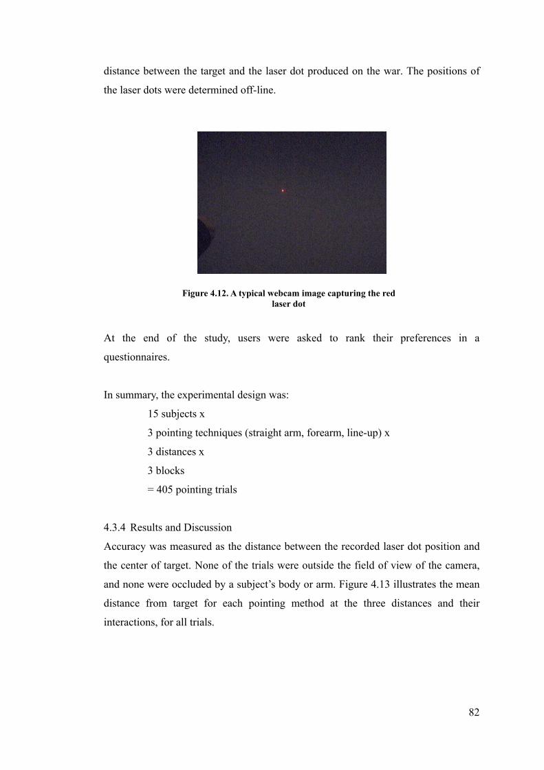
82
distance between the target and the laser dot produced on the war. The positions of
the laser dots were determined off-line.
At the end of the study, users were asked to rank their preferences in a
questionnaires.
In summary, the experimental design was:
15 subjects x
3 pointing techniques (straight arm, forearm, line-up) x
3 distances x
3 blocks
= 405 pointing trials
4.3.4 Results and Discussion
Accuracy was measured as the distance between the recorded laser dot position and
the center of target. None of the trials were outside the field of view of the camera,
and none were occluded by a subject’s body or arm. Figure 4.13 illustrates the mean
distance from target for each pointing method at the three distances and their
interactions, for all trials.
Figure 4.12. A typical webcam image capturing the red laser dot
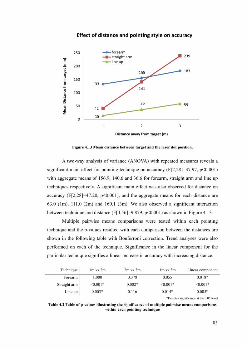
83
Figure 4.13 Mean distance between target and the laser dot position.
A two-way analysis of variance (ANOVA) with repeated measures reveals a
significant main effect for pointing technique on accuracy (F[2,28]=37.97, p<0.001)
with aggregate means of 156.9, 140.6 and 36.6 for forearm, straight arm and line up
techniques respectively. A significant main effect was also observed for distance on
accuracy (F[2,28]=47.20, p<0.001), and the aggregate means for each distance are
63.0 (1m), 111.0 (2m) and 160.1 (3m). We also observed a significant interaction
between technique and distance (F[4,56]=9.879, p<0.001) as shown in Figure 4.13.
Multiple pairwise means comparisons were tested within each pointing
technique and the p-values resulted with each comparison between the distances are
shown in the following table with Bonferroni correction. Trend analyses were also
performed on each of the technique. Significance in the linear component for the
particular technique signifies a linear increase in accuracy with increasing distance.
*Denotes significance at the 0.05 level
Table 4.2 Table of p-values illustrating the significance of multiple pairwise means comparisons within each pointing technique
133
155 183
42
141
239
15
36 59
0
50
100
150
200
250
1 2 3
Mean
Distance from target (m
m)
Distance away from target (m)
Effect of distance and pointing style on accuracy
forearmstraight armline up
Technique 1m vs 2m 2m vs 3m 1m vs 3m Linear component
Forearm 1.000 0.378 0.055 0.018*
Straight arm <0.001* 0.002* <0.001* <0.001*
Line up 0.003* 0.116 0.014* 0.005*
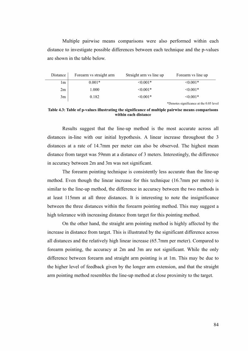
84
Multiple pairwise means comparisons were also performed within each
distance to investigate possible differences between each technique and the p-values
are shown in the table below.
Distance Forearm vs straight arm Straight arm vs line up Forearm vs line up
1m 0.001* <0.001* <0.001*
2m 1.000 <0.001* <0.001*
3m 0.182 <0.001* <0.001*
*Denotes significance at the 0.05 level
Table 4.3: Table of p-values illustrating the significance of multiple pairwise means comparisons within each distance
Results suggest that the line-up method is the most accurate across all
distances in-line with our initial hypothesis. A linear increase throughout the 3
distances at a rate of 14.7mm per meter can also be observed. The highest mean
distance from target was 59mm at a distance of 3 meters. Interestingly, the difference
in accuracy between 2m and 3m was not significant.
The forearm pointing technique is consistently less accurate than the line-up
method. Even though the linear increase for this technique (16.7mm per metre) is
similar to the line-up method, the difference in accuracy between the two methods is
at least 115mm at all three distances. It is interesting to note the insignificance
between the three distances within the forearm pointing method. This may suggest a
high tolerance with increasing distance from target for this pointing method.
On the other hand, the straight arm pointing method is highly affected by the
increase in distance from target. This is illustrated by the significant difference across
all distances and the relatively high linear increase (65.7mm per meter). Compared to
forearm pointing, the accuracy at 2m and 3m are not significant. While the only
difference between forearm and straight arm pointing is at 1m. This may be due to
the higher level of feedback given by the longer arm extension, and that the straight
arm pointing method resembles the line-up method at close proximity to the target.

85
Figure 4.14: Perceived Accuracy and Overall Preference for each pointing technique.
At the end of the experiment, subjects were asked to rate each method for perceived
accuracy and overall preference on a scale from 1 to 5. For perceived accuracy, the
scale is from not very accurate (1) to very accurate (5), and for overall preference, 5
being for strong preference. Figure 4.14 shows the mean rating for the each pointing
technique.
As can be seen, the subjects’ perceived accuracy is in-line with the actual
accuracy discussed previously. For the overall preference, subjects preferred the
straight arm method more so than other methods (mean rating = 4.2) as subjects
regarded this as being comfortable and natural, even though accuracy was not as
good as the line-up method. The line-up method followed closely in second with a
mean rating of 3.9. They found this method accurate, though it was not as natural as
straight arm pointing.
This is not consistent with the results from the first experiment where the
line-up method was by far the most natural method for both task 1 and 3. We
proposed that this inconsistency may be due to the unnaturalness of holding the laser
pointer in an awkward position rather than due the line-up pointing method itself. If
users had used their own hand and fingertip to point with this method, users would
potentially be more in favour of this method. As for the forearm pointing method,
subjects commented that this was comfortable but attention was required to make
sure they have aimed correctly.
4.4
3.0
1.7
3.94.2
2.1
0
1
2
3
4
5
Line‐up Straight arm Forearm
Rating
Pointing Technique
Qualitative Ratings
Perceived Accuracy
Overall Preference

86
4.3.5 Summary
From this experiment, we observed that the line-up method is the most accurate
pointing method, and that the straight arm is more accurate than the forearm method
only at a distance of one metre. From qualitative feedbacks, we observed that the
preference was higher for both the line-up and the straight arm method compared to
the forearm method..
Different interactive systems require different strategies for pointing.
However, pointing strategies have not been systematically studied for use in
interactive systems. Here, we attempt to characterize the mechanism of pointing in
terms of their geometric models used in previous interactive systems, and in the
process, we use the results from our experiments to gain a better understanding of
how and why the line-up method is a more accurate pointing method.
4.4 Models for Targeting
We hypothesized that there is a difference between the two strategies of targeting
using full arm stretch. To investigate the reason for this difference, we begin by
formalizing the concept of targeting from a geometrical perspective based on our
observations and from previous work. We then introduce three models for targeting -
the Point, Touch and the dTouch model. It should be noted that the word “pointing”
and “targeting” can be used interchangeably to mean the act of aiming (at some
target). However, the “Point” model is a similar concept but used in a very specific
manner, as will be discussed below.
4.4.1 Geometrical Configuration
We now define the geometrical configuration in which our models for targeting from
a distance will be based. These are the building blocks for introducing the models of
targeting.
A line of gaze, lg, is directed towards a point on a target object, Po, from a
point at the eye, Pe. While a point provided by a pointing mechanism, Pp, guides a
line of ray, lr, to the target Po. Figure 4.15 illustrates this geometrical arrangement.

87
The task of targeting is therefore to intersect lg with lr at object Po. A pointing
mechanism or visual marker (Pp) may include a variety of pointers that the user holds
or use to point. The fingertip (when user is using their arm) and the laser dot
produced by a laser pointer are examples of such (illustrated in Figure 4.16). On the
other hand, the arm direction is an example of line of pointing (lr).
We now distinguish three models that can explain most of the common strategies
used in the real environment and in many previous interactive systems.
Figure 4.16: Examples of visual markers (Pp).
Pp
lr Pp
lr
A pointing arm and fingertip A visible red laser pointer and its red laser dot
Pe = eye position Po = object/target position lg = line of gaze from eye to object Pp = visual marker (provided by some pointing mechanism or instrument) lr = line of ray/pointing
Figure 4.15: The general configuration for targeting.
Pe: (Xe,Ye,Ze)
lg : Pe->Po Po: (Xo,Yo,Zo)
lr :Pp -> Po Pp: (Xp,Yp,Zp)

88
4.4.2 The Point Model
The Point model describes the occasion when users’ point at a target from a distance
using their arm or a presentation pointer as the pointing instrument.
Targeting using the Point model is characterized by having the eye gaze, lg,
intersects with the pointing direction provided by the arm, lr, at the target object, Po,
such that the pointing marker, Pp, doesn’t meet at the target object Po:
Po ≠ Pp (4.1)
Figure 4.17 illustrates this geometrical arrangement. The task for the user is
to use their pointing instrument to approximate a pointing direction that meets the
target object. However, it is only an approximation, rather than precise targeting,
since the visual marker is not on the surface of the target to assist the targeting
process.
This can be used to model the cases when the arm is fully stretched, when only the
forearm is used to point to the target [102] or when only the fingertips are used, in
the case of [32]. This technique is known as ray casting for interacting with virtual
environments [17]. It can also be used to model the straight-arm method and the
forearm method that were observed and used in our experiments in this chapter 4.2
and 4.3. In these cases, the length of the whole arm, forearm or fingertip is used as a
pointing instrument Pp to infer a line of pointing lr towards a target Po (Figure 4.18a).
This model can also be used to explain the use of an infrared laser pointer
[25]. In their work, the infrared laser pointer is used to point at an on-screen target
Pe = eye position Po = object/target position lg = line of gaze from eye to object Pp = the pointing instrument lr = line of pointing
Figure 4.17: The Point Model for targeting
Pe lg Po
lr Pp

89
(similar to a regular red laser pointer). However, the laser dot is not visible to the user.
Cameras are used to capture the infrared laser dot on the display to determine the
on-screen target selected. The only visual marker to guide the user to point to the
target is the laser pointer itself (and not the laser beam). In this case, the infrared
laser pointer is represented by Pp and its inferred pointing direction lr (Figure 4.18b).
Pointing using this Point model may be inaccurate, due mainly to the distance
between Pp and Po. Consistent with the results of our accuracy experiment in 4.3.4 ,
the straight arm pointing method was observed to be more accurate when the subject,
and hence the arm and hand (Pp), is close to the target, is at a distance of 1 meter
from the target (mean error of 42mm). However, as the user moves further away
from the target, the inaccuracy increased dramatically (mean error of 141mm at a
distance of 2m). Therefore, it can be seen that accuracy is not guaranteed when
pointing techniques which make use of the Point model are used.
4.4.3 The Touch Model
The Touch model describes the occasion when the fingertip is used to physically
touch a target object or when a pointing instrument is used and a visual marker is
seen on the surface of the object.
Targeting using the Touch model is characterized by having the eye gaze, lg,
Figure 4.18: Examples of techniques that use the Point model. (a) pointing with a straight arm, forearm or fingertip. (b) pointing
with an infrared laser pointer.
Pp lr
(a) (b)
Pe lg
Pp
lr
Pe lg
Po Po

90
intersects with the pointing direction provided by the arm, lr, at the target object, Po,
such that the pointing marker, Pp , meets at the target object Po:
Po = Pp (4.2)
Figure 4.19 illustrates this geometrical arrangement. With this model, the task for the
user is to use a visual marker (e.g. their fingertip or a pointing instrument) to
physically makes contact with a target object (more specifically on the surface of the
object). This is a form of precise targeting as the visual marker assists the targeting
process.
This can be used to model any kinds of touch based interaction including
DiamondTouch [38] and SmartSkin [119]. The fingertip acts as a pointing instrument
Pp and is used to make physical contact with the target Po (Figure 4.20a). Other input
methods may be used in place of the fingertip, such as a stylus (a pen like object with
a tip), to act as the pointing instrument.
This model can also be used to explain the use of a red laser pointer, for
example in [108]. The red laser dot produced by the pointer is represented by Pp and
its pointing direction lr.(Figure 4.20b). The red laser can be thought of as an extended
arm, and the laser dot, the index finger.
Pe = eye position Po = object/target position lg = line of gaze from eye to object Pp = the pointing marker/instrument lr = line of pointing
Figure 4.19: The Touch Model for targeting
Pe lg Po
lr Pp

91
Targeting using the Touch model is accurate. This is because the distance between Pp
and Po is zero and they overlap at the same position, which makes targeting a precise
task. Unlike the Point model, estimating the direction of pointing, lr, is not required.
Even when users misalign their pointing instrument and the target, the misalignment
can be easily observed by the user, allowing readjustment of the position of the
pointing instrument. Therefore, it can be seen that accuracy is guaranteed when
pointing techniques which make use of the Touch model are used.
4.5 The dTouch (distant-Touch) Model
The dTouch model describes the occasion when the fingertip or a visual marker is
used to overlap the target object in the user’s view, from a distance. It may also be
describes as using the fingertip to touch the target object from a distance (from the
user’s point of view).
Targeting using the dTouch model is characterized by having the eye gaze, lg,
intersects with the pointing direction provided by the arm, lr, at the pointing marker,
Pp, such that the eye, Pe, the pointing maker, Pp, and the target object, Po, are
collinear. Pp may or may not coincide with Po.
Figure 4.21 illustrates this geometrical arrangement.
Figure 4.20: Examples of techniques that use the Touch model. (a) targeting using the fingertip. (b) pointing with a red laser pointer.
Pp
lr
(a) (b)
Pe lg
Pp
lr
Pe lg
Po Po

92
With this model, the task for the user is to align a visual marker, Pp, anywhere
along the gaze from eye to target, lg, so that it aligns with the object (as seen from the
user’s eye). It is not a requirement that the user is located close to the target object.
The target may even be unreachable to the user (Figure 4.21a). In such case, the
dTouch model can be considered a remote touch, a touch that occurs from afar (touch
interaction without physically touching).
In the case when Pp coincides with Po (i.e. the fingertip touches the target,
Figure 4.21b), it fits both the Touch model and the dTouch model.
The dTouch model can be considered a generalization of the Touch model
since the dTouch model can be used to encompass the case when Pp coincide with Po
(defined by the Touch model), as well as other cases where Pp and Po do not coincide.
In other words, the Touch model is a specific case of the dTouch model. The main
difference between the Touch model and the dTouch model is the position of the
Pe = eye position Po = object/target position lg = line of gaze from eye to object Pp = the pointing marker/instrument lr = line of pointing
Figure 4.21: The dTouch model for targeting
Pe lg Po
lr
Pp
Pe lg
Po
lr
Pp
Pe lg Po
lr
Pp
(a)
(b)
(c)

93
pointing marker, Pp. Even though both models restrict the marker to lie on the line of
gaze, lg, it must be coincident to the target object with the touch model, while it is
unrestricted with the dTouch model. The dTouch model can therefore represent a
wider selection of pointing techniques than the Touch model.
The generalized dTouch model can be used to model previous works that uses
the eye-fingertip line [79] or the head-hand line [33] and the line-up method that
were observed and used in our experiments in this chapter, 4.2 and 4.3. The fingertip
or hand act as a pointing instrument, Pp, and is aligned with the target Po, on the line
of gaze. (Figure 4.22a). When the user interacts with an object using the dTouch
model, the user’s intention is realized on the screen target.
This model can also be used to explain the interactions in previous works on
head mounted virtual displays [112, 117]. In these works, a head mounted display is
worn in front of user’s eye, and the fingertip is used to interact with the virtual
objects. However, the virtual target, Po, is located between the eye, Pe, and the
fingertip, Pp, on the line of gaze, lr (Figure 4.22b).
The accuracy of targeting using the dTouch model depends on the distance
between Pp and Po. Due to hand instability by users, the further away the two points
are from each other, the larger the amount of hand jitter. However, unlike the Point
model, estimating the direction of pointing, lr, is not required. Users can readjust
their position of the pointing instrument when misalignment of the two points is
observed by the user.
Figure 4.22: Examples of techniques that use the dTouch model. (a) targeting using the eye-fingertip or head-hand line. (b) targeting
with a head mounted display and fingertip.
Pp
lr
(a) (b)
Pe lg
Po Pp
lr
Pe lg
Po
Head Mounted
Display

94
This is consistent with the results observed from our accuracy experiment in
4.3.4 , at a distance of 1 meter the line-up method (mean error of 15 mm) is more
accurate than the other two methods based on the Point model (means of 42 and
133mm). This is also consistent with the results from Nickel and Stiefelhagen [102],
where the percentage of targets identified with the head-hand line using our dTouch
model (90%) is higher than the forearm line using our Point model (73%). As can be
seen, the accuracy of the dTouch model is better than the Point model.
When the distance between the two points is reduced to zero, we can expect a
guaranteed accuracy, as with the Touch model.
4.6 Indirect Interaction
Even though our Touch model is only relevant when the interaction is direct, the
model can actually be used to represent indirect interactions, with only minor
modifications. The interaction is indirect when the input space is no longer the same
as the output space. The computer mouse is a good example of this. In such cases,
the line of ray is no longer a straight line. The input and the output space may
certainly have some form of correlation; however, a direct relationship (in terms of
physical space) is no longer necessary. The ray of pointing is therefore no longer
relevant. Here are some examples:
1) The mouse cursor appearing on the screen can be represented as Pp. When the
cursor moves onto an on-screen UI widget, and the mouse is clicked, Po and
Pp coincides. The task for the user here is to align a mouse cursor to the target
(indirectly through a mouse) (Figure 4.23a).
2) Even though remote controllers are discrete input device, they can be thought
of in terms of this model as well. The directional keys on the remote
controller may be mapped to the physical grid-like space on the display
screen. When a directional key is pressed, the on-screen selection indicator
(Pp) is moved closer to its intended target (Po).
3) Yet another example of the use of this model is the EyeToy camera [129]. The
user’s hand image displayed on the screen is represented by Pp. The task for
the user is to shift their on-screen hand image as close to the target (Po) as
possible (Figure 4.23b).
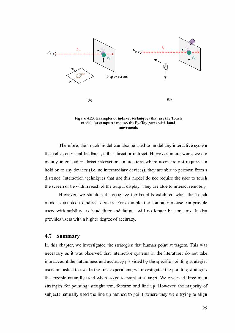
95
Therefore, the Touch model can also be used to model any interactive system
that relies on visual feedback, either direct or indirect. However, in our work, we are
mainly interested in direct interaction. Interactions where users are not required to
hold on to any devices (i.e. no intermediary devices), they are able to perform from a
distance. Interaction techniques that use this model do not require the user to touch
the screen or be within reach of the output display. They are able to interact remotely.
However, we should still recognize the benefits exhibited when the Touch
model is adapted to indirect devices. For example, the computer mouse can provide
users with stability, as hand jitter and fatigue will no longer be concerns. It also
provides users with a higher degree of accuracy.
4.7 Summary
In this chapter, we investigated the strategies that human point at targets. This was
necessary as it was observed that interactive systems in the literatures do not take
into account the naturalness and accuracy provided by the specific pointing strategies
users are asked to use. In the first experiment, we investigated the pointing strategies
that people naturally used when asked to point at a target. We observed three main
strategies for pointing: straight arm, forearm and line up. However, the majority of
subjects naturally used the line up method to point (where they were trying to align
Figure 4.23: Examples of indirect techniques that use the Touch model. (a) computer mouse. (b) EyeToy game with hand
movements
Pp
(a)
Pe lg Po
Pp
Pe lg Po
(b)
Display screen

96
their fingertip between their eye and the target). The second experiment gauged the
accuracy of the different pointing strategies observed. We found that the line up
strategies was the most accurate compared to the other two strategies.
From observing users’ pointing strategies in the two experiments, we were
able to define and distinguish three major models of targeting – Point, Touch, dTouch.
The dTouch model was also shown as a generalized extension of the Touch model.
We have shown that it is possible to describe the models underpinning previous
interactive hand pointing systems, both interactions within arm’s reach and at a
distance.
The models of targeting introduced in this chapter and the interaction
techniques that use them can be summarized in the following table.
Model Intrusive
Methods
Non-intrusive
Methods
Distance Direct/
Indirect
Interaction
Accuracy
Point Infrared laser pointer [25]
Straight arm, forearm [102], fingertip pointing [32]
Distant Direct Inaccurate
Touch Stylus Touch tables, touch screen [38]
Reachable Direct Accurate
Red laser pointer [108]
Distant Direct Accurate
Computer mouse, Remote controller
hand pointing systems requiring visual feedback e.g. EyeToy [129]
Distant Indirect Accurate
dTouch Head Mounted Display[117]
Eye-fingertip line [79], Head-hand line [33]
Distant Direct Accurate (slightly affected by hand jitter
Table 4.4: A summary of interaction methods under each targeting models proposed.
From these models, we can deduce that the Point model does allow direct
interaction from a distance but can be highly inaccurate. The Touch model provides
high accuracy but does not allow bare-hand interaction from a distance. On the other
hand, the dTouch model provides good accuracy and allows direct hand pointing
strategy that we observed to be most natural to the users (eye-fingertip).
Understanding the mechanism of targeting can assist future human-computer
interaction researchers and practitioners to decide the input strategy that best suit
their users in completing the required tasks. When designing an interactive system
that is natural, unintrusive and direct, we recommend that the dTouch model be used
as the underlying strategy.

97
In the next chapter, we will use the dTouch model to design a direct and
non-invasive method for interaction with a large display at a distance with a single
camera.

98
Chapter 5
Conceptual Design of Interaction Model
In the previous chapter, the dTouch model was demonstrated to be one of the best
targeting strategies studied. The eye-fingertip method is a pointing technique that
uses the dTouch model to allow direct, unobtrusive and accurate interaction from a
distance. In this chapter, we propose a conceptual design of our monocular
interactive system that makes use of the eye-fingertip method. We call this the
“dTouch pointing system”.
5.1 Monocular Vision
Our goal is to design a natural interactive system for large screen displays that uses
only a single camera, which relies on monocular computer vision techniques.
Stereoscopic computer vision has the advantage of providing a higher
accuracy due to the additional information provided by the second camera. However,
stereo vision setups usually require prior setup as well as computational cost
associated with matching image streams.
A single camera setup has gained popularity in recent years in the form of
webcam for personal computing and for console gaming [129]. The main advantage
of using a single camera as a basis for designing a new interactive system is the
availability and the accessibility of the webcam. Most PC owners will already have
one, and they are commonly included in laptop computers. This reduces the need for
users to purchase expensive specialized hardware (in the case for a new input device),
or the need for a second webcam (in the case for a stereo camera setup) which may
otherwise be unnecessary. It is hoped that our technique would result in accuracy
comparable to stereoscopic methods.
By using computer vision, users are able to use their natural ability to interact
with the computer thus allowing a more enjoyable experience. Such an approach may
also allow a wider adoption of new interactive technologies in daily life. It is hoped

99
that our method may also allow interaction with personal computing displays, apart
from large displays.
Current monocular systems often use a single camera to detect the position of
the user’s hand. The x and y coordinates in 2D space are determined. This is used to
determine an intended target position on the screen. Interaction, then relies on visual
feedback, usually in the form of an on-screen cursor. Although demonstrated to be
accurate due to the feedback, this provides only an indirect interaction. The major
drawback of this type of interaction is the fixed interaction space in a 2D area. The
user is not able to move around freely as they must stay within the same area to
interact with the system. To provide a more natural interactive system, we attempt to
extract 3D information from the environment and the user, which we discuss in the
following chapter. Here, we will explain our design in detail, and set up an
environment that is natural for the user to interact with large displays.
5.2 Design Overview
We envision that our pointing system would be used in situations where occasional,
quick, and convenient interaction is required, such as in a presentation setting or
information kiosk as opposed to highly accurate and continuous mouse movement
such as those required for typical personal computing usage.
To provide natural interaction, the system must allow users to point at the
display directly using their bare hand. Our method is to place a web-camera above
the screen and have it angled downwards in order to determine the location of the
user. To estimate the user’s pointing direction, a vector is approximated from the
user’s eye through the pointing finger to a point of intersection on the display screen.
The resulting position on the display would be the user’s intended on-screen object.
This makes use of the eye-fingertip method in the dTouch model (Figure 5.1).

100
To determine the pointing direction, image processing must be performed to
track the eye and fingertips. In effect, we wish to construct a straight line in 3D space
which can be used to give us a 3D coordinate on the display screen. The specific
concepts used in this setup are examined.
5.2.1 The View Frustum
A view frustum is used in computer graphics to define the field of view of a camera,
or a region of space which may appear on a computer screen (Figure 5.2). The view
frustum is the area within a rectangular pyramid intersected by a near plane (for
example a computer screen) and a far plane [159]. It defines how much of the virtual
world the user will see [132]. All objects within the view frustum will be captured
and displayed on the screen, while objects outside the view frustum are not drawn to
improve performance.
user
Large Display
webcam
on-screen object fingertip eye
Figure 5.1: Overview of our interactive system
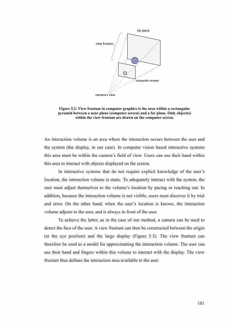
101
An interaction volume is an area where the interaction occurs between the user and
the system (the display, in our case). In computer vision based interactive systems
this area must be within the camera’s field of view. Users can use their hand within
this area to interact with objects displayed on the screen.
In interactive systems that do not require explicit knowledge of the user’s
location, the interaction volume is static. To adequately interact with the system, the
user must adjust themselves to the volume’s location by pacing or reaching out. In
addition, because the interaction volume is not visible, users must discover it by trial
and error. On the other hand, when the user’s location is known, the interaction
volume adjusts to the user, and is always in front of the user.
To achieve the latter, as in the case of our method, a camera can be used to
detect the face of the user. A view frustum can then be constructed between the origin
(at the eye position) and the large display (Figure 5.3). The view frustum can
therefore be used as a model for approximating the interaction volume. The user can
use their hand and fingers within this volume to interact with the display. The view
frustum thus defines the interaction area available to the user.
far plane
camera’s view
view frustum
computer screen
Figure 5.2: View frustum in computer graphics is the area within a rectangular pyramid between a near plane (computer screen) and a far plane. Only object(s)
within the view frustum are drawn on the computer screen.

102
5.2.2 Virtual Touchscreen
To investigate the integration of the benefits afforded by large displays and the
interaction space afforded by the user, we proposed improving interaction with large
displays by leveraging the benefits provided by touch screens. Our idea is to imagine
bringing the large display close enough to the user so that it is within arm’s length
from the user (thereby reachable), and users can imagine a touchscreen right in front
of them. The distance between the user and the virtual objects remains unchanged.
This “virtual” touchscreen and the original large display share the same viewing
angle within the confines of the view frustum (Figure 5.4).
user
view frustum
(interaction volume)
large display
webcam
Figure 5.3: The view frustum is estimated by detecting the user’s head and eye, with the origin at the eye.

103
With this approach, users can use their finger to interact with the virtual touchscreen
as if it was a real touchscreen (Figure 5.5).
The user is therefore restricted to using their fully stretched arm, so that a virtual
touchscreen can always be approximated at the end of their fingertip, eliminating the
guess-work for the user to find the touchscreen. From the experiment in Chapter 4.2,
the majority of subjects were observed to use the full arm stretch and the
eye-fingertip method to point at the target. Therefore, rather than feeling constrained,
view frustum
(interaction volume)
large display
virtual touchscreen
virtual
objects
(a)
(b)
Figure 5.4: (a) the way users used to point at a large display using their hand (b) users point at the virtual touchscreen which is brought towards the users within arm’s reach
view frustum
(interaction volume)
user
large display
webcam
on-screen object
fingertip
eye
virtual touch screen
Figure 5.5: A user is interacting with the large display using their fingertip through a virtual touchscreen at an arm’s length.

104
it should be natural for the user to point in our system.
An advantage of this approach is that it provides a more accurate estimation
of the fingertip position, as the distance between finger and display can now be
estimated from the position of the user. The other advantage is that the virtual
touchscreen is re-adjusted as the user moves (Figure 5.6). In previous interactive
systems, the interaction volume, and therefore the virtual touchscreen, is static. To
interact with such systems, the user must determine the interaction area by initially
guessing and/or through a feedback loop. While the user moves around, the
interaction area does not move correspondingly, it is therefore necessary to re-adjust
their hand position in order to point to the same target. Conversely, in our approach,
as the user’s location is known, the virtual screen adjusts to the user accordingly,
while staying in front of the user. The user will always be able to “find” the virtual
touchscreen as it is always within their view frustum (where the origin is at the user’s
eye position). As long as the user extends their hand within the bounds of the view
frustum (or visibly the large display) they can always interact with the system.
5.2.3 Interaction Model
The moment the user touches a virtual object on the virtual touchscreen, the dTouch
model can be used to define this targeting action, as illustrated in Figure 4.15.
interaction volume
Figure 5.6: The virtual screen is readjusted as the user moves.
large display
virtual touch screen

105
In our system, the task for the user is to move their fingertip (Pp) to the line of gaze
from eye to target (lg) so that it aligns with the object (as seen from the user’s eye).
Pp is also the location of the virtual touchscreen. The object on the large display is
indicated by, Po, which is unreachable to the user, when used at a distance. When the
eye, fingertip and on-screen object coincide, the dTouch model is in action and the
virtual touchscreen is automatically present. The use of dTouch in this case can be
considered a distant touch, a touch that occurs from afar. When the user walks
towards the large display and is able to touch it physically, Pp and Po coincides. The
fingertip touches the target. The virtual touchscreen coincides with the large display,
making up a large touchscreen. In this case, the Touch model applies. In practice, due
to the placement and angle of the camera, the user may not be able to interact with
the display at such close proximity, as the fingertip may be out of the camera’s view.
5.2.4 Fingertip interaction
To select an on-screen object, it is expected that users will use the virtual touchscreen
as a normal touch screen where they select objects by using a forward and backward
motion. However, it may be difficult for the user to know how far they have to push
forward before the system will recognize the selection. Furthermore, since we are
Pe = eye position Po = target object position lg = line of gaze from eye to object Pp = visual marker provided by fingertip lr = line of pointing
Figure 5.7: The dTouch model for targeting with the virtual touchscreen.
Pe: (Xe,Ye,Ze) lg : Pe->Po
Po: (Xo,Yo,Zo)
lr :Pp -> Po
Pp: (Xp,Yp,Zp)
Virtual Touchscreen
Large Display

106
only using a single web-camera, it may be difficult to capture small changes in the
distance of the fingertip from the image. One possible solution is to use dwell
selection, where the user has to stay motionless at a particular position (with a given
tolerance) for a specified time (typically around one second).
5.2.5 Visual Feedback
As the dTouch model is used, user pointing accuracy will be high, except for slight
errors due to hand jitter. In addition, as we do not anticipate continuous use with
pixel-level accuracy, it is expected that users would not require continuous feedback
when selecting targets. When continuous feedback is present, possible system lag
may irritate users. Depending on the system’s estimated accuracy, the presence of
feedback may or may not be required. The use of feedback for this type of system
will be examined further in Chapter 7.
5.2.6 Limitations
The user’s head and fingertip must be within the view of the camera, so that the eye
and fingertips position can be determined from monocular vision.
As mentioned in this chapter, to interact with the virtual touchscreen using
the dTouch model, users must use a straight arm for interaction. They cannot to use a
different pointing strategy, such as forearm pointing. The disadvantage of this is that
users pointing arm may fatigue after prolonged use. However, since this system is
not designed for continuous use, this may not be a problem. The advantage of using a
straight arm for interaction is that users are always aware of the location of the
virtual touchscreen, as it is always at the tip of their index finger (without the need
for trial and error). It also allows the system to be able to estimate the depth of the
fingertip more easily using a monocular vision (see Chapter 6.4).
5.2.7 Summary
We have therefore designed a system that makes use of users’ natural pointing ability,
by using the eye-fingertip pointing strategy and the dTouch model, which was proven
to be natural and accurate as observed from previous work as well as our own studies.
With the use of a virtual touchscreen, the input space is collocated with the output
space giving us a form of direct interaction. Using the hand as the input method frees
users from having to hold any devices, or wear any special gear, giving users

107
unobtrusive and unconstrained interaction. The use of a single consumer webcam
encourages simple and inexpensive setup cost.
Having designed our dTouch interaction system, our methods for extracting 3D
information from 2D images, using constraints from the environment and from the
user, are described in the next chapter.

108
Chapter 6
Monocular Positions Estimation
Our aim is to produce a method for finding the head and fingertip position in 3D
space, as well as the resultant position, all from a 2D camera image. It should be
noted that cameras will become cheaper and better with time, however, the
contributions here can be used as a basis for further advancement in this field for the
years to come.
As described in the previous chapter, our proposed interactive system is
designed to be used for large displays together with the use of a webcam. The
webcam will be positioned on top of the display to detect the users pointing direction.
The pointing direction is estimated by two 3D positions in space the eye and the
fingertip. As users will be using the dTouch model of pointing with the use of a
virtual touchscreen, the first position is the eye position and the second is the
fingertip position from the user. The following diagram illustrates this.
C
P
C – camera
E – eye position
F – fingertip position
P – resultant point on display
de – distance between C and E
df – distance between C and F
F
E
df
de
Large Display
Figure 6.1: Proposed interactive system overview

109
To estimate the pointing direction and the final resulting point, we divide the process
into three steps:
1. eye position (E) estimation
2. fingertip position (F) estimation
3. resultant point (P) estimation
In this chapter we will describe these three stages.
6.1 Environment setup
For simplicity, we assume that the camera center is the origin of the world coordinate
frame (as well as the camera coordinate frame). The z-axis extends outward towards
the center of the camera’s image plane and towards the user and the environment.
The principal point is the location at which the z-axis from the camera center
intersects with the image plane. We assume that this principal point intersects exactly
at the center of the image plane. Figure 6.2 illustrates this.
Camera Center (0,0,0)
Z
Y
X
Camera’s Image Plane
User
Large Display
Principal Point
Figure 6.2: Origin of world coordinates at the webcam’s center
Pointing direction
World/Camera Coordinate Frame

110
6.2 Geometric Constraints
The first two steps both involve finding two points in 3D space given a single 2D
image. In our system, the z-coordinate is the missing information. To acquire extra
information, constraints from the environment are often exploited. It is possible to
use known size of familiar objects in the scene within an unknown environment
[145]. We proposed that it is also possible to use the kinematic constraints provided
naturally by the human body [161]. This has the advantage of being more robust to
different users and is indifferent to the environment. This is the main approach that
we will use in this work.
6.3 Step 1: Eye Location Estimation
The first 3D point that we need to estimate is the eye position. As mentioned earlier
in the previous chapter, we define one end of the view frustum at the eye of the user.
Specifically, we define this point, E, as the dominant eye of the user. To capture this
point, we use a face detection algorithm on each frame we receive from the web
camera. However, this only gives us the x and y coordinates in terms of the web
camera. For the approach to work we need to know this point in 3D space, we
imgw
imgh (0,0)
x
y
Figure 6.3: An illustration of the webcam’s view (camera’s image plane)

111
therefore need to determine the third dimension – the distance between the camera
and the eye de. As can be seen in Figure 6.4, de is vital in determining the position of
E.
Over the years various approaches have been used to determine depth in
computer vision. Most of the previous work as seen in Chapter 2 has been dealing
with stereo camera in which depth can be determined by stereo matching. Of the
ones that only requires a single camera (monocular vision), a study has shown that it
is possible to detected depth by comparing two frames taken from a moving vehicle
[96]. However, in our situation, our camera will not be allowed to move. In another
work, [19] a texture analysis approach was used as well as a histogram inspection
approach to determine depth. However, both approaches can only “determine
whether a point within an image is nearer of farther than another with respect to the
observer” [19]. We require an approximation that can estimate the distance the user’s
face with respect to the camera, not against each other.
It is well known that when an object moves closer to a perspective camera,
the object will appear larger, and when it is moved further away, the object will
appear smaller in the camera’s view. Our approach is based on this fact and
determines the depth from the width of the user’s face. We can observe an increase in
size (in terms of the number of pixels captured by the camera) when the user moves
User
Large Display
E
de
C
C – camera centre E – dominant eye de – distance between c and e d – perpendicular distance between user and the display
d
Figure 6.4: One end of the view frustum is determined to be the eye location of the user. By using the size of the face, the distance between the user and the display can be calculated.

112
forward, closer to the camera, and a decrease in size when the user moves away. This
assumes that we have prior knowledge about the size of the user’s face in pixels at a
particular (known) distance.
depth detected face width
depth
facewidthRatio (6.1)
With this approach, we need to either:
(1) assume that all users have similar face size, or
(2) introduce a calibration phase at the beginning to measure (manually or
automatically) the real width of the user’s face.
For now, the face width is measured manually and individually for each user.
Any face detection algorithm can be used to detect the face, as long as it gives a
consistent approximation of the face at varying distances. The output of the face
detection algorithm gives the number of pixels that encloses the face horizontally,
which vary as the users move forward or backward. To determine the depth from this
pixel count, a width-to-distance ratio (Rwd) is needed. That is, we need to answer the
question: if the actual face width is 17cm, given that the face detection gives 100
pixels, at what distance is the face away from the camera? To calculate Rwd, we need
to determine the field-of-view at known distances away from the camera. We used a
calibration checkerboard pattern as shown in Figure 6.5. The camera is pre-adjusted
for undistortion, so that radial distortions are eliminated.

113
Figure 6.5: Checkerboard pattern for determining Rwd. Each square is measured 3cm by 3cm.
The checkerboard pattern is placed at varies known distances away from the camera
and the number of pixels a square occupies is recorded.
The number of squares that is required to fill the field-of-view horizontally can be
computed.
fovw = actual width of camera’s field-of-view at known depth (cm)
SQUAREw = width of a square (cm)
imgw = Horizontal resolution of camera (px)
squarew = number of pixels occupied per square (px)
d = known depth of checker board (cm)
Checkerboard
known distance (d)
width (w)
C
field-of-view
Figure 6.6: Diagrammatical representation of the position of the checkerboard

114
w
www square
SQUAREimgfov
d
fovR w
wd
(6.2)
Height-to-distance ratio (Rhd) can be similarly determined.
d
fovR h
hd
(6.3)
Results from determining width-to-distance (Rwd) and height-to-distance (Rhd) using a
checkerboard pattern is shown in Figure 6.5.
Figure 6.7 Graph of Field-Of-View (both horizontal and vertical) vs Distance
The mean for Rwd can be estimated to be 0.597 ± 0.008 (±0.008 being the max and
min error), while the mean for Rhd is 0.797 ± 0.006. As can be seen, both ratios do
not vary too highly with distance and thus this method adequately provides a
consistent ratio. It should be noted that this ratio is obtained only for the camera used
0
20
40
60
80
100
120
0 20 40 60 80 100 120 140
distance from camera (cm)
field
-of-
view
(cm
)
height to distance
width to distance

115
throughout this thesis. When a different camera is used this ratio will need to be
re-calculated. Now that we have determined the ratios, we can use the face width as
our reference for depth estimation. Thus, these two ratios are two important ratios
that will continue to be used in the throughout this chapter.
To determine the validity of this approach we implemented this idea and
conducted a simple experiment to test the accuracy of our algorithm.
6.3.1 Implementation
The viability of the proposed technique for depth estimation is demonstrated by
implementing a proof-of-concept prototype. As with all implementations in future
sections of this thesis, we used Visual C++ and an open source computer vision
library – OpenCV – started by Intel Research’s Visual Interactivity Group and now
available on sourceforge.net[109]. It provides image processing, recognition,
measurement, and geometric image processing functions which is needed for our
implementation. Using the API provided, we used the Haar Face Detection algorithm
(a cascade of boosted classifiers working with haar-like features) proposed by Viola
[151] and improved by Lienhart [82], and we were able to detect the human face in
real-time. To increase the tolerance and robustness, we also used an eye detector[110]
which searches for the two eyes using a similar classifier cascade but is trained for
detection of frontal views of eyes only. If only the face or the pair of eyes is detected,
the recorded eyes position will be used, but if both are detected, the average will be
used. A screenshot of our simple application is illustrated in Figure 6.8. The image on
the left is a view from the webcam. The larger blue square indicates the detection of
a face. The smaller rectangle indicates the detection of a pair of eyes. The circle
represents the averaged midpoint between the eyes and the crosshair represents the
right-eye position estimated. The image on the right represents a top view of the
estimated position of the user and the user’s head is represented by a circle. The
inverted red “V” indicates the user’s view frustum. The black “V” indicates the
webcam’s field of view. The horizontal black line at the bottom represents the
display.

116
It should be noted that different algorithms could have been used for face and eye
detections to the same effect. The face and eye detections occur at every frame and
the user’s distance is re-estimated every time. The webcam that we used is Logitech
QuickCam Pro 4000 running at a resolution of 320x240. From the face detection, the
eye positions can be estimated to be a ratio from the width of the box. We found a
ratio of 0.25 and 0.75 are good estimates for the positions of the two eyes.
There are several limitations with the current implementation:
- Only frontal face images are detected. Therefore the user’s head cannot be
tilted too much away from the neutral position in all three axis, yaw, pitch and roll.
In the next section we will test the robustness of the face detection technique. One
implication is that the camera cannot be positioned too high above the display since
users typically look towards the screen and not directly at the camera.
- Faces can only be reliably detected between the range of approximately
30cm and 180cm away from the camera.
6.3.2 Experiment
To evaluate the performance of our depth estimation (using the width of the face), an
experiment was conducted to determine the accuracy of our system. We also tested
the detection rate of the two different detection algorithms as well as the effect of
rotation of the face.
We marked on the ground distances at 30cm intervals up to 180cm. For each
distance, we took 10 different positions (vertically and horizontally) within the field
of view of the camera and ensured that the whole face was inside the camera’s view.
Figure 6.8: Screenshot of our current implementation.

117
We then take the mean recorded distance estimated by our system, as well as whether
the face or the eyes were detected. To control for rotation effect, effort was made to
ensure that the user’s head was facing the camera as orthogonally as possible. At the
end of the experiment, we measured the amount of rotation the system can cope with
before it can no longer detect the face.
6.3.3 Results
It can be observed from Table 6.1 and Figure 6.9 that this method can provide an
adequate estimation of distance. Its peak performance is at a distance from 90cm to
150cm where the mean accuracy is above 95%. At 30 and 60cm, it always
overestimated the distance, while at 180cm, it always underestimated the distance.
Table 6.2 suggests that faces can be detected at all times between 60cm to 150cm,
while at other distances, detection rate suffers. If the user is too close to the camera
(less than 60cm) the whole face might not be visible to the camera, and if too far
away (more than 150cm), the face might be too small for detection. As for the eye
detection algorithm, it works best when it is up close, and its performance reduces
incrementally until it cannot positively detect any eye features from 120cm onwards.
Aggregating all data, we see that the best operational distance is from 90cm to
150cm. It is also observed that the eye detection might not be as helpful as originally
thought.
Results for the head rotation from Table 6.3 shows that our system is robust
enough to accept small head rotations in each direction, but is most vulnerable to
head tilting.
Actual distance (cm) Estimated distance (cm)
Mean accuracy (%) lowest mean highest
30
60
90
120
150
180
39
64
78
107
140
150
40
67
86
117
149
164
43
72
101
127
162
169
67
83
96
98
99
91
Table 6.1: Numerical results of the estimated distances at each distance, as well as the mean accuracy that the system produced.

118
Actual distance (cm) Face detection rate (%) Eye detection rate (%)
30
60
90
120
150
180
40
100
100
100
100
70
100
90
70
0
0
0
40
67
86
117
149
164
0
30
60
90
120
150
180
30 60 90 120 150 180
Actual Distance (cm)
Mea
n E
stim
ated
Dis
tanc
e (c
m)
Figure 6.9: Graph of distance estimated using face detection. The I bars indicate the lowest and highest detected value.
Table 6.2: Numerical results showing face and eye detection rate at each distance.

119
Thus, we have successfully demonstrated a simple algorithm for depth estimation
using monocular computer vision to detect the width of the face. We will now
describe our method for determining the x and y coordinates of the eye.
6.3.4 Face position in 3D
The result from the face detection gave us a rectangular area around the face. The eye
positions are then approximated by using ratios from the bounding box. This gives us
the eye position in the image coordinate frame x and y. To convert them into the
world coordinate frame, it can be calculated through the use of a camera model. We
use the pin-hole camera model to deduce the corresponding X and Y, in world
coordinate.
Head Rotation Positive
rotations
(degrees)
Negative
rotations
(degrees)
Pitch (looking up or down) 40 20
Yaw (turning right or left) 30 30
Roll (tilting right or left) 10 10
Table 6.3: Estimated maximum head rotation on each axis before non-detection at a distance of 100cm. (Values are estimated manually)

120
In Figure 6.10(a) above, the coordinates of the eye position may be represented as
X=(X,Y,Z), and x = (x,y) in the corresponding image plane. f is the focal length. In
our case, given Z (the depth from the face detection), and x and y, we could
potentially calculate Y based on the following:
Let
Z
Yfy
rearranging gives:
f
ZyY
We know Z, the depth and y, the number of pixels, however, we do not know f, the
focal length, because the focal length value calculated from an intrinsic calibration is
an effective focal length(α) in terms of pixel width and pixel height. That is, we are
only given
(a)
(b)
Figure 6.10: Diagrams representing the pinhole camera model. Source:[62]

121
wx P
f ,
hy P
f
where
Pw = width of pixel
Ph = height of pixel
This is not sufficient as it is difficult to measure a pixel’s width and height on the
image plane physically in millimeters, we cannot reliably calculate the focal length, f.
The method we propose is to make use of the ratio between the displacement
of the eye from the center of the image and the image width.
To calculate the value of the x in world coordinate, we can use the ratios we have
calculated in the previous section and use similar triangles to obtain:
wwd img
xRZX (6.4)
x
imgw
(0,0,0)
Figure 6.11: (a) An illustration of the webcam’s view (image plane) (b) a top view of the real world coordinate representation
Z
X
(0,0,0)
image plane

122
where
X = distance from the center of the image in world coordinate
Z = depth detected from the face width detection
Rwd = width-to-distance ratio
Z * Rwd = width of field-of-view at the detected depth
x = number of pixels between center of image and right eye
imgW = width of the camera’s image in pixels
The Y coordinate in world coordinate can be calculated in a similar fashion.
hhd img
yRZY (6.5)
The accuracy of X and Y yielded using this method is deferred until Section 6.4.6 ,
together with fingertip accuracy (after fingertip detection has been described).
6.3.5 Summary
In this section (6.3) we have presented a simple algorithm for depth estimation by
using the relative width of the face. Using monocular computer vision with an
inexpensive webcam, we successfully implemented our algorithm. We see that our
system performs best when the user is at a distance of around 0.9 to 1.5 meters away
from the camera, with a mean estimated accuracy of above 96% and a detection rate
of 100%. It is robust enough to cope with small head rotations.
Now that we have determined the eye position e with respect to the camera c,
the next step will be to detect the second point – the fingertip.
6.4 Step 2: Fingertip Location Estimation
The fingertip point F can also be determined by computer vision. As reviewed in
Chapter 2, there is extensive previous work on hand detection and gesture
recognition. As with the eye estimation, this only gives us an accurate estimation in
2D space. With the 3rd dimension however, it would be very difficult to use the width
of the hand to estimate the distance since users can turn their hand in different ways
when pointing and there, a different strategy is adopted.

123
One way of determining the fingertip position is to estimate it from the user’s
position. From the previous section (6.3), we have knowledge of the exact location of
the eye in 3D space, it is then possible, to estimate the fingertip position using simple
approximations and constraints of the human body.
Our approach is to model the whole arm movement as a sphere around the
shoulder of the pointing arm. The shoulder would then become the centre of the
sphere with the arm’s length as the radius. With this approach we need to make the
assumption that the use is always using a straight (fully stretched) arm. It may also
be possible to assume that the user has a half stretched arm. That is, keeping the
upper arm close to the body and only stretching out the forearm. The elbow joint
between the upper arm and the forearm will effectively become the centre of the
sphere. However, this would violate our dTouch model of pointing, as this would be
using the Point Model, the one that is less accurate, and thus is not preferred.
Figure 6.12 illustrates our idea.
This is a reasonable model since most pointing will be done in front of the user. Only
a small portion of the circumference will be used, and therefore extreme cases such
as where the arm goes behind the body will not be accounted for.
For now, the difference in the horizontal and vertical direction between the
C
P
F
E
Large Display r
C – camera center
E – eye
F – fingertip
P – resultant point on display
r – radius of circle
CF – vector from C to F
Figure 6.12: A fully stretched arm is modelled by a sphere, with the right shoulder as the centre.
CF

124
shoulder position and the eye position is measured manually, and is assumed to be at
the same depth as the eye position. This can then be used the approximate the center
of the sphere. A vector from the camera’s center through to the fingertip position on
the image plane can be used to intersect the sphere to determine the location in 3D
space. When calculating the intersection, two values will be returned, and only the
one closest to the camera will be used.
It should be noted that, in practice, the shoulder position has a slightly
increased depth value than that of the eye position. The following diagram illustrates
this.
This deviation needs to be accounted for after the display plane is calibrated
(explained in section 6.5 ), after which a plane normal is calculated for the large
display. This can be used to calculate the depth offset (z) as shown in Figure 6.14. We
assume that the eye and the shoulder positions are on the same plane, parallel to the
large display.
Z Shoulder position (S)
E C
large display
Figure 6.13: Depth deviation between shoulder and eye position

125
From the plane normal n, we can assume:
By similar triangles and Pythagoras’ Theorem, we can deduce:
Then, the shoulder position after adjustment is:
Figure 6.14: The depth deviation can be calculated based on plane normal of the display
S
E
Y
Z
H
z
y h
n
n – plane normal
Y – y component of plane
Z_ – z component of plane
H – hypotenuse of plane
E – eye position
S – shoulder position
y – y component of SE
z – z component of SE
h – distance between SE
nz
ny plane
znY ynZ
22 )()( XY
hny z
22 )()( XY
hnz y
22
22
)()(
)()(
XY
hnES
XY
hnES
xES
yzz
zyy
xx

126
where h is the measured vertical difference, and x is the measured horizontal
difference, between eye and shoulder position when the person is standing up-right.
6.4.1 Fingertip detection
We have assumed that the user will be using a fully stretched arm with their index
finger extended. Hence the index finger would be closest to the camera. It is possible
to capture the fingertip from a second camera directly on top looking down at the
user and his fingertip (top-down view). Skin colour detection can then be used to
detect the fingertip at the furthest point. However, since we are only using one
camera, we will use the camera that is currently being used to detect the users face.
Using the same principle, the camera needs to be high enough so that the fingertip
becomes the lowest point in the image frame. We can then extract this point using
skin color detection.
This gives us a second position in terms of x and y coordinate in the image
plane (apart from the eye point) as illustrated below:
imgw
imgh
(0,0)
Figure 6.15: An illustration of the webcam’s view
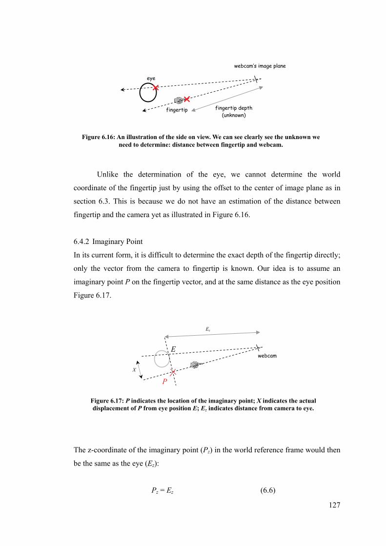
127
Unlike the determination of the eye, we cannot determine the world
coordinate of the fingertip just by using the offset to the center of image plane as in
section 6.3. This is because we do not have an estimation of the distance between
fingertip and the camera yet as illustrated in Figure 6.16.
6.4.2 Imaginary Point
In its current form, it is difficult to determine the exact depth of the fingertip directly;
only the vector from the camera to fingertip is known. Our idea is to assume an
imaginary point P on the fingertip vector, and at the same distance as the eye position
Figure 6.17.
The z-coordinate of the imaginary point (Pz) in the world reference frame would then
be the same as the eye (Ez):
Pz = Ez (6.6)
webcam
P
Ez
Figure 6.17: P indicates the location of the imaginary point; X indicates the actual displacement of P from eye position E; Ez indicates distance from camera to eye.
X
E
webcam’s image plane
fingertip depth (unknown)
eye
fingertip
Figure 6.16: An illustration of the side on view. We can see clearly see the unknown we need to determine: distance between fingertip and webcam.

128
Similar to the determination of the eye, we can use the ratios in equation 6.2 and use
similar triangles to determine X (the distance between P and E).
wwdz img
xREX (6.7)
where
x = distance between eye and fingertip on the image plane
X = the distance eye and imaginary point at depth Ez in world
coordinate
We can then determine Px by adding or subtracting the distance X depending on the
relative position of the fingertip and the eye position.
The y coordinate can be similarly determined:
ex
imgw
(0,0)
Figure 6.18: (a) An illustration of the webcam’s view (image plane) (b) a top view of the real world coordinate representation
Ez
Ex
(0,0,0)
Fx
image plane
fx
C
Px
x
(a) (b)
X

129
hhdz img
yREY (6.8)
6.4.3 Line Equation
Now that we have a vector from the camera’s position (Cx, Cy, Cz) to the imaginary
point (Px, Py, Pz) in the world coordinate we can estimate a line going through these
two points:
zz
z
xx
x
CP
Cz
CP
Cx
(6.9)
zz
z
yy
y
CP
Cz
CP
Cy
(6.10)
As the camera center is the origina of the camera coordinate (Cx, Cy, Cz) = (0,0,0),
the equations can be reduced to:
z
x
P
zPx (6.11)
z
y
P
zPy (6.12)
6.4.4 Intersection with sphere
Now that we have estimated a vector from the webcam to the imaginary point, we
need to estimate the fingertip position. The fingertip position the intersection
between the vector the sphere centered at the shoulder. As mentioned previously, the
shoulder is assumed to have the same depth as the face.

130
Let the coordinate at the shoulder be S = (Sx,Sy,Sz)
The sphere equation is (x-Sx)2 + (y-Sy)
2 + (z-Sz) 2 = r2 and when intersected with the
line equation, we substitute x and y with (6.10) and (6.11) which gives:
22
22
rSzSP
zPS
P
zPzy
z
yx
z
x
(6.13)
Expanding and rearranging will give us:
022 cbzaz (6.14)
where 12
22
z
yx
P
PPa
z
z
yy
z
xx S
P
PS
P
PSb 2
2222 rSSSc zyx
C
r
Shoulder (S)
F
Figure 6.19: The sphere’s center is at the shoulder and its radius is the arm’s length
Imginary Point (P)

131
We can thus solve for z using the quadratic equation. Two solutions will be produced.
a
acbbz
2
42
and a
acbbz
2
42
(6.15)
The one with z value less than that of the eye position will be used, as it represents a
location between the camera and the user. Using 6.10 and 6.11, the new line equation
for webcam to fingertip is therefore:
z
xx P
zPF
zyy P
zPF
zFz
We now have fingertip position (Fx,Fy,Fz)
To determine the validity of this approach we implemented this idea and conducted a
short experiment to test the accuracy of our algorithm.
6.4.5 Implementation
Similar to the implementation of the depth estimation using face information in
section 6.3.1 , the same equipments and development environments are used here.
Fingertip detection is separated into three steps. The first step involves skin color
detection. We used a set of rules for skin color detection based on a constructive
induction algorithm by Gomez and Morales[55]:
Gomez and Morales’s rule for skin colour detection [55]
132
These rules are based on simple arithmetic operations to change its representation
space:
- luminance is normalized at (r+g+b)2
- the red-green channel is used for the first and third condition.
This result produced from this method has been shown to provide a fast and
reasonably accurate skin detection [55, 150] which is particularly important for real
time human interactive systems such as ours.
The second step is to recognize the fingertip from the pixels classified as skin.
The camera can be placed at a high enough place so that when looking directly at the
user and arm, the fingertip would be the lowest skin pixel detected. Our camera was
placed on top of the large display so that it can capture both the user’s face and their
fingertip.
The third step is related to tracking the fingertip while the user’s arm moves
from one place to another. At the initial frame, skin colour detection is done on the
whole image frame. On subsequent frames, the search area is reduced to only
adjacent pixels (for example 10 pixels on all sides) from the previous detected
position. The advantage of this is that the speed of the detection process is increased,
as well as being less susceptible to noise (e.g. other skin colour in the scene)
It should be noted that, we have only shown one way of detecting the
fingertip, other methods can also be used to achieve this.
6.4.6 Experiment
We conducted a simple experiment to gauge the accuracy of our approach with
fingertip detection in the x and y coordinates. We examine the position of the
fingertip by itself. This shows us the accuracy of the system in determining the
imaginary point and thereby testing the process from converting a position from
image plane coordinates to world coordinate. It should be noted that the x and y
positions of the face detection process also relies on this method (please refer to
6.3.4 ).
A webcam was placed on a tripod, pointing parallel to the ground. A white
board is placed exactly 1 meter in front of the webcam, with marked grid of positions
60cm x 50cm. The center of this grid is (0,0). Two lines are marked on the webcam’s
image. We draw a line horizontally across dividing the image in two halves. The

133
same is done vertically. We then line up the webcam so that the dividing lines on the
image aligns as close to the grid as possible. This process is shown in Figure 6.20.
Similarly to the previous dervation, this assume that the origin of the world
coordinate is at the center of the webcam, and whose z direction is directly out into
the white board. The grid at the white board, therefore, has a position (0,0,100) in
centimeters in world coordinate.
A fingertip is positioned in front of the white board. To detect the fingertip, we first
use the aforementioned skin color detection algorithm. The pink color in the figure
indicates the first 10 detected skin colour pixel scanning from the bottom to top of
the image. We used the 10th skin colour pixel to represent the fingertip. Informal
Figure 6.20: An illustration of the grid alignment process with the webcam.
(b)
(a)

134
empirical evaluation reveals that this is much more robust and more stable to false
positives than using the first skin colour encountered. A green crosshair is used to
indicate the detected fingertip position.
Using the video image as a feedback, we align the green crosshair at one of the
marked positions (Figure 6.21). This has the effect of having a known vector from
the webcam to the position of the fingertip. Using our methods in 6.4.2 , assuming a
depth of 100 cm, we can determine the error between the imaginary point calculated
and one of the marked positions on the grid.
6.4.7 Results
For each grid position, we performed 3 trials. The results for the trials are averaged
for each position. The following table shows the imaginary points in x and y in cm.
(z is assumed 100). The results are grouped with respect to their corresponding
position on the grid.
Figure 6.21: An illustration of the grid alignment process with the webcam.

135
X Y X Y X Y
Actual grid position 30 25 0 25 -30 25
Mean detected location 29.34 24.29 0 24.12 -29.09 24.12
Mean difference -0.66 -0.71 0 -0.88 0.91 -0.88
Actual grid position 30 0 0 0 -30 0
Mean detected location 29.34 0 0 -0.17 -29.09 -0.08
Mean difference -0.66 0 0 -0.17 0.91 -0.08
Actual grid position 30 -25 0 -25 -30 -25
Mean detected location 29.42 -24.45 0 -24.37 -29.09 -24.20
Mean difference -0.58 0.55 0 0.63 0.91 0.80
It can be observed from Table 6.4 that the mean detected locations are very close to
the actual location. All of the mean differences are less than 1cm away from the
actual position. It can be seen that the closer it is to the center of the grid, the better
performance our method is, particularly at location (0,0), where the difference is 0
for x and 2 millimeters for the y coordinate. The worst performance was at the top
right corner where the error was around 0.9cm for both coordinates.
We can conclude that our method can provide an adequate estimation of the
imaginary point and thus the image to fingertip vector. It also means that this method
can provide an adequate estimation of the x and y positions of the detected face
position.
6.4.8 Frontal Fingertip Detection
A back projected display was used to project a displayed image on the screen of
81.5cm x 61.5cm with a resolution of 1024x768 pixels. The screen was 125cm off
the ground and the webcam is positioned 207cm off the ground, on top of the display.
We observed a small discrepancy with our fingertip detection method using the
lowest skin colour pixel as the fingertip. Due to the need for face detection, the
height of the camera is restricted. Using a full arm stretch with the fingertip pointing
directly outwards towards the target, we observed the lowest skin colour pixel is in
fact not the fingertip. Figure 6.22(a) shows a portion of an image taken from the
Table 6.4: Table of average detected location and differences for each grid position. All values are measured in centimetres.

136
webcam. We can observe a discrepancy between the actual index fingertip location
(indicated by the red arrow) and the detected lowest fingertip position (green cross).
Figure 6.22(b) shows the user’s view from their dominant eye while pointing to a
target (crosshair).
The simplest solution would be to have the user wear a plastic finger tip, similar to
those used by cashiers. However, this would defeat our aim of not requiring users to
wear anything.
The problem can be solved by lowering the index finger (without lowering the
arm) so that the fingertip is lower than the rest of the hand. This is demonstrated in
Figure 6.23(a). Although it does not represent the way human normally point, the
dTouch model of pointing is still used as the fingertip direction is irrelevant. The
user’s eye still lines up with the fingertip and the target as shown in Figure 6.23(b).
We envision that this would not pose a too much of a problem for users.
index fingertip
(a) (b)
Figure 6.22: (a) webcam’s view showing fingertip detection discrepancy (b) user’s view showing the pointing action

137
Figure 6.24 shows two images of the same scene. The first image shows the
environment before skin colour detection. Pink colour is shown on the second image
to represent those pixels that were detected as skin colour.
6.5 Step 3: Resultant position estimation
Having known the two points (the eye point and the fingertip point) in 3D world
coordinate, it is thus straight forward to calculate the resultant vector. We can then
intersect this vector with the screen and determine a resultant on-screen position. In
Figure 6.24: Before and after skin colour detection
(a) (b)
Figure 6.23: (a) side view of the lowered index finger (b) user’s view illustrating the new pointing action

138
this section, we present two methods for finding the on-screen position. In both of
these cases, the center of camera is assumed to be the center of Euclidean coordinate
frame, which is also known as the world coordinate frame.
6.5.1 Simplified Model
As the display itself is not in the view of the webcam, the system has no way of
knowing the exact location and the size of the display. For simplicity, we can assume
that the web camera is placed directly on top of the display, facing perpendicularly
outwards from the screen. That is, the screen is at the same plane as the webcam’s
position and thereby we approximate a parallel plane to the camera’s image plane.
This means that the display surface is at the z = 0 plane of the webcam.
When the resultant vector (from eye to fingertip) intersects with this plane, a
resultant point can be deduced on the display surface. The final resultant point in
world coordinates can be calculated as:
webcam
display
Field-of-view
E
z=0 plane
P
F
Figure 6.25: Plane z = 0 shared between webcam and display

139
zz
xxzxx FE
FEFFP
zz
yyzyy FE
FEFFP
0zP
Having known the final resultant point in world coordinate, we need to
transform this onto a pixel position on a 2D projected image in the image coordinate.
(For example, a pixel value based on the screen size of 1024x768px).
As the display itself is not in the view of the web camera, the system has no
way of knowing the size and the exact location of the display, only that it lies on the
z=0 plane. Also the projected image may not be exactly rectangular due to distortion.
One approach is to add a calibration phrase to the system before use. During this
phase, the calibrator will point to the four corners of the projected image displayed
on-screen. The four resultant points in world coordinate is then recorded. We can
then compute a 2D homography so that the four corner points on the display plane
(in world coordinate) can be matched to four corner points in the rectangular image
plane (in image coordinate). This phase only needs to be done once.
A 2D-to-2D transformation from the world coordinate to the image
coordinate can be mapped using planar homography. Let x = (x, y, 1) be a point in
homogeneous coordinate in the world space and X = (X, Y ,1) be the corresponding
point in homogeneous coordinate in the image space. They are related by a 3x3
matrix H which is called a planar homography:
X = Hx
1333231
232221
131211
y
x
hhh
hhh
hhh
w
Yw
Xw
where w ≠ 0 is the scaling factor and h33 = 1.

140
This gives us
333231
232221
333231
131211 ,),(hyhxh
hyhxh
hyhxh
hyhxhYX
and expanded, gives two equations:
0333231131211 hyhxhXhyhxh
0333231232221 hyhxhYhyhxh
Since the matrix H has 8 degrees of freedom, we can determine H by using at least
four such point correspondences. A system of eight linear equations can then be
composed and used to solve H.
0
0
0
0
0
0
0
0
1000
0001
1000
0001
1000
0001
1000
0001
32
31
23
22
21
13
12
11
4444444
4444444
3333333
3333333
2222222
2222222
111111
1111111
h
h
h
h
h
h
h
h
YYyYxyx
XXyXxyx
YYyYxyx
XXyXxyx
YYyYxyx
XXyXxyx
YYyYxyx
XXyXxyx
We thus have a matrix equation in the form Ah=0 where h is a 9-element vector. We
can solve this by determining the null space of A using methods such as singular
value decomposition.
After having calibrated the screen, while the user is interacting with the
screen, at each frame, the homography matrix would allow a new final resultant point
to be transformed into a 2D pixel within the image space.
X ~ Hx is then a direct mapping between points

141
1333231
232221
131211
y
x
hhh
hhh
hhh
w
Yw
Xw
w
XwX
w
YwY
(X,Y) would be the final pixel coordinate on large display.
6.5.2 Parallel Plane Model
However, in most cases, we expect the screen position will be higher than the user,
thus the webcam position will need to be adjusted (angled lower in our case) so that
the user will stay within the webcam’s view. This is shown in the following diagram.
As can be seen, the plane for the display’s location is no longer inline with the z=0
plane in the world/camera coordinate (changes in the x-axis). We also anticipate that
the webcam and the display would not line up exactly in the y-axis. In these
situations, if the method in section 6.5.1 is used, the display would be estimated to be
at z=0 plane, which is at an angle further away to the true position of the screen.
webcam
display
field-of-view
user
z=0 plane display plane
Figure 6.26: offset between z=0 plane and display

142
However, it would still produce reasonable accuracy, in theory, as long as the user
does not move their head position after the four corners calibration. Once their head
position is moved, their final pointing position would be inaccurate.
Parallel Plane Estimation
Our approach in solving this problem is to calibrate the display plane by using a
checkerboard pattern parallel to the screen. This would allow us to determine a plane
that is parallel to the screen. To determine the plane of the display, we can simply
calculate it from the plane normal of the checkerboard. This is shown in the next
diagram.
Figure 6.28: an example of checkerboard used to calibrate the display plane
webcam
display
z=0 plane
checkerboard
parallel planes
field-of-view
shared surface normal
Figure 6.27: checkerboard is used to define the plane that the display lies on

143
Assuming that we are using the pinhole camera model, from using a camera
calibration process[14], the camera’s external parameters can be determined, which
includes the 35 corner points found from the checkerboard (as illustrated in Figure
6.28) in the 3D grid coordinate frame (where the corner point marked as position 0
has the coordinates (0,0,0)). It is then possible to transform the points found into their
corresponding points in the camera (world) coordinate frame.
Let Xgrid = (X,Y,Z)T be the coordinate vector for a corner point in the grid
coordinate frame, and Xcam = (Xc,Yc,Zc) T be the coordinate vector for the same
point in the camera coordinate frame.
The corresponding points are related to each other through:
3
2
1
333231
232221
131211
t
t
t
Z
Y
X
rrr
rrr
rrr
Z
Y
X
grid
grid
grid
cam
cam
cam
or concisely as:
Xcam = R Xgrid + t
Where R is a rotation matrix representing the orientation of the grid pattern in
camera coordinate frame, t is a translation vector representing the origin of the grid
pattern (position 0) in the camera coordinate frame. R and t are outputs from the
camera calibration process.
The surface normal of the grid pattern in the camera frame can be calculated using a
cross product:
30040 PPPPn
where n is the surface normal vector and Pi is the coordinate vector of position i in
the grid pattern.
Alternatively, the third column of the rotation matrix can also be used to
represent the surface normal vector [15]:
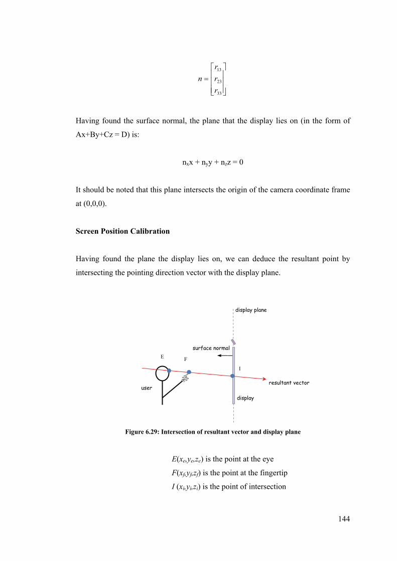
144
33
23
13
r
r
r
n
Having found the surface normal, the plane that the display lies on (in the form of
Ax+By+Cz = D) is:
nxx + nyy + nzz = 0
It should be noted that this plane intersects the origin of the camera coordinate frame
at (0,0,0).
Screen Position Calibration
Having found the plane the display lies on, we can deduce the resultant point by
intersecting the pointing direction vector with the display plane.
E(xe,ye,ze) is the point at the eye
F(xf,yf,zf) is the point at the fingertip
I (xi,yi,zi) is the point of intersection
display
user
display plane
E F
I
surface normal
resultant vector
Figure 6.29: Intersection of resultant vector and display plane

145
As noted in [16], the solution to the line-plane intersection, adapted to our setup, is:
)( EFuEI
)()()( fenfenfen
enenen
zzzyyyxxx
zzyyxxu
As in the simplified model, having known the final resultant point in camera
coordinate, we need to transform this onto a pixel position in a 2D projected image.
Here, we also used a calibration phrase to get four vectors to intersect with the screen
so we can define it size, and record the four resultant points in world coordinate.
Transformation to Screen Coordinates
In the previous model, a parallel plane is assumed, which means that the resultant
position on screen is always in the form (x,y,0), which only required a 2D-2D
transformation from camera coordinates to screen coordinates.
However, in this model, the resultant point is in 3D coordinates. Therefore, a
3D-2D projective transformation is required. This can be achieved using a method
used in [128] where the translation, rotation and scaling involved in the
transformation are summarized in a 2x4 matrix.
Let x = (x, y, z, 1) T be a point in the homogeneous coordinate in the camera
coordinate and X = (X, Y)T be the corresponding point in the screen coordinate.
The corresponding points are related to each other through a projective
transformation matrix:
124232221
14131211
z
y
x
aaaa
aaaa
Y
X

146
As we have 4 such point correspondences, the system of linear equations can be
rewritten as:
4
4
3
3
2
2
1
1
24
23
22
21
14
13
12
11
444
444
333
333
222
222
111
111
10000
00001
10000
00001
10000
00001
10000
00001
Y
X
Y
X
Y
X
Y
X
a
a
a
a
a
a
a
a
zyx
zyx
zyx
zyx
zyx
zyx
zyx
zyx
or concisely as:
XxA
We can then solve for A by using a least square approach with pseudo-inverse:
XxxxA TT 1)(
The resultant position after transformation will be in pixel values in the screen
coordinate frame. It should be noted that this method will be used in our
implementation.
6.6 Estimation error
A prototype of the dTouch pointing system was implemented using the methods
proposed from previous sections of this chapter. The system’s accuracy was tested on
one user. The user’s body measurements were collected and adjusting for the user’s
hand preference and eye dominance. The user was then asked to stand a distance of
160cm from the display and performed the calibration process by pointing to the four
corners of the display. The display was 81.5cm x 61.5cm with a resolution of
1024x768. The webcam used was Logitech QuickCam Pro 4000 at a resolution of
320x240. A target was placed at the center of the display marked with a crosshair,
200px in both width and height. The user was asked to point to the center of the
target for 5 seconds keeping the hand steady. This was done directly after the
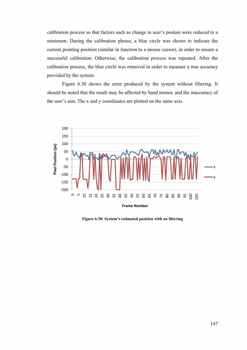
147
calibration process so that factors such as change in user’s posture were reduced to a
minimum. During the calibration phrase, a blue circle was shown to indicate the
current pointing position (similar in function to a mouse cursor), in order to ensure a
successful calibration. Otherwise, the calibration process was repeated. After the
calibration process, the blue circle was removed in order to measure a true accuracy
provided by the system.
Figure 6.30 shows the error produced by the system without filtering. It
should be noted that the result may be affected by hand tremor, and the inaccuracy of
the user’s aim. The x and y coordinates are plotted on the same axis.
Figure 6.30: System’s estimated position with no filtering
‐200
‐150
‐100
‐50
0
50
100
150
200
0 5
10
15
20
25
30
35
40
45
50
55
60
65
70
75
80
85
90
95
100
105
Pixel Position (px)
Frame Number
x
y

148
Figure 6.31: Scatter plot of system’s estimated positions with no filtering.
Figure 6.31 illustrate the estimated position in a scatter plot. The mean position for
the x coordinate is 32.79 pixels away from the target (0,0), while the mean position
for the y coordinate is -58.4. As observed, there is a large systematic variation on the
y axis. From our analysis, this may be due to limitations of the face detection
algorithm used, as it was not designed to detect face width accurately. This affected
the depth estimation and in turn resulted in variations to the resultant positions. The x
positions are not affect to the same extend as the difference in the x coordinate
between the eye and fingertip is less significant (in this scenario). We will investigate
this factor in a more detailed discussion in Chapter 7.4.
We hypothesized that this error can be reduced with a more reliable face
detection algorithm. To evaluate the potential accuracy of our system, we assumed
that the system has accurately estimated the user’s depth. This means that the user’s
distance from camera is manually set to 160cm. The result is presented in Figure
6.32 and Figure 6.33 and was extracted in a separate trial from the same user.
‐200
‐150
‐100
‐50
0
50
100
150
200
‐200 ‐150 ‐100 ‐50 0 50 100 150 200
Y Positions
X Positions

149
The above two figures illustrates the estimated position. It should be noted that
the plot is enlarged so that it only represents an area of 160 px by 160 px. The mean
position for the x coordinates is 26.14 pixels with standard deviation of 16.81, while
the mean position for the y coordinates is -28.08 with standard deviation of 13.00.
This accuracy is higher than the previous set of data, meaning that the depth
estimation was indeed the weakness link in the system.
The observed grid-like positioning of the estimated positions may be attributed to
the limited resolution of the virtual touchscreen. The virtual touchscreen is illustrated
in Figure 6.34 as a blue trapezium. It represents the allowable position of the
‐80
‐60
‐40
‐20
0
20
40
60
80
0 5
10
15
20
25
30
35
40
45
50
55
60
65
70
75
80
85
90
95
100
105
Pixel Position (px)
Frame Number
x
y
‐80
‐60
‐40
‐20
0
20
40
60
80
‐80 ‐60 ‐40 ‐20 0 20 40 60 80
Y Positions
X Positions
Figure 6.33: Scatter plot of system’s estimated positions
Figure 6.32: System’s estimated position with depth assumed accurate

150
fingertip to stay pointing to the display. For example, the user is shown in the figure
to be pointing to the center of the display, where the target is positioned.
The size of the virtual touchscreen, in this case, is around 105 x 85px, while the
display is at 1024x768. The smallest distance between two possible fingertip
positions projected on the large display is 1024/105 = 9.75 pixels in width and 9.04
pixels in height. This explains the appearance of the grid-pattern. In addition, the eye
position may move slightly during the course of the pointing process, and therefore
we see a more varied pointing positions not aligned to the grid position. The
resolution of the webcam can be increased to 640x480px. However, informal
experimentation revealed a decrease in frame rate to around 5 frames per second.
Since real-time interaction was deemed more important, the resolution remained at
320x240px.
To improve the accuracy of the system, Kalman filtering was used. The
smoothing filter is first introduced to the face bounding box as it was observed to
have fluctuated the most, in comparison to the fingertip position, which was
observed to be quite stable. We implemented a 1st order Kalman filter, similar to the
one used in [63], for each of the x and y coordinates. A covariance variable of 80 was
used to adjust the degree of damping. The following two figures show the accuracy
Figure 6.34: A webcam view showing the size and position of the virtual touchscreen.

151
of our system with the eye position smoothed.
It should be noted that a damping value of 80 may be considered quite high and
may introduce lag to the system. This is because with increasing damping value, the
smoothness is also increased. However, it also increases the time it takes to become
stable and thus do not react to sudden movement. A more appropriate value may be
required to trade off between the amount of smoothness and system response time in
real usage scenarios.
‐80
‐60
‐40
‐20
0
20
40
60
80
0 5
10
15
20
25
30
35
40
45
50
55
60
65
70
75
80
85
90
95
100
105
Pixel Position (px)
Frame Number
x
y
‐80
‐60
‐40
‐20
0
20
40
60
80
‐80 ‐60 ‐40 ‐20 0 20 40 60 80
Y Positions
X Positions
Figure 6.36: Scatter plot of system’s estimated positions with filtering for eye position.
Figure 6.35: System’s estimated position with filtering for eye position.

152
After eye position filtering, the mean positions are -5.12 for the x coordinate and
-21.03 for the y coordinate. It can be observed that the accuracy has increased and
the range of the positions within the 5 seconds have reduced. However, the grid-like
positioning of the estimated positions is still clearly visible.
To further increase the accuracy, the same filtering method was applied to the
resultant pointing position, that is, the pixel position represented on the large display.
This is illustrated in Figure 6.37 and Figure 6.38.
‐80
‐60
‐40
‐20
0
20
40
60
80
0 5
10
15
20
25
30
35
40
45
50
55
60
65
70
75
80
85
90
95
100
105
Pixel Position (px)
Frame Number
x
y
‐80
‐60
‐40
‐20
0
20
40
60
80
‐80 ‐60 ‐40 ‐20 0 20 40 60 80
Y Positions
X Positions
Figure 6.38: Scatter plot of system’s estimated positions after resultant point filtering
Figure 6.37: System’s estimated positions after resultant point filtering

153
The mean position for the x coordinate is -5.19 while the mean for the y
coordinate is -12.7. As can be seen, the accuracy has improved and the pointing
positions have stabilized. All these processes were used to ensure results from a best
case scenario. Further results are shown in the next chapter.
6.7 Summary
In this chapter, we have proposed methods for estimating 3D positions using
monocular computer vision. The eye position was estimated using the width of the
face and a width-to-depth ratio specific to the camera used. The fingertip position
was then determined by intersecting a sphere provided by the user’s shoulder and
arm and was intersected with a vector coming from a fingertip position detected in
the camera’s image. A vector starting at the eye position extending to the fingertip
position is used to represent the pointing direction. This vector is then intersected
with a plane that represents the position of the display. By using transformation
matrix, we were able to determine the exact screen coordinates that the user is
pointing to. In addition, we also demonstrated the accuracy of our proof-of-concept
prototype in the best case scenario.
In the next chapter, we will present four controlled usability experiments with
multiple users, which illustrate the accuracy provided by our pointing system with
varying factors.

154
Chapter 7
Experimental Evaluation
In the last chapter, we presented a method for implemented a proof-of-concept
dTouch pointing system. In this chapter we presented an evaluation of our prototype
system through experimental evaluation. In order to verify the usability of our system,
we invited volunteers to act as users. Four usability studies were conducted:
- to compare the accuracy of using the dTouch pointing technique with a
similar pointing system, and the effect of feedback on pointing accuracy;
- to determine the optimal size for a target in system such as ours;
- to evaluate the tolerance of our system with respect to the amount of
calibration necessary for each individual user to achieve reasonable
accuracy;
- to evaluate the system’s ability to handle varying user’s standing location.
To begin with, the apparatus and procedures used common to all four
experiments are described, followed by a detailed account for each experiment.

155
7.1 General Experimental Setup
A back projected display was used to project an image on a screen of 102 cm
x 82 cm with a resolution of 1280 x 1024 pixels. The screen was elevated 125cm off
the ground at the lowest end and 207cm at the highest point. To reduce the number of
factors we were testing in each experiment, subjects were asked to stand at a fixed
distance of 160 cm from the screen by default, and this depth is assumed to have
estimated accurately by the system (except in experiment 2, when depth estimation is
included as a factor for testing).
Using this setup, however, it was discovered that when interacting with the
screen, the user’s face is quite often occluded by the user’s pointing hand, inhibiting
the system’s ability to perform face tracking, especially when a right handed user
tries to point to the upper left section of the screen. To minimize this occurrence, our
windowed application was resized to 1024x768 and moved to the lowest position
possible which occupied 81.5cm x 61.5cm. This translated to 0.80 mm per pixel
horizontally and vertically. Although this did not eliminate the problem from ever
occurring (particularly when calibrating the four corners), the number of occurrence
was minimized sufficiently enabling the continuation of the pointing tasks within
tolerable limits.
160cm
125 cm
82 cm
95cm
Figure 7.1: A diagrammatical illustration of our experimental setup
212 cm
webcam
display
back-projector
user
table

156
The webcam used in these experiments was a Logitech Quickcam Pro 4000
capturing at a resolution of 320x240 with an average frame rate of 22 frames per
second (post image processing). It was placed centred on top of the screen.
The accuracy of the system is defined as the discrepancy between the user’s
intention and the system’s estimation of the user’s intention. Unless stated otherwise,
in all experiments, the accuracy was attained by asking the subjects to point to a
target (crosshair), 200px in both width and height. Users began by resting their hand
on a table directly in front of them, which was approximately at waist height for most
subjects (95cm). This ensured that user’s pointing hand was within the camera’s view
and was being captured at the start of each trial, to prevent the system from losing the
hand trajectory.
As there were difficulties in detecting the fingertip front on from the
webcam’s view, subjects were asked to lower their index finger (without lowering
their arm) so that it appeared as the lowest skin colour pixel in the webcam’s view.
Although it does not represent the way human normally point, the models of pointing
remain the same as the fingertip direction is irrelevant.
These experiments were conducted in a controlled laboratory environment.
102cm
82 cm Target
Reduced Interaction
Window (1024x768px)
200px
Figure 7.2: Diagram of display used and the target position.
61.5 cm
81.5 cm
Projected Image (1280x1024px)

157
The amount of interference in the environment captured by the camera was
minimized, for example, reducing the background surrounding, and blocking out
sunlight. In our current implementation, subjects were told to avoid sensitive colours
such as red, orange and brown, and wore long sleeves clothing, for improved skin
colour detection, thereby minimizing false detections.
7.1.1 The Task
We envisioned that our dTouch pointing system would be used in situations where
occasional, quick, and convenient interaction are required, such as during a
presentation setting or at an information kiosk (As opposed to the highly accurate
and continuous mouse movement, required for typical personal computing usage).
Therefore, the task was to point to a target on a projected display, as comfortably as
possible.
Users point to the center of the target with a straight arm using the dTouch
technique to select the target. To achieve a successful selection, users must stay
pointing at the target until their hand was deemed to have stabilised and was no
longer moving. This is a common method for object selection where there is a lack of
buttons for selection (for example, buttons on a computer mouse) and is often called
“dwelling”. In our implementation, a dwell was recorded when the positions in a 1
second timeframe (around 22 frames sequence) did not deviate by more than 15
pixels (within the sequence). This was a reasonable requirement, as was observed in
Figure 7.3: A photo of the experimental setup.

158
Chapter 6.6 the accuracy achievable is 20 pixels within 5 seconds. When successfully
selected, a red circle was highlighted over the target. Due to hand jitter, an average of
10 frames was used to determine the position at which selection occurred, as opposed
to an instantaneous position from 1 frame. Apart from the red circle, users were
given no feedback (i.e. no continuous graphical representation “cursor” was shown,
except in experiment 1 where this type of feedback was specifically tested as a
factor).
Figure 7.4: A red circle is highlighted over the target when it is selected successfully.
Unless stated otherwise, a four seconds time limit was imposed on each
pointing task, to minimize fatiguing of the arm (except for experiment one, where it
was five seconds). When the time limit was exceeded, a time-out error was recorded
and the trial was not repeated. However, the accuracy (or the lack of) was still
recorded. It should be noted that the effect of target size on selection accuracy is
tested specifically in experiment 2.
Occasionally, the user’s hand may be absent from the camera’s view, either
because the user had unintentionally hidden their hand, had moved it outside the
camera’s view, or when interference such as background noise being falsely

159
identified as skin colour. When detection errors occur through no fault of the user,
the trial is restarted and does not count as an error, as it is an error caused by the
detection system, rather than due to the (lack of) accuracy of pointing.
For each trial, users were asked to move their hand towards the target once
only for each pointing task and stay motionless until the system had recorded their
intended position. This was inline with the intended use of the system where the user
points to a target occasionally. However, when feedback was introduced in
experiment 1, they were allowed to move more than once, but were asked to keep it
to a minimum. Once completed, they can then lower their arm and relax.
Volunteers were give a choice as to how many and which experiments they
liked to participate in, as each experiment was done independently from the others.
7.1.2 Statistical Treatment
Unless otherwise specified, a 5% significant level was used when reporting results
from t-tests and analysis of variance (ANOVA) tests. This meant that if the p-value
was smaller than 0.05, there was a statistically significant difference between the sets
of data being tested, and the null hypothesis was rejected, which in most cases
signified a difference between the means of the sets of data being tested. Selective
multiple means comparison (a priori) was performed subsequent to all ANOVA tests
unless stated otherwise. Otherwise, the post hoc testing, where all sets of data are
compared to each other, was used. This allowed us to minimize the familywise error
rate in order to restrict the alpha value as close to 0.05 as possible.
7.2 Experiment 1: The effect of feedback on DTouch and EyeToy
targeting system
To evaluate our system, it was compared with the use of a similar hand pointing
system that uses a similar but different (Touch) model and also uses a single
webcam.
7.2.1 2D Targeting System
The EyeToy game for PlayStation[129] is a good example of a common 2D

160
interactive system in use. When users place their hand in front of the interaction area,
an image of themselves is mirrored on the display and virtual objects are overlaid on
top of that image. By waving their hand over an object, they can interact with that
particular object. This arrangement provides users with feedback regarding how far
they have to stretch and position their hand in order to select the object. The size of
the interaction area can be increased or decreased by placing the EyeToy camera
closer to or further away from users.
This model of pointing only provides 2D interaction as the system does not
detect depth. Users adjust to the position of the interaction area and must stay inside
it to interact with the system. This model of pointing is adopted and modified to suit
our experiment. A webcam is placed on top of a large display and is used to detect
skin colour pixels. The position of the fingertip is then translated to an on-screen
cursor. Instead of using the full field of view of the webcam, as is the case for
EyeToy, users were asked to define a rectangular area in front of them. This has two
rationales. Users can define an area that is more comfortable for them, rather than
having to stretch their arm. It also helped to reduce detection errors when the hand is
directly in front of the head. Similar pointing techniques are used in [153] where it is
called “relative pointing” and is also used in [46, 146, 160]. We will call this the
“EyeToy” system or technique, and is evaluated against our own system. The same
fingertip detection system is used for both pointing techniques to ensure equality.
user
large display
webcam
on-screen object
Figure 7.5: An illustration of the EyeToy system.
interaction plane
on-screen feedback
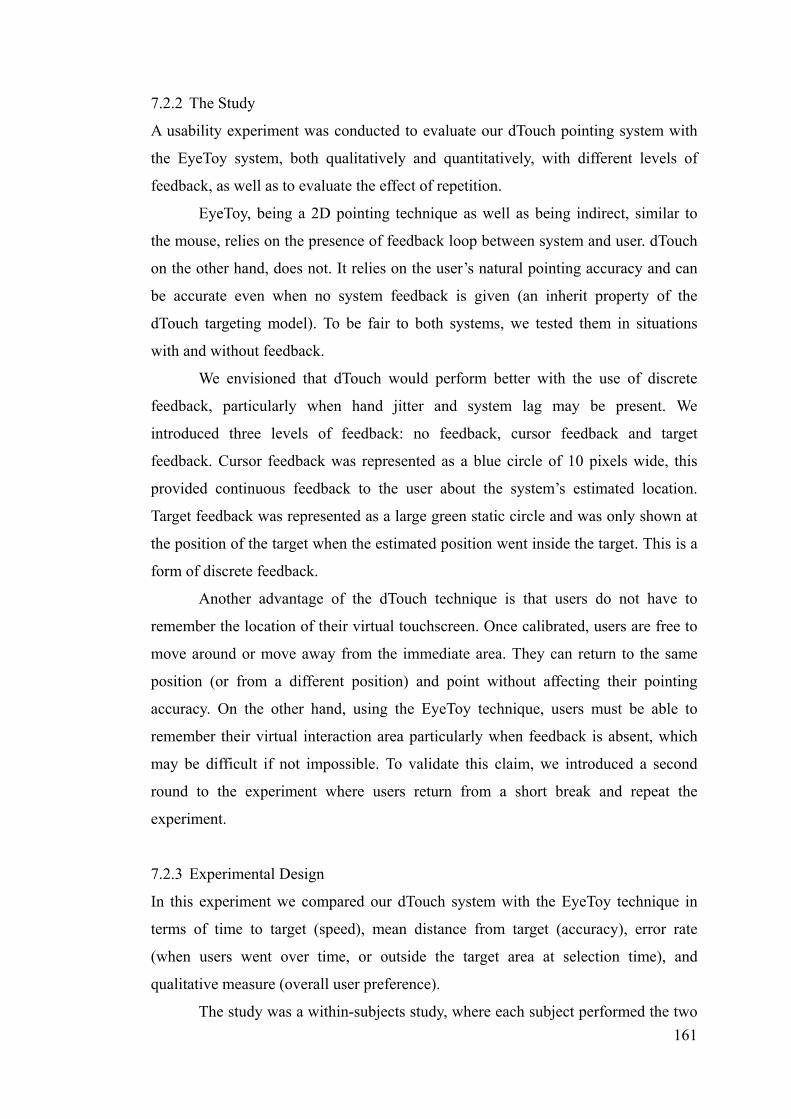
161
7.2.2 The Study
A usability experiment was conducted to evaluate our dTouch pointing system with
the EyeToy system, both qualitatively and quantitatively, with different levels of
feedback, as well as to evaluate the effect of repetition.
EyeToy, being a 2D pointing technique as well as being indirect, similar to
the mouse, relies on the presence of feedback loop between system and user. dTouch
on the other hand, does not. It relies on the user’s natural pointing accuracy and can
be accurate even when no system feedback is given (an inherit property of the
dTouch targeting model). To be fair to both systems, we tested them in situations
with and without feedback.
We envisioned that dTouch would perform better with the use of discrete
feedback, particularly when hand jitter and system lag may be present. We
introduced three levels of feedback: no feedback, cursor feedback and target
feedback. Cursor feedback was represented as a blue circle of 10 pixels wide, this
provided continuous feedback to the user about the system’s estimated location.
Target feedback was represented as a large green static circle and was only shown at
the position of the target when the estimated position went inside the target. This is a
form of discrete feedback.
Another advantage of the dTouch technique is that users do not have to
remember the location of their virtual touchscreen. Once calibrated, users are free to
move around or move away from the immediate area. They can return to the same
position (or from a different position) and point without affecting their pointing
accuracy. On the other hand, using the EyeToy technique, users must be able to
remember their virtual interaction area particularly when feedback is absent, which
may be difficult if not impossible. To validate this claim, we introduced a second
round to the experiment where users return from a short break and repeat the
experiment.
7.2.3 Experimental Design
In this experiment we compared our dTouch system with the EyeToy technique in
terms of time to target (speed), mean distance from target (accuracy), error rate
(when users went over time, or outside the target area at selection time), and
qualitative measure (overall user preference).
The study was a within-subjects study, where each subject performed the two

162
techniques and three types of feedback per technique. For each of the 6 combinations,
they were asked to point to a target at the center of the screen as smoothly as possible.
Subjects were asked to perform three blocks of trials and the mean position was
determined. Half of all subjects began with dTouch, while the 3 feedback conditions
within them were presented based on a Latin Square, counter-balancing to avoid
ordering effects. The order of the second round of experiment was the same as the
first to maintain consistency. It should be noted that results from the second round
were only used to compare with its respective first round results for the purpose of
validating the difference in ability for the two techniques to allow accurate pointing,
even after moving away.
For this experiment only, a 5 second time limit was imposed on each pointing
task. In addition, a requirement for successful dwelling was that the recorded
position must be within 160 pixels in radius from the target. This gave a generous
amount of target area, approximately 31% of the vertical and 42% of the horizontal
screen size. Otherwise, it was deemed off-target and dwelling was disabled, which
eventually led to a time-out error. This requirement was necessary in order to
categorize the type of errors made by each pointing technique.
In summary, the experimental design was:
22 subjects x
2 pointing techniques (dTouch, EyeToy) x
3 feedback types (none, cursor, target) x
1 target (center target) x
2 rounds (before and after short break) x
3 blocks (per combinations) x
= 792 pointing trials
7.2.4 Participants
Twenty two volunteers, 2 female and 20 male, age ranged from 20 to 36 participated
in this experiment. They were mostly working or studying in the area of computer
science or engineering. Three subjects were left handed while 15 of them were right
eye dominant. Most have used alternate input devices such as joystick and touch
screens. Fifteen have played the Nintendo Wii before, while only four have
experienced with the PlayStation EyeToy game once or twice. Participants were
provided chocolates and juice as gratuity during the breaks.

163
7.2.5 Procedure
Participants started off by filing out an initial questionnaire indicating their details
including hand preference, eye sight, and experiences with alternate input devices.
Participant’s physical dimensions were then measured, which were used to calculate
the x and y deviations from user’s dominant eye to their right or left shoulder
depending on the hand they used.
They were then given a learning phase on the differences between dTouch
and EyeToy system. They were reminded that dTouch is a 3D pointing system where
both the face and fingertip positions are detected, and a virtual touchscreen exists
where their fingertip is, while EyeToy is a 2D pointing system where only the
fingertip position is important. A calibration phase was then performed. For dTouch,
they pointed at four corners of the screen with a straight arm. While for EyeToy, each
user defined a rectangular area or “virtual interaction area” in front of them. Straight
arm was not required. They were given a chance to recalibrate if they were not
comfortable with the calibration. A blue cursor was shown during this phase as
feedback to the user and the experimenter. They were allowed a few practice runs.
7.2.6 Hypotheses
For the dTouch technique, we hypothesized that the presence of feedback would not
affect the accuracy nor time taken for pointing, which is the main advantage of
dTouch.
For the EyeToy technique, cursor feedback should provide the best accuracy
due to its small size, resulting in higher resolution. While no feedback would be the
least accurate as users are not given any indication where their interaction area is.
Target feedback should reduce the time taken for pointing as the perceived size of the
target is larger.
Comparing the two techniques, dTouch would be more accurate than EyeToy
when feedback is not given due to the inherit difference between the two pointing
models. But when feedback is given, the accuracy of both techniques should be
similar. In terms of speed, dTouch would be quicker overall, while EyeToy would be
slower due to the reliance on system feedback.
We hypothesized that accuracy would degrade for the EyeToy-No feedback
condition when the experiment is repeated after a short break away from the setup, as

164
users are provided no hint where their interaction area is. For the same reason, when
feedback is provided for the other EyeToy conditions, the time taken would increase.
On the other hand, accuracy for dTouch would not degrade for all conditions.
Overall, we expected users to find dTouch more satisfying to use as it is
direct and natural to them, while EyeToy would be more comfortable as there is less
effort in lifting the arm.
7.2.7 Results and Discussion
Accuracy Analysis
Accuracy was measured as the distance from the recorded position to the center of
target. Trials that have timed out were included in the analysis as users were still
pointing at the time limit and thus represent their best effort. Some of these trials
may also have timed out due to unsteady arms and hands. An analysis of these error
rates will be discussed later in this section. Figure 7.7 below shows the mean
distance from target for each technique with the three different feedback types and
their interactions for all trials.
Figure 7.7: Effect of feedback on accuracy
A two-way ANOVA with repeated measures reveals a significant main effect
for pointing technique on accuracy (F[1,21] = 22.6, p < 0.001) with means of 42 and
115 pixels for dTouch and EyeToy respectively. A significant main effect was also
obtained for feedback type on accuracy (F[2,42] = 31.1, p < 0.001), and the means
for each feedback types are 113 (none), 23 (cursor) and 99 pixels (target). We also
observed a significant interaction between technique and feedback type (F[2,42] =
13.6, p < 0.001).
53
174
24 22
49
150
0
50
100
150
200
dTouch EyeToyMean
Distance from target (px)
Pointing Technique
Effect of feedback on accuracy
nonecursortarget

165
Multiple pairwise means comparisons within the dTouch technique show
significant differences between cursor and no feedback (t[21]=4.1, p<0.001).
However, the difference between cursor and target feedback is not significant
(t[21]=2.87, p=0.009), as well as between no feedback and target feedback
(t[21]=0.67, p=0.51). For Eyetoy, there is also significant difference between cursor
and no feedback (t[21]=5.53, p<0.001), as well as between cursor and target
feedback(t[21]=5.71, p<0.001), but no significant between target and no feedback
(t[21]=1.12, p=0.27).
Comparing the two pointing techniques for each feedback, we found
significant difference for no feedback (t[21] = 4.33, p< 0.001) and target feedback
(t[21]=4.27, p< 0.001), but no significant difference for cursor feedback (t[21]=0.58,
p< 0.57).
As we have 9 comparisons, the significant levels were adjusted using the
Bonferroni correction. Each test would only be significant when the p-value is less
than α = 0.05/9 = 0.0056.
None vs cursor Cursor vs target None vs target dTouch <0.001* 0.009 0.51
Eyetoy <0.001* <0.001* 0.27
None Cursor Target dTouch vs
Eyetoy <0.001* <0.001* 0.57
*Denotes significance at the 0.0056 level
Table 7.1: A summary of p-values and significance of multiple pairwise means comparisons for accuracy analysis
Within dTouch, cursor feedback was in fact more accurate than with no
feedback, contrary to our hypothesis. This may be due to the fact that, with the
presence of cursor feedback, the deviation only shows the amount of hand jitter. But
with no feedback, the accuracy shows the amount of hand jitter plus the system’s best
estimate of the user’s pointing location, i.e. system’s estimation error. Therefore, the
system’s estimation error may be determined as:
53.26 (no feedback: system’s estimation + user’s estimation)
– 24.10 (cursor feedback: user’s estimation)
= 29.16 pixels (system’s estimation of the mean accuracy)

166
For the EyeToy technique, as expected, the cursor feedback provided the best
accuracy and no feedback provided the worst accuracy. Even when target feedback
was brought in, users easily went past the target requiring readjustments, which often
led to reaching the time limit.
Comparing the two pointing techniques, when no feedback was present,
dTouch was indeed more accurate than the EyeToy method. Once again, this
confirmed that the dTouch method provides a more accurate pointing model. When
cursor feedback was present, both methods performed with similar accuracy.
From this analysis, we saw that the dTouch technique dominates EyeToy
when no feedback is given. Cursor feedback provided improved accuracy for both
techniques over no feedback. Target feedback provided no significant improvement
in accuracy for both techniques.
Trial Time Completion Analysis
Time taken for each selection task was measured from when their hand started
moving until the target was successfully selected. As such, reaction time was
excluded (mean=0.85s) for consistency between all subjects, while the time taken for
dwell selection was included, which lasted for around 1 second (25 frames). Trials
that were over the time limit were excluded from this analysis, so that only
successful trials were analysed. Figure 7.8 shows the time taken for each method
with the three types of feedback.

167
Figure 7.8: Effect of feedback on task completion time
As we now have unequal sample size for the six groups, we used the two-way
ANOVA between-groups test. The test reveals a significant main effect for feedback
type on task time (F[2,281]=10.01, p<0.001) and the aggregate unweighted means
for each feedback type are 2.61 (none), 2.97 (cursor) and 2.54 pixels (target).
However, there were no significant main effect for technique on task time
(F[1,281]=0.781, p=0.378) with aggregate unweighted means of 2.75, 2.67 for
dTouch and EyeToy respectively. There were also no significant interaction between
technique and feedback type (F2,281=0.797, p=0.452).
Multiple means comparisons within the dTouch technique show significant
differences between cursor and no feedback (t[77]= -3.81, p<0.001), as well as
between cursor and target feedback (t[89]=3.30, p=0.001). However, the difference
between no feedback and target feedback is not significant (t[115]=-0.34, p=0.736).
On the other hand, within the Eyetoy technique, there are no significant differences
between the three groups; t(60)=-1.28, p=0.205 for none vs cursor feedback, t(63) =
0.865, p=0.390 for none vs target feedback, and t(73)=2.37, p=0.021 for cursor vs
target feedback. Again, each test would only be significant when the p-value is less
than α = 0.0056.
2.572.65
3.062.88
2.61
2.48
0
1
2
3
4
dTouch EyeToy
Mean
Task Time (s)
Pointing Technique
Effect of feedback on task completion time
none cursor target

168
None vs cursor Cursor vs target None vs target dTouch <0.001* 0.001* 0.736
Eyetoy 0.205 0.021 0.390
None Cursor Target dTouch vs
Eyetoy 0.633 0.251 0.411
*Denotes significance at the 0.0056 level
Table 7.2: A summary of p-values and significance of multiple pairwise means comparisons for task time completion analysis
Contrary to our hypothesis, cursor feedback with the dTouch technique was
in fact the most time consuming. This may suggest difficulties when adjusting with
cursor feedback. The pointing process may be broken down into two phases:
In the first phase, users first lined up their fingertip with the target (common to
all feedback types).
The second phase was the realization of the slight offset between the cursor and
target (only emerge with cursor feedback). Users reacted to this by adjusting
their fingertip and moved the cursor closer to the target center, even when it
means their fingertip will no longer line up with the target. This may have
delayed the dwell selection. Perhaps even more so when the deviation of this
adjustment is larger than 15 pixels (stability requirement for a successful dwell).
This is consistent with our analysis in the previous section where the
difference between the system’s estimation and the user’s estimation is 29.16 pixels.
The absence of the second phase in the target feedback condition may be due to the
lack of the need for readjustment, as the target feedback circle provided a coarser
resolution, users may have been content with their selection earlier. It should be
noted that the first phase is not present in the EyeToy-Cursor condition, which
explains the small but insignificant time reduction compared to the dTouch-Cursor
conditions.
For the EyeToy technique, target feedback did indeed provide the quickest
selection time and cursor feedback was indeed the slowest due to the time needed for
the feedback loop, although both were insignificant.
Between the two techniques, there is no significant difference in selection
time for all three feedback types. This should not be surprising considering

169
inaccuracy and error rate are not taken into account in this analysis. The results only
represent the time required to lift the arm or forearm and line up with the target.
Overall, the type of feedback did not affect the time required for selection
between dTouch and EyeToy, except that cursor feedback hindered the time taken for
dTouch. It should be noted that the time trial completion results should not be used to
compare with systems external to this thesis, as the parameters used were strictly
controlled and are specific to this comparison.
Error Rate Analysis
An error was recorded when the time limit of five seconds was exceeded for each
trial. These were included in the analysis of accuracy but were excluded from the
time completion analysis, as these trials were not completed within the time limit.
Figure 7.9 shows the percentage of trials that were counted as error (out of 66 trials)
within each condition.
Figure 7.9: Error rate for each condition (over time limit)
Overall, the error count was indeed highest for the EyeToy-No feedback
condition due to nature of the pointing method and the lack of feedback. The lowest
6%
32%
6%
15%20%
17%
2%
0%
2%
38%
0%
29%
0%
10%
20%
30%
40%
50%
60%
DT‐None DT‐Cursor DT‐Target ET‐None ET‐Cursor ET‐Target
Percentage
of all trials (%
)
Conditions (Technique‐Feedback)
Error rate for each condition (over time limit)
out of target
in target

170
number of errors were dTouch-None and dTouch-Target.
In terms of in-target but over-time trials, dTouch-Cursor has the highest number
of errors, even though the accuracy was one of the best. This may be due to the
increased time users took to select the target – intricate adjustment of their fingertip
in the presence of a high accuracy cursor feedback. They also had to remain still for
target selection. This is consistent with the time completion analysis where the time
taken was the highest.
For EyeToy, it is interesting to observe a consistent in-target error rate for all
types of feedback. This may be due to the low resolution of the EyeToy technique
provided by the smaller interaction area compared to that of dTouch. Higher stability
is thus required from the users for dwell selection. Despite this, the accuracy was not
at all compromised, as the EyeToy-Cursor condition had the highest accuracy of all
six conditions (Figure 7.7).
For errors that were both off target and beyond time limit, we observed a
substantially high rate for EyeToy-None and EyeToy-Target. This is consistent with
the worst accuracies shown from previous analysis. On the other hand, it is
interesting to observe, although not surprising, that all trials were inside the target for
cursor feedback with both techniques.
Effect of Repetition (Before and After) Analysis
Two rounds of experiments were completed for each subject, where the second round
was done after a short break. Subjects were asked to return to the same position as
they did in the first round and repeat the experiment.

171
Figure 7.10: Effect of before and after on Pointing Accuracy for dTouch
Figure 7.11: Effect of before and after on Pointing Accuracy for EyeToy
In this analysis, we are only concerned with comparing before and after
within each feedback condition for each technique, therefore, only 6 paired t-tests
were performed. All pairs returned insignificant difference.
53 57
2421
49
58
0
10
20
30
40
50
60
70
before after
Mean
Distance from Target (px)
Condition
Effect of before and after on Pointing Accuracy for dTouch
none
cursor
target
173150
2221
150 142
0
20
40
60
80
100
120
140
160
180
200
before after
Mean
Distance from Target (px)
Condition
Effect of before and after on Pointing Accuracy for EyeToy
none
cursor
target

172
Feedback
Type
dTouch Technique EyeToy Technique
before after p-values before after p-values
None 53.26 57.03 0.5924 173.4 149.9 0.3181
Cursor 24.10 21.26 0.4852 22.02 21.07 0.7699
Target 49.24 58.42 0.3362 149.5 142.3 0.8130
Table 7.3: Table of p-values for each before and after t-tests.
Contrary to our hypothesis, the accuracy of EyeToy with no feedback in
particular did not deteriorate. Surprisingly, the second round of trials was in fact
more accurate, although this was not significant. This may suggest the presence of a
learning effect, where subjects in the second round are more experienced than in the
first. It is also interesting to note the small but insignificant deterioration of dTouch
technique with target feedback. To understand this occurrence, we shall investigate
further by looking at the error rate for both rounds.
From Figure 7.12 and Figure 7.13, we observed a general trend where all types of
errors have decreased by a few percentage points from one round to the next. This
supports the theory of potential learning effect as proposed earlier. There are,
however, two exceptions:
- The number of trials that went out of target increased slightly from 38%
to 41% for the EyeToy-None condition. This is inline with our hypothesis
that users did not remember where their interaction area is.
- For the dTouch-target condition, even though the number of out-of-target
trials has reduced to zero, the in-target error has doubled from 6.1% to
12.1%. This is consistent with the small but insignificant deterioration
observed for the accuracy. This may be attributed to the more relaxed
attitude from the now more experienced users. After target feedback was
given to users, they are less concerned with the stability of their hand, as
they know their objective has been completed, thus taking longer for
dwell selection.

173
Figure 7.12: Error rate for dTouch
Figure 7.13: Error rate for EyeToy
Qualitative Analysis
Participants were asked to rank and comment on their preference for each of the six
conditions from 1 to 6, 6 being the most preferred way of selecting the target. Figure
7.14 shows the mean rank of the six conditions.
6% 5%
32%
24%
6%12%2% 0%
0%
0%
2%0%
0%
10%
20%
30%
40%
R1‐None R2‐None R1‐Cursor R2‐Cursor R1‐Target R2‐Target
Percentage
of all trials (%
)
Conditions (Round # ‐ Feedback Type)
Error rate for dTouch
out of target in target
15%11%
20%18% 17% 15%
38% 41%
0%0%
29%27%
0%
10%
20%
30%
40%
50%
60%
R1‐None R2‐None R1‐Cursor R2‐Cursor R1‐Target R2‐Target
Percentage
of all trials (%
)
Conditions (Round # ‐ Feedback Type)
Error rate for EyeToy
out of target in target

174
Figure 7.14: User Preference (rank 1-6)
As can been seen from the graph above, the dTouch-cursor condition is the
most preferred method of pointing, while the EyeToy-none condition is the least
favourite. Within all three feedback types, dTouch is the more preferred method
compared to EyeToy.
In general, subjects liked the dTouch technique mainly because their fingertip
provided a reference point, especially in the absence of any on-screen feedback. The
ability to line up the fingertip and target allows them to just point to where they are
looking at. It is seen by many as a quick and accurate technique for pointing. The
disadvantage was the fatigue of the arm, but it was only commented by 5 subjects.
The other major concern was the need to maintain the body posture at calibration as
slight movement of the upper body would affect the system’s estimated position.
Of the 22 subjects, 18 of them ranked dTouch-cursor as 6 or 5. The other 4
subjects ranked them towards the bottom. Subjects found the continuous feedback
made the task much easier than it would otherwise be.
Target feedback for dTouch was praised as quick, responsive and better than
no feedback. It gave them a general sense of being near the center of the target, but
subjects were not comfortable with the absence of a more precise feedback. This is
perhaps an indication of their influence by the ubiquitous mouse cursor.
No feedback was the least preferred for both techniques. Almost all subjects
commented that it was difficult to know if the system had recognized their pointing
position. This was expected, and thus in real usage scenario, the dTouch method
would be used with some form of discrete visual feedback.
1.7
3.9 3.6
0.5
3.1
2.2
0
1
2
3
4
5
6
none cursor target
Mean
Ran
k
Feedback Type
User Preference
dTouch EyeToy

175
The main concern with the EyeToy technique was that they couldn’t
remember where the virtual interaction area is (as expected) and that there was an
offset between where the target is and where their fingertip needs to be, although it
was more comfortable than dTouch technique. In all three feedback types the EyeToy
technique had the lower ranking.
7.2.8 General Discussions
Within the dTouch technique, cursor feedback provided the best accuracy, but this
advantage was offset by the longer trial time (and hence higher error rate). No
feedback and target feedback had the opposite effect. In addition, the no feedback
condition was least preferred. Therefore, the choice is between continuous cursor
feedback (accurate) and target feedback (quick and error prone).
The EyeToy pointing technique is best used with cursor feedback as it
excelled in all categories. This is consistent with the initial hypothesis.
Comparing the two techniques, for both target and no feedback, dTouch is
more accurate, less error prone and more preferred by users. For cursor feedback, the
difference is less apparent. EyeToy is more error prone and has (insignificantly)
shorter completion time, though dTouch is slightly more preferred by users.
7.2.9 Limitations
It should be noted that there are limitations to this experiments:
With current segmentation techniques, it is still difficult to detect the fingertip
from a frontal view. Subjects were asked to lower their fingertip so that it would
appear as the lowest skin colour pixel. Many subjects felt that this was awkward and
uncomfortable after prolonged use. However, as this style of pointing was used in all
conditions, users’ ability to use a particular style of pointing for target selection was
not impaired. Once detection techniques have improved, users of this kind of system
would be able to naturally interact with the dTouch system, closer to pointing in the
real physical world.
Detection and tracking may also have contributed to the jitter that we
observed as hand jitter. If this was improved, the accuracy may increase. The time
taken for dwell selection may in turn decrease.
The number of errors and time taken for task completion may be reduced if a
more relaxed criteria for dwelling are used, for example, reducing the number of

176
subsequent frames required and increasing the number of pixels that these frames
must stay within.
Users’ body postures were restricted as slight deviation would increase
system estimation error. This was seen by users during the calibration phase of the
system. These estimation errors were found to have stemmed from the inaccuracy of
the face detector used. Improving the face detection algorithm would minimize such
errors.
These limitations are also present in the rest of the experiments in this chapter,
as the same system was used for all experiments. In light of these limitations and
constraints, it was felt that the results were not significantly distorted and are
sufficient for testing on our prototype.
7.2.10 Summary
We have presented a usability experiment set out to evaluate the feasibility of our
dTouch technique by testing against a similar pointing system, EyeToy. We also
investigated the use of different types of feedback and the effect on pointing
performance of the two systems. The experiment was done twice to detect any
deterioration in accuracy after a short break.
Results from this study suggested that the two techniques are comparable,
each with its pros and cons. When designing an interface where continuous feedback
is not required, we suggest using the dTouch technique with target feedback (due to
its speed). Conversely, when continuous feedback is important, both techniques may
suffice. EyeToy provides quantitative advantages, though dTouch is more preferred
by users.
This is inline with the inherent accuracy provided by the pointing models that
was described in Chapter 4. We have thus demonstrated the feasibility of using the
dTouch technique to allow interaction with a large display using a single webcam.
It should be noted that the dTouch method is designed with mobility in mind.
Users are expected to be able to move around and can point to the same target with
consistent accuracy. However, the EyeToy method does not allow this.

177
7.3 Experiment 2: Minimizing target size
Having observed the potential of the dTouch pointing technique, we would like to
investigate the size of target that is most suited to our pointing system. Obviously, the
larger the target, the easier it is for user to point and select. We would like to
determine the smallest possible size the target can be, yet still achieve reasonable
success rate and time. Therefore, an experiment was conducted to investigate the
minimum target size that can be selected. The factors that were tested are speed (task
time) & error rate.
Circular targets were chosen as it provides a uniform acceptable distance from
the target, compared to square targets. From the previous experiment, we attained a
mean distance from target of around 55 pixels, in this experiment we selected six
target size, three of which were smaller and three larger than the mean distance. The
smallest circular target was 50 pixels and the largest 175 pixels in diameter, with a
gap of 25 pixels between successive targets. The effective accuracy required to select
the target is half the target size.
Target Size (diameter in px) 50 75 100 125 150 175
Effective pointing accuracy required
(distance from target in px) 25 37.5 50 62.5 75 87.5
Table 7.4 Target size and their corresponding effecting pointing accuracy required
7.3.1 Participants
Twenty-two volunteers (2 female and 20 male) aged between 20 and 36 participated
in this experiment. They are all working or studying in the area of computer science
or engineering. Three subjects are left handed while 15 of them are right eye
dominate. Most have used alternate input devices such as joystick and touch screens.
Fifteen have played the Nintendo Wii before, while only four have played with the
PS2 eyetoy game once or twice. Participants were provided chocolates and juice as
gratuity during the breaks within the experiment.
7.3.2 Procedure and Design
Participants started off by filing out an initial questionnaire about themselves and
their experiences. Participant’s physical dimensions were then measured and the
calibration phase completed.

178
This study was a within-subjects study, where each subject performed the six
conditions and was required to point to the six targets shown at the center of the
screen. Subjects were asked to perform 3 blocks of these trials. The order of the
targets was randomized to avoid ordering effects.
A time limit of five seconds was imposed on each selection task. Users were notified
when this happened by the appearance of a red circle over the target. The current
pointing position was recorded regardless of whether the pointing position was inside
the target or not. This happened at two occasions: 1) when the user had not selected
the target yet and 2) when the user was pointing inside the target but had not
stabilized enough to activate a dwell. Neither of these would count as a successful
selection.
In summary, the experimental design was:
22 subjects x
6 targets (50, 75, 100, 125, 150, 175px) x
3 blocks of trials
= 396 pointing trials
7.3.3 Results
In this experiment, it was not necessary to combine the three trials for each target per
subject. Instead the number of successful selection for each target size was simply
added up, giving a total of 66 trials for each target size. We classified the trials into
three categories:
In target & within time limit - Successful selection
In target but over time limit - Borderline
Out of target & over time limit - Unsuccessful selection
The case when the trials are in target but went over the time limit was classified as
borderline because strictly speaking, they would have selected the target if more time
was given. The delay in selection may have been due to a number of reasons:
- hand jitter causing unstable pointing position, thereby increasing time
required to dwell
- pointing position may have been inside the target in one frame and
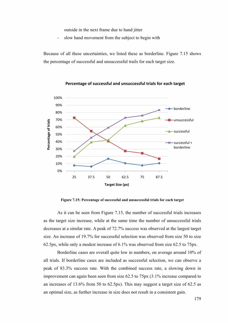
179
outside in the next frame due to hand jitter
- slow hand movement from the subject to begin with
Because of all these uncertainties, we listed these as borderline. Figure 7.15 shows
the percentage of successful and unsuccessful trails for each target size.
Figure 7.15: Percentage of successful and unsuccessful trials for each target
As it can be seen from Figure 7.15, the number of successful trials increases
as the target size increase, while at the same time the number of unsuccessful trials
decreases at a similar rate. A peak of 72.7% success was observed at the largest target
size. An increase of 19.7% for successful selection was observed from size 50 to size
62.5px, while only a modest increase of 6.1% was observed from size 62.5 to 75px.
Borderline cases are overall quite low in numbers, on average around 10% of
all trials. If borderline cases are included as successful selection, we can observe a
peak of 83.3% success rate. With the combined success rate, a slowing down in
improvement can again been seen from size 62.5 to 75px (3.1% increase compared to
an increases of 13.6% from 50 to 62.5px). This may suggest a target size of 62.5 as
an optimal size, as further increase in size does not result in a consistent gain.
0%
10%
20%
30%
40%
50%
60%
70%
80%
90%
100%
25 37.5 50 62.5 75 87.5
Percentage
of trials
Target Size (px)
Percentage of successful and unsuccessful trials for each target
borderline
unsuccessful
successful
successful + borderline

180
Figure 7.16: Mean Time Taken for Target Selection
Figure 7.16 shows mean time taken when pointing to different targets. Time
taken is calculated from the moment subjects begins moving their hand until a
successful selection or when time limit is reached, hence reaction is not included in
these time recording.
As expected, the time required for successful selection is lower than those of
combined successful selections. Two one-way ANOVA for between-groups were
tested for successful and successful+borderline trials. It shows no significant
difference for successful selections across all target size (F[5,195] = 0.857, p =
0.5113). There were also no significant difference for successful+borderline
selections (F[5,234] = 1.693, p = 0.1371).
We can see a general consistency in time taken for all targets. However, it is
interesting to note that the largest target size did not attain the quickest, though
insignificant, mean selection time. The quickest selected target is 62.5px for
successful selection with a time of 2.51s, while target 75px came second at 2.53s.
The quickest selected target for combined successful selection is 75px at 2.69s, while
target 62.5px came second at 2.72s.
0
1
2
3
4
5
25 37.5 50 62.5 75 87.5
Mean
Tim
e Taken for selection (s)
Target Size (px)
Mean Time Taken for Target Selection
borderline
unsuccessful
successful
successful + borderline

181
It should be noted that accuracy was not a factor because in order to select the targets
successfully, the accuracy must be within the target size.
Aggregating the two factors (numbers of successful trials and time taken for
selection) we can conclude that a target size of 62.5px (125px diameter) is the most
suitable choice for system such as ours. On a 1024x768 screen, one can fit around 8
targets horizontally, and 6 targets vertically, a total of 48 targets. In terms of physical
dimensions in our setup, this translates to around 99.5mm for each target both
vertically and horizontally. Further investigation may be under taken to refine the
target resolution than those used in this experiment.
7.4 Experiment 3: The Effect of Calibration
To use the system reliably, the system needs to attain information about the user and
the environment. This is done through a calibration process, which is broken into two
phases. The first process involves measuring the user’s biometric parameters: the
distance between eye and shoulder, and the arm’s length. These are required so that
we can estimate the position and radius of the sphere needed to determine the 3D
position of the fingertip (for further information please refer to chapter 5.x). The
second process gives the system knowledge of the exact location of the display that
the user is pointing to. The system has no prior knowledge of the location of the
display as the display is not within the webcam’s view. This is done by having the
user point at the four corners of the display.
After the system has been calibrated by the calibrator, when a different user
would like to use the system, it needs to be recalibrated. Ideally, when both processes
are done for the new user, the system would then be able to detect the user’s pointing
location accurately. However, there are times when the calibration of both or either
one of the calibration processes cannot be completed due to time constraint or would
inconvenience the potential user. Also, we would like to investigate the possibility of
simplifying the setup cost of our system. It would also be interesting to test the
robustness of the system if no calibration is done for the new user.
An experiment was conducted to investigate the effect of varying the amount
of calibration on the overall system accuracy. Mixing up the two calibration factors
gives us four conditions:
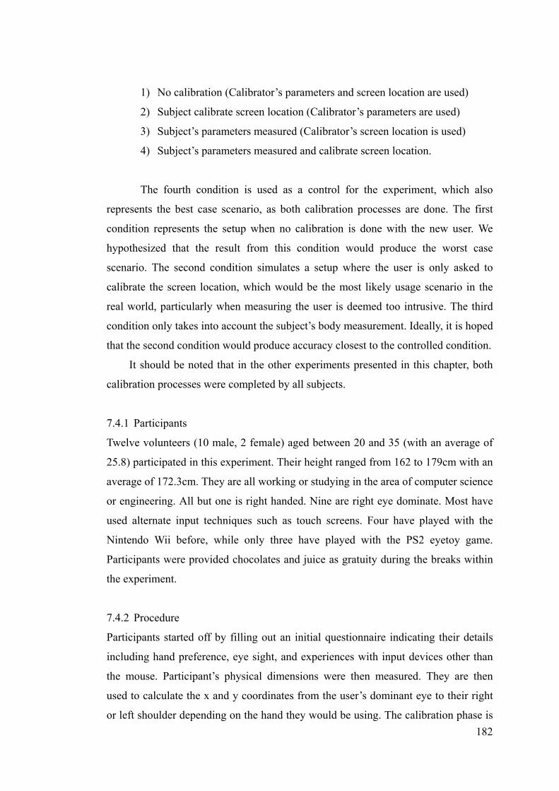
182
1) No calibration (Calibrator’s parameters and screen location are used)
2) Subject calibrate screen location (Calibrator’s parameters are used)
3) Subject’s parameters measured (Calibrator’s screen location is used)
4) Subject’s parameters measured and calibrate screen location.
The fourth condition is used as a control for the experiment, which also
represents the best case scenario, as both calibration processes are done. The first
condition represents the setup when no calibration is done with the new user. We
hypothesized that the result from this condition would produce the worst case
scenario. The second condition simulates a setup where the user is only asked to
calibrate the screen location, which would be the most likely usage scenario in the
real world, particularly when measuring the user is deemed too intrusive. The third
condition only takes into account the subject’s body measurement. Ideally, it is hoped
that the second condition would produce accuracy closest to the controlled condition.
It should be noted that in the other experiments presented in this chapter, both
calibration processes were completed by all subjects.
7.4.1 Participants
Twelve volunteers (10 male, 2 female) aged between 20 and 35 (with an average of
25.8) participated in this experiment. Their height ranged from 162 to 179cm with an
average of 172.3cm. They are all working or studying in the area of computer science
or engineering. All but one is right handed. Nine are right eye dominate. Most have
used alternate input techniques such as touch screens. Four have played with the
Nintendo Wii before, while only three have played with the PS2 eyetoy game.
Participants were provided chocolates and juice as gratuity during the breaks within
the experiment.
7.4.2 Procedure
Participants started off by filling out an initial questionnaire indicating their details
including hand preference, eye sight, and experiences with input devices other than
the mouse. Participant’s physical dimensions were then measured. They are then
used to calculate the x and y coordinates from the user’s dominant eye to their right
or left shoulder depending on the hand they would be using. The calibration phase is

183
then performed, where they had to point at the four corners of the pointing area. They
were given a chance to recalibrate when deemed necessary.
7.4.3 Design
The study was a within-subjects study, where each subject performed all four
conditions and was required to point at 5 different targets in turn. Subjects were
asked to perform 3 blocks of these trials. For each of the 20 combinations, the mean
position was determined from the three blocks. The order of the conditions was
presented based on a Latin Square and the targets randomized, counter-balancing to
avoid ordering effects. A four second time limit was imposed on each pointing task.
If after four seconds they still have not dwelled successfully at the target, the system
will dwell regardless and record the current pointing position. This is to minimize
fatiguing of the hand. Five targets were used to identify if the system produces
consistent accuracy. As subjects were told to use the dTouch method of pointing, the
subject’s pointing accuracy is guaranteed, except for a small amount of hand jitter.
In summary, the experimental design was:
12 subjects x
4 conditions (none, screen, measurement, both) x
5 targets (top, left, center, right, bottom) x
3 block of trials
= 720 pointing trials
7.4.4 Results
We measured the distance between the target and the systems estimation of where the
user had pointed to, in number of pixels. The mean distance for each target is
illustrated in Figure 7.17. The last group of bars on the right hand side indicates the
aggregate mean distance for all targets.

184
Figure 7.17: Accuracy of pointing to each target
As can be see, the condition when both are calibrated, users can more accurately
select their targets in all positions (control condition), while the setup that required
no calibration was the least accurate, as suggested earlier, except for a slight
inconsistency for condition 3 while selecting the left target.
Aggregating all targets, using a one-way ANOVA test for repeated measures,
we observed a significant difference across all conditions (F[3,177] = 42.13, p <
0.001). An a priori multiple means comparisons reveals significance between all 4
groups except between condition 2 and 3. The following table shows the p-values for
each pair of test after adjusting for Bonferroni correction. The aggregate means for
each condition are also shown.
C1: No calibration C2: Screen only C3: Measurement only C4: Both
Aggregate mean (px) 149.07 101.67 128.39 52.46
C1: No calibration - 0.000 * 0.018 * 0.000 *
C2: Screen only - - 0.254 0.000 *
C3: Measurement - - - 0.000 *
*Denotes significance
Table 7.5: Table of p-values illustrating the significance of multiple pairwise means comparisons between each condition.
125
149
135
163173
149
94
10595 95
120
10298
153
119127
144
128
4652 50 47
68
52
0
20
40
60
80
100
120
140
160
180
200
Top Left Center Right Bottom Aggregate
Mean
distance from target (px)
Target Positions
Accuracy of pointing to each target (in pixels)
C1: No calibration C2: screen only C3: measurement only C4: both

185
It can be seen that the performance of all 4 conditions are very clear cut,
except between condition 2 and 3. Calibrating the user’s body measurement gave us
around 13.9% improvement on the worst case, while calibrating the screen gives
31.8% over the worst case, although this was not deemed to be significant. However,
to be able to use the system with only screen calibration, we will need to increase
target size at least two fold, reducing the number of targets to a maximum of 12
targets. However, when both calibration processes are performed, the mean accuracy
of the system can be as high as 52 pixels.
As can be seen, from the prototype as it is now, even though only calibrating
the screen or the body measurement has significant improvement on the default
calibration, it is still not yet practical to reduce the amount of calibration for each
new user, as it does not provide similar accuracy. However, we have demonstrated
that our system is accurate for new users to use our system after the two calibration
processes.
7.5 Experiment 4: The Effect of User’s location
One of the main advantages of our system compared to other single camera
interaction system is the system’s ability to adjust to changing user’s location. When
the user moves to a new location, the interaction area changes to match the user’s
new location, making sure that the virtual touch screen stays directly in front of the
user, between the user and the large display. To evaluate this fact, a usability study
was conducted to evaluate the accuracy of dTouch pointing system when the user is
standing at various locations.
It should be noted that the evaluation is limited to our current setup. The
user’s head and fingertip must be within the view of the camera. From our current
implementation for face detection, the user is restricted to a maximum of 180cm
from the webcam.
We will test our system at 4 different locations including 2 distances. This is
illustrated in the following diagram:

186
Apart from using different locations as a factor, it is also appropriate to test for the
accuracy of depth detection using face width on different users. Two conditions were
introduced. In the first condition, the system is assumed to have accurate depth
estimation at 135 and 160cm. In the second condition, the system estimates the user’s
location from their face width. In both cases, subjects were asked to stand at the four
different locations, which include both distances.
7.5.1 Participants
Thirteen volunteers (2 female and 11 male) aged between 20 and 34 participated in
this experiment. They are all working or studying in the area of computer science or
engineering. One left hander. Nine are right eye dominate. Most have used alternate
input techniques such as touch screens. Eight have played the Nintendo Wii before,
while only four have played with the PS2 eyetoy game. Participants were provided
chocolates and juice as gratuity during the breaks within the experiment.
7.5.2 Procedure and Design
Participants started off by filling out an initial questionnaire about themselves and
their experiences. Participant’s physical dimensions were then measured and the
calibration phase completed.
Standing Positions
40 cm
135 cm
81.5 cm (1024 px)
160 cm
Large screen
left
front
center right
Figure 7.18: An illustration of the position of the four standing locations.

187
This study was a within-subjects study, where each subject performed the two
conditions and was required to stand at each location in turn and point to the same
target. Subjects were asked to perform 3 blocks of these trials. For each of the 8
combinations, the mean accuracy was determined from the three blocks. The order of
the locations was presented based on a Latin Square and the conditions were
counter-balanced to avoid ordering effects.
In summary, the experimental design was:
13 subjects x
1 target (center) x
2 conditions (depth assumed accurate, estimated depth) x
4 standing locations (front, left, center, right) x
3 blocks of trials
= 312 pointing trials
It should be noted that the face detection algorithm used detected a face that was
wider than the face measured, as can be seen below:
To compensate for this, in addition to the two calibration processes, we added a third
calibration process for each subject in this experiment. We measured the number of
pixels the two widths occupies in a frame captured by the camera, such as the one
shown above. One can then estimate the detected face width in physical
detected face width
actual face width
Figure 7.19: An illustration of the difference between detected face width and the actual face width

188
measurement (cm). We will use this as the face width instead of the actual face
width.
Detected face width (cm) = detected face width (px) X actual face width(cm)
actual face width (px)
7.5.3 Results
The distance between the target and the systems estimation of where the user has
pointed is measured. The mean accuracy for each location is illustrated in Figure
7.20. The blue bars indicate the distance recorded when depth was assumed accurate,
while the red bars indicate the mean distance when depth was estimated by the
system.
Figure 7.20: Accuracy of pointing from different locations
As can be seen, the pointing accuracy is consistent across different standing
locations when depth was assumed accurate. A one-way Analysis of Variance
(ANOVA) test for repeated measures revealed no significant difference (F[3,36] =
2.544, p=0.071). On the other hand, when depth was estimated, the accuracy
deteriorates, particularly for the case of the front standing position. However, the
ANOVA test also revealed no significant difference (F[3,36] = 1.521, p=0.226).
78
105
7264
207
150139
125
0
50
100
150
200
250
front left center right
Mean
distance from target (px)
Standing location
Accuracy of pointing from different locations
accurate depth
estimated depth

189
Between the two conditions within each standing location, four separate paired t-tests
reveal significant difference in accuracy, except for the case of the left position.
Standing location front left center right
Pvalue 0.0074* 0.0660 0.0403* 0.0355*
*Denotes significance at the 0.05 level
Table 7.6: Paired t-test between the two conditions
The significant differences may be explained by the inaccuracy in the depth
estimation as illustrated in Figure 7.21.
Figure 7.21: Mean estimated depth at various standing position
The actual standing position is 135cm for the front position and 160cm for the other
three. From the above figure, we can observe a discrepancy between the estimated
depth and the actual depth. Upon further investigation, we found the estimated depth
were spread throughout a wide range (Figure 7.22)
146.2
154.2 154.0152.9
135
140
145
150
155
160
front left center right
Estimated distance from cam
era (cm
)
Standing Positions
Mean estimated depth at various standing position
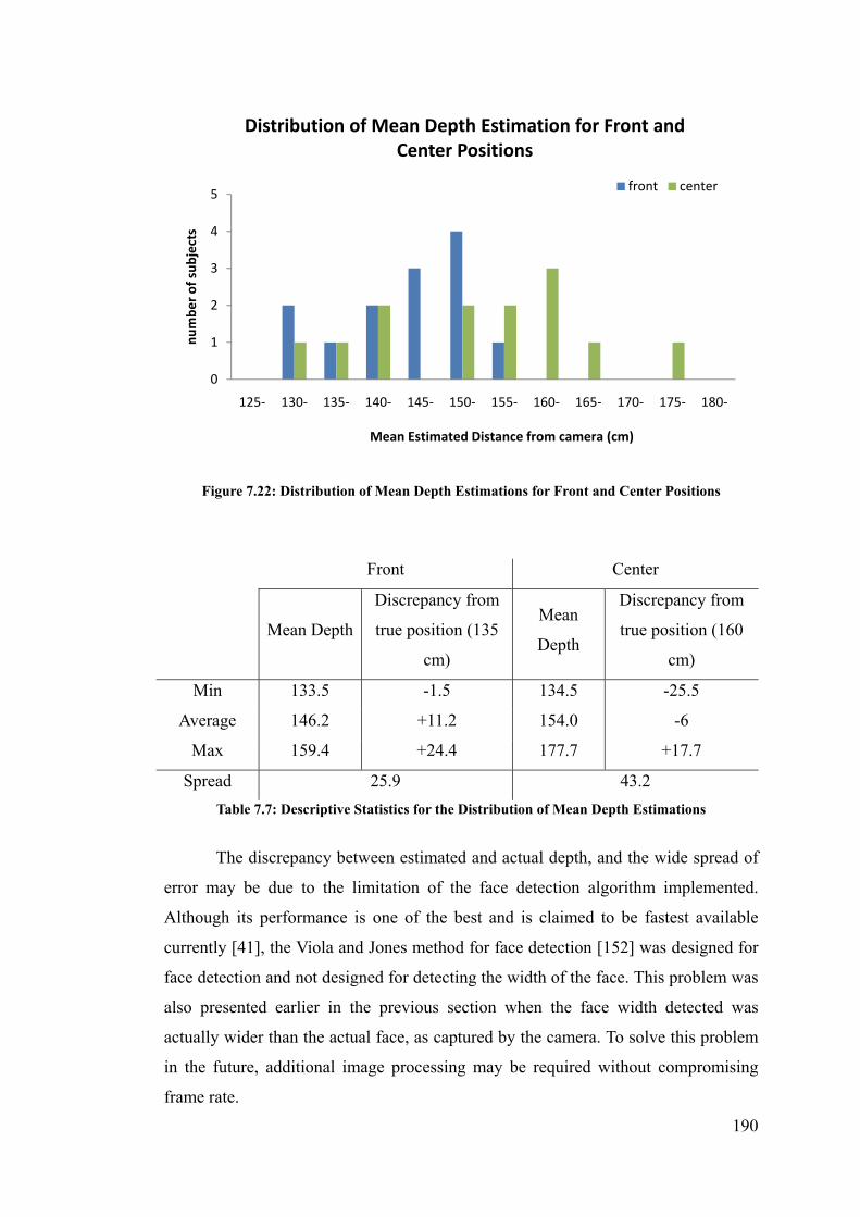
190
Figure 7.22: Distribution of Mean Depth Estimations for Front and Center Positions
Front Center
Mean Depth
Discrepancy from
true position (135
cm)
Mean
Depth
Discrepancy from
true position (160
cm)
Min 133.5 -1.5 134.5 -25.5
Average 146.2 +11.2 154.0 -6
Max 159.4 +24.4 177.7 +17.7
Spread 25.9 43.2
Table 7.7: Descriptive Statistics for the Distribution of Mean Depth Estimations
The discrepancy between estimated and actual depth, and the wide spread of
error may be due to the limitation of the face detection algorithm implemented.
Although its performance is one of the best and is claimed to be fastest available
currently [41], the Viola and Jones method for face detection [152] was designed for
face detection and not designed for detecting the width of the face. This problem was
also presented earlier in the previous section when the face width detected was
actually wider than the actual face, as captured by the camera. To solve this problem
in the future, additional image processing may be required without compromising
frame rate.
0
1
2
3
4
5
125‐ 130‐ 135‐ 140‐ 145‐ 150‐ 155‐ 160‐ 165‐ 170‐ 175‐ 180‐
number of subjects
Mean Estimated Distance from camera (cm)
Distribution of Mean Depth Estimation for Front and Center Positions
front center

191
These depth estimation results are not consistent with those reported from the
initial feasibility study for depth estimation using face width in 6.3.3. From that study,
the mean depth estimation was much closer to the actual depth. For an actual depth
of 150cm, the mean estimated depth is 149cm with a minimum and maximum of 140
and 162 cm respectively. This discrepancy may be due to the position and therefore
the angle of the camera. In that study, the camera was placed at eye-level to the user
where the full frontal face of the user was detected. However, in this experiment, and
other experiments in this chapter, the camera was positioned above the large display.
The subjects were not directly facing the camera and therefore the estimation may
have been affected.
Furthermore, accuracy results from this experiment are not consistent with
those found in experiment 1 and 3 of this chapter, when depth was not estimated. At
the condition when depth assumed accurately estimated at the center position
(160cm), result from this experiment indicates a mean distance from target of 72cm,
whereas in experiment 3, the mean distance was 50cm when both of the calibration
processes were completed, as was in this experiment. The difference between these
two results is significant according to a two-sample unequal variance t-test (p=0.047).
This discrepancy may be due to the variability of the subject’s head position. In
previous experiments, subjects were only asked to stand at a specific location, where
as in this experiment subjects were told to move to different locations at various
times. This may have caused their body to rotate slightly. Since our conceptual model
is designed so that the body is parallel to the screen, such rotations may have affected
the result. In addition, for the comfort of the user and to minimize detection errors, a
table was setup directly in front of them. This also has the effect of helping subjects
stay consistent at the same position. In this experiment, the table was setup at 135cm,
so they only relied on a marked X on the floor, their variable posture may have
affected their head position.
As the same limitations were faced by all subjects alike, from these results,
we can conclude that users can select the same target consistently from various
locations within the view of the camera, when depth can be estimated correctly.
7.5.4 Summary
This experiment sets out to evaluate the system’s ability to adjust to changing user’s
location. Results from this study suggested a consistent mean pointing accuracy of 64
192
to 105 cm from the target when depth is estimated correctly. We observed difficulties
in estimating the user’s distance from the camera due to weakness in the face
detection algorithm and inconsistent user’s standing position. In light of the
limitations presented, we showed that the existing implementation of our concept
does provide a reasonable pointing accuracy varying user locations and reflects a
viable pointing system.
7.6 Overall Summary
In this chapter, we have evaluated our dTouch pointing system in four usability
experiments. We found that our dTouch system is much more accurate, less error
prone and preferred by users overall compared to the EyeToy pointing method,
which represent a well known pointing method. Our system can be used comfortably
by subjects with target size of around 125pixels square which gives us around 48
targets on a large display. Although the system still requires a full calibration for each
new user, we have shown that it is viable for users to use the system to point at
objects on a large display from various locations and with reasonable accuracy.
Therefore, the dTouch model, in conjunction with monocular vision system, has the
potential to allow a new type of interaction systems for large displays.
In light of the limitations and constraints mentioned, such as the system
detection inaccuracy and the rigid body movement, it was felt that the results were
not significantly affected and are sufficient for testing on a prototype such as ours.
These experiments should only be regarded as initial performance evaluation of the
theories involved, and a validation of the worth of such concepts for continuing
research and development.

193
Chapter 8
Conclusion
A summary of the thesis is presented in this chapter. We discuss the implication of
this work as well as the possible application domains. Ideas for further work are also
presented.
8.1 Summary
This thesis set out to investigate the feasibility of using monocular computer vision
for natural 3D interaction with large displays at a distance.
Initial case study
To begin with, a usability study was conducted to compare two common consumer
input devices – the isotonic (computer) mouse and the handheld remote controller –
and study the way users use them in a living room environment with a large display.
The tasks required is commonly used in real life scenarios: playing a specified song,
search for photos, browsing through folders, and dealing with UI widgets such as
drop down menus.
Results showed that even though both devices can be used to accomplish the
required tasks, there were problems associated with each device. The mouse
restricted users to a fixed place of interaction while the remote required learning and
thereby hindering the users’ task. The common difficulty arising from the use of both
devices was the lack of naturalness. We observed that future interaction techniques
should resemble the way we interact with things in the physical world, much like
using our hand to point at objects.
Pointing Strategies
Current bare-hand interactive systems often require users to use pointing strategies
that may not be natural nor provide the best accuracy. We therefore conducted two

194
usability experiments to study the way we point at physical world objects and gauge
the accuracy provided naturally by these different pointing strategies.
We found that full arm stretch was the most common pointing strategy, while
the most accurate strategy was when users line up the target with their eye and
fingertip. From the observations, we systematically analysed the various natural
pointing strategies and formalized geometric models to explain their differences. The
dTouch model was found to give the most accurate strategy and we recommend the
use of this model for designing future interactive systems that requires interaction at
a distance. Thus, it was used as a basis for designing our system.
dTouch Pointing System
Our dTouch interactive system was designed to provide users a more natural
(bare-hand pointing) and direct (where the input and output space coincides) method
for interacting with large displays. At the heart of the dTouch system are three key
elements: dynamic virtual touchscreen, the dTouch model and monocular vision.
Virtual touchscreen stems from the realization that the advantage of a large touch
display could be leveraged by bringing the whole screen (virtually) towards the user
so that the display can be interacted within arm’s reach. By taking into account the
users’ location, a dynamic virtual touchscreen enables users to roam around the room
and still be able to interact with it.
As the dTouch pointing model was used, the task for the users was to line up
their fingertip between the eye and the target object. This gave users the illusion that
they were touching the target with their fingertips. The pointing direction was
defined by two 3D points, which allowed pointing to occur in physical
3-Dimensional space. As long as users stood within the camera’s view, they could
interact with the screen at arm’s reach.
With the use of monocular computer vision, retrieving depth information
becomes nontrivial. Our attempt at solving this problem was to exploit geometric
constrains in the environment. Face detection was used to detect the position of the
dominant eye, while depth was determined from the width of the face. The fingertip
was detected as the lowest skin colour pixel from the view of the camera. The depth
of the fingertip was calculated by intersecting a sphere (where the center is at the
user’s shoulder, with arm’s length as the radius) and a line vector from the center of
camera to the position of the detected fingertip in the camera’s image plane.

195
Experimental Evaluation
Four usability experiments were conducted to evaluate various aspects of our system.
The dTouch pointing system was compared with the use of a similar
hand pointing system (EyeToy) which also used a single webcam, but
used the Touch model of targeting. Results showed that our system
was much more accurate, less error prone and preferred by users
overall, compared to the EyeToy system, which represents a well
known pointing method.
Our system can be used comfortably by subjects with a target size of
around 125pixels square, which gives us around 48 targets on a large
display.
In an attempt to reduce the amount of calibration required for each
new user, the effect of varying the amount of calibration on the overall
system accuracy was investigated. However we found that this was
still not yet practical as the accuracy observed was not sufficient.
We have shown that it is viable for users to use the system to point at
objects on a large display from various locations and with reasonable
accuracy, even though face detection difficulty was observed.
These initial performance evaluations demonstrated the feasibility of using the
dTouch model and monocular vision to develop an interaction method for large
displays.
8.2 Implications of this research
The push for post-WIMP interfaces is hindered mainly because of the fact that most
software products are designed with the keyboard and mouse as the primary
interaction device. In order to push the current interaction techniques out of the
current WIMP interface, future systems must build upon users’ existing skills and
experiences or offer enormous advantages over traditional techniques [93]. We
provided a non technology-oriented solution, in terms of a theoretical exploration
into what is possible now and in the future. This thesis can be seen as a step towards
this goal by using input techniques that only required the user’s natural pointing
ability.

196
We met all the objectives that were laid down in the beginning of this thesis,
in that our dTouch pointing system is natural, direct, unintrusive, unconstrained,
untethered, inexpensive and simple to setup. We exploited geometric constraints in
the environment, and from this we were able to use monocular computer vision to
allow bare-hand interaction with large displays. From the result of the experimental
evaluation of the dTouch system, it is observed that this approach has the potential to
serve as a basis for the design of next generation interactive system.
At its current state, we see our implementation as a basic prototype of our
idea, further research and development will be needed to make the dTouch pointing
technique more practical and robust in real usage scenario.
In addition, the case study presented in Chapter 3 and the pointing models
that were formalized in Chapter 4 may serve as guidelines for system designers to
build future interactive systems that can provide a more natural and more satisfying
interaction experience to their users.
8.3 Application Domains
We envision that this interactive system is suited for applications that only require
intermittent pointing with object-level accuracy.
Presentation environment – The use of such systems in a presentation environment
would reduce hindrance to the presenters as hand pointing is a natural human
behaviour. This allows presenters to roam around and occasionally point at the screen
to highlight certain things to their audience. Bare hand interaction has been shown to
be more accepted and preferred by users over the use of laser pointer and the
standard mouse and keyboard, in presentation type environments [21].
3D Immersive Virtual Reality Displays – With the use of head position detection,
the dTouch pointing system is ideal for VR environments; where users can move
around in all directions in front of the displays and their position is updated so that a
corresponding 3D view produced from this new position will be displayed. This
gives users a sense of being inside this virtual space. Similar research has been done
with a low-cost setup such as using the Wii Remote [78]. The advantage of using the
dTouch system is that users are not required to wear or hold on to any device.

197
Personal Entertainment – In addition to head position detection, the dTouch system
also detects the pointing finger. A toy gun could be used by users in a First Person
Shooter game. The aiming model with the use of a gun is consistent with the dTouch
model of pointing. The fingertip position can be replaced by the sight often found on
top of a gun. This gives users the realism of actually being in the environment as well
as being able to interact with animated characters in the virtual world.
Informational Public Display – A webcam can be easily attached to a public
touchscreen (for example directory service in a shopping center). This gives users the
ability to touch the screen physically or use their arm to point at a specific location
when they are not in reach. Alternatively, it is possible for stores to incorporate the
dTouch system behind their shop front window, so that users can still interact with
the display from a distance even when the shop is closed. Currently, these touch
screens are used for these type of systems [147, 149].
Figure 8.1: 3D model of Manchester city in virtual reality cave[148]
Figure 8.2: First Person Shooter arcade game – Time Crisis 4[100]

198
Remote Collaboration – Similar to the use in the IshinDenshin System[81] and
ClearBoard[68], the dTouch system can be used in conjunction with video
conferencing systems providing both sides the ability to interact with on-screen
objects together virtually. In addition, collaborators are not restricted to be right in
front of the display.
Figure 8.3: Ralph Lauren’s window shopping touch screen[149].
Figure 8.4: The IshinDenshin System was designed to increase the sense of presence between remote collaborators[81]

199
8.4 Future Research Direction
As observed throughout this thesis, there are potentials for further research and
development based on this research.
Pointing Direction
A more thorough investigation into the different pointing styles may be necessary.
Particularly one that is able to detect and segment users’ pointing direction using
stereo computer vision [32, 40]. In our research, the natural style of pointing was
observed rather than measured accurately, and the accuracy of the different styles
was only measured through the use of laser pointers. They are limited in their ability
to represent the pointing hand. However, our research provides a good basis for
further analysis.
As observed from our experimental evaluation in Chapter 7, using a straight arm
to point at the target may fatigue the user after prolonged use. However the
requirement of using the straight arm is only a restriction specific to our current
implementation, the dTouch model of pointing does not have such requirement. It is
hoped that future monocular systems may be able to detect the eye and fingertip
positions without the need for a straight arm, allowing a more natural and
comfortable user experience.
Hand Detection
With current segmentation techniques in the computer vision area of research, it is
difficult to detect users’ fingertip from a frontal image of a pointing arm. In our
experimental evaluations, subjects were asked to adjust their index fingertip so that it
is lower than the natural position. As was observed, subjects found this requirement
unnatural and uncomfortable. It is hoped that advances in the area of segmentation
techniques may alleviate this, thereby giving users a fully natural interactive
experience.
In addition to using skin colour, it may also be possible to use background
subtraction or motion analysis to detect users’ pointing hand. Incorporating these
methods may allow a more robust interactive system.

200
Automatic Body Measurements
To reduce the need for explicit body measurements taken by each new user, it may be
automatically calculated by only needing the user to stand at a specific distance away,
while holding their arm straight out to the side. An image of this stance can be taken
from the webcam and background subtracted out, leaving only the user’s silhouette,
which can be used for detecting the length of the arm or the height of the user [71]. It
may also be possible to begin with a standard profile and adapt it to the user after
multiple use.
Gestures
Incorporating gestures into our system is a natural next step. With a wave of the arm,
users could change to the next slide in a presentation, browse to the next photo in
their slideshow or even fast-forward to their favourite song. The possibilities are
endless.
Computer Supported Cooperative Work
It is possible to have two people using the system at the same time. The challenge
then is to distinguish which hand belongs to which user. VideoArm is a good
example of solving this [140, 141]. In remote collaborative environments, allowing
the collaborators to see each others’ hand and be more aware of where each other are
looking at and pointing to are also of high importance [4].
Office of the Future
The ultimate dream would be to allow users to interact with a room that contains
both vertical displays as well as horizontal surfaces. In addition, objects in the room
may also be selected. Users are allowed to walk freely around the room, interacting
with objects anywhere with nothing more than their pointing hand.
8.5 Final Remark
In his landmark paper “The Computer for the 21st Century”, Mark Weiser describes
future computer systems as “one that takes into account the natural human
environment and allows the computers themselves to vanish into the background”
[155]. He coined the term “ubiquitous computing” describing the new wave in

201
computing where technologies recedes into the background of our lives - “Long term,
the PC and workstation will wither because computer access will be everywhere: in
the wall,…lying about to be grabbed as needed” [156].
We are now one step closer towards this dream.

202
Bibliography
[1] 3DV Systems, "ZCam", 2008, http://www.3dvsystems.com/ [2] Agarawala, A. and Balakrishnan, R., "Keepin' It Real: Pushing the Desktop Metaphor with
Physics, Piles and the Pen," in Proceedings of CHI '06, ACM Press., 2006, pp. 1283-1292. [3] AirForceLink, "Mission Control Center, Houston", 2006,
http://www.af.mil/photos/index.asp?galleryID=255&page=17, date accessed: 24 September [4] Andersson, R. and Ehrensvard, A., "Mixed Presence Groupware (MPG): Requirements and
Taxonomy for Collaboration and Sketching." Master of Science Thesis, Goteborg, Sweden, Chalmers University of Technology, 2008.
[5] Apple Computer Inc., "MacDraw Manual", 1984, [6] Apple Computer Inc., Macintosh System 1,
http://r-101.blogspot.com/2006_08_01_archive.html [7] Baudisch, P., Cutrell, E., Robbins, D., Czerwinski, M., Tandler, P., Bederson, B., and
Zierlinger, A., "Drag-and-Pop and Drag-and-Pick: Techniques for Accessing Remote Screen Content on Touch- and Pen-operated Systems," in Proceedings of INTERACT 2003, Zurich, Switzerland, IOS Press., August, 2003, pp. 57-94.
[8] Baudisch, P., Sinclair, M., and Wilson, A., "Soap: a Pointing Device that Works in Mid-Air," in Proceedings of UIST '06, ACM Press., 2006, pp. 43-46.
[9] Beaudouin-Lafon, M. and Mackay, W., "Prototyping Tools and Techniques," in The Human-Computer Interaction Handbook, J. A. Jacko and A. Sears, Eds., Mahwah, New Jersey, Lawrence Erlbaum Associates, Inc., 2003, pp. 1006-1031.
[10] Beck, J., "CES: 3DV Systems does Wii-like fun with no controller", 2008, http://www.sfgate.com/cgi-bin/blogs/sfgate/detail?blogid=19&entry_id=23275
[11] Biever, C., "Why a robot is better with one eye than two," New Scientist, 188(2530), pp. 30-31, 2005.
[12] blfelectronics.net, "A person playing with the EyeToy game.", http://blfelectronics.net/eyetoy2.jpg
[13] Bolt, R. A., ""Put-that-there": Voice and gesture at the graphics interface," in Proceedings of SIGGRAPH, Seattle, ACM Press., 1980, pp. 262-270.
[14] Bouguet, J.-Y., "Camera Calibration Toolbox for Matlab", 2008, http://www.vision.caltech.edu/bouguetj/calib_doc/, date accessed: 15 September 2008
[15] Bouguet, J.-Y., "Camera Calibration Toolbox for Matlab: Description of the calibration parameters", 2008, http://www.vision.caltech.edu/bouguetj/calib_doc/htmls/parameters.html, date accessed: 15 September 2008
[16] Bourke, P., "Intersection of a plane and a line", 1991, http://local.wasp.uwa.edu.au/~pbourke/geometry/planeline/, date accessed: 13 November 2007
[17] Bowman, D. A. and Hodges, L. F., "An Evaluation of Techniques for Grabbing and Manipulating Remote Objects in Immersive Virtual Environments," in Proceedings of Symposium on Interactive 3D Graphics, 1997, pp. 35-38.
[18] Burscough Archery Club, "Robin Hood and the Golde Arrow", 1938, http://www.burscougharchers.co.uk/historyofarchery.html
[19] Cantoni, V., Lombardi, L., Porta, M., and Vallone, U., "Qualitative Estimation of Depth in Monocular Vision," in Proceedings of 4th International Workshop on Visual Form, Capri, Italy, Springer-Verlag, 2001, pp. 135-144.
[20] Cantzler, H. and Hoile, C., "A Novel Form of a Pointing Device," in Proceedings of Vision, Video, and Graphics, University of Bath, July, 2003, pp. 57-62.
[21] Cao, X., Ofek, E., and Vronay, D., "Evaluation of Alternative Presentation Control Techniques," in Proceedings of CHI 2005, Portland, Oregon, ACM Press., April 2-7, 2005,
203
pp. 1248-1251. [22] Card, S. K., English, W. K., and Burr, B. J., "Evaluation of Mouse, Rate-Controlled Isometric
Joystick, Step Keys, and Text Keys for Text Selection on a CRT," Ergonomics, 21(8), pp. 601-613, 1978.
[23] Cavens, D., Vogt, F., Fels, S., and Meitner, M., "Interacting with the Big Screen: Pointers to Ponder," in Proceedings of Proceedings of CHI '02 Conference on Human Factors in Computing Systems, Extended Abstracts, Minnesota, ACM Press., April, 2002, pp. 678-679.
[24] Chen, M. C., Anderson, J. R., and Sohn, M. H., "What can a mouse cursor tell us more? Correlation of eye/mouse movements on web browsing," in Proceedings of CHI'01 conference on Human factors in computing systems, Seattle, ACM, 2001, pp. 281-282.
[25] Cheng, K. and Pulo, K., "Direct Interaction with large-scale display systems using infrared laser tracking devices," in Proceedings of Proceedings of the Australian Symposium on Information Visualisation (invis '03), Adelaide, ACS Inc., 2003, pp. 67-74.
[26] Cheng, K. and Takatsuka, M., "Real-time Monocular Tracking of View Frustum for Large Screen Human-Computer Interaction," in Proceedings of Proceedings of the 28th Australasian Computer Science Conference, Newcastle, Australia, 2005, pp. 125-134.
[27] Cheng, K. and Takatsuka, M., "Estimating Virtual Touchscreen for Fingertip Interaction with Large Displays," in Proceedings of Proc. OZCHI 2006, Sydney, ACM Press., 2006, pp. 397-400.
[28] Cheng, K. and Takatsuka, M., "Hand Pointing Accuracy for Vision-Based Interactive Systems," in Proceedings of INTERACT 2009, 12th IFIP TC13 Conference in Human-Computer Interaction, Uppsala, Sweden, Springer Verlag (to appear), 2009.
[29] Cheng, K. and Takatsuka, M., "Initial Evaluation of a Bare-Hand Interaction Technique for Large Displays using a Webcam," in Proceedings of EICS'09, ACM SIGCHI Symposium on Engineering Interactive Computing Systems, Pittsburgh, Pennsylvania, ACM Press. (to appear), 2009.
[30] Cheng, K. and Takatsuka, M., "Interaction Paradigms for Bare-Hand Interaction with Large Displays," in Human-Computer Interaction, A. Lazinica, Ed., Vienna, IN-TECH (accepted for publication), ISBN 978-953-7619-26-8, 2009.
[31] Cheng, K., Vronay, D., and Yu, F., "Interaction Design for the Media PC," in Proceedings of Companion proc. UIST'04, Santa Fe, New Mexico, ACM Press., 2004, pp. 5-6.
[32] Cipolla, R. and Hollinghurst, N. J., "A Human-Robot Interface using Pointing with Uncalibrated Stereo Vision," in Computer Vision for Human-Machine Interaction, R. Cipolla and A. Pentland, Eds., Cambridge University Press, 1998, pp. 97-110.
[33] Colombo, C., Bimbo, A. D., and Valli, A., "Visual Capture and Understanding of Hand Pointing Actions in a 3-D Environment," IEEE Transactions on Systems, Man, and Cybernetics, 33(4), University of Florence, Italy, pp. 677-686, August 2003.
[34] Cooliris, "Cooliris", http://www.cooliris.com/ [35] Cotter, C., "Turtle Graphics Interface for REDUCE Version 3", 1998,
www.zib.de/Symbolik/reduce/moredocs/turtle.pdf [36] Crowley, J. L., Coutaz, J., and Berard, F., "Things that See," Communications of the ACM,
43(3), ACM Press., pp. 54-64, March 2000. [37] Czerwinski, M., Smith, G., Regan, T., Meyers, B., Robertson, G., and Starkweather, G.,
"Toward Characterizing the Productivity Benefits of Very Large Displays," in Proceedings of INTERACT 2003, International Conference on Human-Computer Interaction, IOS Press, 2003, pp. 9-16.
[38] Dietz, P. and Leigh, D., "DiamondTouch: A Multi-User Touch Technology," in Proceedings of UIST '01, ACM Press., 2001, pp. 219-226.
[39] Dix, A., Finlay, J., Abowd, G. D., and Beale, R., Human-Computer Interaction, 3rd ed., Pearson Education Limited, 2004.
[40] Do, J.-H., Kim, J.-B., Park, K.-H., Bang, W.-C., and Bien, Z. Z., "Soft Remote Control System using Hand Pointing Gestures," International Journal of Human-friendly Welfare Robotic Systems, 3(1), pp. 27-30, 2002.
[41] Dominguez, S., Keaton, T., and Sayed, A., "Robust Finger Tracking for Wearable Computer Interfacing," in Proceedings of Perceptive User Interfaces, Orlando, ACM Press., 2001, pp. 1-5.
[42] Douglas, S. A., Kirkpatrick, A. E., and MacKenzie, I. S., "Testing Pointing Device Performance and User Assessment with the ISO 9241, Part 9 Standard," in Proceedings of CHI'99, Conference on Human Factors in Computing Systems, Pittsburgh, ACM Press., 1999, pp. 215-222.

204
[43] Douglas, S. A. and Mithal, A. K., "The Effect of Reducing Homing Time on the Speed of a Finger-Controlled isometric Pointing Device," in Proceedings of CHI '94, Conference on Human Factors in Computing Systems, Boston, ACM Press., 1994, pp. 411-416.
[44] Drucker, S. M., Glatzer, A., Mar, S. D., and Wong, C., "SmartSkip: Consumer level browsing and skipping of digital video content," in Proceedings of CHI'02, Conference on Human factors in Computing Systems, Minneapolis, ACM Press., 2002, pp. 219-226.
[45] Eckert, R. R. and Moore, J. A., "The Classroom of the 21st Century: The Interactive Learning Wall," ACM SIGCHI Bulletin, 32(2), pp. 33-40, 2000.
[46] Eisenstein, J. and Mackay, W., "Interacting with Communication Appliances: An evaluation of two computer vision based selection techniques," in Proceedings of CHI, Montreal, Quebec, Canada, ACM Press., 2006, pp. 1111-1114.
[47] Engadget, Steve Jobs' 2008 WWDC Keynote, http://www.engadget.com/2008/06/09/steve-jobs-keynote-live-from-wwdc-2008/
[48] Engelbart, D., The First ever Computer Mouse, http://cerncourier.com/cws/article/cern/28358/1/cernbooks2_12-00
[49] Engelbart, D. C. and English, W. K., "A Research Center for Augmenting Human Intellect," in Proceedings of AFIPS Conference Proceedings of the 1968 Fall Joint Computer Conference, San Francisco, CA, December, 1968, pp. 395-410.
[50] Enns, N. R. N. and MacKenzie, I. S., "Touchpad-based Remote Control Devices," in Proceedings of Companion Proceedings of the CHI '98 conference on Human Factors in Computing Systems, ACM, 1998, pp. 229-230.
[51] Eronen, L. and Vuorimaa, P., "User Interfaces for Digital Television: a Navigator Case Study," in Proceedings of AVI 2000, Conference on Advanced Visual Interfaces, 2000, pp. 276-279.
[52] Franjcic, Z., Anglart, M., Sundin, M., and Fjeld, M., "Softly Elastic Device for 6DOF Input," in Proceedings of NordiCHI 2008, Lund, Sweden, ACM Press, 2008, pp. id5-id6.
[53] Fredriksson, J., Ryen, S. B., and Fjeld, M., "Real-Time 3D Hand-Computer Interaction: Optimization and Complexity Reduction," in Proceedings of NordiCHI, Lund, Sweden, ACM Press., 2008, pp. 133-141.
[54] GentleMouse, "GentleMouse", http://www.gentlemouse.com/ [55] Gomez, G. and Morales, E. F., "Automatic Feature Construction and a Simple Rule Induction
Algorithm for Skin Detection," in Proceedings of ICML Workshop on Machine Learning in Computer Vision, Sydney, Australia, July 9, 2002, pp. 31-38.
[56] Gorodnichy, D., Malik, S., and Roth, G., "Nouse ‘Use Your Nose as a Mouse’ - a New Technology for Hands-free Games and Interfaces.," in Proceedings of VI'02, International Conference on Vision Interface, Calgary, May, 2002, pp. 354-361.
[57] Grossman, T., Wigdor, D., and Balakrishnan, R., "Multi-Finger Gestural Interaction with 3D Volumetric Displays," in Proceedings of 17th ACM Symposium on User Interface Software and Technology,, Santa Fe, ACM Press., 2004, pp. 931-931.
[58] Guiard, Y., Blanch, R., and Beaudouin-Lafon, M., "Object Pointing: A Complement to Bitmap Pointing in GUIs," in Proceedings of Proceedings of Graphics Interface, London, Ontario, May, 2004, pp. 9-16.
[59] Gyration Inc., "Gyration GyroMouse", 2006, http://www.gyration.com/ [60] Han, J., "Low-Cost Multi-Touch Sensing through Fustrated Total Internal Reflection," in
Proceedings of UIST '05, Seattle, Washington, ACM Press., 2005, pp. 115-118. [61] Hardenberg, C. v. and Berard, F., "Bare-Hand Human-Computer Interaction," in Proceedings
of ACM Workshop on Perceptive User Interfaces, Orlando, Florida, ACM Press., 2001, pp. 1-8.
[62] Hartley, R. and Zisserman, A., Multiple view geometry in computer vision. Cambridge, New York, Cambridge University Press, 2000.
[63] Hawkins, T., "Kalman Filtering", 2006, http://www.techsystemsembedded.com/Kalman.html [64] Hedman, A. and Lenman, S., "A Media Rich Interface vs A Simple Interface for Interactive
Television," in Proceedings of E-Learn 2002, World Conference on E-Learning in Corporate, Government, Healthcare, & Higher Education, Montreal, 2002, pp. 420-425.
[65] Hinckley, K., "Input Technologies and Techniques," in The Human-Computer Interaction Handbook, J. A. Jacko and A. Sears, Eds., Lawrence Erlbaum Associates Inc, 2003, pp. 151-168.
[66] Hung, Y.-P., Yang, Y.-S., Chen, Y.-S., Hsieh, I.-B., and Fuh, C.-S., "Free-Hand Pointer by Use of an Active Stereo Vision System," in Proceedings of ICPR'98, 14th International Conference on Pattern Recognition, Brisbane, August, 1998, pp. 1244-1246.

205
[67] Interlink, "RemotePoint, Interlink Electronics", 2008, http://www.interlinkelec.com/ [68] Ishii, H. and Kobayashi, M., "ClearBoard: A Seamless Medium for Shared Drawing and
Conversation with Eye Contact," in Proceedings of CHI '92, SIGCHI Conference on Human Factors in Computing Systems, ACM Press., 1992, pp. 525-532.
[69] Jacob, R. J. K., "Human-Computer Interaction: Input Devices," ACM Computing Surveys, 28(1), pp. 177-179, March 1996.
[70] Jacob, R. J. K., "Computers in Human-Computer Interaction," in The Human-Computer Interaction Handbook, J. A. Jacko and A. Sears, Eds., Mahwah, New Jersey, Lawrence Erlbaum Associates, Inc., 2003, pp. 147-149.
[71] Jaimes, A., "Posture and Activity Silhouettes for Self-Reporting, Interruption Management, and Attentive Interfaces," in Proceedings of IUI'06, Sydney, ACM Press., January 29 - February 1, 2006, pp. 24-31.
[72] Jul, S., ""This Is a Lot Easier!": Constrained Movement Speeds Navigation," in Proceedings of Proceedings of the CHI'03 conference on Human factors in computing systems, Ft. Lauderdale, ACM, 2003, pp. 776-777.
[73] Keefe, D., Acevado, D., Moscovish, T., Laidlaw, D., and LaViola, J., "CavePainting: A Fully Immersive 3D Artistic Medium and Interactive Experience," in Proceedings of Symposium on Interactive 3D Graphics 2001, 2001, pp. 85-93.
[74] Kirstein, C. and Muller, H., "Interaction with a Projection Screen Using a Camera-Tracked Laser Pointer," in Proceedings of MMM'08, Conference on MultiMedia Modeling, IEEE Computer Soceity, 1998, pp. 191-192.
[75] Kooper, R. and MacIntyre, B., "Browsing the Real-World Wide Web: Maintaining Awareness of Virtual Information in an AR Information Space," International Journal of Human-Computer Interaction, 16(3), pp. 425-446, 2003.
[76] Kurata, T., Okuma, T., Kourogi, M., and Sakaue, K., "The Hand-mouse: A Human Interface Suitable for Augmented Reality Environments Enabled by Visual Wearables," in Proceedings of ISMR2001, International Symposium on Mixed Reality, Yokohama, Japan, 2001, pp. 188-189.
[77] Kurata, T., Okuma, T., Kourogi, M., and Sakaue, K., "The Hand Mouse: GMM Hand-Color Classication and Mean Shift Tracking," in Proceedings of IEEE ICCV Workshop on Recognition, Analysis, and Tracking of Faces and Gestures in Real-Time Systems (RATFG-RTS'01), Vancouver, IEEE, July, 2001, pp. 119-124.
[78] Lee, J. C., "Head Tracking for Desktop VR Displays using the Wii Remote", 2007, http://www.cs.cmu.edu/~johnny/projects/wii/, date accessed: 4 June 2008
[79] Lee, M. S., Weinshall, D., Cohen-Solal, E., Colmenarez, A., and Lyons, D., "A computer vision system for on-screen item selection by finger pointing," in Proceedings of IEEE Computer Society Conference on Computer Vision and Pattern Recognition 2001, 2001, pp. 1026-1033.
[80] Leibe, B., Starner, T., Ribarsky, W., Wartell, Z., Krum, D., Weeks, J., Singletary, B., and Hodges, L., "Towards Spontaneous Interaction with the Perceptive Workbench, a Semi-Immersive Virtual Environment," IEEE Computer Graphics and Applications, 20(6), IEEE, pp. 54-65, November/December 2000.
[81] Lertrusdachakul, T., Taguchi, A., Aoki, T., and Yasuda, H., "Transparent eye contact and gesture videoconference," International Journal of Wireless and Mobile Computing, 1(1), pp. 29-37, 2005.
[82] Lienhart, R. and Maydt, J., "An Extended Set of Haar-like Features for Rapid Object Detection," in Proceedings of International Conference on Image Processing, IEEE, September 22-25, 2002, pp. 900-903.
[83] Lock, A., "Language Development: Past, Present and Future," in Proceedings of Bulletin of British Psychological Society 33, 1980, pp. 5-8.
[84] MacKenzie, I. S. and Jusoh, S., "An Evaluation of Two Input Devices for Remote Pointing," in Proceedings of 8th IFIP International Conference on Engineering for Human-Computer Interaction 2001, 2001, pp. 235-250.
[85] Maggioni, C. and Kammerer, B., "GestureComputer - History, Design and Applications," in Computer Vision for Human-Machine Interaction, R. Cipolla and A. Pentland, Eds., Cambridge University Press, 1998, pp. 23-51.
[86] Mase, K., "Human Reader: A Vision-Based Man-Machine Interface," in Computer Vision for Human-Machine Interaction, R. Cipolla and A. Pentland, Eds., Cambridge University Press, 1998, pp. 53-81.
[87] Matsushita, N. and Rekimoto, J., "HoloWall: Designing a Finger, Hand, Body, and Object

206
Sensitive Wall," in Proceedings of UIST '97, ACM Press., 1997, pp. 209-210. [88] McNeill, D., Hand and mind: what gestures reveal about thought, University of Chicago
Press, 1992. [89] Microsoft, "Microsoft Surface", http://www.microsoft.com/surface/index.html [90] Microsoft, "Microsoft Home Living Room", 2007,
http://www.microsoft.com/presspass/events/mshome/gallery.mspx, date accessed: 24 September 2008
[91] Mithal, A. K. and Douglas, S. A., "Differences in Movement Microstructure of the Mouse and the Finger-Controlled Isometric Joystick," in Proceedings of CHI '96, Vancouver, ACM Press., 1996, pp. 300-307.
[92] Molyneaux, D., Gellersen, H., Kortuem, G., and Schiele, B., "Cooperative Augmentation of Smart Objects with Projector-Camera Systems," in Proceedings of Ubicomp 2007: 9th International Conference on Ubiquitous Computing, LNCS, Springer-Verlag, September, 2007, pp. 501-518.
[93] Moran, T. P. and Zhai, S., "Beyond the Desktop Metaphor in Seven Dimensions," in Beyond The Desktop Metaphor: Designing Integrated Digital Work Environments V. Kaptelinin and M. Czerwinski, Eds., The MIT Press., 2006.
[94] Muller-Tomfelde, C., "Dwell-Based Pointing in Applications of Human Computer Interaction," in Proceedings of INTERACT 2007, 11th IFIP TC13 International Conference on Human-Computer Interaction Springer Verlag, April 2007, 2007.
[95] Murdock, K. L., "3Dconnexion's Spaceball 5000 Product Reviews", http://www.gamedev.net/features/reviews/productreview.asp?productid=509
[96] Murphey, Y. L., Chen, J., Crossman, J., and Zhang, J., "A Real-time Depth Detection System using Monocular Vision," in Proceedings of SSGRR conference, 2000.
[97] Myers, B. A., "A Brief History of Human-Computer Interaction Technology," ACM Interactions, 5(2), ACM Press., pp. 44-54, March 1998.
[98] Myers, B. A., Bhatnagar, R., Nichols, J., Peck, C. H., Kong, D., Miller, R., and Long, A. C., "Interacting at a Distance: Measuring the Performance of Laser Pointers and Other Devices," in Proceedings of Proc. CHI '02, Minnesota, ACM Press, April, 2002, pp. 33-40.
[99] Myers, B. A., Peck, C. H., Nichols, J., Kong, D., and Miller, R., "Interacting at a Distance Using Semantic Snarfing," in Proceedings of Ubicomp 2001, Springer-Verlag, 2001, pp. 305-314.
[100] Namco, "Time Crisis 4", 2008, http://kotaku.com/gaming/namco/aou2006-namcos-time-crisis-4-soul-calibur-iii-ae-155679.php
[101] NaturalPoint, "NaturalPoint SmartNav.", 2004, http://www.naturalpoint.com/smartnav/ [102] Nickel, K. and Stiefelhagen, R., "Pointing Gesture Recognition based on 3D-Tracking of
Face, Hands and Head-Orientation," in Proceedings of ICMI '03, International Conference on Multimodal Interfaces, Vancouver, ACM Press, November, 2003, pp. 140-146.
[103] Nielsen, J., "Iterative User-Interface Design," IEEE Computer, 26(11), pp. 32-41, 1993. [104] Nintendo, "Nintendo Wii Console", 2008, http://wii.com/ [105] Norman, D. A., Cognitive Engineering vol. chapter I-3, 31-61. New Jersey, Lawrence
Erlbaum Associates, Inc., 1986. [106] Oh, J.-Y. and Stuerzlinger, W., "Laser Pointers as Collaborative Pointing Devices," in
Proceedings of Graphics Interface, 2002, pp. 141-149. [107] Oka, K., Sato, Y., and Koike, H., "Real-Time Fingertip Tracking and Gesture Recognition,"
IEEE Computer Graphics and Applications, 22(6), pp. 64-71, 2002. [108] Olsen, D. R. and Nielsen, T., "Laser Pointer Interaction," in Proceedings of CHI'01, ACM
Conference on Human Factors in Computing Systems, Seattle, WA, ACM Press., 2001, pp. 17-22.
[109] OpenCV, "OpenCV", http://sourceforge.net/projects/opencvlibrary/ [110] OpenCV, "OpenCV forum, posted by Yusuf Bediz", 2004,
http://groups.yahoo.com/group/OpenCV/message/18953 [111] Peck, C. H., "Useful Parameters for the Design of Laser Pointer Interaction Techniques," in
Proceedings of CHI 2001 (Extended Abstracts), Conference on Human Factors in Computer Systems, Minnesota, ACM Press., April, 2002, pp. 461-462.
[112] Pierce, J., Forsberg, A., Conway, M., Hong, S., and Zeleznik, R., "Image Plane Interaction Techniques In 3D Immersive Environments," in Proceedings of Symposium on Interactive 3D Graphics, 1997, pp. 39-43.
[113] Pinhanez, C., "Using a Steerable Projector and a Camera to Transform Surfaces Into
207
Interactive Displays," in Proceedings of CHI 2001, IBM T J Watson Research Center, March, 2001, pp. 369-370.
[114] Pinhanez, C., "The Everywhere Displays Project", 2003, http://www.research.ibm.com/ed/ [115] Polhemus, "Polhemus FasTrak", http://www.cybermind.nl/Info/EURO_PriceList.htm [116] Preece, J., Human-Computer Interaction, Addison-Wesley, 1994. [117] Rakkolainen, I., "MobiVR - A Novel User Interface Concept for Mobile Computing," in
Proceedings of 4th International Workshop on Mobile Computing, Rostock, Germany, June 17-18, 2003, pp. 107-112.
[118] Rauterberg, M., "Über die Qualifizierung software-ergonomischer Richtlinien." Ph.D Thesis, Zurich, University of Zurich, 1995.
[119] Rekimoto, J., "SmartSkin: An Infrastructure for Freehand Manipulation on Interactive Surfaces," in Proceedings of CHI '02, ACM Press, April, 2002, pp. 113-120.
[120] Ringel, M. and Henry Berg, Y. J., Terry Winograd, "Barehands: Implement-Free Interaction with a Wall-Mounted Display," in Proceedings of CHI 2001, ACM Press, 2001, pp. 367-368.
[121] Robertson, S., Wharton, C., Ashworth, C., and Franzke, M., "Dual Device User Interface Design: PDAs and Interactie Television," in Proceedings of CHI'96, Conference on Human Factors in Computing Systems, ACM Press., 1996, pp. 79-86.
[122] Sato, Y., Saito, M., and Koike, H., "Real-Time Input of 3D Pose and Gestures of a User's Hand and Its Applications for HCI," in Proceedings of VR'01, IEEE Virtual Reality 2001 Conference, March, 2001, pp. 79-86.
[123] Saxena, A., Chung, S. H., and Ng, A. Y., "3-D Depth Reconstruction from a Single Still Image," International Journal of Computer Vision, 76(1), pp. 53-69, 2007.
[124] Segen, J. and Kumar, S., "GestureVR: Vision-Based 3D Hand Interface for Spatial Interaction," in Proceedings of ACM Multimedia Conference, Bell Laboratories, 1998, pp. 455-464.
[125] Shneiderman, B., "Direct Manipulation: A Step Beyond Programming Languages," IEEE Computer, 16(8), pp. 57-69, August 1983.
[126] Shneiderman, B., Designing the User Interface: Strategies for Effective Human-Computer Interaction, Addison-Wesley Publishing Company, 1987.
[127] SMART, "DViT: Digital Vision Touch Technology, White Paper, SMART Technologies Inc, 2003", 2003, http://www.smarttech.com/dvit/DViT_white_paper.pdf
[128] Song, L. and Takatsuka, M., "Real-time 3D Finger Pointing for an Augmented Desk," in Proceedings of 6th Australasian User Interface Conference (AUIC2005), Newcastle, ACS., 2005.
[129] SONY, "SONY EyeToy", 2003, http://www.eyetoy.com, date accessed: 15 March 2008 [130] Strickon, J. and Paradiso, J., "Tracking Hands Above Large Interactive Surfaces with a
Low-Cost Scanning Laser Rangefinder," in Proceedings of Extended Absracts of CHI'98 Conference, ACM Press, April 21-23, 1998, pp. 213-232.
[131] Sukthankar, R., Stockton, R. G., and Mullin, M. D., "Self-Calibrating Camera-Assisted Presentation Interface," in Proceedings of ICARCV'00, International Conference on Automation, Control, Robotics and Computer Vision, December, 2000, pp. 33-40.
[132] Sun, "Sun Microsystems Inc., definition of View Frustum," 2004, http://java.sun.com/products/java-media/3D/forDevelopers/j3dguide/glossary.doc.html#47353
[133] Sun Microsystems, "Project Looking Glass, Sun Microsystems", 2004, http://wwws.sun.com/software/looking_glass/
[134] Sundin, M., "Elastic Computer Input Control in Six Degrees of Freedom." Ph.D Thesis, Stockholm, Sweden, Royal Institute of Technology (ETH), 2001.
[135] SunMicrosystems, "Project Looking Glass, Sun Microsystems", 2004, http://wwws.sun.com/software/looking_glass/
[136] Sydell, A., "Microsoft Surface Image", http://sparkingtech.com/computers/microsoft-surface-coming-sooner-due-to-high-demand/
[137] Takatsuka, M., West, G. A. W., Venkatesh, S., and Caelli, T. M., "Low-cost interactive active range finder," Machine Vision and Application, 14, Springer-Verlag, pp. 139-144, 2003.
[138] Takenaka Corporation, "Hand Pointing System", 1998, http://www.takenaka.co.jp/takenaka_e/news_e/pr9806/m9806_02_e.htm, date accessed: 5 July 2004
[139] Tan, D. S., Gergle, D., Scupelli, P. G., and Pausch, R., "With Similar Visual Angles, Larger Displays Improve Spatial Performance," in Proceedings of CHI '03, ACM Press, April, 2003, pp. 217-224.

208
[140] Tang, A., Boyle, M., and Greenberg, S., "Display and Presence Disparity in Mixed Presence Groupware," in Proceedings of AUIC '04 the Fifth Conference on Australasian User Interface, Dunedin, New Zealand, ACM Press., 2004, pp. 73-82.
[141] Tang, A., Neustaedter, C., and Greenberg, S., "VideoArms: Embodiments for Mixed Presence Groupware," in Proceedings of 20th British HCI Group Annual Conference (HCI 2006), London, UK, ACM Press., 2006, pp. 85-102.
[142] Taylor, J. and McCloskey, D. I., "Pointing," Behavioural Brain Research, 29, pp. 1-5, 1988. [143] The Gale Group Inc., "Gale Encyclopedia of Neurological Disorders", 2005,
http://www.answers.com/topic/proprioception [144] TiVo Inc., http://www.tivo.com/0.0.asp [145] Torralba, A. and Oliva, A., "Depth Estimation from Image Structure," IEEE Transactions on
Pattern Analysis and Machine Intelligence, 24(9), pp. 1226-1238, 2002. [146] Tosas, M. and Li, B., "Virtual Touch Screen for Mixed Reality " in Proceedings of European
Conference on Computer Vision, Prague, Springer Berlin, 2004, pp. 72-82. [147] TouchMe, "TouchMe Interactive Solutions AB", http://www.touchme.nu/, date accessed:
1/5/09 [148] University Of Salford, "3D Manchester in virtual reality cave", 2008,
http://www.vision.salford.ac.uk/cms/pages/photo_gallery/category?cat=virtual [149] USA Today, "Ralph Lauren debuts 'window shopping' touch screen", 2007,
http://www.usatoday.com/tech/news/techinnovations/2007-06-20-ralph-lauren-window-shopping_N.htm, date accessed: 24 September 2008
[150] Vezhnevets, V., Sazonov, V., and Andreeva, A., "A Survey on Pixel-Based Skin Color Detection Techniques," in Proceedings of Graphicon, Russia, 2003, pp. 85-92.
[151] Viola, P. and Jones, M., "Rapid Object Detection using a Boosted Cascade of Simple Features," in Proceedings of Proceedings of the 2001 IEEE Computer Society Conference on Computer Vision and Pattern Recognition, IEEE, December 8-14, 2001, pp. 511-518.
[152] Viola, P. and Jones, M., "Robust Real-Time Face Detection," International Journal of Computer Vision, 57(2), pp. 137-154, 2004.
[153] Vogel, D. and Balakrishnan, R., "Distant Freehand Pointing and Clicking on Very Large, High Resolution Displays," in Proceedings of UIST'05, ACM Symposium on User Interface Software and Technology, Seattle, ACM Press., 2005, pp. 33-42.
[154] Wahlster, W., "User and discourse models for multimodal communication," in Proceedings of Intelligent User Interfaces, New York, ACM Press., 1991, pp. 45-67.
[155] Weiser, M., "The Computer for the 21st Century," Scientific American, 265, Xerox Parc, pp. 94-104, September 1991.
[156] Weiser, M., "Ubiquitous Computing", 1993, http://nano.xerox.com/hypertext/weiser/UbiCompHotTopics.html, date accessed: 9 September 2008
[157] Wellner, P., "Interacting with Paper on the DigitalDesk," Communications of the ACM, 36(7), ACM Press., pp. 87-96, July 1993.
[158] Westerink, J. H. D. M. and Reek, K. v. d., "Pointing in Entertainment-Oriented Environments: Appreciation versus Performance," in Proceedings of CHI'95, Conference on Human Factors in Computing Systems, ACM Press., 1995, pp. 41-44.
[159] Wikipedia, "Definition of View Frustum", 2004, http://en.wikipedia.org/wiki/View_frustum [160] Wilson, A. and Oliver, N., "GWindows: Robust Stereo Vision for Gesture-Based Control of
Windows," in Proceedings of International Conference on Multimodal Interfaces, ACM, 2003, pp. 211-218.
[161] Zatsiorsky, V. M., Kinematics of Human Motion, 1 ed., Human Kinetics Publishers, 1998.
Copyright © 2022 FDOKUMEN