Investigation of Autostereoscopic Displays Based on Various ...
16
Citation: Chen, F.; Qiu, C.; Liu, Z. Investigation of Autostereoscopic Displays Based on Various Display Technologies. Nanomaterials 2022, 12, 429. https://doi.org/10.3390/ nano12030429 Academic Editor: Iván Mora-Seró Received: 16 December 2021 Accepted: 18 January 2022 Published: 27 January 2022 Publisher’s Note: MDPI stays neutral with regard to jurisdictional claims in published maps and institutional affil- iations. Copyright: © 2022 by the authors. Licensee MDPI, Basel, Switzerland. This article is an open access article distributed under the terms and conditions of the Creative Commons Attribution (CC BY) license (https:// creativecommons.org/licenses/by/ 4.0/). nanomaterials Review Investigation of Autostereoscopic Displays Based on Various Display Technologies Fuhao Chen 1 , Chengfeng Qiu 1,2 and Zhaojun Liu 1,2, * 1 Department of Electrical and Electronic Engineering, The Southern University of Science and Technology, Shenzhen 518000, China; [email protected] (F.C.); [email protected] (C.Q.) 2 Shenzhen Sitan Technology CO., LTD., 13F, Block A, Kaihaoda Plaza, Building 1, Industrial Park Road, Dalang Street, Longhua District, Shenzhen 518055, China * Correspondence: [email protected] Abstract: The autostereoscopic display is a promising way towards three-dimensional-display tech- nology since it allows humans to perceive stereoscopic images with naked eyes. However, it faces great challenges from low resolution, narrow viewing angle, ghost images, eye strain, and fatigue. Nowadays, the prevalent liquid crystal display (LCD), the organic light-emitting diode (OLED), and the emerging micro light-emitting diode (Micro-LED) offer more powerful tools to tackle these challenges. First, we comprehensively review various implementations of autostereoscopic displays. Second, based on LCD, OLED, and Micro-LED, their pros and cons for the implementation of au- tostereoscopic displays are compared. Lastly, several novel implementations of autostereoscopic displays with Micro-LED are proposed: a Micro-LED light-stripe backlight with an LCD, a high- resolution Micro-LED display with a micro-lens array or a high-speed scanning barrier/deflector, and a transparent floating display. This work could be a guidance for Micro-LED applications on autostereoscopic displays. Keywords: autostereoscopic display; Micro-LED; light-emitting diode 1. Introduction Human eyes are capable of perceiving three-dimensional (3D) scenes and sensing the depth of objects, but the present two-dimensional (2D) displays are unable to show the depth perception, so people are pursuing more advanced 3D displays to make images closer to the reality. In physiology, depth cues include many agents; here, we focus on the physiological cues used in 3D displays: accommodation, convergence, binocular parallax, and motion parallax [1,2]. Accommodation refers to the adjustment of focal length of eyes on the watched object; convergence refers to the rotation of eyeballs to converge on the perceived point; binocular parallax, or binocular disparity, refers to the slightly different perceived images from left and right eyes, and the brain merges the two images into a stereoscopic image. It is the most important depth cue utilized in 3D displays. The last, motion parallax, refers to the relative location change of objects when moving our viewing position. In these cues, binocular parallax gives rise to a strong depth sensation. Based on binocular parallax, many types of 3D displays were invented. In general, they can be classi- fied into stereoscopic and autostereoscopic displays, respectively. Stereoscopic displays require audience wearing specialized glasses to perceive 3D images, but autostereoscopic displays permit watching 3D images with naked eyes. The very first autostereoscopic display was invented by Charles Wheatstone in 1830s using two tilted mirrors with 90 ◦ between them. Here, we focus on autostereoscopic displays because it is much closer to our natural visual experience. Moreover, in this article, the term “3D displays” is limited to “autostereoscopic displays”. Nanomaterials 2022, 12, 429. https://doi.org/10.3390/nano12030429 https://www.mdpi.com/journal/nanomaterials
-
Upload
khangminh22 -
Category
Documents
-
view
0 -
download
0
Transcript of Investigation of Autostereoscopic Displays Based on Various ...

�����������������
Citation: Chen, F.; Qiu, C.; Liu, Z.
Investigation of Autostereoscopic
Displays Based on Various Display
Technologies. Nanomaterials 2022, 12,
429. https://doi.org/10.3390/
nano12030429
Academic Editor: Iván Mora-Seró
Received: 16 December 2021
Accepted: 18 January 2022
Published: 27 January 2022
Publisher’s Note: MDPI stays neutral
with regard to jurisdictional claims in
published maps and institutional affil-
iations.
Copyright: © 2022 by the authors.
Licensee MDPI, Basel, Switzerland.
This article is an open access article
distributed under the terms and
conditions of the Creative Commons
Attribution (CC BY) license (https://
creativecommons.org/licenses/by/
4.0/).
nanomaterials
Review
Investigation of Autostereoscopic Displays Based on VariousDisplay TechnologiesFuhao Chen 1 , Chengfeng Qiu 1,2 and Zhaojun Liu 1,2,*
1 Department of Electrical and Electronic Engineering, The Southern University of Science and Technology,Shenzhen 518000, China; [email protected] (F.C.); [email protected] (C.Q.)
2 Shenzhen Sitan Technology CO., LTD., 13F, Block A, Kaihaoda Plaza, Building 1, Industrial Park Road,Dalang Street, Longhua District, Shenzhen 518055, China
* Correspondence: [email protected]
Abstract: The autostereoscopic display is a promising way towards three-dimensional-display tech-nology since it allows humans to perceive stereoscopic images with naked eyes. However, it facesgreat challenges from low resolution, narrow viewing angle, ghost images, eye strain, and fatigue.Nowadays, the prevalent liquid crystal display (LCD), the organic light-emitting diode (OLED),and the emerging micro light-emitting diode (Micro-LED) offer more powerful tools to tackle thesechallenges. First, we comprehensively review various implementations of autostereoscopic displays.Second, based on LCD, OLED, and Micro-LED, their pros and cons for the implementation of au-tostereoscopic displays are compared. Lastly, several novel implementations of autostereoscopicdisplays with Micro-LED are proposed: a Micro-LED light-stripe backlight with an LCD, a high-resolution Micro-LED display with a micro-lens array or a high-speed scanning barrier/deflector,and a transparent floating display. This work could be a guidance for Micro-LED applications onautostereoscopic displays.
Keywords: autostereoscopic display; Micro-LED; light-emitting diode
1. Introduction
Human eyes are capable of perceiving three-dimensional (3D) scenes and sensing thedepth of objects, but the present two-dimensional (2D) displays are unable to show thedepth perception, so people are pursuing more advanced 3D displays to make imagescloser to the reality. In physiology, depth cues include many agents; here, we focus on thephysiological cues used in 3D displays: accommodation, convergence, binocular parallax,and motion parallax [1,2].
Accommodation refers to the adjustment of focal length of eyes on the watched object;convergence refers to the rotation of eyeballs to converge on the perceived point; binocularparallax, or binocular disparity, refers to the slightly different perceived images from leftand right eyes, and the brain merges the two images into a stereoscopic image. It is themost important depth cue utilized in 3D displays. The last, motion parallax, refers to therelative location change of objects when moving our viewing position.
In these cues, binocular parallax gives rise to a strong depth sensation. Based onbinocular parallax, many types of 3D displays were invented. In general, they can be classi-fied into stereoscopic and autostereoscopic displays, respectively. Stereoscopic displaysrequire audience wearing specialized glasses to perceive 3D images, but autostereoscopicdisplays permit watching 3D images with naked eyes. The very first autostereoscopicdisplay was invented by Charles Wheatstone in 1830s using two tilted mirrors with 90◦
between them. Here, we focus on autostereoscopic displays because it is much closer toour natural visual experience. Moreover, in this article, the term “3D displays” is limited to“autostereoscopic displays”.
Nanomaterials 2022, 12, 429. https://doi.org/10.3390/nano12030429 https://www.mdpi.com/journal/nanomaterials
Nanomaterials 2022, 12, 429 2 of 16
Autostereoscopic displays of interest to the market, and there are several commercialproducts which employ them, such as Nintendo 3DS, HTC EVO 3D, Sony Spatial RealityDisplay, and Google Starline. It shows that many corporations are striving to promoteautostereoscopic displays to consumers. However, they still face challenges such as imageblur, low resolution, narrow viewing angular range, limited viewing distance, eye strain,and fatigue [3,4].
2. Light-Field Displays
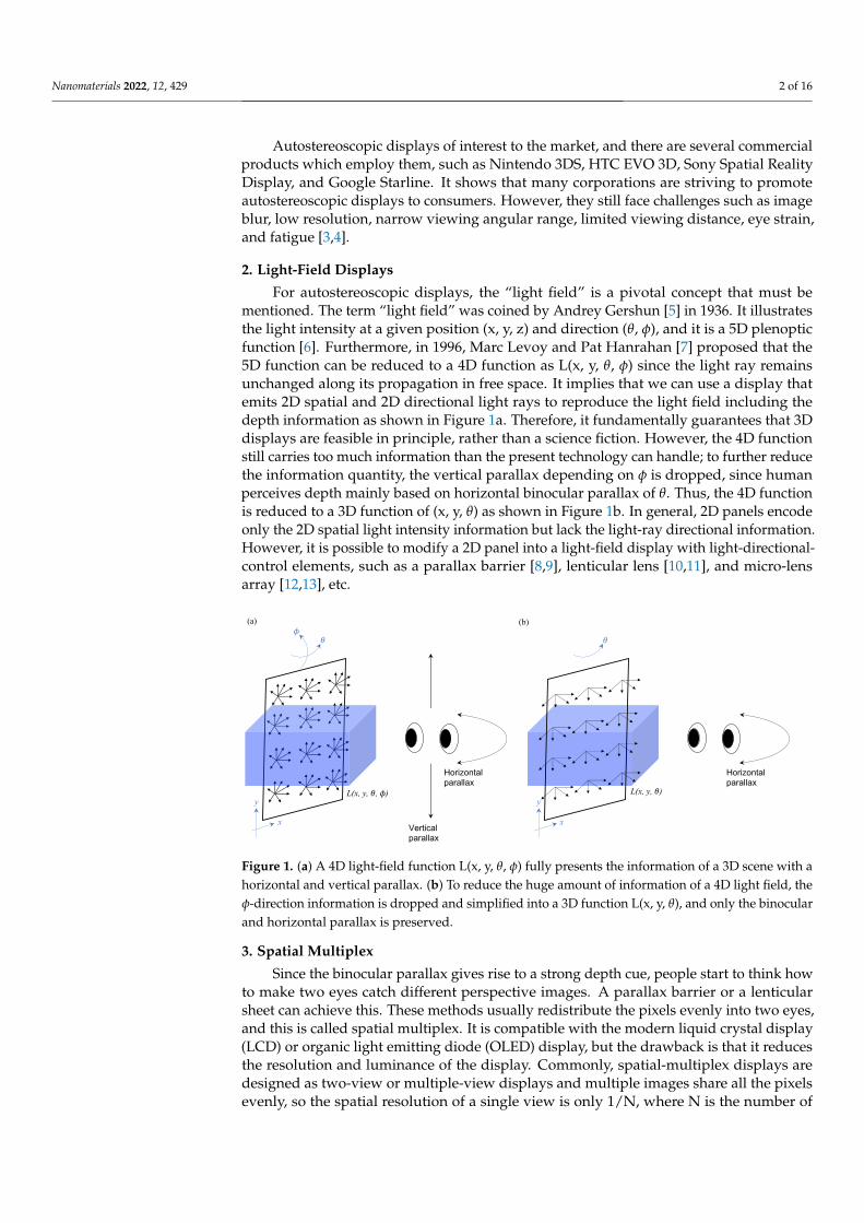
For autostereoscopic displays, the “light field” is a pivotal concept that must bementioned. The term “light field” was coined by Andrey Gershun [5] in 1936. It illustratesthe light intensity at a given position (x, y, z) and direction (θ, φ), and it is a 5D plenopticfunction [6]. Furthermore, in 1996, Marc Levoy and Pat Hanrahan [7] proposed that the5D function can be reduced to a 4D function as L(x, y, θ, φ) since the light ray remainsunchanged along its propagation in free space. It implies that we can use a display thatemits 2D spatial and 2D directional light rays to reproduce the light field including thedepth information as shown in Figure 1a. Therefore, it fundamentally guarantees that 3Ddisplays are feasible in principle, rather than a science fiction. However, the 4D functionstill carries too much information than the present technology can handle; to further reducethe information quantity, the vertical parallax depending on φ is dropped, since humanperceives depth mainly based on horizontal binocular parallax of θ. Thus, the 4D functionis reduced to a 3D function of (x, y, θ) as shown in Figure 1b. In general, 2D panels encodeonly the 2D spatial light intensity information but lack the light-ray directional information.However, it is possible to modify a 2D panel into a light-field display with light-directional-control elements, such as a parallax barrier [8,9], lenticular lens [10,11], and micro-lensarray [12,13], etc.
Vertical parallax
Horizontal parallax
L(x, y, 𝜃, 𝜙)
x
y
𝜃𝜙
Horizontal parallax
x
y
𝜃
L(x, y, 𝜃)
(a) (b)
Figure 1. (a) A 4D light-field function L(x, y, θ, φ) fully presents the information of a 3D scene with ahorizontal and vertical parallax. (b) To reduce the huge amount of information of a 4D light field, theφ-direction information is dropped and simplified into a 3D function L(x, y, θ), and only the binocularand horizontal parallax is preserved.
3. Spatial Multiplex
Since the binocular parallax gives rise to a strong depth cue, people start to think howto make two eyes catch different perspective images. A parallax barrier or a lenticularsheet can achieve this. These methods usually redistribute the pixels evenly into two eyes,and this is called spatial multiplex. It is compatible with the modern liquid crystal display(LCD) or organic light emitting diode (OLED) display, but the drawback is that it reducesthe resolution and luminance of the display. Commonly, spatial-multiplex displays aredesigned as two-view or multiple-view displays and multiple images share all the pixelsevenly, so the spatial resolution of a single view is only 1/N, where N is the number of
Nanomaterials 2022, 12, 429 3 of 16
views. The problem can be resolved by the time-multiplex method, which is introduced inSection 4.
3.1. Parallax Barrier
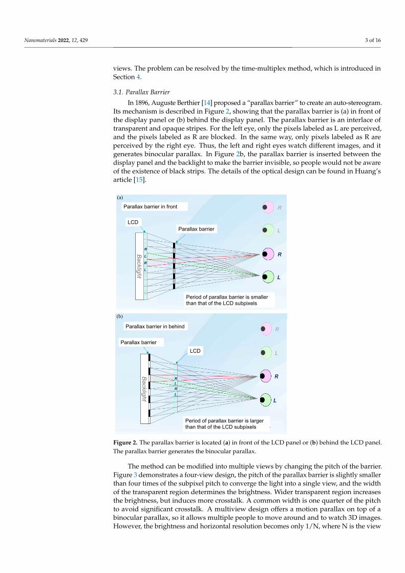
In 1896, Auguste Berthier [14] proposed a “parallax barrier” to create an auto-stereogram.Its mechanism is described in Figure 2, showing that the parallax barrier is (a) in front ofthe display panel or (b) behind the display panel. The parallax barrier is an interlace oftransparent and opaque stripes. For the left eye, only the pixels labeled as L are perceived,and the pixels labeled as R are blocked. In the same way, only pixels labeled as R areperceived by the right eye. Thus, the left and right eyes watch different images, and itgenerates binocular parallax. In Figure 2b, the parallax barrier is inserted between thedisplay panel and the backlight to make the barrier invisible, so people would not be awareof the existence of black strips. The details of the optical design can be found in Huang’sarticle [15].
Parallax barrier in front
Parallax barrier
Period of parallax barrier is smaller than that of the LCD subpixels
LCD
(a)
Parallax barrier in behind
Parallax barrier
Period of parallax barrier is larger than that of the LCD subpixels
LCD
(b)
Figure 2. The parallax barrier is located (a) in front of the LCD panel or (b) behind the LCD panel.The parallax barrier generates the binocular parallax.
The method can be modified into multiple views by changing the pitch of the barrier.Figure 3 demonstrates a four-view design, the pitch of the parallax barrier is slightly smallerthan four times of the subpixel pitch to converge the light into a single view, and the widthof the transparent region determines the brightness. Wider transparent region increasesthe brightness, but induces more crosstalk. A common width is one quarter of the pitchto avoid significant crosstalk. A multiview design offers a motion parallax on top of abinocular parallax, so it allows multiple people to move around and to watch 3D images.However, the brightness and horizontal resolution becomes only 1/N, where N is the view

Nanomaterials 2022, 12, 429 4 of 16
number. The low brightness remains a problem of the parallax barrier; in Section 3.2, alenticular method is introduced to reconcile the brightness problem.
Subpixels
Parallax barrier
View 1 View 2 View 3 View 4
1234 1234 1234
Figure 3. In the four-view design, the pitch of the parallax barrier is slightly smaller than four timesthe subpixel pitch.
For practical use, this type of 3D display is usually designed as a 2D/3D switchabledisplay. In real life, we have a bunch of 2D content such as texts, 2D images and videos, andwatching 2D content with a parallax barrier makes the images fragmented, so switchingback to the conventional 2D display is more suitable. The Nintendo 3DS [16] is a popu-lar commercial product with a switchable parallax barrier. It used the configuration ofFigure 2b and replaced the parallax barrier with a switchable liquid crystal (LC) shutterarray, and it produced a two-view 3D image with 400 × 240 pixels for each eye. SharpInc. [17] also developed a 2D/3D switchable display with a switchable binary liquid crystalpanel in front of a LCD; it is similar to the Nintendo 3DS but with a configuration shown inFigure 2a. Meanwhile, Samsung Inc. [18] and LG Inc. [19] have published a similar workwith a switching LCD barrier inserted between the LCD and its backlight. Sanyo Inc. [20]used polymer-dispersed liquid crystal (PDLC) as a transparent/diffuse switchable film.With an applied electric field, the transparent mode makes the parallax barrier effectiveas a 3D mode; on the contrary, the diffuse mode disturbs the direction of light and makesthe barrier ineffective as a 2D mode. It is worth mentioning that the Industrial TechnologyResearch Institute (ITRI) [21] developed a localized 2D/3D switchable display and won theR&D100 award in 2010. It stacked two same-resolution LCDs and a micro-retarder filmto form a localized parallax barrier, so the 2D content and 3D content were shown at thesame time.
3.2. Lenticular Lenses
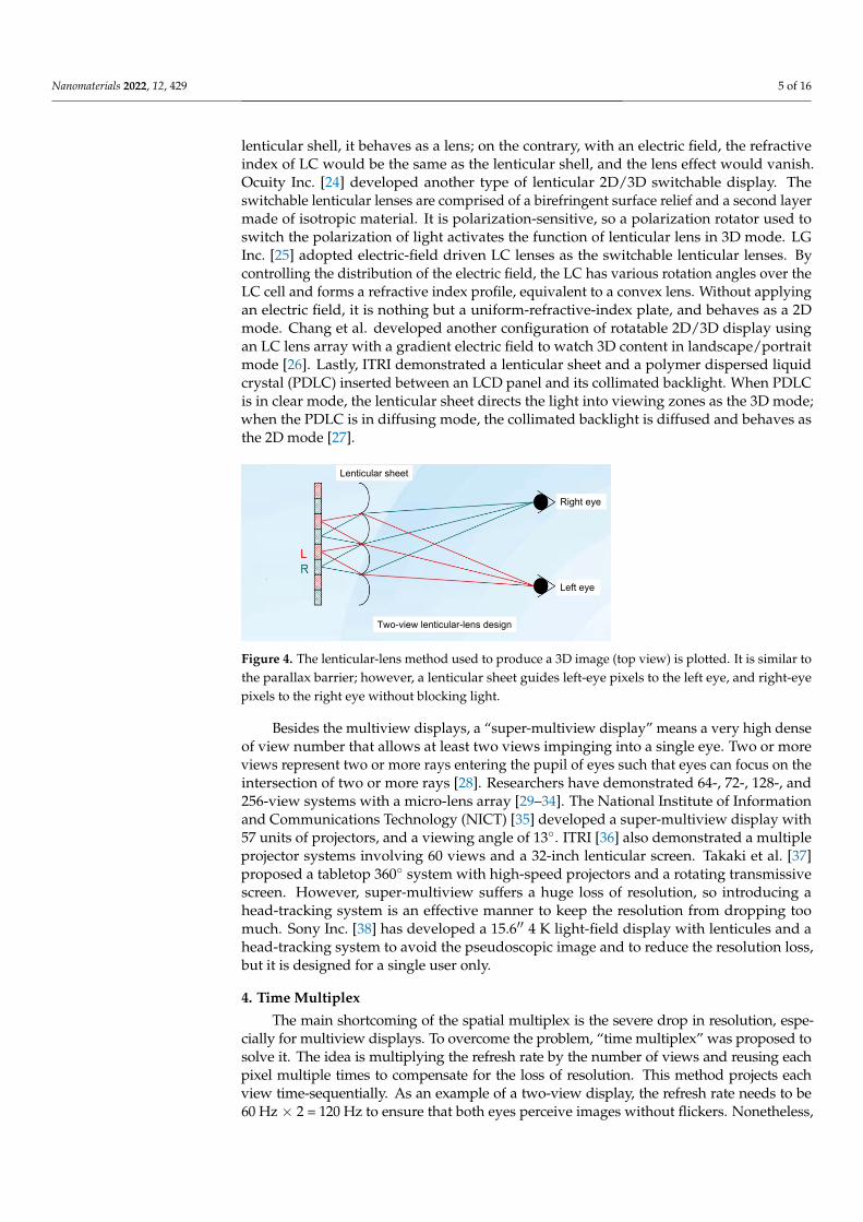
The parallax-barrier method faces the degradation of brightness. To overcome theproblem, Hess [22] invented a lenticular-lens method in 1915, which is described in Figure 4.The lenticular sheet is a one-dimensional cylindrical micro-lens array which replaces the roleof the parallax barrier and collimates the diffused light from pixels into a specific direction,being received by a specific eye in the end. Hence, two eyes receive different images andmerge them into an image with depth. Since the lenticular sheet is a transparent film, noneof light is blocked; hence, it maintains the level of brightness. This is a remarkable advantageover a parallax barrier. On the other hand, a multiview setup can be implemented with thepitch of the lenticular array slightly less than N times of the width of a subpixel. However,it still suffers from the 1/N reduction in resolution.
Nowadays, many companies have developed lenticular 2D/3D switchable displays.Philips Inc. [23] developed LC switchable lenticular lenses that consist of a hollow lenticularshell filled LC in the hollow part. It is the 3D mode if the electric field is off, and 2D modeif the electric field is on. Given the mismatch of refractive index of LC and the material of
Nanomaterials 2022, 12, 429 5 of 16
lenticular shell, it behaves as a lens; on the contrary, with an electric field, the refractiveindex of LC would be the same as the lenticular shell, and the lens effect would vanish.Ocuity Inc. [24] developed another type of lenticular 2D/3D switchable display. Theswitchable lenticular lenses are comprised of a birefringent surface relief and a second layermade of isotropic material. It is polarization-sensitive, so a polarization rotator used toswitch the polarization of light activates the function of lenticular lens in 3D mode. LGInc. [25] adopted electric-field driven LC lenses as the switchable lenticular lenses. Bycontrolling the distribution of the electric field, the LC has various rotation angles over theLC cell and forms a refractive index profile, equivalent to a convex lens. Without applyingan electric field, it is nothing but a uniform-refractive-index plate, and behaves as a 2Dmode. Chang et al. developed another configuration of rotatable 2D/3D display usingan LC lens array with a gradient electric field to watch 3D content in landscape/portraitmode [26]. Lastly, ITRI demonstrated a lenticular sheet and a polymer dispersed liquidcrystal (PDLC) inserted between an LCD panel and its collimated backlight. When PDLCis in clear mode, the lenticular sheet directs the light into viewing zones as the 3D mode;when the PDLC is in diffusing mode, the collimated backlight is diffused and behaves asthe 2D mode [27].
Right eye
Left eye
Two-view lenticular-lens design
Lenticular sheet
Figure 4. The lenticular-lens method used to produce a 3D image (top view) is plotted. It is similar tothe parallax barrier; however, a lenticular sheet guides left-eye pixels to the left eye, and right-eyepixels to the right eye without blocking light.
Besides the multiview displays, a “super-multiview display” means a very high denseof view number that allows at least two views impinging into a single eye. Two or moreviews represent two or more rays entering the pupil of eyes such that eyes can focus on theintersection of two or more rays [28]. Researchers have demonstrated 64-, 72-, 128-, and256-view systems with a micro-lens array [29–34]. The National Institute of Informationand Communications Technology (NICT) [35] developed a super-multiview display with57 units of projectors, and a viewing angle of 13◦. ITRI [36] also demonstrated a multipleprojector systems involving 60 views and a 32-inch lenticular screen. Takaki et al. [37]proposed a tabletop 360◦ system with high-speed projectors and a rotating transmissivescreen. However, super-multiview suffers a huge loss of resolution, so introducing ahead-tracking system is an effective manner to keep the resolution from dropping toomuch. Sony Inc. [38] has developed a 15.6′′ 4 K light-field display with lenticules and ahead-tracking system to avoid the pseudoscopic image and to reduce the resolution loss,but it is designed for a single user only.
4. Time Multiplex
The main shortcoming of the spatial multiplex is the severe drop in resolution, espe-cially for multiview displays. To overcome the problem, “time multiplex” was proposed tosolve it. The idea is multiplying the refresh rate by the number of views and reusing eachpixel multiple times to compensate for the loss of resolution. This method projects eachview time-sequentially. As an example of a two-view display, the refresh rate needs to be60 Hz × 2 = 120 Hz to ensure that both eyes perceive images without flickers. Nonetheless,
Nanomaterials 2022, 12, 429 6 of 16
achieving an even higher refresh rate is not easy for common LCDs and the directionaldevice, and it is also one of the major barriers to pursuing multiviews in time multiplex.
In general, the spatial multiplex can be generalized to time multiplex. For a parallaxbarrier, we can just shift the position of open slits by one half pitch, so all the pixels areperceived by two eyes, illustrated in Figure 5. In this case, the barrier and frame rate arescanning with doubled 120 Hz, so human eyes would not feel flickers.
L R L R L R L R
Left eye Right eyet = 0 s(a)
R L R L R L R L
Left eye Right eyet = 1/120 s
Shift one half pitch
(b)
Figure 5. The parallax barrier slits are shifted by one half pitch within 1/120 s, so both eyes canperceive red and blue pixels, and then the resolution is retained. (a) As t = 0 s, the parallax barrier isat the original place. (b) As t = 1/120 s, the parallax barrier shifts one half pitch.
This type of scanning parallax barrier can be realized with an electro-controllable LCshutter array. So far, most time-multiplex displays are two-view displays owing to theslow scanning rate of LC. Samsung Inc. [39,40] has developed a fast-scanning parallaxbarrier with an optical compensated bend (OCB) display mode to achieve a 5 ms responsetime, and an active-matrix OLED (AMOLED) display was adopted because of its highrefresh rate. Overall, a 2.2-inch, full resolution 240 × 320, two-view time-multiplex displaywas demonstrated. PolarScreens Inc. [41] demonstrated a 120Hz 3D LCD panel, a verticalpatterned active shutter panel and a head tracking system to achieve a full resolutionautostereoscopic display.
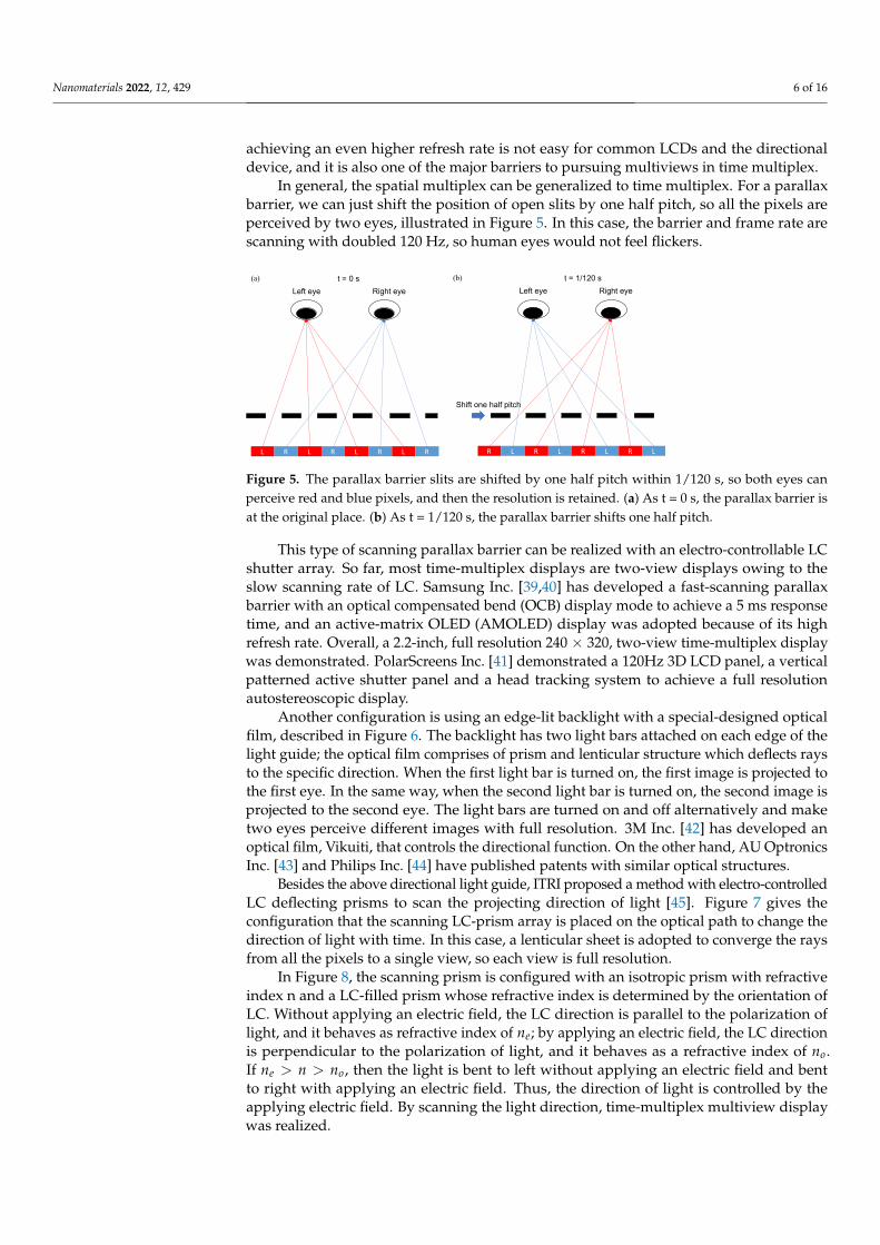
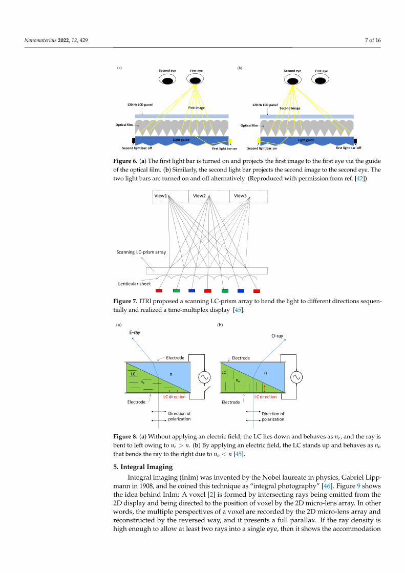
Another configuration is using an edge-lit backlight with a special-designed opticalfilm, described in Figure 6. The backlight has two light bars attached on each edge of thelight guide; the optical film comprises of prism and lenticular structure which deflects raysto the specific direction. When the first light bar is turned on, the first image is projected tothe first eye. In the same way, when the second light bar is turned on, the second image isprojected to the second eye. The light bars are turned on and off alternatively and maketwo eyes perceive different images with full resolution. 3M Inc. [42] has developed anoptical film, Vikuiti, that controls the directional function. On the other hand, AU OptronicsInc. [43] and Philips Inc. [44] have published patents with similar optical structures.
Besides the above directional light guide, ITRI proposed a method with electro-controlledLC deflecting prisms to scan the projecting direction of light [45]. Figure 7 gives theconfiguration that the scanning LC-prism array is placed on the optical path to change thedirection of light with time. In this case, a lenticular sheet is adopted to converge the raysfrom all the pixels to a single view, so each view is full resolution.
In Figure 8, the scanning prism is configured with an isotropic prism with refractiveindex n and a LC-filled prism whose refractive index is determined by the orientation ofLC. Without applying an electric field, the LC direction is parallel to the polarization oflight, and it behaves as refractive index of ne; by applying an electric field, the LC directionis perpendicular to the polarization of light, and it behaves as a refractive index of no.If ne > n > no, then the light is bent to left without applying an electric field and bentto right with applying an electric field. Thus, the direction of light is controlled by theapplying electric field. By scanning the light direction, time-multiplex multiview displaywas realized.
Nanomaterials 2022, 12, 429 7 of 16
First eyeSecond eye
Second light bar: off
Light guide
First light bar: on
Optical film
120 Hz LCD panelFirst image
(a)First eyeSecond eye
Second light bar: on
Light guide
First light bar: off
Optical film
120 Hz LCD panelSecond image
(b)
Figure 6. (a) The first light bar is turned on and projects the first image to the first eye via the guideof the optical film. (b) Similarly, the second light bar projects the second image to the second eye. Thetwo light bars are turned on and off alternatively. (Reproduced with permission from ref. [42])
Lenticular sheet
View1 View2 View3
Scanning LC-prism array
Figure 7. ITRI proposed a scanning LC-prism array to bend the light to different directions sequen-tially and realized a time-multiplex display [45].
LC direction
ne
n
E-ray
Electrode
Electrode
Direction of polarization
no
n
O-ray
Electrode
Electrode
Direction of polarization
LC
LC direction
(a) (b)
LC
Figure 8. (a) Without applying an electric field, the LC lies down and behaves as ne, and the ray isbent to left owing to ne > n. (b) By applying an electric field, the LC stands up and behaves as no
that bends the ray to the right due to no < n [45].
5. Integral Imaging
Integral imaging (InIm) was invented by the Nobel laureate in physics, Gabriel Lipp-mann in 1908, and he coined this technique as “integral photography” [46]. Figure 9 showsthe idea behind InIm: A voxel [2] is formed by intersecting rays being emitted from the2D display and being directed to the position of voxel by the 2D micro-lens array. In otherwords, the multiple perspectives of a voxel are recorded by the 2D micro-lens array andreconstructed by the reversed way, and it presents a full parallax. If the ray density ishigh enough to allow at least two rays into a single eye, then it shows the accommodation

Nanomaterials 2022, 12, 429 8 of 16
effect [47] that resolves the accommodation-convergence conflict [6]. Hence, it mitigatesthe fatigue problem. The range of pupil diameter is 4–6 mm [48], indicating the ray separa-tion is 2–3 mm when arriving at the eyes, so hundreds of rays in horizontal and verticaldirections are required to cover a head movement in hundreds of millimeters, and theoverall ray number could be tens of thousands; thus, the native display resolution must betens of thousands-fold the perceived resolution, so an extremely-high-resolution displayis required.
Voxel
Voxel
2D micro-lens array
2D display
Figure 9. The principle behind integral imaging: The light field is reconstructed by the rays from the2D display, which are directed to the voxel’s position by the micro-lens 2D array and intersect witha voxel.
A large-screen InIm of 87 inch and a 360◦ light-field display with a holographicfunctional film was demonstrated [49,50]. In addition, a floating 96 × 96 view-point systemwas demonstrated at a 45◦ viewing angle [51]. Another interesting application of InIm istabletop displays. A 360◦ interactive tabletop display comprised of an 8K LCD, lens array,optical diffuser film, and a hand-tracking device has been demonstrated [52].
6. Electronic Holography
Holography was invented by the Nobel laureate, Dennis Gabor [53] in 1947. It recordsall the information of the light field, consisting of its amplitude and phase. In a reversedmanner, the light field is reconstructed as a 3D image. Since holography does not mimic3D with 2D images, it builds the authentic 3D wavefront instead; hence, holography isregarded as the ultimate 3D display. The formation of holography, in Figure 10, is that theobject beam interferes with the reference beam coherently and the interference fringe isrecorded on a photo film. Since the fringe carries the phase and amplitude information ofthe object beam, we can reconstruct the wavefront of object beam in reversal by illuminatingthe hologram with the original reference beam, so eyes perceive not only the amplitude butalso the phase that produces the sensation of depth.
Electronic holography is an ideal solution for autostereoscopic display; however, itfaces some large challenges. First, an ultrahigh resolution spatial light modulator (SLM) isrequired. The fringe width could be one half the wavelength, so it can go down to 200 nmbased on 400 nm blue light; then, a 127,000-ppi SLM with 200-nm pixel size is needed todisplay such a narrow fringe. So far, the commercial SLM can achieve only 7000 ppi [54], soit needs a huge jump in pixel density. Second, to compute, restore, and display such a highresolution image, a huge computing power, transfer rate, and memory are required [55].

Nanomaterials 2022, 12, 429 9 of 16
Object beam
Reference beam Photo film
Virtual image
Reference beam
Photo film
Reconstructed wavefront
(a) (b)
Figure 10. (a) The wavefront of the object beam interferes with the reference beam, and the fringe isrecorded on a photo film to form a hologram. (b) Illuminating a hologram with the original referencebeam reconstructs the wavefront of the object beam, so it includes the phase and amplitude such thateyes sense the depth of the object.
The Media Lab at Massachusetts Institute of Technology (MIT) developed an electronicholographic display, Mark III [56]. It utilized a lithium niobate guided-wave acousto-opticdevice as an SLM that provides 200 MHz bandwidth to create the fringe pattern, whichcan display a 24◦ viewing angle, an 80 mm × 60 mm × 80 mm viewing volume with a532 nm laser source. University of Arizona developed a updatable holographic displaywith a photorefractive polymer as an SLM, which exhibits a viewing angle of 45◦, 4 inches;the downside is that it takes two seconds to refresh a frame [57,58]. ITRI proposed anotherconfiguration of a head-mounted holographic display that reduces the required pixeldensity to the level of presentation of the SLM [59,60]. For this head-mounted configuration,the holography display only needs to generate a small viewing angle around 4◦ to cover asingle eye; thus, the fringe width is around a few microns, which can be displayed in thepresent SLM.
7. Comprehensive Analysis of 3D Display Based on LCD, OLED, and Micro-LED
Nowadays, LCD and OLED dominate the display market, and the micro-light emittingdiode (Micro-LED) is the next emerging display technology. All of them can be used toimplement 3D displays based on different scenarios. LCD requires a backlight to light thedisplay on, so it has an extra flexibility to implement the light-directional-control elementswithin the backlight, such as the parallax barrier in Figure 1b, directional backlight [61,62],or a light-bar method introduced in Section 8. However, LCD has a slow response timearound few ms [63,64], so it is hard to achieve a high refresh rate. On the contrary, OLEDand Micro-LED both achieve fast response times of the order of µs and ns, respectively [65].Hence, they are beneficial to time-multiplex. Another drawback of LCD is that it is lesspower efficient than OLED and Micro-LED; using a parallax-barrier setup would furtherdeteriorate the power efficiency.
As shown in Figure 11, LCD usually has an encapsulation glass around 0.5 mm thick,which leads to small viewing zone pitch comparing to the larger viewing zone pitch ofOLED/Micro-LED whose encapsulation layer is less than 1 µm [66]. Under the samenumber of views, small viewing zone pitch shrinks the viewing angle, which is harmfulto auditing experience. Hence, OLED/Micro-LED have the advantage of enlarging theviewing angle than LCD with the same number of views.
On the other hand, OLED usually has a pentile-pixel arrangement (Figure 12), whichis more sophisticated than LCD’s RGB arrangement, and it requires a special pattern designfor the parallax barrier. Lee and Kim have shown how to design the parallax barriers intheir work [67,68]. In our group, we also developed a slanted-barrier autostereoscopicdisplay with OLED, whose slanted angle is arctan(1/4), owning a 12-view, 166-ppi, viewing

Nanomaterials 2022, 12, 429 10 of 16
angle up to 50◦, because we removed the cover glass and took the advantage of the thinencapsulation of OLED. The left, middle, and right perspectives are shown in Figure 13,and it shows the horizontal parallax that the relative positions of petals and trunk changeover views.
Micro-LED is further superior to LCD/OLED with even lower power consumptionand higher brightness [65]. The most impressive superiority is the ultra-high resolution as8500-ppi [69] that can even support a super-multiview or InIm setup. OLED has achieved10,000-ppi [70] as well, but its brightness is far lower than Micro-LED by at least one order.The overall comparison is summarized in Table 1.
Small viewing zone pitch
Subpixels
Thick encapsulation layer
Large viewing zone pitch
Thin encapsulation layer
Subpixels
(b)(a)
Figure 11. (a) The viewing zone pitch is small in a thick-encapsulation-layer system, such as LCD, thathas a thick front glass around 0.5 mm. (b) The thin-encapsulation-layer system, e.g., OLED/Micro-LED has an ultra-thin film less than 1 µm, which shows a large viewing zone pitch.
Figure 12. The pentile-pixel-arrangement image captured from an OLED display, showing a moresophisticated pattern than the RGB pattern of LCD, such that it is trickier to design the parallaxbarrier or lenticular pattern.

Nanomaterials 2022, 12, 429 11 of 16
(a)
(b)
(c)
Figure 13. We have implemented an autostereoscopic display with an OLED smartphone. Comparingthe (a) left, (b) middle, and (c) right views, the relative positions of petals and trunk (in the red circle)are different, and it shows a horizontal parallax.
Table 1. The pros-and-cons comparison of LCD, OLED, and Micro-LED for 3D-display applications.
Type Pros for 3D Display Cons for 3D Display
LCD 1. LCD is more flexible regarding instal-lation of the light-directional-control el-ement cooperating with the backlightor in front of the color filter.
1. Slow response time (∼ms), unsuit-able for time multiplex.2. Cover glass is ∼0.5 mm thick, lead-ing to a small viewing zone pitch.3. Moderate brightness (∼1000 nits),unfavorable for the parallax-barriersetup.
OLED 1. High resolution ∼10,000-ppi com-pensates for the resolution loss of mul-tiview.2. Fast response time (∼µs), suitablefor time-multiplex.3. Ultra-thin encapsulation layer, lead-ing to a larger viewing zone pitch.
1. No backlight, the light-directional-control element must be mounted infront of the panel, less flexible setup.2. Moderate brightness (∼1000 nits),unfavorable for parallax barrier.
Micro-LED 1. High resolution of ∼8500-ppi com-pensates for the resolution loss of mul-tiview.2. Fast response time (∼ns), suitablefor time multiplex.3. Ultra-thin encapsulation layer<1 µm, leading to a larger viewing zonepitch.4. High brightness (∼10,000 nits) andlow power consumption (6∼7 cd/W)compensates for light loss of the paral-lax barrier.
1. No backlight, the light-directional-control element must be mounted infront of the panel, less flexible setup.

Nanomaterials 2022, 12, 429 12 of 16
8. The Future of 3D Display: Micro-LED Plays the Key Role
Micro-LED is an emerging technology that potentially drives the realization of 3Ddisplays. Micro-LED provides the pixel size down to few microns, equivalent to tensof thousands of ppi [71]. Micro-LED satisfies the ultra-high-resolution requirement forInIm, and it is able to push the development of InIm greatly forward. Second, Micro-LEDprovides response time of nanoseconds such that it can be used as a time-multiplex display,so every time-multiplex method in Section 4 can be applied with Micro-LED. Third, Micro-LED offers a partial-coherent light source because of its small-area luminance, and it iscapable of replacing the laser as the point light source to reduce the speckle effect for theelectronic holographic display [72].
On the other hand, considering Micro-LED as a function of the backlight, the configu-ration in Figure 14 illustrates how the rays propagate through each pixel and converge tothe viewing zone; here is an example for a four-view display, and the pitch of line stripes isslightly larger than four times the pixels. In this manner, the narrower the light stripe is,the less crosstalk is induced. Taking the advantage of small dimension of Micro-LED, thecrosstalk can be effectively suppressed. ITRI [73,74] has developed a light-stripe backlightwith inverted trapezoids, but its light efficiency is moderate. Now, it is possible to assembleMicro-LEDs as the light-stripe backlight and promote their light efficiency significantly.
View 1
LCD
View 2 View 3 View 4
Figure 14. The Micro-LEDs form a light-stripe 1D array with a well-designed pitch, such that thepartial pixels are projected to the corresponding views.
This light-stripe method can be generalized to time-multiplex display with multiplesets of light-stripe arrays. In Figure 15, four light-stripe sets are introduced, and they aremanipulated with the lighting on and off in the order of yellow, purple, grey, and blackcyclically. Each light-stripe set projects a quarter of the pixels to a single eye, and four setsof light stripes allow all the pixels to be perceived by a single eye. Hence, it achieves a fullresolution with time-multiplex lighting on-and-off. For the four-view example, it turns240 Hz lighting on and off. Based on the fast response of Micro-LED, it is easy to turnhigh-frequency lighting on and off. ITRI [45,61] has demonstrated another variant withlight stripes and a lenticular sheet to collimate the backlight into a single direction; turningon different light-stripe sets directs the collimated backlight into different directions, andfull-resolution images are delivered into various directions.
In addition, Micro-LED can be transferred onto a transparent glass substrate, andit becomes a transparent display that owns a floating 3D effect [75]. Japan virtual idolHatsune Miku already demonstrated a projection image onto a transparent curved screento mimic a holographic image [76]. Furthermore, Micro-LED has much higher luminance,up to tens of thousands of nits, than LCD, OLED, so it can be used outdoors where theambient light is high.
Lastly, Micro-LED has a fast response time down to nano-seconends [65], it is especiallysuitable for time-multiplex 3D displays. Speeding up the frame rate up to 960 Hz and with

Nanomaterials 2022, 12, 429 13 of 16
the same-speed scanning barrier or a deflector such as the LC deflector shown in Figure 8,it generates a sixteen-fold multiview without any loss of resolution. Moreover, Micro-LEDis more power-saving such that it prolongs the battery time for mobile devices, such assmart phones and tablets.
View 1
Light-bar 1D array
LCD
View 2 View 3 View 4
Figure 15. Introducing multiple sets of light-stripe arrays (grouped by colors) and switching eachset of light stripes on and off sequentially allows every pixel to be perceived at each view. It is atime-multiplex method to achieve full resolution. Here, only the rays emitted from a single light-stripeset are plotted, and each view receives four pixels rather than a single pixel to demonstrate that afull-resolution image is perceived.
9. Conclusions
We comprehensively reviewed the understanding of how human eyes physiologicallyperceive three-dimensional objects, and the optical principles behind autostereoscopicdisplays, including the concept of the light field, parallax barrier, lenticular lens, integralimaging, and electronic holography. On top of that, based on LCD, OLED, and Micro-LED, we investigated their pros and cons for the implementation of autostereoscopicdisplays. Among these technologies, Micro-LED has the advantages of high resolution, fastresponse time, ultra-thin encapsulation layer, and high brightness, and they are beneficialto improving the performance of autosteroscopic displays. Based on these features, weproposed several implementations of autostereoscpic displays with Micro-LED: a Micro-LED light-stripe backlight with a LCD, a high-resolution Micro-LED display with a micro-lens array or a high-speed scanning barrier/deflector, and a transparent floating display.
Author Contributions: Conceptualization, F.C. and Z.L.; investigation, F.C., C.Q. and Z.L.; resources,C.Q. and Z.L.; writing—original draft preparation, F.C.; writing—review and editing, Z.L.; visual-ization, F.C.; supervision, Z.L.; project administration, Z.L.; funding acquisition, C.Q. and Z.L. Allauthors have read and agreed to the published version of the manuscript.
Funding: This research was funded by the Shenzhen Science and Technology Program (Grant No.KQTD20170810110313773); High-level University Fund G02236005.
Institutional Review Board Statement: Not applicable.
Informed Consent Statement: Not applicable.
Data Availability Statement: Not applicable.
Acknowledgments: The authors would like to thank SUSTech-HUAWEI Joint Lab for the PhotonicsIndustry for their support and discussions.
Conflicts of Interest: The authors declare no conflict of interest.

Nanomaterials 2022, 12, 429 14 of 16
References1. Okoshi, T. Physiology and Psychology of Depth Perception. In Three-Dimensional Imaging Techniques; Okoshi, T., Ed.; Academic
Press: Cambridge, MA, USA, 1976; pp. 43–59. [CrossRef]2. Geng, J. Three-dimensional display technologies. Adv. Opt. Photonics 2013, 5, 456. [CrossRef] [PubMed]3. Ukai, K.; Howarth, P.A. Visual fatigue caused by viewing stereoscopic motion images: Background, theories, and observations.
Displays 2008, 29, 106–116. [CrossRef]4. Kim, C.Y. New challenges for future 3D TV. In Proceedings of the WIO 2013—12th Workshop on Information Optics, Tenerife,
Spain, 15–19 July 2013; pp. 1–3. [CrossRef]5. Gershun, A. The Light Field. J. Math. Phys. 1939, 18, 51–151. [CrossRef]6. Martínez-Corral, M.; Javidi, B. Fundamentals of 3D imaging and displays: A tutorial on integral imaging, light-field, and
plenoptic systems. Adv. Opt. Photonics 2018, 10, 512. [CrossRef]7. Levoy, M.; Hanrahan, P. Light field rendering. In Proceedings of the 23rd Annual Conference on Computer Graphics and
Interactive Techniques (SIGGRAPH 1996), New York, NY, USA, 8 January 1996; pp. 31–42. [CrossRef]8. Ives, F.E. A novel stereogram. J. Frankl. Inst. 1902, 153, 51–52. [CrossRef]9. Guo, J.; Diao, Z.; Yan, S.; Zhang, E.; Kong, L. Immersive autostereoscopic display based on curved screen and parallax barrier.
Chin. Opt. Lett. 2021, 19, 013301. [CrossRef]10. Zhao, W.X.; Wang, Q.H.; Wang, A.H.; Li, D.H. Autostereoscopic display based on two-layer lenticular lenses. Opt. Lett. 2010,
35, 4127. [CrossRef]11. Huang, T.; Han, B.; Zhang, X.; Liao, H. High-performance autostereoscopic display based on the lenticular tracking method. Opt.
Express 2019, 27, 20421. [CrossRef]12. Bogaert, L.; Meuret, Y.; Roelandt, S.; Avci, A.; De Smet, H.; Thienpont, H. Demonstration of a multiview projection display using
decentered microlens arrays. Opt. Express 2010, 18, 26092. [CrossRef]13. Yuan, W.; Li, L.H.; Lee, W.B.; Chan, C.Y. Fabrication of Microlens Array and Its Application: A Review. Chin. J. Mech. Eng. (Engl.
Ed.) 2018, 31, 16. [CrossRef]14. Berthier, A. Images stéréoscopiques de grand format. Cosmos Revue Encyclopédique Hebdomadaire des Progrès des Sciences 1896,
34, 210–227.15. Huang, K.C.; Chou, Y.H.; Lin, L.C.; Lin, H.Y.; Chen, F.H.; Liao, C.C.; Chen, Y.H.; Lee, K.; Hsu, W.H. A study of optimal viewing
distance in a parallax barrier 3D display. J. Soc. Inf. Disp. 2013, 21, 263–270. [CrossRef]16. Harris, M. 3-D without four eyes. IEEE Spectr. 2010, 47, 50–56. [CrossRef]17. Jacobs, A.; Mather, J.; Winlow, R.; Montgomery, D.; Jones, G.; Willis, M.; Tillin, M.; Hill, L.; Khazova, M.; Stevenson, H.; et al.
2D/3D switchable displays. Shapu Giho/Sharp Tech. J. 2003, 85, 15–18.18. Nam, H.; Lee, J.; Jang, H.; Song, M.; Kim, B. 7.3: Auto-Stereoscopic Swing 3D Display. SID Symp. Dig. Tech. Pap. 2005, 36, 94.
[CrossRef]19. Kim, K.J.; Kang, H.; Jang, M.K.; Ahn, B.C.; Chung, I.J.; Park, T.S.; Chang, J.W.; Lee, K.I.; Kim, S.T. Development of a 42-in.
2-D/3-D switchable display using multi-view technology for public-information-display applications. J. Soc. Inf. Disp. 2007,15, 899. [CrossRef]
20. Hamagishi, G.; Sakata, M.; Mashitani, K.; Inoue, M.; Taima, K.; Oyamada, K.; Kishimoto, S.I. 32.1: Invited Paper: A DisplaySystem with 2-D/3-D Compatibility. In SID Symposium Digest of Technical Papers; Blackwell Publishing Ltd.: Oxford, UK, 1998;Volume 29, p. 915. [CrossRef]
21. Tsai, R.Y.; Tsai, C.H.; Lee, K.; Wu, C.L.; Lin, L.C.D.; Huang, K.C.; Hsu, W.L.; Wu, C.S.; Lu, C.F.; Yang, J.C.; et al. Challenge of3D LCD displays. In Three-Dimensional Imaging, Visualization, and Display 2009; International Society for Optics and Photonics:Chandigarh, India, 2009; Volume 7329, p. 732903. [CrossRef]
22. Hess, W. Stereoscopic Picture. 1915. Available online: https://en.wikipedia.org/wiki/Autostereoscopy (accessed on 16 December2021)
23. Dekker, T.; De Zwart, S.T.; Ijzerman, W.L. 2D/3D switchable displays. Proc. Int. Meet. Inf. Disp. 2006, 1, 31–35. [CrossRef]24. Woodgate, G.J.; Harrold, J. LP-1: Late-News Poster: High Efficiency Reconfigurable 2D/3D Autostereoscopic Display. SID Symp.
Dig. Tech. Pap. 2003, 34, 394. [CrossRef]25. Hong, H.K.; Jung, S.M.; Lee, B.J.; Im, H.J.; Shin, H.H. 25.3: Autostereoscopic 2D/3D Switching Display Using Electric-Field-Driven
LC Lens (ELC Lens). SID Symp. Dig. Tech. Pap. 2008, 39, 348. [CrossRef]26. Chang, Y.C.; Jen, T.H.; Ting, C.H.; Huang, Y.P. High-resistance liquid-crystal lens array for rotatable 2D/3D autostereoscopic
display. Opt. Express 2014, 22, 2714. [CrossRef]27. Chen, W.L.; Chen, F.H.; Tsai, C.H. 2D/3D Switchable Autostereoscopic Display Using Conventional Lenticular Plate. In
Proceedings of the 11th International Meeting on Information Display, Beppu, Japan, 5–7 January 2017; p. 64.28. Honda, T.; Kajiki, Y.; Susami, K.; Hamaguchi, T.; Endo, T.; Hatada, T.; Fujii, T. Three-dimensional display technologies satisfying
“super multiview condition”. In Three-Dimensional Video and Display: Devices and Systems: A Critical Review; International Societyfor Optics and Photonics: Chandigarh, India, 2001; Volume 10298, p. 102980B. [CrossRef]
29. Nakanuma, H.; Kamei, H.; Takaki, Y. Natural 3D display with 128 directional images used for human-engineering evaluation.In Stereoscopic Displays and Virtual Reality Systems XII; International Society for Optics and Photonics: Chandigarh, India, 2005;Volume 5664, p. 28. [CrossRef]

Nanomaterials 2022, 12, 429 15 of 16
30. Takaki, Y.; Nago, N. Multi-projection of lenticular displays to construct a 256-view super multi-view display. Opt. Express 2010,18, 8824. [CrossRef] [PubMed]
31. Kikuta, K.; Takaki, Y. Development of SVGA resolution 128-directional display. In Stereoscopic Displays and Virtual Reality SystemsXIV; International Society for Optics and Photonics: Chandigarh, India, 2007; Volume 6490, p. 64900U. [CrossRef]
32. Takaki, Y.; Dairiki, T. 72-directional display having VGA resolution for high-appearance image generation. In StereoscopicDisplays and Virtual Reality Systems XIII; International Society for Optics and Photonics: Chandigarh, India, 2006; Volume 6055, p.60550X. [CrossRef]
33. Takaki, Y. Multi-view 3-D display employing a flat-panel display with slanted pixel arrangement. J. Soc. Inf. Disp. 2010, 18, 476.[CrossRef]
34. Kanebako, T.; Takaki, Y. Time-multiplexing display module for high-density directional display. In Stereoscopic Displays andApplications XIX; International Society for Optics and Photonics: Chandigarh, India, 2008; Volume 6803, p. 68030P. [CrossRef]
35. Inoue, N.; Kawakita, M.; Yamamoto, K. 200-Inch Glasses-Free 3D Display and Electronic Holography Being Developed at NICT; IEEE:Piscataway, NJ, USA, 2013; pp. 1–2. [CrossRef]
36. Chen, W.L.; Tsai, C.H.; Wu, C.S.; Chen, C.Y.; Cheng, S.C. A high-resolution autostereoscopic display system with a wide viewingangle using an LCOS projector array. J. Soc. Inf. Disp. 2010, 18, 647. [CrossRef]
37. Takaki, Y.; Uchida, S. Table screen 360-degree three-dimensional display using a small array of high-speed projectors. Opt.Express 2012, 20, 8848. [CrossRef] [PubMed]
38. Aoyama, K.; Yokoyama, K.; Yano, T.; Nakahata, Y. Eye-sensing light field display for spatial reality reproduction. Dig. Tech. Pap.SID Int. Symp. 2021, 52, 669–672. [CrossRef]
39. Lee, H.J.; Nam, H.; Lee, J.D.; Jang, H.W.; Song, M.S.; Kim, B.S.; Gu, J.S.; Park, C.Y.; Choi, K.H. 8.2: A High ResolutionAutostereoscopic Display Employing a Time Division Parallax Barrier. SID Symp. Dig. Tech. Pap. 2006, 37, 81. [CrossRef]
40. Kim, D.S.; Shestak, S.; Cha, K.H.; Park, S.M.; Hwang, S.D. Time-sequential autostereoscopic OLED display with segmentedscanning parallax barrier. In Three-Dimensional Imaging, Visualization, and Display 2009; International Society for Optics andPhotonics: Chandigarh, India, 2009; Volume 7329, p. 73290U. [CrossRef]
41. Gaudreau, J.E. Full-resolution autostereoscopic display using an all-electronic tracking/steering system. In Stereoscopic Displaysand Applications XXIII; International Society for Optics and Photonics: Chandigarh, India, 2012; Volume 8288, p. 82881Z.[CrossRef]
42. Schultz, J.C.; Brott, R.; Sykora, M.; Bryan, W.; Fukamib, T.; Nakao, K.; Takimoto, A. 11.5L: Late-News Paper: Full ResolutionAutostereoscopic 3D Display for Mobile Applications. SID Symp. Dig. Tech. Pap. 2009, 40, 127. [CrossRef]
43. Chien, K.W.; Shieh, H.P.; Chu, Y.M.; Tsai, C.Y.; Lin, Y.L.; Hu, C.J.; Chang, C.M.; Hsu, Y.C.; Chen, P.L. Three-Dimensional DisplaySystem and Method Thereof. U.S. Patent 7,333,158, 19 February 2008.
44. Cornelissen, H.J. Display Device with Multi-Grooved Light Direction Element and First and Second Alternating IlluminatedLight Sources Simultaneously Switched for 2D Display and Synchronously Switched for 3D Display. U.S. Patent 7,518,663, 14April 2009.
45. Chen, F.H.; Tsai, C.H.; Tiao, K.T.; Liou, J.C. Stereoscopic Display. U.S. Patent App. 13/077,987, 2 February 2012.46. Lippmann, G. Épreuves réversibles. Photographies intégrales. Comptes Rendus de l’Académie des Sciences 1908, 146, 446–451.47. Deng, H.; Wang, Q.H.; Luo, C.G.; Liu, C.L.; Li, C. Accommodation and convergence in integral imaging 3D display. J. Soc. Inf.
Disp. 2014, 22, 158–162. [CrossRef]48. MacLachlan, C.; Howland, H.C. Normal values and standard deviations for pupil diameter and interpupillary distance in
subjects aged 1 month to 19 years. Ophthalmic Physiol. Opt. 2002, 22, 175–182. [CrossRef]49. Sang, X.; Fan, F.C.; Jiang, C.C.; Choi, S.; Dou, W.; Yu, C.; Xu, D. Demonstration of a large-size real-time full-color three-dimensional
display. Opt. Lett. 2009, 34, 3803–3805. [CrossRef] [PubMed]50. Xin Gao, X.G.; Xinzhu Sang, X.S.; Xunbo Yu, X.Y.; Wanlu Zhang, W.Z.; Binbin Yan, B.Y.; Chongxiu Yu, C.Y. 360° light field 3D
display system based on a triplet lenses array and holographic functional screen. Chin. Opt. Lett. 2017, 15, 121201. [CrossRef]51. Sang, X.; Gao, X.; Yu, X.; Xing, S.; Li, Y.; Wu, Y. Interactive floating full-parallax digital three-dimensional light-field display based
on wavefront recomposing. Opt. Express 2018, 26, 8883. [CrossRef] [PubMed]52. Ma, X.M.; Xing, Y.; Zheng, J.C.; Li, X.W.; Wang, Q.H. A real-time interactive rendering method for 360° tabletop integral imaging
3D display. J. Soc. Inf. Disp. 2021, 29, 679–688. [CrossRef]53. Gabor, D. A new microscopic principle. Nature 1948, 161, 777–778. [CrossRef]54. Chen, H.M.P.; Yang, J.P.; Yen, H.T.; Hsu, Z.N.; Huang, Y.; Wu, S.T. Pursuing high quality phase-only liquid crystal on silicon
(LCoS) devices. Appl. Sci. 2018, 8, 2323. [CrossRef]55. Sugie, T.; Akamatsu, T.; Nishitsuji, T.; Hirayama, R.; Masuda, N.; Nakayama, H.; Ichihashi, Y.; Shiraki, A.; Oikawa, M.; Takada, N.;
et al. High-performance parallel computing for next-generation holographic imaging. Nat. Electron. 2018, 1, 254–259. [CrossRef]56. Smalley, D.E.; Smithwick, Q.Y.J.; Bove, V.M., Jr. Holographic video display based on guided-wave acousto-optic devices. In
Practical Holography XXI: Materials and Applications; International Society for Optics and Photonics: Chandigarh, India, 2007;Volume 6488, p. 64880L. [CrossRef]
57. Tay, S.; Blanche, P.A.; Voorakaranam, R.; Tunç, A.V.; Lin, W.; Rokutanda, S.; Gu, T.; Flores, D.; Wang, P.; Li, G.; et al. An updatableholographic three-dimensional display. Nature 2008, 451, 694–698. [CrossRef]

Nanomaterials 2022, 12, 429 16 of 16
58. Blanche, P.A.; Bablumian, A.; Voorakaranam, R.; Christenson, C.; Lin, W.; Gu, T.; Flores, D.; Wang, P.; Hsieh, W.Y.; Kathaperumal,M.; et al. Holographic three-dimensional telepresence using large-area photorefractive polymer. Nature 2010, 468, 80–83.[CrossRef]
59. Chen, F.H.; Liao, L.Y.; Chen, C.H.; Tsai, C.H. Binary Holograms for Electro-Holographic Displays. In Digital Holography andThree-Dimensional Imaging; OSA Technical Digest (online); Optical Society of America: Kohala Coast, HI, USA, 2013; p. DTh2A.6.[CrossRef]
60. Liao, L.Y.; Chen, C.H.; Chen, F.H.; Tsai, C.H.; Liao, E.; Hong, S. Phase-modulation lcos display system with off-axis LEDreconstruction light. Dig. Tech. Pap. SID Int. Symp. 2013, 44, 905–908. [CrossRef]
61. Liou, J.C.; Chen, F.H. Design and fabrication of optical system for time-multiplex autostereoscopic display. Opt. Express 2011,19, 11007. [CrossRef]
62. Fattal, D.; Peng, Z.; Tran, T.; Vo, S.; Fiorentino, M.; Brug, J.; Beausoleil, R.G. A multi-directional backlight for a wide-angle,glasses-free three-dimensional display. Nature 2013, 495, 348–351. [CrossRef] [PubMed]
63. Chen, F.H.; Huang, K.C.; Lin, L.C.; Chou, Y.H.; Lee, K. System crosstalk measurement of a time-sequential 3D display using idealshutter glasses. In Stereoscopic Displays and Applications XXII; International Society for Optics and Photonics: Chandigarh, India,2011; Volume 7863, p. 78632E. [CrossRef]
64. Peng, F.; Huang, Y.; Gou, F.; Hu, M.; Li, J.; An, Z.; Wu, S.T. High performance liquid crystals for vehicle displays. Opt. Mater.Express 2016, 6, 717–726. [CrossRef]
65. Huang, Y.; Hsiang, E.L.; Deng, M.Y.; Wu, S.T. Mini-LED, Micro-LED and OLED displays: Present status and future perspectives.Light. Sci. Appl. 2020, 9, 105. [CrossRef]
66. Park, J.S.; Chae, H.; Chung, H.K.; Lee, S.I. Thin film encapsulation for flexible AM-OLED: A review. Semicond. Sci. Technol. 2011,26, 34001. [CrossRef]
67. Lee, W.; Shin, Y.; Yoon, J.; Kim, J.; Lee, C.K.; Jeong, Y.; Jang, C.; Hong, J.Y.; Lee, B. Mobile autostereoscopic 3D display using adiamond pixel structured OLED pentile display panel. In Optics InfoBase Conference Papers; OSA Technical Digest (online); OpticalSociety of America: Seattle, WA, USA, 2014; p. JTu4A.8. [CrossRef]
68. Kim, J.; Lee, C.K.; Jeong, Y.; Jang, C.; Hong, J.Y.; Lee, W.; Shin, Y.C.; Yoon, J.H.; Lee, B. Crosstalk-reduced dual-mode mobile 3Ddisplay. IEEE/OSA J. Disp. Technol. 2015, 11, 97–103. [CrossRef]
69. Park, J.; Choi, J.H.; Kong, K.; Han, J.H.; Park, J.H.; Kim, N.; Lee, E.; Kim, D.; Kim, J.; Chung, D.; et al. Electrically drivenmid-submicrometre pixelation of InGaN micro-light-emitting diode displays for augmented-reality glasses. Nat. Photonics 2021,15, 449–455. [CrossRef]
70. Joo, W.J.; Kyoung, J.; Esfandyarpour, M.; Lee, S.H.; Koo, H.; Song, S.; Kwon, Y.N.; Ho Song, S.; Bae, J.C.; Jo, A.; et al. Metasurface-driven OLED displays beyond 10,000 pixels per inch. Science 2020, 370, 459–463. [CrossRef]
71. Liu, Z.; Lin, C.H.; Hyun, B.R.; Sher, C.W.; Lv, Z.; Luo, B.; Jiang, F.; Wu, T.; Ho, C.H.; Kuo, H.C.; et al. Micro-light-emitting diodeswith quantum dots in display technology. Light. Sci. Appl. 2020, 9, 83. [CrossRef]
72. Deng, Y.; Chu, D. Coherence properties of different light sources and their effect on the image sharpness and speckle ofholographic displays. Sci. Rep. 2017, 7, 5893. [CrossRef]
73. Yen, W.T.; Chen, F.H.; Chen, W.L.; Liou, J.C.; Tsai, C.H. Enhance light efficiency for slim light-strip array backlight on au-tostereoscopic display. In Proceedings of the 3DTV-Conference: The True Vision-Capture, Transmission and Display of 3D Video(3DTV-CON), Zurich, Switzerland, 15–17 October 2012; pp. 1–4. [CrossRef]
74. Chen, F.H.; Chen, W.L.; Yen, W.T.; Liou, J.C.; Tsai, C.H. Stereoscopic Display Device. CN103728769B. 2013.75. Peng, D.; Zhang, K.; Chao, V.S.D.; Mo, W.; Lau, K.M.; Liu, Z. Full-color pixelated-addressable light emitting diode on transparent
substrate (LEDoTS) micro-displays by CoB. J. Disp. Technol. 2016, 12, 742–746. [CrossRef]76. Liang, N. The application of the holographic laser projection in the entertaining performance. In Proceedings of the IEEE
International Conference on Advanced Materials for Science and Engineering: Innovation, Science and Engineering (IEEE-ICAMSE 2016), Tainan, Taiwan, 12–13 November 2016; pp. 629–631. [CrossRef]