MASTER 3D graphics rendering for multiview displays - Pure
85
Eindhoven University of Technology MASTER 3D graphics rendering for multiview displays Compen, J.H. Award date: 2005 Link to publication Disclaimer This document contains a student thesis (bachelor's or master's), as authored by a student at Eindhoven University of Technology. Student theses are made available in the TU/e repository upon obtaining the required degree. The grade received is not published on the document as presented in the repository. The required complexity or quality of research of student theses may vary by program, and the required minimum study period may vary in duration. General rights Copyright and moral rights for the publications made accessible in the public portal are retained by the authors and/or other copyright owners and it is a condition of accessing publications that users recognise and abide by the legal requirements associated with these rights. • Users may download and print one copy of any publication from the public portal for the purpose of private study or research. • You may not further distribute the material or use it for any profit-making activity or commercial gain
-
Upload
khangminh22 -
Category
Documents
-
view
1 -
download
0
Transcript of MASTER 3D graphics rendering for multiview displays - Pure
Eindhoven University of Technology
MASTER
3D graphics rendering for multiview displays
Compen, J.H.
Award date:2005
Link to publication
DisclaimerThis document contains a student thesis (bachelor's or master's), as authored by a student at Eindhoven University of Technology. Studenttheses are made available in the TU/e repository upon obtaining the required degree. The grade received is not published on the documentas presented in the repository. The required complexity or quality of research of student theses may vary by program, and the requiredminimum study period may vary in duration.
General rightsCopyright and moral rights for the publications made accessible in the public portal are retained by the authors and/or other copyright ownersand it is a condition of accessing publications that users recognise and abide by the legal requirements associated with these rights.
• Users may download and print one copy of any publication from the public portal for the purpose of private study or research. • You may not further distribute the material or use it for any profit-making activity or commercial gain
TECHNISCHE UNIVERSITEIT EINDHOVEN
Department of Mathematics and Computing Science
MASTER’S THESIS
3D graphics renderingfor multiview displays
ing. J.H. Compen
Supervisors: dr.ir. A.J.F. Kok, dr.ir. B.G.B. Barenbrug
Eindhoven, March 2005

Technical note TN-2004/00920
Issued: 4/2005
3D graphics rendering for multiviewdisplaysUsing programmable shaders on graphics cards
Johan Compen
Philips Research Eindhoven
Company Confidential till 04/2006
c© Koninklijke Philips Electronics N.V. 2005
TN-2004/00920 Company Confidential till 04/2006
Concerns: Master’s thesis
Period of Work: March 2004 - March 2005
Notebooks:
Authors’ addressJ.H. Compen [email protected]
c© KONINKLIJKE PHILIPS ELECTRONICS N.V. 2005All rights reserved. Reproduction or dissemination in whole or in part is prohibitedwithout the prior written consent of the copyright holder.
ii c© Koninklijke Philips Electronics N.V. 2005
Company Confidential till 04/2006 TN-2004/00920
Title: 3D graphics rendering for multiview displays
Author(s): Johan Compen
Reviewer(s): dr. ir. Arjan Kok ([email protected])dr. ir. Bart Barenbrug ([email protected])
Technical Note: TN-2004/00920
AdditionalNumbers:
Subcategory:
Project:
Customer: Philips Research
Keywords: RGBD rendering, GPU, pixel shaders, 3D, multiview displays, OpenGL
Abstract: Philips Research is developing multiview 3D displays. By presenting differ-ent views to a viewer’s left and right eye, a 3D impression can be given. Oneapproach to create these views is to use a 2D image plus its depth-map. Thistechnique is known as RGBD rendering. The goal of this master project is toinvestigate how realtime RGBD rendering can be implemented on a graphicscard itself (for graphical applications on a PC platform such as games). Toaccomplish this, the programmable pixel shaders available on modern graph-ics cards will be used.
Conclusions: High quality realtime RGBD rendering on graphics hardware itself is not fea-sible. This is caused by the limited programming model of the graphics hard-ware. It forces us to use a inefficient (inverse) version of the RGBD renderingalgorithm. Either a huge performance increase of the graphics hardware, ora more general programming model is needed.
There are however two other approaches that enable games to be playedin realtime on the multiview display:
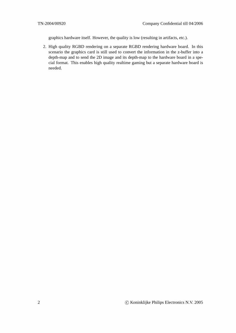
• Low quality RGBD rendering on graphics hardware. This can be donein realtime on the graphics hardware. However the quality is low (re-sulting in artifacts, etc.).
• High quality RGBD rendering on a separate RGBD rendering hard-ware board. In this scenario the graphics card is still used to convertthe information in the z-buffer into a depth-map and to send the 2D im-age and its depth-map to the hardware board in a special format. Thisenables high quality realtime gaming but a separate hardware board isneeded.
c© Koninklijke Philips Electronics N.V. 2005 iii
TN-2004/00920 Company Confidential till 04/2006
iv c© Koninklijke Philips Electronics N.V. 2005
Company Confidential till 04/2006 TN-2004/00920
Contents
1 Introduction 1
2 Background information 32.1 Stereoscopic vision . . . . . . . . . . . . . . . . . . . . . . . . . . . . . . . . 32.2 Depth perception . . . . . . . . . . . . . . . . . . . . . . . . . . . . . . . . . 32.3 3D displays . . . . . . . . . . . . . . . . . . . . . . . . . . . . . . . . . . . . 4
2.3.1 Screen disparity . . . . . . . . . . . . . . . . . . . . . . . . . . . . . . 42.3.2 Perceived depth . . . . . . . . . . . . . . . . . . . . . . . . . . . . . .52.3.3 Image separation . . . . . . . . . . . . . . . . . . . . . . . . . . . . .5
2.4 Philips 3D displays . . . . . . . . . . . . . . . . . . . . . . . . . . . . . . . . 62.4.1 Multiple views . . . . . . . . . . . . . . . . . . . . . . . . . . . . . . 72.4.2 Sub-pixel display layout . . . . . . . . . . . . . . . . . . . . . . . . . 82.4.3 Image preparation for 3D display . . . . . . . . . . . . . . . . . . . .92.4.4 3D images . . . . . . . . . . . . . . . . . . . . . . . . . . . . . . . .10
2.5 3D computer graphics . . . . . . . . . . . . . . . . . . . . . . . . . . . . . . .112.5.1 Computer graphics for the 3D display . . . . . . . . . . . . . . . . . .122.5.2 Double buffering . . . . . . . . . . . . . . . . . . . . . . . . . . . . .122.5.3 Programmable shaders . . . . . . . . . . . . . . . . . . . . . . . . . .122.5.4 Shader programming languages . . . . . . . . . . . . . . . . . . . . .14
3 Rendering multiple times 153.1 OpenGL wrapper . . . . . . . . . . . . . . . . . . . . . . . . . . . . . . . . .153.2 Rendering in tiled format . . . . . . . . . . . . . . . . . . . . . . . . . . . . .153.3 Interleaving with pixel shader . . . . . . . . . . . . . . . . . . . . . . . . . . .173.4 Advantages and disadvantages . . . . . . . . . . . . . . . . . . . . . . . . . .17
4 Assignment 19
5 RGBD rendering 205.1 Theory . . . . . . . . . . . . . . . . . . . . . . . . . . . . . . . . . . . . . . .20
5.1.1 Related work . . . . . . . . . . . . . . . . . . . . . . . . . . . . . . .205.1.2 Depth-dependent pixel shifting . . . . . . . . . . . . . . . . . . . . . .205.1.3 Occlusions and deocclusions . . . . . . . . . . . . . . . . . . . . . . .21
5.2 Implementation . . . . . . . . . . . . . . . . . . . . . . . . . . . . . . . . . .235.2.1 Forward RGBD rendering . . . . . . . . . . . . . . . . . . . . . . . .23
5.3 Advantages and disadvantages . . . . . . . . . . . . . . . . . . . . . . . . . .23
c© Koninklijke Philips Electronics N.V. 2005 v
TN-2004/00920 Company Confidential till 04/2006
6 From z-buffer to perceived depth 256.1 Z-buffering . . . . . . . . . . . . . . . . . . . . . . . . . . . . . . . . . . . . 256.2 Normalized disparity to perceived depth . . . . . . . . . . . . . . . . . . . . .256.3 Normalized depth to normalized disparity . . . . . . . . . . . . . . . . . . . .266.4 Z-buffer to normalized depth . . . . . . . . . . . . . . . . . . . . . . . . . . .27
6.4.1 Z-buffer . . . . . . . . . . . . . . . . . . . . . . . . . . . . . . . . . . 276.4.2 Forward calculation . . . . . . . . . . . . . . . . . . . . . . . . . . .276.4.3 Reverse calculation . . . . . . . . . . . . . . . . . . . . . . . . . . . .306.4.4 Issues . . . . . . . . . . . . . . . . . . . . . . . . . . . . . . . . . . .30
7 RGBD rendering on GPU 337.1 Render central view . . . . . . . . . . . . . . . . . . . . . . . . . . . . . . . .337.2 Framebuffer to textures . . . . . . . . . . . . . . . . . . . . . . . . . . . . . .357.3 Z to D . . . . . . . . . . . . . . . . . . . . . . . . . . . . . . . . . . . . . . . 35
7.3.1 Intermediate depth texture . . . . . . . . . . . . . . . . . . . . . . . .357.3.2 Pixel shader . . . . . . . . . . . . . . . . . . . . . . . . . . . . . . . .377.3.3 Detecting the projection matrix . . . . . . . . . . . . . . . . . . . . .387.3.4 Z-buffer errors . . . . . . . . . . . . . . . . . . . . . . . . . . . . . .39
7.4 RGBD rendering . . . . . . . . . . . . . . . . . . . . . . . . . . . . . . . . .417.4.1 Forward versus inverse RGBD rendering . . . . . . . . . . . . . . . .417.4.2 Implementation . . . . . . . . . . . . . . . . . . . . . . . . . . . . . .427.4.3 Determine the view numbers . . . . . . . . . . . . . . . . . . . . . . .437.4.4 RGBD rendering variants . . . . . . . . . . . . . . . . . . . . . . . .447.4.5 Output-depth RGBD rendering . . . . . . . . . . . . . . . . . . . . . .457.4.6 Input-depth find-nearest RGBD rendering . . . . . . . . . . . . . . . .467.4.7 Input-depth RGBD rendering . . . . . . . . . . . . . . . . . . . . . .47
7.5 YUVD output . . . . . . . . . . . . . . . . . . . . . . . . . . . . . . . . . . . 48
8 Performance measurements and analysis 528.1 Systems . . . . . . . . . . . . . . . . . . . . . . . . . . . . . . . . . . . . . .528.2 Overall performance . . . . . . . . . . . . . . . . . . . . . . . . . . . . . . .53
8.2.1 Measurements . . . . . . . . . . . . . . . . . . . . . . . . . . . . . .538.2.2 Analysis . . . . . . . . . . . . . . . . . . . . . . . . . . . . . . . . .53
8.3 Detailed performance . . . . . . . . . . . . . . . . . . . . . . . . . . . . . . .548.3.1 Framerate formula . . . . . . . . . . . . . . . . . . . . . . . . . . . .558.3.2 Measurements . . . . . . . . . . . . . . . . . . . . . . . . . . . . . .568.3.3 Analysis . . . . . . . . . . . . . . . . . . . . . . . . . . . . . . . . .59
9 Conclusions & future work 609.1 Conclusions . . . . . . . . . . . . . . . . . . . . . . . . . . . . . . . . . . . .609.2 Future work . . . . . . . . . . . . . . . . . . . . . . . . . . . . . . . . . . . .61References . . . . . . . . . . . . . . . . . . . . . . . . . . . . . . . . . . . . . . . .63
A Pixel shaders source code 65A.1 Z to D . . . . . . . . . . . . . . . . . . . . . . . . . . . . . . . . . . . . . . . 65A.2 RGBD output-depth . . . . . . . . . . . . . . . . . . . . . . . . . . . . . . . .65A.3 RGBD input-depth find-nearest . . . . . . . . . . . . . . . . . . . . . . . . . .66A.4 RGBD input-depth . . . . . . . . . . . . . . . . . . . . . . . . . . . . . . . .67
vi c© Koninklijke Philips Electronics N.V. 2005
Company Confidential till 04/2006 TN-2004/00920
A.5 YUVD output . . . . . . . . . . . . . . . . . . . . . . . . . . . . . . . . . . . 69A.6 YUVD output (morph 3x1) . . . . . . . . . . . . . . . . . . . . . . . . . . . . 70A.7 YUVD output (morph 5) . . . . . . . . . . . . . . . . . . . . . . . . . . . . . 70A.8 YUVD output (morph 3x3) . . . . . . . . . . . . . . . . . . . . . . . . . . . . 71A.9 Interleaving . . . . . . . . . . . . . . . . . . . . . . . . . . . . . . . . . . . .72
B Configuration files 73B.1 wrapper_rgbd.ini . . . . . . . . . . . . . . . . . . . . . . . . . . . . . . . . .73
c© Koninklijke Philips Electronics N.V. 2005 vii


Company Confidential till 04/2006 TN-2004/00920
Chapter 1
Introduction
Philips Research is developing multiview 3D displays. These displays require no special glassesand can be viewed by several people at the same time. What a viewer sees on such a displaydepends on the viewing angle. Because both eyes of a viewer have a different viewing anglethey both see a different image on the display. This can be used to create a 3D experience byshowing different views of a scene.
Approaches to create these views are to take photographs of a real scene, or to render a 3Dscene in a computer a number of times. Yet another approach to create these views is to use a2D image in combination with its depth-map. From the image and the depth-map, new viewscan be reconstructed. This technique is known as RGBD rendering. A depth-map contains theper pixel depth information that is missing in a 2D image itself.
The Philips 3D displays can be used for a wide range of applications. One such applicationis showing 3D content in a PC-like environment, for example for playing 3D games. The goalof this master project is to investigate how realtime RGBD rendering can be implemented on thegraphics card (for graphical applications on a PC platform such as games). To accomplish this,the programmable pixel shaders available on modern graphics cards will be used.
This thesis is organized as follows: chapter 2 will start with some background information on3D viewing, 3D displays and 3D computer graphics. In chapter 3, the existing software (render-ing multiple times) will be discussed, including its disadvantages. This leads to my assignment(RGBD rendering on GPU) in chapter 4. The theory behind RGBD rendering is discussed inchapter 5. RGBD rendering uses the information in the z-buffer of a graphics card to create per-ceived depth on the 3D display. The theory behind this is presented in chapter 6. The changesand additions required to implement RGBD rendering on the GPU are discussed in chapter 7.The performance of our software is measured and analyzed in chapter 8. The final chapter con-tains the conclusions and some ideas for future work. Appendix A contains the source code ofthe pixel shaders used and appendix B contains a sample configuration file.
The most important conclusion of this thesis is that high quality realtime RGBD rendering onthe graphics hardware itself is not feasible. This is caused by the limited programming modelof the graphics hardware. It forces us to use an inefficient inverse version of the RGBD render-ing algorithm. Either a huge performance increase of the graphics hardware, or a more generalprogramming model is needed. There are however two other approaches that enable games tobe played in realtime on the multiview display:
1. Low quality RGBD rendering on graphics hardware. This can be done in realtime on the
c© Koninklijke Philips Electronics N.V. 2005 1
TN-2004/00920 Company Confidential till 04/2006
graphics hardware itself. However, the quality is low (resulting in artifacts, etc.).
2. High quality RGBD rendering on a separate RGBD rendering hardware board. In thisscenario the graphics card is still used to convert the information in the z-buffer into adepth-map and to send the 2D image and its depth-map to the hardware board in a spe-cial format. This enables high quality realtime gaming but a separate hardware board isneeded.
2 c© Koninklijke Philips Electronics N.V. 2005
Company Confidential till 04/2006 TN-2004/00920
Chapter 2
Background information
2.1 Stereoscopic vision
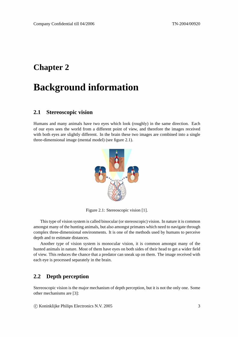
Humans and many animals have two eyes which look (roughly) in the same direction. Eachof our eyes sees the world from a different point of view, and therefore the images receivedwith both eyes are slightly different. In the brain these two images are combined into a singlethree-dimensional image (mental model) (see figure 2.1).
Figure 2.1: Stereoscopic vision [1].
This type of vision system is called binocular (or stereoscopic) vision. In nature it is commonamongst many of the hunting animals, but also amongst primates which need to navigate throughcomplex three-dimensional environments. It is one of the methods used by humans to perceivedepth and to estimate distances.
Another type of vision system is monocular vision, it is common amongst many of thehunted animals in nature. Most of them have eyes on both sides of their head to get a wider fieldof view. This reduces the chance that a predator can sneak up on them. The image received witheach eye is processed separately in the brain.
2.2 Depth perception
Stereoscopic vision is the major mechanism of depth perception, but it is not the only one. Someother mechanisms are [3]:
c© Koninklijke Philips Electronics N.V. 2005 3
TN-2004/00920 Company Confidential till 04/2006
Motion parallax: When you move your head from side to side, objects that are close to youmove relatively faster than objects that are further away.
Interposition: An object that is occluding another is in front of that object.
Light and shade: Shadows give information about the three-dimensional form of an object. Ifthe position of the light source is known the shadow can also provide information aboutthe position of the object itself.
Relative size: Objects of the same size at different distances are perceived with different sizesby the eye. This size-distance relation gives information about the distance of objects ofknown size. In a flat image this effect can be recreated by using a perspective projection.
Distance fog: Objects far away appear hazier.
All these mechanisms are used together by our brain for depth perception.
2.3 3D displays
When looking at a traditional display both eyes view the same image. Although this flat imagecan contain almost all depth cues, it is missing the most important one: the stereoscopic effect.This effect can be recreated by providing both eyes with a different image. A display that doesthis is called astereoscopic display.
2.3.1 Screen disparity
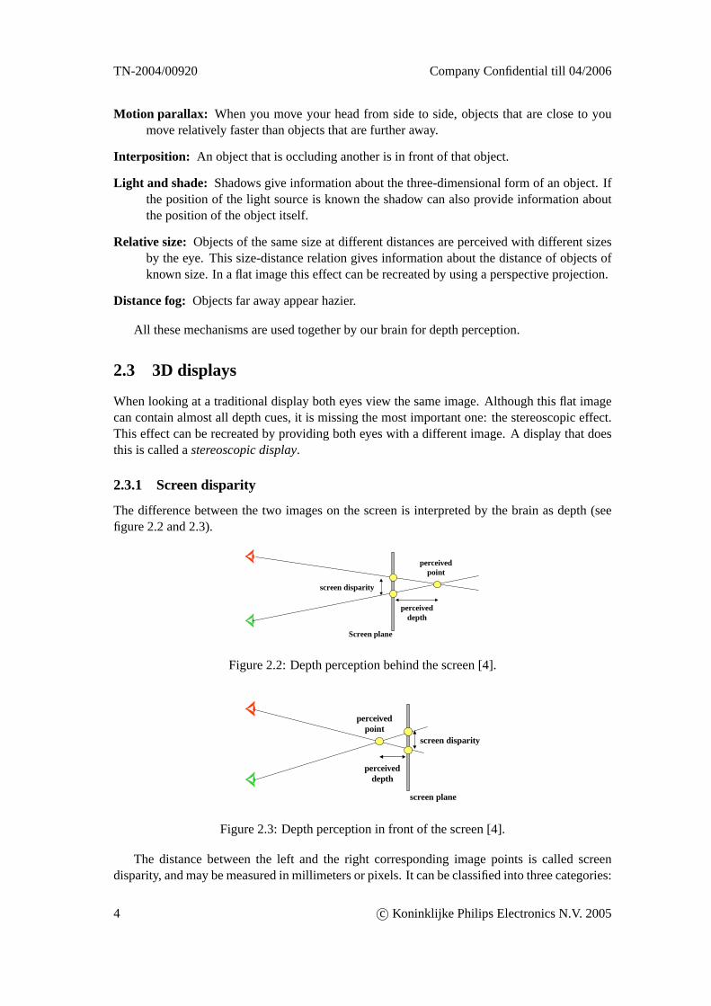
The difference between the two images on the screen is interpreted by the brain as depth (seefigure 2.2 and 2.3).
Screen plane
perceivedpoint
screen disparity
perceiveddepth
Figure 2.2: Depth perception behind the screen [4].
screen plane
perceivedpoint
screen disparity
perceiveddepth
Figure 2.3: Depth perception in front of the screen [4].
The distance between the left and the right corresponding image points is called screendisparity, and may be measured in millimeters or pixels. It can be classified into three categories:
4 c© Koninklijke Philips Electronics N.V. 2005
Company Confidential till 04/2006 TN-2004/00920
• Positive disparity - objects appear behind the screen (figure 2.2).
• Zero disparity - objects appear on the plane of the screen.
• Negative disparity - objects appear in front of the screen (figure 2.3).
Limiting screen disparity
The disparity used on a stereoscopic display should be restricted to horizontal disparity only.Vertical disparity causes eyestrain [15].
Using large (positive or negative) disparity values on a 3D display causes viewing discom-fort. This has to do, amongst other things, with the accomodation/convergence relationship [5].The brain cannot merge the two images if they are too different from each other. This will notbe discussed further here. We only use the result that states that disparity should be limited to acertain range which is comfortable to view. The maximum disparity depends on the type of 3Ddisplay.
2.3.2 Perceived depth
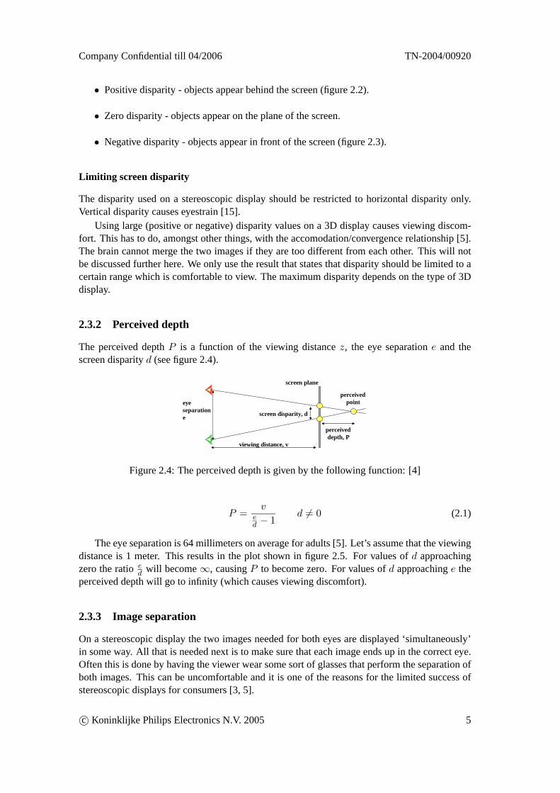
The perceived depthP is a function of the viewing distancez, the eye separatione and thescreen disparityd (see figure 2.4).
screen plane
perceivedpoint
screen disparity, d
perceiveddepth, P
viewing distance, v
eyeseparatione
Figure 2.4: The perceived depth is given by the following function: [4]
P =v
ed − 1
d 6= 0 (2.1)
The eye separation is 64 millimeters on average for adults [5]. Let’s assume that the viewingdistance is 1 meter. This results in the plot shown in figure 2.5. For values ofd approachingzero the ratioed will become∞, causingP to become zero. For values ofd approachinge theperceived depth will go to infinity (which causes viewing discomfort).
2.3.3 Image separation
On a stereoscopic display the two images needed for both eyes are displayed ‘simultaneously’in some way. All that is needed next is to make sure that each image ends up in the correct eye.Often this is done by having the viewer wear some sort of glasses that perform the separation ofboth images. This can be uncomfortable and it is one of the reasons for the limited success ofstereoscopic displays for consumers [3, 5].
c© Koninklijke Philips Electronics N.V. 2005 5
TN-2004/00920 Company Confidential till 04/2006
Figure 2.5: Perceived depth behind the screen as function of the screen disparity (for a viewingdistance of 1 meter and an eye separation of 64 millimeter).
2.4 Philips 3D displays
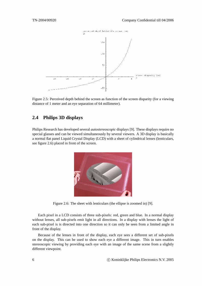
Philips Research has developed severalautostereoscopicdisplays [9]. These displays require nospecial glasses and can be viewed simultaneously by several viewers. A 3D display is basicallya normal flat panel Liquid Crystal Display (LCD) with a sheet of cylindrical lenses (lenticulars,see figure 2.6) placed in front of the screen.
Figure 2.6: The sheet with lenticulars (the ellipse is zoomed in) [9].
Each pixel in a LCD consists of three sub-pixels: red, green and blue. In a normal displaywithout lenses, all sub-pixels emit light in all directions. In a display with lenses the light ofeach sub-pixel is is directed into one direction so it can only be seen from a limited angle infront of the display.
Because of the lenses in front of the display, each eye sees a different set of sub-pixelson the display. This can be used to show each eye a different image. This in turn enablesstereoscopic viewing by providing each eye with an image of the same scene from a slightlydifferent viewpoint.
6 c© Koninklijke Philips Electronics N.V. 2005
Company Confidential till 04/2006 TN-2004/00920
2.4.1 Multiple views
The image that is visible from a certain viewing angle in front of the display is called aview.The minimum number of views that a stereoscopic display has to show is two (one for each eye).The displays created at Philips typically show more than two views.
The (example) 3D display used in the rest of this report is an 20 inch LCD with a nativeresolution of 1600 x 1200 (UXGA). It is a nine view screen, which means it can show ninedifferent images from different viewing angles. The perceived depth range is about 10 centimeterin front of the screen and 15 centimeter behind the screen. Using larger screen disparities tocreate more perceived depth results in ghosting, but this also depends on the content (brightness,sharpness, etc.), so these numbers are an indication only. Please note that all technical propertiesmentioned here (numbers, etc.) are specific to this type of screen. There are other screens withdifferent resolutions, number of views, etc.
Having a 3D display with more than two views has several advantages and of course alsosome disadvantages, as we will see.
Advantages
First the user has much more viewing freedom. When viewing a display with only two views(without glasses) the user has to be almost precisely at the correct position in front of the screen,otherwise the stereoscopic effect will be lost. Head tracking can be used to solve this problem,but that only works for a single person and is therefore not considered a suitable technologyfor the consumer market [3]. Having multiple views makes the 3D effect visible from a widerviewing angle and thus also enables multiple persons to simultaneously view the screen.
The second advantage of having multiple views is that the user can experience motion par-allax, e.g. ‘look around’ objects, by moving his head horizontally.
Disadvantages
A great disadvantage of having multiple views is the decreased resolution per view. The nativeresolution of the screen is divided up among the views, so a high resolution 2D display is neededto create a low resolution multiview display.
Another disadvantage of the first generation of 3D displays is that they can only be usedfor displaying 3D content. Normal 2D content only looks acceptable at a low resolution. Thisproblem has been solved by the development of switchable lenses so the display can still be usedas a regular 2D display. By making the lenses switchable per region it would even be possibleto display both 2D and 3D content at the same time.
Viewing zones
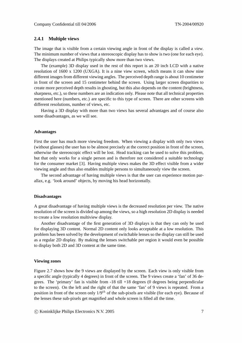
Figure 2.7 shows how the 9 views are displayed by the screen. Each view is only visible froma specific angle (typically 4 degrees) in front of the screen. The 9 views create a ‘fan’ of 36 de-grees. The ‘primary’ fan is visible from -18 till +18 degrees (0 degrees being perpendicularto the screen). On the left and the right of that the same ‘fan’ of 9 views is repeated. From aposition in front of the screen only 1/9th of the sub-pixels are visible (for each eye). Because ofthe lenses these sub-pixels get magnified and whole screen is filled all the time.
c© Koninklijke Philips Electronics N.V. 2005 7
TN-2004/00920 Company Confidential till 04/2006
Figure 2.7: Multiple views (a 7 view display is shown instead of a 9 view) [9].
Crosstalk and ghosting
Adjacent views are not completely separated: there is quite some overlap between two adjacentviews which is calledcrosstalk. Crosstalk causes each eye to see not exactly one view, but alsosomewhat of the adjacent two views. It is caused by the optics of the lenticulars to let the viewsgo smoothly from one to another. A great disadvantage of the large crosstalk isghosting, whichoccurs if two adjacent views differ too much from each other. It makes it harder for the brain tomerge the two images received by the eyes into one.
2.4.2 Sub-pixel display layout
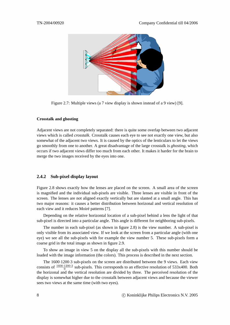
Figure 2.8 shows exactly how the lenses are placed on the screen. A small area of the screenis magnified and the individual sub-pixels are visible. Three lenses are visible in front of thescreen. The lenses are not aligned exactly vertically but are slanted at a small angle. This hastwo major reasons: it causes a better distribution between horizonal and vertical resolution ofeach view and it reduces Moiré patterns [7].
Depending on the relative horizontal location of a sub-pixel behind a lens the light of thatsub-pixel is directed into a particular angle. This angle is different for neighboring sub-pixels.
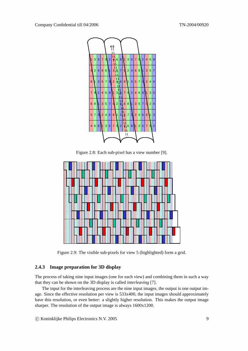
The number in each sub-pixel (as shown in figure 2.8) is the view number. A sub-pixel isonly visible from its associated view. If we look at the screen from a particular angle (with oneeye) we see all the sub-pixels with for example the view number 5. These sub-pixels form acoarse grid in the total image as shown in figure 2.9.
To show an image in view 5 on the display all the sub-pixels with this number should beloaded with the image information (the colors). This process is described in the next section.
The 1600·1200·3 sub-pixels on the screen are distributed between the 9 views. Each viewconsists of1600·1200·3
9 sub-pixels. This corresponds to an effective resolution of 533x400. Boththe horizonal and the vertical resolution are divided by three. The perceived resolution of thedisplay is somewhat higher due to the crosstalk between adjacent views and because the viewersees two views at the same time (with two eyes).
8 c© Koninklijke Philips Electronics N.V. 2005
Company Confidential till 04/2006 TN-2004/00920
1 3 5 7 9 2 4 6 8
9 2 4 6 8 1 3 5 7
8 1 3 5 7 9 2 4 6
7 9 2 4 6 8 1 3 5
6 8 1 3 5 7 9 2 4
5 7 9 2 4 6 8 1 3
4 6 8 1 3 5 7 9 2
1 3 5 7 9 2 4 6 8
9 2 4 6 8 1 3 5 7
8 1 3 5 7 9 2 4 6
7 9 2 4 6 8 1 3 5
6 8 1 3 5 7 9 2 4
5 7 9 2 4 6 8 1 3
4 6 8 1 3 5 7 9 2
54
Figure 2.8: Each sub-pixel has a view number [9].
Figure 2.9: The visible sub-pixels for view 5 (highlighted) form a grid.
2.4.3 Image preparation for 3D display
The process of taking nine input images (one for each view) and combining them in such a waythat they can be shown on the 3D display is calledinterleaving[7].
The input for the interleaving process are the nine input images, the output is one output im-age. Since the effective resolution per view is 533x400, the input images should approximatelyhave this resolution, or even better: a slightly higher resolution. This makes the output imagesharper. The resolution of the output image is always 1600x1200.
c© Koninklijke Philips Electronics N.V. 2005 9
TN-2004/00920 Company Confidential till 04/2006
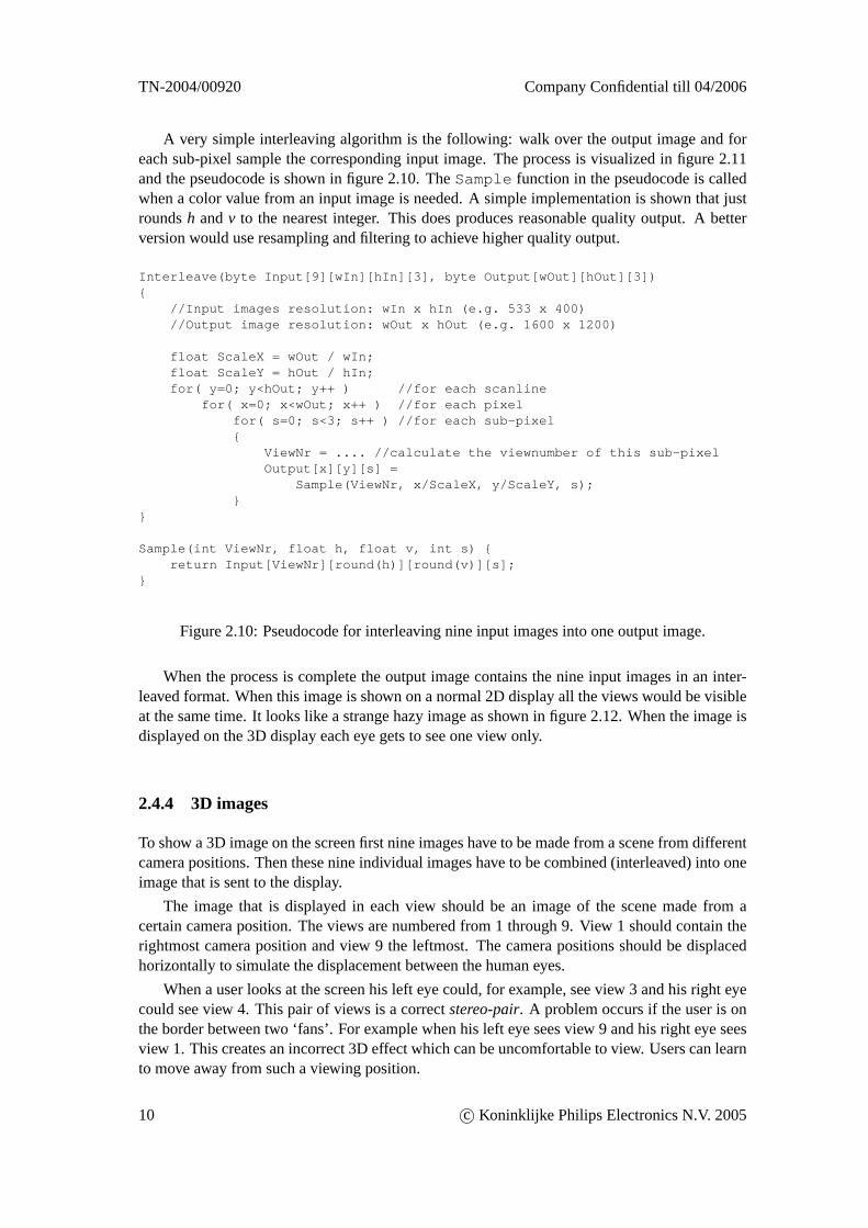
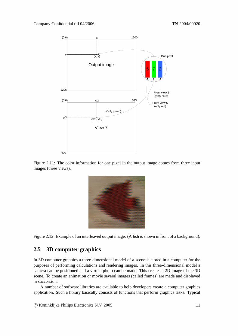
A very simple interleaving algorithm is the following: walk over the output image and foreach sub-pixel sample the corresponding input image. The process is visualized in figure 2.11and the pseudocode is shown in figure 2.10. TheSample function in the pseudocode is calledwhen a color value from an input image is needed. A simple implementation is shown that justroundsh andv to the nearest integer. This does produces reasonable quality output. A betterversion would use resampling and filtering to achieve higher quality output.
Interleave(byte Input[9][wIn][hIn][3], byte Output[wOut][hOut][3]){
//Input images resolution: wIn x hIn (e.g. 533 x 400)//Output image resolution: wOut x hOut (e.g. 1600 x 1200)
float ScaleX = wOut / wIn;float ScaleY = hOut / hIn;for( y=0; y<hOut; y++ ) //for each scanline
for( x=0; x<wOut; x++ ) //for each pixelfor( s=0; s<3; s++ ) //for each sub-pixel{
ViewNr = .... //calculate the viewnumber of this sub-pixelOutput[x][y][s] =
Sample(ViewNr, x/ScaleX, y/ScaleY, s);}
}
Sample(int ViewNr, float h, float v, int s) {return Input[ViewNr][round(h)][round(v)][s];
}
Figure 2.10: Pseudocode for interleaving nine input images into one output image.
When the process is complete the output image contains the nine input images in an inter-leaved format. When this image is shown on a normal 2D display all the views would be visibleat the same time. It looks like a strange hazy image as shown in figure 2.12. When the image isdisplayed on the 3D display each eye gets to see one view only.
2.4.4 3D images
To show a 3D image on the screen first nine images have to be made from a scene from differentcamera positions. Then these nine individual images have to be combined (interleaved) into oneimage that is sent to the display.
The image that is displayed in each view should be an image of the scene made from acertain camera position. The views are numbered from 1 through 9. View 1 should contain therightmost camera position and view 9 the leftmost. The camera positions should be displacedhorizontally to simulate the displacement between the human eyes.
When a user looks at the screen his left eye could, for example, see view 3 and his right eyecould see view 4. This pair of views is a correctstereo-pair. A problem occurs if the user is onthe border between two ‘fans’. For example when his left eye sees view 9 and his right eye seesview 1. This creates an incorrect 3D effect which can be uncomfortable to view. Users can learnto move away from such a viewing position.
10 c© Koninklijke Philips Electronics N.V. 2005
Company Confidential till 04/2006 TN-2004/00920
Output image
y
x(0,0)
(x, y)
1200
1600
5 7 2
View 7
y/3
x/3(0,0)
(x/3, y/3)
400
533
From view 2(only blue)
From view 5(only red)
(Only green)
One pixel
Figure 2.11: The color information for one pixel in the output image comes from three inputimages (three views).
Figure 2.12: Example of an interleaved output image. (A fish is shown in front of a background).
2.5 3D computer graphics
In 3D computer graphics a three-dimensional model of a scene is stored in a computer for thepurposes of performing calculations and rendering images. In this three-dimensional model acamera can be positioned and a virtual photo can be made. This creates a 2D image of the 3Dscene. To create an animation or movie several images (called frames) are made and displayedin succession.
A number of software libraries are available to help developers create a computer graphicsapplication. Such a library basically consists of functions that perform graphics tasks. Typical
c© Koninklijke Philips Electronics N.V. 2005 11
TN-2004/00920 Company Confidential till 04/2006
functions include specifying scene components (points, lines, polygons), applying transforma-tions and selecting views from a scene. The definition of all the functions in the library is calledthe Application Programming Interface (API).
OpenGL1 and Direct3D2 are two popular computer graphics APIs. Most graphics cardsprovide hardware acceleration for these APIs, which enables realtime rendering of complex 3Dscenes. The implementation of the graphics libraries is partly done in software and (possibly,not required) partly in hardware. The whole system is called therendering pipeline. It consist ofdifferent stages that perform operations on data. It begins with the primitives generated by theapplication and ends with the pixels drawn on the screen.
2.5.1 Computer graphics for the 3D display
‘Normal’ 3D applications (or games) create only a single view for each frame in a sequence.To use such an application on the 3D display not one but nine views need to be created andcombined into a single image that is suited for the 3D display. A solution would be to implementthe support for the 3D display in each application itself. This would require changing eachindividual application, which is of course not desirable or even feasible.
An alternative approach is to implement the support in the graphics API. This would enableall existing programs to use the functionality of the 3D display. This approach has been chosen.Currently only OpenGL applications are supported by the means of a so called OpenGL wrapper.
Before we can explain this approach some knowledge is required of two other subjects:double buffering and procedural shaders. These are explained in the next two sections. In thenext chapter the OpenGL wrapper is discussed.
2.5.2 Double buffering
The memory on a graphics card that contains the pixels that are currently displayed on the screenis called the framebuffer. The framebuffer is actually a collection of buffers: the (front and back)color buffer, the z-buffer, the stencil buffer, etc.
Most interactive graphics applications use a technique called double buffering. This is amethod of using two (color) framebuffers: a visible front color buffer and an invisible backcolor buffer. While the front buffer is being displayed the next frame is being rendered in theback buffer. When the new frame is finished the buffers are swapped. Using double bufferingensures that the viewer sees a perfect image all the time. Graphics APIs, including OpenGL,have support for double buffering. When an application has rendered a complete frame it has tocall the function that swaps the buffers. We will call this functionSwapBuffers in the rest ofthis report.
2.5.3 Programmable shaders
Historically graphics hardware used to have a fixed-function rendering pipeline. This has changedrecently with the appearance of programmable Graphics Processing Units3 (GPU). These allowcertain stages of the rendering pipeline to be programmed. A program that runs on the GPU is
1http://www.opengl.org/about/overview.html2http://www.microsoft.com/windows/directx/default.aspx3Very limited support for shaders appeared in ‘DirectX 8 class hardware’. ‘DirectX 9 class hardware’ and beyond
has more powerful support for shaders. Two examples are the Nvidia Geforce FX and the ATI Radeon 9500. Theyboth support the OpenGL extension ARB_fragment_program.
12 c© Koninklijke Philips Electronics N.V. 2005
Company Confidential till 04/2006 TN-2004/00920
called a shader. All sorts of nice effects can be rendered with shaders and recent games4 makeextensive use of them.
A graphics application must enable a shader program when it wants to use it (and disableit afterwards). While a shader program is active it replaces a part of the functionality of thefixed-function pipeline.
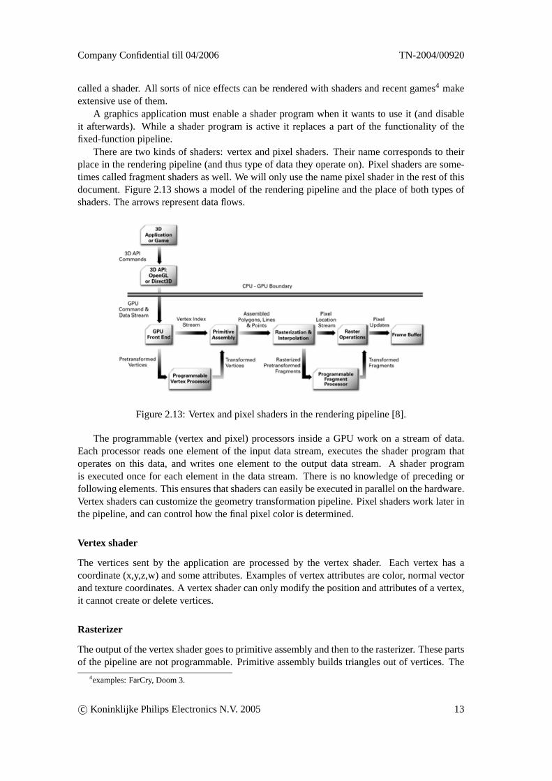
There are two kinds of shaders: vertex and pixel shaders. Their name corresponds to theirplace in the rendering pipeline (and thus type of data they operate on). Pixel shaders are some-times called fragment shaders as well. We will only use the name pixel shader in the rest of thisdocument. Figure 2.13 shows a model of the rendering pipeline and the place of both types ofshaders. The arrows represent data flows.
Figure 2.13: Vertex and pixel shaders in the rendering pipeline [8].
The programmable (vertex and pixel) processors inside a GPU work on a stream of data.Each processor reads one element of the input data stream, executes the shader program thatoperates on this data, and writes one element to the output data stream. A shader programis executed once for each element in the data stream. There is no knowledge of preceding orfollowing elements. This ensures that shaders can easily be executed in parallel on the hardware.Vertex shaders can customize the geometry transformation pipeline. Pixel shaders work later inthe pipeline, and can control how the final pixel color is determined.
Vertex shader
The vertices sent by the application are processed by the vertex shader. Each vertex has acoordinate (x,y,z,w) and some attributes. Examples of vertex attributes are color, normal vectorand texture coordinates. A vertex shader can only modify the position and attributes of a vertex,it cannot create or delete vertices.
Rasterizer
The output of the vertex shader goes to primitive assembly and then to the rasterizer. These partsof the pipeline are not programmable. Primitive assembly builds triangles out of vertices. The
4examples: FarCry, Doom 3.
c© Koninklijke Philips Electronics N.V. 2005 13
TN-2004/00920 Company Confidential till 04/2006
rasterizer splits these triangles into pixels. While doing this it also (linearly) interpolates theper-vertex-attributes.
Pixel shader
The output of the rasterizer (pixels with associated interpolated attributes) forms the input forthe pixel shader. The pixel shader can use these inputs to determine the color of the pixel. Theoutput of the pixel shader (color) is then passed to framebuffer-test unit to (possibly) update areal pixel in the framebuffer.
2.5.4 Shader programming languages
A shader program can be written in an assembly language specifically for a particular type ofGPU and graphics API or in a general high-level language. These high-level languages in-clude Nvidia’s C for graphics (Cg), Microsoft’s High-Level Shading Language (HLSL) and theOpenGL Shading Language (GLSL). Using a high-level language has the usual advantages ofportability, increased programmer productivity, easier code reuse, etc. In our software Cg is usedand therefore it is discussed in more detail below.
Cg
Cg is developed by Nvidia, but it is not specific for their GPUs. It is a hardware focused general-purpose language. Cg code looks almost exactly like C code, with the same syntax for declara-tions, function calls, and most data types. A Cg program is portable across hardware generations,operating systems, and graphics API’s [11].
Because the capabilities of GPUs grow rapidly there are major differences between differentgenerations of graphics hardware. Cg exposes these hardware differences vialanguage profiles.A profile specifies the subset of the full Cg language that is supported on a specific processor.There are different profiles for vertex and pixel processors, for DirectX 8 and 9 class hardware,etc.
Cg has support for scalar data types (such as float) and for vector and matrix types (such asfloat3, float4x4). Textures are represented with the specialsamplertype.
Limitations
Shader programs have some limitations that are caused by the hardware on which they run.Their length (number of instructions) is limited. Pointers are not supported. There are morelimitations, but these depend on the shader profile used.
Input types
A Cg shader program can have two kinds of inputs:varyinganduniform. The first kind of inputvaries with each execution of the shader. Examples are position, normal vector and texture coor-dinates. The second kind of input stays the same for many executions of the shader. This valueis set by the application and stays the same until the application sets another value. Examplesare reflectivity and light color.
14 c© Koninklijke Philips Electronics N.V. 2005
Company Confidential till 04/2006 TN-2004/00920
Chapter 3
Rendering multiple times
To use a graphics application on the 3D display nine views of each frame are needed (instead ofone). This is currently (at the start of this project) done by using an OpenGL wrapper to rendereach frame nine times and then using a pixel shader to do the interleaving.
The current system is described in this chapter. Some of its disadvantages lead to my assign-ment, which is described in the next chapter.
3.1 OpenGL wrapper
OpenGL is a library of functions that can be used by an application to perform graphics tasks.On the Windows platform the code of all these functions resides inside a Dynamic Link Library(DLL). A possible way to extend the functionality of OpenGL is to create a wrapper DLL. AnOpenGL DLL wrapper has been developed at Philips Research [6].
This wrapper process works as follows: the original opengl32.dll is renamed to wopengl32.dll.A new opengl32.dll (the ‘wrapper’ DLL) is made which exports the same OpenGL interface.Applications that normally use the original opengl32.dll now automatically use the wrapperDLL, because it has the same filename.
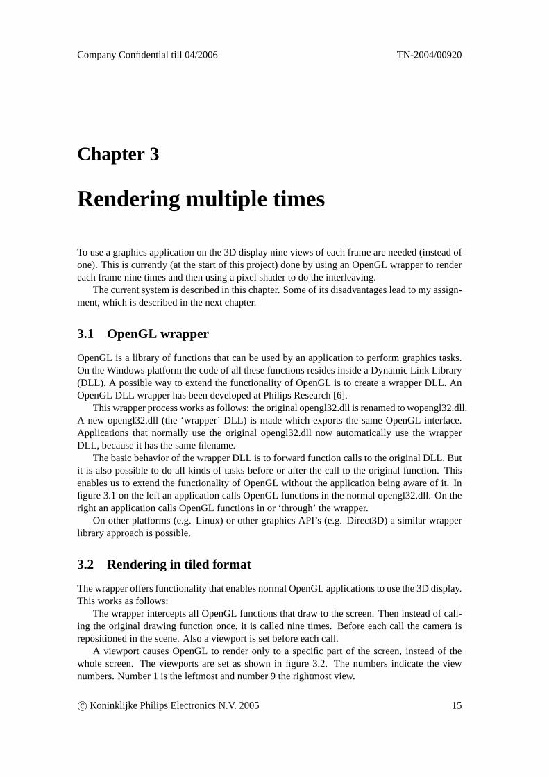
The basic behavior of the wrapper DLL is to forward function calls to the original DLL. Butit is also possible to do all kinds of tasks before or after the call to the original function. Thisenables us to extend the functionality of OpenGL without the application being aware of it. Infigure 3.1 on the left an application calls OpenGL functions in the normal opengl32.dll. On theright an application calls OpenGL functions in or ‘through’ the wrapper.
On other platforms (e.g. Linux) or other graphics API’s (e.g. Direct3D) a similar wrapperlibrary approach is possible.
3.2 Rendering in tiled format
The wrapper offers functionality that enables normal OpenGL applications to use the 3D display.This works as follows:
The wrapper intercepts all OpenGL functions that draw to the screen. Then instead of call-ing the original drawing function once, it is called nine times. Before each call the camera isrepositioned in the scene. Also a viewport is set before each call.
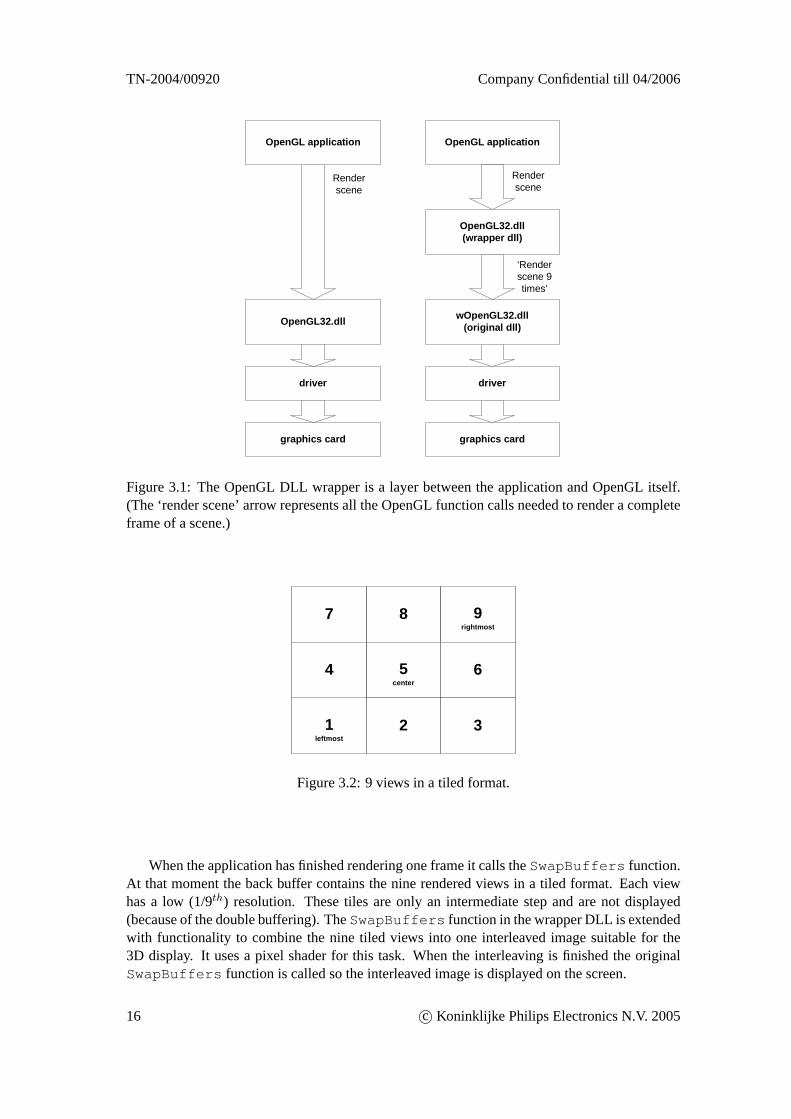
A viewport causes OpenGL to render only to a specific part of the screen, instead of thewhole screen. The viewports are set as shown in figure 3.2. The numbers indicate the viewnumbers. Number 1 is the leftmost and number 9 the rightmost view.
c© Koninklijke Philips Electronics N.V. 2005 15
TN-2004/00920 Company Confidential till 04/2006
OpenGL application
wOpenGL32.dll(original dll)
Renderscene
‘Renderscene 9times’
OpenGL32.dll
Renderscene
OpenGL application
driver
graphics card
OpenGL32.dll(wrapper dll)
driver
graphics card
Figure 3.1: The OpenGL DLL wrapper is a layer between the application and OpenGL itself.(The ‘render scene’ arrow represents all the OpenGL function calls needed to render a completeframe of a scene.)
1leftmost
8 9rightmost
7
65center
3
4
2
Figure 3.2: 9 views in a tiled format.
When the application has finished rendering one frame it calls theSwapBuffers function.At that moment the back buffer contains the nine rendered views in a tiled format. Each viewhas a low (1/9th) resolution. These tiles are only an intermediate step and are not displayed(because of the double buffering). TheSwapBuffers function in the wrapper DLL is extendedwith functionality to combine the nine tiled views into one interleaved image suitable for the3D display. It uses a pixel shader for this task. When the interleaving is finished the originalSwapBuffers function is called so the interleaved image is displayed on the screen.
16 c© Koninklijke Philips Electronics N.V. 2005

Company Confidential till 04/2006 TN-2004/00920
3.3 Interleaving with pixel shader
After the nine views have been rendered in a tiled format it is the task of the pixel shader tointerleave them.
A pixel shader gets executed once for each pixel (x,y) in the output image and its task is tocalculate the color. A pixel consists of three sub-pixels and the color of each sub-pixel shouldcome from a different view (see figure 2.11).
Beforehand a table is constructed that contains for each (x,y) position in the output imagethe required three positions in the tiled input image. This table has a size of 22 MB1. The tabletable is stored as six textures on the graphics card. All the six textures have to be completelyread once of each frame. This requires a memory bandwidth of 22MB per frame.
The shader does six texture fetches and this results in six values. These six values representthree (x,y) positions. Then the image of the nine tiled views is sampled at these three positionsand the three resulting colors are combined to form the output color of the pixel. The Cg codefor the pixel shader is in appendix A.9.
Interleaving has to be done on the graphics card itself: transferring the rendered image to themain memory and performing the interleaving on the CPU is too slow because of the asymmet-ric bandwidth2 of the Accelerated Graphics Port (AGP). Receiving data from it is much slowerthan sending data to it. (This problem will be reduced when graphics cards with a PCI Expressinterface become common3.) The bandwidth problem is not the only reason for using the graph-ics hardware, it also allows the use of the hardware texture filters for the resampling. Doing theresampling on the CPU would be more expensive. Perhaps the biggest advantage of using thegraphics hardware is its parallelism: the CPU cannot compete with that.
The following steps are performed to get the pixel shader running:
1. Save the current OpenGL state.
2. Copy the content of the back buffer to a texture. This is necessary because the pixel shaderneeds read access to the image in the back buffer, which is normally not possible.
3. Set up an orthographic projection.
4. Enable (bind) the pixel shader.
5. Draw a rectangle that completely fills the screen. Because of the orthographic projectionthe pixel shader gets executed once for each pixel in the rectangle, which is once for eachpixel on the screen.
6. Disable (unbind) the pixel shader and restore the OpenGL state.
3.4 Advantages and disadvantages
A great advantage of rendering multiple times is the quality of the output. There are no artifactsresulting from deoclusions or transparencies, this will become clear in section 5.3.
1Calculation:1600 · 1200 · 3 sub-pixels·2 values/sub-pixel·2 bytes/value= 22 MB.2APG 8X has a bandwidth of 2.1 GB/s downstream and 266 MB/s upstream, half-duplex.3PCI Express x16 has a bandwidth of 4 GB/s in both directions, full-duplex.
c© Koninklijke Philips Electronics N.V. 2005 17
TN-2004/00920 Company Confidential till 04/2006
Perhaps the biggest disadvantage of rendering multiple times is that the depth effect is noteasily adjustable. The amount of perceived depth can be controlled by varying the distancebetween the nine virtual camera’s. But this gives no control over how the depth range in thescene produces perceived depth on the display. This really is a big problem: it is, for example,not possible to get a good depth effect for both objects very close to the camera and (at the sametime) also for objects further away. Currently only objects a little further away from the cameraget a good depth effect. Objects very close to the camera (for example a gun in a first personshooter) get a screen disparity that is too large which causes viewing discomfort. Currently thisis ‘solved’ by disabling the rendering of the gun in the game.
Another big disadvantage is the performance overhead. Rendering everything 9 times is acertain factor slower than rendering only one view. The time taken scales linearly with the num-ber of polygons (and with the number of views). Rendering multiple times increases the load onthe first stages of the rendering pipeline (where vertices are processed). It also increases the loadon the CPU. Recent games use increasingly more polygons and future multiview displays mighthave more views. These developments are a bad prospect for rendering multiple times. Alsothe pixel shader that does the interleaving is slow: it has to read a large texture for each frame.Another implementation could use less bandwidth per frame at the cost of more computations.
The quality of the current implementation is limited by the resolution of the tiled intermedi-ate image. The resolution per view is 1/9th but a slightly higher resolution would be better. Thiscan be done in the future, but it requires a major change4.
The current implementation is not perfect: not all OpenGL functions have been extended tosupport 9x rendering. There is also another currently unsolved problem: an application can readback pixels from the framebuffer. Some application do this, for example to create a texture froman image that’s rendered in the framebuffer. This is a problem because the framebuffer containsthe 9 small tiled views, and the application expects just one normal view. This problem could besolved in the future, by changing the behavior of certain OpenGL functions in the wrapper (seetable 7.1).
4Rendering to texture, see 9.2.
18 c© Koninklijke Philips Electronics N.V. 2005
Company Confidential till 04/2006 TN-2004/00920
Chapter 4
Assignment
Rendering each frame nine times is getting more and more expensive over time since new gamesuse increasingly more polygons. A better performance can perhaps be achieved by only render-ing the central view and then use the depth map to generate the other views out of that. Thisapproach is known as ‘RGBD rendering’. RGBD stands for Red Green Blue + Depth.
Philips Research has already developed a RGBD rendering algorithm. It is implemented asan offline (non-realtime) program. It works (per frame) on two input files: a file containing theRGB colors and a file containing the depth. It produces (per frame) one output file that containsan interleaved 3D image. It is far from realtime (less than one frame per second on a normalPC).
Philips is interested in RGBD rendering in general and wants to investigate the possibilitiesof implementing the RGBD rendering algorithm on a graphics card (by using the programmableshaders). This is my assignment. It should result in a new OpenGL wrapper, which in turnshould make it possible to play recent games with an acceptable performance on the 3D display.The idea is to use the z-buffer of the graphics card as the required depth-map for the RGBDrendering.
c© Koninklijke Philips Electronics N.V. 2005 19
TN-2004/00920 Company Confidential till 04/2006
Chapter 5
RGBD rendering
RGBD rendering takes an image plus its depth-map and produces one or more new images fornew viewpoints. RGBD rendering is based on the horizontally shifting of pixels, in which theamount of shift depends on the depth of a pixel.
In this chapter the theory behind RGBD rendering is explained and the existing algorithmis briefly discussed. The changes and additions necessary to implement RGBD rendering on agraphics card will be discussed in the next chapters.
5.1 Theory
5.1.1 Related work
Some work that is related to our problem comes from the field of image based rendering (IBR).The general idea of IBR is to use one or more existing images as input for the rendering of a newimage. It is a complete other approach to rendering than the usual geometry based rendering.
The basic idea of using a 2D image and its depth map to generate a virtual view is describedin [15]. This approach is used in the existing offline algorithm and it is described in this chapter.The same approach will also be used in our RGBD rendering algorithm that will run on the GPU.
5.1.2 Depth-dependent pixel shifting
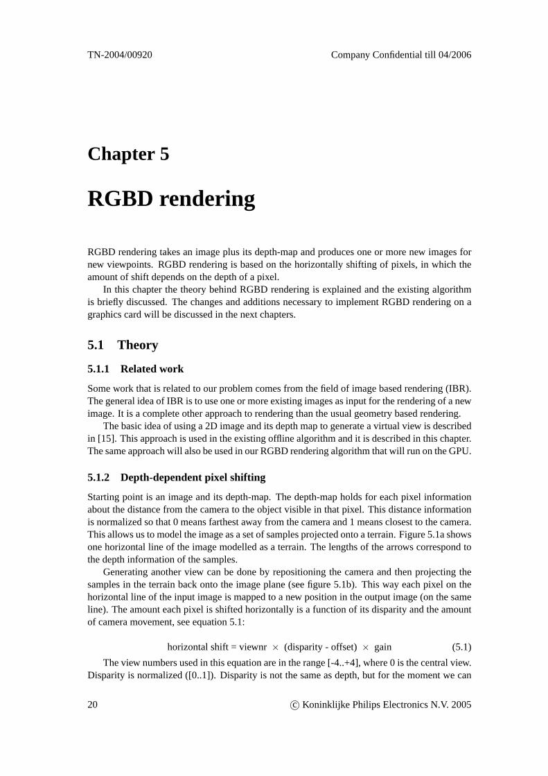
Starting point is an image and its depth-map. The depth-map holds for each pixel informationabout the distance from the camera to the object visible in that pixel. This distance informationis normalized so that 0 means farthest away from the camera and 1 means closest to the camera.This allows us to model the image as a set of samples projected onto a terrain. Figure 5.1a showsone horizontal line of the image modelled as a terrain. The lengths of the arrows correspond tothe depth information of the samples.
Generating another view can be done by repositioning the camera and then projecting thesamples in the terrain back onto the image plane (see figure 5.1b). This way each pixel on thehorizontal line of the input image is mapped to a new position in the output image (on the sameline). The amount each pixel is shifted horizontally is a function of its disparity and the amountof camera movement, see equation 5.1:
horizontal shift = viewnr× (disparity - offset)× gain (5.1)
The view numbers used in this equation are in the range [-4..+4], where 0 is the central view.Disparity is normalized ([0..1]). Disparity is not the same as depth, but for the moment we can
20 c© Koninklijke Philips Electronics N.V. 2005
Company Confidential till 04/2006 TN-2004/00920
ѽ½´«¼»¼Minication Magnication
ø¿÷ ø¾÷½¿³»®¿ ª·»©°±·²¬
·³¿¹» °´¿²»
¬»®®¿·²
Figure 5.1: (a) Horizontal line of the image modelled as a terrain with depth. (b) Samplesprojected back onto the image plane for a different camera position.
ignore the difference. Disparity can be calculated from depth, this will be explained in the nextchapter. Offset is a parameter that controls the type of screen disparity in the resulting outputimage: it can be used for example so that the output image only uses depth in front of the screen,or for example 40% in front of the screen and 60% behind the screen, etc. Gain is a parameterthat controls the amount of screen disparity and thus the amount of perceived depth. A gain ofzero means no depth and the higher the gain the more depth. This can be visualized in figure 5.1by thinking of gain as the amount of camera translation. Both offset and gain are normally tunedso that the resulting 3D image looks ‘good’.
5.1.3 Occlusions and deocclusions
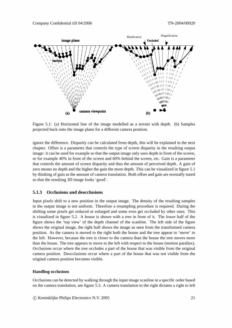
Input pixels shift to a new position in the output image. The density of the resulting samplesin the output image is not uniform. Therefore a resampling procedure is required. During theshifting some pixels get reduced or enlarged and some even get occluded by other ones. Thisis visualized in figure 5.2. A house is shown with a tree in front of it. The lower half of thefigure shows the ‘top view’ of the depth channel of the scanline. The left side of the figureshows the original image, the right half shows the image as seen from the transformed cameraposition. As the camera is moved to the right both the house and the tree appear to ‘move’ tothe left. However, because the tree is closer to the camera than the house the tree moves morethan the house. The tree appears to move to the left with respect to the house (motion parallax).Occlusions occur where the tree occludes a part of the house that was visible from the originalcamera position. Deocclusions occur where a part of the house that was not visible from theoriginal camera position becomes visible.
Handling occlusions
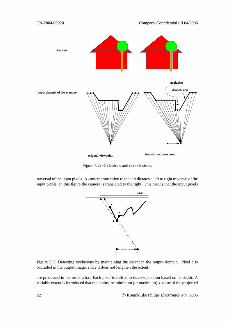
Occlusions can be detected by walking through the input image scanline in a specific order basedon the camera translation, see figure 5.3. A camera translation to the right dictates a right to left
c© Koninklijke Philips Electronics N.V. 2005 21
TN-2004/00920 Company Confidential till 04/2006
½¿²´·²»
¼»°¬¸ ½¸¿²²»´ ±º ¬¸» ½¿²´·²»
±®·¹·²¿´ ª·»©°±·²¬ ¬®¿²º±®³»¼ ª·»©°±·²¬
¼»±½½´«·±²
±½½´«·±²
Figure 5.2: Occlusions and deocclusions.
traversal of the input pixels. A camera translation to the left dictates a left to right traversal of theinput pixels. In this figure the camera is translated to the right. This means that the input pixels
Figure 5.3: Detecting occlusions by maintaining the extent in the output domain. Pixel c isoccluded in the output image, since it does not lengthen the extent.
are processed in the order a,b,c. Each pixel is shifted to its new position based on its depth. Avariable extent is introduced that maintains the minimum (or maximum) x-value of the projected
22 c© Koninklijke Philips Electronics N.V. 2005
Company Confidential till 04/2006 TN-2004/00920
pixels in the output image. When a shifted pixel does not decrease (or increase) the extent, itmust be occluded by any of the previous shifted pixels. So this pixel should not be visible inthe output image. In the figure this is the case with pixel c: it does not lengthen the extent andtherefore it is occluded (in this case by pixel b).
Handling deocclusions
Deocclusions can be detected by measuring the distance between two pixels in the output do-main. The greater this distance, the more of an object is visible that was not visible in theoriginal input image. It should be noticed however that it is not exactly possible to detect thedifference between a normal enlargement on an object and a real deocclusion. In figure 5.2 adeocclusion occurs at the large gap between two pixels in the output image. Deocclusions canbe handled by repeating the background. The ‘background’ is the pixel with the largest depthvalue. Repeating the background gives better results than repeating the foreground because inthe real world, looking around an objects reveals more of the background behind the object.
5.2 Implementation
5.2.1 Forward RGBD rendering
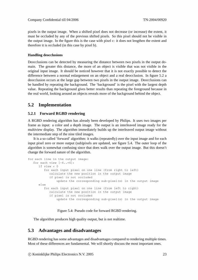
A RGBD rendering algorithm has already been developed by Philips. It uses two images perframe as input: a color and a depth image. The output is an interleaved image ready for themultiview display. The algorithm immediately builds up the interleaved output image withoutthe intermediate step of the nine tiled images.
It is a so called ’forward’ algorithm: it walks (repeatedly) over the input image and for eachinput pixel zero or more output (sub)pixels are updated, see figure 5.4. The outer loop of thealgorithm is somewhat confusing since that does walk over the output image. But this doesn’tchange the forward nature of the algorithm.
for each line in the output image:for each view [-4..+4]:
if view < 0for each input pixel on one line (from right to left)
calculate the new position in the output imageif pixel is not occluded
update the corresponding sub-pixel(s) in the output imageelse
for each input pixel on one line (from left to right)calculate the new position in the output imageif pixel is not occluded
update the corresponding sub-pixel(s) in the output image
Figure 5.4: Pseudo code for forward RGBD rendering.
The algorithm produces high quality output, but is not realtime.
5.3 Advantages and disadvantages
RGBD rendering has some advantages and disadvantages compared to rendering multiple times.Most of these differences are fundamental. We will shortly discuss the most important ones.
c© Koninklijke Philips Electronics N.V. 2005 23
TN-2004/00920 Company Confidential till 04/2006
Advantages of RGBD rendering compared to rendering multiple times:
• Better control over the amount of depth.When rendering multiple times the only way to control the amount of depth in the outputimage is by changing the amount of camera translation (and this gives no control overthe depth distribution in the scene). RGBD rendering makes this totally controllable byprocessing the depth-map (see section 6.4.4).
• Performance.When there are no restrictions on the implementation, RGBD rendering is expected to befaster than rendering multiple times. The time taken by RGBD rendering is (almost com-pletely) scene-independent whereas the time taken by rendering is considerably scene-dependent.
• RGBD rendering has much more advantages (for Philips in general), but these are notreally relevant for us.For example rendering multiple times is only possible when a 3D model of a scene isavailable. Most of the time this is not the case, for example with 2D video. The onlyoption then is create depth-maps and do RGBD rendering. Depth-maps can be estimatedout of 2D video by special algorithms.
Also the output of rendering multiple times (the interleaved image) is display dependent.The intermediate output (the tiled image) is also display dependent: fixed number ofviews, fixed amount of camera translation. The RGBD format, on the other hand, isnot display dependent. This makes it a highly suitable format for 3D content.
A depth-map can be stored along with a 2D image at little cost: using video compressionit approximately takes 20% of the size of the 2D image. Special compression algorithmscan reduce this even further.
The RGBD format is backwards compatible with 2D displays (simply ignore the depth). Itshould be noticed however that a tiled 9 view image is also backwards compatible: simplyignore all but the central view.
Disadvantages of RGBD rendering compared to rendering multiple times:
• Deocclusions are filled in with a ‘guessed’ background, instead of what’s really visible.
• Transparency effects can cause problems.The problem with transparency is that color of a pixel is a combination of the color of thebackground and the color of the transparent object itself. So the pixel should in fact havetwo depth values, which is not the case. Only one of them is available in the depth-map.Based on this the pixel is remapped to a new location. This is not correct: ideally thecolor of the background and the color of the transparent object should be mapped to twodifferent new locations. The same story holds for atmospheric effects like fog.
• View dependent effects can cause problems.An assumption made by the RGBD rendering is that a surface looks the same independentof the viewing angle. This is not always the case. Specular lighting depends on the view-ing angle. This will not be rendered correctly in the virtual views with RGBD rendering,which will degrade the quality.
24 c© Koninklijke Philips Electronics N.V. 2005
Company Confidential till 04/2006 TN-2004/00920
Chapter 6
From z-buffer to perceived depth
We want to implement RGBD rendering on a graphics card and use the information in the z-buffer as the required ‘depth information’ for the rendering. In this chapter we will discuss thetheory of all the steps required to go from the information in a z-buffer to the perceived depth onthe display (see figure 6.1). The implementation of these steps is discussed in the next chapter(in section 7.3).
z-buffer→ . . .→ perceived depth.
Figure 6.1: From z-buffer to perceived depth.
6.1 Z-buffering
Z-buffering is a commonly used hidden surface removal method. It uses a 2D buffer that storesthe ‘depth’ of the visible object at each pixel. When the rendering of a frame starts the completez-buffer is initialized to infinity. During the rendering of an object the color of a pixel is onlyupdated if the depth of the object is less than the depth stored in the z-buffer. This means that anobject is only visible if is closer to the camera than an already rendered object, just like in thereal world.
Z-buffering is practically used by all 3D games.
6.2 Normalized disparity to perceived depth
Perceived depth is the depth that a viewer experiences when looking at the display. It is causedby the screen disparity as explained in section 2.3.2 (see figure 6.2).
z-buffer→ . . .→ screen disparity→ perceived depth.
Figure 6.2: Screen disparity causes perceived depth.
The relation between screen disparity and perceived depth was plotted in figure 2.5. As canbe seen this function is non-linear for the domain that is plotted. In section 2.3.1 we discussedthat the maximum (positive and negative) screen disparity should be limited (see section 2.3.1).
c© Koninklijke Philips Electronics N.V. 2005 25
TN-2004/00920 Company Confidential till 04/2006
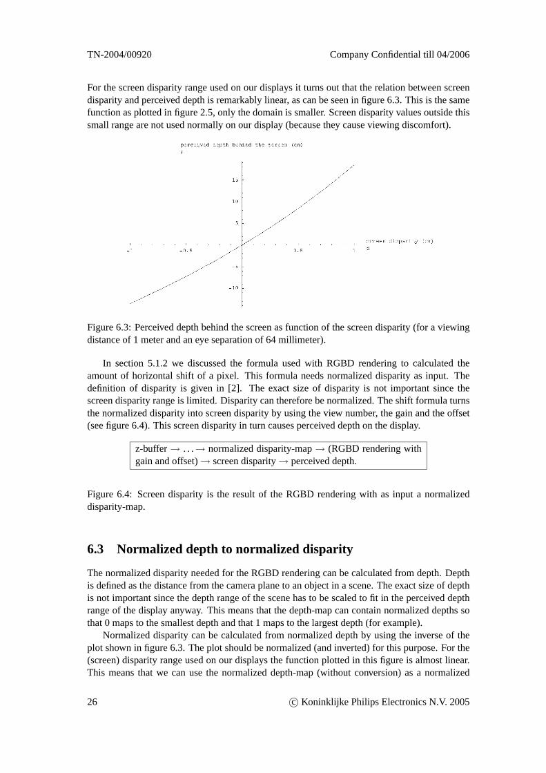
For the screen disparity range used on our displays it turns out that the relation between screendisparity and perceived depth is remarkably linear, as can be seen in figure 6.3. This is the samefunction as plotted in figure 2.5, only the domain is smaller. Screen disparity values outside thissmall range are not used normally on our display (because they cause viewing discomfort).
Figure 6.3: Perceived depth behind the screen as function of the screen disparity (for a viewingdistance of 1 meter and an eye separation of 64 millimeter).
In section 5.1.2 we discussed the formula used with RGBD rendering to calculated theamount of horizontal shift of a pixel. This formula needs normalized disparity as input. Thedefinition of disparity is given in [2]. The exact size of disparity is not important since thescreen disparity range is limited. Disparity can therefore be normalized. The shift formula turnsthe normalized disparity into screen disparity by using the view number, the gain and the offset(see figure 6.4). This screen disparity in turn causes perceived depth on the display.
z-buffer→ . . .→ normalized disparity-map→ (RGBD rendering withgain and offset)→ screen disparity→ perceived depth.
Figure 6.4: Screen disparity is the result of the RGBD rendering with as input a normalizeddisparity-map.
6.3 Normalized depth to normalized disparity
The normalized disparity needed for the RGBD rendering can be calculated from depth. Depthis defined as the distance from the camera plane to an object in a scene. The exact size of depthis not important since the depth range of the scene has to be scaled to fit in the perceived depthrange of the display anyway. This means that the depth-map can contain normalized depths sothat 0 maps to the smallest depth and that 1 maps to the largest depth (for example).
Normalized disparity can be calculated from normalized depth by using the inverse of theplot shown in figure 6.3. The plot should be normalized (and inverted) for this purpose. For the(screen) disparity range used on our displays the function plotted in this figure is almost linear.This means that we can use the normalized depth-map (without conversion) as a normalized
26 c© Koninklijke Philips Electronics N.V. 2005
Company Confidential till 04/2006 TN-2004/00920
disparity-map for the RGBD rendering (see figure 6.5). The depths in the depth-map are mapped(almost) linearly to perceived depths on the display, which is what we want. Note however thatfor displays with a larger screen disparity range the conversion step from normalized depth tonormalized disparity can no longer be skipped.
z-buffer→ . . .→ normalized depth-map→ (RGBD rendering with gainand offset)→ screen disparity→ perceived depth.
Figure 6.5: A normalized depth-map can be used without conversion as a normalized disparity-map because the relation between depth and disparity is almost linear for our display.
6.4 Z-buffer to normalized depth
6.4.1 Z-buffer
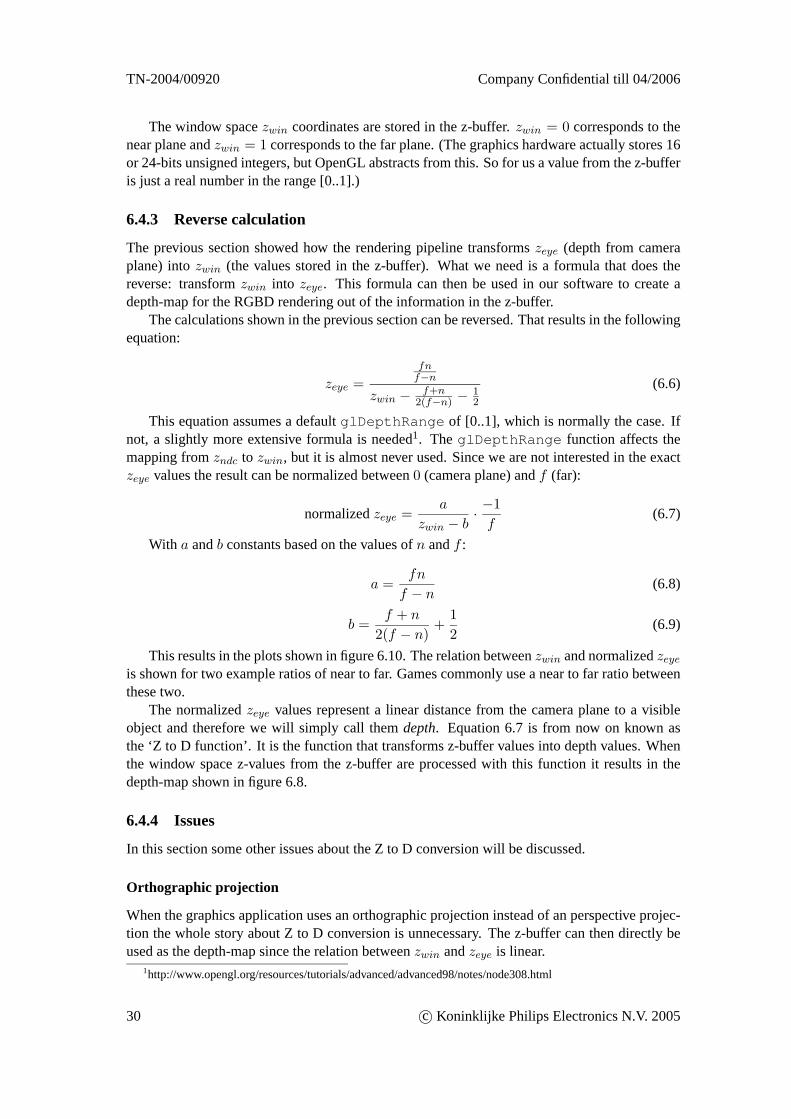
When a frame has been rendered completely the image is available in the color framebuffer (seefigure 6.6 for an example of the game Quake). A by-product of the rendering is the ‘z-map’ thatis available in the z-buffer. It contains the z-value of the visible object at each pixel. The valuesstored in the z-buffer of a graphics card are the result of a series of calculations in the graphicspipeline (see figure 6.9).
The z-buffer contains the window space z-values from the end of the transformation se-quence. We are interested in the eye space z-values. In eye space the camera is located in theorigin and looks down the negative z axis. In this space the z-coordinate is the distance from apoint to the camera plane (zeye = 0). Thesezeye coordinates can be used as a depth-map (sincethey represent distance from the camera plane).
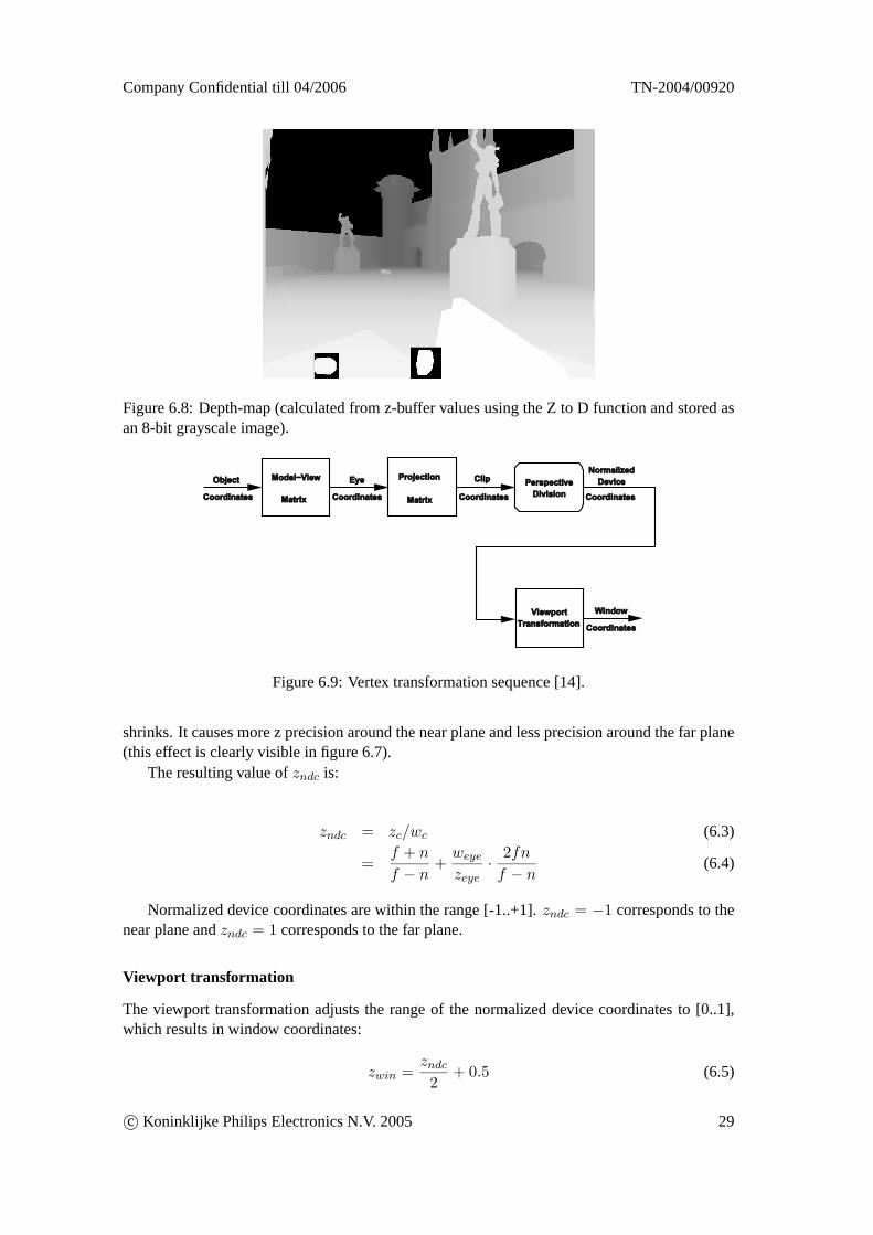
The z-buffer usually has a precision of 16 or 24 bits per pixel. Figure 6.7 shows the eightmost significant bits of the z-map as a grayscale image. If this z-map would be used directly asthe depth-map for the RGBD rendering it would result in a 3D image where only objects veryclose to the viewer would get a good depth effect and all the other objects would end up in theback. In our example the gun would use a large part of the available perceived depth range andall the other objects that are a little further away would be in last part of the perceived depthrange. Therefore the z-map cannot be used directly as a depth-map. A conversion step is neededto transform the z-map into a depth-map (as shown in figure 6.8).
6.4.2 Forward calculation
We should reverse the calculations done in the transformation sequence to go from window spacez-coordinates back to eye space z-coordinates. But let’s first look at the forward calculations(that occur in the rendering pipeline):
Projection matrix
Eye coordinates(xeye, yeye, zeye, weye) are multiplied by the projection matrix to get clip coor-dinates(xc, yc, zc, wc).
The projection matrix can be anything, but for games and a lot of other applications it is al-most always a perspective projection matrix. When an OpenGL application specifies a perspec-tive projection it must specify (amongst others) the values of the near and far planes (n andf ).
c© Koninklijke Philips Electronics N.V. 2005 27
TN-2004/00920 Company Confidential till 04/2006
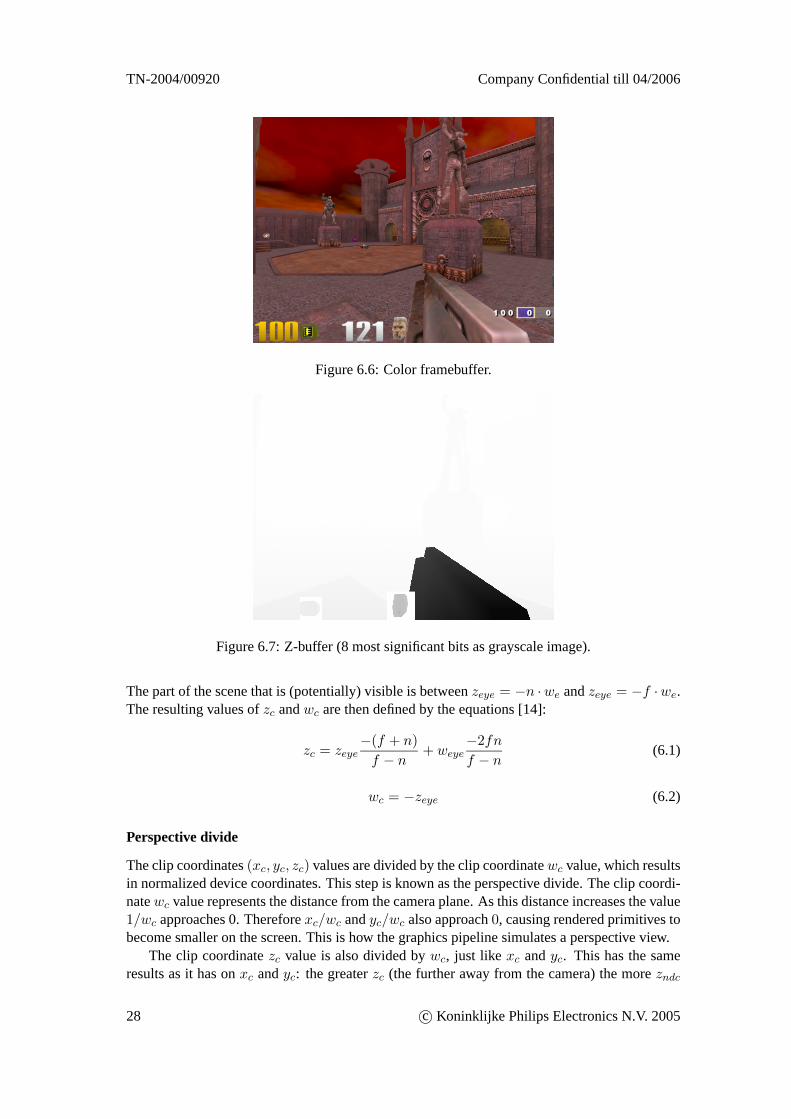
Figure 6.6: Color framebuffer.
Figure 6.7: Z-buffer (8 most significant bits as grayscale image).
The part of the scene that is (potentially) visible is betweenzeye = −n ·we andzeye = −f ·we.The resulting values ofzc andwc are then defined by the equations [14]:
zc = zeye−(f + n)f − n
+ weye−2fnf − n
(6.1)
wc = −zeye (6.2)
Perspective divide
The clip coordinates(xc, yc, zc) values are divided by the clip coordinatewc value, which resultsin normalized device coordinates. This step is known as the perspective divide. The clip coordi-natewc value represents the distance from the camera plane. As this distance increases the value1/wc approaches 0. Thereforexc/wc andyc/wc also approach0, causing rendered primitives tobecome smaller on the screen. This is how the graphics pipeline simulates a perspective view.
The clip coordinatezc value is also divided bywc, just like xc andyc. This has the sameresults as it has onxc andyc: the greaterzc (the further away from the camera) the morezndc
28 c© Koninklijke Philips Electronics N.V. 2005
Company Confidential till 04/2006 TN-2004/00920
Figure 6.8: Depth-map (calculated from z-buffer values using the Z to D function and stored asan 8-bit grayscale image).
Ѿ¶»½¬
ݱ±®¼·²¿¬» ݱ±®¼·²¿¬»
Û§»
ݱ±®¼·²¿¬»
É·²¼±©
ݱ±®¼·²¿¬»
Ò±®³¿´·¦»¼
Ü»ª·½»Ó±¼»´óÊ·»©
Ó¿¬®·¨
л®°»½¬·ª»
Ü·ª··±²
Ê·»©°±®¬
Ì®¿²º±®³¿¬·±²
ݱ±®¼·²¿¬»
Ý´·°Ð®±¶»½¬·±²
Ó¿¬®·¨
Figure 6.9: Vertex transformation sequence [14].
shrinks. It causes more z precision around the near plane and less precision around the far plane(this effect is clearly visible in figure 6.7).
The resulting value ofzndc is:
zndc = zc/wc (6.3)
=f + n
f − n+weyezeye
· 2fnf − n
(6.4)
Normalized device coordinates are within the range [-1..+1].zndc = −1 corresponds to thenear plane andzndc = 1 corresponds to the far plane.
Viewport transformation
The viewport transformation adjusts the range of the normalized device coordinates to [0..1],which results in window coordinates:
zwin =zndc
2+ 0.5 (6.5)
c© Koninklijke Philips Electronics N.V. 2005 29
TN-2004/00920 Company Confidential till 04/2006
The window spacezwin coordinates are stored in the z-buffer.zwin = 0 corresponds to thenear plane andzwin = 1 corresponds to the far plane. (The graphics hardware actually stores 16or 24-bits unsigned integers, but OpenGL abstracts from this. So for us a value from the z-bufferis just a real number in the range [0..1].)
6.4.3 Reverse calculation
The previous section showed how the rendering pipeline transformszeye (depth from cameraplane) intozwin (the values stored in the z-buffer). What we need is a formula that does thereverse: transformzwin into zeye. This formula can then be used in our software to create adepth-map for the RGBD rendering out of the information in the z-buffer.
The calculations shown in the previous section can be reversed. That results in the followingequation:
zeye =fnf−n
zwin − f+n2(f−n) −
12
(6.6)
This equation assumes a defaultglDepthRange of [0..1], which is normally the case. Ifnot, a slightly more extensive formula is needed1. TheglDepthRange function affects themapping fromzndc to zwin, but it is almost never used. Since we are not interested in the exactzeye values the result can be normalized between0 (camera plane) andf (far):
normalizedzeye =a
zwin − b· −1f
(6.7)
With a andb constants based on the values ofn andf :
a =fn
f − n(6.8)
b =f + n
2(f − n)+
12
(6.9)
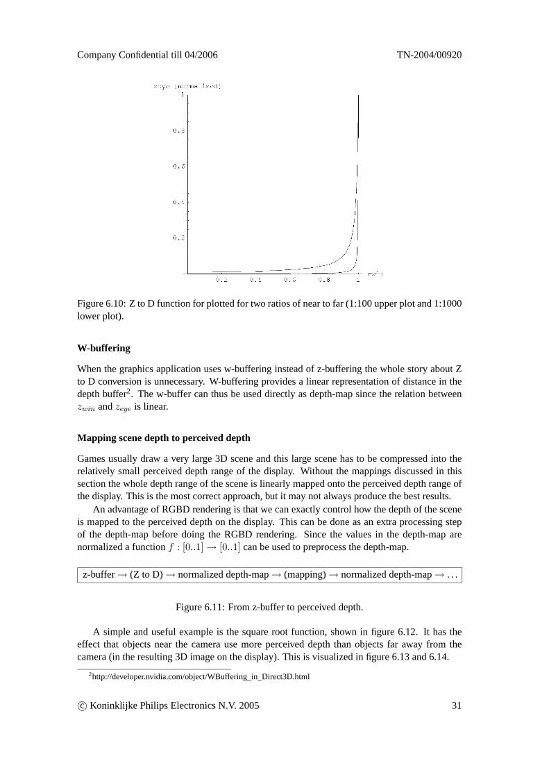
This results in the plots shown in figure 6.10. The relation betweenzwin and normalizedzeyeis shown for two example ratios of near to far. Games commonly use a near to far ratio betweenthese two.
The normalizedzeye values represent a linear distance from the camera plane to a visibleobject and therefore we will simply call themdepth. Equation 6.7 is from now on known asthe ‘Z to D function’. It is the function that transforms z-buffer values into depth values. Whenthe window space z-values from the z-buffer are processed with this function it results in thedepth-map shown in figure 6.8.
6.4.4 Issues
In this section some other issues about the Z to D conversion will be discussed.
Orthographic projection
When the graphics application uses an orthographic projection instead of an perspective projec-tion the whole story about Z to D conversion is unnecessary. The z-buffer can then directly beused as the depth-map since the relation betweenzwin andzeye is linear.
1http://www.opengl.org/resources/tutorials/advanced/advanced98/notes/node308.html
30 c© Koninklijke Philips Electronics N.V. 2005
Company Confidential till 04/2006 TN-2004/00920
Figure 6.10: Z to D function for plotted for two ratios of near to far (1:100 upper plot and 1:1000lower plot).
W-buffering
When the graphics application uses w-buffering instead of z-buffering the whole story about Zto D conversion is unnecessary. W-buffering provides a linear representation of distance in thedepth buffer2. The w-buffer can thus be used directly as depth-map since the relation betweenzwin andzeye is linear.
Mapping scene depth to perceived depth
Games usually draw a very large 3D scene and this large scene has to be compressed into therelatively small perceived depth range of the display. Without the mappings discussed in thissection the whole depth range of the scene is linearly mapped onto the perceived depth range ofthe display. This is the most correct approach, but it may not always produce the best results.
An advantage of RGBD rendering is that we can exactly control how the depth of the sceneis mapped to the perceived depth on the display. This can be done as an extra processing stepof the depth-map before doing the RGBD rendering. Since the values in the depth-map arenormalized a functionf : [0..1]→ [0..1] can be used to preprocess the depth-map.
z-buffer→ (Z to D)→ normalized depth-map→ (mapping)→ normalized depth-map→ . . .
Figure 6.11: From z-buffer to perceived depth.
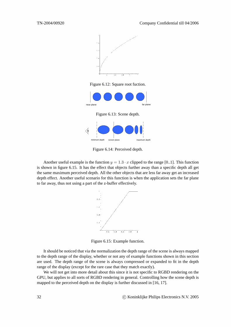
A simple and useful example is the square root function, shown in figure 6.12. It has theeffect that objects near the camera use more perceived depth than objects far away from thecamera (in the resulting 3D image on the display). This is visualized in figure 6.13 and 6.14.
2http://developer.nvidia.com/object/WBuffering_in_Direct3D.html
c© Koninklijke Philips Electronics N.V. 2005 31
TN-2004/00920 Company Confidential till 04/2006
Figure 6.12: Square root fuction.
near plane far plane
Figure 6.13: Scene depth.
minimum depth screen plane maximum depth
Figure 6.14: Perceived depth.
Another useful example is the functiony = 1.3 · x clipped to the range [0..1]. This functionis shown in figure 6.15. It has the effect that objects further away than a specific depth all getthe same maximum perceived depth. All the other objects that are less far away get an increaseddepth effect. Another useful scenario for this function is when the application sets the far planeto far away, thus not using a part of the z-buffer effectively.
Figure 6.15: Example function.
It should be noticed that via the normalization the depth range of the scene is always mappedto the depth range of the display, whether or not any of example functions shown in this sectionare used. The depth range of the scene is always compressed or expanded to fit in the depthrange of the display (except for the rare case that they match exactly).
We will not get into more detail about this since it is not specific to RGBD rendering on theGPU, but applies to all sorts of RGBD rendering in general. Controlling how the scene depth ismapped to the perceived depth on the display is further discussed in [16, 17].
32 c© Koninklijke Philips Electronics N.V. 2005
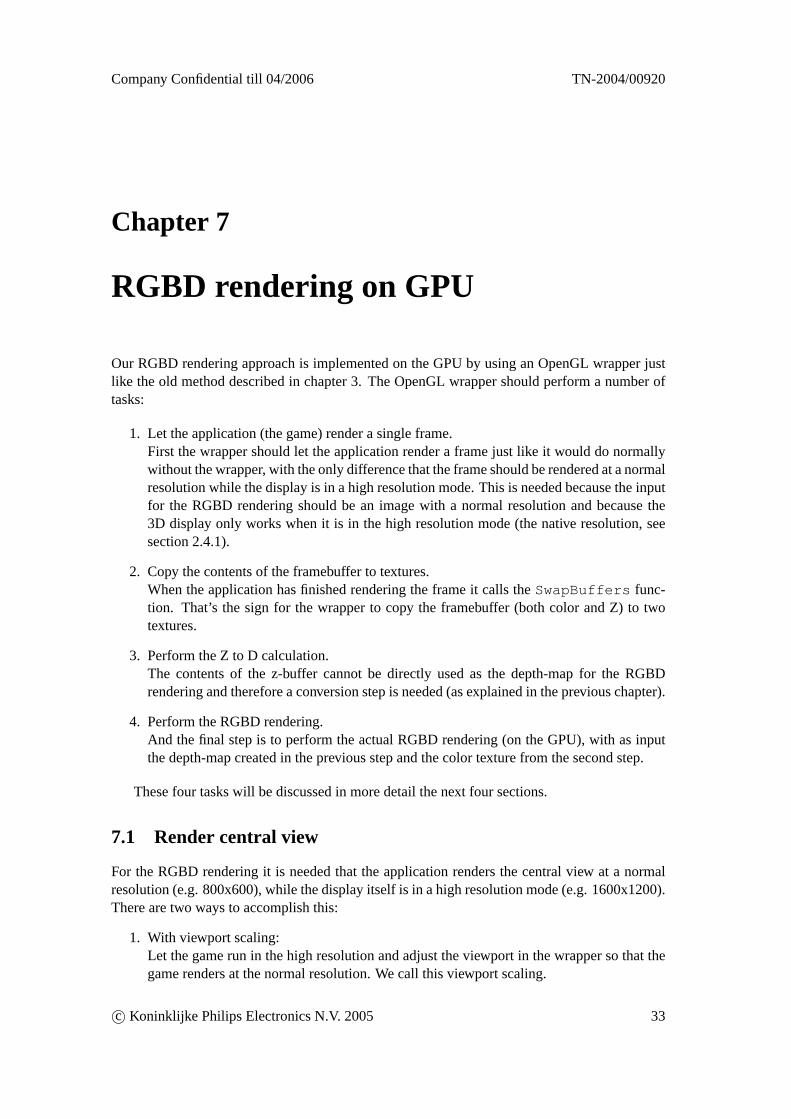
Company Confidential till 04/2006 TN-2004/00920
Chapter 7
RGBD rendering on GPU
Our RGBD rendering approach is implemented on the GPU by using an OpenGL wrapper justlike the old method described in chapter 3. The OpenGL wrapper should perform a number oftasks:
1. Let the application (the game) render a single frame.First the wrapper should let the application render a frame just like it would do normallywithout the wrapper, with the only difference that the frame should be rendered at a normalresolution while the display is in a high resolution mode. This is needed because the inputfor the RGBD rendering should be an image with a normal resolution and because the3D display only works when it is in the high resolution mode (the native resolution, seesection 2.4.1).
2. Copy the contents of the framebuffer to textures.When the application has finished rendering the frame it calls theSwapBuffers func-tion. That’s the sign for the wrapper to copy the framebuffer (both color and Z) to twotextures.
3. Perform the Z to D calculation.The contents of the z-buffer cannot be directly used as the depth-map for the RGBDrendering and therefore a conversion step is needed (as explained in the previous chapter).
4. Perform the RGBD rendering.And the final step is to perform the actual RGBD rendering (on the GPU), with as inputthe depth-map created in the previous step and the color texture from the second step.
These four tasks will be discussed in more detail the next four sections.
7.1 Render central view
For the RGBD rendering it is needed that the application renders the central view at a normalresolution (e.g. 800x600), while the display itself is in a high resolution mode (e.g. 1600x1200).There are two ways to accomplish this:
1. With viewport scaling:Let the game run in the high resolution and adjust the viewport in the wrapper so that thegame renders at the normal resolution. We call this viewport scaling.
c© Koninklijke Philips Electronics N.V. 2005 33
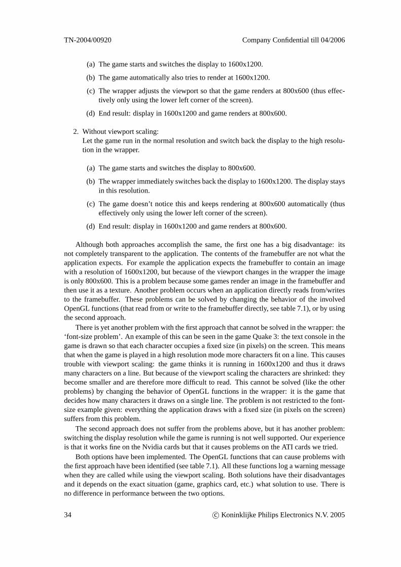
TN-2004/00920 Company Confidential till 04/2006
(a) The game starts and switches the display to 1600x1200.
(b) The game automatically also tries to render at 1600x1200.
(c) The wrapper adjusts the viewport so that the game renders at 800x600 (thus effec-tively only using the lower left corner of the screen).
(d) End result: display in 1600x1200 and game renders at 800x600.
2. Without viewport scaling:Let the game run in the normal resolution and switch back the display to the high resolu-tion in the wrapper.
(a) The game starts and switches the display to 800x600.
(b) The wrapper immediately switches back the display to 1600x1200. The display staysin this resolution.
(c) The game doesn’t notice this and keeps rendering at 800x600 automatically (thuseffectively only using the lower left corner of the screen).
(d) End result: display in 1600x1200 and game renders at 800x600.
Although both approaches accomplish the same, the first one has a big disadvantage: itsnot completely transparent to the application. The contents of the framebuffer are not what theapplication expects. For example the application expects the framebuffer to contain an imagewith a resolution of 1600x1200, but because of the viewport changes in the wrapper the imageis only 800x600. This is a problem because some games render an image in the framebuffer andthen use it as a texture. Another problem occurs when an application directly reads from/writesto the framebuffer. These problems can be solved by changing the behavior of the involvedOpenGL functions (that read from or write to the framebuffer directly, see table 7.1), or by usingthe second approach.
There is yet another problem with the first approach that cannot be solved in the wrapper: the‘font-size problem’. An example of this can be seen in the game Quake 3: the text console in thegame is drawn so that each character occupies a fixed size (in pixels) on the screen. This meansthat when the game is played in a high resolution mode more characters fit on a line. This causestrouble with viewport scaling: the game thinks it is running in 1600x1200 and thus it drawsmany characters on a line. But because of the viewport scaling the characters are shrinked: theybecome smaller and are therefore more difficult to read. This cannot be solved (like the otherproblems) by changing the behavior of OpenGL functions in the wrapper: it is the game thatdecides how many characters it draws on a single line. The problem is not restricted to the font-size example given: everything the application draws with a fixed size (in pixels on the screen)suffers from this problem.
The second approach does not suffer from the problems above, but it has another problem:switching the display resolution while the game is running is not well supported. Our experienceis that it works fine on the Nvidia cards but that it causes problems on the ATI cards we tried.
Both options have been implemented. The OpenGL functions that can cause problems withthe first approach have been identified (see table 7.1). All these functions log a warning messagewhen they are called while using the viewport scaling. Both solutions have their disadvantagesand it depends on the exact situation (game, graphics card, etc.) what solution to use. There isno difference in performance between the two options.
34 c© Koninklijke Philips Electronics N.V. 2005
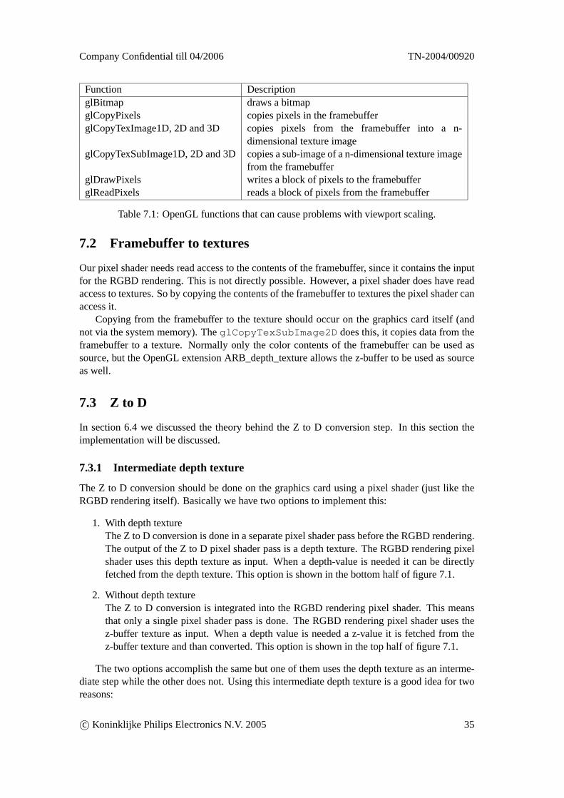
Company Confidential till 04/2006 TN-2004/00920
Function DescriptionglBitmap draws a bitmapglCopyPixels copies pixels in the framebufferglCopyTexImage1D, 2D and 3D copies pixels from the framebuffer into a n-
dimensional texture imageglCopyTexSubImage1D, 2D and 3Dcopies a sub-image of a n-dimensional texture image
from the framebufferglDrawPixels writes a block of pixels to the framebufferglReadPixels reads a block of pixels from the framebuffer
Table 7.1: OpenGL functions that can cause problems with viewport scaling.
7.2 Framebuffer to textures
Our pixel shader needs read access to the contents of the framebuffer, since it contains the inputfor the RGBD rendering. This is not directly possible. However, a pixel shader does have readaccess to textures. So by copying the contents of the framebuffer to textures the pixel shader canaccess it.
Copying from the framebuffer to the texture should occur on the graphics card itself (andnot via the system memory). TheglCopyTexSubImage2D does this, it copies data from theframebuffer to a texture. Normally only the color contents of the framebuffer can be used assource, but the OpenGL extension ARB_depth_texture allows the z-buffer to be used as sourceas well.
7.3 Z to D
In section 6.4 we discussed the theory behind the Z to D conversion step. In this section theimplementation will be discussed.
7.3.1 Intermediate depth texture
The Z to D conversion should be done on the graphics card using a pixel shader (just like theRGBD rendering itself). Basically we have two options to implement this:
1. With depth textureThe Z to D conversion is done in a separate pixel shader pass before the RGBD rendering.The output of the Z to D pixel shader pass is a depth texture. The RGBD rendering pixelshader uses this depth texture as input. When a depth-value is needed it can be directlyfetched from the depth texture. This option is shown in the bottom half of figure 7.1.
2. Without depth textureThe Z to D conversion is integrated into the RGBD rendering pixel shader. This meansthat only a single pixel shader pass is done. The RGBD rendering pixel shader uses thez-buffer texture as input. When a depth value is needed a z-value it is fetched from thez-buffer texture and than converted. This option is shown in the top half of figure 7.1.
The two options accomplish the same but one of them uses the depth texture as an interme-diate step while the other does not. Using this intermediate depth texture is a good idea for tworeasons:
c© Koninklijke Philips Electronics N.V. 2005 35
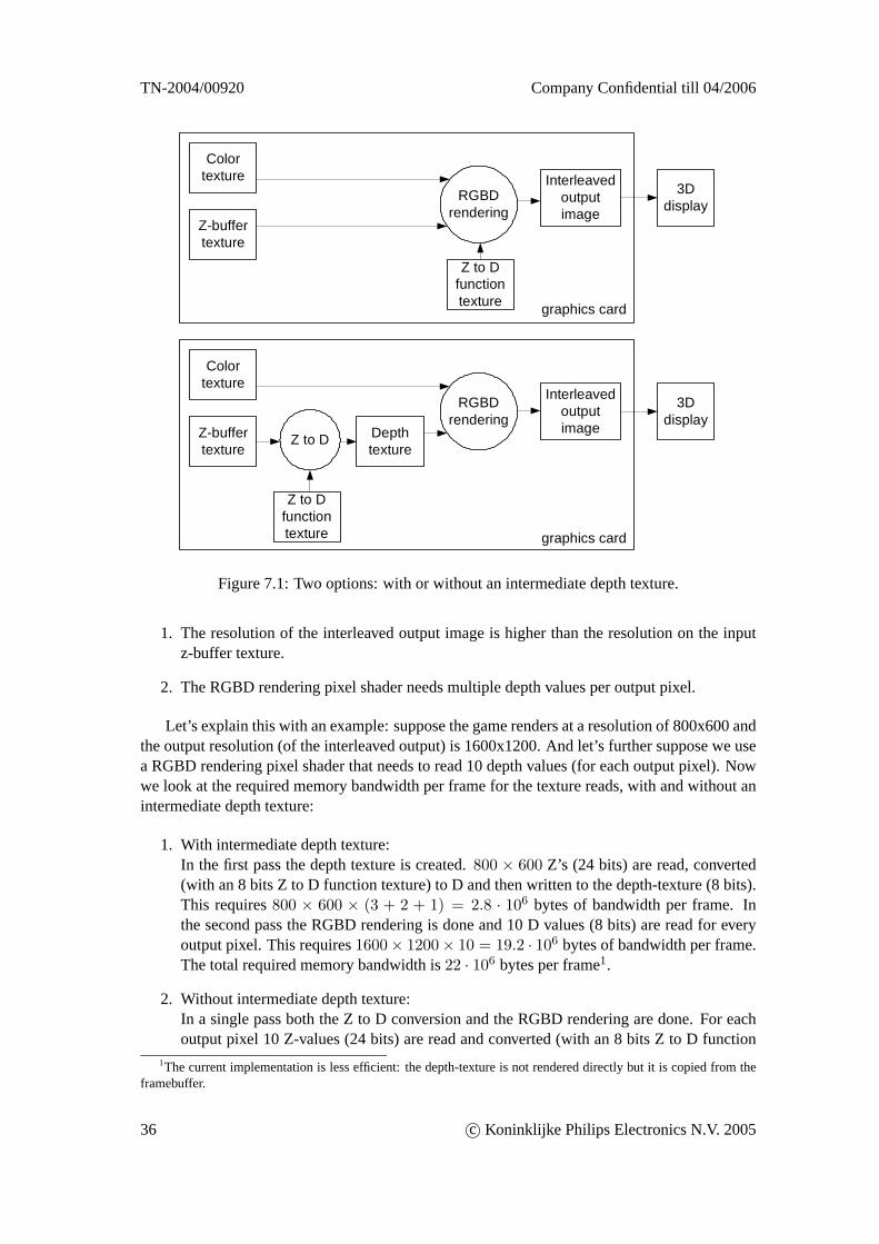
TN-2004/00920 Company Confidential till 04/2006
Colortexture
Z-buffertexture
RGBDrendering
Colortexture
Z-buffertexture
Depthtexture
Interleavedoutputimage
Z to D
RGBDrendering
Z to Dfunctiontexture
Z to Dfunctiontexture
graphics card
3Ddisplay
graphics card
Interleavedoutputimage
3Ddisplay
Figure 7.1: Two options: with or without an intermediate depth texture.
1. The resolution of the interleaved output image is higher than the resolution on the inputz-buffer texture.
2. The RGBD rendering pixel shader needs multiple depth values per output pixel.
Let’s explain this with an example: suppose the game renders at a resolution of 800x600 andthe output resolution (of the interleaved output) is 1600x1200. And let’s further suppose we usea RGBD rendering pixel shader that needs to read 10 depth values (for each output pixel). Nowwe look at the required memory bandwidth per frame for the texture reads, with and without anintermediate depth texture:
1. With intermediate depth texture:In the first pass the depth texture is created.800 × 600 Z’s (24 bits) are read, converted(with an 8 bits Z to D function texture) to D and then written to the depth-texture (8 bits).This requires800 × 600 × (3 + 2 + 1) = 2.8 · 106 bytes of bandwidth per frame. Inthe second pass the RGBD rendering is done and 10 D values (8 bits) are read for everyoutput pixel. This requires1600× 1200× 10 = 19.2 · 106 bytes of bandwidth per frame.The total required memory bandwidth is22 · 106 bytes per frame1.
2. Without intermediate depth texture:In a single pass both the Z to D conversion and the RGBD rendering are done. For eachoutput pixel 10 Z-values (24 bits) are read and converted (with an 8 bits Z to D function
1The current implementation is less efficient: the depth-texture is not rendered directly but it is copied from theframebuffer.
36 c© Koninklijke Philips Electronics N.V. 2005
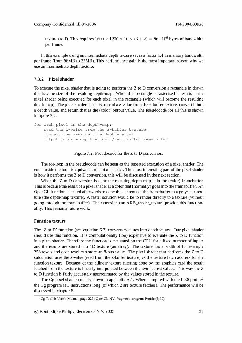
Company Confidential till 04/2006 TN-2004/00920
texture) to D. This requires1600 × 1200 × 10 × (3 + 2) = 96 · 106 bytes of bandwidthper frame.
In this example using an intermediate depth texture saves a factor4.4 in memory bandwidthper frame (from 96MB to 22MB). This performance gain is the most important reason why weuse an intermediate depth texture.
7.3.2 Pixel shader
To execute the pixel shader that is going to perform the Z to D conversion a rectangle in drawnthat has the size of the resulting depth-map. When this rectangle is rasterized it results in thepixel shader being executed for each pixel in the rectangle (which will become the resultingdepth-map). The pixel shader’s task is to read a z-value from the z-buffer texture, convert it intoa depth value, and return that as the (color) output value. The pseudocode for all this is shownin figure 7.2.
for each pixel in the depth-map:read the z-value from the z-buffer texture;convert the z-value to a depth-value;output color = depth-value; //writes to framebuffer
Figure 7.2: Pseudocode for the Z to D conversion.
The for-loop in the pseudocode can be seen as the repeated execution of a pixel shader. Thecode inside the loop is equivalent to a pixel shader. The most interesting part of the pixel shaderis how it performs the Z to D conversion, this will be discussed in the next section.
When the Z to D conversion is done the resulting depth-map is in the (color) framebuffer.This is because the result of a pixel shader is a color that (normally) goes into the framebuffer. AnOpenGL function is called afterwards to copy the contents of the framebuffer to a grayscale tex-ture (the depth-map texture). A faster solution would be to render directly to a texture (withoutgoing through the framebuffer). The extension can ARB_render_texture provide this function-ality. This remains future work.
Function texture
The ‘Z to D’ function (see equation 6.7) converts z-values into depth values. Our pixel shadershould use this function. It is computationally (too) expensive to evaluate the Z to D functionin a pixel shader. Therefore the function is evaluated on the CPU for a fixed number of inputsand the results are stored in a 1D texture (an array). The texture has a width of for example256 texels and each texel can store an 8-bits value. The pixel shader that performs the Z to Dcalculation uses the z-value (read from the z-buffer texture) as the texture fetch address for thefunction texture. Because of the bilinear texture filtering done by the graphics card the resultfetched from the texture is linearly interpolated between the two nearest values. This way the Zto D function is fairly accurately approximated by the values stored in the texture.
The Cg pixel shader code is shown in appendix A.1. When compiled with the fp30 profile2
the Cg program is 3 instructions long (of which 2 are texture fetches). The performance will bediscussed in chapter 8.
2Cg Toolkit User’s Manual, page 225: OpenGL NV_fragment_program Profile (fp30)
c© Koninklijke Philips Electronics N.V. 2005 37
TN-2004/00920 Company Confidential till 04/2006
Precision issues
The Z input for the Z to D function should be have a precision of more than 8 bits. An 8 bitsz-buffer texture has not enough precision to use it as input for the Z to D function. When this isdone anyway it results in banding artifacts as shown in figure 7.3. The z-buffer texture shouldhave a precision of more than 8 bits, on a graphics card that usually means 16 or 24 bits.
Figure 7.3: Depth-map (calculated from 8 bits z-buffer values) with banding artifacts.
The result of the Z to D function, the depth-map, can be stored with a precision of 8 bits.This is enough for our example 3D display since 256 ‘depth-levels’ is enough for the perceiveddepth range.
Scaling down the depth-map
During the conversion from Z to D the resolution (in pixels) of the resulting depth-map can besmaller than the resolution (in pixels) of the z-buffer. This can be done by varying the size of therectangle that is drawn to execute the pixel shader. This increases performance and decreasesquality. Scaling down the depth-map results in less Z to D conversions, faster framebuffer totexture copy and less memory bandwidth during the RGBD rendering pass. Scaling down thedepth-map is an option of our software that can be enabled in the configuration file (see ap-pendix B.1).
7.3.3 Detecting the projection matrix
To build the Z to D function texture on the CPU the values for the near and far planes are needed.These two values determine the precise shape of the function (see figure 6.10). The wrappershould detect these two values when the application sets a perspective projection matrix. This isnot as simple as it seems.
The easiest solution is to use a fixed function, independent of the actual near and far planesused by the application. For example: we could just assume that the ratio near:far is 1:500 anduse that to calculate the Z to D function. This works always, although the results are not exactlycorrect (since that is only possible when the exact ratio near:far is known).
The correct solution is to detect the actual near and far plane values used by the application.A simple approach might be to wait for for theSwapBuffers call and then read out the current
38 c© Koninklijke Philips Electronics N.V. 2005
Company Confidential till 04/2006 TN-2004/00920
projection matrix. This however doesn’t work in a lot of cases: by the time the application callstheSwapBuffers function the projection matrix can be different from the projection matrixused to render the scene. Games usually draw some 2D overlays over the rendered scene usingan orthographic projection. When the orthographic projection is set it overwrites the perspectiveprojection matrix. When theSwapBuffers function is called there is no way anymore to findout what the old projection matrix was. So a better solution is needed.
Everything the OpenGL application does goes via the wrapper, also the modification of theprojection matrix. This enables us to detect changes to the projection matrix at the moment theyoccur. A list of OpenGL functions that can (possibly) change the projection matrix is shown intable 7.2. These functions are extended with functionality in the wrapper that enables them tosee when a perspective projection matrix is set or modified. Then the values of near and far canbe determined from this projection matrix and the exact the Z to D function can be constructed.There are some complications however: the projection matrix can change for each renderedframe, so it has to be detected each frame again. But it gets worse: it can even change whilethe application renders a frame. An application can for example render a part of the scene (witha perspective projection), change the perspective projection, and render a different part of thescene. This means there is not necessary a single Z to D function that is correct for the wholescene. This however is more a theoretical problem than a practical one: the current wrapper onlydetects the first perspective projection matrix used for each new frame, and that one is used tocalculate the Z to D function for that frame. This seems to work fine for the moment.
Function DescriptionglFrustum multiplies the current matrix by a perspective matrixglLoadIdentity replaces the current matrix with the identity matrixglLoadMatrix replaces the current matrix with an arbitrary matrixglMultMatrix multiplies the current matrix by an arbitrary matrixglPopMatrix push the current matrix stackglPushMatrix pop the current matrix stack
Table 7.2: OpenGL functions that can change the projection matrix.
7.3.4 Z-buffer errors
If we look at the 2D image in figure 6.6 and its depth-map in figure 6.8 two things can be noticed:
1. Color but no matching depth.At some places an object is visible in the color image, but not in the depth-map. Forexample the numbers at the bottom of the screen appear in the image but not in the depth-map. The depth value in the depth-map is from the background behind the object.
2. Depth but no matching color.At some other places there is a depth value in the depth-map that doesn’t correspond toan object in the color image. This happens for example at the small head in the bottom ofthe screen. The rectangle surrounding the head appears in the depth-map, but not in theimage.
These two problems are easy visible in the depth-map, but the real problem is already presentin the z-buffer (since the depth-map is just the result of a calculation performed on the z-buffer).An incorrect z-value in the z-buffer will result in an incorrect depth in the depth-map.
c© Koninklijke Philips Electronics N.V. 2005 39
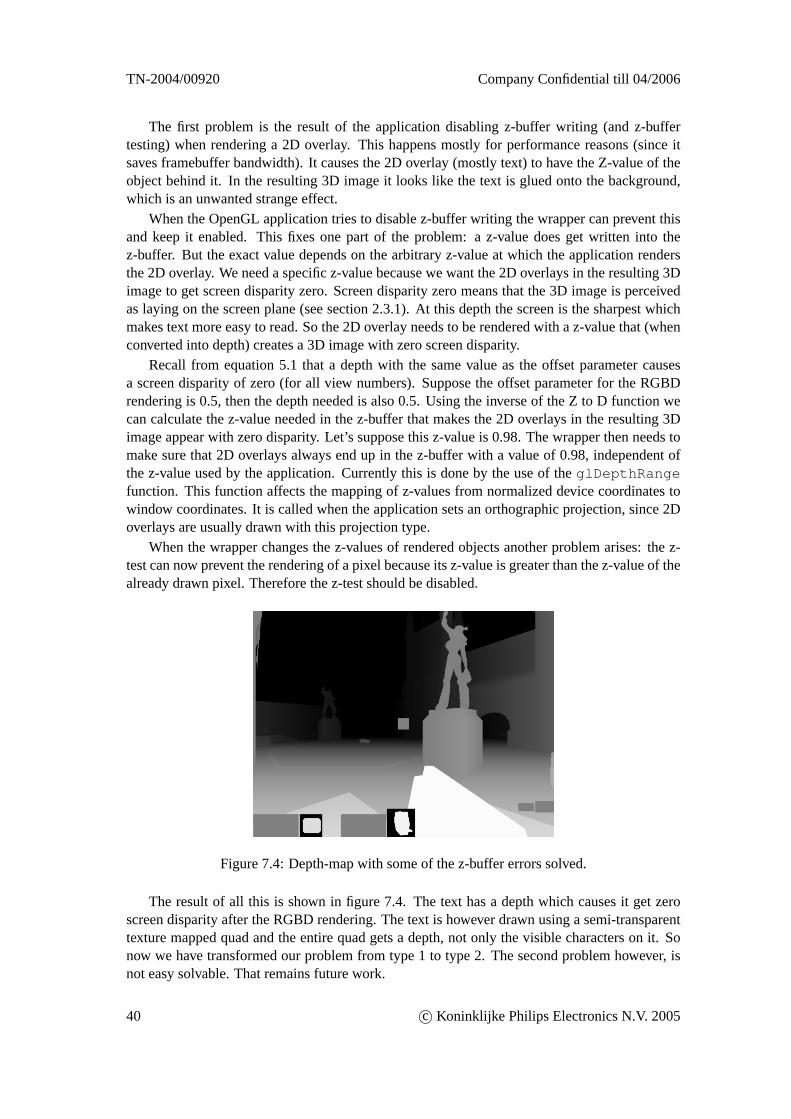
TN-2004/00920 Company Confidential till 04/2006
The first problem is the result of the application disabling z-buffer writing (and z-buffertesting) when rendering a 2D overlay. This happens mostly for performance reasons (since itsaves framebuffer bandwidth). It causes the 2D overlay (mostly text) to have the Z-value of theobject behind it. In the resulting 3D image it looks like the text is glued onto the background,which is an unwanted strange effect.
When the OpenGL application tries to disable z-buffer writing the wrapper can prevent thisand keep it enabled. This fixes one part of the problem: a z-value does get written into thez-buffer. But the exact value depends on the arbitrary z-value at which the application rendersthe 2D overlay. We need a specific z-value because we want the 2D overlays in the resulting 3Dimage to get screen disparity zero. Screen disparity zero means that the 3D image is perceivedas laying on the screen plane (see section 2.3.1). At this depth the screen is the sharpest whichmakes text more easy to read. So the 2D overlay needs to be rendered with a z-value that (whenconverted into depth) creates a 3D image with zero screen disparity.
Recall from equation 5.1 that a depth with the same value as the offset parameter causesa screen disparity of zero (for all view numbers). Suppose the offset parameter for the RGBDrendering is 0.5, then the depth needed is also 0.5. Using the inverse of the Z to D function wecan calculate the z-value needed in the z-buffer that makes the 2D overlays in the resulting 3Dimage appear with zero disparity. Let’s suppose this z-value is 0.98. The wrapper then needs tomake sure that 2D overlays always end up in the z-buffer with a value of 0.98, independent ofthe z-value used by the application. Currently this is done by the use of theglDepthRangefunction. This function affects the mapping of z-values from normalized device coordinates towindow coordinates. It is called when the application sets an orthographic projection, since 2Doverlays are usually drawn with this projection type.
When the wrapper changes the z-values of rendered objects another problem arises: the z-test can now prevent the rendering of a pixel because its z-value is greater than the z-value of thealready drawn pixel. Therefore the z-test should be disabled.
Figure 7.4: Depth-map with some of the z-buffer errors solved.
The result of all this is shown in figure 7.4. The text has a depth which causes it get zeroscreen disparity after the RGBD rendering. The text is however drawn using a semi-transparenttexture mapped quad and the entire quad gets a depth, not only the visible characters on it. Sonow we have transformed our problem from type 1 to type 2. The second problem however, isnot easy solvable. That remains future work.
40 c© Koninklijke Philips Electronics N.V. 2005
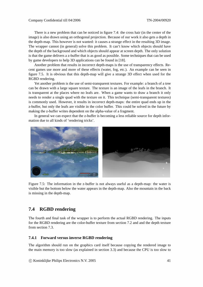
Company Confidential till 04/2006 TN-2004/00920
There is a new problem that can be noticed in figure 7.4: the cross hair (in the center of theimage) is also drawn using an orthogonal projection. Because of our work it also gets a depth inthe depth-map. This however is not wanted: it causes a strange effect in the resulting 3D image.The wrapper cannot (in general) solve this problem. It can’t know which objects should havethe depth of the background and which objects should appear at screen depth. The only solutionis that the game delivers a z-buffer that is as good as possible. Some techniques that can be usedby game developers to help 3D applications can be found in [18].
Another problem that results in incorrect depth-maps is the use of transparency effects. Re-cent games use more and more of these effects (water, fog, etc.). An example can be seen infigure 7.5. It is obvious that this depth-map will give a strange 3D effect when used for theRGBD rendering.
Yet another problem is the use of semi-transparent textures. For example: a branch of a treecan be drawn with a large square texture. The texture is an image of the leafs in the branch. Itis transparent at the places where no leafs are. When a game wants to draw a branch it onlyneeds to render a single quad with the texture on it. This technique (semi-transparent textures)is commonly used. However, it results in incorrect depth-maps: the entire quad ends up in thez-buffer, but only the leafs are visible in the color buffer. This could be solved in the future bymaking the z-buffer writes dependent on the alpha-value of a fragment.
In general we can expect that the z-buffer is becoming a less reliable source for depth infor-mation due to all kinds of ‘rendering tricks’.
Figure 7.5: The information in the z-buffer is not always useful as a depth-map: the water isvisible but the bottom below the water appears in the depth-map. Also the mountain in the backis missing in the depth-map.
7.4 RGBD rendering
The fourth and final task of the wrapper is to perform the actual RGBD rendering. The inputsfor the RGBD rendering are the color-buffer texture from section 7.2 and and the depth texturefrom section 7.3.
7.4.1 Forward versus inverse RGBD rendering
The algorithm should run on the graphics card itself because copying the rendered image tothe main memory is too slow (as explained in section 3.3) and because the CPU is too slow to
c© Koninklijke Philips Electronics N.V. 2005 41
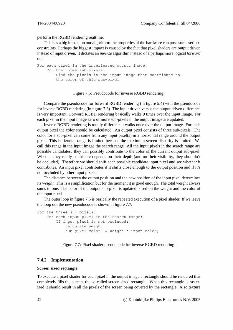
TN-2004/00920 Company Confidential till 04/2006
perform the RGBD rendering realtime.This has a big impact on our algorithm: the properties of the hardware can pose some serious
constraints. Perhaps the biggest impact is caused by the fact that pixel shaders are output driveninstead of input driven. It dictates aninversealgorithm instead of a perhaps more logicalforwardone.
For each pixel in the interleaved output image:For the three sub-pixels:
Find the pixels in the input image that contribute tothe color of this sub-pixel
Figure 7.6: Pseudocode for inverse RGBD rendering.
Compare the pseudocode for forward RGBD rendering (in figure 5.4) with the pseudocodefor inverse RGBD rendering (in figure 7.6). The input driven versus the output driven differenceis very important. Forward RGBD rendering basically walks 9 times over the input image. Foreach pixel in the input image zero or more sub-pixels in the output image are updated.
Inverse RGBD rendering is totally different: it walks once over the output image. For eachoutput pixel the color should be calculated. An output pixel consists of three sub-pixels. Thecolor for a sub-pixel can come from any input pixel(s) in a horizontal range around the outputpixel. This horizontal range is limited because the maximum screen disparity is limited. Wecall this range in the input image the search range. All the input pixels in the search range arepossible candidates: they can possibly contribute to the color of the current output sub-pixel.Whether they really contribute depends on their depth (and on their visibility, they shouldn’tbe occluded). Therefore we should shift each possible candidate input pixel and see whether itcontributes. An input pixel contributes if it shifts close enough to the output position and if it’snot occluded by other input pixels.
The distance between the output position and the new position of the input pixel determinesits weight. This is a simplification but for the moment it is good enough. The total weight alwayssums to one. The color of the output sub-pixel is updated based on the weight and the color ofthe input pixel.
The outer loop in figure 7.6 is basically the repeated execution of a pixel shader. If we leavethe loop out the new pseudocode is shown in figure 7.7.
For the three sub-pixels:For each input pixel in the search range:
If input pixel is not occluded:calculate weightsub-pixel color += weight * input color;
Figure 7.7: Pixel shader pseudocode for inverse RGBD rendering.
7.4.2 Implementation
Screen sized rectangle
To execute a pixel shader for each pixel in the output image a rectangle should be rendered thatcompletely fills the screen, the so-called screen sized rectangle. When this rectangle is raster-ized it should result in all the pixels of the screen being covered by the rectangle. Also texture
42 c© Koninklijke Philips Electronics N.V. 2005
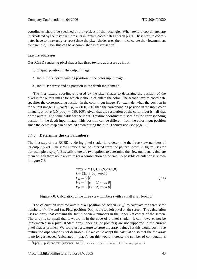
Company Confidential till 04/2006 TN-2004/00920
coordinates should be specified at the vertices of the rectangle. When texture coordinates areinterpolated by the rasterizer it results in texture coordinates at each pixel. These texture coordi-nates have to be exactly correct (since the pixel shader uses them to calculate the viewnumbersfor example). How this can be accomplished is discussed in3.
Texture addresses
Our RGBD rendering pixel shader has three texture addresses as input:
1. Output: position in the output image.
2. Input RGB: corresponding position in the color input image.
3. Input D: corresponding position in the depth input image.
The first texture coordinate is used by the pixel shader to determine the position of thepixel in the output image for which it should calculate the color. The second texture coordinatespecifies the corresponding position in the color input image. For example, when the position inthe output image isoutput(x, y) = (100, 200) then the corresponding position in the input colorimage isinputRGB(x, y) = (50, 100), given that the resolution of the color input is half thatof the output. The same holds for the input D texture coordinate: it specifies the correspondingposition in the depth input image. This position can be different from the color input positionsince the depth-map can be scaled down during the Z to D conversion (see page 38).
7.4.3 Determine the view numbers
The first step of our RGBD rendering pixel shader is to determine the three view numbers ofits output pixel. The view numbers can be inferred from the pattern shown in figure 2.8 (forour example display). Basically there are two options to determine the view numbers: calculatethem or look them up in a texture (or a combination of the two). A possible calculation is shownin figure 7.8.
array V = {1,3,5,7,9,2,4,6,8}i = (3x+ 4y) mod 9VR = V [i]VG = V [(i+ 1) mod 9]VB = V [(i+ 2) mod 9]
(7.1)
Figure 7.8: Calculation of the three view numbers (with a small array lookup.)
The calculation uses the output pixel position on screen(x, y) to calculate the three viewnumbers:VR, VG andVB. Pixel position(0, 0) is the top left pixel on the screen. The calculationuses an array that contains the first nine view numbers in the upper left corner of the screen.The array is so small that it would fit in the code of a pixel shader. It can however not beimplemented in a pixel shader: array indexing (or pointers) are not supported in the currentpixel shader profiles. We could use a texture to store the array values but this would cost threetexture lookups which is not desirable. Or we could adapt the calculation so that the the arrayis no longer needed (calculated in place), but this would increase the number of computations
3OpenGL pixel and texel placement:http://www.bpeers.com/articles/glpixel/
c© Koninklijke Philips Electronics N.V. 2005 43
TN-2004/00920 Company Confidential till 04/2006
which is also not desirable. A better approach is to get rid off the computations and only use atexture lookup.
It is possible to create a large texture (with the same resolution as the output resolution)that contains for each output pixel the view numbers as a RGB color value. In the pixel shaderonly a single texture fetch is needed then, which is cheap. This single texture fetch returns thethree view numbers as a RGB color value. No calculations are needed then, but more memorybandwidth is used.
We can considerably decrease the size of the texture by making use of the repeating patternin the numbers. The repeating square is 3x9 pixels, which means that after three pixels in thehorizontal direction the numbers start to repeat. The same holds for nine pixels in the verticaldirection.
Textures in OpenGL are required to have a width and height that are both powers of two.Since the size of the view number texture is not a power of two this is troublesome. Two OpenGLextensions exist that can remove this limitation:
• ARB_texture_rectangle
– dimension-dependent (non-normalized) texture coordinates: [0..w]x[0..h] range.
– REPEAT wrap mode not supported.
• ARB_texture_non_power_of_two
– dimension-independent (normalized) texture coordinates: [0..1]x[0..1] range.
– REPEAT wrap mode supported.
The ARB_texture_rectangle extension has been used because it is supported on more graph-ics cards. Since the repeat wrap mode is not supported the modulo division of the texture coor-dinates is done in the pixel shader itself (see figure 7.9).
float2 TexCoordViewNrs;TexCoordViewNrs.x = fmod(Input.TexCoordOutput.x, 3); // x = [0.5 .. 2.5]TexCoordViewNrs.y = fmod(Input.TexCoordOutput.y, 9); // y = [0.5 .. 8.5]
float3 ViewNrs; ViewNrs = texRECT(ViewNrTexture, TexCoordViewNrs);ViewNrs = ViewNrs - (5/255.0); //central view is 0 now
Figure 7.9: Cg pixel shader code for determining the three view numbers.
After the view numbers have been fetched from the texture they are all positive. For theRGBD rendering it is needed that the central view is zero. A constant value is subtracted fromthe view numbers to accomplish this.
7.4.4 RGBD rendering variants
When the viewnumbers are known the next step of the pixel shader is to perform the RGBDrendering. Three pixel shader variants for the RGBD rendering have been developed. Theydiffer in their computational cost and the quality of their output.
1. Output-depth RGBD rendering
2. Input-depth find-nearest RGBD rendering
44 c© Koninklijke Philips Electronics N.V. 2005
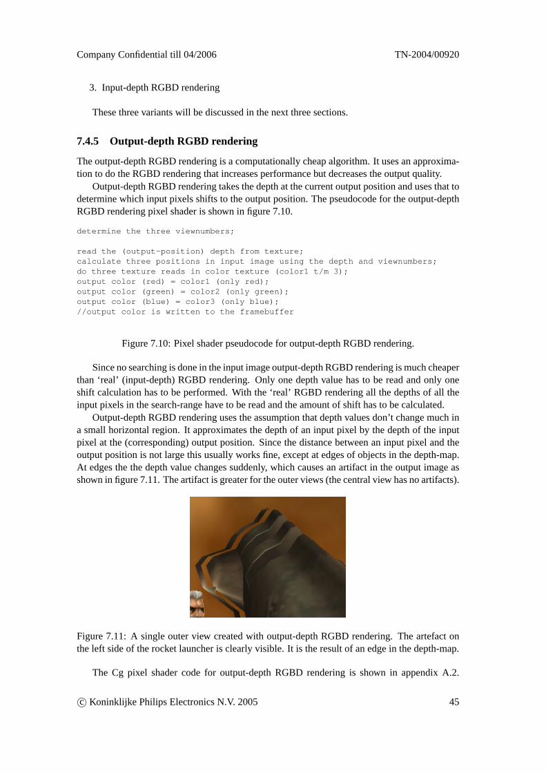
Company Confidential till 04/2006 TN-2004/00920
3. Input-depth RGBD rendering
These three variants will be discussed in the next three sections.
7.4.5 Output-depth RGBD rendering
The output-depth RGBD rendering is a computationally cheap algorithm. It uses an approxima-tion to do the RGBD rendering that increases performance but decreases the output quality.
Output-depth RGBD rendering takes the depth at the current output position and uses that todetermine which input pixels shifts to the output position. The pseudocode for the output-depthRGBD rendering pixel shader is shown in figure 7.10.
determine the three viewnumbers;
read the (output-position) depth from texture;calculate three positions in input image using the depth and viewnumbers;do three texture reads in color texture (color1 t/m 3);output color (red) = color1 (only red);output color (green) = color2 (only green);output color (blue) = color3 (only blue);//output color is written to the framebuffer
Figure 7.10: Pixel shader pseudocode for output-depth RGBD rendering.
Since no searching is done in the input image output-depth RGBD rendering is much cheaperthan ‘real’ (input-depth) RGBD rendering. Only one depth value has to be read and only oneshift calculation has to be performed. With the ‘real’ RGBD rendering all the depths of all theinput pixels in the search-range have to be read and the amount of shift has to be calculated.
Output-depth RGBD rendering uses the assumption that depth values don’t change much ina small horizontal region. It approximates the depth of an input pixel by the depth of the inputpixel at the (corresponding) output position. Since the distance between an input pixel and theoutput position is not large this usually works fine, except at edges of objects in the depth-map.At edges the the depth value changes suddenly, which causes an artifact in the output image asshown in figure 7.11. The artifact is greater for the outer views (the central view has no artifacts).
Figure 7.11: A single outer view created with output-depth RGBD rendering. The artefact onthe left side of the rocket launcher is clearly visible. It is the result of an edge in the depth-map.
The Cg pixel shader code for output-depth RGBD rendering is shown in appendix A.2.
c© Koninklijke Philips Electronics N.V. 2005 45
TN-2004/00920 Company Confidential till 04/2006
When compiled with the fp30 profile the Cg program is 30 instructions long (of which 5 aretexture fetches). The performance will be discussed in chapter 8.
The code basically shows how a single depth value is read (using the output position) andhow this value is used to calculate thex position of three input pixels. The vector datatypefloat3 is used to calculate three results (for r,g,b) at once. Graphics hardware can do vectorizedcomputations (with up to four components) without performance loss compared to scalar com-putations. The calculatedx positions are used as the texture address for three texture fetches inthe color input.
7.4.6 Input-depth find-nearest RGBD rendering
The second pixel shader variant that has been developed is called input-depth find-nearest. Asthe name states it uses the depth from the input position. This is the correct approach: an inputpixel is shifted based on its own depth.
The second part of the name is find-nearest. This refers to the fact that the algorithm onlyfinds one input pixel (per sub-pixel in the output) that shifts the nearest to the output position.The algorithm is computationally more expensive than the previous (output-depth) variant. Butit still doesn’t perform all the operations needed for a ‘real’ RGBD rendering algorithm. Noocclusion handling or filtering is done.
The pseudocode for the input-depth find-nearest RGBD rendering pixel shader is shown infigure 7.12.
determine the three viewnumbers;
minimum distance = infinite;for each input pixel (i) in the search range:
read depth from texture;for the three sub-pixels (vectorized):
calculate new position based on depth;calculate distance between output position and new position;
if distance < minimum distance:nearest pixel = i;minimum distance = distance;
for the three nearest input pixels:read color from texture;output sub-pixel color = color; (only r,g or b)
//output color is written to the framebuffer
Figure 7.12: Pixel shader pseudocode for input-depth find-nearest RGBD rendering.
The algorithm consists of a small loop: it walks over a small horizontal region in the inputimage around the output position. The position (in the output image) of the current input pixel iscalculated based on its depth. This is done for all the three views at once (vectorized). Then thedistance between the calculated position and the output position is measured. The goal is to findthe pixel with the smallest distance. This is why the algorithm is called find-nearest. Actuallythere are three nearest pixels (for r,g,b). Once these pixels have been found three texture fetchesare done in the color input texture to get the colors. Only one color component of each color isused. These three components are then combined into the final output color of the pixel shader.This pixel then ends up in the interleaved output image.
46 c© Koninklijke Philips Electronics N.V. 2005
Company Confidential till 04/2006 TN-2004/00920
The algorithm explained in section 5.1.3 to handle occlusions is not used. This means thatpixels that are not visible in a new view are not removed like they should. The algorithm tohandle occlusions is not used because that allows us to do only a single pass over the inputpixels. Using the algorithm would mean that three passes over the input pixels are necessary(for the three viewnumbers), which is more expensive. Also no filtering is done: the color of thepixel that shifts the closest to the output position is just used.
This variant is more expensive than the output-depth variant above because a search is donein the input image. The width of the search range in the input image is adjustable. This meansthat more texture fetches in the depth texture are needed. A larger search range means moredepth in the resulting 3D image but it also means more texture fetches.
This variant is also more expensive because more calculations are needed: the minimumdistance has to be found. The distance has to be computed for each candidate input pixel basedon its depth. Again, these calculations have been vectorized wherever possible.
The Cg pixel shader code for input-depth find-nearest RGBD rendering is shown in ap-pendix A.3. When compiled with the fp30 profile the Cg program is 120 instructions long (ofwhich 13 are texture fetches). These numbers are for a search range of 9 input pixels. Loops areunrolled by the Cg compiler.
After implementing and testing this pixel shader it became clear that this algorithm is notan improvement over the previous (output-depth) version. The shader is slower but it doesn’tproduce better results. The artifacts caused by this variant are more noticeable than the artifactsof the previous variant, especially for moving images. The artifacts can be seen on edges (in thedepth-map). The artifacts can vary quickly when the input image changes only slightly whereasthe artifacts of the previous variant are more stable.
Because of the bad quality/performance ratio of this variant it is no longer used. Also noperformance measurements will be done in chapter 8 for this variant.
7.4.7 Input-depth RGBD rendering
The third RGBD rendering variant is called input-depth. The goal of this variant is to be equiv-alent with the already existing offline algorithm (from section 5.2.1). So it should produce highquality output, which means: handle occlusions and deocclusions and do proper filtering.
The pseudocode for the input-depth RGBD rendering pixel shader is shown in figure 7.13.The algorithm consists of three major parts: first the color and depth of the all the input pixelsin the search range are read (from the texture) and stored into two arrays. This done because thecolor and depth of an input pixel are needed multiple times later on. Storing them in an arrayreduces the the number of texture fetches that are needed. Array indexing is possible in this casebecause loops are unrolled by the Cg compiler.
The second part of the algorithm uses the depth of the input pixels to compute their newpositions. For each input pixel three new positions are computed (for the three viewnumbers ofthe RGB sub-pixels). These computations are done vectorized for performance reasons.
The new positions of the input pixels are used in the third part of the algorithm. Here it ischecked if a pixel is not occluded by another pixel. If this is not the case a so called weight iscalculated. The weight defines how much the color of the input pixel contributes to the colorof the output sub-pixel. The weight can be calculated by using a filter function. Based on theweight the color of the input pixel is added to the color of the output sub-pixel. The third part ofthe algorithm cannot be vectorised like the previous part. This is because the occlusion detectionalgorithm is based on the order of which the input pixel are processed. And it is almost never the
c© Koninklijke Philips Electronics N.V. 2005 47
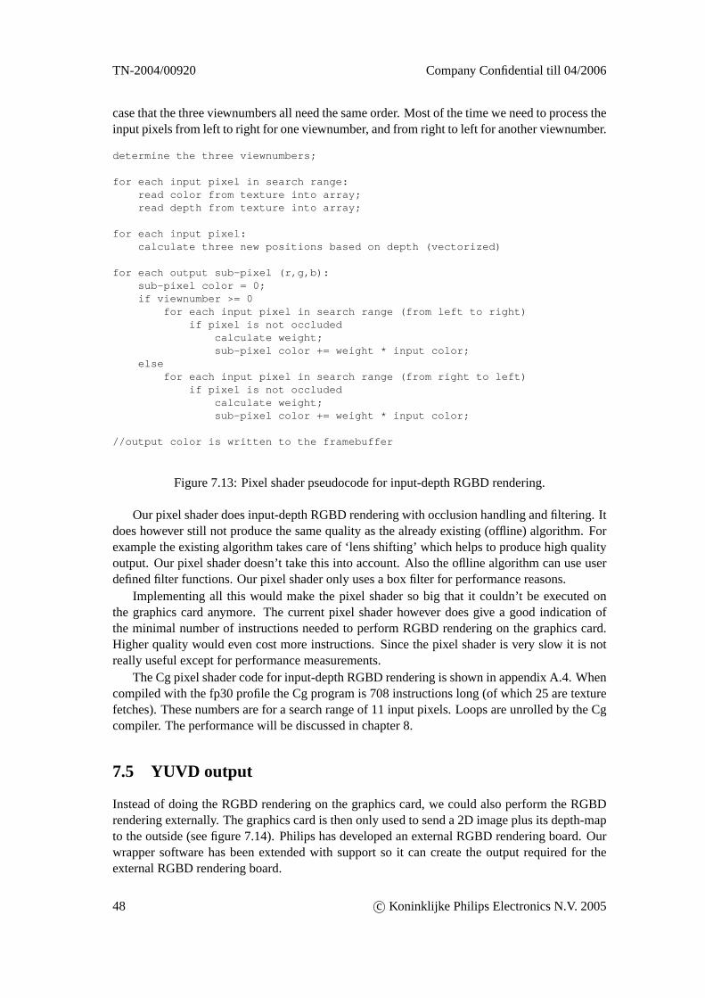
TN-2004/00920 Company Confidential till 04/2006
case that the three viewnumbers all need the same order. Most of the time we need to process theinput pixels from left to right for one viewnumber, and from right to left for another viewnumber.
determine the three viewnumbers;
for each input pixel in search range:read color from texture into array;read depth from texture into array;
for each input pixel:calculate three new positions based on depth (vectorized)
for each output sub-pixel (r,g,b):sub-pixel color = 0;if viewnumber >= 0
for each input pixel in search range (from left to right)if pixel is not occluded
calculate weight;sub-pixel color += weight * input color;
elsefor each input pixel in search range (from right to left)
if pixel is not occludedcalculate weight;sub-pixel color += weight * input color;
//output color is written to the framebuffer
Figure 7.13: Pixel shader pseudocode for input-depth RGBD rendering.
Our pixel shader does input-depth RGBD rendering with occlusion handling and filtering. Itdoes however still not produce the same quality as the already existing (offline) algorithm. Forexample the existing algorithm takes care of ‘lens shifting’ which helps to produce high qualityoutput. Our pixel shader doesn’t take this into account. Also the oflline algorithm can use userdefined filter functions. Our pixel shader only uses a box filter for performance reasons.
Implementing all this would make the pixel shader so big that it couldn’t be executed onthe graphics card anymore. The current pixel shader however does give a good indication ofthe minimal number of instructions needed to perform RGBD rendering on the graphics card.Higher quality would even cost more instructions. Since the pixel shader is very slow it is notreally useful except for performance measurements.
The Cg pixel shader code for input-depth RGBD rendering is shown in appendix A.4. Whencompiled with the fp30 profile the Cg program is 708 instructions long (of which 25 are texturefetches). These numbers are for a search range of 11 input pixels. Loops are unrolled by the Cgcompiler. The performance will be discussed in chapter 8.
7.5 YUVD output
Instead of doing the RGBD rendering on the graphics card, we could also perform the RGBDrendering externally. The graphics card is then only used to send a 2D image plus its depth-mapto the outside (see figure 7.14). Philips has developed an external RGBD rendering board. Ourwrapper software has been extended with support so it can create the output required for theexternal RGBD rendering board.
48 c© Koninklijke Philips Electronics N.V. 2005
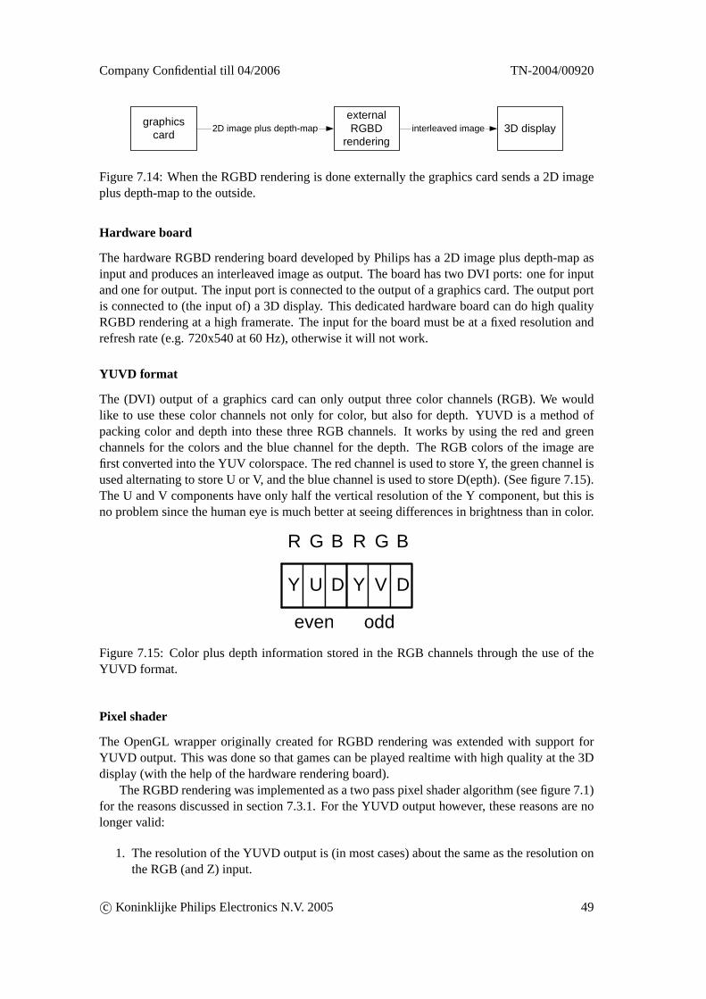
Company Confidential till 04/2006 TN-2004/00920
graphicscard 3D display
externalRGBD
rendering2D image plus depth-map interleaved image
Figure 7.14: When the RGBD rendering is done externally the graphics card sends a 2D imageplus depth-map to the outside.
Hardware board
The hardware RGBD rendering board developed by Philips has a 2D image plus depth-map asinput and produces an interleaved image as output. The board has two DVI ports: one for inputand one for output. The input port is connected to the output of a graphics card. The output portis connected to (the input of) a 3D display. This dedicated hardware board can do high qualityRGBD rendering at a high framerate. The input for the board must be at a fixed resolution andrefresh rate (e.g. 720x540 at 60 Hz), otherwise it will not work.
YUVD format
The (DVI) output of a graphics card can only output three color channels (RGB). We wouldlike to use these color channels not only for color, but also for depth. YUVD is a method ofpacking color and depth into these three RGB channels. It works by using the red and greenchannels for the colors and the blue channel for the depth. The RGB colors of the image arefirst converted into the YUV colorspace. The red channel is used to store Y, the green channel isused alternating to store U or V, and the blue channel is used to store D(epth). (See figure 7.15).The U and V components have only half the vertical resolution of the Y component, but this isno problem since the human eye is much better at seeing differences in brightness than in color.
R G B R G B
Y U D Y V D
even oddFigure 7.15: Color plus depth information stored in the RGB channels through the use of theYUVD format.
Pixel shader
The OpenGL wrapper originally created for RGBD rendering was extended with support forYUVD output. This was done so that games can be played realtime with high quality at the 3Ddisplay (with the help of the hardware rendering board).
The RGBD rendering was implemented as a two pass pixel shader algorithm (see figure 7.1)for the reasons discussed in section 7.3.1. For the YUVD output however, these reasons are nolonger valid:
1. The resolution of the YUVD output is (in most cases) about the same as the resolution onthe RGB (and Z) input.
c© Koninklijke Philips Electronics N.V. 2005 49
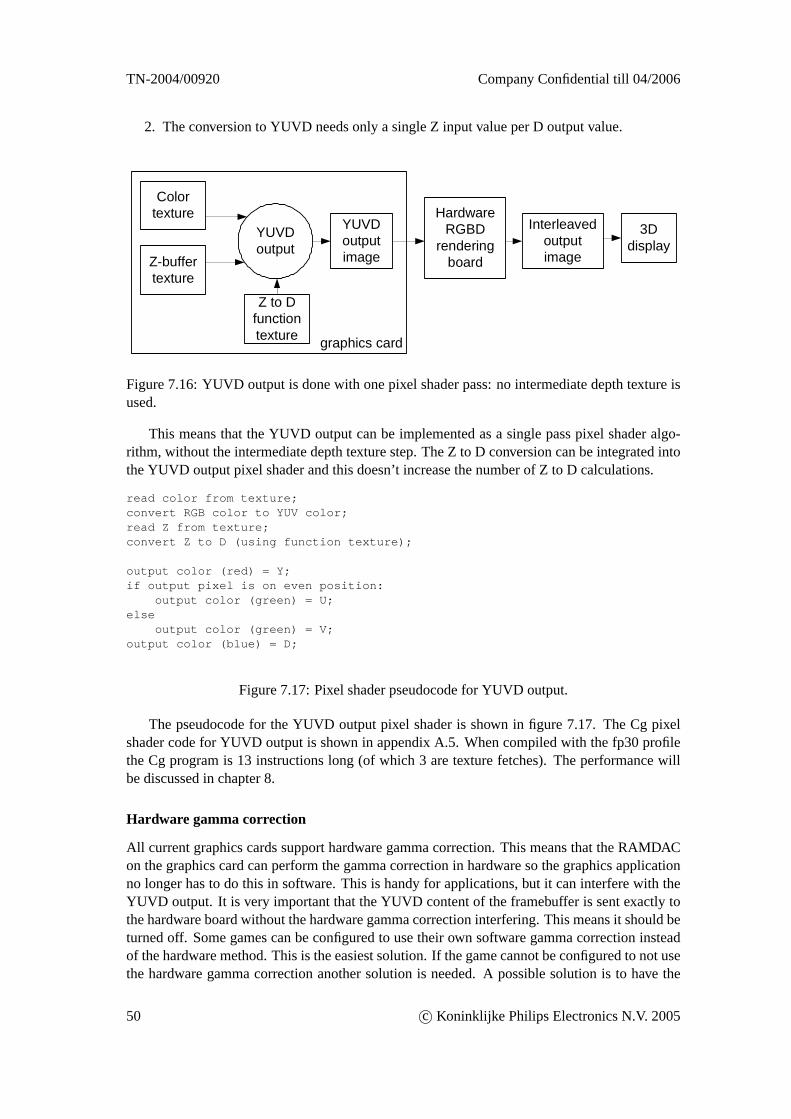
TN-2004/00920 Company Confidential till 04/2006
2. The conversion to YUVD needs only a single Z input value per D output value.
Colortexture
Z-buffertexture
YUVDoutputimage
YUVDoutput
Z to Dfunctiontexture graphics card
HardwareRGBD
renderingboard
3Ddisplay
Interleavedoutputimage
Figure 7.16: YUVD output is done with one pixel shader pass: no intermediate depth texture isused.
This means that the YUVD output can be implemented as a single pass pixel shader algo-rithm, without the intermediate depth texture step. The Z to D conversion can be integrated intothe YUVD output pixel shader and this doesn’t increase the number of Z to D calculations.
read color from texture;convert RGB color to YUV color;read Z from texture;convert Z to D (using function texture);
output color (red) = Y;if output pixel is on even position:
output color (green) = U;else
output color (green) = V;output color (blue) = D;
Figure 7.17: Pixel shader pseudocode for YUVD output.
The pseudocode for the YUVD output pixel shader is shown in figure 7.17. The Cg pixelshader code for YUVD output is shown in appendix A.5. When compiled with the fp30 profilethe Cg program is 13 instructions long (of which 3 are texture fetches). The performance willbe discussed in chapter 8.
Hardware gamma correction
All current graphics cards support hardware gamma correction. This means that the RAMDACon the graphics card can perform the gamma correction in hardware so the graphics applicationno longer has to do this in software. This is handy for applications, but it can interfere with theYUVD output. It is very important that the YUVD content of the framebuffer is sent exactly tothe hardware board without the hardware gamma correction interfering. This means it should beturned off. Some games can be configured to use their own software gamma correction insteadof the hardware method. This is the easiest solution. If the game cannot be configured to not usethe hardware gamma correction another solution is needed. A possible solution is to have the
50 c© Koninklijke Philips Electronics N.V. 2005
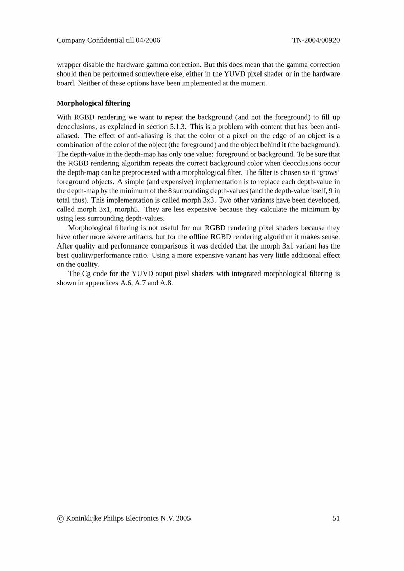
Company Confidential till 04/2006 TN-2004/00920
wrapper disable the hardware gamma correction. But this does mean that the gamma correctionshould then be performed somewhere else, either in the YUVD pixel shader or in the hardwareboard. Neither of these options have been implemented at the moment.
Morphological filtering
With RGBD rendering we want to repeat the background (and not the foreground) to fill updeocclusions, as explained in section 5.1.3. This is a problem with content that has been anti-aliased. The effect of anti-aliasing is that the color of a pixel on the edge of an object is acombination of the color of the object (the foreground) and the object behind it (the background).The depth-value in the depth-map has only one value: foreground or background. To be sure thatthe RGBD rendering algorithm repeats the correct background color when deocclusions occurthe depth-map can be preprocessed with a morphological filter. The filter is chosen so it ‘grows’foreground objects. A simple (and expensive) implementation is to replace each depth-value inthe depth-map by the minimum of the 8 surrounding depth-values (and the depth-value itself, 9 intotal thus). This implementation is called morph 3x3. Two other variants have been developed,called morph 3x1, morph5. They are less expensive because they calculate the minimum byusing less surrounding depth-values.
Morphological filtering is not useful for our RGBD rendering pixel shaders because theyhave other more severe artifacts, but for the offline RGBD rendering algorithm it makes sense.After quality and performance comparisons it was decided that the morph 3x1 variant has thebest quality/performance ratio. Using a more expensive variant has very little additional effecton the quality.
The Cg code for the YUVD ouput pixel shaders with integrated morphological filtering isshown in appendices A.6, A.7 and A.8.
c© Koninklijke Philips Electronics N.V. 2005 51
TN-2004/00920 Company Confidential till 04/2006
Chapter 8
Performance measurements andanalysis
Since our software will be used to play interactive games performance is an important aspect.We have measured and analyzed the performance of both our own software and the alreadyexisting ‘rendering multiple times’ software. The results are presented in this chapter.
First the overall performance (the achieved framerate) will be measured in two games. Usingthese measurements we will draw some conclusions. Then we will look more closely at thevarious detailed aspects that determine this overall performance.
Only the performance of our software will be measured and not the quality. Quality mea-surement is a difficult and (partly) subjective task, which is not considered useful at the moment.The quality of the RGBD rendering variants has already been described in section 7.4.4.
8.1 Systems
For the performance measurements two PC’s were used:
• System ‘5950’: Pentium 4 (2.4 GHz), Nvidia Geforce FX 5950 ultra (AGP 8x)
• System ‘6800’: Pentium 4 (2.4 GHz), Nvidia Geforce FX 6800 ultra (AGP 8x)
System ‘6800’ has a graphics card of the latest generation, the graphics card in system ’5950’is one generation older. Both cards are the fastest versions of their respective generation. Doingthe measurements on two systems enables us to analyze how the software scales with respect tonew graphics cards.
Both systems have almost identical hard- and software except for the amount of memory,but that shouldn’t affect our measurements. The software installed on both systems includes thefollowing:
• Windows XP
• Nvidia ForceWare drivers 66.93
• Nvidia Cg Compiler Release 1.3 Beta 2
52 c© Koninklijke Philips Electronics N.V. 2005
Company Confidential till 04/2006 TN-2004/00920
8.2 Overall performance
The overall performance of a graphics application can be measured in frames/second (fps). Agame can be played realtime if the number of frames per seconds stays above a certain minimalvalue. Usually 30 to 50 frames per second is considered the minimum for realtime gaming.
8.2.1 Measurements
A series of tests were performed to determine the overall performance in two games: Quake 3and Doom 3. Quake 3 is an old game (released in 1999) while Doom 3 is a fairly new game(released in 2004). In each game a demo was recorded and later played back, while using thefollowing wrappers/pixel shaders:
no wrapper: The game uses the original opengl32.dll file directly. The resolution mentionedin the table is the resolution at which the game renders.
empty wrapper: The game uses the an empty wrapper DLL. This wrapper DLL only forwardsfunction calls to the original DLL, without doing anything else. The resolution mentionedin the table is the resolution at which the game renders.
9 view rendering: The game uses the old ‘rendering multiple times’ wrapper DLL, as explainedin chapter 3. The game renders at 533x400 and the resolution of the interleaved outputimage is 1600x1200.
RGBD output-depth: The game uses our wrapper DLL with the output-depth RGBD renderingpixel shader (see section 7.4.5). The game renders at 800x600 and the resolution of theinterleaved output image is 1600x1200. The intermediate depth texture is not scaled down:it is also 800x600.
RGBD input-depth: The game uses our wrapper DLL with the input-depth RGBD renderingpixel shader (see section 7.4.7). The pixel shader uses a search range of 11 pixels inthe input image. (The effect of the search range on the performance is measured in sec-tion 8.3). The game renders at 800x600 and the resolution of the interleaved output imageis 1600x1200. The intermediate depth texture is not scaled down: it is also 800x600.
YUVD output: The game uses our wrapper DLL with the YUVD output pixel shader (seesection 7.5). The game renders at 720x540 and the resolution of YUVD output is also720x540.
The results of the measurements are shown in table 8.1 and 8.2. The input-depth find-nearestRGBD rendering variant was not included in the measurements because it is slower than theoutput-depth variant but doesn’t produce better results (see section 7.4.6).
In the tables two numbers are presented: frames/seconds (fps) and time per frame (ms/frame).The time per frame is simply the reciprocal of the framerate.
8.2.2 Analysis
What can be concluded from the overall performance measurements?
• Playing recent games on the 3D display is only possible with the RGBD output-depthwrapper (33.4 fps) or with the YUVD output wrapper in combination with the hardwarerendering (52.7 fps). The mentioned framerates are for an 6800 card.
c© Koninklijke Philips Electronics N.V. 2005 53
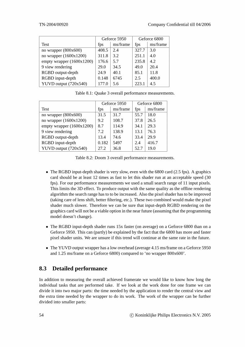
TN-2004/00920 Company Confidential till 04/2006
Geforce 5950 Geforce 6800Test fps ms/frame fps ms/frameno wrapper (800x600) 408.5 2.4 327.7 3.0no wrapper (1600x1200) 311.8 3.2 251.1 4.0empty wrapper (1600x1200)176.6 5.7 235.8 4.29 view rendering 29.0 34.5 49.0 20.4RGBD output-depth 24.9 40.1 85.1 11.8RGBD input-depth 0.148 6745 2.5 400.0YUVD output (720x540) 177.0 5.6 223.1 4.5
Table 8.1: Quake 3 overall performance measurements.
Geforce 5950 Geforce 6800Test fps ms/frame fps ms/frameno wrapper (800x600) 31.5 31.7 55.7 18.0no wrapper (1600x1200) 9.2 108.7 37.8 26.5empty wrapper (1600x1200)8.7 114.9 34.1 29.39 view rendering 7.2 138.9 13.1 76.3RGBD output-depth 13.4 74.6 33.4 29.9RGBD input-depth 0.182 5497 2.4 416.7YUVD output (720x540) 27.2 36.8 52.7 19.0
Table 8.2: Doom 3 overall performance measurements.
• The RGBD input-depth shader is very slow, even with the 6800 card (2.5 fps). A graphicscard should be at least 12 times as fast to let this shader run at an acceptable speed (30fps). For our performance measurements we used a small search range of 11 input pixels.This limits the 3D effect. To produce output with the same quality as the offline renderingalgorithm the search range has to to be increased. Also the pixel shader has to be improved(taking care of lens shift, better filtering, etc.). These two combined would make the pixelshader much slower. Therefore we can be sure that input-depth RGBD rendering on thegraphics card will not be a viable option in the near future (assuming that the programmingmodel doesn’t change).
• The RGBD input-depth shader runs 15x faster (on average) on a Geforce 6800 than on aGeforce 5950. This can (partly) be explained by the fact that the 6800 has more and fasterpixel shader units. We are unsure if this trend will continue at the same rate in the future.
• The YUVD output wrapper has a low overhead (average 4.15 ms/frame on a Geforce 5950and 1.25 ms/frame on a Geforce 6800) compared to ‘no wrapper 800x600’.
8.3 Detailed performance
In addition to measuring the overall achieved framerate we would like to know how long theindividual tasks that are performed take. If we look at the work done for one frame we candivide it into two major parts: the time needed by the application to render the central view andthe extra time needed by the wrapper to do its work. The work of the wrapper can be furtherdivided into smaller parts:
54 c© Koninklijke Philips Electronics N.V. 2005
Company Confidential till 04/2006 TN-2004/00920
1. Application render time
2. Wrapper overhead time:
(a) Save & set state
(b) Update textures
(c) Z to D
(d) RGBD rendering
(e) Restore state
For the YUVD output the division is somewhat different: there is no separate Z to D stepsince that is integrated into the YUVD output step:
1. Application render time
2. Wrapper overhead time:
(a) Save & set state
(b) Update textures
(c) YUVD output
(d) Restore state
8.3.1 Framerate formula
The achieved frameratef (in frames/sec) of a graphics application in combination with ourwrapper is determined by the following formula:
frameratef =1
a+ w(8.1)
wherea is the time (in seconds) needed by the application to render a frame andw is theoverhead time (in seconds) needed by the wrapper to do its work. Suppose an application (with-out wrapper) achieves a framerate of 50 frames/sec. This means thata is 0.02 seconds (20 ms).If we use this application in combination with a wrapper that needs 10 ms per frame to do itswork then framerate will drop to 1
0.02+0.01 = 33.3 fps.Formula 8.1 is a simplification of the real situation. Using a wrapper DLL not only affects
the timew, but also the timea needed by the application to render a frame. This is because theforwarding of function calls to the original DLL takes some time. We will ignore this effect inour calculations, but this effect is visible in table 8.1. There is a difference in framerate between‘no wrapper (1600x1200)’ and ‘empty wrapper (1600x1200)’.
We would like to know how large the overhead timew is for the different wrappers/pixelshaders. This would enable us to calculate the new framerate of a graphics application given theoriginal framerate (without wrapper).
Also our software has many parameters (different resolutions, search range, etc.). We wouldlike to know how these parameters affect the performance of the individual steps shown in sec-tion 8.3 and and how this scales.
Parameters
The parameters in table 8.3 can possibly affect the performance of our software.
c© Koninklijke Philips Electronics N.V. 2005 55
TN-2004/00920 Company Confidential till 04/2006
Application render resolution (# pixels) Na
Color depth (bits per pixel) BcZ-buffer precision (bits per pixel) BzDepth texture resolution (# pixels) Nd
RGBD or YUVD output resolution (# pixels) No
Z to D function texture width (# texels) Nf
Table 8.3: Parameters that can possibly affect the performance of our software.
8.3.2 Measurements
Reliability
We have added code in our wrapper that measures how long the individual steps shown in sec-tion 8.3 take. This is not as simple as it seems: it is not enough to measure the time it takes to dothe OpenGL function calls. The OpenGL calls only submit rendering requests to a buffer. Theactual rendering is done on the graphics card asynchronously later. To get good timing resultswe have to wait until the OpenGL calls have been executed (by the hardware). TheglFinishcall can be used for that: it blocks until all the previous commands have been executed. It syn-chronizes the CPU and the GPU. This means that the timing code in the wrapper affects themeasurements, but this is inevitable.
In the next five sections the individual measurements will be discussed. We will measure thefollowing steps:
• Update textures
• Z to D
• RGBD output-depth rendering
• RGBD input-depth rendering
• YUVD output
We will not measure the time taken by the save & set state and the restore state steps sincethey are very small.
Update textures
Update textures copies the framebuffer (both RGB and Z) to two textures. Since this is donewith a memory copy on the graphics card itself the time this takes will be proportional to therender resolution of the application (Na). Two other parameters that affect the performance arethe color depth of the color buffer (Bc) and the precision of the z-buffer (Bz).
We variedNa and measured the time update textures takes (withBc = 8 andBz = 24). Asexpected the performance scaled linearly with the resolution. This resulted in 1.56 ns/pixel ona Geforce 5950 and 0.69 ns/pixel on a Geforce 6800. Using these results we can calculate thespeed at which both graphics cards can copy memory internally.
Memory copy bandwidth (5950)=1
1.56 · 10−9· 3 · 8 + 24
8= 3.58 GB/s (8.2)
56 c© Koninklijke Philips Electronics N.V. 2005
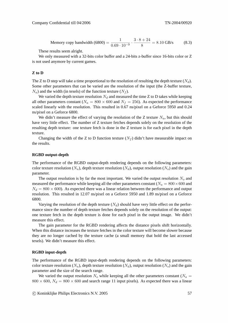
Company Confidential till 04/2006 TN-2004/00920
Memory copy bandwidth (6800)=1
0.69 · 10−9· 3 · 8 + 24
8= 8.10 GB/s (8.3)
These results seem alright.We only measured with a 32-bits color buffer and a 24-bits z-buffer since 16-bits color or Z
is not used anymore by current games.
Z to D
The Z to D step will take a time proportional to the resolution of resulting the depth texture (Nd).Some other parameters that can be varied are the resolution of the input (the Z-buffer texture,Na) and the width (in texels) of the function texture (Nf ).
We varied the depth texture resolutionNd and measured the time Z to D takes while keepingall other parameters constant (Na = 800 × 600 andNf = 256). As expected the performancescaled linearly with the resolution. This resulted in 0.67 ns/pixel on a Geforce 5950 and 0.24ns/pixel on a Geforce 6800.
We didn’t measure the effect of varying the resolution of the Z textureNa, but this shouldhave very little effect. The number of Z texture fetches depends solely on the resolution of theresulting depth texture: one texture fetch is done in the Z texture is for each pixel in the depthtexture.
Changing the width of the Z to D function texture (Nf ) didn’t have measurable impact onthe results.
RGBD output-depth
The performance of the RGBD output-depth rendering depends on the following parameters:color texture resolution (Na), depth texture resolution (Nd), output resolution (No) and the gainparameter.
The output resolution is by far the most important. We varied the output resolutionNo andmeasured the performance while keeping all the other parameters constant (Na = 800×600 andNd = 800× 600). As expected there was a linear relation between the performance and outputresolution. This resulted in 12.07 ns/pixel on a Geforce 5950 and 1.89 ns/pixel on a Geforce6800.
Varying the resolution of the depth texture (Nd) should have very little effect on the perfor-mance since the number of depth texture fetches depends solely on the resolution of the output:one texture fetch in the depth texture is done for each pixel in the output image. We didn’tmeasure this effect.
The gain parameter for the RGBD rendering affects the distance pixels shift horizontally.When this distance increases the texture fetches in the color texture will become slower becausethey are no longer cached by the texture cache (a small memory that hold the last accessedtexels). We didn’t measure this effect.
RGBD input-depth
The performance of the RGBD input-depth rendering depends on the following parameters:color texture resolution (Na), depth texture resolution (Nd), output resolution (No) and the gainparameter and the size of the search range.
We varied the output resolutionNo while keeping all the other parameters constant (Na =800 × 600, Nd = 800 × 600 and search range 11 input pixels). As expected there was a linear
c© Koninklijke Philips Electronics N.V. 2005 57
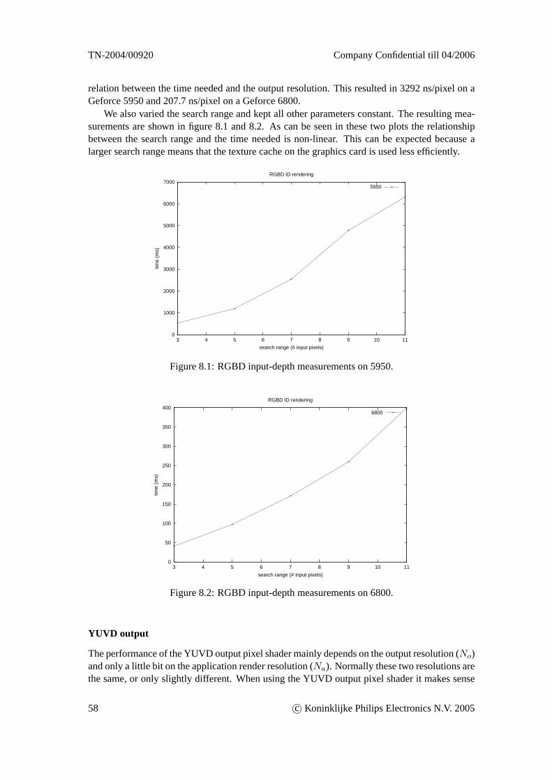
TN-2004/00920 Company Confidential till 04/2006
relation between the time needed and the output resolution. This resulted in 3292 ns/pixel on aGeforce 5950 and 207.7 ns/pixel on a Geforce 6800.
We also varied the search range and kept all other parameters constant. The resulting mea-surements are shown in figure 8.1 and 8.2. As can be seen in these two plots the relationshipbetween the search range and the time needed is non-linear. This can be expected because alarger search range means that the texture cache on the graphics card is used less efficiently.
0
1000
2000
3000
4000
5000
6000
7000
3 4 5 6 7 8 9 10 11
time
(ms)
search range (# input pixels)
RGBD ID rendering
5950
Figure 8.1: RGBD input-depth measurements on 5950.
0
50
100
150
200
250
300
350
400
3 4 5 6 7 8 9 10 11
time
(ms)
search range (# input pixels)
RGBD ID rendering
6800
Figure 8.2: RGBD input-depth measurements on 6800.
YUVD output
The performance of the YUVD output pixel shader mainly depends on the output resolution (No)and only a little bit on the application render resolution (Na). Normally these two resolutions arethe same, or only slightly different. When using the YUVD output pixel shader it makes sense
58 c© Koninklijke Philips Electronics N.V. 2005
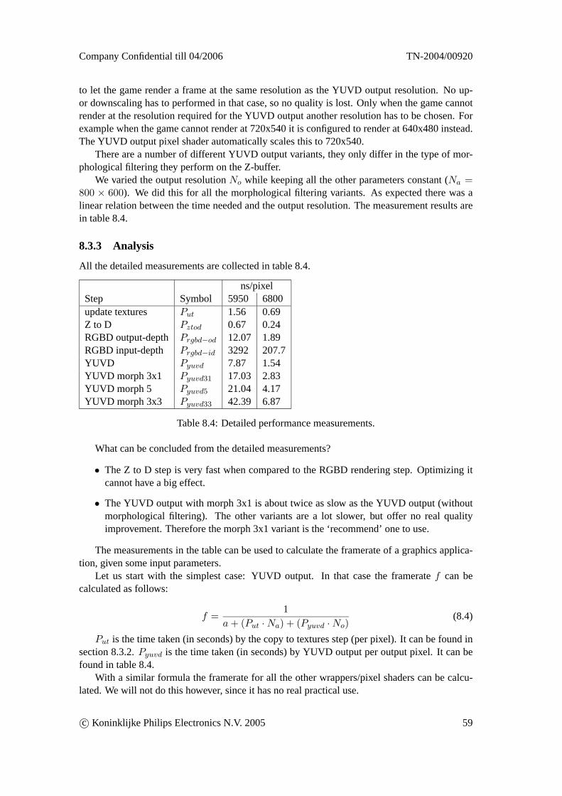
Company Confidential till 04/2006 TN-2004/00920
to let the game render a frame at the same resolution as the YUVD output resolution. No up-or downscaling has to performed in that case, so no quality is lost. Only when the game cannotrender at the resolution required for the YUVD output another resolution has to be chosen. Forexample when the game cannot render at 720x540 it is configured to render at 640x480 instead.The YUVD output pixel shader automatically scales this to 720x540.
There are a number of different YUVD output variants, they only differ in the type of mor-phological filtering they perform on the Z-buffer.
We varied the output resolutionNo while keeping all the other parameters constant (Na =800 × 600). We did this for all the morphological filtering variants. As expected there was alinear relation between the time needed and the output resolution. The measurement results arein table 8.4.
8.3.3 Analysis
All the detailed measurements are collected in table 8.4.
ns/pixelStep Symbol 5950 6800update textures Put 1.56 0.69Z to D Pztod 0.67 0.24RGBD output-depth Prgbd−od 12.07 1.89RGBD input-depth Prgbd−id 3292 207.7YUVD Pyuvd 7.87 1.54YUVD morph 3x1 Pyuvd31 17.03 2.83YUVD morph 5 Pyuvd5 21.04 4.17YUVD morph 3x3 Pyuvd33 42.39 6.87
Table 8.4: Detailed performance measurements.
What can be concluded from the detailed measurements?
• The Z to D step is very fast when compared to the RGBD rendering step. Optimizing itcannot have a big effect.
• The YUVD output with morph 3x1 is about twice as slow as the YUVD output (withoutmorphological filtering). The other variants are a lot slower, but offer no real qualityimprovement. Therefore the morph 3x1 variant is the ‘recommend’ one to use.
The measurements in the table can be used to calculate the framerate of a graphics applica-tion, given some input parameters.
Let us start with the simplest case: YUVD output. In that case the frameratef can becalculated as follows:
f =1
a+ (Put ·Na) + (Pyuvd ·No)(8.4)
Put is the time taken (in seconds) by the copy to textures step (per pixel). It can be found insection 8.3.2.Pyuvd is the time taken (in seconds) by YUVD output per output pixel. It can befound in table 8.4.
With a similar formula the framerate for all the other wrappers/pixel shaders can be calcu-lated. We will not do this however, since it has no real practical use.
c© Koninklijke Philips Electronics N.V. 2005 59
TN-2004/00920 Company Confidential till 04/2006
Chapter 9
Conclusions & future work
9.1 Conclusions
RGBD rendering is a method that takes a 2D image plus its depth-map and uses these to constructnew images for virtual viewpoints. We have investigated how realtime RGBD rendering can beimplemented on a graphics card by using programmable pixel shaders. This was implementedby means of an OpenGL DLL wrapper.
We have accomplished the following:
• We have created an OpenGL DLL wrapper that uses pixel shaders to do RGBD render-ing on a graphics card. Three RGBD rendering variants have been implemented usingpixel shaders. Only one of them (the output-depth variant) is practically useful due toperformance reasons.
• We have analyzed how the information in the z-buffer of a graphics pipeline can be usedas depth information for RGBD rendering. This resulted in the Z to D equation.
• We have modified our OpenGL DLL wrapper and created a new pixel shader that produces‘YUVD output’. YUVD is a method to encode a 2D image plus depth-map in a singleimage. It is used as input for a hardware RGBD rendering board that has been developedby Philips.
Our work resulted in some spinoffs:
• Philips has developed a ‘video-recorder’ OpenGL wrapper [6]. This wrapper logs frame-buffer images to bitmap files on the harddisk. We have created a new video-recorderwrapper that also supports the logging of Z-maps (directly from the z-buffer) and depth-maps (resulting from the Z to D function).
• Philips has developed a CreateWrapper application [6]. It uses an existing DLL file asinput to produce a C source code file that, when compiled, results in an (empty) wrapperDLL. We have made some small modifications to the existing CreateWrapper application.
The most important conclusion of this thesis is that high quality realtime RGBD renderingon the graphics hardware itself is not feasible. This is caused by the limited programming modelof the graphics hardware. A pixel shader is output driven: each execution of a pixel shaderresults in only one output color. It forces us to use an inefficient inverse version of the RGBDrendering algorithm. Either a huge performance increase of the graphics hardware, or a more
60 c© Koninklijke Philips Electronics N.V. 2005
Company Confidential till 04/2006 TN-2004/00920
general programming model is needed. To implement RGBD rendering efficiently we wouldneed input driven pixel shaders that can update the color of multiple output pixels at once.
There are however two other approaches that enable graphical applications such as games tobe played in realtime on the multiview display:
1. Low quality RGBD rendering on graphics hardware. This can be done in realtime on thegraphics hardware itself but the quality is low (resulting in artifacts on edges of objects,less sharp images, etc.).
2. High quality RGBD rendering on a separate RGBD rendering hardware board. In thisscenario the graphics card is still used to convert the information in the z-buffer into adepth-map and to send the 2D image and its depth-map to the hardware board in a specialformat. This enables high quality realtime 3D gaming but a separate hardware board isneeded.
Another important problem for RGBD rendering on the graphics card is that the informationin the z-buffer is increasingly less reliable for use as depth-map. New games use more and more‘rendering tricks’ that result in incorrect depth-maps.
9.2 Future work
There remains enough work for the future:
1. Investigate the effect on our software of enabling anti-aliasing. The game can enableanti-aliasing (multisampling and/or supersampling). How does that affect our wrapper?Possible problems: higher resolution color buffer texture, pixel shader gets executed mul-tiple times per output pixel, etc.
2. Investigate if it is possible to let the game render the central view directly to a texture.Currently the game renders the central view in the framebuffer and the first thing thewrapper does is to copy it to a texture. Letting the game render directly to a texture isexpected to be faster. The OpenGL extension ARB_render_texture can be used for this,but it has some restrictions that could limit its use.
3. Render the depth-map directly to a texture during the Z to D conversion pass. Currently itis rendered to the framebuffer and then copied to a texture directly afterwards. Renderingdirectly to a texture is expected to be faster.
4. Research different kinds of mappings from scene depth to perceived depth (see sec-tion 6.4.4). This could involve making the mappings described in section 6.4.4 realtimeadjustable which allows for easy experimentation with depth effects.
5. Change the behavior of the OpenGL functions listed in table 7.1. These functions causetroubles when viewport scaling is used.
6. Further investigate how the z-buffer errors can be solved. This should result in changesto the wrapper that result in better depth-maps when the application uses all kinds of‘rendering tricks’.
7. Instead of only rendering the central view we could let the game only render the two outerviews and use the two depth-maps to create the in-between views. This would help tosolve the deocclusion problem.
c© Koninklijke Philips Electronics N.V. 2005 61
TN-2004/00920 Company Confidential till 04/2006
8. Improve the detection of the near and far plane values used by the application (see sec-tion 7.3.3).
There are numerous small improvements that can be made in the wrapper and pixel shadersoftware. These have been documented in a text file that is included with source code.
62 c© Koninklijke Philips Electronics N.V. 2005
Company Confidential till 04/2006 TN-2004/00920
References
[1] Vision 3D, What is Stereo Vision?, http://www.vision3d.com/stereo.html
[2] R-P. Berretty and F.J. Peters,Overview of rendering methods for 3d autostereoscopicdisplays, Nat.Lab. Technical Note TN 2004/00529, Philips Research, 2004
[3] Dr. Nick Holliman,3D Display Systems, 2003,http://www.dur.ac.uk/n.s.holliman/Presentations/3dv3-0.pdf
[4] Dr. Nick Holliman, Autostereoscopic Displays: Personal VR for the office andhome, 2001,http://www.dur.ac.uk/n.s.holliman/Presentations/DTI-2001-1up.pdf
[5] StereoGraphics,Developers Handbook, 1997,http://www.stereographics.com/support/downloads_support/handbook.pdf
[6] P. Theune,Dynamic Link Library wrapper, Koninklijke Philips Electronics N.V., 2004,Nat.Lab. Technical Note TN 2001/457
[7] Cees van Berkel,Image Preparation for 3D-LCD, Proc SPIE vol 3639 pp84-91 (1999),http://www.research.philips.com/Assets/Downloadablefile/spie99-1460.pdf
[8] Nvidia Corporation, Cg Toolkit Users Manual, January 2004, http://developer.nvidia.com/object/cg_users_manual.html
[9] Philips, 3D Displays website (public), http://www.research.philips.com/technologies/display/3d/index.html
[10] R-P. Berretty and F. Ernst,Rendering frames for 3DTV: filtering occlusions and fillingin deocclusions, Koninklijke Philips Electronics N.V., 02/2003, Nat.Lab. TechnicalNote 2003/00109
[11] William R. Mark and R. Steven Glanville and Kurt Akeley and Mark J. Kilgard,Cg: asystem for programming graphics hardware in a C-like language, ACM Trans. Graph.,volume 22, number 3, 2003, issn 0730-0301, pages 896–907,http://doi.acm.org/10.1145/882262.882362
[12] Michael W. Halle,Multiple Viewpoint Rendering for 3-Dimensional Displays, Mas-sachusetts Institute of Technology, Program in Media Arts and Sciences, May 1997,http://www.media.mit.edu/groups/spi/SPIPapers/halazar/
c© Koninklijke Philips Electronics N.V. 2005 63
TN-2004/00920 Company Confidential till 04/2006
thesis-orig.pdf
[13] Paul Bourke,Calculating Stereo Pairs, http://tinyurl.com/6z4ae
[14] The OpenGL Graphics System: A Specification,, 2004, version 2.0, SGI,http://www.opengl.org/documentation/specs/version2.0/glspec20.pdf
[15] R. P. Berretty and F. Ernst,High-Quality Images from 2.5D Video, Proceedings ofEUROGRAPHICS ’03, sep 2003
[16] Nick Holliman, Mapping Perceived Depth to Regions of Interest in StereoscopicImages, http://www.comp.leeds.ac.uk/edemand/publications/hol04a.pdf
[17] Nick Holliman,Controlling Perceived Depth in Stereoscopic Images, http://www.dur.ac.uk/n.s.holliman/Presentations/EI4297A-07Protocols.pdf
[18] NVIDIA, GPU Programming Guide, Chapter 9 Stereoscopic Game Devel-opment, http://developer.nvidia.com/object/gpu_programming_guide.html
64 c© Koninklijke Philips Electronics N.V. 2005
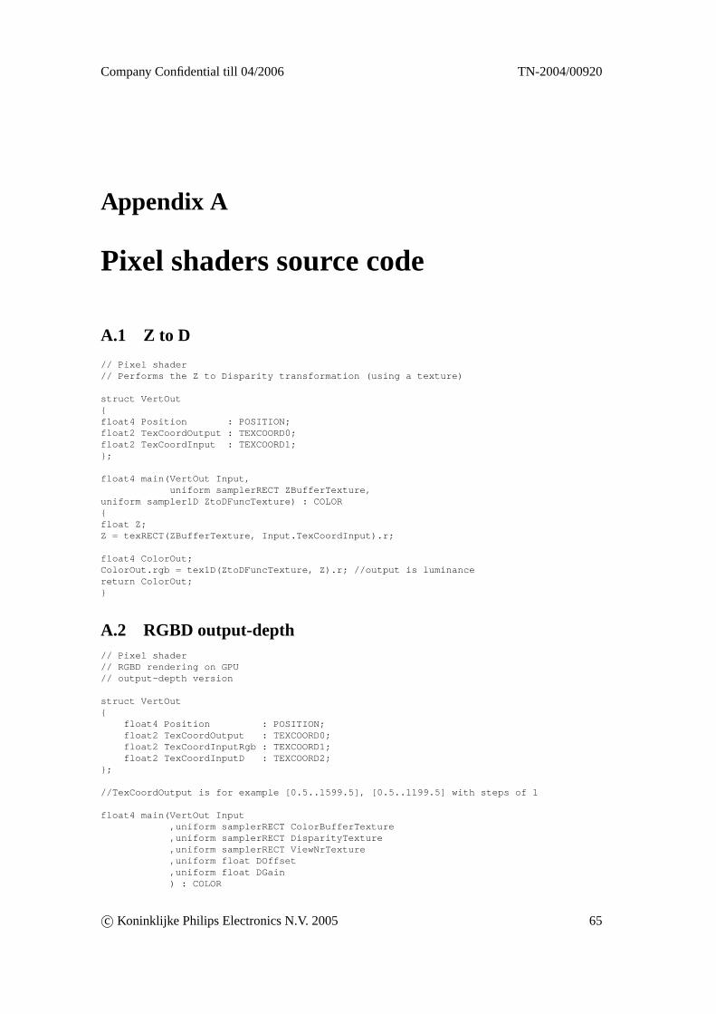
Company Confidential till 04/2006 TN-2004/00920
Appendix A
Pixel shaders source code
A.1 Z to D
// Pixel shader// Performs the Z to Disparity transformation (using a texture)
struct VertOut{float4 Position : POSITION;float2 TexCoordOutput : TEXCOORD0;float2 TexCoordInput : TEXCOORD1;};
float4 main(VertOut Input,uniform samplerRECT ZBufferTexture,
uniform sampler1D ZtoDFuncTexture) : COLOR{float Z;Z = texRECT(ZBufferTexture, Input.TexCoordInput).r;
float4 ColorOut;ColorOut.rgb = tex1D(ZtoDFuncTexture, Z).r; //output is luminancereturn ColorOut;}
A.2 RGBD output-depth// Pixel shader// RGBD rendering on GPU// output-depth version
struct VertOut{
float4 Position : POSITION;float2 TexCoordOutput : TEXCOORD0;float2 TexCoordInputRgb : TEXCOORD1;float2 TexCoordInputD : TEXCOORD2;
};
//TexCoordOutput is for example [0.5..1599.5], [0.5..1199.5] with steps of 1
float4 main(VertOut Input,uniform samplerRECT ColorBufferTexture,uniform samplerRECT DisparityTexture,uniform samplerRECT ViewNrTexture,uniform float DOffset,uniform float DGain) : COLOR
c© Koninklijke Philips Electronics N.V. 2005 65
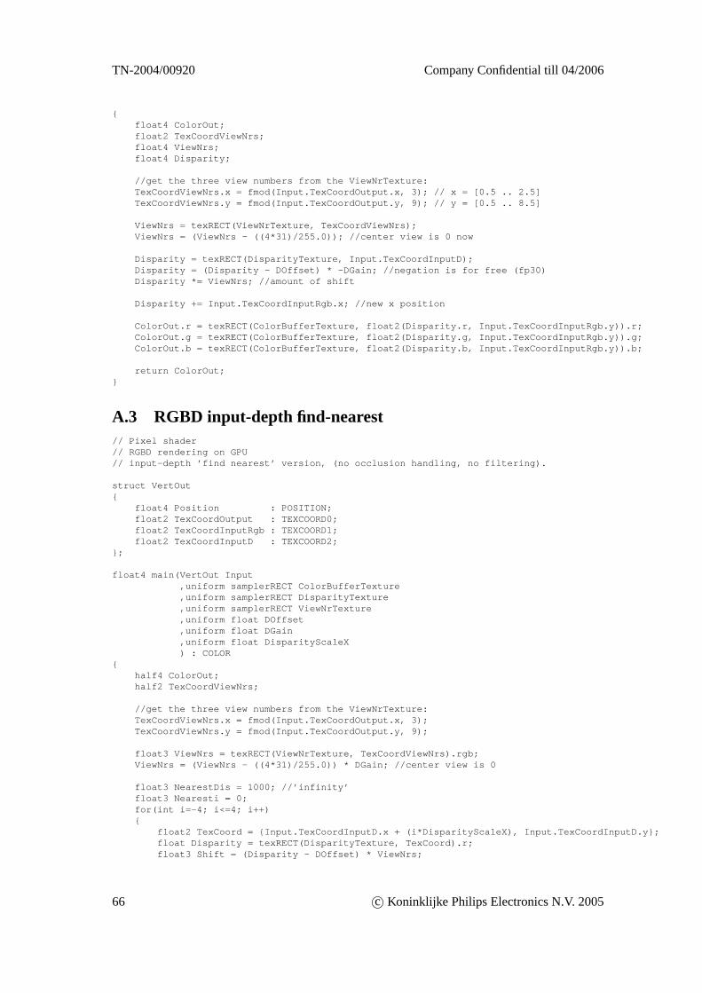
TN-2004/00920 Company Confidential till 04/2006
{float4 ColorOut;float2 TexCoordViewNrs;float4 ViewNrs;float4 Disparity;
//get the three view numbers from the ViewNrTexture:TexCoordViewNrs.x = fmod(Input.TexCoordOutput.x, 3); // x = [0.5 .. 2.5]TexCoordViewNrs.y = fmod(Input.TexCoordOutput.y, 9); // y = [0.5 .. 8.5]
ViewNrs = texRECT(ViewNrTexture, TexCoordViewNrs);ViewNrs = (ViewNrs - ((4*31)/255.0)); //center view is 0 now
Disparity = texRECT(DisparityTexture, Input.TexCoordInputD);Disparity = (Disparity - DOffset) * -DGain; //negation is for free (fp30)Disparity *= ViewNrs; //amount of shift
Disparity += Input.TexCoordInputRgb.x; //new x position
ColorOut.r = texRECT(ColorBufferTexture, float2(Disparity.r, Input.TexCoordInputRgb.y)).r;ColorOut.g = texRECT(ColorBufferTexture, float2(Disparity.g, Input.TexCoordInputRgb.y)).g;ColorOut.b = texRECT(ColorBufferTexture, float2(Disparity.b, Input.TexCoordInputRgb.y)).b;
return ColorOut;}
A.3 RGBD input-depth find-nearest// Pixel shader// RGBD rendering on GPU// input-depth ’find nearest’ version, (no occlusion handling, no filtering).
struct VertOut{
float4 Position : POSITION;float2 TexCoordOutput : TEXCOORD0;float2 TexCoordInputRgb : TEXCOORD1;float2 TexCoordInputD : TEXCOORD2;
};
float4 main(VertOut Input,uniform samplerRECT ColorBufferTexture,uniform samplerRECT DisparityTexture,uniform samplerRECT ViewNrTexture,uniform float DOffset,uniform float DGain,uniform float DisparityScaleX) : COLOR
{half4 ColorOut;half2 TexCoordViewNrs;
//get the three view numbers from the ViewNrTexture:TexCoordViewNrs.x = fmod(Input.TexCoordOutput.x, 3);TexCoordViewNrs.y = fmod(Input.TexCoordOutput.y, 9);
float3 ViewNrs = texRECT(ViewNrTexture, TexCoordViewNrs).rgb;ViewNrs = (ViewNrs - ((4*31)/255.0)) * DGain; //center view is 0
float3 NearestDis = 1000; //’infinity’float3 Nearesti = 0;for(int i=-4; i<=4; i++){
float2 TexCoord = {Input.TexCoordInputD.x + (i*DisparityScaleX), Input.TexCoordInputD.y};float Disparity = texRECT(DisparityTexture, TexCoord).r;float3 Shift = (Disparity - DOffset) * ViewNrs;
66 c© Koninklijke Philips Electronics N.V. 2005
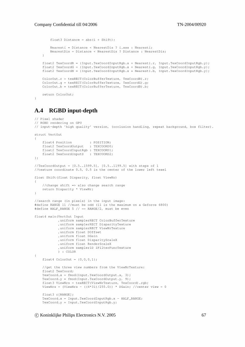
Company Confidential till 04/2006 TN-2004/00920
float3 Distance = abs(i + Shift);
Nearesti = Distance < NearestDis ? i.xxx : Nearesti;NearestDis = Distance < NearestDis ? Distance : NearestDis;
}
float2 TexCoordR = {Input.TexCoordInputRgb.x + Nearesti.r, Input.TexCoordInputRgb.y};float2 TexCoordG = {Input.TexCoordInputRgb.x + Nearesti.g, Input.TexCoordInputRgb.y};float2 TexCoordB = {Input.TexCoordInputRgb.x + Nearesti.b, Input.TexCoordInputRgb.y};
ColorOut.r = texRECT(ColorBufferTexture, TexCoordR).r;ColorOut.g = texRECT(ColorBufferTexture, TexCoordG).g;ColorOut.b = texRECT(ColorBufferTexture, TexCoordB).b;
return ColorOut;}
A.4 RGBD input-depth// Pixel shader// RGBD rendering on GPU// input-depth ’high quality’ version, (occlusion handling, repeat background, box filter).
struct VertOut{
float4 Position : POSITION;float2 TexCoordOutput : TEXCOORD0;float2 TexCoordInputRgb : TEXCOORD1;float2 TexCoordInputD : TEXCOORD2;
};
//TexCoordOutput = [0.5..1599.5], [0.5..1199.5] with steps of 1//texture coordinate 0.5, 0.5 is the center of the lower left texel
float Shift(float Disparity, float ViewNr){
//change shift => also change search rangereturn Disparity * ViewNr;
}
//search range (in pixels) in the input image:#define RANGE 11 //must be odd (11 is the maximum on a Geforce 6800)#define HALF_RANGE 5 // == RANGE/2, must be even
float4 main(VertOut Input,uniform samplerRECT ColorBufferTexture,uniform samplerRECT DisparityTexture,uniform samplerRECT ViewNrTexture,uniform float DOffset,uniform float DGain,uniform float DisparityScaleX,uniform float RenderScaleX,uniform sampler1D IFilterFuncTexture) : COLOR
{float4 ColorOut = {0,0,0,1};
//get the three view numbers from the ViewNrTexture:float2 TexCoord;TexCoord.x = fmod(Input.TexCoordOutput.x, 3);TexCoord.y = fmod(Input.TexCoordOutput.y, 9);float3 ViewNrs = texRECT(ViewNrTexture, TexCoord).rgb;ViewNrs = (ViewNrs - ((4*31)/255.0)) * DGain; //center view = 0
float3 c[RANGE];TexCoord.x = Input.TexCoordInputRgb.x - HALF_RANGE;TexCoord.y = Input.TexCoordInputRgb.y;
c© Koninklijke Philips Electronics N.V. 2005 67
TN-2004/00920 Company Confidential till 04/2006
for(int i=0; i<RANGE; i++){
c[i]= texRECT(ColorBufferTexture, TexCoord).rgb;TexCoord.x += 1;
}
float3 d[RANGE+2]; //nr of d’s needed = nr of colors + 2TexCoord.x = (Input.TexCoordInputRgb.x - HALF_RANGE - 1) * DisparityScaleX;TexCoord.y = Input.TexCoordInputD.y;for(int i=0; i<RANGE+2; i++){
//read in D valued[i] = texRECT(DisparityTexture, TexCoord).r;//apply disparity offsetd[i] -= DOffset;//calculate shift relative to input position id[i] *= ViewNrs;//calculate new position relative to position of output pixeld[i] += (i - HALF_RANGE) * RenderScaleX;
TexCoord.x += DisparityScaleX;}
float dx,dn; //previous and current pixelsfloat pl, pr; //left and right address for ifilter function
for(int subpix=0; subpix<3; subpix++) //r,g,b{
if(ViewNrs[subpix] >= 0){
//camera translation to the left//walk over the input image from the left to the right
//box filter:pl = clamp(d[1][subpix]*0.75 + 0.5, 0, 1);
for(int i=0; i<RANGE; i++) //step over the color input{
if(d[i+2][subpix] > d[i+1][subpix]){
//Splat(dn, OutX, dx, subpix, pIn[ XYC_INDEX(x, (int)(OutY/ScaleY), sub-pix, g_RenderResolutionX) ]);
//void Splat(float left, int address, float right, int subpix, float color)
pr = clamp(d[i+2][subpix]*0.75 + 0.5, 0, 1);
//weight = IFILTFUNC(pr) - IFILTFUNC(pl);
//pRow[address*3+subpix] += weight * color;ColorOut[subpix] += (pr - pl) * c[i][subpix];
pl = pr;}
}}else{
//camera translation to the right//walk over the input image from the right to the left
//box filter:pr = clamp(d[RANGE][subpix]*0.75 + 0.5, 0, 1);
for(int i=RANGE-1; i>=0; i--) //step over the color input{
if(d[i][subpix] < d[i+1][subpix]){
//Splat(dn, OutX, dx, subpix, pIn[ XYC_INDEX(x, (int)(OutY/ScaleY), sub-
68 c© Koninklijke Philips Electronics N.V. 2005
Company Confidential till 04/2006 TN-2004/00920
pix, g_RenderResolutionX) ]);//void Splat(float left, int address, float right, int subpix, float color)
pl = clamp(d[i][subpix]*0.75 + 0.5, 0, 1);
//weight = IFILTFUNC(pr) - IFILTFUNC(pl);
//pRow[address*3+subpix] += weight * color;ColorOut[subpix] += (pr - pl) * c[i][subpix];
pr = pl;}
}}
} //for subpix
return ColorOut;}
A.5 YUVD output
// Pixel shader// YUVD output (for use with hardware rendering board).
// The output is encoded in the RGB channels of the output as follows:// YUD YVD YUD YVD etc.
// Notes:// -Disable hardware gamma correction (in the game) when using this shader!// For Quake3: +set r_ignorehwgamma "1" +set r_ext_gamma_control "0"// -Using halfs instead of floats didn’t improve frame rate on 5950 or 6800 cards.
struct VertOut{float4 Position : POSITION;float2 TexCoordOutput : TEXCOORD0;float2 TexCoordInput : TEXCOORD1;};
float4 main(VertOut Input,uniform samplerRECT ColorBufferTexture,uniform samplerRECT ZBufferTexture,uniform sampler1D ZtoDFuncTexture
) : COLOR{#define Fy 230.0/255.0#define Fuv 235.0/255.0const float3 Yweights = { 0.299*Fy , 0.587*Fy , 0.114*Fy };const float3 Uweights = { -0.169*Fuv, -0.331*Fuv, 0.500*Fuv };const float3 Vweights = { 0.500*Fuv, -0.419*Fuv, -0.081*Fuv };float4 ColorOut;
float4 C = texRECT(ColorBufferTexture, Input.TexCoordInput);float Z = texRECT(ZBufferTexture, Input.TexCoordInput).r;float D = tex1D(ZtoDFuncTexture, Z).r;ColorOut.r = 0.0625+dot(Yweights,C.rgb);ColorOut.g = 0.5 +( frac(0.5*Input.TexCoordOutput.x)<0.5 // odd or even pixel? dot(Uweights,C.rgb): dot(Vweights,C.rgb));ColorOut.b = D;
return ColorOut;}
c© Koninklijke Philips Electronics N.V. 2005 69
TN-2004/00920 Company Confidential till 04/2006
A.6 YUVD output (morph 3x1)struct VertOut{float4 Position : POSITION;float2 TexCoordOutput : TEXCOORD0;float2 TexCoordInput : TEXCOORD1;};
float4 main(VertOut Input,uniform samplerRECT ColorBufferTexture,uniform samplerRECT ZBufferTexture,uniform sampler1D ZtoDFuncTexture
) : COLOR{#define Fy 230.0/255.0#define Fuv 235.0/255.0const float3 Yweights = { 0.299*Fy , 0.587*Fy , 0.114*Fy };const float3 Uweights = { -0.169*Fuv, -0.331*Fuv, 0.500*Fuv };const float3 Vweights = { 0.500*Fuv, -0.419*Fuv, -0.081*Fuv };
// 0 0 0// 1 1 1// 0 0 0float Z;Z = texRECT(ZBufferTexture, Input.TexCoordInput).r;Z = min(Z, texRECT(ZBufferTexture, Input.TexCoordInput+float2(-1, 0)).r);Z = min(Z, texRECT(ZBufferTexture, Input.TexCoordInput+float2( 1, 0)).r);
float4 C = texRECT(ColorBufferTexture, Input.TexCoordInput);float4 ColorOut;ColorOut.r = 0.0625+dot(Yweights,C.rgb);ColorOut.g = 0.5 +( frac(0.5*Input.TexCoordOutput.x)<0.5 // odd or even pixel? dot(Uweights,C.rgb): dot(Vweights,C.rgb));ColorOut.b = tex1D(ZtoDFuncTexture, Z).r;
return ColorOut;}
A.7 YUVD output (morph 5)struct VertOut{float4 Position : POSITION;float2 TexCoordOutput : TEXCOORD0;float2 TexCoordInput : TEXCOORD1;};
float4 main(VertOut Input,uniform samplerRECT ColorBufferTexture,uniform samplerRECT ZBufferTexture,uniform sampler1D ZtoDFuncTexture
) : COLOR{#define Fy 230.0/255.0#define Fuv 235.0/255.0const float3 Yweights = { 0.299*Fy , 0.587*Fy , 0.114*Fy };const float3 Uweights = { -0.169*Fuv, -0.331*Fuv, 0.500*Fuv };const float3 Vweights = { 0.500*Fuv, -0.419*Fuv, -0.081*Fuv };
// 1 0 1// 0 1 0// 1 0 1float Z;Z = texRECT(ZBufferTexture, Input.TexCoordInput).r;
70 c© Koninklijke Philips Electronics N.V. 2005
Company Confidential till 04/2006 TN-2004/00920
Z = min(Z, texRECT(ZBufferTexture, Input.TexCoordInput+float2(-1,-1)).r);Z = min(Z, texRECT(ZBufferTexture, Input.TexCoordInput+float2( 1,-1)).r);Z = min(Z, texRECT(ZBufferTexture, Input.TexCoordInput+float2(-1, 1)).r);Z = min(Z, texRECT(ZBufferTexture, Input.TexCoordInput+float2( 1, 1)).r);
float4 C = texRECT(ColorBufferTexture, Input.TexCoordInput);float4 ColorOut;ColorOut.r = 0.0625+dot(Yweights,C.rgb);ColorOut.g = 0.5 +( frac(0.5*Input.TexCoordOutput.x)<0.5 // odd or even pixel? dot(Uweights,C.rgb): dot(Vweights,C.rgb));ColorOut.b = tex1D(ZtoDFuncTexture, Z).r;
return ColorOut;}
A.8 YUVD output (morph 3x3)
struct VertOut{float4 Position : POSITION;float2 TexCoordOutput : TEXCOORD0;float2 TexCoordInput : TEXCOORD1;};
float4 main(VertOut Input,uniform samplerRECT ColorBufferTexture,uniform samplerRECT ZBufferTexture,uniform sampler1D ZtoDFuncTexture
) : COLOR{#define Fy 230.0/255.0#define Fuv 235.0/255.0const float3 Yweights = { 0.299*Fy , 0.587*Fy , 0.114*Fy };const float3 Uweights = { -0.169*Fuv, -0.331*Fuv, 0.500*Fuv };const float3 Vweights = { 0.500*Fuv, -0.419*Fuv, -0.081*Fuv };
// 1 1 1// 1 1 1// 1 1 1float Z;Z = texRECT(ZBufferTexture, Input.TexCoordInput).r;Z = min(Z, texRECT(ZBufferTexture, Input.TexCoordInput+float2(-1, 0)).r);Z = min(Z, texRECT(ZBufferTexture, Input.TexCoordInput+float2( 1, 0)).r);Z = min(Z, texRECT(ZBufferTexture, Input.TexCoordInput+float2(-1,-1)).r);Z = min(Z, texRECT(ZBufferTexture, Input.TexCoordInput+float2( 0,-1)).r);Z = min(Z, texRECT(ZBufferTexture, Input.TexCoordInput+float2( 1,-1)).r);Z = min(Z, texRECT(ZBufferTexture, Input.TexCoordInput+float2(-1, 1)).r);Z = min(Z, texRECT(ZBufferTexture, Input.TexCoordInput+float2( 0, 1)).r);Z = min(Z, texRECT(ZBufferTexture, Input.TexCoordInput+float2( 1, 1)).r);
float4 C = texRECT(ColorBufferTexture, Input.TexCoordInput);float4 ColorOut;ColorOut.r = 0.0625+dot(Yweights,C.rgb);ColorOut.g = 0.5 +( frac(0.5*Input.TexCoordOutput.x)<0.5 // odd or even pixel? dot(Uweights,C.rgb): dot(Vweights,C.rgb));ColorOut.b = tex1D(ZtoDFuncTexture, Z).r;
return ColorOut;}
c© Koninklijke Philips Electronics N.V. 2005 71
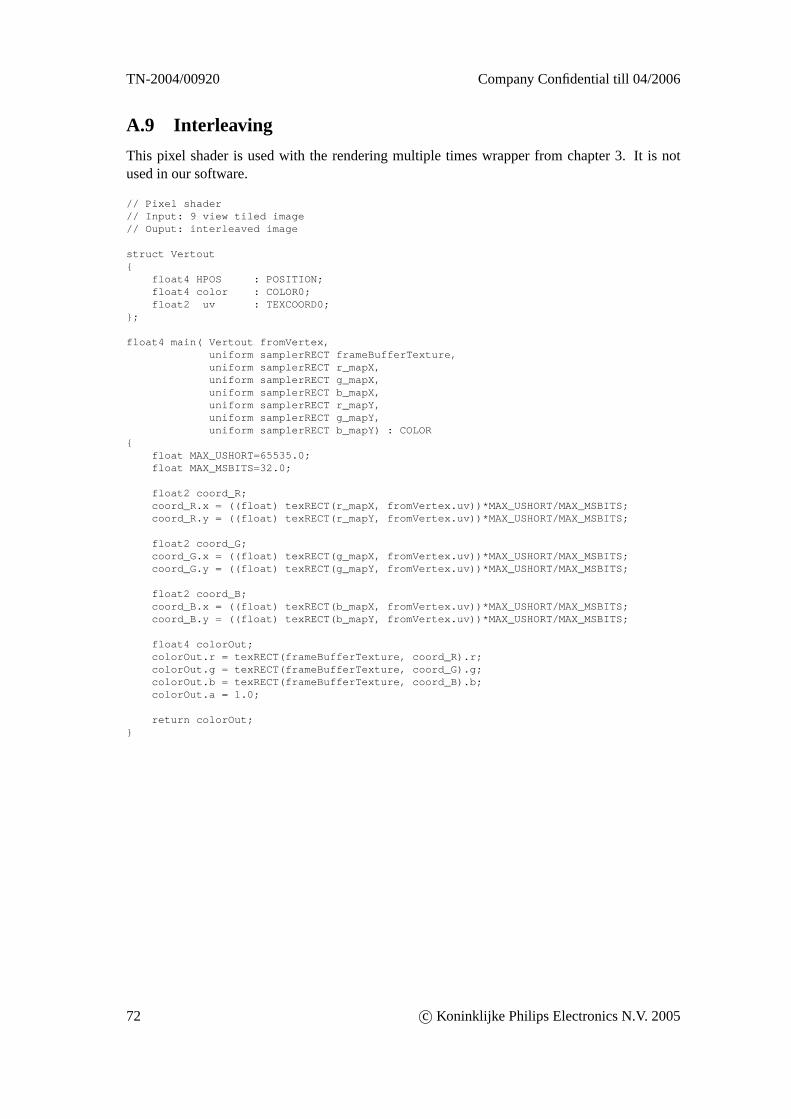
TN-2004/00920 Company Confidential till 04/2006
A.9 Interleaving
This pixel shader is used with the rendering multiple times wrapper from chapter 3. It is notused in our software.
// Pixel shader// Input: 9 view tiled image// Ouput: interleaved image
struct Vertout{
float4 HPOS : POSITION;float4 color : COLOR0;float2 uv : TEXCOORD0;
};
float4 main( Vertout fromVertex,uniform samplerRECT frameBufferTexture,uniform samplerRECT r_mapX,uniform samplerRECT g_mapX,uniform samplerRECT b_mapX,uniform samplerRECT r_mapY,uniform samplerRECT g_mapY,uniform samplerRECT b_mapY) : COLOR
{float MAX_USHORT=65535.0;float MAX_MSBITS=32.0;
float2 coord_R;coord_R.x = ((float) texRECT(r_mapX, fromVertex.uv))*MAX_USHORT/MAX_MSBITS;coord_R.y = ((float) texRECT(r_mapY, fromVertex.uv))*MAX_USHORT/MAX_MSBITS;
float2 coord_G;coord_G.x = ((float) texRECT(g_mapX, fromVertex.uv))*MAX_USHORT/MAX_MSBITS;coord_G.y = ((float) texRECT(g_mapY, fromVertex.uv))*MAX_USHORT/MAX_MSBITS;
float2 coord_B;coord_B.x = ((float) texRECT(b_mapX, fromVertex.uv))*MAX_USHORT/MAX_MSBITS;coord_B.y = ((float) texRECT(b_mapY, fromVertex.uv))*MAX_USHORT/MAX_MSBITS;
float4 colorOut;colorOut.r = texRECT(frameBufferTexture, coord_R).r;colorOut.g = texRECT(frameBufferTexture, coord_G).g;colorOut.b = texRECT(frameBufferTexture, coord_B).b;colorOut.a = 1.0;
return colorOut;}
72 c© Koninklijke Philips Electronics N.V. 2005
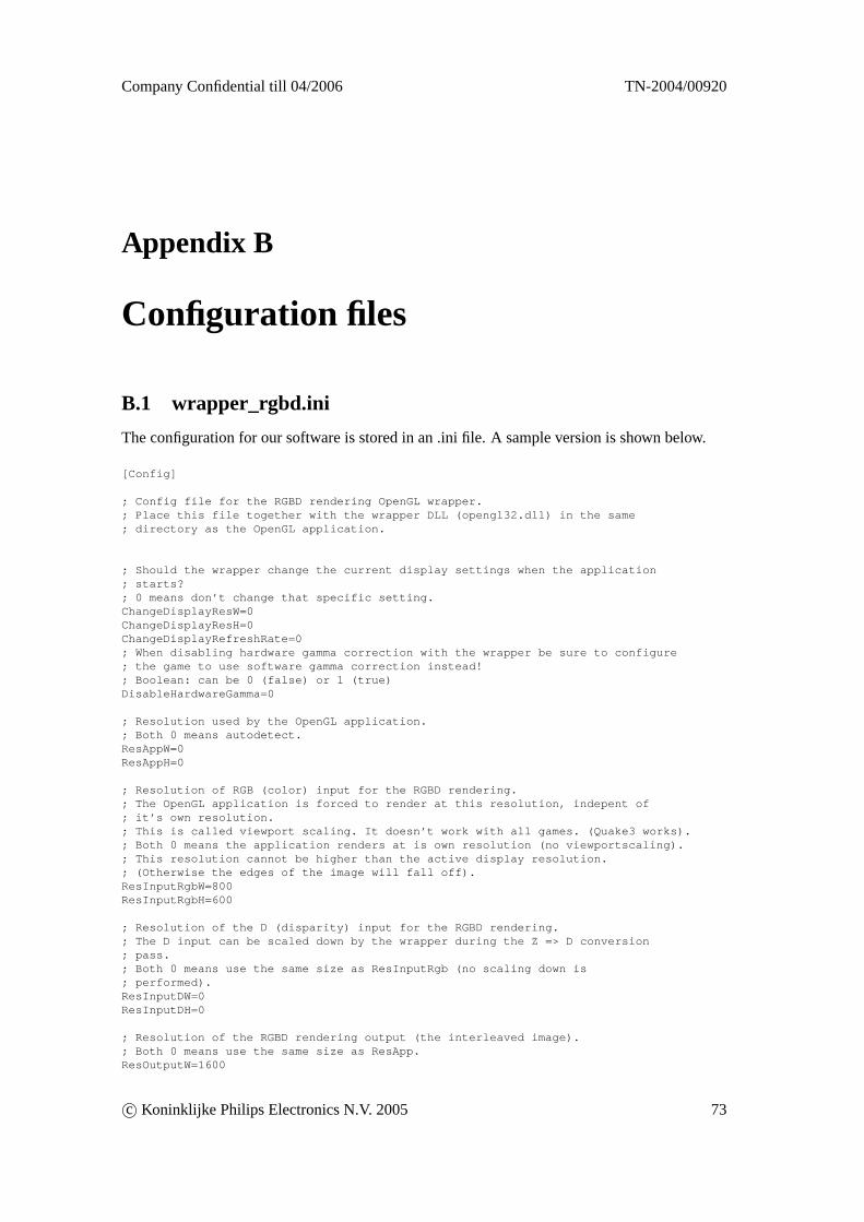
Company Confidential till 04/2006 TN-2004/00920
Appendix B
Configuration files
B.1 wrapper_rgbd.ini
The configuration for our software is stored in an .ini file. A sample version is shown below.
[Config]
; Config file for the RGBD rendering OpenGL wrapper.; Place this file together with the wrapper DLL (opengl32.dll) in the same; directory as the OpenGL application.
; Should the wrapper change the current display settings when the application; starts?; 0 means don’t change that specific setting.ChangeDisplayResW=0ChangeDisplayResH=0ChangeDisplayRefreshRate=0; When disabling hardware gamma correction with the wrapper be sure to configure; the game to use software gamma correction instead!; Boolean: can be 0 (false) or 1 (true)DisableHardwareGamma=0
; Resolution used by the OpenGL application.; Both 0 means autodetect.ResAppW=0ResAppH=0
; Resolution of RGB (color) input for the RGBD rendering.; The OpenGL application is forced to render at this resolution, indepent of; it’s own resolution.; This is called viewport scaling. It doesn’t work with all games. (Quake3 works).; Both 0 means the application renders at is own resolution (no viewportscaling).; This resolution cannot be higher than the active display resolution.; (Otherwise the edges of the image will fall off).ResInputRgbW=800ResInputRgbH=600
; Resolution of the D (disparity) input for the RGBD rendering.; The D input can be scaled down by the wrapper during the Z => D conversion; pass.; Both 0 means use the same size as ResInputRgb (no scaling down is; performed).ResInputDW=0ResInputDH=0
; Resolution of the RGBD rendering output (the interleaved image).; Both 0 means use the same size as ResApp.ResOutputW=1600
c© Koninklijke Philips Electronics N.V. 2005 73
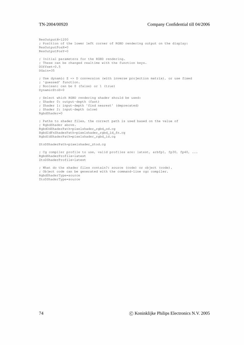
TN-2004/00920 Company Confidential till 04/2006
ResOutputH=1200; Position of the lower left corner of RGBD rendering output on the display:ResOutputPosX=0ResOutputPosY=0
; Initial parameters for the RGBD rendering.; These can be changed realtime with the function keys.DOffset=0.5DGain=35
; Use dynamic Z => D conversion (with inverse projection matrix), or use fixed; ’guessed’ function.; Boolean: can be 0 (false) or 1 (true)DynamicZtoD=0
; Select which RGBD rendering shader should be used:; Shader 0: output-depth (fast); Shader 1: input-depth ’find nearest’ (deprecated); Shader 2: input-depth (slow)RgbdShader=0
; Paths to shader files, the correct path is used based on the value of; RgbdShader above.RgbdOdShaderPath=pixelshader_rgbd_od.cgRgbdIdFnShaderPath=pixelshader_rgbd_id_fn.cgRgbdIdShaderPath=pixelshader_rgbd_id.cg
ZtoDShaderPath=pixelshader_ztod.cg
; Cg compiler profile to use, valid profiles are: latest, arbfp1, fp30, fp40, ...RgbdShaderProfile=latestZtoDShaderProfile=latest
; What do the shader files contain?: source (code) or object (code).; Object code can be generated with the command-line cgc compiler.RgbdShaderType=sourceZtoDShaderType=source
74 c© Koninklijke Philips Electronics N.V. 2005