Non-photorealistic rendering in stereoscopic 3D visualization
148
Dissertation Stereoscopic Non-Photorealistic Rendering ausgef¨ uhrt zum Zwecke der Erlangung des akademischen Grades eines Doktors der technischen Wissenschaften unter der Leitung von Ao. Univ.-Prof. Mag. Dipl.-Ing. Dr. Margrit Gelautz Institut f¨ ur Softwaretechnologie und Interaktive Systeme eingereicht an der Technischen Universit¨ at Wien Fakult¨ at f¨ ur Informatik von Efstathios Stavrakis Favoritenstraße 9-11/188/2 1040 Wien Matr.-Nr. 0226787 Wien, im Dezember 2008 eigenh¨ andige Unterschrift
Transcript of Non-photorealistic rendering in stereoscopic 3D visualization
Dissertation
Stereoscopic Non-Photorealistic Rendering
ausgefuhrt
zum Zwecke der Erlangung des akademischen Grades eines
Doktors der technischen Wissenschaften
unter der Leitung von
Ao. Univ.-Prof. Mag. Dipl.-Ing. Dr. Margrit Gelautz
Institut fur Softwaretechnologie und Interaktive Systeme
eingereicht
an der Technischen Universitat Wien
Fakultat fur Informatik
von
Efstathios Stavrakis
Favoritenstraße 9-11/188/2
1040 Wien
Matr.-Nr. 0226787
Wien, im Dezember 2008 eigenhandige Unterschrift
Abstract
Communication of spatiality in 2D visual arts has been a central topic around
which artistic experimentation has flourished for centuries. The inherent limita-
tion of “flatness” governing most traditional visual media has proven to be fertile
ground for the emergence of advanced pictorial techniques (e.g. linear perspective)
that attempt to counter it. Despite the multitude of pictorial techniques devel-
oped, handcrafted works of art (e.g. paintings, drawings, etc.) that adequately
provide monocular depth cues often fail to capture the vibrancy and plasticity of
a truly three-dimensional world and, in addition, may poorly engage and immerse
the observer. In contrast to these techniques, stereoscopy has been instrumental in
vindicating that monocular depth cues alone were insufficient for our visual system
to infer robustly depth and spatial relations from a single picture. However, while
stereoscopy was adopted soon after its discovery by the scientific community, only a
relatively small number of fine artists have studied and used this peculiar medium
for artistic purposes. The use of stereoscopy in fine arts enabled artists to create
paintings and drawings that could detach from the flat surfaces they were laid on
and float directly in front of the observer’s eyes, opening a whole new world of
possibilities for artistic experimentation.
As stunning an experience of seeing stereoscopic artworks as it is, the creation
of these dual works is a rather tedious and laborious process. The artist not only
has to create the artwork twice from slightly dissimilar vantage points, he is also
required to preserve feature and color correspondences between the two projections
with great care, without introducing artifacts that might hinder stereoscopic fusion.
In the digital era, abundant computational methods have been developed to create
monoscopic images that resemble artwork, using as an input either 3D models or
images. Despite the high availability of such algorithms, hardly any research has
been done so far in the area of artistic stereoscopic rendering from real images.
The work presented in this dissertation provides a stepping stone in the direction
of combining computer graphics and vision techniques to form novel image-based
stereoscopic Non-Photorealistic Rendering algorithms. These algorithms can be used
to transform photographic stereoscopic images into pairs of pictures that resemble
stereoscopic drawings, cartoons or paintings. Central to all our algorithms is the use
of stereo correspondences, calculated by using stereo matching algorithms. These
correspondences, usually encoded in a disparity map, are used to propagate style
i
that is synthesized in the geometry of one stereo view to the other, thus preserving
the consistency of the texture across the two views of a stereo pair. In addition, the
disparity map is utilized in order to identify image areas, known as occluded regions,
that are not visible from both views simultaneously, and thus style generated in one
view cannot be propagated in these areas using stereo correspondences. Instead,
in these occluded regions texture synthesis procedures specifically generate stylized
texture that seamlessly blends with the texture of surrounding non-occluded regions,
within the same stereoscopic view.
Furthermore, the artistic-looking stereoscopic image pairs generated using our
algorithms provide a basis over which a set of interactive methods and tools are built
to enhance the experience of viewers. We provide a way to manipulate stereoscopic
space by simple adjustment of the separation of the two image projections, and
we demonstrate the use of the disparity map as a means of automatically choosing
optimal separation values in order to reduce eye-strain. In addition, we describe the
design of a stereoscopic cursor and a magnifying glass that can be used to inspect the
stereoscopic results generated by our system. Finally, we expose viewers to a new
method of interacting with computer-generated stereoscopic paintings that enables
them to slice through the painting and observe the understructure of the work.
The novel algorithms presented in this work set the foundation to harnessing
stereoscopy as an artistic medium within the context of image-based computer
graphics and vision, and their results may find utility in the game, media or film
industries.
ii
Kurzfassung
Die Darstellung von Raumlichkeit ist eines der zentralen Themen der zweidimensio-
nalen bildenden Kunst, welches jahrhundertlang Inspiration fur kunstlerische Expe-
rimente lieferte. Die inharente “Flachheit”, die einen Großteil der klassischen bil-
denden Kunst beherrschte, war ein fruchtbarer Boden fur die Entwicklung fortge-
schrittener Darstellungstechniken, wie z.B. der perspektivischen Darstellung. Trotz
der Vielzahl der entwickelten Methoden konnen Zeichnungen und Gemalde, die zwar
monokulare Tiefeninformation adaquat bereitstellen, die Lebendigkeit und Plasti-
zitat einer tatsachlich dreidimensionalen Welt oft nicht befriedigend abbilden und
involvieren den Betrachter nur unzureichend in die Szene. Das Aufkommen von Ste-
reoskopie trug maßgeblich zur Erkenntnis bei, dass monokulare Tiefeninformation
fur unser visuelles System nicht ausreichend ist, um robust Tiefe und raumliche Zu-
sammenhange aus einem einzigen Bild abzuleiten. Wahrend die Stereoskopie bereits
bald nach ihrer Entdeckung von der Wissenschaft aufgegriffen wurde, wurde sie nur
von einer relativ kleinen Anzahl von Kunstlern studiert und angewandt. Die Anwen-
dung der Stereoskopie in der darstellenden Kunst ermoglichte erstmals die Schaffung
von Gemalden und Zeichnungen, die sich von der Flache losten und direkt vor den
Augen des Betrachters zu schweben schienen. Dadurch erschloss sich eine ganze neue
Welt fur kunstlerische Experimente.
So uberwaltigend die Erfahrung bei der Betrachtung eines stereoskopischen Bil-
des auch ist - die Erzeugung dieser Zweifach-Darstellungen ist ein langwieriger und
arbeitsintensiver Prozess. Der Kunstler muss das Bild nicht nur zweimal, aus jeweils
leicht unterschiedlichen Blickwinkeln, kreieren, sondern muss auch sehr sorgfaltig die
Korrespondenz von Strukturen, Merkmalen und Farben zwischen beiden Projektio-
nen herstellen, um eine korrekte stereoskopische Verschmelzung sicherzustellen. Im
digitalen Zeitalter wurden bereits viele Methoden entwickelt, die, z.B. auf Basis von
3D Modellen oder Fotos, monoskopische Bilder generieren, die Gemalden, Graphi-
ken oder Zeichnungen ahneln. Trotz der Verfugbarkeit dieser Algorithmen wurde bis
jetzt nur wenig im Bereich automatische Generierung von kunstlerischen stereosko-
pischen Bildern auf Basis von Fotografien geforscht.
In dieser Dissertation werden Methoden aus Computergraphik und maschinellem
Sehen zu neuen bildbasierten, nicht-photorealistischen, stereoskopischen Rendering
Algorithmen kombiniert und so eine Basis fur weitere Entwicklungen geschaffen.
Diese Algorithmen konnen verwendet werden, um aus stereoskopischen Fotografien
iii
Paare von Bildern zu generieren, die stereoskopischen Zeichnungen, Cartoons oder
Gemalden ahneln. Kern der hier entwickelten Methoden ist die Verwendung von
Stereokorrespondenzen, die durch Stereo Matching Algorithmen berechnet werden.
Diese Korrespondenzen, die gewohnlich mittels Disparitatskarten beschrieben sind,
werden verwendet, um eine Konsistenz der Textur in beiden Bildern des Stereopaa-
res zu erreichen. Zusatzlich wird die Disparitatskarte dazu verwendet, sogenannte
verdeckte Bereiche des Bildes zu erkennen, die nicht aus beiden Blickrichtungen
gleichzeitig gesehen werden. In diesen Bereichen konnen Renderingstile nicht durch
Stereokorrespondenz ubertragen werden. Stattdessen wird in diesen Bereichen durch
Textursynthese neue Textur generiert, die innerhalb derselben stereoskopischen An-
sicht nahtlos in die angrenzende Textur sichtbarer Regionen ubergeht.
Die kunstlerisch anmutenden stereoskopischen Bildpaare, die mit Hilfe der ent-
wickelten Algorithmen generiert wurden, bilden die Basis, auf der eine Anzahl von
Methoden und Werkzeugen entwickelt wurden, die dem Betrachter eine interakti-
ve Erfahrung und Erforschung des Bildes ermoglichen. Es wird dem Benutzer ei-
ne Moglichkeit zur Verfugung gestellt, durch einfache Anpassung der Position der
beiden Augpunkte die Tiefendarstellung zu adaptieren. Dabei wird auch die Ver-
wendung der Disparitatskarte zur automatischen Berechnung optimaler Abstands-
parameter demonstriert, um die Augenbelastung zu reduzieren. Zusatzlich wird
das Design eines stereoskopischen Cursers und einer Lupe beschrieben, welche die
Moglichkeit bieten, die generierten Ergebnisse zu inspizieren. Schließlich wurde eine
neue Methode zur Interaktion mit stereoskopischen Bildern entwickelt, die es er-
laubt, durch die einzelnen Schichten eines generierten Bildes zu blattern, um die
zugrunde liegende Struktur zu erkennen.
Die neuen Algorithmen, die in dieser Arbeit vorgestellt werden, legen den Grund-
stein fur die Verwendung von Stereoskopie als kunstlerisches Medium im Kontext
bildbasierter Computergraphik und maschinellen Sehens, deren Ergebnisse nutzliche
Anwendungen in den Bereichen Spieleindustrie, Multimedia- und Filmindustrie fin-
den konnen.
iv
Acknowledgments
During my doctoral work, I have been privileged to work with many people, to whom
I am thankful for their help and support. I am particularly grateful to my advisor,
Prof. Margrit Gelautz, for giving me the opportunity to conduct this doctoral work.
Apart from funding this research, she provided invaluable guidance and encourage-
ment throughout my studies, which were key ingredients to a successful completion.
I am also indebted to Prof. Christian Breiteneder, Head of the Interactive Media
Systems Group, for his remarkable support and mentorship all these years. I would
also like to thank Prof. Eduard Groller for assessing this work as the second reader
and for all his insightful remarks.
I have spent most of my time in the research lab with Michael Bleyer and Danijela
Markovic, with whom I have had many interesting discussions, as well as an excel-
lent collaboration. I additionally want to thank Michael for sharing his knowledge,
datasets, as well as code for the stereoscopic stylization technique.
I want to acknowledge the input, resources and precious correspondence I ex-
changed over the previous years with stereoscopic fine artist Roger Ferragallo. To-
gether with Roger, I want to also thank artist Alfons Schilling, who was kind enough
to show me some of his amazing stereo works and optical devices at his studio in
Vienna. I would like to thank Vladimir Tamari for pointing out to me his stereo
drawing device and artworks, which opened a whole new direction in my investi-
gation into stereoscopy in fine arts. I shall not forget to mention the kind and
informative correspondences I had with Jan Bron of the Magritte Museum in Brus-
sels regarding Magritte’s works, and Cindy Keefer of the Center of Visual Music
in Los Angeles regarding the works of Oskar Fischinger. I am thankful to Thomas
Weynants of the Collection of Early Visual Media for allowing me to reproduce im-
ages of classical stereoscopes, as well as VBK Vienna for granting me permission to
reproduce various fine art paintings in this dissertation.
I also want to thank all my colleagues and friends for being there for me al-
ways. I will refrain from mentioning them individually, as they are too many to list.
However, I would like to make an exception and specially thank Katja Buhler for
translating the English abstract into German.
Finally, I would like to thank my family for believing in me; my mom and dad
for bearing with my lengthy absence, and my brother for encouraging me to take up
a doctorate degree. I hope the enormous amount of time I invested to complete it
v
reflects their behind-the-scenes efforts to keep me motivated, as well as their support
and encouragement for which I will never be able to fully express how grateful I am
to them.
The majority of this work was funded by the Austrian Science Fund (FWF)
project P15663.
vi
Contents
1 Introduction 1
1.1 Background and Terminology . . . . . . . . . . . . . . . . . . . . . . 2
1.1.1 Images and Pictures . . . . . . . . . . . . . . . . . . . . . . . 2
1.1.2 Pictures Beyond Two Dimensions . . . . . . . . . . . . . . . . 5
1.2 Motivation . . . . . . . . . . . . . . . . . . . . . . . . . . . . . . . . . 7
1.3 Summary of Contributions . . . . . . . . . . . . . . . . . . . . . . . . 8
1.4 Publications . . . . . . . . . . . . . . . . . . . . . . . . . . . . . . . . 9
1.5 Overview of Dissertation . . . . . . . . . . . . . . . . . . . . . . . . . 10
2 Stereoscopy & Fine Arts 12
2.1 Depth Perception . . . . . . . . . . . . . . . . . . . . . . . . . . . . . 13
2.1.1 Monocular Depth Cues . . . . . . . . . . . . . . . . . . . . . . 14
2.1.2 Binocular Depth Cues . . . . . . . . . . . . . . . . . . . . . . 18
2.2 Principles of Stereoscopy . . . . . . . . . . . . . . . . . . . . . . . . . 21
2.2.1 Creating and Viewing Stereoscopic Content . . . . . . . . . . 21
2.2.2 Binocular Rivalry . . . . . . . . . . . . . . . . . . . . . . . . . 28
2.3 Stereoscopy in Fine Arts . . . . . . . . . . . . . . . . . . . . . . . . . 29
2.3.1 Stereoscopic Artwork . . . . . . . . . . . . . . . . . . . . . . . 30
2.3.2 Timeline of Stereoscopic Artworks . . . . . . . . . . . . . . . . 31
2.3.3 Drawbacks of the Stereoscopic Medium . . . . . . . . . . . . . 38
3 Related Work 42
3.1 Image-Based Rendering . . . . . . . . . . . . . . . . . . . . . . . . . . 43
3.1.1 Rendering without Geometry . . . . . . . . . . . . . . . . . . 44
3.1.2 Rendering with Implicit Geometry . . . . . . . . . . . . . . . 45
3.1.3 Rendering with Explicit Geometry . . . . . . . . . . . . . . . 46
3.2 Computational Stereo Vision . . . . . . . . . . . . . . . . . . . . . . . 46
3.3 Digital Stereoscopic Imaging . . . . . . . . . . . . . . . . . . . . . . . 49
3.4 Non-Photorealistic Rendering . . . . . . . . . . . . . . . . . . . . . . 51
4 Preliminaries for Stereoscopic NPR 57
4.1 Stereoscopic NPR Framework . . . . . . . . . . . . . . . . . . . . . . 57
4.2 Stereoscopic Rendering Pipeline . . . . . . . . . . . . . . . . . . . . . 59
vii
4.3 Setup for Stereoscopic NPR Algorithms . . . . . . . . . . . . . . . . . 61
5 Stereoscopic Drawing 65
5.1 Stereoscopic Drawing Algorithm . . . . . . . . . . . . . . . . . . . . . 66
5.2 Feature and Contour Extraction . . . . . . . . . . . . . . . . . . . . . 67
5.3 Contour Simplification and Vectorization . . . . . . . . . . . . . . . . 70
5.4 Generating the Second View . . . . . . . . . . . . . . . . . . . . . . . 71
5.5 Results and Discussion . . . . . . . . . . . . . . . . . . . . . . . . . . 71
6 Stereoscopic Stylization 77
6.1 Preprocessing . . . . . . . . . . . . . . . . . . . . . . . . . . . . . . . 78
6.2 Basic Stereoscopic Stylization . . . . . . . . . . . . . . . . . . . . . . 80
6.3 Filling in Occlusions . . . . . . . . . . . . . . . . . . . . . . . . . . . 81
6.4 Distance-Dependent Stereoscopic Stylization . . . . . . . . . . . . . . 84
6.5 Outlining . . . . . . . . . . . . . . . . . . . . . . . . . . . . . . . . . 85
6.6 Results . . . . . . . . . . . . . . . . . . . . . . . . . . . . . . . . . . . 88
7 Stereoscopic Painting 91
7.1 Stereo Painting by Image Warping . . . . . . . . . . . . . . . . . . . 92
7.2 Stereo Painting by Stroke Warping . . . . . . . . . . . . . . . . . . . 98
7.3 Combining Stereoscopic Drawing with Painting . . . . . . . . . . . . 102
7.4 Summary . . . . . . . . . . . . . . . . . . . . . . . . . . . . . . . . . 103
8 Techniques for Stereoscopic Interactivity 105
8.1 Introduction . . . . . . . . . . . . . . . . . . . . . . . . . . . . . . . . 105
8.2 Manipulating Stereoscopic Space . . . . . . . . . . . . . . . . . . . . 106
8.2.1 Frame Cancellation . . . . . . . . . . . . . . . . . . . . . . . . 107
8.2.2 Horizontal Image Translation . . . . . . . . . . . . . . . . . . 108
8.3 Stereoscopic Cursors . . . . . . . . . . . . . . . . . . . . . . . . . . . 110
8.3.1 Simple Stereoscopic Cursor . . . . . . . . . . . . . . . . . . . . 111
8.3.2 Stereoscopic Magnifying Glass . . . . . . . . . . . . . . . . . . 111
8.4 Observing the Anatomy of Stereo Artworks . . . . . . . . . . . . . . . 114
8.5 Discussion . . . . . . . . . . . . . . . . . . . . . . . . . . . . . . . . . 117
9 Conclusions 119
9.1 Summary . . . . . . . . . . . . . . . . . . . . . . . . . . . . . . . . . 119
9.2 Future Work . . . . . . . . . . . . . . . . . . . . . . . . . . . . . . . . 121
viii
A Algorithm for Stereoscopic Painterly Rendering 123
A.1 Stereoscopic Painting Algorithm . . . . . . . . . . . . . . . . . . . . . 123
A.2 Stroke Creation . . . . . . . . . . . . . . . . . . . . . . . . . . . . . . 124
Bibliography 126
List of Figures 136
ix
Chapter 1
Introduction
The expressive depiction of 3D information onto 2D surfaces has been for centuries
a central matter in pictorial visual arts. The intent of artists widely varied together
with the associated techniques that were developed to record scenes and events
taken from everyday life, to make portraits of important individuals or even to
document well-known processes and ideas of their time. Prior to the invention of the
photographic process, artists have been mainly projecting 3D visual stimuli on 2D
surfaces by developing and using various artistic media and techniques. Mastering
these pictorial techniques has been instrumental in the rise of life-like representations
of three-dimensional scenes on flat surfaces, regardless of whether artists attempted
to accurately depict reality as this could be objectively seen or they strove to enrich
or abstract it.
This 3D to 2D projection imposes a natural reduction in the number of degrees
of freedom, since one dimension is discarded. The impact of discarding the third
dimension in order for it to be represented in a 2D form is multifaceted and has
become a point of intersection between a variety of disciplines across both arts and
sciences. The experience of reducing the dimensionality of 3D spaces has propa-
gated from pictorial arts to the science of optics and, subsequently, to photographic
techniques and later to digital imaging, computer graphics and visualization.
The desire of artists to accurately communicate pictorial depth led them very
early into the development of advanced techniques that could be used to make
captivating artwork. For centuries the use of monocular depth cues, such as shading,
linear perspective, etc., has been common practice among picture makers. It was
mainly through refinement of the old understanding and techniques that pictures
became more vivid along the history of visual arts. After the Renaissance (14th–
17th c. AD), it was mainly the discovery of stereoscopic vision in the 19th century
that provided new insight into the ability of humans to see depth. Unlike other
techniques for handcrafting pictures, stereoscopy did not become as popular and
remained mainly as a technique that flourished along with the, almost concurrently
developed, photographic process.
In arts only a small number of artists using traditional media have adopted
1
1.1 Background and Terminology 2
stereoscopy in order to handcraft artistic works that robustly communicate spatial
relationships within a depicted scene. Mainly due to technological advancements, the
popularity of stereoscopy has seen until today many “rise and fall” eras. Even going
a long way from the invention of the first handheld stereoscopes to our contemporary
digital stereoscopic devices, the immense artistic potential of stereoscopy remains to
be unlocked. The key probably is not the artist who is armed with a new technique
for creating artwork, but most likely it is the viewer whose status changes within
a stereoscopic context. The viewer is no longer a mere third-party observer, he is
reinstated in regard to the stereoscopic artwork as a participant who not only will be
immersed and detached from the immediate real world while viewing stereoscopic
content, but he can establish a sense of presence and relate – at least spatially – to
the artwork.
The stereoscopic medium encompasses technicalities that require artists to be-
come familiar with and fastidiously exercise this knowledge taking a step further
from the commonly used methods. They are now required to learn how to create
stereoscopic pictures by hand and, most importantly, how the audience will perceive
them. The plethora of technical subtleties and the finicky details surrounding the
aesthetics of this medium present artists with a very challenging art form. As it will
become apparent in subsequent chapters of this dissertation, stereoscopic arts and
especially the associated aesthetics are a largely unexplored territory.
Taking a technical approach to this vast subject, this dissertation aims to increase
the awareness of both scientists and artists regarding the ability of the stereoscopic
medium to communicate artistic content by utilizing state of the art technologi-
cal advancements in computing that were unavailable to the pioneers of traditional
stereoscopic artwork. Thus the work presented here can potentially motivate sci-
entists to further pursue the development of technical tools for artistic stereoscopic
content creation and simultaneously entice artists to reinstate stereoscopy in their
creative toolset.
1.1 Background and Terminology
1.1.1 Images and Pictures
Forming visual representations, referred to as images, has been the main focus of
photography and computer graphics in recent years. Pictures and images are usually
interchangeably used to refer to generated 2D representations of real or virtual 3D
objects. The question itself of what an “image” is, is not an easy one to answer.
It becomes even more difficult to provide a thorough explanation if the notion of a
1.1 Background and Terminology 3
“picture” is implicated in this subtle clarification.
As Mitchell [73] discusses, it depends from which standpoint one understands
the meaning of these words. Images form a larger family of representations. For
instance there are graphic images, optical images, but also perceptual, mental and
verbal images. Each of these categories embodies ideas of the respective discipline
within which it functions and takes further meaning. Images are not considered
purely as a material object, the function of the word usually suggests “likeness”
and is referring more to the actual represented subject and any associated meanings
or ideas of it and less to the material body of the surface and the physical marks
deposited on it.
Panofsky [77, p.5] identifies three levels of understanding pictorial representa-
tions and, particularly, works of art. The primary or natural subject matter, the
secondary or conventional subject matter and the intrinsic meaning or content. The
first level refers to the basic meanings the material body of the representation sug-
gests. The colors and lines combine into forms that are understood in their basic
factual and expressional qualities, such as material objects (e.g. humans, animals,
etc.) or gestures and events (e.g. mourning, peaceful atmosphere, etc.). The second
level attaches conventional knowledge of iconography and cultural orientation of the
viewer to the forms of the imagery. Thus it is easy for a Western viewer to recognize
religious figures in paintings and icons of Christianity, for example. The third level
Panofsky lays out is that of intrinsic meaning and content. This last level goes be-
yond mere recognition of compositional elements of the image and the identification
of the conventional subject matter. In this level, the viewer seeks to understand the
sociocultural motives of the artist of the composition. It is the level on which the
underlying meaning of the artwork can be identified and uncovered in the scope of
the historical and cultural understanding within which it was executed.
In the context of the discussion herein a distinction is made between “images”
and “pictures”. When looking at the particular words of “image” and “picture”,
a literal distinction can be made. An image has various meanings, such as a copy,
an imitation, as well as a depiction, while a picture is more specifically targeted to
describe an artistic visual representation. Note also that etymology suggests that
“image” stems from the Latin imago, which is akin to the Latin imitari (to imitate),
while “picture” is derived from the Latin pictura, which means painting [60].
In computer science, however, an image is almost always a digital material quan-
tity that is codified into bits. The term is used in a strictly technical context. It is
common for computer graphics and vision scientists to “acquire”, “process”, “trans-
form” or “render” images and not pictures. In contrast a photographer, even though
1.1 Background and Terminology 4
literally will create images with his camera, will usually “take a picture”, rather than
an image. This is because a photographer will interfere with the actual process of
image-making. It is not just the mechanical parameters of the device used that
turns an image into a picture, it is also the selection of the subject, the angle and
the frame which will be chosen for any given photograph that turns it into a picture.
It is the intention of the photographer and scientist that proposes an appropriate
term used to describe essentially the same thing.
When considering the interaction of light with 3D surfaces at a specific time and
a single fixed viewpoint, there is generally one 2D image formed on a projection
screen through a fixed optical device. In contrast, there is an arbitrary number of
pictures that can be created to represent that scene at that same point in time and
viewpoint. As an analogy, one can think of the result produced by using an imaging
device to capture the same scene multiple times without adjusting any of the device’s
parameters, in contrast to the result of an artist’s multiple attempts to depict the
given scene. We are not just dealing with the human inability to reproduce with the
finest detail the same result, but mostly with the humane ingredients (i.e. emotion,
cognition, communication, etc.) that influence the artist’s intention and make the
depiction unique by attaching aesthetic value.
A distinction that is made in this dissertation between images and pictures in
the context of computer graphics is that the latter is not just a projection of 3D
elements onto 2D by means of light interactions. It is not a mere storage area of
numerical values. Making a picture implies that cognitive factors (e.g. attention,
perception, recognition, comprehension, etc.) are accentuated during the process
of image-making. Thus creating pictures with a computer becomes a complex task
that requires to observe and replicate the methodology of humans; to take into
account properties of visual perception and understand their connection to picto-
rial techniques. These are tasks that cannot be captured in a generally applicable
mathematical formula.
This is a significant observation, since it allows us to extend the parametric space
an image is formed within, to the multi-dimensional parameter space a picture is
created in. The additional parameters may describe properties of the natural media
to be used for the depiction, the characteristics of the surface that the picture is to be
placed on or even a procedure by which the picture will be created. These additional
parameters are almost always present when the image-maker intentionally interferes
with the formation process of an image in order to turn it into a picture. Therefore,
images can be considered as the basis for creating pictures, as long as a set of extra
parameters is specified. Many artists unintentionally comply with this procedure of
1.1 Background and Terminology 5
transforming real or fictitious spaces into pictures. For instance, painters of outdoors
scenery create pictures by using not only their painting media and canvases as
additional parameters to the visual image perceived through their eyes, but also their
creativity and subjective perception. When dealing with imaginary compositions,
the associations and interactions between the various parameters are much more
complex. What is significant according to the distinction made here is that these
compositions stemming from imagination will also result in pictures and not images.
Nevertheless, it is not up to the picture-maker to declare the outcome of his work
as a picture or even further as artwork. It is the audience who subjectively will be
able to interpret the visual representation and affirm whether it is a picture or art.
It is thus interpretation of the stimuli arriving on the eyes rather than the retinal
image formed on it, as John Ruskin argues: “You do not see with the lens of the
eye. You see through that, and by means of that, but you see with the soul of the
eye.” [85, p.116].
One could consider that the picture-maker’s function is to provide suggestions
to the audience via the use of pictorial techniques. Equivalently, in computational
visual sciences solving a mathematical formula, e.g. one that models purely physical
interactions of light, does not imply an intent to create pictures, but images. There-
fore an unintentional numerical error in the modeling of this process that scribbles
artifacts into the computed image cannot be declared as an artistic process alone.
An audience is required that will accept it as such. Similarly, when compressing an
image for transmission it cannot be declared as artwork just because abstraction or
stylization of image features takes place as a side effect of the intended purpose of
the image transformation in the first place. The conversion of images into pictures
can be done intentionally in order to become systematic, reproducible and carry the
cognitive information across to the audience. Then these computational processes
are elevated into picture-making tools or even pictorial techniques, rather than side
effects.
1.1.2 Pictures Beyond Two Dimensions
An important property of pictures is not only the effective communication of spatial
information between depicted scene objects, but also between the viewer and the
scene. Pictorial depth is represented indirectly, since the surface carrying the picture
is itself flat. True depth is not present in a two-dimensional representation, but it is
inferred by the viewer himself using visual cues, known as depth cues. Centuries of
artistic and scientific efforts to set rules, develop methods and procedures of creating
pictures that appear three-dimensional have preceded the advent of computational
1.1 Background and Terminology 6
methods that attempt it. In Medieval times, flatness dominated the depictive qual-
ities of paintings, drawings, mosaics, etc. A thorough understanding of optics and
visual perception was a rather obscure territory, but also cultural orientation favored
other qualities in representations rather than spatial depth. For example, in the an-
cient Egyptian decorative artwork it was sufficient to depict significant events and
particular features of the Pharaoh on his tomb rather than construct an accurate
three-dimensional representation of his body. However, artists from the 15th century
and on, have systematically used their contemporary knowledge of picture formation
and incrementally refined their skills to perfection. The masters of the Renaissance
(e.g. Jan van Eyck, Tommaso Masaccio, Leonardo da Vinci, etc.) communicated
the missing third dimension in their works by essentially using — and sometimes
abusing — what in perceptual psychology is referred to as the monocular depth
cues. The contemporary understanding of picture-making was elevated from being
dominantly flat to increasingly being three-dimensional providing a sense of depth
and volume.
Until the 19th century, exploiting the monocular cues has been the standard
method of creating pictures that communicate spatiality and in particular depth
information. While there have been several inquiries throughout history in the facil-
ities of the human visual system with regard to the perception of depth [118], it was
Sir Charles Wheatstone, who for the first time [125] proved experimentally that our
ocular disparity, and the differences in the two retinal images, are mainly responsi-
ble for the robust perception of depth when appropriate stimuli are provided. He
furthermore constructed the first stereoscope in which he presented various stereo-
scopic drawings to demonstrate and prove his theory. He termed the mental ability
to robustly perceive depth information from pairs of 2D stimuli stereopsis, after the
combination of the greek στǫρǫo (which means solid) and oψη (which means ap-
pearance). Simultaneously, the picture-making and viewing of such stimuli widely
became known as stereoscopy.
The introduction of stereoscopy, in combination with the invention of the first
chemical photographic processes, had an avalanche effect in the visual arts. Many
have spoken about the demise of fine arts (i.e. painting). Nevertheless, the realism
of photographs did not subvert the handcrafted appearance of artistic pictures. It
actually functioned as a catalyst for the emergence of new artistic movements such
as Surrealism, Cubism, Expressionism, etc., that followed. Artists shifted their in-
terest in creating photorealistic artwork to more expressive techniques, using new
methods and inventing new techniques. A limited number of artists in their search
for a medium that can better communicate to the viewer depth and distances has ex-
1.2 Motivation 7
perimented with, and even adopted, stereoscopy as one of their creative techniques.
There is no concise historical account of how widespread stereoscopy was in
pictorial visual arts beyond photography, but a review and analysis of known artistic
works that have been executed in the post-stereoscopic era reveals that certain
difficulties arise with this peculiar medium. These are far from being associated
with the creative capacity of the artists and, as the relevant analysis in a subsequent
section shows, can be mapped and tackled through technical means, detached from
the creative intention of the artist.
1.2 Motivation
Leonardo Da Vinci (1452-1519) notes in his “Treatise on Painting” [50, p.14]:
“A painting, though conducted with the greatest art and finished to the
last perfection, both with regard to its contours, its lights, its shadows and
its colors, can never show a relievo equal to that of the natural objects,
unless these be viewed at a distance and with a single eye.”
With this note the Renaissance master embraces the desire of many artists
throughout history, to invent, discover and practice these techniques of depiction
that would allow them to stretch a picture beyond its two-dimensionality. It also
demonstrates that the flatness of the pictorial medium, as well as its effects, was
a well understood and appreciated limitation. It was this limitation that led the
Renaissance artists to invest much of their creative and technical abilities into in-
venting or utilizing methods that replicate reality on the two-dimensional surface.
The same limitation guided modern artists to utilize stereoscopic methods and this
subsequently became a motive for pursuing in this work the design of methods by
which stereoscopic artwork can be created using images in a computer. Therefore,
this dissertation lays out fundamental ideas and algorithms supporting the thesis
that computer algorithms and methods can be devised to turn stereoscopic images
into stereoscopic artistic-looking pictures.
Even though many of the algorithms presented herewith are automated methods
that build upon single view Non-Photorealistic Rendering (NPR) techniques, this
work does not intend to compare the output of these algorithms to the artwork
human artists can create. For the sake of simplicity, from hereon, when the words
“artistic” or “art” are used to describe computer synthesized renditions, they should
be considered to mean artistic-looking or resembling artwork. It is widely accepted
by the scientific community that creating tools which allow non-artist end-users
1.3 Summary of Contributions 8
to generate handcrafted looking images with minor user intervention by no means
equates to art, but may be useful in a number of different contexts. For example,
the proposed algorithms could function as the basis for building advanced computer-
based tools that can assist and complement artists in an interactive framework.
They can potentially also be used by stereo photographers to transform their raw
photographs into stereoscopic pictures (e.g. stereo paintings or line art), without the
requirement of being skilled by hand themselves. Similar to the popularity single-
view Non-Photorealistic Rendering algorithms currently enjoy among commercial
software for image editing, video postprocessing, desktop publishing, etc., these
proposed methods may have great utility in a stereoscopic context.
The main constraint set by the thesis is the requirement of augmenting photo-
graphic images rather than computer-generated images of 3D models. Thus it is
appropriate to focus on the transformation of photographic input images acquired
from imaging devices. The challenges faced in this work, as well as its goals, largely
divert from existing 3D-based techniques that could be used to produce stereoscopic
artwork, mainly because scene objects depicted in photographic images lack geo-
metric descriptions, semantics and any other high level information. In contrast to
these methods, such properties in this work have to be retrieved to some extent,
using computer vision methods.
It is important to state that this work spans across different areas of research in
computer science, but it is also tightly related and dependent on various disciplines of
arts and psychology. The approach taken is to first identify how traditional artists
have generated artistic stereoscopic imagery by hand; to identify their methods,
requirements and limitations and use this knowledge to devise computer algorithms
that can mimic artists or could assist them in the digital domain to achieve their
goal.
1.3 Summary of Contributions
The main contribution of the work presented in this dissertation is the treatment of
stereoscopy as an artistic medium within the scope of Non-Photorealistic Rendering
research. Despite the fact that fine artists have utilized stereoscopy in order to en-
hance the depth perception of artworks, including painting, drawing and cartooning,
to the author’s best knowledge there has been no previous research that explicitly
provided a thorough description of image-based computational methods that can be
used to transform stereoscopic image pairs into stereoscopic pictures that resemble
artwork. We outline in this dissertation a set of guidelines that form the framework
1.4 Publications 9
over which a stereoscopic NPR pipeline has been designed and realized as a coherent
software system. The usefulness of this approach, to identify problems arising due to
the peculiarity of the medium itself and then solve them via computer algorithms,
is demonstrated by the design and implementation of three different stereoscopic
NPR algorithms: stereoscopic drawing, painting and stylization. These algorithms
constitute novel ideas in the area of NPR and provide a stepping stone for further
exploiting the potential of stereoscopy as an artistic medium. In addition, a set of
stereoscopic interactive techniques is presented. These techniques enable the viewer
to indirectly manipulate the stereoscopic space by altering the two stereoscopic im-
ages; they provide him with stereoscopic cursors that can assist him with viewing
and perceiving depth of a stereo image pair and also they allow him to slice the
generated stereoscopic artwork in order to observe the understructure of it.
Many image-based NPR works that have as a goal to create handcrafted looking
pictures in computer science from a single view, take readily available knowledge
from other disciplines and interpret or utilize it directly. In contrast, the thesis of this
dissertation has required that research is first performed to collate material related
to traditional stereoscopic artwork generation. Therefore, apart from the technical
aspects of stereo artwork that may be useful to the computer scientist, in order for
computer algorithms to be designed and implemented, historical information about
handcrafted stereo artwork and artists that have been milestones to the evolution
of the medium are presented. The collation of this non-technical material is further
analyzed in order to expose knowledge that can be useful to other scientists who
may set out to treat the subject from a different perspective or discipline.
1.4 Publications
The material presented in this dissertation has appeared in the following publica-
tions:
• Efstathios Stavrakis and Margrit Gelautz. Interactive Tools for Image-based
Stereoscopic Artwork. SPIE Stereoscopic Displays and Applications XIX, in
San Jose, CA, USA, January 28–30, Vol. 6803, 2008.
• Efstathios Stavrakis, Michael Bleyer, Danijela Markovic, and Margrit Gelautz.
Image-based Stereoscopic Stylization. IEEE International Conference on Im-
age Processing 2005 (ICIP’05) in Genoa, Italy, September 11–14, Vol. III,
pp.5–8, 2005.
1.5 Overview of Dissertation 10
• Efstathios Stavrakis and Margrit Gelautz. Stereo Painting: Pleasing the
Third Eye. Journal of 3D Imaging, The Stereoscopic Society (UK), Issue 168,
pp.20–23, Spring 2005.
• Efstathios Stavrakis and Margrit Gelautz. Computer Generated Stereo-
scopic Artwork. 1st Eurographics Workshop on Computational Aesthetics in
Graphics, Visualization and Imaging (CAe’05) in Girona, Spain, May 18–20,
pp.143–149, 2005.
• Efstathios Stavrakis and Margrit Gelautz. Stereoscopic Painting with Varying
Levels of Detail. SPIE Stereoscopic Displays and Virtual Reality Systems XII,
in San Jose, CA, USA, January 17–20, Vol. 5664, pp.450–459, 2005.
• Margrit Gelautz, Efstathios Stavrakis, and Michael Bleyer. Stereo-based Im-
age and Video Analysis for Multimedia Applications. International Archives
of Photogrammetry, Remote Sensing and Spatial Information Sciences (XXth
ISPRS Congress) in Istanbul, Turkey, July 12–23, Vol. 35, pp.998–1003, 2004.
• Efstathios Stavrakis and Margrit Gelautz. Image-based Stereoscopic Painterly
Rendering. Eurographics Symposium on Rendering (EGSR’04) in Norrkøping,
Sweden, June 21–23, pp.53–60, 2004.
1.5 Overview of Dissertation
This dissertation is progressively structured from the non-technical to the more
rigorous scientific material. Chapter 2 outlines the principles of depth perception
and stereoscopy. It discusses their connection to fine arts and documents the most
important traditional stereoscopic artists and their works. This material sets the
foundation for drawing important theoretical knowledge that is used in the subse-
quent chapters.
Chapter 3 reviews both computer vision and computer graphics literature that
is relevant to the theoretical and practical aspects of this work. In Chapter 4,
the framework for stereoscopic artistic rendering is described and the previously
identified technical tasks that traditional artists have to carry out, are mapped and
adapted from the analogue domain to the computational nature of the framework.
Chapters 5, 6 and 7 provide a thorough description of a set of novel stereoscopic
NPR algorithms. These algorithms encompass many of the ideas discussed in the
previous chapters. The generality of the framework is demonstrated by first pre-
senting an algorithm that converts stereoscopic images into concept stereo drawings
1.5 Overview of Dissertation 11
(Chapter 5); then, an algorithm that generates stylized stereo image pairs that re-
semble stereo cartoons (Chapter 6) and, finally, a method to generate stereoscopic
paintings (Chapter 7).
Chapter 8 proposes a set of human-computer interaction techniques that can
be used to manipulate stereoscopic space and provides insight on how to integrate
stereoscopic cursors. It also shows a method that can be used to interact with the
understructure of stereoscopic artwork generated by our algorithms.
Chapter 9 concludes this work by providing a summary of the presented work
and future directions that constitute potential topics for further research.
Chapter 2
Stereoscopy &
Fine Arts
The process of creating pictorial representations usually involves an artist who uses
an artistic medium (e.g. charcoal, color pencils, oil paints, etc.) to make marks on to
a substrate (e.g. paper, canvas, etc.). Unlike three-dimensional arts (i.e. sculpting),
when applying a 2D artistic medium on a 2D substrate the third dimension of the
depicted 3D scene collapses on the substrate, and therefore works of painting or
drawing can be primarily considered to be flat. Despite this fundamental limitation
of pictorial media, the majority of such artworks manage to provide a sense of depth,
even though it is not really present. To perceptually extend the picture beyond
its flat material body, artists reinforce depth cues in the picture that provide the
observer with information that can be used to infer the spatial properties of the
scene.
In essence this is not different from the way we visually perceive depth and dis-
tances in our immediate environment. To construct the three-dimensional visual
form of the optically perceived world, the human brain uses as input two images
formed on our eye retinae. Thus it relies on the information present in these two 2D
projections, referred to as the retinal images. The significant difference between the
vivid three-dimensional world we are accustomed to naturally see and a painting or
drawing is that the single three-dimensional world we perceive cannot be inferred
only by the information present in the one retinal image, but requires both, some-
thing a single-view pictorial representation lacks. On the other hand, a painting
will give an impression of depth, but in most cases the observer is not deceived
into believing that the painting is a truly three-dimensional world and can easily
distinguish it from such. Since our visual system in both cases (painted and real
world) uses 2D projections, it becomes crucial to understand why this discrepancy
arises between the real world and a depicted one.
The main reason lies in the ability of the visual system to use the dissimilarities
of the two retinal images in order to disambiguate depth information. When looking
at a three-dimensional scene, the two retinal images are spatially dissimilar and, in
12
2.1 Depth Perception 13
addition, there are points of the scene that one eye can see while the other one
cannot, commonly referred to as occlusions. This parallax between scene points
coupled with occlusions is exactly what provides the visual system with enough
information to disambiguate depth and distances. The spatial disparity of a point
between the two retinal images decreases as the point moves away from the observer.
When looking at flat surfaces, such as pictorial representations, even though the two
retinal images formed are dissimilar, they lack occlusions and the retinal disparities
remain uniform across the surface. Therefore the visual system not only is not led
to perceive true depth, but in contrast it can detect more easily the flatness of the
medium.
Pictures may trigger controversial interpretations of depth perception and this
has been used to create unfamiliar and thought-provoking artwork, as well as optical
illusions. However, most artistic works usually are executed so that the viewer can
establish a viewpoint to the artwork that enables him to become spatially related
to it. But most importantly, artwork that intrinsically contains more than a single
depth layer needs to communicate this information to the viewer, in order to be fully
appreciated. Artworks lacking multiple depth layers and providing no means for the
observer to spatially relate to them may shift to the realm of non-representational
art; they may be perceived as incomprehensible, abstract or even fail to communicate
effectively the third dimension. In this dissertation, such intentional interplay of
depth perception with artistic expression will not be investigated. The main focus
of our discussion will be on those works that actively employ traditional techniques
in order to communicate depth information.
2.1 Depth Perception
The perception of depth and distances is triggered by a variety of discriminative
stimuli. We are accustomed to process this visual information and subconsciously
make estimates of relative and absolute distances. The information used by our
visual system can be divided in two categories: monocular and binocular depth cues.
The former can be perceived using only one eye, whilst the second category requires
both eyes to be utilized. As Wheatstone demonstrated [125, 126], and subsequently
various other researchers, binocular cues can be provided to the visual system by
presenting each eye with a slightly different 2D image, similar to the ones formed
on the retinae when looking at a real three-dimensional scene. These two images
should allow the observer to replicate the geometric relationship that is established
between himself and the various scene objects, as well as judge the relative positions
2.1 Depth Perception 14
of objects in space.
By utilizing the random-dot stereogram (RDS1), Julesz [54] provided evidence
that even in the absence of other depth cues, binocular depth cues supply sufficient
information for the perception of three-dimensional extents. Julesz was not the first
to construct RDSs [52, p.547], although his research established the RDS as a major
instrument for the study of many complex aspects of both the physiology of the eye
and binocular vision. The random patterns visible in an RDS allowed Julesz and
others to isolate binocular cues from other mechanisms of visual perception that give
rise to depth and study them independently of monocular cues. Julesz’s research is
important because it provides experimental evidence that binocular depth cues, in
close distances, are dominant and therefore exploiting them in traditional visual arts
could serve well the purpose of communicating spatiality, for instance in a painting
or a drawing.
Pictorial depth is perceived by the use of a subset of monocular depth cues that
can be replicated within a picture. Durand [31] makes an extensive analysis of the
limitations of the pictorial medium and proposes that limitations can be dealt either
by eliminating them, compensating for them, or accentuating them. Durand points
out that the strategy of elimination in order to deal with the flatness of the pictorial
medium can be achieved by the reintroduction of the missing binocular cues through
the use of stereoscopy. Even though a limited number of artists was aware of this
strategy and exploited it, the main medium of communicating depth information in
artistic works over the centuries has been the utilization of monocular cues. Thus
we will summarize the monocular cues as these have been used by artists in the
next section and then we will investigate the use of binocular stimuli in pictorial
visual arts in the remainder of this chapter. For an exhaustive list of all sources
of information for the perception of distance and relative depth, as well as pointers
for specific analysis of each depth cue (in the context of vision science), interested
readers should consult [51, p.5].
2.1.1 Monocular Depth Cues
The compositional elements making up a handcrafted picture usually carry a combi-
nation of several monocular depth cues. The depth cues commonly found in various
1A Random-Dot Stereogram (RDS) is a stereo pair of which the images are composed byrandomly distributed dots. The images suggest no recognizable structure or objects when they areinspected monocularly. However, when these images are seen stereoscopically an underlying 3Dstructure emerges. The basic idea for creating an RDS is to shift the random dots only in one ofthe images to provide the necessary stereo disparity. An in-depth treatise of the RDS, its creationand its uses can be found in [55].
2.1 Depth Perception 15
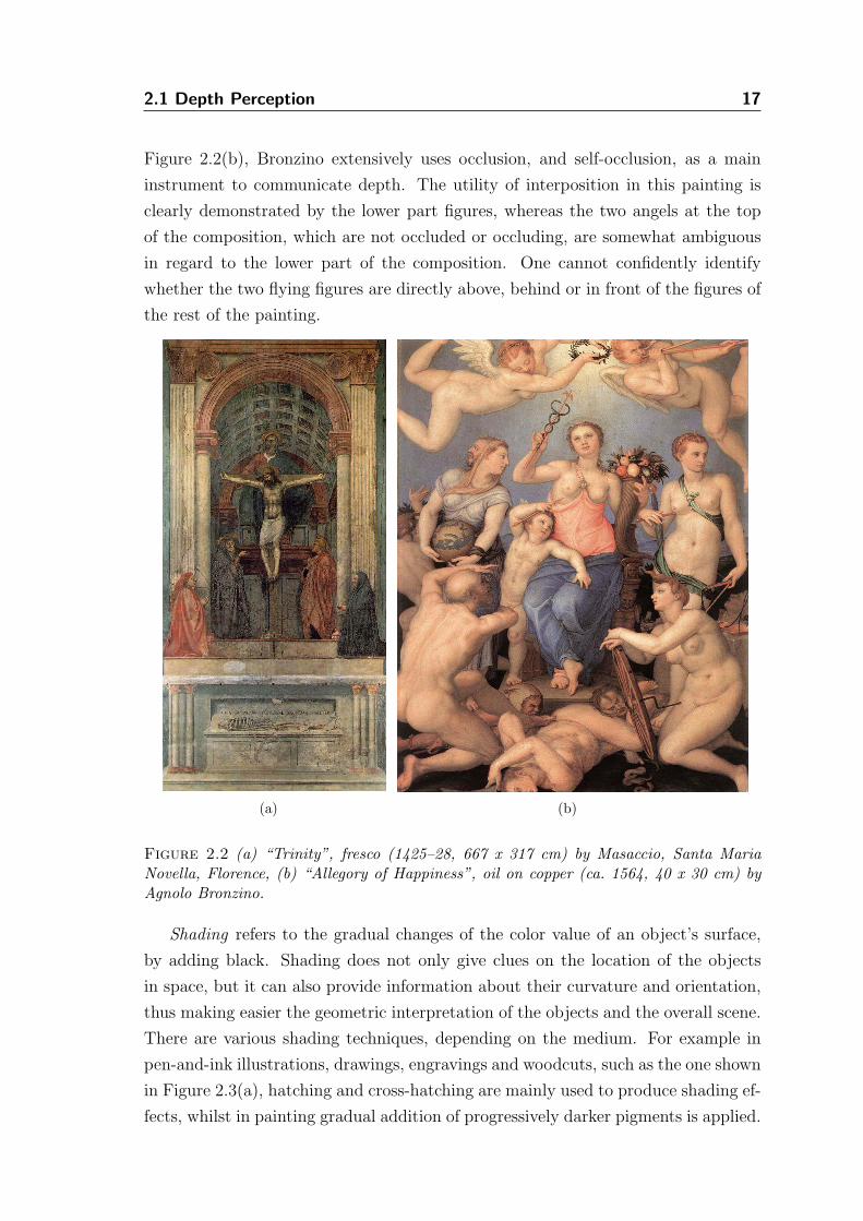
paintings, gravures, drawings, etc., are linear perspective, size, occlusion, shades and
shading, texture gradient and atmospheric perspective. These cues are psycholog-
ical and depend on our experience, cultural background and interaction with the
environment. For depictions to be comprehensible, the audience must poses a cog-
nitive understanding of the pictorial technique. Even though there are also two
other monocular cues, accommodation and motion parallax, they are not replicated
in static two-dimensional artwork. The former is an oculomotor cue that utilizes
the adjustments of the muscles used to change the focal length of the eyes’ lenses
in order to focus at different distances. The second one sources from the motion
of objects or the eye in regard to a point of fixation at a distance, e.g. moving ob-
jects with constant speed appear to move faster when they are located closer to the
observer, than objects that are further away.
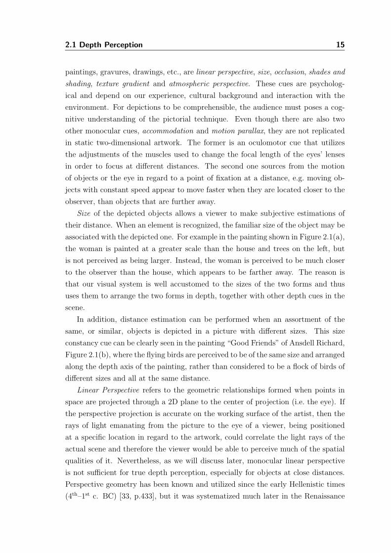
Size of the depicted objects allows a viewer to make subjective estimations of
their distance. When an element is recognized, the familiar size of the object may be
associated with the depicted one. For example in the painting shown in Figure 2.1(a),
the woman is painted at a greater scale than the house and trees on the left, but
is not perceived as being larger. Instead, the woman is perceived to be much closer
to the observer than the house, which appears to be farther away. The reason is
that our visual system is well accustomed to the sizes of the two forms and thus
uses them to arrange the two forms in depth, together with other depth cues in the
scene.
In addition, distance estimation can be performed when an assortment of the
same, or similar, objects is depicted in a picture with different sizes. This size
constancy cue can be clearly seen in the painting “Good Friends” of Ansdell Richard,
Figure 2.1(b), where the flying birds are perceived to be of the same size and arranged
along the depth axis of the painting, rather than considered to be a flock of birds of
different sizes and all at the same distance.
Linear Perspective refers to the geometric relationships formed when points in
space are projected through a 2D plane to the center of projection (i.e. the eye). If
the perspective projection is accurate on the working surface of the artist, then the
rays of light emanating from the picture to the eye of a viewer, being positioned
at a specific location in regard to the artwork, could correlate the light rays of the
actual scene and therefore the viewer would be able to perceive much of the spatial
qualities of it. Nevertheless, as we will discuss later, monocular linear perspective
is not sufficient for true depth perception, especially for objects at close distances.
Perspective geometry has been known and utilized since the early Hellenistic times
(4th–1st c. BC) [33, p.433], but it was systematized much later in the Renaissance
2.1 Depth Perception 16
(a) (b)
Figure 2.1 (a) “Faraway Thoughts”, oil on canvas (ca. 1880, 97.2 x 74.3 cm) by Ferdi-nand Heilbuth, (b) “Good Friends”, oil on canvas (ca. 1856, 91.4 x 71.1 cm) by RichardAnsdell.
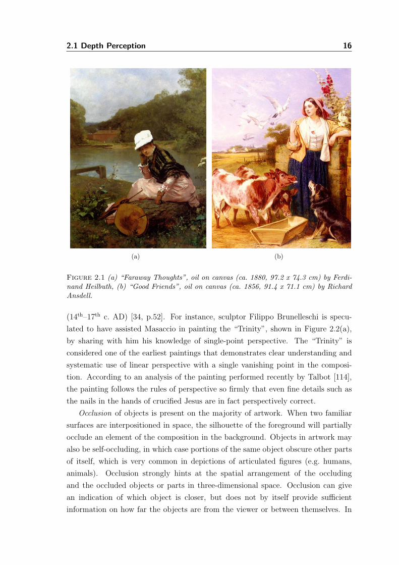
(14th–17th c. AD) [34, p.52]. For instance, sculptor Filippo Brunelleschi is specu-
lated to have assisted Masaccio in painting the “Trinity”, shown in Figure 2.2(a),
by sharing with him his knowledge of single-point perspective. The “Trinity” is
considered one of the earliest paintings that demonstrates clear understanding and
systematic use of linear perspective with a single vanishing point in the composi-
tion. According to an analysis of the painting performed recently by Talbot [114],
the painting follows the rules of perspective so firmly that even fine details such as
the nails in the hands of crucified Jesus are in fact perspectively correct.
Occlusion of objects is present on the majority of artwork. When two familiar
surfaces are interpositioned in space, the silhouette of the foreground will partially
occlude an element of the composition in the background. Objects in artwork may
also be self-occluding, in which case portions of the same object obscure other parts
of itself, which is very common in depictions of articulated figures (e.g. humans,
animals). Occlusion strongly hints at the spatial arrangement of the occluding
and the occluded objects or parts in three-dimensional space. Occlusion can give
an indication of which object is closer, but does not by itself provide sufficient
information on how far the objects are from the viewer or between themselves. In
2.1 Depth Perception 17
Figure 2.2(b), Bronzino extensively uses occlusion, and self-occlusion, as a main
instrument to communicate depth. The utility of interposition in this painting is
clearly demonstrated by the lower part figures, whereas the two angels at the top
of the composition, which are not occluded or occluding, are somewhat ambiguous
in regard to the lower part of the composition. One cannot confidently identify
whether the two flying figures are directly above, behind or in front of the figures of
the rest of the painting.
(a) (b)
Figure 2.2 (a) “Trinity”, fresco (1425–28, 667 x 317 cm) by Masaccio, Santa MariaNovella, Florence, (b) “Allegory of Happiness”, oil on copper (ca. 1564, 40 x 30 cm) byAgnolo Bronzino.
Shading refers to the gradual changes of the color value of an object’s surface,
by adding black. Shading does not only give clues on the location of the objects
in space, but it can also provide information about their curvature and orientation,
thus making easier the geometric interpretation of the objects and the overall scene.
There are various shading techniques, depending on the medium. For example in
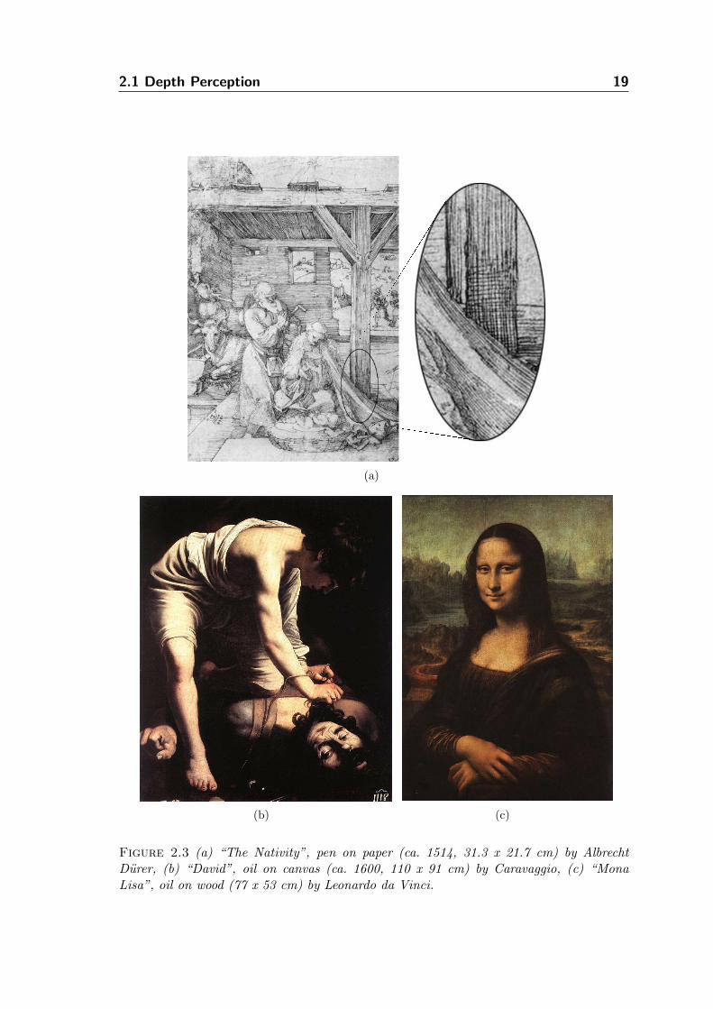
pen-and-ink illustrations, drawings, engravings and woodcuts, such as the one shown
in Figure 2.3(a), hatching and cross-hatching are mainly used to produce shading ef-
fects, whilst in painting gradual addition of progressively darker pigments is applied.
2.1 Depth Perception 18
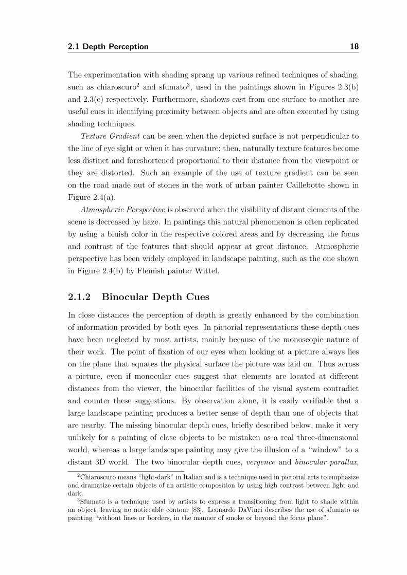
The experimentation with shading sprang up various refined techniques of shading,
such as chiaroscuro2 and sfumato3, used in the paintings shown in Figures 2.3(b)
and 2.3(c) respectively. Furthermore, shadows cast from one surface to another are
useful cues in identifying proximity between objects and are often executed by using
shading techniques.
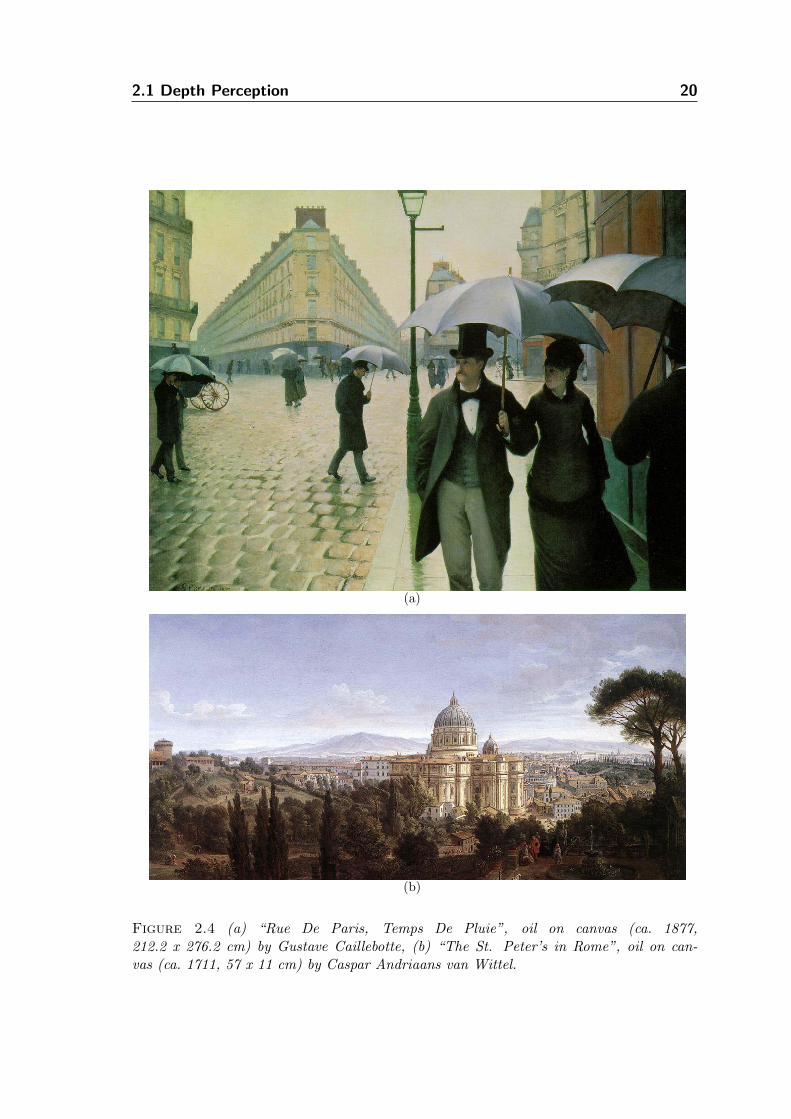
Texture Gradient can be seen when the depicted surface is not perpendicular to
the line of eye sight or when it has curvature; then, naturally texture features become
less distinct and foreshortened proportional to their distance from the viewpoint or
they are distorted. Such an example of the use of texture gradient can be seen
on the road made out of stones in the work of urban painter Caillebotte shown in
Figure 2.4(a).
Atmospheric Perspective is observed when the visibility of distant elements of the
scene is decreased by haze. In paintings this natural phenomenon is often replicated
by using a bluish color in the respective colored areas and by decreasing the focus
and contrast of the features that should appear at great distance. Atmospheric
perspective has been widely employed in landscape painting, such as the one shown
in Figure 2.4(b) by Flemish painter Wittel.
2.1.2 Binocular Depth Cues
In close distances the perception of depth is greatly enhanced by the combination
of information provided by both eyes. In pictorial representations these depth cues
have been neglected by most artists, mainly because of the monoscopic nature of
their work. The point of fixation of our eyes when looking at a picture always lies
on the plane that equates the physical surface the picture was laid on. Thus across
a picture, even if monocular cues suggest that elements are located at different
distances from the viewer, the binocular facilities of the visual system contradict
and counter these suggestions. By observation alone, it is easily verifiable that a
large landscape painting produces a better sense of depth than one of objects that
are nearby. The missing binocular depth cues, briefly described below, make it very
unlikely for a painting of close objects to be mistaken as a real three-dimensional
world, whereas a large landscape painting may give the illusion of a “window” to a
distant 3D world. The two binocular depth cues, vergence and binocular parallax,
2Chiaroscuro means “light-dark” in Italian and is a technique used in pictorial arts to emphasizeand dramatize certain objects of an artistic composition by using high contrast between light anddark.
3Sfumato is a technique used by artists to express a transitioning from light to shade withinan object, leaving no noticeable contour [83]. Leonardo DaVinci describes the use of sfumato aspainting “without lines or borders, in the manner of smoke or beyond the focus plane”.
2.1 Depth Perception 19
(a)
(b) (c)
Figure 2.3 (a) “The Nativity”, pen on paper (ca. 1514, 31.3 x 21.7 cm) by AlbrechtDurer, (b) “David”, oil on canvas (ca. 1600, 110 x 91 cm) by Caravaggio, (c) “MonaLisa”, oil on wood (77 x 53 cm) by Leonardo da Vinci.
2.1 Depth Perception 20
(a)
(b)
Figure 2.4 (a) “Rue De Paris, Temps De Pluie”, oil on canvas (ca. 1877,212.2 x 276.2 cm) by Gustave Caillebotte, (b) “The St. Peter’s in Rome”, oil on can-vas (ca. 1711, 57 x 11 cm) by Caspar Andriaans van Wittel.
2.2 Principles of Stereoscopy 21
are very important in close distances and allow for less reliable depth estimates as
the distance from the viewpoint increases.
Vergence of the eyes toward a point of interest in the visual field allows the
human visual system, when estimating depth, to take into consideration the ten-
sion of the extraocular muscles that support the movement of the eyeballs. It has
been experimentally found that convergence as a depth cue is less effective beyond
2 meters. It must be noted, however, that horizontal eye convergence can be volun-
tarily controlled, which, as we will discuss in the next section, is crucial for viewing
stereoscopic pictures that provide the binocular depth cues.
Binocular disparity describes the differences between corresponding retinal pro-
jections of the same points in space. When the eyes fixate on objects, the point that
the visual axes intersect lies on the surface of the object and its projection back to
the retina is the same on both eyes. In this case we define horizontal disparity as
being zero. The images of any points closer than the point of fixation are said to
have negative disparities, whereas points beyond have positive disparities. Depth
perception due to binocular disparity disappears at long distances from the eyes,
since differences in the two retinal images are nearly absent.
2.2 Principles of Stereoscopy
Stereoscopic vision is the ability of the brain to combine the information from the
two retinal images into a unified 3D percept. As Wheatstone has demonstrated with
his mirror stereoscope [125] that when two pictures of the same scene, such as the
ones shown in Figure 2.5, are created from horizontally disparate vantage points and
then they are dichoptically presented to the eyes4, the depth cues of convergence
and binocular parallax are replicated. Note that even though binocular disparity is
usually expressed in terms of the convergence angle, that is the angle (θ) formed at
the intersection of the visual axes, shown in Figure 2.6, it is more intuitive to treat
disparity as the displacement of points or features at the two projection planes.
2.2.1 Creating and Viewing Stereoscopic Content
The concept behind the generation of stereoscopic content is to depict a three-
dimensional object on two surfaces, with correct proportions and horizontal dispari-
ties from two slightly displaced viewpoints. These two planes of projection can then
be viewed stereoscopically, in which case the 2D points in the images are mentally
4When controlling the stimuli of each eye separately, then the stimuli arriving at each eye aresaid to be dichoptic [50, p.33].
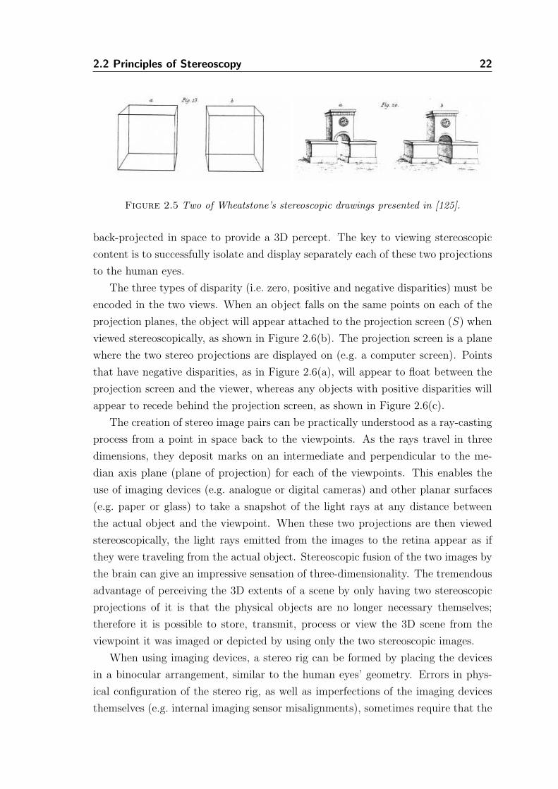
2.2 Principles of Stereoscopy 22
Figure 2.5 Two of Wheatstone’s stereoscopic drawings presented in [125].
back-projected in space to provide a 3D percept. The key to viewing stereoscopic
content is to successfully isolate and display separately each of these two projections
to the human eyes.
The three types of disparity (i.e. zero, positive and negative disparities) must be
encoded in the two views. When an object falls on the same points on each of the
projection planes, the object will appear attached to the projection screen (S) when
viewed stereoscopically, as shown in Figure 2.6(b). The projection screen is a plane
where the two stereo projections are displayed on (e.g. a computer screen). Points
that have negative disparities, as in Figure 2.6(a), will appear to float between the
projection screen and the viewer, whereas any objects with positive disparities will
appear to recede behind the projection screen, as shown in Figure 2.6(c).
The creation of stereo image pairs can be practically understood as a ray-casting
process from a point in space back to the viewpoints. As the rays travel in three
dimensions, they deposit marks on an intermediate and perpendicular to the me-
dian axis plane (plane of projection) for each of the viewpoints. This enables the
use of imaging devices (e.g. analogue or digital cameras) and other planar surfaces
(e.g. paper or glass) to take a snapshot of the light rays at any distance between
the actual object and the viewpoint. When these two projections are then viewed
stereoscopically, the light rays emitted from the images to the retina appear as if
they were traveling from the actual object. Stereoscopic fusion of the two images by
the brain can give an impressive sensation of three-dimensionality. The tremendous
advantage of perceiving the 3D extents of a scene by only having two stereoscopic
projections of it is that the physical objects are no longer necessary themselves;
therefore it is possible to store, transmit, process or view the 3D scene from the
viewpoint it was imaged or depicted by using only the two stereoscopic images.
When using imaging devices, a stereo rig can be formed by placing the devices
in a binocular arrangement, similar to the human eyes’ geometry. Errors in phys-
ical configuration of the stereo rig, as well as imperfections of the imaging devices
themselves (e.g. internal imaging sensor misalignments), sometimes require that the
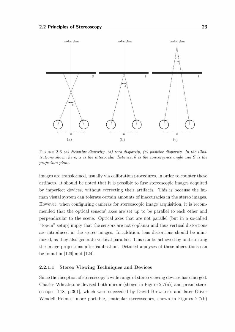
2.2 Principles of Stereoscopy 23
a
S
q
median plane
(a)
a
S
q
median plane
(b)
a
S
q
median plane
(c)
Figure 2.6 (a) Negative disparity, (b) zero disparity, (c) positive disparity. In the illus-trations shown here, α is the interocular distance, θ is the convergence angle and S is theprojection plane.
images are transformed, usually via calibration procedures, in order to counter these
artifacts. It should be noted that it is possible to fuse stereoscopic images acquired
by imperfect devices, without correcting their artifacts. This is because the hu-
man visual system can tolerate certain amounts of inaccuracies in the stereo images.
However, when configuring cameras for stereoscopic image acquisition, it is recom-
mended that the optical sensors’ axes are set up to be parallel to each other and
perpendicular to the scene. Optical axes that are not parallel (but in a so-called
“toe-in” setup) imply that the sensors are not coplanar and thus vertical distortions
are introduced in the stereo images. In addition, lens distortions should be mini-
mized, as they also generate vertical parallax. This can be achieved by undistorting
the image projections after calibration. Detailed analyses of these aberrations can
be found in [129] and [124].
2.2.1.1 Stereo Viewing Techniques and Devices
Since the inception of stereoscopy a wide range of stereo viewing devices has emerged.
Charles Wheatstone devised both mirror (shown in Figure 2.7(a)) and prism stere-
oscopes [118, p.301], which were succeeded by David Brewster’s and later Oliver
Wendell Holmes’ more portable, lenticular stereoscopes, shown in Figures 2.7(b)
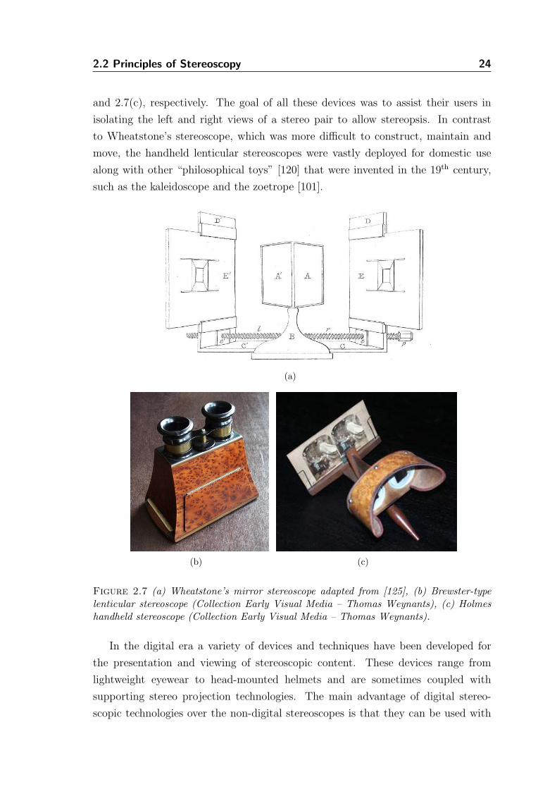
2.2 Principles of Stereoscopy 24
and 2.7(c), respectively. The goal of all these devices was to assist their users in
isolating the left and right views of a stereo pair to allow stereopsis. In contrast
to Wheatstone’s stereoscope, which was more difficult to construct, maintain and
move, the handheld lenticular stereoscopes were vastly deployed for domestic use
along with other “philosophical toys” [120] that were invented in the 19th century,
such as the kaleidoscope and the zoetrope [101].
(a)
(b) (c)
Figure 2.7 (a) Wheatstone’s mirror stereoscope adapted from [125], (b) Brewster-typelenticular stereoscope (Collection Early Visual Media – Thomas Weynants), (c) Holmeshandheld stereoscope (Collection Early Visual Media – Thomas Weynants).
In the digital era a variety of devices and techniques have been developed for
the presentation and viewing of stereoscopic content. These devices range from
lightweight eyewear to head-mounted helmets and are sometimes coupled with
supporting stereo projection technologies. The main advantage of digital stereo-
scopic technologies over the non-digital stereoscopes is that they can be used with
2.2 Principles of Stereoscopy 25
computer-generated stereo pairs and therefore hardcopy printouts are not required.
In addition they can be used to view stereoscopic videos and generally facilitate a
wider range of possibilities via the use of emerging computer graphics and vision
technologies. Popular manifestations of elaborate digital stereoscopy are those of
Virtual and Augmented Reality.
Generally, a projection screen may be used to display the components of a
stereo pair simultaneously (time-parallel) or in a sequence (time-multiplexed or
field-sequential) [71]. All these methods on their basis are targeted toward opti-
cally separating the stereo components. In time-parallel stereo, both the left and
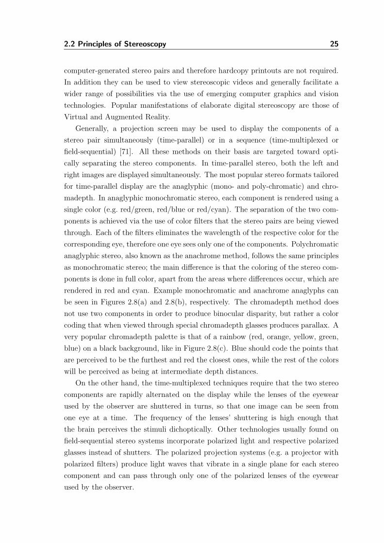
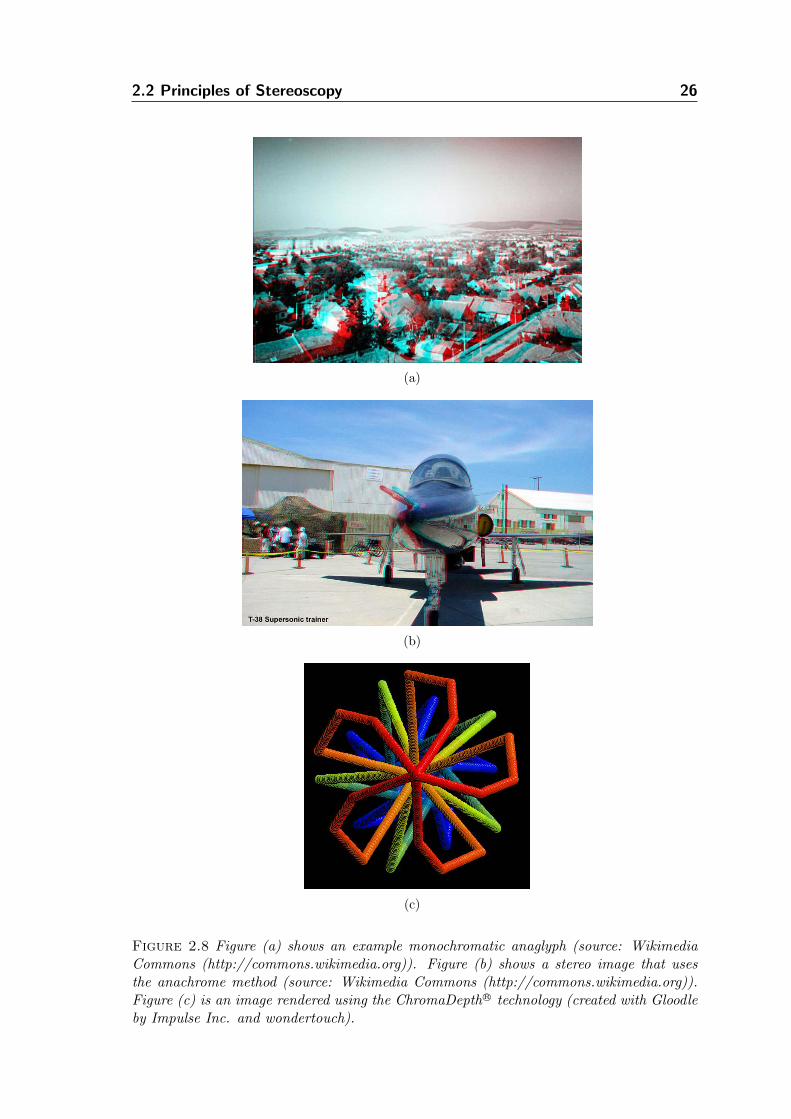
right images are displayed simultaneously. The most popular stereo formats tailored
for time-parallel display are the anaglyphic (mono- and poly-chromatic) and chro-
madepth. In anaglyphic monochromatic stereo, each component is rendered using a
single color (e.g. red/green, red/blue or red/cyan). The separation of the two com-
ponents is achieved via the use of color filters that the stereo pairs are being viewed
through. Each of the filters eliminates the wavelength of the respective color for the
corresponding eye, therefore one eye sees only one of the components. Polychromatic
anaglyphic stereo, also known as the anachrome method, follows the same principles
as monochromatic stereo; the main difference is that the coloring of the stereo com-
ponents is done in full color, apart from the areas where differences occur, which are
rendered in red and cyan. Example monochromatic and anachrome anaglyphs can
be seen in Figures 2.8(a) and 2.8(b), respectively. The chromadepth method does
not use two components in order to produce binocular disparity, but rather a color
coding that when viewed through special chromadepth glasses produces parallax. A
very popular chromadepth palette is that of a rainbow (red, orange, yellow, green,
blue) on a black background, like in Figure 2.8(c). Blue should code the points that
are perceived to be the furthest and red the closest ones, while the rest of the colors
will be perceived as being at intermediate depth distances.
On the other hand, the time-multiplexed techniques require that the two stereo
components are rapidly alternated on the display while the lenses of the eyewear
used by the observer are shuttered in turns, so that one image can be seen from
one eye at a time. The frequency of the lenses’ shuttering is high enough that
the brain perceives the stimuli dichoptically. Other technologies usually found on
field-sequential stereo systems incorporate polarized light and respective polarized
glasses instead of shutters. The polarized projection systems (e.g. a projector with
polarized filters) produce light waves that vibrate in a single plane for each stereo
component and can pass through only one of the polarized lenses of the eyewear
used by the observer.
2.2 Principles of Stereoscopy 26
(a)
(b)
(c)
Figure 2.8 Figure (a) shows an example monochromatic anaglyph (source: WikimediaCommons (http://commons.wikimedia.org)). Figure (b) shows a stereo image that usesthe anachrome method (source: Wikimedia Commons (http://commons.wikimedia.org)).Figure (c) is an image rendered using the ChromaDepthR© technology (created with Gloodleby Impulse Inc. and wondertouch).
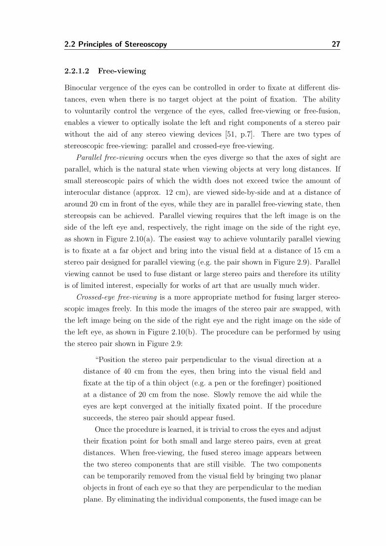
2.2 Principles of Stereoscopy 27
2.2.1.2 Free-viewing
Binocular vergence of the eyes can be controlled in order to fixate at different dis-
tances, even when there is no target object at the point of fixation. The ability
to voluntarily control the vergence of the eyes, called free-viewing or free-fusion,
enables a viewer to optically isolate the left and right components of a stereo pair
without the aid of any stereo viewing devices [51, p.7]. There are two types of
stereoscopic free-viewing: parallel and crossed-eye free-viewing.
Parallel free-viewing occurs when the eyes diverge so that the axes of sight are
parallel, which is the natural state when viewing objects at very long distances. If
small stereoscopic pairs of which the width does not exceed twice the amount of
interocular distance (approx. 12 cm), are viewed side-by-side and at a distance of
around 20 cm in front of the eyes, while they are in parallel free-viewing state, then
stereopsis can be achieved. Parallel viewing requires that the left image is on the
side of the left eye and, respectively, the right image on the side of the right eye,
as shown in Figure 2.10(a). The easiest way to achieve voluntarily parallel viewing
is to fixate at a far object and bring into the visual field at a distance of 15 cm a
stereo pair designed for parallel viewing (e.g. the pair shown in Figure 2.9). Parallel
viewing cannot be used to fuse distant or large stereo pairs and therefore its utility
is of limited interest, especially for works of art that are usually much wider.
Crossed-eye free-viewing is a more appropriate method for fusing larger stereo-
scopic images freely. In this mode the images of the stereo pair are swapped, with
the left image being on the side of the right eye and the right image on the side of
the left eye, as shown in Figure 2.10(b). The procedure can be performed by using
the stereo pair shown in Figure 2.9:
“Position the stereo pair perpendicular to the visual direction at a
distance of 40 cm from the eyes, then bring into the visual field and
fixate at the tip of a thin object (e.g. a pen or the forefinger) positioned
at a distance of 20 cm from the nose. Slowly remove the aid while the
eyes are kept converged at the initially fixated point. If the procedure
succeeds, the stereo pair should appear fused.
Once the procedure is learned, it is trivial to cross the eyes and adjust
their fixation point for both small and large stereo pairs, even at great
distances. When free-viewing, the fused stereo image appears between
the two stereo components that are still visible. The two components
can be temporarily removed from the visual field by bringing two planar
objects in front of each eye so that they are perpendicular to the median
plane. By eliminating the individual components, the fused image can be
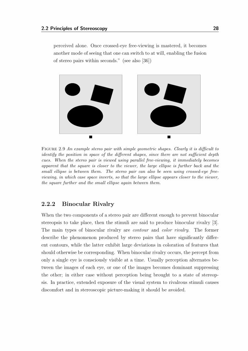
2.2 Principles of Stereoscopy 28
perceived alone. Once crossed-eye free-viewing is mastered, it becomes
another mode of seeing that one can switch to at will, enabling the fusion
of stereo pairs within seconds.” (see also [36])
Figure 2.9 An example stereo pair with simple geometric shapes. Clearly it is difficult toidentify the position in space of the different shapes, since there are not sufficient depthcues. When the stereo pair is viewed using parallel free-viewing, it immediately becomesapparent that the square is closer to the viewer, the large ellipse is further back and thesmall ellipse is between them. The stereo pair can also be seen using crossed-eye free-viewing, in which case space inverts, so that the large ellipse appears closer to the viewer,the square further and the small ellipse again between them.
2.2.2 Binocular Rivalry
When the two components of a stereo pair are different enough to prevent binocular
stereopsis to take place, then the stimuli are said to produce binocular rivalry [3].
The main types of binocular rivalry are contour and color rivalry. The former
describe the phenomenon produced by stereo pairs that have significantly differ-
ent contours, while the latter exhibit large deviations in coloration of features that
should otherwise be corresponding. When binocular rivalry occurs, the percept from
only a single eye is consciously visible at a time. Usually perception alternates be-
tween the images of each eye, or one of the images becomes dominant suppressing
the other; in either case without perception being brought to a state of stereop-
sis. In practice, extended exposure of the visual system to rivalrous stimuli causes
discomfort and in stereoscopic picture-making it should be avoided.
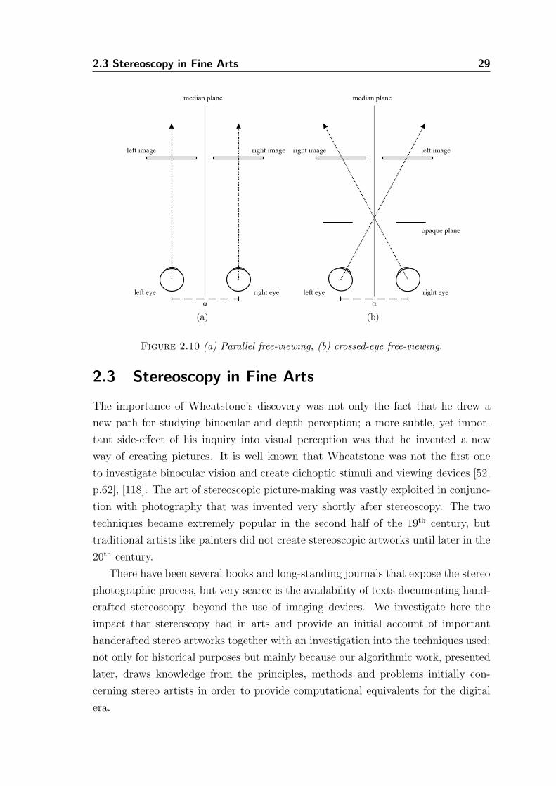
2.3 Stereoscopy in Fine Arts 29
a
right imageleft image
left eye right eye
median plane
(a)
a
right image left image
left eye right eye
opaque plane
median plane
(b)
Figure 2.10 (a) Parallel free-viewing, (b) crossed-eye free-viewing.
2.3 Stereoscopy in Fine Arts
The importance of Wheatstone’s discovery was not only the fact that he drew a
new path for studying binocular and depth perception; a more subtle, yet impor-
tant side-effect of his inquiry into visual perception was that he invented a new
way of creating pictures. It is well known that Wheatstone was not the first one
to investigate binocular vision and create dichoptic stimuli and viewing devices [52,
p.62], [118]. The art of stereoscopic picture-making was vastly exploited in conjunc-
tion with photography that was invented very shortly after stereoscopy. The two
techniques became extremely popular in the second half of the 19th century, but
traditional artists like painters did not create stereoscopic artworks until later in the
20th century.
There have been several books and long-standing journals that expose the stereo
photographic process, but very scarce is the availability of texts documenting hand-
crafted stereoscopy, beyond the use of imaging devices. We investigate here the
impact that stereoscopy had in arts and provide an initial account of important
handcrafted stereo artworks together with an investigation into the techniques used;
not only for historical purposes but mainly because our algorithmic work, presented
later, draws knowledge from the principles, methods and problems initially con-
cerning stereo artists in order to provide computational equivalents for the digital
era.
2.3 Stereoscopy in Fine Arts 30
2.3.1 Stereoscopic Artwork
A stereoscopic piece of art is composed by two components, which can be thought of
as the simulation of each of the retinal images of the artist’s, or viewer’s, eyes. This
two-viewpoint depiction can be considered as an uncoupling of a real or illusionary
3D composition space into a stereo pair of projections. This means that the dual
artwork may be either an artist’s depiction of reality, directly as it is seen and
subsequently transferred to a pictorial working surface, or an artistic composition
from the artist’s imagination.
Each of the two finished pictures can perfectly stand as an artistic piece of work
separately. However, there is a distinct advantage: viewing the artwork stereoscopi-
cally, with the ‘third eye’, the spectator can see inside the artist’s composition space
and observe the peculiar three-dimensional world made out of artistic media, which
cannot be perceived in either of the stereo components alone. But it is not simply an
accurate communication of three-dimensionality that makes stereo art interesting.
When artwork is executed and viewed stereoscopically, depicted objects can freely
detach from the pictorial surface and protrude toward the observer or recede behind
the surface they have been laid on, immediately exposing an immersive space that
exists perceptually in the brain; the observer does not have to imagine and assign
spatial relationships to the 2D picture, but can directly see what the artist was
intended to present him with.
Stereo artwork should be considered as a well defined technique for an artist to
intentionally engage his viewer into spatial aesthetics, rather than a limiting factor
for the viewer’s imagination. Stereoscopy can function as an artistic medium that
clarifies space and improves the perception of spatiality. When the intention of the
artist is to allow subjective interpretation by providing ambiguous depth cues, there
are long standing monoscopic techniques to achieve it. Actually, the masterful cre-
ation and manipulation of stereoscopic spaces enabled artists to produce interesting
spatial effects that were not possible in single-view artwork.
A rather obscure advantage of stereoscopic artworks over other media lies be-
neath the obvious communication of depth. When viewing stereoscopically, it is not
possible for the observer to divert his attention out of the stereoscopic space. While
the viewer is looking at the two components of a stereo piece, the real world itself
defocuses and is superseded by the stereoscopically fused artwork. This side-effect of
absorbing the viewers’ visual attention within the artwork is an effect many artists
would be pleased with, if achieved under any circumstances. In stereoscopic arts, it
becomes a requirement to engage visually with the artwork in order to perceive its
extent, opening a direct channel of communication between artist and observer.
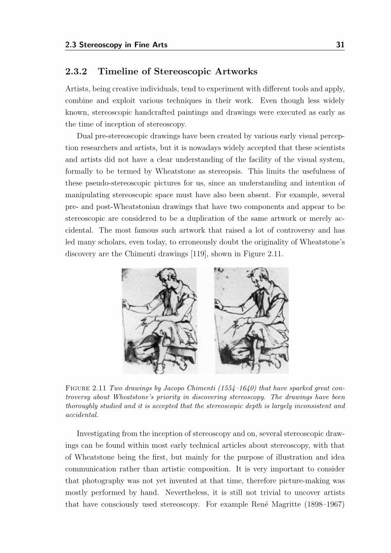
2.3 Stereoscopy in Fine Arts 31
2.3.2 Timeline of Stereoscopic Artworks
Artists, being creative individuals, tend to experiment with different tools and apply,
combine and exploit various techniques in their work. Even though less widely
known, stereoscopic handcrafted paintings and drawings were executed as early as
the time of inception of stereoscopy.
Dual pre-stereoscopic drawings have been created by various early visual percep-
tion researchers and artists, but it is nowadays widely accepted that these scientists
and artists did not have a clear understanding of the facility of the visual system,
formally to be termed by Wheatstone as stereopsis. This limits the usefulness of
these pseudo-stereoscopic pictures for us, since an understanding and intention of
manipulating stereoscopic space must have also been absent. For example, several
pre- and post-Wheatstonian drawings that have two components and appear to be
stereoscopic are considered to be a duplication of the same artwork or merely ac-
cidental. The most famous such artwork that raised a lot of controversy and has
led many scholars, even today, to erroneously doubt the originality of Wheatstone’s
discovery are the Chimenti drawings [119], shown in Figure 2.11.
Figure 2.11 Two drawings by Jacopo Chimenti (1554–1640) that have sparked great con-troversy about Wheatstone’s priority in discovering stereoscopy. The drawings have beenthoroughly studied and it is accepted that the stereoscopic depth is largely inconsistent andaccidental.
Investigating from the inception of stereoscopy and on, several stereoscopic draw-
ings can be found within most early technical articles about stereoscopy, with that
of Wheatstone being the first, but mainly for the purpose of illustration and idea
communication rather than artistic composition. It is very important to consider
that photography was not yet invented at that time, therefore picture-making was
mostly performed by hand. Nevertheless, it is still not trivial to uncover artists
that have consciously used stereoscopy. For example Rene Magritte (1898–1967)
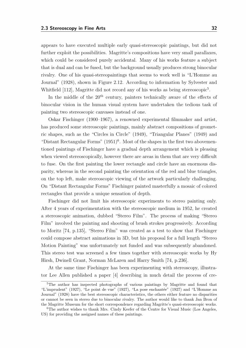
2.3 Stereoscopy in Fine Arts 32
appears to have executed multiple early quasi-stereoscopic paintings, but did not
further exploit the possibilities. Magritte’s compositions have very small parallaxes,
which could be considered purely accidental. Many of his works feature a subject
that is dual and can be fused, but the background usually produces strong binocular
rivalry. One of his quasi-stereopaintings that seems to work well is “L’Homme au
Journal” (1928), shown in Figure 2.12. According to information by Sylvester and
Whitfield [112], Magritte did not record any of his works as being stereoscopic5.
In the middle of the 20th century, painters technically aware of the effects of
binocular vision in the human visual system have undertaken the tedious task of
painting two stereoscopic canvases instead of one.
Oskar Fischinger (1900–1967), a renowned experimental filmmaker and artist,
has produced some stereoscopic paintings, mainly abstract compositions of geomet-
ric shapes, such as the “Circles in Circle” (1949), “Triangular Planes” (1949) and
“Distant Rectangular Forms” (1951)6. Most of the shapes in the first two abovemen-
tioned paintings of Fischinger have a gradual depth arrangement which is pleasing
when viewed stereoscopically, however there are areas in them that are very difficult
to fuse. On the first painting the lower rectangle and circle have an enormous dis-
parity, whereas in the second painting the orientation of the red and blue triangles,
on the top left, make stereoscopic viewing of the artwork particularly challenging.
On “Distant Rectangular Forms” Fischinger painted masterfully a mosaic of colored
rectangles that provide a unique sensation of depth.
Fischinger did not limit his stereoscopic experiments to stereo painting only.
After 4 years of experimentation with the stereoscopic medium in 1952, he created
a stereoscopic animation, dubbed “Stereo Film”. The process of making “Stereo
Film” involved the painting and shooting of brush strokes progressively. According
to Moritz [74, p.135], “Stereo Film” was created as a test to show that Fischinger
could compose abstract animations in 3D, but his proposal for a full length “Stereo
Motion Painting” was unfortunately not funded and was subsequently abandoned.
This stereo test was screened a few times together with stereoscopic works by Hy
Hirsh, Dwinell Grant, Norman McLaren and Harry Smith [74, p.236].
At the same time Fischinger has been experimenting with stereoscopy, illustra-
tor Lee Allen published a paper [4] describing in much detail the process of cre-
5The author has inspected photographs of various paintings by Magritte and found that“L’imprudent” (1927), “Le point de vue” (1927), “La pose enchantee” (1927) and “L’Homme auJournal” (1928) have the best stereoscopic characteristics, the others either feature no disparitiesor cannot be seen in stereo due to binocular rivalry. The author would like to thank Jan Bron ofthe Magritte Museum for the short correspondence regarding Magritte’s quasi-stereoscopic works.
6The author wishes to thank Mrs. Cindy Keefer of the Centre for Visual Music (Los Angeles,US) for providing the assigned names of these paintings.
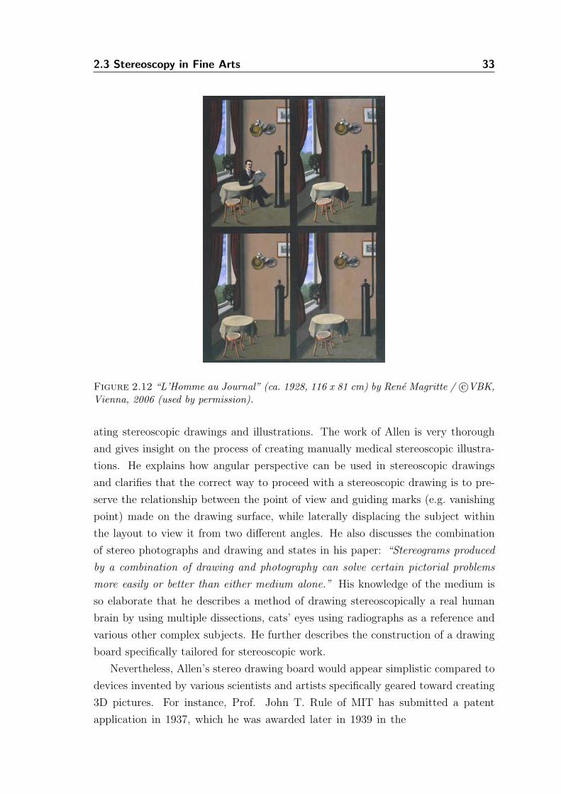
2.3 Stereoscopy in Fine Arts 33
Figure 2.12 “L’Homme au Journal” (ca. 1928, 116 x 81 cm) by Rene Magritte / c©VBK,Vienna, 2006 (used by permission).
ating stereoscopic drawings and illustrations. The work of Allen is very thorough
and gives insight on the process of creating manually medical stereoscopic illustra-
tions. He explains how angular perspective can be used in stereoscopic drawings
and clarifies that the correct way to proceed with a stereoscopic drawing is to pre-
serve the relationship between the point of view and guiding marks (e.g. vanishing
point) made on the drawing surface, while laterally displacing the subject within
the layout to view it from two different angles. He also discusses the combination
of stereo photographs and drawing and states in his paper: “Stereograms produced
by a combination of drawing and photography can solve certain pictorial problems
more easily or better than either medium alone.” His knowledge of the medium is
so elaborate that he describes a method of drawing stereoscopically a real human
brain by using multiple dissections, cats’ eyes using radiographs as a reference and
various other complex subjects. He further describes the construction of a drawing
board specifically tailored for stereoscopic work.
Nevertheless, Allen’s stereo drawing board would appear simplistic compared to
devices invented by various scientists and artists specifically geared toward creating
3D pictures. For instance, Prof. John T. Rule of MIT has submitted a patent
application in 1937, which he was awarded later in 1939 in the
2.3 Stereoscopy in Fine Arts 34
great detail an instrument for stereoscopic drawing [84]. His apparatus is composed
by a drawing board, a pencil that can be adjusted in space, a binocular viewer and
other supporting mechanical parts. Similarly, Cook submitted a patent application
for a different, but impractically complex, stereoscopic drawing apparatus in 1953,
which was awarded to him in 1958 [22]. A more compact and accurate instrument
was invented independently by Palestinian artist and scientist Vladimir Tamari in
1963. Tamari’s invention is notable not only because of the mechanical superiority it
features over previous devices, but also because the inventor himself as an artist has
produced hundreds of artistic stereoscopic drawings while using it; for an example
see Figure 2.13(a). Tamari’s 3 Dimensional Drawing (3DD) instrument, shown in
Figure 2.13(b), has been featured in multiple publications with central focus on
stereoscopy and he has written various articles about its construction, as well as its
use for artistic purposes [115].
In the same line of work in stereoscopic drawing, but much later, Arthur Girling
has published a book [37] that explains methods for creating stereoscopic draw-
ings by hand. The book is more of a hands-on guide and it cannot be directly
derived whether the author was aware of the work of Lee Allen and others, neither
does he provide any relevant bibliographic references to older stereoscopic artworks.
However, his methods are easy to follow and his book has some thought-provoking
well-illustrated text and many stereoscopic drawings.
At the beginning of the 1970s, Alphons Schilling, Salvador Dalı (1904–89), Roger
Ferragallo, Michael Kupka and Heinz Gunther Leitner almost concurrently created
stereo paintings and drawings proving that even though handcrafted stereoscopic
content is particularly demanding in artistic and technical capacity, it can be used
purely as an artistic medium beyond its obvious utility in sciences.
Alphons Schilling has executed a multitude of stereoscopic compositions that are
both dual- and single-component. Schilling has built various viewing devices, the
Sehmaschinen, that allowed him to take stereo artwork a step further and generate
not only dual component works, but also single component canvases. The former are
both compositions using paints on canvas, but also various black and white pieces
that have the appearance of random-dot stereograms (e.g. revealing shapes of human
bodies in various postures). The single component paintings are compositions of
gradient patterns in which, according to Schilling himself, lines define planes that
when viewed with both eyes open and a single prismatic lens in front of the one
eye only, a pleasing sensation of gradual depth can be perceived. Other notable
achievements of Schilling include the installation of a massive stereoscope in Helen
Hayes Hospital on Hudson River (New York, 1983), his pseudoscopes that invert
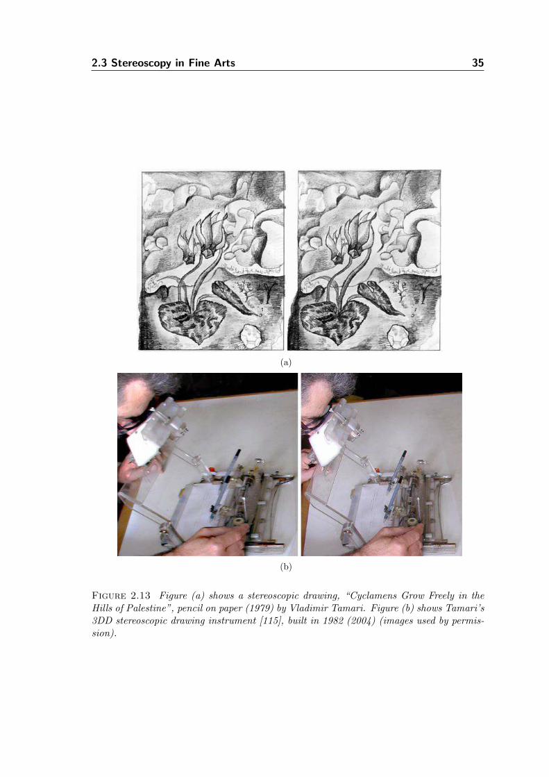
2.3 Stereoscopy in Fine Arts 35
(a)
(b)
Figure 2.13 Figure (a) shows a stereoscopic drawing, “Cyclamens Grow Freely in theHills of Palestine”, pencil on paper (1979) by Vladimir Tamari. Figure (b) shows Tamari’s3DD stereoscopic drawing instrument [115], built in 1982 (2004) (images used by permis-sion).
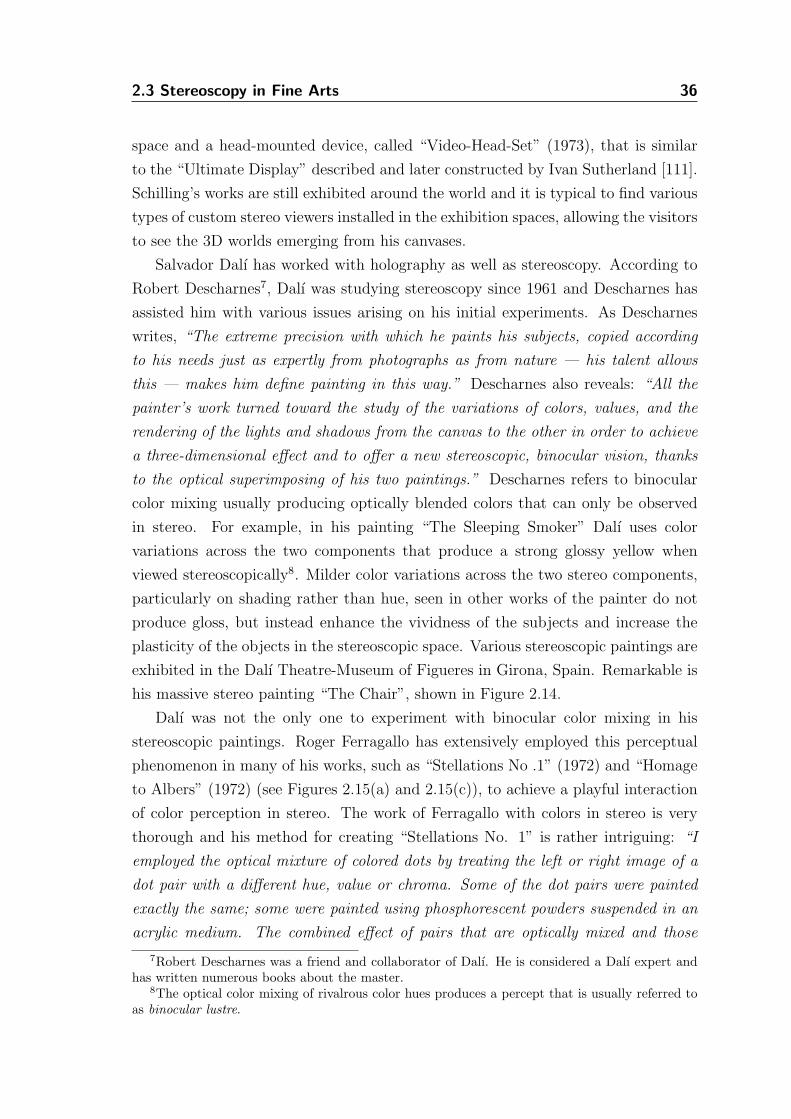
2.3 Stereoscopy in Fine Arts 36
space and a head-mounted device, called “Video-Head-Set” (1973), that is similar
to the “Ultimate Display” described and later constructed by Ivan Sutherland [111].
Schilling’s works are still exhibited around the world and it is typical to find various
types of custom stereo viewers installed in the exhibition spaces, allowing the visitors
to see the 3D worlds emerging from his canvases.
Salvador Dalı has worked with holography as well as stereoscopy. According to
Robert Descharnes7, Dalı was studying stereoscopy since 1961 and Descharnes has
assisted him with various issues arising on his initial experiments. As Descharnes
writes, “The extreme precision with which he paints his subjects, copied according
to his needs just as expertly from photographs as from nature — his talent allows
this — makes him define painting in this way.” Descharnes also reveals: “All the
painter’s work turned toward the study of the variations of colors, values, and the
rendering of the lights and shadows from the canvas to the other in order to achieve
a three-dimensional effect and to offer a new stereoscopic, binocular vision, thanks
to the optical superimposing of his two paintings.” Descharnes refers to binocular
color mixing usually producing optically blended colors that can only be observed
in stereo. For example, in his painting “The Sleeping Smoker” Dalı uses color
variations across the two components that produce a strong glossy yellow when
viewed stereoscopically8. Milder color variations across the two stereo components,
particularly on shading rather than hue, seen in other works of the painter do not
produce gloss, but instead enhance the vividness of the subjects and increase the
plasticity of the objects in the stereoscopic space. Various stereoscopic paintings are
exhibited in the Dalı Theatre-Museum of Figueres in Girona, Spain. Remarkable is
his massive stereo painting “The Chair”, shown in Figure 2.14.
Dalı was not the only one to experiment with binocular color mixing in his
stereoscopic paintings. Roger Ferragallo has extensively employed this perceptual
phenomenon in many of his works, such as “Stellations No .1” (1972) and “Homage
to Albers” (1972) (see Figures 2.15(a) and 2.15(c)), to achieve a playful interaction
of color perception in stereo. The work of Ferragallo with colors in stereo is very
thorough and his method for creating “Stellations No. 1” is rather intriguing: “I
employed the optical mixture of colored dots by treating the left or right image of a
dot pair with a different hue, value or chroma. Some of the dot pairs were painted
exactly the same; some were painted using phosphorescent powders suspended in an
acrylic medium. The combined effect of pairs that are optically mixed and those
7Robert Descharnes was a friend and collaborator of Dalı. He is considered a Dalı expert andhas written numerous books about the master.
8The optical color mixing of rivalrous color hues produces a percept that is usually referred toas binocular lustre.
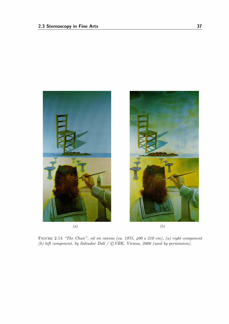
2.3 Stereoscopy in Fine Arts 37
(a) (b)
Figure 2.14 “The Chair”, oil on canvas (ca. 1975, 400 x 210 cm), (a) right component(b) left component, by Salvador Dalı / c©VBK, Vienna, 2006 (used by permission).
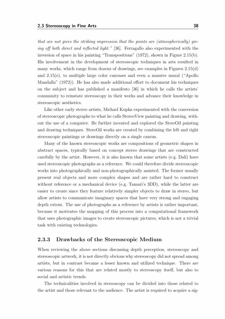
2.3 Stereoscopy in Fine Arts 38
that are not gives the striking impression that the points are (atmospherically) giv-
ing off both direct and reflected light.” [36]. Ferragallo also experimented with the
inversion of space in his painting “Transpositions” (1972), shown in Figure 2.15(b).
His involvement in the development of stereoscopic techniques in arts resulted in
many works, which range from dozens of drawings, see examples in Figures 2.15(d)
and 2.15(e), to multiple large color canvases and even a massive mural (“Apollo
Mandalla” (1972)). He has also made additional effort to document his techniques
on the subject and has published a manifesto [36] in which he calls the artists’
community to reinstate stereoscopy in their works and advance their knowledge in
stereoscopic aesthetics.
Like other early stereo artists, Michael Kupka experimented with the conversion
of stereoscopic photographs to what he calls StereoView painting and drawing, with-
out the use of a computer. He further invented and explored the StereOil painting
and drawing techniques. StereOil works are created by combining the left and right
stereoscopic paintings or drawings directly on a single canvas.
Many of the known stereoscopic works are compositions of geometric shapes in
abstract spaces, typically based on concept stereo drawings that are constructed
carefully by the artist. However, it is also known that some artists (e.g. Dalı) have
used stereoscopic photographs as a reference. We could therefore divide stereoscopic
works into photographically and non-photographically assisted. The former usually
present real objects and more complex shapes and are rather hard to construct
without reference or a mechanical device (e.g. Tamari’s 3DD), while the latter are
easier to create since they feature relatively simpler objects to draw in stereo, but
allow artists to communicate imaginary spaces that have very strong and engaging
depth extent. The use of photographs as a reference by artists is rather important,
because it motivates the mapping of this process into a computational framework
that uses photographic images to create stereoscopic pictures, which is not a trivial
task with existing technologies.
2.3.3 Drawbacks of the Stereoscopic Medium
When reviewing the above sections discussing depth perception, stereoscopy and
stereoscopic artwork, it is not directly obvious why stereoscopy did not spread among
artists, but in contrast became a lesser known and utilized technique. There are
various reasons for this that are related mostly to stereoscopy itself, but also to
social and artistic trends.
The technicalities involved in stereoscopy can be divided into those related to
the artist and those relevant to the audience. The artist is required to acquire a sig-
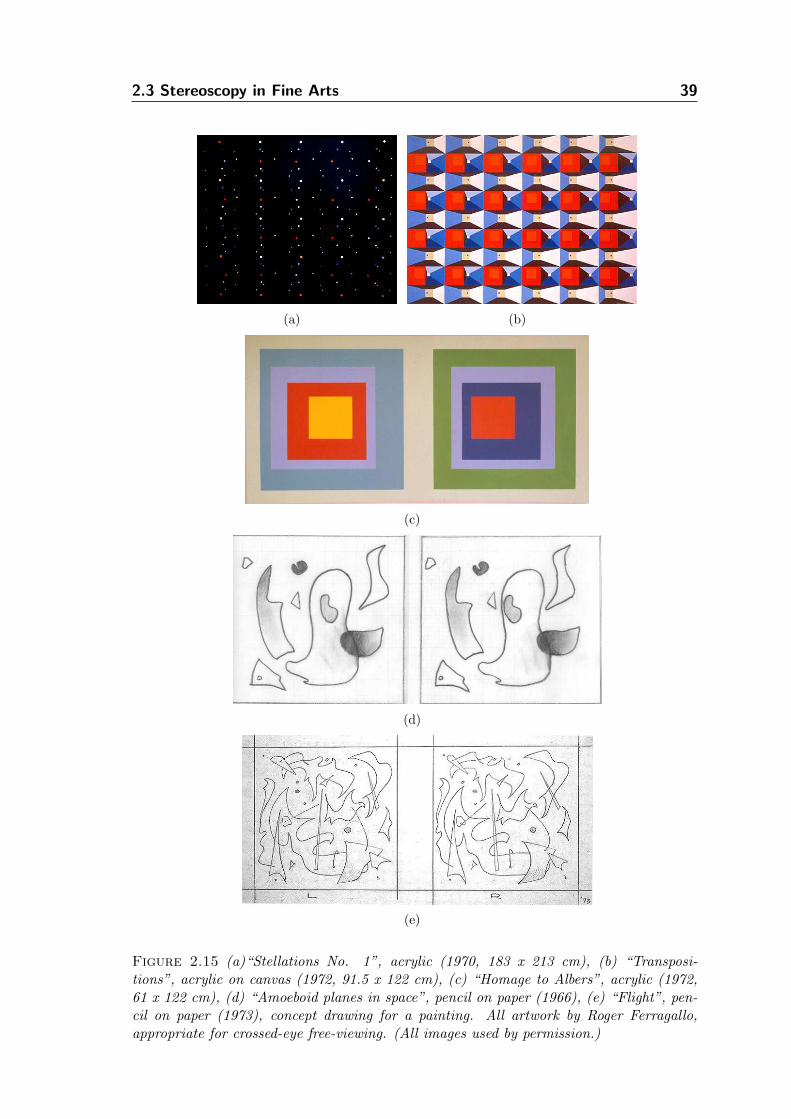
2.3 Stereoscopy in Fine Arts 39
(a) (b)
(c)
(d)
(e)
Figure 2.15 (a)“Stellations No. 1”, acrylic (1970, 183 x 213 cm), (b) “Transposi-tions”, acrylic on canvas (1972, 91.5 x 122 cm), (c) “Homage to Albers”, acrylic (1972,61 x 122 cm), (d) “Amoeboid planes in space”, pencil on paper (1966), (e) “Flight”, pen-cil on paper (1973), concept drawing for a painting. All artwork by Roger Ferragallo,appropriate for crossed-eye free-viewing. (All images used by permission.)
2.3 Stereoscopy in Fine Arts 40
nificant amount of technical knowledge about the human visual system, the creation
of stereoscopic stimuli and the constraints within which they become effective for
their audience. Manipulating spatial properties of the artwork by shifting between
stereoscopic and normal vision while working constitutes one of the less critical, yet
important, limitations. In practice the artist, for a single work, will alternate his
vision between the two viewing modes multiple times to ensure that the artwork de-
velops as desired regarding the stereoscopic properties of it. Using photographs as a
reference and further creating accurate stereoscopic drawings to preserve disparities
is not sufficient, since coloration has to also be stereoscopically correct. Particu-
larly challenging are fluid pigments that, when overlaid, they may blend to produce
undesired inconsistencies.
Looking at stereo artwork creation from a purely practical viewpoint, an artist
is required to work at least twice as much as he would for an equivalent single com-
ponent piece. The complexity of the artwork in terms of disparity variations alone
increases the required effort significantly compared to traditional monoscopic tech-
niques. This appears as a valid reason to explain why many stereoscopic handmade
works, especially paintings, depict geometric shapes and objects, rather than real
life compositions. Consistency and time, however, were not the only factors that
forced the demise of stereoscopy.
Photography, that was invented almost concurrently with stereoscopy, functioned
as a catalyst for the birth of new art movements. As Silverman writes “As a mere
mechanical process, photography could not exercise the tasteful judgment of the hu-
man artist” [101]. Since monoscopic and stereoscopic photography allowed precise
imaging of reality and particularly accurate depiction of spatial dimensions, artists
turned away from realistic depiction and experimented with more expressive tech-
niques the camera could not compete with. Willats [128, p.220–247] argues that
artists’ interest shifted from the use of traditional representational systems, such as
perspective, and found alternative means of creating pictures that suggested flat-
ness, rather than aiming for three-dimensionality. This was a shift in aesthetics,
which had an impact on which techniques were to be used. Art movements such as
Impressionism, Expressionism, Cubism, Op-art and various others emerged shortly
after stereoscopy and photography were invented. While the Modernists were ex-
ploring new expressive picture-making techniques, stereoscopy remained mainly a
photographic technique until the second half of the 20th century, when artists utilized
it in pictorial representations to reintroduce the communication of depth [59, 36].
On the opposite end, the inability of the audiences to readily view stereoscopic
artwork by free-viewing made it relatively difficult to disseminate the works of stereo-
2.3 Stereoscopy in Fine Arts 41
scopic artwork. Artists equipped their exhibitions with stereo viewing devices to
allow the audiences to see beyond the flat canvases. Free-viewing, or special stere-
oscopes, are necessary when viewing large stereo works. Printing stereo artwork
(e.g. in books) in a smaller scale than the one they have been originally created
compresses depth, since disparities are scaled down, and may render the artwork’s
spatial characteristics weak or imperceptible. If free-viewing were an ability pos-
sessed by most art enthusiasts, then stereo artwork may have become more popular.
According to Crary [23, p.127–136], the sociocultural demise of the stereoscope,
around the turn of the 19th century, was not strictly because of its association
with pornographic images, as others have claimed. He argues that the simulation
of reality by using the stereoscope required the observer to shift away from the
classical viewing techniques of monocular pictures. Stereoscopy has brought around
a new viewing technique that reconfigured the observer in relation to the visual
representation. This was radical enough a change that stereoscopy, even in its 20th
century resurfacing, did not achieve to become a standard viewing technique and,
therefore, its popularity receded again.
In the past two decades, however, stereoscopy was subtly integrated into Virtual
and Augmented Reality systems. The quality and ubiquity of such systems have im-
proved rapidly and have become acceptable by the targeted audiences, especially for
applications in domains where realistic simulation of percepts is important. Stere-
oscopy has also penetrated the environment of the home user. Three-dimensional
games and applications can now be used in combination with affordable stereoscopic
systems. However, the stereoscopic technique is not a main objective for most 3D
software makers, since the market is still relatively small.
Chapter 3
Related Work
The broader goal of this work, which is to turn 2D stereoscopic images into artistic-
looking picture pairs, presents us with a number of problems that implicate tech-
niques from different areas of computer science.
We assume in this work that decoupled imaging devices (i.e. digital cameras) are
used in a stereoscopic formation for input acquisition. This approach is more flexible
than requiring specialized stereoscopic hardware and allows a variety of devices to
be used with the rest of the rendering system implementing our algorithms. This
increased flexibility of attaching arbitrary devices comes with the price of requiring
to manipulate the acquired images in order for the image pairs to be suitable1 for
processing by stereo analysis algorithms.
In fact it is more of a rule rather than an exception that the two imaging de-
vices will have variable imperfections on their sensors as well as other deviations
in hardware construction. This means that even if the two devices are arranged
carefully side-by-side, the 2D images captured may still not be suitable to directly
be utilized for stereoscopic analysis or synthesis. To create a proper stereoscopic
coupling between the two input devices, their image planes must be reprojected to
ensure that their geometry allows further processing.
The requirement of using 2D images of real scenes as an input from the onset of
the work suggests that traditional rendering techniques using 3D geometric objects
cannot be directly applied. Instead, to generate stereo views we use principles from
Image-Based Rendering (IBR) techniques to generate new renditions from images,
rather than geometric objects. An important consideration in this work is that
selective rendering of features in the new stylized stereo views cannot be readily
performed, since high-level information of scene structure is absent. Thus we re-
cover some of the underlying geometric information in the scene (i.e. depth) using
stereo vision. We can then selectively apply artistic filters on the extracted objects
or features based on this information. Because depth is critical in the comprehen-
1In the context of this work, the acquired image pairs become suitable for stereoscopic imageanalysis after bringing them into an epipolar geometry, in which the horizontal scanlines of theone image correspond to the equivalent scanlines of the other image, as described in Section 3.2.
42
3.1 Image-Based Rendering 43
sion of stereoscopic space, this gives us an advantage over single-view algorithms,
which usually treat images as flat surfaces and apply effects selectively using either
2D features, frequency, or saliency information in the image. While this informa-
tion provides in many cases adequate input for selecting and highlighting specific
features in an image, these techniques are solely based on monocular depth cues
already present in the image. Furthermore, in a stereoscopic context, without es-
tablishing an appropriate correspondence of features between the two views (which
is a major focus in this work), applying an algorithm separately on the two input
images will result in new images that may be inconsistent. However, while some
inconsistencies may be tackled via appropriate processing (e.g. in the same sense
temporally coherent algorithms are applied to an image sequence), selective render-
ing of features according to their distance from the viewpoint will not be possible.
The latter prevents such techniques from automatically manipulating stereoscopic
features, and manual intervention is therefore required to apply rendering styles
selectively according to scene depth.
Turning photographic images into artistic-looking pictures requires both image
analysis and synthesis procedures. Creating such human-oriented renditions usually
requires the modeling of natural media or simulation of traditional picture-making
techniques in a consistent manner that is meaningful, in order to provide output that
is appropriate for stereoscopic viewing. We will look for solutions to the synthesis
of artistic-looking images mainly in Non-Photorealistic Rendering, but in a hybrid
context in which computational stereo vision is first used to recover scene structure.
Then stereoscopic view synthesis is employed to handle the consistent generation
of the stereo views and selective NPR is applied to artistically augment the stereo
views.
3.1 Image-Based Rendering
Image-Based Rendering techniques concentrate around the concept of synthesizing
images by using existing input images. In contrast to computer graphics geometry-
based rendering methods, IBR provides an alternative set of methods to solve the
image synthesis problem without the requirement of explicit 3D geometry. Another
main advantage of IBR over traditional 3D computer graphics methods is that the
input image samples required to generate new views of a scene can be easily ac-
quired with imaging devices. In IBR, images are the rendering primitives, rather
than polygonal meshes, which also indicates that performance of IBR techniques
is independent of scene complexity. High fidelity images can be synthesized much
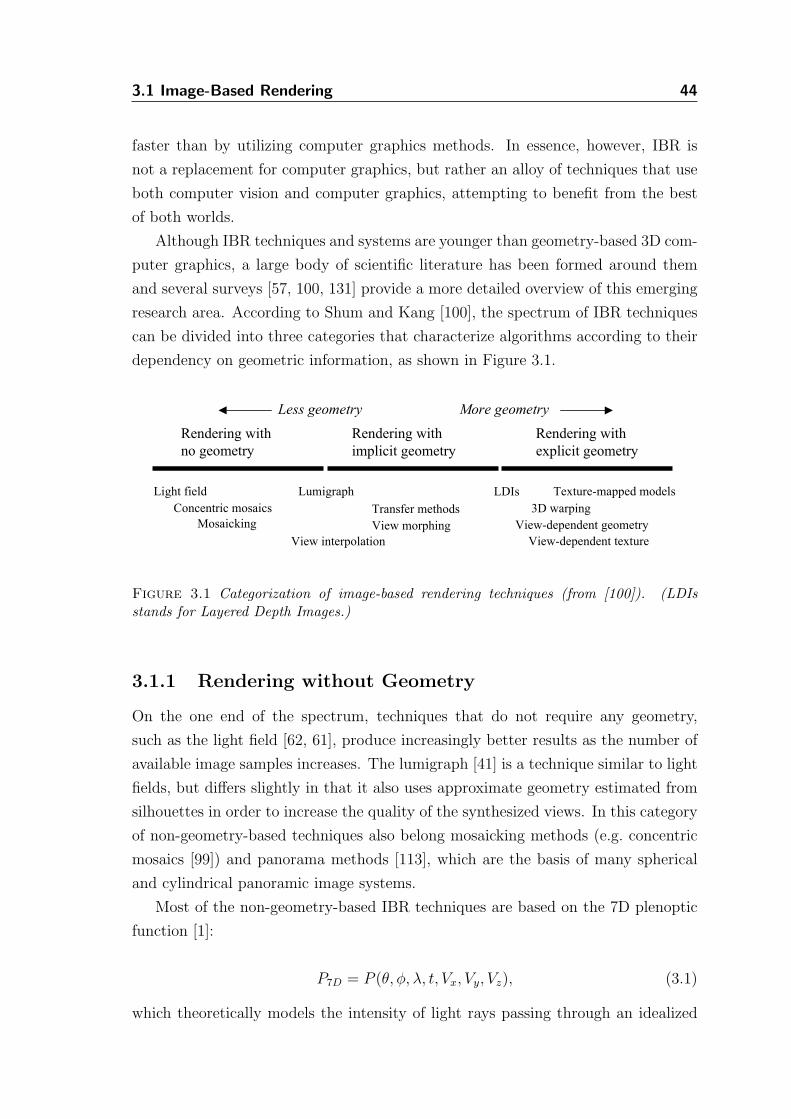
3.1 Image-Based Rendering 44
faster than by utilizing computer graphics methods. In essence, however, IBR is
not a replacement for computer graphics, but rather an alloy of techniques that use
both computer vision and computer graphics, attempting to benefit from the best
of both worlds.
Although IBR techniques and systems are younger than geometry-based 3D com-
puter graphics, a large body of scientific literature has been formed around them
and several surveys [57, 100, 131] provide a more detailed overview of this emerging
research area. According to Shum and Kang [100], the spectrum of IBR techniques
can be divided into three categories that characterize algorithms according to their
dependency on geometric information, as shown in Figure 3.1.
Less geometry More geometry
Rendering with
no geometry
Rendering with
implicit geometry
Rendering with
explicit geometry
Light field
Mosaicking
Concentric mosaics
View-dependent geometry
View-dependent texture
View morphing
LDIsLumigraph Texture-mapped models
View interpolation
3D warpingTransfer methods
Figure 3.1 Categorization of image-based rendering techniques (from [100]). (LDIsstands for Layered Depth Images.)
3.1.1 Rendering without Geometry
On the one end of the spectrum, techniques that do not require any geometry,
such as the light field [62, 61], produce increasingly better results as the number of
available image samples increases. The lumigraph [41] is a technique similar to light
fields, but differs slightly in that it also uses approximate geometry estimated from
silhouettes in order to increase the quality of the synthesized views. In this category
of non-geometry-based techniques also belong mosaicking methods (e.g. concentric
mosaics [99]) and panorama methods [113], which are the basis of many spherical
and cylindrical panoramic image systems.
Most of the non-geometry-based IBR techniques are based on the 7D plenoptic
function [1]:
P7D = P (θ, φ, λ, t, Vx, Vy, Vz), (3.1)
which theoretically models the intensity of light rays passing through an idealized
3.1 Image-Based Rendering 45
eye placed at every point (Vx,Vy,Vz) in a scene observed from every possible angle
(θ,φ), for every wavelength λ, at every time t.
The complete plenoptic function (Eq. 3.1) is 7D and it is technically impossible to
fully reconstruct it. Therefore, most systems based on it set constraints (e.g. consider
the scene to be static) to reduce the high dimensionality of the plenoptic function in
order to arrive at a viable approximation that can be practically used. For example,
2D panoramas with a fixed viewpoint (e.g. [17]) can be obtained by reducing the
plenoptic function to:
P2D = P (θ, φ)
Due of the nature of the plenoptic function, practical systems require multiple
samples to be acquired and used to resample the light rays of the plenoptic function
in order to synthesize novel views, which results in a requirement to efficiently
compress and store the samples.
3.1.2 Rendering with Implicit Geometry
Methods of this category are implicitly dependent on geometry. Usually computer vi-
sion techniques are employed to establish feature correspondence between the avail-
able views, and projective geometry is mainly utilized to generate the new views.
The number of image samples used is much smaller than those required for IBR
without geometry, but recovering the correspondence between pixels or features in
the input views may be computationally intensive. Notable techniques are the view
interpolation [17], view morphing [95] and view synthesis from stereo [92], as well
as projective transformation methods using epipolar constraints in pairs of images
or trifocal tensors when three images are available [44].
View interpolation uses “morph maps”, which are maps providing a forward per-
pixel mapping from the one input view to the second. Then linear interpolation is
used to approximate the perspective viewing matrix of the desired view in order
to generate it. View morphing is a shape-preserving image transformation that
produces a new image using two input images, their respective projection matrices,
as well as a pixel correspondence map. The correspondence map in this case is
derived by a combination of user-defined correspondences in the two images and
automatic interpolation via the use of image morphing techniques. View synthesis
via stereo vision techniques relies on using stereoscopic configurations to solve the
novel view image synthesis problem. This is achieved by first recovering the distance
of each point in the observed scene to the viewpoint using stereoscopic projective
geometry, via stereo matching, and then, by using image warping, a new image is
3.2 Computational Stereo Vision 46
generated that corresponds to a hypothetical new camera pose. Since many aspects
of stereo, not directly associated with novel view synthesis, play a central role in this
work, we treat it later in more detail. All the above methods are particular cases of
more general approaches that share the common characteristic of using fundamental
matrices or trifocal tensors to establish the correspondence between input samples
in order to derive novel views.
3.1.3 Rendering with Explicit Geometry
On the other end of the IBR spectrum, techniques use representations that incor-
porate incrementally more 3D information. These include popular algorithms and
their variations such as 3D image warping [67], layered depth image [96] and view-
dependent texture mapping [26]. 3D image warping is based on the concept of using
existing depth values to project input pixel values from 2D to 3D space and then
reproject these values to the image plane of the desired novel view. The layered
depth image representation [96] can be used to store multiple depth values for a
single pixel across each line of sight using a single camera, describing not only the
visible surfaces across each ray, but also surfaces that are occluded. Then, according
to the visibility of a surface, the appropriate depth values can be used to synthesize
the desired novel view. In view-dependent texture mapping the goal is to use a set
of input images to texture map existing geometry from novel views. The visibility
of each polygon is resolved and then “view maps” are constructed to allow efficient
selection and blending of input images for the generation of novel views by projective
texture mapping.
3.2 Computational Stereo Vision
We have described in Section 2.2 the principles of stereoscopy from a standpoint
not related to computer science. In this section we revise this information within
the context of computer vision and specifically within the scope of computational
stereo vision research, which is interested in the recovery of depth information of a
3D scene using two or more images acquired through specially selected viewpoints.
Stereo vision is used to establish a set of scene point correspondences between
the reference views, without fully describing the imaged objects. Similarly to how
the human visual system estimates depth from binocular vision, the input from a
camera stereo rig can be used to identify the disparity between features in the two
stereo projections. Disparity can in turn be used to infer the distance of a given
scene point from the sensors. Of course depth estimation of scene points that are not
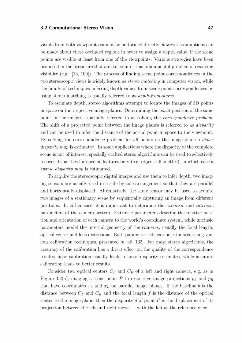
3.2 Computational Stereo Vision 47
visible from both viewpoints cannot be performed directly, however assumptions can
be made about these occluded regions in order to assign a depth value, if the scene
points are visible at least from one of the viewpoints. Various strategies have been
proposed in the literature that aim to counter this fundamental problem of resolving
visibility (e.g. [13, 109]). The process of finding scene point correspondences in the
two stereoscopic views is widely known as stereo matching in computer vision, while
the family of techniques inferring depth values from scene point correspondences by
using stereo matching is usually referred to as depth-from-stereo.
To estimate depth, stereo algorithms attempt to locate the images of 3D points
in space on the respective image planes. Determining the exact position of the same
point in the images is usually referred to as solving the correspondence problem.
The shift of a projected point between the image planes is referred to as disparity
and can be used to infer the distance of the actual point in space to the viewpoint.
By solving the correspondence problem for all points on the image plane a dense
disparity map is estimated. In some applications where the disparity of the complete
scene is not of interest, specially crafted stereo algorithms can be used to selectively
recover disparities for specific features only (e.g. object silhouettes), in which case a
sparse disparity map is estimated.
To acquire the stereoscopic digital images and use them to infer depth, two imag-
ing sensors are usually used in a side-by-side arrangement so that they are parallel
and horizontally displaced. Alternatively, the same sensor may be used to acquire
two images of a stationary scene by sequentially capturing an image from different
positions. In either case, it is important to determine the extrinsic and intrinsic
parameters of the camera system. Extrinsic parameters describe the relative posi-
tion and orientation of each camera to the world’s coordinate system, while intrinsic
parameters model the internal geometry of the cameras, usually the focal length,
optical center and lens distortions. Both parameter sets can be estimated using var-
ious calibration techniques, presented in [46, 133]. For most stereo algorithms, the
accuracy of the calibration has a direct effect on the quality of the correspondence
results; poor calibration usually leads to poor disparity estimates, while accurate
calibration leads to better results.
Consider two optical centers CL and CR of a left and right camera, e.g. as in
Figure 3.2(a), imaging a scene point P to respective image projections pL and pR
that have coordinates xL and xR on parallel image planes. If the baseline b is the
distance between CL and CR and the focal length f is the distance of the optical
center to the image plane, then the disparity d of point P is the displacement of its
projection between the left and right views — with the left as the reference view —
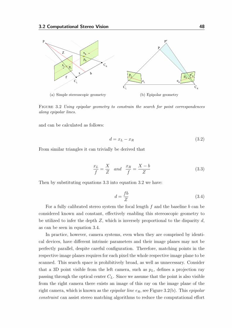
3.2 Computational Stereo Vision 48
fb
CR
CL
P
pL
pR
xL
xR
Z
x
(a) Simple stereoscopic geometry
CR
CL
P
P’
pL
p’Rp
R
eL
eR
(b) Epipolar geometry
Figure 3.2 Using epipolar geometry to constrain the search for point correspondencesalong epipolar lines.
and can be calculated as follows:
d = xL − xR (3.2)
From similar triangles it can trivially be derived that
xL
f=X
Zand
xR
f=X − b
Z(3.3)
Then by substituting equations 3.3 into equation 3.2 we have:
d =fb
Z(3.4)
For a fully calibrated stereo system the focal length f and the baseline b can be
considered known and constant, effectively enabling this stereoscopic geometry to
be utilized to infer the depth Z, which is inversely proportional to the disparity d,
as can be seen in equation 3.4.
In practice, however, camera systems, even when they are comprised by identi-
cal devices, have different intrinsic parameters and their image planes may not be
perfectly parallel, despite careful configuration. Therefore, matching points in the
respective image planes requires for each pixel the whole respective image plane to be
scanned. This search space is prohibitively broad, as well as unnecessary. Consider
that a 3D point visible from the left camera, such as pL, defines a projection ray
passing through the optical center CL. Since we assume that the point is also visible
from the right camera there exists an image of this ray on the image plane of the
right camera, which is known as the epipolar line eR, see Figure 3.2(b). This epipolar
constraint can assist stereo matching algorithms to reduce the computational effort
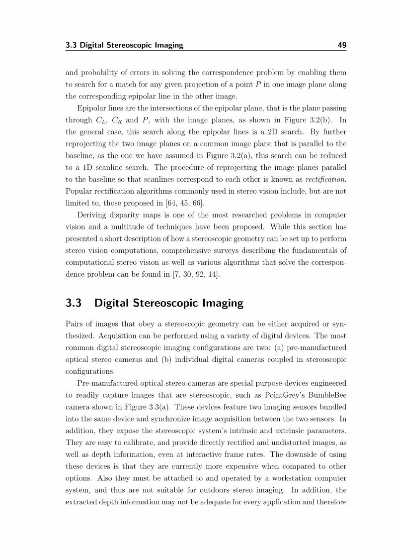
3.3 Digital Stereoscopic Imaging 49
and probability of errors in solving the correspondence problem by enabling them
to search for a match for any given projection of a point P in one image plane along
the corresponding epipolar line in the other image.
Epipolar lines are the intersections of the epipolar plane, that is the plane passing
through CL, CR and P , with the image planes, as shown in Figure 3.2(b). In
the general case, this search along the epipolar lines is a 2D search. By further
reprojecting the two image planes on a common image plane that is parallel to the
baseline, as the one we have assumed in Figure 3.2(a), this search can be reduced
to a 1D scanline search. The procedure of reprojecting the image planes parallel
to the baseline so that scanlines correspond to each other is known as rectification.
Popular rectification algorithms commonly used in stereo vision include, but are not
limited to, those proposed in [64, 45, 66].
Deriving disparity maps is one of the most researched problems in computer
vision and a multitude of techniques have been proposed. While this section has
presented a short description of how a stereoscopic geometry can be set up to perform
stereo vision computations, comprehensive surveys describing the fundamentals of
computational stereo vision as well as various algorithms that solve the correspon-
dence problem can be found in [7, 30, 92, 14].
3.3 Digital Stereoscopic Imaging
Pairs of images that obey a stereoscopic geometry can be either acquired or syn-
thesized. Acquisition can be performed using a variety of digital devices. The most
common digital stereoscopic imaging configurations are two: (a) pre-manufactured
optical stereo cameras and (b) individual digital cameras coupled in stereoscopic
configurations.
Pre-manufactured optical stereo cameras are special purpose devices engineered
to readily capture images that are stereoscopic, such as PointGrey’s BumbleBee
camera shown in Figure 3.3(a). These devices feature two imaging sensors bundled
into the same device and synchronize image acquisition between the two sensors. In
addition, they expose the stereoscopic system’s intrinsic and extrinsic parameters.
They are easy to calibrate, and provide directly rectified and undistorted images, as
well as depth information, even at interactive frame rates. The downside of using
these devices is that they are currently more expensive when compared to other
options. Also they must be attached to and operated by a workstation computer
system, and thus are not suitable for outdoors stereo imaging. In addition, the
extracted depth information may not be adequate for every application and therefore
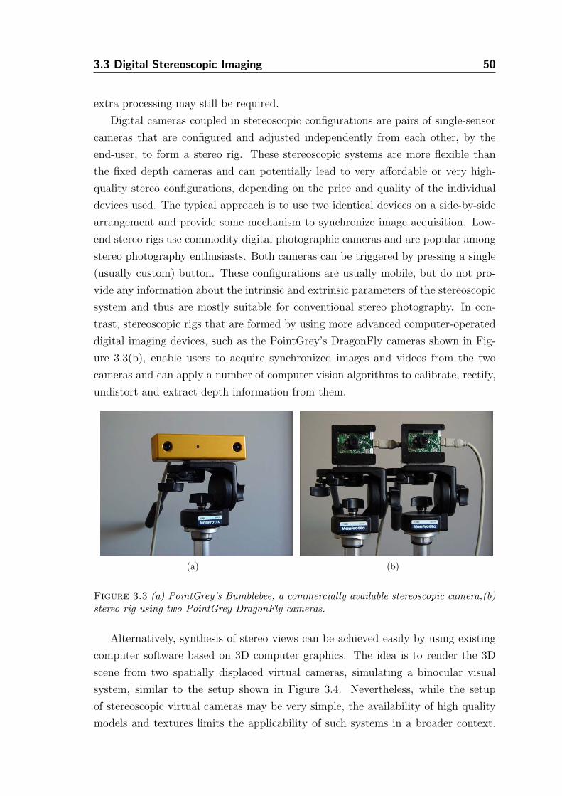
3.3 Digital Stereoscopic Imaging 50
extra processing may still be required.
Digital cameras coupled in stereoscopic configurations are pairs of single-sensor
cameras that are configured and adjusted independently from each other, by the
end-user, to form a stereo rig. These stereoscopic systems are more flexible than
the fixed depth cameras and can potentially lead to very affordable or very high-
quality stereo configurations, depending on the price and quality of the individual
devices used. The typical approach is to use two identical devices on a side-by-side
arrangement and provide some mechanism to synchronize image acquisition. Low-
end stereo rigs use commodity digital photographic cameras and are popular among
stereo photography enthusiasts. Both cameras can be triggered by pressing a single
(usually custom) button. These configurations are usually mobile, but do not pro-
vide any information about the intrinsic and extrinsic parameters of the stereoscopic
system and thus are mostly suitable for conventional stereo photography. In con-
trast, stereoscopic rigs that are formed by using more advanced computer-operated
digital imaging devices, such as the PointGrey’s DragonFly cameras shown in Fig-
ure 3.3(b), enable users to acquire synchronized images and videos from the two
cameras and can apply a number of computer vision algorithms to calibrate, rectify,
undistort and extract depth information from them.
(a) (b)
Figure 3.3 (a) PointGrey’s Bumblebee, a commercially available stereoscopic camera,(b)stereo rig using two PointGrey DragonFly cameras.
Alternatively, synthesis of stereo views can be achieved easily by using existing
computer software based on 3D computer graphics. The idea is to render the 3D
scene from two spatially displaced virtual cameras, simulating a binocular visual
system, similar to the setup shown in Figure 3.4. Nevertheless, while the setup
of stereoscopic virtual cameras may be very simple, the availability of high quality
models and textures limits the applicability of such systems in a broader context.
3.4 Non-Photorealistic Rendering 51
Rendered views are relatively restricted in content and realism and may take a
significant amount of time to calculate, when compared to those that can be acquired
with imaging devices. The task of manually creating 3D models and textures is both
time-consuming and resource-demanding, therefore alternatives are sought, not so
in the direction of improving existing 3D algorithms, but more in the direction of
merging and integrating them with computer vision techniques. An obvious step
toward this direction is to either use input images of IBR systems to generate novel
views that are stereoscopic, or use techniques of IBR within 3D computer graphics
software systems to speed up computations. In this context it has been shown that
IBR methods can be utilized to generate partially the second view from the first,
using the geometric correspondences that can be easily derived within a 3D system.
For example, Adelson et al. [2] discuss how the stereoscopic perspective projection
can be used in a 3D rendering system in order to optimize various traditional 3D
algorithms, such as polygon rendering, polygon and line clipping and hidden surface
elimination. Wan et al. [121] present a system for interactive stereoscopic rendering
of volumetric environments. They first generate a depth map and the left reference
image by using volumetric ray casting. They constrain the virtual viewpoints so as
to obey a stereoscopic projection that allows them to warp most of the left view to
the right using the depth map for the reprojection of splats2. They then directly ray
cast the volume from the right viewpoint in order to fill in holes in the right image.
The above discussion leads us to the conclusion that stereoscopic image synthesis
is possible using independently computer vision or computer graphics methods as
the starting point. Nevertheless, a combination of properties from both areas allows
more flexibility and can counter to some extent the various drawbacks presented by
each.
3.4 Non-Photorealistic Rendering
Non-Photorealistic Rendering, in contrast to photorealistic approaches, aims to
produce images that stimulate not only the optical nerves, but also trigger the
mental abilities of our higher-level cognitive mechanisms. Advances in NPR have
enabled computers to simulate natural media [19, 9, 70, 82, 58] and artistic pro-
cesses [87, 47, 105, 39]. The majority of these algorithms and systems are targeted
toward producing a monoscopic rendition by processing geometry or images from
a single viewpoint. Only recently, techniques that use multiple viewpoints have
2Splats are chunks of texture that are splatted, or forward-mapped, from a source onto a targettexture.
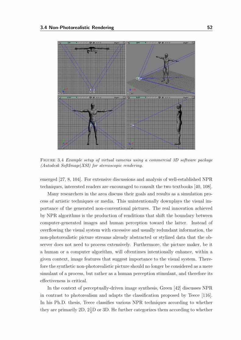
3.4 Non-Photorealistic Rendering 52
Figure 3.4 Example setup of virtual cameras using a commercial 3D software package(Autodesk SoftImage|XSI) for stereoscopic rendering.
emerged [27, 8, 104]. For extensive discussions and analysis of well-established NPR
techniques, interested readers are encouraged to consult the two textbooks [40, 108].
Many researchers in the area discuss their goals and results as a simulation pro-
cess of artistic techniques or media. This unintentionally downplays the visual im-
portance of the generated non-conventional pictures. The real innovation achieved
by NPR algorithms is the production of renditions that shift the boundary between
computer-generated images and human perception toward the latter. Instead of
overflowing the visual system with excessive and usually redundant information, the
non-photorealistic picture streams already abstracted or stylized data that the ob-
server does not need to process extensively. Furthermore, the picture maker, be it
a human or a computer algorithm, will oftentimes intentionally enhance, within a
given context, image features that suggest importance to the visual system. There-
fore the synthetic non-photorealistic picture should no longer be considered as a mere
simulant of a process, but rather as a human perception stimulant, and therefore its
effectiveness is critical.
In the context of perceptually-driven image synthesis, Green [42] discusses NPR
in contrast to photorealism and adapts the classification proposed by Teece [116].
In his Ph.D. thesis, Teece classifies various NPR techniques according to whether
they are primarily 2D, 21
2D or 3D. He further categorizes them according to whether
3.4 Non-Photorealistic Rendering 53
they require user intervention or they are fully automatic. Finally, he looks at the
objectives of research, i.e. natural media simulation, image enhancement, artistic
expression and animation. This classification, while adequate for categorizing most
of the published research to that date, does not account for emerging technologies,
such as stereoscopic NPR presented in this work. Even though it considers tempo-
rality of the objectives as a category itself (i.e. animation), it leaves out spatiality.
We therefore propose that research is also differentiated by the spatial dimension of
its intended outputs, which could be divided into 2D images, 3D models (i.e. styl-
ized 3D models [80, 69]), novel NPR views generated by image- or example-based
rendering and stereoscopic or other multi-dimensional approaches (i.e. holographic
outputs) that may emerge.
In our work, we focus on stroke-based rendering [48], and of special interest
are techniques that use depth information to enhance the appearance of the artis-
tic composition by introducing valuable monocular depth cues. Strokes are marks
strategically deposited on a substrate to convey shape and color in a picture. While
strokes are modeled individually, usually following local information of a picture or a
model, a collection of them is usually grouped perceptually to represent higher-level
features in the final picture. Line drawing for instance is commonly performed by
sampling data points describing a continuous line (e.g. an object silhouette) and
then, using those samples, shorter and looser lines or parametric splines are fitted,
similar to the way humans create drawings. An interactive system that uses spline
fitting on user-supplied data points is described in detail in [79].
Strokes have been used in early graphical systems as means of human-computer
interaction [110], but they have since evolved from simple line representation tech-
niques into more elaborate descriptions of marks that not only simulate simple tips
of media applicators, but also complex brushes. In general, some algorithms utilize
strokes to simulate the way artists deposit marks on their working surfaces. Other
algorithms use strokes to model the physical interactions of a medium, an applicator
and a substrate. These techniques vary in the level of interactivity required. Early
systems for drawing and painting, such as [102, 127, 107, 78], required a user to
input the sample points along which strokes were drafted.
Haeberli [43] introduced his painting system that first generates automatically
locations for brush strokes from an intensity color image and then lets the user drive
the painting process by selecting at which of these locations strokes should actually
be painted. He also describes extensions to this approach such as an automated
painting procedure by relaxation. Around the same time Cockshott [19] proposed
“Wet and Sticky”, a physically-based painting system that models the interaction of
3.4 Non-Photorealistic Rendering 54
color pigments with a substrate. Saito et al. [86] have introduced the use of Geomet-
ric Buffers, known as G-Buffers, to enhance the legibility and comprehensibility of
their images. G-Buffers usually encode geometric information of 3D scenes into im-
age buffers, such as surface normals, depth values, object IDs, and others. By using
image processing techniques in a postprocessing step, G-Buffers are utilized to en-
hance selectively image features of the final renditions. Schofield [94] used G-Buffers
in the Piranesi system, a hybrid interactive and 3D rendering painting system, to
select object regions that users could then paint interactively. Similarly, other re-
searchers [29, 75, 76] have used additional data extracted from 3D datasets in order
to drive the NPR image synthesis step in their techniques. Curtis [24] uses a depth
map to render stylized silhouettes around objects by generating a force field that
guides a physically based particle system that erases ink from thick outlines initially
drawn. Eissele et al. [32] have further proposed the G2-Buffer framework, a graphics
hardware implementation of G-Buffers that is useful for real-time GPU-based ren-
dering. Even though most techniques differ in the extraction, representation and
utilization of G-Buffers, they all present enhanced results over previous methods. In
general, the concept of G-Buffers has become a norm in NPR techniques.
Litwinowicz [63] presented in detail a fully automated painting system, similar
to that of Haeberli [43], that uses image gradients to orient strokes, significantly
improving the existing techniques and suggesting algorithms to incorporate optical
flow, a motion estimation technique, in order to animate the painted images. Hertz-
mann [47] introduced curved brush strokes of multiple sizes that, by using an input
image, are planned and rendered automatically to generate paintings in a variety of
different styles. His technique uses a coarse-to-fine concept, where the foundation
of a painting is roughly set by using large brush strokes and is then progressively
refined with smaller spline brush strokes, similarly to how painters work; that is
by first painting in the more uniformly colored areas and then progressively adding
detail. One of the main reasons Hertzmann’s work is significant is because it mar-
ries for the first time the older ideas of using simple straight lines for modeling the
strokes in automated systems with the spline-based interactive painting techniques
into a coherent automated algorithm that makes use of the best features of both
approaches. Other notable advances in NPR around the same period were the pen-
and-ink illustration system of Salisbury et al. [88] and the watercolor simulation
system of Curtis et al. [25].
Later, Raskar et al. [81] have developed a novel hardware-assisted method to
automatically create comprehensible illustrations of real images by using depth dis-
continuities to enhance legibility. They use multiple images taken by a multi-flash
3.4 Non-Photorealistic Rendering 55
camera where cast shadows are used to detect depth discontinuities in the scene.
These depth edges together with the original texture of the scene objects are styl-
ized to convey and better communicate the important information of even complex
scenes. To achieve good results, the technique requires that cast shadows can be
detected and processed.
Bartesaghi et al. [8] presented a non-photorealistic rendering technique that uses
multiple images to compute a single view. They infer geometric features, i.e. sur-
face normals and principal directions, from stereo images and use them to generate
pen-and-ink illustrations. They point out that the surface normals’ recovery can
be rather unreliable, especially when using disparity maps computed from stereo
matching techniques. This of course is one of the main problems associated with
image-based stereoscopic rendering techniques, since any inaccuracies in the stereo
matching process are delegated to the successive processes of image synthesis.
A limited number of other techniques have proposed the use of depth information
to prevent inadequate stylization of salient features. Shiraishi and Yamaguchi [97]
use a depth map, computed by ray-tracing, to adaptively control the parameters of
their image moment-based painterly rendering algorithm [98]. The technique adjusts
the size of the stroke textures used, so that distant objects are approximated by
larger strokes, whilst objects closer to the viewer are rendered with smaller strokes.
They also use depth to introduce a mask that restricts each stroke to approximate
only one object within the window that encompasses the stroke. Objects of the
same color that lie at different depths are preserved as separate objects on the final
painted image. This could be considered as a 21
2D stroke clipping, following ideas
similar to 2D stroke-clipping algorithms, such as in the work of Litwinowicz [63].
Gooch et al. [39] use segmentation and morphological operations to automatically
create paintings by planning and rendering a resolution-independent set of strokes.
In the same work, an extension of the algorithm uses depth maps, computed from 3D
scenes, to assist the segmentation process via which better results are reported on
the final painted images. A discussion about depth-from-stereo, in the same work,
also highlights the problems arising from such depth maps. A common characteristic
of the algorithms using depth to enhance stylization is that they demonstrate results
obtained using highly accurate depth information computed by ray-tracing of 3D
scenes and, therefore, are not exposed to the problems present in the depth maps
estimated by using depth-from-stereo.
Snavely et al. [104] process multiple video sequences of the same scene and ap-
ply a spacetime stereo technique to extract depth information. The 21
2D video
sequences are then further processed to produce temporally coherent stylized ani-
3.4 Non-Photorealistic Rendering 56
mations. While their preprocessing steps are very similar to those of our setup, they
do not direct their efforts toward the output of stereoscopic content, but rather they
use temporal disparity maps to provide frame-to-frame coherent object segmentation
and assist in the stylization process.
Available view independent rendering techniques based on 3D scenes, such as [56,
130], can potentially produce stereoscopic output since the artistic primitives used
are attached and remain on the 3D model’s surface, independent of the location of
the viewing point. This, however, becomes particularly challenging in our research,
since our techniques use images as their input which lack a geometric description
of the underlying scene structure. Therefore, additional processing is required (e.g.
recovery of depth information), which in practice may yield unreliable data. In
general, algorithms that process 3D models can potentially render a scene from two
horizontally displaced viewpoints to generate stereoscopic image pairs, however the
requirement of 3D modeling poses a significant limitation.
Other methods to create stylized stereoscopic renditions of photographic images
involve the use of image convolution algorithms found in many commercial image
editing applications. Usually, these algorithms operate locally on a small pixel
neighborhood and apply simple stroke models, edge detection and color filtering.
They can potentially generate stylized stereo pairs by processing individually the
two images, nevertheless they lack high level description of scene structure and
therefore they cannot separate objects and treat them individually; neither can
they simulate artistic media which require surface descriptions and elaborate stroke
models.
All the techniques described aim to generate monoscopic content and do not pro-
vide stereo output, which requires consistent stylization on both stereo views. We
also observe that NPR techniques using depth-from-stereo do not attempt to extract
a geometric description of the scene objects in order to process them for an artistic
effect in 3D. Most of these techniques use either reliable features (e.g. depth discon-
tinuities) related to the extracted depth information or provide alternative mecha-
nisms in the stylization process that compensate for those inaccuracies (e.g. adaptive
resizing of strokes).
In the following chapters, we present a set of different NPR techniques which
are based on processing stereoscopic input images, but instead of a single rendition
they provide consistent stereoscopic image pairs.
Chapter 4
Preliminaries for
Stereoscopic NPR
The first part of this chapter outlines the framework in which the connection between
individual algorithms and their technical aspects pertain to our previous analysis
of the stereoscopic medium in the domain of arts. The second part describes the
common basis for all the stereoscopic Non-Photorealistic Rendering algorithms that
are detailed in the subsequent chapters.
4.1 Stereoscopic NPR Framework
Based on the fundamentals of the stereoscopic medium in arts and sciences, we pro-
pose a practical framework of design and implementation considerations that stereo-
scopic algorithms for artistic content creation should account for. The components
of the framework directly link computational techniques, methods and technical
details to the goal-oriented design of stereo NPR algorithms.
This framework, acting mostly as a set of guidelines rather than as a formal
ruleset, can further be modified and adapted by other single-view NPR algorithms
to generate artistic stereoscopic content. It allows to devise a modular processing
pipeline, described later, in which processing modules can be added or removed
depending on the targeted algorithm. The modularization of the various processes
allows for flexible modification of the generic pipeline to enable both speed opti-
mizations and incorporation of other sub-processing algorithms, without significant
modifications to the rest of the pipeline.
• Feature Correspondence - Features must be consistent across the two views.
Artifacts, e.g. brush strokes that cannot be matched in both views, will in-
hibit stereo fusion and the viewers may experience discomfort. Large non-
corresponding areas and deviations in color, or style, will produce similar un-
desired effects. The human visual system is able to tolerate a small percentage
of inconsistency, which varies from person to person, but algorithms should
57
4.1 Stereoscopic NPR Framework 58
strive on providing the best possible correspondence between the two stereo
components.
• Randomness - Stochastic procedures used in generating artistic effects must be
carefully designed so that the feature correspondence constraint is met. Non-
Photorealistic Rendering techniques, such as [87, 63, 47], use random numbers
to inject irregularity into the artistic process. In image-based stereoscopic
NPR, randomness must be as consistent as possible across a stereo image pair,
so that irregularity can be equally modeled within the two views. Perturbation
functions applied on stylization parameters must also account for the desired
consistency.
• Performance - Stereo pairs exhibit correlative information between their im-
ages that can be used to optimize the performance of a variety of algorithms
(e.g. compression algorithms [91] or rasterization [2] of stereo pairs). Auto-
mated NPR algorithms can take advantage of the stereo pair relationships
(i.e. stereo disparity) to reduce the computational effort of planning or ren-
dering of the artistic images.
• Depth from Stereo - Disparity maps acquired by using automated computer
vision algorithms, such as stereo matching algorithms [93], cannot be used
to perfectly reconstruct a scene and they often encode artifacts that falsify
depth information of scene points. Establishing a feature correspondence by
using imperfect depth-from-stereo information may inhibit the artistic process.
Artistic algorithms that use such depth maps have to be able to counterbalance
the inaccurate geometric descriptions of the scene objects, without degrading
the quality of the final artwork. It must be noted that it should be preferable to
trade off artistic fidelity for consistency, since in stereo viewing inconsistencies
have an unpleasant effect on the viewers.
• Texture Continuity and Occlusions - Occluded regions in stereo imaging, which
are sets of points in the scene not visible from both viewpoints, must be spe-
cially treated. When viewed stereoscopically, occlusions have no correspon-
dence and cannot be fused, however they must be filled in with appropriate
content. In an artistic process, the style and color over an occluded region
must seamlessly blend with the surrounding regions for perceptual consistency.
Since occlusions have no representation in a feature correspondence map, such
as a disparity map, their distance from the viewpoint cannot be computed
and assumptions have to be made. The assigned depth values for occluded
4.2 Stereoscopic Rendering Pipeline 59
regions are usually extrapolated depth values of surrounding areas (e.g. using
background depth values).
• Paint Spilling - Paint spilling practically occurs when color that is naturally
expected by the viewer to belong to one object appears to extend to another
object which lies at a different distance. This usually happens because of in-
accuracies encoded in the depth map used, e.g. due to the common effect of
block-based stereo matchers that “fatten” the foreground objects in the dis-
parity map. It can also be a side effect of consistently applying a random
function to the parameters of the composition elements. Generally, we call
paint spilling the result of composition elements being inadequately extended
across surfaces that are at different depths. Intersurface paint spilling does
not necessarily degrade the quality of the individual stereo components, how-
ever, when the two components are viewed stereoscopically it becomes rather
noticeable.
4.2 Stereoscopic Rendering Pipeline
We set up a stereoscopic rendering pipeline that takes advantage of the stereoscopic
projection geometry that we constrain our image inputs to be within. Contrary to
the method of Wan et al. [121], we use real images captured from cameras and, hence,
a preprocessing step is required to establish the stereo correspondences between the
two views. This task is usually computationally intensive and does not allow us
to perform it at interactive frame rates. To overcome this limitation we detach
the stereo matching process from the core artistic stereo synthesis algorithms and
perform it as a preprocessing step.
The general form of our stereoscopic processing pipeline, shown in Figure 4.1,
can be described as follows:
Preprocessing:
• Capture a left and right image from a calibrated camera stereo rig.
• Rectify and undistort the two image planes, so that a raster scanline in the
resulting rectified left image (IL) corresponds to the equivalent scanline of the
right image (IR).
• Apply a stereo matching algorithm (or any other auxiliary algorithms) to ex-
tract 21
2D scene descriptions.
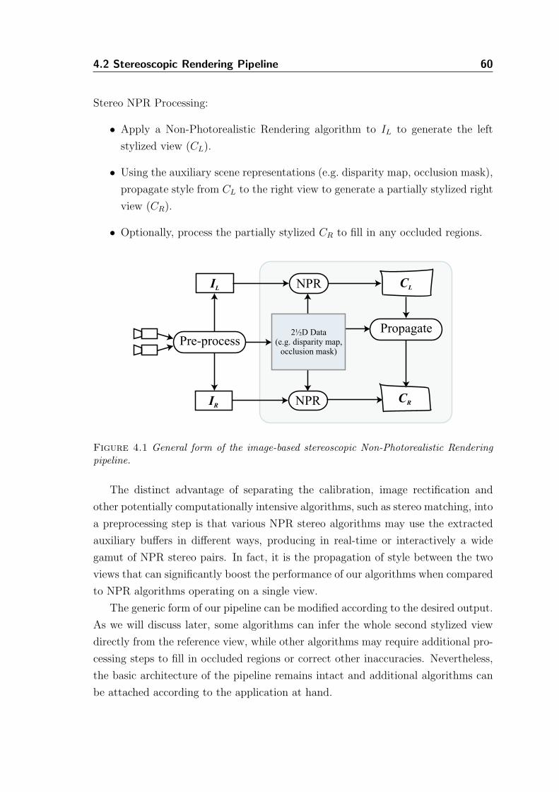
4.2 Stereoscopic Rendering Pipeline 60
Stereo NPR Processing:
• Apply a Non-Photorealistic Rendering algorithm to IL to generate the left
stylized view (CL).
• Using the auxiliary scene representations (e.g. disparity map, occlusion mask),
propagate style from CL to the right view to generate a partially stylized right
view (CR).
• Optionally, process the partially stylized CR to fill in any occluded regions.
Pre-process
IL
IR NPR
NPR
2½D Data(e.g. disparity map,
occlusion mask)
CL
CR
Propagate
Figure 4.1 General form of the image-based stereoscopic Non-Photorealistic Renderingpipeline.
The distinct advantage of separating the calibration, image rectification and
other potentially computationally intensive algorithms, such as stereo matching, into
a preprocessing step is that various NPR stereo algorithms may use the extracted
auxiliary buffers in different ways, producing in real-time or interactively a wide
gamut of NPR stereo pairs. In fact, it is the propagation of style between the two
views that can significantly boost the performance of our algorithms when compared
to NPR algorithms operating on a single view.
The generic form of our pipeline can be modified according to the desired output.
As we will discuss later, some algorithms can infer the whole second stylized view
directly from the reference view, while other algorithms may require additional pro-
cessing steps to fill in occluded regions or correct other inaccuracies. Nevertheless,
the basic architecture of the pipeline remains intact and additional algorithms can
be attached according to the application at hand.
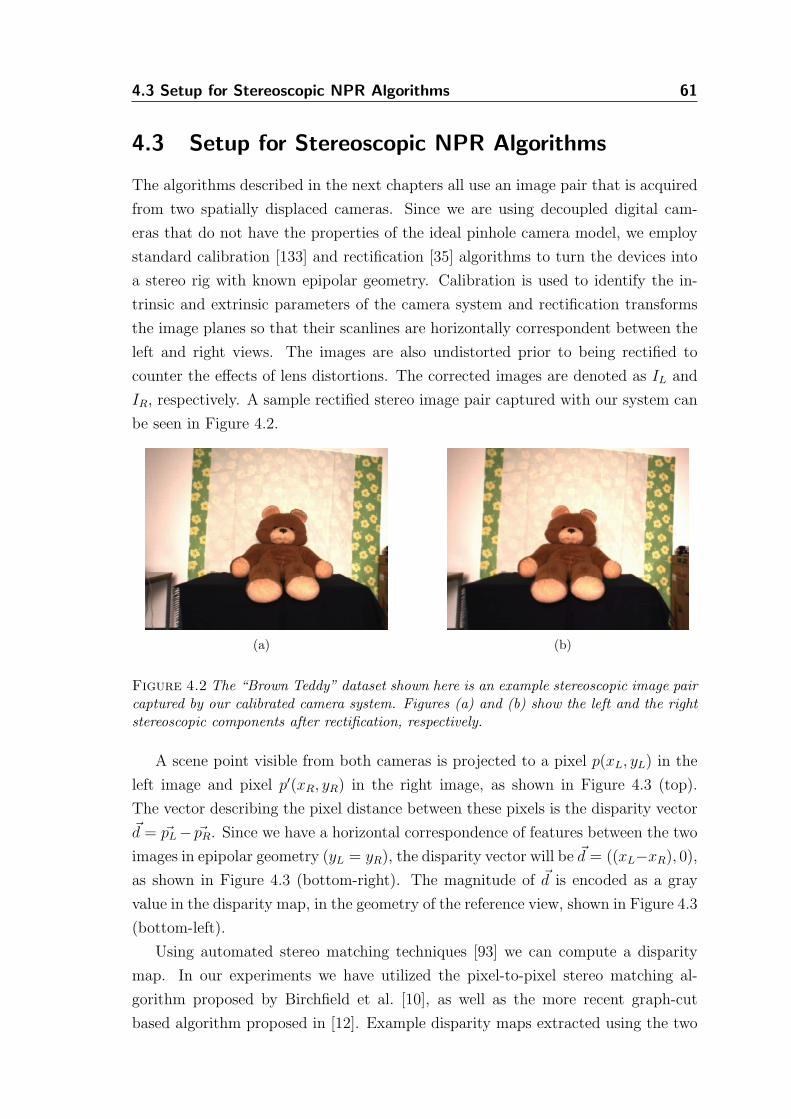
4.3 Setup for Stereoscopic NPR Algorithms 61
4.3 Setup for Stereoscopic NPR Algorithms
The algorithms described in the next chapters all use an image pair that is acquired
from two spatially displaced cameras. Since we are using decoupled digital cam-
eras that do not have the properties of the ideal pinhole camera model, we employ
standard calibration [133] and rectification [35] algorithms to turn the devices into
a stereo rig with known epipolar geometry. Calibration is used to identify the in-
trinsic and extrinsic parameters of the camera system and rectification transforms
the image planes so that their scanlines are horizontally correspondent between the
left and right views. The images are also undistorted prior to being rectified to
counter the effects of lens distortions. The corrected images are denoted as IL and
IR, respectively. A sample rectified stereo image pair captured with our system can
be seen in Figure 4.2.
(a) (b)
Figure 4.2 The “Brown Teddy” dataset shown here is an example stereoscopic image paircaptured by our calibrated camera system. Figures (a) and (b) show the left and the rightstereoscopic components after rectification, respectively.
A scene point visible from both cameras is projected to a pixel p(xL, yL) in the
left image and pixel p′(xR, yR) in the right image, as shown in Figure 4.3 (top).
The vector describing the pixel distance between these pixels is the disparity vector~d = ~pL − ~pR. Since we have a horizontal correspondence of features between the two
images in epipolar geometry (yL = yR), the disparity vector will be ~d = ((xL−xR), 0),
as shown in Figure 4.3 (bottom-right). The magnitude of ~d is encoded as a gray
value in the disparity map, in the geometry of the reference view, shown in Figure 4.3
(bottom-left).
Using automated stereo matching techniques [93] we can compute a disparity
map. In our experiments we have utilized the pixel-to-pixel stereo matching al-
gorithm proposed by Birchfield et al. [10], as well as the more recent graph-cut
based algorithm proposed in [12]. Example disparity maps extracted using the two
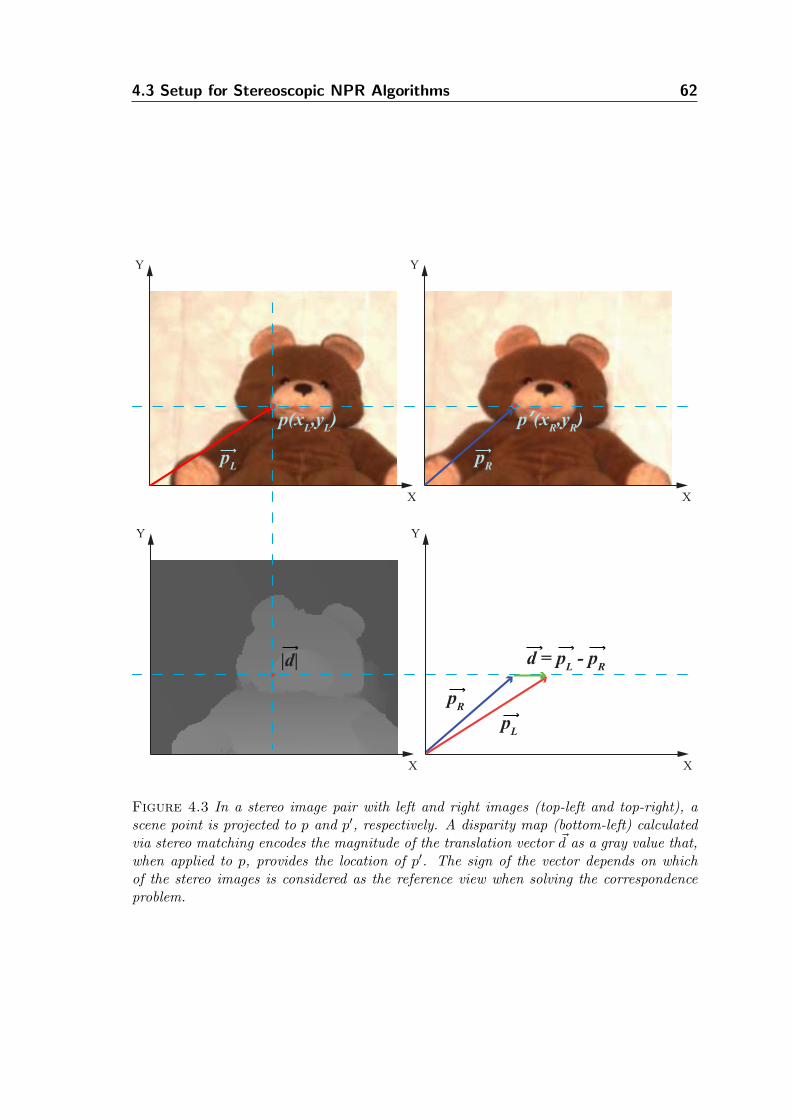
4.3 Setup for Stereoscopic NPR Algorithms 62
X
Y
X
Y
p(xL,y
L) p’(x
R,y
R)
X
Y
X
Y
pL
pR
d = pL - p
R
pR
pL
|d|
Figure 4.3 In a stereo image pair with left and right images (top-left and top-right), ascene point is projected to p and p′, respectively. A disparity map (bottom-left) calculatedvia stereo matching encodes the magnitude of the translation vector ~d as a gray value that,when applied to p, provides the location of p′. The sign of the vector depends on whichof the stereo images is considered as the reference view when solving the correspondenceproblem.
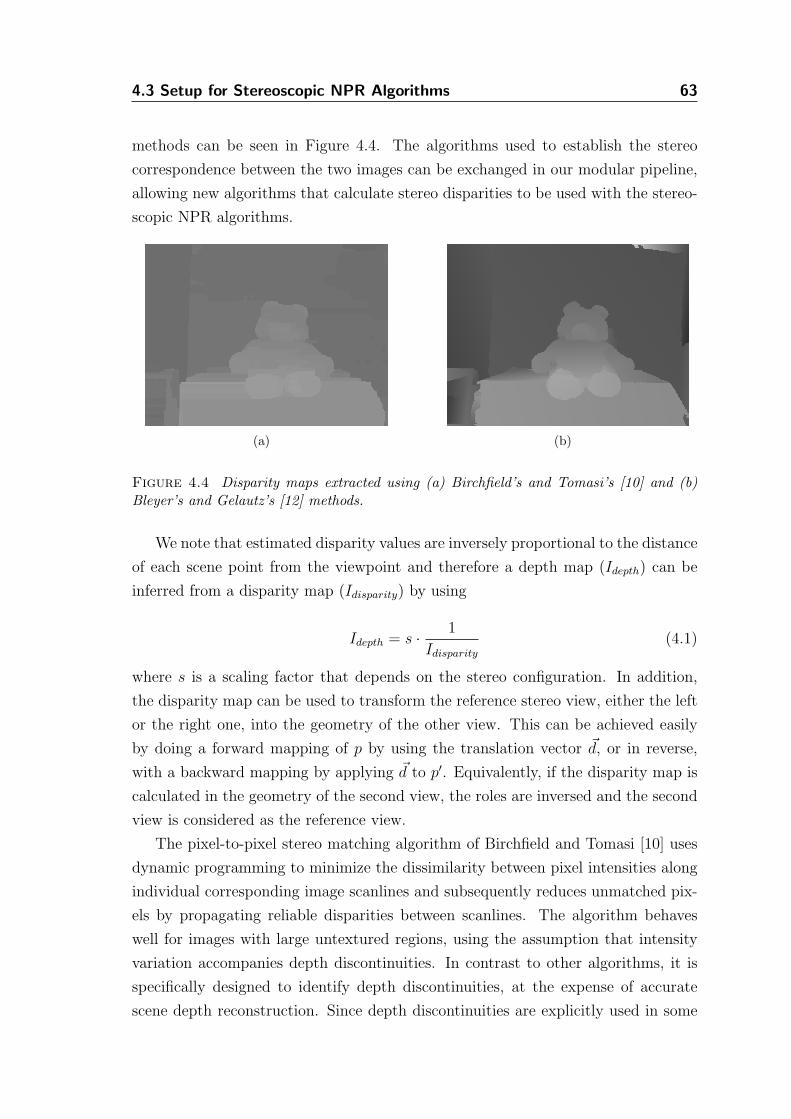
4.3 Setup for Stereoscopic NPR Algorithms 63
methods can be seen in Figure 4.4. The algorithms used to establish the stereo
correspondence between the two images can be exchanged in our modular pipeline,
allowing new algorithms that calculate stereo disparities to be used with the stereo-
scopic NPR algorithms.
(a) (b)
Figure 4.4 Disparity maps extracted using (a) Birchfield’s and Tomasi’s [10] and (b)Bleyer’s and Gelautz’s [12] methods.
We note that estimated disparity values are inversely proportional to the distance
of each scene point from the viewpoint and therefore a depth map (Idepth) can be
inferred from a disparity map (Idisparity) by using
Idepth = s ·1
Idisparity
(4.1)
where s is a scaling factor that depends on the stereo configuration. In addition,
the disparity map can be used to transform the reference stereo view, either the left
or the right one, into the geometry of the other view. This can be achieved easily
by doing a forward mapping of p by using the translation vector ~d, or in reverse,
with a backward mapping by applying ~d to p′. Equivalently, if the disparity map is
calculated in the geometry of the second view, the roles are inversed and the second
view is considered as the reference view.
The pixel-to-pixel stereo matching algorithm of Birchfield and Tomasi [10] uses
dynamic programming to minimize the dissimilarity between pixel intensities along
individual corresponding image scanlines and subsequently reduces unmatched pix-
els by propagating reliable disparities between scanlines. The algorithm behaves
well for images with large untextured regions, using the assumption that intensity
variation accompanies depth discontinuities. In contrast to other algorithms, it is
specifically designed to identify depth discontinuities, at the expense of accurate
scene depth reconstruction. Since depth discontinuities are explicitly used in some
4.3 Setup for Stereoscopic NPR Algorithms 64
of our NPR algorithms, i.e. to identify and render object outlines, this stereo match-
ing algorithm offers an alternative to more computationally intensive methods that
provide more robust depth estimates across the whole scene.
The stereo matching algorithm of Bleyer and Gelautz [12] solves the correspon-
dence problem by using a graph-cut based optimization technique. The rectified
input images are color segmented and within each segment disparity is considered
to vary smoothly. These disparity segments are clustered into layers which are likely
to describe scene objects by minimizing a global cost function through graph-cut
optimization. While this algorithm performs slower than [10], the stereo correspon-
dences are more accurately recovered. The algorithm can handle scenes with large
untextured regions and occlusions. Occlusions, treated symmetrically in both views,
are handled by assigning them to neighboring non-occluded segments and then ex-
trapolating reliable disparity values of the visible segments to the occluded ones.
The advantage of this algorithm is that disparities are smoothly interpolated over
single surfaces and the depth discontinuities are properly localized at real object
boundaries. In addition, the layers extracted in the stereo matching process can be
used as an auxiliary buffer in successive image synthesis steps, as we will show later
in Chapter 6, when we present a distance-dependent NPR technique.
Stereo-derived depth values can normally only be computed for those pixels that
are visible in both the left and right image. This means that for some scene points
the depth values may not be possible to be inferred. Whenever required, we estimate
and reconstruct the missing depth values by using reliable neighboring depth values.
We store the locations of those pixels, usually a small portion of the whole image,
in a binary map, which we refer to as the occlusion map. The occlusion map can
be computed for both the left and the right view, if disparity maps are given in the
geometry of both views. The pixels encoded in the occlusion mask require special
consideration during the image synthesis steps further down the processing pipeline,
as correspondences are not present in the disparity maps.
Chapter 5
Stereoscopic
Drawing
Initially, stereoscopic line drawing has been used to communicate the essentials
of stereoscopic vision by Wheatstone [125, 126]. Thereafter, stereo drawings can
be found in comic books [15], as self-contained artwork [37] or even as an effec-
tive medium to convey the third dimension of scientific data (e.g. molecular forma-
tions [53] or medical illustrations [4]). The construction of stereoscopic drawings by
hand is a rather tedious task and it has been very scarcely treated in art literature.
As the line has tremendous utility in monoscopic artwork, since it provides valu-
able depth cues, similarly its use within a stereoscopic context contributes positively
to the construction of effective content. Sketches or simple concept drawings made
out of lines, usually of a single color, lack many of the monocular cues found in other
art forms. Shades and light, texture and atmospheric effects are mainly absent and
therefore depth becomes less apparent. With stereoscopy the absence of these cues
does not impair the perception of depth. Flat artwork, even made out of simple
lines describing unfamiliar objects, can emerge in three-dimensional space with the
use of correctly constructed stereo components. Adding outlines to objects at dif-
ferent distances in stereo pairs hints the observers’ perception on the interposition
of objects. Silhouettes and outlines, even when these are partial, assist the observer
in the perceptual decoupling of the depth layers in the scene. The utility of stereo-
scopic concept drawings and sketches is also important for the foundation of other
works, such as color illustrations and paintings.
We describe here an image-based method for automatic computation of stereo-
scopic concept drawings. Within our stereoscopic processing pipeline, we integrate
basic digital image processing algorithms and line rendering techniques to create
stereoscopic sketches that are both accurate and appealing. Our goal is to create
simple stereoscopic line drawings that provide depth cues for the comprehension
of the 3D structure of a stereoscopically imaged scene, without the use of known
geometry (i.e. 3D models).
The main challenges we are presented with here are two. First, the extraction of
65
5.1 Stereoscopic Drawing Algorithm 66
silhouettes and other feature lines with standard image processing techniques, such
as edge detection, may introduce visual clutter in the stereoscopic result. Inten-
sity discontinuities captured by such algorithms will bias, and potentially confuse,
the observer’s perception of the scene’s depth, since some of the detected features
will merely capture texture discontinuities, rather than depth discontinuities. Since
intensity image discontinuities captured by them are a superset of depth discontinu-
ities, we would ideally want to extract only those lines that can assist the viewer to
separate the depth layers of the scene. The second challenge, which is fundamental
to stereoscopy, is to preserve consistency across the two generated stereo views. If
edge detection is applied separately on the two images, which means that together
with a subset of the intensity edges the depth discontinuities will be extracted, it is
not guaranteed that the lines extracted for the left and right stereo components will
be stereoscopically consistent.
To overcome these two shortcomings, we adjust our stereoscopic rendering
pipeline to accommodate techniques that will extract only depth discontinuities and
preserve consistency. As a byproduct of using the pipeline, the performance of the
rendering algorithm is vastly enhanced by utilizing the established correspondence
between the two input stereo images. In this specific algorithmic scenario, the
second view can be fully derived from the reference view, without the need of
additional expensive computation. Finally, the modular architecture of the pipeline
allows the use of a variety of line rendering styles to be used with the stereo sketches.
The stereo pipeline of Figure 4.1 is therefore simplified for this algorithm, as shown
in Figure 5.1.
5.1 Stereoscopic Drawing Algorithm
To fulfill the requirement of extracting object boundaries that represent changes in
scene depth, we use edge detection to detect depth discontinuities in the disparity
map. However, since we want to simultaneously optimize the performance of the
algorithm and preserve consistency, not all standard edge detectors can be used out
of the box. Our approach in optimizing performance is based on the concept of style
propagation between the two views. Instead of extracting features in both the left
and the right views and then processing them for consistency, we extract features
only in the geometry of the reference view (i.e. the left) and we then use warping
to fully generate the right view, without further processing. To achieve this we
constrain the extraction of image features to edges that are visible in both views,
which implies that a value corresponding to the second view will be available for all
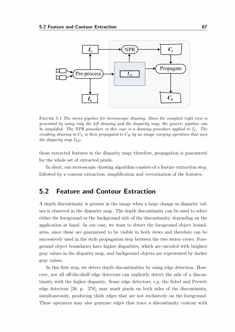
5.2 Feature and Contour Extraction 67
Pre-process
IL
IR
NPR CL
CR
PropagateILD
Figure 5.1 The stereo pipeline for stereoscopic drawing. Since the complete right view isgenerated by using only the left drawing and the disparity map, the generic pipeline canbe simplified. The NPR procedure in this case is a drawing procedure applied to IL. Theresulting drawing in CL is then propagated to CR by an image warping operation that usesthe disparity map ILD.
those extracted features in the disparity map; therefore, propagation is guaranteed
for the whole set of extracted pixels.
In short, our stereoscopic drawing algorithm consists of a feature extraction step,
followed by a contour extraction, simplification and vectorization of the features.
5.2 Feature and Contour Extraction
A depth discontinuity is present in the image when a large change in disparity val-
ues is observed in the disparity map. The depth discontinuity can be used to select
either the foreground or the background side of the discontinuity, depending on the
application at hand. In our case, we want to detect the foreground object bound-
aries, since these are guaranteed to be visible in both views and therefore can be
successively used in the style propagation step between the two stereo views. Fore-
ground object boundaries have higher disparities, which are encoded with brighter
gray values in the disparity map, and background objects are represented by darker
gray values.
In this first step, we detect depth discontinuities by using edge detection. How-
ever, not all off-the-shelf edge detectors can explicitly detect the side of a discon-
tinuity with the higher disparity. Some edge detectors, e.g. the Sobel and Prewitt
edge detectors [38, p. 578], may mark pixels on both sides of the discontinuity,
simultaneously, producing thick edges that are not exclusively on the foreground.
These operators may also generate edges that trace a discontinuity contour with
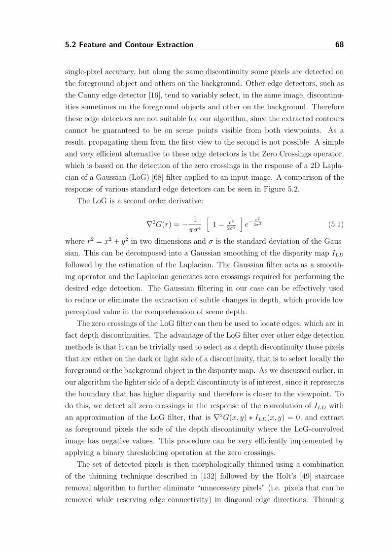
5.2 Feature and Contour Extraction 68
single-pixel accuracy, but along the same discontinuity some pixels are detected on
the foreground object and others on the background. Other edge detectors, such as
the Canny edge detector [16], tend to variably select, in the same image, discontinu-
ities sometimes on the foreground objects and other on the background. Therefore
these edge detectors are not suitable for our algorithm, since the extracted contours
cannot be guaranteed to be on scene points visible from both viewpoints. As a
result, propagating them from the first view to the second is not possible. A simple
and very efficient alternative to these edge detectors is the Zero Crossings operator,
which is based on the detection of the zero crossings in the response of a 2D Lapla-
cian of a Gaussian (LoG) [68] filter applied to an input image. A comparison of the
response of various standard edge detectors can be seen in Figure 5.2.
The LoG is a second order derivative:
∇2G(r) = −1
πσ4
[
1 − r2
2σ2
]
e−r2
2σ2 (5.1)
where r2 = x2 + y2 in two dimensions and σ is the standard deviation of the Gaus-
sian. This can be decomposed into a Gaussian smoothing of the disparity map ILD
followed by the estimation of the Laplacian. The Gaussian filter acts as a smooth-
ing operator and the Laplacian generates zero crossings required for performing the
desired edge detection. The Gaussian filtering in our case can be effectively used
to reduce or eliminate the extraction of subtle changes in depth, which provide low
perceptual value in the comprehension of scene depth.
The zero crossings of the LoG filter can then be used to locate edges, which are in
fact depth discontinuities. The advantage of the LoG filter over other edge detection
methods is that it can be trivially used to select as a depth discontinuity those pixels
that are either on the dark or light side of a discontinuity, that is to select locally the
foreground or the background object in the disparity map. As we discussed earlier, in
our algorithm the lighter side of a depth discontinuity is of interest, since it represents
the boundary that has higher disparity and therefore is closer to the viewpoint. To
do this, we detect all zero crossings in the response of the convolution of ILD with
an approximation of the LoG filter, that is ∇2G(x, y) ∗ ILD(x, y) = 0, and extract
as foreground pixels the side of the depth discontinuity where the LoG-convolved
image has negative values. This procedure can be very efficiently implemented by
applying a binary thresholding operation at the zero crossings.
The set of detected pixels is then morphologically thinned using a combination
of the thinning technique described in [132] followed by the Holt’s [49] staircase
removal algorithm to further eliminate “unnecessary pixels” (i.e. pixels that can be
removed while reserving edge connectivity) in diagonal edge directions. Thinning
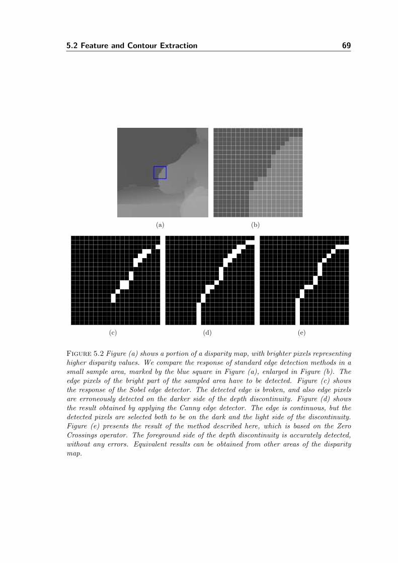
5.2 Feature and Contour Extraction 69
(a) (b)
(c) (d) (e)
Figure 5.2 Figure (a) shows a portion of a disparity map, with brighter pixels representinghigher disparity values. We compare the response of standard edge detection methods in asmall sample area, marked by the blue square in Figure (a), enlarged in Figure (b). Theedge pixels of the bright part of the sampled area have to be detected. Figure (c) showsthe response of the Sobel edge detector. The detected edge is broken, and also edge pixelsare erroneously detected on the darker side of the depth discontinuity. Figure (d) showsthe result obtained by applying the Canny edge detector. The edge is continuous, but thedetected pixels are selected both to be on the dark and the light side of the discontinuity.Figure (e) presents the result of the method described here, which is based on the ZeroCrossings operator. The foreground side of the depth discontinuity is accurately detected,without any errors. Equivalent results can be obtained from other areas of the disparitymap.
5.3 Contour Simplification and Vectorization 70
and staircase removal strive to eliminate edge information until edges are of unit
thickness. While the discarded information, in our case coded in image pixels, may
be imperceptible by visual inspection of monoscopic images, it is an important step
for successive processing, such as vectorization, to succeed.
A simple iterative contour extraction procedure is then used to convert the edge
pixels into connected components. This is trivially achieved by detecting end pixels
(i.e. pixels that have only one neighbor) and then recursively following the connected
pixels until no more pixels remain to process for the current pixel set. Each extracted
connected component is represented by a set of points p(x, y), with x and y being
their coordinates in the 2D coordinate system of the image. To further enhance the
output of the detected contours, prior to rendering them, very small lines can be
removed using a user defined threshold that is related to the amount of points in
the connected components.
5.3 Contour Simplification and Vectorization
The detected contours will usually appear to trace objects and form long continuous
lines that turn and curve unnaturally to follow depth discontinuities, resembling
more closely the result of a mechanical plotter, rather than a human sketch.
To create a more appealing set of lines that appear less mechanical and computer-
generated, we detect points of high curvature along the contours (i.e. corners) and
recursively subdivide the lines at those points, effectively creating a set of non-
overlapping disconnected segments that represent the initial contour, similarly to
how humans simplify long continuous lines when drawing.
While the detection and extraction steps of foreground pixels that make up line
segments are sufficient to directly synthesize an image reminiscent of a sketch, the
raster representation of the extracted contours is limiting in a number of ways. The
points describing each contour may be unnecessarily dense, leading to both decrease
of performance as well as increase of storage requirements. In addition, existing
algorithms for stroke stylization and rendering are usually based on parametric curve
models [48] and therefore are not applicable. Finally, the raster representation
cannot be reliably scaled and therefore transferring the stereo drawings on paper or
other media may lead to loss of quality.
To overcome these limitations, we describe a simple method for simplifying and
vectorizing the raster contours extracted. Raster-to-vector conversion is a widely
used technique for converting pixel-based representations into geometrical primi-
tives, finding great utility in digitization of line drawings [103] and optical character
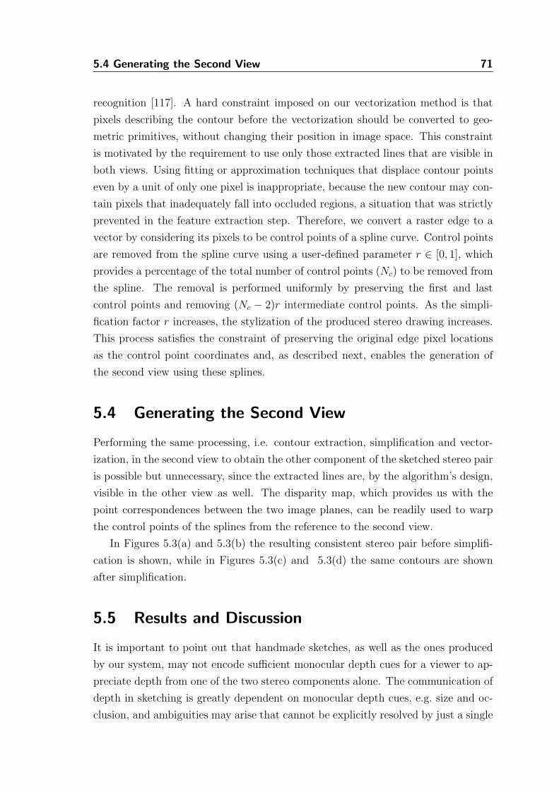
5.4 Generating the Second View 71
recognition [117]. A hard constraint imposed on our vectorization method is that
pixels describing the contour before the vectorization should be converted to geo-
metric primitives, without changing their position in image space. This constraint
is motivated by the requirement to use only those extracted lines that are visible in
both views. Using fitting or approximation techniques that displace contour points
even by a unit of only one pixel is inappropriate, because the new contour may con-
tain pixels that inadequately fall into occluded regions, a situation that was strictly
prevented in the feature extraction step. Therefore, we convert a raster edge to a
vector by considering its pixels to be control points of a spline curve. Control points
are removed from the spline curve using a user-defined parameter r ∈ [0, 1], which
provides a percentage of the total number of control points (Nc) to be removed from
the spline. The removal is performed uniformly by preserving the first and last
control points and removing (Nc − 2)r intermediate control points. As the simpli-
fication factor r increases, the stylization of the produced stereo drawing increases.
This process satisfies the constraint of preserving the original edge pixel locations
as the control point coordinates and, as described next, enables the generation of
the second view using these splines.
5.4 Generating the Second View
Performing the same processing, i.e. contour extraction, simplification and vector-
ization, in the second view to obtain the other component of the sketched stereo pair
is possible but unnecessary, since the extracted lines are, by the algorithm’s design,
visible in the other view as well. The disparity map, which provides us with the
point correspondences between the two image planes, can be readily used to warp
the control points of the splines from the reference to the second view.
In Figures 5.3(a) and 5.3(b) the resulting consistent stereo pair before simplifi-
cation is shown, while in Figures 5.3(c) and 5.3(d) the same contours are shown
after simplification.
5.5 Results and Discussion
It is important to point out that handmade sketches, as well as the ones produced
by our system, may not encode sufficient monocular depth cues for a viewer to ap-
preciate depth from one of the two stereo components alone. The communication of
depth in sketching is greatly dependent on monocular depth cues, e.g. size and oc-
clusion, and ambiguities may arise that cannot be explicitly resolved by just a single
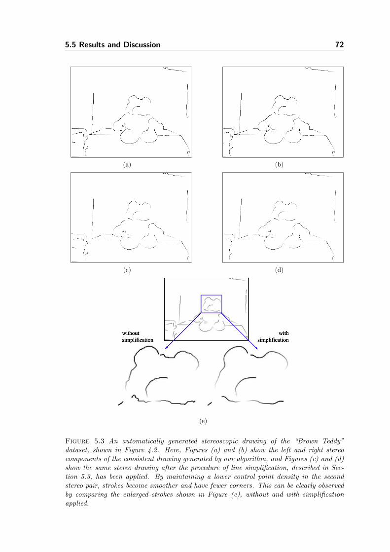
5.5 Results and Discussion 72
(a) (b)
(c) (d)
(e)
Figure 5.3 An automatically generated stereoscopic drawing of the “Brown Teddy”dataset, shown in Figure 4.2. Here, Figures (a) and (b) show the left and right stereocomponents of the consistent drawing generated by our algorithm, and Figures (c) and (d)show the same stereo drawing after the procedure of line simplification, described in Sec-tion 5.3, has been applied. By maintaining a lower control point density in the secondstereo pair, strokes become smoother and have fewer corners. This can be clearly observedby comparing the enlarged strokes shown in Figure (e), without and with simplificationapplied.
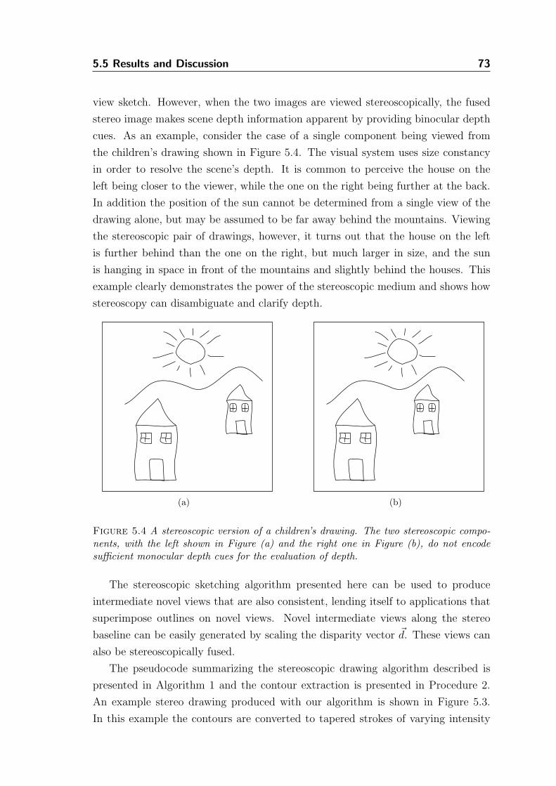
5.5 Results and Discussion 73
view sketch. However, when the two images are viewed stereoscopically, the fused
stereo image makes scene depth information apparent by providing binocular depth
cues. As an example, consider the case of a single component being viewed from
the children’s drawing shown in Figure 5.4. The visual system uses size constancy
in order to resolve the scene’s depth. It is common to perceive the house on the
left being closer to the viewer, while the one on the right being further at the back.
In addition the position of the sun cannot be determined from a single view of the
drawing alone, but may be assumed to be far away behind the mountains. Viewing
the stereoscopic pair of drawings, however, it turns out that the house on the left
is further behind than the one on the right, but much larger in size, and the sun
is hanging in space in front of the mountains and slightly behind the houses. This
example clearly demonstrates the power of the stereoscopic medium and shows how
stereoscopy can disambiguate and clarify depth.
(a) (b)
Figure 5.4 A stereoscopic version of a children’s drawing. The two stereoscopic compo-nents, with the left shown in Figure (a) and the right one in Figure (b), do not encodesufficient monocular depth cues for the evaluation of depth.
The stereoscopic sketching algorithm presented here can be used to produce
intermediate novel views that are also consistent, lending itself to applications that
superimpose outlines on novel views. Novel intermediate views along the stereo
baseline can be easily generated by scaling the disparity vector ~d. These views can
also be stereoscopically fused.
The pseudocode summarizing the stereoscopic drawing algorithm described is
presented in Algorithm 1 and the contour extraction is presented in Procedure 2.
An example stereo drawing produced with our algorithm is shown in Figure 5.3.
In this example the contours are converted to tapered strokes of varying intensity
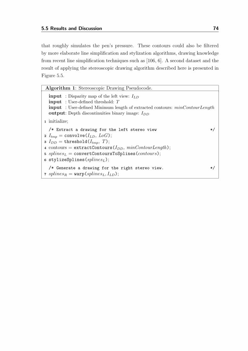
5.5 Results and Discussion 74
that roughly simulates the pen’s pressure. These contours could also be filtered
by more elaborate line simplification and stylization algorithms, drawing knowledge
from recent line simplification techniques such as [106, 6]. A second dataset and the
result of applying the stereoscopic drawing algorithm described here is presented in
Figure 5.5.
Algorithm 1: Stereoscopic Drawing Pseudocode.
input : Disparity map of the left view: ILD
input : User-defined threshold: T
input : User-defined Minimum length of extracted contours: minContourLength
output: Depth discontinuities binary image: IDD
initialize;1
/* Extract a drawing for the left stereo view */
Itmp = convolve(ILD, LoG);2
IDD = threshold(Itmp, T);3
contours = extractContours(IDD, minContourLength);4
splinesL = convertContoursToSplines(contours);5
stylizeSplines(splinesL);6
/* Generate a drawing for the right stereo view. */
splinesR = warp(splinesL, ILD);7
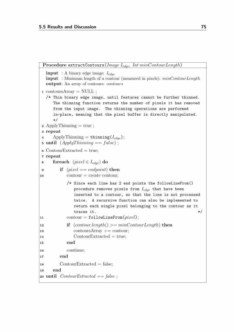
5.5 Results and Discussion 75
Procedure extractContours(Image Iedge, Int minContourLength)
input : A binary edge image: Iedge
input : Minimum length of a contour (measured in pixels): minContourLength
output: An array of contours: contours
contoursArray = NULL ;1
/* Thin binary edge image, until features cannot be further thinned.
The thinning function returns the number of pixels it has removed
from the input image. The thinning operations are performed
in-place, meaning that the pixel buffer is directly manipulated.
*/
ApplyThinning = true ;2
repeat3
ApplyThinning = thinning(Iedge);4
until (ApplyThinning == false) ;5
ContourExtracted = true;6
repeat7
foreach (pixel ∈ Iedge) do8
if (pixel == endpoint) then9
contour = create contour;10
/* Since each line has 2 end points the followLineFrom()
procedure removes pixels from Iedge that have been
inserted to a contour, so that the line is not processed
twice. A recursive function can also be implemented to
return each single pixel belonging to the contour as it
traces it. */
contour = followLineFrom(pixel);11
if (contour.length() >= minContourLength) then12
contoursArray += contour;13
ContourExtracted = true;14
end15
continue;16
end17
ContourExtracted = false;18
end19
until ContourExtracted == false ;20
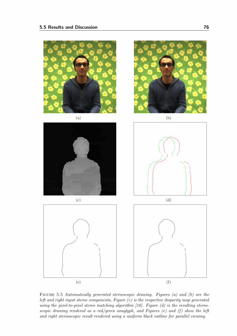
5.5 Results and Discussion 76
(a) (b)
(c) (d)
(e) (f)
Figure 5.5 Automatically generated stereoscopic drawing. Figures (a) and (b) are theleft and right input stereo components, Figure (c) is the respective disparity map generatedusing the pixel-to-pixel stereo matching algorithm [10]. Figure (d) is the resulting stereo-scopic drawing rendered as a red/green anaglyph, and Figures (e) and (f) show the leftand right stereoscopic result rendered using a uniform black outline for parallel viewing.
Chapter 6
Stereoscopic
Stylization
In recent years, DeCarlo and Santella published a series of papers [28, 89, 90] de-
scribing a stylization technique that uses color image segmentation, focusing mainly
on the use of eye-tracking data to guide the stylization process and evaluate its
results. Their techniques, as well as the work of Gooch et al. [39] and successively
various others [20, 8], provide solid evidence that computer vision techniques can be
used in place of, or in conjunction with, traditional computer graphics algorithms
to generate artistic-looking images. The need for controlled enhancement of images
specifically targeted to various aspects of the human visual system and perception
points in the direction of using methods to understand image features from a per-
ceptual standpoint and not at the low-level of signal processing alone. The output
of blackbox NPR algorithms has been proven too sterile for such a demanding task
and these algorithms are phased down in light of new methods. The design of these
new methods promotes human factors, which are after all central in NPR. This set
of NPR techniques was therefore a natural evolution of the field at a conceptual
and theoretical level, which also had an obvious role in the intertwining of computer
vision and computer graphics algorithms. This trend of understanding features in
images and then enhance them is now becoming common practice in NPR with
much success.
Along this line of work, we present a method that can be used to generate
stylized stereo imagery. The algorithm presented here tackles a set of problems that
are associated with multiview processing. The spatial structure of an imaged scene
is first extracted, and this information becomes the basis for the stylization of the
input stereo pairs. On a basic level, the method demonstrates that it is possible
to interchange certain computer graphics algorithms with computer vision methods
without altering neither the stereoscopic pipeline nor the guidelines that are used in
the work presented throughout this dissertation.
The stereo stylization method is not restricted to provide only the consistency re-
77
6.1 Preprocessing 78
quired in stereo NPR, but it is further extended to incorporate a distance-dependent
rendering mechanism that is motivated by traditional level of detail (LOD) tech-
niques [65] and perception-based image synthesis and associated experiments [122].
This extended version of the algorithm is an example of how depth can increase
the perceptibility of selected features, by abstracting and stylizing portions of the
images according to their distance from the viewer. The viewer is no longer driving
the selection of the appropriate level of detail, but he is rather presented with a
composition in which the picture-maker guides the viewer’s perception in the third
dimension. In our work, we bias the depth perception of the viewer by enhanc-
ing certain monocular depth cues (i.e. texture and silhouettes) simultaneously to
providing binocular depth cues via the consistently stylized stereo pictures.
6.1 Preprocessing
Like in the previous methods we use stereo vision techniques to analyze real stereo
image pairs. We utilize the region-based stereo matching algorithm proposed by
Bleyer and Gelautz [12], which does not only estimate disparities of the given scene,
but it additionally provides as a byproduct a secondary 21
2D representation of the
scene. This auxiliary buffer encodes the spatial extents of the different depth layers
of the scene, in image space. This representation can be thought of as the outcome of
a depth segmentation process and it can be utilized in many different ways for both
monoscopic and stereoscopic NPR. Much like how G-Buffers have been previously
used in traditional NPR [108, p.183], the disparity map and the depth layers buffer
can be considered to be the depth and the ID-buffer, respectively. This is because
the disparity map can be used to infer a depth map and the depth layers suggest a
rough object segmentation of the scene. The output of this stereo algorithm is both a
dense disparity map and a depth layers map, an example of these two representations
is shown in Figure 6.1. A schematic overview of the proposed method is shown in
Figure 6.2. It must be noted here that the depth layers map used in the subsequent
stereo stylization procedure could also be provided by the user interactively. This
would enable the user to semantically separate scene objects and group them into
different depth layers, rather than rely on a segmentation based on low-level image
features. A major advantage of these semantically segmented scenes is that the user
would then have more control over the stylization parameters on a per object basis.
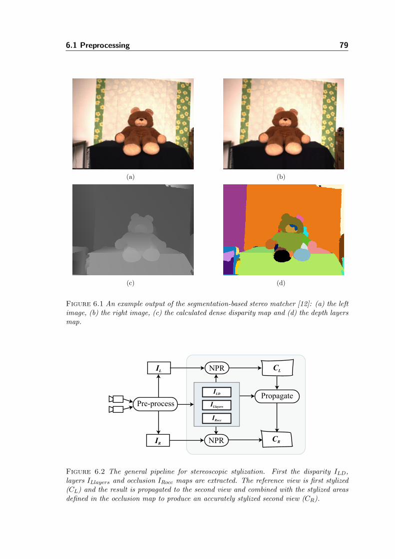
6.1 Preprocessing 79
(a) (b)
(c) (d)
Figure 6.1 An example output of the segmentation-based stereo matcher [12]: (a) the leftimage, (b) the right image, (c) the calculated dense disparity map and (d) the depth layersmap.
Pre-process
IL
IR NPR
NPR CL
CR
PropagateILD
ILlayers
IRocc
Figure 6.2 The general pipeline for stereoscopic stylization. First the disparity ILD,layers ILlayers and occlusion IRocc maps are extracted. The reference view is first stylized(CL) and the result is propagated to the second view and combined with the stylized areasdefined in the occlusion map to produce an accurately stylized second view (CR).
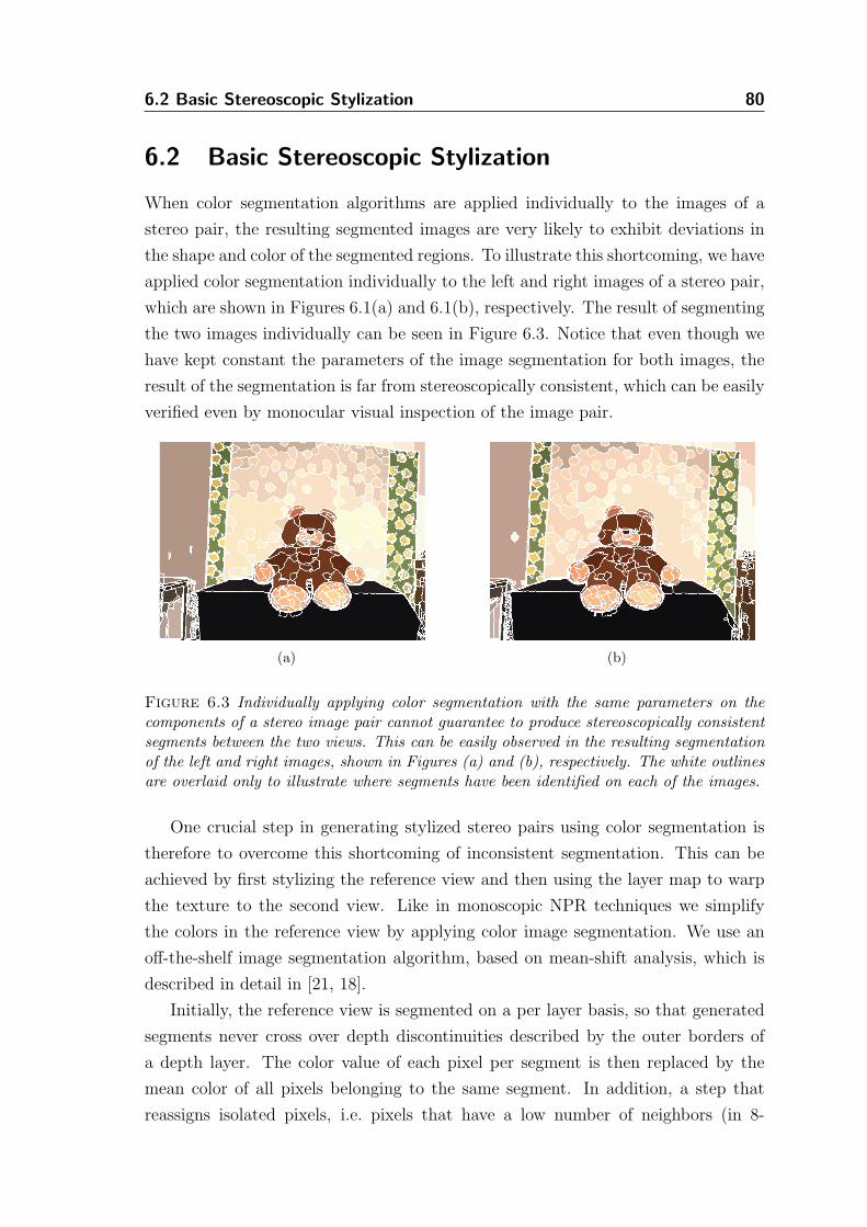
6.2 Basic Stereoscopic Stylization 80
6.2 Basic Stereoscopic Stylization
When color segmentation algorithms are applied individually to the images of a
stereo pair, the resulting segmented images are very likely to exhibit deviations in
the shape and color of the segmented regions. To illustrate this shortcoming, we have
applied color segmentation individually to the left and right images of a stereo pair,
which are shown in Figures 6.1(a) and 6.1(b), respectively. The result of segmenting
the two images individually can be seen in Figure 6.3. Notice that even though we
have kept constant the parameters of the image segmentation for both images, the
result of the segmentation is far from stereoscopically consistent, which can be easily
verified even by monocular visual inspection of the image pair.
(a) (b)
Figure 6.3 Individually applying color segmentation with the same parameters on thecomponents of a stereo image pair cannot guarantee to produce stereoscopically consistentsegments between the two views. This can be easily observed in the resulting segmentationof the left and right images, shown in Figures (a) and (b), respectively. The white outlinesare overlaid only to illustrate where segments have been identified on each of the images.
One crucial step in generating stylized stereo pairs using color segmentation is
therefore to overcome this shortcoming of inconsistent segmentation. This can be
achieved by first stylizing the reference view and then using the layer map to warp
the texture to the second view. Like in monoscopic NPR techniques we simplify
the colors in the reference view by applying color image segmentation. We use an
off-the-shelf image segmentation algorithm, based on mean-shift analysis, which is
described in detail in [21, 18].
Initially, the reference view is segmented on a per layer basis, so that generated
segments never cross over depth discontinuities described by the outer borders of
a depth layer. The color value of each pixel per segment is then replaced by the
mean color of all pixels belonging to the same segment. In addition, a step that
reassigns isolated pixels, i.e. pixels that have a low number of neighbors (in 8-
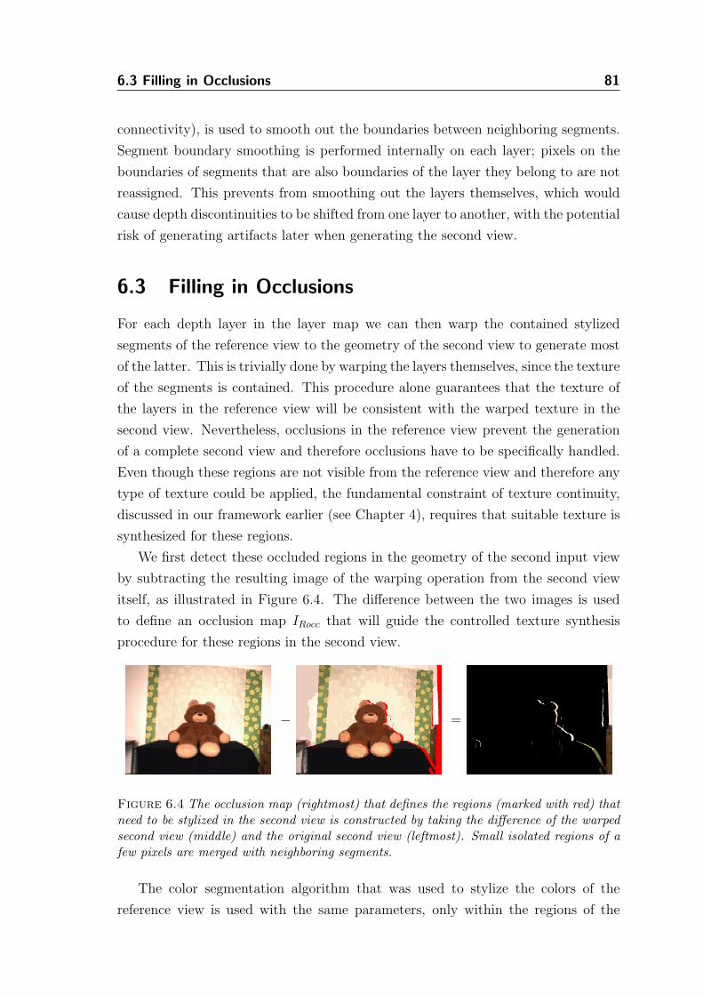
6.3 Filling in Occlusions 81
connectivity), is used to smooth out the boundaries between neighboring segments.
Segment boundary smoothing is performed internally on each layer; pixels on the
boundaries of segments that are also boundaries of the layer they belong to are not
reassigned. This prevents from smoothing out the layers themselves, which would
cause depth discontinuities to be shifted from one layer to another, with the potential
risk of generating artifacts later when generating the second view.
6.3 Filling in Occlusions
For each depth layer in the layer map we can then warp the contained stylized
segments of the reference view to the geometry of the second view to generate most
of the latter. This is trivially done by warping the layers themselves, since the texture
of the segments is contained. This procedure alone guarantees that the texture of
the layers in the reference view will be consistent with the warped texture in the
second view. Nevertheless, occlusions in the reference view prevent the generation
of a complete second view and therefore occlusions have to be specifically handled.
Even though these regions are not visible from the reference view and therefore any
type of texture could be applied, the fundamental constraint of texture continuity,
discussed in our framework earlier (see Chapter 4), requires that suitable texture is
synthesized for these regions.
We first detect these occluded regions in the geometry of the second input view
by subtracting the resulting image of the warping operation from the second view
itself, as illustrated in Figure 6.4. The difference between the two images is used
to define an occlusion map IRocc that will guide the controlled texture synthesis
procedure for these regions in the second view.
− =
Figure 6.4 The occlusion map (rightmost) that defines the regions (marked with red) thatneed to be stylized in the second view is constructed by taking the difference of the warpedsecond view (middle) and the original second view (leftmost). Small isolated regions of afew pixels are merged with neighboring segments.
The color segmentation algorithm that was used to stylize the colors of the
reference view is used with the same parameters, only within the regions of the
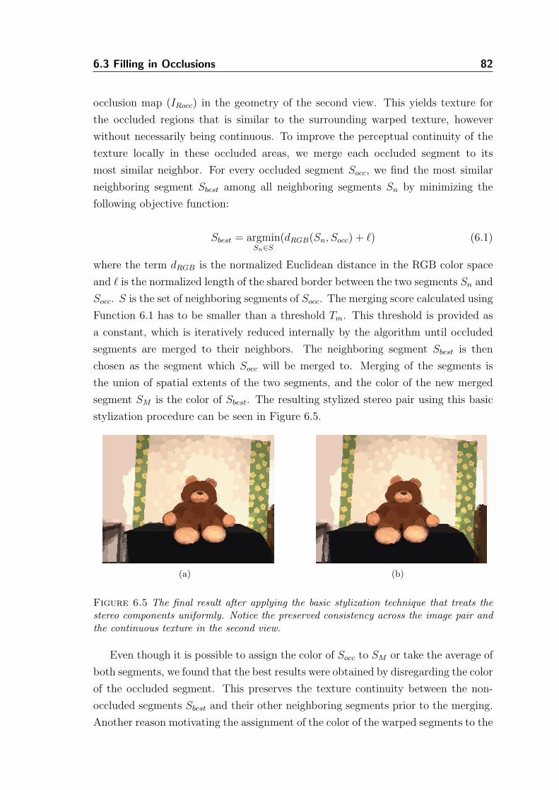
6.3 Filling in Occlusions 82
occlusion map (IRocc) in the geometry of the second view. This yields texture for
the occluded regions that is similar to the surrounding warped texture, however
without necessarily being continuous. To improve the perceptual continuity of the
texture locally in these occluded areas, we merge each occluded segment to its
most similar neighbor. For every occluded segment Socc, we find the most similar
neighboring segment Sbest among all neighboring segments Sn by minimizing the
following objective function:
Sbest = argminSn∈S
(dRGB(Sn, Socc) + ℓ) (6.1)
where the term dRGB is the normalized Euclidean distance in the RGB color space
and ℓ is the normalized length of the shared border between the two segments Sn and
Socc. S is the set of neighboring segments of Socc. The merging score calculated using
Function 6.1 has to be smaller than a threshold Tm. This threshold is provided as
a constant, which is iteratively reduced internally by the algorithm until occluded
segments are merged to their neighbors. The neighboring segment Sbest is then
chosen as the segment which Socc will be merged to. Merging of the segments is
the union of spatial extents of the two segments, and the color of the new merged
segment SM is the color of Sbest. The resulting stylized stereo pair using this basic
stylization procedure can be seen in Figure 6.5.
(a) (b)
Figure 6.5 The final result after applying the basic stylization technique that treats thestereo components uniformly. Notice the preserved consistency across the image pair andthe continuous texture in the second view.
Even though it is possible to assign the color of Socc to SM or take the average of
both segments, we found that the best results were obtained by disregarding the color
of the occluded segment. This preserves the texture continuity between the non-
occluded segments Sbest and their other neighboring segments prior to the merging.
Another reason motivating the assignment of the color of the warped segments to the
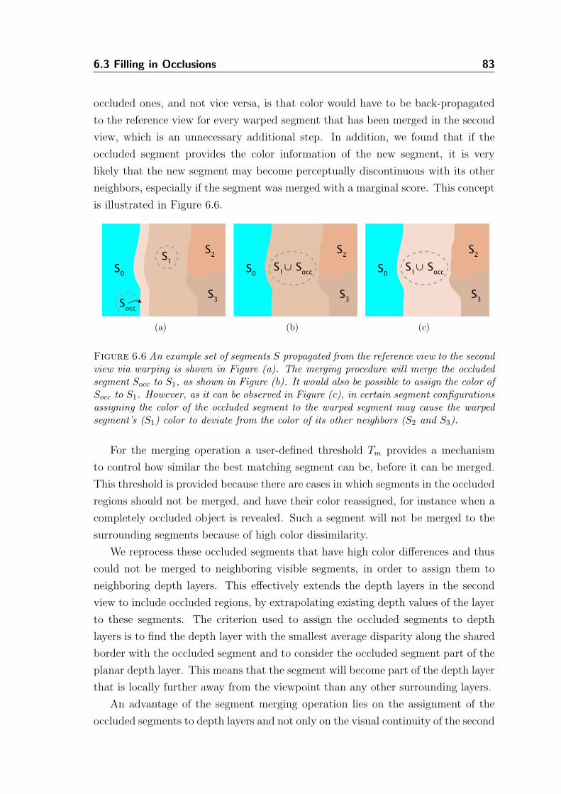
6.3 Filling in Occlusions 83
occluded ones, and not vice versa, is that color would have to be back-propagated
to the reference view for every warped segment that has been merged in the second
view, which is an unnecessary additional step. In addition, we found that if the
occluded segment provides the color information of the new segment, it is very
likely that the new segment may become perceptually discontinuous with its other
neighbors, especially if the segment was merged with a marginal score. This concept
is illustrated in Figure 6.6.
S0
S2
S3
S1
Socc
(a)
S0
S2
S3
S1∪ S
occ
(b)
S0
S2
S3
S1∪ S
occ
(c)
Figure 6.6 An example set of segments S propagated from the reference view to the secondview via warping is shown in Figure (a). The merging procedure will merge the occludedsegment Socc to S1, as shown in Figure (b). It would also be possible to assign the color ofSocc to S1. However, as it can be observed in Figure (c), in certain segment configurationsassigning the color of the occluded segment to the warped segment may cause the warpedsegment’s (S1) color to deviate from the color of its other neighbors (S2 and S3).
For the merging operation a user-defined threshold Tm provides a mechanism
to control how similar the best matching segment can be, before it can be merged.
This threshold is provided because there are cases in which segments in the occluded
regions should not be merged, and have their color reassigned, for instance when a
completely occluded object is revealed. Such a segment will not be merged to the
surrounding segments because of high color dissimilarity.
We reprocess these occluded segments that have high color differences and thus
could not be merged to neighboring visible segments, in order to assign them to
neighboring depth layers. This effectively extends the depth layers in the second
view to include occluded regions, by extrapolating existing depth values of the layer
to these segments. The criterion used to assign the occluded segments to depth
layers is to find the depth layer with the smallest average disparity along the shared
border with the occluded segment and to consider the occluded segment part of the
planar depth layer. This means that the segment will become part of the depth layer
that is locally further away from the viewpoint than any other surrounding layers.
An advantage of the segment merging operation lies on the assignment of the
occluded segments to depth layers and not only on the visual continuity of the second
6.4 Distance-Dependent Stereoscopic Stylization 84
view, which was the primary motivation. Since layers represent planar surfaces over
which disparity varies smoothly, by extending them over the newly merged segments
and extrapolating depth values over them, we can obtain a dense disparity map for
the second view with the occlusions filled in. The second disparity map can be used
to do inverse image warping and is useful when generating intermediate novel views.
6.4 Distance-Dependent Stereoscopic Stylization
The approach described above is rather straightforward, but provides limited control
over the stylization result. Even though the images are consistently stylized, they
are treated uniformly and the significant information of scene depth is not utilized
in any other way apart from generating the second view. In the evaluation of their
work with eye-gaze directed stylization, Santella and DeCarlo [90] specifically point
out that the effectiveness of NPR can be increased by meaningful abstraction and
they show that this can be achieved by varying the detail of the abstracted images
according to where their users are fixating with their eyes.
In our stereoscopic system we incorporate the idea that objects closer to the
viewer in the natural world have normally higher resolution, and more detail can
therefore be distinguished than on objects located further away. We also assume
that objects closer to the viewer are of more interest to him. These two assumptions
converge into the design of an algorithmic texture synthesis that accentuates the
monocular depth cue of texture gradient of foreground objects and attenuates it for
objects that are further away.
To achieve this we apply non-uniform stylization across the input images by using
the various depth layers of the scene. The key here is to modulate the segmentation
process by making its parameters a function of the distance of the surface to be
segmented to the viewpoint. To meet the design requirement of “closer-sharper” and
“farther-rougher”, we abstract closer surfaces less than distant ones, by representing
them with more segments. The described distance-dependent NPR algorithm is
closely related to the concept of view-dependent level of detail selection [65, p.104].
The feature (hr) and spatial (hs) bandwidths1, as well as the minimum region
parameter M , of the mean-shift-based segmentation algorithm, can be used to con-
trol the granularity of the texture across the different depth layers. Small values of
spatial bandwidth combined with small values of feature bandwidth provide a finer
segmentation. As the two parameters increase, the resolution of the segmentation
1The parameters hr and hs of the mean-shift color segmentation algorithm denote the radii ofthe windows used to compute the offset of the mean vector from the center of that window, in theLUV color space and the image’s lattice, respectively.
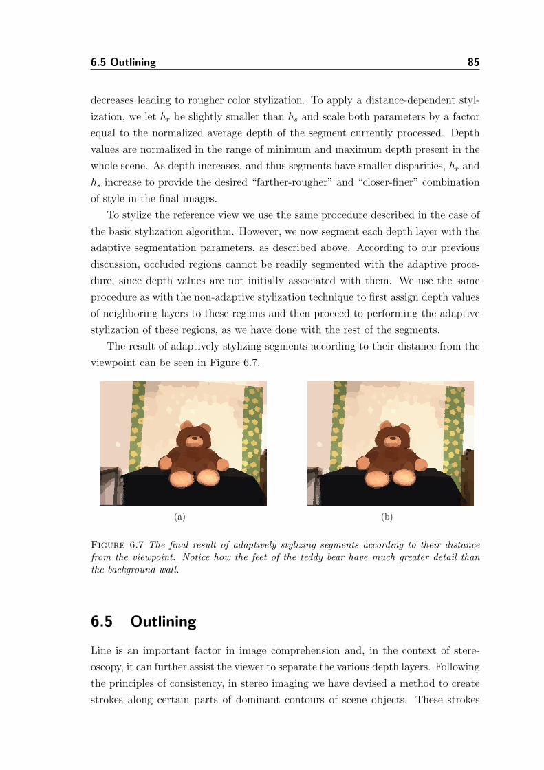
6.5 Outlining 85
decreases leading to rougher color stylization. To apply a distance-dependent styl-
ization, we let hr be slightly smaller than hs and scale both parameters by a factor
equal to the normalized average depth of the segment currently processed. Depth
values are normalized in the range of minimum and maximum depth present in the
whole scene. As depth increases, and thus segments have smaller disparities, hr and
hs increase to provide the desired “farther-rougher” and “closer-finer” combination
of style in the final images.
To stylize the reference view we use the same procedure described in the case of
the basic stylization algorithm. However, we now segment each depth layer with the
adaptive segmentation parameters, as described above. According to our previous
discussion, occluded regions cannot be readily segmented with the adaptive proce-
dure, since depth values are not initially associated with them. We use the same
procedure as with the non-adaptive stylization technique to first assign depth values
of neighboring layers to these regions and then proceed to performing the adaptive
stylization of these regions, as we have done with the rest of the segments.
The result of adaptively stylizing segments according to their distance from the
viewpoint can be seen in Figure 6.7.
(a) (b)
Figure 6.7 The final result of adaptively stylizing segments according to their distancefrom the viewpoint. Notice how the feet of the teddy bear have much greater detail thanthe background wall.
6.5 Outlining
Line is an important factor in image comprehension and, in the context of stere-
oscopy, it can further assist the viewer to separate the various depth layers. Following
the principles of consistency, in stereo imaging we have devised a method to create
strokes along certain parts of dominant contours of scene objects. These strokes
6.5 Outlining 86
usually represent parts of silhouettes and creases of objects that are visible in both
stereoscopic views.
We construct an edge image using the stereoscopic drawing algorithm described
in Chapter 5. We also construct a second edge map by tracing the boundaries of
the depth layers found in the layer map. The first image provides a set of lines that
can be readily used to stroke foreground features of the scene. However, this image
is very sensitive to artifacts in the disparity map and also provides by design short
lines that are more relevant for a drawing or a sketch than for making complete
outlines. For the stylized images that resemble cartoons, produced by the previous
segmentation-based stereo algorithm, a more continuous and less sketchy line would
be more adequate. The second edge map that essentially is constructed by tracing
the depth layer boundaries may include inadequately outlined features, such as
background depth layer outlines, or outlines that produce clutter rather than clarity.
We make use of the best features of both edge maps. We first label the endpoints
of all lines in the extracted edge image using the stereo drawing algorithm in the
geometry of the reference view. We take advantage of the depth layer boundaries
here to connect lines that belong to the same depth discontinuity that runs along
the boundary of a depth layer. Furthermore, we also use the stereo drawing to
remove extraneous edge segments that would otherwise be present, if the outlines
generated by the layer map were kept intact. This provides a combined set of lines
that can also be warped from the reference to the second view in order to generate
a consistent stereoscopic outline. This outline can be laid over the stylized stereo
pairs to elucidate depth differences in the final stereo rendition.
The density of the lines present in the final edge map can be controlled by a user-
defined parameter that provides the maximum distance along a boundary that two
edge endpoints may connect. Additional procedures incorporated in the stereoscopic
drawing algorithm, such as simplification and vectorization, can be used to further
filter the resulting depth edges.
Figure 6.8 shows the final stylized output with the stereo drawing algorithm
applied to the “Brown Teddy” dataset. Figure 6.9 shows the result of using the
stereo drawing algorithm in combination with the depth layer boundary tracing
method described above.
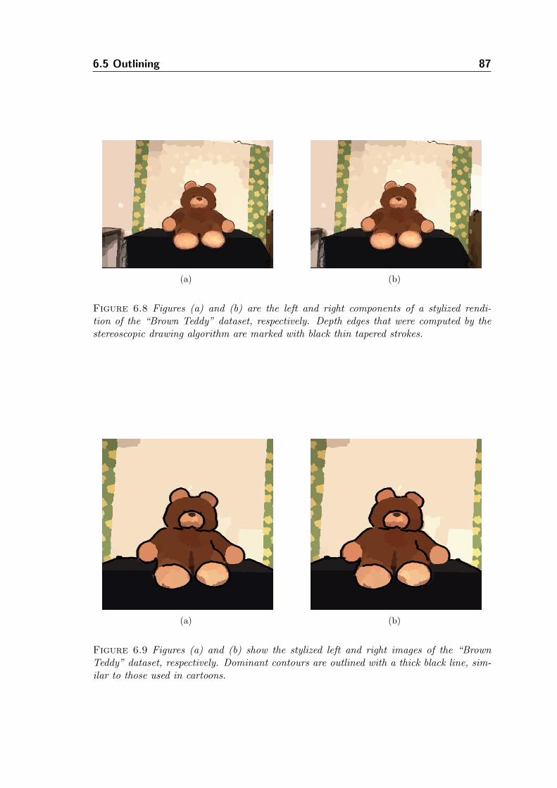
6.5 Outlining 87
(a) (b)
Figure 6.8 Figures (a) and (b) are the left and right components of a stylized rendi-tion of the “Brown Teddy” dataset, respectively. Depth edges that were computed by thestereoscopic drawing algorithm are marked with black thin tapered strokes.
(a) (b)
Figure 6.9 Figures (a) and (b) show the stylized left and right images of the “BrownTeddy” dataset, respectively. Dominant contours are outlined with a thick black line, sim-ilar to those used in cartoons.
6.6 Results 88
6.6 Results
We have tested our algorithm with various real image datasets. Apart from the self-
recorded “Brown Teddy” dataset, we have also stylized the “Venus” dataset of [93],
shown in Figure 6.10.
Figures 6.10(a) and 6.10(b) show the original left and right components of the
stereo image pair. This scene has a mixture of textured and untextured surfaces,
which are split into layers (Figure 6.10(c)) and the respective disparity map extracted
by the stereo matching algorithm is shown in Figure 6.10(d). The left stylized view
is shown in Figure 6.10(e), and the warped right view before stylizing occlusions
is presented in 6.10(f). Example results of the combined stylization and outlining
algorithms applied on the “Venus” dataset are shown in Figure 6.11.
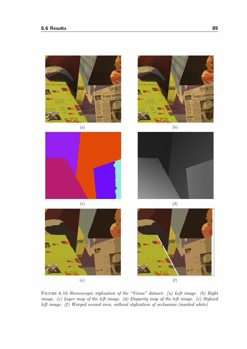
6.6 Results 89
(a) (b)
(c) (d)
(e) (f)
Figure 6.10 Stereoscopic stylization of the “Venus” dataset. (a) Left image. (b) Rightimage. (c) Layer map of the left image. (d) Disparity map of the left image. (e) Stylizedleft image. (f) Warped second view, without stylization of occlusions (marked white)
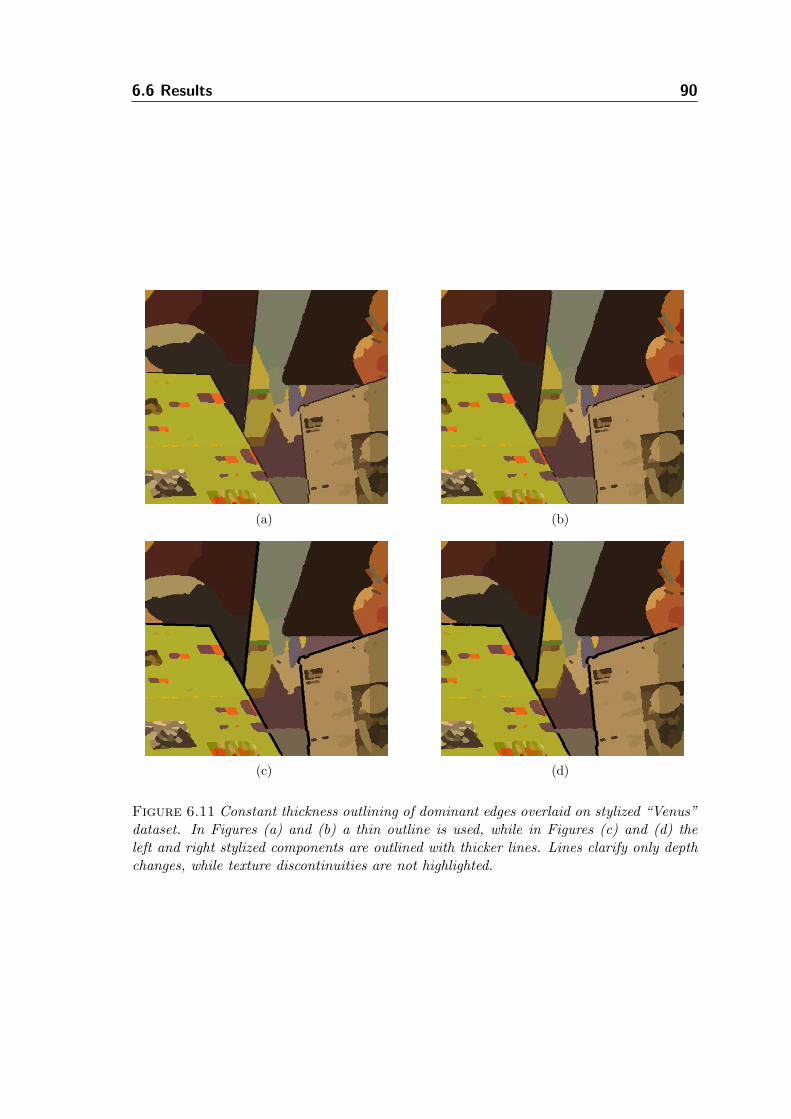
6.6 Results 90
(a) (b)
(c) (d)
Figure 6.11 Constant thickness outlining of dominant edges overlaid on stylized “Venus”dataset. In Figures (a) and (b) a thin outline is used, while in Figures (c) and (d) theleft and right stylized components are outlined with thicker lines. Lines clarify only depthchanges, while texture discontinuities are not highlighted.
Chapter 7
Stereoscopic
Painting
One of the most difficult artistic stereo techniques is stereoscopic painting, both
when executed by hand or simulated with a computer. It requires a high level of
artistic merit combined with technical expertise. As we have extensively discussed in
Section 2.3, the small number of artists that have taken up the task of creating stereo
paintings by hand were faced with many technical and perceptual difficulties. To
better appreciate the requirements for an image-based algorithm simulating stereo
painting, we have identified these problems (e.g. feature correspondence) in the
analogue domain, and we now map them into an algorithm that can be used to
generate stereoscopic paintings with a computer.
Creating pleasing stereoscopic content requires artwork that effectively commu-
nicates the third dimension by means of adequate stimulation of binocular vision.
Therefore, stereo artists strive to suppress mistakes in the artwork that lead to
binocular rivalry [11]. Particularly, stereo painters that aim to produce static color
stimuli preserve across the stereo components the intrinsic properties of the depicted
scene objects, such as form, size, color and luminance.
Maintaining consistency of these characteristics between the two projections is
not only time consuming, but it may also impose physical constraints for an artist.
Thus stereo artwork shifts from being a familiar means of artistic expression to a
creative task that also requires considerable technical knowledge. Stereo painters
have used a variety of techniques to overcome these technical issues (i.e. preserve the
viewpoint and colors’ consistency). Some have used careful preliminary stereo draw-
ings, while others have employed reference photographs. Furthermore, we observe
that stereo painting does not become less of a demanding task in the digital domain.
Digital stereo painters are still required to spend a considerable amount of time on
repetitive tasks when using standard 2D image editing and synthesis software. They
have to ensure that consistency is preserved manually, since these applications are
not targeted for stereoscopic content generation and thus lack appropriate stereo
image editing and manipulation tools.
91
7.1 Stereo Painting by Image Warping 92
Considering that our algorithms are based on stereo images as an input, our
methods are analogous to photographically-assisted stereo painting, in which artists
use photographs as a reference. Our strategy to build a relationship between the left
and right input stereo images and successively exploit it in a synthesis procedure
can also be applied to stereoscopic painting. This suggests that:
• we can preserve the intrinsic properties of objects depicted in the two stereo
components by exploiting their similarities,
• we can preserve consistency within occluded and non-occluded regions in each
of the components by identifying and exploiting the dissimilarities between
the two stereo components,
• the speed of synthesizing stereo paintings can be increased by generating most
of the second, slightly dissimilar, stereoscopic component using information
from the first view.
In the following, we show how consistent stereo paintings can be generated using
stroke-based rendering.
7.1 Stereo Painting by Image Warping
For a given stereoscopic image pair with IL and IR the left and right components,
respectively, as shown in Figures 7.1(a) and 7.1(b), we use the respective disparity
map ILD (see Figure 7.1(c)) calculated in the geometry of the left view to identify
occluded regions of the scene in the right view. Since the disparity map provides a
pixel by pixel correspondence to the right view, it is sufficient to use image warping to
reproject pixels of the left view into the right. Any remaining pixels in the right view
that cannot be mapped could be considered to represent the projections of invisible
scene points from the left view. These occluded pixels are encoded with a value of
1 into a binary occlusion map IRocc for the right view, as shown in Figure 7.1(d).
We associate this map with the right view and not with the left one, because it will
be later utilized as a mask when painting the right view. Pixels in the occlusion
map with a value of 1 are considered as being unmasked pixels, while those with a
value of 0 are masked. The painting simulation is applied only in unmasked pixel
regions rather than the whole view, thus improving the performance of the overall
stereoscopic synthesis.
We first apply a painterly simulation algorithm in IL to generate the left canvas
CL, based on Hertzmann’s [47] curved brush strokes algorithm of multiple sizes (see
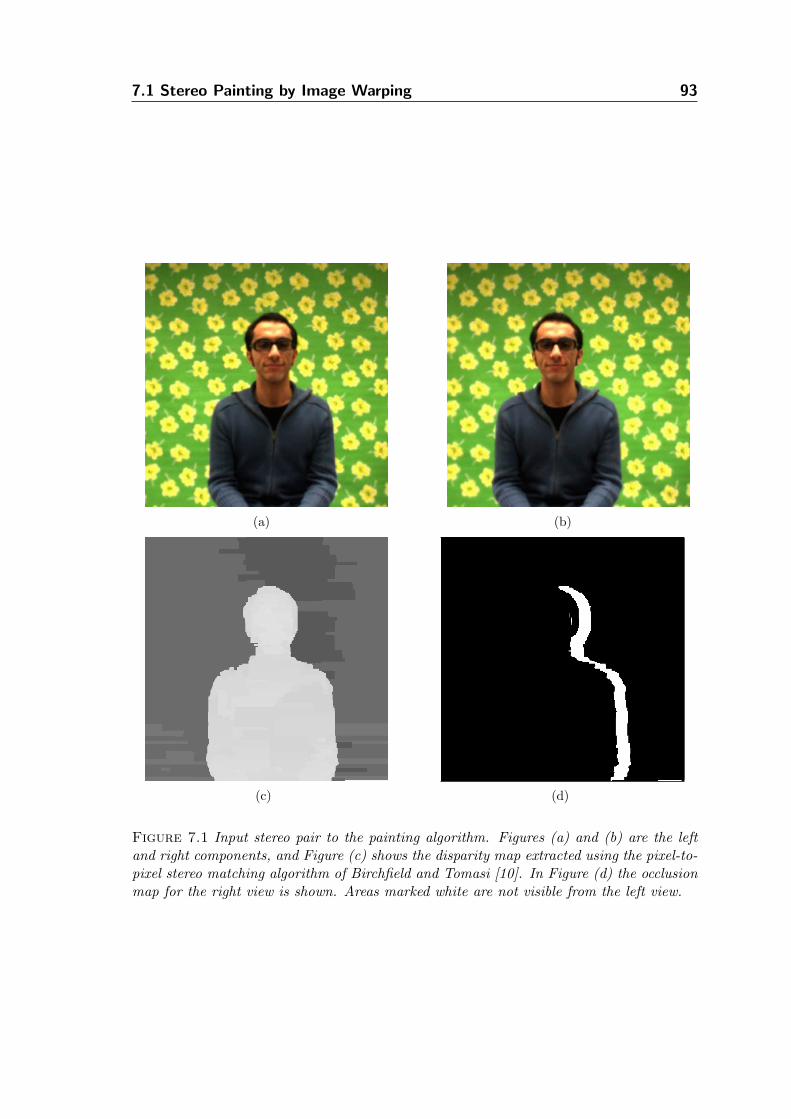
7.1 Stereo Painting by Image Warping 93
(a) (b)
(c) (d)
Figure 7.1 Input stereo pair to the painting algorithm. Figures (a) and (b) are the leftand right components, and Figure (c) shows the disparity map extracted using the pixel-to-pixel stereo matching algorithm of Birchfield and Tomasi [10]. In Figure (d) the occlusionmap for the right view is shown. Areas marked white are not visible from the left view.
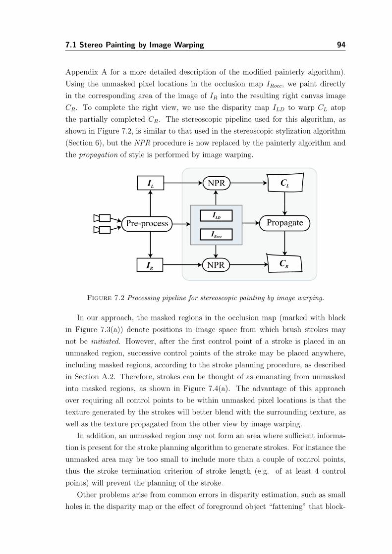
7.1 Stereo Painting by Image Warping 94
Appendix A for a more detailed description of the modified painterly algorithm).
Using the unmasked pixel locations in the occlusion map IRocc, we paint directly
in the corresponding area of the image of IR into the resulting right canvas image
CR. To complete the right view, we use the disparity map ILD to warp CL atop
the partially completed CR. The stereoscopic pipeline used for this algorithm, as
shown in Figure 7.2, is similar to that used in the stereoscopic stylization algorithm
(Section 6), but the NPR procedure is now replaced by the painterly algorithm and
the propagation of style is performed by image warping.
Pre-process
IL
IR NPR
NPR CL
CR
PropagateILD
IRocc
Figure 7.2 Processing pipeline for stereoscopic painting by image warping.
In our approach, the masked regions in the occlusion map (marked with black
in Figure 7.3(a)) denote positions in image space from which brush strokes may
not be initiated. However, after the first control point of a stroke is placed in an
unmasked region, successive control points of the stroke may be placed anywhere,
including masked regions, according to the stroke planning procedure, as described
in Section A.2. Therefore, strokes can be thought of as emanating from unmasked
into masked regions, as shown in Figure 7.4(a). The advantage of this approach
over requiring all control points to be within unmasked pixel locations is that the
texture generated by the strokes will better blend with the surrounding texture, as
well as the texture propagated from the other view by image warping.
In addition, an unmasked region may not form an area where sufficient informa-
tion is present for the stroke planning algorithm to generate strokes. For instance the
unmasked area may be too small to include more than a couple of control points,
thus the stroke termination criterion of stroke length (e.g. of at least 4 control
points) will prevent the planning of the stroke.
Other problems arise from common errors in disparity estimation, such as small
holes in the disparity map or the effect of foreground object “fattening” that block-
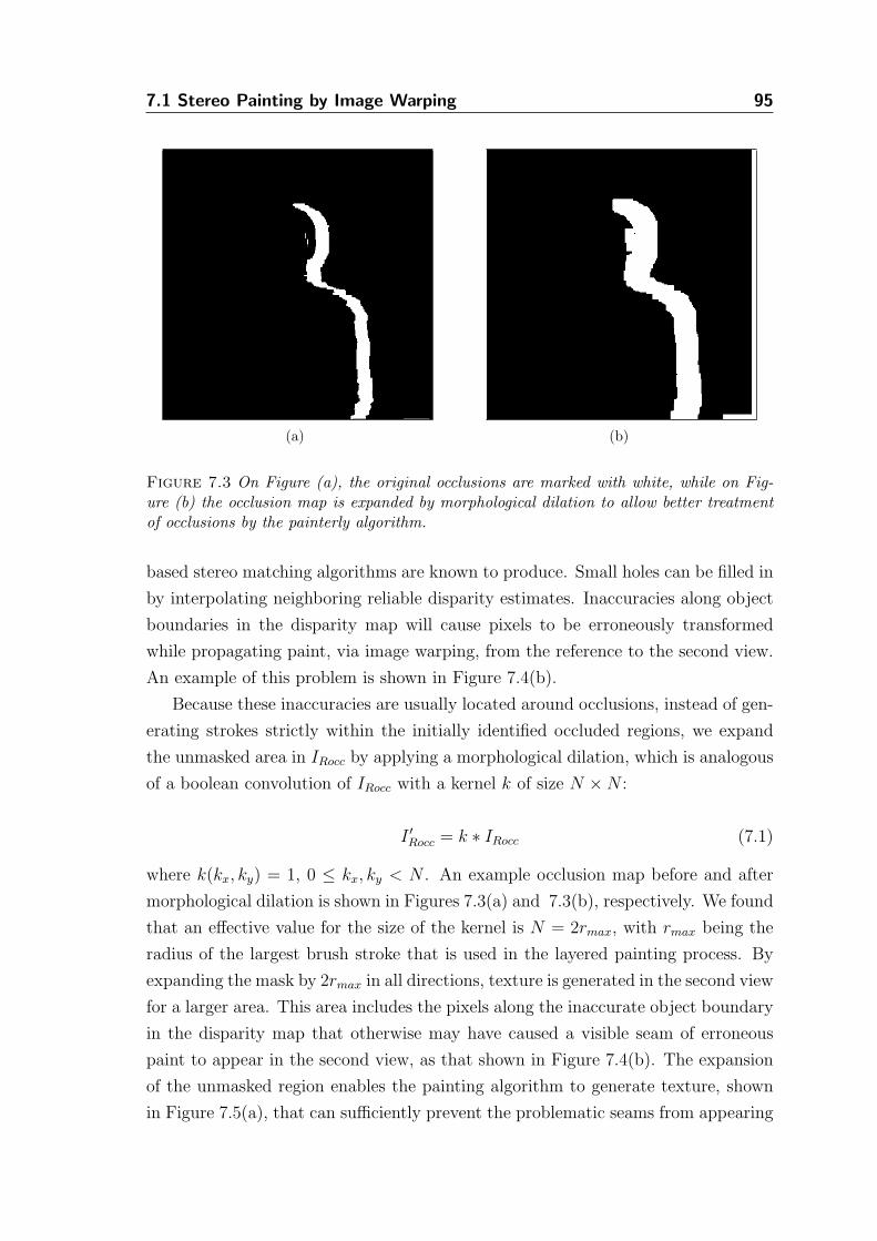
7.1 Stereo Painting by Image Warping 95
(a) (b)
Figure 7.3 On Figure (a), the original occlusions are marked with white, while on Fig-ure (b) the occlusion map is expanded by morphological dilation to allow better treatmentof occlusions by the painterly algorithm.
based stereo matching algorithms are known to produce. Small holes can be filled in
by interpolating neighboring reliable disparity estimates. Inaccuracies along object
boundaries in the disparity map will cause pixels to be erroneously transformed
while propagating paint, via image warping, from the reference to the second view.
An example of this problem is shown in Figure 7.4(b).
Because these inaccuracies are usually located around occlusions, instead of gen-
erating strokes strictly within the initially identified occluded regions, we expand
the unmasked area in IRocc by applying a morphological dilation, which is analogous
of a boolean convolution of IRocc with a kernel k of size N ×N :
I ′Rocc = k ∗ IRocc (7.1)
where k(kx, ky) = 1, 0 ≤ kx, ky < N . An example occlusion map before and after
morphological dilation is shown in Figures 7.3(a) and 7.3(b), respectively. We found
that an effective value for the size of the kernel is N = 2rmax, with rmax being the
radius of the largest brush stroke that is used in the layered painting process. By
expanding the mask by 2rmax in all directions, texture is generated in the second view
for a larger area. This area includes the pixels along the inaccurate object boundary
in the disparity map that otherwise may have caused a visible seam of erroneous
paint to appear in the second view, as that shown in Figure 7.4(b). The expansion
of the unmasked region enables the painting algorithm to generate texture, shown
in Figure 7.5(a), that can sufficiently prevent the problematic seams from appearing
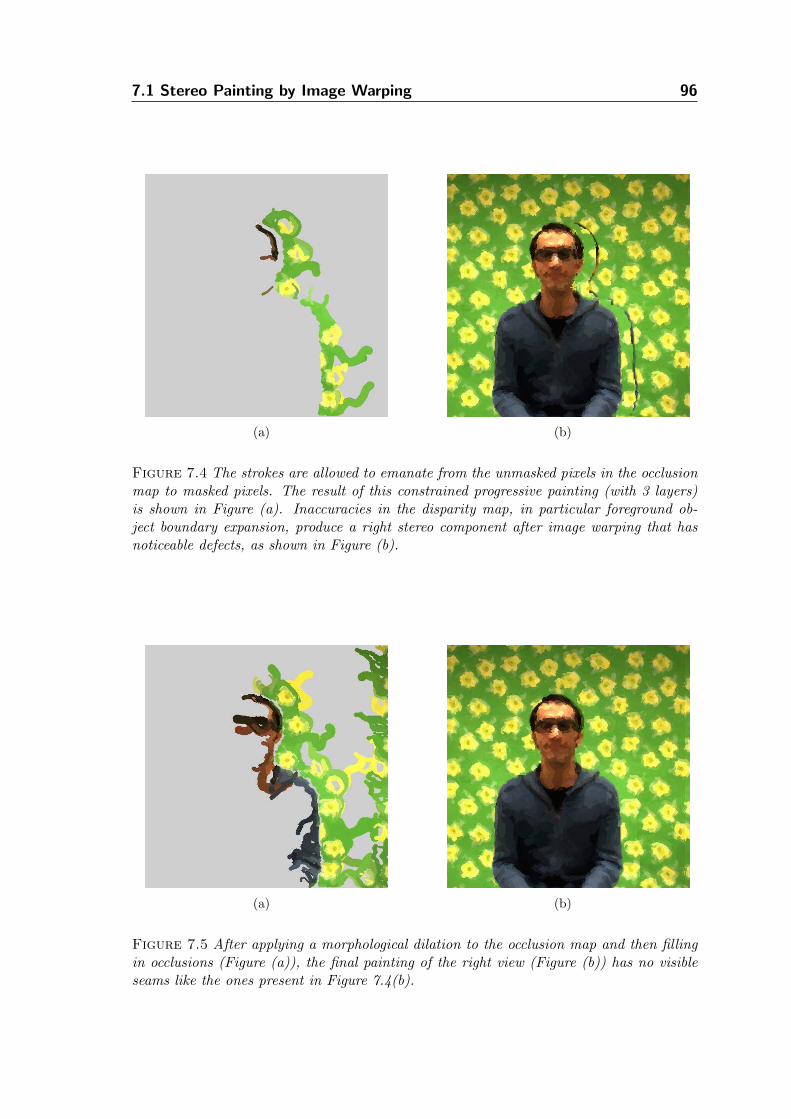
7.1 Stereo Painting by Image Warping 96
(a) (b)
Figure 7.4 The strokes are allowed to emanate from the unmasked pixels in the occlusionmap to masked pixels. The result of this constrained progressive painting (with 3 layers)is shown in Figure (a). Inaccuracies in the disparity map, in particular foreground ob-ject boundary expansion, produce a right stereo component after image warping that hasnoticeable defects, as shown in Figure (b).
(a) (b)
Figure 7.5 After applying a morphological dilation to the occlusion map and then fillingin occlusions (Figure (a)), the final painting of the right view (Figure (b)) has no visibleseams like the ones present in Figure 7.4(b).
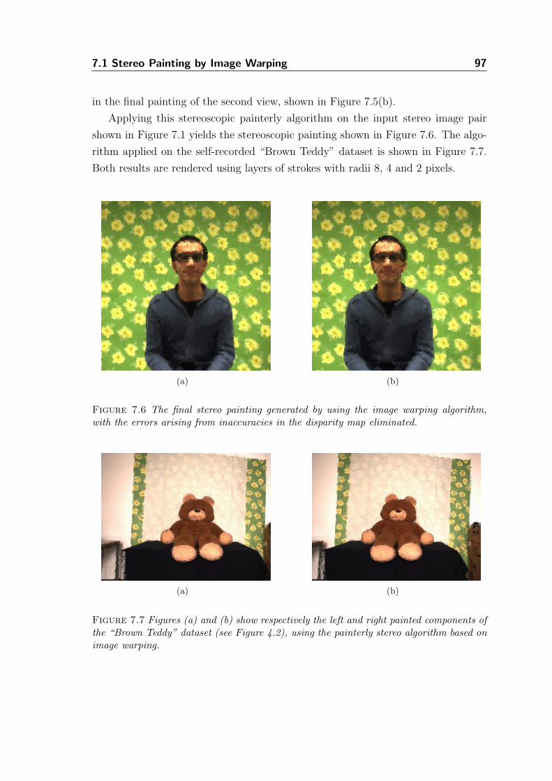
7.1 Stereo Painting by Image Warping 97
in the final painting of the second view, shown in Figure 7.5(b).
Applying this stereoscopic painterly algorithm on the input stereo image pair
shown in Figure 7.1 yields the stereoscopic painting shown in Figure 7.6. The algo-
rithm applied on the self-recorded “Brown Teddy” dataset is shown in Figure 7.7.
Both results are rendered using layers of strokes with radii 8, 4 and 2 pixels.
(a) (b)
Figure 7.6 The final stereo painting generated by using the image warping algorithm,with the errors arising from inaccuracies in the disparity map eliminated.
(a) (b)
Figure 7.7 Figures (a) and (b) show respectively the left and right painted components ofthe “Brown Teddy” dataset (see Figure 4.2), using the painterly stereo algorithm based onimage warping.
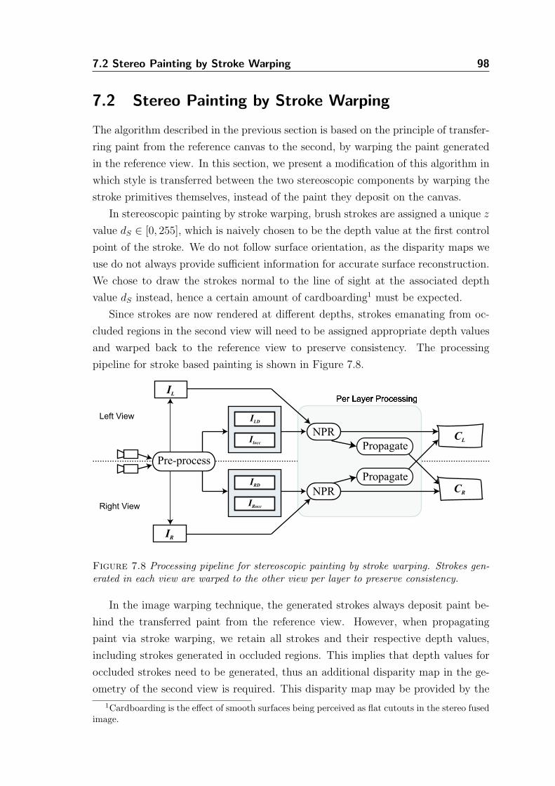
7.2 Stereo Painting by Stroke Warping 98
7.2 Stereo Painting by Stroke Warping
The algorithm described in the previous section is based on the principle of transfer-
ring paint from the reference canvas to the second, by warping the paint generated
in the reference view. In this section, we present a modification of this algorithm in
which style is transferred between the two stereoscopic components by warping the
stroke primitives themselves, instead of the paint they deposit on the canvas.
In stereoscopic painting by stroke warping, brush strokes are assigned a unique z
value dS ∈ [0, 255], which is naively chosen to be the depth value at the first control
point of the stroke. We do not follow surface orientation, as the disparity maps we
use do not always provide sufficient information for accurate surface reconstruction.
We chose to draw the strokes normal to the line of sight at the associated depth
value dS instead, hence a certain amount of cardboarding1 must be expected.
Since strokes are now rendered at different depths, strokes emanating from oc-
cluded regions in the second view will need to be assigned appropriate depth values
and warped back to the reference view to preserve consistency. The processing
pipeline for stroke based painting is shown in Figure 7.8.
CR
Left View
Right View
Pre-process
IL
IR
CL
Propagate
ILD
Ilocc
IRD
IRocc
Propagate
NPR
NPR
Figure 7.8 Processing pipeline for stereoscopic painting by stroke warping. Strokes gen-erated in each view are warped to the other view per layer to preserve consistency.
In the image warping technique, the generated strokes always deposit paint be-
hind the transferred paint from the reference view. However, when propagating
paint via stroke warping, we retain all strokes and their respective depth values,
including strokes generated in occluded regions. This implies that depth values for
occluded strokes need to be generated, thus an additional disparity map in the ge-
ometry of the second view is required. This disparity map may be provided by the
1Cardboarding is the effect of smooth surfaces being perceived as flat cutouts in the stereo fusedimage.
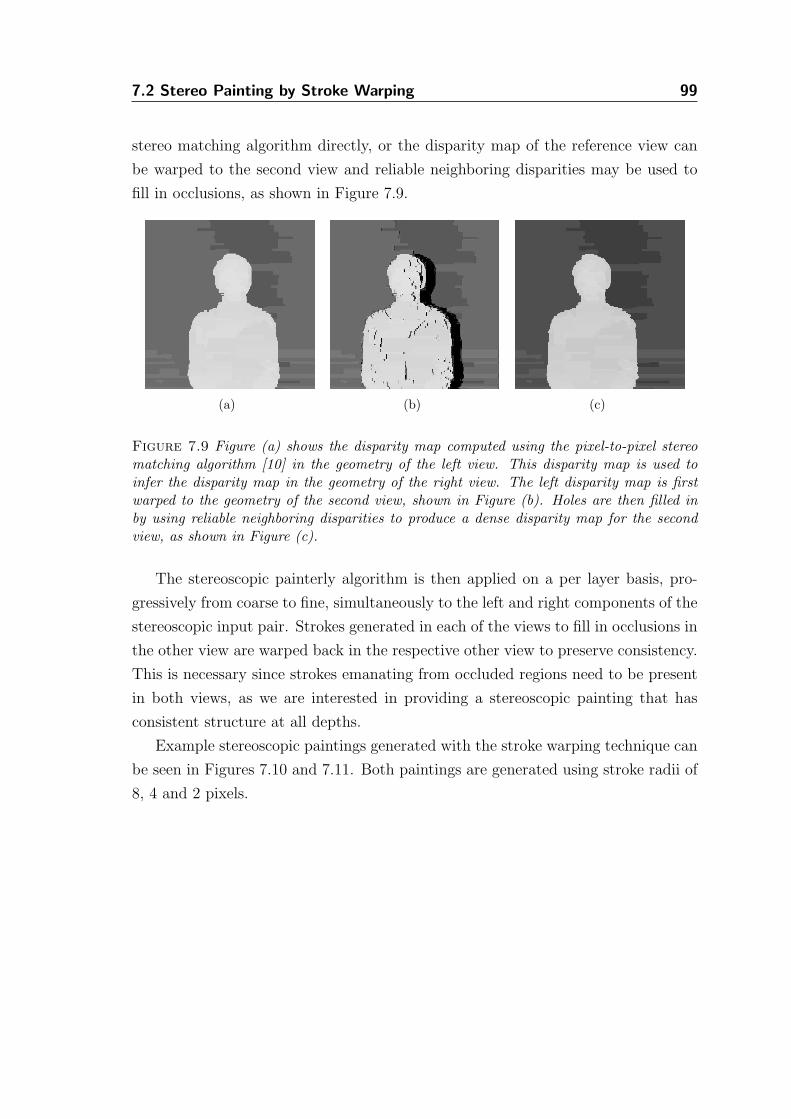
7.2 Stereo Painting by Stroke Warping 99
stereo matching algorithm directly, or the disparity map of the reference view can
be warped to the second view and reliable neighboring disparities may be used to
fill in occlusions, as shown in Figure 7.9.
(a) (b) (c)
Figure 7.9 Figure (a) shows the disparity map computed using the pixel-to-pixel stereomatching algorithm [10] in the geometry of the left view. This disparity map is used toinfer the disparity map in the geometry of the right view. The left disparity map is firstwarped to the geometry of the second view, shown in Figure (b). Holes are then filled inby using reliable neighboring disparities to produce a dense disparity map for the secondview, as shown in Figure (c).
The stereoscopic painterly algorithm is then applied on a per layer basis, pro-
gressively from coarse to fine, simultaneously to the left and right components of the
stereoscopic input pair. Strokes generated in each of the views to fill in occlusions in
the other view are warped back in the respective other view to preserve consistency.
This is necessary since strokes emanating from occluded regions need to be present
in both views, as we are interested in providing a stereoscopic painting that has
consistent structure at all depths.
Example stereoscopic paintings generated with the stroke warping technique can
be seen in Figures 7.10 and 7.11. Both paintings are generated using stroke radii of
8, 4 and 2 pixels.
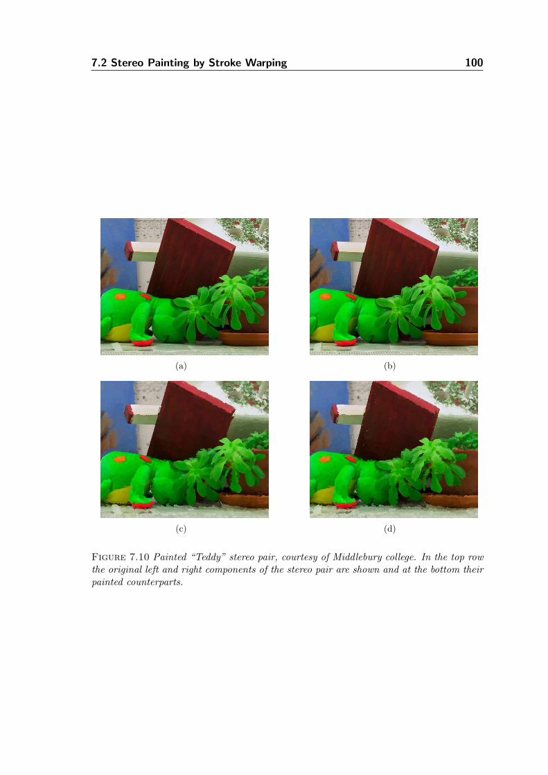
7.2 Stereo Painting by Stroke Warping 100
(a) (b)
(c) (d)
Figure 7.10 Painted “Teddy” stereo pair, courtesy of Middlebury college. In the top rowthe original left and right components of the stereo pair are shown and at the bottom theirpainted counterparts.
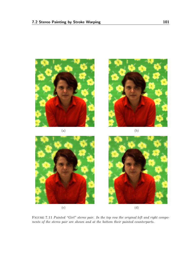
7.2 Stereo Painting by Stroke Warping 101
(a) (b)
(c) (d)
Figure 7.11 Painted “Girl” stereo pair. In the top row the original left and right compo-nents of the stereo pair are shown and at the bottom their painted counterparts.
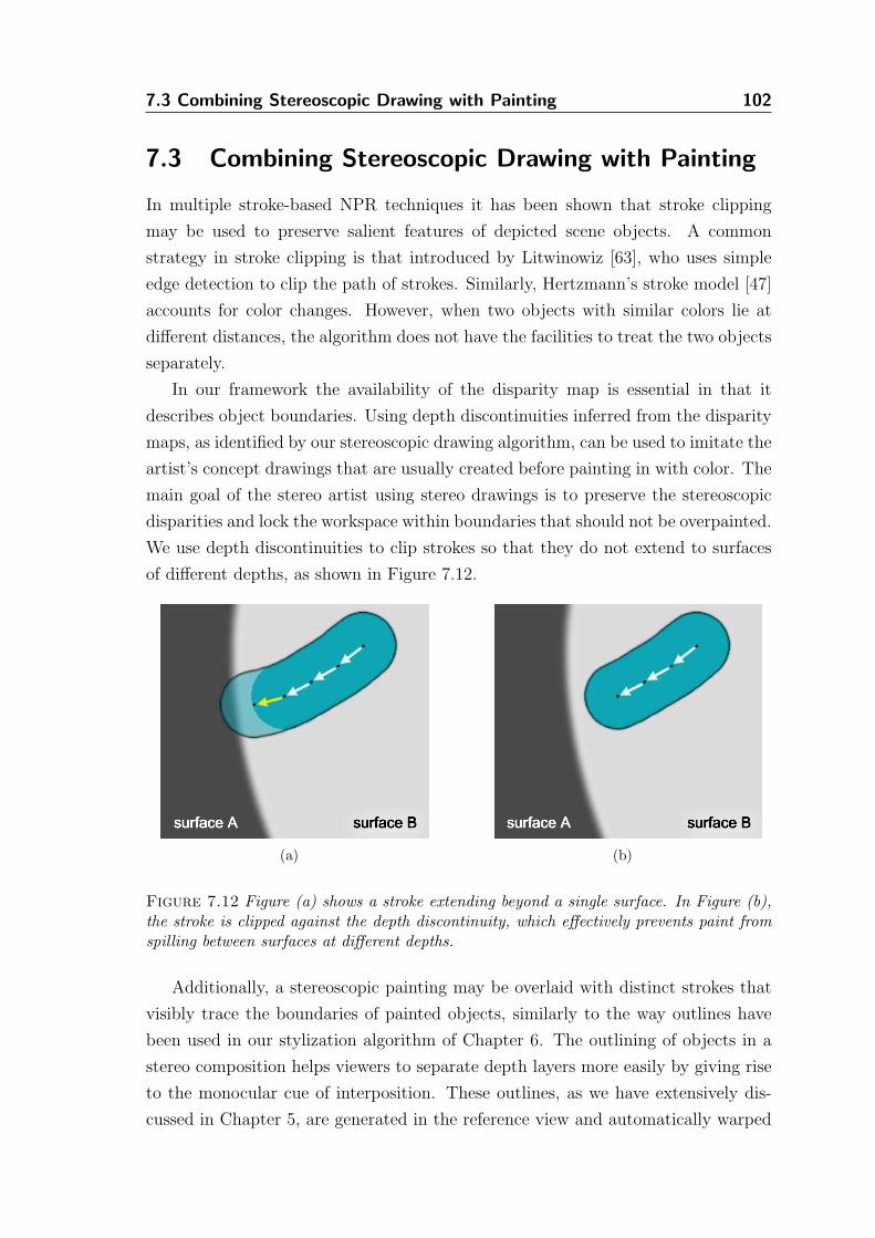
7.3 Combining Stereoscopic Drawing with Painting 102
7.3 Combining Stereoscopic Drawing with Painting
In multiple stroke-based NPR techniques it has been shown that stroke clipping
may be used to preserve salient features of depicted scene objects. A common
strategy in stroke clipping is that introduced by Litwinowiz [63], who uses simple
edge detection to clip the path of strokes. Similarly, Hertzmann’s stroke model [47]
accounts for color changes. However, when two objects with similar colors lie at
different distances, the algorithm does not have the facilities to treat the two objects
separately.
In our framework the availability of the disparity map is essential in that it
describes object boundaries. Using depth discontinuities inferred from the disparity
maps, as identified by our stereoscopic drawing algorithm, can be used to imitate the
artist’s concept drawings that are usually created before painting in with color. The
main goal of the stereo artist using stereo drawings is to preserve the stereoscopic
disparities and lock the workspace within boundaries that should not be overpainted.
We use depth discontinuities to clip strokes so that they do not extend to surfaces
of different depths, as shown in Figure 7.12.
(a) (b)
Figure 7.12 Figure (a) shows a stroke extending beyond a single surface. In Figure (b),the stroke is clipped against the depth discontinuity, which effectively prevents paint fromspilling between surfaces at different depths.
Additionally, a stereoscopic painting may be overlaid with distinct strokes that
visibly trace the boundaries of painted objects, similarly to the way outlines have
been used in our stylization algorithm of Chapter 6. The outlining of objects in a
stereo composition helps viewers to separate depth layers more easily by giving rise
to the monocular cue of interposition. These outlines, as we have extensively dis-
cussed in Chapter 5, are generated in the reference view and automatically warped
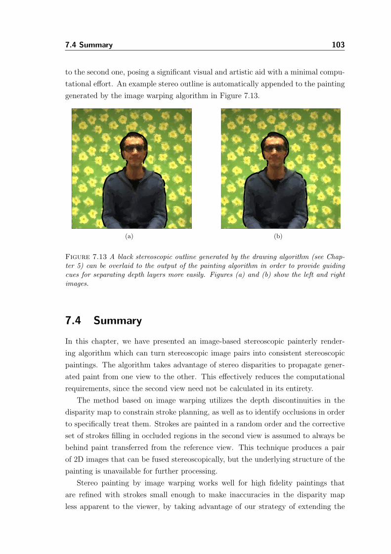
7.4 Summary 103
to the second one, posing a significant visual and artistic aid with a minimal compu-
tational effort. An example stereo outline is automatically appended to the painting
generated by the image warping algorithm in Figure 7.13.
(a) (b)
Figure 7.13 A black stereoscopic outline generated by the drawing algorithm (see Chap-ter 5) can be overlaid to the output of the painting algorithm in order to provide guidingcues for separating depth layers more easily. Figures (a) and (b) show the left and rightimages.
7.4 Summary
In this chapter, we have presented an image-based stereoscopic painterly render-
ing algorithm which can turn stereoscopic image pairs into consistent stereoscopic
paintings. The algorithm takes advantage of stereo disparities to propagate gener-
ated paint from one view to the other. This effectively reduces the computational
requirements, since the second view need not be calculated in its entirety.
The method based on image warping utilizes the depth discontinuities in the
disparity map to constrain stroke planning, as well as to identify occlusions in order
to specifically treat them. Strokes are painted in a random order and the corrective
set of strokes filling in occluded regions in the second view is assumed to always be
behind paint transferred from the reference view. This technique produces a pair
of 2D images that can be fused stereoscopically, but the underlying structure of the
painting is unavailable for further processing.
Stereo painting by image warping works well for high fidelity paintings that
are refined with strokes small enough to make inaccuracies in the disparity map
less apparent to the viewer, by taking advantage of our strategy of extending the
7.4 Summary 104
unmasked regions in the occlusion map. We then have modified the stereoscopic
painterly algorithm to warp strokes instead of the paint deposited by them. This
modification enables stereoscopic paintings that are consistent at all depths and
motivates the design of a slicing tool that can be used to examine the understructure
of a stereoscopic painting, as will be discussed in detail in Section 8.4.
We have finally shown that stereoscopic outlines may be utilized in stereoscopic
painterly rendering, either as an algorithmic aid (e.g. to clip strokes) or as stimuli
to assist the viewer’s visual system in separating the depth layers.
Chapter 8
Techniques for
Stereoscopic
Interactivity
To interact with the stereo artwork generated with the various algorithms presented
in the previous chapters, two modes of interactivity are introduced here and their
corresponding supportive user interfacing is described. The first mode of interac-
tivity built into our image-based stereoscopic non-photorealistic rendering system
enables users to manipulate the stereoscopic components to adjust the perceived
depth of the scene. The second mode provides the observer a set of unique tools for
exploring the structure of the automatically generated stereo artwork.
The two interaction methods allow a user to affect the look-and-feel of the art-
work in stereo. The interactive interface is very intuitive and easy to use. It provides
to non-expert users those tools required to explore the stereoscopic space occupied
by the stereo artwork within the stereoscopic space itself. By combining interac-
tion techniques of both modes, the artwork can be decomposed or explored by the
spectator, while simultaneously maintaining an eye-strain-free stereo display, which
further enhances the viewing experience.
8.1 Introduction
Recently, interactive stereoscopic techniques have become popular in 3D virtual and
augmented reality applications. Typically, such stereoscopic systems use tracking
to identify the position and orientation of the user’s head and then they utilize this
information to render accurately stereoscopic image pairs of the available virtual
geometric objects of the 3D scene. Users may be provided with a wide range of
tools to interact with the virtual worlds and can freely move within them, however
the complexity of these worlds is limited to the availability of 3D objects. As these
systems are primarily based on 3D geometry, while very flexible, they may not be
105
8.2 Manipulating Stereoscopic Space 106
ideal for 2D artists (e.g. painters). In addition, obtaining and maintaining virtual
and augmented reality systems is still quite costly and thus less appealing for the
end-user (artist or art enthusiast).
Advances in image-based modeling and rendering may eventually enable digital
artists to use photographic images instead of 3D models as their raw material.
Nevertheless, the rapidly expanding areas of automatic stereoscopic image synthesis
and analysis cannot alone lead artists to adopt stereoscopy as an artistic medium,
neither their audiences may find the automatically generated content satisfactory.
Enhancing interactivity in the process of image-based artistic stereoscopic content
generation, as well as visualization, may be a key to the wider use of stereoscopy in
arts.
Along this line of investigation, we describe a number of interactive methods
and tools that can be used within an image-based rendering system to inspect and
interact with digital computer-generated stereoscopic artworks. First, we outline
the use of horizontal image translation as a way of manipulating stereoscopic space,
while preventing frame cancellation. We then describe an image-based method for
rendering stereoscopic cursors and show how the method can be applied to provide
a simple stereoscopic pointer, as well as a stereoscopic magnifying glass. Finally, we
provide a description of the spatial arrangement of artwork generated in our system,
which enables us to provide a special interactive tool that can be used to peel away
layers of the artwork which are at different distances.
8.2 Manipulating Stereoscopic Space
Basic interaction with a real three-dimensional scene, using only a single stereo-
scopic image pair, does not require expensive and complicated-to-setup virtual real-
ity equipment. Instead, standard stereoscopic graphics hardware can be used (i.e. a
graphics card capable of stereoscopic rendering and a pair of active stereo shutter
glasses). The level of interactivity possible is, of course, limited when compared
to complete 3D systems. This can be partially compensated by inferring geometric
attributes of the depicted scene objects, without however attempting to fully re-
construct and segment the scene’s objects. In our system, we use disparity maps
as auxiliary data both by the NPR stereo algorithms, as well as by the interactive
methods described in this section.
8.2 Manipulating Stereoscopic Space 107
8.2.1 Frame Cancellation
A common problem when viewing stereo image pairs arises when binocular disparity
is incompatible with an overlap cue to depth. The most common example of this is
when the frame of the presentation window, within the digital display, perceptually
occludes an object that has negative disparity. This means that the object’s stereo
depth provides the viewer’s visual system the sensation that it is located not on or
behind the display, but in front of it. As, however, the frame is always at the plane of
zero parallax, which coincides with the physical surface of the display, the occlusion
of the object by the frame signals to the viewer that the frame is in front of the
displayed object. Then the two contradicting depth cues of binocular disparity and
overlap are handed down to the visual system which resolves the conflict usually by
dropping the information provided by disparity and favoring that of overlap alone, a
typical case of depth cue dominance [50]. This conflict is sometimes also referred to
as frame cancellation and is tightly related to the breakdown of stereopsis. Various
researchers have proposed algorithms that dynamically prevent frame cancellation,
mainly by selecting viewpoints that do not let objects intersect with the frame
around the display area.
Treating this very problem of conflicting overlap and disparity cues in stereo im-
ages and sequences, McVeigh et al. [72] proposed an algorithm that applies horizon-
tal image translation according to a statistical analysis of the disparity information
present in the image pairs. Their approach, however, is to always ensure that all per-
ceived points lie on or behind the screen, without considering the tremendous depth
sensation provided by scene objects appearing between the user and the physical
display. For instance, consider the case of an object’s left and right stereo pro-
jections that do not intersect the presentation frame but have negative disparities.
Perceptually, bringing this object behind the display may not always be as engaging
as allowing it to float in space in front of the display. In fact, features protruding
the plane of zero parallax give a sense of presence in the perceived 3D environment,
while scenes perceptually behind the display provide a feeling of looking through a
window.
Ware et al. [123] also provide insight on how to automatically adjust the pa-
rameters of a stereo display for optimal stereo viewing. Their algorithm is targeted
toward virtual scenes where the scene is generated by the computer and is contin-
uously changing. In contrast, our content is mostly static and our goal is to allow
the user to intuitively adjust the parameters of the stereo system in order to bring
features of his liking behind, on, or in front of the display. While very similar in con-
cept, Ware et al. [123] perform false-eye separation and not image shifting. Many of
8.2 Manipulating Stereoscopic Space 108
the ideas and results of their user studies can be taken into consideration in our case
too, however, the practical implementation cannot be adapted. The main reason
is that the viewpoints in our case are precalculated and fixed, while most false-eye
separation algorithms strive to select the optimal separation between the viewpoints
for a given scene and use it to render the two stereo projections from.
In his doctoral dissertation, Wartell [124] discusses various problems that arise
when using stereoscopic head-tracked displays and describes fusion control algo-
rithms that can be used to counter them. In our work, the stereoscopic display
system is based on static stimuli and not all techniques are meaningful in this con-
text. However, of particular interest is the image shifting technique presented by
Wartell, in which the two image projections are translated either closer or further
away from each other in order to bring the perceived frustum at a certain distance
from the observer.
Bringing these ideas together, we let the user of our stereoscopic system interac-
tively change the separation of the two projections by horizontally translating the
two components. At the most basic form, we allow the user to provide input via the
keyboard to increase or decrease the separation of the stereo images. We define hor-
izontal image translation as a pair of translation vectors (~tL and ~tR), always parallel
to the x-axis, whose magnitudes are equal, but their directions opposite (~tR = −~tL).
The two image planes are of the same size (width×height) and, when viewed in
our system, they are both centered at (width2, height
2), with initial values of ~tL = ~tR = 0.
A positive value of horizontal image translation denotes that the two image planes,
left and right, are moving toward each other, otherwise further apart.
8.2.2 Horizontal Image Translation
We found empirically that in most cases users of the stereoscopic viewing system
tend to set a horizontal image translation that perceptually brings scene objects
in front of the screen rather than behind it, but only if frame cancellation would
not occur. Driven by this observation, instead of always positioning the two stereo
images so that |~t| = 0, we adjust the viewing parameters of the system so that
an optimal horizontal image translation is calculated by processing the available
disparity information of the current image pair. Optimality is considered in regards
to the initial goal of preventing frame cancellation.
The algorithm does not set all scene points behind the frame, as other techniques
do. Instead it scans the border of the disparity map associated with the reference
view of the stereo pair for the maximum disparity value. The width of the border
can be set as a user parameter. This maximum disparity value is converted to
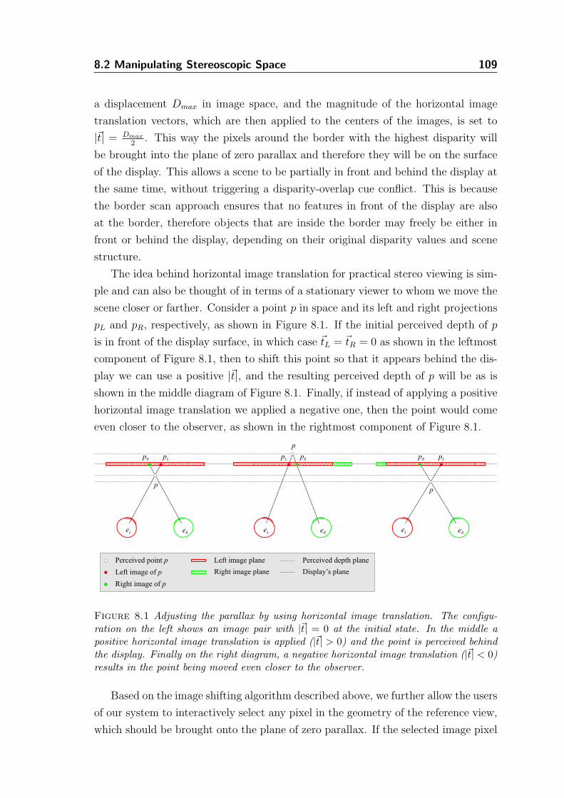
8.2 Manipulating Stereoscopic Space 109
a displacement Dmax in image space, and the magnitude of the horizontal image
translation vectors, which are then applied to the centers of the images, is set to
|~t| = Dmax
2. This way the pixels around the border with the highest disparity will
be brought into the plane of zero parallax and therefore they will be on the surface
of the display. This allows a scene to be partially in front and behind the display at
the same time, without triggering a disparity-overlap cue conflict. This is because
the border scan approach ensures that no features in front of the display are also
at the border, therefore objects that are inside the border may freely be either in
front or behind the display, depending on their original disparity values and scene
structure.
The idea behind horizontal image translation for practical stereo viewing is sim-
ple and can also be thought of in terms of a stationary viewer to whom we move the
scene closer or farther. Consider a point p in space and its left and right projections
pL and pR, respectively, as shown in Figure 8.1. If the initial perceived depth of p
is in front of the display surface, in which case ~tL = ~tR = 0 as shown in the leftmost
component of Figure 8.1, then to shift this point so that it appears behind the dis-
play we can use a positive |~t|, and the resulting perceived depth of p will be as is
shown in the middle diagram of Figure 8.1. Finally, if instead of applying a positive
horizontal image translation we applied a negative one, then the point would come
even closer to the observer, as shown in the rightmost component of Figure 8.1.
Perceived point p
Right image of p
Left image of p Right image plane
Left image plane
pR
eL
pL
eR
p
eL eR
pR pL
p
eL eR
pR pL
p
Perceived depth plane
Display’s plane
Figure 8.1 Adjusting the parallax by using horizontal image translation. The configu-ration on the left shows an image pair with |~t| = 0 at the initial state. In the middle apositive horizontal image translation is applied (|~t| > 0) and the point is perceived behindthe display. Finally on the right diagram, a negative horizontal image translation (|~t| < 0)results in the point being moved even closer to the observer.
Based on the image shifting algorithm described above, we further allow the users
of our system to interactively select any pixel in the geometry of the reference view,
which should be brought onto the plane of zero parallax. If the selected image pixel
8.3 Stereoscopic Cursors 110
is iL and its disparity is DiL , then we apply horizontal image translation vectors with
a magnitude of |~t| =DiL
2. Interactivity provided via a pointing device, in contrast to
the keyboard or automatic initial adjustment of image separation, has two further
shortcomings that should be carefully considered. First, as the user interacts with
the resulting artwork of the system, without seeing the disparity map, the image
plane of the reference view will cease to correspond with the image plane of the
disparity map. Care must be taken so that the coordinates of the user’s pointer are
mapped into the coordinate system of the reference image plane, so that they can be
successfully used to retrieve the disparity value of the selected pixel in the disparity
map1.
The second problem is related to the speed of applying the horizontal image
translation vectors. Ware et al. [123] performed user studies which are particularly
interesting in this context. They reveal that dynamic changes in eye separation
should not be rapid, so that the visual system of the viewer can adapt to the new
depth information without an abrupt readjustment of the human sensory facilities
that could cause them to perceptually exit the virtual world. They report that a low
rate of change is an acceptable speed for adjusting the separation of the viewpoints
gradually. In our case we set this rate to a predefined default value, and let users
adjust it. The difference in our approach is that we are not changing the virtual eye
separation, but the image separation. Since we do not have any information about
the visual system of the observer and the display hardware, the rate of change
that is acceptable and comfortable will depend on the size of the images and the
viewing configuration. Instead of directly applying the translation vector described
earlier, we perform this change over a period of time using linear interpolation, which
provides a smooth unnoticeable adjustment of the overall position of the scene in
depth.
8.3 Stereoscopic Cursors
Commonly used cursors in most computer applications do not provide a perceptu-
ally sound mechanism for interaction with stereoscopic image pairs. When stereo
pairs are overlaid with a standard monoscopic cursor, which is rendered at the same
position in both views, then the cursor always appears to be at the plane of zero
parallax. This is particularly inappropriate when the cursor is moved over opaque
1This is important when rendering with OpenGL’s stereo buffers in a standard widget’s window.Most window managers will only be able to supply the user’s pointer coordinates in the coordinatesystem of the widget and not in the image planes’ displayed within it. Normally one should remapthese coordinates to identify the pixel location the user has selected.
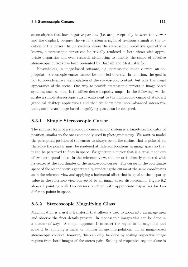
8.3 Stereoscopic Cursors 111
scene objects that have negative parallax (i.e. are perceptually between the viewer
and the display), because the visual system is signaled rivalrous stimuli at the lo-
cation of the cursor. In 3D systems where the stereoscopic projective geometry is
known, a stereoscopic cursor can be trivially rendered in both views with appro-
priate disparities and even research attempting to identify the shape of effective
stereoscopic cursors has been presented by Barham and McAllister [5].
Nevertheless, in image-based software, e.g. stereoscopic image viewers, an ap-
propriate stereoscopic cursor cannot be modeled directly. In addition, the goal is
not to provide active manipulation of the stereoscopic content, but only the visual
appearance of the scene. One way to provide stereoscopic cursors in image-based
systems, such as ours, is to utilize dense disparity maps. In the following, we de-
scribe a simple stereoscopic cursor equivalent to the monoscopic cursor of standard
graphical desktop applications and then we show how more advanced interactive
tools, such as an image-based magnifying glass, can be designed.
8.3.1 Simple Stereoscopic Cursor
The simplest form of a stereoscopic cursor in our system is a target-like indicator of
position, similar to the ones commonly used in photogrammetry. We want to model
the perceptual position of the cursor to always be on the surface that is pointed at,
therefore the pointer must be rendered at different locations in image space so that
it can be perceived to float in space. We generate a cursor that is a cross made out
of two orthogonal lines. In the reference view, the cursor is directly rendered with
its center at the coordinates of the monoscopic cursor. The cursor in the coordinate
space of the second view is generated by rendering the cursor at the same coordinates
as in the reference view and applying a horizontal offset that is equal to the disparity
value in the reference view converted to an image space displacement. Figure 8.2
shows a painting with two cursors rendered with appropriate disparities for two
different points in space.
8.3.2 Stereoscopic Magnifying Glass
Magnification is a useful transform that allows a user to zoom into an image area
and observe the finer details present. In monoscopic images this can be done in
a number of ways. A simple approach is to select the region to be magnified and
scale it by applying a linear or bilinear image interpolation. In an image-based
stereoscopic context, however, this can only be done by scaling respective image
regions from both images of the stereo pair. Scaling of respective regions alone is
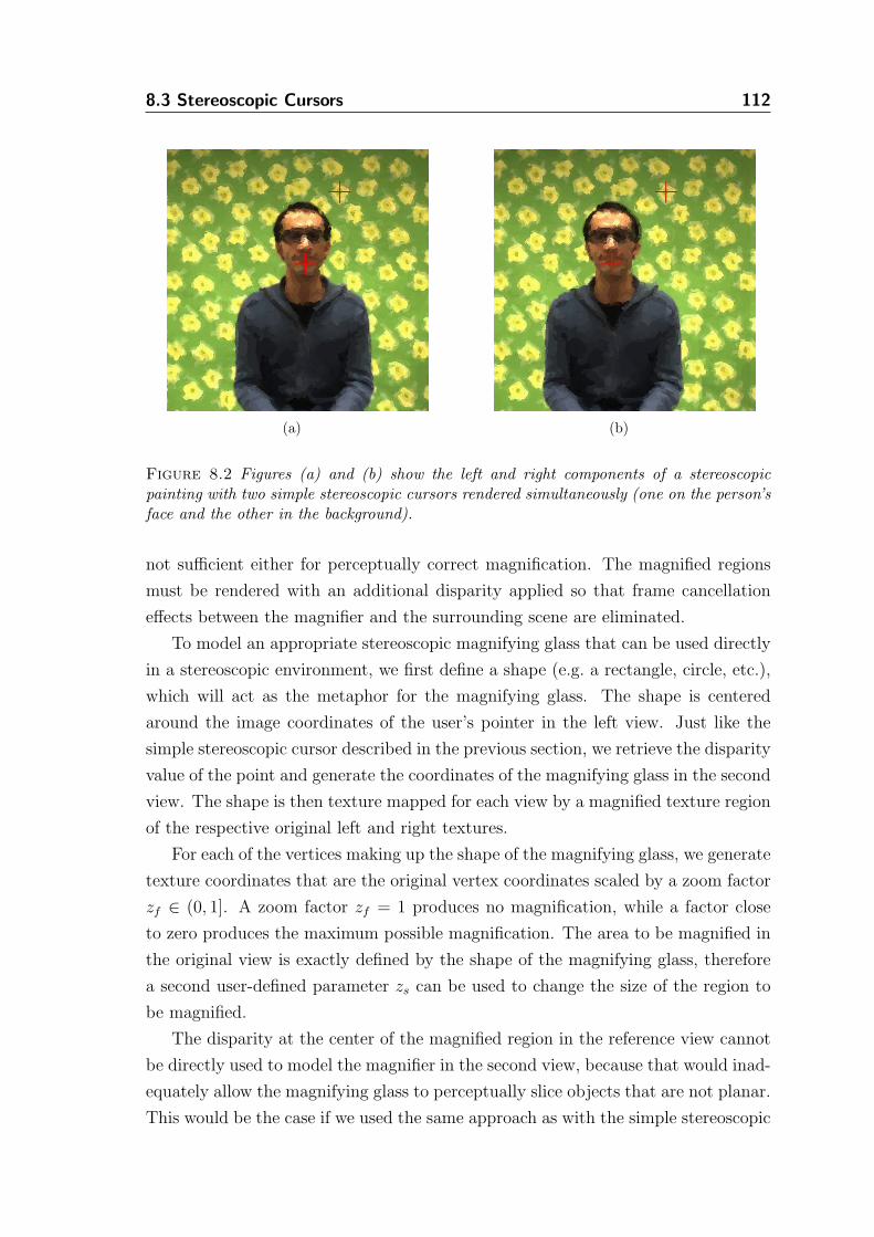
8.3 Stereoscopic Cursors 112
(a) (b)
Figure 8.2 Figures (a) and (b) show the left and right components of a stereoscopicpainting with two simple stereoscopic cursors rendered simultaneously (one on the person’sface and the other in the background).
not sufficient either for perceptually correct magnification. The magnified regions
must be rendered with an additional disparity applied so that frame cancellation
effects between the magnifier and the surrounding scene are eliminated.
To model an appropriate stereoscopic magnifying glass that can be used directly
in a stereoscopic environment, we first define a shape (e.g. a rectangle, circle, etc.),
which will act as the metaphor for the magnifying glass. The shape is centered
around the image coordinates of the user’s pointer in the left view. Just like the
simple stereoscopic cursor described in the previous section, we retrieve the disparity
value of the point and generate the coordinates of the magnifying glass in the second
view. The shape is then texture mapped for each view by a magnified texture region
of the respective original left and right textures.
For each of the vertices making up the shape of the magnifying glass, we generate
texture coordinates that are the original vertex coordinates scaled by a zoom factor
zf ∈ (0, 1]. A zoom factor zf = 1 produces no magnification, while a factor close
to zero produces the maximum possible magnification. The area to be magnified in
the original view is exactly defined by the shape of the magnifying glass, therefore
a second user-defined parameter zs can be used to change the size of the region to
be magnified.
The disparity at the center of the magnified region in the reference view cannot
be directly used to model the magnifier in the second view, because that would inad-
equately allow the magnifying glass to perceptually slice objects that are not planar.
This would be the case if we used the same approach as with the simple stereoscopic
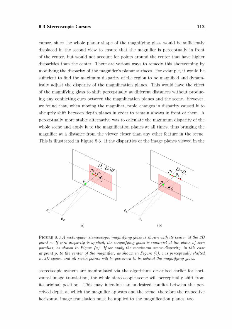
8.3 Stereoscopic Cursors 113
cursor, since the whole planar shape of the magnifying glass would be sufficiently
displaced in the second view to ensure that the magnifier is perceptually in front
of the center, but would not account for points around the center that have higher
disparities than the center. There are various ways to remedy this shortcoming by
modifying the disparity of the magnifier’s planar surfaces. For example, it would be
sufficient to find the maximum disparity of the region to be magnified and dynam-
ically adjust the disparity of the magnification planes. This would have the effect
of the magnifying glass to shift perceptually at different distances without produc-
ing any conflicting cues between the magnification planes and the scene. However,
we found that, when moving the magnifier, rapid changes in disparity caused it to
abruptly shift between depth planes in order to remain always in front of them. A
perceptually more stable alternative was to calculate the maximum disparity of the
whole scene and apply it to the magnification planes at all times, thus bringing the
magnifier at a distance from the viewer closer than any other feature in the scene.
This is illustrated in Figure 8.3. If the disparities of the image planes viewed in the
cp
pL
pR
eR
eL
DD=0
p
(a)
c
p
pL
pR
eR
eL
D=Dz
(b)
Figure 8.3 A rectangular stereoscopic magnifying glass is shown with its center at the 3Dpoint c. If zero disparity is applied, the magnifying glass is rendered at the plane of zeroparallax, as shown in Figure (a). If we apply the maximum scene disparity, in this caseat point p, to the center of the magnifier, as shown in Figure (b), c is perceptually shiftedin 3D space, and all scene points will be perceived to be behind the magnifying glass.
stereoscopic system are manipulated via the algorithms described earlier for hori-
zontal image translation, the whole stereoscopic scene will perceptually shift from
its original position. This may introduce an undesired conflict between the per-
ceived depth at which the magnifier appears and the scene, therefore the respective
horizontal image translation must be applied to the magnification planes, too.
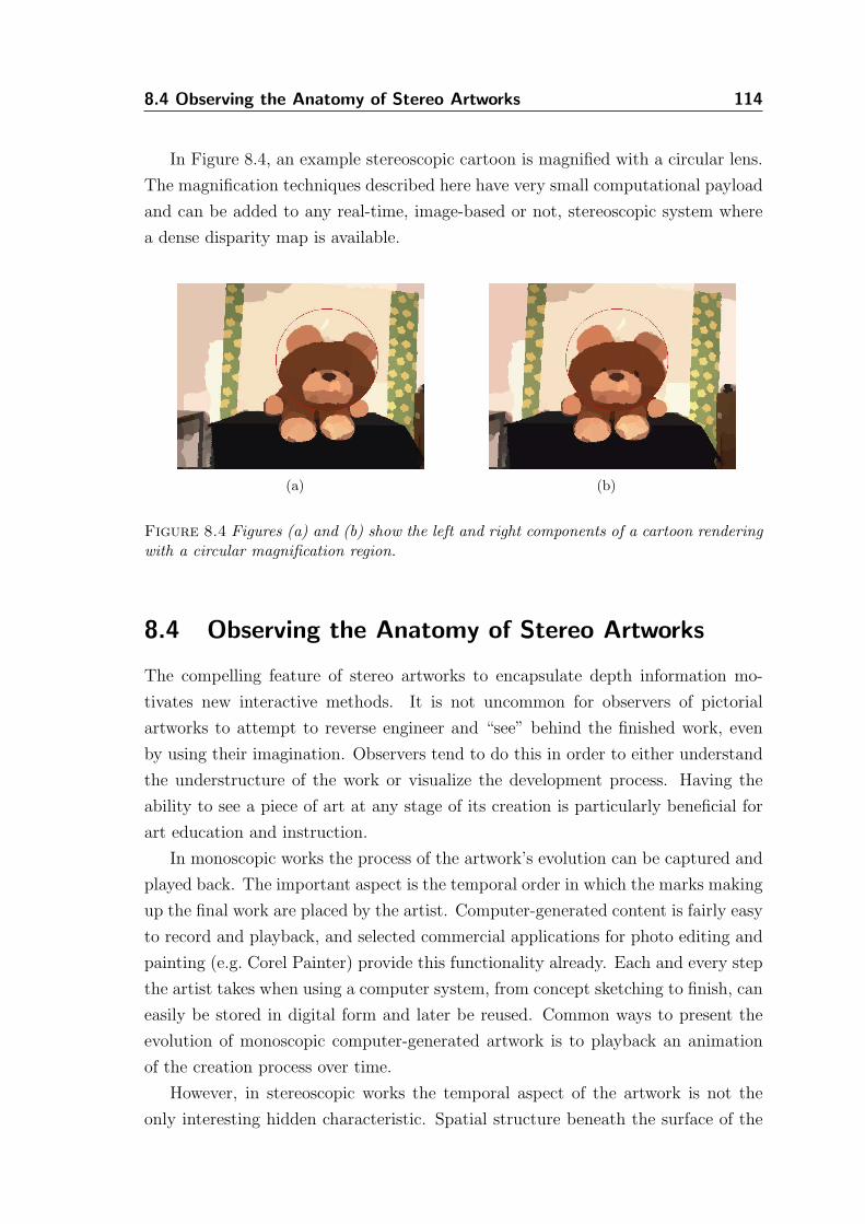
8.4 Observing the Anatomy of Stereo Artworks 114
In Figure 8.4, an example stereoscopic cartoon is magnified with a circular lens.
The magnification techniques described here have very small computational payload
and can be added to any real-time, image-based or not, stereoscopic system where
a dense disparity map is available.
(a) (b)
Figure 8.4 Figures (a) and (b) show the left and right components of a cartoon renderingwith a circular magnification region.
8.4 Observing the Anatomy of Stereo Artworks
The compelling feature of stereo artworks to encapsulate depth information mo-
tivates new interactive methods. It is not uncommon for observers of pictorial
artworks to attempt to reverse engineer and “see” behind the finished work, even
by using their imagination. Observers tend to do this in order to either understand
the understructure of the work or visualize the development process. Having the
ability to see a piece of art at any stage of its creation is particularly beneficial for
art education and instruction.
In monoscopic works the process of the artwork’s evolution can be captured and
played back. The important aspect is the temporal order in which the marks making
up the final work are placed by the artist. Computer-generated content is fairly easy
to record and playback, and selected commercial applications for photo editing and
painting (e.g. Corel Painter) provide this functionality already. Each and every step
the artist takes when using a computer system, from concept sketching to finish, can
easily be stored in digital form and later be reused. Common ways to present the
evolution of monoscopic computer-generated artwork is to playback an animation
of the creation process over time.
However, in stereoscopic works the temporal aspect of the artwork is not the
only interesting hidden characteristic. Spatial structure beneath the surface of the
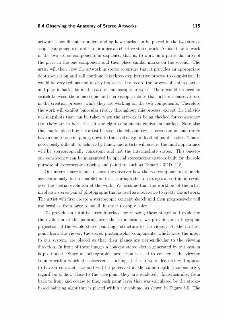
8.4 Observing the Anatomy of Stereo Artworks 115
artwork is significant in understanding how marks can be placed in the two stereo-
scopic components in order to produce an effective stereo work. Artists tend to work
in the two stereo components in sequence; that is, to work on a particular area of
the piece in the one component and then place similar marks on the second. The
artist will then view the artwork in stereo to ensure that it provides an appropriate
depth sensation and will continue this three-step iterative process to completion. It
would be very tedious and mostly impractical to record the process of a stereo artist
and play it back like in the case of monoscopic artwork. There would be need to
switch between the monoscopic and stereoscopic modes that artists themselves use
in the creation process, while they are working on the two components. Therefore
the work will exhibit binocular rivalry throughout this process, except the individ-
ual snapshots that can be taken when the artwork is being checked for consistency
(i.e. there are in both the left and right components equivalent marks). Note also
that marks placed by the artist between the left and right stereo components rarely
have a one-to-one mapping, down to the level of e.g. individual paint strokes. This is
notoriously difficult to achieve by hand, and artists will ensure the final appearance
will be stereoscopically consistent and not the intermediate states. This one-to-
one consistency can be guaranteed by special stereoscopic devices built for the sole
purpose of stereoscopic drawing and painting, such as Tamari’s 3DD [115].
Our interest here is not to show the observer how the two components are made
asynchronously, but to enable him to see through the artist’s eyes at certain intervals
over the spatial evolution of the work. We assume that the workflow of the artist
involves a stereo pair of photographs that is used as a reference to create the artwork.
The artist will first create a stereoscopic concept sketch and then progressively will
use brushes, from large to small, in order to apply color.
To provide an intuitive user interface for viewing these stages and exploring
the evolution of the painting over the z-dimension, we provide an orthographic
projection of the whole stereo painting’s structure to the viewer. At the farthest
point from the viewer, the stereo photographic components, which were the input
to our system, are placed so that their planes are perpendicular to the viewing
direction. In front of these images a concept stereo sketch generated by our system
is positioned. Since an orthographic projection is used to construct the viewing
volume within which the observer is looking at the artwork, features will appear
to have a constant size and will be perceived at the same depth (monocularly),
regardless of how close to the viewpoint they are rendered. Incrementally, from
back to front and coarse to fine, each paint layer that was calculated by the stroke-
based painting algorithm is placed within the volume, as shown in Figure 8.5. The
8.4 Observing the Anatomy of Stereo Artworks 116
volume will then be sliced using a clipping plane in order to allow the viewer to see
behind the finer strokes that occlude rougher strokes which are positioned further
at the back.
Figure 8.5 A third-person view of the left component of a stereo painting with three layers.The user looks from the eye position. A consistent right view is calculated for the othereye.
The viewing volume used to render the stereo artwork within is of W ×H ×D
dimensions and the eyes are at the plane where z = 0. The W × H dimensions
of the frustum correspond to the size of the stereoscopic images used throughout
the algorithmic processing. Recall that each stroke of an individual layer has an
associated depth value dS that is guaranteed to be within a range of [0, 255], with 255
being closer to the viewpoint. However, strokes usually fall within a smaller range.
We scale this subrange linearly so that depth values of strokes occupy the whole
[0, 255] range. This helps to increase the distance between strokes, because many
scenes have a limited amount of depth and therefore strokes at different depths are
usually densely distributed inside a smaller range of depth values. The motivation
for this scaling is to increase the z-resolution of the paintings and allow the clipping
plane to travel more distance between the strokes of an individual layer, providing
easier control of the clipping plane to the end-user.
The overall depth D of the volume is calculated according to the amount of
layers that are to be displayed within it, and an additional offset value for spacing
the layers can also be applied. If there are N layers then D = N(256+offset). This
ensures that the viewing frustum is sufficiently sized to accommodate all layers. If
the roughest layer is considered to have an index n = 0 and for any refining layers
n is incremented, then the overall z-position of each stroke SZ of each layer can be
8.5 Discussion 117
trivially calculated as SZ = (256 + offset)(N − n) − dS. If we have not spaced
apart the refining layers, then their differently sized strokes would be at the same
distance from the viewer. Therefore, it would not be possible to use 3D clipping to
toggle the visibility of individual strokes and, hence, slicing would not be intuitive.
For instance consider the stereo image pair shown in Figures 8.6(a) and (b).
When painted using three painting layers (N = 3), the stereo components are ar-
ranged as shown in Figure 8.5. The clipping plane provided to the user can be
interactively shifted along the z-axis. Strokes that are between the viewpoint and
the clipping plane are hidden, allowing the rougher layers to be seen. A slice through
the painting can be seen in Figures 8.6(c) and 8.6(d). Clipping is equivalently per-
formed in both the left and right stereo components and, since at every depth plane
the visibility of the stereo primitives is consistently toggled, a stereo impression of
the understructure can be perceived.
8.5 Discussion
The set of interactive methods described in this chapter aim to enrich the user’s
experience when viewing the stereoscopic content generated by our algorithms.
The implemented system is capable of self-adjusting some of its parameters
according to predefined goals, such as preventing frame cancellation, but it can-
not provide personalized stereoscopic viewing conditions without user interaction.
Therefore simple interactive tools for manipulation and inspection of scene depth,
as described in Section 8.2, can be an effective way to enable the end user to alter
the stereoscopic content as desired. This level of interactivity is particularly useful
in our image-based stereoscopic NPR system, since the system itself is agnostic of
the potential end user’s position relative to the viewing display. Thus, for example,
it cannot predict the amount of horizontal image translation that would be more
appealing for a given user. In addition, the stereoscopic cursor and the stereoscopic
magnifying glass are means of inspecting the generated renditions, while the paint
slicing tool demonstrates one of many possible mechanisms to allow a user to go
beyond the traditional passive stereoscopic viewing of stereo artwork.
In essence, the collection of these tools allows the user to explore the stereo-
scopic space occupied by the stereo artwork within the stereoscopic space itself. By
combining interaction techniques of both modes, i.e. manipulation and inspection,
the artwork can be decomposed or explored by the spectator, while simultaneously
maintaining an eye-strain-free stereo display, which further enhances the viewing
experience.
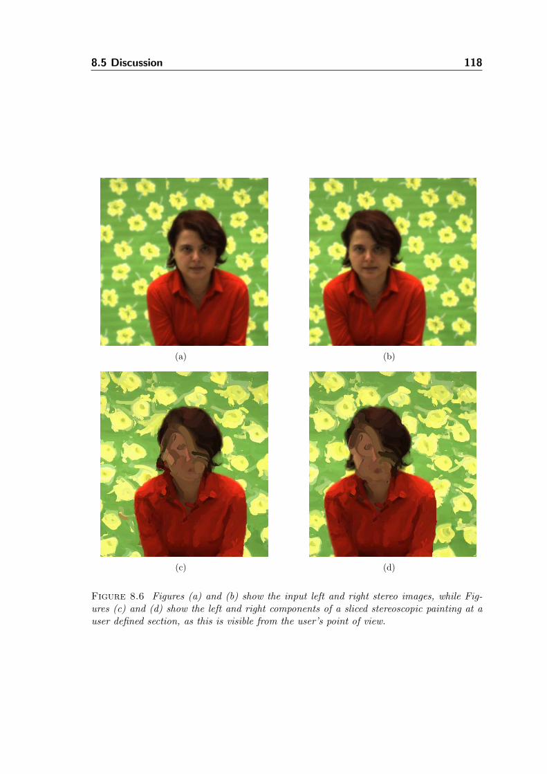
8.5 Discussion 118
(a) (b)
(c) (d)
Figure 8.6 Figures (a) and (b) show the input left and right stereo images, while Fig-ures (c) and (d) show the left and right components of a sliced stereoscopic painting at auser defined section, as this is visible from the user’s point of view.
Chapter 9
Conclusions
9.1 Summary
In this dissertation we have combined computer graphics and computer vision tech-
niques to propose a set of algorithms that can be used to transform stereoscopic
images into stereoscopic pictures resembling artwork, including stereoscopic draw-
ings, cartoons and paintings.
We start with a thorough inquiry into the area of stereoscopic fine arts (Chap-
ter 2) that collects vital information for understanding the techniques used by tradi-
tional artists. Several problems and drawbacks surrounding the creation and viewing
of stereoscopic artwork by hand have been identified. The ability of the medium to
engage the observer into a world of spatial aesthetics and its profound advantage
of effectively communicating depth information over other traditional visual media
have been exposed and discussed.
In Chapter 3, we review relevant work in computer science, which is later com-
bined with the knowledge drawn from our research in stereoscopy and fine arts. The
outcome of this combination is a framework (Chapter 4) that captures a number
of issues (e.g. feature correspondence, randomness, etc.), which arise within the
context of applying stereoscopically Non-Photorealistic Rendering algorithms.
In the subsequent chapters we have shown that image-based stereoscopic render-
ing can be blended with NPR techniques to tackle the difficult problem of creating
non-conventional stereoscopic imagery. We first presented a stereoscopic drawing
algorithm (Chapter 5) that provides a basis for generating preliminary drawings.
The stereoscopic lines generated by this algorithm describe rapid depth changes
that provide the observer with silhouette cues, which particularly hint and assist
the visual system to separate depth layers in a scene. We have demonstrated three
main utilities of these stereoscopic drawings: (a) they can be used independently
in any application requiring stereoscopic outlines that describe depth changes, (b)
they can form the basis for more elaborate artworks, and (c) they can be utilized as
a clipping mechanism together with other stereoscopic NPR algorithms to prevent
depth discontinuity overruns.
119
9.1 Summary 120
The stereoscopic stylization algorithm of Chapter 6 demonstrates how purely
computer vision techniques (e.g. image segmentation) can be used to preserve con-
sistency across a synthesized stereo pair of pictures, while simultaneously stylizing
colors. The designed algorithm may be used to assist the production of stereoscopic
cartoons from real footage.
In Chapter 7, the techniques proposed to tackle stereoscopic painting show how
existing NPR algorithms can be adapted to stereoscopy. Stereoscopic paintings can
be very challenging to generate interactively, thus we propose simulating the painting
process by taking into consideration the additional information provided by the use
of stereoscopic images as an input. In particular, stroke-based rendering is adapted
to account for depth discontinuities, to ensure consistent painting of the two views,
as well as consistent generation of texture in occluded regions.
The proposed techniques generate output that can be presented as flat 2D images,
or it can be spread over the z-dimension to enable interactive stereoscopic tools to
be used (Chapter 8). As a proof of this concept, we have demonstrated how a simple
stereoscopic cursor can be trivially modeled using disparities together with a more
advanced stereoscopic magnifying glass that can be utilized to explore finer details
of the artwork in stereo. In addition, we have shown how procedurally generated
geometry, as in the case of the stereoscopic paintings, can be laid out in depth. The
understructure of these paintings may be uncovered and visualized using a slicing
mechanism, which enables viewers to see more than just the final artwork.
Disparity maps have played a pivotal role in this work. On the one hand, the
stereoscopic correspondences encoded in them enabled us to preserve consistency
across the generated stereoscopic views. On the other hand, they have been utilized
to identify occlusions between the two views, which were then used to synthesize
seamless and consistent texture between occluded and non-occluded regions of the
same stereoscopic view.
9.2 Future Work 121
9.2 Future Work
The work proposed here crosses the boundaries of computer graphics and vision and
reaches out into fine arts within the context of image-based stereoscopy. Several
aspects of the algorithms described require further experimentation and validation.
Following is a list of topics that may be worth pursuing in the future.
• Temporal stereoscopic Non-Photorealistic Rendering.
While stereoscopic video processing with computer vision algorithms is a par-
ticularly difficult problem to solve and the computation times can be sig-
nificant, it would be possible to generate artwork that is not only spatially
coherent, as we have shown in this work, but extended to also be temporally
coherent. This may require the generation of temporal correspondence maps
and the use of frame-to-frame coherent NPR algorithms. This would lead to
useful applications mainly in entertainment (e.g. television, cinema), where
stylized videos and cartoons may reach a large audience.
• Interactive stereoscopic Non-Photorealistic Rendering.
Within the context of image-based rendering, interactive systems can be built
that are targeted specifically to the fine artist. Currently, existing photo edit-
ing, painting and drawing applications allow artists to use a number of simu-
lated natural media, brushes and working surfaces to develop digital artwork
using photographs. Equivalent stereoscopic tools and software applications
could be developed to fill in this vacuum. Computer vision algorithms can
be employed to establish correspondences between input stereo photographs,
which could be successively exploited by an automated system that lets the
user draw or paint on the reference view, while the system as a deus ex machina
generates the second view.
• Exploring stereoscopic aesthetics further.
We have shown in this dissertation that certain interactive tools enable users
to manipulate the stereoscopic space and affect the quality of the stereoscopic
experience. More tools and interactive techniques could be built not only to
explore preset stereoscopic content, but also to modify it. As stereoscopic
aesthetics are not a deeply understood area and perceptual phenomena in
single view artwork do not map directly into the stereoscopic domain, and
vice versa, algorithms could be built to allow artists to manipulate stereoscopic
space without the use of 3D modeling software. As an example, a system could
allow artists to do playful use of disparities to achieve space inversion and color
9.2 Future Work 122
mixing effects in a predictable way, similar to how affine transformations are
applied to arrange elements of 2D visual artwork and how color mixers are
used to apply colors.
• NPR novel views.
Image-based rendering techniques are becoming more and more feasible in
commodity hardware, and the widespread use of digital cameras suggests that
NPR may have a significant impact in teleoperation and telecommunications.
NPR may provide a better alternative to rendering photorealistic images in
these domains, since such applications may require additional context-specific
annotations to accompany the photorealistic images in order to make them
more legible. Novel view generation of perceptually enhanced footage may lift
the requirement of full 3D reconstructions and decrease computation.
• Stereoscopic Illustration.
Stereoscopic illustration is widely adopted for communication of technical con-
tent because of its ability to communicate depth. Therefore, it can better ex-
pose the three-dimensional extents in a scene. Medical, industrial and educa-
tional sectors can significantly benefit from illustrative techniques that require
only stereoscopic images as an input without the availability of 3D models.
Even though the stereoscopic stylization technique we have proposed can be
used for this purpose, illustrations usually require the modeling of transparen-
cies and multilayer decomposable content that have not been tackled in this
work.
Appendix A
Algorithm for
Stereoscopic
Painterly
Rendering
The stereo painting algorithm used in this work is a variant of Hertzmann’s [47]
single-image painting algorithm based on the use of curved brush strokes of multiple
sizes. For completeness, we briefly describe the original algorithm together with
the modifications required by our image-based stereoscopic framework. Readers
are encouraged to consult the original publication for a thorough discussion of all
properties of the painting algorithm.
A.1 Stereoscopic Painting Algorithm
A list of brush stroke sizes of radii Ri . . . Rn is used to paint progressively a series
of layers, from coarse to fine. Each layer is created by filtering the original image
Isource (either IL or IR) with a median filter, to obtain a reference image Iref . The
median filtered image is computed by convolving Isource with a pixel-centered kernel
of size K ×K, where K = 2 · fσRi + 1, with fσ as a blurring factor. The median
filter’s response gives rise to intensity edges that are helpful in distinguishing objects
in stereo viewing.
A jittered grid is used to place strokes as described in the original algorithm.
The jittered grid is an equally spaced grid with cell size fgRi, where fg is a grid
scaling factor. At a neighborhood M ∈ Iref of size (fgRi)× (fgRi) around each grid
point, we find the pixel in M that has the maximum Euclidean distance, in RGB
color space, from its corresponding pixel in the image Icanvas, which is the image we
progressively paint on. If this distance is above a threshold T , we plan a stroke by
defining the first control point (x0, y0) of the spline brush stroke at that location.
123
A.2 Stroke Creation 124
To order the strokes that paint the respective canvas Icanvas for Isource, we gen-
erate a random list of numbers that is equal to the maximum value of the depth
map’s histogram. The maximum value of this histogram can be thought of as the
maximum amount of brush strokes that may be painted on the canvas at a particular
depth value. From the largest to the smallest depth value, we order and render all
strokes at each depth value by using the random list, effectively avoiding regularity
that may occur in areas where successive strokes may have the same depth (i.e. a
surface perpendicular to the viewing direction). For views where a disparity map is
unavailable a zero valued disparity map is assumed.
To create the stereo painting, we first use the process described above on IL to
generate the left painting. We apply paint on all pixels of the left image. We then
process IR, but we now take into consideration the pixel locations of the right view
that could not be seen from the left, which are encoded within an occlusion mask
Iocc. We allow strokes to be initiated only from the image locations of occluded
pixels. By clearing the occlusion mask, the complete view is considered for stroke
placement. The occlusion map remains constant between refining layers and the
strokes are allowed to expand beyond the borders of the occluded regions. Once the
painting of occluded areas is completed, the disparity map is used to transform the
left painting atop of the current painting of IR.
A.2 Stroke Creation
The spline stroke planning procedure places control points (xi, yi) normal to the
direction of the gradient of the Sobel-filtered luminance of Iref , at a distance of Ri.
The color of the brush stroke is set to the color of Iref at the location of the first
control point (x0, y0). Note that a stroke can only be initiated from a location at
which an occluded pixel is present, when painting the right image. We continue to
place control points until one of the following criteria is met:
(a) a predefined maximum number of control points has been reached,
(b) the difference between the color of Iref at (xi−1, yi−1) and the constant brush
stroke color is larger than the difference between the color of Iref and the color of
Icanvas at (xi−1, yi−1),
(c) the magnitude of the gradient of the Sobel-filtered luminance of Iref becomes
zero,
(d) any pixel P within a distance from (xi, yi) smaller than Ri has an absolute
difference of depth value from the depth value at (xi, yi) which is greater than a
predefined depth threshold Tdepth.
A.2 Stroke Creation 125
Termination criteria (a) through (c) are part of the original algorithm, we intro-
duced criterion (d) to handle paint spilling as explained next.
As we discussed in Section 4.1, paint spilling over neighboring surfaces at different
depths may be uncomfortable to see in a stereo painting. Termination criterion (d)
of the stroke creation algorithm prevents paint spilling. The problem arises because,
as the spline stroke is being planned, control points may be located inadequately
close to a depth discontinuity, which will cause paint to spill beyond the object’s
boundaries. This happens because the stroke has a width of Ri and when painted,
it will extend further from where the actual spline has been planned. Calculating
the difference between the depth value at the current control point location and
each pixel’s depth value within a window of size (2 · Ri + 1) × (2 · Ri + 1) around
it, ensures that no depth discontinuities larger than Tdepth are in proximity and the
control point can be added to the stroke. In addition, the pixels tested for depth
difference include all the possible locations for the next candidate control point,
which should be placed at a distance Ri.
Bibliography
[1] E. H. Adelson and J. R. Bergen. The plenoptic function and the elements ofearly vision. Computational Models of Visual Processing, pages 3–20, 1991.
[2] S. J. Adelson, J. B. Bentley, I. S. Chong, L. F. Hodges, and J. Winograd.Simultaneous generation of stereoscopic views. Computer Graphics Forum,10(1):3–10, 1991.
[3] D. Alais and R. Blake. Binocular Rivalry. MIT Press, 2004.
[4] L. Allen. Stereoscopic drawing techniques. Journal of the Institute of Medicaland Biological Illustration, 1(4):182–200, 1951.
[5] P. T. Barham and D. F. McAllister. A comparison of stereoscopic cursors forthe interactive manipulation of b-splines. In Proceedings of SPIE - StereoscopicDisplays and Applications II, volume 1457, pages 18–26, 1991.
[6] P. Barla, J. Thollot, and F. X. Sillion. Geometric clustering for line drawingsimplification. In Proceedings of the Eurographics Symposium on Rendering(EGSR’05), pages 183–192, 2005.
[7] S. T. Barnard and M. A. Fischler. Computational stereo. ACM ComputingSurveys, 14(4):553–572, 1982.
[8] A. Bartesaghi, G. Sapiro, T. Malzbender, and D. Gelb. Three-dimensionalshape rendering from multiple images. Graphical Models, 67(4):332–346, 2005.
[9] W. Baxter, J. Wendt, and M. C. Lin. Impasto - a realistic, interactive model forpaint. In Proceedings of the 3rd International Symposium on Non-PhotorealisticAnimation and Rendering (NPAR’04), pages 45–56, 2004.
[10] S. Birchfield and C. Tomasi. Depth discontinuities by pixel-to-pixel stereo.International Journal of Computer Vision, 35(3):269–293, 1999.
[11] R. Blake. A primer on binocular rivalry, including current controversies. Brainand Mind, 2(1):5–38, 2001.
[12] M. Bleyer and M. Gelautz. Graph-based surface reconstruction from stereopairs using image segmentation. In Proceedings of SPIE - Videometrics VIII,volume 5665, pages 288–299, 2005.
[13] M. Bleyer and M. Gelautz. A layered stereo matching algorithm using imagesegmentation and global visibility constraints. ISPRS Journal of Photogram-metry and Remote Sensing, 59(3):128–150, 2005.
126
Bibliography 127
[14] M. Z. Brown, D. Burschka, and G. D. Hager. Advances in computationalstereo. IEEE Transactions on Pattern Analysis and Machine Intelligence,25(8):993–1008, 2003.
[15] J. S. Campbell and A. Hartnell. Danger Girl 3-D SPECIAL. WildStormProductions, 2003.
[16] F. J. Canny. A computational approach to edge detection. IEEE Transactionson Pattern Analysis and Machine Intelligence, 8(6):679–698, 1986.
[17] S. E. Chen. QuickTime VR - An image-based approach to virtual environ-ment navigation. In Proceedings of the 22nd Annual Conference on ComputerGraphics and Interactive Techniques (SIGGRAPH’95), pages 29–38, 1995.
[18] C. Christoudias, B. Georgescu, and P. Meer. Synergism in low level vision.In Proceedings of the 16th International Conference on Pattern Recognition(ICPR’02), volume 4, pages 150–155, 2002.
[19] T. Cockshott. Wet and Sticky: A novel model for computer based painting.PhD thesis, University of Glasgow, UK, 1991.
[20] J. P. Collomosse, D. Rowntree, and P. M. Hall. Rendering cartoon-style motioncues in post-production video. Graphical Models, 67(6):549–564, 2005.
[21] D. Comaniciu and P. Meer. Mean shift: A robust approach toward featurespace analysis. IEEE Transactions on Pattern Analysis and Machine Intelli-gence, 24(5):603–619, 2002.
[22] A. W. Cook. US Patent #2,859,521: Apparatus for making stereoscopic draw-ings, 1958.
[23] J. Crary. Techniques of the Observer: On Vision and Modernity in the Nine-teenth Century. MIT Press, 1992.
[24] C. J. Curtis. Loose and sketchy animation. In Electronic Art and AnimationCatalog (SIGGRAPH’98), page 145, 1998.
[25] C. J. Curtis, S. E. Anderson, J. E. Seims, K. W. Fleischer, and D. H. Salesin.Computer-generated watercolor. In Proceedings of the 24th Annual Conferenceon Computer Graphics and Interactive Techniques (SIGGRAPH’97), pages421–430, 1997.
[26] P. E. Debevec, Y. Yu, and G. Borshukov. Efficient view-dependent image-based rendering with projective texture-mapping. In 9th Eurographics Ren-dering Workshop (EGSR’98), pages 105–116, 1998.
[27] D. DeCarlo, A. Finkelstein, S. Rusinkiewicz, and A. Santella. Suggestivecontours for conveying shape. ACM Transactions on Graphics, 22(3):848–855,2003.
Bibliography 128
[28] D. DeCarlo and A. Santella. Stylization and abstraction of photographs. InProceeding of the 29th Annual Conference on Computer Graphics and Inter-active Techniques (SIGGRAPH’02), pages 769–776, 2002.
[29] P. Decaudin. Cartoon-looking rendering of 3d-scenes. Technical Report 2919,INRIA, Universite de Technologie de Compiegne, 1996.
[30] U. R. Dhond and J. Aggarwal. Structure from stereo – a review. IEEETransactions on Systems, Man and Cybernetics, 19(6):1489–1510, 1982.
[31] F. Durand. Limitations of the medium and pictorial techniques. In Perceptualand Artistic Principles for Effective Computer Depiction, Course Notes forACM SIGGRAPH 2002, pages 27–45. 2002.
[32] M. Eissele, D. Weiskopf, and T. Ertl. The G2-buffer framework. In Proceedingsof SimVis, pages 287–298, 2004.
[33] J. A. Evans, editor. Ancient Greece and Rome, volume 2 of Arts & HumanitiesThrough the Eras. Thomson Gale, 2004.
[34] J. A. Evans, editor. Renaissance Europe, volume 4 of Arts & HumanitiesThrough the Eras. Thomson Gale, 2004.
[35] O. Faugeras. Three-Dimensional Computer Vision: a Geometric Viewpoint.MIT Press, 1993.
[36] R. Ferragallo. On stereoscopic painting. Leonardo, 7(2):97–104, 1974.
[37] A. N. Girling. Stereoscopic Drawing: A Theory of 3D Vision and Its Applica-tion to Stereoscopic Drawing. AN Girling, 1990.
[38] R. C. Gonzalez and R. E. Woods. Digital Image Processing. Prentice-Hall,2nd edition, 2002.
[39] B. Gooch, G. Coombe, and P. Shirley. Artistic vision: Painterly rendering us-ing computer vision techniques. In Proceedings of the 2nd International Sym-posium on Non-Photorealistic Animation and Rendering (NPAR’02), pages83–90, 2002.
[40] B. Gooch and A. A. Gooch. Non-Photorealistic Rendering. AK Peters, Ltd.,2001.
[41] S. J. Gortler, R. Grzeszczuk, R. Szeliski, and M. F. Cohen. The lumigraph.In Proceedings of the 23rd Annual Conference on Computer Graphics and In-teractive Techniques (SIGGRAPH’96), pages 43–54, 1996.
[42] S. Green, D. H. Salesin, S. Schofield, A. Hertzmann, P. C. Litwinowicz, A. A.Gooch, C. J. Curtis, and B. Gooch. Non-photorealistic rendering. In CourseNotes 17 for ACM SIGGRAPH 1999. 1999.
Bibliography 129
[43] P. Haeberli. Paint by numbers: Abstract image representations. In Proceed-ings of the 17th Annual Conference on Computer Graphics and InteractiveTechniques (SIGGRAPH’90), pages 207–214, 1990.
[44] R. Hartley and A. Zisserman. Multiple View Geometry in Computer Vision.Cambridge University Press, 2nd edition, 2004.
[45] R. I. Hartley. Theory and practice of projective rectification. InternationalJournal of Computer Vision, 35(2):115–127, 2005.
[46] J. Heikkila and O. Silven. A four-step camera calibration procedure withimplicit image correction. In Proceedings of the IEEE Computer Vision andPattern Recognition (CVPR’97), pages 1106–1112, 1997.
[47] A. Hertzmann. Painterly rendering with curved brush strokes of multiplesizes. In Proceedings of the 25th Annual Conference on Computer Graphicsand Interactive Techniques (SIGGRAPH’98), pages 453–460, 1998.
[48] A. Hertzmann. A survey of stroke-based rendering. IEEE Computer Graphicsand Applications, 23(4):70–81, 2003.
[49] C. M. Holt, A. Stewart, M. Clint, and R. H. Perrott. An improved parallelthinning algorithm. Communications of the ACM, 30(2):156–160, 1987.
[50] I. P. Howard and B. J. Rogers. Binocular Vision and Stereopsis. OxfordUniversity Press, 1995.
[51] I. P. Howard and B. J. Rogers. Seeing in Depth - Basic Mechanisms, volume 1.I. Porteous, 2002.
[52] I. P. Howard and B. J. Rogers. Seeing in Depth - Depth Perception, volume 2.I. Porteous, 2002.
[53] C. K. Johnson. OR-TEP: A FORTRAN thermal-ellipsoid plot program forcrystal structure illustrations. Technical Report ONRL Report #3794, OakRidge National Laboratory, 1965.
[54] B. Julesz. Binocular depth perception without familiarity cues. Science,145(3630):356–362, 1964.
[55] B. Julesz, T. V. Papathomas, and F. Phillips. Foundations of Cyclopean Per-ception. MIT Press, 2006.
[56] R. D. Kalnins, L. Markosian, B. J. Meier, M. A. Kowalski, J. C. Lee, P. L.Davidson, M. Webb, J. F. Hughes, and A. Finkelstein. WYSIWYG NPR:Drawing strokes directly on 3d models. ACM Transactions on Graphics,21(3):755–762, 2002.
[57] S. B. Kang. A survey of image-based rendering techniques. In Proceedings ofSPIE - Videometrics VI, volume 3641, pages 2–16, 1999.
Bibliography 130
[58] T. V. Laerhoven and F. V. Reeth. Real-time simulation of watery paint.Computer Animation and Virtual Worlds, 16(3-4):429–439, 2005.
[59] H. A. Layer. Exploring stereo images: A changing awareness of space in thefine arts. Leonardo, 4(3):233–238, 1971.
[60] G. M. Lee, editor. Oxford Latin Dictionary. Oxford University Press, 1968.
[61] M. Levoy. Light fields and computational imaging. Computer, 39(8):46–55,2006.
[62] M. Levoy and P. Hanrahan. Light field rendering. In Proceedings of the23rd Annual Conference on Computer Graphics and Interactive Techniques(SIGGRAPH’96), pages 31–42, 1996.
[63] P. C. Litwinowicz. Processing images and video for an impressionist effect. InProceedings of the 24th Annual Conference on Computer Graphics and Inter-active Techniques (SIGGRAPH’97), pages 407–414, 1997.
[64] C. Loop and Z. Zhang. Computing rectifying homographies for stereo vi-sion. In Proceedings of the IEEE Computer Vision and Pattern Recognition(CVPR’99), volume 1, page 1125, 1999.
[65] D. Luebke, M. Reddy, J. D. Cohen, A. Varshney, B. Watson, and R. Huebner.Level of Detail for 3D Graphics. Morgan Kaufmann, 1st edition, 2003.
[66] J. Mallon and P. F. Whelan. Projective rectification from the fundamentalmatrix. Image and Vision Computing, 23(7):643–650, 2005.
[67] W. R. Mark, L. McMillan, and G. Bishop. Post-rendering 3d warping. InProceedings of the 1997 Symposium on Interactive 3D Graphics (SI3D’97),pages 7–16, 1997.
[68] D. Marr and E. Hildreth. Theory of edge detection. Proceedings of the RoyalSociety of London, 207(1167):187–217, 1980.
[69] D. Martın, S. Garcıa, and J. C. Torres. Observer dependent deformationsin illustration. In Proceedings of the 1st International Symposium on Non-Photorealistic Animation and Rendering (NPAR’00), pages 75–82, 2000.
[70] H. Matsui, H. Johan, and T. Nishita. Creating colored pencil style imagesby drawing strokes based on boundaries of regions. In Computer GraphicsInternational (CGI’05), pages 148–154, 2005.
[71] D. F. McAllister. Encyclopedia of Imaging Science and Technology, chapterStereo and 3D Display Technologies, pages 1327–1344. John Wiley & Sons,2002.
[72] J. S. McVeigh, M. Siegel, and A. Jordan. Algorithm for automated eye strainreduction in real stereoscopic images and sequences. In Proceedings of SPIE -Human Vision and Electronic Imaging, volume 2657, pages 307–316, 1996.
Bibliography 131
[73] W. J. T. Mitchell. What is an image? New Literary History, 15(3):503–537,1984.
[74] W. Moritz. Optical Poetry: The life and work of Oskar Fischinger. JohnLibbey Publishing, 2004.
[75] M. Nienhaus and J. Dollner. Edge-enhancement - an algorithm for real-timenon-photorealistic rendering. In Proceedings of the 11th International Confer-ence in Central Europe on Computer Graphics, Visualization and ComputerVision (WSCG’03), pages 346–353, 2003.
[76] M. Nienhaus and J. Dollner. Sketchy drawings. In Proceedings of the 3rd In-ternational Conference on Computer Graphics, Virtual Reality, Visualisationand Interaction in Africa (AFRIGRAPH’04), pages 73–81, 2004.
[77] E. Panofsky. Studies in Iconology: Humanistic Themes in the Art of theRenaissance. Icon Editions, Westview Press, 1972.
[78] B. Pham. Expressive brush strokes. Graphical Models and Image Processing,53(1):1–6, 1991.
[79] T. Pudet. Real time fitting of hand-sketched pressure brushstrokes. ComputerGraphics Forum, 13(3):205–220, 1994.
[80] P. Rademacher. View-dependent geometry. In Proceedings of the 26th An-nual Conference on Computer Graphics and Interactive Techniques (SIG-GRAPH’99), pages 439–446, 1999.
[81] R. Raskar, K. Tan, R. Feris, J. Yu, and M. Turk. Non-photorealistic camera:Depth edge detection and stylized rendering using multi-flash imaging. ACMTransactions on Graphics, 23(3):679–688, 2004.
[82] D. Rudolf, D. Mould, and E. Neufeld. A bidirectional deposition model of waxcrayons. Computer Graphics Forum, 24(1):27–39, 2005.
[83] H. Ruhemann. Leonardo’s use of sfumato. The British Journal of Aesthetics,1(4):231–237, 1961.
[84] J. T. Rule. US Patent #2,171,894: Apparatus for producing stereographicdrawings, 1939.
[85] J. Ruskin. The Eagle’s Nest. George Allen, 2nd edition, 1891.
[86] T. Saito and T. Takahashi. Comprehensible rendering of 3-d shapes. In Pro-ceedings of the 17th Annual Conference on Computer Graphics and InteractiveTechniques (SIGGRAPH’90), pages 197–206, 1990.
[87] M. P. Salisbury. Image-Based Pen-and-Ink Illustration. PhD thesis, Depart-ment of Computer Science and Engineering, University of Washington, USA,1997.
Bibliography 132
[88] M. P. Salisbury, S. E. Anderson, R. Barzel, and D. H. Salesin. Interactivepen-and-ink illustration. In Proceedings of the 21st Annual Conference onComputer Graphics and Interactive Techniques (SIGGRAPH’94), pages 101–108, 1994.
[89] A. Santella and D. DeCarlo. Abstracted painterly renderings using eye-tracking data. In Proceedings of the 2nd International Symposium on Non-Photorealistic Animation and Rendering (NPAR’02), pages 75–82, 2002.
[90] A. Santella and D. DeCarlo. Visual interest and NPR: an evaluation and mani-festo. In Proceedings of the 3rd International Symposium on Non-PhotorealisticAnimation and Rendering (NPAR’04), pages 71–78, 2004.
[91] H. S. Sawhney, Y. Guo, K. Hanna, R. Kumar, S. Adkins, and S. Zhou. Hy-brid stereo camera: an IBR approach for synthesis of very high resolutionstereoscopic image sequences. In Proceedings of the 28th Annual Conferenceon Computer Graphics and Interactive Techniques (SIGGRAPH’01), pages451–460, 2001.
[92] D. Scharstein. View Synthesis Using Stereo Vision, volume 1583 of LectureNotes in Computer Science (LNCS). Springer Verlag, 1999.
[93] D. Scharstein and R. Szeliski. A taxonomy and evaluation of dense two-framestereo correspondence algorithms. International Journal of Computer Vision,47(1-3):7–42, 2002.
[94] S. Schofield. Non-photorealistic Rendering: A Critical Examination and Pro-posed System. PhD thesis, School of Art and Design, Middlesex University,UK, 1994.
[95] S. M. Seitz and C. R. Dyer. View morphing. In Proceedings of the 23rd
Annual Conference on Computer Graphics and Interactive Techniques (SIG-GRAPH’96), pages 21–30, 1996.
[96] J. Shade, S. Gortler, L. He, and R. Szeliski. Layered depth images. In Pro-ceedings of the 25th Annual Conference on Computer Graphics and InteractiveTechniques (SIGGRAPH’98), pages 231–242, 1998.
[97] M. Shiraishi and Y. Yamaguchi. Adaptive parameter control for imagemoment-based painterly rendering. In 9th International Conference on Ge-ometry and Graphics, pages 389–393, 2000.
[98] M. Shiraishi and Y. Yamaguchi. An algorithm for automatic painterly ren-dering based on local source image approximation. In Proceedings of the1st International Symposium on Non-Photorealistic Animation and Render-ing (NPAR’00), pages 53–58, 2000.
[99] H.-Y. Shum and L.-W. He. Rendering with concentric mosaics. In Proceed-ings of the 26th Annual Conference on Computer Graphics and InteractiveTechniques (SIGGRAPH’99), pages 299–306, 1999.
Bibliography 133
[100] H.-Y. Shum and S. B. Kang. A review of image-based rendering techniques. InIEEE/SPIE Visual Communications and Image Processing (VCIP’00), pages2–13, 2000.
[101] R. J. Silverman. The stereoscope and photographic depiction in the 19th
century. Technology and Culture, pages 729–756, 1993.
[102] A. R. Smith. Paint. Technical Report 7, Computer Graphics Lab, New YorkInstitute of Technology, 1978.
[103] R. W. Smith. Computer processing of line images: a survey. Pattern Recog-nition, 20(1):7–15, 1987.
[104] N. Snavely, C. L. Zitnick, S. B. Kang, and M. F. Cohen. Stylizing 2.5-D video.In Proceedings of the 4th International Symposium on Non-Photorealistic An-imation and Rendering (NPAR’06), pages 63–69, 2006.
[105] M. C. Sousa. Computer-Generated Graphite Pencil Materials and Rendering.PhD thesis, Department of Computing Science, University of Alberta, Canada,1999.
[106] M. C. Sousa and P. Prusinkiewicz. A few good lines: Suggestive drawing of3d models. Computer Graphics Forum, 22(3):381–390, 2003.
[107] S. Strassmann. Hairy brushes. In Proceedings of the 13th Annual Conferenceon Computer Graphics and Interactive Techniques (SIGGRAPH’86), pages225–232, 1986.
[108] T. Strothotte and S. Schlechtweg. Non-Photorealistic Computer Graphics -Modeling, Rendering and Animation. Morgan Kaufmann, 2002.
[109] J. Sun, Y. Li, S. B. Kang, and H.-Y. Shum. Symmetric stereo matching forocclusion handling. In Proceedings of the IEEE Computer Vision and PatternRecognition (CVPR’05), volume 2, pages 399–406, 2005.
[110] I. E. Sutherland. Sketchpad: A Man-Machine Graphical Communication Sys-tem. PhD thesis, Massachusetts Institute of Technology, Lincoln Lab, USA,1963.
[111] I. E. Sutherland. The ultimate display. In Proceedings of IFIPS Congress,volume 2, pages 506–508, 1965.
[112] D. Sylvester and S. Whitfield. Rene Magritte - Catalogue Raisonne I: Oilpaintings 1916 - 1930. Flammarion/Fonds Mercator, 1992.
[113] R. Szeliski and H.-Y. Shum. Creating full view panoramic image mosaics andenvironment maps. In Proceedings of the 24th Annual Conference on ComputerGraphics and Interactive Techniques (SIGGRAPH’97), pages 251–258, 1997.
[114] R. Talbot. Speculations on the origins of linear perspective. Nexus NetworkJournal, 5(1):64–98, 2003.
Bibliography 134
[115] V. F. Tamari. Influences and motivations in the work of a palestinianartist/inventor. Leonardo, 24(1):7–14, 1991.
[116] D. Teece. Three Dimensional Interactive Non-Photorealistic Rendering. PhDthesis, University of Sheffield, UK, 1998.
[117] Ø. D. Trier, A. K. Jain, and T. Taxt. Feature extraction methods for characterrecognition – a survey. Pattern Recognition, 29(4):641–662, 1996.
[118] N. J. Wade. A Natural History of Vision. The MIT Press, 1998.
[119] N. J. Wade. The chimenti controversy. Perception, 32:185–200, 2003.
[120] N. J. Wade. Philosophical instruments and toys: Optical devices extendingthe art of seeing. Journal of the History of the Neurosciences, 13:102–124,2004.
[121] M. Wan, N. Zhang, H. Qu, and A. E. Kaufman. Interactive stereoscopicrendering of volumetric environments. IEEE Transactions on Visualizationand Computer Graphics, 10(1):15–28, 2004.
[122] L. C. Wanger, J. A. Ferwerda, and D. P. Greenberg. Perceiving spatial rela-tionships in computer-generated images. IEEE Computer Graphics and Ap-plications, 12(3):44–51, 54–58, 1992.
[123] C. Ware, C. Gobrecht, and M. A. Paton. Dynamic adjustment of stereo displayparameters. IEEE Transactions on Systems, Man and Cybernetics, Part A,28(1):56–65, 1998.
[124] Z. Wartell. Stereoscopic Head-Tracked Displays: Analysis and Development ofDisplay Algorithms. PhD thesis, Georgia Institute of Technology, USA, 2001.
[125] C. Wheatstone. Contributions to the physiology of vision–part the first. Onsome remarkable, and hitherto unobserved, phenomena of binocular vision.Philosophical Transactions of the Royal Society of London, 128:371–394, 1838.
[126] C. Wheatstone. Contributions to the physiology of vision–part the second. Onsome remarkable, and hitherto unobserved, phenomena of binocular vision.Philosophical Transactions of the Royal Society of London, 142:1–17, 1852.
[127] T. Whitted. Anti-aliased line drawing using brush extrusion. In Proceedings ofthe 10th Annual Conference on Computer Graphics and Interactive Techniques(SIGGRAPH’83), pages 151–156, 1983.
[128] J. Willats. Art and Representation: New Principles in the Analysis of Pictures.Princeton University Press, 1997.
[129] A. Woods, T. Docherty, and R. Koch. Image distortions in stereoscopic videosystems. In Proceedings of SPIE - Stereoscopic Displays and Applications IV,volume 1915, pages 36–48, 1993.
Bibliography 135
[130] J. Zander, T. Isenberg, S. Schlechtweg, and T. Strothotte. High quality hatch-ing. Computer Graphics Forum, 23(3):421–430, 2004.
[131] C. Zhang and T. Chen. A survey on image-based rendering - representation,sampling and compression. Technical Report AMP03-03, Electrical and Com-puter Engineering, Carnegie Mellon University, 2003.
[132] T. Y. Zhang and C. Y. Suen. A fast parallel algorithm for thinning digitalpatterns. Communications of the ACM, 27(3):236–239, 1984.
[133] Z. Zhang. A flexible new technique for camera calibration. IEEE Transactionson Pattern Analysis and Machine Intelligence, 22(11):1330–1334, 2000.
Figures
List of Figures
2.1 The depth cues of familiar size and size constancy in painting . . . . 162.2 Linear perspective and occlusion in painting . . . . . . . . . . . . . . 172.3 Examples of various shading techniques in painting . . . . . . . . . . 192.4 Texture gradient and atmospheric effects used in painting . . . . . . . 202.5 Wheatstone’s stereoscopic drawings . . . . . . . . . . . . . . . . . . . 222.6 Horizontal disparity . . . . . . . . . . . . . . . . . . . . . . . . . . . . 232.7 Various pre-digital stereoscopes . . . . . . . . . . . . . . . . . . . . . 242.8 Various types of stereoscopic images . . . . . . . . . . . . . . . . . . . 262.9 Example stereo pair . . . . . . . . . . . . . . . . . . . . . . . . . . . . 282.10 Free-viewing methods . . . . . . . . . . . . . . . . . . . . . . . . . . . 292.11 The Chimenti drawings . . . . . . . . . . . . . . . . . . . . . . . . . . 312.12 Quasi-stereo artwork “L’Homme au Journal” by Rene Magritte . . . 332.13 Vladimir Tamari’s 3DD instrument and stereoscopic drawing . . . . . 352.14 “The Chair” stereoscopic painting by Salvador Dalı . . . . . . . . . . 372.15 Stereoscopic drawings and paintings by Roger Ferragallo . . . . . . . 39
3.1 Categorization of image-based rendering techniques . . . . . . . . . . 443.2 Stereoscopic and epipolar geometry . . . . . . . . . . . . . . . . . . . 483.3 Example digital devices for stereoscopic imaging . . . . . . . . . . . . 503.4 Example setup for stereoscopic image synthesis using 3D software . . 52
4.1 Pipeline image-based stereoscopic Non-Photorealistic Rendering . . . 604.2 Self-recorded “Brown Teddy” input stereo pair . . . . . . . . . . . . . 614.3 Mapping pixels between stereo views using a disparity map . . . . . . 624.4 Example disparity maps . . . . . . . . . . . . . . . . . . . . . . . . . 63
5.1 Stereoscopic drawing pipeline . . . . . . . . . . . . . . . . . . . . . . 675.2 Comparison of edge detectors . . . . . . . . . . . . . . . . . . . . . . 695.3 Automatically generated stereoscopic drawings . . . . . . . . . . . . . 725.4 Stereoscopic drawing with ambiguous monocular depth cues . . . . . 735.5 Stereoscopic drawing result . . . . . . . . . . . . . . . . . . . . . . . . 76
6.1 Disparity and layer maps . . . . . . . . . . . . . . . . . . . . . . . . . 796.2 Stereoscopic stylization pipeline . . . . . . . . . . . . . . . . . . . . . 796.3 Individually segmented stereo components . . . . . . . . . . . . . . . 806.4 Constructing the occlusion map . . . . . . . . . . . . . . . . . . . . . 816.5 Consistently stylized stereo pair . . . . . . . . . . . . . . . . . . . . . 826.6 Segment merging . . . . . . . . . . . . . . . . . . . . . . . . . . . . . 836.7 Distance-dependent stylized stereo pair . . . . . . . . . . . . . . . . . 856.8 Stylized “Brown Teddy” dataset with thin tapered outlines . . . . . . 87
136
LIST OF FIGURES 137
6.9 Stylized “Brown Teddy” dataset with thick outlines . . . . . . . . . . 876.10 Stereoscopic stylization of the “Venus” dataset . . . . . . . . . . . . . 896.11 Stylized “Venus” dataset with outlines . . . . . . . . . . . . . . . . . 90
7.1 Input data and the disparity map for stereoscopic painting . . . . . . 937.2 Processing pipeline for stereoscopic painting by image warping . . . . 947.3 Morphological dilation of the occlusion map . . . . . . . . . . . . . . 957.4 Occlusions’ treatment in stereoscopic painting . . . . . . . . . . . . . 967.5 Occlusions’ treatment after dilation of the occlusion map . . . . . . . 967.6 Final painted stereo image pair using image warping . . . . . . . . . . 977.7 Painted “Brown Teddy” dataset using image warping algorithm . . . 977.8 Processing pipeline for stereoscopic painting by stroke warping . . . . 987.9 Disparity maps used for stroke-based stereoscopic painting . . . . . . 997.10 Middlebury’s “Teddy” dataset painted stereoscopically . . . . . . . . 1007.11 “Girl” dataset painted stereoscopically . . . . . . . . . . . . . . . . . 1017.12 Clipping strokes against depth boundaries . . . . . . . . . . . . . . . 1027.13 Stereoscopic painting overlaid with a stereoscopic outline . . . . . . . 103
8.1 Adjusting parallax by using horizontal image translation . . . . . . . 1098.2 Stereoscopic painting with two simple stereoscopic cursors . . . . . . 1128.3 Image-based stereoscopic zooming . . . . . . . . . . . . . . . . . . . . 1138.4 Stereoscopic cartoon with zoomed section . . . . . . . . . . . . . . . . 1148.5 Left painting in a viewing volume. . . . . . . . . . . . . . . . . . . . . 1168.6 Slicing of a stereoscopic painting . . . . . . . . . . . . . . . . . . . . . 118
Curriculum vitae
Efstathios Stavrakis was born in 1979 in the island of Lesvos, Greece. He received
a Bachelor of Arts in Creative Visualisation at the University of Teesside in 2000.
The next year, at the same university, he was awarded the Master of Science in
Computer-Aided Graphical Technology Applications (CAGTA) with distinction. In
2002 he moved to Austria to work toward a PhD degree at the Interactive Media
Systems group at the Institute for Software Technology and Interactive Systems of
the Vienna University of Technology. He also joined the Computer Graphics group
of the Institute of Computer Graphics and Algorithms in 2007. His research efforts
have been focused on techniques at the intersection of computer graphics and vision,
in particular on non-photorealistic and stereoscopic rendering.