Realistic and Fast Cloud Rendering
17
Realistic and Fast Cloud Rendering Niniane Wang Microsoft Corporation (now at Google Inc.) [email protected] November 11, 2003 Abstract Clouds are an important aspect of rendering outdoor scenes. This paper de- scribes a cloud system that extends texture splatting on particles to model a dozen cloud types (e.g., stratus, cumulus congestus, cumulonimbus), an improvement over earlier systems that modeled only one type of cumulus. We also achieve fast real-time rendering, even for scenes of dense overcast coverage, which was a lim- itation for previous systems. We present a new shading model that uses artist-driven controls rather than a programmatic approach to approximate lighting. This is suitable when fine-grained control over the look-and-feel is necessary, and artistic resources are available. We also introduce a way to simulate cloud formation and dissipation using texture splatted particles. 1 Introduction Figure 1: Scene of realistic clouds at sunset. 1
Transcript of Realistic and Fast Cloud Rendering

Realistic and Fast Cloud Rendering
Niniane WangMicrosoft Corporation (now at Google Inc.)
November 11, 2003
Abstract
Clouds are an important aspect of rendering outdoor scenes.This paper de-scribes a cloud system that extends texture splatting on particles to model a dozencloud types (e.g., stratus, cumulus congestus, cumulonimbus), an improvementover earlier systems that modeled only one type of cumulus. We also achieve fastreal-time rendering, even for scenes of dense overcast coverage, which was a lim-itation for previous systems.
We present a new shading model that uses artist-driven controls rather than aprogrammatic approach to approximate lighting. This is suitable when fine-grainedcontrol over the look-and-feel is necessary, and artistic resources are available. Wealso introduce a way to simulate cloud formation and dissipation using texturesplatted particles.
1 Introduction
Figure 1: Scene of realistic clouds at sunset.
1

Clouds play an important role in simulating outdoor environments. Realistic-lookingclouds can be one of the most compelling graphical components of outdoor scenes, es-pecially for real-world applications such as flight simulators and movie productions.
In interactive real-world applications, cloud systems must look realistic from anycamera position and must scale to handle the wide spectrum ofcloud types (e.g., stratus,cumulus congestus) and coverages (e.g., sparse, broken, overcast) that exist in reallife. For example, our cloud system ships with Microsoft Flight Simulator 2004: ACentury of Flight, which allows users to download real-world weather and see currentconditions reflected in the game graphics. One design constraint on our system wasthat it must yield high-quality results for all scenarios that occur in the real world, fromwispy stratus clouds to overcast thunderstorm skies.
To be useful for practical interactive applications, our system must maintain ag-gressive performance. Using Flight Simulator as an example, the game operates athigh framerates while performing computations for numerous systems besides cloudrendering, such as physics, AI, and terrain rendering. Therefore, our cloud modelingmust maintain low render times of milliseconds. Additionally, it must achieve fast per-formance even on low-end PCs, which represent the hardware constraints for a largepercentage of the user base.
The appearance of clouds is affected by the light cast by the sun and filtered fromthe sky, which must be reflected in the cloud shading. Our system targets applicationsthat require fine-grained control over the look-and-feel and have artistic resources avail-able, such as movie productions and computer games.
In the real world, clouds do not remain static. They move across the sky, formin areas of moisture and unstable air, and dissipate when these conditions abate. Tosimulate these changes, our cloud rendering method must include a mechanism forforming and dissipating clouds in a realistic manner over time.
In this paper, we present a cloud rendering system that addresses all of the above.We use texture splatting on particles to create ”puffs” in the cloud, which allows usto model a dozen cloud types such as nimbostratus and altocumulus, an improvementover previous systems that modeled one type of cumulus cloud. We use an octagonalring of impostors to achieve fast performance, even for scenes of dense overcast cloudcover, which have traditionally proven to be a challenge. Toapproximate sky and sunlight, we use a simple efficient shading model. Finally, our approach allows us todynamically evolve the cloud into existence or fade parts ofit away.
Section 2 reviews the background and previous work. Section3 describes our tech-nique, and section 4 explains how our system dynamically forms and dissipates clouds.Section 5 covers our shading methods, and section 6 presentsperformance metrics andresults. Section 7 describes our experiences, algorithmiclimitations, and directions forfuture work.
A short video demonstrating the cloud system is available online at the web addresslisted at the end of this paper.
2 Previous Work
Many techniques have been used to model, animate, and renderclouds.
2

[Per85] modeled cloud volumes by filling them with procedural solid noise tech-niques, and [ES00] extended this to model clouds in real-time using textured ellipsoids.[DKY +00] used metaballs — also called blobs — to realistically model cloud shapesbased on atmospheric conditions. With programmatic approaches, it is often difficultto achieve an exact desired result, as the creation process involves tweaking equationparameters rather than directly adjusting the visual model.
To create clouds that change dynamically, [DNYO99] used voxels with forms ofcellular automata. [Ebe97] combined volume rendering and a-buffer rendering tech-niques to animate gaseous phenomena based on turbulent flow.These systems pro-duced beautiful images but were not real-time.
Shading has also been explored in various systems. [Bli82] pioneered work oncloud shading by introducing a single scattering model of light reflected by uniformsmall particles. [NDN96, Har03] simulated multiple anisotropic scattering of lightfrom particles in the cloud as well as sky light. These systems created accurate shad-ing. When designing our system, we made the tradeoff of accepting small shadinginaccuracies in exchange for fewer computations and higherartistic control.
Many flight simulation games feature clouds. Recent examples are Flight Simu-lator 2002, IL-2 Sturmovik, and Combat Flight Simulator III. In games, a commonapproach is to paint clouds onto the skybox texture. This places almost no overheadon performance but the clouds do not look three-dimensionaland never get closer asthe camera moves. Another solution is to use a single sprite per cloud, which looksrealistic from a stationary camera but produces anomalies as the camera rotates aroundit. A couple of recent approaches use clusters of texture splatted particles similar toour system. Some use unique textures for every cloud, which has a high video memorycost as the number of clouds in the scene increases. Other systems use small blurry tex-tures, which creates clouds that look volumetric but lack definition (small details thatresemble wisps and eddies). These systems also lack the ability to form and dissipateclouds.
Our work is most closely related to [HL01, Har03], a real-time system that builtvolumetric clouds from texture splatted particles, with a uniform Gaussian blob tex-ture. Harris internalciteHarris:2003 dynamically generated an impostor for each cloud,and achieved framerates of 1 - 500 frames per second. The system also modeled thefluid motion and thermodynamic forces behind cloud animation. Our system differsin that we can render large clouds such as cumulonimbus, as well as scenes of over-cast clouds, which had prohibitively high video memory costs in Harris internalcite-Harris:2003’s system, since large clouds require large impostors. We also tackle theadditional problem of scaling to multiple cloud types.
3 Cloud Modeling
Our cloud rendering technique renders each cloud as 5 to 400 alpha-blended tex-tured sprites. The sprites face the camera during renderingand together comprise a3-dimensional volume. We render them back-to-front based on distance to the camera.
3

Figure 2: Frontal view of a single cloud with sprites outlined.
3.1 Cloud Creation Process
We designed our authoring process to give artists fine-grained control over the finallook of the cloud model, with immediate visual feedback during editing. We chose notto use a more automated approach to programmatically generate the cloud models, asour experiences with them indicated that getting a particular desired effect was difficultsince it involved tweaking parameters in equations whose effect on the visual modelwas less directly controllable. Our choice requires the availability of artists, which istrue for our applications such as games and movie productions.
We wrote a plug-in to 3D Studio Max that allows artists to denote a cloud shapeby creating and placing a series of boxes. When they press a button in our plug-in UI,the plug-in populates the boxes with randomly placed sprites. See Figures 3 and 4.The artist can control the number of sprites to create denseror wispier clouds. He alsospecifies ranges for the width and height of the sprites. In the clouds we created, themajority of sprites are square, though we used some wide, short sprites to create hazyareas since their texture gets stretched horizontally.
There are generally 20 – 200 boxes for each 16 square kilometer section of clouds,and 1 – 100 sprites per box depending on the cloud density. TheUI allows the artistto specify the aforementioned sprite dimensions and density, along with the textures touse and other cloud properties.
After creating a list of randomly placed sprite centers, thetool traverses the listand eliminates any sprite whose 3-D distance to another sprite is less than a thresholdvalue. This reduces overdraw in the final rendering, and alsoeliminates redundantsprites created from overlapping boxes. We have found that acull radius of 1
3 of thesprite height works well for typical clouds, and1
5 ... 16 of the sprite height yields dense
clouds.After the artist edits the clouds, he uses a custom written exporter to create a bi-
nary file containing the sprite center locations, rotations, width, and height, along withtexture and shading information. These files are loaded during game execution andrendered.
4

Figure 3: Boxes in 3D Studio Max representing a square regionof clouds.
3.2 Textures
We mix-and-match 16 textures to create a dozen distinct cloud types. Three of ourcloud types can be seen in Figure 5.
The 16 textures can be seen in Figure 6. They are 32-bit, and used for both colorand alpha. The flat-bottomed texture in the upper righthand corner is used to create flatbottoms in cumulus clouds. The three foggy textures in the top row are used heavily instratus clouds and have a subtle bluish-grey tinge. The six puffy textures in the bottomtwo rows give interesting nuances to cumulus clouds, and theremaining six are wispysprites that are used across all cloud types.
By creating interesting features inside the textures that resemble eddies and wisps,we are able to create more realistic looking clouds with fewer sprites. We keep thevideo memory cost low by placing all 16 textures on a single 512x512 texture sheet,which spares the cost of switching textures between drawingcalls to the video card.Economizing video memory is important for performance on low-end PCs runningvideo cards with 8 or 16 megabytes of memory, and we achieve a significantly lowercost as compared to other cloud systems which use a differenttexture for every cloud.
To create more variation from these 16 textures, the artist specifies a minimum andmaximum range of rotation for each sprite. When the binary file is loaded into thegame, the sprite is given a random rotation within the range.We have found that itlooks best to give the cumulus cloud bottoms a narrow range (-5 to 5 degrees) and allother sprites the full range of rotation (0 to 360 degrees). We do not apply a rotation tonon-square sprites.
3.3 In-cloud Experience
Our approach generates a natural in-cloud experience wherethe camera appears to bepassing through puffs of the cloud. As the camera passes through a sprite, the spriteimmediately disappears from view. This ceates a consistentin-cloud experience, in
5

Figure 4: After running our script, the boxes from Figure 3 are filled in with texturedsprites.
contrast to the sometimes jarring transition that occurs with the technique of playing acanned animation when the user flies into the cloud.
When we first implemented our solution, we had the sprites always face the cameraso that they would not be seen edge-on. However, during the in-cloud experience, thecamera was so close to the sprite center that small movementsin the camera positioncaused large rotations of the cloud sprite. This resulted ina ”parting of the Red Sea”effect as sprites moved out of the way of the oncoming camera.
Our solution is to lock the facing angle of the sprite when thecamera comes withinhalf of the sprite radius. This removes the Red Sea effect, but creates a new problemwhen the camera moves close to the sprite, causing it to lock,and then pivots arounduntil the sprite can be seen edge-on. We experimented with detecting this situation andshifting the sprite to a new locked orientation, but it causes a noticeable jump rightas the user passes through the sprite. Our solution is to detect the angle between thesprite’s locked orientation and the vector to the camera, and adjust the transparencyof the sprite, which also produces the side effect of making that section of the cloudappear less opaque.
4 Cloud Formation and Dissipation
Enabling the formation and dissipation of clouds adds another level of realism to thevisual experience. We control the evolution of a cloud by adjusting the transparencylevel of sprites. To do this, we calculate a transparency factor and multiply it into thealpha from the shading equations for each vertex.
We decide the transparency factor based on the sprite’s position within the cloud.When a cloud is beginning to form, we render only the sprites whose center is withinhalf of the cloud radius from the cloud center, and we render them with a high trans-parency level that we decrease over time. After they have reached a threshold opacity,
6

Figure 5: Scene showing 3 of our 10 cloud types: a lower layer of stratus, middle layerof cumulus congestus, and high layer of altocumulus.
we begin to render sprites whose center is over half of the cloud radius from the cloudcenter.
Cloud dissipation is simulated by reversing the process. Wefirst increase the trans-parency of sprites whose centers are greater than half the cloud radius from the cloudcenter. When they have faded away completely, we increase the transparency of thesprites within half the cloud radius, with a greater transparency for sprites nearer thecloud edges. A sequence can be seen in Figures 7, 8, 9.
5 Cloud Shading
Previous research on cloud shading have calculated single and multiple scattering oflight reflecting off particles within the cloud. We chose to use simpler calculationsbased on artist settings that yield a reasonable approximation, foregoing some lightingeffects in exchange for more artistic control and fewer runtime computations.
The two factors that go into our cloud shading system are sky light and sunlight.
5.1 Approximation of Scattered Sky Light
As rays of light pass from the sky through the cloud, they are scattered and filtered bythe particles within the cloud. As a result, clouds typically have darker bottoms. Tosimulate this, our artists use a color picker in 3D Studio maxto specify 5 ”color levels”for each cloud. The color level consists of a height on the cloud with an associatedRGBA color. These levels are exported in the cloud description file. (See Figure 10).
The artists can also use these ambient color levels to model the distinct cloud types.They set the color levels on stratus clouds to light gray, andnimbostratus a darker grayfor a more ominous appearance. Cumulonimbus clouds receivea dark look from top
7

Figure 6: Sheet of 16 cloud sprite textures.
to bottom, while small cumulus humilis puffs are nearly uniformly white. The artistcan also adjust the alpha values to make some clouds types more transparent, such asstratus.
Separately, for a set of times throughout the day, the artistwill specify a percentagevalue to be multiplied into the ambient color levels at each particular time of day. Thisallows the ambient contribution to decrease approaching night. We allow more samplesaround dawn and dusk.
When rendering a cloud during game execution, we calculate the 4 corners of eachsprite after pivoting it to face the camera and determining locking due to close proxim-ity to the camera. For each corner vertex, we take the vertical component of the positionand use it to interpolate between the vertical color levels to get an RGBA color. Inde-pendently, we use the time of day to interpolate between the array of percentages overthe day. We multiply the RGBA color by the percentage to get the ambient color forthis sprite vertex at this time of day.
Given a vertex(Vx,Vy,Vz) at a time of dayT between timeT0 with colorCT0 andtimeT1 with colorCT1, letAT = T1–T
T1–T0. If Vy is between vertical color levelV0 with color
TV0 and levelV1 with colorCV1, let AV =V1–VyV1–V0
. Then the ambient color calculation isgiven by:
Camb = (AV ∗CV0 +(1–AV )∗CV1)∗ (AT ∗CT0 +(1–AT )∗CT1) (1)
8

Figure 7: Cloud prior to dissipation.
Figure 8: Cloud edges are fading out.
5.2 Approximation of Sunlight
The sun casts directional light on a cloud, which generates dramatic scenes, especiallyaround dawn and dusk. We simulate the effect that areas of thecloud facing the sunreceive more directional light while areas facing away fromthe cloud receive less. Wedo not simulate clouds casting shadows on themselves, otherclouds, or other objectsin the scene.
Our artists specify shading groups, sections of 1 – 30 sprites that are shaded as aunit, when they build the clouds in 3D Studio Max from boxes. On each box, they set acustom user property with a shading group number, and sprites generated for that boxwill belong to that shading group. These shading groups simulate clumps on the cloud.We calculate the directional component of shading for a given vertex in the cloud byfirst computing the vector to that point from the shading group center. We also find thevector from the group center to the sun, and compute the dot product of the two vectorsafter normalization. See Figure 11.
9

Figure 9: Cloud is mostly faded out.
Figure 10: Ambient shading through vertical color levels.
We want to map the dot product from the range of[-1,1] to [Cmin,Cmax], biasing theresult so that[-1,0] maps to[Cmin,Cmedian] and[0,1] maps to[Cmedian,Cmax]. The reasonfor biasing the result is to avoid a sharp transition from light to dark down the middleof the cloud. The result from the mapping function determines the percentage of themaximum directional color for that vertex. The colorsCmin,Cmedian,Cmax are decidedby artists.
Artists specify directional colors for various times throughout the day, and we in-terpolate between them to get the maximum directional colorat a given time of day.We multiply this color by the percentage computed above.
Given a vertex at time of dayT between timeT0 with colorCT0 and timeT1 withcolorCT1, letAT = T1–T
T1–T0as above. IfVvc denotes the normalized vector from the vertex
to the cloud center, andVcs is the normalized vector from the cloud center to the sun,then the directional color calculation is given by:
10
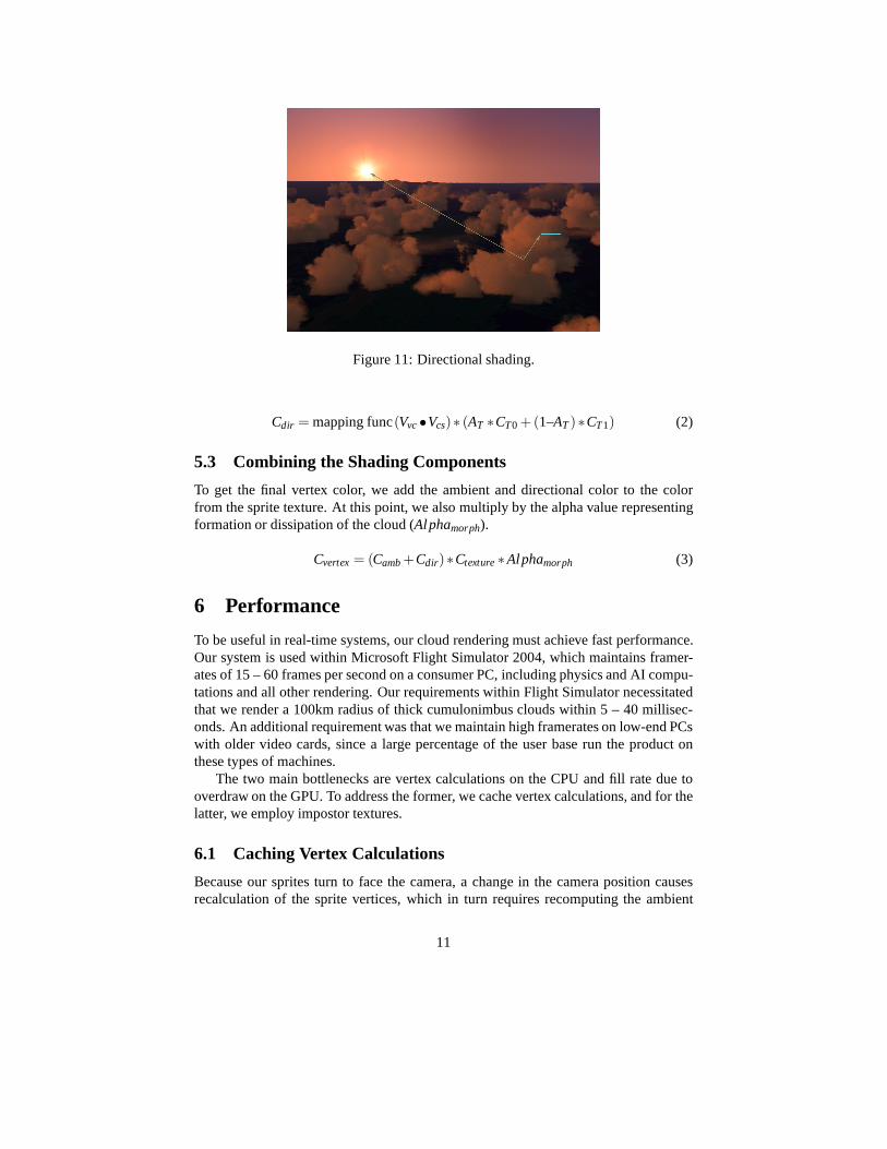
Figure 11: Directional shading.
Cdir = mapping func(Vvc •Vcs)∗ (AT ∗CT0 +(1–AT )∗CT1) (2)
5.3 Combining the Shading Components
To get the final vertex color, we add the ambient and directional color to the colorfrom the sprite texture. At this point, we also multiply by the alpha value representingformation or dissipation of the cloud (Alphamorph).
Cvertex = (Camb +Cdir)∗Ctexture ∗Alphamorph (3)
6 Performance
To be useful in real-time systems, our cloud rendering must achieve fast performance.Our system is used within Microsoft Flight Simulator 2004, which maintains framer-ates of 15 – 60 frames per second on a consumer PC, including physics and AI compu-tations and all other rendering. Our requirements within Flight Simulator necessitatedthat we render a 100km radius of thick cumulonimbus clouds within 5 – 40 millisec-onds. An additional requirement was that we maintain high framerates on low-end PCswith older video cards, since a large percentage of the user base run the product onthese types of machines.
The two main bottlenecks are vertex calculations on the CPU and fill rate due tooverdraw on the GPU. To address the former, we cache vertex calculations, and for thelatter, we employ impostor textures.
6.1 Caching Vertex Calculations
Because our sprites turn to face the camera, a change in the camera position causesrecalculation of the sprite vertices, which in turn requires recomputing the ambient
11

and directional shading values. Recalculating a scene of 500 clouds can take up to 3milliseconds.
We mitigate this cost by caching computations and recalculating only when the timeelapsed or the camera position delta exceeds threshold values. These values are basedon the distance of the cloud to the camera, because rotational changes in nearby spritesare more visually noticeable than changes in distant sprites. We tweaked the thresholdsto ensure they were not large enough to cause visual popping.We also recompute morefrequently when the cloud is forming or dissipating.
6.2 Reducing Overdraw with Impostors
The heavy amount of overdraw in the clouds presents an opportunity to improve per-formance. We use the impostor technique [Sch95] of dynamically rendering multipleclouds into a texture that we then display as a billboard. (See Figure 12.) This reducesoverdraw as well as the number of triangles being rendered.
Figure 12: Rendering clouds onto an impostor.
We create an octagonal ring of impostor textures around the camera, each witha 45-degree field of view. We can render hundreds of clouds into a single impostor.Our system compares clouds in 16 square kilometer blocks against the ring radius, andrenders only the blocks beyond the radius into impostors. Cloud blocks within theradius are rendered as individual sprites. (See Figure 13.)This reduces video memoryrequirements since creating impostors for nearby clouds would require larger texturesto maintain the level of detail.
Our system allows the user to set the radius for the ring, which poses a tradeoff. Asmaller ring radius signifies that more clouds are rendered into the impostors, whichboosts framerate, but there are more noticeable visual anomalies. (See section 7.) Alarger ring radius means that there is less performance gainfrom the impostors sincefewer clouds are rendered into them, but there are fewer anomalies, and the impostorscan be updated less frequently.
12

Figure 13: Ring of impostors around the camera. Clouds within the ring are renderedin 3-d.
We render the 8 impostors in fixed world positions facing the center of the ring, andrecreate them when the camera or sun position has changed past threshold values. Werecalculate all 8 rather than a lazy recomputation, so that the impostors are availableif the user suddenly changes the camera orientation. Empirical results show that theuser can move through 15% of the impostor ring radius horizontally or 2% of the ringradius vertically before recalculation becomes necessary.
To prevent variability in framerate from the overhead of rendering to impostors, wespread out the impostor calculation over multiple frames. For video cards that supportit, we do a hardware render-to-texture into a 32-bit texturewith alpha over 8 frames,one for each impostor. For the other video cards, we use a software rasterizer to renderinto the texture over dozens of frames, one 16 square kilometer cloud block per frame.When we update to a new set of impostors, we crossfade betweenthe two sets.
We translate the impostor texture vertically up or down based on the angle betweenthe clouds and the camera. When the clouds are displaced morethan 10,000 feetvertically from the camera, we stop rendering them into impostors because the viewangle is too sharp. In this situation, the clouds are furtheraway and take up less spaceon the screen, so there is less overdraw and performance onlysuffers slightly from notrendering into impostors.
Since video memory is frequently a tight resource on consumer PCs, we designedthe impostor system to have low video memory usage. Our ring of 8 impostors, each a256 x 256 texture with 32-bit color, adds up to a video memory cost of 8∗256∗256∗4 = 2 megabytes uncompressed. When crossfading, both impostorrings are rendered,which adds another 2 megabytes during the transition.
6.3 Performance Results
Our cloud system is implemented using the DirectX API on Windows PC systems.We found that framerate is correlated to both the number of sprites and their sizes.We created a metric that we call the ”cloud block overdraw”, which we calculate bysumming the sizes of all sprites in a 16 square kilometer block and diving by the two-
13

dimensional area of that block.We ran three cloud scenarios in Microsoft Flight Simulator:sparse clouds with an
overdraw of 170%, scattered clouds with an overdraw of 200%,and overcast skies withan overdraw of 475%. We ran each scenario with and without impostors, at a resolutionof 1024 x 768 with 32-bit color.
Figure 14: Thick overcast layer covering the sky.
A graph of the results is shown in Figure 15. As we can see, impostors dramaticallyimprove performance on lower-end systems, more so than on faster machines wherefill rate is less of a limiting factor. Across both machines, we are able to achieve 15to 60 frames per second with impostors, maintaining high framerates even in overcastscenarios, which have traditionally been challenging froma performance standpoint.We show a screenshot of the overcast scene we used in Figure 14.
Figure 15: Chart comparing performance with and without impostors, on two systems.
14

7 Limitations and Extensions
We separate this section into cloud modeling, animation andshading, performance, andextensions to other visuals.
7.1 Modeling
Our system is well suited for creating voluminous clouds butless suited for creating flatclouds. Of the four basic cloud types – cumulus, stratus, cumulonimbus, and cirrus, oursystem easily handles the first three but has difficulty with cirrus clouds because theyare so flat as to be almost two-dimensional. To replicate cirrus clouds in our system, wewould need a large number of sprites, which would cause a performance hit. Instead,our system represents cirrus clouds with flat textured rectangles.
Because sprites within each cloud are sorted back-to-frontbased on distance tothe camera, moving the camera can occasionally result in popping as sprites switchpositions in the draw order. This is more noticeable at dawn and dusk when directionalshading plays a greater role. One potential solution would be to save the previousordering and fade between sprites when their order changes.In our experience, thepopping was not jarring enough to necessitate this solution.
Our in-cloud experience sometimes does not appear as dense as one would expect.One scenario is when the user flies through wispy clouds compromised of relativelyfew sprites. When the camera is at the cloud’s center, only half of the sprites lie infront of the camera, so that the cloud is half as opaque as whenthe user viewed it fromthe outside. However, in real life, often the cloud appears most opaque at its center.
Another situation in which the in-cloud experience appearstoo non-opaque is whenthe user changes the camera orientation. Suppose the user isflying parallel to theground. When he moves close enough to the sprites, they lock in an orientation per-pendicular to the ground. If he looks down, he will now see large gaps between thesprites. A potential solution is to detect when the user has entered into the core of thecloud and combine an additive fogging effect with our existing in-cloud experience.
7.2 Animation and Shading
Currently clouds do not change shape except for formation and dissipation. In reallife, air flow causes clouds to morph over time. We can simulate this by rotating ortranslating sprites within the cloud, giving the impression that wisps are moving andtumbling with the wind. As groups of sprites are translated,the cloud could condenseinto itself or break apart into several pieces. We could alsofade individual sprites inand out to alter the overall shape of the cloud.
Because our shading model does not simulate the scattering of light, clouds do notcast shadows on themselves or neighboring clouds. Another shading inaccuracy is thatdirectional shading is measured based on angle to the sun rather than density of cloudmass that the light has passed through. For example, we do notget a halo effect whenthe cloud is between the sun and the camera. One potential solution that fixes both ofthese problems is to pre-calculate the lit and shadowed regions of the cloud for a set
15

of sun angles. We can load this information at runtime and interpolate based on sunangle.
7.3 Performance
Overdraw accounts for much of the cost of rendering our clouds, so the framerate canvary based on how much of the scene is taken up by clouds. When the camera movesinto a cloud, there is a higher amount of overdraw, and framerate tends to drop. Oneway to alleviate this is to detect when the camera has moved inside a cloud using thebounding box of the sprites, and to add a fog effect. This would allow us to draw fewerclouds in the distance.
Using a ring of impostors can create visual anomalies. Suppose that beyond theimpostor ring radius lies a mountain surrounded by clouds. Those clouds are renderedinto a single ring of impostors, so that the mountain must draw either in front of orbehind all the clouds, rather than behind some clouds and in front of others. Thiscan be mitigated by adding more rings of impostors, but that increases video memoryusage.
Impostors can also look wrong due to lack of parallax. The clouds in the impostordo not move relative to each other. Their motion also looks inaccurate relative to theclouds within the impostor ring radius that are rendered as individual sprites.
An area for future work is to take advantage of newer hardwareand implementsome of our techniques using vertex shaders. We have not yet done so because ourapplication supports a user base with a wide spectrum of machines, many of whichhave video cards that do not support hardware vertex shaders.
7.4 Extensions to Other Visuals
Our system can be extended to other gaseous phenomena, such as fog, smoke, andfire. Fog is a natural candidate, since it is essentially a stratus layer placed close tothe ground. The problem is that hard lines can be seen where the sprites intersectthe ground polygons, which can be alleviated either by splitting the sprites along theground or multiplying by a one-dimensional alpha texture based on the altitude.
To extend our system for simulating smoke, we would use darker, wispier sprites.Since smoke is more fluid and moves faster than clouds, we would also need to enhancethe movement, potentially by adding some air flow simulation.
8 Acknowledgements
This work was made possible by the artistic contributions ofJohn W. Smith and AdrianWoods. We also thank Jason Waskey, Carl Edlund, Eric Haines,Chris Prince, IanPieragostini, Jim Blinn, Mark Harris, and the Microsoft Flight Simulator team.
16

9 Web Information
The figures in this paper, along with additional screenshotsand a link to a short videodemonstrating the techniques, are available online at http://www.acm.org/jgt/papers/Wang03.
References
[Bli82] J Blinn. Light reflection functions for simulation of clouds and dustysurfaces. InComputer Graphics (Proceedings of ACM SIGGRAPH 82),Computer Graphics Proceedings, Annual Conference Series,pages 21–29.ACM, ACM Press / ACM SIGGRAPH, 1982.
[DKY +00] Y Dobashi, K Kaneda, H Yamashita, T Okita, and T Nishita. Asimple,efficient method for realistic animation of clouds. InProceedings of ACMSIGGRAPH 2000, Computer Graphics Proceedings, Annual ConferenceSeries, pages 19–28. ACM, ACM Press / ACM SIGGRAPH, 2000.
[DNYO99] Y Dobashi, T Nishita, H Yamashita, and T Okita. Using metaballs tomodeling and animate clouds from satellite images. 15(9):471–492, 1999.
[Ebe97] D S Ebert. Volumetric modeling with implicit functions: A cloud is born.In Visual Proceedings of ACM SIGGRAPH 1997, Computer Graphics Pro-ceedings, Annual Conference Series, page 147. ACM, ACM Press / ACMSIGGRAPH, 1997.
[ES00] P Elinas and W Stuerzlinger. Real-time rendering of 3d clouds. Journalof Graphics Tools, 5(4):33–45, 2000.
[Har03] Mark Harris. Real-Time Cloud Simulation and Rendering. PhD thesis,University of North Carolina at Chapel Hill, 2003.
[HL01] M Harris and A Lastra. Real-time cloud rendering. InComputer GraphicsForum, volume 20, pages 76–84. Blackwell Publishers, 2001.
[NDN96] T Nishita, Y Dobashi, and E Nakamae. Display of clouds taking into ac-count multiple anisotropic scattering and sky light. InProceedings of ACMSIGGRAPH 96, Computer Graphics Proceedings, Annual Conference Se-ries, pages 379–386. ACM, ACM Press / ACM SIGGRAPH, 1996.
[Per85] K Perlin. An image synthesizer. InComputer Graphics (Proceedings ofACM SIGGRAPH 85), Computer Graphics Proceedings, Annual Confer-ence Series, pages 287–296. ACM, ACM Press / ACM SIGGRAPH, 1985.
[Sch95] G Schaufler. Dynamically generated imposters. InModeling VirtualWorlds - Distributed Graphics, MVD Workshop, pages 129–136, 1995.
17