F10 Displays, Indicators and Controls
14
BMW Service F10 Displays, Indicators and Controls
-
Upload
khangminh22 -
Category
Documents
-
view
0 -
download
0
Transcript of F10 Displays, Indicators and Controls

BMW�Service
F10�Displays,�Indicators�and�Controls
QT34424
Edit for US

General�information
Symbols�used
The�following�symbol�/�sign�is�used�in�this�document�to�facilitate�better�comprehension�and�to�drawattention�to�particularly�important�information:
Contains�important�safety�guidance�and�information�that�is�necessary�for�proper�system�functioningand�which�it�is�imperative�to�follow.
Information�status�and�national-market�versions
The�BMW�Group�produces�vehicles�to�meet�the�very�highest�standards�of�safety�and�quality.�Changesin�terms�of�environmental�protection,�customer�benefits�and�design�make�it�necessary�to�developsystems�and�components�on�a�continuous�basis.�Consequently,�this�may�result�in�differences�betweenthe�content�of�this�document�and�the�vehicles�available�in�the�training�course.
As�a�general�principle,�this�document�describes�left-hand�drive�vehicles�in�the�European�version.�Somecontrols�or�components�are�arranged�differently�in�right-hand�drive�vehicles�than�those�shown�on�thegraphics�in�this�document.�Further�discrepancies�may�arise�from�market‐specific�or�country-specificequipment�specifications.
Additional�sources�of�information
Further�information�on�the�individual�topics�can�be�found�in�the�following:
• in�the�Owner's�Handbook• in�the�integrated�service�technical�application
Contact:�[email protected]
©2009�BMW�AG,�Munich,�Germany
Reprints�of�this�publication�or�its�parts�require�the�written�approval�of�BMW�AG,�Munich
The�information�in�the�document�is�part�of�the�BMW�Group�technical�training�course�and�is�intendedfor�its�trainers�and�participants.�Refer�to�the�latest�relevant�BMW�Group�information�systems�for�anychanges/supplements�to�the�technical�data.
Information�status:�December�2009

F10�Displays,�Indicators�and�ControlsContents1. System�Overview..........................................................................................................................................................................................................................1
1.1. Introduction.....................................................................................................................................................................................................................1
2. System�Components.............................................................................................................................................................................................................22.1. Instrument�cluster.................................................................................................................................................................................................2
2.1.1. Basic�instrument�panel...............................................................................................................................................22.1.2. Brake�energy�display......................................................................................................................................................22.1.3. On-board�computer..........................................................................................................................................................3
2.2. Central�Information�Display...................................................................................................................................................................42.2.1. CID�with�10.2"�screen�diagonal.....................................................................................................................42.2.2. CID�with�7"�screen�diagonal...............................................................................................................................5
2.3. Head‐Up�Display� ...................................................................................................................................................................................................52.4. Night�Vision�2..............................................................................................................................................................................................................62.5. Controls�on�the�steering�wheel.......................................................................................................................................................72.6. Operating�controls�in�the�center�console........................................................................................................................82.7. Driver�assistance�systems�operating�unit.......................................................................................................................9


F10�Displays,�Indicators�and�Controls1.�System�Overview
1
1.1.�IntroductionAs�in�all�other�BMW�models,�the�operating�and�control�concept�of�the�new�BMW�5�Series�F10�is�basedon�clear�and�optimum�structuring�of�the�cockpit.�A�reduced�number�of�switches�simplifies�the�logicaloperation.�The�display,�indicator�and�control�elements�are�organized�in�a�hierarchical�arrangementcorresponding�to�their�function.
F10�Overview�of�the�display,�indicator�and�control�elements
Index Explanation1 Head-up�display�HUD2 Central�Information�Display,�CID3 Favorite�buttons�for�individual�assignment�and�operation�of�the�heating�and�air
conditioning�system4 Controller�CON5 Gear�selector�switch�GWS6 Steering�wheel�buttons7 Driver�assistance�systems�operating�unit8 Instrument�cluster�KOMBI

F10�Displays,�Indicators�and�Controls2.�System�Components
2
2.1.�Instrument�clusterThe�instrument�panel�receives�information�on�the�wiring�harness�in�the�form�of�analog�and�digitalelectrical�signals.�These�signals�are�processed�and�displayed�in�the�instrument�panel�or�passed�on�asinformation�to�other�control�units.
As�a�control�unit,�the�instrument�panel�is�a�bus�device�in�the�MOST�bus�and�in�the�powertrain�CAN.
2.1.1.�Basic�instrument�panelThe�basic�instrument�panel�already�familiar�from�the�F07�is�used�in�all�versions�of�the�F10.�A�TFTdisplay�with�a�resolution�of�640�x�160�pixels�is�located�in�the�basic�instrument�panel�under�the�roundinstruments.�It�has�a�screen�diagonal�of�5.7".�The�round�instruments�are�always�surrounded�by�aclosed�ring.
F10�Basic�instrument�panel�(Not�US)
Index Explanation1 TFT�display2 Closed�instrument�ring
2.1.2.�Brake�energy�displayThe�F10�comes�standard�with�Brake�Energy�Regeneration.�Brake�Energy�Regeneration�transformsthe�vehicle’s�kinetic�energy�into�electricity,�and�uses�this�power�to�charge�the�battery.�As�a�result,�thebattery�draws�less�power�from�the�engine,�and�fuel�consumption�is�reduced.
The�kinetic�energy�of�the�vehicle�is�converted�into�electrical�energy�while�the�vehicle�is�in�coastingmode�or�under�braking.�The�battery�is�partially�charged�and�the�fuel�consumption�can�be�reduced.
The�blue�indicator�in�the�instrument�panel�below�the�tachometer,�which�lights�up�whenever�kineticenergy�is�converted�into�electricity�(while�coasting�off�the�accelerator�or�under�braking).�The�redsection�of�the�display�below�the�“P”�is�the�mile�per�gallon�gauge.

F10�Displays,�Indicators�and�Controls2.�System�Components
3
F10�Current�fuel�consumption�display�in�coasting�(overrun)�mode
2.1.3.�On-board�computerThe�on-board�computer�functions�can�be�called�up�by�briefly�pressing�the�on-board�computer�buttonon�the�steering�column�switch.
Pressing�the�on-board�computer�button�again�displays�information�in�the�following�order:
• Range• Average�fuel�consumption• Average�speed• Distance�(with�activated�route�guidance)• Estimated�time�of�arrival�(with�activated�route�guidance)• Date• Road�sign�recognition.
F10�Buttons�on�the�steering�column�switch

F10�Displays,�Indicators�and�Controls2.�System�Components
4
Index Explanation1 Button�for�on-board�computer2 High-beam�assistant�button3 Steering-column�switches
More�detailed�information�can�be�found�in�the�current�vehicle�owner's�manual�for�the�BMW�5�Series.
2.2.�Central�Information�DisplayDepending�on�the�equipment,�two�different�versions�of�the�Central�Information�Display�CID�areinstalled�in�the�F10.
As�on�all�new�BMW�models,�the�system�is�operated�by�means�of�the�central�control�element,�thecontroller.
The�central�information�display�is�an�integrated�display�and�operating�unit�for�the�following�functions:
• Audio�functions,�for�example�radio,�CD,�MP3• Telephone�and�data�services• On-board�computer,�journey�computer• Vehicle�info,�integrated�operating�instructions�IBA• Heating�and�air�conditioning�system• Personalized�features,�for�example�radio�station�selection• Vehicle�functions,�for�example�PDC�and�EDC• BMW�Services.
2.2.1.�CID�with�10.2"�screen�diagonalIn�conjunction�with�the�Navigation�system�(option�609),�a�CID�with�10.2"�screen�diagonal�is�installed.The�resolution�of�the�display�is�1280�x�480�pixels.
F10�CID�with�10.2"�screen�diagonal

F10�Displays,�Indicators�and�Controls2.�System�Components
5
2.2.2.�CID�with�7"�screen�diagonalIn�conjunction�with�a�vehicle�configuration�without�a�navigation�system,�a�CID�with�7"�screen�diagonalis�installed.�The�resolution�of�this�display�is�800�x�480�pixels.
F10�CID�with�7"�screen�diagonal
2.3.�Head‐Up�DisplayThe�very�name�"Head‐Up"�describes�the�principle�benefit�of�this�system.�The�Head‐Up�Display�HUDprojects�a�virtual�image�into�the�driver's�field�of�vision.�Important�information�such�as�cruise�controldetails�or�arrow�displays�from�the�navigation�system�are�projected�onto�the�windscreen�and�are�thuspermanently�visible�within�the�driver's�field�of�view.
The�head‐up�display�(option�610)�in�the�F10�contains�various�functions�aimed�at�enhancing�roadsafety�and�driving�comfort.
The�head-up�display�includes�the�following:
• the�Dynamic�Cruise�Control�DCC• the�Active�Cruise�Control�with�Stop�&�Go�function• the�collision�warning�with�brake�application�function• information�from�the�navigation�system• Check�Control�messages• road�speed.
Having�the�displays�in�the�driver's�direct�field�of�view�increases�safety,�as�the�eyes�are�always�on�thetraffic.

F10�Displays,�Indicators�and�Controls2.�System�Components
6
F10�Head-up�display
For�more�information�on�the�head-up�display,�refer�to�the�F01�entitled�"Head-Up�Display�HUD"�trainingmaterial�available�on�TIS�and�ICP.
2.4.�Night�Vision�2The�BMW�Night�Vision�2�system�provides�the�driver�with�a�black-and-white�image�of�the�drivingenvironment�ahead�of�the�vehicle�in�the�Central�Information�Display�CID.
BMW�Night�Vision�2�is�a�100�%�passive�system�without�active�infrared�illumination.�Objects�situatedahead�of�the�vehicle�are�shown�in�varying�degrees�of�brightness�depending�on�their�temperature.�Thisenables�the�driver�to�detect�in�good�time�heat-emitting�objects,�such�as�people,�animals�and�othervehicles.
This�information�is�recorded�with�a�far�infrared�camera�via�a�special�imaging�sensor�which�detects�theinfrared�radiation�in�a�specific�wavelength�range.
Intelligent�algorithms�in�the�control�unit�makes�it�possible�to�automatically�detect�persons�in�the�image.Following�evaluation�of�distance�and�direction�of�movement,�a�symbol�on�the�central�informationdisplay�and�in�the�head-up�display�warns�the�driver�of�any�persons�at�risk.
F10�Night�Vision�display�in�the�head‐up�display

F10�Displays,�Indicators�and�Controls2.�System�Components
7
Night�Vision�2�is�available�for�the�F10�as�the�optional�equipment�BMW�Night�Vision�with�pedestriandetection�(option�6UK).
As�in�the�F01/F02,�the�video�camera�for�BMW�Night�Vision�is�installed�in�the�F10�behind�the�radiatorgrill,�on�the�top�left�corner.
For�more�information�on�Night�Vision�2,�refer�to�the�F01�"BMW�Night�Vision�2"�training�materialavailable�on�TIS�and�ICP.
2.5.�Controls�on�the�steering�wheelThere�is�a�switch�block�in�the�steering�wheel�on�the�left�and�right.
The�operating�elements�for�cruise�control�with�braking�function�(Dynamic�Cruise�Control�DCC)�and�theActive�Cruise�Control�ACC�are�located�on�the�left�side�of�the�steering�wheel.
The�controls�for�operation�of�the�radio�and�telephone�functions�are�on�the�right.
F10�Controls�on�the�steering�wheel
Index Explanation1 Reduce�distance�button�(only�with�option�5DF)2 ±�rocker�switch,�change�speed,�set�speed3 Knurled�wheel,�select/set�radio�station�or�music�track4 MODE�button,�switch�audio�sources5 Shift�up�shift�paddle�(only�with�option�2TB)6 +�rocker�switch,�increase�volume7 -�rocker�switch,�reduce�volume8 Voice�control�button9 Telephone�button
F10�Displays,�Indicators�and�Controls2.�System�Components
8
Index Explanation10 Increase�distance�button�(only�with�option�5DF)11 Switch�on/off,�interrupt�ACC/DCC12 Resume,�call�up�stored�speed�button13 Speed�limit�button�or�the�“SET”�speed�button�in�the�US14 Shift�down�shift�paddle�(only�with�option�2TB)
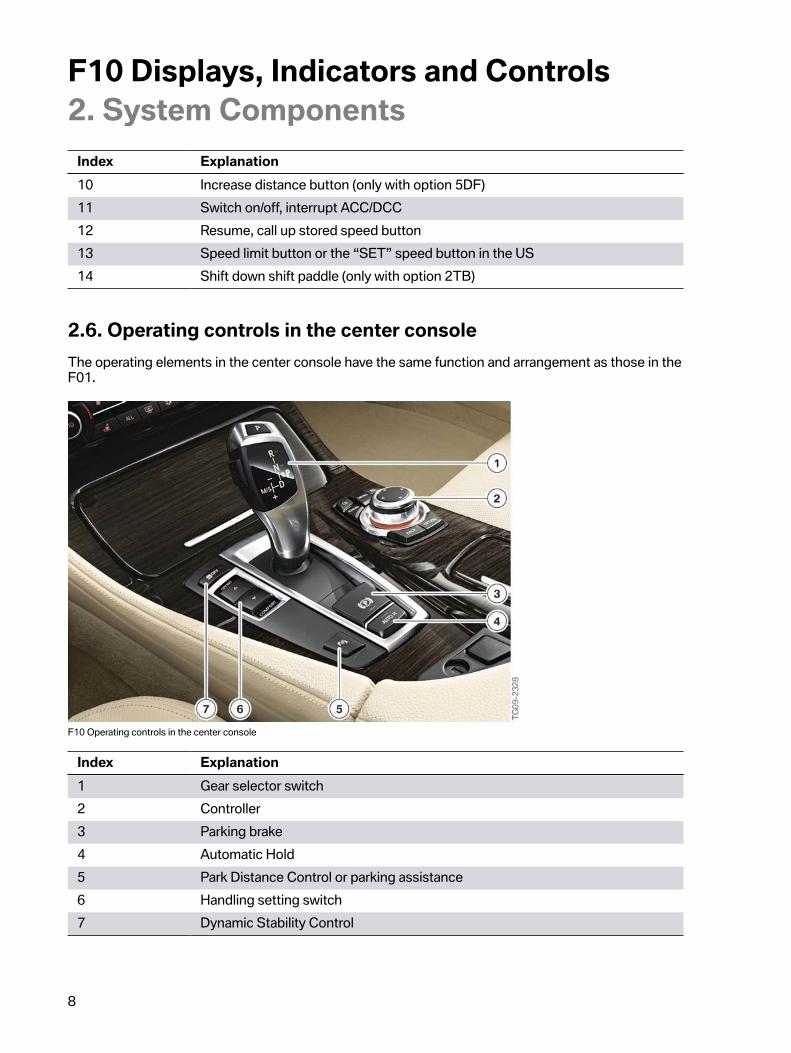
2.6.�Operating�controls�in�the�center�consoleThe�operating�elements�in�the�center�console�have�the�same�function�and�arrangement�as�those�in�theF01.
F10�Operating�controls�in�the�center�console
Index Explanation1 Gear�selector�switch2 Controller3 Parking�brake4 Automatic�Hold5 Park�Distance�Control�or�parking�assistance6 Handling�setting�switch7 Dynamic�Stability�Control

F10�Displays,�Indicators�and�Controls2.�System�Components
9
2.7.�Driver�assistance�systems�operating�unitThe�individual�assist�systems�can�be�activated�or�deactivated�via�the�assist�system�operating�unit.�It�islocated�next�to�the�steering�wheel�in�the�dashboard.
F10�Assist�system�operating�unit
Index Explanation1 Blind�Spot�Detection2 Collision�warning�(adaptive�dynamic�brake�control�with�warning�function)3 Lane�Departure�Warning4 Night�Vision�with�person�recognition5 Head‐Up�Display
For�more�information�on�the�assist�systems�refer�to�the�"F10�Assist�systems"�of�this�training�material.

Bayerische�Motorenwerke�AktiengesellschaftHändlerqualifizierung�und�TrainingRöntgenstraße�785716�Unterschleißheim,�Germany