Ruggedized flat panel displays using COTS components
10
Ruggedized flat panel displays using COTS components Robert Smith-Gillespie E3 Displays, 21410 N. 19 th Ave., Phoenix, AZ 85027 USA ABSTRACT Continuing advances in commercial off-the-shelf (COTS) flat panel display components offer attractive opportunities for reducing overall display head costs while improving display performance as well as packaging efficiencies in size, weight, and power. Capturing these benefits requires consideration of multiple engineering and manufacturing trade-offs and can seem overwhelming to system integrators. Modification and/or integration of optical, mechanical and electronic components can be required to meet environmental or usage requirements which frequently exceed the performance envelope of COTS components. This study focuses on how to determine which trade-offs are important in particular applications and how to evaluate trade-off opportunities for cost and performance while maintaining conformance with application requirements. Keywords: LCD, COTS, commercial-off-the-shelf, LCD ruggedization, LCD mechanical design 1. INTRODUCTION 1.1 COTS versus Custom LCDs Commercial off-the-shelf (COTS) LCD displays provide an attractive alternative to custom designed displays from a number of standpoints. In fact, the benefits so outweigh the detractions that virtually all new airborne display programs are using non-square glass formats to leverage commercial product offerings into avionics displays. Generally, companies developing avionics and military display hardware look first to commercial product offerings, and in many cases set product specs based on available sizes and performance capabilities. Table 1-1. Comparison of LCD performance criteria for COTS, repackaged COTS, and full custom LCD modules. Product Criteria COTS LCD Module Modified COTS LCD Module Custom LCD Glass & Packaging Development Costs (NRE/NRT) Development Cycle Time Design Stability Design Flexibility Environmental Performance / / Competitive Advantage Display Performance / / Recurring Cost (LCD, Module + Pkg) - Good - Acceptable - Poor As Table 1-1 highlights, several key criteria heavily favor the use of commercial displays and modified commercial displays over custom glass based designs. While initial COTS directives were financially driven, the ability to rapidly integrate available displays into new products has reduced development lead times allowing companies to quickly introduce new display products for general and commercial aviation, marine, and land vehicle environments. 1.2 Avionics LCD format trends – No longer square In the early days of flight deck LCDs, square formats dominated as they were replacing square format CRTs. Examples include 3-ATI, 4-ATI, and D-Sized LCDs used in commercial and corporate jet aircraft such as the Boeing 777,
-
Upload
independent -
Category
Documents
-
view
3 -
download
0
Transcript of Ruggedized flat panel displays using COTS components

Ruggedized flat panel displays using COTS components
Robert Smith-Gillespie E3 Displays, 21410 N. 19th Ave., Phoenix, AZ 85027 USA
ABSTRACT
Continuing advances in commercial off-the-shelf (COTS) flat panel display components offer attractive opportunities for reducing overall display head costs while improving display performance as well as packaging efficiencies in size, weight, and power. Capturing these benefits requires consideration of multiple engineering and manufacturing trade-offs and can seem overwhelming to system integrators. Modification and/or integration of optical, mechanical and electronic components can be required to meet environmental or usage requirements which frequently exceed the performance envelope of COTS components. This study focuses on how to determine which trade-offs are important in particular applications and how to evaluate trade-off opportunities for cost and performance while maintaining conformance with application requirements.
Keywords: LCD, COTS, commercial-off-the-shelf, LCD ruggedization, LCD mechanical design
1. INTRODUCTION
1.1 COTS versus Custom LCDs
Commercial off-the-shelf (COTS) LCD displays provide an attractive alternative to custom designed displays from a number of standpoints. In fact, the benefits so outweigh the detractions that virtually all new airborne display programs are using non-square glass formats to leverage commercial product offerings into avionics displays. Generally, companies developing avionics and military display hardware look first to commercial product offerings, and in many cases set product specs based on available sizes and performance capabilities.
Table 1-1. Comparison of LCD performance criteria for COTS, repackaged COTS, and full custom LCD modules.
Product Criteria
COTS LCD
Module
Modified COTS LCD
Module
Custom LCD Glass
& Packaging
Development Costs (NRE/NRT)
Development Cycle Time
Design Stability
Design Flexibility
Environmental Performance / /
Competitive Advantage
Display Performance / /
Recurring Cost (LCD, Module + Pkg)
- Good - Acceptable - Poor
As Table 1-1 highlights, several key criteria heavily favor the use of commercial displays and modified commercial displays over custom glass based designs. While initial COTS directives were financially driven, the ability to rapidly integrate available displays into new products has reduced development lead times allowing companies to quickly introduce new display products for general and commercial aviation, marine, and land vehicle environments.
1.2 Avionics LCD format trends – No longer square
In the early days of flight deck LCDs, square formats dominated as they were replacing square format CRTs. Examples include 3-ATI, 4-ATI, and D-Sized LCDs used in commercial and corporate jet aircraft such as the Boeing 777,

737/57/67 airplanes, Airbus A-320/340, Gulfstream G-IV and G-V. In order for general aviation to apply sophisticated avionics information, lower cost LCD alternatives were sought. Manufacturers looked to industrial type LCDs as alternatives to the costly custom LCDs used on early platforms. With this, came the move to non-square aspect ratios (4:3 mostly) typical of these type displays.
Figure 1-1. Square D-sized displays of the A-340 and the 4:3 aspect COTS based display in Cirrus SR-22.
Figure 1-1 provides examples of various avionics displays based on commercially available LCD glass, each with its own unique and proprietary set of “enhancements” to make it suitable to the rugged avionics environment. Similar display conversions are made for land and marine vehicles as shown in Figure 1-2.
1.3 Mobile display platforms
One of the most challenging areas for ruggedized display product designers is that of portable computers for field applications. While in-vehicle based displays can utilize industrial grade LCDs with a limited set of enhancements, it is much more difficult to ruggedize commercial notebook LCDs to meet the rigorous environments such as those imposed by military and special use portable computer applications. Thinner bezels, light guides, and frames and LCD glass as thin as 0.35mm present a unique set of mechanical and thermal issues for the product designer to address.
Figure 1-2. Typical LCD module assembled (L) and with frame removed (R) showing row and column drivers.
The unique requirements placed on off-the-shelf displays as they are deployed in aircraft, marine, land vehicle and portable display environments necessitates that careful attention be paid to upgrading various aspects of the LCD module to extend its life and enhance the reliability to environments beyond which the display was originally designed. Key areas of interest in the product design are discussed in the following sections.
2. RUGGEDIZATION ALTERNATIVES
As product designs move away from fully custom LCD glass designs, there are a number of alternatives available depending on product requirements and the availability of standard displays.
2.1 Direct COTS application:
No modification is made to the commercially available LCD module. The product designer simply integrates the LCD module directly into the product. Standard backlight, front surface, and mechanical packaging are used.

2.2 Enhanced COTS application:
A commercial LCD module is upgraded to enhance some performance aspect such as display brightness or sunlight contrast, environmental performance, or mechanical packaging. This can be a relatively simple upgrade that extends the usable display envelope to that required by the end user. Examples of enhancements include:
• Active and passive backlight upgrades for improved daylight viewing
• CCFL to LED backlight conversions to extend operating temperature range and increase display luminance
• Anti-reflective front surface treatments (AR-film lamination, AR glass window)
• Addition of EMI filters, transparent heaters or integration of touch screens
2.3 Ruggedized COTS application:
In this case a commercial LCD module is disassembled and aggressively upgraded to extend such performance parameters as humidity resistance, operating temperature range, backlight configuration (edge-lit to direct-view conversion), viewing envelope, vibration and impact resistance and electronic emissions. While not covered here, LCD aspect ratio changes by cutting the LCD glass, would fall under this category. Examples of ruggedization enhancements include the basic enhancements above plus:
• Application of sealant to polarizer edges – Prevents moisture penetration into polarizer
• Polarizer upgrades –Replace stock polarizer with extended temperature/humidity range polarizer
• Application of sealant to drivers and flex-to-glass contact interface
• Upgrade backlight films to environmentally robust alternatives
• Optically bonded AR glass (adds impact resistance along with optical enhancement)
• Repackage LCD module to incorporate direct-view backlighting (LED, CCFL, or HCFL)
• Remove and replace driver flexes to accommodate thicker backlight modules
2.4 Custom LCD on Standard Footprint:
This is where the line gets fuzzy. It is possible, with significant NRE expenditure and the right volume forecast, to commission development of a semi-custom LCD on a standard commercial LCD footprint. In this case, an LCD manufacturer could use the LCD masks for the standard product but apply custom materials and processes to meet the user’s requirements. By using the commercial LCD fab to set, a savings approaching a million dollars can be realized, still yielding a semi-custom LCD display. Customizations at the LCD panel level can include:
• Custom LC fluid for extended temperature range operation
• Custom LC alignment direction – Portrait mode orientation instead of landscape
• Custom drivers
• Custom polarizers and compensation films
• Custom color filter array; low reflectance black mask
3. RUGGEDIZATION TECHNICAL DETAILS
LCD enhancements can be broadly classified according to whether the upgrade addresses primarily environmentally induced reliability issues or optical issues unique to the display use environment. Some enhancements, such as optically bonded cover glass or LED backlight retrofits may address both areas. The following discussion categorizes various displays enhancements according to their primary focus: environment reliability [REL] and those which improve display optical performance [OPT].
3.1 Environmental requirements overview
While great progress has been made to improve environmental performance for automotive grade displays by such companies as Sharp and Optrex, the limited size offerings (mostly 6.5” and below) make them unsuitable for large display applications. Table 3-1 summarizes environmental performance specifications for typical commercial display categories including so-called industrial LCD modules, automotive grade and notebook computer LCD modules. Additionally, the table provides a summary for flight deck equipment requirements from RTCA DO-160 for comparison.

It is obvious that the temperature and humidity specifications for industrial LCDs fall somewhat below the requirements for airborne equipment, hence the need for ruggedization.
Table 3-1 Comparison of performance requirements for typical display types and flight deck equipment
Notebook PC1
Std. Industrial 2
Hi Rel. Industrial 3 Automotive 4
Top (min/max) -15/+70°C 0/+50°C 0/+60°C -20/+70°C -30/+80°C
Tstorage (min/max) -55/+85°C -20/+60°C -25/+70°C -30/+80°C -30/+80°C
Humidity95%, 65°C,
240h590%, 40°C,
300h95%, 40°C,
240h90%, 60°C,
240h95%, 40°C,
240h
Vibration 1.48Grms10-2kHz
1.5Grms10-500Hz
1Grms58-500Hz
2Grms5-100Hz
2Grms 58-500Hz
Mechanical Shock(1/2 sine impulse)
20G11ms
240G2ms
50G11ms
55G11ms
50G6ms
Contrast Ratio >250:1 typ 200:1 min 250:1 typ 300:1 min 250:1 min 350:1 typ
Luminance (cd/m 2) >600 typ160 min 200 typ
240 min 300 typ
500 min 260 min 350 typ
Viewing Angle (H/V)Depends on Installation
±40+10/-30
±45+45/-30
±70+70/-50
±60±35
Notes: 1 AUO B141XG09 4 Sharp LQ064V3DG01
2 Sharp LQ084V1DG21 5 Severe humidity environment
3 NEC 6448BC26-09C
LCD Product CategoryRequirement
DO-160Flight Deck Equipment
3.2 LCD heaters - [REL]
LCD low temperature performance is limited due to liquid crystal viscosity increases with reduction in temperature. At temperatures below -10° to -20°C, the response time of the liquid crystal begins to increase sharply from tenths of a second to upwards of 10 seconds. To provide extended temperature range performance and reduce cold-start warm-up times transparent heaters are often applied to the rear surface of the LCD. The ITO coated heaters may be specified in a range of resistances (10-25Ω/sq typical) based upon power dissipation needed. However, as the ITO layers become thicker (lower resistance), the transmission and reflectance of the ITO goes up, impacting optical performance.
ITO heaters can be built on glass or plastic substrates, though for higher thermal dissipation applications, which can see temperatures in excess of 120°C, glass is the preferred substrate. Figure 3-1 shows a typical heater glass configuration with bus bars (usually printed silver-epoxy) and lead wires. A transmission-reflectance plot is shown at right.
Figure 3-1. Example of ITO-type heater glass for LCD application (from JDSU, Inc.). The optional AR coating applied to the non-conductive surface improves transmission and reduces reflectance as shown at right.
Many options are available for transparent heaters and care must be taken in specifying optical properties as well as thermal properties. While index matching of the ITO to the glass and air can provide optical benefits, depending on the location in the optical stack, the added cost may not be justified. In the world of full custom LCDs, at least one
manufacturer (APC, Inc.) has a proprietary internal heater system that uses patterned metalization within the cell to provide a heating path. The optical advantages of increased transmission coupled with the reduced power dissipation arising from the proximity of the heater to the LC fluid make this a very attractive solution for systems which justify the cost of full-custom LCDs.
3.3 Display electronics
The susceptibility of the LCD drivers and driver interconnects to humidity related failures necessitate ruggedizing enhancements for displays which will be exposed to high humidity, high temperature environments. While it is obvious that marine displays see long-term exposure to high humidity (and salt laden condensation as well), aircraft equipment often see conditions where warm, moist air is cooled at altitude causing a condensing humidity exposure.
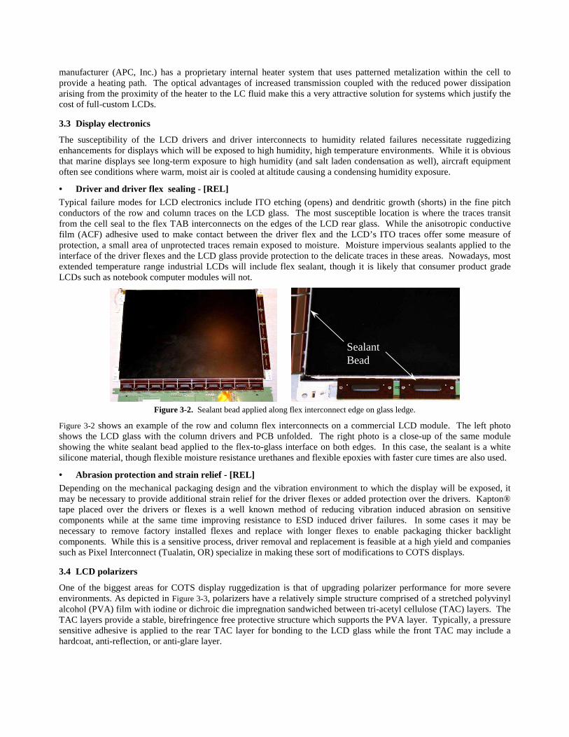
• Driver and driver flex sealing - [REL] Typical failure modes for LCD electronics include ITO etching (opens) and dendritic growth (shorts) in the fine pitch conductors of the row and column traces on the LCD glass. The most susceptible location is where the traces transit from the cell seal to the flex TAB interconnects on the edges of the LCD rear glass. While the anisotropic conductive film (ACF) adhesive used to make contact between the driver flex and the LCD’s ITO traces offer some measure of protection, a small area of unprotected traces remain exposed to moisture. Moisture impervious sealants applied to the interface of the driver flexes and the LCD glass provide protection to the delicate traces in these areas. Nowadays, most extended temperature range industrial LCDs will include flex sealant, though it is likely that consumer product grade LCDs such as notebook computer modules will not.
Figure 3-2. Sealant bead applied along flex interconnect edge on glass ledge.
Figure 3-2 shows an example of the row and column flex interconnects on a commercial LCD module. The left photo shows the LCD glass with the column drivers and PCB unfolded. The right photo is a close-up of the same module showing the white sealant bead applied to the flex-to-glass interface on both edges. In this case, the sealant is a white silicone material, though flexible moisture resistance urethanes and flexible epoxies with faster cure times are also used.
• Abrasion protection and strain relief - [REL] Depending on the mechanical packaging design and the vibration environment to which the display will be exposed, it may be necessary to provide additional strain relief for the driver flexes or added protection over the drivers. Kapton® tape placed over the drivers or flexes is a well known method of reducing vibration induced abrasion on sensitive components while at the same time improving resistance to ESD induced driver failures. In some cases it may be necessary to remove factory installed flexes and replace with longer flexes to enable packaging thicker backlight components. While this is a sensitive process, driver removal and replacement is feasible at a high yield and companies such as Pixel Interconnect (Tualatin, OR) specialize in making these sort of modifications to COTS displays.
3.4 LCD polarizers
One of the biggest areas for COTS display ruggedization is that of upgrading polarizer performance for more severe environments. As depicted in Figure 3-3, polarizers have a relatively simple structure comprised of a stretched polyvinyl alcohol (PVA) film with iodine or dichroic die impregnation sandwiched between tri-acetyl cellulose (TAC) layers. The TAC layers provide a stable, birefringence free protective structure which supports the PVA layer. Typically, a pressure sensitive adhesive is applied to the rear TAC layer for bonding to the LCD glass while the front TAC may include a hardcoat, anti-reflection, or anti-glare layer.
Sealant Bead

Figure 3-3. Typical polarizer construction showing TAC layers encapsulating the PVA layer.
The polarizer film stack is sensitive to environmentally induced degradation on a number of fronts. First, at extreme temperatures, the polarizer may undergo distortion as the stretched PVA layer attempts to relax to an unstressed state. The worst-case result of this is gross delamination of the PVA from the TAC layer. Also, PSA adhesive failure may occur due to exposure to high- or low-temperature extremes or temperature cycling. In both these cases, the only remedy is to replace the polarizer with an environmentally more robust alternative.
Figure 3-4. Polarizer degradation and delamination, 60°C water immersion (L) and 65°C/90% humidity test (R). [Photos courtesy of Nitto Denko (L) and FPD Solutions (R)]
A more common mode of failure is leaching of iodine from the PVA layer due to moisture penetration along the edges in a high humidity environment. This failure presents as a cloudy to clear marginal area penetrating from the edge of the polarizer toward the center of the film. The affected regions will no longer exhibit polarizing properties so the display image will fade out in this zone. A worst case scenario will exhibit delamination beginning at the edges as the TAC begins to separate from the moisture compromised edges. Figure 3-4 shows examples of temperature and humidity failures of commercial grade polarizers. It is possible to reduce moisture penetration failures by sealing the cut edges of the polarizer with a moisture impervious, optical grade flexible sealant such as silicones or urethane acrylates.
3.5 Polarizer performance categories
Polarizer manufacturers typically produce numerous polarizer grades to meet varied product requirements. In general, polarizers with the highest levels of polarization efficiency are also the most durable as these products are aimed at high-
Iodine TypePolarizer
Thermal Resistance
Hum
idity
Res
ista
nce
70°C 80°C 90°C 100°C 110° C
75°/95%
55°/90%
60°/90%
60°/95%
65°/95%
MonitorApps
Dye TypePolarizer
High PerformanceApplications
New DevelopmentIodine Type
Polarizer
Thermal Resistance
Hum
idity
Res
ista
nce
70°C 80°C 90°C 100°C 110° C
75°/95%
55°/90%
60°/90%
60°/95%
65°/95%
MonitorApps
Dye TypePolarizer
High PerformanceApplications
New Development
New Development
Figure 3-5. Polarizer environmental durability. Gray shades represent polarizing efficiency (dark = high efficiency).

end applications. Since the cost of polarizers increases sharply with increasing performance, consumer product displays generally employ lower grade (i.e. lower cost) materials which may be susceptible to degradation at elevated temperature and humidity. Figure 3-5 presents diagrammatically the performance categories for polarizers. Note that dye type polarizers exhibit the highest level of environmental resistance but, due to their lower polarization efficiency (roughly 89% versus >99.5% for hi-performance iodine type), the dye type are not suitable for TFT LCDs. Recent work by Nitto-Denko aimed at approaching dye type polarizer performance in iodine based substrates looks very promising and should offer new upgrade options for panel ruggedizers in the coming months.
3.6 Polarizer upgrade paths
• Polarizer sealing - [REL] Figure 3-6 shows an example of an edge seal being applied to the polarizer of an avionics LCD module. In this case a flexible sealant seals the polarizer edge at the same time the glass-to-bezel interface is sealed to prevent moisture penetration into the electronics and backlight.
Figure 3-6. Application of LCD polarizer sealant on 3 ATI module [Photos from E3 Displays].
• Polarizer encapsulation - [REL] The optical bonding of protective and anti-reflective cover glasses to the
front of the LCD module can provide a robust encapsulation of the front polarizer. (See Section 3.9 for optical bonding details.) Care must be taken however not to induce stress on the polarizer due to adhesive shrinkage or thermal expansion induced stresses as the birefringence resulting from polarizer stresses will degrade the display image. Encapsulates must be flexible over temperature, especially at low temperature, have low shrinkage and low CTE (coefficient of thermal expansion).
• Polarizer R&R - [REL/OPT] When polarizer enhancements (edge seal, encapsulation) are insufficient to ensure performance in extreme environments, replacement of the polarizers with a high-performance alternative is a viable, though more costly, option. To replace the polarizers, the COTS display module must be completely disassembled opening the display to other failure modes such as driver failures and handling induced optical defects. Contact polarizer manufacturers such as Nitto-Denko or San Ritz for environmentally robust polarizer options.
3.7 Backlight films - [REL/OPT]
It is well known that one possible optical upgrade path is the addition of specialty optical films to the backlight film stack. However, the impact of adding films without adjusting the mechanical housings to accommodate the added film thickness may result in optical defects as films interfere during vibration or temperature cycling. In fact, in some consumer product displays, the prism films were found to degrade due to vibration induced rubbing against other components. Additionally, it has been found that films in displays designed for a consumer grade maximum temperature (~60°C), can exhibit wrinkling if the display is exposed to higher temperatures in rugged applications (75-80°C). Figure 3-7 shows an example of a display in which vibration induced film rubbing was found (L) and one with thermally induced prism film warping (R). With redesigned mechanical housings, it may be possible to use a more robust film stack and boost luminance while eliminating optical failures.
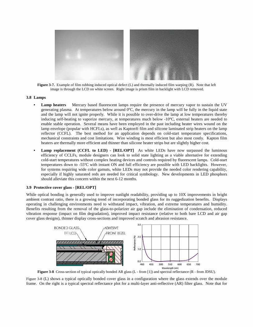
Figure 3-7. Example of film rubbing induced optical defect (L) and thermally induced film warping (R). Note that left image is through the LCD on white screen. Right image is prism film in backlight with LCD removed.
3.8 Lamps
• Lamp heaters Mercury based fluorescent lamps require the presence of mercury vapor to sustain the UV generating plasma. At temperatures below around 0ºC, the mercury in the lamp will be fully in the liquid state and the lamp will not ignite properly. While it is possible to over-drive the lamp at low temperatures thereby inducing self-heating to vaporize mercury, at temperatures much below -10ºC, external heaters are needed to enable stable operation. Several means have been employed in the past including heater wires wound on the lamp envelope (popular with HCFLs), as well as Kapton® film and silicone laminated strip heaters on the lamp reflector (CCFL). The best method for an application depends on cold-start temperature specifications, mechanical constraints and cost limitations. Wire winding is most efficient but also most costly. Kapton film heaters are thermally more efficient and thinner than silicone heater strips but are slightly higher cost.
• Lamp replacement (CCFL to LED) - [REL/OPT] As white LEDs have now surpassed the luminous efficiency of CCLFs, module designers can look to solid state lighting as a viable alternative for extending cold-start temperatures without complex heating devices and controls required by fluorescent lamps. Cold-start temperatures down to -55ºC with instant ON and full efficiency are possible with LED backlights. However, for systems requiring wide color gamuts, white LEDs may not provide the needed color rendering capability, especially if highly saturated reds are needed for critical symbology. New developments in LED phosphors should alleviate this concern within the next 6-12 months.
3.9 Protective cover glass - [REL/OPT]
While optical bonding is generally used to improve sunlight readability, providing up to 10X improvements in bright ambient contrast ratio, there is a growing trend of incorporating bonded glass for its ruggedization benefits. Displays operating in challenging environments need to withstand impact, vibration, and extreme temperatures and humidity. Benefits resulting from the removal of the glass-to-polarizer air gap include the elimination of condensation, reduced vibration response (impact on film degradation), improved impact resistance (relative to both bare LCD and air gap cover glass designs), thinner display cross-sections and improved scratch and abrasion resistance.
Figure 3-8 Cross-section of typical optically bonded AR glass (L - from [1]) and spectral reflectance (R - from JDSU).
Figure 3-8 (L) shows a typical optically bonded cover glass in a configuration where the glass extends over the module frame. On the right is a typical spectral reflectance plot for a multi-layer anti-reflective (AR) filter glass. Note that for

an untreated polarizer the reflectance is a relatively flat 4%. For an index matched adhesive bonded AR glass the reflectance is reduced to tenths of a percent.
The graphs in Figure 3-9, from reference [1], show the vibration response for a 14.1” notebook LCD with and without bonded cover glass. Note the five-fold reduction in acceleration and displacement responses at the first fundamental frequency (~35Hz). In fact, the 0.04” displacement of the unbonded LCD was sufficient to cause contact between the LCD rear polarizer and the optical film stack. The bonded glass not only reduced the displacement to less than 0.01” but eliminated completely the second harmonic. This is a significant result for long-term reliability in vibration rich environments.
Sinusoidal Vibration Response14.1 WXGA Notebook LCD
0.10
1.00
10.00
0 50 100 150 200 250 300 350 400 450 500Frequency (Hz)
Acc
eler
atio
n (g
)
ControlLCD Only LCD + 0.7mm GlassLCD + 1.1mm Glass
0.0001
0.0010
0.0100
0.1000
0 50 100 150 200 250
Frequency (Hz)R
elat
ive
Dis
plac
emen
t (in
)
Figure 3-9. Vibration response for 14.1” notebook LCD modules with and without bonded cover glass. [1]
Figure 3-10 (also from ref. [1]) shows the results for impact testing of bonded and unbonded LCD modules. The charts show a 2X to 3X increase in failure energy or drop height for the steel ball. In most cases, failure was the result of LCD fracture (rear LCD glass), while the cover glass did not fracture, but simple deflected elastically during impact. The use of chemically strengthened glass allowed equivalent performance of non-CS glass in a 20% thinner package. See reference [1] for complete test details.
The benefits of optical bonding of anti-reflective cover glass to commercial off-the-shelf LCD modules extend well beyond improvements to bright ambient readability. Increases in stiffness and torsional rigidity and four-fold reduction in displacement at resonance will aid in preventing mechanically induced electrical and optical failures.
0
5
10
15
20
25
30
35
40
45
LCD Only 0.7mm DB 0.85mm CS DB 1.1mm DB
Ave
rage
Fai
lure
Hei
ght (
in.)
0.000
0.050
0.100
0.150
0.200
0.250
0.300
Fai
lure
Ene
rgy
(Jou
les)
AVG. Fail Height (in) AVG. Fail Energy (J) MAX. Fail Energy (J) MIN. Fail Energy (J)
6 Samples 5 Samples6 Samples 3 Samples
0
5
10
15
20
25
30
LCD Only 0.7mm DB 1.1mm DB
Ave
rage
Fai
lure
Hei
ght (
in.)
0.00
0.05
0.10
0.15
0.20
0.25
Fai
lure
Ene
rgy
(Jou
les)
AVG. Fail Height (in) AVG. Fail Energy (J) MAX. Fail Energy (J) MIN. Fail Energy (J)
3 Samples 3 Samples 2 Samples
Figure 3-10. Failure height and energy for 225 gram ball drop impact on 13.3” (L) and 14.1”W (R) LCD modules. Failure height and energy for 225 gram ball drop impact on LCD modules. [1]
3.10 Adhesive requirements
When bonding AR glass, touch screens, or filters to commercial LCDs, it is important to consider the optical sensititvity of the LCD to stresses induced on the cell during bonding (cure related stresses) and due to differential thermal expansion of the bonded components. Tests show that in order to survive the robust environment of military, avionics and marine

products, the optical bonding adhesive must have a low bulk modulus and low durometer and a glass transition temperature below the minimum display storage temperature (<-55°C preferred). Additionally, the adhesive should have a low CTE to prevent thermally induced stresses being generated in the adhesive itself as well as a relatively high adhesion to TAC, glass, and stainless steel to prevent delamination during thermal cycling and humidity exposure.
Table 3-2. Comparison of optical adhesive properties for PVB, epoxies, urethanes and silicones.
Polyvinyl Butyral
Epoxy Urethane (poly)
AcrylateSilicone
TypicalBond Type
Semi-rigid, flexible Rigid, Semi-rigidHigh strength
Flexible Flexible to gel
Cure Type 1 Part Thermal 1 Part, 2 PartPhotocatalyzed
2 PartPhoto-catalyzed
1 Part Moisture Cure2 Part, Pt Catalyzed
Cure Cycle 120°C, 100 psi1 hr
RT-48 hr, ET-Var. T/tUV
RT - VariousUV
RT - 48 hrET - >70°C
Glass Transition Temperature
50°C to 150°C Typical: 50 to 100°C Custom: < - 55°C
< -40°C
Service Temp -60°C to 125°C -70°C to 150°C -60°C to 125°C -70°C to 200°C
Bond Strength(psi)
2,000 - 4,000 600 - 4,000 600 - 2,000 200 - 300
Table 3-2 provides a comparison of typical material and process properties for popular bonding adhesives. PVB, due to its high process temperature requirement, is not really a candidate but, since it is an industry standard for glass-to-glass lamination, is included here for reference. Epoxies have found application by some bonders but their rigidity and poor UV yellowing performance limit their application. Silicones are a popular alternative and have come into favor with many bonders. However, the short-comings of silicone gels relative to adhesion and CTE (>200ppm) must be carefully considered before committing to a silicone bonded system. Urethane acrylates offer an excellent alternative, though very few off-the-shelf formulations meet the full range of mechanical, optical and UV exposure requirements needed for extreme environmental exposure.
While ultra-low modulus adhesives/gels may provide good optical performance and reduce optical defects due to mechanical stresses, low adhesion of these materials may lead to delamination over time. Additionally, creep in shear loading over time can lead to mechanical failure as can adhesive migration with, for example, gel formulations of extremely low cross-link density. Full qualification at the display level with temperature and humidity levels exceeding the expected product specification should be performed to ensure product reliability for all adhesive systems.
4. DISCUSSION AND CONCLUSIONS
Numerous opportunities exist for improving environmental performance of commercial-off-the-shelf LCD modules. It is up to the product designer to determine and validate through testing, the appropriate level of ruggedization enhancement necessary for a given COTS display for a particular product environment. In the end, the cost of upgrades must be carefully weighed against the product performance and reliability benefit. In all cases the upgrade materials and processes should be qualified through rigorous life testing.
REFERENCES
[1] Smith-Gillespie, R. and Bandel, W., “LCD Ruggedization in Displays with Optically Bonded AR Glass Lamination”, Society for Information Display, ADEAC 2006, No. 7.3.
[2] S. T. Gulati, et.al., “Mechanical Reliability of LCD Panels under Static Loading,” 2004 SID Paper 62.1 [3] “Environmental Conditions and Test Procedures for Airborne Equipment”, RTCA/DO-160D, RTCA, Inc.