Challenge of 3D LCD displays
8
Challenge of 3D LCD Displays Rung-Ywan Tsai, Chao-Hsu Tsai, Kuen Lee, Chou-Lin Wu, Lang-Chin D. Lin, Kuo-Chung Huang, Wei-Liang Hsu, Chang-Shuo Wu, Chun-Fu Lu, Jinn-Cherng Yang, Ying-Chi Chen Electronic and Optoelectronic Laboratories, Industrial Technology Research Institute, Hsinchu 310, Taiwan ABSTRACT A multiview autostereoscopic LCD display with a localized 2D/3D switching function is developed based on the actively switchable parallax barrier technology. This switchable barrier comprises of an electro-optically switchable liquid crystal (LC) and a microretarder. Polymer dispersed liquid crystal (PDLC) with switchable clear and diffusing states and twisted nematic liquid crystal (TNLC) with polarization switching function are used as switching devices. The microretarder is prepared by self-developed multibeam laser scanning process, which is clean, friendly to the environment, and easy for scale up and mass production. The influence factors on the image qualities of 3D displays based on LCD panel technology are analyzed and discussed. Some solutions have proposed to solve the commercial application issues. Keywords: multiview autostereoscopic LCD display, localized switchable 2D/3D display, actively switchable parallax barrier INTRODUCTION Flat panel display (FPD) is the most important industry in the world due to its versatile applications- from the small (<10”) display devices like mobile phone to the large (>40”) ones like TV. The revenue of the global FPD industry is more than 100 billions US dollars in year 2008. Among that most of the revenue is contributed from LCD displays, which has the share ratio over 85%. Companies in Japan, Korea and Taiwan are the major manufacturers of the production of LCD displays in the world. However, due to the strong business competition, the price erosion rate and the earning profit decrease rapidly with time. The growth rates of revenue for those companies in Taiwan were even negative in year 2008. The average sale prices of panels at the end of year 2008 decreased 30~40% compared to that in 2007. The economic crisis made the worldwide LCD business become more difficult and more challenge. Facing with the price competition, many LCD makers are making serious adjustments to accommodate to changing of the global market. They are also trying to find the new applications to explore the new market to increase their revenue and profit. In the consumer electronic show and consumer electronic advisory panel discussion of 2009, display for the next wave innovation became one of the five technology trends to watch. Among that 3D-TV is one of the consumers most interest in emerging display technologies. The attention on the connection of 3D video in the home with the 3D-TV system is a hot topic. It has been reported that the future applications of major driving momentum for LCD panel industry will be LCD-TV and notebook, which covers the whole spectrum of panel size from small to large. However, the stereoscopic and/or autostereoscopic LCD-TV and notebook are interesting to the manufacturers and sellers but not to the customers. The key problem is that stereoscopic and autostereoscopic LCD displays is still in a stage of research and development, which offers a great potential for the commercial applications, but is not mature for mass production. Not even is a commodity accepted by the users. There are many issues needed to be solved before the 3D-TV become commercialization: (1) it must be an autostereoscopic display without wearing any special glasses; (2) the 3D content is already available; (3) the depth sense for 3D effect (human factor) is easily adjustable; (4) the quality of 3D image is as good as a 2D display (wide view angle & high resolution); (4) it is viewable from different locations and distances; (5) it’s 2D/3D compatible; (6) it has the flexibility for different sizes of 3D-TVs; (7) it should be cost effective and acceptable for the customers; and (8) the standard for 3D-TV broadcasting is already ready. With so many issues, it is still a long distance to make 3D-TV at home. Invited Paper Three-Dimensional Imaging, Visualization, and Display 2009, edited by Bahram Javidi, Jung-Young Son, Manuel Martinez-Corral, Fumio Okano, Wolfgang Osten, Proc. of SPIE Vol. 7329, 732903 · © 2009 SPIE · CCC code: 0277-786X/09/$18 · doi: 10.1117/12.820169 Proc. of SPIE Vol. 7329 732903-1
Transcript of Challenge of 3D LCD displays

Challenge of 3D LCD Displays Rung-Ywan Tsai, Chao-Hsu Tsai, Kuen Lee, Chou-Lin Wu, Lang-Chin D. Lin, Kuo-Chung Huang,
Wei-Liang Hsu, Chang-Shuo Wu, Chun-Fu Lu, Jinn-Cherng Yang, Ying-Chi Chen
Electronic and Optoelectronic Laboratories, Industrial Technology Research Institute, Hsinchu 310, Taiwan
ABSTRACT
A multiview autostereoscopic LCD display with a localized 2D/3D switching function is developed based on the actively switchable parallax barrier technology. This switchable barrier comprises of an electro-optically switchable liquid crystal (LC) and a microretarder. Polymer dispersed liquid crystal (PDLC) with switchable clear and diffusing states and twisted nematic liquid crystal (TNLC) with polarization switching function are used as switching devices. The microretarder is prepared by self-developed multibeam laser scanning process, which is clean, friendly to the environment, and easy for scale up and mass production. The influence factors on the image qualities of 3D displays based on LCD panel technology are analyzed and discussed. Some solutions have proposed to solve the commercial application issues.
Keywords: multiview autostereoscopic LCD display, localized switchable 2D/3D display, actively switchable parallax barrier
INTRODUCTION Flat panel display (FPD) is the most important industry in the world due to its versatile applications- from the small (<10”) display devices like mobile phone to the large (>40”) ones like TV. The revenue of the global FPD industry is more than 100 billions US dollars in year 2008. Among that most of the revenue is contributed from LCD displays, which has the share ratio over 85%. Companies in Japan, Korea and Taiwan are the major manufacturers of the production of LCD displays in the world. However, due to the strong business competition, the price erosion rate and the earning profit decrease rapidly with time. The growth rates of revenue for those companies in Taiwan were even negative in year 2008. The average sale prices of panels at the end of year 2008 decreased 30~40% compared to that in 2007. The economic crisis made the worldwide LCD business become more difficult and more challenge. Facing with the price competition, many LCD makers are making serious adjustments to accommodate to changing of the global market. They are also trying to find the new applications to explore the new market to increase their revenue and profit.
In the consumer electronic show and consumer electronic advisory panel discussion of 2009, display for the next wave innovation became one of the five technology trends to watch. Among that 3D-TV is one of the consumers most interest in emerging display technologies. The attention on the connection of 3D video in the home with the 3D-TV system is a hot topic. It has been reported that the future applications of major driving momentum for LCD panel industry will be LCD-TV and notebook, which covers the whole spectrum of panel size from small to large. However, the stereoscopic and/or autostereoscopic LCD-TV and notebook are interesting to the manufacturers and sellers but not to the customers. The key problem is that stereoscopic and autostereoscopic LCD displays is still in a stage of research and development, which offers a great potential for the commercial applications, but is not mature for mass production. Not even is a commodity accepted by the users. There are many issues needed to be solved before the 3D-TV become commercialization: (1) it must be an autostereoscopic display without wearing any special glasses; (2) the 3D content is already available; (3) the depth sense for 3D effect (human factor) is easily adjustable; (4) the quality of 3D image is as good as a 2D display (wide view angle & high resolution); (4) it is viewable from different locations and distances; (5) it’s 2D/3D compatible; (6) it has the flexibility for different sizes of 3D-TVs; (7) it should be cost effective and acceptable for the customers; and (8) the standard for 3D-TV broadcasting is already ready. With so many issues, it is still a long distance to make 3D-TV at home.
Invited Paper
Three-Dimensional Imaging, Visualization, and Display 2009,edited by Bahram Javidi, Jung-Young Son, Manuel Martinez-Corral, Fumio Okano, Wolfgang Osten,
Proc. of SPIE Vol. 7329, 732903 · © 2009 SPIE · CCC code: 0277-786X/09/$18 · doi: 10.1117/12.820169
Proc. of SPIE Vol. 7329 732903-1

In this report, we are aimed at the development of multiview autostereoscopic LCD display to solve partially the above mentioned issues for 3D-TV at home. This autostereoscopic LCD display has the 2D and 3D switching function, which can display 2D and 3D images simultaneously located at the different areas of the screen. In our laboratory, we have developed an active switchable barrier for the direction of left- and right-eye images based on the binocular parallax technology. This active switchable barrier comprises of an electro-optically switchable liquid crystal (LC) and a microretarder. Polymer dispersed liquid crystal (PDLC) with switchable clear and diffusing states and twisted nematic liquid crystal (TNLC) with polarization switching function are used as switching devices. Flexible PDLC and TNLC, which can be manufactured by roll-to-roll process, are used to minimize the thickness, weight, and cost. The microretarder is prepared by self-developed laser scanning process, which is clean, friendly to the environment, and easy for scale up and mass production. We have developed a multihead or multibeam laser scanning process to increase the throughput as well as the quality of microretarder preparation. Although our current developed technologies could not solve all the concern issues for 3D-LCD TV applications, it has the potential to meet the customers’ expectations for the near term product applications like mobile phone, personal digital assistance (PDA) and digital photo frame. Those products with the 2D/3D switchable functions have been developed in our laboratories and also demonstrated in some public scenes. We also study the 3D image qualities by measuring its luminance, uniformity of luminance, viewing freedom, optimum viewing distance and cross talk. Although there is no standard on the measurement of stereoscopic and autostereoscopic displays, the image quality is quite important for us to understand the effect of image qualities on the viewer’s perception feeling.
AUTOSTEREOSCOPIC DISPLAY
1.1 Multiview 3D display
For an ideal multiview 3D display using binocular parallax, the right and left eyes are able to see only the images for the right and left eyes, respectively. When the corresponding portion of the right and left images is overlapped, the 3D images distributed at the lateral direction are realized. This is called a binocular disparity. Several technologies have been used for the making of multiview 3D display1-14. The most frequently used technologies for multiview 3D display based on LCD panel include lenticular optics1-10 and barrier strip methods11-14. Fig.1 shows the principle of parallax barrier autostereoscopic LCD display14. It bases on the spatial multiplexing to distribute the multiviews along the horizontal direction (horizontal parallax) or in both horizontal and vertical directions (full parallax). Some chromatic aberrations and diffractions may occur due to the poor quality of the lenticular or barrier, which is easy to cause the leakage of one eye’s image into the other eye. This kind of interocular cross talk is a major factor to induce the jeopardize stereopsis of the autostereoscopic display and creates ghost image and causes the dizziness of the viewers. In order to improve the quality of the stereopsis, except for the making low chromatic aberration and diffraction optical components, we have tried to use another optical component to reduce the cross talk. Moreover, for multiview autostereoscopic display, the total pixels of the display have to be distributed for N images and the resolution of each image is decreased to 1/N of that of 2D mode. The low image resolution is not acceptable for the customers in some special applications, such as medical images or text characteristics. One way to solve the sacrifice of the resolution for N views is to increase N times resolution of the display panels. However, the ultrahigh resolution of LCD panels is always difficult to make; and even we can make it, the price is always higher than what we can offer. The other solution is to make the display with 2D/3D switchable functions, users can choose the display mode at any display area depending on the resolution requirement of the image content.
Proc. of SPIE Vol. 7329 732903-2

Parallax Barrier
Image LCDPixels
Bac
klig
ht
Fig. 1. Parallax barrier autostereoscopic LCD display.
1.2 Switchable 2D/3D parallax barrier display For a 2D/3D switchable parallax barrier display, an active module comprising of the microretarder and PDLC is adapted for the switching of 2D and 3D modes11-14. The schematic view of 2D/3D switchable parallax barrier LCD display is shown in Fig. 214. An active rear parallax barrier essentially comprises a PDLC and a microreatrder located between the backlight and LCD image panel. The PDLC is a switching device, which is transparent in the voltage off state and is diffusive in the voltage on state. The microretarder film is made by polycarbonate or Arton or other polymeric material, which has an optical retardation state of 0 and λ/2 on alternate vertical strips15-17. The principle of 2D/3D switchable parallax barrier display is shown in Fig. 3. When PDLC is in a clear state (Fig. 3 (b))14, the light with linear polarization can pass through it without any change in polarization state and incident into the microreatrder. No polarization change is observed when the incident polarized light goes through the 0 phase retardation area of microretarder, but the polarization of the output light is rotated a 2θ angle when it passes through the λ/2 phase retardation area of microretarder. If the output light has the same polarization state as that of the rear polarizer on LCD panel, it passes through the LCD panel, whereas it is blocked by the polarizer when the polarization is perpendicular to polarizer. Therefore, the parallax barrier of 3D image is observed as shown in Fig. 3(b). When the PDLC is in a diffusing state (Fig. 3(a)), the polarization of incident light from the backlight is scattered into random, which will pass through the microretarder without any change. An image with 2D mode is then observed as shown in Fig. 3(a).
Light Source
Polarizer
PDLC
microretarder
Image LC panel
Fig. 2. Schematic view of 2D/3D switchable parallax barrier LCD display.
Proc. of SPIE Vol. 7329 732903-3
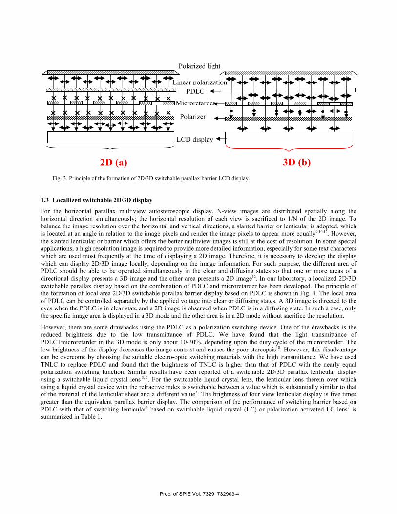
Fig. 3. Principle of the formation of 2D/3D switchable parallax barrier LCD display.
1.3 Locallized switchable 2D/3D display
For the horizontal parallax multiview autosteroscopic display, N-view images are distributed spatially along the horizontal direction simultaneously; the horizontal resolution of each view is sacrificed to 1/N of the 2D image. To balance the image resolution over the horizontal and vertical directions, a slanted barrier or lenticular is adopted, which is located at an angle in relation to the image pixels and render the image pixels to appear more equally9,10,12. However, the slanted lenticular or barrier which offers the better multiview images is still at the cost of resolution. In some special applications, a high resolution image is required to provide more detailed information, especially for some text characters which are used most frequently at the time of displaying a 2D image. Therefore, it is necessary to develop the display which can display 2D/3D image locally, depending on the image information. For such purpose, the different area of PDLC should be able to be operated simultaneously in the clear and diffusing states so that one or more areas of a directional display presents a 3D image and the other area presents a 2D image12. In our laboratory, a localized 2D/3D switchable parallax display based on the combination of PDLC and microretarder has been developed. The principle of the formation of local area 2D/3D switchable parallax barrier display based on PDLC is shown in Fig. 4. The local area of PDLC can be controlled separately by the applied voltage into clear or diffusing states. A 3D image is directed to the eyes when the PDLC is in clear state and a 2D image is observed when PDLC is in a diffusing state. In such a case, only the specific image area is displayed in a 3D mode and the other area is in a 2D mode without sacrifice the resolution.
However, there are some drawbacks using the PDLC as a polarization switching device. One of the drawbacks is the reduced brightness due to the low transmittance of PDLC. We have found that the light transmittance of PDLC+microretarder in the 3D mode is only about 10-30%, depending upon the duty cycle of the microretarder. The low brightness of the display decreases the image contrast and causes the poor stereopsis18. However, this disadvantage can be overcome by choosing the suitable electro-optic switching materials with the high transmittance. We have used TNLC to replace PDLC and found that the brightness of TNLC is higher than that of PDLC with the nearly equal polarization switching function. Similar results have been reported of a switchable 2D/3D parallax lenticular display using a switchable liquid crystal lens 3, 7. For the switchable liquid crystal lens, the lenticular lens therein over which using a liquid crystal device with the refractive index is switchable between a value which is substantially similar to that of the material of the lenticular sheet and a different value3. The brightness of four view lenticular display is five times greater than the equivalent parallax barrier display. The comparison of the performance of switching barrier based on PDLC with that of switching lenticular3 based on switchable liquid crystal (LC) or polarization activated LC lens7 is summarized in Table 1.
LCD display
PDLC
Microretarder
Polarizer
Linear polarization
3D (b)
×
Polarized light
2D (a)
× × × × × × ×× × × × × × ×
× ×
× × × × ×
Proc. of SPIE Vol. 7329 732903-4

Fig. 4. Principle of the formation of local area 2D/3D switchable parallax barrier display based on PDLC.
Table 1. The performance comparison between switching barrier and switching lenticular.
Items Switching Lenticular
(Philips3, Ocuity7)
Switching Barrier
(ITRI)
Principle Switchable LC lens, or Polarization activated LC lens Polarization switching device + μ-R
Localized switching capability Yes Yes
Brightness High (80-90% of original 2D panel) Low (~1/3-1/6 of original 2D panel)
Brightness difference on 2D/3D mode Little difference Obvious difference
Cost High Low
In order to increase the brightness of the localized switchable 2D/3D LCD display, the combination of the polarization switching LC and microretarder is used as the switching barrier. The principle of the localized 2D/3D switchable parallax barrier display based on polarization switching LC is shown in Fig. 5. When the polarization switching LC is at an on state, the linear polarization of incident light is changed into left-hand circular polarization after passing through it. This left-hand circular polarization remains the same state or changes into right-hand circular polarization when it passes through microretarder with 0 and λ/2 retardation area, respectively. Both obtained right-hand and left-hand polarization light can pass through the polarizer on LCD partially and a 2D image is directed into the viewer’s eyes. When the polarization switch LC is at an off state, similar to that of clear PDLC, a 3D image is then observed.
The brightness difference between 2D and 3D image area is a common problem for localized switchable 2D/3D displays based on the parallax barrier technologies using PDLC or TNLC as the switching device. The unbalanced image brightness degrades the image quality and causes the sickness of the viewer18. This unbalanced brightness can be compensated by using the backlight with the local area dimming function, which can control the local area brightness by using a specifically designed driving circuit19. The best choice of the light source is light emitting diode (LED), which acts like the point light source and is easy to be controlled individually. Meanwhile, the switching time of the LED is fast,
LCD display
PDLC
Microretarder
Polarizer
Linear polarization
2D 2D 3D
× × × ×× × × × × ×××××
Polarized light source
Proc. of SPIE Vol. 7329 732903-5

less than ms, so do for the PDLC and TNLC switching devices. Therefore, the residual image problem due to the slower transition time between the 2D and 3D modes is avoided and a much better image quality of the display can be obtained.
Fig. 5. Principle of the localized of 2D/3D switchable parallax barrier LCD display based on polarization switching liquid crystal.
FABRICATION OF MICROREATARDER
A microretarder is an optically transparent film with two or many kinds of optical phase retardation in different areas. By simply attaching a microretarder film to an LC panel, it’s easy to make a 2D/3D fully compatible display15-17. The microretarder can be embedded in the LCD cell to increase the viewing angle and viewing distance of stereoscopic displays20. By wearing polarized glasses, a 3D image with a wide view angle is achieved. The microretarder is also a quite important materials used as a switchable parallax barrier for the switchable 2D/3D autostereoscopic LCD display. The acceptance of autostereoscopic displays in the market is strongly influenced by the performace/cost value of the microretarder.
Several methods have been proposed for fabricating the microretarder. The most commonly used methods are based on the laser scanning15-17, and lithographic and etching techniques21,22. It has been found that microretarder prepared by laser scanning is a simple relatively, environment friendly and cost effectively method. The laser scanning process is easy to be scaled up, which is especially suitable for the roll-to-roll manufacturing of large area of retardation films. It doesn’t need the expensive masks used for the lithographic. Meanwhile, the process of laser scanning is quite compatible with the current LCD process and can be integrated in the LCD production line. A CO2 laser is used as a heating element and is directed and scanned on to the polymer retardation films (such as polycarbonates or Arton..etc.). To increase the production throughput, multi-head or multi-beam of lasers are adopted17. Microretarder prepared by a modified multi-beam laser scanning has a more uniform retardation phase distribution and a sharper transition edge between the adjacent different phases than that with a single beam laser scanning. The measured contrast ratio of the retardation film is about 100:1 of the polarization extinction ratio for the pass band the rejection band. It has been reported that the quality of stereopsis is strongly dependent on the brightness and cross talk of the image23. This kind of interocular cross talk is a major factor to induce the jeopardize stereopsis of the autostereoscopic display and creates ghost image and causes the dizziness of the viewers24. The interocular crosstalk is expressed as:
Interocular crosstalk = co-location image contrast × system crosstalk (1)
Polarized light source
Circular polarization
LCD display
Polarization switching LC
Microretarder
Polarizer
Linear polarization
2D 2D 3D
Proc. of SPIE Vol. 7329 732903-6

The interocular cross talk can be compensated with the cost of contrast. According to Weber’s law, the Weber ratio for the large enough binocular disparity at the daily luminance is 0.02. When the co-locating image contrast is 100, the calculated maximum tolerable system crosstalk contributed from the microretarder is 2×10⁻⁴. Such a value will become criteria for the design and fabrication of microretardation film offering a good quality without any perceivable crosstalk.
CONCLUSION
The getting popular applications of 3D products based on LCD panels have become more and more attractive recently. Most of the LCD panel manufacturers are concerning on the development of 3D LCD displays, especially for those major makers located in Japan, Korea, and Taiwan. However, there are some critical issues, such as image qualities and human factors, needed to be improved before the 3D LCD displays become more acceptable for commercialize productions. A multiview autostereoscopic LCD display with a localized 2D/3D switching function is developed based on the actively switchable parallax barrier technology. This switchable barrier comprises of an electro-optically switchable liquid crystal (LC) and a microretarder. Polymer dispersed liquid crystal (PDLC) with switchable clear and diffusing states and twisted nematic liquid crystal (TNLC) with polarization switching function are used as switching devices. The microretarder is prepared by self-developed multibeam laser scanning process, which is clean, friendly to the environment, and easy for scale up and mass production. The brightness difference between 2D and 3D image area is a common problem for localized switchable 2D/3D displays based on the parallax barrier technologies using PDLC or TNCL as the switching device. This unbalanced brightness can be compensated by using the backlight with the local area dimming function by using a specifically designed driving circuit.
ACKNOWLEDGEMENT The authors gratefully acknowledge the financial support from the Ministry of Economic Affairs of Taiwan under the project 8301XS1E10 and Electronics and Optoelectronics Systems Laboratories of ITRI. We also thank the support of Dr. Tzuan-Ren Jeng and Managers of Chun-Jung Chen, Chia-Chen Chen and Wu-Li Chen in the Division of 3D Image System of EOL.
REFERENCES
[1] Berkel, C. van, Parker, D. W. and Franklin A. R., “Multiview 3D-LCD,” Proc. SPIE 2653, 32-39 (1996). [2] Jachimowicz, K.E. and Lebby, M. S., “Switchable lens/diffuser,” US Pat. 5644369 (1997). [3] Battersby, S. J., “Autostereoscopic display apparatus,” US Pat. 6069650 (2000). [4] Tsai, C. H., Lee, K., Hsueh, W. J., and Lee, C.K., “Flat Panel Autostereoscopic Display,” Proc. SPIE 4297, 165-174
(2001). [5] Uehara, S. I., Takanashi, N. and Hayama, H., “3D image/2D image switching display apparatus and portable
terminal device,” EP 1394593 (2004). [6] Ijzerman, W. L., Krijn, M. P. C. M., “Autostereoscopic display,” US Pub. No. 0262395 A1 (2006). [7] Harrold, J. and Woogate, G. J., “Autostereoscopic display technology for mobile 3DTV applications,” Proc. SPIE
6490, 1-12 (2007). [8] Kim, D. S., Jung C. S. And Yoon, S. K., “Method and apparatus for encording/decoding video data to implement
local three-dimensional video,” US Pub. No. 0002041 A1 (2007). [9] Zwart, S. T. De, Ijzerman, W. L., Dekker, T. and Gorkom, R. P. Van, “3D display with an improved pixel structure
(pixelsplitting),“ US Pub. No. 031951 A1 (2008). [10] Chen, W. J., Hsu, W. L., Tsai, C. H., Wang, C. L. and Wu, C. S., “An autostereoscopic display with high resolution
and large numer of view-zones,” Proc. SPIE 6803, 68030L-1-68030L-8 (2008). [11] Sullivan, A., “DepthCube Solid-State 3D volumetric display,” Proc. SPIE 5291, 279-284 (2004).
Proc. of SPIE Vol. 7329 732903-7

[12] Harrold, J. and Woodgate G. J., “Spatial light modulator, directional display and directional light source,” US Pat. 5969850 (1999).
[13] Woodgate, G. J., Harrold, J., Jacobs, A. M. S., Moseley, R. R. and Ezra, D., “Flat panel autostereoscopic displays-characterization and enhancement,” Proc. SPIE 3957, 153-164 (2000).
[14] Wu, C. L., Tsai, C. H. And Lee, K., “2D/3D switchable mobile display,” IDMC DO-221 (2007). [15] Tsai, C. H., Huang, K. C., Lee, K. and Hsueh, W. J., “Fabrication microretarders by CO2 laser heating process
technology,” Opt. Eng. 40, 2577-2581 (2001). [16] Lee, K and Tsai, C. H., “Micro-retarder plate” US Pat. 0040703 A1 (2001). [17] Lin, L., Chen, Y. C., Tsai, C. H. and Lee, K., “A method of fabricating micro-reatrder plates by a laser system,”
Proc. SPIE 6803, 68031H-1-68031H-10 (2008). [18] Salmimaa, M. and Javenpaa, T., “Objective evaluation of multi-view autostereoscopic 3D displays,” SID
Symposium Digest 39, 267-270 (2008). [19] Huang, J. F. and Chung, L. P., “Backlight control apparatus,” US Pat. Appl. No. 12/120386 (2008). [20] Tseng, E. F., Tsai, C. H., Lin, H. Y., Huang, W. J., Huang, K. C. and Lee, K., “The fabrication of microretarder for
in-cell stereoscopic LCD using reactive liquid crystal,” Proc. SPIE 6490, 64900W1-64900W8 (2007). [21] Faris, S. M., “Novel 3D-stereoscopic imaging technology,” Proc. SPIE 2177, 180-195 (1994). [22] Faris, S. M., “Multi-mode stereoscopic imaging system,” US Pat. 5264964 (1993). [23] Huang, K. C., Yuan, J.-Y., Tsai, C. H., Hsueh, W. J. and Wang, N. Y., “A study of how crosstalk affects stereopsis
in stereoscopic displays,” Proc. SPIE 5006, 247-253 (2003). [24] Yeh, Y. and Silverstein, L. D., “Limits of fusion and depth judgement in stereoscopic color displays,” Human
Factors, 32, 45-60, (1990).
Proc. of SPIE Vol. 7329 732903-8