Experimental investigation of deposition and removal of particles during gas filtration with various...
9
Review Experimental investigation of deposition and removal of particles during gas filtration with various fabric filters E.H. Tanabe ⇑ , P.M. Barros, K.B. Rodrigues, M.L. Aguiar Chemical Engineering Department, Federal University of São Carlos, Via Washington Luis, Km 235, 13565-905 São Carlos, SP, Brazil article info Article history: Received 27 September 2010 Received in revised form 4 March 2011 Accepted 19 April 2011 Available online 17 May 2011 Keywords: Fabric filter Gas filtration Particle deposition Porosity Adhesion force abstract The aim of this study was to investigate the deposition of particles in three types of synthetic fabric filter by scanning electron microscope (SEM) and to determine the experimental adhesive force of filter cakes in fabric filters. The fabrics used were acrylic, polypropylene and polyester. The particulate matter was phosphate rock. The particles were deposited in the filters during 10 filtration cycles, with a superficial filtration velocity of 0.10 m/s and maximum pressure drop of 980 Pa across the filter. The cleaning tech- nique used was reverse air flow at 0.12 m/s. The results showed that the deposition depth of particles in the polypropylene filter was lower than those observed in the polyester and acrylic filters. Nevertheless, the residual pressure drop of the polypropylene at the beginning of the filtration assays was highest, owing to the greater accumulation of particles at the surface of the filter and the characteristics of the filter itself. It was also observed that the adhesion force was higher in the polypropylene filter than in the other filters, making it hard to remove the filter cake from that filter. Ó 2011 Elsevier B.V. All rights reserved. Contents 1. Introduction ......................................................................................................... 187 2. Theory .............................................................................................................. 188 2.1. Filtration principles .............................................................................................. 188 2.2. Adhesion forces ................................................................................................. 188 2.3. Cake porosity ................................................................................................... 188 3. Materials and methods ................................................................................................ 189 3.1. Particulate matter ............................................................................................... 189 3.2. Filter media .................................................................................................... 189 3.3. Experimental procedures ......................................................................................... 189 3.3.1. Deposition of particles in the filter media .................................................................... 189 3.3.2. Determining force of adhesion between the filter cake and filter .................................................. 190 4. Results and discussion ................................................................................................. 191 4.1. Deposition of the phosphate rock particles ........................................................................... 191 4.2. Adhesion force of the filter cakes ................................................................................... 193 5. Conclusions .......................................................................................................... 194 Acknowledgements ................................................................................................... 195 References .......................................................................................................... 195 1. Introduction The increasing concern about air pollution, recently com- pounded by industrial growth, has made the development of tech- niques and equipment for the purification of gases absolutely essential. In addition to environmental issues, improving the tech- niques for filtering various kinds of emitted particles is important to the industries that recover them. Capturing this airborne pow- der could add value to the by-product released into the atmo- sphere, increasing the overall profits of the industry. Among the several air purification methods, current filtering techniques stand out as the main approach to gas–solid separation. Bag filters are frequently used in such processes, since they are 1383-5866/$ - see front matter Ó 2011 Elsevier B.V. All rights reserved. doi:10.1016/j.seppur.2011.04.031 ⇑ Corresponding author. Tel.: +55 16 33518695; fax: +55 16 33518266. E-mail address: [email protected] (E.H. Tanabe). Separation and Purification Technology 80 (2011) 187–195 Contents lists available at ScienceDirect Separation and Purification Technology journal homepage: www.elsevier.com/locate/seppur
-
Upload
independent -
Category
Documents
-
view
1 -
download
0
Transcript of Experimental investigation of deposition and removal of particles during gas filtration with various...
Separation and Purification Technology 80 (2011) 187–195
Contents lists available at ScienceDirect
Separation and Purification Technology
journal homepage: www.elsevier .com/ locate /seppur
Review
Experimental investigation of deposition and removal of particles during gasfiltration with various fabric filters
E.H. Tanabe ⇑, P.M. Barros, K.B. Rodrigues, M.L. AguiarChemical Engineering Department, Federal University of São Carlos, Via Washington Luis, Km 235, 13565-905 São Carlos, SP, Brazil
a r t i c l e i n f o
Article history:Received 27 September 2010Received in revised form 4 March 2011Accepted 19 April 2011Available online 17 May 2011
Keywords:Fabric filterGas filtrationParticle depositionPorosityAdhesion force
1383-5866/$ - see front matter � 2011 Elsevier B.V. Adoi:10.1016/j.seppur.2011.04.031
⇑ Corresponding author. Tel.: +55 16 33518695; faxE-mail address: [email protected] (E.H. Tan
a b s t r a c t
The aim of this study was to investigate the deposition of particles in three types of synthetic fabric filterby scanning electron microscope (SEM) and to determine the experimental adhesive force of filter cakesin fabric filters. The fabrics used were acrylic, polypropylene and polyester. The particulate matter wasphosphate rock. The particles were deposited in the filters during 10 filtration cycles, with a superficialfiltration velocity of 0.10 m/s and maximum pressure drop of 980 Pa across the filter. The cleaning tech-nique used was reverse air flow at 0.12 m/s. The results showed that the deposition depth of particles inthe polypropylene filter was lower than those observed in the polyester and acrylic filters. Nevertheless,the residual pressure drop of the polypropylene at the beginning of the filtration assays was highest,owing to the greater accumulation of particles at the surface of the filter and the characteristics of thefilter itself. It was also observed that the adhesion force was higher in the polypropylene filter than inthe other filters, making it hard to remove the filter cake from that filter.
� 2011 Elsevier B.V. All rights reserved.
Contents
1. Introduction . . . . . . . . . . . . . . . . . . . . . . . . . . . . . . . . . . . . . . . . . . . . . . . . . . . . . . . . . . . . . . . . . . . . . . . . . . . . . . . . . . . . . . . . . . . . . . . . . . . . . . . . . 1872. Theory . . . . . . . . . . . . . . . . . . . . . . . . . . . . . . . . . . . . . . . . . . . . . . . . . . . . . . . . . . . . . . . . . . . . . . . . . . . . . . . . . . . . . . . . . . . . . . . . . . . . . . . . . . . . . . 188
2.1. Filtration principles . . . . . . . . . . . . . . . . . . . . . . . . . . . . . . . . . . . . . . . . . . . . . . . . . . . . . . . . . . . . . . . . . . . . . . . . . . . . . . . . . . . . . . . . . . . . . . 1882.2. Adhesion forces . . . . . . . . . . . . . . . . . . . . . . . . . . . . . . . . . . . . . . . . . . . . . . . . . . . . . . . . . . . . . . . . . . . . . . . . . . . . . . . . . . . . . . . . . . . . . . . . . 1882.3. Cake porosity . . . . . . . . . . . . . . . . . . . . . . . . . . . . . . . . . . . . . . . . . . . . . . . . . . . . . . . . . . . . . . . . . . . . . . . . . . . . . . . . . . . . . . . . . . . . . . . . . . . 188
3. Materials and methods . . . . . . . . . . . . . . . . . . . . . . . . . . . . . . . . . . . . . . . . . . . . . . . . . . . . . . . . . . . . . . . . . . . . . . . . . . . . . . . . . . . . . . . . . . . . . . . . 189
3.1. Particulate matter . . . . . . . . . . . . . . . . . . . . . . . . . . . . . . . . . . . . . . . . . . . . . . . . . . . . . . . . . . . . . . . . . . . . . . . . . . . . . . . . . . . . . . . . . . . . . . . 1893.2. Filter media . . . . . . . . . . . . . . . . . . . . . . . . . . . . . . . . . . . . . . . . . . . . . . . . . . . . . . . . . . . . . . . . . . . . . . . . . . . . . . . . . . . . . . . . . . . . . . . . . . . . 1893.3. Experimental procedures . . . . . . . . . . . . . . . . . . . . . . . . . . . . . . . . . . . . . . . . . . . . . . . . . . . . . . . . . . . . . . . . . . . . . . . . . . . . . . . . . . . . . . . . . 1893.3.1. Deposition of particles in the filter media . . . . . . . . . . . . . . . . . . . . . . . . . . . . . . . . . . . . . . . . . . . . . . . . . . . . . . . . . . . . . . . . . . . . 1893.3.2. Determining force of adhesion between the filter cake and filter. . . . . . . . . . . . . . . . . . . . . . . . . . . . . . . . . . . . . . . . . . . . . . . . . . 190
4. Results and discussion . . . . . . . . . . . . . . . . . . . . . . . . . . . . . . . . . . . . . . . . . . . . . . . . . . . . . . . . . . . . . . . . . . . . . . . . . . . . . . . . . . . . . . . . . . . . . . . . . 191
4.1. Deposition of the phosphate rock particles . . . . . . . . . . . . . . . . . . . . . . . . . . . . . . . . . . . . . . . . . . . . . . . . . . . . . . . . . . . . . . . . . . . . . . . . . . . 1914.2. Adhesion force of the filter cakes. . . . . . . . . . . . . . . . . . . . . . . . . . . . . . . . . . . . . . . . . . . . . . . . . . . . . . . . . . . . . . . . . . . . . . . . . . . . . . . . . . . 1935. Conclusions. . . . . . . . . . . . . . . . . . . . . . . . . . . . . . . . . . . . . . . . . . . . . . . . . . . . . . . . . . . . . . . . . . . . . . . . . . . . . . . . . . . . . . . . . . . . . . . . . . . . . . . . . . 194Acknowledgements . . . . . . . . . . . . . . . . . . . . . . . . . . . . . . . . . . . . . . . . . . . . . . . . . . . . . . . . . . . . . . . . . . . . . . . . . . . . . . . . . . . . . . . . . . . . . . . . . . . 195References . . . . . . . . . . . . . . . . . . . . . . . . . . . . . . . . . . . . . . . . . . . . . . . . . . . . . . . . . . . . . . . . . . . . . . . . . . . . . . . . . . . . . . . . . . . . . . . . . . . . . . . . . . 195
1. Introduction
The increasing concern about air pollution, recently com-pounded by industrial growth, has made the development of tech-niques and equipment for the purification of gases absolutely
ll rights reserved.
: +55 16 33518266.abe).
essential. In addition to environmental issues, improving the tech-niques for filtering various kinds of emitted particles is importantto the industries that recover them. Capturing this airborne pow-der could add value to the by-product released into the atmo-sphere, increasing the overall profits of the industry.
Among the several air purification methods, current filteringtechniques stand out as the main approach to gas–solid separation.Bag filters are frequently used in such processes, since they are

188 E.H. Tanabe et al. / Separation and Purification Technology 80 (2011) 187–195
inexpensive, easy to use and highly efficient at collecting particles[1]. Nowadays, a considerable variety of filters are used in indus-trial processes, including woven and nonwoven (felt) filters. Thesefabrics can be made of natural, artificial and synthetic fibers.
In order to enhance the efficiency of filter media, filters receiveseveral types of surface treatment, including calendering andsingeing. Such treatments result in less deposition inside the filtermedium, leading to a more surface-based filtration operation [2].This process improves the performance of the filter, prolongingthe filtration period and reducing the pressure drop after cleaning[3]. According to Rodrigues et al. [4], in a study on the performanceof various filter media in filtration, the treatment of the surface ofthe filter afforded in increased particle collecting efficiency and areduced residual pressure drop during the filtration.
The process of filtering can be divided into three stages. Thefirst, called depth filtration, takes place at the start of the process,when the capture of particles occurs inside the fabric, the particu-late matter being retained between the fibers. During the secondtransition stage, the particles captured start to form dendrites thatact as new collecting elements and the pressure drop starts to riseprogressively. Finally, once a layer of particles has formed insidethe filter, the stage of superficial filtration takes place, in whichthe filter cake takes on the main role of capturing the particulatematter [5].
The formation of thick filter cakes can prejudice the action ofthe filter. Consequently, the filter has to be cleaned and the filtercake removed from the filter in order to keep the pressure dropdown to a suitable level for the filtration process. The most fre-quently used cleaning techniques are mechanical vibration, reverseair flow and pulse jet.
After the cleaning process, the fabric does not regain its initialproperties, since the complete removal of particles is not possibleduring cleaning [6]. Frequently, the patchy cleaning phenomenontakes place, in which only part of the cake is removed while therest remains in patches on the surface of the filter medium [7]. Thisphenomenon is due to flaws in the cake/fabric adhesion force,which create preferential cleaning spots, and also to the cohesionforces between the particles. According to Callé et al. [8], the higherthe adhesion force, the larger the fragment of the cake detached.
Tognetti et al. [9] studied patchy cleaning, observing that asmaller amount of cake retained on the polyester filter resultedin a lower residual pressure drop during filtration.
The presence of the particulate matter in the surface pores ofthe filter after cleaning has a significant effect on particle penetra-tion and the particle mass deposited after the cleaning process,increasing considerably the residual pressure drop and the filtra-tion resistance [2,3]. Hence, better knowledge of the particle depo-sition process and adhesion forces in the cake would improve ourunderstanding and control of gas filtration operations.
With these points in mind, this study was to investigate theinfluence of the physical and chemical properties of the filter med-ium in the operation of gas filtration (cake formation and filtercleaning cycles). For these purposes, several variables were ana-lyzed during the formation and removal of the cake, over a se-quence of filtration cycles, namely: pressure drop across thefilter, mass retained after cleaning, efficiency of regeneration,depth of penetration and the number of particles deposited insidethe filtering medium.
2. Theory
2.1. Filtration principles
Filtration is an important operation used to separate gases fromsolids [10]. One variable used to describe performance in a filter
medium is the pressure drop (DP). It is very important to knowDP, since it determines the filter cleaning frequency and, conse-quently, affects the filter life [11]. Furthermore, the maximum per-missible pressure drop before cleaning must be known todetermine the required power of the system.
In general, the total pressure drop (DPT) observed in a filteringoperation is divided into two parts: the pressure drop in the filtermedium (DPM) and the pressure drop across the cake being formedon the filter (DPC), as indicated in following equation [12]:
DPT ¼ DPM þ DPC ¼ kmv s þ kcv sW ð1Þ
where km is the resistance of the filter medium, kc the specific resis-tance of the cake, W the mass of particle deposited per unit cross-sectional area of filter, and vs is the filtration superficial velocity.
2.2. Adhesion forces
A number of studies have been done on the pressure drop infabric filters and their efficiency in operation. However, little hasbeen reported regarding cleaning cycles and their effects on the fil-ter. Knowledge of the adhesion force between the cake and fabric isof great importance to the cleaning of the fabric, since it enablesthe correct design of the cake-removal step. Nevertheless, it israrely possible to measure the actual forces involved when dustparticle adhere to fabric surfaces, except under controlled condi-tions in the laboratory [13].
Two methods of removing the cake are found in the literaturethat, in laboratory conditions, enable the cake adhesion force tobe estimated. The first, proposed by Morris and Allen [14], is basedon a single mechanical pulse, while the second, put forward by Se-ville et al. [15], makes use of a reverse flow of air. In both methods,it is assumed that the cake is ruptured at the fabric-cake interface.
Seville et al. [15] suggests a method to estimate the cake/fabricadhesion force by observing a flow of gas in the opposite to the fil-tration. Below the critical removal velocity, the cake behaves as inthe filtration cycle. As the critical velocity is approached, the pres-sure drop through the filter and cake can be written as:
DPTc ¼ kmv sc þ DPCc ð2Þ
where the subscript c indicates that the variables have their criticalvalues for removal. Under such conditions, DPCc, the pressure dropin the cake, is the cake/fabric force of adhesion per unit area and vsc
is the superficial velocity of the gas under the conditions of removal.The Seville method was used in previous work, to determine the
adhesion force per unit cross-sectional area, with satisfactoryresults [17,18].
2.3. Cake porosity
The porosity of the filter cake is directly related to its compress-ibility, which in turn determines its degree of compaction and thusinfluences the rise in the pressure drop across the cake [16]. Thecompressibility of gas filter cakes has been measured by someresearchers [12,19–22].
While the study of porosity and compressibility of gas filtercakes is of great importance for the design and operation of filters,little has been published yet on this topic. This reflects the diffi-culty encountered in determining the porosity of the cakes exper-imentally, due to the extreme fragility of the dust layer formed onthe surface of the fabric [19]. Notwithstanding this, a few research-ers [17,20,22,23] have used theoretical correlations to predict thisvariable.
Aguiar and Coury [20] and Al-Otoom [23] estimated the poros-ity of the cake by employing the correlations described by Ergunand Rudnick-Happel and reported that, for thinner cakes, the esti-mated values were close to those obtained experimentally. On the

Table 1Characteristics of the particulate matter.
Characterization Phosphate rock material particulate
Specific mass (103 kg/m3) 3.1Mean volume diameter (lm) 4.8Mean Stokes’s diameter (lm) 5.6Sphericity 0.59
E.H. Tanabe et al. / Separation and Purification Technology 80 (2011) 187–195 189
other hand, Aguiar and Coury [20] observed that, as cakes becamethicker, the Ergun correlation [Eq. (3)] was the better approxima-tion to experimental data; hence, this formula has been adoptedin the present study
DPL¼ 150ð1� eÞ2lvs
e3d2p
þ1:75ð1� eÞqgv2
s
e3dpð3Þ
where L is the thickness of the cake, e is the mean porosity of thelayer, l and qg the viscosity and density of the gas, vs the superficialvelocity of filtration and dp particles of mean Stokes’ diameter. For avery high collection efficiency, the mass of particles deposited (M)on the filter is:
M ¼ Qt ¼ LAqpð1� eÞ ð4Þ
where Q is the mass flow rate, t the filtration time, A the superficialarea of the cake, and qp the particle density. Thus, L can be definedas:
L ¼ QtAqpð1� eÞ ð5Þ
Substituting L [Eq. (5)] in Eq. (3) leads to the Ergun’s equation asa function of filtration time:
DPt¼ 150ð1� eÞlQv s
e3Aqpd2p
þ1:75Qqgv2
s
e3Aqpdpð6Þ
This equation can be used to estimate the porosity of the cakethrough the experimental data of pressure drop (DP) versus time(t) [20].
3. Materials and methods
In this section, the characteristics of the materials used, proce-dures of filtration and the experimental tests and analyses aredescribed.
3.1. Particulate matter
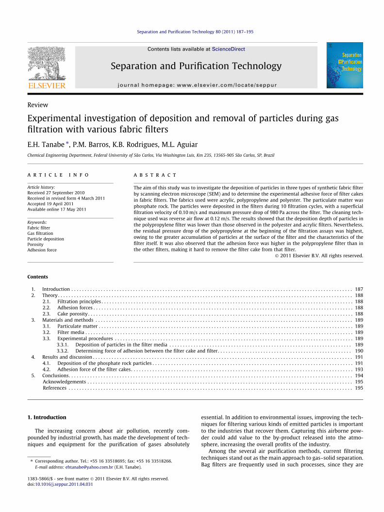
The particulate used in the filtration experiments was pow-dered phosphate rock. Fig. 1 shows a micrograph of the phosphaterock taken with a scanning electron microscope (SEM). Table 1shows the characteristics of the particulate. The sphericity was
Fig. 1. SEM image of the surface of the phosphate rock particles, at a magnificationof 1000�.
determined by Image Pro Plus 7.0 and calculated from the follow-ing equation [24]:
/ ¼ 4pA
P2e
ð7Þ
where A is a projected area and Pe the perimeter.The density of the particles was determined with a helium pyc-
nometer AccuPyc 1330 (Micromeritics). The mean volume diame-ter was measure with a Malvern Mastersizer Microplus and themean Stokes’ diameter with a Sedigraph 5000 ET Particle Size Ana-lyzer (Micromeritics).
3.2. Filter media
The filters used in the experiments were acrylic, polypropylene,and polyester. Fig. 2 shows SEM micrographs of the filter surfaces,where it may be observed that the fabrics show signs of calender-ing and singeing treatments, which tend to prevent particles pene-trating inside the filter element, leading to a more superficialfiltration.
The characteristics and physical properties of the fabrics areshown in Table 2. Rodrigues et al. [4] determined the surfaceporosity by analyzing the images obtained with a scanning elec-tron microscope (SEM).
3.3. Experimental procedures
Fig. 3 shows the apparatus used in the filtration tests, whichconsists of a dust dispenser, an air humidity control system, a fil-tration system, a data acquisition system, pressure transducers, acontroller and a blower. The filtration system was composed oftwo cylinders and two conical lids. Between the cylinders werefixed a stainless steel frame to hold the filter medium. The lidswere each connected to a 2-in tube, the upper one leading to thedust dispenser and the lower to a 7.5 HP blower. To control therotation speed of the blower and hence maintain a constant filter-ing velocity, an orifice plate transducer was installed in line, nextto the blower, which monitors the flow rate whether the air isbeing sucked (filtration) or blown (cleaning). A data-acquisitioncard was coupled to the main system to collect the values of pres-sure drop, filtering time and air flow rate, during the tests.
3.3.1. Deposition of particles in the filter mediaThe air in the dust dispenser was brought to constant air
humidity, below 15% R.H. The particles were sucked (through aVenturi tube) and sprayed into the top part of the filter system.The air stream flowed through the filter, with a filtration area of0.0225 m2, placed perpendicular to the direction of flow.
The rate of flow of air exiting the filter was measured with anorifice plate coupled to a digital manometer, before the air wasreleased into the atmosphere through a blower controlled by feed-back. The superficial filtration velocity (vs) was kept constant at0.10 m/s, with a fixed maximum pressure drop of 980 Pa. The massflow rate of the powder was 0.04 g/s. The cake was removed byreverse air flow at a cleaning velocity (vl) of 0.12 m/s for 2 min.
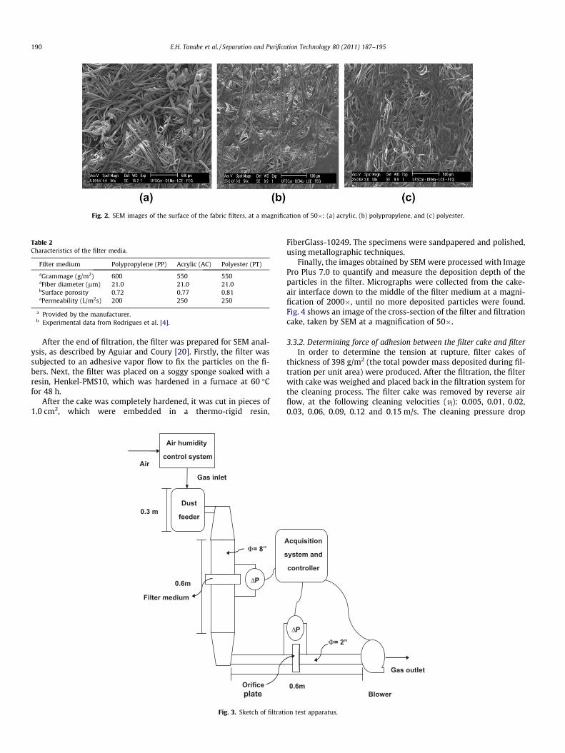
Fig. 2. SEM images of the surface of the fabric filters, at a magnification of 50�: (a) acrylic, (b) polypropylene, and (c) polyester.
Table 2Characteristics of the filter media.
Filter medium Polypropylene (PP) Acrylic (AC) Polyester (PT)
aGrammage (g/m2) 600 550 550aFiber diameter (lm) 21.0 21.0 21.0bSurface porosity 0.72 0.77 0.81aPermeability (L/m2s) 200 250 250
a Provided by the manufacturer.b Experimental data from Rodrigues et al. [4].
190 E.H. Tanabe et al. / Separation and Purification Technology 80 (2011) 187–195
After the end of filtration, the filter was prepared for SEM anal-ysis, as described by Aguiar and Coury [20]. Firstly, the filter wassubjected to an adhesive vapor flow to fix the particles on the fi-bers. Next, the filter was placed on a soggy sponge soaked with aresin, Henkel-PMS10, which was hardened in a furnace at 60 �Cfor 48 h.
After the cake was completely hardened, it was cut in pieces of1.0 cm2, which were embedded in a thermo-rigid resin,
Gas inlet
Dust
feeder
Filter medium
0.3 m
0.6m
Φ= 8’’
ΔP
Orifice plate
Air humidity
control system Air
Fig. 3. Sketch of filtrati
FiberGlass-10249. The specimens were sandpapered and polished,using metallographic techniques.
Finally, the images obtained by SEM were processed with ImagePro Plus 7.0 to quantify and measure the deposition depth of theparticles in the filter. Micrographs were collected from the cake-air interface down to the middle of the filter medium at a magni-fication of 2000�, until no more deposited particles were found.Fig. 4 shows an image of the cross-section of the filter and filtrationcake, taken by SEM at a magnification of 50�.
3.3.2. Determining force of adhesion between the filter cake and filterIn order to determine the tension at rupture, filter cakes of
thickness of 398 g/m2 (the total powder mass deposited during fil-tration per unit area) were produced. After the filtration, the filterwith cake was weighed and placed back in the filtration system forthe cleaning process. The filter cake was removed by reverse airflow, at the following cleaning velocities (vl): 0.005, 0.01, 0.02,0.03, 0.06, 0.09, 0.12 and 0.15 m/s. The cleaning pressure drop
Blower
Acquisition
system and
controller
0.6m
Gas outlet
Φ= 2’’
ΔP
on test apparatus.
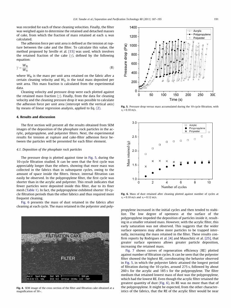
Fig. 5. Pressure drop versus mass accumulated during the 10-cycle filtration, withvs = 0.10 m/s.
Fig. 6. Mass of dust retained after cleaning plotted against number of cycles atvs = 0.10 m/s and vl = 0.12 m/s.
E.H. Tanabe et al. / Separation and Purification Technology 80 (2011) 187–195 191
was recorded for each of these cleaning velocities. Finally, the filterwas weighed again to determine the retained and detached massesof cake, from which the fraction of mass retained at each vl wascalculated.
The adhesion force per unit area is defined as the tension at rup-ture between the cake and the filter. To calculate this value, themethod proposed by Seville et al. [15] was used, which involvesthe retained fraction of the cake (c), defined by the followingequation:
c ¼WRi
WEið8Þ
where WRi is the mass per unit area retained on the fabric after acertain cleaning velocity and WEi is the total mass deposited perunit area. This mass fraction is calculated from the experimentaldata.
Cleaning velocity and pressure drop were each plotted againstthe retained mass fraction (c). Finally, from the data for cleaningvelocity and the cleaning pressure drop it was possible to calculatethe adhesion force per unit area (intercept with the vertical axis)by means of linear regression analysis, applied to Eq. (2).
4. Results and discussion
The first section will present all the results obtained from SEMimages of the deposition of the phosphate rock particles in the ac-rylic, polypropylene, and polyester filters. Next, the experimentalresults for tension at rupture and cake-filter adhesion force be-tween the particles will be presented for each filter element.
4.1. Deposition of the phosphate rock particles
The pressure drop is plotted against time in Fig. 5, during the10-cycle filtration studied. It can be seen that the first cycle wasappreciably longer than the others, showing that more mass wascollected in the fabrics than in subsequent cycles, owing to theamount of space inside the filters. Hence, internal filtration caneasily be observed. In the polypropylene filter, the first cycle wasshorter than in the acrylic and polyester. This result indicates thatfewer particles were deposited inside this filter, due to its finermesh (Table 1). In fact, the polypropylene exhibited shorter 10-cy-cle filtration periods than the other fabrics and thus required morefrequent cleaning.
Fig. 6 presents the mass of dust retained in the fabrics aftercleaning at each cycle. The mass retained in the polyester and poly-
Fig. 4. SEM image of the cross section of the filter and filtration cake obtained at amagnification of 50�.
propylene increased in the initial cycles and then tended to stabi-lize. The low degree of openness at the surface of thepolypropylene impeded the deposition of particles inside it, result-ing in a smaller retained mass. However, with the acrylic filter, thisearly saturation was not observed. This suggests that the widersurface openness may allow more particles to be trapped inter-nally, increasing the mass retained in the filter. These results con-firm reports by Rodrigues et al. [4] and Mauschitz et al. [25], thatgreater surface openness allows greater particle deposition,increasing the retained mass.
Fig. 7 shows curves of regeneration efficiency (RE) plottedagainst number of filtration cycles. It can be seen that the polyesterfilter showed the highest RE, corroborating the behavior observedin Fig. 5, in which the polyester fabric attained the longest periodof filtration during the 10 cycles, around 275 s, followed by about260 s for the acrylic and 185 s for the polypropylene. The filtermedium that retained lowest mass of dust was the polypropylene,which had the lowest RE. Even though the acrylic filter retained thegreatest quantity of dust (Fig. 6), its RE was no more than that ofthe polypropylene. It might be expected, from the other character-istics of the fabrics, that the RE of the acrylic filter would be near
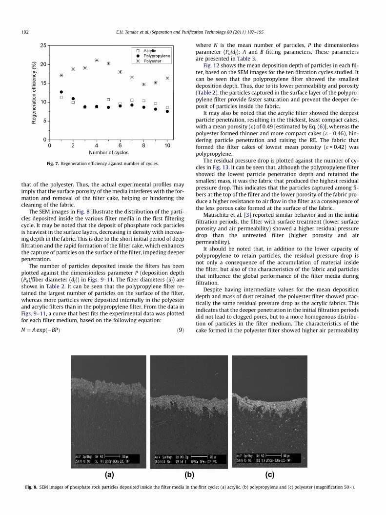
Fig. 7. Regeneration efficiency against number of cycles.
192 E.H. Tanabe et al. / Separation and Purification Technology 80 (2011) 187–195
that of the polyester. Thus, the actual experimental profiles mayimply that the surface porosity of the media interferes with the for-mation and removal of the filter cake, helping or hindering thecleaning of the fabric.
The SEM images in Fig. 8 illustrate the distribution of the parti-cles deposited inside the various filter media in the first filteringcycle. It may be noted that the deposit of phosphate rock particlesis heaviest in the surface layers, decreasing in density with increas-ing depth in the fabric. This is due to the short initial period of deepfiltration and the rapid formation of the filter cake, which enhancesthe capture of particles on the surface of the filter, impeding deeperpenetration.
The number of particles deposited inside the filters has beenplotted against the dimensionless parameter P (deposition depth(Pd)/fiber diameter (df)) in Figs. 9–11. The fiber diameters (df) areshown in Table 2. It can be seen that the polypropylene filter re-tained the largest number of particles on the surface of the filter,whereas more particles were deposited internally in the polyesterand acrylic filters than in the polypropylene filter. From the data inFigs. 9–11, a curve that best fits the experimental data was plottedfor each filter medium, based on the following equation:
N ¼ A expð�BPÞ ð9Þ
Fig. 8. SEM images of phosphate rock particles deposited inside the filter media in th
where N is the mean number of particles, P the dimensionlessparameter (Pd/df); A and B fitting parameters. These parametersare presented in Table 3.
Fig. 12 shows the mean deposition depth of particles in each fil-ter, based on the SEM images for the ten filtration cycles studied. Itcan be seen that the polypropylene filter showed the smallestdeposition depth. Thus, due to its lower permeability and porosity(Table 2), the particles captured in the surface layer of the polypro-pylene filter provide faster saturation and prevent the deeper de-posit of particles inside the fabric.
It may also be noted that the acrylic filter showed the deepestparticle penetration, resulting in the thickest, least compact cakes,with a mean porosity (e) of 0.49 [estimated by Eq. (6)], whereas thepolyester formed thinner and more compact cakes (e = 0.46), hin-dering particle penetration and raising the RE. The fabric thatformed the filter cakes of lowest mean porosity (e = 0.42) waspolypropylene.
The residual pressure drop is plotted against the number of cy-cles in Fig. 13. It can be seen that, although the polypropylene filtershowed the lowest particle penetration depth and retained thesmallest mass, it was the fabric that produced the highest residualpressure drop. This indicates that the particles captured among fi-bers at the top of the filter and the lower porosity of the fabric pro-duce a higher resistance to air flow in the filter as a consequence ofthe less porous cake formed at the surface of the fabric.
Mauschitz et al. [3] reported similar behavior and in the initialfiltration periods, the filter with surface treatment (lower surfaceporosity and air permeability) showed a higher residual pressuredrop than the untreated filter (higher porosity and airpermeability).
It should be noted that, in addition to the lower capacity ofpolypropylene to retain particles, the residual pressure drop isnot only a consequence of the accumulation of material insidethe filter, but also of the characteristics of the fabric and particlesthat influence the global performance of the filter media duringfiltration.
Despite having intermediate values for the mean depositiondepth and mass of dust retained, the polyester filter showed prac-tically the same residual pressure drop as the acrylic fabrics. Thisindicates that the deeper penetration in the initial filtration periodsdid not lead to clogged pores, but to a more homogenous distribu-tion of particles in the filter medium. The characteristics of thecake formed in the polyester filter showed higher air permeability
e first cycle: (a) acrylic, (b) polypropylene and (c) polyester (magnification 50�).

Fig. 9. Variation of the mean number of particles deposited inside the acrylic filterwith the dimensionless parameter P.
Fig. 11. Variation of the mean number of particles deposited inside the polyesterfilter with the dimensionless parameter P.
Fig. 10. Variation of the mean number of particles deposited inside the polypro-pylene filter with the dimensionless parameter P.
Table 3Parameters of the mean number of particles Eq. 9.
Parameter Acrylic Polypropylene Polyester
A 459.5 516.1 499.8B 0.15 0.23 0.13R2 0.92 0.97 0.91
Fig. 12. Variation of the mean deposition depth of particles with the number ofcycles.
Fig. 13. Residual pressure drop plotted against number of cycles.
E.H. Tanabe et al. / Separation and Purification Technology 80 (2011) 187–195 193
and lower flow resistance facilitating the stripping of the cake fromthe surface of the fabric.
4.2. Adhesion force of the filter cakes
Fig. 14 shows the cleaning velocity plotted against the fractionof the mass retained after cleaning. It can be seen that the higherthe cleaning velocity, the larger the amount of dust removed fromthe filters. Rodrigues [26] found similar results, while studying therupture tension needed to remove phosphate rock particles frompolypropylene and cotton filters. It was concluded that the poly-propylene filter exhibited the lowest fraction of mass retainedamong the fabrics studied, as mentioned previously.
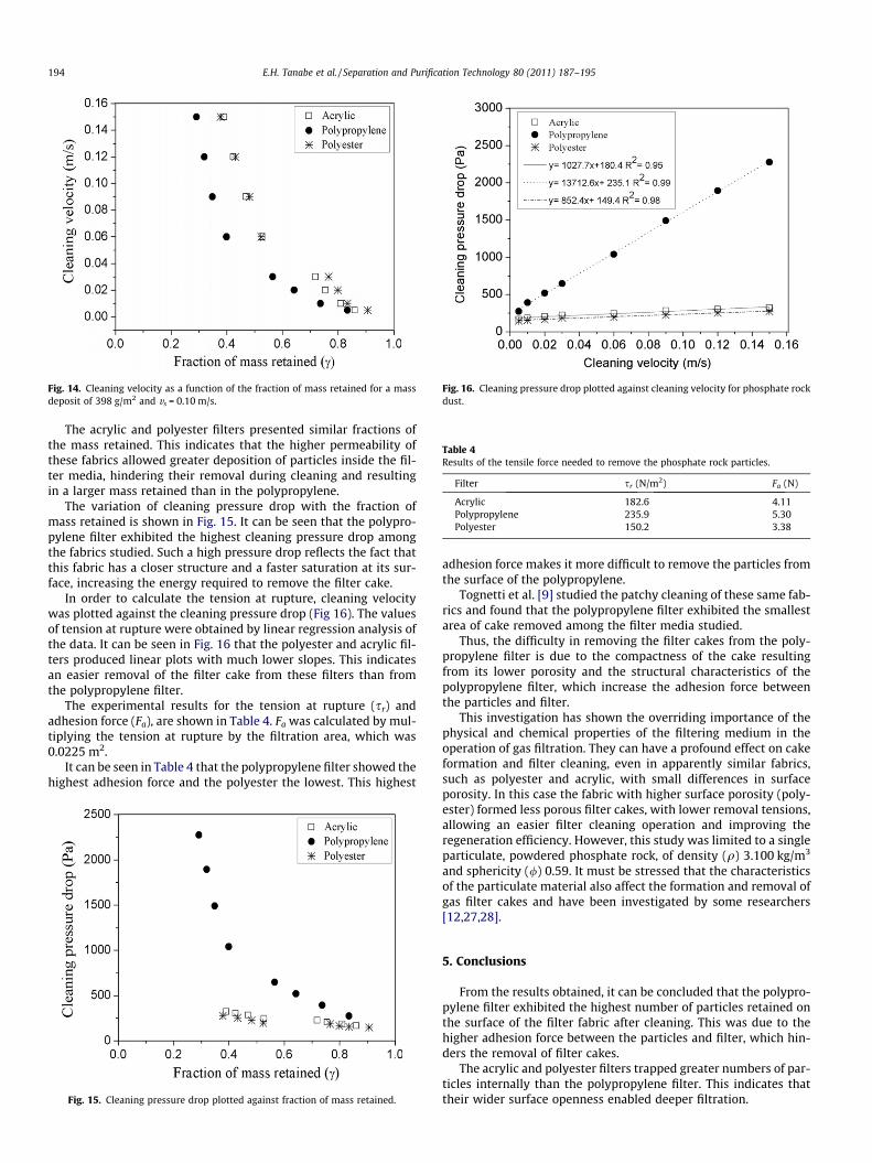
Fig. 14. Cleaning velocity as a function of the fraction of mass retained for a massdeposit of 398 g/m2 and vs = 0.10 m/s.
Fig. 16. Cleaning pressure drop plotted against cleaning velocity for phosphate rockdust.
Table 4Results of the tensile force needed to remove the phosphate rock particles.
Filter sr (N/m2) Fa (N)
Acrylic 182.6 4.11Polypropylene 235.9 5.30Polyester 150.2 3.38
194 E.H. Tanabe et al. / Separation and Purification Technology 80 (2011) 187–195
The acrylic and polyester filters presented similar fractions ofthe mass retained. This indicates that the higher permeability ofthese fabrics allowed greater deposition of particles inside the fil-ter media, hindering their removal during cleaning and resultingin a larger mass retained than in the polypropylene.
The variation of cleaning pressure drop with the fraction ofmass retained is shown in Fig. 15. It can be seen that the polypro-pylene filter exhibited the highest cleaning pressure drop amongthe fabrics studied. Such a high pressure drop reflects the fact thatthis fabric has a closer structure and a faster saturation at its sur-face, increasing the energy required to remove the filter cake.
In order to calculate the tension at rupture, cleaning velocitywas plotted against the cleaning pressure drop (Fig 16). The valuesof tension at rupture were obtained by linear regression analysis ofthe data. It can be seen in Fig. 16 that the polyester and acrylic fil-ters produced linear plots with much lower slopes. This indicatesan easier removal of the filter cake from these filters than fromthe polypropylene filter.
The experimental results for the tension at rupture (sr) andadhesion force (Fa), are shown in Table 4. Fa was calculated by mul-tiplying the tension at rupture by the filtration area, which was0.0225 m2.
It can be seen in Table 4 that the polypropylene filter showed thehighest adhesion force and the polyester the lowest. This highest
Fig. 15. Cleaning pressure drop plotted against fraction of mass retained.
adhesion force makes it more difficult to remove the particles fromthe surface of the polypropylene.
Tognetti et al. [9] studied the patchy cleaning of these same fab-rics and found that the polypropylene filter exhibited the smallestarea of cake removed among the filter media studied.
Thus, the difficulty in removing the filter cakes from the poly-propylene filter is due to the compactness of the cake resultingfrom its lower porosity and the structural characteristics of thepolypropylene filter, which increase the adhesion force betweenthe particles and filter.
This investigation has shown the overriding importance of thephysical and chemical properties of the filtering medium in theoperation of gas filtration. They can have a profound effect on cakeformation and filter cleaning, even in apparently similar fabrics,such as polyester and acrylic, with small differences in surfaceporosity. In this case the fabric with higher surface porosity (poly-ester) formed less porous filter cakes, with lower removal tensions,allowing an easier filter cleaning operation and improving theregeneration efficiency. However, this study was limited to a singleparticulate, powdered phosphate rock, of density (q) 3.100 kg/m3
and sphericity (/) 0.59. It must be stressed that the characteristicsof the particulate material also affect the formation and removal ofgas filter cakes and have been investigated by some researchers[12,27,28].
5. Conclusions
From the results obtained, it can be concluded that the polypro-pylene filter exhibited the highest number of particles retained onthe surface of the filter fabric after cleaning. This was due to thehigher adhesion force between the particles and filter, which hin-ders the removal of filter cakes.
The acrylic and polyester filters trapped greater numbers of par-ticles internally than the polypropylene filter. This indicates thattheir wider surface openness enabled deeper filtration.

E.H. Tanabe et al. / Separation and Purification Technology 80 (2011) 187–195 195
The high residual pressure drop in the polypropylene filter, rel-ative to the acrylic and polyester filters, was due to the greaternumber of particles retained on the surface of the filter and to itscloser structure, which made it the filter with the highest resis-tance to flow.
The polyester and acrylic filters performed similarly and theirbehavior was stabler than that of the polypropylene filter, underthe experimental conditions studied.
Finally, it may be concluded that the increase in the residualpressure drop does not depend only on the deposition of particles,but also on the operational conditions of the filtration and cleaningprocesses, the cake-fabric adhesion forces, the cake porosity andthe characteristics of the filter medium.
Acknowledgements
Authors gratefully acknowledge Gino Cacciari Indústria e Comé-rcio de Filtros Ltda for the filter media, Henkel Brasil for the resinPMS-10, Fosfértil for the phosphate rock, and CNPq for the financialsupport.
References
[1] C.B. Song, H.S. Park, Analytic solutions for filtration of polydisperse aerosols infibrous filter, Powder Technol. 170 (2006) 64–70.
[2] W. Höflinger, H. Rud, G. Mauschitz, Estimation on the particle penetration andthe dust holding capacity of different surface-treated needle felts, Sep. Purif.Technol. 58 (2007) 256–261.
[3] G. Mauschitz, W. Koschutnig, W. Hoeflinger, Analysis of the clogging behaviorof thermally finished nonwoven dust filter media by optically detectedporosity parameters, In: Proceedings Filtech Europa, Wiesbanden, Germany,2005, pp. II20–II28.
[4] K.B. Rodrigues, E.F. Tieni, J.A.S. Gonçalves, M.L. Aguiar, Filter media and powdermaterials influence in the performance of filtration cycles, In: ProceedingsFiltech Europa, Wiesbaden, Germany, 2005, pp. II123–II130.
[5] C.B. Song, H.S. Park, K.W. Lee, Experimental study of filter clogging withmonodisperse PSL particles, Powder Technol. 163 (2006) 152–159.
[6] N. Mao, Y. Yao, M. Hata, M. Wada, C. Kanaoka, Comparison of filter cleaningperformance between VDI and JIS testing rigs for cleanable fabric filter, PowderTechnol. 180 (2008) 109–114.
[7] S. Callé, P. Contal, D. Thomas, D. Bémer, D. Leclerc, Evolutions of efficiency andpressure drop of filter media during clogging and cleaning cycles, PowderTechnol. 128 (2002) 213–217.
[8] S. Callé, D. Bémer, D. Thomas, P. Contal, D. Leclerc, Changes in theperformances of filter media during clogging and cleaning cycles, Ann.Occup. Hyg. 45 (2001) 115–121.
[9] E.R. Tognetti, P.A. Paschoal, V.M. Osório, M.L. Aguiar, Influence of theoperational conditions on the formation and detachment of the cake on gas-solid filtration, In: Proceedings Filtech Europa, Wiesbaden, Germany, 2007, pp.II136–II143.
[10] R.P. Donavan, Fabric filtration for combustion sources, Marcel Dekker, NewYork, 1985.
[11] K. Jeon, Y.A. Jung, Simulation study on the compression behavior of dust cakes,Powder Technol. 141 (2004) 1–11.
[12] Y.H. Cheng, C.J. Tsai, Factors influencing pressure drop through of a dust cakeduring filtration, Aerosol Sci. Technol. 29 (1998) 315–328.
[13] E. Schmidt, F. Löffler, Preparation of dust cakes for microscopic examination,Powder Technol. 60 (1990) 173–177.
[14] K. Morris, R.W.K. Allen, The influence of dust and gas properties on cakeadhesion in fabric filters, Filtr. Separat. 33 (1996) 339–343.
[15] J.P.K. Seville, W. Cheung, R.A. Clift, Patchy cleaning interpretation of dust cakerelease form non-woven fabrics, Filtr. Separat. 26 (1989) 187–190.
[16] J.H. Kim, Y. Liang, K.M. Sakong, J.H. Choi, Y.C. Bak, Temperature effect on thepressure drop across the cake of coal gasification ash formed on a ceramicfilter, Powder Technol. 181 (2008) 67–73.
[17] C.R.N. Silva, V.S. Negrini, M.L. Aguiar, J.R. Coury, Influence of gas velocity on thecake formation and detachment, Powder Technol. 101 (1999) 165–172.
[18] J.R. Coury, M.L. Aguiar, Rupture of dry agglomerates, Powder Technol. 85(1995) 37–43.
[19] J.H. Choi, S.J. Ha, H.J. Jang, Compression properties of dust cake of fine fly ashesfrom a fluidized bed coal combustor on a ceramic filter, Powder Technol. 140(2004) 106–115.
[20] M.L. Aguiar, J.R. Coury, Cake formation in fabric filtration of gases, Ind. Eng.Chem. Res. 35 (1996) 3673–3679.
[21] Y.S. Chen, S.S. Hsiau, Influence of filtration superficial velocity on cakecompression and cake formation, Chem. Eng. Process 48 (2009) 988–996.
[22] Y. Endo, D.R. Chen, D.H.Y. Pui, Effects of particle polydispersity and shapefactor during dust cake loading on air filters, Powder Technol. 98 (1998) 241–249.
[23] A.Y. Al-Otoom, Prediction of the collection efficiency, the porosity, and thepressure drop across filter cakes in particulate air filtration, Atmos. Environ. 39(2005) 51–57.
[24] U. Ulusoy, Application of ANOVA to image analysis results of talc particlesproduced by different milling, Powder Technol. 188 (2008) 133–138.
[25] G. Mauschitz, H. Rud, W. Hoflinger, Particle deposition in the depth ofnonwoven dust filter media and its effect on filter clogging. In: ProceedingsFiltech Europa, Wiesbaden, Germany, 2007, pp. II34–II41.
[26] A.C.M. Rodrigues. Master’s Dissertation, Federal University of São Carlos, 2004(in Portuguese).
[27] Y. Endo, D.R. Chen, D.Y.H. Pui, Air and water permeation resistance across dustcakes on filters–effects of particle polydispersity and shape factor, PowderTechnol. 118 (2001) 24–31.
[28] L.X. Ito, M.L. Aguiar, A study of the porosity of gas filtration cakes, Braz. J.Chem. Eng.