Three-Dimensional Displays: A Review and Applications ...
10
IEEE TRANSACTIONS ON BROADCASTING 57(2), JUNE 2011, PP. 362-371, DOI: 10.1109/TBC.2011.2130930 Three-Dimensional Displays: A Review and Applications Analysis Nicolas S. Holliman, Neil A. Dodgson, Gregg E. Favalora, and Lachlan Pockett Abstract—S. Benton published a definitive taxonomy of the first one hundred and seventy years of 3D displays covering the field up to the year 2000. In this article we review how display technolo- gies have advanced in the last ten years and update Benton’s tax- onomy to include the latest additions. Our aim is to produce a dis- play taxonomy suitable for content producers highlighting which displays have common requirements for image delivery. We also analyze key technical characteristics of 3D displays and use these characteristics to suggest the future applications for each category of display. Index Terms—Human factors, image resolution, stereo vision, three dimensional displays. I. INTRODUCTION T HE field of three-dimensional display has become one with a fascinating variation and depth of research since the original observations by Sir Charles Wheatstone were presented to the Royal Society in London in 1838 [1] following his con- struction of the first stereoscope in 1832. The subsequent 170 years of progress in the development of three-dimensional dis- plays were reviewed in Benton’s definitive book [2] both high- lighting progress in the field and providing a taxonomy within which new developments can be categorized. Here we review recent technology developments in the field within Benton’s framework and then analyze the application suitability of dif- ferent display designs. The taxonomy we adopt [2] is based on the degree of parallax that a display system is capable of reproducing at any percep- tual instant in time. The simplest are two-view systems which at any instant reproduce just two views, one for the left eye and one for the right eye. An intermediate display system in this tax- onomy is the horizontal-parallax displays which produce mul- tiple horizontal parallax views of a scene; also known as a par- allax panoramagram [3]. These displays allow a viewer to look around objects in the 3D image and see differing views at dif- fering horizontal eye positions. The most complete display type in our taxonomy are those that are full-parallax. These repro- duce variations in the images seen by the viewer with both hor- izontal and vertical head movements. The importance of this taxonomy is that it captures how close a display technology is to reproducing the real world experience of parallax and the characteristics of a display that are most im- portant to content generators. Specifically, it defines how much information a particular display technology needs to be supplied with to operate, this in turn determines camera systems, edit functions and the communication bandwidth required to pro- duce and distribute content. A term recently used to describe 3D displays is light field dis- plays. This has been adopted from computer graphics and com- putational photography where it describes the rendering of light traveling in a set of directions from an object [4]. A similar term used is free viewpoint TV where a synthetic camera is used to render views not captured by a physical camera. All displays re- produce some form of light field and as the directionality of the display increases, i.e. the number of parallax views increases, the closer the light field produced becomes to that of the real scene. II. TWO-VIEW 3D DISPLAYS The category of displays that generate two separate viewing zones, one for each eye, is large and ranges from simple hand- held Wheatstone stereo viewers through head-mounted elec- tronic displays to autostereoscopic head tracked displays. These fall into different categories as shown in Fig. 1. A. Wavelength Selective Displays One of the earliest and simplest forms of two-view display is the color anaglyph in which a user views a color print or display encoding left and right views in two different color channels with a pair of colored filter glasses, often red for the left eye and cyan for the right eye. This has the advantage that almost any color display device can be used to present the stereo-pair image but the obvious disadvantage is that each eye is seeing a different color stimulus. A recent adaptation of the anaglyph approach is the Infitec [5] system. This transmits two different full color images to each eye, by using different narrow waveband primary colors for each eye. While normally the red primary is a broad range of wavelengths centered at a wavelength of about 600 nm, in the Infitec approach only a small range of red wavelengths are trans- mitted to the left eye, centered on 600 nm and spanning about 50 nm, while a different range, centered on 650 nm and span- ning 50 nm, are transmitted to the right eye. The user then wears glasses that are tuned so that the left eye filter only lets through narrowband wavelengths around 600 nm and the right eye only
-
Upload
khangminh22 -
Category
Documents
-
view
0 -
download
0
Transcript of Three-Dimensional Displays: A Review and Applications ...
IEEE TRANSACTIONS ON BROADCASTING 57(2), JUNE 2011, PP. 362-371, DOI: 10.1109/TBC.2011.2130930
Three-Dimensional Displays: A Review andApplications Analysis
Nicolas S. Holliman, Neil A. Dodgson, Gregg E. Favalora, and Lachlan Pockett
Abstract—S. Benton published a definitive taxonomy of the firstone hundred and seventy years of 3D displays covering the field upto the year 2000. In this article we review how display technolo-gies have advanced in the last ten years and update Benton’s tax-onomy to include the latest additions. Our aim is to produce a dis-play taxonomy suitable for content producers highlighting whichdisplays have common requirements for image delivery. We alsoanalyze key technical characteristics of 3D displays and use thesecharacteristics to suggest the future applications for each categoryof display.
Index Terms—Human factors, image resolution, stereo vision,three dimensional displays.
I. INTRODUCTION
T HE field of three-dimensional display has become onewith a fascinating variation and depth of research since the
original observations by Sir Charles Wheatstone were presentedto the Royal Society in London in 1838 [1] following his con-struction of the first stereoscope in 1832. The subsequent 170years of progress in the development of three-dimensional dis-plays were reviewed in Benton’s definitive book [2] both high-lighting progress in the field and providing a taxonomy withinwhich new developments can be categorized. Here we reviewrecent technology developments in the field within Benton’sframework and then analyze the application suitability of dif-ferent display designs.
The taxonomy we adopt [2] is based on the degree of parallaxthat a display system is capable of reproducing at any percep-tual instant in time. The simplest are two-view systems whichat any instant reproduce just two views, one for the left eye andone for the right eye. An intermediate display system in this tax-onomy is the horizontal-parallax displays which produce mul-tiple horizontal parallax views of a scene; also known as a par-allax panoramagram [3]. These displays allow a viewer to lookaround objects in the 3D image and see differing views at dif-fering horizontal eye positions. The most complete display typein our taxonomy are those that are full-parallax. These repro-duce variations in the images seen by the viewer with both hor-izontal and vertical head movements.
The importance of this taxonomy is that it captures how closea display technology is to reproducing the real world experienceof parallax and the characteristics of a display that are most im-portant to content generators. Specifically, it defines how muchinformation a particular display technology needs to be suppliedwith to operate, this in turn determines camera systems, editfunctions and the communication bandwidth required to pro-duce and distribute content.
A term recently used to describe 3D displays is light field dis-plays. This has been adopted from computer graphics and com-putational photography where it describes the rendering of lighttraveling in a set of directions from an object [4]. A similar termused is free viewpoint TV where a synthetic camera is used torender views not captured by a physical camera. All displays re-produce some form of light field and as the directionality of thedisplay increases, i.e. the number of parallax views increases,the closer the light field produced becomes to that of the realscene.
II. TWO-VIEW 3D DISPLAYS
The category of displays that generate two separate viewingzones, one for each eye, is large and ranges from simple hand-held Wheatstone stereo viewers through head-mounted elec-tronic displays to autostereoscopic head tracked displays. Thesefall into different categories as shown in Fig. 1.
A. Wavelength Selective Displays
One of the earliest and simplest forms of two-view display isthe color anaglyph in which a user views a color print or displayencoding left and right views in two different color channelswith a pair of colored filter glasses, often red for the left eyeand cyan for the right eye. This has the advantage that almostany color display device can be used to present the stereo-pairimage but the obvious disadvantage is that each eye is seeing adifferent color stimulus.
A recent adaptation of the anaglyph approach is the Infitec[5] system. This transmits two different full color images toeach eye, by using different narrow waveband primary colorsfor each eye. While normally the red primary is a broad rangeof wavelengths centered at a wavelength of about 600 nm, in theInfitec approach only a small range of red wavelengths are trans-mitted to the left eye, centered on 600 nm and spanning about50 nm, while a different range, centered on 650 nm and span-ning 50 nm, are transmitted to the right eye. The user then wearsglasses that are tuned so that the left eye filter only lets throughnarrowband wavelengths around 600 nm and the right eye only

Fig. 1. The taxonomy we use categorizes displays based on the amount of simultaneous parallax the displays generate and then based on the technology choicesmade by the designers [2]. We highlight the parallax characteristic as this is the key requirement that application and content producers must consider whenproducing images for 3D displays.
lets through wavelengths around 650 nm. A similar differenceis implemented for the green and blue primaries.
The result is that a left image can be analyzed with one set ofprimary filters and seen only in the left eye, and similarly for theright eye. As the coding does not rely on polarization there is abenefit that any standard projection screen can be used to viewthe images and low crosstalk levels are reported. Because of theshift in wavelength the left and right eye images do individuallyappear to be different colors. However when combined the effectis less noticeable and color signal processing can be used topre-adjust the color of the images for color critical applications.
B. Stereoscopes and Head-Mounted Displays
The standard approach to designing a stereoscopic headmounted display is to use a pair of micro displays and matchedenlarging optics to generate a finite distance virtual image[6]. While there have been incremental steps in micro-displaytechnology, and optical elements [7] the fundamental principleof many designs of HMD remains as described by Benton [2].
A new approach to HMD design is to replace the pair of bulkyoptical elements in front of the eyes with a waveguide [8], [9],looking very much like a conventional pair of glasses. The wave-guide enables the bulk of the optical engine to be removed fromin-front of the eyes placing it on the side of the glasses or be-tween the eyes.
The high-precision waveguide transmits light via total in-ternal reflection from a display source to the eyes, it is aided bytwo diffractive gratings that provide in-coupling and out-cou-pling. The in-coupling diffractive grating couples infinitely fo-cused light from the optical engine into the waveguide, whereit is internally reflected through the waveguide to the out-cou-pling grating where the order of light is changed enabling it tobe refracted out of the waveguide and into the eye. The angleof reflection is preserved throughout in order to preserve theimage’s integrity. Waveguides can additionally serve as opticalexpanders, enlarging the size of the exit pupil, and thus allowingsmaller sized display optics to be used to create a much largerfreedom of eye position.
This resulting display allows the user to see full-color imagesoverlaying their view of the real world. Further advantages ofthis technology over standard HMD technology are that it pro-vides improved form factor, transparent devices when the dis-play is switched off, reduced weight and components, and wherethe same image is monoscopically presented to both eyes it alsoremoves all forms of misalignments between the eyes.
Waveguide technology has issues of maintaining color acrossthe image as the strength of the internally reflected light di-minishes across the width of the grating. Varying grating depthacross the out-coupling varies the percentage of light extractedand thus compensates for loss in signal strength across the widthof the waveguide. Differences in efficiency between red, greenand blue cause color artifacts in the image, this can be improvedby stacking waveguides, causing a different number of reflec-tions for each color [10].
Recent analysis using diffraction theory and ray tracing haveenabled specially designed slanted gratings to be etched intoglass and plastic substrates, enabling control of the dominant di-rection of light propagation and increased in-coupling and out-coupling efficiency. Slanted gratings can be manufactured tocreate waveguides by use of holographic interference to createholographic films that are placed on the substrate [10]. Use ofetching techniques enable a steeper slant on gratings causingimproved efficiency, and the possibility of replicating the wave-guides [9].
C. Time-Sequential Two-View Displays
The interleaving of images in time allows a single displaydevice to be used to generate two or more alternating views. Ifthe views switch quickly enough, greater than 58 Hz per eye forlarge bright stimuli [11], then the viewer should not perceivethe switching nor any related flicker. A classic example of thisapproach is the electronic shutter glasses which use an LCD cellthat switches on and off in time with the appropriate image beingdisplayed on a CRT [12].
1) Time-Sequential Polarization: An alternative to placing aswitching device at the eye is to attach the switching device tothe display and, for example, use polarization as the mechanism
to code left and right views. The viewer then wears a pair ofpassive polarizing glasses to filter the light so that each eye seesthe appropriate view. A recent implementation of this methodis the RealD technology [13] used in both cinema and profes-sional markets. An important component in this approach is aDLP projection device which has the capability to exceed theminimum flicker fusion frequency for each eye when operatedin stereoscopic mode.
The RealD approach is to fit a fixed polarizer followed by aliquid-crystal polarization switch. In the Zscreen the device usestwo pi-cells which both provide a quarter wave retardation andin combination act as a half-wave switch giving the rotationangle required. This generates the required quasi-circular po-larizations and is matched by circular analyzers in the viewer’sglasses. A second design, ALPS, reported in detail in [13] uses astack of passive retarders in combination with two LC pi-cells toimplement an alternative linear polarizing solution, which needsto be matched by implementing linear analyzers in the viewer’spassive glasses.
With all solutions the quality of the end-to-end system de-termines the viewer’s experience of the 3D effect and for po-larizing projection the screen choice is an important part of thewhole. With a good polarization preserving screen both systemsare able to provide good low crosstalk performance, althoughhead and viewing angles are factors and long throw lenses arerecommend. A tradeoff is that, like LC shutter glasses, a signif-icant portion of the light that would be seen in a 2D operatingmode is absorbed by the polarizers and further light is lost dueto sequential operation.
2) Time-Sequential Backlight: An autostereoscopic solutionfor a time-sequential display is to use directional optics behind aspatial light modulator (SLM) display to direct light alternatelythrough the display in two different directions. If, as above,the display device can switch quickly enough in time with theswitching of the directional light then the user need not wear 3Dglasses and yet will see a binocular image from the display.
Nelson and Brot [14] describe one such device using a back-light with a double sided lenticular-plus-prism film in combi-nation with a Fresnel lens element. The backlight is designed tohave a light source on each side of the display with a wave-guidesurface between them. The optical design of the backlight plusthe prism film is such that when the right-hand light source isswitched on light is directed so that the display can be seen onlyby the viewer’s left eye and vice-versa. The Fresnel lens, be-tween the prism film and the SLM, serves to extend the size ofdisplay that can be used at short viewing distances. At a typicaldesktop viewing distance of 330 mm the combined effect allowsup to a 500 mm diagonal display to be used.
One significant benefit of this display design is that unlikemany autostereoscopic 3D displays there is no pseudoscopicviewing position, the viewer either sees the correct orthoscopic3D image or sees the same 2D image in each eye. A furtherbenefit is that it can be driven from the same video signal as thewidely available electronic shutter glasses. However the poten-tial for crosstalk from stray light reflections in the backlight op-tics and from slow switching of the SLM is always there. Nelsonand Brot explicitly suggest this is only suitable for SLM displays
with a switching speed of over 90 Hz, to achieve at least 45 Hzin each eye. Depending on the brightness and size of the display[11] this should be fast enough to avoid flicker in many embod-iments of the design.
D. Time-Parallel Two-View Displays
In contrast to time-sequential displays, time-parallel displayspresent the two views simultaneously to both eyes. Thesedisplays do not normally suffer from temporal artifacts, such asflicker, as both views are driven synchronously. However theyhave the disadvantage that the varied optical designs requiremany different image interlacing schemes and as these arenot standardized they require a wide range of drivers to beavailable in graphics systems. This lack of standards can resultin variations in perceived depth reproduction between differentdisplays types [15].
1) Stereoscopic Time-Parallel Displays: Displays whichuse glasses and generate two simultaneous images includethe widely available dual projection systems which combinetwo projectors and polarizing filters matched with appropriateglasses. These are easy to construct and are currently widelyavailable from many suppliers. The quality of the polarizersand the polarization preserving nature of the projection screensare important in controlling crosstalk and maintaining evenbrightness across the screen.
In addition there are display designs [16] that use dual LCDpanels and a half mirror so that one image is seen in transmissionand one in reflection, this rotates the natural polarization of thereflected display so that linear polarizing glasses can be usedfor viewing. These are simple, but effective, re-embodiments ofLand’s original 1937 design [17] which used prints, polarizingsheets and a half mirror.
2) Autostereoscopic Time-Parallel Displays: The majority oftwo-view auto-stereoscopic displays use either a parallax (slit)barrier or a lenticular lens array as the directional optical ele-ment in combination with an SLM device such as an LCD panel.The slits or lenses are aligned vertically so that half of the dis-play is visible from the left eye and half from the right eye. Theresult is a display with a central viewing sweet-spot at a designedviewing distance from the display. There are normally a numberof repeat viewing positions to each side of the central viewpointthat also provide a stereoscopic view.
Harrold et al. [18] describe an autostereoscopic two-view 3Ddisplay that uses micro-lenses as the directional optical element.The design consists of a stack of three elements, the first two aTFT-LCD and a micro-lens array form a conventional design foran autostereoscopic display. The third layer is a liquid crystalswitch which in combination with the specially designed polar-ization activated micro-lens allows the 3D effect to be electron-ically switched on and off. The micro-lens is activated when theLC switch is in one polarization state and deactivated when it isin the other.
The resulting display retains comparable brightness in both2D and 3D display modes, which is a benefit compared to slitbarriers that inherently block light and reduce brightness. The
design also has low cross-talk between the two viewing chan-nels at less than one percent in the central viewing position. Re-peated experience shows low crosstalk is very important in de-livering a high quality 3D experience for high contrast imageswith significant depth [19]. As with all time parallel devices thatuse a single LCD panel the resolution in each eye is half the fullpanel resolution.
An alternative design is to use two LCD panels in combina-tion with bulk or micro optics to steer the light through one panelto the left eye and through the other panel to the right eye. Cobb[20] describes one such design using bulk optics, and McKay[21] describes another. Both of these designs generate a stereo-scopic viewing position at a sweet spot in-front of the display,there are no repeated viewing positions so these are single userdisplays. The benefit of this approach is it delivers a full reso-lution image in each eye and zero crosstalk as the two viewingchannels are optically isolated from each other; the result is ahigh quality perceived 3D image.
E. Head-Tracked 3D Displays
Head tracking systems can either follow the viewer’s headposition or, more accurately, track the eye positions. For 3Ddisplays simply being able to track the center line of the faceis often enough to drive a view steering mechanism that allowsthe left view to follow the left eye and the right view to followthe right eye.
Displays like the Sharp micro-optic twin-LCD design [22]tested various head tracking methods implementing both IR de-tectors and video tracking systems. In this auto-stereoscopic dis-play the steering mechanism was constructed from micro-op-tics, lenses and slit arrays that were moved mechanically tomake the left and right views follow the observer. Key to per-formance is minimizing the latency between the viewer’s headmovement and the system responding by moving the views.The higher the latency the lower the maximum head speed sup-ported. Several head tracked single LCD panel designs were de-veloped by Sharp [22] and a similar design, the Free2C, wascreated by the Fraunhofer HHI group.
Head tracking systems have a number of benefits, first theycan extend the viewing range of the display laterally and, insome designs, also perpendicularly to the display. In additionif the head position data is accurate enough it can be fed to acomputer graphics system and the images on the display up-dated as the viewer moves. This results in realistic look-aroundeffects where the viewer can see around, above and below theobject on the screen. It also removes the unnatural shearing thatresults from not updating the view correctly in response to headmovements [23].
A design for a single LCD head tracked display was presentedby Perlin [24], this proposed the use of an electronically pro-grammable slit barrier in front of the LCD to steer the views.The design aim being to allow the slits to vary with the viewer’seye position and allow lateral and perpendicular movement to betracked, in addition the design could respond to head rotation.Theoretically this could respond to all possible head movements
of the viewer and maintain a correct stereoscopic view. In prac-tice the challenge of building an electronically programmableslit barrier are significant.
Multi-viewer displays with head tracking of each viewer havebeen reported, such as the HELIUM3D display [25]. This de-sign uses lasers and a fast light valve in combination with indi-vidual pupil trackers to deliver binocular images to several si-multaneous viewers. This approach requires a very high framerate in order to deliver flicker free images to viewers.
The benefits of eye tracking system for 3D optical and con-tent producers are that the bandwidth of the display system canbe reduced to support only that information required for theviewer from their current viewing position. This has been ex-ploited in stereoscopic displays designs, as above, and also inintegral imaging [26] and pseudo-holographic displays [27]. Inthe later case the eye tracking used is critical in reducing thecomputational and optical bandwidth required so that an imagecan be generated in real time as the viewer moves.
III. HORIZONTAL PARALLAX MULTIVIEW 3D DISPLAYS
These displays provide stereoscopy without eyeglasses andoften without head tracking [28]. Such a display produces mul-tiple different images, each of which is visible only in a partic-ular viewing zone. These zones are usually 20–30 mm wide atthe optimal viewing distance and abut one another. Each of theviewer’s eyes is in a different zone, so each eye sees a differentimage on the screen, and therefore we achieve stereoscopy. Themultiple images are generated from multiple cameras, either realor virtual, arranged in a horizontal row.
This type of display has traditionally been called autostereo-scopic: because it automatically produces stereoscopy withoutany artificial aids. For disambiguation, this is often qualified asmulti-view autostereoscopic. More recently, the term automul-tiscopic was coined, by Konrad and Agniel, as a shorter descrip-tion of this type of display [29].
Many technologies have been developed to produce the multi-view effect. All have an optimal viewing distance and all haveregions where stereoscopy works and regions where it does not.Analysis of the viewing zones, and of exactly what is visible onthe screen from any given location, can be found in Dodgson’spapers [30], [31]. Empirical analysis of the number of viewingzones required and benefits for task performance are reportedby Hassaine [23].
A. Lenticular Displays
The most common type of multi-view display uses lenticularlenslets: vertical slices of cylinders abutting one another in frontof a flat-panel display. These ensure that each column of pixelsis visible only in a particular zone in space, thus dividing the res-olution of the underlying display into a number of distinct views:one visible in each zone. The traditional vertical alignment ofthe lenticulars had two problems. It meant that there are dark re-gions between the viewing zones in space, where the inter-pixelgaps are projected rather than the pixels themselves. And it alsomeans that traditional lenticular displays are, for practical pur-poses, limited to 4 views, because the horizontal resolution ofthe underlying display is being shared between the views. The

vertical resolution, by contrast, is not shared between the viewsand each view thus has the same vertical resolution as the un-derlying flat panel. For example, a monoscopic 1920 1080display becomes a four-view 480 1080 display.
In 1996, van Berkel, at Philips, succeeded in producing aseven-view lenticular display, by slanting the lenticulars rela-tive to the underlying pixels [32], a technique also proposed byWinnek in 1968 [33], [34]. This solves the dark zone problemand divides both vertical and horizontal resolution rather thanjust the horizontal resolution. He thus succeeded in producinga multiview display with more than four views and with a us-able resolution in both directions. Many commercially availablelenticular displays have used the slanted-lenticular idea, for ex-ample displays have been available that produce between sevenand nine views. Recent research by Hassaine et al. [23] intothe optimal number of views required for task performance hasshown that a low number of views (less than one viewing zoneper cm) is the maximum required to achieve good stereoscopicresults. While Speranza et al. [35] suggest higher number ofviews give improved perception of smoothness. There are ex-perimental displays with rather more views, such as the 60 viewexperimental display produced by LG Display [36], but their in-dividual view resolution is too low to be of practical use (the LGdisplay has only 260 480 pixels in each view).
B. Parallax Barrier Displays
Another type of multi-view display design uses a parallax bar-rier (or raster barrier) element, in which an array of vertical orslanted translucent and opaque regions enables an observer onone side of the barrier to see only a subset of the illuminationon the other side of the barrier This creates a set of viewingzones in each of which only some of the pixels are visible. Aswith lenticular displays, using vertical slits will limit a practicaldisplay to about four views. And again, as with lenticular dis-plays, slanting the barriers allows for more views [37]. Parallaxbarriers have, traditionally, been less successful than lenticularsbecause they are considerably less bright, as by design the bar-rier blocks most of the light.
Over the last decade, there have been three interesting ex-tensions to parallax barriers, each of which makes them moreattractive. In one, 4D-Vision produced a “wavelength-selectivefilter array”, which provides a different parallax barrier for eachof red, green, and blue and which, they claim, provides a betterlooking result [37]. In a second extension, the parallax barrieris made dynamic, changing rapidly so that every pixel on thescreen is visible to the eye at some point within the eye’s inte-gration time (i.e., within a thirtieth of a second) [38]. In a thirdextension, the display is constructed from two fully addressablepanels, and a system of equations is solved in order to createthe optimal color for pixels on both panels [39]. While the frontpanel can still be considered to be a parallax barrier, in somesense, this extension of the idea goes well beyond the traditionalconcept of a barrier and this third extension takes us outside therealm of horizontal parallax displays.
C. Multi-Projector Displays
Both of the methods above work by dividing the resolutionof an underlying display panel into multiple views of lower res-
olution. The multi-projector displays, by contrast, use a singleprojector to generate each view. The projectors are mounted ina horizontal row some distance behind a special screen. Thescreen is normally a vertically diffusing double-lenticular lensor holographic optical element, which use a single projector tocreate each narrow zone in front of the screen. The result is adisplay that, visually, appears much the same as parallax bar-rier and lenticular displays and which works, visually, in thesame way, as described by Dodgson [30], [31]. The advantageof multi-projector displays is that the screen can be much larger,as it is not limited by the size of an underlying flat-panel. Thedisadvantages are that it requires one projector per view andthat these projectors must be precisely aligned. Despite this,several research laboratories have vigorously investigated suchdisplays, including a sixteen-view experimental display fromMitsubishi [40] and a 128-view experimental display from theTokyo University of Agriculture and Technology [41].
As the number of views increases, the terminology reachesfor more superlatives, and we have super-multi-view displays[42]. These are displays where the pitch between viewing zonesis so small that a single slice is no wider than the pupil of theeye. Once this density of viewing zones has been reached Sper-anza [35] concludes increasing the density further will not beable to improve smoothness. However, recent research suggeststhat there are benefits in building displays that can reproducemultiple views across the width of the pupil. It should then bepossible to support physical accommodation cues and Hoffmanet al. [43] conclude that these are important in accurate depthreproduction at shorter viewing distances.
An alternative approach has been to time-multiplex the pro-jectors, so that a single projector can produce more than oneview. The original prototypes used a single projector, producingbetween four and sixteen views. Such displays have been pushedas high as 28 views, with four projectors producing seven viewseach [44]. The optical path length required by such displaysmakes them commercially unappealing in an age of flat-paneldisplays.
D. Displays Using Holographic Components
Two companies, Holografika and Qinetiq, have attempted toaddress the problem of view density by tackling it in a differentway: essentially by replacing distinct viewing zones with some-thing closer to a continuum. Both companies use holographicelements in their displays, but do so in different ways.
Holografika produce a display that uses a sheet of holo-graphic optical elements (HOE) as its principal screen [45],[46]. These direct the light coming from different directionsbehind the screen into different sectors in front of the screen.The screen is illuminated by a series of laser projectors, eachof which is modulated so that each “pixel” on the screen isilluminated by several projectors from different angles. TheHOE sheet ensures that these beams are emitted in carefullycontrolled angular sections, so that each pixel is visible fromall directions, but that the pixel’s color can be different fordifferent directions. The effect is similar to a horizontal parallaxmulti-view display, because Holografika only allow differencesin the horizontal direction; there is no modulation vertically.However, it is different to a multi-view display because it does
not have individual views, in the way described by Dodgson[30], [31]. Instead, each pixel has its own set of angular sectors,determined by its location relative to the laser projectors. Thismeans that the viewed imagery seems more continuous, withoutthe jumping between views visible in other types of display. Italso means that creating imagery for the Holografika displays isnot simply a matter of rendering multiple views of a scene takenfrom multiple cameras, but also requires a sophisticated viewinterleaving scheme. Holografika’s displays have pixel countsof between and pixels. This pixel-count is similar tothat enjoyed by the super-multi-view displays, described about,where there are around views with around pixels each.
Qinetiq use optically-addressed spatial light modulators(OASLM) which are able to affect the phase of laser light [47].The resulting interference patterns create a holographic effect.Spatial quantization is required to make it possible to calculatethe necessary phase array and the result is therefore similarto a horizontal parallax multi-view display. Vertical parallaxcan be achieved at the same time, with some loss of acuitycompared with horizontal-only. Using three lasers, of differentcolors, and time-multiplexing the different color channels,they have been able to demonstrate full-color hologram-likeimagery. Their experimental system used pixels to producean image 140 mm wide with an update rate of 30 Hz. To maketruly holographic displays, Qinetiq estimate that they wouldneed pixels [48]. This is clearly not possible with today’stechnology but it is possible that future developments will makesuch a display possible.
IV. FULL PARALLAX MULTIVIEW 3D DISPLAYS
Full parallax 3D displays allow viewers to see a scene in 3Dfrom any viewing angle. This requires both vertical and hori-zontal parallax to be available so that full look-around can besupported. In addition a viewer tilting their head should stillbe able to see a valid stereoscopic image on the display at anyangle. These displays can be simulated using a head-mounteddisplay in combination with a six-degrees of freedom head-tracking. However, in this section we concentrate on displaysthat are not attached to the viewer and are required to generateviews simultaneously in many viewing directions.
A. Integral Imaging Displays
Integral imaging is an approach to auto-stereoscopic 3D dis-play that adds vertical as well as horizontal parallax, movinga step closer to reproducing the visual experience that viewershave in the real world. It was first described as a photographictechnique by Lippmann in 1908 [49] and has recently receivedattention from many researchers [50].
An integral display uses spherical, or more accurately hemi-spherical, micro-lenses instead of the cylindrical lenses used bylenticular displays. These micro-lenses are typically arranged ina regular 2D array, or fly’s eye arrangement, over a 2D surfacepresenting the image information. Each hemi-spherical micro-lens directs light from the pixels it covers in different hori-zontal and vertical directions. This generates the vertical andhorizontal parallax required. A similar micro-lens arrangementcan be used to capture the images and a digital processing chainmakes this most practical.
Integral imaging displays are less common than lenticulardisplays as, given the same pixel count, they sacrifice signif-icant spatial resolution to be used as vertical directional reso-lution [3]. Among the additional challenges of these displaysare a limited viewing angle, very limited depth of field in re-constructed images and the manufacture of micro-lens arrays ofsufficient imaging quality.
One way to address the viewing angle concern is to use acurved lens array and curved image surface. This is practicallycomplicated using real lenses but a recent advance proposed byTakahashi et al. [51] is to use a flat holographic optical elementthat works as a virtual curved lens. A prototype HOE demonstra-tion implementing a 17x13 curved micro-lens array showed animprovement from fourteen to seventy degrees horizontal fieldof view.
The depth of field can be improved using image relay devicesthat create a floating image with extended longitudinal magnifi-cation [52], or using devices that create multiple imaging planesby such as moving the image plane mechanically or electrically[53].
For many viewing situations there is the practical questionabout whether the vertical parallax integral imaging displayscan reproduce is worth the additional imaging cost. There is atthis time limited evidence that vertical parallax has a substantialbenefit in depth perception.
B. Volumetric 3D Displays
Volumetric displays generate imagery from light-emitting,light-scattering, or light-relaying regions capable of occupyinga volume rather than a surface in space, as averaged over thedisplay’s refresh period [54], [55]. Typically, the image volumeis composed of volume pixels, or voxels.
Over the 10 year scope of this article, advances in volumetricdisplay development continue to be reported [56], though per-haps at a slower rate of progress than previously. These gener-ally build on the themes of “canonical” types, such as: Hartwig’slaser projection onto a spinning helix [57], Lewis et al.’s explo-rations of solid-state 3-D display [58], Traub’s varifocal mirrordisplay [59], and the swept-screen system of Hirsch [60]. Thereare also re-imaging displays that project a real 3-D image somedistance from an object or image source [61]. Most electronicdisplays using this approach re-image a 2D display in free spacebut cannot be counted as 3D as the display does not produce astereoscopic image.
New directions for volumetric displays are: image resolutionwith100 million voxels in one commercially-available system[62], the demonstration of nontrivial light field reproduction thatsupports viewer-position-dependent effects such as occlusion[54], and open-air volumetric display via plasma [63]. An openquestion remains at what point super-multiview displays, suchas [42], would become functionally equivalent to volumetricdisplays providing voxels that both reproduce positional lumi-nance and accommodation cues.
C. Multiplanar Volumetric 3D Displays
One subset of volumetric displays includes multiplanar, or“slice-stacking displays” in Benton’s taxonomy [2]. They re-construct a 3-D image by relying on persistence of vision to inte-
grate multiple 2-D pattern-carrying surfaces into a 3-D volume.Some slice-stacking displays employ a rotating or reciprocatingdiffuser onto which 2-D patterns are projected, while othershave an emissive surface.
Within the past 10 years there were two primary examplesof slice-stacking displays having passive projection: the Per-specta Display [64] and the DepthCube [65]. The PerspectaDisplay (formerly made by Actuality Systems, Inc., Arlington,MA) generated volume-filling imagery of approximately 100million voxels within a transparent 25 cm diameter dome. Per-specta accepted graphics commands over gigabit Ethernet froma standard Microsoft Windows XP workstation, which were in-terpreted and converted into R, G, and B voxel-illuminationdata by an NVIDIA GPU and stored in a custom dual volumebuffer. Each volume was composed of 198 radially-disposedslices of 768 768 resolution and a 30 Hz volume refreshrate. Therefore, three Texas Instruments (Plano, TX) DigitalLight Processing (DLP) engines projectedslices/second onto a diffuser screen rotating at 900 rpm.
The LightSpace Technologies DepthCube [65] also uses DLPtechnology, projecting a total of 15 million voxels onto a stackof 20 liquid crystal panels from a DLP projector. It resembles alarge CRT, with a viewing zone of 90 degrees in both directions.
Love [66] reports a volumetric multiplanar display using afast display and a novel fast switchable lens such that it repeat-edly creates images at four different focal planes. The aim is toproduce a display that can correctly support consistent binoculardisparity, vergence and accommodation (focus) cues to depth.These features are found in many volumetric display designsand may prove to become a key benefit.
Within the last 10 years, several researchers have createdvolumetric displays capable of depicting occlusion and otherviewer-position-dependent effects to reproduce non-trivialdirectional light fields. This capability is often erroneouslydeemed impossible [2]. Two swept-screen occlusion-capabledisplays include Cossairt et al.’s Perspecta whose diffusescreen was replaced with mylar [54], and the display of Joneset al. [55] that employed a brushed-metal tented screen andmore advanced rendering software. Yendo et al.’s “Seelinder”display [67] uses several vertically-oriented linear arrays ofLEDs that rotate in one direction while a parallax barrierrotates in the opposite direction. The LEDs are activated withsynchronization sufficient to create 3-D imagery. To-date, thesesystems are horizontal parallax only. There is no consensus onwhether these are volumetric displays, “volumetric multi-viewdisplays,” or a different name entirely.
D. Solid State Volumetric 3D Displays
It is also possible to generate multiplanar imagery through“solid state” processes such as two-step upconversion [58],in which a first laser beam excites the electrons of a dopedsubstrate (such as erbium in ZBLAN), to a metastable state, asecond laser beam excites the region to a radiative state, andvisible light is emitted [68]. The intersection point of the twolasers can be steered using mirror scanners, for example.
Voxel-selection can occur using more complicated means, aswell. A recent advance is reported by 3DIcon Corp. (Tulsa, OK),which uses 30 W lasers at 1532 nm and 850 nm to activate green
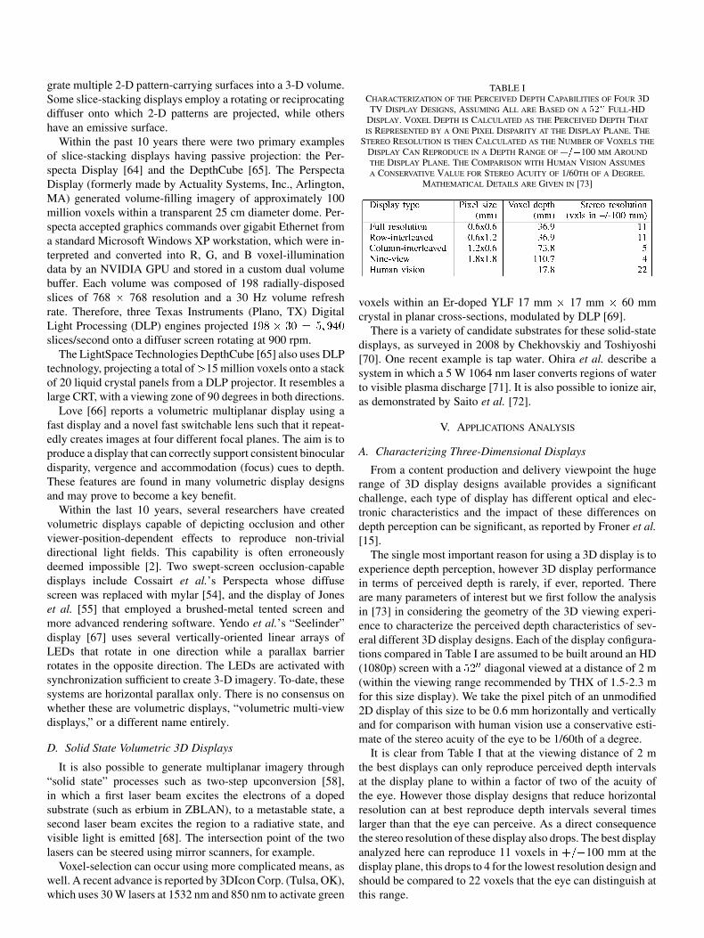
TABLE ICHARACTERIZATION OF THE PERCEIVED DEPTH CAPABILITIES OF FOUR 3DTV DISPLAY DESIGNS, ASSUMING ALL ARE BASED ON A �� FULL-HD
DISPLAY. VOXEL DEPTH IS CALCULATED AS THE PERCEIVED DEPTH THAT
IS REPRESENTED BY A ONE PIXEL DISPARITY AT THE DISPLAY PLANE. THE
STEREO RESOLUTION IS THEN CALCULATED AS THE NUMBER OF VOXELS THE
DISPLAY CAN REPRODUCE IN A DEPTH RANGE OF ���100 MM AROUND
THE DISPLAY PLANE. THE COMPARISON WITH HUMAN VISION ASSUMES
A CONSERVATIVE VALUE FOR STEREO ACUITY OF 1/60TH OF A DEGREE.MATHEMATICAL DETAILS ARE GIVEN IN [73]
voxels within an Er-doped YLF 17 mm 17 mm 60 mmcrystal in planar cross-sections, modulated by DLP [69].
There is a variety of candidate substrates for these solid-statedisplays, as surveyed in 2008 by Chekhovskiy and Toshiyoshi[70]. One recent example is tap water. Ohira et al. describe asystem in which a 5 W 1064 nm laser converts regions of waterto visible plasma discharge [71]. It is also possible to ionize air,as demonstrated by Saito et al. [72].
V. APPLICATIONS ANALYSIS
A. Characterizing Three-Dimensional Displays
From a content production and delivery viewpoint the hugerange of 3D display designs available provides a significantchallenge, each type of display has different optical and elec-tronic characteristics and the impact of these differences ondepth perception can be significant, as reported by Froner et al.[15].
The single most important reason for using a 3D display is toexperience depth perception, however 3D display performancein terms of perceived depth is rarely, if ever, reported. Thereare many parameters of interest but we first follow the analysisin [73] in considering the geometry of the 3D viewing experi-ence to characterize the perceived depth characteristics of sev-eral different 3D display designs. Each of the display configura-tions compared in Table I are assumed to be built around an HD(1080p) screen with a diagonal viewed at a distance of 2 m(within the viewing range recommended by THX of 1.5-2.3 mfor this size display). We take the pixel pitch of an unmodified2D display of this size to be 0.6 mm horizontally and verticallyand for comparison with human vision use a conservative esti-mate of the stereo acuity of the eye to be 1/60th of a degree.
It is clear from Table I that at the viewing distance of 2 mthe best displays can only reproduce perceived depth intervalsat the display plane to within a factor of two of the acuity ofthe eye. However those display designs that reduce horizontalresolution can at best reproduce depth intervals several timeslarger than that the eye can perceive. As a direct consequencethe stereo resolution of these display also drops. The best displayanalyzed here can reproduce 11 voxels in 100 mm at thedisplay plane, this drops to 4 for the lowest resolution design andshould be compared to 22 voxels that the eye can distinguish atthis range.

We identify a number of additional display characteristics thatwe believe are important for content producers and delivery sys-tems. These determine the amount of information that needs tobe captured, edited and delivered to the display system and alsodirectly determine the quality of the viewer’s experience of thedisplay. Finding a single set of characteristics that apply to allthe displays we review is challenging because not all displaysuse the same approach to reproducing perceived depth. Thosewe feel are key are:
• Number of discrete viewing zones (eye positions).• Resolution (pixels or voxels) per viewing zone.• Total number of voxels reproduced by a display.• Number of simultaneous viewers.• Constraints on head position.• Maximum and minimum physical display size supported.• Working, comfortable, perceived depth range.• Color reproduction capability.• Crosstalk level between views.A quality concern for some, but not all displays, relates to
the inherent accommodation-vergence conflict for stereoscopicimages viewed at close range. This is where the eye’s focussystem and vergence system are provided conflicting cues bya stereoscopic display such that the eye must maintain focus onthe display plane while the vergence system is driven to followthe stereoscopic image cue and verge away from the displayplane.
Only a few studies investigate this in detail [74] and the ev-idence now suggests that certainly for close viewing distances,less than 2 m, there is an effect on perception and comfort.Hoffman et al. [43] investigate how mismatched accommoda-tion affects comfort in stereoscopic image perception and Li-versedge et al. [75] investigate how eye vergence movementsdiffer in 2D, stereo 3D and real world 3D. However, at TVand cinema viewing distances (greater than 2 m) the eye has alarge depth of field and it seems unlikely this particular concernis such an important issue. Contemporary reports of problemswith comfort in these situations seem at least as likely to be dueto poor quality content production than to accommodation-ver-gence conflicts.
B. Application Recommendations
Given the broad range of capabilities of the different tech-nologies we have reviewed and the needs of different applica-tions it does not seem that a single technology will form thebasis for a universal 3D display, rather certain technologies willbecome better suited to certain applications. We identify fiveapplication areas with distinctive display requirements and thecharacteristics of the displays that could in future work well forthem.
1) 3D Cinema: Here the solution of a pair of 3D glasses perviewer and matching polarized or wavelength filtered projectionseems suited to the viewing environment and cost constraintsinvolved. Time-parallel solutions could help reduce temporalartifacts.
2) 3D Information Presentation and Advertising: In grouppresentation situations the glasses free multiview and volu-metric displays could see long term success; providing viewingfreedom and removing the need to wear glasses.
3) 3D TV Display: Glasses based solutions are availableat the time of writing but in the long term 2D/3D switchablemultiview displays may be an improvement. These allow auto-matic switching to and from 3D mode and remove the need forviewers to know where the glasses are, recent solutions have lowcrosstalk values which is a key quality criteria.
4) 3D Desktop Display: Here displays using glasses canwork well, while autostereoscopic solutions that retain resolu-tion are potentially attractive for a wide range of desktop tasks.Super-multiview could help resolve accommodation-vergenceconflict resulting from the short viewing distance.
5) 3D Portable Display: For portable devices, cell phonesand games systems, it seems likely that display users willwish to avoid the use of glasses and the ability to implementa {2D/3D} switching autostereoscopic display on a volumemarket cell phone has already been demonstrated.
Fundamental challenges lie in developing content productionand delivery tools that can cost effectively target the broad rangeof 3D displays that are becoming commercially successful [76].
VI. CONCLUSION
We have reviewed the most important approaches to 3D dis-play that have emerged over the past decade and have empha-sized the application of the displays. We have grouped them withrespect to their ability to reproduce parallax, because this affectsthe range of possible head positions, the smoothness with whichusers can look-around objects, and the ease of task performance.
For applications and content generators the parallax require-ments of a 3D display are critical because each new parallaxview requires the content generator to provide that view. Res-olution and size changes for 2D displays are relatively easy tosupport, but adding a new parallax view to a 3D display requiresa new image to be captured or rendered from a new camera po-sition. Intermediate view synthesis techniques are emerging butthese have difficulty interpolating missing image data from oc-clusions and disocclusions accurately.
Stereoscopic and autostereoscopic technologies are now de-veloped to a point where they are being used in everyday appli-cations. Volumetric displays are still a niche product, but couldsee a new lease of life as interest in displaying the results ofcomputational photography and light fields increases. For thefuture, computational holography is still experimental but may,one day, find its way into commercial products.
REFERENCES
[1] C. Wheatstone, “Contributions to the physiology of vision I: On someremarkable and hitherto unobserved phenomena of vision,” Phil. Trans.R. Soc. (Biol.), vol. 18, no. 13, pp. 371–395, Jun. 1838.
[2] Selected Papers on Three-Dimensional Displays, S. Benton, Ed..Bellingham, WA: SPIE Press, 2001.
[3] M. Halle, “Autostereoscopic displays and computer graphics,” ACMComput. Graphics, vol. 31, no. 2, pp. 58–62, May 1997.
[4] M. Levoy and P. Hanrahan, “Light field rendering,” in SIGGRAPH ’96:Proc. 23rd Annu. Conf. Comput. Graphics Interactive Tech., New York,NY, 1996, pp. 31–42, ACM.
[5] J. Helmut and F. Markus, “Infitec-a new stereoscopic visualisation toolby wavelength multiplex imaging,” J. Three Dimensional Images, vol.19, no. 3, pp. 50–56, 2005.
[6] Helmet-Mounted Displays: Sensation, Perception and Cognition Is-sues, C. E. Rash, M. B. Russo, T. R. Letowski, and E. T. Schmeisser,Eds. Fort Rucker, AL: US Army Aeromedical Research Laboratory,2009.
370 IEEE TRANSACTIONS ON BROADCASTING, VOL. 57, NO. 2, JUNE 2011
[7] J. Rolland and O. Cakmakci, “The past, present and future ofhead-mounted display designs,” in Display Systems, Y. Wang, Z.Weng, S. Ye, and J. M. Sasian, Eds. Bellingham, WA: SPIE, 2005,pp. 368–377, no. 1.
[8] T. Levola, “Diffractive optics for virtual reality displays,” J. SID, vol.14, no. 5, pp. 467–475, 2006.
[9] T. Levola, “Replicated slanted gratings with a high refractive indexmaterial for in and outcoupling of light,” Opt. Express, vol. 15, no. 5,pp. 2067–2074, 2007.
[10] H. Mukawa, K. Akutsu, I. Matsumura, S. Nakano, T. Yoshida, M.Kuwahara, and K. Aiki, “A full-color eyewear display using planarwaveguides with reflection volume holograms,” J. SID, vol. 17, no. 3,pp. 185–9193, 2009.
[11] S. Hecht and E. Smith, “Intermittent stimulation by light : VI. area andthe relation between critical frequency and intensity,” The J. GeneralPhysiology, vol. 19, no. 6, pp. 979–989, 1936.
[12] W. Hartman and H. Hikspoors, “Three-dimensional TV with cordlessFLC spectacles,” Information Display, vol. 3, no. 9, pp. 15–17, Oct.1987.
[13] G. D. Sharp and M. G. Robinson, “Enabling stereoscopic 3D tech-nology,” in Proc. SPIE Stereoscopic Displays and Virtual Reality Syst.XIV, ser. Electronic Imaging, A. J. Woods, N. A. Dodgson, J. O. Mer-ritt, M. T. Bolas, and I. E. McDowall, Eds., Bellingham, WA, 2007,vol. 6490, p. 64900X.
[14] J. Nelson and R. L. Brott, “Autostereoscopic display with fresnellens element and double sided prism film adjacent a backlighthaving a light transmission surface with left and right eye sourcesat opposing ends modulated at a rate of at least 90 Hz,” US 7750 982, Jul. 6, 2010.
[15] B. Froner, N. Holliman, and S. Liversedge, “A comparative study offine depth perception on two-view 3d displays,” Displays Journal, vol.29, no. 5, pp. 440–450, Dec. 2008.
[16] J. Fergason, “Monitor for showing high-resolution and three dimen-sional images and method,” US 7401923, 2008.
[17] E. H. Land, “Stereoscopic viewer,” US 2084350, 1937.[18] J. Harrold, D. Wilkes, and G. Woodgate, “Switchable 2D/3D display
– solid phase liquid crystal microlens array,” in Proc. IDW, 2004, vol.11, pp. 1495–1496.
[19] G. Woodgate and J. Harrold, “High efficiency reconfigurable 2D/3Dautostereoscopic display,” SID Symp. Digest Tech. Papers, vol. 34, no.1, pp. 394–397, May 2003, SID.
[20] J. Cobb, “Autostereoscopic desktop display: An evolution of tech-nology,” in Proc. SPIE, 2005, vol. 5664, pp. 139–149.
[21] S. McKay, S. Mason, L. Mair, P. Waddell, and S. Fraser, “Stereoscopicdisplay using a 1.2-m diameter stretchable membrane mirror,” in Proc.SPIE, 1999, vol. 3639, pp. 122–131.
[22] G. Woodgate, D. Ezra, J. Harrold, N. Holliman, G. Jones, and R.Moseley, “Observer tracking autostereoscopic 3D display systems,”in Proc. SPIE, S. S. Fisher, J. O. Merritt, and M. T. Bolas, Eds., 1997,vol. 3012, pp. 187–198.
[23] D. Hassaine, N. Holliman, and S. Liversedge, “Investigating the perfor-mance of path searching tasks in depth on multiview displays,” Trans.Appl. Perception, vol. 8, no. 1, pp. 8:1–8:18, Oct. 2010.
[24] K. Perlin, S. Paxia, and J. Kollin, “An autostereoscopic display,” inProc. 27th Annu. Conf. Comput. Graphics Interactive Tech. (Siggraph),2000, pp. 319–326, ACM.
[25] P. Surman, I. Sexton, K. Hopf, W. K. Lee, F. Neumann, E. Buckley, G.Jones, A. Corbett, R. Bates, and S. Talukdar, “Laser-based multi-user3D display,” J. Soc. Inf. Display, vol. 16, pp. 743–753, 2008.
[26] G. Park, J.-H. Jung, K. Hong, Y. Kim, Y.-H. Kim, S.-W. Min, and B.Lee, “Multi-viewer tracking integral imaging system and its viewingzone analysis,” Opt. Express, vol. 17, no. 20, pp. 17 895–17 908,2009.
[27] R. Haussler, S. Reichelt, N. Leister, E. Zschau, R. Missbach, and A.Schwerdtner, “Large real-time holographic displays: from prototypesto a consumer product,” in Proc. SPIE Stereoscopic Displays Appl. XX,A. J. Woods, N. S. Holliman, and J. O. Merritt, Eds., 2009, vol. 7237.
[28] N. Dodgson, “Autostereoscopic 3D displays,” Computer, vol. 38, no.8, pp. 31–36, 2005.
[29] J. Konrad and P. Agniel, “Subsampling models and anti-alias filtersfor 3-D automultiscopic displays,” IEEE Trans. Image Process., vol.15, no. 1, pp. 128–140, Jan. 2006.
[30] N. A. Dodgson, “Analysis of the viewing zone of the Cambridge au-tostereoscopic display,” Appl. Opt.: Optical Technology & BiomedicalOpt., vol. 35, no. 10, pp. 1705–1710, 1996.
[31] N. A. Dodgson, “Analysis of the viewing zone of multi-view au-tostereoscopic displays,” in Proc. SPIE Stereoscopic Displays andVirtual Reality Systems IX, 2002, vol. 4660, pp. 254–265.
[32] C. van Berkel and J. Clarke, “Characterisation and optimisation of3D-LCD module design,” in Proc. SPIE Stereoscopic Displays and Vir-tual Reality Systems IV, 1997, vol. 3012, pp. 179–186.
[33] D. Winnek, Composite stereography Nov. 1968, US 3409351.[34] L. Lipton and M. Feldman, “A new autostereoscopic display tech-
nology: the SynthaGram,” in Proc. SPIE Stereoscopic Displays VirtualReality Syst. IX, 2002, vol. 4660, pp. 229–235.
[35] F. Speranza, W. J. Tam, T. Martin, L. Stelmach, and C. Ahn, “Per-ceived smoothness of viewpoint transition in multi-viewpoint stereo-scopic displays,” in Proc. SPIE Stereoscopic Displays Virtual RealitySyst. XII, 2005, vol. 5664, pp. 72–82.
[36] H.-J. Im, B.-J. Lee, H.-K. Hong, and H.-H. Shin, “Auto-stereoscopic60 view 3D using slanted lenticular lens arrays,” J. Inf. Display, vol. 8,no. 4, pp. 23–26, 2007.
[37] A. Schmidt and A. Grasnick, “Multiviewpoint autostereoscopic dis-plays from 4d-vision gmbh,” in Proc. SPIE Stereoscopic Displays Vir-tual Reality Syst. IX, A. J. Woods, J. O. Merritt, S. A. Benton, and M.T. Bolas, Eds., Bellingham, WA, 2002, vol. 4660, pp. 212–221.
[38] T. Peterka, R. L. Kooima, D. J. Sandin, A. Johnson, J. Leigh, and T. A.DeFanti, “Advances in the dynallax solid-state dynamic parallax bar-rier autostereoscopic visualization display system,” IEEE Trans. Vis.Comput. Graphics, vol. 14, pp. 487–499, 2008.
[39] D. Lanman, M. Hirsch, Y. Kim, and R. Raskar, “Content-adaptive par-allax barriers for automultiscopic 3D display,” ACM Trans. Graphics,vol. 29, no. 6, pp. 163:1–163:10, Dec. 2010.
[40] W. M. Hanspeter and Pfister, “3D TV: a scalable system for real-timeacquisition, transmission, and autostereoscopic display of dynamicscenes,” in ACM SIGGRAPH, New York, NY, 2004, pp. 814–824.
[41] Y. Takaki, “Super multi-view display with 128 viewpoints and view-point formation,” in Proc. SPIE Stereoscopic Displays Appl. XX, 2009,vol. 7237.
[42] T. Honda, Y. Kajiki, K. Susami, T. Hamaguchi, T. Endo, T. Hatada,and T. Fujii, “Three-dimensional display technologies satisfying supermultiview condition,” in SPIE Critical Reviews. Bellingham, WA:SPIE, 2001, pp. 218–249, no. CR76.
[43] D. Hoffman, A. Girshick, K. Akeley, and M. Banks, “Vergence-accom-modation conflicts hinder visual performance and cause visual fatigue,”J. Vision, vol. 8, no. 3, pp. 1–20, 2008.
[44] N. Dodgson, J. Moore, S. Lang, G. Martin, and P. Canepa, “A time-se-quential multi-projector autostereoscopic display,” J. Soc. Inf. Display,vol. 8, no. 2, pp. 169–176, 2000.
[45] T. Balogh, “The Holovizio system,” in Stereoscopic Displays VirtualReality Syst. XIII, A. J. Woods, N. A. Dodgson, J. O. Merritt, M. T.Bolas, and I. E. McDowall, Eds., p. 60550U, SPIE.
[46] T. Balogh, P. Kovacs, and A. Barsi, “Holovizio 3D display system,” in3DTV Conf., May 2007, pp. 1–4.
[47] M. Stanley, M. Smith, A. Smith, P. Watson, S. Coomber, C. Cameron,C. Slinger, and A. Wood, “3D electronic holography display systemusing a 100-megapixel spatial light modulator,” in Proc. SPIE Opt. De-sign Eng., 2004, vol. 5249, pp. 297–308.
[48] C. Slinger, C. Cameron, and M. Stanley, “Computer-generated holog-raphy as a generic display technology,” Computer, vol. 38, no. 8, pp.46–53, 2005.
[49] G. Lippmann, “La photographie integrale,” Comtes Rendus, Academiedes Sciences, vol. 146, pp. 446–451, 1908.
[50] J.-H. Park, K. Hong, and B. Lee, “Recent progress in three-dimensionalinformation processing based on integral imaging,” Appl. Opt., vol. 48,no. 34, pp. H77–H94, Dec. 2009.
[51] H. Takahashi, H. Fujinami, and K. Yamada, “Wide-viewing-anglethree-dimensional display system using HOE lens array,” in Proc.SPIE Stereoscopic Displays Virtual Reality Syst. XIII, Bellingham,WA, 2006, vol. 6055, pp. 453–461.
[52] J. Kim, S.-W. Min, and B. Lee, “Viewing region maximization of anintegral floating display through location adjustment of viewing regionmaximization viewing region maximization of an integral floating dis-play through location adjustment of viewing window,” Opt. Express,vol. 15, pp. 13 023–13 034, 2007.
[53] Y. Kim, J.-H. Park, H. Choi, J. Kim, S.-W. Cho, and B. Lee, “Depth-enhanced three-dimensional integral imaging by use of multilayereddisplay devices,” Appl. Opt., vol. 45, pp. 4334–4343, 2006.
[54] O. S. Cossairt, J. Napoli, S. L. Hill, R. K. Dorval, and G. E. Favalora,“Occlusion-capable multiview volumetric three-dimensional display,”Appl. Opt., vol. 46, no. 8, pp. 1244–1250, 2007.
[55] A. Jones, I. McDowall, H. Yamada, M. Bolas, and P. Debevec, “Aninteractive 360 degree light field display,” in ACM Siggraph: EmergingTechnol., 2007.
[56] G. Favalora, “Volumetric 3D displays and application infrastructure,”Computer, vol. 38, no. 8, pp. 4–37, Aug. 2007.
[57] R. Hartwig, “Vorrichtung zur dreidimensionalen abbildung in einemzylindersymmetrischen abbildungsraum,” DE2622802C2, 1983.
[58] J. Lewis, C. Yerber, and R. McGhee, “A true three-dimensional dis-play,” Trans. Electron Devices, vol. 18, no. 9, pp. 724–732, Sep. 1971.
[59] A. Traub, “Three-dimensional display,” US3493290, 1970.[60] M. Hirsch, “Three dimensional display apparatus,” US2979561, 1961.
[61] S. Adhya and J. Noe, “A complete ray-trace analysis of the ‘mirage’toy,” in Proc. SPIE ETOP, 2007.
[62] G. Favalora, J. Napoli, D. Hall, R. Dorval, M. Giovinco, M. Richmond,and W. Chun, “100 million-voxel volumetric display,” in Cockpit Dis-plays IX: Displays Defense Appl., D. Hopper, Ed., Aug. 2002, vol.4712, Proc. SPIE, pp. 300–312.
[63] H. Kimura, T. Uchiyama, and H. Yoshikawa, “Laser produced 3D inthe air,” in ACM Siggraph Emerging Technol., 2006, p. 20.
[64] G. E. Favalora, R. K. Dorval, D. M. Hall, M. Giovinco, and J. Napoli,“Volumetric three-dimensional display system with rasterization hard-ware,” in SPIE Stereoscopic Displays Virtual Reality Syst. VIII, A. J.Woods, M. T. Bolas, J. O. Merritt, and S. A. Benton, Eds., 2001, vol.4297, pp. 227–235, SPIE.
[65] A. Sullivan, “Depthcube solid-state 3D volumetric display,” in SPIEConf. Series, 2004, vol. 5291, pp. 279–284.
[66] G. D. Love, D. M. Hoffman, P. J. Hands, J. Gao, A. K. Kirby, and M.S. Banks, “High-speed switchable lens enables the development of avolumetric stereoscopic display,” Opt. Express, vol. 17, no. 18, pp. 15716–15 725, 2009.
[67] T. Endo, Y. Kajiki, T. Honda, and M. Sato, “Cylindrical 3-D videodisplay observable from all directions,” in 8th Pacific Conf. Comput.Graphics Appl., 2000, pp. 300–306.
[68] E. Downing, “A three-color, solid-state, three-dimensional display,”Science, vol. 273, pp. 1185–1189, 1996.
[69] H. Refai, “Static volumetric three-dimensional display,” J. DisplayTechnol., vol. 5, no. 10, pp. 391–397, Oct. 2009.
[70] A. Chekhovskiy and H. Toshiyoshi, “The use of laser burst for volu-metric displaying inside transparent liquid,” Japanese J. Appl. Physics,vol. 47, no. 8, pp. 6790–6793, Aug. 2008.
[71] Y. Ohira, A. Chekhovskiy, T. Yamanoi, T. Endo, H. Fujita, and H.Toshiyoshi, “Hybrid mems optical scanner for volumetric 3D display,”J. Soc. Inf. Display, vol. 17, no. 5, pp. 419–422, May 2009.
[72] H. Saito, H. Kimura, S. Shimada, T. Naemura, J. Kayahara, S. Jarusiri-sawad, V. Nozick, H. Ishikawa, T. Murakami, J. Aoki, A. Asano, T.Kimura, M. Kakehata, F. Sasakia, H. Yashiro, M. Mori, K. Torizuka,and K. Ino, “Laser-plasma scanning 3D display for putting digital con-tents in free space,” in Proc. SPIE, A. J. Woods, N. S. Holliman, and J.O. Merritt, Eds., 2008, vol. 6803, p. 680309.
[73] N. S. Holliman, Three-Dimensional Display Systems, J. Dakin and R.Brown, Eds. New York: Taylor and Francis, 2006.
[74] M. Emoto, T. Niida, and F. Okano, “Repeated vergence adaptationcauses the decline of visual functions in watching stereoscopic tele-vision,” IEEE J. Display Technol., vol. 1, no. 2, p. 328, 2005.
[75] S. Liversedge, N. Holliman, and H. Blythe, “Binocular coordination inresponse to stereoscopic stimuli,” in SPIE Stereoscopic Displays Appl.XX, A. Woods, N. Holliman, and J. Merritt, Eds., Jan. 2009, vol. 7237.
[76] J. Patterson, N. Dodgson, and P. Willis, “What’s up Prof?: current is-sues in the visual effects & post-production industry,” Leonardo, vol.43, no. 1, pp. 1530–9282, 2010.
Nicolas S. Holliman is a Senior Lecturer in theSchool of Engineering and Computing Sciencesat Durham University, U.K., where he heads theInnovative Computing Group. In 1994 he establishedthe Durham Visualization Laboratory to research allaspects of the application, use and human factors of3D displays. Prior to joining Durham he was Prin-cipal Researcher at Sharp Laboratories of Europe,Oxford, UK, leading a team researching graphicsand imaging algorithms for 3D display systems(http://www.durham.ac.uk/n.s.holliman).
Neil A. Dodgson is Professor of Graphics andImaging at the University of Cambridge Com-puter Laboratory in England, where he is partof the Graphics and Interaction Research Group(Rainbow). He has undertaken research in stereo-scopic displays (since 1992), subdivision surfaces(since 2000) and aesthetic imaging (since 2002),with forays into other 3D modeling, imaging, andanimation applications. In 2007, he was awardeda higher doctorate (Doctor of Science) by theUniversity of Cambridge in recognition of his
research achievements.
Gregg E. Favalora received the BS from Yale Uni-versity, New Haven, CT, and the SM degree fromHarvard University, Cambridge, MA.
He founded Actuality Systems, Inc. in 1997,which developed and sold the Perspecta Spatial 3-DSystem. While at Actuality, Mr. Favalora directedthe creation of a 198-view scanned-lenticular dis-play, several light field displays, a single-SLM 20Mpixel projector, and the 100 Mvoxel Perspecta. Heis currently Principal at Optics for Hire. In 1999 hewas listed as one of the top innovators under 35 by
Technology Review magazine.
Lachlan Pockett received the double degree ofmechatronic engineering and mathematics and com-puter science from Adelaide University, Australia.He is currently working on a related Ph.D. at DurhamUniversity. He is a Stereoscopic Imaging Specialistat Nokia Research Center.