Metamorphosis of three-dimensional kirigami-inspired ...
12
Metamorphosis of three-dimensional kirigami-inspired reconfigurable and reprogrammable architected matter Yanbin Li, Jie Yin * Department of Mechanical and Aerospace Engineering, North Carolina State University, Raleigh, NC, 27695, USA article info Article history: Received 31 May 2021 Received in revised form 23 August 2021 Accepted 23 August 2021 Available online 25 August 2021 Keywords: Three-dimensional kirigami Architected materials Kinematic bifurcation Reconfigurability Reprogrammability abstract Most shape-morphing materials are limited to one-to-one shape-changing process, i.e., one design corresponds to one target shape, thus it is hard to be reshaped due to the constraint of limited mobilities (degrees of freedom). Here, we propose harnessing kinematic bifurcation in mechanisms with multiple branched transformation paths to achieve enhanced reconfigurability and shape reprogrammability in a new class of three-dimensional (3D) kirigami-inspired architected matter. The reconfigurable and reprogrammable architected matter is constructed from planar tessellation of 3D kirigami-inspired transformable modules. The module consisting of eight closed-loop connected cubes exhibits both 3D non-bifurcated and bifurcated transformation modes, the motions of which are well captured by the developed kinematics model. The modules can be periodically tessellated in plane to form a flat, thick panel in both a diluted (with voids) and compact (without voids) pattern with multiple encoded, compatible transformation modes. Consequently, it can undergo a series of consecutive shape changes by reconfiguring into varieties of 3D transformable architectures that are conceptually in analogy to metamorphosis in some living organisms during growth. The endowed rich mobilities are found to derive from the kinematic bifurcation. Among them, a unique transformed 3D architecture can be further reprogrammed to reconfigure into multiple architected shapes with zero and non-zero Gaussian cur- vature through both forward and inverse designs. Such 3D reconfigurable kinematic matter is attractive for potential applications in reconfigurable metamaterials and morphing architectures. © 2021 Elsevier Ltd. All rights reserved. 1. Introduction The architecture of living or artificial matter is crucial for their properties and functionalities. Some living systems such as animals and microorganisms undergo a series of abrupt shape trans- formation during their developmental stages to adapt to different living environments. Such a biological evolution process of shape changes in form and structure is named metamorphosis. Similar artificial metamorphic materials and structures that are capable of changing their geometries and architectures have recently attrac- ted growing interest due to shape changing imparted rich new properties and functionalities [1e4]. Such metamorphic materials have found broad applications in reconfigurable metamaterials [5], self-reconfigurable robots [6], morphing aerostructures [7], and four-dimensional (4D) printing [8]. The ancient paper art of origami and kirigami [9, 10] provides unique ways to design metamorphic materials via folding in origami and cutting/folding in kirigami with demonstrated broad applications in engineering [11e23]. Starting from a thin flat sheet with prescribed creases in origami, it can rigidly fold into virtually any 3D shape [24]. Similarly, a thin flat sheet with cut patterns (slits or holes) in kirigami can morph into desired expanded 2D shapes [15,25,26] or 3D pop-up structures [27 ,28]. Reversely, inverse design of crease or cut patterns can be prescribed to fit target surface morphologies with intrinsic curvature [27 ,29]. Mathematically, both 2D and 3D shape shifting can be consid- ered as a one-to-one mapping, i.e., one certain crease or cut pattern corresponds to one target shape, thus, once morphed, normally it is challenging to be reprogrammed into other different shapes. To enhance its reconfigurability, one can design pluripotent crease patterns in origami [30] or combine cutting and folding in kirigami thin sheets [16,31], where the same crease or cutting pattern could transform into multiple 3D configurations through combinatorial folding [16,23,30,31], i.e., one-to-multiple mapping. Beyond con- ventional 2D thin sheet-based origami and kirigami [9], designing * Corresponding author. E-mail address: [email protected] (J. Yin). Contents lists available at ScienceDirect Materials Today Physics journal homepage: https://www.journals.elsevier.com/ materials-today-physics https://doi.org/10.1016/j.mtphys.2021.100511 2542-5293/© 2021 Elsevier Ltd. All rights reserved. Materials Today Physics 21 (2021) 100511
-
Upload
khangminh22 -
Category
Documents
-
view
5 -
download
0
Transcript of Metamorphosis of three-dimensional kirigami-inspired ...
lable at ScienceDirect
Materials Today Physics 21 (2021) 100511
Contents lists avai
Materials Today Physicsjournal homepage: https: / /www.journals .e lsevier .com/
mater ia ls- today-physics
Metamorphosis of three-dimensional kirigami-inspiredreconfigurable and reprogrammable architected matter
Yanbin Li, Jie Yin*
Department of Mechanical and Aerospace Engineering, North Carolina State University, Raleigh, NC, 27695, USA
a r t i c l e i n f o
Article history:Received 31 May 2021Received in revised form23 August 2021Accepted 23 August 2021Available online 25 August 2021
Keywords:Three-dimensional kirigamiArchitected materialsKinematic bifurcationReconfigurabilityReprogrammability
* Corresponding author.E-mail address: [email protected] (J. Yin).
https://doi.org/10.1016/j.mtphys.2021.1005112542-5293/© 2021 Elsevier Ltd. All rights reserved.
a b s t r a c t
Most shape-morphing materials are limited to one-to-one shape-changing process, i.e., one designcorresponds to one target shape, thus it is hard to be reshaped due to the constraint of limited mobilities(degrees of freedom). Here, we propose harnessing kinematic bifurcation in mechanisms with multiplebranched transformation paths to achieve enhanced reconfigurability and shape reprogrammability in anew class of three-dimensional (3D) kirigami-inspired architected matter. The reconfigurable andreprogrammable architected matter is constructed from planar tessellation of 3D kirigami-inspiredtransformable modules. The module consisting of eight closed-loop connected cubes exhibits both 3Dnon-bifurcated and bifurcated transformation modes, the motions of which are well captured by thedeveloped kinematics model. The modules can be periodically tessellated in plane to form a flat, thickpanel in both a diluted (with voids) and compact (without voids) pattern with multiple encoded,compatible transformation modes. Consequently, it can undergo a series of consecutive shape changes byreconfiguring into varieties of 3D transformable architectures that are conceptually in analogy tometamorphosis in some living organisms during growth. The endowed rich mobilities are found toderive from the kinematic bifurcation. Among them, a unique transformed 3D architecture can be furtherreprogrammed to reconfigure into multiple architected shapes with zero and non-zero Gaussian cur-vature through both forward and inverse designs. Such 3D reconfigurable kinematic matter is attractivefor potential applications in reconfigurable metamaterials and morphing architectures.
© 2021 Elsevier Ltd. All rights reserved.
1. Introduction
The architecture of living or artificial matter is crucial for theirproperties and functionalities. Some living systems such as animalsand microorganisms undergo a series of abrupt shape trans-formation during their developmental stages to adapt to differentliving environments. Such a biological evolution process of shapechanges in form and structure is named metamorphosis. Similarartificial metamorphic materials and structures that are capable ofchanging their geometries and architectures have recently attrac-ted growing interest due to shape changing imparted rich newproperties and functionalities [1e4]. Such metamorphic materialshave found broad applications in reconfigurable metamaterials [5],self-reconfigurable robots [6], morphing aerostructures [7], andfour-dimensional (4D) printing [8].
The ancient paper art of origami and kirigami [9,10] provides
unique ways to design metamorphic materials via folding inorigami and cutting/folding in kirigami with demonstrated broadapplications in engineering [11e23]. Starting from a thin flat sheetwith prescribed creases in origami, it can rigidly fold into virtuallyany 3D shape [24]. Similarly, a thin flat sheet with cut patterns (slitsor holes) in kirigami can morph into desired expanded 2D shapes[15,25,26] or 3D pop-up structures [27,28]. Reversely, inversedesign of crease or cut patterns can be prescribed to fit targetsurface morphologies with intrinsic curvature [27,29].
Mathematically, both 2D and 3D shape shifting can be consid-ered as a one-to-one mapping, i.e., one certain crease or cut patterncorresponds to one target shape, thus, once morphed, normally it ischallenging to be reprogrammed into other different shapes. Toenhance its reconfigurability, one can design pluripotent creasepatterns in origami [30] or combine cutting and folding in kirigamithin sheets [16,31], where the same crease or cutting pattern couldtransform into multiple 3D configurations through combinatorialfolding [16,23,30,31], i.e., one-to-multiple mapping. Beyond con-ventional 2D thin sheet-based origami and kirigami [9], designing
Y. Li and J. Yin Materials Today Physics 21 (2021) 100511
3D origami and kirigami-inspired modules with multiple defor-mation modes provides a promising way to construct 3D recon-figurable architected materials with enhanced reconfigurability[32e35]. Recent studies demonstrate that space-filling tessellationof 3D polyhedral origami-inspired modules creates 3D prismaticarchitected materials that can reconfigure into multiple 3D struc-tural modes via internal mechanism [33]. Very recently, wedemonstrate utilizing the complementary shapes between recon-figurable 3D kirigami modules to design multi-dimensional archi-tected materials that can be disassembled and re-assembled forprogrammable properties [35]. Despite the advance, the shapechanges in such 3D reconfigurable materials follow the stableequilibrium folding paths with limited mobilities (degrees offreedom) [16,23,32e35].
Beyond equilibrium motion, bifurcation provides an effectiveway to generate multiple shape transformation with branchedtransition paths in engineering systems when independent vari-ants reach critical values [36], for instance, the bifurcation of Euler'sElastica rod can lead to multiple deformed shapes [37]. Notably,bifurcation often occurs in the kinematic deployment of rigidmechanisms composed of rotatable joint hinges and bar links [38],i.e., kinematic bifurcation. For a bifurcated rigid mechanism, whenthe rotating angles of its joint hinges reach a critical value, itsconfiguration transformation can deviate from its original equilib-rium path and branch into distinct kinematic deployment path(s) atthe bifurcation point [39], which provides more design space forenhanced structural transformation. In comparison, the non-bifurcated (equilibrium) rigid mechanism will transform itsshapes by following certain equilibrium paths with less mobilitiesduring reconfiguration. Naturally, it provokes the question ofwhether one can harness kinematic bifurcation to unleash their fullpotential in generating rich structural reconfigurations in 3Dorigami/kirigami module-inspired reconfigurable materials.
Here, we explore the potential of leveraging kinematic bifurca-tion [40] for enhancing both reconfigurability and reprogramm-ability in an example system of 3D kirigami-inspired architectedmatter. As illustrated in Fig. 1A, inspired by the thin sheet-basedkirigami approach [15,25,26] and the toy of infinity cube or flex-icube [41], we construct 3D kirigami modules by cutting bulk ma-terials with non-negligible thickness into a closed-loop connectionof a different number of cubes [15,35].We explore the kinematics ofthe closed-loop mechanism-based 3D kirigami-inspired modules.We find that the eight cube-based kirigami module shows thehighest level of reconfigurability by transforming intomore distinct3D shapes, arising from the kinematic bifurcation (Fig. 1B). Through
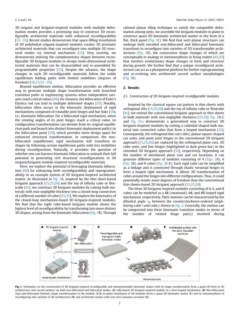
Fig. 1. Schematics on the construction of 3D kirigami-inspired reconfigurable and reprograarchitectures and curved surfaces via both non-bifurcated and bifurcated modes. (A) cube-(top) and bifurcated (bottom) shape transformation in the module. (C-E) In-plane tessellareconfiguring into varieties of 3D architectures (D) and architected surface with non-zero G
2
rational planar tiling technique to satisfy the compatible defor-mation among units, we assemble the kirigami modules in plane toconstruct quasi-3D kinematic architected matter in the form of aflat, thick panel (Fig. 1C). We find that such planar structures canundergo both encoded non-bifurcated and bifurcated kinematictransitions to reconfigure into varieties of 3D transformable archi-tectures (Fig. 1D), the consecutive shape changes of which areconceptually in analogy to metamorphosis in living matter [42,43]that involves evolutionary shape changes in form and structureduring growth. We further find that a unique reconfigured archi-tecture can act as a pluripotent platform for further reprogrammingand re-evolving into architected curved surface morphologies(Fig. 1E).
2. Results
2.1. Construction of 3D kirigami-inspired reconfigurable modules
Inspired by the classical square cut pattern in thin sheets withorthogonal slits [15,25,26] and the toy of infinity cube or flexicube[41], we extend the conventional kirigami approach in thin sheetsto bulk materials with non-negligible thickness [15,35]. Fig. 2A-Cand Fig. S1a demonstrate a generalized way to construct 3Dkirigami-inspired modules by cutting a cuboidal-shaped bulk ma-terial into connected cubes that form a looped mechanism [35].Consequently, the orthogonal line cuts (slits), planar square-shapedcut units, and point joint hinges in the conventional 2D kirigamiapproach [15,25,26] are replaced by the orthogonal plane cuts, 3Dcube units, and line hinges (highlighted in dark green bar) in theextended 3D kirigami approach [35], respectively. Depending onthe number of introduced plane cuts and cut locations, it cangenerate different types of modules consisting of 4 (Figs. 2A), 6(Fig. 2B), and 8 cubes (Fig. 2C-E). Each rigid cube can be simplifiedas a linkage and is connected through elastic torsional hinges toform a looped rigid mechanism. It allows 3D transformation ofcubes around the hinges into different configurations. Thus, it couldpotentially render more degrees of freedom than the conventionalthin sheets-based 2D kirigami approach [15,25,26].
The three 3D kirigami-inspired modules consisting of 4, 6, and 8cubes can be modeled as a 4R (rotational), 6R, and 8R looped rigidmechanism, respectively. Their motions can be characterized by thedihedral angle gij between the counterclockwise-ordered neigh-boring cube i and cube j shown in Fig. 2. Generally, the motion canbe categorized into three kinematic transition modes in terms ofthe number of rotated hinge pair(s) involved during
mmable kinematic matter with its shape transformation from a quasi-3D form to 3Dbased 3D kirigami-inspired module in a close-looped mechanism. (B) Non-bifurcatedtion of 3D modules forms a quasi-3D kinematic matter (C) and its metamorphosis ofaussian curvature (E).

Fig. 2. Construction of 3D kirigami-inspired transformable modules through generalized plane cutting. (A-C) Schematic illustration of generating 4-cube (A), 6-cube (B), and 8-cubemodules (C) by introducing 2, 4, and 4 cutting planes to cuboidal bulk materials. Each cube act as a linkage and is connected through elastic torsional line hinges to form a rigidmechanism. (CeE) Three kinematic transformation modes in 8-cube module: Mode 1 in (C) with one rotational (1R) linkage mechanism; Mode 2 in (D) with 6R linkage mechanism;and Mode 3 in (E) with 8R linkage mechanism. Only Mode 3 exhibits kinematic bifurcation with two demonstrated bifurcation points when transforming from configuration State#1 to State #9.
Y. Li and J. Yin Materials Today Physics 21 (2021) 100511
reconfiguration.
(1) Mode 1 with 1R linkage mechanism in all the three modules(Fig. 2A (ii-iii), Fig. 2B (iii), and Fig. S1b), where their motioncan be described by a single non-zero dihedral angle g, whileall other angles are zero, e.g., g12 ¼ g34 ¼ g in Fig. 2A (ii),g23 ¼ g61 ¼ g in Fig. 2B (ii), and g12 ¼ g56 ¼ g in Fig. 2C (iii). Itundergoes monotonic shape changes, and the plane cutsremain closed during motion.
(2) Mode 2 with 4R linkage mechanism in the 6-cube module(Fig. 2B) and 6R linkage mechanism in the 8-cube module(Fig. 2D and Fig. S1C), where only two dihedral angles arekept as zero during motion, e.g., g23 ¼ g61 ¼ 0 in Fig. 2B (ii)and g23 ¼ g67 ¼ 0 in Fig. 2D, while all other angles are non-
3
zero. The plane cuts are opened to form a 3D void duringmotion.
(3) Mode 3 with 8R linkage mechanism (Fig. 2E and Fig. S1c) inthe 8-cube module, where all the plane cuts are opened, andall the eight dihedral angles become non-zero duringmotion.
We note that Mode 1 and Mode 2 are stable transition modes byfollowing the 1R or 6R motion path without bifurcation. Bycontrast, Mode 3 undergoes multiple consecutive kinematic bi-furcations. It exhibits alternative transition pathways at the bifur-cated points shown in Fig. 2E. For example, when it transformsfrom configuration State #1 to State #3, it preserves the looped 8Rlinkage and shows no bifurcation. However, the intermediate
Y. Li and J. Yin Materials Today Physics 21 (2021) 100511
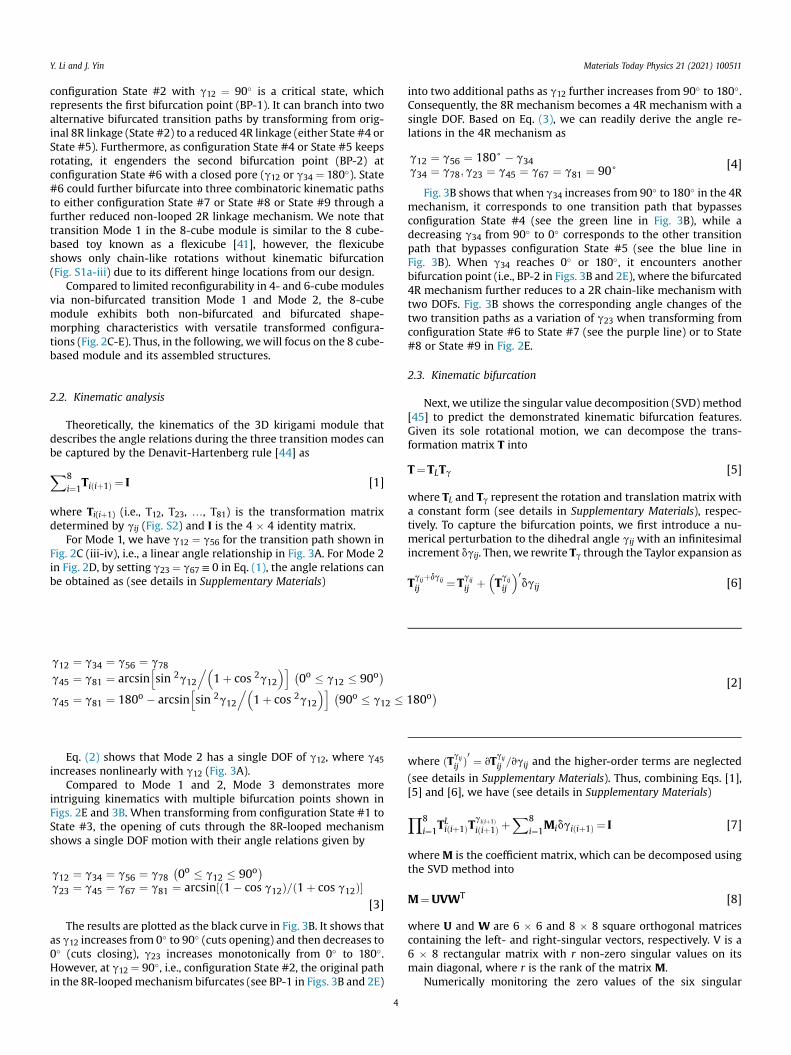
configuration State #2 with g12 ¼ 90� is a critical state, whichrepresents the first bifurcation point (BP-1). It can branch into twoalternative bifurcated transition paths by transforming from orig-inal 8R linkage (State #2) to a reduced 4R linkage (either State #4 orState #5). Furthermore, as configuration State #4 or State #5 keepsrotating, it engenders the second bifurcation point (BP-2) atconfiguration State #6 with a closed pore (g12 or g34 ¼ 180�). State#6 could further bifurcate into three combinatoric kinematic pathsto either configuration State #7 or State #8 or State #9 through afurther reduced non-looped 2R linkage mechanism. We note thattransition Mode 1 in the 8-cube module is similar to the 8 cube-based toy known as a flexicube [41], however, the flexicubeshows only chain-like rotations without kinematic bifurcation(Fig. S1a-iii) due to its different hinge locations from our design.
Compared to limited reconfigurability in 4- and 6-cube modulesvia non-bifurcated transition Mode 1 and Mode 2, the 8-cubemodule exhibits both non-bifurcated and bifurcated shape-morphing characteristics with versatile transformed configura-tions (Fig. 2C-E). Thus, in the following, wewill focus on the 8 cube-based module and its assembled structures.
2.2. Kinematic analysis
Theoretically, the kinematics of the 3D kirigami module thatdescribes the angle relations during the three transition modes canbe captured by the Denavit-Hartenberg rule [44] as
X8i¼1
Tiðiþ1Þ ¼ I [1]
where Ti(iþ1) (i.e., T12, T23, …, T81) is the transformation matrixdetermined by gij (Fig. S2) and I is the 4 � 4 identity matrix.
For Mode 1, we have g12 ¼ g56 for the transition path shown inFig. 2C (iii-iv), i.e., a linear angle relationship in Fig. 3A. For Mode 2in Fig. 2D, by setting g23 ¼ g67 ≡ 0 in Eq. (1), the angle relations canbe obtained as (see details in Supplementary Materials)
g12 ¼ g34 ¼ g56 ¼ g78g45 ¼ g81 ¼ arcsin
hsin 2g12
.�1þ cos 2g12
�i �0o � g12 � 90o
�
g45 ¼ g81 ¼ 180o � arcsinhsin 2g12
.�1þ cos 2g12
�i �90o � g12 � 180o
� [2]
Eq. (2) shows that Mode 2 has a single DOF of g12, where g45increases nonlinearly with g12 (Fig. 3A).
Compared to Mode 1 and 2, Mode 3 demonstrates moreintriguing kinematics with multiple bifurcation points shown inFigs. 2E and 3B. When transforming from configuration State #1 toState #3, the opening of cuts through the 8R-looped mechanismshows a single DOF motion with their angle relations given by
g12 ¼ g34 ¼ g56 ¼ g78�0o � g12 � 90o
�g23 ¼ g45 ¼ g67 ¼ g81 ¼ arcsin½ð1� cos g12Þ=ð1þ cos g12Þ�
[3]
The results are plotted as the black curve in Fig. 3B. It shows thatas g12 increases from 0� to 90� (cuts opening) and then decreases to0� (cuts closing), g23 increases monotonically from 0� to 180�.However, at g12 ¼ 90�, i.e., configuration State #2, the original pathin the 8R-loopedmechanism bifurcates (see BP-1 in Figs. 3B and 2E)
4
into two additional paths as g12 further increases from 90� to 180�.Consequently, the 8R mechanism becomes a 4R mechanism with asingle DOF. Based on Eq. (3), we can readily derive the angle re-lations in the 4R mechanism as
g12 ¼ g56 ¼ 180+ � g34g34 ¼ g78;g23 ¼ g45 ¼ g67 ¼ g81 ¼ 90+ [4]
Fig. 3B shows that when g34 increases from 90� to 180� in the 4Rmechanism, it corresponds to one transition path that bypassesconfiguration State #4 (see the green line in Fig. 3B), while adecreasing g34 from 90� to 0� corresponds to the other transitionpath that bypasses configuration State #5 (see the blue line inFig. 3B). When g34 reaches 0� or 180�, it encounters anotherbifurcation point (i.e., BP-2 in Figs. 3B and 2E), where the bifurcated4R mechanism further reduces to a 2R chain-like mechanism withtwo DOFs. Fig. 3B shows the corresponding angle changes of thetwo transition paths as a variation of g23 when transforming fromconfiguration State #6 to State #7 (see the purple line) or to State#8 or State #9 in Fig. 2E.
2.3. Kinematic bifurcation
Next, we utilize the singular value decomposition (SVD) method[45] to predict the demonstrated kinematic bifurcation features.Given its sole rotational motion, we can decompose the trans-formation matrix T into
T¼TLTg [5]
where TL and Tg represent the rotation and translation matrix witha constant form (see details in Supplementary Materials), respec-tively. To capture the bifurcation points, we first introduce a nu-merical perturbation to the dihedral angle gij with an infinitesimalincrement dgij. Then, we rewrite Tg through the Taylor expansion as
Tgijþdgij
ij ¼Tgij
ij þ�Tgij
ij
�0dgij [6]
where ðTgij
ij Þ0 ¼ vT
gij
ij =vgij and the higher-order terms are neglected
(see details in Supplementary Materials). Thus, combining Eqs. [1],[5] and [6], we have (see details in Supplementary Materials)
Y8i¼1
TLiðiþ1ÞTgiðiþ1Þiðiþ1Þ þ
X8i¼1
Midgiðiþ1Þ ¼ I [7]
whereM is the coefficient matrix, which can be decomposed usingthe SVD method into
M¼UVWT [8]
where U and W are 6 � 6 and 8 � 8 square orthogonal matricescontaining the left- and right-singular vectors, respectively. V is a6 � 8 rectangular matrix with r non-zero singular values on itsmain diagonal, where r is the rank of the matrix M.
Numerically monitoring the zero values of the six singular

Fig. 3. Kinematic analysis of 8-cube module. (A, B) Kinematic paths defined as dihedral angle relations during its transformation in Mode 1 and Mode 2 (A), and Mode 3 (B). (C)Variations of six singular values vii during transformation Mode 3. (D) Comparison of the sixth singular value v66 between Mode 2 and Mode 3.
Y. Li and J. Yin Materials Today Physics 21 (2021) 100511
values vkk (k ¼ 1, 2, …, 6) of the matrix V predicts the locations ofbifurcation points of the 3D kirigami module. Fig. 3C and Fig. S3show the presence of three predicted bifurcation points (BP-0,BP-1, and BP-2) located at g12 ¼ 0�, 90�, and 180� when the sixthsingular value v66 is equal to zero, i.e., v66 ¼ 0. Kinematically, BP-0 represents the three potential transition modes (i.e., Mode 1 toMode 3 in Fig. 2C-E), while BP-1 and BP-2 are the bifurcation pointsas demonstrated in Mode 3. We further compare the variation ofv66 in Mode 2 with 6R mechanism and Mode 3 with 8R mechanismin Fig. 3D. It shows that no bifurcation occurs in Mode 2 when0� < g12 < 180�, which is consistent with the demonstration inFig. 2D.
2.4. Design of ‘�’ and ‘þ’ -shaped building blocks with preservedkinematics
Next, we assemble the reconfigurable modules as units in aperiodic way to form reconfigurable quasi-3D architected matterthrough in-plane tiling. It should be noted that periodic tiling of theunits is non-trivial and rather challenging, considering (1) the out-of-plane transformation in the 8R linkage, (2) compatible kinematicmotions to avoid structural frustrations, and (3) encoding richshape-morphing features from the base unit without sacrificing itsintrinsic multiple kinematic non-bifurcated and bifurcated modes.
To address the challenge, we design two types of building blocksin the “�” (Fig. 4A) and “þ” (Fig. 4B) shapes that will be used forconstructing reconfigurable architected matter with compatible,
5
preserved transformation modes. Merging the overlapped cubesbetween the base unit (center) and its transformed shapes(configuration State #3 in Mode 3) uni-axially and bi-axially gen-erates the “� “- and “þ “-shaped building blocks, respectively (seedetails on the hinge distribution in Fig. S4a). To experimentallyexplore their transformation, we fabricate the prototypes of thecube modules using 3D printing (Convex Objet-260) and connectthem using ultra-flexible plastic tapes to imitate free-rotationalhinges (see details in Supplementary Materials).
Fig. 4CeD demonstrate their configuration evolutions through3D-printed prototypes. To eliminate the potential torsion of theirflexible hinges, we also fabricate the prototypes of building blocksmade of wooden cubes connected with metal hinges. We find thatthe kinematic transitions in both 3D-printed and wooden pro-totypes are consistent with each other (Fig. S4b-S4d andSupplementary Video S1). Remarkably, both building blocks pre-serve all the three non-bifurcated and bifurcated kinematic tran-sitionmodes in the base unit without causing structural frustration.Thus, following the three transition modes in the base unit, bothbuilding blocks can consecutively reconfigure into a library ofdistinct 3D transformable architectures (e.g., car, box, stair, build-ing, airplane, and other complex 3D shapes in Fig. 4CeD and Fig. S5-S6). For example, Fig. 4C (i) and Fig. 4D (i) show the transformablearchitectures via the bifurcated Mode 3 from 8R to 4R and to 2R/1Rtransformation. Fig. 4C (ii) and Fig. 4D (ii-a) (Type-1) demonstratethe structural reconfigurations via non-bifurcated Mode 1 from 4Rto 2R and 1R. Similar structural reconfigurations via non-bifurcated
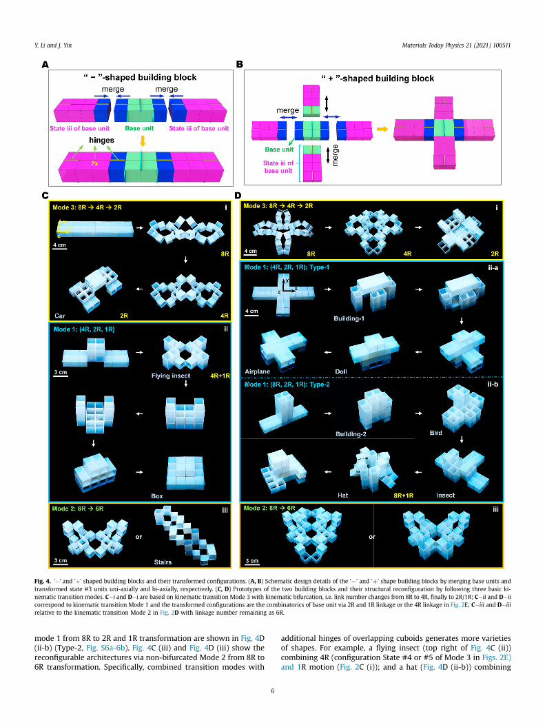
Fig. 4. ‘�’ and ‘þ’ shaped building blocks and their transformed configurations. (A, B) Schematic design details of the ‘¡’ and ‘þ’ shape building blocks by merging base units andtransformed state #3 units uni-axially and bi-axially, respectively. (C, D) Prototypes of the two building blocks and their structural reconfiguration by following three basic ki-nematic transition modes. C�i and D�i are based on kinematic transition Mode 3 with kinematic bifurcation, i.e. link number changes from 8R to 4R, finally to 2R/1R; C�ii and D�iicorrespond to kinematic transition Mode 1 and the transformed configurations are the combinatorics of base unit via 2R and 1R linkage or the 4R linkage in Fig. 2E; C�iii and D�iiirelative to the kinematic transition Mode 2 in Fig. 2D with linkage number remaining as 6R.
Y. Li and J. Yin Materials Today Physics 21 (2021) 100511
mode 1 from 8R to 2R and 1R transformation are shown in Fig. 4D(ii-b) (Type-2, Fig. S6a-6b). Fig. 4C (iii) and Fig. 4D (iii) show thereconfigurable architectures via non-bifurcated Mode 2 from 8R to6R transformation. Specifically, combined transition modes with
6
additional hinges of overlapping cuboids generates more varietiesof shapes. For example, a flying insect (top right of Fig. 4C (ii))combining 4R (configuration State #4 or #5 of Mode 3 in Figs. 2E)and 1R motion (Fig. 2C (i)); and a hat (Fig. 4D (ii-b)) combining
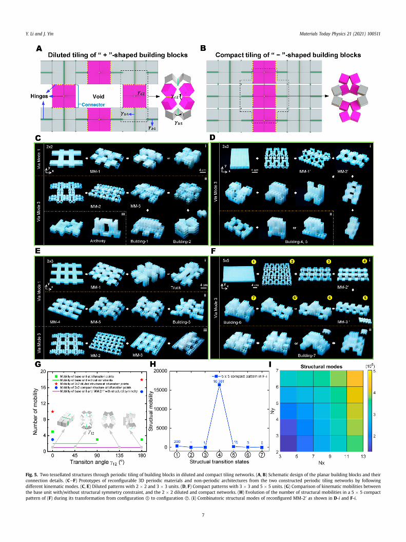
Fig. 5. Two tessellated structures through periodic tiling of building blocks in diluted and compact tiling networks. (A, B) Schematic design of the planar building blocks and theirconnection details. (CeF) Prototypes of reconfigurable 3D periodic materials and non-periodic architectures from the two constructed periodic tiling networks by followingdifferent kinematic modes. (C, E) Diluted patterns with 2 � 2 and 3 � 3 units. (D, F) Compact patterns with 3 � 3 and 5 � 5 units. (G) Comparison of kinematic mobilities betweenthe base unit with/without structural symmetry constraint, and the 2 � 2 diluted and compact networks. (H) Evolution of the number of structural mobilities in a 5 � 5 compactpattern of (F) during its transformation from configuration ① to configuration ⑦. (i) Combinatoric structural modes of reconfigured MM-20 as shown in D-i and F-i.
Y. Li and J. Yin Materials Today Physics 21 (2021) 100511
7
Y. Li and J. Yin Materials Today Physics 21 (2021) 100511
8R (configuration State #1 in Figs. 2E) and 1R motion (Fig. 2C (iii)).Supplementary video related to this article can be found at
https://doi.org/10.1016/j.mtphys.2021.100511
2.5. Metamorphosis of reconfigurable architected matter
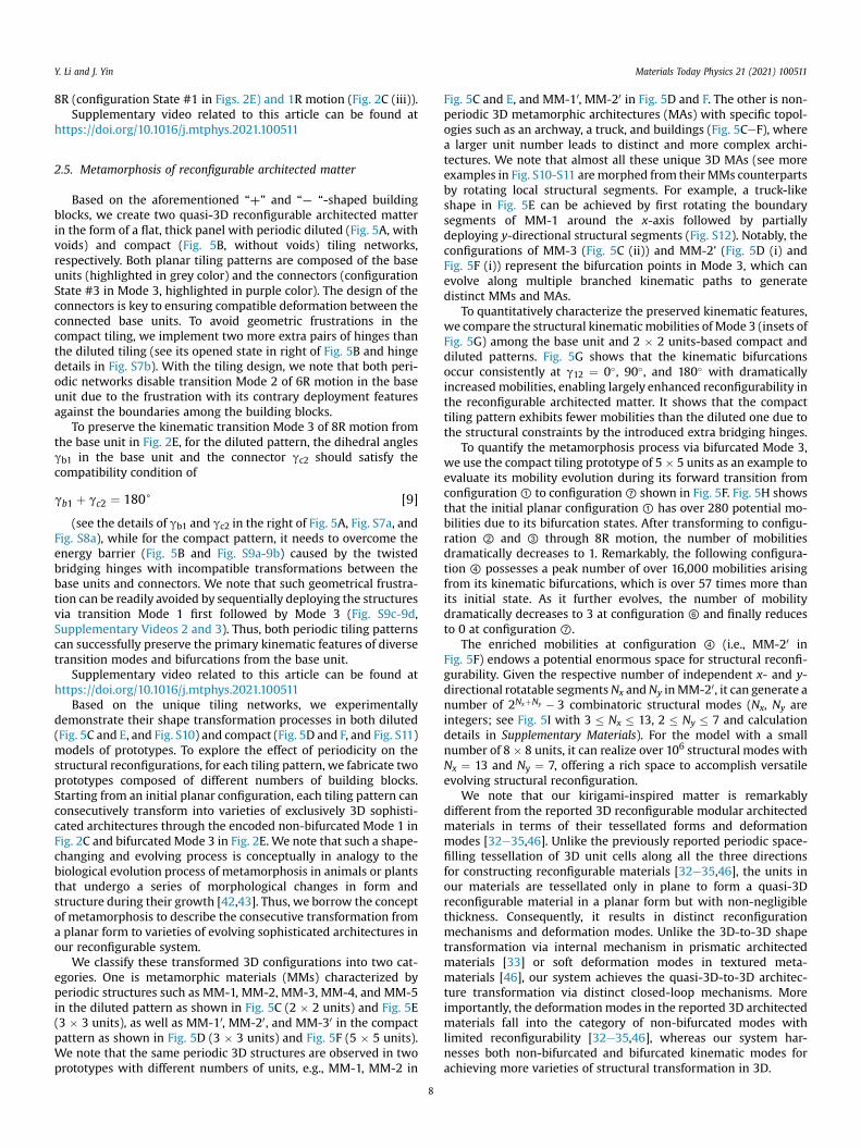
Based on the aforementioned “þ” and “¡ “-shaped buildingblocks, we create two quasi-3D reconfigurable architected matterin the form of a flat, thick panel with periodic diluted (Fig. 5A, withvoids) and compact (Fig. 5B, without voids) tiling networks,respectively. Both planar tiling patterns are composed of the baseunits (highlighted in grey color) and the connectors (configurationState #3 in Mode 3, highlighted in purple color). The design of theconnectors is key to ensuring compatible deformation between theconnected base units. To avoid geometric frustrations in thecompact tiling, we implement two more extra pairs of hinges thanthe diluted tiling (see its opened state in right of Fig. 5B and hingedetails in Fig. S7b). With the tiling design, we note that both peri-odic networks disable transition Mode 2 of 6R motion in the baseunit due to the frustration with its contrary deployment featuresagainst the boundaries among the building blocks.
To preserve the kinematic transition Mode 3 of 8R motion fromthe base unit in Fig. 2E, for the diluted pattern, the dihedral anglesgb1 in the base unit and the connector gc2 should satisfy thecompatibility condition of
gb1 þ gc2 ¼ 180+ [9]
(see the details of gb1 and gc2 in the right of Fig. 5A, Fig. S7a, andFig. S8a), while for the compact pattern, it needs to overcome theenergy barrier (Fig. 5B and Fig. S9a-9b) caused by the twistedbridging hinges with incompatible transformations between thebase units and connectors. We note that such geometrical frustra-tion can be readily avoided by sequentially deploying the structuresvia transition Mode 1 first followed by Mode 3 (Fig. S9c-9d,Supplementary Videos 2 and 3). Thus, both periodic tiling patternscan successfully preserve the primary kinematic features of diversetransition modes and bifurcations from the base unit.
Supplementary video related to this article can be found athttps://doi.org/10.1016/j.mtphys.2021.100511
Based on the unique tiling networks, we experimentallydemonstrate their shape transformation processes in both diluted(Fig. 5C and E, and Fig. S10) and compact (Fig. 5D and F, and Fig. S11)models of prototypes. To explore the effect of periodicity on thestructural reconfigurations, for each tiling pattern, we fabricate twoprototypes composed of different numbers of building blocks.Starting from an initial planar configuration, each tiling pattern canconsecutively transform into varieties of exclusively 3D sophisti-cated architectures through the encoded non-bifurcated Mode 1 inFig. 2C and bifurcatedMode 3 in Fig. 2E. We note that such a shape-changing and evolving process is conceptually in analogy to thebiological evolution process of metamorphosis in animals or plantsthat undergo a series of morphological changes in form andstructure during their growth [42,43]. Thus, we borrow the conceptof metamorphosis to describe the consecutive transformation froma planar form to varieties of evolving sophisticated architectures inour reconfigurable system.
We classify these transformed 3D configurations into two cat-egories. One is metamorphic materials (MMs) characterized byperiodic structures such as MM-1, MM-2, MM-3, MM-4, and MM-5in the diluted pattern as shown in Fig. 5C (2 � 2 units) and Fig. 5E(3 � 3 units), as well as MM-10, MM-20, and MM-30 in the compactpattern as shown in Fig. 5D (3 � 3 units) and Fig. 5F (5 � 5 units).We note that the same periodic 3D structures are observed in twoprototypes with different numbers of units, e.g., MM-1, MM-2 in
8
Fig. 5C and E, and MM-10, MM-20 in Fig. 5D and F. The other is non-periodic 3D metamorphic architectures (MAs) with specific topol-ogies such as an archway, a truck, and buildings (Fig. 5CeF), wherea larger unit number leads to distinct and more complex archi-tectures. We note that almost all these unique 3D MAs (see moreexamples in Fig. S10-S11 aremorphed from their MMs counterpartsby rotating local structural segments. For example, a truck-likeshape in Fig. 5E can be achieved by first rotating the boundarysegments of MM-1 around the x-axis followed by partiallydeploying y-directional structural segments (Fig. S12). Notably, theconfigurations of MM-3 (Fig. 5C (ii)) and MM-2' (Fig. 5D (i) andFig. 5F (i)) represent the bifurcation points in Mode 3, which canevolve along multiple branched kinematic paths to generatedistinct MMs and MAs.
To quantitatively characterize the preserved kinematic features,we compare the structural kinematic mobilities of Mode 3 (insets ofFig. 5G) among the base unit and 2 � 2 units-based compact anddiluted patterns. Fig. 5G shows that the kinematic bifurcationsoccur consistently at g12 ¼ 0�, 90�, and 180� with dramaticallyincreased mobilities, enabling largely enhanced reconfigurability inthe reconfigurable architected matter. It shows that the compacttiling pattern exhibits fewer mobilities than the diluted one due tothe structural constraints by the introduced extra bridging hinges.
To quantify the metamorphosis process via bifurcated Mode 3,we use the compact tiling prototype of 5 � 5 units as an example toevaluate its mobility evolution during its forward transition fromconfiguration① to configuration⑦ shown in Fig. 5F. Fig. 5H showsthat the initial planar configuration ① has over 280 potential mo-bilities due to its bifurcation states. After transforming to configu-ration ② and ③ through 8R motion, the number of mobilitiesdramatically decreases to 1. Remarkably, the following configura-tion ④ possesses a peak number of over 16,000 mobilities arisingfrom its kinematic bifurcations, which is over 57 times more thanits initial state. As it further evolves, the number of mobilitydramatically decreases to 3 at configuration ⑥ and finally reducesto 0 at configuration ⑦.
The enriched mobilities at configuration ④ (i.e., MM-20 inFig. 5F) endows a potential enormous space for structural reconfi-gurability. Given the respective number of independent x- and y-directional rotatable segmentsNx andNy inMM-20, it can generate anumber of 2NxþNy � 3 combinatoric structural modes (Nx, Ny areintegers; see Fig. 5I with 3 � Nx � 13, 2 � Ny � 7 and calculationdetails in Supplementary Materials). For the model with a smallnumber of 8 � 8 units, it can realize over 106 structural modes withNx ¼ 13 and Ny ¼ 7, offering a rich space to accomplish versatileevolving structural reconfiguration.
We note that our kirigami-inspired matter is remarkablydifferent from the reported 3D reconfigurable modular architectedmaterials in terms of their tessellated forms and deformationmodes [32e35,46]. Unlike the previously reported periodic space-filling tessellation of 3D unit cells along all the three directionsfor constructing reconfigurable materials [32e35,46], the units inour materials are tessellated only in plane to form a quasi-3Dreconfigurable material in a planar form but with non-negligiblethickness. Consequently, it results in distinct reconfigurationmechanisms and deformation modes. Unlike the 3D-to-3D shapetransformation via internal mechanism in prismatic architectedmaterials [33] or soft deformation modes in textured meta-materials [46], our system achieves the quasi-3D-to-3D architec-ture transformation via distinct closed-loop mechanisms. Moreimportantly, the deformation modes in the reported 3D architectedmaterials fall into the category of non-bifurcated modes withlimited reconfigurability [32e35,46], whereas our system har-nesses both non-bifurcated and bifurcated kinematic modes forachieving more varieties of structural transformation in 3D.
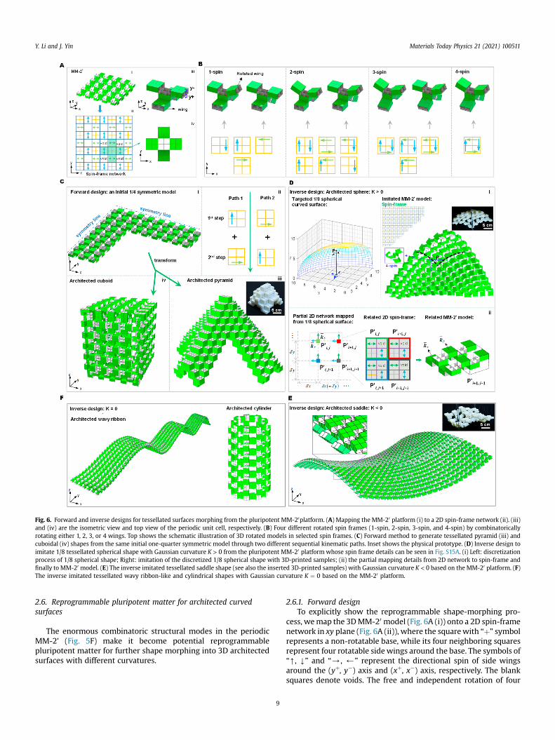
Fig. 6. Forward and inverse designs for tessellated surfaces morphing from the pluripotent MM-20platform. (A) Mapping the MM-20 platform (i) to a 2D spin-frame network (ii). (iii)and (iv) are the isometric view and top view of the periodic unit cell, respectively. (B) Four different rotated spin frames (1-spin, 2-spin, 3-spin, and 4-spin) by combinatoricallyrotating either 1, 2, 3, or 4 wings. Top shows the schematic illustration of 3D rotated models in selected spin frames. (C) Forward method to generate tessellated pyramid (iii) andcuboidal (iv) shapes from the same initial one-quarter symmetric model through two different sequential kinematic paths. Inset shows the physical prototype. (D) Inverse design toimitate 1/8 tessellated spherical shape with Gaussian curvature K > 0 from the pluripotent MM-20 platform whose spin frame details can be seen in Fig. S15A. (i) Left: discretizationprocess of 1/8 spherical shape; Right: imitation of the discretized 1/8 spherical shape with 3D-printed samples; (ii) the partial mapping details from 2D network to spin-frame andfinally to MM-20 model. (E) The inverse imitated tessellated saddle shape (see also the inserted 3D-printed samples) with Gaussian curvature K < 0 based on the MM-20 platform. (F)The inverse imitated tessellated wavy ribbon-like and cylindrical shapes with Gaussian curvature K ¼ 0 based on the MM-20 platform.
Y. Li and J. Yin Materials Today Physics 21 (2021) 100511
2.6. Reprogrammable pluripotent matter for architected curvedsurfaces
The enormous combinatoric structural modes in the periodicMM-2' (Fig. 5F) make it become potential reprogrammablepluripotent matter for further shape morphing into 3D architectedsurfaces with different curvatures.
9
2.6.1. Forward designTo explicitly show the reprogrammable shape-morphing pro-
cess, wemap the 3DMM-20 model (Fig. 6A (i)) onto a 2D spin-framenetwork in xy plane (Fig. 6A (ii)), where the squarewith “þ” symbolrepresents a non-rotatable base, while its four neighboring squaresrepresent four rotatable side wings around the base. The symbols of“[, Y” and “/, )” represent the directional spin of side wingsaround the (yþ, y�) axis and (xþ, x�) axis, respectively. The blanksquares denote voids. The free and independent rotation of four
Y. Li and J. Yin Materials Today Physics 21 (2021) 100511
side wings in the 3D unit cells (Fig. 6A (iii)) generates four differentcombinatoric deployment mechanisms: 1-spin, 2-spin, 3-spin, and4-spin, where n-spin represents rotating n wings that generate Cn
4deployment motifs as illustrated in Fig. 6B. Thus, through thecombinatoric deployment of different motifs among unit cells inthe initial spin pattern, we can achieve a large number of pro-grammable architectures with divergent topologies by followingrational kinematic paths.
To demonstrate its programmable shape morphing of MM-20,starting from the initial cross shape (one quarter of the model isshown in Fig. 6C considering its symmetry around both x- and y-axis), we realize an architected pyramid shape (Fig. 6C (iii)) throughthe forward design approach (Fig. S14, A to B) with two pathsshown in Fig. 6C (ii). Furthermore, the same spin-frame networkcan also transform into an architected cuboid shape by rationallyprogramming the spin rotation angles (Fig. 6C (iv)). The detaileddeployment spin-frame network for achieving the pyramid shape isshown in Fig. S14C, which utilizes four combined spin motifs in theunit cell such as 1-spin (around xþ), two 2-spin (around xþ and x�;xþ and yþ), and 3-spin (around xþ, x�, and yþ).
The kinematic path during the transformation can be quanti-tatively described by a shape function F(R), which takes the generalform of:
FðRÞ¼Y
RnxðqnÞRkyðqkÞ [10]
where R is the 3� 3 right-bottom corner part of the transformationmatrix Tij (see Eq. S2 in the Supplementary Materials), and П rep-resents the multiplication operation of matrices. Rnx and Rky
represent the respective local spin-rotation matrix along the x- andy-axis in each unit cell, which is determined only by its relatedrotated angles 0��qn, qk �90� (Supplementary Materials). Since eachproduct order represents one deployment path, given the inde-pendence of the rotational spins, there are infinite kinematic pathsto achieve the target shape by randomly arranging the productorder of R in Eq. [10]. Representatively, we decompose the spinmotifs into two sequential deployment paths to generate the targetpyramid shape: Path 1 with x-spin first followed by y-spin (i.e.,FPath�1ðRÞ ¼ P
n¼1RnxP
k¼1Rky) and Path 2 with y-spin first fol-lowed by x-spin (i.e., FPath�2ðRÞ ¼P
k¼1RkyP
n¼1Rnx) with qn ¼ 90�
and qk ¼ 90� (see Fig. S13 and the virtual model in Fig. S14).
2.6.2. Inverse designStarting from the pluripotent MM-20 platform, we propose an
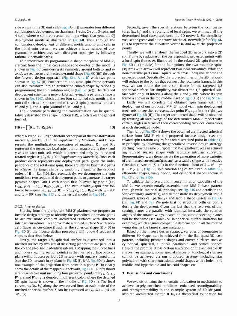
inverse design strategy to identify the prescribed kinematic pathsto achieve more complex architected surfaces with differentintrinsic curvatures. To approximate a curved surface S with non-zero Gaussian curvature K such as the spherical shape (K > 0) inFig. 6D (i), the inverse design procedure will follow 4 sequentialsteps as described below.
Firstly, the target 1/8 spherical surface is discretized into ameshed surface by two sets of dissecting planes that are parallel tothe xz- and yz-plane in identical intervals. Mapping the curved linesand nodes (i.e., intersection points) in the meshed surface onto xz-planewill produce a periodic 2D networkwith square-shaped units(see the 2D network in xy-plane in Fig. 6D (i), left). Fig. 6D (i) showsone example of the projection from point P to point P’. To clearlyshow the details of the mapped 2D network, Fig. 6D (ii) (left) showsa representative unit including four projected points of P'i, j, P'iþ1, j,P'i, jþ1, and P'iþ1, j þ1 denoted in different color, where the detailed2D spin frame is shown in the middle of Fig. 6D (ii). The localcurvatures (kx, ky) along the two curved lines at each node of themeshed spherical surface S can be expressed as (kx, ky) ¼ ðvS =vx;vS =vyÞ.
10
Secondly, given the special relations between the local curva-tures (kx, ky) and the rotations of local spins, we will map all thedetermined local curvatures onto the 2D network. For simplicity,we use the green and blue arrows on the 2D network (left of Fig. 6D(ii)) to represent the curvature vector kx and ky at the projectionpoints.
Thirdly, we will transform the mapped 2D network into a 2Dspin frame by replacing all the corresponding projected points witha local spin frame. As illustrated in the related 2D spin frame inFig. 6D (ii) (middle) for the four points, the two rotatable spins(squares with arrow) will represent two local curvatures, while thenon-rotatable part (small square with cross lines) will denote theprojected point. Specifically, the projected lines of the 2D networkwill reduce to the bonds that connect the local spin frames. In thisway, we can obtain the entire spin frame for the targeted 1/8spherical surface. For simplicity, we dissect the 1/8 spherical sur-face with only 10 intervals along the x and y-axis, where its spinframe is shown in the top middle inset of Fig. 6D (i) and Fig. S15a-i.
Lastly, we will correlate the obtained spin frame with thedeployment of our proposed MM-20 model via n-spin deploymentmechanism (see the representative point P'iþ1, jþ1 in the right twofigures of Fig. 6D (ii)). The target architected shape will be obtainedby rotating all local wings of the determined MM-20 model withcertain angles in terms of their corresponding two local curvaturesat each discretized node.
The right of Fig. 6D (i) shows the obtained architected sphericalsurface from MM-20 via the proposed inverse design (see therelated spin rotation angles for each discretized point in Table S1).In principle, by following the generalized inverse design strategy,starting from the same pluripotentMM-20 platform, we can achieveany curved surface shape with arbitrary intrinsic curvature.Representatively, we demonstrate the generation of more varietiesof architected curved surfaces such as a saddle shape with negativeGaussian curvature (K < 0) in the functional form of S ¼ x2 � y2
(0 ¼ x, y � 1) (Fig. 6E, spin rotation angles are listed in Table S2),ellipsoidal shapes, wavy ribbon, and cylindrical shapes shown inFig. 6F and Fig. S15b.
To validate the forward and inverse imitation capability of theMM-20, we experimentally assemble one MM-20 base patternthrough multi-material 3D printing (see Fig. S16 and details in theSupplementary Materials), and demonstrate its deployment into apyramid, spherical (partially), and saddle shape (insets in Fig. 6C(iii), Fig. 6D and 6E). We note that no structural collision occursduring the deployment. Given the fact that the two sets of dis-secting planes are parallel with identical intervals, the rotationangles of the rotated wings located on the same dissecting planeswill be the same (see Table- S1 in spherical surface imitation forexample), which ensures compatible deformation in all the rotatedwings during the target shape imitation.
Based on the inverse design strategy, varieties of geometries indifferent 3D shapes can be achieved from the flat, quasi-3D basepattern, including prismatic shapes and curved surfaces such ascylindrical, spherical, elliptical, paraboloid, and conical shapes.Despite the promise, it has certain limitation on the achievable 3Dshapes. For example, some special shapes or topological changescannot be achieved via our proposed strategy, including starpolyhedron with sharp extrusions, toroid shapes with a hole in themiddle, and hyperboloid and helicoid shapes etc.
3. Discussions and conclusions
We exploit utilizing the kinematic bifurcation in mechanism toachieve largely enriched mobilities, enhanced reconfigurability,and reprogrammability in the example system of 3D kirigami-inspired architected matter. It lays a theoretical foundation for
Y. Li and J. Yin Materials Today Physics 21 (2021) 100511
designing reconfigurable and shape-reprogrammable materialswith evolving shape-morphing features. We uncover the kine-matics underpinning its multiple transformation modes includingthe kinematic bifurcation through the developed models. Rationaldesigns of building blocks enable their frustration-free and periodicplanar tessellation with encoded non-bifurcated/bifurcated tran-sition modes. We demonstrate leveraging kinematic bifurcation forachieving the mapping from one design to many structural con-figurations. Moreover, the bifurcated structure provides a pluripo-tent platform to be reprogrammed intomultiple architected curvedsurfaces through both forward and inverse designs.
The 3D kirigami-inspired modules largely free the constrainedstructural mobilities in conventional kirigami designs of planar thinsheets [15,25,26]. We note that the 3D kirigami-inspired approachcould be generalized to generate more derived transformablemodules [35]. Considering the four connection ways between twoneighboring cubes, the 3D kirigami-inspired modules consisting of4, 6, and 8 cubes in Fig. 2A-C could further evolve into 44 ¼ 256,46 ¼ 4,096, and 48 ¼ 65,536 derived modules by manipulatingcombinatorial designs of the cube connections, respectively.Furthermore, more complex 3D modules can be constructed bycombining the three basic modules, e.g., 12-cube modules bycombining the units of 4 cubes and 8 cubes in Fig. 2. However, itdoes not necessarily result in more structural reconfigurationmodes and more bifurcated kinematic paths compared to the 8-cube module (Fig. S17), which depends on how the cubes areconnected in a symmetric or asymmetric way.
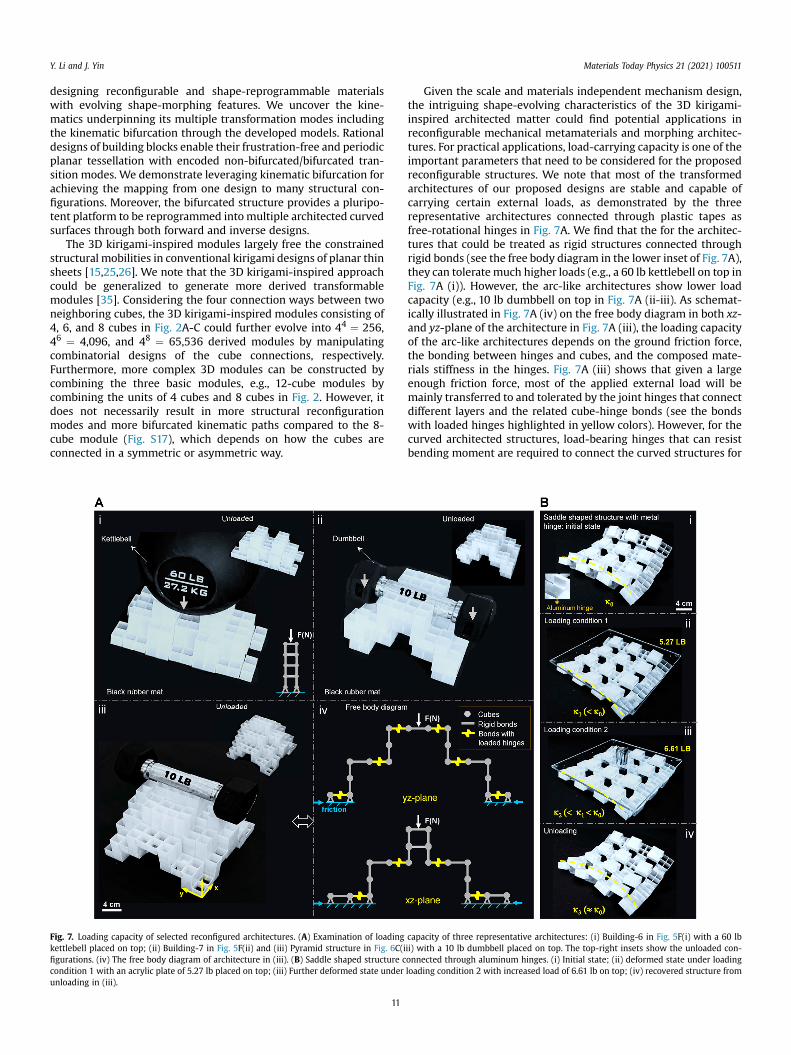
Fig. 7. Loading capacity of selected reconfigured architectures. (A) Examination of loadingkettlebell placed on top; (ii) Building-7 in Fig. 5F(ii) and (iii) Pyramid structure in Fig. 6C(ifigurations. (iv) The free body diagram of architecture in (iii). (B) Saddle shaped structure ccondition 1 with an acrylic plate of 5.27 lb placed on top; (iii) Further deformed state underunloading in (iii).
11
Given the scale and materials independent mechanism design,the intriguing shape-evolving characteristics of the 3D kirigami-inspired architected matter could find potential applications inreconfigurable mechanical metamaterials and morphing architec-tures. For practical applications, load-carrying capacity is one of theimportant parameters that need to be considered for the proposedreconfigurable structures. We note that most of the transformedarchitectures of our proposed designs are stable and capable ofcarrying certain external loads, as demonstrated by the threerepresentative architectures connected through plastic tapes asfree-rotational hinges in Fig. 7A. We find that the for the architec-tures that could be treated as rigid structures connected throughrigid bonds (see the free body diagram in the lower inset of Fig. 7A),they can toleratemuch higher loads (e.g., a 60 lb kettlebell on top inFig. 7A (i)). However, the arc-like architectures show lower loadcapacity (e.g., 10 lb dumbbell on top in Fig. 7A (ii-iii). As schemat-ically illustrated in Fig. 7A (iv) on the free body diagram in both xz-and yz-plane of the architecture in Fig. 7A (iii), the loading capacityof the arc-like architectures depends on the ground friction force,the bonding between hinges and cubes, and the composed mate-rials stiffness in the hinges. Fig. 7A (iii) shows that given a largeenough friction force, most of the applied external load will bemainly transferred to and tolerated by the joint hinges that connectdifferent layers and the related cube-hinge bonds (see the bondswith loaded hinges highlighted in yellow colors). However, for thecurved architected structures, load-bearing hinges that can resistbending moment are required to connect the curved structures for
capacity of three representative architectures: (i) Building-6 in Fig. 5F(i) with a 60 lbii) with a 10 lb dumbbell placed on top. The top-right insets show the unloaded con-onnected through aluminum hinges. (i) Initial state; (ii) deformed state under loadingloading condition 2 with increased load of 6.61 lb on top; (iv) recovered structure from
Y. Li and J. Yin Materials Today Physics 21 (2021) 100511
carrying external loading; otherwise, they will collapse via freerotation of the hinges. To demonstrate it, we use thin aluminumplates as connection hinges (Fig. 7B (i)) and show that the curvedsaddle-like structure can support about 6 lb external load with adecreased curvature (Fig. 7B (ii-iii)). After unloading, the curvatureof the curved structure almost returns to its original value beforeloading (Fig. 7B (iv)).
Meanwhile, control and actuation of deployment will beimportant considering their rich mobilities, especially at thebifurcation points for a desired transition pathway. Exclusive linearkinematic paths for target shapes (e.g., the linear path in Fig. S13)will be needed for easy control of hinge rotating with motion ac-tuators such as motors [47] or other stimuli-responsive actuators[48]. As demonstrated in Fig. 3B, despite multiple transition path-ways at the bifurcated points, a certain desired path for a targetshape change is possible by tuning the specified dihedral foldingangle between different cubes. Thus, to achieve a target transitionpathway via actuation, the revealed kinematics modeling couldprovide important guidance for appropriate sequential actuationsof the specified folding angles.
4. Materials and methods
Details of fabrication of prototypes and assembly, kinematicsanalysis, transitions of building blocks and their tessellation, ki-nematic mobility, and forward and inverse designs are described inSupplementary Materials.
Author contribution
Y. L. and J. Y. proposed and designed the research. Y. L. designedand fabricated the prototypes and performed theoretical analysis ofthe system. Y. L. and J. Y. wrote the manuscript.
Funding
The authors acknowledge the funding support from NationalScience Foundation, United States, under award number CMMICAREER-2005374.
Data and materials availability
All data is available in the main text or the supplementarymaterials.
Declaration of competing interest
The authors declare that they have no known competingfinancial interests or personal relationships that could haveappeared to influence the work reported in this paper.
12
Acknowledgments
The authors thank Sid Collins for artistic inspiration.
Appendix A. Supplementary data
Supplementary data to this article can be found online athttps://doi.org/10.1016/j.mtphys.2021.100511.
References
[1] S.C. Goldstein, et al., Computer 38 (6) (2005) 99.[2] K. Oliver, et al., J. Mater. Sci. 51 (24) (2016) 10663.[3] H. Ko, A. Javey, Acc. Chem. Res. 50 (4) (2017) 691.[4] T. van Manen, et al., Mater. Today 21 (2) (2018) 144.[5] K. Bertoldi, et al., Nature Reviews Materials 2 (11) (2017) 17066.[6] M. Yim, et al., IEEE Robot. Autom. Mag. 14 (1) (2007) 43.[7] S. Barbarino, et al., J. Intell. Mater. Syst. Struct. 22 (9) (2011) 823.[8] F. Momeni, et al., Mater. Des. 122 (2017) 42.[9] S.J.P. Callens, A.A. Zadpoor, Mater. Today 21 (3) (2018) 241.
[10] X. Ning, et al., Advanced Materials Interfaces 5 (13) (2018) 1800284.[11] Y. Chen, et al., Science 349 (6246) (2015) 396.[12] R.J. Lang, et al., Appl. Mech. Rev. 70 (1) (2018).[13] E.A. Peraza-Hernandez, et al., Smart Mater. Struct. 23 (9) (2014): 094001.[14] N. Turner, et al., Proc. IME C J. Mech. Eng. Sci. 230 (14) (2016) 2345.[15] Y. Cho, et al., Proc. Natl. Acad. Sci. Unit. States Am. 111 (49) (2014) 17390.[16] D.M. Sussman, et al., Proc. Natl. Acad. Sci. Unit. States Am. 112 (24) (2015)
7449.[17] M.K. Blees, et al., Nature 524 (7564) (2015) 204.[18] T.C. Shyu, et al., Nat. Mater. 14 (8) (2015) 785.[19] R.M. Neville, et al., Sci. Rep. 6 (1) (2016) 31067.[20] Y. Tang, et al., Adv. Mater. 29 (10) (2017) 1604262.[21] Y. Yang, et al., Physical Review Materials 2 (11) (2018) 110601.[22] D.-G. Hwang, M.D. Bartlett, Sci. Rep. 8 (1) (2018) 3378.[23] Y. Tang, et al., Proc. Natl. Acad. Sci. Unit. States Am. 116 (52) (2019) 26407.[24] E.D. Demaine, J. O'Rourke, Geometric Folding Algorithms: Linkages, Origami,
Polyhedra, Cambridge University Press, 2007.[25] Y. Tang, J. Yin, Extreme Mechanics Letters 12 (2017) 77.[26] J.N. Grima, K.E. Evans, J. Mater. Sci. Lett. 19 (17) (2000) 1563.[27] G.P.T. Choi, et al., Nat. Mater. 18 (9) (2019) 999.[28] A. Rafsanjani, K. Bertoldi, Phys. Rev. Lett. 118 (2017): 084301.[29] L.H. Dudte, et al., Nat. Mater. 15 (5) (2016) 583.[30] P. Dieleman, et al., Nat. Phys. 16 (1) (2020) 63.[31] T. Castle, et al., Science Advances 2 (9) (2016): e1601258.[32] J.T.B. Overvelde, et al., Nat. Commun. 7 (1) (2016) 10929.[33] J.T.B. Overvelde, et al., Nature 541 (7637) (2017) 347.[34] N. Yang, J.L. Silverberg, Proc. Natl. Acad. Sci. Unit. States Am. 114 (14) (2017)
3590.[35] Y. Li, et al., Adv. Funct. Mater. (2021) 2105641.[36] P. Blanchard, et al., Differential Equations, Thompson, London, 2006.[37] B. Davide, Nonlinear Solid Mechanics: Bifurcation Theory and Material
Instability, Cambridge University Press, 2012.[38] Y. Chen, et al., Int. J. Solid Struct. 42 (8) (2005) 2287.[39] P. Kumar, S. Pellegrino, Int. J. Solid Struct. 37 (46) (2000) 7003.[40] T. Tarnai, Kinematic bifurcation, in: S. Pellegrino (Ed.), Deployable Structures,
Springer Vienna, Vienna, 2001, p. 143.[41] https://erikdemaine.org/thok/flexcube.html.[42] J.W. Truman, L.M. Riddiford, Nature 401 (6752) (1999) 447.[43] S. Kriegman, et al., Proc. Natl. Acad. Sci. Unit. States Am. 117 (4) (2020) 1853.[44] J. Denavit, R.S. Hartenberg, J. Appl. Mech. 22 (1955) 215.[45] W.W. Gan, S. Pellegrino, Proc. IME C J. Mech. Eng. Sci. 220 (7) (2006) 1045.[46] C. Coulais, et al., Nature 535 (7613) (2016) 529.[47] B. Vanderborght, et al., Robot. Autonom. Syst. 61 (12) (2013) 1601.[48] Y. Liu, et al., Prog. Polym. Sci. 52 (2016) 79.