Cell motility and mechanics in three-dimensional collagen matrices
Upload
khangminh22Category
view
1download
0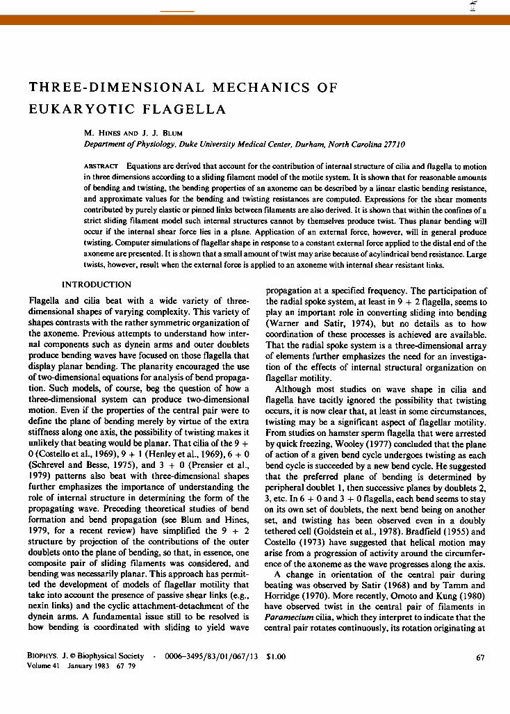
THREE-DIMENSIONAL MECHANICS OF
EUKARYOTIC FLAGELLA
M. HINES AND J. J. BLUMDepartment ofPhysiology, Duke University Medical Center, Durham, North Carolina 27710
ABSTRACT Equations are derived that account for the contribution of internal structure of cilia and flagella to motionin three dimensions according to a sliding filament model of the motile system. It is shown that for reasonable amountsof bending and twisting, the bending properties of an axoneme can be described by a linear elastic bending resistance,and approximate values for the bending and twisting resistances are computed. Expressions for the shear momentscontributed by purely elastic or pinned links between filaments are also derived. It is shown that within the confines of astrict sliding filament model such internal structures cannot by themselves produce twist. Thus planar bending willoccur if the internal shear force lies in a plane. Application of an external force, however, will in general producetwisting. Computer simulations of flagellar shape in response to a constant external force applied to the distal end of theaxoneme are presented. It is shown that a small amount of twist may arise because of acylindrical bend resistance. Largetwists, however, result when the external force is applied to an axoneme with internal shear resistant links.
INTRODUCTION
Flagella and cilia beat with a wide variety of three-dimensional shapes of varying complexity. This variety ofshapes contrasts with the rather symmetric organization ofthe axoneme. Previous attempts to understand how inter-nal components such as dynein arms and outer doubletsproduce bending waves have focused on those flagella thatdisplay planar bending. The planarity encouraged the useof two-dimensional equations for analysis of bend propaga-tion. Such models, of course, beg the question of how athree-dimensional system can produce two-dimensionalmotion. Even if the properties of the central pair were todefine the plane of bending merely by virtue of the extrastiffness along one axis, the possibility of twisting makes itunlikely that beating would be planar. That cilia of the 9 +0 (Costello et al., 1969), 9 + 1 (Henley et al., 1969), 6 + 0(Schrevel and Besse, 1975), and 3 + 0 (Prensier et al.,1979) patterns also beat with three-dimensional shapesfurther emphasizes the importance of understanding therole of internal structure in determining the form of thepropagating wave. Preceding theoretical studies of bendformation and bend propagation (see Blum and Hines,1979, for a recent review) have simplified the 9 + 2structure by projection of the contributions of the outerdoublets onto the plane of bending, so that, in essence, onecomposite pair of sliding filaments was considered, andbending was necessarily planar. This approach has permit-ted the development of models of flagellar motility thattake into account the presence of passive shear links (e.g.,nexin links) and the cyclic attachment-detachment of thedynein arms. A fundamental issue still to be resolved ishow bending is coordinated with sliding to yield wave
propagation at a specified frequency. The participation ofthe radial spoke system, at least in 9 + 2 flagella, seems toplay an important role in converting sliding into bending(Warner and Satir, 1974), but no details as to howcoordination of these processes is achieved are available.That the radial spoke system is a three-dimensional arrayof elements further emphasizes the need for an investiga-tion of the effects of internal structural organization onflagellar motility.
Although most studies on wave shape in cilia andflagella have tacitly ignored the possibility that twistingoccurs, it is now clear that, at least in some circumstances,twisting may be a significant aspect of flagellar motility.From studies on hamster sperm flagella that were arrestedby quick freezing, Wooley (1977) concluded that the planeof action of a given bend cycle undergoes twisting as eachbend cycle is succeeded by a new bend cycle. He suggestedthat the preferred plane of bending is determined byperipheral doublet 1, then successive planes by doublets 2,3, etc. In 6 + 0 and 3 + 0 flagella, each bend seems to stayon its own set of doublets, the next bend being on anotherset, and twisting has been observed even in a doublytethered cell (Goldstein et al., 1978). Bradfield (1955) andCostello (1973) have suggested that helical motion mayarise from a progression of activity around the circumfer-ence of the axoneme as the wave progresses along the axis.A change in orientation of the central pair during
beating was observed by Satir (1968) and by Tamm andHorridge (1970). More recently, Omoto and Kung (1980)have observed twist in the central pair of filaments inParamecium cilia, which they interpret to indicate that thecentral pair rotates continuously, its rotation originating at
BIOPHYS. J. e Biophysical Society - 0006-3495/83/01/067/13 $1.00Volume 41 January 1983 67-79
67
brought to you by COREView metadata, citation and similar papers at core.ac.uk
provided by Elsevier - Publisher Connector

the base of the cilium. Thus there are many indicationsthat twisting of at least some ciliary components occursduring ciliary motion and, indeed, may play a role indetermining the three-dimensional motion. The need for acomprehensive analysis of the contribution of internalstructure to three-dimensional flagellar mechanics is there-fore clear.
In section I of this paper we analyze flagellar shape bydeveloping a formalism that accounts for the change incoordinate axes of each of the filaments in a flagellum forarbitrary bending and twisting, and show how coordinatetransformations can be used to keep track of local orienta-tion of the internal components. Section II then formulatesthe sliding filament model, explicitly allowing for thecontribution of each of the outer doublets. A method forcomputing the bending and twisting resistances of a flagel-lum is presented in section III. When a central pair ispresent, the bending resistance encountered in response toan internal dynein-generated force will depend on theangle that the force makes within the central pair crosssection. Estimates of the values of the components of thebend resistance matrix are obtained. In section IV wederive general expressions for the moments generated byinternal shear forces, and apply these to an analysis of thecontribution of nexinlike links. This analysis shows thatsuch elastic links cannot contribute any twisting moment.Section V presents a numerical method for computeranalysis of the three-dimensional sliding filament modeland simulations of flagellar shape in response to applica-tion of a constant external force for various degrees ofinternal asymmetry. The contribution of internal structureto bend shape and twist is then examined, and conditionsfor nearly planar bending are discussed.A brief outline of some of these results has been
presented (Hines and Blum, 1982).
NOMENCLATURE
Depending upon the context, a subscript may refer to the filamentnumber, i = 1, 9; a component of a vector, i = 1, 3; or a discrete point onthe flagellum, p = 1, N. In the rare case that confusion is possible, themeaning is explicitly stated.An arrow over a symbol denotes a three-dimensional vector. A
circumflex over a symbol denotes a unit vector. Two tildes under a symboldenote a 3 x 3 matrix.
Symbols that appear in more than one section of the paper are listedbelow with their units:
AEbEJ,, En, EzzEsA-
F, Ft,,fii
LiAM
coordinate transformationbending resistance matrixdiagonal components of Eb (pNMm2)shear force coefficient (pN/Im)external force density (pN/um)external force on positive face of axoneme (pN)force caused by link between ith and jth doublet (pN)effective shear (radians)curvature (rad/Mm)vector from neutral axis to ith doublet (,um)length of flagellum (Mm)moment on positive face of axoneme cross section(pNAm)
rs
sTU'
position vector (,um)arc length (Am)internal shear force (pN)tangent vectorsliding of ith doublet relative to central pair (Am).
I. FLAGELLAR SHAPE
Consider an orthogonal coordinate system with its origin atarc length position s along the neutral axis (see Lublinerand Blum, 1971) of the axoneme. The location of thisorigin with respect to some fixed point in the laboratory isexpressed by the position vector, r. The orientation of thiscoordinate system is taken as fixed relative to the structureof the axoneme. We call this system the body coordinatesystem and, for convenience, choose to orient the z axisalong the neutral axis of the axoneme, i.e., along thetangent. The orientation of the x axis can be arbitrarilyfixed with respect to some conventional structural featureof the axoneme such as along the long cross section of thecentral pair. The y axis is then fixed by the furtherrequirement that the body coordinate system be right-handed. The value of using such body coordinate systems istwofold. First, many mechanical and structural propertiesare independent of s when expressed in this system.Second, vectors describing structure, position, and forcesacting on the axoneme have very simple representations.The shape of the axoneme can be envisioned as a continu-ous string of coordinate systems with their origins sepa-rated by an infinitesimal distance, ds, along the filamentaxis.
Fig. 1 illustrates how the overall shape is governed by therelative rotation of adjacent body coordinate systems. Forexample, pure twist is built up by successive relativerotations about the z axis and pure bending in the xz planeis built up by successive rotations about the y axis. Thechange of orientation with respect to arc length about thethree local body coordinate axes are the three componentsof the curvature vector, Ki, along these axes. Notice that wehave identified Kz as the amount of twist per unit arc length.As a flagellum changes its orientation continuously (but
z
LKy
FIGURE I Bending and twist generated by relative rotation of adjacentbody coordinate systems about the body coordinate axes. Rotation onlyabout the z axis produces pure twist, Kz Rotation only about the x axisproduces pure bending in the Y, Z plane, Kx, and similarly about the yaxis.
BIOPHYSICAL JOURNAL VOLUME 41 198368

with Kz = 0 everywhere) parts of the flagellum will rotate;such rotations should not be confused with twist. Theseconcepts are rigorously expressed in the appendix wherecoordinate transformations are used to derive the usualexpression for the directional derivative of a vector,
dV /dV\= + K x V. ~~~~(1)
ds ds body
This formula relates the change of a vector, V, withrespect to arc length, to the derivative of its components inthe body coordinate system at position s; the cross productterm accounts for possible changes in direction of the axesof the body coordinate system if the axoneme is undergoingbending or twisting. For example, because the tangentvector, T, has been defined so that it is constant in bodycoordinates,
dT-d= x T. (2)ds
Given -K(s) in body coordinates, one can determine theshape of the flagellum by using the transformationmatrices described in the appendix. From Eq. A5, theinfinitesimal transformation from position s to s - ds is
I -KdS Kyds
A(s -ds,s) = Kzds I -Kxds (3)
-KydS KXds I
The finite transformation from position s back to the origin(s = 0) is then achieved by the infinite product of theseinfinitesimal transformations:
A(0, s) = A(0, ds)A(ds, 2ds) . . .
A(s-2ds,s-ds)A(s - ds,s). (4)
Because dr/ds = T in body coordinates is z, then theposition vector, r, to the flagellum at position s from anorigin at s = 0 is
7(s) = A(0, s')zds'. (5)
Thus in fixed coordinates the X, Y, and Z components ofthe position vector are
X(s) = f A13(0,s')ds'
Y(s) = f A23(0,s')ds'
Z(s) = A33(0,s')ds'. (6)
II. SLIDING FILAMENT MODEL
The position vector of the ith doublet of the axoneme canbe written formally as
ri(si) = 7(s) + Li(s), (7)
where 7 refers to the position vector of the central pair ofmicrotubules (Fig. 2). The sliding filament model isexpressed succinctly merely by requiring that Li, a vectorfrom the central pair to the ith outer doublet, be a constantvector in body coordinates. We choose Li normal to thecentral pair tangent vector. (For convenience Li may bethought of as directed along an undistorted radial link.)This formalism then specifies that the normal distancebetween the central pair and any of the outer doublets isfixed, but allows the axoneme as a whole to bend and twistin three dimensions. It is important to realize that si in Eq.7 is not an independent parameter, but is the arc length ofthe ith filament in the cross section of the axoneme at arclength s along the neutral axis. Warner's (1978) datashows that during extensive cross bridging the ciliumassumes an ellipsoidal shape, i.e., is distorted, with somedoublets approaching the central pair while others movesome distance away. This refinement, which would requirethat the magnitude of Li be a variable, is ignored here. It isimplicit in this formulation that the central pair retains afixed orientation relative to a marker (such as the positionof the 5-6 bridge) somewhere on one of the outer doublets.If the central pair rotated within the interior of thecylindrical region defined by the outer doublets, as indi-cated by the studies of Omoto and Kung (1980), then theaxonemal body coordinates in which Ei is constant could nolonger be identified with central pair body coordinates.Although it would be simple to allow for rotation of thecentral pair relative to the outer cylinder of doublets, weignore that possibility here.The relationship between the tangent vectors of the
central pair and the ith outer doublet can be obtained bydifferentiating Eq. 2.1 with respect to s,
dr dr dLids ds ds (8)
ith OUTER DOUBLET
_i:'1 ~ CENTRAL PAIR
I,riTSj (s)Jis
IJA r (s)IA
X~~~~
FIGURE 2 The central pair and the ith outer doublet of an axoneme areshown relative to a fixed coordinate system, XYZ. The body coordinateaxis is tangent to the central pair (strictly, the neutral axis) at arc lengthposition s, and Li(s) is perpendicular to the tangent and has a fixedlength.
HINES AND BLUM Three-dimensional Mechanics ofEukaryotic Flagella 69
The term on the left side of this equation is, by the chainrule, (dir/dsi) (dsi/ds). Because Li is a constant in bodycoordinates, dtE/ds = i(s) x ti(S). Thus Eq. 8 can berewritten as
ds2T = T(s) + it(s) x Li(s), (9)ds
where we have used the fact that the arc length derivativeof the position vector is the tangent vector. If one definesthe relative sliding, ui(s), as s - si(s) (note that positivesliding or distal movement makes the value of si < s), thenupon taking the norm of Eq. 9 one obtains
dui(s) 1-I T(s) + iW(s) x Li(s)j (10)ds
If the twist per unit arc length, Kz, is not too great, thenorm in Eq. 10 can be expanded in a Taylor's series to yieldthe second-order approximation,
-i (Lx T) . K- (LiK)2/2. ( 11)ds
This equation is exact if Kz = 0 (i.e., no twist). Notice alsothat L x T has no z component; thus, to first order, slidingis independent of twist.
For planar bending without twist the integral of Eq. 10equals L times the total bend angle. For pure twist (KX =KY= 0) sliding of the outer doublets relative to the centralpair occurs because of the increased length of the spiralpath. Fig. 3 demonstrates the accumulation of sliding atthe tip for a three-filament axoneme (outer filamentsnumbered 1 and 2) with constant K, and constant KX and, forconvenience, Ky = 0. In the linear approximation, u2 - ul is2K,LA at the distal end, where A is the length of theaxoneme. In the second-order approximation, u, =(-KXL - 0.5L2K2)A and u2 = (KXL - 0.5L2K2)A, and again
FIGURE 3 A three-filament axoneme with the central filament labeled 0and two outer doublets labeled I and 2 is shown. The filaments, fixed atthe base, are 20 gm long and the spacing between the central rilament andfilaments I and 2 is + I and -1I gm, respectively, in the body coordinate xaxis. Curvature is set at K., = 4.5, KY = 0, KZ = 9 degrees/Mlm. Markersspaced at 1 Mm intervals along the outer doublets and normal to them aswell as to the central pair are shown as an aid to visualizing the twist andthe sliding.
U2-ui is 2KXLA. The exact relative sliding (from Eq. 10),however, is
U2 - Ul
= [(1 + K1L)2 + K2L2 _ (1 -KL)2 + K,L2]A. (12)
The exact value for u2 -uI therefore contains a very small(order K3L3) contribution due to twist. For a flagellum 20gm long with a spacing of 0.1 sm between central pair andan outer doublet, a KX of 4.5 degrees/,um and a Kz of 9.0degrees/,gm, the value of U2 -ul = 0.315789,um to secondorder, and the exact result is 0.315790.
Schreiner (1977) has derived equations that allow one tocompute the displacement and sliding of twisted filamentsin cilia and flagella, and Holwill et al. (1979) modified thetreatment of Schreiner (1977) for ease of computation ofthe doublet pattern to be expected at the tip of cilia in theeffective and recovery stroke positions. Their derivationaccounts for the changing projection of the filaments ontothe plane of bending, but ignores the sliding due tospiraling of the filaments about the central pair. If, forexample, the twist was so large that the doublets essentiallycoiled around the base of the flagellum, their equationswould predict zero sliding relative to the central pair,whereas the actual sliding would be almost the negative ofthe full length of the flagellum. Although the equationsused by Holwill et al. (1979) are correct only to first order,their use to compute relative sliding of outer doubletseliminates terms equivalent to the term (LK,,)2/2 in Eq. 11,so that their computations of relative tip displacements arecorrect to second order and hence entirely adequate.
III. BENDING RESISTANCEOF THE AXONEME
By bending resistance we mean the sum of the bendingresistance of the individual doublets. Other contributionsto "stiffness" from interdoublet links such as nexin links,radial spokes, or dynein cross-bridges, will be treated ascontributing to shear resistance. Even if one assumes thatthe bending resistance of individual doublets is linearlyelastic (i.e., the bending moment is proportional to curva-ture), it is not clear whether the axoneme can be treated sosimply. For example, in a twisted but otherwise straightaxoneme, the outer doublets would spiral around thecentral pair and their direction would not be parallel to theaxonemal axis. Axonemal bending resistance might thusbe a complicated function of shape. In this section weexamine this question and ask under what conditions it isappropriate to use a simple linear elastic bending resis-tance to describe the bending resistance of a flagellum.The assumption that individual doublets are linearly
elastic can be expressed as
M= - bKi. (13)
Here Mi is the bending moment and Eb, is the bendingresistance of the ith filament. The representation of bend-
BIOPHYSICAL JOURNAL VOLUME 41 198370

ing resistance in ith doublet body coordinates is particu-larly simple; because we have chosen the coordinate axes tolie along the principal axes of the doublet, all off-diagonalterms of the matrix are zero, and
Exx
EFbi.= O Eyy O .
O O Ezz-(14)
To derive reasonable values for'the components of thebend resistance matrix, we make use of a generalized formof Hooke's law, which states that linear strain is propor-tional to force per unit area via ex = [ay - v(ay + a7)]/E,with similar equations for the y and z components of thestrain, e. In this equation, ay and ao are the forces acting perunit area on the y and z faces of an infinitesimal element ofthe body, E is Young's modulus of elasticity, and v isPoisson's ratio,' a number that ranges from =0.3 for metalsto =0.5 for rubber. Hooke's law also states that the shearforce is proportional to the shear strain via the shearmodulus G = E/2(1 + v). It can be shown (Crandall andDahl, 1959) for slender members that the twisting momentgenerated by Kz is given by
Mz = -CIlZZKZ, (15)
where Izz, is the moment of inertia around the Z axis.Similarly, the bending moment is given by
Mi=-EIj1Kji=L, 2 (16)
where Ij = fA xjxjdA. Electron microscopic studies showthat typical dimensions for an outer doublet are -20 nmfrom the center of the B subfiber to the center of the Asubfiber, and wall thickness is -5 nm. For convenience ofcomputation, we replace the outer doublet by a pair ofoverlapping tubules, as shown in Fig. 4. The area of one ofthe annuli is 27r r'It. The moments of inertia are given by
I. = 2 r2dA = 2 f (x. + r')2dA = 2 Area (X2 + r2),
IXX = 2f (X. + r' cos )2rtdO = 2 Area(X + 2
and
rP2Iy,==2Area . (17)
2
Using a value of E = 4 * 107 pN/tUm2 (Hines and Blum,1979) and choosing v = 1/3, one obtains the followingapproximate values for the bend resistances of an individ-ual doublet: EXX = 3.6, Eyy = 1.2, Ezz = 5.4 pN,tm2. Recentmeasurements of the bending resistance of isolated dou-
'When an elastic material is stretched, it also becomes slightly thinner. Ifthe initial length and diameters are l and d0, respectively, then v =- lateral strain/longitudinal strain -[(d-do)ld]/[(l - lo)/l]
FIGURE 4 Shape used for computation of moment of inertia of an outerdoublet. For simplicity of computation, a doublet is drawn as twooverlapping singlets with the dimensions shown. This slightly overesti-mates the moment of inertia in the overlap region, but this is more thancompensated for by use of the average value of the radius of the annulus inthe computation of the moment of inertia. Because the body coordinatesare oriented as shown (with the x axis perpendicular to the paper), theoff-diagonal elements of the moment of inertia matrix are zero bysymmetry. XO (not shown) is a vector from the origin of the coordinatesystem to the center of either singlet microtubule.
blets (Ishijima and Hiramoto, 1982, and personal commu-nication), however, indicate a value for bend resistance of-10 pN ,um2, suggesting that the above value of E may betoo low for a tubulin doublet.The bending moment of the axoneme is just the sum of
the bending moments of the individual filaments. To findEb, we choose a curvature for the central pair, find thecurvature for each of the outer doublet filaments (usingEq. 9, appropriate to a sliding filament model with nodistortion of the axoneme), then use Eq. 13 to find themoments of each filament, and add those momentstogether. We then do the same thing for slightly differentcurvatures of the central pair to build an expression for Eb,via Eb. = bMilbKj.To carry out this program, it is first necessary to find a
transformation matrix, which we denote Ajo, from centralpair body coordinates to ith outer doublet body coordi-nates. Once the vectors of interest (i.e., bending momentvectors) are expressed in the same coordinate system,conventional vectorial operations can be done componentby component.
Ajo(s), the transformation from central pair body coordi-nates to the ith outer doublet body coordinates at arclength s1(s) is simply the product of three elementaryrotations, Aio = BCD. The first of these, ID, is a rotationabout the central pair z axis by an amount 0, so that thenew x' axis is along Li (Fig. 5):
cos Oi sin 0, 0
D = -sinOi cos0i .
O O 1(18)
HINES AND BLUM Three-dimensional Mechanics ofEukaryotic Flagella 71
The matrix B is the transformation for a rotation about z"by an angle 4 and therefore has the same form as that ofmatrix D (see Eq. 18). Notice that because of matrix C, Ajois a function of curvature. The bending moment of theaxoneme as a whole can then be written as follows,
axoneme"
io fbiAio)IK.-
Ebo (A-US (23)
x I1 TO PAGE
ttI1T PG xii
9izi I TO PAGE
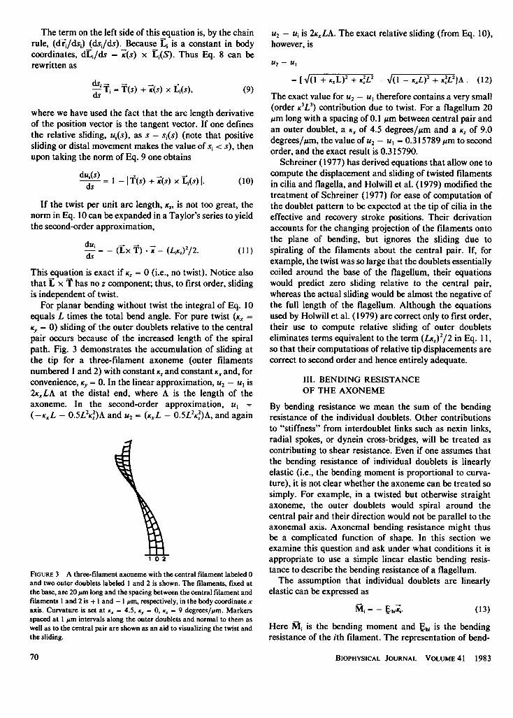
FIGURE 5 Shown are three elementary coordinate transformations usedto build up the finite transformation from central pair body coordinate toith doublet. The solid horizontal arrows between similar views imply a
transformation of coordinates. The dashed vertical arrows betweendifferent views denote merely a change in the observer's viewpoint toallow easy visualization of the following transformation.
Next, we rotate about the x' axis by the amount requiredfor the new z" axis to be in the direction Ti. To find thetransformation, C, we use two pieces of information. First,the representation of Li in double prime coordinates is thesame as it is in prime coordinates, as we are rotating aboutan axis parallel to Li. Thus
(0 =C 0 (19)
The second piece of information is that Tj = i". From Eq.9, the representation of 1i in prime coordinates is
( ) +(KZ) (0) (20)
Til= ddsids
Eq. 19 and 20 imply that
1 0
C=Io 1 - LKy,dsi/ds
LKZ._ dsi/ds
0
LK,,dsi/ds
1 - LKYdsi/ds _
with
dsl/ds = [(LK(,)2 + (1 LK )2]O.5
(21)
The first term in this equation is the bending moment ofthe central pair. In the second term, dsi/ds accounts for thefact that for a given change in bend angle there are
different arc lengths for each outer doublet and hencedifferent curvatures. This is usually ignored in treatmentsof planar motion, but differs from unity whenever curva-
ture is large or when there is appreciable twist. The term inparentheses represents the ith outer doublet bending resis-tance in central pair body coordinates, and also depends on
curvature.For a straight flagellum using the bend resistance values
derived above, the values of E.,, Eyy, and E,, for the wholeaxoneme are 25.2, 22.8, and 54.0 pN ,um2, with theoff-diagonal elements <10'6 pN ,Om2. Thus the effect ofaveraging the contribution of the doublets with that of thecentral pair is to produce a bend resistance matrix which isonly slightly acylindrical (EXX = Eyy) Furthermore, themagnitudes of bend resistance are identical to the average
contribution of the outer doublets plus 3.6 or 1.2 due to thecentral pair. The twist resistance, on the other hand, issimply the sum of the individual twist resistances of eachdoublet. For a helical flagellum with Kx = KY = KZ = 1
rad/Mm, the bending moment computed from Eq. 23 hascomponents Mx = 25.8, My = 23.4, and Mz = 54.5 pN ,tm.If the bending resistance of the straight axoneme were
applicable to a flagellum with this curvature, the bendingmoment components (using the same form as Eq. 3.1)would be Mx = 25.2, My = 22.8, and Mz = 54.0 pN zm.Thus, even with this very large degree of curvature, a <5%error is made in the bending moment if one uses a constantEb. It is interesting to note that the bend resistance matrixwith this curvature has diagonal elements 26.0, 23.6, and53.3 pN 11m2 (instead of 25.2, 22.8, and 54.0 pN ,um2 forthe straight flagellum), and the off-diagonal terms range
from 0.2 to 1.2 pN IAm2 (instead of <10 6pN ,um2). Clearlyit is an excellent approximation to consider Eb as beingindependent of curvature. In the simulations to be pre-sented below, we will use Eb appropriate for a straightaxoneme, which is applicable with negligible error tonormally curved flagella and cilia.
IV. SHEAR MOMENTS
The only components of force between filaments that are ofinterest are those that tend to move any of the doublets inways that are allowed. Thus forces that tend to distort theaxoneme by, e.g., moving an outer doublet closer to or
(22) farther from the central pair are ignored, because we
BIOPHYSICAL JOURNAL VOLUME 41 1983
21 TO PAGE
D
C
72

assume that forces of constraint exist that prevent suchmotion (i.e., that exactly balance the forces tending toproduce such distortion). All components of forces alongthe direction of any of the doublets, however, must beaccounted for, because they will produce relative sliding.Thus, in so far as the radial link system merely acts toprevent axonemal distortion, it will not contribute tosliding. If the radial link system, however, undergoes acyclic attachment-detachment process and resists relativesliding while attached, its contributions to the productionof bending moments cannot be ignored. Until furtherinformation is available as to the details of operation of theradial link system, we shall assume that it acts only toprevent distortion and as a source of passive shear resis-tance. The treatment that we now develop for the periph-eral nexin links can, however, be easily extended to includethe contribution of the radial link system to sliding when adetailed model of its action is proposed.
Link forces contribute to the tension in the outer dou-blets, and these tensions, because they are a distance Lifrom the body coordinate z axis, have resultant moments.Fig. 6 illustrates how the moment proximal to a stretchedlink is computed for links that cannot themselves transmitmoments, i.e., pinned links. We write the tension in the ithfilament at arc length s,, where it passes through the crosssection at arc length s, as
Tensioni = Z Ti(s) f A(s) T,(s') . fi(s')ds', (24)
where we have approximated the links between the ith andjth filaments as a continuous distribution and the sum isover all filaments that have links connecting to the ithfilament. For nexin links there are only two terms in thissum because the ith outer doublet (i = 1 ... 9) has nexinlinks only with the two adjacent doublets. For radial links,
D
EF
FF
there would be one term for each outer doublet and nineterms for the central pair. The total moment due to theselinks is then
9
M(s) = EE ILL(s) x T (s)f A[Ti(s') * fj(s')Jds'I. (25)
In the usual first-order approximation it is appropriateto assume that (a) si(s) = s, i.e., that opposite ends of a linkare not located at significantly different arc length; (b)Ti(s) = T(s), i.e., that the doublets at opposite ends of alink have similar tangents. This approximation impliesthat
dM -_ _ _=S= Lix T(T * fij),ds i-l j-i
(26)
i.e., that the links produce only a shear force, 3, to firstorder. It is of interest, however, to ask if the twistingmoment generated by the action of links in a slidingfilament system is significant. To assess the magnitude ofthe twisting moment, we retain the first-order term in theapproximation to Ti, i.e., Ti = T - Kz(L x T) (see Eq. 9).The twisting moment, M,, from Eq. 25 is then given by
Z ~~fA (T .-
)s'Mz =- IE KziE I T fij)ds' (27)
For elastic peripheral links (i.e., nexin links), Mz = 0 asfi = -fji and Li is a constant. Thus any twisting momentdue to peripheral links is at least third order in Li and hencenegligible. For radial links, the first summation should gofrom i = 0 to i = 9, where i = 0 represents the central pair.The forces,Aio, exerted on the ith outer doublet contribute atwisting moment, but -(oi (acting on the central pair) donot contribute a twisting moment. Thus radial links con-tribute a (second order in Li) twisting moment, propor-tional to the twist component of curvature, Kz. The twistingresistance due to the elasticity of the filaments is E, Thetwisting resistance of the axoneme due to radial links is
9
Z- L? fA (T. f-i) ds'.i-I
A
B
C
(28)
Before attempting to assess the magnitude of this twist-ing resistance term, it is convenient to return to the shearforce (Eq. 26) and cast it in a form suitable for analysis.We begin by assuming that the doublets are firmly tiedtogether at the proximal end, i.e., ui(O) = 0 for i = O.... 9.If we ignore the second-order effect of twist on sliding inEq. 11 it becomes
FIGURE 6 The conceptual process involved in determining the bendingmoment at some point proximal to a stretched link. In panels A-C, thestretched link produces a force along the link but constraints (not shown)keeping the filaments a constant distance apart exactly balance the forcecomponents that are not tangent to the filament. In panel D, the force F ofpanel C produces a constant tension along the filament proximal to thelink. In panels E and F, the tension in the filament is a distance L from theorigin of the cross section, thus producing a moment of magnitude LF aswell as a tension F along the axonemal axis.
ds' -*, (Li X T). (29)
The effective shear, j, analogous to the definition of y usedfor the analysis of planar motion (Hines and Blum, 1978)can now be written as
ui = - *- (Li x T) (30)
HINES AND BLUM Three-dimensional Mechanics ofEukaryotic Flagella 73

thereby allowing one to use j instead of the nine values ofui. Because both Li and T are constant in body coordinates,Eqs. 29 and 30 are consistent if the three body coordinatecomponents (k = 1, 2, 3) are defined by the relation dYk/ds = Kk. Because ui(O) = 0, 7(O) = 0 and when twisting issmall, plane sections will remain planar in three-dimen-sional bends. Under these conditions, and in so far as theradial links can be treated as a passive system, the twistingresistance of the axoneme due to the radial links will bezero to second order because the tension, f, (T * (i0)ds', onopposite sides of the axoneme will cancel. The contributionof an active radial link system to twist resistance could onlybe evaluated in terms of a specific model for the behavior ofthe radial links. If the constraints on axonemal distortionwere relaxed so that the central pair was free to rotate it iseasy to envision how an active radial link system couldcause rotation of the central pair.
For further evaluation of the shear force we assume thata nexin link produces a linear elastic force proportional toits length and that the radial links act merely as structuralconstraints. Then
fi=- E*(ui1T + Lij), (31)
where now i and j denote adjacent doublets with relativesliding uij = ui - uj and separation L11 = - L1 and E*isthe resistance of a nexin link to stretch.To get the contribution of the nine nexin links within an
axonemal cross section at s to the shear force at s* we treatthe sum in Eq. 26 as an integral,
- 9 f2w - x )S = 2 r (Lii x T) (T * fij)dO
V. COMPUTATIONS FORSTATIC EQUILIBRIA
Equilibrium EquationsIn sections III and IV we have derived expressions for thebending moments due to the bending and shear resistancesof the axonemal components. At equilibrium the sum of allof the bending moments, Mb +Ms + Mext, must vanish atevery point on the flagellum, where Mb is the moment dueto axonemal bending resistance, MS is the moment arisingfrom all internal shear producing or resisting links, andMext is the moment due to external forces such as viscosity.In this paper we treat only static equilibrium, where theviscous moment is zero. For purposes of numerical compu-tation the most convenient way to express the equilibriumcondition is in terms of the three component derivatives ofthe moment balance equation, expressed in body coordi-nates. From Eqs. 13 and 14,
-E - Si + ds = °biijd S i ds 0 (35)
We have shown earlier (Blum and Hines, 1979) that anexternal force per unit length, +, produces an externalmoment through the equations
'x' + = 0,ds(36)
and
(32) (37)x +Tx Fext = 0,dswith 1ij specified in Eq. 31 and t,, represented in bodycoordinates by
Lii = L{ cosO-cos Q-9g)]x
+ [sinO - sin - 9y (33)
After some algebraic manipulation, one finds
dMshearsne - d -Es (,y.x + Syy9,). (34)nexinf ds (34
where Es = 27r2/9 L2Es*As noted above, the present analysis has been confined
to pinned links, i.e., links that cannot support a moment attheir point of attachment. Because attached dynein armsare unlikely to behave as pinned links, it is possible that theaction of dynein arms could generate twist. An analysis ofthe capacity of dynein arms to generate twist will requirean extension of the present formalism. The present analy-sis, therefore, is merely the first step in understanding thefactors contributing to twist generation in cilia and flagel-la.
where Yext(s) is the force on the positive face of a crosssection of flagellum due to all external forces proximal tothat cross section. Eqs. 35-37 determine the shape of aflagellum given an external force and appropriate boun-dary conditions. At the distal end (s = A), Mext =
Ms = 0, and therefore Mb = 0. Thus dyj(A)/ds = 0 for thebody coordinates j = 1, 2, 3. The application of a pointforce at the distal end implies that Fex1(A) = _(A)ds. If theapplied force were distributed over a region of the axo-neme, as would be the case for viscous forces, thenFext(A) = 0 because ds is infinitesimal. If the external forcewere applied at the tip as, for instance, a needle point, then+(A) would be a delta function such that +(A) ds equalsthe total force applied by the needle. A further boundarycondition is the constraint that there is no sliding at theproximal end, i.e., yj(O) = 0. This implies that Sj(O) takeson whatever shear force is necessary to prevent sliding ats = 0. The final boundary condition depends on whetherthe proximal end is free, in which case the proximal forceand moment are equal to zero, or embedded in a wall, inwhich case we know the proximal position and angle withrespect to fixed coordinates. In this paper we deal only withthe latter case.
BIOPHYSICAL JOURNAL VOLUME 41 198374
In the absence of an external force, Mext(s) = 0. BecauseK has no tangential component, S3 = 0. Then from Eq. 5. 1,Eb3,d2yj/ds2 = 0. Because the tangential direction of acylinder is necessarily one of the principal axes of the bendresistance matrix, d2Y3/ds2 = 0. Thus shear forces, whetherproduced by peripheral links or passive radial links cannotproduce twist. In the absence of external forces and ofmoment transmitting links, the problem of three-dimen-sional motion can be reduced to that of two independentplanar problems.
Computational MethodsEqs. 35-37 with associated boundary conditions may besolved numerically by defining i(s) and 1cx,(s) in bodycoordinates at N + 1 points, p = 0 .... N, separated bydistance As, with p = 0 and p = N defining the proximaland distal ends, respectively. Mex,(), iK(s), and +(s) (inbody coordinates) are defined at theN intermediate points,e.g., M[(p + 0.5) As]. Eqs. 35 and 37 are evaluated atpoints p and Eq. 36 is evaluated at points (p + 0.5) usingapproximations correct to order As2. Thus the equationsfor coordinates i = 1, 2, 3 are written,
-(Ebj/lAs2)[,yj(p + 1) - 2yj(p) + ,yj(p - 1)] - Sj(p)+ (I/As)[Mi(p + 0.5) - Mj(p - 0.5)] = 0,
p=l ...N-1 (38)
(1/As)[Fi(p + 1) - F(p)]
+ j[f(p + 1)-y(P)] x [F(p + 1) + F(p)]AS 2 E
+ oi(p + 0-5) = 0, p = 0. ... N-1I (39)
and
( lA/s) [Mi(p + 0.5) -Mj(p -0.5)]
+ jy(p + 1)-y(p -1)] (M(p + 0.5) + M(p-0.5)]+ ~~2Avs x2i
+ [T x -F(p)], = 0, p = I . .. N-1. (40)
In these equations, the cross product terms come aboutbecause Eqs. 36 and 37 contain vector derivatives (see Eq.1). The boundary conditions are expressed as
-yi(0) = 0, (41)Mi(N-0.5) =-Fj(N)As/2, and (42)
yi(N)- yi(N - 1) = 0. (43)
Note that for simplicity Eq. 43 is correct only to first order.Because Si in Eq. 38 and the cross product terms in Eqs. 39and 40 are nonlinear, this set of equations must be solvedby an iterative procedure. At the kth iterative step the
linear variation of each nonlinear term, say Wj, withrespect to the variable x, is computed numerically as
W(xk) = W(xk ')
+ [W(xk + h) - W(xk -)] (xk xk ')/h (44)
where h is a small number. The resulting linear equationsare solved by Gaussian elimination. The iterations areperformed until the difference between the values of thesum of the variable differences between the kth and k -1th iterations is <10-4.
Effect of Asymmetrical Bend Resistanceon Twist
In the absence of internal shear forces, twisting may arise ifan external force that is not along either the thick or thethin axis of the central pair is applied to an initially straightflagellum. Fig. 7 (left panel) illustrates this for a normalforce applied at the distal end to bend the flagellum by 900.The amount of twist depends on the plane of the bendrelative to the central pair, the magnitude of the twistresistance, and the ratio of the thick and thin axis bendingresistances. As shown in the right-hand panel, the amountof twist is small even for a thick-to-thin axis bend-resistance ratio of 2, i.e., 50 vs. 25 pN Aim2. For a realflagellum the ratio between thick and thin axis bendingresistances is close to unity (see section III) so thatapplication of an external force in the absence of shearresistance would not cause appreciable twist. For a givenratio (say 50 vs. 25 pN 1Am2) the amount of twist is notdirectly proportional to the twist resistance (cf. the dottedline, with EXX = 25, Eyy = 50, Ezz = 25 with the solid linelabeled 50, for which EXX = 25, Eyy = 50, and E,, = 54 pNUm2). When Eyy equals 200 pN Im2 (with EXX = 25 andEzz = 54 pN 4m2), the shape of the flagellum becomescomplex so that the plot of total twist vs. angle from the yaxis is of little interest and is therefore not plotted. Itshould be noted that the equilibrium shape in these simula-tions was independent of the previous computational his-tory.
Effect of Asymmetrical Shear Resistanceon Twisting
The simulations in this section were carried out for acylindrical bend resistance matrix (EXX = 300, Eyy = 300,Ezz = 500 pN UMm2) but with different shear resistancesalong the x and y body coordinate axes. The presence of anasymmetrical shear resistance causes the equilibriumshape to depend on computational history. In Fig. 8, theforce is applied initially along the fixed x direction with themagnitude required to bend the distal end by 450 withrespect to the fixed x axes, and then that force is rotated insteps of 50 with magnitude adjusted to keep the distal endat 450 to the z axis so that at the end of the series of stepsthe force is 600 with respect to the x axis. In Fig. 9, the
HINES AND BLUM Three-dimensional Mechanics ofEukaryotic Flagella 75

angle from Y-axis
FIGURE 7 Twist due to an external force and an asymmetric bending resistance. A filament is bent by the action of an external force (leftpanel, arrows) so that the tangent at the distal end is normal to the fixed Z-axis. The external force applied at the distal end is at all timesnormal to the tangent. Bending resistances of the thin and thick axes were 25 and 100 pN ,um2, respectively, and twisting resistance was 54 pNgiM2. The direction and relative magnitude of normal force which caused the distal end tangent to be 00, 450, and 900 from the fixed Y-axis andnormal to the Z-axis are shown as arrows. At 00 and 900 the external force is in the negative Z direction. It takes four times the force to bendthe filament along the thick axis and there is no twist. At 450 the external force is not in the Z direction and the twist is 280. The right-handpanel shows total twist at the distal end as a function of the angle of the distal end-tangent from the Y-axis for thick axis bending resistances of50, 100, and 200 pN gm2. The 200 pN gim2 filament displays very complex behavior at large angles and only the linear portion is plotted. Thedotted line is for thick axis bending and twisting resistances of 100 pN gM2 each.
force was first applied in the fixed y direction and thenrotated in steps of -5°, keeping the distal end 450 from thez axis, such that in the final equilibrium the force is 600from the x axis. The two left panels of each of these figuresshow two views of the final equilibrium position. Compari-
z
g -Q1
<-0~~~~".1}
Y-
(FIGURE 8 An axoneme 40 ,m long is anchored in the XY plane at X =10 gim, Y = 10 gim, Z = 0. The filaments are assumed to be tied at theproximal end. A point force parallel to the XY plane was applied at thedistal end initially in the X direction until the distal end was 450 withrespect to the Z axis. The force required to achieve this configuration was1 1.8 pN. The direction of this point force was then rotated to the XYplanein steps of 50 and adjusted in magnitude so that the tangent at the distalend was maintained at 450 with respect to the Z axis until the final force(of magnitude 1 1.1 pN) was at 600 with respect to theX axis. The two leftpanels of this figure show two views of the flagellum in its finalconfiguration. At the distal end, the twist was 23.30, the direction of thetangent to theX axis was 480, and the sliding components were y" = 0.44rad and yy = 0.51 rad. The components of the curvature vector, K, areshown as a function of arc length in the right-hand side of the figure.Parameter values used in this simulation were, for the bending resis-tances, E. = 300, Eyy = 300, E,z = 500 pN IM2, for the shear resistances,E,= 10, E5y = 8 pN.
son of Fig. 8 with Fig. 9 shows that the final shapes differ.The components of the curvature vector are also displayedin each figure. It can be seen that in the presence ofasymmetric shear resistance the final shape depends on theprevious computational history. We have not attempted toascertain the maximum ratio of ESX to E,Y for which finalshape is independent of history. (This ratio would probablydepend on Eb.) It is noteworthy that in both simulations anoscillation in the sign of the curvature components occursand that the wavelengths are comparable. We also notethat had the proximal end of the flagellum been free torotate, then the final configuration would lie in a plane andshape would be independent of previous history.
z I~~~~ KXY Los0.1 .
g -0.1
-oil0 s(OLm)X Y
FIGURE 9 This simulation is identical to that shown in Fig. 8 except thatthe sequence of forces that brought it to the final configuration shown inthe left panels began with a force of magnitude 14.8 pN directed along they axis, followed by rotations of- 50 until the force was 600 from the Xaxis. The magnitude of the final force was 13.3 pN. At the distal end thetwist was - 10.60, the direction of the tangent to theX axis was 61.70 (andto the Z axis was 450), and the sliding components were y, = 0.64 rad andzy = 0.37 rad.
BIOPHYSICAL JOURNAL VOLUME 41 198376
DISCUSSION
Crowley et al. (1981) have considered the propagation ofthree-dimensional bends along an axoneme in terms of twoorthogonal noncoupled, planar, bending-moment equilib-rium equations. The present paper shows that such aformulation is satisfactory for shear forces caused bypinned links even if the bending resistance is not radiallyuniform. The present work also permits the computation oftwisting due to external forces, for such a system.
In this paper we have used the mathematics of coordi-nate transformations to describe the contribution of inter-nal structural organization to flagellar mechanics. Thecoordinate system in which the three-dimensional struc-ture of cilia and flagella finds its simplest representation isbody coordinates. It is, of course, also possible to representall the vectors characterizing the structure in a fixedcoordinate system, in which case the appropriate funda-mental variables are the Euler angles which describe finiterotations. Morgan et al. (1979) have used the Euler anglesto describe the shape of a flagellum when the curvature isgiven. Because none of the vectors or matrices are constantin fixed coordinates, functions of the Euler angles willappear throughout the equations and render any attemptsto derive the curvature from the internal mechanismcumbersome. The fact that structural quantities are con-stant when represented in body coordinates makes this therepresentation of choice. Products of matrices need betaken only after the moment balance equations are satis-fied and one wishes to compute the shape. The generalapproach we have followed in using the coordinate trans-formations to develop the equilibrium equations is the onealready familiar from the study of planar models (Blumand Hines, 1979), i.e., the axonemal cross section isassumed to be structurally invariant except for the arclength position of a doublet within the cross section. Theproblem then reduces to that of knowing the orientation ofeach cross section of the axoneme. The only forces ofinterest are then those forces that tend to change theorientation of the cross sections. Because bending momentsdetermine orientation, a single bending moment equilib-rium equation suffices to determine the shape of the entireflagellum.
This approach, which is a strict form of the slidingfilament model, bypasses the question of what structuresare implicated in maintaining the uniformity of each crosssection by lumping the forces due to such structures underthe rubric of forces of constraint and thereafter ignoringthem. To deal with such forces realistically will require ahighly detailed model of the properties of the dynein armsand of the radial links and central pair projections. (If thenexin links do not behave as the simple elastic elements wehave assumed them to be, then a more realistic representa-tion of their properties would also be necessary.) Conceptu-ally, however, the procedure to be followed for elimination
of the forces of constraint is straightforward. One has onlyto write the moment equilibrium equation for each fila-ment separately, treating cross-bridge forces (and perhapsmoments) as external forces (and moments), and solvingthe equilibrium equations simultaneously. In practice thisis a formidable problem for even a two-filament model.As a prerequisite for considering the contributions of
such elements as nexin links, dynein cross-bridges, and theradial link system to flagellar mechanics, it is of coursenecessary to account for the effective resistance of thedoublet microtubules themselves to bending and twisting.Use of the body coordinate transformation formalism haspermitted us to show that the bend resistance matrix that isstrictly applicable to a structure with the complexity of anaxoneme can, to within the negligible error, be representedas a constant matrix; we have computed the principalvalues on the assumption that the doublets have elasticmoduli appropriate for a collagenlike substance. Even so,the total bending resistance of the 10 doublets is still verysmall, and only one-tenth of the value used by Brokaw(1980) in his modeling studies. Okuno and Hiramoto(1979) found that the minimum effective stiffness inflagella inactivated by C02-saturated sea water was -300pN IAm2, but interpretation of their measurements isambiguous because of contributions to stiffness that mayhave arisen from nexin links or radial spokes (Blum andHines, 1979). Recent measurements of the stiffness ofindividual doublets (Ishijima and Hiramoto, 1982) yield arange of values for Eb from 10 to 380 pN IAm2, indicating ahigher elastic coefficient for polymerized tubulin than wehave used for the present computations. Okuno and Hira-moto (1979) report that after removal of a deflecting forcethe flagellum returns to its initial shape. Thus, purelyelastic forces are probably adequate as a first approxima-tion to the structural properties.The relative values E_x:Eyy:E,z = 1:0.9:2.2 were derived
(section III) on the assumption of an idealized 9 + 2configuration in which the central pair was treated as oneouter doublet. (The absolute values, as already discussed,depend on the value of the elastic modulus.) To the extentthat the central pair is more asymmetric than an outerdoublet, there may be a slight increase in the disparitybetween EXX and Eyy and hence in the propensity to twistunder the action of an external force, but it is unlikely thatthis effect will be appreciable. A consequence of the slidingfilament model is that pinned links between filamentscontribute to shear resistance and not bending resistance.An exception to this, however, might be a permanent 5-6cross-bridge, known to occur in some cilia. If these bridgeswere pinned and resisted stretch with the same highelasticity as the doublets themselves, then their effectwould better be described as a substantial increase in bendresistance in the plane defined by filaments five and six andnot as a very high shear resistance. Because relative slidingdue to twist between outer doublets is a third-order effect
HINES AND BLUM Three-dimensional Mechanics ofEukaryotic Flagella 77

proportional to L3K3 (section II), such a permanent 5-6bridge would cause virtually no increase in twisting resis-tance and thus cannot stabilize the plane of bending.Although relative sliding between an outer doublet and thecentral pair is proportional to L2KY, this is still too small tocause appreciable change in the effective twist resistance.Indeed, any structure that lies in the plane of the axonemalcross section cannot affect twist to first order because inthe strict sliding filament model the axonemal cross sectionis invariant. If, however, cross-bridges (whether permanent5-6 cross-bridges or other dynein arms) are rigidlyattached and hence can support moments, then such linkscould lead to twisting. Such links are not dealt with in thispaper.The analysis presented here implies that for planar
motion to occur the dynein shear force must be carefullyarranged so that the net active shear force lies in a planeover the entire arc length. Several authors (Satir, 1968;Tamm and Horridge, 1970; Omoto and Kung, 1980) haveproposed that the central pair may act as a commutator.Such active internal twist of one structure relative toanother at a given cross section is also not dealt with in thispaper.
In a strict sliding filament system containing onlypinned links, twist may arise only in response to an externalforce that does not lie in the plane of the flagellum. If aflagellum is beating with planar motion, viscous forces will,therefore, not produce twist. If, however, fluid is made toflow normal to the plane of the flagellum, substantial twistwill result. Gibbons (1975) observed that by flowing astream of water past a flagellum in rigor, the flagellumcould be twisted through 1800, and that this twist, whichwas reversible, could occur within a segment of flagellumas short as 3 Am in length. The speed of water flow requiredto produce this twist was about one-sixth that of the rate ofwater flow past the flagellum during normal swimming.This result could arise either because of a low twistresistance of the flagellum combined with a large torsionalmoment acting, for the particular shape, at the point ofmaximum observed twisting, or else the twist resistance atall points except those where twisting occurred was high.
Gibbons (1975) further observed that in flagella in rigorbut with a normal waveform there was a twisting of.400-600 near each junction between a straight andcurved region, and that the handedness of the twistappeared to alternate at consecutive regions, so that littleor no net twist accumulated over the length of the axo-neme. This cannot happen within the confines of thepresent model, and points to the necessity of extending thepresent analysis to include moment-bearing links.
Contrary to our initial intuitive belief that a slidingfilament system containing only pinned links might natu-rally twist because of internal forces acting away from theneutral axis, the present work shows that in a strict slidingfilament model internal forces cannot by themselves gener-ate twist. Experimentally observed twisting may therefore
suggest either an active twisting of the central pair in theopposite sense to that of the cylinder of the outer doubletsor could result from the presence of moment bearing links.
APPENDIX
Coordinate TransformationsA thorough exposition of coordinate transformations can be found inGoldstein (1950). In this Appendix we briefly present those mathematicalconcepts directly relevant to this paper. A vector, V, specified in onecoordinate system has three components, say V, Vy, and VK. The samevector in another coordinate system will have different values of thecomponents. Conversely, different vectors may have the same representa-tion if they are expressed in terms of differing coordinate systems. Thispoint is central to an understanding of three-dimensional motion and twistin a flagellum. Consider a coordinate system, which we designate as the xsystem, defined by three unit vectors 'x, X2, X3 that are orthogonal to eachother. Now define a new X coordinate system with unit vectors X,, Rb, &The representation of the same vector in the x coordinate system can bewritten in terms of its representation in the x system as
1\X Xx2 X,*X3 V j(*Xi
2 = X2 * X X2 X2 X2 *X3 V -X2
The elements of the 3 x 3 matrix are the direction cosines of theX systemaxes with respect to the x system axes. In more compact notation,
V(X) = A(X, x)V(x), (A2)
where the superscript refers to the particular coordinate system in whichV is represented. Transformation matrix A(X, x) transforms a vectorrepresented from system x to system X. If we wish to transform the vectorto a third coordinate system, y,
VY) = A(y, X)A(X, x)V(x) = A(y, x)V(x). (A3)
Thus a transformation may be built from a succession of intermediatetransformations (which must be carried out in the correct order, because,in general, matrices do not commute).From Eq. Al it can be seen that the inverse transformation is given by
the transpose of the matrix, i.e., this orthogonal condition provides sixindependent relations among the direction cosines of the transformationmatrix. Thus three quantities suffice to determine a coordinate transfor-mation. This fact finds expression in Euler's theorem that states that anyproper transformation is a rotation about some axis (see Goldstein, 1950,for further details). The three quantities that specify a finite transforma-tion do not form a vector. A vector can, however, be associated withinfinitesimal transformations.The transformation from body coordinates at s to body coordinates at
s + ds can be written as an infinitesimal rotation about the x axis by angledO, followed by an infinitesimal rotation about the y axis by do and thenabout the z axis, by d4'. (The general form of a rotation about the x axis,e.g., is
1 0 0
0 cosO sin 0 .
o -sin0 coso]
(A4)
For infinitesimal rotations, the cosine terms become 1 and the sine termsbecome dO.) Note that the order of the rotations is not important becauseinfinitesimal transformations commute. Multiplication of the three in-
BIOPHYSICAL JOURNAL VOLUME 41 198378

finitesimal rotation matrices (omitting higher-order terms) yields amatrix that can be written as
O Kz -Ky
A(s,s + ds) = 1 + ds -[Kz 0 Kx j (A5)
LKy -KX °
where KX = dO/ds, Ky = d4/ds, and K,z = d#/ds. It turns out that thecomponents of the matrix in Eq. A5 transform as the components of avector under proper rotations. For example, the vector
lKzVy - KyVz
KV = KX VZ - KZ Vx (A6)
KyVx - Kx Ay
has the same components as the vector cross product -K x V. Nowconsider the derivative with respect to arc length of a vector
dV =lim VV(s + As) - V(s) (A7)ds a- o As
The indicated subtraction can be performed only when the two vectors arerepresented in the same coordinate system. Suppose thatV_(s) andVi(s + As), with i = 1, 2, 3, are the representations of V in bodycoordinates at s and s + As, respectively. Then the representation of Eq.A7 in body coordinates at s is
dV A 1(s, s + As) Vj(s + As) - Vi(s)lim (A8)ds Aas-O As
Note that the left-hand side is the ith component in body coordinates at sof the vector dV/ds. Now, using Eq. A5, we have
dV dV-= 'KijVi (A9)
ds, ds (9
Returning to vector notation yields Eq. 1 of the text.
This work was supported by National Institutes of Health grantNSI 1613. We are grateful to Dr. Y. Hiramoto for permission to useunpublished data.
Receivedfor publication 26 March 1982 and in revisedform 16 August1982.
REFERENCES
Blum, J. J., and M. Hines. 1979. Biophysics of flagellar motility. Q. Rev.Biophys. 12:104-180.
Bradfield, J. R. G. 1955. Fiber patterns in animal flagella and cilia.Symp. Soc. Exp. Biol. 9:306-334.
Brokaw, C. J. 1980. Theoretical models for oscillation and bend propaga-tion by sperm flagella. In Testicular Development, Structure, andFunction. A. Steinberger and E. Steinberger, editors. Raven Press,New York. 447-453.
Costello, D. P. 1973. A new theory on the mechanics of ciliary andflagellar motility. II. Theoretical considerations. Biol. Bull. 145:292-309.
Costello, D. P., C. Henley, and C. R. Ault. 1969. Microtubules inspermatozoa of Chilidia (Turbellaria, Acoela) revealed by negativestaining. Science (Wash. D.C.). 163:678-679.
Crandall, S. H., and N. C. Dahl. 1959. An Introduction to the Mechanicsof Solids. McGraw-Hill, Inc., New York. 244.
Crowley, P. H., C. J. Benham, S. M. Lenhart, and J. L. Morgan. 1981.Peripheral doublet microtubules and wave generation in eukaryoticflagella. J. Theor. Biol. 93:769-784.
Gibbons, I. R. 1975. The molecular basis of flagellar motility in seaurchin spermatozoa. In Molecules and Cell Movement. S. Inoue andR. E. Stephens, editors. Raven Press, New York. 207-231.
Goldstein, H. 1950. Classical Mechanics. Addison-Wesley, Reading.93-140.
Goldstein, S. F., C. Besse, and J. Schrevel. 1978. Structure and physiol-ogy of a "6 + 0" flagellum. Abstracts, U.S.-Japan Science Seminar onMechanism and controls of prokaryotic and eukaryotic flagellar motili-ty, Hakone. 21.
Gray, J., and G. J. Hancock. 1955. The propulsion of sea urchinspermatozoa. J. Exp. Biol. 32:802-814.
Henley, C., D. P. Costello, M. B. Thomas, and W. D. Newton. 1969. The"9 + 1" pattern of microtubules in spermatozoa of mesostoma(Platyhelminthes, Turbellaris). Proc. Nat!. Acad. Sci. U.S.A. 64:849-856.
Hines, M., and J. J. Blum. 1978. Bend propagation in flagella. I.Derivation of equations of motion and their simulation. Biophys. J.23:41-57.
Hines, M., and J. J. Blum. 1979. Bend propagation in flagella. II.Incorporation of dynein cross-bridge kinetics into the equations ofmotion. Biophys. J. 25:421-441.
Hines, M., and J. J. Blum. 1982. Three dimensional ciliary mechanics.Cell Motil. Suppl. 1:153-158.
Holwill, M. E. J., H. J. Cohen, and P. Satir. 1979. A sliding microtubulemodel incorporating axonemal twist and compatible with three dimen-sional ciliary bending. J. Exp. Biol. 78:265-280.
Ishijima, S., and Hiramoto, Y. 1982. Mechanical properties of spermflagella. Cell. Motil. Suppi. 1:149-152.
Lubliner, J. 1973. An analysis of interrilament shear in flagella. J. Theor.Biol. 41:119-125.
Lubliner, J., and J. J. Blum. 1971. Model for bend propagation in flagella.J. Theor. Biol. 31:1-24.
Morgan, J. L., P. H. Crowley, C. J. Benham, T. L. Hayden, and S. M.Lenhart. 1979. Model for wave generation by eukaryotic flagella. J.Cell Biol. 83(2 Pt. 2):177a (Abstr.).
Okuno, M., and Y. Hiramoto. 1979. Direct measurements of the stiffnessof echinoderm sperm flagella. J. Exp. Biol. 79:235-243.
Omoto, C. K., and C. Kung. 1980. Rotation and twist of the central-pair microtubules in the cilia of Paramecium. J. Cell Biol. 87:33-46.
Prensier, G., E. Vivier, S. Goldstein, and J. Schrevel. 1979. Motileflagellum with a "3 + 0" ultrastructure. Science (Wash. D.C.)207:1493-1494.
Satir, P. 1968. Studies on cilia. III. Further studies on the cilium tip and a"sliding filament model" of ciliary motility. J. Cell Biol. 39:77-94.
Schreiner, K. E. 1977. Displacement and sliding of twisted filaments incilia and flagella. J. Biomech. 10:1-4.
Schrevel, J., and C. Besse. 1975. Un type flagellaire fonctionnel de base6 + 0. J. Cell Biol. 66:492-507.
Tamm, S. L., and G. H. Horridge. 1970. The relation between theorientation of the central fibrils and the direction of beat in cilia ofOpalina. Proc. R. Soc. Lond. B. Biol. Sci. 175:219-233.
Warner, F. D. 1978. Cation-induced attachment of ciliary dynein cross-bridges. J. Cell Biol. 77:Rl9-R26.
Warner, F. D., and P. Satir. 1974. The structural basis of ciliary bendformation: Radial spoke positional changes accompanying microtubulesliding. J. Cell Biol. 63:35-63.
Wooley, D. M. 1977. Evidence for "twisted plane" undulations in goldenhamster sperm tails. J. Cell Biol. 75:851-865.
HINE-S AND BLUM Three-dimensional Mechanics ofEukaryotic Flagella 79
Copyright © 2022 FDOKUMEN