Mechanics Lab Experiments
56
Imam Mohammed bin Saud Islmic University Physics Scienc e Collag e Physics 011 Mechanics Lab Manual Prepared and Designed by: Hanan Akhdar (MSc) 2008
Transcript of Mechanics Lab Experiments

Imam Mohammed bin Saud Islmic
UniversityPhysics
Science
Collage
Physics 011Mechanics Lab Manual
Prepared and Designed by:
Hanan Akhdar (MSc)
2008

For any questions:[email protected]
Imam UniversityScience Collage
Physics Department
Prepared and Designed by:
Hanan Akhdar (MSc)

Table of Contents
Lab
Physics
011
Page 1
Section 1: Lab rulesPage 2Section 2: Lab reportPage 3Section 3: Graphing Page 4Section 4: Equipment used in LabPage 6Section 5: ExperimentsPage 11 Experiment 1: Acceleration of linear uniform motion Page 12 Experiment 2: Free fallPage 15 Experiment 3: Newton’s second lawPage 18 Experiment 4: The inclined plane
Page 23 Experiment 5: Friction of an inclined plane
Page 26 Experiment 6: Hook’s lawPage 30 Experiment 7: Conservation of mechanical energy
Page 31 Experiment 8: Equilibrant force
Page 34 Experiment 9: Torque Page 37 Experiment 10: Center of massPage 41
Section 6: Appendix Page 47

Lab RulesSection 1
Physics
011
Page 2
-You must attend the lab section.-No one is admitted to the lab once the lab begins.-Each student must have her own lab notebook.-No food. No drinks.-The lab must be clean at all time.-Ask your teacher to check your equipments before starting your experiment.-At the end of each lab arrange all equipment tidily on the bench. -The laboratory manuals are NOT meant to be stand-alone documents; students are expected to use a text book for supplementary reading.-Lab reports must be submitted in a week’s time.-Lab reports writing must be an individual effort although the experiments will be performed in groups.-The grading of the lab will be as follows: 5 grades for the lab reports, 5 grades for the final theoretical exam and 10 grades for the final experimental exam.-A missed lab will receive a zero grade.-A make up lab must be performed during the same week of the missed lab.

Lab ReportSection 2
Physics
011
Page 3
The lab report should contain:Title: This should begin each report. The student's name followed by the date on which the experiment was performed and the date the report is submitted and the name of experiment.Theory: A brief introduction including important formulas and units.Objective: The main objectives of the experiment.Procedure: This briefly and clearly describes both the experimental apparatus and how it was used. Data Analyses: This is the heart of the report. Here you describe how derived quantities were calculated from the raw data. You should explain carefully and concisely the steps involved in manipulating the data. You should include appropriate analysis of any uncertainties. Include any tables and figures that are necessary to explain your experiment.Conclusion: This is where you summarize the results of the lab and the percentage error.

A graph is the clearest way to represent the relationship between the quantities of interest.
A graph indicates a relation between two quantities, x and y, when other variables or parameters have fixed values. Before plotting points on a graph, it may be useful to arrange the corresponding values of x and y in a table.
It is very important to use graph paper.
Choose a convenient scale for each axis so that the plotted points will occupy a substantial part of the graph paper, but do not choose a scale which is difficult to plot and read.
Label each axis to identify the variable being plotted and the units being used.
Identify plotted points with appropriate symbols.
Often there will be a theory concerning the relationship of the two plotted variables. A linear relationship can be demonstrated if the data points fall along a single straight line. The straight line should be drawn as near the mean of the all various points as is optimal. The line should be drawn with about as many points above it as below it, and with the 'aboves' and 'belows' distributed at random along the line.
GraphingSection 3
Physics
011
Page 4

GraphingSection 3
Physics
011
Page 5
A Slope is often used to describe the measurement of the steepness, incline, gradient, or grade of a straight line. The slope of a line in the plane containing the x and y axes is generally represented by the letter m, and is defined as the change in the y coordinate divided by the corresponding change in the x coordinate, between two distinct points on the line. This is described by the following equation:
xym

Lab EquipmentSection 4
Physics
011
Page 6
Electronic Stop Clock Used to measure short time intervalsTiming starts and stops manually or
dynamically
Holding ElectromagnetElectromagnet with temporally-defined triggering of motions

Lab EquipmentSection 4
Physics
011
Page 7
Track Contains two running rails on its top
surface and it is equipped with a recessed measuring scale on one side and grooved rails on each side for attaching
accessories
Pulley Used to hang weights using threads

Lab EquipmentSection 4
Physics
011
Page 8
Trolley The wheels are designed so as to make the
trolley self-centering anda string holder is provided at both ends
of the trolley
Mass Hanger Used to slot weights

Lab EquipmentSection 4
Physics
011
Page 9
Slotted weights Used with the weigh hanger
Light BarrierUsed as a sensor

Lab EquipmentSection 4
Physics
011
Page 10
Helical SpringWith scale on transparent tube for good
visibility of the spring balance construction


Theory:Equations of motion are used to study the linear motion of a uniformly accelerated body.
where:
From the equation of motion:d = v0t + (1/2)at2
If the object starts at rest, we get:d = (1/2) a t2 Equation 1.1
Acceleration of Linear Uniform
Motion
Experiment # 1
Physics
011
Page 11
2advvatvv
at21tvd
20
2f
0f
20
d:Displacement or change in
position
vo:
Original velocity, the velocity at the start of the acceleration
vf:Final velocity, the velocity at the end of the acceleration.
a:Acceleration, this is a constant acceleration
t:Time, this is the time period of the acceleration.

Acceleration of Linear Uniform
Motion
Experiment # 1
Physics
011
Page 12
Objective:To calculate the acceleration of an object moving in a straight line with a constant acceleration using equations of motion.
Equipment:Track – trolley – holding magnet – electronic stop clock – light barrier – pulley – mass hanger – slotted weights – cables.

Acceleration of Linear Uniform
Motion
Experiment # 1
Physics
011
Page 13
Procedure:Set the equipment, use the cable to connect the trolley with the pulley and the hanging mass.Connect the holding magnet to the stop clock and adjust the voltage so that the trolley is held.Put the light barrier at a certain distance.Release the trolley by stopping the magnet and record the time the trolley took to pass the light barrier.Repeat and record the time three times then calculate the average time.Change the distance and repeat the previous steps for each distance.Tabulate your data.
Plot a graph between the square time (x-axis) and the distance (y-axis) or displacement traveled by the trolley.Draw the best line and find its slope.Calculate the acceleration from the slope using equation 1.1.
Distancem
Time 1s
Time 2s
Time 3s
Average Times
Time square
s2

Theory:Under free fall all objects have the same constant acceleration, which in the metric system is 9.8 m/s2 at sea level, directed towards the center of the earth.
Equations that describe free fall without air resistance are:
where
Free FallExperimen
t # 2
Physics
011
Page 14
Δy:Vertical displacement
vo:
Original velocity, the velocity at the start of the acceleration
vf:
Final velocity, the velocity at the end of the acceleration.
g:Acceleration due to gravity
t:Time, this is the time period of the acceleration.
Δy 2gvvgtvv
gt21tvΔy
20
2f
0f
20
Free FallExperimen
t # 2
Physics
011
Page 15
From the equation of motion:
If the object starts at rest, we get:Δy = (1/2) g t2 Equation 2.1
Objective:To calculate the gravitational acceleration of a free falling ball.
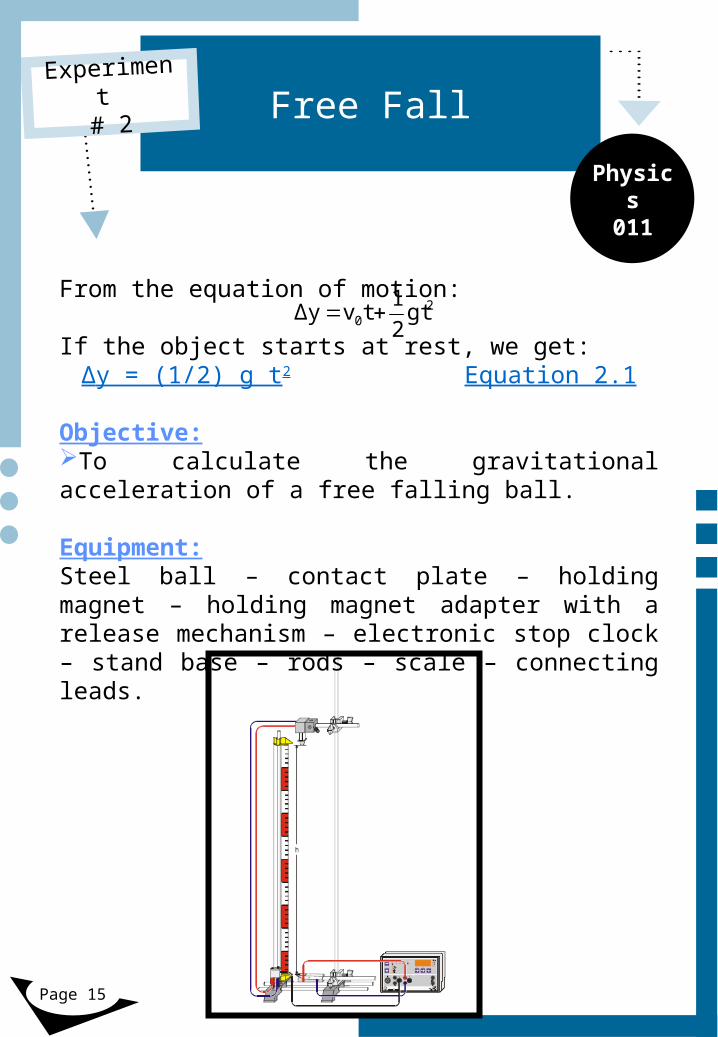
Equipment:Steel ball – contact plate – holding magnet – holding magnet adapter with a release mechanism – electronic stop clock – stand base – rods – scale – connecting leads.
20 gt2
1tvΔy

Free FallExperimen
t # 2
Physics
011
Page 16
Procedure:Set the equipment and hold the steel ball using the holding magnet at a certain height.Release the ball and read the time the ball took traveling the vertical distance, then reset the stop clock and reattach the ball and read the time again , you should take three readings of the time then find the average time the ball has traveled.Reduce the height and repeat the previous steps.Tabulate your data.
Plot a graph between the square time (x-axis) and the height (y-axis) or displacement of ball.Draw the best line and find its slope.Calculate the gravitational acceleration from the slope using equation 2.1.Find the percentage error.
Heightm
Time 1s
Time 2s
Time 3s
Average Times
Time square
s2

Theory: Newton'slawsofmotionarethreephysicallaws whichproviderelationshipsbetweenthe forcesactingonabodyandthemotionofthe, . body firstcompiledbySirIsaacNewton
Newton's First Law: an object with no force acting on it moves with a constant velocity.Newton's Second Law: the acceleration of a body is directly proportional to the net force acting on it and inversely proportional to its mass.
∑F = ma Equation 3.1Newton's Third Law: for every action there is an equal and opposite reaction.
In order to apply Newton’s second law; a free body diagram should be drawn for every object in the system.
Newton’s Second Law
Experiment # 3
Physics
011
Page 17

If two masses connected by a string over a pulley. One mass, M, is a trolley resting on a horizontal track and held by a magnet. The other mass, m, is hanging freely and is subject to a downward force due to gravity (its weight); W = mg, and an upward force due to the tension T in the string. The masses of the string and pulley as well as the frictional resistance of the pulley are assumed to be negligible.
Cart at Rest: When the cart is held stationary, there is no net force on the hanging mass, so the tension in the string is given by: T = W.
Cart accelerating: Since the length of the string does not change, the cart and the hanger accelerate at the same rate, a.
Newton’s Second Law
Experiment # 3
Physics
011
Page 18

From the free body diagram of the hanging mass, we get:
T – W = - maor
W - T = maor
T = mg - ma Equation 3.2
where m is the hanging mass.
Newton’s Second Law
Experiment # 3
Physics
011
Page 19

From the free body diagram of the cart, we get:
T - fk = Ma
where M is the mass of the cart and fk is the frictional force between the cart and the track and fk = μk (fN), where μk is the kinetic friction coefficient and fN is the normal force done by the track on the cart. In this case fN = W = Mg, Which gives that:
T – W = Maor
T - μk (Mg) = Maor
T = Ma + μk (Mg) Equation 3.3
From equations 3.2 and 3.3 we get:
Ma + μk (Mg) = mg – ma μk = (mg – ma – Ma)/Mg Equation 3.4
Newton’s Second Law
Experiment # 3
Physics
011
Page 20

Newton’s Second Law
Experiment # 3
Physics
011
Page 21
Objective:To find the kinetic friction coefficient of a trolley moving on a track using Newton’s second law.
Equipment:Track – trolley – holding magnet – electronic stop clock – light barrier – pulley – mass hanger – slotted weights – cables.

Newton’s Second Law
Experiment # 3
Physics
011
Page 22
Procedure:Set the equipment, use the cable to connect the trolley with the pulley and the hanging mass, the hanging mass should be kept constant through out the experiment.Connect the holding magnet to the stop clock and adjust the voltage so that the trolley is held.Put the light barrier at a certain distance, the distance should be kept constant through out the experiment.Release the trolley by stopping the magnet and record the time the trolley took to pass the light barrier.Repeat and record the time three times then calculate the average time, the acceleration and the kinetic friction coefficient from equation 3.4.Increase the weight of the trolley by adding blocks on top of it.Repeat the previous steps for each mass.Tabulate your data
Give your conclusion.
Mass (M)kg
Time 1s
Time 2s
Time 3s
Average Times
Time square
s2
a = 2d/t2
m/s2μk

Theory:When an object slides down an incline, the component of gravity pushing the block down the incline plane is:
Wx = mg sin(θ) Equation 4.1
The Inclined Plane
Experiment # 4
Physics
011
Page 23

The Inclined Plane
Experiment # 4
Physics
011
Page 24
Objective:Balancing a rolling mass on an inclined plane.
Equipment:Magnet board – Inclined plane – Pulley – Masses – Spring balance – Rolling mass – Mass hanger – String.

Procedure:Weigh the rolling mass using the balance spring and calculate its weight. Set the incline on the magnet board at a certain angle and record it.Attach the rolling mass with a string and tie the string to the balance spring and support the string with a pulley.For accurate results, the string should be parallel to the plane.The Tension of the string is equal to the component of gravity pushing the mass down the incline Wx.The tension also could be measured using the balance spring.Find the percentage error between the two values of the force.Change the angle of the incline and repeat the previous steps.Tabulate your data.
The Inclined Plane
Experiment # 4
Physics
011
Page 25
DegreeFx (Measured)Wx (calculated)Percentage Error30° 40° 50° 60°

Theory: , ’ Whenanobjectisplacedonanincline Newton s :secondlawcouldbeappliedasfollows
Componentofgravitypushingtheblockdownthe : = (inclineplane Wx mgsin θ). Componentof gravitypushingtheblockagainsttheincline: = (plane Wy mgcos θ)
Friction of an Inclined Plane
Experiment # 5
Physics
011
Page 26

’ :UsingNewton ssecondlaw∑ = F ma
- :Onthey axisfN – Wy = 0
fN = Wy = (mgcos θ) 5.1Equation - :Onthex axis
fk – Wx = - maμk (fN) – Wx = - maμk (fN) = Wx – ma
5.1:Bysubstitutingfromequationμk ( mgcosθ) = mgsinθ – ma
μk = ( mgsinθ – ) / ma ( mgcosθ) 5.2 Equation
From the equation of motion:d = v0t + (1/2)at2
If the object starts at rest, we get:d = (1/2) a t2 Equation 5.3
Friction of an Inclined Plane
Experiment # 5
Physics
011
Page 27

Friction of an Inclined Plane
Experiment # 5
Physics
011
Page 28
Objective:To find the kinetic friction coefficient of an inclined plane.
Equipment:Magnet board – plane with protractor – blocks – stop clock.

Friction of an Inclined Plane
Experiment # 5
Physics
011
Page 29
Procedure:Attach the inclined plane to the magnet board with a certain angle, record the angle.Put a block on the plane and start the stop clock at the time you release the block.Stop the stop clock at the time the block reaches the end of the plane and record the time it took the block to travel the plane.Repeat three times an find the average time of the block sliding the plane.Use equation 5.3 to calculate the acceleration of the block.Use the result in equation 5.2 to find the kinetic friction coefficient of the plane’s surface with the block.Repeat the previous steps with two different angles. Compare all results and give your conclusion.
Time 1s
Time 2s
Time 3s
Average Times
Time square
s2
a = 2d/t2
m/s2μk

Theory:A material has a rest shape and its shape departs away from the rest shape due to stress. The amount of departure from rest shape is called deformation, the proportion of deformation to original size is called strain. Elastic material retain their rest shape after the stress is removed. A spring is an example of elastic materials.A spring-mass system obeys Hook's law, which states that the extension produced is directly proportional to the load:
F = - kΔx Equation 6.1Where:Δx: is the distance that the spring has been stretched or compressed away from the equilibrium position [usually in m]. F: is the restoring force exerted by the material [usually in N]. K: is the force constant (spring constant) and it is a measure of the spring's stiffness [usually in N/m].
The negative sign in Equation 6.1 indicates that the direction of F is always opposite the direction of the displacement. This implies that the spring force is a restoring force. In other words, the spring force always acts to restore, or return, the body to the equilibrium position regardless of the direction of the displacement,
Hook’s law:Expansion of a Helical Spring
Experiment # 6
Physics
011
Page 30

Hook’s law:Expansion of a Helical Spring
Experiment # 6
Physics
011
Page 31
Objective:To determine a spring constant using Hook’s law.
Equipment:Helical spring – magnetic board – mass hanger – slotted weights

Hook’s law:Expansion of a Helical Spring
Experiment # 6
Physics
011
Page 32
Procedure:Attach the spring to the magnetic board.The spring is placed in a scaled transparent tube which allows reading the expansion or the force applied on the spring directly.Hang the mass hanger at the end of the spring and note its mass.Start adding slotted masses on the hanger one after another.For each mass read the expansion and the force.Tabulate your data.
Plot a graph between the force (x-axis) and the expansion (y-axis) of the spring.Draw the best line and find its slope.Calculate the spring’s constant from the slope using equation 6.1.
Masskg
WeightN
Expansionm

Theory: Energyistheabilitytodoworkandismeasured . byJouls :Mechanicalenergyhastwodifferentforms
Potential energy is the energy an object stores due to its position.The gravitational potential energy is given by:
PE = m g h Equation 7.1Where m is the mass of the object, g is the gravitational acceleration and h is the height of the object.
Kinetic energy is the energy of motion.The kinetic energy is given by:KE = (1/2) m v2 Equation 7.2
The total mechanical energy E, of any isolated system of objects, is defined as the sum of the kinetic and potential energies:
E = PE + KE Equation 7.3
The principle of conservation of energy could be written as:
Ei = Ef Equation 7.4Where Ei is the initial energy and Ef is the final energy
Conservation of Mechanical Energy
Experiment # 7
Physics
011
Page 33

Anobjectonaninclinewillmovedownwith . constantacceleration Energyconservation:law Ei = EfKEi + PEi = KEf + PEf 7.5Equation
(1/2) mvi2 + mgh i= (1/2) mvf
2 + mghf , :Iftheobjectstartsfromrest weget mghi = (1/2) mvf2 + mghf 7.6Equation(1/2) mvf
2 = mghi – mghf (1/2) vf2 = ghi – ghf
7.7Equation :Fromtheequationsofmotion = (1/2) (d vi + vf) t 7.8Equation , :Iftheobjectstartsatrest wegetv f= 2 / d t 7.9Equation Whichmeansthatthefinalvelocitycouldbe foundeitherbytheenergyconservationlaw( 7.7) ( 7.9). Eqn orbyequationofmotion Eqn
Conservation of Mechanical Energy
Experiment # 7
Physics
011
Page 34
)h2g(hv fif

Conservation of Mechanical Energy
Experiment # 7
Physics
011
Page 35
Objective:To find the final velocity of an object sliding an incline with constant acceleration using energy conservation law.
Equipment:Track – trolley – holding magnet – electronic stop clock – light barrier – cables.

Conservation of Mechanical Energy
Experiment # 7
Physics
011
Page 36
Procedure:Set the track so that it will become an incline by rising one side of it, use the holding magnet to hold the trolley still.Connect the stop clock with a light barrier and put the light barrier at a certain distance and record the distance that the trolley should travel.Measure the height at the beginning and at the end of the motion of the trolley.Release the trolley and find the time it needs to travel the distance three times and find the average time of traveling.Use the equation 7.7 and 7.9 to find the final velocity. The two values should be equal.Find the percentage error.Calculate the initial and final PE and KE.Repeat the previous steps by changing the height, the mass and the distance and conclude their effect on energy.

Theory: Anobjectissaidtobeinequilibriumifthethe . resultantforceactingontheobjectiszero
Ifaresultantforceactsonanobjectthenthat objectcanbebroughtintoequilibriumby applyinganadditionalforcethatexactly . balancesthisresultant Suchaforceiscalled theequilibrantandisequalinmagnitudebut oppositeindirectiontotheoriginal .resultantforceactingontheobject
Equilibrant Force
Experiment # 8
Physics
011
Page 37

Equilibrant Force
Experiment # 8
Physics
011
Page 38
Objective:To find the resultant force of two forces, then find the equilibrant force.
Equipment:Magnet board – degree scale – pulleys – masses – mass hangers – spring balance – force ring – string.

Equilibrant Force
Experiment # 8
Physics
011
Page 39
Procedure:Use the magnet board to attach the degree scale.Tie three strings to the force ring and attach two strings with two mass holders with different slotted masses.Set the hangers as pulling forces by using pulleys and make the forces act in different angles with respect to the zero degree line.Use the holding pin to prevent the ring from accelerating.Now attach the third string with the spring.Adjust the spring balance until the force ring is in equilibrium.
Draw the two forces F1 and F2 and find graphically their resultant.The resultant force you found should be equal to the force applied by the spring (magnitude and direction), check your results.

Theory:When a force F acts on a point which is displaced from the axis of rotation a distance d, the torque by this force is
τ = Fd sinθ Equation 9.1
where the θ is the angle between F and d.
When torque acts on an object, it rotates. Therefore, the net torque must be zero to establish a mechanical equilibrium.
TorqueExperimen
t # 9
Physics
011
Page 40

TorqueExperimen
t # 9
Physics
011
Page 41
Objective:Balancing an object with different torques.
Equipment:Magnet board – balance beam – pulleys – masses – mass hangers – spring balance – string.

Procedure:Use the magnet board to attach the balance beam.Hang two mass holders with different slotted masses.Change the distance until the beam is balanced.Calculate the torques and check your answer.
TorqueExperimen
t # 9
Physics
011
Page 42

Now remove one of the mass holders and use the degree scale and the spring balance to apply another forces on the beam with an angle of 30o.Adjust the spring in order to balance the beam.
Record the first force applied by the hanging mass.Then tabulate your data to find the force applied by the spring and find the percentage error.Change the angle and repeat the previous steps.
TorqueExperimen
t # 9
Physics
011
Page 43
DegreeF1τ=F1d1sinθError: (τ1-τ2)/τ2 x10030° 40° 50° 60°

Theory:The center of mass is an important concept in physics. The center of mass is the point at which an object can be balanced. Sometimes finding the center of mass of an object can be challenging, especially if the object has an odd shape. This experiment illustrates a simple way to find the center of mass of some interesting shapes.
Center of MassExperimen
t # 10
Physics
011
Page 44

Center of MassExperimen
t # 10
Physics
011
Page 45
Objective:Finding the center of mass of a plane.
Equipment:Magnet board – Planar mass – masses – mass hangers – Degree plate – string.

Procedure:Hang the planar mass from the holding pin of the degree plate. Since the force of the pin acting on the mass is equilibrant to the sum of the gravitational forces acting on the mass, the line of the force exerted by the pin must pass through the center of mass of the planar mass.Hang a piece of string with a hanging mass from the holding pin.Tape a piece of paper to the Planar Mass as shown.Mark the paper to indicate the line of the string across the Planar Mass. Now hang the planar mass from a different point. Again, mark the line of the string. By finding the intersection of the two lines, locate the center of mass of the planar mass.Hang the Planar Mass from a third point. Does the line of the string pass through the center of mass?
Center of MassExperimen
t # 10
Physics
011
Page 46


Basic SI Units and Prefix
AppendixA
Physics
011
MultiplePrefixSymbol1012TeraT109GigaG196MegaM103KiloK102HectorH10DecaDa10-1Decid10-2Centic10-3Millim10-6Microμ10-9Nanon10-12Picop
SI Prefix
Unit NameUnit SymbolQuantityMetermLength
KilogramkMassSecondsTimeJouleJEnergyWattWPower
SI Units Basic

FractionsAppendixB
Physics
011
A fraction is expressed as , where a is called the numerator and b the denominator.
The addition or subtraction of fractions:
The product of fractions:
ba
dbcbad
dc
ba
db
cbaddc
ba
dbac
dcx
ba

VectorsAppendixC
Physics
011
Scalars: are quantities which are fully described by a magnitude alone. Vectors: are quantities which are fully described by both a magnitude and a direction.A vector in the x-y plane has two components, Ax and Ay.
The sum of two vectors, and , is a vector , which is obtained by placing the initial point of on the final point of , and then drawing a line from the initial point of to the final point of .Then
A
A
B
C
B
A
A
B
yyy
xxx
CBACBA
CBA

VectorsAppendixC
Physics
011
The subtraction of two vectors, and , is a vector , Then
A
B
C
yyy
xxx
CBACBA
CBA

Free Body Diagram
AppendixD
Physics
011
Free body diagrams are simplified representations in a problem of an object, and the force vectors acting on it. This body is free because the diagram will show it without its surroundings.some of the main forces:Gravity: The first is that due to gravity, which is called the gravitational force. The acceleration due to gravity of Earth is approximately g = 9.8 m/s2. The force, by Newton's Second Law is: Fg = m g Normal: The normal force is one which prevents objects from falling into whatever it is they are sitting upon. It is always perpendicular to the surface with which an object is in contact.Friction: Related to the normal force is the frictional force. The two are related because they are both due to the fact that the body is in contact with the surface. Friction is divided into two types-static and kinetic. Push and Pull: Another force which may act on an object could be any physical push or pull.Tension: Tension in an object results if the pulling force acts on its ends, such as in a rope used to pull an object.

Phone: 2585190Website: www.imamu.edu.sa
Imam Mohammed bin Saud Islamic University