
Textile-Friendly Interconnection between Wearable ...
16
http://www.diva-portal.org Postprint This is the accepted version of a paper published in Sensors. This paper has been peer- reviewed but does not include the final publisher proof-corrections or journal pagination. Citation for the original published paper (version of record): Seoane, F., Soroudi, A., Lu, K., Nilsson, D., Nilsson, M. et al. (2019) Textile-Friendly Interconnection between Wearable Measurement Instrumentation and Sensorized Garments—Initial Performance Evaluation for Electrocardiogram Recordings Sensors, 19(29): 4426 https://doi.org/10.3390/s19204426 Access to the published version may require subscription. N.B. When citing this work, cite the original published paper. Permanent link to this version: http://urn.kb.se/resolve?urn=urn:nbn:se:hb:diva-23229
-
Upload
khangminh22 -
Category
Documents
-
view
0 -
download
0
Transcript of Textile-Friendly Interconnection between Wearable ...

http://www.diva-portal.org
Postprint
This is the accepted version of a paper published in Sensors. This paper has been peer-reviewed but does not include the final publisher proof-corrections or journal pagination.
Citation for the original published paper (version of record):
Seoane, F., Soroudi, A., Lu, K., Nilsson, D., Nilsson, M. et al. (2019)Textile-Friendly Interconnection between Wearable Measurement Instrumentationand Sensorized Garments—Initial Performance Evaluation for ElectrocardiogramRecordingsSensors, 19(29): 4426https://doi.org/10.3390/s19204426
Access to the published version may require subscription.
N.B. When citing this work, cite the original published paper.
Permanent link to this version:http://urn.kb.se/resolve?urn=urn:nbn:se:hb:diva-23229
sensors
Article
Textile-Friendly Interconnection between WearableMeasurement Instrumentation and SensorizedGarments—Initial Performance Evaluation forElectrocardiogram Recordings
Fernando Seoane 1,2,3,* , Azadeh Soroudi 1 , Ke Lu 4 , David Nilsson 5, Marie Nilsson 5 ,Farhad Abtahi 3,6 and Mikael Skrifvars 1
1 Swedish School of Textiles, University of Borås, 501 90 Borås, Sweden; [email protected] (A.S.);[email protected] (M.S.)
2 Department of Medical Care Technology, Karolinska University hospital, 14 157 Huddinge, Sweden3 Institute for Clinical Science, Intervention and Technology, Karolinska Institutet, 141 57 Huddinge, Sweden;
[email protected] Department of Electrical Engineering, Chalmers University of Technology, 412 96 Göteborg, Sweden;
[email protected] RISE Research Institutes of Sweden, Box 857, 501 15 Borås, Sweden; [email protected] (D.N.)
[email protected] (M.N.)6 School of Engineering Sciences in Chemistry, Biotechnology and Health, KTH Royal Institute of Technology,
141 57 Huddinge, Sweden* Correspondence: [email protected]; Tel.: +4633-4354414
Received: 31 August 2019; Accepted: 9 October 2019; Published: 12 October 2019
Abstract: The interconnection between hard electronics and soft textiles remains a noteworthychallenge in regard to the mass production of textile–electronic integrated products such as sensorizedgarments. The current solutions for this challenge usually have problems with size, flexibility, cost,or complexity of assembly. In this paper, we present a solution with a stretchable and conductive carbonnanotube (CNT)-based paste for screen printing on a textile substrate to produce interconnectorsbetween electronic instrumentation and a sensorized garment. The prototype connectors wereevaluated via electrocardiogram (ECG) recordings using a sensorized textile with integrated textileelectrodes. The ECG recordings obtained using the connectors were evaluated for signal quality andheart rate detection performance in comparison to ECG recordings obtained with standard pre-gelledAg/AgCl electrodes and direct cable connection to the ECG amplifier. The results suggest that theECG recordings obtained with the CNT paste connector are of equivalent quality to those recordedusing a silver paste connector or a direct cable and are suitable for the purpose of heart rate detection.
Keywords: conductive polymers; wearable technology; smart textiles; textile–electronic integration
1. Introduction
Wearable garments for the measurement of vital signs and biosignals are believed to be aprimary part of more personalized, pervasive healthcare to tackle the problems arising with theaging population. During the last decade, several wearable systems including textile electrodes havebeen reported [1–3] and are even being used in commercial products, e.g., Hexoskin T-shirts andEquivital vests. However, there still are issues with the textile–electronic integration, limiting the massproduction of such sensorized garments and delaying the market growth forecasted for wearabletechnology. Manufacturing solutions for interconnecting sensors and wearable instrumentation, suchas intarsia knitting with conductive yarn [4], have been proposed. However, these solutions are
Sensors 2019, 19, 4426; doi:10.3390/s19204426 www.mdpi.com/journal/sensors
Sensors 2019, 19, 4426 2 of 15
inadequate for the mass production of embedded cables in the garments, and there are still other keyareas where practical solutions for textile–electronic integration are required.
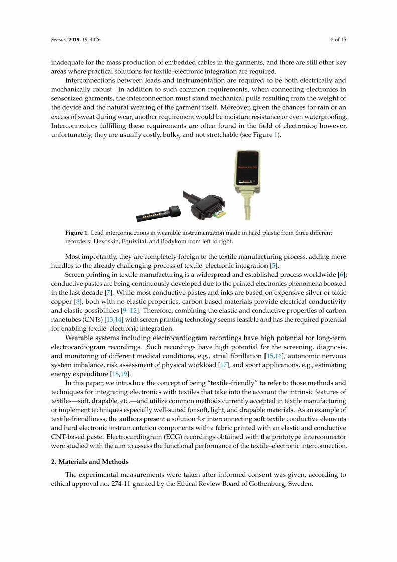
Interconnections between leads and instrumentation are required to be both electrically andmechanically robust. In addition to such common requirements, when connecting electronics insensorized garments, the interconnection must stand mechanical pulls resulting from the weight ofthe device and the natural wearing of the garment itself. Moreover, given the chances for rain or anexcess of sweat during wear, another requirement would be moisture resistance or even waterproofing.Interconnectors fulfilling these requirements are often found in the field of electronics; however,unfortunately, they are usually costly, bulky, and not stretchable (see Figure 1).
Sensors 2019, 12, x FOR PEER REVIEW 2 of 16
Wearable garments for the measurement of vital signs and biosignals are believed to be a
primary part of more personalized, pervasive healthcare to tackle the problems arising with the
aging population. During the last decade, several wearable systems including textile electrodes have
been reported [1–3] and are even being used in commercial products, e.g., Hexoskin T-shirts and
Equivital vests. However, there still are issues with the textile–electronic integration, limiting the
mass production of such sensorized garments and delaying the market growth forecasted for
wearable technology. Manufacturing solutions for interconnecting sensors and wearable
instrumentation, such as intarsia knitting with conductive yarn [4], have been proposed. However,
these solutions are inadequate for the mass production of embedded cables in the garments, and
there are still other key areas where practical solutions for textile–electronic integration are required.
Interconnections between leads and instrumentation are required to be both electrically and
mechanically robust. In addition to such common requirements, when connecting electronics in
sensorized garments, the interconnection must stand mechanical pulls resulting from the weight of
the device and the natural wearing of the garment itself. Moreover, given the chances for rain or an
excess of sweat during wear, another requirement would be moisture resistance or even
waterproofing. Interconnectors fulfilling these requirements are often found in the field of
electronics; however, unfortunately, they are usually costly, bulky, and not stretchable (see Figure 1).
Most importantly, they are completely foreign to the textile manufacturing process, adding
more hurdles to the already challenging process of textile–electronic integration [5].
Screen printing in textile manufacturing is a widespread and established process worldwide [6];
conductive pastes are being continuously developed due to the printed electronics phenomena
boosted in the last decade [7]. While most conductive pastes and inks are based on expensive silver
or toxic copper [8], both with no elastic properties, carbon-based materials provide electrical
conductivity and elastic possibilities [9–12]. Therefore, combining the elastic and conductive
properties of carbon nanotubes (CNTs) [13,14] with screen printing technology seems feasible and
has the required potential for enabling textile–electronic integration.
Wearable systems including electrocardiogram recordings have high potential for long-term
electrocardiogram recordings. Such recordings have high potential for the screening, diagnosis, and
monitoring of different medical conditions, e.g., atrial fibrillation [15,16], autonomic nervous system
imbalance, risk assessment of physical workload [17], and sport applications, e.g., estimating energy
expenditure [18,19].
In this paper, we introduce the concept of being “textile-friendly” to refer to those methods and
techniques for integrating electronics with textiles that take into the account the intrinsic features of
textiles—soft, drapable, etc.—and utilize common methods currently accepted in textile
manufacturing or implement techniques especially well-suited for soft, light, and drapable
materials. As an example of textile-friendliness, the authors present a solution for interconnecting
soft textile conductive elements and hard electronic instrumentation components with a fabric
printed with an elastic and conductive CNT-based paste. Electrocardiogram (ECG) recordings
obtained with the prototype interconnector were studied with the aim to assess the functional
performance of the textile–electronic interconnection.
Figure 1. Lead interconnections in wearable instrumentation made in hard plastic from three differentrecorders: Hexoskin, Equivital, and Bodykom from left to right.
Most importantly, they are completely foreign to the textile manufacturing process, adding morehurdles to the already challenging process of textile–electronic integration [5].
Screen printing in textile manufacturing is a widespread and established process worldwide [6];conductive pastes are being continuously developed due to the printed electronics phenomena boostedin the last decade [7]. While most conductive pastes and inks are based on expensive silver or toxiccopper [8], both with no elastic properties, carbon-based materials provide electrical conductivityand elastic possibilities [9–12]. Therefore, combining the elastic and conductive properties of carbonnanotubes (CNTs) [13,14] with screen printing technology seems feasible and has the required potentialfor enabling textile–electronic integration.
Wearable systems including electrocardiogram recordings have high potential for long-termelectrocardiogram recordings. Such recordings have high potential for the screening, diagnosis,and monitoring of different medical conditions, e.g., atrial fibrillation [15,16], autonomic nervoussystem imbalance, risk assessment of physical workload [17], and sport applications, e.g., estimatingenergy expenditure [18,19].
In this paper, we introduce the concept of being “textile-friendly” to refer to those methods andtechniques for integrating electronics with textiles that take into the account the intrinsic features oftextiles—soft, drapable, etc.—and utilize common methods currently accepted in textile manufacturingor implement techniques especially well-suited for soft, light, and drapable materials. As an example oftextile-friendliness, the authors present a solution for interconnecting soft textile conductive elementsand hard electronic instrumentation components with a fabric printed with an elastic and conductiveCNT-based paste. Electrocardiogram (ECG) recordings obtained with the prototype interconnectorwere studied with the aim to assess the functional performance of the textile–electronic interconnection.
2. Materials and Methods
The experimental measurements were taken after informed consent was given, according toethical approval no. 274-11 granted by the Ethical Review Board of Gothenburg, Sweden.
Sensors 2019, 19, 4426 3 of 15
2.1. Polymer-Based Conductive Elastic Paste
The conductive paste was developed at the University of Borås, and it is based on a stretchablepolymer compound formulated with multi-walled carbon nanotubes (MWCNTs) (Chengdu organicchemicals, P.R. China) as the conductive component, proper additives to promote homogienity/printability,and polyurethane (PU) as the binder. The paste manufacturing process was optimized regarding materialcompositions and mixing parameters (speed and duration), targeting conductivity, homogeneity,and printability parameters including viscosity, dispersion quality, and nominal sheet resistivity ina relaxed state and after elongation. The process started with 10 min high-speed mixing using anoverhead mixer equipped with a bladed propeller stirrer, IKA RW 20 Digital Dual-Range Mixers,Germany. After mixing and homogenizing using magnetic stirring at room temperature for 13 h,the prepared mix of the PU, CNTs with water, and additives was filtered through an 80 µm mesh,and the printable MWCNT paste was obtained.
The surface impedance of the developed paste was characterized for different values of thicknessand elongation, applying a four-probe method using a Keithley 2000 digital multimeter (KeithleyInstruments, Ohio, USA).
2.2. Connectors
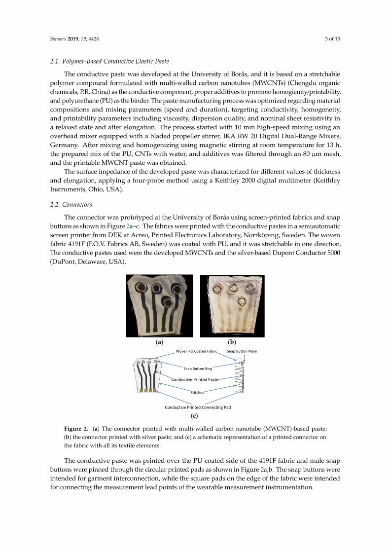
The connector was prototyped at the University of Borås using screen-printed fabrics and snapbuttons as shown in Figure 2a–c. The fabrics were printed with the conductive pastes in a semiautomaticscreen printer from DEK at Acreo, Printed Electronics Laboratory, Norrköping, Sweden. The wovenfabric 4191F (F.O.V. Fabrics AB, Sweden) was coated with PU, and it was stretchable in one direction.The conductive pastes used were the developed MWCNTs and the silver-based Dupont Conductor 5000(DuPont, Delaware, USA).
Sensors 2019, 12, x FOR PEER REVIEW 3 of 16
Figure 1. Lead interconnections in wearable instrumentation made in hard plastic from three
different recorders: Hexoskin, Equivital, and Bodykom from left to right.
2. Materials and Methods
The experimental measurements were taken after informed consent was given, according to
ethical approval no. 274-11 granted by the Ethical Review Board of Gothenburg, Sweden.
2.1. Polymer-Based Conductive Elastic Paste
The conductive paste was developed at the University of Borås, and it is based on a stretchable
polymer compound formulated with multi-walled carbon nanotubes (MWCNTs) (Chengdu organic
chemicals, P.R. China) as the conductive component, proper additives to promote
homogienity/printability, and polyurethane (PU) as the binder. The paste manufacturing process
was optimized regarding material compositions and mixing parameters (speed and duration),
targeting conductivity, homogeneity, and printability parameters including viscosity, dispersion
quality, and nominal sheet resistivity in a relaxed state and after elongation. The process started with
10 min high-speed mixing using an overhead mixer equipped with a bladed propeller stirrer, IKA
RW 20 Digital Dual-Range Mixers, Germany. After mixing and homogenizing using magnetic
stirring at room temperature for 13 h, the prepared mix of the PU, CNTs with water, and additives
was filtered through an 80 μm mesh, and the printable MWCNT paste was obtained.
The surface impedance of the developed paste was characterized for different values of
thickness and elongation, applying a four-probe method using a Keithley 2000 digital multimeter
(Keithley Instruments, Ohio, USA).
2.2. Connectors
The connector was prototyped at the University of Borås using screen-printed fabrics and snap
buttons as shown in Figure 2a–c. The fabrics were printed with the conductive pastes in a
semiautomatic screen printer from DEK at Acreo, Printed Electronics Laboratory, Norrköping,
Sweden. The woven fabric 4191F (F.O.V. Fabrics AB, Sweden) was coated with PU, and it was
stretchable in one direction. The conductive pastes used were the developed MWCNTs and the
silver-based Dupont Conductor 5000 (DuPont, Delaware, USA).
The conductive paste was printed over the PU-coated side of the 4191F fabric and male snap
buttons were pinned through the circular printed pads as shown in Figure 2a,b. The snap buttons
were intended for garment interconnection, while the square pads on the edge of the fabric were
intended for connecting the measurement lead points of the wearable measurement
instrumentation.
The screen-printed fabrics were cured in a fume hood for 120 min at room temperature for the
MWCNT paste and 16 min at 100 °C for the Conductor 5000.
The sister connector using the Dupont 5000 paste was produced to evaluate the influence of the
intrinsic electrical conductivity on the functional performance of the connector.
(a) (b)
Sensors 2019, 12, x FOR PEER REVIEW 4 of 16
(c)
Figure 2. (a) The connector printed with multi-walled carbon nanotube (MWCNT)-based paste; (b) the connector printed with silver paste; and (c) a schematic representation of a printed connector on the fabric with all its textile elements.
The junction impedance was measured using a Keithley 2000 digital multimeter (Keithley Instruments, Ohio, USA) using the two-probe method over three sets of textile–electronic interconnectors in static conditions and during elongation and folding.
2.3. Sensorized Garment
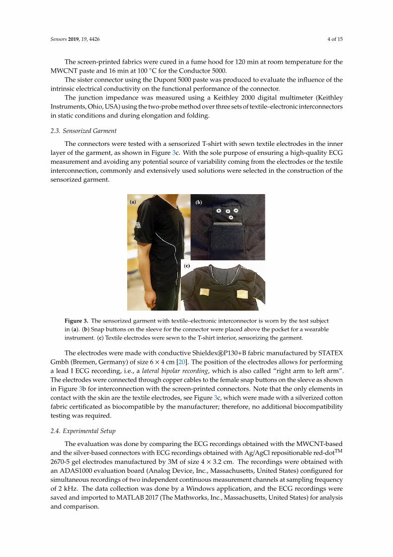
The connectors were tested with a sensorized T-shirt with sewn textile electrodes in the inner layer of the garment, as shown in Figure 3c. With the sole purpose of ensuring a high-quality ECG measurement and avoiding any potential source of variability coming from the electrodes or the textile interconnection, commonly and extensively used solutions were selected in the construction of the sensorized garment.
Figure 3. The sensorized garment with textile–electronic interconnector is worn by the test subject in (a). (b) Snap buttons on the sleeve for the connector were placed above the pocket for a wearable instrument. (c) Textile electrodes were sewn to the T-shirt interior, sensorizing the garment.
The electrodes were made with conductive Shieldex® P130+B fabric manufactured by STATEX Gmbh (Bremen, Germany) of size 6 × 4 cm [20]. The position of the electrodes allows for performing a lead I ECG recording, i.e., a lateral bipolar recording, which is also called “right arm to left arm”. The electrodes were connected through copper cables to the female snap buttons on the sleeve as shown in Figure 3b for interconnection with the screen-printed connectors. Note that the only elements in contact with the skin are the textile electrodes, see Figure 3c, which were made with a silverized cotton fabric certificated as biocompatible by the manufacturer; therefore, no additional biocompatibility testing was required.
2.4. Experimental Setup
Woven PU Coated Fabric
Stitches
Conductive Printed Paste
Snap Button Ring
Conductive Printed Connecting Pad
Snap Button Male
Figure 2. (a) The connector printed with multi-walled carbon nanotube (MWCNT)-based paste;(b) the connector printed with silver paste; and (c) a schematic representation of a printed connector onthe fabric with all its textile elements.
The conductive paste was printed over the PU-coated side of the 4191F fabric and male snapbuttons were pinned through the circular printed pads as shown in Figure 2a,b. The snap buttons wereintended for garment interconnection, while the square pads on the edge of the fabric were intendedfor connecting the measurement lead points of the wearable measurement instrumentation.
Sensors 2019, 19, 4426 4 of 15
The screen-printed fabrics were cured in a fume hood for 120 min at room temperature for theMWCNT paste and 16 min at 100 C for the Conductor 5000.
The sister connector using the Dupont 5000 paste was produced to evaluate the influence of theintrinsic electrical conductivity on the functional performance of the connector.
The junction impedance was measured using a Keithley 2000 digital multimeter (KeithleyInstruments, Ohio, USA) using the two-probe method over three sets of textile–electronic interconnectorsin static conditions and during elongation and folding.
2.3. Sensorized Garment
The connectors were tested with a sensorized T-shirt with sewn textile electrodes in the innerlayer of the garment, as shown in Figure 3c. With the sole purpose of ensuring a high-quality ECGmeasurement and avoiding any potential source of variability coming from the electrodes or the textileinterconnection, commonly and extensively used solutions were selected in the construction of thesensorized garment.
Sensors 2019, 12, x FOR PEER REVIEW 4 of 16
(c)
Figure 2. (a) The connector printed with multi-walled carbon nanotube (MWCNT)-based paste; (b)
the connector printed with silver paste; and (c) a schematic representation of a printed connector on
the fabric with all its textile elements.
The junction impedance was measured using a Keithley 2000 digital multimeter (Keithley
Instruments, Ohio, USA) using the two-probe method over three sets of textile–electronic
interconnectors in static conditions and during elongation and folding.
2.3. Sensorized Garment
The connectors were tested with a sensorized T-shirt with sewn textile electrodes in the inner
layer of the garment, as shown in Figure 3c. With the sole purpose of ensuring a high-quality ECG
measurement and avoiding any potential source of variability coming from the electrodes or the
textile interconnection, commonly and extensively used solutions were selected in the construction
of the sensorized garment.
Figure 3. The sensorized garment with textile–electronic interconnector is worn by the test subject in
(a). (b) Snap buttons on the sleeve for the connector were placed above the pocket for a wearable
instrument. (c) Textile electrodes were sewn to the T-shirt interior, sensorizing the garment.
The electrodes were made with conductive Shieldex® P130+B fabric manufactured by STATEX
Gmbh (Bremen, Germany) of size 6 × 4 cm [20]. The position of the electrodes allows for performing
a lead I ECG recording, i.e., a lateral bipolar recording, which is also called “right arm to left arm”. The
electrodes were connected through copper cables to the female snap buttons on the sleeve as shown
in Figure 3b for interconnection with the screen-printed connectors. Note that the only elements in
contact with the skin are the textile electrodes, see Figure 3c, which were made with a silverized
cotton fabric certificated as biocompatible by the manufacturer; therefore, no additional
biocompatibility testing was required.
2.4. Experimental Setup
WovenPUCoatedFabric
Stitches
ConductivePrintedPaste
SnapButtonRing
ConductivePrintedConnectingPad
SnapButtonMale
Figure 3. The sensorized garment with textile–electronic interconnector is worn by the test subjectin (a). (b) Snap buttons on the sleeve for the connector were placed above the pocket for a wearableinstrument. (c) Textile electrodes were sewn to the T-shirt interior, sensorizing the garment.
The electrodes were made with conductive Shieldex®P130+B fabric manufactured by STATEXGmbh (Bremen, Germany) of size 6 × 4 cm [20]. The position of the electrodes allows for performinga lead I ECG recording, i.e., a lateral bipolar recording, which is also called “right arm to left arm”.The electrodes were connected through copper cables to the female snap buttons on the sleeve as shownin Figure 3b for interconnection with the screen-printed connectors. Note that the only elements incontact with the skin are the textile electrodes, see Figure 3c, which were made with a silverized cottonfabric certificated as biocompatible by the manufacturer; therefore, no additional biocompatibilitytesting was required.
2.4. Experimental Setup
The evaluation was done by comparing the ECG recordings obtained with the MWCNT-basedand the silver-based connectors with ECG recordings obtained with Ag/AgCl repositionable red-dotTM
2670-5 gel electrodes manufactured by 3M of size 4 × 3.2 cm. The recordings were obtained withan ADAS1000 evaluation board (Analog Device, Inc., Massachusetts, United States) configured forsimultaneous recordings of two independent continuous measurement channels at sampling frequencyof 2 kHz. The data collection was done by a Windows application, and the ECG recordings weresaved and imported to MATLAB 2017 (The Mathworks, Inc., Massachusetts, United States) for analysisand comparison.
Sensors 2019, 19, 4426 5 of 15
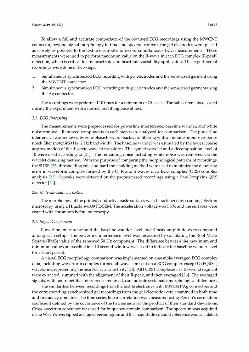
To allow a full and accurate comparison of the obtained ECG recordings using the MWCNTconnector, beyond signal morphology in time and spectral content, the gel electrodes were placedas closely as possible to the textile electrodes to record simultaneous ECG measurements. Thesemeasurements were used to perform maximum value on the R-wave in each ECG complex (R-peak)detection, which is critical to any heart rate and heart rate variability application. The experimentalrecordings were done in two steps:
1. Simultaneous synchronized ECG recording with gel electrodes and the sensorized garment usingthe MWCNT connector;
2. Simultaneous synchronized ECG recording with gel electrodes and the sensorized garment usingthe Ag connector.
The recordings were performed 10 times for a minimum of 20 s each. The subject remained seatedduring the experiment with a normal breathing pace at rest.
2.5. ECG Processing
The measurements were preprocessed for powerline interference, baseline wander, and whitenoise removal. Removed components in each step were analyzed for comparison. The powerlineinterference was removed by zero-phase forward–backward filtering with an infinite impulse responsenotch filter (notch@50 Hz, 2 Hz bandwidth). The baseline wander was estimated by the lowest coarseapproximation of the discrete wavelet transform. The symlet wavelet and a decomposition level of10 were used according to [21]. The remaining noise including white noise was removed via thewavelet denoising method. With the purpose of comparing the morphological patterns of recordings,the SURE [22] thresholding rule and hard thresholding method were used to minimize the denoisingerror in waveform complex formed by the Q, R and S waves on a ECG complex (QRS) complexanalysis [23]. R-peaks were detected on the preprocessed recordings using a Pan-Tompkins QRSdetector [24].
2.6. Material Characterization
The morphology of the printed conductive paste surfaces was characterized by scanning electronmicroscopy using a Hitachi s-4800 FE-SEM. The acceleration voltage was 5 kV, and the surfaces werecoated with chromium before microscopy.
2.7. Signal Comparison
Powerline interference and the baseline wander level and R-peak amplitude were comparedamong each setup. The powerline interference level was measured by calculating the Root MeanSquare (RMS) value of the removed 50 Hz component. The difference between the maximum andminimum values on baseline in a 10-second window was used to indicate the baseline wander levelfor a short period.
A visual ECG morphology comparison was implemented on ensemble-averaged ECG complexdata, including waverform complex formed all waves present on a ECG complex except U (PQRST)waveforms, representing the heart’s electrical activity [25]. All PQRST complexes in a 15-second segmentwere extracted, summed with the alignment of their R-peak, and then averaged [26]. The averagedsignals, with non-repetitive interference removed, can indicate systematic morphological differences.
The similarities between recordings from the textile electrodes with MWCNT/Ag connectors andthe corresponding synchronized gel recordings from the gel electrode were examined in both timeand frequency domains. The time series linear correlation was measured using Person’s correlationcoefficient defined by the covariance of the two series over the product of their standard deviations.Cross-spectrum coherence was used for frequency domain comparison. The spectrum was acquiredusing Welch’s overlapped averaged periodogram and the magnitude-squared coherence was calculated.
Sensors 2019, 19, 4426 6 of 15
The agreement of the Time between R peak in consecutive ECG complexes (RR Intervals) seriesextracted from the recordings obtained with the textile electrodes using MWCNT-based and silverconnectors and the corresponding synchronized recordings obtained with the gel electrodes wasevaluated by calculating the Lin’s concordance correlation coefficient [27].
3. Results
Electrical Characterization of the MWCNT Elastic Paste
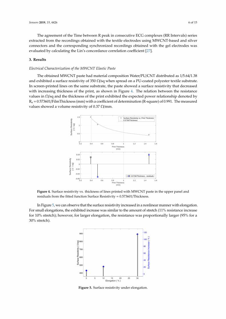
The obtained MWCNT paste had material composition Water/PU/CNT distributed as 1/5.64/1.38and exhibited a surface resistivity of 350 Ω/sq when spread on a PU-coated polyester textile substrate.In screen-printed lines on the same substrate, the paste showed a surface resistivity that decreasedwith increasing thickness of the print, as shown in Figure 4. The relation between the resistancevalues in Ω/sq and the thickness of the print exhibited the expected power relationship denoted byRs = 0.573601/FilmThickness (mm) with a coefficient of determination (R-square) of 0.991. The measuredvalues showed a volume resistivity of 0.37 Ω/mm.
Sensors 2019, 12, x FOR PEER REVIEW 6 of 16
The similarities between recordings from the textile electrodes with MWCNT/Ag connectors
and the corresponding synchronized gel recordings from the gel electrode were examined in both
time and frequency domains. The time series linear correlation was measured using Person’s
correlation coefficient defined by the covariance of the two series over the product of their standard
deviations. Cross-spectrum coherence was used for frequency domain comparison. The spectrum
was acquired using Welch's overlapped averaged periodogram and the magnitude-squared
coherence was calculated.
The agreement of the Time between R peak in consecutive ECG complexes (RR Intervals) series
extracted from the recordings obtained with the textile electrodes using MWCNT-based and silver
connectors and the corresponding synchronized recordings obtained with the gel electrodes was
evaluated by calculating the Lin’s concordance correlation coefficient [27].
3. Results
3.1. Electrical Characterization of the MWCNT Elastic Paste
The obtained MWCNT paste had material composition Water/PU/CNT distributed as
1/5.64/1.38 and exhibited a surface resistivity of 350 Ω/sq when spread on a PU-coated polyester
textile substrate. In screen-printed lines on the same substrate, the paste showed a surface resistivity
that decreased with increasing thickness of the print, as shown in Figure 4. The relation between the
resistance values in Ω/sq and the thickness of the print exhibited the expected power relationship
denoted by Rs = 0.573601/FilmThickness (mm) with a coefficient of determination (R-square) of 0.991.
The measured values showed a volume resistivity of 0.37 Ω/mm.
Figure 4. Surface resistivity vs. thickness of lines printed with MWCNT paste in the upper panel and
residuals from the fitted function Surface Resistivity = 0.573601/Thickness.
In Figure 5, we can observe that the surface resistivity increased in a nonlinear manner with
elongation. For small elongations, the exhibited increase was similar to the amount of stretch (11%
resistance increase for 10% stretch); however, for larger elongation, the resistance was proportionally
larger (95% for a 30% stretch).
0.2 0.4 0.6 0.8 1 1.2 1.4 1.6
Print Thickness
(mm)
0
0.5
1
1.5
Surf
ace R
esis
tivity
( / s
q)
Surface Resistivity vs. Print Thickness
0.5736/Thickness
0.2 0.4 0.6 0.8 1 1.2 1.4 1.6
Print Thickness
(mm)
-0.06
-0.04
-0.02
0
0.02
0.04
Surf
ace R
esis
tivity
(
/ sq)
0.5736/Thickness - residuals
Figure 4. Surface resistivity vs. thickness of lines printed with MWCNT paste in the upper panel andresiduals from the fitted function Surface Resistivity = 0.573601/Thickness.
In Figure 5, we can observe that the surface resistivity increased in a nonlinear manner with elongation.For small elongations, the exhibited increase was similar to the amount of stretch (11% resistance increasefor 10% stretch); however, for larger elongation, the resistance was proportionally larger (95% for a30% stretch).Sensors 2019, 12, x FOR PEER REVIEW 7 of 16
Figure 5. Surface resistivity under elongation.
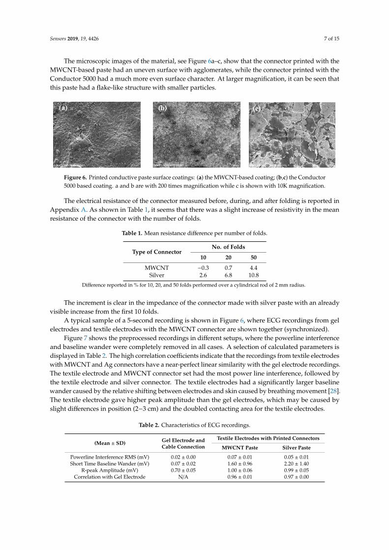
The microscopic images of the material, see Figure 6a−c, show that the connector printed with
the MWCNT-based paste had an uneven surface with agglomerates, while the connector printed
with the Conductor 5000 had a much more even surface character. At larger magnification, it can be
seen that this paste had a flake-like structure with smaller particles.
Figure 6. Printed conductive paste surface coatings: (a) the MWCNT-based coating; (b) and (c) the
Conductor 5000 based coating. a and b are with 200 times magnification while c is shown with 10K
magnification.
The electrical resistance of the connector measured before, during, and after folding is reported
in Appendix A. As shown in Table 1, it seems that there was a slight increase of resistivity in the
mean resistance of the connector with the number of folds.
Table 1. Mean resistance difference per number of folds.
Type of
Connector
No. of Folds
10 20 50
MWCNT −0.3 0.7 4.4
Silver 2.6 6.8 10.8
* Difference reported in % for 10, 20, and 50 folds performed over a cylindrical rod of 2 mm radius.
The increment is clear in the impedance of the connector made with silver paste with an already
visible increase from the first 10 folds.
A typical sample of a 5-second recording is shown in Figure 6, where ECG recordings from gel
electrodes and textile electrodes with the MWCNT connector are shown together (synchronized).
Figure 7 shows the preprocessed recordings in different setups, where the powerline
interference and baseline wander were completely removed in all cases. A selection of calculated
parameters is displayed in Table 2. The high correlation coefficients indicate that the recordings from
textile electrodes with MWCNT and Ag connectors have a near-perfect linear similarity with the gel
electrode recordings. The textile electrode and MWCNT connector set had the most power line
Figure 5. Surface resistivity under elongation.
Sensors 2019, 19, 4426 7 of 15
The microscopic images of the material, see Figure 6a–c, show that the connector printed with theMWCNT-based paste had an uneven surface with agglomerates, while the connector printed with theConductor 5000 had a much more even surface character. At larger magnification, it can be seen thatthis paste had a flake-like structure with smaller particles.
Sensors 2019, 12, x FOR PEER REVIEW 7 of 16
Figure 5. Surface resistivity under elongation.
The microscopic images of the material, see Figure 6a−c, show that the connector printed with
the MWCNT-based paste had an uneven surface with agglomerates, while the connector printed
with the Conductor 5000 had a much more even surface character. At larger magnification, it can be
seen that this paste had a flake-like structure with smaller particles.
Figure 6. Printed conductive paste surface coatings: (a) the MWCNT-based coating; (b) and (c) the
Conductor 5000 based coating. a and b are with 200 times magnification while c is shown with 10K
magnification.
The electrical resistance of the connector measured before, during, and after folding is reported
in Appendix A. As shown in Table 1, it seems that there was a slight increase of resistivity in the
mean resistance of the connector with the number of folds.
Table 1. Mean resistance difference per number of folds.
Type of
Connector
No. of Folds
10 20 50
MWCNT −0.3 0.7 4.4
Silver 2.6 6.8 10.8
* Difference reported in % for 10, 20, and 50 folds performed over a cylindrical rod of 2 mm radius.
The increment is clear in the impedance of the connector made with silver paste with an already
visible increase from the first 10 folds.
A typical sample of a 5-second recording is shown in Figure 6, where ECG recordings from gel
electrodes and textile electrodes with the MWCNT connector are shown together (synchronized).
Figure 7 shows the preprocessed recordings in different setups, where the powerline
interference and baseline wander were completely removed in all cases. A selection of calculated
parameters is displayed in Table 2. The high correlation coefficients indicate that the recordings from
textile electrodes with MWCNT and Ag connectors have a near-perfect linear similarity with the gel
electrode recordings. The textile electrode and MWCNT connector set had the most power line
Figure 6. Printed conductive paste surface coatings: (a) the MWCNT-based coating; (b,c) the Conductor5000 based coating. a and b are with 200 times magnification while c is shown with 10K magnification.
The electrical resistance of the connector measured before, during, and after folding is reported inAppendix A. As shown in Table 1, it seems that there was a slight increase of resistivity in the meanresistance of the connector with the number of folds.
Table 1. Mean resistance difference per number of folds.
Type of ConnectorNo. of Folds
10 20 50
MWCNT −0.3 0.7 4.4Silver 2.6 6.8 10.8
Difference reported in % for 10, 20, and 50 folds performed over a cylindrical rod of 2 mm radius.
The increment is clear in the impedance of the connector made with silver paste with an alreadyvisible increase from the first 10 folds.
A typical sample of a 5-second recording is shown in Figure 6, where ECG recordings from gelelectrodes and textile electrodes with the MWCNT connector are shown together (synchronized).
Figure 7 shows the preprocessed recordings in different setups, where the powerline interferenceand baseline wander were completely removed in all cases. A selection of calculated parameters isdisplayed in Table 2. The high correlation coefficients indicate that the recordings from textile electrodeswith MWCNT and Ag connectors have a near-perfect linear similarity with the gel electrode recordings.The textile electrode and MWCNT connector set had the most power line interference, followed bythe textile electrode and silver connector. The textile electrodes had a significantly larger baselinewander caused by the relative shifting between electrodes and skin caused by breathing movement [28].The textile electrode gave higher peak amplitude than the gel electrodes, which may be caused byslight differences in position (2−3 cm) and the doubled contacting area for the textile electrodes.
Table 2. Characteristics of ECG recordings.
(Mean ± SD) Gel Electrode andCable Connection
Textile Electrodes with Printed Connectors
MWCNT Paste Silver Paste
Powerline Interference RMS (mV) 0.02 ± 0.00 0.07 ± 0.01 0.05 ± 0.01Short Time Baseline Wander (mV) 0.07 ± 0.02 1.60 ± 0.96 2.20 ± 1.40
R-peak Amplitude (mV) 0.70 ± 0.05 1.00 ± 0.06 0.99 ± 0.05Correlation with Gel Electrode N/A 0.96 ± 0.01 0.97 ± 0.00
Sensors 2019, 19, 4426 8 of 15
Sensors 2019, 12, x FOR PEER REVIEW 8 of 16
interference, followed by the textile electrode and silver connector. The textile electrodes had a
significantly larger baseline wander caused by the relative shifting between electrodes and skin
caused by breathing movement [28]. The textile electrode gave higher peak amplitude than the gel
electrodes, which may be caused by slight differences in position (2−3 cm) and the doubled
contacting area for the textile electrodes.
Table 2. Characteristics of ECG recordings.
(Mean ± SD) Gel Electrode and
Cable Connection
Textile Electrodes with Printed
Connectors
MWCNT Paste Silver Paste
Powerline Interference RMS
(mV) 0.02 ± 0.00 0.07 ± 0.01 0.05 ± 0.01
Short Time Baseline Wander
(mV) 0.07 ± 0.02 1.60 ± 0.96 2.20 ± 1.40
R-peak Amplitude (mV) 0.70 ± 0.05 1.00 ± 0.06 0.99 ± 0.05
Correlation with Gel Electrode N/A 0.96 ± 0.01 0.97 ± 0.00
Figure 7. Five-second preprocessed ECG recordings obtained with the three setups.
The average resistance values of the textile–electronic connectors were 7.47 Ω and 10.47 kΩ for
the Ag and the MWCNTs, respectively. Averaged PQRST waves are shown in Figure 8. The
waveforms from the MWCNT and Ag connectors are almost identical. The textile electrode
recordings had slightly higher amplitude in all waveforms and sharper peaks for R and S waves
when compared to the Ag/AgCl electrode recordings. We can observe the amplitude of the peaks in
the obtained recordings plotted in Figure 9 and their spectral content in Figure 10. These indicate
that the skin–electrode interface in the case of the Ag/AgCl electrodes produced a low-pass filter
with a cut-off frequency lower than in the case of textile electrodes, resulting in a smoother PQRST
complex.
Figure 7. Five-second preprocessed ECG recordings obtained with the three setups.
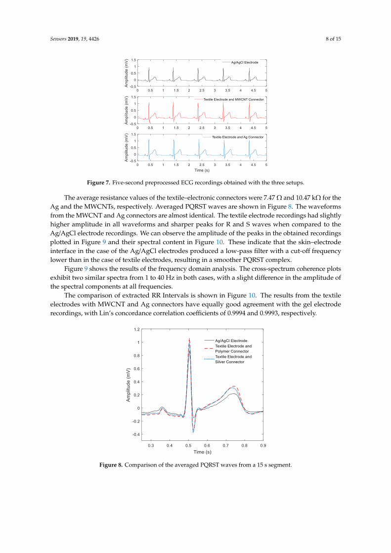
The average resistance values of the textile–electronic connectors were 7.47 Ω and 10.47 kΩ for theAg and the MWCNTs, respectively. Averaged PQRST waves are shown in Figure 8. The waveformsfrom the MWCNT and Ag connectors are almost identical. The textile electrode recordings had slightlyhigher amplitude in all waveforms and sharper peaks for R and S waves when compared to theAg/AgCl electrode recordings. We can observe the amplitude of the peaks in the obtained recordingsplotted in Figure 9 and their spectral content in Figure 10. These indicate that the skin–electrodeinterface in the case of the Ag/AgCl electrodes produced a low-pass filter with a cut-off frequencylower than in the case of textile electrodes, resulting in a smoother PQRST complex.
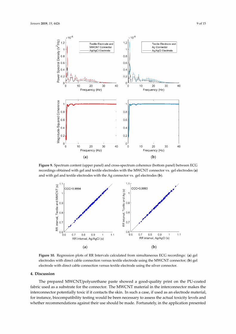
Figure 9 shows the results of the frequency domain analysis. The cross-spectrum coherence plotsexhibit two similar spectra from 1 to 40 Hz in both cases, with a slight difference in the amplitude ofthe spectral components at all frequencies.
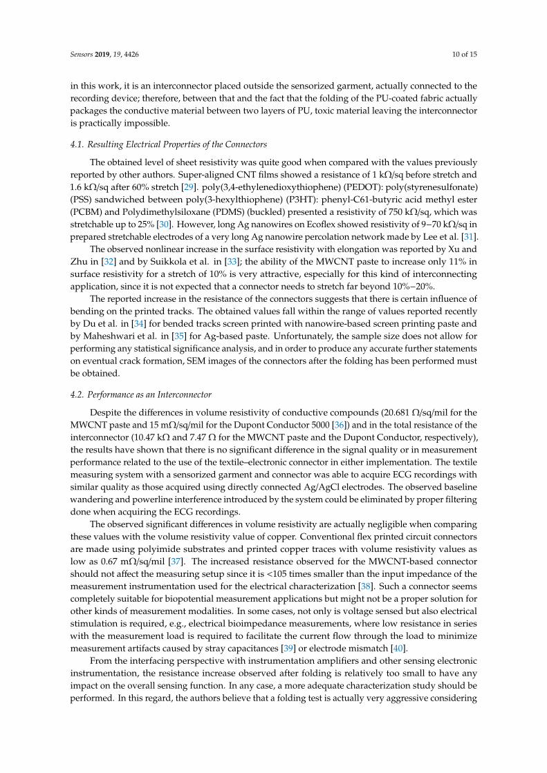
The comparison of extracted RR Intervals is shown in Figure 10. The results from the textileelectrodes with MWCNT and Ag connectors have equally good agreement with the gel electroderecordings, with Lin’s concordance correlation coefficients of 0.9994 and 0.9993, respectively.Sensors 2019, 12, x FOR PEER REVIEW 9 of 16
Figure 8. Comparison of the averaged PQRST waves from a 15 s segment.
(a) (b)
Figure 9. Spectrum content (upper panel) and cross-spectrum coherence (bottom panel) between
ECG recordings obtained with gel and textile electrodes with the MWCNT connector vs. gel
electrodes (a) and with gel and textile electrodes with the Ag connector vs. gel electrodes (b).
Figure 9 shows the results of the frequency domain analysis. The cross-spectrum coherence
plots exhibit two similar spectra from 1 to 40 Hz in both cases, with a slight difference in the
amplitude of the spectral components at all frequencies.
The comparison of extracted RR Intervals is shown in Figure 10. The results from the textile
electrodes with MWCNT and Ag connectors have equally good agreement with the gel electrode
recordings, with Lin’s concordance correlation coefficients of 0.9994 and 0.9993, respectively.
Figure 8. Comparison of the averaged PQRST waves from a 15 s segment.
Sensors 2019, 19, 4426 9 of 15
Sensors 2019, 12, x FOR PEER REVIEW 9 of 16
Figure 8. Comparison of the averaged PQRST waves from a 15 s segment.
(a) (b)
Figure 9. Spectrum content (upper panel) and cross-spectrum coherence (bottom panel) between
ECG recordings obtained with gel and textile electrodes with the MWCNT connector vs. gel
electrodes (a) and with gel and textile electrodes with the Ag connector vs. gel electrodes (b).
Figure 9 shows the results of the frequency domain analysis. The cross-spectrum coherence
plots exhibit two similar spectra from 1 to 40 Hz in both cases, with a slight difference in the
amplitude of the spectral components at all frequencies.
The comparison of extracted RR Intervals is shown in Figure 10. The results from the textile
electrodes with MWCNT and Ag connectors have equally good agreement with the gel electrode
recordings, with Lin’s concordance correlation coefficients of 0.9994 and 0.9993, respectively.
Figure 9. Spectrum content (upper panel) and cross-spectrum coherence (bottom panel) between ECGrecordings obtained with gel and textile electrodes with the MWCNT connector vs. gel electrodes (a)and with gel and textile electrodes with the Ag connector vs. gel electrodes (b).
Sensors 2019, 12, x FOR PEER REVIEW 10 of 16
(a) (b)
Figure 10. Regression plots of RR Intervals calculated from simultaneous ECG recordings: (a) gel
electrodes with direct cable connection versus textile electrode using the MWCNT connector; (b) gel
electrode with direct cable connection versus textile electrode using the silver connector.
4. Discussion
The prepared MWCNT/polyurethane paste showed a good-quality print on the PU-coated
fabric used as a substrate for the connector. The MWCNT material in the interconnector makes the
interconnector potentially toxic if it contacts the skin. In such a case, if used as an electrode material,
for instance, biocompatibility testing would be been necessary to assess the actual toxicity levels and
whether recommendations against their use should be made. Fortunately, in the application
presented in this work, it is an interconnector placed outside the sensorized garment, actually
connected to the recording device; therefore, between that and the fact that the folding of the
PU-coated fabric actually packages the conductive material between two layers of PU, toxic material
leaving the interconnector is practically impossible.
4.1. Resulting Electrical Properties of the Connectors
The obtained level of sheet resistivity was quite good when compared with the values
previously reported by other authors. Super-aligned CNT films showed a resistance of 1 kΩ/sq
before stretch and 1.6 kΩ/sq after 60% stretch [29]. poly(3,4-ethylenedioxythiophene) (PEDOT) :
poly(styrenesulfonate) (PSS) sandwiched between poly(3-hexylthiophene) (P3HT) :
phenyl-C61-butyric acid methyl ester (PCBM) and Polydimethylsiloxane (PDMS) (buckled)
presented a resistivity of 750 kΩ/sq, which was stretchable up to 25% [30]. However, long Ag
nanowires on Ecoflex showed resistivity of 9−70 kΩ/sq in prepared stretchable electrodes of a very
long Ag nanowire percolation network made by Lee et al. [31].
The observed nonlinear increase in the surface resistivity with elongation was reported by Xu
and Zhu in [32] and by Suikkola et al. in [33]; the ability of the MWCNT paste to increase only 11% in
surface resistivity for a stretch of 10% is very attractive, especially for this kind of interconnecting
application, since it is not expected that a connector needs to stretch far beyond 10%−20%.
The reported increase in the resistance of the connectors suggests that there is certain influence
of bending on the printed tracks. The obtained values fall within the range of values reported
recently by Du et al. in [34] for bended tracks screen printed with nanowire-based screen printing
paste and by Maheshwari et al. in [35] for Ag-based paste. Unfortunately, the sample size does not
allow for performing any statistical significance analysis, and in order to produce any accurate
further statements on eventual crack formation, SEM images of the connectors after the folding has
been performed must be obtained.
4.2. Performance as an Interconnector
Figure 10. Regression plots of RR Intervals calculated from simultaneous ECG recordings: (a) gelelectrodes with direct cable connection versus textile electrode using the MWCNT connector; (b) gelelectrode with direct cable connection versus textile electrode using the silver connector.
4. Discussion
The prepared MWCNT/polyurethane paste showed a good-quality print on the PU-coatedfabric used as a substrate for the connector. The MWCNT material in the interconnector makes theinterconnector potentially toxic if it contacts the skin. In such a case, if used as an electrode material,for instance, biocompatibility testing would be been necessary to assess the actual toxicity levels andwhether recommendations against their use should be made. Fortunately, in the application presented
Sensors 2019, 19, 4426 10 of 15
in this work, it is an interconnector placed outside the sensorized garment, actually connected to therecording device; therefore, between that and the fact that the folding of the PU-coated fabric actuallypackages the conductive material between two layers of PU, toxic material leaving the interconnectoris practically impossible.
4.1. Resulting Electrical Properties of the Connectors
The obtained level of sheet resistivity was quite good when compared with the values previouslyreported by other authors. Super-aligned CNT films showed a resistance of 1 kΩ/sq before stretch and1.6 kΩ/sq after 60% stretch [29]. poly(3,4-ethylenedioxythiophene) (PEDOT): poly(styrenesulfonate)(PSS) sandwiched between poly(3-hexylthiophene) (P3HT): phenyl-C61-butyric acid methyl ester(PCBM) and Polydimethylsiloxane (PDMS) (buckled) presented a resistivity of 750 kΩ/sq, which wasstretchable up to 25% [30]. However, long Ag nanowires on Ecoflex showed resistivity of 9−70 kΩ/sq inprepared stretchable electrodes of a very long Ag nanowire percolation network made by Lee et al. [31].
The observed nonlinear increase in the surface resistivity with elongation was reported by Xu andZhu in [32] and by Suikkola et al. in [33]; the ability of the MWCNT paste to increase only 11% insurface resistivity for a stretch of 10% is very attractive, especially for this kind of interconnectingapplication, since it is not expected that a connector needs to stretch far beyond 10%−20%.
The reported increase in the resistance of the connectors suggests that there is certain influence ofbending on the printed tracks. The obtained values fall within the range of values reported recentlyby Du et al. in [34] for bended tracks screen printed with nanowire-based screen printing paste andby Maheshwari et al. in [35] for Ag-based paste. Unfortunately, the sample size does not allow forperforming any statistical significance analysis, and in order to produce any accurate further statementson eventual crack formation, SEM images of the connectors after the folding has been performed mustbe obtained.
4.2. Performance as an Interconnector
Despite the differences in volume resistivity of conductive compounds (20.681 Ω/sq/mil for theMWCNT paste and 15 mΩ/sq/mil for the Dupont Conductor 5000 [36]) and in the total resistance of theinterconnector (10.47 kΩ and 7.47 Ω for the MWCNT paste and the Dupont Conductor, respectively),the results have shown that there is no significant difference in the signal quality or in measurementperformance related to the use of the textile–electronic connector in either implementation. The textilemeasuring system with a sensorized garment and connector was able to acquire ECG recordings withsimilar quality as those acquired using directly connected Ag/AgCl electrodes. The observed baselinewandering and powerline interference introduced by the system could be eliminated by proper filteringdone when acquiring the ECG recordings.
The observed significant differences in volume resistivity are actually negligible when comparingthese values with the volume resistivity value of copper. Conventional flex printed circuit connectorsare made using polyimide substrates and printed copper traces with volume resistivity values aslow as 0.67 mΩ/sq/mil [37]. The increased resistance observed for the MWCNT-based connectorshould not affect the measuring setup since it is <105 times smaller than the input impedance of themeasurement instrumentation used for the electrical characterization [38]. Such a connector seemscompletely suitable for biopotential measurement applications but might not be a proper solution forother kinds of measurement modalities. In some cases, not only is voltage sensed but also electricalstimulation is required, e.g., electrical bioimpedance measurements, where low resistance in serieswith the measurement load is required to facilitate the current flow through the load to minimizemeasurement artifacts caused by stray capacitances [39] or electrode mismatch [40].
From the interfacing perspective with instrumentation amplifiers and other sensing electronicinstrumentation, the resistance increase observed after folding is relatively too small to have anyimpact on the overall sensing function. In any case, a more adequate characterization study should beperformed. In this regard, the authors believe that a folding test is actually very aggressive considering
Sensors 2019, 19, 4426 11 of 15
the intended purpose of the connector. Bending is probably a more realistic and adequate test for aconnector meant to be attached to a recording device.
4.3. Functionalization of Textiles as Textile–Electronic Interconnections
CNT-based products have been used for functionalizing textiles for a decade [41], and screenprinting processes have been shown to be effective for producing conductive textiles [42] with variouspurposes such as transmission lines [43] or radiofrequency antennas [44]. Combining CNTs with screenprinting has been a successful approach to prototyping electronics on rubber substrates producingelastic diodes [45,46].
In the presented approach, the elasticity was preserved by PU, which is used in a twofold roleas a binder and coating agent. First, as an elastic binding agent, polyurethane preserves the abilityto stretch to the conductive paste; second, as a coating agent, it treats the fabric surface for printing.Coating the surface of a fabric with PU is one of the most common finishing techniques in textilemanufacturing. In this case, the PU coating is critical for obtaining a successful print since the coatingnot only smooths the otherwise coarse surface of the fabric, which is essential for avoiding open-circuitconnections, but also facilitates the bonding with the elastic MWCNT paste during the thermal curing.
The results suggest that the presented solution, combining screen printing, a PU–MWCNT blendedconductive paste, and stretchable PU-coated commercially available fabrics, is feasible for prototypingtextile–electronic interconnectors. Given the widespread and established use of the material and theprocesses in textile production, the presented approach has the required potential for enabling trueseries textile manufacturing.
The intended use of this combination of conductive and stretchable fabrics is to produce anelastic interconnection between a measuring device, typically wearable, with textile conductive padsin sensorized garments. Sensing or actuating electronic devices usually have a relatively small numberof inputs/outputs (Bodykom 5, Hexoskin 9, Equivital EQ02 11), and an interconnector printed onfabric would suit these wearable devices nicely at Printed Circuit Board (PCB) -level interconnection.If attempting to interconnect other levels of integrations, like an Integrated Circuit (IC) pinout level,this type of technology will face size limitations that will prohibit its use. If the application requires alarge number of interconnections, e.g., 16, given the current resolutions achievable with screen printing,it is reasonable to think that the proposed solution will suit such cases similarly to the ball grid arraypresented in [47].
Other authors have presented alternatives for textile electronic interconnections, but while beingsuccessful in decreasing the size of the interconnections, such a feature is achieved at the expense ofelasticity [48].
The stretchability is provided by the conductive elastomer, PU, used in this formulation.Conductive elastomeric materials in the form of inks and pastes are the most common approaches asindicated in [49]
4.4. Textile-Friendly Methods
The method of choice to transfer both conductive and elastic properties into the conformableplanar surfaces of textile fabrics is printing technologies [50], especially when the alternative ismicro-fabrication processes.
Not only the production cost should be taken into account when manufacturing sensorizedgarments—we also need to consider the adoption of the applied manufacturing techniques. Methodslike soldering which are industrially mature but foreign to the textile manufacturing world, like in [48],will be more difficult to adopt in textile production lines than common methods already widely spreadwithin textile manufacturing, like additive methods [50].
Much effort has been put into obtaining good textile electrodes with good sensing capabilities butvery little effort has been devoted to developing methods and materials to support textile-friendly andeasy-to-adopt techniques for textile–electronic integration. The use of well-known textile materials
Sensors 2019, 19, 4426 12 of 15
together with broadly accepted methods for textile functionalization reduces the risk when proposinga novel application of them combined, such as in this electronic interconnector fully integrated on atextile substrate.
4.5. Impact in Sensing Performace
The fact of producing a better-expressed QRS is an encouraging result because it suggests thatthe connector does not negatively impact the recordings; however, the authors believe that thebetter-expressed QRS is a product of using textile electrodes and not related to the use of the printedconnector. The recordings suggest that the use of textile electrodes, with bigger areas than normalAg/AgCl electrodes, produces a skin–electrode interface with lower resistance, increasing the cut-off
frequency of the low-pass filter at the skin–electrode interface. Therefore, higher-frequency componentsare preserved, which in some cases can be seen as advantage for QRS segmentation but in otherscenarios might produce noisier recordings. In such a case, there are plenty of digital noise cancelingmethods to choose from.
5. Conclusions and Future Work
This study has presented positive results, especially from the functional perspective, since thesensing function was actually allowed. Now that that function has been shown to be possible, the nextstep is to investigate other material aspects further.
Future work will be focused on investigating the stability under certain degrees of deformation;assessing the need for encapsulation, if any; and evaluating the performance in other kinds of biosignalmeasurements or other applications such as digital interfacing, i.e., discrete voltage signals. In this study,the experimental protocol was selected to target the influence of the interconnection; therefore, sittingat rest was selected to avoid other sources of errors like motion artifacts. Now that interconnectionshows promising results, assessment during exercise, as done in [51], should be done.
Author Contributions: Conceptualization, F.S., A.S., D.N. and M.S.; Data curation, K.L. and F.A.; Formal analysis,A.S., K.L. and M.S.; Funding acquisition, F.S. and M.S.; Investigation, F.S., A.S., M.N. and F.A.; Methodology, F.S.;Project administration, F.S. and M.S.; Resources, F.S., D.N. and M.S.; Software, K.L.; Supervision, F.S., F.A. andM.S.; Validation, K.L. and F.A.; Visualization, K.L. and F.A.; Writing—original draft, F.S.; Writing—review andediting, A.S., D.N. and F.A.
Funding: This research was funded by VINNOVA, the Swedish Agency of Innovation Systems, grantnumber 2014-03413.
Acknowledgments: The support of the Chinese Scholarship Council is acknowledged, and the authors wouldalso like to thank FOV Fabrics AB for facilitating the fabric coatings.
Conflicts of Interest: F.S. is the founder and owner of Z-Health Technologies A.B.
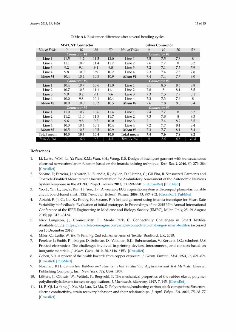
Appendix A. Connector Resistance after Folding
Table A1 contains the measurements obtained during the folding experiments performed on bothconnector types.
Sensors 2019, 19, 4426 13 of 15
Table A1. Resistance difference after several bending cycles.
MWCNT Connector Silver ConnectorNo. of Folds 0 10 20 50 No. of Folds 0 10 20 50
Connector #1 Connector #1Line 1 11.5 11.2 11.5 12.0 Line 1 7.5 7.5 7.8 8Line 2 11.1 10.9 11.4 11.7 Line 2 7.6 7.7 8 8.2Line 3 9.2 9.4 9.1 9.8 Line 3 7.2 7.1 7.5 7.9Line 4 9.8 10.0 9.9 10.2 Line 4 7.3 7.4 7.5 7.8
Mean #1 10.4 10.4 10.5 10.9 Mean #1 7.4 7.4 7.7 8.0Connector #2 Connector #2
Line 1 10.4 10.7 10.6 11.0 Line 1 8.1 8.3 8.5 8.8Line 2 10.7 10.3 11.1 11.1 Line 2 7.8 8 8.1 8.5Line 3 9.0 9.2 9.1 9.6 Line 3 7.3 7.5 7.9 8.1Line 4 10.0 9.8 10.1 10.4 Line 4 7.3 7.3 7.6 8
Mean #2 10.0 10.0 10.2 10.5 Mean #2 7.6 7.8 8.0 8.4Connector #3 Connector #3
Line 1 11.0 10.7 10.6 11.4 Line 1 7.4 7.7 8 8.2Line 2 11.2 11.0 11.5 11.7 Line 2 7.3 7.8 8 8.3Line 3 9.6 9.8 9.7 10.0 Line 3 7.1 7.4 8.2 8.5Line 4 10.3 10.4 10.1 10.4 Line 4 7.2 7.7 8.1 8.4
Mean #3 10.5 10.5 10.5 10.9 Mean #3 7.3 7.7 8.1 8.4Total mean 10.3 10.3 10.4 10.8 Total mean 7.4 7.6 7.9 8.2Total ∆ (%) 0 −0.3 0.7 4.4 Total ∆ (%) 0 2.6 6.8 10.8
References
1. Li, L.; Au, W.M.; Li, Y.; Wan, K.M.; Wan, S.H.; Wong, K.S. Design of intelligent garment with transcutaneouselectrical nerve stimulation function based on the intarsia knitting technique. Text. Res. J. 2010, 80, 279–286.[CrossRef]
2. Seoane, F.; Ferreira, J.; Alvarez, L.; Buendia, R.; Ayllon, D.; Llerena, C.; Gil-Pita, R. Sensorized Garments andTextrode-Enabled Measurement Instrumentation for Ambulatory Assessment of the Autonomic NervousSystem Response in the ATREC Project. Sensors 2013, 13, 8997–9015. [CrossRef] [PubMed]
3. Yoo, J.; Yan, L.; Lee, S.; Kim, H.; Yoo, H.-J. A wearable ECG acquisition system with compact planar-fashionablecircuit board-based shirt. IEEE Trans. Inf. Technol. Biomed. 2009, 13, 897–902. [CrossRef] [PubMed]
4. Abtahi, F.; Ji, G.; Lu, K.; Rodby, K.; Seoane, F. A knitted garment using intarsia technique for Heart RateVariability biofeedback: Evaluation of initial prototype. In Proceedings of the 2015 37th Annual InternationalConference of the IEEE Engineering in Medicine and Biology Society (EMBC), Milan, Italy, 25–29 August2015; pp. 3121–3124.
5. Nick Langston, J.; Connectivity, T.; Menlo Park, C. Connectivity Challenges in Smart Textiles.Available online: https://www.telecomengine.com/article/connectivity-challenges-smart-textiles/ (accessedon 10 December 2018).
6. Miles, C.; Leslie, W. Textile Printing, 2nd ed.; Amer Assn of Textile: Bradford, UK, 2010.7. Perelaer, J.; Smith, P.J.; Mager, D.; Soltman, D.; Volkman, S.K.; Subramanian, V.; Korvink, J.G.; Schubert, U.S.
Printed electronics: The challenges involved in printing devices, interconnects, and contacts based oninorganic materials. J. Mater. Chem. 2010, 20, 8446–8453. [CrossRef]
8. Cohen, S.R. A review of the health hazards from copper exposure. J. Occup. Environ. Med. 1974, 16, 621–624.[CrossRef] [PubMed]
9. Norman, R.H. Conductive Rubbers and Plastics: Their Production, Application and Test Methods; ElsevierPublishing Company, Inc.: New York, NY, USA, 1957.
10. Lötters, J.; Olthuis, W.; Veltink, P.; Bergveld, P. The mechanical properties of the rubber elastic polymerpolydimethylsiloxane for sensor applications. J. Micromech. Microeng. 1997, 7, 145. [CrossRef]
11. Li, F.; Qi, L.; Yang, J.; Xu, M.; Luo, X.; Ma, D. Polyurethane/conducting carbon black composites: Structure,electric conductivity, strain recovery behavior, and their relationships. J. Appl. Polym. Sci. 2000, 75, 68–77.[CrossRef]
Sensors 2019, 19, 4426 14 of 15
12. Gubbels, F.; Blacher, S.; Vanlathem, E.; Jérôme, R.; Deltour, R.; Brouers, F.; Teyssie, P. Design of electricalcomposites: Determining the role of the morphology on the electrical properties of carbon black filledpolymer blends. Macromolecules 1995, 28, 1559–1566. [CrossRef]
13. Shin, M.K.; Oh, J.; Lima, M.; Kozlov, M.E.; Kim, S.J.; Baughman, R.H. Elastomeric conductive compositesbased on carbon nanotube forests. Adv. Mater. 2010, 22, 2663–2667. [CrossRef]
14. Marinho, B.; Ghislandi, M.; Tkalya, E.; Koning, C.E.; de With, G. Electrical conductivity of compacts ofgraphene, multi-wall carbon nanotubes, carbon black, and graphite powder. Powder Technol. 2012, 221,351–358. [CrossRef]
15. Lin, C.-T.; Chang, K.-C.; Lin, C.-L.; Chiang, C.-C.; Lu, S.-W.; Chang, S.-S.; Lin, B.-S.; Liang, H.-Y.; Chen, R.-J.;Lee, Y.-T. An intelligent telecardiology system using a wearable and wireless ECG to detect atrial fibrillation.IEEE Trans. Inf. Technol. Biomed. 2010, 14, 726–733. [PubMed]
16. Nemati, S.; Ghassemi, M.M.; Ambai, V.; Isakadze, N.; Levantsevych, O.; Shah, A.; Clifford, G.D. Monitoringand detecting atrial fibrillation using wearable technology. In Proceedings of the 2016 38th AnnualInternational Conference of the IEEE Engineering in Medicine and Biology Society (EMBC), Orlando, FL,USA, 16–20 August 2016; pp. 3394–3397.
17. Yang, L.; Lu, K.; Diaz-Olivares, J.A.; Seoane, F.; Lindecrantz, K.; Forsman, M.; Abtahi, F.; Eklund, J.A. Towardssmart work clothing for automatic risk assessment of physical workload. IEEE Access 2018, 6, 40059–40072.[CrossRef]
18. Lu, K.; Yang, L.; Seoane, F.; Abtahi, F.; Forsman, M.; Lindecrantz, K. Fusion of Heart Rate, Respiration andMotion Measurements from a Wearable Sensor System to Enhance Energy Expenditure Estimation. Sensors2018, 18, 3092. [CrossRef] [PubMed]
19. Lu, K.; Yang, L.; Abtahi, F.; Lindecrantz, K.; Rödby, K.; Seoane, F. Wearable Cardiorespiratory Monitoring Systemfor Unobtrusive Free-Living Energy Expenditure Tracking; Springer: Singapore, 2019; pp. 433–437.
20. Seoane, F.; Mohino-Herranz, I.; Ferreira, J.; Alvarez, L.; Buendia, R.; Ayllón, D.; Llerena, C.; Gil-Pita, R.Wearable biomedical measurement systems for assessment of mental stress of combatants in real time.Sensors 2014, 14, 7120–7141. [CrossRef] [PubMed]
21. Zhang, D. Wavelet approach for ECG baseline wander correction and noise reduction. In Proceedings of the2005 IEEE Engineering in Medicine and Biology 27th Annual Conference, Shanghai, China, 17–18 Januar2006; pp. 1212–1215.
22. Donoho, D.L.; Johnstone, I.M. Adapting to unknown smoothness via wavelet shrinkage. J. Am. Stat. Assoc.1995, 90, 1200–1224. [CrossRef]
23. Tikkanen, P. Nonlinear wavelet and wavelet packet denoising of electrocardiogram signal. Biol. Cybern.1999, 80, 259–267. [CrossRef] [PubMed]
24. Pan, J.; Tompkins, W.J. A real-time QRS detection algorithm. Biomed. Eng. IEEE Trans. 1985, 32, 230–236. [CrossRef]25. Willems, J. Recommendations for measurement standards in quantitative electrocardiography. Eur. Heart J.
1985, 6, 815–825.26. Abtahi, F.; Seoane, F.; Lindecrantz, K.; Löfgren, N. Elimination of ECG Artefacts in Foetal EEG Using
Ensemble Average Subtraction and Wavelet Denoising Methods: A Simulation. In Proceedings of the XIIIMediterranean Conference on Medical and Biological Engineering and Computing 2013, Seville, Spain,25–28 September 2013; pp. 551–554.
27. Lawrence, I.; Lin, K. A concordance correlation coefficient to evaluate reproducibility. Biometrics 1989, 255–268.28. Kim, S.; Leonhardt, S.; Zimmermann, N.; Kranen, P.; Kensche, D.; Muller, E.; Quix, C. Influence of contact
pressure and moisture on the signal quality of a newly developed textile ECG sensor shirt. In Proceedings ofthe 2008 5th International Summer School and Symposium on Medical Devices and Biosensors, Hong Kong,China, 1–3 June 2008; pp. 256–259.
29. Feng, C.; Liu, K.; Wu, J.S.; Liu, L.; Cheng, J.S.; Zhang, Y.; Sun, Y.; Li, Q.; Fan, S.; Jiang, K. Flexible, stretchable,transparent conducting films made from superaligned carbon nanotubes. Adv. Funct. Mater. 2010, 20,885–891. [CrossRef]
30. Lipomi, D.J.; Tee, B.C.K.; Vosgueritchian, M.; Bao, Z. Stretchable organic solar cells. Adv. Mater. 2011, 23,1771–1775. [CrossRef] [PubMed]
31. Lee, P.; Lee, J.; Lee, H.; Yeo, J.; Hong, S.; Nam, K.H.; Lee, D.; Lee, S.S.; Ko, S.H. Highly stretchable andhighly conductive metal electrode by very long metal nanowire percolation network. Adv. Mater. 2012, 24,3326–3332. [CrossRef] [PubMed]
Sensors 2019, 19, 4426 15 of 15
32. Xu, F.; Zhu, Y. Highly conductive and stretchable silver nanowire conductors. Adv. Mater. 2012, 24, 5117–5122.[CrossRef] [PubMed]
33. Suikkola, J.; Björninen, T.; Mosallaei, M.; Kankkunen, T.; Iso-Ketola, P.; Ukkonen, L.; Vanhala, J.; Mäntysalo, M.Screen-printing fabrication and characterization of stretchable electronics. Sci. Rep. 2016, 6, 25784. [CrossRef]
34. Du, D.; Yang, X.; Yang, Y.; Zhao, Y.; Wang, Y. Silver Nanowire Ink for Flexible Circuit on Textiles. Micromachines2019, 10, 42. [CrossRef]
35. Maheshwari, N.; Abd-Ellah, M.; Goldthorpe, I.A. Transfer printing of silver nanowire conductive ink forE-textile applications. Flex. Print. Electron. 2019, 4, 2. [CrossRef]
36. 5000 Silver Conductor-DuPont. Available online: https://www.google.com.hk/url?sa=t&rct=j&q=&esrc=s&source=web&cd=1&ved=2ahUKEwi0yMvj65XlAhVYFogKHdaOC0YQFjAAegQIAxAC&url=https%3A%2F%2Fwww.dupont.com%2Fcontent%2Fdam%2Fdupont%2Fproducts-and-services%2Felectronic-and-electrical-materials%2Fdocuments%2Fprodlib%2F5000.pdf&usg=AOvVaw1LHS6FbW7Y5qrYZMvMsu1s(accessed on 10 October 2019).
37. Khandpur, R.S. Printed Circuit Boards: Design, Fabrication, Assembly and Testing; Tata McGraw-Hill Education:New Delhi, India, 2005.
38. Lee, J.W.; Kim, D.M.; Park, I.Y.; Park, H.J.; Cho, J.H. Characteristics of human skin impedance including atbiological active points. IEEE Trans. Fundam. Electron. Commun. Comput. Sci. 2003, E86A, 1476–1479.
39. Scharfetter, H.; Hartinger, P.; Hinghofer-Szalkay, H.; Hutten, H. A model of artefacts produced by straycapacitance during whole body or segmental bioimpedance spectroscopy. Physiol. Meas. 1998, 19, 247–261.[CrossRef]
40. Buendía, R.; Bogonez-Franco, P.; Nescolarde, L.; Seoane, F. Influence of electrode mismatch on Cole parameterestimation from Total Right Side Electrical Bioimpedance Spectroscopy measurements. Med. Eng. Phys.2012, 34, 1024–1028. [CrossRef]
41. Liu, Y.; Wang, X.; Qi, K.; Xin, J. Functionalization of cotton with carbon nanotubes. J. Mater. Chem. 2008, 18,3454–3460. [CrossRef]
42. Kazani, I.; Hertleer, C.; De Mey, G.; Schwarz, A.; Guxho, G.; Van Langenhove, L. Electrical conductive textilesobtained by screen printing. Fibres Text. East. Eur. 2012, 20, 57–63.
43. Locher, I.; Tröster, G. Screen-printed textile transmission lines. Text. Res. J. 2007, 77, 837–842. [CrossRef]44. Scarpello, M.L.; Kazani, I.; Hertleer, C.; Rogier, H.; Ginste, D.V. Stability and efficiency of screen-printed
wearable and washable antennas. IEEE Antennas Wirel. Propag. Lett. 2012, 11, 838–841. [CrossRef]45. Sekitani, T.; Nakajima, H.; Maeda, H.; Fukushima, T.; Aida, T.; Hata, K.; Someya, T. Stretchable active-matrix
organic light-emitting diode display using printable elastic conductors. Nat. Mater. 2009, 8, 494–499.[CrossRef] [PubMed]
46. Sekitani, T.; Noguchi, Y.; Hata, K.; Fukushima, T.; Aida, T.; Someya, T. A rubberlike stretchable active matrixusing elastic conductors. Science 2008, 321, 1468–1472. [CrossRef]
47. Mehmann, A.; Varga, M.; G, K. A ball-grid-array-like electronics-to-textile pocket connector for wearableelectronics. In Proceedings of the 2015 ACM International Symposium on Wearable Computers, Osaka,Japan, 7–11 September 2015; pp. 57–60.
48. Poupyrev, I.; Gong, N.-W.; Fukuhara, S.; Karagozler, M.E.; Schwesig, C.; Robinson, K.E. Project Jacquard:Interactive digital textiles at scale. In Proceedings of the 2016 CHI Conference on Human Factors inComputing Systems, San Jose, CA, USA, 7–12 May 2016; pp. 4216–4227.
49. Tan, E.; Jing, Q.; Smith, M.; Kar-Narayan, S.; Occhipinti, L. Needs and enabling technologies for stretchableelectronics commercialization. MRS Adv. 2017, 2, 1721–1729. [CrossRef]
50. Seifert, T.; Sowade, E.; Roscher, F.; Wiemer, M.; Gessner, T.; Baumann, R.R. Additive manufacturingtechnologies compared: Morphology of deposits of silver ink using inkjet and aerosol jet printing. Ind. Eng.Chem. Res. 2015, 54, 769–779. [CrossRef]
51. Meziane, N.; Yang, S.; Shokoueinejad, M.; Webster, J.; Attari, M.; Eren, H. Simultaneous comparison of 1 gelwith 4 dry electrode types for electrocardiography. Physiol. Meas. 2015, 36, 513. [CrossRef]
© 2019 by the authors. Licensee MDPI, Basel, Switzerland. This article is an open accessarticle distributed under the terms and conditions of the Creative Commons Attribution(CC BY) license (http://creativecommons.org/licenses/by/4.0/).