TCP-friendly video transfer
11
TCP-friendly video transfer Naoki Wakamiya, Masayuki Murata, Hideo Miyahara Graduate School of Engineering Science, Osaka University 1-3 Machikaneyama, Toyonaka, Osaka 560-8531, JAPAN ABSTRACT When both TCP and UDP connections co-exist in the Internet environment, the performance of TCP connections is heavily affected by the behavior of “greedy” UDP connections of real-time multimedia applications. In this paper, we propose a new TCP-friendly rate control protocol for video connections, called MPEG-TFRCP, to fairly share the link with TCP connections. To achieve fairness among TCP and UDP connections while performing high quality video transmission, we argue that (1) the interval of rate control must be appropriately determined, (2) the network condition must be accurately predicted, (3) the TCP throughput must be precisely estimated and (4) the video rate must be effectively adjusted. Although our algorithm is based on the existing proposals which do not satisfy all of those conditions, through careful considerations on the applicability of TFRCP to the actual video applications ours can achieve the high-quality MPEG-2 video transfer while satisfying the TCP-friendliness. Through simulation experiments, we show that the TCP throughput estimation based on pseudo-TCP feedback collection is acceptable and the rate adjustment based on the quantization control should be performed at the interval of 32 times as long as estimated RTT. Keywords: TCP-friendly, video transfer, rate control, MPEG 1. INTRODUCTION In the current Internet, each application chooses the preferable transport protocol to achieve the required QoS (Quality of Service) because the network does not provide QoS guarantee mechanisms. For example, traditional data applications such as http, ftp and telnet employ TCP which accomplishes the reliable data transfer by means of window-based flow control and retransmission mechanisms. On the other hand, to avoid the unacceptable delay introduced by the retransmission, real-time multimedia applications such as video conferencing prefer UDP. The multimedia application emits a considerable amount of data especially when video streams are employed to achieve the impressive presentation. The network is easily driven to congestion by such greedy UDP packets without any appropriate control mechanism. When the congestion occurs, TCP connections shrink their congestion window cwnd to recover from the congestion. On the contrary, UDP connections are persistent with sending much data for the high quality video presentation. This means that the performance of TCP connections is heavily affected by UDP. 1,2 One way to achieve fairness among TCP and UDP connections is for intermediate routers to employ the appropriate packet scheduling mechanisms such as CBQ (Class-Based Queueing) or WFQ (Weighted Fair Queueing). 2–4 However, it is required that each intermediate router distinguishes the ill-behaved flows and gives them incentive to regulate the data emission rate. 1 Furthermore, all routers should employ the same scheduling mechanism with same control parameters to achieve the end-to-end fairness. An alternative and easier way is to apply the rate control algorithm to UDP connections. In recent years, the number of researches have been devoted to achieving the fairness among TCP and UDP connections by introducing the concept of TCP- friendly. 5–11 In those works, “TCP-friendly” is defined as “a non-TCP connection should receive the same share of bandwidth as a TCP connection if they traverse the same path”. The TCP-friendly rate control protocol regulates its data emission rate according to the network condition to achieve the same throughput that a TCP connection would acquire on the same path. In that sense, their control mechanisms provide the TCP-friendliness, but the fairness among TCP and UDP connections can be achieved by using carefully chosen parameters. More importantly, they do not take into account characteristics of video applications. For example, because it is preferable to provide users with meaningful and effective video presentation, the rate control interval should be long enough to avoid frequent video quality fluctuation. However, infrequent control leads to the unfairness because the video applications cannot catch up with changes of network condition. In this paper, we propose a new TCP-friendly rate control mechanism suitable to the video applications where the video emission rate can be adjusted to the appropriate level according to the estimated network condition. To achieve fairness among Correspondence: [email protected], http://www-mis.nal.ics.es.osaka-u.ac.jp/wakamiya, +81-6-6850-6586
Transcript of TCP-friendly video transfer

TCP-friendly video transfer
Naoki Wakamiya, Masayuki Murata, Hideo Miyahara
Graduate School of Engineering Science, Osaka University1-3 Machikaneyama, Toyonaka, Osaka 560-8531, JAPAN
ABSTRACT
When both TCP and UDP connections co-exist in the Internet environment, the performance of TCP connections is heavilyaffected by the behavior of “greedy” UDP connections of real-time multimedia applications. In this paper, we propose a newTCP-friendly rate control protocol for video connections, called MPEG-TFRCP, to fairly share the link with TCP connections.To achieve fairness among TCP and UDP connections while performing high quality video transmission, we argue that (1) theinterval of rate control must be appropriately determined, (2) the network condition must be accurately predicted, (3) the TCPthroughput must be precisely estimated and (4) the video rate must be effectively adjusted. Although our algorithm is based onthe existing proposals which do not satisfy all of those conditions, through careful considerations on the applicability of TFRCPto the actual video applications ours can achieve the high-quality MPEG-2 video transfer while satisfying the TCP-friendliness.Through simulation experiments, we show that the TCP throughput estimation based on pseudo-TCP feedback collection isacceptable and the rate adjustment based on the quantization control should be performed at the interval of 32 times as long asestimated RTT.
Keywords: TCP-friendly, video transfer, rate control, MPEG
1. INTRODUCTION
In the current Internet, each application chooses the preferable transport protocol to achieve the required QoS (Quality ofService) because the network does not provide QoS guarantee mechanisms. For example, traditional data applications such ashttp, ftp andtelnet employ TCP which accomplishes the reliable data transfer by means of window-based flow controland retransmission mechanisms. On the other hand, to avoid the unacceptable delay introduced by the retransmission, real-timemultimedia applications such as video conferencing prefer UDP.
The multimedia application emits a considerable amount of data especially when video streams are employed to achievethe impressive presentation. The network is easily driven to congestion by such greedy UDP packets without any appropriatecontrol mechanism. When the congestion occurs, TCP connections shrink their congestion windowcwnd to recover from thecongestion. On the contrary, UDP connections are persistent with sending much data for the high quality video presentation.This means that the performance of TCP connections is heavily affected by UDP.1,2
One way to achieve fairness among TCP and UDP connections is for intermediate routers to employ the appropriate packetscheduling mechanisms such as CBQ (Class-Based Queueing) or WFQ (Weighted Fair Queueing).2–4 However, it is requiredthat each intermediate router distinguishes the ill-behaved flows and gives them incentive to regulate the data emission rate.1
Furthermore, all routers should employ the same scheduling mechanism with same control parameters to achieve the end-to-endfairness. An alternative and easier way is to apply the rate control algorithm to UDP connections. In recent years, the number ofresearches have been devoted to achieving the fairness among TCP and UDP connections by introducing the concept ofTCP-friendly.5–11 In those works, “TCP-friendly” is defined as “a non-TCP connection should receive the same share of bandwidthas a TCP connection if they traverse the same path”. The TCP-friendly rate control protocol regulates its data emission rateaccording to the network condition to achieve the same throughput that a TCP connection would acquire on the same path.In that sense, their control mechanisms provide the TCP-friendliness, but the fairness among TCP and UDP connections canbe achieved by using carefully chosen parameters. More importantly, they do not take into account characteristics of videoapplications. For example, because it is preferable to provide users with meaningful and effective video presentation, the ratecontrol interval should be long enough to avoid frequent video quality fluctuation. However, infrequent control leads to theunfairness because the video applications cannot catch up with changes of network condition.
In this paper, we propose a new TCP-friendly rate control mechanism suitable to the video applications where the videoemission rate can be adjusted to the appropriate level according to the estimated network condition. To achieve fairness among
Correspondence: [email protected], http://www-mis.nal.ics.es.osaka-u.ac.jp/wakamiya, +81-6-6850-6586

time
control intervalI i-1 I i I i+1
ACK
lost
estimationdetermine and
sending rateri-1 ri ri+1
Lossri I i
sendingend station
receivingend station
Figure 1. TCP-friendly rate control protocol
TCP and UDP connections while performing high quality video transmission, we will argue that (1) the interval of rate controlmust be appropriately determined, (2) the network condition must be accurately predicted, (3) the TCP throughput must beprecisely estimated and (4) the video rate must be effectively adjusted. Through simulation experiments using the MPEG-2video application, we show that high quality video transfer can be performed with our proposed method and the link bandwidthis fairly shared among TCP and UDP connections.
This paper is organized as follows. In Section 2, we propose MPEG-TFRCP, TCP-friendly rate control protocol suitable forvideo applications. In Section 3, we then evaluate the performance and effectiveness our MPEG-TFRCP mechanism throughsimulation experiments. Further, in Section 4, we investigate the way to improve the MPEG-TFRCP algorithm. Finally, wesummarize our paper and outline our future work in Section 5.
2. TCP-FRIENDLY RATE CONTROL PROTOCOL
In this section, we consider new TFRCP (Tcp-Friendly Rate Control Protocol) suitable for real-time video applications, calledMPEG-TFRCP. TFRCPs proposed5–11 behave as illustrated in Fig. 1; at the end of the control intervali−1 (with durationIi−1),the sender estimates the network condition from information gathered within the interval. Then it estimates the throughput ofthe TCP connection which traverses the same path and finally adjusts its emission rateri for the next intervali to the estimatedTCP throughputrTCP .
2.1. TCP Throughput Estimation
Mathis et al. proposed a formula to derive the TCP throughputrTCP from RTT, MTU and packet loss probabilityp;
rTCP = C × MTU
RTT√
p(1)
0.87 is given forC when the client employs the delayed ACK mechanism, and 1.22 otherwise.5 This formula is attractive forits simplicity, but they assume that packet loss occurs randomly and timeout does not happen. Another formula proposed byPadhye et al.8 takes into account the timeout and the advertised window. TCP throughputrTCP is derived from the advertisedwindow sizeWmax, MTU, RTT, RTOT0 and packet loss probabilityp;
rTCP ≈ min(MTU Wmax
RTT ,MTU
RTT√
2bp3 +T0 min(1,3
√3bp8 )p(1+32p2)
) (2)
whereb is 2 for delayed ACK and otherwise 1.
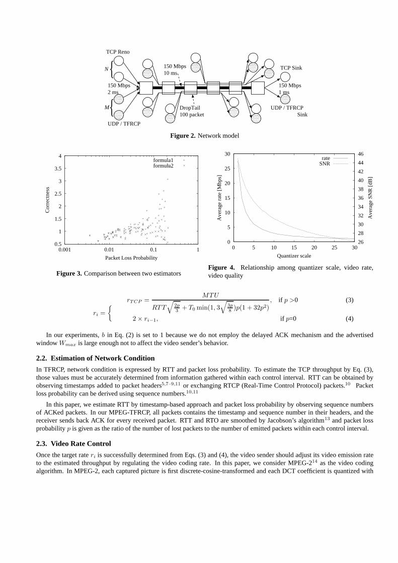
We evaluate the applicability of those two formulas in the network model shown in Fig. 2 where TCP Reno and UDPconnections coexist. Simulation experiments shown in this paper are performed withns version 2.12 The simulationresults are depicted in Fig. 3 where “Correctness” is defined as the ratio of the estimated throughput to the actual throughput.From Fig. 3, it is obvious that Eq. (2) is a better estimator than Eq. (1). In this paper, we employ Eq. (2) for the TCP throughputestimation in MPEG-TFRCP. However, the formula is not applicable when no packet is lost within a preceding control interval.Thus, according to,9 we determine the video emission rateri in the next intervali as;
{N
TCP Reno
UDP / TFRCP
TCP Sink
UDP / TFRCP Sink
150 Mbps2 ms
150 Mbps1 ms
{M
150 Mbps10 ms
DropTail100 packet
Figure 2. Network model
0.5
1
1.5
2
2.5
3
3.5
4
0.001 0.01 0.1 1
Cor
rect
ness
Packet Loss Probability
formula1formula2
Figure 3. Comparison between two estimators
0
5
10
15
20
25
30
0 5 10 15 20 25 3026
28
30
32
34
36
38
40
42
44
46
Ave
rage
rat
e [M
bps]
Ave
rage
SN
R [d
B]
Quantizer scale
rateSNR
Figure 4. Relationship among quantizer scale, video rate,video quality
ri ={ rTCP =
MTU
RTT√
2p3
+ T0 min(1, 3√
3p8
)p(1 + 32p2), if p >0 (3)
2 × ri−1, if p=0 (4)
In our experiments,b in Eq. (2) is set to 1 because we do not employ the delayed ACK mechanism and the advertisedwindowWmax is large enough not to affect the video sender’s behavior.
2.2. Estimation of Network Condition
In TFRCP, network condition is expressed by RTT and packet loss probability. To estimate the TCP throughput by Eq. (3),those values must be accurately determined from information gathered within each control interval. RTT can be obtained byobserving timestamps added to packet headers5,7–9,11 or exchanging RTCP (Real-Time Control Protocol) packets.10 Packetloss probability can be derived using sequence numbers.10,11
In this paper, we estimate RTT by timestamp-based approach and packet loss probability by observing sequence numbersof ACKed packets. In our MPEG-TFRCP, all packets contains the timestamp and sequence number in their headers, and thereceiver sends back ACK for every received packet. RTT and RTO are smoothed by Jacobson’s algorithm13 and packet lossprobabilityp is given as the ratio of the number of lost packets to the number of emitted packets within each control interval.
2.3. Video Rate Control
Once the target rateri is successfully determined from Eqs. (3) and (4), the video sender should adjust its video emission rateto the estimated throughput by regulating the video coding rate. In this paper, we consider MPEG-214 as the video codingalgorithm. In MPEG-2, each captured picture is first discrete-cosine-transformed and each DCT coefficient is quantized with
05
1015
2025
30
TCP
051015202530
UDP
05
1015202530354045
Friendliness
05
1015
2025
30
TCP
051015202530
UDP
05
1015202530354045
Friendliness
Figure 5. Friendliness (UDP)
05
1015
2025
30
TCP
051015202530
TFRCP
0.30.40.50.60.70.80.9
11.11.2
Friendliness
05
1015
2025
30
TCP
051015202530
TFRCP
0.30.40.50.60.70.80.9
11.11.2
Friendliness
Figure 6. Friendliness (MPEG-TFRCP)
specified quantizer scale. Thus, the coded video quality and the amount of data can be regulated by choosing the appropriatequantizer scale.
In Fig. 4, we depict an example of the relationship among the quantizer scale, the average video coding rate and the videoquality in terms of SNR (Signal to Noise Ratio). The video sequence was coded by the MPEG-2 VBR coding algorithm where astatic quantizer scale is applied to all pictures in the sequence.15 The video sequence consists of 150 pictures of 704×480 pixelsand the frame rate is 29.97 fps. By applying the method proposed in,15 we can easily determine the appropriate quantizer scaleto adjust the video rate to the estimated TCP throughput.
In our MPEG-TFRCP mechanism, the sender is allowed to emit the video data as far as the sum of data injected intothe network is smaller than the multiple of the target rateri and the length of control intervalIi. When the network is heavilycongested, considerable numbers of packets are lost and the target rate determined from Eq. (3) becomes far below the minimumvideo rate, which corresponds to the largest quantizer scale. In such cases, the video application first applies the largest quantizerscale to make the data emission rate as small as possible and sends the video data as much as possible.
2.4. Control Interval Appropriate for Video Application
As described in Section 1, the duration of each control intervalIi (Fig. 1) must be carefully determined to accomplish theeffective control. It is expected that the fair share of network bandwidth can be achieved by frequent rate control. Ideally, itshould be in the same order as TCP. However, the amount of feedback information gathered by the sender becomes insufficientto accurately estimate TCP throughput within a short interval. More importantly, the frequent video rate control results inthe unacceptable video quality fluctuation because the rate adjustment is realized by a means of video quality regulation asexplained in Subsection 2.3. On the other hand, if the control interval is too long, the MPEG-TFRCP rate control does notreflect the dynamics of network condition and the fair-share of bandwidth cannot be expected. The structure of MPEG-2 videostream consists of GoP (Group of Pictures), i.e., the repeated sequence of three types of coded pictures. In this paper, weemploy the duration of 32 times as long as a smoothed RTT.7 The control interval is then rounded to the GoP time unit by�32 × RTT/GoPtime� × GoPtime. Here, a GoP time unit is given as the multiple of the number of pictures in a GoP and theframe interval, that is 30/29.97=1.001 sec in this paper.
3. SIMULATION RESULTS
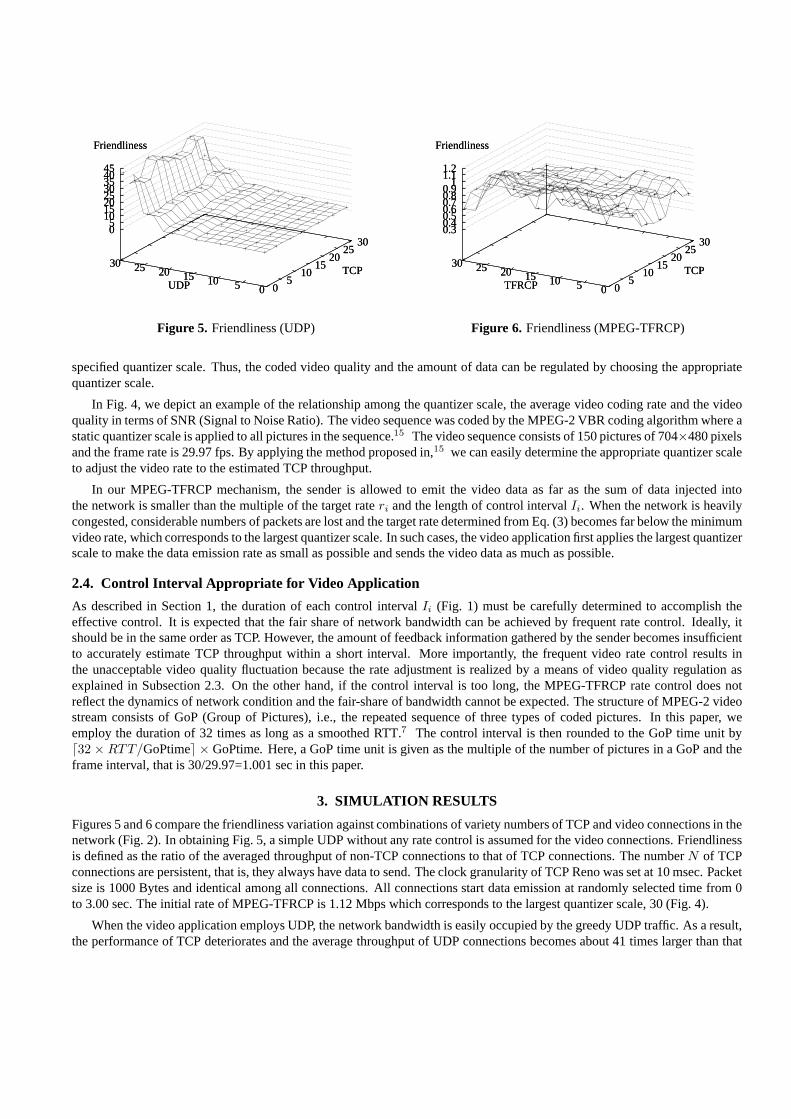
Figures 5 and 6 compare the friendliness variation against combinations of variety numbers of TCP and video connections in thenetwork (Fig. 2). In obtaining Fig. 5, a simple UDP without any rate control is assumed for the video connections. Friendlinessis defined as the ratio of the averaged throughput of non-TCP connections to that of TCP connections. The numberN of TCPconnections are persistent, that is, they always have data to send. The clock granularity of TCP Reno was set at 10 msec. Packetsize is 1000 Bytes and identical among all connections. All connections start data emission at randomly selected time from 0to 3.00 sec. The initial rate of MPEG-TFRCP is 1.12 Mbps which corresponds to the largest quantizer scale, 30 (Fig. 4).
When the video application employs UDP, the network bandwidth is easily occupied by the greedy UDP traffic. As a result,the performance of TCP deteriorates and the average throughput of UDP connections becomes about 41 times larger than that
0
2
4
6
8
10
12
14
16
0 10 20 30 40 50 60
Rat
e [M
bps]
Time [sec]
TFRCPTCP
Figure 7. Averaged rate variation (MPEG-TFRCP)
0
2
4
6
8
10
12
14
16
0 10 20 30 40 50 60
Rat
e [M
bps]
Time [sec]
TFRCPTCP
Figure 8. Rate variation (MPEG-TFRCP)
0
2
4
6
8
10
12
0 10 20 30 40 50 600.0001
0.001
0.01
0.1
1
Rat
e [M
bps]
Pac
ket L
oss
Pro
babi
lity
Time [sec]
TFRCPLoss
Figure 9. Packet loss probability variation (MPEG-TFRCP)
0
2
4
6
8
10
12
0 10 20 30 40 50 600
5
10
15
20
25
30
35
40
Rat
e [M
bps]
SN
R [d
B]
Time [sec]
TFRCPSNR
Figure 10. Picture quality variation (MPEG-TFRCP)
of TCP connections as shown in Fig. 5. On the other hand, when our MPEG-TFRCP algorithm is employed by the videoapplication, the TCP-friendly video transmission is achieved where the “friendliness” ranges from 0.374 to 1.125 (see Fig. 6).
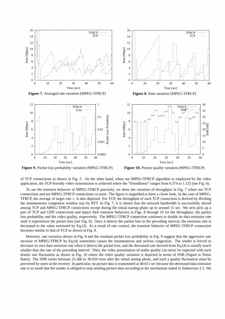
To see the transient behavior of MPEG-TFRCP precisely, we show the variation of throughput in Fig. 7 where ten TCPconnections and ten MPEG-TFRCP connections co-exist. The figure is magnified to have a closer look. In the case of MPEG-TFRCP, the average of target rateri is also depicted. For TCP, the throughput of each TCP connection is derived by dividingthe instantaneous congestion window size by RTT. In Fig. 7, it is shown that the network bandwidth is successfully sharedamong TCP and MPEG-TFRCP connections except during the initial startup phase up to around 15 sec. We next pick up apair of TCP and UDP connections and depict their transient behaviors in Figs. 8 through 10 for the throughput, the packetloss probability and the video quality, respectively. The MPEG-TFRCP connection continues to double its data emission rateuntil it experiences the packet loss (see Fig. 9). Once it detects the packet loss in the preceding interval, the emission rate isdecreased to the value estimated by Eq.(3). As a result of rate control, the transient behavior of MPEG-TFRCP connectionbecomes similar to that of TCP as shown in Fig. 8.
However, rate variation shown in Fig. 8 and the resultant packet loss probability in Fig. 9 suggest that the aggressive rateincrease of MPEG-TFRCP by Eq.(4) sometimes causes the instantaneous and serious congestion. The sender is forced todecrease its own data emission rate when it detects the packet loss, and the decreased rate derived from Eq.(4) is usually muchsmaller than the rate of the preceding interval. Then, the video presentation of stable quality can never be expected with suchdrastic rate fluctuation as shown in Fig. 10 where the video quality variation is depicted in terms of SNR (Signal to NoiseRatio). The SNR varies between 25.360 to 39.020 even after the initial startup phase, and such a quality fluctuation must beperceived by users at the receiver. In particular, no picture data is transmitted at 40.611 sec because the decreased data emissionrate is so small that the sender is obliged to stop sending picture data according to the mechanism stated in Subsection 2.3. We

0
2
4
6
8
10
12
14
16
0 10 20 30 40 50 60
Rat
e [M
bps]
Time [sec]
TFRCPTCP
Figure 11. Averaged rate variation (TFRCP-AI)
0
2
4
6
8
10
12
14
16
0 10 20 30 40 50 60
Rat
e [M
bps]
Time [sec]
TFRCPTCP
Figure 12. Rate variation (TFRCP-AI)
0
1
2
3
4
5
6
7
0 10 20 30 40 50 600
5
10
15
20
25
30
35
40
Rat
e [M
bps]
SN
R [d
B]
Time [sec]
TFRCPSNR
Figure 13. Picture quality variation (TFRCP-AI)
05
1015
2025
30
TCP
051015202530
TFRCP
0.40.50.60.70.80.9
11.1
Friendliness
05
1015
2025
30
TCP
051015202530
TFRCP
0.40.50.60.70.80.9
11.1
Friendliness
Figure 14. Friendliness (TFRCP-AI)
should also note that the SNR values in Fig. 10 are obtained at the sender side, which means that the picture quality perceivedat the receiver must be smaller than that in Fig. 10 because some packets could be lost in the network.
4. IMPROVING MPEG-TFRCP PERFORMANCE
In this section, we describe several methods to improve the MPEG-TFRCP mechanism for achieving the higher friendlinessand the stable video quality.
4.1. Consideration on MPEG-TFRCP Rate Increase
In our MPEG-TFRCP mechanism proposed in Section 2, the data emission rate is doubled when there is no packet loss inthe preceding control interval. Such sudden and aggressive rate increase leads to the instantaneous congestion as having beenshown in Section 3. In this section, we introduce another way of increasing the MPEG-TFRCP rate which is not aggressive,but still more similar to that of TCP.
During the congestion avoidance phase, TCP increases the congestion window size by 1/cwnd every time it receivesACK. Thus, the congestion window is increased by one segment size each RTT.13 Our modified MPEG-TFRCP imitates thismechanism by translating the window-based flow control to the rate-based one. The new algorithm becomes as follows:
ri =
rTCP =MTU
RTT√
2p3 + T0 min(1, 3
√3p8 )p(1 + 32p2)
, if p >0 (5)
ri +MTU × Ii
RTT 2, if p=0 (6)
0
5
10
15
20
25
30
35
40
0 10 20 30 40 50 60
Rat
e [M
bps]
Time [sec]
TFRCPTCP
Figure 15. Averaged rate variation (TFRCP-SP)
0
10
20
30
40
50
60
0 10 20 30 40 50 60
Rat
e [M
bps]
Time [sec]
TFRCPTCP
Figure 16. Rate variation (TFRCP-SP)
0
10
20
30
40
50
60
0 10 20 30 40 50 601e-06
1e-05
0.0001
0.001
0.01
0.1
Rat
e [M
bps]
Pac
ket L
oss
Pro
babi
lity
Time [sec]
TFRCPLoss
Figure 17. Packet loss probability variation (TFRCP-SP)
0
10
20
30
40
50
60
0 10 20 30 40 50 600
5
10
15
20
25
30
35
40
45
Rat
e [M
bps]
SN
R [d
B]
Time [sec]
TFRCPSNR
Figure 18. Picture quality variation (TFRCP-SP)
By introducing Eq. (6), the additive rate increase as in TCP can be performed in MPEG-TFRCP.
We evaluate MPEG-TFRCP with an additive increase mechanism (TFRCP-AI) under the same simulation environment asin Section 3. The simulation results are depicted in Figs. 11 through 14. Compared with MPEG-TFRCP proposed in Section 2,the rate variation becomes smoother as shown in Figs. 11 and 12. As a result, the video quality becomes stable and ranges from28.570 to 36.080 (see Fig. 13). The averaged SNR of TFRCP-AI experiments is 30.537 dB, which is slightly higher than thatof MPEG-TFRCP, 29.535 dB. In addition, the variation of SNR becomes smaller.
It should be noted that the bandwidth occupied by TFRCP-AI is close to that of TCP (see Fig. 11). It follows that the highTCP-friendliness is achieved and the network bandwidth is fairly shared among TCP and MPEG-TFRCP connections. Thefriendliness variation in TFRCP-AI is depicted in Fig. 14, which ranges from 0.439 to 1.002.
4.2. Consideration on Estimation of Packet Loss Probability
Next, we consider how the packet loss probabilityp should be estimated. In Section 2, the packet loss probability is obtained bydividing the number of lost packets by the number of emitted packet within a control interval. This approach seems attractive forits simplicity but could be inappropriate because the estimated TCP throughput is easily affected by the short-term congestion.It is one of the reasons of rate fluctuation that we want to eliminate. Considering the fact that Eq. (2) is used to derive the“averaged” throughput of the TCP connection under the stable network condition, the packet loss probability used in Eq. (3)should be calculated over the long interval, or smoothed by applying the low pass filter function such as exponentially weightedmoving averaging method against instantaneous values.
We apply the latter approach to the rate increase mechanism. We employ the low-pass filter which is similar to that for RTT

estimation in TCP. That is, the smoothed packet loss probabilitypsi is determined as,
psi =
7psi−1
8+
pi−1
8(7)
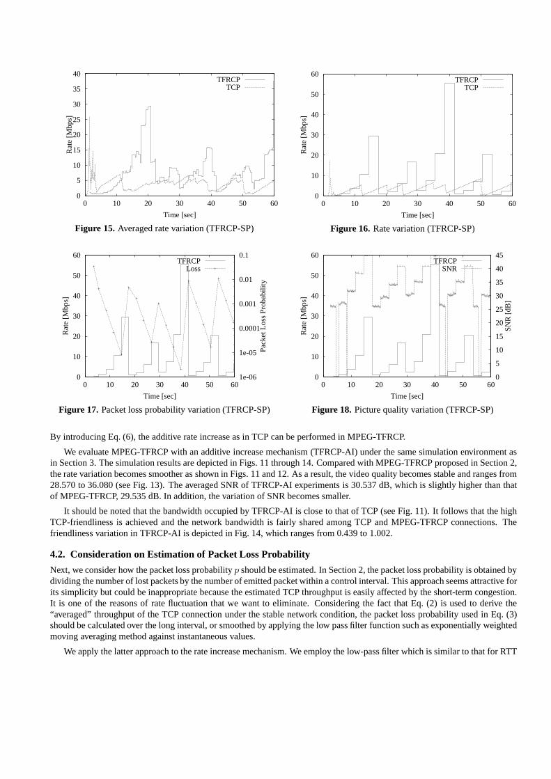
It is substituted to Eq. (3) to derive the target rateri at the end of intervali − 1. Here,pi−1 corresponds to the observed packetloss probability in the intervali − 1. The simulation results of MPEG-TFRCP with smoothed packet loss probability (TFRCP-SP) are shown in Figs. 15 through 18. As shown in Fig. 15, the average throughput of TFRCP-SP connections becomes higherthan that of TCP in most of cases because the TFRCP-SP connection aggressively increases its data emission rate according tothe estimated TCP throughput (Fig. 16). The reason for this greedy behavior can be observed in Fig. 17. With the algorithmin Eq. (7), the smoothed packet loss probabilityps
i for intervali becomes ten times smaller thanpsi−1 when there is no packet
loss in the intervali − 1. By applying the smoothed probabilitypsi to Eq. (3), the data emission rate of the intervali becomes√
10 times larger than that of the preceding intervali − 1. As a result, the rate increase of TFRCP-SP becomes much higherthan that of TFRCP-AI. Such a sudden increase causes the periodic and influential packet loss, and the video quality fluctuatesvery much as shown in Fig. 18. Thus, we have to employ the filter which provides more smoother changes than Eq. (7) in thesmoothed packet loss probability. However, to achieve the effective control with such a filter, several numbers of parametersshould be carefully chosen dependent on the network condition and the traffic characteristics.
From above observations, we conclude that the estimation of loss probability in our proposed MPEG-TFRCP described inSubsection 2.2 provides reasonable performance and is attractive for its simpleness.
4.3. Consideration on Appropriate Control Interval
So far, the MPEG-TFRCP algorithms proposed in this paper estimate the TCP throughput from the observed network conditionand regulate the data emission rate at the periodic interval. In the rest of this section, we call this strategy as 32–GoP. Ashaving been shown in Subsection 4.1, MPEG-TFRCP with 32–GoP interval and an additive increase mechanism provides goodperformance. However, one may expect the higher friendliness and an effective usage of network bandwidth by introducing theshorter interval. Or, the network condition could be kept stable with the longer interval while expecting the less fluctuation ofthe video quality. In the rest of the paper, MPEG-TFRCP with the additive increase mechanism, i.e. TFRCP-AI, is used andreferred to as MPEG-TFRCP.
In Figs. 19 through 26, we depict variations of the averaged rate and the picture quality for several settings of control interval,i.e., smoothed RTT, single GoP-time, 16×RTT rounded by GoP-time and 64×RTT rounded by GoP-time, respectively. Thefriendliness of those trials ranges from 0.587 to 0.749. From Figs. 19, 21, 23 and 25, we observe that the smaller control intervalenables MPEG-TFRCP to regulate its data emission rate similarly with TCP. However, the frequent control leads to the lowerthroughput of MPEG-TFRCP because it causes frequent and bursty packet loss.
When the rate control is performed every RTT as in TCP window-based flow control, MPEG-TFRCP behaves as pseudo-TCP and accomplishes the TCP-friendly video data transfer in an almost satisfactory way. However, Fig. 20 shows that the videoquality seriously deteriorates with RTT-based rate control. The smoothed RTT in the simulation experiment is about 106 msecand is not a multiple of a picture time (1000/29.97=33.37 msec), which is still smaller than a GoP-time (30/29.97=1.001 sec).Thus, the sender of the MPEG-TFRCP connection is forced to regulate its data emission rate by adjusting the quantizer scalewhile the picture is being coded. It is almost impossible to inter-picture rate adjustment in the MPEG-2 algorithm. It is im-possible to predict the resultant picture size in such adjustment because the MPEG-2 employs the DCT transform, quantizationand variable length coding. Then, the coded picture size often exceeds the allowable amount of bits and the sender abandonsdata emission in such a case. As a result, the picture quality fluctuates in RTT-based control as shown in Fig. 20.
The GoP-based rate control seems preferable for the MPEG-2 coding algorithm. We employed the MPEG-2 VBR codingalgorithm where the quantizer scale is fixed during a control interval. However, the MPEG-2 CBR coding algorithm such as“Test Model 5”16 might be useful if the control interval is a multiple of GoP-time and the rate control is performed on a GoPbasis. The resultant picture quality variation is depicted in Fig. 22. Compared with Fig. 20 of RTT-based MPEG-TFRCP, thepicture quality is much improved but the periodic quality degradation is perceptible as shown in Fig. 22, while the average SNRis almost same as that of 32–GoP MPEG-TFRCP in Fig. 13.
In Figs. 23 and 24, we depict the simulation results of MPEG-TFRCP with 16–GoP interval. The 16–GoP interval isidentical to the GoP-time in this case because RTT in our simulation environment is around 106 msec and the GoP-time isabout 1001 msec, i.e., the control interval is�16×106
1001�× 1001=1001 msec. However, we believe that the control interval should
be determined based on the estimated RTT because the TCP’s behavior is dominated by RTT.

0
2
4
6
8
10
12
14
16
0 10 20 30 40 50 60
Rat
e [M
bps]
Time [sec]
TFRCPTCP
Figure 19. Averaged rate variation (RTT)
0
1
2
3
4
5
6
0 2 4 6 8 10 12 140
5
10
15
20
25
30
35
Rat
e [M
bps]
SN
R [d
B]
Time [sec]
TFRCPSNR
Figure 20. Picture quality variation (RTT)
0
2
4
6
8
10
12
14
16
0 10 20 30 40 50 60
Rat
e [M
bps]
Time [sec]
TFRCPTCP
Figure 21. Averaged rate variation (GoP)
0
1
2
3
4
5
6
7
0 10 20 30 40 50 600
5
10
15
20
25
30
35
40
Rat
e [M
bps]
SN
R [d
B]
Time [sec]
TFRCPSNR
Figure 22. Picture quality variation (GoP)
Finally, we examine a longer control interval to achieve the stable control. As mentioned in Subsection 4.2, estimation ofTCP throughput by Eq. (3) is expected to be accurate when we observe the network condition for long duration. Figs. 25 and 26correspond to the simulation results of the 64–GoP MPEG-TFRCP. As expected, the rate variation of MPEG-TFRCP becomesstable as shown in Fig. 25. It means that the aggregated MPEG-TFRCP connections can be regarded as the CBR connectionfrom TCP connections. Thus, the half of the network bandwidth is occupied by MPEG-TFRCP and TCP connections competefor the rest in this case. It follows that the fair share of bandwidth can be accomplished by MPEG-TFRCP without the bandwidthreservation mechanism. The video quality changes in the longer cycle as shown in Fig. 26 and it is preferable to the videoapplication.
However, one may claim that 64–GoP MPEG-TFRCP cannot catch up the sudden and drastic changes of the networkcondition. One possible and easy solution against this problem is to employ the shorter control interval, such as 32–GoP.Another is to adjust the control interval when the network condition changes. It is obviously difficult for an end system toidentify the number and the characteristics of flows in the network. However, by considering the fact that those changes shouldinvolve the variation of RTT and packet loss probability, our MPEG-TFRCP algorithm is expected to accomplish the up-to-datecontrol to a large extent. The reason is that the control interval takes into account the smoothed RTT and the data emissionrate is determined from the packet loss probability. To achieve higher performance, we are now considering on the regulationof control interval based on the packet loss probability from the standpoint that the high packet loss probability indicates thenetwork congestion, which is caused by the newly started connection or the bursty data emission of ill-behaved flow.

0
2
4
6
8
10
12
14
16
0 10 20 30 40 50 60
Rat
e [M
bps]
Time [sec]
TFRCPTCP
Figure 23. Averaged rate variation (16–GoP)
0
1
2
3
4
5
6
7
8
9
10
0 10 20 30 40 50 600
5
10
15
20
25
30
35
40
Rat
e [M
bps]
SN
R [d
B]
Time [sec]
TFRCPSNR
Figure 24. Picture quality variation (16–GoP)
0
2
4
6
8
10
12
14
16
0 10 20 30 40 50 60
Rat
e [M
bps]
Time [sec]
TFRCPTCP
Figure 25. Averaged rate variation (64–GoP)
0
2
4
6
8
10
12
14
16
0 10 20 30 40 50 600
5
10
15
20
25
30
35
40
Rat
e [M
bps]
SN
R [d
B]
Time [sec]
TFRCPSNR
Figure 26. Picture quality variation (64–GoP)
5. CONCLUSION
In this paper, we proposed the TCP-friendly rate control algorithm with which the fair-share of network bandwidth amongTCP and video connections is accomplished. We give considerations on some aspects of the MPEG-TFRCP algorithm andinvestigate possible variants. Through simulation experiments, we show that the 32–GoP MPEG-TFRCP with additive increasemechanism provides the best performance.
One interesting observation in our simulation results is that the network condition becomes relatively steady after the initialstartup phase of about 15 sec. This implies that the MPEG-TFRCP sender can perform the stable video transfer if it initiallysends dummy data for several seconds and then emits the actual video data after the rate variations becomes small. The highquality video presentation can also be achieved by introducing the playout buffer at the receiver side and store a sufficientamount of data during the initial startup phase. After the initial phase, the receiver can expect the steady data arrival as far asthe network condition does not drastically change.
In this paper, we only employ the single network model (Fig.2) where RTT is about 106 msec and there is no dynamicchanges in the number of active flows. Although we have not examine the applicability of our MPEG-TFRCP to the changesof network condition, we expect that the network becomes stable after some period.
We are currently working on the implementation issues of our MPEG-TFRCP in the actual network and obtained somepreliminary results.17 In our implementation, MPEG-TFRCP is on the RTP protocol stack and effectively utilizes the mech-anism of RTCP to obtain the feedback information required for the estimation of network condition. In RTP-based approach,the feedback information is obtained by exchanging RTCP packets. In such a case, we should employ some error recoverymechanism to avoid the inaccurate estimation from the insufficient information which would be caused by the loss of RTCPpackets. One possible way is to exchange several numbers of RTCP packets in each interval. Another is for the RTCP packet to
have the redundant information, where the RTCP packet contains the information the preceding RTCP packet had. We shouldalso consider the variation of RTT. In the actual network, observed RTT considerably changes. Especially when the network iscongested, RTT becomes large and it leads to the longer control interval. As shown in Subsection 2.4, the infrequent controlcannot catch up the changes of network condition.
In addition, we also consider the definition of fairness. TCP-friendly originally pursuits the fair-share of link bandwidthamong protocols. However, from the standpoint of users, the same share of bandwidth is not necessarily identical to thefairness in terms of application-level QoS, for example, file transfer delay for TCP application and video quality for TFRCPvideo application. We have extended our MPEG-TFRCP to deal with the application-level QoS fairness and provided somesimulation results.18
ACKNOWLEDGMENTS
This work was partly supported by Research for the Future Program of Japan Society for the Promotion of Science underthe Project “Integrated Network Architecture for Advanced Multimedia Application Systems”, a Grant-in-Aid for ScientificResearch (A) 11305030 and a Grant-in-Aid for Encouragement of Young Scientists 12750322 from The Ministry of Education,Science, Sports and Culture of Japan, and Special Coordination Funds for promoting Science and Technology of the Scienceand Technology Agency of the Japanese Government, and Telecommunication Advancement Organization of Japan under theProject “Global Experimental Networks for Information Sciety Project.”
REFERENCES1. S. Floyd and K. Fall, “Promoting the use of end-to-end congestion control in the Internet,”IEEE/ACM Transactions on
Networking , May 1999.2. S. Floyd and V. Jacobson, “Link-sharing and resource managament models for packet networks,”IEEE/ACM Transactions
on Networking 3, pp. 365–386, August 1995.3. J. C. R. Bennett and H. Zhang, “Hierachical packet fair queueing algorithms,”Proceedings of ACM SIGCOMM’96 26,
pp. 143–156, October 1996.4. D. Lin and R. Morris, “Dynamics of random early detection,”Proceedings of ACM SIGCOMM ’97 , pp. 127–137, Septem-
ber 1997.5. M. Mathis, J. Semke, J. Mahdavi, and T. Ott, “The macroscopic behavior of the TCP congestion avoidance algorithm,”
ACM Computer Communication Review 27, pp. 67–82, July 1997.6. T. Turletti, S. F. Parisis, and J.-C. Bolot, “Experiments with a layered transmission scheme over the Internet,”INRIA
Research Report 3296 , November 1997.7. W.-T. Tan and A. Zakhor, “Real-time Internet video using error resilient scalable compression and TCP-friendly transport
protocol,” IEEE Transactions on Multimedia 1, pp. 172–186, June 1999.8. J. Padhye, V. Firoiu, D. Towsley, and J. Kurose, “Modeling TCP throughput: A simple model and its empirical validation,”
Proceedings of ACM SIGCOMM’98 28, pp. 303–314, October 1998.9. J. Padhye, J. Kurose, D. Towsley, and R. Koodli, “A model based TCP-friendly rate control protocol,”UMASS-CMPSCI
Technical Report (TR98-47) , October 1998.10. J.-C. Bolot and T. Turletti, “Experience with control mechanisms for packet video in the Internet,”ACM SIGCOMM
Computer Communication Review 28, pp. 4–15, January 1998.11. R. Rejaie, M. Handley, and D. Estrin, “RAP: An end-to-end rate-based congestion control mechanism for realtime streams
in the Internet,”Proceedings of IEEE INFOCOM’99 , March 1999.12. The VINT Project, “UCB/LBNL/VINT network simulator - ns (version 2),”http://www-mash.cs.berkeley.
edu/ns/ , 1996.13. W. Stevens,TCP/IP Illustrated, Addison-Wesley, 1994.14. ISO/IEC DIS 13818-2, “MPEG-2 video,”ISO standard , 1994.15. K. Fukuda, N. Wakamiya, M. Murata, and H. Miyahara, “QoS mapping between user’s preference and bandwidth control
for video transport,”Proceedings of Fifth IFIP International Workshop on Quality of Service , pp. 291–302, May 1997.16. ISO/IEC/JTC1/SC29/WG11, “Test model 5,” April 1994.17. M. Miyabayashi, N. Wakamiya, M. Murata, and H. Miyahara, “Implementation of video transfer with TCP-friendly rate
control,” Proceedings of International Technical Conference on Circuits/Systems, Computers and Communications 20001, pp. 117–120, July 2000.
18. N. Wakamiya, M. Murata, and H. Miyahara, “On TCP-friendly video transfer with consideration on application-levelQoS,”Proceedings of IEEE International Conference of Multimedia & EXPO 2000 , July 2000.