Variation of hydrogen adsorption with increasing Li doping on carbon nanotubes
Fuel 90 (2011) 3123–3140
Contents lists available at ScienceDirect
Fuel
journal homepage: www.elsevier .com/locate / fuel
Review article
Recent applications of carbon nanotubes in hydrogen production and storage
Renáta Orináková ⇑, Andrej OrinákDepartment of Physical Chemistry, Faculty of Science, P.J. Šafárik University, Moyzesova 11, SK-04154 Košice, Slovak Republic
a r t i c l e i n f o a b s t r a c t
Article history:Received 25 March 2010Received in revised form 4 March 2011Accepted 14 June 2011Available online 12 July 2011
Keywords:HydrogenCarbon nanotubeProductionStorage
0016-2361/$ - see front matter � 2011 Elsevier Ltd. Adoi:10.1016/j.fuel.2011.06.051
⇑ Corresponding author. Tel.: +421 55 2342328; faxE-mail address: [email protected] (R. Orin
Hydrogen is actually of great interest because it is the cleanest, sustainable and renewable energy carrierwith a significantly reduced impact on the environment. In the future, hydrogen energy systems areexpected to progressively replace the existing fossil fuels. Although hydrogen possesses significantadvantages, it also exhibits major drawbacks in its utilization. The most important of them are produc-tion costs and storage characteristics. Carbon nanotubes (CNTs) have proven to possess ability as supportfor the fabrication of efficient heterogeneous catalysts in hydrogen production processes. Moreover, CNTsrepresent convenient adsorbent material that could form the basis of technologically viable hydrogenstorage systems. This paper gives an overview of technologies used in the carbon nanotubes productionand in the production and storage of hydrogen. In particular, it investigates the feasibility of CNTs andCNTs based catalyst materials in the mentioned processes. Our purpose is to overview the challengesof hydrogen production and storage technologies based on CNTs, to discuss and compare the differentresults published, and to emphasize recently developed modifications of CNTs that show potential toenhance hydrogen production and storage.
� 2011 Elsevier Ltd. All rights reserved.
Contents
1. Introduction . . . . . . . . . . . . . . . . . . . . . . . . . . . . . . . . . . . . . . . . . . . . . . . . . . . . . . . . . . . . . . . . . . . . . . . . . . . . . . . . . . . . . . . . . . . . . . . . . . . . . . . . 31232. Carbon nanotubes . . . . . . . . . . . . . . . . . . . . . . . . . . . . . . . . . . . . . . . . . . . . . . . . . . . . . . . . . . . . . . . . . . . . . . . . . . . . . . . . . . . . . . . . . . . . . . . . . . . 31243. Production of hydrogen . . . . . . . . . . . . . . . . . . . . . . . . . . . . . . . . . . . . . . . . . . . . . . . . . . . . . . . . . . . . . . . . . . . . . . . . . . . . . . . . . . . . . . . . . . . . . . . 3126
3.1. Application of CNTs in hydrogen production. . . . . . . . . . . . . . . . . . . . . . . . . . . . . . . . . . . . . . . . . . . . . . . . . . . . . . . . . . . . . . . . . . . . . . . . . 3127
4. Storage of hydrogen . . . . . . . . . . . . . . . . . . . . . . . . . . . . . . . . . . . . . . . . . . . . . . . . . . . . . . . . . . . . . . . . . . . . . . . . . . . . . . . . . . . . . . . . . . . . . . . . . . 31284.1. Application of CNTs in hydrogen storage. . . . . . . . . . . . . . . . . . . . . . . . . . . . . . . . . . . . . . . . . . . . . . . . . . . . . . . . . . . . . . . . . . . . . . . . . . . . 3129
4.1.1. Physisorption . . . . . . . . . . . . . . . . . . . . . . . . . . . . . . . . . . . . . . . . . . . . . . . . . . . . . . . . . . . . . . . . . . . . . . . . . . . . . . . . . . . . . . . . . . 31304.1.1.1. Theoretical study . . . . . . . . . . . . . . . . . . . . . . . . . . . . . . . . . . . . . . . . . . . . . . . . . . . . . . . . . . . . . . . . . . . . . . . . . . . . . . . . . . . . . . 31304.1.1.2. Experimental investigation . . . . . . . . . . . . . . . . . . . . . . . . . . . . . . . . . . . . . . . . . . . . . . . . . . . . . . . . . . . . . . . . . . . . . . . . . . . . . . 31304.1.1.3. Modification of CNTs . . . . . . . . . . . . . . . . . . . . . . . . . . . . . . . . . . . . . . . . . . . . . . . . . . . . . . . . . . . . . . . . . . . . . . . . . . . . . . . . . . . 31324.1.2. Chemisorption . . . . . . . . . . . . . . . . . . . . . . . . . . . . . . . . . . . . . . . . . . . . . . . . . . . . . . . . . . . . . . . . . . . . . . . . . . . . . . . . . . . . . . . . . 31324.1.3. Electrochemical hydrogen storage. . . . . . . . . . . . . . . . . . . . . . . . . . . . . . . . . . . . . . . . . . . . . . . . . . . . . . . . . . . . . . . . . . . . . . . . . . 31344.1.4. Variation of results . . . . . . . . . . . . . . . . . . . . . . . . . . . . . . . . . . . . . . . . . . . . . . . . . . . . . . . . . . . . . . . . . . . . . . . . . . . . . . . . . . . . . . 31355. Conclusions. . . . . . . . . . . . . . . . . . . . . . . . . . . . . . . . . . . . . . . . . . . . . . . . . . . . . . . . . . . . . . . . . . . . . . . . . . . . . . . . . . . . . . . . . . . . . . . . . . . . . . . . . 3136Acknowledgement . . . . . . . . . . . . . . . . . . . . . . . . . . . . . . . . . . . . . . . . . . . . . . . . . . . . . . . . . . . . . . . . . . . . . . . . . . . . . . . . . . . . . . . . . . . . . . . . . . . 3136References . . . . . . . . . . . . . . . . . . . . . . . . . . . . . . . . . . . . . . . . . . . . . . . . . . . . . . . . . . . . . . . . . . . . . . . . . . . . . . . . . . . . . . . . . . . . . . . . . . . . . . . . . 3136
1. Introduction
Recent researches have been focusing on two main problems:energy sources and environment. The pollution problems
ll rights reserved.
: +421 55 6222124.áková).
associated with the combustion of petroleum related fuels leadto undesired alterations in the Earth’s climate. The scarcity of fossilfuels and global warming have directed attention towards thesearch of alternative fuels [1–6]. It is widely hoped that the useof carbon-free energy carriers could reverse or decelerate the‘‘greenhouse’’ phenomenon. The utilization of sustainable energyresources is predicted to increase exponentially in the coming

3124 R. Orináková, A. Orinák / Fuel 90 (2011) 3123–3140
years. Since hydrogen is the cleanest and efficient energy carrierwith a significantly reduced impact on the environment, it hasbeen increasingly recognized as the fuel of the future [3,4,7–12].Hydrogen is considered as an ideal alternative fuel for many energyconverters because of its clean-burning nature, high conversionefficiency, lightweight, zero pollutant emission and potentiallyabundant production from other renewable resources [1–4,11–15]. One of the main proposed applications of hydrogen is its useas ecologically clean fuel in power transport vehicles or portableelectronic devices such as, mobile phones and chargeable/dis-chargeable electrolytic cells of high energy density [16–20]. Itcan be used as fuel either directly in internal combustion engines(ICE) or, indirectly, to supply electricity using polymer electrolytemembrane (PEM) fuel cells, in which electricity is produced byelectrochemical oxidation of hydrogen across a proton conductingmembrane [2,21–23]. However, there is no large-scale utilizationof hydrogen because of several major problems, which constraintthe development of hydrogen economy. One of them is how to pro-duce hydrogen at low cost. Its explosive nature and large volumeare the two main hindrances for the transportation and storagepurposes. All above mentioned problems (production, storageand application of hydrogen) have been posing challenges to thescientific community for the past several decades [1,3,20,24].
The new carbon forms like carbon nanotubes (CNTs) and nanof-ibers (CNFs) have generated an intense effervescence in the scien-tific community due to their well known fascinating properties. Inrecent years, CNTs have proven to be a highly versatile material inthe field of nanoscience [3,25]. Exploring their ability as support forthe fabrication of efficient heterogeneous catalysts in hydrogenproduction processes is one of the current objectives of research[2,12,26]. The CNTs are found to offer some advantages, such as,electronic property, high mechanical strength and thermal stabil-ity, and possibility to create anchoring sites over conventional sup-ports, like carbon, Al2O3 and SiO2. Also, the catalytically activemetal nanoparticles can be implemented in the cavities or in theexternal walls of the CNTs [2]. Moreover, CNTs seem to be conve-nient adsorbent materials that could form the basis of technologi-cally viable hydrogen storage systems [17]. The interest in such
Fig. 1. Scheme of different SWNTs: armchair (10; 10)
applications in recent years is reflected by several reviews[19,27–30].
This paper summarizes the major achievements in the researchof carbon nanotube in connection with their possible applicationsin hydrogen production and storage. The paper is organized as fol-lows: Section 2 focuses on the characterization and synthesis ofcarbon nanotubes. Section 3 presents recent methods for hydrogenproduction and considers possible applications of CNTs in this pro-cess. Section 4 deals with the hydrogen storage systems. Amongthe materials examined in this respect, CNTs possess a prominentposition. The report ends with a summary.
2. Carbon nanotubes
Elemental carbon in sp2 hybridization can form a variety ofamazing structures, such as, graphite, graphene, CNTs and fuller-ene [28,31]. CNTs defined by Iijima in 1991 [32] can be regardedas a unique inner hollow tubular structures of nanometer diameterrolled with graphite plates with large length/diameter ratios andwithout any aperture in the tube wall. The carbon network of theshells is closely related to the honeycomb arrangement of the car-bon atoms in the graphite sheets [16,28,31]. CNTs can be dividedinto two sorts: singlewalled carbon nanotubes (SWNTs) (Fig. 1)and multiwalled carbon nanotubes (MWNTs) (Fig. 2). SWNT con-sist of a seamless graphene sheet rolled up into a cylinder of afew nanometers diameter and several microns length. Most ofthem are aligned and packed together to form ropes of 10 to 100parallel tubes. A MWNT is an arrangement of several, up to tensand hundreds of concentric tubes of graphite sheets with adjacentshells separation of �0.34 nm (Fig. 2). On each tube, the carbonatoms are arranged in a helical fashion along the tube axis. Theouter diameter of these MWNT is about several tens of nanome-ters, and they have a length of 10–100 lm [16,27,28,33]. Depend-ing on the rolling, CNTs can be further classified as armchair, zigzagand chiral types (Fig. 1). Only armchair nanotubes are truly metal-lic [5], while other tubes zigzag as well as chiral 1/3 are narrow-gap and 2/3 wide-gap semiconductors [3].
(a); zigzag (14; 0) (b); and chiral (7; 3) (c) [17].

Fig. 2. Scheme of MWNT.
R. Orináková, A. Orinák / Fuel 90 (2011) 3123–3140 3125
Since their discovery, these new carbon tubular macromole-cules have attracted great attention owing to their tremendouscharacteristics, such as, unique structure, high surface area, porousnature, low density, high strength, good electrical conductivity,extraordinary mechanical and thermal properties, special func-tional properties and they are relatively chemically stable[1,3,15,19,25,27,34–37]. CNTs have ultra-high Young’s modulusand tensile strength, which makes them promising in serving asa reinforcement of composite materials with improved mechanicalproperties [28,31]. Properties of individual CNTs may differ fromthese of CNT powder. A Young’s modulus of over 1 TPa, and a ten-sile strength of about 200 GPa can be achieved for individual nano-tube [33]. Many physical or chemical properties of nanotubes areconnected with the smooth, straight, one-dimensional channel intheir cores. The inside channels can hold atoms or molecules ofother species by capillarity or adsorption, which thus brings aboutsome unique possibilities of using nanotubes as super-adsorbent,nano-sized container, reactor and templates for fabrication of no-vel one-dimensional nanomaterials such as, nanowires [38].
Their tremendously high surface area (�1000 m2/g) [39,40] incombination with the ability to attach essentially any chemicalspecies to their sidewalls (functionalization) provides an opportu-nity for unique catalyst supports [33]. Their electrical conductivitymay also be exploited in the search for new catalysts and catalyticbehavior.
The nanotubes can be metallic or semiconducting depending ontheir structural parameters. For a SWNT with a given (n, m) index[28,31,41,33], when (2n + m) = 3q (q is an integer), the nanotubeis metallic, otherwise the nanotube is a semiconductor, whileMWNTs are reported to be always electrically conductive and tohave an electrical conductivity approximately 1850 S/cm [42].
As a result, CNTs have a variety of potential applications for useas an effective high-capacity hydrogen storage medium, differentenergy conversion systems, such as, solar cells, fuel cells, batteries(specifically Li-ion), field emitter in display technology, catalystand catalyst supports, composite materials, various chemical andbiological sensors and actuators, one-dimensional quantum wireand resistors, nanoprobes in scanning and atomic force micros-copies, conductive films, bio-nanomaterials, as well as nanoelec-tronic devices [15,25,27,28,31,34–37,43–49]. As catalyst supports,CNTs offer several advantages over other carbon and oxide sup-ports, and demonstrate superior catalytic activity and in somecases greater selectivity [25].
To put this unique material into wide use, one of the main chal-lenges is to develop an effective technology for low-cost produc-tion of pure CNTs. In addition, their mass production isimportant to enable both fundamental studies and industrial pro-cesses. Therefore, the synthesis of higher quality CNTs at lower costis of great importance. Nowadays, CNTs are produced mainly bythree techniques: arc discharge, laser ablation and chemical va-pour deposition (CVD) [1,15,25,27,28,31,34–36]. The most recentway to obtain SWNT is the arc discharge method in the presenceof catalyst. MWNTs can be obtained by arc discharge withoutany metal catalyst. Crystallinity and structural perfection of arc-produced CNTs are higher in comparison to other methods. Arcgrowth was the first method for the production of macroscopicamounts of MWNTs [6–16], but they were often obtained from cat-alytic pyrolysis of hydrocarbides [17,27,28,31,50,51]. In laser abla-tion for producing CNTs, an intense laser beam is used to ablate/vaporize a target consisting of a mixture of graphite and metal cat-alyst in a flow of inert gas. This method favors the growth ofSWNTs with controlled diameter depending on reaction tempera-ture [31,52,53]. The resulting SWCNTs contain very few defectsand contaminants. However, the both above methods, in principle,cannot synthesize CNTs continuously; hence, the product yield islimited. CVD of hydrocarbon gases over catalysts is one of the mostsimplest and versatile techniques to synthesize CNTs. This methodinvolves catalyst-assisted decomposition of hydrocarbons (com-monly benzene, ethanol, acetylene, propylene, methane, ethylene,CO, etc.) and growth of CNTs over the catalyst (usually transitionmetals, such as, Ni, Fe, Co, etc.) in a temperature range of 300–1200 �C [1,25,28,31,54]. Comparing with the other methods, CVDcan produce mass and relatively high purity CNTs. CVD offers thepossibility of growing aligned CNTs for specific applications (orien-tation control) and, to a certain extent, synthesis of small-diameterCNTs. Control over shell number and growth rate of CNTs are alsorealized with this method. The essential disadvantage of CVD is thehigh defect density of the obtained CNTs owing to low synthesistemperatures, compared with arc discharge and laser ablation[1,15,25,28,31,55–58].
The CVD of methane into hydrogen and CNTs has been widelydescribed [59–61], fewer studies have dealt with the productionof hydrogen and CNTs by ethanol decomposition [15,62], using li-quid petroleum gas (LPG) [25,63] and acetylene [64,65]. Importantprogress has been made in large scale CNT production owing todevelopments in the laser ablation [52,66], electrical arc discharge[51,67] and novel torch arc method operated in open air [68]. Pro-duction of CNTs by a pyrolysis technique was also reported[18,22,69]. Detailed overview of CNTs production from all threementioned dominant techniques was given e.g. by Valentin Popov[28].
The by-products in CNTs production by CVD are usually aro-matic carbon, amorphous carbon, polyhedral carbon, metal parti-cles, etc. In SWNT synthesis using arc discharge and laserablation, side products, such as, amorphous carbon, C60 and otherfullerenes, graphite particles, and graphitic polyhedrons with en-closed metal particles are also formed. Metal impurities are usuallyresidues from the transition metal catalysts [31,37]. Such impuri-ties impede utilization of the unique properties of CNTs. To fulfilthe extensive potential applications and to investigate the extraor-dinary physical and chemical properties of CNTs, highly efficientpurification of the as-prepared CNTs is, therefore, very important.While catalyst particles and fullerenes are relatively easy to re-move, amorphous carbon and carbon nanoparticles are difficultto eliminate because their oxidation temperatures are similar tothose of CNTs. Moreover, as-synthesized carbon nanotubes usuallyhave both ends closed, which may hinder their adsorption and cap-illarity properties. Therefore, in general, a purification procedureshould involve both opening the tubes ends and the elimination

3126 R. Orináková, A. Orinák / Fuel 90 (2011) 3123–3140
of the impurities [31,37]. Purification strategy must vary accordingto the features of the raw CNTs, and the specific requirement andtarget applications of the purified CNTs. Several purificationmethods have been reported: dilute HNO3 reflux/air oxidationprocedure, dispersion by sonication in a surfactant, filtration andhigh-temperature heating under neutral or lightly oxidizingconditions [14,15], bromination and infrared irradiation in air[27,31,37,70,71]. Techniques for the purification of CNTs have beenreviewed in detail, with an emphasis on their purification princi-ples by Hou et al. [31] or by Pillai et al. [72]. Since the qualityand accompanying impurities of as-prepared CNTs strongly de-pend on the synthesis method and experimental conditions, it ishard to propose a universal method. Although considerable pro-gress has been achieved, it is still difficult to find a simple methodthat can purify CNTs effectively. Multi-step methods that combinethe advantages of different purifications provide a solution for get-ting CNTs with higher purity [31].
Nanotubes still have a wide range of unexplored potentialapplications in various technological areas, such as, aerospace, en-ergy, automobile, medicine, or chemical industry. It is now awidely-shared view that carbon-based materials are likely to be amajor field in the twenty first century technology.
3. Production of hydrogen
The shift towards a hydrogen economy has been forecasted totake place in the next decades, which will result in a strong in-crease in the demand for hydrogen. Thereby, new routes for hydro-gen production must be found [26,73]. At present, there are fourtraditional methods for hydrogen production: water electrolysis,gasification reactions, partial oxidation reactions of heavy oil, andhydrocarbon steam reforming reactions [1,15,74–77].
One of the most promising methods, where the pure hydrogencan be supplied by true renewable and fully environmentallyfriendly energy sources, without evolution of the green-housegas, is water electrolysis [7,12,78,79] using renewable energysources (e.g., solar energy). Water is the ideal source for hydrogen,although water splitting is a process still in the initial phase ofdevelopment [26,80]. Some experiments have been done withthe plasma electrolysis. This process is likely to increase the rateof generation and collection of hydrogen over those of the currentelectrolysis methods with high potential for integration into fuelcell systems and the modular units for augmentation of small-scalepower systems for distributed electricity generation [81]. How-ever, water electrolysis is not competitive considering the currentenergy costs. Thus, alternative routes for the production of CO-freehydrogen become necessary for fuel-cell applications (e.g., PEMcells) [12].
Other promising renewable, clean and abundant source forhydrogen production is biomass [26,82,83]. It is formed by fixingcarbon dioxide in the atmosphere during the process of plant pho-tosynthesis and, therefore, it is carbon neutral in its lifecycle. Bio-mass research is recently receiving increasing attention because ofthe probable waste-to-energy application. Alternative thermo-chemical (pyrolysis and gasification) and biological (biophotolysis,water–gas shift reaction and fermentation) processes can be prac-tically applied to produce hydrogen. One of the major drawbacks isthe low efficiency of utilizing biomass. Alternatively, convertingbiomass into gaseous and aqueous fuels, electricity and especiallyhydrogen is possibly a more efficient way of biomass utilization[83]. A number of biomaterials have attracted attention in the lastyears to produce hydrogen by reforming [26,82,84–86]. In thisway, biomass fermentation leads to bioethanol, which can be sub-jected to reforming to provide an alternative hydrogen productionroute. However, the fast deactivation of the metal catalysts used in
this reaction and the presence of other competitive reactions,which decrease hydrogen selectivity, impose severe limitationson this technology [87,88]. The thermochemical pyrolysis and gas-ification hydrogen production methods are economically viableand will become competitive with the conventional natural gasreforming method. Biological dark fermentation is also a promisinghydrogen production method for commercial use in the future.With further development of these technologies, biomass will playan important role in the development of sustainable hydrogeneconomy [83].
Currently, H2 in the form of compressed gas, liquid or in hydro-gen-storage materials are being used for onboard storage of hydro-gen in fuel cell vehicles (FCVs). But the technical limitationsassociated with storage, safety, and refuelling restrict the use ofH2 for mobile fuel cell applications. These problems can be over-come by the production of hydrogen onboard the vehicle from asuitable H2 rich liquid fuel [2]. Among the various fuels, ethanolis an appropriate candidate for hydrogen production via steam re-form, photo-catalysis and decomposition, because of its low-toxic-ity, easy-generation from renewable resources (it can be easilyobtained from biomass), low production costs and relatively highhydrogen content [1,15,76,89–94]. Many research groups reportedthe production of hydrogen via ethanol decomposition under dif-ferent conditions [15,95–97] as well by steam reforming of ethanoland its mechanism [1,62,93,98–102], but only few of them men-tioned the production of CNFs or CNTs accompanied by hydrogenduring ethanol decomposition.
Also methanol can easily be converted into a hydrogen-rich gasusing a catalytic reactor. Hydrogen is being obtained from metha-nol by steam reforming [103–105], decomposition [106,107], par-tial oxidation [103–111] or oxidative steam reforming [112–114]techniques. Among these methods, selective production of hydro-gen by partial oxidation of methanol (POM) is having some obviousadvantages, since it is an exothermic reaction and higher reactionrate is expected, which shortens the reaction time to reach theworking temperature from the cold start-up conditions [2,115].In the previous studies, it was reported that supported copper,palladium, platinum and gold catalysts are active for hydrogengeneration from methanol by POM. Presently, great attention ispaid on supported gold catalysts due to their high activity at lowtemperatures in a number of important reactions [115]. The mostwidely used catalysts for hydrogen production from methanol bypartial oxidation are Cu–Zn-based catalysts over conventionalsupports, such as, Al2O3 and SiO2 [2].
Nowadays, steam or authothermal reforming of methane/natu-ral gas is the most convenient source of hydrogen for fuel cells. Thesteam reforming (SMR) of natural gas reduces the cost of hydrogenproduction by the optimization of the use of energy in the centra-lised version of this process [23,26,116]. It involves the endother-mic transformation of methane and water into hydrogen andcarbon oxides (CO and CO2).
The process of hydrogen production from steam reforming ofnatural gas consists of several stages: (i) highly endothermic cata-lytic reforming of methane at a high temperature range (1073–1173 K) to produce synthesis gas; (ii) low temperature catalyticwater gas shift (WGS) reaction (450–530 K) to convert CO intoCO2; (iii) separation of the H2–CO2 mixture using a pressure-swingadsorption (PSA) unit. A stock desulphurization unit and a steamgeneration section are other stages of this process. If the producedhydrogen is stored in high pressure cylinders, CO2 and H2O must becleaned out from hydrogen as much as possible in order to avoidany blocking at the cylinder exit by the condensation of theseimpurity gases at the adiabatic expansion of hydrogen when it isdischarged. For hydrogen use in polymeric exchange membranefuel cells, CO concentration must also be minimized (less than10 ppm), because it strongly poisons the anode electrocatalyst

R. Orináková, A. Orinák / Fuel 90 (2011) 3123–3140 3127
(Pt or Pt–Ru) of the fuel cell. However, the growth of concern onthe anthropogenic CO2 emissions reduction is forcing to captureand storage the CO2 produced in each stage. The economic and en-ergy cost of mentioned collateral operations decreases the overalleffectivity of this process, increasing the price of the hydrogen pro-duced by steam reforming [23,26].
Recently, chemical decomposition of ammonia, hydrogen sul-phide or fossil gas is an attractive method to produce hydrogen;however, fossil gas is a non-renewable resource [1,15,117]. Meth-ane decomposition has taken most of the attention so far, and sev-eral attempts have been reported [23,26,60,118–121]. In additionto the production of hydrogen, it also results in the generation ofnanocarbon materials like CNFs or CNTs [15,23,26,118,122,123].Economic analysis has shown that if the carbon produced can berecovered and utilized, this approach could be financially attractive[12].
With the ongoing energy crisis and growing environmental con-cerns there is an increasing push towards reducing or eliminatingCO2 emissions from manufacturing and energy conversion. Non-oxidative, catalytic decomposition of hydrocarbons is an alterna-tive, simple and a fully green chemical process to produce bothpure hydrogen free of carbon oxides and carbon nanotubes whichmay have important technological application [122].
Among the possible hydrogen production technologies, the cat-alytic methane decomposition (CMD), under a condition whereactivated oxygen species (H2O, CO, O2, etc.) are absent, is a rela-tively short route to produce hydrogen without carbon oxides[23,26,60,124–126]. The methane decomposition reaction is amoderately endothermic process. The energy required per moleof hydrogen produced (45 kJ/mol (H2) at 1073 K) is less than thatfor the steam reforming of methane (48 kJ/mol (H2)). Unlike thesteam reforming process, the CDM process does not include WGSand PSA stages or other CO2 capture and storage steps, which con-siderably simplifies the process and brings near the economicalcost of hydrogen compared to that of the SMR process. The ratioof hydrogen produced per methane fed is lower for CDM than forsteam reforming, but this is compensated by a smaller and lesscomplex fuel processor for CDM. The hydrogen product has no pol-lutants released in burning, and can be used directly as fuel for pro-ton exchange membrane fuel cell (PEMFC), with poor CO-tolerance[23,26,60,127] In addition to hydrogen as a major product, the pro-cess produces a very reactive by-product, carbon nanofibers. Thus,the development of new carbon applications is a key factor to con-solidate CDM technology as a feasible method for producinghydrogen. The carbon uses will depend on its nature and properties[23,26,118].
A high temperature is thermodynamically required and a cata-lyst with high activity is needed to break the strong C–H bond ofthe methane molecular in the endothermic methane decomposi-tion reaction [12,26,60,128–130]. However, the solid carbon prod-ucts are produced simultaneously in large amounts at hightemperature, which destroy the structure of the catalyst andmake the catalyst deactive rapidly, through blocking the activepores of catalyst or encapsulating the whole catalyst particles[12,26,60,125,129–132]. This causes reactor blocking and the needfor catalyst regeneration. However, to completely avoid formationof carbon oxides (CO or CO2), the catalyst must not be regenerated[26]. An appropriate catalyst for the direct decomposition ofhydrocarbons must render a highly sustainable activity and regen-eration capability. Two important parameters to meet these de-mands are the choice of a proper support chemical compositionfor the dispersion of transition and/or noble metal and the use ofadequate regeneration conditions (gas and temperature treatment)[12,133,134]. Traditionally, methane decomposition has been per-formed using transition metals, such as, Ni, Pd and Co [12,23,60].Mainly Ni-based catalysts showed significant catalytic activity to-
wards the direct decomposition of methane. If the objective ofthe process is nanofiber production, Ni–catalyst must be destroyedafter the reaction. However, when the aim of the process is hydro-gen production, the Ni-catalyst must be recovered [26,135]. Re-peated production of hydrogen by catalytic decomposition ofmethane followed by oxidation of the formed carbon nanofiberswas demonstrated by Otsuka et al. [23] over supported-Ni cata-lysts: Ni/TiO2, Ni/Al2O3 and Pd–Ni/SiO2. Their catalytic activitieswere recovered repeatedly by the oxidation of the deposited car-bon with O2 at 753 K. Methane decomposition over a Ni/Cu/Al2O3
catalyst in a two-stage fluidized bed reactor was reported by Qianet al. [60]. Low temperature was adopted in the lower stage andhigh temperature in the upper stage. This allows the fluidized cat-alysts to decompose methane with high activity in the high tem-perature condition; then the carbon produced will diffuseeffectively to form CNTs in both low and high temperature regions.Thus the catalytic cycle of carbon production and carbon diffusionin micro scale can be tailored by a macroscopic method, which per-mits the catalyst to have high activity and high thermal stabilityeven at 1123 K for hydrogen production for long times. Such con-trolled temperature condition also provides an increased thermaldriving force for the nucleation of CNTs; hence, favors the graphi-tization of CNTs. The effect of the temperature and the Ni loadingson the production of hydrogen and MWNTs from the decomposi-tion of ethanol over Ni/Al2O3 catalysts was investigated by Wanget al. [15]. It was found out that the hydrogen production increasedwith increasing temperature and Ni loadings. However, both thequality and the quantity of the nanotubes formed at the relativelyhigh temperatures of 700 and 800 �C decreased due to sintering ofthe Ni particles. The co-production of hydrogen and CNTs from thedecomposition of ethanol Al2O3-supported Fe catalysts over at dif-ferent temperatures and feeding rates of ethanol was investigatedby Li et al. [1]. The results indicated that catalysts have an obvi-ously catalytic effect in the co-production of H2 and CNTs from eth-anol decomposition, and the activity and stability of Fe/Al2O3
catalysts depend strongly on the loading amount of Fe.
3.1. Application of CNTs in hydrogen production
Methane decomposition into the hydrogen and carbon productshas been performed also using inexpensive catalysts, which showlow deactivation during the process. Carbon catalysts are notexpensive materials, hence no regeneration is needed. To avoidthe contamination of the produced hydrogen with CO or CO2, theoxygenate groups usually present on the carbon surface are re-moved before reaching the methane decomposition temperature[26]. Specific studies using a variety of commercial carbons, suchas, coal char, activated carbons or carbon blacks, as catalysts in thisprocess, have been carried out [26,120,136–142]. Catalyst deacti-vation is present always as a major issue as a consequence of highamounts of carbon formed from methane decomposition. The mostactive catalyst at short reaction times is activated carbon, but itunderwent a fast deactivation. On the contrary, carbon blackspresent high reaction rates for methane decomposition at bothshort and long reaction times. Carbon nanotubes exhibit a rela-tively low activity in spite of containing significant amounts ofmetals [26].
The support of catalyst plays an essential role in catalysis. Now-adays, CNTs were also applied as the support of catalyst owing totheir special structural morphology and characteristics [25,143].The surface of CNTs is usually modified to create the functionalgroups for specific needs before their use as the support. Catalystsfor hydrogen production supported on CNTs have been producedby impregnation [12,144,145], precipitation [2,146], chemicalreduction [143,144] and hydrothermal method [147].
3128 R. Orináková, A. Orinák / Fuel 90 (2011) 3123–3140
The fundamental study on the direct decomposition of ethyleneover Ni supported on novel CNTs was reported by Savva and co-workers [12]. This work provides important information concern-ing the effects of support chemical composition, catalyst synthesismethod and Ni metal loading on catalyst activity and stability to-wards ethylene decomposition followed by catalyst regenerationfor carbon removal. The catalytic performance of the Ni/CNTs cat-alyst was found to strongly depend on the Ni metal loading. Devel-oped catalytic system presented the highest hydrogen yield andcarbon capacity ever reported in the literature for both the ethyl-ene and methane decomposition reactions. It was found that cata-lyst 0.5 wt.% Ni/CNTs showed 50 times higher hydrogen yieldcompared to a 0.3 wt.% Ni/SiO2 catalyst which has been examinedunder the same experimental conditions. Further, it was concludedthat 0.5 wt.% Ni is approximately an optimum metal loading in the0.15–10 wt.% range studied. The variation of the catalytic proper-ties of supported-Ni catalysts could be associated with the geomet-ric and electronic factors of the support. The geometric factorimplies formation of nickel clusters of a certain size on the surfaceof support, while the electronic factor concerns the modification ofelectronic properties of Ni due to electronic interactions with thesupport [12,148]. Hou et al. [146] reports on high catalytic activityof CNTs-supported Ni catalyst synthesized by the homogeneousdeposition–precipitation method, which was successfully appliedfor low-temperature reforming of organic compounds in bio-oil.The H2 yield reached about 92.5% over the catalyst with optimalNi-loading (15 wt.% Ni–CNTs).
The novel catalyst Ni–Cu alloys supported on CNTs was pre-pared by reduction with formaldehyde and applied in steamreforming of methanol by Liao and Yang [143]. CNTs were firsttraded with nitric acid and sulphuric acid to create defects on theirsurface and than using ethanol to improve their hydrophilicity. TheNi–Cu alloys were anchored on the surface of CNTs by co-reductionof Ni- and Cu-precursors under the use of tetra-n-methylammoni-um hydroxide to reduce the aggregation of Ni–Cu particles. Forcomparison, Ni–Cu catalyst supported on activated carbon (Ni–Cu/C) and the bimetal of Ni and Cu supported on CNTs (Ni/Cu/CNTs) were studied at the same conditions. The hydrogen yieldin steam reforming of methanol was near 100% at 360 �C over20 wt.% Ni20–Cu80/CNTs. The catalytic activity of Ni20–Cu80/CNTswas much higher than that of Ni20–Cu80/C and Ni20/Cu80/CNTs. Bet-ter metallic distribution and lower aggregation of metal particleswere observed by using CNTs as supports than using activated car-bon as supports. For activated carbon, the Ni–Cu alloys migratedand aggregated to form bigger particles; that made the activity ofNi–Cu/C reduced significantly in spite of the large surface areaof C.
Carbon nanotubes were used as support to Cu–Zn catalysts forpartial oxidation of methanol with an aim to produce hydrogenby Eswaramoorthi [2]. The high quality CNTs were prepared byCVD method using anodic aluminum oxide template and acetyleneas carbon source. The Cu–Zn/CNTs catalysts were prepared by co-precipitation method. The deposition of Cu on CNTs surface re-sulted in creation of strong Lewis acid sites. The methanol conver-sion rate and hydrogen selectivity are found to increase withreaction temperature and Cu loading up to the threshold value(12 wt.%). Catalyst 12 wt.% Cu–9 wt.% Zn/CNTs showed good stabil-ity in time-on stream studies with suppressed formation of CO. Theresults indicated that Cu0 species is an active species for high activ-ity for hydrogen production with suppressed formation of COwhile unreduced species Cu+ and Cu2+ inhibits the hydrogen pro-duction from methanol.
A new Cu/ZnO–CNTs nano-catalyst for steam reforming reac-tion of methanol was prepared by a chemical reduction and wetimpregnation method by Yang and Liao [144]. Before their use asthe support, the CNTs were pre-treated by nitric acid and sulphuric
acid at 60 �C for 24 h to create defects and functional groups on itssurface and after that by ethanol to enhance the hydrophilicity. Agood dispersion of Cu nano-particles on the surface of CNTs withparticle size about 10 nm was obtained. Employing the 23 wt.%Cu80ZnO20–CNTs as the catalyst, authors obtained the hydrogenyield for steam reforming of methanol of 83% at 280 �C and near100% at temperatures higher than 320 �C with 1.5 of molar ratioof water to methanol.
Wang et al. [145] have used stacked-cone CNTs as the supportmedium to prepare Pt and Pd catalysts for partial dehydrogenationof cyclohexane and methylcyclohexane to produce pure hydrogen.The authors concluded 0.25 wt.% Pt/SC-CNT catalyst has the samecatalytic activity and selectivity to produce aromatic productsand hydrogen as a commercial 1 wt.% Pt/Al2O3 catalyst. Even0.1 wt.% Pt/SC-CNT shows high reaction activity for the dehydroge-nation of cyclohexane and methylcyclohexane, and this catalysthas the highest turn over number for hydrogen production. Pd sup-ported on SC-CNT was not nearly as effective as Pt/SC-CNT for thedehydrogenation of cyclohexane and methylcyclohexane. In amore recent paper [147], the same authors applied again stackedcone CNTs as the support medium to prepare Pt catalysts for partialdehydrogenation of tetralin and decalin to produce pure hydrogenand naphthalene. They demonstrated that for dehydrogenation oftetralin at 240 �C, 1.0 wt.% Pt/SC-CNT is more active than 1.0 wt.%Pt catalyst supported on granular carbon or carbon black (acety-lene soot) and more active than 1.0 wt.% Pt, Pd, or Rh supportedon alumina. HRTEM characterization of the used catalysts estab-lished that Pt was more highly dispersed on SC-CNT than on theother supports.
Currently, one of the main challenges for utilization of CNTmight be the high cost, but also the industrial scale of productionachieved by CVD. However, application of CNTs as the catalyst sup-port appears to be effective and attractive regarding its extensiveemployment.
4. Storage of hydrogen
Hydrogen storage with a safe, effective and cheap system re-mains a major hurdle before any potential application is possible.There still exists a technical obstacle in H2 storage with high en-ergy density, thus on-going research is focused on the develop-ment of advance hydrogen storage materials [4,11,16–18,20,69,149,150].
In the last years, different storage technologies have been inves-tigated to develop a secure and cheap way to save hydrogen. Thereare few major technologies for hydrogen storage, such as: com-pressed gas, cryogenic liquid (liquefaction), in the form of metalhydrides, glass microsphere storage, underground storage, ad-sorbed on high surface area materials, e.g. metal–organic frame-works (MOFs) as well as chemical hydrogen storage usingcomplex hydrides and electrochemical hydrogen storage[3,4,11,20,22,150–154]. The first two alternatives are either unsafeor expensive and furthermore are hampered with many practicaldifficulties in storing technique related to tank volume, compres-sion requirements, loss due to evaporation and wastes in hydrogenenergy [4,16,22,69]. Metal hydrides can be considered as the bestway of storing atomic hydrogen and solving the present perennialproblems regarding pollution and depletion caused by fossil fuels.Hydrogen forms metal hydrides with some metals and alloys, lead-ing to solid-state storage under moderate temperature and pres-sure that gives them the important safety advantage over the gasand liquid-storage methods. Metal hydrides have higher hydrogenstorage density than hydrogen gas or liquid hydrogen [22,155].Many alloys are able of reversibly storing large amount ofhydrogen [18,156]. On the other hand, metal hydrides posses the

R. Orináková, A. Orinák / Fuel 90 (2011) 3123–3140 3129
disadvantages of low gravimetric storage capacity, large weight,excessive cost of manufacture and high temperatures of decompo-sition [4,69,149,153,157]. Electrochemical hydrogen storage is aconvenient method, by which atomic hydrogen is adsorbed inhydrogen storage materials during electrochemical decompositionof an aqueous medium [11,158,159]. With the absence of the stepto decompose molecular hydrogen into atomic hydrogen, thismethod may bring high capacity and recently has found a wideapplication in nickel/metal hydride (Ni/MH) accumulators [11].However, the poor cycling life of investigated hydrogen storage al-loys restricts the practical applications. Storage by gas compres-sion, hydrogen liquefaction, or in the form of metal hydrides,possesses severe disadvantages. These drawbacks have inducedthe study of new storage concepts as physical adsorption onnanomaterials. Adsorption of hydrogen on the surface of porousmaterials of high surface area is one of the most important tech-niques to store hydrogen with the potential to meet the capacitygoals (6.5 wt.%) set by US Department of Energy (DOE) as wellas the advantages of low weight and ease of desorption[4,20,24,149,151,160]. An overview for the storage methods avail-able today with respect to the progress made recently and prob-lems still there was given by Zhou [161].
Materials at nanoscale prove to be promising contenders forthis race as these materials exhibit novel physical and chemicalproperties and possess nanosize. Especially novel carbon materials,such as, carbon nanotubes, activated carbon and carbon nanofibershave attracted a lot of interest, however, the values for their hydro-gen storage capacity scatter over several orders of magnitude[3,11,24,150,151,162–164].
4.1. Application of CNTs in hydrogen storage
Carbon is well known as one of the better adsorbents forgases. This feature results from its ability to exist in a very finepowdered form with highly porous structure and from theappearance of special interactions between carbon atoms andgas molecules. Currently, many improvements have been per-formed to obtain microporous and ultra microporous carbona-ceous materials having very high adsorbing properties for themost current gases [27]. Pores of molecular dimension can adsorblarge quantities of gases, enhanced density of the adsorbed mate-rials inside the pores being a consequence of the attractivepotential of the porous walls [64]. Different carbon materialshave been investigated with optimized structures for hydrogenadsorption. CNTs, with their impressive chemical stability, largesurface area, hollowness, regular nanometric microstructure andwetting properties can serve as a safe storage medium for othermaterials. They are able to draw liquid or gas inside by capillarity[69]. The recent discovery of the high and reversible hydrogenstorage capacity of carbon nanotubes have stimulated tremen-dous interests in the research community to exploit the light-weight novel carbon materials as ideal candidates for hydrogenstorage devices [19,27,69,150,156]. CNTs can be used for on-board hydrogen storage with high energy density, large capacityand transition flexibility at room temperature [3,16,30,63,64,165–167]. Several reviews have been published reflected the interestin such applications [19,27,29,30,168]. Darkrim et al. [27] discussand compare the different results of hydrogen adsorption in car-bon nanotube materials over a wide range of pressure and tem-perature. Both experimental and simulation adsorption dataconcerning the hydrogen gas within nanotube material frame-work are given. It was concluded that the possibility of control-ling microscopic parameters will enable to control the gasadsorption. Moreover, it was noticed that both the material syn-thesis and purification will have to be optimized in order toenable the gas adsorption measurements. The theoretical predic-
tions and experimental results on the hydrogen uptake of carbonnanotubes and nanofibers were summarized by Cheng et al. [19].It was pointed out by the authors that, in order to accelerate thedevelopment of carbon nanotubes and nanofibers as a practicalhydrogen storage medium in fuel cell-driven vehicles, many ef-forts have to be made to reproduce and verify the results boththeoretically and experimentally, and to investigate their volu-metric capacity, cycling characteristics and release behavior. Inrecent review of the Yurum et al. [168], it was claimed that de-spite all the encouraging developments, current nanomaterialtechnologies still remain far from meeting the DOE target of6.5 wt.% loaded hydrogen. While hydrogen storage capacitiesand kinetics have been satisfactorily quantified in carbonaceousmaterials, the mechanisms of hydrogen uptake and release re-main to be better elucidated. Preparing future designs for hydro-gen storage appears to rest upon better understanding manyfactors, such as, the nature of the surface pendent functionalgroups, the pore and surface microstructure and topology, theadsorption and desorption properties, the thermodynamic and ki-netic behavior of pure materials as well as their metal-dopedcomposites, and the hydrogen uptake–release mechanism.
It has been observed both theoretically and experimentally thathydrogen can be adsorbed on carbon nanotubes by physisorptionand/or chemisorption [3,4,16,17,168]. Physisorption (molecularadsorption, binding energy of 0.1 eV (9.6 kJ/mol)) takes place whenhydrogen maintains its molecular structure and is based on weakvan der Waals forces that carbon atoms exert on hydrogen mole-cules [4,27,150,156,169]. The maximum gravimetric excessadsorption density correlates linearly with the specific surfaceand the pore volume of the adsorbent [169]. At a given tempera-ture, the amount of gas adsorbed is only a function of the pressureand is desorbed when pressure decreases: the phenomenon isreversible with pressure [27]. In chemisorptions (atomic adsorp-tion, binding energy more than 2–3 eV (192.5–288.7 kJ/mol)),atoms of hydrogen create chemical bonds with the carbon of thenanotubes. Hydrogen trapping states on/in carbon nanotubes orig-inate from covalent C–H interaction [4,156]. It is difficult to deter-mine if hydrogen is adsorbed exclusively by physisorption orchemisorption also takes place. As the strength of the interactionbetween hydrogen and adsorbent materials increases, molecularhydrogen tends to dissociate into atomic hydrogen and subse-quently diffuse into the adsorbents, which is typically observedin metal hydrides. The heat of adsorption then increases signifi-cantly. Modifying chemistry or structures of materials that canhold hydrogen in either atomic or molecular form is a feasibleway to change desorption temperature though in a limited range[170].
Although many studies of hydrogen adsorption in carbon nano-tubes have been carried out, the mechanism is not very clear [171].It is commonly agreed that hydrogen can be stored in the interiorsurfaces of CNTs, shaping a cylindrical monolayer form, or on theexterior surface, or between the nanotubes in the case of bundlesof carbon nanotubes [4,18]. In considering the surface topologyof CNTs, it was observed that hydrogen adsorption was favoredonly on some specific sites [149,168]. Three different places ofbonding have been proposed where H2 molecular axis is posi-tioned: (i) parallel and above C–C bond, (ii) perpendicular andabove carbon ring and (iii) parallel and above carbon ring respec-tively [3,4]. Density functional calculations predicted two chemi-sorption sites at the ends of the tube and one inclusion sitewithin the hollow space of nanotubes [168]. Active sites, molecularconfigurations, effectively accessible surface area, pore size, sur-face topology, chemical composition of the surface, applied pres-sure and temperature, defects and dopant are some of theimportant factors that strongly affect the hydrogen adsorption inCNTs.

3130 R. Orináková, A. Orinák / Fuel 90 (2011) 3123–3140
4.1.1. PhysisorptionThe fast kinetics and complete reversibility give clear evidence
that the process responsible for hydrogen adsorption in mostmicroporous activated carbons (ACs) and related carbon nano-structures at moderate temperature is physisorption[18,150,168,172]. The capacity of a hydrogen storage materialthrough physisorption is limited by its specific surface area, anddesorption (or release) temperature of hydrogen is determinedby the strength of the interaction between hydrogen and the mate-rial’s surface, called the heat of adsorption [170].
Hydrogen adsorption has already been investigated in activatedcarbon with high grade of porosity developing highly specific areasthat would permit the gas adsorption in micropores whereas, themesopores and the macropores do not influence the adsorptionamount as they are only concerned with the gas compression[27,150]. Considerable experimental and theoretical efforts havebeen devoted to hydrogen storage capacity of different carbonnanostructures, including SWNTs, MWNTs, graphite nanofibers(GNF), and other nanocarbon materials, together with the conven-tional microporous ACs, after the report by Dillon et al. [173] whohave declared (mentioned, presented, stated) that the carbonnanomaterials can store 5–10 wt.% of hydrogen. The research inthis area took a dramatic turn with a variety of investigations deal-ing with modification of carbon materials like metal loading, pre-paring carbon materials in different geometrical forms withphase purity and addition of metal oxides. In spite of high cost is-sues, SWNTs have appeared to outperform ACs, at least in some re-spects, as evidenced by a higher hydrogen coverage per unit areaand a larger bulk density, leading to better volumetric storage.The major advantage of CNTs is related to the fact that the carbonstructure is practically known. This aspect has permitted the corre-lation of experimental data with theoretical predictions [168,169].
4.1.1.1. Theoretical study. Many publications have been devoted tothe theoretical study of hydrogen adsorption on CNTs. The chemi-sorption model calculations (that could be realized electrochemi-cally) have been studied by density functional theory (DFT) basedmethods [174,175], while the prediction of hydrogen storagecapacity of CNTs, based on the assumption of physical adsorptionhave been carried out mainly by Monte Carlo dynamic simulationsin a Grand Canonical Ensemble [50,176] in which only nonbondinginteractions described by the Lennard–Jones potential are includedin the potential functions used [4,17].
A density functional calculation of the adsorption of molecularhydrogen on the external surface of un-doped coiled carbon nano-tubes (CCNTs) was reported by Gayathri et al. [3]. CCNTs are one ofthe classifications of carbon nanotubes with spiral like structurepredicted to exhibit unique physical and chemical properties asthat of its linear tubes. The occurrence of heptagons and pentagonsalong with the hexagonal network gives raise to coiled (helical)structure of the CNTs. The CCNTs have very high surface area andcontains large number of defects. The hydrogen binding energyvalues in CCNTs have been examined as a function of three differ-ent orientations and at three different sites like hexagon, pentagonand heptagon. The results show an increment of 80% in the bindingenergy compared to linear tube for case of hexagon site and hepta-gon site. For the pentagon site an increase of 50% was observed.The curvature and topology of CCNT are responsible for this con-siderable enhancement. When the nanotube surface was fully cov-ered with one molecule per graphitic hexagon, pentagon andheptagon gives the 6.8 wt.% storage capacity.
Properties of hydrogen physisorption in SWNTs, MWNTs andSWNT arrays (SWNTA) were investigated in detail by Cheng et al.[177]. The mechanism of hydrogen physisorption in CNT and its ar-rays were described by the potential effect and the space effect.The grand canonical Monte Carlo (GCMC) method was adopted
to study the dependence of hydrogen storage capacity on the diam-eter of SWNTs, the distance between walls and the shell number ofMWNTs as well as the inter-tube distance and configuration ofSWNTAs, at 298 K and 10 MPa. Obtained results show that thestorage capacity through hydrogen physisorption in CNTs can alsobe increased effectively if we can control CNTs structure and sizeexperimentally. The same method was applied by the same groupto investigate the hydrogen physisorption in a Li-doped SWNT ar-ray [178]. The GCMC method with different Li doping schemes isadopted to investigate the influence of Li doping arrangement,doping-site position and doping ratio on hydrogen physisorptionin a Li-doped SWNT array at room temperature and moderate pres-sure. It was found that the influence of doping-site position anddoping ratio on hydrogen storage is remarkable. With the best dop-ing scheme and the reasonable control of SWNT array’s structureand size, the hydrogen storage capacity of a Li-doped SWNT arraycan reach and exceed DOE’s target for the year 2015 (9 wt.%) atnormal temperature and moderate pressure.
Molecular mechanics calculations and molecular dynamics sim-ulations were carried out by Dodziuk and Dolgonos [17] for thesystems consisting of armchair, zigzag, chiral nanotubes and forthe nanotube bundle built of seven armchair nanotubes and hydro-gen molecules with the aim to analyze the possibility of the use ofnanotubes as hydrogen containers. No essential difference was de-tected among armchair, zigzag and chiral nanotubes as concernstheir ability to host hydrogen molecules inside them. The totalamount of the hydrogen inside the nanotubes is very small andH2 molecules outside the nanotubes do not ‘stick’ to them at highertemperatures. The results of the calculations seem to indicate thathigh hydrogen content in the nanotubes cannot be achievedthrough physisorption.
4.1.1.2. Experimental investigation.4.1.1.2.1. SWNTs. A number of papers reporting experimentalhydrogen storage data in carbon nanotubes have been published[179,180]. Experimental studies have reported widely differentassessments of hydrogen adsorption capacity of CNTs. Dillonet al. [173] first measured hydrogen adsorption capacity of as-pre-pared carbon soot containing only about 0.1–0.2 wt.% SWNTs at133 K. They concluded that non-purified SWNTs could store signif-icant amounts of hydrogen, ranging between 5 and 10 wt.%, atroom temperature under a pressure of 40 kPa, and predicted thatSWCNTs with diameters between 1.63 and 2 nm would have stor-age values close to 6.5 wt.%. The TPD experiment indicated thatphysisorption of hydrogen mainly occurred. However, Hirscheret al. [29] found that the adsorption amount of hydrogen in SWNTsis less than 1 wt.% at room temperature and ambient pressure. Hesuggested that the H2 adsorption reported by Dillon et al. may beowing to a hydrogen-adsorbing metal alloy contaminant in thesamples.
Ye et al. [181] measured hydrogen adsorption on purifiedSWNTs by a volumetric method, using a Sieverts apparatus, atlow temperature (80 K) and pressure in the range of 4–8 MPa.The hydrogen adsorption capacity of high-purity crystalline ropesof SWNT was evaluated up to 8 wt.%. Liu et al. [182] analyzedthe effects of pretreatments of SWNT on their hydrogen adsorptioncapacity. High purity and large diameter SWNTs were preparedusing charge-arc method. It was reported that SWNT pickled inan aqueous solution of HCl and heat treated under vacuum condi-tion can adsorb H2 up to 4.2 wt.% at room temperature and 10 MPa.The high hydrogen uptake was attributed to the presence of cavi-ties or defects which originate from the acid treatment. Nijkampet al. [183] have studied hydrogen adsorption on a large numberof carbonaceous sorbents at 77 K in the pressure range 0–0.1 MPa. The samples were selected to represent a large varietyin surface areas. It was found out that the amount of adsorbed

R. Orináková, A. Orinák / Fuel 90 (2011) 3123–3140 3131
hydrogen correlated well with the specific surface area and themajor part of the uptake was due to physisorption of hydrogenon the sample.
Nishimiya et al. [68] have measured isotherms of hydrogensorption by volumetric method for SWNTs with averaged diameterof 1.32 nm, prepared by a novel torch arc method operated in openair. The maximum hydrogen concentrations reached 0.932 wt.% at295 K under 106.7 kPa and 2.37 wt.% at 77 K under 107.9 kPa withthe hydrogen uptakes not yet saturated. The observed surface H/Cratio, 0.680 at 77 K under 100 kPa, exceeded the expected value,0.333, for the commensurate adsorption structure, and the upper-most value, 0.49, for the densest monolayer, which suggested thepresence of unknown sorption mechanism(s) other than physi-sorption on carbon hexagons.
The hydrogen storage data for an as-grown and heat-treatedarc-generated SWNTs obtained by a volumetric procedure were re-ported by Anson et al. [162]. The amounts of hydrogen adsorbed atatmospheric pressure reach approximately 0.01 wt.% at 298 K and1 wt.% at 77 K. It was proved that the oxidative processes by heattreatment in air, which are quite often applied to SWNT materialsin order to remove some of the amorphous carbon impurities, de-velop microporosity. The generated micropores may contribute toH2 adsorption at 77 K, but most of them have an adsorption energythat is probably too low to imply adsorption at ambient tempera-ture. However, the slight increase of the H2 adsorption at 298 K andatmospheric pressure for the heat-treated sample was related tosome high-energy adsorption sites that are generated by the heattreatment.4.1.1.2.2. MWNTs. Although SWNTs has been reported of anextraordinary capacity for hydrogen storage [167], it is difficultto get sufficient amount for a volumetric measurement which isthe most appropriate method for adsorption study. Moreover,SWNT cannot be produced on a large scale. On the other hand,MWNT also seem to have an attractive future for H2 storage andcan be produced on a large scale [184]. Therefore, hydrogen storagein MWNTs is also widely studied [185–187].
The physisorption mechanism for hydrogen adsorption on car-bon nanostructures (SWNT, MWNT and graphite) was confirmedalso by Sudan et al. [188]. The desorption of D2 and H2 from carbonnanostructures in their as-produced state was investigated as afunction of temperature by means of thermal desorption spectros-copy (TDS). Samples were exposed to a D2 or H2 atmosphere at apressure of 2 MPa for 1 h at 298 or 873 K. A main reversibledesorption site was observed throughout the range 77–320 K.The same D2 and H2 desorption characteristics were observed forvarious carbon nanostructured samples. A clear site of physisorbedH2 on the surface of the carbon was found at low temperature(90 K). The increase in the desorption spectrum originates fromthe gas adsorbed on the carbon contained in the SWNT sample. Adesorption peak was also found for MWNTs, and also for graphitesamples. Furthermore, it was concluded that the maximum hydro-gen capacity of carbon nanostructures is proportional to the spe-cific surface area of the sample.
The mechanism of hydrogen uptake on superactivated carbonand MWCTs, in both powder and pellet forms was studied basedon the adsorption isotherms collected for a wide range of temper-ature and pressure by Zhou et al. [184]. Hydrogen adsorption wasmeasured by a volumetric method and results were analyzedbased on the progress made in the study of supercritical adsorptiontheory. It was concluded that the hydrogen physically adsorbed isarranged on carbon surface monolayerly; therefore, the storagecapacity depends only on the specific surface area of the carbon.The storage capacity of a physisorption-based hydrogen carrier isthe sum of the capacity due to adsorption on solid surface andthe capacity due to compression in the void space. Finally, it wasconcluded by the authors that the carbon nanotubes cannot be
good carriers of hydrogen due to the small surface area, but super-activated carbon is of great potential and a storage capacity over10 wt.% was proven for the condition of 77 K and 6 MPa.
Better understanding of the parameters which affect surfacereactivity and hydrogen storage on CNTs, such as, specific surfacearea and wall thickness was provided by the work of Ioannatosand Verykios [4]. CNTs of variable wall thickness (multi walled,thin walled and single walled) and of variable purity were pre-pared by CVD of C2H4 or C2H2 and tested for their hydrogenadsorption capacity at 77 and 298 K, in the pressure range of 0–133.3 kPa. The quantity of hydrogen adsorbed at equilibrium wasfound to be significantly affected by the type of CNT employed orby the wall thickness and by the purity of the CNTs. Maximumadsorption capacity per unit mass of the solid was observed overSWNTs, followed by thin-walled CNTs and MWNTs. SWNTs adsorbsignificantly higher quantities of hydrogen per unit mass of the so-lid, while the opposite is true on a per unit surface area basis. Thisobservation implies that adsorption takes place selectively on spe-cific sites on the surface. Adsorption capacity was also observed toincrease monotonically with increasing purity. TPD studies re-vealed that there is only a single adsorption site on the surfaceand that adsorption of hydrogen on CNTs may involve relativelyweak chemisorption bonds.
The hydrogen adsorption experiments performed by Garcia-Garcia et al. [65] have demonstrated that carbonaceous materialsare not suitable for hydrogen storage, because they cannot retainmore than 0.5 wt.% at room temperature and moderate pressures,even after specific chemical treatments. Tested CNTs were synthe-sized by catalytic CVD of acetylene, over several iron–silicacatalysts, in a fluidized bed reactor at 973 K. The isolated carbona-ceous samples were submitted to acidic treatments (HF and/orHNO3), in order to purify CNTs from inorganic materials as wellto produce structural changes in the nanotubes structure. Adsorp-tion of hydrogen at 300 K and relative high pressures (up to 7 MPa)have also been investigated on these purified carbon nanotubes aswell on different carbon materials. The same conclusion as wasmade by Garcia-Garcia et al. [65] was reported recently by Chenet al. [189]. These authors measured the hydrogen adsorptioncapacities of MWNTs, ACs, SWNTs, GNFs, and graphite oxide usinga Sieverts apparatus. It was found out that at ambient and liquidnitrogen temperature, the physisorption on the wall of the samplecell has a great influence on the measurement, especially whenboth sample load and hydrogen adsorption capacity are small. Thisinfluence will be strong for large sample cells due to their largersurface area. It was suggested by the authors that the correctionof the sample cell physisorption in the hydrogen adsorption shouldbe carried out to achieve more accurate measurement. After thecorrection of this physisorption, the capacity of carbon materialswas restricted between 1.38 and 1.41 wt.% at 7.5 MPa. Moreover,the results show that there are no strong hydrogen adsorptionson these carbon materials, not more than 0.5 wt.% at ambienttemperature. Furthermore, the true adsorptions of these carbonmaterials except AC (4 wt.%) were less than 1 wt.% at 77 K up to7.5 MPa.
The current recognized view points are that hydrogen storagecapacity of CNTs is small at room temperature and that significanthydrogen adsorption is only observed at very low temperatures orhigh pressures. Therefore, some researchers are still exploring newhydrogen storage materials. The physisorption based hydrogenstorage in single-walled boron–nitride nanotubes (SWBNNTs)and SWNTs was studied by Xiu-Ying et al. [190] using GCMC sim-ulations. For SWBNNTs and SWNTs with the same conditions, thephysisorption properties of the former were superior to those ofthe latter; however, the differences between them diminish withthe increase of temperature. The physisorption amounts ofSWBNNTs were comparable to those of the SWNTs in room

3132 R. Orináková, A. Orinák / Fuel 90 (2011) 3123–3140
temperatures, which are only slightly larger than SWNTs. Jhi [170]selected two types of nanotubes, namely boron nitride nanotubes(BNTs) and CNTs, to study the effect of chemical activation onhydrogen adsorption, by quantum mechanical simulations. It wasshown that severe chemical treatments, such as, peroxidationcan lead to a drastic increase of hydrogen binding energy on nano-tubes, thus demonstrating a possibility of designing room temper-ature hydrogen storage through physisorption based on atomisticsimulations.
4.1.1.3. Modification of CNTs. Many studies have indicated that thephysisorption on pure CNTs may not be a feasible method of stor-ing hydrogen [18,149,168]. This has led to a variety of investiga-tions dealing with modification of carbon materials like creatingdefects, loading of alkali or transition metals, preparing carbonmaterials in various geometrical forms, and phase purity and addi-tion of metal oxides [20,24,164,169,170].
The effect of ball milling on the hydrogen adsorption behaviorof the short MWNTs with open tips was studied by Liu et al.[171]. The hydrogen adsorption capacity of carbon nanotubesmilled for 10 h was 0.66 wt.% at room temperature under a pres-sure of 8–9 MPa, which was about six times that of MWNTs with-out milling. For the carbon nanotubes milled with MgO for 1 h, ahydrogen adsorption capacity of 0.69 wt.% was obtained. Theenhancement of hydrogen adsorption was regarded by the authorsas a result from the increase of defects and surface area of theMWNTs caused by ball milling.
Different types of acid treatment followed by bromine, NaOH,and KOH are found to be highly successful in creating defects oncarbon nanotube surfaces [20]. An efficient purification procedureinvolving room temperature bromination was established for thefloating catalyst method synthesized SWNT and MWNT powdersby Fan et al. [37]. Hydrogen up-take values of the as-synthesizedand purified CNT products were measured using the quasi-equilib-rium volumetric method. It was observed that SWNTs possesssomewhat higher uptake values than MWNTs, but the absolutehydrogen up-takes were relatively low for both products. It wasalso found that, the purification procedure does not significantlyinfluence the CNT adsorption properties. At room temperatureand gas pressure up to 15.2 MPa for both SWNTs and MWNTs,hydrogen up-take does not exceed 1.5 wt.% and is weakly depen-dent on the product purity. Since all the purified samples are tubeswith essentially open ends, the low up-take values suggest that un-der the investigated conditions (i.e., temperature, pressure) thesemicrostructures cannot adsorb hydrogen molecules at higher level.Relationships between synthesis techniques and carbon nanotubestructural features, such as, degree of crystallinity, tube diameter,tube wall structure as well as bundling behavior in purificationand hydrogen adsorption were discussed by Shen et al. [167]. Itwas suggested that MWNTs with low crystallinity and SWNTs withlarge diameters and open tube ends yielded the highest hydrogenuptake capacities. Both MWNTs and SWNTs show low hydrogenstorage capacities (less than 1 wt.%) at hydrogen pressures up to1.48 MPa. Hydrogen was found to preferentially adsorb on defectsites. High concentration of defects derived from low crystallinitiesof tube walls increased hydrogen adsorption on MWNTs. Smallbundle sizes along with big tube diameters and high defect con-centration were found to facilitate hydrogen adsorption on SWNTs.Rakhi et al. [64] have investigated the hydrogen adsorption onMWNTs synthesized by chemical vapour decomposition of acety-lene over rare-earth based AB2 alloy hydride catalysts (DyNi2,DyCo2 and DyFe2). Due to the large decrepitation upon hydrogena-tion/dehydrogenation process, these hydrides are suitable catalystsfor the production of MWNT with a purity of 95%. The as-growncarbon nanotubes were purified by acid and heat. The hydrogenadsorption studies of as-grown and purified MWNT show that
the hydrogen adsorption capacity increases with purification andwith decrease of temperature. A maximum hydrogen storagecapacity of 3.5 wt.% is obtained for purified MWNT prepared withDyNi2 alloy hydride catalyst at 143 K and 7.5 MPa. The hydrogena-tion behavior of CNTs obtained from the pyrolysis of acetylene,with different quartz tube dimensions and gas flow rates was stud-ied by Shaijumon and Ramaprabhu [69]. The hydrogen adsorptionstudies on the as-grown and purified carbon nanotubes were car-ried out at room temperature and in the pressure range 1–10 MPa bar, using a high pressure Sieverts apparatus. The hydro-gen storage capacity in these carbon nanotubes was found to be in-creased after subjecting them to heat treatment and acid treatmentand a maximum hydrogen storage capacity of 2.1 wt.% at 298 Kand at 10 MPa was obtained. Structural characteristics of SWNTssynthesized by electric arc evaporation of carbon rods containinga 3Co/Ni mixture or YNi2 as catalysts was reported by Tarasovet al. [163]. Synthesis of SWNTs with different diameters and adevelopment of techniques for purification and opening can con-tribute to the improvement of their H storage efficiency. A purifica-tion procedure including alternation of acid treatment and thermaloxidation in air allows obtaining open-ended nanotubes with pur-ity greater than 75 wt.%. The reversible storage capacity of 2.4 wt.%H was observed on purified samples at cryogenic temperaturesbelow �150 �C and at a pressure of 2.5 MPa H. Thermal desorptionstudies revealed the presence of weakly bonded physisorbedhydrogen (90%) and chemically bonded hydrogen (10%). The latterwas released at temperatures above 450 �C as a result of breakingof the covalent C–H bonds.
4.1.2. ChemisorptionSlow uptake of H2 and equilibria reached after a time span of
the order of hours together with impossibility of complete desorp-tion of the adsorbed hydrogen in vacuo are clear indications ofchemisorption, whether at ambient temperature or at cryogenictemperatures [191]. Chemisorption involves the formation of cova-lent or ionic bonds, as well as charge exchange of adsorbate. Theadsorbate must overcome a potential barrier associated withbreaking of chemical bonds required for subsequent chemisorp-tion; and moreover, if it occurs in the form of a molecule, it mustpass to the atomic form [192].
The theoretical investigation on chemisorption of hydrogen ongraphite has been of long-standing interest. A non-self-consistenttight-binding (TB) model suitable for the computational study ofhydrogenated-carbon systems at high temperatures was presentedby Volpe and Cleri [193]. The model was employed to study thechemisorption properties and dynamics of atomic hydrogen onperfect and defective surfaces of graphite and carbon nanotubes.The thermodynamics and kinetics of chemisorption of hydrogenin CNTs was studied by Bulyarskii and Basaev [192] for estimatingthe maximum sorptive power of CNTs, as well as conditions underwhich these values are attained. The described model of chemi-sorption indicated that the number of adsorption sites is equal tothe number of unit cells on the graphene plane from which aCNT is formed. The capacity of a CNT relative to chemisorbedhydrogen was estimated at 4 wt.%. Such values can be attained ata high temperature required for reducing the adsorption timeand high values of hydrogen pressure.
Density functional theory (B3LYP) calculations using 6-31G(d)basis set performed by Dinadayalane et al. [194] showed thatthe chemisorptions of one and two hydrogen atoms on the exter-nal surface of (3, 3), (4, 4), (5, 5), and (6, 6) armchair single-walledcarbon nanotubes (SWNTs) are exothermic processes. The exo-thermicity of hydrogen chemisorption decreased with the increas-ing diameter of the armchair nanotubes. Results clearly indicatedthat two hydrogen atoms favor binding at adjacent positionsrather than at alternate carbon sites. The chemisorptions of one
R. Orináková, A. Orinák / Fuel 90 (2011) 3123–3140 3133
and two hydrogen atoms significantly alter the C�C bond lengthsof the nanotube in the vicinity of hydrogen addition as a result ofa change in hybridization of the carbon atom(s) at the chemisorp-tion site(s) from sp2 to sp3. Density functional simulations werecarried out also by Zhou et al. [195]. It was found that a compres-sive strain can lower the energy barrier of the chemisorption(desorption), while the tensile strain increased the energy barrier,but makes the chemisorption configuration (C1C4) become morestable compared to the corresponding physisorption configura-tion. The hydrogen adsorption and release of the most stablechemisorption state (C2C3) are based on the transition betweenthe C2C3 and C1C4 configurations. Density functional theory(DFT) has been used also by Ni and Zeng [196] with the aim toinvestigate the chemisorption and diffusion of H atoms on thesurface of SWNTs. It was found that the binding energy as wellthe diffusion barrier of a single hydrogen atom on the SWNTs sur-face decreased with increasing tube diameter. Two hydrogenatoms have favored binding at adjacent and opposite positionsrather than at alternate carbon site. Results indicated that an iso-lated H atom can diffuse rather than desorb on the small SWNTupon heating and the diffusion barriers varied with the relativesites of the two H atoms when the H atom diffuses around an-other H atom. Results of molecular dynamics simulations for theeffects of atomic hydrogen chemisorption on the structure anddeformation of single-walled carbon nanotubes were reportedby Muniz et al. [197]. Upon hydrogenation, the nanotubes ex-panded depending on the hydrogen coverage extend. The onsetof a structural transition associated with the sp2-to-sp3 bondingtransition marks the critical hydrogen coverage at approximately25–30%. At lower-than-critical coverage, sp2 C–C bonding domi-nated and nanotube swelling was negligible; at higher-than-criti-cal coverage, sp3 C–C bonding dominated and radial and axialstrains increased monotonically with coverage. This behaviorwas found to be independent of nanotube chirality and diameterand of temperature.
The energetics of the chemisorption of molecular hydrogen onsmall-diameter armchair carbon nanotubes has been investigatedusing first-principles DFT by Bilic and Gale [198]. The adsorptionof hydrogen was examined from low to full monolayer coverage.Carbon nanotubes of sufficiently small diameter were shown tohave the capacity to store a full monolayer of hydrogen effectivelyvia chemisorption. It was found that the adsorbed hydrogen acts asan autocatalyst for further hydrogenation. On the basis of thesefindings, the chemical reaction of hydrogen with carbon nanotubeswas expected to become increasingly exothermic and also to pro-ceed more rapidly at higher coverages. Computational studies onthe interaction between a hydrogen molecule with a single carbonnanotube, as in gas phase conditions, and with a solid of carbonnanotube arrays under high pressure was reported by Chan et al.[199]. It was found from first principles calculations that directreaction between an H2 and two adjacent nanotubes in solid couldproceed under high pressure with the dissociative chemisorptionof H2. The breaking of the H–H bond take place simultaneouslywith the formation of two C–H bonds on two adjacent carbonnanotubes in solid phase. This process is supported by the applica-tion of high pressure which shortened the interstitial distance be-tween nanotubes and is reversible upon the release of externalpressure. The charging effect on hydrogen molecule chemisorptionon (3, 3), (5, 5), (5, 0), and (8, 0) carbon nanotubes by first-princi-ples calculations was systematically investigated by Zhou et al.[200]. The influence of injected charge on the chemisorption en-ergy barriers was found to be sensitive to the nanotube diameterand chirality. The calculated results also indicated that electroninjection is more effective in lowering the energy barrier for arm-chair carbon nanotubes while hole injection is more effective forzigzag nanotubes.
Ab initio molecular orbital results on adsorption of H atoms ondifferent planes of graphite were reported by Yang and Yang [191].It was concluded that adsorption of H on the basal plane graphitesites is exothermic and stable. Based on the three common featuresexist in the reported experiments on hydrogen storage in carbonnanotubes (slow uptake, irreversibly adsorbed species, and thepresence of reduced transition metals) combined with the molecu-lar orbital results, a mechanism that involves H2 dissociation (onmetal catalyst) followed by H spillover and adsorption (on nano-tubes) was proposed for hydrogen storage in carbon nanotubes.The adsorption of 1 H per carbon would correspond to 8.3 wt.%storage.
A first-principle calculation shows that a dissociative chemi-sorption of hydrogen on carbon nanotubes should be possible.The chemisorbed hydrogen, however, can only be released athigher temperatures [160]. In fact, the dissociative equilibrium be-tween free molecular hydrogen and atomic hydrogen chemisorbedin graphite has proven difficult to establish, both experimentallyand with the help of theoretical models [193]. Dissociation ofhydrogen to atomic H is known to take place on the edge sites ofgraphite with a free sp2 electron per carbon site as well as on themetals contained in the nanotubes. Additives act as a catalytic ac-tive center for the dissociation of hydrogen. The dissociated hydro-gen atom then can spillover from the additive sites to the carbonnetwork and finally become bound to carbon atoms [160]. Quiteoften, the chemisorbed hydrogen atom is transferred via surfacediffusion from the metallic site to a final resting site in the carbonstructure [168]. It is generally professed that metallic compoundschemisorb hydrogen atoms via dissociation of dihydrogen whereascarbon materials physisorb hydrogen molecules by establishingweak van der Waals interactions. In combining these physisorptionand chemisorption modes, composite storage materials comprisingmetal dopants and carbonaceous supports have shown a propen-sity to display the advantages of both [168].
Theoretical and experimental results on hydrogen storage oncarbon nanotubes with various metal dopants were published[18,20,63,172,201,202]. Chen et al. [201] carried out experimentsto assess the effects of lithium or potassium inclusion on the chem-isorptive behavior of MWNTs. They reported hydrogen storagecapacities of 20 wt.% on Li-doped CNTs at 653 K and 14 wt.% onK-doped CNTs at room temperature. A chemical dissociation hasbeen proposed to occurre inside the nanotubes. More recent stud-ies by Yang [202] denied the results of Chen et al. It was found thatonly about 2 wt.% hydrogen was adsorbed in K-doped MWNTs.They attributed the great hydrogen storage capacity reported byChen to moisture coming from wet hydrogen.
Alkali-doped microporous activated carbons and SWNTs weretested for their adsorption properties of hydrogen and deuterium,respectively by Challet et al. [172]. Microporous doped activatedcarbons present comparable or lower sorption capacity than rawactivated carbon. The higher sorption capacity at 77 K of potassiumdoped activated carbon compared to lithium doped one was re-lated to the easier intercalation of the potassium atoms in betweenthe carbon layers. In potassium doped SWNTs, no chemisorption ofdeuterium was observed at room temperature. The best hydrogenstorage capacity was registered for potassium doped SWNTs at al-most 0.1 MPa pressure and 33 K and it was found to be 2.61 wt.%.Results have shown that at low temperature in closed-end dopedSWNTs, the D2 molecules are physisorbed at low relative pressurein the free interstitial voids (micropores) in between the SWNTs.
Reddy and Ramaprabhu [18] have studied the hydrogen adsorp-tion/desorption properties of nanocrystalline Pt dispersed single-walled carbon nanotubes (Pt/SWNTs). Hydrogen storage propertiesof as-grown, purified SWNT and nanocrystalline Pt dispersedSWNT have been investigated using high-pressure Seiverts’ appa-ratus in the pressure range 0.1–10 MPa and at 298 and 125 K.

3134 R. Orináková, A. Orinák / Fuel 90 (2011) 3123–3140
The effects of purification and dispersion of Pt nanoparticles on thehydrogen storage capacity have been discussed based on thechemisorption process. The experimental results illustrate thatthe hydrogen adsorption ability of the purified CNTs was greatlyimproved compared to the as-grown counterpart in both Pt dis-persed and non-dispersed SWNT. The elimination of impuritiesand opening up of the ends of SWNTs increased the exposed sur-face area of SWNTs which in turn enhanced the hydrogen storagecapacity of the purified sample. The Pt dispersed SWNT showed ahydrogen uptake up to 3.03 wt.% at 125 K and at 7.8 MPa due tothe catalytic activity of the Pt particles which enhanced hydrogenstorage by dissociating dihydrogen and thereby providing a meansfor atomic hydrogen to strongly adsorb at the defect sites of eachnanotube.
Spillover of physisorbed hydrogen to the carbon nanotubes isone of the unique features that occur during the hydrogen storagein metal and metal oxide doped CNTs. Transition metal or metaloxide nanoparticle doped carbon nanotubes dissociates the hydro-gen molecule into atomic hydrogen and spills over the low bindingsites, such as, external wall or groove sites of carbon nanotubes.Non-classical spd hybridization and spillover improve the hydro-gen storage capacity of composite materials synthesized by metalor metal oxide nanoparticles and carbon nanotube [20,63].
Modification of multiwalled carbon nanotubes by silver metalwas performed by Rather et al. [20] in an attempt to enhance thehydrogen storage capacity of nanotubes by spillover effect. Priorto incorporation of metal, CNT were first treated by acid and thenfollowed by bromine water in order to remove the metal catalystand create defects. The hydrogen storage studies were performedusing Sievert’s volumetric equipment at 298 K and equilibriumpressure of 2.3 MPa. It was concluded that incorporation of silvermetal catalyst into carbon nanotubes increased the hydrogen stor-age capacity up to 0.86 wt.% which was approximately 40% more ascompared to purified carbon nanotubes measured under similarexperimental conditions. Enhancement of hydrogen storage capac-ity in Ag/CNT hybrid was attributed to the spillover of physisorbedhydrogen by metal catalyst onto the carbon nanotubes. The Ag/CNT samples followed the monotonous dependence of hydrogenstorage capacity on the partial hydrogen pressures. Suttisawatet al. [63] have reported the hydrogen sorption capacity of treatedmulti-walled CNTs compared with CNTs decorated with Pd or Vmeasured by Sievert’s volumetric apparatus at room temperatureand at �196 �C under a hydrogen pressure of 6.5 MPa. CNTs weregrown by the CVD method using LPG as the carbon source andLaNi5 as the catalyst. Before metal deposition, the purified CNTswere treated through oxidation by concentrated HNO3 under ultra-sonication for 1 h. At �196 �C, the treated CNTs showed a maxi-mum hydrogen uptake of 1.21 wt.%, while the CNTs depositedwith Pd and CNTs deposited with V, had a hydrogen uptake of0.37 and 0.4 wt.%, respectively. Higher sorption capacity of thetreated CNTs corresponded to the highest specific surface areascompared with those of the Pd/CNTs or V/CNTs and indicated thatphysisorption was the mechanism responsible for the hydrogenuptake. For hydrogen sorption at room temperature, the CNTs dec-orated with the metal nanoparticles had a higher hydrogen uptakecompared to the treated CNTs. Hydrogen adsorption capacity was0.125 and 0.1 wt.% for the Pd/CNTs and V/CNTs, respectively. Forthe second cycle, only half of the first hydrogen uptake was ob-tained. This was attributed by the authors to the recrystallizationof the defect sites on the carbon substrate after the first hydrogendesorption. Thus, the main hydrogen uptake of the Pd/CNTs or V/CNTs in the second cycle resulted from the hydrogen absorptionof the metal in the form of metal hydride.
Atomic hydrogen storage by CNTs and highly oriented pyrolyticgraphite using a flow catalytic reactor and an ultra-high vacuumsurface science apparatus was studied by Yoo et al. [203]. The
amount of hydrogen stored has been exactly measured by thermalprogrammed desorption (TPD). Up to 1.5 wt.% of atomic hydrogenwas stored at atmospheric pressure by defective CNTs prepared byoxidation using La and Co catalysts, where Pd catalysts was alsodoped for the dissociation of H2 at 573 K. The desorption tempera-ture of H2 was as high as 700–900 K.
The work of Reddy and Ramaprabhu [22] is aimed at designingand fabricating CNT-based fuel cell stack and micro fuel cell andstudying the performance by coupling to in-house fabricated metalhydride-based hydrogen-storage device. MWNTs have been syn-thesized by pyrolysis of acetylene over hydrogen decrepitated alloyhydride catalyst. Pt-supported MWNTs (Pt/MWNTs) electrocata-lysts have been prepared by chemical reduction method usingfunctionalized MWNTs. Metal hydride-based hydrogen-storage de-vice was capable of storing 70 l of hydrogen reversibly at ambientconditions with 500 g of ZrMn0.85Cr0.1V0.05Fe0.5Ni0.5.
The alternative of doping carbon materials with metals may beheteroatoms like N, P, S and B. They seem to be promising as acti-vators in heteroatom containing carbon materials for hydrogenstorage application due to their properties like higher redox poten-tial than that of carbon and the lower standard free energy of for-mation of hydrides [24,149,151]. The effect of substitution ofheteroatom in CNT network for hydrogen activation and the mech-anism of hydrogen migration was examined using a combined Uni-versal Force Field (UFF) and DFT methods by Sankaran andViswanathan [149]. It was shown by the authors that the hetero-atom containing CNTs are able to activate the hydrogen in a facilemanner compared to pure CNTs. For effective hydrogenation andhydrogen storage these heteroatoms should be incorporated geo-metrically and chemically into the carbon network. The impor-tance of gradation and the geometrical positions of hetero-atomsubstitution in CNTs for hydrogen activation were studied theoret-ically in another work of the same authors [24] applying identicalmethods. In correlation to theoretical results, experiments werecarried out to show the role of hetero-atoms for hydrogen activa-tion. Pure CNTs and hetero-atom containing carbon nanotubes(HCNTs) were prepared by using various templates, such as, zeo-lite, clay and alumina membranes. The hydrogen absorption capac-ity of these materials has been evaluated. The results indicated aneed to stabilize nitrogen in the carbon nanotube framework forreproducible hydrogen uptake. In the case of boron containing car-bon nanotubes (BCNTs), two different chemical environment ofboron facilitated hydrogen interaction. They exhibited a maximumof 2 wt.% of hydrogen storage capacity at 8 MPa and 300 K.
Boron containing carbon nanotubes with uniform pore diame-ter have been produced successfully by template synthesis methodusing hydroborane polymer as the carbon precursor in aluminamembrane template. These materials show different chemicalenvironments for boron with maximum 2 wt.% of hydrogen storagecapacity at 8 MPa and room temperature [151,164].
The doping effects of B and N on atomic and molecular adsorp-tion of hydrogen in single-walled carbon nanotubes (SWNTs) wereinvestigated by Zhou et al. [156] through DFT calculations. Both Band N doping decreased the hydrogen molecular adsorption ener-gies in carbon nanotubes. B-doping formed an electron-deficientsix-membered ring structure, and a coordination-like B–H bondwas formed when hydrogen atom was adsorbed on top of B atom.The N-doping formed an electron-rich six-membered ring struc-ture, and decreased the hydrogen atomic adsorption energies.
4.1.3. Electrochemical hydrogen storageCapillary structure of CNTs may be in favor of electrochemical
hydrogen storage [11,16]. Various studies on electrochemicalhydrogen storage of CNTs have been reported in electrochemicalsystem [204–210].
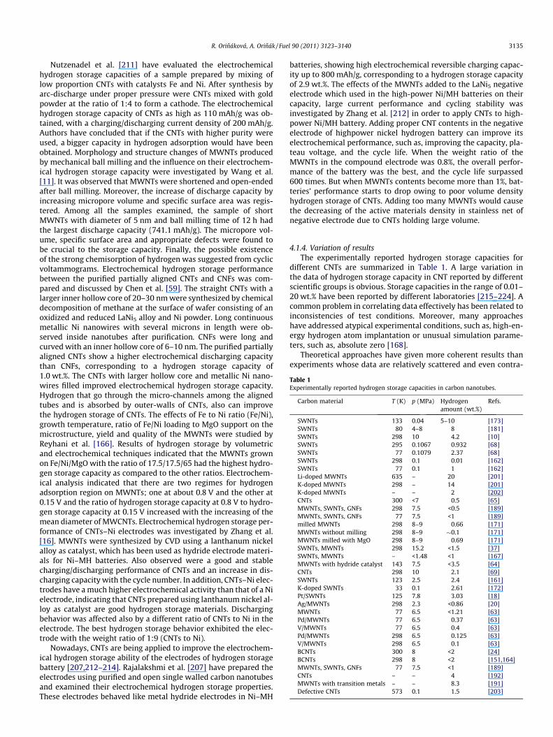
Table 1Experimentally reported hydrogen storage capacities in carbon nanotubes.
Carbon material T (K) p (MPa) Hydrogenamount (wt.%)
Refs.
SWNTs 133 0.04 5–10 [173]SWNTs 80 4–8 8 [181]SWNTs 298 10 4.2 [10]SWNTs 295 0.1067 0.932 [68]SWNTs 77 0.1079 2.37 [68]SWNTs 298 0.1 0.01 [162]SWNTs 77 0.1 1 [162]Li-doped MWNTs 635 – 20 [201]K-doped MWNTs 298 – 14 [201]K-doped MWNTs – – 2 [202]CNTs 300 <7 0.5 [65]MWNTs, SWNTs, GNFs 298 7.5 <0.5 [189]MWNTs, SWNTs, GNFs 77 7.5 <1 [189]milled MWNTs 298 8–9 0.66 [171]MWNTs without milling 298 8–9 �0.1 [171]MWNTs milled with MgO 298 8–9 0.69 [171]SWNTs, MWNTs 298 15.2 <1.5 [37]SWNTs, MWNTs – <1.48 <1 [167]MWNTs with hydride catalyst 143 7.5 <3.5 [64]CNTs 298 10 2.1 [69]SWNTs 123 2.5 2.4 [161]K-doped SWNTs 33 0.1 2.61 [172]Pt/SWNTs 125 7.8 3.03 [18]Ag/MWNTs 298 2.3 <0.86 [20]MWNTs 77 6.5 <1.21 [63]Pd/MWNTs 77 6.5 0.37 [63]V/MWNTs 77 6.5 0.4 [63]Pd/MWNTs 298 6.5 0.125 [63]V/MWNTs 298 6.5 0.1 [63]BCNTs 300 8 <2 [24]BCNTs 298 8 <2 [151,164]MWNTs, SWNTs, GNFs 77 7.5 <1 [189]CNTs – – 4 [192]MWNTs with transition metals – – 8.3 [191]Defective CNTs 573 0.1 1.5 [203]
R. Orináková, A. Orinák / Fuel 90 (2011) 3123–3140 3135
Nutzenadel et al. [211] have evaluated the electrochemicalhydrogen storage capacities of a sample prepared by mixing oflow proportion CNTs with catalysts Fe and Ni. After synthesis byarc-discharge under proper pressure were CNTs mixed with goldpowder at the ratio of 1:4 to form a cathode. The electrochemicalhydrogen storage capacity of CNTs as high as 110 mAh/g was ob-tained, with a charging/discharging current density of 200 mAh/g.Authors have concluded that if the CNTs with higher purity wereused, a bigger capacity in hydrogen adsorption would have beenobtained. Morphology and structure changes of MWNTs producedby mechanical ball milling and the influence on their electrochem-ical hydrogen storage capacity were investigated by Wang et al.[11]. It was observed that MWNTs were shortened and open-endedafter ball milling. Moreover, the increase of discharge capacity byincreasing micropore volume and specific surface area was regis-tered. Among all the samples examined, the sample of shortMWNTs with diameter of 5 nm and ball milling time of 12 h hadthe largest discharge capacity (741.1 mAh/g). The micropore vol-ume, specific surface area and appropriate defects were found tobe crucial to the storage capacity. Finally, the possible existenceof the strong chemisorption of hydrogen was suggested from cyclicvoltammograms. Electrochemical hydrogen storage performancebetween the purified partially aligned CNTs and CNFs was com-pared and discussed by Chen et al. [59]. The straight CNTs with alarger inner hollow core of 20–30 nm were synthesized by chemicaldecomposition of methane at the surface of wafer consisting of anoxidized and reduced LaNi5 alloy and Ni powder. Long continuousmetallic Ni nanowires with several microns in length were ob-served inside nanotubes after purification. CNFs were long andcurved with an inner hollow core of 6–10 nm. The purified partiallyaligned CNTs show a higher electrochemical discharging capacitythan CNFs, corresponding to a hydrogen storage capacity of1.0 wt.%. The CNTs with larger hollow core and metallic Ni nano-wires filled improved electrochemical hydrogen storage capacity.Hydrogen that go through the micro-channels among the alignedtubes and is absorbed by outer-walls of CNTs, also can improvethe hydrogen storage of CNTs. The effects of Fe to Ni ratio (Fe/Ni),growth temperature, ratio of Fe/Ni loading to MgO support on themicrostructure, yield and quality of the MWNTs were studied byReyhani et al. [166]. Results of hydrogen storage by volumetricand electrochemical techniques indicated that the MWNTs grownon Fe/Ni/MgO with the ratio of 17.5/17.5/65 had the highest hydro-gen storage capacity as compared to the other ratios. Electrochem-ical analysis indicated that there are two regimes for hydrogenadsorption region on MWNTs; one at about 0.8 V and the other at0.15 V and the ratio of hydrogen storage capacity at 0.8 V to hydro-gen storage capacity at 0.15 V increased with the increasing of themean diameter of MWCNTs. Electrochemical hydrogen storage per-formance of CNTs–Ni electrodes was investigated by Zhang et al.[16]. MWNTs were synthesized by CVD using a lanthanum nickelalloy as catalyst, which has been used as hydride electrode materi-als for Ni–MH batteries. Also observed were a good and stablecharging/discharging performance of CNTs and an increase in dis-charging capacity with the cycle number. In addition, CNTs–Ni elec-trodes have a much higher electrochemical activity than that of a Nielectrode, indicating that CNTs prepared using lanthanum nickel al-loy as catalyst are good hydrogen storage materials. Dischargingbehavior was affected also by a different ratio of CNTs to Ni in theelectrode. The best hydrogen storage behavior exhibited the elec-trode with the weight ratio of 1:9 (CNTs to Ni).
Nowadays, CNTs are being applied to improve the electrochem-ical hydrogen storage ability of the electrodes of hydrogen storagebattery [207,212–214]. Rajalakshmi et al. [207] have prepared theelectrodes using purified and open single walled carbon nanotubesand examined their electrochemical hydrogen storage properties.These electrodes behaved like metal hydride electrodes in Ni–MH
batteries, showing high electrochemical reversible charging capac-ity up to 800 mAh/g, corresponding to a hydrogen storage capacityof 2.9 wt.%. The effects of the MWNTs added to the LaNi5 negativeelectrode which used in the high-power Ni/MH batteries on theircapacity, large current performance and cycling stability wasinvestigated by Zhang et al. [212] in order to apply CNTs to high-power Ni/MH battery. Adding proper CNT contents in the negativeelectrode of highpower nickel hydrogen battery can improve itselectrochemical performance, such as, improving the capacity, pla-teau voltage, and the cycle life. When the weight ratio of theMWNTs in the compound electrode was 0.8%, the overall perfor-mance of the battery was the best, and the cycle life surpassed600 times. But when MWNTs contents become more than 1%, bat-teries’ performance starts to drop owing to poor volume densityhydrogen storage of CNTs. Adding too many MWNTs would causethe decreasing of the active materials density in stainless net ofnegative electrode due to CNTs holding large volume.
4.1.4. Variation of resultsThe experimentally reported hydrogen storage capacities for
different CNTs are summarized in Table 1. A large variation inthe data of hydrogen storage capacity in CNT reported by differentscientific groups is obvious. Storage capacities in the range of 0.01–20 wt.% have been reported by different laboratories [215–224]. Acommon problem in correlating data effectively has been related toinconsistencies of test conditions. Moreover, many approacheshave addressed atypical experimental conditions, such as, high-en-ergy hydrogen atom implantation or unusual simulation parame-ters, such as, absolute zero [168].
Theoretical approaches have given more coherent results thanexperiments whose data are relatively scattered and even contra-

3136 R. Orináková, A. Orinák / Fuel 90 (2011) 3123–3140
dictory. The nanotubes considered in molecular simulations areopen tubes, well structured, without amorphous carbon and impu-rities, having well determined and chosen diameters and geomet-rical location in the bundles. Despite the promising characteristicsof SWNTs for hydrogen physisorption (cylindrical shape, size notlarger than a few molecular diameters), theoretical storage resultspredicted values quite far from the practical applicability target of6.5 wt.% at ambient temperature and pressure. However, someothers give maximum storage capacities around 5–14 wt.%[37,162]. This controversy may be related to the interaction poten-tial models used to describe the gas–solid interaction [4]. Essen-tially, all the theoretical calculations address one or the otheraspects of the problem Moreover, the calculations favor adsorptionin between the tubes rather than inside the tubes [149].
Experimental approach is also difficult due to some differentreasons. Discrepancies concerning hydrogen storage capacity ofCNTs are mainly attributed to: (a) Different experimental condi-tions, such as, hydrogen pressure and temperature. (b) Differentmethods of CNTs synthesis resulting in different specific surfaceareas. (c) Different processing histories and pretreatment proce-dures of CNTs prior to adsorption (heating, vacuum). (d) Differentconfigurations of CNTs, such as, tube diameters, tube lengths, bun-dle size, the longitudinal shape and orientation and inter tubespacing, which allow hydrogen either to move into the tube or tobe constrained in the interstitial pores. Furthermore, CNTs openedin the edge are able to adsorb hydrogen on both the inside and out-side walls, whereas closed CNTs do not. (e) Different purificationmethods of CNTs. (f) Different activation by the presence of varyingamounts and types of impurities within the samples (i.e., metalcatalysts, amorphous carbon) [4,162,167,168]. The nanotube sam-ples used, in experimental investigations are not of high purity,containing amorphous carbon and several impurities (generallycatalytic residues resulting from their synthesis). Moreover,nanotubes were often only available in small quantities, whichare required for adsorption measurement methods carried out onvery sensitive devices inevitably less accurate than conventionalapparatuses [37]. Small calibration errors in sorption techniquesmay largely influence the interpretation of the final results [162].The contributing factors to such errors include sample degassingprocedures, hydrogen compressibility, gas purity, and differencesin helium and hydrogen leak rates. The accuracy in the determina-tion of the quantity of hydrogen absorbed had an important influ-ence on the obtained hydrogen storage capacity data as well[59,189]. Virtually every research group studies a different system.Therefore, it is very difficult to compare published results and drawconclusions on the role of CNT structures in hydrogen storageapplications.
CNTs as a hydrogen storage medium have attracted consider-able research interest following promising reports during theyears. A large number of papers reporting theoretical and experi-mental hydrogen storage data in carbon nanotubes have been pub-lished. Essentially, all the theoretical calculations and experimentalmeasurements so far reported in literature address one or theother aspects of the problem as follows. It is difficult to separateout the impacts of different parameters from the results. Unfortu-nately, the reproducibility of most of the reported data is quite low.The discrepancies in the storage capacity claimed by different lab-oratories are so large that it is difficult to understand the presentedresults correctly and to conclude whether carbon nanostructuresare really an effective medium for hydrogen storage.
5. Conclusions
In this report, the major developments in both the hydrogenpreparation and hydrogen storage application of the carbon nano-
tubes are reviewed with focus on the advantages and limitations ofdifferent processes. The main challenges and developing trends inthis subject are considered. This review aims to provide guidanceand to stimulate innovative thoughts on the utilization of CNTsin connection with hydrogen.
Application of CNTs as the catalyst support in hydrogen produc-tion appears to be effective and attractive owing to their specialstructural morphology and characteristics. The surface of CNTs isusually modified to create the functional groups for specific needs.Catalysts for hydrogen production supported on CNTs have beenproduced by impregnation, precipitation, chemical reduction andhydrothermal method.
Non-oxidative, catalytic decomposition of hydrocarbons is analternative, simple and a fully green chemical process to producesimultaneously both pure hydrogen free of carbon oxides and car-bon nanotubes. This approach could be financially attractive andmay have important technological application.
Because hydrogen storage represents one of the essential chal-lenges in developing a clean-burning hydrogen economy, heavy ef-fort has been directed on optimizing the current state ofproduction as well storage technologies. Nanostructured carbonmaterials exhibit commercial advantages over other storage meth-ods. As well, they assign to flexibilities relating to their design andthe option to employ physical and/or combined physicochemicalstorage strategies. In combining physisorption and chemisorptionmodes, composite storage materials comprising metal dopantsand carbonaceous supports have shown a propensity to displaythe advantages of both.
Most of the results testified that the storage capacity of SWNTsand MWNTs for hydrogen is lower than 1 wt.% at ambient temper-ature, but the capacity could be raised considerably to between 4and 8 wt.% when decreasing the temperature of adsorption ormodifying the CNTs. The hydrogen storage property of CNTs canbe enhanced by purification and functionalization, preparing car-bon materials in different geometrical forms, dense alignment ofnanotubes, mechanicall ball milling, creating of defects, dopingor embedding the transition metal and metal oxide particles andby introducing the heteroatoms.
Carbon nanotubes technology represents a new direction for so-lid hydrogen storage especially if these materials can be altered tostore large amounts of hydrogen at room temperature.
Acknowledgement
The authors wish to acknowledge the financial support from theGrant Agency of Ministry of Education of the Slovak Republic(Grants Nos. 1/0211/12 and 1/0134/10).
References
[1] Li W, Wang H, Ren Z, Wang G, Bai J. Co-production of hydrogen and multi-wall carbon nanotubes from ethanol decomposition over Fe/Al2O3 catalysts.Appl Catal B Environ 2008;84:433–9.
[2] Eswaramoorthi I, Sundaramurthy V, Dalai AK. Partial oxidation of methanolfor hydrogen production over carbon, nanotubes supported Cu–Zn catalysts.Appl Catal A: Gen 2006;313:22–34.
[3] Gayathri V, Devi NR, Geetha R. Hydrogen storage in coiled carbon nanotubes.Int J Hydrogen Energy 2010;35:1313–20.
[4] Ioannatos GE, Verykios XE. H2 storage on single- and multi-walled carbonnanotubes. Int J Hydrogen Energy 2010;35:622–8.
[5] Jamal Y, Wyszynski JL. On-board generation of hydrogen-rich gaseous fuels –a review. Int J Hydrogen Energy 1994;19:557–72.
[6] Pettersson L, Sjostrom K. Onboard hydrogen generation by methanoldecomposition for the cold start of neat methanol engines. Int J HydrogenEnergy 1991;16:671–6.
[7] Orinakova R, Filkusova M. Hydrogen evolution on microstructuredpolypyrrole films modified with nickel. Synth Met 2010;160:927–31.
[8] Aydin R, Koleli F. Hydrogen evolution on conducting polymer electrodes inacidic media. Prog Org Coating 2006;56:76–80.

R. Orináková, A. Orinák / Fuel 90 (2011) 3123–3140 3137
[9] Navarro-Flores E, Omanovic S. Hydrogen production by electrochemicaldecomposition of formic acid via solid polymer electrolyte. J Mol Catal A:Chem 2005;242:182–94.
[10] Jukic A, Metikos-Hukovic M. The hydrogen evolution reaction on pure andpolypyrrole-coated GdNi4Al electrodes. Electrochim Acta 2003;48:3929–37.
[11] Wang Y, Deng W, Liu X, Wang X. Electrochemical hydrogen storage propertiesof ball-milled multi-wall carbon nanotubes. Int J Hydrogen Energy2009;34:1437–43.
[12] Savva PG, Olympiou GG, Costa CN, Ryzhkov VA, Efstathiou AM. Hydrogenproduction by ethylene decomposition over Ni supported on novel carbonnanotubes and nanofibers. Catal Today 2005;102–103:78–84.
[13] Wang H, Takenaka S, Otsuka K. Hydrogen storage properties of modifiedfumed-Fe-dust generated from a revolving furnace at a steel industry. Int JHydrogen Energy 2006;31:1732–46.
[14] Kruger P. Electric power requirement for large-scale production of hydrogenfuel for the world vehicle fleet. Int J Hydrogen Energy 2001;26:1137–47.
[15] Wang G, Wang H, Tang Z, Li W, Bai J. Simultaneous production of hydrogenand multi-walled carbon nanotubes by ethanol decomposition over Ni/Al2O3
catalysts. Appl Catal B: Environ 2009;88:142–51.[16] Zhang H, Fu X, Chen Y, Yi S, Li S, Zhu Y, et al. The electrochemical hydrogen
storage of multi-walled carbon nanotubes synthesized by chemical vapordeposition using a lanthanum nickel hydrogen storage alloy as catalyst.Physica B 2004;352:66–72.
[17] Dodziuk H, Dolgonos G. Molecular modeling study of hydrogen storage incarbon nanotubes. Chem Phys Lett 2002;356:79–83.
[18] Reddy ALM, Ramaprabhu S. Hydrogen adsorption properties of single-walledcarbon nanotube – nanocrystalline platinum composites. Int J HydrogenEnergy 2008;33:1028–34.
[19] Cheng HM, Yang QH, Liu Ch. Hydrogen storage in carbon nanotubes. Carbon2001;39:1447–54.
[20] Rather SU, Naik MUD, Hwang SW, Kim AR, Nahm KS. Room temperaturehydrogen uptake of carbon nanotubes promoted by silver metal catalyst. JAlloys Compd 2009;475:L17–21.
[21] Amphlett JC, Creber KA, Davis JM, Mann RF, Peppley BA, Stokes DM. Hydrogenproduction by steam reforming of methanol for polymer electrolyte fuel cells.Int J Hydrogen Energy 1994;19:131–7.
[22] Reddy ALM, Ramaprabhu S. Design and fabrication of carbon nanotube-basedmicrofuel cell and fuel cell stack coupled with hydrogen storage device. Int JHydrogen Energy 2007;32:4272–8.
[23] Otsuka K, Takenaka S, Ohtsuki H. Production of pure hydrogen by cyclicdecomposition of methane and oxidative elimination of carbon nanofibers onsupported-Ni-based catalysts. Appl Catal A: Gen 2004;273:113–24.
[24] Viswanathan B, Sankaran M. Hetero-atoms as activation centers forhydrogen absorption in carbon nanotubes. Diamond Relat Mater 2009;18:429–32.
[25] Ndungu P, Nechaev A, Khotseng L, Onyegebule N, Davids W, Mohammed R,et al. Carbon nanomaterials synthesized using liquid petroleum gas: analysistoward applications in hydrogen storage and production. Int J HydrogenEnergy 2008;33:3102–6.
[26] Serrano DP, Botas JA, Guil-Lopez R. H2 production from methane pyrolysisover commercial carbon catalysts: kinetic and deactivation study. Int JHydrogen Energy 2009;34:4488–94.
[27] Darkrim FL, Malbrunot P, Tartaglia GP. Review of hydrogen storage byadsorption in carbon nanotubes. Int J Hydrogen Energy 2002;27:193–202.
[28] Popov VN. Carbon nanotubes: properties and application. Mater Sci Eng R2004;43:61–102.
[29] Hirscher M, Becher M, Haluska M, Quintel A, Skakalova V, Choi YM, et al.Hydrogen storage in carbon nanostructures. J Alloys Compd 2002;330–332:654–8.
[30] Dillon AC, Heben MJ. Hydrogen storage using carbon adsorbents: past,present and future. Appl Phys A: Mater Sci Process 2001;72:133–42.
[31] Hou PX, Liu Ch, Cheng HM. Purification of carbon nanotubes. Carbon2008;46:2003–25.
[32] Iijima S. Helical microtubules of graphitic carbon. Nature 1991;354:56–8.[33] Dai H. Carbon nanotubes: opportunities and challenges. Surf Sci
2002;500:218–41.[34] Baughman RH, Zakhidov AA, Heer WA. Carbon nanotubes – the route toward
applications. Science 2002;297:787–92.[35] Wei Y, Yin H, Cao X, Ndungu P, Yang G, Bradley JC, et al. Nanoelectrodes
fabricated from electron beam deposited carbon as potential electrochemicalneuronal probes. J Biomed Nanotechnol 2005;1:336–40.
[36] Guldi DM, Rahman GMA, Zerbetto F, Prato M. Carbon nanotubes in electrondonor–acceptor nanocomposites. Acc Chem Res 2005;38:871–8.
[37] Fan YY, Kaufmann A, Mukasyan A, Varma A. Single- and multi-wall carbonnanotubes produced using the floating catalyst method: synthesis,purification and hydrogen up-take. Carbon 2006;44:2160–70.
[38] Yang Q, Li F, Hou P, Liu Ch, Liu M, Cheng H. Evaluation of diameterdistribution of inside cavities of open CNTs by analyses of nitrogen cryo-adsorption isotherm. Chin Sci Bull 2001;46:1317–20.
[39] Peigney A, Laurent Ch, Flahaut E, Bacsa RR, Rousset A. Specific surface areaof carbon nanotubes and bundles of carbon nanotube. Carbon 2001;39:507–14.
[40] Li F, Wang Y, Wang D, Wei F. Characterization of single-wall carbonnanotubes by N2 adsorption. Carbon 2004;42:2375–83.
[41] Saito R, Fujita M, Dresselhaus G, Dresselhaus MS. Electronicstructure of chiralgraphene tubules. Appl Phys Lett 1992;60:2204–6.
[42] Sulong AB, Muhamad N, Sahari J, Ramli R, Deros BM, Park J. Electricalconductivity behaviour of chemical functionalized MWCNTs epoxynanocomposites. Eur J Sci Res 2009;29:13–21.
[43] Kang SJ, Kocabas C, Kim HS, Cao O, Meitl MA, Khang DY, et al. Printedmultilayer superstructures of aligned singlewalled carbon nanotubes forelectronic applications. Nano Lett 2007;7:3343–8.
[44] Williams KA, Eklund PC. Monte Carlo simulations of H2 physisorpotion infinite-diameter carbon nanotubes ropes. Chem Phys Lett 2000;320:352–8.
[45] He XJ, Du JH, Ying Z, Cheng HM. Positive temperature coefficient effect inmultiwalled carbon nanotube/high density polyethylene composites. ApplPhys Lett 2005;86:062112.
[46] Nguyen CV, Ye Q, Meyyappan M. Carbon nanotube tips for scanning probemicroscopy: fabrication and high aspect ratio nanometrology. Meas SciTechnol 2005;16:2138–46.
[47] Liu C, Tong Y, Cheng HM, Golberg D, Bando Y. Field emission properties ofmacroscopic single-walled carbon nanotube strands. Appl Phys Lett2005;86:223114.
[48] Martin CR, Kohli P. The emerging field of nanotube biotechnology. Nat RevDrug Discovery 2003;2:29–37.
[49] Nguyen CV, Chao KJ, Stevens RMD, Delzeit L, Cassell A, Han J, et al. Carbonnanotube tip probes: stability and lateral resolution in scanning probemicroscopy and application to surface science in semiconductors.Nanotechnology 2001;12:363.
[50] Darkrim FL, Levesque D. High adsorptive property of opened carbonnanotubes at 77 K. J Phys Chem B 2000;104:6773–6.
[51] Biro LP, Horvath ZE, Szalmas L, Kertesz K, Weber F, Juhasz G, et al. Continuouscarbon nanotube production in underwater AC electric arc. Chem Phys Lett2003;372:399–402.
[52] Arepalli S. Laser ablation process for single-walled carbon nanotubeproduction. J Nanosci Nanotechnol 2004;4:317–25.
[53] Collins PG, Avouris P. Nanotubes for electronic. Sci Am 2000;283:62–9.[54] Maruyama S, Kojima R, Miyauchi Y, Chiashi S, Kohno M. Low-temperature
synthesis of high-purity single-walled carbon nanotubes from alcohol. ChemPhys Lett 2002;360:229–34.
[55] Colomer JF, Stephan C, Lefrant S, Van Tendeloo G, Willems I, Konya Z, et al.Large-scale synthesis of single-wall carbon nanotubes by catalytic chemicalvapour deposition (CCVD) method. Chem Phys Lett 2000;317:83–9.
[56] Perez-Cabero M, Rodriguez-Ramos I, Guerrero-Ruiz A. Characterization ofcarbon nanotubes and carbon nanofibers prepared by catalyticdecomposition of acetylene in a fluidized bed reactor. J Catal2003;215:305–16.
[57] Dai H. Carbon nanotubes: synthesis, integration, and properties. Acc ChemRes 2002;35:1035–44.
[58] Ding RG, Lu GQ, Yan ZF, Wilson MA. Recent advances in the preparation andutilization of carbon nanotubes for hydrogen storage. J Nanosci Nanotechnol20001;1:7–29.
[59] Chen X, Zhang Y, Gao XP, Pan GL, Jiang XY, Qu JQ, et al. Electrochemicalhydrogen storage of carbon nanotubes and carbon nanofibers. Int J HydrogenEnergy 2004;29:743–8.
[60] Qian W, Liu T, Wang Z, Wei F, Li Z, Luo G, et al. Production of hydrogen andcarbon nanotubes from methane decomposition in a two-stage fluidized bedreactor. Appl Catal A: Gen 2004;260:223–8.
[61] Zein SHS, Mohamed AR. Mn/Ni/TiO2 catalyst for the production of hydrogenand carbon nanotubes from methane decomposition. Energy Fuels2004;18:1336–45.
[62] Laosiripojana N, Assabumrungrat S. Catalytic steam reforming of ethanol overhigh surface area CeO2: the role of CeO2 as an internal pre-reforming catalyst.Appl Catal B: Environ 2006;66:29–39.
[63] Suttisawat Y, Rangsunvigit P, Kitiyanan B, Williams M, Ndungu P, LototskyyMV, et al. Investigation of hydrogen storage capacity of multi-walledcarbon nanotubes deposited with Pd or V. Int J Hydrogen Energy2009;34:6669–75.
[64] Rakhi RB, Sethupathi K, Ramaprabhu S. Synthesis and hydrogen storageproperties of carbon nanotubes. Int J Hydrogen Energy 2008;33:381–6.
[65] Garcia-Garcia FR, Perez-Cabero M, Nevskaia DM, Rodriguez-Ramos I,Guerrero-Ruiz A. Improving the synthesis of high purity carbon nanotubesin a catalytic fluidized bed reactor and their comparative test for hydrogenadsorption capacity. Catal Today 2008;133–135:815–21.
[66] Kuo TF, Chi CC, Lin IN. Synthesis of carbon nanotubes by laser ablation ofgraphites at room temperature. Jpn J Appl Phys 2001;40:7147–50.
[67] Aoyagi M. Fabrication of carbon nanotubes and byproducts by arc dischargein DC motors. IEEJ Trans Electr Electron Eng 2008;3:664–8.
[68] Nishimiya N, Ishigaki K, Takikawa H, Ikeda M, Hibi Y, Sakakibara T, et al.Hydrogen sorption by single-walled carbon nanotubes prepared by a torcharc method. J Alloys Compd 2002;339:275–82.
[69] Shaijumon MM, Ramaprabhu S. Studies of yield and nature of carbonnanostructures synthesized by pyrolysis of ferrocene and hydrogenadsorption studies of carbon nanotubes. Int J Hydrogen Energy2005;30:311–7.
[70] Dillon AC, Gennett T, Jones KM, Alleman JL, Parilla PA, Heben MJ. A simple andcomplete purification of single-walled carbon nanotube materials. Adv Mater1999;11:1354–8.
[71] Ando Y, Zhao X, Shimoyama H. Structure analysis of purified multiwalledcarbon nanotubes. Carbon 2001;39:569–74.
[72] Pillai SK, Ray SS, Moodley M. Purification of multi-walled carbon nanotubes. JNanosci Nanotechnol 2008;8:6187–207.

3138 R. Orináková, A. Orinák / Fuel 90 (2011) 3123–3140
[73] Marban G, Valdes-Solis T. Towards the hydrogen economy? Int J HydrogenEnergy 2007;32:1625–37.
[74] Faungnawakij K, Tanaka Y, Shimoda N, Fukunaga T, Kikuchi R, Eguchi K.Hydrogen production from dimethyl ether steam reforming over compositecatalysts of copper ferrite spinel and alumina. Appl Catal B: Environ2007;74:144–51.
[75] Sheng PY, Yee A, Bowmaker GA, Idriss H. H2 production from ethanol overRh–Pt/CeO2 catalysts: the role of rh for the efficient dissociation of thecarbon–carbon bond. J Catal 2002;208:393–403.
[76] Davidian T, Guilhaume N, Iojoiu E, Provendier H, Mirodatos C. Hydrogenproduction from crude pyrolysis oil by a sequential catalytic process. ApplCatal B: Environ 2007;73:116–27.
[77] Haryanto A, Fernando S, Murali N, Adhikari S. Current status of hydrogenproduction techniques by steam reforming of ethanol: a review. Energy Fuels2005;19:2098–106.
[78] Mo X, Wang J, Wang Z, Wang S. The application of polypyrrole fibrils inhydrogen evolution reaction. Synth Met 2004;142:217–21.
[79] Zabinski PR, Kowalik R, Piwowarczyk M. Cobalt–tungsten alloys forhydrogen evolution in hot 8 M NaOH. Arch Metall Mater 2007;52:627–34.
[80] Ikuma Y, Bessho H. Effect of Pt concentration on the production ofhydrogen by TiO2 photocatalyst. Int J Hydrogen Energy 2007;32:2689–92.
[81] Chaffin JH, Bobbio SM, Inyang HI, Kaanagbara L. Hydrogen production byplasma electrolysis. J Energy Eng 2006;132:104–8.
[82] Merida W, Maness PCh, Brown RC, Levind DB. Enhanced hydrogen productionfrom indirectly heated, gasified biomass, and removal of carbon gasemissions using a novel biological gas reformer. Int J Hydrogen Energy2004;29:283–90.
[83] Ni M, Leung DYC, Leung MKH, Sumathy K. An overview of hydrogenproduction from biomass. Fuel Process Technol 2006;87:461–72.
[84] Westermann P, Jorgensen B, Lange L, Ahring B, Christensen CH. Maximizingrenewable hydrogen production from biomass in a bio/catalytic refinery. Int JHydrogen Energy 2007;32:4135–41.
[85] Rass-Hansen J, Johansson R, Moller M, Christensen CH. Steam reforming oftechnical bioethanol for hydrogen production. Int J Hydrogen Energy2008;33:4547–54.
[86] Marino F, Boveri M, Baronetti G, Laborde M. Hydrogen production from steamreforming of bioethanol using Cu/Ni/K/-Al2O3 catalysts. Effect of Ni. Int JHydrogen Energy 2001;26:665–8.
[87] Ni M, Dennis YC, Leung MKH. A review on reforming bioethanol for hydrogenproduction. Int J Hydrogen Energy 2007;32:3238–47.
[88] Duprez D, Miloudi A, Delahay G, Maurel R. Selective steam reforming ofaromatic hydrocarbons. IV. Steam conversion and hydroconversion ofselected monoalkyl- and dialkyl-benzenes on Rh catalysts. J Catal1984;90:292–303.
[89] Sun GB, Hidajat K, Wu XS, Kawi S. A crucial role of surface oxygen mobility onnanocrystalline Y2O3 support for oxidative steam reforming of ethanol tohydrogen over Ni/Y2O3 catalysts. Appl Catal B: Environ 2008;81:303–12.
[90] Birot A, Epron F, Descorme C, Duprez D. Ethanol steam reforming over Rh/CexZr1�xO2 catalysts: impact of the CO–CO2–CH4 interconversion reactions onthe H2 production. Appl Catal B: Environ 2008;79:17–25.
[91] Lin SSY, Kim DH, Ha SY. Hydrogen production from ethanol steam reformingover supported cobalt catalysts. Catal Lett 2008;122:295–301.
[92] Montini T, Rogatis LD, Gombac V, Fornasiero P, Graziani M.Rh(1%)@CexZr1�xO2–Al2O3 nanocomposites: active and stable catalysts forethanol steam reforming. Appl Catal B: Environ 2007;71:125–34.
[93] Yang YZ, Chang CH, Idriss H. Photo-catalytic production of hydrogen formethanol over M/TiO2 catalysts (M = Pd, Pt or Rh). Appl Catal B: Environ2006;67:217–22.
[94] Mattos LV, Noronha FB. Hydrogen production for fuel cell applications byethanol partial oxidation on Pt/CeO2 catalysts: the effect of the reactionconditions and reaction mechanism. J Catal 2005;233:453–63.
[95] Laosiripojana N, Sutthisripok W, Assabumrungrat S. Reactivity of high surfacearea CeO2 synthesized by surfactant-assisted method to ethanoldecomposition with and without steam. Chem Eng J 2007;127:31–8.
[96] Barthos R, Szechenyi A, Koos A, Solymosi F. The decomposition of ethanolover Mo2C/carbon catalysts. Appl Catal A: Gen 2007;327:95–105.
[97] Resini C, Cavallaro S, Frusteri F, Freni S, Busca G. Initial steps in the productionof H2 from ethanol: a FT-IR study of adsorbed species on Ni/MgO catalystsurface. React Kinet Catal Lett 2007;90:117–26.
[98] Yuan L, Ye T, Gong F, Guo Q, Youshifumi T, Mitsuo Y, et al. Hydrogenproduction from the current-enhanced reforming and decomposition ofethanol. Energy Fuels 2009;23:3103–12.
[99] Liguras DK, Kondarides DI, Verykios XE. Production of hydrogen for fuel cellsby steam reforming of ethanol over supported noble metal catalysts. ApplCatal B: Environ 2003;43:345–54.
[100] Goula MA, Kontou SK, Tsiakaras PE. Hydrogen production by ethanol steamreforming over a commercial Pd/c-Al2O3 catalyst. Appl Catal B: Environ2004;49:135–44.
[101] Simson A, Waterman E, Farrauto R, Castaldi M. Kinetic and process study forethanol reforming using a Rh/Pt washcoatedmonolith catalyst. Appl Catal B:Environ 2009;89:58–64.
[102] Silveira JL, Braga LB, Caetano de Souza AC, Antunes JS, Zanzi R. The benefits ofethanol use for hydrogen production in urban transportation. Renew SustainEnergy Rev 2009;13:2525–34.
[103] Jiang CJ, Trimm DL, Wainwright MS, Cant NW. Kinetic mechanism for thereaction between methanol and water over a Cu–ZnO–Al2O3 catalyst. ApplCatal A: Gen 1993;97:145–58.
[104] Palo DR, Dagle RA, Holladay JD. Methanol steam reforming for hydrogenproduction. Chem Rev 2007;107:3992–4021.
[105] Itoh N, Kaneko Y, Igarashi A. Efficient hydrogen production via methanolsteam reforming by preventing back-permeation of hydrogen in a palladiummembrane reactor. Ind Eng Chem Res 2002;41:4702–6.
[106] Tsoncheva T, Areva S, Dimitrov M, Paneva D, Mitov I, Linden M, et al. MCM-41silica modified with copper and iron oxides as catalysts for methanoldecomposition. J Mol Catal A: Chem 2006;246:118–27.
[107] Choia HJ, Kang M. Hydrogen production from methanol/water decompositionin a liquid photosystem using the anatase structure of Cu loaded TiO2. Int JHydrogen Energy 2007;32:3841–8.
[108] Agrell J, Hasselbo K, Jansson K, Jaras SG, Boutonnet M. Production of hydrogenby partial oxidation of methanol over Cu/ZnO catalysts prepared bymicroemulsion technique. Appl Catal A: Gen 2001;211:239–50.
[109] Kulprathipanja A, Falconer JL. Partial oxidation of methanol for hydrogenproduction using ITO/Al2O3 nanoparticle catalysts. Appl Catal A: Gen2004;261:77–86.
[110] Mo L, Zheng X, Yeh ChT. A novel CeO2/ZnO catalyst for hydrogen productionfrom the partial oxidation of methanol. Chem Phys Chem 2005;6:1470–2.
[111] Velu S, Suzuki K, Osaki T. Selective production of hydrogen by partialoxidation of methanol over catalysts derived from CuZnAl-layered doublehydroxides. Catal Lett 1999;62:159–67.
[112] Muricia-Mascaros S, Navarro RM, Gomez-Sainero L, Costantino U, NocchettiM, Fierro JLG. Oxidative methanol reforming reactions on CuZnAl catalystsderived from hydrotalcite-like precursors. J Catal 2001;198:338–47.
[113] Patel S, Pant KK. Hydrogen production by oxidative steam reforming ofmethanol using ceria promoted copper–alumina catalysts. Fuel ProcessTechnol 2007;88:825–32.
[114] Basile A, Gallucci F, Paturzo L. Hydrogen production from methanol byoxidative steam reforming carried out in a membrane reactor. Catal Today2005;104:251–9.
[115] Chang FW, SCh Lai, Roselin LS. Hydrogen production by partial oxidation ofmethanol over ZnO-promoted Au/Al2O3 catalysts. J Mol Catal A: Chem2008;282:129–35.
[116] Kinoshita CM, Turn SQ. Production of hydrogen from bio-oil using CaO as aCO2 sorbent. Int J Hydrogen Energy 2003;28:1065–71.
[117] Ogihara H, Takenaka S, Yamanaka I, Tanabe E, Genseki A, Otsuka K. Formationof highly concentrated hydrogen through methane decomposition over Pd-based alloy catalysts. J Catal 2006;238:353–60.
[118] Takenaka S, Kobayashi S, Ogihara H, Otsuka K. Ni/SiO2 catalyst effective formethane decomposition into hydrogen and carbon nanofiber. J Catal2003;217:79–87.
[119] Villacampa JI, Royo C, Romeo E, Montoya JA, Del Angel P, Monzon A. Catalyticdecomposition of methane over Ni–Al2O3 coprecipitated catalysts: reactionand regeneration studies. Appl Catal A: Gen 2003;252:363–83.
[120] Bai Z, Chen H, Li W, Li B. Hydrogen production by methane decompositionover coal char. Int J Hydrogen Energy 2006;31:899–905.
[121] Ruoppolo G, Ammendola P. Hydrogen production by catalytic methanedecomposition and catalyst regeneration by oxygen mixtures in fluidised andfixed bed reactors. Int J Nucl Hydrogen Prod Appl 2009;2:4–20.
[122] Wang Y, Shah N, Huffman GP. Simultaneous production of hydrogen andcarbon nanostructures by decomposition of propane and cyclohexane overalumina supported binary catalysts. Catal Today 2005;99:359–64.
[123] Almeida RM, Fajardo HV, Mezalira DZ, Nuernberg GB, Noda LK, Probst LFD,et al. Preparation and evaluation of porous nickel–alumina spheres ascatalyst in the production of hydrogen from decomposition of methane. J MolCatal 2006;259:328–35.
[124] Ermakova MA, Ermakov DY, Kuvshinov GG. Effective catalysts for directcracking of methane to produce hydrogen and filamentous carbon: Part I.Nickel catalysts. Appl Catal A: Gen 2000;201:61–70.
[125] Monnerat B, Kiwi-Minsker L, Renken A. Hydrogen production by catalyticcracking of methane over nickel gauze under periodic reactor operation.Chem Eng Sci 2001;56:633–9.
[126] Muradov N. Hydrogen via methane decomposition: an application fordecarbonization of fossil fuels. Int J Hydrogen Energy 2001;26:1165–75.
[127] Choudhary TV, Goodman DW. CO-free fuel processing for fuel cellapplications. Catal Today 2002;77:65–78.
[128] Snocek JW, Froment GF, Fowles M. Filamentous carbon formation andgasification: thermodynamics, driving force, nucleation, and steady-stategrowth. J Catal 1997;169:240–9.
[129] Zhang TJ, Amiridis MD. Hydrogen production via the direct cracking ofmethane over silica-supported nickel catalysts. Appl Catal A: Gen1998;167:161–72.
[130] Li YD, Chen JL, Qin YN, Chang L. Simultaneous production of hydrogen andnanocarbon from decomposition of methane on a nickel-based catalyst.Energy Fuels 2000;14:1188–94.
[131] Baratholomew CH. Mechanisms of catalyst deactivation. Appl Catal A: Gen2001;212:17–60.
[132] Kuvshinov GG, Mogilnykh YI, Kuvshinov DG. Kinetics of carbon formationfrom CH4–H2 mixtures over a nickel containing catalyst. Catal Today1998;42:357–60.
[133] Takenaka S, Tomikubo Y, Kato E, Otsuka K. Sequential production of H2 andCO over supported Ni catalysts. Fuel 2004;83:47–57.

R. Orináková, A. Orinák / Fuel 90 (2011) 3123–3140 3139
[134] Aiello R, Fiscus JE, zur Loye HC, Amiridis MD. Hydrogen production via thedirect cracking of methane over Ni/SiO2: catalyst deactivation andregeneration. Appl Catal A: Gen 2000;192:227–34.
[135] Venugopal A, Kumar SN, Ashok J, Prasad DH, Kumari VD, Prasad KBS, et al.Hydrogen production by catalytic decomposition of methane over Ni/SiO2.Int J Hydrogen Energy 2007;32:1782–8.
[136] Pinilla JL, Suelves I, Utrilla R, Galvez ME, Lazaro MJ, Moliner R. Hydrogenproduction by thermo-catalytic decomposition of methane: regeneration ofactive carbons using CO2. J Power Sources 2007;169:103–9.
[137] Dunker AM, Kumar S, Mulawa PA. Production of hydrogen by thermaldecomposition of methane in a fluidized-bed reactor-effects of catalyst,temperature, and residence time. Int J Hydrogen Energy 2006;31:473–84.
[138] Sarada Prasad J, Radhika B, Venkateswara Rao M, Himabindu V, Anjaneyulu Y.Thermo catalytic decomposition of methane on carbon catalysts: acomparative study. Icfai Univ J Environ Sci 2009;3:52–9.
[139] Ashok J, Subrahmanyam M, Venugopal A. Development of methanedecomposition catalysts for COx free hydrogen. Catal Surv Asia2008;12:229–37.
[140] Muradov N, Smith F, T-Raisi A. Catalytic activity of carbons for methanedecomposition reaction. Catal Today 2005;102–103:225–33.
[141] Huang L, Santiso EE, Nardelli MB, Gubbins KE. Catalytic role of carbons inmethane decomposition for CO- and CO2-free hydrogen generation. J ChemPhys 2008;128:214702 [7p].
[142] Moliner R, Suelves I, Lazaro MJ, Moreno O. Thermocatalytic decomposition ofmethane over activated carbons: influence of textural properties and surfacechemistry. Int J Hydrogen Energy 2005;30:293–300.
[143] Liao PH, Yang HM. Preparation of catalyst Ni–Cu/CNTs by chemical reductionwith formaldehyde for steam reforming of methanol. Catal Lett2008;121:274–82.
[144] Yang HM, Liao PH. Preparation and activity of Cu/ZnO–CNTs nano-catalyst on steam reforming of methanol. Appl Catal A: Gen 2007;317:226–33.
[145] Wang Y, Shah N, Huffman GP. Pure hydrogen production by partialdehydrogenation of cyclohexane and methylcyclohexane over nanotube-supported Pt and Pd catalysts. Energy Fuels 2004;18:1429–33.
[146] Hou T, Yuan L, Ye T, Gong L, Tu J, Yamamoto M, et al. Hydrogenproduction by low-temperature reforming of organic compounds inbio-oil over a CNT-promoting Ni catalyst. Int J Hydrogen Energy2009;34:9095–107.
[147] Wang Y, Shah N, Huggins FE, Huffman GP. Hydrogen production by catalyticdehydrogenation of tetralin and decalin over stacked cone carbon nanotube-supported Pt catalysts. Energy Fuels 2006;20:2612–5.
[148] Reshetenko TV, Avdeeva LB, Ismagilov ZR, Chuvilin AL, Ushakov A. Carboncapacious Ni–Cu–Al2O3 catalysts for high-temperature methanedecomposition. Appl Catal A: Gen 2003;247:51–63.
[149] Sankaran M, Viswanathan B. The role of heteroatoms in carbon nanotubes forhydrogen storage. Carbon 2006;44:2816–21.
[150] Panella B, Hirscher M, Roth S. Hydrogen adsorption in different carbonnanostructures. Carbon 2005;43:2209–14.
[151] Sankaran M, Viswanathan B, Srinivasa Murthy S. Boron substituted carbonnanotube – how appropriate are they for hydrogen storage? Int J HydrogenEnergy 2008;33:393–403.
[152] Chen CH, Huang CC. Enhancement of hydrogen spillover onto carbonnanotubes with defect feature. Microporous Mesoporous Mater2008;109:549–59.
[153] Zuttel A. Materials for hydrogen storage. Mater Today 2003;6:24–33.[154] Li Y, Yang RT. Hydrogen storage on platinum nanoparticles doped on
superactivated carbon. J Phys Chem C 2007;111:11086–94.[155] Eberle U, Arnold G, Helmholt RV. Hydrogen storage in metal–hydrogen
systems and their derivatives. J Power Sources 2006;154:456–60.[156] Zhou Z, Gao X, Yan J, Song D. Doping effects of B and N on hydrogen
adsorption in single-walled carbon nanotubes through density functionalcalculations. Carbon 2006;44:939–47.
[157] Grochala W, Edwards PP. Thermal decomposition of the noninterstitialhydrides for the storage and production of hydrogen. Chem Rev2004;104:1283–316.
[158] Miranda-Hernández M, Ayala J, Rincón ME. Electrochemical storage ofhydrogen in nanocarbon materials: electrochemical characterization ofcarbon black matrices. J Solid State Electrochem 2003;7:264–70.
[159] Jurewicz K, Frackowiak E, Beguin F. Electrochemical storage of hydrogen inactivated carbons. Fuel Process Technol 2002;77–78:415–21.
[160] Strobel R, Garche J, Moseley PT, Jorissen L, Wolfd G. Hydrogen storage bycarbon materials. J Power Sources 2006;159:781–801.
[161] Zhou L. Progress and problems in hydrogen storage methods. Renew SustainEnergy Rev 2005;9:395–408.
[162] Anson A, Callejas MA, Benito AM, Maser WK, Izquierdo MT, Rubio B, et al.Hydrogen adsorption studies on single wall carbon nanotubes. Carbon2004;42:1243–8.
[163] Tarasov BP, Maehlen JP, Lototsky MV, Muradyan VE, Yartys VA. Hydrogensorption properties of arc generated single-wall carbon nanotubes. J AlloysCompd 2003;356–357:510–4.
[164] Sankaran M, Viswanathan B. Hydrogen storage in boron substituted carbonnanotubes. Carbon 2007;45:1628–35.
[165] Thomas KM. Hydrogen adsorption and storage on porous materials. CatalToday 2007;120:389–98.
[166] Reyhani A, Mortazavi SZ, Moshfegh AZ, Golikand AN. A study on the effects ofFex/Niy/MgO(1�x�y) catalysts on the volumetric and electrochemical hydrogenstorage of multi-walled carbon nanotubes. Int J Hydrogen Energy2010;35:231–7.
[167] Shen K, Xu H, Jiang Y, Pietraß T. The role of carbon nanotube structure inpurification and hydrogen adsorption. Carbon 2004;42:2315–22.
[168] Yurum Y, Taralp A, Veziroglu TN. Storage of hydrogen in nanostructuredcarbon materials. Int J Hydrogen Energy 2009;34:3784–98.
[169] Benard P, Chahine R. Storage of hydrogen by physisorption on carbon andnanostructured materials. Scr Mater 2007;56:803–8.
[170] Jhi SH. A theoretical study of activated nanostructured materials forhydrogen storage. Catal Today 2007;120:383–8.
[171] Liu F, Zhang X, Cheng J, Tu J, Kong F, Huang W, et al. Preparation of shortcarbon nanotubes by mechanical ball milling and their hydrogen adsorptionbehaviour. Carbon 2003;41:2527–32.
[172] Challet S, Azais P, Pellenq RJM, Isnard O, Soubeyroux JL, Duclaux L. Hydrogenadsorption in microporous alkali-doped carbons (activated carbon and singlewall nanotubes). J Phys Chem Solids 2004;65:541–4.
[173] Dillon AC, Jones KM, Bekkedahl TA, Kiang CH, Bethune DS, Heben MJ. Storageof hydrogen in single-walled carbon nanotubes. Nature 1997;386:377–9.
[174] Vilaplana AF. Ab initio computational investigation of physisorption ofmolecular hydrogen on achiral singlewalled carbon nanotubes. J Chem Phys2005;122:214724–6.
[175] Arellano JS, Molina LM, Rubio A, Lopez MJ, Alonso JA. Interaction of molecularand atomic hydrogen with (5, 5) and (6, 6) single-wall carbon nanotubes. JChem Phys 2002;117:2281–8.
[176] Maddox MW, Sowers SL, Gubbins KE. Molecular simulation of binary mixtureadsorption in buckytubes and MCM-41. Adsorption 1996;2:23–32.
[177] Cheng J, Yuan X, Zhao L, Huang D, Zhao M, Dai L, et al. GCMC simulation ofhydrogen physisorption on carbon nanotubes and nanotube arrays. Carbon2004;42:2019–24.
[178] Cheng J, Yuan X, Fang X, Zhang L. Computer simulation of hydrogenphysisorption in a Li-doped single walled carbon nanotube array. Carbon2010;488:557–70.
[179] Zuttel A, Sudan P, Mauron PH, Kiyobayashi T, Emmenegger CH, Schlapbach L.Hydrogen storage in carbon nanostructures. Int J Hydrogen Energy2002;27:203–12.
[180] Poirier E, Chahine R, Bose TK. Hydrogen adsorption in carbon nanostrucutres.Int J Hydrogen Energy 2001;26:831–5.
[181] Ye Y, Ahn CC, Witham C, Fultz B, Liu J, Rinzler AG, et al. Hydrogen adsorptionand cohesive energy of single-walled carbon nanotubes. Appl Phys Lett1999;74:2307–9.
[182] Liu C, Fan YY, Liu M, Cong HT, Cheng HM, Dresselhaus MS. Hydrogen storagein single-walled carbon nanotubes at room temperature. Science1999;286:1127–9.
[183] Nijkamp MG, Raaymakers JEMJ, van Dillen AJ, de Jong KP. Hydrogenstorage using physisorption – materials demands. Appl Phys A 2001;72:619–23.
[184] Zhou L, Zhou Y, Sun Y. Studies on the mechanism and capacity of hydrogenuptake by physisorption-based materials. Int J Hydrogen Energy2006;31:259–64.
[185] Wu HB, Chen P, Lin J, Tan KL. Hydrogen uptake by carbon nanotubes. Int JHydrogen Energy 2000;25:261–5.
[186] Zhu HW, Cao AY, Li XS, Xu CL, Mao ZQ, Ruan DB, et al. Hydrogen adsorption inbundles of well-aligned carbon nanotubes at room temperature. Appl Surf Sci2001;178:50–5.
[187] Hou PX, Xu ST, Ying Z, Yang QH, Liu C, Cheng HM. Hydrogen adsorption/desorption behavior of multi-walled carbon nanotubes with differentdiameters. Carbon 2003;41:2471–6.
[188] Sudan P, Zuttel A, Mauron P, Emmenegger Ch, Wenger P, Schlapbach L.Physisorption of hydrogen in single-walled carbon nanotubes. Carbon2003;41:2377–83.
[189] Chen Y, Liu Q, Yan Y, Cheng X, Liu Y. Influence of sample cell physisorption onmeasurements of hydrogen storage of carbon materials using a SievertsApparatus. Carbon 2010;48:714–20.
[190] Xiu-Ying L, Chao-Yang W, Yong-Jian T, Wei-Guo S, Wei-Dong W, Jia-Jing X.Theoretical studies on hydrogen adsorption of single-walled boron-nitrideand carbon nanotubes using grand canonical Monte Carlo method. Physica B2009;404:1892–6.
[191] Yang FH, Yang RT. Ab initio molecular orbital study of adsorption of atomichydrogen on graphite: insight into hydrogen storage in carbon nanotubes.Carbon 2002;40:437–44.
[192] Bulyarskii SV, Basaev AS. Chemisorption of hydrogen by carbon nanotubes.Technol Phys 2009;54:1612–7.
[193] Volpe M, Cleri F. Chemisorption of atomic hydrogen in graphite and carbonnanotubes. Surf Sci 2003;544:24–34.
[194] Dinadayalane TC, Kaczmarek A, Łukaszewicz J, Leszczynski J. Chemisorptionof hydrogen atoms on the sidewalls of Armchair single-walled carbonnanotubes. J Phys Chem C 2007;111:7376–83.
[195] Zhou B, Guo W, Dai Y. Chemisorption of hydrogen molecule on axiallystrained (8, 0) carbon nanotube. J Phys Chem C 2008;112:18516–20.
[196] Ni M, Zeng Z. Chemisorption and diffusion of hydrogen atoms on single-walled carbon nanotubes. J Nanosci Nanotechnol 2010;10:5408–12.
[197] Muniz AR, Singh T, Maroudas D. Effects of hydrogen chemisorption on thestructure and deformation of single-walled carbon nanotubes. Appl Phys Lett2009;94:103108–10.
3140 R. Orináková, A. Orinák / Fuel 90 (2011) 3123–3140
[198] Bilic A, Gale JD. Chemisorption of molecular hydrogen on carbon nanotubes:a route to effective hydrogen storage? J Phys Chem C 2008;112:12568–75.
[199] Chan SP, Chen G, Gong XG, Liu ZF. Chemisorption of hydrogen molecules oncarbon nanotubes under high pressure. Phys Rev Lett 2001;87:205502 [4p].
[200] Zhou B, Guo W, Tang Ch. Chemisorption of hydrogen molecules on carbonnanotubes: charging effect from first-principles calculations. Nanotechnology2008;19:075707.
[201] Chen P, Wu X, Lin J, Tan KL. High H2 uptake by alkali-doped carbon nanotubesunder ambient pressure and moderate temperatures. Science1999;285:91–3.
[202] Yang RT. Hydrogen storage by alkali-doped carbon nanotubes revisited.Carbon 2000;38:623–6.
[203] Yoo E, Habe T, Nakamura J. Possibilities of atomic hydrogen storage by carbonnanotubes or graphite materials. Sci Technol Adv Mater 2005;6:615–9.
[204] Lee SM, Lee YH. Hydrogen storage in single-walled carbon nanotubes. ApplPhys Lett 2000;76:2877–9.
[205] Feng H, Wei YL, Shao C, Lai YT, Feng S, Dong Z. Study on overpotential of theelectrochemical hydrogen storage of multiwall carbon nanotubes. Int JHydrogen Energy 2007;32:1294–8.
[206] Qin X, Gao XP, Liu H, Yuan HT, Yan DY, Gong WL, et al. Electrochemicalhydrogen storage of multiwalled carbon nanotubes. Electrochem Solid StateLett 2000;3:532–5.
[207] Rajalakshmi N, Dhathathreyan KS, Govindaraj A, Satishkumar BC.Electrochemical investigation of single-walled carbon nanotubes forhydrogen storage. Electrochim Acta 2000;45:4511–5.
[208] Dai GP, Liu M, Chen DM, Hou PX, Tong Y, Cheng HM. Electrochemcial charge–discharge capacity of purified single-walled carbon nanotube. ElectrochemSolid State Lett 2002;5:E13–5.
[209] Zhang HY, Fu XJ, Yin JF, Zhou C, Chen YM, Li MH, et al. The effect of MWNTswith different diameters on the electrochemical hydrogen storage capability.Phys Lett A 2005;339:370–7.
[210] Volpe M, Cleri F. Role of surface chemistry in hydrogen adsorption in single-wall carbon nanotubes. Chem Phys Lett 2003;371:476–82.
[211] Nutzenadel C, Zuttel A, Chartouni D, Schlapbach L. Electrochemicalstorage of hydrogen in nanotube materials. Electrochem Solid State Lett1999;2:30–2.
[212] Zhang H, Chen Y, Zhu Q, Zhang G, Chen Y. The effects of carbon nanotubes onthe hydrogen storage performance of the alloy electrode for high-power Ni–MH batteries. Int J Hydrogen Energy 2008;33:6704–9.
[213] Zhang H, Fu X, Chen Y, Yi S, Li S, Zhu Y, et al. The electrochemical hydrogenstorage of multi-walled carbon nanotubes synthesized by chemical vapordeposition using a lanthanum nickel hydrogen storage alloy as catalyst. PhysB: Condens Matter 2004;352:66–72.
[214] Li S, Pan G, Zhang Y, Gao X, Qu J, Yan J, et al. Electrochemical properties ofMmNi3.6Co0.7Al0.3Mn0.4 alloy containing carbon nanotubes. J Alloys Compd2003;353:295–300.
[215] Yildirim T, Iniguez J, Ciraci S. Molecular and dissociative adsorption ofmultiple hydrogens on transition metal decorated C60. Phys Rev B2005;72:153403 [4p].
[216] Zhang C, Lu X, Gu A. How to accurately determine the uptake of hydrogen incarbonaceous materials. Int J Hydrogen Energy 2004;29:1271–6.
[217] Yang FH, Lachawiec AJ, Yang RT. Adsorption of spillover hydrogen atoms onsingle-wall carbon nanotubes. J Phys Chem B 2006;110:6236–44.
[218] Kiyobayashi T, Takeshita HT, Tanaka H, Takeichi N, Zuttel A, Schlapbach L.Hydrogen adsorption in carbonaceous materials: how to determine thestorage capacity accurately. J Alloys Compd 2002;330–332:666–9.
[219] Tibbetts GG, Meisner GP, Olk CH. Hydrogen storage capacity of carbonnanotubes, filaments, and vapor-grown fibers. Carbon 2001;39:2291–301.
[220] Zheng Q, Gu A, Lu X, Lin W. Temperature-dependent state of hydrogenmolecules within the nanopore of multi-walled carbon nanotubes. Int JHydrogen Energy 2004;29:481–9.
[221] Anson A, Lafuente E, Urriolabeitia E, Navarro R, Benito AM, Maser WK, et al.Hydrogen capacity of palladium-loaded carbon materials. J Phys Chem B2006;110:6643–8.
[222] Gundiah G, Govindaraj A, Rajalakshmi N, Dhathathreyan KS, Rao CNR.Hydrogen storage in carbon nanotubes and related materials. J Mater Chem2003;13:209–13.
[223] Zhao Y, Kim YH, Dillon AC, Heben MJ, Zhang SB. Hydrogen storage in novelorganometallic buckyballs. Phys Rev Lett 2005;94:155504–7.
[224] Blackman JM, Patrick JW, Snape CE. An accurate volumetric differentialpressure method for the determination of hydrogen storage capacity at highpressures in carbon materials. Carbon 2006;44:918–27.
Copyright © 2022 FDOKUMEN