
Hydrogen storage systems from waste Mg alloys
10
Hydrogen storage systems from waste Mg alloys C. Pistidda a, * , N. Bergemann a , J. Wurr a , A. Rzeszutek a , K.T. Møller b , B.R.S. Hansen b , S. Garroni c , C. Horstmann a , C. Milanese d , A. Girella d , O. Metz a , K. Taube a , T.R. Jensen b , D. Thomas e , H.P. Liermann f , T. Klassen a , M. Dornheim a a Institute of Materials Research, Materials Technology, Helmholtz-Zentrum Geesthacht GmbH, Max-Planck-Strasse 1, D-21502 Geesthacht, Schleswig- Holstein, Germany b Center for Materials Crystallography, iNANO, and Department of Chemistry, Aarhus University, Langelandsgade 140, 8000 Aarhus, Denmark c Dipartimento di Chimica e Farmacia, Universit a di Sassari and INSTM, Via Vienna 2, I-07100 Sassari, Italy d Pavia H 2 Lab, C.S.G.I. & Dipartimento di Chimica, Sezione di Chimica Fisica, Universit a di Pavia, Viale Taramelli 16, Pavia I-27100, Italy e MAX IV Laboratory, Lund University, R€ omers v€ ag 1, 22363 Lund, Sweden f Photon Science, Deutsches Elektronen Synchrontron DESY, Hamburg, Germany highlights Mg based wastes can be used for H 2 storage purposes. The hydrogenated alloys show a H 2 capacity of ~6 wt.%. The conversion process is possible and easily achievable. article info Article history: Received 11 April 2014 Received in revised form 11 July 2014 Accepted 21 July 2014 Available online 30 July 2014 Keywords: Hydrogen storage Magnesium waste Hydrogen storage Magnesium waste abstract The production cost of materials for hydrogen storage is one of the major issues to be addressed in order to consider them suitable for large scale applications. In the last decades several authors reported on the hydrogen sorption properties of Mg and Mg-based systems. In this work magnesium industrial wastes of AZ91 alloy and Mg-10 wt.% Gd alloy are used for the production of hydrogen storage materials. The hydrogen sorption properties of the alloys were investigated by means of volumetric technique, in situ synchrotron radiation powder X-ray diffraction (SR-PXD) and calorimetric methods. The measured reversible hydrogen storage capacity for the alloys AZ91 and Mg-10 wt.% Gd are 4.2 and 5.8 wt.%, respectively. For the Mg-10 wt.% Gd alloy, the hydrogenated product was also successfully used as starting reactant for the synthesis of Mg(NH 2 ) 2 and as MgH 2 substitute in the Reactive Hydride Com- posite (RHC) 2LiBH 4 þ MgH 2 . The results of this work demonstrate the concrete possibility to use Mg alloy wastes for hydrogen storage purposes. © 2014 Elsevier B.V. All rights reserved. 1. Introduction Magnesium based alloys find applications in the construction of several products used in our daily life (e.g. automotive application and machinery components). With the advent of light weight/low fuel consumption cars, the overall market for magnesium alloys is destined to grow increasingly. During the manufacture, part of the material is lost as a production waste (e.g. defective parts and shavings). The recycling of the magnesium based wastes is an important issue to be addressed in order to exploit these materials more efficiently. While the industry today effectively recycles the clean process scrap in a closed loop, the challenge is to find a so- lution to close the loop for the lower grade scrap such as dross, shavings and chips [1]. An interesting possibility is to employ such a waste for producing materials for hydrogen storage. In particular magnesium hydride has the highest energy density of most reversible hydrides applicable for hydrogen storage (9 MJ kg 1 Mg) [2]. This material combines a high hydrogen storage capacity of 7.7 wt% with good reversibility [3e11] . The production costs of materials for hydrogen storage are one of the major barriers to be overcome in order to consider these materials suitable for a large scale application. The utilization of * Corresponding author. E-mail addresses: [email protected], [email protected] (C. Pistidda). Contents lists available at ScienceDirect Journal of Power Sources journal homepage: www.elsevier.com/locate/jpowsour http://dx.doi.org/10.1016/j.jpowsour.2014.07.129 0378-7753/© 2014 Elsevier B.V. All rights reserved. Journal of Power Sources 270 (2014) 554e563
-
Upload
independent -
Category
Documents
-
view
0 -
download
0
Transcript of Hydrogen storage systems from waste Mg alloys

lable at ScienceDirect
Journal of Power Sources 270 (2014) 554e563
Contents lists avai
Journal of Power Sources
journal homepage: www.elsevier .com/locate/ jpowsour
Hydrogen storage systems from waste Mg alloys
C. Pistidda a, *, N. Bergemann a, J. Wurr a, A. Rzeszutek a, K.T. Møller b, B.R.S. Hansen b,S. Garroni c, C. Horstmann a, C. Milanese d, A. Girella d, O. Metz a, K. Taube a, T.R. Jensen b,D. Thomas e, H.P. Liermann f, T. Klassen a, M. Dornheim a
a Institute of Materials Research, Materials Technology, Helmholtz-Zentrum Geesthacht GmbH, Max-Planck-Strasse 1, D-21502 Geesthacht, Schleswig-Holstein, Germanyb Center for Materials Crystallography, iNANO, and Department of Chemistry, Aarhus University, Langelandsgade 140, 8000 Aarhus, Denmarkc Dipartimento di Chimica e Farmacia, Universit�a di Sassari and INSTM, Via Vienna 2, I-07100 Sassari, Italyd Pavia H2 Lab, C.S.G.I. & Dipartimento di Chimica, Sezione di Chimica Fisica, Universit�a di Pavia, Viale Taramelli 16, Pavia I-27100, Italye MAX IV Laboratory, Lund University, R€omers v€ag 1, 22363 Lund, Swedenf Photon Science, Deutsches Elektronen Synchrontron DESY, Hamburg, Germany
h i g h l i g h t s
� Mg based wastes can be used for H2 storage purposes.� The hydrogenated alloys show a H2 capacity of ~6 wt.%.� The conversion process is possible and easily achievable.
a r t i c l e i n f o
Article history:Received 11 April 2014Received in revised form11 July 2014Accepted 21 July 2014Available online 30 July 2014
Keywords:Hydrogen storageMagnesium wasteHydrogen storageMagnesium waste
* Corresponding author.E-mail addresses: [email protected],
(C. Pistidda).
http://dx.doi.org/10.1016/j.jpowsour.2014.07.1290378-7753/© 2014 Elsevier B.V. All rights reserved.
a b s t r a c t
The production cost of materials for hydrogen storage is one of the major issues to be addressed in orderto consider them suitable for large scale applications. In the last decades several authors reported on thehydrogen sorption properties of Mg and Mg-based systems. In this work magnesium industrial wastes ofAZ91 alloy and Mg-10 wt.% Gd alloy are used for the production of hydrogen storage materials. Thehydrogen sorption properties of the alloys were investigated by means of volumetric technique, in situsynchrotron radiation powder X-ray diffraction (SR-PXD) and calorimetric methods. The measuredreversible hydrogen storage capacity for the alloys AZ91 and Mg-10 wt.% Gd are 4.2 and 5.8 wt.%,respectively. For the Mg-10 wt.% Gd alloy, the hydrogenated product was also successfully used asstarting reactant for the synthesis of Mg(NH2)2 and as MgH2 substitute in the Reactive Hydride Com-posite (RHC) 2LiBH4 þ MgH2. The results of this work demonstrate the concrete possibility to use Mgalloy wastes for hydrogen storage purposes.
© 2014 Elsevier B.V. All rights reserved.
1. Introduction
Magnesium based alloys find applications in the construction ofseveral products used in our daily life (e.g. automotive applicationand machinery components). With the advent of light weight/lowfuel consumption cars, the overall market for magnesium alloys isdestined to grow increasingly. During the manufacture, part of thematerial is lost as a production waste (e.g. defective parts andshavings). The recycling of the magnesium based wastes is an
important issue to be addressed in order to exploit these materialsmore efficiently. While the industry today effectively recycles theclean process scrap in a closed loop, the challenge is to find a so-lution to close the loop for the lower grade scrap such as dross,shavings and chips [1]. An interesting possibility is to employ such awaste for producing materials for hydrogen storage. In particularmagnesium hydride has the highest energy density of mostreversible hydrides applicable for hydrogen storage (9 MJ kg�1 Mg)[2]. This material combines a high hydrogen storage capacity of7.7 wt% with good reversibility [3e11] .
The production costs of materials for hydrogen storage are oneof the major barriers to be overcome in order to consider thesematerials suitable for a large scale application. The utilization of

Fig. 1. SEM analysis of the AZ91 alloy as received (A) and after the milling-hydrogenation process (B).
C. Pistidda et al. / Journal of Power Sources 270 (2014) 554e563 555
hydrogen storage systems obtained by recycling of waste magne-sium alloys will significantly contribute to the cost reduction of thisclass of materials. In this work, industrial magnesium based wastesof AZ91 alloy (90wt.%Mg; 8.71 wt.% Al; 0.66 wt.% Zn; 0.22wt.%Mn;0.043 wt.% Si; 0.001 wt.% Fe; 0.002 wt.% Cu and 0.001wt.% Ni) andMg-10 wt.% Gd alloy (90 wt.%Mg; 10 wt.% Gd) in shaving formwereused for the production of hydrogen storage materials. Firstly, thehydrogen sorptive properties of the alloys will be investigated.Secondly, the hydrogenated alloys will be used as starting reactantfor the synthesis of further hydrogen storage materials.
Alkali and alkaline earth metal amides, although known sincethe 19h century and extensively studied for industrials application,only recently have been subject to intensive studies as hydrogenstorage systems [12,13]. Magnesium amide, Mg(NH2)2, and lithiumamide, LiNH2, are of currently the most studied amides forhydrogen storage purposes [14e22].
In this work we present results on the synthesis of magnesiumamide via reactive ball milling starting from the hydrogenated Mg-10 wt.% Gd alloy and gaseous NH3.
One of the major issues connected with the storage of hydrogenin metal hydrides and complex metal hydrides is their high ther-modynamic stability.
In 1967 Reilly et al. discovered the possibility to change the re-action enthalpy of composites containing hydrides, by mixing themwith additives, which react reversibly with the hydride duringdesorption to form a stable compound. They showed that, at theexpense of hydrogen capacity, the reaction enthalpy of a3MgH2þMgCu2 composite is lowered if compared topureMgH2 [23].Recently, this approachofReilly et al. hasbeenmodifiedbyChenet al.[14] and later Vajo et al. [24] and Barkhordarian et al. [25], by usinghydridemixtureswhich are also called Reactive Hydride Composites(RHC). This concept offers the advantage to maintain the highgravimetric storage capacity of the single hydrides. Very interestingexamples for suchhydridemixtures are 2LiBH4þMgH2 [24e32], and2NaBH4þMgH2 [25,33e44]. Themixture Ca(BH4)2þMgH2 [45e48]was also considered as an RHC system, however, it was recently re-ported that Ca(BH4)2 andMgH2decompose independently fromeachother. In this work the possibility to substitute MgH2 with the hy-drogenated Mg-10 wt.% Gd alloy in the Reactive Hydride Composite(RHC)2LiBH4þMgH2will be investigated. Thematerialmorphology,material composition and sorption behavior of the as received andsynthesized materials were investigated by means of scanningelectron microscopy coupled with energy dispersive X-ray spec-troscopy (SEM-EDS), volumetric measurements, differential thermalanalysis (DTA), and in situ e ex situ XRD techniques.
2. Experimental
Waste AZ91 alloy and Mg-10 wt.% Gd alloy were obtained fromthe in-house workshop at the Helmholtz-Zentrum Geesthacht inshape of shavings. Before starting this work, the material wasstored in air for several months. The alloys were charged into ahardened steel vial and milled for a total time of 1 h in a Spex 8000ball mill, with a ball to powder ratio of 1:1, using steel spheres witha diameter of 5 mm and weight of 0.4 g. The use of such a ball topowder ratio and balls was chosen to avoid phenomena of coldwelding during milling [49]. The milling process was stopped everyfive minutes and the finest fraction of material was separated witha micro-mesh sieve (mesh size ¼ 125 mm). The portion of materialwhich could not pass trough the sieve was additionally milled forfurther 5 min in a reiterative process. The milling was performed ina dedicated glove box under a continuously purified argon atmo-sphere. Based on the van't Hoff equation the equilibrium hydrogenpressure of MgH2 was calculated to be of 19.49 bar at 400 �C(assuming an enthalpy of formation DHF equal to �74.4 kJ mol�1
[50], and entropy of formation DSF of �135 J mol�1 K�1 [50] for therange of temperatures between 314 and 576 �C). Consequently, inorder to achieve a fast hydrogenation kinetic the sieved materialwas hydrogenated by heat treatment at 400 �C and 50 bar ofhydrogen pressure. Thematerial was kept at 400 �C for 5 h and thenit was cooled down to room temperature always under a hydrogenpressure of 50 bar. After hydrogenation, the material was milled foradditional 5 min as described above.
This milling-hydrogenation process was repeated two moretimes before the material was further characterized.
The reactive ball milling was performed under 7 bar of gaseousNH3, using a high pressure milling vial from Evico Magnetics and aFritsch Planetary Mono Mill PULVERISETTE 6. Milling vial andmilling tools were made of hardened steel. Half a gram of hydro-genated Mg-10 wt.% Gd alloy was charged in the high pressuremilling vial and milled under 7 bar of gaseous NH3 for 20 h at300 rpm with a ball to powder ratio of 10:1.
Ex situ powder X-ray diffraction analyses (PXD) were carried outwith a Siemens D5000 X-ray diffractometer, using Cu Ka radiation(l¼ 1.54056Å). The powderwas spread onto a silicon single crystaland sealed in the glove box with an airtight hood transparent to theX-rays. In situ Synchrotron Radiation Powder X-ray diffraction (SR-PXD) measurements were performed at the MAX II Synchrotronstorage ring, at beamline I711 at MAX IV laboratory, Lund, Sweden,

Fig. 3. XRD patterns of the AZ91 alloy as received (A) and after full hydrogenation at400 �C and 50 bar of hydrogen (l ¼ 1.54056 Å) (B).
C. Pistidda et al. / Journal of Power Sources 270 (2014) 554e563556
and at the High Resolution Powder Diffraction (HRPD) beamline,PETRA III, Deutsches Elektronen Synchrotron (DESY) Hamburg,Germany. The selected wavelengths were 1.097 and 0.207 Å,respectively. A special sample holder designed for in situ moni-toring of solid/gas reactions was utilized [26,51e53]. At the HRPDbeamline (PETRA III), diffraction patterns were collected on a CsIbonded amorphous Silicon detector, XRD1621 from Perkin Elmer.Sample to Detector Distance (SDD) was calibrated with a LaB6standard from NIST. All the raw SR diffraction data were evaluatedand converted to 2D powder patterns by the use of FIT2D program[54]. Thermodynamic investigations were performed by differen-tial thermal analysis (DTA, NetzschSTA409). The differential ther-mal analysis measurements were carried out at the constant argonflow of 50 mln min�1 and with a heating rate of 5 �C min�1 in openAl2O3 crucibles. Volumetric measurements were performed using aSievert's type apparatus (Hera, Quebec, Canada). The hydrogendesorption measurements were performed at a hydrogen pressureof 1 bar, heating the material from RT up to 400 �C (heating rate of3 �C min�1) and then keeping it at 400 �C. The hydrogenationmeasurements were carried out at a hydrogen pressure of 50 bar,heating the material from 90 �C (Fig. 7) and RT (Fig. 2) up to 400 �C(heating rate of 3 �C min�1) and then keeping it at 400 �C. Themorphology and local composition of the material were charac-terized by scanning electron microscopy (SEM), using an EvoMA10microscope (Zeiss, Germany) equipped with a LaB6 filament. Toavoid oxidation during the material handling, a special sampleholder was used. The samplewas loaded into the sample holder in aglove box and afterwards a vacuumwas created inside the holder totransport the sample to the SEM.
Fig. 2. Hydrogen desorption kinetics of the milled-hydrogenated AZ91 alloy (A). The sam3 �C min�1). Hydrogen absorption kinetic of the desorbed AZ91 alloy (B). The sample was h
3. Results
The SEM characterization of the AZ91 alloy as received from theworkshop and after complete milling-hydrogenation process isreported in Fig. 1, picture A and B respectively. The as received
ple was heated under 1 bar hydrogen pressure from RT to 400 �C (heating rate ofeated under 50 bar hydrogen pressure from RT to 400 �C (heating rate of 3 �C min�1).

Fig. 4. DTA traces for the AZ91 alloy as received (A) and after the milling-hydrogenation process (B), measured under an argon flow of 50 mL min�1 from RTto 550 �C (5 �C min�1 heating).
C. Pistidda et al. / Journal of Power Sources 270 (2014) 554e563 557
material consists of alloy shavings of several hundreds of micro-meters of dimension. After the milling-hydrogenation process, themorphology of the material drastically changes. The hydrogenatedmaterial appears powdery and the dimension of the particles isbetween 5 mm to roughly 100 mm.
The hydrogen sorption properties of the AZ91 alloy wereinvestigated by means of volumetric technique. Fig. 2(A) shows thedesorption kinetics of the hydrogenated AZ91 alloy. The materialappears to be stable up to 350 �C were the material starts to releasehydrogen. The hydrogen desorption reaction takes place in a singlestep and it is complete in only a few minutes. The final amount ofhydrogen released is equal to 6.25 wt.%. The re-hydrogenation ofthe desorbed material is shown in Fig. 2(B). The material starts toabsorb hydrogen at roughly 200 �C. The absorption reaction con-tinues during the remaining heating period and the followinghours of isothermal treatment at 400 �C, reaching the final amountof stored hydrogen equal only to 4.2 wt.%.
Fig. 5. Series of SR-PXD patterns of the milled-hydrogenated AZ91 magnesium alloy.The sample was heated under 1 bar hydrogen pressure from RT to 450 �C (heating rateof 3 �C min�1; l ¼ 0.207 Å).
The AZ91 alloy as received and after hydrogenation at 400 �Cand 50 bar of hydrogen was also characterized by XRD technique(Fig. 3). In the diffraction pattern of the as received alloy the peaksof Mg and Mg17Al12 are visible. No traces of MgO and of the otheralloying elements or derivate of the alloying elements areobserved. The diffraction pattern of the hydrogenated alloy showsthe presence of beta-MgH2 and Al. Hence, the conversion of thestarting Mg and Mg contained in the Mg17Al12 alloy into beta-MgH2 is complete.
In order to gain insight into the hydrogen desorption propertiesof the AZ91 alloy, the as received AZ91 alloy as well as after themilling-hydrogenation process were characterized by DTA tech-nique (Fig. 4, respectively trace A and B). The measurements wereperformed heating the samples from room temperature up to550 �C. In trace A, upon heating two small signals, one exothermicwith onset temperature at 110 �C and one endothermic at 425 �C,are detectable. These signals can be attributed to the reaction of thewater physisorbed on the surface of the material with the materialand to themelting of a small portion of the alloy, respectively. TraceB shows upon heating a major endothermic signal with onsettemperature at 375 �C, followed by a second small endothermicsignal which, as for the as received alloy, has onset temperature at425 �C. The cooling portions of both the traces are omitted becausethey did not show relevant events.
Fig. 6. SEM analysis of the Mg-10 wt.% Gd alloy as received (A) and after the milling-hydrogenation process (B).

Fig. 7. Hydrogen desorption kinetics of the milled-hydrogenated Mg-10 wt.% Gd alloy (A). The sample was heated under 1 bar hydrogen pressure from RT to 400 �C (heating rate of3 �C min�1). Hydrogen absorption kinetic of the desorbed Mg-10 wt.% Gd alloy (B). The sample was heated under 50 bar hydrogen pressure from 90 to 400 �C (heating rate of3 �C min�1).
Fig. 8. XRD patterns of the Mg-10 wt.% Gd alloy as received (A), after partial hydro-genation at 150 �C and 50 bar of hydrogen, and after full hydrogenation at 400 �C and50 bar of hydrogen (C); l ¼ 0.939 Å.
C. Pistidda et al. / Journal of Power Sources 270 (2014) 554e563558
Fig. 5 shows the in situ SR-PXD characterization of the hydrogendesorption process of the hydrogenated AZ91 alloy. The measure-ment was carried out at the hydrogen pressure of 1 bar, heating thematerial from room temperature up to 450 �C. As previously seen inthe diffraction pattern B of Fig. 3, the visible diffracted peaks can beattributed to the presence of magnesium hydride and a smallamount of Al. Due to thermal expansion of the unit cells, all thecorresponding peaks shift toward lower 2 Theta angle upon heat-ing. The intensity of the peaks of MgH2 starts to decrease at about370 �C. Simultaneously with the MgH2 disappearance and conse-quent formation of free Mg, the main visible peaks of Al alsodisappear. The decomposition of beta-MgH2 is complete at 390 �C.
Fig. 6 shows the SEM characterization of the Mg-10 wt.% Gdalloy as received and after the millingehydrogenation process,picture A and B respectively. The as received material consists ofalloy shavings of several millimeters of dimension. As a conse-quence of the millingehydrogenation process, the morphology ofthe material significantly changes. The hydrogenated material ap-pears powdery and the average dimension of the particles is around100 mm.
Fig. 7(A) shows the desorption kinetics of the hydrogenated Mg-10 wt.% Gd alloy. The material appears to be stable up to 310 �C: atthis temperature the material starts to release hydrogen. Thehydrogen desorption reaction takes place in a single step and it iscomplete at roughly 370 �C. The final amount of hydrogen releasedis equal to 5.8 wt.%. As for the AZ91 alloy, an attempt to re-hydrogenate the desorbed material was made (Fig. 2(B)). Surpris-ingly, the material starts to absorb hydrogen, although in moderate
amount, already at 90 �C. The absorption reaction continues duringthe heating period and the following 5 h of isothermal treatment at400 �C, reaching the final amount of stored hydrogen equal to5.8 wt.%.

Fig. 10. Series of SR-PXD patterns of the milled- hydrogenated Mg-10 wt.% Gd alloy.The sample was heated under 1 bar hydrogen pressure from RT to 400 �C (heating rateof 3 �C min�1; l ¼ 1.097 Å).
C. Pistidda et al. / Journal of Power Sources 270 (2014) 554e563 559
In order to understand the reason behind the hydrogenation ofMg-10 wt.% Gd alloy at the low temperature, XRD characterizationwas carried out (Fig. 8). The diffraction patterns of the material asreceived, heated up to 150 �C (heating rate of 3 �C min�1) at 50 barof hydrogen pressure, and fully hydrogenated at 400 �C and 50 barof hydrogen pressure are displayed in Fig. 8(A) and (B), respectively.In the diffraction pattern A only the Bragg reflections of magnesiumare visible. The pattern acquired for the material heated up to150 �C under 50 bar of hydrogen pressure shows the presence ofbeta-MgH2, GdH2 and GdH3 plus un-reacted Mg. The formation ofthese hydride phases clearly justifies the hydrogen absorption atlow temperature, observed for the volumetric analysis presented inFig. 7. Finally, the diffraction pattern of the fully hydrogenatedmaterial shows almost complete conversion of the startingMg (stillvisible) into beta-MgH2, plus the reflections of GdH2 and GdH3.
The hydrogen desorption reaction of the hydrogenated Mg-10 wt.% Gd alloy was studied also by DTA technique. Fig. 9 showsthe DTA traces of the as received alloy (trace A) and of the hydro-genated material (trace B). The measurements were performedheating the sample from room temperature up to 650 �C. The traceof the as received alloy shows a single endothermic signal withonset at 600 �C. This signal can be attributed to the melting of aportion of the sample, as it is deducible from the binary Mg-Gdphase diagram [55]. The DTA trace of the hydrogenated materialshows the first endothermic signal with onset at 375 �C, followedby the endothermic signal of the partial melting of the alloy at600 �C. The signal at 375 �C is related to the hydrogen release fromthe material; however, it is interesting to notice that in this case thereaction onset is at a temperature which is roughly 65 �C higherthan that observed in the volumetric analysis of Fig. 7(A) (310 �C). Infact, being the volumetric analysis performed under hydrogen backpressure, we expected the onset temperature of the volumetricanalysis to be shifted to a temperature higher than that observed inthe DTA measurement.
Fig. 10 shows the in situ SR-PXD analysis of the hydrogendesorption process of the hydrogenated Mg-10 wt.% Gd alloy. Themeasurement was performed at the hydrogen pressure of 1 bar,heating up the material from room temperature up to 400 �C andthen keeping it under isothermal conditions for several minutes. Asobserved in Fig. 8 pattern C, the starting material consist of amixture of beta-MgH2, GdH2, GdH3 plus a small amount of un-
Fig. 9. DTA traces of the Mg-10 wt.% Gd alloy as received (A) and after the milling-hydrogenation process (B), measured under an argon flow of 50 mL min�1 from RT to650 �C (5 �C min�1 heating rate).
reacted Mg. Upon heating, a continuous shift of all the peaks to-wards lower 2 Theta angle is visible due to expansion of the unitcells. The phases appear to be stable up to 315 �C after which theintensity of beta-MgH2 and GdH3 reflections start to decrease, andthey completely disappear at around 350 �C. Simultaneously withthe MgH2 disappearance, the reflections of Mg rise. Although it isnot clearly visible, it is possible to assume that GdH3 partially de-sorbs hydrogen to form GdH2, which appears stable during theheating and subsequent isothermal period at 400 �C.
Under the conditions applied in this study the alloy AZ91 showshigher first hydrogen desorption capacity with respect to the alloyMg-10 wt.% Gd, but during the re-hydrogenation process, thehydrogen capacity is considerably reduced, whereas in the case ofMg-10 wt.% Gd alloy, the full amount of hydrogen could be re-stored. For this reason the hydrogenated alloy Mg-10 wt.% Gdwas chosen as starting reactant for the synthesis of furtherhydrogen storage systems.
Magnesium amide Mg(NH2)2 has recently been studied ashydrogen storage material alone and in combination with otherhydrides [56e58]. In the following, an attempt of synthesizingmagnesium amide starting fromhydrogenatedMg-10wt.% Gd alloyvia reactive ball milling in gaseous NH3 is reported, described bythe equation below:
MgH2 þ 2NH3 / Mg(NH2)2 þ 2H2. (1)
The black color of the starting material changes during milling,since, the milling product appears bright gray and the materialvolume largely increased.
The decomposition process of the ball milled material wasinvestigated via DTA technique. In Fig. 11, the DTA traces of theammoniated Mg-10 wt.% Gd alloy (trace A) and of pure gadoliniumhydride (GdH2), milled in ammonia atmosphere with the sameparameters as used for the hydrogenated Mg-10 wt.% Gd alloy(trace B), are presented. The measurements were performedheating the samples from RT up to 490 �C and then cooling themdown to RT again. Trace A shows three main signals occurringduring the heating process: one exothermic with onset at 275 �Cand two endothermic with onsets at 328 and 459 �C. The coolingpart of trace A does not show significant events. In trace B no signalsare visible, neither upon heating nor during cooling.

Fig. 11. DTA traces of the ammoniated hydrogenated Mg-10 wt.% Gd alloy (A) and ofpure gadolinium hydride (GdH2) milled in ammonia atmosphere (B), measured underan argon flow of 50 mL min�1 from RT to 490 �C and back to RT (5 �C min�1 heating-cooling rate).
C. Pistidda et al. / Journal of Power Sources 270 (2014) 554e563560
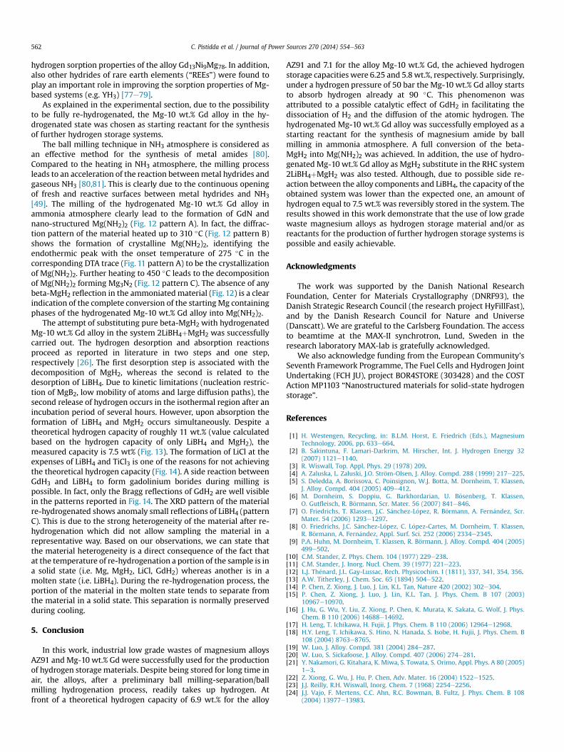
To understand the nature of the signal observed in Fig. 11, XRDcharacterization of ammoniated Mg-10 wt.% Gd alloy was carriedout (Fig. 12). In the diffraction pattern of ammoniated Mg-10 wt.%Gd (A), only the weak diffraction peaks of GdN are visible. A portionof the ammoniated material was heated up to 310 �C under argonatmosphere. In the DTA (trace A of Fig. 11), these conditionscorrespond to the end of the exothermic signal observed uponheating. The diffraction analysis of this material (pattern B) showsthe clear presence of Mg(NH2)2. The diffraction pattern of thematerial after complete desorption at 450 �C at 1 bar of hydrogenpressure (pattern C) shows only the presence of Mg3N2. In pattern Band C, the diffraction peaks of GdN are not visible anymore becauseof the overlap with the peaks of the predominant Mg(NH2)2 andMg3N2.
In order to investigate the possibility of replacing the high puritybeta-MgH2 with hydrogenated Mg-10 wt%Gd waste alloy in the
Fig. 12. XRD patterns of the ammoniated hydrogenated Mg-10 wt.% Gd alloy (A),ammoniated hydrogenated Mg-10 wt.% Gd alloy after heating up to 310 �C under argonatmosphere (B) and ammoniated hydrogenated Mg-10 wt.% Gd alloy after completedesorption at 450 �C at 1 bar of hydrogen pressure (l ¼ 1.54056 Å).
RHC systems, the mixture 2LiBH4þMgH2 was chosen. The mixturewas prepared by ball milling two mol of LiBH4 together with a molof the hydrogenation Mg-10 wt.% Gd and 2.5 mol% of TiCl3 for fivehours in a Spex 8000 ball mill, with a ball to powder ratio of 10:1.The addition of TiCl3 to 2LiBH4þMgH2 was reported to be beneficialfor the hydrogen sorption properties of this system [59]. The firsthydrogen desorption and the first hydrogen absorption of the ob-tained LiBH4-hydridizedMg-10 wt.% Gdmixture is shown in Fig. 13.The desorption measurement was performed heating up the ma-terial from room temperature up to 400 �C with a heating rate of3 �C min�1 and then keeping the material under isothermal con-ditions at 400 �C for several hours. The measurement was carriedout at a hydrogen pressure of 3 bar. The desorption process startsduring the heating period at about 300 �C and continues during theisothermal period at 400 �C, releasing in a first step an amount ofhydrogen equal to roughly 2.5 wt.% and in the second step anadditional 5 wt.%. After desorption, the material underwent a re-hydrogenation process at the constant temperature of 350 �C and50 bar of hydrogen pressure. The absorption reaction took place in asingle step charging within seven hours an amount of hydrogenequal to that released in the previous desorption (i.e. 7.5 wt.%).Hence, the system is fully reversible.
The XRD characterization of the LiBH4-hydridized Mg-10 wt.%Gd mixture upon cycling is shown in Fig. 14. In the diffractionpattern of the as milled material (pattern A) the reflections of theorthorhombic LiBH4, beta-MgH2, GdH2 and LiCl are visible. TheLiCl phase is formed by reaction of the TiCl3 with the LiBH4. Thehydrogen desorption of the as milled material at 3 bar ofhydrogen pressure and at a temperature of 400 �C lead to theformation of MgB2, Mg and LiH, GdH2 and LiCl appear to be stable(pattern B). The pattern of the material after the re-hydrogenation process at 350 �C and 50 bar of hydrogen pres-sure (pattern C) shows the presence of the orthorhombic LiBH4,beta-MgH2, beside the reflections of GdH2 and LiCl. The diffractedintensity of this last pattern was multiplied by a factor of 0.5. There-hydrogenated material appears highly heterogeneous, since,the portion of the sample rich in LiBH4 appears glassy and madeof big particles, whereas the portion of sample rich in MgH2 ispowdery.
Fig. 13. Hydrogen desorption kinetic of the as milled LiBH4-hydrogenatedMg-10 wt.%Gd mixture. The sample was heated under 3 bar hydrogen pressure from RT to 400 �C(heating rate of 3 �C min�1). Hydrogen absorption kinetic of the desorbed LiBH4-hy-drogenated Mg-10 wt.% Gd mixture. The sample was kept for several hours under50 bar of hydrogen pressure at 350 �C.

Fig. 14. XRD patterns of the as milled LiBH4-hydrogenated Mg-10 wt.% Gd mixture (A),LiBH4-hydrogenated Mg-10 wt.% Gd mixture after hydrogen desorption at 400 �C and3 bar of H2 pressure (B) and LiBH4-hydrogenated Mg-10 wt.% Gd mixture after re-hydrogenated at 350 �C and 50 bar of H2 pressure (l ¼ 1.54056 Å).
C. Pistidda et al. / Journal of Power Sources 270 (2014) 554e563 561
4. Discussion
The results presented above demonstrate that the use of mag-nesium industrial wastes for hydrogen storage purposes is possibleand easily achievable.
As discussed in the experimental section, a preliminary ballmilling-separation-hydrogenation process was carried out. Thisfirst step in the material preparation was employed in order toobtain a fine and reactive alloy powder. In fact, before starting thiswork, the materials (the shavings of the alloys AZ91 and Mg-10 wt.% Gd) were stored in air and, as previously reported in severalpublications concerning Mg and Mg alloys, it is likely that aninsulating layer of few nano-meters of magnesium oxide/magne-sium hydroxide was present at the topmost part of the materialsurface [60e70]. In addition, it is well known from the literaturethat in the early instants of the hydrogenation of the magnesiumfraction of the alloys, the hydrogenation process is limited by thehydrogen dissociation on themagnesium surface [6]. Therefore, theemployment of the ball milling technique, to reduce the particlesize of the alloys and to break the passivating oxide/hydroxidelayer, greatly improved the kinetics and completeness ofhydrogenation.
The theoretical hydrogen storage capacities of the AZ91 andMg-10 wt.% Gd alloys (6.9 and 7.1 wt.%, respectively) were calculatedbased on their nominal chemical composition. Magnesium alloynames are often given by two letters followed by two numbers.Letters stand for the alloying elements (A ¼ aluminium, Z ¼ zinc,M ¼manganese, S ¼ silicon). Numbers indicate respective nominalcompositions of main alloying elements. The acronym AZ91, forexample, denotes an magnesium alloy with roughly 9 wt.%aluminium and 1 wt.% zinc. In fact, the exact composition of thealloy AZ91 is 90 wt.% Mg; 8.71 wt.% Al; 0.66 wt.% Zn; 0.22 wt.% Mn;0.043 wt.% Si; 0.001 wt.% Fe; 0.002 wt.% Cu and 0.001wt.% Ni,whereas the Mg-10 wt.% Gd alloy consists of 90 wt.% Mg and10wt.% Gd. For the AZ91 alloy we considered the hydrogen capacityto depend only on the formation of beta-MgH2, and for the Mg-10wt.% Gd alloy on the formation of beta-MgH2 and GdH3.Although these are the nominal compositions, the real composi-tions of the as received waste material might differ slightly due to
burn off phenomena during melting and material reactionwith thereactor walls upon alloy synthesis and casting. This would partiallyexplain the reason for not achieving the expected gravimetrichydrogen capacity, in particular in the case of the alloy AZ91 (Fig. 2).In fact, for this alloy the XRD pattern of the hydrogenated materialshows a full conversion of all the Mg present in the alloy into beta-MgH2 (Figs. 3 and 5), whereas in the case of the Mg-10 wt.% Gdalloy, the unachieved storage capacity (Fig. 7) is mostly due toincomplete conversion of the starting Mg into beta-MgH2 (Figs. 8and 10). This effect was already described in literature for the hy-drogenation of pure Mg: if the Mg particles are relatively large, thegrowing MgH2 layer on the surface of these particles acts asdiffusion barrier for the hydrogen hindering the absorption process[10].
Despite the differences of composition between the two alloys,the desorption kinetics are similar. In fact, in both cases thehydrogen desorption takes place in a single step and it is completein a time period of approximately five minutes.
The earlier beginning of the desorption reaction in the case ofthe hydrogenated AZ91 alloy compared to the hydrogenated Mg-10 wt.% Gd alloy (~50 �C) can be explained by the presence of Al. Infact, compared to pure magnesium the plateau pressure of MgeAlalloys are generally higher, therefore, the presence of Al in the AZ91alloy might facilitate the MgH2 decomposition reaction [71].
After dehydrogenation, the following hydrogenation of the AZ91alloy shows a significant reduction of the achieved hydrogen ca-pacity (�33% of the capacity measured during desorption).
Beside a possible massive growth of the alloy particles andcrystallites, the presence of Mg17Al12 in equilibriumwith Mg in thealloy AZ91 can partially justify the reduction of hydrogen storagecapacity. The hydrogenation reaction of the alloy Mg17Al12 isdescribed by the two simplified following equations [72e75]:
Mg17Al12 þ 9H2 4 9MgH2 þ 4Mg2Al3 (2)
4Mg2Al3 þ 8H2 4 8MgH2 þ 12Al (3)
The enthalpies of reaction for the two hydrogenation stepsare �72 ± 2 kJ mol�1 H2 and �62 ± 2 kJ mol�1 H2, respectively forstep 1 and step 2 [73]. Consequently, considering the final hydro-genation temperature used for the hydrogenation process shown inFig. 2 (i.e. 400 �C) only the first step of hydrogenation of Mg17Al12 ispossible.
Although the preliminary hydrogenation of the alloy AZ91 wascarried out also at a temperature of 400 �C and 50 bar of hydrogen,its diffraction pattern (Fig. 3(B)) shows a complete conversion of thestarting material into MgH2 and Al. This is due to the fact that afterthe hydrogenation the completematerial was cooled down to roomtemperature under a constant hydrogen pressure of 50 bar, there-fore, the hydrogenation of Mg2Al3 (equation (2)) took place at atemperature equal to or lower than 330 �C.
After the first hydrogen desorption, the subsequent hydroge-nation of Mg-10 wt.% Gd alloy shows a full reversibility. Interest-ingly, the desorbed Mg-10 wt.% Gd alloy starts to absorb hydrogenalready at 90 �C under a hydrogen pressure of 50 bar and reaches acapacity of stored hydrogen equal to 0.6 wt.% already at 150 �C. Thedesorbed AZ91 under the same hydrogen pressure conditions startsto absorb hydrogen at roughly 200 �C. Assuming that all Gd presentin the desorbed state of the hydrogenated Mg-10 wt.% Gd alloy isconfined to GdH2, the absorption of hydrogen at low temperaturemight be explained by a possible catalytic effect of GdH2 in facili-tating the dissociation of H2 and the diffusion of the H atoms. Thiswould also justify the complete reversibility of the hydrogenationprocess of the Mg-10 wt.% Gd alloy. A similar behavior wasobserved by Couillaud et al. [76] during the investigation of the
C. Pistidda et al. / Journal of Power Sources 270 (2014) 554e563562
hydrogen sorption properties of the alloy Gd13Ni9Mg78. In addition,also other hydrides of rare earth elements (“REEs”) were found toplay an important role in improving the sorption properties of Mg-based systems (e.g. YH3) [77e79].
As explained in the experimental section, due to the possibilityto be fully re-hydrogenated, the Mg-10 wt.% Gd alloy in the hy-drogenated state was chosen as starting reactant for the synthesisof further hydrogen storage systems.
The ball milling technique in NH3 atmosphere is considered asan effective method for the synthesis of metal amides [80].Compared to the heating in NH3 atmosphere, the milling processleads to an acceleration of the reaction betweenmetal hydrides andgaseous NH3 [80,81]. This is clearly due to the continuous openingof fresh and reactive surfaces between metal hydrides and NH3[49]. The milling of the hydrogenated Mg-10 wt.% Gd alloy inammonia atmosphere clearly lead to the formation of GdN andnano-structured Mg(NH2)2 (Fig. 12 pattern A). In fact, the diffrac-tion pattern of the material heated up to 310 �C (Fig. 12 pattern B)shows the formation of crystalline Mg(NH2)2, identifying theendothermic peak with the onset temperature of 275 �C in thecorresponding DTA trace (Fig. 11 pattern A) to be the crystallizationof Mg(NH2)2. Further heating to 450 �C leads to the decompositionof Mg(NH2)2 forming Mg3N2 (Fig. 12 pattern C). The absence of anybeta-MgH2 reflection in the ammoniatedmaterial (Fig. 12) is a clearindication of the complete conversion of the startingMg containingphases of the hydrogenated Mg-10 wt.% Gd alloy into Mg(NH2)2.
The attempt of substituting pure beta-MgH2 with hydrogenatedMg-10 wt.% Gd alloy in the system 2LiBH4þMgH2 was successfullycarried out. The hydrogen desorption and absorption reactionsproceed as reported in literature in two steps and one step,respectively [26]. The first desorption step is associated with thedecomposition of MgH2, whereas the second is related to thedesorption of LiBH4. Due to kinetic limitations (nucleation restric-tion of MgB2, low mobility of atoms and large diffusion paths), thesecond release of hydrogen occurs in the isothermal region after anincubation period of several hours. However, upon absorption theformation of LiBH4 and MgH2 occurs simultaneously. Despite atheoretical hydrogen capacity of roughly 11 wt.% (value calculatedbased on the hydrogen capacity of only LiBH4 and MgH2), themeasured capacity is 7.5 wt% (Fig. 13). The formation of LiCl at theexpenses of LiBH4 and TiCl3 is one of the reasons for not achievingthe theoretical hydrogen capacity (Fig. 14). A side reaction betweenGdH3 and LiBH4 to form gadolinium borides during milling ispossible. In fact, only the Bragg reflections of GdH2 are well visiblein the patterns reported in Fig. 14. The XRD pattern of the materialre-hydrogenated shows anomaly small reflections of LiBH4 (patternC). This is due to the strong heterogeneity of the material after re-hydrogenation which did not allow sampling the material in arepresentative way. Based on our observations, we can state thatthe material heterogeneity is a direct consequence of the fact thatat the temperature of re-hydrogenation a portion of the sample is ina solid state (i.e. Mg, MgH2, LiCl, GdH2) whereas another is in amolten state (i.e. LiBH4). During the re-hydrogenation process, theportion of the material in the molten state tends to separate fromthe material in a solid state. This separation is normally preservedduring cooling.
5. Conclusion
In this work, industrial low grade wastes of magnesium alloysAZ91 and Mg-10 wt.% Gd were successfully used for the productionof hydrogen storagematerials. Despite being stored for long time inair, the alloys, after a preliminary ball milling-separation/ballmilling hydrogenation process, readily takes up hydrogen. Atfront of a theoretical hydrogen capacity of 6.9 wt.% for the alloy
AZ91 and 7.1 for the alloy Mg-10 wt.% Gd, the achieved hydrogenstorage capacities were 6.25 and 5.8wt.%, respectively. Surprisingly,under a hydrogen pressure of 50 bar the Mg-10 wt.% Gd alloy startsto absorb hydrogen already at 90 �C. This phenomenon wasattributed to a possible catalytic effect of GdH2 in facilitating thedissociation of H2 and the diffusion of the atomic hydrogen. Thehydrogenated Mg-10 wt.% Gd alloy was successfully employed as astarting reactant for the synthesis of magnesium amide by ballmilling in ammonia atmosphere. A full conversion of the beta-MgH2 into Mg(NH2)2 was achieved. In addition, the use of hydro-genatedMg-10 wt.% Gd alloy as MgH2 substitute in the RHC system2LiBH4þMgH2 was also tested. Although, due to possible side re-action between the alloy components and LiBH4, the capacity of theobtained system was lower than the expected one, an amount ofhydrogen equal to 7.5 wt.% was reversibly stored in the system. Theresults showed in this work demonstrate that the use of low gradewaste magnesium alloys as hydrogen storage material and/or asreactants for the production of further hydrogen storage systems ispossible and easily achievable.
Acknowledgments
The work was supported by the Danish National ResearchFoundation, Center for Materials Crystallography (DNRF93), theDanish Strategic Research Council (the research project HyFillFast),and by the Danish Research Council for Nature and Universe(Danscatt). We are grateful to the Carlsberg Foundation. The accessto beamtime at the MAX-II synchrotron, Lund, Sweden in theresearch laboratory MAX-lab is gratefully acknowledged.
We also acknowledge funding from the European Community'sSeventh Framework Programme, The Fuel Cells and Hydrogen JointUndertaking (FCH JU), project BOR4STORE (303428) and the COSTAction MP1103 “Nanostructured materials for solid-state hydrogenstorage”.
References
[1] H. Westengen, Recycling, in: B.L.M. Horst, E. Friedrich (Eds.), MagnesiumTechnology, 2006, pp. 633e664.
[2] B. Sakintuna, F. Lamari-Darkrim, M. Hirscher, Int. J. Hydrogen Energy 32(2007) 1121e1140.
[3] R. Wiswall, Top. Appl. Phys. 29 (1978) 209.[4] A. Zaluska, L. Zaluski, J.O. Str€om-Olsen, J. Alloy. Compd. 288 (1999) 217e225.[5] S. Deledda, A. Borissova, C. Poinsignon, W.J. Botta, M. Dornheim, T. Klassen,
J. Alloy. Compd. 404 (2005) 409e412.[6] M. Dornheim, S. Doppiu, G. Barkhordarian, U. B€osenberg, T. Klassen,
O. Gutfleisch, R. B€ormann, Scr. Mater. 56 (2007) 841e846.[7] O. Friedrichs, T. Klassen, J.C. S�anchez-L�opez, R. B€ormann, A. Fern�andez, Scr.
Mater. 54 (2006) 1293e1297.[8] O. Friedrichs, J.C. S�anchez-L�opez, C. L�opez-Cartes, M. Dornheim, T. Klassen,
R. B€ormann, A. Fern�andez, Appl. Surf. Sci. 252 (2006) 2334e2345.[9] P.A. Huhn, M. Dornheim, T. Klassen, R. B€ormann, J. Alloy. Compd. 404 (2005)
499e502.[10] C.M. Stander, Z. Phys. Chem. 104 (1977) 229e238.[11] C.M. Stander, J. Inorg. Nucl. Chem. 39 (1977) 221e223.[12] L.J. Th�enard, J.L. Gay-Lussac, Rech. Physicochim. I (1811), 337, 341, 354, 356.[13] A.W. Titherley, J. Chem. Soc. 65 (1894) 504e522.[14] P. Chen, Z. Xiong, J. Luo, J. Lin, K.L. Tan, Nature 420 (2002) 302e304.[15] P. Chen, Z. Xiong, J. Luo, J. Lin, K.L. Tan, J. Phys. Chem. B 107 (2003)
10967e10970.[16] J. Hu, G. Wu, Y. Liu, Z. Xiong, P. Chen, K. Murata, K. Sakata, G. Wolf, J. Phys.
Chem. B 110 (2006) 14688e14692.[17] H. Leng, T. Ichikawa, H. Fujii, J. Phys. Chem. B 110 (2006) 12964e12968.[18] H.Y. Leng, T. Ichikawa, S. Hino, N. Hanada, S. Isobe, H. Fujii, J. Phys. Chem. B
108 (2004) 8763e8765.[19] W. Luo, J. Alloy. Compd. 381 (2004) 284e287.[20] W. Luo, S. Sickafoose, J. Alloy. Compd. 407 (2006) 274e281.[21] Y. Nakamori, G. Kitahara, K. Miwa, S. Towata, S. Orimo, Appl. Phys. A 80 (2005)
1e3.[22] Z. Xiong, G. Wu, J. Hu, P. Chen, Adv. Mater. 16 (2004) 1522e1525.[23] J.J. Reilly, R.H. Wiswall, Inorg. Chem. 7 (1968) 2254e2256.[24] J.J. Vajo, F. Mertens, C.C. Ahn, R.C. Bowman, B. Fultz, J. Phys. Chem. B 108
(2004) 13977e13983.

C. Pistidda et al. / Journal of Power Sources 270 (2014) 554e563 563
[25] G. Barkhordarian, T. Klassen, M. Dornheim, R. B€ormann, J. Alloy. Compd. 440(2007) L18eL21.
[26] U. B€osenberg, S. Doppiu, L. Mosegaard, G. Barkhordarian, N. Eigen,A. Borgschulte, T.R. Jensen, Y. Cerenius, O. Gutfleisch, T. Klassen, M. Dornheim,R. B€ormann, Acta Mater. 55 (2007) 3951e3958.
[27] U. B€osenberg, J.W. Kim, D. Gosslar, N. Eigen, T.R. Jensen, J.M.B. von Colbe, Y.Zhou, M. Dahms, D.H. Kim, R. Gunther, Y.W. Cho, K.H. Oh, T. Klassen, R.B€ormann, M. Dornheim, Acta Mater. 58 3381e3389.
[28] J.J. Vajo, G.L. Olson, Scr. Mater. 56 (2007) 829e834.[29] E. Deprez, A. Justo, T.C. Rojas, C. L�opez-Cart�es, C. Bonatto Minella,
U. B€osenberg, M. Dornheim, R. B€ormann, A. Fern�andez, Acta Mater. 58 (2010)5683e5694.
[30] E. Deprez, M.A. Munoz-M�arquez, M.C. Jimenez De Haro, F.J. Palomares,F. Soria, M. Dornheim, R. B€ormann, A. Fern�andez, J. Appl. Phys. 109 (2011)014913.
[31] E. Deprez, M.A. Munoz-M�arquez, M.A. Rold�an, C. Prestipino, F.J. Palomares,C.B. Minella, U. B€osenberg, M. Dornheim, R. B€ormann, A. Fern�andez, J. Phys.Chem. C 114 3309e3317.
[32] A. Fern�andez, E. Deprez, O. Friedrichs, Int. J. Hydrogen Energy 36 (2011)3932e3940.
[33] S. Garroni, C. Milanese, A. Girella, A. Marini, G. Mulas, E. Menendez, C. Pistidda,M. Dornheim, S. Surinach, M.D. Bar�o, Int. J. Hydrogen Energy 35 (2010)5434e5441.
[34] S. Garroni, C. Milanese, D. Pottmaier, G. Mulas, P. Nolis, A. Girella, R. Caputo,D. Olid, F. Teixdor, M. Baricco, A. Marini, S. Surinach, M.D. Bar�o, J. Phys. Chem.C 115 (2011) 16664e16671.
[35] S. Garroni, C.B. Minella, D. Pottmaier, C. Pistidda, C. Milanese, A. Marini,S. Enzo, G. Mulas, M. Dornheim, M. Baricco, O. Gutfleisch, S. Surinach,M.D. Bar�o, Int. J. Hydrogen Energy 38 (2013) 2363e2369.
[36] S. Garroni, C. Pistidda, M. Brunelli, G.B.M. Vaughan, S. Surinach, M.D. Bar�o, Scr.Mater. 60 (2009) 1129e1132.
[37] J.F. Mao, X.B. Yu, Z.P. Guo, H.K. Liu, Z. Wu, J. Ni, J. Alloy. Compd. 479 (2009)619e623.
[38] C.C. Nwakwuo, C. Pistidda, M. Dornheim, J.L. Hutchison, J.M. Sykes, Int. J.Hydrogen Energy 37 (2012) 2382e2387.
[39] C.C. Nwakwuo, C. Pistidda, M. Dornheim, J.L. Hutchison, J.M. Sykes, Scr. Mater.64 (2011) 351e354.
[40] C. Pistidda, G. Barkhordarian, A. Rzeszutek, S. Garroni, C.B. Minella, M.D. Bar�o,P. Nolis, R. B€ormann, T. Klassen, M. Dornheim, Scr. Mater. 64 (2011)1035e1038.
[41] C. Pistidda, S. Garroni, C.B. Minella, F. Dolci, T.R. Jensen, P. Nolis, U. B€osenberg,Y. Cerenius, W. Lohstroh, M. Fichtner, M.D. Bar�o, R. B€ormann, M. Dornheim,J. Phys. Chem. C 114 (2010) 21816e21823.
[42] C. Pistidda, E. Napolitano, D. Pottmaier, M. Dornheim, T. Klassen, M. Baricco,S. Enzo, Int. J. Hydrogen Energy 38 (2013) 10479e10484.
[43] D. Pottmaier, C. Pistidda, E. Groppo, S. Bordiga, G. Spoto, M. Dornheim,M. Baricco, Int. J. Hydrogen Energy 36 (2011) 7891e7896.
[44] C. Pistidda, D. Pottmaier, F. Karimi, S. Garroni, A. Rzeszutek, M. Tolkiehn,M. Fichtner, W. Lohstroh, M. Baricco, T. Klassen, M. Dornheim, Int. J. HydrogenEnergy 39 (2014) 5030e5036.
[45] K.S. Alcantara, J.M. Ramallo-Lopez, U. B€osenberg, I. Saldan, C. Pistidda,F.G. Requejo, T. Jensen, Y. Cerenius, M. Sørby, J. Avila, J.B. von Colbe, K. Taube,T. Klassen, M. Dornheim, J. Phys. Chem. C 116 (2012) 7207e7212.
[46] G. Barkhordarian, T.R. Jensen, S. Doppiu, U. B€osenberg, A. Borgschulte,R. Gremaud, Y. Cerenius, M. Dornheim, T. Klassen, R. B€ormann, J. Phys. Chem.C 112 (2008) 2743e2749.
[47] C. Bonatto Minella, S. Garroni, D. Olid, F. Teixidor, C. Pistidda, I. Lindemann,O. Gutfleisch, M.D. Bar�o, R. B€ormann, T. Klassen, M. Dornheim, J. Phys. Chem. C115 (2011) 18010e18014.
[48] C.B. Minella, C. Pistidda, S. Garroni, P. Nolis, M.D. Bar�o, O. Gutfleisch,T. Klassen, R. B€ormann, M. Dornheim, J. Phys. Chem. C 117 (2013) 3846e3852.
[49] C. Suryanarayana, Prog. Mater. Sci. 46 (2001) 1e184.[50] K. Zeng, T. Klassen, W. Oelerich, R. B€ormann, Int. J. Hydrogen Energy 24 (1999)
989e1004.[51] B.S. Clausen, G. Steffensen, B. Fabius, J. Villadsen, R. Feidenhansl, H. Topsoe,
J. Catal. 132 (1991) 524e535.[52] J.A. Rodriguez, J.C. Hanson, A.I. Frenkel, J.Y. Kim, M. Perez, J. Am. Chem. Soc.
124 (2002) 346e354.[53] T.R. Jensen, T.K. Nielsen, Y. Filinchuk, J.-E. Jorgensen, Y. Cerenius, E.M. Gray,
C.J. Webb, J. Appl. Crystallogr. 43 (2010) 1456e1463.[54] http://www.esrf.eu/computing/scientific/FIT2D/.[55] H. Okamoto, J. Phase Equilib. 14 (1993) 534e535.[56] Y. Nakamori, G. Kitahara, A. Ninomiya, M. Aoki, T. Noritake, S.I. Towata,
S.I. Orimo, Mater. Trans. 46 (2005) 2093e2097.[57] O.I. Velikokhatnyi, P.N. Kumta, Mater. Sci. Eng. B 140 (2007) 114e122.[58] D.H. Gregory, J. Mater. Chem. 18 (2008) 2321e2330.[59] J.J. Vajo, S.L. Skeith, F. Mertens, J. Phys. Chem. B 109 (2005) 3719e3722.[60] S. Feliu Jr., C. Maffiotte, J.C. Galv�an, V. Barranco, Corros. Sci. 53 (2011)
1865e1872.[61] S. Feliu Jr., C. Maffiotte, A. Samaniego, J.C. Galv�an, V. Barranco, Electrochim.
Acta 56 (2011) 4554e4565.[62] S. Feliu Jr., A. Pardo, M.C. Merino, R. Arrabal, E. Matykina, Adv. Mater. Sci. Eng.
(2009) 1e7.[63] S. Feliu Jr., A. Pardo, M.C. Merino, A.E. Coy, F. Viejo, R. Arrabal, Appl. Surf. Sci.
255 (2009) 4102e4108.[64] S. Feliu Jr., A. Samaniego, E.A. Bermudez, A.A. El-Hadad, I. Llorente, J.C. Galv�an,
Materials 7 (2014) 2534e2560.[65] K. Asami, S. Ono, J. Electrochem. Soc. 147 (2000) 1408e1413.[66] T. Do, S.J. Splinter, C. Chen, N.S. McIntyre, Surf. Sci. 387 (1997) 192e198.[67] J.C. Fuggle, L.M. Watson, D.J. Fabian, S. Affrossman, Surf. Sci. 49 (1975) 61e76.[68] N.S. McIntyre, C. Chen, Corros. Sci. 40 (1998) 1697e1709.[69] M. Santamaria, F. Di Quarto, S. Zanna, P. Marcus, Electrochim. Acta 53 (2007)
1314e1324.[70] S.J. Splinter, N.S. McIntyre, W.N. Lennard, K. Griffiths, G. Palumbo, Surf. Sci.
292 (1993) 130e144.[71] A. Andreasen, Int. J. Hydrogen Energy 33 (2008) 7489e7497.[72] S. Bouaricha, J.P. Dodelet, D. Guay, J. Huot, S. Boily, R. Schulz, J. Alloy. Compd.
297 (2000) 282e293.[73] J.C. Crivello, T. Nobuki, S. Kato, M. Abe, T. Kuji, J. Alloy. Compd. 446e447
(2007) 157e161.[74] J.C. Crivello, T. Nobuki, T. Kuji, Int. J. Hydrogen Energy 34 (2009) 1937e1943.[75] M. Sato, T. Kuji, Mater. Trans. 52 (2011) 1773e1776.[76] S. Couillaud, E. Gaudin, F. Weill, S. Gomez, C. Stan, D. Plante, S. Miraglia,
J.L. Bobet, Acta Mater. 60 (2012) 4144e4151.[77] J.L. Bobet, B. Chevalier, M.Y. Song, B. Darriet, J. Etourneau, J. Alloy. Compd. 336
(2002) 292e296.[78] Z. Li, X. Liu, L. Jiang, S. Wang, Int. J. Hydrogen Energy 32 (2007) 1869e1874.[79] S. Orimo, H. Fujii, M. Tabata, J. Alloy. Compd. 210 (1994) 37e43.[80] H.Y. Leng, T. Ichikawa, S. Hino, N. Hanada, S. Isobe, H. Fujii, J. Power Sources
156 (2006) 166e170.[81] F.W. Bergstrom, W.C. Fernelius, Chem. Rev. 12 (1933) 43e179.